JP2021525598A - Multi-stage steam-based ablation processing method and steam generation and delivery system - Google Patents
Multi-stage steam-based ablation processing method and steam generation and delivery system Download PDFInfo
- Publication number
- JP2021525598A JP2021525598A JP2020566982A JP2020566982A JP2021525598A JP 2021525598 A JP2021525598 A JP 2021525598A JP 2020566982 A JP2020566982 A JP 2020566982A JP 2020566982 A JP2020566982 A JP 2020566982A JP 2021525598 A JP2021525598 A JP 2021525598A
- Authority
- JP
- Japan
- Prior art keywords
- catheter
- ablation
- patient
- treatment
- positioning elements
- Prior art date
- Legal status (The legal status is an assumption and is not a legal conclusion. Google has not performed a legal analysis and makes no representation as to the accuracy of the status listed.)
- Pending
Links
Images


Classifications
-
- A—HUMAN NECESSITIES
- A61—MEDICAL OR VETERINARY SCIENCE; HYGIENE
- A61B—DIAGNOSIS; SURGERY; IDENTIFICATION
- A61B18/00—Surgical instruments, devices or methods for transferring non-mechanical forms of energy to or from the body
- A61B18/04—Surgical instruments, devices or methods for transferring non-mechanical forms of energy to or from the body by heating
-
- A—HUMAN NECESSITIES
- A61—MEDICAL OR VETERINARY SCIENCE; HYGIENE
- A61B—DIAGNOSIS; SURGERY; IDENTIFICATION
- A61B18/00—Surgical instruments, devices or methods for transferring non-mechanical forms of energy to or from the body
- A61B18/02—Surgical instruments, devices or methods for transferring non-mechanical forms of energy to or from the body by cooling, e.g. cryogenic techniques
- A61B18/0218—Surgical instruments, devices or methods for transferring non-mechanical forms of energy to or from the body by cooling, e.g. cryogenic techniques with open-end cryogenic probe, e.g. for spraying fluid directly on tissue or via a tissue-contacting porous tip
-
- A—HUMAN NECESSITIES
- A61—MEDICAL OR VETERINARY SCIENCE; HYGIENE
- A61B—DIAGNOSIS; SURGERY; IDENTIFICATION
- A61B18/00—Surgical instruments, devices or methods for transferring non-mechanical forms of energy to or from the body
- A61B2018/00053—Mechanical features of the instrument of device
- A61B2018/00214—Expandable means emitting energy, e.g. by elements carried thereon
- A61B2018/0022—Balloons
- A61B2018/0025—Multiple balloons
- A61B2018/00261—Multiple balloons arranged in a line
-
- A—HUMAN NECESSITIES
- A61—MEDICAL OR VETERINARY SCIENCE; HYGIENE
- A61B—DIAGNOSIS; SURGERY; IDENTIFICATION
- A61B18/00—Surgical instruments, devices or methods for transferring non-mechanical forms of energy to or from the body
- A61B2018/00053—Mechanical features of the instrument of device
- A61B2018/00273—Anchoring means for temporary attachment of a device to tissue
- A61B2018/00279—Anchoring means for temporary attachment of a device to tissue deployable
- A61B2018/00285—Balloons
-
- A—HUMAN NECESSITIES
- A61—MEDICAL OR VETERINARY SCIENCE; HYGIENE
- A61B—DIAGNOSIS; SURGERY; IDENTIFICATION
- A61B18/00—Surgical instruments, devices or methods for transferring non-mechanical forms of energy to or from the body
- A61B2018/00315—Surgical instruments, devices or methods for transferring non-mechanical forms of energy to or from the body for treatment of particular body parts
- A61B2018/00345—Vascular system
-
- A—HUMAN NECESSITIES
- A61—MEDICAL OR VETERINARY SCIENCE; HYGIENE
- A61B—DIAGNOSIS; SURGERY; IDENTIFICATION
- A61B18/00—Surgical instruments, devices or methods for transferring non-mechanical forms of energy to or from the body
- A61B2018/00315—Surgical instruments, devices or methods for transferring non-mechanical forms of energy to or from the body for treatment of particular body parts
- A61B2018/00482—Digestive system
- A61B2018/00488—Esophagus
-
- A—HUMAN NECESSITIES
- A61—MEDICAL OR VETERINARY SCIENCE; HYGIENE
- A61B—DIAGNOSIS; SURGERY; IDENTIFICATION
- A61B18/00—Surgical instruments, devices or methods for transferring non-mechanical forms of energy to or from the body
- A61B2018/00315—Surgical instruments, devices or methods for transferring non-mechanical forms of energy to or from the body for treatment of particular body parts
- A61B2018/00482—Digestive system
- A61B2018/00494—Stomach, intestines or bowel
-
- A—HUMAN NECESSITIES
- A61—MEDICAL OR VETERINARY SCIENCE; HYGIENE
- A61B—DIAGNOSIS; SURGERY; IDENTIFICATION
- A61B18/00—Surgical instruments, devices or methods for transferring non-mechanical forms of energy to or from the body
- A61B2018/00315—Surgical instruments, devices or methods for transferring non-mechanical forms of energy to or from the body for treatment of particular body parts
- A61B2018/00541—Lung or bronchi
-
- A—HUMAN NECESSITIES
- A61—MEDICAL OR VETERINARY SCIENCE; HYGIENE
- A61B—DIAGNOSIS; SURGERY; IDENTIFICATION
- A61B18/00—Surgical instruments, devices or methods for transferring non-mechanical forms of energy to or from the body
- A61B2018/00571—Surgical instruments, devices or methods for transferring non-mechanical forms of energy to or from the body for achieving a particular surgical effect
- A61B2018/00577—Ablation
-
- A—HUMAN NECESSITIES
- A61—MEDICAL OR VETERINARY SCIENCE; HYGIENE
- A61B—DIAGNOSIS; SURGERY; IDENTIFICATION
- A61B18/00—Surgical instruments, devices or methods for transferring non-mechanical forms of energy to or from the body
- A61B2018/00636—Sensing and controlling the application of energy
- A61B2018/00696—Controlled or regulated parameters
- A61B2018/0072—Current
-
- A—HUMAN NECESSITIES
- A61—MEDICAL OR VETERINARY SCIENCE; HYGIENE
- A61B—DIAGNOSIS; SURGERY; IDENTIFICATION
- A61B18/00—Surgical instruments, devices or methods for transferring non-mechanical forms of energy to or from the body
- A61B2018/00636—Sensing and controlling the application of energy
- A61B2018/00696—Controlled or regulated parameters
- A61B2018/00744—Fluid flow
-
- A—HUMAN NECESSITIES
- A61—MEDICAL OR VETERINARY SCIENCE; HYGIENE
- A61B—DIAGNOSIS; SURGERY; IDENTIFICATION
- A61B18/00—Surgical instruments, devices or methods for transferring non-mechanical forms of energy to or from the body
- A61B2018/00982—Surgical instruments, devices or methods for transferring non-mechanical forms of energy to or from the body combined with or comprising means for visual or photographic inspections inside the body, e.g. endoscopes
-
- A—HUMAN NECESSITIES
- A61—MEDICAL OR VETERINARY SCIENCE; HYGIENE
- A61B—DIAGNOSIS; SURGERY; IDENTIFICATION
- A61B18/00—Surgical instruments, devices or methods for transferring non-mechanical forms of energy to or from the body
- A61B18/04—Surgical instruments, devices or methods for transferring non-mechanical forms of energy to or from the body by heating
- A61B2018/044—Surgical instruments, devices or methods for transferring non-mechanical forms of energy to or from the body by heating the surgical action being effected by a circulating hot fluid
- A61B2018/048—Surgical instruments, devices or methods for transferring non-mechanical forms of energy to or from the body by heating the surgical action being effected by a circulating hot fluid in gaseous form
-
- A—HUMAN NECESSITIES
- A61—MEDICAL OR VETERINARY SCIENCE; HYGIENE
- A61B—DIAGNOSIS; SURGERY; IDENTIFICATION
- A61B90/00—Instruments, implements or accessories specially adapted for surgery or diagnosis and not covered by any of the groups A61B1/00 - A61B50/00, e.g. for luxation treatment or for protecting wound edges
- A61B90/06—Measuring instruments not otherwise provided for
- A61B2090/061—Measuring instruments not otherwise provided for for measuring dimensions, e.g. length
-
- A—HUMAN NECESSITIES
- A61—MEDICAL OR VETERINARY SCIENCE; HYGIENE
- A61B—DIAGNOSIS; SURGERY; IDENTIFICATION
- A61B2218/00—Details of surgical instruments, devices or methods for transferring non-mechanical forms of energy to or from the body
- A61B2218/001—Details of surgical instruments, devices or methods for transferring non-mechanical forms of energy to or from the body having means for irrigation and/or aspiration of substances to and/or from the surgical site
- A61B2218/007—Aspiration
Abstract
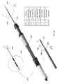
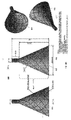
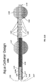
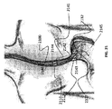
アブレーション・カテーテル及びシステムは、ターゲット組織にアブレーション剤を送るための、遠位針又はポートを有する可撓性カテーテル先端を含む。アブレーションの間に圧力モニタリングを行うことによって、安全性限界内で及び所望の有効性で動作することを確認する。位置決め要素は、前記デバイスをターゲット組織に対して適切な配置に維持するのに役立ち、及び、アブレーション剤が正常組織に届くことも防止する。【選択図】図1KAblation catheters and systems include flexible catheter tips with distal needles or ports for delivering ablation agents to target tissue. Pressure monitoring during ablation ensures that it operates within safety limits and with the desired effectiveness. The positioning element helps maintain the device in proper placement with respect to the target tissue and also prevents the ablation agent from reaching the normal tissue. [Selection diagram] Fig. 1K
Description
本出願は「アブレーションシステムand方法」と題され、2018年6月1日に出願された米国特許仮出願第62/679,694号に依拠し、その全体が参考として本明細書に援用される。 This application, entitled "Ablation System and Method," relies on US Patent Provisional Application No. 62 / 679,694, filed June 1, 2018, which is incorporated herein by reference in its entirety.
本出願は、米国特許優先権出願第15/600,670号(名称「統合冷却付きアブレーションカテーテル」)(2017年5月19日出願)(これは「方法およびシステムforアブレーション」という名称の、2016年11月22日出願の米国特許優先権出願第62/425,144号、および「冷却同軸アブレーションカテーテル」という名称の、2016年5月19日出願の米国特許優先権出願第62/338,871号に依拠する)に関連する。 This application is filed in US Patent Priority Application No. 15 / 600,670 (named "Integrated Cooled Ablation Catheter") (filed May 19, 2017) (this is called "Methods and Systems for Ablation", November 2016. Relying on US Patent Priority Application No. 62 / 425,144 filed on 22nd May, and US Patent Priority Application 62 / 338,871 filed May 19, 2016 under the name "Cool Coaxial Ablation Catheter"). Related.
また、本出願は米国特許出願公開第15/144,768号(発明の名称:「誘導に基づく微小体積加熱システム」)(2016年5月2日出願、米国特許出願公開第14/594,444号、発明の名称:「組織アブレーションのための方法および器具」)(2015年1月12日出願)、および米国特許第9,561,068号(2017年2月7日発行、米国特許出願公開第14/158,687号(2014年1月17日出願)、および米国特許第9,561,067号(2017年2月7日発行)にも関し、同名称の米国仮特許出願第61/753,831号(2013年1月17日出願)に優先権を依存する。 In addition, this application is filed in US Patent Application Publication No. 15 / 144,768 (Title of the invention: "Induction-based microvolume heating system") (filed May 2, 2016, US Patent Application Publication No. 14 / 594,444, invention of the invention. Name: "Methods and Instruments for Tissue Ablation") (filed January 12, 2015), and US Patent No. 9,561,068 (issued February 7, 2017, US Patent Application Publication No. 14 / 158,687 (2014)). Prioritized US Patent Application No. 9,561,067 (issued February 7, 2017) and US Provisional Patent Application No. 61 / 753,831 (filed January 17, 2013) with the same name. Depends on.
米国特許出願公開第14/158,687号は2012年6月1日に出願された「組織アブレーションのための方法及び装置」と題する、米国特許出願公開第13/486,980号の一部継続出願である 2017年2月7日の米国特許第9,561,066号と同様に、同名称の米国仮特許出願第61/493,344号に依拠し、2011年6月3日に優先権を主張して出願された。 U.S. Patent Application Publication No. 14 / 158,687 is a partial continuation of U.S. Patent Application Publication No. 13 / 486,980, entitled "Methods and Devices for Tissue Ablation," filed June 1, 2012. Similar to US Pat. No. 9,561,066 on February 7, 2011, it relied on US Provisional Patent Application No. 61 / 493,344 of the same name and was filed on June 3, 2011, claiming priority.
また、米国特許出願公開第13/486,980号は2009年10月6日に出願された「組織アブレーションのための方法および器具」という名称の米国特許出願公開第12/573,939号の一部継続出願であり、この出願は、2008年10月6日に出願された同名称の米国仮特許出願第61/102,885号に優先権を依存する。 In addition, US Patent Application Publication No. 13 / 486,980 is a partial continuation application of US Patent Application Publication No. 12 / 573,939 entitled "Methods and Instruments for Tissue Ablation" filed on October 6, 2009. Yes, this application relies on priority of US Provisional Patent Application No. 61 / 102,885 of the same name filed on October 6, 2008.
上記で参照された出願の全ては、その全体が参照により本明細書に組み込まれる。 All of the applications referenced above are incorporated herein by reference in their entirety.
本明細書はアブレーション治療のために気体を生成し、送達するように構成されたシステムおよび方法に関する。より詳細には、本明細書が特定の臓器システムにアブレーション治療を送達するための針またはポートを有する可撓性カテーテル位置決め要素(positioning element)および/または先端を備えるシステムおよび方法に関する。 The present specification relates to systems and methods configured to produce and deliver gases for ablation therapy. More specifically, the present specification relates to a system and method comprising a flexible catheter positioning element and / or a tip having a needle or port for delivering ablation therapy to a particular organ system.
アブレーションは本明細書に関連するように、高周波エネルギー、レーザーエネルギー、超音波エネルギー、シロエージェント、または水蒸気などの破壊剤の導入による身体組織の除去または破壊に関する。アブレーションはシステマティック、ポリス、腫瘍、血液病などのような病気や不要な組織を排除するために一般的に用いられているが、他に限定されない。 Ablation relates to the removal or destruction of body tissue by the introduction of destructive agents such as high frequency energy, laser energy, ultrasonic energy, white agents, or water vapor, as relevant herein. Ablation is commonly used to eliminate diseases such as systematic, police, tumors, blood diseases and unwanted tissues, but is not limited to others.
米国特許番号に開示されているような水蒸気ベースのアブレーションシステム。9,615,875, 9,433,457、9,376,497、9,561,068、9,561,067、および9,561,066は、組織標的に向かって1つ以上の内腔を通して水蒸気を制御可能に送達するアブレーションシステムを開示する。全てのこのような水蒸気ベースのアブレーションシステムが有する1つの課題は、健康な組織の潜在的な過熱又は燃焼である。体腔内の流路を通過する水蒸気は流路の表面を加熱し、操作ツール端部自体以外の医療ツールの外面を過度に高温にすることがある。その結果、医師は器具の先端の操作端以外のデバイスの外部部分が健康な組織に偶発的に接触したときに、意図せずに健康な組織を焼くことがある。米国特許番号。9,561,068, 9,561,067および9,561,066は、参照により本明細書に組み込まれる。 A water vapor-based ablation system as disclosed in the US patent number. 9,615,875, 9,433,457, 9,376,497, 9,561,068, 9,561,067, and 9,561,066 disclose an ablation system that controlsally delivers water vapor through one or more lumens towards a tissue target. One challenge with all such steam-based ablation systems is the potential overheating or burning of healthy tissue. Water vapor passing through the flow path in the body cavity heats the surface of the flow path, which may cause the outer surface of the medical tool other than the operation tool end itself to become excessively hot. As a result, physicians may unintentionally burn healthy tissue when an external portion of the device other than the operating end of the instrument tip accidentally comes into contact with healthy tissue. US patent number. 9,561,068, 9,561,067 and 9,561,066 are incorporated herein by reference.
さらに、水蒸気の効果的な使用はしばしば、ある体積の組織を水蒸気に制御可能に曝露することを必要とする。しかしながら、水蒸気アブレーションに対する従来技術のアプローチは治療される体積を十分に封入することができず、それによって組織を十分に露出させないか、または治療される体積を過度に封入し、それによって、患者臓器内の圧力および/または温度を危険にも上昇させるかのいずれかである。カテーテル上に配置された加圧センサーはエネルギーデリバリーを調整するのに役立ち得るが、それらは必ずしも信頼性がなく、システムにおける潜在的な故障の臨界点を表す。 Moreover, effective use of water vapor often requires a controllable exposure of a volume of tissue to water vapor. However, prior art approaches to steam ablation have not been able to adequately enclose the volume to be treated, thereby not adequately exposing the tissue or over-encapsulating the volume to be treated, thereby causing the patient's organs. Either the pressure and / or temperature inside is dangerously increased. Pressure sensors placed on the catheter can help regulate energy delivery, but they are not always reliable and represent the critical point of potential failure in the system.
したがって、使用中の望ましくない燃焼を防止する安全機構をデバイス自身に組み込む水蒸気ベースのアブレーションデバイスを有することが望ましい。さらに、ターゲット組織がさらされる蒸気の量をより良く制御する方法を提供できることが望ましい。また、カテーテル自身の圧力センサーに依存することなく、密閉体積内の圧力量を制御できることが望ましい。最後に、食道、十二指腸、胆管、および膵臓における前癌性または癌性組織を含む種々の条件を治療するために使用される水蒸気ベースのアブレーションシステムおよび方法を提供することも望ましい。 Therefore, it is desirable to have a steam-based ablation device that incorporates into the device itself a safety mechanism that prevents unwanted combustion during use. In addition, it is desirable to be able to provide a better way to control the amount of vapor that the target tissue is exposed to. Further, it is desirable that the amount of pressure in the sealed volume can be controlled without depending on the pressure sensor of the catheter itself. Finally, it is also desirable to provide water vapor-based ablation systems and methods used to treat a variety of conditions, including precancerous or cancerous tissue in the esophagus, duodenum, bile ducts, and pancreas.
本明細書は蒸気切除システムを使用して十二指腸組織を切除することによって、過剰体重、肥満、摂食障害、代謝障害、脂質異常症、糖尿病、多嚢胞性卵巣疾患、脂肪肝疾患、非アルコール性脂肪肝疾患、または非アルコール性脂肪肝炎疾患のうちの少なくとも1つを治療するための多段階方法を開示し、蒸気切除システムは少なくとも1つのポンプとデータ通信する少なくとも1つのプロセッサと、少なくともポンプと流体連通するカテーテル接続ポートとを有するコントローラを備え、多段階方法は第1のカテーテルの近位端をカテーテル接続ポートに接続して、少なくとも1つのポンプと流体連通する第1のカテーテルを配置することを含み、第1のカテーテルはカテーテルの長さに沿って分離された少なくとも2つの位置決め要素と、少なくとも2つの位置決め要素の間に配置された少なくとも2つのポートとを備え、少なくとも2つの位置決め要素の各々は第1の構成および第2の構成を有し、第1の構成では少なくとも2つの位置決め要素の各々が内部で圧縮される。少なくとも2つの位置決め要素の各々が少なくとも部分的にカテーテルの外側に拡張され、少なくとも2つの位置決め要素の各々が第2の構成内に拡張されると、少なくとも2つの位置決め要素のうちの遠位の1つが、患者の小腸内に配置され、少なくとも2つの位置決め要素のうちの近位の1cmを超えて近位に配置されるように、第1のカテーテルの内側に少なくとも部分的に拡張されるように、第1のカテーテルを患者の体内に配置し、少なくとも2つの位置決め要素のうちの近位の1つが、少なくとも2つの位置決め要素の遠位の1つから1cmを超えて近位に配置されるように、第1のカテーテル内に配置されるように、第2の構成内に拡張される;少なくとも2つの位置決め要素の各々をそれらの第2の構成内に拡張する;コントローラを起動すると、コントローラは起動時に、少なくとも1つのポンプに、第1のカテーテル内の少なくとも1つの管腔内に生理食塩水を送達させるように構成され、起動時に、コントローラは第1のカテーテルの少なくとも1つの管腔内に配置された少なくとも1つの電極に電流を送達させるように構成され;少なくとも2つの 生理食塩水および電流の送達;第1の治療段階を完了するために患者から第1のカテーテルを除去すること;第1の治療段階を完了するために第1のカテーテルを除去すること;第1の治療段階の効力を決定すること;決定された効力に応じて、第2のカテーテルの近位端をカテーテル接続ポートに接続して、少なくとも1つのポンプと流体連通させることを決定すること;第2のカテーテルはカテーテルの長さに沿って分離された少なくとも2つの位置決め要素と、少なくとも2つの位置決め要素の間に配置された少なくとも2つのポートとを含み、少なくとも2つの位置決め要素の各々は第1の構成および第2の構成を有し、第1の構成では少なくとも2つの位置決め要素の各々がカテーテル内で圧縮され、第2の構成では少なくとも2つの位置決め要素の各々が少なくとも部分的にカテーテルの外側に拡張される;第2のカテーテルを、第2の構成に拡張されると、少なくとも2つの位置決め要素のうちの遠位1つは以下の中に配置される。患者の小腸および少なくとも2つの位置決め要素のうちの近位の1つは少なくとも2つの位置決め要素の遠位の1cmよりも近位に配置され、少なくとも2つの位置決め要素のそれぞれをそれらの第2の構成に拡張し、コントローラを作動させ、コントローラは作動時に、少なくとも1つのポンプに、第1のカテーテル内の少なくとも1つの管腔内に生理食塩水を送達させ、作動時に、コントローラは第1のカテーテルの少なくとも1つの管腔内に配置された少なくとも1つの電極に電流を送達させ、少なくとも2つの位置決め要素の間に第2のカテーテル内に配置されたポートを通して蒸気を送達し、コントローラを使用して、生理食塩水および電流の送達を遮断し、第2のカテーテルを患者から除去して、第2の治療段階を完了するように構成される。 This specification describes overweight, obesity, feeding disorders, metabolic disorders, dyslipidemia, diabetes, polycystic ovarian disease, steatohepatitis, non-alcoholic by excising duodenal tissue using a steam excision system. Disclosing a multi-step method for treating at least one of adipose liver disease, or non-alcoholic steatohepatitis disease, the steam excision system communicates data with at least one pump, with at least one processor, and at least with the pump. A controller with a fluid communication catheter connection port is provided, and the multi-step method connects the proximal end of the first catheter to the catheter connection port to place a fluid communication first catheter with at least one pump. The first catheter comprises at least two positioning elements separated along the length of the catheter and at least two ports located between the at least two positioning elements of the at least two positioning elements. Each has a first configuration and a second configuration, in which each of at least two positioning elements is internally compressed. When each of the at least two positioning elements is at least partially extended outside the catheter and each of the at least two positioning elements is extended within the second configuration, the distal one of the at least two positioning elements One is placed in the patient's small intestine and at least partially extended inside the first catheter so that it is placed proximally beyond 1 cm proximal to at least two positioning elements. Place the first catheter within the patient's body so that at least one of the two positioning elements proximal is located more than one cm distal to at least one of the two positioning elements. Extends into the second configuration so that it is placed within the first catheter; expands each of at least two positioning elements into their second configuration; when the controller is activated, the controller At start-up, at least one pump is configured to deliver physiological saline into at least one lumen in the first catheter, and at start-up, the controller is in at least one lumen in the first catheter. Configured to deliver current to at least one placed electrode; delivery of at least two physiological saline and current; removal of the first catheter from the patient to complete the first treatment step; Removing the first catheter to complete one treatment stage; determining the efficacy of the first treatment stage; depending on the determined efficacy, connect the proximal end of the second catheter to the catheter connection port Determine to connect to at least one pump for fluid communication; the second catheter is placed between at least two positioning elements separated along the length of the catheter and at least two positioning elements. Each of the at least two positioning elements has a first configuration and a second configuration, the first configuration in which each of the at least two positioning elements is compressed within the catheter, including at least two ports. In the second configuration, each of at least two positioning elements is at least partially extended outside the catheter; when the second catheter is extended to the second configuration, it is far of at least two positioning elements. One place is placed in the following. The patient's lumen and one proximal of at least two positioning elements are located proximal to at least 1 cm distal to the two positioning elements, and each of the at least two positioning elements is their second configuration. When activated, the controller causes at least one pump to deliver saline into at least one lumen within the first catheter, and at the time of activation, the controller is of the first catheter. A controller is used to deliver current to at least one electrode located in at least one lumen and through a port located in a second catheter between at least two positioning elements. It is configured to block the delivery of saline and current and remove the second catheter from the patient to complete the second treatment phase.
任意選択的に、治療の第1段階および治療の第2段階の両方において、生理食塩水および電流のデリバリーは、60秒以下の後に自動的に遮断される。 Optionally, in both the first stage of treatment and the second stage of treatment, saline and current delivery is automatically blocked after 60 seconds or less.
任意選択で、本方法は、治療の第1段階および治療の第2段階の両方において、コントローラとデータ通信するフットペダル、カテーテル上のスイッチ、またはコントローラ上のスイッチのうちの少なくとも1つを使用して、生理食塩水を管腔内に送達するようにコントローラを繰り返し作動させるステップと、電流を少なくとも1つの電極に送達するステップとをさらに含む。 Optionally, the method uses at least one of a foot pedal, a switch on the catheter, or a switch on the controller that communicates data with the controller in both the first and second stages of treatment. It further comprises repeatedly activating the controller to deliver saline into the lumen and delivering current to at least one electrode.
任意選択的に、治療の第1段階および治療の第2段階の両方において、毎秒5カロリー~毎秒2500カロリーの範囲のエネルギー量が送達されるように、蒸気が送達される。 Optionally, in both the first and second stages of treatment, the steam is delivered such that an amount of energy in the range of 5 calories per second to 2500 calories per second is delivered.
任意選択的に、治療の第1段階および治療の第2段階の両方において、切除される組織1グラム当たり5カロリー~40カロリーの範囲のエネルギー量が送達されるように、蒸気が送達される。
任意選択的に、治療の第1段階および治療の第2段階の両方において、小腸の周囲の少なくとも50パーセントが切除されるように蒸気が送達される。
Optionally, in both the first and second stages of treatment, the steam is delivered such that an amount of energy ranging from 5 to 40 calories per gram of excised tissue is delivered.
Optionally, in both the first and second stages of treatment, the steam is delivered such that at least 50 percent of the circumference of the small intestine is excised.
任意選択的に、治療の第1段階において、少なくとも2つの位置決め要素(positioning element)は小腸と共に、密閉体積を画定し、少なくとも2つの位置決め要素(positioning element)のうちの少なくとも1つは、気体が送達されるときに、密閉体積から空気の流れを可能にするように小腸に対して配置される。 Optionally, in the first stage of treatment, at least two positioning elements, along with the small intestine, define a closed volume, and at least one of the at least two positioning elements is gas. When delivered, it is placed against the small intestine to allow air flow from the closed volume.
任意選択的に、治療の第2段階では少なくとも2つの位置決め要素(positioning element)が小腸と共に、密閉体積を画定し、少なくとも2つの位置決め要素(positioning element)のうちの少なくとも1つは蒸気が送達されるときに、密閉体積から空気の流れを可能にするように小腸に対して配置される。 Optionally, in the second phase of treatment, at least two positioning elements, along with the small intestine, define a closed volume, and at least one of the at least two positioning elements is delivered with steam. When so, it is placed against the small intestine to allow air flow from the closed volume.
任意選択的に、治療の第1の状態および第2の段階の両方において、有効性は以下のうちの少なくとも1つによって決定される:患者の総体重が切除前の患者の総体重に対して少なくとも1%減少する;患者の過剰体重が切除前の患者の過剰体重に対して少なくとも1%減少する;患者の総体重が切除前の患者の総体重に対して少なくとも1%減少し、患者の健康レベルは切除前の患者の健康レベルに対して5%以下減少する;患者の過剰体重が切除前の患者の過剰体重に対して少なくとも1%減少し、患者の過剰体重は切除前の患者の健康レベルに対して少なくとも1%減少し;患者の過剰体重が切除前の患者の健康レベルに対して5%以下減少する;患者の食前グレリンレベルが前と比較して少なくとも1%減少する。?切除前の患者の食後グレリンレベル;切除前の患者の食後グレリンレベルと比較して少なくとも1%減少する;患者の運動出力が切除前の患者のグルカゴン様ペプチド?1レベルと比較して少なくとも1%増加する;患者のレプチンレベルが切除前の患者のレプチンレベルと比較して少なくとも1%増加する;患者の食欲が所定の期間にわたって減少する。アブレーション前の患者の食欲と比較して、患者のペプチドYYレベルはアブレーション前の患者のペプチドYYレベルと比較して少なくとも1%増加し、患者のリポ多糖レベルはアブレーション前の患者のリポ多糖レベルと比較して少なくとも1%減少し、患者のモチリン関連ペプチドレベルは減少する。患者のモチリン関連ペプチドレベルは切除前の患者のコレシストキニンレベルに対して少なくとも1%増加し、患者の安静時代謝率は切除前の患者の血漿βエンドルフィンレベルに対して少なくとも1%増加し、患者のHbA1cレベルは切除前の患者のHbA1cレベルに対して少なくとも0.3%減少し、患者のトリグリセリドレベルは切除前の患者の総血中コレステロールレベルに対して少なくとも1%減少し、患者の血糖レベルは切除前の患者の血糖レベルに対して少なくとも1%減少する。人物の構成 消化管微生物叢が切除前の第1の状態から切除後の第2の状態に変調し、第1の状態は第1のレベルのバクテロイデスおよび第1のレベルの硬結を有し、第2の状態は第2のレベルのバクテロイデスおよび第2のレベルの硬結を有し、第2のレベルのバクテロイデスは第1のレベルのバクテロイデスより少なくとも3%大きく、第2のレベルの硬結は第1のレベルの硬結より少なくとも3%小さいか、または患者の抗糖尿病薬の累積1日用量が切除前の患者の抗糖尿病薬の累積1日用量に対して少なくとも10%減少する。
Optionally, in both the first and second stages of treatment, efficacy is determined by at least one of the following: the total weight of the patient relative to the total weight of the patient before resection At least 1% loss; patient overweight is reduced by at least 1% relative to pre-excision patient overweight; patient total weight is reduced by at least 1% relative to pre-excision patient total weight Health level is reduced by less than 5% of the pre-excision patient's health level; patient overweight is reduced by at least 1% of pre-excision patient overweight, and patient overweight is reduced by at least 1% of pre-excision patient overweight. At least 1% reduction relative to health level; patient overweight reduced by less than 5% relative to pre-excision patient health level; patient pre-meal grelin level reduced by at least 1% compared to before. Post-meal ghrelin levels in pre-resect patients; at least 1% reduction in post-meal ghrelin levels in pre-resect patients; at least 1% of patients' motor output compared to pre-resect patients' glucagon-like peptides? % Increase; patient's leptin level increases by at least 1% compared to the patient's leptin level before resection; patient's appetite decreases over a given period of time. Compared to the pre-ablation patient's appetite, the patient's peptide YY levels were increased by at least 1% compared to the pre-ablation patient's peptide YY levels, and the patient's lipopolysaccharide levels were comparable to the pre-ablation patient's lipopolysaccharide levels. It is reduced by at least 1% in comparison and the patient's motilin-related peptide levels are reduced. Patients' motilin-related peptide levels increased by at least 1% relative to the patient's colesistoxinin levels before resection, and the patient's resting metabolic rate increased by at least 1% relative to the patient's plasma β-endolphin levels before resection. Patient HbA1c levels are reduced by at least 0.3% relative to pre-resect patient HbA1c levels, patient triglyceride levels are reduced by at least 1% relative to pre-resect patient total blood cholesterol levels, and patient blood glucose levels are It is reduced by at least 1% of the patient's blood glucose level before resection. Human composition The gastrointestinal microbial flora is modulated from the first state before excision to the second state after excision, the first state having the first level of Bacteroides and the first level of induration, the first.
任意に、治療の第1段階および第2段階の両方において、有効性は少なくとも以下の1つによって決定される:患者の脂質プロフィールがアブレーション前の患者の脂質プロフィールに対して少なくとも10%だけ改善し、ここで、脂質プロフィールはLDLコレステロール対HDLコレステロールの比によって少なくとも規定され、改善することはLDLコレステロール対HDLコレステロールの比の減少と定義される;患者のLDLコレステロールレベルがアブレーション前の患者のLDLコレステロールレベルに対して少なくとも10%低下する;または患者のVLDLコレステロールレベルがアブレーション前の患者のVLDLコレステロールレベルに対して少なくとも10%低下する。 Optionally, in both the first and second stages of treatment, efficacy is determined by at least one of the following: the patient's lipid profile improves by at least 10% over the pre-ablation patient's lipid profile. Here, the lipid profile is at least defined by the ratio of LDL cholesterol to HDL cholesterol, and improvement is defined as a decrease in the ratio of LDL cholesterol to HDL cholesterol; the patient's LDL cholesterol level is pre-ablation patient's LDL cholesterol. It is reduced by at least 10% relative to the level; or the patient's VLDL cholesterol level is reduced by at least 10% relative to the pre-ablation patient's VLDL cholesterol level.
任意に、治療の第1段階および第2段階において、有効性はアブレーション前のALTまたはASTレベルに対するALTまたはASTレベルのいずれかの10%の低下;アブレーション前の血清フェリチンレベルに対する1.5 ULN未満の絶対的血清フェリチンレベル(正常上限);アブレーション前の肝生検で測定されたHSレベルに対する5%未満の肝脂肪症(HS);磁気共鳴(MR)イメージングで測定された、アブレーション前のNAFLD線維化スコア(NFS)がNFSより5%以上改善、アブレーション前のNAFLD活動性スコア(NAS)が5%以上改善、アブレーション前のSAFスコアより5%以上改善 アブレーション前の平均年間線維化進行率組織学的検査、fibrosis-4(FIB-4)指数、血小板比指数(AST)、血清バイオマーカー(Fibrometer、FibroTest、またはHepascore)、画像検査(transient elastography(TE)、MRエラストグラフィー(MRE)、音響放射力インパルスイメージング、または超音波せん断波エラストグラフィー)で測定した肝線維化進行率アブレーション前のサイトケラチン-18断片の循環レベルと比較して少なくとも5%の低下振動制御一過性エラストグラフィー(VCTE/FibroScan)で測定した肝硬度と比較して少なくとも5%の低下NASの改善肝細胞のバルーニングが1ポイント以上改善し、小葉の炎症または脂肪症スコアが1ポイント以上改善し、NAS、肝細胞のバルーニング、小葉の炎症に比して線維症スコアが上昇しなかった 、アブレーション前の脂肪変性および線維化スコア;アブレーション前のNFSスコアと比較してNFSスコアが5%以上改善;または偽介入またはプラセボと比較して、上記のNAFLDパラメータのいずれかが5%以上改善。 Optionally, in the first and second stages of treatment, efficacy is reduced by 10% of either ALT or AST levels relative to pre-ablation ALT or AST levels; absolute less than 1.5 ULN relative to pre-ablation serum ferritin levels. Serum ferritin levels (upper normal); less than 5% of HS levels measured by pre-ablation liver biopsy (HS); pre-ablation NAFLD fibrosis as measured by magnetic resonance (MR) imaging Score (NFS) improved by 5% or more over NFS, NAFLD activity score (NAS) before ablation improved by 5% or more, SAF score before ablation improved by 5% or more Average annual fibrosis progression rate before ablation Examination, fibrosis-4 (FIB-4) index, platelet ratio index (AST), serum biomarker (Fibrometer, FibroTest, or Hepascore), imaging test (transient elastography (TE), MR elastography (MRE), acoustic radiation power Liver fibrosis progression rate measured by impulse imaging or ultrasonic shear wave elastography (VCTE / FibroScan) reduced by at least 5% compared to the circulation level of cytokeratin-18 fragments before ablation Vibration control transient elastography (VCTE / FibroScan) ) Reduced by at least 5% compared to liver hardness NAS improvement Hepatocyte baluning improved by 1 point or more, lobular inflammation or steatosis score improved by 1 point or more, NAS, hepatocyte baluning, No elevated fibrosis score compared to lobular inflammation, pre-ablation lipolysis and fibrosis score; improved NFS score by 5% or more compared to pre-ablation NFS score; or compared to sham intervention or placebo Then, one of the above NAFLD parameters is improved by 5% or more.
本明細書はまた、蒸気切除システムを使用して癌性または前癌性食道組織を切除することによって癌性または前癌性食道組織を治療するための多段階方法を開示し、蒸気切除システムは少なくとも1つのポンプとデータ通信する少なくとも1つのプロセッサと、少なくともポンプと流体連通するカテーテル接続ポートとを有するコントローラを備え、多段階方法は第1のカテーテルの近位端をカテーテル接続ポートに接続して、第1のカテーテルを少なくとも1つのポンプと流体連通するように配置するステップを含み、第1のカテーテルはカテーテルの長さに沿って分離された少なくとも2つの位置決め要素と、少なくとも2つの位置決め要素の間に配置された少なくとも2つのポートとを備え、少なくとも2つの位置決め要素の各々は第1の構成および第2の構成を有し、第1の構成では少なくとも2つの位置決め要素の各々がカテーテル内で圧縮され、第2の構成では少なくとも2つの位置決め要素の各々がカテーテルの少なくとも部分的に外側に拡張される;第1のカテーテルを位置決めする。少なくとも2つの位置決め要素のうちの遠位要素が患者の食道に隣接して配置され、少なくとも2つの位置決め要素のうちの近位要素のうちの遠位要素が少なくとも2つの位置決め要素の遠位要素のうちの遠位要素から1cmを超えて近位に配置されるように、少なくとも2つの位置決め要素のうちの遠位要素が患者の内部に拡張されると、少なくとも2つの位置決め要素のそれぞれをそれらの第2の構成に拡張することと、コントローラを作動させることと、コントローラは作動時に、少なくとも1つのポンプに、第1のカテーテル内の少なくとも1つの管腔に生理食塩水を送達させ、作動時に、コントローラは第1のカテーテルの少なくとも1つの管腔内に配置された少なくとも1つの電極に電流を送達させるように構成され、少なくとも2つの位置決め要素の間に配置されたポートを通して蒸気を送達することと、コントローラを使用して、生理食塩水および電流の送達を遮断することと、第1のカテーテルを患者から除去して、治療の第1の段階を完了させることと、少なくとも6週間待機することと、効力を判定することと 第1のカテーテルの近位端を第2のカテーテル接続ポートに接続して、第1の治療フェーズの近位端をカテーテル接続ポートに配置し、第2のカテーテルを第1の治療フェーズの近位端に流体連通させるが、第2のカテーテルは少なくとも1つのポートと、遠位先端に取り付けられた少なくとも1つの位置決め要素とを有する遠位先端を含み、動作構成にあるときに、少なくとも1つの位置決め要素が少なくとも1つのポートを取り囲み、少なくとも1つのポートから出るすべての蒸気を導くように構成され、少なくとも1つの位置決め要素の遠位表面が患者の食道に隣接して位置決めされるように、第2のカテーテルを患者の内側に位置決めし、制御装置を作動させると、制御装置は作動時に、少なくとも1つのポンプに第2のカテーテルの少なくとも1つの管腔に生理食塩水を送達させ、作動時に、制御装置は第2のカテーテルの少なくとも1つの管腔内に位置決めされた少なくとも1つの電極に電流を送達させるように構成され、蒸気を送達する。第2のカテーテルの遠位端に配置された少なくとも1つのポートを介して、コントローラを使用して、生理食塩水および電流の送達を遮断し、第2のカテーテルを患者から除去して、治療の第2の段階を完了する。 The present specification also discloses a multi-step method for treating cancerous or precancerous esophageal tissue by removing cancerous or precancerous esophageal tissue using a steam resection system. The multi-step method comprises connecting the proximal end of the first catheter to the catheter connection port, comprising at least one processor for data communication with at least one pump and at least a catheter connection port for fluid communication with the pump. The first catheter comprises at least two positioning elements separated along the length of the catheter and at least two positioning elements, including the step of arranging the first catheter in fluid communication with at least one pump. With at least two ports arranged between, each of the at least two positioning elements has a first configuration and a second configuration, in the first configuration each of the at least two positioning elements is within the catheter. Compressed, in the second configuration each of at least two positioning elements is at least partially extended outward of the catheter; positioning the first catheter. The distal element of at least two positioning elements is placed adjacent to the patient's esophagus, and the distal element of the proximal element of at least two positioning elements is the distal element of at least two positioning elements. When the distal element of at least two positioning elements is extended inside the patient so that it is located more than 1 cm proximal to our distal element, each of the at least two positioning elements is placed in them. Expanding to the second configuration, activating the controller, and activating, the controller has at least one pump deliver physiological saline to at least one lumen in the first catheter during activation, The controller is configured to deliver current to at least one electrode located within at least one lumen of the first catheter, delivering steam through a port located between at least two positioning elements. Using the controller, blocking the delivery of physiological saline and current, removing the first catheter from the patient to complete the first stage of treatment, and waiting for at least 6 weeks. , Determining efficacy and connecting the proximal end of the first catheter to the second catheter connection port, placing the proximal end of the first treatment phase in the catheter connection port, and placing the second catheter in the second Fluid communication to the proximal end of one treatment phase, but the second catheter includes a distal tip with at least one port and at least one positioning element attached to the distal tip and is in a working configuration. When, at least one positioning element surrounds at least one port and is configured to guide all steam exiting at least one port, with the distal surface of at least one positioning element positioned adjacent to the patient's esophagus. When the second catheter is positioned inside the patient and the controller is activated so that the controller activates at least one pump with physiological saline in at least one lumen of the second catheter. Upon delivery and operation, the control device is configured to deliver current to at least one electrode positioned within at least one lumen of the second catheter and deliver steam. Through at least one port located at the distal end of the second catheter, a controller is used to block the delivery of saline and current and remove the second catheter from the patient for treatment. Complete the second stage.
任意選択的に、治療の第1段階および治療の第2段階の両方において、生理食塩水および電流のデリバリーは、60秒以下の後に自動的に遮断される。 Optionally, in both the first stage of treatment and the second stage of treatment, saline and current delivery is automatically blocked after 60 seconds or less.
任意選択で、本方法は、治療の第1段階および治療の第2段階の両方において、コントローラとデータ通信するフットペダル、カテーテル上のスイッチ、またはコントローラ上のスイッチのうちの少なくとも1つを使用して、生理食塩水を管腔内に送達するようにコントローラを繰り返し作動させるステップと、電流を少なくとも1つの電極に送達するステップとをさらに含む。 Optionally, the method uses at least one of a foot pedal, a switch on the catheter, or a switch on the controller that communicates data with the controller in both the first and second stages of treatment. It further comprises repeatedly activating the controller to deliver saline into the lumen and delivering current to at least one electrode.
任意選択的に、治療の第1段階および治療の第2段階の両方において、毎秒5カロリー~毎秒2500カロリーの範囲のエネルギー量が送達されるように、蒸気が送達される。 Optionally, in both the first and second stages of treatment, the steam is delivered such that an amount of energy in the range of 5 calories per second to 2500 calories per second is delivered.
任意選択的に、治療の第1段階および治療の第2段階の両方において、切除される組織1グラム当たり5カロリー~40カロリーの範囲のエネルギー量が送達されるように、蒸気が送達される。 Optionally, in both the first and second stages of treatment, the steam is delivered such that an amount of energy ranging from 5 to 40 calories per gram of excised tissue is delivered.
任意選択的に、治療の第1段階および治療の第2段階の両方において、小腸の周囲の少なくとも50パーセントが切除されるように蒸気が送達される。 Optionally, in both the first and second stages of treatment, the steam is delivered such that at least 50 percent of the circumference of the small intestine is excised.
任意選択的に、治療の第1段階において、少なくとも2つの位置決め要素(positioning element)は食道組織と共に、封入容積を画定し、少なくとも2つの位置決め要素(positioning element)のうちの少なくとも1つは、食道組織に対して位置決めされて、気体が送達されるときに封入容積から空気の流れを可能にする。 Optionally, in the first stage of treatment, at least two positioning elements, along with the esophageal tissue, define the encapsulation volume, and at least one of the at least two positioning elements is the esophagus. Positioned relative to the tissue, it allows the flow of air from the encapsulation volume when the gas is delivered.
任意選択的に、治療の第2段階では、少なくとも1つの位置決め要素(positioning element)が食道組織と共に、密閉体積を画定し、少なくとも1つの位置決め要素(positioning element)は気体が送達されるときに、密閉体積から外への気流を可能にするように食道組織に対して位置決めされる。 Optionally, in the second phase of treatment, at least one positioning element, along with the esophageal tissue, defines a closed volume, and at least one positioning element is when the gas is delivered. Positioned relative to the esophageal tissue to allow outflow from the enclosed volume.
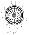
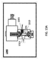
本明細書はまた、カテーテルの先端に組み込まれるように構成された柔軟性加熱室を開示し、柔軟性加熱室は外側被覆装置と、前記外側被覆装置に同軸の内側コアと、前記外側被覆装置と前記内側コアとの間に配置された第1の電極アレイであって、前記第1の電極アレイは複数の第1のフィンを有する第1の金属リングと、前記外側被覆装置と前記内側コアとの間に配置された第2の電極アレイとを備え、前記第2の電極アレイは複数の第2のフィンを有する第2の金属リングを備え、前記第1のフィンと第2のフィンとはセグメント空間が前記第1のフィンと第2のフィンとのそれぞれを分離するように互いに嵌合する。 The present specification also discloses a flexible heating chamber configured to be incorporated into the tip of a catheter, which comprises an outer coating device, an inner core coaxial with the outer coating device, and the outer coating device. A first electrode array disposed between the inner core and the inner core, wherein the first electrode array includes a first metal ring having a plurality of first fins, the outer covering device, and the inner core. It comprises a second electrode array disposed between the first and second electrode arrays, the second electrode array having a second metal ring having a plurality of second fins, and the first fin and the second fin. Fit together so that the segment space separates the first fin and the second fin, respectively.
任意選択で、前記複数の第1および第2のフィンは前記外側被覆装置と前記内側コアとの間の空間内に半径方向に延在し、前記複数の第1および第2のフィンもまた、加熱室の長軸に沿って延在する。 Optionally, the plurality of first and second fins extend radially in the space between the outer covering device and the inner core, and the plurality of first and second fins also extend in the radial direction. It extends along the long axis of the heating chamber.
任意に、前記複数の第1および第2フィンの各々は、加熱室の半径に沿った第1の寸法と、加熱室の長軸に沿った第2の寸法とを有する。 Optionally, each of the plurality of first and second fins has a first dimension along the radius of the heating chamber and a second dimension along the long axis of the heating chamber.
任意選択で、水または生理食塩水が前記セグメント空間を通って流れ、電流が前記第1および第2の電極アレイに供給されて、前記第1および第2のフィンに熱を発生させ、前記水または生理食塩水を水蒸気に気化させる。 Optionally, water or saline flows through the segment space and an electric current is supplied to the first and second electrode arrays to generate heat in the first and second fins, which causes the water. Alternatively, the saline solution is vaporized into water vapor.
任意選択的に、加熱室は、1~5mmの範囲の幅および5~50mmの範囲の長さを有する。 Optionally, the heating chamber has a width in the range of 1-5 mm and a length in the range of 5-50 mm.
任意に、電極の第1のアレイは1~50フィンの範囲を有し、電極の第2のアレイは、1~50フィンの範囲を有する。 Optionally, the first array of electrodes has a range of 1-50 fins and the second array of electrodes has a range of 1-50 fins.
任意選択的に、前記セグメント空間は、0.01~2mmの範囲である。 Optionally, the segment space is in the range of 0.01 to 2 mm.
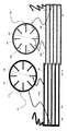
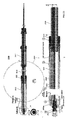
本明細書はまた、ターゲット組織のアブレーションを行うためのカテーテルであって、近位端と、遠位端と、第1の管腔と、第2の管腔とを有する本体を有するカテーテルを開示し、前記カテーテルは近位バルーンと、本体の遠位端に近接して配置された遠位バルーンと、前記近位バルーンと遠位バルーンとの間で本体に配置された複数のポートと、第2の管腔に組み込まれ、近位バルーンに近接して配置された第1の可撓性加熱チャンバとを備え、前記第1の可撓性加熱チャンバはを含む: 外側被覆装置と、前記外側被覆装置と同軸の内側コアと、前記外側被覆装置と内側コアとの間に配置された第1の電極アレイであって、前記第1の電極アレイは複数の第1のフィンを有する第1の金属リングと、前記外側被覆装置と前記内側コアとの間に配置された第2の電極アレイとを含み、前記第2の電極アレイは複数の第2のフィンを有する第2の金属リングを含み、前記第1のフィンと第2のフィンとは、第1のセグメント空間が前記第1のフィンと第2のフィンとのそれぞれを分離するように互いに嵌合する。 The present specification also discloses a catheter for performing ablation of target tissue, the catheter having a body having a proximal end, a distal end, a first lumen, and a second lumen. However, the catheter comprises a proximal balloon, a distal balloon located close to the distal end of the body, a plurality of ports located in the body between the proximal balloon and the distal balloon, and a first. It comprises a first flexible heating chamber incorporated into two lumens and located in close proximity to the proximal balloon, said first flexible heating chamber including: an outer covering device and said outer. A first electrode array disposed between an inner core coaxial with the covering device and the outer covering device and the inner core, wherein the first electrode array has a plurality of first fins. The metal ring includes a second electrode array disposed between the outer coating device and the inner core, and the second electrode array includes a second metal ring having a plurality of second fins. , The first fin and the second fin are fitted to each other so that the first segment space separates the first fin and the second fin, respectively.
任意選択で、本体の近位端に結合された第1のポンプは近位バルーンおよび先端のバルーンを膨張させるために第1の内腔を通して空気を推進し、本体の近位端に結合された第2のポンプは第2の内腔を通して水または生理食塩水を推進して、第1の加熱室の近位端に前記水または生理食塩水を供給し、本体の近位端に結合された高周波発生器は電極の前記第1および第2の配列に電流を供給し、前記第1および第2のフィンに熱を発生させ、前記水または生理食塩水を水蒸気に気化させて、前記ポートを通してターゲット組織にデリバリーする。 Optionally, a first pump coupled to the proximal end of the body propelled air through the first lumen to inflate the proximal balloon and the tip balloon and was coupled to the proximal end of the body. The second pump propelled water or saline through the second lumen to supply the water or saline to the proximal end of the first heating chamber and was coupled to the proximal end of the body. The high frequency generator supplies current to the first and second arrangements of the electrodes, generates heat in the first and second fins, vaporizes the water or saline into water vapor and passes through the port. Deliver to the target organization.
任意選択で、前記複数の第1および第2のフィンは前記外側被覆装置と第1の加熱室の前記内側コアとの間の空間内に半径方向に延在し、前記複数の第1および第2のフィンもまた、第1の加熱室の長軸に沿って延在する。 Optionally, the plurality of first and second fins extend radially in the space between the outer coating device and the inner core of the first heating chamber, the plurality of first and second fins. The second fin also extends along the long axis of the first heating chamber.
任意に、前記複数の第1フィンおよび第2フィンの各々は、第1加熱室の半径に沿った第1寸法と、第1加熱室の長軸に沿った第2寸法とを有する。 Optionally, each of the plurality of first fins and second fins has a first dimension along the radius of the first heating chamber and a second dimension along the long axis of the first heating chamber.
任意選択的に、カテーテルは前記可撓性加熱室と直列に配置された第2の可撓性加熱室をさらに備え、第2の可撓性加熱室は外側被覆装置と、外側被覆装置と内側コアとの間に同軸の内側コアと、外側被覆装置と内側コアとの間に配置された第3の電極アレイであって、複数の第3のフィンを有する第3の金属リングを備える第3の電極アレイと、外側被覆装置と内側コアとの間に配置された第4の電極アレイとを備え、第4の電極アレイは複数の第4のフィンを有する第4の金属リングを備え、第3および第4のフィンは第2のセグメント空間が前記第3および第4のフィンのそれぞれを分離するように互いに嵌合する。 Optionally, the catheter further comprises a second flexible heating chamber arranged in series with the flexible heating chamber, the second flexible heating chamber being an outer coating device, an outer coating device and an inner side. A third electrode array located between the inner core coaxial with the core and between the outer covering device and the inner core, comprising a third metal ring with a plurality of third fins. The electrode array is provided with a fourth electrode array located between the outer coating device and the inner core, and the fourth electrode array is provided with a fourth metal ring having a plurality of fourth fins. The third and fourth fins fit together such that the second segment space separates each of the third and fourth fins.
任意に、複数の第3及び第4のフィンは前記外側被覆装置と前記第2の加熱室の内側コアとの間の空間内に放射状に延び、前記複数の第3及び第4のフィンもまた、前記第2の加熱室の長軸に沿って延びる。 Optionally, the plurality of third and fourth fins radiate into the space between the outer coating device and the inner core of the second heating chamber, and the plurality of third and fourth fins also. , Extends along the long axis of the second heating chamber.
任意に、前記複数の第3および第4のフィンはそれぞれ、第2の加熱室の半径に沿った第1の寸法と、第2の加熱室の長軸に沿った第2の寸法とを有する。 Optionally, the plurality of third and fourth fins each have a first dimension along the radius of the second heating chamber and a second dimension along the long axis of the second heating chamber. ..
任意選択で、前記第1および第2の加熱室のそれぞれは、1~5mmの範囲の幅および5~50mmの範囲の長さを有する。 Optionally, each of the first and second heating chambers has a width in the range of 1-5 mm and a length in the range of 5-50 mm.
任意に、電極の第1および第3のアレイは1~50フィンの範囲を有し、電極の第2および第4のアレイは、1~50フィンの範囲を有する。 Optionally, the first and third arrays of electrodes have a range of 1 to 50 fins, and the second and fourth arrays of electrodes have a range of 1 to 50 fins.
任意選択で、前記第1および第2のセグメント空間は、0.01~2mmの範囲である。 Optionally, the first and second segment spaces range from 0.01 to 2 mm.
本明細書はまた、患者の食道にカテーテルを挿入することを含み、該カテーテルは近位端、遠位端、第1の管腔および第2の管腔を有する本体を有し、カテーテルは近位バルーンと、該本体の遠位端に近接して位置する遠位バルーンと、該近位バルーンと遠位バルーンとの間の本体上に位置する複数のポートと、第2の管腔内に組み込まれ、近位バルーンに近接して配置される少なくとも1つの可撓性加熱チャンバーとを含み、該少なくとも1つの可撓性加熱チャンバーは外側カバーと、該外側カバーと該内側コアとの間に配置される電極の第1のアレイであって、該電極の該第1のアレイは複数の第1のフィンを有する第1の金属リングと、該外側カバーと該内側コアとの間に配置される電極の第2のアレイとを含み、該電極の該第2のアレイは複数の第2のフィンを有する第2の金属リングを含み、該第1の可撓性加熱チャンバーは該第2のフィンを有する第2の金属リングを含む、バレットの食道組織のアブレーションを実行する方法を開示する第1および第2のフィンは第1のセグメント空間が前記第1および第2のフィンの各々を互いに交差するように、バレット食道の一部分より遠位側に遠位バルーンを配置し、バレット食道の一部分より近位側に近位バルーンを配置し、ポートがバレット食道の前記一部分に配置されるようにし、近位バルーンおよび遠位バルーンを膨張させて食道内にカテーテルを配置し、カテーテルに水または生理食塩水を供給し、電極の前記第1および第2のアレイに電流を供給して、前記第1および第2のフィンが熱を発生させ、水または生理食塩水を蒸気に気化させ、前記蒸気が前記ポートを通って送達されてバレット食道組織を除去する。 The present specification also includes inserting a catheter into the patient's esophagus, the catheter having a body having a proximal end, a distal end, a first lumen and a second lumen, the catheter being close. In a second lumen, a catheter, a distal balloon located close to the distal end of the body, multiple ports located on the body between the proximal balloon and the distal balloon, and a second lumen. It includes at least one flexible heating chamber that is incorporated and placed in close proximity to the proximal balloon, said at least one flexible heating chamber between the outer cover and the outer cover and the inner core. A first array of electrodes to be arranged, the first array of electrodes being arranged between a first metal ring having a plurality of first fins and the outer cover and the inner core. The second array of electrodes comprises a second array of electrodes, the second array of electrodes comprises a second metal ring having a plurality of second fins, and the first flexible heating chamber comprises the second. The first and second fins disclose how to perform ablation of the esophageal tissue of the valet, including a second metal ring with fins, where the first segment space allows each of the first and second fins to each other. A distal balloon is placed distal to a portion of the Barrett esophagus and a proximal balloon located proximal to a portion of the Barrett esophagus so that the port is located in said portion of the Barrett esophagus so that it intersects. , Proximal and distal balloons are inflated to place a catheter in the esophagus, the catheter is fed with water or physiological saline, and current is delivered to the first and second arrays of electrodes. The first and second fins generate heat, vaporizing water or physiological saline into steam, which is delivered through the port to remove Barrett esophageal tissue.
任意選択で、本体の近位端に結合された第1のポンプは近位バルーンおよび先端のバルーンを膨張させるために、第1の内腔を通して空気を推進し、本体の近位端に結合された第2のポンプは水または生理食塩水を第2の内腔を通して推進して、前記水または生理食塩水を加熱室の近位端に供給し、本体の近位端に結合された高周波発生器は、前記第1および第2の電極アレイに電流を供給する。 Optionally, a first pump coupled to the proximal end of the body propels air through the first lumen to inflate the proximal balloon and the tip balloon and is coupled to the proximal end of the body. The second pump propels water or saline through the second lumen to supply the water or saline to the proximal end of the heating chamber, generating high frequencies coupled to the proximal end of the body. The vessel supplies current to the first and second electrode arrays.
任意に、前記複数の第1および第2フィンの各々は、加熱室の半径に沿った第1の寸法と、加熱室の長軸に沿った第2の寸法とを有する。 Optionally, each of the plurality of first and second fins has a first dimension along the radius of the heating chamber and a second dimension along the long axis of the heating chamber.
本明細書はまた、エコー内視鏡と、遠位端に針を有し、前記エコー内視鏡の流路内を通過して前記膵臓組織に蒸気を送達するように構成されたカテーテルと、治療されている障害の種類に基づいて前記アブレーション剤の最高線量を制限するようにプログラムされ、患者の膵臓内の圧が5atmを超えないように送達される熱エネルギーの量を制限するようにプログラムされた、前記膵臓組織を切除するのに必要な熱エネルギーの量を決定するようにプログラムされたコントローラと、前記エコー内視鏡を患者の胃腸管内および前記膵臓組織に近接して前進させるステップと、前記エコー内視鏡を使用して前記膵臓組織を局在化させるステップと、前記針が穿刺部位で胃腸壁を通過して前記膵臓組織に入るように前記エコー内視鏡の前記流路を通って前記カテーテルを前進させるステップと、アブレーションのために前記針を通って前記膵臓組織内に蒸気を送達するステップとを含む、アブレーションデバイスを提供する方法を開示する。 The present specification also includes an echo endoscope and a catheter having a needle at the distal end and configured to pass through the flow path of the echo endoscope to deliver steam to the pancreatic tissue. Programmed to limit the maximum dose of said ablation agent based on the type of disorder being treated and to limit the amount of heat energy delivered so that the pressure in the patient's pancreas does not exceed 5 atm A controller programmed to determine the amount of heat energy required to remove the pancreatic tissue, and a step of advancing the echo endoscope in the patient's gastrointestinal tract and in close proximity to the pancreatic tissue. The step of localizing the pancreatic tissue using the echo endoscope and the flow path of the echo endoscope so that the needle passes through the gastrointestinal wall at the puncture site and enters the pancreatic tissue. Disclosed is a method of providing an ablation device comprising the step of advancing the catheter through it and the step of delivering steam through the needle through the needle into the pancreatic tissue for ablation.
任意選択で、本方法は、前記エコー内視鏡を使用して前記膵臓組織の少なくとも1つの寸法を測定する工程と、前記少なくとも1つの測定された寸法を使用して送達すべき蒸気量を計算する前記コントローラとをさらに含む。 Optionally, the method uses the echo endoscope to measure at least one dimension of the pancreatic tissue and the at least one measured dimension to calculate the amount of steam to be delivered. The controller is further included.
任意選択で、本方法は前立腺組織から液体および/または細胞を吸引するために気体を送達する前に、前記針に吸引を適用するステップをさらに含む。 Optionally, the method further comprises applying suction to the needle prior to delivering gas to aspirate fluid and / or cells from the prostate tissue.
任意選択で、前記針は外側シースを含み、前記方法は前記穿刺部位を冷却するために蒸気が送達されるときに、前記外側シースを通って水を循環させることをさらに含む。 Optionally, the needle comprises an outer sheath, and the method further comprises circulating water through the outer sheath when steam is delivered to cool the puncture site.
任意選択的に、本方法は、アブレーションが行われるときに前記膵臓組織を観察するために前記エコー内視鏡を使用することと、目視によって適切なアブレーションが達成されると前記アブレーションを停止することとをさらに含む。 Optionally, the method uses the echo endoscope to observe the pancreatic tissue when ablation is performed and stops the ablation when appropriate ablation is achieved visually. And further include.
任意選択的に、アブレーションは、前記膵臓内で測定された圧が少なくとも1秒間0.1~5圧力に留まった後に終了される。任意選択で、本方法はアブレーションが少なくとも1秒間終了した後に、再度気相を送達するステップをさらに含む。 Optionally, ablation is terminated after the pressure measured in the pancreas remains at 0.1-5 pressure for at least 1 second. Optionally, the method further comprises the step of delivering the gas phase again after the ablation has completed for at least 1 second.
任意選択的に、アブレーションは、前記アブレーションデバイス内で測定された圧が5気圧を超えたときに停止される。 Optionally, ablation is stopped when the pressure measured in the ablation device exceeds 5 atmospheres.
任意選択的に、前記膵臓組織の温度は、アブレーション処置の少なくとも一部の間、100℃~110℃である。 Optionally, the temperature of the pancreatic tissue is 100 ° C. to 110 ° C. during at least part of the ablation procedure.
任意選択で、前記アブレーションデバイスは、加圧センサーをさらに含む。 Optionally, the ablation device further includes a pressure sensor.
任意選択で、前記アブレーションデバイスは、温センサーをさらに含む。 Optionally, the ablation device further includes a temperature sensor.
また、本明細書は切除装置を提供するステップであって、中空シャフトと、切除剤が通過することができる格納式針とを有するカテーテルと、前記切除剤を前記上部消化管組織に送達するための前記針上の少なくとも1つの注入ポートと、前記カテーテルの少なくとも1つのパラメータを測定するための少なくとも1つのセンサと、前記切除剤の送達を制御するためのマイクロプロセッサを備えるコントローラと、患者の上部消化管内にエコー内視鏡を挿入するステップと、前記エコー内視鏡を使用して切除されるべき膵臓組織を識別するステップと、前記少なくとも1つの遠位位置決め要素が前記消化管内で切除されるべき前記膵臓組織の近位に配置されるように、前記エコー内視鏡を前記内視鏡に通すステップと、前記注入ポートが前記患者の前記膵臓組織内に配置されるように、前記針を前記患者の上部消化管内腔内のカテーテルを通して延在させるステップと、前記カテーテルの少なくとも1つのパラメータを測定するために前記少なくとも1つのセンサを動作させるステップと、前記少なくとも1つのパラメータ測定値を使用して制御するステップとを含む、切除装置を開示する。前記膵臓組織に送達するための切除剤の流れと、前記膵臓組織を切除するために前記少なくとも1つの注入ポートを通して前記切除剤を送達すること。 Also, the present specification is a step of providing a resection device for delivering a catheter having a hollow shaft, a retractable needle through which the resection agent can pass, and the resection agent to the upper gastrointestinal tissue. A controller with at least one infusion port on the needle, at least one sensor for measuring at least one parameter of the catheter, and a microprocessor for controlling the delivery of the excision agent, and an upper part of the patient. The step of inserting an echo endoscope into the gastrointestinal tract, the step of identifying the pancreatic tissue to be excised using the echo endoscopy, and the at least one distal positioning element being excised in the gastrointestinal tract. The step of passing the echo endoscope through the endoscope so that it is located proximal to the pancreatic tissue to be located, and the needle so that the injection port is located within the pancreatic tissue of the patient. Using the step of extending through a catheter in the upper gastrointestinal lumen of the patient, the step of operating the at least one sensor to measure at least one parameter of the catheter, and the at least one parameter measurement. Disclose a resection device, including steps to control. A flow of excision agent for delivery to the pancreatic tissue and delivery of the excision agent through the at least one infusion port for excision of the pancreatic tissue.
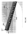
本明細書はまた、長さを有する細長い管状部材と、高温流体を近位端から遠位端に搬送するための内腔とを備え、遠位端が開放され、ターゲット組織において温度および低圧で蒸気を噴霧するように適合された、高温流体アブレーションのための内視鏡とともに使用するためのデバイスを開示し、デバイスの外径は、内視鏡を通るデバイスの通過を可能にするように構成される、デバイスの少なくとも一部を覆う断熱要素を含む。 The specification also comprises an elongated tubular member having a length and a lumen for transporting hot fluid from the proximal end to the distal end, the distal end being opened, at temperature and low pressure in the target tissue. Disclosed a device for use with an endoscope for high temperature fluid ablation, adapted to spray steam, the outer diameter of the device is configured to allow the device to pass through the endoscope. Includes an insulating element that covers at least a portion of the device.
任意に、高温流体は、気相または気相である。任意選択で、温度は65℃~150℃の範囲である。任意選択的に、圧力は<5atmである。任意選択的に、断熱要素は耐熱ポリマーである。 Optionally, the hot fluid is a gas phase or a gas phase. Optionally, the temperature is in the range of 65 ° C to 150 ° C. Optionally, the pressure is <5 atm. Optionally, the insulating element is a heat resistant polymer.
本明細書はまた、切除流体の流れのための流路を画定する内面を有する管状部材と、供給源から切除流体を受け取るための近位端と、ターゲット組織に低圧アブレーション剤を噴霧するように適合された遠位端と、管状部材の長さの少なくとも一部に沿って長手方向に配置された絶縁要素とを備える、アブレーション処置に使用するためのカテーテルを開示する。 The specification also comprises spraying a low pressure ablation agent onto the target tissue with a tubular member having an inner surface that defines a flow path for the flow of excision fluid, and a proximal end for receiving excision fluid from a source. Disclosed is a catheter for use in an ablation procedure, comprising a fitted distal end and an insulating element located longitudinally along at least a portion of the length of the tubular member.
本明細書はまた、熱アブレーション処置において内視鏡と共に使用するためのカテーテルを開示し、カテーテルはアブレーション剤を受容するための近位端を有する管状部材と、ターゲット組織に低圧アブレーション剤を噴霧するように適合された開放遠位端と、流路を画定し、近位端から遠位端に流れるアブレーション剤に接するように構成された耐熱ポリマーを備える内面と、外面の少なくとも一部に沿って長手方向に配置された冷却要素とを備える。 The present specification also discloses a catheter for use with an endoscope in a thermal ablation procedure, in which the catheter sprays a low pressure ablation agent onto a tubular member having a proximal end to receive the ablation agent and a target tissue. Along at least a portion of the inner and outer surfaces, with an open distal end adapted as such and a heat resistant polymer configured to demarcate the flow path and contact the ablator flowing from the proximal end to the distal end. It includes a cooling element arranged in the longitudinal direction.
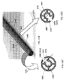
また、本明細書は内視鏡と、遠位端を有するカテーテルであって、前記カテーテルが前記内視鏡内に配置されているカテーテルと、導管によって前記カテーテルに取り付けられた蒸気源と、を備え、使用時に、高温、低圧蒸気が前記カテーテル遠位端から出るように構成され、前記カテーテルの前記遠位端が、前記カテーテルの前記軸線に実質的に垂直な半径方向に蒸気を噴霧するように構成されている、蒸気噴霧アブレーション用の蒸気アブレーション(vapor ablation)器具を開示している。 Further, the present specification includes an endoscope, a catheter having a distal end, a catheter in which the catheter is arranged in the endoscope, and a steam source attached to the catheter by a conduit. Provided, upon use, high temperature, low pressure steam is configured to exit the distal end of the catheter so that the distal end of the catheter sprays steam in a radial direction substantially perpendicular to the axis of the catheter. Discloses a vapor ablation device for vapor spray ablation, which is configured in.
本明細書はまた、内視鏡がターゲット組織の位置を突き止めるために使用されるように、水晶体が設けられた遠位端を有する内視鏡と、遠位端を有し、前記カテーテルが内視鏡に接続され、それによって運ばれるカテーテルと、導管によってカテーテルに接続され、患者の外部に配置される蒸気源とを備え、使用時に、高温低圧蒸気がカテーテル遠位端を出るように構成される、蒸気噴霧アブレーションのための蒸気噴霧装置を開示する。 The present specification also has an endoscope having a distal end provided with a crystalline body and a distal end such that the catheter is internal so that the endoscope can be used to locate the target tissue. It comprises a catheter connected to and carried by an endoscope and a steam source connected to the catheter by a conduit and placed outside the patient, configured to allow hot, low pressure steam to exit the distal end of the catheter during use. Discloses a steam spray device for steam spray ablation.
本明細書はまた、中空組織または中空器官を切除する方法を開示し、この方法は、中空組織または器官の天然の含有量を導電性媒体で置換する工程と、導電性媒体にアブレーション剤を送達して組織または器官を切除する工程とを含む。 The specification also discloses a method of excising a hollow tissue or organ, which method replaces the natural content of the hollow tissue or organ with a conductive medium and delivers an ablation agent to the conductive medium. And the step of excising the tissue or organ.
本明細書はまた、導電性媒体を送達するための口およびアブレーション剤源を含む、アブレーションのためのデバイスを開示する。 The specification also discloses a device for ablation, including a mouth and an ablation agent source for delivering a conductive medium.
任意選択で、前記アブレーションは、凍結切除または熱アブレーションのうちの1つを含む。 Optionally, the ablation comprises one of cryoablation or thermal ablation.
任意選択で、デバイスは、空洞臓器または導電性媒体の含有量を除去するためのポートを備える。 Optionally, the device comprises a port for removing the content of hollow organs or conductive media.
本明細書はまた、標的血管内の血液を導電性媒体で置換する工程と、導電性媒体にアブレーション剤を送達して所望の血管を切除する工程とを含む、血管を切除する方法を開示する。 The present specification also discloses a method of excising a blood vessel, which comprises a step of replacing blood in a target blood vessel with a conductive medium and a step of delivering an ablation agent to the conductive medium to excise a desired blood vessel. ..
任意選択的に、方法は、標的血管への血液の流れを停止することをさらに含む。任意選択的に、血流は、止血帯の適用によって閉塞される。任意選択的に、血流は、管腔内閉塞要素の適用によって閉塞される。任意選択的に、管腔内閉塞要素は、一方向バルブを含む。 Optionally, the method further comprises stopping the flow of blood to the target vessel. Optionally, blood flow is blocked by the application of a tourniquet. Optionally, blood flow is obstructed by the application of an intraluminal obstruction element. Optionally, the intraluminal occlusion element includes a one-way valve.
任意選択で、アブレーション剤の流れを制御するためにセンサーが使用される。 Optionally, a sensor is used to control the flow of the ablation agent.
任意選択で、導電性媒体は、水または生理食塩水のうちの1つ。 Optionally, the conductive medium is one of water or saline.
本明細書はまた、近位端および遠位端を有するカテーテルを含む血管を切除するためのデバイスを開示し、ここで、近位端は遠位端に操作可能に接続され、遠位端には標的血管中の血液を導電性媒体で置換するための導電性媒体の注入のための口、および遠位端にはアブレーション剤を前記導電性媒体に送達するための供給源がある。 The present specification also discloses a device for excising a blood vessel, including a catheter having a proximal end and a distal end, where the proximal end is operably connected to the distal end and to the distal end. Has a mouth for injecting a conductive medium to replace blood in a target vessel with a conductive medium, and a source at the distal end for delivering an ablation agent to the conductive medium.
任意選択で、デバイスは、血流または導電性媒体を制限するための閉塞要素をさらに備える。任意選択的に、閉塞要素は、一方向バルブを含む。任意選択的に、閉塞要素は、血管内にアブレーション剤源を配置するために使用される。 Optionally, the device further comprises an occlusion element to limit blood flow or conductive medium. Optionally, the occlusion element includes a one-way valve. Optionally, the occlusion element is used to place the ablation agent source within the blood vessel.
任意選択で、デバイスはさらに、血または導電性媒体を取り出すための吸引口を備える。 Optionally, the device further comprises a suction port for extracting blood or a conductive medium.
任意選択で、デバイスは、アブレーション剤、血流、またはアブレーションパラメータのデリバリーを測定するセンサーをさらに備える。 Optionally, the device further comprises a sensor that measures the delivery of ablation agents, blood flow, or ablation parameters.
本明細書はまた、血管壁を切除する方法を開示し、これは、血管のセグメントにカテーテルを配置する工程と、血管のセグメントへの血液の流れを閉塞する工程と、セグメント内の血液の一部を導電性媒体で置換する工程と、導電性媒体にアブレーション剤を加える工程と、導電性媒体を通して血管壁に切除エネルギーを伝導して、前記血管壁のアブレーションを引き起こす工程とを含む。 The present specification also discloses a method of excising a vessel wall, which comprises placing a catheter on a segment of a blood vessel, blocking the flow of blood to the segment of the vessel, and one of the blood within the segment. It includes a step of replacing the portion with a conductive medium, a step of adding an ablation agent to the conductive medium, and a step of transmitting excision energy to the blood vessel wall through the conductive medium to cause ablation of the blood vessel wall.
本明細書はまた、近位端および遠位端を有する同軸カテーテルと、外側シースと、内側管状部材と、導電性媒体を注入するための少なくとも1つのポートと、アブレーション剤のデリバリー源と、血液の流れを制限し、血管内にアブレーション剤源を位置するように構成された少なくとも1つの閉塞要素とを備える血管を切除するためのデバイスを開示し、同軸カテーテルの少なくとも外側シースは、絶縁物質から作製される。 The specification also includes a coaxial catheter with proximal and distal ends, an outer sheath, an inner tubular member, at least one port for injecting a conductive medium, a source of ablation agent, and blood. Disclosed is a device for excising a blood vessel with at least one occlusive element configured to restrict the flow of the ablation agent source within the blood vessel, and at least the outer sheath of the coaxial catheter is from the insulating material. It is made.
本明細書はまた、近位端に取っ手を有するカテーテルと遠位端に針とを備えるアブレーションデバイスを提供する工程と、前記カテーテルを患者に通し、前記カテーテルを前記嚢胞に前進させる工程と、前記針を前記嚢胞に挿入する工程と、前記カテーテルに吸引を適用して前記嚢胞の内容物の少なくとも一部を除去する工程と、前記針を通して前記嚢胞に導電性媒体を注入する工程と、前記針を通して前記導電性媒体にアブレーション剤を送達する工程と、前記導電性媒体および前記アブレーション剤を除去するために前記カテーテルに吸引を適用する工程とを含む、嚢胞を切除する方法を開示する。 The specification also comprises providing an ablation device with a catheter having a handle at the proximal end and a needle at the distal end, passing the catheter through a patient and advancing the catheter into the cyst. A step of inserting a needle into the cyst, a step of applying suction to the catheter to remove at least a part of the contents of the cyst, a step of injecting a conductive medium into the cyst through the needle, and the needle. Disclosed is a method of excising a cyst, comprising delivering an ablation agent to the conductive medium through the catheter and applying suction to the catheter to remove the conductive medium and the ablation agent.
本明細書はまた、シストにカテーテルを設置し、シスト中の内容物の一部を導電性媒体に交換し、導電性媒体にアブレーション剤を加え、導電性媒体を通る導電性媒体を通してシストウォールにアブレーションエネルギーを行い、当該シストのアブレーションを引き起こすという工程からなるシストをアブレートする方法を開示している。 The present specification also installs a catheter in the cyst, replaces a part of the contents in the cyst with a conductive medium, adds an ablation agent to the conductive medium, and passes the conductive medium through the conductive medium to the cyst wall. We disclose a method of ablating cysts, which consists of a step of performing ablation energy to cause ablation of the cysts.
本明細書はまた、近位端および遠位端を有する同軸カテーテルと、外側シースと、内側管状部材と、導電性媒体を注入するための少なくとも1つのポートと、アブレーション剤をデリバリーするための供給源と、嚢胞の中身を取り出すための少なくとも1つのポートとを備え、同軸カテーテルの少なくとも外側シースが絶縁物質から作製される、嚢胞を切除するためのデバイスを開示する。 The present specification also includes a coaxial catheter having proximal and distal ends, an outer sheath, an inner tubular member, at least one port for injecting a conductive medium, and a supply for delivering an ablation agent. Disclosed is a device for excision of a cyst, comprising a source and at least one port for removing the contents of the cyst, and at least the outer sheath of the coaxial catheter made of insulating material.
任意選択で、デバイスは、アブレーション剤のデリバリーを制御するための、またはアブレーション効果の計測のためのセンサーをさらに備える。 Optionally, the device further comprises a sensor for controlling the delivery of the ablation agent or for measuring the ablation effect.
任意選択的に、カテーテルは、超音波誘導下で嚢胞内へのカテーテルの配置を補助するためのエコー源性元素を含む。 Optionally, the catheter contains an echogenic element to assist in the placement of the catheter within the cyst under ultrasound guidance.
任意選択的に、カテーテルは、無線指針の下で嚢胞内へのカテーテルの配置を補助するための無線不透過性元素を含む。 Optionally, the catheter contains a radio opaque element to assist in the placement of the catheter within the cyst under radio pointers.
本明細書はまた、腫瘍内にカテーテルを配置する工程と、腫瘍内に導電性媒体を滴下する工程と、導電性媒体内にアブレーション剤を添加する工程と、腫瘍のアブレーションを引き起こすために導電性媒体を通して腫瘍に切除エネルギーを伝導する工程とを含む固形腫瘍を切除する方法を開示する。 The specification also includes placing a catheter in the tumor, dropping a conductive medium into the tumor, adding an ablation agent into the conductive medium, and conducting to cause tumor ablation. Disclosed is a method of excising a solid tumor, comprising the step of transmitting excision energy to the tumor through a medium.
本明細書はまた、近位端および遠位端を有する絶縁カテーテル、導電性媒体を注入するための少なくとも1つの口、ならびにアブレーション剤のデリバリー源を含む、腫瘍を切除するためのデバイスを開示する。 The specification also discloses a device for excising a tumor, including an insulated catheter with proximal and distal ends, at least one mouth for injecting a conductive medium, and a source of ablation agent. ..
任意選択で、デバイスは、アブレーション剤のデリバリーを制御するための、またはアブレーション効果の計測のためのセンサーをさらに備える。 Optionally, the device further comprises a sensor for controlling the delivery of the ablation agent or for measuring the ablation effect.
任意選択的に、カテーテルは、超音波誘導下で嚢胞内へのカテーテルの配置を補助するためのエコー源性元素を含む。 Optionally, the catheter contains an echogenic element to assist in the placement of the catheter within the cyst under ultrasound guidance.
任意選択的に、カテーテルは、無線指針の下で嚢胞内へのカテーテルの配置を補助するための無線不透過性元素を含む。 Optionally, the catheter contains a radio opaque element to assist in the placement of the catheter within the cyst under radio pointers.
本明細書はアブレーションデバイスを提供する工程を含む組織を切除する方法を開示し、これは、 中空シャフトと、アブレーション剤が移動することができる格納式針とを有する断熱カテーテルと、 前記アブレーション剤を前記組織にデリバリーするための前記針上の少なくとも1つの注入ポートと、 前記アブレーション剤のデリバリーを制御するためのマイクロプロセッサーを含むコントローラと、前記カテーテルを通過させ、前記針および注入ポートが前記患者の前記組織内に配置されるように前記少なくとも1つの注入ポートと共に前記針を延ばす工程と、 前記組織を切除するために前記アブレーション剤を前記少なくとも1つの注入ポートを通して送達する工程と、を含む。 The present specification discloses a method of excising a tissue including a step of providing an ablation device, which comprises an adiabatic catheter having a hollow shaft, a retractable needle through which the ablation agent can move, and the ablation agent. A controller containing at least one injection port on the needle for delivery to the tissue, a microprocessor for controlling delivery of the ablation agent, and the catheter through the needle and injection port of the patient. It comprises extending the needle with the at least one injection port so that it is located within the tissue and delivering the ablation agent through the at least one injection port to excise the tissue.
任意選択で、前記アブレーションデバイスは前記組織の少なくとも1つのパラメータを測定するための少なくとも1つのセンサーをさらに含み、前記方法は、前記少なくとも1つのセンサーを動作させて前記組織の少なくとも1つのパラメータを測定する工程と、前記少なくとも1つのパラメータを使用して前記組織に送達するアブレーション剤の量を決定する工程とをさらに含む。 Optionally, the ablation device further comprises at least one sensor for measuring at least one parameter of the tissue, and the method operates the at least one sensor to measure at least one parameter of the tissue. And the step of determining the amount of ablation agent to be delivered to the tissue using the at least one parameter.
任意選択で、前記アブレーションデバイスは前記カテーテルの少なくとも1つのパラメータを測定するための少なくとも1つのセンサーをさらに含み、前記方法は、前記少なくとも1つのセンサーを操作して前記カテーテルの少なくとも1つのパラメータを測定する工程と、前記少なくとも1つのパラメータを使用して前記組織へのアブレーション剤のデリバリーを停止する工程とをさらに含む。 Optionally, the ablation device further comprises at least one sensor for measuring at least one parameter of the catheter, and the method operates the at least one sensor to measure at least one parameter of the catheter. And the step of stopping the delivery of the ablation agent to the tissue using the at least one parameter.
任意選択で、前記少なくとも1つのセンサーは、温度、気圧、赤外、電磁気、音響、または高周波エネルギ発光およびセンサーを含む。 Optionally, the at least one sensor includes temperature, barometric, infrared, electromagnetic, acoustic, or high frequency energy emission and sensors.
任意選択的に、前記カテーテルは、前記位置決め要素(positioning element)が配備されると、前記カテーテルがアブレーションのために前記組織に近接して配置されるように構成された少なくとも1つの先端の位置決め要素(positioning element)を備える。任意選択的に、前記少なくとも1つの位置決め要素(positioning element)は、膨張可能な風船、ワイヤメッシュディスク、コーンアタッチメント、環形アタッチメント、または自由形状アタッチメントのいずれか1つ。任意選択的に、前記位置決め要素(positioning element)は切除される前記組織を越えて熱エネルギーが逃げるのを防止するために、断熱物質によって覆われる。 Optionally, the catheter is at least one tip positioning element configured such that when the positioning element is deployed, the catheter is placed in close proximity to the tissue for ablation. It has a (positioning element). Optionally, the at least one positioning element is any one of an inflatable balloon, a wire mesh disc, a cone attachment, a ring attachment, or a free-form attachment. Optionally, the positioning element is covered with adiabatic material to prevent thermal energy from escaping beyond the tissue to be excised.
任意選択的に、前記少なくとも1つの先端の位置決め要素(positioning element)は、切除される組織から0.1mmを超える距離で分離される。 Optionally, the at least one tip positioning element is separated from the tissue to be excised at a distance greater than 0.1 mm.
任意選択的に、前記アブレーション剤の前記デリバリーは、所定のプログラム命令によって案内される。 Optionally, the delivery of the ablation agent is guided by a predetermined program instruction.
任意選択で、前記アブレーションデバイスは前記組織のパラメータを測定するための少なくとも1つのセンサーをさらに含み、前記方法は、前記少なくとも1つのセンサーを動作させて前記組織のパラメータを測定する工程と、前記パラメータ測定値を使用して前記組織への前記アブレーション剤の流れを制御する工程とをさらに含む。 Optionally, the ablation device further comprises at least one sensor for measuring the parameters of the tissue, the method of operating the at least one sensor to measure the parameters of the tissue, and the parameters. It further comprises the step of controlling the flow of the ablation agent into the tissue using the measured values.
任意選択で、前記センサーは、温、圧、光、または化学センサーのいずれか1つ。 Optionally, the sensor is one of a temperature, pressure, light, or chemical sensor.
任意選択で、前記アブレーションデバイスは前記少なくとも1つの位置決め要素(positioning element)を拘束するように構成された同軸部材をさらに含み、前記少なくとも1つの先端の位置決め要素(positioning element)を展開する前記工程は、前記同軸部材を前記アブレーションデバイスから取り外すことをさらに含む。 Optionally, the ablation device further includes a coaxial member configured to constrain the at least one positioning element, and the step of deploying the at least one tip positioning element. Further includes removing the coaxial member from the ablation device.
任意選択で、前記カテーテルは少なくとも1つの吸引口をさらに含み、前記方法は、前記少なくとも1つの吸引口を操作して、切除された組織を身体から除去することをさらに含む。 Optionally, the catheter further comprises at least one suction port, and the method further comprises manipulating the at least one suction port to remove the resected tissue from the body.
任意選択で、前記アブレーションデバイスは入力デバイスをさらに含み、前記方法は、前記アブレーション剤のデリバリーを制御するために前記入力デバイスを使用する操作者の工程をさらに含む。 Optionally, the ablation device further comprises an input device, and the method further comprises the steps of an operator using the input device to control delivery of the ablation agent.
任意選択的に、前記組織は嚢胞である。 Optionally, the tissue is a cyst.
本明細書はまた、中空シャフトと、アブレーション剤が通過することができる引き込み可能な針とを有するカテーテルと、前記カテーテルの遠位端に取り付けられた少なくとも1つの遠位位置決め要素(positioning element)と、前記アブレーション剤を前記組織にデリバリーするための前記針上の少なくとも1つの注入ポートであって、前記アブレーション剤を前記遠位位置決め要素(positioning element)によって画定される空間に送達するように構成された前記少なくとも1つの注入ポートと、前記アブレーションデバイスの方法を制御するためのマイクロプロセッサーを備えるコントローラとを備えるアブレーション剤を提供するステップと、前記少なくとも1つの位置決め要素(positioning element)が切除される前記組織に近接して配置されるように前記カテーテルを挿入するステップと、注入ポートが組織に近接して配置されるように前記針をカテーテルを通して延在させるステップと、前記組織を切除するために前記アブレーション剤を前記少なくとも1つの注入ポートを通して送達するステップとを含む、組織を切除するデリバリーを開示する。 The specification also includes a catheter having a hollow shaft and a retractable needle through which the ablation agent can pass, and at least one distal positioning element attached to the distal end of the catheter. , At least one injection port on the needle for delivering the ablation agent to the tissue, configured to deliver the ablation agent to a space defined by the distal positioning element. A step of providing an ablation agent comprising the at least one injection port and a controller with a microprocessor for controlling the method of the ablation device, and the cutting of the at least one positioning element. The step of inserting the catheter so that it is placed close to the tissue, the step of extending the needle through the catheter so that the injection port is placed close to the tissue, and the step of removing the tissue. Disclosed is a delivery that excises tissue, including the step of delivering the ablation agent through the at least one infusion port.
任意選択的に、前記アブレーションデバイスは、前記アブレーション剤を受け入れるための少なくとも1つのインプットポートを前記カテーテル上にさらに備える。 Optionally, the ablation device further comprises at least one input port on the catheter for receiving the ablation agent.
任意選択的に、前記組織は膵嚢胞である。 Optionally, the tissue is a pancreatic cyst.
また、本明細書は、アブレーションカテーテルを胃腸管に挿入するステップであって、アブレーションカテーテルが少なくとも1つの位置決め要素(positioning element)と、蒸気をデリバリーするための口とを備えるステップと、少なくとも1つの位置決め要素(positioning element)の外面と胃腸管の壁面との間に封止を形成するステップと、胃腸管内に密閉体積を形成するステップと、アブレーションカテーテルを通して密閉体積内に蒸気を送達するステップと、胃腸管内の組織上に蒸気を凝縮するステップとを含む、患者の胃腸管にアブレーション治療を提供する方法を開示する。 Also herein is the step of inserting the ablation catheter into the gastrointestinal tract, the step of which the ablation catheter comprises at least one positioning element and a mouth for delivering steam, and at least one. A step of forming a seal between the outer surface of the positioning element and the wall surface of the gastrointestinal tract, a step of forming a sealed volume in the gastrointestinal tract, a step of delivering vapor into the sealed volume through an ablation catheter, and a step of delivering vapor into the sealed volume. Disclosed are methods of providing ablation therapy to a patient's gastrointestinal tract, including the step of condensing vapor onto tissues within the gastrointestinal tract.
任意選択的に、シールは温度依存性である。任意選択的に、密閉体積内の温度が90℃を超えると、シールが破壊される。 Optionally, the seal is temperature dependent. Optionally, if the temperature in the sealed volume exceeds 90 ° C, the seal will break.
任意に、シールは圧力に依存する。任意選択的に、密閉体積内の圧力が5気圧を超えると、シールが破れる。 Optionally, the seal depends on pressure. Optionally, the seal breaks when the pressure in the sealed volume exceeds 5 atmospheres.
本明細書はまた、アブレーションカテーテルを胃腸管に挿入することと、生理食塩水の流速が可変であるアブレーションカテーテルを通る生理食塩水の流れを開始することと、生理食塩水に高周波エネルギーを供給して蒸気を発生させることによって生理食塩水を加熱することと、アブレーションカテーテルを通って胃腸管に蒸気を供給することと、胃腸管内の組織上で蒸気を凝縮することとを含む、患者の胃腸管にアブレーション治療を提供する方法を開示する。 The specification also provides high frequency energy to the saline solution by inserting the ablation catheter into the gastrointestinal tract, initiating the flow of saline solution through the ablation catheter with variable flow velocity of the saline solution. The patient's gastrointestinal tract, including heating the saline solution by generating steam, supplying the steam to the gastrointestinal tract through an ablation catheter, and condensing the steam on the tissues within the gastrointestinal tract. Disclose how to provide ablation therapy to.
任意選択で、熱療法中の生理食塩水の流量は、熱療法が送達されない段階中の生理食塩水の流量とは異なる。 Optionally, the flow rate of saline during heat therapy is different from the flow of saline during the stage when heat therapy is not delivered.
任意選択的に、熱療法中の生理食塩水の流量は、熱療法が送達されない段階中の生理食塩水の流量よりも高い。 Optionally, the flow rate of saline during heat therapy is higher than the flow of saline during the stage when heat therapy is not delivered.
任意選択的に、熱療法中の生理食塩水の流量は、熱療法が送達されない段階中の生理食塩水の流量よりも低い。 Optionally, the flow rate of saline during heat therapy is lower than the flow of saline during the stage when heat therapy is not delivered.
本明細書はまた、患者の消化管(GI)路に第1のアブレーションカテーテルを挿入するステップであって、前記第1のアブレーションカテーテルは、遠位位置決め要素と、前記遠位位置決め要素と前記近位位置決め要素との間の複数の蒸気送達ポートと、前記遠位位置決め要素と前記GI路との間に第1の密閉治療容積を形成するように拡張するステップと、前記送達ポートを介して蒸気を送達するステップと、前記第1の密閉治療容積内の組織上に蒸気を凝縮させて前記GI路を円周方向にアブレーションするステップと、前記第1のアブレーションカテーテルによってアブレーションされた組織の領域を検査して、集束アブレーションを必要とする組織のパッチを同定するステップと、内視鏡を介して前記GI路に第2のアブレーションカテーテルを挿入するステップとを含む、組織をアブレーションするための方法を開示している ここで、第2のアブレーションカテーテルは遠位アタッチメントまたは位置決め要素を少なくとも含むカテーテルの遠位端にある1つの送達ポート;遠位付着部または位置決め要素の周辺部とGI管との間に第2のシールを形成するために遠位付着部または位置決め要素を拡張し、遠位付着部または位置決め要素と患者のGI管の表面との間に第2の封入された治療容積を形成する;少なくとも1つのポートを介して蒸気を送達する;蒸気が第2の封入された治療容積内の組織上に凝縮して組織を焦点除去することを可能にする;およびGI管から第2のアブレーションカテーテルを除去する。 The present specification is also a step of inserting a first ablation catheter into the gastrointestinal (GI) tract of a patient, wherein the first ablation catheter comprises a distal positioning element, said distal positioning element and said close. A plurality of steam delivery ports between the position positioning elements, a step extending to form a first sealed treatment volume between the distal positioning elements and the GI pathway, and steam through the delivery ports. A step of condensing steam onto the tissue within the first closed treatment volume to ablate the GI tract in a circumferential direction, and a region of the tissue ablated by the first ablation catheter. A method for ablating tissue, including examining and identifying patches of tissue that require focused ablation and inserting a second ablation catheter into the GI tract via an endoscope. Disclosure Here, the second ablation catheter is one delivery port at the distal end of the catheter that contains at least a distal attachment or positioning element; between the distal attachment or the periphery of the positioning element and the GI tube. Extend the distal attachment or positioning element to form a second seal to form a second enclosed therapeutic volume between the distal attachment or positioning element and the surface of the patient's GI tube. Deliver steam through at least one port; allow steam to condense onto tissue within a second enclosed treatment volume and defocus tissue; and a second ablation from the GI tube Remove the catheter.
本発明の上記および他の実施形態は、以下に提供される図面および詳細な説明において、より深く説明される。 The above and other embodiments of the present invention will be described in more depth in the drawings and detailed description provided below.
本発明のこれらおよび他の特徴および利点は添付の図面と関連して考察されるときに、詳細な説明を参照することによってより良く理解されるように、さらに理解されるのであろう:
本明細書の実施形態は、食道、十二指腸、胆管、および膵臓における前癌性または癌性組織を含むがこれらに限定されない様々な適応症を治療するためのアブレーションシステムおよび方法を提供する。様々な実施形態では、生理食塩水を加熱することによって生成される水蒸気がアブレーション剤として使用される。様々な実施形態ではアブレーションシステムが気相(気相)に変換するための液体(生理食塩水)を供給するための供給源と、前記気相を変換および送達するためのカテーテルとを備える、アブレーション剤(気相発生器)を生成するための発生器を含み、カテーテルはカテーテルの中央管腔に埋め込まれ、生理食塩水を気相に変換するための加熱チャンバとして機能するように構成された少なくとも1つの電極を備える。アブレーションシステムはカテーテルの遠位端にアタッチメントをさらに含み、アタッチメントは、針、キャップ、フード、またはディスクのうちの少なくとも1つを含む。付属品は、アブレーション剤のデリバリーを方向付けるように構成される。カテーテルは、最適な水蒸気デリバリーのためにカテーテルを位置決めするための位置決め要素(positioning element)をさらに含むことができる。アタッチメントおよび位置決め要素(positioning element)はシールを形成し、水蒸気のデリバリーおよびターゲット組織のアブレーションのための密閉された処理容積を形成するように構成される。実施形態では、本明細書のアブレーションシステムおよび方法が少なくとも1つの位置決めアタッチメントで組織の領域または体積を囲み、その領域または体積を蒸気で満たし、その領域または体積内の温度を100℃を超えて上昇させ、次いで、追加の蒸気を逃がし、所定の持続時間にわたって100℃を超える温度を維持し、5気圧未満の領域または体積内の圧力を維持して、蒸気が組織を縮合および切除することを可能にするように構成される。 Embodiments herein provide ablation systems and methods for treating a variety of indications including, but not limited to, precancerous or cancerous tissues in the esophagus, duodenum, bile ducts, and pancreas. In various embodiments, the water vapor produced by heating the saline solution is used as the ablation agent. In various embodiments, the ablation system comprises a source for supplying a liquid (saline) for converting the gas phase (saline) and a catheter for converting and delivering the gas phase. Containing a generator to generate the agent (gas phase generator), the catheter is implanted in the central lumen of the catheter and is configured to function as a heating chamber for converting saline to gas phase at least. It has one electrode. The ablation system further includes an attachment at the distal end of the catheter, which includes at least one of a needle, cap, hood, or disc. The accessories are configured to direct the delivery of the ablation agent. The catheter can further include a positioning element for positioning the catheter for optimal water vapor delivery. Attachments and positioning elements are configured to form a seal and form a closed processing volume for water vapor delivery and target tissue ablation. In embodiments, the ablation systems and methods herein enclose a region or volume of tissue with at least one positioning attachment, fill that region or volume with steam, and raise the temperature within that region or volume by more than 100 ° C. Allows the vapor to allow additional vapor to escape, maintain temperatures above 100 ° C. for a predetermined duration, and maintain pressure in the region or volume below 5 atmospheres, allowing the vapor to condense and excise tissue. Is configured to.
本明細書の実施形態のアブレーションシステムの様々なカテーテルの構成は、治療される組織または臓器システムに基づいて異なってもよい。例えば、いくつかの実施形態に、食道および十二指腸アブレーションのためのカテーテルは、2つの位置決め要素(positioning element)の間に気相デリバリーポートを有するカテーテルの末端部分の末端部分および近位端に配置された2つの位置決め要素(positioning element)の間の間隔が十二指腸出願(約1~10cm)よりも食道出願(約1~20cm)の方が大きくなり得ることを除いて、同様である。本明細書のシステムおよび方法によって提供されるアブレーションの分布および深さは、蒸気への曝露時間、アブレーションの大きさ、蒸気の温度、蒸気との接触時間、および組織の種類に依存する。 The various catheter configurations of the ablation system of the embodiments herein may differ based on the tissue or organ system being treated. For example, in some embodiments, catheters for esophageal and duodenal ablation are placed at the distal and proximal ends of the distal portion of the catheter having a gas phase delivery port between the two positioning elements. This is similar, except that the distance between the two positioning elements can be larger in the esophageal application (about 1-20 cm) than in the duodenal application (about 1-10 cm). The distribution and depth of ablation provided by the systems and methods herein will depend on the time of exposure to steam, the magnitude of ablation, the temperature of the steam, the time of contact with the steam, and the type of tissue.
いくつかの実施形態に、患者はターゲット組織の完全またはほぼ完全なアブレーションを確実にするために、2工程の方法で治療される。いくつかの実施形態に、患者は、まず、最初に展開される先端の位置決め要素(positioning element)と、その後に展開される近位位置決め要素(positioning element)と、2つの位置決め要素(positioning element)の間に配置されるポートを有する管長との2つの位置決め要素(positioning element)を有するカテーテルで治療され、それによって、ワイドエリアネットワーク円周方向アブレーションを可能にする。位置決め要素(positioning element)は、風船、円板、または任意の他の構成であってもよい。第1の封止は、前記遠位および近位位置決め要素(positioning element)において、位置決め要素(positioning element)の周辺部を被験者の組織と当接させることによって形成される。第1の封止の形成は、先端の端における先端の位置決め要素(positioning element)、近位端としての近位位置決め要素(positioning element)、および側面上の食道または十二指腸などの患者の組織の壁によって境界付けられる、囲まれた第1の治療容積の形成をもたらす。次いで、水蒸気の形態の切除エネルギーがカテーテルによってポートを介して第1の治療容積内に送達され、そこで、切除エネルギーは凝縮し、円周方向のアブレーションのために患者の組織に接触し、位置決め要素(positioning element)によって遮断されるときに遠位または近位端から逃げることができず、あるいは、以下でさらに説明するように、位置決め要素(positioning element)の構成に基づいて遠位または近位端から制御可能に逃げることができない。 In some embodiments, the patient is treated in a two-step manner to ensure complete or near-complete ablation of the target tissue. In some embodiments, the patient first deploys a tip positioning element, then deploys a proximal positioning element, and two positioning elements. It is treated with a catheter that has two positioning elements with a tube length that has a port placed between them, which allows for wide area network circumferential ablation. The positioning element may be a balloon, a disk, or any other configuration. The first seal is formed by bringing the periphery of the positioning element into contact with the tissue of the subject at the distal and proximal positioning elements. The formation of the first seal is the wall of the patient's tissue, such as the tip positioning element at the tip end, the proximal positioning element as the proximal end, and the lateral esophagus or duodenum. It results in the formation of an enclosed first therapeutic volume, bounded by. The excision energy in the form of water vapor is then delivered by the catheter through the port into the first treatment volume, where the excision energy condenses, contacts the patient's tissue for circumferential ablation, and positions the positioning element. Cannot escape from the distal or proximal end when blocked by the positioning element, or as further described below, the distal or proximal end based on the configuration of the positioning element. Cannot escape controllably from.
2つの位置決め要素(positioning element)を有するカテーテルを使用してアブレーションを行った後、アブレーション領域を医師によって検査する。患者を観察すると、医師は、集束アブレーションを必要とする組織のパッチを識別することができる。次いで、第2の工程が行われ、ここで、遠位端に針またはキャップ、フード、またはディスク取り付け部を有する第2のカテーテルが、内視鏡に通され、そして焦点アブレーションのために使用される。針は方向付けられた焦点アブレーションを提供し、キャップ、フード、またはディスク取付け部は焦点アブレーション領域を囲み、組織のアブレーションのための第2の封止および囲まれた第2の治療容積を作り出す。シールは、キャップ、フード、またはディスクアタッチメントの周囲の少なくとも一部を食道または十二指腸などの患者の組織の表面と接触させて、患者の組織の一部がアタッチメントによって囲まれた領域内に配置されるように配置することによって生成される。水蒸気を受け入れるように構成され、アタッチメントの側面および患者組織の前記外接部分によって境界付けられる第2の治療容積は、シールが形成されるときに形成される。次いで、水蒸気の形態の切除エネルギーがカテーテルの遠位端の少なくとも1つのポートによってカテーテルを介して第2の治療容積内に送達され、そこで、切除エネルギーは凝縮し、焦点アブレーションのために患者の組織に接触し、取付部材によって境界付けられるときに逃げることができず、あるいは、以下でさらに説明するように、取付部材の構成に基づいて取付部材から制御可能に逃げることができない。ある実施形態に、密閉された、または部分的に密閉された体積から出る蒸気の流量はカテーテルポートから密閉された、または部分的に密閉された体積への蒸気の流量の所定の割合であり、所定の割合は、1%~80%、好ましくは50%未満、より好ましくは30%未満である。少なくとも1つのポートはアタッチメントが配置されたときに第2の治療容積内に出るように、カテーテルの遠位端に配置される。 After ablation is performed using a catheter with two positioning elements, the ablation area is examined by a physician. Upon observing the patient, the physician can identify patches of tissue that require focused ablation. A second step is then performed, where a second catheter with a needle or cap, hood, or disc attachment at the distal end is passed through the endoscope and used for focal ablation. NS. The needle provides directed focal ablation, and the cap, hood, or disc attachment encloses the focal ablation area, creating a second seal and enclosed second therapeutic volume for tissue ablation. The seal is placed within the area surrounded by the attachment, with at least part of the circumference of the cap, hood, or disc attachment in contact with the surface of the patient's tissue, such as the esophagus or duodenum. It is generated by arranging in the same way. A second therapeutic volume, configured to receive water vapor and bounded by the sides of the attachment and the circumscribed portion of the patient's tissue, is formed when the seal is formed. The excision energy in the form of water vapor is then delivered via the catheter into the second treatment volume by at least one port at the distal end of the catheter, where the excision energy condenses and the patient's tissue for focal ablation. Cannot escape when in contact with and bound by the mounting member, or, as further described below, cannot escape controllably from the mounting member based on the configuration of the mounting member. In certain embodiments, the flow rate of steam emanating from a sealed or partially sealed volume is a predetermined percentage of the flow rate of steam from a catheter port to a sealed or partially sealed volume. The predetermined proportion is 1% to 80%, preferably less than 50%, more preferably less than 30%. At least one port is located at the distal end of the catheter so that it exits within the second treatment volume when the attachment is placed.
第1および第2の工程の両方の間、封入された第1および第2の処理容積を作り出すとき、完全な(100%)シールを作り出すことを避けることが好ましい。完全なシールは、治療容積内に空気を捕捉する。捕捉された空気はアブレーションのために使用される水蒸気と比較して熱くはなく、従って、放熱板として作用し、水蒸気の熱アブレーションエネルギーの一部を垂れ下げ、その結果、水蒸気のアブレーティブエネルギーの不均一な分配をもたらす「冷気ポケット」を生成するのであろう。完全なシールよりも小さいシールを形成することは、水蒸気が処理容積内に送達されるときに、シール内のギャップを通って、空気が処理容積から押し出されることを可能にする。 When creating the enclosed first and second treated volumes during both the first and second steps, it is preferable to avoid creating a complete (100%) seal. A complete seal traps air within the treatment volume. The captured air is not hot compared to the water vapor used for ablation and therefore acts as a heat sink, hanging some of the heat ablation energy of the water vapor, resulting in the ablation energy of the water vapor. Will create a "cold air pocket" that results in a non-uniform distribution of. Forming a seal that is smaller than the complete seal allows air to be pushed out of the processing volume through the gaps in the seal as water vapor is delivered into the processing volume.
また、処理容積内の温度が上昇すると、温度が100℃以上になるまで水蒸気が逃げない。この時点で水蒸気凝縮は止まり、隙間から水蒸気が逃げて処理容積の過剰な加圧を防止する。いくつかの実施形態に、カテーテルは送達された水蒸気に背圧を提供するマイクロ孔を備えたフィルターを備えており、カテーテルから治療容積に入る際に水蒸気を加圧す。フィルター内の微小孔の所定の大きさは、背圧、従って、生成される蒸気の温度を決定する。2つの位置決め要素(positioning element)を有する取り付け具とのアブレーション中、様々な実施形態では、間隙、または完全ではない密封が先端の位置決め要素(positioning element)のみ、近位位置決め要素(positioning element)のみ、または先端のおよび近位位置決め要素(positioning element)の両方に配置される。 Further, when the temperature in the processing volume rises, water vapor does not escape until the temperature reaches 100 ° C. or higher. At this point, the water vapor condensation stops and the water vapor escapes from the gap to prevent excessive pressurization of the processing volume. In some embodiments, the catheter comprises a filter with micropores that provide back pressure to the delivered water vapor, pressurizing the water vapor as it enters the therapeutic volume from the catheter. The predetermined size of the micropores in the filter determines the back pressure and thus the temperature of the steam produced. During ablation with a fixture that has two positioning elements, in various embodiments, the gap, or incomplete sealing, is the tip positioning element only, the proximal positioning element only. , Or both at the tip and on the proximal positioning element.
ギャップまたは完全未満のシールを作成し、空気を漏らすか、または治療容積から押し出すことを可能にするために、本明細書の実施形態は、患者組織と接触するそれらの表面積の40%~99%の範囲を有する位置決め要素(positioning element)またはアタッチメントを提供する。実施形態において、位置決め要素(positioning element)または付着物が組織に接触する平面に沿った断面切片の表面積は、20%~99%である。20%などの低い値は極めて多孔性のシールを表し、位置決め要素(positioning element)またはアタッチメントと組織との間に間隔が存在すること、または位置決め要素(positioning element)またはアタッチメントがその中に空隙を含むことを示し、一方、99%などの高い値は、ほぼ完全なシールを表す。さらに、第1および第2のシールは、低圧シールと考えられ、シールによって形成される第1および第2の処理容積内の圧力は5atm未満であり、通常は1atmに近い。したがって、圧力が所定の圧力を超えて上昇すると、封止が破れ、加熱された空気または蒸気が逃げることができ、それによって、カテーテル自体に圧力センサーを行う必要がなくなる。 In order to create gaps or less than complete seals and allow air to leak or be extruded from the therapeutic volume, embodiments herein are 40% to 99% of their surface area in contact with patient tissue. Provide a positioning element or attachment having a range of. In embodiments, the surface area of the cross-sectional section along the plane of contact of the positioning element or deposit with the tissue is 20% to 99%. A low value, such as 20%, represents a very porous seal, where there is a gap between the positioning element or attachment and the tissue, or where the positioning element or attachment creates a void in it. Includes, while high values such as 99% represent near-perfect seals. In addition, the first and second seals are considered low pressure seals and the pressure within the first and second treated volumes formed by the seals is less than 5 atm, usually close to 1 atm. Therefore, when the pressure rises above a predetermined pressure, the seal can be broken and heated air or steam can escape, thus eliminating the need for a pressure sensor on the catheter itself.
実施形態では、位置決め要素(positioning element)または取付部材のうちの1つ以上が2つの位置決め要素(positioning element)または取付部材によって囲まれた治療容積からの一連の流れを可能にするように構成される。許容される流出は密閉体積内への蒸気流の機能であり、それによって、リリーフバルブとして作用し、蒸気発生器自体からの調整なしに、所望圧力領域(5気圧未満)の維持を可能にする。いくつかの実施形態に、位置決め要素(positioning element)またはアタッチメントは位置決め要素(positioning element)またはアタッチメントの表面積内に、および/または位置決め要素(positioning element)またはアタッチメントの周囲と組織との間に、蒸気発生器からの調整なしに密閉体積内の圧水準を5気圧未満に維持するために、蒸気入力流量の1~80%の密閉体積からの液体の流れを可能にするのに充分な複数の空間を含む。 In embodiments, one or more of the positioning elements or mounting members are configured to allow a series of flows from a therapeutic volume surrounded by two positioning elements or mounting members. NS. The permissible outflow is the function of the steam flow into the sealed volume, thereby acting as a relief valve, allowing the maintenance of the desired pressure range (less than 5 atmospheres) without adjustment from the steam generator itself. .. In some embodiments, the positioning element or attachment is vaporized within the surface area of the positioning element or attachment and / or between the surroundings of the positioning element or attachment and the tissue. Multiple spaces sufficient to allow liquid flow from a closed volume of 1-80% of the vapor input flow rate to maintain a pressure level within the closed volume below 5 atm without adjustment from the generator. including.
いくつかの実施形態に、切除すべき粘膜の表面積が5cm2~200cm2の範囲である場合、密閉体積は3cc~450ccの範囲である。 In some embodiments, if the surface area of the mucosa to be excised is in the range of 5 cm2 to 200 cm2, the sealed volume is in the range of 3 cc to 450 cc.
実施形態において、1つ以上の位置決め要素(positioning element)または付着は、治療の過程にわたって変形可能である。本明細書の実施形態による位置決め要素(Positioning element)およびアタッチメントは、治療容積内の圧力が基準圧力の10%を超えて増加すると、物理的に修正または変形するように設計され、したがって、圧力解放バルブとして効果的に作用する。変形する能力の結果、2つの位置決め要素(positioning element)または付属物で囲まれた体積からの流出は可変である。例示的な実施形態では、治療の開始時に、密閉体積から出る流れのごく一部(もしあれば)のみが遮断される。遮断される流れの割合は治療の過程にわたって減少し、それによって、圧力変化による漏れを増加させる。いくつかの実施形態に、位置決め要素(positioning element)または付着ブロックが治療の開始時に、100%(全流れ閉塞または全断面が覆われている)~20%(流れ閉塞の20%のみまたは断面積の20%のみが覆われている)の範囲で、密閉体積から流出する(または覆われた断面積を有する)と仮定すると、割合は治療中に変化し、ここで、閉塞/断面積の量は、開始割合に対して1%~25%減少する。様々な実施形態では前述のように、コストおよび起こり得るセンサー破損を低減するために、加圧センサーはカテーテル自体に含まれないことが好ましい。従って、変形可能な位置決め要素(positioning element)は活圧力感知を必要とせずに、自然にリリーフバルブとして作用する。 In embodiments, one or more positioning elements or attachments are deformable throughout the course of treatment. Positioning elements and attachments according to embodiments herein are designed to be physically modified or deformed when the pressure in the treatment volume increases by more than 10% of the reference pressure, and thus pressure release. Acts effectively as a valve. As a result of its ability to deform, the outflow from the volume enclosed by the two positioning elements or appendages is variable. In an exemplary embodiment, at the beginning of treatment, only a small portion (if any) of the flow out of the sealed volume is blocked. The percentage of blocked flow decreases over the course of treatment, thereby increasing leakage due to pressure changes. In some embodiments, the positioning element or adherent block is 100% (total flow blockage or full cross-section covered) to 20% (only 20% of flow blockage or cross-sectional area) at the start of treatment. Assuming that it flows out of the closed volume (or has a covered cross-sectional area), within the range of (only 20% of which is covered), the proportion changes during treatment, where the amount of occlusion / cross-section Decreases 1% to 25% of the starting rate. In various embodiments, as mentioned above, it is preferred that the pressure sensor is not included in the catheter itself in order to reduce cost and possible sensor damage. Therefore, the deformable positioning element naturally acts as a relief valve without the need for active pressure sensing.
様々な実施形態では、本明細書に記載されるアブレーションデバイスおよびカテーテルが2015年1月12日に出願され、2017年2月7日に米国特許第9,561,068号として発行された、「組織アブレーションのための方法および器具」という名称の米国特許出願公開第14/594,444号に記載された暖房システムのいずれか1つまたは複数と併せて使用され、その全体が本明細書に参考として援用される。
「処理する」、「処理する」、およびそれらの変更とは、状態に関連する1以上の症状(symptom)または徴候の程度、頻度、または重症度における任意の低下を意味する。
In various embodiments, the ablation devices and catheters described herein were filed on January 12, 2015 and issued on February 7, 2017 as US Pat. No. 9,561,068, "For Tissue Ablation. Method and Equipment, used in conjunction with any one or more of the heating systems described in US Patent Application Publication No. 14 / 594,444, which is incorporated herein by reference in its entirety.
"Treat,""treat," and their alterations mean any reduction in the degree, frequency, or severity of one or more symptoms or signs associated with the condition.
「期間」およびその変形は開始から結論までの、処方された処理の時間経過を指し、処理が、状態が解消されたために終了されるか、または処理が何らかの理由で中断されるかどうかを指す。治療期間にわたって、複数の治療期間が処方されてもよく、その間に、1つ以上の処方された刺激が対象に投与される。 "Period" and its variants refer to the passage of time of the prescribed treatment from start to conclusion, whether the treatment is terminated due to the resolution of the condition or the treatment is interrupted for any reason. .. Over the treatment period, multiple treatment periods may be prescribed, during which one or more prescribed stimuli are administered to the subject.
「期間」は、処方された治療計画の一部として、刺激の「用量」が対象に投与される時間を指す。 "Period" refers to the time at which a "dose" of stimulus is administered to a subject as part of a prescribed treatment plan.
「および/または」という用語は、列挙された要素のうちの1つまたはすべて、あるいは列挙された要素のうちの任意の2つ以上の組合せを意味する。 The term "and / or" means one or all of the listed elements, or any combination of any two or more of the listed elements.
本出願の明細書及びクレームの範囲において、用語「備える」、「含む」および「有する」のそれぞれ、およびその形態は必ずしも、用語が関連付けられ得るリスト中のメンバーに限定されず、用語「備える」およびその変形はこれらの用語が明細書及びクレームの範囲に現れる場合に限定的な意味を有さない。 Within the specification and claims of the present application, the terms "provide," "include," and "have," respectively, and their forms are not necessarily limited to members of the list to which the term can be associated, but the term "provide." And its variations have no limited meaning as long as these terms appear within the scope of the specification and claims.
特に明記しない限り、「a」、「an」、「the」、「1つまたは複数」、および「少なくとも1つ」は、互換的に使用され、1つまたは複数を意味する。 Unless otherwise stated, "a", "an", "the", "one or more", and "at least one" are used interchangeably and mean one or more.
「コントローラ」という語は、1つまたは複数の処理要素が1つまたは複数のメモリ要素に格納されたプログラム命令を実行するように構成されている、ランダムアクセスメモリまたはリードオンリメモリなどのメモリ要素とデータ通信する、集積回路、特定用途向け集積回路、および/またはフィールドプログラマブルゲートアレイなどの複数の処理要素によって定義される集積ハードウエアおよびソフトウエアシステムを指す。 The term "controller" refers to memory elements such as random access memory or read-only memory in which one or more processing elements are configured to execute program instructions stored in one or more memory elements. Refers to integrated hardware and software systems defined by multiple processing elements such as integrated circuits, application-specific integrated circuits, and / or field programmable gate arrays that communicate data.
「蒸気発生システム」という語は、本出願に記載された水から蒸気を発生させるための加熱器または誘導ベースのアプローチのいずれかまたは全てを指す。 The term "steam generation system" refers to any or all of the heater or induction-based approaches for generating steam from water as described in this application.
別個のステップを含む本明細書で開示される任意の方法について、ステップは、任意の実現可能な順序で実行され得る。また、必要に応じて、2つ以上の工程の任意の組み合わせを同時に行ってもよい。 For any method disclosed herein, including separate steps, the steps may be performed in any feasible order. Further, if necessary, any combination of two or more steps may be performed at the same time.
また、本明細書において、終点による数値範囲の列挙はその範囲内に包含される全ての数を含む(例えば、1~5は、1、1.5、2、2.75、3、3.80、4、5などを含む)。特に断らない限り、本明細書および特許請求の範囲で使用される成分、分子量などの量を表すすべての数字は「約」という語によってすべての例で修飾されるものとして理解されるべきであり、したがって、別段の指示がない限り、本明細書および特許請求の範囲に記載される数値パラメータは、本明細書によって得ることが求められる所望の特性に応じて変化し得る近似である。最低限でも、特許請求の範囲に均等論を限定する試みとしてではなく、それぞれの数値パラメータは、少なくとも、報告された有効数字の数を考慮して、通常の四捨五入技法を適用することによって解釈されるべきである。 Also, in the present specification, the enumeration of the numerical range by the end point includes all the numbers included in the range (for example, 1 to 5 are 1, 1.5, 2, 2.75, 3, 3.80, 4, 5 and so on. including). Unless otherwise stated, all numbers representing quantities such as components, molecular weights, etc. used herein and in the claims should be understood as being modified in all examples by the word "about". Therefore, unless otherwise indicated, the numerical parameters described herein and in the claims are approximations that may vary depending on the desired properties required to be obtained by the specification. At a minimum, not as an attempt to limit the doctrine of equivalents to the claims, each numerical parameter is interpreted by applying the usual rounding technique, at least taking into account the number of significant figures reported. Should be.
本明細書の広い範囲を記載する数値範囲およびパラメータは近似値であるにもかかわらず、特定の具体例に記載される数値は、できるだけ正確に報告される。しかしながら、全ての数値は本質的に、それぞれの試験測定において見出される標準偏差から必然的に生じる範囲を含む。 Although the numerical ranges and parameters that describe the broad range herein are approximate values, the numerical values that are described in the particular embodiment are reported as accurately as possible. However, all numbers essentially include the range that inevitably arises from the standard deviation found in each test measurement.
本明細書のデバイスおよび方法は、再上皮化を伴う完全な治癒が起こり得る様式で、標的組織の制御された焦点または円周アブレーションを、様々な深さまで引き起こすために使用され得る。さらに、蒸気は、良性および悪性の組織成長を処置/切除するために使用され得、その結果、切除された組織の破壊、液状化、および吸収を生じる。治療の線量および様式は、組織の種類および必要とされるアブレーションの深さに基づいて調節され得る。このアブレーションデバイスは、心不整脈、バレット食道および食道形成異常、平坦な結腸ポリープ、消化管出血病変、子宮内膜アブレーション、肺アブレーションの治療だけでなく、炎症性病変、腫よう、ポリープおよび血管病変など、粘膜、粘膜下または周囲のあらゆる病変の治療に用いることができる。本アブレーションデバイスはまた、体内の任意の中空臓器または中空体内通路の局所または周囲の粘膜または粘膜下病変の治療に使用することができる。中空臓器は、胃腸管、膵胆道、泌尿生殖器、気道または血管のような血管構造の1ち得る。アブレーションデバイスは内視鏡的に、放射線学的に、外科的に、または直接可視化されて配置され得る。様々な実施形態では、ワイヤレス内視鏡または単一繊維内視鏡をデバイスの一部として組み込むことができる。別の実施形態では、磁気ナビゲーションまたは定位ナビゲーションを使用して、カテーテルを所望の位置にナビゲートすることができる。放射線不透過性または超音波物質は、放射線学的局在化のためにカテーテルの本体に組み込まれ得る。強磁性または強磁性物質は磁気誘導を助けるために、カテーテルに組み込まれ得る。 The devices and methods herein can be used to induce controlled focal or circumferential ablation of target tissue to varying depths in a manner that allows complete healing with re-epithelialization. In addition, vapors can be used to treat / excise benign and malignant tissue growth, resulting in destruction, liquefaction, and absorption of excised tissue. The dose and mode of treatment can be adjusted based on the type of tissue and the depth of ablation required. This ablation device treats cardiac arrhythmias, bullet esophageal and esophageal dysplasia, flat colon polyps, gastrointestinal bleeding lesions, endometrial ablation, lung ablation, as well as inflammatory lesions, swelling, polyps and vascular lesions, etc. Can be used to treat any lesion, mucosal, submucosal or surrounding. The ablation device can also be used to treat local or surrounding mucosal or submucosal lesions of any hollow organ or passage in the hollow body. Hollow organs can be one of the vascular structures such as the gastrointestinal tract, pancreatobiliary tract, genitourinary system, respiratory tract or blood vessels. The ablation device can be placed endoscopically, radiologically, surgically, or directly visualized. In various embodiments, a wireless endoscope or a single fiber endoscope can be incorporated as part of the device. In another embodiment, magnetic navigation or stereotactic navigation can be used to navigate the catheter to the desired location. Radiodensity or ultrasonic material can be incorporated into the body of the catheter for radiological localization. Ferromagnetism or ferromagnetism can be incorporated into the catheter to aid magnetic induction.
水蒸気、加熱されたガス、または低温流体(例えば、これらに限定されないが、液体窒素)のようなアブレーション剤は安価であり、容易に入手可能であり、そして注入口を介して、アブレーションのために標的化された、固定された一定の距離で保持された組織上に向けられる。これは、標的組織上のアブレーション剤の均一な分配を可能にする。アブレーション剤の流れは、切除される組織の特性、必要なアブレーション深さ、および組織からの口の距離に基づいて、所定の方法に従ってマイクロプロセッサーによって制御される。マイクロプロセッサはアブレーション剤の流れを制御するために、温度、圧力または他の感知データーを使用することができる。さらに、1つ以上の吸引口が、標的組織の近傍からアブレーション剤を吸引するために提供される。標的部分は、アブレーション剤の持続注入によって、またはマイクロプロセッサーによって決定され、制御されるようなアブレーション剤の注入および除去のサイクルを介して、処置され得る。 Ablation agents such as water vapor, heated gas, or cold fluids (eg, liquid nitrogen, but not limited to these) are inexpensive, readily available, and for ablation via the inlet. It is directed onto a targeted, fixed, constant distance-held tissue. This allows uniform distribution of the ablation agent on the target tissue. The flow of the ablation agent is controlled by the microprocessor according to a predetermined method based on the characteristics of the tissue to be excised, the required ablation depth, and the distance of the mouth from the tissue. The microprocessor can use temperature, pressure or other sensing data to control the flow of the ablation agent. In addition, one or more suction ports are provided to aspirate the ablation agent from the vicinity of the target tissue. The target portion can be treated by continuous injection of the ablation agent or through a cycle of injection and removal of the ablation agent as determined and controlled by the microprocessor.
本明細書に記載のデバイスおよび実施形態は、制御命令を実行するマイクロプロセッサを備えるコントローラと協働して実施されることを理解されたい。コントローラはデスクトップ、ノート型パソコン、およびモバイル・デバイスを含む任意の計算デバイスの形成とすることができ、有線又は無線形成でアブレーションデバイスに制御信号を通信することができる。 It should be understood that the devices and embodiments described herein are implemented in collaboration with a controller comprising a microprocessor that executes control instructions. The controller can be the formation of any computing device, including desktops, laptops, and mobile devices, and can communicate control signals to the ablation device by wired or wireless formation.
本発明は、複数の実施形態を対象とする。以下の開示は、当業者が本発明を実施することを可能にするために提供される。本明細書で使用される言語は、任意の1つの特定の実施形態の一般的な否認として解釈されるべきではなく、または特許請求の範囲を、その中で使用される用語の意味を超えて限定するために使用されるべきではない。本明細書で定義される一般的な原理は、本発明の精神および範囲から逸脱することなく、他の実施形態および用途に適用されてもよい。また、使用される用語および語法は例示的な実施形態を説明するためのものであり、限定するものとみなされるべきではない。したがって、本発明は、開示された原理および特徴と一致する多数の代替物、修正物、および均等物を包含する最も広い範囲を与えられるべきである。明確にするために、本発明に関連する技術分野で知られている技術物質に関する詳細は本発明を不必要に曖昧にしないように、詳細には説明されていない。 The present invention is directed to a plurality of embodiments. The following disclosures are provided to allow one of ordinary skill in the art to practice the present invention. The language used herein should not be construed as a general denial of any one particular embodiment, or claims beyond the meaning of the terms used therein. Should not be used to limit. The general principles defined herein may be applied to other embodiments and uses without departing from the spirit and scope of the invention. Also, the terms and usage used are for illustration purposes and should not be considered limiting. Therefore, the invention should be given the broadest scope, including a number of alternatives, modifications, and equivalents that are consistent with the disclosed principles and characteristics. For clarity, details regarding technical materials known in the art related to the present invention have not been described in detail so as not to unnecessarily obscure the present invention.
本明細書では、特定の実施形態に関連して説明される任意の特徴または構成要素が特に明確に示されない限り、任意の他の実施形態とともに使用され、実装され得ることに留意されたい。 It should be noted that in this specification, any features or components described in connection with a particular embodiment may be used and implemented with any other embodiment unless specifically indicated.
図1Aは、本明細書の実施形態によるアブレーションシステム100を示す。このアブレーションシステムは、少なくとも1つの第1の先端の取り付け部または位置決め要素(positioning element)11と、カテーテル10の内腔内に配置され、カテーテル10に提供される流体を加熱して、アブレーション治療のために前記流体を気体に変えるように構成された、内側加熱室18とを有するカテーテル10を備える。いくつかの実施形態に、カテーテル10はカテーテル本体からの切除エネルギーの漏れを防止するために、絶縁物質で作られるか、または覆われる。カテーテル10は、水蒸気などのアブレーション剤を注入するための1つまたは複数の注入ポート12を備える。いくつかの実施形態に、1つ以上の注入ポート12は、針の遠位端に単一の注入ポートを備える。いくつかの実施形態に、カテーテルは、注入ポート12の近位に第2の位置決め要素(positioning element)13を含む。様々な実施形態では、第1の先端の取付具または位置決め要素(positioning element)11および第2の位置決め要素(positioning element)13が円板、フード、キャップ、または膨張可能なバルーンのうちの任意の1つであってもよい。いくつかの実施形態に、第1の先端の取付部または位置決め要素(positioning element)11および第2の位置決め要素(positioning element)13は、空気またはアブレーション剤を逃がすための孔19を含む。生理食塩水のような流体は、カテーテル10に接続された生理食塩水ポンプ14のようなリザーバに貯蔵される。アブレーション剤のデリバリーはコントローラ15によって制御され、治療はコントローラ15を介して治療する医師によって制御される。コントローラ15は、生理食塩水ポンプ14とデータ通信する少なくとも1つのプロセッサ23と、生理食塩水ポンプ14と液体通信するカテーテル接続ポート21とを含む。いくつかの実施形態に、少なくとも1つの任意選択のセンサー17は、アブレーション剤の流れを案内するためにアブレーション領域の変化を監視する。いくつかの実施形態に、任意のセンサー17は、温度センサー又は圧力センサーの少なくとも1つを含む。いくつかの実施形態に、カテーテル10は送達された水蒸気に背圧を提供し、それによって水蒸気を加圧するマイクロ孔を有するフィルター16を含む。フィルター内の微小孔の所定の大きさは、背圧、従って、生成される蒸気の温度を決定する。いくつかの実施形態に、システムは、コントローラ15とデータ通信するフットペダル25、カテーテル10上のスイッチ27、またはコントローラ15上のスイッチ29をさらに備え、蒸気流を制御する。
FIG. 1A shows an
ある実施形態に、マイクロプロセッサ15に含まれるユーザーインターフェースは医師がデバイス、機関、および条件を定義することを可能にし、これは、次いで、温度、サイクル、体積(音)、および標準高周波設定のための省略時設定を生成する。ある実施形態に、これらのデフォルトは、医師によってさらに修正され得る。また、ユーザーインターフェイスには、すべてのキー変数の標準表示と、値が特定のレベルを超えた場合や下回った場合の警告も含まれる。 In certain embodiments, the user interface included in the microprocessor 15 allows physicians to define devices, institutions, and conditions, which in turn allow for temperature, cycle, volume (sound), and standard high frequency settings. Generate default settings for. In certain embodiments, these defaults may be further modified by the physician. The user interface also includes a standard display of all key variables and a warning if the value exceeds or falls below a certain level.
本アブレーションデバイスはまた、断熱、および任意選択的に、冷気面一、冷水面一、および治療の開始と停止を示すための警報/音を含む、ユーザがカテーテルを操作している間に火傷することを防止するための安全機構を含む。 The ablation device also burns while the user is manipulating the catheter, including adiabatic, and optionally, cold air, cold water, and alarms / sounds to indicate the start and stop of treatment. Includes a safety mechanism to prevent this.
図1Bは、本明細書の一実施形態による、カテーテルの末端部分または先端に組み込まれるように構成された柔軟性加熱室130の横断面図121である。図1Cは、本明細書の一実施形態による、第1の電極アレイ136の横断面図122aおよび縦断面図122bを、カテーテル用の柔軟性加熱室の第2の電極アレイ138の横断面図123aおよび縦断面図123bとともに示す。図1Dおよび1Eは、それぞれ、組み立てられた第1および第2の電極136、138を含む、加熱室130の断面図124および縦断面図125である。
FIG. 1B is a
図1B、図1C、図1E、および図1Eを同時に参照すると、加熱室130は、外側被覆装置132と、同軸の内側コア、チャンネル、または内腔134とを備える。第1及び第2の電極アレイ136、138として構成された複数の電極が、外側被覆装置132と内側管腔134との間に配置されている。いくつかの実施形態に、電極136、138の第1および第2の配列はそれぞれメタルリング142、144を含み、そこから複数の電極フィンまたは元素136'、138'が、外側被覆装置132と内側管腔134との間の空間内に半径方向に延びる(122a、123a参照)。電極フィンまたは元素136'、138'はまた、加熱室130の縦軸150(122b、123b参照)に沿って長手方向に延在する。換言すれば、電極フィン136'、138'の各々は、加熱室130の半径に沿った第1の寸法と、加熱室130の長軸150に沿った第2の寸法とを有する。電極フィンまたは元素136'、138'はそれらの間に複数のセグメント空間140を画定し、それらの間を生理食塩水/水が流れ、水蒸気に気化される。電流はコントローラから、内腔を通ってカテーテル内に、そして電極136、138に導かれ、これは、フィンまたは元素136'、138'に熱を発生させ、次いで、この熱は生理食塩水を水蒸気に変換するために、生理食塩水に伝達される。第1および第2の寸法により、電極136、138は、空間140内を流れる生理食塩水/水を加熱するための表面積を増大させることができる。一実施形態によれば、第1の電極136は第1の極性を有し、第2の電極138は前記第1の極性と反対の第2の極性を有する。一実施形態では、第1の極性は負(カソード)であり、第2の極性は正(アノード)である。
With reference to FIGS. 1B, 1C, 1E, and 1E at the same time, the
実施形態では、外側被覆装置132および内側管腔134がシリコーン、テフロン(登録商標)、セラミックス、または当業者に公知の任意の他の好適な熱可塑性のエラストマーから構成される。内側管腔134、外側被覆装置132、電極136、138(環142、144およびフィンまたは元素136'、138'を含む)は全て柔軟性であり、カテーテルの末端部分またはチップの曲げを可能にし、アブレーション手続の間、カテーテルのより良好な位置決めを提供する。実施形態では、内側管腔134が電極136、138を安定化させ、カテーテルの先端が使用中に屈曲または屈曲する間、電極136、138間の分離または間隔140を維持する。
In embodiments, the
図1Dおよび1Eに示されるように、加熱室130が組み立てられるとき、電極フィンまたは元素136'、138'はカソード元素が次いでアノード元素が続いて、再び、アノード元素が続いて、アノード元素が続いて、そして、各カソード元素およびアノード元素を分離する空間140があるように、互いに(2つの留め手の指に類似して)他にかみ合うか、またはインターロックする。様々な実施形態では、各空間140がカソード要素から0.01mmから2mmの範囲のアノード要素までの距離を有する。いくつかの実施形態に、電極136の第1のアレイは好ましい数の4つの電極フィン136'を有する1~50の電極フィン136'の範囲を有し、一方、電極138の第2のアレイは、好ましい数の4つの電極フィン138'を有する1~50の電極フィン138'の範囲を有する。様々な実施形態では、加熱室130が1~5mmの範囲の幅wと、5~50mmの範囲の長さlとを有する。
As shown in FIGS. 1D and 1E, when the
本明細書の一態様によれば、複数の加熱室130をカテーテル先端に配置することができる。図1Fおよび図1Gは、本明細書の一実施形態による、2つの加熱室130が直列に配置されたカテーテル先端155の長手方向断面図である。図1Fと1Gを参照すると、2つの加熱室130は2つの加熱室130の間の空間160がヒンジとして機能し、カテーテル先端155に曲がりやすいように付加された柔軟性を付与するように、連続的に配置されている。2つの加熱室130は、それぞれ、電極136、138の互いにかみ合った第1および第2のアレイを含む。2つのような複数の加熱室130の使用はカテーテル先端155の柔軟性を維持しながら、電極136、138の表面積のさらなる増加を可能にする。
According to one aspect of the present specification, a plurality of
図1B~図1Gを参照すると、水蒸気を発生させるために、液体はシリンジのようなリザーバから、ポンプ又は他の加圧装置によって加熱室130に供給される。実施形態では、流体が一定または可変の流体流量で送達される無菌の生理食塩水または水である。加熱室130に接続されたRF発生剤は、電極136、138の第1および第2のアレイに電力を供給する。図1Eに示すように、蒸気発生中、流体が加熱室130内の空間140を流れ、電極136、138に電力が印加されて電極が加熱されると、流体は加熱室130の第1の近位領域170内で加温される。流体が大気圧で100℃のような十分な温度に加熱されると、流体は第2の中間領域175で気相または気相に変換し始める。全ての流体は、第3の遠位領域180に到達するまでに蒸気に変換され、その後、加熱室130の遠位端133を出てカテーテル先端155を出ることができる。加熱室内の圧力が大気圧よりも大きい場合、より高い温度が必要となり、大気圧よりも低い場合、より低い温度は蒸気を発生する。
Referring to FIGS. 1B-1G, liquid is pumped from a reservoir, such as a syringe, to the
ある実施形態に、センサープローブは、カテーテル内の加熱室の遠位端に配置されてもよい。蒸気発生中、センサープローブは信号をコントローラに伝達する。コントローラは、信号を使用して、流体が加熱室の遠位端部から出る前に、完全に気相中に発達したかどうかを判定してもよい。生理食塩水が完全に水蒸気に変換されたかどうかを感知することは、高品質(低水分含量)水蒸気を送達することがより効果的な治療をもたらす様々な組織のアブレーションなどの多くの外科的用途に特に有用な。いくつかの実施形態に、加熱室は少なくとも1つのセンサー137を含む。様々な実施形態では、前記少なくとも1つのセンサー137がインピーダンス、温度、圧力、または流量センサーを含み、圧力センサーはあまり好ましくない。ある実施形態に、電極アレイ136、138のインピーダンスを感知することができる。他の実施形態では、流体の温度、電極アレイの温度、流体流量、圧、または同様のパラメータを感知することができる。
In certain embodiments, the sensor probe may be located at the distal end of the heating chamber within the catheter. During steam generation, the sensor probe transmits a signal to the controller. The controller may use the signal to determine if the fluid has developed completely into the gas phase before exiting the distal end of the heating chamber. Sensing whether saline has been completely converted to water vapor has many surgical uses, such as ablation of various tissues, where delivering high quality (low water content) water vapor results in more effective treatment. Especially useful for. In some embodiments, the heating chamber comprises at least one
図1Hおよび図1Iは、本明細書の実施形態による、多管腔バルーンカテーテル161および171をそれぞれ示す。カテーテル161、171はそれぞれ、近位端および遠位端を有する細長い本体162、172を含む。カテーテル161、171は、それらの遠位端に近接して少なくとも1つの位置決め要素(positioning element)を含む。様々な実施形態では、位置決め要素(positioning element)は風船である。いくつかの実施形態に、カテーテルは2つ以上の位置決め要素(positioning element)を含む。
1H and 1I show the
図1Hおよび図1Iに示す実施形態では、カテーテル161、171はそれぞれ、近位バルーン166、176と、本体162、172の遠位端に近接して配置された遠位バルーン168、178とを含み、2つのバルーン166、176、および168、178の間の本体162、172上に配置された複数の注入口167、177を有する。本体162、172はまた、近位バルーン166、176に近接し、近位にある少なくとも1つの加熱室130を含む。図1時間の実施形態は近位バルーン166に近接し、近位の本体165に含まれる1つの加熱室130を示す。いくつかの実施形態に、多数の加熱室がカテーテル本体内に直列に配置されている。
In the embodiments shown in FIGS. 1H and 1I,
図1Iの実施形態では、2つの加熱室130が本体172内に、近位バルーン176に近接して、近位バルーンのすぐ近位に配置される。図1Iを参照すると、バルーン176、178を膨張させ、電流および液をカテーテル171に供給するために、液体ポンプ179、エアポンプ173および高周波発生器184が本体172の近位端に連結されている。エアポンプ173は(本体172の長さに沿って延びる)第1の内腔を通して第1の口を介して空気を送り、バルーン176、178を膨張させ、それによってカテーテル171がアブレーション治療のための位置に保持される。別の実施形態では、カテーテル171がバルーン176、178を個別に膨張させることができるように、追加の空気ポートおよび追加の空気管腔を含む。流体ポンプ179は、(本体172の長さに沿って延在する)第2の内腔を通して加熱室130に流体を送り込む。RF発生剤184は電極136、138(図1G、1時間)に電流を供給し、電極136、138に熱を発生させ、それによって、加熱室130を通って流れる流体を蒸気に変換させる。発生した蒸気は、第2の内腔を通って流れ、ポート177から出る。柔軟性加熱室130はカテーテル161、171に改善された柔軟性および操縦性を付与し、医師が患者の食道内のバレット食道組織を切除するなどのアブレーション手続を実施するときに、カテーテル161、171をより良好に位置することを可能にする。
In the embodiment of FIG. 1I, the two
図1Jは、本明細書の実施形態による、図1時間または図1Iのカテーテル161、171を使用して、被験者の食道におけるバレット食道組織のアブレーションを行う複数のステップのフローチャートである。工程185では、カテーテル161、171を患者の食道に挿入する。工程186において、遠位バルーン168、178をバレット食道の一部の遠位に、近位バルーン166、176をバレット食道の一部の近位に配置し、注入ポート167、177がバレット食道の前記部分に配置されるようにする。工程187では、エアポンプを用いてバルーン166、176及び168、178を膨張させ、カテーテル161、171を食道内に位置決めする。工程188では、流体ポンプを介して、水または生理食塩水などの流体をカテーテル161、171に供給する。最後に、工程189において、RF発生剤を使用して電極136、138に電流を供給し、電極を加熱し、流体を蒸気に変換し、発生した蒸気は、注入ポート167、177を通して送達され、患者のバレット食道組織を切除する。
FIG. 1J is a multi-step flow chart for ablation of Barrett's esophageal tissue in a subject's esophagus using the
図1Kは、本明細書の実施形態による、近位および遠位位置決め要素(positioning element)196、198および電熱チャンバ130を有するカテーテル191を示す。カテーテル191は、近位端および遠位端を有する細長い本体192を含む。カテーテル191は近位位置決め要素(positioning element)196と、本体192の先端の端に近接して配置された先端の位置決め要素(positioning element)198とを含み、2つの位置決め要素(positioning element)196、198の間の本体192上に複数の注入ポート197が配置されている。本体192はまた、中心内腔に少なくとも1つの加熱室130を含む。いくつかの実施形態に、近位位置決め要素(positioning element)196および先端の位置決め要素(positioning element)198は、展開時に配備する圧縮可能なディスクを備える。いくつかの実施形態に、近位位置決め要素(positioning element)196および先端の位置決め要素(positioning element)198は、形状記憶金属から構成され、内視鏡の内腔を通してデリバリーするための第1の圧縮された構成と、処理するための第2の拡張された構成とから変形可能である。実施形態では、ディスクが複数の孔199を含み、上述のように、2つの位置決め要素(positioning element)196、198の間に形成された密閉された処理容積内の圧力及び/又は温度が所定の限度に達すると、アブレーション処置の開始に空気を逃がすことができ、水蒸気を逃がすことができる。いくつかの実施形態に、カテーテル191は送達された水蒸気に背圧を提供し、それによって水蒸気を加圧するマイクロ孔を有するフィルター193を含む。フィルター内の微小孔の所定の大きさは、背圧、従って、生成される蒸気の温度を決定する。
FIG. 1K shows a
フィルタ193はポートからの蒸気の流れを可能にし、カテーテル内に戻る、またはカテーテル内の上流への蒸気の流れを制限する任意の構造であってもよいことを理解されたい。好ましくは、フィルタが薄い多孔質金属またはプラスチック構造であり、カテーテル管腔内に配置され、1つ以上のポートに近接している。あるいは気体をポートから流出させるが、カテーテルに戻さないようにする一方向バルブを使用してもよい。ある実施形態に、フィルター、バルブ、または多孔質構造であり得るこの構造193はポートから5cm以内、好ましくはポートから0.1cm~5cmの範囲内、より好ましくはポートから1cm以内に配置され、これは気体がカテーテルから流出して被験者に流入し得る実際の孔として定義される。
It should be understood that the
図1Lは、本明細書のいくつかの実施形態による、患者の胃腸管内の組織を切除する方法を示すフローチャートである。図1Lの方法は食道、十二指腸、胆管、または膵臓内の前がん性組織、がん性組織、または他の望ましくない組織を治療するために、患者を観察した後に集束蒸気アブレーション(vapor ablation)が後に続く円周方向蒸気アブレーション(vapor ablation)を示す。実施形態において、図1Kのアブレーションカテーテル191のような本明細書に開示されるアブレーションカテーテルは、図1Lのアブレーション方法を実行するために使用される。
FIG. 1L is a flow chart illustrating a method of excising tissue in a patient's gastrointestinal tract according to some embodiments herein. The method in Figure 1L shows focused vapor ablation after observing the patient to treat precancerous tissue, cancerous tissue, or other unwanted tissue in the esophagus, duodenum, bile duct, or pancreas. Indicates the circumferential vapor ablation that follows. In embodiments, ablation catheters disclosed herein, such as the
102では、消化管用に構成されたアブレーションカテーテルを被験者の消化管に挿入する。104において、アブレーションカテーテルの外面と消化管の内壁との間に封止が形成され、治療容積を形成する。封止は本明細書の実施形態で説明されるように、アブレーションカテーテルの1つ以上の位置決め要素(positioning element)の膨張によって生成される。いくつかの実施形態に、シールは温度依存性であり、シール部または処理体積内の温度または圧力が閾値を超えると、シールが破損するか、または多孔質になる。ある実施形態に、比温は90℃である。いくつかの実施形態に、シールは圧力依存性であり、シール部または治療容積内の圧力が所定の圧力を超えると、シールは漏れ始める。ある実施形態に、比圧は5気圧である。106において、気体は、アブレーションカテーテルを通して消化管内の密封部内に送達され、一方、シール部依然として適所にある。108において、蒸気は治療中の組織上で凝縮し、それによって組織を切除する。 At 102, an ablation catheter configured for the gastrointestinal tract is inserted into the gastrointestinal tract of the subject. At 104, a seal is formed between the outer surface of the ablation catheter and the inner wall of the gastrointestinal tract, forming a therapeutic volume. Encapsulation is produced by the expansion of one or more positioning elements of the ablation catheter, as described in embodiments herein. In some embodiments, the seal is temperature dependent and if the temperature or pressure within the seal or treated volume exceeds a threshold, the seal will break or become porous. In one embodiment, the specific temperature is 90 ° C. In some embodiments, the seal is pressure dependent and when the pressure within the seal or treatment volume exceeds a predetermined pressure, the seal begins to leak. In one embodiment, the specific pressure is 5 atmospheres. At 106, the gas is delivered through the ablation catheter into the seal within the gastrointestinal tract, while the seal is still in place. At 108, the vapor condenses on the tissue being treated, thereby excising the tissue.
図1Mは、本明細書の他の実施形態による、患者の胃腸管内の組織を切除する方法を示すフローチャートである。実施形態において、図1Mの方法は食道、十二指腸、胆管、または膵臓における前がん性組織、がん性組織、または他の望ましくない組織を治療するために、患者を観察した後に集束蒸気アブレーション(vapor ablation)が続く円周方向蒸気アブレーション(vapor ablation)を示す。実施形態において、図1Kのアブレーションカテーテル191のような本明細書に開示されるアブレーションカテーテルは、図1Mのアブレーション方法を実行するために使用される。112において、胃腸管(GI)管用に構成されたアブレーションカテーテルが、患者のGI管に挿入される。114において、可変流量を有する生理食塩水が、アブレーションカテーテルを通して消化管に導入される。116において、生理食塩水は、高周波エネルギーを用いて加熱され、アブレーションカテーテルを通して消化管内に気体を生成する。実施形態では、気相デリバリー中の生理食塩水の流速が治療が送達されない段階中の生理食塩水の流速とは異なっている。いくつかの実施形態に、治療中の生理食塩水の流速は、治療を行わない間の流速よりも低い。いくつかの実施形態に、治療中の生理食塩水の流速は、治療中の生理食塩水の流速よりも低い。118において、蒸気は治療中の組織上で凝縮し、それによって組織を切除する。
FIG. 1M is a flow chart showing a method of excising tissue in a patient's gastrointestinal tract according to another embodiment of the present specification. In embodiments, the method of Figure 1M focuses steam ablation after observing the patient to treat precancerous, cancerous, or other unwanted tissue in the esophagus, duodenum, bile duct, or pancreas ( A circumferential vapor ablation followed by a vapor ablation is shown. In embodiments, the ablation catheters disclosed herein, such as the
例示的処理胃腸管システム
図1Nは、本明細書の実施形態による、蒸気アブレーション(vapor ablation)システムを使用して患者体内の胃腸状態を治療するための方法を示すフローチャートである。様々な実施形態では状態が肥満、過体重、摂食障害、メタボリックシンドローム、および糖尿病、脂肪肝、非アルコール性脂肪肝疾患(NAFLD)、または非アルコール性脂肪性肝炎(NASH)を含み得るが、これらに限定されない。蒸気アブレーション(vapor ablation)システムは、少なくとも1つのポンプとデータ通信する少なくとも1つのプロセッサと、少なくとも1つのポンプと流体連通するカテーテル接続ポートとを有するコントローラを備える。工程101では、第1のカテーテルの近位端がカテーテル接続ポート、第1のカテーテルを少なくとも1つのポンプと流体連通させる。第1のカテーテルはカテーテルの長さに沿って分離された少なくとも2つの位置決め要素(positioning element)と、少なくとも2つの位置決め要素(positioning element)の間に配置された少なくとも2つのポートとを備え、少なくとも2つの位置決め要素(positioning element)の各々は第1の構成および第2の構成を有し、第1の構成では少なくとも2つの位置決め要素(positioning element)の各々がカテーテル内で圧縮され、第2の構成では少なくとも2つの位置決め要素(positioning element)の各々がカテーテルの外で少なくとも部分的に拡張される。工程103で、第1のカテーテルは第2の構成に拡張されると、少なくとも2つの位置決め要素(positioning element)の遠位1つが患者の小腸内に配置され、少なくとも2つの位置決め要素(positioning element)の近位1つが、少なくとも2つの位置決め要素(positioning element)の遠位1つから1cmを超えて近位に配置されるように、患者の内部に配置される。次に、工程105において、少なくとも2つの位置決め要素(positioning element)の各々は、それらの第2の構成に拡張される。工程107ではコントローラが活性化され、活性化時に、コントローラは少なくとも1つのポンプに、第1のカテーテル内の少なくとも1つの内腔内に生理食塩水を送達させるように構成され、活性化時に、コントローラは第1のカテーテルの少なくとも1つの内腔内に配置された少なくとも1つの電極に電流を送達させるように構成される。電流は電極を加熱させ、生理食塩水と加熱電極との接触は生理食塩水を水蒸気に変換し、水蒸気は少なくとも2つのポートを介して送達され、胃腸組織を切除する。様々な実施形態において、胃腸管に送達されるそれぞれの治療用量は、以下のパラメータを含む:1~15cmの連続または非連続の小腸粘膜が治療される;小腸の周囲の少なくとも50%が治療される;1~60秒の5~25J/cmの2 ;デリバリー周期のエネルギー;5~2,500 cal/秒のデリバリー速度;切除されるべき組織の5~40cal/gmの総用量;60℃~110℃の間のターゲット組織温度;99℃~110℃の間の蒸気温度;および5気圧未満、好ましくは1気圧未満の胃腸管内圧。
Illustrative Treatment Gastrointestinal System Figure 1N is a flow chart showing a method for treating a gastrointestinal condition in a patient using a vapor ablation system according to an embodiment of the present specification. In various embodiments, the condition may include obesity, overweight, eating disorders, metabolic syndrome, and diabetes, fatty liver, non-alcoholic steatohepatitis (NAFLD), or non-alcoholic steatohepatitis (NASH). Not limited to these. A vapor ablation system comprises a controller having at least one processor for data communication with at least one pump and a catheter connection port for fluid communication with at least one pump. In
工程109において、コントローラは、1~60秒の範囲の期間の後、生理食塩水および電流のデリバリーを遮断する。実施形態では、コントローラが生理食塩水および電流のデリバリーを自動的に遮断する。コントローラは医師が処置を終了するまで、生理食塩水を管腔内に送達し、電流を少なくとも1つの電極に送達するために、工程111で繰り返し作動される。いくつかの実施形態に、システムはコントローラとデータ通信するフットペダル、カテーテル上のスイッチ、またはコントローラ上のスイッチをさらに含み、蒸気流を制御するための工程111は、コントローラとデータ通信するフットペダル、カテーテル上のスイッチ、またはコントローラ上のスイッチを使用して達成される。第1のカテーテルは、ステップ113で患者から取り除かれる。
In
次いで、医師は処理の有効性を評価する前に、ステップ115で少なくとも6週間待つ。いくつかの実施形態に、医師は、治療の有効性を評価するまで、6週間~2年の範囲の期間を待つ。処理の有効性は本明細書に開示されるように、胃腸障害に関する少なくとも1つの生理学的パラメータを測定し、測定されたパラメータを所望の治療エンドポイントと比較する工程117で決定される。処理エンドポイントが達成された場合、工程129で処理が完了する。治療的エンドポイントが達成されていない場合は、アブレーション療法を工程119で繰り返す。
The physician then waits at least 6 weeks in
上記の議論は十二指腸アブレーションに向けられているが、機関内の組織を切除するために使用される本明細書の任意のアブレーションなカテーテルまたはシステムはコントローラと共に使用され得、ここで、コントローラは機関内の気相/気相などのアブレーション液によって生成される圧を5圧力または100psi未満に制限するように構成されることを理解されたい。様々な実施形態において、器官は、膵胞、食道、十二指腸/小腸、子宮腔、前立腺、気管支または肺胞腔であってよい。 Although the above discussion is directed to duodenal ablation, any ablated catheter or system herein used to remove tissue within the institution can be used with the controller, where the controller is institutional. It should be understood that the pressure generated by the ablation solution, such as the gas phase / gas phase, is configured to be limited to less than 5 pressures or 100 psi. In various embodiments, the organ may be the pancreas, esophagus, duodenum / small intestine, uterine cavity, prostate, bronchus or alveolar space.
針気相デリバリーデバイス
図2Aは、本明細書の一実施形態による、針ベースの気相デリバリーデバイス2000の斜視図を示す。デバイス2000は、複合ハンドル2010の遠位端2011から突出する針2005を備える。針2005は針先部2001を有し、その近位端が内側または中央カテーテル2002および外側カテーテル2003によって取り囲まれている。いくつかの実施形態に、複合取っ手2010及び針2005は空洞である。いくつかの実施形態では、2005年の針はコンポジット・ハンドル2010年の中でリトラクタブルである。いくつかの実施形態に、針2005はステンレススチール製であり、中央カテーテル2002はPTFE(ポリテトラフルオロエチレン)製であり、外側カテーテル2003は編組テフロン製である。
Needle Gas Phase Delivery Device FIG. 2A shows a perspective view of a needle-based gas
図2Bは複合ハンドル2010の断面図であり、遠位端2011、前部または遠位ハンドル部分2013、および後部または近位ハンドル部分2014から出る針2005を示す。内腔2008は近位端2012から複合ハンドル2010の遠位端2011まで延在し、針2005の内腔2024と連通している。生理食塩水は近位端2012から管腔2008に入り、水蒸気は、針2005の遠位端2006に位置する少なくとも1つの口2007から出る。加圧センサー2009は、複合取っ手2010の近位端2012の近くに位置する。
FIG. 2B is a cross-sectional view of the
図2Cは、複合ハンドル2010の前部または遠位ハンドル部分2013の拡大図を示す。図2Bおよび図2Cを参照すると、遠位ハンドル部分2013は、遠位端で遠位係止部2016に連結され、近位端で前部ハンドル2017に連結された前部管2015を備える組立体である。ロック2021は、フロントチューブ2015をフロントハンドル2017に確保する。圧力センサー2018は前部取っ手2017の近位端に近接して配置され、一方、圧力センサー2009は近位端2012に近接して配置される。
FIG. 2C shows an enlarged view of the anterior or
図2Dは、複合ハンドル2010の背面または近位ハンドル部分2014の拡大図を示す。図2B、図2C、および図2Dを参照すると、近位ハンドル部分2014は、遠位端で前部ハンドル2017に連結され、近位端で後部ハンドル2020に連結された後部管2019を備える組立体である。ロック2025は、バックチューブ2019をバックハンドル2020に確保する。内腔2008は、補強管またはシース2022内に覆われるか、または包囲される。複合ハンドル2010の近位端2012は、生理食塩水が内腔2008に入ることを可能にする孔を画定するルアー連結部2023を含む。加圧センサー2009は、図2Dの背面または近位取っ手部2014の拡大図で再度見える。
FIG. 2D shows an enlarged view of the back or
再び図2A、図2B、図2Cおよび図2Dを参照すると、例示的な実施形態によれば、デバイス2000は、以下の寸法を有する:ルアー接続2023の近位端から針2005の遠位端2006までの1715mmの長さ、針2005の遠位ロック2016の遠位端から遠位端2006までの1367mmの長さ、遠位ロック2016の近位端からロック2021の遠位端までの41mmの長さ、ロック2021の遠位端から前部ハンドル2017の近位端までの71mmの長さ、前部ハンドル2017の近位端からロック2025の遠位端までの83mmの長さ、ロック2025の遠位端から近位端2012までの124mmの長さ、遠位ロック2016の遠位端からルアー接続2023の近位端までの348mmの長さ、遠位ロック2016の近位端から近位端までの62.8mmの長さフロントチューブ2015、シース2022の外径は2.8mm、フロントハンドル2017及びバックハンドル2020の外径は19mm、フロントチューブ2015及びバックチューブ2019の内径は7.5mm、フロントチューブ2015及びバックチューブ2019の外径は12.5mmである。
With reference to FIGS. 2A, 2B, 2C and 2D again, according to an exemplary embodiment, the
本明細書の一態様によれば、針アブレーションカテーテルおよびデバイスの針は針が従来の内視鏡と機能することを可能にするフォームファクタ、すなわち、フォームファクタは、針が内視鏡の作業チャンネルを通って摺動することを可能にするフォームファクタを有する。図3Aおよび図3Bは、屈曲部3062と、内視鏡3060の作業チャンネル3061から突出する針アブレーションカテーテルの針3005とを有する従来の内視鏡3060を示す。実施形態では、曲げられた場合、屈曲部第1の遠位長さl1、3cmの第2の中間長l2、および3cmの第3の近位長さl3を含む、10cmの曲線長c1を有する。屈曲部3062の先端と近位端との距離d1は、屈曲時に5cmである。図3Aに示されるように、針3005は、少なくとも45度の角度だけ曲がるか、または屈曲することができる。
According to one aspect of the specification, the needle of a needle ablation catheter and device is a form factor that allows the needle to function with a conventional endoscope, i.e. the form factor is the working channel of the needle. It has a foam factor that allows it to slide through. 3A and 3B show a
図4A、4Bは本明細書の一実施形態による、針4005の斜視図を示し、図4Cは、針4005の断面図を示す。一実施形態によれば、針4005は、遠位針先端部分4001と、中間部分4002'と、近位部分4003'とに区別することができる。図4A、図4B、および図4Cの長手方向断面図4030は、針先端部分4001、内側または中間カテーテル4002、および外側カテーテル4003を示す。一実施形態によれば、針先端部分4001は、針先端部分4001の近位端から遠位端まで80mm(+/60mm)の長さを有する。針4005は、中間部分4002'の近位端から針先部4001の先端までの長さが100mm(+/50mm)である。近位部分4003'は、1650mmの長さを有する。
4A and 4B show a perspective view of the
次に、図4Cの縦断面図4030を参照すると、中間部分4002'は、近位レーザ切断部分4026(図4Bにも示される)と、先端のテーパ部分4027とを含む。本明細書の一実施形態によれば、近位部分4003'は、近位レーザ切断部分4026に近接して配置された少なくとも1つの柔軟性加熱室4028(複数のRF電極を含む)を収容または収容する(少なくとも1つの柔軟性加熱室4028も図4Bに示されている)。動作中、生理食塩水は近位端(図2Bの2012)から入り、加熱室4028に到達し、そこで、生理食塩水は、針4005の遠位端4006に位置する少なくとも1つの口4007を通って出る気相/気相に変換される。
Next, referring to the
拡大断面図4032に示すように、ある実施形態に、テーパ部分4027の近位端において、針4005は1.76mmの内径および1.96mmの外径を有し、一方、内側カテーテル4002は、2.6mmの外径および2mmの内径を有する。別の実施形態では、内側カテーテル4002が2.7mmの外径および2.4mmの内径を有する。テーパ部分4027の遠位端において、針4005は、0.9mmの内径を有する。近位端から遠位端まで、部位4027は、横軸に対して8.4度のテーパまたは傾斜を有する。テーパ部分4027の長さは、10mmである。
As shown in
拡大断面図4035に示されるように、先端部4001において、針4005は、1.1mmの外径および0.9mmの内径を有する。拡大断面図4038に示されるように、中間部分4002'において、針4005は1.76mmの内径および1.96mmの外径を有し、一方、内側または中間カテーテル4002は、2.6mmの外径を有する。拡大断面図4040に示されるように、近位部分4003'において、針4005は依然として1.76mmの内径および1.96mmの外径を有し、内側または中間カテーテル4002は依然として2.6mmの外径を有し、一方、外側カテーテル4003は、2.9mmの内径および3.3mmの外径を有する。
At the
いくつかの実施形態に、針4005の近位部分4003'は(加熱室4028を収容するために)1.5mm以上の内径を有し、一方、針先部分4001は、漏れおよび感染を最小限にするために1.1mm以下の外径を有する。いくつかの実施形態に、針4005は、電気的に絶縁され、その長さに沿って漏れを有さない(図4Dを参照)。様々な実施形態では、針4005が先端部および近位部分4001、4003'で十分に剛性であり、内視鏡に屈曲を作るために、10cm~20cmの柔軟性中間部分4002'を有する。
In some embodiments, the proximal portion 4003'of the
図4Dは、本明細書の別の実施形態による、針4005の断面図を示す。この実施形態では、針4005が少なくとも1つのポート4007に近接する点まで、近位部分4003'、中間部分4002'および針先端部分4001を覆う絶縁コーティング4042で覆われるか、またはシースされる。いくつかの実施形態に、絶縁コーティング4042は、いくつかの実施形態に内側カテーテルの先端の8cmを含む針4005の全体を覆う。いくつかの実施形態に、針4005の径は12バーミンガムゲージ(G)および30Gの範囲内であり、針4005の長さは、1cm~10cmの範囲内である。いくつかの実施形態に、針テーパーの傾きは、12G/1cm~30G/10cmである。近位部分4003'は、近位レーザ切断部分4026に近接して配置された少なくとも1つの柔軟性加熱室4028(複数の電極を備える)を収容または収容する。
FIG. 4D shows a cross-sectional view of the
図4Dを参照すると、一実施形態では針4005が以下の寸法を有する:針4005の遠位端4006から中間部分4002'の遠位端までの80mmの長さ、遠位端からテーパ部分4027の近位端までの8mmの長さ、レーザー切断部分4026の遠位端から近位部分4003'の近位端までの1712mmの長さ、針4005の近位部分4003'の近位端から遠位端4006までの1800mm(+/30mm)の全長、およびテーパ部分4027は1~20度の範囲(またはその中の任意の増分)、好ましくは3~10度の範囲(またはその中の任意の増分)、より好ましくは横軸に対して6.2度のテーパまたは傾斜を有する。先端部分4001において、針4005は1.1mmの外径および0.9mmの内径を有し、一方、近位部分4003'において、針4005は、1.76mmの内径および1.96mmの外径を有する。
Referring to FIG. 4D, in one embodiment the
針4105、4205、4305はステンレススチールなどの金属で構成され、絶縁コーティング4102、4202、4302はPTFE、ePTFE、またはシリコーンを含むが、これらに限定されない。
本明細書の一態様によれば、針アブレーションカテーテルの針は、その長さにわたって可変剛性を有するように構成される。図5Aに示されるように、針5005の近位部分5003´は第1の剛性を有し、中間部分5002´は第2の剛性を有し、先端部分5001は、第3の剛性を有する。いくつかの実施形態に、第2の剛性は、第1の剛性および第3の剛性よりも小さい。いくつかの実施形態に、第1および第3の剛性は実質的に同じである。いくつかの実施形態に、第1の剛性は第3の剛性よりも大きい。いくつかの実施形態に、第1の剛性は第3の剛性よりも小さい。
According to one aspect of the specification, the needle of a needle ablation catheter is configured to have variable stiffness over its length. As shown in FIG. 5A, the proximal portion 5003'of the needle 5005 has a first stiffness, the intermediate portion 5002'has a second stiffness and the
次に、図5Aおよび5Bに加えて、図4Cを参照すると、中間部分4002'、5002'は第2の剛性を有する中間部分4002'、5002'を付与するレーザ切断部分4026を含み、それによって、針4005、5005が部分4002'、5002'で曲がることが可能になり、しかも、比較的高い第1および第3の剛性は、先端部分4001、5001および近位部分4003'、5003'に十分な剛性を可能にする。いくつかの実施形態に、中間部分4002'、5002'は、テーパ部分4027をさらに含むように構成される。テーパ部分4027は、中間部分4002'、5002'にさらなる屈曲性および柔軟性を付与する。
Then, in addition to FIGS. 5A and 5B, referring to FIG. 4C, intermediate portions 4002', 5002' include a
図5Bは、本明細書のいくつかの実施形態による、可変剛性を有する針アブレーションカテーテルの各種針5105、5205、5305を示す。各針5105、5205、5305は中間部分5102'、5202'、5302'に異なるレーザ切断パターンを有し、各針に、この部分で異なる剛性を付与し、したがって、異なる程度の柔軟性を付与する。例えば、一実施形態では、針5105が先端部分5101が近位部分5103'に対して温度範囲5115で撓むことができるように、レーザ切断された中間部分5102'を有する。可変の剛性は、中間部分での曲げとカテーテル本体に沿った押し込み性の両方を可能にする。
FIG. 5B shows the
図5Cは、本明細書のいくつかの実施形態による、様々な針5405、5505の様々な部分に様々なレベルの剛性を付与するためのレーザー切断パターンまたは設計を示す。図5Cに示されるように、ある実施形態に、針5405の中間部分5402'は、実質的に螺旋状または螺旋状のレーザー切断5445を有するように構成される。切削2045のピッチは中間部分5402'の長さに沿って変化し、針5405が中間部分5402'に沿って曲がることを可能にするために、所定レベルの剛性を付与する。別の実施形態では針5505の先端部5501が第1のレベルの剛性を領域に付与する第1のレーザ切断設計5546を有し、中間部分5502'は第2のレベルの剛性を領域に付与する第2のレーザ切断設計5547を有し、近位部5503'は第3のレベルの剛性を領域に付与する第3のレーザ切断設計5548を有する。ある実施形態に、第1のレーザ切断設計5546は、第2のレーザ切断設計5547と比較して、先端部5501内の針5505の物質がより少なく除去されるようになっている。その結果、第2レベルの剛性は、第1レベルの剛性よりも比較的少ない。他方、第3のレーザー切断設計5548は、近位部5503'内の物質を取り除かないか、または実質的に取り除かないことを含んでもよい。その結果、第3レベルの剛性は、第1および第2レベルの剛性よりも大きい。
FIG. 5C shows a laser cutting pattern or design for imparting different levels of stiffness to different parts of
図5Dは、本明細書のいくつかの実施形態による、様々な針の様々な部分に様々なレベルの剛性を付与するための追加のレーザー切断設計を示す。図は、第1、第2、第3、第4、第5、第6、および第7のレーザ切断パターン5050、5051、5052、5053、5054、5055、5056をそれぞれ示す。例えば、パターン5056は最も疎であり、したがって、最小量の剛性を与える。パターン5052、5054、および5055は、針の物質の除去が少なく、それによってパターン5056と比較してより高い剛性水準に対応するという点で、比較的密である。
FIG. 5D shows an additional laser cutting design for imparting different levels of stiffness to different parts of different needles, according to some embodiments herein. The figure shows the first, second, third, fourth, fifth, sixth, and seventh
いくつかの実施形態中、針4005は図4Cおよび図4Dに示されるように、加熱室4028を収容し、加熱室は、別個の気相デリバリーカテーテル内に収容され、針内には収容されない。図6Aおよび6Bは、近位端に取っ手610、遠位先端に拡張可能な先端615、および近位端からカテーテル605の遠位端まで延在する管腔620を有する気相デリバリーカテーテル605の長手方向断面図を示す。図6Bに示されるように、いくつかの実施形態に、ハンドル610は、結果として生じるレバーアームの長さを著しく増加させることなく、内視鏡ハンドル上に係止するように構成される。食塩水および(暖房チャンバ628のための)電線は、近位端から取っ手610に入る。
In some embodiments, the
ここで図6Aおよび6Bを参照すると、少なくとも1つの柔軟性加熱室628(複数の電極を備える)が、膨張性先端615の近位端に近接して内腔620内に配置される。一実施形態によれば、拡張可能な先端615の外径は図4Cおよび4Dの針4005などのアブレーション針の管腔の内径未満であり、その結果、先端615は、針の管腔内に容易に滑り込むことができる。いくつかの実施形態に、気相デリバリーカテーテル605は針内に配置され、針は外側カテーテル内に配置される。いくつかの実施形態に、外側カテーテルの内径は3.5mmであり、針2005の外径は3.1mmであり、気相デリバリーカテーテル605の外径は2.1mmである。
With reference to FIGS. 6A and 6B, at least one flexible heating chamber 628 (with multiple electrodes) is located in
動作中、生理食塩水は近位端を通ってカテーテル605に入り、膨張性先端615を通って針の内腔に入る気相/気相に変換される。実施形態において、カテーテル605は、生理食塩水をデリバリーするための食塩水インポート606と、RF巻/加熱室628のための電流デリバリーのための電気コネクタのためのコネクタ607とを含む。拡張可能な先端615は、流れる蒸気で加熱され、先端615の外径が針の管腔の内径に近づくように拡張するように半径方向に拡張する。これにより、拡張した先端615と針との間の空間が塞がれ、シールが形成され、カテーテル605と針との間の蒸気の逆流が防止される。
During operation, saline is converted into a gas phase / gas phase that enters the catheter 605 through the proximal end and enters the lumen of the needle through the
いくつかの実施形態に、膨張性先端615はPTFE、ePTFE、およびシリコーンのような(ただし、これらに限定されない)絶縁性熱可塑性樹脂によって覆われた膨張性金属コイルを有する。いくつかの実施形態に、膨張性金属コイルの金属は、マルテンサイト状態からオーステナイト状態への形質転換による半径方向の膨張を示す形状記憶金属である。いくつかの実施形態に、エキスパンドメタルコイルの金属は、鋼の熱膨張による半径方向の膨張を示す鋼である。図6Cおよび6Dは、本明細書の様々な実施形態による、第1および第2の複数の拡張可能チップ設計を示す。図6Cは、拡張可能な先端615のための第1、第2、第3、第4および第5のウェブまたはメッシュパターン630、631、632、633、634をそれぞれ示す。図6Dは、拡張可能な先端615のための第6、第7、第8及び第9のウエブ又はメッシュパターン635、636、637、638をそれぞれ示す。
In some embodiments, the
位置決め要素(Positioning element)
図7A~7Eの位置決め要素(positioning element)は、上記関連出願に開示されている。しかしながら、このケースでは、位置決め要素(positioning element)が5圧力のような所定の閾値を満たすかまたは超える2つ以上の位置決め要素(positioning element)によって囲まれた容積内の圧が例えば、板、ディスク部、フラップ、メッシュウィービングのような1つ以上の成分を有することによって、位置決め要素(positioning element)が変形し、元の展開された形を画定する平面から内向きまたは外向きに曲がり、囲まれた容積の内側から囲まれた容積の外側の領域への液体の流れを増大させるように修正されている。変形は、ヒンジ、折り目、グルーブ、より可撓性の物質、または1つ以上の構成要素と位置決め要素(positioning element)の残りの部分との間の減少した物質強度51の他の点を追加することによって達成され得る。
Positioning element
The positioning elements of FIGS. 7A-7E are disclosed in the related application. However, in this case, the pressure within the volume surrounded by two or more positioning elements where the positioning element meets or exceeds a predetermined threshold, such as 5 pressures, is, for example, a plate, a disk. By having one or more components such as parts, flaps, and mesh weaving, the positioning element is deformed and bent inward or outward from the plane defining the original unfolded shape and surrounded. It has been modified to increase the flow of liquid from the inside of the volume to the area outside the enclosed volume. Deformation adds hinges, creases, grooves, more flexible material, or other points of reduced
図7Aは、本明細書の一実施形態による、同軸カテーテル設計を有するアブレーションデバイスを示す。同軸設計は、ハンドル52aと、注入ポート53aと、内側シース54aと、外側シース55aとを有する。外側鞘55aは、位置決めデバイス56aを閉鎖位置に拘束するために使用され、ポート57aを取り囲む。図7Bは部分的に配置された位置決めデバイス56bを示し、ポート57bは、依然として外部シース55b内にある。位置決めデバイス56bは、シース55bからカテーテル54bを押し出すことによって部分的に展開される。 FIG. 7A shows an ablation device having a coaxial catheter design according to one embodiment of the specification. The coaxial design has a handle 52a, an injection port 53a, an inner sheath 54a, and an outer sheath 55a. The outer sheath 55a is used to constrain the positioning device 56a to the closed position and surrounds the port 57a. FIG. 7B shows a partially positioned positioning device 56b, with port 57b still within the outer sheath 55b. The positioning device 56b is partially deployed by pushing the catheter 54b out of the sheath 55b.
図7Cは、完全に展開された位置決めデバイス56cを示す。注入ポート57cは、シース55cの外にある。注入ポート57cを含むカテーテル54cの長さ「l」および位置決め要素(positioning element)56cの径「d」は予め決定/既知であり、必要とされる熱エネルギの量を計算するために使用される。図7Dは、位置決め要素(positioning element)の円錐形のデザインを示す図である。位置決め要素(positioning element)56dは、アブレーションに必要な熱エネルギの量を計算するために使用される既知の長さ'l'及び直径'd'を有する円錐形である。図7Eは、円周リング59eを備える位置決め要素(positioning element)56eのディスク形状の設計を図示する。いくつかの実施形態に、位置決め要素(positioning element)56eは、5mm~55mmの範囲の径を有する。位置決め要素(Positioning element)56eは、いかなる円形であってもよく、必ずしも真円でなくてもよい。円周リング59eは、カテーテル54eから固定された所定の距離に設けられ、患者の体内の中空器官または中空通路の直径を推定するために使用される。 FIG. 7C shows a fully deployed positioning device 56c. The injection port 57c is outside the sheath 55c. The length "l" of the catheter 54c, including the injection port 57c, and the diameter "d" of the positioning element 56c are predetermined / known and are used to calculate the amount of thermal energy required. .. FIG. 7D is a diagram showing the conical design of the positioning element. The positioning element 56d is a cone with a known length'l'and diameter'd' used to calculate the amount of thermal energy required for ablation. FIG. 7E illustrates the disc-shaped design of a positioning element 56e with a circumferential ring 59e. In some embodiments, the positioning element 56e has a diameter in the range of 5 mm to 55 mm. The Positioning element 56e may be any circular shape, not necessarily a perfect circle. The circumferential ring 59e is provided at a predetermined distance fixed from the catheter 54e and is used to estimate the diameter of a hollow organ or hollow passage in the patient's body.
フード気相デリバリーデバイス
図8Aは、本明細書の一実施形態による、位置決め要素(positioning element)または付属品805を示す。位置決め要素(positioning element)805は、カテーテル807のチップ806に近接して取り付けられる実質的に円錐形の絶縁フードとして構成される。いくつかの実施形態に、位置決め要素(positioning element)は、それぞれ0.5cmおよび5cmの長さおよび幅を有する。代替の実施形態では位置決め要素(positioning element)805が正方形、長方形、および平行四辺形を含むが、これらに限定されない、様々な構造である。カテーテル807は、一実施形態ではカテーテル807の近位端に入る生理食塩水を気相/気相に変換するための複数の高周波電極を備える少なくとも1つの柔軟性加熱室808を収容する。
Hooded Gas Phase Delivery Device Figure 8A shows a positioning element or
図8Bは、本明細書の一実施形態による、位置決め要素(positioning element)805のための例示的寸法の第1の組を図示する。実質的に円錐形のフードまたは位置決め要素(positioning element)805は、2.4mmの近位直径d 1、10mmの遠位直径d 2 、および10mmの長さ「l」を有する。様々な実施形態では長さ「l」が0.1mm~10cmの範囲であり、先端の径d2は0.1mm~10cmの範囲である。好ましい実施形態では、長さ「l」および先端の径d2が5mm~5cmである。
FIG. 8B illustrates a first set of exemplary dimensions for a
図8Cおよび図8Dは、本明細書の一実施形態による、位置決め要素(positioning element)805をカテーテル807のチップ806に連結するためのボールアンドソケット取付部材815を示す。先端806はその遠位端に、ボール810と、前方発射または直線発射ポート812とを有する。位置決め要素(positioning element)805は、その近位端にソケット816を有する。図8Dに示されるように、位置決め要素(positioning element)805が先端部806に取り付けられると、ボール810は、ソケット815内に収容されて、ボールおよびソケット取り付け部815を形成する。
8C and 8D show a ball-and-
次に、図8Cおよび図8Dを参照すると、ボールおよびソケット取り付け部815は、先端部806に対する位置決め要素(positioning element)805の充分な動きを可能にする。いくつかの実施形態に、先端806に対する位置決め要素(positioning element)805の最小可動範囲は、任意の方向において90度である。図820、822は、位置決め要素(positioning element)805および先端806が外側カテーテル内に配置されている場合など、閉鎖構成の位置決め要素(positioning element)805を示す。いくつかの実施形態に、位置決め要素(positioning element)805は、閉鎖構成の場合、直径2.35mmの円筒形状である。図835、837は、位置決め要素(positioning element)805および先端806が外側カテーテルから押し出されたときなど、開いたまたは展開された構成の位置決め要素(positioning element)805を示す。位置決め要素(positioning element)805は、いくつかの実施形態12mmの基部径および7mmの側面を有する、開放または展開形態の実質的に円錐形を獲得する。いくつかの実施形態に、位置決め要素(positioning element)805は、PTFE、ePTFEまたはシリコーンでコーティングされたNiTi管、ウエブまたは網目である。いくつかの実施形態に、シリコンなどのコーティングは、位置決め要素(positioning element)805の一部または全体を覆う。いくつかの実施形態に、シリコーン被覆位置決め要素(positioning element)805は、10ミクロン~1000ミクロンの範囲の各々の孔の径を有する1つ以上の細孔を有する。細孔は、空気または蒸気が室から排出されることを可能にすることができる。
Then, referring to FIGS. 8C and 8D, the ball and
図8Eは、本明細書の一実施形態による、カテーテル807のチップ806に取り付けられた位置決め要素(positioning element)805の第1の斜視図840、第2の斜視図842、および長手方向断面図845を示す。カテーテル807は、位置決め要素(positioning element)805が位置決め要素(positioning element)805が実質的に円錐形の構成を獲得する展開された構成にあるように、外側カテーテル847から外に延びるように示されている。先端806は、遠位端に前部発射または直線発射ポート812、および/または先端806の両側に正反一対に形成され、先端806の遠位端に近接して配置された2一対の側部ポート813を含む。いくつかの実施形態に、ポート812は直径0.9mmを有し、貫通するガイドワイヤを可能にし、一方、ポート813は、直径0.3mmを有する。いくつかの実施形態に、カテーテル807は、カテーテル807の近位端から位置決め要素(positioning element)805の遠位端まで2500mmの長さを有する。いくつかの実施形態に、外側カテーテル847は、近位端から外側カテーテル847の遠位端まで1800mm(+/50mm)の長さを有する。
FIG. 8E is a
図8Fは、本明細書の一実施形態による、位置決め要素(positioning element)805の第1の構成850の斜視図および断面図を図示する。第1の構成850は、実質的に円筒形の近位部分851fと、実質的に円錐形の遠位部分852fとを備える。いくつかの実施形態に、実質的に円筒形の近位部851fは図8Eに示されるように、接着剤を使用することなどによってチップ806に取り付けられる。第1の構成850では略円筒状基端部851fが直径2.4mmおよび長さ3mmを有し、略円錐状先端部852fは基部直径10mm(+/1mm)、長さ10mm(+/1mm)および頂点または開口角41.6度を有する。近位部分851fおよび末端部分852fの全長は13mmである。
FIG. 8F illustrates a perspective view and a cross-sectional view of a first configuration 850 of a
図8Gは、本明細書の一実施形態による、位置決め要素(positioning element)805の第2の構成855の斜視図および断面図を図示する。第2の構成855は、実質的に円筒形の近位部分851gと、実質的に円錐形の遠位部分852gとを含む。いくつかの実施形態に、実質的に円筒形の近位部851gは図8Eに示されるように、接着剤を使用することなどによってチップ806に取り付けられる。第2の構成855では実質的に円筒形の近位部分851gが2.4mmの直径および5mmの長さを有し、実質的に円錐形の遠位部分852gは15mm(+/2mm)の基部直径、15mm(+/1mm)の長さ、および45.6度の頂点または開口角度を有する。近位部分851gおよび末端部分852gの全長は20mmである。
FIG. 8G illustrates a perspective view and a cross-sectional view of a
図8Hは、本明細書の一実施形態による、位置決め要素(positioning element)805の第3の構成860の斜視図および断面図を図示する。第3の構成860は、実質的に円筒形の近位部分851hと、実質的に円錐形の遠位部分852hとを備える。いくつかの実施形態に、実質的に円筒形の近位部851hは図8Eに示されるように、例えば接着剤を使用することによって、チップ806に取り付けられる。第3の構成860では実質的に円筒状の基端部851hが直径2.4mmを有し、実質的に円錐状の先端部852hは基部直径20mm(+/2mm)、長さ20mm(+/2mm)および頂点または開口角47.5度を有する。近位部分851hおよび末端部分852hの全長は25mmである。
FIG. 8H illustrates a perspective view and a cross-sectional view of a
図8Iは、本明細書の一実施形態による、位置決め要素(positioning element)805の第4の構成865の斜視図および断面図を示す。第4の構成865は、実質的に円筒形の近位部分851iと、実質的に円錐形の中間部分852iと、実質的にピラミッド形の遠位部分853iとを含む。実質的にピラミッド形の遠位部分853iは、塩基として実質的に円錐形の中間部分852iに取り付けられる。代替実施形態では、位置決め要素(positioning element)805全体が実質的にピラミッド形である。
FIG. 8I shows a perspective view and a sectional view of a
いくつかの実施形態に、実質的に円筒形の近位部851iは図8Eに示されるように、例えば接着剤を使用することによって、チップ806に取り付けられる。第4の構成865では実質的に円筒状の基端部分851iが直径2.4mmおよび長さ5mmを有し、実質的に円錐状の中間部分852iは長さ10mm(+/2mm)および頂点または開口角度41.6度を有し、一方、実質的にピラミッド状の先端部分853iは各側面が15mm(+/2mm)を有する正方形の底面を有する。中央部分852iおよび末端部分853iの全長は、15mm(+/2mm)である。近位部分8511、中間部分852i、および末端部分853iの全長は、20mm(+/2mm)である。図8A~8Iは円錐形および角錐形または長方形の形状を有する位置決め要素(positioning element)を示すが、他の実施形態では位置決め要素(positioning element)またはアタッチメントが他の寸法多角形または曲面形状を有する可能性がある。
In some embodiments, the substantially cylindrical proximal portion 851i is attached to the
様々な実施形態では、位置決め要素(positioning element)が内視鏡チャンネルまたは外側カテーテル内に通すために機械的に圧縮され、展開または突出したときに拡張する。 In various embodiments, the positioning element is mechanically compressed to pass through the endoscopic channel or lateral catheter and expands when deployed or protruding.
いくつかの実施形態に、位置決め要素(positioning element)805はニチノールなどの形状記憶合金を含み、それによって、内視鏡を通したデリバリーのための圧縮形態から治療のための拡張形態に変形することを可能にする。いくつかの実施形態に、圧縮された構成はカテーテルの遠位端に取り付けられた内視鏡の内腔を通過することを可能にするために、円筒形状に近似し、5mmの径および0.5cm~5cmの長さを有する。膨張すると、位置決め要素(positioning element)805は、1cm2から6.25cm2の範囲の表面積(そこから水蒸気が出る)を有する。好ましい実施形態では、表面積が1.5cm×1.5cmの寸法を有する正方形である。拡張時には長さはいくらか短くなるので、拡張された構成は圧縮された構成よりも短い長さを有することになる。一実施形態では、位置決め要素(positioning element)805を有するアブレーションカテーテルの使用が1cmの半径、1cmの長さ、6.28cmの2の表面積、および3.14cmの3の治療容積を有するアブレーション領域を形成する封止を生成する。
In some embodiments, the
図7A~図7Eおよび図8A~図8Iに関連して説明した本位置決め要素(positioning element)の様々な実施形態を参照すると、いくつかの実施形態に、消化管(GI)領域の適用について、一連の気相デリバリー時間は1秒~20秒である。粘膜温度が60℃以上110℃未満の期間は1秒から10秒の間であり、1秒以上30分未満のオフタイム後に複数回のセッションを繰り返すことができる。各セッションの継続時間は、同じまたは異なる場合がある。ある実施形態に、2つ以上のセッションの持続時間は同じであり、別の実施形態では、第1のセッションの持続時間が第2のセッションの持続時間よりも短い。別の実施形態では、第1のセッションの持続時間が第2のセッションの持続時間よりも長い。 With reference to the various embodiments of this positioning element described in connection with FIGS. 7A-7E and 8A-8I, in some embodiments, the application of the gastrointestinal (GI) region is described. The series of gas phase delivery times is 1 to 20 seconds. The period when the mucosal temperature is 60 ° C. or higher and lower than 110 ° C. is between 1 second and 10 seconds, and multiple sessions can be repeated after an off-time of 1 second or more and less than 30 minutes. The duration of each session may be the same or different. In one embodiment, the duration of two or more sessions is the same, and in another embodiment, the duration of the first session is shorter than the duration of the second session. In another embodiment, the duration of the first session is longer than the duration of the second session.
様々な実施形態では、変数時間/用量を有する複数のセッションが適用される。いくつかの実施形態に、それぞれのセッションは、治療期間(T1)および照射量(D1)によって定義される。一実施形態では、第1のセッションが照射量T1で時間<T1の間送達される。その後、医師は1秒から30分までの時間を待って一定程度の浮腫を設定し、その後1×T1~5×T1の範囲で1秒量で2回目を照射する。吸引または真空の形態の負圧が組織を冷却するために血流を増加させるために水蒸気が止められた後に、切除されたゾーンに適用される。このようにして血流を増加させると、浮腫形成も増加する可能性がある。 In various embodiments, multiple sessions with variable time / dose are applied. In some embodiments, each session is defined by duration of treatment (T1) and dose (D1). In one embodiment, the first session is delivered at dose T1 for time <T1. After that, the doctor waits for a time from 1 second to 30 minutes to set a certain degree of edema, and then irradiates the second dose in the range of 1 × T1 to 5 × T1 for 1 second. Negative pressure in the form of suction or vacuum is applied to the excised zone after water vapor is stopped to increase blood flow to cool the tissue. Increasing blood flow in this way may also increase edema formation.
図8Jは、本明細書のいくつかの実施形態による、少なくとも1つの円錐形状の取り付け部または位置決め要素(positioning element)872と、電熱チャンバ874とを有するアブレーションカテーテル870を示す。様々な実施形態では、取付具または位置決め要素(positioning element)872が図8A~8Iに関して説明したものと同様である。アタッチメントまたは位置決め要素(positioning element)872は、カテーテル870の遠位端に配置され、少なくとも1つのポート876はカテーテル870が展開されると、ポートがアタッチメントまたは位置決め要素(positioning element)によって囲まれた体積内に気相または気相を送達するように、カテーテルの遠位端に配置される。実施形態では、カテーテル870の遠位端871が少なくとも1つのポート876と、遠位端871に取り付けられた少なくとも1つの位置決め要素(positioning element)872とを備え、動作構成にあるとき、少なくとも1つの位置決め要素(positioning element)872は少なくとも1つのポート876を取り囲み、少なくとも1つのポート876から出るすべての蒸気を導くように構成される。いくつかの実施形態に、取付具または位置決め要素(positioning element)872は、形状記憶金属から構成され、内視鏡の内腔を通してデリバリーするための第1の圧縮された構成と、処理するための第2の拡張された構成とから変形可能である。電極加熱室874はカテーテル本体878の内腔内に配置され、実施形態ではデリバリー口876から1mm~50cmの範囲にある。いくつかの実施形態に、カテーテル870は送達された水蒸気に背圧を提供し、それによって水蒸気を加圧するマイクロ孔を有するフィルター880を含む。フィルター内の微小孔の所定の大きさは、背圧、従って、生成される蒸気の温度を決定する。
FIG. 8J shows an
図9Aは、本明細書の他の実施形態による、患者の胃腸管内の組織を切除する方法を示すフローチャートである。実施形態では、図9Aの方法が食道、十二指腸、胆管、および膵臓に残存するあらゆる前癌性または癌性組織を治療するために、円周方向の焦点アブレーション後に患者を観察した後に行われる局所アブレーションを示す。実施形態では、図8Jのアブレーションカテーテル870などの本明細書に開示されるアブレーションカテーテルを使用して、図9Aのアブレーション方法を実施する。902では、消化管用に構成されたアブレーションカテーテルを被験者の消化管に挿入する。904において、アブレーションカテーテルの外面と消化管の内壁との間に封止が形成され、治療容積を形成する。この封止は本明細書の実施形態で説明したように、アブレーションカテーテルの取付部または位置決め要素(positioning element)の膨張によって形成される。いくつかの実施形態に、シールは温度依存性であり、シール部または処理体積内の温度が所定の温度を超えると破断する。ある実施形態に、比温は90℃である。いくつかの実施形態に、シールは圧力に依存し、シール部または治療容積内の圧力が所定の圧力を超えると破壊する。ある実施形態に、比圧は5気圧である。906において、気体は、アブレーションカテーテルを通して消化管内の密封部内に送達され、一方、シール部依然として定位置にある。908において、蒸気は治療中の組織上で凝縮し、それによって組織を切除する。
FIG. 9A is a flow chart showing a method of excising tissue in a patient's gastrointestinal tract according to another embodiment of the present specification. In an embodiment, the method of Figure 9A is performed after observing the patient after circumferential focal ablation to treat any precancerous or cancerous tissue remaining in the esophagus, duodenum, bile ducts, and pancreas. Is shown. In an embodiment, the ablation method of FIG. 9A is performed using an ablation catheter disclosed herein, such as the
図9Bは、本明細書の他の実施形態による、患者の胃腸管内の組織を切除する方法を示すフローチャートである。実施形態では、図9Bの方法が食道、十二指腸、胆管、および膵臓に残存するあらゆる前癌性または癌性組織を治療するために、円周方向の焦点アブレーション後に患者を観察した後に実施される局所アブレーションを示す。実施形態では、図8Jのアブレーションカテーテル870などの本明細書に開示されるアブレーションカテーテルを使用して、図9Bのアブレーション方法を実施する。912では、消化管用に構成されたアブレーションカテーテルを被験者の消化管に挿入する。914において、可変流量を有する生理食塩水が、アブレーションカテーテルを通して消化管に導入される。916において、生理食塩水は、高周波エネルギーを用いて加熱され、アブレーションカテーテルを通して消化管内に気体を生成する。実施形態では、気相デリバリー中の生理食塩水の流速が治療が送達されない段階中の生理食塩水の流速とは異なっている。いくつかの実施形態に、治療中の生理食塩水の流速は、治療を行わない間の流速よりも低い。いくつかの実施形態に、治療中の生理食塩水の流速は、治療中の生理食塩水の流速よりも低い。918において、蒸気は治療中の組織上で凝縮し、それによって組織を切除する。
FIG. 9B is a flow chart showing a method of excising tissue in a patient's gastrointestinal tract according to another embodiment of the present specification. In an embodiment, the method of Figure 9B is performed locally after observing the patient after circumferential focal ablation to treat any precancerous or cancerous tissue remaining in the esophagus, duodenum, bile ducts, and pancreas. Shows ablation. In an embodiment, the ablation method of FIG. 9B is performed using an ablation catheter disclosed herein, such as the
図9Cは本明細書のいくつかの実施形態による、第1のアブレーションカテーテルを使用して円周方向アブレーションを実行し、次いで第2のアブレーションカテーテルを使用して焦点アブレーションを実行する方法を示すフローチャートである。任意選択で、他の実施形態では、第1のアブレーションカテーテルを使用する円周方向アブレーションの第1の段階の後に、焦点アブレーションのために第2のアブレーションカテーテルを使用するのではなく、すぐにまたは後日に、同じ第1のアブレーションカテーテルを使用する円周方向アブレーションの第2の段階が続くことに留意されたい。図9Cの方法は、ターゲット組織の完全な又はほぼ完全なアブレーションを保証するための2工程又は工程の処理を含む。いくつかの実施形態に、第1段階において、患者は、周方向アブレーションを行うために2つの位置決め要素(positioning element)を有する第1のアブレーションカテーテルで治療される。実施形態では、第1の段階に使用される2つの位置決め要素(positioning element)を有する第1のアブレーションカテーテルが図1Kのアブレーションカテーテル1991と同様である。工程922において、第1のアブレーションカテーテルは、患者の消化管に挿入される。工程924において、先端の位置決め要素(positioning element)が拡張される。次に、工程926において、近位位置決め要素(positioning element)が拡張され、遠位および近位位置決め要素(positioning element)の周辺部とGI管との間に第1の封止が形成され、2つの位置決め要素(positioning element)と患者のGI管の表面との間に第1の密閉された治療容積が形成される。工程928において、蒸気は、位置決め要素(positioning element)の間の第1のアブレーションカテーテル上に配置されたポートを介して、第1の封入された治療容積内に送達される。いくつかの実施形態に、システムはカテーテルを制御するコントローラとデータ通信するフットペダル、カテーテル上のスイッチ、またはコントローラ上のスイッチを含み、蒸気流を制御するために、工程928は、コントローラとデータ通信するフットペダル、カテーテル上のスイッチ、またはコントローラ上のスイッチを使用して達成される。蒸気はステップ930において、第1の囲まれた治療容積内の組織上で凝縮し、組織を円周方向に切除する。次に、工程932において、2つの位置決め要素(positioning element)を有する第1のアブレーションカテーテルが消化管から除去される。
FIG. 9C is a flowchart showing how a first ablation catheter is used to perform circumferential ablation and then a second ablation catheter is used to perform focal ablation, according to some embodiments herein. Is. Optionally, in other embodiments, after the first stage of circumferential ablation using the first ablation catheter, immediately or instead of using a second ablation catheter for focal ablation. Note that at a later date, a second stage of circumferential ablation using the same first ablation catheter will follow. The method of FIG. 9C involves two steps or steps to ensure complete or near complete ablation of the target tissue. In some embodiments, in the first stage, the patient is treated with a first ablation catheter having two positioning elements to perform circumferential ablation. In an embodiment, the first ablation catheter with two positioning elements used in the first stage is similar to the ablation catheter 1991 in FIG. 1K. In
2つの位置決め要素(positioning element)を有する第1のアブレーションカテーテルを使用してアブレーションが行われた後、工程934において、アブレーション領域が医師によって検査される。患者を観察すると、医師は、集束アブレーションを必要とする組織のパッチを識別することができる。次に、第2の段階が実行され、遠位端に針またはキャップ、フード、またはディスク取付具または位置決め要素(positioning element)を有する第2のアブレーションカテーテルが、焦点アブレーションのために使用される。第2のフェーズは第1のフェーズの直後に、または後の日に実行されてもよい。実施形態では第2のフェーズに使用される、針またはキャップ、フード、またはディスクアタッチメントまたは位置決め要素(positioning element)を先端の端に有する第2のアブレーションカテーテルは図8Jのアブレーションカテーテル870と同様である(代替的に、他の実施形態では医師が6週間から2年の間待機し、第1のフェーズの有効性を測定し、次いで、同じ第1のアブレーションカテーテルを使用して、別の円周方向アブレーションのために第2のフェーズを実行することができる)工程936で、先端のアタッチメントまたは位置決め要素(positioning element)を有する第2のアブレーションカテーテルが内視鏡の内腔を通して患者の消化管に挿入される。工程938において、先端の取付具または位置決め要素(positioning element)は拡張され、先端の取付具または位置決め要素(positioning element)の周囲とGI管との間に第2の密封を形成し、先端の取付具または位置決め要素(positioning element)と患者のGI管の表面との間に第2の密封された治療容積を形成する。蒸気は、工程940において、カテーテルの遠位端に配置された少なくとも1つのポートを介して、第2の封入された治療容積内に送達される。いくつかの実施形態に、システムはカテーテルを制御するコントローラとデータ通信するフットペダル、カテーテル上のスイッチ、またはコントローラ上のスイッチを含み、蒸気流を制御するための工程940は、コントローラとデータ通信するフットペダル、カテーテル上のスイッチ、またはコントローラ上のスイッチを使用して達成される。蒸気は工程942において、第2の包囲された治療容積内の組織上で凝縮し、組織を局所的に切除する。次に、工程944で、先端の取付部または位置決め要素(positioning element)を有する第2のアブレーションカテーテルを消化管から取り外す。
After ablation is performed using a first ablation catheter with two positioning elements, the ablation area is examined by a physician in step 934. Upon observing the patient, the physician can identify patches of tissue that require focused ablation. A second step is then performed and a second ablation catheter with a needle or cap, hood, or disc attachment or positioning element at the distal end is used for focal ablation. The second phase may be performed immediately after or at a later date of the first phase. In the second embodiment, the second ablation catheter with a needle or cap, hood, or disc attachment or positioning element at the tip end used in the second phase is similar to the
図9Dは、本明細書の実施形態による、肥満、過体重、摂食障害、メタボリックシンドローム、糖尿病、脂質異常症、非アルコール性脂肪性肝炎(NASH)、非アルコール性脂肪肝疾患(NAFLD)、または多嚢胞性卵巣疾患を治療するために十二指腸アブレーションのために蒸気アブレーション(vapor ablation)システムを使用する多相方法を示すフローチャートである。工程952において、患者は、最初にスクリーニングされて、患者が本明細書のアブレーションシステムを使用して、十二指腸アブレーションのための候補であるかどうかを決定する。糖尿病、メタボリックシンドローム、肥満または過剰体重について、様々な実施形態において、患者は25以上のBMI(体重指数)(過体重は25~30であり、肥満は30以上であり、病的肥満は35以上)を有さなければならない。本明細書の種々の局面に従って、糖尿病患者は、少なくとも6.5gm%のHbA1cレベル、少なくとも126mg/dLの空腹時血糖レベルまたは少なくとも200mg/dLのランダム血漿グルコースレベル、経口グルコース負荷試験(OGTT)中の少なくとも200mg/dL(11.1mmol/L)の2時間血漿グルコースレベル、または少なくとも5.7μU/mL(109pmol/L)の空腹時インスリン濃度を有しなければならない。インスリン抵抗性については様々な実施形態において、患者は少なくとも1.6のインスリン抵抗性(HOMA-IR)のホメオスタシスモデル評価を有しなければならない。本明細書の様々な態様によれば、脂質異常症の患者は、少なくとも130mg/dL(1.47mmol/L)の血清トリグリセリド濃度、または3.0(1.8 SI単位)を超える高密度リポタンパク質(HDL)コレステロール濃度に対するトリグリセリドの比を有さなければならない。
FIG. 9D shows obesity, overweight, feeding disorders, metabolic syndrome, diabetes, dyslipidemia, non-alcoholic steatohepatitis (NASH), non-alcoholic steatohepatitis (NAFLD), according to the embodiments herein. Alternatively, it is a flowchart showing a polymorphic method using a vapor ablation system for duodenal ablation to treat polycystic ovarian disease. In
次に、工程952でスクリーニングされ、十二指腸アブレーションの候補であると判定された患者は、本明細書の実施形態による蒸気アブレーション(vapor ablation)システムを使用してアブレーション処置を進める。蒸気アブレーション(vapor ablation)システムは上に列挙した条件のうちの任意の1つ以上を治療するために、患者の十二人指腸または小腸の周囲アブレーションを送達するように構成される。蒸気アブレーション(vapor ablation)システムは、少なくとも1つのポンプとデータ通信する少なくとも1つのプロセッサと、少なくとも1つのポンプと流体連通するカテーテル接続ポートとを有するコントローラを備える。第1の処理段階の工程954では、第1のカテーテルの近位端をカテーテル接続ポート、第1のカテーテルを少なくとも1つのポンプと流体連通させる。第1のカテーテルはカテーテルの長さに沿って分離された少なくとも2つの位置決め要素(positioning element)と、少なくとも2つの位置決め要素(positioning element)の間に配置された少なくとも2つのポートとを備え、少なくとも2つの位置決め要素(positioning element)の各々は第1の構成および第2の構成を有し、第1の構成では少なくとも2つの位置決め要素(positioning element)の各々がカテーテル内で圧縮され、第2の構成では少なくとも2つの位置決め要素(positioning element)の各々がカテーテルの外で少なくとも部分的に拡張される。工程956で、第1のカテーテルは第2の構成に拡張されると、少なくとも2つの位置決め要素(positioning element)の遠位1つが患者の小腸内に配置され、少なくとも2つの位置決め要素(positioning element)の近位1つが、少なくとも2つの位置決め要素(positioning element)の遠位1つから1cmを超えて近位に配置されるように、患者の内部に配置される。次に、工程958において、少なくとも2つの位置決め要素(positioning element)の各々は、それらの第2の構成に拡張される。工程960ではコントローラが活性化され、活性化時に、コントローラは少なくとも1つのポンプに、第1のカテーテル内の少なくとも1つの内腔内に生理食塩水を送達させるように構成され、活性化時に、コントローラは第1のカテーテルの少なくとも1つの内腔内に配置された少なくとも1つの電極に電流を送達させるように構成される。電流は電極を加熱させ、生理食塩水と加熱電極との接点は生理食塩水を気相または気相に変換し、気相は少なくとも2つのポートを介して送達され、ターゲット組織を円周方向に切除する。
Patients screened in
様々な実施形態では、蒸気が少なくとも1~15cmの連続または非連続小腸粘膜を治療するために送達される。様々な実施形態では、蒸気が小腸の周囲の少なくとも50%を治療するために送達される。様々な実施形態では、気相照射量が5~25J/cmの2のエネルギーを有し、1~60秒にわたって送達され、5~2500cal/秒のエネルギー速度で送達され、総照射量が切除されるべき組織の5~40カロリー/グラムであるように送達され、60℃を超えるが110℃未満のターゲット組織温度を上昇させるために送達され、99℃~110℃の間の気相温度を有し、または小腸内の圧が5気圧未満、好ましくは1気圧未満であるように送達されるのうちの少なくとも1つを特徴とする。 In various embodiments, steam is delivered to treat continuous or discontinuous small intestinal mucosa of at least 1-15 cm. In various embodiments, steam is delivered to treat at least 50% of the circumference of the small intestine. In various embodiments, the gas phase dose has 2 energies of 5-25 J / cm, is delivered over 1-60 seconds, is delivered at an energy rate of 5-2500 cal / sec, and the total dose is excised. Delivered to be 5-40 calories / gram of tissue to be delivered, delivered to raise the target tissue temperature above 60 ° C but below 110 ° C, with a gas phase temperature between 99 ° C and 110 ° C. It is characterized by at least one of which is delivered such that the pressure in the small intestine is less than 5 atmospheres, preferably less than 1 atmosphere.
工程962において、コントローラは、1~60秒の範囲の期間の後、生理食塩水および電流のデリバリーを遮断する。実施形態では、コントローラが生理食塩水および電流のデリバリーを自動的に遮断する。コントローラは医師が処置を終了するまで、生理食塩水を管腔内に送達し、電流を少なくとも1つの電極に送達するために、工程964で繰り返し作動される。いくつかの実施形態に、システムはコントローラとデータ通信するフットペダル、カテーテル上のスイッチ、またはコントローラ上のスイッチをさらに含み、蒸気流を制御するために、工程964は、コントローラとデータ通信するフットペダル、カテーテル上のスイッチ、またはコントローラ上のスイッチを使用して達成される。第1のカテーテルは治療の第1の段階を完了するために、工程966で患者から除去される。
In
工程968では、次に、医師は治療の有効性を評価する以前に、アブレーション治療が効力を発揮できるようにするために、第1段階の終了後少なくとも6週間待つ。少なくとも6週間後、工程970において、第1段階後の評価が行われ、第1段階の治療の有効性は治療されている条件に関する生理学的パラメータを測定し、測定値を所望の治療目標またはエンドポイントと比較することによって決定される。
In
様々な実施態様において、アブレーション治療は肥満、過剰体重、摂食障害、脂質異常症、又は糖尿病の患者に対する以下の治療目標又はエンドポイントを達成するために提供され、以下の治療目標又はエンドポイントのいずれか1つ以上に到達した場合、これらの患者に対して成功とみなされる:アブレーション前の患者の総体重が患者の総体重に対して少なくとも1%減少すること;アブレーション前の患者の過剰体重が患者の過剰体重に対して少なくとも1%減少すること;アブレーション前の患者の総体重に対して少なくとも1%減少し、患者の健康状態レベルがアブレーション前の患者の健康状態レベルに対して5%以上減少しないこと;患者の過剰体重がアブレーション前の患者の過剰体重に対して少なくとも1%減少し、患者の健康状態レベルが5を超えないこと;アブレーション前の患者の過剰体重に対して少なくとも1%減少し、患者の健康状態レベルが5を超えないこと % アブレーション前の患者の幸福レベルと比較して、患者の1%以上減少する;アブレーション前の患者の食前グレリンレベルと比較して、患者の食後グレリンレベルが1%以上減少する;アブレーション前の患者の運動出力と比較して、患者の運動出力が1%以上増加する;アブレーション前の患者のグルカゴン様ペプチド-1レベルと比較して、患者のグルカゴン様ペプチド-1レベルが1%以上増加する;アブレーション前の患者のレプチンレベルと比較して、患者のレプチンレベルが1%以上増加する;アブレーション前の患者の食欲があらかじめ定められた期間にわたって減少する;アブレーション前の患者の食欲と比較して、患者のペプチドYYレベルが1%以上増加する;アブレーション前の患者のペプチドYYレベルと比較して、患者のペプチドYYレベルが1%以上増加する; アブレーション前の患者のリポ多糖レベルが患者のモチリン関連ペプチドレベルと比較して少なくとも1%減少する;アブレーション前の患者のコレシストキニンレベルと比較して患者の安静時代謝率が少なくとも1%増加する;アブレーション前の患者の血漿βエンドルフィンレベルと比較して患者の血漿βエンドルフィンレベルが少なくとも1%増加する;アブレーション前の患者のHbA1cレベルと比較して患者のHbA1cレベルが少なくとも0.3%減少する;アブレーション前の患者のトリグリセリドレベルと比較して患者のトリグリセリドレベルが少なくとも1%減少する;患者の総血中コレステロール値が総血中コレステロール値に対して少なくとも1%減少すること アブレーション前の患者の血糖値レベルに対して、患者の血糖値レベルが少なくとも1%減少する;アブレーション前の患者の血糖値レベルに対して、患者の腸内細菌叢の組成がアブレーション前の第1の状態から第2の状態へと変調する;ここで、第1の状態は第1のレベルのバクテロイデスおよび第2のレベルのファージキュテスを有し、ここで、第2の状態は第2のレベルのバクテロイデスおよび第2のレベルのファージキュテスを有し、ここで、第2のレベルのバクテロイデスは第1のレベルよりも、少なくとも3%増加し、そしてファージキュテスの第2のレベルは少なくともファージキュテスの第1レベルよりも、少なくとも3%減少する;またはアブレーション前の患者の抗糖尿病薬の累積1日用量に対して、患者の抗糖尿病薬の累積1日用量が少なくとも10%減少する。 In various embodiments, ablation treatment is provided to achieve the following treatment goals or endpoints for patients with obesity, overweight, feeding disorders, dyslipidemia, or diabetes, of the following treatment goals or endpoints: Reaching any one or more is considered successful for these patients: the total weight of the pre-ablation patient is reduced by at least 1% of the patient's total weight; the pre-ablation patient's overweight Is reduced by at least 1% of the patient's overweight; at least 1% of the patient's total weight before ablation, and the patient's health level is 5% of the pre-ablation patient's health level. Do not lose more; the patient's overweight is reduced by at least 1% of the pre-ablation patient's overweight and the patient's health level does not exceed 5; at least 1 of the pre-ablation patient's overweight % Decreased and patient's health level should not exceed 5% Compared to pre-ablation patient's well-being level, decreased by more than 1% of patient; patient compared to pre-ablation patient's pre-meal grelin level Postprandial grelin levels are reduced by ≥1%; patients'exercise output is increased by ≥1% compared to pre-ablation patient motility; compared to pre-ablation patient glucagon-like peptide-1 levels, Patients' glucagon-like peptide-1 levels are increased by ≥1%; Patients' leptin levels are increased by ≥1% compared to pre-ablation patients' leptin levels; Pre-ablation patients' appetite is pre-determined Decreases over; increases patient peptide YY levels by more than 1% compared to pre-ablation patient appetite; increases patient peptide YY levels by more than 1% compared to pre-ablation patient peptide YY levels The patient's lipopolysaccharide levels before ablation are reduced by at least 1% compared to the patient's motilin-related peptide levels; the patient's resting metabolic rate is at least 1% compared to the patient's colesistinine levels before ablation Increased; patient's plasma β-endolphin level increased by at least 1% compared to pre-ablation patient's plasma β-endolphin level; patient's HbA1c level decreased by at least 0.3% compared to pre-ablation patient's HbA1c level Compared to pre-ablation patient triglyceride levels The patient's triglyceride level is reduced by at least 1%; the patient's total blood glucose level is reduced by at least 1% relative to the total blood cholesterol level. Value levels are reduced by at least 1%; the composition of the patient's gut flora changes from a pre-ablation first state to a second state relative to the patient's pre-ablation blood glucose levels; where The first state has a first level of bacteroides and a second level of phagecutes, where the second state has a second level of bacteroides and a second level of phagecutes. Here, the second level of Bacteroides is increased by at least 3% from the first level, and the second level of phagecutes is decreased by at least 3% from the first level of phagecutes. Alternatively, the cumulative daily dose of the patient's anti-diabetic drug is reduced by at least 10% relative to the cumulative daily dose of the patient's anti-diabetic drug before ablation.
様々な実施形態では脂質異常症を有する患者について以下の治療目標またはエンドポイントを達成するためにアブレーション治療が提供され、以下の治療目標またはエンドポイントのうちのいずれか1つ以上に到達した場合、これらの患者について第1段階の治療が成功したとみなされる:患者の脂質プロファイルはアブレーション前の患者の脂質プロファイルに対して少なくとも10%改善し、ここで、脂質プロファイルはHDLコレステロールに対するLDLコレステロールの比率によって少なくとも定義され、改善はHDLコレステロールに対するLDLコレステロールの比率の減少として定義される;患者のLDLコレステロールレベルがアブレーション前の患者のLDLコレステロールレベルに対して少なくとも10%減少する;または患者のVLDLコレステロールレベルがアブレーション前の患者のVLDLコレステロールレベルに対して少なくとも10%減少する。 In various embodiments, ablation therapy is provided for patients with dyslipidemia to achieve the following treatment goals or endpoints, if any one or more of the following treatment goals or endpoints is reached: First-stage treatment is considered successful for these patients: the patient's lipid profile improved by at least 10% over the pre-ablation patient's lipid profile, where the lipid profile is the ratio of LDL cholesterol to HDL cholesterol. At least defined by, improvement is defined as a decrease in the ratio of LDL cholesterol to HDL cholesterol; the patient's LDL cholesterol level is reduced by at least 10% relative to the pre-ablation patient's LDL cholesterol level; or the patient's VLDL cholesterol level Is reduced by at least 10% of VLDL cholesterol levels in pre-ablation patients.
様々な実施形態では、アブレーション療法が非アルコール性脂肪性肝炎(NASH)または非アルコール性脂肪性肝疾患(NAFLD)患者に対する以下の治療目標またはエンドポイントを達成するために提供され、治療の第一段階はアブレーション前のALTまたはASTレベルのいずれか1つ以上の低下;アブレーション前の血清フェリチンレベルの少なくとも10%の改善または血清フェリチンレベルの絶対値(正常上限値);アブレーション前のHSレベルに対する少なくとも5%の改善;磁気共鳴(MR)画像法により測定されるアブレーション前のHSレベルに対する少なくとも5%の改善またはHSレベル未満、スペクトロスコピーまたはプロトン密度フラクションのいずれかで、少なくとも5%の改善が アブレーション前のNFSに対するNAFLD線維化スコア(NFS);アブレーション前のSAFスコアに対するNAFLD活動性スコア(SAF)の少なくとも5%の改善;アブレーション前の平均年間線維化進行率に対して少なくとも5%の低下、組織学的検査、fibrosis-4(FIB-4)指数、血小板比指数(APRI)、血清バイオマーカー(Enhanced liver fibrosis(ELF)パネル、Fibrometer、Hepascore、または画像診断(transient elastography(TE)、MR elastography(MRE)、音響放射力インパルスイメージング)により測定 または超音波せん断波エラストグラフィー;アブレーション前のサイトケラチン-18断片の循環レベルに対するサイトケラチン-18断片の少なくとも5%の減少;FIB-4指数、アスパラギン酸アミノトランスフェラーゼ(AST)の少なくとも5%の改善 肝線維症(ELF)パネル、血清バイオマーカー比(APRI)、線維計、Hepascore)、または画像診断(transient elastography(TE)、MRエラストグラフィー(MRE0、音響放射力インパルスイメージング、または超音波せん断波エラストグラフィー)とFIB-4指数、血小板比指数(APRI)、血清バイオマーカー(Enhanced liver Fibrometer、FibroTest、またはHepascore)、またはアブレーション前の画像診断(transient elastography(TE)、音響放射力インパルスイメージング、または超音波せん断波エラストグラフィー);振動制御一過性エラストグラフィー(VCTE/FibroScan)で測定した肝硬度と比較して少なくとも5%の低下;NASの改善肝細胞のバルーニングが1ポイント以上改善し、小葉の炎症または脂肪化スコアが1ポイント以上改善し、NASと比較して線維化スコアの上昇は認められなかった アブレーション前のバルーニング、小葉の炎症、脂肪症、および線維化スコア;アブレーション前のNFSスコアと比較してNFSスコアが5%以上改善;または偽介入またはプラセボと比較して、上記のNAFLDパラメータのいずれかが5%以上改善。 In various embodiments, ablation therapy is provided to achieve the following therapeutic goals or endpoints for patients with non-alcoholic fatty hepatitis (NASH) or non-alcoholic fatty liver disease (NAFLD), the first of treatment. The stage is one or more reductions in either pre-ablation ALT or AST levels; at least 10% improvement in pre-ablation serum ferritin levels or absolute serum ferritin levels (upper normal limit); at least relative to pre-ablation HS levels 5% improvement; at least 5% improvement over pre-ablation HS levels measured by magnetic resonance (MR) imaging or less than HS levels, at least 5% improvement in either spectroscopy or proton density fraction ablation NAFLD fibrosis score (NFS) for previous NFS; at least 5% improvement in NAFLD activity score (SAF) for pre-ablation SAF score; at least 5% decrease in mean pre-ablation average annual fibrosis progression, Histological examination, fibrosis-4 (FIB-4) index, platelet ratio index (APRI), enhanced liver fibrosis (ELF) panel, Fibrometer, Hepascore, or diagnostic imaging (transient elastography (TE), MR elastography) (MRE), acoustic radiation impulse imaging) measured or ultrasonic shear wave elastography; reduction of at least 5% of cytokeratin-18 fragments relative to circulating levels of cytokeratin-18 fragments before ablation; FIB-4 index, asparagine At least 5% improvement in acid aminotransferase (AST) Liver fibrosis (ELF) panel, serum biomarker ratio (APRI), fibrosis, Hepascore), or diagnostic imaging (transient elastography (TE), MR elastography (MRE0,) Acoustic radiation impulse imaging, or ultrasonic shear wave elastography) and FIB-4 index, platelet ratio index (APRI), serum biomarkers (Enhanced liver Fibrometer, FibroTest, or Hepascore), or transient elastography before ablation (TE), Acoustic radiation impulse imaging, or ultrasonic shear wave elastography); At least 5% reduction in hepatocyte hardness as measured by vibration-controlled transient elastography (VCTE / FibroScan); NAS improvement Hepatocyte baluning Improvement of 1 point or more, lobular inflammation or fattening score improved by 1 point or more, no increase in fibrosis score compared to NAS Pre-ablation baluning, lobular inflammation, steatosis, and fibrosis Score; NFS score improved by 5% or more compared to pre-ablation NFS score; or any of the above NAFLD parameters improved by 5% or more compared to sham intervention or placebo.
上記の治療目標またはエンドポイントのいずれか1つが満たされる場合、治療は工程972で完了し、さらなるアブレーションは行われない。上記の治療目標またはエンドポイントのいずれも満たされない場合、スクリーニングプロセスを除き、工程954~970を含むアブレーション手続および評価全体が、第2の治療フェーズ、および治療目標またはエンドポイントがまだ満たされていない場合には後続の治療フェーズについて繰り返され、各アブレーション手続と各評価との間で少なくとも6週間毎に待機する。
If any one of the above treatment goals or endpoints is met, treatment is completed in
図9Eは、本明細書の様々な実施形態による、がん性または前がん性食道組織を治療するための蒸気アブレーション(vapor ablation)システムを使用する多段階方法を示すフローチャートである。蒸気アブレーション(vapor ablation)システムは、少なくとも1つのポンプとデータ通信する少なくとも1つのプロセッサと、少なくとも1つのポンプと流体連通するカテーテル接続ポートとを有するコントローラを備える。工程953では第1のカテーテルの近位端がカテーテル接続口に接続されて、第1のカテーテルを少なくとも1つのポンプと流体連通させ、第1のカテーテルはカテーテルの長さに沿って分離された少なくとも2つの位置決め要素(positioning element)と、少なくとも2つの位置決め要素(positioning element)の間に配置された少なくとも2つのポートとを含み、少なくとも2つの位置決め要素(positioning element)の各々は第1の構成および第2の構成を有し、第1の構成では少なくとも2つの位置決め要素(positioning element)の各々がカテーテル内および第2の構成で圧縮され、少なくとも2つの位置決め要素(positioning element)の各々は少なくとも部分的にカテーテルの外部になるように拡張される。工程955において、第1のカテーテルは第2の構成に拡張されると、少なくとも2つの位置決め要素(positioning element)の遠位側1つが患者の食道に隣接して配置され、少なくとも2つの位置決め要素(positioning element)の近位側1つが、少なくとも2つの位置決め要素(positioning element)の遠位側1つから1cmを超えて近位側に配置されるように、患者の内部に配置される。工程957において、少なくとも2つの位置決め要素(positioning element)の各々は、それらの第2の構成に拡張される。工程959ではコントローラが活性化され、活性化時に、コントローラは少なくとも1つのポンプに、第1のカテーテルの少なくとも1つの内腔内に生理食塩水を送達させるように構成され、活性化時に、コントローラは第1のカテーテルの少なくとも1つの内腔内に配置された少なくとも1つの電極に電流を送達させるように構成される。電流は電極を加熱させ、生理食塩水と加熱電極との接点は生理食塩水を気相または気相に変換し、気相は少なくとも2つのポートを介して送達され、ターゲット組織を円周方向に切除する。いくつかの実施形態に、治療の第1段階の間、少なくとも2つの位置決め要素(positioning element)は食道組織と共に、第1の密閉体積を画定し、少なくとも2つの位置決め要素(positioning element)のうちの少なくとも1つは、気体が送達されるときに第2の密閉体積から空気の流れを可能にするように、食道組織に対して位置決めされる。
FIG. 9E is a flow chart illustrating a multi-step method using a vapor ablation system for treating cancerous or precancerous esophageal tissue according to various embodiments herein. A vapor ablation system comprises a controller having at least one processor for data communication with at least one pump and a catheter connection port for fluid communication with at least one pump. In
様々な実施形態では、蒸気が少なくとも1~15cmの連続または非連続小腸粘膜を治療するために送達される。様々な実施形態では、蒸気が小腸の周囲の少なくとも50%を治療するために送達される。様々な実施形態では、気相照射量が5~25J/cmの2のエネルギーを有し、1~60秒にわたって送達され、5~2500cal/秒のエネルギー速度で送達され、総照射量が切除されるべき組織の5~40カロリー/グラムであるように送達され、60℃を超えるが110℃未満のターゲット組織温度を上昇させるために送達され、99℃~110℃の間の気相温度を有し、または小腸内の圧が5気圧未満、好ましくは1気圧未満であるように送達されるのうちの少なくとも1つを特徴とする。 In various embodiments, steam is delivered to treat continuous or discontinuous small intestinal mucosa of at least 1-15 cm. In various embodiments, steam is delivered to treat at least 50% of the circumference of the small intestine. In various embodiments, the gas phase dose has 2 energies of 5-25 J / cm, is delivered over 1-60 seconds, is delivered at an energy rate of 5-2500 cal / sec, and the total dose is excised. Delivered to be 5-40 calories / gram of tissue to be delivered, delivered to raise the target tissue temperature above 60 ° C but below 110 ° C, with a gas phase temperature between 99 ° C and 110 ° C. It is characterized by at least one of which is delivered such that the pressure in the small intestine is less than 5 atmospheres, preferably less than 1 atmosphere.
様々な実施形態では、蒸気が少なくとも1~15cmの連続または非連続小腸粘膜を治療するために送達される。様々な実施形態では、蒸気が小腸の周囲の少なくとも50%を治療するために送達される。様々な実施形態では、気相照射量が5~25J/cmの2のエネルギーを有し、1~60秒にわたって送達され、5~2500cal/秒のエネルギー速度で送達され、総照射量が切除されるべき組織の5~40カロリー/グラムであるように送達され、60℃を超えるが110℃未満のターゲット組織温度を上昇させるために送達され、99℃~110℃の間の気相温度を有し、または小腸内の圧が5気圧未満、好ましくは1気圧未満であるように送達されるのうちの少なくとも1つを特徴とする。 In various embodiments, steam is delivered to treat continuous or discontinuous small intestinal mucosa of at least 1-15 cm. In various embodiments, steam is delivered to treat at least 50% of the circumference of the small intestine. In various embodiments, the gas phase dose has 2 energies of 5-25 J / cm, is delivered over 1-60 seconds, is delivered at an energy rate of 5-2500 cal / sec, and the total dose is excised. Delivered to be 5-40 calories / gram of tissue to be delivered, delivered to raise the target tissue temperature above 60 ° C but below 110 ° C, with a gas phase temperature between 99 ° C and 110 ° C. It is characterized by at least one of which is delivered such that the pressure in the small intestine is less than 5 atmospheres, preferably less than 1 atmosphere.
工程961において、コントローラは、生理食塩水および電流のデリバリーを遮断する。実施形態では、コントローラが生理食塩水および電流のデリバリーを自動的に遮断する。必要に応じて、工程963で、医師が処置を終了するまで、コントローラを再活性化して、生理食塩水を第1のカテーテルの内腔に送達し、電流を電極に送達する。カテーテルは、工程965で患者から除去され、治療の第1段階を完了する。
In step 961, the controller shuts off the delivery of saline and current. In an embodiment, the controller automatically shuts off the delivery of saline and electrical current. If necessary, in
医師は第1段階の有効性を評価する前に、工程967で少なくとも6週間待つ。少なくとも6週間後、工程969において、第1段階後の評価が行われ、ここで、処理される条件に関する生理学的パラメータを測定し、測定値を所望の治療目標またはエンドポイントと比較することによって、処理の第1段階の有効性が決定される。(あるいは他の実施形態では目視評価が第1の段階の終了直後に行われ、目視観察に基づいて必要と考えられる場合、第2のカテーテルを使用する処理の第2の段階は少なくとも6週間待機する前に行われる。)
Physicians wait at least 6 weeks in
所望の治療目標またはエンドポイントが達成されていない場合、第2段階の治療が行われる。工程971では、第2のカテーテルの近位端がカテーテル接続ポート、第2のカテーテルを少なくとも1つのポンプと流体連通させ、第2のカテーテルは少なくとも1つのポートと、動作構成にあるときに、少なくとも1つの位置決め要素(positioning element)が少なくとも1つのポートを取り囲み、少なくとも1つのポートから出るすべての気体を導くように構成されるように、遠位先端に取り付けられた少なくとも1つの位置決め要素(positioning element)とを有する遠位先端を備える。工程973において、第2のカテーテルは少なくとも1つの位置決め要素(positioning element)の遠位面が患者の食道に近接して位置決めされるように、患者の内側に位置決めされる。任意に、少なくとも1つの位置決め要素(positioning element)は第1の、つぶれた構成から拡張された、動作可能な構成に拡張可能であり、工程975で、少なくとも1つの位置決め要素(positioning element)は、動作構成に拡張される。工程977ではコントローラが活性化され、活性化時に、コントローラは少なくとも1つのポンプに、第2のカテーテルの少なくとも1つの内腔内に生理食塩水を送達させるように構成され、活性化時に、コントローラは第2のカテーテルの少なくとも1つの内腔内に配置された少なくとも1つの電極に電流を送達させるように構成される。電流は電極を加熱させ、生理食塩水と加熱電極との接点は生理食塩水を気相または気相に変換し、気相は少なくとも1つの口を介して送達されて、ターゲット組織を局所的に切除する。いくつかの実施形態に、治療の第2段階の間、少なくとも1つの位置決め要素(positioning element)は食道組織と共に、第2の密閉体積を画定し、少なくとも1つの位置決め要素(positioning element)は食道組織に対して位置決めされ、蒸気が送達されるときに、第2の密閉体積から外への空気の流れを可能にする。
If the desired treatment goal or endpoint is not achieved, a second stage of treatment is given. In
様々な実施形態では、蒸気が少なくとも1~15cmの連続または非連続小腸粘膜を治療するために送達される。様々な実施形態では、蒸気が小腸の周囲の少なくとも50%を治療するために送達される。様々な実施形態では、気相照射量が5~25J/cmの2のエネルギーを有し、1~60秒にわたって送達され、5~2500cal/秒のエネルギー速度で送達され、総照射量が切除されるべき組織の5~40カロリー/グラムであるように送達され、60℃を超えるが110℃未満のターゲット組織温度を上昇させるために送達され、99℃~110℃の間の気相温度を有し、または小腸内の圧が5気圧未満、好ましくは1気圧未満であるように送達されるのうちの少なくとも1つを特徴とする。 In various embodiments, steam is delivered to treat continuous or discontinuous small intestinal mucosa of at least 1-15 cm. In various embodiments, steam is delivered to treat at least 50% of the circumference of the small intestine. In various embodiments, the gas phase dose has 2 energies of 5-25 J / cm, is delivered over 1-60 seconds, is delivered at an energy rate of 5-2500 cal / sec, and the total dose is excised. Delivered to be 5-40 calories / gram of tissue to be delivered, delivered to raise the target tissue temperature above 60 ° C but below 110 ° C, with a gas phase temperature between 99 ° C and 110 ° C. It is characterized by at least one of which is delivered such that the pressure in the small intestine is less than 5 atmospheres, preferably less than 1 atmosphere.
工程979において、コントローラは、1~60秒の範囲の期間の後、生理食塩水および電流のデリバリーを遮断する。実施形態では、コントローラが生理食塩水および電流のデリバリーを自動的に遮断する。任意選択的に、いくつかの実施形態において、医師が処置を終了するまで、生理食塩水を管腔内に送達し、電流を少なくとも1つの電極に送達するために、工程981でコントローラが繰り返し作動される。いくつかの実施形態に、システムはコントローラとデータ通信するフットペダル、カテーテル上のスイッチ、またはコントローラ上のスイッチをさらに含み、蒸気流を制御するために、工程981は、コントローラとデータ通信するフットペダル、カテーテル上のスイッチ、またはコントローラ上のスイッチを使用して達成される。第2のカテーテルは、工程983で患者から取り除かれ、第2の処理段階を完了する。いくつかの実施形態に、評価は第2段階の有効性を決定するために、第2段階の完了の少なくとも6週間~2年後に実施され、所望であれば、治療目標またはエンドポイントが達成されず、さらなる第1段階および/または第2段階がさらなる評価とともに、必要に応じて実施されてもよい。
In
アブレーション治療の治療圧プロファイル
様々な実施形態では、本明細書のカテーテルがアブレーション治療中に組織に伝達される熱エネルギの量を制限するために、気相/気相の圧力を測定し、監視し、圧力を5atmまたは5psiなどの所定の限界未満に維持する。
Treatment Pressure Profile for Ablation Treatment In various embodiments, the catheters herein measure and monitor gas phase / gas phase pressure to limit the amount of heat energy transferred to the tissue during ablation treatment. , Keep the pressure below a predetermined limit such as 5 atm or 5 psi.
本明細書の一態様によれば、加熱室によって消費されるエネルギーは、生成される蒸気圧の反射性である。図10Aは、本明細書の一実施形態による、加熱室(RF電極を有する柔軟性加熱室または誘導コイルベースの加熱室)によるエネルギー消費プロファイルと、アブレーション治療中に生成される蒸気の圧力プロファイルとを示す第1および第2のグラフを示す。第1のグラフ1005は時間に関する加熱室の電力またはエネルギー消費プロファイル(ワット単位)を図示し、第2のグラフ1007は、時間に関する加熱室の入口における蒸気圧プロファイルを図示する。図10Bに示すように、蒸気圧が5psiのような所定の限度を超えると、アブレーション治療が停止され、警報1008が生成される。
According to one aspect of the specification, the energy consumed by the heating chamber is the reflectivity of the vapor pressure produced. FIG. 10A shows the energy consumption profile by the heating chamber (flexible heating chamber with RF electrodes or induction coil based heating chamber) and the pressure profile of the steam produced during the ablation treatment according to one embodiment of the present specification. The first and second graphs showing are shown. The first graph 1005 illustrates the power or energy consumption profile (in watts) of the heating chamber with respect to time, and the second graph 1007 illustrates the vapor pressure profile at the inlet of the heating chamber with respect to time. As shown in Figure 10B, when the vapor pressure exceeds a predetermined limit, such as 5 psi, ablation treatment is stopped and
本明細書の別の態様によれば、蒸気の温度は、蒸気の経路に沿って測定された蒸気圧と相関する。図10Cは、本明細書の一実施形態による、蒸気の温度プロファイルおよびアブレーション治療中に生成される蒸気の圧力プロファイルを示す第3および第4のグラフを示す。第3のグラフ1010は時間に対する蒸気の温度プロファイルを示し、第4のグラフ1012は、時間に対する蒸気経路に沿った蒸気圧プロファイルを示す。
According to another aspect of the specification, the steam temperature correlates with the vapor pressure measured along the steam path. FIG. 10C shows third and fourth graphs showing the temperature profile of steam and the pressure profile of steam produced during ablation treatment according to one embodiment of the specification. The third graph 1010 shows the temperature profile of steam with respect to time, and the
図10D~10Pは、本明細書の実施形態による、アブレーション中の複数の例示的な蒸気圧ベースの治療プロファイルを示す。各図の圧力治療プロファイルは、X軸に時間(秒)を、Y軸に圧力(雰囲気、雰囲気)を有するグラフとして示されている。 10D-10P show a plurality of exemplary vapor pressure-based therapeutic profiles during ablation according to embodiments herein. The pressure treatment profile in each figure is shown as a graph with time (seconds) on the X-axis and pressure (atmosphere, atmosphere) on the Y-axis.
図10Dは、気相デリバリーが開始され、圧力が3気圧などの所望の最大圧力1017まで上昇される圧力治療プロファイル1015を示す。蒸気圧は、所定の期間、例えば10秒間、最大圧力1017に維持され、その後、蒸気デリバリーは停止され、圧力がベースライン1018に戻ることを可能にする。
FIG. 10D shows a
図10Eは、所望の最大圧力1017が各サイクルについて同じで複数のサイクルについて繰り返される圧力治療プロファイル1015を示す。図10Fは、所望の最大圧力1017が各サイクルに対してカスタマイズされる、複数のサイクルに対して繰り返される圧力治療プロファイル1015を示す。例えば、所望の最大圧力1017は、第1のサイクル1020aでは2atm、第2のサイクル1020bでは2.5atm、第3のサイクル1020cでは3atmである。その後、所望の最大圧力1017は、第4のサイクル1020dでは3atmに維持され、第5のサイクル1020eでは2.5atmに維持され、第6のサイクル1020fでは2atmに維持される。換言すれば、所望の最大圧力1017は、カスタム処理プロファイルを生成するために蒸気の流れを増減することによって、個々のサイクル1020a~1020fについて増減される。
FIG. 10E shows a
図10G、10H、および10Iは圧力治療プロファイル1025、1026、および1027を示し、ここで、気相デリバリーの圧力は目標圧力1028に到達するように漸増され、その時点で、気相デリバリーは中止され、圧力が基準圧力1029に戻ることを可能にする。図10Jは圧力治療プロファイル1025、1026、および1027のうちの少なくとも1つの複数のサイクルを示し、各サイクルについて、治療圧力は所望の目標圧力1028まで上昇し、次いで、停止して、基準圧力1029に戻り、再循環する。
Figures 10G, 10H, and 10I show
図10Kは圧力治療プロファイル1030を示し、気相デリバリーの圧力は所定の期間中に目標圧力1032に到達するように急速に増加し、その後、気相デリバリーは徐々に減少し、圧力が基準圧力1034にゆっくりと戻ることを可能にする。
Figure 10K shows the
図10Lは一対の第1および第2の圧力プロファイル1035、1037の複数サイクルを図示し、第1の圧力プロファイル1035は第1の最大圧力1036を有し、第2の圧力プロファイル1037は、第2の最大圧力1038を有する。いくつかの実施形態に、第1の最大圧力1036は、第2の最大圧力1038よりも高い。したがって、気相デリバリーのより高い圧力は、気相デリバリーのより低い圧力でサイクルされる。
FIG. 10L illustrates multiple cycles of a pair of first and
図10Mは圧力プロファイル1040の複数のサイクルを示しており、各サイクル、蒸気は、所定の期間、圧力P1に送達される。次に、ガスデリバリーは中止され、圧力は、別の所定の持続時間の間、ベースライン1042未満の圧力P 2に減少することが可能である。その後、ポンプデリバリーは再開され、さらに別の所定の時間にわたって圧力P 3に送られる。最後に、気相デリバリーは中止され、圧力が基線圧力1042に戻ることを可能にする。いくつかの実施形態に、圧力P 1 は、P 2とP 3の合計と同等か、ほぼ同等である。
FIG. 10M shows multiple cycles of
図10Nは圧力プロファイル1045の複数のサイクルを示しており、各サイクル、蒸気は、所定の持続時間の間、圧力P1に送達される。次に、ガスデリバリーは中止され、圧力は、別の所定の持続時間の間、ベースライン1047未満の圧力P 3に減少することが可能である。これで、ポンプデリバリーが再開され、別の所定の時間にわたって圧力P 2に送られる。次に、ポンプデリバリーは中止され、圧力は、別の所定の継続時間の間、ベースライン1047を下回る圧力P 3まで減少することが可能である。その後、ポンプデリバリーは再開され、別の所定の時間にわたって圧力P 2に送られる。最後に、気相デリバリーは中止され、圧力が基線圧力1047に戻ることを可能にする。いくつかの実施形態に、圧力P 1 は、P 2とP 3の合計と同等か、ほぼ同等である。
FIG. 10N shows multiple cycles of
図10Oは圧力プロファイル1050の複数のサイクルを示し、各サイクル、蒸気は、所定の持続時間にわたって圧力P1に送達される。次に、ガスデリバリーは中止され、圧力は、別の所定の持続時間の間、ベースライン1052未満の圧力P 3に減少することが可能である。これで、ポンプデリバリーが再開され、別の所定の時間にわたって圧力P 2に送られる。次に、ポンプデリバリーは中止され、圧力は、別の所定の継続時間の間、ベースライン1052を下回る圧力P 3まで減少することが可能である。その後、ポンプデリバリーは再開され、別の所定の時間にわたって圧力P 1に送られる。最後に、気相デリバリーは中止され、圧力が基線圧力1052に戻ることを可能にする。いくつかの実施形態に、圧力P 1 は、P 2とP 3の合計と同等か、ほぼ同等である。
FIG. 10O shows multiple cycles of
図10Pは圧力プロファイル1055の複数のサイクルを示し、各サイクル、蒸気は、所定の持続時間の間、圧力P1に送達される。次に、ガスデリバリーは中止され、圧力は、別の所定の持続時間の間、ベースライン1057未満の圧力P 2に減少することが可能である。これで、ポンプデリバリーが再開され、別の所定の時間にわたって圧力P 1に送られる。次に、ポンプデリバリーは中止され、圧力は、別の所定の継続時間の間、ベースライン1057を下回る圧力P 2まで減少することが可能である。その後、ポンプデリバリーは再開され、別の所定の時間にわたって圧力P 1に送られる。最後に、気相デリバリーは中止され、圧力が基線圧力1057に戻ることを可能にする。いくつかの実施形態では、圧力P 1 は圧力P 2よりも実質的に大きくなる。
FIG. 10P shows multiple cycles of
図11Aおよび11Bは、本明細書の実施形態による、単一および同軸の二重バルーンカテーテル1145a、1145bを示す。カテーテル1145a、1145bは、近位端11511および遠位端1153と、第1の内腔1155と、第2の内腔1156と、第3の内腔1157とを内部に有する細長い本体1146を含む。一実施形態によると、細長い本体1146は絶縁される。カテーテル1145a、1145bは、それらの遠位端1153に近接して少なくとも1つの位置決め要素(positioning element)1148を含む。様々な実施形態では、位置決め要素(positioning element)は膨張可能なバルーンである。いくつかの実施形態に、カテーテルは2つ以上の位置決め要素(positioning element)を含む。図11Bに示すように、同軸カテーテル1145bは、細長い本体1146を収容する外側カテーテル1146bを含む。
11A and 11B show single and coaxial
図11A、11Bに示す実施形態では、カテーテル1145a、1145bは本体1146の遠位端に近接して配置された近位の第1の膨張可能バルーン1147および遠位の第2の膨張可能バルーン1148を含み、2つのバルーン1147、1148の間の本体1146上に複数の注入ポート1149が配置されている。バルーンが好ましいが、前述のような他の位置決め要素(positioning element)を使用してもよいことを理解されたい。
In the embodiments shown in FIGS. 11A, 11B, the
本体1146はカテーテル本体1146の近位端11511にある第1のインプットポート1165と、前記近位の第1のバルーン1147と流体連通する第1の管腔1155(本体1146の全長の一部に沿って延在する)を含み、第1の管腔1155を通して空気を供給または吸引することによって、近位の第1のバルーン1147、1148を膨張または収縮させる。一実施形態では、図11Aおよび11Bに示されるような2バルーンカテーテルの使用がシールの生成および半径3cm、長さ9cm、表面積169.56cm2、および処置体積254.34cm3を有する処置領域の形成をもたらす。本体1146はカテーテル本体1146の近位端1152にある第2の入力ポート1166と流体連通し、遠位第2のバルーン1148と流体連通し、第2の内腔1156を通って空気を供給または吸引することによって遠位第2のバルーン1148を膨張または収縮させる第2の内腔1156(本体1146の全長に沿って延在する)を含む。別の実施形態では、本体がカテーテルの近位端と流体連通するための第1の内腔と、前記バルーンを膨張および収縮させるための第1および第2のバルーンとのみを含む。本体1146はまた、カテーテル本体1146の近位端1152における第3のインプットポート1167および前記注入ポート1149と流体連通する(本体1146の長さに沿って延在する)第2の第3の内腔1157内に配置されたインライン加熱要素1150を含む。ある実施形態に、加熱要素1150は注入口1149に近接し、そのすぐ近位にある第3の内腔1157内に配置される。一実施形態では、加熱要素1150が複数の電極を含む。ある実施形態に、加熱要素1150の電極は第3の内腔1157に供給される液との電極の表面積を増大させるために、前後に折り畳まれる。第2の第3の内腔1157は、水/生理食塩水などの液を加熱要素1150に送る役割を果たす。
The
様々な実施形態では、最も近い口1149からの加熱要素1150の距離が実行される治療処置の種類に応じて1mm~50cmの範囲である。
In various embodiments, the distance of the
流体ポンプ、空気ポンプ、およびRF発生剤が、本体1146の近接端部に結合される。エアポンプはカテーテル1145a、1145bがアブレーション治療のための位置に保持されるように、バルーン1147、1148を膨張させるために、第1および第2の内腔を通して前記第1および第2の入力1165、1166を介して空気を推進する。流体ポンプは、水/生理食塩水などの液を、前記第3の入力1167を介して、第2の第3の内腔1157を通して加熱要素1150に送る。高周波発生器は加熱要素1150の電極に電流を供給し、それによって、電極を加熱し、液体(加熱要素1150の周囲を流れる)を蒸気に変換する。生成された気体は、ターゲット組織のアブレーション治療のためにポート1149を出る。実施形態では液および電流の供給、したがって気体のデリバリーはマイクロプロセッサーによって制御される。
A fluid pump, an air pump, and an RF generator are coupled to the close end of the
図11Cは、本明細書の一実施形態による、カテーテル1145a、1145bを使用して、被験者のバレット食道などの体腔内でアブレーションを行う複数のステップのフローチャートである。工程1171において、カテーテル1145a、1145bを体腔に挿入する。ある実施形態に、体腔は、患者の食道である。工程1172において、バルーン1147、1148を膨張させて、バレット食道などの標的アブレーション領域を画定し、注入ポート1149がバレット食道の一部などの標的アブレーション領域に配置されるように、カテーテル1145a、1145bを配置する。工程1173では、カテーテル1145a、1145bの近位端に水または生理食塩水などの液を供給する。最後に、工程1174で、加熱要素1150の電極に電流を供給して電極を加熱し、液を蒸気に変換し、発生した蒸気を注入ポート1149を通して送達して、患者のバレット食道などのターゲット組織を切除する。様々な実施形態では、工程1173および1174が同時に実行されるか、または工程1173の前に工程1174が実行される。
FIG. 11C is a flow chart of a plurality of steps of ablation in a body cavity such as Barrett's esophagus of a
図12Aは本明細書の一実施形態による、カテーテルハンドル1210と流体的に直列に(または直列に)結合または取り付けられた誘導加熱ユニット1205を含む気体発生システム1200の組み立てられた概略図であり、図12Bおよび図12Cは、誘導加熱ユニット1205の上流および下流の構成要素の分解図である。図12A、12B、および12Cを同時に参照すると、誘導加熱ユニット1205は加熱室1215を囲む誘導コイル1212を含み、加熱室は、今度が内部に金属または強磁性コア1220を収容する。実施形態において、誘導コイル1212は、密な螺旋状にリッツ電磁導電性配線創傷を含む。電力ケーブル1207は、誘導コイル1212から発電機まで延在する。誘導コイル1212は、熱絶縁された外部「ソフト皮膚」収容1202内に配置される。いくつかの実施形態では、収容1202がクラトン(媒体)などの低デュロメータから中デュロメータの熱可塑性のエラストマー物質からなる、熱的に安定なオーバーモールドされた構成要素である。任意選択的に、誘導加熱ユニット1205は、加熱室1215における入出力温度を測定するための少なくとも1つの熱電対1214をさらに備える。
FIG. 12A is an assembled schematic of a
実施形態では加熱室1215がPEEK(ポリエーテルエーテルケトン)またはポリスルホンなどの高温耐性物質から製造されるが、これらに限定されない。コア1220は導電性金属または合金(例えば、炭素鋼、ステンレススチール、または他の強磁性物質(例えば、Mu金属(高透磁率および効率的な電磁気伝導性のために、高いニッケル/鉄含有量を有する軟磁性合金))から作製され得るが、これらに限定されない)。例示的なMu金属の組成は、約77%のニッケル、16%の鉄、5%の銅、および2%のクロムまたはモリブデンであってもよい。
In embodiments, the
誘導加熱ユニット1205は再利用可能であり、加熱室1215にしっかりとロックされる。いくつかの実施形態に、誘導加熱ユニット1205は、加熱室1215の上にスナップ嵌めされる。いくつかの実施形態に、加熱室1215は、収容1202の内面上のメスデテント上にロックされるオスデテントをその外面上に組み込む。このようにして、誘導加熱ユニット1205は加熱室1215上を積極的にロックし、アブレーション中にオペレータを熱影響部から絶縁する。本明細書の態様によれば、一旦加熱室1215上に装填されると、誘導加熱ユニット1205はカテーテルハンドル1210に関連付けられたカテーテルの周りの作業空間が乱雑でないことを保証するために、操作者の好みに基づいて、その長手方向軸の周りで回転され得る。
The
加熱室1215の内側に配置されたコア1220は、誘導加熱ユニット1205の近位端で生理食塩水/給水管1225を通して受け入れられた生理食塩水/水を、電気が誘導コイル1212を通過すると水蒸気に変換する加熱要素として機能する。生理食塩水/給水チューブ1225は使い捨てポンプヘッドから追跡し、その遠位端に第1の親指ラッチ1237で操作される第1の雌カプラハウジング本体1236を組み込む。第1メスカプラハウジング本体1236は、加熱室1215の近位部分から延在する第1オスカプラエンドキャップ1230上にロックするように構成される。
The core 1220, located inside the
実施形態では、コア1220が中実または管状である。任意に、コア1220は水から水蒸気への変換を補助するために、その外径に有孔または螺旋ねじ山を有する可能性がある。コア1220は、第1の雄型結合器エンドキャップ1230を介して加熱室1215の内部でロック/保持される。第1の雄カプラエンドキャップ1230は、加熱室1215を第1の雌カプラハウジング本体1236に接続する。第1の雄型結合器1230が第1の雌型結合器ハウジング本体1236に挿入されると、水密シールが生成され、これにより、アセンブリからの水/蒸気の漏れが防止される。第1の雄および雌結合器部品を脱結合するために、第1の親指ラッチ1237は押し下げられ、部品は軸方向に分離される。第1の雄型カプラエンドキャップ1230は水/蒸気接触型であり、例えばPEEKまたはポリスルホンなどの高温耐性物質から製造される。
In embodiments, the core 1220 is solid or tubular. Optionally, the core 1220 may have a perforated or spiral thread on its outer diameter to assist in the conversion of water to water vapor. The core 1220 is locked / held inside the
図12Aおよび12Cに示されるように、実施形態におけるソレノイドバルブなどの3方法流量制御バルブ1240は、加熱室1215と誘導加熱ユニット1205をカテーテルハンドル1210に接続する第2の雄カプラ1245との間で誘導加熱ユニット1205の下流側に位置する。図13Aおよび13Bは、それぞれ、3方法流量制御ソレノイドバルブ1340(バルブ740と同様)の非通電状態および通電状態を示す。バルブ1340は次の種類の流れ動作を可能にする: a)常時閉鎖流れ動作図13Aに示されるように、バルブ1340が通電解除されると、圧力ポート1305が閉鎖され、排気口1310がシリンダポート1315に接続される。バルブ1340が通電されると、排気口1310は閉じられ、圧力ポート1305はシリンダポート1315に接続される; b)常時開流量作動図13Bに示されるように、バルブ1340が通電されないと、圧力ポート1305はシリンダポート1315に接続され、排気口1310は閉じられる。バルブ1340が通電されると、圧力ポート1305が閉じ、シリンダポート1315が排気口1310に接続される。
As shown in FIGS. 12A and 12C, a three-way
図12A~図12Cを再び参照すると、アブレーション手続きの開始に、アブレーションシステム1200が設定され、「プライミング」されると、すでにシステム1200内に残留水リザーバが存在することになる。この水(または縮合物)はシステム1200から排出されなければならず、標的アブレーション部位に注入される高温蒸気の量は最大化されなければならない。システム1200をプライミングするために、発電機はスイッチオンされ、デューティサイクルが起動される。凝縮物の流れは、気相のみがこのラインを出るような時まで、凝縮物ドレナージラインまたはチューブ1250に分流される。一旦これが起こると、発電機コントローラが、ソレノイドバルブ1240を開位置(図13B)に付勢する。このようにして、システム1200は蒸気でプライミングされ、凝縮液が排出され、蒸気のみが加熱室1215からカテーテルに送達される。
Referring again to FIGS. 12A-12C, when the
図12Cに示すように、第2の雄カプラ1245は、バルブ1240をカテーテルハンドル1210の近位端に位置決めされた第2の親指ラッチ1255で作動する第2の雌カプラハウジング本体1260に接続する。本明細書の態様によれば、誘導加熱ユニット1205アセンブリ全体はカテーテルの長手方向軸の周りで回転可能であり、関連する電力ケーブルおよび管路が、操作者によって所望されるように配置され得ることを確実にする。
As shown in FIG. 12C, the second
図14Aは本明細書の実施形態による、デュアルバルーン、デュアルシャフト、マルチルーメンカテーテルシステム1400を示し、図14Bは、カテーテルシステム1400のための2つの細長いカテーテルシャフト1405、1407を示す。図14Aと14Bを同時に参照すると、カテーテルシステム1400 はある実施形態ではそれぞれ2 つの異なったカテーテル軸1405、1407 と共に、遠方および近接のアンカー可能なバルーン1410、1412 を構成している。カテーテル軸1405、1407は多管腔構造であり、PEEKまたはポリスルホンのような、110℃~120℃の範囲の気相/気相および温度に連続露光れても性能を維持することができるポリマー物質から製造される。
FIG. 14A shows a dual balloon, dual shaft,
外側シャフト1407は近位バルーン1412に接続され、一方、内側シャフト1405は遠位バルーン1410に接続される。外側シャフト1407は、内側シャフト1405を収容するための第1の管腔1408と、インフレーションのために近位バルーン1412内にインフレーション流体(空気など)を流入させるか、または収縮のために吸引することを可能にするための第2の管腔1409とを有する。内側シャフト1405は、第1の内腔1408内で軸方向に入れ子式に伸縮する。内側シャフト1405は最初の(気相)ルーム1415を備えており、気相などのアブレーション流体がカテーテルシステム1400を通して流入し、遠方バルーン1410、1412、および第2ルーメン1417の間に位置する複数の出口1440から放出されて、インフレーションのために遠方バルーン1410に流入するか、またはデフレーションのために吸引されることを可能にする。したがって、両方のカテーテルシャフト1405、1407は、互いに独立して軸方向に移動することができる。このようにして、先端のバルーン1410と近位バルーン1412との間の距離は、アブレーション処置の前後または最中に調節され方法、それによって、凝固/アブレーション帯1420の長さを調節する。いくつかの実施形態に、帯1420の長さは、4cm~6cmの範囲である。いくつかの実施形態に、内腔1409および1417は、「笑顔の」形状の断面を有する。しかしながら、代替の実施形態では断面が円形、正方形、または長方形などの他の形状であってもよいが、他に限定されない。
The outer shaft 1407 is connected to the proximal balloon 1412, while the
一旦、適切なアブレーション処置位置に配置されると、遠位バルーン1410および近位バルーン1412は膨張され、そして、例えば、食道の壁面に対して、遠位および近位の両方で、固定される。これは、治療部位への気体の生成およびデリバリーの前に、規定された制御された凝固領域1420が達成されることを確実にする。いくつかの実施形態に、近位バルーン1410および先端のバルーン1412の両方の直径は、処置されるべき一連の所望の食道直径(18mm~32mmの範囲)を覆うように膨張され得る。バルーンが所定の位置に膨張されると、気体は、患者体外のカテーテルハンドル1210(図12A)の近位端で誘導発熱ユニット1205(図12A)を介して生成され、内側シャフト1405の気体内腔1415を通して注入される。
Once placed in the appropriate ablation procedure position, the distal balloon 1410 and proximal balloon 1412 are inflated and fixed, for example, both distally and proximally to the wall of the esophagus. This ensures that a defined controlled coagulation region 1420 is achieved prior to gas production and delivery to the treatment site. In some embodiments, the diameters of both the proximal balloon 1410 and the distal balloon 1412 can be inflated to cover a set of desired esophageal diameters (range 18 mm to 32 mm) to be treated. When the balloon is inflated in place, gas is generated at the proximal end of the catheter handle 1210 (FIG. 12A) outside the patient's body via an induction heating unit 1205 (FIG. 12A) and the gas lumen of the
バルーン1410、1412の間のカテーテル軸システム1400の一部は、軸1405、1407の円周の周りに構成された多数のアイホールを含む。これらのアイホールは蒸気出口1440として機能している。図14Cおよび図14Dは、それぞれ、本明細書の実施形態による第1および第2のアイホールパターン1430、1435を示す。第1のアイホールパターン1430は第1の(気相)管腔1415内への内側シャフト1405の両側に形成された複数の出口ポート1440を有し、遠位バルーンインフレーション管腔1417の両側の円形軸の周りに約90度に配置され、一方、第2のアイホールパターン1435は、第1の(気相)管腔1415内への内側シャフト1405の遠位バルーンインフレーション管腔1417の反対側の片側に複数の出口ポート1440を有する。蒸気はこれらのポート1440から送達され、両方のバルーン1410、1412によって画定された凝固/アブレーション帯1420に封入された病変組織に接触し、治療する。
Part of the
図14Eは、本明細書の一実施形態による、図14Aのカテーテルシステム1400のマルチルーメンシャフト1450eの横断面図を示す。軸1450eは水/生理食塩水がその中を流れることを可能にし、また、柔軟性加熱室(複数の電極を備える)または誘導加熱室(誘導コイルを備える)などの加熱要素を収容する第1の最も内側の内腔1452eを備え、第2の内腔1454eは遠位バルーン1410の膨張または遠位位置決め要素(positioning element)の制御のための経路を提供し、第3の内腔1456eは内側シースとして構成され、第4の内腔1458eは近位バルーン1412の膨張または近位位置決め要素(positioning element)の制御のための経路を提供する。実施形態では、加熱要素が複数の気体排出ポート1440に実質的に近接して配置される。様々な実施形態では、加熱要素が近位バルーン1412の遠位端から6インチ以下後方に配置される。
FIG. 14E shows a cross-sectional view of the
図15Aおよび15Bは、本明細書の実施形態による、図14Aのデュアルバルーン、デュアルシャフト、マルチルーメンカテーテルシステム1400と共に使用するための入れ子式カテーテルハンドル1500を示す。図14A、図14B、図15Aおよび図15Bを同時に参照すると、ハンドル1500は、本明細書のある実施形態に従って、第2のハンドル構成要素1510に対して第1の位置にある第1のハンドル構成要素1505を備える。ある実施形態に、第1のハンドル構成要素1505は近位端および遠位端を有する細長い本体を有し、近位端で親指掛け1503が作動する雌カプラ1502を備える。ある実施形態に、第2の取っ手成分1510は、近位端および遠位端を有する細長い本体を有する。第2のハンドル構成要素1510は第1のハンドル構成要素1505の先端の内外に入れ子式に伸縮し、それによって、先バルーン1410と近位バルーン1412との間の距離を調節する。コネクタ1515は、第2のハンドル構成要素1510の遠位端に含まれ、カテーテルハンドル1500を内視鏡ハンドルの作業チャネルポートに取り付けるためのルアー構成要素1517(コネクタ1515の遠位端に)を含む。デュアルバルーンマルチルーメンカテーテルシステム1400のシャフトは、第2の取っ手成分1510の遠位端を越えて延びる。
15A and 15B show a nested catheter handle 1500 for use with the dual balloon, dual shaft,
第1の吸込口1525は、第1のハンドル構成要素1505に配置され、遠位バルーン1410を膨張/収縮させるために内側シャフト1405に取り付けられる。第2の吸込口1530は、第2のハンドル構成要素1510に配置され、外側シャフト1407に取り付けられて、近位バルーン1412を膨張/収縮させる。第1のハンドル構成要素1505はカテーテルシステム1400を内視鏡を越えて延ばすための第1のつまみねじ1532を含み、第2のハンドル構成要素1510は、凝固/アブレーション帯1420の長さを調節するための第2のつまみねじ1535を含む。
The
図15Aに描かれた第1の位置では、第1のハンドル構成要素1505が第2のハンドル構成要素1510に対して最も近位側に配置される。図15Bを参照すると、第2のハンドル構成要素1510は、その本体に沿って複数のマーキング1533を含む。ある実施形態に、マーキング1533は数字である。第1のハンドル構成要素1505は第2のハンドル構成要素1510に対して長手方向に移動することにつれて、その遠位端に近接する窓1540を含み、この窓は、第1のハンドル構成要素1505が前記マーキングの1つと整列する。窓1540内の標識1533は、内視鏡の作業チャンネルの遠位端を越えて、被験者の体腔内に延びるカテーテルシステム1400の長さを示す。図15Bは、第1のハンドル構成要素1505が第2のハンドル構成要素1510に対して第2の位置にあるカテーテルハンドル1500を示す。窓1540内のマーク1533は第1のハンドル構成要素1505が第2のハンドル構成要素1510に対してその最も遠位の位置にあり、カテーテルシステム900が患者の体腔内で完全に伸長されていることを操作者に示す。
In the first position depicted in FIG. 15A, the
次に、図12A、12B、12Cと共に図15Cを参照すると、カテーテルハンドル1500は、その遠位端において、様々な実施形態において、ルアー成分1517またはラッチ型ロック機構によって、内視鏡1545の作業チャネルポートに取り付けられる。その近位端で、カテーテルハンドル1500は、親指掛け1503によって操作される雌カプラ1502を介して誘導加熱ユニット1205に接続される。図15Cは、誘導コイル1212を備える収容1202が摺動可能に取り付けられている加熱室1215およびコア1220のアセンブリを示す誘導加熱ユニット1205の分解図を示す。電力ケーブル1207は、誘導コイル1212から発電機まで延在する。3方向流れ制御バルブ1240はまた、カテーテルハンドル1500とインダクションヒーティングユニット1205との間に配置されて示されている。親指ラッチ1503で作動する雌結合器1502は、バルブ1240および加熱室1215およびコア1220のアセンブリをカテーテルハンドル1500から取り付け/取り外すメカニズムを操作者に提供する。
Then, referring to FIG. 15C along with FIGS. 12A, 12B, 12C, the catheter handle 1500 is located at its distal end, in various embodiments, by the luer component 1517 or the latching locking mechanism, the working channel of the endoscope 1545. Attached to the port. At its proximal end, the catheter handle 1500 is connected to the
図15Dは第2のハンドル構成要素1510の分解図であり、図15Eは第1のハンドル構成要素1505から分離された第2のハンドル構成要素1510の斜視図であり、図15Fは、第2のハンドル構成要素1510の断面図である。次に、図15D、15E、15Fを図14Aおよび14Bとともに参照すると、第2の取っ手成分1510は、その近位端で、第2の吸込口1530に接続されるチューブ1550を収容する。カテーテルシステム1400は図15E、15Fに示されるように、第2の取っ手成分1510に沿って通過する。第2の吸込口1530は、スカイブ1419を介して外側シャフト1407の第2の内腔1409内に流体連通して、近位バルーン1412のインフレーション/収縮を可能にする。
FIG. 15D is an exploded view of the
図15Gは第1のハンドル構成要素1505の破断面図であり、一方、図15Hは、第1のハンドル構成要素1505の断面図である。ここで、図14A、14Bと共に図15G、15Hを参照すると、第1の吸込口1525はマニホルド1555内に取り付けられ(一実施形態ではねじ切りされ)、遠位バルーン1410のインフレーション/収縮を可能にするために、内側シャフト1405の第2の内腔1417と流体接続される。雌結合器1502の収容1560は、マニホルド1555の雄ルアー1559に取り付けられる。
FIG. 15G is a fractured view of the
図16Aは、本明細書の実施形態による、図14Aのデュアルバルーン多層内腔カテーテルシステム1400のための単一の多層内腔軸1600を示す。ここで図16Aおよび図14Aを同時に参照すると、先端の軸1410および近位軸1412は、単一のマルチルーメンシャフト1600と連結される。その結果、バルーン1410、1412の距離が固定され、凝固/アブレーション帯1420の長さも固定される。バルーン1410、1412間の軸1600の遠位部分には、蒸気出口ポート1440として働く多数のアイホールが含まれる。
FIG. 16A shows a single multilayer lumen axis 1600 for the dual balloon multilayer
一実施形態によれば、軸1600は5つの内腔を含み、PEEKまたはポリスルホンなどの、気相/気相および110℃~120℃の範囲の温度に連続露光れても性能を維持することができるポリマー物質から製造される。第1の内腔1605は、気相/気相などのアブレーション液がそこを通って流れ、気相出口ポート1440から出ることを可能にする。第2の内腔1610はバルーン1410のインフレーション/収縮のために、空気のようなインフレーション流体を流すか、またはそこを通って吸引することを可能にするために、遠位バルーン1410と流体連通している。第3の内腔1615は近位バルーン1412と流体連通しており、バルーン1412のインフレーション/収縮のために、空気などのインフレーション流体がそこを通って流れるか、または吸引されることを可能にする。第4および第5の内腔1620、1625は、第1の(水蒸気)内腔1605のための補助内腔として働く。第4および第5の内腔1620、1625は軸1600の末端部分で第1の内腔1605と連通しており、第1の内腔1605から第4および第5の内腔1620、1625を通って、出口ポート1440から出て、ターゲット組織を切除することを可能にする。
According to one embodiment, the axis 1600 comprises five lumens and is capable of maintaining performance with continuous exposure to vapor phase / vapor phase and temperatures in the 110 ° C to 120 ° C range, such as PEEK or polysulfone. Manufactured from a polymeric substance that can. The
図16Bは、本明細書の一実施形態による、軸1600の遠位部における蒸気出口ポート1440のパターンを示す。図示されるように、蒸気出口ポート1440は、シャフト1600の長手軸に沿って、第1および第2の側面1630、1635上に配置され、その結果、2つの側面1630、1635が180ψ対向する。図16C、16Dに示されるように、気相または気相内腔1605は、軸1600の中心に位置する。中心水蒸気管腔1605から水蒸気を噴射するために、ポート1440は、軸1600の外壁1640、補助管腔1620、1625、及び水蒸気管腔1605の内壁1645を貫通して穿孔/レーザ切断される。
FIG. 16B shows the pattern of
軸16Eおよび軸16Fは、それぞれ、本明細書の実施形態による、単一のマルチルーメンシャフト1600と共に使用するための非入れ子式カテーテルハンドル1650の斜視軸および破断軸を示す。図14Aとともに図16Eおよび16Fを参照すると、カテーテルハンドル1650は、遠位バルーン1410のインフレーション/収縮を可能にするために第2の内腔1610と流体連通してポート1655を保持する第1のマニホルド1656に取り付けられた第1の吸込口1655と、近位バルーン1412のインフレーション/収縮を可能にするために第3の内腔1615と流体連通してポート1660を保持する第2のマニホルド1662に取り付けられた第2の吸込口1660とを備える、細長い本体1652を有する。いくつかの実施形態に、第1および第2のマニホルド1656、1662は、シャフト1600に連結されるように構成され、PEEK/ポリスルホンから製造される。第1および第2の管路(図示せず)は、それぞれ第1および第2のポート1655、1660に接続される。近位端線は、発電機内に収容された2つの独立したインフレーションポンプに接続されている。両方のバルーン1410、1412の膨張および収縮(所望であれば)は、両方のラインを介して制御される。実施形態では、両方のチューブラインが可撓性ポリマー押出成形品であり、使い捨てである。 Axis 16E and Axis 16F, respectively, indicate the squint and fracture axes of the non-nested catheter handle 1650 for use with a single multi-lumen shaft 1600, as defined herein. Referring to FIGS. 16E and 16F with FIG. 14A, the catheter handle 1650 is a first manifold that holds port 1655 in fluid communication with a second lumen 1610 to allow inflation / contraction of the distal balloon 1410. Attached to a first suction port 1655 attached to 1656 and a second manifold 1662 that holds port 1660 in fluid communication with a third lumen 1615 to allow inflation / contraction of the proximal balloon 1412. It has an elongated body 1652 with a second suction port 1660. In some embodiments, the first and second manifolds 1656, 1662 are configured to be coupled to shaft 1600 and are made from PEEK / polysulfone. The first and second pipelines (not shown) are connected to the first and second ports 1655 and 1660, respectively. The proximal end line is connected to two independent inflation pumps housed within the generator. The expansion and contraction (if desired) of both balloons 1410, 1412 is controlled via both lines. In embodiments, both tube lines are flexible polymer extrusions and are disposable.
コネクタ1666は、本体1652の遠位端に配置され、ルアー成分はハンドル1650が内視鏡の作業チャネルポートに取り付けられることを可能にするために、コネクタ1666の遠位端に取り付けられる。カテーテルシャフト1600は、コネクタの遠位端を越えて延びる。 The connector 1666 is located at the distal end of the body 1652 and the luer component is attached to the distal end of the connector 1666 to allow the handle 1650 to be attached to the working channel port of the endoscope. The catheter shaft 1600 extends beyond the distal end of the connector.
つまみねじ1665はハンドル1600が内視鏡の作業チャネルに取り付けられたときに、内視鏡を越えた軸1600の調整を可能にするために、ハンドル1650の遠位端に近接して配置される。親指ラッチ1670で作動される雌結合器1675は、誘導加熱ユニット(ユニット1205など)が(図15Cに図示されるように)ハンドル1650に直列または直列に取り付けられることを可能にするために、ハンドル1650の近位端に配置される。第2のマニホルド1662は、メスカプラ1675のハウジング本体に流体的に接続される。 The thumbscrew 1665 is placed close to the distal end of the handle 1650 to allow adjustment of the axis 1600 beyond the endoscope when the handle 1600 is attached to the working channel of the endoscope. .. The female coupler 1675, actuated by the thumb latch 1670, allows an induction heating unit (such as unit 1205) to be mounted in series or in series with the handle 1650 (as shown in Figure 15C). Located at the proximal end of 1650. The second manifold 1662 is fluidly connected to the housing body of the female coupler 1675.
本明細書の態様によれば、ハンドル1650が内視鏡上にロックされたときに、向きが操作者に向かうように、つまみねじ1665およびつまみラッチ1670が同じ方向を向いていることが好ましい。また、両方のポート1655、1660は操作者にとって良好な人間工学を提供し、アブレーション処置中にハンドル1650の操作を妨げないように、つまみラッチ1670に対向して、ほぼ90°配置または配向されることが良好な。 According to aspects of the present specification, it is preferred that the thumbscrew 1665 and the knob latch 1670 point in the same direction so that when the handle 1650 is locked onto the endoscope, the direction is toward the operator. Both ports 1655 and 1660 also provide good ergonomics for the operator and are positioned or oriented approximately 90 ° facing the knob latch 1670 so as not to interfere with the operation of the handle 1650 during the ablation procedure. That is good.
本明細書の一態様によれば、図17Cは内視鏡に取り外し可能に取り付けられるインダクションヒーティングユニットを示し、図17Aおよび17Bは、本明細書の実施形態によるクランプの斜視図を示す。図12Aと共に図17A、図17B及び図17Cを参照すると、加熱室1215(コア1220を有する)及び誘導コイル1212の組立体を含む誘導加熱ユニット1205は、内視鏡1705の生検ポート分岐部1707の下で内視鏡1705の本体に取り付けられる。インダクションヒーティングユニット1205をこの位置に取り付けることにより、カテーテルハンドル1710上のモーメントアームおよび重量が低減され、多数の構成要素がデュアルバルーンマルチルーメンカテーテル(図14Aのカテーテルシステム1400など)の先端のバルーンおよび近位バルーンのインフレーション/収縮のための先端のバルーンインフレーション単位1725および近位バルーンインフレーション単位1730と同様に、蝶ネジ1715、1720の周りのすぐ近くのハンドル作業空間から離れるように移動される。いくつかの実施形態に、カテーテルハンドル1710は入れ子式ハンドル(図15Aのハンドル1500など)であり、他の実施形態では、カテーテルハンドル1710が非入れ子式ハンドル(図16Eのハンドル1650など)である。
According to one aspect of the specification, FIG. 17C shows an induction heating unit detachably attached to the endoscope, and FIGS. 17A and 17B show perspective views of the clamp according to embodiments of the present specification. With reference to FIGS. 17A, 17B and 17C with FIG. 12A, the
誘導加熱ユニット1205は、ソフトグリップクランプ1735を用いて内視鏡1705の主軸に取り外し可能に取り付けられる。一実施形態では、クランプ1735が誘導加熱ユニット1205を取り付けるための括弧1750を組み込んだ剛性ポリマーフレーム1745に取り付けられた、柔らかく変形可能なゴムグリップ1740からなる。一実施形態によると、括弧1750は、Cクランプとして構成される。図17Dに示すように、一実施形態によると、加熱室1215、コア1220、および2つの雄型結合器エンドキャップ1230は、モジュール1770として予め組み立てられている。次に、モジュール1770は、誘導コイル1212を備える収容1202内に摺動可能に挿入され、それによって誘導加熱ユニット1205を形成する。続いて、誘導加熱ユニット1205は、括弧1750のほぼC字形状の空間1775に摺動される。
The
再び図17A、17Bおよび17Cを参照すると、誘導加熱ユニット1205がCクランプ内に摺動可能に取り付けられると、アセンブリは、生検ポートの下で内視鏡1705のシャフト上に装填される。ゴムグリップ1740の変形可能な性質は、内視鏡1705への確実な取り付けを提供する。クランプ1735のこの方位は、アブレーション処置中のインダクションヒーティングユニット1205の好ましい方位に適合するように容易に調整することができる。クランプ1735は、ブラケットアセンブリを外側に引っ張るだけで取り外すことができる。
With reference to FIGS. 17A, 17B and 17C again, once the
使い捨て可能な水/食塩水管ライン1755は誘導加熱ユニット1205の近位端で親指ラッチで作動する雌結合器1756に接続し、使い捨て可能な気相デリバリー管ライン1760は親指ラッチを介してユニット1205に接続され、ユニット1205の遠位端で雌結合器1757を作動し、ハンドル1710の近位端で別の親指ラッチで作動する雌結合器1762を介してハンドル1710に接続される。様々な実施形態では、気相デリバリー管路1760がPEEK、ポリスルホン、高温ナイロン、ポリカーボネート、またはポリイミド物質から作製される。いくつかの実施形態に、このチューブはまた、手続中のねじれに対してチューブをより抵抗性にするために、編組強化されてもよい。図17Cには示されていないが、バルブ1240などの3方法流量制御バルブが、単位1205と取っ手1710との間に配置されることが理解されるべきである。
A disposable water / saline tube line 1755 connects to a female coupler 1756 operated by a thumb latch at the proximal end of the
図18は、本明細書のアブレーションシステムと共に使用される使い捨てチューブセット1800の実施形態の図である。一実施形態によると、チュービングセット1800は、生理食塩水バッグまたはリザーバ1802、柔軟性ポリマーチュービング1803、加圧センサー1804、および親指ラッチ1805を備えたカプラを穿刺するための硬質プラスチックスパイク1801を含む。圧力センサー1804は、蒸気発生器上のマイクロコントローラに接続され、蒸気発生およびデリバリーが開始されると、システム内の圧力を監視および制御するために使用される。親指掛け金1805を備えた結合器は、チューブ1803を誘導加熱ユニットの近位端にしっかりと固定するように構成される。あるいは実施形態において、親指ラッチ付き結合器1805はオス結合器と置き換えられ、図17Cに描かれた誘導加熱ユニット1205の近位端で雌結合器1756と接続する。一実施形態では、チューブセット1800はまた、生理食塩水バッグまたはリザーバ1802からの流量を制御するための親指ダイヤル1806を有する流量制御構成要素を含む。
FIG. 18 is a diagram of an embodiment of a disposable tube set 1800 used with the ablation system herein. According to one embodiment, the tubing set 1800 includes a saline bag or reservoir 1802, a flexible polymer tubing 1803, a pressure sensor 1804, and a rigid plastic spike 1801 for puncturing a coupler with a thumb latch 1805. The pressure sensor 1804 is connected to a microcontroller on the steam generator and is used to monitor and control the pressure in the system once steam generation and delivery are initiated. The coupler with thumb latch 1805 is configured to securely secure tube 1803 to the proximal end of the induction heating unit. Alternatively, in an embodiment, the thumb latched coupler 1805 is replaced with a male coupler and connects to the female coupler 1756 at the proximal end of the
チューブ組1800はまた、可撓性ポリマー押出成形品である第1および第2の使い捨て膨張管を含む。第1および第2の膨張ラインチューブの遠位端は、それぞれ、カテーテルハンドルの遠位および近位バルーン膨張ポートに接続する。近位端第1および第2の膨張管は、2つの独立した膨張ポンプに接続されている。先端のバルーンおよび近位バルーンの両方の膨張および収縮(所望であれば)は、第1および第2の膨張ラインチューブを介して制御される。 The tube set 1800 also includes first and second disposable expansion tubes, which are extruded flexible polymers. The distal ends of the first and second expansion line tubes connect to the distal and proximal balloon expansion ports of the catheter handle, respectively. Proximal end first and second expansion tubes are connected to two independent expansion pumps. The expansion and contraction (if desired) of both the distal and proximal balloons is controlled via the first and second expansion line tubes.
図19は、本明細書の一実施形態による、内視鏡1950に取り付けられた入れ子式カテーテルハンドル1910の図である。近位バルーンインフレーション線1905は近位バルーンのインフレーションのために近位バルーンインフレーションポート1906に接続され、遠位バルーンインフレーション線1908は遠位バルーンのインフレーションのために遠位バルーンインフレーションポート1909に取り付けられる。誘導加熱ユニット1915は、カテーテルハンドル1910の近位端に取り付けられ、誘導コイルの配線に電流を供給するための電力線1917を含む。生理食塩水デリバリー線1920は、インダクションヒーティングユニット1915の近位端に接続されている。カテーテル1910とインダクションヒーティングユニット1915との間には三方バルブ1912が設けられており、システムを準備して残留水分を除去した後に水蒸気を発生させる。 FIG. 19 is a view of a nested catheter handle 1910 attached to an endoscope 1950, according to an embodiment of the present specification. The Proximal Balloon Inflation Line 1905 is connected to the Proximal Balloon Inflation Port 1906 for Proximal Balloon Inflation, and the Distal Balloon Inflation Line 1908 is attached to the Distal Balloon Inflation Port 1909 for Distal Balloon Inflation. The induction heating unit 1915 is attached to the proximal end of the catheter handle 1910 and includes a power line 1917 for supplying current to the wiring of the induction coil. The saline delivery line 1920 is connected to the proximal end of the induction heating unit 1915. A three-way valve 1912 is provided between the catheter 1910 and the induction heating unit 1915 to prepare the system to remove residual moisture and then generate water vapor.
図20Aは蒸気発生器2050の組立図であり、図20Bは蒸気発生器2050の部分分解図であり、図20Cは本明細書の一実施形態による、蒸気発生器2050の使い捨てポンプの分解図であり、図20Dは使い捨てポンプの組立図であり、図20Eは、蒸気発生器2050の他の構成要素に流体的に接続された使い捨てポンプを示す。図20A~図20Eを参照すると、同時に、蒸気発生器2050は、第1のチューブ2060に流体的に取り付けられた水/生理食塩水バッグまたはリザーバ2055を備える。一端において、第1のチューブ2060はリザーバ2055を穿刺するための硬質プラスチック製スパイク2056を有し、他端において、第1のチューブ2050は、使い捨て可能なポンプ2075の供給中チューブ部分2070の第1のオス結合器エンドキャップ2065に迅速に接続するための第1のラッチ作動メスコネクタ2058を有する。
FIG. 20A is an assembly view of the
使い捨てポンプ2025は、ポンプモータ収容2074に取り付けられるポンプヘッド2072を備える。第1のチューブ2060は、リザーバ2055からポンプ2075に水/生理食塩水を供給する。ポンプ2075によって出力される加圧水/食塩水は、第2の雌型カプラ2095によって、ポンプ2075のチューブ部分2090の第2の雄型カプラ端部キャップ2085に取り付けられる第2のチューブ2080によって前進される。第2のチューブ2080は、加圧水/生理食塩水を誘導加熱ユニットの加熱室に供給する。
The disposable pump 2025 comprises a
胃腸管アブレーション
図21は、本明細書の一実施形態による、バレット食道を有する上部消化管に配置されてバレット組織を選択的に切除するアブレーションカテーテルを示す。図21に言及すると、上部消化管は、バレット食道2141、胃噴門2142、胃食道接合部2143および偏位したスクアモ円柱接合部2144を含む。胃食道接合部2143と偏位したスクアモ円柱接合部2144との間の領域は、アブレーションの標的であるバレット食道2141である。噴門2142の先端のには胃2145があり、噴門2142の近位には食道2146がある。アブレーションデバイスは食道2146に通され、バルーン2110、2112は、バルーン2112が胃食道接合部2143に隣接する胃噴門2142内に配置されるように配置される。これは、アブレーションカテーテルおよびその注入ポート(図4Aに示される)を食道2146の中心に固定し、バレット食道2141へのアブレーション剤の均一なデリバリーを可能にする。流体デリバリーポート2127および吸引口2132はa)流体のデリバリーがアブレーション剤のデリバリーを有意に妨害しないように、およびb)吸引過程がアブレーション剤の吸引をもたらさないように、アブレーションされる組織から離れた部位に配置されることを理解されたい。
Gastrointestinal Ablation Figure 21 shows an ablation catheter according to one embodiment herein that is placed in the upper gastrointestinal tract with Barrett's esophagus to selectively excise Barrett's tissue. With reference to FIG. 21, the upper gastrointestinal tract includes Barrett's
図22は、本明細書のある実施形態によるバレット食道のアブレーションの方法を示すフローチャートである。図22を参照して、第1工程2201では、患者に対して内視鏡検査を行い、患者のバレット食道の長さを測定する。その後、工程2202において、測定された長さは、バレット食道を切除するために必要とされる切除エネルギーの量を計算するために使用されるアブレーションシステムのプロセッサに入力される。別の実施形態では、測定された長さはバレット食道の長さに近似するために、適切なアブレーションセグメントの長さのカテーテルを選択するための基準として使用される。次に、工程2203において、遠位バルーンが患者の噴門組織に近接して配置され、近位バルーンがバレット食道の上部に近接して配置されるように、遠位端に第1の位置決めバルーンを有し、近位端に第2の位置決めバルーンを有するカテーテルが、内視鏡流路または内視鏡流路に沿って通過される。
FIG. 22 is a flowchart showing a method of ablation of Barrett's esophagus according to an embodiment of the present specification. With reference to FIG. 22, in
次に、工程2204では、2つのバルーンを設定圧力(P1)まで膨張させ、近位バルーンを使用してバレット食道の直径を測定する。この径は手動または自動でプロセッサに入力され、工程2205に示されるように、切除されるバレットセグメントの表面積が計算される。
Next, in
次に、工程2206では、バレット食道を切除するために、90~100℃で、カテーテル上の1つ以上の気相デリバリーポートを通して、1つ以上のサイクルの気相が食道粘膜に送達される。工程2207において、アブレーション剤のデリバリー中のバルーン圧力は、圧力P1以上の圧力P2に維持される。任意選択的に、工程2208において、バルーンは、アブレーションサイクル間の圧力P1以下である圧力P3まで収縮される。最後に、工程2209において、アブレーションが完了した後に、内視鏡およびカテーテルが除去される。
Then, in step 2206, one or more cycles of gas phase are delivered to the esophageal mucosa through one or more gas phase delivery ports on the catheter at 90-100 ° C. to excise Barrett's esophagus. In
機関内の組織を切除するために使用される、本明細書の任意のアブレーションなカテーテルまたはシステムがコントローラと共に使用され得、ここで、コントローラは、機関内の気相/気相などのアブレーション液によって生成される圧を、5圧力または100psi未満に制限するように構成されることを理解されたい。 Any ablated catheter or system used herein that is used to excise tissue in the institution can be used with the controller, where the controller is driven by an ablation fluid such as gas phase / gas phase in the institution. It should be understood that the pressure generated is configured to be limited to 5 pressures or less than 100 psi.
図23Aは、本明細書のある実施形態による、十二指腸アブレーションのための絶縁膜2349を有するアブレーションカテーテル2340の、収縮した2340d図、横方向に膨張した2340l図、および前方に膨張した2340f図を示す。いくつかの実施形態に、カテーテル2340は、近位膨張可能バルーン2342と、近位バルーン2342の近位端から遠位バルーン2344の遠位端まで延在する絶縁膜2349を有する遠位膨張可能バルーン2344とを有する水冷カテーテルを備える。複数の気相デリバリーポート2343が、近位バルーン2342と遠位バルーン2344との間でカテーテル2340上に配置される。一旦、バルーン2342、2344が側面視2340lに描かれるように、膨張されると、バルーン2342、2344の間の絶縁膜2349の伸張によって、カテーテル2340が湾曲し、バテアのアンプルアの上に絶縁膜を位置決めするのを助け、それによって、蒸気アブレーション(vapor ablation)治療中に、アンプルアの上に保護シールドを提供する。
FIG. 23A shows a contracted 2340d, a laterally inflated 2340l, and an anteriorly inflated 2340f of an
図23Bは、本明細書のある実施形態に従って、被験者の十二指腸2350内に展開された図23Aのアブレーションカテーテル2340を示す。カテーテル2340は先端の膨張可能バルーン2344が空腸2352の近位の先端の十二指腸2350dに配置され、近位膨張可能バルーン2342が近位十二指腸2350pに配置されるように、内視鏡2341の作業チャネルを通して展開されている。断熱膜2349は十二指腸2350に送達されるアブレーション剤2345が前記膨大部2351を損傷することを防止するために、ファーター膨大部2351の上に配置される。断熱膜2349の近位部分2349pおよび末端部分2349dはそれぞれ、近位膨張可能バルーン2342および遠位膨張可能バルーン2344に取り付けられ、カテーテル2340が展開されると、断熱膜2349は十二指腸2350の形状に一致するように伸張される。
FIG. 23B shows the
様々な実施形態において、本明細書の蒸気アブレーション(vapor ablation)システムによって提供されるアブレーション治療は種々の条件を治療するために送達され、治療の有効性は治療後少なくとも6週間~2年の間に、以下にさらに記載されるように、特定の生理学的パラメータを測定することによって決定される。6週間以上経過しても治療エンドポイントが達成されない場合は、アブレーション療法を繰り返す。次いで、生理学的パラメータを、少なくともさらに6週間後に測定し、そしてアブレーション治療を、所望の治療エンドポイントが達成されるまで、同様の6週間周期で繰り返し、そして評価し得る。 In various embodiments, the ablation therapies provided by the vapor ablation system herein are delivered to treat a variety of conditions, and the effectiveness of the treatment is at least 6 weeks to 2 years after treatment. In addition, as further described below, it is determined by measuring specific physiological parameters. If the treatment endpoint is not achieved after 6 weeks or more, repeat ablation therapy. Physiological parameters can then be measured after at least an additional 6 weeks, and ablation therapy can be repeated and evaluated in a similar 6-week cycle until the desired treatment endpoint is achieved.
様々な実施形態において、本明細書の蒸気アブレーション(vapor ablation)システムによって提供されるアブレーション療法、特に十二指腸アブレーションは、脂肪肝、非アルコール性脂肪肝疾患(NAFLD)、非アルコール性脂肪性肝炎、II型糖尿病、メタボリックシンドローム、過体重患者、および肥満のうちの少なくとも1つを治療するために送達される。様々な実施形態においては本明細書の蒸気アブレーション(vapor ablation)システムにより提供されるアブレーション療法、特にデュオディナル・アブレーションは以下の処理エンドポイントを達成するために提供される:処理後最低6週間後に測定されるHbA1cまたは血糖値の少なくとも10%の低下を達成することによって2型糖尿病を処理する;メタボリックシンドロームを処理する;または処理後最低6週間後に測定される総コレステロールまたはLDLまたはルグリセリドの少なくとも5%の低下またはHDKコレステロールの少なくとも5%の向上を達成することによって、高脂血症を処理する。
In various embodiments, the ablation therapies provided by the vapor ablation system herein, in particular duodenal ablation, include fatty liver, non-alcoholic steatohepatitis (NAFLD), non-alcoholic steatohepatitis, II. Delivered to treat at least one of type diabetes, metabolic syndrome, overweight patients, and obesity. In various embodiments, the ablation therapy provided by the vapor ablation system herein, in particular dual ablation, is provided to achieve the following processing endpoints: measured at least 6 weeks after treatment. Treat
脂肪肝または非アルコール性脂肪肝疾患(NAFLD)/非アルコール性脂肪肝炎の治療の場合、本明細書の蒸気切除システムの実施形態によって提供される切除療法、特に十二指腸切除は治療後少なくとも6週間で測定して、以下の治療エンドポイントを達成するために送達される:ALTまたはASTレベルの少なくとも10%の減少;血清フェリチンレベルの10%以下の相対的改善または1.5 ULN以下の絶対的レベル(正常上限);肝臓生検で測定して、少なくとも5%以下のHS;磁気共鳴(MR)イメージングによって測定して、HSの少なくとも5%の相対的改善分光法またはプロトン密度脂肪分画による;NAFLD線維症スコア(NFS)の少なくとも5%の相対的改善;NAFLD活性スコア(NAS)の少なくとも5%の相対的改善;脂肪症活性線維症(SAF)の少なくとも5%の相対的改善)組織学、fibrosis-4(FIB-4)指数、アスパラギン酸アミノトランスフェラーゼ(AST)対血小板比指数(ELF)、Fibrometer、FibroTest、およびHepascoreによって測定される平均年間線維症進行率の低下を示す患者の少なくとも10%;サイトケラチン-18断片の循環レベルにおける少なくとも5%の相対的改善;FIB-4指数、アスパラギン酸アミノトランスフェラーゼ(AST)対血小板比指数(APRI)、血清バイオマーカー(ELF)パネル、Fibrometer、FibroTest、およびHepascore)、またはイメージング(TE、MRE、音響放射力インパルスイメージング)・振動制御過渡エラストグラフィー(VCTE(FibroScan))によって測定された肝硬直の少なくとも5%の相対的改善NASが2ポイント改善し、肝細胞バルーニングが1ポイント以上改善し、小葉炎症または脂肪症スコアが1ポイント改善し、線維症スコアが増加しない患者の割合;NFSスコアが10%以上改善した患者の割合;および上に挙げたNAFLDパラメータのいずれかが偽介入またはプラセボと比較して5%以上改善した患者の割合。様々な実施形態において、相対的な治療目標およびエンドポイントは、対応して記載された生理学的指標の1つ以上の治療前レベルに対して提供される。 For the treatment of fatty liver or non-alcoholic fatty liver disease (NAFLD) / non-alcoholic steatosis, the resection therapy provided by embodiments of the steam resection system herein, especially duodenal resection, is at least 6 weeks after treatment. Measured and delivered to achieve the following treatment endpoints: at least 10% reduction in ALT or AST levels; relative improvement of serum ferritin levels of 10% or less or absolute levels of 1.5 ULN or less (normal) Upper limit); HS of at least 5% as measured by liver biopsy; relative improvement of at least 5% of HS as measured by magnetic resonance (MR) imaging or by proton density fat fraction; NAFLD fibers At least 5% relative improvement in symptom score (NFS); at least 5% relative improvement in NAFLD activity score (NAS); at least 5% relative improvement in steatosis active fibrosis (SAF)) histology, fibrosis At least 10% of patients with reduced mean annual fibrosis progression as measured by -4 (FIB-4) index, aspartate aminotransferase (AST) to platelet ratio index (ELF), Fibrometer, FibroTest, and Hepascore; Relative improvement of at least 5% in circulating levels of cytokeratin-18 fragments; FIB-4 index, aspartate aminotransferase (AST) to platelet ratio index (APRI), serum biomarker (ELF) panel, Fibrometer, FibroTest, and Hepascore), or at least 5% relative improvement in liver rigidity as measured by imaging (TE, MRE, acoustic radiation impulse imaging) and vibration-controlled transient elastography (VCTE (FibroScan)) NAS improved by 2 points, liver Percentage of patients with 1 or more improvement in cell baluning, 1 point improvement in lobular inflammation or steatosis score, and no increase in fibrosis score; Percentage of patients with 10% or more improvement in NFS score; and NAFLD parameters listed above Percentage of patients who have improved by 5% or more compared to sham intervention or placebo. In various embodiments, relative therapeutic goals and endpoints are provided for one or more pretreatment levels of the correspondingly described physiological indicators.
様々な実施形態では本明細書の蒸気アブレーションシステムによって提供されるアブレーション療法、特に十二指腸アブレーションは治療後少なくとも6週間で測定されるように、以下の治療エンドポイントのうちの1つを達成することによって人の肥満を治療するために送達される:人の総体重はアブレーション前の人の総体重に対して少なくとも1%減少する;人の過剰体重がアブレーション前の人の過剰体重に対して少なくとも1%減少する;人の総体重がアブレーション前の人の総体重に対して少なくとも1%減少する;人の総体重がアブレーション前の人の総体重に対して少なくとも1%減少し、人の健康レベルはアブレーション前の人の健康レベルに対して5%を超えて減少しない;人の過剰体重がアブレーション前の人の過剰体重に対して少なくとも1%減少し、人の健康レベルは人の健康レベルに対して5%を超えて減少しない。人の食前グレリンレベルがアブレーション前の人の食前グレリンレベルに対して少なくとも1%減少し、アブレーション前の人の食前グレリンレベルに対して少なくとも1%減少し、アブレーション後の人の食後グレリンレベルはアブレーション前の人の食後グレリンレベルに対して少なくとも1%減少し、アブレーションセッション後の患者の運動出力はアブレーション前の患者の運動出力に対して少なくとも1%増加し、アブレーション後の人のグルカゴン様ペプチド?1レベルはアブレーション前の人のグルカゴン様ペプチド?1レベルに対して少なくとも1%増加し、アブレーション後の人のレプチンレベルはアブレーション前の人のレプチンレベルに対して少なくとも1%増加し、アブレーション後の少なくとも1回のアブレーション後の患者の食欲はアブレーション前の患者の食欲に対して所定の期間にわたって減少する; 少なくとも1回の切除後、人のペプチドYYレベルは切除前の人のペプチドYYレベルに対して少なくとも1%増加する;少なくとも1回の切除後、人のリポ多糖レベルは切除前の人のモチリン関連ペプチドレベルに対して少なくとも1%減少する;少なくとも1回の切除後、人のコレシストキニンレベルは切除前の人のコレシストキニンレベルに対して少なくとも1%増加する;少なくとも1回の切除前の人の安静時代謝率に対して少なくとも1%増加する;少なくとも1回の切除後、人の血漿ベータエンドルフィンレベルは切除前の人の血漿ベータエンドルフィンレベルに対して少なくとも1%増加する;少なくとも1回の切除後本人 ヘモグロビンA1cのレベルが少なくとも0.3%に等しい量だけ減少し、少なくとも1回の切除後、人のトリグリセリドレベルは切除前の人の総血中コレステロールレベルに対して少なくとも1%だけ減少し、少なくとも1回の切除後、人の血糖レベルは切除前の人の血糖レベルに対して少なくとも1%だけ減少し、少なくとも1回の切除後、人の腸内微生物叢の組成は第1の状態から第2の状態に調節され、第1の状態は第1のレベルの菌状体を有し、第2の状態は第2のレベルの菌状体を有する。ここで、第2のレベルのバクテロイドは第1のレベルのバクテロイドよりも少なくとも3%大きく、第2のレベルのバクテロイドは第1のレベルよりも小さい。少なくとも1回の切除後、患者の抗糖尿病薬の累積1日用量は少なくとも10%減少し、少なくとも1回の切除後、患者の脂質プロファイルは少なくとも10%改善し、少なくとも1回の切除後、患者のLDL?コレステロールは少なくとも10%減少し、少なくとも1回の切除後、患者のVLDL?コレステロールは少なくとも10%減少する。様々な実施形態において、相対的な治療目標およびエンドポイントは、対応して記載された生理学的指標の1つ以上の治療前レベルに対して提供される。 In various embodiments, the ablation therapy provided by the steam ablation system herein, in particular duodenal ablation, is measured at least 6 weeks after treatment by achieving one of the following treatment endpoints: Delivered to treat a person's obesity: a person's total weight is reduced by at least 1% relative to the pre-ablation person's total weight; a person's overweight is at least 1 relative to the pre-ablation person's overweight % Loss; a person's total weight is reduced by at least 1% of the pre-ablation person's total weight; a person's total weight is reduced by at least 1% of the pre-ablation person's total weight, and the person's health level Does not decrease by more than 5% of the pre-ablation person's health level; the person's overweight decreases by at least 1% of the pre-ablation person's overweight, and the person's health level becomes the person's health level On the other hand, it does not decrease by more than 5%. A person's pre-meal ghrelin level is reduced by at least 1% compared to a pre-ablation person's pre-meal ghrelin level, a pre-ablation person's pre-meal ghrelin level is reduced by at least 1%, and a post-ablation person's post-meal ghrelin level is ablation. Postprandial ghrelin levels in the previous person decreased by at least 1%, post-ablation session patient motor output increased by at least 1% relative to pre-ablation patient motor output, post-ablation person glucagon-like peptide? 1 level increased by at least 1% relative to pre-ablation person's glucagon-like peptide? 1 level, post-ablation person's ghrelin level increased by at least 1% relative to pre-ablation person's ghrelin level, and post-ablation The appetite of a patient after at least one ablation decreases over a predetermined period of time relative to the appetite of a pre-ablation patient; after at least one excision, the human peptide YY level is relative to the pre-excision human peptide YY level. Increases by at least 1%; after at least one resection, human lipopolysaccharide levels decrease by at least 1% relative to pre-resectation human ghrelin-related peptide levels; after at least one resection, human ghrelin kinin Levels increase by at least 1% relative to ghrelin ghrelin levels in pre-resectation; at least 1% increase in resting metabolic rate in pre-resectation; humans after at least 1 resection Plasma beta-endolphin levels increase by at least 1% relative to pre-resectation human plasma beta-endolphin levels; after at least one resection, the person's hemoglobin A1c levels decrease by an amount equal to at least 0.3%, and at least once. After resection, a person's triglycerin level is reduced by at least 1% of the person's total blood cholesterol level before resection, and after at least one resection, the person's blood glucose level is relative to the person's blood glucose level before resection. It is reduced by at least 1%, and after at least one excision, the composition of the human intestinal microflora is regulated from the first state to the second state, where the first state produces the first level of bacterial cells. The second state has a second level of bacterial cells. Here, the second level bacteroid is at least 3% larger than the first level bacteroid, and the second level bacteroid is smaller than the first level. After at least one resection, the cumulative daily dose of antidiabetic drug in the patient decreased by at least 10%, after at least one resection, the patient's lipid profile improved by at least 10%, and after at least one resection, the patient LDL-cholesterol is reduced by at least 10%, and after at least one resection, the patient's VLDL-cholesterol is reduced by at least 10%. In various embodiments, relative therapeutic goals and endpoints are provided for one or more pretreatment levels of the correspondingly described physiological indicators.
本明細書のアブレーションシステムおよび方法、特に十二指腸アブレーションは、肥満、過剰体重、摂食障害、メタボリックシンドロームおよび糖尿病、NASH/NAFLDまたは多嚢胞性卵巣病のいずれか1つを含む条件を治療するために使用され得る。本明細書の種々の局面に従って、アブレーションシステムおよび方法、特に十二指腸アブレーションは25以上のBMI(ボディマスインデックス)(過体重は25~30であり、肥満は30以上であり、病的肥満は35以上)を有するヒトを処置することを可能にする。本明細書の種々の局面に従って、アブレーションシステムおよび方法、特に十二指腸アブレーションはまた、経口グルコース耐性試験(OGTT)の間に、少なくとも6.5 gmのHbA1cレベル、少なくとも126mg/dLの空腹時血糖レベル、または少なくとも200mg/dLのランダムプラズマグルコースレベル、少なくとも200mg/dL(11.1mmol/L)の2時間プラズマグルコースレベルを有する人を処置することを可能にする。アブレーションシステムおよび方法、特に十二指腸アブレーションはまた、少なくとも130mg/dL(1.47mmol/L)の血清トリグリセリド濃度、少なくとも3.0(1.8 SI単位)の高密度リポタンパク質(HDL)コレステロール濃度に対するトリグリセリドの比率、および少なくとも5.7μU/mL(109pmol/L)の空腹時インシュリン濃度で、非糖尿病の正常血圧過体重の個体を処置するために使用され得る。アブレーションシステムおよび方法、特に十二指腸アブレーションは、少なくとも1.6のインシュリン抵抗性のホメオスタシスモデルアセスメント(HOMA‐IR)、または関連障害として定義されるインシュリン抵抗性を有する患児の治療にも使用することができる。アブレーションシステムと方法、特に十二指腸アブレーションは、脂質異常症の治療にも使用患者。 The ablation systems and methods herein, in particular duodenal ablation, are used to treat conditions involving any one of obesity, overweight, eating disorders, metabolic syndrome and diabetes, NASH / NAFLD or polycystic ovary disease. Can be used. According to various aspects of the specification, ablation systems and methods, especially duodenal ablation, have a BMI (body mass index) of 25 or greater (overweight is 25-30, obesity is 30 or greater, pathological obesity is 35 or greater). Allows treatment of humans with. According to various aspects of the specification, ablation systems and methods, especially duodenal ablation, also have HbA1c levels of at least 6.5 gm, fasting blood glucose levels of at least 126 mg / dL, or at least during the Oral Glucose Tolerance Test (OGTT). Allows treatment of persons with random plasma glucose levels of 200 mg / dL, plasma glucose levels of at least 200 mg / dL (11.1 mmol / L) for 2 hours. Ablation systems and methods, especially duodenal ablation, also include a serum triglyceride concentration of at least 130 mg / dL (1.47 mmol / L), a ratio of triglyceride to a high density lipoprotein (HDL) cholesterol concentration of at least 3.0 (1.8 SI units), and at least. At a fasting insulin concentration of 5.7 μU / mL (109 pmol / L), it can be used to treat non-diabetic normotensive and overweight individuals. Ablation systems and methods, especially duodenal ablation, can also be used for at least 1.6 insulin resistance homeostasis model assessments (HOMA-IR), or for the treatment of children with insulin resistance defined as associated disorders. Ablation systems and methods, especially duodenal ablation, are also used in the treatment of dyslipidemia in patients.
図24は、本明細書のある実施形態による大腸のアブレーションの方法を示すフローチャートである。図24を参照すると、第1工程2401は、内視鏡を被験者の下部消化管に挿入する工程を含む。次に、工程2402において、アブレーションデバイスのカテーテルが内視鏡を通過させられ、カテーテルは、アブレーション剤が通過することができる中空シャフトと、少なくとも1つの位置決め要素(positioning element)と、アブレーション剤を受け入れるための少なくとも1つのインプットポートと、アブレーション剤を送達するための少なくとも1つの注入ポートとを含む。カテーテルは位置決め要素が切除される結腸組織に近接して位置決めされるように、内視鏡に通される。一実施形態では、本アブレーションデバイスがアブレーション剤のデリバリーを制御するためのマイクロプロセッサーを含むコントローラを含む。工程2403において、位置決め要素(positioning element)が患者の結腸の一部と接触し、カテーテルおよび注入ポートが結腸管腔内に配置されるように、位置決め要素(positioning element)が患者の結腸管腔内に配備される。ある実施形態に、位置決め要素(positioning element)は、結腸組織の上に配置され、結腸組織を包含する。最後に、工程2406において、アブレーション剤が注入口を通って送達され、結腸組織を切除する。
FIG. 24 is a flowchart showing a method of ablation of the large intestine according to an embodiment of the present specification. Referring to FIG. 24,
任意選択的に、センサーは工程2404で大腸の少なくとも1つの寸法を測定するために使用され、測定は工程2405で送達されるアブレーション剤の量を決定するために使用される。
Optionally, the sensor is used to measure at least one dimension of the large intestine in
様々な実施形態では、本明細書の蒸気アブレーション(vapor ablation)システムによって提供されるアブレーション治療が十二指腸アブレーションのための以下の治療エンドポイントを達成するために送達される:組織温を100℃以下に維持する;十二指腸粘膜の表面積の少なくとも50%を切除する;膨大部粘膜の有意なアブレーションなしに十二指腸粘膜を切除する;空腹時血糖を治療前空腹時血糖に対して少なくとも5%低下させる;治療前HbA1cに対して少なくとも5%低下させる;治療前体重に対して少なくとも1%総体重を低下させる;治療前過剰体重に対して少なくとも3%過剰体重を低下させる;治療前平均血圧に対して少なくとも3%平均血圧を低下させる;および治療前総コレステロールに対して少なくとも3%総コレステロールを低下させる。 In various embodiments, the ablation therapies provided by the vapor ablation system herein are delivered to achieve the following therapeutic endpoints for duodenal ablation: tissue temperature below 100 ° C. Maintain; excise at least 50% of the surface area of the duodenal mucosa; excise the duodenal mucosa without significant ablation of the ampulla mucosa; reduce fasting blood glucose by at least 5% relative to pretreatment fasting blood glucose; before treatment Reduces HbA1c by at least 5%; reduces total weight by at least 1% against pretreatment weight; reduces overweight by at least 3% against pretreatment overweight; reduces at least 3% against pretreatment mean blood pressure % Lowers mean blood pressure; and lowers total cholesterol by at least 3% relative to pretreatment total cholesterol.
図25は、本明細書の一実施形態による、アブレーションデバイスによって治療されている出血性血管障害を有する上部消化管を示す。血管病変は、潰瘍2562の底部にある可視血管2561である。アブレーションカテーテル2563は、内視鏡2564の流路を通過する。円錐位置決め要素(positioning element)2565は、可視容器2561上に配置される。円錐位置決め要素(positioning element)2565は既知の長さ「l」および径「d」を有し、これらは、止血を達成するために目に見える血管の凝固に必要な熱エネルギの量を計算するために使用される。円錐位置決め要素(positioning element)は、疾病部位からの熱エネルギーまたは気体の漏れを防止する任意の断熱膜を有する。
FIG. 25 shows the upper gastrointestinal tract with hemorrhagic angiopathy being treated by an ablation device according to one embodiment of the specification. The vascular lesion is the visible blood vessel 2561 at the bottom of the
ある実施形態に、位置決め取付具は、0.1mmよりも大きく、好ましくは1mm、より好ましくは1cmだけアブレーション領域から離れていなければならない。ある実施形態に、長さ「l」は、0.1mmより大きく、好ましくは5~10mmである。ある実施形態に、径「d」は病巣の大きさに依存し、1mm~10cm、好ましくは1~5cmであり得る。 In certain embodiments, the positioning fixture must be greater than 0.1 mm, preferably 1 mm, more preferably 1 cm away from the ablation region. In certain embodiments, the length "l" is greater than 0.1 mm, preferably 5-10 mm. In some embodiments, the diameter "d" depends on the size of the lesion and can be 1 mm to 10 cm, preferably 1 to 5 cm.
図26は、本明細書のある実施形態による上部消化管のアブレーションの方法を示すフローチャートである。図26を参照すると、第1工程2601は、内視鏡を被験者の上部消化管に挿入する工程を含む。次に、工程2602において、アブレーションデバイスのカテーテルが内視鏡を通過させられ、カテーテルは、アブレーション剤が通過することができる中空シャフトと、少なくとも1つの位置決め要素(positioning element)と、アブレーション剤を受け入れるための少なくとも1つのインプットポートと、アブレーション剤を送達するための少なくとも1つの注入ポートとを含む。カテーテルは位置決め要素(positioning element)が切除される上部消化管組織に近接して配置されるように、内視鏡に通される。一実施形態では、本アブレーションデバイスがアブレーション剤のデリバリーを制御するためのマイクロプロセッサーを含むコントローラを含む。工程2603において、位置決め要素(positioning element)が患者の上部消化管の一部と接触し、カテーテルおよび注入ポートが上部消化管内腔に配置されるように、位置決め要素(positioning element)が患者の上部消化管内腔に配備される。ある実施形態に、位置決め要素(positioning element)は上部消化管組織の上に配置され、上部消化管組織を包囲する。最後に、工程2606において、上部消化管組織を切除するために、注入口を通してアブレーション剤が送達される。
FIG. 26 is a flowchart showing a method of ablation of the upper gastrointestinal tract according to an embodiment of the present specification. Referring to FIG. 26,
任意選択的に、センサーは工程2604において上部消化管の少なくとも1つの寸法を測定するために使用され、測定は工程2605において送達されるべきアブレーション剤の量を決定するために使用される。
Optionally, the sensor is used in
図27Aは、本明細書のある実施形態に従って膵臓腫瘍2765に対して行われている膵臓アブレーションの説明である。アブレーションデバイス2760は、アブレーションのために気体を送達するために病巣に挿入されるように構成された針2761を含む。アブレーションデバイス2760は、患者の胃腸管2764内に挿入されたエコー内視鏡2763の流路を通され、患者の膵臓2766が観察される。蒸気は、アブレーションデバイス2760の針2761を通して送達され、膵臓腫瘍2765を切除する。
FIG. 27A is a description of pancreatic ablation performed for
図27Bは、膵臓アブレーションの方法のある実施形態に関与する工程を列挙するフローチャートである。工程2770では、エコー内視鏡を膵臓組織の近位に進める。剥離すべき膵病変は、工程2771でエコー内視鏡を用いて局在化される。工程2772では、エコー内視鏡を使用して病変の寸法が測定される。測定された寸法の1つは、工程2773で送達する蒸気量を計算するために使用される。アブレーション針は、エコー内視鏡内の流路を通って、工程2774において消化管壁の穿刺を通して膵臓病巣に通される。工程2775では、病巣から流体/細胞を吸引するために、針に任意選択で吸引が適用される。工程2776で、水が針の外側シースを通って循環されて穿刺部位を冷却すると同時に、蒸気が針を通って膵臓病変内に通されて病変を加熱する。アブレーション領域は工程2777で内視鏡と併用して観測される。気体の通過は、工程2778で十分なアブレーションが達成されると停止される。工程2779で、アブレーション針をエコー内視鏡から取り出し、エコー内視鏡を患児から取り出す。
FIG. 27B is a flow chart listing the steps involved in certain embodiments of the pancreatic ablation method. In
図27Cは、膵嚢胞のアブレーションの方法のある実施形態に関与する工程を列挙するフローチャートである。工程2780では、嚢胞の大きさを明らかにするために超音波内視鏡(EUS)を行う。嚢胞の大きさは、工程2781において、提供される切除治療の量を計算するために、アブレーションシステムのコントローラのマイクロプロセッサに投入される。エコーチップベーパーデリバリーニードルは、工程2782において、EUS指針のもとで嚢胞内に配置される。工程2783では、嚢胞からいくらかの流体を吸引して、嚢胞の流体体積を減少させる。工程2784において、嚢胞内の流体を45~100℃に加熱し、周囲の膵臓組織を有意に損傷することなく嚢胞壁の内層を切除するために、1サイクル以上の気相デリバリーが嚢胞に送達される。任意選択的に、工程2785において、アブレーション後の液体が嚢胞から吸引される。工程2786において、針は嚢胞から除去される。
FIG. 27C is a flow chart listing the steps involved in certain embodiments of the method of ablation of pancreatic cysts. In
様々な実施形態において、本明細書の蒸気アブレーション(vapor ablation)システムによって提供されるアブレーション療法は胆管内またはその近傍の腫瘍に対する以下の処理エンドポイントを達成するために送達される:100℃以下の組織温を維持する;アブレーション後に、断面積が処理前の断面積に対して少なくとも10%改善するように、標的癌粘膜の表面積の少なくとも50%を充分な深さまで切除する;胆汁性流動は、処理前の胆汁性流動に対して少なくとも10%改善する;腫瘍体積が処理前の腫瘍体積に対して少なくとも10%減少する。 In various embodiments, the ablation therapy provided by the vapor ablation system herein is delivered to achieve the following processing endpoints for tumors in or near the bile duct: below 100 ° C. Maintain tissue temperature; after ablation, remove at least 50% of the surface area of the target cancer mucosa to a sufficient depth so that the cross-sectional area improves by at least 10% compared to the cross-sectional area before treatment; At least 10% improvement over pre-treatment bile flow; tumor volume is reduced by at least 10% relative to pre-treatment tumor volume.
図28は、胆管における組織アブレーションの方法のある実施形態に関与する工程を列挙するフローチャートである。工程2801では、内視鏡的逆行性胆管膵管造影(ERCP)が行われる。次に、工程2802において、胆管にカニューレを挿管し、ガイドワイヤをその中に配置する。工程2803において、切除されるべき胆管セグメントの長さが測定される。次いで、工程2804において、長さをアブレーションシステムのコントローラに投入して、提供するアブレーション療法の量を決定する。別の実施形態では、長さは適切なアブレーションセグメント長さのカテーテルを選択するために使用される。次いで、本アブレーションシステムのカテーテルをガイド配線上のERCP流路に通す。カテーテルは、第1の位置決め要素(positioning element)と、第1の位置決め要素(positioning element)に対して遠位の第2の位置決め要素(positioning element)と、第1の位置決め要素(positioning element)と第2の位置決め要素(positioning element)との間でカテーテル上に配置された複数のデリバリーポートとを含む。工程2805において、第2の第1の位置決め要素(positioning element)(バルーン)が切除されるべき胆管の先端のに配置され、第1の位置決め要素(positioning element)(バルーン)が切除されるべき胆管の近位に配置されるように、カテーテルがERCP流路を通過させられる。工程2806では、2つのバルーンを設定圧力P1まで膨張させ、2つのバルーンのいずれかの直径または2つのバルーンの直径の平均を使用して胆管の直径を測定する。測定された胆管径は、手動または自動のいずれかでコントローラに入力され、2807において、切除されるべき胆管の表面積を計算するために使用される。その後、2808において、蒸気の1つ以上のサイクルが、90~100℃の温度で、1つ以上の蒸気デリバリーポートを通って胆管に送達され、胆管組織を切除する。ある実施形態に、バルーン圧力は、アブレーション剤のデリバリー中、2809の圧力P1以上の圧力P2に維持される。任意選択的に、バルーンは、2810のアブレーションサイクルの間にP1以下の圧P3まで収縮される。内視鏡およびカテーテルは、工程2811でアブレーションが完了した後に除去される。
FIG. 28 is a flow chart listing the steps involved in certain embodiments of the method of tissue ablation in the bile duct. In
気管支アブレーション
肺機能に関しては、4つの肺気量と4つの肺気量がある。肺気量は2つ以上の肺気量からなる。肺気量は1回換気量(VT)、予備吸気量(IRV)、予備呼気量(ERV)、残気量(RV)である。4つの肺容量は、総肺容量(TLC)、吸気容量(IC)、機能的残気容量(FRC)、および肺活量(VC)である。DLCO(単呼気拡散能力)の計測は、制限的および障害性の両方の(Link)の(Link)を評価するための高速で安全な手段である。動脈血ガス(Link)(ABG)は、選択された患者における肺機能検査において有用な測定値である。健康で安定した個体においてABGを測定する主な役割は呼吸筋力低下または進行性COPD (Link)などの病歴に基づいて疑われる場合に、低換気を確認することである。肺活量測定には、努力肺活量(FVC)、努力呼気の第1の第2の端部における努力呼気量(FEVOB)、努力呼気流量(FEF)値、努力吸気流量(FIF)、および最大随意換気(MVV)の測定などの肺力学の試験が含まれる。肺力学を測定することで、気道閉塞を特定するために肺が気道をすばやく大量の空気を移動させる能力を評価する。
Bronchial ablation For lung function, there are four lung volumes and four lung volumes. Lung volumes consist of two or more lung volumes. Lung volumes are tidal volume (VT), preliminary inspiratory volume (IRV), preliminary expiratory volume (ERV), and residual volume (RV). The four lung volumes are total lung volume (TLC), inspiratory volume (IC), functional residual capacity (FRC), and vital capacity (VC). DLCO (Diffusing Capacity for Carbon) measurements are a fast and safe means of assessing both restrictive and impaired (Link) (Link). Arterial blood gas (Link) (ABG) is a useful measure in lung function testing in selected patients. The main role of measuring ABG in healthy and stable individuals is to confirm hypoventilation when suspected based on a medical history such as respiratory weakness or progressive COPD (Link). Vital capacity measurements include vital capacity (FVC), forced expiratory volume (FEVOB) at the first and second ends of forced expiratory, forced expiratory flow (FEF) values, forced inspiratory flow (FIF), and maximum voluntary ventilation (FIF). Includes spirometry tests such as MVV) measurements. By measuring lung mechanics, we assess the ability of the lungs to move large amounts of air quickly through the airways to identify airway obstruction.
様々な実施形態では、本明細書の蒸気アブレーションシステムによって提供されるアブレーション治療が肺アブレーションのための以下の治療エンドポイントを達成するために送達される:組織温度を100℃以下に維持すること;治療前TLCに対して最大膨張で肺の容積として定義されるTLCを少なくとも5%減少させること;治療前VTに対して静かな呼吸中に肺に出入りする空気の容積として定義されるVTを少なくとも5%増加させること;治療前RVに対して最大呼気後に肺に残る空気の容積として定義されるRVを5%減少させること;治療前RVに対して呼気終末位置から呼気できる空気の最大容積として定義されるERVを治療前ERVに対して5%増加させること;治療前IRVに対して少なくとも5%吸気終末レベルから吸入できる最大容積として定義されるIRVを増加させること;治療前ICに対して少なくとも5%ICを増加させること; 最大呼気容量(IVC)を治療前のIVCに対して少なくとも5%増加させる;VCを、治療前のIVCに対して少なくとも5%増加させる;FRCを、治療前のFRCに対して少なくとも5%減少させる;RVを治療前のRVに対して少なくとも5%減少させる;治療前のVAに対して少なくとも5%減少させる;肺胞ガス容量(VA)を、治療前のtに対して少なくとも5%減少させる;治療前のVLに対して導電性気道(VL)の容量を含む実際の肺容量に変化がない;DLCOを治療前のDLCOに対して少なくとも5%増加させる;血漿中に溶解した酸素の分圧(PaOOOD)を少なくとも2%増加させるおよび/または血漿中に溶解した二酸化炭素の分圧(PaCOOOD)を少なくとも1%減少させる。治療前のPaOOODおよびPaCOOODレベル;治療前の肺活量測定結果と比較して、肺活量を少なくとも5%増加させる;治療前のFVCと比較して、最大努力呼気量(FEVOF)を少なくとも5%増加させる;治療前のFEVOGと比較して、最初のt秒間の努力条件下で呼気量を少なくとも5%増加させる;治療前のFEVOIと比較して、FEVOHを少なくとも5%増加させる;治療前のFEFOBと比較して、FVC操作中に達成される最大瞬間流量として定義されるFEFOJを少なくとも5%増加させる;治療前のFIFと比較して、FIFを少なくとも5%増加させる;最大努力呼気流量計で測定される最大努力呼気流量(PEF)として定義される。治療前のPEFと比較して5%以上、MVVを増加させる。治療前のMVVと比較して少なくとも5%の、反復的な最大努力の間に特定の期間に呼気された空気である。 In various embodiments, the ablation therapy provided by the steam ablation system herein is delivered to achieve the following therapeutic endpoints for pulmonary ablation: maintaining tissue temperature below 100 ° C; Decrease at least 5% of TLC defined as lung volume at maximal expansion relative to pretreatment TLC; at least VT defined as volume of air entering and exiting the lung during quiet breathing relative to pretreatment VT 5% increase; 5% decrease in RV defined as the volume of air remaining in the lungs after maximal exhalation relative to pretreatment RV; as the maximum volume of air that can be exhaled from the exhalation terminal position relative to pretreatment RV Increasing the defined ERV by 5% relative to the pretreatment ERV; increasing the IRV defined as the maximum volume that can be inhaled from the terminal inspiratory level by at least 5% relative to the pretreatment IRV; for the pretreatment IC Increase IC by at least 5%; increase maximal expiratory volume (IVC) by at least 5% relative to pretreatment IVC; increase VC by at least 5% relative to pretreatment IVC; FRC, pretreatment Reduces RV by at least 5% against FRC; reduces RV by at least 5% against pretreatment RV; reduces at least 5% against pretreatment VA; alveolar gas volume (VA) before treatment Decrease by at least 5% relative to t; no change in actual lung volume, including volume of conductive airway (VL) relative to pretreatment VL; DLCO increased by at least 5% relative to pretreatment DLCO Allow; increase the partial pressure of oxygen dissolved in plasma (PaOOOD) by at least 2% and / or decrease the partial pressure of carbon dioxide dissolved in plasma (PaCOOOD) by at least 1%. Pretreatment PaOOOD and PaCOOOD levels; Increase vital capacity by at least 5% compared to pretreatment vital capacity measurements; Increase maximum expiratory flow (FEVOF) by at least 5% compared to pretreatment FVC; Increases expiratory capacity by at least 5% under first t seconds of effort conditions compared to pretreatment FEVOG; increases FEVOH by at least 5% compared to pretreatment FEVOI; compared to pretreatment FEFOB Increases FEF OJ, which is defined as the maximum instantaneous flow rate achieved during FVC operation, by at least 5%; increases FIF by at least 5% compared to pretreatment FIF; as measured by maximum effort expiratory flow meter. Defined as maximum vital capacity (PEF). Increases MVV by more than 5% compared to pretreatment PEF. At least 5% of the air exhaled during a specific period of repetitive maximal effort compared to pretreatment MVV.
図29Aは、本明細書の一実施形態による気管支肺胞組織のアブレーションの方法を示すフローチャートである。図29Aを参照すると、第1の工程2901は、患者の気管支内に気管支鏡を挿入することを含む。次に、工程2902において、アブレーションデバイスのカテーテルが気管支鏡に通され、カテーテルは、アブレーション剤が移動することができる中空シャフトと、少なくとも1つの位置決め要素(positioning element)と、アブレーション剤を送達するための少なくとも1つの注入口とを含む。一実施形態では、本アブレーションデバイスがアブレーション剤のデリバリーを制御するためのマイクロプロセッサーを含むコントローラを含む。カテーテルは、位置決め要素(positioning element)が切除される気管支組織を含む水疱性キャビティに接続された気管支内に配置されるように、気管支鏡内に挿入される。位置決め要素(positioning element)は気管支の一部と接触するように展開され、工程2903において、カテーテルおよび注入ポートは水疱性キャビティに近接して配置される。ある実施形態に、気管支鏡は、水疱性キャビティにカテーテルおよび注入口を配置するのを補助するための固定点として使用される。最後に、工程2904において、気管支組織を切除するために、注入口を通してアブレーション剤が送達される。
FIG. 29A is a flowchart showing a method of ablation of bronchoalveolar tissue according to one embodiment of the present specification. With reference to FIG. 29A, the
図29Bは、本明細書の別の実施形態による気管支組織のアブレーションの方法を示すフローチャートである。図29Bを参照すると、第1の工程2911は、患者の気管支内に気管支鏡を挿入することを含む。次に、工程2912において、アブレーションデバイスのカテーテルが気管支鏡に通され、カテーテルは、アブレーション剤が通過することができる中空シャフトと、少なくとも1つの第1の位置決め要素(positioning element)と、前記少なくとも1つの第1の位置決め要素(positioning element)の先端のに配置された少なくとも1つの第2の位置決め要素(positioning element)と、アブレーション剤を送達するための少なくとも1つの注入口とを含む。一実施形態では、本アブレーションデバイスがアブレーション剤のデリバリーを制御するためのマイクロプロセッサーを含むコントローラを含む。カテーテルは第1の位置決め要素(positioning element)が切除される気管支組織の近位の気管支内に配置され、第2の位置決め要素(positioning element)が切除される気管支組織の先端のに配置されるように、気管支鏡内に挿入される。工程2913において、位置決め要素(positioning element)は切除される組織の近位および遠位で気管支に接するように展開され、カテーテルおよび注入ポートは切除される組織の近位に配置される。最後に、工程2914において、気管支組織を切除するために、注入口を通してアブレーション剤が送達される。
FIG. 29B is a flowchart showing a method of bronchial tissue ablation according to another embodiment of the present specification. With reference to FIG. 29B, the first step 2911 involves inserting a bronchoscope into the patient's bronchus. Then, in
気管支温熱形成術
図30Aは、本明細書の一実施形態による、気管支熱形成術を実施するためのカテーテル3005の断面図を示す。カテーテル3005は、近位端および遠位端を有する細長い本体3010と、遠位端に膨張可能な多層バルーン3015とを含む。いくつかの実施形態に、細長い本体3010は、第1、第2、および第3の内腔3012、3013、3014を有する。
Bronchial thermoplasty FIG. 30A shows a cross-sectional view of
第1の内腔3012はインフレーションのために、近位端からバルーン3015内に送気されることを可能にする。第2の内腔3013は、複数の高周波電極を有する可撓性加熱室であってもよい加熱要素3020を収容する。生理食塩水は、近位端から第2の内腔3013内に送り込まれて、気相/気相に変換するために加熱要素3020に入ることができる。第3の内腔3014は、生理食塩水/水が近位端から流出することを可能にする。
The first lumen 3012 allows air to be pumped into the balloon 3015 from the proximal end for inflation. The
多層バルーン3015は、一緒に融合された外側バルーン層および内側バルーン層を含む。複数の流体チャネルまたは経路3022が画定され、外層と内層との間に挟まれる。流路3022は第2の内腔3013内で生成された気相/気相が流路3022を通って循環し、第3の内腔3014を通ってカテーテルから流出するように、第2の内腔3013および第3の内腔3014と流体連通している。動作中、バルーン3015はターゲット組織に触れるように膨張され、気相/気相は流路3022を通って循環して、瘢痕化することなくターゲット組織に深い火傷を作り出すことができる。これは、制御され、循環させることができる方法で、組織領域にわたって水蒸気が非連続的に広がることをもたらす。
Multilayer balloon 3015 includes an outer and inner balloon layers fused together. Multiple fluid channels or
様々な実施形態では流路3022が循環する気相/気相がバルーン3015の残りの領域(すなわち、流路3022がない領域)にアブレーションを生じることなく、流路3022の領域に近接してアブレーションを生成するように、複数のパターン(波、一連の線、正弦波、方形波などであるが、これらに限定されない)に構成される。実施形態では、バルーン3022が切除される組織の体積を制御するために能動的に空冷される。様々な実施形態では、カテーテル3005が例えば、PV(肺静脈)アブレーション(心臓)、腎神経支配(高血圧)、および肝静脈アブレーション(糖尿病)などの、円周方向のアブレーションが必要とされない中空器官における神経または筋肉アブレーションにおける複数の用途を有する。PVアブレーションの例示的な用途では流路3022がPVに著しい狭窄を引き起こすことなく、PVから左心房(LA)への活動の伝導を阻止するのに充分なPV内のアブレーションのパターンを生成し、アブレーションの円周パターンの長さはアブレーションに近接するPVの円周よりも大きい。いくつかの実施形態に、2つの隣り合う円周アブレーションパターン間の距離は、太陽電池の厚さの2倍よりも大きい。
In various embodiments, the gas / gas phase in which the
図30Bは、本明細書の様々な実施形態による、流路3022の複数のパターンを示す。図は、第1、第2、第3、第4、第5、第6および第7の例示的なパターン3031、3032、3033、3034、3035、3036、3037を示す。パターンのそれぞれについて、第1の経路3040は気相/気相の流れの方向を示し、第2の経路3045は、水/塩水の流れの外への方向を示す。流路3022のパターンは、アブレーションパターンを決定する。
FIG. 30B shows a plurality of patterns of
図30Cは、本明細書の一実施形態による、カテーテル3005を使用して気管支熱形成術を実施するためのワークフローを示す。工程3050において、内視鏡チューブ3052はアブレーションのためにターゲット組織領域に近接して配置するために、被験者の肺内に挿入される。工程3055では、バルーン3015がターゲット組織領域に配置されるように、カテーテル3005が内視鏡3052の作業チャンネルを通して挿入される。その後、工程3060で、ターゲット組織領域にバルーン3015が接触するように、バルーン3015が空気で膨張される。気相/気相はここで、ターゲット組織領域を切除するために、風船のパターン化された流路3022を通って循環される。
FIG. 30C shows a workflow for performing bronchial
肺容積減少
図31Aは本明細書の実施形態による、肺容量減少(LVR)カテーテル3105を示し、図31Bは、内視鏡/気管支鏡3110を通して展開されたLVRカテーテル3105を示す。ここで図31A、31Bを参照すると、カテーテル3105は、近位端および遠位端を有する細長いシャフト3115を含む。遠位端は、少なくとも1つの気相デリバリー口3120および複数の吸引口有する。位置決め要素(positioning element)3122は、少なくとも1つの気相デリバリー口3120の近傍に位置する。いくつかの実施形態に、位置決め要素(positioning element)3122は膨張可能なバルーンである。
Lung Volume Reduction Figure 31A shows a lung volume reduction (LVR)
いくつかの実施形態に、細長いシャフト3115は、近位端から遠位端まで延在する第1および第2の内腔3130、3132を有する。第1の内腔3130は、本明細書の複数の高周波電極を備える柔軟性加熱室などの加熱要素3135を収容する。生理食塩水/水は近位端に入って加熱要素3135に到達し、そこで、少なくとも1つの気相デリバリー口3120を通るデリバリーのために気相/気相に変換される。第2の内腔3132は、複数の吸引ポート3125と流体連通している。作動中、蒸気は少なくとも1つの蒸気デリバリーポート3120を通って送達され、空気は複数の吸引口3125を通って吸入され、それによって、蒸気デリバリーポート3120と吸引口3125との間で熱エネルギーの循環を生成する。一実施形態では、第3の内腔(図示せず)が空気が膨張のためにバルーン3122内に送り込まれることを可能にする。図31Bは、内視鏡3110の作業チャネルを通して展開されたカテーテル3105を示す。
In some embodiments, the
いくつかの実施形態に、少なくとも1つの気相デリバリー口3120は、複数の吸引口最も近い吸込口から少なくとも1cm離れている。
In some embodiments, the at least one gas
図31Cは、本明細書の一実施形態による、カテーテル3105を使用して肺容積減少を実施するためのワークフローである。工程3150では、アブレーション治療のために患部が同定される。工程3152において、気管支鏡3110は、疾患領域の気道内に配置される。工程3154において、カテーテル3105は気管支鏡3110の作業チャネルを通して展開され、その結果、カテーテル3105は疾患領域に近接して配置される。工程3156では、バルーン3122が膨張され、気相/気相が(病変領域の塊に応じて)3~10期間などの所定の時間、(気相デリバリー口3120を介して)病変領域に送達され、一方、吸引口3125を介して吸引される。
FIG. 31C is a workflow for performing lung volume
図32Aは、一実施形態による、図1A~図1Dの1つの柔軟性加熱室130を組み込んだ針カテーテル3200を示す。図32Bは、一実施形態による、2つの柔軟性加熱室130を組み込んだ針カテーテル3220を示す。ここで図32Aおよび32Bを参照すると、カテーテル3200、3220はそれぞれ、近位端および遠位端を有する細長い本体3205、3225を備える。本体3205、3225はそれぞれ、その長さに沿った管腔と、その遠位端に少なくとも1つの針3210、3230とを有する。いくつかの実施形態に、針は格納式である。一実施形態では少なくとも1つの注入口3215、3235は針3210、3230の近位端に近接して、または中空であってもよい針3210、3230上に配置される。様々な実施形態では少なくとも1つの注入ポート3215、3235は加熱室130から1mm~50cmの範囲に配置される。様々な実施形態では針カテーテル3200、3220は本明細書で論じられる針実施形態のいずれかを含む。少なくとも1つの加熱室130が、本体3205、3225の遠位端に近接してカテーテル3200、3220に組み込まれる。図32Aの実施形態は1つの加熱室130を示し、図32Bの実施形態は、直列に配置された2つの加熱室130を示す。図32Bを参照すると、本体3225の近位端に連結されたウォーターポンプ3240は、水/生理食塩水を、カテーテル本体3225の内腔3226を通って、加熱室130の近位端に供給する。高周波発生器3245は加熱室130に含まれる複数の電極(例えば、電極136、138)に電流を供給し、電極に熱を発生させ、ここで、前記熱は前記水/生理食塩水に伝達されて、水/生理食塩水を蒸気に変換し、次いで、注入口3235を介して送達されて、ターゲット組織を切除する。
FIG. 32A shows a
いくつかの実施形態に、カテーテル3200、3220は任意選択で、本体3205、3225の遠位端に、膨張可能なバルーンなどの少なくとも1つの位置決め要素(positioning element)を含むことができる。
In some embodiments, the
使用中、ポンプ3240は水/生理食塩水を加熱室130の近位端に送達し、一方、高周波発生器3245は、電極を加熱させ、加熱室130を通って流れる水/生理食塩水を気化させる。生成された蒸気は、少なくとも1つのポート3235を通って出る。柔軟性加熱室130はカテーテル3200、3220に改善された柔軟性および操縦性を付与し、医師がニードルアブレーション手続を実施する際にカテーテル3200、3220をより良好に位置することを可能にする。
During use,
図32Cは、図32Aおよび32Bの針カテーテル3200、3220を使用する組織のアブレーションの方法のある実施形態を示すフローチャートである。第1の工程3232では、少なくとも1つの位置決め要素(positioning element)が切除されるべき組織に近接して配置されるように、カテーテルが挿入される。次工程3234は少なくとも1つの注入ポートが組織に近接して配置されるように、カテーテルを通して針を延ばすことを含む。工程3236では、ウォーターポンプを作動させることによって、水/生理食塩水が加熱室に(いくつかの実施形態に2つ以上の加熱室に)供給される。工程3238において、RF発生剤を使用して、電流が加熱室の電極に供給され、水/生理食塩水を、組織を切除するために注入ポートを出る蒸気に変換する。別の実施形態では、デバイスは位置決め要素(positioning element)を含まず、方法は切除される組織に近接して位置決め要素(positioning element)を配置する工程を含まない。
FIG. 32C is a flow chart illustrating an embodiment of a method of tissue ablation using the
上記の実施例は、本システムの多くの用途を単に例示するものである。本明細書では本発明のいくつかの実施形態のみを説明したが、本発明は本発明の精神または範囲から逸脱することなく、多くの他の特定の形態で実施され得ることを理解されたい。したがって、本発明の実施例および実施形態は例示的なものであって限定的なものではないと考えられるべきであり、本発明は、添付の特許請求の範囲内で修正され得る。 The above examples merely illustrate many uses of the system. Although only some embodiments of the present invention have been described herein, it should be understood that the present invention may be practiced in many other specific embodiments without departing from the spirit or scope of the invention. Therefore, the examples and embodiments of the present invention should be considered to be exemplary and not limiting, and the invention may be modified within the appended claims.
Claims (19)
前記多段階の方法は、以下を含む:
第1のカテーテルの近位端を前記カテーテル接続ポートに接続して、前記第1のカテーテルを前記少なくとも1つのポンプと流体をやり取りできる状態にする段階、ここで、前記第1のカテーテルは、前記カテーテルの長軸方向に沿って分離した少なくとも2つの位置決め要素、及び前記少なくとも2つの位置決め要素の間に配置した少なくとも2つのポートを含む、ここで、前記少なくとも2つの位置決め要素の各々は、第1の構成及び第2の構成を有する、並びにここで、前記第1の構成では、前記少なくとも2つの位置決め要素の各々が、前記カテーテル内で圧縮されている、及び前記第2の構成では、前記少なくとも2つの位置決め要素の各々が、前記カテーテルの少なくとも部分的には外側になるように展開する;
前記第1のカテーテルを、患者の内部に、以下のようになるように配置する段階、前記第1のカテーテルが前記第2の構成に展開されると、前記少なくとも2つの位置決め要素のうちの遠位の位置決め要素が、患者の小腸内に配置される、及び前記少なくとも2つの位置決め要素のうちの近位の位置決め要素が、前記少なくとも2つの位置決め要素のうちの前記遠位の位置決め要素から1 cmより大きく離れて近位に配置される;
前記少なくとも2つの位置決め要素の各々を、それらの第2の構成に展開する段階;
前記コントローラを起動する段階、ここで、前記コントローラを起動すると、前記コントローラは、前記少なくとも1つのポンプが前記第1のカテーテル内の少なくとも1つの内腔に生理食塩水を送るように、構成されている、及び、ここで、前記コントローラを起動すると、前記コントローラは、前記第1のカテーテルの前記少なくとも1つの内腔内に配置した少なくとも1つの電極に電流を送るように構成されている;
前記第1のカテーテル内、前記少なくとも2つの位置決め要素の間に配置したポートを介して蒸気を送る段階;
前記コントローラを使用して、生理食塩水及び電流を送ることを止める段階;
前記患者から前記第1のカテーテルを除去し、治療の第1段階を完了する段階;
少なくとも6週間、待つ段階;
第1相の治療の有効性を判定する段階;
判定した有効性に応じて、第2のカテーテルの近位端を前記カテーテル接続ポートに接続して、前記第2のカテーテルを前記少なくとも1つのポンプと流体をやり取りできる状態にする段階、ここで、前記第2のカテーテルは、前記カテーテルの長軸方向に沿って分離した少なくとも2つの位置決め要素、及び前記少なくとも2つの位置決め要素の間に配置した少なくとも2つのポートを含む、ここで、前記少なくとも2つの位置決め要素の各々は、第1の構成及び第2の構成を有する、並びにここで、前記第1の構成では、前記少なくとも2つの位置決め要素の各々が、前記カテーテル内で圧縮されている、及び前記第2の構成では、前記少なくとも2つの位置決め要素の各々が、前記カテーテルの少なくとも部分的には外側になるように展開する;
前記第2のカテーテルを、患者の内部に、以下のようになるように配置する段階、前記第2のカテーテルが前記第2の構成に展開されると、前記少なくとも2つの位置決め要素のうちの遠位の位置決め要素が、患者の小腸内に配置される、及び前記少なくとも2つの位置決め要素のうちの近位の位置決め要素が、前記少なくとも2つの位置決め要素のうちの前記遠位の位置決め要素から1 cmより大きく離れて近位に配置される;
前記少なくとも2つの位置決め要素の各々を、それらの第2の構成に展開する段階;
前記コントローラを起動する段階、ここで、前記コントローラを起動すると、前記コントローラは、前記少なくとも1つのポンプが前記第1のカテーテル内の少なくとも1つの内腔に生理食塩水を送るように、構成されている、及び、ここで、前記コントローラを起動すると、前記コントローラは、前記第1のカテーテルの前記少なくとも1つの内腔内に配置した少なくとも1つの電極に電流を送るように構成されている;
前記第2のカテーテル内、前記少なくとも2つの位置決め要素の間に配置したポートを介して蒸気を送る段階;
前記コントローラを使用して、生理食塩水及び電流を送ることを止める段階;並びに
前記患者から前記第2のカテーテルを除去し、治療の第2段階を完了する段階。 By ablating duodenal tissue using a steam ablation system, overweight, obesity, feeding disorders, metabolic syndrome, dyslipidemia, diabetes, polycystic ovarian disease, fatty liver disease, non-alcoholic A multi-step method for treating at least one of fatty liver disease or non-alcoholic steatohepatitis disease, wherein the steam ablation system communicates data with at least one pump at least one. Includes a controller with one processor, and at least a catheter connection port that is ready to exchange fluid with the pump.
The multi-step method includes:
The step of connecting the proximal end of the first catheter to the catheter connection port to allow the first catheter to exchange fluid with at least one pump, wherein the first catheter is said to be said. Each of the at least two positioning elements comprises at least two positioning elements separated along the longitudinal direction of the catheter and at least two ports located between the at least two positioning elements, wherein each of the at least two positioning elements is a first. And here, in the first configuration, each of the at least two positioning elements is compressed in the catheter, and in the second configuration, at least Each of the two positioning elements deploys to be at least partially lateral to the catheter;
At the stage of arranging the first catheter inside the patient so as to be as follows, when the first catheter is deployed in the second configuration, it is far from the at least two positioning elements. The position positioning element is placed in the patient's small intestine, and the proximal positioning element of the at least two positioning elements is 1 cm from the distal positioning element of the at least two positioning elements. Larger apart and proximally located;
The stage of deploying each of the at least two positioning elements into their second configuration;
At the stage of activating the controller, where the controller is activated, the controller is configured such that the at least one pump delivers physiological saline to at least one lumen in the first catheter. And, here, when the controller is activated, the controller is configured to deliver current to at least one electrode located within said at least one lumen of the first catheter;
A step of delivering steam through a port located within the first catheter and between the at least two positioning elements;
The step of stopping the delivery of saline and current using the controller;
The stage of removing the first catheter from the patient and completing the first stage of treatment;
Waiting for at least 6 weeks;
The stage of determining the effectiveness of phase 1 treatment;
Depending on the effectiveness determined, the proximal end of the second catheter is connected to the catheter connection port to allow the second catheter to exchange fluid with at least one pump, wherein. The second catheter comprises at least two positioning elements separated along the longitudinal direction of the catheter and at least two ports located between the at least two positioning elements, wherein the at least two positioning elements. Each of the positioning elements has a first configuration and a second configuration, and where, in the first configuration, each of the at least two positioning elements is compressed within the catheter, and said. In the second configuration, each of the at least two positioning elements deploys at least partially outward of the catheter;
At the stage of arranging the second catheter inside the patient as follows, when the second catheter is deployed in the second configuration, it is far from the at least two positioning elements. The position positioning element is placed in the patient's small intestine, and the proximal positioning element of the at least two positioning elements is 1 cm from the distal positioning element of the at least two positioning elements. Larger apart and proximally located;
The stage of deploying each of the at least two positioning elements into their second configuration;
At the stage of activating the controller, where the controller is activated, the controller is configured such that the at least one pump delivers physiological saline to at least one lumen in the first catheter. And, here, when the controller is activated, the controller is configured to deliver current to at least one electrode located within said at least one lumen of the first catheter;
A step of delivering steam through a port located within the second catheter and between the at least two positioning elements;
The step of stopping the delivery of saline and electrical current using the controller; and the step of removing the second catheter from the patient and completing the second step of treatment.
前記患者の総体重が、アブレーション前の前記患者の総体重に対して、少なくとも1%減少する;
前記患者の過剰体重が、アブレーション前の前記患者の過剰体重に対して少なくとも1%減少する;
前記患者の総体重が、アブレーション前の前記患者の総体重に対して、少なくとも1%減少する、及び前記患者の健康レベルが、アブレーション前の前記患者の健康レベルに対して、5%より大きく減少しない;
前記患者の過剰体重が、アブレーション前の前記患者の過剰体重に対して、少なくとも1%減少する、及び前記患者の健康レベルが、アブレーション前の前記患者の健康レベルに対して、5%より大きく減少しない;
前記患者の食前のグレリン・レベルが、アブレーション前の前記患者の食前グレリン・レベルに対して、少なくとも1%減少する;
前記患者の食後のグレリン・レベルが、アブレーション前の前記患者の食後グレリン・レベルに対して、少なくとも1%減少する;
前記患者の運動アウトプットが、アブレーション前の前記患者の運動アウトプットに対して、少なくとも1%増加する;
前記患者のグルカゴン様ペプチド?1レベルが、アブレーション前の前記患者のグルカゴン様ペプチド?1レベルに対して、少なくとも1%増加する;
前記患者のレプチン・レベルが、アブレーション前の前記患者のレプチン・レベルに対して、少なくとも1%増加する;
前記患者の食欲が、所定の期間にわたって、アブレーション前の前記患者の食欲に対して、減少する;
前記患者のペプチドYYレベルが、アブレーション前の前記患者のペプチドYYレベルに対して、少なくとも1%増加する;
前記患者のリポ多糖レベルが、アブレーション前の患者のリポ多糖レベルに対して、少なくとも1%減少する;
前記患者のモチリン関連ペプチド・レベルが、アブレーション前の前記患者のモチリン関連ペプチド・レベルに対して、少なくとも1%減少する;
前記患者のコレシストキニン・レベルが、アブレーション前の前記患者のコレシストキニン・レベルに対して、少なくとも1%増加する;
前記患者の安静時の代謝率が、アブレーション前の前記患者の安静時の代謝率に対して、少なくとも1%増加する;
前記患者の血漿ベータ・エンドルフィン・レベルが、アブレーション前の前記患者の血漿ベータ・エンドルフィン・レベルに対して、少なくとも1%増加する;
前記患者のHbA1cレベルが、アブレーション前の前記患者のHbA1cレベルに対して、少なくとも0.3%減少する;
前記患者のトリグリセリド・レベルが、アブレーション前の前記患者のトリグリセリド・レベルに対して、少なくとも1%減少する;
前記患者の総血中コレステロール・レベルが、アブレーション前の前記患者の総血中コレステロール・レベルに対して、少なくとも1%減少する;
前記患者の血糖レベルが、アブレーション前の前記患者の血糖レベルに対して、少なくとも1%減少する;
ヒトの腸内微生物叢の組成が、アブレーション前の第1の状態からアブレーション後の第2の状態に変わる、ここで、前記第1の状態は、第1のレベルのバクテロイデス及び第1のレベルのフィルミクテスである、ここで、前記第2の状態は、第2のレベルのバクテロイデス及び第2のレベルのフィルミクテスである、ここで、第2のレベルのバクテロイデスは、第1のレベルのバクテロイデスよりも、少なくとも3%大きい、及びここで、第2のレベルのフィルミクテスは、第1のレベルのフィルミクテスよりも、少なくとも3%少ない;又は、
前記患者の抗糖尿病薬の累積1日用量が、アブレーション前の前記患者の抗糖尿病薬の累積1日用量に対して、少なくとも10%減少する。 The method of claim 1, wherein in both the first stage of treatment and the second stage of treatment, said efficacy is determined by at least one of the following:
The total body weight of the patient is reduced by at least 1% of the total body weight of the patient before ablation;
The patient's overweight is reduced by at least 1% compared to the patient's overweight before ablation;
The total body weight of the patient is reduced by at least 1% with respect to the total body weight of the patient before ablation, and the health level of the patient is reduced by more than 5% with respect to the health level of the patient before ablation. do not;
The patient's overweight is reduced by at least 1% with respect to the pre-ablation patient's overweight, and the patient's health level is reduced by more than 5% with respect to the pre-ablation patient's health level. do not;
The patient's pre-meal ghrelin level is reduced by at least 1% relative to the pre-ablation patient's pre-meal ghrelin level;
The postprandial ghrelin level of the patient is reduced by at least 1% relative to the postprandial ghrelin level of the patient before ablation;
The patient's exercise output is increased by at least 1% relative to the patient's exercise output before ablation;
The glucagon-like peptide-1 level of the patient is increased by at least 1% compared to the glucagon-like peptide-1 level of the patient before ablation;
The patient's leptin level is increased by at least 1% relative to the patient's leptin level before ablation;
The patient's appetite is reduced relative to the pre-ablation patient's appetite over a predetermined period of time;
The patient's peptide YY levels are increased by at least 1% relative to the patient's peptide YY levels before ablation;
The patient's lipopolysaccharide levels are reduced by at least 1% relative to the pre-ablation patient's lipopolysaccharide levels;
The patient's motilin-related peptide levels are reduced by at least 1% relative to the patient's pre-ablation motilin-related peptide levels;
The patient's cholecystokinin levels are increased by at least 1% relative to the patient's cholecystokinin levels before ablation;
The resting metabolic rate of the patient is increased by at least 1% relative to the resting metabolic rate of the patient before ablation;
The patient's plasma beta-endorphin levels are increased by at least 1% relative to the patient's plasma beta-endorphin levels before ablation;
The HbA1c level of the patient is reduced by at least 0.3% relative to the HbA1c level of the patient before ablation;
The patient's triglyceride level is reduced by at least 1% relative to the patient's triglyceride level before ablation;
The patient's total blood cholesterol level is reduced by at least 1% relative to the patient's total blood cholesterol level before ablation;
The patient's blood glucose level is reduced by at least 1% relative to the patient's blood glucose level before ablation;
The composition of the human gut microflora changes from a pre-ablation first state to a post-ablation second state, wherein the first state is of the first level of Bacteroides and the first level of Bacteroides. Firmicutes, where the second state is the second level Bacteroides and the second level Firmicutes, where the second level Bacteroides is more than the first level Bacteroides. At least 3% greater, and where the second level Firmicutes is at least 3% less than the first level Firmicutes; or
The cumulative daily dose of the patient's anti-diabetes drug is reduced by at least 10% relative to the cumulative daily dose of the patient's anti-diabetes drug prior to ablation.
前記患者の脂質プロファイルが、アブレーション前の前記患者の脂質プロファイルに対して、少なくとも10%改善する、ここで、脂質プロファイルを、HDLコレステロールに対するLDLコレステロールの比率によって少なくとも定義する、及び、改善を、HDLコレステロールに対するLDLコレステロールの比率が減少することと定義する;
前記患者のLDLコレステロール・レベルが、アブレーション前の前記患者のLDLコレステロール・レベルに対して、少なくとも10%減少する;
又は、前記患者のVLDLコレステロール・レベルが、アブレーション前の前記患者のVLDLコレステロール・レベルに対して、少なくとも10%減少する。 The method of claim 1, wherein in both the first stage of treatment and the second stage of treatment, said efficacy is determined by at least one of the following:
The patient's lipid profile improves by at least 10% relative to the patient's lipid profile before ablation, where the lipid profile is defined by at least the ratio of LDL cholesterol to HDL cholesterol, and the improvement is HDL. Defined as a decrease in the ratio of LDL cholesterol to cholesterol;
The patient's LDL cholesterol level is reduced by at least 10% relative to the patient's LDL cholesterol level before ablation;
Alternatively, the patient's VLDL cholesterol level is reduced by at least 10% relative to the patient's VLDL cholesterol level before ablation.
ALT又はASTレベルのいずれかが、アブレーション前のALT又はASTレベルに対して、10%減少する;
絶対的な血清フェリチン・レベルが、アブレーション前の血清フェリチン・レベルに対して、1.5 ULN (正常上限 (upper limit normal))未満である;
肝生検で測定した場合、肝脂肪変性(hepatic steatosis (HS))が、アブレーション前のHSレベルに対して、5%未満である;
磁気共鳴(MR)イメージング、分光法又はプロトン密度脂肪率の何れかによって測定した場合、肝脂肪変性(hepatic steatosis (HS))が、アブレーション前のHSレベルに対して、5%未満である;
NAFLDファイブローシス・スコア(NAFLD Fibrosis Score (NFS))が、アブレーション前のNFSに対して、少なくとも5%改善する;
NAFLDアクティビティ・スコア(NAFLD Activity Score (NAS))が、アブレーション前のNASに対して、少なくとも5%改善する;
スティアトウスィス・アクティビティ・ファイブローシス(Steatosis Activity Fibrosis (SAF))スコアが、アブレーション前のSAFスコアに対して、少なくとも5%改善する;
組織学的検査、ファイブローシス-4(Fibrosis-4 (FIB-4))インデックス、アスパラギン酸アミノトランスフェラーゼ(aspartate aminotransferase (AST))対血小板比インデックス(AST to platelet ratio index (APRI))、血清バイオマーカー(エンハンスド・リバー・ファイブローシス(Enhanced Liver Fibrosis(ELF))パネル、ファイブロメータ(Fibrometer)、ファイブロテスト(FibroTest)、若しくはへパスコア(Hepascore))、又はイメージング(トランジエント・エラストグラフィ(transient elastography(TE)))、MRエラストグラフィ(MRE)、音響放射力インパルス・イメージング、又は超音波せん断波エラストグラフィー)によって測定した場合、平均年間線維化進行率が、アブレーション前の平均年間線維化進行率に対して、少なくとも5%減少する;
サイトケラチン-18フラグメントの循環レベルが、アブレーション前のサイトケラチン-18フラグメントの循環レベルに対して、少なくとも5%減少する;
振動制御トランジエント・エラストグラフィー(VCTE/FibroScan)によって測定した場合、肝硬度が、アブレーション前の肝硬度に対して、少なくとも5%減少する;
アブレーション前のNAS、肝細胞のバルーニング、葉炎症、脂肪症、及びファイブローシス・スコアに対して、NASが少なくとも2ポイント改善する、肝細胞のバルーニングが少なくとも1ポイント改善する、及び葉炎症又は脂肪症スコアのどちらかが少なくとも1ポイント改善する、並びにファイブローシス・スコアが増加しない;
NFSスコアが、アブレーション前のNFSスコアに対して、少なくとも5%改善する;又は
上記のNAFLDパラメータのいずれかが、シャムの介入又はプラセボと比較して、少なくとも5%改善する。 The method of claim 1, wherein in both the first stage of treatment and the second stage of treatment, said efficacy is determined by at least one of the following:
Either ALT or AST level is reduced by 10% compared to pre-ablation ALT or AST level;
Absolute serum ferritin levels are less than 1.5 ULN (upper limit normal) relative to pre-ablation serum ferritin levels;
Hepatic steatosis (HS), as measured by liver biopsy, is less than 5% of the HS level before ablation;
Hepatic steatosis (HS), as measured by either magnetic resonance (MR) imaging, spectroscopy or proton density fat ratio, is less than 5% of the HS level before ablation;
NAFLD Fibrosis Score (NFS) improves by at least 5% over pre-ablation NFS;
NAFLD Activity Score (NAS) improves by at least 5% over pre-ablation NAS;
The Steatosis Activity Fibrosis (SAF) score improves by at least 5% over the pre-ablation SAF score;
Histological examination, Fibrosis-4 (FIB-4) index, aspartate aminotransferase (AST) to platelet ratio index (APRI), serum bio Markers (Enhanced Liver Fibrosis (ELF) panel, Fibrometer, FibroTest, or Hepascore), or imaging (transient elastography) (TE)))), MR elastography (MRE), acoustic radiation impulse imaging, or ultrasonic shear wave elastography), the average annual fibrosis progression rate is the average annual fibrosis progression rate before ablation. At least 5% reduction against
The circulating level of the cytokeratin-18 fragment is reduced by at least 5% relative to the circulating level of the cytokeratin-18 fragment before ablation;
Liver hardness is reduced by at least 5% relative to pre-ablation liver hardness as measured by vibration-controlled transient elastography (VCTE / FibroScan);
NAS improves at least 2 points, hepatocyte baluning improves at least 1 point, and leaf inflammation or fat for pre-ablation NAS, hepatocyte baluning, leaf inflammation, steatosis, and fibrosis scores. Either symptom score improves by at least 1 point, and fibrosis score does not increase;
NFS score improves by at least 5% relative to pre-ablation NFS score; or any of the above NAFLD parameters improve by at least 5% compared to Siamese intervention or placebo.
前記多段階の方法は、以下を含む:
第1のカテーテルの近位端を前記カテーテル接続ポートに接続して、前記第1のカテーテルを前記少なくとも1つのポンプと流体をやり取りできる状態にする段階、ここで、前記第1のカテーテルは、前記カテーテルの長軸方向に沿って分離した少なくとも2つの位置決め要素、及び前記少なくとも2つの位置決め要素の間に配置した少なくとも2つのポートを含む、ここで、前記少なくとも2つの位置決め要素の各々は、第1の構成及び第2の構成を有する、並びにここで、前記第1の構成では、前記少なくとも2つの位置決め要素の各々が、前記カテーテル内で圧縮されている、及び前記第2の構成では、前記少なくとも2つの位置決め要素の各々が、前記カテーテルの少なくとも部分的には外側になるように展開する;
前記第1のカテーテルを、患者の内部に、以下のようになるように配置する段階、前記第1のカテーテルが前記第2の構成に展開されると、前記少なくとも2つの位置決め要素のうちの遠位の位置決め要素が、患者の食道に隣接して配置される、及び前記少なくとも2つの位置決め要素のうちの近位の位置決め要素が、前記少なくとも2つの位置決め要素のうちの前記遠位の位置決め要素から1 cmより大きく離れて近位に配置される;
前記少なくとも2つの位置決め要素の各々を、それらの第2の構成に展開する段階;
前記コントローラを起動する段階、ここで、前記コントローラを起動すると、前記コントローラは、前記少なくとも1つのポンプが前記第1のカテーテル内の少なくとも1つの内腔に生理食塩水を送るように、構成されている、及び、ここで、前記コントローラを起動すると、前記コントローラは、前記第1のカテーテルの前記少なくとも1つの内腔内に配置した少なくとも1つの電極に電流を送るように構成されている;
前記第1のカテーテル内、前記少なくとも2つの位置決め要素の間に配置したポートを介して蒸気を送る段階;
前記コントローラを使用して、生理食塩水及び電流を送ることを止める段階;
前記患者から前記第1のカテーテルを除去し、治療の第1段階を完了する段階;
少なくとも6週間、待つ段階;
第1相の治療の有効性を判定する段階;
有効性の判定に応じて、第2のカテーテルの近位端を前記カテーテル接続ポートに接続して、前記第2のカテーテルを前記少なくとも1つのポンプと流体をやり取りできる状態にする段階、ここで、前記第2のカテーテルは、少なくとも1つのポートを有する遠位端、及び前記遠位端に付いた少なくとも1つの位置決め要素、を含み、動作構成にあるときに、少なくとも1つの位置決め要素は、前記少なくとも1つのポートを取り囲み、及び前記少なくとも1つのポートから出るすべての蒸気を導くように構成される;
前記第2のカテーテルを、前記患者の内部に、前記少なくとも1つの位置決め要素の遠位表面が前記患者の食道に隣接して配置されるように、配置する段階:
前記コントローラを起動する段階、ここで、前記コントローラを起動すると、前記コントローラは、前記少なくとも1つのポンプが前記第2のカテーテル内の少なくとも1つの内腔に生理食塩水を送るように、構成されている、及び、ここで、前記コントローラを起動すると、前記コントローラは、前記第2のカテーテルの前記少なくとも1つの内腔内に配置した少なくとも1つの電極に電流を送るように構成されている;
前記第2のカテーテルの遠位端に配置した少なくとも1つのポートを介して蒸気を送る段階;
前記コントローラを使用して、生理食塩水及び電流を送ることを止める段階;並びに
前記患者から前記第2のカテーテルを除去し、治療の第2段階を完了する段階。 A multi-step method for treating cancerous or precancerous esophageal tissue by ablating cancerous or precancerous esophageal tissue using a steam ablation system, wherein said steam. The ablation system includes a controller having at least one processor that communicates data with at least one pump, and at least a catheter connection port that is ready to exchange fluid with the pump.
The multi-step method includes:
The step of connecting the proximal end of the first catheter to the catheter connection port to allow the first catheter to exchange fluid with at least one pump, wherein the first catheter is said to be said. Each of the at least two positioning elements comprises at least two positioning elements separated along the longitudinal direction of the catheter and at least two ports located between the at least two positioning elements, wherein each of the at least two positioning elements is a first. And here, in the first configuration, each of the at least two positioning elements is compressed in the catheter, and in the second configuration, at least Each of the two positioning elements deploys to be at least partially lateral to the catheter;
At the stage of arranging the first catheter inside the patient as follows, when the first catheter is deployed in the second configuration, it is far from the at least two positioning elements. Positional positioning elements are placed adjacent to the patient's esophagus, and proximal positioning elements of the at least two positioning elements are from said distal positioning element of the at least two positioning elements. Placed proximally more than 1 cm apart;
The stage of deploying each of the at least two positioning elements into their second configuration;
At the stage of activating the controller, where the controller is activated, the controller is configured such that the at least one pump delivers physiological saline to at least one lumen in the first catheter. And, here, when the controller is activated, the controller is configured to deliver current to at least one electrode located within said at least one lumen of the first catheter;
A step of delivering steam through a port located within the first catheter and between the at least two positioning elements;
The step of stopping the delivery of saline and current using the controller;
The stage of removing the first catheter from the patient and completing the first stage of treatment;
Waiting for at least 6 weeks;
The stage of determining the effectiveness of phase 1 treatment;
Depending on the determination of efficacy, the proximal end of the second catheter is connected to the catheter connection port to allow the second catheter to exchange fluid with at least one pump, wherein. The second catheter comprises a distal end having at least one port and at least one positioning element attached to the distal end, and when in an operating configuration, at least one positioning element is said to be at least said. It is configured to surround one port and direct all steam exiting at least one of the ports;
The step of placing the second catheter inside the patient so that the distal surface of the at least one positioning element is located adjacent to the patient's esophagus:
At the stage of activating the controller, where the controller is activated, the controller is configured such that the at least one pump delivers physiological saline to at least one lumen in the second catheter. And, here, upon activation of the controller, the controller is configured to deliver current to at least one electrode located within said at least one lumen of the second catheter;
The step of delivering steam through at least one port located at the distal end of the second catheter;
The step of stopping the delivery of saline and electrical current using the controller; and the step of removing the second catheter from the patient and completing the second step of treatment.
12. The method of claim 12, wherein in the second stage of treatment, said at least one positioning element, together with esophageal tissue, defines a closed volume, and where said at least one positioning element is attached to the esophagus. Placed against the tissue and sent steam allows air to flow out of the sealed volume.
Applications Claiming Priority (3)
| Application Number | Priority Date | Filing Date | Title |
|---|---|---|---|
| US201862679694P | 2018-06-01 | 2018-06-01 | |
| US62/679,694 | 2018-06-01 | ||
| PCT/US2019/034991 WO2019232432A1 (en) | 2018-06-01 | 2019-05-31 | Multi-stage vapor-based ablation treatment methods and vapor generation and delivery systems |
Publications (2)
| Publication Number | Publication Date |
|---|---|
| JP2021525598A true JP2021525598A (en) | 2021-09-27 |
| JP2021525598A5 JP2021525598A5 (en) | 2021-11-04 |
Family
ID=68697655
Family Applications (1)
| Application Number | Title | Priority Date | Filing Date |
|---|---|---|---|
| JP2020566982A Pending JP2021525598A (en) | 2018-06-01 | 2019-05-31 | Multi-stage steam-based ablation processing method and steam generation and delivery system |
Country Status (7)
| Country | Link |
|---|---|
| US (2) | US11806066B2 (en) |
| EP (1) | EP3801324A4 (en) |
| JP (1) | JP2021525598A (en) |
| CN (1) | CN113015494A (en) |
| AU (1) | AU2019279011A1 (en) |
| CA (1) | CA3102080A1 (en) |
| WO (1) | WO2019232432A1 (en) |
Families Citing this family (16)
| Publication number | Priority date | Publication date | Assignee | Title |
|---|---|---|---|---|
| US9561067B2 (en) | 2008-10-06 | 2017-02-07 | Virender K. Sharma | Method and apparatus for tissue ablation |
| US10695126B2 (en) | 2008-10-06 | 2020-06-30 | Santa Anna Tech Llc | Catheter with a double balloon structure to generate and apply a heated ablative zone to tissue |
| US10064697B2 (en) | 2008-10-06 | 2018-09-04 | Santa Anna Tech Llc | Vapor based ablation system for treating various indications |
| US11331140B2 (en) | 2016-05-19 | 2022-05-17 | Aqua Heart, Inc. | Heated vapor ablation systems and methods for treating cardiac conditions |
| AU2019279011A1 (en) | 2018-06-01 | 2021-01-07 | Santa Anna Tech Llc | Multi-stage vapor-based ablation treatment methods and vapor generation and delivery systems |
| WO2020256898A1 (en) | 2019-06-19 | 2020-12-24 | Boston Scientific Scimed, Inc. | Balloon surface photoacoustic pressure wave generation to disrupt vascular lesions |
| US11911574B2 (en) | 2019-06-26 | 2024-02-27 | Boston Scientific Scimed, Inc. | Fortified balloon inflation fluid for plasma system to disrupt vascular lesions |
| WO2021041818A1 (en) * | 2019-08-28 | 2021-03-04 | Santa Anna Tech Llc | Systems and methods for ablating prostate tissue |
| WO2021146526A1 (en) * | 2020-01-15 | 2021-07-22 | Aqua Medical, Inc. | Vapor ablation system with simplified control over vapor delivery |
| US20210290286A1 (en) | 2020-03-18 | 2021-09-23 | Bolt Medical, Inc. | Optical analyzer assembly and method for intravascular lithotripsy device |
| EP4225180A1 (en) * | 2020-10-08 | 2023-08-16 | Santa Anna Tech LLC | Visualization-enabled ablation catheters, systems, and methods |
| US20220117645A1 (en) * | 2020-10-15 | 2022-04-21 | Tsunami Medtech, Llc | Medical system and method of use |
| US11806075B2 (en) | 2021-06-07 | 2023-11-07 | Bolt Medical, Inc. | Active alignment system and method for laser optical coupling |
| US20230136199A1 (en) * | 2021-11-02 | 2023-05-04 | John H. Shadduck | Systems and methods for treating gi tract dysbiosis |
| US11839391B2 (en) | 2021-12-14 | 2023-12-12 | Bolt Medical, Inc. | Optical emitter housing assembly for intravascular lithotripsy device |
| WO2023154327A1 (en) * | 2022-02-14 | 2023-08-17 | Bolt Medical, Inc. | Manifold integrated handle assembly for intravascular lithotripsy device |
Family Cites Families (607)
| Publication number | Priority date | Publication date | Assignee | Title |
|---|---|---|---|---|
| US408899A (en) | 1889-08-13 | Island | ||
| US697181A (en) | 1901-08-20 | 1902-04-08 | Lundy B Smith | Instrument for cooling or for warming internal portions of the human body. |
| US1719750A (en) | 1927-09-29 | 1929-07-02 | Charles E Parkhurst | Dental apparatus |
| US3938502A (en) | 1972-02-22 | 1976-02-17 | Nicolaas Bom | Apparatus with a catheter for examining hollow organs or bodies with the ultrasonic waves |
| US3818913A (en) | 1972-08-30 | 1974-06-25 | M Wallach | Surgical apparatus for removal of tissue |
| US3924628A (en) | 1972-12-01 | 1975-12-09 | William Droegemueller | Cyrogenic bladder for necrosing tissue cells |
| US3880168A (en) | 1973-12-21 | 1975-04-29 | Robert A Berman | Endotracheal tube |
| US3930505A (en) | 1974-06-24 | 1976-01-06 | Hydro Pulse Corporation | Surgical apparatus for removal of tissue |
| US4024866A (en) | 1974-12-02 | 1977-05-24 | Hydro Pulse Corporation | Surgical apparatus for removal of tissue |
| US4083077A (en) | 1975-12-15 | 1978-04-11 | Knight Arlen M | Hand tool for cleaning fabric |
| US4701587A (en) | 1979-08-31 | 1987-10-20 | Metcal, Inc. | Shielded heating element having intrinsic temperature control |
| US5542915A (en) | 1992-08-12 | 1996-08-06 | Vidamed, Inc. | Thermal mapping catheter with ultrasound probe |
| US5385544A (en) | 1992-08-12 | 1995-01-31 | Vidamed, Inc. | BPH ablation method and apparatus |
| US5421819A (en) | 1992-08-12 | 1995-06-06 | Vidamed, Inc. | Medical probe device |
| US5435805A (en) | 1992-08-12 | 1995-07-25 | Vidamed, Inc. | Medical probe device with optical viewing capability |
| US5370675A (en) | 1992-08-12 | 1994-12-06 | Vidamed, Inc. | Medical probe device and method |
| US4672962A (en) | 1983-09-28 | 1987-06-16 | Cordis Corporation | Plaque softening method |
| US4682596A (en) | 1984-05-22 | 1987-07-28 | Cordis Corporation | Electrosurgical catheter and method for vascular applications |
| EP0192712A1 (en) | 1984-09-05 | 1986-09-03 | Intra Optics Laboratories Pty. Limited | Control of blood flow |
| US4773410A (en) | 1984-10-09 | 1988-09-27 | Transpirator Technologies, Inc. | Method and apparatus for the treatment of the respiratory track with vapor-phase water |
| US4672963A (en) | 1985-06-07 | 1987-06-16 | Israel Barken | Apparatus and method for computer controlled laser surgery |
| US4917084A (en) | 1985-07-31 | 1990-04-17 | C. R. Bard, Inc. | Infrared laser catheter system |
| DE3686621T2 (en) | 1985-07-31 | 1993-02-25 | Bard Inc C R | INFRARED LASER CATHETER DEVICE. |
| US4748979A (en) | 1985-10-07 | 1988-06-07 | Cordis Corporation | Plaque resolving device |
| US4793352A (en) | 1986-02-07 | 1988-12-27 | Eichenlaub John E | Limited heat transfer device and method |
| DE3715418A1 (en) | 1986-05-08 | 1987-11-12 | Olympus Optical Co | LITHOTOM |
| US4872920A (en) | 1987-11-25 | 1989-10-10 | Flynn Tom S | Asbestos removal method and system |
| JPH01139081A (en) | 1987-11-27 | 1989-05-31 | Olympus Optical Co Ltd | Apparatus for radiating laser beam |
| US5112328A (en) | 1988-01-25 | 1992-05-12 | Refractive Laser Research & Development Program, Ltd. | Method and apparatus for laser surgery |
| US5328471A (en) | 1990-02-26 | 1994-07-12 | Endoluminal Therapeutics, Inc. | Method and apparatus for treatment of focal disease in hollow tubular organs and other tissue lumens |
| US4915113A (en) | 1988-12-16 | 1990-04-10 | Bio-Vascular, Inc. | Method and apparatus for monitoring the patency of vascular grafts |
| US5352512A (en) | 1989-03-15 | 1994-10-04 | The United States Of America As Represented By The Secretary Of The Air Force | Microscopic tube material and its method of manufacture |
| US5011566A (en) | 1989-03-15 | 1991-04-30 | The United States Of America As Represented By The Secretary Of The Air Force | Method of manufacturing microscopic tube material |
| US4976711A (en) | 1989-04-13 | 1990-12-11 | Everest Medical Corporation | Ablation catheter with selectively deployable electrodes |
| US5263951A (en) | 1989-04-21 | 1993-11-23 | Kerus Medical Systems | Correction of the optical focusing system of the eye using laser thermal keratoplasty |
| US5006119A (en) | 1989-05-25 | 1991-04-09 | Engineering & Research Associates, Inc. | Hollow core coaxial catheter |
| US5084044A (en) | 1989-07-14 | 1992-01-28 | Ciron Corporation | Apparatus for endometrial ablation and method of using same |
| US5562608A (en) | 1989-08-28 | 1996-10-08 | Biopulmonics, Inc. | Apparatus for pulmonary delivery of drugs with simultaneous liquid lavage and ventilation |
| JP2935519B2 (en) | 1989-08-28 | 1999-08-16 | シーキンス,ケイ・マイケル | Lung cancer hyperthermia treatment via convection with ultrasound and / or perfluorocarbon liquid |
| US5045056A (en) | 1989-09-15 | 1991-09-03 | Behl Robert S | Method and device for thermal ablation of hollow body organs |
| US5222938A (en) | 1989-09-15 | 1993-06-29 | Interventional Thermodynamics, Inc. | Method for thermal ablation of hollow body organs |
| FR2655548A1 (en) | 1989-12-11 | 1991-06-14 | Cleef Jean Francois Van | Catheter with walls which are not smooth (catheter with walls which are moulded) |
| US5084043A (en) | 1990-01-12 | 1992-01-28 | Laserscope | Method for performing a percutaneous diskectomy using a laser |
| US4985027A (en) | 1990-02-26 | 1991-01-15 | Dressel Thomas D | Soft tissue aspiration device and method |
| US5102410A (en) | 1990-02-26 | 1992-04-07 | Dressel Thomas D | Soft tissue cutting aspiration device and method |
| US5624392A (en) | 1990-05-11 | 1997-04-29 | Saab; Mark A. | Heat transfer catheters and methods of making and using same |
| US5417686A (en) | 1990-07-10 | 1995-05-23 | The Texas A&M University System | Temperature control mechanisms for a micro heat pipe catheter |
| US5190539A (en) | 1990-07-10 | 1993-03-02 | Texas A & M University System | Micro-heat-pipe catheter |
| CA2048120A1 (en) | 1990-08-06 | 1992-02-07 | William J. Drasler | Thrombectomy method and device |
| AU647533B2 (en) | 1990-10-16 | 1994-03-24 | Summit Technology, Inc. | Laser thermokeratoplasty methods and apparatus |
| US5122138A (en) | 1990-11-28 | 1992-06-16 | Manwaring Kim H | Tissue vaporizing accessory and method for an endoscope |
| DE69111079T2 (en) | 1990-12-10 | 1995-11-02 | Howmedica | Device for the interstitial application of laser light. |
| US5409453A (en) | 1992-08-12 | 1995-04-25 | Vidamed, Inc. | Steerable medical probe with stylets |
| CA2107459C (en) | 1991-04-05 | 1999-05-04 | Steven A. Daniel | Instrument for cutting, coagulating and ablating tissue |
| CH682177A5 (en) * | 1991-04-12 | 1993-07-30 | Condair Ag | |
| US6113722A (en) | 1991-04-24 | 2000-09-05 | The United States Of America As Represented By The Secretary Of Air Force | Microscopic tube devices and method of manufacture |
| US6194066B1 (en) | 1991-04-24 | 2001-02-27 | The United States Of America As Represented By The Secretary Of The Air Force | Microscopic tube devices and method of manufacture |
| US5242390A (en) | 1991-05-03 | 1993-09-07 | Goldrath Milton H | Endometrium coagulating surgical method for thermal destruction of the endometrium |
| US5542928A (en) | 1991-05-17 | 1996-08-06 | Innerdyne, Inc. | Method and device for thermal ablation having improved heat transfer |
| WO1992020290A1 (en) | 1991-05-17 | 1992-11-26 | Innerdyne Medical, Inc. | Method and device for thermal ablation |
| US5217459A (en) | 1991-08-27 | 1993-06-08 | William Kamerling | Method and instrument for performing eye surgery |
| US5697281A (en) | 1991-10-09 | 1997-12-16 | Arthrocare Corporation | System and method for electrosurgical cutting and ablation |
| US5697909A (en) | 1992-01-07 | 1997-12-16 | Arthrocare Corporation | Methods and apparatus for surgical cutting |
| US6461296B1 (en) | 1998-06-26 | 2002-10-08 | 2000 Injectx, Inc. | Method and apparatus for delivery of genes, enzymes and biological agents to tissue cells |
| US5524620A (en) | 1991-11-12 | 1996-06-11 | November Technologies Ltd. | Ablation of blood thrombi by means of acoustic energy |
| DE4138115A1 (en) | 1991-11-19 | 1993-05-27 | Delma Elektro Med App | MEDICAL HIGH FREQUENCY COAGULATION INSTRUMENT |
| US5683366A (en) | 1992-01-07 | 1997-11-04 | Arthrocare Corporation | System and method for electrosurgical tissue canalization |
| US6210402B1 (en) | 1995-11-22 | 2001-04-03 | Arthrocare Corporation | Methods for electrosurgical dermatological treatment |
| US6183469B1 (en) | 1997-08-27 | 2001-02-06 | Arthrocare Corporation | Electrosurgical systems and methods for the removal of pacemaker leads |
| US6159194A (en) | 1992-01-07 | 2000-12-12 | Arthrocare Corporation | System and method for electrosurgical tissue contraction |
| US6024733A (en) | 1995-06-07 | 2000-02-15 | Arthrocare Corporation | System and method for epidermal tissue ablation |
| US6770071B2 (en) | 1995-06-07 | 2004-08-03 | Arthrocare Corporation | Bladed electrosurgical probe |
| US6109268A (en) | 1995-06-07 | 2000-08-29 | Arthrocare Corporation | Systems and methods for electrosurgical endoscopic sinus surgery |
| US6053172A (en) | 1995-06-07 | 2000-04-25 | Arthrocare Corporation | Systems and methods for electrosurgical sinus surgery |
| US6974453B2 (en) | 1993-05-10 | 2005-12-13 | Arthrocare Corporation | Dual mode electrosurgical clamping probe and related methods |
| US6190381B1 (en) | 1995-06-07 | 2001-02-20 | Arthrocare Corporation | Methods for tissue resection, ablation and aspiration |
| US5902272A (en) | 1992-01-07 | 1999-05-11 | Arthrocare Corporation | Planar ablation probe and method for electrosurgical cutting and ablation |
| US6142992A (en) | 1993-05-10 | 2000-11-07 | Arthrocare Corporation | Power supply for limiting power in electrosurgery |
| US6179824B1 (en) | 1993-05-10 | 2001-01-30 | Arthrocare Corporation | System and methods for electrosurgical restenosis of body lumens |
| US5697882A (en) | 1992-01-07 | 1997-12-16 | Arthrocare Corporation | System and method for electrosurgical cutting and ablation |
| US7429262B2 (en) | 1992-01-07 | 2008-09-30 | Arthrocare Corporation | Apparatus and methods for electrosurgical ablation and resection of target tissue |
| US5681282A (en) | 1992-01-07 | 1997-10-28 | Arthrocare Corporation | Methods and apparatus for ablation of luminal tissues |
| US6102046A (en) | 1995-11-22 | 2000-08-15 | Arthrocare Corporation | Systems and methods for electrosurgical tissue revascularization |
| US6500173B2 (en) | 1992-01-07 | 2002-12-31 | Ronald A. Underwood | Methods for electrosurgical spine surgery |
| US5843019A (en) | 1992-01-07 | 1998-12-01 | Arthrocare Corporation | Shaped electrodes and methods for electrosurgical cutting and ablation |
| US6355032B1 (en) | 1995-06-07 | 2002-03-12 | Arthrocare Corporation | Systems and methods for selective electrosurgical treatment of body structures |
| US7297145B2 (en) | 1997-10-23 | 2007-11-20 | Arthrocare Corporation | Bipolar electrosurgical clamp for removing and modifying tissue |
| US6063079A (en) | 1995-06-07 | 2000-05-16 | Arthrocare Corporation | Methods for electrosurgical treatment of turbinates |
| US6296638B1 (en) | 1993-05-10 | 2001-10-02 | Arthrocare Corporation | Systems for tissue ablation and aspiration |
| US6086585A (en) | 1995-06-07 | 2000-07-11 | Arthrocare Corporation | System and methods for electrosurgical treatment of sleep obstructive disorders |
| US5217465A (en) | 1992-02-28 | 1993-06-08 | Alcon Surgical, Inc. | Flexible and steerable aspiration tip for microsurgery |
| US5330518A (en) | 1992-03-06 | 1994-07-19 | Urologix, Inc. | Method for treating interstitial tissue associated with microwave thermal therapy |
| US5443470A (en) | 1992-05-01 | 1995-08-22 | Vesta Medical, Inc. | Method and apparatus for endometrial ablation |
| US5331947A (en) | 1992-05-01 | 1994-07-26 | Shturman Cardiology Systems, Inc. | Inflatable sheath for introduction of ultrasonic catheter through the lumen of a fiber optic endoscope |
| US5344397A (en) | 1992-06-26 | 1994-09-06 | Advanced Surgical, Inc. | Cholangiogram catheter |
| US5354331A (en) | 1992-07-15 | 1994-10-11 | Schachar Ronald A | Treatment of presbyopia and other eye disorders |
| WO1994002077A2 (en) | 1992-07-15 | 1994-02-03 | Angelase, Inc. | Ablation catheter system |
| US5470308A (en) | 1992-08-12 | 1995-11-28 | Vidamed, Inc. | Medical probe with biopsy stylet |
| US5630794A (en) | 1992-08-12 | 1997-05-20 | Vidamed, Inc. | Catheter tip and method of manufacturing |
| US5720718A (en) | 1992-08-12 | 1998-02-24 | Vidamed, Inc. | Medical probe apparatus with enhanced RF, resistance heating, and microwave ablation capabilities |
| US5720719A (en) | 1992-08-12 | 1998-02-24 | Vidamed, Inc. | Ablative catheter with conformable body |
| US5672153A (en) | 1992-08-12 | 1997-09-30 | Vidamed, Inc. | Medical probe device and method |
| US5667488A (en) | 1992-08-12 | 1997-09-16 | Vidamed, Inc. | Transurethral needle ablation device and method for the treatment of the prostate |
| US5556377A (en) | 1992-08-12 | 1996-09-17 | Vidamed, Inc. | Medical probe apparatus with laser and/or microwave monolithic integrated circuit probe |
| US5542916A (en) | 1992-08-12 | 1996-08-06 | Vidamed, Inc. | Dual-channel RF power delivery system |
| US5484400A (en) | 1992-08-12 | 1996-01-16 | Vidamed, Inc. | Dual channel RF delivery system |
| US5425931A (en) | 1992-09-04 | 1995-06-20 | Nippon Steel Corporation | Small diameter pitch-based carbon fiber bundle and production method thereof |
| US5318014A (en) | 1992-09-14 | 1994-06-07 | Coraje, Inc. | Ultrasonic ablation/dissolution transducer |
| US5312399A (en) | 1992-09-29 | 1994-05-17 | Hakky Said I | Laser resectoscope with mechanical cutting means and laser coagulating means |
| DE4338758C2 (en) | 1992-11-13 | 2001-08-09 | Scimed Life Systems Inc | Catheter assembly |
| AU685086B2 (en) | 1993-02-02 | 1998-01-15 | Vidamed, Inc. | Transurethral needle ablation device |
| US6117109A (en) | 1995-11-22 | 2000-09-12 | Arthrocare Corporation | Systems and methods for electrosurgical incisions on external skin surfaces |
| US6254600B1 (en) | 1993-05-10 | 2001-07-03 | Arthrocare Corporation | Systems for tissue ablation and aspiration |
| US6391025B1 (en) | 1993-05-10 | 2002-05-21 | Arthrocare Corporation | Electrosurgical scalpel and methods for tissue cutting |
| US5766153A (en) | 1993-05-10 | 1998-06-16 | Arthrocare Corporation | Methods and apparatus for surgical cutting |
| US6749604B1 (en) | 1993-05-10 | 2004-06-15 | Arthrocare Corporation | Electrosurgical instrument with axially-spaced electrodes |
| US6235020B1 (en) | 1993-05-10 | 2001-05-22 | Arthrocare Corporation | Power supply and methods for fluid delivery in electrosurgery |
| US6896674B1 (en) | 1993-05-10 | 2005-05-24 | Arthrocare Corporation | Electrosurgical apparatus having digestion electrode and methods related thereto |
| US6832996B2 (en) | 1995-06-07 | 2004-12-21 | Arthrocare Corporation | Electrosurgical systems and methods for treating tissue |
| US6915806B2 (en) | 1993-05-10 | 2005-07-12 | Arthrocare Corporation | Method for harvesting graft vessel |
| CA2164860C (en) | 1993-06-10 | 2005-09-06 | Mir A. Imran | Transurethral radio frequency ablation apparatus |
| US5405376A (en) | 1993-08-27 | 1995-04-11 | Medtronic, Inc. | Method and apparatus for ablation |
| US5980516A (en) | 1993-08-27 | 1999-11-09 | Medtronic, Inc. | Method and apparatus for R-F ablation |
| US5431649A (en) | 1993-08-27 | 1995-07-11 | Medtronic, Inc. | Method and apparatus for R-F ablation |
| US5449380A (en) | 1993-09-17 | 1995-09-12 | Origin Medsystems, Inc. | Apparatus and method for organ ablation |
| US6056738A (en) | 1997-01-31 | 2000-05-02 | Transmedica International, Inc. | Interstitial fluid monitoring |
| KR0141224B1 (en) | 1993-10-11 | 1998-06-01 | 김광호 | Rapid display device |
| US5797903A (en) | 1996-04-12 | 1998-08-25 | Ep Technologies, Inc. | Tissue heating and ablation systems and methods using porous electrode structures with electrically conductive surfaces |
| US5433739A (en) | 1993-11-02 | 1995-07-18 | Sluijter; Menno E. | Method and apparatus for heating an intervertebral disc for relief of back pain |
| DE4338866C1 (en) | 1993-11-13 | 1995-06-14 | Wolf Gmbh Richard | Medical instrument for the application of hot gas |
| US5462521A (en) | 1993-12-21 | 1995-10-31 | Angeion Corporation | Fluid cooled and perfused tip for a catheter |
| US5503638A (en) | 1994-02-10 | 1996-04-02 | Bio-Vascular, Inc. | Soft tissue stapling buttress |
| US5437629A (en) | 1994-04-14 | 1995-08-01 | Bei Medical Systems | Fluid delivery system for hysteroscopic endometrial ablation |
| JP3009472B2 (en) | 1994-04-14 | 2000-02-14 | ビーイーアイ メディカル システムズ | Hysteroscopy fluid delivery system |
| US5707349A (en) | 1994-05-09 | 1998-01-13 | Somnus Medical Technologies, Inc. | Method for treatment of air way obstructions |
| US5674191A (en) | 1994-05-09 | 1997-10-07 | Somnus Medical Technologies, Inc. | Ablation apparatus and system for removal of soft palate tissue |
| US5730719A (en) | 1994-05-09 | 1998-03-24 | Somnus Medical Technologies, Inc. | Method and apparatus for cosmetically remodeling a body structure |
| US5743870A (en) | 1994-05-09 | 1998-04-28 | Somnus Medical Technologies, Inc. | Ablation apparatus and system for removal of soft palate tissue |
| US5824703A (en) | 1994-05-13 | 1998-10-20 | Synthetic Blood International, Inc. | Method of assisting normal breathing in a mammal having a lung disorder |
| US6002968A (en) | 1994-06-24 | 1999-12-14 | Vidacare, Inc. | Uterine treatment apparatus |
| US5540658A (en) | 1994-06-27 | 1996-07-30 | Innerdyne, Inc. | Transcervical uterine access and sealing device |
| US5591157A (en) | 1994-09-07 | 1997-01-07 | Hennings; David R. | Method and apparatus for tympanic membrane shrinkage |
| US5609151A (en) | 1994-09-08 | 1997-03-11 | Medtronic, Inc. | Method for R-F ablation |
| US8025661B2 (en) | 1994-09-09 | 2011-09-27 | Cardiofocus, Inc. | Coaxial catheter instruments for ablation with radiant energy |
| US5545171A (en) | 1994-09-22 | 1996-08-13 | Vidamed, Inc. | Anastomosis catheter |
| US5601591A (en) | 1994-09-23 | 1997-02-11 | Vidamed, Inc. | Stent for use in prostatic urethra, apparatus and placement device for same and method |
| US5558673A (en) | 1994-09-30 | 1996-09-24 | Vidamed, Inc. | Medical probe device and method having a flexible resilient tape stylet |
| AU3761995A (en) | 1994-10-03 | 1996-04-26 | Heart Technology, Inc. | Transluminal thrombectomy apparatus |
| US5783046A (en) | 1994-11-28 | 1998-07-21 | Gentech, Inc. | Process and apparatus for the destructive distillation of rubber |
| US5588960A (en) | 1994-12-01 | 1996-12-31 | Vidamed, Inc. | Transurethral needle delivery device with cystoscope and method for treatment of urinary incontinence |
| US6676629B2 (en) | 1995-02-06 | 2004-01-13 | Mark S. Andrew | Tissue liquefaction and aspiration for dental treatment |
| US6544211B1 (en) | 1995-02-06 | 2003-04-08 | Mark S. Andrew | Tissue liquefaction and aspiration |
| US5616120A (en) | 1995-02-06 | 1997-04-01 | Andrew; Mark S. | Method and apparatus for lenticular liquefaction and aspiration |
| US5669907A (en) | 1995-02-10 | 1997-09-23 | Valleylab Inc. | Plasma enhanced bipolar electrosurgical system |
| US6063081A (en) | 1995-02-22 | 2000-05-16 | Medtronic, Inc. | Fluid-assisted electrocautery device |
| US5897553A (en) | 1995-11-02 | 1999-04-27 | Medtronic, Inc. | Ball point fluid-assisted electrocautery device |
| US6176842B1 (en) | 1995-03-08 | 2001-01-23 | Ekos Corporation | Ultrasound assembly for use with light activated drugs |
| US5672290A (en) | 1995-03-13 | 1997-09-30 | Raychem Corporation | Power source and method for induction heating of articles |
| US6602248B1 (en) | 1995-06-07 | 2003-08-05 | Arthro Care Corp. | Methods for repairing damaged intervertebral discs |
| US6264650B1 (en) | 1995-06-07 | 2001-07-24 | Arthrocare Corporation | Methods for electrosurgical treatment of intervertebral discs |
| US6203542B1 (en) | 1995-06-07 | 2001-03-20 | Arthrocare Corporation | Method for electrosurgical treatment of submucosal tissue |
| US6159208A (en) | 1995-06-07 | 2000-12-12 | Arthocare Corporation | System and methods for electrosurgical treatment of obstructive sleep disorders |
| US5800493A (en) | 1995-04-26 | 1998-09-01 | Gynecare, Inc. | Intrauterine ablation system |
| US5755753A (en) | 1995-05-05 | 1998-05-26 | Thermage, Inc. | Method for controlled contraction of collagen tissue |
| US5554172A (en) | 1995-05-09 | 1996-09-10 | The Larren Corporation | Directed energy surgical method and assembly |
| US6632193B1 (en) | 1995-06-07 | 2003-10-14 | Arthrocare Corporation | Systems and methods for electrosurgical tissue treatment |
| US6772012B2 (en) | 1995-06-07 | 2004-08-03 | Arthrocare Corporation | Methods for electrosurgical treatment of spinal tissue |
| WO2003024506A2 (en) | 2001-09-14 | 2003-03-27 | Arthrocare Corporation | Methods and apparatus for treating intervertebral discs |
| US7179255B2 (en) | 1995-06-07 | 2007-02-20 | Arthrocare Corporation | Methods for targeted electrosurgery on contained herniated discs |
| US6837888B2 (en) | 1995-06-07 | 2005-01-04 | Arthrocare Corporation | Electrosurgical probe with movable return electrode and methods related thereto |
| US6149620A (en) | 1995-11-22 | 2000-11-21 | Arthrocare Corporation | System and methods for electrosurgical tissue treatment in the presence of electrically conductive fluid |
| US20050004634A1 (en) | 1995-06-07 | 2005-01-06 | Arthrocare Corporation | Methods for electrosurgical treatment of spinal tissue |
| US5944686A (en) | 1995-06-07 | 1999-08-31 | Hydrocision, Inc. | Instrument for creating a fluid jet |
| US6837887B2 (en) | 1995-06-07 | 2005-01-04 | Arthrocare Corporation | Articulated electrosurgical probe and methods |
| US6363937B1 (en) | 1995-06-07 | 2002-04-02 | Arthrocare Corporation | System and methods for electrosurgical treatment of the digestive system |
| US5741248A (en) | 1995-06-07 | 1998-04-21 | Temple University-Of The Commonwealth System Of Higher Education | Fluorochemical liquid augmented cryosurgery |
| US6238391B1 (en) | 1995-06-07 | 2001-05-29 | Arthrocare Corporation | Systems for tissue resection, ablation and aspiration |
| US5992769A (en) | 1995-06-09 | 1999-11-30 | The Regents Of The University Of Michigan | Microchannel system for fluid delivery |
| US5849011A (en) | 1995-06-19 | 1998-12-15 | Vidamed, Inc. | Medical device with trigger actuation assembly |
| US6607529B1 (en) | 1995-06-19 | 2003-08-19 | Medtronic Vidamed, Inc. | Electrosurgical device |
| EP0771176B2 (en) | 1995-06-23 | 2006-01-04 | Gyrus Medical Limited | An electrosurgical instrument |
| US6293942B1 (en) | 1995-06-23 | 2001-09-25 | Gyrus Medical Limited | Electrosurgical generator method |
| US6015406A (en) | 1996-01-09 | 2000-01-18 | Gyrus Medical Limited | Electrosurgical instrument |
| US6780180B1 (en) | 1995-06-23 | 2004-08-24 | Gyrus Medical Limited | Electrosurgical instrument |
| CA2224975A1 (en) | 1995-06-23 | 1997-01-09 | Gyrus Medical Limited | An electrosurgical instrument |
| US6254597B1 (en) | 1995-08-31 | 2001-07-03 | Biolase Technology, Inc. | Tissue remover and method |
| US5741247A (en) | 1995-08-31 | 1998-04-21 | Biolase Technology, Inc. | Atomized fluid particles for electromagnetically induced cutting |
| US5785521A (en) | 1995-08-31 | 1998-07-28 | Biolase Technology, Inc. | Fluid conditioning system |
| US6231567B1 (en) | 1995-08-31 | 2001-05-15 | Biolase Technology Inc. | Material remover and method |
| US6669685B1 (en) | 1997-11-06 | 2003-12-30 | Biolase Technology, Inc. | Tissue remover and method |
| US5700262A (en) | 1995-10-16 | 1997-12-23 | Neuro Navigational, L.L.C. | Bipolar electrode with fluid channels for less invasive neurosurgery |
| US6095149A (en) | 1996-08-13 | 2000-08-01 | Oratec Interventions, Inc. | Method for treating intervertebral disc degeneration |
| US6228078B1 (en) | 1995-11-22 | 2001-05-08 | Arthrocare Corporation | Methods for electrosurgical dermatological treatment |
| US7270661B2 (en) | 1995-11-22 | 2007-09-18 | Arthocare Corporation | Electrosurgical apparatus and methods for treatment and removal of tissue |
| US6805130B2 (en) | 1995-11-22 | 2004-10-19 | Arthrocare Corporation | Methods for electrosurgical tendon vascularization |
| US6461350B1 (en) | 1995-11-22 | 2002-10-08 | Arthrocare Corporation | Systems and methods for electrosurgical-assisted lipectomy |
| US6896672B1 (en) | 1995-11-22 | 2005-05-24 | Arthrocare Corporation | Methods for electrosurgical incisions on external skin surfaces |
| US6228082B1 (en) | 1995-11-22 | 2001-05-08 | Arthrocare Corporation | Systems and methods for electrosurgical treatment of vascular disorders |
| US5735811A (en) | 1995-11-30 | 1998-04-07 | Pharmasonics, Inc. | Apparatus and methods for ultrasonically enhanced fluid delivery |
| US6013076A (en) | 1996-01-09 | 2000-01-11 | Gyrus Medical Limited | Electrosurgical instrument |
| US6071278A (en) * | 1996-02-28 | 2000-06-06 | Ep Technologies, Inc. | Tissue heating and ablation systems and methods using porous electrode structures with specified electrical resistivities |
| US6036713A (en) | 1996-01-24 | 2000-03-14 | Archimedes Surgical, Inc. | Instruments and methods for minimally invasive vascular procedures |
| US5800379A (en) | 1996-02-23 | 1998-09-01 | Sommus Medical Technologies, Inc. | Method for ablating interior sections of the tongue |
| US5820580A (en) | 1996-02-23 | 1998-10-13 | Somnus Medical Technologies, Inc. | Method for ablating interior sections of the tongue |
| US5800482A (en) | 1996-03-06 | 1998-09-01 | Cardiac Pathways Corporation | Apparatus and method for linear lesion ablation |
| US6032077A (en) | 1996-03-06 | 2000-02-29 | Cardiac Pathways Corporation | Ablation catheter with electrical coupling via foam drenched with a conductive fluid |
| US5830179A (en) | 1996-04-09 | 1998-11-03 | Endocare, Inc. | Urological stent therapy system and method |
| US7604633B2 (en) | 1996-04-12 | 2009-10-20 | Cytyc Corporation | Moisture transport system for contact electrocoagulation |
| US6813520B2 (en) | 1996-04-12 | 2004-11-02 | Novacept | Method for ablating and/or coagulating tissue using moisture transport |
| US5769880A (en) | 1996-04-12 | 1998-06-23 | Novacept | Moisture transport system for contact electrocoagulation |
| US5989249A (en) | 1996-04-29 | 1999-11-23 | Kirwan Surgical Products, Inc. | Bipolar suction coagulator |
| US6077257A (en) | 1996-05-06 | 2000-06-20 | Vidacare, Inc. | Ablation of rectal and other internal body structures |
| US6419673B1 (en) | 1996-05-06 | 2002-07-16 | Stuart Edwards | Ablation of rectal and other internal body structures |
| US20050245894A1 (en) | 1996-05-20 | 2005-11-03 | Medtronic Vascular, Inc. | Methods and apparatuses for drug delivery to an intravascular occlusion |
| IT1283090B1 (en) | 1996-06-04 | 1998-04-07 | Imr Srl | LOW PRESSURE SHELL CASTING PLANT, WITH INCREASED POTENTIALITY |
| GB9612993D0 (en) | 1996-06-20 | 1996-08-21 | Gyrus Medical Ltd | Electrosurgical instrument |
| GB2314274A (en) | 1996-06-20 | 1997-12-24 | Gyrus Medical Ltd | Electrode construction for an electrosurgical instrument |
| US6726684B1 (en) | 1996-07-16 | 2004-04-27 | Arthrocare Corporation | Methods for electrosurgical spine surgery |
| US6620155B2 (en) | 1996-07-16 | 2003-09-16 | Arthrocare Corp. | System and methods for electrosurgical tissue contraction within the spine |
| US6468274B1 (en) | 1996-07-16 | 2002-10-22 | Arthrocare Corporation | Systems and methods for treating spinal pain |
| US7357798B2 (en) | 1996-07-16 | 2008-04-15 | Arthrocare Corporation | Systems and methods for electrosurgical prevention of disc herniations |
| US7104986B2 (en) | 1996-07-16 | 2006-09-12 | Arthrocare Corporation | Intervertebral disc replacement method |
| US5976123A (en) | 1996-07-30 | 1999-11-02 | Laser Aesthetics, Inc. | Heart stabilization |
| US6102885A (en) | 1996-08-08 | 2000-08-15 | Bass; Lawrence S. | Device for suction-assisted lipectomy and method of using same |
| US6126682A (en) | 1996-08-13 | 2000-10-03 | Oratec Interventions, Inc. | Method for treating annular fissures in intervertebral discs |
| US5891134A (en) | 1996-09-24 | 1999-04-06 | Goble; Colin | System and method for applying thermal energy to tissue |
| CA2266073C (en) | 1996-10-02 | 2006-08-08 | Medtronic, Inc. | Fluid-assisted electrocautery device |
| US5986662A (en) | 1996-10-16 | 1999-11-16 | Vital Images, Inc. | Advanced diagnostic viewer employing automated protocol selection for volume-rendered imaging |
| US5752965A (en) | 1996-10-21 | 1998-05-19 | Bio-Vascular, Inc. | Apparatus and method for producing a reinforced surgical fastener suture line |
| US6719755B2 (en) | 1996-10-22 | 2004-04-13 | Epicor Medical, Inc. | Methods and devices for ablation |
| US5827268A (en) | 1996-10-30 | 1998-10-27 | Hearten Medical, Inc. | Device for the treatment of patent ductus arteriosus and method of using the device |
| US5954714A (en) | 1996-11-20 | 1999-09-21 | Gynecare, Inc. | Heated balloon having rotary fluid impeller |
| US5782914A (en) | 1996-11-29 | 1998-07-21 | Bio-Vascular, Inc. | Method for preparing heterogeneous tissue grafts |
| US5885243A (en) | 1996-12-11 | 1999-03-23 | Alcon Laboratories, Inc. | Liquefaction handpiece |
| US6394996B1 (en) | 1997-01-07 | 2002-05-28 | C. R. Bard, Inc. | System for aspirating and irrigating tract wounds |
| US5879329A (en) | 1997-01-22 | 1999-03-09 | Radiant Medical, Inc. | Infusion systems and methods for introducing fluids into the body within a desired temperature range |
| US5861005A (en) | 1997-02-11 | 1999-01-19 | X-Site, L.L.C. | Arterial stapling device |
| US6699244B2 (en) | 1997-02-12 | 2004-03-02 | Oratec Interventions, Inc. | Electrosurgical instrument having a chamber to volatize a liquid |
| US6086582A (en) | 1997-03-13 | 2000-07-11 | Altman; Peter A. | Cardiac drug delivery system |
| US6017361A (en) | 1997-03-13 | 2000-01-25 | Endo Care, Inc. | Urethral warming catheter |
| WO1998044562A1 (en) | 1997-03-31 | 1998-10-08 | Research Triangle Institute | Thin-film thermoelectric device and fabrication method of same |
| US6200333B1 (en) | 1997-04-07 | 2001-03-13 | Broncus Technologies, Inc. | Bronchial stenter |
| US6488673B1 (en) | 1997-04-07 | 2002-12-03 | Broncus Technologies, Inc. | Method of increasing gas exchange of a lung |
| US6634363B1 (en) | 1997-04-07 | 2003-10-21 | Broncus Technologies, Inc. | Methods of treating lungs having reversible obstructive pulmonary disease |
| US6273907B1 (en) | 1997-04-07 | 2001-08-14 | Broncus Technologies, Inc. | Bronchial stenter |
| US5972026A (en) | 1997-04-07 | 1999-10-26 | Broncus Technologies, Inc. | Bronchial stenter having diametrically adjustable electrodes |
| US6083255A (en) | 1997-04-07 | 2000-07-04 | Broncus Technologies, Inc. | Bronchial stenter |
| US5873877A (en) | 1997-04-11 | 1999-02-23 | Vidamed, Inc. | Medical probe device with transparent distal extremity |
| US5871481A (en) | 1997-04-11 | 1999-02-16 | Vidamed, Inc. | Tissue ablation apparatus and method |
| US5964756A (en) | 1997-04-11 | 1999-10-12 | Vidamed, Inc. | Transurethral needle ablation device with replaceable stylet cartridge |
| US5891457A (en) | 1997-05-12 | 1999-04-06 | Neuwirth; Robert S. | Intrauterine chemical necrosing method, composition, and apparatus |
| US5913856A (en) | 1997-05-19 | 1999-06-22 | Irvine Biomedical, Inc. | Catheter system having a porous shaft and fluid irrigation capabilities |
| US7025762B2 (en) | 1997-05-23 | 2006-04-11 | Crymed Technologies, Inc. | Method and apparatus for cryogenic spray ablation of gastrointestinal mucosa |
| WO1998056324A1 (en) | 1997-06-13 | 1998-12-17 | Arthrocare Corporation | Electrosurgical systems and methods for recanalization of occluded body lumens |
| US5938660A (en) | 1997-06-27 | 1999-08-17 | Daig Corporation | Process and device for the treatment of atrial arrhythmia |
| US5957919A (en) | 1997-07-02 | 1999-09-28 | Laufer; Michael D. | Bleb reducer |
| BR9811101A (en) | 1997-07-08 | 2001-12-26 | Univ California | Device assembly and circumferential ablation method |
| US6652515B1 (en) | 1997-07-08 | 2003-11-25 | Atrionix, Inc. | Tissue ablation device assembly and method for electrically isolating a pulmonary vein ostium from an atrial wall |
| US6139571A (en) | 1997-07-09 | 2000-10-31 | Fuller Research Corporation | Heated fluid surgical instrument |
| US6096037A (en) | 1997-07-29 | 2000-08-01 | Medtronic, Inc. | Tissue sealing electrosurgery device and methods of sealing tissue |
| US6080151A (en) | 1997-07-21 | 2000-06-27 | Daig Corporation | Ablation catheter |
| EP1014873A4 (en) | 1997-09-22 | 2003-07-09 | Ethicon Inc | Cryosurgical system and method |
| US6045549A (en) | 1997-09-30 | 2000-04-04 | Somnus Medical Technologies, Inc. | Tissue ablation apparatus and device for use therein and method |
| US6238389B1 (en) | 1997-09-30 | 2001-05-29 | Boston Scientific Corporation | Deflectable interstitial ablation device |
| US7094215B2 (en) | 1997-10-02 | 2006-08-22 | Arthrocare Corporation | Systems and methods for electrosurgical tissue contraction |
| US6139538A (en) | 1997-10-06 | 2000-10-31 | Iotek, Inc. | Iontophoretic agent delivery to the female reproductive tract |
| WO1999022656A1 (en) | 1997-10-30 | 1999-05-14 | Sonique Surgical Systems, Inc. | Laser-assisted liposuction method and apparatus |
| US6130671A (en) | 1997-11-26 | 2000-10-10 | Vital Images, Inc. | Volume rendering lighting using dot product methodology |
| US5964752A (en) | 1998-02-02 | 1999-10-12 | Stone; Kevin R. | Articular cartilage surface shaping apparatus and method |
| US6440127B2 (en) | 1998-02-11 | 2002-08-27 | Cosman Company, Inc. | Method for performing intraurethral radio-frequency urethral enlargement |
| US6258087B1 (en) | 1998-02-19 | 2001-07-10 | Curon Medical, Inc. | Expandable electrode assemblies for forming lesions to treat dysfunction in sphincters and adjoining tissue regions |
| US6045532A (en) | 1998-02-20 | 2000-04-04 | Arthrocare Corporation | Systems and methods for electrosurgical treatment of tissue in the brain and spinal cord |
| BR9909656A (en) | 1998-03-17 | 2001-10-16 | Gary S Kochamba | Method and apparatus for stabilizing tissue |
| ES2172986T3 (en) | 1998-03-23 | 2002-10-01 | Bio Vascular Inc | IMPLANTS AND PREPARATION PROCESS. |
| GB9807303D0 (en) | 1998-04-03 | 1998-06-03 | Gyrus Medical Ltd | An electrode assembly for an electrosurgical instrument |
| US6053909A (en) | 1998-03-27 | 2000-04-25 | Shadduck; John H. | Ionothermal delivery system and technique for medical procedures |
| US6669694B2 (en) | 2000-09-05 | 2003-12-30 | John H. Shadduck | Medical instruments and techniques for highly-localized thermally-mediated therapies |
| US8016823B2 (en) | 2003-01-18 | 2011-09-13 | Tsunami Medtech, Llc | Medical instrument and method of use |
| US6210404B1 (en) | 1998-10-28 | 2001-04-03 | John H. Shadduck | Microjoule electrical discharge catheter for thrombolysis in stroke patients |
| US7674259B2 (en) | 2000-12-09 | 2010-03-09 | Tsunami Medtech | Medical instruments and techniques for thermally-mediated therapies |
| US6508816B2 (en) | 1998-03-27 | 2003-01-21 | John H. Shadduck | Medical instrument working end creating very high pressure gradients |
| US6911028B2 (en) | 1998-10-28 | 2005-06-28 | John H. Shadduck | Medical instrument working end and method for endoluminal treatments |
| US7892229B2 (en) | 2003-01-18 | 2011-02-22 | Tsunami Medtech, Llc | Medical instruments and techniques for treating pulmonary disorders |
| US6047700A (en) | 1998-03-30 | 2000-04-11 | Arthrocare Corporation | Systems and methods for electrosurgical removal of calcified deposits |
| US6522930B1 (en) | 1998-05-06 | 2003-02-18 | Atrionix, Inc. | Irrigated ablation device assembly |
| US6327505B1 (en) | 1998-05-07 | 2001-12-04 | Medtronic, Inc. | Method and apparatus for rf intraluminal reduction and occlusion |
| US6493589B1 (en) | 1998-05-07 | 2002-12-10 | Medtronic, Inc. | Methods and apparatus for treatment of pulmonary conditions |
| US6216703B1 (en) | 1998-05-08 | 2001-04-17 | Thermatrx, Inc. | Therapeutic prostatic thermotherapy |
| US6740082B2 (en) | 1998-12-29 | 2004-05-25 | John H. Shadduck | Surgical instruments for treating gastro-esophageal reflux |
| US6763836B2 (en) | 1998-06-02 | 2004-07-20 | Arthrocare Corporation | Methods for electrosurgical tendon vascularization |
| US6398759B1 (en) | 1998-06-04 | 2002-06-04 | Alcon Manufacturing, Ltd. | Liquefracture handpiece tip |
| US6179805B1 (en) | 1998-06-04 | 2001-01-30 | Alcon Laboratories, Inc. | Liquefracture handpiece |
| US6579270B2 (en) | 1998-06-04 | 2003-06-17 | Alcon Manufacturing, Ltd. | Liquefracture handpiece tip |
| US6589201B1 (en) | 1998-06-04 | 2003-07-08 | Alcon Manufacturing, Ltd. | Liquefracture handpiece tip |
| US6206848B1 (en) | 1998-06-04 | 2001-03-27 | Alcon Laboratories, Inc. | Liquefracture handpiece |
| US6331171B1 (en) | 1998-06-04 | 2001-12-18 | Alcon Laboratories, Inc. | Tip for a liquefracture handpiece |
| US6315755B1 (en) | 1998-06-04 | 2001-11-13 | Alcon Manufacturing, Ltd. | Method of controlling a liquefracture handpiece |
| US6080128A (en) | 1998-06-04 | 2000-06-27 | Alcon Laboratories, Inc. | Liquefaction handpiece |
| US6860868B1 (en) | 1998-06-04 | 2005-03-01 | Alcon Manufacturing, Ltd. | Surgical handpiece |
| US20020161326A1 (en) | 1998-06-04 | 2002-10-31 | Glenn Sussman | Tip for a liquefracture handpiece |
| US6676628B2 (en) | 1998-06-04 | 2004-01-13 | Alcon Manufacturing, Ltd. | Pumping chamber for a liquefracture handpiece |
| US6196989B1 (en) | 1998-06-04 | 2001-03-06 | Alcon Laboratories, Inc. | Tip for liquefracture handpiece |
| US5997499A (en) | 1998-06-04 | 1999-12-07 | Alcon Laboratories, Inc. | Tip for a liquefaction handpiece |
| US5989212A (en) | 1998-06-04 | 1999-11-23 | Alcon Laboratories, Inc. | Pumping chamber for a liquefaction handpiece having a countersink electrode |
| US6599311B1 (en) | 1998-06-05 | 2003-07-29 | Broncus Technologies, Inc. | Method and assembly for lung volume reduction |
| US6066132A (en) | 1998-06-30 | 2000-05-23 | Ethicon, Inc. | Articulating endometrial ablation device |
| US6099251A (en) | 1998-07-06 | 2000-08-08 | United Technologies Corporation | Coolable airfoil for a gas turbine engine |
| US6112123A (en) | 1998-07-28 | 2000-08-29 | Endonetics, Inc. | Device and method for ablation of tissue |
| US7276063B2 (en) | 1998-08-11 | 2007-10-02 | Arthrocare Corporation | Instrument for electrosurgical tissue treatment |
| US7435247B2 (en) | 1998-08-11 | 2008-10-14 | Arthrocare Corporation | Systems and methods for electrosurgical tissue treatment |
| WO2000019926A1 (en) | 1998-10-05 | 2000-04-13 | Scimed Life Systems, Inc. | Large area thermal ablation |
| AU5630799A (en) | 1998-11-17 | 2000-06-05 | Henri Mehier | Device for directly delivering an active substance within a cell tissue, means for implanting said device and appliances for injecting active substance into said device |
| GB9828696D0 (en) | 1998-12-29 | 1999-02-17 | Houston J G | Blood-flow tubing |
| US6113593A (en) | 1999-02-01 | 2000-09-05 | Tu; Lily Chen | Ablation apparatus having temperature and force sensing capabilities |
| US6458231B1 (en) | 1999-03-17 | 2002-10-01 | The United States Of America As Represented By The Secretary Of The Air Force | Method of making microtubes with axially variable geometries |
| US6162232A (en) | 1999-03-18 | 2000-12-19 | Shadduck; John H. | Instruments and techniques for high-velocity fluid abrasion of epidermal layers with skin cooling |
| US6299620B1 (en) | 1999-03-18 | 2001-10-09 | Aq Technologies, Inc. | Instruments and techniques for inducing neocollagenesis in skin treatments |
| DE19912844A1 (en) | 1999-03-22 | 2000-09-28 | Saphir Medical Products Gmbh | Use of a cutting device, which uses a fluid as cutting medium, for surgical treatment |
| US6409723B1 (en) | 1999-04-02 | 2002-06-25 | Stuart D. Edwards | Treating body tissue by applying energy and substances |
| AU4666900A (en) | 1999-04-28 | 2000-11-10 | Georgia Tech Research Corporation | Instrument and method for phacoemulsification by direct thermal irradiation |
| ES2279757T3 (en) | 1999-05-11 | 2007-09-01 | Atrionix, Inc. | BALL ANCHORING THREAD. |
| US6375635B1 (en) | 1999-05-18 | 2002-04-23 | Hydrocision, Inc. | Fluid jet surgical instruments |
| GB9911956D0 (en) | 1999-05-21 | 1999-07-21 | Gyrus Medical Ltd | Electrosurgery system and method |
| US6156036A (en) | 1999-06-11 | 2000-12-05 | Alcon Laboratories, Inc. | Surgical handpiece tip |
| US7022088B2 (en) | 1999-08-05 | 2006-04-04 | Broncus Technologies, Inc. | Devices for applying energy to tissue |
| DE60008072T2 (en) | 1999-08-05 | 2004-08-05 | Broncus Technologies, Inc., Mountain View | METHOD AND DEVICES FOR PRODUCING COLLATERAL CHANNELS IN THE LUNG |
| US6712812B2 (en) | 1999-08-05 | 2004-03-30 | Broncus Technologies, Inc. | Devices for creating collateral channels |
| US6610043B1 (en) | 1999-08-23 | 2003-08-26 | Bistech, Inc. | Tissue volume reduction |
| US20020087155A1 (en) | 1999-08-30 | 2002-07-04 | Underwood Ronald A. | Systems and methods for intradermal collagen stimulation |
| US6312474B1 (en) | 1999-09-15 | 2001-11-06 | Bio-Vascular, Inc. | Resorbable implant materials |
| US6379350B1 (en) | 1999-10-05 | 2002-04-30 | Oratec Interventions, Inc. | Surgical instrument for ablation and aspiration |
| CA2385624A1 (en) | 1999-10-05 | 2001-04-12 | Omnisonics Medical Technologies, Inc. | Method and apparatus for ultrasonic medical treatment, in particular, for debulking the prostate |
| AU7985700A (en) | 1999-10-14 | 2001-04-23 | Trustees Of Boston University | Variable peak pressure ventilation method and system |
| US6398775B1 (en) | 1999-10-21 | 2002-06-04 | Pulmonx | Apparatus and method for isolated lung access |
| US20060095032A1 (en) | 1999-11-16 | 2006-05-04 | Jerome Jackson | Methods and systems for determining physiologic characteristics for treatment of the esophagus |
| US6558379B1 (en) | 1999-11-18 | 2003-05-06 | Gyrus Medical Limited | Electrosurgical system |
| US6575932B1 (en) | 1999-12-02 | 2003-06-10 | Ottawa Heart Institute | Adjustable multi-balloon local delivery device |
| US6277130B1 (en) | 1999-12-14 | 2001-08-21 | John H. Shadduck | Electrical discharge surgical fastener for meniscal repairs |
| WO2001054568A1 (en) | 2000-01-27 | 2001-08-02 | Sterilis, Inc. | Cavity enlarger method and apparatus |
| US6758846B2 (en) | 2000-02-08 | 2004-07-06 | Gyrus Medical Limited | Electrosurgical instrument and an electrosurgery system including such an instrument |
| US6558314B1 (en) | 2000-02-11 | 2003-05-06 | Iotek, Inc. | Devices and method for manipulation of organ tissue |
| US6629974B2 (en) | 2000-02-22 | 2003-10-07 | Gyrus Medical Limited | Tissue treatment method |
| US6673071B2 (en) | 2000-02-24 | 2004-01-06 | Vandusseldorp Gregg A. | Partial ablation procedure and device therefor |
| US6551274B2 (en) | 2000-02-29 | 2003-04-22 | Biosense Webster, Inc. | Cryoablation catheter with an expandable cooling chamber |
| US6443947B1 (en) | 2000-03-01 | 2002-09-03 | Alexei Marko | Device for thermal ablation of a cavity |
| US20030070683A1 (en) | 2000-03-04 | 2003-04-17 | Deem Mark E. | Methods and devices for use in performing pulmonary procedures |
| US6679264B1 (en) | 2000-03-04 | 2004-01-20 | Emphasys Medical, Inc. | Methods and devices for use in performing pulmonary procedures |
| ES2643763T3 (en) | 2000-03-06 | 2017-11-24 | Salient Surgical Technologies, Inc. | Fluid supply system and controller for electrosurgical devices |
| US6558385B1 (en) | 2000-09-22 | 2003-05-06 | Tissuelink Medical, Inc. | Fluid-assisted medical device |
| US6575929B2 (en) | 2000-03-14 | 2003-06-10 | Alcon Manufacturing, Ltd. | Pumping chamber for a liquefaction handpiece |
| US6510854B2 (en) | 2000-03-16 | 2003-01-28 | Gyrus Medical Limited | Method of treatment of prostatic adenoma |
| US6770070B1 (en) | 2000-03-17 | 2004-08-03 | Rita Medical Systems, Inc. | Lung treatment apparatus and method |
| US6988983B2 (en) | 2000-04-14 | 2006-01-24 | Solace Therapeutics, Inc. | Implantable self-inflating attenuation device |
| US6652517B1 (en) | 2000-04-25 | 2003-11-25 | Uab Research Foundation | Ablation catheter, system, and method of use thereof |
| AU2001257212B9 (en) | 2000-04-25 | 2007-03-29 | Impres Medical, Inc. | Method and apparatus for creating intrauterine adhesions |
| US6755794B2 (en) | 2000-04-25 | 2004-06-29 | Synovis Life Technologies, Inc. | Adjustable stylet |
| US6488680B1 (en) | 2000-04-27 | 2002-12-03 | Medtronic, Inc. | Variable length electrodes for delivery of irrigated ablation |
| JP4926359B2 (en) | 2000-05-03 | 2012-05-09 | シー・アール・バード・インコーポレーテッド | Apparatus and method for mapping and cauterization in electrophysiological procedures |
| AU2001263239A1 (en) | 2000-05-18 | 2001-11-26 | Nuvasive, Inc. | Tissue discrimination and applications in medical procedures |
| US6991631B2 (en) | 2000-06-09 | 2006-01-31 | Arthrocare Corporation | Electrosurgical probe having circular electrode array for ablating joint tissue and systems related thereto |
| EP1289439B1 (en) | 2000-06-13 | 2005-03-16 | Atrionix, Inc. | Surgical ablation probe for forming a circumferential lesion |
| US6726708B2 (en) | 2000-06-14 | 2004-04-27 | Innercool Therapies, Inc. | Therapeutic heating and cooling via temperature management of a colon-inserted balloon |
| US6716252B2 (en) | 2000-06-30 | 2004-04-06 | Wit Ip Corporation | Prostatic stent with localized tissue engaging anchoring means and methods for inhibiting obstruction of the prostatic urethra |
| US6969376B2 (en) | 2000-07-12 | 2005-11-29 | Mitsubishi Pencil Kabushiki Kaisha | Safety indwelling needle |
| US6647300B1 (en) | 2000-07-28 | 2003-11-11 | Rockwell Automation Technologies, Inc. | Bidding partner cache for autonomous cooperative control system |
| US6679879B2 (en) | 2000-08-16 | 2004-01-20 | John H. Shadduck | Electrical discharge catheter system for extracting emboli in endovascular interventions |
| US6569146B1 (en) | 2000-08-18 | 2003-05-27 | Scimed Life Systems, Inc. | Method and apparatus for treating saphenous vein graft lesions |
| US6669692B1 (en) | 2000-08-21 | 2003-12-30 | Biosense Webster, Inc. | Ablation catheter with cooled linear electrode |
| JP2002078809A (en) | 2000-09-07 | 2002-03-19 | Shutaro Satake | Balloon catheter for electrically isolating pulmonary vein |
| US6551309B1 (en) | 2000-09-14 | 2003-04-22 | Cryoflex, Inc. | Dual action cryoprobe and methods of using the same |
| US7031504B1 (en) | 2000-09-26 | 2006-04-18 | Vital Images, Inc. | Image data based retrospective temporal selection of medical images |
| US20030158545A1 (en) | 2000-09-28 | 2003-08-21 | Arthrocare Corporation | Methods and apparatus for treating back pain |
| US6551300B1 (en) | 2000-10-04 | 2003-04-22 | Vidamed, Inc. | Device and method for delivery of topically applied local anesthetic to wall forming a passage in tissue |
| US6585639B1 (en) | 2000-10-27 | 2003-07-01 | Pulmonx | Sheath and method for reconfiguring lung viewing scope |
| US6527761B1 (en) | 2000-10-27 | 2003-03-04 | Pulmonx, Inc. | Methods and devices for obstructing and aspirating lung tissue segments |
| US6455825B1 (en) | 2000-11-21 | 2002-09-24 | Sandia Corporation | Use of miniature magnetic sensors for real-time control of the induction heating process |
| US7225040B2 (en) | 2001-11-14 | 2007-05-29 | Exxon Mobil Oil Corporation | Method and system for reducing lead-time in the packaging industry |
| US7549987B2 (en) | 2000-12-09 | 2009-06-23 | Tsunami Medtech, Llc | Thermotherapy device |
| US9433457B2 (en) | 2000-12-09 | 2016-09-06 | Tsunami Medtech, Llc | Medical instruments and techniques for thermally-mediated therapies |
| US6681998B2 (en) | 2000-12-22 | 2004-01-27 | Chrysalis Technologies Incorporated | Aerosol generator having inductive heater and method of use thereof |
| US20020087151A1 (en) | 2000-12-29 | 2002-07-04 | Afx, Inc. | Tissue ablation apparatus with a sliding ablation instrument and method |
| AU2002239929A1 (en) * | 2001-01-16 | 2002-07-30 | Novacept | Apparatus and method for treating venous reflux |
| US6653525B2 (en) | 2001-01-18 | 2003-11-25 | The Brigham And Women's Hospital, Inc. | Prosthetic device for respiratory patients |
| US6695839B2 (en) | 2001-02-08 | 2004-02-24 | Oratec Interventions, Inc. | Method and apparatus for treatment of disrupted articular cartilage |
| US7087040B2 (en) | 2001-02-28 | 2006-08-08 | Rex Medical, L.P. | Apparatus for delivering ablation fluid to treat lesions |
| US7422586B2 (en) | 2001-02-28 | 2008-09-09 | Angiodynamics, Inc. | Tissue surface treatment apparatus and method |
| US6666862B2 (en) | 2001-03-01 | 2003-12-23 | Cardiac Pacemakers, Inc. | Radio frequency ablation system and method linking energy delivery with fluid flow |
| US7798147B2 (en) | 2001-03-02 | 2010-09-21 | Pulmonx Corporation | Bronchial flow control devices with membrane seal |
| US20020177846A1 (en) | 2001-03-06 | 2002-11-28 | Mulier Peter M.J. | Vaporous delivery of thermal energy to tissue sites |
| US6623444B2 (en) | 2001-03-21 | 2003-09-23 | Advanced Medical Applications, Inc. | Ultrasonic catheter drug delivery method and device |
| US6726696B1 (en) | 2001-04-24 | 2004-04-27 | Advanced Catheter Engineering, Inc. | Patches and collars for medical applications and methods of use |
| US6551271B2 (en) | 2001-04-30 | 2003-04-22 | Biosense Webster, Inc. | Asymmetrical bidirectional steerable catheter |
| EP1385439A1 (en) | 2001-05-10 | 2004-02-04 | Rita Medical Systems, Inc. | Rf tissue ablation apparatus and method |
| WO2002095686A1 (en) | 2001-05-23 | 2002-11-28 | Vital Images, Inc. | Occlusion culling for object-order volume rendering |
| US6837884B2 (en) | 2001-06-18 | 2005-01-04 | Arthrocare Corporation | Electrosurgical apparatus having compound return electrode |
| US6860847B2 (en) | 2001-07-10 | 2005-03-01 | Spiration, Inc. | Constriction device viewable under X ray fluoroscopy |
| US20030097035A1 (en) | 2001-07-18 | 2003-05-22 | Tucker Robert D. | Combination radiation and thermal energy source |
| CA2453410A1 (en) | 2001-07-27 | 2003-02-13 | Wit Ip Corporation | Methods for treating prostatitis |
| US7130697B2 (en) | 2002-08-13 | 2006-10-31 | Minnesota Medical Physics Llc | Apparatus and method for the treatment of benign prostatic hyperplasia |
| US6827718B2 (en) | 2001-08-14 | 2004-12-07 | Scimed Life Systems, Inc. | Method of and apparatus for positioning and maintaining the position of endoscopic instruments |
| US6776765B2 (en) | 2001-08-21 | 2004-08-17 | Synovis Life Technologies, Inc. | Steerable stylet |
| AU2002336575A1 (en) | 2001-09-14 | 2003-04-01 | Arthrocare Corporation | Electrosurgical apparatus and methods for tissue treatment and removal |
| JP3607231B2 (en) | 2001-09-28 | 2005-01-05 | 有限会社日本エレクテル | High frequency heating balloon catheter |
| AU2002332031A1 (en) | 2001-10-02 | 2003-04-14 | Arthrocare Corporation | Apparatus and methods for electrosurgical removal and digestion of tissue |
| JP2005506693A (en) | 2001-10-05 | 2005-03-03 | リサーチ・トライアングル・インスティチュート | Phonon blocking electron transfer low dimensional structure |
| EP1434615B1 (en) | 2001-10-11 | 2007-07-11 | Emphasys Medical, Inc. | Bronchial flow control device |
| EP1434530A2 (en) | 2001-10-12 | 2004-07-07 | AMS Research Corporation | Surgical instrument and method |
| US6592594B2 (en) | 2001-10-25 | 2003-07-15 | Spiration, Inc. | Bronchial obstruction device deployment system and method |
| US7004941B2 (en) | 2001-11-08 | 2006-02-28 | Arthrocare Corporation | Systems and methods for electrosurigical treatment of obstructive sleep disorders |
| US20030130738A1 (en) | 2001-11-08 | 2003-07-10 | Arthrocare Corporation | System and method for repairing a damaged intervertebral disc |
| US8444636B2 (en) | 2001-12-07 | 2013-05-21 | Tsunami Medtech, Llc | Medical instrument and method of use |
| US6740081B2 (en) | 2002-01-25 | 2004-05-25 | Applied Medical Resources Corporation | Electrosurgery with improved control apparatus and method |
| US6929637B2 (en) | 2002-02-21 | 2005-08-16 | Spiration, Inc. | Device and method for intra-bronchial provision of a therapeutic agent |
| FR2836047B1 (en) | 2002-02-21 | 2004-04-02 | Henri Mehier | FACILITY FOR DELIVERING CALORIES IN ALL OR PART OF A HUMAN OR ANIMAL CELLULAR FABRIC |
| US6896675B2 (en) | 2002-03-05 | 2005-05-24 | Baylis Medical Company Inc. | Intradiscal lesioning device |
| US6528771B1 (en) | 2002-03-08 | 2003-03-04 | The Boeing Company | System and method for controlling an induction heating process |
| US20030181922A1 (en) | 2002-03-20 | 2003-09-25 | Spiration, Inc. | Removable anchored lung volume reduction devices and methods |
| US7128748B2 (en) | 2002-03-26 | 2006-10-31 | Synovis Life Technologies, Inc. | Circular stapler buttress combination |
| US7288109B2 (en) | 2002-04-04 | 2007-10-30 | Innercool Therapies. Inc. | Method of manufacturing a heat transfer element for in vivo cooling without undercuts |
| US8145316B2 (en) | 2002-04-08 | 2012-03-27 | Ardian, Inc. | Methods and apparatus for renal neuromodulation |
| US7653438B2 (en) | 2002-04-08 | 2010-01-26 | Ardian, Inc. | Methods and apparatus for renal neuromodulation |
| US6955674B2 (en) | 2002-04-11 | 2005-10-18 | Medtronic, Inc. | Medical ablation catheter control |
| EP1499235B1 (en) | 2002-04-17 | 2016-08-17 | Covidien LP | Endoscope structures and techniques for navigating to a target in branched structure |
| US7503904B2 (en) | 2002-04-25 | 2009-03-17 | Cardiac Pacemakers, Inc. | Dual balloon telescoping guiding catheter |
| US6780178B2 (en) | 2002-05-03 | 2004-08-24 | The Board Of Trustees Of The Leland Stanford Junior University | Method and apparatus for plasma-mediated thermo-electrical ablation |
| US6588613B1 (en) | 2002-05-13 | 2003-07-08 | The United States Of America As Represented By The Secretary Of The Air Force | Baby-feeding nipple |
| US6852108B2 (en) | 2002-05-14 | 2005-02-08 | Spiration, Inc. | Apparatus and method for resecting and removing selected body tissue from a site inside a patient |
| US20030216729A1 (en) | 2002-05-20 | 2003-11-20 | Marchitto Kevin S. | Device and method for wound healing and uses therefor |
| TWI328164B (en) | 2002-05-29 | 2010-08-01 | Tokyo Electron Ltd | Method and apparatus for monitoring tool performance |
| AU2003240512B2 (en) | 2002-06-04 | 2009-11-05 | The Board Of Trustees Of The Leland Stanford Junior University | Device and method for rapid aspiration and collection of body tissue from within an enclosed body space |
| US6734405B2 (en) | 2002-06-12 | 2004-05-11 | Steris Inc. | Vaporizer using electrical induction to produce heat |
| US6967315B2 (en) | 2002-06-12 | 2005-11-22 | Steris Inc. | Method for vaporizing a fluid using an electromagnetically responsive heating apparatus |
| CA2530042C (en) | 2002-06-17 | 2012-04-03 | Aeris Therapeutics, Inc. | Compositions and methods for reducing lung volume |
| US6960203B2 (en) | 2002-06-26 | 2005-11-01 | Ethicon, Inc. | Thermal ablation with deployable cage |
| US6929642B2 (en) | 2002-06-28 | 2005-08-16 | Ethicon, Inc. | RF device for treating the uterus |
| US20130197555A1 (en) | 2002-07-01 | 2013-08-01 | Recor Medical, Inc. | Intraluminal devices and methods for denervation |
| US7458967B2 (en) | 2003-10-31 | 2008-12-02 | Angiodynamics, Inc. | Endovascular treatment apparatus and method |
| US6730079B2 (en) | 2002-07-22 | 2004-05-04 | Medtronic Vidamed, Inc. | Method for calculating impedance and apparatus utilizing same |
| US6866662B2 (en) | 2002-07-23 | 2005-03-15 | Biosense Webster, Inc. | Ablation catheter having stabilizing array |
| US6921385B2 (en) | 2002-08-05 | 2005-07-26 | Alcon, Inc. | Apparatus for delivery of fluid to opthalmic surgical handpiece |
| US20040116922A1 (en) | 2002-09-05 | 2004-06-17 | Arthrocare Corporation | Methods and apparatus for treating intervertebral discs |
| US7101367B2 (en) | 2002-09-30 | 2006-09-05 | Ethicon, Inc. | Deployable cryosurgical catheter |
| US7004940B2 (en) | 2002-10-10 | 2006-02-28 | Ethicon, Inc. | Devices for performing thermal ablation having movable ultrasound transducers |
| US7192400B2 (en) | 2002-10-24 | 2007-03-20 | Synovis Life Technologies, Inc. | Device and method for vascular monitoring |
| US6905496B1 (en) | 2002-11-01 | 2005-06-14 | Alan G. Ellman | RF electrosurgery cryogenic system |
| WO2004047616A2 (en) | 2002-11-21 | 2004-06-10 | Hibler Timothy B | Cervical medical device, system and method |
| US6918869B2 (en) | 2002-12-02 | 2005-07-19 | Scimed Life Systems | System for administering a combination of therapies to a body lumen |
| WO2004050171A2 (en) | 2002-12-03 | 2004-06-17 | Arthrocare Corporation | Devices and methods for selective orientation of electrosurgical devices |
| US6972014B2 (en) | 2003-01-04 | 2005-12-06 | Endocare, Inc. | Open system heat exchange catheters and methods of use |
| US7083612B2 (en) | 2003-01-15 | 2006-08-01 | Cryodynamics, Llc | Cryotherapy system |
| US7144588B2 (en) | 2003-01-17 | 2006-12-05 | Synovis Life Technologies, Inc. | Method of preventing surgical adhesions |
| JP4067976B2 (en) | 2003-01-24 | 2008-03-26 | 有限会社日本エレクテル | High frequency heating balloon catheter |
| US7297143B2 (en) | 2003-02-05 | 2007-11-20 | Arthrocare Corporation | Temperature indicating electrosurgical apparatus and methods |
| WO2004073751A2 (en) | 2003-02-14 | 2004-09-02 | Alcon, Inc. | Apparatus and method for determining that a surgical fluid container is near empty |
| AU2003303928A1 (en) | 2003-02-14 | 2004-09-09 | Alcon, Inc. | Apparatus and method for determining that a surgical fluid container is near empty |
| US6875194B2 (en) | 2003-02-25 | 2005-04-05 | Alcon, Inc. | Reduction or elimination of the introduction of air within fluid introduced into a surgical field |
| US20040230188A1 (en) | 2003-05-12 | 2004-11-18 | Iulian Cioanta | Treatment catheters with thermally insulated regions |
| US20040230316A1 (en) | 2003-05-12 | 2004-11-18 | Iulian Cioanta | Method for treating the prostate and inhibiting obstruction of the prostatic urethra using biodegradable stents |
| US7144402B2 (en) | 2003-06-16 | 2006-12-05 | Synovis Life Technologies, Inc. | Vascular clamp |
| US7235070B2 (en) * | 2003-07-02 | 2007-06-26 | St. Jude Medical, Atrial Fibrillation Division, Inc. | Ablation fluid manifold for ablation catheter |
| EP1651127B1 (en) | 2003-07-16 | 2012-10-31 | Arthrocare Corporation | Rotary electrosurgical apparatus |
| US7220252B2 (en) | 2003-07-18 | 2007-05-22 | Polyzen, Inc. | Inflatable dual balloon catheter |
| EP2316328B1 (en) | 2003-09-15 | 2012-05-09 | Super Dimension Ltd. | Wrap-around holding device for use with bronchoscopes |
| EP2113189B1 (en) | 2003-09-15 | 2013-09-04 | Covidien LP | System of accessories for use with bronchoscopes |
| WO2005039390A2 (en) | 2003-10-20 | 2005-05-06 | Arthrocare Corporation | Electrosurgical method and apparatus for removing tissue within a bone body |
| US7347859B2 (en) | 2003-12-18 | 2008-03-25 | Boston Scientific, Scimed, Inc. | Tissue treatment system and method for tissue perfusion using feedback control |
| JP4391221B2 (en) | 2003-12-22 | 2009-12-24 | 有限会社日本エレクテル | High frequency heating balloon catheter |
| CA2551555A1 (en) | 2003-12-22 | 2005-07-14 | Ams Research Corporation | Cryosurgical devices and methods for endometrial ablation |
| US7585295B2 (en) | 2003-12-23 | 2009-09-08 | Itos International Ltd. | Thermal airflow tool and system |
| US6991028B2 (en) | 2004-01-29 | 2006-01-31 | Comeaux Vernal J | Thermal reservoir for two-pipe hydronic air-conditioning system |
| US7476242B2 (en) | 2004-01-30 | 2009-01-13 | Ams Research Corporation | Electrically heated/phase change probe temperature control |
| US7727228B2 (en) | 2004-03-23 | 2010-06-01 | Medtronic Cryocath Lp | Method and apparatus for inflating and deflating balloon catheters |
| ATE392536T1 (en) | 2004-04-23 | 2008-05-15 | Shell Int Research | PREVENTING SCABING EFFECTS IN DRILL HOLES |
| JP5001833B2 (en) | 2004-04-23 | 2012-08-15 | フォレスト,レナード・エドワード | Apparatus and method for treatment or removal of an intervertebral disc |
| WO2006009688A2 (en) | 2004-06-16 | 2006-01-26 | Pneumrx, Inc. | Intra-bronchial lung volume reduction system |
| SE0401708D0 (en) | 2004-06-30 | 2004-06-30 | Wallsten Medical Sa | Balloon Catheter |
| EP1814466A4 (en) | 2004-07-07 | 2010-11-10 | Super Dimension Ltd | Methods for localized intra-body treatment of tissue |
| EP1786502A2 (en) | 2004-07-15 | 2007-05-23 | Incumed | Device and method for treating a blood vessel |
| US20060047291A1 (en) | 2004-08-20 | 2006-03-02 | Uptake Medical Corporation | Non-foreign occlusion of an airway and lung collapse |
| US20060130830A1 (en) | 2004-09-07 | 2006-06-22 | Uptake Medical Corporation | Intra-bronchial implants for improved attachment |
| US20060085054A1 (en) | 2004-09-09 | 2006-04-20 | Zikorus Arthur W | Methods and apparatus for treatment of hollow anatomical structures |
| US7335197B2 (en) | 2004-10-13 | 2008-02-26 | Medtronic, Inc. | Transurethral needle ablation system with flexible catheter tip |
| US7261710B2 (en) | 2004-10-13 | 2007-08-28 | Medtronic, Inc. | Transurethral needle ablation system |
| US7261709B2 (en) | 2004-10-13 | 2007-08-28 | Medtronic, Inc. | Transurethral needle ablation system with automatic needle retraction |
| US20060089636A1 (en) | 2004-10-27 | 2006-04-27 | Christopherson Mark A | Ultrasound visualization for transurethral needle ablation |
| ES2645340T3 (en) | 2004-11-16 | 2017-12-05 | Uptake Medical Technology Inc. | Lung treatment device |
| CN2757751Y (en) | 2004-12-22 | 2006-02-15 | 赵巧 | Ablation device for solid endometrium |
| FR2884149B1 (en) | 2005-04-12 | 2007-06-08 | Henri Mehier | IMPLANTABLE TUBE FOR THE INJECTION IN PARTICULAR OF HEAT PUMP FLUID IN ALL OR PART OF A HUMAN OR ANIMAL TISSUE |
| NZ562364A (en) | 2005-04-22 | 2010-12-24 | Shell Int Research | Reducing heat load applied to freeze wells using a heat transfer fluid in heat interceptor wells |
| IN266867B (en) | 2005-04-22 | 2015-06-10 | Shell Int Research | |
| US8945152B2 (en) | 2005-05-20 | 2015-02-03 | Neotract, Inc. | Multi-actuating trigger anchor delivery system |
| US20060270916A1 (en) | 2005-05-20 | 2006-11-30 | Medtronic, Inc. | Portable therapy delivery device with a removable connector board |
| US8157815B2 (en) | 2005-05-20 | 2012-04-17 | Neotract, Inc. | Integrated handle assembly for anchor delivery system |
| US7758594B2 (en) | 2005-05-20 | 2010-07-20 | Neotract, Inc. | Devices, systems and methods for treating benign prostatic hyperplasia and other conditions |
| US7909836B2 (en) | 2005-05-20 | 2011-03-22 | Neotract, Inc. | Multi-actuating trigger anchor delivery system |
| US7645286B2 (en) | 2005-05-20 | 2010-01-12 | Neotract, Inc. | Devices, systems and methods for retracting, lifting, compressing, supporting or repositioning tissues or anatomical structures |
| US7896891B2 (en) | 2005-05-20 | 2011-03-01 | Neotract, Inc. | Apparatus and method for manipulating or retracting tissue and anatomical structure |
| US20070032785A1 (en) | 2005-08-03 | 2007-02-08 | Jennifer Diederich | Tissue evacuation device |
| US7563010B2 (en) | 2005-10-07 | 2009-07-21 | Karl Storz Endovision, Inc. | Endoscopic light source safety and control system with optical sensor |
| EP1941127A1 (en) | 2005-10-24 | 2008-07-09 | Shell Oil Company | Systems and methods for producing hydrocarbons from tar sands with heat created drainage paths |
| US8226637B2 (en) | 2005-11-01 | 2012-07-24 | Japan Electel, Inc. | Balloon catheter system |
| CN100402005C (en) | 2005-12-22 | 2008-07-16 | 尹格平 | Multifunctional thermal coagulation therapeutic instrument for gynaecologic disease |
| US7713216B2 (en) | 2006-04-10 | 2010-05-11 | Intrapartum, Llc | Method for cervical dilation and/or measurement |
| US20110077628A1 (en) | 2006-01-10 | 2011-03-31 | Tsunami Medtech, Llc | Medical system and method of use |
| US20070179496A1 (en) | 2006-01-31 | 2007-08-02 | Medtronic, Inc. | Flexible catheter for ablation therapy |
| US20070225750A1 (en) | 2006-03-10 | 2007-09-27 | Brooke Ren | Embolic protection systems |
| RU2415259C2 (en) | 2006-04-21 | 2011-03-27 | Шелл Интернэшнл Рисерч Маатсхаппий Б.В. | Successive heat of multitude layers of hydrocarbon containing bed |
| JP4890991B2 (en) | 2006-07-31 | 2012-03-07 | 株式会社リコー | Fixing device and image forming apparatus using the same |
| US8298145B2 (en) | 2006-08-01 | 2012-10-30 | Gynesonics, Inc. | Peri-capsular fibroid treatment |
| AU2007310991B2 (en) | 2006-10-18 | 2013-06-20 | Boston Scientific Scimed, Inc. | System for inducing desirable temperature effects on body tissue |
| ES2560006T3 (en) | 2006-10-18 | 2016-02-17 | Vessix Vascular, Inc. | Induction of desirable temperature effects on body tissue |
| US8585645B2 (en) | 2006-11-13 | 2013-11-19 | Uptake Medical Corp. | Treatment with high temperature vapor |
| US7993323B2 (en) | 2006-11-13 | 2011-08-09 | Uptake Medical Corp. | High pressure and high temperature vapor catheters and systems |
| US20080183036A1 (en) | 2006-12-18 | 2008-07-31 | Voyage Medical, Inc. | Systems and methods for unobstructed visualization and ablation |
| US8475452B2 (en) | 2007-02-21 | 2013-07-02 | Electromedical Associates, Llc | Instruments and methods for thermal tissue treatment |
| US7896871B2 (en) | 2007-02-22 | 2011-03-01 | Medtronic, Inc. | Impedance computation for ablation therapy |
| US20080275440A1 (en) | 2007-05-03 | 2008-11-06 | Medtronic, Inc. | Post-ablation verification of lesion size |
| US8641711B2 (en) | 2007-05-04 | 2014-02-04 | Covidien Lp | Method and apparatus for gastrointestinal tract ablation for treatment of obesity |
| FR2915872B1 (en) | 2007-05-10 | 2009-07-10 | Ct D Etude Et De Rech Medicale | INSTALLATION FOR THE INJECTION OF WATER VAPOR IN A HUMAN OR ANIMAL BLOOD VESSEL |
| EP2195070A4 (en) | 2007-05-30 | 2011-10-26 | Critical Care Innovations Inc | Process and device for selectively treating interstitial tissue |
| US20090125010A1 (en) | 2007-07-06 | 2009-05-14 | Sharkey Hugh R | Uterine Therapy Device and Method |
| WO2009009398A1 (en) | 2007-07-06 | 2009-01-15 | Tsunami Medtech, Llc | Medical system and method of use |
| US8758366B2 (en) | 2007-07-09 | 2014-06-24 | Neotract, Inc. | Multi-actuating trigger anchor delivery system |
| EP2198797B1 (en) | 2007-08-23 | 2011-04-13 | Aegea Medical, Inc. | Uterine therapy device |
| JP2010540028A (en) | 2007-09-20 | 2010-12-24 | ボストン サイエンティフィック サイムド,インコーポレイテッド | Hand-held thermal ablation device |
| US8147532B2 (en) | 2007-10-22 | 2012-04-03 | Uptake Medical Corp. | Determining patient-specific vapor treatment and delivery parameters |
| US8322335B2 (en) | 2007-10-22 | 2012-12-04 | Uptake Medical Corp. | Determining patient-specific vapor treatment and delivery parameters |
| US8251991B2 (en) | 2007-11-14 | 2012-08-28 | Halt Medical Inc. | Anchored RF ablation device for the destruction of tissue masses |
| WO2009074844A1 (en) | 2007-12-12 | 2009-06-18 | Vectec | Single use, disposable, uterine manipulator and method of use |
| US9924992B2 (en) | 2008-02-20 | 2018-03-27 | Tsunami Medtech, Llc | Medical system and method of use |
| WO2009111736A1 (en) | 2008-03-06 | 2009-09-11 | Aquabeam Llc | Tissue ablation and cautery with optical energy carried in fluid stream |
| US8272383B2 (en) | 2008-05-06 | 2012-09-25 | Nxthera, Inc. | Systems and methods for male sterilization |
| US8721632B2 (en) | 2008-09-09 | 2014-05-13 | Tsunami Medtech, Llc | Methods for delivering energy into a target tissue of a body |
| JP2011522633A (en) | 2008-06-06 | 2011-08-04 | バリックス・メディカル・コーポレイション | Vascular treatment device and method |
| US8579888B2 (en) | 2008-06-17 | 2013-11-12 | Tsunami Medtech, Llc | Medical probes for the treatment of blood vessels |
| JP2010002603A (en) | 2008-06-19 | 2010-01-07 | Konica Minolta Business Technologies Inc | Fixing device and image forming apparatus |
| US8932207B2 (en) | 2008-07-10 | 2015-01-13 | Covidien Lp | Integrated multi-functional endoscopic tool |
| US10842555B2 (en) | 2008-08-20 | 2020-11-24 | Prostacare Pty Ltd | Catheter for treating tissue with non-thermal ablation |
| EP2341859B1 (en) | 2008-10-06 | 2017-04-05 | Virender K. Sharma | Apparatus for tissue ablation |
| US9561067B2 (en) | 2008-10-06 | 2017-02-07 | Virender K. Sharma | Method and apparatus for tissue ablation |
| US10695126B2 (en) | 2008-10-06 | 2020-06-30 | Santa Anna Tech Llc | Catheter with a double balloon structure to generate and apply a heated ablative zone to tissue |
| US10064697B2 (en) * | 2008-10-06 | 2018-09-04 | Santa Anna Tech Llc | Vapor based ablation system for treating various indications |
| US9561068B2 (en) | 2008-10-06 | 2017-02-07 | Virender K. Sharma | Method and apparatus for tissue ablation |
| US9561066B2 (en) * | 2008-10-06 | 2017-02-07 | Virender K. Sharma | Method and apparatus for tissue ablation |
| WO2010054237A1 (en) | 2008-11-06 | 2010-05-14 | Nxthera, Inc. | Systems and methods for treatment of bph |
| SI2352453T1 (en) | 2008-11-06 | 2018-10-30 | Nxthera, Inc. | Systems and methods for treatment of prostatic tissue |
| WO2010054220A1 (en) | 2008-11-06 | 2010-05-14 | Nxthera, Inc. | Systems and methods for treatment of prostatic tissue |
| EP2382933B1 (en) | 2008-12-19 | 2016-11-30 | Japan Electel Inc. | Balloon catheter system |
| US9352174B2 (en) | 2008-12-30 | 2016-05-31 | St. Jude Medical, Atrial Fibrillation Division, Inc. | Ablation system with blood leakage minimization and tissue protective capabilities |
| US8388611B2 (en) | 2009-01-14 | 2013-03-05 | Nxthera, Inc. | Systems and methods for treatment of prostatic tissue |
| US20100179416A1 (en) | 2009-01-14 | 2010-07-15 | Michael Hoey | Medical Systems and Methods |
| US11284931B2 (en) | 2009-02-03 | 2022-03-29 | Tsunami Medtech, Llc | Medical systems and methods for ablating and absorbing tissue |
| US8229588B2 (en) | 2009-03-03 | 2012-07-24 | Taiwan Semiconductor Manufacturing Company, Ltd. | Method and system for tuning advanced process control parameters |
| US20100298948A1 (en) | 2009-04-27 | 2010-11-25 | Michael Hoey | Systems and Methods for Prostate Treatment |
| US9833277B2 (en) | 2009-04-27 | 2017-12-05 | Nxthera, Inc. | Systems and methods for prostate treatment |
| US8437870B2 (en) | 2009-06-05 | 2013-05-07 | Taiwan Semiconductor Manufacturing Company, Ltd. | System and method for implementing a virtual metrology advanced process control platform |
| CN112089394A (en) * | 2009-10-27 | 2020-12-18 | 努瓦拉公司 | Delivery device with coolable energy emitting assembly |
| US8900223B2 (en) | 2009-11-06 | 2014-12-02 | Tsunami Medtech, Llc | Tissue ablation systems and methods of use |
| US9161801B2 (en) | 2009-12-30 | 2015-10-20 | Tsunami Medtech, Llc | Medical system and method of use |
| US8926602B2 (en) | 2010-01-28 | 2015-01-06 | Medtronic Cryocath Lp | Triple balloon catheter |
| US9033965B2 (en) | 2010-02-01 | 2015-05-19 | Boston Scientific Scimed, Inc. | Nested balloon cryotherapy |
| EP4230160A3 (en) | 2010-03-25 | 2023-12-06 | Boston Scientific Scimed, Inc. | Systems and methods for prostate treatment |
| US20120197358A1 (en) * | 2010-04-09 | 2012-08-02 | Prescott Marvin A | Light Therapy for Treating or Managing Diabetes and Metabolic Syndrome |
| US9918787B2 (en) | 2010-05-05 | 2018-03-20 | St. Jude Medical, Atrial Fibrillation Division, Inc. | Monitoring, managing and/or protecting system and method for non-targeted tissue |
| EP2568905A4 (en) | 2010-05-12 | 2017-07-26 | Shifamed Holdings, LLC | Low profile electrode assembly |
| US9943353B2 (en) | 2013-03-15 | 2018-04-17 | Tsunami Medtech, Llc | Medical system and method of use |
| WO2012039829A1 (en) | 2010-09-24 | 2012-03-29 | C.R. Bard | Means for securing a catheter into a vessel |
| AU2011236083A1 (en) | 2010-10-20 | 2012-05-10 | Maria G. Aboytes | Catheter apparatuses having expandable mesh structures for renal neuromodulation and associated systems and methods |
| US20130030410A1 (en) | 2010-11-23 | 2013-01-31 | William Joseph Drasler | Venous heated ablation catheter |
| US20120232409A1 (en) | 2010-12-15 | 2012-09-13 | Stahmann Jeffrey E | System and method for renal artery occlusion during renal denervation therapy |
| EP3834757B1 (en) | 2011-01-19 | 2022-03-09 | Fractyl Health, Inc. | Devices for the treatment of the small intestine |
| EP3590453B1 (en) | 2011-02-01 | 2024-02-28 | Channel Medsystems, Inc. | Apparatus for cryogenic treatment of a body cavity or lumen |
| JP2012168403A (en) | 2011-02-15 | 2012-09-06 | Ricoh Co Ltd | Fixing device and image forming apparatus |
| US8512326B2 (en) | 2011-06-24 | 2013-08-20 | Arqos Surgical, Inc. | Tissue extraction devices and methods |
| EP3785653A1 (en) * | 2011-04-12 | 2021-03-03 | Thermedical, Inc. | Devices for remote temperature monitoring in fluid enhanced ablation therapy |
| JP5853426B2 (en) | 2011-06-08 | 2016-02-09 | 東レ株式会社 | Ablation catheter with balloon |
| CN103917200B (en) * | 2011-09-13 | 2016-03-30 | 恩克斯特拉公司 | For the system and method for prostate treatment |
| CN104066368B (en) | 2011-09-22 | 2017-02-22 | 乔治华盛顿大学 | Systems and methods for visualizing ablated tissue |
| US20130116683A1 (en) | 2011-11-09 | 2013-05-09 | Tsunami Medtech, Llc | Medical system and method of use |
| EP2788078B1 (en) | 2011-12-09 | 2020-09-02 | Metavention, Inc. | Therapeutic neuromodulation of the hepatic system |
| JP2013132364A (en) | 2011-12-26 | 2013-07-08 | Nippon Erekuteru:Kk | Balloon catheter |
| IL296643A (en) | 2012-02-27 | 2022-11-01 | Fractyl Health Inc | Heat ablation systems, devices and methods for the treatment of tissue |
| WO2013152119A1 (en) | 2012-04-03 | 2013-10-10 | Nxthera, Inc. | Induction coil vapor generator |
| US20130267939A1 (en) * | 2012-04-10 | 2013-10-10 | Robert Lawrence Barry | Methods and Apparatus for Ablating Lung Nodules with Vapor |
| JP5500273B1 (en) | 2012-07-05 | 2014-05-21 | 有限会社日本エレクテル | Balloon catheter system |
| EP2882362B1 (en) * | 2012-08-09 | 2024-01-03 | Fractyl Health, Inc. | Ablation systems, devices and methods for the treatment of tissue |
| JP6301926B2 (en) | 2012-08-09 | 2018-03-28 | ユニバーシティ オブ アイオワ リサーチ ファウンデーション | Catheter, catheter system, and method for piercing tissue structure |
| US10022176B2 (en) * | 2012-08-15 | 2018-07-17 | Thermedical, Inc. | Low profile fluid enhanced ablation therapy devices and methods |
| US10537375B2 (en) | 2015-04-24 | 2020-01-21 | Neurotronic, Inc. | Chemical ablation and method of treatment for various diseases |
| US9179973B2 (en) | 2013-03-15 | 2015-11-10 | St. Jude Medical, Cardiology Division, Inc. | Feedback systems and methods for renal denervation utilizing balloon catheter |
| KR20150140760A (en) | 2013-04-08 | 2015-12-16 | 아파마 메디칼, 인크. | Cardiac ablation catheters and methods of use thereof |
| US9636172B2 (en) | 2013-05-31 | 2017-05-02 | Medtronic Cryocath Lp | Compliant balloon with liquid injection |
| WO2014197632A2 (en) | 2013-06-04 | 2014-12-11 | Fractyl Laboratories, Inc. | Methods, systems and devices for reducing the luminal surface area of the gastrointestinal tract |
| WO2015038973A1 (en) | 2013-09-12 | 2015-03-19 | Fractyl Laboratories, Inc. | Systems, methods and devices for treatment of target tissue |
| EP3043733A1 (en) | 2013-09-13 | 2016-07-20 | Boston Scientific Scimed, Inc. | Ablation balloon with vapor deposited cover layer |
| CA2930612A1 (en) | 2013-11-22 | 2015-05-28 | Fractyl Laboratories, Inc. | Systems, devices and methods for the creation of a therapeutic restriction in the gastrointestinal tract |
| EP3079617B1 (en) | 2013-12-10 | 2018-09-26 | Nxthera, Inc. | Vapor ablation systems |
| US9855089B2 (en) | 2014-03-21 | 2018-01-02 | Medtronic Cryocath Lp | Shape changing ablation balloon |
| WO2015179662A1 (en) | 2014-05-22 | 2015-11-26 | Aegea Medical Inc. | Integrity testing method and apparatus for delivering vapor to the uterus |
| EP3169260B1 (en) * | 2014-07-16 | 2019-09-25 | Fractyl Laboratories, Inc. | System for treating diabetes and related diseases and disorders |
| US9844641B2 (en) | 2014-07-16 | 2017-12-19 | Fractyl Laboratories, Inc. | Systems, devices and methods for performing medical procedures in the intestine |
| KR101540543B1 (en) * | 2014-08-26 | 2015-07-29 | 황보기만 | A generator of steam containing nitric oxide have a means of suppliing water |
| WO2016123498A1 (en) | 2015-01-29 | 2016-08-04 | Nxthera, Inc. | Vapor ablation systems and methods |
| US10531906B2 (en) | 2015-02-02 | 2020-01-14 | Uptake Medical Technology Inc. | Medical vapor generator |
| EP4134027A1 (en) | 2016-05-19 | 2023-02-15 | Santa Anna Tech LLC | Ablation catheter with integrated cooling |
| WO2018089773A1 (en) | 2016-11-10 | 2018-05-17 | Fractyl Laboratories, Inc. | Systems, devices, and methods for performing medical procedures in the intestine |
| AU2019279011A1 (en) | 2018-06-01 | 2021-01-07 | Santa Anna Tech Llc | Multi-stage vapor-based ablation treatment methods and vapor generation and delivery systems |
-
2019
- 2019-05-31 AU AU2019279011A patent/AU2019279011A1/en active Pending
- 2019-05-31 JP JP2020566982A patent/JP2021525598A/en active Pending
- 2019-05-31 US US16/428,598 patent/US11806066B2/en active Active
- 2019-05-31 CA CA3102080A patent/CA3102080A1/en not_active Abandoned
- 2019-05-31 EP EP19811306.0A patent/EP3801324A4/en active Pending
- 2019-05-31 CN CN201980051330.4A patent/CN113015494A/en active Pending
- 2019-05-31 WO PCT/US2019/034991 patent/WO2019232432A1/en unknown
-
2022
- 2022-01-14 US US17/575,950 patent/US11864809B2/en active Active
Also Published As
| Publication number | Publication date |
|---|---|
| WO2019232432A1 (en) | 2019-12-05 |
| US11864809B2 (en) | 2024-01-09 |
| US20220133382A1 (en) | 2022-05-05 |
| US20190388133A1 (en) | 2019-12-26 |
| CA3102080A1 (en) | 2019-12-05 |
| US11806066B2 (en) | 2023-11-07 |
| AU2019279011A1 (en) | 2021-01-07 |
| EP3801324A4 (en) | 2022-03-30 |
| EP3801324A1 (en) | 2021-04-14 |
| CN113015494A (en) | 2021-06-22 |
Similar Documents
| Publication | Publication Date | Title |
|---|---|---|
| JP2021525598A (en) | Multi-stage steam-based ablation processing method and steam generation and delivery system | |
| JP2021525598A5 (en) | ||
| US20210113257A1 (en) | Method and Apparatus for Tissue Ablation | |
| US11564727B2 (en) | Systems and methods for treatment of prostatic tissue | |
| JP7035026B2 (en) | Catheter with double-balloon structure for creating heated excision zones and applying to tissue | |
| CN109464186B (en) | Device and method for treating lung tumors | |
| JP6195920B2 (en) | Ablation device having an expandable chamber for anchoring the ablation device to tissue | |
| AU2001245794B2 (en) | Lung treatment apparatus | |
| US9161801B2 (en) | Medical system and method of use | |
| JP2017536187A (en) | Systems and methods for modulating nerves or other tissues | |
| US20070179496A1 (en) | Flexible catheter for ablation therapy | |
| IL202453A (en) | Prevention of kinks in catheter irrigation tubes | |
| US20220233249A1 (en) | Medical system and method of use | |
| US20220175438A1 (en) | Medical system and method of use | |
| US20220117645A1 (en) | Medical system and method of use | |
| US20240000493A1 (en) | Medical system and method of use |
Legal Events
| Date | Code | Title | Description |
|---|---|---|---|
| A524 | Written submission of copy of amendment under article 19 pct |
Free format text: JAPANESE INTERMEDIATE CODE: A524 Effective date: 20210906 |