JP2021136890A - Fishing reel component and its manufacturing method - Google Patents
Fishing reel component and its manufacturing method Download PDFInfo
- Publication number
- JP2021136890A JP2021136890A JP2020035884A JP2020035884A JP2021136890A JP 2021136890 A JP2021136890 A JP 2021136890A JP 2020035884 A JP2020035884 A JP 2020035884A JP 2020035884 A JP2020035884 A JP 2020035884A JP 2021136890 A JP2021136890 A JP 2021136890A
- Authority
- JP
- Japan
- Prior art keywords
- main body
- die
- body member
- coating layer
- support
- Prior art date
- Legal status (The legal status is an assumption and is not a legal conclusion. Google has not performed a legal analysis and makes no representation as to the accuracy of the status listed.)
- Granted
Links
- 238000004519 manufacturing process Methods 0.000 title claims abstract description 11
- 239000011247 coating layer Substances 0.000 claims abstract description 66
- 239000010410 layer Substances 0.000 claims abstract description 61
- 238000005260 corrosion Methods 0.000 claims abstract description 46
- 230000007797 corrosion Effects 0.000 claims abstract description 45
- XAGFODPZIPBFFR-UHFFFAOYSA-N aluminium Chemical compound [Al] XAGFODPZIPBFFR-UHFFFAOYSA-N 0.000 claims abstract description 23
- 229910052782 aluminium Inorganic materials 0.000 claims abstract description 22
- 239000000463 material Substances 0.000 claims description 53
- 238000007743 anodising Methods 0.000 claims description 26
- 239000000470 constituent Substances 0.000 claims description 25
- 230000002093 peripheral effect Effects 0.000 claims description 15
- 238000000465 moulding Methods 0.000 claims description 3
- 238000005266 casting Methods 0.000 claims 1
- 238000002844 melting Methods 0.000 claims 1
- 230000008018 melting Effects 0.000 claims 1
- 238000004381 surface treatment Methods 0.000 abstract description 19
- 238000004512 die casting Methods 0.000 abstract description 5
- 239000007787 solid Substances 0.000 abstract description 2
- 239000002994 raw material Substances 0.000 abstract 3
- 238000002048 anodisation reaction Methods 0.000 abstract 1
- 238000000034 method Methods 0.000 description 19
- 235000010210 aluminium Nutrition 0.000 description 18
- 238000009987 spinning Methods 0.000 description 10
- 229910000838 Al alloy Inorganic materials 0.000 description 9
- 238000000576 coating method Methods 0.000 description 9
- 239000011248 coating agent Substances 0.000 description 8
- 238000004804 winding Methods 0.000 description 7
- 239000010408 film Substances 0.000 description 6
- 238000003754 machining Methods 0.000 description 6
- 239000013535 sea water Substances 0.000 description 6
- XLYOFNOQVPJJNP-UHFFFAOYSA-N water Substances O XLYOFNOQVPJJNP-UHFFFAOYSA-N 0.000 description 6
- 230000008569 process Effects 0.000 description 5
- 230000009471 action Effects 0.000 description 4
- 239000000654 additive Substances 0.000 description 4
- 239000000126 substance Substances 0.000 description 4
- 101100162020 Mesorhizobium japonicum (strain LMG 29417 / CECT 9101 / MAFF 303099) adc3 gene Proteins 0.000 description 3
- 101100434411 Saccharomyces cerevisiae (strain ATCC 204508 / S288c) ADH1 gene Proteins 0.000 description 3
- 101150102866 adc1 gene Proteins 0.000 description 3
- 239000000956 alloy Substances 0.000 description 3
- 230000006866 deterioration Effects 0.000 description 3
- JEIPFZHSYJVQDO-UHFFFAOYSA-N iron(III) oxide Inorganic materials O=[Fe]O[Fe]=O JEIPFZHSYJVQDO-UHFFFAOYSA-N 0.000 description 3
- 239000002245 particle Substances 0.000 description 3
- 238000005498 polishing Methods 0.000 description 3
- 229920005989 resin Polymers 0.000 description 3
- 239000011347 resin Substances 0.000 description 3
- 238000005507 spraying Methods 0.000 description 3
- 238000005299 abrasion Methods 0.000 description 2
- 239000000853 adhesive Substances 0.000 description 2
- 230000001070 adhesive effect Effects 0.000 description 2
- 229910045601 alloy Inorganic materials 0.000 description 2
- 230000015572 biosynthetic process Effects 0.000 description 2
- 238000005520 cutting process Methods 0.000 description 2
- 238000010586 diagram Methods 0.000 description 2
- 238000004043 dyeing Methods 0.000 description 2
- 230000001771 impaired effect Effects 0.000 description 2
- 230000007246 mechanism Effects 0.000 description 2
- 230000003449 preventive effect Effects 0.000 description 2
- 238000007789 sealing Methods 0.000 description 2
- RYGMFSIKBFXOCR-UHFFFAOYSA-N Copper Chemical compound [Cu] RYGMFSIKBFXOCR-UHFFFAOYSA-N 0.000 description 1
- FYYHWMGAXLPEAU-UHFFFAOYSA-N Magnesium Chemical compound [Mg] FYYHWMGAXLPEAU-UHFFFAOYSA-N 0.000 description 1
- 229910000861 Mg alloy Inorganic materials 0.000 description 1
- XUIMIQQOPSSXEZ-UHFFFAOYSA-N Silicon Chemical compound [Si] XUIMIQQOPSSXEZ-UHFFFAOYSA-N 0.000 description 1
- 239000000919 ceramic Substances 0.000 description 1
- 230000008859 change Effects 0.000 description 1
- 238000004140 cleaning Methods 0.000 description 1
- 239000010949 copper Substances 0.000 description 1
- 229910052802 copper Inorganic materials 0.000 description 1
- 238000004042 decolorization Methods 0.000 description 1
- 238000005238 degreasing Methods 0.000 description 1
- 238000004070 electrodeposition Methods 0.000 description 1
- 238000005246 galvanizing Methods 0.000 description 1
- 238000009434 installation Methods 0.000 description 1
- 239000007788 liquid Substances 0.000 description 1
- 229910052749 magnesium Inorganic materials 0.000 description 1
- 239000011777 magnesium Substances 0.000 description 1
- 230000003647 oxidation Effects 0.000 description 1
- 238000007254 oxidation reaction Methods 0.000 description 1
- 238000010422 painting Methods 0.000 description 1
- 238000005240 physical vapour deposition Methods 0.000 description 1
- 239000000843 powder Substances 0.000 description 1
- 239000003566 sealing material Substances 0.000 description 1
- 229910052710 silicon Inorganic materials 0.000 description 1
- 239000010703 silicon Substances 0.000 description 1
- 239000007921 spray Substances 0.000 description 1
- 229920003002 synthetic resin Polymers 0.000 description 1
- 239000000057 synthetic resin Substances 0.000 description 1
- 238000007751 thermal spraying Methods 0.000 description 1
- 238000000427 thin-film deposition Methods 0.000 description 1
- 238000007740 vapor deposition Methods 0.000 description 1
Images


Classifications
-
- A—HUMAN NECESSITIES
- A01—AGRICULTURE; FORESTRY; ANIMAL HUSBANDRY; HUNTING; TRAPPING; FISHING
- A01K—ANIMAL HUSBANDRY; AVICULTURE; APICULTURE; PISCICULTURE; FISHING; REARING OR BREEDING ANIMALS, NOT OTHERWISE PROVIDED FOR; NEW BREEDS OF ANIMALS
- A01K89/00—Reels
- A01K89/015—Reels with a rotary drum, i.e. with a rotating spool
- A01K89/0192—Frame details
- A01K89/01929—Frame details with lubrication features
-
- A—HUMAN NECESSITIES
- A01—AGRICULTURE; FORESTRY; ANIMAL HUSBANDRY; HUNTING; TRAPPING; FISHING
- A01K—ANIMAL HUSBANDRY; AVICULTURE; APICULTURE; PISCICULTURE; FISHING; REARING OR BREEDING ANIMALS, NOT OTHERWISE PROVIDED FOR; NEW BREEDS OF ANIMALS
- A01K89/00—Reels
- A01K89/01—Reels with pick-up, i.e. with the guiding member rotating and the spool not rotating during normal retrieval of the line
- A01K89/01121—Frame details
-
- A—HUMAN NECESSITIES
- A01—AGRICULTURE; FORESTRY; ANIMAL HUSBANDRY; HUNTING; TRAPPING; FISHING
- A01K—ANIMAL HUSBANDRY; AVICULTURE; APICULTURE; PISCICULTURE; FISHING; REARING OR BREEDING ANIMALS, NOT OTHERWISE PROVIDED FOR; NEW BREEDS OF ANIMALS
- A01K89/00—Reels
- A01K89/01—Reels with pick-up, i.e. with the guiding member rotating and the spool not rotating during normal retrieval of the line
- A01K89/0108—Pick-up details
-
- A—HUMAN NECESSITIES
- A01—AGRICULTURE; FORESTRY; ANIMAL HUSBANDRY; HUNTING; TRAPPING; FISHING
- A01K—ANIMAL HUSBANDRY; AVICULTURE; APICULTURE; PISCICULTURE; FISHING; REARING OR BREEDING ANIMALS, NOT OTHERWISE PROVIDED FOR; NEW BREEDS OF ANIMALS
- A01K89/00—Reels
- A01K89/015—Reels with a rotary drum, i.e. with a rotating spool
- A01K89/01931—Spool or spool shaft details
Landscapes
- Life Sciences & Earth Sciences (AREA)
- Environmental Sciences (AREA)
- Animal Husbandry (AREA)
- Biodiversity & Conservation Biology (AREA)
Abstract
Description
本発明は、例えばスピニングリール等の様々なタイプの魚釣用リールの構成部材及びその製造方法に関する。 The present invention relates to components of various types of fishing reels such as spinning reels and methods for manufacturing the same.
魚釣用リールの構成部材では、一般に、ダイキャスト成型品が、比較的複雑な形状の製品の量産を低コストに抑えられること等に起因して、汎用性の高い素材として使用される。このようなダイキャスト成型品は、アルミニウム合金等のダイキャスト素材を溶融して金型に流し込んで高い圧力をかけて鋳造するダイキャスト法により所望形状に成型され、所定の前処理後に所望の外観を得るために装飾用の外観塗装が施される。 In the constituent members of fishing reels, die-cast molded products are generally used as highly versatile materials because mass production of products having relatively complicated shapes can be suppressed at low cost. Such a die-cast molded product is molded into a desired shape by a die-casting method in which a die-cast material such as an aluminum alloy is melted, poured into a mold, and cast by applying high pressure, and a desired appearance is obtained after a predetermined pretreatment. Decorative exterior painting is applied to obtain.
また、魚釣用リールの構成部材は、第1として、海水、水、異物等が付着し易い厳しい屋外で使用されるため、耐食性に優れていること、第2として、地面に落としたり、他物に当たるなどのケースが多いため、容易に傷が付かないこと、第3として、実釣後、クーラーに入れて車のトランクに収納する等、夏場などにおいて、特に温度変化が大きい環境に晒されることがあっても、温度変化に強く外観表面が劣化し難いこと、などの品質(耐食性、表面硬度、温度変化耐性など)が外観表面に関して要求される。 In addition, the components of the fishing reel are, firstly, used in harsh outdoors where seawater, water, foreign matter, etc. are likely to adhere, so they have excellent corrosion resistance, and secondly, they can be dropped on the ground, etc. Since there are many cases where it hits an object, it is not easily scratched. Third, after actual fishing, it is put in a cooler and stored in the trunk of a car. Even if there are cases, quality (corrosion resistance, surface hardness, temperature change resistance, etc.) such as resistance to temperature changes and resistance to deterioration of the appearance surface is required for the appearance surface.
このような外観表面の要求品質を満たすべく外観塗装よりも耐食性、硬度の面で優れている陽極酸化被膜層をアルミニウム合金のダイキャスト成型品の素材上に形成することが知られているが、添加物が多いアルミニウム合金のダイキャスト素材を陽極酸化処理(アルマイト処理)しても、硬度が高く光沢感のある良好な外観を実現することが困難である。 It is known that an anodized film layer, which is superior in corrosion resistance and hardness to exterior coating, is formed on the material of an aluminum alloy die-cast molded product in order to satisfy the required quality of the exterior surface. Even if an aluminum alloy die-cast material containing a large amount of additives is anodized (anodized), it is difficult to achieve a good appearance with high hardness and glossiness.
そこで、アルミニウム合金のダイキャスト素材上に陽極酸化処理によって防食層を形成する表面処理を所定の仕上げ寸法精度が要求される軸受やネジ穴等の精密仕上げ部位に適用して耐食性を向上させるとともに、アルミニウム合金のダイキャスト素材上に、このダイキャスト素材のアルミニウム純度に比して高純度なアルミニウムにより形成されるコーティング層と、陽極酸化処理により形成される防食層とを順次に積層させる表面処理を外部環境に対して露出する外表面部位(外装部位)に適用して耐食性のみならず良好な光輝外観をも可能とすることにより、耐食性と光輝外観性とに関してリール構成部材の部位に応じた要求品質を満たすようにした表面処置形態が特許文献1で提案されている。
Therefore, a surface treatment that forms an anticorrosion layer on an aluminum alloy die-cast material by anodizing is applied to precision-finished parts such as bearings and screw holes that require predetermined finishing dimensional accuracy to improve corrosion resistance. A surface treatment is performed in which a coating layer formed of aluminum having a higher purity than the aluminum purity of the die-cast material and an anticorrosion layer formed by anodizing are sequentially laminated on the die-cast material of an aluminum alloy. By applying it to the outer surface part (exterior part) exposed to the external environment to enable not only corrosion resistance but also a good brilliant appearance, the requirements for corrosion resistance and brilliant appearance according to the part of the reel component member.
特許文献1で提案される表面処理形態によれば、ダイキャスト成型品を使用した魚釣用リールの構成部材において、従来と比べて良好な外観と精密仕上げ部位の高精度な仕上げ寸法とを実現できるが、精密仕上げ部位に適用される表面処理層、すなわち、添加物の多いダイキャスト素材上に直接に陽極酸化処理によって形成される防食層は、数ミクロン程度の薄さの陽極酸化処理被膜しかもたらさない。この薄さは、膜厚のバラツキの影響を受けないという点で寸法精度が要求される精密仕上げ部位への適用において好ましいが、このような薄さの陽極酸化処理被膜しか伴わない精密仕上げ部位が駆動部材を回転可能に支持する支持部を形成する場合には、海水、水、異物等が付着し易い使用環境の厳しい釣場において耐食性が不十分となり、魚釣用リールの使用条件及び使用環境に制約が生じる。したがって、駆動部材を回転可能に支持する支持部では、耐食性の向上が依然として望まれる。
According to the surface treatment form proposed in
また、前述した特許文献1において、防食層の形成工程を精密仕上げ部位と外表面部位とで共通化して表面処理全体の作業効率を高めるべく、精密仕上げ部位と外表面部位とに対して同時にコーディング層及び防食層を形成した後に、前述した異なる表面処理形態を精密仕上げ部位と外表面部位とにおいてそれぞれ得るためには、陽極酸化処理による防食層の形成後(一次アルマイト処理後)に、精密仕上げ部位において、切削等によって既に形成されたコーディング層及び防食層を除去しつつ精密仕上げ加工を行ない、その後に再び精密仕上げ部位と外表面部位とに対して全体的に陽極酸化処理(二次アルマイト処理)を行なう必要があるが、このようにして陽極酸化処理(アルマイト処理)を複数回にわたって行なうと、前処理(一次アルマイト処理)時の陽極酸化処理被膜にダメージ(脱色、劣化など)を与える可能性があり、処理条件の管理が難しくなるとともに、表面処理工程の増加によって製造コストの増大及び作業効率の悪化も招く結果となる。
Further, in
本発明は、上記した問題に着目してなされたものであり、駆動部材を回転可能に支持する精密仕上げ部位で十分な耐食性を確保しつつ高精度な仕上げ寸法を実現できると同時にメタリック感のある重厚な光輝外観をも実現でき、表面処理全体の作業効率を向上させることもできる魚釣用リールの構成部材及びその製造方法を提供することを目的とする。 The present invention has been made by paying attention to the above-mentioned problems, and can realize a highly accurate finishing dimension while ensuring sufficient corrosion resistance at a precision finishing portion that rotatably supports a driving member, and at the same time has a metallic feeling. It is an object of the present invention to provide a constituent member of a fishing reel and a method for manufacturing the same, which can realize a profound brilliant appearance and improve the work efficiency of the entire surface treatment.
上記した目的を達成するために、本発明は、ダイキャスト素材により形成される魚釣用リールの構成部材であって、前記ダイキャスト素材上にこのダイキャスト素材のアルミニウム純度に比して高純度なアルミニウムにより形成されるコーティング層と、このコーティング層上に陽極酸化処理により形成される防食層とを有する本体部材と、前記本体部材に設けられ、駆動部材を回転可能に支持する支持部とを備え、前記支持部は、前記本体部材とは別体を成して前記本体部材の前記ダイキャスト素材よりも耐食性が高い支持部材により形成されることを特徴とする。 In order to achieve the above object, the present invention is a component of a fishing reel formed of a die-cast material, and has a higher purity than the aluminum purity of the die-cast material on the die-cast material. A main body member having a coating layer formed of aluminum, an anticorrosion layer formed on the coating layer by anodizing treatment, and a support portion provided on the main body member and rotatably supporting the drive member. The support portion is characterized in that it is formed of a support member that is separate from the main body member and has higher corrosion resistance than the die-cast material of the main body member.
上記構成によれば、前述した特許文献1に開示されるように添加物の多いダイキャスト素材上に直接に陽極酸化処理によって形成される薄い防食層しか伴わない本体部材の部位(精密仕上げ部位)を支持部として駆動部材を回転可能に支持するのではなく、ダイキャスト素材上にコーティング層を介して設けられる防食層を伴う支持部で、すなわち、コーティング層の介在により十分な厚さを確保できる防食層上に設けられてダイキャスト素材よりも耐食性が高い支持部で、駆動部材を回転可能に支持できるため、海水、水、異物等が付着し易い使用環境の厳しい釣場においても十分な耐食性を支持部で得ることができ、魚釣用リールの使用条件及び使用環境に制約を生じさせないで済む。また、支持部が本体部材とは別体の支持部材から形成されるため、支持部材に高い寸法精度をもたせることにより、支持部で高精度な仕上げ寸法を実現できる。
According to the above configuration, as disclosed in
また、上記構成によれば、純度の高いアルミニウムのコーティング層の作用により、陽極酸化処理して形成したコーティング層上の防食層の防食性及び防錆性が高められるとともに、メタリック感のある重厚な光輝外観性が得られ、しかも、表面硬度が高められる。また、上記構成において、ダイキャスト素材がアルミニウム合金(例えばADC1,ADC3,ADC10,ADC12等)から成る場合には、アルミニウム同士の結合により本体部材に対するコーティング層の密着性が高められ、ひいては、防食層の耐食性がより向上される。 Further, according to the above configuration, the action of the highly pure aluminum coating layer enhances the anticorrosive property and the rust preventive property of the anticorrosive layer on the coating layer formed by the anodizing treatment, and also has a heavy metallic feeling. A brilliant appearance can be obtained, and the surface hardness is increased. Further, in the above configuration, when the die-cast material is made of an aluminum alloy (for example, ADC1, ADC3, ADC10, ADC12, etc.), the adhesion of the coating layer to the main body member is enhanced by the bonding between the aluminums, and by extension, the anticorrosion layer. Corrosion resistance is further improved.
また、上記構成によれば、陽極酸化処理(アルマイト処理)を複数回にわたって行なわなくて済み、また、仮に支持部材を機械加工する場合であっても、支持部材が耐食性を有することから、機械加工後の陽極酸化処理を行なわなくて済むため、既に形成された陽極酸化処理被膜(防食層)にダメージ(脱色、劣化など)を与えずに済み(耐食性を損なわずに済み)、したがって、品質向上が図れる。また、表面処理が少なくて済むため、コストダウンを図ることができるとともに、表面処理全体の作業効率を向上させることもできる。 Further, according to the above configuration, it is not necessary to perform the anodic oxidation treatment (anodizing treatment) a plurality of times, and even if the support member is machined, the support member has corrosion resistance, so that the support member is machined. Since it is not necessary to perform the subsequent anodizing treatment, the already formed anodized coating (corrosion-proof layer) is not damaged (decolorization, deterioration, etc.) (corrosion resistance is not impaired), and therefore quality is improved. Can be planned. Further, since the amount of surface treatment required is small, the cost can be reduced and the work efficiency of the entire surface treatment can be improved.
以上のように、本発明によれば、魚釣用リールの構成部材に基本的に要求される耐食性に加え、「駆動支持部位の寸法精度」及び「外表面部位の重厚で良好な外観」の両立が可能となり、要求品質が多様化する魚釣用リールの構成部材としてダイキャスト素材の効果的な使用が可能となる。 As described above, according to the present invention, in addition to the corrosion resistance basically required for the constituent members of the fishing reel, "dimensional accuracy of the drive support portion" and "heavy and good appearance of the outer surface portion". Both are possible, and the die-cast material can be effectively used as a component of a fishing reel whose required quality is diversified.
なお、上記構成において、「ダイキャスト素材よりも耐食性が高い支持部材」としては、例えば、ステンレス合金、アルミニウム合金+アルマイト、合成樹脂、セラミック、銅系合金等を挙げることができる。また、上記構成において、「駆動部材」とは、魚釣用リールの駆動に関与する回転可能な部材のことであり、例えば、ハンドル軸、スプール軸、及び、ピニオン軸などを挙げることができる。 In the above configuration, examples of the "support member having higher corrosion resistance than the die-cast material" include stainless alloys, aluminum alloys + alumite, synthetic resins, ceramics, and copper-based alloys. Further, in the above configuration, the "driving member" is a rotatable member involved in driving the fishing reel, and examples thereof include a handle shaft, a spool shaft, and a pinion shaft.
また、上記構成において、支持部は、本体部材の精密仕上げ部位を形成し得る。ここで、「精密仕上げ部位」とは、魚釣用リールの構成部材の部位のうち、所定の(一般に高い)仕上げ寸法精度が要求される部位のことであり、例えば、歯車を有する駆動回転軸を支持する軸受の部位、或いは、回転支持部などを挙げることができる。また、支持部以外の本体部材の部位は、表面部位を形成し得る。ここで、「表面部位」とは、前記精密仕上げ部位を除く魚釣用リールの構成部材の表面部位のことであり、外部環境に露出される外表面部位は勿論のこと、外部環境に晒されない内側の表面(内面)部位も含み、例えば、リール本体の内外面や、リール本体に取り付けられるカバー部材、スプール、ロータの内外面、或いは、ベールの外表面、ハンドルの内外面、ドラグ調整部品など挙げることができる。 Further, in the above configuration, the support portion may form a precision finishing portion of the main body member. Here, the "precision finishing part" is a part of a component member of a fishing reel that requires a predetermined (generally high) finishing dimensional accuracy, and is, for example, a drive rotation shaft having a gear. The part of the bearing that supports the above, the rotation support part, and the like can be mentioned. Further, the portion of the main body member other than the support portion may form a surface portion. Here, the "surface portion" is a surface portion of the constituent member of the fishing reel excluding the precision finishing portion, and is not exposed to the external environment as well as the outer surface portion exposed to the external environment. It also includes the inner surface (inner surface), for example, the inner and outer surfaces of the reel body, the cover member attached to the reel body, the spool, the inner and outer surfaces of the rotor, the outer surface of the bale, the inner and outer surfaces of the handle, the drag adjustment parts, etc. Can be mentioned.
また、上記構成において、支持部材は、駆動部材を回転可能に支持する軸受が嵌合される内周面を有し、本体部材の嵌合部(内周部又は外周部)に固定されてもよい。また、この場合には、本体部材の機械加工された嵌合部に支持部材が嵌合固定されてもよい。ここで、本体部材の機械加工部位を防水域内にとどめることにより、加工されたダイキャスト素材と腐食原因物質(水、海水など)とが接触しないため、腐食を防止できる。更にこの場合に、防水域内の本体部材の機械加工部位を被覆体で覆い、この被覆体と重合させるように耐食性部材としての支持部材を配置すれば、防水性を更に向上させることができる。 Further, in the above configuration, the support member has an inner peripheral surface into which a bearing that rotatably supports the drive member is fitted, and is fixed to the fitting portion (inner peripheral portion or outer peripheral portion) of the main body member. good. Further, in this case, the support member may be fitted and fixed to the machined fitting portion of the main body member. Here, by keeping the machined portion of the main body member within the waterproof area, corrosion can be prevented because the processed die-cast material and the corrosion-causing substance (water, seawater, etc.) do not come into contact with each other. Further, in this case, if the machined portion of the main body member in the waterproof area is covered with a covering body and a support member as a corrosion resistant member is arranged so as to overlap with the covering body, the waterproof property can be further improved.
また、上記構成において、支持部材の軸受が嵌合される内周面は、本体部材に支持部材が固定された状態で機械加工されてもよい。この場合も、前述したように、加工される支持部材は耐食性を有するため、機械加工後の表面処理(耐食処理;アルマイト処理)は不要である。また、上記構成では、高精度が必要となる本体部材の部位に耐食性を有する支持部材をインサート成形後、その表面にコーティング層及び防食層を施して、耐食性の支持部材のみを機械加工してもよい。 Further, in the above configuration, the inner peripheral surface into which the bearing of the support member is fitted may be machined with the support member fixed to the main body member. Also in this case, as described above, since the supported member to be processed has corrosion resistance, surface treatment (corrosion resistance treatment; alumite treatment) after machining is not required. Further, in the above configuration, even if a support member having corrosion resistance is insert-molded in a portion of the main body member that requires high accuracy, a coating layer and an anticorrosion layer are applied to the surface thereof, and only the corrosion resistant support member is machined. good.
また、本発明は、前述した特徴を伴う魚釣用リールの構成部材の製造方法も提供する。 The present invention also provides a method for manufacturing a constituent member of a fishing reel having the above-mentioned characteristics.
本発明によれば、駆動部材を回転可能に支持する精密仕上げ部位で十分な耐食性を確保しつつ高精度な仕上げ寸法を実現できると同時にメタリック感のある重厚な光輝外観をも実現でき、表面処理全体の作業効率を向上させることもできる魚釣用リールの構成部材及びその製造方法が得られる。 According to the present invention, it is possible to realize high-precision finishing dimensions while ensuring sufficient corrosion resistance at a precision-finished portion that rotatably supports a driving member, and at the same time, it is possible to realize a profound brilliant appearance with a metallic feeling, and surface treatment. A component member of a fishing reel and a method for manufacturing the same can be obtained, which can improve the overall work efficiency.
以下、添付図面を参照しながら、本発明の一実施形態に係る魚釣用リールの構成部材について説明する。
まず最初に、この発明の一実施形態に係る魚釣用リールの構成部材を説明するのに先立ち、本発明が適用される魚釣用リールの概略構成についてスピニングリールを例にとって図1、図7、及び、図9を参照して説明する。
Hereinafter, the constituent members of the fishing reel according to the embodiment of the present invention will be described with reference to the attached drawings.
First, prior to explaining the constituent members of the fishing reel according to the embodiment of the present invention, FIGS. 1 and 7 show the schematic configuration of the fishing reel to which the present invention is applied, taking a spinning reel as an example. , And FIG. 9 will be described.
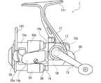
図1に示されるように、魚釣用リールとしてのスピニングリール1は、前方に突出するスプール軸8及び駆動軸筒9(図10の(a)参照)を有するリールボディ(リール本体)10を有し、このリールボディ10には、図示しない釣竿に取り付けられる竿取付部111を有する脚部11が延出されて形成されるとともに、その一部にボディカバー12が着脱自在に被着される。これらの脚部11及びボディカバー12を含むリールボディ10は、例えば後述するようにダイキャスト素材を用いて形成される。
As shown in FIG. 1, the spinning
また、リールボディ10にはロータ14と釣糸が巻回されるスプール15とが設けられる。この場合、ロータ14は公知のように駆動軸筒9の前端部に固定され(図10の(a)参照)、スプール15はスプール軸8の前端に取り付けられる。
Further, the
リールボディ10はハンドル軸13aを回転自在に支持しており(図1及び図8参照)、ハンドル軸13aはリールボディ10内を左右方向に延在している。ハンドル軸13aにはドライブギヤ19が一体的に設けられており、ハンドル軸13aの回転に伴ってドライブギヤ19が回転するようになっている。なお、ハンドル軸13aの端部はリールボディ10を貫通してリールボディ10の側方に突出しており、この突出したハンドル軸13aの端部にハンドル13が取り付けられている。
The
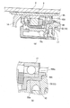
図10に示されるように、リールボディ10の前側に設けられた筒部10a内には、軸受17を介して回転自在に支持された前述の駆動軸筒9と、該駆動軸筒9内に挿通された前述のスプール軸8とが設けられている。
As shown in FIG. 10, in the
駆動軸筒9の前端部にはロータ14が固定され、駆動軸筒9の後端にはドライブギヤ19と噛合するピニオンギヤ9Aが形成される。このため、ハンドル13を回転操作すると、その回転駆動力がドライブギヤ19及びピニオンギヤ9Aを介して駆動軸筒9に伝達され、駆動軸筒9と共にロータ14が回転する。
A
図1に示されるように、ロータ14は、リールボディ10の筒部10aの外周側に位置する円筒部30と、一対のアーム部14b,14bとを備えている。各アーム部14b,14b(図1では一方のアーム部のみが見える)の前端部には、スプール15へと延びる釣糸を拾い上げるためのベール141と図示しないラインローラとを支持するベール支持部材29,29が回動自在に取り付けられ、これらのベール支持部材29,29(図1では一方のベール支持部材のみ見える)が釣糸巻き取り位置と釣糸放出位置との間で回動することによってベール141の姿勢が釣糸巻き取り姿勢と釣糸放出姿勢との間で切り換えられるようになっている。
As shown in FIG. 1, the
スプール軸8の前端には図示しないドラグ機構を介してスプール15が取り付けられている。スプール15は、釣糸が巻回される釣糸巻回胴部15aと、釣糸巻回胴部15aの後部に設けられたスカート部15bと、釣糸巻回胴部15aの前側に設けられた前側フランジ15cとを有する。
A
スプール軸8の後端は、リールボディ10内に設けられる公知の構成のスプール往復動装置に連結される。したがって、ハンドル13が巻き取り操作されると、ハンドル軸13aからの回転運動を直線運動へと変換して、スプール15を前後動(往復動)させる。そのため、ハンドル13の巻き取り操作(回転操作)に伴う前述したロータ14の回転と相俟って、ベール141により拾い上げられた図示しない釣糸がラインローラを介してスプール15の釣糸巻回胴部15aに均等に巻き付けられる。
The rear end of the
次に、スピニングリール1の構成部材について説明する。
スピニングリール1は、前述したように、その構成部材である単一の部材(リールボディ10、ボディカバー12、ロータ14、ハンドル13、外装部材等)を有しており、これらの構成部材は、ダイキャスト素材により形成されるとともに、要求される機能(駆動部材の高精度支持、重厚な光輝外観色調、耐食性)に応じた表面処理を適所に有する。
Next, the constituent members of the spinning
As described above, the spinning
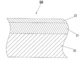
このような構成部材のうち、脚部11を含むリールボディ10は、前述したようにダイキャスト素材により形成されるとともに、図4に示されるように、ダイキャスト素材20上にこのダイキャスト素材20のアルミニウム純度に比して高純度なアルミニウムにより形成されるコーティング層21と、このコーティング層21上に陽極酸化処理により形成される防食層22とを有する表面処理領域を伴う本体部材50を含む。
Among such constituent members, the
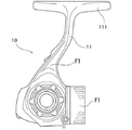
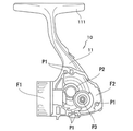
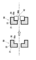
また、図2及び図3に示されるように、リールボディ10は、所定の仕上げ寸法精度が要求される精密仕上げ部位Pと、該精密仕上げ部位を除く表面部位Fとを有し、ここで、精密仕上げ部位Pは、リールボディ10の部位のうち、所定の(一般に高い)仕上げ寸法精度が要求される部位のことであり、組み込み・加工証及びネジ穴P1や、ハンドル軸13a(駆動部材)を支持する軸受設置部位P2、歯車の支持部P3等、軸受部を介して回転可能に駆動部材を支持する支持部を含む。また、表面部位Fは、精密仕上げ部位Pを除くリールボディ10の表面部位であり、外部環境に露出される外表面部位F1、外部環境に晒されない内側の表面(内表面)部位F2を含む。また、このような精密仕上げ部位及び表面部位はボディカバー12等の他のリール構成部材にも存在する。本発明の技術的思想は、リールボディ10やボディカバー12の精密仕上げ部位のうち、駆動部材を回転可能に支持する支持部に適用されるものである。
Further, as shown in FIGS. 2 and 3, the
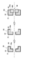
図5及び図6には、本発明の技術的思想が概念的に示されている。図示のように、ダイキャスト素材により形成される魚釣用リールの構成部材は、前述したように、ダイキャスト素材20上にこのダイキャスト素材20のアルミニウム純度に比して高純度なアルミニウムにより形成されるコーティング層21と、このコーティング層21上に陽極酸化処理により形成される防食層22とを有する本体部材50を有する。そして、この本体部材50には、駆動部材を回転可能に支持する支持部40が設けられるが、この支持部40は、本体部材50とは別体を成して本体部材50のダイキャスト素材よりも耐食性が高い支持部材40Aにより形成される。ここで、回転可能な駆動部材としては、例えば、魚釣用リールのハンドル軸、スプール軸、及び、ピニオン軸などを挙げることができ、本実施形態のスピニングリール1では、前述したハンドル軸13a及び駆動軸筒9がこの駆動部材に相当する。
5 and 6 conceptually show the technical idea of the present invention. As shown in the figure, the constituent members of the fishing reel formed of the die-cast material are formed on the die-
支持部材40Aは、図5に示されるように、コーティング層21と防食層22とを伴う本体部材50の嵌合部(開口部)50aに、芯ズレのない状態に本体部材50と共に治具にセットした状態で公知の固定手段によって固定して取り付けられてもよい。あるいは、支持部材40Aは、図6に示されるように、本体部材50の加工証を基準に機械加工された嵌合部(開口部)50aに嵌合固定されてもよい。この場合、嵌合部50aの機械加工では、図示のように、コーティング層21と防食層22とが切削によりダイキャスト素材20から除去されてもよい。ここで、本体部材50の機械加工部位に支持部材40Aを嵌合固定し外気に触れないように封止して防水域内にとどめることにより、加工されたダイキャスト素材20と腐食原因物質(水、海水など)とが接触しないため、腐食を防止できる。更にこの場合に、防水域内の本体部材50の機械加工部位を図示しない被覆体で覆い、この被覆体と重合させるように耐食性部材としての支持部材40Aを配置すれば、防水性を更に向上させることができる。
As shown in FIG. 5, the
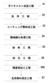
ここで、図5に示されるようにコーティング層21と防食層22とを伴う本体部材50の嵌合部50aにそのまま支持部材40Aを固定して取り付ける場合には、図11に示されるように、最初に、ダイキャスト成型工程(成形ステップ)S1において、例えば珪素(Si)が7%以上含まれるアルミニウム合金(例えばADC1,ADC3,ADC10,ADC12等)等のダイキャスト素材を溶融して金型に流し込んで高い圧力をかけて鋳造する周知のダイキャスト法により、所望形状の成型品(ダイキャスト素材)20を形成する。続いて、このダイキャスト成型した成型品20は、洗浄工程S2において、周知の脱脂、化学研磨処理が施されて、その後、アルミニウムのコーティング層形成工程S3に移行される。
Here, when the
コーティング層形成工程(コーディング層形成ステップ)S3においては、ダイキャスト素材に比して高純度、例えば99パーセント以上の高純度のアルミニウム(純Al)の粉末粒子を成型品20の表面に吹き付けて膜厚が10μm〜100μmのコーティング層21を形成する。このアルミニウム粉末粒子の吹き付け手法としては、表面の平滑性・均一性を考慮すると、周知のコールドスプレー法と称する衝撃被膜形成処理が望ましい。このコーティング層21は、リール構成部材の例えば全面に吹き付けて形成される。また、コーティング層21が蒸着、特に枚葉式、バッジ式等にて物理蒸着により形成されてもよい。このようにすると、コーティング層21の膜厚を大きく確保できる。その場合、成型品20の表面に微細な凹凸を予め形成してコーティング層21を積層すると、成型品20に対するコーティング層21の付着力が高まるため有益である。そして、この成型品20に形成されたコーティング層21は、例えばその表面にバレル、ショット、バフ等の研磨処理が施される。
In the coating layer forming step (coding layer forming step) S3, powder particles of aluminum (pure Al) having a higher purity than that of the die-cast material, for example, 99% or more of high purity, are sprayed onto the surface of the molded
また、コーティング層21としては、例えば10μm〜100μmとすることにより、アルミニウ粒子を成型品20上に吹き付ける際、ダイキャスト素材の影響を受けることがなく、しかも、被覆むらを最小限に保つことが可能となり、所望の製品寸法精度を確保することが可能となる。
Further, by setting the
次に、コーティング層21を形成した成型品20は、陽極酸化処理工程(防食層形成ステップ)S4において、そのコーティング層21を含む全表面に陽極酸化処理、例えばアルマイト処理が施されて、コーティング層21を含む表面上に防食層であるアルマイト層22が形成される。
Next, the molded
ここで、コーティング層21を含む表面にアルマイト層22が形成された成型品20は、そのコーティング層21上のアルマイト層22の硬度が、該コーティング層21の作用により、高硬度(例えば、ビッカース硬さHv500〜800程度)となる。また、この成型品20のコーティング層21上のアルマイト層22は、その耐摩耗性が、同様にコーティング層21の作用により、ダイキャスト素材上に直接に形成した場合に比して高められるとともに、その外観が、いわゆるメタリック感のある光輝な状態に設定される。
Here, in the molded
これにより、コーティング層21上のアルマイト層22は、傷等が付きづらく、しかも、光輝性を有することにより、汚れ等の防止か図れ、腐食、錆等の発生の防止が図れて、耐久性の向上が図れる。
As a result, the
また、陽極酸化処理によりアルマイト層22を形成した成型品22は、必要に応じて染色工程S5において、例えば所望の周面に染色処理が施され、その後、封孔工程S6において、封孔処理が施されて、構成部材である例えばリールボディ10として完成品が製作される。
Further, the molded
その後、支持部材固定工程(固定ステップ)S7において、本体部材50のダイキャスト素材20よりも耐食性が高い支持部材40Aが本体部材50の例えば嵌合部50aに嵌合固定される。
After that, in the support member fixing step (fixing step) S7, the
また、図6に示されるように本体部材50の機械加工された嵌合部50aに支持部材40Aを固定する場合には、図12に示されるように、前述した各工程S1〜S6を経た後、精度部加工工程S6Aにおいて、本体部材50の嵌合部50aに対して機械加工、例えば高精度な寸法を出すための精密仕上げ加工を施し、その後、支持部材固定工程S7において、支持部材40Aを本体部材50の嵌合部50aに嵌合固定する。また、いずれの場合においても、支持部材固定工程S7の後、図13に示されるように支持部材40Aに対して精密仕上げ加工を施す支持部材加工工程S8を行なってもよい。
Further, when the
ここで、陽極酸化処理後に、光輝性、耐食性、耐摩耗性、耐傷付き性の何れかに特化した表面特性を得るためには、コーティング層21の厚み及びアルマイト層(防食層)22の厚みを制御することが重要である。例えば、光輝性等を高めるために、コーティング層21の厚さを10μm以下にするとともに、アルマイト層22の厚さを5μm以下としてもよい。ここで、コーティング層21が薄ければ薄いほどコーティング層21の表面は平滑になる。また、アルマイト層22が薄ければ薄いほど、耐食性は、低くなるが、高い光沢性を得るには、コーティング層21の形成後に物理研磨(バフ)や化学研磨を施し、その後、アルマイト層22を5μm以下の厚さで形成してもよい。或いは、コーティング層21の厚さを30μm以上とし、アルマイト層22の厚さを5μm以下としても、高い光沢性を得ることができる。
Here, in order to obtain surface characteristics specialized in any one of brilliance, corrosion resistance, abrasion resistance, and scratch resistance after the anodizing treatment, the thickness of the
また、耐食性に特化した表面特性を得るためには、コーティング層21の厚さを15μm以下にして、アルマイト層22の厚さを10μm以上にすることが好ましい。また、耐食性に加えて、耐摩耗性及び耐傷付き性を得るためには、コーティング層21の厚さを15μm以下にして、アルマイト層22は厚さが10μm以上の硬質アルマイトにすることが好ましい。
Further, in order to obtain surface characteristics specialized in corrosion resistance, it is preferable that the thickness of the
また、ADC以外のダイキャスト素材でも輝度の高いアルマイト外観を得ることができる。例えば、マグネシウム合金素材上にコーティング層21及びアルマイト層22を形成してもよい。この場合、マグネシウム専用の処理液で陽極酸化処理を行なった後、コーティング層を形成してアルマイト処理してもよい。これは、電着塗装の代替であるとともに、装飾外観にもなる(すなわち、装飾用の塗装が不要になる)。また、樹脂部品に純Alをコーティングしてアルマイト処理してもよい。この場合、樹脂は、アルマイト処理が行なえるように非導電性の樹脂とする。
Further, even with a die-cast material other than ADC, a high-brightness alumite appearance can be obtained. For example, the
次に、本発明の概念を具体的部位に適用した実施例について説明する。
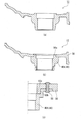
図7は、リール構成部材としてのボディカバー12に本発明を適用した具体的な実施例である。一般のボディカバー12は、図7の(a)に示されるように、単一の一体部材として形成されているが、本実施例では、図7の(b)及び(c)に示されるように、駆動部材としてのハンドル軸13aの一端側を軸受(図示せず)を介して回転可能に支持する支持部40を構成する支持部材40Aと、リールボディ10に取り付けられる本体部材50とによってボディカバー12が構成される。本体部材50は、前述したように、コーティング層21と防食層22とを伴っており、支持部材40Aは、精密仕上げ加工が施された又は施されない本体部材50の嵌合部50aを構成する図7の(b)に図示した開口部或いは図7の(c)に図示した筒部50cの外周部50bに対して取り付けられる。なお、取り付け方法としては、例えば、圧入、カシメ、接着、ネジ止めなどの公知の固定手段が挙げられる(図7の(c)では、リベット55を介して取り付けられている)。また、本体部材50は、例えば加工証や組み込み証を基準としてリールボディ10に組み付けられることで、位置精度が確保される。
Next, an example in which the concept of the present invention is applied to a specific part will be described.
FIG. 7 is a specific example in which the present invention is applied to the
図8は、リール構成部材としてのリールボディ10に本発明を適用した具体的な実施例である。図示のように、本実施例のリールボディ10では、ハンドル軸13aの支持部40の外側をカバーしてハンドル軸13aを支持する軸受39の抜け止め支持を兼ねるカバー体38がリールボディ10に図示しないネジ部材によって取着固定されている。支持部40を形成する支持部材40Aは、駆動部材としてのハンドル軸13aを回転可能に支持する軸受39が嵌合される内周面40Aaを有し、リールボディ10を構成する本体部材50の嵌合部50aに芯ズレのない状態に治具にセットして嵌合された後、リベット37により固定される。ここで、本体部材50は、前述したようにコーティング層21と防食層22とを伴っており、本体部材50の嵌合部50aは、精密仕上げ加工が施されてもよく又は施されなくてもよい。
FIG. 8 is a specific example in which the present invention is applied to the
図9も、図7と同様、リール構成部材としてのボディカバー12に本発明を適用した具体的な実施例である。図示のように、ボディカバー12は、駆動部材としてのハンドル軸13aの一端側を軸受(図示せず)を介して回転可能に支持する支持部40を構成する支持部材40Aと、コーティング層21と防食層22とを伴ってリールボディ10に取り付けられる本体部材50とによって構成される。また、この実施例では、前記軸受が嵌合される支持部材40Aの内周面40Aaが、本体部材50に対して支持部材40Aが固定された状態で加工証を基準に治具にセットされつつ機械加工されて成る(図中、太線で示される参照符号80の部位が機械加工部位)。このように軸受を受けるために高い寸法精度が要求される内周面40Aaの部位を機械加工(精密仕上げ加工)することにより、本体部材50に対する支持部材40Aの組み付け後に所望の位置精度を確保できる。なお、支持部材40Aの全体をSUSなどの耐食性材料により形成してもよいが、軸受を受ける内周面40Aa部位のみをSUSにより形成し、その他の部位を陽極酸化されたアルミなどの耐食性部材により形成すれば、不要な重量増加を抑えることができる。
FIG. 9 is also a specific embodiment in which the present invention is applied to the
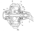
図10は、リール構成部材としてのリールボディ10に本発明を適用した具体的な実施例である。図示のように、本実施例では、リールボディ10を構成する本体部材50の嵌合部50aにカラー部材としての支持部材40Aが嵌合固定されて支持部40を形成し、支持部材40Aは、回転可能な駆動部材としての駆動軸筒9を回転可能に支持する軸受17が嵌合される内周面40Aaを有する。ここで、本体部材50は、前述したようにコーティング層21と防食層22とを伴っており、これらの層の形成後に本体部材50の嵌合部50aに精密仕上げ加工が施される。そして、この精密仕上げ加工部位が防水域内にとどめられる。言い換えると、精密仕上げ加工部位にカラー部材としての支持部材40Aを被せて防水域を作成する。防水域の作成方法としては、接着材(本体部材50の嵌合部50aに支持部材40Aを接着する)、シーリング材(Oリング、コーキング材)によるものが考えられる。
FIG. 10 is a specific example in which the present invention is applied to the
以上のように、本実施形態によれば、前述した特許文献1に開示されるように添加物の多いダイキャスト素材上に直接に陽極酸化処理によって形成される薄い防食層しか伴わない本体部材の部位(精密仕上げ部位)を支持部として駆動部材を回転可能に支持するのではなく、ダイキャスト素材上にコーティング層21を介して設けられる防食層22を伴う支持部40で、すなわち、コーティング層21の介在により十分な厚さを確保できる防食層22上に設けられてダイキャスト素材20よりも耐食性が高い支持部40で、駆動部材を回転可能に支持できるため、海水、水、異物等が付着し易い使用環境の厳しい釣場においても十分な耐食性を支持部40で得ることができ、魚釣用リールの使用条件及び使用環境に制約を生じさせないで済む。また、支持部40が本体部材50とは別体の支持部材40Aから形成されるため、支持部材40Aに高い寸法精度をもたせることにより、支持部40で高精度な仕上げ寸法を実現できる。
As described above, according to the present embodiment, as disclosed in
また、本実施形態によれば、純度の高いアルミニウムのコーティング層21の作用により、陽極酸化処理して形成したコーティング層21上の防食層22の防食性及び防錆性が高められるとともに、メタリック感のある重厚な光輝外観性が得られ、しかも、表面硬度が高められる。また、ダイキャスト素材がアルミニウム合金(例えばADC1,ADC3,ADC10,ADC12等)から成るため、アルミニウム同士の結合により本体部材50に対するコーティング層21の密着性が高められ、ひいては、防食層22の耐食性がより向上される。
Further, according to the present embodiment, the action of the highly pure
また、本実施形態によれば、陽極酸化処理(アルマイト処理)を複数回にわたって行なわなくて済み、また、仮に支持部材40Aを機械加工する場合であっても、支持部材40Aが耐食性を有することから、機械加工後の陽極酸化処理を行なわなくて済むため、既に形成された陽極酸化処理被膜(防食層)22にダメージ(脱色、劣化など)を与えずに済み(耐食性を損なわずに済み)、したがって、品質向上が図れる。また、表面処理が少なくて済むため、コストダウンを図ることができるとともに、表面処理全体の作業効率を向上させることもできる。
Further, according to the present embodiment, it is not necessary to perform the anodizing treatment (anodizing treatment) a plurality of times, and even if the
なお、本発明は、前述した実施形態に限定されず、その要旨を逸脱しない範囲で種々変形して実施できる。例えば、前述した実施形態では、本発明がスピニングリールの構成部材に適用されたが、本発明は、両軸受型リール等の他のタイプの魚釣用リールの構成部材にも適用可能である。また、前述の実施形態では、アルミニウムのコーティング層21をダイキャスト素材の成型品20に形成する手法として、ショットコーティング法を用いて吹き付け形成するように構成した場合で説明したが、これに限ることなく、その他、蒸着法、溶射法、溶融メッキ法等を用いて形成するように構成することも可能である。
The present invention is not limited to the above-described embodiment, and can be modified in various ways without departing from the gist thereof. For example, in the above-described embodiment, the present invention has been applied to a constituent member of a spinning reel, but the present invention can also be applied to a constituent member of another type of fishing reel such as a double bearing type reel. Further, in the above-described embodiment, as a method of forming the
10 リールボディ(魚釣用リールの構成部材)
12 ボディカバー(魚釣用リールの構成部材)
20 ダイキャスト素材
21 コーティング層
22 防食層
40 支持部
40A 支持部材
40Aa 内周面
50 本体部材
50a 嵌合部
P 精密仕上げ部位
F 表面部位
10 Reel body (component of fishing reel)
12 Body cover (Fishing reel component)
20 Die-
Claims (7)
前記ダイキャスト素材上にこのダイキャスト素材のアルミニウム純度に比して高純度なアルミニウムにより形成されるコーティング層と、このコーティング層上に陽極酸化処理により形成される防食層とを有する本体部材と、
前記本体部材に設けられ、駆動部材を回転可能に支持する支持部と、
を備え、
前記支持部は、前記本体部材とは別体を成して前記本体部材の前記ダイキャスト素材よりも耐食性が高い支持部材により形成されることを特徴とする魚釣用リールの構成部材。 A component of a fishing reel made of die-cast material.
A main body member having a coating layer formed of aluminum having a purity higher than that of the aluminum purity of the die-cast material on the die-cast material, and an anticorrosion layer formed on the coating layer by anodizing treatment.
A support portion provided on the main body member to rotatably support the drive member, and
With
A constituent member of a fishing reel, wherein the support portion is formed of a support member that is separate from the main body member and has higher corrosion resistance than the die-cast material of the main body member.
ダイキャスト素材を溶融して金型に流し込み高圧で鋳造することによって所望形状の本体部材を成形する成形ステップと、
前記本体部材の表面上に前記ダイキャスト素材のアルミニウム純度に比して高純度のアルミニウムのコーティング層を形成するコーティング層形成ステップと、
前記コーティング層上に陽極酸化処理によって防食層を形成する防食層形成ステップと、
駆動部材を回転可能に支持するようになっているとともに前記本体部材の前記ダイキャスト素材よりも耐食性が高い支持部材を前記本体部材に固定する固定ステップと、
を含むことを特徴とする製造方法。 It is a method of manufacturing the components of a fishing reel.
A molding step of melting a die-cast material, pouring it into a mold, and casting it at high pressure to form a main body member of a desired shape.
A coating layer forming step of forming a coating layer of aluminum having a higher purity than the aluminum purity of the die-cast material on the surface of the main body member.
An anticorrosion layer forming step of forming an anticorrosion layer on the coating layer by anodizing treatment,
A fixing step for fixing the support member, which is designed to rotatably support the drive member and has higher corrosion resistance than the die-cast material of the main body member, to the main body member.
A manufacturing method comprising.
Priority Applications (3)
| Application Number | Priority Date | Filing Date | Title |
|---|---|---|---|
| JP2020035884A JP7311443B2 (en) | 2020-03-03 | 2020-03-03 | Structural member of fishing reel and manufacturing method thereof |
| US17/183,419 US11412724B2 (en) | 2020-03-03 | 2021-02-24 | Fishing reel components and method of manufacturing the same |
| CN202110217234.1A CN113349174A (en) | 2020-03-03 | 2021-02-26 | Component of fishing reel and method for manufacturing the same |
Applications Claiming Priority (1)
| Application Number | Priority Date | Filing Date | Title |
|---|---|---|---|
| JP2020035884A JP7311443B2 (en) | 2020-03-03 | 2020-03-03 | Structural member of fishing reel and manufacturing method thereof |
Publications (2)
| Publication Number | Publication Date |
|---|---|
| JP2021136890A true JP2021136890A (en) | 2021-09-16 |
| JP7311443B2 JP7311443B2 (en) | 2023-07-19 |
Family
ID=77524760
Family Applications (1)
| Application Number | Title | Priority Date | Filing Date |
|---|---|---|---|
| JP2020035884A Active JP7311443B2 (en) | 2020-03-03 | 2020-03-03 | Structural member of fishing reel and manufacturing method thereof |
Country Status (3)
| Country | Link |
|---|---|
| US (1) | US11412724B2 (en) |
| JP (1) | JP7311443B2 (en) |
| CN (1) | CN113349174A (en) |
Citations (5)
| Publication number | Priority date | Publication date | Assignee | Title |
|---|---|---|---|---|
| JP2001045926A (en) * | 1999-08-06 | 2001-02-20 | Daiwa Seiko Inc | Components of fishing reel |
| US20080216383A1 (en) * | 2007-03-07 | 2008-09-11 | David Pierick | High performance nano-metal hybrid fishing tackle |
| JP2013099264A (en) * | 2011-11-08 | 2013-05-23 | Shimano Inc | Fishing-reel reel unit, fishing reel and method of manufacturing fishing-reel reel unit |
| JP5956741B2 (en) * | 2011-11-08 | 2016-07-27 | 株式会社シマノ | Fishing reel body and fishing reel |
| JP2019122273A (en) * | 2018-01-12 | 2019-07-25 | グローブライド株式会社 | Component member of fishing reel |
Family Cites Families (5)
| Publication number | Priority date | Publication date | Assignee | Title |
|---|---|---|---|---|
| JP2000312549A (en) * | 1999-04-30 | 2000-11-14 | Daiwa Seiko Inc | Components of fishing reel |
| JP2001321036A (en) * | 2000-03-08 | 2001-11-20 | Daiwa Seiko Inc | Components of fishing reel |
| JP2002209483A (en) * | 2001-01-19 | 2002-07-30 | Daiwa Seiko Inc | Components of fishing reel |
| JP2004082612A (en) * | 2002-08-28 | 2004-03-18 | Shimano Inc | Outdoor appearance component |
| JP2008081839A (en) * | 2006-08-30 | 2008-04-10 | Aisan Ind Co Ltd | Member made of aluminum alloy, method for producing the same, and fuel pump with the member made of aluminum alloy |
-
2020
- 2020-03-03 JP JP2020035884A patent/JP7311443B2/en active Active
-
2021
- 2021-02-24 US US17/183,419 patent/US11412724B2/en active Active
- 2021-02-26 CN CN202110217234.1A patent/CN113349174A/en active Pending
Patent Citations (5)
| Publication number | Priority date | Publication date | Assignee | Title |
|---|---|---|---|---|
| JP2001045926A (en) * | 1999-08-06 | 2001-02-20 | Daiwa Seiko Inc | Components of fishing reel |
| US20080216383A1 (en) * | 2007-03-07 | 2008-09-11 | David Pierick | High performance nano-metal hybrid fishing tackle |
| JP2013099264A (en) * | 2011-11-08 | 2013-05-23 | Shimano Inc | Fishing-reel reel unit, fishing reel and method of manufacturing fishing-reel reel unit |
| JP5956741B2 (en) * | 2011-11-08 | 2016-07-27 | 株式会社シマノ | Fishing reel body and fishing reel |
| JP2019122273A (en) * | 2018-01-12 | 2019-07-25 | グローブライド株式会社 | Component member of fishing reel |
Also Published As
| Publication number | Publication date |
|---|---|
| US20210274764A1 (en) | 2021-09-09 |
| JP7311443B2 (en) | 2023-07-19 |
| CN113349174A (en) | 2021-09-07 |
| US11412724B2 (en) | 2022-08-16 |
Similar Documents
| Publication | Publication Date | Title |
|---|---|---|
| JP6914207B2 (en) | Manufacturing method of components of fishing reel | |
| JP2005245215A (en) | Reel sheet manufacturing method for fishing rod | |
| JP5956741B2 (en) | Fishing reel body and fishing reel | |
| US7014135B2 (en) | Fishing reel | |
| JP7311443B2 (en) | Structural member of fishing reel and manufacturing method thereof | |
| JP2000342127A (en) | Coated part | |
| JP5906017B2 (en) | Reel for fishing, component for fishing reel, and manufacturing method thereof | |
| US20030219609A1 (en) | Plated component with a hybrid surface and method for manufacturing same | |
| TWI257957B (en) | Plated component for use in an outdoor environment | |
| JP2005013153A (en) | Components for fishing reels | |
| JP3203878U (en) | Outdoor parts | |
| JP2000312549A (en) | Components of fishing reel | |
| JP2001045926A (en) | Components of fishing reel | |
| JPH11332428A (en) | Surface structure of fishing tackle | |
| JP4034434B2 (en) | Parts assembly | |
| JP2000209986A (en) | Spinning reel for fishing | |
| JP2001321036A (en) | Components of fishing reel | |
| JP3445935B2 (en) | Surface structure of fishing gear | |
| JPH11332427A (en) | Surface structure of fishing tackle | |
| JP2007270276A (en) | Parts for outdoor use | |
| JPH1118627A (en) | Fishing matter having decorative layer | |
| JPH0494629A (en) | Production of reel main body having bearings at both sides | |
| JP2003080123A (en) | Atomizing head of electrostatic coater | |
| JPH09121728A (en) | Spool for fishing reel | |
| US6412723B1 (en) | Reel for fishing |
Legal Events
| Date | Code | Title | Description |
|---|---|---|---|
| A621 | Written request for application examination |
Free format text: JAPANESE INTERMEDIATE CODE: A621 Effective date: 20220420 |
|
| A977 | Report on retrieval |
Free format text: JAPANESE INTERMEDIATE CODE: A971007 Effective date: 20230126 |
|
| A131 | Notification of reasons for refusal |
Free format text: JAPANESE INTERMEDIATE CODE: A131 Effective date: 20230209 |
|
| A521 | Request for written amendment filed |
Free format text: JAPANESE INTERMEDIATE CODE: A523 Effective date: 20230406 |
|
| TRDD | Decision of grant or rejection written | ||
| A01 | Written decision to grant a patent or to grant a registration (utility model) |
Free format text: JAPANESE INTERMEDIATE CODE: A01 Effective date: 20230615 |
|
| A61 | First payment of annual fees (during grant procedure) |
Free format text: JAPANESE INTERMEDIATE CODE: A61 Effective date: 20230706 |
|
| R150 | Certificate of patent or registration of utility model |
Ref document number: 7311443 Country of ref document: JP Free format text: JAPANESE INTERMEDIATE CODE: R150 |