JP2021136855A - Variable torque motor and variable torque structure of the motor - Google Patents
Variable torque motor and variable torque structure of the motor Download PDFInfo
- Publication number
- JP2021136855A JP2021136855A JP2020034394A JP2020034394A JP2021136855A JP 2021136855 A JP2021136855 A JP 2021136855A JP 2020034394 A JP2020034394 A JP 2020034394A JP 2020034394 A JP2020034394 A JP 2020034394A JP 2021136855 A JP2021136855 A JP 2021136855A
- Authority
- JP
- Japan
- Prior art keywords
- planetary gear
- torque
- motor
- clutch
- gear
- Prior art date
- Legal status (The legal status is an assumption and is not a legal conclusion. Google has not performed a legal analysis and makes no representation as to the accuracy of the status listed.)
- Granted
Links
Images

Landscapes
- Structure Of Transmissions (AREA)
- Connection Of Motors, Electrical Generators, Mechanical Devices, And The Like (AREA)
Abstract
Description
本発明は可変トルクモータ、およびモータのトルク可変構造に係り、特に、大きく異なる二種類のトルクを一台のモータから、しかも同じ出力軸から取り出すことのできる、可変トルクモータ等に関するものである。 The present invention relates to a variable torque motor and a torque variable structure of the motor, and more particularly to a variable torque motor or the like capable of extracting two types of torques that are significantly different from one motor and from the same output shaft.
サーボモータにおいて高トルクが必要な場合、減速機と組み合わせ、回転速度を犠牲にする(高速回転できない)ことで減速比倍のトルクを得るという手法が、一般的には取られている。しかし、たとえばサーボプレスなどボールねじを用いた機構の場合は、モータを高速で回転させて位置決めを行った後に即、高トルクで加圧したいという動作パターンがある。だが、減速機を用いた機構では高トルクは出力可能だが、高速回転を出力することは不可能である。またこれとは逆に、高速回転を出力する場合には減速機との組み合わせによる高トルク出力は不可能となる。 When a high torque is required in a servomotor, a method of obtaining torque at a reduction ratio double by sacrificing the rotation speed (cannot rotate at high speed) in combination with a speed reducer is generally adopted. However, in the case of a mechanism using a ball screw such as a servo press, there is an operation pattern in which a motor is rotated at a high speed to perform positioning and then immediately pressurized with a high torque. However, although a mechanism using a reduction gear can output high torque, it is impossible to output high-speed rotation. On the contrary, when outputting high-speed rotation, high torque output in combination with a speed reducer becomes impossible.
すなわち、減速機を用いる場合には回転速度を犠牲にせざるを得ないため、高速回転出力と高トルク出力を両立させることができない。つまり、減速機を用いつつ高低二段階のトルクを一台のモータから、しかも同じ出力軸から取り出すことは、従来不可能であった。したがって、高速回転出力と高トルク出力の両立のためには、複雑な機構による二種類(二台)のモータを用いた対応がなされていた。 That is, when a speed reducer is used, the rotation speed must be sacrificed, so that both high-speed rotation output and high torque output cannot be achieved at the same time. That is, it has been impossible in the past to extract high and low two-stage torque from one motor and from the same output shaft while using a speed reducer. Therefore, in order to achieve both high-speed rotation output and high torque output, two types (two) of motors with a complicated mechanism have been used.
なお、かかる問題の根本的解決策になり得るものとして、減速機を用いつつ低速回転高トルク仕様、高速回転低トルク仕様の両仕様で利用できる方法が既に特許出願されている(後掲特許文献1)。この文献には、低速回転高トルク仕様、高速回転低トルク仕様の両仕様で利用できる減速機として、モータ軸の回転力を減速して第1の駆動力を出力対象に出力する複数の出力部材を有する減速機構、複数の出力部材に接続するキャリアを有し、第1の駆動力を増速して第2の駆動力をデフケースに出力する増速機構、増速機構―デフケース、また減速機構―デフケースをそれぞれ断続可能に連結するクラッチを備える構成が開示されている。 As a potential solution to this problem, a patent application has already been filed for a method that can be used with both low-speed rotation and high-torque specifications and high-speed rotation and low-torque specifications while using a speed reducer. 1). In this document, as a speed reducer that can be used in both low-speed rotation high-torque specifications and high-speed rotation low-torque specifications, a plurality of output members that reduce the rotational force of the motor shaft and output the first driving force to the output target. A deceleration mechanism having a speed-increasing mechanism, a speed-up mechanism having a carrier connected to a plurality of output members, a speed-increasing mechanism for increasing the first driving force and outputting a second driving force to a differential case, a speed-increasing mechanism-a differential case, and a deceleration mechanism. -A configuration including a clutch for intermittently connecting the differential cases is disclosed.
上記文献開示技術は、減速機が増速機構と減速機構とを備えてなる構成であり、デフケースに増速機構または減速機構を選択して接続するクラッチにより、高速回転低トルク、低速回転高トルク、二種類の出力が取り出されるという方式である。つまり、減速機構だけではなく増速機構をも設け減速機にするという複雑な構成、方式であり、これを搭載する装置全体の大型化の抑制や、モータと減速機との組み合わせにおける組み合わせ機構の簡素化には向かない。したがって、搭載される装置全体の大型化抑制、組み合わせ機構の簡素化に資することもできる、より簡素な構成、方式が求められる。 The above-mentioned document disclosure technology has a configuration in which a speed reducer is provided with a speed-increasing mechanism and a speed-reducing mechanism, and a clutch for selecting and connecting a speed-increasing mechanism or a speed-reducing mechanism to a differential case allows high-speed rotation low torque and low-speed rotation high torque. , Two types of output are taken out. In other words, it is a complicated configuration and method in which not only a speed reduction mechanism but also a speed increase mechanism is provided to make a speed reducer. Not suitable for simplification. Therefore, a simpler configuration and method that can contribute to suppressing the increase in size of the entire mounted device and simplifying the combination mechanism are required.
また、サーボモータでは従来、停電時などの緊急停止に対応するため、無励磁作動型ブレーキを搭載することが一般的である。しかし、かかる無励磁作動型ブレーキの搭載は、その分のスペースを要し、これも搭載される装置全体の大型化を抑えるには不利である。高速回転低トルク、低速回転高トルクという二種類の出力を一台のモータおよび単一の出力軸によって取り出せるとともに、無励磁作動型ブレーキの搭載を不要とすることができれば、搭載される装置全体の大型化抑制、組み合わせ機構の簡素化には有利である。 Further, conventionally, in order to cope with an emergency stop such as a power failure, a servomotor is generally equipped with a non-excitation actuated brake. However, mounting such a non-excitation actuated brake requires a corresponding amount of space, which is also disadvantageous in suppressing the increase in size of the entire device to be mounted. If two types of outputs, high-speed rotation low torque and low-speed rotation high torque, can be taken out by one motor and a single output shaft, and if it is possible to eliminate the need to install a non-excitation actuated brake, the entire equipment to be installed can be installed. It is advantageous for suppressing the increase in size and simplifying the combination mechanism.
そこで本発明が解決しようとする課題は、かかる従来技術の問題点をなくし、搭載される装置における組み合わせ機構を簡素化し、全体の大型化を押さえつつ、高速回転低トルク、低速回転高トルクという二種類の出力を一台のモータおよび単一の出力軸によって取り出すことを可能とする、可変トルクモータ、およびモータのトルク可変構造を提供することである。また、これに加えて本発明の課題は、搭載される装置における組み合わせ機構を簡素化し、全体の大型化を押さえつつ、高速回転低トルク、低速回転高トルクという二種類の出力を一台のモータおよび単一の出力軸によって取り出せるとともに無励磁作動型ブレーキの搭載を不要とすることのできる、可変トルクモータ、およびモータのトルク可変構造を提供することである。 Therefore, the problem to be solved by the present invention is to eliminate the problems of the prior art, simplify the combination mechanism in the mounted device, suppress the overall size increase, and achieve high-speed rotation low torque and low-speed rotation high torque. It is to provide a variable torque motor, and a torque variable structure of the motor, which allows a type of output to be taken out by a single motor and a single output shaft. Further, in addition to this, an object of the present invention is to simplify the combination mechanism in the mounted device, suppress the overall size increase, and output two types of outputs, high-speed rotation low torque and low-speed rotation high torque, into one motor. And to provide a variable torque motor and a torque variable structure of the motor that can be taken out by a single output shaft and can eliminate the need for mounting a non-excitation actuated brake.
本願発明者は上記課題について検討した結果、モータと減速機の間に電磁クラッチを設け、高速回転出力時はギヤ比の低い減速機構と接続し、高トルク出力が必要な場合にはギヤ比の高い減速機構と接続することでギヤ比倍のトルクを得られることを見出し、またかかる構成によって無励磁作動型ブレーキを用いることなく緊急停止可能な機構も実現できることを見いだし、これらに基づいて本発明を完成するに至った。すなわち、上記課題を解決するための手段として本願で特許請求される発明、もしくは少なくとも開示される発明は、以下の通りである。 As a result of examining the above problems, the inventor of the present application provides an electromagnetic clutch between the motor and the speed reducer, connects it to a reduction mechanism having a low gear ratio at high speed rotation output, and adjusts the gear ratio when high torque output is required. It has been found that a torque twice as much as the gear ratio can be obtained by connecting with a high reduction mechanism, and it has been found that a mechanism capable of emergency stop without using a non-excitation actuated brake can be realized by such a configuration, and the present invention is based on these. Has been completed. That is, the inventions claimed in the present application as means for solving the above problems, or at least the inventions disclosed, are as follows.
〔1〕 減速機により2種類のトルクを同一出力軸から取り出すことのできる可変トルクモータであって、減速機として不思議遊星歯車機構を用い、モータ本体と減速機との間にクラッチを設け、該不思議遊星歯車機構はモータ軸と一体に回転する太陽歯車と、該太陽歯車の周りを自転しながら公転する遊星歯車と、該遊星歯車と噛み合いかつ該クラッチによる作用を受ける第二内歯車と、該遊星歯車と噛み合い該第二内歯車とは歯数が異なっていて出力軸と一体に回転する第一内歯車と、および該遊星歯車を収容しかつ該クラッチによる作用を受けるキャリアとからなり、該クラッチの動作により該第二内歯車を固定した場合は低速回転高トルクが出力され、該キャリアを固定した場合は高速回転低トルクが出力されることを特徴とする、可変トルクモータ。
〔2〕 前記遊星歯車は、前記第一内歯車に噛み合う第一遊星歯車と、前記第二内歯車に噛み合う第二遊星歯車とが一体構造となっている二段遊星歯車であることを特徴とする、〔1〕に記載の可変トルクモータ。
〔3〕 前記クラッチは釈放により前記第二内歯車を、吸引により前記キャリアをそれぞれ固定することを特徴とする、〔1〕、〔2〕のいずれかに記載の可変トルクモータ。
[1] A variable torque motor capable of extracting two types of torque from the same output shaft by a speed reducer. A mysterious planetary gear mechanism is used as the speed reducer, and a clutch is provided between the motor body and the speed reducer. The mysterious planetary gear mechanism includes a sun gear that rotates integrally with the motor shaft, a planet gear that revolves while rotating around the sun gear, a second internal gear that meshes with the planet gear and is acted by the clutch, and the like. It consists of a first internal gear that meshes with a planetary gear and has a different number of teeth from the second internal gear and rotates integrally with the output shaft, and a carrier that accommodates the planetary gear and is acted on by the clutch. A variable torque motor characterized in that low-speed rotation high torque is output when the second internal gear is fixed by the operation of a clutch, and high-speed rotation low torque is output when the carrier is fixed.
[2] The planetary gear is a two-stage planetary gear having an integral structure of a first planetary gear that meshes with the first internal gear and a second planetary gear that meshes with the second internal gear. The variable torque motor according to [1].
[3] The variable torque motor according to any one of [1] and [2], wherein the clutch fixes the second internal gear by release and the carrier by suction.
〔4〕 前記クラッチは無励磁作動型であり、これにより停電時の出力軸緊急停止が可能であることを特徴とする、〔1〕、〔2〕、〔3〕のいずれかに記載の可変トルクモータ。
〔5〕 無励磁作動型ブレーキが備えられていないことを特徴とする、〔1〕、〔2〕、〔3〕、〔4〕のいずれかに記載の可変トルクモータ。
〔6〕 モータにおいて2種類のトルクを同一出力軸から取り出すことのできるトルク可変構造であって、不思議遊星歯車機構による減速機と、クラッチとからなり、該不思議遊星歯車機構はモータ軸と一体に回転する太陽歯車と、該太陽歯車の周りを自転しながら公転する遊星歯車と、該遊星歯車と噛み合いかつ該クラッチによる作用を受ける第二内歯車と、該遊星歯車と噛み合い該第二内歯車とは歯数が異なっていて出力軸と一体に回転する第一内歯車と、および該遊星歯車を収容しかつ該クラッチによる作用を受けるキャリアとからなり、該遊星歯車は該第一内歯車に噛み合う第一遊星歯車と、該第二内歯車に噛み合う第二遊星歯車とが一体構造となっている二段遊星歯車であり、該クラッチの動作により該第二内歯車を固定した場合は低速回転高トルクが出力され、該キャリアを固定した場合は高速回転低トルクが出力されることを特徴とする、モータのトルク可変構造。
〔7〕 前記クラッチは無励磁作動型であり、これにより停電時の出力軸緊急停止を可能とすることを特徴とする、〔6〕に記載のモータのトルク可変構造。
[4] The variable according to any one of [1], [2], and [3], wherein the clutch is a non-excitation actuated type, whereby an emergency stop of the output shaft in the event of a power failure is possible. Torque motor.
[5] The variable torque motor according to any one of [1], [2], [3], and [4], which is not provided with a non-excitation actuated brake.
[6] The motor has a variable torque structure that can extract two types of torque from the same output shaft, and consists of a speed reducer with a mysterious planetary gear mechanism and a clutch. The mysterious planetary gear mechanism is integrated with the motor shaft. A rotating sun gear, a planetary gear that revolves around the sun gear, a second internal gear that meshes with the planetary gear and is acted on by the clutch, and a second internal gear that meshes with the planetary gear. Consists of a first internal gear that has a different number of teeth and rotates integrally with the output shaft, and a carrier that houses the planetary gear and is acted on by the clutch, and the planetary gear meshes with the first internal gear. It is a two-stage planetary gear in which the first planetary gear and the second planetary gear that meshes with the second internal gear have an integral structure, and when the second internal gear is fixed by the operation of the clutch, the low rotation height A variable torque structure of a motor, characterized in that torque is output and high-speed rotation and low torque are output when the carrier is fixed.
[7] The torque variable structure of the motor according to [6], wherein the clutch is a non-excitation actuated type, which enables an emergency stop of the output shaft in the event of a power failure.
本発明の可変トルクモータ、およびモータのトルク可変構造は上述のように構成されるため、これらによれば、搭載される装置における組み合わせ機構を簡素化し、全体の大型化を押さえつつ、高速回転低トルク、低速回転高トルクという二種類の出力を一台のモータおよび単一の出力軸によって取り出すことができる。また、これに加えて本発明では、無励磁作動型ブレーキを用いない緊急停止機構も実現されるため、無励磁作動型ブレーキの搭載を不要とすることもできる。 Since the variable torque motor of the present invention and the torque variable structure of the motor are configured as described above, according to these, the combination mechanism in the mounted device is simplified, the overall size is suppressed, and the high-speed rotation is low. Two types of output, torque and low-speed rotation high torque, can be extracted by a single motor and a single output shaft. Further, in addition to this, in the present invention, since the emergency stop mechanism that does not use the non-excitation actuated brake is also realized, it is possible to eliminate the need to mount the non-excitation actuated brake.
上述の通り従来は、減速機有無による二種類のトルクを一台のモータから、かつ同じ出力軸から取り出すことが不可能であったため、複雑な機構を伴う二種類のモータを用意していた。本発明により、一台で減速機有無による二種類のトルクを可変利用可能なモータを実現でき、さらに無励磁作動型ブレーキも廃止できることで、組み合わせ機構の大幅な簡素化が可能となる。 As described above, conventionally, it has been impossible to extract two types of torque depending on the presence or absence of a speed reducer from one motor and from the same output shaft, so two types of motors with a complicated mechanism have been prepared. According to the present invention, it is possible to realize a motor in which two types of torque can be variably used depending on the presence or absence of a speed reducer, and further, by eliminating a non-excitation actuated brake, it is possible to greatly simplify the combination mechanism.
すなわち本発明可変トルクモータは、高速回転出力時はギヤ比の低い減速機構と接続し、高トルク出力が必要な場合にはギヤ比の高い減速機構と接続して減速比倍のトルクを得ることができる。また、停電などによる高速回転時の緊急停止の際は、従来は無励磁作動型ブレーキを用いることが一般的であるが、本発明ではクラッチを無励磁作動型とすることで、停電時に減速機と接続してモータコギングトルクを利用して停止させることが可能となった。つまり、無励磁作動型ブレーキを用いずに緊急停止が可能となった。 That is, the variable torque motor of the present invention is connected to a reduction mechanism having a low gear ratio at the time of high-speed rotation output, and is connected to a reduction mechanism having a high gear ratio when a high torque output is required to obtain a torque double the reduction ratio. Can be done. Further, in the case of an emergency stop at high speed rotation due to a power failure or the like, conventionally, a non-excitation actuated brake is generally used, but in the present invention, by making the clutch a non-excitation actuated type, a speed reducer is used in the event of a power failure. It became possible to stop using the motor cogging torque by connecting with. In other words, an emergency stop is possible without using a non-excitation actuated brake.
なお、上述の文献開示技術は、増速機構と減速機構とを備えた減速機を用い、デフケースに増速機構または減速機構を選択して接続するクラッチによって二種類の出力が取り出される方式であり、内歯車の固定・開放により出力を変える本発明の方式は、これとは異なる。そして本発明は、当該先行技術と比較して、搭載される装置における組み合わせ機構の簡素化効果、全体の大型化の抑制効果を有する。 The above-mentioned document disclosure technology is a method in which a speed reducer equipped with a speed-up mechanism and a speed-reduction mechanism is used, and two types of outputs are taken out by a clutch that selects and connects the speed-up mechanism or the speed-reduction mechanism to the differential case. , The method of the present invention that changes the output by fixing / opening the internal gear is different from this. Further, the present invention has an effect of simplifying the combination mechanism in the mounted device and an effect of suppressing an overall increase in size as compared with the prior art.
以下、図面により本発明を詳細に説明する。
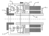
図1、2は、本発明可変トルクモータの構成および作用を示す側断面視の説明図であり、図1は高トルクモード、図2は高速回転モードをそれぞれ示す。これらに示すように本可変トルクモータ10は、減速機により2種類のトルクを同一出力軸から取り出すことのできるモータであり、減速機として不思議遊星歯車機構2を用い、モータ本体9と減速機2との間にクラッチ1を設け、不思議遊星歯車機構2はモータ軸8と一体に回転する太陽歯車3と、太陽歯車3の周りを自転しながら公転する遊星歯車4と、遊星歯車4と噛み合いかつクラッチ1による作用を受ける第二内歯車6と、遊星歯車4と噛み合い第二内歯車6とは歯数が異なっていて出力軸11と一体に回転する第一内歯車5と、および遊星歯車4を収容しかつクラッチ1による作用を受けるキャリア7とからなることを、主たる構成とする。クラッチ1は電磁クラッチ(電磁摩擦クラッチ)とし、図中の符号1wはクラッチ板等、クラッチ作用対象への伝達・遮断作用がなされるクラッチ作用部である。
Hereinafter, the present invention will be described in detail with reference to the drawings.
1 and 2 are explanatory views of a side sectional view showing the configuration and operation of the variable torque motor of the present invention, FIG. 1 shows a high torque mode, and FIG. 2 shows a high speed rotation mode. As shown in these, the
かかる構成の本可変トルクモータ10においては、図1のようにクラッチ1のクラッチ作用部1wが第二内歯車6方向に移動してこれに接続し、それにより第二内歯車6が固定されて停止した状態となっている場合には、遊星歯車4を収容するキャリア7は開放されており、したがって第二内歯車6と噛み合っている遊星歯車4は、自転しつつ、モータ軸8と同期して回転する太陽歯車3の周りを公転する。かかる遊星歯車4の回転は、第二内歯車6とは歯数が異なる第一内歯車5へと伝動され、一体に回転する出力軸11へと出力される。すなわち、モータ軸8の回転は不思議遊星歯車機構2による有効な減速作用を受けて減速され、これによって低速回転高トルクの出力が出力軸11に出力される。
In the
一方、図2に示すようにクラッチ1のクラッチ作用部1wがキャリア7方向に移動してこれに接続し、それによってキャリア7が固定された場合には、遊星歯車4と噛み合う第二内歯車6は開放されており、したがって第二内歯車6と噛み合っている遊星歯車4は、キャリア7が固定されているため、その場で、モータ軸8と同期して回転している太陽歯車3に合わせて自転する。かかる遊星歯車4の回転が第一内歯車5へと伝動され、一体に回転する出力軸11へと出力される。すなわちモータ軸8の回転は、不思議遊星歯車機構2によって減速されることなく、単純な遊星歯車機構として、一体に回転する出力軸11へと出力される。すなわち、モータ軸8の回転は不思議遊星歯車機構2による有効な減速作用を受けずに伝動され、これによって、高速回転低トルクの出力が出力軸11に出力される。出力軸11はモータ軸8とともに高速回転する。
On the other hand, as shown in FIG. 2, when the clutch acting portion 1w of the clutch 1 moves in the direction of the carrier 7 and is connected to the clutch acting portion 1w, and the carrier 7 is fixed thereby, the second
このようにして本可変トルクモータ10では、クラッチ1の動作選択、つまり第二内歯車6を固定するように動作させるか、それともキャリア7を固定するように動作させるか、によって、前者の場合は低速回転高トルクモードで、後者の場合は高速回転低トルクモードで、それぞれ回転出力を得ることができる。すなわち減速機2により、同一出力軸から2種類のトルクを取り出すことができる。よって、高速回転出力が必要な時は不思議遊星歯車機構2と接続せずに単純な遊星歯車機構としてモータ本体9の低減速比出力を利用し、一方、高トルク出力が必要時は、不思議遊星歯車機構2と接続して、高減速比のトルクを得ることができる。
In this way, in the
各図に示すように本可変トルクモータ10のクラッチ1は、そのクラッチ作用部1wが、釈放により第二内歯車6を、吸引によりキャリア7をそれぞれ固定するように構成するものとすることができる。これにより、クラッチ1が釈放の場合は第二内歯車6の固定(キャリア7の解放)がなされて減速機2が有効に作用し、上述の低速回転高トルクモードでの運転がなされ、一方、クラッチ1が吸引の場合はキャリア7の固定(第二内歯車6の解放)がなされて減速機2の減速作用が無効となり、上述の高速回転低トルクモードでの運転がなされる。なお、クラッチ1の釈放―吸引と固定対象のパターンを逆にした場合も、本発明の範囲内である。
As shown in each figure, the
本発明可変トルクモータ10はたとえば、サーボプレスなどボールねじを用いた機構において、モータを高速で回転させて位置決めを行った後に、即、高トルクで加圧するという動作パターンを実行するのに便利である。すなわち、位置決めまでの移動時は、クラッチ作用部1wをキャリア7に接続して減速機2による減速を行わずにモータ本体9におけるモータ軸8の回転を出力軸11に伝動する高速回転低トルクモード、そして位置決め後の加圧動作時は、クラッチ作用部1wを第二内歯車6に接続して減速機2による減速を行って出力軸11に出力する高速回転低トルクモードで本可変トルクモータ10を運転すればよい。
The
各モードでの減速機2のギヤ比は、任意に設計することができる。たとえば、クラッチ1w釈放(第二内歯車6固定)による低速回転高トルクモードでは、第一内歯車5(および出力軸11)における出力を、モータ軸8の1/23.57に減速し、一方、クラッチ1w吸引(キャリア7固定)による高速回転低トルクモードでは、第一内歯車5(および出力軸11)における出力を、モータ軸8の1/1.5に減速する仕様などで、上記の位置決め〜加圧の工程を円滑に実行できることを試験済みである。
The gear ratio of the
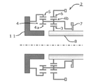
図3は、図1等に示した本発明可変トルクモータに係る減速機部分の拡大図である。図示するように本可変トルクモータ10の減速機である不思議遊星歯車機構2の遊星歯車4は、第一内歯車5に噛み合う第一遊星歯車4aと、第二内歯車6に噛み合う第二遊星歯車4bとが一体構造となっている二段遊星歯車である。すなわち、太陽歯車3が第二遊星歯車4bを回し、その回転を受けて、一体部品となっている第一遊星歯車4aが回転することで、第一内歯車5が回転する。
FIG. 3 is an enlarged view of a speed reducer portion according to the variable torque motor of the present invention shown in FIG. 1 and the like. As shown in the figure, the
本発明可変トルクモータ10のクラッチ1は無励磁作動型とすることができる。従来、停電などによる高速回転時の緊急停止対応としては、無励磁作動型ブレーキを用いることが一般的である。しかし、本可変トルクモータ10の電磁クラッチ1を無励磁作動型とすることにより、停電時にはクラッチ1が釈放される等してクラッチ作用部1wが第二内歯車6に接触してこれを固定し、モータ本体9のモータ軸8は減速機2と接続することになる。すなわちモータ軸8の回転は減速機2による減速作用を受け、モータコギングトルクを利用して停止させることが可能となる。なお、出力軸11の停止トルクは、モータコギングトルクの減速比倍となる。
The
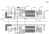
したがって本可変トルクモータ10は、無励磁作動型ブレーキを用いなくても緊急停止することが可能なのであり、上述のいずれかの構成に加えて無励磁作動型ブレーキが備えられていないことをも特徴とする可変トルクモータもまた、本発明の範囲内である。もっとも、図4に示すように無励磁作動型ブレーキBrを備えた構成の可変トルクモータ210であってもよい。組み合わせ機構の簡素化や装置全体の大型化抑制の要請がさほどない場合、2種類のトルクを同一出力軸から取り出すことができ、緊急停止手段たる無励磁作動型クラッチ21のバックアップを備える構成として有意義である。
Therefore, the
なお、クラッチを無励磁作動型とする場合、停電時にはクラッチが吸引される等して第二内歯車6を解放し、減速機構を無効とする作動方式も、本発明の範囲内である。この場合、出力軸11の停止トルクはモータコギングトルクのみとなる。
When the clutch is a non-excitation actuated type, an actuating method in which the second
なおまた、図1等に示すモータのトルク可変構造12もまた、本発明の範囲内である。モータのトルク可変構造12は、上述したいずれかの構成の不思議遊星歯車機構による減速機2とクラッチ1とからなる。クラッチ1の動作により第二内歯車6を固定した場合は低速回転高トルクが出力され、キャリア7を固定した場合は高速回転低トルクが出力され、モータにおいて2種類のトルクを同一出力軸から取り出すことができる。上述の通り、クラッチ1は無励磁作動型とすることができ、この場合は、停電時の出力軸緊急停止が可能である。
Further, the torque variable structure 12 of the motor shown in FIG. 1 and the like is also within the scope of the present invention. The torque variable structure 12 of the motor includes a
本発明の可変トルクモータ、およびモータのトルク可変構造によれば、搭載される装置における組み合わせ機構を簡素化し、全体の大型化を押さえつつ、高速回転低トルク、低速回転高トルクという二種類の出力を一台のモータおよび単一の出力軸によって取り出すことができる上、無励磁作動型ブレーキを用いない緊急停止機構も可能である。したがって、産業用モータを初めとするモータ製造・使用分野、および関連する全分野において、産業上利用性が高い発明である。 According to the variable torque motor of the present invention and the torque variable structure of the motor, two types of outputs, high-speed rotation low torque and low-speed rotation high torque, are simplified by simplifying the combination mechanism in the mounted device and suppressing the overall increase in size. Can be taken out by a single motor and a single output shaft, and an emergency stop mechanism that does not use a non-excitation actuated brake is also possible. Therefore, it is an invention with high industrial applicability in the fields of motor manufacturing and use including industrial motors and all related fields.
1、21…クラッチ
1w、21w…クラッチ作用部
2、22…減速機(不思議遊星歯車機構)
3、23…太陽歯車
4、24…遊星歯車(二段遊星歯車)
4a…第一遊星歯車
4b…第二遊星歯車
5、25…第一内歯車
6、26…第二内歯車
7、27…キャリア
8、28…モータ軸
9、29…モータ本体
10、210…可変トルクモータ
11、211…出力軸
12…トルク可変構造
Br…ブレーキ(無励磁作動型ブレーキ
Rs…レゾルバ(回転検出器)
1, 21 ... Clutch 1w, 21w ... Clutch working
3, 23 ... Sun gears 4, 24 ... Planetary gears (two-stage planetary gears)
4a ... 1st
Claims (7)
減速機として不思議遊星歯車機構を用い、
モータ本体と減速機との間にクラッチを設け、
該不思議遊星歯車機構は
モータ軸と一体に回転する太陽歯車と、
該太陽歯車の周りを自転しながら公転する遊星歯車と、
該遊星歯車と噛み合いかつ該クラッチによる作用を受ける第二内歯車と、
該遊星歯車と噛み合い該第二内歯車とは歯数が異なっていて出力軸と一体に回転する第一内歯車と、
および該遊星歯車を収容しかつ該クラッチによる作用を受けるキャリアとからなり、
該クラッチの動作により該第二内歯車を固定した場合は低速回転高トルクが出力され、該キャリアを固定した場合は高速回転低トルクが出力される
ことを特徴とする、可変トルクモータ。 A variable torque motor that can extract two types of torque from the same output shaft using a speed reducer.
Using a mysterious planetary gear mechanism as a reducer,
A clutch is provided between the motor body and the reducer.
The mysterious planetary gear mechanism consists of a sun gear that rotates integrally with the motor shaft.
A planetary gear that revolves while rotating around the sun gear,
A second internal gear that meshes with the planetary gear and is acted on by the clutch.
A first internal gear that meshes with the planetary gear and has a different number of teeth from the second internal gear and rotates integrally with the output shaft.
And a carrier that houses the planetary gear and is acted upon by the clutch.
A variable torque motor characterized in that low-speed rotation high torque is output when the second internal gear is fixed by the operation of the clutch, and high-speed rotation low torque is output when the carrier is fixed.
不思議遊星歯車機構による減速機と、
クラッチとからなり、
該不思議遊星歯車機構は
モータ軸と一体に回転する太陽歯車と、
該太陽歯車の周りを自転しながら公転する遊星歯車と、
該遊星歯車と噛み合いかつ該クラッチによる作用を受ける第二内歯車と、
該遊星歯車と噛み合い該第二内歯車とは歯数が異なっていて出力軸と一体に回転する第一内歯車と、
および該遊星歯車を収容しかつ該クラッチによる作用を受けるキャリアとからなり、
該遊星歯車は該第一内歯車に噛み合う第一遊星歯車と、該第二内歯車に噛み合う第二遊星歯車とが一体構造となっている二段遊星歯車であり、
該クラッチの動作により該第二内歯車を固定した場合は低速回転高トルクが出力され、該キャリアを固定した場合は高速回転低トルクが出力される
ことを特徴とする、モータのトルク可変構造。 It has a variable torque structure that can extract two types of torque from the same output shaft in the motor.
A reducer with a mysterious planetary gear mechanism,
Consists of a clutch
The mysterious planetary gear mechanism consists of a sun gear that rotates integrally with the motor shaft.
A planetary gear that revolves while rotating around the sun gear,
A second internal gear that meshes with the planetary gear and is acted on by the clutch.
A first internal gear that meshes with the planetary gear and has a different number of teeth from the second internal gear and rotates integrally with the output shaft.
And a carrier that houses the planetary gear and is acted upon by the clutch.
The planetary gear is a two-stage planetary gear in which a first planetary gear that meshes with the first internal gear and a second planetary gear that meshes with the second internal gear have an integral structure.
A variable torque structure of a motor, characterized in that low-speed rotation high torque is output when the second internal gear is fixed by the operation of the clutch, and high-speed rotation low torque is output when the carrier is fixed.
The torque variable structure of the motor according to claim 6, wherein the clutch is a non-excitation actuated type, whereby an emergency stop of the output shaft in the event of a power failure is possible.
Priority Applications (1)
| Application Number | Priority Date | Filing Date | Title |
|---|---|---|---|
| JP2020034394A JP7332108B2 (en) | 2020-02-28 | 2020-02-28 | Variable torque motor and motor torque variable structure |
Applications Claiming Priority (1)
| Application Number | Priority Date | Filing Date | Title |
|---|---|---|---|
| JP2020034394A JP7332108B2 (en) | 2020-02-28 | 2020-02-28 | Variable torque motor and motor torque variable structure |
Publications (2)
| Publication Number | Publication Date |
|---|---|
| JP2021136855A true JP2021136855A (en) | 2021-09-13 |
| JP7332108B2 JP7332108B2 (en) | 2023-08-23 |
Family
ID=77661877
Family Applications (1)
| Application Number | Title | Priority Date | Filing Date |
|---|---|---|---|
| JP2020034394A Active JP7332108B2 (en) | 2020-02-28 | 2020-02-28 | Variable torque motor and motor torque variable structure |
Country Status (1)
| Country | Link |
|---|---|
| JP (1) | JP7332108B2 (en) |
Cited By (2)
| Publication number | Priority date | Publication date | Assignee | Title |
|---|---|---|---|---|
| DE102022133638A1 (en) * | 2022-12-16 | 2024-06-27 | Zf Friedrichshafen Ag | Switchable planetary gear and method for switching the planetary gear |
| JP7618161B2 (en) | 2020-11-25 | 2025-01-21 | 多摩川精機株式会社 | Clutch mechanism for servo motor |
Citations (3)
| Publication number | Priority date | Publication date | Assignee | Title |
|---|---|---|---|---|
| JP2010270907A (en) * | 2009-04-23 | 2010-12-02 | Daiken Co Ltd | Electromagnetic clutch |
| JP2019120316A (en) * | 2018-01-04 | 2019-07-22 | 本田技研工業株式会社 | Transmission mechanism |
| JP2019173772A (en) * | 2018-03-27 | 2019-10-10 | 本田技研工業株式会社 | Rotary electric machine device and vehicle with the same |
-
2020
- 2020-02-28 JP JP2020034394A patent/JP7332108B2/en active Active
Patent Citations (3)
| Publication number | Priority date | Publication date | Assignee | Title |
|---|---|---|---|---|
| JP2010270907A (en) * | 2009-04-23 | 2010-12-02 | Daiken Co Ltd | Electromagnetic clutch |
| JP2019120316A (en) * | 2018-01-04 | 2019-07-22 | 本田技研工業株式会社 | Transmission mechanism |
| JP2019173772A (en) * | 2018-03-27 | 2019-10-10 | 本田技研工業株式会社 | Rotary electric machine device and vehicle with the same |
Cited By (2)
| Publication number | Priority date | Publication date | Assignee | Title |
|---|---|---|---|---|
| JP7618161B2 (en) | 2020-11-25 | 2025-01-21 | 多摩川精機株式会社 | Clutch mechanism for servo motor |
| DE102022133638A1 (en) * | 2022-12-16 | 2024-06-27 | Zf Friedrichshafen Ag | Switchable planetary gear and method for switching the planetary gear |
Also Published As
| Publication number | Publication date |
|---|---|
| JP7332108B2 (en) | 2023-08-23 |
Similar Documents
| Publication | Publication Date | Title |
|---|---|---|
| US9447830B2 (en) | Electric brake actuator for vehicles | |
| CN1866686B (en) | Drive train electric motor with planetary gear system | |
| JPWO2012029756A1 (en) | Multistage reducer | |
| JP2011208681A (en) | Vehicular reduction gear | |
| KR20150023606A (en) | Planetary gear system using two input characteristic and gear module thereof and method for controlling the same | |
| JP6928798B2 (en) | Transmission, drive means with transmission, and methods for operating the drive means | |
| JP2021525349A (en) | Power-shiftable multi-speed transmission | |
| JP2021136855A (en) | Variable torque motor and variable torque structure of the motor | |
| JPS6228549A (en) | Speed reduction gears with driving source | |
| KR20180121407A (en) | Geared transmission unit | |
| JP2020085015A (en) | Gear train of vehicle | |
| JP7365714B2 (en) | Rotary transmission mechanism | |
| CN110966356A (en) | Small tooth difference planetary reducer | |
| JP2012016200A (en) | Cylindrical motor | |
| TW201622313A (en) | Hollow motor module | |
| CN104956004B (en) | The device for revolving and driving of engineering machinery | |
| JP2011153717A (en) | Reduction gear | |
| JP4444894B2 (en) | GEARED MOTOR SERIES AND GEARED MOTOR MANUFACTURING METHOD | |
| JP2022083850A (en) | Servo motor clutch mechanism | |
| JP2020148216A (en) | Mechanical paradox planetary gear reducer, backdrive structure thereof, backdrive method and robot | |
| JP2004291191A (en) | Electric operating device for chuck | |
| TW201833454A (en) | Self-locking type decelerating mechanism capable of eliminating the insufficient positioning precision problem for the apparatus axially connected to a power-output end without using an additional braking device | |
| CN105387147A (en) | Micro planetary reducer used on dial linking machine | |
| CN223105212U (en) | A new transmission structure of large speed ratio transmission | |
| JP2006034366A (en) | Toilet seat device |
Legal Events
| Date | Code | Title | Description |
|---|---|---|---|
| A621 | Written request for application examination |
Free format text: JAPANESE INTERMEDIATE CODE: A621 Effective date: 20221116 |
|
| TRDD | Decision of grant or rejection written | ||
| A977 | Report on retrieval |
Free format text: JAPANESE INTERMEDIATE CODE: A971007 Effective date: 20230712 |
|
| A01 | Written decision to grant a patent or to grant a registration (utility model) |
Free format text: JAPANESE INTERMEDIATE CODE: A01 Effective date: 20230802 |
|
| A61 | First payment of annual fees (during grant procedure) |
Free format text: JAPANESE INTERMEDIATE CODE: A61 Effective date: 20230802 |
|
| R150 | Certificate of patent or registration of utility model |
Ref document number: 7332108 Country of ref document: JP Free format text: JAPANESE INTERMEDIATE CODE: R150 |