JP2021136831A - Vehicle and charging system - Google Patents
Vehicle and charging system Download PDFInfo
- Publication number
- JP2021136831A JP2021136831A JP2020033528A JP2020033528A JP2021136831A JP 2021136831 A JP2021136831 A JP 2021136831A JP 2020033528 A JP2020033528 A JP 2020033528A JP 2020033528 A JP2020033528 A JP 2020033528A JP 2021136831 A JP2021136831 A JP 2021136831A
- Authority
- JP
- Japan
- Prior art keywords
- charging
- power
- inlet
- storage device
- control unit
- Prior art date
- Legal status (The legal status is an assumption and is not a legal conclusion. Google has not performed a legal analysis and makes no representation as to the accuracy of the status listed.)
- Granted
Links
Images


Classifications
-
- B—PERFORMING OPERATIONS; TRANSPORTING
- B60—VEHICLES IN GENERAL
- B60L—PROPULSION OF ELECTRICALLY-PROPELLED VEHICLES; SUPPLYING ELECTRIC POWER FOR AUXILIARY EQUIPMENT OF ELECTRICALLY-PROPELLED VEHICLES; ELECTRODYNAMIC BRAKE SYSTEMS FOR VEHICLES IN GENERAL; MAGNETIC SUSPENSION OR LEVITATION FOR VEHICLES; MONITORING OPERATING VARIABLES OF ELECTRICALLY-PROPELLED VEHICLES; ELECTRIC SAFETY DEVICES FOR ELECTRICALLY-PROPELLED VEHICLES
- B60L53/00—Methods of charging batteries, specially adapted for electric vehicles; Charging stations or on-board charging equipment therefor; Exchange of energy storage elements in electric vehicles
- B60L53/10—Methods of charging batteries, specially adapted for electric vehicles; Charging stations or on-board charging equipment therefor; Exchange of energy storage elements in electric vehicles characterised by the energy transfer between the charging station and the vehicle
- B60L53/14—Conductive energy transfer
- B60L53/16—Connectors, e.g. plugs or sockets, specially adapted for charging electric vehicles
-
- B—PERFORMING OPERATIONS; TRANSPORTING
- B60—VEHICLES IN GENERAL
- B60K—ARRANGEMENT OR MOUNTING OF PROPULSION UNITS OR OF TRANSMISSIONS IN VEHICLES; ARRANGEMENT OR MOUNTING OF PLURAL DIVERSE PRIME-MOVERS IN VEHICLES; AUXILIARY DRIVES FOR VEHICLES; INSTRUMENTATION OR DASHBOARDS FOR VEHICLES; ARRANGEMENTS IN CONNECTION WITH COOLING, AIR INTAKE, GAS EXHAUST OR FUEL SUPPLY OF PROPULSION UNITS IN VEHICLES
- B60K1/00—Arrangement or mounting of electrical propulsion units
- B60K1/04—Arrangement or mounting of electrical propulsion units of the electric storage means for propulsion
-
- B—PERFORMING OPERATIONS; TRANSPORTING
- B60—VEHICLES IN GENERAL
- B60L—PROPULSION OF ELECTRICALLY-PROPELLED VEHICLES; SUPPLYING ELECTRIC POWER FOR AUXILIARY EQUIPMENT OF ELECTRICALLY-PROPELLED VEHICLES; ELECTRODYNAMIC BRAKE SYSTEMS FOR VEHICLES IN GENERAL; MAGNETIC SUSPENSION OR LEVITATION FOR VEHICLES; MONITORING OPERATING VARIABLES OF ELECTRICALLY-PROPELLED VEHICLES; ELECTRIC SAFETY DEVICES FOR ELECTRICALLY-PROPELLED VEHICLES
- B60L53/00—Methods of charging batteries, specially adapted for electric vehicles; Charging stations or on-board charging equipment therefor; Exchange of energy storage elements in electric vehicles
- B60L53/10—Methods of charging batteries, specially adapted for electric vehicles; Charging stations or on-board charging equipment therefor; Exchange of energy storage elements in electric vehicles characterised by the energy transfer between the charging station and the vehicle
- B60L53/14—Conductive energy transfer
- B60L53/18—Cables specially adapted for charging electric vehicles
-
- B—PERFORMING OPERATIONS; TRANSPORTING
- B60—VEHICLES IN GENERAL
- B60L—PROPULSION OF ELECTRICALLY-PROPELLED VEHICLES; SUPPLYING ELECTRIC POWER FOR AUXILIARY EQUIPMENT OF ELECTRICALLY-PROPELLED VEHICLES; ELECTRODYNAMIC BRAKE SYSTEMS FOR VEHICLES IN GENERAL; MAGNETIC SUSPENSION OR LEVITATION FOR VEHICLES; MONITORING OPERATING VARIABLES OF ELECTRICALLY-PROPELLED VEHICLES; ELECTRIC SAFETY DEVICES FOR ELECTRICALLY-PROPELLED VEHICLES
- B60L53/00—Methods of charging batteries, specially adapted for electric vehicles; Charging stations or on-board charging equipment therefor; Exchange of energy storage elements in electric vehicles
- B60L53/60—Monitoring or controlling charging stations
-
- H—ELECTRICITY
- H01—ELECTRIC ELEMENTS
- H01R—ELECTRICALLY-CONDUCTIVE CONNECTIONS; STRUCTURAL ASSOCIATIONS OF A PLURALITY OF MUTUALLY-INSULATED ELECTRICAL CONNECTING ELEMENTS; COUPLING DEVICES; CURRENT COLLECTORS
- H01R13/00—Details of coupling devices of the kinds covered by groups H01R12/70 or H01R24/00 - H01R33/00
- H01R13/62—Means for facilitating engagement or disengagement of coupling parts or for holding them in engagement
- H01R13/639—Additional means for holding or locking coupling parts together, after engagement, e.g. separate keylock, retainer strap
- H01R13/6397—Additional means for holding or locking coupling parts together, after engagement, e.g. separate keylock, retainer strap with means for preventing unauthorised use
-
- H02J7/751—
-
- H—ELECTRICITY
- H01—ELECTRIC ELEMENTS
- H01R—ELECTRICALLY-CONDUCTIVE CONNECTIONS; STRUCTURAL ASSOCIATIONS OF A PLURALITY OF MUTUALLY-INSULATED ELECTRICAL CONNECTING ELEMENTS; COUPLING DEVICES; CURRENT COLLECTORS
- H01R2201/00—Connectors or connections adapted for particular applications
- H01R2201/26—Connectors or connections adapted for particular applications for vehicles
-
- H02J7/685—
-
- Y—GENERAL TAGGING OF NEW TECHNOLOGICAL DEVELOPMENTS; GENERAL TAGGING OF CROSS-SECTIONAL TECHNOLOGIES SPANNING OVER SEVERAL SECTIONS OF THE IPC; TECHNICAL SUBJECTS COVERED BY FORMER USPC CROSS-REFERENCE ART COLLECTIONS [XRACs] AND DIGESTS
- Y02—TECHNOLOGIES OR APPLICATIONS FOR MITIGATION OR ADAPTATION AGAINST CLIMATE CHANGE
- Y02T—CLIMATE CHANGE MITIGATION TECHNOLOGIES RELATED TO TRANSPORTATION
- Y02T10/00—Road transport of goods or passengers
- Y02T10/60—Other road transportation technologies with climate change mitigation effect
- Y02T10/70—Energy storage systems for electromobility, e.g. batteries
-
- Y—GENERAL TAGGING OF NEW TECHNOLOGICAL DEVELOPMENTS; GENERAL TAGGING OF CROSS-SECTIONAL TECHNOLOGIES SPANNING OVER SEVERAL SECTIONS OF THE IPC; TECHNICAL SUBJECTS COVERED BY FORMER USPC CROSS-REFERENCE ART COLLECTIONS [XRACs] AND DIGESTS
- Y02—TECHNOLOGIES OR APPLICATIONS FOR MITIGATION OR ADAPTATION AGAINST CLIMATE CHANGE
- Y02T—CLIMATE CHANGE MITIGATION TECHNOLOGIES RELATED TO TRANSPORTATION
- Y02T10/00—Road transport of goods or passengers
- Y02T10/60—Other road transportation technologies with climate change mitigation effect
- Y02T10/7072—Electromobility specific charging systems or methods for batteries, ultracapacitors, supercapacitors or double-layer capacitors
-
- Y—GENERAL TAGGING OF NEW TECHNOLOGICAL DEVELOPMENTS; GENERAL TAGGING OF CROSS-SECTIONAL TECHNOLOGIES SPANNING OVER SEVERAL SECTIONS OF THE IPC; TECHNICAL SUBJECTS COVERED BY FORMER USPC CROSS-REFERENCE ART COLLECTIONS [XRACs] AND DIGESTS
- Y02—TECHNOLOGIES OR APPLICATIONS FOR MITIGATION OR ADAPTATION AGAINST CLIMATE CHANGE
- Y02T—CLIMATE CHANGE MITIGATION TECHNOLOGIES RELATED TO TRANSPORTATION
- Y02T90/00—Enabling technologies or technologies with a potential or indirect contribution to GHG emissions mitigation
- Y02T90/10—Technologies relating to charging of electric vehicles
- Y02T90/12—Electric charging stations
-
- Y—GENERAL TAGGING OF NEW TECHNOLOGICAL DEVELOPMENTS; GENERAL TAGGING OF CROSS-SECTIONAL TECHNOLOGIES SPANNING OVER SEVERAL SECTIONS OF THE IPC; TECHNICAL SUBJECTS COVERED BY FORMER USPC CROSS-REFERENCE ART COLLECTIONS [XRACs] AND DIGESTS
- Y02—TECHNOLOGIES OR APPLICATIONS FOR MITIGATION OR ADAPTATION AGAINST CLIMATE CHANGE
- Y02T—CLIMATE CHANGE MITIGATION TECHNOLOGIES RELATED TO TRANSPORTATION
- Y02T90/00—Enabling technologies or technologies with a potential or indirect contribution to GHG emissions mitigation
- Y02T90/10—Technologies relating to charging of electric vehicles
- Y02T90/14—Plug-in electric vehicles
Landscapes
- Engineering & Computer Science (AREA)
- Transportation (AREA)
- Mechanical Engineering (AREA)
- Power Engineering (AREA)
- Computer Security & Cryptography (AREA)
- Chemical & Material Sciences (AREA)
- Combustion & Propulsion (AREA)
- Charge And Discharge Circuits For Batteries Or The Like (AREA)
- Electric Propulsion And Braking For Vehicles (AREA)
- Secondary Cells (AREA)
- Hybrid Electric Vehicles (AREA)
- Details Of Connecting Devices For Male And Female Coupling (AREA)
Abstract
【課題】充電中に充電コネクタがアンロック状態であることが検知されると短時間で、出力電流を下げることができる車両または充電システムを提供する。【解決手段】充電システム1において、車両2は、充電ステーション3に設けられた充電コネクタ31と接続可能に構成されたインレット11と、充電コネクタ31をインレット11にロックするロック状態と、充電コネクタ31をインレット11から取り外し可能なアンロック状態との切り替えが可能なロック装置15と、充電コネクタ31を通して供給される電力によって充電される蓄電装置13と、蓄電装置13の充電を制御する制御装置10とを備える。充電コネクタ31がインレット11に接続され、蓄電装置13が充電されている状態において、制御装置10は、ロック装置15がアンロック状態となると充電を停止する。【選択図】図1A vehicle or charging system capable of reducing output current in a short period of time when it is detected that a charging connector is in an unlocked state during charging. In a charging system (1), a vehicle (2) includes an inlet (11) configured to be connectable to a charging connector (31) provided in a charging station (3), a locked state in which the charging connector (31) is locked to the inlet (11), and a charging connector (31). can be removed from the inlet 11 and can be switched to an unlocked state, a power storage device 13 charged with power supplied through a charging connector 31, and a control device 10 controlling charging of the power storage device 13 Prepare. In a state where charging connector 31 is connected to inlet 11 and power storage device 13 is being charged, control device 10 stops charging when locking device 15 is in an unlocked state. [Selection drawing] Fig. 1
Description
本開示は、車両および充電システムに関する。 The present disclosure relates to vehicles and charging systems.
従来から充電ステーションから供給される電力で蓄電装置を充電することができる車両について各種提案されている。 Conventionally, various proposals have been made for vehicles capable of charging the power storage device with the electric power supplied from the charging station.
たとえば、特開2019−47544号公報に記載された車両は、充電ステーションの充電コネクタが接続されるインレットと、充電コネクタをインレットにロックするロック装置と、蓄電装置とを備える。 For example, the vehicle described in Japanese Patent Application Laid-Open No. 2019-47544 includes an inlet to which the charging connector of the charging station is connected, a lock device for locking the charging connector to the inlet, and a power storage device.
車両は、充電コネクタがインレットに接続され、蓄電装置が充電されている状態において、充電コネクタがインレットにロックされているときには、充電ステーションに第1電流値の電流を要求する。 The vehicle requests a current of the first current value from the charging station when the charging connector is locked to the inlet while the charging connector is connected to the inlet and the power storage device is charged.
車両は、充電コネクタがインレットに接続され、蓄電装置が充電されている状態において、充電コネクタがインレットにロックされていないアンロック状態のときには、第2電流値の電流を充電ステーションに要求する。第2電流値は、第1電流値よりも小さい。 The vehicle requests the charging station for a second current value when the charging connector is connected to the inlet and the power storage device is charged and the charging connector is unlocked when the inlet is not locked. The second current value is smaller than the first current value.
上記の車両は、アンロック状態を検知すると、充電ステーションへの要求電流値を小さくしている。 When the above-mentioned vehicle detects the unlocked state, the required current value to the charging station is reduced.
充電ステーションは、車両に供給する出力電力をフィードバック制御によってコントロールしている。ここで、車両からの要求電流値(要求電力値)が変動した際に、出力電力を急峻に変化させると、出力電流(出力電力)がハンチング、オーバーシュートまたはアンダーシュートするおそれがある。 The charging station controls the output power supplied to the vehicle by feedback control. Here, if the output power is suddenly changed when the required current value (required power value) from the vehicle fluctuates, the output current (output power) may hunt, overshoot, or undershoot.
そのため、充電ステーションは、出力する出力電力を車両からの要求電流値(要求電力値)に追従させるために要する追従時間は長い。 Therefore, the charging station takes a long time to follow the output power output from the vehicle to the required current value (required power value) from the vehicle.
その結果、充電中にアンロック状態であることを車両が検知して、充電ステーションが出力電流の電流値を第1電流値から第2電流値に変更するまでに所定時間を要することになる。 As a result, it takes a predetermined time for the vehicle to detect that the vehicle is in the unlocked state during charging and for the charging station to change the current value of the output current from the first current value to the second current value.
その一方で、充電コネクタがアンロック状態である場合には、充電コネクタが抜かれる可能性があるために、短時間で充電ステーションから出力される電流を下げることが求められる。 On the other hand, when the charging connector is in the unlocked state, the charging connector may be pulled out, so that it is required to reduce the current output from the charging station in a short time.
本開示は、上記のような課題に鑑みてなされたものであって、その目的は、充電中に充電コネクタがアンロック状態であることが検知されると短時間で、出力電流を下げることができる車両および充電システムを提供することである。 The present disclosure has been made in view of the above problems, and an object thereof is to reduce the output current in a short time when it is detected that the charging connector is unlocked during charging. It is to provide a vehicle and a charging system that can be used.
本開示に係る車両は、充電ステーションに設けられた充電コネクタと接続可能に構成されたインレットと、充電コネクタをインレットにロックするロック状態と、充電コネクタをインレットから取り外し可能なアンロック状態との切り替えが可能なロック装置と、充電コネクタを通して供給される電力によって充電される蓄電装置と、蓄電装置の充電を制御する制御装置とを備え、充電コネクタがインレットに接続され、蓄電装置が充電されている状態において、制御装置は、ロック装置がアンロック状態となると充電を停止する。 The vehicle according to the present disclosure is switched between an inlet configured to be connectable to a charging connector provided in a charging station, a locked state in which the charging connector is locked to the inlet, and an unlocked state in which the charging connector can be removed from the inlet. A lock device capable of charging, a power storage device charged by power supplied through a charging connector, and a control device for controlling charging of the power storage device are provided, the charging connector is connected to an inlet, and the power storage device is charged. In the state, the control device stops charging when the locking device is in the unlocked state.
上記車両は、充電コネクタから供給される入力電力が入力され、入力された入力電力を調整して蓄電装置に出力電力を出力する充電器をさらに備え、充電器は、制御装置から入力される要求電力に近づけるように出力電力をフィードバック制御しており、充電器は、充電を停止するときには、フィードバック制御をしない。 The vehicle further includes a charger in which the input power supplied from the charging connector is input, the input input power is adjusted, and the output power is output to the power storage device, and the charger is a request input from the control device. The output power is feedback-controlled so as to approach the power, and the charger does not perform feedback control when charging is stopped.
上記車両は、充電コネクタから供給される入力電力が入力され、入力された入力電力を調整して蓄電装置に出力電力を出力する充電器をさらに備え、充電器は、出力電力が制御装置から入力される要求電力となるように駆動しており、制御装置が充電を停止させる際において充電器が出力電力を変化させる変化率は、出力電力が要求電力となるように充電器が出力電力を変化させる変化率よりも高い。 The vehicle further includes a charger in which the input power supplied from the charging connector is input, the input power is adjusted, and the output power is output to the power storage device. The charger is provided with the output power input from the control device. It is driven so as to be the required power, and the rate of change in which the charger changes the output power when the control device stops charging is such that the charger changes the output power so that the output power becomes the required power. Higher than the rate of change to make.
上記制御装置は、ロック装置がアンロック状態の場合に充電を停止し、停止してから所定期間経過した後に、蓄電装置への充電を再開する。 The control device stops charging when the lock device is in the unlocked state, and resumes charging the power storage device after a predetermined period of time has elapsed since the stop.
上記蓄電装置への充電を再開したときにおける第1充電電力は、蓄電装置への充電を停止する前における第2充電電力よりも小さい。 The first charging power when charging the power storage device is restarted is smaller than the second charging power before stopping charging of the power storage device.
充電システムは、充電コネクタが設けられた充電ステーションと、車両と、を備えた充電システムであって、車両は、充電コネクタが接続されるインレットと、インレットに接続された充電コネクタをインレットにロックされたロック状態と、インレットに接続された充電コネクタがインレットから取り外し可能なアンロック状態とに切り替え可能なケーブルロック装置と、充電コネクタから供給される電力で充電可能な蓄電装置と、蓄電装置の充電を制御する制御装置と、を含み、制御装置は、充電コネクタがインレットに接続され、蓄電装置が充電されている状態において、制御装置は、ケーブルロック装置がアンロック状態となると充電を停止する。 The charging system is a charging system including a charging station provided with a charging connector and a vehicle, and the vehicle locks the inlet to which the charging connector is connected and the charging connector connected to the inlet to the inlet. A cable lock device that can switch between a locked state and an unlocked state in which the charging connector connected to the inlet can be removed from the inlet, a power storage device that can be charged with the power supplied from the charging connector, and charging of the power storage device. In the state where the charging connector is connected to the inlet and the power storage device is charged, the control device stops charging when the cable lock device is unlocked.
本開示に係る車両および充電システムによれば、充電中に充電コネクタがアンロック状態であることが検知されると短時間で、出力電流を下げることができる。 According to the vehicle and the charging system according to the present disclosure, the output current can be reduced in a short time when it is detected that the charging connector is in the unlocked state during charging.
図1から図13を用いて、本実施の形態に係る車両2および充電システム1について説明する。図1から図13に示す構成のうち、同一または実質的に同一の構成については、同一の符号を付して重複した説明を省略する。
(実施の形態1)
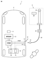
図1は、本実施の形態1に係る充電システム1を模式的に示すブロック図である。充電システム1は、車両2と、充電ステーション3とを備える。車両2は、制御部10と、インレット11と、充電器12と、蓄電装置13と、ロック装置15と、バッテリECU17とを備える。
The
(Embodiment 1)
FIG. 1 is a block diagram schematically showing a
インレット11は、充電ステーション3に設けられた充電コネクタ31が接続される接続部である。なお、車両2には、蓋16が設けられており、蓋16を開けることで、インレット11が外部に露出し、充電コネクタ31を接続することができる。
The
充電器12は、たとえば、AC/DCコンバータなどの変換器である。充電器12は、インレット11を通して、供給される交流電力を直流電力に変換して、蓄電装置13に供給する。
The
蓄電装置13は、リチウムイオン電池などの二次電池、または、キャパシタなどである。蓄電装置13は、図示されていない駆動用インバータなどに電力を供給し、駆動用インバータは、蓄電装置13から供給された直流電力を交流電力に変換して、駆動モータに供給する。駆動モータは、駆動輪を駆動する駆動力を発生する。
The
制御部10は、充電器12などの駆動を制御するECUである。制御部10は、制御部18および制御部19を含む。車両2および充電ステーション3は、充電コネクタ31がインレット11に接続されている状態において、充電ケーブル30および充電コネクタ31を通して、互いに通信することができる。このため、制御部10は、充電ケーブル30および充電コネクタ31を通して、充電ステーション3と各種情報の授受が可能となっている。
The
充電ステーション3は、制御装置20と、充電ケーブル30と、充電コネクタ31と、CCID(Charging Circuit Interrupt Device)32と、電源部33とを含む。CCID32は、インレット11および電源部33の間の電気的な接続を切り替える装置である。
The
CCID32は、図示しないコントロールパイロット回路およびリレーを含む。コントロールパイロット回路は、発信回路を含み、充電コネクタ31がインレット11に接続されると、パルス幅(デューティーサイクル)のパイロット信号CPLTを発振する。パイロット信号CPLTのパルス幅により、供給可能な電流容量がプラグインハイブリッド車に通知される。
CCID 32 includes a control pilot circuit and relay (not shown). The control pilot circuit includes a transmission circuit, and when the
CCID32に設けられたリレーは、充電コネクタ31がインレット11に接続されることでONとなり、インレット11に充電コネクタ31が接続されたことを示すコネクタ信号PISWが制御部10に入力される。
The relay provided in the
図2は、インレット11および充電コネクタ31を模式的に示す斜視図である。インレット11は、筒状に形成された筒部35と、筒部35内に収容された複数の電力端子と、接地端子と、複数の通信端子とを含む。筒部35の外周面には、係合部34が形成されている。ロック装置15は、筒部35の上方に配置されている。ロック装置15は、駆動部40と、押圧ピン41と、押圧力検出センサ42とを含む。
FIG. 2 is a perspective view schematically showing the
駆動部40は、押圧ピン41を上下方向に移動させる。押圧力検出センサ42は、押圧ピン41の下端部に設けられている。
The
充電コネクタ31は、筐体45と、操作スイッチ46と、爪47と、ピン48と、筒部49とを含む。筐体45は充電作業者が把持可能なように形成されている。筐体45の上面には操作スイッチ46が設けられており、筐体45の先端部に爪47および筒部49が設けられている。
The charging
筒部49は筒状に形成されており、筒部35と嵌合するように形成されている。筒部49内には複数の電力端子、接地端子、通信端子が設けられており、筒部49が筒部35に嵌合することで、各電力端子同士、接地端子同士および通信端子同士が接続される。
The
筒部49を筒部35に嵌合させると、爪47が係合部34と係合する。これにより、充電コネクタ31がインレット11に接続される。
When the
なお、爪47および係合部34に係合状態を解除する場合には、操作スイッチ46を押す。操作スイッチ46を押すことで、爪47がピン48を中心に回転して、爪47が上方に移動する。これにより、爪47および係合部34の係合状態が解除される。
When disengaging the
図3は、ロック装置15が充電コネクタ31をインレット11にロックした状態を模式的に示す断面図である。
FIG. 3 is a cross-sectional view schematically showing a state in which the
充電コネクタ31がインレット11に接続されると、制御部10はCCID32からのコネクタ信号PISWを取得し、制御部10は充電コネクタ31が接続されたことを検知する。
When the charging
制御部10は、コネクタ信号PISWを受信した後、充電を開始する前に、駆動部40を駆動させて押圧ピン41を下方に移動させる。インレット11に充電コネクタ31が接続された状態で押圧ピン41が下方に移動すると、押圧ピン41は爪47を押圧する。これにより、操作スイッチ46が操作されたとしても爪47および係合部34の係合状態が維持される。
After receiving the connector signal PISW, the
押圧力検出センサ42は、押圧ピン41の下端部に設けられており、押圧ピン41が爪47を押圧する際には、押圧力検出センサ42も爪47に接触する。押圧力検出センサ42が爪47に接触すると、押圧力検出センサ42は制御部19に接触信号「ON」を送信する。制御部19は、押圧力検出センサ42から接触信号を受信すると、ロック状態であると判断する。
The pressing
図4は、充電コネクタ31およびインレット11がアンロック状態における側断面図である。たとえば、制御部10は、蓄電装置13の充電が完了すると、駆動部40を駆動させて押圧ピン41を上方に移動させる。これにより、操作スイッチ46を操作することで、爪47および係合部34の係合状態を解除することができる。押圧ピン41が上方に移動することで、押圧力検出センサ42は爪47から離れる。押圧力検出センサ42が爪47から離れると、押圧力検出センサ42は、制御部19に接触信号「OFF」を送信する。制御部19は、コネクタ信号PISWを受信しており、押圧力検出センサ42から接触信号「OFF」を受信すると、制御部19は、充電コネクタ31はアンロック状態であると判断する。その一方で、コネクタ信号PISWを受信しなくなると、制御部19は充電コネクタ31が接続されていないと判断する。
FIG. 4 is a side sectional view of the charging
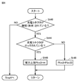
図5は、充電システム1を模式的に示すブロック図である。図6は、充電を開始してから充電を完了するまでの間のフローを示すフロー図である。図6に示すように、充電システム1が充電開始から終了するまでのフローは、充電開始制御(Step1)と、充電中制御(Step2)と、充電が完了したかを判断するステップ(Step3)と、充電を停止するステップ(Step4)とを含む。なお、図6など中において、「St」は「Step」を示す。
FIG. 5 is a block diagram schematically showing the
図5を用いて、充電開始制御について説明する。制御部10は、制御部18および制御部19を含む。制御部19は、パイロット信号CPLTのパルス幅から充電ケーブル30の定格電流を取得する。制御部19は、CCID32からのコネクタ信号PISWに基づいて、充電コネクタ31がインレット11に接続されたことを検知する。制御部19は、ロック装置15からロック状態またはアンロック状態を示す状態信号を取得する。そして、制御部19は、充電ケーブル30の定格電流と、充電コネクタ31の接続状態と、充電コネクタ31のロック状態とを示す情報を制御部18に送信する。
Charging start control will be described with reference to FIG. The
制御部18は、充電コネクタ31がインレット11に接続されると、充電ステーション3の制御装置20と通信確立して、制御装置20との間で各種の情報を授受する。
When the charging
制御装置20は、たとえば、電源部33が家庭用電源である場合においては、制御装置20は当該家などに設けられた他の電気機器からの要求電力などに基づいて、入力上限電力値Plim1を設定する。入力上限電力値Plim1は、電源部33が車両2に供給する電力の上限値である。入力上限電力値Plim1を制御部18に送信する。
For example, when the
バッテリECU17は、蓄電装置13に設けられた温度センサから蓄電装置13の温度を取得する。さらに、バッテリECU17は、蓄電装置13に入出力する電流量および温度などの情報から蓄電装置13のSOCを算出する。また、バッテリECU17は、蓄電装置13のSOCおよび温度から蓄電装置13を充電することができる上限電力値Plim2を算出する。上限電力値Plim2は、たとえば、充電中において、蓄電装置13が所定の閾値温度を超えないようにするための上限値である。
The
そして、バッテリECU17は、制御部18に、蓄電装置13のSOCおよび上限電力値Plim2を示す情報を送信する。
Then, the
制御部18は、入力上限電力値Plim1および上限電力値Plim2の小さい方を上限電力値Pli mfに設定する。
The
制御部18は、蓄電装置13の現状のSOCと、上限電力値Plimfと、充電ケーブル30の定格電流などに基づいて、要求電力Preqを算出する。
The
制御部18は、充電コネクタ31がインレット11に接続されており、充電コネクタ31がロック状態であると、CCID32をONにする。
The
制御部18は、充電器12に「ON」の充電要求Creqを送信し、さらに、要求電力Preqおよび上限電力値Plimfを送信する。
The
充電器12は、「ON」の充電要求Creqを受信すると起動する。そして、制御部18から受信した要求電力Preqおよび上限電力値Plimfに基づいて、蓄電装置13に電力を供給する。具体的には、充電器12から蓄電装置13に出力される出力電力Poutが要求電力Preqとなるように制御すると共に、出力電力Poutが上限電力値Plimfを超えないように制御する。
The
次に、図7を用いて、充電開始後における充電制御フローについて説明する。図7は、充電を開始した後における充電制御フローを示すフロー図である。 Next, the charge control flow after the start of charging will be described with reference to FIG. 7. FIG. 7 is a flow chart showing a charge control flow after charging is started.
制御装置20は、入力上限電力値Plim1を設定する(Step10)。たとえば、家の電気機器からの要求電力が上昇した場合には、入力上限電力値Plim1が小さくなるように設定する。
The
バッテリECU17は、蓄電装置13から取得した現状のSOCおよび蓄電装置13の温度などから上限電力値Plim2を設定する。たとえば、蓄電装置13の温度が所定閾値温度よりも高くなると、小さい上限電力値Plim2を設定する(Step12)。
The
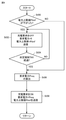
制御部19は、上限電力値Plim3を設定する(Step14)。図8は、上限電力値Plim3を設定するフローを示すフロー図である。
The
制御部19は、充電コネクタ31がインレット11に接続されているか否かを判断する(Step40)。具体的には、制御部19は、CCID32からのコネクタ信号PISWに基づいて、充電コネクタ31がインレット11に接続されているか否かを判断する。
The
制御部19は、充電コネクタ31が接続されていないと判断すると(Step40にてNo)、図4に示すStep4に移行し、充電停止させる(Step4)。具体的には、制御部19は、充電器12の駆動を停止させる。さらに、充電器12および蓄電装置13の間に充電リレーが設けられている場合には、当該充電リレーをOFFにする。このような場合においては、充電中に充電コネクタ31が引き抜かれた可能性が高い。この際、インレット11の電力端子36,37には、蓄電装置13の電圧が印加されている状態であるため、制御部19は、直ぐに、充電リレーをOFFにする。さらに、充電器12をOFFとして、電力端子36,37および蓄電装置13の間の電気的な接続を切断する。
When the
図8において、制御部19は、充電コネクタ31が接続されていると判断すると(Step40にてYes)、制御部19は、ロック装置15が充電コネクタ31をロックしているかを判断する(Step44)。制御部19は、ロック装置15からロック状態またはアンロック状態を示す信号を受信している。ロック装置15は、押圧ピン41が上方に位置している場合には、制御部19にアンロック状態であることを示す信号を送信する。
In FIG. 8, when the
また、ロック装置15は、駆動部40が故障したと判断すると、制御部19にアンロック状態であることを示す信号を送信するようにしてもよい。
Further, when the
制御部19は、ロック装置15が充電コネクタ31をロックしているロック状態であると判断すると(Step44にてYes)、制御部19は、上限電力値Plim3をたとえば、「∞」に設定する(Step46)。その一方で、制御部19は、充電コネクタ31がアンロック状態であると判断すると(Step44にてNo)、制御部19は、上限電力値Plim3にPlim30を設定する(Step48)。なお、上限電力値Plim30は、通常の状態における入力上限電力値Plim1および上限電力値Plim2よりも小さい値である。
When the
図7に戻って、制御部18は、制御装置20に入力上限電力値Plim1を要求する(Step16)。制御装置20は、制御部18から要求信号を受信すると、入力上限電力値Plim1を送信する(Step18)。制御部18はバッテリECU17に上限電力値Plim2を含むパラメータを要求する要求信号を送信する(Step20)。バッテリECU17は、制御部18から要求信号を受信すると、バッテリECU17は、制御部18に上限電力値Plim2および蓄電装置13のSOCを示す情報を送信する(Step22)。
Returning to FIG. 7, the
制御部18は、制御部19に上限電力値Plim3を要求する(Step24)。制御部19は、制御部18からの要求信号を受信すると、制御部19は制御部18に上限電力値Plim3を送信する。制御部18は、上限電力値Plimfを設定する(Step28)。具体的には、制御部18は、取得した入力上限電力値Plim1、上限電力値Plim2および上限電力値Plim3のうち、最も小さい値を上限電力値Plimfに設定する。
The
制御部18は、上限電力値Plimfを設定すると、充電パラメータを送信する(Step30)。充電パラメータは、充電要求Creq、要求電力Preqおよび上限電力値Plimfの少なくとも1つを含む情報である。
When the upper limit power value Plimf is set, the
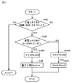
図9は、充電パラメータを送信するステップを詳細に示すフロー図である。図10は、充電器12が受信した上限電力値Plimfと、充電要求Creqと、要求電力Preqと、充電器12が出力する出力電力Poutとを示す状態線図である。
FIG. 9 is a flow chart showing in detail the steps of transmitting charging parameters. FIG. 10 is a state diagram showing the upper limit power value Plimf received by the
制御部18は、上限電力値Plimfが下がったか否かを判断する(Step50)。ここで、図8に示すStep48において、充電コネクタ31がロック装置15によってロックされていると判断した場合には、上限電力値Plim3は、「∞(W)」に設定されている。これにより、図7に示すStep28において、上限電力値Plimfは、入力上限電力値Plim1または上限電力値Plim2のいずれが小さい方に設定されることになる。換言すれば、入力上限電力値Plim1および上限電力値Plim2が変動していない場合には、上限電力値Plimfは変動しない。
The
このような場合においては、Step50において、制御部18は上限電力値Plimfは変動していないと判断する(Step50にてNo)。
In such a case, in Step 50, the
要求電力Preqを算出する(Step56)。具体的には、バッテリECU17から受信した現状のSOCと、蓄電装置13の温度と、充電ケーブル30の定格電流と、上限電力値Plimfなどから要求電力Preqを算出する。ここで、要求電力Preqは、上限電力値Plimf以下となるように設定される。
The required power Preq is calculated (Step 56). Specifically, the required power Preq is calculated from the current SOC received from the
制御部18は、算出した要求電力Preqと、「ON」の充電要求Creqと、上限電力値Plimfとを充電器12に送信する(Step58)。
The
たとえば、図10において、時刻T0から時刻T1においては、上限電力値Plimf、要求電力Preqおよび出力電力Poutは一定に維持されており、充電要求Creqが「ON」に維持されている。 For example, in FIG. 10, from time T0 to time T1, the upper limit power value Plimf, the required power Preq, and the output power Pout are kept constant, and the charging request Creq is kept “ON”.
図8に示すStep48において、上限電力値Plim3に「Plim30」が設定されると、上限電力値Plimfは「Plim30」となり、上限電力値Plimfは小さくなる。なお、Plim30は、通常の入力上限電力値Plim1および上限電力値Plim2よりも遥かに小さい値に設定されている。なお、通常の入力上限電力値Plim1とは、家の電気機器からの要求電力が所定電力よりも小さい状態において、設定される入力上限電力値である。また、通常の上限電力値Plim2とは、たとえば、蓄電装置13の温度が閾値温度よりも小さく、SOCがたとえば、80%よりも小さいときに設定される上限電力値である。
In
そして、制御部18は、図9において、上限電力値Plimfが小さくなったと判断すると(Step50にてYes)、制御部18は充電器12に「OFF」の充電要求Creqを送信する。制御部18は、要求電力Preqとして「0(W)」を送信する。制御部18は、上限電力値Plimfを送信する。なお、充電器12は、制御部18から上記の充電パラメータ(充電要求Creq、要求電力Preqおよび上限電力値Plimfを含む)を受信すると、充電器12は駆動を停止する。これにより、充電器12から蓄電装置13に出力される出力電力Poutは「0(W)」となる。
Then, when the
ここで、充電器12が制御部18からの充電パラメータを受信してから出力電力Poutが「0(W)」になるまでの時間を追従時間fuT1とする。
Here, the time from when the
制御部18は、所定期間TH1が経過するまでの間、継続して、「OFF」の充電要求Creqと、要求電力Preqとして「0(W)」と、上限電力値Plimfとを送信する(Step54)。ここで、所定期間TH1は、追従時間fuT1よりも長い時間である。
The
図10においては、時刻T1において、上限電力値Plimfが小さくなると共に、充電要求Creqが「OFF」となり、要求電力Preqが「0(W)」となっている。 In FIG. 10, at time T1, the upper limit power value Plimf becomes smaller, the charge request Creq becomes “OFF”, and the required power Preq becomes “0 (W)”.
そして、時刻T1から追従時間fuT1経過した時刻T2において、出力電力Poutが「0(W)」となっている。ここで、充電要求Creqが「OFF」となり、要求電力Preqが「0(W)」となったときにおいて、充電器12はフィードバック制御は実施していない。そのため、追従時間fuT1は短い時間である。
Then, at the time T2 when the follow-up time fuT1 has elapsed from the time T1, the output power Pout is "0 (W)". Here, when the charge request Creq becomes "OFF" and the required power Preq becomes "0 (W)", the
時刻T2においては、時刻T1から所定期間TH1経過していないため、充電要求Creqが「OFF」であり、要求電力Preqが「0(W)」である。 At time T2, since TH1 has not elapsed for a predetermined period from time T1, the charge request Creq is “OFF” and the required power Preq is “0 (W)”.
図9に戻って、制御部18は、所定期間TH1経過したと判断すると(Step54にてYes)、要求電力Preqを算出する(Step56)。具体的には、バッテリECU17から受信した現状のSOCと、蓄電装置13の温度と、充電ケーブル30の定格電流と、上限電力値Plimfなどから要求電力Preqを算出する。ここで、要求電力Preqは、上限電力値Plimf以下となるように設定される。
Returning to FIG. 9, when the
制御部18は、算出した要求電力Preqと、「ON」の充電要求Creqと、上限電力値Plimfとを充電器12に送信する(Step58)。
The
図10において、時刻T3は、時刻T1から所定期間TH1経過した時刻である。時刻T3において、充電要求Creqが「ON」となり、要求電力Preqが変更されている。ここで、時刻T3以降において、要求電力Preqは上限電力値Plimfが小さくなったことに伴って小さくなっている。なお、この図10に示す例においては、時刻T3以降において、要求電力Preqは、上限電力値Plimfと同じである。 In FIG. 10, the time T3 is the time when TH1 has elapsed from the time T1 for a predetermined period. At time T3, the charge request Creq is set to “ON” and the required power Preq is changed. Here, after the time T3, the required power Preq becomes smaller as the upper limit power value Plimf becomes smaller. In the example shown in FIG. 10, after the time T3, the required power Preq is the same as the upper limit power value Plimf.
なお、詳細については、後述するが、この図10に示す例においては、時刻T3以降においても、上限電力値Plimfおよび要求電力Preqは、下がった状態が維持されている。そして、出力電力Poutは、時刻T3から徐々に大きくなり、時刻T3から追従時間fuT2経過した時刻T4において、出力電力Poutが要求電力Preqに一致している。 Although the details will be described later, in the example shown in FIG. 10, the upper limit power value Plimf and the required power Preq are maintained in a lowered state even after the time T3. Then, the output power Pout gradually increases from the time T3, and the output power Pout matches the required power Preq at the time T4 when the follow-up time fuT2 elapses from the time T3.
ここで、時刻T3において、充電器12は出力電力Poutを要求電力Preqに近づける際には、フィードバック制御をしながら出力電力Poutを調整する。フィードバック制御としては、たとえば、PID(Proportional-Integral-Differential Controller)制御などを採用することができる。
Here, at time T3, when the output power Pout approaches the required power Preq, the
たとえば、追従時間fuT2を追従時間fuT1と同程度まで短くすると、出力電力Poutが要求電力Preqよりも大きくなり、出力電力Poutが上限電力値Plimfよりも大きくなる(オーバーシュート)おそれがある。 For example, if the follow-up time fuT2 is shortened to the same extent as the follow-up time fuT1, the output power Pout may be larger than the required power Preq, and the output power Pout may be larger than the upper limit power value Plimf (overshoot).
また、出力電力Poutを小さくするように調整する場合において、追従時間fuT2が短い場合には、出力電力Poutが要求電力Preqに対して小さくなり過ぎる(アンダーシュート)おそれがある。 Further, when the output power Pout is adjusted to be small, if the follow-up time fuT2 is short, the output power Pout may become too small (undershoot) with respect to the required power Preq.
このように、追従時間fuT2を短くすると、結果として、出力電力Poutを要求電力Preqに一致させるために要する時間が長くなり、結果として充電効率が低下するおそれがある。そのため、追従時間fuT2は、追従時間fuT1よりも長くなるように設定されている。すなわち、制御部18が充電を停止させる際において充電器12が出力電力Poutを変化させる変化率は、充電器12が制御部18から受信した要求電力Preqに近づけるように出力電力Poutを変化させるときの変化率よりも高い。このように、追従時間fuT1は、追従時間fuT2よりも短く、充電システム1においては、充電コネクタ31がアンロック状態であることが判明すると、短時間のうちに、出力電力Poutを小さく抑えることができる。
If the follow-up time fuT2 is shortened in this way, as a result, the time required to match the output power Pout with the required power Preq becomes long, and as a result, the charging efficiency may decrease. Therefore, the follow-up time fuT2 is set to be longer than the follow-up time fuT1. That is, when the
制御部18は、図9に示すStep58を終了すると、図8に示すStep30を終了することになる。その後、制御部18は、図6に示すように、充電を完了したかを判断する(Step3)。具体的には、制御部18はバッテリECU17から取得した現状のSOCが、たとえば、満充電であると判断すると、充電を停止する(Step4)。充電を停止する際には、制御部18は、充電器12に「OFF」の充電要求Creqと、「0(W)」の要求電力Preqとを送信する。これにより、充電器12は駆動を停止する。なお、充電器12および蓄電装置13の間に充電リレーが設けられている場合には、制御部18は、当該充電リレーをOFFにする。
(実施の形態2)
図11から図13を主に用いて、実施の形態2に係る充電システムについて説明する。なお、実施の形態2に係る充電システムの構成と実施の形態1に係る充電システム1の構成は、実質的に同じであるため、適宜図1などを用いて説明する。
When the
(Embodiment 2)
The charging system according to the second embodiment will be described mainly with reference to FIGS. 11 to 13. Since the configuration of the charging system according to the second embodiment and the configuration of the
実施の形態2に係る充電システムにおいては、図6に示す充電中制御(Step3)が実施の形態1と異なる。 In the charging system according to the second embodiment, the charging control (Step 3) shown in FIG. 6 is different from that of the first embodiment.
図11は、実施の形態2における充電中制御を示すフロー図である。この図11においては、制御部19は、上限電力値Plim3およびフラグF3を設定する(Step14A)。図12は、Step14Aを示すフロー図である。
FIG. 11 is a flow chart showing the control during charging in the second embodiment. In FIG. 11, the
図12に示すように、制御部19は、充電コネクタ31がロック状態であると判断すると(Step44にてYes)、フラグF3を「OFF」にする(Step46A)。pそして、上限電力値Plim3を「∞(W)」に設定する(Step46)。
As shown in FIG. 12, when the
その一方で、制御部18は、充電コネクタ31がアンロック状態であると判断すると(Step44にてNo)、フラグF3を「ON」にする(Step48A)。そして、上限電力値Plim3を「Plim30」に設定する(Step48)。
On the other hand, when the
図11に戻って、制御部19は、制御部18から要求信号を受信すると(Step24)、制御部19は、上限電力値Plim3およびフラグF3の情報を制御部18に送信する(Step26A)。
Returning to FIG. 11, when the
このため、充電コネクタ31がロック状態のときには、上限電力値Plim3=∞(W)であり、フラグF3は「OFF」を示す情報が送信される。充電コネクタ31がアンロック状態のときには、上限電力値Plim3=「Plim30」であり、フラグF3は「ON」であることを示す情報が送信される。
Therefore, when the charging
そして、制御部18は、上限電力値Plimfを設定する(Step28)。そして、制御部18は充電パラメータを設定する(Step30A)。
Then, the
図13は、Step30Aを示すフロー図である。制御部18は、上限電力値Plimfが小さくなった否かを判断する(Step60)。上限電力値Plimfが小さくなったと判断すると(Step60にてYes)、制御部18は、フラグF3がONであるか否かを判断する(Step62)。
FIG. 13 is a flow chart showing Step 30A. The
フラグF3が「ON」の場合には(Step62にてYes)、制御部18は、制御部18は充電器12に「OFF」の充電要求Creqを送信する。制御部18は、要求電力Preqとして「0(W)」を送信する。制御部18は、上限電力値Plimfを送信する(Step64)。なお、充電器12は、制御部18から上記の充電パラメータ(充電要求Creq、要求電力Preqおよび上限電力値Plimfを含む)を受信すると、充電器12は駆動を停止する。これにより、充電器12から蓄電装置13に出力される出力電力Poutは「0(W)」となる。
When the flag F3 is "ON" (Yes in Step 62), the
制御部18は、所定期間TH1が経過するまでの間、継続して、「OFF」の充電要求Creqと、要求電力Preqとして「0(W)」と、上限電力値Plimfとを送信する(Step66)。
The
そして、制御部18は、所定期間TH1経過したと判断すると(Step66にてYes)、要求電力Preqを算出する(Step68)。制御部18は、算出した要求電力Preqと、「ON」の充電要求Creqと、上限電力値Plimfとを充電器12に送信する(Step70)。
Then, when the
その一方で、制御部18は、Step60において、上限電力値Plimfが下がっていなと判断すると(Step60にてNo)、制御部18は、要求電力Preqを算出すし(Step68)、制御部18は、算出した要求電力Preqと、「ON」の充電要求Creqと、上限電力値Plimfとを充電器12に送信する(Step70)。
On the other hand, when the
同様に、Step62において、フラグF3が「OFF」であると判断すると(Step62にてNo)、制御部18は、制御部18は、要求電力Preqを算出し(Step68)、制御部18は、算出した要求電力Preqと、「ON」の充電要求Creqと、上限電力値Plimfとを充電器12に送信する(Step70)。
Similarly, when it is determined in Step 62 that the flag F3 is "OFF" (No in Step 62), the
このように、本実施の形態においては、上限電力値Plim3が下がった場合においても、フラグF3がONのとき(充電コネクタ31がアンロック状態)においてのみ、要求電力Preqを「0(W)」に設定すると共に、充電要求Creqを「OFF」にしている。
As described above, in the present embodiment, even when the upper limit power value Plim3 is lowered, the required power Preq is set to "0 (W)" only when the flag F3 is ON (the charging
そのため、充電コネクタ31がアンロック状態となった場合のように、早急に充電を一旦停止させえる必要がある場合においてのみ、一旦充電を停止させている。
Therefore, charging is temporarily stopped only when it is necessary to stop charging immediately, such as when the charging
その一方で、上限電力値Plimfが下がる場合としては、各種の原因が挙げられる。たとえば、家の電気機器の要求電力が大きくなった結果、入力上限電力値Plim1が小さくなった場合などが挙げられる。このような場合においては、緊急性を要するものではない。そのため、本実施の形態2に係る充電システムにおいては、充電を停止させずに、継続的に充電を実施している。 On the other hand, when the upper limit power value Plimf is lowered, various causes can be mentioned. For example, there is a case where the input upper limit power value Plim1 becomes smaller as a result of increasing the required power of the electric device in the house. In such cases, there is no need for urgency. Therefore, in the charging system according to the second embodiment, charging is continuously performed without stopping the charging.
今回開示された実施の形態はすべての点で例示であって制限的なものではないと考えられるべきである。本発明の範囲は請求の範囲によって示され、請求の範囲と均等の意味および範囲内でのすべての変更が含まれることが意図される。 It should be considered that the embodiments disclosed this time are exemplary in all respects and not restrictive. The scope of the present invention is indicated by the claims and is intended to include all modifications within the meaning and scope equivalent to the claims.
1 充電システム、2 車両、3 充電ステーション、10,18,19 制御部、11 インレット、12 充電器、13 蓄電装置、15 ロック装置、16 蓋、20 制御装置、30 充電ケーブル、31 充電コネクタ、33 電源部、34 係合部、35,49 筒部、36,37 電力端子、40 駆動部、41 押圧ピン、42 押圧力検出センサ、45 筐体、46 操作スイッチ、47 爪、2019 特開、CPLT パイロット信号、Creq 充電要求、ECU17 バッテリ、F3 フラグ、PISW コネクタ信号、Plim2,Plim3,Plim30,Plimf 上限電力値、Plim1 入力上限電力値、Pout 出力電力、Preq 要求電力、T0,T1,T2,T3,T4 時刻、TH1 所定期間、fuT1,fuT2 追従時間。 1 Charging system, 2 vehicles, 3 charging stations, 10, 18, 19 controls, 11 inlets, 12 chargers, 13 power storage devices, 15 lock devices, 16 lids, 20 controls, 30 charging cables, 31 charging connectors, 33 Power supply unit, 34 engaging unit, 35,49 cylinder unit, 36,37 power terminal, 40 drive unit, 41 pressing pin, 42 pressing pressure detection sensor, 45 housing, 46 operation switch, 47 claws, 2019 Japanese Patent Application Laid-Open No. Pilot signal, Creq charge request, ECU17 battery, F3 flag, PISW connector signal, Plim2, Plim3, Plim30, Plimf upper limit power value, Plim1 input upper limit power value, Pout output power, Preq required power, T0, T1, T2, T3 T4 time, TH1 predetermined period, fuT1, fuT2 follow-up time.
Claims (6)
前記充電コネクタを前記インレットにロックするロック状態と、前記充電コネクタを前記インレットから取り外し可能なアンロック状態との切り替えが可能なロック装置と、
前記充電コネクタを通して供給される電力によって充電される蓄電装置と、
前記蓄電装置の充電を制御する制御装置とを備え、
前記充電コネクタが前記インレットに接続され、前記蓄電装置が充電されている状態において、前記制御装置は、前記ロック装置がアンロック状態となると充電を停止する、車両。 An inlet configured to connect to the charging connector provided at the charging station,
A locking device capable of switching between a locked state in which the charging connector is locked to the inlet and an unlocked state in which the charging connector is removable from the inlet.
A power storage device that is charged by the electric power supplied through the charging connector, and
A control device for controlling the charging of the power storage device is provided.
A vehicle in which the control device stops charging when the lock device is unlocked while the charging connector is connected to the inlet and the power storage device is being charged.
前記充電器は、前記制御装置から入力される要求電力に近づけるように前記出力電力をフィードバック制御しており、
前記充電器は、充電を停止するときには、前記フィードバック制御をしない、請求項1に記載の車両。 Further provided is a charger in which the input power supplied from the charging connector is input, the input power is adjusted, and the output power is output to the power storage device.
The charger feedback-controls the output power so as to approach the required power input from the control device.
The vehicle according to claim 1, wherein the charger does not perform the feedback control when charging is stopped.
前記充電器は、前記出力電力が前記制御装置から入力される要求電力となるように駆動しており、
前記制御装置が充電を停止させる際において前記充電器が出力電力を変化させる変化率は、前記出力電力が前記要求電力となるように前記充電器が前記出力電力を変化させる変化率よりも高い、請求項1または請求項2に記載の車両。 Further provided is a charger in which the input power supplied from the charging connector is input, the input power is adjusted, and the output power is output to the power storage device.
The charger is driven so that the output power becomes the required power input from the control device.
The rate of change at which the charger changes the output power when the control device stops charging is higher than the rate of change at which the charger changes the output power so that the output power becomes the required power. The vehicle according to claim 1 or 2.
車両と、
を備えた充電システムであって、
前記車両は、
前記充電コネクタが接続されるインレットと、
前記インレットに接続された前記充電コネクタを前記インレットにロックされたロック状態と、前記インレットに接続された前記充電コネクタが前記インレットから取り外し可能なアンロック状態とに切り替え可能なケーブルロック装置と、
前記充電コネクタから供給される電力で充電可能な蓄電装置と、
前記蓄電装置の充電を制御する制御装置と、
を含み、
前記制御装置は、前記充電コネクタが前記インレットに接続され、前記蓄電装置が充電されている状態において、前記制御装置は、前記ケーブルロック装置がアンロック状態となると充電を停止する、充電システム。 A charging station with a charging connector and
With the vehicle
It is a charging system equipped with
The vehicle
The inlet to which the charging connector is connected and
A cable lock device capable of switching between a locked state in which the charging connector connected to the inlet is locked to the inlet and an unlocked state in which the charging connector connected to the inlet is removable from the inlet.
A power storage device that can be charged with the power supplied from the charging connector,
A control device that controls charging of the power storage device and
Including
The control device is a charging system in which the charging connector is connected to the inlet and the power storage device is charged, and the control device stops charging when the cable lock device is unlocked.
Priority Applications (7)
| Application Number | Priority Date | Filing Date | Title |
|---|---|---|---|
| JP2020033528A JP7415663B2 (en) | 2020-02-28 | 2020-02-28 | Vehicle and charging system |
| US17/125,094 US11485243B2 (en) | 2020-02-28 | 2020-12-17 | Vehicle and charging system |
| CN202110203394.0A CN113320405B (en) | 2020-02-28 | 2021-02-23 | Vehicles and charging systems |
| CN202311470723.3A CN117465249A (en) | 2020-02-28 | 2021-02-23 | Vehicles and charging systems |
| US17/955,833 US11787300B1 (en) | 2020-02-28 | 2022-09-29 | Vehicle and charging system |
| US18/239,799 US12145458B2 (en) | 2020-02-28 | 2023-08-30 | Vehicle and charging system |
| JP2023217826A JP7568046B2 (en) | 2020-02-28 | 2023-12-25 | Vehicles and charging systems |
Applications Claiming Priority (1)
| Application Number | Priority Date | Filing Date | Title |
|---|---|---|---|
| JP2020033528A JP7415663B2 (en) | 2020-02-28 | 2020-02-28 | Vehicle and charging system |
Related Child Applications (1)
| Application Number | Title | Priority Date | Filing Date |
|---|---|---|---|
| JP2023217826A Division JP7568046B2 (en) | 2020-02-28 | 2023-12-25 | Vehicles and charging systems |
Publications (2)
| Publication Number | Publication Date |
|---|---|
| JP2021136831A true JP2021136831A (en) | 2021-09-13 |
| JP7415663B2 JP7415663B2 (en) | 2024-01-17 |
Family
ID=77414375
Family Applications (2)
| Application Number | Title | Priority Date | Filing Date |
|---|---|---|---|
| JP2020033528A Active JP7415663B2 (en) | 2020-02-28 | 2020-02-28 | Vehicle and charging system |
| JP2023217826A Active JP7568046B2 (en) | 2020-02-28 | 2023-12-25 | Vehicles and charging systems |
Family Applications After (1)
| Application Number | Title | Priority Date | Filing Date |
|---|---|---|---|
| JP2023217826A Active JP7568046B2 (en) | 2020-02-28 | 2023-12-25 | Vehicles and charging systems |
Country Status (3)
| Country | Link |
|---|---|
| US (3) | US11485243B2 (en) |
| JP (2) | JP7415663B2 (en) |
| CN (2) | CN113320405B (en) |
Cited By (1)
| Publication number | Priority date | Publication date | Assignee | Title |
|---|---|---|---|---|
| WO2023248386A1 (en) * | 2022-06-22 | 2023-12-28 | 住友電気工業株式会社 | Charging system, charging device, and charging control method |
Families Citing this family (6)
| Publication number | Priority date | Publication date | Assignee | Title |
|---|---|---|---|---|
| DE102019127197A1 (en) * | 2019-10-09 | 2021-04-15 | Sma Solar Technology Ag | METHOD OF LOCKING A PLUG ARRANGED ON A CHARGING CABLE WITH A MISCELLANEOUS PLUG AND CHARGING STATION FOR PERFORMING THE METHOD |
| JP7234960B2 (en) * | 2020-02-07 | 2023-03-08 | トヨタ自動車株式会社 | ELECTRIC VEHICLE AND CONTROL METHOD OF ELECTRIC VEHICLE |
| DE102021103075A1 (en) * | 2021-02-10 | 2022-08-11 | Kiekert Aktiengesellschaft | ELECTRIC MOTOR-DRIVEN LOCKING DEVICE |
| JP7509105B2 (en) * | 2021-09-22 | 2024-07-02 | トヨタ自動車株式会社 | Vehicles and charging systems |
| CN114572028B (en) * | 2022-03-16 | 2023-11-10 | 深圳市广和通科技有限公司 | Charging control device and charging control method |
| WO2025146628A1 (en) * | 2024-01-04 | 2025-07-10 | Chatterjee, Christof | Breakway device for electric vehicles charging |
Citations (8)
| Publication number | Priority date | Publication date | Assignee | Title |
|---|---|---|---|---|
| JP2005057878A (en) * | 2003-08-04 | 2005-03-03 | Toyota Industries Corp | Device for charging battery |
| JP2010183672A (en) * | 2009-02-03 | 2010-08-19 | Toyota Motor Corp | Charging system, electric vehicle, and charging control method |
| JP2012060757A (en) * | 2010-09-08 | 2012-03-22 | Nichicon Corp | Charging control method and charging controller |
| JP2014140279A (en) * | 2013-01-21 | 2014-07-31 | Hitachi Metals Ltd | Charging system for vehicle |
| JP2014166052A (en) * | 2013-02-26 | 2014-09-08 | Toyota Motor Corp | Vehicle charging device |
| JP2017192215A (en) * | 2016-04-13 | 2017-10-19 | 株式会社椿本チエイン | Power control unit |
| JP2018042300A (en) * | 2016-09-05 | 2018-03-15 | トヨタ自動車株式会社 | Charging device and control method of charging device |
| JP2019047544A (en) * | 2017-08-29 | 2019-03-22 | トヨタ自動車株式会社 | vehicle |
Family Cites Families (28)
| Publication number | Priority date | Publication date | Assignee | Title |
|---|---|---|---|---|
| JP3972930B2 (en) | 2004-09-30 | 2007-09-05 | 松下電工株式会社 | Charger |
| US8680813B2 (en) * | 2009-02-17 | 2014-03-25 | Chargepoint, Inc. | Detecting and responding to unexpected electric vehicle charging disconnections |
| US8025526B1 (en) * | 2010-04-21 | 2011-09-27 | Coulomb Technologies, Inc. | Self powered electric vehicle charging connector locking system |
| JP2012080646A (en) * | 2010-09-30 | 2012-04-19 | Tokai Rika Co Ltd | Power feeding plug locking device |
| CN102447294A (en) * | 2010-10-08 | 2012-05-09 | 台达电子工业股份有限公司 | Vehicle charging system with charging efficiency control and adaptive charging service functions |
| JP5658103B2 (en) * | 2011-07-12 | 2015-01-21 | 株式会社東海理化電機製作所 | Power plug lock device |
| NL2008058C2 (en) * | 2011-12-29 | 2013-07-03 | Epyon B V | Method, system and charger for charging a battery of an electric vehicle. |
| JP2013240127A (en) * | 2012-05-11 | 2013-11-28 | Takaoka Electric Mfg Co Ltd | Charger for electric vehicle |
| US9352652B2 (en) * | 2012-06-29 | 2016-05-31 | Schneider Electric USA, Inc. | Coupler for electric vehicle charging station |
| US9475399B2 (en) * | 2013-02-20 | 2016-10-25 | General Electric Company | Power conduit, charging device, and method of charging a power storage device |
| DE102013010283A1 (en) * | 2013-06-19 | 2014-12-24 | Audi Ag | Connection device for an electrical system of a vehicle and method for its operation |
| JP5958432B2 (en) | 2013-07-23 | 2016-08-02 | トヨタ自動車株式会社 | vehicle |
| EP2842793B1 (en) * | 2013-09-02 | 2021-03-03 | Volvo Car Corporation | Method for controlling charging of a hybrid or electric vehicle |
| US9758046B2 (en) * | 2014-11-21 | 2017-09-12 | Uchicago Argonne, Llc | Plug-in electric vehicle (PEV) smart charging module |
| CN106114248B (en) * | 2016-04-28 | 2019-03-26 | 恒大法拉第未来智能汽车(广东)有限公司 | System for unlocking, unlocking method and vehicle |
| DE102016225143B4 (en) * | 2016-12-15 | 2020-03-12 | Audi Ag | Motor vehicle and charging device with this motor vehicle |
| US10453282B2 (en) * | 2017-08-22 | 2019-10-22 | Ford Global Technologies, Llc | EV charging connector unlock via biometric input |
| KR102468384B1 (en) * | 2017-10-23 | 2022-11-18 | 현대자동차주식회사 | Method and system for controlling lock of charging inlet |
| DE102018207219A1 (en) * | 2018-01-10 | 2019-07-11 | Audi Ag | Method for automatically unlocking a charging arrangement and motor vehicle |
| EP3512052B1 (en) * | 2018-01-10 | 2021-09-08 | Audi Ag | Method for automatically unlocking a charging arrangement and motor vehicle |
| JP7024513B2 (en) * | 2018-03-09 | 2022-02-24 | トヨタ自動車株式会社 | Electric vehicle |
| DE102018206051B3 (en) * | 2018-04-20 | 2019-07-11 | Audi Ag | Electrically operated vehicle with charging cable |
| US10521987B1 (en) * | 2018-06-11 | 2019-12-31 | Ford Global Technologies, Llc | Enhanced electrified vehicle charger security |
| JP6805214B2 (en) * | 2018-09-21 | 2020-12-23 | 株式会社Subaru | Vehicle charging system |
| US11279247B2 (en) * | 2019-05-20 | 2022-03-22 | Ford Global Technologies, Llc | All electric range extender electrical topology for a battery electric vehicle |
| DE102019208288A1 (en) * | 2019-06-06 | 2020-12-10 | Volkswagen Aktiengesellschaft | Control of a charging process for a motor vehicle |
| DE102019122377A1 (en) * | 2019-08-20 | 2021-02-25 | Bender Gmbh & Co. Kg | Method and circuit arrangement for emergency unlocking of a charging plug for a charging station for charging an electrical energy storage device of an electric vehicle |
| DE102019127197A1 (en) * | 2019-10-09 | 2021-04-15 | Sma Solar Technology Ag | METHOD OF LOCKING A PLUG ARRANGED ON A CHARGING CABLE WITH A MISCELLANEOUS PLUG AND CHARGING STATION FOR PERFORMING THE METHOD |
-
2020
- 2020-02-28 JP JP2020033528A patent/JP7415663B2/en active Active
- 2020-12-17 US US17/125,094 patent/US11485243B2/en active Active
-
2021
- 2021-02-23 CN CN202110203394.0A patent/CN113320405B/en active Active
- 2021-02-23 CN CN202311470723.3A patent/CN117465249A/en active Pending
-
2022
- 2022-09-29 US US17/955,833 patent/US11787300B1/en active Active
-
2023
- 2023-08-30 US US18/239,799 patent/US12145458B2/en active Active
- 2023-12-25 JP JP2023217826A patent/JP7568046B2/en active Active
Patent Citations (8)
| Publication number | Priority date | Publication date | Assignee | Title |
|---|---|---|---|---|
| JP2005057878A (en) * | 2003-08-04 | 2005-03-03 | Toyota Industries Corp | Device for charging battery |
| JP2010183672A (en) * | 2009-02-03 | 2010-08-19 | Toyota Motor Corp | Charging system, electric vehicle, and charging control method |
| JP2012060757A (en) * | 2010-09-08 | 2012-03-22 | Nichicon Corp | Charging control method and charging controller |
| JP2014140279A (en) * | 2013-01-21 | 2014-07-31 | Hitachi Metals Ltd | Charging system for vehicle |
| JP2014166052A (en) * | 2013-02-26 | 2014-09-08 | Toyota Motor Corp | Vehicle charging device |
| JP2017192215A (en) * | 2016-04-13 | 2017-10-19 | 株式会社椿本チエイン | Power control unit |
| JP2018042300A (en) * | 2016-09-05 | 2018-03-15 | トヨタ自動車株式会社 | Charging device and control method of charging device |
| JP2019047544A (en) * | 2017-08-29 | 2019-03-22 | トヨタ自動車株式会社 | vehicle |
Cited By (2)
| Publication number | Priority date | Publication date | Assignee | Title |
|---|---|---|---|---|
| WO2023248386A1 (en) * | 2022-06-22 | 2023-12-28 | 住友電気工業株式会社 | Charging system, charging device, and charging control method |
| JPWO2023248386A1 (en) * | 2022-06-22 | 2023-12-28 |
Also Published As
| Publication number | Publication date |
|---|---|
| CN113320405A (en) | 2021-08-31 |
| US11787300B1 (en) | 2023-10-17 |
| US12145458B2 (en) | 2024-11-19 |
| CN117465249A (en) | 2024-01-30 |
| JP7568046B2 (en) | 2024-10-16 |
| JP2024038081A (en) | 2024-03-19 |
| CN113320405B (en) | 2023-11-28 |
| US20210268923A1 (en) | 2021-09-02 |
| US20230406125A1 (en) | 2023-12-21 |
| US11485243B2 (en) | 2022-11-01 |
| JP7415663B2 (en) | 2024-01-17 |
Similar Documents
| Publication | Publication Date | Title |
|---|---|---|
| JP7568046B2 (en) | Vehicles and charging systems | |
| EP2196353B1 (en) | Control apparatus for vehicle | |
| CN101730965B (en) | Electric vehicle | |
| US9114714B2 (en) | High voltage charge pack | |
| EP2669131B1 (en) | Hybrid vehicle | |
| EP2768113A1 (en) | Electric vehicle charging device | |
| US20110156642A1 (en) | Power system | |
| US20140184141A1 (en) | Method and Apparatus for High-Voltage DC Charging of Battery-Electric and Plug-in Hybrid Electric Vehicles | |
| WO2014045776A1 (en) | Vehicle control system, vehicle information supply device, and vehicle information supply method | |
| CN102548790A (en) | Electrical connection device for hybrid and electric vehicles and associated method for charging | |
| KR101821007B1 (en) | Recharging device and recharging method for vehicle | |
| JP2013090496A (en) | Charger for electric car | |
| JP5454739B2 (en) | CHARGE CONTROL DEVICE, VEHICLE EQUIPPED WITH THE SAME, AND CHARGE CONTROL METHOD | |
| CN110979094A (en) | Method and system for improving the operability of a PHEV having a low traction battery discharge limit | |
| KR101977412B1 (en) | Communication interface system for charging battery of electric vehicle and charging method using thereof, electric vehicle having communication interface system for charging battery | |
| JP2010124556A (en) | Power feed device and vehicle | |
| CN113054696A (en) | Vehicle battery charging system | |
| KR102316599B1 (en) | Communication interface system for charging battery of electric vehicle and Charging method using thereof, Electric vehicle having communication interface system for charging battery | |
| CN114103672A (en) | Hands-free charging system with internal power supply | |
| JP7020187B2 (en) | In-vehicle power supply | |
| CN118438906A (en) | Method for exchanging energy between a battery of an electric vehicle and a secondary charging facility | |
| KR20170112816A (en) | A charger for electric vehicle | |
| KR20200128638A (en) | Communication interface system for charging battery of electric vehicle and Charging method using thereof, Electric vehicle having communication interface system for charging battery | |
| KR20200128637A (en) | Communication interface system for charging battery of electric vehicle and Charging method using thereof, Electric vehicle having communication interface system for charging battery | |
| KR20200128636A (en) | Communication interface system for charging battery of electric vehicle and Charging method using thereof, Electric vehicle having communication interface system for charging battery |
Legal Events
| Date | Code | Title | Description |
|---|---|---|---|
| A621 | Written request for application examination |
Free format text: JAPANESE INTERMEDIATE CODE: A621 Effective date: 20220214 |
|
| A977 | Report on retrieval |
Free format text: JAPANESE INTERMEDIATE CODE: A971007 Effective date: 20221221 |
|
| A131 | Notification of reasons for refusal |
Free format text: JAPANESE INTERMEDIATE CODE: A131 Effective date: 20230110 |
|
| A521 | Request for written amendment filed |
Free format text: JAPANESE INTERMEDIATE CODE: A523 Effective date: 20230310 |
|
| A131 | Notification of reasons for refusal |
Free format text: JAPANESE INTERMEDIATE CODE: A131 Effective date: 20230704 |
|
| A521 | Request for written amendment filed |
Free format text: JAPANESE INTERMEDIATE CODE: A523 Effective date: 20230904 |
|
| TRDD | Decision of grant or rejection written | ||
| A01 | Written decision to grant a patent or to grant a registration (utility model) |
Free format text: JAPANESE INTERMEDIATE CODE: A01 Effective date: 20231205 |
|
| A61 | First payment of annual fees (during grant procedure) |
Free format text: JAPANESE INTERMEDIATE CODE: A61 Effective date: 20231218 |
|
| R151 | Written notification of patent or utility model registration |
Ref document number: 7415663 Country of ref document: JP Free format text: JAPANESE INTERMEDIATE CODE: R151 |