JP2021136822A - クロージャ及びクロージャの作製方法 - Google Patents
クロージャ及びクロージャの作製方法 Download PDFInfo
- Publication number
- JP2021136822A JP2021136822A JP2020033236A JP2020033236A JP2021136822A JP 2021136822 A JP2021136822 A JP 2021136822A JP 2020033236 A JP2020033236 A JP 2020033236A JP 2020033236 A JP2020033236 A JP 2020033236A JP 2021136822 A JP2021136822 A JP 2021136822A
- Authority
- JP
- Japan
- Prior art keywords
- closure
- nozzle
- valve
- sleeve body
- insulating admixture
- Prior art date
- Legal status (The legal status is an assumption and is not a legal conclusion. Google has not performed a legal analysis and makes no representation as to the accuracy of the status listed.)
- Granted
Links
Images
Landscapes
- Cable Accessories (AREA)
- Gas Or Oil Filled Cable Accessories (AREA)
Abstract
Description
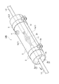
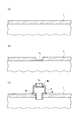
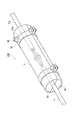
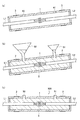
図3は、弁付きノズル4をスリーブ本体1に取付ける凡その工程を模式的に示す断面図である。図3(a)は、弁付きノズル4を取付ける前のスリーブ本体1を示す。図3(b)は、スリーブ本体1に仮穴を開けた様子を示す。図3(c)は、弁付きノズル4を取付けた後の様子を示す図である。
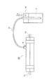
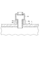
図4は、クロージャ100内に絶縁性混和物5を圧入する工程を模式的に示す図である。図4に示すように、本工程ではクロージャ100の弁付きノズル4と注入ポンプ容器30との間を注入ホース31で接続させる。
図5は、弁付きノズルの変形例を模式的に示す斜視図である。図5に示す弁付きノズル42は、ステンレスバンド32の上に取付けられる。ステンレスバンド32は、ステンレスバンド3(図1)に対して弁付きノズル42を取付ける座金部32aを備える点で異なる。
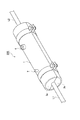
図7は、変形例2のクロージャの外観を模式的に示す斜視図である。図7に示すクロージャ200は、リリーフバルブ7を備える点でクロージャ100(図1)と異なる。
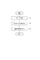
図8は、クロージャ100を作製する手順を示すフローチャートである。
1a,1b:スリーブ本体(1)
2,2a,2b:端面板
3,32:金属バンド(ステンレスバンド)
4,42:弁付きノズル
5:絶縁性混和物
6:接着剤
7:リリーフバルブ
40,41:穴
50:大きな漏斗
51:小さな漏斗
100,200:クロージャ
Claims (6)
- 通信ケーブルの接続部を収納するクロージャであって、
前記クロージャ内は絶縁性混和物で充填されている
ことを特徴とするクロージャ。 - 外部から前記クロージャ内に前記絶縁性混和物を充填させる弁付きノズルを備える
ことを特徴とする請求項1に記載のクロージャ。 - 前記クロージャの外周を押圧して固定する金属バンドを備え、
前記弁付きノズルは前記金属バンドに固定される
ことを特徴とする請求項2に記載のクロージャ。 - 前記クロージャ内のガスを外部に放出するリリーフバルブを備える
ことを特徴とする請求項1乃至3の何れかに記載のクロージャ。 - 通信ケーブルの接続部を収納するクロージャの作製方法であって、
前記クロージャ内に絶縁性混和物を充填させる弁付きノズルを取付ける工程と、
前記弁付きノズルを介して前記絶縁性混和物を圧入する工程と
を有することを特徴とするクロージャの作製方法。 - 前記絶縁性混和物を圧入する工程は、前記クロージャ内の内圧が大気圧より高い圧力状態で行われることを特徴とする請求項5に記載のクロージャの作製方法。
Priority Applications (1)
| Application Number | Priority Date | Filing Date | Title |
|---|---|---|---|
| JP2020033236A JP6929401B1 (ja) | 2020-02-28 | 2020-02-28 | クロージャ及びクロージャの作製方法 |
Applications Claiming Priority (1)
| Application Number | Priority Date | Filing Date | Title |
|---|---|---|---|
| JP2020033236A JP6929401B1 (ja) | 2020-02-28 | 2020-02-28 | クロージャ及びクロージャの作製方法 |
Publications (2)
| Publication Number | Publication Date |
|---|---|
| JP6929401B1 JP6929401B1 (ja) | 2021-09-01 |
| JP2021136822A true JP2021136822A (ja) | 2021-09-13 |
Family
ID=77456338
Family Applications (1)
| Application Number | Title | Priority Date | Filing Date |
|---|---|---|---|
| JP2020033236A Active JP6929401B1 (ja) | 2020-02-28 | 2020-02-28 | クロージャ及びクロージャの作製方法 |
Country Status (1)
| Country | Link |
|---|---|
| JP (1) | JP6929401B1 (ja) |
Citations (5)
| Publication number | Priority date | Publication date | Assignee | Title |
|---|---|---|---|---|
| JPS5947909A (ja) * | 1982-08-09 | 1984-03-17 | ベ−・ア−・エス・エフ・フアルベン・ウント・フア−ゼルン・アクチエンゲゼルシヤフト | ケ−ブル連結箱中に配置されたケ−ブル接続部をキヤスチングする方法および装置 |
| JPH0923557A (ja) * | 1995-01-17 | 1997-01-21 | Thomas & Betts Corp <T&B> | 封入剤流出容器を有する強制封入ケーブル接続包体 |
| JP2009100579A (ja) * | 2007-10-17 | 2009-05-07 | Viscas Corp | 電力ケーブル接続部及びその構成方法 |
| JP2014130331A (ja) * | 2012-11-30 | 2014-07-10 | 3M Innovative Properties Co | 光クロージャ、光クロージャの組立方法、光クロージャの分解方法及び光クロージャの再組立方法。 |
| JP2015142477A (ja) * | 2014-01-30 | 2015-08-03 | 昭和電線ケーブルシステム株式会社 | 外側保護管及び電力ケーブルの中間接続部 |
-
2020
- 2020-02-28 JP JP2020033236A patent/JP6929401B1/ja active Active
Patent Citations (5)
| Publication number | Priority date | Publication date | Assignee | Title |
|---|---|---|---|---|
| JPS5947909A (ja) * | 1982-08-09 | 1984-03-17 | ベ−・ア−・エス・エフ・フアルベン・ウント・フア−ゼルン・アクチエンゲゼルシヤフト | ケ−ブル連結箱中に配置されたケ−ブル接続部をキヤスチングする方法および装置 |
| JPH0923557A (ja) * | 1995-01-17 | 1997-01-21 | Thomas & Betts Corp <T&B> | 封入剤流出容器を有する強制封入ケーブル接続包体 |
| JP2009100579A (ja) * | 2007-10-17 | 2009-05-07 | Viscas Corp | 電力ケーブル接続部及びその構成方法 |
| JP2014130331A (ja) * | 2012-11-30 | 2014-07-10 | 3M Innovative Properties Co | 光クロージャ、光クロージャの組立方法、光クロージャの分解方法及び光クロージャの再組立方法。 |
| JP2015142477A (ja) * | 2014-01-30 | 2015-08-03 | 昭和電線ケーブルシステム株式会社 | 外側保護管及び電力ケーブルの中間接続部 |
Also Published As
| Publication number | Publication date |
|---|---|
| JP6929401B1 (ja) | 2021-09-01 |
Similar Documents
| Publication | Publication Date | Title |
|---|---|---|
| US5345972A (en) | Method for repairing local damage to pipelines by applying cladding with an interposed protective sheath | |
| US2817230A (en) | Leak testing device | |
| US20100012215A1 (en) | Composite Load Transferring Technique | |
| KR20080045252A (ko) | 기계식 커플링 장치 및 지지 장치를 사용하는 cpvc소방 스프링클러 시스템 및 그 조립 방법 | |
| RU2372548C2 (ru) | Способ устранения утечки на газопроводе в зоне фланца | |
| KR100346047B1 (ko) | 밀봉용기 | |
| WO2000043707A1 (en) | Method of repairing a flanged pipe joint | |
| JP6929401B1 (ja) | クロージャ及びクロージャの作製方法 | |
| US6990718B2 (en) | Tee connection to a pipeline | |
| JP5075785B2 (ja) | 圧縮流体封入装置の密封度改善方法、および圧縮流体封入装置 | |
| CN211018121U (zh) | 一种电气工程用缆线保护装置 | |
| US6612341B2 (en) | Securing shell assemblies to pipelines | |
| JP2009041313A (ja) | 壁面の防水装置と止水部材と連結金具と防水工法 | |
| JP6375198B2 (ja) | ケーブルの止水ユニット、その製造方法およびケーブルの止水ユニットの設置構造 | |
| JPH1073190A (ja) | 流体管の漏洩防止方法及び装置 | |
| CN216284836U (zh) | 一种用于验证堵水材料堵水性能的室内试验装置 | |
| CN117477459A (zh) | 一种通舱外电缆密封装置及密封方法 | |
| JP2014219201A (ja) | 埋設管の水密性検査方法 | |
| US3422211A (en) | Apparatus for establishing a fluid-tight bypass | |
| JPS6027255Y2 (ja) | 容器の水密接続部 | |
| CN205475371U (zh) | 沉管隧道水密门检漏装置 | |
| CN215217930U (zh) | 一种阀门离线打压工具 | |
| KR102439797B1 (ko) | 지중배전용 파형관의 연결구조 | |
| JP4093692B2 (ja) | ガス配管用ネジ継手部のガス漏れ修繕工法 | |
| US11982591B2 (en) | Tightness testing system for a cable gland feed-through of a partition |
Legal Events
| Date | Code | Title | Description |
|---|---|---|---|
| A621 | Written request for application examination |
Free format text: JAPANESE INTERMEDIATE CODE: A621 Effective date: 20200228 |
|
| A131 | Notification of reasons for refusal |
Free format text: JAPANESE INTERMEDIATE CODE: A131 Effective date: 20210422 |
|
| A521 | Request for written amendment filed |
Free format text: JAPANESE INTERMEDIATE CODE: A523 Effective date: 20210614 |
|
| TRDD | Decision of grant or rejection written | ||
| A01 | Written decision to grant a patent or to grant a registration (utility model) |
Free format text: JAPANESE INTERMEDIATE CODE: A01 Effective date: 20210803 |
|
| A61 | First payment of annual fees (during grant procedure) |
Free format text: JAPANESE INTERMEDIATE CODE: A61 Effective date: 20210810 |
|
| R150 | Certificate of patent or registration of utility model |
Ref document number: 6929401 Country of ref document: JP Free format text: JAPANESE INTERMEDIATE CODE: R150 |
|
| R250 | Receipt of annual fees |
Free format text: JAPANESE INTERMEDIATE CODE: R250 |
|
| R250 | Receipt of annual fees |
Free format text: JAPANESE INTERMEDIATE CODE: R250 |
|
| S533 | Written request for registration of change of name |
Free format text: JAPANESE INTERMEDIATE CODE: R313533 |
|
| R350 | Written notification of registration of transfer |
Free format text: JAPANESE INTERMEDIATE CODE: R350 |