JP2021136801A - Travel pattern creation device and operation control method using it - Google Patents
Travel pattern creation device and operation control method using it Download PDFInfo
- Publication number
- JP2021136801A JP2021136801A JP2020032405A JP2020032405A JP2021136801A JP 2021136801 A JP2021136801 A JP 2021136801A JP 2020032405 A JP2020032405 A JP 2020032405A JP 2020032405 A JP2020032405 A JP 2020032405A JP 2021136801 A JP2021136801 A JP 2021136801A
- Authority
- JP
- Japan
- Prior art keywords
- pattern
- vehicle
- coasting
- avoidance zone
- brake
- Prior art date
- Legal status (The legal status is an assumption and is not a legal conclusion. Google has not performed a legal analysis and makes no representation as to the accuracy of the status listed.)
- Granted
Links
Images
Classifications
-
- B—PERFORMING OPERATIONS; TRANSPORTING
- B60—VEHICLES IN GENERAL
- B60L—PROPULSION OF ELECTRICALLY-PROPELLED VEHICLES; SUPPLYING ELECTRIC POWER FOR AUXILIARY EQUIPMENT OF ELECTRICALLY-PROPELLED VEHICLES; ELECTRODYNAMIC BRAKE SYSTEMS FOR VEHICLES IN GENERAL; MAGNETIC SUSPENSION OR LEVITATION FOR VEHICLES; MONITORING OPERATING VARIABLES OF ELECTRICALLY-PROPELLED VEHICLES; ELECTRIC SAFETY DEVICES FOR ELECTRICALLY-PROPELLED VEHICLES
- B60L3/00—Electric devices on electrically-propelled vehicles for safety purposes; Monitoring operating variables, e.g. speed, deceleration or energy consumption
- B60L3/0023—Detecting, eliminating, remedying or compensating for drive train abnormalities, e.g. failures within the drive train
- B60L3/0046—Detecting, eliminating, remedying or compensating for drive train abnormalities, e.g. failures within the drive train relating to electric energy storage systems, e.g. batteries or capacitors
-
- B—PERFORMING OPERATIONS; TRANSPORTING
- B60—VEHICLES IN GENERAL
- B60L—PROPULSION OF ELECTRICALLY-PROPELLED VEHICLES; SUPPLYING ELECTRIC POWER FOR AUXILIARY EQUIPMENT OF ELECTRICALLY-PROPELLED VEHICLES; ELECTRODYNAMIC BRAKE SYSTEMS FOR VEHICLES IN GENERAL; MAGNETIC SUSPENSION OR LEVITATION FOR VEHICLES; MONITORING OPERATING VARIABLES OF ELECTRICALLY-PROPELLED VEHICLES; ELECTRIC SAFETY DEVICES FOR ELECTRICALLY-PROPELLED VEHICLES
- B60L15/00—Methods, circuits, or devices for controlling the traction-motor speed of electrically-propelled vehicles
- B60L15/20—Methods, circuits, or devices for controlling the traction-motor speed of electrically-propelled vehicles for control of the vehicle or its driving motor to achieve a desired performance, e.g. speed, torque, programmed variation of speed
- B60L15/2009—Methods, circuits, or devices for controlling the traction-motor speed of electrically-propelled vehicles for control of the vehicle or its driving motor to achieve a desired performance, e.g. speed, torque, programmed variation of speed for braking
-
- B—PERFORMING OPERATIONS; TRANSPORTING
- B60—VEHICLES IN GENERAL
- B60L—PROPULSION OF ELECTRICALLY-PROPELLED VEHICLES; SUPPLYING ELECTRIC POWER FOR AUXILIARY EQUIPMENT OF ELECTRICALLY-PROPELLED VEHICLES; ELECTRODYNAMIC BRAKE SYSTEMS FOR VEHICLES IN GENERAL; MAGNETIC SUSPENSION OR LEVITATION FOR VEHICLES; MONITORING OPERATING VARIABLES OF ELECTRICALLY-PROPELLED VEHICLES; ELECTRIC SAFETY DEVICES FOR ELECTRICALLY-PROPELLED VEHICLES
- B60L7/00—Electrodynamic brake systems for vehicles in general
-
- B—PERFORMING OPERATIONS; TRANSPORTING
- B61—RAILWAYS
- B61C—LOCOMOTIVES; MOTOR RAILCARS
- B61C3/00—Electric locomotives or railcars
- B61C3/02—Electric locomotives or railcars with electric accumulators
-
- B—PERFORMING OPERATIONS; TRANSPORTING
- B61—RAILWAYS
- B61L—GUIDING RAILWAY TRAFFIC; ENSURING THE SAFETY OF RAILWAY TRAFFIC
- B61L27/00—Central railway traffic control systems; Trackside control; Communication systems specially adapted therefor
- B61L27/04—Automatic systems, e.g. controlled by train; Change-over to manual control
-
- B—PERFORMING OPERATIONS; TRANSPORTING
- B60—VEHICLES IN GENERAL
- B60L—PROPULSION OF ELECTRICALLY-PROPELLED VEHICLES; SUPPLYING ELECTRIC POWER FOR AUXILIARY EQUIPMENT OF ELECTRICALLY-PROPELLED VEHICLES; ELECTRODYNAMIC BRAKE SYSTEMS FOR VEHICLES IN GENERAL; MAGNETIC SUSPENSION OR LEVITATION FOR VEHICLES; MONITORING OPERATING VARIABLES OF ELECTRICALLY-PROPELLED VEHICLES; ELECTRIC SAFETY DEVICES FOR ELECTRICALLY-PROPELLED VEHICLES
- B60L2200/00—Type of vehicles
- B60L2200/26—Rail vehicles
-
- B—PERFORMING OPERATIONS; TRANSPORTING
- B61—RAILWAYS
- B61L—GUIDING RAILWAY TRAFFIC; ENSURING THE SAFETY OF RAILWAY TRAFFIC
- B61L2201/00—Control methods
Landscapes
- Engineering & Computer Science (AREA)
- Mechanical Engineering (AREA)
- Transportation (AREA)
- Power Engineering (AREA)
- Life Sciences & Earth Sciences (AREA)
- Sustainable Development (AREA)
- Sustainable Energy (AREA)
- Electric Propulsion And Braking For Vehicles (AREA)
- Train Traffic Observation, Control, And Security (AREA)
Abstract
【課題】 停止回避地帯への停止を回避することができる走行パタン作成装置を提供する。【解決手段】 位置座標軸と車速座標軸との座標系と、車両8の停止回避地帯の位置情報を保持する停止回避地帯位置保持部1と、車両8の仕様のうち少なくとも加速時、減速時及び惰行時それぞれの加速度の情報を保持する車両条件保持部2と、位置情報と減速時の加速度の情報とを用いて、停止回避地帯以外に車両8を停止させるブレーキパタンを作成するブレーキパタン作成部3と、位置情報と惰行時の加速度の情報とを用いて、停止回避地帯以外に車両8を停止させる惰行パタンを作成する惰行パタン作成部4と、位置座標軸、ブレーキパタン及び惰行パタンで囲まれた領域である対象領域5を決定する対象領域決定部5と、対象領域5を回避した走行パタンであり座標系に表現可能な計画走行パタンを作成する計画走行パタン作成部6と、を備えた。【選択図】 図1PROBLEM TO BE SOLVED: To provide a traveling pattern creating device capable of avoiding a stop in a stop avoidance zone. SOLUTION: A coordinate system of a position coordinate axis and a vehicle speed coordinate axis, a stop avoidance zone position holding unit 1 for holding position information of a stop avoidance zone of a vehicle 8, and at least acceleration, deceleration and coasting among the specifications of the vehicle 8. Brake pattern creation unit 3 that creates a brake pattern that stops the vehicle 8 outside the stop avoidance zone by using the vehicle condition holding unit 2 that holds the acceleration information for each hour and the position information and the acceleration information during deceleration. It is surrounded by a coasting pattern creation unit 4 that creates a coasting pattern that stops the vehicle 8 outside the stop avoidance zone using the position information and acceleration information during coasting, and a position coordinate axis, a brake pattern, and a coasting pattern. A target area determination unit 5 for determining the target area 5 which is an area, and a planned travel pattern creation unit 6 for creating a planned travel pattern which is a traveling pattern avoiding the target area 5 and can be expressed in the coordinate system are provided. [Selection diagram] Fig. 1
Description
本発明は、車両の走行パタンを作成する装置及びそれを用いた運転制御方法に関する。 The present invention relates to a device for creating a traveling pattern of a vehicle and a driving control method using the device.
電車が駅間を走行中に、停電や架線故障による給電停止などの異常が発生し電車が力行不可能になった場合、駅間途中で停止してしまう。停止した地点が、停止回避地帯の場合、電車を停止回避地帯から迅速に退避させる必要がある。この「停止回避地帯」とは、停止することを回避すべきと定義されている地帯(例えば、停止することが禁止されている地帯)、具体的には、例えば、橋梁やトンネルなどである。 If an abnormality such as a power outage or a power supply stop due to an overhead line failure occurs while the train is running between stations, the train will stop in the middle of the station. If the stop point is the stop avoidance zone, it is necessary to quickly evacuate the train from the stop avoidance zone. The "stop avoidance zone" is a zone defined to avoid stopping (for example, a zone where stopping is prohibited), specifically, for example, a bridge or a tunnel.
退避の対策として、車上にバッテリを搭載し、停止回避地帯に停止した場合はバッテリから車両へ給電することによって、停止地点から力行し停止回避地帯から退避する方法があるが、車上のスペ−スやコストの制約により、搭載が困難な場合がある。 As a countermeasure for evacuation, there is a method of mounting a battery on the vehicle and, when stopped in the stop avoidance zone, powering the vehicle from the battery to force the vehicle from the stop point and evacuate from the stop avoidance zone. -It may be difficult to install due to space and cost restrictions.
特許文献1では、異常発生時に車両を最も安全な位置に停止させるために、現在位置から停止可能な区間の各地点のリスクを算出し、最もリスクが低い停止地点を判定し、当該停止地点へ停止するためのブレーキの時期を運転士へ通知する手法が記載されている。 In Patent Document 1, in order to stop the vehicle at the safest position when an abnormality occurs, the risk at each point in the section where the vehicle can be stopped is calculated from the current position, the stop point with the lowest risk is determined, and the stop point is reached. A method for notifying the driver of the timing of braking to stop is described.
特許文献1は、停止可能な区間に停止リスクの高い地点が散在する場合、どのような時期にブレーキをかけても、停止リスクの高い地点に車両を停止することになるため、停止回避地帯での停止を避けられないという課題がある。このため異常発生時に、停止回避地帯への停止を避けられるように車両を運転制御する必要がある。本発明は、上記課題に鑑みてなされたものであり、その目的とするところは、停止回避地帯での停止を回避することができる走行パタン作成装置を提供することにある。 According to Patent Document 1, when points with a high stop risk are scattered in a section where a stop can be made, the vehicle will be stopped at a point with a high stop risk no matter when the brake is applied. There is a problem that it is unavoidable to stop. Therefore, when an abnormality occurs, it is necessary to control the operation of the vehicle so as to avoid stopping in the stop avoidance zone. The present invention has been made in view of the above problems, and an object of the present invention is to provide a traveling pattern creating device capable of avoiding a stop in a stop avoidance zone.
上記課題を解決する本発明は、車両の位置又は時間に対応した第1軸とその第1軸と直交し車両の速度に対応した第2軸とより形成された座標系に表現可能な走行パタンを作成する走行パタン作成装置であって、車両の停止が回避されるべきと定義された停止回避地帯の位置情報を保持する停止回避地帯位置保持部と、車両の仕様のうち少なくとも加速時、減速時及び惰行時それぞれの加速度の情報を保持する車両条件保持部と、位置情報と減速時の加速度の情報とを用いて、停止回避地帯以外の位置で車両を停止させるためのパタンであり座標系に表現可能なブレーキパタンを作成するブレーキパタン作成部と、位置情報と惰行時の加速度の情報とを用いて、停止回避地帯以外の位置で車両を停止させるためのパタンであり座標系に表現可能な惰行パタンを作成する惰行パタン作成部と、座標系における第1軸、ブレーキパタン及び惰行パタンで囲まれた領域である対象領域を決定する対象領域決定部と、対象領域を回避した走行パタンであり座標系に表現可能な計画走行パタンを作成する計画走行パタン作成部と、を備えた。 The present invention that solves the above problems has a traveling pattern that can be expressed in a coordinate system formed by a first axis corresponding to the position or time of the vehicle and a second axis orthogonal to the first axis and corresponding to the speed of the vehicle. It is a traveling pattern creation device that creates a stop avoidance zone position holding part that holds the position information of the stop avoidance zone defined that the stop of the vehicle should be avoided, and at least when accelerating and decelerating among the specifications of the vehicle. It is a pattern and coordinate system for stopping the vehicle at a position other than the stop avoidance zone by using the vehicle condition holding unit that holds the acceleration information at the time and coasting, and the position information and the acceleration information at the time of deceleration. It is a pattern for stopping the vehicle at a position other than the stop avoidance zone by using the brake pattern creation part that creates the brake pattern that can be expressed in, and the position information and the acceleration information during coasting, and can be expressed in the coordinate system. With a coasting pattern creation unit that creates a clear coasting pattern, a target area determination unit that determines the target area that is the area surrounded by the first axis, the brake pattern, and the coasting pattern in the coordinate system, and a running pattern that avoids the target area. It is equipped with a planned running pattern creation unit that creates a planned running pattern that can be expressed in a certain coordinate system.
本発明によれば、停止回避地帯への停止を回避することができる走行パタン作成装置を提供できる。 According to the present invention, it is possible to provide a traveling pattern creation device capable of avoiding a stop in a stop avoidance zone.
図1〜図8を用いて本発明の実施例1を説明し、図5及び図9を用いて本発明の実施例2を説明する。なお、本発明の適用対象は、電気鉄道を始め、電気以外の専用動力による鉄道、又は電気式気動車のようなハイブリッド鉄道車両、さらにはハイブリッド自動車(Hybrid Vehicle 以下、HVと略す)、電気自動車(Electric Vehicle 以下、EVと略す)、あるいは、内燃機関自動車にも及ぶ。以下、自動運転中の旅客用電車を例示して説明し、それ以外については適宜に説明する。 The first embodiment of the present invention will be described with reference to FIGS. 1 to 8, and the second embodiment of the present invention will be described with reference to FIGS. 5 and 9. The subject of the present invention is an electric railway, a railway powered by a dedicated power other than electricity, a hybrid railway vehicle such as an electric pneumatic vehicle, a hybrid vehicle (hereinafter abbreviated as HV), and an electric vehicle (hereinafter abbreviated as HV). Electric Vehicle (hereinafter abbreviated as EV), or even an internal combustion engine vehicle. Hereinafter, a passenger train during automatic operation will be described as an example, and other trains will be described as appropriate.
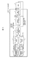
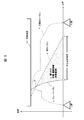
図1は、本発明の実施例1に係る走行パタン作成装置の概略を示すブロック図である。図1に示す走行パタン作成装置10は、車両8の位置、速度、及び残走行時分に関する情報を収集し、それらの情報に基づいて適切な走行パタンを作成し、車両8に運転指令を与える。なお、車両8が運転士の乗務する手動運転時であっても、運転士は走行パタン作成装置10の運転指令どおりに運転できるものとする。 FIG. 1 is a block diagram showing an outline of a traveling pattern creating device according to a first embodiment of the present invention. The traveling pattern creation device 10 shown in FIG. 1 collects information on the position, speed, and remaining traveling time of the vehicle 8, creates an appropriate traveling pattern based on the information, and gives a driving command to the vehicle 8. .. Even when the vehicle 8 is manually driven by the driver, the driver can drive the vehicle according to the operation command of the traveling pattern creation device 10.
その場合、車両8には不図示の対人支援装置が運転台に配設され、有効に機能している状態を想定する。したがって、運転指令を受けた車両8は、特段の外乱等が無ければ、自動運転と、手動走行と、の何れの場合でも走行パタンどおりに走行する。このような条件の下に、車両8は自動運転中の旅客用電車のみを例示して説明するが、本発明の実施例1に係る走行パタン作成装置10は、他の種類の車両にも適用可能である。 In that case, it is assumed that the vehicle 8 is provided with an interpersonal support device (not shown) in the driver's cab and is functioning effectively. Therefore, the vehicle 8 that has received the driving command travels according to the traveling pattern in both the automatic driving and the manual driving unless there is a particular disturbance or the like. Under such conditions, the vehicle 8 will be described by exemplifying only a passenger train during automatic driving, but the traveling pattern creating device 10 according to the first embodiment of the present invention is also applied to other types of vehicles. It is possible.
走行パタン作成装置10は、停止回避地帯位置保持部1、車両条件保持部2、ブレーキパタン作成部3、惰行パタン作成部4、高リスク位置−速度領域決定部(以下、「対象領域決定部」ともいう)5、計画走行パタン作成部6、及び運転指令部7、を備えている。 The traveling pattern creation device 10 includes a stop avoidance zone position holding unit 1, a vehicle condition holding unit 2, a brake pattern creating unit 3, a coasting pattern creating unit 4, and a high risk position-speed region determining unit (hereinafter, “target area determining unit””. (Also referred to as) 5, a planned running pattern creation unit 6, and an operation command unit 7 are provided.
停止回避地帯位置保持部1は、停止回避地帯の位置情報を保持する機能を有する。停止回避地帯の位置情報は、図2を用いて後述するように、各停止回避地帯の始点α位置と終点β位置が位置デ−タで格納された形式とする。車両条件保持部2は、車両8の加減速度特性、走行抵抗式、あるいは列車全長など車両条件を保持する機能を有する。 The stop avoidance zone position holding unit 1 has a function of holding the position information of the stop avoidance zone. As will be described later with reference to FIG. 2, the position information of the stop avoidance zone is in a format in which the start point α position and the end point β position of each stop avoidance zone are stored in the position data. The vehicle condition holding unit 2 has a function of holding vehicle conditions such as acceleration / deceleration characteristics of the vehicle 8, running resistance type, or the total length of the train.
ブレーキパタン作成部3は、図3を用いて後述するように、車両条件保持部2から出力された車両条件に従って、停止回避地帯位置保持部1から出力された停止回避地帯の始点αを基点としたブレーキパタンaを作成する機能を有する。図3にブレーキパタンaの一例を示す。 As will be described later with reference to FIG. 3, the brake pattern creating unit 3 uses the start point α of the stop avoidance zone output from the stop avoidance zone position holding unit 1 as the base point according to the vehicle conditions output from the vehicle condition holding unit 2. It has a function of creating a brake pattern a. FIG. 3 shows an example of the brake pattern a.
惰行パタン作成部4は、車両条件保持部2から出力された車両条件に従って、停止回避地帯位置保持部1から出力された停止回避地帯の終点βを基点とした惰行パタンbを作成する機能を有する。図3に惰行パタンbの一例を示す。 The coasting pattern creating unit 4 has a function of creating a coasting pattern b based on the end point β of the stop avoidance zone output from the stop avoidance zone position holding unit 1 according to the vehicle condition output from the vehicle condition holding unit 2. .. FIG. 3 shows an example of coasting pattern b.
高リスク位置−速度領域決定部5は、ブレーキパタン作成部3から出力されたブレーキパタンaと、惰行パタン作成部4から出力された惰行パタンbと、停止回避地帯の始点αから終点βまで結んだ直線と、の三角形で囲まれた位置−速度領域(以下、「高リスク位置−速度領域」又は「対象領域」という)cを決定する機能を有する。高リスク位置−速度領域cの一例を、図3中のcに示す。 The high-risk position-velocity region determination unit 5 connects the brake pattern a output from the brake pattern creation unit 3 and the coast pattern b output from the coast pattern creation unit 4 from the start point α to the end point β of the stop avoidance zone. It has a function of determining a position-velocity region (hereinafter referred to as "high risk position-velocity region" or "target region") c surrounded by a straight line and a triangle. An example of the high risk position-velocity region c is shown in c in FIG.
計画走行パタン作成部6は、車両8の現在地点及び現在速度を基点として、到着駅までの区間にわたり、高リスク位置−速度領域決定部5から出力された高リスク位置−速度領域cに重ならないような、位置−速度領域を走行する計画走行パタンPを作成する機能を有する。 The planned travel pattern creation unit 6 does not overlap the high risk position-speed region c output from the high risk position-speed region determination unit 5 over the section from the current position and the current speed of the vehicle 8 to the arrival station. It has a function of creating a planned travel pattern P for traveling in the position-speed region.
また、通常の列車制限速度が高リスク位置−速度領域cに重なっている場合も有り得る。例えば、図9を用いて後述する制限速度V2がさらに低い状態であり、どのようにしても、計画走行パタンPが高リスク位置−速度領域cに重なってしまう場合がある。 It is also possible that the normal train speed limit overlaps the high risk position-speed region c. For example, the speed limit V2, which will be described later with reference to FIG. 9, is in a lower state, and the planned running pattern P may overlap the high risk position-speed region c in any case.
その場合、高リスク位置−速度領域cと重なる区間を走行するのに必要な消費電力量の容量が確保されたバッテリ装置(補助蓄電池)を車上に搭載しても良い。その補助蓄電池を付設する場合でも、本発明の実施形態に係る走行パタン作成装置10の適用により、相当に小さな容量で済ませられる効果がある。 In that case, a battery device (auxiliary storage battery) in which the capacity of the power consumption required for traveling in the section overlapping the high risk position-speed region c may be secured may be mounted on the vehicle. Even when the auxiliary storage battery is attached, there is an effect that a considerably small capacity can be achieved by applying the traveling pattern creating device 10 according to the embodiment of the present invention.
運転指令部7は、異常発生時における車両8の現在速度が、停止回避地帯の始点αを基点としたブレーキパタンaより低い速度の場合はブレーキ指令、ブレーキパタンaより高い速度の場合は惰行運転を指令する機能を有する。走行パタン作成装置10では、つぎの運転指令(1)〜(4)を生成する。 The operation command unit 7 performs a brake command when the current speed of the vehicle 8 at the time of an abnormality is lower than the brake pattern a based on the start point α of the stop avoidance zone, and coasts when the speed is higher than the brake pattern a. Has a function to command. The traveling pattern creation device 10 generates the following operation commands (1) to (4).
(1)停止回避地帯への停止を避けられる位置−速度領域にて車両8を走行させる。
(2)異常発生時に車両8の現在速度が、停止回避地帯の始点αを基点としたブレーキパタンaより低い速度の場合、ブレーキをかけて停止回避地帯の始点αより手前側に停止させる。
(3)異常発生時に車両8の現在速度が、停止回避地帯の終点βを基点とした惰行パタンbより高い速度の場合は、惰行運転して停止回避地帯の終点βより向こう側に停止させる。
(4)異常発生時、車両8の現在速度と、いくつかの主要条件と、を勘案した走行パタンPにより、停止回避地帯への停止を回避する。
(1) The vehicle 8 is driven in the position-speed range where the stop in the stop avoidance zone can be avoided.
(2) When the current speed of the vehicle 8 is lower than the brake pattern a based on the start point α of the stop avoidance zone when an abnormality occurs, the brake is applied to stop the vehicle 8 in front of the start point α of the stop avoidance zone.
(3) If the current speed of the vehicle 8 is higher than the coasting pattern b with respect to the end point β of the stop avoidance zone at the time of the occurrence of an abnormality, the vehicle coasts to stop on the side beyond the end point β of the stop avoidance zone.
(4) When an abnormality occurs, the vehicle 8 is prevented from stopping in the stop avoidance zone by the traveling pattern P in consideration of the current speed of the vehicle 8 and some main conditions.
車両8が異常発生時には、運転指令(1)の方針により、運転指令(2)又は(3)のように停止位置を規定することにより、運転指令(4)が実現できる。 When an abnormality occurs in the vehicle 8, the driving command (4) can be realized by defining the stop position as in the driving command (2) or (3) according to the policy of the driving command (1).
なお、走行パタン作成装置10は、車上もしくは地上どちらに設置しても構わない。地上に設置した場合は、無線を用いて計算結果を車両8の車上装置へ送信する。その結果、走行パタン作成装置10は、作成した走行パタンに沿って車両8を運転制御することができる。 The traveling pattern creation device 10 may be installed on the vehicle or on the ground. When installed on the ground, the calculation result is transmitted to the on-board device of the vehicle 8 by radio. As a result, the traveling pattern creating device 10 can control the operation of the vehicle 8 according to the created traveling pattern.
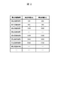
図2は、図1の走行パタン作成装置10における停止回避地帯位置保持部が保持する停止回避地帯の位置情報を例示した表である。図2の表の各行において、実在する停止回避地帯の1種と2種を種類分けし、それぞれを所定の基点からの始点α位置と、終点β位置と、を示す。 FIG. 2 is a table illustrating the position information of the stop avoidance zone held by the stop avoidance zone position holding unit in the traveling pattern creation device 10 of FIG. In each row of the table of FIG. 2, one type and two types of existing stop avoidance zones are classified, and each shows a start point α position from a predetermined base point and an end point β position.
図2の表で特定するような位置情報を演算処理に供するように、停止回避地帯位置保持部1が保持している。停止回避地帯1種は、エアセクションを例示し、一時停止すらも厳禁される。停止回避地帯2種は、海底トンネルの最深部を例示し、緊急脱出の困難性を考慮して、時間の長短を問わず停止を避ける。また、例示しないものの、所定値以下の短時間なら一時停止を許可するが、所定値以上の長時間停止ならば禁止する停止回避地帯N(不図示)を設定しても良い。 The stop avoidance zone position holding unit 1 holds the position information as specified in the table of FIG. 2 so as to be used for the arithmetic processing. One type of stop avoidance zone exemplifies the air section, and even a temporary stop is strictly prohibited. The two types of stop avoidance zones exemplify the deepest part of the undersea tunnel, and avoid stopping regardless of the length of time in consideration of the difficulty of emergency evacuation. Further, although not illustrated, a stop avoidance zone N (not shown) may be set, which allows a temporary stop for a short time of a predetermined value or less, but prohibits a long-time stop of a predetermined value or more.
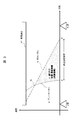
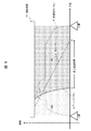
図3は、図1の走行パタン作成装置10において、ブレーキパタン作成部3及び惰行パタン作成部4が作成した走行パタンの一例である。走行パタンは、横軸に基点から車両8の現在位置までの距離を示した路線の位置情報と、縦軸に車両8の速度と、を示した座標において、作成された折れ線グラフであり、運転制御に用いられる。走行パタンは、制限速度V1で規定された速度以下の範囲で生成される。 FIG. 3 is an example of a traveling pattern created by the brake pattern creating unit 3 and the coasting pattern creating unit 4 in the traveling pattern creating device 10 of FIG. The traveling pattern is a line graph created with coordinates showing the distance from the base point to the current position of the vehicle 8 on the horizontal axis and the speed of the vehicle 8 on the vertical axis. Used for control. The traveling pattern is generated in a range equal to or lower than the speed specified by the speed limit V1.
図3に示すように、走行パタン作成装置10は、車両8に所望の運行をさせる前提として、車両8について、予め基本的な走行パタンを作成する。すなわち、車両8毎に固有の車両情報と、路線の情報と、を用いて、演算処理することにより車両8の基本的な走行パタンが得られる。車両情報には、力行時や停止時にそれぞれ正負で示される加速度を始め、車両重量、及び車輪摩擦等が含まれる。路線の情報には、基点から駅J,Kまでの距離のほか、勾配や停止回避地帯の1種、2種(以下、種別は概ね省略)の位置情報が含まれる。 As shown in FIG. 3, the traveling pattern creation device 10 creates a basic traveling pattern in advance for the vehicle 8 on the premise that the vehicle 8 is to perform a desired operation. That is, the basic traveling pattern of the vehicle 8 can be obtained by performing arithmetic processing using the vehicle information unique to each vehicle 8 and the route information. The vehicle information includes accelerations indicated by positive and negative values during power running and stopping, vehicle weight, wheel friction, and the like. The route information includes the distance from the base point to the stations J and K, as well as the location information of the slope and the stop avoidance zone of one type and two types (hereinafter, the types are generally omitted).
走行パタン作成装置10は、ある路線における車両8の基本的な走行パタンとして、ブレーキパタンa(図中a)と、惰行パタン作成部が作成する惰行パタンb(図中b)と、力行パタン(図中d)、を生成する。ブレーキパタンaは、車両8が制限速度で走行中に、緊急でない通常ブレーキ(単に「ブレーキ」という)の作動により、路線の勾配、車両重量、ブレーキ性能及びその他の条件等に基づく負の加速度で停止に至る経過を示す。また、力行パタンdは、車両8の起動時から制限速度に至るまでの加速能力を示すグラフである。 The traveling pattern creating device 10 includes a brake pattern a (a in the figure), a coasting pattern b (b in the figure) created by the coasting pattern creation unit, and a power running pattern (b in the figure) as basic traveling patterns of the vehicle 8 on a certain route. In the figure d), is generated. The brake pattern a is a negative acceleration based on the slope of the route, vehicle weight, braking performance, and other conditions due to the operation of a non-urgent normal brake (simply referred to as "brake") while the vehicle 8 is traveling at the speed limit. Shows the process leading to the stop. Further, the power running pattern d is a graph showing the acceleration ability from the start of the vehicle 8 to the speed limit.
一方、惰行パタンbは、路線の勾配、車両重量、及び車輪摩擦等に基づく負の加速度による緩やかな下降線をたどって停止に至る経過を示す。ブレーキパタンa、惰行パタンb及び力行パタンdは、乗客数に基づく車両重量のほか、環境条件の変化がはなはだしくない限り、概ね高い再現性が見込まれる。なお、力行パタンdは、力行機能が残存している車両8に限るが、ブレーキパタンa、及び惰行パタンbは、力行機能が喪失しても、走行抵抗式等に基づいて有効に再現可能である。 On the other hand, the coasting pattern b indicates the process of stopping by following a gentle descending line due to negative acceleration based on the slope of the route, the weight of the vehicle, the wheel friction, and the like. Brake pattern a, coasting pattern b, and power running pattern d are expected to have high reproducibility in general as long as the vehicle weight based on the number of passengers and the environmental conditions do not change significantly. The power running pattern d is limited to the vehicle 8 in which the power running function remains, but the brake pattern a and the coasting pattern b can be effectively reproduced based on the running resistance formula or the like even if the power running function is lost. be.
したがって、これら、ブレーキパタンa、及び惰行パタンbの組み合わせによって、車両8の停止位置を任意に設定できる。逆に、停止回避地帯を避けて停止することも可能となる。避ける方法は、走行パタン作成装置10における高リスク位置−速度領域決定部が作成する高リスク位置−速度領域c(図中c)に抵触しないように運転パタンを作成し、それに基づく運転指令を車両8に与えれば良い。 Therefore, the stop position of the vehicle 8 can be arbitrarily set by the combination of these, the brake pattern a, and the coasting pattern b. On the contrary, it is possible to avoid the stop avoidance zone and stop. The method of avoiding this is to create a driving pattern so as not to conflict with the high-risk position-speed region c (c in the figure) created by the high-risk position-speed region determination unit in the traveling pattern creation device 10, and issue a driving command based on the driving pattern. Give it to 8.
また、走行パタン作成装置10は、車両8の現在地点から到着駅までの間に複数の停止回避地帯1種、2種が存在する場合、停止回避地帯について、1種と2種毎に、ブレーキパタンa及び惰行パタンbをそれぞれ作成する。あるいは同種の停止回避地帯であっても、必要ならば、ブレーキパタンa及び惰行パタンbをそれぞれ作成する。 Further, when there are a plurality of stop avoidance zones 1 type and 2 types between the current position of the vehicle 8 and the arrival station, the traveling pattern creation device 10 brakes the stop avoidance zones for each type 1 and type 2. Create pattern a and coasting pattern b, respectively. Alternatively, even in the same type of stop avoidance zone, if necessary, a brake pattern a and a coasting pattern b are created, respectively.
走行パタン作成装置10は、運転指令(2)により、異常発生時に車両8の現在速度が、停止回避地帯の始点αを基点としたブレーキパタンaより低い速度の場合、ブレーキをかけて停止回避地帯の手前に停止させるように、走行パタンを作成する。その結果、高リスク位置−速度領域cに抵触しない。 According to the operation command (2), when the current speed of the vehicle 8 is lower than the brake pattern a based on the start point α of the stop avoidance zone, the traveling pattern creation device 10 applies the brake to the stop avoidance zone. Create a running pattern so that it stops before. As a result, it does not conflict with the high risk position-velocity region c.
また、走行パタン作成装置10は、運転指令(3)により、異常発生時に車両8の現在速度が、停止回避地帯の終点βを基点とした惰行パタンbより高い速度の場合は、惰行運転して停止回避地帯の終点βより向こう側に停止させる。その結果、高リスク位置−速度領域cに抵触しない。 Further, according to the operation command (3), the traveling pattern creating device 10 coasts when the current speed of the vehicle 8 is higher than the coasting pattern b with the end point β of the stop avoidance zone as the base point. Stop on the other side of the end point β of the stop avoidance zone. As a result, it does not conflict with the high risk position-velocity region c.
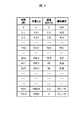
なお、走行パタン作成装置10は、車両条件保持部2から出力された車両条件に対して、車両毎の設計バラツキや応答遅れを加算して、ブレーキパタンa及び惰行パタンbを作成してもよい。つぎに、運転指令(1)〜(4)を生成するベースとなる計画走行パタンPについて説明する。計画走行パタンPは、図4に示すように、各地点における速度や運転操作を時系列デ−タで格納された形式とする。 The traveling pattern creating device 10 may create the brake pattern a and the coasting pattern b by adding the design variation and the response delay for each vehicle to the vehicle conditions output from the vehicle condition holding unit 2. .. Next, the planned running pattern P, which is the base for generating the operation commands (1) to (4), will be described. As shown in FIG. 4, the planned running pattern P has a format in which the speed and driving operation at each point are stored in time-series data.
図4は、図1の走行パタン作成装置10において、計画走行パタン作成部6が作成した計画走行パタンPのデ−タを例示する表である。図4の表は、車両8について、左から1列目に走行時間[秒]を示し、2列目に走行位置[m]を示し、3列目に走行速度[km/h]を示し、4列目に運転操作の内容を示す。 FIG. 4 is a table illustrating data of the planned travel pattern P created by the planned travel pattern creation unit 6 in the travel pattern creation device 10 of FIG. 1. In the table of FIG. 4, for the vehicle 8, the traveling time [seconds] is shown in the first row from the left, the traveling position [m] is shown in the second row, and the traveling speed [km / h] is shown in the third row. The details of the driving operation are shown in the fourth column.
図4の表は、同一の行に示す状態を紐づけて読み出し可能にデータ形成されている。したがって、走行パタン作成装置10は、現在の車両8の状態を時間、走行時間[秒]、走行位置[m]、及び走行速度[km/h]により検出し、検出された状態に応じて最適となる運転操作の信号を出力する。 In the table of FIG. 4, data is formed so as to be readable by associating the states shown in the same row. Therefore, the traveling pattern creation device 10 detects the current state of the vehicle 8 based on the time, the traveling time [seconds], the traveling position [m], and the traveling speed [km / h], and is optimal according to the detected state. The signal of the driving operation is output.
計画走行パタンPを作成する方法について、与えられた目標走行時分で駅J,K間を走行する計画走行パタンPを作成する場合を例示して説明する。この場合、指定された開始地点及び開始速度から次の駅までの区間を最速で走行するパタン(以下、最速パタン)を初期値として作成した上で、最速パタンの走行時分と与えられた目標走行時分の差である余裕時分の範囲内で、パタンの調整するように、山登り法を用いて繰り返す方法が挙げられる。 The method of creating the planned travel pattern P will be described by exemplifying the case of creating the planned travel pattern P for traveling between stations J and K at a given target travel time. In this case, after creating the pattern that travels at the fastest speed in the section from the specified start point and start speed to the next station (hereinafter referred to as the fastest pattern) as the initial value, the travel time of the fastest pattern and the given target There is a method of repeating using the mountain climbing method so as to adjust the pattern within the range of the spare time, which is the difference in the running time.
この方法において、図3に示した高リスク位置−速度領域(対象領域)cに抵触しないように制限しながらパタンを調整する。その結果、高リスク位置−速度領域cに重ならない位置−速度領域を走行する計画走行パタンPを作成することが可能となる。計画走行パタンPの一例を、図5に示す。 In this method, the pattern is adjusted while limiting so as not to conflict with the high risk position-velocity region (target region) c shown in FIG. As a result, it is possible to create a planned travel pattern P that travels in the high-risk position-speed region c that does not overlap with the position-speed region. An example of the planned running pattern P is shown in FIG.
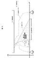
図5は、図1の走行パタン作成装置10において、計画走行パタン作成部6が作成した計画走行パタンPの一例である。図5に示す2つの駅J,K間の一部が停止回避地帯であり、列車8の走行が継続困難となる事情があれば、停止回避地帯の始点αより手前か終点βより遠方で停止させる。 FIG. 5 is an example of the planned travel pattern P created by the planned travel pattern creation unit 6 in the travel pattern creation device 10 of FIG. 1. A part of the area between the two stations J and K shown in FIG. 5 is a stop avoidance zone, and if there is a situation in which it becomes difficult for the train 8 to continue running, the train stops before the start point α of the stop avoidance zone or far from the end point β. Let me.
図5のように作成された計画走行パタンPは、車両8が異常発生時に、上述した運転指令(1)の方針により、運転指令(2)又は(3)のように停止位置を規定することにより、運転指令(4)が実現する。すなわち、図5において、J駅を出発した車両8は、交点Gの左から右へ移行する際、高リスク位置−速度領域cに抵触しないように運転制御される。 In the planned running pattern P created as shown in FIG. 5, when the vehicle 8 has an abnormality, the stop position is specified as in the driving command (2) or (3) according to the policy of the driving command (1) described above. As a result, the operation command (4) is realized. That is, in FIG. 5, the vehicle 8 departing from J station is operated and controlled so as not to conflict with the high risk position-speed region c when shifting from the left to the right of the intersection G.
これにより、図6に示す運転制御が実現する。図6は、図5の走行パタンにおいて、ブレーキ指令を出す場合の位置−速度領域(A)と、惰行運転を指令する場合の位置−速度領域(B)と、を示した説明図である。 As a result, the operation control shown in FIG. 6 is realized. FIG. 6 is an explanatory diagram showing a position-speed region (A) when issuing a brake command and a position-speed region (B) when commanding coasting operation in the traveling pattern of FIG.
(2)異常発生時に車両8の現在速度が、停止回避地帯の始点αを基点としたブレーキパタンaより低い速度の場合、ブレーキをかけて停止回避地帯の始点αより手前側に停止させる。
(3)異常発生時に車両8の現在速度が、停止回避地帯の終点βを基点とした惰行パタンbより高い速度の場合は、惰行運転して停止回避地帯の終点βより向こう側に停止させる。
(2) When the current speed of the vehicle 8 is lower than the brake pattern a based on the start point α of the stop avoidance zone when an abnormality occurs, the brake is applied to stop the vehicle 8 in front of the start point α of the stop avoidance zone.
(3) If the current speed of the vehicle 8 is higher than the coasting pattern b with respect to the end point β of the stop avoidance zone at the time of the occurrence of an abnormality, the vehicle coasts to stop on the side beyond the end point β of the stop avoidance zone.
車両8は、運転指令部7から出力された指令に沿って運転制御される。車両8を制御する具体的な方法は、無人ならば、ATO(Automatic Train Operation;自動列車運転装置)による自動制御で良い。車両8が有人ならば、DAS(Driver Advisory System;運転支援装置)により、運転指令に従って運転士が操作すれば良い。 The vehicle 8 is operated and controlled according to a command output from the operation command unit 7. If the vehicle is unmanned, the specific method for controlling the vehicle 8 may be automatic control by an ATO (Automatic Train Operation). If the vehicle 8 is manned, it may be operated by the driver according to the driving command by the DAS (Driver Advisory System).
ここで、本発明の実施例1に係る走行パタン作成装置10を用いた運転制御方法について、単に運転制御方法、又は本方法ともいう。本方法により、車両の現在地点から到着駅までの区間に停止回避地帯が存在する場合において、計画走行パタンPを作成する処理の手順を、図7のフローチャートを用いて説明する。 Here, the operation control method using the traveling pattern creating device 10 according to the first embodiment of the present invention is also simply referred to as an operation control method or the present method. According to this method, when a stop avoidance zone exists in the section from the current position of the vehicle to the arrival station, the procedure of the process of creating the planned travel pattern P will be described with reference to the flowchart of FIG.
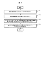
図7は、図1の走行パタン作成装置10において、計画走行パタンPを作成する処理を示すフローチャートである。図7に示すように、ステップS11では、ブレーキパタン作成部3が、車両条件保持部2から出力された車両条件に従って、停止回避地帯位置保持部1から出力された各停止回避地帯の始点αを基点としたブレーキパタンaを作成する。 FIG. 7 is a flowchart showing a process of creating a planned travel pattern P in the travel pattern creation device 10 of FIG. As shown in FIG. 7, in step S11, the brake pattern creating unit 3 sets the start point α of each stop avoidance zone output from the stop avoidance zone position holding unit 1 according to the vehicle condition output from the vehicle condition holding unit 2. Create a brake pattern a as a base point.
ステップS12では、惰行パタン作成部4が、車両条件保持部2から出力された車両条件に従って、停止回避地帯位置保持部1から出力された各停止回避地帯の終点βを基点とした惰行パタンbを作成する。 In step S12, the coasting pattern creating unit 4 sets the coasting pattern b based on the end point β of each stop avoidance zone output from the stop avoidance zone position holding unit 1 according to the vehicle condition output from the vehicle condition holding unit 2. create.
ステップS13では、高リスク位置−速度領域決定部5が、ブレーキパタン作成部3から出力されたブレーキパタンa、惰行パタン作成部4から出力された惰行パタンb、停止回避地帯の始点αと終点βを結んだ直線、で囲まれた位置−速度領域を高リスク位置−速度領域(対象領域)cに決定する。 In step S13, the high-risk position-velocity region determination unit 5 determines the brake pattern a output from the brake pattern creation unit 3, the coast pattern b output from the coast pattern creation unit 4, and the start point α and end point β of the stop avoidance zone. The position-velocity region surrounded by the straight line connecting the two is determined as the high-risk position-velocity region (target region) c.
ステップS14では、計画走行パタン作成部6が、車両8の現在地点及び現在速度を基点として、到着駅までの区間にわたり、高リスク位置−速度領域決定部5から出力された高リスク位置−速度領域cに重ならない位置−速度領域を走行する計画走行パタンPを作成する。以上が、車両8の現在地点から到着駅までの区間に停止回避地帯が存在する場合において、計画走行パタンPを作成する処理の流れである。 In step S14, the planned travel pattern creation unit 6 uses the current position and the current speed of the vehicle 8 as the base points, and extends the section to the arrival station, and the high risk position-speed area determined unit 5 outputs the high risk position-speed area. Create a planned travel pattern P that travels in the position-speed region that does not overlap with c. The above is the flow of the process of creating the planned travel pattern P when the stop avoidance zone exists in the section from the current position of the vehicle 8 to the arrival station.
続いて、実施例1に係る走行パタン作成装置10を用いた運転制御方法について説明する。本方法を適用して、計画走行パタンPに従って駅J,K間を走行する際に、運転指令部から出力する運転指令を決定する処理の手順を、図8のフローチャートを用いて説明する。 Subsequently, an operation control method using the traveling pattern creating device 10 according to the first embodiment will be described. A procedure for determining an operation command output from the operation command unit when traveling between stations J and K according to the planned travel pattern P by applying this method will be described with reference to the flowchart of FIG.
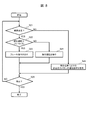
図8は、図1の走行パタン作成装置10において、運転指令部から出力する運転指令を決定する処理を示すフローチャートである。以下、主語がない場合の実行主体は、走行パタン作成装置10である。ステップS21で、車両8の走行中に異常発生を検出された場合はステップS22に進み、異常発生が検出されない場合はステップS25に進む。 FIG. 8 is a flowchart showing a process of determining an operation command output from the operation command unit in the traveling pattern creation device 10 of FIG. Hereinafter, the execution subject when there is no subject is the traveling pattern creation device 10. If an abnormality is detected while the vehicle 8 is running in step S21, the process proceeds to step S22, and if no abnormality is detected, the process proceeds to step S25.
ステップS22で、運転指令部7は、車両8の現在速度がブレーキパタンaより低い速度の場合はステップS23に進み、ブレーキパタンaより高い速度の場合はステップS24に進む。ステップS23で、運転指令部7は車両8へ、ブレーキ指令を出す。ステップS24で、運転指令部7は車両8へ、惰行運転を指令する。 In step S22, the operation command unit 7 proceeds to step S23 when the current speed of the vehicle 8 is lower than the brake pattern a, and proceeds to step S24 when the speed is higher than the brake pattern a. In step S23, the operation command unit 7 issues a brake command to the vehicle 8. In step S24, the driving command unit 7 commands the vehicle 8 to coast.
ステップS25で、運転指令部7は車両8へ、現在位置における計画走行パタンPの運転操作を指令する。ステップS26で、車両8が停止したか判定し、停止していない場合はステップS21へ戻り、停止した場合は処理を終える。 In step S25, the operation command unit 7 instructs the vehicle 8 to operate the planned travel pattern P at the current position. In step S26, it is determined whether or not the vehicle 8 has stopped, and if it has not stopped, the process returns to step S21, and if it has stopped, the process ends.
以上が、計画走行パタンPに従って車両8が駅J,K間を走行する際に、運転指令部7が出力する運転指令を決定する一連の処理についての説明である。また、走行パタン作成装置10は、車両8を長時間停止させることにリスクがある停止回避地帯が存在する駅J,K間を走行する場合に、停止回避地帯を避けられる計画走行パタンPを作成する。 The above is a description of a series of processes for determining a driving command output by the driving command unit 7 when the vehicle 8 travels between stations J and K according to the planned running pattern P. Further, the travel pattern creation device 10 creates a planned travel pattern P that can avoid the stop avoidance zone when traveling between stations J and K where there is a stop avoidance zone in which there is a risk of stopping the vehicle 8 for a long time. do.
そのために、走行パタン作成装置10は、ブレーキパタンa、惰行パタンb、及び高リスク位置−速度領域cを規定する。ブレーキパタンaは、停止回避地帯の始点αを基点として逆行するようにブレーキパタン作成部3が作成する。惰行パタンbは、停止回避地帯の終点βを基点として逆行するように惰行パタン作成部4が作成する。 To that end, the travel pattern creation device 10 defines a brake pattern a, a coasting pattern b, and a high risk position-speed region c. The brake pattern a is created by the brake pattern creating unit 3 so as to reverse the starting point α of the stop avoidance zone as a base point. The coasting pattern b is created by the coasting pattern creating unit 4 so as to go backwards with the end point β of the stop avoidance zone as a base point.
高リスク位置−速度領域(対象領域)cは、停止回避地帯の始点αと終点βを結んだ直線と、ブレーキパタンaと、惰行パタンbと、で囲まれた領域が規定される。図6に示すように、計画走行パタンPは、計画走行パタン作成部6が、高リスク位置−速度領域cに重ならない位置−速度領域を走行するように作成される。 The high-risk position-velocity region (target region) c is defined as a region surrounded by a straight line connecting the start point α and the end point β of the stop avoidance zone, the brake pattern a, and the coasting pattern b. As shown in FIG. 6, the planned travel pattern P is created so that the planned travel pattern creation unit 6 travels in a position-speed region that does not overlap with the high-risk position-speed region c.
走行パタン作成装置10は、以下の作用効果がある。これによれば、停止回避地帯への停止を避けられる位置−速度領域で車両8を走行させることができる。また、異常発生時に車両8の現在速度が停止回避地帯の始点αを基点としたブレーキパタンaより低い速度の場合は、ブレーキをかけて停止回避地帯の始点αより手前に停止させる。 The traveling pattern creating device 10 has the following effects. According to this, the vehicle 8 can be driven in the position-speed region where the stop in the stop avoidance zone can be avoided. If the current speed of the vehicle 8 is lower than the brake pattern a based on the start point α of the stop avoidance zone when an abnormality occurs, the brake is applied to stop the vehicle 8 before the start point α of the stop avoidance zone.
また、車両8がブレーキパタンaより高い速度で走行中は、惰行運転して停止回避地帯の終点βより向こう側に停止させる。このように、走行パタン作成装置10は、補助蓄電池を車載することなく、停止回避地帯への停止を回避することができる。 Further, while the vehicle 8 is traveling at a speed higher than the brake pattern a, the vehicle coasts and stops on the side beyond the end point β of the stop avoidance zone. In this way, the traveling pattern creation device 10 can avoid stopping in the stop avoidance zone without mounting the auxiliary storage battery in the vehicle.
鉄道の信号システムの設定によって、駅J,K間を走行中の車両8に対し、停止回避地帯を避けるように配慮した運転制御も可能である。その逆に、例えば、架線が停電した(架線停電)時に、車両8が停止回避地帯に停止してしまう不適切な運転制御となることもある。 By setting the railway signal system, it is possible to control the operation of the vehicle 8 traveling between the stations J and K so as to avoid the stop avoidance zone. On the contrary, for example, when the overhead line has a power failure (overhead line power failure), the vehicle 8 may stop in the stop avoidance zone, resulting in inappropriate driving control.
一例として、停止回避地帯の始点αより手前の信号が青から黄色に変わると、それまで上限だった制限速度V1から徐行を意味する制限速度V2へと変わるので、車両8は、それに従って徐行運転することになる。 As an example, when the signal before the start point α of the stop avoidance zone changes from blue to yellow, the speed limit V1 which was the upper limit until then changes to the speed limit V2 which means driving, so the vehicle 8 is driving slowly accordingly. Will be done.
その信号に従った徐行運転中に架線停電した場合を想定すると、車両8が高リスク位置−速度領域cに停止してしまう事態を避けられない場合がある。その点に対する改善策を実施例2に係る運転制御方法により提供する。 Assuming a power failure on the overhead line during slow driving according to the signal, it may be unavoidable that the vehicle 8 stops in the high risk position-speed region c. An improvement measure for this point is provided by the operation control method according to the second embodiment.
図9は、実施例2に係る運転制御方法において、制限速度が臨時に下げられた場合、図5の走行パタンをベースに適切な停止位置を決定するための説明図である。この運転制御方法において、走行パタン作成装置10は、交点G以下の制限速度V2に臨時で下げられた情報を取得したならば、つぎの処理を実行する。 FIG. 9 is an explanatory diagram for determining an appropriate stop position based on the traveling pattern of FIG. 5 when the speed limit is temporarily lowered in the operation control method according to the second embodiment. In this operation control method, when the traveling pattern creation device 10 acquires the information temporarily lowered to the speed limit V2 below the intersection G, the following processing is executed.
走行パタン作成装置10は、図9に示すように、力行パタンdを作成し、その力行パタンdを交点Gから手前側へ逆行させて垂下した力行垂下点γを特定する。なお、力行垂下点γを特定する処理は、計画走行パタン作成部6で実行すれば良い。 As shown in FIG. 9, the running pattern creation device 10 creates a power running pattern d, reverses the power running pattern d from the intersection G to the front side, and specifies a power running drooping point γ that hangs down. The process of specifying the powering drooping point γ may be executed by the planned running pattern creation unit 6.
走行パタン作成装置10は、運転指令部7から車両8に、力行垂下点γより手前側で停止して待機させる指令を送信する。これによる待機中に、交点Gを超えるような制限速度V2まで上昇した情報を走行パタン作成装置10が受信したならば、走行パタン作成装置10は、計画走行パタンPを作成する(S14)。 The travel pattern creation device 10 transmits a command from the operation command unit 7 to the vehicle 8 to stop and stand by in front of the powering droop point γ. If the travel pattern creation device 10 receives information that has risen to a speed limit V2 that exceeds the intersection G during standby, the travel pattern creation device 10 creates a planned travel pattern P (S14).
走行パタン作成装置10は、計画走行パタンPに基づいて、車両8の状態を交点Gよりも手前側から向こう側へ交点Gを乗り越えて移行させる指令を運転指令部7から車両8へ送信する。その結果、車両8は、停止回避地帯の終点βより向こう側まで惰行して停止する。 Based on the planned travel pattern P, the travel pattern creation device 10 transmits a command from the operation command unit 7 to the vehicle 8 to shift the state of the vehicle 8 from the front side to the other side of the intersection G over the intersection G. As a result, the vehicle 8 coasts to the other side of the end point β of the stop avoidance zone and stops.
本発明の実施例1,2に係る走行パタン作成装置10及びそれを用いた運転制御方法(本方法)について、以下のように総括できる。 The traveling pattern creation device 10 according to Examples 1 and 2 of the present invention and the operation control method (the present method) using the same can be summarized as follows.
[1]走行パタン作成装置10は、車両8の位置又は時間に対応した第1軸(横軸)と、その第1軸(横軸)と直交し車両8の速度に対応した第2軸(縦軸)とより形成された座標系に表現可能な走行パタンを作成して、所望の運転制御を可能にするコンピュータ装置である。走行パタン作成装置10は、車両8が有人と無人の場合、あるいは手動と自動の何れの場合にも適用可能である。例えば、車両8が、有人手動運転ならば、それを支援するように、走行パタン作成装置10から運転士に最適速度を提示する表示装置等を配設すれば良い。 [1] The traveling pattern creation device 10 has a first axis (horizontal axis) corresponding to the position or time of the vehicle 8 and a second axis (horizontal axis) orthogonal to the first axis (horizontal axis) and corresponding to the speed of the vehicle 8. It is a computer device that creates a traveling pattern that can be expressed in a coordinate system formed by (vertical axis) and more, and enables desired operation control. The traveling pattern creation device 10 can be applied to the case where the vehicle 8 is manned and unmanned, or when the vehicle 8 is manual or automatic. For example, if the vehicle 8 is a manned manual driving, a display device or the like that presents the optimum speed to the driver from the traveling pattern creation device 10 may be provided to support the manned manual driving.
図1に示すように、走行パタン作成装置10は、停止回避地帯位置保持部1と、車両条件保持部2と、ブレーキパタン作成部3と、惰行パタン作成部4と、対象領域決定部(高リスク位置−速度領域決定部)5と、計画走行パタン作成部6と、を備えた。 As shown in FIG. 1, the traveling pattern creating device 10 includes a stop avoidance zone position holding unit 1, a vehicle condition holding unit 2, a brake pattern creating unit 3, a coasting pattern creating unit 4, and a target area determining unit (high). A risk position-speed area determination unit) 5 and a planned running pattern creation unit 6 are provided.
停止回避地帯位置保持部1は、車両8の停止が回避されるべきと定義された停止回避地帯の位置情報を保持する。車両条件保持部2は、車両8の仕様のうち少なくとも加速時、減速時及び惰行時それぞれの加速度の情報を保持する。ブレーキパタン作成部3は、位置情報と減速時の加速度の情報とを用いて、停止回避地帯以外の位置で車両8を停止させるためのパタンであり座標系に表現可能なブレーキパタンを作成する。 The stop avoidance zone position holding unit 1 holds the position information of the stop avoidance zone defined that the stop of the vehicle 8 should be avoided. The vehicle condition holding unit 2 holds at least information on acceleration, deceleration, and coasting in the specifications of the vehicle 8. The brake pattern creating unit 3 creates a brake pattern that is a pattern for stopping the vehicle 8 at a position other than the stop avoidance zone and can be expressed in the coordinate system by using the position information and the acceleration information at the time of deceleration.
惰行パタン作成部4は、位置情報と惰行時の加速度の情報とを用いて、停止回避地帯以外の位置で車両8を停止させるためのパタンであり座標系に表現可能な惰行パタンを作成する。対象領域決定部(高リスク位置−速度領域決定部)5は、座標系において第1軸、ブレーキパタン及び惰行パタンで囲まれた領域である対象領域(高リスク位置−速度領域)を決定する。 The coasting pattern creating unit 4 creates a coasting pattern that is a pattern for stopping the vehicle 8 at a position other than the stop avoidance zone and can be expressed in the coordinate system by using the position information and the acceleration information at the time of coasting. The target area determination unit (high risk position-velocity area determination unit) 5 determines the target area (high risk position-velocity area) which is an area surrounded by the first axis, the brake pattern, and the coasting pattern in the coordinate system.
計画走行パタン作成部6は、対象領域を回避した走行パタンであり座標系に表現可能な計画走行パタンを作成する。このような走行パタン作成装置10は、対象領域決定部(高リスク位置−速度領域決定部)5が、対象領域に重ならないように、それを回避するように走行パタンを作成する。その走行パタンのとおりに運転制御された車両8は、車両8が停止回避地帯へ停止することを回避できる。 The planned running pattern creation unit 6 creates a planned running pattern that is a running pattern that avoids the target area and can be expressed in the coordinate system. Such a traveling pattern creation device 10 creates a traveling pattern so that the target area determination unit (high risk position-speed region determination unit) 5 does not overlap the target area and avoids it. The vehicle 8 whose operation is controlled according to the traveling pattern can prevent the vehicle 8 from stopping in the stop avoidance zone.
[2]走行パタン作成装置10は軌道輸送機関に好適である。軌道輸送機関において、車両8は1両以上で構成されて軌道上を走行する。図3に示すように、停止回避地帯とは、2つ以上の駅J,Kを有する路線の何れかの駅間に存在し、車両8を停止させることにリスクがある箇所をいう。 [2] The traveling pattern creation device 10 is suitable for track transportation. In the orbital transportation system, the vehicle 8 is composed of one or more vehicles and travels on the orbit. As shown in FIG. 3, the stop avoidance zone means a place existing between any stations of a line having two or more stations J and K, and there is a risk of stopping the vehicle 8.
走行パタン作成装置10で作成する走行パタンにおいて、対象領域(高リスク位置−速度領域)cとは、停止回避地帯の始点αを基点としたブレーキパタンaと、停止回避地帯の終点βを基点とした惰行パタンbと、及び停止回避地帯の始点αと終点βを結んだ直線、で囲まれた位置−速度領域をいう。 In the travel pattern created by the travel pattern creation device 10, the target region (high risk position-speed region) c is the brake pattern a with the start point α of the stop avoidance zone as the base point and the end point β of the stop avoidance zone as the base point. The position-velocity region surrounded by the coasting pattern b and the straight line connecting the start point α and the end point β of the stop avoidance zone.
図3の走行パタンを用いた運転制御の指標として、ブレーキパタンa及び惰行パタンbの交点Gを規定する。計画走行パタン作成部6は、車両8の状態が交点Gよりも手前(左)側から向こう(右)側へ移行する場合、交点Gを乗り越えるように走行する計画走行パタンPを作成する。これにより、停止回避地帯への停止を回避することができる。 As an index of operation control using the traveling pattern of FIG. 3, the intersection G of the brake pattern a and the coasting pattern b is defined. When the state of the vehicle 8 shifts from the front (left) side to the other side (right) side of the intersection G, the planned travel pattern creation unit 6 creates a planned travel pattern P for traveling so as to overcome the intersection G. As a result, it is possible to avoid stopping in the stop avoidance zone.
[3]走行パタン作成装置10は、車両8が停電やエンジン故障等により力行能力喪失と判定されたならば、計画走行パタン作成部6その他の機能部により、つぎ処理を実行する。走行パタン作成装置10は、車両8の位置及び速度で規定される車両状態と、ブレーキパタンaと、を対比する。 [3] When the vehicle 8 is determined to have lost power running ability due to a power failure, engine failure, or the like, the travel pattern creation device 10 executes the next process by the planned travel pattern creation unit 6 and other functional units. The traveling pattern creating device 10 compares the vehicle state defined by the position and speed of the vehicle 8 with the brake pattern a.
計画走行パタン作成部6は、車両状態がブレーキパタンaの手前側ならブレーキ作動と決定する。走行パタン作成装置10は、車両状態がブレーキパタンaの向こう側でしかも惰行パタンbよりも高ければ惰行運転と決定する。 The planned travel pattern creation unit 6 determines that the brake is activated if the vehicle state is on the front side of the brake pattern a. The traveling pattern creating device 10 determines that the vehicle is coasting if the vehicle state is on the other side of the brake pattern a and higher than the coasting pattern b.
運転指令部7は、決定どおりに車両8へ指令する。その運転指令に応じた車両8は、力行能力を喪失しても適切な位置で停止するように運転制御される。その結果、停止回避地帯を回避して安全地帯に停止できる。 The operation command unit 7 commands the vehicle 8 as determined. The vehicle 8 in response to the driving command is controlled to stop at an appropriate position even if the power running ability is lost. As a result, it is possible to avoid the stop avoidance zone and stop in the safe zone.
[4]本発明の実施例1,2に係る運転制御方法(本方法)は、走行パタン作成装置10を用いて、車両8の位置に応じた走行パタンを作成して実行する方法である。走行パタン作成装置10は、上述のように、座標系に表現可能な走行パタンを作成して、所望の運転制御を可能する。それを用いた運転制御方法(本方法)は、車両8の位置に応じて適切な走行パタンを作成し、それを車両8に直接又は間接的に実行させる。 [4] The driving control method (the present method) according to the first and second embodiments of the present invention is a method of creating and executing a traveling pattern according to the position of the vehicle 8 by using the traveling pattern creating device 10. As described above, the travel pattern creation device 10 creates a travel pattern that can be expressed in the coordinate system to enable desired operation control. In the driving control method (this method) using the driving pattern, an appropriate traveling pattern is created according to the position of the vehicle 8, and the vehicle 8 is made to execute it directly or indirectly.
走行パタン作成装置10は、車両8の仕様について、少なくとも加速時、減速時及び惰行時それぞれの加速度の情報と、走行路線に存在する停止回避地帯の位置情報と、を予め保持しておく。また、走行パタン作成装置10は、平時にも有事に備えて、図7に示すつぎの処理を実行している。 The traveling pattern creating device 10 holds in advance at least information on acceleration during acceleration, deceleration, and coasting, and information on the position of a stop avoidance zone existing on the traveling route, with respect to the specifications of the vehicle 8. Further, the traveling pattern creating device 10 executes the following processing shown in FIG. 7 in preparation for an emergency even in normal times.
ブレーキパタン作成部3は、停止回避地帯を回避して停止させるように減速時の加速度の情報を用いて車両8のブレーキパタンを作成する(S11)。惰行パタン作成部4は、停止回避地帯を回避して停止させるように惰行時の加速度の情報を用いて車両8の惰行パタンを作成し(S12)する。 The brake pattern creating unit 3 creates a brake pattern of the vehicle 8 by using the information of the acceleration at the time of deceleration so as to avoid the stop avoidance zone and stop (S11). The coasting pattern creating unit 4 creates a coasting pattern of the vehicle 8 by using the information of the acceleration at the time of coasting so as to avoid the stop avoidance zone and stop (S12).
対象領域決定部5は、ブレーキパタンa及び惰行パタンbを組み合わせて回避すべき対象領域cを決定する(S13)。計画走行パタン作成部6は、対象領域cに重ならない位置−速度領域を走行する計画走行パタンPを作成する(S14)。車両8は、このように作成された計画走行パタンPに基づいて運転制御されるので、対象領域cに重ならない位置−速度領域を走行する。これにより、停止回避地帯への停止を回避することができる。 The target area determination unit 5 determines the target area c to be avoided by combining the brake pattern a and the coasting pattern b (S13). The planned travel pattern creation unit 6 creates a planned travel pattern P that travels in a position-speed region that does not overlap the target region c (S14). Since the vehicle 8 is operated and controlled based on the planned travel pattern P created in this way, the vehicle 8 travels in a position-speed region that does not overlap the target region c. As a result, it is possible to avoid stopping in the stop avoidance zone.
[5]走行パタン作成装置10を用いて、1両以上で構成された軌道上を走行する車両8を適切に運転制御する方法(本方法)として、つぎの手順を実行すると良い。走行パタン作成装置10は、図3及び図5に示す走行パタンにおいて、停止回避地帯の始点αを基点としたブレーキパタンa、及び停止回避地帯の終点βを基点とした惰行パタンb、及び停止回避地帯の始点αと終点βを結んだ直線、で囲まれた対象領域(高リスク位置−速度領域)cを規定する。 [5] As a method (this method) of appropriately driving and controlling a vehicle 8 traveling on a track composed of one or more vehicles by using the traveling pattern creation device 10, the following procedure may be executed. In the traveling patterns shown in FIGS. 3 and 5, the traveling pattern creating device 10 has a brake pattern a based on the start point α of the stop avoidance zone, a coasting pattern b based on the end point β of the stop avoidance zone, and a stop avoidance. A target area (high risk position-velocity area) c surrounded by a straight line connecting the start point α and the end point β of the zone is defined.
走行パタン作成装置10は、図3及び図5に示すように、走行パタンにおいて、ブレーキパタンa及び惰行パタンbの交点Gを規定する(S13)。走行パタン作成装置10は、図5に示すように、車両8の状態が交点Gよりも手前側から向こう側へ移行する場合、交点Gを乗り越えるように走行する計画走行パタンPを作成する(S14)。 As shown in FIGS. 3 and 5, the traveling pattern creating device 10 defines the intersection G of the brake pattern a and the coasting pattern b in the traveling pattern (S13). As shown in FIG. 5, the travel pattern creation device 10 creates a planned travel pattern P for traveling so as to overcome the intersection G when the state of the vehicle 8 shifts from the front side to the other side of the intersection G (S14). ).
この運転制御方法によれば、2つ以上の駅J,Kを有する路線の何れかの駅間に存在する停止回避地帯には、車両8を停止させず、そこに停止するリスクを避けるように計画走行パタンPを作成することができる。 According to this operation control method, the vehicle 8 is not stopped in the stop avoidance zone existing between any stations of the line having two or more stations J and K, and the risk of stopping there is avoided. The planned running pattern P can be created.
[6]この運転制御方法において、走行パタン作成装置10は、車両8が力行能力を喪失したと判定したならば、つぎの処理を実行する。走行パタン作成装置10は、車両8の位置及び速度で規定される車両状態と、ブレーキパタンaと、を対比する。 [6] In this driving control method, if it is determined that the vehicle 8 has lost the power running ability, the traveling pattern creating device 10 executes the following processing. The traveling pattern creating device 10 compares the vehicle state defined by the position and speed of the vehicle 8 with the brake pattern a.
走行パタン作成装置10は、車両状態がブレーキパタンaの手前側ならブレーキを作動すると決定し、その決定どおりに車両8へ指令する。その結果、車両8は、停止回避地帯の始点αより手前で停止する。 The traveling pattern creating device 10 determines that the brake is activated if the vehicle state is on the front side of the brake pattern a, and commands the vehicle 8 according to the determination. As a result, the vehicle 8 stops before the start point α of the stop avoidance zone.
走行パタン作成装置10は、車両状態がブレーキパタンaの向こう側でしかも惰行パタンbよりも高ければ惰行運転と決定し、その決定どおりに車両8へ指令する。その結果、車両8は、停止回避地帯の終点βより向こう側まで惰行して停止する。これにより、停止回避地帯への停止を回避することができる。 If the vehicle state is on the other side of the brake pattern a and higher than the coasting pattern b, the traveling pattern creating device 10 determines that the vehicle is coasting, and commands the vehicle 8 according to the determination. As a result, the vehicle 8 coasts to the other side of the end point β of the stop avoidance zone and stops. As a result, it is possible to avoid stopping in the stop avoidance zone.
[7]この運転制御方法において、走行パタン作成装置10は、制限速度V2が交点G以下に臨時で下げられた情報を取得したならば、つぎの処理を実行する。走行パタン作成装置10は、図9に示すように、力行パタンdを作成し、その力行パタンdを交点Gから手前側へ逆行させて垂下した力行垂下点γ特定する。 [7] In this operation control method, the traveling pattern creation device 10 executes the following processing when the information that the speed limit V2 is temporarily lowered to the intersection G or less is acquired. As shown in FIG. 9, the running pattern creating device 10 creates a power running pattern d, reverses the power running pattern d from the intersection G to the front side, and specifies the power running drooping point γ that hangs down.
走行パタン作成装置10は、運転指令部7から車両8に、力行垂下点γより手前側で停止して待機するように運転指令を発令する。これに応じた車両8が待機中に、制限速度V2が交点Gを超えて上昇復帰した情報を走行パタン作成装置10が受信したならば、走行パタン作成装置10は、計画走行パタンPを作成する(S14)。 The traveling pattern creation device 10 issues a driving command to the vehicle 8 from the driving command unit 7 so as to stop and stand by in front of the power running drooping point γ. If the travel pattern creation device 10 receives information that the speed limit V2 has returned above the intersection G while the vehicle 8 is on standby, the travel pattern creation device 10 creates a planned travel pattern P. (S14).
走行パタン作成装置10は、計画走行パタンPに基づいて、車両8の状態を交点Gよりも手前側から向こう側へ、交点Gを乗り越えて移行させる運転指令を運転指令部7から車両8へ発令する。その結果、車両8は、停止回避地帯の終点βより向こう側まで惰行して停止する。これにより、駅J,K間において、臨時に信号が変わる等で、制限速度V2が交点G以下にまで臨時に下げられた場合でも、車両8は停止回避地帯を避けて停止できる。 Based on the planned travel pattern P, the travel pattern creation device 10 issues a driving command from the operation command unit 7 to the vehicle 8 to shift the state of the vehicle 8 from the front side to the other side of the intersection G and over the intersection G. do. As a result, the vehicle 8 coasts to the other side of the end point β of the stop avoidance zone and stops. As a result, even if the speed limit V2 is temporarily lowered to the intersection G or less due to a temporary signal change between stations J and K, the vehicle 8 can stop while avoiding the stop avoidance zone.
なお、本発明は上記した実施例に限定されるものではなく、様々な変形例が含まれる。また、上記の各構成、機能、処理部、処理手段等は、それらの一部又は全部を、例えば集積回路で設計する等によりハードウェアで実現してもよい。また、上記の各構成、機能等は、プロセッサがそれぞれの機能を実現するプログラムを解釈し、実行することによりソフトウェアで実現してもよい。 The present invention is not limited to the above-described examples, and includes various modifications. Further, each of the above configurations, functions, processing units, processing means and the like may be realized by hardware by designing a part or all of them by, for example, an integrated circuit. Further, each of the above configurations, functions, and the like may be realized by software by the processor interpreting and executing a program that realizes each function.
各機能を実現するプログラム、テーブル、ファイル等の情報は、メモリや、ハードディスク、SSD(Solid State Drive)等の記録装置、又は、ICカード、SDカード、DVD等の記録媒体に置いてもよい。走行パタン作成装置10は、FPGA(Field Programmable Gate Array)やカスタムLSI、SRAM(Static Random Access Memory)やフラッシュメモリで実現しても良い。 Information such as programs, tables, and files that realize each function may be placed in a memory, a hard disk, a recording device such as an SSD (Solid State Drive), or a recording medium such as an IC card, an SD card, or a DVD. The traveling pattern creation device 10 may be realized by an FPGA (Field Programmable Gate Array), a custom LSI, a SRAM (Static Random Access Memory), or a flash memory.
1 停止回避地帯位置保持部、2 車両条件保持部、3 ブレーキパタン作成部、4 惰行パタン作成部、5 対象領域決定部(高リスク位置−速度領域決定部)、6 計画走行パタン作成部、7 運転指令部、8 車両、10 走行パタン作成装置 1 Stop avoidance zone position holding unit, 2 Vehicle condition holding unit, 3 Brake pattern creation unit, 4 Coasting pattern creation unit, 5 Target area determination unit (high risk position-speed region determination unit), 6 Planned driving pattern creation unit, 7 Driving command unit, 8 vehicles, 10 running pattern creation device
Claims (7)
前記車両の停止が回避されるべきと定義された停止回避地帯の位置情報を保持する停止回避地帯位置保持部と、
前記車両の仕様のうち少なくとも加速時、減速時及び惰行時それぞれの加速度の情報を保持する車両条件保持部と、
前記位置情報と前記減速時の加速度の情報とを用いて、前記停止回避地帯以外の位置で前記車両を停止させるためのパタンであり前記座標系に表現可能なブレーキパタンを作成するブレーキパタン作成部と、
前記位置情報と前記惰行時の加速度の情報とを用いて、前記停止回避地帯以外の位置で前記車両を停止させるためのパタンであり前記座標系に表現可能な惰行パタンを作成する惰行パタン作成部と、
前記座標系における前記第1軸、前記ブレーキパタン及び前記惰行パタンで囲まれた領域である対象領域を決定する対象領域決定部と、
前記対象領域を回避した走行パタンであり前記座標系に表現可能な計画走行パタンを作成する計画走行パタン作成部と、
を備えた走行パタン作成装置。 A travel pattern creation device that creates a travel pattern that can be expressed in a coordinate system formed by the first axis corresponding to the position or time of the vehicle and the second axis orthogonal to the first axis and corresponding to the speed of the vehicle. There,
A stop avoidance zone position holding unit that holds position information of the stop avoidance zone defined that the vehicle should be avoided, and a stop avoidance zone position holding unit.
Of the vehicle specifications, at least a vehicle condition holding unit that holds information on acceleration during acceleration, deceleration, and coasting, and a vehicle condition holding unit.
A brake pattern creation unit that creates a brake pattern that is a pattern for stopping the vehicle at a position other than the stop avoidance zone and can be expressed in the coordinate system by using the position information and the acceleration information during deceleration. When,
A coasting pattern creation unit that creates a coasting pattern that is a pattern for stopping the vehicle at a position other than the stop avoidance zone and can be expressed in the coordinate system by using the position information and the acceleration information during coasting. When,
A target area determination unit that determines a target area that is a region surrounded by the first axis, the brake pattern, and the coasting pattern in the coordinate system.
A planned running pattern creation unit that creates a planned running pattern that is a running pattern that avoids the target area and can be expressed in the coordinate system.
A running pattern creation device equipped with.
前記停止回避地帯は、2つ以上の駅を有する路線の何れかの駅間に存在し、
前記対象領域は、前記停止回避地帯の始点を基点としたブレーキパタンと、前記停止回避地帯の終点を基点とした惰行パタンと、及び前記停止回避地帯の始点と終点を結んだ直線、で囲まれた領域に規定し、
前記ブレーキパタン及び前記惰行パタンの交点を規定し、
前記計画走行パタン作成部は、前記車両の状態が前記交点よりも手前側から向こう側へ移行する場合、前記交点を乗り越えるように走行する計画走行パタンを作成する、
請求項1に記載の走行パタン作成装置。 The vehicle consists of one or more cars and runs on the track.
The stop avoidance zone exists between any station of a line having two or more stations.
The target area is surrounded by a brake pattern starting from the start point of the stop avoidance zone, a coasting pattern starting from the end point of the stop avoidance zone, and a straight line connecting the start point and the end point of the stop avoidance zone. Defined in the area
The intersection of the brake pattern and the coasting pattern is defined,
When the state of the vehicle shifts from the front side to the other side of the intersection, the planned traveling pattern creation unit creates a planned traveling pattern that travels so as to overcome the intersection.
The traveling pattern creation device according to claim 1.
前記車両の位置及び速度で規定される車両状態と、前記ブレーキパタンと、を対比し、
前記車両状態が前記ブレーキパタンの手前側ならばブレーキ作動と決定し、
前記車両状態が前記ブレーキパタンの向こう側且つ前記惰行パタンよりも高ければ惰行運転と決定し、
前記決定どおりに前記車両へ指令する、
請求項2に記載の走行パタン作成装置。 If the planned running pattern creation unit determines that the power running ability of the vehicle has been lost,
The vehicle condition defined by the position and speed of the vehicle is compared with the brake pattern.
If the vehicle state is on the front side of the brake pattern, it is determined that the brake is activated.
If the vehicle condition is on the other side of the brake pattern and higher than the coasting pattern, it is determined that the vehicle is coasting.
Command the vehicle as determined.
The traveling pattern creation device according to claim 2.
停止を避けるべき停止回避地帯の位置情報を予め保持しておき、
車両の仕様のうち少なくとも加速時、減速時及び惰行時それぞれの加速度の情報も予め保持しておき、
前記位置情報と前記減速時の加速度の情報とを用いて、前記停止回避地帯以外の位置で前記車両を停止させるためのパタンであり前記座標系に表現可能なブレーキパタンを作成し、
前記位置情報と前記惰行時の加速度の情報とを用いて、前記停止回避地帯以外の位置で前記車両を停止させるためのパタンであり前記座標系に表現可能な惰行パタンを作成し、
前記座標系における前記第1軸、前記ブレーキパタン及び前記惰行パタンで囲まれた領域である対象領域を決定し、
前記対象領域を回避した走行パタンであり前記座標系に表現可能な計画走行パタンを作成する、
運転制御方法。 The travel pattern creation device creates a travel pattern that can be expressed in a coordinate system formed by the first axis corresponding to the position or time of the vehicle and the second axis orthogonal to the first axis and corresponding to the speed of the vehicle. This is an operation control method for controlling the desired operation.
Preserve the location information of the stop avoidance zone where the stop should be avoided,
Of the vehicle specifications, at least information on acceleration during acceleration, deceleration, and coasting is also retained in advance.
Using the position information and the acceleration information during deceleration, a brake pattern that is a pattern for stopping the vehicle at a position other than the stop avoidance zone and can be expressed in the coordinate system is created.
Using the position information and the acceleration information during coasting, a coasting pattern that is a pattern for stopping the vehicle at a position other than the stop avoidance zone and can be expressed in the coordinate system is created.
A target region, which is a region surrounded by the first axis, the brake pattern, and the coasting pattern in the coordinate system, is determined.
Create a planned running pattern that is a running pattern that avoids the target area and can be expressed in the coordinate system.
Operation control method.
前記停止回避地帯は、2つ以上の駅を有する路線の何れかの駅間に存在し、前記車両を停止させることにリスクがあり、
前記対象領域は、前記停止回避地帯の始点を基点としたブレーキパタン、及び前記停止回避地帯の終点を基点とした惰行パタン、及び前記停止回避地帯の始点と終点を結んだ直線、で囲まれた領域に規定し、
前記ブレーキパタン及び前記惰行パタンの交点を規定し、
前記車両の状態が前記交点よりも手前側から向こう側へ移行する場合、前記交点を乗り越えるように走行する計画走行パタンを作成する、
請求項4に記載の運転制御方法。 The vehicle consists of one or more cars and runs on the track.
The stop avoidance zone exists between any station of a line having two or more stations, and there is a risk of stopping the vehicle.
The target area is surrounded by a brake pattern starting from the start point of the stop avoidance zone, a coasting pattern starting from the end point of the stop avoidance zone, and a straight line connecting the start point and the end point of the stop avoidance zone. Defined in the area,
The intersection of the brake pattern and the coasting pattern is defined,
When the state of the vehicle shifts from the front side to the other side of the intersection, a planned running pattern for traveling over the intersection is created.
The operation control method according to claim 4.
前記車両の位置及び速度で規定される車両状態と、前記ブレーキパタンと、を対比し、
前記車両状態が前記ブレーキパタンの手前側ならばブレーキ作動と決定し、
前記車両状態が前記ブレーキパタンの向こう側且つ前記惰行パタンよりも高ければ惰行運転と決定し、
前記決定どおりに前記車両へ指令する、
請求項5に記載の運転制御方法。 If it is determined that you have lost power
The vehicle condition defined by the position and speed of the vehicle is compared with the brake pattern.
If the vehicle state is on the front side of the brake pattern, it is determined that the brake is activated.
If the vehicle condition is on the other side of the brake pattern and higher than the coasting pattern, it is determined that the vehicle is coasting.
Command the vehicle as determined.
The operation control method according to claim 5.
該力行パタンを前記交点から手前側へ逆行させて垂下した力行垂下点を特定し、
該力行垂下点より手前側で前記車両を待機させ、
制限速度が前記交点を超えて上昇復帰したならば、
前記車両の状態を前記交点よりも手前側から向こう側へ該交点を乗り越えて移行させるように走行する前記計画走行パタンを作成する、
請求項5に記載の運転制御方法。 If the speed limit temporarily drops below the intersection, create a powering pattern and create a powering pattern.
The power running pattern is reversed from the intersection to the front side to identify the power running drooping point.
The vehicle is made to stand by in front of the powering drooping point.
If the speed limit exceeds the intersection and returns to the rise,
Create the planned travel pattern that travels so as to shift the state of the vehicle from the front side to the other side of the intersection over the intersection.
The operation control method according to claim 5.
Priority Applications (5)
| Application Number | Priority Date | Filing Date | Title |
|---|---|---|---|
| JP2020032405A JP7488061B2 (en) | 2020-02-27 | 2020-02-27 | Travel pattern creation device and driving control method using the same |
| EP20921700.9A EP4112358B1 (en) | 2020-02-27 | 2020-08-31 | Travel pattern creation device and operation control method using same |
| US17/796,572 US12145642B2 (en) | 2020-02-27 | 2020-08-31 | Running pattern creation device and driving control method that uses running pattern creation device |
| PCT/JP2020/032934 WO2021171657A1 (en) | 2020-02-27 | 2020-08-31 | Travel pattern creation device and operation control method using same |
| AU2020431937A AU2020431937B2 (en) | 2020-02-27 | 2020-08-31 | Travel pattern creation device and operation control method using same |
Applications Claiming Priority (1)
| Application Number | Priority Date | Filing Date | Title |
|---|---|---|---|
| JP2020032405A JP7488061B2 (en) | 2020-02-27 | 2020-02-27 | Travel pattern creation device and driving control method using the same |
Publications (3)
| Publication Number | Publication Date |
|---|---|
| JP2021136801A true JP2021136801A (en) | 2021-09-13 |
| JP2021136801A5 JP2021136801A5 (en) | 2023-02-15 |
| JP7488061B2 JP7488061B2 (en) | 2024-05-21 |
Family
ID=77490900
Family Applications (1)
| Application Number | Title | Priority Date | Filing Date |
|---|---|---|---|
| JP2020032405A Active JP7488061B2 (en) | 2020-02-27 | 2020-02-27 | Travel pattern creation device and driving control method using the same |
Country Status (5)
| Country | Link |
|---|---|
| US (1) | US12145642B2 (en) |
| EP (1) | EP4112358B1 (en) |
| JP (1) | JP7488061B2 (en) |
| AU (1) | AU2020431937B2 (en) |
| WO (1) | WO2021171657A1 (en) |
Cited By (1)
| Publication number | Priority date | Publication date | Assignee | Title |
|---|---|---|---|---|
| JPWO2024029184A1 (en) * | 2022-08-05 | 2024-02-08 |
Citations (4)
| Publication number | Priority date | Publication date | Assignee | Title |
|---|---|---|---|---|
| JP2006298069A (en) * | 2005-04-18 | 2006-11-02 | Toshiba Corp | Wireless train control system |
| JP2013010477A (en) * | 2011-06-30 | 2013-01-17 | Toshiba Corp | Train control system, on-board device, and ground device |
| JP2014090556A (en) * | 2012-10-29 | 2014-05-15 | Nippon Signal Co Ltd:The | Train control system |
| JP2016005294A (en) * | 2014-06-13 | 2016-01-12 | 公益財団法人鉄道総合技術研究所 | Collision damage reduction method and collision damage reduction system |
Family Cites Families (6)
| Publication number | Priority date | Publication date | Assignee | Title |
|---|---|---|---|---|
| JP2006320139A (en) * | 2005-05-13 | 2006-11-24 | Railway Technical Res Inst | Vehicle braking method and vehicle braking system |
| JP6067454B2 (en) | 2013-03-28 | 2017-01-25 | 公益財団法人鉄道総合技術研究所 | Driver assistance method for determining the optimal stop of a railway train |
| JP6298336B2 (en) * | 2014-03-27 | 2018-03-20 | 公益財団法人鉄道総合技術研究所 | Train control apparatus and control method |
| JP6839066B2 (en) * | 2017-11-21 | 2021-03-03 | 株式会社日立製作所 | Train control system and operation management device |
| DE102017222930A1 (en) * | 2017-12-15 | 2019-06-19 | Zf Friedrichshafen Ag | Method for operating a drive train of a motor vehicle |
| JP7164306B2 (en) * | 2018-01-30 | 2022-11-01 | 株式会社日立製作所 | Running pattern creation device, running pattern creation method, and automatic train operation device |
-
2020
- 2020-02-27 JP JP2020032405A patent/JP7488061B2/en active Active
- 2020-08-31 US US17/796,572 patent/US12145642B2/en active Active
- 2020-08-31 AU AU2020431937A patent/AU2020431937B2/en active Active
- 2020-08-31 WO PCT/JP2020/032934 patent/WO2021171657A1/en not_active Ceased
- 2020-08-31 EP EP20921700.9A patent/EP4112358B1/en active Active
Patent Citations (4)
| Publication number | Priority date | Publication date | Assignee | Title |
|---|---|---|---|---|
| JP2006298069A (en) * | 2005-04-18 | 2006-11-02 | Toshiba Corp | Wireless train control system |
| JP2013010477A (en) * | 2011-06-30 | 2013-01-17 | Toshiba Corp | Train control system, on-board device, and ground device |
| JP2014090556A (en) * | 2012-10-29 | 2014-05-15 | Nippon Signal Co Ltd:The | Train control system |
| JP2016005294A (en) * | 2014-06-13 | 2016-01-12 | 公益財団法人鉄道総合技術研究所 | Collision damage reduction method and collision damage reduction system |
Cited By (2)
| Publication number | Priority date | Publication date | Assignee | Title |
|---|---|---|---|---|
| JPWO2024029184A1 (en) * | 2022-08-05 | 2024-02-08 | ||
| JP7792004B2 (en) | 2022-08-05 | 2025-12-24 | 株式会社日立製作所 | Train Control System |
Also Published As
| Publication number | Publication date |
|---|---|
| EP4112358A4 (en) | 2024-03-06 |
| US20230052777A1 (en) | 2023-02-16 |
| AU2020431937A1 (en) | 2022-08-25 |
| US12145642B2 (en) | 2024-11-19 |
| WO2021171657A1 (en) | 2021-09-02 |
| JP7488061B2 (en) | 2024-05-21 |
| EP4112358A1 (en) | 2023-01-04 |
| AU2020431937B2 (en) | 2024-03-28 |
| EP4112358B1 (en) | 2025-03-26 |
Similar Documents
| Publication | Publication Date | Title |
|---|---|---|
| JP5944229B2 (en) | Train control device | |
| JP5214078B1 (en) | Train information management apparatus and device control method | |
| US11548542B2 (en) | System and/or method for platooning | |
| JP6619985B2 (en) | Automatic train operation device and train operation support device | |
| CN112124364A (en) | Control method for accurate train stop, ATO, VOBC and train | |
| JP6289187B2 (en) | Train operation control system, on-board device, and train operation control method | |
| JP6298336B2 (en) | Train control apparatus and control method | |
| JP2021121149A (en) | Train control device and train control method | |
| KR102081405B1 (en) | Energy saving automatic driving system for railway vehicle | |
| JP2021136801A (en) | Travel pattern creation device and operation control method using it | |
| CN110803164B (en) | Vehicle distance control method, system and vehicle for fleet | |
| JP6226759B2 (en) | Automatic train driving device | |
| KR102081404B1 (en) | Energy saving driving advisory system for railway vehicle | |
| JP2008187761A (en) | Train control device | |
| JP6837923B2 (en) | Information transmission system and device control method | |
| JP2005280542A (en) | ATC / O equipment | |
| JP2000013925A (en) | Train control apparatus | |
| WO2018225344A1 (en) | In-vehicle control device and train control system | |
| KR20120111440A (en) | Module for controlling train and apparatus for signaling comprising that module | |
| KR20220095317A (en) | Vehicle | |
| JP2013095169A (en) | Ground device, onboard device and vehicle control device | |
| JP7623518B2 (en) | Brake system, computer implemented method for slowing down a rail vehicle, computer program product, and non-volatile data carrier - Patents.com | |
| JP2007060867A (en) | Railway vehicle brake control system | |
| JP7168388B2 (en) | Railway vehicle controller | |
| AU2013101371A4 (en) | Communication management system and method for a rail vehicle |
Legal Events
| Date | Code | Title | Description |
|---|---|---|---|
| A521 | Request for written amendment filed |
Free format text: JAPANESE INTERMEDIATE CODE: A523 Effective date: 20230207 |
|
| A621 | Written request for application examination |
Free format text: JAPANESE INTERMEDIATE CODE: A621 Effective date: 20230207 |
|
| TRDD | Decision of grant or rejection written | ||
| A01 | Written decision to grant a patent or to grant a registration (utility model) |
Free format text: JAPANESE INTERMEDIATE CODE: A01 Effective date: 20240416 |
|
| A61 | First payment of annual fees (during grant procedure) |
Free format text: JAPANESE INTERMEDIATE CODE: A61 Effective date: 20240509 |
|
| R150 | Certificate of patent or registration of utility model |
Ref document number: 7488061 Country of ref document: JP Free format text: JAPANESE INTERMEDIATE CODE: R150 |