JP2021130290A - Inkjet recording device - Google Patents
Inkjet recording device Download PDFInfo
- Publication number
- JP2021130290A JP2021130290A JP2020028115A JP2020028115A JP2021130290A JP 2021130290 A JP2021130290 A JP 2021130290A JP 2020028115 A JP2020028115 A JP 2020028115A JP 2020028115 A JP2020028115 A JP 2020028115A JP 2021130290 A JP2021130290 A JP 2021130290A
- Authority
- JP
- Japan
- Prior art keywords
- blade
- lever
- stopper
- blade base
- cap
- Prior art date
- Legal status (The legal status is an assumption and is not a legal conclusion. Google has not performed a legal analysis and makes no representation as to the accuracy of the status listed.)
- Pending
Links
- 238000011084 recovery Methods 0.000 claims abstract description 68
- 238000007639 printing Methods 0.000 description 14
- 238000001514 detection method Methods 0.000 description 6
- 238000000034 method Methods 0.000 description 5
- 239000007788 liquid Substances 0.000 description 3
- 238000006243 chemical reaction Methods 0.000 description 2
- 238000010586 diagram Methods 0.000 description 2
- 238000001035 drying Methods 0.000 description 2
- 239000000428 dust Substances 0.000 description 2
- 230000015654 memory Effects 0.000 description 2
- 239000002699 waste material Substances 0.000 description 2
- 230000005540 biological transmission Effects 0.000 description 1
- 230000015572 biosynthetic process Effects 0.000 description 1
- 239000000919 ceramic Substances 0.000 description 1
- 210000000078 claw Anatomy 0.000 description 1
- 238000004140 cleaning Methods 0.000 description 1
- 230000015271 coagulation Effects 0.000 description 1
- 238000005345 coagulation Methods 0.000 description 1
- 239000003086 colorant Substances 0.000 description 1
- 230000000694 effects Effects 0.000 description 1
- 238000005516 engineering process Methods 0.000 description 1
- 239000004744 fabric Substances 0.000 description 1
- 230000006870 function Effects 0.000 description 1
- 239000011521 glass Substances 0.000 description 1
- 230000006266 hibernation Effects 0.000 description 1
- 238000003780 insertion Methods 0.000 description 1
- 230000037431 insertion Effects 0.000 description 1
- 239000010985 leather Substances 0.000 description 1
- 238000012423 maintenance Methods 0.000 description 1
- 239000002184 metal Substances 0.000 description 1
- 230000003020 moisturizing effect Effects 0.000 description 1
- 239000002985 plastic film Substances 0.000 description 1
- 229920006255 plastic film Polymers 0.000 description 1
- 230000001360 synchronised effect Effects 0.000 description 1
- 239000002023 wood Substances 0.000 description 1
- 230000003936 working memory Effects 0.000 description 1
Images


Landscapes
- Ink Jet (AREA)
Abstract
Description
本発明は、記録ヘッドを搭載して往復移動するキャリッジユニットと、記録ヘッドの回復動作を行う回復ユニットと、を有するインクジェット記録装置に関する。 The present invention relates to an inkjet recording apparatus including a carriage unit that carries a recording head and reciprocates, and a recovery unit that performs a recovery operation of the recording head.
従来、インクジェット記録装置において、記録ヘッドを主走査方向に往復移動させ印字する手段が広く知られている(シリアルスキャン方式)。インクジェット記録装置は、記録ヘッドを移動しインクを吐出し続けていると、インク吐出口面に増粘したインクやほこりなどが付着したり、吐出口内に気泡が発生したりする。また、非印字時に吐出口を開放していると、吐出口内のインクが乾燥、増粘してインクの吐出能力に影響がでる。 Conventionally, in an inkjet recording apparatus, a means for printing by moving the recording head back and forth in the main scanning direction is widely known (serial scanning method). When the inkjet recording device moves the recording head and continuously ejects ink, thickened ink or dust adheres to the ink ejection port surface, or bubbles are generated in the ejection port. Further, if the ejection port is opened during non-printing, the ink in the ejection port dries and thickens, which affects the ink ejection ability.
インク吐出動作を安定させて良好な画像品位を得る為には、これら吐出口面及び吐出口内の異物を除去(クリーニング)する必要があり、非印字時には吐出口の乾燥を抑制する必要がある。よって、一般の記録装置は、吐出口面を弾性体のワイパーブレードで払拭するワイピングや、吐出口内の気泡を取り除く為に吸引を行い、非印字時の吐出口の乾燥を抑制する為に吐出口を覆うキャップを備えた回復装置を備えている。上記回復動作を行うには、吐出口に対してキャップを相対的に当接、または退避させる移動手段、並びにワイパーブレードを吐出口の吐出口面に対して当接させつつ相対的に平行移動させる手段が必要となる。 In order to stabilize the ink ejection operation and obtain good image quality, it is necessary to remove (clean) the foreign matter on the ejection port surface and the ejection port, and it is necessary to suppress the drying of the ejection port during non-printing. Therefore, in a general recording device, wiping is performed by wiping the discharge port surface with an elastic wiper blade, or suction is performed to remove air bubbles in the discharge port, and the discharge port is suppressed from drying during non-printing. It is equipped with a recovery device with a cap that covers it. In order to perform the recovery operation, the moving means for relatively contacting or retracting the cap with respect to the discharge port, and the wiper blade are relatively parallel-moving while being in contact with the discharge port surface of the discharge port. Means are needed.
特許文献1に開示されている記録装置では、それぞれの移動手段の駆動を遊星ギアを介して選択できる駆動手段を有している。特許文献2に開示されている記録装置では、キャップとワイパーブレードを搭載した部材を、キャリッジの動きに連動して移動させることで、キャップ及びワイピングを行っている。
The recording device disclosed in
ワイピング動作を繰り返し行うと、ワイパーブレードの先端部が徐々に摩耗してインクの除去性能が低下する。記録性能に影響しなければ、可能な限りワイピングの実施回数を減らすことで、ワイパーの耐久性を上げられるが、必要なときだけワイピングするような機構を設けると装置構成が複雑になる。また、キャップから離れた位置でワイピングを行うようにすれば、簡易的な構成で必要なときだけワイピングできるが、キャップ位置で吸引された吐出口面には多量のインクが付着しており、ワイプ位置へヘッドを移動する際にインクが垂れてしまう。 When the wiping operation is repeated, the tip of the wiper blade is gradually worn and the ink removal performance is deteriorated. If the recording performance is not affected, the durability of the wiper can be improved by reducing the number of times of wiping as much as possible, but if a mechanism for wiping only when necessary is provided, the device configuration becomes complicated. In addition, if the wipe is performed at a position away from the cap, it is possible to wipe only when necessary with a simple configuration, but a large amount of ink is attached to the discharge port surface sucked at the cap position, and the wipe is performed. Ink drips when moving the head to the position.
これに対して、特許文献2で開示された記録装置は、上記した問題をクリアするために構成されたものである。しかしながら、この方法では、ワイピングが不要な場合でもワイパーブレードが横方向へ移動するため、ワイパーブレードが拭き取って付着したインクが飛散する場合があった。
On the other hand, the recording device disclosed in
上記課題を解決するために、次のような構成のインクジェット記録装置を用いる。
インクを吐出する記録ヘッドを搭載するとともに、第1の方向および前記第1の方向とは逆の第2の方向へ移動可能なキャリッジユニットと、
前記記録ヘッドの回復動作を行う回復ユニットと、を有するインクジェット記録装置であって、
前記回復ユニットは、
前記記録ヘッドの吐出口をキャッピングするキャップと、
前記キャップを支持するキャップベースと、
前記キャップベースに設けられた前記キャップを上昇させるための第1レバーと、
前記吐出口をワイピングするワイパーブレードと、
前記ワイパーブレードを支持するブレードベースと、
前記ブレードベースに設けられた第2レバーと、
前記第2レバーの回動中心となるブレードベース軸部と、を有し、
前記キャップは、前記キャリッジユニットが前記第1レバーを前記第2の方向へ押圧することで上昇して、前記吐出口をキャッピングするように構成されており、
前記ワイパーブレードは、前記キャリッジユニットが前記第1レバーを押圧した後に、前記キャリッジユニットが前記第2レバーを前記第2の方向へさらに押圧することで、前記ブレードベース軸部を回転中心として回動し、前記ワイピングが可能な位置まで上昇するように構成されており、前記回転中心は、前記キャリッジユニットが前記第2レバーを前記第2の方向へ押圧する際に、前記第1の方向および前記第2の方向へ移動しない
ことを特徴とするインクジェット記録装置。
In order to solve the above problems, an inkjet recording device having the following configuration is used.
A carriage unit that is equipped with a recording head that ejects ink and can move in the first direction and a second direction opposite to the first direction.
An inkjet recording apparatus including a recovery unit that performs a recovery operation of the recording head.
The recovery unit
A cap that caps the discharge port of the recording head and
A cap base that supports the cap and
A first lever provided on the cap base for raising the cap and
A wiper blade that wipes the discharge port and
A blade base that supports the wiper blade and
The second lever provided on the blade base and
It has a blade base shaft portion that serves as a rotation center of the second lever.
The cap is configured so that the carriage unit rises by pressing the first lever in the second direction to cap the discharge port.
The wiper blade rotates about the blade base shaft portion by further pressing the second lever in the second direction after the carriage unit presses the first lever. The center of rotation is configured to rise to a position where the wiper is possible, and the center of rotation is the first direction and the first direction when the carriage unit presses the second lever in the second direction. An inkjet recording device characterized in that it does not move in the second direction.
本発明のインクジェット記録装置は、簡易な構成でキャッピング動作とワイピング動作を切り分け、ワイピングを選択的に実施できるので、不要なワイピングが回避できる。また、ワイパーブレードが横方向へ移動しないので、ブレードに付着したインクが飛散して周囲を汚すことを軽減できる。 In the inkjet recording apparatus of the present invention, the capping operation and the wiping operation can be separated with a simple configuration, and the wiping can be selectively performed, so that unnecessary wiping can be avoided. Further, since the wiper blade does not move in the lateral direction, it is possible to reduce the ink adhering to the blade from scattering and polluting the surroundings.
以下に、添付図面を参照して、本発明の好適な実施の形態を例示的に詳しく説明する。ただし、以下の実施形態に記載されている構成要素はあくまで例示であり、本発明の範囲をそれらのみに限定する趣旨のものではない。 Hereinafter, preferred embodiments of the present invention will be described in detail, exemplary, with reference to the accompanying drawings. However, the components described in the following embodiments are merely examples, and the scope of the present invention is not limited to them.
なお、この明細書において、「記録」(画像形成、印刷とも称する)とは、文字、図形等有意の情報を形成する場合のみならず、有意無意を問わず、また人間が視覚で知覚し得るように顕在化したものであるか否かを問わず、広く記録媒体上に画像、模様、パターン等を形成する、または媒体の加工を行う場合も表すものとする。 In this specification, "recording" (also referred to as image formation or printing) is not limited to the case of forming significant information such as characters and figures, but can be visually perceived by humans regardless of significance. Regardless of whether or not it is manifested as described above, it also refers to the case where an image, a pattern, a pattern, etc. is widely formed on a recording medium, or the medium is processed.
また、「記録媒体」(シートとも称する)とは、一般的な記録装置で用いられる紙のみならず、広く、布、プラスチック・フィルム、金属板、ガラス、セラミックス、木材、皮革等、インクを受容可能なものも表すものとする。 The "recording medium" (also referred to as a sheet) is not limited to paper used in general recording devices, but widely accepts ink such as cloth, plastic film, metal plate, glass, ceramics, wood, and leather. It shall also represent what is possible.
さらに、「インク」とは、上記「記録」の定義と同様広く解釈されるべきもので、記録媒体上に付与されることによって、画像、模様、パターン等の形成または記録媒体の加工、或いはインクの処理(例えば記録媒体に付与されるインク中の色剤の凝固または不溶化)に供され得る液体を表すものとする。 Further, "ink" should be broadly interpreted as in the definition of "recording" above, and when it is applied on a recording medium, it forms an image, a pattern, a pattern, etc., or processes the recording medium, or ink. Represents a liquid that can be subjected to the above-mentioned treatment (for example, coagulation or insolubilization of a colorant in an ink applied to a recording medium).
<実施例1>
(全体構成)
まず図1及び図2を用いてインクジェット記録装置100の全体構成について説明する。図1は、実施例1におけるインクジェット記録装置100の全体の斜視図である。インクジェット記録装置100で印刷を行う際には、記録媒体Pを図中矢印の方向から差し込み印刷完了後取り出す動作を行う。また必要に応じ印刷条件などは操作パネル96よりインクジェット記録装置100にインプット出来る。
<Example 1>
(overall structure)
First, the overall configuration of the
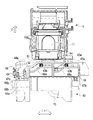
図2は、インクジェット記録装置100の外装部品を除いた記録装置主要部101を示したものである。記録装置主要部101は、キャリッジユニット1、キャリッジ駆動部2、記録媒体セット機構3、記録面基準部材4、回復ユニット5、を備える。これらの部分は、記録装置主要部101のベース部材に直接的または間接的に支持されている。
FIG. 2 shows the
(記録媒体セット機構、記録面基準部材)
記録媒体セット機構3は、記録媒体積載部16および透過型センサである記録媒体検出手段87(図3参照)を備えており、記録媒体Pが挿入されたことを記録媒体検出手段87が検知すると、記録媒体積載部16が上昇して記録面基準部材4に近づく方向に移動し、記録媒体Pを記録面基準部材4に押し当てて保持するように構成されている。
(Recording medium setting mechanism, recording surface reference member)
The recording
このように記録媒体Pが記録面基準部材4に対して押圧・保持されることで、中身の入った封筒など様々な厚みの記録媒体Pにおいても記録ヘッド11と記録媒体Pとの距離を一定距離に保つことが可能である。記録面基準部材4には、記録ヘッド11の吐出口11a(図5、12参照)から吐出されたインクが記録媒体Pへ着弾するのを妨げないように、切欠き部17が設けられている。なお、本実施形態では、記録媒体Pの供給作業は、ユーザによる手作業であるが、自動供給装置を用いた自動供給でもよい。また本実施例では記録媒体検出手段87として透過型センサを用いたが、接触式など記録媒体Pが規定の位置に位置していることを検知できる手段であればどの様な手段でも構わない。
By pressing and holding the recording medium P against the recording
(動作制御)
次に図3を用いて本実施例における動作制御について説明する。図3は、本実施例におけるインクジェット記録装置100の制御系の概略構成を示すブロック図である。制御部50は、CPU82、ASIC83、記録ヘッド駆動制御回路97、および各種モータの駆動を制御するモータ駆動回路86、およびその出力ポート85などを備える。CPU82は、プログラムROM93に記憶された制御プログラムを実行する。プログラムROM93には本実施形態の動作を実現するための制御プログラムや各種テーブルが記憶されている。また、CPU82の作業用のメモリとして、ワークRAM94が使用される。CPU82には、ホストPC80から送信された画像データや記録コマンド等が、インタフェースコントローラ81を介して送信される。さらに、CPU82には、種々の指令やデータの入力を行う操作パネル96が接続されており、ここから入力された指令に基づき、CPU82は種々の制御を行う。すなわち、CPU82は、ASIC83を制御し、画像データに基づく記録動作や、記録媒体検出手段87からの検出信号による記録媒体Pの検出、記録ヘッド11のメンテナンス動作など、インクジェット記録装置100全体の動作を統括的に制御する。
(Operation control)
Next, the operation control in this embodiment will be described with reference to FIG. FIG. 3 is a block diagram showing a schematic configuration of a control system of the
ASIC83は、ホストPC(ホストコンピュータ)82からインタフェースコントローラ81およびCPU82を介して送信されたコマンドを解析し、記録ヘッド駆動制御回路97およびモータ駆動回路86などを制御する。
The ASIC 83 analyzes commands transmitted from the host PC (host computer) 82 via the
ここで、制御部50によって実行される一連の記録動作に関する制御動作を説明する。操作パネル96によって回復動作の指令が入力された場合には、CPU82は、モータ駆動回路86、出力ポート85を介してモータ12を駆動し、駆動ベルト13を介してキャリッジユニット1を所定のホームポジションへと移動させる。次いで、CPU82はASIC83によってポンプモータ95を駆動させ、ホームポジションに位置する記録ヘッド11の吐出口11aからインクの吸引や排出を行うと共に、吐出口11aの吐出口面11bに付着したインクや塵埃の払拭などを行う。これにより、記録ヘッド11の吐出性能が回復する。
Here, a control operation related to a series of recording operations executed by the
この後、記録動作指令が操作パネル96から入力されると、CPU82は、ホストPC80から送られた2値化された記録データをイメージメモリ84にビットマップ展開する。さらにCPU82は、ASIC83を介してモータ12を駆動させ、キャリッジユニット1をホームポジションからA方向(主走査方向)に沿って移動させる。このキャリッジユニット1の移動により、記録ヘッド11もA方向と平行する移動経路に沿って移動する。キャリッジユニット1が移動する間に、CPU82は、リニアエンコーダ15の検出信号に基づいて記録ヘッド11の移動位置を検出する。記録ヘッド11が記録媒体Pに対して画像を記録する領域(記録領域)に達すると、CPU82はASIC83を介して記録ヘッド駆動制御回路97を制御し、記録データに基づいて記録ヘッド11からインクを吐出させる。これにより、記録媒体Pの記録領域に画像が形成される。
After that, when the recording operation command is input from the
(キャリッジユニット、キャリッジ駆動部)
図2に示すように、キャリッジユニット1は、記録を行うための記録ヘッド11を搭載可能であり、A(+)方向(第1の方向)およびA(−)方向(第2の方向)へ移動可能である。記録ヘッド11は、吐出部とインクタンクとを含むカートリッジとして一体構成されている。記録ヘッド11には、インクを吐出する複数の記録素子を配列した記録素子列が設けられている。本実施形態における記録素子は、インクタンクから供給されたインクを吐出する吐出部と、吐出部内に設けられた吐出エネルギー発生素子とにより構成されている。吐出エネルギー発生素子としては、電気熱変換素子(ヒータ)または電気機械変換素子(ピエゾ)などが用いられる。記録素子列は、キャリッジユニット1の移動方向である主走査方向(A方向)と交差する副走査方向(B方向)に沿って配列されている。
(Carriage unit, carriage drive unit)
As shown in FIG. 2, the
キャリッジ駆動部2は、駆動源であるモータ12、モータ12からの駆動をキャリッジユニット1に伝達するための駆動ベルト13、ガイド部14を備えており、キャリッジユニット1に備えられた係合部(不図示)と駆動ベルト13が係合していることでキャリッジユニット1と駆動ベルト13はA方向(主走査方向)に一体的に移動可能である。本実施例では、モータ12はDCモータであるが、ステッピングモータなど、駆動源を駆動ベルト13に伝達できる手段であればよい。ガイド部14は、キャリッジユニット1がA方向に沿って正確に移動するように案内すると共に、キャリッジユニット1上の記録ヘッド11のB方向(副走査方向)における位置を規制する部分であり、ベース部材に固定されている。キャリッジユニット1は、ガイド部14に摺動可能に係合しており、キャリッジユニット1の姿勢を保持する。キャリッジユニット1の動作領域上には、リニアエンコーダ15が設けられており、キャリッジユニット1側に設けられたリニアエンコーダ読取手段(不図示)によって、キャリッジユニット1のA方向の動作位置を検出し、記録ヘッド11の吐出タイミングを制御する。このような位置検出のための手段は、リニアエンコーダ15の代用として、ロータリーエンコーダやステッピングモータ、透過型センサなど位置検出機能を持った技術でも代用可能である。
The
(回復ユニット)
図6〜8は回復ユニット5の斜視図である。図9、10はキャップベース23とブレードベース27の斜視図である。回復ユニット5は、記録ヘッド11の回復動作を行う。回復ユニット5は、記録ヘッド11の吐出口11aを保湿・保護してキャッピングするためのキャップ21、吐出口11aの吐出口面11bを払拭して清掃するためのワイパーブレード26、キャップ21を介して吐出口11aから泡および固着インクなどを吸引するためのポンプ(図示せず)を備えている。
(Recovery unit)
6 to 8 are perspective views of the
キャップ21は、キャップホルダ22に設けられた爪(図示せず)がキャップベース23と係合することによりキャップホルダ22に保持されている。キャップ21は、キャップベース23に対して揺動可能かつ図示しないバネによって矢印C方向(鉛直上向き(記録ヘッド11のある方向))に付勢されている。キャップベース23には4つのアーム23bが設けられている。それぞれのアーム23bは、回復ユニットベース24に設けられた溝24aに沿って移動可能に懸架されており、バネ25により矢印D方向に付勢されている。
The
記録ヘッド11から吐出口11a内の泡抜きなどの為に行われる予備吐出を行う際は、キャップ21上に吐出を行う。キャップ21内に溜まったインクは、前記ポンプにより吸引され廃液タンク(図示せず)内に排出される。
When performing preliminary discharge from the
キャップベース23には、キャップ21を上昇させるための第1レバー23aが一体に成形されている(図9、10)。キャップ21は、キャリッジユニット1が第1レバー23aをA(−)方向(第2の方向)へ押圧することで上昇して、吐出口11aをキャッピングするように構成されている。
A
ブレードベース27は、第2レバー27aとブレードベース軸部27bとを有する。第2レバー27aとブレードベース軸部27bはブレードベース27と一体に成形されている。第2レバー27aは、ブレードベース軸部27bを回動中心としてブレードベース27を回動する。ブレードベース27はブレードベース軸部27bを回動中心として回復ユニットベース24に対し回動可能に軸支されている。なお、第2レバー27aが、ブレードベース軸部27bを回動中心として回動する際に、回動中心は回復ユニットベース24に対してA(+)方向(第1の方向)およびA(−)方向(第2の方向)へ移動しない。図10において、キャップベース23にキャップホルダ22を介してキャップ21が取り付けられており、ブレードベース27にブレードベースストッパ28が取り付けられている。
The
ブレードベース27にはワイパーブレード26が支持されている。ブレードベース27は、キャリッジユニット1が第1レバー23aを押圧した後に、キャリッジユニット1が第2レバー27aをA(−)方向(第2の方向)へさらに押圧することで、ブレードベース軸部27bを回動中心として回動し、ワイピングが可能な位置まで上昇するように構成されている。したがって、ワイパーブレード26もブレードベース軸部27bを回動中心として回動するが、前述したように、回動中心自体はA(+)方向(第1の方向)およびA(−)方向(第2の方向)へ移動しないことから、ワイパーブレード26も第1の方向および第2の方向(つまり、横方向)へ移動しない。よって、ワイパーブレードが横方向へ移動しながら回動する特許文献2に記載された装置よりも、ブレードに付着したインクの飛散は軽減できる。
A
回復ユニット5は回復ユニットベース24を有する。回復ユニットベース24は、A(−)方向(第2の方向)の後端付近に設けられた溝内で、ブレードベース軸部27bをA方向(主走査方向)に対して直角に支持している。回復ユニットベース24は、全体としてA方向に延在して部分的に上下方向の段差を有する溝24aを有する。溝24a内でアーム23bがA方向に対して直角に支持されている。
The
ブレードベース27にストッパ軸部27cが設けられていて、ストッパ軸部27cにブレードベースストッパ28が回動可能に軸支されている。ブレードベースストッパ28は、ワイパーブレード26をワイピングが可能な位置で保持する。引張りバネ29がブレードベースストッパ28と回復ユニットベース24との間に懸架されている。ブレードベースストッパ28が、引張りバネ29の引張り力に抗してワイパーブレード26とともに上昇するようになっている。またブレードベースストッパ28は、引張りバネ29の引張り力に従ってワイパーブレード26とともに下降するように構成されている。
A
回復ユニットベース24は、その一部の上面に、ブレードベースストッパ28を退避位置で載置する載置面24bを有する。ブレードベースストッパ28は、その半径方向の一部に、下向きに突出する面を備えた載置部28bを有する。載置部28bは載置面24bと係合するように構成されている。図7に示すように、ワイパーブレード26がワイピングを行わない退避位置に位置するときは、ブレードベースストッパ28が回復ユニットベース24に引張りバネ29によって付勢され、載置部28bが載置面24b上に載置されることで保持されるようになっている。
The
ブレードベースストッパ28は、A(+)方向(第1の方向)およびA(−)方向(第2の方向)に対して傾斜した傾斜面を備える係合部28aを有する。キャリッジユニット1は、係合部28aと係合するキャリッジ係合部1cを有する。ストッパ軸部27cの軸心は、ブレードベース軸部27bの軸心に対して直角に配置されている。キャリッジ係合部1cが係合部28aをA(+)方向に押圧することでブレードベースストッパ28がストッパ軸部27cの周りで回動して、ブレードベース27の保持が解除されるように構成されている。
The
回復ユニットベース24は、その一部の上面に、ブレードベースストッパ28をワイピング位置で保持する上向きの水平な保持面24cを有する。ブレードベースストッパ28は、その放射方向の一端に、下向きに突出した面を有する保持部28cを有する。保持部28cは保持面24cと係合するように構成されている。図8に示すように、ワイパーブレード26がワイピングを行うワイピング位置に保持される場合は、ブレードベース27が回動してワイパーブレード26が上昇し、キャリッジユニット1がA(+)方向(第1の方向)へ移動することで下降する。ここでブレードベースストッパ28が回復ユニットベース24に向けて引張りバネ29によって付勢されつつ、保持部28cが保持面24c上に保持されるようになっている。
The
(作用)
次に図11〜15を用いてキャッピング、ワイピング動作などを説明する。
(Action)
Next, capping, wiping operations, and the like will be described with reference to FIGS. 11 to 15.
図11は動作説明のフローチャート図である。記録ヘッド11の回復を行う際は、まず記録ヘッド11を搭載したキャリッジユニット1が回復ユニット5に向かってA(−)方向(第2の方向)へ移動すると、キャリッジユニット1の第1突き当て部1a(図5を参照)が、キャップベース23に設けられた第1レバー23aと係合する(図4、12を参照)。この時点で、吐出口11aの吐出口面11bに対して水平(図2矢印A/B)方向にキャップ21の位置が決められる。画像印字前などに予備吐出を行う際は、この状態でインク滴をキャップ21内に吐出する。吐出口11aをキャップする場合は、キャリッジユニット1がさらにA(−)方向に移動する。こうして第1レバー23aを押し込み、キャリッジユニット1の移動に追従する形でキャップ21をキャップベース23と共に移動させる。この際、キャップベース23のアーム23bは、回復ユニットベースの溝24aに沿って移動する為、キャリッジユニット1の移動方向に加えて矢印C方向にも移動し、キャップ21が吐出口11aに付勢されるようになっている。
FIG. 11 is a flowchart of an operation explanation. When recovering the
キャップ21は、キャップホルダ22とともにキャップベース23に対して矢印C方向(記録ヘッド11の方向)へバネ(図示せず)によって付勢されている。そのため、キャップ21は、吐出口11aに接触後、キャップ21及びキャップホルダ22がキャップベース23に沈み込む形で、記録ヘッド11の吐出口面11bにならい吐出口11aを密閉する(図13の状態)。吐出口11aからインクを吸い出す吸引回復を行う際は、この状態でチューブ30と接続された吸引ポンプ(図示せず)を駆動しキャップ21内を減圧することで強制的に吐出口11a内のインクを吸引する。吸引されたインクは、チューブ30を伝って移送され、吸引ポンプ(図示せず)を通過し、廃液タンク(図示せず)へ排出される。
The
ワイピングを行う際は、キャリッジユニット1が図13の状態から更にA(−)方向(第2の方向)側へ移動し、キャリッジユニット1の第2突き当て部1bがブレードベース27に設けられた第2レバー27aを押圧する。第2レバー27aは、押圧されるとブレードベース27のブレードベース軸部27bを中心に回動し、ワイパーブレード26が上昇する(図14の状態)。上昇するとストッパ軸部27cに軸支されたブレードベースストッパ28が引張りバネ29に抗して矢印C方向に回動する。その後キャリッジユニット1が第2レバー27aから離れるA(+)方向(第1の方向)に移動すると、ブレードベースストッパ28が引張りバネ29の戻り力により矢印C方向と反対方向に回動する。その後ブレードベースストッパ28の保持部28cが回復ユニットベース24の保持面24c上に係合して保持される。回復ユニット5がこの状態でキャリッジユニット1がA(+)方向へ移動すると、ワイパーブレード26の先端と記録ヘッド11の吐出口面11bが接触する。その状態でキャリッジユニット1が回復ユニット5から遠ざかるA(+)方向に移動することで、ワイパーブレード26が吐出口面11bを拭きとるワイピングが行われる(図15の状態)。
When performing wiping, the
図8、15に示すワイピング位置から図7に示す退避位置に戻る際は、キャリッジユニット1がA(+)方向(第1の方向)へ移動すると、キャリッジユニット1のキャリッジ係合部1cがブレードベースストッパ28の係合部28aと接触し、ブレードベースストッパ28をストッパ軸部27cに関して回動させる。ブレードベースストッパ28が回動すると回復ユニットベース24との係合が解かれ、引張りバネ29によりブレードベース27が回動し、ワイパーブレード26が元の退避位置に下がる。
When returning from the wiping position shown in FIGS. 8 and 15 to the retracted position shown in FIG. 7, when the
以上説明したように、キャッピングした休止状態から印字を開始する際は、キャッピング状態からキャリッジユニット1が印字領域(A(+)方向)へ移動すればよく、記録ヘッド11の吸引回復を行う際はキャッピング状態から行えばよい。キャッピング状態からA(−)方向へ移動しなければワイピングを行うことなく印字及びキャッピングが可能となる。ワイピングを行う際はキャッピング状態からキャリッジユニット1をA(−)方向へ移動させ、第2レバーを押圧してワイピングブレードを上昇して保持させ、ワイピングが終了する位置までキャリッジユニット1をA(+)方向へ移動させればよい。
As described above, when printing is started from the capped hibernation state, the
このようにキャリッジユニット1のスキャン方向の移動の為の駆動のみでワイピング実施の有無を選択することが出来、キャッピング及び解除動作及びブレード昇降動作において無駄な動作をすることなく一連の動作が可能である。ワイピングの必要のない場合はワイパーブレード26が移動することもなくワイパーブレード26に付着したインクが飛び散るなどして周囲を汚すことも軽減できる。
In this way, it is possible to select whether or not to perform wiping only by driving the
<実施例2>
図16は実施例2における回復ユニットの斜視図である。なお、実施例1で説明された部材と共通又は類似する部材には、実施例2において実施例1の参照符号に40だけ加算した参照符号を付し、実施例1の説明を援用することができる。
<Example 2>
FIG. 16 is a perspective view of the recovery unit according to the second embodiment. In addition, the member common to or similar to the member described in the first embodiment may be provided with a reference code obtained by adding 40 to the reference code of the first embodiment in the second embodiment, and the description of the first embodiment may be incorporated. can.
実施例1においては、キャップベース23に設けられた第1レバー23a及びブレードベース27に設けられた第2レバー27aのどちらもキャリッジユニット1によって押圧されるが、実施例2においては、第1レバー63aはキャリッジユニット1で押圧されるが第2レバー67aは第1レバー63aに設けられた凸部63cを介して押圧されるようになっている。
In the first embodiment, both the
回復動作は実施例1と同様であり、キャリッジユニット1がA(−)方向(第2の方向)(回復ユニット5側)に移動し、キャリッジユニット1とキャップベース63の第1レバー63aが係合した状態を示したものが図17である。そのままキャリッジユニット1が第1レバー63aを押圧しつつA(−)方向に移動し、記録ヘッド11の吐出口11aをキャッピングした状態を示したのが図18である。図18の状態の後、印字を行う場合は、キャリッジユニット1がA(+)方向(第1の方向)に移動して印字を行う。図18の状態の後、ワイピングを行う場合は、更にキャリッジユニット1がA(−)方向に移動し第1レバー63aに設けられた凸部63cがブレードベース67に設けられた第2レバー67aを押圧しワイパーブレード66を上昇させる。こうしてキャリッジユニット1が、凸部63cを介して第2レバー27aをA(−)方向へさらに押圧するように構成されている。ワイパーブレード66が上昇した状態を示したのが図19である。図19の状態の後、キャリッジユニット1はA(+)方向に移動してワイピングを行う。ワイピングの状態を示したのが図20である。ワイパーブレード66の係止保持、解除の構成、動作は実施例1と同様である。
The recovery operation is the same as in the first embodiment, the
実施例1、2どちらの方式でも同様の効果が得られるが実施例2のタイプが連動性に関し良い構成と考えられる。 Although the same effect can be obtained by either method of Examples 1 and 2, the type of Example 2 is considered to have a good configuration in terms of interlocking.
また実施例1、2では、キャップベースのアームを回復ユニットベースの溝に沿わせて移動させてキャップを上昇させることとし、ワイパーブレードを搭載したブレードベースを回動してワイパーブレードを昇降させることとしている。しかしながら、これらの動作は、キャリッジユニット1の動きに同期して途中に無駄な動作が入らないような動作であればよく、本実施例に示されているのは一例であり、その目的を実施可能な技術、配置であれば手段は問わないものとする。また、実施例1、2では、第1レバーと第2レバーを押圧する方向が第2の方向であるものを示したが、第1レバーと第2レバーを押圧する方向は第1の方向とすることも可能である。例えば、図2に示した記録装置を記録媒体の挿入方向から見た際に、装置の構成を左右対称に入れ替えれば、第1レバーと第2レバーを押圧する方向を第1の方向とすることができる。
Further, in the first and second embodiments, the arm of the cap base is moved along the groove of the recovery unit base to raise the cap, and the blade base on which the wiper blade is mounted is rotated to raise and lower the wiper blade. It is said. However, these operations may be any operations that are synchronized with the movement of the
1:キャリッジユニット
1a:第1突き当て部
1b:第2突き当て部
1c:キャリッジ係合部
2:キャリッジ駆動部
3:記録媒体セット機構
4:記録面基準部材
5:回復ユニット
11:記録ヘッド
11a:吐出口
11b:吐出口面
12:モータ
13:駆動ベルト
14:ガイド部
15:リニアエンコーダ
16:記録媒体積載部
17:切欠き部
21、61:キャップ
22、62:キャップホルダ
23、63:キャップベース
23a、63a:第1レバー
23b、63b:アーム
24、64:回復ユニットベース
24a、64a:溝
24b、64b:載置面
24c、64c:保持面
25:バネ
26、66:ワイパーブレード
27、67:ブレードベース
27a、67a:第2レバー
27b、67b:ブレードベース軸部
27c、67c:ストッパ軸部
28、68:ブレードベースストッパ
28a、68a:係合部
28b、68b:載置部
28c、68c:保持部
29、69:引張りバネ
30、70:チューブ
50:制御部
63c:凸部
80:ポストPC
81:インタフェースコントローラ
82:CPU
83:ASIC
84:イメージメモリ
85:出力ポート
86:モータ駆動回路
87:記録媒体検出手段
93:プログラムROM
94:ワークRAM
95:ポンプモータ
96:操作パネル
97:記録ヘッド駆動制御回路
100:インクジェット記録装置
101:記録装置主要部
P:記録媒体
1: Carriage unit 1a:
81: Interface controller 82: CPU
83: ASIC
84: Image memory 85: Output port 86: Motor drive circuit 87: Recording medium detection means 93: Program ROM
94: Work RAM
95: Pump motor 96: Operation panel 97: Recording head drive control circuit 100: Inkjet recording device 101: Recording device main part P: Recording medium
Claims (7)
前記記録ヘッドの回復動作を行う回復ユニットと、を有するインクジェット記録装置であって、
前記回復ユニットは、
前記記録ヘッドの吐出口をキャッピングするキャップと、
前記キャップを支持するキャップベースと、
前記キャップベースに設けられた前記キャップを上昇させるための第1レバーと、
前記吐出口をワイピングするワイパーブレードと、
前記ワイパーブレードを支持するブレードベースと、
前記ブレードベースに設けられた第2レバーと、
前記第2レバーの回動中心となるブレードベース軸部と、を有し、
前記キャップは、前記キャリッジユニットが前記第1レバーを前記第2の方向へ押圧することで上昇して、前記吐出口をキャッピングするように構成されており、
前記ワイパーブレードは、前記キャリッジユニットが前記第1レバーを押圧した後に、前記キャリッジユニットが前記第2レバーを前記第2の方向へさらに押圧することで、前記ブレードベース軸部を回転中心として回動し、前記ワイピングが可能な位置まで上昇するように構成されており、
前記回転中心は、前記キャリッジユニットが前記第2レバーを前記第2の方向へ押圧する際に、前記第1の方向および前記第2の方向へ移動しない
ことを特徴とするインクジェット記録装置。 A carriage unit that is equipped with a recording head that ejects ink and can move in the first direction and a second direction opposite to the first direction.
An inkjet recording apparatus including a recovery unit that performs a recovery operation of the recording head.
The recovery unit
A cap that caps the discharge port of the recording head and
A cap base that supports the cap and
A first lever provided on the cap base for raising the cap and
A wiper blade that wipes the discharge port and
A blade base that supports the wiper blade and
The second lever provided on the blade base and
It has a blade base shaft portion that serves as a rotation center of the second lever, and has a blade base shaft portion.
The cap is configured so that the carriage unit rises by pressing the first lever in the second direction to cap the discharge port.
The wiper blade rotates about the blade base shaft portion by further pressing the second lever in the second direction after the carriage unit presses the first lever. However, it is configured to rise to a position where the wiper is possible.
The center of rotation is an inkjet recording apparatus that does not move in the first direction and the second direction when the carriage unit presses the second lever in the second direction.
前記ブレードベースストッパは、前記キャリッジユニットが前記第2レバーを前記第2の方向へ押圧することで、前記ワイパーブレードの保持が可能な位置まで上昇するように構成されていることを特徴とする、請求項1に記載のインクジェット記録装置。 The recovery unit has a blade base stopper that holds the wiper blade in a position where the wiper blade can be wiped.
The blade base stopper is characterized in that the carriage unit pushes the second lever in the second direction to raise the wiper blade to a position where it can be held. The inkjet recording apparatus according to claim 1.
前記回復ユニットが、前記ブレードベースストッパを保持する保持面を有し、
前記ブレードベースストッパが、前記保持面と係合する保持部を有し、
前記ブレードベースストッパは、前記キャリッジユニットが前記第1の方向へ移動することで下降して、前記保持部が前記保持面上に保持されるように構成されていることを特徴とする、請求項1または2に記載のインクジェット記録装置。 The recovery unit has a blade base stopper that holds the wiper blade in a position where the wiper blade can be wiped.
The recovery unit has a holding surface that holds the blade base stopper.
The blade base stopper has a holding portion that engages with the holding surface.
The blade base stopper is characterized in that the carriage unit is lowered by moving in the first direction, and the holding portion is held on the holding surface. The inkjet recording apparatus according to 1 or 2.
前記ブレードベースがストッパ軸部を有し、
前記ブレードベースストッパが前記ストッパ軸部の周りで回動可能であり、
前記ストッパ軸部の軸心は、前記ブレードベース軸部の軸心と直角に配置されており、
前記回復ユニットが回復ユニットベースを有し、
前記回復ユニットベースと前記ブレードベースストッパとの間に引張りバネが懸架されており、
前記ブレードベースストッパが、前記引張りバネの引張り力に抗して前記ワイパーブレードとともに上昇し、前記引張りバネの引張り力に従って前記ワイパーブレードとともに下降するように構成されていることを特徴とする、請求項1〜3のいずれか1項に記載のインクジェット記録装置。 The recovery unit has a blade base stopper that holds the wiper blade in a position where the wiper blade can be wiped.
The blade base has a stopper shaft portion and has a stopper shaft portion.
The blade base stopper is rotatable around the stopper shaft portion and is rotatable around the stopper shaft portion.
The axial center of the stopper shaft portion is arranged at right angles to the axial center of the blade base shaft portion.
The recovery unit has a recovery unit base and
A tension spring is suspended between the recovery unit base and the blade base stopper.
The blade base stopper is configured to rise with the wiper blade against the tensile force of the tension spring and descend with the wiper blade according to the tensile force of the tension spring. The inkjet recording apparatus according to any one of 1 to 3.
前記ブレードベースがストッパ軸部を有し、
前記ブレードベースストッパが、前記第1の方向および第2の方向に対して傾斜した傾斜面を備える係合部を有し、
前記キャリッジユニットが、前記係合部と係合するキャリッジ係合部を有し、
前記ストッパ軸部の軸心は、前記ブレードベース軸部の軸心と直角に配置されており、
前記キャリッジ係合部が前記係合部を前記第1の方向に押圧することで、前記ブレードベースストッパが前記ストッパ軸部の周りで回動して、前記ブレードベースストッパの保持が解除されるように構成されていることを特徴とする、請求項1〜4のいずれか1項に記載のインクジェット記録装置。 The recovery unit has a blade base stopper that holds the wiper blade in a position where the wiper blade can be wiped.
The blade base has a stopper shaft portion and has a stopper shaft portion.
The blade base stopper has an engaging portion having an inclined surface inclined with respect to the first direction and the second direction.
The carriage unit has a carriage engaging portion that engages with the engaging portion.
The axial center of the stopper shaft portion is arranged at right angles to the axial center of the blade base shaft portion.
When the carriage engaging portion presses the engaging portion in the first direction, the blade base stopper rotates around the stopper shaft portion so that the holding of the blade base stopper is released. The inkjet recording apparatus according to any one of claims 1 to 4, wherein the inkjet recording apparatus is configured in the above.
前記キャリッジユニットが、前記凸部を介して前記第2レバーを前記第2の方向へさらに押圧するように構成されていることを特徴とする、請求項1〜6のいずれか1項に記載のインクジェット記録装置。 The first lever is provided with a convex portion, and the first lever is provided with a convex portion.
The one according to any one of claims 1 to 6, wherein the carriage unit is configured to further press the second lever in the second direction via the convex portion. Inkjet recording device.
Priority Applications (1)
| Application Number | Priority Date | Filing Date | Title |
|---|---|---|---|
| JP2020028115A JP2021130290A (en) | 2020-02-21 | 2020-02-21 | Inkjet recording device |
Applications Claiming Priority (1)
| Application Number | Priority Date | Filing Date | Title |
|---|---|---|---|
| JP2020028115A JP2021130290A (en) | 2020-02-21 | 2020-02-21 | Inkjet recording device |
Publications (2)
| Publication Number | Publication Date |
|---|---|
| JP2021130290A true JP2021130290A (en) | 2021-09-09 |
| JP2021130290A5 JP2021130290A5 (en) | 2023-02-16 |
Family
ID=77551901
Family Applications (1)
| Application Number | Title | Priority Date | Filing Date |
|---|---|---|---|
| JP2020028115A Pending JP2021130290A (en) | 2020-02-21 | 2020-02-21 | Inkjet recording device |
Country Status (1)
| Country | Link |
|---|---|
| JP (1) | JP2021130290A (en) |
Citations (4)
| Publication number | Priority date | Publication date | Assignee | Title |
|---|---|---|---|---|
| JPH0332848A (en) * | 1989-06-29 | 1991-02-13 | Canon Inc | Ink jet recorder |
| JP2005111686A (en) * | 2003-10-03 | 2005-04-28 | Canon Inc | Inkjet recording apparatus |
| JP2007160559A (en) * | 2005-12-09 | 2007-06-28 | Canon Inc | Inkjet recording apparatus |
| JP2010201674A (en) * | 2009-03-02 | 2010-09-16 | Seiko Epson Corp | Fluid jetting apparatus |
-
2020
- 2020-02-21 JP JP2020028115A patent/JP2021130290A/en active Pending
Patent Citations (4)
| Publication number | Priority date | Publication date | Assignee | Title |
|---|---|---|---|---|
| JPH0332848A (en) * | 1989-06-29 | 1991-02-13 | Canon Inc | Ink jet recorder |
| JP2005111686A (en) * | 2003-10-03 | 2005-04-28 | Canon Inc | Inkjet recording apparatus |
| JP2007160559A (en) * | 2005-12-09 | 2007-06-28 | Canon Inc | Inkjet recording apparatus |
| JP2010201674A (en) * | 2009-03-02 | 2010-09-16 | Seiko Epson Corp | Fluid jetting apparatus |
Similar Documents
| Publication | Publication Date | Title |
|---|---|---|
| US6318836B1 (en) | Ink jet recording apparatus recording images when an ink jet recording head is installed thereon and reading images when an image reading head is installed thereon | |
| US6189998B1 (en) | Space saving ink jet recovery device and ink jet recording apparatus using the same | |
| US6830311B2 (en) | Ink jet recording apparatus, moving position control method of capping device therein, and flushing control method therefor | |
| JP2012051132A (en) | Inkjet recording apparatus | |
| JP6881992B2 (en) | Inkjet recording device and its control method | |
| EP1238806B1 (en) | Ink jet recording apparatus and method of controlling wiping operation of recording head in the ink jet recording apparatus | |
| US20060055729A1 (en) | Printhead wiper cleaning mechanism for an imaging apparatus | |
| JP2021130290A (en) | Inkjet recording device | |
| US5886715A (en) | Print head maintenance mechanism | |
| KR20040013644A (en) | Sensor cleaning apparatus for an ink-jet printer | |
| JP2010105348A (en) | Ink-jet recording device | |
| JP2022122070A (en) | Ink jet recording device | |
| JP3536958B2 (en) | Ink jet recording device | |
| JP2008179103A (en) | Image forming apparatus | |
| JP6107275B2 (en) | Droplet ejection device and method for controlling droplet ejection device | |
| JP2019188687A (en) | Ink jet recording device | |
| JP7135020B2 (en) | Inkjet recording device | |
| US7438383B2 (en) | Inkjet recording apparatus | |
| JP4475854B2 (en) | Ink jet recording apparatus and wiping method thereof | |
| US12059902B2 (en) | Printing apparatus and method for the apparatus | |
| JP7500243B2 (en) | Recording apparatus and control method thereof | |
| JP7326945B2 (en) | Wiping unit and liquid ejection device | |
| JP5267085B2 (en) | Inkjet printer and carriage position detection method | |
| JP5183121B2 (en) | Inkjet recording device | |
| JP2007190815A (en) | Printing apparatus, program and method for printing quality information of printing apparatus |
Legal Events
| Date | Code | Title | Description |
|---|---|---|---|
| A521 | Request for written amendment filed |
Free format text: JAPANESE INTERMEDIATE CODE: A523 Effective date: 20230208 |
|
| A621 | Written request for application examination |
Free format text: JAPANESE INTERMEDIATE CODE: A621 Effective date: 20230208 |
|
| A977 | Report on retrieval |
Free format text: JAPANESE INTERMEDIATE CODE: A971007 Effective date: 20231204 |
|
| A131 | Notification of reasons for refusal |
Free format text: JAPANESE INTERMEDIATE CODE: A131 Effective date: 20231205 |
|
| A02 | Decision of refusal |
Free format text: JAPANESE INTERMEDIATE CODE: A02 Effective date: 20240528 |