JP2021116632A - Box type building unit and building using the same - Google Patents
Box type building unit and building using the same Download PDFInfo
- Publication number
- JP2021116632A JP2021116632A JP2020011972A JP2020011972A JP2021116632A JP 2021116632 A JP2021116632 A JP 2021116632A JP 2020011972 A JP2020011972 A JP 2020011972A JP 2020011972 A JP2020011972 A JP 2020011972A JP 2021116632 A JP2021116632 A JP 2021116632A
- Authority
- JP
- Japan
- Prior art keywords
- clt
- clt panel
- box
- panel
- gantry
- Prior art date
- Legal status (The legal status is an assumption and is not a legal conclusion. Google has not performed a legal analysis and makes no representation as to the accuracy of the status listed.)
- Granted
Links
Images
Landscapes
- Load-Bearing And Curtain Walls (AREA)
Abstract
Description
本発明は、直交集成板(CLT(Cross Laminated Timber))からなるパネル(CLTパネル)により形成された箱型建築物ユニットおよびこれを用いた建築物に関する。 The present invention relates to a box-shaped building unit formed of a panel (CLT panel) made of an orthogonal laminated board (CLT (Cross Laminated Timber)) and a building using the same.
直交集成板(CLT)は、板の繊維方向が各層で互いに直交するように積層接着されたパネルである。CLTパネルは直交積層であるため、従来建築の資材として使用されてきた集成材よりも強度が安定しており、変形しにくく、コンクリートにも匹敵する強度を持ち、断熱性にも優れているという特徴がある。 A cross laminated board (CLT) is a panel laminated and bonded so that the fiber directions of the boards are orthogonal to each other in each layer. Since CLT panels are orthogonally laminated, they are more stable in strength than laminated lumber used as a material for conventional construction, are not easily deformed, have strength comparable to concrete, and have excellent heat insulation. There is a feature.
従来、このCLTパネルを利用した住宅構造が提案されている。例えば、特許文献1には、柱材および梁材を組んで形成した木造軸組に、CLTパネルからなる壁板、床板および天井板をビスで固定した住宅構造が開示されている。
Conventionally, a housing structure using this CLT panel has been proposed. For example,
特許文献1に記載の住宅構造は、CLTパネルを単なる面材として使用したものであり、柱材および梁材を組んで形成した木造軸組構造が基本となっている。そのため、この住宅を築造する場合には、建築現場において通常の木造軸組工程に加えてCLTパネルを固定する工程が発生することになり、築造完了までにかなりの日数が必要となる。
The housing structure described in
そこで、本発明においては、工場内において組み立て可能であり、容易に現場に運搬して建築物を築造することが可能な箱型建築物ユニットおよびこれを用いた建築物を提供することを目的とする。 Therefore, an object of the present invention is to provide a box-shaped building unit that can be assembled in a factory and can be easily transported to a site to build a building, and a building using the box-shaped building unit. do.
本発明の箱型建築物ユニットは、壁面、天井面および床面がCLTパネルにより形成される箱型建築物ユニットであって、鉄骨により平面視矩形状に枠組みされた架台であり、直交する壁面の各CLTパネルが周縁角部の上面に固定される架台と、直交する壁面の各CLTパネルの下面に形成された下部スリットと、架台の周縁角部の上面に立設され、直交する壁面の各CLTパネルの下部スリットに挿入されて直交する壁面の各CLTパネルに固定される壁下部接合プレートとを有するものである。 The box-type building unit of the present invention is a box-type building unit in which a wall surface, a ceiling surface, and a floor surface are formed by CLT panels, and is a frame framed in a rectangular shape in a plan view by a steel frame, and is an orthogonal wall surface. A gantry in which each CLT panel is fixed to the upper surface of the peripheral corner portion, a lower slit formed on the lower surface of each CLT panel on the orthogonal wall surface, and a wall surface erected on the upper surface of the peripheral corner portion of the gantry and orthogonal to each other. It has a wall lower joint plate that is inserted into the lower slit of each CLT panel and fixed to each CLT panel on an orthogonal wall surface.
本発明の箱型建築物ユニットは、壁面、天井面および床面がCLTパネルにより形成されており、特に、直交する壁面の各CLTパネルの下面に形成された下部スリットに、架台上の周縁角部の上面に立設された壁下部接合プレートが挿入されて固定されているため、直交する壁面の各CLTパネルが鉄骨により枠組みされた架台と一体となっており、この箱型建築物ユニットは架台ごと容易に現場に運搬することが可能である。 In the box-type building unit of the present invention, the wall surface, the ceiling surface, and the floor surface are formed by CLT panels, and in particular, the peripheral angle on the gantry is formed in the lower slit formed on the lower surface of each CLT panel on the orthogonal wall surface. Since the lower wall joint plate erected on the upper surface of the part is inserted and fixed, each CLT panel on the orthogonal wall surface is integrated with the pedestal framed by the steel frame, and this box-shaped building unit is It is possible to easily transport the entire frame to the site.
ここで、架台は、鉄骨から延設され、床面のCLTパネルの下面に接合される床接合プレートを備えたものであることが望ましい。これにより、架台の下面側からCLTパネルの下面と床接合プレートとを接合することができる。 Here, it is desirable that the gantry is provided with a floor joining plate extending from the steel frame and joined to the lower surface of the CLT panel on the floor surface. As a result, the lower surface of the CLT panel and the floor joining plate can be joined from the lower surface side of the gantry.
また、本発明の箱型建築物ユニットは、直交する壁面の各CLTパネルの上面に形成された上部スリットと、架台の周縁角部の下面に立設され、直交する壁面の各CLTパネルの上部スリットに挿入されて直交する壁面の各CLTパネルに固定される壁上部接合プレートとを有するものであることが望ましい。これにより、本発明の箱型建築物ユニットを積層する場合に、下層の建築物ユニットの直交する壁面の各CLTパネルの上面に形成された上部スリットに対して、上層の箱型建築物ユニットの架台の周縁角部の下面に立設された壁上部接合プレートを挿入して固定することができる。 Further, the box-shaped building unit of the present invention has an upper slit formed on the upper surface of each CLT panel on the orthogonal wall surface and an upper portion of each CLT panel on the orthogonal wall surface erected on the lower surface of the peripheral corner of the gantry. It is desirable to have a wall top joint plate that is inserted into the slit and fixed to each CLT panel on the wall surface that is orthogonal to each other. As a result, when stacking the box-shaped building units of the present invention, the upper-layer box-shaped building unit is subjected to the upper slits formed on the upper surface of each CLT panel on the orthogonal wall surface of the lower-layer building unit. A wall upper joint plate erected on the lower surface of the peripheral corner of the gantry can be inserted and fixed.
また、本発明の箱型建築物ユニットは、架台の周縁角部の上面に固定されたCLTパネルの間の上部に架け渡されたCLTパネルからなる補強梁部であり、天井面のCLTパネルが載置される補強梁部を有するものであることが望ましい。これにより、壁面としての強度を架台の周縁角部の上面に固定されたCLTパネルとこのCLTパネルの間の上部に架け渡されたCLTパネルからなる補強梁部により賄うため、これらのCLTパネルにより囲まれた開口部を広く取ることができる。 Further, the box-shaped building unit of the present invention is a reinforcing beam portion composed of a CLT panel bridged over the CLT panels fixed to the upper surface of the peripheral corner portion of the gantry, and the CLT panel on the ceiling surface is formed. It is desirable that it has a reinforcing beam portion to be mounted. As a result, the strength as a wall surface is covered by the reinforcing beam portion composed of the CLT panel fixed to the upper surface of the peripheral corner portion of the gantry and the CLT panel bridged over the upper part between the CLT panels. The enclosed opening can be widened.
(1)本発明の箱型建築物ユニットは、直交する壁面の各CLTパネルが鉄骨により枠組みされた架台と一体となっており、工場内において組み立て可能であり、この箱型建築物ユニットは架台ごと容易に現場に運搬して短工期で建築物を築造することが可能である。 (1) In the box-shaped building unit of the present invention, each CLT panel on the orthogonal wall surface is integrated with a pedestal framed by a steel frame, and can be assembled in the factory. This box-shaped building unit is a pedestal. It is possible to easily transport each product to the site and build a building in a short period of time.
(2)架台が鉄骨から延設され、床面のCLTパネルの下面に接合される床接合プレートと備えたことにより、架台の下面側からCLTパネルの下面と床接合プレートとを接合することができ、床面のCLTパネルの上面に接合部分が現れず、美観が損なわれることがない。 (2) Since the gantry is provided with a floor joining plate extending from the steel frame and joined to the lower surface of the CLT panel on the floor surface, the lower surface of the CLT panel and the floor joining plate can be joined from the lower surface side of the gantry. As a result, the joint portion does not appear on the upper surface of the CLT panel on the floor surface, and the aesthetic appearance is not spoiled.
(3)箱型建築物ユニットを積層する場合に、下層の建築物ユニットの直交する壁面の各CLTパネルの上面に形成された上部スリットに対して、上層の箱型建築物ユニットの架台の周縁角部の下面に立設された壁上部接合プレートを挿入して容易に固定することができ、複数階の建築物であっても短工期で容易に築造することが可能である。 (3) When stacking box-type building units, the peripheral edge of the gantry of the upper-layer box-type building unit with respect to the upper slit formed on the upper surface of each CLT panel on the orthogonal wall surface of the lower-layer building unit. The wall upper joint plate erected on the lower surface of the corner can be easily fixed by inserting it, and even a multi-story building can be easily constructed in a short construction period.
(4)架台の周縁角部の上面に固定されたCLTパネルの間の上部に架け渡されたCLTパネルからなる補強梁部であり、天井面のCLTパネルが載置される補強梁部を有するものであることにより、開口部を広く取り、施工性に優れた箱型建築物ユニットが得られる。 (4) It is a reinforcing beam portion composed of a CLT panel spanned above between CLT panels fixed to the upper surface of the peripheral corner portion of the gantry, and has a reinforcing beam portion on which the CLT panel on the ceiling surface is placed. As a result, a box-type building unit having a wide opening and excellent workability can be obtained.
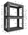
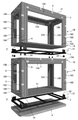
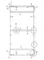
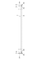
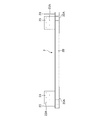
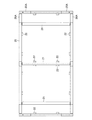
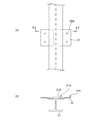
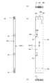
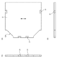
図1は本発明の実施の形態における建築物の斜視図、図2は図1の建築物の分解斜視図、図3は架台の平面図、図4は架台の正面図、図5は架台の左側面図、図6は架台の底面図、図7(A)は図3のVII部拡大図、(B)は(A)のA−A断面図、図8は壁上部接合プレートを示す図であって、(A)は正面図、(B)は左側面図、(C)は底面図である。 1 is a perspective view of a building according to an embodiment of the present invention, FIG. 2 is an exploded perspective view of the building of FIG. 1, FIG. 3 is a plan view of a gantry, FIG. 4 is a front view of the gantry, and FIG. Left side view, FIG. 6 is a bottom view of the gantry, FIG. 7 (A) is an enlarged view of the VII portion of FIG. 3, (B) is a sectional view taken along the line AA of (A), and FIG. (A) is a front view, (B) is a left side view, and (C) is a bottom view.
図1および図2において、本発明の実施の形態における建築物は、2つの箱型建築物ユニット1A,1Bを上下に積み重ねて連結したものである。なお、箱型建築物ユニット1A,1Bは一部を除いてほぼ同一の構成であり、以下では主に箱型建築物ユニット1Aを例にとって詳細に説明するが、箱型建築物ユニット1Bの共通の構成部分については同一符号を付し、その詳細な説明を省略する。
In FIGS. 1 and 2, the building according to the embodiment of the present invention is two box-
箱型建築物ユニット1A,1Bは、主に、鉄骨により形成された架台2と、この架台2上に組み合わされる壁面のCLTパネル10A,10B、10C,10D、床面のCLTパネル11、天井面のCLTパネル12および補強梁部を形成するCLTパネル13A,13Bとにより構成された直方体状のユニットである。
The box-
架台2は、図3〜図6に示すように、鉄骨により平面視矩形状に枠20が枠組みされたものである。鉄骨としては例えばH形鋼が使用できる。架台2の枠20の長辺方向には、所定間隔で短辺方向に延びる梁21が設けられている。また、架台2は、床面のCLTパネル11の下面に接合される床接合プレート22を備える。床接合プレート22は、図7(B)に示すように、その上面22Aが梁21の上面21Aと面一となるように、梁21のフランジ部21Bの内側から外側に向かって延設されている。床接合プレート22には、床面のCLTパネル11と接合するための接合孔22Bが設けられている。
As shown in FIGS. 3 to 6, the
壁面のCLTパネル10AとCLTパネル10B、およびCLTパネル10CとCLTパネル10Dは、それぞれ互いに直交するように、架台2の周縁角部の上面に固定される。このCLTパネル10A〜10Dが固定される架台2の周縁角部の上面には壁下部接合プレート23が立設されている。また、壁下部接合プレート23が立設される位置の架台2の下面側には、補強プレート20Aが設けられている。壁下部接合プレート23には、ドリフトピン27(図2参照。)を用いてCLTパネル10A〜10Dと接合するための接合孔23Aが設けられている。
The
また、上段の箱型建築物ユニット1Bの架台2の周縁角部の下面には、壁上部接合プレート24が立設される。図8に示すように、壁上部接合プレート24は、架台2の下面に面接触する座部25Aと、座部25Aから垂直に垂下された接合部25Bとから構成される。
Further, a wall upper
座部25Aには、架台2とボルト26により接合するための接合孔25Cが設けられている。座部25Aの接合孔25Cの下面にはボルト25Dが螺合されるナット25Eが溶接されている。接合部25Bには、ナット25Eおよびこのナット25Eに螺合されたボルト26が干渉しないように、例えば半円状の切欠部24Dが設けられている。また、接合部25Bには、ドリフトピン27を用いてCLTパネル10A〜10Dと接合するための接合孔24Aが設けられている。
The
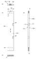
図9は壁面のCLTパネル10Aを示す図であって、(A)は正面図、(B)は左側面図、(C)は平面図、(D)は底面図である。図10は壁面のCLTパネル10Bを示す図であって、(A)は正面図、(B)は右側面図、(C)は平面図、(D)は底面図である。なお、CLTパネル10CはCLTパネル10Bと左右対称形状であり、CLTパネル10DはCLTパネル10Aと左右対称形状である。
9A and 9B are views showing a
各CLTパネル10A〜10Dの下面には、壁下部接合プレート23が挿入される下部スリット14が形成されている。各CLTパネル10A〜10Dの下部には、この下部スリット14に挿入される壁下部接合プレート23の接合孔23Aに対応する位置に、ドリフトピン27を挿入するための接合孔14Aが設けられている。壁下部接合プレート23は各CLTパネル10A〜10Dの下部スリット14に挿入され、接合孔14Aに挿入されるドリフトピン27によって、各CLTパネル10A〜10Dに固定される。
A
各CLTパネル10A〜10Dの上面には、壁上部接合プレート24が挿入される上部スリット15が形成されている。各CLTパネル10A〜10Dの上部には、この上部スリット15に挿入される壁上部接合プレート24の接合孔24Aに対応する位置に、ドリフトピン27を挿入するための接合孔15Aが設けられている。また、各CLTパネル10A〜10Dの上面には、壁上部接合プレート24の座部25Aを埋め込むための座掘り16Aが設けられている。さらに、この座掘り16A内には、ナット25Eおよびこのナット25Eに螺合されたボルト26を埋め込むための座掘り16Bが設けられている。
An
上段の箱型建築物ユニット1Bの架台2の周縁角部の下面にボルト26により接合された壁上部接合プレート24は、それぞれ壁面のCLTパネル10A〜10Dの上部スリット15に挿入され、接合孔15Aに挿入されるドリフトピン27によって各CLTパネル10A〜10Dに固定される。
The wall upper joining
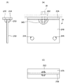
架台2の周縁角部で直交する壁面のCLTパネル10A,10B同士およびCLTパネル10C,10D同士は、蝶千切り(バタフライジョイント)状の接合部材3により接合される。CLTパネル10Aは、その外側主面10A−1がCLTパネル10Bの木端面10B−2と面一となるように、その木端面10A−2がCLTパネル10Bの内側主面10B−3に対して突き合わされて接合される。なお、CLTパネル10A,10Bの木端面10A−2,10B−2とはCLTパネル10A,10Bの短手方向の端面である。
The
CLTパネル10Aの接合部材3による接合部には、接合部材3の蝶形の半分の形状に対応する開口部30が形成されている。開口部30は、外側主面10A−1側からみて開口面30Aが底面30Bより狭い等脚台形状、すなわち木端面10A−2側よりも内側(木端面10A−2から離れる側(図9の右側))が幅広となるように形成されている。
An
一方、このCLTパネル10Aと接合されるCLTパネル10Bの接合部には、接合部材3の蝶形の残り半分の形状に対応する開口部31が形成されている。開口部31は、木端面10B−2側からみて内側主面10B−3側の開口面31Aが外側主面10B−1側の開口面31Bより狭い等脚台形状、すなわち外側主面10B−1側が内側主面10B−3側よりも幅広となるように形成されている。
On the other hand, in the joint portion of the
接合部材3は、これらのCLTパネル10A,10Bの接合部の開口部30,31に対して、CLTパネル10Aの外側主面10A−1側(CLTパネル10Bの木端面10B−2側)から挿入される。接合部材3は、この開口部30,31に挿入した際にCLTパネル10A,10B同士を締め付ける力が働くように勾配が設けられている。CLTパネル10C,10Dも同様の構成である。
The joining
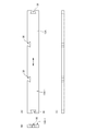
図11は補強梁部のCLTパネル13Aを示す図であって、(A)は正面図、(B)は左側面図、(C)は平面図である。CLTパネル13AはCLTパネル10A,10Dの間の上部に架け渡される。CLTパネル13AのCLTパネル10A,10Dとの接合部には、前述と同様の開口部30が形成されている。一方のCLTパネル10A,10DのCLTパネル13Aとの接合部にも、同様の開口部30が形成されている。CLTパネル13AとCLTパネル10A,10Dとは、CLTパネル13Aの外側主面13A−1側から挿入される接合部材3により接合される。CLTパネル13Bも同様の構成である。
11A and 11B are views showing the
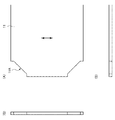
図12は床面のCLTパネル11を示す図であって、(A)は右半分を省略した平面図、(B)は正面図、(C)は左側面図である。床面のCLTパネル11の四隅には、切欠部11Aが設けられている。床面のCLTパネル11は、架台2の枠20および梁21上に載置され、架台2の下面側より床接合プレート22の接合孔22Bを用いて接合される。
12A and 12B are views showing a
図13は天井面のCLTパネル12を示す図であって、(A)は右半分を省略した平面図、(B)は正面図、(C)は左側面図である。天井面のCLTパネル12の四隅にも、切欠部12Aが設けられている。天井面のCLTパネル12は、補強梁部のCLTパネル13A,13B上に載置され、接合部材3を用いて補強梁部のCLTパネル13A,13Bに接合される。
13A and 13B are views showing a
天井面のCLTパネル12の補強梁部のCLTパネル13Aとの接合部には、前述と同様の開口部31が形成されている。一方のCLTパネル13AのCLTパネル12との接合部には、前述と同様の開口部30が形成されている。これらの開口部30,31に対して、CLTパネル13Aの外側主面13A−1側から接合部材3が挿入されることで、天井面のCLTパネル12が補強梁部のCLTパネル13Aと接合される。CLTパネル13Bも同様の構成である。
The
上記構成の建築物は、まず工場内にて2つの箱型建築物ユニット1A,1Bを形成し、壁上部接合プレート24は取り付けないで、それぞれ架台2ごとトレーラやトラック等に積載して建築現場へ搬送する。建築現場では、基礎4上に箱型建築物ユニット1Aを載置してアンカーボルト(図示せず。)を用いて固定する。そして、この箱型建築物ユニット1A上に、壁上部接合プレート24を取り付けた箱型建築物ユニット1Bを載置し、ドリフトピン27を用いて箱型建築物ユニット1Bを箱型建築物ユニット1Aと接合する。
In the building having the above configuration, first, two box-shaped
このように、本実施形態における箱型建築物ユニット1A,1Bは、壁面、天井面および床面がCLTパネル10A〜10D,11,12,13A,13Bにより形成されており、特に、直交する壁面の各CLTパネル10A〜10Dの下面に形成された下部スリット14に、架台2上の周縁角部の上面に立設された壁上部接合プレート24が挿入されて固定されているため、直交する壁面の各CLTパネル10A〜10Dが鉄骨により枠組みされた架台2と一体となっており、工場内において組み立て可能である。そして、この箱型建築物ユニット1A,1Bは架台2ごと容易に現場に運搬して短工期で建築物を築造することが可能である。
As described above, in the box-shaped
また、本実施形態における箱型建築物ユニット1A,1Bでは、架台2が鉄骨から延設された床接合プレート22を備えており、架台2の下面側から床面のCLTパネル11の下面と床接合プレート22とを接合することができ、床面のCLTパネル11の上面に接合部分が現れず、美観が損なわれることがない。
Further, in the box-shaped
また、本実施形態における箱型建築物ユニット1A,1Bを積層する場合に、下層の箱型建築物ユニット1Aの直交する壁面の各CLTパネル10A〜10Dの上面に形成された上部スリット15に対して、上層の箱型建築物ユニット1Bの架台2の周縁角部の下面に立設された壁上部接合プレート24を挿入して容易に固定することができ、複数階の建築物であっても短工期で容易に築造することが可能である。
Further, when the box-shaped
また、本実施形態における箱型建築物ユニット1A,1Bは、架台2の周縁角部の上面に固定されたCLTパネル10A〜10Dの間の上部に架け渡された補強梁部のCLTパネル13A,13Bを有し、天井面のCLTパネル12がこの補強梁部のCLTパネル13A,13Bに載置されており、壁面としての強度をCLTパネル10A〜10Dと補強梁部のCLTパネル13A,13Bにより賄うため、これらのCLTパネル10A〜10D,13A,13Bにより囲まれた開口部を広く取ることができ、施工性に優れている。
Further, in the box-shaped
なお、上記実施形態では、2つの箱型建築物ユニット1A,1Bを上下に積み重ねて連結した例について説明したが、上下に積み重ねず建築物を築造することも可能である。また、積み重ねる箱型建築物ユニット1Bはいくつでもよく、多層構造の建築物であっても容易に積層して築造することが可能である。さらにこの箱型建築物ユニット1A,1Bは水平方向に複数個並べて建築物を築造することも可能である。
In the above embodiment, an example in which two box-shaped
本発明の箱型建築物ユニットは、直交集成板(CLT)からなるパネル(CLTパネル)を用いた建築物の築造に有用である。 The box-type building unit of the present invention is useful for building a building using a panel (CLT panel) made of a cross laminated board (CLT).
1A,1B 箱型建築物ユニット
2 架台
3 接合部材
4 基礎
10A〜10D,11,12,13A,13B CLTパネル
11A,12A 切欠部
14 下部スリット
14A 接合孔
15 上部スリット
15A 接合孔
20 枠
20A 補強プレート
21 梁
21B フランジ部
22 床接合プレート
22B 接合孔
23 壁下部接合プレート
23A 接合孔
24 壁上部接合プレート
24A 接合孔
24D 切欠部
25A 座部
25B 接合部
25C 接合孔
25D ボルト
25E ナット
26 ボルト
27 ドリフトピン
30,31 開口部
1A, 1B Box-
Claims (5)
鉄骨により平面視矩形状に枠組みされた架台であり、直交する壁面の各CLTパネルが周縁角部の上面に固定される架台と、
前記直交する壁面の各CLTパネルの下面に形成された下部スリットと、
前記架台の前記周縁角部の上面に立設され、前記直交する壁面の各CLTパネルの下部スリットに挿入されて前記直交する壁面の各CLTパネルに固定される壁下部接合プレートと
を有する箱型建築物ユニット。 A box-type building unit in which the wall surface, ceiling surface, and floor surface are formed by CLT panels.
A pedestal framed in a rectangular shape in a plan view by a steel frame, and a pedestal in which each CLT panel on the orthogonal wall surface is fixed to the upper surface of the peripheral corner portion.
A lower slit formed on the lower surface of each CLT panel on the orthogonal wall surface, and
A box type having a wall lower joint plate erected on the upper surface of the peripheral corner portion of the gantry, inserted into a lower slit of each CLT panel on the orthogonal wall surface, and fixed to each CLT panel on the orthogonal wall surface. Building unit.
前記架台の前記周縁角部の下面に立設され、前記直交する壁面の各CLTパネルの上部スリットに挿入されて前記直交する壁面の各CLTパネルに固定される壁上部接合プレートと
を有する請求項1または2に記載の箱型建築物ユニット。 An upper slit formed on the upper surface of each CLT panel on the orthogonal wall surface, and
A claim having a wall upper joining plate which is erected on the lower surface of the peripheral corner portion of the gantry, is inserted into an upper slit of each CLT panel of the orthogonal wall surface, and is fixed to each CLT panel of the orthogonal wall surface. The box-type building unit according to 1 or 2.
Priority Applications (1)
| Application Number | Priority Date | Filing Date | Title |
|---|---|---|---|
| JP2020011972A JP7393224B2 (en) | 2020-01-28 | 2020-01-28 | Box-shaped building units and buildings using them |
Applications Claiming Priority (1)
| Application Number | Priority Date | Filing Date | Title |
|---|---|---|---|
| JP2020011972A JP7393224B2 (en) | 2020-01-28 | 2020-01-28 | Box-shaped building units and buildings using them |
Publications (2)
| Publication Number | Publication Date |
|---|---|
| JP2021116632A true JP2021116632A (en) | 2021-08-10 |
| JP7393224B2 JP7393224B2 (en) | 2023-12-06 |
Family
ID=77174319
Family Applications (1)
| Application Number | Title | Priority Date | Filing Date |
|---|---|---|---|
| JP2020011972A Active JP7393224B2 (en) | 2020-01-28 | 2020-01-28 | Box-shaped building units and buildings using them |
Country Status (1)
| Country | Link |
|---|---|
| JP (1) | JP7393224B2 (en) |
Cited By (1)
| Publication number | Priority date | Publication date | Assignee | Title |
|---|---|---|---|---|
| JP2023075553A (en) * | 2021-11-19 | 2023-05-31 | ファーストウッド株式会社 | Structure, trailer house and manufacturing method thereof |
Citations (5)
| Publication number | Priority date | Publication date | Assignee | Title |
|---|---|---|---|---|
| JPH04330135A (en) * | 1991-01-16 | 1992-11-18 | Misawa Homes Co Ltd | Box type dwelling house unit |
| JPH07180229A (en) * | 1993-12-24 | 1995-07-18 | Misawa Homes Co Ltd | Vertical connecting tool of building unit |
| JPH08128112A (en) * | 1994-11-01 | 1996-05-21 | Misawa Homes Co Ltd | Connection member on unit type building with basement, and construction method of the unit type building |
| JPH09328818A (en) * | 1997-03-14 | 1997-12-22 | Misawa Homes Co Ltd | Building unit and unit building |
| JP2019065685A (en) * | 2017-10-04 | 2019-04-25 | 株式会社竹中工務店 | building |
-
2020
- 2020-01-28 JP JP2020011972A patent/JP7393224B2/en active Active
Patent Citations (5)
| Publication number | Priority date | Publication date | Assignee | Title |
|---|---|---|---|---|
| JPH04330135A (en) * | 1991-01-16 | 1992-11-18 | Misawa Homes Co Ltd | Box type dwelling house unit |
| JPH07180229A (en) * | 1993-12-24 | 1995-07-18 | Misawa Homes Co Ltd | Vertical connecting tool of building unit |
| JPH08128112A (en) * | 1994-11-01 | 1996-05-21 | Misawa Homes Co Ltd | Connection member on unit type building with basement, and construction method of the unit type building |
| JPH09328818A (en) * | 1997-03-14 | 1997-12-22 | Misawa Homes Co Ltd | Building unit and unit building |
| JP2019065685A (en) * | 2017-10-04 | 2019-04-25 | 株式会社竹中工務店 | building |
Cited By (1)
| Publication number | Priority date | Publication date | Assignee | Title |
|---|---|---|---|---|
| JP2023075553A (en) * | 2021-11-19 | 2023-05-31 | ファーストウッド株式会社 | Structure, trailer house and manufacturing method thereof |
Also Published As
| Publication number | Publication date |
|---|---|
| JP7393224B2 (en) | 2023-12-06 |
Similar Documents
| Publication | Publication Date | Title |
|---|---|---|
| JP2020084729A (en) | Construction method and building structure | |
| JP6841439B2 (en) | Building method and building structure | |
| JP2005139623A (en) | Reinforcing beam and unit building with the reinforcing beam | |
| JP2021116632A (en) | Box type building unit and building using the same | |
| JP2002097722A (en) | Unit type building and corner reinforcing material therefor | |
| JPS6351226B2 (en) | ||
| JPH07180221A (en) | Construction method for unit building | |
| JP5128313B2 (en) | Unit building | |
| JP5123603B2 (en) | Unit type building and construction method of unit type building | |
| JP2009155986A (en) | Building unit | |
| JP7475675B2 (en) | Strength-bearing column unit and improved wooden frame structure incorporating said strength-bearing column unit, and construction method thereof | |
| JPH0776903A (en) | Building constituent of industialized building and manufacture thereof | |
| JP2001164658A (en) | Beam joint structure and unit building | |
| JP2009228232A (en) | Unit type building | |
| JP2023058304A (en) | Timber frame and building framework | |
| JP3311323B2 (en) | Pillarless building units and unit buildings | |
| JP7097132B1 (en) | Frame structure and its construction method | |
| JP7364267B2 (en) | wooden building structure | |
| JP2003020726A (en) | Unit building and its construction method | |
| JP2024133775A (en) | CLT unit | |
| JP2618542B2 (en) | Column joints for housing units | |
| JP2023110642A (en) | Hardware for joining units | |
| JP3248736B2 (en) | Unit house | |
| KR20250150808A (en) | Recyclable modular building structures with improved ease of construction and demolition | |
| JP5362893B2 (en) | Unit building |
Legal Events
| Date | Code | Title | Description |
|---|---|---|---|
| RD03 | Notification of appointment of power of attorney |
Free format text: JAPANESE INTERMEDIATE CODE: A7423 Effective date: 20200310 |
|
| RD04 | Notification of resignation of power of attorney |
Free format text: JAPANESE INTERMEDIATE CODE: A7424 Effective date: 20200610 |
|
| A621 | Written request for application examination |
Free format text: JAPANESE INTERMEDIATE CODE: A621 Effective date: 20221221 |
|
| A977 | Report on retrieval |
Free format text: JAPANESE INTERMEDIATE CODE: A971007 Effective date: 20231025 |
|
| TRDD | Decision of grant or rejection written | ||
| A01 | Written decision to grant a patent or to grant a registration (utility model) |
Free format text: JAPANESE INTERMEDIATE CODE: A01 Effective date: 20231101 |
|
| A61 | First payment of annual fees (during grant procedure) |
Free format text: JAPANESE INTERMEDIATE CODE: A61 Effective date: 20231124 |
|
| R150 | Certificate of patent or registration of utility model |
Ref document number: 7393224 Country of ref document: JP Free format text: JAPANESE INTERMEDIATE CODE: R150 |