JP2021093902A - Motor, actuator, and motor manufacturing method - Google Patents

Motor, actuator, and motor manufacturing method Download PDF

Info

Publication number
JP2021093902A
JP2021093902A JP2020150820A JP2020150820A JP2021093902A JP 2021093902 A JP2021093902 A JP 2021093902A JP 2020150820 A JP2020150820 A JP 2020150820A JP 2020150820 A JP2020150820 A JP 2020150820A JP 2021093902 A JP2021093902 A JP 2021093902A
Authority
JP
Japan
Prior art keywords
motor
actuator
fitting portion
cover
ball screw
Prior art date
Legal status (The legal status is an assumption and is not a legal conclusion. Google has not performed a legal analysis and makes no representation as to the accuracy of the status listed.)
Granted
Application number
JP2020150820A
Other languages
Japanese (ja)
Other versions
JP7485286B2 (en
Inventor
阿部 健太郎
Kentaro Abe
健太郎 阿部
美那 加藤
Mina Kato
美那 加藤
Current Assignee (The listed assignees may be inaccurate. Google has not performed a legal analysis and makes no representation or warranty as to the accuracy of the list.)
IAI Corp
Original Assignee
IAI Corp
Priority date (The priority date is an assumption and is not a legal conclusion. Google has not performed a legal analysis and makes no representation as to the accuracy of the date listed.)
Filing date
Publication date
Application filed by IAI Corp filed Critical IAI Corp
Publication of JP2021093902A publication Critical patent/JP2021093902A/en
Application granted granted Critical
Publication of JP7485286B2 publication Critical patent/JP7485286B2/en
Active legal-status Critical Current
Anticipated expiration legal-status Critical

Links

Images

Landscapes

  • Motor Or Generator Frames (AREA)
  • Connection Of Motors, Electrical Generators, Mechanical Devices, And The Like (AREA)

Abstract

To provide a highly versatile motor, an actuator, and a motor manufacturing method that makes it possible to attach an operation unit to a different model of motor or actuator, or to replace the operation unit from the same motor or actuator with a different one.SOLUTION: A motor 10 includes an output shaft 10a, a motor body 11 for rotating the output shaft 10a, and a motor cover 12. The motor cover 12 accommodates the motor body 11 with the output shaft 10a protruding outward. A to-be-fitted portion 16, into which an operation panel 50 for setting the operation of the output shaft 10a is fitted, is formed on an upper surface 12a, which is a cover surface.SELECTED DRAWING: Figure 6

Description

本発明は、モータ、アクチュエータ、及びモータの製造方法に関する。 The present invention relates to a motor, an actuator, and a method for manufacturing the motor.

特許文献1には、スライド移動するスライダと、電動モータとを有する電動アクチュエータが開示されている。特許文献1に開示の電動アクチュエータは、スライダ及び電動モータに加えて、例えば、アクチュエータ本体に収容されたボールねじを有しており、ボールねじが、電動モータの出力軸の回転運動をスライダの直線運動に変換し、この変換に基づいて、スライダが往復運動する。スライダの移動速度、移動量、電動モータの出力軸の回転速度等の設定は、ユーザが操作面の押しボタンを操作することにより行われる。 Patent Document 1 discloses an electric actuator having a slider that slides and moves, and an electric motor. The electric actuator disclosed in Patent Document 1 has, for example, a ball screw housed in the actuator body in addition to the slider and the electric motor, and the ball screw causes the rotational movement of the output shaft of the electric motor to be a straight line of the slider. It is converted into motion, and based on this conversion, the slider reciprocates. The moving speed of the slider, the moving amount, the rotation speed of the output shaft of the electric motor, and the like are set by the user operating a push button on the operation surface.

特許第5268096号公報Japanese Patent No. 5268096

上記特許文献1に記載のものにおいては、操作面は、電動モータのモータカバーの表面から露出した状態で、モータカバーに一体的に設けられている。このため、この操作面を有する操作部を脱着して、ユニットとして異なる機種のモータやアクチュエータに取り付けたり、機能等が異なる別の操作部に取り替えたりすることができない。そこで、操作部が取り付け可能であったり、別の操作部に取り替え可能であったりする汎用性の高いアクチュエータが望まれる。 In the one described in Patent Document 1, the operation surface is integrally provided on the motor cover in a state of being exposed from the surface of the motor cover of the electric motor. Therefore, the operation unit having this operation surface cannot be attached to or detached from the motor or actuator of a different model as a unit, or can be replaced with another operation unit having a different function or the like. Therefore, a highly versatile actuator that can be attached to an operation unit or can be replaced with another operation unit is desired.

本発明は、上述の事情の下になされたもので、操作部を異なる機種のモータやアクチュエータに取り付けたり、同一のモータやアクチュエータから別の操作部に取り替えたりすることができる汎用性の高いモータ、アクチュエータ、及びモータの製造方法を提供することを目的とする。 The present invention has been made under the above circumstances, and is a highly versatile motor capable of attaching an operation unit to a different model of motor or actuator, or replacing the same motor or actuator with another operation unit. , Actuators, and methods of manufacturing motors.

上述の目的を達成するために、本発明の第1の観点に係るモータは、
回転軸と、
前記回転軸を回転させるためのモータ本体と、
前記回転軸が外部に突出しつつ、前記モータ本体を収容すると共に、前記回転軸の動作の設定をするための操作部が嵌め込まれる被嵌め込み部が、カバー表面に形成されているモータカバーと、
を備える。
In order to achieve the above object, the motor according to the first aspect of the present invention is
Rotation axis and
A motor body for rotating the rotating shaft and
A motor cover in which the motor body is accommodated while the rotating shaft protrudes to the outside, and an operating portion for setting the operation of the rotating shaft is fitted is formed on the cover surface.
To be equipped.

前記操作部は、ユーザが操作するための操作ボタンが設けられている操作面を有し、
前記被嵌め込み部が形成されている前記カバー表面は、前記被嵌め込み部に嵌め込まれている前記操作部の前記操作面と同一平面に位置するように形成されていてもよい。
The operation unit has an operation surface provided with operation buttons for user operation.
The cover surface on which the fitting portion is formed may be formed so as to be positioned on the same plane as the operating surface of the operating portion fitted in the fitting portion.

前記被嵌め込み部に着脱可能に嵌め込まれる前記操作部と、
前記操作部によって設定された前記回転軸の回転を制御するための電子部品が実装されていると共に、前記モータカバーに収納される第1制御基板と、
を備え、
前記操作部は、
ケースと、
前記回転軸の回転を制御するための電子部品が実装されていると共に、前記ケースに収納される第2制御基板と、を有していてもよい。
The operation unit that is detachably fitted to the fitting portion and
An electronic component for controlling the rotation of the rotating shaft set by the operating unit is mounted, and a first control board housed in the motor cover is mounted on the first control board.
With
The operation unit
With the case
An electronic component for controlling the rotation of the rotating shaft may be mounted, and a second control board housed in the case may be provided.

前記操作部は、前記被嵌め込み部から取り外した状態で、ユーザの前記モータ本体の操作が可能に設けられていてもよい。 The operation unit may be provided so that the user can operate the motor body in a state of being removed from the fitting portion.

前記被嵌め込み部は、前記回転軸の軸心方向に沿って形成されている溝からなっていてもよい。 The fitting portion may be formed of a groove formed along the axial direction of the rotating shaft.

前記被嵌め込み部の内面と、当該内面と対向する前記操作部の外面との一方には、凸部が形成され、
前記被嵌め込み部の内面と、当該内面と対向する前記操作部の外面との他方には、前記凸部が嵌ると共に、前記軸心方向に沿って線状に形成されている線状溝からなる凹部が形成されていてもよい。
A convex portion is formed on one of the inner surface of the fitting portion and the outer surface of the operating portion facing the inner surface.
The convex portion is fitted to the other of the inner surface of the fitting portion and the outer surface of the operating portion facing the inner surface, and is composed of a linear groove formed linearly along the axial direction. A recess may be formed.

前記溝からなる前記被嵌め込み部に、前記操作部と共に嵌め込まれるパネルカバーを備え、
前記パネルカバーの前記軸心方向の長さは、前記被嵌め込み部の前記軸心方向の長さから、前記操作部の前記軸心方向の長さを減じた長さであってもよい。
A panel cover to be fitted together with the operation portion is provided in the fitting portion formed of the groove.
The length of the panel cover in the axial direction may be a length obtained by subtracting the length of the operating portion in the axial direction from the length of the fitting portion in the axial direction.

前記パネルカバーは、弾性を有する素材からなると共に、前記被嵌め込み部の内面を押圧可能な部分を含んで構成され、前記押圧可能な部分の前記被嵌め込み部の内面に対する押圧に基づいて、前記被嵌め込み部に固定可能に形成されていてもよい。 The panel cover is made of an elastic material and includes a portion capable of pressing the inner surface of the fitting portion, and the covering is based on the pressing of the pressable portion against the inner surface of the fitting portion. It may be formed so as to be fixed to the fitting portion.

前記パネルカバーは、前記被嵌め込み部に嵌め込まれている場合に、外部に露出する表面が形成されている天板部と、前記天板部の前記軸心方向に直交する直交方向の一端から延設されている第1の側壁部と、前記天板部の前記直交方向の他端から延設されている第2の側壁部と、を有し、
前記第1の側壁部及び前記第2の側壁部は、前記直交方向の一端及び他端を基点に、前記被嵌め込み部の内面を押圧可能に互いに広がるように形成されていてもよい。
The panel cover extends from one end in the orthogonal direction orthogonal to the axial direction of the top plate portion on which a surface exposed to the outside is formed when the panel cover is fitted in the fitting portion. It has a first side wall portion provided and a second side wall portion extending from the other end of the top plate portion in the orthogonal direction.
The first side wall portion and the second side wall portion may be formed so as to spread each other so that the inner surface of the fitting portion can be pressed against each other with one end and the other end in the orthogonal direction as base points.

前記被嵌め込み部は、底面を有する形状に形成され、
前記被嵌め込み部の前記底面と、前記底面と対向する前記操作部の外面との間に、空間が設けられ、
前記空間は、前記操作部に接続されるケーブルを設置可能に設けられていてもよい。
The fitting portion is formed in a shape having a bottom surface, and is formed.
A space is provided between the bottom surface of the fitting portion and the outer surface of the operation portion facing the bottom surface.
The space may be provided so that a cable connected to the operation unit can be installed.

前記操作部は、前記被嵌め込み部に対する前記操作部の嵌め込む方向を変更可能に設けられていてもよい。 The operating portion may be provided so that the fitting direction of the operating portion with respect to the fitting portion can be changed.

本発明の第2の観点に係るアクチュエータは、
本発明の第1の観点に係るモータを備える。
The actuator according to the second aspect of the present invention is
The motor according to the first aspect of the present invention is provided.

前記モータの前記回転軸の回転運動とともに回転運動するボールネジ軸と、前記ボールネジ軸の回転運動に伴って直線運動するボールネジナットと、を有するボールネジと、
前記ボールネジナットに接続され、前記ボールネジナットの直線運動と共に移動する移動体と、
を備えていてもよい。
A ball screw having a ball screw shaft that rotates with the rotary motion of the rotary shaft of the motor and a ball screw nut that linearly moves with the rotary motion of the ball screw shaft.
A moving body connected to the ball screw nut and moving with the linear motion of the ball screw nut,
May be provided.

前記ボールネジは、前記回転軸に取り付けられた第1カップリングに接続される第2カップリングを有し、
前記ボールネジと、前記移動体の少なくとも一部と、を収容すると共に、前記モータカバーが固定されているアクチュエータハウジングを備えていてもよい。
The ball screw has a second coupling that is connected to a first coupling attached to the rotating shaft.
An actuator housing in which the ball screw and at least a part of the moving body are accommodated and the motor cover is fixed may be provided.

前記回転軸の回転運動を前記ボールネジ軸に伝達するベルトと、前記ベルトを収納すると共に、前記モータカバーが固定されているベルト収容部と、を有する折り返しユニットと、
前記ボールネジと、前記移動体の少なくとも一部と、を収容すると共に、前記ベルト収容部が固定されているアクチュエータハウジングと、
備えていてもよい。
A folding unit having a belt for transmitting the rotational motion of the rotating shaft to the ball screw shaft, a belt accommodating portion for accommodating the belt, and a belt accommodating portion to which the motor cover is fixed.
An actuator housing that accommodates the ball screw and at least a part of the moving body, and to which the belt accommodating portion is fixed.
You may have.

前記移動体の直線運動と共に移動するスライドテーブルを備えていてもよい。 A slide table that moves with the linear motion of the moving body may be provided.

前記移動体の直線運動と共に移動するロッドを備えていてもよい。 A rod that moves with the linear motion of the moving body may be provided.

前記モータの前記回転軸に掛けられて、前記回転軸の回転運動に基づいて動作するベルトと、
前記ベルトに接続されて、前記ベルトの動作に基づいて、直線運動する移動体と、
を備えていてもよい。
A belt that is hung on the rotating shaft of the motor and operates based on the rotational movement of the rotating shaft.
A moving body that is connected to the belt and moves linearly based on the movement of the belt.
May be provided.

本発明の第3の観点に係るモータの製造方法は、
本発明の第1の観点に係るモータの製造方法であって、
前記回転軸の軸心方向に沿って線状に形成されている溝からなる前記被嵌め込み部に対して、前記操作部を、前記軸心方向に沿ってスライド移動させて、前記被嵌め込み部に嵌め込むことを含む。
The method for manufacturing a motor according to the third aspect of the present invention is as follows.
A method for manufacturing a motor according to the first aspect of the present invention.
The operation unit is slid along the axial direction of the fitting portion formed of grooves formed linearly along the axial direction of the rotating shaft, and is moved to the fitting portion. Including fitting.

本発明によれば、モータカバーのカバー表面には、操作部が嵌め込まれる被嵌め込み部が形成されている。これにより、操作部を異なる機種のモータやアクチュエータに取り付けたり、同一のモータやアクチュエータから別の操作部に取り替えたりすることができる汎用性の高いモータ、アクチュエータ、及びモータの製造方法を提供することできる。 According to the present invention, a fitting portion into which the operating portion is fitted is formed on the cover surface of the motor cover. This provides a highly versatile motor, actuator, and a method for manufacturing a motor, which allows the operation unit to be attached to a different model of motor or actuator, or the same motor or actuator can be replaced with another operation unit. it can.

本発明の実施の形態に係るアクチュエータの斜視図である。It is a perspective view of the actuator which concerns on embodiment of this invention. アクチュエータの正面図である。It is a front view of the actuator. 図2のA−A断面図である。FIG. 2 is a cross-sectional view taken along the line AA of FIG. 内部の各構成部品を簡略的に示したアクチュエータの断面図である。It is sectional drawing of the actuator which showed each component inside briefly. アクチュエータの分解斜視図(その1)である。It is an exploded perspective view (the 1) of an actuator. モータの分解斜視図(その1)である。It is an exploded perspective view (part 1) of a motor. モータの分解斜視図(その2)である。It is an exploded perspective view (2) of a motor. (A)は、図3のB−B断面図である。(B)は、操作パネルを外したモータの断面図である。(A) is a cross-sectional view taken along the line BB of FIG. (B) is a cross-sectional view of the motor with the operation panel removed. (A)は、図3のC−C断面図である。(B)は、パネルカバーを外したモータの断面図である。(A) is a cross-sectional view taken along the line CC of FIG. (B) is a cross-sectional view of the motor with the panel cover removed. (A)は、アクチュエータの分解斜視図(その2)である。(B)は、アクチュエータの斜視図である。(A) is an exploded perspective view (No. 2) of the actuator. (B) is a perspective view of the actuator. パネルカバーの被嵌め込み部への嵌込み方法を説明するための斜視図である。It is a perspective view for demonstrating the fitting method to the fitting part of a panel cover. 操作パネルの被嵌め込み部への嵌込み方法を説明するための分解斜視図である。It is an exploded perspective view for demonstrating the fitting method to the fitting part of the operation panel. アクチュエータの動作を説明するための断面図である。It is sectional drawing for demonstrating operation of an actuator. アクチュエータの動作を説明するための斜視図である。It is a perspective view for demonstrating the operation of an actuator. アクチュエータの効果を説明するための分解斜視図(その1)である。It is an exploded perspective view (the 1) for demonstrating the effect of an actuator. アクチュエータの効果を説明するための斜視図である。It is a perspective view for demonstrating the effect of an actuator. アクチュエータの効果を説明するための分解斜視図(その2)である。It is an exploded perspective view (the 2) for demonstrating the effect of an actuator. アクチュエータの効果を説明するための分解斜視図(その3)である。It is an exploded perspective view (No. 3) for demonstrating the effect of an actuator. 変形例1に係るアクチュエータの斜視図である。It is a perspective view of the actuator which concerns on modification 1. FIG. 変形例2に係るアクチュエータの斜視図である。It is a perspective view of the actuator which concerns on modification 2. FIG. 変形例2に係るアクチュエータの説明するための分解斜視図である。It is an exploded perspective view for demonstrating the actuator which concerns on modification 2. FIG. 変形例3に係るアクチュエータの斜視図である。It is a perspective view of the actuator which concerns on modification 3. FIG. 変形例4に係るアクチュエータの斜視図である。It is a perspective view of the actuator which concerns on modification 4. FIG. 変形例5に係るアクチュエータの斜視図である。It is a perspective view of the actuator which concerns on modification 5. FIG. 変形例6に係るアクチュエータの斜視図(その1)である。It is a perspective view (the 1) of the actuator which concerns on modification 6. 変形例6に係るアクチュエータの斜視図(その2)である。FIG. 2 is a perspective view (No. 2) of the actuator according to the modified example 6. 変形例6に係るアクチュエータの断面図である。It is sectional drawing of the actuator which concerns on modification 6. (A)は、変形例6に係るアクチュエータのモータの平面図である。(B)は、変形例6に係るアクチュエータのモータの分解斜視図である。(A) is a plan view of the motor of the actuator according to the modified example 6. (B) is an exploded perspective view of the motor of the actuator according to the modified example 6. (A)は、図26(A)のD−D断面図である。(B)は、操作パネルを外したモータの断面図である。(A) is a cross-sectional view taken along the line DD of FIG. 26 (A). (B) is a cross-sectional view of the motor with the operation panel removed. (A)は、モータカバーに操作パネルを取り付ける方法を説明するための斜視図(その1)である。(B)は、内部の各構成部品を簡略的に示したモータの断面図(その1)である。(A) is a perspective view (No. 1) for explaining a method of attaching an operation panel to a motor cover. (B) is a cross-sectional view (No. 1) of the motor which simply shows each component inside. (A)は、モータカバーに操作パネルを取り付ける方法を説明するための斜視図(その2)である。(B)は、内部の各構成部品を簡略的に示したモータの断面図(その2)である。(A) is a perspective view (No. 2) for explaining a method of attaching an operation panel to a motor cover. (B) is a cross-sectional view (No. 2) of the motor which simply shows each component inside. 内部の各構成部品を簡略的に示した変形例6に係るアクチュエータの断面図である。It is sectional drawing of the actuator which concerns on modification 6 which showed each component in the inside simply. その他の変形例に係るモータの斜視図である。It is a perspective view of the motor which concerns on other modification. パネルカバーの変形例を説明するためのモータの断面図である。It is sectional drawing of the motor for demonstrating the modification of the panel cover. (A)は、変形例に係るパネルカバーの斜視図である。(B)は、変形例に係るパネルカバーの正面図である。(A) is a perspective view of a panel cover according to a modified example. (B) is a front view of the panel cover according to the modified example.

以下、本発明の実施形態に係るモータ10及びアクチュエータ1について説明する。なお、図中のY軸方向は、図1に示すように、スライドテーブルTが進退する直線運動方向D1に平行な方向であり、X軸方向及びZ軸方向は、直線運動方向D1に直交する方向である。また、図中のXY平面は、アクチュエータ1が設置される面に平行な水平面である。 Hereinafter, the motor 10 and the actuator 1 according to the embodiment of the present invention will be described. As shown in FIG. 1, the Y-axis direction in the drawing is a direction parallel to the linear motion direction D1 in which the slide table T moves forward and backward, and the X-axis direction and the Z-axis direction are orthogonal to the linear motion direction D1. The direction. The XY plane in the figure is a horizontal plane parallel to the plane on which the actuator 1 is installed.

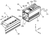
アクチュエータ1は、スライドテーブルTが移動するスライダタイプのアクチュエータである。アクチュエータ1は、図2〜図4に示すように、モータ10及びスライドテーブルTに加え、ボールネジ20と、アクチュエータハウジング30と、移動体40とを備える。 The actuator 1 is a slider type actuator in which the slide table T moves. As shown in FIGS. 2 to 4, the actuator 1 includes a ball screw 20, an actuator housing 30, and a moving body 40 in addition to the motor 10 and the slide table T.

モータ10は、図4及び図5に示すように、出力軸10a(回転軸)と、モータ本体11と、モータカバー12と、オプション収容部13と、エンドカバー14と、モータ用制御基板15(第1制御基板)と、操作パネル50(操作部)と、パネルカバー60とを有する。モータ10は、アクチュエータハウジング30から着脱可能な一つのユニットとして構成されている。 As shown in FIGS. 4 and 5, the motor 10 includes an output shaft 10a (rotating shaft), a motor body 11, a motor cover 12, an option accommodating portion 13, an end cover 14, and a motor control board 15 ( It has a first control board), an operation panel 50 (operation unit), and a panel cover 60. The motor 10 is configured as one unit that can be attached to and detached from the actuator housing 30.

モータ本体11は、例えば、ステッピングモータやサーボモータであり、ロータ、ステータ、エンコーダ11a等を有している。モータ本体11には、商用電源や直流電源からアクチェータケーブルC1とモータ用制御基板15とを経由して電力が供給される。アクチェータケーブルC1は、モータ本体11に外部からの電力供給や制御信号の入出力等を行う。モータ本体11に電力が供給されることによって、モータ本体11のロータが回転する。このロータの回転運動は、出力軸10aに出力される。これにより、出力軸10aは回転する。出力軸10aには、カップリング10b(第1カップリング)が取り付けられている。なお、本実施の形態では、モータ本体11は、ロータ、ステータ、エンコーダ11a等を有するモータであるが、これに限られない。これら以外のモータであってもよい。例えば、エンコーダ11aを有さないモータであってもよい。また、本実施の形態においては、モータ本体11のロータの回転運動は、出力軸10aに出力されるが、これに限られない。モータ本体11のロータの回転運動は、減速器によって所定の減速比で減速されてから、出力軸10aに出力されてもよい。 The motor body 11 is, for example, a stepping motor or a servomotor, and has a rotor, a stator, an encoder 11a, and the like. Electric power is supplied to the motor body 11 from a commercial power source or a DC power source via the actuator cable C1 and the motor control board 15. The actuator cable C1 supplies electric power to the motor body 11 from the outside, inputs / outputs control signals, and the like. By supplying electric power to the motor body 11, the rotor of the motor body 11 rotates. The rotary motion of this rotor is output to the output shaft 10a. As a result, the output shaft 10a rotates. A coupling 10b (first coupling) is attached to the output shaft 10a. In the present embodiment, the motor body 11 is a motor having a rotor, a stator, an encoder 11a, and the like, but the motor body 11 is not limited to this. Motors other than these may be used. For example, the motor may not have the encoder 11a. Further, in the present embodiment, the rotational movement of the rotor of the motor body 11 is output to the output shaft 10a, but the present invention is not limited to this. The rotary motion of the rotor of the motor body 11 may be decelerated by a speed reducer at a predetermined reduction ratio and then output to the output shaft 10a.

モータカバー12は、モータ本体11等を覆う略直方体形状のケースである。モータカバー12は、出力軸10aが突出した状態で、モータ本体11等を収容する。モータカバー12は、例えば、アルミニウム等の金属を押し出し加工することにより形成されている。このモータカバー12の+Z側の上面12a(カバー表面)には、操作パネル50が嵌め込まれる被嵌め込み部16が形成されている。 The motor cover 12 is a case having a substantially rectangular parallelepiped shape that covers the motor body 11 and the like. The motor cover 12 accommodates the motor body 11 and the like with the output shaft 10a protruding. The motor cover 12 is formed by extruding a metal such as aluminum, for example. A fitting portion 16 into which the operation panel 50 is fitted is formed on the upper surface 12a (cover surface) on the + Z side of the motor cover 12.

オプション収容部13は、モータ本体11の+Y側に設けられている空間である。オプション収容部13は、ブレーキ等のオプションを別途、設置するために形成されている。 The option accommodating portion 13 is a space provided on the + Y side of the motor main body 11. The option accommodating portion 13 is formed for separately installing an option such as a brake.

エンドカバー14は、図6に示すように、モータカバー12と共に、モータ本体11等を覆う。エンドカバー14は、モータカバー12の+Y側の端部に、ネジやボルト等の留め具14aによって固定されている。エンドカバー14には、長方形状に形成されているコネクタ用孔部が形成されている。コネクタ用孔部には、モータ用制御基板15に設けられているコネクタが配置され、当該コネクタには、アクチェータケーブルC1が接続される。 As shown in FIG. 6, the end cover 14 covers the motor body 11 and the like together with the motor cover 12. The end cover 14 is fixed to the + Y side end of the motor cover 12 by fasteners 14a such as screws and bolts. The end cover 14 is formed with a rectangular hole for a connector. A connector provided on the motor control board 15 is arranged in the connector hole, and the actuator cable C1 is connected to the connector.

モータ用制御基板15は、図3、図4及び図7に示すように、モータカバー12に収納されている。モータ用制御基板15は、例えば、配線基板であり、操作パネル50や図示しないティーチングペンダントによって設定されたモータ10の出力軸10aの回転を制御するための電子部品等が実装されている。また、モータ用制御基板15は、操作パネル50や図示しないティーチングペンダントによって設定されたモータ10の出力軸10aの回転を制御するためのデータを記憶する記憶部を有する。 The motor control board 15 is housed in the motor cover 12 as shown in FIGS. 3, 4, and 7. The motor control board 15 is, for example, a wiring board on which electronic components for controlling the rotation of the output shaft 10a of the motor 10 set by the operation panel 50 and the teaching pendant (not shown) are mounted. Further, the motor control board 15 has a storage unit for storing data for controlling the rotation of the output shaft 10a of the motor 10 set by the operation panel 50 and the teaching pendant (not shown).

被嵌め込み部16は、Y軸方向に沿って形成されている溝からなる。なお、出力軸10aの軸心方向は、Y軸方向であり、スライドテーブルTが進退する直線運動方向D1と同じ方向である。被嵌め込み部16は、具体的には、図8及び図9に示すように、XY平面に平行な底面16aと、YZ平面に平行な一対の側面16bとからなる溝である。一対の側面16bには、互いに対向するように突出する凸部17がそれぞれ形成されている。 The fitting portion 16 is formed of a groove formed along the Y-axis direction. The axial direction of the output shaft 10a is the Y-axis direction, which is the same direction as the linear motion direction D1 in which the slide table T moves forward and backward. Specifically, as shown in FIGS. 8 and 9, the fitting portion 16 is a groove composed of a bottom surface 16a parallel to the XY plane and a pair of side surfaces 16b parallel to the YZ plane. On each of the pair of side surfaces 16b, convex portions 17 projecting so as to face each other are formed.

凸部17は、本実施の形態においては、図5及び図6に示すように、Y軸方向に沿って線状に延設されている。 In the present embodiment, the convex portion 17 extends linearly along the Y-axis direction as shown in FIGS. 5 and 6.

操作パネル50(操作部)は、ユーザが出力軸10aの動作の設定をすることで、スライドテーブルTの移動速度、加速度、減速度、停止位置(前進端、後退端)を調整するためのものである。本実施の形態においては、操作パネル50は、ティーチングペンダントによって設定できることよりも、簡易的な設定ができるようになっているものであり、ユニットとして、被嵌め込み部16に着脱自在に嵌め込まれている。この操作パネル50は、モータカバー12の上面12aに形成されている被嵌め込み部16に嵌め込まれることで、モータカバー12に一体的に設けられる。操作パネル50は、図7及び図8に示すように、ケース51と、操作パネル用制御基板52(第2制御基板)と、操作パネル用ケーブル53とを有する。 The operation panel 50 (operation unit) is for the user to adjust the moving speed, acceleration, deceleration, and stop position (forward end, backward end) of the slide table T by setting the operation of the output shaft 10a. Is. In the present embodiment, the operation panel 50 can be set more easily than it can be set by the teaching pendant, and is detachably fitted into the fitting portion 16 as a unit. .. The operation panel 50 is integrally provided on the motor cover 12 by being fitted into the fitting portion 16 formed on the upper surface 12a of the motor cover 12. As shown in FIGS. 7 and 8, the operation panel 50 includes a case 51, an operation panel control board 52 (second control board), and an operation panel cable 53.

ケース51は、被嵌め込み部16の底面16aに対向する−Z側の底面と、被嵌め込み部16の+X側及び−X側の側面16bにそれぞれ対向する側面とを有する略直方体の板状に形成されている。ケース51は、例えば、樹脂により形成されている。ケース51の+Z側の表面には操作面51aが設けられている。また、ケース51の両側の側面には、凹部51bがそれぞれ形成されている。 The case 51 is formed in a substantially rectangular parallelepiped shape having a bottom surface on the −Z side facing the bottom surface 16a of the fitting portion 16 and side surfaces facing the + X side and the −X side side surfaces 16b of the fitting portion 16, respectively. Has been done. The case 51 is made of, for example, a resin. An operation surface 51a is provided on the surface of the case 51 on the + Z side. Further, recesses 51b are formed on both side surfaces of the case 51.

操作面51aには、ユーザが操作するための複数の操作ボタンや表示画面(例えば、有機EL(organic electro-luminescence)、液晶等)が設けられている。ユーザは、表示画面を視認しつつ、操作ボタンを操作して、スライドテーブルTの移動速度、加速度、減速度、停止位置(前進端、後退端)を調整する。操作面51aは、操作パネル50が被嵌め込み部16に嵌め込まれた場合に、モータカバー12の+Z側の上面12a(カバー表面)と同一平面に位置するように形成されている。したがって、操作パネル50が、被嵌め込み部16に嵌め込まれると、操作面51aと上面12aとは、面一となる。 The operation surface 51a is provided with a plurality of operation buttons and display screens (for example, organic EL (organic electro-luminescence), liquid crystal, etc.) for the user to operate. The user operates the operation buttons while visually recognizing the display screen to adjust the moving speed, acceleration, deceleration, and stop position (forward end, backward end) of the slide table T. The operation surface 51a is formed so as to be positioned on the same plane as the upper surface 12a (cover surface) on the + Z side of the motor cover 12 when the operation panel 50 is fitted into the fitting portion 16. Therefore, when the operation panel 50 is fitted into the fitting portion 16, the operation surface 51a and the upper surface 12a are flush with each other.

凹部51bには、被嵌め込み部16の凸部17が嵌る形状に形成されている。この凹部51bは、Y軸方向に沿って線状に形成されている線状溝からなる。凹部51bに凸部17が嵌ることにより、操作パネル50は、上方向(+Z方向)に外れないように、モータ10の被嵌め込み部16に嵌め込まれる。 The concave portion 51b is formed in a shape in which the convex portion 17 of the fitting portion 16 is fitted. The recess 51b is formed of a linear groove formed linearly along the Y-axis direction. By fitting the convex portion 17 into the concave portion 51b, the operation panel 50 is fitted into the fitted portion 16 of the motor 10 so as not to come off in the upward direction (+ Z direction).

操作パネル用制御基板52は、ケース51に収納されている。操作パネル用制御基板52は、例えば、配線基板であり、操作パネル50によって設定されたデータをモータ用制御基板15の記憶部に記憶させたり、モータ用制御基板15に記憶された条件でスライドテーブルTの動作開始、動作停止の信号を送ったりするための電子部品や、表示画面を構成する部品が実装されている。ここで、特許請求の範囲の「(第2制御基板の電子部品は、)回転軸の回転を制御する」ことには、操作パネル50によって設定されたデータをモータ用制御基板15の記憶部に記憶させたり、モータ用制御基板15に記憶された条件でスライドテーブルTの動作開始、動作停止の信号を送ったりすることが含まれるものとする。操作パネル用制御基板52がケース51に収納されると共に、モータ用制御基板15がモータカバー12に収納されることにより、操作パネル用制御基板52は、モータ用制御基板15から離間して配置される。また、操作パネル用制御基板52は、操作パネル50のケース51の底壁部分51cと、被嵌め込み部16の底面16aを有するモータカバー12の壁部分12bと、によって、モータ用制御基板15から隔てられて配置される。なお、本実施の形態においては、操作パネル用制御基板52には、操作パネル50や図示しないティーチングペンダントによって設定されたモータ10の出力軸10aの回転を制御するための電子部品は実装されていない。しかしながら、これに限られず、操作パネル用制御基板52には、モータ10の出力軸10aの回転を制御するための電子部品は実装されていてもよい。これにより、操作パネル用制御基板52が、モータ10の出力軸10aの回転を直接制御するようにしてもよい。さらには、操作パネル用制御基板52は、モータ10の出力軸10aの回転を制御するためのデータを記憶する記憶部を有していてもよい。 The control board 52 for the operation panel is housed in the case 51. The operation panel control board 52 is, for example, a wiring board, and the data set by the operation panel 50 is stored in the storage unit of the motor control board 15, or the slide table is stored under the conditions stored in the motor control board 15. Electronic components for sending signals to start and stop the operation of T and components constituting the display screen are mounted. Here, in order to "control the rotation of the rotating shaft (the electronic component of the second control board)" in the claims, the data set by the operation panel 50 is stored in the storage unit of the control board 15 for the motor. It is assumed that the operation start and operation stop signals of the slide table T are sent under the conditions stored in the motor control board 15 and stored. The control board 52 for the operation panel is housed in the case 51, and the control board 15 for the motor is housed in the motor cover 12, so that the control board 52 for the operation panel is arranged apart from the control board 15 for the motor. To. Further, the control board 52 for the operation panel is separated from the control board 15 for the motor by the bottom wall portion 51c of the case 51 of the operation panel 50 and the wall portion 12b of the motor cover 12 having the bottom surface 16a of the fitting portion 16. And placed. In the present embodiment, the control board 52 for the operation panel is not mounted with electronic components for controlling the rotation of the output shaft 10a of the motor 10 set by the operation panel 50 or the teaching pendant (not shown). .. However, the present invention is not limited to this, and electronic components for controlling the rotation of the output shaft 10a of the motor 10 may be mounted on the control board 52 for the operation panel. As a result, the control board 52 for the operation panel may directly control the rotation of the output shaft 10a of the motor 10. Further, the control board 52 for the operation panel may have a storage unit for storing data for controlling the rotation of the output shaft 10a of the motor 10.

操作パネル用ケーブル53は、ケース51の+Y側の端部に接続されているとともに、当該端部から引き出されている。操作パネル用ケーブル53は、折り返されて、モータ用制御基板15に接続されている。詳しくは、例えば、操作パネル用制御基板52の+Y側の端部には、雌コネクタが設けられている。一方、モータ用制御基板15にも、雌コネクタが実装されている。そして、操作パネル用ケーブル53の両端部には、雄コネクタが設けられている。この操作パネル用ケーブル53の一方の雄コネクタを、モータ用制御基板15の雌コネクタに接続した後に、操作パネル用ケーブル53の他方の雄コネクタを、操作パネル用制御基板52の雌コネクタに接続する。これにより、操作パネル用制御基板52は、操作パネル用ケーブル53を介して、モータ用制御基板15に接続される。 The operation panel cable 53 is connected to the + Y side end of the case 51 and is pulled out from the end. The operation panel cable 53 is folded back and connected to the motor control board 15. Specifically, for example, a female connector is provided at the + Y side end of the operation panel control board 52. On the other hand, the female connector is also mounted on the motor control board 15. Male connectors are provided at both ends of the operation panel cable 53. After connecting one male connector of the operation panel cable 53 to the female connector of the motor control board 15, the other male connector of the operation panel cable 53 is connected to the female connector of the operation panel control board 52. .. As a result, the operation panel control board 52 is connected to the motor control board 15 via the operation panel cable 53.

上述の操作パネル50は、本実施の形態においては、図6及び図7に示すように、そのY軸方向の長さL2が、被嵌め込み部16の長さL1よりも短くなるように形成されている。 In the present embodiment, the above-mentioned operation panel 50 is formed so that its length L2 in the Y-axis direction is shorter than the length L1 of the fitting portion 16 as shown in FIGS. 6 and 7. ing.

パネルカバー60は、操作パネル50と共にモータ10の被嵌め込み部16に嵌め込まれることで、被嵌め込み部16の底面16aが露出しないように、操作パネル50が覆いきれなかった底面16aを覆う部品である。パネルカバー60は、操作パネル50と同様に、略直方体の板状に形成されている。パネルカバー60は、例えば、樹脂からなり、押出し成形により形成されている。パネルカバー60の上面60aは、パネルカバー60が被嵌め込み部16に嵌め込まれた場合に、モータカバー12の上面12a及び操作パネル50の操作面51aと同一平面に位置するように形成されている。したがって、パネルカバー60が、操作パネル50と共にモータ10の被嵌め込み部16に嵌め込まれると、パネルカバー60の上面60a、操作パネル50の操作面51a、及びモータカバー12の上面12aは、面一となる。パネルカバー60の+X側及び−X側の両側面60bには凹部61が形成されている。 The panel cover 60 is a component that covers the bottom surface 16a that the operation panel 50 cannot cover so that the bottom surface 16a of the fitting portion 16 is not exposed by being fitted into the fitting portion 16 of the motor 10 together with the operation panel 50. .. Like the operation panel 50, the panel cover 60 is formed in a substantially rectangular parallelepiped plate shape. The panel cover 60 is made of, for example, a resin and is formed by extrusion molding. The upper surface 60a of the panel cover 60 is formed so as to be positioned on the same plane as the upper surface 12a of the motor cover 12 and the operation surface 51a of the operation panel 50 when the panel cover 60 is fitted into the fitting portion 16. Therefore, when the panel cover 60 is fitted into the fitting portion 16 of the motor 10 together with the operation panel 50, the upper surface 60a of the panel cover 60, the operation surface 51a of the operation panel 50, and the upper surface 12a of the motor cover 12 are flush with each other. Become. Recesses 61 are formed on both side surfaces 60b on the + X side and −X side of the panel cover 60.

凹部61には、被嵌め込み部16の凸部17が嵌る形状に形成されている。この凹部61は、Y軸方向に沿って線状に形成されている線状溝からなる。凹部61に凸部17が嵌ることにより、パネルカバー60は+Z方向に外れないように、モータ10の被嵌め込み部16に嵌め込まれる。 The concave portion 61 is formed in a shape in which the convex portion 17 of the fitting portion 16 is fitted. The recess 61 is formed of a linear groove formed linearly along the Y-axis direction. By fitting the convex portion 17 into the concave portion 61, the panel cover 60 is fitted into the fitted portion 16 of the motor 10 so as not to come off in the + Z direction.

このパネルカバー60のY軸方向の長さL3は、被嵌め込み部16のY軸方向の長さL1から、操作パネル50のY軸方向の長さL2を減じた長さである(L3=L1−L2)。パネルカバー60は、モータ10の被嵌め込み部16に操作パネル50と共に嵌め込まれることで、+Y方向又は−Y方向に操作パネル50が位置ずれしないように、操作パネル50を保持するために用いられる。 The length L3 in the Y-axis direction of the panel cover 60 is the length obtained by subtracting the length L2 in the Y-axis direction of the operation panel 50 from the length L1 in the Y-axis direction of the fitting portion 16 (L3 = L1). -L2). The panel cover 60 is used to hold the operation panel 50 so that the operation panel 50 does not shift in the + Y direction or the −Y direction by being fitted together with the operation panel 50 into the fitting portion 16 of the motor 10.

ボールネジ20は、図3及び図4に示すように、ボールネジ軸21と、ボールネジナット22と、カップリング23(第2カップリング)とを有する。 As shown in FIGS. 3 and 4, the ball screw 20 has a ball screw shaft 21, a ball screw nut 22, and a coupling 23 (second coupling).

ボールネジ軸21は、ボールネジナット22との螺合に基づいて、回転するボールネジナット22を直線運動させる。ボールネジ軸21は、−Y側の先端が自由端の状態で、アクチュエータハウジング30内に配置されている。ボールネジ軸21は、外周面が螺旋状のボールねじ面として構成されたボールネジ軸本体21aと、ボールネジ軸本体の後端部(+Y側の端部)に形成され、ボールネジ軸本体21aの径よりも小径となるように形成された小径部21bとから構成される。 The ball screw shaft 21 linearly moves the rotating ball screw nut 22 based on the screwing with the ball screw nut 22. The ball screw shaft 21 is arranged in the actuator housing 30 with the tip on the −Y side at the free end. The ball screw shaft 21 is formed at a ball screw shaft main body 21a whose outer peripheral surface is a spiral ball screw surface and a rear end portion (+ Y side end portion) of the ball screw shaft main body, and is larger than the diameter of the ball screw shaft main body 21a. It is composed of a small diameter portion 21b formed so as to have a small diameter.

ボールネジナット22は、ボールネジ軸本体21aの外周に配置されている。ボールネジナット22は、ボールネジ軸21に複数のボールネジ用転動体を介して嵌め込まれる。このボールネジ用転動体が転動することにより、ボールネジ軸21の回転運動が、ボールネジナット22の直線運動に円滑に変換される。また、ボールネジナット22は、移動体40に対して−Y側から取り付けられて、ボルト等により固定されている。 The ball screw nut 22 is arranged on the outer periphery of the ball screw shaft main body 21a. The ball screw nut 22 is fitted into the ball screw shaft 21 via a plurality of ball screw rolling elements. By rolling the ball screw rolling element, the rotational motion of the ball screw shaft 21 is smoothly converted into the linear motion of the ball screw nut 22. Further, the ball screw nut 22 is attached to the moving body 40 from the −Y side and is fixed by a bolt or the like.

カップリング23は、小径部21bに取り付けられている。このカップリング23は、モータ10の出力軸10aに取り付けられているカップリング10bに接続され、回転するカップリング10bと共に回転する。このカップリング23が、カップリング10bと共に回転するように接続されることにより、小径部21bに出力軸10aの回転運動が伝達され、この結果、ボールネジ軸21は、出力軸10aと共に回転する。 The coupling 23 is attached to the small diameter portion 21b. The coupling 23 is connected to the coupling 10b attached to the output shaft 10a of the motor 10 and rotates together with the rotating coupling 10b. By connecting the coupling 23 so as to rotate together with the coupling 10b, the rotational movement of the output shaft 10a is transmitted to the small diameter portion 21b, and as a result, the ball screw shaft 21 rotates together with the output shaft 10a.

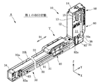
アクチュエータハウジング30は、ボールネジ20と移動体40の一部とを収容すると共に、モータカバー12が固定されている。アクチュエータハウジング30は、図3及び図10に示すように、ベース31と、一対のサイドカバー32R、32Lと、シート部材33と、フロントカバー34と、リアブラケット35と、連結部分カバー36とを有する。 The actuator housing 30 accommodates the ball screw 20 and a part of the moving body 40, and the motor cover 12 is fixed to the actuator housing 30. As shown in FIGS. 3 and 10, the actuator housing 30 has a base 31, a pair of side covers 32R and 32L, a seat member 33, a front cover 34, a rear bracket 35, and a connecting portion cover 36. ..

ベース31は、アクチュエータハウジング30の底部分を構成する。ベース31は、剛性を有する複数のリニアガイド用転動体を介して、移動体40を+Y方向及び−Y方向の双方向にスライド移動可能に支持するレールである。ベース31は、例えば、アルミニウム等の金属を押出成形することによって形成されている。ベース31の内面には、Y軸方向に延びる一対の転動体用溝が形成されている。この転動体用溝を、リニアガイド用転動体が転動することにより、移動体40は、円滑に往復運動をする。 The base 31 constitutes the bottom portion of the actuator housing 30. The base 31 is a rail that supports the moving body 40 so as to be slidable in both the + Y direction and the −Y direction via a plurality of rigid rolling elements for linear guides. The base 31 is formed by, for example, extruding a metal such as aluminum. A pair of rolling element grooves extending in the Y-axis direction are formed on the inner surface of the base 31. When the linear guide rolling element rolls in the rolling element groove, the moving body 40 smoothly reciprocates.

サイドカバー32R、32Lは、アクチュエータハウジング30の両側の側壁部分を構成する。本実施の形態においては、サイドカバー32R、32Lは、ベース31に一体的に形成されている。サイドカバー32R、32Lは、移動体40の両側の側面(+X側の側面及び−X側の側面)を覆いつつ、ベース31と共に、アクチュエータ1の内部の各構成部品を保護する。なお、本実施の形態においては、サイドカバー32R、32Lは、ベース31に一体的に形成されているが、これに限られない。サイドカバー32R、32Lは、ベース31とは別の部品として形成されていてもよい。 The side covers 32R and 32L form side wall portions on both sides of the actuator housing 30. In the present embodiment, the side covers 32R and 32L are integrally formed on the base 31. The side covers 32R and 32L cover both side surfaces (+ X side side surface and −X side side surface) of the moving body 40, and protect each component inside the actuator 1 together with the base 31. In the present embodiment, the side covers 32R and 32L are integrally formed on the base 31, but the present invention is not limited to this. The side covers 32R and 32L may be formed as separate parts from the base 31.

シート部材33は、図10に示すように、Y軸方向を長手方向とする略矩形のシートであり、サイドカバー32Rとサイドカバー32Lとの間の開口部分32aを塞ぐ。これにより、アクチュエータハウジング30の天井壁部分を構成する。シート部材33は、シート部材33の−Y側の端部は、フロントカバー34に固定されている。同様に、シート部材33の+Y側の端部は、リアブラケット35に固定されている。なお、図10においては、理解を容易にするために、シート部材33をドットによる着色によって示している。 As shown in FIG. 10, the seat member 33 is a substantially rectangular sheet whose longitudinal direction is the Y-axis direction, and closes the opening portion 32a between the side cover 32R and the side cover 32L. This constitutes the ceiling wall portion of the actuator housing 30. The end of the seat member 33 on the −Y side is fixed to the front cover 34. Similarly, the + Y side end of the seat member 33 is fixed to the rear bracket 35. In FIG. 10, the sheet member 33 is shown by coloring with dots for easy understanding.

フロントカバー34は、アクチュエータハウジング30の−Y側の先端部分を構成し、ベース31の−Y側に固定されている。フロントカバー34は、ベース31やサイドカバー32R、32Lと共に、アクチュエータ1の内部の各構成部品を保護する。 The front cover 34 constitutes a tip portion on the −Y side of the actuator housing 30 and is fixed to the −Y side of the base 31. The front cover 34, together with the base 31, side covers 32R and 32L, protects each component inside the actuator 1.

リアブラケット35は、図3及び図10に示すように、ベース31の+Y側に固定されていると共に、モータ10のモータ本体11が取り付けられている。リアブラケット35は、図3及び図4に示すように、ベアリング35aを有する。リアブラケット35には、ボールネジ軸21を挿入するための貫通孔35bが形成されており、この貫通孔35bの孔内に、ベアリング35aやモータ10の出力軸10a、カップリング23、10bが配置されている。ベアリング35aは、例えば、ボールベアリングである。このベアリング35aによって、リアブラケット35は、ボールネジ軸21の小径部21bを回転可能に支持する。 As shown in FIGS. 3 and 10, the rear bracket 35 is fixed to the + Y side of the base 31, and the motor body 11 of the motor 10 is attached. The rear bracket 35 has a bearing 35a as shown in FIGS. 3 and 4. A through hole 35b for inserting the ball screw shaft 21 is formed in the rear bracket 35, and the bearing 35a, the output shaft 10a of the motor 10 and the couplings 23 and 10b are arranged in the through hole 35b. ing. The bearing 35a is, for example, a ball bearing. The bearing 35a rotatably supports the small diameter portion 21b of the ball screw shaft 21 on the rear bracket 35.

連結部分カバー36は、図3及び図10に示すように、リアブラケット35の周囲を覆うことにより、リアブラケット35とモータ10との連結部分を保護する。 As shown in FIGS. 3 and 10, the connecting portion cover 36 protects the connecting portion between the rear bracket 35 and the motor 10 by covering the periphery of the rear bracket 35.

移動体40は、図3及び図4に示すように、スライドテーブルTが一体的に形成されていることにより、スライドテーブルTと共に+Y方向及び−Y方向の双方向にスライド移動する部材である。移動体40には、Y軸方向に貫通する貫通孔41が形成されている。この貫通孔41には、ボールネジ軸21が挿通されると共に、ボールネジナット22が−Y側から挿入されて固定されている。なお、本実施の形態では、移動体40には、スライドテーブルTが一体的に形成されているが、これに限られない。スライドテーブルTは、移動体40と別の部品として形成され、移動体40に留め具等で固定されていてもよい。 As shown in FIGS. 3 and 4, the moving body 40 is a member that slides and moves in both the + Y direction and the −Y direction together with the slide table T because the slide table T is integrally formed. The moving body 40 is formed with a through hole 41 penetrating in the Y-axis direction. A ball screw shaft 21 is inserted into the through hole 41, and a ball screw nut 22 is inserted and fixed from the −Y side. In the present embodiment, the slide table T is integrally formed on the moving body 40, but the present invention is not limited to this. The slide table T may be formed as a separate component from the moving body 40 and may be fixed to the moving body 40 with a fastener or the like.

次に、操作パネル50及びパネルカバー60の被嵌め込み部16への嵌込み方法、及びモータ10の製造方法を、図11及び図12を参照して説明する。操作パネル50及びパネルカバー60を被嵌め込み部16に嵌め込む場合、図11に示すように、先ず、ユーザは、パネルカバー60を+Y側から被嵌め込み部16に嵌め込む。このとき、パネルカバー60は、その凹部61に被嵌め込み部16の凸部17が嵌りながら、−Y方向にスライド移動されることにより、被嵌め込み部16に嵌め込まれる。パネルカバー60は、図12に示すように、連結部分カバー36に当接する被嵌め込み部16の−Y側の奥の位置まで嵌め込まれる。続いて、ユーザは、操作パネル50を+Y側から被嵌め込み部16に嵌め込む。このとき、操作パネル50は、その凹部51bに被嵌め込み部16の凸部17が嵌りながら、−Y方向にスライド移動されることにより、被嵌め込み部16に嵌め込まれる。操作パネル50は、パネルカバー60に当接する位置まで嵌め込まれる。最後に、モータカバー12にエンドカバー14が取り付けられることで、操作パネル50は、Y軸方向に移動しないように保持されつつ、モータカバー12に一体的に組み付けられる。 Next, a method of fitting the operation panel 50 and the panel cover 60 into the fitting portion 16 and a method of manufacturing the motor 10 will be described with reference to FIGS. 11 and 12. When fitting the operation panel 50 and the panel cover 60 into the fitting portion 16, as shown in FIG. 11, the user first fits the panel cover 60 into the fitting portion 16 from the + Y side. At this time, the panel cover 60 is fitted into the fitting portion 16 by being slid in the −Y direction while the convex portion 17 of the fitting portion 16 is fitted in the concave portion 61. As shown in FIG. 12, the panel cover 60 is fitted to a position deep on the −Y side of the fitting portion 16 that abuts on the connecting portion cover 36. Subsequently, the user fits the operation panel 50 into the fitting portion 16 from the + Y side. At this time, the operation panel 50 is fitted into the fitting portion 16 by being slid in the −Y direction while the convex portion 17 of the fitting portion 16 is fitted in the concave portion 51b. The operation panel 50 is fitted to a position where it abuts on the panel cover 60. Finally, by attaching the end cover 14 to the motor cover 12, the operation panel 50 is integrally assembled to the motor cover 12 while being held so as not to move in the Y-axis direction.

上述のように構成されたアクチュエータ1の動作について、図13、図14を参照しつつ説明する。先ず、モータ10のモータ本体11に電源が供給されることによって、図13の矢印A1に示すように、出力軸10aが回転する。出力軸10aが回転すると、カップリング10b、23が互いに接続されているため、出力軸10aに接続されているボールネジ軸21が、矢印A2に示すように、出力軸10aとともに回転する。 The operation of the actuator 1 configured as described above will be described with reference to FIGS. 13 and 14. First, when power is supplied to the motor body 11 of the motor 10, the output shaft 10a rotates as shown by the arrow A1 in FIG. When the output shaft 10a rotates, the couplings 10b and 23 are connected to each other, so that the ball screw shaft 21 connected to the output shaft 10a rotates together with the output shaft 10a as shown by the arrow A2.

ボールネジ軸21が回転すると、ボールネジナット22及び移動体40が、矢印A3に示すように、直線運動方向D1に直線運動する。このとき、移動体40は、ベース31に複数のリニアガイド用転動体を介して支持されているため、リニアガイド用転動体の転動によって円滑に移動する。移動体40が直線運動方向D1に移動をすると、移動体40に固定されているスライドテーブルTも、図14に示すように、直線運動方向D1に移動する。 When the ball screw shaft 21 rotates, the ball screw nut 22 and the moving body 40 linearly move in the linear motion direction D1 as shown by the arrow A3. At this time, since the moving body 40 is supported by the base 31 via a plurality of linear guide rolling bodies, the moving body 40 moves smoothly due to the rolling of the linear guide rolling bodies. When the moving body 40 moves in the linear motion direction D1, the slide table T fixed to the moving body 40 also moves in the linear motion direction D1 as shown in FIG.

以上、説明したように、本実施の形態においては、図5及び図6に示すように、モータカバー12の上面12aには、操作パネル50が嵌め込まれる被嵌め込み部16が形成されている。これにより、操作パネル50を異なる機種のモータ10やアクチュエータ1に取り付けたり、同一のモータ10やアクチュエータ1から別の操作パネル50に取り替えたりすることが可能となる。例えば、図15A及び図15Bに示すように、操作パネル50を、アクチュエータ1のモータ10から取り外して、アクチュエータ1よりもサイズの小さい小型のアクチュエータ2のモータ10に取り付けたりすることが可能となる。このため、異なるアクチュエータ1、2に取り付けられる操作パネル50を共用することができる。また、例えば、図16に示すように、同一のモータ10やアクチュエータ1から別の操作パネル50−2に取り替えたりすることが可能となる。これらにより、モータ10やアクチュエータ1、2の汎用性を向上させることができる。また、モータ10及びアクチュエータ1、2の組立て効率を向上させることができる。また、製造上での部品管理も簡略化することができる。なお、図15A及び図15Bのアクチュエータ2において、アクチュエータ1と同一又は同等の構成については、同一の符号を用いて、その説明を省略する。 As described above, in the present embodiment, as shown in FIGS. 5 and 6, the fitting portion 16 into which the operation panel 50 is fitted is formed on the upper surface 12a of the motor cover 12. This makes it possible to attach the operation panel 50 to a different model of motor 10 or actuator 1, or to replace the same motor 10 or actuator 1 with another operation panel 50. For example, as shown in FIGS. 15A and 15B, the operation panel 50 can be removed from the motor 10 of the actuator 1 and attached to the motor 10 of a small actuator 2 having a size smaller than that of the actuator 1. Therefore, the operation panel 50 attached to different actuators 1 and 2 can be shared. Further, for example, as shown in FIG. 16, the same motor 10 or actuator 1 can be replaced with another operation panel 50-2. As a result, the versatility of the motor 10 and the actuators 1 and 2 can be improved. Further, the assembly efficiency of the motor 10 and the actuators 1 and 2 can be improved. In addition, parts management in manufacturing can be simplified. In the actuator 2 of FIGS. 15A and 15B, the same reference numerals are used for the same or equivalent configurations as those of the actuator 1, and the description thereof will be omitted.

また、本実施の形態においては、操作パネル50は、図17に示すように、ユニットとして、被嵌め込み部16に着脱自在に嵌め込まれている。このため、操作パネル50のみをモータ10及びアクチュエータ1から取り外して、ユーザが使用することが可能になる。このため、モータ10及びアクチュエータ1の使い勝手を向上させることができる。 Further, in the present embodiment, as shown in FIG. 17, the operation panel 50 is detachably fitted into the fitting portion 16 as a unit. Therefore, only the operation panel 50 can be removed from the motor 10 and the actuator 1 and used by the user. Therefore, the usability of the motor 10 and the actuator 1 can be improved.

また、本実施の形態においては、図5及び図6に示すように、被嵌め込み部16が形成されているモータカバー12の上面12aは、被嵌め込み部16に嵌め込まれている操作パネル50の操作面51aと同一平面に位置するように形成されている。このため、操作面51aがモータカバー12の上面12aから突出しているものに比べて、モータ10のサイズを大きくする必要がなく、結果として、モータ10及びそれを備えるアクチュエータ1の小型化を実現することができる。また、モータカバー12の上面12aと操作面51aとが同一平面にあるため、段差がなく、ユーザにとっての操作性を向上させると共に、モータ10及びそれを備えるアクチュエータ1の美観を良好にすることができる。 Further, in the present embodiment, as shown in FIGS. 5 and 6, the upper surface 12a of the motor cover 12 on which the fitting portion 16 is formed is an operation of the operation panel 50 fitted in the fitting portion 16. It is formed so as to be located on the same plane as the surface 51a. Therefore, it is not necessary to increase the size of the motor 10 as compared with the operation surface 51a protruding from the upper surface 12a of the motor cover 12, and as a result, the motor 10 and the actuator 1 provided with the motor 10 can be downsized. be able to. Further, since the upper surface 12a of the motor cover 12 and the operation surface 51a are in the same plane, there is no step, the operability for the user can be improved, and the appearance of the motor 10 and the actuator 1 provided with the motor 10 can be improved. it can.

また、本実施の形態においては、図8に示すように、モータ用制御基板15がモータカバー12に収納されると共に、操作パネル用制御基板52が操作パネル50のケース51に収納されている。これにより、モータ用制御基板15は、操作パネル用制御基板52から離間して配置されるため、モータ用制御基板15の発熱による操作パネル用制御基板52への影響を低減させることができる。さらに、本実施の形態においては、モータ用制御基板15は、操作パネル50のケース51の底壁部分51cと、モータカバー12の壁部分12bとによって、操作パネル用制御基板52から隔てられて配置される。これにより、モータ用制御基板15の発熱による操作パネル用制御基板52への影響をさらに低減させることができる。 Further, in the present embodiment, as shown in FIG. 8, the motor control board 15 is housed in the motor cover 12, and the operation panel control board 52 is housed in the case 51 of the operation panel 50. As a result, the motor control board 15 is arranged apart from the operation panel control board 52, so that the influence of heat generated by the motor control board 15 on the operation panel control board 52 can be reduced. Further, in the present embodiment, the motor control board 15 is arranged so as to be separated from the operation panel control board 52 by the bottom wall portion 51c of the case 51 of the operation panel 50 and the wall portion 12b of the motor cover 12. Will be done. As a result, the influence of heat generated by the motor control board 15 on the operation panel control board 52 can be further reduced.

以上、本発明の実施の形態について説明したが、本発明は上記実施の形態によって限定されるものではない。 Although the embodiments of the present invention have been described above, the present invention is not limited to the above embodiments.

(変形例1)
例えば、本実施の形態に係るアクチュエータ1は、図1に示すように、スライドテーブルTが移動するスライダタイプのアクチュエータである。しかしながら、これに限られない。図18に示すアクチュエータ3のように、ロッドRが+Y方向及び−Y方向の双方向に移動するロッドタイプのアクチュエータであってもよい。ロッドRは、その先端がアクチュエータハウジング30から突出している。そして、ロッドRは、アクチュエータハウジング30の内部において、移動体40に固定され、移動体40の直線運動と共に直線運動方向D1に直線運動する。この変形例1においても、本実施の形態に係るアクチュエータ1に用いられた操作パネル50を取り外して、アクチュエータ3のモータ10の被嵌め込み部16に嵌め込むことができる。このため、アクチュエータ3においては、アクチュエータ1に用いられた操作パネル50を共用することができ、本実施の形態に係るアクチュエータ1と同等の効果を有することができる。なお、変形例1では、移動体40には、ロッドRが固定されているが、これに限られない。ロッドRは、移動体40に一体的に形成されていてもよい。また、図18のアクチュエータ3において、アクチュエータ1と同一又は同等の構成については、同一の符号を用いて、その説明を省略する。
(Modification example 1)
For example, the actuator 1 according to the present embodiment is a slider type actuator in which the slide table T moves, as shown in FIG. However, it is not limited to this. Like the actuator 3 shown in FIG. 18, a rod type actuator in which the rod R moves in both the + Y direction and the −Y direction may be used. The tip of the rod R protrudes from the actuator housing 30. Then, the rod R is fixed to the moving body 40 inside the actuator housing 30, and linearly moves in the linear motion direction D1 together with the linear motion of the moving body 40. Also in this modification 1, the operation panel 50 used for the actuator 1 according to the present embodiment can be removed and fitted into the fitted portion 16 of the motor 10 of the actuator 3. Therefore, the actuator 3 can share the operation panel 50 used for the actuator 1, and can have the same effect as the actuator 1 according to the present embodiment. In the first modification, the rod R is fixed to the moving body 40, but the present invention is not limited to this. The rod R may be integrally formed with the moving body 40. Further, in the actuator 3 of FIG. 18, the same reference numerals are used for the same or equivalent configurations as those of the actuator 1, and the description thereof will be omitted.

(変形例2)
また、図1及び図18に示すように、本実施の形態に係るアクチュエータ1、変形例1に係るアクチュエータ3においては、アクチュエータハウジング30に、モータ10のモータカバー12が直接固定されている。しかしながら、これに限られない。図19に示すアクチュエータ4のように、アクチュエータハウジング30には、折り返しユニット70のベルト収容部71が固定され、ベルト収容部71には、モータカバー12が固定されていてもよい。この場合、アクチュエータ4は、モータ10、スライドテーブルT、及びアクチュエータハウジング30等に加えて、折り返しユニット70を備える。なお、アクチュエータ4において、アクチュエータ1と同一又は同等の構成については、同一の符号を用いて、その説明を省略する。
(Modification 2)
Further, as shown in FIGS. 1 and 18, in the actuator 1 according to the present embodiment and the actuator 3 according to the modified example 1, the motor cover 12 of the motor 10 is directly fixed to the actuator housing 30. However, it is not limited to this. As in the actuator 4 shown in FIG. 19, the belt accommodating portion 71 of the folding unit 70 may be fixed to the actuator housing 30, and the motor cover 12 may be fixed to the belt accommodating portion 71. In this case, the actuator 4 includes a folding unit 70 in addition to the motor 10, the slide table T, the actuator housing 30, and the like. In the actuator 4, the same reference numerals are used for the same or equivalent configurations as those of the actuator 1, and the description thereof will be omitted.

折り返しユニット70は、図示しないベルトと、当該ベルトを収納するベルト収容部71とを有する。ベルトは、モータ10の出力軸の回転運動を、ボールネジのボールネジ軸に伝達する。モータ10の出力軸が回転することにより、出力軸の回転運動が、ベルトを介して、ボールネジ軸に伝達される。そして、ボールネジ軸が回転することにより、ボールネジナットが、移動体及びスライドテーブルTと共に直線運動する。また、ベルト収容部71には、モータカバー12が固定されている。また、ベルト収容部71は、アクチュエータハウジング30に固定されている。 The folding unit 70 has a belt (not shown) and a belt accommodating portion 71 for accommodating the belt. The belt transmits the rotational movement of the output shaft of the motor 10 to the ball screw shaft of the ball screw. By rotating the output shaft of the motor 10, the rotational movement of the output shaft is transmitted to the ball screw shaft via the belt. Then, as the ball screw shaft rotates, the ball screw nut moves linearly together with the moving body and the slide table T. Further, the motor cover 12 is fixed to the belt accommodating portion 71. Further, the belt accommodating portion 71 is fixed to the actuator housing 30.

この変形例2においても、本実施の形態に係るアクチュエータ1に用いられた操作パネル50を取り外して、アクチュエータ4のモータ10の被嵌め込み部16に嵌め込むことができる。このとき、操作パネル50をスライド移動させて、被嵌め込み部16に嵌め込むため、図20に示すように、操作パネル50の取付け方向を逆向きにして、被嵌め込み部16に嵌め込むことが可能になる。このため、アクチュエータ4においては、アクチュエータ1、3に取り受けられる操作パネル50を共用することができ、本実施の形態に係るアクチュエータ1、3と同等の効果を有することができる。 Also in this modification 2, the operation panel 50 used for the actuator 1 according to the present embodiment can be removed and fitted into the fitted portion 16 of the motor 10 of the actuator 4. At this time, since the operation panel 50 is slid and fitted into the fitting portion 16, the operation panel 50 can be fitted into the fitting portion 16 by reversing the mounting direction as shown in FIG. become. Therefore, the actuator 4 can share the operation panel 50 received by the actuators 1 and 3, and can have the same effect as the actuators 1 and 3 according to the present embodiment.

(変形例3)
また、図19及び図20に示すように、変形例2に係るアクチュエータ4においては、スライドテーブルTが移動するスライダタイプのアクチュエータであり、且つ、折り返しユニット70を有する折り返しタイプのアクチュエータである。しかしながら、これに限られない。図21に示すアクチュエータ5のように、ロッドRが+Y方向及び−Y方向の双方向に移動するロッドタイプのアクチュエータであり、且つ、折り返しユニット70を有する折り返しタイプのアクチュエータであってもよい。この変形例3においても、本実施の形態に係るアクチュエータ1に用いられた操作パネル50を取り外して、アクチュエータ5のモータ10の被嵌め込み部16に嵌め込むことができる。このため、アクチュエータ5においては、アクチュエータ1に用いられた操作パネル50を共用することができ、変形例2に係るアクチュエータ4と同等の効果を有することができる。なお、アクチュエータ5において、アクチュエータ4と同一又は同等の構成については、同一の符号を用いて、その説明を省略する。
(Modification example 3)
Further, as shown in FIGS. 19 and 20, the actuator 4 according to the second modification is a slider type actuator in which the slide table T moves, and is a folding type actuator having a folding unit 70. However, it is not limited to this. Like the actuator 5 shown in FIG. 21, it may be a rod type actuator in which the rod R moves in both the + Y direction and the −Y direction, and may be a folding type actuator having a folding unit 70. Also in this modification 3, the operation panel 50 used for the actuator 1 according to the present embodiment can be removed and fitted into the fitting portion 16 of the motor 10 of the actuator 5. Therefore, the actuator 5 can share the operation panel 50 used for the actuator 1, and can have the same effect as the actuator 4 according to the second modification. In the actuator 5, the same reference numerals are used for the same or equivalent configurations as those of the actuator 4, and the description thereof will be omitted.

(変形例4)
また、アクチュエータ1〜5においては、操作パネル50が嵌め込まれる被嵌め込み部16は、モータカバー12の+Z側の上面12aに形成されている。しかしながら、これに限られない。被嵌め込み部16は、アクチュエータ1〜5の設置環境や状況に応じて、上面12aとは異なる面に、適宜、形成されていてもよい。例えば、図22に示すアクチュエータ6のように、被嵌め込み部16は、モータカバー12の側面12cに形成されていてもよい。なお、アクチュエータ6において、アクチュエータ1と同一又は同等の構成については、同一の符号を用いて、その説明を省略する。
(Modification example 4)
Further, in the actuators 1 to 5, the fitting portion 16 into which the operation panel 50 is fitted is formed on the upper surface 12a on the + Z side of the motor cover 12. However, it is not limited to this. The fitting portion 16 may be appropriately formed on a surface different from the upper surface 12a depending on the installation environment and conditions of the actuators 1 to 5. For example, as in the actuator 6 shown in FIG. 22, the fitting portion 16 may be formed on the side surface 12c of the motor cover 12. In the actuator 6, the same reference numerals are used for the same or equivalent configurations as those of the actuator 1, and the description thereof will be omitted.

(変形例5)
また、アクチュエータ1〜6においては、モータカバー12には、一つの被嵌め込み部16が形成されている。しかしながら、これに限られない。図23に示すアクチュエータ7のように、モータカバー12には、複数の被嵌め込み部16が形成されていてもよい。この場合、アクチュエータ7の設置環境や状況に応じて、ユーザは、操作パネル50を嵌め込む場所を複数の被嵌め込み部16から選択することができる。このため、モータ10及びアクチュエータ7の使い勝手を向上させることができる。
(Modification 5)
Further, in the actuators 1 to 6, one fitting portion 16 is formed on the motor cover 12. However, it is not limited to this. Like the actuator 7 shown in FIG. 23, the motor cover 12 may be formed with a plurality of fitting portions 16. In this case, the user can select the place to fit the operation panel 50 from the plurality of fitting portions 16 according to the installation environment and the situation of the actuator 7. Therefore, the usability of the motor 10 and the actuator 7 can be improved.

(変形例6)
図8に示すように、本実施の形態に係るアクチュエータ1においては、被嵌め込み部16の底面16aと、底面16aと対向する操作パネル50のケース51の底壁部分51c(操作パネル50の外面、下面)との間の隙間は、比較的小さい。しかしながら、これに限られない。以下、被嵌め込み部16の底面16aと、操作パネル50のケース51の底壁部分51cとの間の隙間が比較的大きく、当該隙間が空間Sとして設けられている変形例6に係るアクチュエータ8について図24A〜図30を用いて説明する。なお、アクチュエータ8において、アクチュエータ1と同一又は同等の構成については、同一の符号を用いて、その説明を省略する。
(Modification 6)
As shown in FIG. 8, in the actuator 1 according to the present embodiment, the bottom surface 16a of the fitting portion 16 and the bottom wall portion 51c of the case 51 of the operation panel 50 facing the bottom surface 16a (the outer surface of the operation panel 50, The gap between the bottom surface) is relatively small. However, it is not limited to this. Hereinafter, the actuator 8 according to the modified example 6 in which the gap between the bottom surface 16a of the fitting portion 16 and the bottom wall portion 51c of the case 51 of the operation panel 50 is relatively large and the gap is provided as a space S. This will be described with reference to FIGS. 24A to 30. In the actuator 8, the same reference numerals are used for the same or equivalent configurations as those of the actuator 1, and the description thereof will be omitted.

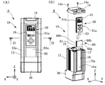
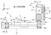
アクチュエータ8は、図24A、図24B及び図25に示すように、スライドテーブルTが移動するスライダタイプのアクチュエータであり、スライドテーブルTの直線運動方向D1と、モータ10の出力軸10a(回転軸)の軸方向とが直交するタイプのものである。アクチュエータ8は、モータ10と、スライドテーブルTと、アクチュエータハウジング30と、移動体40と、ベルト80とを備える。なお、アクチュエータ8は、ボールネジに代えて、ベルト80を備える点で、アクチュエータ1と相違している。 As shown in FIGS. 24A, 24B and 25, the actuator 8 is a slider type actuator in which the slide table T moves, and the linear motion direction D1 of the slide table T and the output shaft 10a (rotation axis) of the motor 10 It is a type that is orthogonal to the axial direction of. The actuator 8 includes a motor 10, a slide table T, an actuator housing 30, a moving body 40, and a belt 80. The actuator 8 is different from the actuator 1 in that the belt 80 is provided instead of the ball screw.

モータ10は、アクチュエータハウジング30から着脱可能な一つのユニットとして構成されている。例えば、モータ10は、図24Aに示す第1の取付状態と、図24Bに示す第2の取付状態とのいずれかの状態で、アクチュエータハウジング30に取り付けられる。第1の取付状態においては、図24Aに示すように、モータ10は、+Z方向に突出するように、アクチュエータハウジング30に取り付けられる。この第1の取付状態においては、ユーザが操作面51aの表示画面の表示の識別がしやすいように、操作パネル50は上向きにモータカバー12に取り付けられる。第2の取付状態においては、図24Bに示すように、モータ10は、−Z方向に突出するように、アクチュエータハウジング30に取り付けられる。この第2の取付状態においても、操作パネル50は上向きにモータカバー12に取り付けられる。 The motor 10 is configured as one unit that can be attached to and detached from the actuator housing 30. For example, the motor 10 is mounted on the actuator housing 30 in either the first mounting state shown in FIG. 24A or the second mounting state shown in FIG. 24B. In the first mounting state, as shown in FIG. 24A, the motor 10 is mounted on the actuator housing 30 so as to project in the + Z direction. In this first mounting state, the operation panel 50 is mounted upward on the motor cover 12 so that the user can easily identify the display on the display screen of the operation surface 51a. In the second mounting state, as shown in FIG. 24B, the motor 10 is mounted on the actuator housing 30 so as to project in the −Z direction. Even in this second mounting state, the operation panel 50 is mounted upward on the motor cover 12.

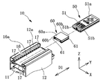
モータ10は、図25及び図26に示すように、出力軸10a(回転軸)と、モータ本体11と、モータカバー12と、オプション収容部13と、エンドカバー14と、モータ用制御基板15(第1制御基板)と、操作パネル50(操作部)と、パネルカバー60とを有する。出力軸10a及びモータ本体11等のモータ10の各部品は、アクチュエータ1のモータ10のものと同等のものである。モータカバー12の+Y側の上面12a(カバー表面)には、操作パネル50が嵌め込まれる被嵌め込み部16が形成されている。 As shown in FIGS. 25 and 26, the motor 10 includes an output shaft 10a (rotating shaft), a motor body 11, a motor cover 12, an option accommodating portion 13, an end cover 14, and a motor control board 15 ( It has a first control board), an operation panel 50 (operation unit), and a panel cover 60. Each component of the motor 10 such as the output shaft 10a and the motor body 11 is the same as that of the motor 10 of the actuator 1. A fitting portion 16 into which the operation panel 50 is fitted is formed on the upper surface 12a (cover surface) on the + Y side of the motor cover 12.

被嵌め込み部16は、本変形例6においては、上下方向(Z軸方向)に沿って形成されている溝からなる。被嵌め込み部16は、具体的には、図26及び図27に示すように、XZ平面に平行な底面16aと、一対の側面16bとからなる溝である。一対の側面16bには、互いに対向するように突出する凸部17がそれぞれ形成されている。 In the present modification 6, the fitting portion 16 is formed of a groove formed along the vertical direction (Z-axis direction). Specifically, as shown in FIGS. 26 and 27, the fitting portion 16 is a groove composed of a bottom surface 16a parallel to the XZ plane and a pair of side surfaces 16b. On each of the pair of side surfaces 16b, convex portions 17 projecting so as to face each other are formed.

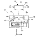
図27に示すように、被嵌め込み部16の底面16aと、底面16aと対向する操作パネル50のケース51の底壁部分51cとの間に、空間Sが設けられている。 As shown in FIG. 27, a space S is provided between the bottom surface 16a of the fitting portion 16 and the bottom wall portion 51c of the case 51 of the operation panel 50 facing the bottom surface 16a.

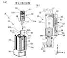
空間Sは、操作パネル50に接続される操作パネル用ケーブル53を設置可能に設けられ(図28(B)参照)、操作パネル用ケーブル53の取り回しを容易にするために形成されている。この空間Sが設けられていることにより、図28及び図29に示すように、操作パネル50は、被嵌め込み部16に対する操作パネル50の嵌め込む方向を変更可能に設けられる。 The space S is provided so that the operation panel cable 53 connected to the operation panel 50 can be installed (see FIG. 28B), and is formed to facilitate the handling of the operation panel cable 53. By providing this space S, as shown in FIGS. 28 and 29, the operation panel 50 is provided so that the fitting direction of the operation panel 50 with respect to the fitting portion 16 can be changed.

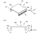
具体的には、図28(A)に示す第1の取付状態においては、操作パネル50は、操作パネル用ケーブル53が接続されている一方の端部54から、第1の取付方向Z1に沿って、被嵌め込み部16に嵌め込まれている。これにより、操作パネル50は上向きにモータカバー12に取り付けられる。図28(B)に示すように、操作パネル用ケーブル53の一端は、操作パネル50の一方の端部54にコネクタ56を介して接続されている。そして、操作パネル用ケーブル53の他端は折り返されて、空間Sに引き出される。そして、引き出された操作パネル用ケーブル53の他端は、例えば、エンドカバー14に引き出されて、その内部で折り返されて、モータ用制御基板15に実装されているコネクタ57に接続される。この結果、操作パネル50は、操作パネル用ケーブル53を介して、モータ用制御基板15に接続される。 Specifically, in the first mounting state shown in FIG. 28A, the operation panel 50 is formed from one end 54 to which the operation panel cable 53 is connected along the first mounting direction Z1. Therefore, it is fitted into the fitting portion 16. As a result, the operation panel 50 is attached to the motor cover 12 upward. As shown in FIG. 28B, one end of the operation panel cable 53 is connected to one end 54 of the operation panel 50 via a connector 56. Then, the other end of the operation panel cable 53 is folded back and pulled out into the space S. Then, the other end of the pulled-out operation panel cable 53 is pulled out to, for example, the end cover 14, folded back inside, and connected to the connector 57 mounted on the motor control board 15. As a result, the operation panel 50 is connected to the motor control board 15 via the operation panel cable 53.

また、図29(A)に示すように、第2の取付状態においては、操作パネル50は、一方の端部54とは反対側の他方の端部55から、第2の取付方向Z2に沿って、被嵌め込み部16に嵌め込まれている。これにより、操作パネル50は上向きにモータカバー12に取り付けられる。図29(B)に示すように、操作パネル用ケーブル53の他端は、空間Sには配置されずに、例えば、モータカバー12の内部、もしくは、オプション収容部13に配置される。そして、操作パネル用ケーブル53の他端は、モータ用制御基板15に実装されているコネクタ57に接続される。この結果、操作パネル50は、操作パネル用ケーブル53を介して、モータ用制御基板15に接続される。 Further, as shown in FIG. 29 (A), in the second mounting state, the operation panel 50 starts from the other end 55 opposite to one end 54 along the second mounting direction Z2. Therefore, it is fitted into the fitting portion 16. As a result, the operation panel 50 is attached to the motor cover 12 upward. As shown in FIG. 29B, the other end of the operation panel cable 53 is not arranged in the space S, but is arranged, for example, inside the motor cover 12 or in the option accommodating portion 13. The other end of the operation panel cable 53 is connected to the connector 57 mounted on the motor control board 15. As a result, the operation panel 50 is connected to the motor control board 15 via the operation panel cable 53.

スライドテーブルT及びアクチュエータハウジング30は、図24A及び図24Bに示すように、アクチュエータ1のものと同等のものである。なお、アクチュエータハウジング30が有する連結部分カバー36は、例えば、樹脂成形により形成されている。連結部分カバー36は、図25に示すように、リアブラケット35や後述するプーリ82を覆うことにより、ベルト本体81とプーリ82との連結部分を、リアブラケット35と共に保護する。 The slide table T and the actuator housing 30 are equivalent to those of the actuator 1 as shown in FIGS. 24A and 24B. The connecting portion cover 36 of the actuator housing 30 is formed by, for example, resin molding. As shown in FIG. 25, the connecting portion cover 36 protects the connecting portion between the belt body 81 and the pulley 82 together with the rear bracket 35 by covering the rear bracket 35 and the pulley 82 described later.

移動体40は、ベルト80のベルト本体81に、板状の取付金具部材を介して、ボルト、ねじなどの留め具によって取り付けられている。これにより、移動体40は、出力軸10aの回転運動に基づくベルト本体81の動作に基づいて、直線運動方向D1に沿って移動し、この結果、スライドテーブルTが移動する。なお、図25においては、ベルト本体81はドットにより着色して示されている。 The moving body 40 is attached to the belt body 81 of the belt 80 via fasteners such as bolts and screws via a plate-shaped mounting bracket member. As a result, the moving body 40 moves along the linear motion direction D1 based on the movement of the belt body 81 based on the rotational motion of the output shaft 10a, and as a result, the slide table T moves. In FIG. 25, the belt body 81 is colored with dots.

ベルト80は、図25及び図30に示すように、出力軸10aの回転運動を移動体40に伝達し、この伝達に基づいて、移動体40及びスライドテーブルTを直線運動方向D1に進退移動させる。ベルト80は、ベルト本体81と、プーリ82、83とを有する。 As shown in FIGS. 25 and 30, the belt 80 transmits the rotational motion of the output shaft 10a to the moving body 40, and based on this transmission, the moving body 40 and the slide table T are moved back and forth in the linear motion direction D1. .. The belt 80 has a belt body 81 and pulleys 82 and 83.

ベルト本体81は、プーリ82とプーリ83とに、張力がかかった状態に掛けられている。ベルト本体81の張力方向は、Y軸方向に平行な方向である。ベルト本体81は、プーリ82の回転運動をプーリ83に伝達する。ベルト本体81は、この伝達に伴って動作し、この動作に伴って、移動体40を直線運動方向D1に沿って移動させる。この結果、スライドテーブルTが移動する。ベルト本体81は、例えば、プーリ82、83に形成された歯に係合する複数の歯が形成されたタイミングベルトである。しかしながら、これに限られず、ベルト本体81は、タイミングベルト以外のものであってもよい。なお、図25においては、ベルト本体81はドットにより着色して示されている。 The belt body 81 is hung on the pulley 82 and the pulley 83 in a tensioned state. The tension direction of the belt body 81 is a direction parallel to the Y-axis direction. The belt body 81 transmits the rotational movement of the pulley 82 to the pulley 83. The belt body 81 operates in association with this transmission, and the moving body 40 is moved along the linear motion direction D1 in accordance with this operation. As a result, the slide table T moves. The belt body 81 is, for example, a timing belt in which a plurality of teeth engaged with the teeth formed on the pulleys 82 and 83 are formed. However, the present invention is not limited to this, and the belt body 81 may be something other than a timing belt. In FIG. 25, the belt body 81 is colored with dots.

プーリ82は、モータ10の出力軸10aに固定されている。また、プーリ82は、リアブラケット35にベアリング82aを介して回転可能に支持されている。これらの構成により、プーリ82は、出力軸10aとともに回転する。 The pulley 82 is fixed to the output shaft 10a of the motor 10. Further, the pulley 82 is rotatably supported by the rear bracket 35 via a bearing 82a. With these configurations, the pulley 82 rotates together with the output shaft 10a.

プーリ83は、アクチュエータハウジング30にベアリング83aを介して回転可能に支持されている。 The pulley 83 is rotatably supported by the actuator housing 30 via a bearing 83a.

この変形例6に係るアクチュエータ8においては、図27に示すように、被嵌め込み部16の底面16aと、操作パネル50のケース51の底壁部分51cとの間に、空間Sが設けられている。このため、ユーザは、操作パネル用ケーブルの取り回し等を気にせずに、被嵌め込み部16に対する操作パネル50の嵌め込む方向を適宜変更することができる。この結果、変形例6においては、汎用性の高いアクチュエータ8を提供することできる。 In the actuator 8 according to the modification 6, as shown in FIG. 27, a space S is provided between the bottom surface 16a of the fitting portion 16 and the bottom wall portion 51c of the case 51 of the operation panel 50. .. Therefore, the user can appropriately change the fitting direction of the operation panel 50 with respect to the fitting portion 16 without worrying about the routing of the operation panel cable. As a result, in the modified example 6, the highly versatile actuator 8 can be provided.

また、変形例6においては、本実施の形態に係るアクチュエータ1等と同様に、操作パネル50を異なる機種のモータやアクチュエータに取り付けたり、同一のモータやアクチュエータから別の操作パネル50に取り替えたりすることができる。したがって、アクチュエータ8は、本実施の形態に係るアクチュエータ1等と同等の効果を奏することができる。 Further, in the modification 6, similarly to the actuator 1 and the like according to the present embodiment, the operation panel 50 is attached to a motor or actuator of a different model, or the same motor or actuator is replaced with another operation panel 50. be able to. Therefore, the actuator 8 can exert the same effect as the actuator 1 and the like according to the present embodiment.

なお、変形例6に係るアクチュエータ8のモータ10に設けられている空間Sは、上記実施の形態や変形例に係るアクチュエータ1〜7に適用されてもよい。 The space S provided in the motor 10 of the actuator 8 according to the modification 6 may be applied to the actuators 1 to 7 according to the embodiment or the modification.

(その他の変形例)
また、アクチュエータ1は、パネルカバー60を一つ備える。しかしながら、これに限られない。アクチュエータ1は、パネルカバー60を複数備えていてもよい。例えば、パネルカバー60のY軸方向の長さを2分の1の長さにして、操作パネル50の+Y側及び−Y側の両側に配置するようにしてもよい。また、操作パネル50の長さL2を、被嵌め込み部16の長さL1に等しくすることにより(L1=L2)、図15A及び図15Bに示すアクチュエータ2のように、パネルカバー60を割愛してもよい。
(Other variants)
Further, the actuator 1 includes one panel cover 60. However, it is not limited to this. The actuator 1 may include a plurality of panel covers 60. For example, the length of the panel cover 60 in the Y-axis direction may be halved and arranged on both the + Y side and the −Y side of the operation panel 50. Further, by making the length L2 of the operation panel 50 equal to the length L1 of the fitting portion 16 (L1 = L2), the panel cover 60 is omitted as in the actuator 2 shown in FIGS. 15A and 15B. May be good.

また、アクチュエータ1が備えるモータ10においては、凸部17は、被嵌め込み部16の側面16bに形成され、凹部51bは、操作パネル50のケース51の側面に形成されている。しかしながら、これとは逆に、被嵌め込み部16の側面16bには凹部が形成され、操作パネル50のケース51の側面には凸部が形成されていてもよい。 Further, in the motor 10 included in the actuator 1, the convex portion 17 is formed on the side surface 16b of the fitting portion 16, and the concave portion 51b is formed on the side surface of the case 51 of the operation panel 50. However, on the contrary, a concave portion may be formed on the side surface 16b of the fitting portion 16 and a convex portion may be formed on the side surface of the case 51 of the operation panel 50.

また、アクチュエータ1においては、凸部17は、Y軸方向に沿って線状に延設されている。しかしながら、これに限られない。凹部51bに嵌る形状であれば、線状に延設された形状以外の形状に形成されていてもよい。例えば、図31に示すように、凸部17は、Y軸方向に沿って断続的に複数形成されていてもよい。 Further, in the actuator 1, the convex portion 17 extends linearly along the Y-axis direction. However, it is not limited to this. As long as it fits in the recess 51b, it may be formed in a shape other than the linearly extending shape. For example, as shown in FIG. 31, a plurality of convex portions 17 may be formed intermittently along the Y-axis direction.

また、パネルカバー60は、図32に示すように、被嵌め込み部16に固定可能に形成されていてもよい。この場合、パネルカバー60は、弾性を有する素材からなる。パネルカバー60の素材は、例えば、弾性を有する樹脂であり、具体的には、ASA(アクリロニトリル・スチレン・アクリレート)である。ただし、パネルカバー60の素材は、これに限られず、パネルカバー60は被嵌め込み部16に固定し得る、弾性を有する素材であれば、ASA以外の素材であってもよい。パネルカバー60は、被嵌め込み部16の一対の側面16bを押圧可能な部分を含んで構成されている。この押圧可能な部分の被嵌め込み部16の一対の側面16bに対する押圧に基づいて、パネルカバー60は、被嵌め込み部16に固定されつつ嵌め込まれる。 Further, as shown in FIG. 32, the panel cover 60 may be formed so as to be fixed to the fitting portion 16. In this case, the panel cover 60 is made of an elastic material. The material of the panel cover 60 is, for example, an elastic resin, specifically, ASA (acrylonitrile styrene acrylate). However, the material of the panel cover 60 is not limited to this, and the panel cover 60 may be a material other than ASA as long as it is an elastic material that can be fixed to the fitting portion 16. The panel cover 60 is configured to include a portion capable of pressing the pair of side surfaces 16b of the fitting portion 16. The panel cover 60 is fitted while being fixed to the fitting portion 16 based on the pressing of the pressable portion against the pair of side surfaces 16b of the fitting portion 16.

このパネルカバー60は、被嵌め込み部16に嵌め込まれている場合に、モータ10の外部に露出する上面60aが形成されている天板部62を有する。また、このパネルカバー60は、図33に示すように、天板部62に加えて、一対の第1の側壁部63R及び第2の側壁部63Lを有する凹字形状に形成されている。第1の側壁部63Rは、天板部62のX軸方向(出力軸10aの軸心方向に直交する直交方向)の一端から、概ね−Z方向に沿って延設されている。第2の側壁部63Lは、天板部62のX軸方向の他端から、概ね−Z方向に沿って延設されている。第1の側壁部63R及び第2の側壁部63Lは、被嵌め込み部16に嵌め込まれる前の状態において、互いに平行な方向に延設されておらず、天板部62の一端及び他端を基点に、互いに広がるように形成されている。第1の側壁部63R及び第2の側壁部63Lには、凹部61が形成されている。 The panel cover 60 has a top plate portion 62 on which an upper surface 60a exposed to the outside of the motor 10 is formed when the panel cover 60 is fitted into the fitting portion 16. Further, as shown in FIG. 33, the panel cover 60 is formed in a concave shape having a pair of first side wall portions 63R and a second side wall portion 63L in addition to the top plate portion 62. The first side wall portion 63R extends substantially along the −Z direction from one end of the top plate portion 62 in the X-axis direction (orthogonal direction orthogonal to the axial direction of the output shaft 10a). The second side wall portion 63L extends substantially along the −Z direction from the other end of the top plate portion 62 in the X-axis direction. The first side wall portion 63R and the second side wall portion 63L are not extended in the direction parallel to each other in the state before being fitted into the fitting portion 16, and the base points are one end and the other end of the top plate portion 62. In addition, they are formed so as to spread each other. A recess 61 is formed in the first side wall portion 63R and the second side wall portion 63L.

ユーザがこのパネルカバー60を被嵌め込み部16に嵌め込む場合、図32に示すように、ユーザは、パネルカバー60を、第1の側壁部63R及び第2の側壁部63Lが互いに狭まるように変形させつつ、被嵌め込み部16に嵌め込む。パネルカバー60が被嵌め込み部16に嵌め込まれると、第1の側壁部63R及び第2の側壁部63Lが、互いに広がるように弾性回復する。この弾性回復により、第1の側壁部63R及び第2の側壁部63Lは、被嵌め込み部16の互いに対向する一対の側面16bそれぞれを押圧する。この結果、パネルカバー60は、被嵌め込み部16に固定される。また、凹部61に嵌め込まれた被嵌め込み部16の凸部17が、凹部61から外れにくくなり、凸部17と凹部61との係止が強固になる。 When the user fits the panel cover 60 into the fitting portion 16, as shown in FIG. 32, the user deforms the panel cover 60 so that the first side wall portion 63R and the second side wall portion 63L are narrowed to each other. It is fitted into the fitting portion 16 while being made to fit. When the panel cover 60 is fitted into the fitting portion 16, the first side wall portion 63R and the second side wall portion 63L elastically recover so as to spread each other. Due to this elastic recovery, the first side wall portion 63R and the second side wall portion 63L press each of the pair of side surfaces 16b of the fitting portion 16 facing each other. As a result, the panel cover 60 is fixed to the fitting portion 16. Further, the convex portion 17 of the fitted portion 16 fitted in the concave portion 61 is less likely to come off from the concave portion 61, and the convex portion 17 and the concave portion 61 are firmly locked.

本発明は、本発明の広義の精神と範囲を逸脱することなく、様々な実施形態及び変形が可能とされるものである。上述した実施形態は、本発明を説明するためのものであり、本発明の範囲を限定するものではない。 The present invention allows for various embodiments and modifications without departing from the broad spirit and scope of the present invention. The above-described embodiments are for explaining the present invention and do not limit the scope of the present invention.

1、2、3、4、5、6、7、8:アクチュエータ
10:モータ
10a:出力軸(回転軸)
10b:カップリング(第1カップリング)
11:モータ本体
11a:エンコーダ
12:モータカバー
12a:上面(カバー表面)
12b:壁部分
12c:側面(カバー表面)
13:オプション収容部
14:エンドカバー
14a:留め具
15:モータ用制御基板(第1制御基板)
16:被嵌め込み部
16a:底面
16b:側面
17:凸部
20:ボールネジ
21:ボールネジ軸
21a:ボールネジ軸本体
21b:小径部
22:ボールネジナット
23:カップリング(第2カップリング)
30:アクチュエータハウジング
31:ベース
32R、32L:サイドカバー
32a:開口部分
33:シート部材
34:フロントカバー
35:リアブラケット
35a:ベアリング
35b:貫通孔
36:連結部分カバー
40:移動体
41:貫通孔
50、50−2:操作パネル(操作部)
51:ケース
51a:操作面
51b:凹部
51c:底壁部分
52:操作パネル用制御基板(第2制御基板)
53:操作パネル用ケーブル
54:一方の端部
55:他方の端部
56、57:コネクタ
60:パネルカバー
60a:上面
60b:側面
61:凹部
62:天板部
63R:第1側壁部
63L:第2側壁部
70:折り返しユニット
71:ベルト収容部
80:ベルト
81:ベルト本体
82、83:プーリ
82a、83a:ベアリング
R:ロッド
T:スライドテーブル
C1:アクチェータケーブル
D1:直線運動方向
A1、A2、A3:矢印
L1:被嵌め込み部のY軸方向の長さ
L2:操作パネルのY軸方向の長さ
L3:パネルカバーのY軸方向の長さ
S:空間
Z1:第1の取付方向
Z2:第2の取付方向
1, 2, 3, 4, 5, 6, 7, 8: Actuator 10: Motor 10a: Output shaft (rotation shaft)
10b: Coupling (first coupling)
11: Motor body 11a: Encoder 12: Motor cover 12a: Top surface (cover surface)
12b: Wall part 12c: Side surface (cover surface)
13: Optional housing 14: End cover 14a: Fastener 15: Motor control board (first control board)
16: Fitted part 16a: Bottom surface 16b: Side surface 17: Convex part 20: Ball screw 21: Ball screw shaft 21a: Ball screw shaft body 21b: Small diameter part 22: Ball screw nut 23: Coupling (second coupling)
30: Actuator housing 31: Base 32R, 32L: Side cover 32a: Opening part 33: Seat member 34: Front cover 35: Rear bracket 35a: Bearing 35b: Through hole 36: Connecting part cover 40: Moving body 41: Through hole 50 , 50-2: Operation panel (operation unit)
51: Case 51a: Operation surface 51b: Recessed portion 51c: Bottom wall portion 52: Control board for operation panel (second control board)
53: Operation panel cable 54: One end 55: The other end 56, 57: Connector 60: Panel cover 60a: Top 60b: Side 61: Recess 62: Top plate 63R: First side wall 63L: No. 2 Side wall 70: Folding unit 71: Belt accommodating 80: Belt 81: Belt body 82, 83: Pulley 82a, 83a: Bearing R: Rod T: Slide table C1: Actuator cable D1: Linear motion direction A1, A2, A3 : Arrow L1: Length of the fitting part in the Y-axis direction L2: Length of the operation panel in the Y-axis direction L3: Length of the panel cover in the Y-axis direction S: Space Z1: First mounting direction Z2: Second Mounting direction

Claims (19)

回転軸と、
前記回転軸を回転させるためのモータ本体と、
前記回転軸が外部に突出しつつ、前記モータ本体を収容すると共に、前記回転軸の動作の設定をするための操作部が嵌め込まれる被嵌め込み部が、カバー表面に形成されているモータカバーと、
を備える、モータ。
Rotation axis and
A motor body for rotating the rotating shaft and
A motor cover in which the motor body is accommodated while the rotating shaft protrudes to the outside, and an operating portion for setting the operation of the rotating shaft is fitted is formed on the cover surface.
Equipped with a motor.
前記操作部は、ユーザが操作するための操作ボタンが設けられている操作面を有し、
前記被嵌め込み部が形成されている前記カバー表面は、前記被嵌め込み部に嵌め込まれている前記操作部の前記操作面と同一平面に位置するように形成されている、請求項1に記載のモータ。
The operation unit has an operation surface provided with operation buttons for user operation.
The motor according to claim 1, wherein the cover surface on which the fitting portion is formed is formed so as to be positioned on the same plane as the operating surface of the operating portion fitted in the fitting portion. ..
前記被嵌め込み部に着脱可能に嵌め込まれる前記操作部と、
前記操作部によって設定された前記回転軸の回転を制御するための電子部品が実装されていると共に、前記モータカバーに収納される第1制御基板と、
を備え、
前記操作部は、
ケースと、
前記回転軸の回転を制御するための電子部品が実装されていると共に、前記ケースに収納される第2制御基板と、を有する、請求項1又は2に記載のモータ。
The operation unit that is detachably fitted to the fitting portion and
An electronic component for controlling the rotation of the rotating shaft set by the operating unit is mounted, and a first control board housed in the motor cover is mounted on the first control board.
With
The operation unit
With the case
The motor according to claim 1 or 2, wherein an electronic component for controlling the rotation of the rotating shaft is mounted, and a second control board housed in the case is provided.
前記操作部は、前記被嵌め込み部から取り外した状態で、ユーザの前記モータ本体の操作が可能に設けられている、請求項3に記載のモータ。 The motor according to claim 3, wherein the operation unit is provided so that the user can operate the motor body in a state of being removed from the fitting portion. 前記被嵌め込み部は、前記回転軸の軸心方向に沿って形成されている溝からなる、請求項1から4のいずれか一項に記載のモータ。 The motor according to any one of claims 1 to 4, wherein the fitting portion is formed of a groove formed along the axial direction of the rotating shaft. 前記被嵌め込み部の内面と、当該内面と対向する前記操作部の外面との一方には、凸部が形成され、
前記被嵌め込み部の内面と、当該内面と対向する前記操作部の外面との他方には、前記凸部が嵌ると共に、前記軸心方向に沿って線状に形成されている線状溝からなる凹部が形成されている、請求項5に記載のモータ。
A convex portion is formed on one of the inner surface of the fitting portion and the outer surface of the operating portion facing the inner surface.
The convex portion is fitted to the other of the inner surface of the fitting portion and the outer surface of the operating portion facing the inner surface, and is composed of a linear groove formed linearly along the axial direction. The motor according to claim 5, wherein a recess is formed.
前記溝からなる前記被嵌め込み部に、前記操作部と共に嵌め込まれるパネルカバーを備え、
前記パネルカバーの前記軸心方向の長さは、前記被嵌め込み部の前記軸心方向の長さから、前記操作部の前記軸心方向の長さを減じた長さである、請求項5又は6に記載のモータ。
A panel cover to be fitted together with the operation portion is provided in the fitting portion formed of the groove.
The length of the panel cover in the axial direction is a length obtained by subtracting the length of the operating portion in the axial direction from the length of the fitting portion in the axial direction, according to claim 5 or 6. The motor according to 6.
前記パネルカバーは、弾性を有する素材からなると共に、前記被嵌め込み部の内面を押圧可能な部分を含んで構成され、前記押圧可能な部分の前記被嵌め込み部の内面に対する押圧に基づいて、前記被嵌め込み部に固定可能に形成されている、請求項7に記載のモータ。 The panel cover is made of an elastic material and includes a portion capable of pressing the inner surface of the fitting portion, and the covering is based on the pressing of the pressable portion against the inner surface of the fitting portion. The motor according to claim 7, which is formed so as to be fixed to the fitting portion. 前記パネルカバーは、前記被嵌め込み部に嵌め込まれている場合に、外部に露出する表面が形成されている天板部と、前記天板部の前記軸心方向に直交する直交方向の一端から延設されている第1の側壁部と、前記天板部の前記直交方向の他端から延設されている第2の側壁部と、を有し、
前記第1の側壁部及び前記第2の側壁部は、前記直交方向の一端及び他端を基点に、前記被嵌め込み部の内面を押圧可能に互いに広がるように形成されている、請求項8に記載のモータ。
The panel cover extends from one end in the orthogonal direction orthogonal to the axial direction of the top plate portion on which a surface exposed to the outside is formed when the panel cover is fitted in the fitting portion. It has a first side wall portion provided and a second side wall portion extending from the other end of the top plate portion in the orthogonal direction.
According to claim 8, the first side wall portion and the second side wall portion are formed so as to spread from one end and the other end in the orthogonal direction so as to be able to press the inner surface of the fitting portion. The described motor.
前記被嵌め込み部は、底面を有する形状に形成され、
前記被嵌め込み部の前記底面と、前記底面と対向する前記操作部の外面との間に、空間が設けられ、
前記空間は、前記操作部に接続されるケーブルを設置可能に設けられている、請求項5から9のいずれか一項に記載のモータ。
The fitting portion is formed in a shape having a bottom surface, and is formed.
A space is provided between the bottom surface of the fitting portion and the outer surface of the operation portion facing the bottom surface.
The motor according to any one of claims 5 to 9, wherein the space is provided so that a cable connected to the operation unit can be installed.
前記操作部は、前記被嵌め込み部に対する前記操作部の嵌め込む方向を変更可能に設けられている、請求項10に記載のモータ。 The motor according to claim 10, wherein the operating portion is provided so that the fitting direction of the operating portion can be changed with respect to the fitting portion. 請求項1から11のいずれか一項に記載のモータを備える、アクチュエータ。 An actuator comprising the motor according to any one of claims 1 to 11. 前記モータの前記回転軸の回転運動とともに回転運動するボールネジ軸と、前記ボールネジ軸の回転運動に伴って直線運動するボールネジナットと、を有するボールネジと、
前記ボールネジナットに接続され、前記ボールネジナットの直線運動と共に移動する移動体と、
を備える、請求項12に記載のアクチュエータ。
A ball screw having a ball screw shaft that rotates with the rotary motion of the rotary shaft of the motor and a ball screw nut that linearly moves with the rotary motion of the ball screw shaft.
A moving body connected to the ball screw nut and moving with the linear motion of the ball screw nut,
12. The actuator according to claim 12.
前記ボールネジは、前記回転軸に取り付けられた第1カップリングに接続される第2カップリングを有し、
前記ボールネジと、前記移動体の少なくとも一部と、を収容すると共に、前記モータカバーが固定されているアクチュエータハウジングを備える、請求項13に記載のアクチュエータ。
The ball screw has a second coupling that is connected to a first coupling attached to the rotating shaft.
The actuator according to claim 13, further comprising an actuator housing for accommodating the ball screw and at least a part of the moving body and to which the motor cover is fixed.
前記回転軸の回転運動を前記ボールネジ軸に伝達するベルトと、前記ベルトを収納すると共に、前記モータカバーが固定されているベルト収容部と、を有する折り返しユニットと、
前記ボールネジと、前記移動体の少なくとも一部と、を収容すると共に、前記ベルト収容部が固定されているアクチュエータハウジングと、
備える、請求項13に記載のアクチュエータ。
A folding unit having a belt for transmitting the rotational motion of the rotating shaft to the ball screw shaft, a belt accommodating portion for accommodating the belt, and a belt accommodating portion to which the motor cover is fixed.
An actuator housing that accommodates the ball screw and at least a part of the moving body, and to which the belt accommodating portion is fixed.
The actuator according to claim 13.
前記移動体の直線運動と共に移動するスライドテーブルを備える、請求項13から15のいずれか一項に記載のアクチュエータ。 The actuator according to any one of claims 13 to 15, further comprising a slide table that moves with the linear motion of the moving body. 前記移動体の直線運動と共に移動するロッドを備える、請求項13から15のいずれか一項に記載のアクチュエータ。 The actuator according to any one of claims 13 to 15, further comprising a rod that moves with the linear motion of the moving body. 前記モータの前記回転軸に掛けられて、前記回転軸の回転運動に基づいて動作するベルトと、
前記ベルトに接続されて、前記ベルトの動作に基づいて、直線運動する移動体と、
を備える、請求項12に記載のアクチュエータ。
A belt that is hung on the rotating shaft of the motor and operates based on the rotational movement of the rotating shaft.
A moving body that is connected to the belt and moves linearly based on the movement of the belt.
12. The actuator according to claim 12.
請求項1から11のいずれか一項に記載のモータの製造方法であって、
前記回転軸の軸心方向に沿って線状に形成されている溝からなる前記被嵌め込み部に対して、前記操作部を、前記軸心方向に沿ってスライド移動させて、前記被嵌め込み部に嵌め込むことを含む、モータの製造方法。
The method for manufacturing a motor according to any one of claims 1 to 11.
The operation unit is slid along the axial direction of the fitting portion formed of grooves formed linearly along the axial direction of the rotating shaft, and is moved to the fitting portion. A method of manufacturing a motor, including fitting.
JP2020150820A 2019-11-28 2020-09-08 Motor, actuator, and method for manufacturing motor Active JP7485286B2 (en)

Applications Claiming Priority (2)

Application Number Priority Date Filing Date Title
JP2019215389 2019-11-28

Publications (2)

Publication Number Publication Date
JP2021093902A true JP2021093902A (en) 2021-06-17
JP7485286B2 JP7485286B2 (en) 2024-05-16

Family

ID=76310980

Family Applications (1)

Application Number Title Priority Date Filing Date
JP2020150820A Active JP7485286B2 (en) 2019-11-28 2020-09-08 Motor, actuator, and method for manufacturing motor

Country Status (1)

Country Link
JP (1) JP7485286B2 (en)

Family Cites Families (8)

* Cited by examiner, † Cited by third party
Publication number Priority date Publication date Assignee Title
JP2000280193A (en) 1999-03-30 2000-10-10 Nissan Motor Co Ltd Control device provided with transportable operation panel
JP4134348B2 (en) 2002-07-23 2008-08-20 Smc株式会社 Electric actuator and control method thereof
JP5258408B2 (en) 2008-06-18 2013-08-07 株式会社エヌ・ティ・ティ・ドコモ Transmitting apparatus and receiving apparatus
JP5722644B2 (en) 2011-01-27 2015-05-27 株式会社日立産機システム Rotating electric machine
DE112014003611T5 (en) 2014-07-01 2016-04-28 Fuji Electric Co., Ltd. Power conversion device
JP6576226B2 (en) 2015-11-30 2019-09-18 株式会社アイエイアイ Actuator
JP2017135979A (en) 2017-03-06 2017-08-03 貴司 徳田 Motor Module System
JP7033297B2 (en) 2017-11-20 2022-03-10 株式会社アイエイアイ Actuator control device and actuator

Also Published As

Publication number Publication date
JP7485286B2 (en) 2024-05-16

Similar Documents

Publication Publication Date Title
CN110099200B (en) Imaging device, electronic apparatus, and method for using electronic apparatus
CN111182096B (en) Electronic device and method for using electronic device
CN111131569B (en) Electronic device and method of use
JP7407786B2 (en) Electronics
CN111163195B (en) Electronic device and method of use
JP4959994B2 (en) robot
TWM510990U (en) Linear actuator
JP2021093902A (en) Motor, actuator, and motor manufacturing method
CN101622146B (en) Driving device
JP7267735B2 (en) drive
JP7333379B2 (en) Electronics
WO2021127917A1 (en) Photographing device, electronic apparatus, and method of using electronic apparatus
JP7300491B2 (en) drive mechanism and electronics
WO2021127920A1 (en) Electronic device and usage method
WO2021127918A1 (en) Electronic device and method for using electronic device
JP4566826B2 (en) Electric actuator
WO2021127922A1 (en) Electronic device and use method
JP6654705B2 (en) Electric slider and electric slide fastener system
JP2015181804A (en) Servo device for radio control
JP6576201B2 (en) Actuator
JP7173543B2 (en) actuator
JP3742639B2 (en) Door frame material mounting device
JP5930936B2 (en) Automotive electronics
JP7180870B2 (en) Motor unit and actuator
JP6034243B2 (en) Actuator

Legal Events

Date Code Title Description
A621 Written request for application examination

Free format text: JAPANESE INTERMEDIATE CODE: A621

Effective date: 20230605

A977 Report on retrieval

Free format text: JAPANESE INTERMEDIATE CODE: A971007

Effective date: 20240118

A131 Notification of reasons for refusal

Free format text: JAPANESE INTERMEDIATE CODE: A131

Effective date: 20240130

A521 Request for written amendment filed

Free format text: JAPANESE INTERMEDIATE CODE: A523

Effective date: 20240329

TRDD Decision of grant or rejection written
A01 Written decision to grant a patent or to grant a registration (utility model)

Free format text: JAPANESE INTERMEDIATE CODE: A01

Effective date: 20240423

A61 First payment of annual fees (during grant procedure)

Free format text: JAPANESE INTERMEDIATE CODE: A61

Effective date: 20240423

R150 Certificate of patent or registration of utility model

Ref document number: 7485286

Country of ref document: JP

Free format text: JAPANESE INTERMEDIATE CODE: R150