JP2021066242A - Vehicular air-conditioning system - Google Patents

Vehicular air-conditioning system Download PDF

Info

Publication number
JP2021066242A
JP2021066242A JP2019191108A JP2019191108A JP2021066242A JP 2021066242 A JP2021066242 A JP 2021066242A JP 2019191108 A JP2019191108 A JP 2019191108A JP 2019191108 A JP2019191108 A JP 2019191108A JP 2021066242 A JP2021066242 A JP 2021066242A
Authority
JP
Japan
Prior art keywords
air
vehicle
seat
conditioning
state
Prior art date
Legal status (The legal status is an assumption and is not a legal conclusion. Google has not performed a legal analysis and makes no representation as to the accuracy of the status listed.)
Pending
Application number
JP2019191108A
Other languages
Japanese (ja)
Other versions
JP2021066242A5 (en
Inventor
四方 一史
Kazufumi Yomo
四方  一史
伸一郎 平井
Shinichiro Hirai
伸一郎 平井
小松原 祐介
Yusuke Komatsubara
祐介 小松原
Current Assignee (The listed assignees may be inaccurate. Google has not performed a legal analysis and makes no representation or warranty as to the accuracy of the list.)
Denso Corp
Original Assignee
Denso Corp
Priority date (The priority date is an assumption and is not a legal conclusion. Google has not performed a legal analysis and makes no representation as to the accuracy of the date listed.)
Filing date
Publication date
Application filed by Denso Corp filed Critical Denso Corp
Priority to JP2019191108A priority Critical patent/JP2021066242A/en
Priority to PCT/JP2020/037052 priority patent/WO2021075258A1/en
Publication of JP2021066242A publication Critical patent/JP2021066242A/en
Publication of JP2021066242A5 publication Critical patent/JP2021066242A5/ja
Pending legal-status Critical Current

Links

Images

Classifications

    • BPERFORMING OPERATIONS; TRANSPORTING
    • B60VEHICLES IN GENERAL
    • B60HARRANGEMENTS OF HEATING, COOLING, VENTILATING OR OTHER AIR-TREATING DEVICES SPECIALLY ADAPTED FOR PASSENGER OR GOODS SPACES OF VEHICLES
    • B60H1/00Heating, cooling or ventilating [HVAC] devices
    • BPERFORMING OPERATIONS; TRANSPORTING
    • B60VEHICLES IN GENERAL
    • B60HARRANGEMENTS OF HEATING, COOLING, VENTILATING OR OTHER AIR-TREATING DEVICES SPECIALLY ADAPTED FOR PASSENGER OR GOODS SPACES OF VEHICLES
    • B60H1/00Heating, cooling or ventilating [HVAC] devices
    • B60H1/32Cooling devices
    • BPERFORMING OPERATIONS; TRANSPORTING
    • B60VEHICLES IN GENERAL
    • B60HARRANGEMENTS OF HEATING, COOLING, VENTILATING OR OTHER AIR-TREATING DEVICES SPECIALLY ADAPTED FOR PASSENGER OR GOODS SPACES OF VEHICLES
    • B60H1/00Heating, cooling or ventilating [HVAC] devices
    • B60H1/34Nozzles; Air-diffusers

Abstract

To provide a vehicular air-conditioning system which has a simpler configuration and is capable of providing occupants with more sufficient comfort.SOLUTION: The vehicular air-conditioning system comprises: an air-conditioning device 10 for blowing air-conditioned air of which temperature is adjusted from blowout ports 100, 120; and a ceiling blowing device 20 which is disposed on the ceiling of a vehicle. It also comprises: state collection parts (S102, S110, S202, S210) for collecting a temperature state of a rear seat space of the vehicle or a seat state of the vehicle; and an air conditioning control parts (S106, S114, S206, S214) which adjust at least one of the temperature or the air volume of the air-conditioned air that is blown from the blowout ports 100, 120 and reaches a suction port 200 of the ceiling blowing device 20 by controlling the air-conditioning device 10 according to the collected state.SELECTED DRAWING: Figure 1

Description

本発明は、車両用空調システムに関するものである。 The present invention relates to a vehicle air conditioning system.

従来、車両の天井に設置されて車室内に空気を送風する天井サーキュレータがある。この装置は、送風する空気の風量および風向を調整することが可能となっている。しかし、この装置は、車室内に送風する空気の温度を調整することができないため、乗員に十分な快適性を提供できない場合がある。 Conventionally, there is a ceiling circulator installed on the ceiling of a vehicle to blow air into the vehicle interior. This device is capable of adjusting the air volume and direction of the blown air. However, this device may not be able to provide sufficient comfort to the occupants because it cannot regulate the temperature of the air that blows into the passenger compartment.

そこで、特許文献1に記載された装置がある。この装置は、車両の前方に配置された第1空調装置と車両の後方に配置された第2空調装置を備えている。そして、第1空調装置により温度調整された空調風を車両の前方に配置された吹出口から送風するとともに、第2空調装置により温度調整された空調風を車両の天井に配置された吹出口から送風するよう構成されている。 Therefore, there is an apparatus described in Patent Document 1. This device includes a first air conditioner arranged in front of the vehicle and a second air conditioner arranged in the rear of the vehicle. Then, the conditioned air whose temperature is adjusted by the first air conditioner is blown from the air outlet arranged in front of the vehicle, and the conditioned air whose temperature is adjusted by the second air conditioner is blown from the air outlet arranged on the ceiling of the vehicle. It is configured to blow air.

特開2019−98770号公報Japanese Unexamined Patent Publication No. 2019-98770

しかしながら、上記特許文献1に記載された装置は、第1空調装置と第2空調装置の2つの空調装置を備えた構成となっているため、構成が複雑でコストが高くなるといった問題がある。 However, since the device described in Patent Document 1 has a configuration including two air conditioners, a first air conditioner and a second air conditioner, there is a problem that the configuration is complicated and the cost is high.

本発明は上記点に鑑みたもので、より簡素な構成で、乗員により十分な快適性を提供できるようにすることを目的とする。 The present invention has been made in view of the above points, and an object of the present invention is to provide a occupant with sufficient comfort with a simpler configuration.

上記目的を達成するため、請求項1に記載の発明は、車両の空調を行う車両用空調システムであって、車両のインストルメントパネル(55)に配置された吹出口(100、120)から車両の前席空間(FS)と後席空間(RS)を有する車室内に温度調整された空調風を送風する空調装置(10)と、車両の天井に配置され、該天井に配置された吸込口(200)から吸い込んだ空調風を車室内の少なくとも後席空間に送風する天井送風装置(20)と、車両の後席空間の温度状態および車両の座席状態の少なくとも一方の状態を収集する状態収集部(S102、S110、S202、S210)と、状態収集部により収集された状態に応じて空調装置を制御することにより吹出口から送風され天井送風装置の吸込口に到達する空調風の温度および風量の少なくとも一方を調整する空調制御部(S106、S114、S206、S214)と、を備えている。 In order to achieve the above object, the invention according to claim 1 is a vehicle air-conditioning system for air-conditioning a vehicle, from the air outlets (100, 120) arranged on the instrument panel (55) of the vehicle. An air conditioner (10) that blows temperature-controlled air-conditioning air into the passenger compartment having a front seat space (FS) and a rear seat space (RS), and a suction port arranged on the ceiling of the vehicle and arranged on the ceiling. A state collector that collects at least one of the temperature state of the rear seat space of the vehicle and the seat state of the vehicle, and the ceiling blower (20) that blows the air conditioning air sucked from (200) to at least the rear seat space in the vehicle interior. The temperature and volume of the air conditioner that is blown from the air outlet and reaches the suction port of the ceiling blower by controlling the air conditioner according to the units (S102, S110, S202, S210) and the state collected by the state collecting unit. It is provided with an air conditioner control unit (S106, S114, S206, S214) that adjusts at least one of the above.

このような構成によれば、状態収集部は、車両の後席空間の温度状態および車両の座席状態の少なくとも一方の状態を収集する。そして、空調制御部は、状態収集部により収集された状態に応じて空調装置を制御することにより吹出口から送風され天井送風装置の吸込口に到達する空調風の温度および風量の少なくとも一方を調整する。したがって、複数の空調装置を備えることなく、より簡素な構成で、乗員により十分な快適性を提供することができる。 According to such a configuration, the state collecting unit collects at least one state of the temperature state of the rear seat space of the vehicle and the seat state of the vehicle. Then, the air-conditioning control unit adjusts at least one of the temperature and the air volume of the air-conditioning air that is blown from the air outlet and reaches the suction port of the ceiling air-conditioning device by controlling the air-conditioning device according to the state collected by the state collecting unit. To do. Therefore, it is possible to provide the occupant with sufficient comfort with a simpler configuration without providing a plurality of air conditioners.

なお、各構成要素等に付された括弧付きの参照符号は、その構成要素等と後述する実施形態に記載の具体的な構成要素等との対応関係の一例を示すものである。 The reference reference numerals in parentheses attached to each component or the like indicate an example of the correspondence between the component or the like and the specific component or the like described in the embodiment described later.

第1実施形態に係る車両用空調システムが搭載された車両の概略断面を示した図である。It is a figure which showed the schematic cross section of the vehicle which mounted the vehicle air-conditioning system which concerns on 1st Embodiment. 第1実施形態の空調システムが搭載される車両のインストルメントパネルの正面図である。It is a front view of the instrument panel of the vehicle which mounts the air-conditioning system of 1st Embodiment. 第1実施形態の車両用空調システムが搭載された車両を鉛直方向上側から見下ろしたときの天井送風装置の構成を示した図である。It is a figure which showed the structure of the ceiling blower when the vehicle which mounted the vehicle air-conditioning system of 1st Embodiment looked down from the upper side in the vertical direction. 第1実施形態の車両用空調システムの空調風の流れを示した図である。It is a figure which showed the flow of the air-conditioning wind of the air-conditioning system for a vehicle of 1st Embodiment. 第1実施形態の車両用空調システムの空調装置の概略断面図である。It is the schematic sectional drawing of the air conditioner of the vehicle air-conditioning system of 1st Embodiment. 第1実施形態の車両用空調システムのブロック図である。It is a block diagram of the vehicle air-conditioning system of 1st Embodiment. 第1実施形態の車両用空調システムの制御装置のフローチャートである。It is a flowchart of the control device of the vehicle air-conditioning system of 1st Embodiment. 第1実施形態に係る車両用空調システムの暖房時の空調風の流れを表した図である。It is a figure which showed the flow of the air-conditioning wind at the time of heating of the vehicle air-conditioning system which concerns on 1st Embodiment. 第2実施形態の車両用空調システムの制御装置のフローチャートである。It is a flowchart of the control device of the vehicle air-conditioning system of 2nd Embodiment. 第2実施形態に係る車両用空調システムの冷房時の空調風の流れを表した図である。It is a figure which showed the flow of the air-conditioning wind at the time of cooling of the air-conditioning system for a vehicle which concerns on 2nd Embodiment. 第2実施形態に係る車両用空調システムの冷房時の空調風の流れを表した図である。It is a figure which showed the flow of the air-conditioning wind at the time of cooling of the air-conditioning system for a vehicle which concerns on 2nd Embodiment. 第2実施形態に係る車両用空調システムの暖房時の空調風の流れを表した図である。It is a figure which showed the flow of the air-conditioning wind at the time of heating of the vehicle air-conditioning system which concerns on 2nd Embodiment. 第2実施形態に係る車両用空調システムの暖房時の空調風の流れを表した図である。It is a figure which showed the flow of the air-conditioning wind at the time of heating of the vehicle air-conditioning system which concerns on 2nd Embodiment. 第3実施形態に係る車両用空調システムの空調風の流れを表した図である。It is a figure which showed the flow of the conditioned wind of the conditioned air system for a vehicle which concerns on 3rd Embodiment. 吹出口に設けられた風向調整板について説明するための図である。It is a figure for demonstrating the wind direction adjustment plate provided in the air outlet. 第3実施形態に係る車両用空調システムの空調風の流れを表した図である。It is a figure which showed the flow of the conditioned wind of the conditioned air system for a vehicle which concerns on 3rd Embodiment. 第3実施形態に係る車両用空調システム空調風の流れを表した図である。It is a figure which showed the flow of the air-conditioning system for a vehicle which concerns on 3rd Embodiment.

以下、本発明の実施形態について図面を参照しつつ説明する。なお、以下の各実施形態相互において、互いに同一もしくは均等である部分には、同一符号を付し、その説明を省略する。 Hereinafter, embodiments of the present invention will be described with reference to the drawings. In each of the following embodiments, the same or equal parts are designated by the same reference numerals, and the description thereof will be omitted.

(第1実施形態)
第1実施形態に係る車両用空調システムについて図1〜図8を用いて説明する。本実施形態の車両用空調システム1は、自動で走行する自動運転モードと、乗員6の運転操作によって走行する手動運転モードとを切替え可能な車両5に搭載される。
(First Embodiment)
The vehicle air conditioning system according to the first embodiment will be described with reference to FIGS. 1 to 8. The vehicle air-conditioning system 1 of the present embodiment is mounted on a vehicle 5 capable of switching between an automatic driving mode in which the vehicle automatically travels and a manual driving mode in which the vehicle travels by the driving operation of the occupant 6.

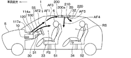
図1に示すように、この車両5には、前席51と後席52が設けられている。なお、前席51は、車両5の車幅方向の右側に配置された運転席側と左側に配置された助手席側に設けられている。前席51は、それぞれリクライニング状態にすることが可能となっている。前席51は、それぞれ乗員6が着座する向きを車両前方向きと車両後方向きに変更可能に構成されている。前席51は、車両5が自動運転モードを実行しているとき、または、停車中などに、車両後方を向くように回転することが可能となっている。 As shown in FIG. 1, the vehicle 5 is provided with a front seat 51 and a rear seat 52. The front seats 51 are provided on the driver's seat side arranged on the right side and the passenger seat side arranged on the left side of the vehicle 5 in the vehicle width direction. Each of the front seats 51 can be in a reclining state. The front seats 51 are configured so that the direction in which the occupant 6 is seated can be changed to the front direction of the vehicle and the rear direction of the vehicle. The front seat 51 can be rotated so as to face the rear of the vehicle when the vehicle 5 is executing the automatic driving mode or when the vehicle is stopped.

上述した車両5に搭載される車両用空調システム1は、空調装置10、天井送風装置20、制御装置30等を備えている。 The vehicle air-conditioning system 1 mounted on the vehicle 5 described above includes an air-conditioning device 10, a ceiling blower 20, a control device 30, and the like.

空調装置10は、インストルメントパネル55の内側に設けられている。空調装置10は、所定の空調モードに応じて温度および湿度を調整した空調風を生成し、その空調風を車両5の前席空間FSと後席空間RSを有する車室内に吹き出すことで、車室内の空気調和を行う。 The air conditioner 10 is provided inside the instrument panel 55. The air-conditioning device 10 generates air-conditioned air whose temperature and humidity are adjusted according to a predetermined air-conditioning mode, and blows the air-conditioned air into the vehicle interior having the front seat space FS and the rear seat space RS of the vehicle 5. Perform indoor air conditioning.

図2に示すように、インストルメントパネル55には、吹出口100と吹出口120が設けられている。吹出口100は、図1中の矢印AF1に示すように、前席51の背もたれの車両前方側の面に向けて空調風を吹き出すフェイス吹出口である。 As shown in FIG. 2, the instrument panel 55 is provided with an outlet 100 and an outlet 120. As shown by the arrow AF1 in FIG. 1, the air outlet 100 is a face air outlet that blows air-conditioning air toward the front surface of the backrest of the front seat 51 on the vehicle front side.

吹出口120は、図1中の矢印AF2に示すように、天井送風装置20の吸込口200に向けて空調風を吹き出す上方吹出口である。吹出口120は、車両5の車幅方向の中央に設けられている。吹出口120は、吹出口100より車両前方に配置されている。 As shown by the arrow AF2 in FIG. 1, the air outlet 120 is an upper air outlet that blows air conditioning air toward the suction port 200 of the ceiling blower 20. The air outlet 120 is provided at the center of the vehicle 5 in the vehicle width direction. The air outlet 120 is arranged in front of the vehicle from the air outlet 100.

吹出口120から送風される空調風は、吹出口100から送風される空調風よりも上下方向上側を向くようになっている。吹出口120は、天井送風装置20の吸込口200へ空調風を導くために専用に設けられたものである。天井送風装置20の作動に伴って、吹出口120から吹き出される空調風は主に天井送風装置20の吸込口200へ吸い込まれる。 The air-conditioning air blown from the air outlet 120 faces upward in the vertical direction with respect to the air-conditioning air blown from the air outlet 100. The air outlet 120 is provided exclusively for guiding the air conditioning air to the suction port 200 of the ceiling blower 20. As the ceiling blower 20 operates, the air conditioning air blown out from the outlet 120 is mainly sucked into the suction port 200 of the ceiling blower 20.

吹出口100は、ダクト114aを介して空調装置10と接続されている。吹出口120は、ダクト117aを介して空調装置10と接続されている。吹出口100には、吹き出す空調風の風量を調整するための不図示のルーバが設けられている。このルーバは、制御装置30によって制御可能となっている。 The air outlet 100 is connected to the air conditioner 10 via a duct 114a. The air outlet 120 is connected to the air conditioner 10 via a duct 117a. The outlet 100 is provided with a louver (not shown) for adjusting the air volume of the air-conditioning air to be blown out. This louver can be controlled by the control device 30.

空調装置10からの空調風は、ダクト114aを通って吹出口100から車両5の車室内に吹出すとともに、ダクト117aを通って吹出口120から車両5の車室内に吹出す。 The conditioned air from the air conditioner 10 is blown out from the outlet 100 into the vehicle interior of the vehicle 5 through the duct 114a, and is blown out from the outlet 120 into the vehicle interior of the vehicle 5 through the duct 117a.

天井送風装置20は、車両5の天井に設けられている。図3に示すように、天井送風装置20は、車両5における後席空間RSの車幅方向の中央に設けられている。天井送風装置20は、遠心送風機200a、吸込口200、吹出口210および吹出口220を有している。なお、天井送風装置20は、冷房機能および暖房機能を有していない。 The ceiling blower 20 is provided on the ceiling of the vehicle 5. As shown in FIG. 3, the ceiling blower 20 is provided at the center of the rear seat space RS in the vehicle 5 in the vehicle width direction. The ceiling blower 20 has a centrifugal blower 200a, a suction port 200, an outlet 210, and an outlet 220. The ceiling blower 20 does not have a cooling function and a heating function.

吸込口200は、車両5の天井に設けられている。より詳細には、吸込口200は、天井送風装置20のうち車両前方側に設けられている。吸込口200は、車両5の車幅方向の中央に設けられている。 The suction port 200 is provided on the ceiling of the vehicle 5. More specifically, the suction port 200 is provided on the front side of the vehicle in the ceiling blower 20. The suction port 200 is provided at the center of the vehicle 5 in the vehicle width direction.

車両5の車幅方向の中央に設けられた吹出口120から吹出された空調風の一部が吸込口200から天井送風装置20の内部に吸い込まれるようになっている。したがって、前席51および後席52の乗員6の姿勢等に関係なく、吹出口120から天井送風装置20の吸込口200に空調風が流れる。 A part of the air-conditioning air blown from the air outlet 120 provided at the center in the vehicle width direction of the vehicle 5 is sucked into the ceiling blower 20 from the suction port 200. Therefore, the air-conditioning air flows from the air outlet 120 to the suction port 200 of the ceiling blower 20 regardless of the postures of the occupants 6 of the front seat 51 and the rear seat 52.

吹出口210および吹出口220は、前席空間FSと後席空間RSに空調風を吹き出すことが可能な位置に設けられている。なお、前席空間FSとは、前席の周囲の空間および前席に着座する乗員の周囲の空間をいう。また、後席空間RSとは、後席52の周囲の空間および後席52に着座する乗員の周囲の空間をいう。なお、前席空間FSと後席空間RSは連続した空間である。 The air outlet 210 and the air outlet 220 are provided at positions where air conditioning air can be blown into the front seat space FS and the rear seat space RS. The front seat space FS refers to the space around the front seat and the space around the occupant seated in the front seat. The rear seat space RS refers to the space around the rear seat 52 and the space around the occupant seated in the rear seat 52. The front seat space FS and the rear seat space RS are continuous spaces.

吹出口210は、主に車両5の前席空間FSに空調風を吹出すものであり、吹出口220は、主に車両5の後席空間RSに空調風を吹出すものである。吹出口210は、吹出口220よりも車両前方に配置されている。 The air outlet 210 mainly blows air conditioning air into the front seat space FS of the vehicle 5, and the air outlet 220 mainly blows air conditioning air into the rear seat space RS of the vehicle 5. The outlet 210 is arranged in front of the vehicle with respect to the outlet 220.

吹出口210は、吹出口210aおよび吹出口210bを有している。吹出口210aは、車両5の車幅方向の右側の部位に配置され、吹出口210bは、車両5の車幅方向の左側の部位に配置されている。 The outlet 210 has an outlet 210a and an outlet 210b. The air outlet 210a is arranged at a portion on the right side of the vehicle 5 in the vehicle width direction, and the air outlet 210b is arranged at a portion on the left side of the vehicle 5 in the vehicle width direction.

吹出口210aは、主に後席空間RSのうち運転席側の車両前方側に向けて空調風を吹出し、吹出口210bは、主に後席空間RSのうち助手席側の車両前方側に向けて空調風を吹出す。 The air-conditioning outlet 210a mainly blows air-conditioned air toward the front side of the vehicle on the driver's seat side of the rear seat space RS, and the air-conditioning outlet 210b mainly faces the front side of the vehicle on the passenger seat side of the rear seat space RS. And blow out the air conditioning wind.

吹出口220は、吹出口220aおよび吹出口220bを有している。吹出口220aは、主に後席空間RSのうち運転席側の車両後方側に向けて空調風を吹出すもので、吹出口220bは、主に後席空間RSのうち助手席側の車両後方側に向けて空調風を吹出すものである。 The outlet 220 has an outlet 220a and an outlet 220b. The air outlet 220a mainly blows air-conditioned air toward the rear side of the vehicle on the driver's seat side of the rear seat space RS, and the air outlet 220b mainly blows air-conditioned air toward the rear side of the vehicle on the driver's seat side of the rear seat space RS. It blows air conditioning air toward the side.

吹出口210aおよび吹出口210bには、後席空間RSに向けて吹出す空調風の向きおよび風量を調整するための不図示のルーバが設けられている。このルーバは、制御装置30によって制御される。 The air outlet 210a and the air outlet 210b are provided with louvers (not shown) for adjusting the direction and air volume of the air-conditioning air blown toward the rear seat space RS. This louver is controlled by the control device 30.

遠心送風機200aは、いずれも不図示の遠心ファンおよびモータを有している。このモータは、制御装置30からの指示にしたがって遠心ファンを回転駆動する。 Each of the centrifugal blowers 200a has a centrifugal fan and a motor (not shown). This motor rotates and drives the centrifugal fan according to the instruction from the control device 30.

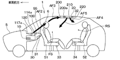
図4は、助手席側の前席51が車両前方を向いており、運転席側の前席51が車両後方を向くように回転した状態を表している。図4中では、吹出口100からの矢印AF1を省略してある。 FIG. 4 shows a state in which the front seat 51 on the passenger seat side faces the front of the vehicle and the front seat 51 on the driver's seat side faces the rear of the vehicle. In FIG. 4, the arrow AF1 from the outlet 100 is omitted.

図4中の矢印AF2に示すように、インストルメントパネル55の吹出口120から車室内に空調風が送風され、その一部は吸込口200から天井送風装置20の内部に吸い込まれる。そして、天井送風装置20の内部に吸い込まれた空調風は、図4中の矢印AF4、AF5に示すように車両5の車室内に吹き出される。 As shown by the arrow AF2 in FIG. 4, the air conditioner air is blown into the vehicle interior from the air outlet 120 of the instrument panel 55, and a part of the air conditioner air is sucked into the ceiling air blower 20 from the suction port 200. Then, the air-conditioning air sucked into the ceiling blower 20 is blown into the vehicle interior of the vehicle 5 as shown by arrows AF4 and AF5 in FIG.

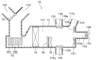
次に、空調装置10の構成について図5を用いて説明する。空調装置10は、空調ケース11の内側に、内外気切替ドア12、送風機13、冷却機器としてのエバポレータ14、加熱機器としてのヒータコア15、エアミックスドア16およびモード切替ドア171、172、173、174などを備えている。 Next, the configuration of the air conditioner 10 will be described with reference to FIG. The air conditioner 10 has an inside / outside air switching door 12, a blower 13, an evaporator 14 as a cooling device, a heater core 15 as a heating device, an air mix door 16, and a mode switching door 171, 172, 173, 174 inside the air conditioning case 11. And so on.

空調ケース11に内側には、空気が流れる通風路111が形成されている。また、空調ケース11は、通風路111の空気流れ方向上流側に、車室内の所定箇所から通風路111に内気を導入するための内気導入口112と、車外から通風路111に外気を導入するための外気導入口113を有している。 A ventilation passage 111 through which air flows is formed inside the air conditioning case 11. Further, the air conditioning case 11 introduces the inside air introduction port 112 for introducing the inside air into the ventilation passage 111 from a predetermined position in the vehicle interior and the outside air from the outside of the vehicle into the ventilation passage 111 on the upstream side in the air flow direction of the ventilation passage 111. It has an outside air introduction port 113 for the purpose.

内外気切替ドア12は、内気導入口112の開口面積と、外気導入口113の開口面積を連続的に調整するものである。内外気切替ドア12は、内気導入口112と外気導入口113のうち、一方の開口部を開くほど他方の開口部を閉じるように回転動作する。これにより、内外気切替ドア12は、通風路111に導入される内気の風量と外気の風量の割合を調整することが可能である。 The inside / outside air switching door 12 continuously adjusts the opening area of the inside air introduction port 112 and the opening area of the outside air introduction port 113. The inside / outside air switching door 12 rotates so as to close the other opening of the inside air introduction port 112 and the outside air introduction port 113 so that one opening is opened. Thereby, the inside / outside air switching door 12 can adjust the ratio of the air volume of the inside air introduced into the ventilation passage 111 to the air volume of the outside air.

送風機13は、遠心ファン131と、その遠心ファン131を回転駆動するモータ132などから構成されている。モータ132の駆動と共に遠心ファン131が回転すると、内気導入口112または外気導入口113から通風路111に内気または外気が導入され、通風路111に空気が送風される。送風機13により送風されて通風路111を流れる空気は、エバポレータ14およびヒータコア15により温度および湿度が調整され、通風路111に連通する複数の吹出開口部114、115、116のいずれかを経由して車室内に吹き出される。 The blower 13 includes a centrifugal fan 131, a motor 132 that rotationally drives the centrifugal fan 131, and the like. When the centrifugal fan 131 rotates with the drive of the motor 132, the inside air or the outside air is introduced into the ventilation passage 111 from the inside air introduction port 112 or the outside air introduction port 113, and the air is blown to the ventilation passage 111. The temperature and humidity of the air blown by the blower 13 and flowing through the ventilation passage 111 are adjusted by the evaporator 14 and the heater core 15, and the air is communicated with the ventilation passage 111 via any of a plurality of outlet openings 114, 115, 116. It is blown into the passenger compartment.

冷却機器としてのエバポレータ14は、通風路111を流れる空気を冷却するための熱交換器である。エバポレータ14は、図示していない圧縮機、凝縮器および膨張弁などと共に周知の冷凍サイクルを構成している。 The evaporator 14 as a cooling device is a heat exchanger for cooling the air flowing through the ventilation passage 111. The evaporator 14 constitutes a well-known refrigeration cycle together with a compressor, a condenser, an expansion valve and the like (not shown).

エバポレータ14が有する図示していないチューブの中を、気液二層状態となった冷媒が流れる。エバポレータ14は、そのチューブの内側を流れる冷媒の蒸発潜熱により、通風路111を流れる空気を冷却する。 A refrigerant in a gas-liquid two-layer state flows through a tube (not shown) included in the evaporator 14. The evaporator 14 cools the air flowing through the ventilation passage 111 by the latent heat of vaporization of the refrigerant flowing inside the tube.

加熱機器としてのヒータコア15は、通風路111を流れる空気を加熱するための熱交換器である。ヒータコア15が有する図示していないチューブの内側を温水等が流れる。ヒータコア15は、そのチューブの内側を流れる温水等と、通風路111を流れる空気との熱交換により、通風路111を流れる空気を加熱する。 The heater core 15 as a heating device is a heat exchanger for heating the air flowing through the ventilation passage 111. Hot water or the like flows inside a tube of the heater core 15 (not shown). The heater core 15 heats the air flowing through the ventilation passage 111 by exchanging heat between the hot water or the like flowing inside the tube and the air flowing through the ventilation passage 111.

エバポレータ14とヒータコア15との間には、エアミックスドア16が設けられている。エアミックスドア16は、エバポレータ14を通過した後にヒータコア15を迂回して流れる風量と、エバポレータ14を通過した後にヒータコア15を通過する風量との割合を調整する。 An air mix door 16 is provided between the evaporator 14 and the heater core 15. The air mix door 16 adjusts the ratio of the air volume that flows around the heater core 15 after passing through the evaporator 14 to the air volume that passes through the heater core 15 after passing through the evaporator 14.

空調ケース11は、通風路111の空気流れ方向下流側に、通風路111から車室内に空気を送風するための複数の吹出開口部114、115、116、117を有している。複数の吹出開口部114、115、116、117は、例えば、フェイス吹出開口部114、フット吹出開口部115、デフロスタ吹出開口部116、上方吹出開口部117などにより構成されている。 The air conditioning case 11 has a plurality of outlet openings 114, 115, 116, 117 for blowing air from the ventilation passage 111 into the vehicle interior on the downstream side in the air flow direction of the ventilation passage 111. The plurality of outlet openings 114, 115, 116, 117 are composed of, for example, a face outlet opening 114, a foot outlet opening 115, a defroster outlet opening 116, an upper outlet opening 117, and the like.

フェイス吹出開口部114は、前席51に着座する乗員6の上半身またはその周囲に向けて空調風を吹き出すものである。フット吹出開口部115は、その乗員6の足元に向けて空調風を吹き出すものである。デフロスタ吹出開口部116は、車両5のフロントガラスに向けて空調風を吹き出すものである。上方吹出開口部117は、車両の上方空間に向けて空調風を吹き出すものである。 The face blowing opening 114 blows air-conditioning air toward or around the upper body of the occupant 6 seated in the front seat 51. The foot blowing opening 115 blows air-conditioning air toward the feet of the occupant 6. The defroster blowout opening 116 blows air-conditioning air toward the windshield of the vehicle 5. The upper blowout opening 117 blows air-conditioning air toward the space above the vehicle.

フェイス吹出開口部114、フット吹出開口部115およびデフロスタ吹出開口部116、上方吹出開口部117には、それぞれの開口部を開閉するためのモード切替ドア171、172、173、174が設けられている。 The face outlet 114, the foot outlet 115, the defroster outlet 116, and the upper outlet 117 are provided with mode switching doors 171, 172, 173, and 174 for opening and closing the respective openings. ..

モード切替ドア171、172、173、174は、フェイスドア171、フットドア172、デフロスタドア173および上方吹出ドア174により構成されている。フェイスドア171は、フェイス吹出開口部114を開閉する。フットドア172は、フット吹出開口部115を開閉する。デフロスタドア173は、デフロスタ吹出開口部116を開閉する。上方吹出ドア174は、上方吹出開口部117を開閉する。 The mode switching doors 171, 172, 173, and 174 are composed of a face door 171, a foot door 172, a defroster door 173, and an upper blowout door 174. The face door 171 opens and closes the face outlet opening 114. The foot door 172 opens and closes the foot outlet opening 115. The defroster door 173 opens and closes the defroster outlet opening 116. The upper outlet door 174 opens and closes the upper outlet opening 117.

なお、上述した内外気切替ドア12、エアミックスドア16、フェイスドア171、フットドア172、デフロスタドア173および上方吹出ドア174はそれぞれ、図示していないサーボモータなどのアクチュエータによって駆動される。 The inside / outside air switching door 12, the air mix door 16, the face door 171, the foot door 172, the defroster door 173, and the upper blowout door 174 are each driven by an actuator such as a servomotor (not shown).

空調ケース11が有する複数の吹出開口部114、115、116、117にはそれぞれ、空調ケース11とは別部材として構成された複数のダクト114a、115a、116a、117aが接続される。 A plurality of ducts 114a, 115a, 116a, 117a configured as separate members from the air conditioning case 11 are connected to the plurality of outlet openings 114, 115, 116, 117 of the air conditioning case 11, respectively.

複数のダクト114a、115a、116a、117aは、例えば、フェイスダクト114a、フットダクト115a、デフロスタダクト116aおよび上方吹出ダクト117a等により構成される。フェイスダクト114aは、フェイス吹出開口部114に接続される。フットダクト115aは、フット吹出開口部115に接続される。デフロスタダクト116aは、デフロスタ吹出開口部116に接続される。上方吹出ダクト117aは、上方吹出開口部117に接続される。なお、空調ケース11と複数のダクト114a、115a、116a、117aは、一体に構成してもよい。 The plurality of ducts 114a, 115a, 116a, 117a are composed of, for example, a face duct 114a, a foot duct 115a, a defroster duct 116a, an upper outlet duct 117a, and the like. The face duct 114a is connected to the face outlet opening 114. The foot duct 115a is connected to the foot outlet opening 115. The defroster duct 116a is connected to the defroster outlet opening 116. The upper outlet duct 117a is connected to the upper outlet opening 117. The air conditioning case 11 and the plurality of ducts 114a, 115a, 116a, 117a may be integrally configured.

図6は、本実施形態の車両用空調システム1のブロック図である。この図に示すように、車両用空調システム1は、空調装置10、天井送風装置20、制御装置30、前方温度センサ31、後方温度センサ32、前席検出部33、乗員検出部34および制御装置30を備えている
前方温度センサ31は、車両5の前席空間FSの熱負荷を判定するためのものである。前方温度センサ31は、インストルメントパネル55の内側に取り付けられている。前方温度センサ31は、車両5の前席空間FSの空気の温度を検出し、検出した温度を示す信号を制御装置30に出力する。
FIG. 6 is a block diagram of the vehicle air conditioning system 1 of the present embodiment. As shown in this figure, the vehicle air conditioner system 1 includes an air conditioner 10, a ceiling blower 20, a control device 30, a front temperature sensor 31, a rear temperature sensor 32, a front seat detection unit 33, an occupant detection unit 34, and a control device. The front temperature sensor 31 including 30 is for determining the heat load of the front seat space FS of the vehicle 5. The front temperature sensor 31 is mounted inside the instrument panel 55. The front temperature sensor 31 detects the temperature of the air in the front seat space FS of the vehicle 5 and outputs a signal indicating the detected temperature to the control device 30.

後方温度センサ32は、車両5の後席空間RSの熱負荷を判定するためのものである。後方温度センサ32は、天井送風装置20の近くの車両5の天井に取り付けられている。本実施形態の後方温度センサ32は、車両5の後席空間RSの空気の温度を検出し、検出した温度を示す信号を制御装置30に出力する。 The rear temperature sensor 32 is for determining the heat load of the rear seat space RS of the vehicle 5. The rear temperature sensor 32 is attached to the ceiling of the vehicle 5 near the ceiling blower 20. The rear temperature sensor 32 of the present embodiment detects the temperature of the air in the rear seat space RS of the vehicle 5 and outputs a signal indicating the detected temperature to the control device 30.

前席検出部33は、車両5の前席51の前後方向の位置、座席51の背もたれの角度および座席51の向きを示す信号を出力する前席検出部33を有している。前席51の向きを検出する。前席検出部33は、前席51の回転を接触または非接触で機械的に検出するセンサを採用することが可能である。前席検出部33によって検出された前席51の向きを示す情報は、制御装置30に伝送される。 The front seat detection unit 33 has a front seat detection unit 33 that outputs signals indicating the position of the front seat 51 of the vehicle 5 in the front-rear direction, the angle of the backrest of the seat 51, and the orientation of the seat 51. The orientation of the front seat 51 is detected. The front seat detection unit 33 can employ a sensor that mechanically detects the rotation of the front seat 51 with or without contact. Information indicating the orientation of the front seat 51 detected by the front seat detection unit 33 is transmitted to the control device 30.

乗員検出部34は、前席51および後席52の乗員の有無、すなわち、前席51および後席52に乗員が着座しているか否かを検出する。乗員検出部34は、前席51および後席52の座部に設けられる着座センサ、または、赤外線センサを採用することが可能である。乗員検出部34によって検出された前席51および後席52の乗員の有無に関する情報は、制御装置30に伝送される。 The occupant detection unit 34 detects the presence or absence of occupants in the front seats 51 and the rear seats 52, that is, whether or not the occupants are seated in the front seats 51 and the rear seats 52. The occupant detection unit 34 can employ a seating sensor or an infrared sensor provided on the seats of the front seat 51 and the rear seat 52. Information regarding the presence or absence of occupants in the front seats 51 and the rear seats 52 detected by the occupant detection unit 34 is transmitted to the control device 30.

制御装置30は、CPU、ROM、RAM、I/O等を備えたコンピュータとして構成されており、ROMに記憶されたプログラムに従って各所処理を実施する。制御装置30は、各種センサ31〜34から各種情報を収集して空調装置10、天井送風装置20を制御する処理を実施する。 The control device 30 is configured as a computer equipped with a CPU, ROM, RAM, I / O, etc., and performs various processes according to a program stored in the ROM. The control device 30 collects various information from various sensors 31 to 34 and executes a process of controlling the air conditioner 10 and the ceiling blower 20.

次に、本実施形態の車両用空調装置の制御装置30の制御処理について図7に従って説明する。図7は、制御装置30が実施する制御処理のフローチャートであり、図示しないメインルーチンのサブルーチンとして実行される。この制御処理は、車両5のイグニッションスイッチがオンされた後、繰り返し実行される。なお、ここでは、図1に示したように、前席51および後席52の背もたれが起きた状態で、かつ、前席51および後席52が車両前方を向いた状態となっているものとする。 Next, the control process of the control device 30 of the vehicle air conditioner of the present embodiment will be described with reference to FIG. 7. FIG. 7 is a flowchart of the control process executed by the control device 30, which is executed as a subroutine of a main routine (not shown). This control process is repeatedly executed after the ignition switch of the vehicle 5 is turned on. Here, as shown in FIG. 1, it is assumed that the backrests of the front seats 51 and the rear seats 52 are raised, and the front seats 51 and the rear seats 52 are facing the front of the vehicle. To do.

まず、制御装置30は、S100にて、空調装置10が冷房中であるか否かを判定する。具体的には、車両に設けられた操作パネルに対する乗員の操作によってエアコンスイッチがオン状態に設定されているか否かに基づいて空調装置10が冷房中であるか否かを判定する。 First, the control device 30 determines in S100 whether or not the air conditioner 10 is cooling. Specifically, it is determined whether or not the air conditioner 10 is cooling based on whether or not the air conditioner switch is set to the ON state by the operation of the occupant on the operation panel provided on the vehicle.

ここで、エアコンスイッチがオン状態に設定されている場合、制御装置30は、S102にて、車両5の後席空間RSの温度状態を収集する。具体的には、後方温度センサ32から車両5の後席空間RSの空気の温度を収集する。 Here, when the air conditioner switch is set to the ON state, the control device 30 collects the temperature state of the rear seat space RS of the vehicle 5 in S102. Specifically, the temperature of the air in the rear seat space RS of the vehicle 5 is collected from the rear temperature sensor 32.

次に、制御装置30は、S104にて、冷房を強める必要があるか否かを判定する。具体的には、車両5の後席空間RSの温度が第1閾値以上であるか否かに基づいて冷房を強める必要があるか否かを判定する。 Next, the control device 30 determines in S104 whether or not it is necessary to strengthen the cooling. Specifically, it is determined whether or not it is necessary to strengthen the cooling based on whether or not the temperature of the rear seat space RS of the vehicle 5 is equal to or higher than the first threshold value.

ここで、S102にて収集した車両5の後席空間RSの温度が第1閾値以上となっている場合、制御装置30は、冷房を強める必要があると判定する。そして、制御装置30は、S106にて、天井送風装置20の吸込口200に到達する空調風の温度を予め定められた所定温度よりも低下させるよう空調装置10を制御する。具体的には、インストルメントパネル55の吹出口120から送風される空調風の温度を所定温度より低下させるよう空調装置10を制御する。 Here, when the temperature of the rear seat space RS of the vehicle 5 collected in S102 is equal to or higher than the first threshold value, the control device 30 determines that it is necessary to strengthen the cooling. Then, in S106, the control device 30 controls the air conditioner 10 so that the temperature of the air conditioning air reaching the suction port 200 of the ceiling blower 20 is lowered to a predetermined temperature lower than a predetermined temperature. Specifically, the air conditioner 10 is controlled so that the temperature of the air conditioning air blown from the air outlet 120 of the instrument panel 55 is lowered below a predetermined temperature.

これにより、空調装置10の冷房能力が増大し、インストルメントパネル55の吹出口120から送風される空調風の温度がより低下する。この空調風は 図1中の矢印AF1に示すように吹出口100から前席51の乗員の上半身に向かって送風されるとともに、図1中の矢印AF2に示すように吹出口120から天井送風装置20の吸込口200に向かって送風される。 As a result, the cooling capacity of the air conditioner 10 is increased, and the temperature of the air conditioning air blown from the air outlet 120 of the instrument panel 55 is further lowered. This air-conditioning air is blown from the air outlet 100 toward the upper body of the occupant of the front seat 51 as shown by the arrow AF1 in FIG. 1, and is blown from the air outlet 120 from the air outlet 120 as shown by the arrow AF2 in FIG. The air is blown toward the suction port 200 of 20.

吹出口120から天井送風装置20の吸込口200に向かって送風された空調風の一部は、図1中の矢印AF3に示すように天井送風装置20の内部に吸い込まれる。そして、吹出口210および吹出口220から冷たい空調風が後席空間RSに吹き出される。具体的には、図1中の矢印AF4に示すように吹出口210から後席52の乗員の足元に向かって空調風が吹き出されるとともに、図1中の矢印AF5に示すように吹出口220から後席52の乗員の上半身に向かって空調風が吹き出される。 A part of the air-conditioning air blown from the air outlet 120 toward the suction port 200 of the ceiling blower 20 is sucked into the ceiling blower 20 as shown by the arrow AF3 in FIG. Then, cold air-conditioned air is blown from the air outlet 210 and the air outlet 220 into the rear seat space RS. Specifically, as shown by arrow AF4 in FIG. 1, air conditioning air is blown from the outlet 210 toward the feet of the occupants in the rear seat 52, and as shown by arrow AF5 in FIG. 1, the outlet 220 is blown. An air-conditioning wind is blown from the upper body of the occupant in the rear seat 52.

また、S100の判定にて、車両に設けられた操作パネルに対する乗員の操作によってエアコンスイッチがオン状態に設定されていない場合、制御装置30は、S108にへ進み、空調装置10が暖房中であるか否かを判定する。 Further, in the determination of S100, if the air conditioner switch is not set to the ON state by the operation of the occupant with respect to the operation panel provided on the vehicle, the control device 30 proceeds to S108, and the air conditioner 10 is heating. Judge whether or not.

また、S102にて収集した車両5の後席空間RSの温度が閾値未満となっている場合も、制御装置30は、S106の処理を実施することなく、S108へ進む。 Further, even when the temperature of the rear seat space RS of the vehicle 5 collected in S102 is less than the threshold value, the control device 30 proceeds to S108 without performing the process of S106.

S108では、制御装置30は、空調装置10が暖房中であるか否かを判定する。例えば、外気温が低く、かつ、車両に設けられた操作パネルに対する乗員の操作によって設定温度が内気温度よりも所定温度以上高くなっている場合、制御装置30は、S108にて、空調装置10が暖房中であると判定し、S110へ進む。 In S108, the control device 30 determines whether or not the air conditioner 10 is heating. For example, when the outside air temperature is low and the set temperature is higher than the inside air temperature by a predetermined temperature or more due to the operation of the occupant on the operation panel provided in the vehicle, the control device 30 is set to S108, and the air conditioner 10 is used. It is determined that the heating is in progress, and the process proceeds to S110.

ここで、制御装置30は、空調装置10が暖房中であると判定すると、S110にて、車両5の後席空間RSの温度状態を収集する。具体的には、後方温度センサ32から車両5の後席空間RSの空気の温度を収集する。 Here, when the control device 30 determines that the air conditioner 10 is heating, the control device 30 collects the temperature state of the rear seat space RS of the vehicle 5 in S110. Specifically, the temperature of the air in the rear seat space RS of the vehicle 5 is collected from the rear temperature sensor 32.

次に、制御装置30は、S112にて、暖房を強める必要があるか否かを判定する。具体的には、車両5の後席空間RSの温度が第1閾値より小さい第2閾値未満であるか否かに基づいて暖房を強める必要があるか否かを判定する。 Next, the control device 30 determines in S112 whether or not it is necessary to increase the heating. Specifically, it is determined whether or not it is necessary to increase the heating based on whether or not the temperature of the rear seat space RS of the vehicle 5 is smaller than the first threshold value and less than the second threshold value.

ここで、車両5の後席空間RSの温度が第2閾値未満となっている場合、制御装置30は、暖房を強める必要があると判定し、S114にて、天井送風装置20の吸込口200に到達する空調風の温度を上昇させるよう空調装置10を制御する。具体的には、インストルメントパネル55の吹出口120から送風される空調風の温度をより上昇させるよう空調装置10を制御し、メインルーチンへ戻る。 Here, when the temperature of the rear seat space RS of the vehicle 5 is less than the second threshold value, the control device 30 determines that it is necessary to increase the heating, and in S114, the suction port 200 of the ceiling blower 20 The air conditioner 10 is controlled so as to raise the temperature of the air conditioning air that reaches. Specifically, the air conditioner 10 is controlled so as to raise the temperature of the air conditioning air blown from the air outlet 120 of the instrument panel 55, and the process returns to the main routine.

これにより、空調装置10の冷房能力が増大し、インストルメントパネル55の吹出口120から送風される空調風の温度がより上昇する。 As a result, the cooling capacity of the air conditioner 10 is increased, and the temperature of the air conditioning air blown from the air outlet 120 of the instrument panel 55 is further increased.

この空調風は、図8中の矢印AF1に示すように吹出口100から前席51の乗員の上半身に向かって送風されるとともに、図1中の矢印AF2に示すように吹出口120から天井送風装置20の吸込口200に向かって送風される。さらに、図8中の矢印AF6に示すように前席51の乗員の足元に向かって送風される。 This air-conditioning air is blown from the air outlet 100 toward the upper body of the occupant of the front seat 51 as shown by the arrow AF1 in FIG. 8, and is blown from the air outlet 120 to the ceiling as shown by the arrow AF2 in FIG. The air is blown toward the suction port 200 of the device 20. Further, as shown by the arrow AF6 in FIG. 8, the air is blown toward the feet of the occupants in the front seat 51.

吹出口120から天井送風装置20の吸込口200に向かって送風された空調風の一部は、図8中の矢印AF3に示すように天井送風装置20の内部に吸い込まれる。そして、吹出口210および吹出口220から暖かい空調風が後席空間RSに吹き出される。 A part of the air-conditioning air blown from the air outlet 120 toward the suction port 200 of the ceiling blower 20 is sucked into the ceiling blower 20 as shown by the arrow AF3 in FIG. Then, warm air-conditioning air is blown from the air outlet 210 and the air outlet 220 into the rear seat space RS.

具体的には、図8中の矢印AF4に示すように吹出口210から後席52の乗員の足元に向かって空調風が吹き出されるとともに、図8中の矢印AF5に示すように吹出口220から後席52の乗員の上半身に向かって空調風が吹き出される。 Specifically, the air-conditioning air is blown from the outlet 210 toward the feet of the occupants in the rear seat 52 as shown by the arrow AF4 in FIG. 8, and the outlet 220 is as shown by the arrow AF5 in FIG. An air-conditioning wind is blown from the upper body of the occupant in the rear seat 52.

また、空調装置10から前席51の乗員の足元に向かって送風された空調風は、図8中の矢印AF7に示すように、後席52の乗員の足元に向かって流れる。 Further, the air-conditioned air blown from the air conditioner 10 toward the feet of the occupants in the front seats 51 flows toward the feet of the occupants in the rear seats 52 as shown by the arrow AF7 in FIG.

以上、説明したように、本実施形態の車両用空調システムは、車両のインストルメントパネル55に配置された吹出口100、120から車両の前席空間FSと後席空間RSを有する車室内に温度調整された空調風を送風する空調装置10を備えている。また、車両の天井に配置され、該天井に配置された吸込口200から吸い込んだ空調風を車室内の少なくとも後席空間に送風する天井送風装置20を備えている。また、車両の後席空間の温度状態および車両の座席状態の少なくとも一方の状態を収集する状態収集部(S102、S110、S202、S210)を備えている。また、状態収集部により収集された状態に応じて空調装置を制御することにより吹出口から送風され天井送風装置の吸込口に到達する空調風の温度および風量の少なくとも一方を調整する空調制御部(S106、S114、S206、S214)を備えている。 As described above, in the vehicle air-conditioning system of the present embodiment, the temperature in the vehicle interior having the front seat space FS and the rear seat space RS of the vehicle is set from the air outlets 100 and 120 arranged on the instrument panel 55 of the vehicle. The air conditioner 10 for blowing the adjusted air conditioning air is provided. Further, the ceiling blower 20 is provided on the ceiling of the vehicle and blows the air-conditioning air sucked from the suction port 200 arranged on the ceiling to at least the rear seat space in the vehicle interior. Further, a state collecting unit (S102, S110, S202, S210) for collecting at least one of the temperature state of the rear seat space of the vehicle and the seat state of the vehicle is provided. In addition, the air-conditioning control unit (which adjusts at least one of the temperature and the air volume of the air-conditioning air that is blown from the air outlet and reaches the suction port of the ceiling air-conditioning device by controlling the air-conditioning device according to the state collected by the state collecting unit ( S106, S114, S206, S214).

このような構成によれば、状態収集部は、車両の後席空間の温度状態および車両の座席状態の少なくとも一方の状態を収集する。そして、空調制御部は、状態収集部により収集された状態に応じて空調装置を制御することにより吹出口から送風され天井送風装置の吸込口に到達する空調風の温度および風量の少なくとも一方を調整する。したがって、複数の空調装置を備えることなく、より簡素な構成で、乗員により十分な快適性を提供することができる。 According to such a configuration, the state collecting unit collects at least one state of the temperature state of the rear seat space of the vehicle and the seat state of the vehicle. Then, the air-conditioning control unit adjusts at least one of the temperature and the air volume of the air-conditioning air that is blown from the air outlet and reaches the suction port of the ceiling air-conditioning device by controlling the air-conditioning device according to the state collected by the state collecting unit. To do. Therefore, it is possible to provide the occupant with sufficient comfort with a simpler configuration without providing a plurality of air conditioners.

また、状態収集部は、車両の後席空間の温度状態として後席空間の空気の温度を収集する。このように、車両の後席空間の温度状態として後席空間の空気の温度を収集することができる。 Further, the state collecting unit collects the temperature of the air in the rear seat space as the temperature state of the rear seat space of the vehicle. In this way, the temperature of the air in the rear seat space can be collected as the temperature state of the rear seat space of the vehicle.

また、吹出口120は、車両の車幅方向の中央に配置されている。したがって、運転席や助手席の乗員の身体によって吹出口120から送風される空調風の流れが変わるのを防止することが可能である。 Further, the outlet 120 is arranged at the center of the vehicle in the vehicle width direction. Therefore, it is possible to prevent the flow of the air-conditioning air blown from the air outlet 120 from being changed by the body of the occupant in the driver's seat or the passenger seat.

また、吹出口120は、天井送風装置20の吸込口200へ空調風を導くために専用に設けられたものである。このように、天井送風装置20の吸込口200へ空調風を導くために専用に設けられた吹出口120を備えることで、乗員に安定的に快適性を提供することができる。 Further, the air outlet 120 is provided exclusively for guiding the air conditioning air to the suction port 200 of the ceiling blower 20. In this way, by providing the air outlet 120 provided exclusively for guiding the air-conditioning air to the suction port 200 of the ceiling blower 20, it is possible to provide the occupants with stable comfort.

また、天井送風装置20の吸込口200は、車両の車幅方向の中央に配置されている。このように、天井送風装置20の吸込口200を車両の車幅方向の中央に配置することもできる。 Further, the suction port 200 of the ceiling blower 20 is arranged at the center in the vehicle width direction of the vehicle. In this way, the suction port 200 of the ceiling blower 20 can be arranged at the center of the vehicle in the vehicle width direction.

特に、吹出口120は、車両の車幅方向の中央に配置し、かつ、天井送風装置20の吸込口200を車両の車幅方向の中央に配置することで、運転席と助手席の乗員の身体によって吹出口120から送風される空調風の流れが妨げられないようにすることが可能である。 In particular, the air outlet 120 is arranged in the center of the vehicle width direction, and the suction port 200 of the ceiling blower 20 is arranged in the center of the vehicle width direction, so that the driver's seat and the passenger's seat occupants can use the air outlet 120. It is possible to prevent the flow of the conditioned air blown from the outlet 120 by the body from being obstructed.

(第2実施形態)
第2実施形態に係る車両用空調システムについて図9〜図10を用いて説明する。本実施形態の車両用空調システムの構成は上記第1実施形態と同様である。本実施形態の車両用空調システムは、上記第1実施形態の車両用空調システムと比較して制御装置30の処理が異なる。
(Second Embodiment)
The vehicle air conditioning system according to the second embodiment will be described with reference to FIGS. 9 to 10. The configuration of the vehicle air conditioning system of this embodiment is the same as that of the first embodiment. The vehicle air-conditioning system of the present embodiment is different from the vehicle air-conditioning system of the first embodiment in the processing of the control device 30.

図9に、本実施形態の制御装置30のフローチャートを示す。上記第1実施形態の制御装置30は、S102にて車両の後席空間RSの温度状態を収集するようにしたが、本実施形態の制御装置30は、S202にて、車両の座席状態を収集する。そして、S206にて、車両の座席状態に応じて空調装置10を制御して、天井送風装置20の吸込口200に到達する空調風の温度をより低下させる。 FIG. 9 shows a flowchart of the control device 30 of the present embodiment. The control device 30 of the first embodiment collects the temperature state of the rear seat space RS of the vehicle in S102, but the control device 30 of the present embodiment collects the seat state of the vehicle in S202. To do. Then, in S206, the air conditioner 10 is controlled according to the seat condition of the vehicle to further lower the temperature of the air conditioner air reaching the suction port 200 of the ceiling blower 20.

制御装置30は、S100にて、空調装置10が冷房中であることを判定すると、S202にて、車両の座席状態を収集する。具体的には、前席検出部33から出力される信号に基づいて車両の座席状態を収集する。なお、車両の座席状態には、車両5の前席51の前後方向の位置、座席51の背もたれの角度および座席51の向きが含まれる。 When the control device 30 determines in S100 that the air conditioner 10 is cooling, the control device 30 collects the seat state of the vehicle in S202. Specifically, the seat state of the vehicle is collected based on the signal output from the front seat detection unit 33. The seating state of the vehicle includes the position of the front seat 51 of the vehicle 5 in the front-rear direction, the angle of the backrest of the seat 51, and the orientation of the seat 51.

次に、制御装置30は、S104にて、冷房を強める必要があるか否かを判定し、冷房を強める必要があると判定すると、S206にて、車両の座席状態を判定するとともに、車両の座席状態に応じて空調装置10を制御して、天井送風装置20の吸込口200に到達する空調風の温度を低下させ、本処理を終了する。 Next, in S104, the control device 30 determines whether or not it is necessary to strengthen the cooling, and if it is determined that it is necessary to strengthen the cooling, the control device 30 determines the seating condition of the vehicle and determines the seating condition of the vehicle in S206. The air conditioner 10 is controlled according to the seat condition to lower the temperature of the air conditioner air reaching the suction port 200 of the ceiling blower 20, and this process is completed.

また、空調装置10が冷房中となっていない場合、あるいは、S104にて、冷房を強める必要がないと判定された場合には、S108へ進み、制御装置30は、空調装置10が暖房中となっているか否かを判定する。 If the air conditioner 10 is not cooling, or if it is determined in S104 that it is not necessary to increase the cooling, the process proceeds to S108, and the control device 30 indicates that the air conditioner 10 is heating. Judge whether or not it is.

ここで、制御装置30は、空調装置10が暖房中であることを判定すると、S210にて、車両の座席状態を収集する。具体的には、前席検出部33から出力される信号に基づいて車両の座席状態を収集する。 Here, when the control device 30 determines that the air conditioner 10 is heating, the seat state of the vehicle is collected in S210. Specifically, the seat state of the vehicle is collected based on the signal output from the front seat detection unit 33.

次に、制御装置30は、S212にて、暖房を強める必要があるか否かを判定し、暖房を強める必要があると判定すると、S214にて、車両の座席状態を判定するとともに、車両の座席状態に応じて空調装置10を制御して、天井送風装置20の吸込口200に到達する空調風の温度をより上昇させ、本処理を終了する。 Next, the control device 30 determines in S212 whether or not it is necessary to increase the heating, and if it determines that it is necessary to increase the heating, in S214, determines the seating condition of the vehicle and the vehicle. The air conditioner 10 is controlled according to the seat condition to further raise the temperature of the air conditioner air reaching the suction port 200 of the ceiling blower 20, and this process is completed.

また、空調装置10が暖房中となっていない場合、あるいは、S210にて、暖房を強める必要がないと判定された場合には、S214へ進むことなく、本処理を終了する。 If the air conditioner 10 is not heating, or if it is determined in S210 that it is not necessary to increase the heating, this process ends without proceeding to S214.

以下、(A)〜(D)の場合に分けて制御装置30の制御処理について説明する。 Hereinafter, the control processing of the control device 30 will be described separately for the cases (A) to (D).

(A)空調装置10が冷房中で、車両の座席状態に基づいて前席51が車両後方側に位置し、かつ、座席51の背もたれがリクライニング状態となっている場合
この場合、制御装置30は、S100にて、空調装置10が冷房中であると判定し、S202にて、車両の座席状態を収集する。そして、制御装置30は、S104にて、冷房を強める必要があると判定すると、S206へ進む。
(A) When the air conditioner 10 is cooling, the front seat 51 is located on the rear side of the vehicle based on the seat condition of the vehicle, and the backrest of the seat 51 is in the reclining state. In this case, the control device 30 is , S100 determines that the air conditioner 10 is cooling, and S202 collects the seat state of the vehicle. Then, when the control device 30 determines in S104 that it is necessary to strengthen the cooling, the process proceeds to S206.

ここで、制御装置30は、S206にて、車両の座席状態がリクライニング状態であるか否かを判定する。具体的には、収集した状態に基づいて、前席51が車両後方側に位置し、かつ、座席51の背もたれが所定位置よりも傾斜しているか否かに基づいて車両の座席状態がリクライニング状態であるか否かを判定する。 Here, the control device 30 determines in S206 whether or not the seat state of the vehicle is the reclining state. Specifically, based on the collected state, the seat state of the vehicle is in the reclining state based on whether the front seat 51 is located on the rear side of the vehicle and the backrest of the seat 51 is tilted from a predetermined position. It is determined whether or not it is.

そして、この判定が肯定判定になった場合、天井送風装置20の吸込口200に到達する空調風の温度をより低下させるよう空調装置10を制御する。 Then, when this determination is affirmative, the air conditioner 10 is controlled so as to further lower the temperature of the air conditioning air reaching the suction port 200 of the ceiling blower 20.

さらに、制御装置30は、図10中の矢印AF1に示すように、第1実施形態の場合と比較して吹出口100から送風される空調風の風量を減少させ、図10中の矢印AF2に示すように、吹出口120から送風される空調風の風量を増加させる。 Further, as shown by the arrow AF1 in FIG. 10, the control device 30 reduces the air volume of the conditioned air blown from the air outlet 100 as compared with the case of the first embodiment, and the arrow AF2 in FIG. As shown, the air volume of the conditioned air blown from the outlet 120 is increased.

なお、制御装置30は、吹出口100に設けられた不図示のルーバを制御することにより吹出口100から吹き出す空調風の風量を減少させることができる。 The control device 30 can reduce the amount of air-conditioning air blown from the air outlet 100 by controlling a louver (not shown) provided at the air outlet 100.

これにより、吹出口100から送風される空調風の風量が減少するため、前席51の乗員の上半身に到達する空調風の風量は減少するが、天井送風装置20の吸込口200に到達する空調風の風量は増加する。 As a result, the air volume of the air conditioning air blown from the air outlet 100 decreases, so that the air volume of the air conditioning air reaching the upper body of the occupant of the front seat 51 decreases, but the air conditioning air reaches the suction port 200 of the ceiling blower 20. The air volume of the wind increases.

また、制御装置30は、第1実施形態の場合と比較して、天井送風装置20の吹出口220から吹き出される空調風の向きは変化させず、吹出口210から吹き出される空調風の向きを車両前方側に変化させる。 Further, as compared with the case of the first embodiment, the control device 30 does not change the direction of the conditioned air blown from the air outlet 220 of the ceiling blower 20, and the direction of the conditioned air blown from the air outlet 210. To the front side of the vehicle.

これにより、リクライニング状態になっている座席51の乗員の頭部に向かって空調風が流れるようになる。つまり、座席51の乗員の上半身から離れた吹出口100から送風される空調風の風量は少なくなるが、座席51の乗員の頭部に近い天井送風装置20の吸込口200からの空調風が乗員の頭部に沿って流れるようにすることができる。 As a result, the air-conditioning air flows toward the head of the occupant of the seat 51 in the reclining state. That is, the amount of air-conditioned air blown from the air outlet 100 away from the upper body of the occupant of the seat 51 is reduced, but the conditioned air from the suction port 200 of the ceiling blower 20 near the head of the occupant of the seat 51 is occupant. Can be made to flow along the head of the air conditioner.

(B)空調装置10が冷房中で、車両の前席51が車両後方を向くように回転した状態となっている場合
この場合、制御装置30は、S100にて、空調装置10が冷房中であると判定し、S202にて、車両の座席状態を収集する。そして、制御装置30は、S104にて、冷房を強める必要があると判定すると、S206へ進む。
(B) When the air conditioner 10 is in the cooling state and the front seat 51 of the vehicle is in a state of being rotated so as to face the rear of the vehicle. In this case, the control device 30 is in S100 and the air conditioner 10 is in the cooling state. It is determined that there is, and the seat condition of the vehicle is collected in S202. Then, when the control device 30 determines in S104 that it is necessary to strengthen the cooling, the process proceeds to S206.

ここで、制御装置30は、S206にて、車両の座席状態が後ろ向き状態であるか否かを判定する。具体的には、収集した状態に基づいて、車両後方を向くように回転した状態となっているか否かを判定する。 Here, the control device 30 determines in S206 whether or not the seat state of the vehicle is in the rearward facing state. Specifically, based on the collected state, it is determined whether or not the vehicle is in a state of being rotated so as to face the rear of the vehicle.

そして、この判定が肯定判定になった場合、天井送風装置20の吸込口200に到達する空調風の温度をより低下させるよう空調装置10を制御する。 Then, when this determination is affirmative, the air conditioner 10 is controlled so as to further lower the temperature of the air conditioning air reaching the suction port 200 of the ceiling blower 20.

さらに、制御装置30は、図11に示すような空調風の流れとなるよう空調装置10および天井送風装置20を制御する。 Further, the control device 30 controls the air conditioner 10 and the ceiling blower 20 so as to have the flow of the air conditioning air as shown in FIG.

具体的には、制御装置30は、吹出口100から空調風が送風されないようにし、吹出口120から送風される空調風の風量を増加させる。 Specifically, the control device 30 prevents the air-conditioning air from being blown from the air outlet 100, and increases the air volume of the air-conditioning air blown from the air outlet 120.

これにより、吹出口100から空調風が送風されないので前席51の背もたれに空調風が当たることによる効率低下を抑制することができる。また、天井送風装置20の吸込口200に到達する空調風の風量を増加させることもできる。 As a result, since the air conditioning air is not blown from the air outlet 100, it is possible to suppress a decrease in efficiency due to the air conditioning air hitting the backrest of the front seat 51. It is also possible to increase the air volume of the air conditioner air reaching the suction port 200 of the ceiling blower 20.

また、制御装置30は、第1実施形態の場合と比較して、天井送風装置20の吹出口210から送風される空調風の向きを車両前方側に変化させる。 Further, the control device 30 changes the direction of the air conditioning air blown from the air outlet 210 of the ceiling blower 20 toward the front side of the vehicle as compared with the case of the first embodiment.

これにより、車両後方を向くよう座席51に着差している乗員の上半身に向かって空調風を流すことができる。 As a result, the air-conditioning air can be blown toward the upper body of the occupant who is wearing the seat 51 so as to face the rear of the vehicle.

(C)空調装置10が暖房中で、車両の座席状態に基づいて前席51が車両後方側に位置し、かつ、座席51の背もたれがリクライニング状態となっている場合
この場合、制御装置30は、S108にて、空調装置10が暖房中であると判定し、S202にて、車両の座席状態を収集する。そして、制御装置30は、S210にて、暖房を強める必要があると判定すると、S214へ進む。
(C) When the air conditioner 10 is heating, the front seat 51 is located on the rear side of the vehicle based on the seat condition of the vehicle, and the backrest of the seat 51 is in the reclining state. In this case, the control device 30 is , S108 determines that the air conditioner 10 is heating, and S202 collects the seat state of the vehicle. Then, when the control device 30 determines in S210 that it is necessary to increase the heating, the process proceeds to S214.

ここで、制御装置30は、S214にて、車両の座席状態がリクライニング状態であるか否かを判定する。具体的には、収集した状態に基づいて、前席51が車両後方側に位置し、かつ、座席51の背もたれが所定位置よりも傾斜しているか否かに基づいて車両の座席状態がリクライニング状態であるか否かを判定する。 Here, the control device 30 determines in S214 whether or not the seat state of the vehicle is the reclining state. Specifically, based on the collected state, the seat state of the vehicle is in the reclining state based on whether the front seat 51 is located on the rear side of the vehicle and the backrest of the seat 51 is tilted from a predetermined position. It is determined whether or not it is.

そして、この判定が肯定判定になった場合、天井送風装置20の吸込口200に到達する空調風の温度をより上昇させるよう空調装置10を制御する。 Then, when this determination is affirmative, the air conditioner 10 is controlled so as to further raise the temperature of the air conditioning air reaching the suction port 200 of the ceiling blower 20.

さらに、制御装置30は、図12中の矢印AF1に示すように、第1実施形態の場合と比較して吹出口100から送風される空調風の風量を減少させ、図10中の矢印AF2に示すように、吹出口120から送風される空調風の風量を増加させる。 Further, as shown by the arrow AF1 in FIG. 12, the control device 30 reduces the air volume of the conditioned air blown from the air outlet 100 as compared with the case of the first embodiment, and the arrow AF2 in FIG. As shown, the air volume of the conditioned air blown from the outlet 120 is increased.

なお、制御装置30は、吹出口100に設けられた不図示のルーバを制御することにより吹出口100から吹き出す空調風の風量を減少させることができる。 The control device 30 can reduce the amount of air-conditioning air blown from the air outlet 100 by controlling a louver (not shown) provided at the air outlet 100.

これにより、吹出口100から送風される空調風の風量を減少させるため、前席51の乗員の上半身に到達する空調風の風量は減少するが、天井送風装置20の吸込口200に到達する空調風の風量は増加する。 As a result, the air volume of the air conditioning air blown from the air outlet 100 is reduced, so that the air volume of the air conditioning air reaching the upper body of the occupant of the front seat 51 is reduced, but the air conditioning air reaching the suction port 200 of the ceiling blower 20 is reduced. The air volume of the wind increases.

また、制御装置30は、天井送風装置20の吹出口220から吹き出される空調風の向きは変化させず、吹出口210から吹き出される空調風の向きを車両前方側に変化させる。 Further, the control device 30 does not change the direction of the conditioned air blown from the air outlet 220 of the ceiling blower 20, but changes the direction of the conditioned air blown from the air outlet 210 toward the front side of the vehicle.

これにより、リクライニング状態になっている座席51の乗員の頭部に向かって空調風が流れるようになる。つまり、座席51の乗員の上半身から離れた吹出口100から送風される空調風の風量は少なくなるが、座席51の乗員の頭部に近い天井送風装置20の吸込口200からの空調風が乗員の頭部に沿って流れるようにすることができる。 As a result, the air-conditioning air flows toward the head of the occupant of the seat 51 in the reclining state. That is, the amount of air-conditioned air blown from the air outlet 100 away from the upper body of the occupant of the seat 51 is reduced, but the conditioned air from the suction port 200 of the ceiling blower 20 near the head of the occupant of the seat 51 is occupant. Can be made to flow along the head of the air conditioner.

また、空調装置10が暖房中の場合、インストルメントパネル55の吹出口100および吹出口120から加熱された空調風が送風されるだけでなく、矢印AF6に示すように前席51の乗員の足元へ向けて加熱された空調風が送風される。 Further, when the air conditioner 10 is heating, not only the heated air conditioning air is blown from the air outlet 100 and the air outlet 120 of the instrument panel 55, but also the feet of the occupants in the front seat 51 as shown by the arrow AF6. The air-conditioned air heated toward is blown.

(D)空調装置10が暖房中で、車両の前席51が車両後方を向くように回転した状態となっている場合
この場合、制御装置30は、S108にて、空調装置10が暖房中であると判定し、S210にて、車両の座席状態を収集する。そして、制御装置30は、S112にて、暖房を強める必要があると判定すると、S214へ進む。
(D) When the air conditioner 10 is heating and the front seat 51 of the vehicle is in a state of rotating so as to face the rear of the vehicle In this case, the control device 30 is in S108, and the air conditioner 10 is heating. It is determined that there is, and the seat condition of the vehicle is collected in S210. Then, when the control device 30 determines in S112 that it is necessary to increase the heating, the process proceeds to S214.

ここで、制御装置30は、S206にて、車両の座席状態が後ろ向き状態であるか否かを判定する。具体的には、収集した状態に基づいて、車両後方を向くように回転した状態となっているか否かを判定する。 Here, the control device 30 determines in S206 whether or not the seat state of the vehicle is in the rearward facing state. Specifically, based on the collected state, it is determined whether or not the vehicle is in a state of being rotated so as to face the rear of the vehicle.

そして、この判定が肯定判定になった場合、天井送風装置20の吸込口200に到達する空調風の温度をより上昇させるよう空調装置10を制御する。 Then, when this determination is affirmative, the air conditioner 10 is controlled so as to further raise the temperature of the air conditioning air reaching the suction port 200 of the ceiling blower 20.

さらに、制御装置30は、図13に示すような空調風の流れとなるよう空調装置10および天井送風装置20を制御する。 Further, the control device 30 controls the air conditioner 10 and the ceiling blower 20 so as to have the flow of the air conditioning air as shown in FIG.

具体的には、制御装置30は、吹出口100から空調風が送風されないようにし、吹出口120から送風される空調風の風量を増加させる。 Specifically, the control device 30 prevents the air-conditioning air from being blown from the air outlet 100, and increases the air volume of the air-conditioning air blown from the air outlet 120.

これにより、吹出口100から空調風が送風されないので前席51の背もたれに空調風が当たることによる効率低下を抑制することができる。また、天井送風装置20の吸込口200に到達する空調風の風量を増加させることもできる。 As a result, since the air conditioning air is not blown from the air outlet 100, it is possible to suppress a decrease in efficiency due to the air conditioning air hitting the backrest of the front seat 51. It is also possible to increase the air volume of the air conditioner air reaching the suction port 200 of the ceiling blower 20.

また、制御装置30は、第1実施形態の場合と比較して、天井送風装置20の吹出口210から送風される空調風の向きを車両前方側に調整する。 Further, the control device 30 adjusts the direction of the air conditioning air blown from the air outlet 210 of the ceiling blower 20 toward the front side of the vehicle as compared with the case of the first embodiment.

これにより、車両後方を向くよう座席51に着差している乗員の上半身に向かって空調風を流すことができる。 As a result, the air-conditioning air can be blown toward the upper body of the occupant who is wearing the seat 51 so as to face the rear of the vehicle.

また、空調装置10が暖房中の場合、インストルメントパネル55の吹出口100および吹出口120から加熱された空調風が送風されるだけでなく、矢印AF6に示すように前席51の乗員の足元へ向けて加熱された空調風が送風される。 Further, when the air conditioner 10 is heating, not only the heated air conditioning air is blown from the air outlet 100 and the air outlet 120 of the instrument panel 55, but also the feet of the occupants in the front seat 51 as shown by the arrow AF6. The air-conditioned air heated toward is blown.

本実施形態では、上記第1実施形態と共通の構成から奏される同様の効果を上記第1実施形態と同様に得ることができる。 In the present embodiment, the same effect obtained from the same configuration as that of the first embodiment can be obtained in the same manner as that of the first embodiment.

また、制御装置30は、車両の座席状態として、車両の座席の前後方向の位置、車両の座席の背もたれの角度、車両の座席の向きおよび車両の座席の乗員の有無の少なくとも1つを収集する。 Further, the control device 30 collects at least one of the front-rear position of the vehicle seat, the angle of the backrest of the vehicle seat, the orientation of the vehicle seat, and the presence or absence of an occupant of the vehicle seat as the vehicle seat state. ..

このように、車両の座席の前後方向の位置、車両の座席の背もたれの角度、車両の座席の向きおよび車両の座席の乗員の有無の少なくとも1つを車両の座席状態として収集することもできる。 In this way, at least one of the front-rear position of the vehicle seat, the angle of the backrest of the vehicle seat, the orientation of the vehicle seat, and the presence or absence of the occupant of the vehicle seat can be collected as the vehicle seat state.

また、制御装置30は、収集された車両の座席の前後方向の位置、車両の座席の背もたれの角度および車両の座席の向きの少なくとも1つに応じて天井送風装置から送風される空調風の向きを変化させる。 Further, the control device 30 determines the direction of the air conditioning air blown from the ceiling blower according to at least one of the collected vehicle seat front-rear position, the vehicle seat backrest angle, and the vehicle seat orientation. To change.

このように、収集された車両の座席の前後方向の位置、車両の座席の背もたれの角度および車両の座席の向きの少なくとも1つに応じて天井送風装置20から送風される空調風の向きを変化させることができる。 In this way, the direction of the conditioned air blown from the ceiling blower 20 is changed according to at least one of the collected front-rear position of the vehicle seat, the angle of the backrest of the vehicle seat, and the orientation of the vehicle seat. Can be made to.

(第3実施形態)
第3実施形態に係る車両用空調システムについて図14を用いて説明する。本実施形態のインストルメントパネル55には、上記した各実施形態の吹出口120が備えられていない。本実施形態の車両用空調システム1は、吹出口120に代えて吹出口100から送風される空調風が天井送風装置20の吸込口200に到達するよう構成されている。
(Third Embodiment)
The vehicle air conditioning system according to the third embodiment will be described with reference to FIG. The instrument panel 55 of the present embodiment is not provided with the outlet 120 of each of the above-described embodiments. The vehicle air conditioning system 1 of the present embodiment is configured so that the air conditioning air blown from the air outlet 100 instead of the air outlet 120 reaches the suction port 200 of the ceiling blower 20.

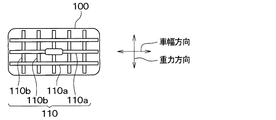
図15に示すように、複数の吹出口100には、風向調整板110が設けられている。風向調整板110は、吹出口100から車室内に吹き出される空調風の向きを調整するものである。例えば、風向調整板110は、吹出口100から車室内に吹き出される空調空の風向きを重力方向に変えるための複数枚の横ルーバー110aと、その空調空の風向きを車幅方向に変えるための複数枚の縦ルーバー110bとを備えている。本実施形態の風向調整板110が備える横ルーバー110aと縦ルーバー110bは、図示していないサーボモータなどのアクチュエータによって駆動される。 As shown in FIG. 15, the plurality of air outlets 100 are provided with wind direction adjusting plates 110. The wind direction adjusting plate 110 adjusts the direction of the air-conditioning air blown into the vehicle interior from the air outlet 100. For example, the wind direction adjusting plate 110 includes a plurality of horizontal louvers 110a for changing the wind direction of the air-conditioned air blown into the vehicle interior from the air outlet 100 in the direction of gravity, and the wind direction of the air-conditioned air for changing the wind direction in the vehicle width direction. It is equipped with a plurality of vertical louvers 110b. The horizontal louver 110a and the vertical louver 110b included in the wind direction adjusting plate 110 of the present embodiment are driven by an actuator such as a servomotor (not shown).

制御装置30は、吹出口100から吹き出される空調風が天井送風装置20の吸込口200に到達するよう縦ルーバー110bおよび横ルーバー110aを駆動するアクチュエータを制御する。 The control device 30 controls the actuators that drive the vertical louvers 110b and the horizontal louvers 110a so that the conditioned air blown from the air outlet 100 reaches the suction port 200 of the ceiling blower 20.

このようにすることで、上記各実施形態の吹出口120を備えることなく、吹出口100からの空調風を天井送風装置20の吸込口200に到達させることができる。 By doing so, the conditioned air from the air outlet 100 can reach the suction port 200 of the ceiling blower 20 without providing the air outlet 120 of each of the above embodiments.

なお、車両の前席51がリクライニング状態の場合には、図16に示す空調風の流れとなるよう空調装置10および天井送風装置20を制御することができる。 When the front seat 51 of the vehicle is in the reclining state, the air conditioner 10 and the ceiling blower 20 can be controlled so as to have the flow of the air conditioning air shown in FIG.

また、車両の前席51が車両後方を向くように回転した状態の場合には、図17に示す空調風の流れとなるよう空調装置10および天井送風装置20を制御することができる。 Further, when the front seat 51 of the vehicle is rotated so as to face the rear of the vehicle, the air conditioner 10 and the ceiling blower 20 can be controlled so as to have the flow of the air conditioning air shown in FIG.

本実施形態では、上記第1実施形態と共通の構成から奏される同様の効果を上記第1実施形態と同様に得ることができる。 In the present embodiment, the same effect obtained from the same configuration as that of the first embodiment can be obtained in the same manner as that of the first embodiment.

また、吹出口100は、車両の前席空間に向けて空調風を送風するフェイス吹出口であり、フェイス吹出口には、空調風の送風方向を変更する風向調整板110が設けられている。そして、風向調整板110によりフェイス吹出口から吹出される空調風の吹出し方向が天井送風装置20の吸込口200へ向いている。 Further, the air outlet 100 is a face air outlet that blows air-conditioned air toward the front seat space of the vehicle, and the face air outlet is provided with a wind direction adjusting plate 110 that changes the air-conditioning air blowing direction. Then, the direction of the air-conditioning air blown out from the face outlet by the wind direction adjusting plate 110 is directed to the suction port 200 of the ceiling blower 20.

このように、フェイス吹出口を利用して空調風を天井送風装置20の吸込口200へ導くこともできる。 In this way, the air-conditioning air can be guided to the suction port 200 of the ceiling blower 20 by using the face outlet.

(他の実施形態)
(1)上記各実施形態では、S102にて、車両5の後席空間RSの温度状態を収集するようにしたが、車両5の後席空間RSの温度に加えて、外気温度、日射量、車両5の乗車している乗員の人数の少なくとも1つを収集することもできる。そして、収集した各種情報に基づいて車両5の後席空間RSの熱負荷を総合的に判断して天井送風装置20の吸込口200に到達する空調風の温度を調整することもできる。
(Other embodiments)
(1) In each of the above embodiments, the temperature state of the rear seat space RS of the vehicle 5 is collected in S102, but in addition to the temperature of the rear seat space RS of the vehicle 5, the outside air temperature, the amount of solar radiation, and the like. It is also possible to collect at least one of the number of occupants in vehicle 5. Then, the heat load of the rear seat space RS of the vehicle 5 can be comprehensively determined based on various collected information, and the temperature of the conditioned air reaching the suction port 200 of the ceiling blower 20 can be adjusted.

(2)上記第1実施形態では、車両5の後席空間RSの熱負荷を判定するために、車両5の後席空間RSの空気の温度を検出し、検出した温度を示す信号を制御装置30に出力する後方温度センサ32を備えた。 (2) In the first embodiment, in order to determine the heat load of the rear seat space RS of the vehicle 5, the temperature of the air in the rear seat space RS of the vehicle 5 is detected, and a signal indicating the detected temperature is output as a control device. A rear temperature sensor 32 that outputs to 30 is provided.

これに対し、車両5の後席空間RSの熱負荷を判定するために、車両5の後席空間RSに配置された内装部品の表面温度および車両5の座席に着座している乗員の身体の表面温度の少なくとも1つの表面温度を検出する赤外線センサを備えることもできる。なお、乗員の身体の表面温度は、乗員の着衣の表面温度でもよく、乗員の身体の肌の表面温度でもよい。 On the other hand, in order to determine the heat load of the rear seat space RS of the vehicle 5, the surface temperature of the interior parts arranged in the rear seat space RS of the vehicle 5 and the body of the occupant seated in the seat of the vehicle 5 An infrared sensor that detects at least one surface temperature of the surface temperature can also be provided. The surface temperature of the occupant's body may be the surface temperature of the occupant's clothing or the surface temperature of the occupant's body skin.

(3)上記実施形態では、S106にて、天井送風装置20の吸込口200に到達する空調風の温度を低下させるようにした。これに対し、天井送風装置20の吸込口200に到達する空調風の風量を増加させるよう空調装置10を制御するようにしてもよい。また、天井送風装置20の吸込口200に到達する空調風の温度を低下させるとともに空調風の風量を増加させるよう空調装置10を制御するようにしてもよい。 (3) In the above embodiment, in S106, the temperature of the air-conditioning air reaching the suction port 200 of the ceiling blower 20 is lowered. On the other hand, the air conditioner 10 may be controlled so as to increase the air volume of the air conditioning air reaching the suction port 200 of the ceiling blower 20. Further, the air conditioner 10 may be controlled so as to lower the temperature of the air conditioning air reaching the suction port 200 of the ceiling blower 20 and increase the air volume of the air conditioning air.

(4)上記実施形態では、S114にて、天井送風装置20の吸込口200に到達する空調風の温度を上昇させるようにした。これに対し、天井送風装置20の吸込口200に到達する空調風の風量を増加させるよう空調装置10を制御するようにしてもよい。また、天井送風装置20の吸込口200に到達する空調風の温度を上昇させるとともに空調風の風量を増加させるよう空調装置10を制御するようにしてもよい。 (4) In the above embodiment, in S114, the temperature of the air-conditioning air reaching the suction port 200 of the ceiling blower 20 is increased. On the other hand, the air conditioner 10 may be controlled so as to increase the air volume of the air conditioning air reaching the suction port 200 of the ceiling blower 20. Further, the air conditioner 10 may be controlled so as to raise the temperature of the air conditioning air reaching the suction port 200 of the ceiling blower 20 and increase the air volume of the air conditioning air.

(5)上記第1実施形態では、状態収集部が車両の後席空間の温度状態を収集し、第2実施形態では車両の座席状態を収集するようにした。これに対し、状態収集部が車両の後席空間の温度状態と車両の座席状態の双方を収集するようにしてもよい。 (5) In the first embodiment, the state collecting unit collects the temperature state of the rear seat space of the vehicle, and in the second embodiment, the seat state of the vehicle is collected. On the other hand, the state collecting unit may collect both the temperature state of the rear seat space of the vehicle and the seat state of the vehicle.

(6)上記実施形態の乗員検出部34によって検出された前席51および後席52の乗員の有無に応じて天井送風装置20の吸込口200に到達する空調風の温度および風量を変化させるようにしてもよい。更に、乗員検出部34によって検出された前席51および後席52の乗員の有無に応じて天井送風装置20から送風される空調風の向きを調整するようにしてもよい。 (6) The temperature and air volume of the conditioned air reaching the suction port 200 of the ceiling blower 20 are changed according to the presence or absence of occupants in the front seats 51 and the rear seats 52 detected by the occupant detection unit 34 of the above embodiment. It may be. Further, the direction of the air conditioning air blown from the ceiling blower 20 may be adjusted according to the presence or absence of passengers in the front seats 51 and the rear seats 52 detected by the occupant detection unit 34.

なお、本発明は上記した実施形態に限定されるものではなく、特許請求の範囲に記載した範囲内において適宜変更が可能である。また、上記各実施形態は、互いに無関係なものではなく、組み合わせが明らかに不可な場合を除き、適宜組み合わせが可能である。また、上記各実施形態において、実施形態を構成する要素は、特に必須であると明示した場合および原理的に明らかに必須であると考えられる場合等を除き、必ずしも必須のものではないことは言うまでもない。また、上記各実施形態において、実施形態の構成要素の個数、数値、量、範囲等の数値が言及されている場合、特に必須であると明示した場合および原理的に明らかに特定の数に限定される場合等を除き、その特定の数に限定されるものではない。また、上記各実施形態において、構成要素等の材質、形状、位置関係等に言及するときは、特に明示した場合および原理的に特定の材質、形状、位置関係等に限定される場合等を除き、その材質、形状、位置関係等に限定されるものではない。 The present invention is not limited to the above-described embodiment, and can be appropriately modified within the scope of the claims. Further, the above-described embodiments are not unrelated to each other, and can be appropriately combined unless the combination is clearly impossible. Further, in each of the above embodiments, it goes without saying that the elements constituting the embodiment are not necessarily essential except when it is clearly stated that they are essential and when they are clearly considered to be essential in principle. No. Further, in each of the above embodiments, when numerical values such as the number, numerical values, amounts, and ranges of the constituent elements of the embodiment are mentioned, when it is clearly stated that they are particularly essential, and in principle, they are clearly limited to a specific number. It is not limited to the specific number except when it is done. Further, in each of the above embodiments, when referring to the material, shape, positional relationship, etc. of the constituent elements, etc., except when specifically specified or when the material, shape, positional relationship, etc. are limited in principle. , The material, shape, positional relationship, etc. are not limited.

(まとめ)
上記各実施形態の一部または全部で示された第1の観点によれば、車両用空調システムは、空調装置と、天井送風装置と、を備えている。空調装置は、車両のインストルメントパネルに配置された吹出口から車両の前席空間と後席空間を有する車室内に温度調整された空調風を送風する。また、天井送風装置は、車両の天井に配置され、該天井に配置された吸込口から吸い込んだ空調風を車室内の少なくとも後席空間に送風する。また、車両用空調システムは、車両の後席空間の温度状態および車両の座席状態の少なくとも一方の状態を収集する状態収集部を備えている。さらに、状態収集部により収集された状態に応じて空調装置を制御することにより吹出口から送風され天井送風装置の吸込口に到達する空調風の温度および風量の少なくとも一方を調整する空調制御部を備えている。
(Summary)
According to the first aspect shown in part or all of the above embodiments, the vehicle air conditioner includes an air conditioner and a ceiling blower. The air conditioner blows temperature-controlled air conditioning air from an air outlet arranged on the instrument panel of the vehicle into the vehicle interior having the front seat space and the rear seat space of the vehicle. Further, the ceiling blower is arranged on the ceiling of the vehicle, and the air-conditioning air sucked from the suction port arranged on the ceiling is blown to at least the rear seat space in the vehicle interior. Further, the vehicle air conditioning system includes a state collecting unit that collects at least one of the temperature state of the rear seat space of the vehicle and the seat state of the vehicle. Further, an air conditioning control unit that adjusts at least one of the temperature and the air volume of the air conditioning air that is blown from the air outlet and reaches the suction port of the ceiling blower by controlling the air conditioning device according to the state collected by the state collecting unit. I have.

また、第2の観点によれば、状態収集部は、前記車両の前記後席空間の温度状態として前記後席空間の空気の温度を収集する。このように、車両の前記後席空間の温度状態として前記後席空間の空気の温度を収集することができる。 Further, according to the second aspect, the state collecting unit collects the temperature of the air in the rear seat space as the temperature state of the rear seat space of the vehicle. In this way, the temperature of the air in the rear seat space can be collected as the temperature state of the rear seat space of the vehicle.

また、第3の観点によれば、状態収集部は、前記車両の前記後席空間の温度状態として前記後席空間に配置された内装部品の表面温度および前記車両の座席に着座している乗員の表面温度の少なくとも1つの表面温度を収集する。 Further, according to the third viewpoint, the state collecting unit determines the surface temperature of the interior parts arranged in the rear seat space as the temperature state of the rear seat space of the vehicle and the occupant seated in the seat of the vehicle. At least one surface temperature of the surface temperature of is collected.

このように、前記車両の前記後席空間の温度状態として前記後席空間に配置された内装部品の表面温度および前記車両の座席に着座している乗員の表面温度の少なくとも1つの表面温度を車両の前記後席空間の温度状態として収集することもできる。 As described above, as the temperature state of the rear seat space of the vehicle, the surface temperature of at least one of the surface temperature of the interior parts arranged in the rear seat space and the surface temperature of the occupant seated in the seat of the vehicle is set to the vehicle. It can also be collected as the temperature state of the rear seat space.

また、第4の観点によれば、吹出口は、前記車両の車幅方向の中央に配置されている。したがって、運転席や助手席の乗員の身体によって吹出口から送風される空調風の流れが変わるのを防止することが可能である。 Further, according to the fourth viewpoint, the air outlet is arranged at the center of the vehicle in the vehicle width direction. Therefore, it is possible to prevent the flow of the air-conditioning air blown from the air outlet from being changed by the body of the occupant in the driver's seat or the passenger seat.

また、第5の観点によれば、吹出口は、前記天井送風装置の前記吸込口へ前記空調風を導くために専用に設けられたものである。このように、天井送風装置20の吸込口200へ空調風を導くために専用に設けられた吹出口を備えることで、乗員に安定的に快適性を提供することができる。 Further, according to the fifth aspect, the air outlet is provided exclusively for guiding the air-conditioning air to the suction port of the ceiling blower. In this way, by providing the air outlet provided exclusively for guiding the air-conditioning air to the suction port 200 of the ceiling blower 20, it is possible to provide the occupants with stable comfort.

また、第6の観点によれば、吹出口は、前記車両の前記前席空間に向けて前記空調風を送風するフェイス吹出口であり、前記フェイス吹出口には、前記空調風の送風方向を変更する風向調整板が設けられている。そして、風向調整板により前記フェイス吹出口から吹出される前記空調風の吹出し方向が前記天井送風装置の前記吸込口へ向いている。このように、フェイス吹出口を利用して空調風を天井送風装置の吸込口へ導くこともできる。 Further, according to the sixth aspect, the air outlet is a face air outlet that blows the air-conditioned air toward the front seat space of the vehicle, and the face air outlet is provided with the air-conditioning air blowing direction. A wind direction adjustment plate to be changed is provided. Then, the blowing direction of the air-conditioning air blown out from the face outlet by the wind direction adjusting plate is directed to the suction port of the ceiling blower. In this way, the air-conditioning air can be guided to the suction port of the ceiling blower by using the face air outlet.

また、第7の観点によれば、天井送風装置の前記吸込口は、前記車両の車幅方向の中央に配置されている。このように、天井送風装置の吸込口を車両の車幅方向の中央に配置することもできる。 Further, according to the seventh aspect, the suction port of the ceiling blower is arranged at the center in the vehicle width direction of the vehicle. In this way, the suction port of the ceiling blower can be arranged at the center of the vehicle in the vehicle width direction.

また、第8の観点によれば、状態収集部は、前記車両の座席状態として、前記車両の座席の前後方向の位置、前記車両の座席の背もたれの角度、前記車両の座席の向きおよび前記車両の座席の乗員の有無の少なくとも1つを収集する。 Further, according to the eighth aspect, the state collecting unit determines the seat state of the vehicle as the position of the seat of the vehicle in the front-rear direction, the angle of the backrest of the seat of the vehicle, the orientation of the seat of the vehicle, and the vehicle. Collect at least one of the seats with or without occupants.

このように、車両の座席の前後方向の位置、車両の座席の背もたれの角度、車両の座席の向きおよび車両の座席の乗員の有無の少なくとも1つを車両の座席状態として収集することもできる。 In this way, at least one of the front-rear position of the vehicle seat, the angle of the backrest of the vehicle seat, the orientation of the vehicle seat, and the presence or absence of the occupant of the vehicle seat can be collected as the vehicle seat state.

また、第9の観点によれば、空調制御部は、前記状態収集部により収集された前記車両の座席の前後方向の位置、前記車両の座席の背もたれの角度、前記車両の座席の向きおよび前記車両の座席の乗員の有無の少なくとも1つに応じて前記天井送風装置から送風される前記空調風の向きを調整する。 Further, according to the ninth aspect, the air conditioning control unit includes the position in the front-rear direction of the seat of the vehicle collected by the state collecting unit, the angle of the backrest of the seat of the vehicle, the orientation of the seat of the vehicle, and the above. The direction of the conditioned air blown from the ceiling blower is adjusted according to at least one of the presence or absence of a occupant in the seat of the vehicle.

このように、収集された車両の座席の前後方向の位置、車両の座席の背もたれの角度、車両の座席の向きおよび車両の座席の乗員の有無の少なくとも1つに応じて天井送風装置20から送風される空調風の向きを調整することができる。 Thus, the air blown from the ceiling blower 20 depending on at least one of the collected vehicle seat anterior-posterior position, vehicle seat backrest angle, vehicle seat orientation and vehicle seat occupant presence or absence. The direction of the air conditioning air to be installed can be adjusted.

なお、上記実施形態における構成と特許請求の範囲の構成との対応関係について説明すると、S102、S110、S202、S210の処理が状態収集部に相当し、S106、S114、S206、S214の処理が空調制御部に相当する。 Explaining the correspondence between the configuration in the above embodiment and the configuration of the claims, the processing of S102, S110, S202, and S210 corresponds to the state collecting unit, and the processing of S106, S114, S206, and S214 is air conditioning. Corresponds to the control unit.

1 車両用空調システム
5 車両
10 空調装置
20 天井送風装置
30 制御装置
31 前方温度センサ
32 後方温度センサ
33 前席検出部
34 後席乗員検出部
51 前席
52 後席
55 インストルメントパネル
100 吹出口
120 吹出口
200 吸込口
1 Vehicle air conditioning system 5 Vehicle 10 Air conditioner 20 Ceiling blower 30 Control device 31 Front temperature sensor 32 Rear temperature sensor 33 Front seat detection unit 34 Rear seat occupant detection unit 51 Front seat 52 Rear seat 55 Instrument panel 100 Air outlet 120 Air conditioner 200 suction port

Claims (9)

車両の空調を行う車両用空調システムであって、
前記車両のインストルメントパネル(55)に配置された吹出口(100、120)から前記車両の前席空間(FS)と後席空間(RS)を有する車室内に温度調整された空調風を送風する空調装置(10)と、
前記車両の天井に配置され、該天井に配置された吸込口(200)から吸い込んだ前記空調風を前記車室内の少なくとも前記後席空間に送風する天井送風装置(20)と、
前記車両の前記後席空間の温度状態および前記車両の座席状態の少なくとも一方の状態を収集する状態収集部(S102、S110、S202、S210)と、
前記状態収集部により収集された前記状態に応じて前記空調装置を制御することにより前記吹出口から送風され前記天井送風装置の吸込口に到達する前記空調風の温度および風量の少なくとも一方を調整する空調制御部(S106、S114、S206、S214)と、を備えた車両用空調システム。
A vehicle air conditioning system that air-conditions vehicles.
A temperature-controlled air-conditioned air is blown from the air outlets (100, 120) arranged on the instrument panel (55) of the vehicle into the vehicle interior having the front seat space (FS) and the rear seat space (RS) of the vehicle. Air conditioner (10) and
A ceiling blower (20) arranged on the ceiling of the vehicle and sucking the air-conditioning air from the suction port (200) arranged on the ceiling to at least the rear seat space in the vehicle interior.
A state collecting unit (S102, S110, S202, S210) that collects at least one of the temperature state of the rear seat space of the vehicle and the seat state of the vehicle.
By controlling the air conditioner according to the state collected by the state collecting unit, at least one of the temperature and the air volume of the air conditioner that is blown from the air outlet and reaches the suction port of the ceiling blower is adjusted. A vehicle air conditioning system including an air conditioning control unit (S106, S114, S206, S214).
前記状態収集部は、前記車両の前記後席空間の温度状態として前記後席空間の空気の温度を収集する請求項1に記載の車両用空調システム。 The vehicle air-conditioning system according to claim 1, wherein the state collecting unit collects the temperature of the air in the rear seat space as the temperature state of the rear seat space of the vehicle. 前記状態収集部は、前記車両の前記後席空間の温度状態として前記後席空間に配置された内装部品の表面温度および前記車両の座席に着座している乗員の表面温度の少なくとも1つの表面温度を収集する請求項1または2に記載の車両用空調システム。 The state collecting unit has at least one surface temperature of the surface temperature of the interior parts arranged in the rear seat space and the surface temperature of the occupant seated in the vehicle seat as the temperature state of the rear seat space of the vehicle. The vehicle air conditioning system according to claim 1 or 2. 前記吹出口は、前記車両の車幅方向の中央に配置されている請求項1ないし3のいずれか1つに記載の車両用空調システム。 The vehicle air-conditioning system according to any one of claims 1 to 3, wherein the air outlet is located at the center of the vehicle in the vehicle width direction. 前記吹出口(120)は、前記天井送風装置の前記吸込口へ前記空調風を導くために専用に設けられたものである請求項4に記載の車両用空調システム。 The vehicle air-conditioning system according to claim 4, wherein the air outlet (120) is provided exclusively for guiding the air-conditioning air to the suction port of the ceiling blower. 前記吹出口は、前記車両の前記前席空間に向けて前記空調風を送風するフェイス吹出口(100)であり、
前記フェイス吹出口には、前記空調風の送風方向を変更する風向調整板(110)が設けられており、
前記風向調整板により前記フェイス吹出口から吹出される前記空調風の吹出し方向が前記天井送風装置の前記吸込口へ向いている請求項4に記載の車両用空調システム。
The air outlet is a face air outlet (100) that blows the air-conditioning air toward the front seat space of the vehicle.
The face outlet is provided with a wind direction adjusting plate (110) for changing the blowing direction of the air conditioning air.
The vehicle air-conditioning system according to claim 4, wherein the air-conditioning air blown out from the face air outlet by the wind direction adjusting plate is directed toward the suction port of the ceiling blower.
前記天井送風装置の前記吸込口は、前記車両の車幅方向の中央に配置されている請求項1ないし6のいずれか1つに記載の車両用空調システム。 The vehicle air-conditioning system according to any one of claims 1 to 6, wherein the suction port of the ceiling blower is arranged at the center in the vehicle width direction of the vehicle. 前記状態収集部は、前記車両の座席状態として、前記車両の座席の前後方向の位置、前記車両の座席の背もたれの角度、前記車両の座席の向きおよび前記車両の座席の乗員の有無の少なくとも1つを収集する請求項1ないし7のいずれか1つに記載の車両用空調システム。 The state collecting unit determines the seat state of the vehicle as at least one of the position of the seat of the vehicle in the front-rear direction, the angle of the backrest of the seat of the vehicle, the orientation of the seat of the vehicle, and the presence or absence of an occupant of the seat of the vehicle. The vehicle air conditioning system according to any one of claims 1 to 7. 前記空調制御部は、前記状態収集部により収集された前記車両の座席の前後方向の位置、前記車両の座席の背もたれの角度、前記車両の座席の向きおよび前記車両の座席の乗員の有無の少なくとも1つに応じて前記天井送風装置から送風される前記空調風の向きを調整する請求項8に記載の車両用空調システム。 The air conditioning control unit is at least the position of the vehicle seat in the front-rear direction, the angle of the backrest of the vehicle seat, the orientation of the vehicle seat, and the presence or absence of an occupant of the vehicle seat, which are collected by the state collecting unit. The vehicle air conditioning system according to claim 8, wherein the direction of the air conditioning air blown from the ceiling blower is adjusted according to one.
JP2019191108A 2019-10-18 2019-10-18 Vehicular air-conditioning system Pending JP2021066242A (en)

Priority Applications (2)

Application Number Priority Date Filing Date Title
JP2019191108A JP2021066242A (en) 2019-10-18 2019-10-18 Vehicular air-conditioning system
PCT/JP2020/037052 WO2021075258A1 (en) 2019-10-18 2020-09-30 Automotive air conditioning system

Applications Claiming Priority (1)

Application Number Priority Date Filing Date Title
JP2019191108A JP2021066242A (en) 2019-10-18 2019-10-18 Vehicular air-conditioning system

Publications (2)

Publication Number Publication Date
JP2021066242A true JP2021066242A (en) 2021-04-30
JP2021066242A5 JP2021066242A5 (en) 2021-11-04

Family

ID=75537990

Family Applications (1)

Application Number Title Priority Date Filing Date
JP2019191108A Pending JP2021066242A (en) 2019-10-18 2019-10-18 Vehicular air-conditioning system

Country Status (2)

Country Link
JP (1) JP2021066242A (en)
WO (1) WO2021075258A1 (en)

Citations (8)

* Cited by examiner, † Cited by third party
Publication number Priority date Publication date Assignee Title
JPH0522113U (en) * 1991-09-03 1993-03-23 三菱重工業株式会社 Air conditioner for vehicle
JPH07117455A (en) * 1993-10-27 1995-05-09 Nippondenso Co Ltd Automobile air-conditioner
JP2002046445A (en) * 2000-08-04 2002-02-12 Denso Corp Air conditioner for vehicle and method of controlling the air conditioner
JP2006248352A (en) * 2005-03-10 2006-09-21 Denso Corp Temperature detecting device for vehicle and air conditioner for vehicle
JP2011025824A (en) * 2009-07-24 2011-02-10 Japan Climate Systems Corp Air conditioner for vehicle
JP2014139066A (en) * 2012-12-20 2014-07-31 Denso Corp Vehicle blowing device
JP2017178032A (en) * 2016-03-30 2017-10-05 ダイハツ工業株式会社 Vehicle structure
JP2019135121A (en) * 2018-02-05 2019-08-15 株式会社デンソー Vehicular air conditioner

Patent Citations (8)

* Cited by examiner, † Cited by third party
Publication number Priority date Publication date Assignee Title
JPH0522113U (en) * 1991-09-03 1993-03-23 三菱重工業株式会社 Air conditioner for vehicle
JPH07117455A (en) * 1993-10-27 1995-05-09 Nippondenso Co Ltd Automobile air-conditioner
JP2002046445A (en) * 2000-08-04 2002-02-12 Denso Corp Air conditioner for vehicle and method of controlling the air conditioner
JP2006248352A (en) * 2005-03-10 2006-09-21 Denso Corp Temperature detecting device for vehicle and air conditioner for vehicle
JP2011025824A (en) * 2009-07-24 2011-02-10 Japan Climate Systems Corp Air conditioner for vehicle
JP2014139066A (en) * 2012-12-20 2014-07-31 Denso Corp Vehicle blowing device
JP2017178032A (en) * 2016-03-30 2017-10-05 ダイハツ工業株式会社 Vehicle structure
JP2019135121A (en) * 2018-02-05 2019-08-15 株式会社デンソー Vehicular air conditioner

Also Published As

Publication number Publication date
WO2021075258A1 (en) 2021-04-22

Similar Documents

Publication Publication Date Title
JP5556619B2 (en) Air conditioner for vehicles
JP4348847B2 (en) Vehicle air conditioner and control method thereof
JP5381834B2 (en) Vehicle seat air conditioner
JP5569425B2 (en) Air conditioner for vehicles
JP5186795B2 (en) Air conditioner for vehicles
US11254187B2 (en) Vehicular air conditioner
JP6696815B2 (en) Vehicle air conditioner
JP2008149998A (en) Vehicular air-conditioner
JP4552360B2 (en) Air conditioner for vehicles
JP3774961B2 (en) Air conditioner for vehicles
JP3794132B2 (en) Air conditioner for vehicles
JP4396759B2 (en) Air conditioner for vehicles
WO2021075258A1 (en) Automotive air conditioning system
JP2013147061A (en) Vehicle air conditioner
JP3791126B2 (en) Air conditioner for vehicles
KR101648226B1 (en) Rear type air conditioner for vehicles
JP2010006136A (en) Vehicular safety device
WO2014103610A1 (en) Air conditioning system for vehicle
JP2019093766A (en) Air-conditioning system
JP2019059260A (en) Air conditioner for vehicle
JP3575119B2 (en) Automotive air conditioning system
JP6958276B2 (en) Air conditioning system
JP5458663B2 (en) Air conditioner for vehicles
JP2004330961A (en) Air conditioner for vehicle
JP6810618B2 (en) Vehicle air conditioner

Legal Events

Date Code Title Description
A521 Request for written amendment filed

Free format text: JAPANESE INTERMEDIATE CODE: A523

Effective date: 20210924

A621 Written request for application examination

Free format text: JAPANESE INTERMEDIATE CODE: A621

Effective date: 20211206

A131 Notification of reasons for refusal

Free format text: JAPANESE INTERMEDIATE CODE: A131

Effective date: 20221213

A02 Decision of refusal

Free format text: JAPANESE INTERMEDIATE CODE: A02

Effective date: 20230606