JP2021052993A - Game machine - Google Patents
Game machine Download PDFInfo
- Publication number
- JP2021052993A JP2021052993A JP2019178066A JP2019178066A JP2021052993A JP 2021052993 A JP2021052993 A JP 2021052993A JP 2019178066 A JP2019178066 A JP 2019178066A JP 2019178066 A JP2019178066 A JP 2019178066A JP 2021052993 A JP2021052993 A JP 2021052993A
- Authority
- JP
- Japan
- Prior art keywords
- control unit
- game
- command
- special symbol
- effect
- Prior art date
- Legal status (The legal status is an assumption and is not a legal conclusion. Google has not performed a legal analysis and makes no representation as to the accuracy of the status listed.)
- Pending
Links
Images


Classifications
-
- Y—GENERAL TAGGING OF NEW TECHNOLOGICAL DEVELOPMENTS; GENERAL TAGGING OF CROSS-SECTIONAL TECHNOLOGIES SPANNING OVER SEVERAL SECTIONS OF THE IPC; TECHNICAL SUBJECTS COVERED BY FORMER USPC CROSS-REFERENCE ART COLLECTIONS [XRACs] AND DIGESTS
- Y02—TECHNOLOGIES OR APPLICATIONS FOR MITIGATION OR ADAPTATION AGAINST CLIMATE CHANGE
- Y02E—REDUCTION OF GREENHOUSE GAS [GHG] EMISSIONS, RELATED TO ENERGY GENERATION, TRANSMISSION OR DISTRIBUTION
- Y02E60/00—Enabling technologies; Technologies with a potential or indirect contribution to GHG emissions mitigation
- Y02E60/10—Energy storage using batteries
Abstract
Description
本発明は、遊技機に関するものである。 The present invention relates to a game machine.
遊技機において、例えば特許文献1には、パチンコ遊技機は、停電からの復旧時には、電源遮断前の動作とは無関係に初期状態の動作を開始することが記載されている。
In the gaming machine, for example,
ところで、例えば停電や瞬断等により、遊技者による遊技の実行中に遊技機が電源断状態になる場合がある。この場合において、遊技機が電源断状態から復帰すると、遊技者が遊技を再開することがある。
本発明は、遊技機の電源断状態からの復帰後に遊技を再開する遊技者が違和感を持つことを抑制することを目的とする。
By the way, the game machine may be turned off during the execution of the game by the player due to, for example, a power failure or a momentary interruption. In this case, when the gaming machine returns from the power off state, the player may resume the game.
An object of the present invention is to prevent a player who resumes a game from feeling uncomfortable after returning from a power-off state of the game machine.
上記の目的を達成する本発明は、次のような遊技機として実現される。この遊技機(例えば、パチンコ遊技機100)は、始動条件の成立に基づいて、特別遊技を行うか否かを判定する判定手段(例えば、特別図柄判定部234)と、前記判定の結果に応じて、変動表示させた図柄(例えば、装飾図柄41)を仮停止させてから停止させる変動演出を行う演出制御手段(例えば、演出制御部300)と、を備えた遊技機であって、前記演出制御手段(例えば、演出制御部300)は、前記特別遊技を行うと判定された場合の前記変動演出の実行中に遊技機が電源断状態(例えば、図67−1(4)の状態)になってから復帰する場合、実行中の前記変動演出に係る前記図柄(例えば、装飾図柄41)を仮停止させることなく、実行中の前記変動演出(例えば、図67−1(6)の変動演出)を終了させることを特徴とする遊技機である。 The present invention that achieves the above object is realized as the following gaming machine. This gaming machine (for example, the pachinko gaming machine 100) responds to the determination means (for example, the special symbol determination unit 234) for determining whether or not to perform a special game based on the establishment of the starting condition, and the result of the determination. The gaming machine is provided with an effect control means (for example, an effect control unit 300) for temporarily stopping and then stopping a variable display symbol (for example, a decorative symbol 41). The control means (for example, the effect control unit 300) puts the gaming machine into a power-off state (for example, the state shown in FIG. 67-1 (4)) during the execution of the variation effect when it is determined that the special game is to be performed. When returning after that, the variation effect (for example, FIG. 67-1 (6)) being executed is not temporarily stopped without temporarily stopping the symbol (for example, the decorative symbol 41) related to the variation effect being executed. ) Is a game machine characterized by ending.
なお、本欄における上記符号は、本発明の説明に際して例示的に付したものであり、この符号により本発明が減縮されるものではない。 It should be noted that the above-mentioned reference numerals in this column are exemplarily attached in the description of the present invention, and the present invention is not reduced by these reference numerals.
本発明によれば、遊技機の電源断状態からの復帰後に遊技を再開する遊技者が違和感を持つことを抑制することができる。 According to the present invention, it is possible to prevent a player who resumes the game after returning from the power off state of the game machine from feeling uncomfortable.
以下、添付図面を参照して、本発明の実施の形態について詳細に説明する。
〔遊技機の基本構成〕
図1は、本実施の形態に係るパチンコ遊技機100の概略正面図である。
図1に示す遊技機の一例としてのパチンコ遊技機100は、遊技者の指示操作により打ち出された遊技球が入賞すると賞球を払い出すように構成されたものである。このパチンコ遊技機100は、遊技球が打ち出される遊技盤110と、遊技盤110を囲む枠部材150とを備えている。遊技盤110は、枠部材150に着脱自在に取り付けられている。
Hereinafter, embodiments of the present invention will be described in detail with reference to the accompanying drawings.
[Basic configuration of game machine]
FIG. 1 is a schematic front view of the
The
遊技盤110は、前面に、遊技球により遊技を行うための遊技領域111と、下方から発射された遊技球が上昇して遊技領域111の上部位置へ向かう通路を形成するレール部材112と、遊技領域111の右側に遊技球を案内する案内部材113とを備えている。
本実施の形態では、遊技者により視認され易い遊技領域111の位置に、演出のための各種の画像を表示する画像表示部114が設けられている。この画像表示部114は、液晶ディスプレイ等による表示画面を備え、遊技者によるゲームの進行に伴い、例えば、図柄抽選結果(図柄変動結果)を遊技者に報知するための装飾図柄を表示したり、キャラクタの登場やアイテムの出現による演出画像や後述の保留表示を用いた演出画像を表示したりする。
また、遊技盤110の前面に、各種の演出に用いられる3つの可動役物115および盤ランプ116を備えている。3つの可動役物115は、それぞれ左右方向に並ぶように配置されている。なお、3つの可動役物115について、それぞれ個別に説明する場合には、左側に配置される可動役物115を「左可動役物115A」と称する。また、中央に配置される可動役物115を「中可動役物115B」と称する。また、右側に配置される可動役物115を「右可動役物115C」と称する。また、3つの可動役物115の各々を特に区別しない場合には、単に可動役物115と称する。可動役物115は、遊技盤110上で作動することにより各種の演出を行う。また、盤ランプ116は、発光することで各種の演出を行う。
The
In the present embodiment, an
Further, on the front surface of the
遊技領域111には、遊技球が落下する方向に変化を与えるための図示しない遊技くぎおよび風車等が設けられている。また、遊技領域111には、入賞や抽選に関する種々の役物が所定の位置に設けられている。また、遊技領域111には、遊技領域111に打ち出された遊技球のうち入賞口に入賞しなかったものを遊技領域111の外に排出するアウト口117が設けられている。
The
本実施の形態では、入賞や抽選に関する種々の役物として、遊技球が入賞すると特別図柄抽選(大当たり抽選)が始動する第1始動口121および第2始動口122と、遊技球が通過すると普通図柄抽選(開閉抽選)が始動する始動ゲート(以下、単にゲートと呼ぶ)124と、が遊技盤110に設けられている。なお、図1において、ゲート124は、遊技領域111の左右にそれぞれ設けられており、左側のゲート124は124Lと記載し、右側のゲート124は124Rと記載している。また、ここにいう第1始動口121および第2始動口122とは、予め定められた1の特別図柄表示器の作動契機となる入賞口をいう。具体的には、第1始動口121および第2始動口122には、入賞の際に遊技球の通過を検知するスイッチ(後述の第1始動口スイッチ211および第2始動口スイッチ212)が設けられている。そして、第1始動口121または第2始動口122に遊技球が入賞した際にこのスイッチが遊技球の通過を検知することが、特別図柄表示器を作動させる契機となる。また、遊技盤110には、発光する発光部137が設けられている。発光部137は、第1始動口121の周囲に設けられている。発光部137は、所定の発光色で点灯することが可能なLED光源を有し、演出制御部300によって制御される。
In the present embodiment, as various accessories related to winning and lottery, the
第2始動口122は、チューリップの花の形をした一対の羽根が電動ソレノイドにより開閉すると共に点灯する普通電動役物としての電動チューリップ(開閉部材)123を備えている。電動チューリップ123は、羽根が閉じていると、遊技球が第2始動口122へ入り難い一方で、羽根が開くと第2始動口122の入口が拡大して遊技球が第2始動口122へ入り易くなるように構成されている。そして、電動チューリップ123は、普通図柄抽選に当選すると、点灯ないし点滅しながら羽根が規定時間(例えば0.15秒ないし1.8秒間)および規定回数(例えば1回ないし3回)だけ開く。
The
パチンコ遊技機100は、遊技状態として、大当たり抽選の当選確率に基づき、当選確率の低い低確率状態と、低確率状態よりも当選確率の高い高確率状態とを有している。そして、大当たりや特別図柄抽選の抽選回数を契機とするなど所定の条件に基づいて低確率状態と高確率状態とのいずれかの状態に制御される。
また、パチンコ遊技機100は、遊技状態として、第2始動口122への入賞機会が少ない電サポ無状態と、電サポ無状態よりも第2始動口122への入賞機会が多い電サポ状態とを有している。そして、例えば、大当たりや特別図柄抽選の抽選回数を契機とするなど所定の条件において、電サポ無状態と、電サポ状態とのいずれかの状態に制御される。電サポ状態とは、例えば、普通図柄変動時間を短縮すること、電動チューリップ123の開時間を延長すること、普通図柄抽選の当たり当選確率を高確率にすること、のいずれか一つまたは複数の組合せによって制御される遊技状態である。
また、パチンコ遊技機100は、遊技状態として、特別図柄変動時間が長い時短無状態と、時短無状態よりも特別図柄変動時間が短い時短状態とを有している。
なお、本実施の形態においては、電サポ状態と時短状態とは同時に制御されるものとする。また、以下の説明においては、電サポ状態かつ時短状態のことを単に時短状態とし、電サポ無状態かつ時短無状態のことを単に時短無状態とする。
The
Further, the
Further, the
In this embodiment, the electric support state and the time saving state are controlled at the same time. Further, in the following description, the electric support state and the time saving state are simply referred to as the time saving state, and the electric support non-state and the time saving non-state are simply referred to as the time saving non-state.
また、本実施の形態では、入賞や抽選に関するその他の役物として、特別図柄抽選の結果に応じて開放する特別電動役物としての大入賞口125と、遊技球が入賞しても抽選を行わない普通入賞口126と、が遊技盤110に設けられている。そして、大入賞口125には、大入賞口125を開閉する大入賞口扉125Dが設けられている。以下の説明において、大入賞口扉125Dの開閉状態や開閉動作のことを、便宜的に、大入賞口125の開閉状態や開閉動作として説明する場合がある。
本実施の形態では、遊技盤110の左下の位置に、判定結果や保留数に関する表示を行う表示器130が設けられている。
Further, in the present embodiment, as other accessories related to winning and lottery, a
In the present embodiment, a
また、遊技盤110の裏面には、特別図柄の当選の判定等を行う遊技制御基板、演出を統括的に制御する演出制御基板、画像および音による演出を制御する画像制御基板、各種のランプおよび可動役物115による演出を制御するランプ制御基板などの図示しない各種の基板等が取り付けられる。また、遊技盤110の裏面には、供給された24VのAC電源をDC電源に変換して各種の基板等に出力するスイッチング電源(不図示)が設けられている。
Further, on the back surface of the
枠部材150は、遊技者がハンドル151に触れてレバー152を時計方向に回転させる操作を行うとその操作角度に応じた打球力にて遊技球を所定の時間間隔(例えば1分間に100個)で電動発射する発射装置(不図示)を備えている。また、枠部材150は、遊技者のレバー152による操作と連動したタイミングで発射装置に遊技球を1つずつ順に供給する供給装置(不図示)と、供給装置が発射装置に供給する遊技球を一時的に溜めておく皿153と、を備えている。この皿153には、例えば払い出しユニットによる払出球が払い出される。
なお、本実施の形態では、皿153を上下皿一体で構成しているが、上皿と下皿とを分離する構成例も考えられる。また、発射装置のハンドル151を所定条件下で発光させる構成例も考えられる。
When the player touches the
In the present embodiment, the
また、枠部材150は、発射装置のハンドル151に遊技者が触れている状態であっても遊技球の発射を一時的に停止させるための停止ボタン154と、皿153に溜まっている遊技球を箱(不図示)に落下させて取り出すための取り出しボタン155と、を備えている。
また、枠部材150は、パチンコ遊技機100の遊技状態や状況を告知したり各種の演出を行ったりするスピーカ156および枠ランプ157を備えている。スピーカ156は、楽曲や音声、効果音による各種の演出を行う。枠ランプ157は、LED等の発光体で構成され、点灯・点滅によるパターンや発光色の違い等で光による各種の演出を行う。なお、枠ランプ157については、光の照射方向を変更する演出を行うことを可能にする構成例が考えられる。
また、枠部材150は、遊技盤110を遊技者と隔てるための透明板(不図示)を備えている。
Further, the
Further, the
Further, the
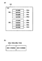
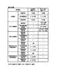
図2は、本実施の形態に係るパチンコ遊技機100を説明する図であり、図2(a)は、遊技盤110の左下に設けられた表示器130の一例を示す拡大図であり、図2(b)は、パチンコ遊技機100の部分平面図である。
パチンコ遊技機100の表示器130は、図2(a)に示すように、第1始動口121の入賞に対応して作動する第1特別図柄表示器221と、第2始動口122の入賞に対応して作動する第2特別図柄表示器222と、ゲート124の通過に対応して作動する普通図柄表示器223と、を備えている。第1特別図柄表示器221は、第1始動口121の入賞に基づき、特別図柄を変動表示した後に停止表示させて判定結果を表示する。第2特別図柄表示器222は、第2始動口122の入賞に基づき、特別図柄を変動表示した後に停止表示させて判定結果を表示する。普通図柄表示器223は、遊技球がゲート124を通過したことに基づき、普通図柄を変動表示した後に停止表示させて判定結果を表示する。本実施の形態では、第1特別図柄表示器221、第2特別図柄表示器222は、各々LEDを配列した表示装置で構成され、その点灯態様によって特別図柄抽選の判定結果が表示される。同様に、普通図柄表示器223も、LEDを配列した表示装置で構成され、その点灯態様によって普通図柄抽選の判定結果が表示される。
FIG. 2 is a diagram illustrating the
As shown in FIG. 2A, the
また、表示器130は、第1特別図柄表示器221での保留に対応して作動する第1特別図柄保留表示器218と、第2特別図柄表示器222での保留に対応して作動する第2特別図柄保留表示器219と、普通図柄表示器223での保留に対応して作動する普通図柄保留表示器220と、を備えている。本実施の形態では、第1特別図柄保留表示器218、第2特別図柄保留表示器219および普通図柄保留表示器220は、各々LEDを配列した表示装置で構成され、その点灯態様によって保留数が表示される。
Further, the
本実施の形態の表示器130において、第1特別図柄表示器221は、例えば複数(本実施の形態では7個)のLEDを同期して一斉に点滅させることによって、特別図柄の変動表示を行う。なお、第1特別図柄表示器221において特別図柄の変動が開始されてから変動停止するまでの間、複数のLEDの点滅の周期は変化せずに一定である。
In the
そして、第1特別図柄表示器221は、例えば複数のLEDのうち予め定められた位置のLEDを点灯させた状態を一定時間維持することで特別図柄の変動停止を表現する。
特別図柄抽選の判定結果がはずれである場合、第1特別図柄表示器221は、例えば複数のLEDのうち端部の1個のLEDだけを点灯させる。一方、特別図柄抽選の判定結果が大当たりである場合、第1特別図柄表示器221は、複数のLEDを予め定められた点灯パターンで点灯させる。なお、特別図柄抽選の判定結果が大当たりである場合、第1特別図柄表示器221は、大当たりに当選した場合の図柄の種類に応じて、異なる点灯パターンを表示する。
なお、第2特別図柄表示器222は、第2始動口122における遊技球の入賞に基づいて、第1特別図柄表示器221と同様の動作を行う。
Then, the first
When the determination result of the special symbol lottery is wrong, the first
The second
ここで、保留について説明する。特別図柄の変動表示動作中(入賞1回分の変動表示が行なわれている間)にさらに第1始動口121または第2始動口122に遊技球が入賞した場合、特別図柄が変動中であるために、後の入賞に基づく特別図柄の変動表示動作を開始することができない。そのため、後の入賞は規定個数(例えば4個)を限度に記憶され、その入賞した遊技球に対する特別図柄を始動させるための権利が、先に入賞した遊技球に対する変動表示動作が終了するまで、保留される。
なお、普通図柄に関しても、特別図柄と同様の処理を行う。このような保留がなされていることおよびその保留の数(未変動数)が、第1特別図柄保留表示器218、第2特別図柄保留表示器219および普通図柄保留表示器220に表示される。
Here, the hold will be described. If a game ball wins a prize in the
It should be noted that the same processing as for the special symbol is performed for the normal symbol. The fact that such a hold is made and the number of holds (unchanged number) are displayed on the first special
さらに、表示器130は、パチンコ遊技機100の状態を表示する状態表示器224を備えている。本実施の形態では、状態表示器224は、3個のLEDを配列した表示装置で構成されている。3個のLEDのうち1つは、パチンコ遊技機100の状態が、特別図柄抽選の当選確率が高確率である高確率状態となっているか否かを点灯により報知するものである。また、他の1つは、パチンコ遊技機100の状態が、特別図柄変動時間が短い時短状態となっているか否かを点灯により報知するものである。さらに他の1つは、右打ちすることによって(遊技球の打球力を変更することによって)遊技者に有利な状態となっているか否かを点灯により報知するものである。
Further, the
また、表示器130は、特別図柄抽選の判定結果に応じて行われる大当たり遊技において大入賞口125が作動される際のラウンド数を表示するラウンド数表示器225を備えている。なお、大当たり遊技については後述する。ラウンド数表示器225は、LEDを配列した表示装置で構成され、その点灯態様によって大当たり遊技における大入賞口125の作動ラウンド数が表示される。
Further, the
また、表示器130は、状態確認表示器226を備えている。状態確認表示器226は、1つのLEDで構成され、後述する設定変更モード又は後述する設定確認モードに設定されていることを示すためのものであり、設定変更モード又は設定確認モードに移行するとLEDの点灯を開始し、設定変更モード又は設定確認モードが終了するとLEDを消灯する。このように、設定変更モード又は設定確認モードに設定されていることを示す状態確認表示器226がパチンコ遊技機100の正面(表面)に設けられているので、設定変更モード又は設定確認モードに設定されているか否かを容易に確認することが可能となっている。なお、状態確認表示器226の設置位置はパチンコ遊技機100の正面(表面)であればよく、その他の場所に設置してもよい。
Further, the
また、本実施形態では、設定変更モードと、設定確認モードとの何れに設定されていても同じ表示態様(点灯表示)で表示するようになっているが、何れのモードに設定されているのかを認識可能に表示してもよい。例えば、設定変更モードに設定されているときは、状態確認表示器226を点灯表示するようにし、設定確認モードに設定されているときは、状態確認表示器226を点滅表示するようにしてもよいし、その逆にしてもよい。
Further, in the present embodiment, the display mode (lighting display) is the same regardless of which of the setting change mode and the setting confirmation mode is set, but which mode is set? May be displayed recognizable. For example, when the setting change mode is set, the
また、本実施形態では、設定変更モード又は設定確認モードに設定されていることを示すために専用の表示器として状態確認表示器226を設けているが、他の表示器と兼用としてもよい。例えば、設定変更モード及び設定確認モードにおいては、第1特別図柄表示器221、第2特別図柄表示器222、第1特別図柄保留表示器218、第2特別図柄保留表示器219、状態表示器224、ラウンド数表示器225などは消灯しているので、これら表示器の1つ又は複数のLEDを点灯させるようにしてもよい。
Further, in the present embodiment, the
パチンコ遊技機100の枠部材150は、遊技者が演出に対する入力を行うための入力装置を備えている。図2(b)に示すように、本実施の形態では、入力装置の一例として、演出ボタン161と、演出ボタン161に隣接し、略十字に配列された複数のキーからなる演出キー162と、が枠部材150に設けられている。図示の例において、複数の画像の中から1つの画像を選択する操作を受け付ける演出を行う場合を考える。この場合、例えば、遊技者が十字に配列された4つのキーからなる演出キー162を操作することにより、画像表示部114に表示されている複数の画像のいずれかを指示し、演出ボタン161を操作することにより、指示した画像を選択するような演出を行うことができる。また、入力装置の形態としては、図示した演出ボタン161および演出キー162の他、レバーやハンドル等、演出の内容等に応じて様々な入力形態を採用することができる。
また、本実施形態の演出ボタン161は、上側へ突出する突出状態と、突出していない非突出状態との間を上下方向へ移動可能に設けられている。
The
Further, the
〔制御ユニットの構成〕
次に、パチンコ遊技機100での動作制御や信号処理を行う制御ユニットについて説明する。
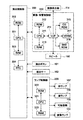
図3は、本実施の形態のパチンコ遊技機の制御ユニットの内部構成を示すブロック図である。
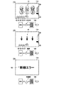
図4は、本実施の形態の画像/音響制御部およびランプ制御部の説明図である。
[Control unit configuration]
Next, a control unit that performs operation control and signal processing in the
FIG. 3 is a block diagram showing an internal configuration of a control unit of the pachinko gaming machine of the present embodiment.
FIG. 4 is an explanatory diagram of an image / acoustic control unit and a lamp control unit according to the present embodiment.
図3に示すように、制御ユニットは、メイン制御手段として、特別図柄の当選の判定等を行う遊技制御部200を備えている。また、サブ制御手段として、演出を統括的に制御する演出制御部300と、払出球の払い出し制御を行う払出制御部330と、を備えている。
As shown in FIG. 3, the control unit includes a
〔遊技制御部の構成・機能〕
遊技制御部200は、特別図柄の当選の判定等を行う際の演算処理を行うCPU201と、CPU201にて実行されるプログラムや各種データ等が記憶されたROM202と、CPU201の作業用メモリ等として用いられるRAM203と、を備えている。
[Configuration / function of game control unit]
The
遊技制御部200は、パチンコ遊技機100の遊技状態を、高確率状態または低確率状態のいずれか、時短無状態または時短状態のいずれかで制御する。これにより、パチンコ遊技機100の遊技状態は、高確率状態および時短状態である高確率時短遊技状態、低確率状態および時短状態である低確率時短遊技状態、高確率状態および時短無状態である高確率時短無遊技状態、低確率状態および時短無状態である低確率時短無遊技状態のいずれかとなる。そして、遊技制御部200は、上述のように大当たりや特別図柄抽選の抽選回数を契機とするなど所定の条件に基づき、高確率状態と低確率状態とを切り替え、時短無状態と時短状態とを切り替える。また、遊技制御部200は、時短状態において、時短無状態よりも普通図柄抽選の当たり当選確率を高確率にする、普通図柄変動時間を短縮する、電動チューリップ123の開時間を延長する等の制御を行う。
The
遊技制御部200は、第1始動口121または第2始動口122に遊技球が入賞したことを契機として特別図柄抽選に用いられる乱数値を取得する。そして、遊技制御部200は、取得した乱数値を用いて特別図柄抽選を行い、特別図柄抽選の判定結果に応じて大当たり遊技等の特別遊技を行う。特別遊技において、遊技制御部200は、特別電動役物である大入賞口125が閉鎖条件(例えば29.5秒経過または遊技球10個の入賞)を満たすまで開状態を維持するラウンドを、大当たり図柄(種類)に応じて予め定められた回数だけ繰り返すように制御する。そして、遊技制御部200は、大入賞口125が開く際の開閉動作間隔を制御する。
The
また、遊技制御部200は、ゲート124を遊技球が通過したことを契機として普通図柄抽選に用いられる乱数値を取得する。そして、遊技制御部200は、取得した乱数値を用いて普通図柄抽選を行い、普通図柄抽選の判定結果に応じて電動チューリップ123の作動を制御する。
また、遊技制御部200は、特別図柄変動中に遊技球が第1始動口121または第2始動口122へ入賞したことにより発生する保留や、普通図柄変動中に遊技球がゲート124を通過したことにより発生する保留の設定を行う。
さらに、遊技制御部200は、特別図柄抽選および普通図柄抽選の判定結果、高確率状態と低確率状態の変更情報、時短無状態と時短状態の変更情報、保留の設定情報等の遊技制御に伴う情報を、後述するコマンドにより演出制御部300に送る。
Further, the
In addition, the
Further, the
さらに、遊技制御部200は、第1始動口121、第2始動口122、大入賞口125および普通入賞口126に遊技球が入賞すると、遊技球が入賞した場所に応じて1つの遊技球当たり所定数の賞球を払い出すように、払出制御部330に対する指示を行う。例えば、第1始動口121に遊技球が入賞すると3個の賞球、第2始動口122に遊技球が入賞すると4個の賞球、大入賞口125に遊技球が入賞すると13個の賞球、普通入賞口126に遊技球が入賞すると10個の賞球をそれぞれ払い出すように、払出制御部330に指示命令(コマンド)を送る。なお、ゲート124を遊技球が通過したことを検出しても、それに連動した賞球の払い出しは払出制御部330に指示しない。
払出制御部330が遊技制御部200の指示に従って賞球の払い出しを行った場合には、遊技制御部200は、払い出した賞球の個数に関する情報を払出制御部330から取得する。それにより、払い出した賞球の個数を管理する。
Further, when a game ball wins in the
When the
遊技制御部200には、検知手段として、図3に示すように、第1始動口121への遊技球の入賞を検出する第1始動口検出部(第1始動口スイッチ(SW))211と、第2始動口122への遊技球の入賞を検出する第2始動口検出部(第2始動口スイッチ(SW))212と、電動チューリップ123を開閉する電動チューリップ開閉部213と、ゲート124への遊技球の通過を検出するゲート検出部(ゲートスイッチ(SW))214と、が接続されている。
さらに、遊技制御部200には、大入賞口125への遊技球の入賞を検出する大入賞口検出部(大入賞口スイッチ(SW))215と、大入賞口125の大入賞口扉125Dを閉状態と突出傾斜した開状態とに設定する大入賞口扉開閉部216と、普通入賞口126への遊技球の入賞を検出する普通入賞口検出部(普通入賞口スイッチ(SW))217と、アウト口117に流入する遊技球からなるアウト球を検出するアウト球検出スイッチ(SW)227と、が接続されている。
As a detection means, the
Further, the
また、遊技制御部200には、特別図柄の変動中に第1始動口121へ入賞した未変動分の保留個数を表示する第1特別図柄保留表示器218と、特別図柄の変動中に第2始動口122へ入賞した未変動分の保留個数を表示する第2特別図柄保留表示器219と、普通図柄の変動中にゲート124を通過した未変動分の保留個数を表示する普通図柄保留表示器220と、が接続されている。
さらに、遊技制御部200には、第1始動口121への遊技球の入賞により行われる特別図柄の変動表示および特別図柄抽選の結果を表示する第1特別図柄表示器221と、第2始動口122への遊技球の入賞により行われる特別図柄の変動表示および特別図柄抽選の結果を表示する第2特別図柄表示器222と、普通図柄の変動表示および普通図柄抽選の結果を表示する普通図柄表示器223と、パチンコ遊技機100の状態を表示する状態表示器224と、ラウンド数表示器225と、状態確認表示器226と、が接続されている。
In addition, the
Further, the
また、遊技制御部200には、RAM203の記憶内容をクリア又は遊技の有利度合いの段階である(大当たり判定で大当たりと判定される確率の)設定値を更新するための信号を入力するRAMクリアスイッチ(SW)228と、設定キーを用いた操作によって後述する設定変更モードや設定確認モードに移行させるための信号を入力する設定キースイッチ(SW)229と、パチンコ遊技機100の実性能を把握可能とする性能情報や設定値を表示するための情報表示器230と、が接続されている。
Further, the
情報表示器230は、左右方向に並べられた4つの7セグメント表示器で構成されている。そして、左から2つの7セグメント表示器によって性能情報の種類(データ種別)を示す識別情報を表示するための識別セグが構成され、右から2つの7セグメント表示器によって設定値や性能情報の数値を示す数値情報を表示するための数値セグが構成されている(図40参照)。
The
また、遊技制御部200には、発射装置を駆動して遊技球の発射を制御する発射制御部250が接続されている。
発射制御部250は、図示しない制御回路及び入出力ポート等を備えている。発射制御部250の入出力ポートには、球送りソレノイド251、タッチセンサ252、発射ボリューム253及び発射用ソレノイド254などが接続されている。発射制御部250では、タッチセンサ252から入力されるタッチ信号によって遊技者の手がハンドル151に触れていることを検出すると、球送りソレノイド251及び発射用ソレノイド254への通電を許容し、発射ボリューム253からの検出信号によってハンドル151の回動角度が変化したことを検出すると、球送りソレノイド251を駆動させると共に、ハンドル151の回動角度に応じた発射強度となるように発射用ソレノイド254を駆動させて遊技球を発射(99.9個/分)させるようになっている。
Further, the
The
そして、第1始動口スイッチ211、第2始動口スイッチ212、ゲートスイッチ214、大入賞口スイッチ215、普通入賞口スイッチ217、アウト球検出スイッチ227、RAMクリアスイッチ228、設定キースイッチ229、および発射制御部250にて検出された検出信号が、遊技制御部200に送られる。また、遊技制御部200からの制御信号が、電動チューリップ開閉部213、大入賞口扉開閉部216、第1特別図柄保留表示器218、第2特別図柄保留表示器219、普通図柄保留表示器220、第1特別図柄表示器221、第2特別図柄表示器222、普通図柄表示器223、状態表示器224、ラウンド数表示器225、状態確認表示器226、および情報表示器230に送られる。それにより、遊技制御部200は、上記した払い出し賞球数に関連する各種制御を行う。
Then, the first
さらに、遊技制御部200には、ホールに設置されたホストコンピュータ(不図示)に対して各種の情報を送信する盤用外部情報端子基板350が接続されている。そして、遊技制御部200は、払出制御部330から取得した、払い出した賞球数に関する情報や遊技制御部200の状態等を示す情報を、盤用外部情報端子基板350を介してホストコンピュータに送信する。
Further, the
〔払出制御部の構成・機能〕
払出制御部330は、払出球の払い出しを制御する際の演算処理を行うCPU331と、CPU331にて実行されるプログラムや各種データ等が記憶されたROM332と、CPU331の作業用メモリ等として用いられるRAM333と、を備えている。
そして、払出制御部330は、遊技制御部200から送られたコマンドに基づいて、払出球の払い出しを制御する。
具体的には、払出制御部330は、遊技制御部200から、遊技球が入賞した場所(第1始動口121等)に応じた所定数の賞球を払い出すコマンドを取得する。そして、コマンドに指定された数だけの賞球を払い出すように払出駆動部334を制御する。ここでの払出駆動部334は、遊技球の貯留部から遊技球を送り出す駆動モータで構成される。
[Configuration / function of payout control unit]
The
Then, the
Specifically, the
また、払出制御部330には、払出駆動部334により遊技球の貯留部から実際に払い出された賞球の数を検出する払出球検出部335と、貯留部(不図示)での遊技球の貯留の有無を検出する球有り検出部336と、遊技者が遊技する際に使用する遊技球や払い出された賞球が保持される皿153が満タン状態に有るか否かを検出する満タン検出部337と、が接続されている。そして、払出制御部330は、払出球検出部335、球有り検出部336および満タン検出部337にて検出された検出信号を受け取り、これらの検出信号に応じた所定の処理を行う。
さらに、払出制御部330には、ホールに設置されたホストコンピュータに対して各種の情報を送信する枠用外部情報端子基板340が接続されている。そして、払出制御部330は、例えば払出駆動部334に対して払い出すように指示した賞球数に関する情報や払出球検出部335にて検出された実際に払い出された賞球数に関する情報等を枠用外部情報端子基板340を介してホストコンピュータに送信する。また、遊技制御部200に対しても、同様の情報を送信する。
Further, the
Further, a frame external
〔演出制御部の構成・機能〕
演出制御部300は、演出を制御する際の演算処理を行うCPU301と、CPU301にて実行されるプログラムや各種データ等が記憶されたROM302と、CPU301の作業用メモリ等として用いられるRAM303と、日時を計測するリアルタイムクロック(RTC)304と、を備えている。
演出制御部300は、例えば遊技制御部200から送られる特別図柄抽選での当選か否かの判定結果および変動パターンに基づいて、演出内容を設定する。その際、演出ボタン161または演出キー162を用いたユーザからの操作入力を受けて、操作入力に応じた演出内容を設定する場合もある。この場合、例えば演出ボタン161等のコントローラ(不図示)から操作に応じた信号(操作信号)を受け付け、この操作信号により識別される操作内容を演出の設定に反映させる。
さらには、演出制御部300は、遊技制御部200より受信した高確率状態と低確率状態の変更情報、時短無状態と時短状態の変更情報に基づいて演出内容を設定する。
また、演出制御部300は、設定した演出内容の実行を指示するコマンドを画像/音響制御部310およびランプ制御部320に送る。
[Structure / function of production control unit]
The
The
Further, the
Further, the
さらに、演出制御部300には、画像および音響を用いた演出を制御する画像/音響制御部310と、各種のランプおよび可動役物115を用いた演出を制御するランプ制御部320と、が接続されている。
Further, the
〔画像/音響制御部の構成・機能〕
画像/音響制御部310は、図4に示すように、演出内容を表現する画像および音響を制御する際の演算処理を行うCPU311と、CPU311にて実行されるプログラムや各種データ等が記憶されたROM312と、CPU311の作業用メモリ等として用いられるRAM313と、VDP(Video Display Processor)314と、CGROM315と、SNDROM316と、VDP314の作業用メモリ等として用いられるVRAM317と、を備えている。
[Configuration / function of image / acoustic control unit]
As shown in FIG. 4, the image /
そして、画像/音響制御部310は、演出制御部300から送られたコマンドに基づいて、画像表示部114に表示する画像およびスピーカ156から出力する音響を制御する。
具体的には、CGROM315には、画像表示部114において遊技中に表示する背景画像、遊技者に判定結果を報知するための装飾図柄、遊技者に予告演出を表示するためのキャラクタやアイテム等といった画像データが記憶されている。また、SNDROM316には、画像データと同期させて、または画像データとは独立にスピーカ156から出力させる楽曲や音声、さらにはジングル等の効果音等といった各種音響データが記憶されている。
CPU311は、演出制御部300から送られた保留数コマンドもしくは変動演出開始コマンドに基づいて、アニメーションパターンの解析や、描画に関するコマンドをまとめたディスプレイリストの作成、およびディスプレイリストのVDP314への送信などを行う。
Then, the image /
Specifically, the
The
VDP314は、CPU311から受信したディスプレイリストに基づいて、CGROM315やSNDROM316にそれぞれ記憶された画像データや音響データを読み出す。さらには、VDP314は、読み出した画像データを用いて背景画像表示、装飾図柄表示、装飾図柄変動、およびキャラクタ/アイテム表示等のための描画処理と、読み出した音響データを用いた音声処理とを行う。そして、VDP314は、描画処理された画像データにより画像表示部114での画面表示を制御する。また、VDP314は、音声処理された音響データによりスピーカ156から出力される音響を制御する。
なお、本実施の形態では、VDP314が描画処理に併せて音声処理も行うよう構成しているが、これに限定されず、音声処理を専用で行うプロセッサを別途設けても構わない。
The
In the present embodiment, the
以上のCPU311およびVDP314の機能、および各装置での制御をより具体的に説明する。
画像/音響制御部310において、CPU311は、演出制御部300から受信した演出内容の実行を指示するコマンドに基づいて、画像表示部114に表示されるべき画像の内容を規定するディスプレイリストを生成し、生成したディスプレイリストを含む描画コマンドをVDP314に対して送信する。RAM313は、CPU311の演算処理時におけるデータのワークエリアとして機能し、ROM312から読み出されたデータを一時的に記憶するものである。
The functions of the
In the image /
VDP314は、複数のフレーム(フレーム画像とも称する)を用いて各種演出を構成する画像(演出画像とも称する)を表示させることができる映像処理回路である。VDP314は、CPU311から受信した描画コマンドに基づき、CGROM315に記憶されている素材画像データを用いて各フレーム画像を生成し、生成した複数のフレーム画像を連続して画像表示部114に表示させるための画像データ(映像信号)を画像表示部114に送信する。これによって、画像表示部114には、VDP314が生成した時系列上に並ぶ複数のフレーム画像からなる動画像が演出画像として表示されることとなる。ただし、画像表示部114に表示される演出画像は、静止画像も含む。
The
CGROM315は、フラッシュメモリ、EEPROM、EPROM、マスクROM等から構成され、所定範囲の画素(例えば、32ピクセル×32ピクセル)における画素情報の集まりからなる画像データ等を圧縮して記憶している。VRAM317は、フレーム画像を生成するためのワークエリアとしてVDP314により利用される。VDP314は、約16.6ミリ秒ごとに、適切な画像表示を行うためのクロックや同期信号等の生成を行う。
The
VDP314と接続されるVRAM317は、画像表示部114に対して画像出力を行うために必要な各種データを一時的に記憶しておくための記憶手段である。当該VRAM317は、記憶保持に外部からの電力供給が必要な揮発性の半導体メモリを有してなり、詳細には当該半導体メモリとしてSDRAMが用いられている。ただし、SDRAMに限定されることはなく、DRAM、SRAM又はデュアルポートRAMといった他のRAMを用いてもよい。当該VRAM317は、パチンコ遊技機100の使用に際して、読み書き両用として用いられる。また、VRAM317には、VDP314により描画データが作成されるフレームバッファが設けられている。なお、VRAM317がVDP314に内蔵されていてもよい。
The
VDP314は、CGROM315から読み出された画像データを用いて、フレームバッファに1フレーム分の描画データを作成する。1フレーム分の描画データとは、予め定められた更新タイミングで画像表示部114における画像が更新される構成において、一の更新タイミングにおける画像を表示させるために必要なデータのことをいう。
The
ここで、フレームバッファには、複数のフレーム領域a,bが設けられている。具体的には、第1フレーム領域aと、第2フレーム領域bとが設けられている。これら各フレーム領域a,bは、それぞれ1フレーム分の描画データを記憶可能な容量に設定されている。具体的には、各フレーム領域a,bにはそれぞれ、画像表示部114の表示面のドット(画素)に所定の倍率で対応させた多数の単位エリアが含まれている。各単位エリアは、いずれの色を表示するかを特定するためのデータを格納可能な記憶容量を有している。より詳細には、フルカラー方式が採用されており、各ドットにおいてR(赤),G(緑),B(青)のそれぞれに256色の設定が可能となっている。これに対応させて、各単位エリアにおいては、RGB各色に1バイト(8ビット)が割り当てられている。つまり、各単位エリアは、少なくとも3バイトの記憶容量を有している。
Here, the frame buffer is provided with a plurality of frame areas a and b. Specifically, a first frame area a and a second frame area b are provided. Each of these frame areas a and b is set to a capacity capable of storing drawing data for one frame. Specifically, each of the frame areas a and b includes a large number of unit areas corresponding to dots (pixels) on the display surface of the
フレームバッファに第1フレーム領域aおよび第2フレーム領域bが設けられていることにより、一方のフレーム領域に作成された描画データを用いて画像表示部114への表示が実行されている状況において、他のフレーム領域に対して今後(通常であれば次フレーム)表示される予定の描画データの作成(描画)が実行される。つまり、フレームバッファとして、ダブルバッファ方式が採用されている。
By providing the first frame area a and the second frame area b in the frame buffer, the display on the
VDP314は、約16.6ミリ秒毎に第1フレーム領域aおよび第2フレーム領域bの切り替えを許可するためのVブランク信号をCPU311へと出力する。従って、処理落ち等のイレギュラー事象の発生を除けば、通常、Vブランク信号の1回の受信を持って第1フレーム領域aおよび第2フレーム領域bの切り替え、すなわち描画が実行されるフレーム領域と表示の対象となるフレーム領域との切り替えが発生し、もって1フレーム分の画像の描画および表示の更新が行われることとなる。つまり、1秒間の間に、1000ミリ秒÷16.6ミリ秒=約60フレーム分の画像の描画および表示の更新が行われることとなる。
The
また、VDP314は、Vブランク信号の他に、CPU311から受信した描画コマンドに応じた描画データの作成(描画)が完了した時点で、CPU311に対して描画完了信号を送信するものとする。
Further, the
CPU311は、Vブランク信号を受信すると第1フレーム領域aおよび第2フレーム領域bを切り替えるためのV割込み処理を実行する。なお、第1フレーム領域aおよび第2フレーム領域bの切り替えは、Vブランク信号のみの受信だけでなく、Vブランク信号と描画完了信号との2信号の受信を確認できた場合に行われる構成としても良い。
Upon receiving the V blank signal, the
〔ランプ制御部の構成・機能〕
ランプ制御部320は、盤ランプ116や枠ランプ157の発光、および可動役物115の動作を制御する際の演算処理を行うCPU321と、CPU321にて実行されるプログラムや各種データ等が記憶されたROM322と、CPU321の作業用メモリ等として用いられるRAM323と、を備えている。
そして、ランプ制御部320は、演出制御部300から送られたコマンドに基づいて、盤ランプ116や枠ランプ157の点灯/点滅や発光色等を制御する。また、可動役物115の動作を制御する。
[Configuration / function of lamp control unit]
The
Then, the
具体的には、ランプ制御部320のROM322には、演出制御部300にて設定される演出内容に応じた盤ランプ116や枠ランプ157での点灯/点滅パターンデータおよび発光色パターンデータ(発光パターンデータ)が記憶されている。CPU321は、ROM322に記憶された発光パターンデータの中から、演出制御部300から送られたコマンドに対応したものを選択して読み出す。そして、ランプ制御部320は、読み出した発光パターンデータにより盤ランプ116や枠ランプ157の発光を制御する。
また、ランプ制御部320のROM322には、演出制御部300にて設定される演出内容に応じた可動役物115の動作パターンデータが記憶されている。CPU321は、可動役物115に対しては、読み出した動作パターンデータによりその動作を制御する。
Specifically, the
Further, the
なお、本実施の形態では、遊技制御部200、演出制御部300、画像/音響制御部310、ランプ制御部320、および払出制御部330各々は、遊技盤110の後面に設けられたメイン基板としての遊技制御基板、サブ基板としての演出制御基板、画像制御基板、ランプ制御基板、および払出制御基板において個別に構成されている。
また、図4を参照して説明した構成例では、演出ボタン161および演出キー162は、演出制御部300に接続され、演出制御部300によって制御されるが、これに限定されない。演出ボタン161および演出キー162は、ランプ制御部320に接続され、このランプ制御部320によって制御されてもよい。
In the present embodiment, the
Further, in the configuration example described with reference to FIG. 4, the
〔遊技制御部の機能構成〕
続いて、遊技制御部200の機能構成を説明する。
図5は、遊技制御部200の機能構成を示すブロック図である。図5に示すように、遊技制御部200は、各種抽選処理を実行する機能部として、乱数取得部231と、普通図柄判定部232と、特別図柄変動制御部233と、特別図柄判定部234と、普通図柄変動制御部236と、を備えている。
また、遊技制御部200は、特別図柄変動に伴う処理を実行する機能部として、変動パターン選択部235を備えている。
さらに、遊技制御部200は、各種役物の動作制御や賞球等に関するデータ処理を実行する機能部として、大入賞口動作制御部237と、電動チューリップ動作制御部238と、賞球処理部239と、出力制御部240と、乱数制御部241と、を備えている。
[Functional configuration of game control unit]
Subsequently, the functional configuration of the
FIG. 5 is a block diagram showing a functional configuration of the
In addition, the
Further, the
乱数取得部231は、特別図柄抽選に用いられる乱数値と、普通図柄抽選に用いられる乱数値とを取得する。特別図柄抽選に用いられる乱数値の場合、具体的には、第1始動口121や第2始動口122に遊技球が入賞したことを条件として、乱数の種類ごとに、所定の範囲の数値の中から1つの数値(乱数値)が選択(取得)される。取得された乱数値は、特別図柄判定部234による判定に用いられる。詳しくは後述するが、特別図柄抽選に用いられる乱数としては、大当たりか否かを示す大当たり乱数、図柄の種類を示す図柄乱数、変動パターン乱数、リーチ乱数等が有る。
また、普通図柄抽選に用いられる乱数値の場合、具体的には、ゲート124を遊技球が通過したことを条件として、所定の範囲の数値の中から1つの数値(乱数値)が選択(取得)される。取得された乱数値は、普通図柄判定部232による判定に用いられる。なお、普通図柄抽選に用いられる乱数としては、当たりか否かを示す当たり乱数の他、当たりの種類を示す図柄乱数や変動パターン乱数等が設定される場合もある。
特別図柄変動制御部233は、特別図柄抽選が行われた場合に、判定結果に応じて、第1特別図柄表示器221または第2特別図柄表示器222における特別図柄の変動を制御する。
The random
Further, in the case of the random number value used for the ordinary symbol lottery, specifically, one numerical value (random number value) is selected (acquired) from the numerical values in a predetermined range on condition that the game ball has passed through the gate 124. ). The acquired random number value is usually used for determination by the
The special symbol
特別図柄判定部234は、特別図柄の変動開始時に、後述する図20に示すような乱数テーブルを用いて、特別図柄抽選の判定結果が「大当たりか否か」、「大当たりに当選した場合の図柄の種類」、「大当たりに当選していない場合での小当たりかはずれか」を判定する。すなわち、乱数取得部231は、検知手段である第1始動口スイッチ211または第2始動口スイッチ212により遊技球の通過が検知されたことを契機として特別図柄に関する乱数値を取得し、特別図柄判定部234は、取得した乱数値に基づいて、遊技者にとって有利な特別遊技(大当たり遊技等)を行うか否かを判定する。なお、前述した特別図柄の抽選(大当たり抽選)は、乱数取得部231および特別図柄判定部234における処理のことをいう。
The special
ここで、「大当たり」は、大当たり遊技の終了後に発生する遊技状態に応じて複数の種類に分けられる。具体的には、時短無状態か時短状態か、および高確率状態か低確率状態かの組合せによって図柄の種類が決まる。すなわち、大当たり遊技の終了後に発生する遊技状態に基づく図柄の種類としては、大当たり遊技の終了後に、高確率時短遊技状態となる大当たり(以下、高確率時短遊技状態の大当たり)、低確率時短遊技状態となる大当たり(以下、低確率時短遊技状態の大当たり)、高確率時短無遊技状態となる大当たり(以下、高確率時短無遊技状態の大当たり)、低確率時短無遊技状態となる大当たり(以下、低確率時短無遊技状態の大当たり)が有り得る。これらの大当たりは、各々個別の特別図柄に対応付けられている。 Here, the "big hit" is divided into a plurality of types according to the game state generated after the end of the big hit game. Specifically, the type of symbol is determined by the combination of the time-saving no state or the time-saving state, and the high-probability state or the low-probability state. That is, as the types of symbols based on the game state generated after the end of the jackpot game, the jackpot that becomes the high-probability time-saving game state after the end of the jackpot game (hereinafter, the jackpot in the high-probability time-saving game state) and the low-probability time-saving game state Big hit (hereinafter, big hit in low probability time saving game state), big hit in high probability time saving no game state (hereinafter, big hit in high probability time saving no game state), big hit in low probability time saving no game state (hereinafter, low) Probability time saving No game state jackpot) is possible. Each of these jackpots is associated with an individual special symbol.
また、「大当たり」は、大当たり遊技の時間が長く多量の遊技球の払い出しが期待できる大当たりと、大当たり遊技の時間が短く遊技球の払出がほとんど期待できない大当たりとに分けられる場合がある。前者は「長当たり」と呼ばれ、後者は「短当たり」と呼ばれる。例えば、「長当たり」では、大入賞口125の開状態が所定条件(例えば29.5秒経過または10個の遊技球の入賞)を満たすまで維持されるラウンドが所定回数(例えば15回)繰り返される。また、「短当たり」では、一定時間(例えば0.9秒)だけ大入賞口125が開状態となるラウンドが所定回数(例えば2回)繰り返される。
Further, the "big hit" may be divided into a jackpot in which the jackpot game time is long and a large amount of game balls can be expected to be paid out, and a jackpot in which the jackpot game time is short and the payout of the game balls can hardly be expected. The former is called "long hit" and the latter is called "short hit". For example, in "long hit", a round in which the open state of the large winning
また、大当たりに当選していない場合の「小当たり」は、一定時間(例えば0.9秒)だけ大入賞口125が開状態となる態様が所定回数(例えば2回)行われる小当たり遊技が行われる。なお、小当たり当選時には、小当たり遊技が終了した後においても小当たり当選前の遊技状態を継続する。すなわち、小当たり当選時の遊技状態が高確率時短遊技状態である場合には、小当たり遊技の終了後においても高確率時短遊技状態が継続され、遊技状態は移行しない。同様に、小当たりの当選時の遊技状態が低確率時短無遊技状態である場合には、小当たり遊技の終了後においても低確率時短無遊技状態が継続され、遊技状態は移行しない。
また、「小当たり」は、「はずれ」の一種であり、遊技者に有利となる上記の遊技状態の何れも設定されない。
In addition, when the big hit is not won, the "small hit" is a small hit game in which the big winning
Further, the "small hit" is a kind of "missing", and none of the above-mentioned gaming states that are advantageous to the player is set.
変動パターン選択部235は、第1特別図柄表示器221や第2特別図柄表示器222にて表示する特別図柄の変動パターン(変動時間)を選択する。具体的には、変動パターン選択部235は、大当たり遊技を行うか否かの判定結果および特別図柄変動にともなう装飾図柄変動演出においてリーチ演出を行うことが可能な変動パターン(例えば13.5秒以上)とするか否かの判定結果等に基づいて、変動パターンを決定する。そして、変動パターン選択部235により選択された変動パターンに基づいて、特別図柄変動制御部233が特別図柄の変動を制御する。変動パターン選択部235および特別図柄変動制御部233の動作の詳細については後述する。
ここで、「リーチ」とは、後述する装飾図柄において遊技者に大当たりを期待させるための演出である。
The variation
Here, the "reach" is an effect for making the player expect a big hit in the decorative design described later.
普通図柄判定部232は、普通図柄の変動開始時に、後述する図20(d)に示すような乱数テーブルを用いて、普通図柄の判定結果が「当たりか否か」を判定する。すなわち、普通図柄判定部232は、乱数取得部231により取得された普通図柄抽選用の乱数値に基づいて、電動チューリップ123を開閉作動させる補助遊技を行うか否かを判定する。また、普通図柄抽選において複数の種類の当たりが設定される場合は、普通図柄判定部232は、判定結果が当たりであった場合の「当たりの種類」を判定する。なお、普通図柄抽選は、乱数取得部231および普通図柄判定部232により行われる処理である。
普通図柄変動制御部236は、普通図柄抽選が行われた場合に、判定結果に応じて、普通図柄表示器223による普通図柄の変動を制御する。
電動チューリップ動作制御部238は、普通図柄判定部232により普通図柄抽選において「当たり」と判定された場合に、電動チューリップ123を規定時間および規定回数だけ開放し、第2始動口122に遊技球が入賞容易となる状態を発生させる。また、「はずれ」と判定された場合には、電動チューリップ123のこのような開放状態を発生させない。電動チューリップ123の作動パターンについては後述するが、例えば0.15秒の開放時間で1回開く作動パターン、および0.90秒の開放時間で2回開放する作動パターンなどがある。
The ordinary
The normal symbol
The electric tulip
大入賞口動作制御部237は、特別図柄判定部234により特別図柄抽選において「大当たり」と判定された場合に、大当たり遊技として、当選した図柄の種類に基づいて特定される作動パターンで大入賞口125の開放動作を制御する。また、大入賞口動作制御部237は、特別図柄判定部234により特別図柄抽選において「小当たり」と判定された場合に、小当たり遊技として、規定時間および規定回数だけ大入賞口125を開放する。例えば、大入賞口125が0.90秒の開放時間で2回開放する作動パターンなどがある。
賞球処理部239は、入賞や抽選に関する種々の役物への入賞個数の管理および入賞に応じた賞球の払い出しの制御用コマンドをセットする。
出力制御部240は、遊技制御部200から演出制御部300および払出制御部330へ制御用コマンドの出力を制御する。
乱数制御部241は、乱数取得部231が所定のタイミングで取得する各種の乱数値を更新する。
When the special symbol lottery determines "big hit" by the special
The prize
The
The random
〔遊技機の基本動作〕
次に、パチンコ遊技機100の基本動作を説明する。
パチンコ遊技機100の遊技制御部200は、電源が投入されると、起動時の基本処理(復旧処理)を実行する。そして、基本処理を行った後、遊技制御部200は、遊技の進行に関する一連の処理である主制御処理を繰り返し実行する。また、電源を遮断する際には、遊技制御部200は、一連の電源遮断時処理を実行する。
[Basic operation of the game machine]
Next, the basic operation of the
When the power is turned on, the
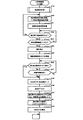
図6は、遊技制御部200による基本処理の動作を示すフローチャートである。
遊技制御部200は、パチンコ遊技機100の電源が投入されると、まず、RAM203(図3参照)へのアクセスを許可する(ステップ(以下、ステップを「S」と記載する)601)。そして、遊技制御部200は、RAM203をクリアするためのRAMクリアスイッチ228がONとなっているか否かを判断する(S602)。
RAMクリアスイッチ228がOFFである場合(S602でNo)、次に、遊技制御部200は、電源遮断時の動作に関するバックアップフラグがONとなっているか否かを判断する(S603)。
バックアップフラグがONである場合(S603でYes)、次に、遊技制御部200は、電源遮断時に作成されたチェックサムが正常か否かを判断する(S604)。
チェックサムが正常である場合(S604でYes)、次に、遊技制御部200は、復帰処理を実行する(S605)。この復帰処理において、遊技制御部200は、電源が遮断された状態からの復帰に伴う、演出制御部300等のサブ制御手段の設定を行う。具体的には、遊技制御部200は、電源が遮断される際におけるパチンコ遊技機100の遊技状態(大当たり遊技中か否か、高確率状態と低確率状態のいずれか、時短状態と時短無状態のいずれか)を反映させるように、サブ制御手段を設定するためのコマンドを演出制御部300へ出力する。また、この復帰処理において、遊技制御部200は、バックアップフラグをOFFにする。
FIG. 6 is a flowchart showing the operation of the basic processing by the
When the power of the
When the RAM
When the backup flag is ON (Yes in S603), the
When the checksum is normal (Yes in S604), the
一方、RAMクリアスイッチ228がON(S602でYes)、バックアップフラグがOFF(S603でNo)、チェックサムが異常(S604でNo)のいずれかに該当する場合、次に遊技制御部200は、初期化処理として、RAM203の記憶内容をクリアし(S606)、RAM203の作業領域を設定する(S607)。そして、遊技制御部200は、サブ制御手段を設定(初期化)するためのコマンドを演出制御部300へ出力し、サブ基板(サブ制御手段)の設定を行う(S608)。サブ基板の設定には、各サブ基板に搭載されているRAM303、RAM313、RAM323をクリアすること等が含まれる。
On the other hand, if the RAM
復帰処理(S605参照)が終了した後、またはサブ基板の設定(S608参照)が終了した後、遊技制御部200は、遊技制御に用いられる各種のカウンタおよびタイマーを設定する(S609)。そして、遊技制御部200は、割り込み許可(S610)、割り込み禁止(S611)、図柄乱数制御処理(S612)、初期値乱数更新処理(S613)、電源遮断フラグがONとなっているか否かの判断(S614)をループ処理として繰り返し実行する。
ここで、割り込み許可(S610)および割り込み禁止(S611)は、このループ処理(S610〜S614)の実行中に割り込み処理の実行を可能とするために設けられている。本実施の形態では、この割り込み処理により、遊技制御における主制御処理が実行される。主制御処理の詳細については後述する。
図柄乱数制御処理(S612)において、遊技制御部200は、特別図柄抽選で用いられる変動パターン乱数の更新を行う。
初期値乱数更新処理(S613)において、遊技制御部200は、遊技制御において用いられる各種の乱数値の初期値を更新する。
電源遮断フラグの判断において、電源遮断フラグがOFFである場合(S614でNo)、パチンコ遊技機100の電源は遮断されず、遊技制御部200は、ループ処理(S610〜S614)と共に割り込みによる主制御処理を繰り返し実行する。一方、電源遮断フラグがONである場合(S614でYes)、遊技制御部200は、パチンコ遊技機100の電源を遮断するための処理(電源遮断時処理)を開始する。
After the return process (see S605) is completed or the sub-board setting (see S608) is completed, the
Here, interrupt enable (S610) and interrupt disable (S611) are provided to enable execution of interrupt processing during execution of this loop processing (S610 to S614). In the present embodiment, the main control process in the game control is executed by this interrupt process. The details of the main control process will be described later.
In the symbol random number control process (S612), the
In the initial value random number update process (S613), the
In the determination of the power cutoff flag, when the power cutoff flag is OFF (No in S614), the power supply of the
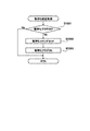
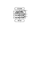
図7は、遊技制御部200による電源遮断時処理の動作を示すフローチャートである。
電源遮断時処理において、遊技制御部200は、まず、各種の出力を行うための出力ポートの設定をクリアする(S701)。次に、遊技制御部200は、チェックサムを作成し、RAM203に格納する(S702)。次に、遊技制御部200は、バックアップフラグをONにし(S703)、RAM203へのアクセスを禁止して(S704)、無限ループに移行する。
FIG. 7 is a flowchart showing the operation of the power cutoff process by the
In the power cutoff process, the
図7に示した電源遮断時処理が行われることにより、パチンコ遊技機100の電源が遮断される。パチンコ遊技機100の電源が遮断された状態を、以下では、電源断状態と称する。例えば、パチンコ遊技機100の電源を遮断するための操作が行われると、パチンコ遊技機100が電源断状態になる。また、例えば、パチンコ遊技機100が設置されるホールにおいて停電が発生すると、パチンコ遊技機100が電源断状態になる。また、例えば、パチンコ遊技機100への電源の供給源とパチンコ遊技機100とを接続するコネクタの接続不良や、スイッチング電源におけるチャタリングの発生等に基づく瞬断により、パチンコ遊技機100が電源断状態になる。
By performing the power cutoff process shown in FIG. 7, the power supply of the
また、本実施形態では、電源断状態においてパチンコ遊技機100に電源が供給されると、図6に示した基本処理が行われることにより、パチンコ遊技機100は、電源断状態になる前の遊技の制御状態になる。パチンコ遊技機100が電源断状態になる前の遊技の制御状態になることは、電源断状態から復帰することとして捉えられる。また、電源断状態においてパチンコ遊技機100が電源の供給を受けて作動することも、広義には、電源断状態からの復帰に含まれる。この作動には、例えば、各種ランプを発光させること、可動役物115や演出ボタン161を動かすこと、スピーカ156から音を出力させること、画像表示部114に画像を表示させること等が含まれる。
Further, in the present embodiment, when power is supplied to the
ここで、パチンコ遊技機100の電源断状態からの復帰には、RAMクリアを伴う復帰と、RAMクリアを伴わない復帰とがある。RAMクリアとは、RAM203の記憶内容を初期化する(RAM203に記憶されている情報を消去する)ことである。RAM203の記憶内容を初期化することとは、RAM203の記憶内容を、パチンコ遊技機100の出荷時における記憶内容にすることである。以下では、RAMクリアを伴う復帰を、初期化復帰と称する。また、RAMクリアを伴わない復帰を、非初期化復帰と称する。
Here, there are two types of recovery from the power off state of the pachinko gaming machine 100: a recovery with RAM clear and a recovery without RAM clear. The RAM clear is to initialize the stored contents of the RAM 203 (erase the information stored in the RAM 203). Initializing the stored contents of the
本実施形態では、パチンコ遊技機100が電源断状態から復帰する場合に、各種のランプ等を用いた処理が行われる。この処理には、初期化復帰が行われる場合の処理と、非初期化復帰が行われる場合の処理とがある。初期化復帰が行われる場合の処理を、以下では、初期化復帰処理と称する。また、非初期化復帰が行われる場合の処理を、以下では、非初期化復帰処理と称する。
In the present embodiment, when the
また、本実施形態では、パチンコ遊技機100が電源断状態から復帰する場合に、可動役物115等にテスト動作させる処理が行われる。この処理には、初期化復帰が行われる場合の処理と、非初期化復帰が行われる場合の処理とがある。初期化復帰が行われる場合の処理を、以下では、初期化テスト動作処理と称する。また、非初期化復帰が行われる場合の処理を、以下では、非初期化テスト動作処理と称する。
Further, in the present embodiment, when the
さらに、本実施形態では、初期化復帰が行われる場合に、RAM203の記憶内容が初期化(RAMクリア)されることを報知する処理が行われる。RAM203の記憶内容が初期化されることを報知する処理を、以下では、初期化報知処理と称する。
なお、初期化復帰処理、非初期化復帰処理、初期化テスト動作処理、非初期化テスト動作処理、および初期化報知処理の処理内容については、後に詳述する。
Further, in the present embodiment, when the initialization return is performed, a process for notifying that the stored contents of the
The processing contents of the initialization / recovery processing, the non-initialization / recovery processing, the initialization test operation processing, the non-initialization test operation processing, and the initialization notification processing will be described in detail later.
〔遊技機の主制御処理〕
次に、パチンコ遊技機100の主制御処理を説明する。
遊技制御部200は、主制御処理において、パチンコ遊技機100における遊技を制御すると共に、サブ制御手段である演出制御部300に対して演出の制御を指示し、払出制御部330に対して賞球の払い出しの制御を指示する。
[Main control process of game machine]
Next, the main control process of the
In the main control process, the
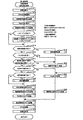
図8は、遊技制御部200の主制御処理を示すフローチャートである。
主制御処理は、遊技制御における一連の処理からなり、予め設定された一定時間(例えば4ミリ秒)ごとに繰り返し実行される。本実施の形態において、遊技制御部200は、予め設定された一定時間ごとに割り込みを発生させ、図6に示すループ処理の中で割り込みが許可(S610参照)されると、割り込み処理として主制御処理を実行する。図8に示すように、主制御処理では、乱数更新処理、スイッチ処理、図柄処理、電動役物処理、賞球処理、出力処理、情報用プログラム呼出時処理、遊技球計数処理、通常ベース値算出処理、性能表示データ設定処理、試験データ作成処理、出力制御処理が順次実行される(S801〜S880)。
FIG. 8 is a flowchart showing the main control process of the
The main control process consists of a series of processes in game control, and is repeatedly executed at predetermined fixed time (for example, 4 milliseconds). In the present embodiment, the
乱数更新処理(S801)では、遊技制御部200は、乱数制御部241の機能(サブルーチン)を呼び出し、遊技制御部200による遊技制御で用いられる各種の乱数の値を更新する。乱数の設定および乱数値の更新の詳細については後述する。
In the random number update process (S801), the
スイッチ処理(S802)としては、始動口スイッチ処理、ゲートスイッチ処理が行われる。
始動口スイッチ処理では、遊技制御部200は、乱数取得部231の機能(サブルーチン)を呼び出し、図3の第1始動口スイッチ211および第2始動口スイッチ212の状態を監視し、スイッチがONとなった場合に、特別図柄抽選のための処理を実行する。また、詳しくは後述するが、第1始動口スイッチ211および第2始動口スイッチ212において事前判定処理を行う場合は、特別図柄判定部234、変動パターン選択部235の各機能(サブルーチン)を呼び出し、事前判定のための処理を実行する。
ゲートスイッチ処理では、遊技制御部200は、乱数取得部231の機能(サブルーチン)を呼び出し、図3のゲートスイッチ214の状態を監視し、スイッチがONとなった場合に、普通図柄抽選のための処理を実行する。
これらのスイッチ処理の詳細な内容については後述する。
As the switch process (S802), a start port switch process and a gate switch process are performed.
In the start port switch process, the
In the gate switch process, the
The detailed contents of these switch processes will be described later.
図柄処理(S803)としては、特別図柄処理、普通図柄処理が行われる。
特別図柄処理では、遊技制御部200は、特別図柄変動制御部233、特別図柄判定部234、変動パターン選択部235の各機能(サブルーチン)を呼び出し、特別図柄変動およびこの図柄変動に伴う処理を実行する。
普通図柄処理では、遊技制御部200は、普通図柄判定部232および普通図柄変動制御部236の機能(サブルーチン)を呼び出し、普通図柄変動およびこの図柄変動に伴う処理を実行する。
これらの図柄処理の詳細な内容については後述する。
As the symbol processing (S803), a special symbol processing and a normal symbol processing are performed.
In the special symbol processing, the
In the normal symbol processing, the
The detailed contents of these symbol processing will be described later.
電動役物処理(S804)としては、大入賞口処理および電動チューリップ処理が行われる。
大入賞口処理では、遊技制御部200は、大入賞口動作制御部237の機能(サブルーチン)を呼び出し、所定の条件に基づいて特別電動役物である大入賞口125の開放動作を制御する。
電動チューリップ処理では、遊技制御部200は、電動チューリップ動作制御部238の機能(サブルーチン)を呼び出し、所定の条件に基づいて普通電動役物である電動チューリップ123の開放動作を制御する。
これらの電動役物処理の詳細な内容については後述する。
As the electric accessory processing (S804), a large winning opening processing and an electric tulip processing are performed.
In the large winning opening process, the
In the electric tulip processing, the
The detailed contents of these electric accessory processing will be described later.
賞球処理(S805)では、遊技制御部200は、賞球処理部239の機能(サブルーチン)を呼び出し、入賞個数の管理および入賞に応じた賞球の払い出しの制御用コマンドをセットする。
In the prize ball processing (S805), the
出力処理(S806)では、遊技制御部200は、出力制御部240の機能(サブルーチン)を呼び出し、演出制御用のコマンドを演出制御部300へ出力し、払い出し制御用のコマンドを払出制御部330へ出力する。演出制御用コマンドは、S802からS804までの各処理において生成され、RAM203に設けられた制御用コマンドの格納領域に格納(セット)される。払い出し制御用コマンドは、S805の処理において生成され、RAM203に設けられた制御用コマンドの格納領域に格納(セット)される。RAM203には、制御用コマンドの種類ごとに格納領域が設定されている。
In the output process (S806), the
出力制御部240は、RAM203の各制御用コマンドの格納領域を順に調べ、個々の格納領域に制御用コマンドが格納されていれば(すなわち、S802〜S805の処理で制御用コマンドが生成されていれば)、その制御用コマンドを読み出し、出力先(演出制御部300または払出制御部330)へ出力する。
The
本実施の形態では、図8に示したように、一連の主制御処理の最後に出力処理を行う。すなわち、第1の処理手段としての上記各機能によるS802〜S805の各処理において生成されたコマンドを、その各処理においてはRAM203の対応する格納領域に格納しておく。そして、これらの処理の後に、第2の処理手段としての出力制御部240が、RAM203の格納領域に蓄積された、各処理で生成されたコマンドをまとめて出力する。言い換えれば、本実施の形態では、主制御処理を1サイクル実行すると、その1サイクルの実行において生成されたコマンドが、その1サイクルの実行における最後のコマンド生成が行われた後に、出力される。
In the present embodiment, as shown in FIG. 8, the output process is performed at the end of a series of main control processes. That is, the commands generated in each of the processes S802 to S805 by each of the above functions as the first processing means are stored in the corresponding storage area of the
情報用プログラム呼出時処理(S810)では、遊技制御部200は、対象となる情報用プログラムを呼び出すための処理を行う。
In the information program call time processing (S810), the
遊技球計数処理(情報用プログラム(S820))では、遊技制御部200は、通常遊技状態(低確率時短無遊技状態)中における各種入賞口への遊技球の入賞に基づく賞球の払出数である通常中払出数、通常遊技状態中におけるアウト球検出スイッチ227で検出された遊技球数である通常中アウト数、遊技状態に拘らずにアウト球検出スイッチ227で検出された遊技球数である総アウト数といった遊技実績情報を計数するための処理を行う。
なお、総アウト数、通常中払出数、及び、通常中アウト数については、設定値を変化させたとしても影響を受けない(設定値とは無関係な)遊技実績情報となっているため、これらを計数しておくことで設定値の影響を排除した性能情報(後述する通常ベース値)を算出することが可能となり、パチンコ遊技機100の性能把握に役立てることが可能となる。
In the game ball counting process (information program (S820)), the
Note that the total number of outs, the number of regular outs, and the number of normal outs are game performance information that is not affected even if the set value is changed (irrelevant to the set value). By counting the numbers, it is possible to calculate performance information (normal base value described later) excluding the influence of the set value, which is useful for grasping the performance of the
通常ベース値算出処理(情報用プログラム(S830))では、遊技制御部200は、総アウト数によって区切られる現在の遊技区間における通常ベース値((通常中払出数÷通常中アウト数)×100)を算出すると共に、RAM203の記憶領域であって情報用プログラムの実行に際してワーク(作業領域)として用いられる情報用RAM領域に設定されるベース記憶領域の第1領域に小数点第一位で四捨五入した通常ベース値をセーブする処理を行う。
なお、遊技区間は、総アウト数が6万個となる毎に更新されるようになっており、ベース記憶領域は、現在の遊技区間における通常ベース値が記憶される第1領域と、1回前の遊技区間における通常ベース値を記憶するための第2領域と、2回前の遊技区間における通常ベース値を記憶するための第3領域と、3回前の遊技区間における通常ベース値を記憶するための第4領域とが設けられており、現在を含む4つの遊技区間分の通常ベース値がそれぞれの領域にセーブされることになる。
In the normal base value calculation process (information program (S830)), the
The game section is updated every time the total number of outs reaches 60,000, and the base storage area is once with the first area in which the normal base value in the current game section is stored. A second area for storing the normal base value in the previous game section, a third area for storing the normal base value in the game section two times before, and a normal base value in the game section three times before are stored. A fourth area is provided for this purpose, and the normal base values for the four game sections including the present are saved in each area.
性能表示データ設定処理(情報用プログラム(S850))では、遊技制御部200は、通常ベース値算出処理で算出されてベース記憶領域にセーブされている4つの遊技区間分の通常ベース値(性能情報)を5秒毎に切り替えながら情報表示器230に表示させるための性能表示データを設定する処理を行う。なお、性能表示データ設定処理の詳細は後述する。
In the performance display data setting process (information program (S850)), the
試験データ作成処理(情報用プログラム(S870))では、遊技制御部200は、パチンコ遊技機100の試験を行う際に使用する試験設備に出力する試験データ(試験情報)を作成する処理を行う。
In the test data creation process (information program (S870)), the
出力制御処理(情報用プログラム(S880))では、遊技制御部200は、性能表示データ設定処理で設定した性能表示データ(性能情報)等の信号を各種表示器に出力させる表示出力処理や、試験データ作成処理で作成した試験データ等の信号を出力する処理を行う。
In the output control process (information program (S880)), the
〔遊技機の基本動作の変形例〕
なお、図6乃至図8を参照して説明した動作例では、基本処理におけるループ処理の部分で割り込みを許可し、割り込み処理として一連の処理からなる主制御処理を実行した。しかしながら、主制御処理は、一定時間ごとに繰り返し実行されるように構成されていれば良く、具体的な実現手段(実行手順)は、図6乃至図8に示した例には限定されない。例えば、基本処理の一連の動作の中に主制御処理を組み入れておき、所定のタイミングで経過時間を計測し、一定時間(例えば4ミリ秒)ごとに主制御処理へ戻る構成としても良い。また、基本処理の一連の動作の中に主制御処理を組み入れる一方で、図6乃至図8を参照して説明した動作と同様に、一定時間ごとに割り込みを発生させ、割り込みが発生したならば基本処理中に組み入れられた主制御処理へ戻る構成としても良い。
[Modification example of basic operation of game machine]
In the operation example described with reference to FIGS. 6 to 8, interrupts are permitted in the loop processing portion of the basic processing, and the main control processing including a series of processing is executed as the interrupt processing. However, the main control process may be configured to be repeatedly executed at regular intervals, and the specific realization means (execution procedure) is not limited to the examples shown in FIGS. 6 to 8. For example, the main control process may be incorporated into a series of operations of the basic process, the elapsed time may be measured at a predetermined timing, and the process may be returned to the main control process at regular time intervals (for example, 4 milliseconds). Further, while incorporating the main control process into a series of operations of the basic process, interrupts are generated at regular intervals in the same manner as the operations described with reference to FIGS. 6 to 8, and if an interrupt occurs. It may be configured to return to the main control process incorporated during the basic process.
また、基本処理で生成されたコマンドを出力する場合は、原則として、コマンドを生成する度に、RAM203のコマンド格納領域に格納し、第2の処理手段である出力制御部240の機能を呼び出して出力する。基本処理は、遊技の進行に関わる主制御処理とは異なり、電源投入時にのみ行われる初期動作等の特別な処理である。また、基本処理は、電源投入時のパチンコ遊技機100の状態等の条件に基づく分岐により処理手順が変動する場合があるため、出力処理に漏れが無いように、生成したコマンドを速やかに出力する処理である。なお、関連する複数の処理により連続的にコマンドが生成される場合等、具体的な処理の要請に応じて、複数のコマンドをRAM203のコマンド格納領域に格納し、まとめて出力する処理手順を採っても良い。
Further, when outputting the command generated in the basic processing, as a general rule, each time the command is generated, it is stored in the command storage area of the
〔遊技制御部による乱数更新処理〕
特別図柄抽選等の遊技制御における各種の抽選に用いられる判定情報としての乱数値は、カウンタによって計数され、所定の初期値から始まって、図8に示す主制御処理の乱数更新処理(S801)が行われるたびに1ずつ加算される。そして、各抽選が行われた時点の値が始動口スイッチ処理(図9)およびゲートスイッチ処理(図10)で取得され、特別図柄処理(図11)や普通図柄処理(図16)で使用される。この乱数値のカウンタは無限ループカウンタであり、計数された乱数値が、設定されている乱数の最大値(例えば、後述する図20(a)に示した大当たり乱数では299)に達した後は、再び初期値に戻る。また、乱数更新処理は一定時間ごとに行われるため、各乱数の初期値が特定されてしまうと、更新間隔や初期値の情報に基づいて当選値が推定される恐れがある。そこで、主制御処理から図6に示す基本処理に戻った後、S613の初期値乱数更新処理において、各乱数の初期値をランダムに変更する。
[Random number update processing by the game control unit]
The random number value as the determination information used for various lottery in the game control such as the special symbol lottery is counted by the counter, and the random number update process (S801) of the main control process shown in FIG. 8 starts from a predetermined initial value. One is added each time it is done. Then, the value at the time when each lottery is performed is acquired by the start port switch process (FIG. 9) and the gate switch process (FIG. 10), and is used in the special symbol process (FIG. 11) and the normal symbol process (FIG. 16). To. This random number value counter is an infinite loop counter, and after the counted random number value reaches the maximum value of the set random number (for example, 299 for the jackpot random number shown in FIG. 20A described later). , Returns to the initial value again. Further, since the random number update process is performed at regular intervals, if the initial value of each random number is specified, the winning value may be estimated based on the update interval and the information of the initial value. Therefore, after returning from the main control process to the basic process shown in FIG. 6, the initial value of each random number is randomly changed in the initial value random number update process of S613.
〔遊技制御部による始動口スイッチ処理〕
図9は、図8のS802に示したスイッチ処理のうちの始動口スイッチ処理の内容を示すフローチャートである。
この始動口スイッチ処理は、第1始動口121における入賞に対する処理と、第2始動口122における入賞に対する処理とが順次行われる。図9を参照すると、遊技制御部200は、まず、第1始動口121に遊技球が入賞して第1始動口スイッチ211がONとなったか否かを判断する(S901)。第1始動口スイッチ211がONとなったならば、次に遊技制御部200は、第1始動口121の入賞における未変動分の保留数U1が上限値未満か否かを判断する(S902)。図9に示す例では、上限値を4個としている。保留数U1が上限値に達している場合は(S902でNo)、それ以上未変動分の入賞を保留することができないので、第1始動口121における入賞に対する処理を終了する。
[Starting port switch processing by the game control unit]
FIG. 9 is a flowchart showing the contents of the start port switch process among the switch processes shown in S802 of FIG.
In this start port switch process, a process for winning a prize at the
一方、保留数U1が上限値未満である場合(S902でYes)、遊技制御部200の乱数取得部231は、今回の入賞による判定のための乱数値を取得し、RAM203に格納する(S903)。ここでは、第1始動口121の入賞なので、特別図柄抽選のための乱数値が取得される。このとき取得される乱数値は、S801の乱数更新処理で更新された値である。そして、この乱数値により、後の特別図柄処理において特別図柄抽選の結果が確定される。ここにいう乱数値としては、大当たり、小当たりまたははずれを決定する大当たり乱数値、図柄の種類(大当たり遊技の終了後における時短状態か時短無状態、高確率状態と低確率状態、長当たり、短当たり)を決定する図柄乱数値(大当たり図柄乱数値)、図柄変動における変動パターンを特定するための変動パターン乱数値、はずれのときに後述のリーチ演出を実行可能な変動パターン(変動時間)にするか否かを決定するリーチ乱数値、等が含まれる。
On the other hand, when the hold number U1 is less than the upper limit value (Yes in S902), the random
次に、遊技制御部200は、事前判定処理を行う(S904)。事前判定処理とは、上記図柄処理(S803)における特別図柄処理によりも前に、始動口への入賞にともない取得される乱数の判定を行う(事前判定)処理である。
Next, the
そして、演出制御部300は、事前判定処理によって判定された乱数の判定結果(事前判定結果)に基づいて、上記図柄処理(S803)における特別図柄処理による判定結果が報知されるよりも前に、その判定結果を示唆する予告演出を行うことができる。この予告演出は、例えば、始動口への入賞にともない取得される乱数の発生に応じて、画像表示部114に表示される保留表示演出(後述)等を用いて行われる。
Then, the
そして、遊技制御部200は、保留数U1の値を1加算する(S905)。
この後、遊技制御部200は、事前判定結果を演出制御部300に通知するために、S904の事前判定処理による事前判定情報を含む事前判定結果コマンドをRAM203にセットする(S906)。
さらに、遊技制御部200は、S905による保留数U1の増加を演出制御部300に通知するための保留数増加コマンドをRAM203にセットし(S907)、第1始動口121における入賞に対する処理を終了する。
Then, the
After that, the
Further, the
次に、第2始動口122における入賞に対する処理が行われる。図9を参照すると、次に遊技制御部200は、第2始動口122に遊技球が入賞して第2始動口スイッチ212がONとなったか否かを判断する(S908)。第2始動口スイッチ212がONとなったならば、次に、遊技制御部200は、第2始動口122の入賞における未変動分の保留数U2が上限値未満か否かを判断する(S909)。図9に示す例では、上限値を4個としている。保留数U2が上限値に達している場合は(S909でNo)、それ以上未変動分の入賞を保留することができないので、第2始動口122における入賞に対する処理を終了する。
Next, processing for winning a prize at the
一方、保留数U2が上限値未満である場合(S909でYes)、遊技制御部200の乱数取得部231は、今回の入賞による抽選のための乱数値を取得し、RAM203に格納する(S910)。ここでは、第2始動口122の入賞なので、上記のS903と同様に、特別図柄抽選のための乱数値(大当たり乱数値、大当たり図柄乱数値、リーチ乱数値、変動パターン乱数値など)が取得される。このとき取得される乱数値は、S801の乱数更新処理で更新された値である。そして、この乱数値により後の特別図柄処理において特別図柄抽選の結果が確定される。
On the other hand, when the number of reservations U2 is less than the upper limit value (Yes in S909), the random
次に、遊技制御部200は、事前判定処理を行う(S911)。この事前判定処理の内容は、上記のS904と同様である。
そして、遊技制御部200は、保留数U2の値を1加算する(S912)。
この後、遊技制御部200は、事前判定結果を演出制御部300に通知するために、S911の事前判定処理による事前判定情報を含む事前判定結果コマンドをRAM203にセットする(S913)。
さらに、遊技制御部200は、S912による保留数U2の増加を演出制御部300に通知するための保留数増加コマンドをRAM203にセットし(S914)、第2始動口122における入賞に対する処理を終了する。
Next, the
Then, the
After that, the
Further, the
なお、図示は省略するが、低確率時短無遊技状態においては第2始動口122への入賞にともなう事前判定処理(S911)を不実行(禁則)とする制御を行い、高確率時短遊技状態においては第1始動口121への入賞にともなう事前判定処理(S904)を不実行とする制御を行ってもよい。
Although not shown, in the low-probability time-saving game state, the pre-determination process (S911) accompanying the winning of the
〔遊技制御部によるゲートスイッチ処理〕
図10は、ゲート124を遊技球が通過した場合のゲートスイッチ処理の内容を示すフローチャートである。
このゲートスイッチ処理において、遊技制御部200は、まず、ゲート124を遊技球が通過してゲートスイッチ214がONとなったか否かを判断する(S1001)。ゲートスイッチ214がONとなったならば、次に遊技制御部200は、未変動分の保留数Gが上限値未満か否かを判断する(S1002)。図10に示す例では、上限値を4個としている。保留数Gが上限値に達している場合は(S1002でNo)、それ以上未変動分の入賞を保留することができないので、ゲートスイッチ処理を終了する。
[Gate switch processing by the game control unit]
FIG. 10 is a flowchart showing the contents of the gate switch processing when the game ball passes through the gate 124.
In this gate switch process, the
一方、保留数Gが上限値未満である場合(S1002でYes)、遊技制御部200の乱数取得部231は、今回の入賞による抽選のための乱数値を取得し、RAM203に格納する(S1003)。ここでは、ゲート124の入賞なので、普通図柄抽選のための乱数値(当たり乱数値など)が取得される。
On the other hand, when the number of holds G is less than the upper limit value (Yes in S1002), the random
次に、遊技制御部200は、保留数Gの値を1加算する(S1004)。
S1004で保留数Gの値が加算された後、遊技制御部200は、S1004による保留数Gの増加を演出制御部300に通知するための保留数G増加コマンドをRAM203にセットし(S1005)、ゲート124における入賞に対する処理を終了する。
Next, the
After the value of the hold number G is added in S1004, the
〔遊技制御部による特別図柄処理〕
図11は、図8のS803に示した図柄処理のうちの特別図柄処理の内容を示すフローチャートである。
この特別図柄処理において、遊技制御部200の特別図柄変動制御部233は、まず、RAM203においてセットされるフラグの設定(以下、フラグ設定)において大当たり遊技フラグがONになっているか否かを調べる(S1101)。ここで、大当たり遊技フラグは、特別図柄抽選の結果に応じて行われる大当たり遊技を実行中であるか否かを識別するためにセットされるフラグである。
[Special symbol processing by the game control unit]
FIG. 11 is a flowchart showing the contents of the special symbol processing among the symbol processing shown in S803 of FIG.
In this special symbol processing, the special symbol
大当たり遊技フラグがONである場合、既にパチンコ遊技機100は大当たり遊技を実行中であるので、特別図柄変動を開始することなく特別図柄処理を終了する(S1101でYes)。なお、大当たり遊技を実行中とは、前回の特別図柄抽選の判定および変動にかかる遊技である大当たり遊技を実行しているときとして捉えることができる。さて、大当たり遊技フラグがOFFである場合(S1101でNo)、次に特別図柄変動制御部233は、パチンコ遊技機100の現在の状態が特別図柄変動中か否かを判断する(S1102)。特別図柄変動中でない場合(S1102でNo)、次に特別図柄変動制御部233は、特別図柄の未変動分の保留数U1、U2(図9参照)に関する処理を行う(S1103〜S1106)。本実施の形態では、第1始動口121の入賞に係る保留数U1と第2始動口122の入賞に係る保留数U2とを区別しているので、この処理も対応する始動口に設けられたスイッチごとに個別に行う。
When the jackpot game flag is ON, the
具体的には、特別図柄変動制御部233は、まず第2始動口122の入賞に係る保留数U2が1以上か判断する(S1103)。保留数U2が1以上である場合(S1103でYes)、特別図柄変動制御部233は、保留数U2の値を1減算する(S1104)。一方、保留数U2=0である場合は(S1103でNo)、特別図柄変動制御部233は、次に第1始動口121の入賞に係る保留数U1が1以上か判断する(S1105)。保留数U1が1以上である場合(S1105でYes)、特別図柄変動制御部233は、保留数U1の値を1減算する(S1106)。一方、保留数U1=0である場合は(S1105でNo)、特別図柄の抽選を始動するための入賞が無いことを意味するため、特別図柄変動を開始せず、別ルーチンの客待ち設定処理を実行して処理を終了する(S1116)。
なお、本実施の形態では、第2始動口122の入賞に係る保留数U2に関する処理を優先させて行う。すなわち、保留数U2が1以上である場合は保留数U2に関する処理を行い、保留数U2=0である場合に保留数U1に関する処理を行う(S803〜S806参照)。これに対し、第1始動口121と第2始動口122のどちらの入賞かに関わらず、入賞した順に保留数U1、U2を減算していくような制御とすることも可能である。
Specifically, the special symbol
In the present embodiment, the process related to the number of reservations U2 related to the winning of the
S1104またはS1106で保留数U1または保留数U2を減算した後、特別図柄変動制御部233は、RAM203のフラグ設定においてセットされた客待ちフラグをOFFとする(S1107)。客待ちフラグは、パチンコ遊技機100が客待ち状態であることを識別するためのフラグであり、客待ち設定処理(S1116、後述する図15参照)においてセットされる。
After subtracting the hold number U1 or the hold number U2 in S1104 or S1106, the special symbol
次に、特別図柄変動制御部233は、別ルーチンによる大当たり判定処理および変動パターン選択処理を実行する(S1108、S1109)。詳しくは後述するが、この大当たり判定処理および変動パターン選択処理によって、第1特別図柄表示器221、第2特別図柄表示器222に変動表示される特別図柄の変動用の設定情報(大当たり図柄、遊技状態、変動パターン等)が決定される。なお、これらの情報は演出制御部300に送られる変動開始コマンドに含まれる。
Next, the special symbol
この後、特別図柄変動制御部233は、大当たり判定処理および変動パターン選択処理で決定された設定内容に基づき、図2に示す第1特別図柄表示器221、第2特別図柄表示器222により表示される特別図柄の変動を開始する(S1110)。そして、この設定内容を示す設定情報(大当たり図柄、遊技状態、変動パターン等)を含んだ変動開始コマンドを生成し、RAM203にセットする(S1111)。S1111でセットされた変動開始コマンドは、図8のS806に示した出力処理で演出制御部300へ送信される。
After that, the special symbol
S1102で特別図柄変動中と判断された場合(S1102でYes)、またはS1111で変動開始コマンドがセットされた後、特別図柄変動制御部233は、変動時間を経過したか否かを判断する(S1112)。すなわち、S1110で特別図柄の変動を開始してからの経過時間がS1109の変動パターン選択処理で設定された変動時間に達したか否かが判断される。変動時間を経過していなければ(S1112でNo)、特別図柄変動が継続されるので、そのまま特別図柄処理が終了する。
When it is determined in S1102 that the special symbol is changing (Yes in S1102), or after the change start command is set in S1111, the special symbol
一方、変動時間を経過した場合(S1112でYes)、特別図柄変動制御部233は、まず、第1特別図柄表示器221、第2特別図柄表示器222における特別図柄の変動をS1108の大当たり判定処理で決定された図柄で停止する(S1113)。後述する装飾図柄を停止させるための変動停止コマンドをRAM203にセットする(S1114)。そして、別ルーチンの停止中処理を実行する(S1115)。停止中処理の内容については後述する。S1114でセットされた変動停止コマンドは、図8のS806に示した出力処理で演出制御部300へ送信される。
On the other hand, when the fluctuation time has elapsed (Yes in S1112), the special symbol
〔遊技制御部による大当たり判定処理〕
図12は、大当たり判定処理(図11のS1108)の内容を示すフローチャートである。
この大当たり判定処理において、遊技制御部200の特別図柄判定部234は、まず、今回の特別図柄抽選における大当たり乱数値の判定を行い(S1201)、大当たりまたは小当たりしたか否かを判断する(S1202、S1205)。大当たりまたは小当たりしたか否かは、図9のS903またはS910で取得した大当たり乱数の値が、大当たりの当選値として設定された値または小当たりの当選値として設定された値と一致したか否かを判断することによって決定される(図20(a)参照)。
[Big hit judgment processing by the game control unit]
FIG. 12 is a flowchart showing the contents of the jackpot determination process (S1108 in FIG. 11).
In this jackpot determination process, the special
S1201の乱数判定の結果が大当たりだった場合(S1202でYes)、次に特別図柄判定部234は、大当たり図柄乱数値の判定を行う(S1203)。この判定の結果に応じて、図柄の種類(高確率時短遊技状態の大当たり、低確率時短無遊技状態の大当たりなど)が決定される。何れの大当たりとなるかは、図9のS903またはS910で取得した大当たり図柄乱数の値が、図柄の種類ごとに予め設定された値のうちの何れと一致したかによって決定される(図20(b)参照)。
When the result of the random number determination in S1201 is a big hit (Yes in S1202), the special
以上の判定の後、特別図柄判定部234は、大当たり図柄乱数の判定により決定された大当たり図柄を設定情報としてRAM203にセットする(S1204)。
After the above determination, the special
S1201の乱数判定の結果が小当たりだった場合(S1202でNo、S1205でYes)、次に特別図柄判定部234は、小当たりであることを表す図柄(以下、小当たり図柄)を設定情報としてRAM203にセットする(S1206)。
When the result of the random number determination in S1201 is a small hit (No in S1202, Yes in S1205), then the special
S1201の乱数判定の結果が大当たりでも小当たりでもない場合(S1202、S1205でNo)、次に特別図柄判定部234は、抽選にはずれたことを表す図柄(以下、はずれ図柄)を設定情報としてRAM203にセットする(S1207)。
When the result of the random number determination in S1201 is neither a big hit nor a small hit (No in S1202 and S1205), then the special
〔遊技制御部による変動パターン選択処理〕
図13は、変動パターン選択処理(図11のS1109)の内容を示すフローチャートである。
この変動パターン選択処理において、遊技制御部200の変動パターン選択部235は、まず、パチンコ遊技機100の遊技状態(時短無状態か時短状態か、および高確率状態か低確率状態か)を参照する(S1301)。そして、大当たり判定処理(図12)のS1202の判断結果を用いて今回の特別図柄抽選で大当たりしたか否かを判断する(S1302)。そして、大当たりだった場合(S1302でYes)、変動パターン選択部235は、大当たり用の変動パターンテーブルをROM202から読み出してRAM203にセットする(S1303)。
[Variation pattern selection process by the game control unit]
FIG. 13 is a flowchart showing the contents of the variation pattern selection process (S1109 in FIG. 11).
In this variation pattern selection process, the variation
一方、大当たりしなかった場合(S1302でNo)、次に変動パターン選択部235は、遊技者に大当たりを期待させるためのいわゆるリーチ演出を行うか否かを決定するための乱数値の判定を行う(S1304)。リーチ演出を実行可能な変動パターンとするか否かは、図9のS903またはS910で取得したリーチ乱数の値が予め設定された値と一致したか否かを判断することによって決定される(図20(c)参照)。
乱数値を用いた判定の結果、リーチ演出を実行可能な変動パターン(変動時間)とする場合(S1305でYes)、変動パターン選択部235は、リーチ用の変動パターンテーブルをROM202から読み出してRAM203にセットする(S1306)。また、リーチ演出を実行可能な変動パターン(変動時間)としない場合(S1305でNo)、変動パターン選択部235は、はずれ用の変動パターンテーブルをROM202から読み出してRAM203にセットする(S1307)。
ここで、変動パターンテーブルとは、予め用意されている複数の変動パターン(変動時間3秒、7秒、13秒、15秒、30秒、60秒、90秒など)と変動パターン乱数の値とを対応付けたテーブルである。
On the other hand, if there is no big hit (No in S1302), then the fluctuation
As a result of the determination using the random value, when the reach effect is set to the executable variation pattern (variation time) (Yes in S1305), the variation
Here, the fluctuation pattern table is a plurality of fluctuation patterns (
次に、変動パターン選択部235は、図9のS903またはS910で取得した変動パターン乱数値およびS1303、S1306、S1307でセットされた変動パターンテーブルを用いて、変動パターン乱数値の判定を行う(S1308)。すなわち、変動パターン選択部235は、RAM203にセットされた変動パターンテーブルを参照し、変動パターン乱数の乱数値に応じた変動パターンを選択する。したがって、同じ乱数値が取得された場合でも、パチンコ遊技機100の遊技状態(時短状態か時短無し状態か、および高確率状態か低確率状態か)、特別図柄抽選の結果(大当たりしたか否か、大当たりしていない場合はリーチ演出を行うか否か)等の違いに応じて参照される変動パターンテーブルが異なるので、決定される変動パターンが異なる。
Next, the fluctuation
この後、変動パターン選択部235は、S1308で選択した変動パターンを設定情報としてRAM203にセットする(S1309)。S1309でセットされた変動パターンの設定情報は、図11のS1111でセットされる変動開始コマンドに含まれ、図8のS806に示した出力処理で演出制御部300へ送信される。本実施の形態で選択される変動パターンおよびその設定の詳細については後述する。
After that, the fluctuation
〔遊技制御部による停止中処理〕
図14は、停止中処理(図11のS1115)の内容を示すフローチャートである。
この停止中処理において、遊技制御部200は、まず、RAM203のフラグ設定において時短状態であることを示すフラグ(以下、時短フラグ)がONになっているか否かを調べる(S1401)。時短フラグがONである場合(S1401でYes)、遊技制御部200は、時短状態での抽選回数(変動回数)Jの値を1減算し(S1402)、抽選回数Jが0になったか否かを調べる(S1403)。そして、抽選回数J=0であれば(S1403でYes)、時短フラグをOFFにする(S1404)。なお、時短フラグをONにする操作と、抽選回数Jの初期値の設定は、後述の大入賞口処理(図17)における遊技状態設定処理(図18)で行われる。
[Processing during stop by the game control unit]
FIG. 14 is a flowchart showing the contents of the stopped processing (S1115 of FIG. 11).
In this stopped processing, the
時短フラグがOFFであった場合(S1401でNo)またはS1404で時短フラグをOFFにした後、あるいはS1402で減算した後の抽選回数Jの値が0でない場合(S1403でNo)、次に遊技制御部200は、RAM203のフラグ設定において高確率状態であることを示すフラグ(以下、高確フラグ)がONになっているか否かを調べる(S1405)。なお、この高確フラグと先の時短フラグが共にONである場合は、高確率時短遊技状態であり、高確フラグがONであり時短フラグがOFFである場合は、高確率時短無遊技状態である。
When the time saving flag is OFF (No in S1401), after turning off the time saving flag in S1404, or when the value of the lottery number J after subtraction in S1402 is not 0 (No in S1403), then the game control The
高確フラグがONである場合(S1405でYes)、遊技制御部200は、高確率状態での抽選回数(変動回数)Xの値を1減算し(S1406)、抽選回数Xが0になったか否かを調べる(S1407)。そして、抽選回数X=0であれば(S1407でYes)、高確フラグをOFFにする(S1408)。なお、高確フラグをONにする操作と、抽選回数Xの初期値の設定は、後述の大入賞口処理(図17)における遊技状態設定処理(図18)で行われる。
When the high probability flag is ON (Yes in S1405), the
高確フラグがOFFであった場合(S1405でNo)またはS1408で高確フラグをOFFにした後、あるいはS1406で減算した後の抽選回数Xの値が0でない場合(S1407でNo)、次に遊技制御部200は、今回の特別図柄抽選で大当たりしたか否かを判断する(S1409)。そして、大当たりだった場合(S1409でYes)、次に遊技制御部200は、図柄の種類を判断する(S1410)。なお、ここでは図柄の種類の判断の一例として、長当たりか否かが判断される。
When the high accuracy flag is OFF (No in S1405), after the high accuracy flag is turned OFF in S1408, or when the value of the lottery count X after subtraction in S1406 is not 0 (No in S1407), then The
ここで、大当たりか否かの判断は、大当たり判定処理(図12)の判定結果に基づいて判断することができる。例えば、後述する図20(b)の図表に示す図柄の何れかがセットされているならば、S1409でYesである。大当たり判定処理によりRAM203に、はずれ図柄または小当たり図柄がセットされているならば、S1409でNoである。
Here, the determination of whether or not the jackpot is a jackpot can be determined based on the determination result of the jackpot determination process (FIG. 12). For example, if any of the symbols shown in the chart of FIG. 20B, which will be described later, is set, it is Yes in S1409. If a missed symbol or a small hit symbol is set in the
例えば低確率図柄Aなど図柄の種類が長当たりであった場合(S1410でYes)、遊技制御部200は、長当たり遊技フラグをONにする(S1411)。これにより、RAM203の遊技状態の設定が、図柄の種類が長当たりである大当たり遊技状態(長当たり遊技状態)となる。なお、ここでは長当たりにおいて、高確率状態か低確率状態かを区別していない。高確率状態となるか低確率状態となるかは、後述の大入賞口処理(図17)における遊技状態設定処理(図18)で該当するフラグをONにすることによって特定される。
For example, when the type of the symbol such as the low-probability symbol A is a long hit (Yes in S1410), the
例えば高確率図柄Eなど図柄の種類が長当たりでなかった場合(S1410でNo)、遊技制御部200は、短当たり遊技フラグをONにする(S1412)。これにより、RAM203の遊技状態の設定が、図柄の種類が短当たりである大当たり遊技状態(短当たり遊技状態)となる。長当たりの場合と同様、短当たりの場合も高確率状態か低確率状態かを区別していない。
For example, when the type of the symbol such as the high-probability symbol E is not a long hit (No in S1410), the
S1411またはS1412で大当たり遊技フラグをONにした後、遊技制御部200は、抽選回数J、Xの値を初期化する(S1413)。また、遊技制御部200は、S1401において時短フラグがONであって、S1403において抽選回数Jが0でなかった場合に、時短フラグをOFFにする(S1414)。同様に、S1405において高確フラグがONであって、S1407において抽選回数Xが0でなかった場合に、高確フラグをOFFにする(S1414)。
After turning on the jackpot game flag in S1411 or S1412, the
S1413で抽選回数J、Xの値を初期化した後、遊技制御部200は、オープニング動作を開始する(S1417)。ここで、オープニング動作の内容は、S1411、S1412の何れで当たり遊技フラグがONとなったかに応じて異なる。言い替えると、特別図柄抽選の判定結果に応じたオープニング動作が設定される。
この後、遊技制御部200は、演出制御部300において大当たり遊技フラグに応じたオープニング動作における演出を行うためのオープニングコマンドをRAM203にセットして(S1418)、停止中処理を終了する。このオープニングコマンドは、図8のS806に示した出力処理で演出制御部300へ送信される。
After initializing the values of the lottery times J and X in S1413, the
After that, the
これに対し、今回の特別図柄抽選の結果が大当たりでなかった場合(S1409でNo)、次に遊技制御部200は、今回の特別図柄抽選の結果が小当たりであったか否かを判断する(S1415)。小当たりでなかった場合は(S1415でNo)、停止中処理を終了する。
一方、小当たりであった場合(S1415でYes)、遊技制御部200は、小当たり遊技を開始する(S1416)。これにより、RAM203の遊技状態の設定が小当たり遊技状態となる。なお、小当たり遊技では、前述したように、大入賞口125を所定回数開閉し、所定時間経過後に終了する。
On the other hand, if the result of the special symbol lottery this time is not a big hit (No in S1409), then the
On the other hand, if it is a small hit (Yes in S1415), the
〔遊技制御部による客待ち設定処理〕
図15は、客待ち設定処理(図11のS1116)の内容を示すフローチャートである。
この客待ち設定処理において、遊技制御部200は、まず、RAM203のフラグ設定において客待ちフラグがONになっているか否かを調べる(S1501)。ここで、客待ちフラグは、パチンコ遊技機100が客待ち状態であることを識別するためにセットされるフラグである。
[Customer waiting setting processing by the game control unit]
FIG. 15 is a flowchart showing the contents of the customer waiting setting process (S1116 in FIG. 11).
In this customer waiting setting process, the
客待ちフラグがONである場合、パチンコ遊技機100は客待ち状態であるので、そのまま処理を終了する(S1501でYes)。一方、客待ちフラグがOFFである場合(S1501でNo)、遊技制御部200は、客待ちコマンドを生成してRAM203にセットし(S1502)、客待ちフラグをONにする(S1503)。S1502でセットされた客待ちコマンドは、図8のS806に示した出力処理で演出制御部300へ送信される。ここで、客待ちフラグとは、上記図11における客待ち設定処理(S1116)で説明した通り、大当たり遊技を実行中でなく(S1101でNo)、特別図柄の変動中でもなく(S1102でNo)、さらに保留が無い状態(S1103およびS1105でNo)である場合に、セットされるフラグである。
When the customer waiting flag is ON, the
〔遊技制御部による普通図柄処理〕
図16は、図8のS803に示した図柄処理のうちの普通図柄処理の内容を示すフローチャートである。
この普通図柄処理において、遊技制御部200の普通図柄変動制御部236は、まず、RAM203のフラグ設定において補助遊技フラグがONになっているか否かを調べる(S1601)。ここで、補助遊技フラグは、普通図柄抽選で当選した場合にセットされるフラグである。補助遊技フラグが設定されている状態は、電動チューリップ123が後述の電動チューリップ処理(図19)にしたがって開放され、第2始動口122に入賞し易い状態である(補助遊技状態)。
[Normal symbol processing by the game control unit]
FIG. 16 is a flowchart showing the contents of the normal symbol processing among the symbol processing shown in S803 of FIG.
In this normal symbol processing, the normal symbol
補助遊技フラグがONである場合、既に補助遊技状態となっており、普通図柄が停止している状態なので、普通図柄変動を開始することなく普通図柄処理を終了する(S1601でYes)。一方、補助遊技フラグがOFFである場合(S1601でNo)、次に普通図柄変動制御部236は、パチンコ遊技機100の現在の状態が普通図柄変動中か否かを判断する(S1602)。普通図柄変動中でない場合(S1602でNo)、次に普通図柄変動制御部236は、普通図柄の未変動分の保留数G(図10参照)が1以上か判断する(S1603)。保留数G=0である場合は(S1603でNo)、普通図柄の抽選を始動するための入賞が無いことを意味するため、普通図柄変動を開始せずに処理を終了する。
When the auxiliary game flag is ON, the auxiliary game state is already in effect and the normal symbol is stopped. Therefore, the normal symbol processing is terminated without starting the normal symbol change (Yes in S1601). On the other hand, when the auxiliary game flag is OFF (No in S1601), the normal symbol
これに対し、保留数Gが1以上である場合(S1603でYes)、普通図柄変動制御部236は、保留数Gの値を1減算する(S1604)。そして、普通図柄判定部232が、今回の普通図柄抽選における当たり乱数の判定を行って、普通図柄抽選に当選したか否かを判断する(S1605)。当選したか否かは、図10のS1003で取得した当たり乱数の値が、後述する図20(d)に示すテーブル等において当選値として設定された値と一致したか否かを判断することによって決定される。
On the other hand, when the hold number G is 1 or more (Yes in S1603), the normal symbol
次に、普通図柄変動制御部236は、普通図柄抽選の結果に応じて普通図柄の設定を行う(S1606)。すなわち、普通図柄抽選に当選した場合は、当選したことを表す図柄(以下、当たり図柄)を設定情報としてRAM203にセットする。一方、普通図柄抽選に当選しなかった場合は、抽選にはずれたことを表す図柄(以下、はずれ図柄)を設定情報としてRAM203にセットする。
Next, the normal symbol
次に、普通図柄変動制御部236は、普通図柄の変動時間の設定を行う(S1607)。この変動時間は、図14におけるS1404、S1414、後述の図18におけるS1804、S1807等の処理で設定される時短フラグに基づいて設定される。すなわち、S1607による設定の際に時短フラグがONである場合は、短時間(例えば1.5秒)に設定され、時短フラグがOFFである場合は、長時間(例えば4.0秒)に設定される。この設定の後、普通図柄変動制御部236は、S1607の設定内容に基づき、図2(a)および図3に示す普通図柄表示器223における普通図柄の変動を開始する(S1608)。なお、普通図柄の変動パターンを抽選により決定することもできる。この場合、例えば、遊技球がゲート124を通過した際に、乱数取得部231が普通図柄の変動パターン乱数値を取得し、S1607において、普通図柄変動制御部236が普通図柄の変動パターン乱数値を判定することにより、変動時間が設定される。
Next, the normal symbol
S1608で普通図柄の変動を開始した後、またはS1602で普通図柄変動中と判断された場合(S1602でYes)、普通図柄変動制御部236は、変動時間を経過したか否かを判断する(S1609)。すなわち、S1608で普通図柄の変動を開始してからの経過時間がS1607で設定された変動時間に達したか否かが判断される。変動時間を経過していなければ(S1609でNo)、普通図柄変動が継続されるので、そのまま普通図柄処理が終了する。
After starting the fluctuation of the normal symbol in S1608, or when it is determined in S1602 that the normal symbol is changing (Yes in S1602), the normal symbol
一方、変動時間を経過した場合(S1609でYes)、普通図柄変動制御部236は、普通図柄表示器223における普通図柄の変動を停止する(S1610)。そして、普通図柄変動制御部236は、S1605の判定結果が当選であったか否かを判断する(S1611)。当選であったならば(S1611でYes)、補助遊技フラグをONにする(S1612)。一方、抽選にはずれたならば(S1611でNo)、補助遊技フラグをONにすること無く普通図柄処理を終了する。
On the other hand, when the fluctuation time has elapsed (Yes in S1609), the normal symbol
〔遊技制御部による大入賞口処理〕
図17は、図8のS804に示した電動役物処理のうちの大入賞口処理の内容を示すフローチャートである。
この大入賞口処理において、遊技制御部200の大入賞口動作制御部237は、まず、RAM203のフラグ設定において大当たり遊技フラグがONになっているか否かを調べる(S1701)。大当たり遊技フラグがOFFである場合、大入賞口125への入賞はないので、大入賞口処理を終了する(S1701でNo)。一方、大当たり遊技フラグがONである場合(S1701でYes)、次に大入賞口動作制御部237は、パチンコ遊技機100が停止中処理(図14)で開始された大当たり時の動作制御におけるオープニング動作の最中か否かを判断する(S1702)。
[Large winning opening processing by the game control unit]
FIG. 17 is a flowchart showing the contents of the large winning opening processing among the electric accessory processing shown in S804 of FIG.
In this big prize opening process, the big winning opening
パチンコ遊技機100がオープニング中である場合(S1702でYes)、次に大入賞口動作制御部237は、予め設定されたオープニング動作が行われるべき時間(オープニング時間)を経過したか否かを判断する(S1703)。オープニング時間を経過していないならば、大入賞口125でのオープニング動作が継続されるので、大入賞口処理を終了する(S1703でNo)。一方、オープニング時間を経過したならば(S1703でYes)、次に大入賞口動作制御部237は、大入賞口125の作動設定を行い(S1704)、入賞個数Cを初期化(C=0)し(S1705)、大入賞口125の作動のラウンド数Rの値を現在の値から1加算して(S1706)、大入賞口125を作動開始(開放)する(S1707)。
When the
S1704の作動設定では、大入賞口125の作動パターンと、その作動パターンで作動させるラウンド数(作動ラウンド数)とが設定される。大入賞口125が作動する場合の例としては、特別図柄抽選で、長当たりまたは短当たりの大当たりであった場合と、小当たりであった場合がある。作動パターンおよびラウンド数は、これらの当たりの種類に応じて様々に設定される。なお、大当たり遊技においては、大入賞口125の作動を複数回(複数ラウンド)連続して行うことが規定されている。一例としては、長当たりの場合、例えば、15ラウンド(15R)作動させ、1ラウンドでは29.5秒の開放を1回行う。短当たりの場合、例えば、2ラウンド(2R)作動させ、1ラウンドでは0.9秒の開放を1回行う。さらに説明をすると、0.9秒開放して1.0秒閉鎖した後、0.9秒開放する。一方、小当たりの場合、例えば、0.9秒開放して1.0秒閉鎖した後、0.9秒開放する。ここで、短当たりでの作動と小当たりでの作動を上記の例で比較すると、共に0.9秒の開放が2回行われることとなる。すなわち、遊技者から見える大入賞口125の動作は、短当たりの場合と小当たりの場合とで同じであり、遊技盤110上の大入賞口125の動作のみから短当たりと小当たりとを区別することはできない。
In the operation setting of S1704, the operation pattern of the large winning
なお、小当たりの際には、大入賞口125の開放累積時間が1.8秒以内に設定されなければならないことが法令により定められている。一方で、大当たり(長当たりまたは短当たり)の際には、大当たり遊技のラウンド数Rだけ、大入賞口125を複数回連続開放させなければならない。そこで、上記のように小当たりでの作動と短当たりでの作動を外見上区別し難くしようとする場合、小当たりでは、1作動での開放累積時間が1.8秒以内を満たす範囲で、大入賞口125が2回以上開放する作動形態が設定され、短当たりでは、小当たりの開放回数と同数のラウンド数が設定される。
In the case of a small hit, the law stipulates that the cumulative opening time of the large winning
次に、大入賞口動作制御部237は、S1704で設定された作動パターンにおける開放時間を経過したか否かを判断する(S1708)。大入賞口125での開放状態が開放時間を経過していない場合(S1708でNo)、次に大入賞口動作制御部237は、大入賞口125への入賞個数Cが規定の個数(例えば9個)以上か否かを判断する(S1709)。開放時間を経過しておらず、かつ入賞個数Cが規定個数未満である場合は、大入賞口125の作動状態(開放状態)が継続されるので、大入賞口処理を終了する(S1709でNo)。一方、開放時間を経過したか(S1708でYes)、または入賞個数Cが規定個数に達した場合(S1709でYes)、大入賞口動作制御部237は、大入賞口125を作動終了(閉口)する(S1710)。
Next, the large winning opening
次に、大入賞口動作制御部237は、大入賞口125の作動のラウンド数RがS1704で設定された最大値に達したか否かを判断する(S1711)。そして、最大値に達していないならば、残りの作動が行われるため、大入賞口処理を終了する(S1711でNo)。
Next, the large winning opening
大入賞口125の作動のラウンド数Rが最大値に達したならば(S1711でYes)、次に大入賞口動作制御部237は、エンディング動作を開始する(S1712)。ここで、エンディング動作の内容は、長当たり遊技、短当たり遊技の各遊技において設定されたエンディング動作のうち、大当たり遊技フラグの状態に対応するものとなる。
この後、大入賞口動作制御部237は、演出制御部300において大当たり遊技フラグに応じたエンディング動作における演出を行うためのエンディングコマンドをRAM203にセットする(S1713)。このエンディングコマンドは、図8のS806に示した出力処理で演出制御部300へ送信される。
When the number of rounds R of the operation of the large winning
After that, the big prize opening
次に、大入賞口動作制御部237は、大入賞口125の作動のラウンド数Rを0にリセットした後(S1714)、エンディング動作の開始からの経過時間が予め設定されたエンディング動作が行われるべき時間(エンディング時間)を経過したか否かを判断する(S1717)。エンディング時間を経過していないならば、エンディング動作が継続されるので、大入賞口処理を終了する(S1717でNo)。一方、エンディング時間を経過したならば(S1717でYes)、次に大入賞口動作制御部237は、遊技制御部200による遊技状態設定処理を経た後(S1718)、大当たり遊技フラグをOFFにして、大入賞口処理を終了する(S1719)。遊技状態設定処理の内容については後述する。
Next, the large winning opening
S1702で、パチンコ遊技機100がオープニング中ではないと判断した場合(S1702でNo)、次に大入賞口動作制御部237は、エンディング中か否かを判断する(S1715)。そして、エンディング中であるならば(S1715でYes)、上記S1717以降の動作を実行する。
When it is determined in S1702 that the
一方、パチンコ遊技機100がエンディング中でもないならば(S1715でNo)、次に大入賞口動作制御部237は、大入賞口125が作動(開放)中か否かを判断する(S1716)。そして、作動中でないならば(S1716でNo)、上記S1705以降の動作を実行し、作動中であるならば(S1716でYes)、上記S1708以降の動作を実行する。
なお、前述した小当たり遊技で行われる演出は、短当たり遊技で行われる演出と同様であり、演出から短当たりと小当たりとを区別することはできない。
On the other hand, if the
It should be noted that the effect performed in the small hit game described above is the same as the effect performed in the short hit game, and it is not possible to distinguish between the short hit and the small hit from the effect.
〔遊技状態設定処理〕
エンディング時間が経過した場合(S1717でYes)に実行される、遊技制御部200による遊技状態設定処理(S1718)の内容を図18に示す。
遊技状態設定処理が行われる場合、前提として、図17のS1701で大当たり遊技フラグがONとなっている。そこで、図18に示すように、遊技制御部200は、まず、その図柄の種類を判断する(S1801、S1802、S1803、S1806)。これらの判断は、例えば大当たり判定処理(図12)でRAM203に設定情報としてセットされた図柄の種類に基づいて判断することができる。なお、これらの判断は大当たり判定処理(図12)のS1202、S1203、S1205と概ね同様であるので、S1202、S1203、S1205の判断結果を用いても良い。
[Game state setting process]
FIG. 18 shows the contents of the game state setting process (S1718) by the
When the game state setting process is performed, the jackpot game flag is ON in S1701 of FIG. 17 as a premise. Therefore, as shown in FIG. 18, the
小当たりである場合(S1801でYes)、遊技状態は変更しないので、遊技状態設定処理を終了する。
図柄の種類が低確率時短遊技状態の大当たりである場合(S1801でNo、S1802、S1803でYes)、遊技制御部200は、時短フラグをONにする(S1804)。これにより、RAM203の遊技状態の設定が低確率時短遊技状態となる。また、遊技制御部200は、抽選回数Jの初期値を設定し(S1805)、遊技状態設定処理を終了する。抽選回数Jの初期値は、図示の例では100回である。したがって、低確率時短遊技状態において特別図柄抽選の判定結果がはずれとなる抽選が連続して100回行われたならば、低確率時短遊技状態が終了し、低確率時短無遊技状態となる。
If it is a small hit (Yes in S1801), the game state is not changed, so the game state setting process is terminated.
When the type of the symbol is a big hit in the low-probability time-saving game state (No in S1801, Yes in S1802, Yes in S1803), the
一方、図柄の種類が低確率時短無遊技状態の大当たりである場合(S1801でNo、1802でYes、S1803でNo)、遊技制御部200は、時短フラグ、高確フラグともONにせずに処理を終了する。したがって、この大当たりの後の遊技に対するRAM203の遊技状態の設定は、低確率時短無遊技状態となる。
On the other hand, when the type of symbol is a big hit in a low-probability time-saving non-game state (No in S1801, Yes in 1802, No in S1803), the
図柄の種類が高確率時短遊技状態の大当たりである場合(S1801、S1802でNo、S1806でYes)、遊技制御部200は、時短フラグをONにし(S1807)、抽選回数Jの初期値を設定する(S1808)。この場合の抽選回数Jの初期値は、図示の例では10000回である。また、遊技制御部200は、高確フラグをONにし(S1809)、抽選回数Xの初期値を設定する(S1810)。抽選回数Xの初期値は、図示の例では10000回である。これにより、RAM203の遊技状態の設定が高確率時短遊技状態となる。そして、この高確率時短遊技状態において特別図柄抽選の判定結果がはずれとなる抽選が連続して10000回行われたならば、高確率時短遊技状態が終了し、低確率時短無遊技状態となる。
When the type of the symbol is a big hit in the high-probability time-saving game state (No in S1801 and S1802, Yes in S1806), the
一方、図柄の種類が高確率時短無遊技状態の大当たりである場合(S1801、S1802、S1806でNo)、遊技制御部200は、高確フラグのみをONにし(S1809)、抽選回数Xの初期値(10000回)を設定する(S1810)。これにより、RAM203の遊技状態の設定が高確率時短無遊技状態となる。そして、この高確率時短無遊技状態において特別図柄抽選の判定結果がはずれとなる抽選が連続して10000回行われたならば、高確率時短無遊技状態が終了し、低確率時短無遊技状態となる。
On the other hand, when the type of the symbol is a big hit in a high-probability time-saving non-game state (No in S1801, S1802, S1806), the
〔遊技制御部による電動チューリップ処理〕
図19は、図8のS804に示した電動役物処理のうちの電動チューリップ処理の内容を示すフローチャートである。
電動チューリップ処理において、遊技制御部200の電動チューリップ動作制御部238は、まず、RAM203のフラグ設定において補助遊技フラグがONになっているか否かを調べる(S1901)。補助遊技フラグがOFFである場合、電動チューリップ123は開放しないため、電動チューリップ処理を終了する(S1901でNo)。一方、補助遊技フラグがONである場合(S1901でYes)、次に電動チューリップ動作制御部238は、電動チューリップ123が作動中か否かを判断する(S1902)。
[Electric tulip processing by the game control unit]
FIG. 19 is a flowchart showing the contents of the electric tulip processing among the electric accessory processing shown in S804 of FIG.
In the electric tulip processing, the electric tulip
電動チューリップ123が作動中でない場合(S1902でNo)、電動チューリップ動作制御部238は、電動チューリップ123の作動パターンの設定を行い(S1903)、設定した作動パターンで電動チューリップ123を作動させる(S1904)。ここで、作動パターンは、図14におけるS1404、S1414、図18におけるS1804、S1807等の処理で設定される時短フラグに基づいて設定される。例えば、S1903による設定の際に時短フラグがOFFである場合は、0.15秒の開放時間で1回開放する作動パターンが設定され、時短フラグがONである場合は、1.80秒の開放時間で3回開放する作動パターンが設定される。このように、通常、時短フラグがONであるとき(時短状態のとき)は、電動チューリップ123が長時間、複数回開放され、第2始動口122に入賞し易くなる入賞サポート(電チューサポート)が行われる。なお、時短フラグがONの場合またはOFFの場合における電動チューリップ123の作動パターン(補助遊技の種類)を複数用意し、普通図柄処理(図16参照)で判定される当たりの種類に応じて、作動パターンを設定するように構成しても良い。
When the
S1902で電動チューリップ123が作動中と判断された場合(S1902でYes)、またはS1904で電動チューリップ123を作動させた後、電動チューリップ動作制御部238は、設定されている作動パターンにおける開放時間が経過したか否かを判断する(S1905)。開放時間を経過していなければ、電動チューリップ123の作動状態(開放状態)が継続されるので、電動チューリップ処理を終了する(S1905でNo)。一方、開放時間を経過したならば(S1905でYes)、電動チューリップ動作制御部238は、補助遊技フラグをOFFとして、電動チューリップ処理を終了する(S1906)。
When it is determined in S1902 that the
〔乱数による判定の手法〕
ここで、大当たり判定処理(図12)、変動パターン選択処理(図13)、普通図柄処理(図16)等で行われる、乱数による判定の手法について詳細に説明する。
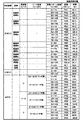
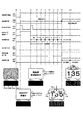
図20は、本実施の形態において特別図柄抽選および普通図柄抽選で用いられる乱数(判定テーブル)の構成例を示す図である。
図20(a)には特別図柄抽選で用いられる大当たり乱数の構成例、図20(b)には特別図柄抽選で用いられる大当たり図柄乱数の構成例、図20(c)には特別図柄抽選で用いられるリーチ乱数の構成例、図20(d)には普通図柄抽選で用いられる当たり乱数の構成例が、それぞれ示されている。
[Random number judgment method]
Here, a random number determination method performed in the jackpot determination process (FIG. 12), the variation pattern selection process (FIG. 13), the ordinary symbol process (FIG. 16), and the like will be described in detail.
FIG. 20 is a diagram showing a configuration example of a random number (determination table) used in the special symbol lottery and the ordinary symbol lottery in the present embodiment.
FIG. 20 (a) shows a configuration example of a jackpot random number used in a special symbol lottery, FIG. 20 (b) shows a configuration example of a jackpot symbol random number used in a special symbol lottery, and FIG. 20 (c) shows a special symbol lottery. A configuration example of the reach random number used and a configuration example of the winning random number used in the ordinary symbol lottery are shown in FIG. 20 (d), respectively.
図20(a)を参照すると、大当たり乱数の判定値として、大当たり判定時のパチンコ遊技機100の遊技状態が低確率状態の場合の大当たりと大当たり判定時の遊技状態が高確率状態の場合の大当たりの2種類と、小当たりとが設定されている。乱数(大当たり乱数)の値の範囲は、何れも0〜299の300個である。低確率状態の特別図柄抽選(大当たり抽選)の場合、当選値は1つだけが設定され、当選確率は1/300である。また高確率状態の特別図柄抽選の場合、当選値は10個設定され、当選確率は10/300(=1/30)である。すなわち図示の例では、高確率状態で始動口121、122に入賞し特別図柄抽選が行われると、低確率状態で特別図柄抽選が行われる場合に比べて、当選確率が10倍となる。また、小当たりの当選値は、低確率状態か高確率状態かに関わらず3個設定され、当選確率は3/300(=1/100)である。
ここで、低確率状態の特別図柄抽選を例に説明をすると、上記第1始動口121または第2始動口122への入賞を契機として取得した大当たり乱数値(S903、S910参照)が、図20(a)における低確率状態の大当たり抽選の当選値である「5」と一致するかが判定される。詳細な説明は省略するが、高確率状態の特別図柄抽選および小当たりの特別図柄抽選についても同様である。
With reference to FIG. 20A, as the determination value of the jackpot random number, the jackpot when the gaming state of the
Here, to explain by taking a special symbol lottery in a low probability state as an example, the jackpot random number values (see S903 and S910) acquired by winning a prize in the
図20(b)を参照すると、大当たり図柄には、低確率図柄A、低確率図柄B、高確率図柄A、高確率図柄B、高確率図柄C、高確率図柄D、高確率図柄E、潜確図柄の8種類が用意されている。ここで、低確率図柄Aおよび低確率図柄Bは、低確率状態の大当たりであることを表す図柄であり、このうち低確率図柄Aは長当たり(8ラウンド)かつ低確率時短遊技状態の大当たりであることを示す。低確率図柄Bは長当たり(4ラウンド)かつ低確率時短遊技状態の大当たりであることを示す。高確率図柄Aおよび高確率図柄Bは長当たり(15ラウンド)かつ高確率時短遊技状態の大当たりであることを示す。高確率図柄Cおよび高確率図柄Dは、長当たり(8ラウンド)かつ高確率時短遊技状態の大当たりであることを示す。高確率図柄Eは、短当たり(2ラウンド)かつ高確率時短無遊技状態の大当たりであることを示す。潜確図柄は、短当たり(2ラウンド)かつ高確率時短無遊技状態の大当たりであることを表す図柄である。したがって、高確率図柄Eと潜確図柄とは大当たり遊技後の遊技状態が同じであるが、潜確図柄は、高確率状態であることを遊技者に明確に報知しない潜伏演出を行う条件とするために高確率図柄Eとは分けて設けられている。乱数の値の範囲は0〜249の250個である。また、大当たり図柄乱数では、特別図柄抽選が行われる契機となる第1始動口121と第2始動口122の各々について当選値が設定される。
With reference to FIG. 20B, the jackpot symbols include low-probability symbol A, low-probability symbol B, high-probability symbol A, high-probability symbol B, high-probability symbol C, high-probability symbol D, high-probability symbol E, and latent. Eight types of probabilistic patterns are available. Here, the low-probability symbol A and the low-probability symbol B are symbols indicating that they are jackpots in the low-probability state, and among them, the low-probability symbol A is a jackpot in a long hit (8 rounds) and a low-probability short-time gaming state. Indicates that there is. The low-probability symbol B indicates that it is a long hit (4 rounds) and a big hit in a low-probability short-time gaming state. The high-probability symbol A and the high-probability symbol B indicate that they are long hits (15 rounds) and big hits in a high-probability short-time gaming state. The high-probability symbol C and the high-probability symbol D indicate that they are long hits (8 rounds) and big hits in a high-probability short-time gaming state. The high-probability symbol E indicates a short hit (2 rounds) and a high-probability short-time non-game state jackpot. The latent probability symbol is a symbol indicating that it is a short hit (2 rounds) and a big hit in a high-probability short-time non-game state. Therefore, the high-probability symbol E and the latent probability symbol have the same game state after the jackpot game, but the latent probability symbol is a condition for performing a latent effect that does not clearly notify the player that the high-probability symbol is in the high-probability state. Therefore, it is provided separately from the high-probability symbol E. The range of random number values is 250 from 0 to 249. Further, in the jackpot symbol random number, winning values are set for each of the
低確率図柄Aでは、第1始動口121および第2始動口122ともに、当選値として35個の値が割り当てられている。したがって、大当たりに当選した場合に低確率図柄Aでの当選となる確率は、35/250(=7/50)である。
低確率図柄Bでは、第1始動口121および第2始動口122ともに、当選値として15個の値が割り当てられている。したがって、大当たりに当選した場合に低確率図柄Bでの当選となる確率は、15/250(=3/50)である。
In the low-probability symbol A, 35 values are assigned as winning values to both the
In the low-probability symbol B, 15 values are assigned as winning values to both the
高確率図柄Aでは、第1始動口121に入賞した場合の当選値として20個の値が割り当てられている。したがって、第1始動口121に入賞したことによって開始された特別図柄抽選において大当たりに当選した場合に高確率図柄Aでの当選となる確率は、20/250(=2/25)である。
一方、第2始動口122に入賞した場合の当選値として150個の値が割り当てられている。したがって、第2始動口122に入賞したことによって開始された特別図柄抽選において大当たりに当選した場合に高確率図柄Aでの当選となる確率は、150/250(=15/25)である。
In the high-probability symbol A, 20 values are assigned as winning values when the
On the other hand, 150 values are assigned as winning values when the
高確率図柄Bでは、第1始動口121に入賞した場合の当選値として5個の値が割り当てられている。したがって、第1始動口121に入賞したことによって開始された特別図柄抽選において大当たりに当選した場合に高確率図柄Bでの当選となる確率は、5/250(=1/50)である。
一方、第2始動口122に入賞した場合の当選値として25個の値が割り当てられている。したがって、第2始動口122に入賞したことによって開始された特別図柄抽選において大当たりに当選した場合に高確率図柄Bでの当選となる確率は、25/250(=1/10)である。
In the high-probability symbol B, five values are assigned as winning values when the
On the other hand, 25 values are assigned as winning values when the
高確率図柄Cでは、第1始動口121に入賞した場合の当選値として25個の値が割り当てられている。したがって、第1始動口121に入賞したことによって開始された特別図柄抽選において大当たりに当選した場合に高確率図柄Cでの当選となる確率は、25/250(=1/10)である。
一方、第2始動口122に入賞した場合の当選値として10個の値が割り当てられている。したがって、第2始動口122に入賞したことによって開始された特別図柄抽選において大当たりに当選した場合に高確率図柄Bでの当選となる確率は、10/250(=1/25)である。
In the high-probability symbol C, 25 values are assigned as winning values when the
On the other hand, 10 values are assigned as winning values when the
高確率図柄Dでは、第1始動口121に入賞した場合の当選値として25個の値が割り当てられている。したがって、第1始動口121に入賞したことによって開始された特別図柄抽選において大当たりに当選した場合に高確率図柄Dでの当選となる確率は、25/250(=1/10)である。
一方、第2始動口122に入賞した場合の当選値として10個の値が割り当てられている。したがって、第2始動口122に入賞したことによって開始された特別図柄抽選において大当たりに当選した場合に高確率図柄Dでの当選となる確率は、10/250(=1/25)である。
In the high-probability symbol D, 25 values are assigned as winning values when the
On the other hand, 10 values are assigned as winning values when the
高確率図柄Eでは、第1始動口121に入賞した場合の当選値として25個の値が割り当てられている。したがって、第1始動口121に入賞したことによって開始された特別図柄抽選において大当たりに当選した場合に高確率図柄Eでの当選となる確率は、25/250(=1/10)である。
一方、第2始動口122に入賞した場合の当選値として5個の値が割り当てられている。したがって、第2始動口122に入賞したことによって開始された特別図柄抽選において大当たりに当選した場合に高確率図柄Eでの当選となる確率は、5/250(=1/50)である。
In the high-probability symbol E, 25 values are assigned as winning values when the
On the other hand, five values are assigned as winning values when the
潜確図柄では、第1始動口121に入賞した場合の当選値として100個の値が割り当てられている。したがって、第1始動口121に入賞したことによって開始された特別図柄抽選において大当たりに当選した場合に潜確図柄での当選となる確率は、100/250(=2/5)である。
一方、第2始動口122には潜確図柄での当選値が割り当てられておらず、第2始動口122に入賞した場合に潜確図柄での当選となることはない。
In the latent probability symbol, 100 values are assigned as winning values when the
On the other hand, the winning value in the latent probability symbol is not assigned to the
ここで、低確率図柄Aを例に説明をすると、上記第1始動口121または第2始動口122への入賞を契機として取得した大当たり図柄乱数値(S903、S910参照)が、図20(b)における低確率図柄Aの当選値である「0〜34」と一致するかが判定される。詳細な説明は省略するが、低確率図柄Bなどの特別図柄抽選についても同様である。
Here, to explain using the low-probability symbol A as an example, the jackpot symbol random value (see S903 and S910) acquired when the
以上のように、第1始動口121に入賞した場合と第2始動口122に入賞した場合における図柄の種類の当選確率を相違させることにより、様々な遊技性を持たせることができる。また、遊技盤110における第1始動口121と第2始動口122の配置を工夫し、特定の状態(モード)では第1始動口121と第2始動口122の何れか一方を狙い易くなるように構成することによって、遊技者にさらに積極的な遊技への参加を促すことも可能である。
As described above, by making the winning probability of the symbol type different between the case where the
次に、リーチ乱数の判定について説明する。なお、リーチ乱数の振り分けは、後述するように保留数に応じて設定されている。ここでは、例として保留数が0個であるときの、リーチ乱数について説明をする。
図20(c)を参照すると、乱数の値の範囲は0〜249の250個であり、リーチ演出を実行可能な変動パターン(変動時間)とする(例えば、13.5秒以上)判定結果(リーチ有)に22個の乱数値が割り当てられ、リーチ演出を実行可能な変動パターンとしない(例えば、13.5秒未満)判定結果(リーチ無)に228個の乱数値が割り当てられている。すなわち図示の例では、特別図柄抽選で大当たりしなかった場合に、22/250(=11/125)の確率でリーチ演出が行われる。ここで、リーチ演出は、特別図柄変動時に画像表示部114において行われる演出である。以下、リーチ演出を実行可能な変動パターンとしない特別図柄変動時の演出をリーチ無し演出と呼び、これに対応してリーチ演出を実行可能な変動パターンとする特別図柄変動時の演出をリーチ有り演出と呼ぶ。
Next, the determination of the reach random number will be described. The distribution of reach random numbers is set according to the number of holds, as will be described later. Here, as an example, a reach random number when the number of pending numbers is 0 will be described.
With reference to FIG. 20 (c), the range of random number values is 250 from 0 to 249, and the reach effect is a feasible fluctuation pattern (fluctuation time) (for example, 13.5 seconds or more). Twenty-two random number values are assigned to (with reach), and 228 random number values are assigned to the determination result (without reach) in which the reach effect is not an executable variation pattern (for example, less than 13.5 seconds). That is, in the illustrated example, if a big hit is not made in the special symbol lottery, the reach effect is performed with a probability of 22/250 (= 11/125). Here, the reach effect is an effect performed on the
ここで、リーチ有を例に説明をすると、上記第1始動口121または第2始動口122への入賞を契機として取得したリーチ乱数値(S903、S910参照)が、図20(c)におけるリーチ有の当選値である「0〜21」と一致するかが判定される。詳細な説明は省略するが、リーチ無の特別図柄抽選についても同様である。
Here, demonstrating the presence of reach as an example, the reach random value (see S903 and S910) acquired by winning a prize in the
多くの場合、特別図柄変動時には、第1特別図柄表示器221および第2特別図柄表示器222(以下、これらを区別しない場合は特別図柄表示器221、222と記載)の表示制御に連動させて、画像表示部114において装飾図柄を用いた演出が行われる。装飾図柄は、例えば、「1」から「9」までの数字が縦方向に連続して記された数列からなる図柄が3列表示されて構成される。また、装飾図柄は、例えば、青、緑、赤など複数の色のいずれかで表示されている。詳細は後述するが、各装飾図柄における例えば数字要素411(後述する図35)が青、緑、赤のいずれかで表示される。そして、特別図柄表示器221、222における特別図柄の変動表示が開始されるのと同時に、画像表示部114に表示された装飾図柄がスクロールを開始する。また、特別図柄の変動表示の開始(装飾図柄のスクロール開始)から所定時間経過後、特別図柄が停止表示されるのと同時に、装飾図柄も確定停止する。一般に、特別図柄抽選の判定結果が大当たりである場合、装飾図柄の停止表示では、横または斜めにわたる一直線上に同一の数字が三つ揃って並ぶ。この特別図柄の変動表示に伴って行われる装飾図柄を用いた演出を変動演出と呼ぶ。
In many cases, when the special symbol changes, it is linked to the display control of the first
リーチ有り演出においては、変動演出として、装飾図柄に関して例えば次のような動作が行われる。まず、縦(横)方向にスクロールする装飾図柄を確定停止するまでに、まず、いずれか2つの図柄(数列)が先に仮停止する。このとき、横(縦)または斜めにわたる一直線上に同一の数字が仮停止される。さらに説明をすると、装飾図柄が縦方向にスクロールしていれば、横方向の一列で同一の数字が仮停止される。
次に、最後の一列がスクロール速度を徐々に遅くして、一直線上に同一の数字が三つ揃うのではないかという期待感を遊技者に与える。そして、最後の一列が仮停止した後、3つの図柄が確定停止する。
ここで、リーチ有り演出では、3つの図柄を確定停止させる前に、SPリーチ演出やSPSPリーチ演出が行われる場合がある。なお、SPリーチ演出は、一般にスーパーリーチやスペシャルリーチと呼ばれ、リーチよりも大当たりすることを期待させる演出であり、さまざまなキャラクタが登場したり、ストーリーが展開したりする動画像の演出である。また、SPSPリーチは、一般にスーパースーパーリーチやスペシャルスペシャルリーチと呼ばれ、SPリーチよりも大当たりすることを期待させる演出であり、さまざまなキャラクタが登場したり、ストーリーが展開したりする動画像の演出である。
また、後述する図21に示すように、本実施の形態では、変動時間がより長い(例えば90秒や60秒)場合に、SPリーチやSPSPリーチ演出を実行するように設定している。なお、リーチ有り演出と共に行われる上記の変動演出をリーチ時変動演出とも呼ぶ。
一方、リーチ無し演出においては、縦(横)方向にスクロールする装飾図柄が確定停止するまでに、例えばリーチ有り演出のような遊技者に期待感を与える演出が抑制され、横(縦)または斜めにわたる一直線上に同一の数字が揃わない状態で図柄が確定停止される。
In the effect with reach, for example, the following operations are performed with respect to the decorative pattern as the variable effect. First, one of the two symbols (sequential sequence) is temporarily stopped before the decorative symbol that scrolls in the vertical (horizontal) direction is fixedly stopped. At this time, the same numbers are temporarily stopped on a straight line extending horizontally (vertically) or diagonally. To further explain, if the decorative pattern is scrolled in the vertical direction, the same numbers are temporarily stopped in a row in the horizontal direction.
Next, the last row gradually slows down the scrolling speed, giving the player the expectation that three identical numbers will line up in a straight line. Then, after the last row is temporarily stopped, the three symbols are fixedly stopped.
Here, in the effect with reach, the SP reach effect or the SPSP reach effect may be performed before the three symbols are fixedly stopped. The SP reach production is generally called super reach or special reach, and is a production that expects a bigger hit than the reach, and is a production of moving images in which various characters appear and the story develops. .. In addition, SPSP reach is generally called super super reach or special special reach, and it is a production that makes you expect a bigger hit than SP reach, and it is a production of moving images in which various characters appear and the story develops. Is.
Further, as shown in FIG. 21 described later, in the present embodiment, the SP reach or the SPSP reach effect is set to be executed when the fluctuation time is longer (for example, 90 seconds or 60 seconds). The above-mentioned variable effect performed together with the effect with reach is also referred to as a variable effect during reach.
On the other hand, in the non-reach effect, by the time the decorative symbol scrolling in the vertical (horizontal) direction is fixed and stopped, the effect that gives the player a sense of expectation, such as the effect with reach, is suppressed, and the horizontal (vertical) or diagonal effect is suppressed. The symbol is fixed and stopped when the same numbers are not aligned on the straight line.
このように、リーチ乱数は、大当たり乱数の判定の結果がはずれであった場合に、画像表示部114においてリーチ演出を実行可能な変動パターンとするリーチ有り演出を行うか、リーチ演出を実行可能な変動パターンとしないリーチ無し演出を行うかを決定するための乱数である。また、保留数に応じてリーチ有り演出の実行割合を変えるなどすることにより、効率の良い遊技進行を可能にしつつ、遊技者に対して適度に期待感が与えられる。
付言すると、大当たりに当選した場合には、リーチ有り演出が行われ、最終的に横(縦)または斜めにわたる一直線上に、同一の数字が揃った状態で装飾図柄が確定停止する態様とすることができる。これに対して、小当たりに当選した場合やはずれの場合のリーチ有り演出は、上記一直線上に、同一の数字が揃わない状態で装飾図柄が確定停止する。
In this way, when the result of the determination of the jackpot random number is incorrect, the reach random number can be produced with a reach as a variable pattern in which the reach effect can be executed on the
In addition, if the jackpot is won, the effect with reach will be performed, and finally the decorative pattern will be fixed and stopped with the same numbers aligned on a straight line extending horizontally (vertically) or diagonally. Can be done. On the other hand, in the case of winning a small hit or losing, the decorative symbol is fixedly stopped in the state where the same numbers are not aligned on the above straight line.
次に、普通図柄抽選に用いられる当たり乱数の判定について説明する。
図20(d)を参照すると、乱数の値の範囲は0〜9の10個であり、時短フラグOFFのときの当選値として1個の値が割り当てられ、時短フラグONのときの当選値として9個の値が割り当てられている。したがって、時短無状態のときにゲート124を遊技球が通過して普通図柄抽選が行われると、1/10の確率で当選する。これに対し、時短状態のときにゲート124を遊技球が通過して普通図柄抽選が行われると、9/10の確率で当選する。
Next, the determination of the winning random number used in the ordinary symbol lottery will be described.
With reference to FIG. 20D, the range of random number values is 10 from 0 to 9, and one value is assigned as the winning value when the time saving flag is OFF, and as the winning value when the time saving flag is ON. Nine values are assigned. Therefore, if the game ball passes through the gate 124 and the normal symbol lottery is performed in the state of no time saving, the player wins with a probability of 1/10. On the other hand, if the game ball passes through the gate 124 and the normal symbol lottery is performed in the time saving state, the player wins with a probability of 9/10.
ここで、時短フラグOFFを例に説明をすると、上記ゲート124、第1始動口121または第2始動口122の遊技球の通過を契機として取得した当たり乱数値(S1003参照)が、図20(d)における時短フラグOFFの当選値である「0」と一致するかが判定される。詳細な説明は省略するが、時短フラグONの普通図柄抽選についても同様である。
Here, when the time saving flag OFF is described as an example, the winning random number value (see S1003) acquired when the game ball of the gate 124, the
また、特に図示していないが、普通図柄抽選で当たりと判定された場合に行われる補助遊技の内容(電動チューリップ123の開放パターン)が異なる複数の当たりを設定することができる。この場合、例えば、特別図柄抽選における図柄の種類を特定する大当たり図柄乱数(図20(b)参照)と同様に、普通図柄抽選における当たりの種類を特定するための当たり図柄乱数が設定される。そして、遊技制御部200は、乱数取得部231により、ゲートスイッチ処理(図10参照)で当たり乱数の乱数値と共に、当たり図柄乱数の乱数値を取得し、普通図柄判定部232により、取得された乱数値に基づいて当たりの種類を特定する。
なお、図20の各乱数の構成例に示した乱数の範囲、当選値の割合、当選値の各値は例示に過ぎず、図示の値に限定されるものではない。
Further, although not particularly shown, it is possible to set a plurality of hits having different contents (opening pattern of the electric tulip 123) of the auxiliary game to be performed when it is determined to be a hit in the ordinary symbol lottery. In this case, for example, a winning symbol random number for specifying the winning type in the normal symbol lottery is set in the same manner as the jackpot symbol random number for specifying the symbol type in the special symbol lottery (see FIG. 20B). Then, the
The range of random numbers, the ratio of winning values, and the values of winning values shown in the configuration example of each random number in FIG. 20 are merely examples, and are not limited to the values shown.
〔変動パターンの設定例〕
次に、図13に示した変動パターン選択処理において用いられる変動パターンとテーブルの設定例について説明する。
図21は、図13に示した変動パターン選択処理において用いられる変動パターンとテーブルの設定例を示す図である。なお、図21には、低確率時短無遊技状態の設定例を示している。図示は省略するが、高確率時短遊技状態など他の遊技状態に関しては、変動パターン選択処理において選択される変動パターンの設定のテーブルが個別に設けられる。
また、図21には、第1始動口121に遊技球が入賞した場合の設定例を示している。第2始動口122に遊技球が入賞する場合に関しては、変動パターン選択処理において選択される変動パターンの設定のテーブルが個別に設けられてもよいし、第1始動口121に遊技球が入賞した場合に参照するテーブルを共用して参照するようにしてもよい。
[Example of setting fluctuation pattern]
Next, a variation pattern and a table setting example used in the variation pattern selection process shown in FIG. 13 will be described.
FIG. 21 is a diagram showing a variation pattern and a table setting example used in the variation pattern selection process shown in FIG. Note that FIG. 21 shows a setting example of a low-probability time-saving non-game state. Although not shown, for other gaming states such as the high-probability time-saving gaming state, a table for setting the variation pattern selected in the variation pattern selection process is individually provided.
Further, FIG. 21 shows a setting example when the game ball wins a prize in the
図21に示すように、特別図柄変動制御部233は、特別図柄抽選の判定結果が大当たりの場合(図13のS1302でYesの場合)、大当たり図柄および変動パターン乱数に基づいて変動パターンを決定する。具体的には、特別図柄変動制御部233は、乱数取得部231によって大当たり乱数値とともに取得された変動パターン乱数値(S903参照)が、大当たり図柄ごとに割り振られた変動パターン乱数値のいずれと一致するかに基づいて、変動パターンを決定する。例えば、大当たり図柄が「高確率図柄A」であり、変動パターン乱数が「51」である場合、図21における「高確率図柄A」に割り振られた変動パターン乱数範囲「50〜69」に一致するので、変動パターンとして「PB3」が選択される。なお、この「PB3」における特別図柄変動時間は、「90.18秒」である。
As shown in FIG. 21, when the determination result of the special symbol lottery is a big hit (Yes in S1302 of FIG. 13), the special symbol
また、特別図柄変動制御部233は、特別図柄抽選の判定結果がはずれの場合(図13のS1302でNoの場合)、第1特別図柄抽選の保留数U1、リーチ乱数、および変動パターン乱数に基づいて変動パターンを決定する。具体的には、特別図柄変動制御部233は、第1特別図柄抽選の保留数U1が「0」である場合、乱数取得部231によって大当たり乱数値とともに取得されたリーチ乱数値(S903参照)が、図21における「はずれ」の保留数「0」に割り振られたリーチ乱数範囲「0〜21」に割り振られるのか、リーチ乱数範囲「22〜249」に割り振られるのかを判定する。そして、この取得されたリーチ乱数がリーチ乱数範囲「0〜21」に含まれる場合、乱数取得部231によって大当たり乱数値とともに取得された変動パターン乱数値(S903参照)が、リーチ乱数範囲「0〜21」に割り振られた変動パターン乱数値のいずれと一致するかに基づいて、変動パターンを決定する。例えば、変動パターン乱数が「51」である場合、変動パターン乱数範囲「50〜89」に一致するので、変動パターンとして「PR4」が選択される。
Further, when the determination result of the special symbol lottery is wrong (when No in S1302 of FIG. 13), the special symbol
上記のように、遊技制御部200は、遊技球が始動口121、122に入賞した際に取得した変動パターン乱数値(図9のS903、S910参照)と、パチンコ遊技機100の遊技状態、リーチ演出の有無、保留数等の条件とに基づいて特別図柄の変動パターンを決定する。そして、決定された特別図柄の変動パターンの情報は、変動開始コマンドに含まれて、遊技制御部200から演出制御部300へ送られる。演出制御部300では、後述するように、特別図柄変動時の演出として、変動開始コマンドに含まれる変動パターンの情報に基づいて特定される変動時間に対応する(その変動時間で実行可能な)演出が選択されて実行される。
As described above, the
〔事前判定に基づく予告演出を行うための遊技制御部のRAMおよび演出制御部のRAMの構成〕
続いて、事前判定に基づく予告演出を実行するための、本実施の形態における遊技制御部200のRAM203および演出制御部300のRAM303の構成について説明する。
図22は、本実施の形態に係る遊技制御部200のRAM203(図3参照)の構成例を説明するブロック図である。図22(a)は、記憶領域204の構成を示すブロック図であり、図22(b)は、図22(a)に示す記憶部の各々の構成を示すブロック図である。
[Structure of the RAM of the game control unit and the RAM of the effect control unit for performing the advance notice effect based on the prior determination]
Subsequently, the configuration of the
FIG. 22 is a block diagram illustrating a configuration example of the RAM 203 (see FIG. 3) of the
図22(a)に示すように、RAM203は、大当たり乱数抽選により取得した大当たり乱数を記憶する特別図柄保留記憶領域としての記憶領域204を備えている。この記憶領域204は、第1始動口121の保留数と第2始動口122の保留数の最大値に対応する8つの記憶部を有している(各保留数の上限値が4の場合)。具体的に説明すると、記憶領域204は、第1記憶部204a、第2記憶部204b、第3記憶部204c、第4記憶部204d、第5記憶部204e、第6記憶部204f、第7記憶部204g、第8記憶部204hを有している。
As shown in FIG. 22A, the
また、図22(b)に示すように、これらの記憶部204a〜204hの各々は、入賞した始動口(第1始動口121または第2始動口122)の別を表す情報が記憶される領域と、取得された大当たり乱数が記憶される領域と、図柄乱数が記憶される領域と、リーチ乱数が記憶される領域と、変動パターン乱数が記憶される領域と、を有する。すなわち、記憶部204a〜204hの各々には、大当たり乱数、図柄乱数、リーチ乱数および変動パターン乱数が記憶される。
Further, as shown in FIG. 22B, each of these
ここで、各乱数は、第1記憶部204aから順に記憶していく。より具体的に説明すると、例えば、第1記憶部204a〜第8記憶部204hの何れにも乱数が記憶されていないときには、取得した乱数が第1記憶部204aに記憶されることになる。また、例えば、第1記憶部204a〜第4記憶部204dに乱数がすでに記憶されているときには、取得した乱数が第5記憶部204eに記憶されることになる。
Here, each random number is stored in order from the
図23は、本実施の形態に係る演出制御部300のRAM303(図3参照)の構成例を説明するブロック図である。図23(a)は、保留記憶領域305、306の構成を示すブロック図であり、図23(b)は、図23(a)に示す記憶部の各々の構成を示すブロック図である。
図23(a)に示すように、RAM303は、保留球が保留されている状況を記憶する保留状況記憶領域としての第1保留記憶領域305および第2保留記憶領域306を備えている。この第1保留記憶領域305および第2保留記憶領域306は、第1始動口121への入賞に対する保留および第2始動口122への入賞に対する保留にそれぞれ対応しており、各々4つの記憶部を有している。具体的には、第1保留記憶領域305は、第1記憶部305a、第2記憶部305b、第3記憶部305c、第4記憶部305dを有している。また、第2保留記憶領域306は、第1記憶部306a、第2記憶部306b、第3記憶部306c、第4記憶部306dを有している。
FIG. 23 is a block diagram illustrating a configuration example of the RAM 303 (see FIG. 3) of the
As shown in FIG. 23A, the
また、図23(b)に示すように、これらの記憶部305a〜305d、306a〜306dの各々は、保留フラグをON/OFFする保留フラグ記憶領域と、報知フラグをON/OFFする報知フラグ記憶領域と、を有している。保留フラグは、各記憶部305a〜305d、306a〜306dごとに保留球の有無を識別するためのフラグである。すなわち、例えば第1始動口121への入賞による保留数が3である場合、第1〜3記憶部305a、305b、305cの3つの保留フラグ記憶領域において、保留フラグがONとなる。報知フラグは、個々の保留球に関して事前判定結果に基づいて予告演出を行うか否かを設定するためのフラグである。本実施の形態のパチンコ遊技機100では、演出制御部300において、遊技状態や演出の状況に応じて事前判定結果に基づく予告演出を行うか否かを設定可能としている。そこで、予告演出を行う場合には報知フラグをONとし、予告演出を行わない場合には報知フラグをOFFとする。詳細は後述するが、事前判定演出選択処理(S2703)の結果、例えば上記3つの保留球のうち3番目の保留球に対して予告演出を行う場合は、事前判定の対象となった第3記憶部305cの報知フラグ記憶領域において、報知フラグがONとなる。
Further, as shown in FIG. 23B, each of these
また、特に図示しないが、図22(a)に示した構成とは別に、RAM203は、事前判定情報が記憶される領域(以下、事前判定情報格納領域)を有する。事前判定情報とは、上記の各乱数に基づく事前判定処理(図9のS904、S911参照)によって得られた情報である。事前判定情報の内容は、特別図柄処理(図11参照)における各種の判定結果として得られる情報と同様であり、具体的には、大当たりしたか否か(および小当たりしたか否か)、大当たりであった場合にはその図柄の種類、変動パターン(変動時間)がリーチ演出を実行可能な長さであるか、変動パターンの内容といったことを示すための情報である。事前判定情報格納領域に格納された事前判定情報は、事前判定処理が行われた入賞球(保留球)に対応する保留に関する情報(以下、保留情報)と共に、あるいはこの保留情報とは別に独自のタイミングで、事前判定結果コマンドに含められて遊技制御部200から演出制御部300へ送られる。
Further, although not particularly shown, the
〔事前判定処理〕
次に、事前判定処理(図9のS904、S911参照)について詳細に説明する。
本実施の形態における事前判定処理では、特別図柄処理(図11参照)と同一の判定を実行することにより、特別図柄処理で大当たりと判定されるか否か、言い替えると当該変動で大当たりと判定されるか否かを判定する。具体的には、遊技制御部200では、図20や図21を参照しながら説明した乱数の構成例と同様の乱数テーブルを用いて以下のとおり事前判定を行う。
[Preliminary judgment processing]
Next, the pre-determination process (see S904 and S911 in FIG. 9) will be described in detail.
In the pre-judgment process in the present embodiment, by executing the same determination as the special symbol process (see FIG. 11), whether or not the special symbol process determines a jackpot, in other words, the fluctuation determines a jackpot. Judge whether or not. Specifically, the
図24は、本実施の形態に係る事前判定処理(図9のS904、S911)の内容を示すフローチャートである。
図24に示すように、遊技制御部200は、まず、遊技状態が高確率状態か否かを判断し(S2401)、高確率状態であると判断すると(S2401でYes)、高確率状態用のテーブルを選択して、大当たり乱数および大当たり図柄乱数の事前判定を行う(S2402)。一方、S2401でNoと判断した場合には、低確率状態用のテーブルを選択して、大当たり乱数および大当たり図柄乱数の事前判定を行う(S2403)。
FIG. 24 is a flowchart showing the contents of the pre-determination process (S904, S911 in FIG. 9) according to the present embodiment.
As shown in FIG. 24, the
S2402またはS2403の大当たり乱数および大当たり図柄乱数の事前判定の後、遊技制御部200は、遊技状態が時短状態か否かを判断し(S2404)、時短状態であると判断すると(S2404でYes)、時短状態用のテーブルを選択して、リーチ乱数の事前判定を行う(S2405)。さらに、時短状態用のテーブルを選択して、変動パターン乱数の事前判定を行う(S2406)。
一方、S2404でNoと判断した場合には、時短無状態用のテーブルを選択して、リーチ乱数の事前判定を行う(S2407)。さらに、時短無状態用のテーブルを選択して、変動パターン乱数の事前判定を行う(S2408)。
After the pre-determination of the jackpot random number and the jackpot symbol random number of S2402 or S2403, the
On the other hand, when it is determined as No in S2404, the table for the time saving stateless state is selected and the reach random number is pre-determined (S2407). Further, a table for the time saving stateless state is selected, and the fluctuation pattern random number is pre-determined (S2408).
この後、遊技制御部200は、上述のとおり得られた大当たり乱数の事前判定の結果、大当たり図柄乱数の事前判定の結果、リーチ乱数の事前判定の結果、および変動パターンの事前判定の結果を、事前判定情報として事前判定情報格納領域に記憶する(S2409)。さらに、演出制御部300に事前判定情報を送信するために、事前判定情報を含む事前判定結果コマンドをRAM203にセットする(S2410)。
After that, the
ここで、上述の事前判定は、始動口121、122への遊技球の入賞に応じて取得された乱数値(図9のS903、S910参照)と、大当たり判定処理で用いられる判定テーブル(図20参照)と同様の構成の判定テーブルとを用いて行った。すなわち、使用する判定テーブルを選択した後の判定自体は、大当たり判定処理における判定(図12のS1201参照)と同様である。そこで、本実施の形態では、特別図柄処理(図11参照)で用いた大当たり判定処理のサブルーチン(図11のS1108および図12参照)を呼び出し、上記の事前判定における乱数の判定を行う。
Here, the above-mentioned pre-judgment includes a random number value (see S903 and S910 in FIG. 9) acquired according to the winning of the game ball to the starting
このような構成としたことにより、本実施の形態では、事前判定処理における乱数の判定を行うために、大当たり判定処理とは別に乱数を判定する処理機能(サブルーチン)を用意する必要がない。そのため、制御命令の数を削減し、大当たり判定処理および事前判定処理に関するプログラムのサイズの増大を抑制することができる。また、上記のように、事前判定に用いる判定テーブルを大当たり判定で用いる判定テーブルと同様の構成とする場合には、大当たり判定で用いる判定テーブルを事前判定においても用いるようにしても良い。 With such a configuration, in the present embodiment, it is not necessary to prepare a processing function (subroutine) for determining a random number separately from the jackpot determination process in order to determine the random number in the pre-determination process. Therefore, the number of control instructions can be reduced, and an increase in the size of the program related to the jackpot determination process and the pre-determination process can be suppressed. Further, as described above, when the determination table used for the pre-judgment has the same configuration as the determination table used for the jackpot determination, the determination table used for the jackpot determination may also be used for the pre-judgment.
また、ここでは特別図柄抽選に関する事前判定(大当たりか否か)についてのみ説明したが、本実施の形態では、特別図柄抽選における変動パターンについても、先読み(事前判定)を行う。特別図柄抽選における変動パターンの選択は、始動口121、122への遊技球の入賞に応じて取得された変動パターン選択用の乱数値(図9のS903、S910参照)と変動パターンテーブル(図21参照)とを用いて行われる(図11のS1109および図13参照)。したがって、変動パターンの先読みにおいても、入賞時に取得した変動パターン選択用の乱数値と、特別図柄処理の変動パターン選択処理で用いた変動パターンテーブルと同様の構成の先読みテーブルを用いて、選択される変動パターンを先読みすることができる。
Further, although only the preliminary determination (whether or not it is a big hit) regarding the special symbol lottery has been described here, in the present embodiment, the pre-reading (preliminary determination) is also performed for the fluctuation pattern in the special symbol lottery. For the selection of the variation pattern in the special symbol lottery, the random value for the variation pattern selection (see S903 and S910 in FIG. 9) and the variation pattern table (see FIG. 21) acquired according to the winning of the game ball to the starting
この場合、変動パターン選択処理で選択される変動パターンを先読みするために、特別図柄処理(図11参照)で用いた変動パターン選択処理のサブルーチン(図11のS1109および図13参照)を呼び出して用いることができる。また、変動パターン選択の先読みに用いる先読みテーブルに関しても、特別図柄処理の変動パターン選択処理で用いられる変動パターンテーブルを用いて良い。このように構成すれば、変動パターン選択の先読みに関する制御命令の数を削減し、プログラムのサイズの増大を抑制することができる。 In this case, in order to pre-read the variation pattern selected in the variation pattern selection process, the subroutine of the variation pattern selection process used in the special symbol process (see FIG. 11) (see S1109 and FIG. 13 in FIG. 11) is called and used. be able to. Further, as the look-ahead table used for pre-reading the variation pattern selection, the variation pattern table used in the variation pattern selection process of the special symbol processing may be used. With this configuration, the number of control instructions related to look-ahead of variation pattern selection can be reduced, and an increase in the size of the program can be suppressed.
なお、事前判定処理と特別図柄変動時の大当たり判定処理とを、同様の判定テーブル群を用い同じサブルーチンにて行った場合、各処理の実行時が異なるために、事前判定結果と特別図柄変動時の大当たり判定処理による判定結果とが異なる場合があり得る。すなわち、事前判定処理の実行後、特別図柄変動開始時までにパチンコ遊技機100の遊技状態(高確率状態か低確率状態か、時短状態か時短無状態か)が変化した場合である。この場合、判定テーブルは遊技状態に応じて異なる種類のものが用いられるため、事前判定処理の実行時と大当たり判定処理の実行時とでは、判定に用いられる具体的な判定テーブルが異なることになる。そのため、始動口121、122への入賞時に獲得した同一の乱数値を使用しても、事前判定結果と大当たり判定処理の判定結果と異なる場合がある。このような場合、演出制御部300において、事前判定処理の実行後、特別図柄変動の開始時までに遊技状態が変化する場合は、事前判定結果に基づく演出を不実行とする(禁則)制御等を行っても構わない。
If the pre-judgment process and the jackpot judgment process at the time of special symbol change are performed by the same subroutine using the same judgment table group, the execution time of each process is different, so that the pre-judgment result and the special symbol change time. The judgment result by the jackpot judgment processing of the above may be different. That is, it is a case where the gaming state (high probability state or low probability state, time saving state or time saving no state) of the
〔コマンドの構成および伝送方式〕
ここで、遊技制御部200から演出制御部300へ出力されるコマンド(演出制御用コマンドおよび設定用コマンド)の構成および伝送方式について説明する。
図25−1は、コマンドの構成を示す図である。図25−1(a)はコマンドのデータ構造を示し、図25−1(b)はコマンドのビット列としての構造を示す。
[Command configuration and transmission method]
Here, the configuration and transmission method of commands (commands for effect control and commands for setting) output from the
FIG. 25-1 is a diagram showing a command configuration. FIG. 25-1 (a) shows the data structure of the command, and FIG. 25-1 (b) shows the structure as a bit string of the command.
図25−1(a)に示すように、遊技制御部200から演出制御部300へ出力されるコマンドは、1コマンドが2バイトで構成される。このコマンドは、第1データ部としての1バイトの「コード」と、第2データ部としての1バイトの「データ」で構成されている。「コード」は、コマンドの種類を示し、「データ」は、コマンドの値を示す。このコマンドは、1本のシリアル信号により調歩同期を用いて、遊技制御部200から演出制御部300へ送信される。なお、より一般的には、第1データ部である「コード」は、aビット(aは2以上の整数)のサイズで、先頭の1ビットの値が1または0の何れか一方に特定され、第2データ部である「データ」は、n×aビット(nは1以上の整数)のサイズで、先頭の1ビットの値が前記第1データ部の先頭の1ビットの値とは異なる値に特定されている。
As shown in FIG. 25-1 (a), one command is composed of two bytes in the command output from the
調歩同期を用いるため、コマンドを構成する「コード」および「データ」の各々の先頭には1ビットのスタートビット(図中、「S」と記載されたビット)が設けられ、最後尾には1ビットのエンドビット(図中、「E」と記載されたビット)が設けられる。また、コマンドを構成する「コード」および「データ」の各々には1ビットのパリティビット(図中、「P」と記載されたビット)が設けられる。 Since the pace synchronization is used, a 1-bit start bit (bit described as "S" in the figure) is provided at the beginning of each of the "code" and "data" constituting the command, and 1 is provided at the end. The end bit of the bit (the bit described as "E" in the figure) is provided. Further, each of the "code" and the "data" constituting the command is provided with a 1-bit parity bit (a bit described as "P" in the figure).
図25−1(a)に示したように、コマンドを構成する「コード」と「データ」とは、どちらも1バイト(8ビット)のデータサイズを有する。そして、伝送される際、「コード」および「データ」には、それぞれ、スタートビット、エンドビットおよびパリティビットが設けられる。そのため、コマンドを受信する演出制御部300において、受信したデータ列がコマンドの「コード」であるのか「データ」であるのかを、データ列の外形から識別することは容易ではない。そこで、本実施の形態では、「コード」と「データ」とを識別するためのフラグを設定する。具体的には、「コード」を構成する8ビット値の特定箇所の値と、「データ」を構成する8ビット値のうち「コード」の特定箇所に対応する箇所の値とが異なるようにする。
As shown in FIG. 25-1 (a), both the "code" and the "data" constituting the command have a data size of 1 byte (8 bits). Then, when transmitted, the "code" and the "data" are provided with a start bit, an end bit, and a parity bit, respectively. Therefore, in the
図25−1(b)に示す例では、「コード」および「データ」のそれぞれの先頭の1ビットをフラグとして用いている。すなわち、「コード」を構成する8ビット値においては、先頭の1ビットの値を「1」とし、「データ」を構成する8ビット値においては、先頭の1ビットの値を「0」とする。これにより、演出制御部300は、受信したデータ列のスタートビットに続く先頭の1ビットの値を調べることにより、そのデータ列が「コード」か「データ」かを識別することができる。なお、フラグの具体的な値は例示に過ぎず、「コード」と「データ」とを識別可能であれば、上記に示す値とは異なる値を用いても良い。
In the example shown in FIG. 25-1 (b), the first bit of each of the "code" and the "data" is used as a flag. That is, in the 8-bit value constituting the "code", the value of the first 1 bit is set to "1", and in the 8-bit value constituting the "data", the value of the first 1 bit is set to "0". .. As a result, the
ここで、「コード」は先頭の1ビットの値が「1」に特定されているので、「コード」が取り得る値の範囲は、10000000B(=80H)から11111111B(=FFH)までの128個である。なお、各値に付された文字「B」は2進数表記であることを示し、文字「H」は16進数表記であることを示す。また、「データ」は先頭の1ビットの値が「0」に特定されているので、「データ」が取り得る値の範囲は、00000000B(=00H)から01111111B(=7FH)までの128個である。すなわち、図25−1(a)、(b)に示す構成によれば、各々128種類の値を取り得る、128種類のコマンドを設定することができる。 Here, since the value of the first bit of the "code" is specified as "1", the range of values that the "code" can take is 128 from 10000000B (= 80H) to 11111111B (= FFH). Is. The letter "B" attached to each value indicates that it is in binary notation, and the letter "H" indicates that it is in hexadecimal notation. Further, since the value of the first bit of "data" is specified as "0", the range of values that "data" can take is 128 from 00000000000B (= 00H) to 01111111B (= 7FH). is there. That is, according to the configurations shown in FIGS. 25-1 (a) and 25-1 (b), 128 types of commands that can take 128 types of values can be set.
ところで、パチンコ遊技機100では、遊技状態や特別図柄抽選の判定結果等に応じて多くの種類の演出が実行される。そのため、演出制御用のコマンドも多くのコマンド数が用意される。特に、コマンドの具体的な内容を示す値である「データ」は、上記の128個では不足することもあり得る。一方、コマンドの種類を示す「コード」は、通常、上記の128個よりも小さい数で足りる。そこで、「コード」のビット列の一部を、「データ」の値を記述するために用いることが考えられる。
By the way, in the
例えば、「コード」の最後尾の1ビットを「データ」の値の記述に用いる場合を考える。以下、「コード」および「データ」を構成する8ビットのビット列における各ビットを、第1ビット〜第8ビットと呼ぶ。また、「コード」を構成するビット列とは別に、実際にコマンドの種類を示す「コード」の値を「コード値」と呼び、「データ」を構成するビット列とは別に、実際にコマンドの値を示す「データ」の値を「データ値」と呼ぶ。すると、コード値は、「コード」のビット列のうち、第1ビットから第7ビットまでを用いて記述され、データ値は、「データ」のビット列の全て(第1ビットから第8ビットまで)と、「コード」の第8ビットとを用いて記述される。 For example, consider the case where the last 1 bit of the "code" is used to describe the value of the "data". Hereinafter, each bit in the 8-bit bit string constituting the "code" and "data" will be referred to as a first bit to an eighth bit. In addition, the value of "code" that actually indicates the type of command is called "code value" separately from the bit string that constitutes "code", and the value of the command is actually set separately from the bit string that constitutes "data". The value of the indicated "data" is called a "data value". Then, the code value is described using the 1st to 7th bits of the "code" bit string, and the data value is the entire bit string of the "data" (1st to 8th bits). , Is described using the 8th bit of the "code".
このように構成すれば、コード値の取り得る範囲は、第1ビットの値が「1」に特定されており、全体で7ビットのサイズであるので、1000000B(=40H)から1111111B(=7FH)までの64個である。また、データ値の取り得る範囲は、第1ビットの値が「0」に特定された「データ」の8ビットで表現される128個と「コード」の第8ビットの値「0」、「1」とを合わせて、256個である。したがって、データ値として256種類の値を持つコマンドを設定することが可能となる。 With this configuration, the possible range of the code value is 1000000B (= 40H) to 1111111B (= 7FH) because the value of the first bit is specified as "1" and the size is 7 bits as a whole. ) Up to 64. In addition, the range of data values that can be taken is 128, in which the value of the first bit is represented by 8 bits of "data" specified as "0", and the values of the 8th bit of "code" are "0" and ". In total, there are 256 pieces. Therefore, it is possible to set a command having 256 kinds of values as data values.
なお、「コード」の一部を用いてデータ値を記述する場合における上記の構成は例示に過ぎず、具体的なビット数や値は上記の構成例には限定されない。例えば、「コード」の第7ビットおよび第8ビットを用いてデータ値を記述するように構成しても良い。より一般的には、第1データ部である「コード」を構成する所定のビットと、第2データ部である「データ」を構成するビットとを用いて、所定の種類のデータ(データ値)が記録される。そして、第1データ部である「コード」における上記の所定のビットを除く残りのビットを用いて、所定の種類のデータ(データ値)とは異なる他の種類のデータ(コード値)が記録される。言い換えると、第2データ部である「データ」を構成するaビットと、第1データ部である「コード」を構成するbビット(bはa−1よりも小さく、1以上の整数)とを用いて、(a+b)ビットのサイズのデータ値が記録される。 It should be noted that the above configuration in the case of describing the data value using a part of the "code" is merely an example, and the specific number of bits and the value are not limited to the above configuration example. For example, it may be configured to describe the data value using the 7th bit and the 8th bit of the "code". More generally, a predetermined type of data (data value) is used by using a predetermined bit constituting the "code" which is the first data unit and a bit constituting the "data" which is the second data unit. Is recorded. Then, other types of data (code values) different from the predetermined types of data (data values) are recorded by using the remaining bits other than the above-mentioned predetermined bits in the "code" which is the first data unit. To. In other words, the a bit that constitutes the second data part "data" and the b bit that constitutes the first data part "code" (b is smaller than a-1 and is an integer of 1 or more). In use, data values of the size of the (a + b) bits are recorded.
また、扱うことができるデータ値の数を増やす手段としては、データ値を記述する「データ」のビット列を増やすことも考えられる。例えば、データ値を記述するビット列として、「第1データ」と「第2データ」とを用意することが考えられる。この場合、各ビット列を8ビットとすれば、合計で16ビットのビット列によりデータ値を記述することが可能となる。「第1データ」と「第2データ」とを識別するために、8ビットのビット列のうち第2ビットをフラグとして用いることにすると、例えば、「第1データ」の第1ビットおよび第2ビットを「00B」とし、「第2データ」の第1ビットおよび第2ビットは「01B」とすることができる。なお、第1ビットは、「コード」と識別するためのフラグとして値「0」となっている。すなわち、第2データ部である「データ」は、個々のデータ値を表すビット列(「第1データ」、「第2データ」、……)のサイズである8ビットごとに(より一般的には、上記aビットごとに)、先頭の1ビットの値と同じ値が設定される。 Further, as a means for increasing the number of data values that can be handled, it is conceivable to increase the bit string of "data" that describes the data values. For example, it is conceivable to prepare "first data" and "second data" as bit strings for describing data values. In this case, if each bit string is 8 bits, the data value can be described by a total of 16 bits. If the second bit of the 8-bit bit string is used as a flag in order to distinguish between the "first data" and the "second data", for example, the first bit and the second bit of the "first data" Can be set to "00B", and the first and second bits of the "second data" can be set to "01B". The first bit has a value of "0" as a flag for identifying the "code". That is, the "data" which is the second data part is every 8 bits (more generally) which is the size of the bit strings ("first data", "second data", ...) Representing individual data values. , For each a bit above), the same value as the value of the first 1 bit is set.
このように構成すると、「第1データ」の取り得る値の範囲は、00000000B(=00H)から00111111B(=3FH)までの64個であり、「第2データ」の取り得る値の範囲は、01000000B(=40H)から01111111B(=7FH)までの64個であるので、合計で4096(=64×64)個となる。なお、ここでは、「コード」と「データ」(「第1データ」および「第2データ」)を識別するためのフラグとして第1ビットを用い、「第1データ」と「第2データ」とを識別するためのフラグとして第2ビットを用いることとしたが、第1、第2ビットを用いて4種類のビット列を識別するためのフラグを設定しても良い。例えば、「コード」は第1、第2ビットの値を「11B」とし、「データ」は第1、第2ビットの値を「00B」、「01B」、「10B」の何れかとすることが考えられる。 With this configuration, the range of possible values for the "first data" is 64 from 0000000000B (= 00H) to 001111111B (= 3FH), and the range of possible values for the "second data" is Since there are 64 pieces from 01000000B (= 40H) to 01111111B (= 7FH), the total number is 4096 (= 64 × 64). Here, the first bit is used as a flag for distinguishing the "code" and the "data" (the "first data" and the "second data"), and the "first data" and the "second data" are used. Although the second bit is used as the flag for identifying the above, the flag for identifying the four types of bit strings may be set by using the first and second bits. For example, the "code" may have the values of the first and second bits set to "11B", and the "data" may have the values of the first and second bits set to any of "00B", "01B", and "10B". Conceivable.
〔遊技制御部のRAMにおけるコマンド出力のための構成例〕
図25−2は、RAM203におけるコマンド格納領域の構成例を示す図である。
図25−2に示すように、遊技制御部200のRAM203は、図8に示した主制御処理等の各種の処理により生成される個々のコマンドが割り当てられたコマンド格納領域(記憶領域)を有する。図25−2に示す例では、領域01から領域031までの31個のコマンド格納領域がRAM203に設定されている。ここで、各コマンド格納領域に対するコマンドの割り当ては、必ずしも1対1の対応関係とはならない。例えば、同時に生成されることがない複数のコマンドを、同一のコマンド格納領域に割り当てることが可能である。図25−2に示す例では、領域01、領域09、領域012、領域019、領域020、領域021、領域022、領域023、領域030に対して複数のコマンドが割り当てられており、その他のコマンド格納領域にはそれぞれ1個ずつのコマンドが割り当てられている。
[Configuration example for command output in RAM of game control unit]
FIG. 25-2 is a diagram showing a configuration example of a command storage area in the
As shown in FIG. 25-2, the
図25−2に示す例において、領域01には、電源投入に関するコマンドが割り当てられている。電源投入に関するコマンドには、RAMクリア時の電源投入を制御するコマンドと、復旧時の電源投入を制御するコマンドとがある。これらのコマンドは、生成される場面が異なるので同時に生成されることがなく、いずれも領域01に割り当てられている。
In the example shown in FIG. 25-2, a command related to power-on is assigned to the
領域02〜領域04には、第1始動口121への入賞に関する3つのコマンド(図では「始動口1入賞」と記載)が割り当てられている。第1始動口121への入賞に関するコマンドの一つは、第1始動口121への入賞に基づく事前判定(図9のS904参照)における判定(先読み)結果を示すコマンド(図では「特図1図柄先読み」と記載)であり、領域02に割り当てられている。他の一つは、判定結果と共に特定される変動パターンの先読み(事前判定)結果を示すコマンド(図では「特図1変動パターン先読み」と記載)であり、領域03に割り当てられている。さらに他の一つは、第1始動口121への入賞に基づき特別図柄抽選の保留数を更新(ここでは値を1増加)したことを示すコマンド(図では「特図1保留(+1)」と記載)であり、領域04に割り当てられている。
Three commands (described as "starting
領域05〜領域07には、第2始動口122への入賞に関する3つのコマンド(図では「始動口2入賞」と記載)が割り当てられている。第2始動口122への入賞に関するコマンドの一つは、第2始動口122への入賞に基づく事前判定(図9のS911参照)における判定結果を示すコマンド(図では「特図2図柄先読み」と記載)であり、領域05に割り当てられている。他の一つは、判定結果と共に特定される変動パターンの先読み結果を示すコマンド(図では「特図2変動パターン先読み」と記載)であり、領域06に割り当てられている。さらに他の一つは、第2始動口122への入賞に基づき特別図柄抽選の保留数を更新(ここでは値を1増加)したことを示すコマンド(図では「特図2保留(+1)」と記載)であり、領域07に割り当てられている。
Areas 05 to 07 are assigned three commands (described as "starting
領域08〜領域010には、普通図柄抽選に関する5つのコマンド(図では、それぞれ「普図保留」、「普図種類」、「普図確定」、「普図開閉」、「普図保留」と記載)が割り当てられている。普通図柄抽選に関するコマンドのうち、「普図保留」コマンドの一つは、遊技球がゲート124を通過したことに基づき普通図柄抽選の保留数を更新(ここでは値を1増加)したことを示すコマンド(図では「普図保留(+1)」と記載)であり、領域08に割り当てられている。「普図種類」コマンドは、普通図柄抽選において、判定結果を表す普通図柄を指定し、普通図柄表示器223の変動表示を開始したことを示すコマンド(図では「普通図柄変動開始」と記載)であり、領域09に割り当てられている。「普図確定」コマンドは、普通図柄抽選において、普通図柄表示器223を停止表示させ、普通図柄抽選の判定結果を表す普通図柄を確定させたことを示すコマンド(図では「普通図柄確定」と記載)であり、領域09に割り当てられている。「普図開閉」コマンドは、普通図柄抽選の判定結果に基づき普通電動役物である電動チューリップ123を作動させること(補助遊技)を示すコマンド(図では「普電開放・閉鎖」と記載)であり、領域09に割り当てられている。「普図保留」コマンドの他の一つは、普通図柄抽選の処理が行われたことにより保留数を更新(ここでは値を1減少)したことを示すコマンド(図では「普図保留(−1)」と記載)であり、領域010に割り当てられている。
In areas 08 to 010, there are five commands related to the normal symbol lottery (in the figure, "Public map hold", "Public map type", "Public map confirmation", "Public map open / close", and "Public map hold", respectively. Described) is assigned. Among the commands related to the normal symbol lottery, one of the "normal symbol hold" commands indicates that the number of hold of the normal symbol lottery has been updated (here, the value is increased by 1) based on the fact that the game ball has passed through the gate 124. It is a command (described as "Public figure hold (+1)" in the figure) and is assigned to the area 08. The "normal symbol type" command specifies a normal symbol representing the judgment result in the normal symbol lottery, and indicates that the fluctuation display of the
ここで、普通図柄抽選の処理において、普通図柄の変動表示、普通図柄の停止表示、補助遊技による電動チューリップ123の作動は、一連の操作として順次実行される。そして、電動チューリップ123の作動中に他の遊技球がゲート124を通過したことに基づく普通図柄の変動表示が開始されることはない(図16参照)。そのため、上記の「普図種類」、「普図確定」、「普電開閉」の3種類のコマンドは、いずれも同時に生成されることはない。そこで、図25−2に示す例では、これら3種類のコマンドを同一のコマンド格納領域(領域09)に割り当てている。
Here, in the process of the ordinary symbol lottery, the variation display of the ordinary symbol, the stop display of the ordinary symbol, and the operation of the
領域011〜領域014には、特別図柄抽選に関する9つのコマンド(図では、「特図変動」、「特図特電」と記載)が割り当てられている。特別図柄抽選に関するコマンドのうち、「特図変動」コマンドの一つは、パチンコ遊技機100の現在の遊技状態(高確率状態か低確率状態か、時短状態か時短無状態か)を示すコマンド(図では「遊技状態」と記載)であり、領域011に割り当てられている。「特図変動」コマンドの他の一つは、特別図柄抽選において、特別図柄抽選の判定結果を表す特別図柄を指定し、第1特別図柄表示器221、第2特別図柄表示器222の変動表示を開始したことを示すコマンド(図では「特図指定」と記載)であり、領域012に割り当てられている。「特図変動」コマンドのさらに他の一つは、特別図柄抽選において行われる特別図柄変動の変動パターンを特定するコマンド(図では「変動パターン」と記載)であり、領域013に割り当てられる。「特図変動」コマンドのさらに他の一つは、特別図柄抽選の処理が行われたことにより保留数を更新(ここでは値を1減少)したことを示すコマンド(図では「特図保留(−1)」と記載)であり、領域014に割り当てられている。
Nine commands related to the special symbol lottery (indicated as "special figure fluctuation" and "special figure special electric train" in the figure) are assigned to the areas 011 to 014. Among the commands related to the special symbol lottery, one of the "special symbol fluctuation" commands is a command indicating the current gaming state of the pachinko gaming machine 100 (high probability state or low probability state, time saving state or time saving no state) ( In the figure, it is described as "gaming state") and is assigned to the area 011. The other one of the "special symbol fluctuation" commands is to specify a special symbol representing the judgment result of the special symbol lottery in the special symbol lottery, and to display variations of the first
一方、「特図特電」コマンドの一つは、パチンコ遊技機100が客待ち状態であることを示すコマンド(図では「客待ち」と記載)であり、領域012に割り当てられている。「特図特電」コマンドの他の一つは、特別図柄抽選の判定結果に基づき特別電動役物である大入賞口125を作動させること(特別遊技、大当たり遊技)を示すコマンド(図では「特電開放」と記載)であり、領域012に割り当てられている。「特図特電」コマンドのさらに他の一つは、大当たり遊技のオープニング動作が開始されたことを示すコマンド(図では「大当たりOP」と記載)であり、領域012に割り当てられている。「特図特電」コマンドのさらに他の一つは、大当たり遊技のエンディング動作が開始されたことを示すコマンド(図では「大当たりED」と記載)であり、領域012に割り当てられている。「特図特電」コマンドのさらに他の一つは、第1特別図柄表示器221、第2特別図柄表示器222を停止表示させ、特別図柄抽選の判定結果を表す特別図柄を確定させたことを示すコマンド(図では「特図確定」と記載)であり、領域012に割り当てられている。
On the other hand, one of the "special figure special electric train" commands is a command indicating that the
ここで、特別図柄抽選の処理において、特別図柄の変動表示、特別図柄の停止表示、特別遊技による大入賞口125の作動は、一連の操作として順次実行される。そして、特別遊技の実行中に他の遊技球の入賞に基づく特別図柄の変動表示が開始されることはない(図11参照)。また、大当たり遊技では、オープニング動作、大入賞口125の作動、エンディング動作が、一連の操作として順次実行される。そのため、上記の「特図変動」コマンドにおける「特図指定」コマンドおよび5種類の「特図特電」コマンドは、いずれも同時に生成されることはない。そこで、図25−2に示す例では、これら6種類のコマンドを同一のコマンド格納領域(領域012)に割り当てている。
Here, in the process of the special symbol lottery, the variable display of the special symbol, the stop display of the special symbol, and the operation of the large winning
領域015〜領域018には、スイッチ検出に関する4つのコマンド(図では「スイッチ通過」と記載)が割り当てられている。スイッチ検出に関するコマンドの一つは、遊技領域111の左側のゲート124Lを遊技球が通過したことを示すコマンド(図では「左ゲート通過」と記載)であり、領域015に割り当てられている。スイッチ検出に関するコマンドの他の一つは、遊技領域111の右側のゲート124Rを遊技球が通過したことを示すコマンド(図では「右ゲート通過」と記載)であり、領域016に割り当てられている。スイッチ検出に関するコマンドのさらに他の一つは、第2始動口122に遊技球が入賞したことを示すコマンド(図では「始動口SW2通過(電チュー)」と記載)であり、領域017に割り当てられている。スイッチ検出に関するコマンドのさらに他の一つは、大入賞口125に遊技球が入賞したことを示すコマンド(図では「大入賞口入賞」と記載)であり、領域018に割り当てられている。
Four commands related to switch detection (denoted as "switch pass" in the figure) are assigned to regions 015 to 018. One of the commands related to switch detection is a command indicating that the game ball has passed through the
領域019〜領域030には、エラーに関するコマンド(図では「エラー」と記載)が割り当てられている。パチンコ遊技機100の遊技制御部200が検出するエラーとしては、例えば、払出球が皿153(図1、図2(b)参照)に一杯になったことを示す満タンエラー、枠部材150の前面枠が開状態となっていることを示す扉開放エラー、払い出しユニットによる遊技球の払い出しができなくなったことを示す払い出しエラー、ゲートスイッチ214や始動口スイッチ211、212等の各種の検知スイッチが未接続となっていることを示すスイッチ未接続エラー等がある。図25−2に示す例では、これらのエラーが、それぞれ領域019〜領域023に割り当てられている。また、エラーごとに、各エラーが発生したことを示すコマンド(図では「〜エラー開始」と記載)と、各エラーが解消したことを示すコマンド(図では「〜エラー終了」と記載)とが、同一のコマンド格納領域に割り当てられている。
Commands related to errors (denoted as "error" in the figure) are assigned to areas 019 to 030. The errors detected by the
この他、パチンコ遊技機100の仕様や機能に応じて種々の制御項目やエラー項目を設定し、制御項目に応じたコマンド、エラーが発生したことを示すコマンド、エラーの種類によってはエラーが解消したことを示すコマンド等を生成するように構成して良い。そして、これらのコマンドを、コマンド格納領域に適宜割り当てることができる。図25−2に示す例では、領域024〜領域030に、種々のエラーに関するコマンドが個別に割り当てられている。また、領域031に、特定の入賞を検出して通知するためのコマンド(図では「入賞通知指定」と記載)が割り当てられている。
In addition, various control items and error items are set according to the specifications and functions of the
以上のように、遊技制御部200のRAM203に設けられたコマンド格納領域は、1つのコマンド格納領域に対して一種類または複数種類のコマンドが対応付けられている。そして、図8に示した主制御処理において、遊技制御部200は、生成したコマンドを、そのコマンドに対応付けられているコマンド格納領域に格納していく。
ここで、主制御処理では、1サイクルの処理が実行される度に、必ずしも全てのコマンドが生成される訳ではない。例えば、第1始動口121や第2始動口122への入賞がないときは、上記の始動口121、122への入賞に関するコマンドや「特図変動」コマンドは生成されない。また、普通図柄抽選に関するコマンドのうちの「普図開閉」コマンドや「特図特電」コマンドは、これらの電動役物を作動させるべきタイミングでなければ生成されない。また、エラーの発生に関するコマンドは、そもそもエラーが発生していなければ生成されない。
したがって、主制御処理の出力処理(図8のS806参照)が行われる際には、通常、RAM203に設けられたコマンド格納領域のうち、いくつかのコマンド格納領域にはコマンドが格納されており、他のコマンド格納領域にはコマンドが格納されていない状態となる。
As described above, in the command storage area provided in the
Here, in the main control process, not all commands are always generated every time one cycle of the process is executed. For example, when there is no winning in the
Therefore, when the output process of the main control process (see S806 in FIG. 8) is performed, the command is usually stored in some command storage areas among the command storage areas provided in the
〔コマンドの出力動作〕
図25−3は、出力制御部240による出力処理の内容を示すフローチャートである。
本実施の形態では、出力制御部240は、図25−2に示したRAM203のコマンド格納領域の上から順に(領域番号の順に)着目し、各コマンド格納領域に格納されているコマンドを出力する。
[Command output operation]
FIG. 25-3 is a flowchart showing the contents of output processing by the
In this embodiment, the
図25−3に示すように、遊技制御部200の出力制御部240は、まず、RAM203に設けられたコマンド格納領域のうち、先頭のコマンド格納領域(図25−2に示す例では領域01)に着目し(S2501)、コマンドが格納されているか否かを調べる(S2502)。そして、コマンドが格納されているならば(S2502でYes)、出力制御部240は、格納されているコマンドを読み出して演出制御部300へ出力する(S2503)。
As shown in FIG. 25-3, the
着目したコマンド格納領域(初期的には領域01)にコマンドが格納されていなかった場合(S2502でNo)、またはS2503でコマンド格納領域に格納されていたコマンドを出力した後、出力制御部240は、次の領域番号のコマンド格納領域が有るか否かを調べる(S2504)。次のコマンド格納領域が有る場合(S2504でYes)、出力制御部240は、そのコマンド格納領域に着目し(S2505)、S2502へ戻って、コマンドの有無の確認(S2502)、出力(S2503)を繰り返す。そして、最後のコマンド格納領域(図25−2に示す例では領域031)に対して処理を行ったならば、次の領域番号のコマンド格納領域が無いので(S2504でNo)、出力処理を終了する。
When the command is not stored in the command storage area (initially area 01) of interest (No in S2502), or after outputting the command stored in the command storage area in S2503, the
〔コマンドの出力順の設定〕
主制御処理においては、図9乃至図19を参照して説明した各処理においてコマンドが生成されると、通常、直ちに生成されたコマンドがRAM203の対応するコマンド格納領域に格納される。すなわち、コマンド格納領域へのコマンドの格納は、一般に、コマンドが生成された順に行われる。
一方、図25−3を参照して説明したように、出力制御部240による出力処理では、一定の順序(上記の例では領域番号の順)で各コマンド格納領域に着目し、格納されているコマンドを出力する。すなわち、コマンドの出力は、コマンドが生成された順に関わらず、予め定められた特定の順序で行われる。これは、コマンドに基づく演出制御部300の演出制御において混乱を防ぐために、特定のコマンドに関しては特定の順序で演出制御部300に送信されることが望ましい場合があるためである。すなわち、演出制御部300は遊技制御部200から受信した順にコマンドに基づく演出制御を実行するため、コマンドを受信する順番が異なることによって、演出制御に矛盾が生じる等の混乱が生じる場合があるので、これを防止する必要がある。
[Set command output order]
In the main control process, when a command is generated in each process described with reference to FIGS. 9 to 19, the generated command is usually stored in the corresponding command storage area of the
On the other hand, as described with reference to FIG. 25-3, in the output processing by the
なお、上記のように遊技制御部200から演出制御部300へ出力されるコマンドに従い、演出制御部300は、例えば画像表示部114、盤ランプ116、スピーカ156、枠ランプ157などを制御する。例えば、扉開放エラー開始を示すコマンドを演出制御部300が受信した際には、演出制御部300は、「係員を呼んで下さい。」とのメッセージや、異常状態を示す画像などを画像表示部114に表示させる。また、演出制御部300は、スピーカ156から、異常状態を示す警報などを出力させるとともに、楽曲や音声、効果音などを出力させることを制限する。また、演出制御部300は、異常状態を示す態様として、例えば赤色で盤ランプ116や枠ランプ157を点灯させる。
In addition, according to the command output from the
〔演出制御部の動作〕
次に、演出制御部300の動作を説明する。
図26は、演出制御部300の動作を示すフローチャートである。
演出制御部300の動作は、図26(a)に示すメイン処理と、図26(b)に示す割り込み処理とからなる。図26(a)を参照すると、演出制御部300は、まず起動時に初期設定を行い(S2601)、CTC(Counter/Timer Circuit)の周期設定を行った後(S2602)、設定された周期にしたがって、演出制御において用いられる乱数を更新しながら(S2603)、割り込み処理を受け付ける。
[Operation of production control unit]
Next, the operation of the
FIG. 26 is a flowchart showing the operation of the
The operation of the
割り込み処理は、S2602で設定された周期にしたがって定期的に行われる。図26(b)を参照すると、この割り込み処理において、演出制御部300は、遊技制御部200からのコマンドを受信してコマンド受信処理を行う(S2611)。このコマンド受信処理において、演出内容(演出パターン)が選択される。また、演出制御部300は、遊技者による演出ボタン161等の操作を受け付けるための演出ボタン処理を行う(S2612)。この後、演出制御部300は、選択した演出パターンの情報を含むコマンドを画像/音響制御部310およびランプ制御部320に送信するコマンド送信処理を行う(S2613)。これにより、画像表示部114への画像表示や音響出力、可動役物115の動作、盤ランプ116や枠ランプ157の発光等による演出が行われる。
The interrupt processing is periodically performed according to the cycle set in S2602. Referring to FIG. 26B, in this interrupt process, the
〔演出制御部によるコマンド受信処理〕
図27は、コマンド受信処理(図26(b)のS2611)の内容を示すフローチャートである。
このコマンド受信処理において、演出制御部300は、まず、事前判定結果コマンドおよび保留数増加コマンドを受信したか否かを判断する(S2701)。なお、事前判定結果コマンドおよび保留数増加コマンドは、遊技制御部200において、図9に示した始動口スイッチ処理においてセットされ(S906、S907、S913、S914)、図8に示した出力処理(S806)で演出制御部300へ送信されたコマンドである。
そして、演出制御部300は、事前判定結果コマンドおよび保留数増加コマンドを受信したと判断した場合(S2701でYes)、RAM303に保持されている保留数の値を1加算する(S2702)。さらに、演出制御部300は、事前判定結果コマンドおよび保留数増加コマンドに基づいて、事前判定演出選択処理を行う(S2703)。なお、事前判定演出選択処理の内容については後に説明する。
[Command reception processing by the production control unit]
FIG. 27 is a flowchart showing the contents of the command reception process (S2611 in FIG. 26B).
In this command reception process, the
Then, when the
受信したコマンドが事前判定結果コマンドおよび保留数増加コマンドでない場合(S2701でNo)、演出制御部300は、受信したコマンドが変動開始コマンドか否かを判断する(S2704)。この変動開始コマンドは、遊技制御部200において、図11に示した特別図柄処理においてセットされ(S1111)、図8に示した出力処理(S806)で演出制御部300へ送信されたコマンドである。
受信したコマンドが変動開始コマンドであった場合(S2704でYes)、演出制御部300は、演出選択処理を実行する(S2705)。また、変動開始コマンドを受信した際は、演出選択処理において用いられる演出制御用の乱数値が取得される。この乱数値は、図26(a)に示すメイン処理のS2603で定期的に更新される乱数値である。演出選択処理の詳細については後述する。
When the received command is not the pre-determination result command or the hold number increase command (No in S2701), the
When the received command is a fluctuation start command (Yes in S2704), the
受信したコマンドが事前判定結果コマンド、保留数増加コマンドおよび変動開始コマンドでない場合(S2701およびS2704でNo)、演出制御部300は、受信したコマンドが変動停止コマンドか否かを判断する(S2706)。この変動停止コマンドは、遊技制御部200において、図11に示した特別図柄処理においてセットされ(S1114)、図8に示した出力処理(S806)で演出制御部300へ送信されたコマンドである。
受信したコマンドが変動停止コマンドであった場合(S2706でYes)、演出制御部300は、変動演出終了中処理を実行する(S2707)。なお、変動演出終了中処理においては、演出制御部300は、受信した変動停止コマンドを解析し、図柄変動の演出の終了を指示するための変動演出終了コマンドをRAM303にセットする。
If the received command is not a pre-determination result command, a hold number increase command, or a fluctuation start command (No in S2701 and S2704), the
When the received command is a fluctuation stop command (Yes in S2706), the
受信したコマンドが事前判定結果コマンド、保留数増加コマンド、変動開始コマンドおよび変動停止コマンドでない場合(S2701、S2704およびS2706でNo)、演出制御部300は、受信したコマンドが大当たり遊技のオープニング動作を開始するためのオープニングコマンドか否かを判断する(S2708)。このオープニングコマンドは、図14に示した停止中処理においてセットされ(S1418)、図8に示した出力処理(S806)で演出制御部300へ送信されたコマンドである。
受信したコマンドがオープニングコマンドであった場合(S2708でYes)、演出制御部300は、大当たり演出選択処理を実行する(S2709)。大当たり演出選択処理の詳細については後述する。
If the received command is not a pre-judgment result command, a hold number increase command, a fluctuation start command, or a fluctuation stop command (No in S2701, S2704, and S2706), the
When the received command is an opening command (Yes in S2708), the
受信したコマンドが事前判定結果コマンド、保留数増加コマンド、変動開始コマンド、変動停止コマンドおよびオープニングコマンドでない場合(S2701、S2704、S2706およびS2708でNo)、演出制御部300は、受信したコマンドが大当たり遊技のエンディング動作を開始するためのエンディングコマンドか否かを判断する(S2710)。このエンディングコマンドは、図17に示した大入賞口処理においてセットされ(S1713)、図8に示した出力処理(S806)で演出制御部300へ送信されたコマンドである。
受信したコマンドがエンディングコマンドであった場合(S2710でYes)、演出制御部300は、エンディング演出選択処理を実行する(S2711)。エンディング演出選択処理の詳細については後述する。
If the received command is not a pre-judgment result command, a hold number increase command, a fluctuation start command, a fluctuation stop command, or an opening command (No in S2701, S2704, S2706, and S2708), the
When the received command is an ending command (Yes in S2710), the
受信したコマンドが事前判定結果コマンド、保留数増加コマンド、変動開始コマンド、変動停止コマンド、オープニングコマンドおよびエンディングコマンドでない場合(S2701、S2704、S2706、S2708およびS2710でNo)、次に演出制御部300は、受信したコマンドが客待ち状態に移行するための客待ちコマンド受信処理を実行する(S2712)。具体的には、演出制御部300は、客待ちコマンドを受信した場合、客待ち演出(デモ演出)を行うための客待ち演出コマンドをRAM303にセットして客待ちコマンド受信処理を終了する。
If the received command is not a pre-judgment result command, a hold number increase command, a fluctuation start command, a fluctuation stop command, an opening command, or an ending command (No in S2701, S2704, S2706, S2708, and S2710), then the
図28は、図27の事前判定演出選択処理(S2703)および演出選択処理(S2705)の内容を示すフローチャートである。
事前判定演出選択処理において、演出制御部300は、まず、遊技制御部200から受信した事前判定結果コマンドを解析する(S2801)。さらに、演出制御部300は、遊技制御部200から受信した保留数増加コマンドを解析する(S2802)。そして、演出制御部300は、事前判定結果コマンドおよび保留数増加コマンドに基づいて、事前判定演出で用いられる演出パターン(事前判定演出パターン)を選択する(S2803)。
FIG. 28 is a flowchart showing the contents of the pre-determination effect selection process (S2703) and the effect selection process (S2705) of FIG. 27.
In the pre-determination effect selection process, the
ここで、事前判定演出パターンとしては、特別図柄処理による乱数の判定結果に基づく変動の開始以前に、その特別図柄処理による乱数の判定結果を予告するような各種の演出パターンを設けることができる。例えば、保留表示演出や、連続予告演出等の演出を事前判定演出パターンとして設けることができる。本実施の形態では、保留球が発生した際、保留球数を表す表示を、表示器130の第1特別図柄保留表示器218および第2特別図柄保留表示器219に表示する(図2参照)と共に、画像表示部114に保留の発生や保留数を示唆する保留表示を行う(保留表示演出)。そこで、この保留表示演出において、保留表示の表示態様等に事前判定結果を反映させる。このことにより、その保留球に関して、その後に特別図柄処理による乱数の判定が行われた際の判定結果を遊技者に示唆する事前判定演出を実行することができる。
なお、以下の説明において、事前判定演出によって事前判定結果を報知する対象となった保留(権利)のことを報知対象と呼ぶ。また、本実施の形態の説明において、便宜上、報知対象である保留について図柄変動が開始された後においても、その権利のことを報知対象と呼ぶ。
Here, as the pre-judgment effect pattern, various effect patterns can be provided to foretell the random number determination result by the special symbol processing before the start of the fluctuation based on the random number determination result by the special symbol processing. For example, an effect such as a hold display effect or a continuous advance notice effect can be provided as a pre-determination effect pattern. In the present embodiment, when a reserved ball is generated, a display indicating the number of reserved balls is displayed on the first special
In the following description, the hold (right) for which the preliminary determination result is notified by the preliminary determination effect is referred to as a notification target. Further, in the description of the present embodiment, for convenience, the right of the hold, which is the notification target, is referred to as the notification target even after the symbol change is started.
なお、ここでは保留表示演出を事前判定演出として用いる場合について説明したが、特別図柄処理による乱数の判定結果に基づく変動の開始以前に行われる各種の演出内容に反映させることで、多様な予告演出を行うことが可能になる。例えば、画像表示部114に表示される演出画像を用いた演出、盤ランプ116や枠ランプ157の発光による演出、可動役物の動作による演出、楽曲や効果音等の音響出力による演出等を事前判定演出パターンとして設定することができる。
In addition, although the case where the hold display effect is used as the pre-judgment effect has been described here, various advance notice effects can be produced by reflecting it in various effects performed before the start of the fluctuation based on the random number determination result by the special symbol processing. Will be able to do. For example, an effect using an effect image displayed on the
また、事前判定演出は、事前判定が行われた入賞球(保留球)に対する図柄変動よりも先に行われる他の入賞球に対する図柄変動に伴って実行される。本実施の形態では、保留球は、一つの始動口(第1始動口121または第2始動口122)につき4個を上限としている(図9参照)。また、第2始動口122の保留球の消化を優先するものとする。ここで、第2始動口122の保留球の上限を4個とした場合において、例えば第2始動口122のある保留球について事前判定を行ったならば、その保留球についての図柄変動が行われる前に、現在変動中の変動(当該変動と呼ぶ)を含め、最大で4個の入賞球についての図柄変動が行われることとなる。事前判定が行われた保留球に係る予告演出において、その保留球についての図柄変動が行われる前に複数回の図柄変動が行われる場合、その複数回の図柄変動にまたがる予告演出(連続予告演出)を行っても良い。
Further, the pre-determination effect is executed in accordance with the symbol change for other winning balls performed before the symbol change for the winning ball (reserved ball) for which the pre-determination is performed. In the present embodiment, the maximum number of reserved balls is four per one starting port (first starting
そして、演出制御部300は、加算後の保留数の値と、事前判定演出選択処理において選択された事前判定演出パターンの情報とが含まれる保留数コマンドをRAM303にセットする(S2804)。なお、保留数コマンドには、画像/音響制御部310のCPU311に対して選択された事前判定演出パターンを通知するために、当該パターンを示す情報が含まれる。CPU311は保留数コマンドを受信することで、選択された事前判定演出パターンに対応する画像や音響をVDP314に描画、出力処理させるためのディスプレイリスト等の作成を行う。VDP314は当該ディスプレイリスト等に基づいて、選択された事前判定演出パターンを表すための画像データや音響データをCGROM315やSNDROM316から読み出して、事前判定演出を画像表示部114やスピーカ156を用いて表現する。
Then, the
演出選択処理において、演出制御部300は、まず、受信した変動開始コマンドを解析する(S2811)。また、RAM303に保持されている保留数の値を1減算する(S2812)。そして、演出制御部300は、変動開始コマンドの解析結果から得られる各種の設定情報(図柄の種類、大当たり遊技後の遊技状態、変動パターン等の情報)などに基づき、画像表示部114に表示する画像による図柄変動の変動演出パターンを選択する(S2813)。
In the effect selection process, the
最後に、演出制御部300は、選択した演出の実行開始を指示する変動演出開始コマンドをRAM303にセットする(S2814)。なお、変動演出開始コマンドには、CPU311に対して選択された変動演出パターンを通知するために、当該パターンを示す情報が含まれる。CPU311は変動演出開始コマンドを受信することで、選択された変動演出パターンに対応する画像や音響をVDP314に描画処理および出力処理させるためのディスプレイリスト等の作成を行う。VDP314は当該ディスプレイリスト等に基づいて、選択された変動演出パターンを表すための画像データや音響データをCGROM315やSNDROM316から読み出して、変動演出を画像表示部114やスピーカ156を用いて表現する。
Finally, the
詳述しないが、S2813における図柄変動の変動演出パターンの選択処理では、変動パターンに基づいて変動演出パターンが決定される。ここで決定された変動演出パターンに基づいて、装飾図柄の変動表示、背景演出および予告演出等が決定される。なお、装飾図柄の変動表示とは、第1特別図柄表示器221または第2特別図柄表示器222で行われる特別図柄の変動表示に伴い、画像表示部114にて行われる演出表示である。この装飾図柄の変動表示において、リーチ演出等が実行される。なお、本実施の形態とは異なり、変動パターンに対して複数の変動演出パターンが設定されている場合には、演出乱数(図26(a)のS2603において更新されている乱数の一つであり、変動開始コマンド受信時に演出乱数値を取得)を用いて、抽選により変動演出パターンを選択してもよい。
Although not described in detail, in the selection process of the variation effect pattern of the symbol variation in S2813, the variation effect pattern is determined based on the variation pattern. Based on the variation effect pattern determined here, the variation display of the decorative pattern, the background effect, the notice effect, and the like are determined. The decorative symbol variation display is an effect display performed by the
また、演出選択処理においては、特別図柄抽選の判定結果を表す特別図柄を指定する特図指定コマンドに応じて、停止図柄として表示される装飾図柄を決定する。例えば、特別図柄抽選の判定結果がはずれであることを示す特図指定コマンドを受領した場合に、演出制御部300は、演出乱数を用いて、停止図柄として表示される装飾図柄(例えば、「454」)を決定する(後述する図34(A)参照)。
なお、この説明とは異なり、特図指定コマンドに応じて、演出制御部300ではなく、画像/音響制御部310が停止図柄として表示される装飾図柄を決定してもよい。
Further, in the effect selection process, the decorative symbol to be displayed as the stop symbol is determined in response to the special symbol designation command for designating the special symbol representing the determination result of the special symbol lottery. For example, when a special symbol designation command indicating that the determination result of the special symbol lottery is out of order is received, the
In addition, unlike this description, the image /
なお、演出制御部300のCPU301が行う事前判定演出選択処理および演出選択処理は、所定の時間(例えば4ミリ秒)間隔ごとに繰り返し実行される。すなわち、演出制御部300は、所定の時間(例えば4ミリ秒)間隔で、割り込み処理により事前判定結果コマンド、保留数増加コマンド、変動開始コマンド、または変動停止コマンドを取得し、これらの各種コマンドに基づいて事前判定演出選択処理や演出選択処理を実行する。
さらに、先述のとおり、画像/音響制御部310のVDP314が行う描画処理および出力処理は、所定の時間(例えば16.6ミリ秒)間隔ごとに繰り返し実行される。すなわち、画像/音響制御部310は、所定の時間(例えば16.6ミリ秒)間隔で、保留数コマンド、または変動演出開始コマンドが取得されたことを認識し、描画処理および出力処理を実行する。
The pre-determination effect selection process and the effect selection process performed by the
Further, as described above, the drawing process and the output process performed by the
ここで、本実施の形態のパチンコ遊技機100では、遊技制御部200が変動開始コマンドを作成したタイミングに対して、演出制御部300、さらには、画像/音響制御部310がそれぞれ処理を行うタイミングに時間のずれが発生する場合がある。
Here, in the
演出制御部300は、上述のとおり、所定の時間(例えば4ミリ秒)間隔ごとに処理を行う。そのため、演出制御部300は、例えば、演出制御部300が演出選択処理を終了したときに遊技制御部200から変動開始コマンドを取得すると、新たな演出選択処理を、所定の時間(例えば4ミリ秒)後に実行することになる。
また、画像/音響制御部310は、上述のとおり、所定の時間(例えば16.6ミリ秒)間隔ごとに処理を行う。そのため、画像/音響制御部310は、例えば画像/音響制御部310が描画処理および出力処理を終了したときに変動演出開始コマンドが取得されたことを認識すると、新たな描画処理や出力処理を、所定の時間(例えば16.6ミリ秒)後に実行することになる。
As described above, the
Further, as described above, the image /
以上より、遊技制御部200が変動開始コマンドを作成してから、その変動開始コマンドに基づいて最終的に画像/音響制御部310によって処理が行われるまで、最大で数十ミリ秒(例えば、4ミリ秒+例えば16.6ミリ秒)の遅れが生じる場合がある。そのため、遊技制御部200によって制御される表示器130での特別図柄の変動開始のタイミングに対して、画像/音響制御部310によって制御される画像表示部114に表示される装飾図柄(後述する小図柄を含む)の変動開始のタイミングが遅れる場合がある。
From the above, a maximum of several tens of milliseconds (for example, 4) from the
同様に、遊技制御部200が変動停止コマンドを作成してから、その変動停止コマンドに基づいて最終的に画像/音響制御部310によって処理が行われるまで、最大で数十ミリ秒(例えば、4ミリ秒+例えば16.6ミリ秒)の遅れが生じる場合がある。そのため、遊技制御部200によって制御される表示器130での特別図柄の変動停止のタイミングに対して、画像/音響制御部310によって制御される画像表示部114に表示される装飾図柄(後述する小図柄を含む)の変動停止のタイミングが遅れる場合がある。
Similarly, a maximum of several tens of milliseconds (for example, 4) from the
従って、本実施の形態のパチンコ遊技機100では、特別図柄の変動開始もしくは変動停止のタイミングと、装飾図柄の変動開始もしくは変動停止のタイミングとが異なる場合がある。また、本実施の形態のパチンコ遊技機100では、特別図柄の変動時間と装飾図柄の変動時間とが異なる場合がある。
Therefore, in the
図29は、図27の大当たり演出選択処理(S2709)の内容を示すフローチャートである。
この大当たり演出選択処理において、演出制御部300は、まず受信したオープニングコマンド(大当たり図柄の種別についての情報を含む)を解析し(S3001)、演出のパターン(大当たり演出パターン)を選択する(S3002)。そして、演出制御部300は、選択した大当たり演出パターンによる演出に用いられる画像データや音響データをROM302から読み出し、これらのデータと共に、選択した演出を指示する大当たり演出開始コマンドをRAM303にセットして、大当たり演出選択処理を終了する(S3003)。これにより、大当たり中の演出が決定される。なお、大当たり演出パターンの選択(S3002)において、コマンド受信時に取得される乱数値に基づく判定を行っても良い。なお、大当たり演出とは、前回の特別図柄抽選の判定および変動にかかる大当たり遊技を実行する際に行われる演出として捉えることができる。
FIG. 29 is a flowchart showing the contents of the jackpot effect selection process (S2709) of FIG. 27.
In this jackpot effect selection process, the
図30は、図27のエンディング演出選択処理(S2711)の内容を示すフローチャートである。
このエンディング演出選択処理において、演出制御部300は、まず受信したエンディングコマンド(大当たり図柄の種別についての情報を含む)を解析し(S3101)、演出のパターン(エンディング演出パターン)を選択する(S3102)。そして、演出制御部300は、選択したエンディング演出パターンによる演出に用いられる画像データや音響データをROM302から読み出し、これらのデータと共に、選択した演出を指示するエンディング演出開始コマンドをRAM303にセットして、エンディング演出選択処理を終了する(S3103)。なお、エンディング演出パターンの選択(S3102)において、コマンド受信時に取得される乱数値に基づく判定を行っても良い。
FIG. 30 is a flowchart showing the contents of the ending effect selection process (S2711) of FIG. 27.
In this ending effect selection process, the
以上のようにしてコマンド受信処理が完了すると、RAM303には、変動演出開始コマンド、変動演出終了コマンド、大当たり演出開始コマンド、エンディング演出開始コマンド、客待ち演出コマンドの何れかがセットされている。
When the command reception process is completed as described above, any one of the variable effect start command, the variable effect end command, the jackpot effect start command, the ending effect start command, and the customer waiting effect command is set in the
図31は、演出ボタン処理(図26(b)のS2612)の内容を示すフローチャートである。
この演出ボタン処理において、演出制御部300は、まず遊技者による演出ボタン161等の操作手段が所定の受付期間(有効期間)中に操作されたか否かを判断する(S3301)。ここで、操作手段の操作とは、演出ボタン161が押下されてONとなること、演出キー162の中央キーや周囲キーが押下されてONとなることを含む。また、タッチパネル等、演出ボタン161および演出キー162以外の操作用デバイスがパチンコ遊技機100に設けられている場合は、そのデバイスの操作を検知したことを含む。演出制御部300は、これらのデバイスのコントローラから操作信号を受け付けて、操作が行われたことを検知する。
FIG. 31 is a flowchart showing the contents of the effect button processing (S2612 in FIG. 26B).
In this effect button processing, the
演出ボタン161等の操作手段が操作されたならば(S3301でYes)、演出制御部300は、操作手段の操作内容を示す情報を含む演出ボタンコマンドをRAM303にセットして演出ボタン処理を終了する(S3302)。
If the operation means such as the
この後、演出制御部300は、図26(b)のコマンド送信処理(S2613)を行って、上記のコマンド受信処理および演出ボタン処理でRAM303にセットされたコマンドを画像/音響制御部310およびランプ制御部320に送信する。そして、画像/音響制御部310およびランプ制御部320が、受信したコマンドに基づき、画像表示部114による画像表示、スピーカ156による音響出力、可動役物115の動作、盤ランプ116や枠ランプ157の発光等を制御して、設定された演出を実行する。
After that, the
〔各種駆動源の初期動作〕
次に、各種駆動源の初期動作について説明する。
本実施形態では、パチンコ遊技機100の電源が投入されると、パチンコ遊技機100による遊技が可能な状態になる前に、電動チューリップ開閉部213や大入賞口扉開閉部216等の各種駆動源を動作させる初期動作が行われる。以下では、各種駆動源の初期動作を行うために必要な構成、および初期動作の動作内容について説明する。
[Initial operation of various drive sources]
Next, the initial operation of various drive sources will be described.
In the present embodiment, when the power of the
なお、図32乃至図56を参照しながら行う説明においては、説明の都合上、各構成部材に新たに符号を付して説明をする。すなわち、上記の構成部材と、図32乃至図56を参照しながら説明する構成部材とにおいては、同一の符号が異なる部材に付されることがある。 In the description given with reference to FIGS. 32 to 56, for convenience of explanation, each component member will be newly added with a reference numeral. That is, the same reference numerals may be attached to different members in the above-mentioned constituent members and the constituent members described with reference to FIGS. 32 to 56.
また、上述した電動チューリップ開閉部213、大入賞口扉開閉部216は、それぞれ、図32乃至図56を参照しながら説明する第2始動口開閉ソレノイド48b、第2大入賞口開閉ソレノイド57bに対応する。また、上述したパチンコ遊技機100、遊技盤110、レール部材112、遊技領域111、案内部材113、普通入賞口126(普通入賞口スイッチ217)、ゲート124(ゲートスイッチ214)、第1始動口121(第1始動口スイッチ211)、第2始動口122(第2始動口スイッチ212、電動チューリップ123、電動チューリップ開閉部213)、大入賞口123(大入賞口スイッチ215、大入賞口扉開閉部216)、表示器130、可動役物115、画像表示部114、枠部材150、サブ基板、主制御基板、CPU201、RAM203、RAM333、払出制御部330、設定キースイッチ229、RAMクリアスイッチ228、情報表示器230、盤用外部情報端子基板350、スイッチング電源、枠ランプ157、盤ランプ116、スピーカ156、状態確認表示器226、タッチセンサ233、アウト球検出スイッチ227、第1特別図柄表示器221、第2特別図柄表示器222、普通図柄表示器223、アウト口117、第1特別図柄保留表示器218、第2特別図柄保留表示器219、普通図柄保留表示器220、ラウンド数表示器225、状態表示器224、RAMクリアは、それぞれ、図32乃至図56を参照しながら説明する遊技機1、遊技盤5、内側レール35および外側レール36、遊技領域5a、飾り枠40、一般入賞口43(一般入賞口検出スイッチ43a)、普図ゲート44(ゲート検出スイッチ44a)、第1始動口45(第1始動口検出スイッチ45a)、可変始動部46(第2始動口47、第2始動口検出スイッチ47a、第2始動口開閉ソレノイド48b、第2始動口開閉部材48)、第2可変入賞部55(第2大入賞口56、第2大入賞口検出スイッチ56a、第2大入賞口開閉部材57、第2大入賞口開閉ソレノイド57b)、メイン情報表示器69、第1可動部材73aおよび第2可動部材73b、第1画像表示装置70、外枠2と遊技盤取付枠3とガラス枠4、演出制御基板130および払出制御基板120、主制御基板110、メインCPU110a、メインRAM110c、払出RAM121c、払出制御部121、設定キースイッチ112a、RWMクリアスイッチ111a、情報表示器113、遊技情報出力端子板90、電源基板160、枠用照明装置10、盤用照明装置74、音声出力装置9、状態確認表示器68、タッチセンサ15a、アウト球検出スイッチ39a、第1特別図柄表示器60、第2特別図柄表示器61、普通図柄表示器62、アウト口39、第1特別図柄保留表示器63、第2特別図柄保留表示器64、普通図柄保留表示器65、ラウンド数表示器66、右打ち表示器67、RWMクリアに対応する。
Further, the electric tulip opening /
〔第1実施形態〕
(遊技盤の構成)
次に、図32を参照して、本発明の実施形態における遊技盤5の構成について具体的に説明する。図32は遊技盤5の分解斜視図である。
[First Embodiment]
(Composition of game board)
Next, with reference to FIG. 32, the configuration of the
遊技盤5は、遊技盤5の前側を構成する盤面ユニット500と、遊技盤5の後側を構成する裏面ユニット501とによって構成されている。
The
盤面ユニット500は、上述した内側レール35及び外側レール36によって表面に遊技領域5aが形成されると共に、後方を視認可能とする窓部が形成される透明樹脂製の遊技板500aを有している。
The
そして、遊技板500aの遊技領域5aの内側に上述した飾り枠40、一般入賞口43、普図ゲート44(ゲート検出スイッチ44a)、第1始動口45(第1始動口検出スイッチ45a)、可変始動部46(第2始動口47、第2始動口検出スイッチ47a、第2始動口開閉ソレノイド48b)、第2可変入賞部55(第2大入賞口56、第2大入賞口検出スイッチ56a、第2大入賞口開閉部材57、第2大入賞口開閉ソレノイド57b)が設けられ、遊技領域5aの外側にメイン情報表示器69が設けられている。
Then, inside the game area 5a of the game board 500a, the above-mentioned
また、遊技板500aの右下部には、遊技機1に固有の識別情報が付された証紙が貼付される証紙プレート502が左側を軸として左右方向に回動可能な状態で設けられ、遊技板500aの4隅には、盤面ユニット500と裏面ユニット501とを着脱可能に取り付けるための固定具503aがそれぞれ設けられている。
Further, at the lower right portion of the game board 500a, a
遊技板500aの右下に位置する固定具503aは、常態では証紙プレート502によって覆われており、証紙プレートの右側を指先でつまんで左側に向けて回動させると露出するようになっている。
The
固定具503aは、遊技板500aの前面側に位置する操作部と、該操作部から遊技板500aの裏面側まで延在する軸部と、該軸部の先端に設けられると共に遊技板500aの裏面側に位置する係合片とを備えており、操作部を操作することで係合片が第1状態(非係合姿勢)と第2状態(係合姿勢)とに変化するようになっている。
The
裏面ユニット501は、前面が開口する凹室状に形成されると共に、後方を視認可能とする窓部が形成されるユニットベース501aを有しており、凹室内には、第2画像表示装置71、可動演出装置73(第1可動部材73a、第2可動部材73b)等が設けられ、窓部の後方には第1画像表示装置70が設けられる。また、第1画像表示装置70の後側には、演出制御基板130を有する演出制御装置130Aが設けられ、演出制御装置130Aの下方には、主制御基板110を有する主制御装置110Aが設けられている。
The
ユニットベース501aの4隅には、上述した固定具503aの係合片と係合することで盤面ユニット500と裏面ユニット501とを着脱可能に取り付けるための固定受部503bがそれぞれ設けられている。
At the four corners of the
そして、盤面ユニット500と裏面ユニット501とを取り付ける場合には、証紙プレート502を開状態にして4つの固定具503aの係合片を第1状態(非係合姿勢)とする。そして、盤面ユニット500に設けられる各種電子部品(各種ソレノイド、各種スイッチ)から導出されるハーネスHNの先端に設けられる雄コネクタCNを、裏面ユニット501の右側部に設けられる貫通穴HAに通す。その後、盤面ユニット500の裏面と裏面ユニット501の前面を当接させると、固定具503aの係合片が固定受部503bの内部に進入した状態となる。
When the
この状態で4つの固定具503aの操作部を回すことで係合片を第2状態(係合姿勢)とすると、係合片が固定受部503bに係合し、盤面ユニット500と裏面ユニット501とが固定される。その後、各種電子部品(各種ソレノイド、各種スイッチ)から導出されるハーネスHNの先端に設けられる雄コネクタCNを主制御装置110Aの雌コネクタに接続し、証紙プレート502を閉状態にすると、盤面ユニット500と裏面ユニット501の取り付け作業が完了する。
In this state, when the engaging piece is brought into the second state (engaging posture) by turning the operating portions of the four
一方、盤面ユニット500と裏面ユニット501とを取り外す場合には、主制御装置110Aの雌コネクタに接続されている雄コネクタCNを引き抜き、証紙プレート502を開状態にする。その後、4つの固定具503aの操作部を回すことで係合片を第1状態とすると、係合片と固定受部503bとの係合が解除される。
On the other hand, when removing the
この状態で、盤面ユニット500と裏面ユニット501とを離間させると、4つの固定具503aの係合片が固定受部503bから退出する。その後、ハーネスHNの先端に設けられる雄コネクタCNを貫通穴HAから引き抜くと、盤面ユニット500と裏面ユニット501の取り外し作業が完了する。
In this state, when the
なお、本実施形態では、遊技盤5(盤面ユニット500と裏面ユニット501のセット)のみの交換の他に、遊技機1のライクニューという観点から盤面ユニット500のみの交換も可能となっている。そのため、ここでは遊技盤取付枠3に遊技盤5が取り付けられていない状態での盤面ユニット500と裏面ユニット501との着脱について説明したが、遊技盤取付枠3に取り付けられた状態の遊技盤5から盤面ユニット500のみを交換することも可能となっている。
In the present embodiment, in addition to replacing only the game board 5 (a set of the
具体的には、遊技盤取付枠3に遊技盤5が取り付けられている状態では、遊技盤取付枠3に対してロック機構を介して裏面ユニット501のみが固定されるようになっており、ロック機構によって盤面ユニット500が固定されないようにすることで盤面ユニット500のみの交換(ライクニュー)を可能としている。そのため、盤面ユニット500のみを交換する場合については、ガラス枠4を開放状態にした後に上述した取り外しの作業を行うとよい。
Specifically, when the
(主制御基板のメイン処理)
図33を用いて、主制御基板110のメイン処理(遊技用プログラム)を説明する。図33は、主制御基板110におけるメイン処理を示すフローチャートである。このメイン処理は、電源基板160から電源電圧が供給されることで発生するシステムリセットがメインCPU110aに入力されることで行われる。
(Main processing of main control board)
The main process (game program) of the
まず、メインCPU110aは、ステップS10において、初期設定処理を行う。具体的には、遊技の制御を開始するための準備処理、設定変更操作に基づき設定値を変更するための設定変更処理、RWMクリア操作に基づきメインRAM110cの所定のRWM領域を初期化するためのRWMクリア処理、設定確認操作に基づき設定値を確認するための設定確認処理、盤面ユニット500に設けられる各種駆動源(第2始動口開閉ソレノイド48b、第2大入賞口開閉ソレノイド57b)を初期動作させるための駆動源初期動作処理等を行う。なお、初期設定処理の詳細は後述する。
First, the main CPU 110a performs the initial setting process in step S10. Specifically, a preparatory process for starting the control of the game, a setting change process for changing the set value based on the setting change operation, and a predetermined RWM area of the main RAM 110c based on the RWM clear operation. RWM clear processing, setting confirmation processing for confirming the set value based on the setting confirmation operation, initial operation of various drive sources (second start opening opening / closing solenoid 48b, second winning opening opening / closing solenoid 57b) provided on the
メインCPU110aは、ステップS50において、特別図柄判定用乱数値及びリーチ判定用乱数値を更新し、ステップS51において、大当たり判定用初期乱数値、特別図柄判定用初期乱数値、当たり判定用初期乱数値、普通図柄決定用初期乱数値を更新する。 In step S50, the main CPU 110a updates the special symbol determination random value and the reach determination random value, and in step S51, the jackpot determination initial random value, the special symbol determination initial random value, the hit determination initial random value, The initial random number value for normal symbol determination is updated.
メインCPU110aは、ステップS52において、電源基板160の電断検出回路162から供給電源の電圧降下(例えば24ボルトで供給されていた供給電源が18ボルト未満に低下すること)の発生を示す電圧降下検知信号が入力されているか否かを判定する。電圧降下検知信号が入力されていない場合には、ステップS50に処理を移し、電圧降下検知信号が入力されている場合には、ステップS53に処理を移す。
In step S52, the main CPU 110a detects a voltage drop indicating the occurrence of a voltage drop of the power supply from the power
メインCPU110aは、ステップS53において、電圧降下検知信号が所定期間(例えば10ミリ秒)継続して入力されているか否かを判定する。所定期間継続して入力されている場合には、完全なる停電が発生したものとしてステップS54に処理を移し、所定期間継続していない場合には、供給電源が一瞬だけ電圧降下する瞬間停電の可能性があるものとしてステップS52に処理を移す。 In step S53, the main CPU 110a determines whether or not the voltage drop detection signal is continuously input for a predetermined period (for example, 10 milliseconds). If the input is continued for a predetermined period, the process is moved to step S54 assuming that a complete power failure has occurred, and if the input is not continued for a predetermined period, a momentary power failure is possible in which the voltage of the power supply drops for a moment. The process is transferred to step S52 as having the property.
メインCPU110aは、ステップS54において、タイマ割込を禁止する割込禁止を設定し、ステップS55において、払出制御基板120に対して電源遮断の処理を開始したことを通知するための電源遮断指定コマンドを送信する。これにより、電源遮断指定コマンドを受信した払出制御基板120から払出RAM121cに記憶されている遊技球の残り払出数を示す残り払出数指定コマンドが送信されてくることになる。 In step S54, the main CPU 110a sets interrupt prohibition for prohibiting timer interruption, and in step S55, issues a power cutoff designation command for notifying the payout control board 120 that the power cutoff process has started. Send. As a result, the payout control board 120 that has received the power cutoff designation command transmits the remaining payout number designation command indicating the remaining payout number of the game balls stored in the payout RAM 121c.
メインCPU110aは、ステップS56において、残り払出数指定コマンドを受信したか否かを判定する。残り払出数指定コマンドを受信していない場合には、ステップS57に処理を移し、残り払出数指定コマンドを受信した場合には、ステップS58に処理を移す。 In step S56, the main CPU 110a determines whether or not the remaining payout number designation command has been received. If the remaining payout number designation command has not been received, the process is moved to step S57, and if the remaining payout number designation command is received, the process is moved to step S58.
メインCPU110aは、ステップS57において、残り払出数指定コマンドの受信を待機するための待機時間が経過したか否かを判定する。待機時間が経過していない場合には、ステップS56に処理を移し、待機時間が経過している場合には、払出制御基板120と正常な通信ができないものとしてステップS58に処理を移す。 In step S57, the main CPU 110a determines whether or not the waiting time for waiting for the reception of the remaining payout number designation command has elapsed. If the standby time has not elapsed, the process is transferred to step S56, and if the standby time has elapsed, the process is transferred to step S58 assuming that normal communication with the payout control board 120 is not possible.
メインCPU110aは、ステップS58において、メインRAM110cの遊技用RWM領域に設定される払出カウンタに払出数をセーブする。具体的には、残り払出数指定コマンドを受信している場合には、残り払出数指定コマンドにより特定される残り払出数をセーブし、残り払出数指定コマンドを受信していない場合には、残り払出数として「0」をセーブする。なお、ここでセーブされた残り払出数は、タイマ割込の賞球処理において参照され、電源が復旧した後に残り払出数に応じた払出数指定コマンドが払出制御基板120に送信されることになる。 In step S58, the main CPU 110a saves the number of payouts in the payout counter set in the game RWM area of the main RAM 110c. Specifically, if the remaining payout number specification command is received, the remaining payout number specified by the remaining payout number specification command is saved, and if the remaining payout number specification command is not received, the remaining payout number is specified. Save "0" as the number of payouts. The remaining number of payouts saved here is referred to in the prize ball processing of the timer interrupt, and after the power is restored, a command for specifying the number of payouts according to the number of remaining payouts is transmitted to the payout control board 120. ..
メインCPU110aは、ステップS59において、出力ポートをクリアする。これにより、出力ポートの出力状態が初期化されて各種表示器や各種駆動源(モータ、ソレノイド)の動作が停止することになる。 The main CPU 110a clears the output port in step S59. As a result, the output state of the output port is initialized, and the operations of various indicators and various drive sources (motor, solenoid) are stopped.
メインCPU110aは、ステップS60において、メインRAM110cの遊技用RWM領域のチェックサム(異常判定データ)を算出し、遊技用RWM領域の所定の領域にセーブする。このようにすることで、次回の電源ON時にチェックサムによる遊技用RWM領域のデータ異常判定を行うことが可能となる。 In step S60, the main CPU 110a calculates a checksum (abnormality determination data) of the game RWM area of the main RAM 110c and saves it in a predetermined area of the game RWM area. By doing so, it is possible to determine the data abnormality of the game RWM area by the checksum when the power is turned on next time.
メインCPU110aは、ステップS61において、メインRAM110cの遊技用RWM領域にメインRAM110cのデータがバックアップされている(電源復旧である)ことを示すバックアップフラグをセーブし、ステップS62において、RWMアクセスを禁止し、以降は電源供給が完全に断たれるまで待機する。 In step S61, the main CPU 110a saves a backup flag indicating that the data of the main RAM 110c is backed up (power recovery) in the game RWM area of the main RAM 110c, and in step S62, prohibits RWM access. After that, wait until the power supply is completely cut off.
このように、遊技機1の動作に必要な動作電源(18ボルト以上)の供給が開始された場合には初期設定処理を行うが、瞬間停電(18ボルト未満への電圧降下)の発生に伴って動作電源の供給が再開された場合には、初期設定処理が行われないようになっている。つまり、瞬間停電の発生時に何らかの要因で設定変更操作、設定確認操作、RWMクリア操作が行われていたとしても、設定変更処理、設定確認処理、RWMクリア処理が実行されることがないため、遊技機が意図していない動作を行うことがなくなり、遊技機としての信頼性を担保することが可能となる。
In this way, when the supply of the operating power supply (18 volts or more) required for the operation of the
(主制御基板の初期設定処理)
図34を用いて、主制御基板110の初期設定処理(遊技用プログラム)を説明する。図34は、主制御基板110の初期設定処理を示すフローチャートである。
(Initial setting process of main control board)
The initial setting process (game program) of the
まず、メインCPU110aは、ステップS11において、全割込を禁止し、ステップS12において、内蔵レジスタの設定などのCPUの初期設定を行い、ステップS13において、他の制御基板の起動待ち処理を行う。具体的には、主制御基板110からのコマンドの取りこぼしが無いように、払出制御基板120や演出制御基板130が起動するのを1秒間に亘って待機する。
First, the main CPU 110a prohibits all interrupts in step S11, performs initial CPU settings such as internal register settings in step S12, and performs startup waiting processing for other control boards in step S13. Specifically, it waits for one second for the payout control board 120 and the
メインCPU110aは、ステップS14において、メインRAM110cのRWM領域へのアクセスを許可し、ステップS15において、発射許可指定コマンドを払出制御基板120に送信する。これにより、払出制御部121によって発射装置による遊技球の発射を許可するための処理が行われることになる。
The main CPU 110a permits access to the RWM area of the main RAM 110c in step S14, and transmits a launch permission designation command to the payout control board 120 in step S15. As a result, the
メインCPU110aは、ステップS16において、メインRAM110cの遊技用RWM領域に電源復旧であることを示すバックアップフラグがセーブされているか否かを判定する。バックアップフラグがセーブされている場合には、電源復旧であるものとしてステップS17に処理を移し、バックアップフラグがセーブされていない場合には、初回の電源投入又はイレギュラーな電源復旧(ステップS18〜ステップS35の実行中の電源断からの電源復旧)であるものとしてステップS18に処理を移す。 In step S16, the main CPU 110a determines whether or not a backup flag indicating that the power is restored is saved in the game RWM area of the main RAM 110c. If the backup flag is saved, the process is moved to step S17 assuming that the power is restored, and if the backup flag is not saved, the power is turned on for the first time or irregular power restoration (steps S18 to step). The process is moved to step S18 assuming that the power is restored from the power failure during execution of S35).
メインCPU110aは、ステップS17において、メインRAM110cの遊技用RWM領域のチェックサム(異常判定データ)を算出し、遊技用RWM領域にセーブされているバックアップフラグをクリアする。 In step S17, the main CPU 110a calculates a checksum (abnormality determination data) of the game RWM area of the main RAM 110c, and clears the backup flag saved in the game RWM area.
メインCPU110aは、ステップS18において、設定変更操作があったか否かを判定する。具体的には、設定キースイッチ112a、及び、RWMクリアスイッチ111aがON状態であるか否かを判定する。設定変更操作があった場合には、設定変更モードに移行するものとしてステップS19に処理を移し、設定変更操作がなかった場合には、ステップS20に処理を移す。 In step S18, the main CPU 110a determines whether or not there has been a setting change operation. Specifically, it is determined whether or not the setting key switch 112a and the RWM clear switch 111a are in the ON state. If there is a setting change operation, the process is moved to step S19 as a transition to the setting change mode, and if there is no setting change operation, the process is moved to step S20.
メインCPU110aは、ステップS19において、設定変更処理(遊技用プログラム)を行う。具体的には、RWMクリアスイッチ111aの操作に基づいて、遊技の有利度合いの段階である(大当たり判定で大当たりと判定される確率の)設定値を変更(更新)するための処理を行う。なお、設定変更処理の詳細は後述する。本処理を終了すると、ステップS24に処理を移す。 The main CPU 110a performs a setting change process (game program) in step S19. Specifically, based on the operation of the RWM clear switch 111a, a process for changing (updating) the set value (probability of being determined as a jackpot in the jackpot determination) at the stage of the advantage degree of the game is performed. The details of the setting change process will be described later. When this process is completed, the process is transferred to step S24.
メインCPU110aは、ステップS20において、チェックサムが正常であるか否かを判定する。具体的には、メインRAM110cの遊技用RWM領域にセーブされているチェックサムと、ステップS17で算出したチェックサムが一致するか否かを判定する。チェックサムが正常である(RWM領域のデータに異常がない)場合には、ステップS21に処理を移し、チェックサムが正常でない(RWM領域のデータに異常がある)場合には、ステップS22に処理を移す。 In step S20, the main CPU 110a determines whether or not the checksum is normal. Specifically, it is determined whether or not the checksum saved in the game RWM area of the main RAM 110c and the checksum calculated in step S17 match. If the checksum is normal (the data in the RWM area is normal), the process is transferred to step S21, and if the checksum is not normal (the data in the RWM area is abnormal), the process is performed in step S22. To move.
なお、バックアップフラグがセーブされていない場合には、初回の電源投入又は上述したイレギュラーな電源復旧であるものとして、チェックサムが異常であると判定されるようになっており、ステップS22に処理を移すことになる。 If the backup flag is not saved, it is determined that the checksum is abnormal, assuming that the power is turned on for the first time or the above-mentioned irregular power recovery is performed, and the process is performed in step S22. Will be transferred.
メインCPU110aは、ステップS21において、設定値(遊技中)領域の設定値は適正範囲(ここでは、1〜4)であるか否かを判定する。設定値(遊技中)領域の設定値が適正範囲であると判定された場合には、ステップS23に処理を移し、設定値(遊技中)領域の設定値が適正範囲ではないと判定された場合には、ステップS22に処理を移す。 In step S21, the main CPU 110a determines whether or not the set value in the set value (during game) area is within an appropriate range (here, 1 to 4). When it is determined that the set value in the set value (during game) area is within the appropriate range, the process is transferred to step S23, and when it is determined that the set value in the set value (during game) area is not in the appropriate range. The process is transferred to step S22.
「設定値(遊技中)領域」とは、設定変更モードではないときに、設定値をセーブしている領域であって、確定した設定値がセーブされている領域である。設定値(遊技中)領域における設定値範囲は、「1〜4」となっており、設定値(変更中)領域の設定値に+1した値となっている。
「設定値(変更中)領域」とは、設定変更モードであるときに、設定中の設定値を一時的にセーブしておく領域である。設定値(変更中)領域における設定値範囲は、0〜3となっており、設定値(遊技中)領域の設定値から−1した値となっている。
なお、単に「設定値領域」という場合は、「設定値(遊技中)領域」及び「設定値(変更中)領域」のこととする。
The "set value (during game) area" is an area in which the set value is saved when the setting change mode is not set, and is an area in which the fixed set value is saved. The set value range in the set value (during game) area is "1 to 4", which is a value obtained by adding +1 to the set value in the set value (changing) area.
The "setting value (changing) area" is an area in which the setting value being set is temporarily saved in the setting change mode. The set value range in the set value (changing) area is 0 to 3, which is -1 from the set value in the set value (during game) area.
The term "set value area" means "set value (during game) area" and "set value (changing) area".
メインCPU110aは、ステップS22において、復帰不可能エラー処理(遊技用プログラム)を行う。具体的には、情報表示器113に復帰不可能エラーを示すエラー情報「E」を表示し、演出制御基板130に復帰不可能エラーが発生したことを示す復帰不可能エラー指定コマンドを送信した後に、タイマ割込を禁止する割込禁止を設定し、出力ポートをクリアした後に遊技情報出力端子板90のセキュリティ信号端子から復帰不可能エラーの発生を示す復帰不可能エラー信号(セキュリティ信号)を出力し、電源供給が完全に断たれるまで待機する処理を行う。これにより、演出制御基板130では、復帰不可能エラーが発生したことを示す復帰不可能エラー報知を実行するための処理が行われることになる。
In step S22, the main CPU 110a performs non-recoverable error processing (game program). Specifically, after displaying the error information "E" indicating an unrecoverable error on the
「復帰不可能エラー」とは、遊技の制御が行われなくなる(遊技の制御に移行しなくなる)エラー状態となっており、設定変更処理が実行されないと解除されないようになっている。そのため、復帰不可能エラーが発生した場合には、電源基板160に設けられる電源スイッチをOFFにした後に、設定変更操作を伴わずに電源スイッチをONにしたとしても解除されることがなく、設定変更操作を伴って電源スイッチをONにしなければならなくなっている。なお、復帰不可能エラー中にあっては、各種入力装置(各種スイッチ、各種センサ)からの信号入力の有無を一切監視しないようになっている。 The "unrecoverable error" is an error state in which the game is not controlled (it does not shift to the game control), and is not cleared unless the setting change process is executed. Therefore, when an unrecoverable error occurs, even if the power switch provided on the power supply board 160 is turned off and then the power switch is turned on without the setting change operation, the setting is not canceled. The power switch must be turned on with the change operation. During an unrecoverable error, the presence or absence of signal input from various input devices (various switches, various sensors) is not monitored at all.
「復帰不可能エラー報知」とは、画像表示装置に復帰不可能エラーが発生したことを認識させるための復帰不可能エラー画面(「復帰不可能エラーです。設定変更を行って下さい」)を表示したり、枠用照明装置10や盤用照明装置74を電源断まで所定の発光色(例えば赤)で全点灯させたり、音声出力装置9から復帰不可能エラーが発生したことを示す復帰不可能エラー音(「復帰不可能エラーです」+ブザー音)を電源断まで出力したりすることである。
"Unrecoverable error notification" displays an unrecoverable error screen ("Unrecoverable error. Please change the settings") to let the image display device recognize that an unrecoverable error has occurred. Or, the
メインCPU110aは、ステップS23において、RWMクリア操作があったか否かを判定する。具体的には、RWMクリアスイッチ111aがON状態であるか否かを判定する。RWMクリア操作があった場合には、RWMクリアを行うものとしてステップS24に処理を移し、RWMクリア操作がなかった場合には、ステップS27に処理を移す。 The main CPU 110a determines in step S23 whether or not the RWM clear operation has been performed. Specifically, it is determined whether or not the RWM clear switch 111a is in the ON state. If there is an RWM clear operation, the process is transferred to step S24 as if the RWM clear operation is performed, and if there is no RWM clear operation, the process is transferred to step S27.
メインCPU110aは、ステップS24において、RWMクリア処理(遊技用プログラム)を行う。具体的には、RWMクリアスイッチ111aの操作に基づいて、遊技の制御状態を初期化(遊技用RWM領域の設定値領域以外を初期化)するための処理を行う。なお、RWMクリア処理の詳細は後述する。 The main CPU 110a performs the RWM clearing process (game program) in step S24. Specifically, based on the operation of the RWM clear switch 111a, a process for initializing the control state of the game (initializing a region other than the set value region of the RWM region for the game) is performed. The details of the RWM clearing process will be described later.
メインCPU110aは、ステップS25において、駆動源初期動作処理(遊技用プログラム)を行う。具体的には、盤面ユニット500に設けられるとともに遊技の進行に応じて主制御基板110が作動させることになる各種駆動源(第2始動口開閉ソレノイド48b、第2大入賞口開閉ソレノイド57b)を所定期間に亘って初期動作させるための処理を行う。なお、各種駆動源の初期動作についての詳細は後述する。
In step S25, the main CPU 110a performs a drive source initial operation process (game program). Specifically, various drive sources (second start opening opening / closing solenoid 48b, second winning opening opening / closing solenoid 57b) provided on the
メインCPU110aは、ステップS26において、遊技の制御状態が初期化されたこと及び現在の遊技状態(ここでは通常遊技状態としての非時短遊技状態)を示す電源投入指定コマンドを払出制御基板120及び演出制御基板130に送信し、ステップS33に処理を移す。これにより、演出制御基板130では、遊技の制御状態が初期化されたこと示す電源投入報知を実行するための処理が行われることになる。
In step S26, the main CPU 110a issues a power-on designation command indicating that the game control state has been initialized and the current game state (here, a non-time-saving game state as a normal game state). It is transmitted to the
「電源投入報知」とは、画像表示装置に遊技の制御状態が初期化されたことを認識させるための電源投入時の初期画面(背景画像と初期演出図柄「135」)を表示したり、枠用照明装置10や盤用照明装置74を所定期間(例えば60秒間)に亘って所定の発光色(例えば白)で全点灯させたり、音声出力装置9からRWM領域が初期化されたことを示す電源投入報知音(「RWMがクリアされました」+ブザー音)を所定期間(例えば30秒間)に亘って出力したりすることである。
なお、電源投入報知において、第1画像表示装置70、第2画像表示装置71に初期画面を表示するのではなく、第1画像表示装置70、第2画像表示装置71にRWM領域がクリアされたことを報知する表示を表示するようにしてもよい。
The "power-on notification" is to display an initial screen (background image and initial effect symbol "135") at the time of power-on to make the image display device recognize that the control state of the game has been initialized, or to display a frame. It indicates that the
In the power-on notification, the RWM area was cleared on the first
メインCPU110aは、ステップS27において、設定確認操作があったか否かを判定する。具体的には、設定キースイッチ112aがON状態であるか否かを判定する。設定確認操作があった場合には、設定確認モードに移行するものとしてステップS28に処理を移し、設定確認操作がなかった場合には、遊技の制御状態を電源断前の状態に復帰させるためにステップS30に処理を移す。 In step S27, the main CPU 110a determines whether or not there has been a setting confirmation operation. Specifically, it is determined whether or not the setting key switch 112a is in the ON state. If there is a setting confirmation operation, the process is moved to step S28 to shift to the setting confirmation mode, and if there is no setting confirmation operation, the control state of the game is returned to the state before the power was turned off. The process is transferred to step S30.
メインCPU110aは、ステップS28において、設定確認処理(遊技用プログラム)を行う。具体的には、遊技用RWM領域の設定値(遊技中)領域にセーブされている設定値を情報表示器113に表示させるための処理を行う。なお、設定確認処理の詳細は後述する。
The main CPU 110a performs a setting confirmation process (game program) in step S28. Specifically, a process is performed to display the set value saved in the set value (during game) area of the game RWM area on the
メインCPU110aは、ステップS29において、駆動源初期動作処理(遊技用プログラム)を行う。具体的には、上述した各種駆動源(第2始動口開閉ソレノイド48b、第2大入賞口開閉ソレノイド57b)を所定期間に亘って初期動作させるための処理を行う。なお、各種駆動源の初期動作についての詳細は後述する。 In step S29, the main CPU 110a performs a drive source initial operation process (game program). Specifically, processing is performed to initially operate the various drive sources (second starting port opening / closing solenoid 48b, second winning opening opening / closing solenoid 57b) over a predetermined period. The details of the initial operation of various drive sources will be described later.
メインCPU110aは、ステップS30において、メインRAM110cの遊技用RWM領域にセーブされているチェックサムをクリア(0クリア)する等の電源復旧時のRWM領域の設定を行う。これにより、遊技の進行状態(制御状態)が電源断前の状態に復帰(復旧)するので、電源断前の状態から遊技を再開することが可能となる。 In step S30, the main CPU 110a sets the RWM area at the time of power restoration, such as clearing (clearing 0) the checksum saved in the game RWM area of the main RAM 110c. As a result, the progress state (control state) of the game is restored (recovered) to the state before the power is turned off, so that the game can be restarted from the state before the power is turned off.
メインCPU110aは、ステップS31において、遊技の制御状態が復旧したこと及び停電発生前の遊技状態を示す電源復旧指定コマンドを演出制御基板130に送信する。これにより、演出制御基板130では、設定確認報知等を終了させて遊技の制御状態が電源断前の状態に復帰したことを示す電源復旧報知を実行するための処理が行われることになる。
In step S31, the main CPU 110a transmits a power restoration designation command indicating that the control state of the game has been restored and the game state before the occurrence of the power failure to the
「電源復旧報知」とは、画像表示装置に遊技の制御状態が電源断前の状態に復帰したことを認識させるため電源復旧画面を所定期間(例えば30秒間)に亘って表示したり、枠用照明装置10や盤用照明装置74を所定期間(例えば60秒間)に亘って所定の発光色(例えば白)で全点灯させたり、音声出力装置9から電源が(停電から)復旧したことを示す電源復旧報知音(ブザー音)を所定期間(例えば30秒間)に亘って出力したりすることである。
"Power recovery notification" is to display the power recovery screen for a predetermined period (for example, 30 seconds) or for a frame in order to make the image display device recognize that the control state of the game has returned to the state before the power was cut off. It indicates that the
メインCPU110aは、ステップS32において、その他のコマンド(後述する特別図柄記憶指定コマンド、普通図柄記憶指定コマンド等)を演出制御基板130に送信する。これにより、演出制御基板130では特図保留数を把握することが可能となると共に、画像表示装置に後述する変動画像51や保留画像52を表示させるための処理が行われることになる。
In step S32, the main CPU 110a transmits other commands (special symbol storage designation command, ordinary symbol storage designation command, etc., which will be described later) to the
メインCPU110aは、ステップS33において、設定値指定コマンドを演出制御基板130に送信する。これにより、演出制御基板130では現在の設定値を把握することが可能となる。なお、この設定値指定コマンドは、電源投入指定コマンドや電源復旧指定コマンドが送信される前に演出制御基板130に送信してもよい。また、設定値指定コマンドを特別図柄の変動表示の開始毎にも送信してもよいし、大当たり遊技の開始毎にも送信してもよい。
In step S33, the main CPU 110a transmits a set value designation command to the
メインCPU110aは、ステップS34において、タイマ割込(4ミリ秒)を発生させるためのCTC(カウンタタイマサーキット)を起動し、ステップS35において、全割込を許可することで遊技の進行制御(主制御基板110のタイマ割込)を開始し、今回の初期設定処理を終了する。 The main CPU 110a activates a CTC (counter timer circuit) for generating a timer interrupt (4 milliseconds) in step S34, and permits all interrupts in step S35 to control the progress of the game (main control). The timer interrupt of the board 110) is started, and the initial setting process of this time is completed.
つまり、遊技機1の電源がONとなってから初期設定処理が終了するまでは、遊技の進行制御が開始される前の開始前状態となり、初期設定処理が終了した後は遊技の進行制御が行われる遊技可能状態となる。
That is, from the time the power of the
このように、設定変更操作、RWMクリア操作、及び、設定確認操作については、複数の条件(操作)が設定されていることで、容易に設定変更やRWMクリアや設定確認を行うことができないため、不正行為を抑制することができ、遊技機のセキュリティを向上させることが可能となる。 As described above, since a plurality of conditions (operations) are set for the setting change operation, the RWM clear operation, and the setting confirmation operation, it is not possible to easily change the setting, clear the RWM, or confirm the setting. , It is possible to suppress fraudulent activities and improve the security of the game machine.
また、RWMクリア操作や設定確認操作に設定されている条件(操作)よりも、設定変更操作に設定されている条件(操作)の数の方が多くなっていることで、設定変更という最も不正行為が行われ易い事象のセキュリティを高くすることができ、効果的に不正行為を防止することが可能となる。 In addition, the number of conditions (operations) set for the setting change operation is larger than the conditions (operations) set for the RWM clear operation and setting confirmation operation, which is the most illegal setting change. It is possible to increase the security of events in which acts are likely to occur, and it is possible to effectively prevent fraudulent acts.
また、チェックサムが異常の場合(バックアップフラグがセーブされていない場合も含む)に復帰不可能エラー処理を実行して遊技の進行を停止させるようになっていることで、遊技機が不測の動作を行ってしまって遊技店や遊技者に迷惑をかけることがなくなり、遊技機の信頼性を向上させることが可能となる。 In addition, when the checksum is abnormal (including the case where the backup flag is not saved), the non-recoverable error processing is executed to stop the progress of the game, so that the game machine operates unexpectedly. It is possible to improve the reliability of the game machine without causing trouble to the game store and the player.
また、設定値(遊技中)領域の値が適正範囲でない場合、つまり、前回の電源断が設定変更中に発生した可能性がある場合においては、チェックサムが正常であっても復帰不可能エラー処理を実行して遊技の進行を停止させるようになっていることで、遊技店側が意図していない設定値が設定された状態で遊技が進行することがなくなり、遊技機の信頼性を向上させることが可能となる。 Also, if the value in the set value (during game) area is not in the proper range, that is, if the previous power off may have occurred during the setting change, an unrecoverable error occurs even if the checksum is normal. By executing the process and stopping the progress of the game, the game does not proceed in a state where the set value not intended by the game store is set, and the reliability of the game machine is improved. It becomes possible.
また、設定変更中(設定変更モード中)や設定確認中(設定確認モード中)において、遊技機1の正面(表面)では、状態確認表示器68、第1画像表示装置70、第2画像表示装置71、枠用照明装置10や盤用照明装置74を確認することで設定変更中であることを認識可能であり、背面(裏面)では、情報表示器113を確認することで設定変更中であることを認識可能となっている。つまり、遊技機1の正面(表面)と背面(裏面)との何れからでも設定変更中であるか否かを把握可能となる。
Further, during setting change (setting change mode) or setting confirmation (setting confirmation mode), the
なお、設定変更操作、RWMクリア操作、及び、設定確認操作について、条件として、ガラス枠4の開放(開閉)を検出するための開放検出スイッチ31aがON状態であることを含めてもよい。開放検出スイッチ31aは、例えば、遊技盤取付枠3に設けられる。このようにすることで、条件が増えるので、不正行為を抑制することができ、遊技機のセキュリティをさらに向上させることが可能となる。
The setting change operation, the RWM clear operation, and the setting confirmation operation may include, as a condition, that the opening detection switch 31a for detecting the opening (opening / closing) of the
なお、ステップS20でチェックサムが異常と判定されると復帰不可能エラー処理が実行されるようになっているが、チェックサムが異常と判定された時点で、メインRAM110cの遊技用RWM領域の設定値領域に初期値「1」をセーブして、ステップS24に処理を移すようにしてもよい。 When the checksum is determined to be abnormal in step S20, the non-recoverable error processing is executed. However, when the checksum is determined to be abnormal, the game RWM area of the main RAM 110c is set. The initial value "1" may be saved in the value area, and the process may be moved to step S24.
また、電源投入指定コマンド及び電源復旧指定コマンドには、現在の遊技状態を示す情報を含めて送信するようにしているが、電源投入指定コマンドや電源復旧指定コマンドを送信した後に、現在の遊技状態を示す遊技状態指定コマンドを送信するようにしてもよい。 In addition, the power-on designation command and the power recovery designation command are sent including information indicating the current game state, but after the power-on designation command and the power recovery designation command are sent, the current game state is sent. The game state specification command indicating the above may be transmitted.
また、設定変更中フラグの有無を判定しないようにすることで、前回の電源断が設定変更中に発生した場合であっても復帰不可能エラー処理が行われないようにしてもよい。 Further, by not determining the presence / absence of the setting changing flag, the unrecoverable error processing may not be performed even if the previous power failure occurs during the setting change.
また、電源断の発生時や電源の投入時において、遊技用RWM領域(設定値領域を除く)のチェックサムを算出するようになっているが、全RWM領域のチェックサムを算出するようにしてもよいし、遊技用RWM領域のチェックサムと情報用RWM領域のチェックサムを別個に算出し、何れか一方のチェックサムが異常である場合に復帰不可能エラー処理に移行させるようにしてもよい。 Further, when the power is turned off or when the power is turned on, the checksum of the game RWM area (excluding the set value area) is calculated, but the checksum of the entire RWM area is calculated. Alternatively, the checksum of the game RWM area and the checksum of the information RWM area may be calculated separately, and if one of the checksums is abnormal, the checksum may be shifted to the non-recoverable error processing. ..
(主制御基板の設定変更処理)
図35を用いて、主制御基板110の設定変更処理(遊技用プログラム)を説明する。図35は、主制御基板110の設定変更処理を示すフローチャートである。
(Main control board setting change processing)
The setting change process (game program) of the
まず、メインCPU110aは、ステップS19−1において、設定変更中信号(セキュリティ信号)の出力処理を行う。具体的には、遊技情報出力端子板90のセキュリティ信号端子から設定変更中であることを示す設定変更中信号(セキュリティ信号)の出力を開始する。なお、設定変更中信号(セキュリティ信号)は、設定変更中は出力し続け、設定変更が終了しても200msの間出力を継続してから出力を終了する。
First, in step S19-1, the main CPU 110a performs output processing of the setting changing signal (security signal). Specifically, the security signal terminal of the game information
ステップS19−2において、状態確認表示器68に設定変更中であることを示す状態確認表示を表示する。具体的には、状態確認表示器68の1つのLEDを点灯する。これにより、遊技店員が状態確認表示器68を確認することで設定変更中であることを把握することが可能となる。
In step S19-2, a status confirmation display indicating that the setting is being changed is displayed on the
メインCPU110aは、ステップS19−3において、設定変更指定コマンドを演出制御基板130に送信する。これにより、演出制御基板130では、設定値の変更中であることを報知するための設定変更報知を実行するための処理が行われることになる。
In step S19-3, the main CPU 110a transmits a setting change designation command to the
「設定変更報知」とは、第1画像表示装置70や第2画像表示装置71に設定値の変更中であることを示す設定変更中画面を表示したり、枠用照明装置10や盤用照明装置74を設定変更中に亘って所定の発光色(例えば白色)で全点灯させたりすることである。なお、音声出力装置9から設定変更中であることを示す設定変更報知音(「設定変更中です」)を出力してもよい。これにより、遊技店員が第1画像表示装置70や第2画像表示装置71、枠用照明装置10、盤用照明装置74や音声出力装置9を確認することで設定変更中であることを把握することが可能となる。
The "setting change notification" is to display a setting changing screen indicating that the set value is being changed on the first
メインCPU110aは、ステップS19−4において、設定値(遊技中)領域の設定値を−1して設定値(変更中)領域にセーブし、ステップS19−5において、メインRAM110cの遊技用RWM領域の設定値(遊技中)領域を初期化(0クリア)する。 In step S19-4, the main CPU 110a decrements the set value of the set value (during game) area by -1 and saves it in the set value (changing) area, and in step S19-5, the game RWM area of the main RAM 110c. Initialize (clear 0) the set value (during game) area.
メインCPU110aは、ステップS19−6において、設定値(変更中)領域の設定値は適正範囲(ここでは、0〜3)であるか否かを判定する。設定値(変更中)領域の設定値が適正範囲であると判定された場合には、ステップS19−8に処理を移し、設定値(変更中)領域の設定値が適正範囲ではないと判定された場合には、ステップS19−7に処理を移す。 In step S19-6, the main CPU 110a determines whether or not the set value in the set value (changing) area is within an appropriate range (here, 0 to 3). If it is determined that the set value in the set value (changing) area is within the appropriate range, the process is moved to step S19-8, and it is determined that the set value in the set value (changing) area is not in the appropriate range. If so, the process is moved to step S19-7.
ステップS19−6において設定値(変更中)領域の設定値が適正範囲ではないと判定された場合、メインCPU110aは、ステップS19−7において、設定値(変更中)領域の設定値に初期値「0」をセットする。 When it is determined in step S19-6 that the set value in the set value (changing) area is not in the appropriate range, the main CPU 110a sets the initial value "in the set value (changing) area" in step S19-7. Set "0".
メインCPU110aは、ステップS19−8において、情報表示器113に現在の設定値を表示する。具体的には、設定値(変更中)領域の設定値を参照して、+1加算した値(ここでは、1〜4)を情報表示器113の1つの7セグメントLEDに表示する。これにより、遊技店員が情報表示器113を確認することで変更前の設定値を把握することが可能となる。
In step S19-8, the main CPU 110a displays the current set value on the
メインCPU110aは、ステップS19−9において、設定値更新操作があったか否かを判定する。具体的には、RWMクリアスイッチ111aがOFF状態からON状態となったか否かを判定する。設定値更新操作があった場合には、ステップS19−10に処理を移し、設定値更新操作がなかった場合には、ステップS19−13に処理を移す。 In step S19-9, the main CPU 110a determines whether or not the set value update operation has been performed. Specifically, it is determined whether or not the RWM clear switch 111a has changed from the OFF state to the ON state. If there is a set value update operation, the process is transferred to step S19-10, and if there is no set value update operation, the process is transferred to step S19-13.
メインCPU110aは、ステップS19−10において、設定値(変更中)領域の設定値を+1更新し、ステップS19−11において、設定値補正処理を行う。具体的には、更新した設定値が適正範囲(ここでは、0〜3)を超えた「4」となっている場合に、設定値を「0」に補正する処理を行う。 The main CPU 110a updates the set value in the set value (changing) area by +1 in step S19-10, and performs the set value correction process in step S19-11. Specifically, when the updated set value is "4" that exceeds the appropriate range (here, 0 to 3), the process of correcting the set value to "0" is performed.
メインCPU110aは、ステップS19−12において、情報表示器113に現在の設定値を表示する。具体的には、設定値(変更中)領域の設定値を参照して、+1加算した値(ここでは、1〜4)を情報表示器113の1つの7セグメントLEDに表示する。これにより、遊技店員が情報表示器113を確認することで確定前の設定値を把握することが可能となる。
In step S19-12, the main CPU 110a displays the current set value on the
メインCPU110aは、ステップS19−13において、設定値確定操作があったか否かを判定する。具体的には、設定キースイッチ112aがON状態からOFF状態になったか否かを判定する。設定値確定操作があった場合には、設定値が確定した(設定変更モードを終了させる)ものとしてステップS19−14に処理を移し、設定値確定操作がなかった場合には、設定値が更新される可能性があるものとしてステップS19−9に処理を移す。 The main CPU 110a determines in step S19-13 whether or not the set value determination operation has been performed. Specifically, it is determined whether or not the setting key switch 112a has changed from the ON state to the OFF state. If there is a setting value confirmation operation, the process is moved to step S19-14 assuming that the setting value has been confirmed (the setting change mode is terminated), and if there is no setting value confirmation operation, the setting value is updated. The process is moved to step S19-9 as it may be performed.
メインCPU110aは、ステップS19−14において、設定値(変更中)領域の設定値を+1して設定値(遊技中)領域にセーブし、ステップS19−15において、設定値(変更中)領域の設定値を初期化(0クリア)する。 In step S19-14, the main CPU 110a adds +1 to the set value of the set value (changing) area and saves it in the set value (during game) area, and in step S19-15, sets the set value (changing) area. Initialize the value (clear 0).
メインCPU110aは、ステップS19−16において、情報表示器113での設定値の表示を終了し、ステップS19−17において、状態確認表示器68の表示を終了し、今回の設定変更処理を終了する。
In step S19-16, the main CPU 110a ends the display of the set value on the
このように、設定値が適正範囲でなかった場合であっても、設定値として初期値がセットされるようになっていることで、不定な値が設定値として設定されて遊技機が不測の動作を行ってしまって遊技店や遊技者に迷惑をかけることがなくなり、遊技機の信頼性を向上させることが可能となる。 In this way, even if the set value is not in the proper range, the initial value is set as the set value, so that an indefinite value is set as the set value and the game machine is unexpected. It is possible to improve the reliability of the game machine without causing trouble to the game store and the player by performing the operation.
また、遊技店員は、設定変更中(設定変更モード中)において、遊技機1の正面(表面)では、状態確認表示器68、第1画像表示装置70、第2画像表示装置71、枠用照明装置10や盤用照明装置74を確認することで設定変更中であることを認識可能であり、背面(裏面)では、情報表示器113を確認することで設定変更中であることを認識可能となっている。つまり、遊技機1の正面(表面)と背面(裏面)との何れからでも設定変更中であるか否かを把握可能となっている。
In addition, while the setting is being changed (during the setting change mode), the game clerk is on the front (front surface) of the
なお、設定値確定操作を設定キースイッチ112aがON状態からOFF状態になったことにしていたが、RWMクリアスイッチ111aがOFF状態からON状態になったことにしてもよいし、専用スイッチがOFF状態からON状態になったことにしてもよいし、タッチセンサ15aからの信号を主制御基板110にも入力するようにしてタッチセンサ15aがOFF状態からON状態になったことにしてもよいし、特定の入賞口(始動口を含む)に設けられる検出スイッチ(例えば一般入賞口検出スイッチ43a等)がOFF状態からON状態になったことにしてもよいし、開放検出スイッチ31aがOFF状態からON状態になったことにしてもよい。
In addition, although the setting value confirmation operation was set to change the setting key switch 112a from the ON state to the OFF state, the RWM clear switch 111a may be changed from the OFF state to the ON state, or the dedicated switch may be turned OFF. The state may be changed from the state to the ON state, or the touch sensor 15a may be changed from the OFF state to the ON state by inputting the signal from the touch sensor 15a to the
また、設定変更処理の開始時に設定変更指定コマンドを送信し、設定変更処理の終了後に電源投入指定コマンドを送信するようになっているが、設定変更指定コマンドに代えて設定変更開始指定コマンドを送信し、電源投入指定コマンドに代えて設定変更終了指定コマンドを送信するようにしてもよい。この場合には、設定変更終了指定コマンドを設定変更処理の最後に送信してもよいし、設定変更処理の終了後に送信してもよい。 In addition, the setting change specification command is sent at the start of the setting change processing, and the power-on specification command is sent after the setting change processing is completed. However, the setting change start specification command is sent instead of the setting change specification command. Then, instead of the power-on designation command, the setting change end designation command may be sent. In this case, the setting change end specification command may be sent at the end of the setting change process, or may be sent after the setting change process is completed.
(主制御基板のRWMクリア処理)
図36を用いて、主制御基板110のRWMクリア処理(遊技用プログラム)を説明する。図36は、主制御基板110のRWMクリア処理を示すフローチャートである。
(RWM clear processing of main control board)
The RWM clearing process (game program) of the
まず、メインCPU110aは、ステップS24−1において、メインRAM110cの遊技用RWM領域の設定値領域以外を初期化(0クリア)する。これにより、遊技の進行状態が初期状態(遊技機1の出荷時の状態)に初期化されることになり、RWMクリア前の遊技用RWM領域のデータ(設定値以外)が引き継がれないことになる。 First, in step S24-1, the main CPU 110a initializes (clears 0) other than the set value area of the game RWM area of the main RAM 110c. As a result, the progress state of the game is initialized to the initial state (the state at the time of shipment of the game machine 1), and the data (other than the set value) of the game RWM area before clearing the RWM is not inherited. Become.
メインCPU110aは、ステップS24−2において、RWMクリア信号(セキュリティ信号)の出力処理を行う。具体的には、遊技情報出力端子板90のセキュリティ信号端子からRWMクリアが行われたことを示すRWMクリア信号(セキュリティ信号)を出力するための処理を行う。なお、セキュリティ信号端子から他のセキュリティ信号が出力されていれば、出力されているセキュリティ信号の出力期間の終了後にRWMクリア信号(セキュリティ信号)の出力を開始する。
In step S24-2, the main CPU 110a performs output processing of the RWM clear signal (security signal). Specifically, processing is performed to output an RWM clear signal (security signal) indicating that the RWM has been cleared from the security signal terminal of the game information
メインCPU110aは、ステップS24−3において、RWMクリア指定コマンドを演出制御基板130に送信し、今回のRWMクリア処理を終了する。
In step S24-3, the main CPU 110a transmits the RWM clear designation command to the
なお、RWMクリア処理の開始時にRWMクリア指定コマンドを送信し、RWMクリア処理の終了後に電源投入指定コマンドを送信するようになっているが、RWMクリア指定コマンドに代えてRWMクリア開始指定コマンドを送信し、電源投入指定コマンドに代えてRWMクリア終了指定コマンドを送信するようにしてもよい。この場合には、RWMクリア終了指定コマンドをRWMクリア処理の最後に送信してもよいし、RWMクリア処理の終了後に送信してもよい。 The RWM clear specification command is transmitted at the start of the RWM clear process, and the power-on specification command is transmitted after the RWM clear process is completed. However, the RWM clear start specification command is transmitted instead of the RWM clear specification command. Then, instead of the power-on designation command, the RWM clear end designation command may be transmitted. In this case, the RWM clear end specification command may be transmitted at the end of the RWM clear process, or may be transmitted after the end of the RWM clear process.
(主制御基板の設定確認処理)
図37を用いて、主制御基板110の設定確認処理(遊技用プログラム)を説明する。図37は、主制御基板110の設定確認処理を示すフローチャートである。
(Main control board setting confirmation process)
The setting confirmation process (game program) of the
まず、メインCPU110aは、ステップS28−1において、設定確認中信号(セキュリティ信号)の出力処理を行う。具体的には、遊技情報出力端子板90のセキュリティ信号端子から設定確認中であることを示す設定確認中信号(セキュリティ信号)の出力を開始する。なお、設定確認中信号(セキュリティ信号)は、設定確認中は出力し続け、設定確認が終了しても200msの間出力を継続してから出力を終了する。
First, in step S28-1, the main CPU 110a performs output processing of the setting confirmation signal (security signal). Specifically, the security signal terminal of the game information
メインCPU110aは、ステップS28−2において、状態確認表示器68に設定変更中であることを示す状態確認表示を表示する。具体的には、状態確認表示器68の1つのLEDを点灯する。これにより、遊技店員が状態確認表示器68を確認することで設定確認中であることを把握することが可能となる。
In step S28-2, the main CPU 110a displays a status confirmation display indicating that the setting is being changed on the
メインCPU110aは、ステップS28−3において、設定確認指定コマンドを演出制御基板130に送信する。これにより、演出制御基板130によって設定確認が行われていることを報知するための設定確認報知を実行するための処理が行われることになる。
In step S28-3, the main CPU 110a transmits a setting confirmation designation command to the
「設定確認報知」とは、第1画像表示装置70や第2画像表示装置71に設定確認中であることを示す設定確認中画面を表示したり、枠用照明装置10や盤用照明装置74を設定確認中に亘って所定の発光色(例えば白)で全点灯させたりすることである。なお、音声出力装置9から設定確認中であることを示す設定確認報知音(「設定値の確認中です」)を出力してもよい。これにより、遊技店員が第1画像表示装置70、第2画像表示装置71、枠用照明装置10、盤用照明装置74や音声出力装置9を確認することで設定確認中であることを把握することが可能となる。
The "setting confirmation notification" is to display a setting confirmation screen indicating that the setting is being confirmed on the first
メインCPU110aは、ステップS28−4において、情報表示器113に現在の設定値を表示する。具体的には、設定値(遊技中)領域の設定値を参照して、情報表示器113の1つの7セグメントLEDに設定値を示す数字(ここでは1〜4)を表示する。これにより、遊技店員が情報表示器113を確認することで現在の設定値を把握することが可能となる。
In step S28-4, the main CPU 110a displays the current set value on the
メインCPU110aは、ステップS28−5において、確認終了操作があったか否かを判定する。具体的には、設定キースイッチ112aがON状態からOFF状態になったか否かを判定する。確認終了操作があった場合には、ステップS28−6に処理を移し、確認終了操作がなかった場合には、ステップS28−5の処理を繰り返し行う。 The main CPU 110a determines in step S28-5 whether or not the confirmation end operation has been performed. Specifically, it is determined whether or not the setting key switch 112a has changed from the ON state to the OFF state. If there is a confirmation end operation, the process is moved to step S28-6, and if there is no confirmation end operation, the process of step S28-5 is repeated.
メインCPU110aは、ステップS28−6において、情報表示器113での設定値の表示を終了し、ステップS28−7において、状態確認表示器68の表示を終了し、今回の設定変更処理を終了する。
In step S28-6, the main CPU 110a ends the display of the set value on the
なお、設定確認処理の開始時に設定確認指定コマンドを送信し、設定確認処理の終了後に電源復旧指定コマンドを送信するようになっているが、設定確認指定コマンドに代えて設定確認開始指定コマンドを送信し、電源投入指定コマンドに代えて設定確認終了指定コマンドを送信するようにしてもよい。この場合には、設定確認終了指定コマンドを設定確認処理の最後に送信してもよいし、設定確認処理の終了後に送信してもよい。 The setting confirmation specification command is sent at the start of the setting confirmation process, and the power recovery specification command is sent after the setting confirmation process is completed. However, the setting confirmation start specification command is sent instead of the setting confirmation specification command. Then, instead of the power-on designation command, the setting confirmation end designation command may be sent. In this case, the setting confirmation end specification command may be sent at the end of the setting confirmation process, or may be sent after the setting confirmation process is completed.
以上のように、本実施形態では、設定変更中信号と、RWMクリア信号と、設定確認中信号と、復帰不可能エラー信号とは、同一のセキュリティ信号端子から出力されるようになっている。このようにすることで、限られた信号端子数でも多くの種類の信号を出力することができ、遊技機の利便性を向上することが可能となる。 As described above, in the present embodiment, the setting changing signal, the RWM clear signal, the setting confirmation signal, and the unrecoverable error signal are output from the same security signal terminal. By doing so, it is possible to output many types of signals even with a limited number of signal terminals, and it is possible to improve the convenience of the game machine.
また、電源供給の開始から遊技の進行制御(主制御基板110のタイマ割込)が行われる遊技可能状態となるまで(開始前状態において)は、RWMクリアスイッチ111aや設定キースイッチ112a以外の入力装置(アウト球検出スイッチ39a、一般入賞口検出スイッチ43a、ゲート検出スイッチ44a、第1始動口検出スイッチ45a、第2始動口検出スイッチ47a、第2大入賞口検出スイッチ56a)からの信号入力の有無を監視しないようになっている。 Further, from the start of power supply until the game progress control (timer interruption of the main control board 110) is performed (in the state before the start), inputs other than the RWM clear switch 111a and the setting key switch 112a are input. Signal input from the device (out ball detection switch 39a, general winning opening detection switch 43a, gate detection switch 44a, first starting opening detection switch 45a, second starting opening detection switch 47a, second major winning opening detection switch 56a) It is designed not to monitor the presence or absence.
つまり、遊技の進行制御が開始される前の開始前状態においては、各種入賞口(始動口含む)に遊技球が入賞しても、その入賞は無効となって遊技球の払い出しが行われないようになっている。また、第1始動口45や第2始動口47に遊技球が入賞しても、その入賞は無効となって第1特別図柄表示器60や第2特別図柄表示器61での特別図柄の変動表示が行われず、大当たり遊技や小当たり遊技が実行されないようになっている。また、普図ゲート44を遊技球が通過しても、その通過は無効となって普通図柄表示器62での普通図柄の変動表示が行われず、補助遊技が実行されないようになっている。そのため、遊技の進行制御が開始される前という遊技者による遊技が行われることが想定し難い状況下において無駄な処理を行わずに済み、処理負荷を軽減することが可能となる。
That is, in the pre-start state before the progress control of the game is started, even if the game ball wins in various winning openings (including the starting opening), the winning is invalid and the game ball is not paid out. It has become like. Further, even if a game ball wins a prize in the
また、遊技の進行制御が開始される前の開始前状態においては、各種エラーが発生するような状況が発生していたとしても、エラー報知が行われないようになっている。そのため、遊技の進行制御が開始される前という不正行為が行われることが想定し難い状況下において無駄な処理を行わずに済み、処理負荷を軽減することが可能となる。 Further, in the state before the start of the game progress control, even if various errors occur, the error notification is not performed. Therefore, it is possible to reduce the processing load by avoiding unnecessary processing in a situation where it is difficult to assume that a fraudulent act will be performed before the progress control of the game is started.
なお、設定変更中信号と、RWMクリア信号と、設定確認中信号と、復帰不可能エラー信号とを共通のセキュリティ信号端子から出力させるのではなく、別々の出力端子から出力させてもよい。 The setting changing signal, the RWM clear signal, the setting confirmation signal, and the unrecoverable error signal may be output from separate output terminals instead of being output from the common security signal terminal.
(主制御基板の性能表示データ設定処理)
図38を用いて、主制御基板110の性能表示データ設定処理(遊技用プログラム)を説明する。図38は、主制御基板110における性能表示データ設定処理を示すフローチャートである。
(Performance display data setting processing of the main control board)
The performance display data setting process (game program) of the
まず、メインCPU110aは、ステップS850−1において、情報表示器113に表示される性能情報を切り替えるか否かを判定するためにメインRAM110cの情報用RWM領域にセーブされている表示切替時間カウンタが表示切替値「0」であるか否かを判定する。表示切替値「0」である場合には、情報表示器113に表示される性能情報(通常ベース値)を切り替えるものとしてステップ850−2に処理を移し、表示切替値「0」でない場合には、情報表示器113に表示される性能情報を切り替えないものとしてステップS850−6に処理を移す。なお、遊技機1への電源投入後に本処理が最初に実行される場合には、表示切替時間カウンタの値が表示切替値である「0」となっている。
First, in step S850-1, the main CPU 110a displays a display switching time counter saved in the information RWM area of the main RAM 110c in order to determine whether or not to switch the performance information displayed on the
メインCPU110aは、ステップS850−2において、情報用RWM領域に情報表示器113の点灯確認が済んでいるか否かを判定するための点灯確認済フラグがセーブされているか否かを判定する。点灯確認済フラグがセーブされている場合には、情報表示器113に通常ベース値を表示するものとしてステップS850−4に処理を移し、点灯確認済フラグがセーブされていない場合には、情報表示器113の点灯確認を行うものとしてステップS850−3に処理を移す。なお、遊技機1への電源投入後に本処理が最初に実行される場合には、点灯確認済フラグがセーブされていない状態となっている。
In step S850-2, the main CPU 110a determines whether or not the lighting confirmed flag for determining whether or not the lighting confirmation of the
メインCPU110aは、ステップ850−3において、情報表示器113を構成している4つの7セグメント表示器(113a〜113d)の全てのセグメント(デシマルポイントを含む)を点灯させるための点灯確認用の表示データを決定する。
In step 850-3, the main CPU 110a displays a lighting confirmation display for lighting all segments (including decimal points) of the four 7-segment displays (113a to 113d) constituting the
メインCPU110aは、ステップS850−4において、メインRAM110cの情報用RWM領域に設けられたベース記憶領域からデータ選択カウンタ値に応じた(情報表示器113に表示するための)通常ベース値を取得する。具体的には、データ選択カウンタ値が「0」であれば、ベース記憶領域の第1領域にセーブしてある通常ベース値を取得し、データ選択カウンタ値が「1」であれば、ベース記憶領域の第2領域にセーブしてある通常ベース値を取得し、データ選択カウンタ値が「2」であれば、ベース記憶領域の第3領域にセーブしてある通常ベース値を取得し、データ選択カウンタ値が「3」であれば、ベース記憶領域の第4領域にセーブしてある通常ベース値を取得する。 In step S850-4, the main CPU 110a acquires a normal base value (for displaying on the information display 113) according to the data selection counter value from the base storage area provided in the information RWM area of the main RAM 110c. Specifically, if the data selection counter value is "0", the normal base value saved in the first area of the base storage area is acquired, and if the data selection counter value is "1", the base storage is stored. The normal base value saved in the second area of the area is acquired, and if the data selection counter value is "2", the normal base value saved in the third area of the base storage area is acquired and the data is selected. If the counter value is "3", the normal base value saved in the fourth area of the base storage area is acquired.
メインCPU110aは、ステップS850−5において、図示しない表示データ決定テーブルを参照して、区間カウンタ値、通常中アウト数カウンタが示す通常中アウト数、及び、取得した通常ベース値に基づいて、情報表示器113に表示させる通常ベース値の表示データを決定する。
In step S850-5, the main CPU 110a displays information based on the interval counter value, the number of normal medium outs indicated by the normal medium out number counter, and the acquired normal base value with reference to a display data determination table (not shown). The display data of the normal base value to be displayed on the
メインCPU110aは、ステップS850−6において、決定した表示データを情報表示器113の表示情報として情報用RWM領域の出力データ領域にセットする。これにより、上述したステップS880の出力制御処理で情報用RWM領域の出力データ領域にセットされた表示データが参照され、該表示データに応じた通常ベース値(性能情報)が情報表示器113に表示されることになる。なお、各遊技区間における情報表示器113の表示情報については後述する。
The main CPU 110a sets the determined display data in step S850-6 in the output data area of the information RWM area as the display information of the
メインCPU110aは、ステップS850−7において、上述した表示切替時間カウンタに1を加算し、ステップS850−8において、表示切替時間カウンタが上限値(例えば5秒)よりも大きいか否かを判定する。上限値よりも大きくない場合には、情報表示器113の表示を切り替える時間が経過していないものとして、ステップS850−15に処理を移し、上限値よりも大きい場合には、情報表示器113に表示される性能情報を切り替える時間が経過したものとして、ステップS850−9において、表示切替時間カウンタを0クリア(初期化)する。
In step S850-7, the main CPU 110a adds 1 to the above-mentioned display switching time counter, and in step S850-8, determines whether or not the display switching time counter is larger than the upper limit value (for example, 5 seconds). If it is not larger than the upper limit value, it is assumed that the time for switching the display of the
メインCPU110aは、ステップS850−10において、メインRAM110cの情報用RWM領域に上述した点灯確認済フラグがあるか否かを判定する。点灯確認済フラグがある場合には、ステップS850−12に処理を移し、点灯確認済フラグがない場合には、ステップS850−11において、メインRAM110cの情報用RWM領域に点灯確認済フラグをセーブする。 In step S850-10, the main CPU 110a determines whether or not the above-mentioned lighting confirmed flag is present in the information RWM area of the main RAM 110c. If there is a lighting confirmed flag, the process is moved to step S850-12, and if there is no lighting confirmed flag, the lighting confirmed flag is saved in the information RWM area of the main RAM 110c in step S850-11. ..
メインCPU110aは、ステップS850−12において、上述したデータ選択カウンタに1を加算し、ステップS85−13において、データ選択カウンタが上限値(例えば3)よりも大きいか否かを判定する。上限値よりも大きくない場合には、ステップS850−15に処理を移し、上限値よりも大きい場合には、ステップS850−14において、データ選択カウンタを0クリア(初期化)する。 In step S850-12, the main CPU 110a adds 1 to the above-mentioned data selection counter, and in step S85-13, determines whether or not the data selection counter is larger than the upper limit value (for example, 3). If it is not larger than the upper limit value, the process is transferred to step S850-15, and if it is larger than the upper limit value, the data selection counter is cleared (initialized) to 0 in step S850-14.
メインCPU110aは、ステップS850−15において、上述した遊技球計数処理でメインRAM110cの情報用RWM領域に退避したレジスタを復帰し、ステップS850−16において、上述した遊技球計数処理でメインRAM110cの情報用RWM領域に退避した遊技用スタックポインタを復帰し、今回の性能表示データ設定処理を終了する。 In step S850-15, the main CPU 110a restores the register saved in the information RWM area of the main RAM 110c by the game ball counting process described above, and in step S850-16, the game ball counting process described above restores the register for information of the main RAM 110c. The game stack pointer saved in the RWM area is returned, and the performance display data setting process this time is completed.
このように、遊技機1の電源ON後であって性能情報(通常ベース値)を表示する前において、情報表示器113の4つの7セグメント表示器の全てのセグメントが点灯する(点灯確認が行われる)ため、情報表示器113が故障していないかや、どのセグメントが故障しているか等の確認を行うことが可能となる。
In this way, after the power of the
また、表示切替時間(5秒)が経過する毎に、現在の遊技区間と過去の3つの遊技区間からなる4つの遊技区間の性能情報(通常ベース値)が順に表示されるため、直近の4つの遊技区間における性能情報(通常ベース値)を比較することができ、遊技機の実性能の確認や不正行為が行われた可能性を把握することが可能となる。 In addition, every time the display switching time (5 seconds) elapses, the performance information (normal base value) of the four game sections consisting of the current game section and the past three game sections is displayed in order, so that the latest 4 is displayed. Performance information (usually base value) in one game section can be compared, and it is possible to confirm the actual performance of the game machine and grasp the possibility of fraudulent activity.
(各遊技区間における情報表示器の表示情報)
次に、図39を用いて、各遊技区間における情報表示器113の表示情報について説明する。図39の表示情報の表には、区間カウンタ値(遊技区間の種類)と、通常中アウト数と、データ選択カウンタ値と、情報表示器113の表示内容とが対応付けられている。
(Display information of information display in each game section)
Next, the display information of the
情報表示器113の識別セグに表示される識別情報としては、現在の遊技区間の通常ベース値であることを示す「bL.」、1回前の遊技区間の通常ベース値であることを示す「b1.」、2回前の遊技区間の通常ベース値であることを示す「b2.」、及び、3回前の遊技区間の通常ベース値であることを示す「b3.」がある。
The identification information displayed on the identification segment of the
情報表示器113の数値セグに表示される数値情報としては、算出された通常ベース値がないことを示す「−−」、通常ベース値が「0」又は通常中アウト数が「0」であることを示す「00」、通常中アウト数が「1」以上であって通常ベース値が「1」〜「99」であることをそれぞれ示す「01」〜「99」、及び、通常ベース値が「100」以上であることを示す「99.」がある。なお、通常ベース値が「10」未満の場合には、数値情報の十の位が必ず「0」となって2桁で表示されるようになっている。
The numerical information displayed on the numerical segment of the
そして、数値セグに表示される数値情報については、遊技区間や通常中アウト数に拘らず表示態様が変化しない(点灯表示される)が、識別セグに表示される識別情報については、遊技区間や通常中アウト数等(算出された通常ベース値の有無や算出された通常ベース値の信憑性の有無)によって表示態様が変化する(点滅表示又は点灯表示される)ようになっている。 The display mode of the numerical information displayed in the numerical segment does not change (lights up) regardless of the game section or the number of outs during normal operation, but the identification information displayed in the identification segment is the game section or The display mode changes (blinks or lights up) depending on the number of outs during normal times (whether or not there is a calculated normal base value or whether or not the calculated normal base value is credible).
具体的には、第1〜第4遊技区間では、算出された通常ベース値がない遊技区間の識別情報を表示する場合には、識別情報が点滅表示されることになる。また、第2遊技区間以降の遊技区間では、現在の遊技区間の識別情報(「bL.」)を表示する場合には、算出された通常ベース値の信憑性が低い期間(通常中アウト数が0〜5999個)だと、識別情報が点滅表示されることになる。それ以外の場合には、識別情報が点灯表示される。 Specifically, in the first to fourth game sections, when the identification information of the game section without the calculated normal base value is displayed, the identification information is displayed blinking. Further, in the game section after the second game section, when the identification information (“bL.”) Of the current game section is displayed, the calculated normal base value has a low credibility period (the number of outs during normal use is high). If it is 0 to 5999), the identification information will be displayed blinking. In other cases, the identification information is lit and displayed.
ここで、情報表示器113の表示について一例を示すと、区間カウンタ値が「1」であって、通常中アウト数が0〜5999個の範囲内であって、データ選択カウンタ値が「0」であって、ベース記憶領域の第1領域に記憶された通常ベース値が「35」の場合、情報表示器113の識別セグには、「bL.」が点滅表示され、数値セグには「35」が点灯表示されることになる。
Here, to show an example of the display of the
このように、通常ベース値が「99」以下の場合には、数値セグに「00」〜「99」という7セグメント表示器のデシマルポイントDPを用いていない性能情報が表示される一方、通常ベース値が「100」以上の場合には、数値セグに「99.」という7セグメント表示器のデシマルポイントDPを用いた性能情報が表示されるため、異常な通常ベース値であること把握し易くなる。 In this way, when the normal base value is "99" or less, the performance information of "00" to "99" that does not use the decimal point DP of the 7-segment display is displayed in the numerical segment, while the normal base value is displayed. When the value is "100" or more, the performance information using the decimal point DP of the 7-segment display "99." is displayed in the numerical segment, so it is easy to grasp that it is an abnormal normal base value. ..
また、通常ベース値が「10」未満の場合には、数値セグの十の位に必ず「0」が表示されて2桁(例えば「01」等)で表示されるため、数値セグとしての2つの7セグメント表示器を有効に使用して分かり易い表示とすることが可能となる。 In addition, when the base value is usually less than "10", "0" is always displayed in the tens digit of the numerical segment and displayed in two digits (for example, "01"), so 2 as a numerical segment. It is possible to make an easy-to-understand display by effectively using the two 7-segment displays.
また、現在の遊技区間の通常ベース値を表示する場合であって、現在の遊技区間の通常中アウト数が通常ベース値を算出するために十分な数量に達していない0〜5999個である場合には、識別セグに表示される識別情報「bL.」が点滅表示されるため、現在表示されている通常ベース値が信憑性の低い情報であることを把握し易くなる。 Further, when the normal base value of the current game section is displayed, and the number of normal outs in the current game section is 0 to 5999, which is not sufficient for calculating the normal base value. Since the identification information "bL." Displayed in the identification segment is blinking and displayed, it becomes easy to grasp that the normally displayed base value is low credibility information.
また、算出された通常ベース値がない場合には、数値セグに数値ではない「−−」が表示されるため、識別セグに表示される識別情報に対応する遊技区間では通常ベース値が算出されていないことが把握し易くなる。 In addition, if there is no calculated normal base value, a non-numerical "---" is displayed in the numerical segment, so the normal base value is calculated in the game section corresponding to the identification information displayed in the identification segment. It becomes easier to understand that it is not.
なお、遊技球計数処理、通常ベース値算出処理、及び、性能表示データ設定処理を情報用プログラムとして実行するのではなく、何れか1つ又は2つを遊技用プログラムとして実行する(例えば、遊技球計数処理を各種スイッチ類からの信号入力の有無を監視している入力制御処理内で実行する)一方、残りを情報用プログラムとして実行するようにしてもよい。 It should be noted that, instead of executing the game ball counting process, the normal base value calculation process, and the performance display data setting process as an information program, one or two of them are executed as a game program (for example, a game ball). The counting process is executed in the input control process that monitors the presence or absence of signal input from various switches), while the rest may be executed as an information program.
また、情報表示器113に性能情報を表示するための表示データを出力する処理を、遊技用プログラムである出力制御処理において実行するのではなく、性能用プログラムで実行するようにしてもよい。
Further, the process of outputting the display data for displaying the performance information on the
また、アウト球検出スイッチ39aによって、一般入賞口43、第1始動口45、第2始動口47及び第2大入賞口56に入賞した遊技球、及び、アウト口39に流入した遊技球からなるアウト球を検出するのではなく、アウト球検出スイッチ39aによってアウト口に流入した遊技球のみを検出するようにしてもよい。その場合には、アウト球検出スイッチ39a、一般入賞口検出スイッチ43a、第1始動口検出スイッチ45a、第2始動口検出スイッチ47a、第2大入賞口検出スイッチ56aで遊技球を検出する毎にアウト数(総アウト数、通常中アウト数)を1ずつ加算するとよい。
Further, the out ball detection switch 39a comprises a game ball that has won a general winning
(設定変更後に各種駆動源を初期動作させる場合の具体例)
図40を用いて、設定変更後に各種駆動源を初期動作させる場合の具体例について説明する。図40は、設定変更後に各種駆動源を初期動作させる場合のタイミングチャートと演出例を示す図である。
(Specific example when various drive sources are initially operated after changing the settings)
A specific example of the initial operation of various drive sources after the setting is changed will be described with reference to FIG. 40. FIG. 40 is a diagram showing a timing chart and an production example when various drive sources are initially operated after changing the settings.
まず、T0のタイミングにおいて、遊技機1の電源がOFFとなっている。このとき、所定領域(第2始動口47、第2大入賞口56)に遊技球が入球するか否か(入球難易度)を変化させる等の遊技の結果に影響を与える可動体(第2始動口開閉部材48、第2大入賞口開閉部材57)を動作させるための各種駆動源(第2始動口開閉ソレノイド48b、第2大入賞口開閉ソレノイド57b)が停止した状態となっている。
First, at the timing of T0, the power of the
また、ラウンド遊技中において大入賞口(第2大入賞口56)を所定態様で発光させることになる大入賞口LEDが消灯しており、メイン情報表示器69(第1特別図柄表示器60、第2特別図柄表示器61、普通図柄表示器62、第1特別図柄保留表示器63、第2特別図柄保留表示器64、普通図柄保留表示器65、ラウンド数表示器66、右打ち表示器67、状態確認表示器68)、第1画像表示装置70、及び、情報表示器113が非表示(非作動、消灯、消去)の状態となっている。
Further, during the round game, the large winning opening LED that causes the large winning opening (second large winning opening 56) to emit light in a predetermined mode is turned off, and the main information display 69 (first
T1のタイミングにおいて、遊技機1の電源がONしたときに設定変更操作(設定キースイッチ112aがON、RWMクリアスイッチ111aがON)が行われると、主制御基板110では設定変更モードが開始されて遊技の進行制御が開始される前の開始前状態となる。このとき、状態確認表示器68に設定変更中であることを示す状態確認表示が表示され、上述した設定変更報知が開始される。また、情報表示器113のうちの右端の7セグメント表示器113dに現在の設定値(ここでは「6」)が表示される。
At the timing of T1, when the setting change operation (setting key switch 112a is ON, RWM clear switch 111a is ON) is performed when the power of the
T2のタイミングにおいて、設定値確定操作(設定キースイッチ112aがOFF)が行われると、設定変更モード及び設定変更報知が終了して各種駆動源の初期動作が開始され、情報表示器113の右端の7セグメント表示器113dに表示されていた設定値が消去されて非表示となる。このとき、状態確認表示器68での状態確認表示が終了し、各種駆動源の動作確認を促すための初期動作報知(初期動作中画面の表示、初期動作確認音声「ソレノイドの動作を確認して下さい」の出力)が開始される。
When the set value confirmation operation (setting key switch 112a is OFF) is performed at the timing of T2, the setting change mode and the setting change notification are terminated, the initial operation of various drive sources is started, and the right end of the
T3のタイミングにおいて、初期動作報知が開始されてから作動待機時間(ここでは7秒)が経過すると、各種駆動源の1回目の作動(駆動源=ON)が開始され、T4のタイミングにおいて、各種駆動源の作動時間(ここでは0.512秒)が経過すると、各種駆動源の作動が停止(駆動源=OFF)する。 At the timing of T3, when the operation standby time (7 seconds in this case) elapses after the initial operation notification is started, the first operation of various drive sources (drive source = ON) is started, and at the timing of T4, various types are started. When the operation time of the drive source (0.512 seconds in this case) elapses, the operation of various drive sources is stopped (drive source = OFF).
T5のタイミングにおいて、各種駆動源の作動が停止してから停止時間(ここでは0.512秒)が経過すると、各種駆動源の2回目の作動が開始され、T6のタイミングにおいて、各種駆動源の作動時間(ここでは0.512秒)が経過すると、各種駆動源の作動が停止(駆動源=OFF)する。 At the timing of T5, when the stop time (0.512 seconds in this case) elapses after the operation of the various drive sources is stopped, the second operation of the various drive sources is started, and at the timing of T6, the various drive sources When the operating time (0.512 seconds in this case) elapses, the operation of various drive sources is stopped (drive source = OFF).
T7のタイミングにおいて、各種駆動源の作動が停止してから停止時間(ここでは0.512秒)が経過すると、各種駆動源の3回目の作動が開始され、T8のタイミングにおいて、各種駆動源の作動時間(ここでは0.512秒)が経過すると、各種駆動源の作動が停止(駆動源=OFF)する。 At the timing of T7, when the stop time (0.512 seconds in this case) elapses after the operation of the various drive sources is stopped, the third operation of the various drive sources is started, and at the timing of T8, the various drive sources When the operating time (0.512 seconds in this case) elapses, the operation of various drive sources is stopped (drive source = OFF).
T9のタイミングにおいて、各種駆動源の作動が停止してから停止時間(ここでは0.512秒)が経過すると、各種駆動源の初期動作及び初期動作報知が終了し、主制御基板110では開始前状態から遊技の進行制御が行われる遊技可能状態に移行する。
At the timing of T9, when the stop time (0.512 seconds in this case) elapses after the operation of the various drive sources is stopped, the initial operation and the initial operation notification of the various drive sources are completed, and the
このとき、メイン情報表示器69での各種表示(特別図柄の表示、普通図柄の表示、特図保留数の表示、普図保留数の表示等)が開始されると共に、上述した電源投入報知が開始される。また、演出制御基板130によって制御される可動演出装置73(第1可動部材73a、第2可動部材73b)の初期動作が開始されると共に、情報表示器113において全ての7セグメント表示器113a〜113dが全点灯して点灯確認が開始される。なお、所定期間が経過すると可動演出装置73の初期動作が終了する。
At this time, various displays (display of special symbol, display of normal symbol, display of number of reserved special figures, display of number of reserved symbols, etc.) on the
T10のタイミングにおいて、情報表示器113の点灯確認が開始してから確認時間(ここでは5秒)が経過すると、7セグメント表示器113a〜113dの全点灯が終了して性能情報(ここでは現在の遊技区間の通常ベース値)の表示が開始される。その後は、表示切替時間(5秒)が経過する毎に、現在の遊技区間と過去の3つの遊技区間からなる4つの遊技区間の性能情報(通常ベース値)が順に表示されることになる。
At the timing of T10, when the confirmation time (5 seconds in this case) elapses from the start of the lighting confirmation of the
(設定確認後に各種駆動源を初期動作させる場合の具体例)
図41を用いて、設定確認後に各種駆動源を初期動作させる場合の具体例について説明する。図41は、設定確認後に各種駆動源を初期動作させる場合のタイミングチャートと演出例を示す図である。
(Specific example when various drive sources are initially operated after confirming the settings)
A specific example of the case where various drive sources are initially operated after the setting is confirmed will be described with reference to FIG. 41. FIG. 41 is a diagram showing a timing chart and an production example when various drive sources are initially operated after the setting is confirmed.
まず、T0のタイミングにおいて、遊技機1の電源がOFFとなっている。このとき、所定領域(第2始動口47、第2大入賞口56)に遊技球が入球するか否か(入球難易度)を変化させる等の遊技の結果に影響を与える可動体(第2始動口開閉部材48、第2大入賞口開閉部材57)を動作させるための各種駆動源(第2始動口開閉ソレノイド48b、第2大入賞口開閉ソレノイド57b)が停止した状態となっている。
First, at the timing of T0, the power of the
また、ラウンド遊技中において大入賞口(第2大入賞口56)を所定態様で発光させることになる大入賞口LEDが消灯しており、メイン情報表示器69(第1特別図柄表示器60、第2特別図柄表示器61、普通図柄表示器62、第1特別図柄保留表示器63、第2特別図柄保留表示器64、普通図柄保留表示器65、ラウンド数表示器66、右打ち表示器67、状態確認表示器68)、第1画像表示装置70、及び、情報表示器113が非表示(非作動、消灯、消去)の状態となっている。
Further, during the round game, the large winning opening LED that causes the large winning opening (second large winning opening 56) to emit light in a predetermined mode is turned off, and the main information display 69 (first
T1のタイミングにおいて、遊技機1の電源がONしたときに設定確認操作(設定キースイッチ112aがON)が行われると、主制御基板110では設定確認モードが開始されて遊技の進行制御が開始される前の開始前状態となる。このとき、状態確認表示器68に設定確認中であることを示す状態確認表示が表示され、上述した設定確認報知が開始される。また、情報表示器113のうちの右端の7セグメント表示器113dに現在の設定値(ここでは「6」)が表示される。
At the timing of T1, if the setting confirmation operation (setting key switch 112a is ON) is performed when the power of the
T2のタイミングにおいて、確認終了操作(設定キースイッチ112aがOFF)が行われると、設定確認モード及び設定確認報知が終了して各種駆動源の初期動作が開始され、情報表示器113の右端の7セグメント表示器113dに表示されていた設定値が消去されて非表示となる。このとき、状態確認表示器68での状態確認表示が終了し、各種駆動源の動作確認を促すための初期動作報知(初期動作中画面の表示、初期動作確認音声「ソレノイドの動作を確認して下さい」の出力)が開始される。
When the confirmation end operation (setting key switch 112a is OFF) is performed at the timing of T2, the setting confirmation mode and the setting confirmation notification are terminated, the initial operations of various drive sources are started, and the 7 at the right end of the
なお、T3のタイミング〜T10のタイミングまでの具体例は、図40に示した設定変更後に各種駆動源を初期動作させる場合の具体例のT3のタイミング〜T10のタイミングまでの具体例と同一であるため、ここでの説明は省略する。 The specific examples from the timing of T3 to the timing of T10 are the same as the specific examples from the timing of T3 to the timing of T10 in the specific example when the various drive sources are initially operated after the setting change shown in FIG. 40. Therefore, the description here is omitted.
このように、本実施形態によれば、遊技の進行制御が開始される前の開始前状態において、遊技の結果に影響を与える可動体(第2始動口開閉部材48、第2大入賞口開閉部材57)を動作させるための各種駆動源(第2始動口開閉ソレノイド48b、第2大入賞口開閉ソレノイド57b)を初期動作させるようになっているため、遊技機1(遊技盤5のみ、盤面ユニット500のみの場合も含む)の工場出荷時や遊技店での入れ替え(遊技盤5のみ、盤面ユニット500のみの交換を含む)時において、遊技の進行制御を行う主制御手段によって制御される駆動源の動作確認を容易に行うことが可能となる。
As described above, according to the present embodiment, the movable body (second start opening opening / closing member 48, second large winning opening opening / closing) that affects the result of the game in the state before the start before the progress control of the game is started. Since various drive sources (second start opening opening / closing solenoid 48b, second winning opening opening / closing solenoid 57b) for operating the member 57) are initially operated, the game machine 1 (
また、本実施形態によれば、遊技の結果に影響を与える可動体を動作させるための各種駆動源を初期動作させているとき(開始前状態中)には、状態確認表示器68を除くメイン情報表示器69(第1特別図柄表示器60、第2特別図柄表示器61、普通図柄表示器62、第1特別図柄保留表示器63、第2特別図柄保留表示器64、普通図柄保留表示器65、ラウンド数表示器66、右打ち表示器67)を非表示(非作動)の状態としているため、余計な処理負担を主制御基板110に与えないようにすることができると共に、各種駆動源の動作確認に集中させることが可能となる。
Further, according to the present embodiment, when various drive sources for operating the movable body that affect the result of the game are initially operated (during the state before the start), the main except for the
また、本実施形態によれば、遊技の結果に影響を与える可動体を動作させるための各種駆動源を初期動作させているときに、各種駆動源の動作確認を促すための初期動作報知を行うようになっているため、各種駆動源の動作確認を行うタイミングであることを遊技機1の動作確認を行う作業者(工員、遊技店員)に知らしめることができ、適切に動作確認を行わせることが可能となる。
Further, according to the present embodiment, when the various drive sources for operating the movable body that affect the result of the game are initially operated, the initial operation notification for prompting the operation confirmation of the various drive sources is performed. Therefore, it is possible to inform the operator (worker, game clerk) who confirms the operation of the
また、本実施形態によれば、遊技の進行制御が開始される前の開始前状態であっても、設定変更モード(設定確認モード)が終了した後に遊技の結果に影響を与える可動体を動作させるための各種駆動源を初期動作させるようになっているため、設定変更(設定確認)を行いながら各種駆動源の動作確認を行うといった複雑なことせずに済み、動作確認を適切に行うことが可能となる。 Further, according to the present embodiment, even in the state before the start before the progress control of the game is started, the movable body that affects the result of the game is operated after the setting change mode (setting confirmation mode) is finished. Since the initial operation of various drive sources for operation is performed, it is not necessary to check the operation of various drive sources while changing the settings (confirmation of settings), and the operation check should be performed appropriately. Is possible.
また、本実施形態によれば、設定変更モード(設定確認モード)が終了した後に作動待機時間を経てから遊技の結果に影響を与える可動体を動作させるための各種駆動源の作動が開始されるようになっているため、設定変更(設定確認)が終了してから各種駆動源の動作確認を行うまでの時間的余裕を持たせることができ、動作確認を適切に行うことが可能となる。 Further, according to the present embodiment, after the operation standby time has passed after the setting change mode (setting confirmation mode) is completed, the operation of various drive sources for operating the movable body that affects the result of the game is started. Therefore, it is possible to allow time from the completion of the setting change (setting confirmation) to the operation confirmation of various drive sources, and the operation confirmation can be performed appropriately.
また、本実施形態によれば、遊技の結果に影響を与える可動体を動作させるための各種駆動源の初期動作が設定変更モードの終了後であるか設定確認モードの終了後であるかに拘らず、同一の初期動作報知を行うようになっているため、初期動作報知の制御を簡便なものにすることができ、遊技機1の開発コストの低減(開発期間の短縮等)を図ることが可能となる。
Further, according to the present embodiment, it does not matter whether the initial operation of various drive sources for operating the movable body that affects the result of the game is after the end of the setting change mode or after the end of the setting confirmation mode. However, since the same initial operation notification is performed, the control of the initial operation notification can be simplified, and the development cost of the
また、本実施形態によれば、第2大入賞口開閉部材57を動作させるための各種駆動源を初期動作させているときは、大入賞口LEDを消灯したままとしているため、大入賞口LEDからの光によって第2大入賞口開閉部材57の動作確認を行いにくくなるといった不都合を回避することができ、動作確認を適切に行うことが可能となる。
Further, according to the present embodiment, when various drive sources for operating the second large winning opening opening / closing
また、本実施形態によれば、遊技の進行制御が行われる前の開始前状態において遊技の結果に影響を与える可動体を動作させるための各種駆動源の初期動作を行い、遊技の進行制御が行われる遊技可能状態において遊技の結果に影響を与えない可動演出装置73の初期動作を行うようになっているため、2種類の初期動作を順番に確認することができ、動作確認を適切に行うことが可能となる。
Further, according to the present embodiment, the progress control of the game is performed by performing the initial operation of various drive sources for operating the movable body that affects the result of the game in the state before the start before the progress control of the game is performed. Since the initial operation of the
また、本実施形態によれば、第2大入賞口開閉部材57を動作させるための各種駆動源を初期動作させているときは、第2大入賞口が開放しているにも拘らず開放中信号を出力しないようになっているため、余計な処理負担を主制御基板110に与えないようにすることができると共に、遊技機1から出力される情報を収集するホールコンピュータ等の情報収集装置が遊技の進行に応じない情報を収集してしまう等の不都合を回避することが可能となる。
Further, according to the present embodiment, when various drive sources for operating the second special winning opening opening / closing
また、本実施形態によれば、遊技機の電源ONから遊技の進行制御が開始されるまでは、情報表示器113に遊技機の性能情報(通常ベース値)が表示されない(性能情報の表示が規制される)ようになっているため、余計な処理負担を主制御基板110に与えないようにすることが可能となる。
Further, according to the present embodiment, the performance information (normal base value) of the game machine is not displayed on the
また、本実施形態によれば、遊技の進行制御が開始された後に遊技機の性能情報(通常ベース値)が表示される(性能情報の表示が許容される)ようになっているため、遊技の進行制御が開始されているか否かの確認を行うことができると共に、性能情報が遊技に関するものであることを知らしめることが可能となる。 Further, according to the present embodiment, the performance information (normal base value) of the game machine is displayed (display of the performance information is permitted) after the progress control of the game is started. It is possible to confirm whether or not the progress control of the game has been started, and to inform that the performance information is related to the game.
また、本実施形態によれば、設定変更モード中や設定確認モード中において、現在の設定値が表示されている7セグメント表示器113d以外の7セグメント表示器113a〜113cにも性能情報を表示しないことで、現在の設定値を適切に報知することができ、遊技店側の利便性を確保することが可能となる。
Further, according to the present embodiment, the performance information is not displayed on the 7-
また、本実施形態によれば、各種駆動源の初期動作中において、情報表示器113に設定値や遊技機の性能情報を表示しないようになっているため、各種駆動源の初期動作の確認に対して遊技店の従業員の意識を集中させることができ、各種駆動源の故障を的確に判断することが可能となる。
Further, according to the present embodiment, the set value and the performance information of the game machine are not displayed on the
なお、本実施形態では、遊技の進行制御が開始された後に情報表示器113の全ての7セグメント表示器113a〜113dを全点灯させて点灯確認を行うようになっているが、設定変更モードや設定確認モードの後においては点灯確認を行わないようにしてもよい。
In the present embodiment, after the progress control of the game is started, all the 7-
(動作比較表)
図42を用いて、盤面ユニット500に設けられる各種駆動源(第2始動口開閉ソレノイド48b、第2大入賞口開閉ソレノイド57b)の各種動作タイミング(初期動作、大当たり遊技動作、通常遊技状態における補助遊技動作、時短遊技状態における補助遊技動作)における動作を比較する。
(Operation comparison table)
Using FIG. 42, various operation timings (initial operation, jackpot game operation, assistance in the normal game state) of various drive sources (second start opening opening / closing solenoid 48b, second winning opening opening / closing solenoid 57b) provided in the
第2始動口開閉ソレノイド48bの駆動回数は、時短遊技状態中の補助遊技動作時と初期動作時とでは同じとなっている。そのため、第2始動口開閉ソレノイド48bが時短遊技状態中の補助遊技動作を行うことができるか否かを初期動作時に確認することができ、動作確認の精度を向上させることが可能となる。 The number of times the second start port opening / closing solenoid 48b is driven is the same during the auxiliary game operation and the initial operation during the time-saving game state. Therefore, it is possible to confirm at the time of the initial operation whether or not the second start opening opening / closing solenoid 48b can perform the auxiliary game operation during the time-saving game state, and it is possible to improve the accuracy of the operation confirmation.
第2始動口開閉ソレノイド48bの1回の駆動時間は、通常遊技状態中の補助遊技動作時よりも初期動作時の方が長くなっている。そのため、通常遊技状態中の補助遊技動作を行うことができるか否かを初期動作時に確認することができ、動作確認の精度を向上させることが可能となる。 The one drive time of the second start port opening / closing solenoid 48b is longer in the initial operation than in the auxiliary game operation in the normal game state. Therefore, it is possible to confirm at the time of the initial operation whether or not the auxiliary game operation in the normal game state can be performed, and it is possible to improve the accuracy of the operation confirmation.
また、第2始動口開閉ソレノイド48bの総駆動時間は、時短遊技状態中の補助遊技動作時よりも初期動作時の方が短くなっている。そのため、第2始動口開閉ソレノイド48bの初期動作時における確認時間を短縮することが可能となる。 Further, the total driving time of the second start port opening / closing solenoid 48b is shorter in the initial operation than in the auxiliary game operation in the time-saving game state. Therefore, it is possible to shorten the confirmation time at the time of initial operation of the second starting port opening / closing solenoid 48b.
第2大入賞口開閉ソレノイド57bの総駆動時間は、大当たり遊技動作時よりも初期動作時の方が短くなっている。そのため、第2大入賞口開閉ソレノイド57bの初期動作時における確認時間を短縮することが可能となる。 The total driving time of the second prize opening opening / closing solenoid 57b is shorter in the initial operation than in the jackpot game operation. Therefore, it is possible to shorten the confirmation time at the time of initial operation of the second prize opening opening / closing solenoid 57b.
なお、初期動作時における第2始動口開閉ソレノイド48bの駆動回数、1回の駆動時間、総駆動時間の少なくとも1つを、通常遊技状態中の補助遊技動作時における駆動回数、1回の駆動時間、総駆動時間と同じ値又はほぼ同じ(類似)値にしてもよい。このようにすると、第2始動口開閉ソレノイド48bが通常遊技状態中の補助遊技動作を行うことができるか否かを初期動作時に確認することができ、動作確認の精度を向上させることが可能となる。 It should be noted that at least one of the number of times the second start port opening / closing solenoid 48b is driven during the initial operation, one drive time, and the total drive time is the number of drives during the auxiliary game operation during the normal game state, and one drive time. , The value may be the same as or almost the same (similar) as the total drive time. By doing so, it is possible to confirm at the time of the initial operation whether or not the second start opening opening / closing solenoid 48b can perform the auxiliary game operation during the normal game state, and it is possible to improve the accuracy of the operation confirmation. Become.
また、初期動作時における第2始動口開閉ソレノイド48bの駆動回数、1回の駆動時間、総駆動時間の少なくとも1つを、通常遊技状態中の補助遊技動作時における駆動回数、1回の駆動時間、総駆動時間よりも小さな値にしてもよい。このようにすると、第2大入賞口開閉ソレノイド57bの初期動作時における確認時間を短縮することが可能となる。 Further, at least one of the number of times the second start port opening / closing solenoid 48b is driven during the initial operation, one drive time, and the total drive time is the number of drives during the auxiliary game operation during the normal game state, and one drive time. , The value may be smaller than the total drive time. By doing so, it is possible to shorten the confirmation time at the time of initial operation of the second large winning opening opening / closing solenoid 57b.
また、初期動作時における第2始動口開閉ソレノイド48bの駆動回数、1回の駆動時間、総駆動時間の少なくとも1つを、時短遊技状態中の補助遊技動作時における駆動回数、1回の駆動時間、総駆動時間と同じ値又はほぼ同じ(類似)値にしてもよい。このようにすると、第2始動口開閉ソレノイド48bが時短遊技状態中の補助遊技動作を行うことができるか否かを初期動作時に確認することができ、動作確認の精度を向上させることが可能となる。 Further, at least one of the number of times the second start port opening / closing solenoid 48b is driven during the initial operation, one drive time, and the total drive time is set to the number of times during the auxiliary game operation during the time-saving game state, and one drive time. , The value may be the same as or almost the same (similar) as the total drive time. In this way, it is possible to confirm at the time of the initial operation whether or not the second start opening opening / closing solenoid 48b can perform the auxiliary game operation during the time-saving game state, and it is possible to improve the accuracy of the operation confirmation. Become.
また、初期動作時における第2始動口開閉ソレノイド48bの駆動回数、1回の駆動時間、総駆動時間の少なくとも1つを、時短遊技状態中の補助遊技動作時における駆動回数、1回の駆動時間、総駆動時間よりも大きな値にしてもよい。このようにすると、第2始動口開閉ソレノイド48bが時短遊技状態中の補助遊技動作を行うことができるか否かを初期動作時に確認することができ、動作確認の精度を向上させることが可能となる。 Further, at least one of the number of times the second start port opening / closing solenoid 48b is driven during the initial operation, one drive time, and the total drive time is set to the number of times during the auxiliary game operation during the time-saving game state, and one drive time. , The value may be larger than the total drive time. In this way, it is possible to confirm at the time of the initial operation whether or not the second start opening opening / closing solenoid 48b can perform the auxiliary game operation during the time-saving game state, and it is possible to improve the accuracy of the operation confirmation. Become.
また、初期動作時における第2始動口開閉ソレノイド48bの駆動回数、1回の駆動時間、総駆動時間の少なくとも1つを、時短遊技状態中の補助遊技動作時における駆動回数、1回の駆動時間、総駆動時間よりも小さな値としてもよい。このようにすると、第2始動口開閉ソレノイド48bの初期動作時における確認時間を短縮することが可能となる。 Further, at least one of the number of times the second start port opening / closing solenoid 48b is driven during the initial operation, one drive time, and the total drive time is set to the number of times during the auxiliary game operation during the time-saving game state, and one drive time. , It may be a value smaller than the total drive time. By doing so, it is possible to shorten the confirmation time at the time of initial operation of the second starting port opening / closing solenoid 48b.
また、初期動作時における第2大入賞口開閉ソレノイド57bの駆動回数、1回の駆動時間、総駆動時間の少なくとも1つを、大当たり遊技動作(4R又は10R)時における1回の駆動時間、総駆動時間と同じ値又はほぼ同じ(類似)値にしてもよい。このようにすると、第2大入賞口開閉ソレノイド57bが大当たり遊技動作を行うことができるか否かを初期動作時に確認することができ、動作確認の精度を向上させることが可能となる。 In addition, at least one of the number of times the second prize opening opening / closing solenoid 57b is driven during the initial operation, one drive time, and the total drive time is the total drive time during the jackpot game operation (4R or 10R). It may be the same value as the drive time or a value almost the same (similar). In this way, it is possible to confirm at the time of the initial operation whether or not the second special winning opening opening / closing solenoid 57b can perform the big hit game operation, and it is possible to improve the accuracy of the operation confirmation.
また、初期動作時における第2大入賞口開閉ソレノイド57bの駆動回数、1回の駆動時間、総駆動時間の少なくとも1つを、大当たり遊技動作時における1回の駆動時間、総駆動時間よりも大きな値としてもよい。このようにすると、第2大入賞口開閉ソレノイド57bが大当たり遊技動作を行うことができるか否かを初期動作時に確認することができ、動作確認の精度を向上させることが可能となる。 Further, at least one of the number of times the second prize opening opening / closing solenoid 57b is driven during the initial operation, one drive time, and the total drive time is larger than the one drive time and the total drive time during the jackpot game operation. It may be a value. In this way, it is possible to confirm at the time of the initial operation whether or not the second special winning opening opening / closing solenoid 57b can perform the big hit game operation, and it is possible to improve the accuracy of the operation confirmation.
(第1変形例)
以下、各種駆動源の初期動作の第1変形例について、図43〜図50を用いて具体的に説明する。なお、第1変形例では、RWMクリアスイッチ111aを再び操作するまでRWMクリア処理が継続する点、設定変更処理や設定確認処理やRWMクリア処理の実行中に駆動源初期動作処理を行う点で第1実施形態と相違するため、ここでは、第1実施形態との相違点のみ説明する。
(First modification)
Hereinafter, a first modification of the initial operation of various drive sources will be specifically described with reference to FIGS. 43 to 50. In the first modification, the RWM clear process continues until the RWM clear switch 111a is operated again, and the drive source initial operation process is performed during the setting change process, the setting confirmation process, and the RWM clear process. Since it is different from the first embodiment, only the difference from the first embodiment will be described here.
(主制御基板の初期設定処理)
図43を用いて、第1変形例における主制御基板110の初期設定処理(遊技用プログラム)を説明する。図43は、主制御基板110の初期設定処理を示すフローチャートである。
ここでは、図34に示した第1実施形態の主制御基板の初期設定処理と一致する箇所については同一の符号を付して説明を省略し、異なる箇所周辺についてのみ説明する。
(Initial setting process of main control board)
The initial setting process (game program) of the
Here, the parts that match the initial setting processing of the main control board of the first embodiment shown in FIG. 34 are designated by the same reference numerals, and the description thereof will be omitted, and only the periphery of the different parts will be described.
メインCPU110aは、ステップS19において、設定変更処理(遊技用プログラム)を行う。具体的には、RWMクリアスイッチ111aの操作に基づいて、遊技の有利度合いの段階である(大当たり判定で大当たりと判定される確率の)設定値を変更(更新)するための処理、及び、上述した駆動源初期動作処理(遊技用プログラム)を行う。なお、設定変更処理の詳細は後述する。本処理を終了すると、ステップS24に処理を移す。 The main CPU 110a performs a setting change process (game program) in step S19. Specifically, based on the operation of the RWM clear switch 111a, the process for changing (updating) the set value (probability of being determined as a jackpot in the jackpot determination) at the stage of the advantage of the game, and the above-mentioned process. Performs the drive source initial operation processing (game program). The details of the setting change process will be described later. When this process is completed, the process is transferred to step S24.
メインCPU110aは、ステップS24において、RWMクリア処理(遊技用プログラム)を行う。具体的には、RWMクリアスイッチ111aの操作に基づいて、遊技の制御状態を初期化(遊技用RWM領域の設定値領域以外を初期化)するための処理、及び、上述した駆動源初期動作処理(遊技用プログラム)を行い、ステップS26に処理を移す。なお、RWMクリア処理の詳細は後述する。 The main CPU 110a performs the RWM clearing process (game program) in step S24. Specifically, the process for initializing the control state of the game (initializing the area other than the set value area of the RWM area for the game) based on the operation of the RWM clear switch 111a, and the drive source initial operation process described above. (Game program) is performed, and the process is transferred to step S26. The details of the RWM clearing process will be described later.
メインCPU110aは、ステップS28において、設定確認処理(遊技用プログラム)を行う。具体的には、遊技用RWM領域の設定値(遊技中)領域にセーブされている設定値を情報表示器113に表示させるための処理、及び、上述した駆動源初期動作処理を行う。なお、設定確認処理の詳細は後述する。本処理を終了すると、ステップS30に処理を移す。
The main CPU 110a performs a setting confirmation process (game program) in step S28. Specifically, the process for displaying the set value saved in the set value (during game) area of the game RWM area on the
(主制御基板の設定変更処理)
図44を用いて、第1変形例における主制御基板110の設定変更処理(遊技用プログラム)を説明する。図44は、主制御基板110の設定変更処理を示すフローチャートである。
ここでは、図35に示した第1実施形態の主制御基板の設定変更処理と一致する箇所については同一の符号を付して説明を省略し、異なる箇所周辺についてのみ説明する。
(Main control board setting change processing)
The setting change process (game program) of the
Here, the parts that match the setting change processing of the main control board of the first embodiment shown in FIG. 35 are designated by the same reference numerals, and the description thereof will be omitted, and only the periphery of the different parts will be described.
メインCPU110aは、ステップS19−12aにおいて、駆動源初期動作処理(遊技用プログラム)を実行する。具体的には、盤面ユニット500に設けられるとともに遊技の進行に応じて主制御基板110が作動させることになる各種駆動源(第2始動口開閉ソレノイド48b、第2大入賞口開閉ソレノイド57b)を設定変更モードが終了するまで初期動作させるための処理を行う。なお、設定変更モード中における各種駆動源の初期動作についての詳細は後述する。本処理を終了すると、ステップS19−13に処理を移す。
The main CPU 110a executes the drive source initial operation process (game program) in steps S19-12a. Specifically, various drive sources (second start opening opening / closing solenoid 48b, second winning opening opening / closing solenoid 57b) provided on the
メインCPU110aは、ステップS19−17aにおいて、設定値確定操作によって設定変更モードが終了することに伴い、各種駆動源の初期動作を停止させるための処理を行い、今回の設定変更処理を終了する。 In steps S19-17a, the main CPU 110a performs a process for stopping the initial operation of various drive sources as the setting change mode ends due to the setting value confirmation operation, and ends the current setting change process.
(主制御基板のRWMクリア処理)
図45を用いて、第1変形例における主制御基板110のRWMクリア処理(遊技用プログラム)を説明する。図45は、主制御基板110のRWMクリア処理を示すフローチャートである。
(RWM clear processing of main control board)
The RWM clearing process (game program) of the
まず、メインCPU110aは、ステップS24−1において、RWMクリア準備指定コマンドを演出制御基板130に送信し、RWMクリア準備モードに移行する。これにより、演出制御基板ではRWMクリア準備報知を行うための処理が行われることになる。
First, in step S24-1, the main CPU 110a transmits the RWM clear preparation designation command to the
「RWMクリア準備報知」とは、画像表示装置にRWMクリア準備中であることを認識させるためのクリア準備画面を表示したり、音声出力装置9から「再度RWMクリアスイッチを押して下さい」との報知音声を所定期間に亘って出力したりすることである。
The "RWM clear preparation notification" is to display a clear preparation screen for the image display device to recognize that the RWM clear preparation is being prepared, or to notify the
メインCPU110aは、ステップS24−2において、駆動源初期動作処理(遊技用プログラム)を実行する。具体的には、盤面ユニット500に設けられるとともに遊技の進行に応じて主制御基板110が作動させることになる各種駆動源(第2始動口開閉ソレノイド48b、第2大入賞口開閉ソレノイド57b)をRWMクリア準備モードが終了するまで初期動作させるための処理を行う。なお、RWMクリア準備モード中における各種駆動源の初期動作についての詳細は後述する。
In step S24-2, the main CPU 110a executes the drive source initial operation process (game program). Specifically, various drive sources (second start opening opening / closing solenoid 48b, second winning opening opening / closing solenoid 57b) provided on the
メインCPU110aは、ステップS24−3において、RWMクリア承認操作があったか否かを判定する。具体的には、RWMクリアスイッチ111aがON状態であるか否かを判定する。RWMクリア承認操作があった場合には、RWMクリア準備モードを終了させてRWMクリアを行うものとしてステップS24−4に処理を移し、RWMクリア承認操作がなかった場合には、ステップS24−2に処理を移す。 The main CPU 110a determines in step S24-3 whether or not the RWM clear approval operation has been performed. Specifically, it is determined whether or not the RWM clear switch 111a is in the ON state. If there is an RWM clear approval operation, the process is moved to step S24-4 assuming that the RWM clear preparation mode is terminated and the RWM clear is performed, and if there is no RWM clear approval operation, the process proceeds to step S24-2. Move the process.
メインCPU110aは、ステップS24−4において、メインRAM110cの遊技用RWM領域の設定値領域以外を初期化(0クリア)する。これにより、遊技の進行状態が初期状態(遊技機1の出荷時の状態)に初期化されることになり、RWMクリア前の遊技用RWM領域のデータが引き継がれないことになる。 In step S24-4, the main CPU 110a initializes (clears 0) a region other than the set value region of the game RWM region of the main RAM 110c. As a result, the progress state of the game is initialized to the initial state (the state at the time of shipment of the game machine 1), and the data of the game RWM area before clearing the RWM is not inherited.
メインCPU110aは、ステップS24−5において、RWMクリア信号(セキュリティ信号)の出力処理を行う。具体的には、遊技情報出力端子板90のセキュリティ信号端子からRWMクリアが行われたことを示すRWMクリア信号(セキュリティ信号)を出力するための処理を行う。
In step S24-5, the main CPU 110a performs output processing of the RWM clear signal (security signal). Specifically, processing is performed to output an RWM clear signal (security signal) indicating that the RWM has been cleared from the security signal terminal of the game information
メインCPU110aは、ステップS24−6において、遊技の制御状態が初期化されたことを示すRWMクリア指定コマンドを払出制御基板120及び演出制御基板130に送信する。これにより、演出制御基板130では、上述したRWMクリア準備報知を終了させるための処理が行われることになる。
In step S24-6, the main CPU 110a transmits an RWM clear designation command indicating that the control state of the game has been initialized to the payout control board 120 and the
メインCPU110aは、ステップS24−7において、RWMクリア承認操作によってRWMクリア準備モードが終了することに伴い、各種駆動源の初期動作を停止させるための処理を行い、今回のRWMクリア処理を終了する。 In step S24-7, the main CPU 110a performs a process for stopping the initial operation of various drive sources as the RWM clear preparation mode ends due to the RWM clear approval operation, and ends the current RWM clear process.
(主制御基板の設定確認処理)
図46を用いて、第1変形例における主制御基板110の設定確認処理(遊技用プログラム)を説明する。図46は、主制御基板110の設定確認処理を示すフローチャートである。
ここでは、図37に示した第1実施形態の主制御基板の設定確認処理と一致する箇所については同一の符号を付して説明を省略し、異なる箇所周辺についてのみ説明する。
(Main control board setting confirmation process)
The setting confirmation process (game program) of the
Here, the parts that match the setting confirmation process of the main control board of the first embodiment shown in FIG. 37 are designated by the same reference numerals, and the description thereof will be omitted, and only the periphery of the different parts will be described.
メインCPU110aは、ステップS28−4aにおいて、駆動源初期動作処理(遊技用プログラム)を実行する。具体的には、盤面ユニット500に設けられるとともに遊技の進行に応じて主制御基板110が作動させることになる各種駆動源(第2始動口開閉ソレノイド48b、第2大入賞口開閉ソレノイド57b)を設定確認モードが終了するまで初期動作させるための処理を行う。なお、設定確認モード中における各種駆動源の初期動作についての詳細は後述する。本処理を終了すると、ステップS28−5に処理を移す。
In step S28-4a, the main CPU 110a executes the drive source initial operation process (game program). Specifically, various drive sources (second start opening opening / closing solenoid 48b, second winning opening opening / closing solenoid 57b) provided on the
メインCPU110aは、ステップS28−5において、確認終了操作があったか否かを判定する。具体的には、設定キースイッチ112aがON状態からOFF状態になったか否かを判定する。確認終了操作があった場合には、ステップS28−6に処理を移し、確認終了操作がなかった場合には、ステップS28−4aに処理を移す。 The main CPU 110a determines in step S28-5 whether or not the confirmation end operation has been performed. Specifically, it is determined whether or not the setting key switch 112a has changed from the ON state to the OFF state. If there is a confirmation end operation, the process is transferred to step S28-6, and if there is no confirmation end operation, the process is transferred to step S28-4a.
メインCPU110aは、ステップS28−7aにおいて、確認終了操作によって設定確認モードが終了することに伴い、各種駆動源の初期動作を停止させるための処理を行い、今回の設定確認処理を終了する。 In step S28-7a, the main CPU 110a performs a process for stopping the initial operation of various drive sources as the setting confirmation mode ends due to the confirmation end operation, and ends the current setting confirmation process.
(設定変更中に各種駆動源を初期動作させる場合の具体例)
図47を用いて、設定変更中に各種駆動源を初期動作させる場合の具体例について説明する。図47は、設定変更中に各種駆動源を初期動作させる場合のタイミングチャートと演出例を示す図である。
(Specific example when various drive sources are initially operated while changing settings)
A specific example of the initial operation of various drive sources during the setting change will be described with reference to FIG. 47. FIG. 47 is a diagram showing a timing chart and an example of effect when various drive sources are initially operated while the setting is changed.
まず、T0のタイミングにおいて、遊技機1の電源がOFFとなっている。このとき、所定領域(第2始動口47、第2大入賞口56)に遊技球が入球するか否か(入球難易度)を変化させる等の遊技の結果に影響を与える可動体(第2始動口開閉部材48、第2大入賞口開閉部材57)を動作させるための各種駆動源(第2始動口開閉ソレノイド48b、第2大入賞口開閉ソレノイド57b)が停止した状態となっている。
First, at the timing of T0, the power of the
また、ラウンド遊技中において大入賞口(第2大入賞口56)を所定態様で発光させることになる大入賞口LEDが消灯しており、メイン情報表示器69(第1特別図柄表示器60、第2特別図柄表示器61、普通図柄表示器62、第1特別図柄保留表示器63、第2特別図柄保留表示器64、普通図柄保留表示器65、ラウンド数表示器66、右打ち表示器67、状態確認表示器68)、第1画像表示装置70、及び、情報表示器113が非表示(非作動、消灯、消去)の状態となっている。
Further, during the round game, the large winning opening LED that causes the large winning opening (second large winning opening 56) to emit light in a predetermined mode is turned off, and the main information display 69 (first
T1のタイミングにおいて、遊技機1の電源がONしたときに設定変更操作(設定キースイッチ112aがON、RWMクリアスイッチ111aがON)が行われると、主制御基板110では設定変更モードが開始されて遊技の進行制御が開始される前の開始前状態となる。
At the timing of T1, when the setting change operation (setting key switch 112a is ON, RWM clear switch 111a is ON) is performed when the power of the
このとき、状態確認表示器68に設定変更中であることを示す状態確認表示が表示されると共に、各種駆動源の初期動作として作動(駆動源=ON)が開始される。また、設定変更中であること及び各種駆動源の動作確認を促すための設定変更報知(設定変更中画面の表示、設定変更中音声「設定変更中です」と初期動作確認音声「ソレノイドの動作も確認して下さい」の交互出力)が開始される。また、情報表示器113のうちの右端の7セグメント表示器113dに現在の設定値(ここでは「6」)が表示される。
At this time, a status confirmation display indicating that the setting is being changed is displayed on the
T2のタイミングにおいて、各種駆動源の作動時間(ここでは0.512秒)が経過すると、各種駆動源の作動が停止(駆動源=OFF)し、以降はT3のタイミング〜T10のタイミングまで各種駆動源の作動と停止が繰り返される。 At the timing of T2, when the operating time of various drive sources (0.512 seconds in this case) elapses, the operation of various drive sources is stopped (drive source = OFF), and thereafter, various drives are performed from the timing of T3 to the timing of T10. The source is repeatedly activated and stopped.
T10のタイミングにおいて、T9のタイミングから開始された各種駆動源の作動時間が経過していない状態で設定値確定操作(設定キースイッチ112aがOFF)が行われると、設定変更モード及び設定変更報知が終了すると共に、即座に各種駆動源の作動が停止(駆動源=OFF)して各種駆動源の初期動作が終了し、情報表示器113の右端の7セグメント表示器113dでの設定値の表示も終了する。そして、主制御基板110では開始前状態から遊技の進行制御が行われる遊技可能状態に移行する。
At the timing of T10, if the set value confirmation operation (setting key switch 112a is OFF) is performed while the operating time of various drive sources started from the timing of T9 has not elapsed, the setting change mode and the setting change notification are sent. Upon termination, the operation of various drive sources is immediately stopped (drive source = OFF), the initial operation of various drive sources is terminated, and the set value is displayed on the 7-
このとき、メイン情報表示器69での各種表示(特別図柄の表示、普通図柄の表示、特図保留数の表示、普図保留数の表示等)が開始されると共に、上述した電源投入報知が開始される。また、演出制御基板130によって制御される可動演出装置73(第1可動部材73a、第2可動部材73b)の初期動作が開始されると共に、情報表示器113において全ての7セグメント表示器113a〜113dが全点灯して点灯確認が開始される。なお、可動演出装置73の初期動作は所定期間経過後に終了する。
At this time, various displays (display of special symbol, display of normal symbol, display of number of reserved special figures, display of number of reserved symbols, etc.) on the
T11のタイミングにおいて、情報表示器113の点灯確認が開始してから確認時間(ここでは5秒)が経過すると、7セグメント表示器113a〜113dの全点灯が終了して性能情報(ここでは現在の遊技区間の通常ベース値)の表示が開始される。その後は、表示切替時間(5秒)が経過する毎に、現在の遊技区間と過去の3つの遊技区間からなる4つの遊技区間の性能情報(通常ベース値)が順に表示されることになる。
At the timing of T11, when the confirmation time (5 seconds in this case) elapses from the start of the lighting confirmation of the
(RWMクリア準備中に各種駆動源を初期動作させる場合の具体例)
図48を用いて、RWMクリア準備中に各種駆動源を初期動作させる場合の具体例について説明する。図48は、RWMクリア準備中に各種駆動源を初期動作させる場合のタイミングチャートと演出例を示す図である。
(Specific example when various drive sources are initially operated during preparation for clearing RWM)
A specific example of the initial operation of various drive sources during the preparation for clearing the RWM will be described with reference to FIG. 48. FIG. 48 is a diagram showing a timing chart and an production example when various drive sources are initially operated during preparation for clearing RWM.
まず、T0のタイミングにおいて、遊技機1の電源がOFFとなっている。このとき、所定領域(第2始動口47、第2大入賞口56)に遊技球が入球するか否か(入球難易度)を変化させる等の遊技の結果に影響を与える可動体(第2始動口開閉部材48、第2大入賞口開閉部材57)を動作させるための各種駆動源(第2始動口開閉ソレノイド48b、第2大入賞口開閉ソレノイド57b)が停止した状態となっている。
First, at the timing of T0, the power of the
また、ラウンド遊技中において大入賞口(第2大入賞口56)を所定態様で発光させることになる大入賞口LEDが消灯しており、メイン情報表示器69(第1特別図柄表示器60、第2特別図柄表示器61、普通図柄表示器62、第1特別図柄保留表示器63、第2特別図柄保留表示器64、普通図柄保留表示器65、ラウンド数表示器66、右打ち表示器67、状態確認表示器68)、第1画像表示装置70、及び、情報表示器113が非表示(非作動、消灯、消去)の状態となっている。
Further, during the round game, the large winning opening LED that causes the large winning opening (second large winning opening 56) to emit light in a predetermined mode is turned off, and the main information display 69 (first
T1のタイミングにおいて、遊技機1の電源がONしたときにRWMクリア操作(RWMクリアスイッチ111aがON)が行われると、主制御基板110ではRWMクリア準備モードが開始されて遊技の進行制御が開始される前の開始前状態となる。
When the RWM clear operation (RWM clear switch 111a is ON) is performed when the power of the
このとき、状態確認表示器68にRWMクリア準備中であることを示す状態確認表示が表示されると共に、各種駆動源の初期動作として作動(駆動源=ON)が開始される。また、RWMクリア準備中であること及び各種駆動源の動作確認を促すためのRWMクリア準備報知(クリア準備画面の表示、「再度RWMクリアスイッチを押してください」の報知音声と「ソレノイドの動作を確認して下さい」の初期動作確認音声の交互出力)が開始される。
At this time, a status confirmation display indicating that RWM clearing is being prepared is displayed on the
T2のタイミングにおいて、各種駆動源の作動開始から作動時間(ここでは0.512秒)が経過すると、各種駆動源の作動が停止(駆動源=OFF)し、以降はT3のタイミング〜T10のタイミングまで各種駆動源の作動と停止が繰り返される。 At the timing of T2, when the operation time (0.512 seconds in this case) elapses from the start of operation of the various drive sources, the operation of the various drive sources is stopped (drive source = OFF), and thereafter, the timing of T3 to the timing of T10. The operation and stop of various drive sources are repeated until.
T10のタイミングにおいて、T9のタイミングから開始された各種駆動源の作動時間が経過していない状態でRWMクリア承認操作(RWMクリアスイッチ111aがON)が行われると、RWMクリア準備モード及びRWMクリア準備報知が終了すると共に、即座に各種駆動源の作動が停止(駆動源=OFF)して各種駆動源の初期動作が終了し、主制御基板110では開始前状態から遊技の進行制御が行われる遊技可能状態に移行する。
At the timing of T10, if the RWM clear approval operation (RWM clear switch 111a is ON) is performed in a state where the operating time of various drive sources started from the timing of T9 has not elapsed, the RWM clear preparation mode and the RWM clear preparation mode and the RWM clear preparation are performed. When the notification ends, the operation of various drive sources is immediately stopped (drive source = OFF), the initial operation of various drive sources ends, and the
このとき、メイン情報表示器69での各種表示(特別図柄の表示、普通図柄の表示、特図保留数の表示、普図保留数の表示等)が開始されると共に、上述した電源投入報知が開始される。また、演出制御基板130によって制御される可動演出装置73(第1可動部材73a、第2可動部材73b)の初期動作が開始されると共に、情報表示器113において全ての7セグメント表示器113a〜113dが全点灯して点灯確認が開始される。なお、可動演出装置73の初期動作は所定期間経過後に終了する。
At this time, various displays (display of special symbol, display of normal symbol, display of number of reserved special figures, display of number of reserved symbols, etc.) on the
T11のタイミングにおいて、情報表示器113の点灯確認が開始してから確認時間(ここでは5秒)が経過すると、7セグメント表示器113a〜113dの全点灯が終了して性能情報(ここでは現在の遊技区間の通常ベース値)の表示が開始される。その後は、表示切替時間(5秒)が経過する毎に、現在の遊技区間と過去の3つの遊技区間からなる4つの遊技区間の性能情報(通常ベース値)が順に表示されることになる。
At the timing of T11, when the confirmation time (5 seconds in this case) elapses from the start of the lighting confirmation of the
(設定確認中に各種駆動源を初期動作させる場合の具体例)
図49を用いて、設定確認中に各種駆動源を初期動作させる場合の具体例について説明する。図49は、設定確認中に各種駆動源を初期動作させる場合のタイミングチャートと演出例を示す図である。
(Specific example when various drive sources are initially operated during setting confirmation)
A specific example of the initial operation of various drive sources during the setting confirmation will be described with reference to FIG. 49. FIG. 49 is a diagram showing a timing chart and an production example when various drive sources are initially operated during setting confirmation.
まず、T0のタイミングにおいて、遊技機1の電源がOFFとなっている。このとき、所定領域(第2始動口47、第2大入賞口56)に遊技球が入球するか否か(入球難易度)を変化させる等の遊技の結果に影響を与える可動体(第2始動口開閉部材48、第2大入賞口開閉部材57)を動作させるための各種駆動源(第2始動口開閉ソレノイド48b、第2大入賞口開閉ソレノイド57b)が停止した状態となっている。
First, at the timing of T0, the power of the
また、ラウンド遊技中において大入賞口(第2大入賞口56)を所定態様で発光させることになる大入賞口LEDが消灯しており、メイン情報表示器69(第1特別図柄表示器60、第2特別図柄表示器61、普通図柄表示器62、第1特別図柄保留表示器63、第2特別図柄保留表示器64、普通図柄保留表示器65、ラウンド数表示器66、右打ち表示器67、状態確認表示器68)、第1画像表示装置70、及び、情報表示器113が非表示(非作動、消灯、消去)の状態となっている。
Further, during the round game, the large winning opening LED that causes the large winning opening (second large winning opening 56) to emit light in a predetermined mode is turned off, and the main information display 69 (first
T1のタイミングにおいて、遊技機1の電源がONしたときに設定確認操作(設定キースイッチ112aがON)が行われると、主制御基板110では設定確認モードが開始されて遊技の進行制御が開始される前の開始前状態となる。
At the timing of T1, if the setting confirmation operation (setting key switch 112a is ON) is performed when the power of the
このとき、状態確認表示器68に設定確認中であることを示す状態確認表示が表示されると共に、各種駆動源の初期動作として作動(駆動源=ON)が開始される。また、設定確認中であること及び各種駆動源の動作確認を促すための設定確認報知(設定確認中画面の表示、設定確認中音声「設定確認中です」と初期動作確認音声「ソレノイドの動作も確認して下さい」の交互出力)が開始される。また、情報表示器113のうちの右端の7セグメント表示器113dに現在の設定値(ここでは「6」)が表示される。
At this time, a status confirmation display indicating that the setting is being confirmed is displayed on the
T2のタイミングにおいて、各種駆動源の作動開始から作動時間(ここでは0.512秒)が経過すると、各種駆動源の作動が停止(駆動源=OFF)し、以降はT3のタイミング〜T10のタイミングまで各種駆動源の作動と停止が繰り返される。 At the timing of T2, when the operation time (0.512 seconds in this case) elapses from the start of operation of the various drive sources, the operation of the various drive sources is stopped (drive source = OFF), and thereafter, the timing of T3 to the timing of T10. The operation and stop of various drive sources are repeated until.
T10のタイミングにおいて、T9のタイミングから開始された各種駆動源の作動時間が経過していない状態で確認終了操作(設定キースイッチ112aがOFF)が行われると、設定確認モード及び設定確認報知が終了すると共に、即座に各種駆動源の作動が停止(駆動源=OFF)して各種駆動源の初期動作が終了し、情報表示器113の右端の7セグメント表示器113dでの設定値の表示も終了する。そして、主制御基板110では開始前状態から遊技の進行制御が行われる遊技可能状態に移行する。
At the timing of T10, if the confirmation end operation (setting key switch 112a is OFF) is performed while the operating time of various drive sources started from the timing of T9 has not elapsed, the setting confirmation mode and the setting confirmation notification are completed. At the same time, the operation of the various drive sources is immediately stopped (drive source = OFF), the initial operation of the various drive sources is completed, and the display of the set value on the 7-
このとき、メイン情報表示器69での各種表示(特別図柄の表示、普通図柄の表示、特図保留数の表示、普図保留数の表示等)が開始されると共に、上述した電源復旧報知が開始される。また、演出制御基板130によって制御される可動演出装置73(第1可動部材73a、第2可動部材73b)の初期動作が開始されると共に、情報表示器113において全ての7セグメント表示器113a〜113dが全点灯して点灯確認が開始される。なお、可動演出装置73の初期動作は所定期間経過後に終了する。
At this time, various displays (display of special symbol, display of normal symbol, display of number of reserved special figures, display of number of reserved symbols, etc.) on the
T11のタイミングにおいて、情報表示器113の点灯確認が開始してから確認時間(ここでは5秒)が経過すると、7セグメント表示器113a〜113dの全点灯が終了して性能情報(ここでは現在の遊技区間の通常ベース値)の表示が開始される。その後は、表示切替時間(5秒)が経過する毎に、現在の遊技区間と過去の3つの遊技区間からなる4つの遊技区間の性能情報(通常ベース値)が順に表示されることになる。
At the timing of T11, when the confirmation time (5 seconds in this case) elapses from the start of the lighting confirmation of the
このように、本変形例によれば、遊技の進行制御が開始される前の開始前状態において、遊技の結果に影響を与える可動体(第2始動口開閉部材48、第2大入賞口開閉部材57)を動作させるための各種駆動源(第2始動口開閉ソレノイド48b、第2大入賞口開閉ソレノイド57b)を初期動作させるようになっているため、遊技機1(遊技盤5のみ、盤面ユニット500のみの場合も含む)の工場出荷時や遊技店での入れ替え(遊技盤5のみ、盤面ユニット500のみの交換を含む)時において、遊技の進行制御を行う主制御手段によって制御される駆動源の動作確認を容易に行うことが可能となる。
As described above, according to the present modification, the movable body (second start opening opening / closing member 48, second large winning opening opening / closing) that affects the result of the game in the state before the start before the progress control of the game is started. Since various drive sources (second start opening opening / closing solenoid 48b, second winning opening opening / closing solenoid 57b) for operating the member 57) are initially operated, the game machine 1 (
また、本変形例によれば、遊技の結果に影響を与える可動体を動作させるための各種駆動源を初期動作させているとき(開始前状態中)には、状態確認表示器68を除くメイン情報表示器69(第1特別図柄表示器60、第2特別図柄表示器61、普通図柄表示器62、第1特別図柄保留表示器63、第2特別図柄保留表示器64、普通図柄保留表示器65、ラウンド数表示器66、右打ち表示器67)を非表示(非作動)の状態としているため、余計な処理負担を主制御基板110に与えないようにすることができると共に、各種駆動源の動作確認に集中させることが可能となる。
Further, according to this modification, when various drive sources for operating a movable body that affects the result of the game are initially operated (during the state before the start), the main except for the
また、本変形例によれば、遊技の結果に影響を与える可動体を動作させるための各種駆動源を初期動作させているときに、設定変更中であること及び各種駆動源の動作確認を促すための設定変更報知(設定確認中であること及び各種駆動源の動作確認を促すための設定確認報知)を行うようになっているため、各種駆動源の動作確認を行うタイミングであることを遊技機1の動作確認を行う作業者(工員、遊技店員)に知らしめることができ、適切に動作確認を行わせることが可能となる。
Further, according to this modification, when the various drive sources for operating the movable body that affect the result of the game are initially operated, the setting is being changed and the operation confirmation of the various drive sources is urged. Because the setting change notification for this purpose (setting confirmation is being performed and setting confirmation notification for prompting the operation confirmation of various drive sources) is performed, it is a game that it is the timing to confirm the operation of various drive sources. It is possible to notify the worker (worker, game clerk) who confirms the operation of the
また、本変形例によれば、設定変更モード(設定確認モード)において遊技の結果に影響を与える可動体を動作させるための各種駆動源を初期動作させるようになっているため、遊技の進行制御が開始される前の開始前状態において複数の状態を創設せずに済み、遊技機1の開発コストの低減(開発期間の短縮等)を図ることが可能となる。 Further, according to this modification, since various drive sources for operating the movable body that affects the result of the game are initially operated in the setting change mode (setting confirmation mode), the progress control of the game is controlled. It is not necessary to create a plurality of states in the pre-start state before the start of the game, and it is possible to reduce the development cost of the game machine 1 (shorten the development period, etc.).
また、本変形例によれば、設定値確定操作(確認終了操作)があって開始前状態が終了するときには、各種駆動源の作動時間が経過する前であっても即座に各種駆動源の作動を終了させるようになっているため、各種駆動源の初期動作が遊技可能状態に行われることがなくなり、遊技の進行に応じた各種駆動源の作動と混同してしまうような不都合を回避することが可能となる。 Further, according to this modification, when the set value confirmation operation (confirmation end operation) is performed and the pre-start state ends, the various drive sources are immediately activated even before the operation time of the various drive sources has elapsed. Is designed to end, so that the initial operation of various drive sources is not performed in the game-enabled state, and the inconvenience of being confused with the operation of various drive sources according to the progress of the game is avoided. Is possible.
また、本変形例によれば、遊技の進行制御が行われる前の開始前状態において遊技の結果に影響を与える可動体を動作させるための各種駆動源の初期動作を行い、遊技の進行制御が行われる遊技可能状態において遊技の結果に影響を与えない可動演出装置73の初期動作を行うようになっているため、2種類の初期動作を順番に確認することができ、動作確認を適切に行うことが可能となる。
Further, according to this modification, the progress control of the game is performed by performing the initial operation of various drive sources for operating the movable body that affects the result of the game in the state before the start before the progress control of the game is performed. Since the initial operation of the
また、本変形例によれば、第2大入賞口開閉部材57を動作させるための各種駆動源を初期動作させているときは、大入賞口LEDを消灯したままとしているため、大入賞口LEDからの光によって第2大入賞口開閉部材57の動作確認を行いにくくなるといった不都合を回避することができ、動作確認を適切に行うことが可能となる。
Further, according to this modification, when the various drive sources for operating the second large winning opening opening / closing
また、本変形例によれば、第2大入賞口開閉部材57を動作させるための各種駆動源を初期動作させているときは、第2大入賞口が開放しているにも拘らず開放中信号を出力しないようになっているため、余計な処理負担を主制御基板110に与えないようにすることができると共に、遊技機1から出力される情報を収集するホールコンピュータ等の情報収集装置が遊技の進行に応じない情報を収集してしまう等の不都合を回避することが可能となる。
Further, according to this modification, when various drive sources for operating the second special winning opening opening / closing
また、本変形例によれば、遊技機の電源ONから遊技の進行制御が開始されるまでは、情報表示器113に遊技機の性能情報(通常ベース値)が表示されない(性能情報の表示が規制される)ようになっているため、余計な処理負担を主制御基板110に与えないようにすることが可能となる。
Further, according to this modification, the performance information (normal base value) of the game machine is not displayed on the
また、本変形例によれば、遊技の進行制御が開始された後に遊技機の性能情報(通常ベース値)が表示される(性能情報の表示が許容される)ようになっているため、遊技の進行制御が開始されているか否かの確認を行うことができると共に、性能情報が遊技に関するものであることを知らしめることが可能となる。 Further, according to this modification, the performance information (normal base value) of the game machine is displayed (display of the performance information is allowed) after the progress control of the game is started. It is possible to confirm whether or not the progress control of the game has been started, and to inform that the performance information is related to the game.
また、本変形例によれば、設定変更モード中や設定確認モード中において、現在の設定値が表示されている7セグメント表示器113d以外の7セグメント表示器113a〜113cにも性能情報を表示しないことで、現在の設定値を適切に報知することができ、遊技店側の利便性を確保することが可能となる。
Further, according to this modification, the performance information is not displayed on the 7-
なお、本変形例では、設定変更モードにおける設定変更報知において、「設定変更中」の文字が表示される設定変更中画面を表示するようになっていたが、「設定変更中」の文字に加えて、各種駆動源の初期動作の目視確認を促す「駆動源初期動作中」又は「ソレノイドの動作を確認して下さい」の文字が表示される設定変更中画面を表示するようにしてもよい。 In this modified example, in the setting change notification in the setting change mode, the setting changing screen in which the character "setting changing" is displayed is displayed, but in addition to the character "setting changing" Alternatively, a setting changing screen may be displayed in which the characters "During the initial operation of the drive source" or "Please check the operation of the solenoid" are displayed to prompt the visual confirmation of the initial operation of various drive sources.
(動作比較表)
図50を用いて、盤面ユニット500に設けられる各種駆動源(第2始動口開閉ソレノイド48b、第2大入賞口開閉ソレノイド57b)の各種動作タイミング(初期動作、大当たり遊技動作、通常遊技状態における補助遊技動作、時短遊技状態における補助遊技動作)における動作を比較する。
(Operation comparison table)
Using FIG. 50, various operation timings (initial operation, jackpot game operation, assistance in the normal game state) of various drive sources (second start opening opening / closing solenoid 48b, second winning opening opening / closing solenoid 57b) provided in the
第2始動口開閉ソレノイド48bの1回の駆動時間は、通常遊技状態中の補助遊技動作時よりも初期動作時の方が長くなっている。そのため、通常遊技状態中の補助遊技動作を行うことができるか否かを初期動作時に確認することができ、動作確認の精度を向上させることが可能となる。 The one drive time of the second start port opening / closing solenoid 48b is longer in the initial operation than in the auxiliary game operation in the normal game state. Therefore, it is possible to confirm at the time of the initial operation whether or not the auxiliary game operation in the normal game state can be performed, and it is possible to improve the accuracy of the operation confirmation.
なお、初期動作時における第2始動口開閉ソレノイド48bの1回の駆動時間を、通常遊技状態中の補助遊技動作時における1回の駆動時間と同じ値又はほぼ同じ(類似)値にしてもよい。このようにすると、第2始動口開閉ソレノイド48bが通常遊技状態中の補助遊技動作を行うことができるか否かを初期動作時に確認することができ、動作確認の精度を向上させることが可能となる。 It should be noted that the one drive time of the second start port opening / closing solenoid 48b during the initial operation may be set to the same value or substantially the same (similar) value as the one drive time during the auxiliary game operation during the normal game state. .. By doing so, it is possible to confirm at the time of the initial operation whether or not the second start opening opening / closing solenoid 48b can perform the auxiliary game operation during the normal game state, and it is possible to improve the accuracy of the operation confirmation. Become.
また、初期動作時における第2始動口開閉ソレノイド48bの1回の駆動時間を、通常遊技状態中の補助遊技動作時における1回の駆動時間よりも小さな値としてもよい。このようにすると、第2始動口開閉ソレノイド48bの初期動作時における確認時間を短縮することが可能となる。 Further, the one drive time of the second start port opening / closing solenoid 48b during the initial operation may be set to a value smaller than the one drive time during the auxiliary game operation during the normal game state. By doing so, it is possible to shorten the confirmation time at the time of initial operation of the second starting port opening / closing solenoid 48b.
また、初期動作時における第2始動口開閉ソレノイド48bの1回の駆動時間を、時短遊技状態中の補助遊技動作時における1回の駆動時間と同じ値又はほぼ同じ(類似)値にしてもよい。このようにすると、第2始動口開閉ソレノイド48bが時短遊技状態中の補助遊技動作を行うことができるか否かを初期動作時に確認することができ、動作確認の精度を向上させることが可能となる。 Further, the one drive time of the second start port opening / closing solenoid 48b during the initial operation may be set to the same value or substantially the same (similar) value as the one drive time during the auxiliary game operation during the time-saving game state. .. In this way, it is possible to confirm at the time of the initial operation whether or not the second start opening opening / closing solenoid 48b can perform the auxiliary game operation during the time-saving game state, and it is possible to improve the accuracy of the operation confirmation. Become.
また、初期動作時における第2始動口開閉ソレノイド48bの1回の駆動時間を、時短遊技状態中の補助遊技動作時における1回の駆動時間よりも大きな値としてもよい。このようにすると、第2始動口開閉ソレノイド48bが時短遊技状態中の補助遊技動作を行うことができるか否かを初期動作時に確認することができ、動作確認の精度を向上させることが可能となる。 Further, one drive time of the second start port opening / closing solenoid 48b during the initial operation may be set to a value larger than one drive time during the auxiliary game operation during the time-saving game state. In this way, it is possible to confirm at the time of the initial operation whether or not the second start opening opening / closing solenoid 48b can perform the auxiliary game operation during the time-saving game state, and it is possible to improve the accuracy of the operation confirmation. Become.
また、初期動作時における第2大入賞口開閉ソレノイド57bの1回の駆動時間を、大当たり遊技動作(4R又は10R)時における1回の駆動時間と同じ値又はほぼ同じ(類似)値にしてもよい。このようにすると、第2大入賞口開閉ソレノイド57bが大当たり遊技動作を行うことができるか否かを初期動作時に確認することができ、動作確認の精度を向上させることが可能となる。 Further, even if the one drive time of the second large winning opening opening / closing solenoid 57b during the initial operation is set to the same value or almost the same (similar) value as the one drive time during the jackpot game operation (4R or 10R). Good. In this way, it is possible to confirm at the time of the initial operation whether or not the second special winning opening opening / closing solenoid 57b can perform the big hit game operation, and it is possible to improve the accuracy of the operation confirmation.
また、初期動作時における第2大入賞口開閉ソレノイド57bの1回の駆動時間を、大当たり遊技動作時における1回の駆動時間よりも大きな値としてもよい。このようにすると、第2大入賞口開閉ソレノイド57bが大当たり遊技動作を行うことができるか否かを初期動作時に確認することができ、動作確認の精度を向上させることが可能となる。 Further, the one drive time of the second special winning opening opening / closing solenoid 57b at the time of the initial operation may be set to a value larger than the one drive time at the time of the big hit game operation. In this way, it is possible to confirm at the time of the initial operation whether or not the second special winning opening opening / closing solenoid 57b can perform the big hit game operation, and it is possible to improve the accuracy of the operation confirmation.
(第2変形例)
以下、各種駆動源の初期動作の第2変形例について、図51〜図52を用いて具体的に説明する。なお、第2変形例では、設定変更機能や設定確認機能を搭載していない点、状態確認表示器68を有していない点、及び、RWMクリアスイッチ111aを再び操作するまでRWMクリア処理が継続する点で第1実施形態と相違するため、ここでは、第1実施形態との相違点のみ説明する。
(Second modification)
Hereinafter, a second modification of the initial operation of various drive sources will be specifically described with reference to FIGS. 51 to 52. In the second modification, the setting change function and the setting confirmation function are not installed, the
(主制御基板の初期設定処理)
図51を用いて、第2変形例における主制御基板110の初期設定処理(遊技用プログラム)を説明する。図51は、主制御基板110の初期設定処理を示すフローチャートである。
(Initial setting process of main control board)
The initial setting process (game program) of the
メインCPU110aは、ステップS11において、全割込を禁止し、ステップS12において、内蔵レジスタの設定などのCPUの初期設定を行い、ステップS13において、他の制御基板の起動待ち処理を行う。具体的には、主制御基板110からのコマンドの取りこぼしが無いように、払出制御基板120や演出制御基板130が起動するのを1秒間に亘って待機する。
The main CPU 110a prohibits all interrupts in step S11, performs initial CPU settings such as internal register settings in step S12, and performs start-up waiting processing for other control boards in step S13. Specifically, it waits for one second for the payout control board 120 and the
メインCPU110aは、ステップS14において、メインRAM110cのRWM領域へのアクセスを許可し、ステップS15において、発射許可指定コマンドを払出制御基板120に送信する。これにより、払出制御部121によって発射装置26による遊技球の発射を許可するための処理が行われることになる。
The main CPU 110a permits access to the RWM area of the main RAM 110c in step S14, and transmits a launch permission designation command to the payout control board 120 in step S15. As a result, the
メインCPU110aは、ステップS16において、RWMクリア操作があったか否かを判定する。具体的には、RWMクリアスイッチ111aがON状態であるか否かを判定する。RWMクリア操作があった場合には、RWMクリア準備モードに移行するものとしてステップS23に処理を移し、RWMクリア操作がなかった場合には、ステップS17に処理を移す。 The main CPU 110a determines in step S16 whether or not the RWM clear operation has been performed. Specifically, it is determined whether or not the RWM clear switch 111a is in the ON state. If there is an RWM clear operation, the process is transferred to step S23 as a transition to the RWM clear preparation mode, and if there is no RWM clear operation, the process is transferred to step S17.
メインCPU110aは、ステップS17において、メインRAM110cの遊技用RWM領域に電源復旧であることを示すバックアップフラグがセーブされているか否かを判定する。バックアップフラグがセーブされている場合には、電源復旧であるものとしてステップS18に処理を移し、バックアップフラグがセーブされていない場合には、初回の電源投入であるものとしてステップS23に処理を移す。 In step S17, the main CPU 110a determines whether or not a backup flag indicating that the power is restored is saved in the game RWM area of the main RAM 110c. If the backup flag is saved, the process is moved to step S18 as if the power was restored, and if the backup flag is not saved, the process is moved to step S23 as if the power was turned on for the first time.
メインCPU110aは、ステップS18において、メインRAM110cの遊技用RWM領域のチェックサム(異常判定データ)を算出し、ステップS19において、チェックサムが正常であるか否かを判定する。具体的には、メインRAM110cの遊技用RWM領域にセーブされているチェックサムと、ステップS18で算出したチェックサムが一致するか否かを判定する。チェックサムが正常である(RWM領域のデータに異常がない)場合には、ステップS20に処理を移し、チェックサムが正常でない(RWM領域のデータに異常がある)場合には、RWMクリア準備モードに移行するものとしてステップS23に処理を移す。 In step S18, the main CPU 110a calculates a checksum (abnormality determination data) of the game RWM area of the main RAM 110c, and in step S19, determines whether or not the checksum is normal. Specifically, it is determined whether or not the checksum saved in the game RWM area of the main RAM 110c and the checksum calculated in step S18 match. If the checksum is normal (the data in the RWM area is normal), the process is moved to step S20, and if the checksum is not normal (the data in the RWM area is normal), the RWM clear preparation mode The process is transferred to step S23 as a transition to step S23.
メインCPU110aは、ステップS20において、メインRAM110cの遊技用RWM領域にセーブされているバックアップフラグ及びチェックサムをクリア(0クリア)し、電源復旧時のRWM領域の設定を行う。これにより、遊技の進行状態(制御状態)が電源断前の状態に復帰(復旧)するので、電源断前の状態から遊技を再開することが可能となる。 In step S20, the main CPU 110a clears (clears 0) the backup flag and checksum saved in the game RWM area of the main RAM 110c, and sets the RWM area at the time of power restoration. As a result, the progress state (control state) of the game is restored (recovered) to the state before the power is turned off, so that the game can be restarted from the state before the power is turned off.
メインCPU110aは、ステップS21において、遊技の制御状態が復旧したこと及び停電発生前の遊技状態を示す電源復旧指定コマンドを演出制御基板130に送信する。これにより、演出制御基板130では、遊技の制御状態が電源断前の状態に復帰したことを示す電源復旧報知を実行するための処理が行われることになる。
In step S21, the main CPU 110a transmits a power restoration designation command indicating that the control state of the game has been restored and the game state before the occurrence of the power failure to the
メインCPU110aは、ステップS22において、その他のコマンド(後述する特別図柄記憶指定コマンド、普通図柄記憶指定コマンド等)を演出制御基板130に送信する。これにより、演出制御基板130では特図保留数を把握することが可能となると共に、画像表示装置に変動画像51(後述)や保留画像52(後述)を表示させるための処理が行われることになる。本処理を終了すると、ステップS30に処理を移す。
In step S22, the main CPU 110a transmits other commands (special symbol storage designation command, ordinary symbol storage designation command, etc., which will be described later) to the
メインCPU110aは、ステップS23において、RWMクリア準備指定コマンドを演出制御基板130に送信し、RWMクリア準備モードに移行する。これにより、演出制御基板130ではRWMクリア準備報知を行うための処理が行われることになる。
In step S23, the main CPU 110a transmits the RWM clear preparation designation command to the
「RWMクリア準備報知」とは、画像表示装置にRWMクリア準備中であることを認識させるためのクリア準備画面を表示したり、音声出力装置9から「再度RWMクリアスイッチを押して下さい」との報知音声を所定期間に亘って出力したりすることである。
The "RWM clear preparation notification" is to display a clear preparation screen for the image display device to recognize that the RWM clear preparation is being prepared, or to notify the
メインCPU110aは、ステップS24において、RWMクリア承認操作があったか否かを判定する。具体的には、RWMクリアスイッチ111aがON状態であるか否かを判定する。RWMクリア承認操作があった場合には、RWMクリア準備モードを終了させてRWMクリアを行うものとしてステップS25に処理を移し、RWMクリア承認操作がなかった場合には、ステップS24の処理を繰り返し行う。 In step S24, the main CPU 110a determines whether or not the RWM clear approval operation has been performed. Specifically, it is determined whether or not the RWM clear switch 111a is in the ON state. If there is an RWM clear approval operation, the process is moved to step S25 assuming that the RWM clear preparation mode is terminated and the RWM clear is performed, and if there is no RWM clear approval operation, the process of step S24 is repeated. ..
メインCPU110aは、ステップS25において、メインRAM110cの遊技用RWM領域を初期化(0クリア)する。これにより、遊技の進行状態が初期状態(遊技機1の出荷時の状態)に初期化されることになり、RWMクリア前の遊技用RWM領域のデータが引き継がれないことになる。 In step S25, the main CPU 110a initializes (clears 0) the game RWM area of the main RAM 110c. As a result, the progress state of the game is initialized to the initial state (the state at the time of shipment of the game machine 1), and the data of the game RWM area before clearing the RWM is not inherited.
メインCPU110aは、ステップS26において、RWMクリア信号(セキュリティ信号)の出力処理を行う。具体的には、遊技情報出力端子板90のセキュリティ信号端子からRWMクリアが行われたことを示すRWMクリア信号(セキュリティ信号)を出力するための処理を行う。
In step S26, the main CPU 110a performs an output process of the RWM clear signal (security signal). Specifically, processing is performed to output an RWM clear signal (security signal) indicating that the RWM has been cleared from the security signal terminal of the game information
メインCPU110aは、ステップS27において、駆動源初期動作処理(遊技用プログラム)を行う。具体的には、盤面ユニット500に設けられる各種駆動源(第2始動口開閉ソレノイド48b、第2大入賞口開閉ソレノイド57b)を初期動作させるための処理を行う。なお、各種駆動源の初期動作についての詳細は後述する。
In step S27, the main CPU 110a performs a drive source initial operation process (game program). Specifically, processing is performed to initially operate various drive sources (second start opening opening / closing solenoid 48b, second winning opening opening / closing solenoid 57b) provided on the
メインCPU110aは、ステップS28において、遊技の制御状態が初期化されたこと及び現在の遊技状態(ここでは通常遊技状態としての非時短遊技状態)を示す電源投入指定コマンドを払出制御基板120及び演出制御基板130に送信し、ステップS30に処理を移す。これにより、演出制御基板130では、遊技の制御状態が初期化されたこと示す電源投入報知を実行するための処理が行われることになる。
In step S28, the main CPU 110a issues a power-on designation command indicating that the game control state has been initialized and the current game state (here, a non-time-saving game state as a normal game state). It is transmitted to the
メインCPU110aは、ステップS30において、タイマ割込(4ミリ秒)を発生させるためのCTC(カウンタタイマサーキット)を起動し、ステップS31において、全割込を許可することで遊技の進行制御を開始し、今回の初期設定処理を終了する。 In step S30, the main CPU 110a activates a CTC (counter timer circuit) for generating a timer interrupt (4 milliseconds), and in step S31, allows all interrupts to start game progress control. , End the initial setting process this time.
(RWMクリア後に各種駆動源を初期動作させる場合の具体例)
図52を用いて、RWMクリア後に各種駆動源を初期動作させる場合の具体例について説明する。図52は、RWMクリア後に各種駆動源を初期動作させる場合のタイミングチャートと演出例を示す図である。
(Specific example when various drive sources are initially operated after clearing RWM)
A specific example of the case where various drive sources are initially operated after the RWM is cleared will be described with reference to FIG. 52. FIG. 52 is a diagram showing a timing chart and an production example when various drive sources are initially operated after the RWM is cleared.
まず、T0のタイミングにおいて、遊技機1の電源がOFFとなっている。このとき、所定領域(第2始動口47、第2大入賞口56)に遊技球が入球するか否か(入球難易度)を変化させる等の遊技の結果に影響を与える可動体(第2始動口開閉部材48、第2大入賞口開閉部材57)を動作させるための各種駆動源(第2始動口開閉ソレノイド48b、第2大入賞口開閉ソレノイド57b)が停止した状態となっている。
First, at the timing of T0, the power of the
また、ラウンド遊技中において大入賞口(第2大入賞口56)を所定態様で発光させることになる大入賞口LEDが消灯しており、メイン情報表示器69(第1特別図柄表示器60、第2特別図柄表示器61、普通図柄表示器62、第1特別図柄保留表示器63、第2特別図柄保留表示器64、普通図柄保留表示器65、ラウンド数表示器66、右打ち表示器67)、第1画像表示装置70、及び、情報表示器113が非表示(非作動、消灯、消去)の状態となっている。
Further, during the round game, the large winning opening LED that causes the large winning opening (second large winning opening 56) to emit light in a predetermined mode is turned off, and the main information display 69 (first
T1のタイミングにおいて、遊技機1の電源がONしたときにRWMクリア操作(RWMクリアスイッチ111aがON)が行われると、主制御基板110ではRWMクリア準備モードが開始されて遊技の進行制御が開始される前の開始前状態となる。このとき、上述したRWMクリア準備報知が開始される。
When the RWM clear operation (RWM clear switch 111a is ON) is performed when the power of the
T2のタイミングにおいて、RWMクリア承認操作(RWMクリアスイッチ111aがON)が行われると、RWMクリア準備モードが終了して各種駆動源の初期動作が開始される。このとき、各種駆動源の動作確認を促すための初期動作報知(初期動作中画面の表示、「ソレノイドの動作を確認して下さい」の初期動作確認音声の出力)が開始される。 When the RWM clear approval operation (RWM clear switch 111a is ON) is performed at the timing of T2, the RWM clear preparation mode ends and the initial operation of various drive sources is started. At this time, the initial operation notification (display of the initial operation screen, output of the initial operation confirmation voice of "Please confirm the operation of the solenoid") for prompting the operation confirmation of various drive sources is started.
T3のタイミングにおいて、初期動作報知が開始されてから作動待機時間(ここでは7秒)が経過すると、各種駆動源の1回目の作動(駆動源=ON)が開始され、T4のタイミングにおいて、各種駆動源の作動時間(ここでは0.512秒)が経過すると、各種駆動源の作動が停止(駆動源=OFF)する。 At the timing of T3, when the operation standby time (7 seconds in this case) elapses after the initial operation notification is started, the first operation of various drive sources (drive source = ON) is started, and at the timing of T4, various types are started. When the operation time of the drive source (0.512 seconds in this case) elapses, the operation of various drive sources is stopped (drive source = OFF).
T5のタイミングにおいて、各種駆動源の作動が停止してから停止時間(ここでは0.512秒)が経過すると、各種駆動源の2回目の作動が開始され、T6のタイミングにおいて、各種駆動源の作動時間(ここでは0.512秒)が経過すると、各種駆動源の作動が停止(駆動源=OFF)する。 At the timing of T5, when the stop time (0.512 seconds in this case) elapses after the operation of the various drive sources is stopped, the second operation of the various drive sources is started, and at the timing of T6, the various drive sources When the operating time (0.512 seconds in this case) elapses, the operation of various drive sources is stopped (drive source = OFF).
T7のタイミングにおいて、各種駆動源の作動が停止してから停止時間(ここでは0.512秒)が経過すると、各種駆動源の3回目の作動が開始され、T8のタイミングにおいて、各種駆動源の作動時間(ここでは0.512秒)が経過すると、各種駆動源の作動が停止(駆動源=OFF)する。 At the timing of T7, when the stop time (0.512 seconds in this case) elapses after the operation of the various drive sources is stopped, the third operation of the various drive sources is started, and at the timing of T8, the various drive sources When the operating time (0.512 seconds in this case) elapses, the operation of various drive sources is stopped (drive source = OFF).
T9のタイミングにおいて、各種駆動源の作動が停止してから停止時間(ここでは0.512秒)が経過すると、各種駆動源の初期動作及び初期動作報知が終了し、主制御基板110では開始前状態から遊技の進行制御が行われる遊技可能状態に移行する。
At the timing of T9, when the stop time (0.512 seconds in this case) elapses after the operation of the various drive sources is stopped, the initial operation and the initial operation notification of the various drive sources are completed, and the
このとき、メイン情報表示器69での各種表示(特別図柄の表示、普通図柄の表示、特図保留数の表示、普図保留数の表示等)が開始されると共に、上述した電源投入報知が開始される。また、演出制御基板130によって制御される可動演出装置73(第1可動部材73a、第2可動部材73b)の初期動作が開始されると共に、情報表示器113において全ての7セグメント表示器113a〜113dが全点灯して点灯確認が開始される。なお、可動演出装置73の初期動作は所定期間経過後に終了する。
At this time, various displays (display of special symbol, display of normal symbol, display of number of reserved special figures, display of number of reserved symbols, etc.) on the
T10のタイミングにおいて、情報表示器113の点灯確認が開始してから確認時間(ここでは5秒)が経過すると、7セグメント表示器113a〜113dの全点灯が終了して性能情報(ここでは現在の遊技区間の通常ベース値)の表示が開始される。その後は、表示切替時間(5秒)が経過する毎に、現在の遊技区間と過去の3つの遊技区間からなる4つの遊技区間の性能情報(通常ベース値)が順に表示されることになる。
At the timing of T10, when the confirmation time (5 seconds in this case) elapses from the start of the lighting confirmation of the
このように、本変形例によれば、遊技の進行制御が開始される前の開始前状態において、遊技の結果に影響を与える可動体(第2始動口開閉部材48、第2大入賞口開閉部材57)を動作させるための各種駆動源(第2始動口開閉ソレノイド48b、第2大入賞口開閉ソレノイド57b)を初期動作させるようになっているため、遊技機1(遊技盤5のみ、盤面ユニット500のみの場合も含む)の工場出荷時や遊技店での入れ替え(遊技盤5のみ、盤面ユニット500のみの交換を含む)時において、遊技の進行制御を行う主制御手段によって制御される駆動源の動作確認を容易に行うことが可能となる。
As described above, according to the present modification, the movable body (second start opening opening / closing member 48, second large winning opening opening / closing) that affects the result of the game in the state before the start before the progress control of the game is started. Since various drive sources (second start opening opening / closing solenoid 48b, second winning opening opening / closing solenoid 57b) for operating the member 57) are initially operated, the game machine 1 (
また、本変形例によれば、遊技の結果に影響を与える可動体を動作させるための各種駆動源を初期動作させているとき(開始前状態中)には、メイン情報表示器69(第1特別図柄表示器60、第2特別図柄表示器61、普通図柄表示器62、第1特別図柄保留表示器63、第2特別図柄保留表示器64、普通図柄保留表示器65、ラウンド数表示器66、右打ち表示器67)を非表示(非作動)の状態としているため、余計な処理負担を主制御基板110に与えないようにすることができると共に、各種駆動源の動作確認に集中させることが可能となる。
Further, according to this modification, when various drive sources for operating the movable body that affect the result of the game are initially operated (during the state before the start), the main information display 69 (first).
また、本変形例によれば、遊技の結果に影響を与える可動体を動作させるための各種駆動源を初期動作させているときに、各種駆動源の動作確認を促すための初期動作報知を行うようになっているため、各種駆動源の動作確認を行うタイミングであることを遊技機1の動作確認を行う作業者(工員、遊技店員)に知らしめることができ、適切に動作確認を行わせることが可能となる。
Further, according to the present modification, when various drive sources for operating the movable body that affect the result of the game are initially operated, the initial operation notification for prompting the operation confirmation of the various drive sources is performed. Therefore, it is possible to inform the workers (workers, game clerk) who check the operation of the
また、本変形例によれば、遊技の進行制御が開始される前の開始前状態であっても、RWMクリア準備モードが終了した後に遊技の結果に影響を与える可動体を動作させるための各種駆動源を初期動作させるようになっているため、RWMクリア承認操作を行いながら各種駆動源の動作確認を行うといった複雑なことせずに済み、動作確認を適切に行うことが可能となる。 Further, according to this modification, various types for operating a movable body that affects the result of the game after the end of the RWM clear preparation mode even in the state before the start before the progress control of the game is started. Since the drive source is initially operated, it is not necessary to check the operation of various drive sources while performing the RWM clear approval operation, and it is possible to appropriately check the operation.
また、本変形例によれば、RWMクリア準備モードが終了した後に作動待機時間を経てから遊技の結果に影響を与える可動体を動作させるための各種駆動源の作動が開始されるようになっているため、RWMクリア承認操作が終了してから各種駆動源の動作確認を行うまでの時間的余裕を持たせることができ、動作確認を適切に行うことが可能となる。 Further, according to this modification, the operation of various drive sources for operating the movable body that affects the result of the game is started after the operation standby time has passed after the RWM clear preparation mode is completed. Therefore, it is possible to have a time margin from the completion of the RWM clear approval operation to the operation check of various drive sources, and the operation check can be performed appropriately.
また、本変形例によれば、第2大入賞口開閉部材57を動作させるための各種駆動源を初期動作させているときは、大入賞口LEDを消灯したままとしているため、大入賞口LEDからの光によって第2大入賞口開閉部材57の動作確認を行いにくくなるといった不都合を回避することができ、動作確認を適切に行うことが可能となる。
Further, according to this modification, when the various drive sources for operating the second large winning opening opening / closing
また、本変形例によれば、遊技の進行制御が行われる前の開始前状態において遊技の結果に影響を与える可動体を動作させるための各種駆動源の初期動作を行い、遊技の進行制御が行われる遊技可能状態において遊技の結果に影響を与えない可動演出装置73の初期動作を行うようになっているため、2種類の初期動作を順番に確認することができ、動作確認を適切に行うことが可能となる。
Further, according to this modification, the progress control of the game is performed by performing the initial operation of various drive sources for operating the movable body that affects the result of the game in the state before the start before the progress control of the game is performed. Since the initial operation of the
また、本変形例によれば、第2大入賞口開閉部材57を動作させるための各種駆動源を初期動作させているときは、第2大入賞口が開放しているにも拘らず開放中信号を出力しないようになっているため、余計な処理負担を主制御基板110に与えないようにすることができると共に、遊技機1から出力される情報を収集するホールコンピュータ等の情報収集装置が遊技の進行に応じない情報を収集してしまう等の不都合を回避することが可能となる。
Further, according to this modification, when various drive sources for operating the second special winning opening opening / closing
また、本変形例によれば、遊技機の電源ONから遊技の進行制御が開始されるまでは、情報表示器113に遊技機の性能情報(通常ベース値)が表示されない(性能情報の表示が規制される)ようになっているため、余計な処理負担を主制御基板110に与えないようにすることが可能となる。
Further, according to this modification, the performance information (normal base value) of the game machine is not displayed on the
また、本変形例によれば、遊技の進行制御が開始された後に遊技機の性能情報(通常ベース値)が表示される(性能情報の表示が許容される)ようになっているため、遊技の進行制御が開始されているか否かの確認を行うことができると共に、性能情報が遊技に関するものであることを知らしめることが可能となる。 Further, according to this modification, the performance information (normal base value) of the game machine is displayed (display of the performance information is allowed) after the progress control of the game is started. It is possible to confirm whether or not the progress control of the game has been started, and to inform that the performance information is related to the game.
なお、第2変形例における盤面ユニット500に設けられる各種駆動源(第2始動口開閉ソレノイド48b、第2大入賞口開閉ソレノイド57b)の各種動作タイミング(初期動作、大当たり遊技動作、通常遊技状態における補助遊技動作、時短遊技状態における補助遊技動作)における動作比較については、図48に示した動作比較表と同じであるため、ここでの説明は省略する。
In addition, various operation timings (initial operation, jackpot game operation, normal game state) of various drive sources (second start opening opening / closing solenoid 48b, second winning opening opening / closing solenoid 57b) provided in the
(第3変形例)
以下、各種駆動源の初期動作の第3変形例について、図53〜図54を用いて具体的に説明する。なお、第3変形例では、設定変更機能や設定確認機能を搭載していない点、及び、RWMクリアスイッチ111aを再び操作するまでRWMクリア処理が継続する点で第1実施形態と相違し、RWMクリア準備モード中に駆動源初期動作処理を行う点で第2変形例とする。
(Third modification example)
Hereinafter, a third modification of the initial operation of various drive sources will be specifically described with reference to FIGS. 53 to 54. The third modification is different from the first embodiment in that the setting change function and the setting confirmation function are not installed and that the RWM clear process continues until the RWM clear switch 111a is operated again, which is different from the RWM. This is a second modification in that the drive source initial operation processing is performed during the clear preparation mode.
(主制御基板の初期設定処理)
図53を用いて、第3変形例における主制御基板110の初期設定処理(遊技用プログラム)を説明する。図53は、主制御基板110の初期設定処理を示すフローチャートである。
ここでは、図51に示した第2変形例における主制御基板の初期設定処理と一致する箇所については同一の符号を付して説明を省略し、異なる箇所周辺についてのみ説明する。
(Initial setting process of main control board)
The initial setting process (game program) of the
Here, the parts that match the initial setting processing of the main control board in the second modification shown in FIG. 51 are designated by the same reference numerals, and the description thereof will be omitted, and only the periphery of the different parts will be described.
メインCPU110aは、ステップS24において、駆動源初期動作処理(遊技用プログラム)を実行する。具体的には、盤面ユニット500に設けられるとともに遊技の進行に応じて主制御基板110が作動させることになる各種駆動源(第2始動口開閉ソレノイド48b、第2大入賞口開閉ソレノイド57b)をRWMクリア準備モードが終了するまで初期動作させるための処理を行う。なお、RWMクリア準備モード中における各種駆動源の初期動作についての詳細は後述する。本処理を終了すると、ステップS25に処理を移す。
In step S24, the main CPU 110a executes the drive source initial operation process (game program). Specifically, various drive sources (second start opening opening / closing solenoid 48b, second winning opening opening / closing solenoid 57b) provided on the
メインCPU110aは、ステップS25において、RWMクリア承認操作があったか否かを判定する。具体的には、RWMクリアスイッチ111aがON状態であるか否かを判定する。RWMクリア承認操作があった場合には、RWMクリア準備モードを終了させてRWMクリアを行うものとしてステップS26に処理を移し、RWMクリア承認操作がなかった場合には、ステップS24に処理を移す。 In step S25, the main CPU 110a determines whether or not the RWM clear approval operation has been performed. Specifically, it is determined whether or not the RWM clear switch 111a is in the ON state. If there is an RWM clear approval operation, the process is transferred to step S26 assuming that the RWM clear preparation mode is terminated and the RWM clear is performed, and if there is no RWM clear approval operation, the process is transferred to step S24.
メインCPU110aは、ステップS26において、各種駆動源の初期動作を停止させるための処理を行い、ステップS27において、メインRAM110cの遊技用RWM領域を初期化(0クリア)する。これにより、遊技の進行状態が初期状態(遊技機1の出荷時の状態)に初期化されることになり、RWMクリア前の遊技用RWM領域のデータが引き継がれないことになる。 In step S26, the main CPU 110a performs a process for stopping the initial operation of various drive sources, and in step S27, initializes (clears 0) the game RWM area of the main RAM 110c. As a result, the progress state of the game is initialized to the initial state (the state at the time of shipment of the game machine 1), and the data of the game RWM area before clearing the RWM is not inherited.
メインCPU110aは、ステップS28において、RWMクリア信号(セキュリティ信号)の出力処理を行う。具体的には、遊技情報出力端子板90のセキュリティ信号端子からRWMクリアが行われたことを示すRWMクリア信号(セキュリティ信号)を出力するための処理を行う。
In step S28, the main CPU 110a performs output processing of the RWM clear signal (security signal). Specifically, processing is performed to output an RWM clear signal (security signal) indicating that the RWM has been cleared from the security signal terminal of the game information
メインCPU110aは、ステップS29において、遊技の制御状態が初期化されたこと及び現在の遊技状態(ここでは通常遊技状態としての非時短遊技状態)を示す電源投入指定コマンドを払出制御基板120及び演出制御基板130に送信し、ステップS30に処理を移す。これにより、演出制御基板130では、遊技の制御状態が初期化されたこと示す電源投入報知を実行するための処理が行われることになる。
In step S29, the main CPU 110a issues a power-on designation command indicating that the game control state has been initialized and the current game state (here, a non-time-saving game state as a normal game state). It is transmitted to the
(RWMクリア準備中に各種駆動源を初期動作させる場合の具体例)
図54を用いて、RWMクリア準備中に各種駆動源を初期動作させる場合の具体例について説明する。図54は、RWMクリア準備中に各種駆動源を初期動作させる場合のタイミングチャートと演出例を示す図である。
(Specific example when various drive sources are initially operated during preparation for clearing RWM)
A specific example of the initial operation of various drive sources during the preparation for clearing the RWM will be described with reference to FIG. 54. FIG. 54 is a diagram showing a timing chart and an production example when various drive sources are initially operated during preparation for clearing RWM.
まず、T0のタイミングにおいて、遊技機1の電源がOFFとなっている。このとき、所定領域(第2始動口47、第2大入賞口56)に遊技球が入球するか否か(入球難易度)を変化させる等の遊技の結果に影響を与える可動体(第2始動口開閉部材48、第2大入賞口開閉部材57)を動作させるための各種駆動源(第2始動口開閉ソレノイド48b、第2大入賞口開閉ソレノイド57b)が停止した状態となっている。
First, at the timing of T0, the power of the
また、ラウンド遊技中において大入賞口(第2大入賞口56)を所定態様で発光させることになる大入賞口LEDが消灯しており、メイン情報表示器69(第1特別図柄表示器60、第2特別図柄表示器61、普通図柄表示器62、第1特別図柄保留表示器63、第2特別図柄保留表示器64、普通図柄保留表示器65、ラウンド数表示器66、右打ち表示器67)、第1画像表示装置70、及び、情報表示器113が非表示(非作動、消灯、消去)の状態となっている。
Further, during the round game, the large winning opening LED that causes the large winning opening (second large winning opening 56) to emit light in a predetermined mode is turned off, and the main information display 69 (first
T1のタイミングにおいて、遊技機1の電源がONしたときにRWMクリア操作(RWMクリアスイッチ111aがON)が行われると、主制御基板110ではRWMクリア準備モードが開始されて遊技の進行制御が開始される前の開始前状態となる。
When the RWM clear operation (RWM clear switch 111a is ON) is performed when the power of the
このとき、各種駆動源の初期動作として作動(駆動源=ON)が開始される。また、RWMクリア準備中であること及び各種駆動源の動作確認を促すためのRWMクリア準備報知(クリア準備画面の表示、「再度RWMクリアスイッチを押してください」の報知音声と「ソレノイドの動作を確認して下さい」の初期動作確認音声の交互出力)が開始される。 At this time, operation (drive source = ON) is started as an initial operation of various drive sources. In addition, the RWM clear preparation is being prepared and the RWM clear preparation notification to prompt the operation check of various drive sources (display of the clear preparation screen, the notification sound of "Please press the RWM clear switch again" and the operation of the solenoid are confirmed. "Please do" (alternate output of the initial operation confirmation voice) is started.
T2のタイミングにおいて、各種駆動源の作動開始から作動時間(ここでは0.512秒)が経過すると、各種駆動源の作動が停止(駆動源=OFF)し、以降はT3のタイミング〜T10のタイミングまで各種駆動源の作動と停止が繰り返される。 At the timing of T2, when the operation time (0.512 seconds in this case) elapses from the start of operation of the various drive sources, the operation of the various drive sources is stopped (drive source = OFF), and thereafter, the timing of T3 to the timing of T10. The operation and stop of various drive sources are repeated until.
T10のタイミングにおいて、T9のタイミングから開始された各種駆動源の作動時間が経過していない状態でRWMクリア承認操作(RWMクリアスイッチ111aがON)が行われると、RWMクリア準備モード及びRWMクリア準備報知が終了すると共に、即座に各種駆動源の作動が停止(駆動源=OFF)して各種駆動源の初期動作が終了し、主制御基板110では開始前状態から遊技の進行制御が行われる遊技可能状態に移行する。
At the timing of T10, if the RWM clear approval operation (RWM clear switch 111a is ON) is performed in a state where the operating time of various drive sources started from the timing of T9 has not elapsed, the RWM clear preparation mode and the RWM clear preparation mode and the RWM clear preparation are performed. When the notification ends, the operation of various drive sources is immediately stopped (drive source = OFF), the initial operation of various drive sources ends, and the
このとき、メイン情報表示器69での各種表示(特別図柄の表示、普通図柄の表示、特図保留数の表示、普図保留数の表示等)が開始されると共に、上述した電源投入報知が開始される。また、演出制御基板130によって制御される可動演出装置73(第1可動部材73a、第2可動部材73b)の初期動作が開始されると共に、情報表示器113において全ての7セグメント表示器113a〜113dが全点灯して点灯確認が開始される。なお、可動演出装置73の初期動作は所定期間経過後に終了する。
At this time, various displays (display of special symbol, display of normal symbol, display of number of reserved special figures, display of number of reserved symbols, etc.) on the
T11のタイミングにおいて、情報表示器113の点灯確認が開始してから確認時間(ここでは5秒)が経過すると、7セグメント表示器113a〜113dの全点灯が終了して性能情報(ここでは現在の遊技区間の通常ベース値)の表示が開始される。その後は、表示切替時間(5秒)が経過する毎に、現在の遊技区間と過去の3つの遊技区間からなる4つの遊技区間の性能情報(通常ベース値)が順に表示されることになる。
At the timing of T11, when the confirmation time (5 seconds in this case) elapses from the start of the lighting confirmation of the
このように、本変形例によれば、遊技の進行制御が開始される前の開始前状態において、遊技の結果に影響を与える可動体(第2始動口開閉部材48、第2大入賞口開閉部材57)を動作させるための各種駆動源(第2始動口開閉ソレノイド48b、第2大入賞口開閉ソレノイド57b)を初期動作させるようになっているため、遊技機1(遊技盤5のみ、盤面ユニット500のみの場合も含む)の工場出荷時や遊技店での入れ替え(遊技盤5のみ、盤面ユニット500のみの交換を含む)時において、遊技の進行制御を行う主制御手段によって制御される駆動源の動作確認を容易に行うことが可能となる。
As described above, according to the present modification, the movable body (second start opening opening / closing member 48, second large winning opening opening / closing) that affects the result of the game in the state before the start before the progress control of the game is started. Since various drive sources (second start opening opening / closing solenoid 48b, second winning opening opening / closing solenoid 57b) for operating the member 57) are initially operated, the game machine 1 (
また、本変形例によれば、遊技の結果に影響を与える可動体を動作させるための各種駆動源を初期動作させているとき(開始前状態中)には、メイン情報表示器69(第1特別図柄表示器60、第2特別図柄表示器61、普通図柄表示器62、第1特別図柄保留表示器63、第2特別図柄保留表示器64、普通図柄保留表示器65、ラウンド数表示器66、右打ち表示器67)を非表示(非作動)の状態としているため、余計な処理負担を主制御基板110に与えないようにすることができると共に、各種駆動源の動作確認に集中させることが可能となる。
Further, according to this modification, when various drive sources for operating the movable body that affect the result of the game are initially operated (during the state before the start), the main information display 69 (first).
また、本変形例によれば、遊技の結果に影響を与える可動体を動作させるための各種駆動源を初期動作させているときに、RWMクリア準備中であること及び各種駆動源の動作確認を促すためのRWMクリア準備報知を行うようになっているため、各種駆動源の動作確認を行うタイミングであることを遊技機1の動作確認を行う作業者(工員、遊技店員)に知らしめることができ、適切に動作確認を行わせることが可能となる。
Further, according to this modification, when the various drive sources for operating the movable body that affect the result of the game are initially operated, it is confirmed that the RWM clear is being prepared and the operation of the various drive sources is confirmed. Since the RWM clear preparation notification for prompting is provided, it is possible to inform the workers (workers, game clerk) who check the operation of the
また、本変形例によれば、RWMクリア準備モードにおいて遊技の結果に影響を与える可動体を動作させるための各種駆動源を初期動作させるようになっているため、遊技の進行制御が開始される前の開始前状態において複数の状態を創設せずに済み、遊技機1の開発コストの低減(開発期間の短縮等)を図ることが可能となる。 Further, according to this modification, since various drive sources for operating the movable body that affects the result of the game are initially operated in the RWM clear preparation mode, the progress control of the game is started. It is not necessary to create a plurality of states in the state before the start, and it is possible to reduce the development cost of the game machine 1 (shorten the development period, etc.).
また、本変形例によれば、RWMクリア承認操作があって開始前状態が終了するときには、各種駆動源の作動時間が経過する前であっても即座に各種駆動源の作動を終了させるようになっているため、各種駆動源の初期動作が遊技可能状態に行われることがなくなり、遊技の進行に応じた各種駆動源の作動と混同してしまうような不都合を回避することが可能となる。 Further, according to this modification, when the pre-start state ends due to the RWM clear approval operation, the operation of the various drive sources is immediately terminated even before the operating time of the various drive sources has elapsed. Therefore, the initial operation of the various drive sources is not performed in the game-enabled state, and it is possible to avoid the inconvenience of being confused with the operation of the various drive sources according to the progress of the game.
また、本変形例によれば、遊技の進行制御が行われる前の開始前状態において遊技の結果に影響を与える可動体を動作させるための各種駆動源の初期動作を行い、遊技の進行制御が行われる遊技可能状態において遊技の結果に影響を与えない可動演出装置73の初期動作を行うようになっているため、2種類の初期動作を順番に確認することができ、動作確認を適切に行うことが可能となる。
Further, according to this modification, the progress control of the game is performed by performing the initial operation of various drive sources for operating the movable body that affects the result of the game in the state before the start before the progress control of the game is performed. Since the initial operation of the
また、本変形例によれば、第2大入賞口開閉部材57を動作させるための各種駆動源を初期動作させているときは、大入賞口LEDを消灯したままとしているため、大入賞口LEDからの光によって第2大入賞口開閉部材57の動作確認を行いにくくなるといった不都合を回避することができ、動作確認を適切に行うことが可能となる。
Further, according to this modification, when the various drive sources for operating the second large winning opening opening / closing
また、本変形例によれば、第2大入賞口開閉部材57を動作させるための各種駆動源を初期動作させているときは、第2大入賞口が開放しているにも拘らず開放中信号を出力しないようになっているため、余計な処理負担を主制御基板110に与えないようにすることができると共に、遊技機1から出力される情報を収集するホールコンピュータ等の情報収集装置が遊技の進行に応じない情報を収集してしまう等の不都合を回避することが可能となる。
Further, according to this modification, when various drive sources for operating the second special winning opening opening / closing
また、本変形例によれば、遊技機の電源ONから遊技の進行制御が開始されるまでは、情報表示器113に遊技機の性能情報(通常ベース値)が表示されない(性能情報の表示が規制される)ようになっているため、余計な処理負担を主制御基板110に与えないようにすることが可能となる。
Further, according to this modification, the performance information (normal base value) of the game machine is not displayed on the
また、本変形例によれば、遊技の進行制御が開始された後に遊技機の性能情報(通常ベース値)が表示される(性能情報の表示が許容される)ようになっているため、遊技の進行制御が開始されているか否かの確認を行うことができると共に、性能情報が遊技に関するものであることを知らしめることが可能となる。 Further, according to this modification, the performance information (normal base value) of the game machine is displayed (display of the performance information is allowed) after the progress control of the game is started. It is possible to confirm whether or not the progress control of the game has been started, and to inform that the performance information is related to the game.
なお、本変形例では、RWMクリア準備モードにおけるRWMクリア準備報知において、「RWMクリア準備中」の文字が表示されるクリア準備画面を表示するようになっていたが、「RWMクリア準備中」の文字に加えて、各種駆動源の初期動作の目視確認を促す「駆動源初期動作中」又は「ソレノイドの動作を確認して下さい」の文字が表示されるクリア準備画面を表示するようにしてもよい。 In this modified example, in the RWM clear preparation notification in the RWM clear preparation mode, the clear preparation screen in which the characters "RWM clear preparation in preparation" is displayed is displayed, but "RWM clear preparation in preparation" is displayed. In addition to the characters, the clear preparation screen that prompts the visual confirmation of the initial operation of various drive sources with the characters "During initial operation of drive source" or "Please check the operation of the solenoid" is displayed. Good.
なお、第3変形例における盤面ユニット500に設けられる各種駆動源(第2始動口開閉ソレノイド48b、第2大入賞口開閉ソレノイド57b)の各種動作タイミング(初期動作、大当たり遊技動作、通常遊技状態における補助遊技動作、時短遊技状態における補助遊技動作)における動作比較については、図50に示した動作比較表と同じであるため、ここでの説明は省略する。
In addition, various operation timings (initial operation, jackpot game operation, normal game state) of various drive sources (second start opening opening / closing solenoid 48b, second winning opening opening / closing solenoid 57b) provided in the
(第4変形例)
以下、第1実施形態の第4変形例について、図55〜図56を用いて具体的に説明する。なお、第4変形例では、設定変更機能や設定確認機能を搭載していない点で第1実施形態と相違し、RWMクリア準備モードを経ずにRWMクリアが行われる点で第2変形例と相違するため、ここでは、第1実施形態及び第2変形例との相違点のみ説明する。
(Fourth modification)
Hereinafter, the fourth modification of the first embodiment will be specifically described with reference to FIGS. 55 to 56. The fourth modification is different from the first embodiment in that the setting change function and the setting confirmation function are not installed, and the RWM clear is performed without going through the RWM clear preparation mode, which is different from the second modification. Since they are different, only the differences from the first embodiment and the second modification will be described here.
(主制御基板の初期設定処理)
図55を用いて、第4変形例における主制御基板110の初期設定処理(遊技用プログラム)を説明する。図55は、主制御基板110の初期設定処理を示すフローチャートである。
ここでは、図51に示した第2変形例における主制御基板の初期設定処理と一致する箇所については同一の符号を付して説明を省略し、異なる箇所周辺についてのみ説明する。
(Initial setting process of main control board)
The initial setting process (game program) of the
Here, the parts that match the initial setting processing of the main control board in the second modification shown in FIG. 51 are designated by the same reference numerals, and the description thereof will be omitted, and only the periphery of the different parts will be described.
メインCPU110aは、ステップS23において、メインRAM110cの遊技用RWM領域を初期化(0クリア)する。これにより、遊技の進行状態が初期状態(遊技機1の出荷時の状態)に初期化されることになり、RWMクリア前の遊技用RWM領域のデータが引き継がれないことになる。 In step S23, the main CPU 110a initializes (clears 0) the game RWM area of the main RAM 110c. As a result, the progress state of the game is initialized to the initial state (the state at the time of shipment of the game machine 1), and the data of the game RWM area before clearing the RWM is not inherited.
メインCPU110aは、ステップS24において、RWMクリア信号(セキュリティ信号)の出力処理を行う。具体的には、遊技情報出力端子板90のセキュリティ信号端子からRWMクリアが行われたことを示すRWMクリア信号(セキュリティ信号)を出力するための処理を行う。
In step S24, the main CPU 110a performs an output process of the RWM clear signal (security signal). Specifically, processing is performed to output an RWM clear signal (security signal) indicating that the RWM has been cleared from the security signal terminal of the game information
メインCPU110aは、ステップS25において、駆動源初期動作処理(遊技用プログラム)を実行する。具体的には、盤面ユニット500に設けられるとともに遊技の進行に応じて主制御基板110が作動させることになる各種駆動源(第2始動口開閉ソレノイド48b、第2大入賞口開閉ソレノイド57b)を所定期間に亘って初期動作させるための処理を行う。なお、各種駆動源の初期動作についての詳細は後述する。
In step S25, the main CPU 110a executes the drive source initial operation process (game program). Specifically, various drive sources (second start opening opening / closing solenoid 48b, second winning opening opening / closing solenoid 57b) provided on the
メインCPU110aは、ステップS26において、遊技の制御状態が初期化されたこと及び現在の遊技状態(ここでは通常遊技状態としての非時短遊技状態)を示す電源投入指定コマンドを払出制御基板120及び演出制御基板130に送信し、ステップS30に処理を移す。これにより、演出制御基板130では、遊技の制御状態が初期化されたこと示す電源投入報知を実行するための処理が行われることになる。
In step S26, the main CPU 110a issues a power-on designation command indicating that the game control state has been initialized and the current game state (here, a non-time-saving game state as a normal game state). It is transmitted to the
(RWMクリア後に各種駆動源を初期動作させる場合の具体例)
図56を用いて、RWMクリア後に各種駆動源を初期動作させる場合の具体例について説明する。図56は、RWMクリア後に各種駆動源を初期動作させる場合のタイミングチャートと演出例を示す図である。
(Specific example when various drive sources are initially operated after clearing RWM)
A specific example of the case where various drive sources are initially operated after the RWM is cleared will be described with reference to FIG. 56. FIG. 56 is a diagram showing a timing chart and an production example when various drive sources are initially operated after the RWM is cleared.
まず、T0のタイミングにおいて、遊技機1の電源がOFFとなっている。このとき、所定領域(第2始動口47、第2大入賞口56)に遊技球が入球するか否か(入球難易度)を変化させる等の遊技の結果に影響を与える可動体(第2始動口開閉部材48、第2大入賞口開閉部材57)を動作させるための各種駆動源(第2始動口開閉ソレノイド48b、第2大入賞口開閉ソレノイド57b)が停止した状態となっている。
First, at the timing of T0, the power of the
また、ラウンド遊技中において大入賞口(第2大入賞口56)を所定態様で発光させることになる大入賞口LEDが消灯しており、メイン情報表示器69(第1特別図柄表示器60、第2特別図柄表示器61、普通図柄表示器62、第1特別図柄保留表示器63、第2特別図柄保留表示器64、普通図柄保留表示器65、ラウンド数表示器66、右打ち表示器67)、第1画像表示装置70、及び、情報表示器113が非表示(非作動、消灯、消去)の状態となっている。
Further, during the round game, the large winning opening LED that causes the large winning opening (second large winning opening 56) to emit light in a predetermined mode is turned off, and the main information display 69 (first
T1のタイミングにおいて、遊技機1の電源がONしたときにRWMクリア操作(RWMクリアスイッチ111aがON)が行われると、主制御基板110ではRWMクリアが行われて遊技の進行制御が開始される前の開始前状態となる。このとき、各種駆動源の動作確認を促すための初期動作報知(初期動作中画面の表示、「ソレノイドの動作を確認して下さい」の初期動作確認音声の出力)が開始される。
If the RWM clear operation (the RWM clear switch 111a is turned ON) is performed when the power of the
T2のタイミングにおいて、初期動作報知が開始されてから作動待機時間(ここでは7秒)が経過すると、各種駆動源の1回目の作動(駆動源=ON)が開始され、T3のタイミングにおいて、各種駆動源の作動時間(ここでは0.512秒)が経過すると、各種駆動源の作動が停止(駆動源=OFF)する。 At the timing of T2, when the operation standby time (7 seconds in this case) elapses after the initial operation notification is started, the first operation of various drive sources (drive source = ON) is started, and at the timing of T3, various types are started. When the operation time of the drive source (0.512 seconds in this case) elapses, the operation of various drive sources is stopped (drive source = OFF).
T4のタイミングにおいて、各種駆動源の作動が停止してから停止時間(ここでは0.512秒)が経過すると、各種駆動源の2回目の作動が開始され、T5のタイミングにおいて、各種駆動源の作動時間(ここでは0.512秒)が経過すると、各種駆動源の作動が停止(駆動源=OFF)する。 At the timing of T4, when the stop time (0.512 seconds in this case) elapses after the operation of the various drive sources is stopped, the second operation of the various drive sources is started, and at the timing of T5, the various drive sources When the operating time (0.512 seconds in this case) elapses, the operation of various drive sources is stopped (drive source = OFF).
T6のタイミングにおいて、各種駆動源の作動が停止してから停止時間(ここでは0.512秒)が経過すると、各種駆動源の3回目の作動が開始され、T7のタイミングにおいて、各種駆動源の作動時間(ここでは0.512秒)が経過すると、各種駆動源の作動が停止(駆動源=OFF)する。 At the timing of T6, when the stop time (0.512 seconds in this case) elapses after the operation of the various drive sources is stopped, the third operation of the various drive sources is started, and at the timing of T7, the various drive sources When the operating time (0.512 seconds in this case) elapses, the operation of various drive sources is stopped (drive source = OFF).
T8のタイミングにおいて、各種駆動源の作動が停止してから停止時間(ここでは0.512秒)が経過すると、各種駆動源の初期動作及び初期動作報知が終了し、主制御基板110では開始前状態から遊技の進行制御が行われる遊技可能状態に移行する。
At the timing of T8, when the stop time (0.512 seconds in this case) elapses after the operation of the various drive sources is stopped, the initial operation and the initial operation notification of the various drive sources are completed, and the
このとき、メイン情報表示器69での各種表示(特別図柄の表示、普通図柄の表示、特図保留数の表示、普図保留数の表示等)が開始されると共に、上述した電源投入報知が開始される。また、演出制御基板130によって制御される可動演出装置73(第1可動部材73a、第2可動部材73b)の初期動作が開始されると共に、情報表示器113において全ての7セグメント表示器113a〜113dが全点灯して点灯確認が開始される。なお、可動演出装置73の初期動作は所定期間経過後に終了する。
At this time, various displays (display of special symbol, display of normal symbol, display of number of reserved special figures, display of number of reserved symbols, etc.) on the
T9のタイミングにおいて、情報表示器113の点灯確認が開始してから確認時間(ここでは5秒)が経過すると、7セグメント表示器113a〜113dの全点灯が終了して性能情報(ここでは現在の遊技区間の通常ベース値)の表示が開始される。その後は、表示切替時間(5秒)が経過する毎に、現在の遊技区間と過去の3つの遊技区間からなる4つの遊技区間の性能情報(通常ベース値)が順に表示されることになる。
At the timing of T9, when the confirmation time (5 seconds in this case) elapses after the lighting confirmation of the
このように、本変形例によれば、遊技の進行制御が開始される前の開始前状態において、遊技の結果に影響を与える可動体(第2始動口開閉部材48、第2大入賞口開閉部材57)を動作させるための各種駆動源(第2始動口開閉ソレノイド48b、第2大入賞口開閉ソレノイド57b)を初期動作させるようになっているため、遊技機1(遊技盤5のみ、盤面ユニット500のみの場合も含む)の工場出荷時や遊技店での入れ替え(遊技盤5のみ、盤面ユニット500のみの交換を含む)時において、遊技の進行制御を行う主制御手段によって制御される駆動源の動作確認を容易に行うことが可能となる。
As described above, according to the present modification, the movable body (second start opening opening / closing member 48, second large winning opening opening / closing) that affects the result of the game in the state before the start before the progress control of the game is started. Since various drive sources (second start opening opening / closing solenoid 48b, second winning opening opening / closing solenoid 57b) for operating the member 57) are initially operated, the game machine 1 (
また、本変形例によれば、遊技の結果に影響を与える可動体を動作させるための各種駆動源を初期動作させているとき(開始前状態中)には、メイン情報表示器69(第1特別図柄表示器60、第2特別図柄表示器61、普通図柄表示器62、第1特別図柄保留表示器63、第2特別図柄保留表示器64、普通図柄保留表示器65、ラウンド数表示器66、右打ち表示器67)を非表示(非作動)の状態としているため、余計な処理負担を主制御基板110に与えないようにすることができると共に、各種駆動源の動作確認に集中させることが可能となる。
Further, according to this modification, when various drive sources for operating the movable body that affect the result of the game are initially operated (during the state before the start), the main information display 69 (first).
また、本変形例によれば、遊技の結果に影響を与える可動体を動作させるための各種駆動源を初期動作させているときに、各種駆動源の動作確認を促すための初期動作報知を行うようになっているため、各種駆動源の動作確認を行うタイミングであることを遊技機1の動作確認を行う作業者(工員、遊技店員)に知らしめることができ、適切に動作確認を行わせることが可能となる。
Further, according to the present modification, when various drive sources for operating the movable body that affect the result of the game are initially operated, the initial operation notification for prompting the operation confirmation of the various drive sources is performed. Therefore, it is possible to inform the workers (workers, game clerk) who check the operation of the
また、本変形例によれば、RWMクリア操作が行われた後に作動待機時間を経てから遊技の結果に影響を与える可動体を動作させるための各種駆動源の作動が開始されるようになっているため、RWMクリア操作が終了してから各種駆動源の動作確認を行うまでの時間的余裕を持たせることができ、動作確認を適切に行うことが可能となる。 Further, according to this modification, the operation of various drive sources for operating the movable body that affects the result of the game is started after the operation standby time has passed after the RWM clear operation is performed. Therefore, it is possible to have a time margin from the completion of the RWM clearing operation to the operation check of various drive sources, and the operation check can be performed appropriately.
また、本変形例によれば、第2大入賞口開閉部材57を動作させるための各種駆動源を初期動作させているときは、大入賞口LEDを消灯したままとしているため、大入賞口LEDからの光によって第2大入賞口開閉部材57の動作確認を行いにくくなるといった不都合を回避することができ、動作確認を適切に行うことが可能となる。
Further, according to this modification, when the various drive sources for operating the second large winning opening opening / closing
また、本変形例によれば、遊技の進行制御が行われる前の開始前状態において遊技の結果に影響を与える可動体を動作させるための各種駆動源の初期動作を行い、遊技の進行制御が行われる遊技可能状態において遊技の結果に影響を与えない可動演出装置73の初期動作を行うようになっているため、2種類の初期動作を順番に確認することができ、動作確認を適切に行うことが可能となる。
Further, according to this modification, the progress control of the game is performed by performing the initial operation of various drive sources for operating the movable body that affects the result of the game in the state before the start before the progress control of the game is performed. Since the initial operation of the
また、本変形例によれば、第2大入賞口開閉部材57を動作させるための各種駆動源を初期動作させているときは、第2大入賞口が開放しているにも拘らず上述した開放中信号を出力しないようになっているため、余計な処理負担を主制御基板110に与えないようにすることができると共に、遊技機1から出力される情報を収集するホールコンピュータ等の情報収集装置が遊技の進行に応じない情報を収集してしまう等の不都合を回避することが可能となる。
Further, according to the present modification, when various drive sources for operating the second special winning opening opening / closing
また、本変形例によれば、遊技機の電源ONから遊技の進行制御が開始されるまでは、情報表示器113に遊技機の性能情報(通常ベース値)が表示されない(性能情報の表示が規制される)ようになっているため、余計な処理負担を主制御基板110に与えないようにすることが可能となる。
Further, according to this modification, the performance information (normal base value) of the game machine is not displayed on the
また、本変形例によれば、遊技の進行制御が開始された後に遊技機の性能情報(通常ベース値)が表示される(性能情報の表示が許容される)ようになっているため、遊技の進行制御が開始されているか否かの確認を行うことができると共に、性能情報が遊技に関するものであることを知らしめることが可能となる。 Further, according to this modification, the performance information (normal base value) of the game machine is displayed (display of the performance information is allowed) after the progress control of the game is started. It is possible to confirm whether or not the progress control of the game has been started, and to inform that the performance information is related to the game.
なお、第4変形例における盤面ユニット500に設けられる各種駆動源(第2始動口開閉ソレノイド48b、第2大入賞口開閉ソレノイド57b)の各種動作タイミング(初期動作、大当たり遊技動作、通常遊技状態における補助遊技動作、時短遊技状態における補助遊技動作)における動作比較については、図42に示した動作比較表と同じであるため、ここでの説明は省略する。
In addition, various operation timings (initial operation, jackpot game operation, normal game state) of various drive sources (second start opening opening / closing solenoid 48b, second winning opening opening / closing solenoid 57b) provided in the
なお、第1実施形態(変形例む)では、遊技の進行制御が開始される前の開始前状態において発射許可指定コマンドが払出制御基板120に送信されて遊技球の発射を行うことが可能となっているが、遊技の進行制御が開始されるときに発射許可指定コマンドを払出制御基板120に送信することで、遊技可能状態となってから遊技球の発射を行えるようにしてもよい。 In the first embodiment (variation example), it is possible to launch the game ball by transmitting the launch permission designation command to the payout control board 120 in the state before the start before the progress control of the game is started. However, by transmitting a launch permission designation command to the payout control board 120 when the progress control of the game is started, the game ball may be launched after the game becomes available.
また、第1実施形態(変形例む)では、遊技の進行制御が開始される前の開始前状態であっても払出制御基板120は払出制御を行うことが可能であるため、遊技機1に並設される球貸機からの払い出し要求に基づく遊技球の払い出し(球貸し)については可能となっているが、遊技の進行制御が開始されて遊技可能状態となった後に球貸機からの払い出し要求に基づく遊技球の払い出し(球貸し)を可能としてもよい。
Further, in the first embodiment (variation example), since the payout control board 120 can perform payout control even in the state before the start before the progress control of the game is started, the
また、第1実施形態(変形例む)では、払出制御基板120(払出RAM121c)にバックアップ電源が供給されていないため、遊技機1への電源がONとなった際に払出制御基板120(払出RAM121c)に未払出の払出球数データが残存していることがないが、払出制御基板120(払出RAM121c)にバックアップ電源を供給するようにしてもよく、この場合、遊技機1への電源がONとなった際に未払出の払出球数データが払出制御基板120(払出RAM121c)に残存していれば、遊技の進行制御が開始される前の開始前状態であっても、この未払出の払出球数データに基づく遊技球の払い出しについては可能としてもよい。
Further, in the first embodiment (variation example), since the backup power is not supplied to the payout control board 120 (payout RAM 121c), the payout control board 120 (payout) when the power to the
また、第1実施形態(変形例む)、メイン情報表示器69を遊技領域5aの外側に設けたが、メイン情報表示器69を遊技領域5の内側に設けるようにしてもよい。
Further, although the
また、第1実施形態(変形例む)では、付与条件の成立(入賞口、始動口、大入賞口への遊技球の入賞)に基づき賞球(賞価値)を付与するようになっていたが、遊技者の持ち球をデータとして管理し、賞球データを付与(持ち球データへの加算)するようにしてもよい。 Further, in the first embodiment (variation example), a prize ball (prize value) is given based on the establishment of the grant condition (winning of the game ball to the winning opening, the starting opening, and the large winning opening). However, the player's ball may be managed as data, and the prize ball data may be added (added to the ball data).
〔変動演出パターンテーブル〕
図57および図58は、図28(b)の演出選択処理における変動演出パターン選択(S2813)において用いられる変動演出パターンテーブルの設定例を示す図である。なお、図57は低確率時短無遊技状態における大当たり用の変動演出パターンテーブルを示し、図58は低確率時短無遊技状態における小当たりおよびはずれ用の変動演出パターンテーブルを示す。
[Variable production pattern table]
57 and 58 are diagrams showing a setting example of the variation effect pattern table used in the variation effect pattern selection (S2813) in the effect selection process of FIG. 28 (b). Note that FIG. 57 shows a variation effect pattern table for big hits in the low-probability time-saving no-game state, and FIG. 58 shows a variation effect pattern table for small hits and misses in the low-probability time-saving no-game state.
図57に示す大当たり用の変動演出パターンテーブルには、複数の変動演出パターンが設定されている。上記の図21を用いて設定される変動パターン「PA1」〜「PA6」、「PB1」〜「PB14」、および「PC1〜PC2」に対して、変動演出パターン「EA1」〜「EA6」、「EB1」〜「EB14」、および「EC1〜EC2」が1対1で対応付けられている。
また、図58に示す小当たりおよびはずれ用の変動演出パターンテーブルには、複数の変動演出パターンが設定されている。上記の図21を用いて設定される変動パターン「PD1〜PD2」および「PR1」〜「PR10」に対して、変動演出パターン「ES1〜ES2」および「ER1」〜「ER10」が1対1で対応付けられている。
A plurality of variable effect patterns are set in the variable effect pattern table for jackpot shown in FIG. 57. For the variation patterns "PA1" to "PA6", "PB1" to "PB14", and "PC1 to PC2" set using FIG. 21 above, the variation effect patterns "EA1" to "EA6", ""EB1" to "EB14" and "EC1 to EC2" are associated with each other on a one-to-one basis.
Further, in the variation effect pattern table for small hits and misses shown in FIG. 58, a plurality of variation effect patterns are set. The variation effect patterns "ES1 to ES2" and "ER1" to "ER10" are one-to-one with respect to the variation patterns "PD1 to PD2" and "PR1" to "PR10" set using FIG. 21 above. It is associated.
ここで、変動演出とは、装飾図柄を変動表示させてから停止表示することによって、特別図柄抽選の判定結果(つまり、大当たりしたか否か)を報知する演出である。
また、図示の変動演出パターンにおいては、「疑似連続回数」、「ノーマル」、「SPリーチ」、および「SPSPリーチ」が設定されている。なお、図示のテーブルの各欄における「‐」は、該当する演出が実行されないことを示す。
Here, the variable effect is an effect of notifying the determination result (that is, whether or not a big hit) of the special symbol lottery by displaying the decorative symbol in a variable manner and then stopping the display.
Further, in the illustrated variation effect pattern, "pseudo continuous number of times", "normal", "SP reach", and "SPSP reach" are set. In addition, "-" in each column of the illustrated table indicates that the corresponding effect is not executed.
ここで、「疑似連続回数」は、疑似連続演出(疑似連)の回数である。この疑似連続演出は、特別図柄の一変動分の変動表示において、複数回分の装飾図柄の変動表示が行われているかのように見せる演出である。疑似連続演出においては、演出制御部300は、リーチ状態とする前に、装飾図柄を変動させた後、装飾図柄を一旦仮停止させ、その後再び装飾図柄の変動表示を開始させる。言い替えると、疑似連続演出においては、装飾図柄の変動開始後、設定された疑似連続回数だけ装飾図柄の仮停止と再変動とを繰り返した後、確定停止させることで、特別図柄の一変動分の変動表示を終える。
ここで、仮停止とは、一見して装飾図柄が停止しているように見えるものの、実際には図柄がわずかに揺れ動いている疑似的な停止状態である。言い替えると、装飾図柄の仮停止は、遊技制御上は変動が継続しているものとして扱われる状態である。仮停止は、例えば、装飾図柄41の変動速度が「0」となって、装飾図柄41が停留して表示され、例えば微少な揺れや伸縮などを行う状態を例示できる。
また、装飾図柄の確定停止とは、特別図柄の一変動分の変動表示において、停止図柄として確定させる状態をいう。なお、装飾図柄の仮停止には、微少な揺れや伸縮なども生じさせず、所定時間(例えば1秒間)よりも短い時間だけ、完全停止表示することなどが含まれても良い。
図示の例においては、「疑似連続回数」が「‐」、「1」、「2」、「3」すなわち0回から3回の間で設定される。また、疑似連続回数は、大当たりの当選の期待度と関連付けて設定されている。すなわち、疑似連続回数が多いほど、大当たりの当選の期待度が高くなるように設定されている。
Here, the "pseudo-continuous number of times" is the number of times of the pseudo-continuous production (pseudo-ream). This pseudo-continuous effect is an effect that makes it appear as if a plurality of times of variable display of the decorative symbol is performed in the variable display of one variation of the special symbol. In the pseudo continuous effect, the
Here, the temporary stop is a pseudo-stop state in which the decorative symbol seems to be stopped at first glance, but the symbol is actually slightly swaying. In other words, the temporary stop of the decorative symbol is treated as if the fluctuation is continuing in terms of game control. The temporary stop can be, for example, a state in which the fluctuation speed of the
Further, the fixed stop of the decorative symbol means a state in which the fixed symbol is fixed as a stopped symbol in the variation display for one variation of the special symbol. The temporary stop of the decorative symbol may include displaying a complete stop display for a time shorter than a predetermined time (for example, 1 second) without causing slight shaking or expansion / contraction.
In the illustrated example, the "pseudo-continuous number" is set between "-", "1", "2", "3", that is, 0 to 3 times. In addition, the number of pseudo-consecutive times is set in association with the degree of expectation of winning a jackpot. That is, the higher the number of pseudo-consecutive times, the higher the expectation of winning the jackpot.
「ノーマル」は、リーチ演出の種別を示す。図示の例においては、リーチ演出の種別として、「N1」、「N2」、「N3」、「N4」のいずれかが実行される。
「SPリーチ」は、SPリーチ演出の種別を示す。図示の例においては、SPリーチ演出の種別として、「SP1」、「SP2」、「SP3」、「SP4」のいずれかが実行される。また、「SP1」、「SP2」、「SP3」、「SP4」の順で、数字が大きいほど、大当たりの当選の期待度が高くなるように設定されている。
"Normal" indicates the type of reach effect. In the illustrated example, any one of "N1", "N2", "N3", and "N4" is executed as the type of reach effect.
"SP reach" indicates the type of SP reach effect. In the illustrated example, any one of "SP1", "SP2", "SP3", and "SP4" is executed as the type of SP reach effect. Further, in the order of "SP1", "SP2", "SP3", and "SP4", the larger the number, the higher the expectation of winning the jackpot.
「SPSPリーチ」とは、SPSPリーチ演出の種別を示す。図示の例においては、SPSPリーチ演出の種別として、「SPSP1」、「SPSP2」、「SPSP3」のいずれかが実行される。また、「SPSP1」、「SPSP2」、「SPSP3」の順で、数字が大きいほど大当たりの当選の期待度が高くなるように設定されている。 “SPSP reach” indicates the type of SPSP reach effect. In the illustrated example, any one of "SPSP1", "SPSP2", and "SPSP3" is executed as the type of SPSP reach effect. Further, in the order of "SPSP1", "SPSP2", and "SPSP3", the larger the number, the higher the expectation of winning the jackpot.
さて、演出制御部300は、図57に示すテーブルに基づいて、変動演出パターンを決定する。具体的には、演出制御部300は、図57に示すテーブルに基づいて、変動パターン選択処理(図13参照)にて設定される変動パターンに対応した変動演出パターンを選択する。
例えば、図57において、「大当たり図柄」が「高確率図柄A」であり、かつ変動パターンが「PB1」である場合、変動演出パターンとして「EB1」が選択される。そして、この変動演出パターン「EB1」においては、「疑似連続回数」は「1」、すなわち疑似連続演出が1回実行される。また、「ノーマル」として「N1」が実行され、「SPリーチ」として「SP1」が実行され、「SPSPリーチ」として「SPSP1」が実行される。
By the way, the
For example, in FIG. 57, when the "big hit symbol" is "high probability symbol A" and the variation pattern is "PB1", "EB1" is selected as the variation effect pattern. Then, in this variable effect pattern "EB1", the "pseudo-continuous number of times" is "1", that is, the pseudo-continuous effect is executed once. Further, "N1" is executed as "normal", "SP1" is executed as "SP reach", and "SPSP1" is executed as "SPSP reach".
〔画像〕
次に、演出制御部300が画像表示部114に表示させる画像について説明する。
図59−1に示すように、演出制御部300が制御することにより、画像表示部114に画像が表示される。本実施の形態においては、画像表示部114に表示される画像には、装飾図柄41が含まれる。また、画像表示部114には、変動画像51、保留画像52、保留数表示55、小図柄56、ステージ画像61、復帰中画像62、メニュー表示説明画像63、音量画像64、客待ち画像65、初期化中画像66、初期化完了画像67、SPリーチ画像68、SPSPリーチ画像69、オープニング画像70、右打ち画像71、ラウンド中画像72、楽曲選択画像73、ラウンド数画像74、ポイント数画像75、高確煽り画像76、高確報知画像77、キャラクタ選択画像79、高確開始画像80、遊技継続指示画像81、予告画像82、復帰中右打ち画像83、大当たり報知画像84、遊技開始報知画像85、遊技実行指示画像86、右打ち指示画像87、当たり目画像88、およびボタン操作画像89が表示されてもよい。
以下では、上記の各画像について説明する。
〔image〕
Next, an image to be displayed on the
As shown in FIG. 59-1, an image is displayed on the
Each of the above images will be described below.
(装飾図柄41)
図59−1(1)に示すように、画像表示部114には、装飾図柄41が表示される。本実施の形態において、装飾図柄41は、3つの図柄によって構成されている。そして、装飾図柄41を構成する3つの図柄は、それぞれ左右方向に並ぶように配置されている。なお、装飾図柄41を構成する3つの図柄について、それぞれ個別に説明する場合には、左側に配置される図柄を「左装飾図柄41」、中央に配置される図柄を「中装飾図柄41」、右側に配置される図柄を「右装飾図柄41」と称する。また、左装飾図柄41および右装飾図柄41をまとめて説明する場合には、「左右の装飾図柄41」と称する。さらに、左装飾図柄41、中装飾図柄41、および右装飾図柄41をまとめて説明する場合には、「3つの装飾図柄41」と称する。
(Decorative pattern 41)
As shown in FIG. 59-1 (1), the
演出制御部300は、装飾図柄41の変動演出において、3つの装飾図柄41を例えば縦スクロールにて変動表示させた後、まず、左装飾図柄41(例えば数字の「2」)を仮停止させ、次に右装飾図柄41(例えば数字の「3」)を仮停止させ、次に中装飾図柄41(例えば数字の「1」)を仮停止させ、最後に全ての装飾図柄41を確定停止させる。なお、図59−1(1)に示した、停止表示した装飾図柄41の組み合わせ「213」は、特別図柄抽選の抽選結果がはずれの場合の組み合わせの一例である。
In the variable effect of the
また、本実施形態においては、装飾図柄41の表示態様として、数字などの文字に加えてキャラクタの画像などが表示された装飾性の高い表示態様(図59−1(1)参照)と、数字などの文字を主体として表示する装飾性の低い表示態様(図63−2(10)参照)とが存在する。ここで、装飾図柄41の表示態様は、遊技状態の変化あるいは演出の進行などに応じて切り替えられる。詳細は後述するが、例えば、装飾性の低い装飾図柄41は、SPリーチ演出、SPSPリーチ演出、および高確率時短遊技状態などにおいて表示され、装飾性の低い装飾図柄41はこれら以外の場合などにおいて表示される。
Further, in the present embodiment, as the display mode of the
(変動画像51)
図62(1)に示すように、画像表示部114には、特別図柄変動制御部233(図5等参照)により特別図柄が変動中(装飾図柄41の変動表示中)となっていることを示す変動画像51が表示される。そして、変動画像51は、特別図柄の変動開始とともに変動画像51が表示される領域(図示の例では、画像表示部114の表示領域における下側中央部)に表示が開始され、その特別図柄の変動停止とともに表示が消える。また、変動画像51が表示される領域には、変動台座が表示されている。
(Variable image 51)
As shown in FIG. 62 (1), the
ここで、変動画像51の表示態様は、事前判定処理による事前判定結果に基づいて決定される。また、変動画像51は、例えば色や模様や形状等(以下、「色など」と記載)の表示態様が変化することによって、事前判定処理による事前判定結果に基づいて、大当たりの当選の期待度を報知または示唆する場合がある。
Here, the display mode of the
(保留画像52)
図62(1)に示すように、画像表示部114には、RAM303(図3等参照)における今回の保留球に対応する記憶領域の情報に基づいて、保留画像52が表示される。つまり、保留画像52は、大当たり判定の権利が保留されていることを示す画像である。また、本実施の形態では、表示画面における保留画像52の表示態様は、事前判定処理による事前判定結果に基づいて決定される。
また、保留画像52が表示される領域には、保留台座が表示されている。変動画像51の変動台座と保留画像52の保留台座とは、それぞれ異なる態様で表示される。
(Hold image 52)
As shown in FIG. 62 (1), the
Further, a holding pedestal is displayed in the area where the holding
また、保留画像52は、例えば事前判定処理による事前判定結果に基づいて、色などの表示態様が変化することによって、大当たりの当選の期待度を報知または示唆する。ここで、保留画像52の色などの表示態様は、事前判定処理による事前判定結果が大当たりの場合の方が、はずれの場合よりも、期待度が高い種別の表示態様となるように設定されている。例えば、保留画像52の色として白、青、黄、緑、赤、金が設定される場合に、この順番で期待度がより高くなるように設定されてもよい。
Further, the
また、本実施の形態では、保留画像52および変動画像51は、基本的にそれぞれ同一または類似する形態によって構成される。ただし、演出内容や演出の進行に応じて、保留画像52および変動画像51の間、あるいは複数の保留画像52の間で形態が異なってもよい。
Further, in the present embodiment, the
なお、以下の説明においては、最大で4つ表示される保留画像52について、変動画像51に近い順に、それぞれ「1番目の保留画像52」、「2番目の保留画像52」、「3番目の保留画像52」、「4番目の保留画像52」と称することがある。
In the following description, with respect to the four
(保留数表示55)
図62(1)に示すように、画像表示部114には、RAM303(図3等参照)における保留球に対応する記憶領域の情報に基づいて、保留数表示55が表示される。この保留数表示55は、保留数を示す画像である。ここで、上記の保留画像52は、第1始動口121および第2始動口122それぞれへの入賞についての保留数に応じて、画像表示部114に表示される数が変化する。
(Holding number display 55)
As shown in FIG. 62 (1), the
(小図柄56)
ここで、装飾図柄41は、表示位置や表示サイズやデザインなどが例えば変動演出の進行に伴って変化する場合がある。また、装飾図柄41は、画像表示部114の表示画面に対して移動可能な可動役物115によって全部や一部が隠される場合もある。このような場合、本来特別図柄が変動表示されていることを遊技者に報知するための装飾図柄が、遊技者から視認し辛くなるおそれがある。
そこで、本実施の形態では、画像表示部114の表示画面に小図柄56を表示することで、特別図柄が変動表示されていることを遊技者に報知する。さらに、本実施の形態では、小図柄56を表示することで、装飾図柄41による大当たりの判定結果の報知や、装飾図柄41が示す大当たりの図柄の種類の報知を補助的に行うようにしている。
なお、実施の形態において、小図柄56は、遊技者が常に視認可能な態様によって画像表示部114の表示画面に表示される。つまり、小図柄56は、他の画像や可動役物115等によって、全部や一部が隠されないようになっている。
(Small design 56)
Here, the display position, display size, design, and the like of the
Therefore, in the present embodiment, the
In the embodiment, the
図62(1)に示すように、小図柄56は、装飾図柄41に対応して、3つの図柄によって構成されている。そして、小図柄56を構成する3つの図柄は、それぞれ上下方向に並ぶように配置されている。この小図柄56は、装飾図柄41よりも表示サイズが小さい画像として表示される。また、上記のように、装飾図柄41は装飾性の高い表示態様で表示される場合と装飾性の低い表示態様で表示される場合とがあるが、小図柄56は、装飾性の低い表示態様でのみ表示される。ただし、小図柄56においても、装飾性の高い表示態様で表示されてもよい。
As shown in FIG. 62 (1), the
なお、図62(1)に示す例では、小図柄56を構成する3つの図柄が上下方向に並べて配置されているが、この態様に限定されない。例えば、小図柄56を構成する3つの図柄が左右方向に並べて配置されていても良い。
In the example shown in FIG. 62 (1), the three symbols constituting the
また、小図柄56を構成する図柄の数は、装飾図柄41を構成する図柄の数と一致していなくても良い。例えば、装飾図柄41を構成する図柄の数が3つ(3桁)である場合に、小図柄56を構成する図柄の数が1つ(1桁)でも良い。
さらに、小図柄56は、3つの図柄を1つのペアとして、画像表示部114において1つのペアが設けられることに限定されない。例えば、小図柄56は、画像表示部114において2つ以上のペアが同時に表示されていても良い。
Further, the number of symbols constituting the
Further, the
(ステージ画像61)
図59−1(1)に示すように、画像表示部114には、装飾図柄41などの背景として、ステージ画像61が表示される。このステージ画像61は、例えばパチンコ遊技機100の題材となったコンテンツ(アイドルやアニメキャラクタ等)に関する画像(舞台等)などである。図示の例では、ステージ画像61として、宇宙をテーマにした画像が表示されている。ステージ画像61は、例えば、一のステージにおける変動演出が予め定められた回数行われた場合に切り替わる。また、ステージ画像61は、例えば、特定の変動演出(例えばSPSPリーチ演出が行われる変動演出)が行われた場合に切り替わってもよい。
(Stage image 61)
As shown in FIG. 59-1 (1), the
(復帰中画像62)
図59−1(4)に示すように、画像表示部114には、復帰中画像62が表示される。この復帰中画像62は、パチンコ遊技機100が電源断状態から復帰中であることを報知する画像である。図示の例では、復帰中画像62として、「復帰中」というテキストが表示されている。パチンコ遊技機100の電源断状態からの復帰が完了すると、復帰中画像62は非表示になる。
(
As shown in FIG. 59-1 (4), the returning
(メニュー表示説明画像63)
図59−2(7)に示すように、画像表示部114には、メニュー表示説明画像63が表示される。このメニュー表示説明画像63は、メニュー画面を表示させるための方法を説明するための画像である。メニュー画面とは、遊技者が設定可能な演出の項目が表示された画面である。図示の例では、メニュー表示説明画像63には、演出ボタン161を模した画像および「ボタンでメニュー画面を表示」というテキストが表示されている。
(Menu display explanation image 63)
As shown in FIG. 59-2 (7), the menu display
(音量画像64)
図59−2(7)に示すように、画像表示部114には、音量画像64が表示される。この音量画像64は、スピーカ156から出力される音の音量を示した画像である。図示の例では、音量画像64には、音量の大きさとして出力可能な複数段階のうちの、現在設定されている音量の大きさの段階がゲージにより示されている。また、音量画像64には、スピーカ156を模した画像が示されている。遊技者が演出キー162を操作すると、スピーカ156から出力される音量が調整されるとともに、音量画像64には、調整された音量に対応する段階のゲージが示される。
(Volume image 64)
As shown in FIG. 59-2 (7), the
(客待ち画像65)
図59−2(8)に示すように、画像表示部114には、客待ち画像65が表示される。この客待ち画像65は、例えばパチンコ遊技機100の題材となったコンテンツ(アイドルやアニメキャラクタ等)に関する映像である。客待ち画像65は、パチンコ遊技機100が客待ち状態であるときに表示される。
(Customer waiting image 65)
As shown in FIG. 59-2 (8), the
(初期化中画像66)
図60−1(4)に示すように、画像表示部114には、初期化中画像66が表示される。この初期化中画像66は、初期化復帰の実行中であることを報知する画像である。図示の例では、初期化中画像66として、「初期化中」というテキストが表示されている。初期化復帰が完了すると、初期化中画像66は非表示になる。
(
As shown in FIG. 60-1 (4), the
(初期化完了画像67)
図60−2(5)に示すように、画像表示部114には、初期化完了画像67が表示される。この初期化完了画像67は、初期化復帰が完了したことを報知する画像である。図示の例では、初期化完了画像67として、「初期化しました」というテキストが表示されている。
(Initialization completed image 67)
As shown in FIG. 60-2 (5), the initialization completed
(SPリーチ画像68)
図63−2(10)に示すように、画像表示部114には、SPリーチ画像68が表示される。このSPリーチ画像68は、例えば、パチンコ遊技機100の題材となったコンテンツに登場するキャラクタがミニゲームを行う動画像である。
(SP reach image 68)
As shown in FIG. 63-2 (10), the
(SPSPリーチ画像69)
図63−2(11)に示すように、画像表示部114には、SPSPリーチ画像69が表示される。このSPSPリーチ画像69は、例えば、パチンコ遊技機100の題材となったコンテンツに登場するキャラクタが闘う動画像である。
(SPSP reach image 69)
As shown in FIG. 63-2 (11), the
(オープニング画像70)
図64−2(10)に示すように、画像表示部114には、オープニング画像70が表示される。このオープニング画像70は、大当たり遊技の開始を遊技者に報知するための画像である。図示の例では、オープニング画像70として、「BIG Bonus!Congratulations」というテキストが表示されている。このオープニング画像70は、大当たりの種類(例えば、総ラウンド数)、および大当たり遊技の終了後の遊技状態を示唆する内容となっている。
(Opening image 70)
As shown in FIG. 64-2 (10), the opening
(右打ち画像71)
図64−2(10)に示すように、画像表示部114には、右打ち画像71が表示される。この右打ち画像71は、遊技球を遊技領域111における右側に向けて発射させることを遊技者に指示するための画像である。図示の例では、右打ち画像71として、右側に向かう矢印のマーク、および「右打ち」というテキストが表示されている。右打ち画像71は、例えば、大当たり遊技の実行中や時短遊技状態において表示される。
(Right-handed image 71)
As shown in FIG. 64-2 (10), the right-
(ラウンド中画像72)
図64−2(11)に示すように、画像表示部114には、ラウンド中画像72が表示される。このラウンド中画像72は、パチンコ遊技機100の題材となったコンテンツに登場するキャラクタの動画像である。ラウンド中画像72は、大当たり遊技におけるラウンド中に表示される。
(
As shown in FIG. 64-2 (11), the
(楽曲選択画像73)
図64−2(11)に示すように、画像表示部114には、楽曲選択画像73が表示される。この楽曲選択画像73は、実行されている大当たり遊技中にスピーカ156から出力される楽曲を選択するための画像である。図示の例では、楽曲選択画像73において、「楽曲A」が選択されている。遊技者が演出キー162を操作して楽曲を選択すると、選択された楽曲がスピーカ156から出力されるとともに、選択された楽曲の名称が楽曲選択画像73に表示される。
(Music selection image 73)
As shown in FIG. 64-2 (11), the
(ラウンド数画像74)
図64−2(11)に示すように、画像表示部114には、ラウンド数画像74が表示される。このラウンド数画像74は、大当たり遊技において現在実行しているラウンドのラウンド数を遊技者に報知するための画像である。図示の例では、ラウンド数画像74として、「Round1」というテキストが表示されている。
(Round number image 74)
As shown in FIG. 64-2 (11), the
(ポイント数画像75)
図64−2(11)に示すように、画像表示部114には、ポイント数画像75が表示される。このポイント数画像75は、大当たり遊技において大入賞口125に遊技球が入賞したことによる賞球数を遊技者に報知するための画像である。図示の例では、ポイント数画像75として、「50pt」というテキストが表示されている。
(Point number image 75)
As shown in FIG. 64-2 (11), the
(高確煽り画像76)
図64−2(12)に示すように、画像表示部114には、高確煽り画像76が表示される。この高確煽り画像76は、大当たり遊技の終了後におけるパチンコ遊技機100の遊技状態が、高確率時短遊技状態になるか否かを煽る画像である。高確煽り画像76は、例えば、パチンコ遊技機100の題材となったコンテンツに登場するキャラクタがミニゲームを行う動画像である。
(Highly accurate fan image 76)
As shown in FIG. 64-2 (12), the highly accurate fanned
(高確報知画像77)
図64−2(13)に示すように、画像表示部114には、高確報知画像77が表示される。この高確報知画像77は、大当たり遊技の終了後におけるパチンコ遊技機100の遊技状態が、高確率時短遊技状態になることを示唆または報知する画像である。
(High accuracy notification image 77)
As shown in FIG. 64-2 (13), the high-
(キャラクタ選択画像79)
図64−2(16)に示すように、画像表示部114には、キャラクタ選択画像79が表示される。このキャラクタ選択画像79は、大当たり遊技の終了後の演出において登場するキャラクタを遊技者が選択するための画像である。キャラクタ選択画像79においては、遊技者による演出キー162の操作に応じたキャラクタが表示される。
(Character selection image 79)
As shown in FIG. 64-2 (16), the
(高確開始画像80)
図64−3(17)に示すように、画像表示部114には、高確開始画像80が表示される。この高確開始画像80は、高確率時短遊技状態の開始を報知する画像である。図示の例では、高確開始画像80として、「エキサイトモード突入!!」というテキストが表示されている。
(High accuracy start image 80)
As shown in FIG. 64-3 (17), the high-
(遊技継続指示画像81)
図65−2(5)に示すように、画像表示部114には、遊技継続指示画像81が表示される。この遊技継続指示画像81は、遊技を継続して実行することを遊技者に指示するための画像である。より具体的には、遊技継続指示画像81は、パチンコ遊技機100が電源断状態になる前に遊技者が行っていた遊技の継続を指示するための画像である。図示の例では、遊技継続指示画像81として、「遊技を続けてください」というテキストが表示されている。なお、遊技継続指示画像81としては、例えば、「遊技が行われています」というテキスト等、遊技が実行中であることを報知する画像であってもよい。
(Game continuation instruction image 81)
As shown in FIG. 65-2 (5), the game
(予告画像82)
図66−2(9)に示すように、画像表示部114には、予告画像82が表示される。この予告画像82は、実行中である変動の次以降の変動演出において大当たりに当選する可能性があることを予告する画像である。図示の例では、予告画像82として、「次変動でチャンス!?」というテキストが表示されている。予告画像82は、事前判定処理による事前判定結果に基づいて表示される。
(Preliminary image 82)
As shown in FIG. 66-2 (9), the
(復帰中右打ち画像83)
図67−2(11)に示すように、画像表示部114には、復帰中右打ち画像83が表示される。この復帰中右打ち画像83は、パチンコ遊技機100が電源断状態から復帰中であるときにおいて、遊技球を遊技領域111における右側に向けて発射させることを遊技者に指示するための画像である。本実施形態の復帰中右打ち画像83は、右打ち画像71(図64−2(10)参照)とは表示態様が異なっている。より具体的には、復帰中右打ち画像83には、右打ち画像71よりも太い矢印のマークが表示されている。また、復帰中右打ち画像83には、「右打ち」というテキストが表示されている。
(Right-
As shown in FIG. 67-2 (11), the right-
(大当たり報知画像84)
図68(3)に示すように、画像表示部114には、大当たり報知画像84が表示される。この大当たり報知画像84は、大当たり遊技の実行中であることを示唆または報知する画像である。図示の例では、大当たり報知画像84として、「大当たり中」というテキストが表示されている。
(Big hit notification image 84)
As shown in FIG. 68 (3), the
(遊技開始報知画像85)
図68(3)に示すように、画像表示部114には、遊技開始報知画像85が表示される。この遊技開始報知画像85は、遊技が実行中であることを示唆または報知する画像である。図示の例では、遊技開始報知画像85として、「遊技は開始されています」というテキストが表示されている。
(Game start notification image 85)
As shown in FIG. 68 (3), the game
(遊技実行指示画像86)
図68(3)に示すように、画像表示部114には、遊技実行指示画像86が表示される。この遊技実行指示画像86は、遊技を行うことを遊技者に指示するための画像である。図示の例では、遊技実行指示画像86には、「遊技を行ってください」というテキストが表示されている。
(Game execution instruction image 86)
As shown in FIG. 68 (3), the game
(右打ち指示画像87)
図68(3)に示すように、画像表示部114には、右打ち指示画像87が表示される。この右打ち指示画像87は、遊技球を遊技領域111における右側に向けて発射させることを遊技者に指示するための画像である。図示の例では、右打ち指示画像87として、「右打ちしてください」というテキストが表示されている。
(Right-handed instruction image 87)
As shown in FIG. 68 (3), the right-
(当たり目画像88)
図64−2(11)に示すように、画像表示部114には、当たり目画像88が表示される。この当たり目画像88は、特別図柄抽選の抽選結果が大当たりの場合の変動演出において組み合わされた装飾図柄41の数字を示す画像である。図示の例では、数字の「6」が表示されている。
(Hit image 88)
As shown in FIG. 64-2 (11), the
(ボタン操作画像89)
図71−1(6)に示すように、画像表示部114には、ボタン操作画像89が表示される。このボタン操作画像89が表示されることにより、遊技者が演出ボタン161を操作するタイミングであることを認識できる。図示の例では、ボタン操作画像89として、演出ボタン161を模した画像が表示される。
(Button operation image 89)
As shown in FIG. 71-1 (6), the
〔演出例〕
本実施形態では、種々の演出が実行される。例えば、演出例は、変化演出、チャンス目表示演出、高確煽り演出、高確報知演出、高確開始報知演出、次変動期待演出、操作演出、役物動作演出を含む。以下、各演出について説明する。
[Production example]
In this embodiment, various effects are performed. For example, the production example includes a change effect, a chance eye display effect, a high-accuracy fanning effect, a high-accuracy notification effect, a high-accuracy start notification effect, a next fluctuation expectation effect, an operation effect, and an accessory operation effect. Hereinafter, each production will be described.
(変化演出)
変化演出は、図63−1(2)に示すように、変動画像51または保留画像52の表示態様を変化させる演出である。より具体的には、変化演出とは、変動画像51または保留画像52の表示色や模様や形状等(以下、「表示色など」と呼ぶ)を変化させる演出である。本実施形態では、変動画像51または保留画像52の表示色などを変化させることで、遊技者に対して大当たりの当選の期待度を報知または示唆するようにしている。変化演出については、事前判定処理による事前判定結果に基づいて実行することができる。図示の例においては、表示色として、「青色」、「黄色」、「緑色」、「赤色」、「金色」の何れかが選択される。例えば、変動画像の最終表示色としては、青色、黄色、緑色、赤色、金色の順番において、遅い順番ほど期待度がより高くなるように設定されてもよい。図示の例では、変化演出が実行されることにより、3番目の保留画像52が青色により表示される。
(Change production)
As shown in FIG. 63-1 (2), the change effect is an effect of changing the display mode of the
(チャンス目表示演出)
チャンス目表示演出は、図63−1(3)に示すように、チャンス目を表示させる演出である。ここで、チャンス目とは、同色の異なる図柄により組み合わせられた3つの装飾図柄41である。チャンス目表示演出は、例えば、次以降の特別図柄の変動表示において大当たりとなる可能性が高いことを報知または示唆する。チャンス目表示演出は、予告演出の一態様である。図示の例では、チャンス目表示演出により、3つの装飾図柄41の全体が青色により表示される。
(Chance eye display production)
As shown in FIG. 63-1 (3), the chance eye display effect is an effect of displaying the chance eye. Here, the chance eyes are three
(高確煽り演出)
高確煽り演出は、図64−2(12)に示すように、大当たり遊技の終了後におけるパチンコ遊技機100の遊技状態が高確率時短遊技状態になるか否かを煽る演出である。高確煽り演出においては、高確煽り画像76が表示される。
(Highly accurate production)
As shown in FIG. 64-2 (12), the high-probability fanning effect is an effect of fanning whether or not the gaming state of the
(高確報知演出)
高確報知演出は、図64−2(13)に示すように、大当たり遊技の終了後におけるパチンコ遊技機100の遊技状態が、高確率時短遊技状態になることを示唆または報知する演出である。高確報知演出においては、高確報知画像77が表示される。
(Highly accurate notification production)
As shown in FIG. 64-2 (13), the high-probability notification effect is an effect that suggests or notifies that the gaming state of the
(高確開始報知演出)
高確開始報知演出は、図64−3(17)に示すように、高確率時短遊技状態の開始を報知する演出である。高確開始報知演出においては、高確開始画像80が表示される。
(Highly accurate start notification production)
As shown in FIG. 64-3 (17), the high-probability start notification effect is an effect of notifying the start of a high-probability time-saving game state. In the high-accuracy start notification effect, the high-
(次変動期待演出)
次変動期待演出は、図66−2(9)に示すように、実行中である変動の次以降の変動で大当たりに当選することを期待させる演出である。この次変動期待演出は、予告演出の一例である。次変動期待演出においては、予告画像82が表示される。
(Next fluctuation expectation production)
As shown in FIG. 66-2 (9), the next fluctuation expectation effect is an effect that expects a jackpot to be won in the subsequent fluctuations after the fluctuation being executed. This next fluctuation expectation effect is an example of a notice effect. In the next fluctuation expectation effect, the
(操作演出)
操作演出は、図71−1(6)に示すように、演出ボタン161の操作を遊技者に促す演出である。操作演出においては、ボタン操作画像89が表示される。
(Operation production)
As shown in FIG. 71-1 (6), the operation effect is an effect that prompts the player to operate the
(役物動作演出)
役物動作演出は、図71−1(7)に示すように、可動役物115が画像表示部114の前側に移動して画像表示部114における画像表示領域の全体または一部を覆う演出である。また、役物動作演出として、可動役物115が発光してもよい。また、役物動作演出として、可動役物115が画像表示部114の前側とは異なる位置に移動してもよい。また、役物動作演出として、可動役物115が移動することなく発光してもよい。
(Character movement production)
As shown in FIG. 71-1 (7), the accessory movement effect is an effect in which the
〔変動ランプおよび保留ランプ〕
次に、本実施形態のパチンコ遊技機100の変動ランプおよび保留ランプについて説明する。
図1に示すように、遊技盤110には、特別図柄が変動中であることを示す第1変動ランプ133および第2変動ランプ134が設けられている。この第1変動ランプ133および第2変動ランプ134は、所定の発光色で点灯することが可能なLED光源を有し、演出制御部300によって制御される。
第1変動ランプ133は、第1始動口121に対応する。また、第2変動ランプ134は、第2始動口122に対応する。
[Variable lamp and hold lamp]
Next, the variable lamp and the holding lamp of the
As shown in FIG. 1, the
The first
そして、第1変動ランプ133と第2変動ランプ134とにおいて所定の表示色(たとえば、青色)で一定の時間間隔で点灯と消灯とを繰り返す状態を継続することによって変動表示が実現される。表示器130の第1特別図柄表示器221において特別図柄が変動表示する際に、第1変動ランプ133における特別図柄用の変動表示が行われる。また、表示器130の第2特別図柄表示器222において特別図柄が変動表示する際に、第2変動ランプ134における特別図柄用の変動表示が行われる。
Then, the variable display is realized by continuing the state in which the first
また、第1特別図柄表示器221において大当たり図柄が停止表示されるときには、第1特別図柄用の第1変動ランプ133において大当たりを示唆する表示色(たとえば、赤色)で点灯されたままになる。同様に、第2特別図柄表示器222において大当たり図柄が停止表示されるときには、第2変動ランプ134において大当たりを示唆する表示色(たとえば、赤色)で点灯されたままになる。
そして、本実施形態では、特別図柄の変動表示および停止表示に伴って、第1変動ランプ133または第2変動ランプ134を変動表示および停止表示させる。ただし、上述のとおり、第1変動ランプ133または第2変動ランプ134は、装飾図柄の種類を遊技者が認識不可能な態様でLED光源を作動させる。
Further, when the jackpot symbol is stopped and displayed on the first
Then, in the present embodiment, the first
本実施形態において、画像表示部114に表示される装飾図柄41は、特別図柄の変動表示および停止表示に伴い、装飾図柄の種類を遊技者が認識可能な態様で変動表示および停止表示を行う。同様に、画像表示部114に表示される小図柄56は、特別図柄の変動表示および停止表示に伴い、装飾図柄の種類を遊技者が認識可能な態様で変動表示および停止表示を行う。
一方で、本実施形態の第1変動ランプ133および第2変動ランプ134は、特別図柄の変動表示および停止表示に伴い、装飾図柄の種類を遊技者が認識不可能な態様でLED光源を発光させる。つまり、第1変動ランプ133および第2変動ランプ134は、単に、装飾図柄が変動していることを遊技者に報知する。
In the present embodiment, the
On the other hand, the first
ところで、本実施形態では、例えば、画像表示部114における装飾図柄41や小図柄56の表示に万が一、不具合が発生した場合であっても、第1変動ランプ133や第2変動ランプ134によって特別図柄が変動していることを演出として遊技者に報知することを担保している。ただし、第1変動ランプ133や第2変動ランプ134によって装飾図柄の種類までも厳密に表示しようとすると、例えば、装飾図柄の種類数に応じて第1変動ランプ133や第2変動ランプ134の点灯パターンのバリエーションを準備し、その複数のバリエーションに応じて第1変動ランプ133や第2変動ランプ134を点灯させる必要がある。そうすると、第1変動ランプ133および第2変動ランプ134を制御するランプ制御部320の負荷が大きくなり、ひいては、ランプ制御部320を制御する演出制御部300にかかる負荷が大きくなるおそれがある。
そこで、本実施の形態のパチンコ遊技機100では、第1変動ランプ133や第2変動ランプ134に装飾図柄の種類を報知させず、最低限の機能として装飾図柄が変動していることを報知させるようにしている。
By the way, in the present embodiment, for example, even if a problem occurs in the display of the
Therefore, in the
ただし、上述の画像制御の負荷の抑制の観点とは別に、例えば、第1変動ランプ133および第2変動ランプ134の機能は、画像表示部114の表示画面に行っても良い。すなわち、第1変動ランプ133および第2変動ランプ134の機能を、表示画像によって実現しても構わない。
However, apart from the above-mentioned viewpoint of suppressing the load of image control, for example, the functions of the
また、図1に示すように、遊技盤110には、保留が生じていることを示す第1保留ランプ135および第2保留ランプ136が設けられている。この第1保留ランプ135および第2保留ランプ136は、所定の発光色で点灯することが可能なLED光源を有し、演出制御部300によって制御される。
第1保留ランプ135は、第1始動口121に対応する。また、第2保留ランプ136は、第2始動口122に対応する。
Further, as shown in FIG. 1, the
The
そして、第1保留ランプ135および第2保留ランプ136において所定の点灯態様により表示されることで、保留の有無および保留数が示唆される。表示器130の第1特別図柄保留表示器218が所定の保留数を示す点灯態様により作動する際に、この所定の保留数を示す点灯態様により第1保留ランプ135が作動する。また、表示器130の第2特別図柄保留表示器219が所定の保留数を示す点灯態様により作動する際に、この所定の保留数を示す点灯態様により第2保留ランプ136が作動する。
Then, the presence / absence of hold and the number of hold are suggested by displaying the
なお、第1保留ランプ135および第2保留ランプ136の機能は、画像表示部114の表示画面に行っても良い。すなわち、第1保留ランプ135および第2保留ランプ136の機能を、表示画像によって実現しても構わない。
The functions of the
図59−1および図59−2は、パチンコ遊技機100が電源断状態から復帰する場合に遊技制御部200および演出制御部300が行う処理の一例を示した図である。
次に、図59−1および図59−2を参照しながら、パチンコ遊技機100が電源断状態から復帰する場合に遊技制御部200および演出制御部300が行う処理について具体的に説明する。なお、図59−1および図59−2に示す演出制御部300の処理は、復旧時の電源投入を制御するコマンド(図25−2参照)が遊技制御部200から演出制御部300に送信されることにより行われる。
FIGS. 59-1 and 59-2 are diagrams showing an example of processing performed by the
Next, with reference to FIGS. 59-1 and 59-2, the processing performed by the
(処理例1)
まず、図59−1(1)に示すように、演出制御部300によって、1つ前の特別図柄の変動が終了することにともない、画像表示部114の画面において装飾性の高い装飾図柄41である「213」が確定停止されているものとする。また、このとき、画像表示部114には、保留数表示55、小図柄56、ステージ画像61が表示されている。また、このとき、第1始動口121の保留数表示55および第2始動口122の保留数表示55は何れも「0」を示し、小図柄56である「213」が確定停止されている。
(Processing example 1)
First, as shown in FIG. 59-1 (1), with the
また、このとき、第1特別図柄表示器221においては、特別図柄が停止表示されている。また、このとき、第1変動ランプ133は停止表示されている。また、このとき、スピーカ156から所定のBGMが出力されている。このBGMは、ステージ画像61の種類に応じて定められたBGMである。
また、このとき、左可動役物115A、中可動役物115B、右可動役物115C、枠ランプ157、盤ランプ116、演出ボタン161は、白色に発光している。なお、可動役物115、枠ランプ157、盤ランプ116、および演出ボタン161は、何れも、発光可能な発光手段として捉えられる。
At this time, the special symbol is stopped and displayed on the first
At this time, the left
そして、パチンコ遊技機100が電源断状態になると、図59−1(2)に示すように、画像表示部114には、画像が表示されなくなる。より具体的には、画像表示部114が消灯する。また、このとき、第1特別図柄表示器221においては、特別図柄が消灯する。また、このとき、第1変動ランプ133が消灯する。また、このとき、スピーカ156からは音が出力されなくなる。また、このとき、左可動役物115A、中可動役物115B、右可動役物115C、枠ランプ157、盤ランプ116、演出ボタン161の各々が、何れも消灯する。
Then, when the
そして、RAMクリアスイッチ228がOFFである状態において、パチンコ遊技機100が電源断状態から復帰する。すなわち、処理例1においては、非初期化復帰が行われる。この場合、図59−1(3)に示すように、第1特別図柄表示器221においては、特別図柄が停止表示される。一方、第1変動ランプ133においては、消灯の状態を維持している。また、画像表示部114においても、消灯の状態を維持している。また、スピーカ156においては、音が出力されていない状態を維持している。また、左可動役物115A、中可動役物115B、右可動役物115C、枠ランプ157、盤ランプ116、演出ボタン161の各々においては、消灯の状態を維持している。
Then, in the state where the RAM
次に、図59−1(4)に示すように、画像表示部114には、復帰中画像62が表示される。また、このとき、第1変動ランプ133が停止表示される。
次に、図59−2(5)に示すように、画像表示部114には、装飾図柄41である「315」が表示される。また、画像表示部114には、小図柄56である「315」が表示される。また、画像表示部114には、保留数表示55が表示される。また、画像表示部114には、ステージ画像61として、宇宙をテーマにした画像が表示される。すなわち、パチンコ遊技機100が電源断状態になる直前と同じステージ画像61が表示される。また、このとき、非初期化復帰処理が行われる。非初期化復帰処理においては、左可動役物115A、中可動役物115B、右可動役物115C、枠ランプ157、盤ランプ116、演出ボタン161の各々が、何れも青色に発光する。なお、このとき、演出ボタン161が遊技者に操作されたことによる演出は行われない。
Next, as shown in FIG. 59-1 (4), the returning
Next, as shown in FIG. 59-2 (5), the
次に、図59−2(6)に示すように、非初期化テスト動作処理が行われる。非初期化テスト動作処理においては、左可動役物115A、中可動役物115B、および右可動役物115Cが、それぞれ、画像表示部114の一部を覆うように下降する。また、非初期化テスト動作処理においては、演出ボタン161が非突出状態から突出状態になるように移動する。なお、非初期化テスト動作処理における可動役物115の動作は、図32乃至図56を参照しながら説明した、RWMクリア処理が行われない場合における可動演出装置73(第1可動部材73a、第2可動部材73b)の初期動作の一例である。また、このとき、演出ボタン161が遊技者に操作されたことによる演出は実行されない。また、このとき、非初期化復帰処理が継続して行われている。
Next, as shown in FIG. 59-2 (6), the non-initialization test operation process is performed. In the non-initialization test operation process, the left
そして、図59−2(7)に示すように、左可動役物115A、中可動役物115B、および右可動役物115Cがそれぞれ上昇するとともに、演出ボタン161が突出状態から非突出状態に戻り、非初期化テスト動作処理が完了する。また、画像表示部114には、メニュー表示説明画像63および音量画像64が表示される。また、このとき、左可動役物115A、中可動役物115B、右可動役物115C、枠ランプ157、盤ランプ116、演出ボタン161は、何れも白色に発光する。すなわち、左可動役物115A、中可動役物115B、右可動役物115C、枠ランプ157、盤ランプ116、演出ボタン161の各々の発光態様は、何れも、パチンコ遊技機100が電源断状態になる前の発光態様に戻る。なお、パチンコ遊技機100が電源断状態になる前の発光態様を、以下では、通常発光態様と称する。この通常発光態様には、パチンコ遊技機100が電源断状態になっていない場合の発光態様が含まれる。言い換えると、通常発光態様は、初期化復帰および非初期化復帰が行われていないときのパチンコ遊技機100の発光態様である。
また、パチンコ遊技機100が電源断状態になる前の作動態様を、以下では、通常作動態様と称する。この通常作動態様には、パチンコ遊技機100が電源断状態になっていない場合の作動態様が含まれる。言い換えると、通常作動態様は、初期化復帰および非初期化復帰が行われていないときのパチンコ遊技機100の作動態様である。ここで、通常発光態様は、通常作動態様の一例である。
Then, as shown in FIG. 59-2 (7), the left
Further, the operation mode before the
そして、図59−2(8)に示すように、画像表示部114には、客待ち画像65が表示される。また、このとき、スピーカ156においては、音が出力されない状態を維持する。すなわち、スピーカ156においては、パチンコ遊技機100の電源断状態が生じてから、音が出力されない状態を維持している。
Then, as shown in FIG. 59-2 (8), the
なお、処理例1においては、復帰中画像62が表示されているときに第1変動ランプ133が停止表示されることを説明したが、これに限定されない。例えば、復帰中画像62が表示された後に第1変動ランプ133が停止表示されてもよい。また、例えば、復帰中画像62が表示されるときに、第1特別図柄表示器221において特別図柄が停止表示されてもよい。また、復帰中画像62が表示された後に、第1特別図柄表示器221において特別図柄が停止表示され、その後、第1変動ランプ133が停止表示されてもよい。すなわち、第1特別図柄表示器221において特別図柄が表示された後に第1変動ランプ133が停止表示されればよい。
In the processing example 1, it has been described that the
また、処理例1においては、遊技者が演出ボタン161を操作するか否かに関わらず、非初期化テスト動作処理において演出ボタン161が動作しているが、これに限定されない。
例えば、非初期化テスト動作処理において、遊技者が演出ボタン161を操作することにより、演出ボタン161が動作してもよい。
Further, in the process example 1, the
For example, in the non-initialization test operation process, the
(処理例2)
図60−1および図60−2は、パチンコ遊技機100が電源断状態から復帰する場合に遊技制御部200および演出制御部300が行う処理の一例を示した図である。
次に、図60−1および図60−2を参照しながら、パチンコ遊技機100が電源断状態から復帰する場合に遊技制御部200および演出制御部300が行う処理について他の具体例(処理例2)を説明する。
なお、以下の説明においては、処理例1と相違する点を主に説明し、処理例1と一致する点については説明を省略することがある。また、図60−1および図60−2に示す演出制御部300の処理は、RAMクリア時の電源投入を制御するコマンド(図25−2参照)が遊技制御部200から演出制御部300に送信されることにより行われる。
(Processing example 2)
60-1 and 60-2 are diagrams showing an example of processing performed by the
Next, with reference to FIGS. 60-1 and 60-2, another specific example (processing example) regarding the processing performed by the
In the following description, the differences from the processing example 1 will be mainly described, and the description of the points that are the same as the processing example 1 may be omitted. Further, in the processing of the
まず、図60−1(1)に示すように、演出制御部300によって、1つ前の特別図柄の変動が終了することにともない、画像表示部114の画面において装飾図柄41である「213」が確定停止されている。また、このとき、第1特別図柄表示器221においては、特別図柄が停止表示されている。また、このとき、第1変動ランプ133は停止表示されている。また、このとき、スピーカ156からBGMが出力されている。また、このとき、左可動役物115A、中可動役物115B、右可動役物115C、枠ランプ157、盤ランプ116、演出ボタン161は、何れも白色に発光している。
First, as shown in FIG. 60-1 (1), as the
そして、パチンコ遊技機100が電源断状態になると、図60−1(2)に示すように、画像表示部114が消灯する。また、このとき、第1特別図柄表示器221においては、特別図柄が消灯する。また、このとき、第1変動ランプ133が消灯する。また、このとき、スピーカ156からは音が出力されなくなる。また、このとき、左可動役物115A、中可動役物115B、右可動役物115C、枠ランプ157、盤ランプ116、演出ボタン161の各々が、何れも消灯する。
Then, when the
そして、RAMクリアスイッチ228がONである状態において、パチンコ遊技機100が電源断状態から復帰する。すなわち、処理例2においては、初期化復帰が行われる。この場合、図60−1(3)に示すように、第1特別図柄表示器221においては、特別図柄が停止表示される。
次に、図60−1(4)に示すように、画像表示部114には、初期化中画像66が表示される。また、このとき、第1変動ランプ133が停止表示される。
Then, in the state where the RAM
Next, as shown in FIG. 60-1 (4), the
そして、図60−2(5)に示すように、画像表示部114には、装飾図柄41である「753」が表示される。また、画像表示部114には、小図柄56である「753」が表示される。また、画像表示部114には、ステージ画像61として、宇宙をテーマにした画像が表示される。すなわち、パチンコ遊技機100が電源断状態になる直前と同じステージ画像61が表示される。また、このとき、画像表示部114には、初期化完了画像67が表示される。また、このとき、初期化報知処理が行われる。初期化報知処理においては、初期化処理が行われたことが音声により報知される。より具体的には、初期化報知処理においては、スピーカ156から「初期化しました」という音声が出力されるとともに、この音声に続いて警告音が出力される。また、このとき、初期化復帰処理が行われる。初期化復帰処理においては、左可動役物115A、中可動役物115B、右可動役物115C、枠ランプ157、盤ランプ116、演出ボタン161の各々が、何れも赤色に発光する。なお、このとき、演出ボタン161が遊技者に操作されたことによる演出は実行されない。
Then, as shown in FIG. 60-2 (5), the
次に、図60−2(6)に示すように、初期化テスト動作処理が行われる。初期化テスト動作処理においては、左可動役物115A、中可動役物115B、および右可動役物115Cが、それぞれ、画像表示部114の一部を覆うように下降する。また、初期化テスト動作処理においては、演出ボタン161が、非突出状態から突出状態になるように移動するとともに、振動する。なお、初期化テスト動作処理における可動役物115の動作は、図32乃至図56を参照しながら説明した、RWMクリア処理が行われる場合における可動演出装置73(第1可動部材73a、第2可動部材73b)の初期動作の一例である。また、このとき、再び、初期化報知処理が行われる。また、このとき、初期化復帰処理が継続して行われている。なお、このとき、演出ボタン161が遊技者に操作されたことによる演出は実行されない。
Next, as shown in FIG. 60-2 (6), the initialization test operation process is performed. In the initialization test operation process, the left
次に、図60−2(7)に示すように、左可動役物115A、中可動役物115B、および右可動役物115Cがそれぞれ上昇するとともに、演出ボタン161が突出状態から非突出状態に戻り、初期化テスト動作処理が完了する。また、このとき、再び、初期化報知処理が行われる。また、このとき、初期化復帰処理が継続して行われている。なお、このとき、演出ボタン161が遊技者に操作されたことによる演出は実行されない。
Next, as shown in FIG. 60-2 (7), the left
そして、3回目の初期化報知処理が完了すると、図60−2(8)に示すように、画像表示部114には、メニュー表示説明画像63および音量画像64が表示される。すなわち、スピーカ156から音が出力されなくなる際に、メニュー表示説明画像63および音量画像64が表示される。また、このとき、左可動役物115A、中可動役物115B、右可動役物115C、枠ランプ157、盤ランプ116、演出ボタン161は、何れも白色に発光する。すなわち、左可動役物115A、中可動役物115B、右可動役物115C、枠ランプ157、盤ランプ116、演出ボタン161の各々の発光態様が何れも通常発光態様に戻る。
Then, when the third initialization notification process is completed, as shown in FIG. 60-2 (8), the menu
そして、図60−3(9)に示すように、画像表示部114には、客待ち画像65が表示される。また、このとき、スピーカ156においては、音が出力されない状態を維持する。すなわち、スピーカ156においては、メニュー表示説明画像63および音量画像64が表示される際から、音が出力されない状態を維持している。言い換えると、スピーカ156においては、左可動役物115A、中可動役物115B、右可動役物115C、枠ランプ157、盤ランプ116、演出ボタン161の各々の発光態様が通常発光態様に変化する際から、音が出力されない状態を維持している。
Then, as shown in FIG. 60-3 (9), the
なお、処理例2においては、遊技者が演出ボタン161を操作するか否かに関わらず、初期化テスト動作処理において演出ボタン161が動いているが、これに限定されない。
例えば、初期化テスト動作処理において、遊技者が演出ボタン161を操作することにより、演出ボタン161が動いてもよい。
In the process example 2, the
For example, in the initialization test operation process, the
また、処理例2では、装飾図柄41が表示される際に初期化報知処理が開始されることを説明したが、これに限定されない。
例えば、初期化中画像66が表示されているときに初期化報知処理が開始されてもよい。すなわち、装飾図柄41やステージ画像61が表示される前に初期化報知処理が行われてもよい。そして、装飾図柄41やステージ画像61が表示される際には、初期化報知処理が完了しており、スピーカ156からは音が出力されないようにしてもよい。
Further, in the processing example 2, it has been described that the initialization notification processing is started when the
For example, the initialization notification process may be started when the initializing
以上の通り、本実施形態では、演出制御部300は、初期化復帰が行われる場合、非初期化復帰が行われる場合とは異なる作動態様により枠ランプ157等を作動させる。なお、初期化復帰は、RAM203に記憶されている情報の初期化を伴う第1復帰として捉えられる。また、非初期化復帰は、RAM203に記憶されている情報の初期化を伴わない第2復帰として捉えられる。また、枠ランプ157は、演出を実行する演出手段の一例である。さらに、盤ランプ116、可動役物115、および演出ボタン161の各々も、演出手段として捉えられる。
As described above, in the present embodiment, when the initialization return is performed, the
この場合、例えば、パチンコ遊技機100が設置されるホールの店員は、パチンコ遊技機100の電源断状態からの復帰が行われる場合における作動態様を確認することにより、初期化復帰および非初期化復帰の何れが行われたかを認識することができる。そのため、例えば、ホールの店員は、初期化復帰させる目的であるにも関わらずRAMクリアスイッチ228をOFFにした状態でパチンコ遊技機100の電源を投入した場合に、パチンコ遊技機100の作動態様を確認して、初期化復帰が行われていないことを認識し、初期化復帰をさせることができる。すなわち、ホールの店員が初期化復帰させる目的であるにも関わらずパチンコ遊技機100の非初期化復帰が行われたままにされ続けることを抑制することができる。
In this case, for example, the clerk in the hall where the
また、本実施形態では、演出制御部300は、初期化復帰が行われる場合、演出ボタン161および可動役物115を、非初期化復帰が行われる場合とは異なる特別作動態様により作動させる。そして、演出制御部300は、演出ボタン161の作動態様を特別作動態様から通常作動態様に変える場合に、可動役物115の作動態様も特別作動態様から通常作動態様に変える。なお、特別作動態様とは、初期化復帰が行われる場合の演出ボタン161および可動役物115の作動態様である。また、演出ボタンは、遊技者が操作可能な操作手段として捉えられる。
Further, in the present embodiment, the
この場合、演出ボタン161および可動役物115の何れか一方の作動態様が通常作動態様に変わる場合に他方の作動態様が変わらない場合に比べて、演出ボタン161および可動役物115の作動態様の変化が目立つ分、演出ボタン161および可動役物115の作動態様の変化が認識され易くなる。そのため、パチンコ遊技機100が電源断状態から復帰する場合における演出ボタン161および可動役物115の作動の確認作業が容易になる。
In this case, the operation mode of the
また、本実施形態では、初期化復帰が行われる場合、枠ランプ157の少なくとも一部および盤ランプ116の少なくとも一部は、非初期化復帰が行われる場合とは異なる特別発光態様により発光し、枠ランプ157の少なくとも一部の発光態様が特別発光態様から通常発光態様に変わる場合に、盤ランプ116の少なくとも一部の発光態様も特別発光態様から通常発光態様に変わる。
Further, in the present embodiment, when the initialization restoration is performed, at least a part of the
この場合、枠ランプ157および盤ランプ116の何れか一方の発光態様が通常発光態様に変わる場合に他方の発光態様が変わらない場合に比べて、枠ランプ157および盤ランプ116の発光態様の変化が目立つ分、枠ランプ157および盤ランプ116の発光態様の変化が認識され易くなる。そのため、パチンコ遊技機100が電源断状態から復帰する場合における枠ランプ157および盤ランプ116の発光の確認作業が容易になる。
In this case, when one of the light emitting modes of the
また、本実施形態では、演出制御部300は、複数の可動役物115のうち少なくとも一の可動役物115を、初期化復帰が行われる場合と非初期化復帰が行われる場合とで同じ移動態様により移動させ、複数の可動役物115のうちの少なくとも一の可動役物115を、初期化復帰が行われる場合と非初期化復帰が行われる場合とで異なる態様により作動させる。なお、左可動役物115A、中可動役物115B、右可動役物115Cの各々は、可動部として捉えられる。また、広義には、演出ボタン161も可動部として捉えられる。
Further, in the present embodiment, the
この場合、初期化復帰および非初期化復帰の何れが行われる場合であっても、パチンコ遊技機100の電源断状態からの復帰に際して必要なテスト動作を可動役物115に行わせることができる。一方、例えば、パチンコ遊技機100が設置されるホールの店員は、可動役物115の作動態様を確認することにより、初期化復帰および非初期化復帰の何れが行われたかを認識することができる。
In this case, regardless of whether the initialization return or the non-initialization return is performed, the
また、本実施形態では、枠ランプ157、盤ランプ116、可動役物115、および演出ボタン161について、初期化復帰処理が行われているときの発光態様が通常発光態様に変わるタイミングを互いに同期させている。
この場合、枠ランプ157、盤ランプ116、可動役物115、および演出ボタン161の各々の発光態様が通常発光態様に変わったことがより認識され易くなる。
Further, in the present embodiment, with respect to the
In this case, it becomes easier to recognize that the light emitting modes of the
また、本実施形態では、非初期化復帰が行われた場合に表示されるステージ画像61(図59−2(5)参照)と、初期化復帰が行われる場合に表示されるステージ画像61(図60−2(5)参照)とが同じである。一方、初期化復帰が行われる場合には初期化中画像66が表示されるが、この初期化中画像66は、非初期化復帰が行われる場合には表示されない。すなわち、初期化復帰が行われる場合、パチンコ遊技機100が電源断状態になってからステージ画像61が表示されるまでに、非初期化復帰が行われる場合には表示されない画像が表示される。
この場合、ホールの店員は、画像表示部114の表示内容を確認することで、初期化復帰および非初期化復帰の何れが行われたかを認識することができる。
Further, in the present embodiment, the stage image 61 (see FIG. 59-2 (5)) displayed when the non-initialization restoration is performed and the stage image 61 (displayed when the initialization restoration is performed) (see FIG. 59-2 (5)). (See FIG. 60-2 (5)) is the same. On the other hand, the initializing
In this case, the clerk in the hall can recognize whether the initialization recovery or the non-initialization recovery has been performed by checking the display contents of the
なお、初期化復帰が行われる場合であっても、ステージ画像61が表示されるまでに、初期化中画像66の代わりに復帰中画像62が表示されてもよい。この場合に、復帰中画像62に加えて、初期化処理が行われていることを示唆または報知する画像が表示されてもよい。さらに、初期化復帰が行われる場合と、非初期化復帰が行われる場合とで、ステージ画像61が表示されるまでの画像表示部114における表示内容が同じでもよい。
Even when the initialization return is performed, the resetting
また、本実施形態では、枠ランプ157、盤ランプ116、可動役物115、および演出ボタン161の各々の発光態様を、特定の画像が表示されるタイミングで、通常発光態様に変化させている。ここで、特定の画像としては、例えば、メニュー表示説明画像63や音量画像64等が挙げられる。
この場合、特定の画像が表示されても各発光手段の発光態様が通常発光態様にならないことでパチンコ遊技機100に異常が生じていると誤認されることを抑制できる。
Further, in the present embodiment, the light emitting modes of the
In this case, even if a specific image is displayed, it is possible to prevent the
また、本実施形態では、初期化復帰が行われる場合、非初期化復帰が行われる場合には出力されない音が出力される。
この場合、ホールの店員は、スピーカ156から出力される音を聞くことで、初期化復帰および非初期化復帰の何れが行われたかを認識することができる。
Further, in the present embodiment, when the initialization return is performed, a sound that is not output when the non-initialization return is performed is output.
In this case, the clerk in the hall can recognize whether the initialization recovery or the non-initialization recovery has been performed by listening to the sound output from the
また、本実施形態では、初期化復帰が行われる場合に出力される音、すなわち、初期化報知処理において出力される音は、メニュー表示説明画像63や音量画像64等の特定の画像が表示されるタイミングで出力されなくなる。
この場合、初期化報知処理において発生する音が特定の画像の表示後においても出力され続けることでパチンコ遊技機100に異常が生じていると誤認されることを抑制できる。
Further, in the present embodiment, as the sound output when the initialization restoration is performed, that is, the sound output in the initialization notification process, a specific image such as the menu
In this case, it is possible to prevent the
また、本実施形態では、枠ランプ157、盤ランプ116、可動役物115、および演出ボタン161の各々の発光態様を、初期化報知処理において発生する音が出力されなくなるタイミングで、通常発光態様に変化させている。
この場合、初期化報知処理において発生する音が出力されなくなっても各発光手段の発光態様が通常発光態様に戻らないことでパチンコ遊技機100に異常が生じていると誤認されることを抑制できる。
Further, in the present embodiment, the light emitting modes of the
In this case, even if the sound generated in the initialization notification process is no longer output, the light emitting mode of each light emitting means does not return to the normal light emitting mode, so that it is possible to prevent the
なお、本実施形態では、枠ランプ157、盤ランプ116、可動役物115、および演出ボタン161の各々について、非初期化復帰処理時の発光態様を通常発光態様とは異なる発光態様にしているが、これに限定されない。各発光手段の非初期化復帰処理時の発光態様は、通常発光態様であってもよい。
In the present embodiment, each of the
また、本実施形態では、枠ランプ157、盤ランプ116、可動役物115、および演出ボタン161の各々について、初期化復帰処理時の発光色を、非初期化復帰処理時の発光色とは異ならせているが、これに限定されない。
例えば、各発光手段における初期化復帰処理時の光の点滅の態様を、非初期化復帰処理時の光の点滅の態様と異ならせてもよい。すなわち、各発光手段における初期化復帰処理時の発光態様を、非初期化復帰処理時の発光態様とは異なるようにすればよい。
Further, in the present embodiment, for each of the
For example, the mode of blinking the light during the initialization / recovery process in each light emitting means may be different from the mode of blinking the light during the non-initialization / recovery process. That is, the light emitting mode at the time of the initialization / returning process in each light emitting means may be different from the light emitting mode at the time of the non-initialization / returning process.
また、本実施形態では、初期化復帰処理において、枠ランプ157、盤ランプ116、可動役物115、および演出ボタン161の各々の発光態様を同じにしているが、これに限定されない。初期化復帰処理において、枠ランプ157、盤ランプ116、可動役物115、および演出ボタン161のうち、少なくとも二つ以上の発光態様を同じようにしてもよいし、何れの発光態様も異なるようにしてもよい。
Further, in the present embodiment, in the initialization / return processing, the light emitting modes of the
また、本実施形態では、枠ランプ157、盤ランプ116、可動役物115、および演出ボタン161の各々について、初期化復帰処理時の発光態様を、非初期化復帰処理時の発光態様とは異ならせているが、これに限定されない。
例えば、枠ランプ157、盤ランプ116、可動役物115、および演出ボタン161のうちの少なくとも一つについて、初期化復帰処理時の発光態様を、非初期化復帰処理時の発光態様と異なるようにしてもよい。この場合に、枠ランプ157、盤ランプ116、可動役物115、および演出ボタン161のうちの何れにおける初期化復帰処理時の発光態様を、非初期化復帰処理時の発光態様と同じになるようにしてもよい。
Further, in the present embodiment, for each of the
For example, for at least one of the
また、本実施形態では、枠ランプ157、盤ランプ116、可動役物115、および演出ボタン161について、初期化復帰処理時の発光態様から通常発光態様に変わるタイミングを互いに同期させているが、これに限定されない。
例えば、枠ランプ157、盤ランプ116、可動役物115、および演出ボタン161のうちの何れか二つが初期化復帰処理時の発光態様から通常発光態様に変わるタイミングを、他の二つが初期化復帰処理時の発光態様から通常発光態様に変わるタイミングとは異ならせてもよい。また、例えば、盤ランプ116、可動役物115、および演出ボタン161のうちの何れか三つが初期化復帰処理時の発光態様から通常発光態様に変わるタイミングを、他の一つが初期化復帰処理時の発光態様から通常発光態様に変わるタイミングとは異ならせてもよい。また、枠ランプ157、盤ランプ116、可動役物115、および演出ボタン161のうち、初期化報知処理時の発光態様から通常発光態様に変わるタイミングを同期させる対象は、何れの組み合わせであってもよい。
Further, in the present embodiment, the
For example, the timing at which any two of the
また、例えば、初期化復帰処理時において枠ランプ157および盤ランプ116が非初期化復帰処理時とは異なる発光態様により発光する場合に、異なる発光態様により発光する部分は、枠ランプ157および盤ランプ116の全体でなくてもよい。すなわち、初期化復帰処理時において、枠ランプ157の一部および盤ランプ116の一部は非初期化復帰処理時とは異なる発光態様により発光し、枠ランプ157の他の一部および盤ランプ116の他の一部は非初期化復帰処理時と同じ発光態様により発光してもよい。この場合に、初期化復帰処理時に非初期化復帰処理時とは異なる発光態様により発光する枠ランプ157の部分は、第1発光部として捉えられる。また、初期化復帰処理時に非初期化復帰処理時とは異なる発光態様により発光する盤ランプ116の部分は、第2発光部として捉えられる。また、この第1発光部の発光態様が初期化復帰処理時の発光態様から通常発光態様に変わるタイミングを、第2発光部の発光態様が初期化復帰処理時の発光態様から通常発光態様に変わるタイミングに同期させてもよい。
また、例えば、枠ランプ157および盤ランプ116が初期化復帰処理時の発光態様から通常発光態様に変わるタイミングを互いに同期させる場合に、発光態様が変わるタイミングが同期する部分は、枠ランプ157および盤ランプ116の全体でなくてもよく、枠ランプ157の少なくとも一部および盤ランプ116の少なくとも一部であればよい。すなわち、枠ランプ157、盤ランプ116、可動役物115、および演出ボタン161のうちの何れか二つ以上が初期化復帰処理時の発光態様から通常発光態様に変わるタイミングを互いに同期させる場合に、発光態様が変わるタイミングが同期する部分は、各発光手段の少なくとも一部であればよい。
Further, for example, when the
Further, for example, when the
また、本実施形態では、3つの可動役物115は、初期化テスト動作処理と、非初期化テスト動作処理とで同じように動くが、これに限定されない。
例えば、3つの可動役物115のうちの一つまたは二つの可動役物115が、初期化テスト動作処理と、非初期化テスト動作処理とで、異なる動きをするようにしてもよい。
Further, in the present embodiment, the three
For example, one or two of the three
また、本実施形態では、3つの可動役物115の各々が、初期化復帰処理と、非初期化復帰処理とで発光態様を異ならせているが、これに限定されない。
例えば、3つの可動役物115のうちの一つまたは二つの可動役物115は、初期化復帰処理と非初期化復帰処理とで同じ発光態様であってもよい。すなわち、3つの可動役物115のうちの少なくとも一つの可動役物115が、初期化復帰処理と非初期化復帰処理とで異なる発光態様であればよい。
Further, in the present embodiment, each of the three
For example, one or two of the three
(客待ち画像65が表示されるまでの期間)
次に、パチンコ遊技機100の電源断状態が解消されてから客待ち画像65が表示されるまでの期間について説明する。
図61は、処理例1においてパチンコ遊技機100の電源断状態が解消されてから客待ち画像65が表示されるまでの期間、および、処理例2においてパチンコ遊技機100の電源断状態が解消されてから客待ち画像65が表示されるまでの期間の説明図である。
(Period until the
Next, the period from when the power off state of the
FIG. 61 shows a period from when the power-off state of the
図61(A)に示すように、処理例1において、電源断状態においてパチンコ遊技機100が電源の供給を受けて電源断状態が解消すると、復帰中画像62(図59−1(4)参照)が表示される。その後、装飾図柄41が表示されるとともに、非初期化復帰処理が開始される。また、装飾図柄41が表示されてから時間T1が経過したときに、非初期化テスト動作処理が開始される。また、非初期化テスト動作処理が開始されてから時間T2が経過したときに、非初期化テスト動作処理が完了する。また、非初期化テスト動作処理が完了してから時間T3が経過したときに、メニュー表示説明画像63および音量画像64が表示される。また、このとき、枠ランプ157、盤ランプ116、可動役物115、および演出ボタン161の発光態様が、通常発光態様に変わる。さらに、メニュー表示説明画像63が表示されてから時間T4が経過したときに、客待ち画像65が表示される。
As shown in FIG. 61 (A), in the process example 1, when the
すなわち、非初期化復帰が行われる場合においては、装飾図柄41が表示されてから「時間T1+時間T2+時間T3」が経過したときに、メニュー表示説明画像63および音量画像64が表示される。また、装飾図柄41が表示されてから「時間T1+時間T2+時間T3+時間T4」が経過したときに、客待ち画像65が表示される。
That is, when the deinitialization restoration is performed, the menu display
また、図61(B)に示すように、処理例2において、電源断状態においてパチンコ遊技機100が電源の供給を受けて電源断状態が解消すると、初期化中画像66(図60−1(4)参照)が表示される。その後、装飾図柄41が表示されるとともに、初期化復帰処理が開始される。また、このとき、1回目の初期化報知処理が行われる。また、装飾図柄41が表示されてから時間T5が経過したときに、初期化テスト動作処理が開始される。この時間T5は、時間T1(図61(A)参照)に等しい。また、1回目の初期化報知処理が行われてから時間T6が経過したときに、2回目の初期化報知処理が行われる。また、初期化テスト動作処理が開始されてから時間T7が経過したときに、初期化テスト動作処理が完了する。この時間T7は、時間T2に等しい。また、2回目の初期化報知処理が行われてから時間T8が経過したときに、3回目の初期化報知処理が行われる。この時間T8は、時間T6に等しい。また、3回目の初期化報知処理が行われてから時間T9が経過したときに、メニュー表示説明画像63および音量画像64が表示される。また、このとき、枠ランプ157、盤ランプ116、可動役物115、および演出ボタン161の発光態様が、通常発光態様に変わる。さらに、メニュー表示説明画像63が表示されてから時間T10が経過したときに、客待ち画像65が表示される。ここで、時間T9は、時間T3に等しい。また、時間T10は、時間T4に等しい。
Further, as shown in FIG. 61 (B), in the process example 2, when the
すなわち、初期化復帰が行われる場合においては、装飾図柄41が表示されてから「時間T6+時間T8+時間T9」が経過したときに、メニュー表示説明画像63および音量画像64が表示される。また、装飾図柄41が表示されてから「時間T6+時間T8+時間T9+時間T10」が経過したときに、客待ち画像65が表示される。ここで、処理例2においては、初期化報知処理が行われる分だけ、処理例1に比べて、装飾図柄41が表示されてからメニュー表示説明画像63が表示されるまでの時間が長い。また、処理例2においては、初期化報知処理が行われる分だけ、処理例1に比べて、装飾図柄41が表示されてから客待ち画像65が表示されるまでの時間が長い。
That is, when the initialization restoration is performed, the menu display
以上の通り、本実施形態では、画像表示部114は、パチンコ遊技機100が電源断状態から復帰する場合に、第1画像を表示し、その後、第1画像とは異なる第2画像を表示する。そして、初期化復帰が行われる場合と、非初期化復帰が行われる場合とでは、第1画像が表示されてから第2画像が表示されるまでの時間が異なる。なお、第1画像としては、例えば、装飾図柄41、保留数表示55、小図柄56、ステージ画像61等が挙げられる。また、第2画像としては、例えば、メニュー表示説明画像63、音量画像64、客待ち画像65等が挙げられる。
この場合、例えば、ホールの店員は、第1画像が表示されてから第2画像が表示されるまでの時間を確認することにより、初期化復帰および非初期化復帰の何れが行われたかを認識することができる。
As described above, in the present embodiment, the
In this case, for example, the clerk in the hall recognizes whether the initialization recovery or the non-initialization recovery has been performed by checking the time from the display of the first image to the display of the second image. can do.
特に、本実施形態では、初期化復帰が行われる場合には、初期化報知処理が行われる分だけ、非初期化復帰が行われる場合に比べて、第1画像が表示されてから第2画像が表示されるまでの時間が長い。
この場合、例えば、初期化報知処理中に第2画像が表示されることによりホールの店員が第2画像に注目して初期化報知処理を確認し忘れることを抑制できる。
In particular, in the present embodiment, when the initialization recovery is performed, the second image is displayed after the first image is displayed, as compared with the case where the non-initialization recovery is performed by the amount of the initialization notification processing. Is displayed for a long time.
In this case, for example, by displaying the second image during the initialization notification process, it is possible to prevent the hall clerk from paying attention to the second image and forgetting to check the initialization notification process.
なお、本実施形態では、非初期化復帰が行われる場合には、パチンコ遊技機100の電源断状態の解消後に音が出力されない状態が維持されることを説明したが、これに限定されない。
例えば、非初期化復帰が行われる場合に、パチンコ遊技機100が電源断状態から復帰したことを示唆または報知する音を出力させてもよい。そして、この場合に出力される音を、初期化報知処理において出力される音とは異なるようにすればよい。また、この場合に、初期化報知処理において初期化処理が行われたことの報知期間が、非初期化復帰が行われた場合においてパチンコ遊技機100が電源断状態から復帰したことを示唆または報知する期間よりも長くなるようにしてもよい。ここで、初期化報知処理において初期化処理が行われたことの報知期間が、非初期化復帰が行われた場合においてパチンコ遊技機100が電源断状態から復帰したことを示唆または報知する期間よりも長くなることには、非初期化復帰が行われた場合においてパチンコ遊技機100が電源断状態から復帰したことの示唆および報知の何れもされないことが含まれる。また、初期化報知処理において初期化処理が行われたことの報知回数が、非初期化復帰が行われた場合においてパチンコ遊技機100が電源断状態から復帰したことを示唆または報知する回数よりも多くなるようにしてもよい。
In the present embodiment, it has been described that when the non-initialization return is performed, the state in which no sound is output is maintained after the power off state of the
For example, when the non-initialization return is performed, a sound suggesting or notifying that the
また、本実施形態では、非初期化復帰が行われる場合において、ステージ画像61や装飾図柄41が表示される際に非初期化復帰処理が行われるが、これに限定されない。
例えば、非初期化復帰が行われる場合において、ステージ画像61や装飾図柄41が表示される前に非初期化復帰処理が行われてもよい。また、この場合に、ステージ画像61や装飾図柄41が表示される際に、枠ランプ157、盤ランプ116、可動役物115、および演出ボタン161の発光態様が通常発光態様に変わってもよい。
Further, in the present embodiment, when the non-initialization restoration is performed, the non-initialization restoration processing is performed when the
For example, when the deinitialization return is performed, the deinitialization return process may be performed before the
また、本実施形態では、初期化復帰が行われる場合において、ステージ画像61や装飾図柄41が表示される際に初期化復帰処理が行われるが、これに限定されない。
例えば、初期化復帰が行われる場合において、ステージ画像61や装飾図柄41が表示される前に初期化復帰処理が行われてもよい。また、この場合に、ステージ画像61や装飾図柄41が表示される際に、枠ランプ157、盤ランプ116、可動役物115、および演出ボタン161の発光態様が通常発光態様に変わってもよい。
また、例えば、ステージ画像61や装飾図柄41が表示される前であって初期化報知処理の開始時または開始後に初期化復帰処理が行われ、初期化報知処理が完了した後に、枠ランプ157、盤ランプ116、可動役物115、および演出ボタン161の発光態様が通常発光態様に変わってもよい。また、各発光手段の発光態様が通常発光態様に変わる際にステージ画像61や装飾図柄41が表示されてもよい。すなわち、初期化報知処理が行われる分だけ、各発光手段の発光態様が通常発光態様に変わるタイミングや装飾図柄41が表示されるタイミングを遅らせてもよい。
Further, in the present embodiment, when the initialization return is performed, the initialization return process is performed when the
For example, when the initialization return is performed, the initialization return process may be performed before the
Further, for example, before the
また、本実施形態では、メニュー表示説明画像63や音量画像64が表示されてから所定時間が経過すると、客待ち画像65が表示されることを説明したが、これに限定されない。
例えば、メニュー表示説明画像63や音量画像64が表示されてから所定時間が経過した場合に、パチンコ遊技機100における消費電力を減少させる節電モードであることを示唆または報知する節電中画像が表示されてもよい。この場合に節電中画像は、第2画像として捉えられる。
Further, in the present embodiment, it has been described that the
For example, when a predetermined time elapses after the menu
次に、図62を参照しながら、演出制御部300が画像表示部114などを用いて行う装飾図柄41の変動演出について具体的に説明する。
なお、図62は、図58における「変動演出パターン」として「ER1」が選択された場合に実行される変動演出である。この「変動演出パターン」として「ER1」が選択された場合においては、「ノーマル」などの演出は実行されない。また、以下の説明においては、上記各処理例と相違する点を主に説明し、各処理例と一致する点については説明を省略することがある。
Next, with reference to FIG. 62, the variation effect of the
Note that FIG. 62 is a variation effect executed when “ER1” is selected as the “variation effect pattern” in FIG. 58. When "ER1" is selected as the "variable effect pattern", an effect such as "normal" is not executed. Further, in the following description, the points different from each of the above processing examples will be mainly described, and the description of the points corresponding to each processing example may be omitted.
(変動演出例1)
まず、図62(1)に示すように、演出制御部300によって、1つ前の特別図柄の変動が終了することにともない、画像表示部114の画面において装飾図柄41が確定停止されている。また、このとき、画像表示部114には、変動画像51および保留画像52が白色により表示されている。また、このとき、保留数表示55、小図柄56が表示されている。また、第1始動口121の保留数表示55は「4」を示し、第2始動口122の保留数表示55は「0」を示す。また、このとき、スピーカ156から、BGMが出力されている。
(Variable production example 1)
First, as shown in FIG. 62 (1), the
そして、図62(2)に示すように、次の特別図柄の変動表示開始にともない装飾図柄41の変動が開始される。本実施の形態では、左装飾図柄41、中装飾図柄41、および右装飾図柄41は、それぞれ、数字の「1」から「9」までを順に表示することで変動表示を行う。すなわち、本実施の形態では、左装飾図柄41、中装飾図柄41、および右装飾図柄41は、個別に数字が変化可能になっている。なお、左装飾図柄41、中装飾図柄41、および右装飾図柄41は、例えば英文字など、数字とは異なる文字を表示してもよい。このように、次の特別図柄の変動表示が開始されるとき、保留画像52は、2番目、3番目、4番目の保留画像52は、変動画像51の表示位置に向けて移動する。また、このとき、1番目の保留画像52は、変動画像51の表示位置に移動する。なお、図面において装飾図柄41および小図柄56が特に高速で変動表示(スクロール)していることを示す場合、判り易くするために、装飾図柄41および小図柄56をそれぞれ矢印(↓)によって表示する。また、第1始動口121の保留数表示55は、「3」を示す。また、このとき、スピーカ156からは、BGMが出力されている。
なお、図62に示す例では、装飾図柄41は、左装飾図柄41、中装飾図柄41、および右装飾図柄41が左右方向に並べて配置され、変動表示される際に上下方向に移動(スクロール)するが、この態様に限定されない。例えば、装飾図柄41は、左装飾図柄41、中装飾図柄41、および右装飾図柄41が上下方向に並べて配置されるとともに、それぞれが左右方向に移動(スクロール)しても良い。
Then, as shown in FIG. 62 (2), the
In the example shown in FIG. 62, in the
そして、図62(3)に示すように、左装飾図柄41は、低速でスクロールした後に、変動開始まで確定停止されていた位置で仮停止する。より具体的には、左装飾図柄41である数字の「4」が仮停止する。なお、図面において装飾図柄41が仮停止していることを表す場合、判り易くするために、装飾図柄41の周囲にダブルコーテーションマークと同様な表示を用いて表現する。また、このとき、スピーカ156からは、BGMが出力されている。
Then, as shown in FIG. 62 (3), the left
次に、図62(4)に示すように、右装飾図柄41は、低速でスクロールした後に、変動開始まで確定停止されていた位置で仮停止する。より具体的には、右装飾図柄41である数字の「1」が仮停止する。また、このとき、スピーカ156からは、BGMが出力されている。
次に、図62(5)に示すように、中装飾図柄41は、低速でスクロールした後に、変動開始まで確定停止されていた位置で仮停止する。より具体的には、中装飾図柄41である数字の「2」が仮停止する。また、このとき、スピーカ156からは、BGMが出力されている。
Next, as shown in FIG. 62 (4), the right
Next, as shown in FIG. 62 (5), the intermediate
そして、特別図柄の変動停止にともない、図62(6)に示すように、3つの装飾図柄41が確定停止する。この装飾図柄41の組み合わせ「421」は、特別図柄抽選の抽選結果がはずれの場合の組み合わせの一例である。また、特別図柄の変動停止にともない、小図柄56も停止する。このとき、小図柄56の組み合わせ「421」は、装飾図柄41の組み合わせと一致する。また、このとき、スピーカ156からは、BGMが出力されている。
Then, as the fluctuation of the special symbol is stopped, as shown in FIG. 62 (6), the three
そして、図62(7)に示すように、次の特別図柄の変動表示開始にともない装飾図柄41の変動が開始される。また、このとき、スピーカ156からは、BGMが出力されている。
Then, as shown in FIG. 62 (7), the
なお、変動演出例1においては、複数の特別図柄の変動にわたって、スピーカ156からBGMが出力され続けることを説明したが、これに限定されない。
例えば、装飾図柄41が確定停止するタイミング(図62(1)および図62(6)参照)で、スピーカ156からのBGMの出力が途切れるようにしてもよい。
In addition, in the variation effect example 1, it has been described that the BGM is continuously output from the
For example, the output of the BGM from the
(変動演出例2)
図63−1および図63−2は、演出制御部300が画像表示部114などを用いて行う演出の一態様を示す図である。
次に、図63−1および図63−2を参照しながら装飾図柄41の変動演出について他の具体例(変動演出例2)を説明する。
なお、図63−1および図63−2は、図58における「変動演出パターン」として「ER3」が選択された場合に実行される変動演出である。この「変動演出パターン」として「ER3」が選択された場合においては、「ノーマル」として「N1」が実行され、「SPリーチ」として「SP1」が実行され、「SPSPリーチ」として「SPSP1」が実行される。また、以下の説明においては、上記各処理例および変動演出例1と相違する点を主に説明し、各処理例および変動演出例1と一致する点については説明を省略することがある。
(Variable production example 2)
63-1 and 63-2 are diagrams showing one aspect of the effect performed by the
Next, another specific example (variation effect example 2) of the variation effect of the
63-1 and 63-2 are variation effects executed when "ER3" is selected as the "variation effect pattern" in FIG. 58. When "ER3" is selected as this "variable effect pattern", "N1" is executed as "normal", "SP1" is executed as "SP reach", and "SPSP1" is executed as "SPSP reach". Will be executed. Further, in the following description, the points different from each of the above processing examples and the variation effect example 1 will be mainly described, and the points that match each processing example and the variation effect example 1 may be omitted.
まず、図63−1(1)に示すように、演出制御部300によって、1つ前の特別図柄の変動が終了することにともない、画像表示部114において装飾図柄41が確定停止されている。
First, as shown in FIG. 63-1 (1), the
そして、図63−1(2)に示すように、次の特別図柄の変動表示開始にともない装飾図柄41の変動が開始される。また、このとき、変化演出が実行される。図示の例では、変化演出が実行されることにより、3番目の保留画像52が青色により表示される。
Then, as shown in FIG. 63-1 (2), the variation of the
次に、図63−1(3)に示すように、3つの装飾図柄41である数字の「351」が確定停止する際に、チャンス目表示演出が実行される。図示の例では、チャンス目表示演出により、3つの装飾図柄41の全体が青色により表示される。
Next, as shown in FIG. 63-1 (3), when the number "351", which is the three
次に、図63−1(4)に示すように、次の特別図柄の変動開始にともない装飾図柄41の変動が開始される。
次に、図63−1(5)に示すように、3つの装飾図柄41である数字の「572」が確定停止する際に、チャンス目表示演出が実行される。図示の例では、チャンス目表示演出により、3つの装飾図柄41の全体が緑色により表示される。
Next, as shown in FIG. 63-1 (4), the change of the
Next, as shown in FIG. 63-1 (5), when the number "572", which is the three
次に、図63−1(6)に示すように、次の特別図柄の変動開始にともない装飾図柄41の変動が開始される。
次に、図63−1(7)に示すように、3つの装飾図柄41である数字の「713」が確定停止する際に、チャンス目表示演出が実行される。図示の例では、チャンス目表示演出により、3つの装飾図柄41の全体が赤色により表示される。
Next, as shown in FIG. 63-1 (6), the change of the
Next, as shown in FIG. 63-1 (7), when the number "713", which is the three
次に、図63−1(8)に示すように、次の特別図柄の変動開始にともない装飾図柄41の変動が開始される。また、このとき、変化演出が実行される。図示の例においては、変化演出により、変動画像51が赤色により表示される。
Next, as shown in FIG. 63-1 (8), the change of the
次に、図63−2(9)に示すように、リーチ演出が実行される。より具体的には、左装飾図柄41である数字の「4」を仮停止させた後、右装飾図柄41である数字の「4」を仮停止させ、リーチ状態とする。
次に、図63−2(10)に示すように、SPリーチ演出が実行される。SPリーチ演出の実行中においては、SPリーチ画像68が表示される。また、SPリーチ演出が実行されている際に、左右の装飾図柄41は、小さな表示態様で且つ装飾性の低い表示態様で表示される。図示の例においては、左装飾図柄41は、画像表示部114の上側における左隅に表示されており、右装飾図柄41は、画像表示部114の上側における右隅に表示されている。
Next, as shown in FIG. 63-2 (9), the reach effect is executed. More specifically, after the number "4" which is the left
Next, as shown in FIG. 63-2 (10), the SP reach effect is executed. While the SP reach effect is being executed, the
次に、図63−2(11)に示すように、SPSPリーチ演出が実行される。SPSPリーチ演出の実行中においては、SPSPリーチ画像69が表示される。
次に、図63−2(12)に示すように、中装飾図柄41が数字の「5」で仮停止する。このとき、中装飾図柄41は、装飾性の低い表示態様で且つ左右の装飾図柄41よりも大きな表示態様で仮停止される。
Next, as shown in FIG. 63-2 (11), the SPSP reach effect is executed. While the SPSP reach effect is being executed, the
Next, as shown in FIG. 63-2 (12), the intermediate
次に、図63−2(13)に示すように、装飾性の高い3つの装飾図柄41が仮停止する。
そして、特別図柄の変動停止にともない、図63−2(14)に示すように、3つの装飾図柄41が確定停止する。この装飾図柄41の組み合わせ「454」は、特別図柄抽選の抽選結果がはずれの場合の組み合わせの一例である。また、特別図柄の変動停止にともない、小図柄56も停止する。このとき、小図柄56の組み合わせ「454」は、装飾図柄41の組み合わせと一致する。
Next, as shown in FIG. 63-2 (13), the three highly decorative
Then, as the fluctuation of the special symbol is stopped, as shown in FIG. 63-2 (14), the three
(変動演出例3)
図64−1乃至図64−3は、演出制御部300が画像表示部114などを用いて行う演出の一態様を示す図である。
次に、図64−1乃至図64−3を参照しながら装飾図柄41の変動演出について他の具体例(変動演出例3)を説明する。
なお、図64−1乃至図64−3は、図57における「変動演出パターン」として「EB9」が選択された場合に実行される変動演出である。この「変動演出パターン」として「EB9」が選択された場合においては、「ノーマル」として「N2」が実行され、「SPリーチ」として「SP3」が実行され、「SPSPリーチ」として「SPSP3」が実行される。また、以下の説明においては、上述した各処理例および各演出と相違する点を主に説明し、上記の各処理例および各演出と一致する点については説明を省略することがある。
(Variable production example 3)
64-1 to 64-3 are diagrams showing one aspect of the effect performed by the
Next, another specific example (variation effect example 3) of the variation effect of the
It should be noted that FIGS. 64-1 to 64-3 are variation effects executed when "EB9" is selected as the "variation effect pattern" in FIG. 57. When "EB9" is selected as this "variable effect pattern", "N2" is executed as "normal", "SP3" is executed as "SP reach", and "SPSP3" is executed as "SPSP reach". Will be executed. Further, in the following description, the points different from each of the above-mentioned processing examples and each effect will be mainly described, and the description of the points that match each of the above-mentioned processing examples and each effect may be omitted.
まず、図64−1(1)に示すように、演出制御部300によって、1つ前の特別図柄の変動が終了することにともない、画像表示部114において装飾図柄41が確定停止されている。
そして、図64−1(2)に示すように、次の特別図柄の変動表示開始にともない装飾図柄41の変動が開始される。
First, as shown in FIG. 64-1 (1), the
Then, as shown in FIG. 64-1 (2), the variation of the
次に、図64−1(3)に示すように、リーチ演出が実行される。より具体的には、左装飾図柄41である数字の「6」を仮停止させた後、右装飾図柄41である数字の「6」を仮停止させ、リーチ状態とする。
次に、図64−1(4)に示すように、SPリーチ演出が実行される。
次に、図64−1(5)に示すように、SPSPリーチ演出が実行される。
Next, as shown in FIG. 64-1 (3), the reach effect is executed. More specifically, after the number "6" which is the left
Next, as shown in FIG. 64-1 (4), the SP reach effect is executed.
Next, as shown in FIG. 64-1 (5), the SPSP reach effect is executed.
次に、図64−1(6)に示すように、3つの装飾図柄41が仮停止する。図示の例においては、装飾図柄41が「666」の組み合わせで表示されることにより、遊技者に対して、特別図柄抽選の抽選結果が大当たりであることが報知される。また、このとき、装飾図柄41は、SPSPリーチ演出の実行中における表示態様に比べて、表示サイズが大きくなっている。また、このとき、中装飾図柄41の表示サイズは、左右の装飾図柄41の表示サイズよりも大きくなっている。また、小図柄56は、3つの図柄が変動表示されている状態を維持する。
Next, as shown in FIG. 64-1 (6), the three
次に、図64−1(7)に示すように、3つの装飾図柄41の表示サイズが縮小されて仮停止される。また、このとき、3つの装飾図柄41は、何れも同じ表示サイズにより表示されている。
次に、図64−1(8)に示すように、3つの装飾図柄41は、装飾性の高い表示態様により仮停止する。
Next, as shown in FIG. 64-1 (7), the display sizes of the three
Next, as shown in FIG. 64-1 (8), the three
そして、特別図柄の変動停止にともない、図64−2(9)に示すように、装飾図柄41の変動が停止される。この装飾図柄41の数字の組み合わせ「666」は、特別図柄抽選の抽選結果が大当たりの場合の組み合わせの一例である。また、小図柄56として「666」が表示される。すなわち、装飾図柄41および小図柄56の表示が「666」の組み合わせで一致した状態となる。また、このとき、スピーカ156からは、音が出力されていない。
Then, as the fluctuation of the special symbol is stopped, the fluctuation of the
次に、図64−2(10)に示すように、画像表示部114には、オープニング画像70が表示される。また、画像表示部114には、右打ち画像71が表示されている。また、このとき、スピーカ156からは、オープニング画像70に応じたBGMが出力されている。
次に、図64−2(11)に示すように、大当たり遊技が開始されると、画像表示部114には、ラウンド中画像72と、楽曲選択画像73と、ラウンド数画像74と、ポイント数画像75と、当たり目画像88とが表示される。ラウンド中画像72においては、パチンコ遊技機100の題材となったキャラクタが右手を下げている。また、ラウンド数画像74においては、「Round1」というテキストが表示されている。また、ポイント数画像75においては、「50pt」というテキストが表示されている。また、当たり目画像88においては、数字の「6」が表示されている。また、このとき、スピーカ156からは、大当たり遊技に応じたBGMが出力されている。
Next, as shown in FIG. 64-2 (10), the opening
Next, as shown in FIG. 64-2 (11), when the jackpot game is started, the
次に、図64−2(12)に示すように、高確煽り演出が開始される。高確煽り演出においては、高確煽り画像76が表示される。また、このとき、ラウンド数画像74においては、「Round2」というテキストが表示されている。また、このとき、ポイント数画像75においては、「150pt」というテキストが表示されている。また、このとき、スピーカ156からは、大当たり遊技に応じたBGMが出力されている。
Next, as shown in FIG. 64-2 (12), the highly accurate fanning effect is started. In the high-accuracy fanning effect, the high-
次に、図64−2(13)に示すように、高確報知演出が行われる。高確報知演出においては、高確報知画像77が表示される。また、このとき、ラウンド数画像74においては、「Round2」というテキストが表示されている。また、このとき、ポイント数画像75においては、「200pt」というテキストが表示されている。また、このとき、スピーカ156からは、大当たり遊技に応じたBGMが出力されている。
Next, as shown in FIG. 64-2 (13), a highly accurate notification effect is performed. In the high-accuracy notification effect, the high-
次に、図64−2(14)に示すように、画像表示部114には、再びラウンド中画像72が表示される。このラウンド中画像72においては、キャラクタが右手を挙げている。すなわち、大当たり遊技の進行に伴い、ラウンド中画像72における動画像の表示内容が、高確煽り演出の実行前の表示内容(図64−2(11)参照)から変化している。また、このとき、ラウンド数画像74においては、「Round3」というテキストが表示されている。また、このとき、ポイント数画像75においては、「300pt」というテキストが表示されている。また、このとき、スピーカ156からは、大当たり遊技に応じたBGMが出力されている。
Next, as shown in FIG. 64-2 (14), the
次に、図64−2(15)に示すように、ラウンド中画像72においては、「Round3」のときに表示されていたラウンド中画像72におけるキャラクタ(図64−2(14)参照)とは異なるキャラクタが右手を下げている。すなわち、大当たり遊技の進行に伴い、ラウンド中画像72における表示内容がさらに変化している。また、このとき、ラウンド数画像74においては、「Round7」というテキストが表示されている。また、このとき、ポイント数画像75においては、「610pt」というテキストが表示されている。また、このとき、スピーカ156からは、大当たり遊技に応じたBGMが出力されている。
Next, as shown in FIG. 64-2 (15), in the in-
次に、図64−2(16)に示すように、キャラクタ選択画像79が表示される。また、このとき、ラウンド数画像74においては、「Round8」というテキストが表示されている。また、このとき、ポイント数画像75においては、「720pt」というテキストが表示されている。また、このとき、スピーカ156からは、大当たり遊技に応じたBGMが出力されている。
そして、大当たり遊技が終了すると、図64−3(17)に示すように、高確開始画像80が表示される。また、このとき、スピーカ156からは、高確開始画像80に応じたBGMが出力されている。
Next, as shown in FIG. 64-2 (16), the
Then, when the jackpot game is completed, the high-
次に、高確率時短遊技状態において、図64−3(18)に示すように、画像表示部114には、装飾性の低い装飾図柄41(「666」)が確定停止されている。なお、このときに表示されている装飾図柄41は、大当たり遊技が実行される前、すなわち大当たりに当選した際に最終的に確定停止された数字の並びに対応している。そして、小図柄56も、装飾図柄41と同様に「666」の数字の並びによって確定停止されている。また、このとき、スピーカ156からは、高確率時短遊技状態におけるステージに応じたBGMが出力されている。
Next, in the high-probability time-saving game state, as shown in FIG. 64-3 (18), the decorative symbol 41 (“666”) having low decorativeness is fixedly stopped in the
そして、例えば、第2始動口122に遊技球が入賞すると、図64−3(19)に示すように、特別図柄の変動表示開始にともない装飾図柄41の変動が開始される。また、このとき、変動台座が低確率時短無遊技状態(例えば図64−1(1)参照)とは異なる表示態様で表示される。また、このとき、スピーカ156からは、高確率時短遊技状態におけるステージに応じたBGMが出力されている。
Then, for example, when the game ball wins the
なお、変動演出例3においては、装飾図柄41である数字の「666」が確定停止される際にスピーカ156から音が出力されなくなることを説明したが、これに限定されない。装飾図柄41である数字の「666」が確定停止される際であっても、スピーカ156からBGMが出力されてもよい。
In addition, in the variation effect example 3, it was explained that the sound is not output from the
また、変動演出例3では、装飾性の低い3つの装飾図柄41を仮停止させ(図64−1(7)参照)、その後、装飾性の高い装飾図柄41を表示させているが、これに限定されない。
例えば、装飾性の低い3つの装飾図柄41を仮停止させた後、この装飾性の低い3つの装飾図柄41を確定停止させ、その後、大当たり遊技が行われるようにしてもよい。すなわち、特別図柄抽選の抽選結果が大当たりであることの報知に、装飾性の高い装飾図柄41を用いなくてもよい。
Further, in the variation effect example 3, three
For example, after temporarily stopping the three
また、変動演出例3では、大当たり遊技におけるラウンド中に、大当たり遊技に応じたBGMがスピーカ156から流れ続けるが、BGMとしての楽曲がラウンド中において一曲分流れた場合、この楽曲が再び冒頭から流れるようにしてもよい。
Further, in the variable production example 3, the BGM corresponding to the jackpot game continues to be played from the
(変動演出例4)
図65−1および図65−2は、演出制御部300が画像表示部114などを用いて行う演出の一態様を示す図である。
次に、図65−1および図65−2を参照しながら装飾図柄41の変動演出について他の具体例(変動演出例4)を説明する。
なお、図65−1および図65−2は、図58における「変動演出パターン」として「ER2」が選択された場合に実行される変動演出である。この「変動演出パターン」として「ER2」が選択された場合においては、「ノーマル」として「N1」が実行される。また、以下の説明においては、上述した各処理および各演出と相違する点を主に説明し、上記の各処理および各演出と一致する点については説明を省略することがある。
(Variable production example 4)
65-1 and 65-2 are diagrams showing one aspect of the effect performed by the
Next, another specific example (variation effect example 4) of the variation effect of the
Note that FIGS. 65-1 and 65-2 are variation effects executed when "ER2" is selected as the "variation effect pattern" in FIG. 58. When "ER2" is selected as the "variable effect pattern", "N1" is executed as the "normal". Further, in the following description, the points different from each of the above-mentioned processes and each effect will be mainly described, and the points that match each of the above-mentioned processes and each effect may be omitted.
まず、図65−1(1)に示すように、演出制御部300によって、1つ前の特別図柄の変動が終了することにともない、画像表示部114に装飾図柄41である「213」が確定停止されている。また、このとき、第1特別図柄表示器221においては、特別図柄が停止表示されている。また、このとき、第1変動ランプ133は停止表示されている。また、このとき、第1特別図柄保留表示器218においては、第1特別図柄表示器221での保留の数である「4」に対応する点灯態様により保留数が表示されている。また、このとき、第1保留ランプ135は、第1始動口121への入賞についての保留数である「4」に対応する点灯態様により表示されている。また、このとき、発光部137は消灯している。また、このとき、スピーカ156からはBGMが出力されている。
First, as shown in FIG. 65-1 (1), the
そして、図65−1(2)に示すように、次の特別図柄の変動表示開始にともない装飾図柄41の変動が開始される。また、このとき、3つの保留画像52が表示される。また、このとき、第1始動口121の保留数表示55は「3」を示す。また、このとき、第1特別図柄表示器221においては、特別図柄が変動表示される。また、このとき、第1変動ランプ133は変動表示される。また、このとき、第1特別図柄保留表示器218においては、第1特別図柄表示器221での保留の数である「3」に対応する点灯態様により保留数が表示される。また、このとき、第1保留ランプ135は、第1始動口121への入賞についての保留数である「3」に対応する点灯態様により表示される。また、このとき、発光部137は、白色に発光する。また、このとき、スピーカ156からは、BGMが出力されている。
Then, as shown in FIG. 65-1 (2), the variation of the
次に、図65−1(3)に示すように、リーチ演出が実行される。より具体的には、左装飾図柄41である数字の「4」を仮停止させた後、右装飾図柄41である数字の「4」を仮停止させ、リーチ状態とする。
Next, as shown in FIG. 65-1 (3), the reach effect is executed. More specifically, after the number "4" which is the left
そして、パチンコ遊技機100が電源断状態になると、図65−1(4)に示すように、画像表示部114が消灯する。また、このとき、第1特別図柄表示器221においては、特別図柄が消灯する。また、このとき、第1変動ランプ133、第1特別図柄保留表示器218、および第1保留ランプ135が消灯する。また、このとき、発光部137が消灯する。また、このとき、スピーカ156からは音が出力されなくなる。
Then, when the
そして、RAMクリアスイッチ228がOFFである状態において、パチンコ遊技機100の電源断状態が解消する。すなわち、変動演出例4においては、非初期化復帰が行われる。この場合、復旧時の電源投入を制御するコマンド(図25−2参照)が、遊技制御部200から演出制御部300に送信される。これにより、図65−2(5)に示すように、画像表示部114には、復帰中画像62および遊技継続指示画像81が表示される。また、このとき、第1特別図柄表示器221においては、特別図柄が変動表示される。また、このとき、第1特別図柄保留表示器218においては、第1特別図柄表示器221での保留の数である「3」に対応する点灯態様により保留数が表示される。一方、第1変動ランプ133および第1保留ランプ135は、消灯している状態を維持する。また、発光部137は、消灯している状態を維持する。また、スピーカ156においては、音が出力されない状態を維持する。
Then, in the state where the RAM
次に、図65−2(6)に示すように、第1変動ランプ133は、変動表示される。また、このとき、第1保留ランプ135は、第1始動口121への入賞についての保留数である「3」に対応する点灯態様により表示される。また、発光部137は、消灯している状態を維持する。また、スピーカ156においては、音が出力されない状態を維持する。これ以降、特別図柄が変動停止するまで、画像表示部114、第1特別図柄表示器221、第1特別図柄保留表示器218、第1変動ランプ133、第1保留ランプ135、発光部137、およびスピーカ156の各々は、これらの状態を維持する。
Next, as shown in FIG. 65-2 (6), the
そして、特別図柄の変動停止に伴い、図65−2(7)に示すように、装飾性の高い3つの装飾図柄41である数字の「315」が確定停止する。また、特別図柄の変動停止にともない、小図柄56が停止する。このとき、小図柄56の組み合わせ「315」は、装飾図柄41の組み合わせと一致する。また、このとき、3つの保留画像52が表示される。また、このとき、第1始動口121の保留数表示55は「3」を示す。また、このとき、画像表示部114には、変動画像51が表示されない。また、このとき、第1特別図柄表示器221においては、特別図柄が停止表示される。また、第1変動ランプ133が停止表示される。また、このとき、第1特別図柄保留表示器218においては、第1特別図柄表示器221での保留の数である「3」に対応する点灯態様により保留数が表示される。また、このとき、第1保留ランプ135は、第1始動口121への入賞についての保留数である「3」に対応する点灯態様により表示される。また、発光部137は、消灯している状態を維持する。また、スピーカ156においては、音が出力されない状態を維持する。
Then, as the fluctuation of the special symbol is stopped, as shown in FIG. 65-2 (7), the number "315", which is the three highly decorative
そして、図65−2(8)に示すように、次の特別図柄の変動表示開始にともない装飾図柄41の変動が開始される。また、このとき、2番目、3番目の保留画像52は、変動画像51の表示位置に向けて移動する。また、このとき、1番目の保留画像52が、変動画像51の表示位置に移動することで、変動画像51が表示される。また、このとき、第1始動口121の保留数表示55は「2」を示す。また、このとき、第1特別図柄表示器221においては、特別図柄が変動表示される。また、このとき、第1変動ランプ133が変動表示される。また、このとき、第1特別図柄保留表示器218においては、第1特別図柄表示器221での保留の数である「2」に対応する点灯態様により保留数が表示される。また、このとき、第1保留ランプ135は、第1始動口121への入賞についての保留数である「2」に対応する点灯態様により表示される。また、このとき、発光部137は、白色に発光する。また、このとき、スピーカ156からBGMが出力される。
Then, as shown in FIG. 65-2 (8), the variation of the
以上の通り、本実施形態では、第1復帰が行われる場合と、第2復帰が行われる場合とでは、復帰から画像表示部114に所定画像が表示されるまでの画像表示部114における表示内容が異なる。ここで、第1復帰は、例えば、初期化復帰である。また、第2復帰は、例えば、RAM203に保留が記憶されているときの非初期化復帰である。また、所定画像としては、例えば、装飾図柄41、保留数表示55、小図柄56、ステージ画像61等が挙げられる。
この場合、所定画像が表示される前に、初期化復帰、および、保留が生じているときの非初期化復帰の何れが行われたかが認識される。
As described above, in the present embodiment, the display contents in the
In this case, it is recognized whether the initialization restoration or the non-initialization restoration when the hold occurs is performed before the predetermined image is displayed.
また、本実施形態では、パチンコ遊技機100の電源断状態からの復帰には、RAM203に保留が記憶されていないときの復帰である第1復帰と、RAM203に保留が記憶されているときの復帰である第2復帰とがある。そして、第1復帰が行われる場合と、第2復帰が行われる場合とでは、復帰から画像表示部114に所定画像が表示されるまでの画像表示部114における表示内容が異なる。
Further, in the present embodiment, in the return from the power off state of the
この場合、例えば、遊技者による遊技中に電源断状態になり、その後電源断状態が解消された場合に、遊技者は、所定画像が表示されるまでの画像表示部114における表示内容を確認することで、保留が生じているか否かを認識することができる。そのため、保留が生じているにも関わらず保留が生じていないと遊技者が誤認することを抑制できる。
In this case, for example, when the power is turned off during the game by the player and then the power off state is resolved, the player confirms the display contents on the
なお、例えば、変動演出の実行中であって、保留が生じていないときにおいて、パチンコ遊技機100が電源断状態になってから電源断状態が解消された場合に、復帰中画像62に加えて、「保留は生じていません」というテキスト等からなる画像を表示させてもよい。すなわち、変動演出の実行中であって保留が生じていないときにパチンコ遊技機100の電源断状態が解消される場合には、変動演出が実行されていないときであって保留が生じていないときにパチンコ遊技機100の電源断状態が解消される場合、および変動演出の実行中であって保留が生じているときにパチンコ遊技機100の電源断状態が解消される場合の何れとも異なる画像表示部114における表示内容としてもよい。
In addition to the returning
また、本実施形態では、演出制御部300は、RAM203に保留が記憶されているときにパチンコ遊技機100が電源断状態から復帰する場合、電源断状態のときにRAM203に記憶されている保留の数に対応する数の保留画像52を画像表示部114に表示してから、表示した保留画像52の移動表示に伴って保留画像52の数を減らす。
Further, in the present embodiment, when the
この場合、電源断状態が解消された後に画像表示部114に表示される保留画像52の数は、電源断状態になる直前の保留数として遊技者が認識していた保留数と一致する。そのため、電源断状態の解消後、遊技者が遊技を再開する際に保留数について違和感を持つことを抑制できる。
In this case, the number of held
また、本実施形態では、演出制御部300は、遊技制御部200に保留が記憶されているときにパチンコ遊技機100が電源断状態から復帰する場合、画像表示部114に装飾図柄41を表示するときに変動画像51を表示せず、遊技制御部200から送信された信号に応じて保留画像52を表示し、表示した保留画像52の移動表示に伴って変動画像51を表示する。なお、遊技制御部200は、遊技の進行を制御するメイン制御手段として捉えられる。また、演出制御部300は、演出を制御するサブ制御手段として捉えられる。また、変動画像51は、実行中の変動表示に係る判定に関する情報の内容を示唆する実行画像として捉えられる。
この場合、電源断状態の解消後、遊技者が保留数について違和感を持つことを抑制できるとともに、次の変動の開始タイミングが分かり易くなるため、遊技者が、遊技を再開する際に遊技の進行状態について違和感を持つことを抑制できる。
Further, in the present embodiment, the
In this case, after the power off state is resolved, it is possible to prevent the player from feeling uncomfortable about the number of holdings, and it becomes easier to understand the start timing of the next fluctuation. Therefore, when the player resumes the game, the game progresses. It is possible to suppress feeling uncomfortable about the condition.
なお、変動演出例4では、非初期化復帰が行われ装飾図柄41が表示された際に発光部137が消灯している(図65−2(7)参照)が、これに限定されない。
例えば、非初期化復帰が行われ装飾図柄41が表示された際に発光部137が点滅してもよい。すなわち、パチンコ遊技機100が電源断状態になる直前と、非初期化復帰が行われた際とで、発光部137における発光態様が異なっていればよい。
In the variation effect example 4, the
For example, the
また、変動演出例4では、パチンコ遊技機100が電源断状態になってから、非初期化復帰が行われる場合に、復帰中画像62および遊技継続指示画像81が表示されることを説明したが、これに限定されない。
例えば、メニュー表示説明画像63が表示されているときや、変動演出が行われているときや、大当たり遊技が行われているときや、客待ち演出が行われているときに、復旧時の電源投入を制御するコマンドが遊技制御部200から演出制御部300に送信されることがある。この場合、演出制御部300は、画像表示部114において表示中の画像の表示を規制して、復帰中画像62を表示させてもよい。
Further, in the variation effect example 4, it has been described that the returning
For example, when the menu
(変動演出例5)
図66−1乃至図66−3は、演出制御部300が画像表示部114などを用いて行う演出の一態様を示す図である。
次に、図66−1乃至図66−3を参照しながら装飾図柄41の変動演出について他の具体例(変動演出例5)を説明する。
なお、図66−1乃至図66−3は、図58における「変動演出パターン」として「ER3」が選択された場合に実行される変動演出である。すなわち、この変動演出例5は、変動演出例2(図63−1および図63−2参照)と同じ変動演出である。また、以下の説明においては、上述した各処理例および各演出と相違する点を主に説明し、上記の各処理例および各演出と一致する点については説明を省略することがある。
(Variable production example 5)
66-1 to 66-3 are diagrams showing one aspect of the effect performed by the
Next, another specific example (variation effect example 5) of the variation effect of the
Note that FIGS. 66-1 to 66-3 are variation effects executed when "ER3" is selected as the "variation effect pattern" in FIG. 58. That is, the variation effect example 5 is the same variation effect as the variation effect example 2 (see FIGS. 63-1 and 63-2). Further, in the following description, the points different from each of the above-mentioned processing examples and each effect will be mainly described, and the description of the points that match each of the above-mentioned processing examples and each effect may be omitted.
まず、図66−1(1)に示すように、演出制御部300によって、1つ前の特別図柄の変動が終了することにともない、画像表示部114において装飾図柄41が確定停止されている。
次に、図66−1(2)に示すように、次の特別図柄の変動表示開始にともない装飾図柄41の変動が開始される。また、このとき、変化演出が実行される。より具体的には、変化演出が実行されることにより、3番目の保留画像52が青色により表示される。
First, as shown in FIG. 66-1 (1), the
Next, as shown in FIG. 66-1 (2), the variation of the
次に、図66−1(3)に示すように、3つの装飾図柄41である数字の「351」が確定停止する。このとき、チャンス目表示演出が実行される。より具体的には、チャンス目表示演出が実行されることにより、3つの装飾図柄41の全体が青色により表示される。
次に、図66−1(4)に示すように、次の特別図柄の変動開始にともない装飾図柄41の変動が開始される。
Next, as shown in FIG. 66-1 (3), the number "351", which is the three
Next, as shown in FIG. 66-1 (4), the change of the
そして、パチンコ遊技機100が電源断状態になると、図66−1(5)に示すように、画像表示部114が消灯する。
そして、RAMクリアスイッチ228がOFFである状態において、パチンコ遊技機100の電源断状態が解消する。すなわち、変動演出例5においては、非初期化復帰が行われる。この場合、図66−1(6)に示すように、画像表示部114には、復帰中画像62および遊技継続指示画像81が表示される。
Then, when the
Then, in the state where the RAM
そして、特別図柄の変動停止に伴い、図66−1(7)に示すように、装飾性の高い3つの装飾図柄41である数字の「315」が確定停止する。なお、このとき、チャンス目表示演出は実行されない。また、このとき、2つの保留画像52が表示される。ここで、2番目の保留画像52、すなわち、パチンコ遊技機100が電源断状態になる直前に青色により表示されていた保留画像52(図66−1(4)参照)は、白色により表示される。また、このとき、変動画像51は表示されていない。
Then, as the fluctuation of the special symbol is stopped, as shown in FIG. 66-1 (7), the number "315", which is the three highly decorative
次に、図66−1(8)に示すように、次の特別図柄の変動開始にともない装飾図柄41の変動が開始される。
次に、図66−2(9)に示すように、次変動期待演出が行われる。次変動期待演出においては、予告画像82が表示される。
次に、図66−2(10)に示すように、3つの装飾図柄41である数字の「412」が確定停止される。なお、このとき、チャンス目表示演出は実行されない。
Next, as shown in FIG. 66-1 (8), the change of the
Next, as shown in FIG. 66-2 (9), the next fluctuation expectation effect is performed. In the next fluctuation expectation effect, the
Next, as shown in FIG. 66-2 (10), the number "412", which is the three
次に、図66−2(11)に示すように、次の特別図柄の変動開始にともない装飾図柄41の変動が開始される。また、このとき、変化演出が実行される。より具体的には、変化演出により、変動画像51の表示色が白色から赤色に変化する。
次に、図66−2(12)に示すように、リーチ演出が実行される。より具体的には、左装飾図柄41である数字の「4」を仮停止させた後、右装飾図柄41である数字の「4」を仮停止させ、リーチ状態とする。
Next, as shown in FIG. 66-2 (11), the change of the
Next, as shown in FIG. 66-2 (12), the reach effect is executed. More specifically, after the number "4" which is the left
次に、図66−2(13)に示すように、SPリーチ演出が実行される。
次に、図66−2(14)に示すように、SPSPリーチ演出が実行される。
次に、図66−2(15)に示すように、中装飾図柄41が数字の「5」で仮停止する。
次に、図66−2(16)に示すように、装飾性の高い3つの装飾図柄41が仮停止する。
Next, as shown in FIG. 66-2 (13), the SP reach effect is executed.
Next, as shown in FIG. 66-2 (14), the SPSP reach effect is executed.
Next, as shown in FIG. 66-2 (15), the intermediate
Next, as shown in FIG. 66-2 (16), three highly decorative
そして、特別図柄の変動停止にともない、図66−3(17)に示すように、3つの装飾図柄41が確定停止する。この装飾図柄41の組み合わせ「454」は、特別図柄抽選の抽選結果がはずれの場合の組み合わせの一例である。また、特別図柄の変動停止にともない、小図柄56も停止する。このとき、小図柄56の組み合わせ「454」は、装飾図柄41の組み合わせと一致する。
Then, as the fluctuation of the special symbol is stopped, as shown in FIG. 66-3 (17), the three
以上の通り、本実施形態では、変化演出により表示態様が変化した保留画像52の表示中にパチンコ遊技機100が電源断状態になり、その後非初期化復帰が行われると、表示態様が変化した保留画像52の表示態様は、変化演出が行われる前の表示態様に戻る。また、この保留画像52の表示中には変化演出が行われないが、保留画像52が移動して変動画像51として表示されているときに、変化演出が行われる。
As described above, in the present embodiment, when the
例えば、「一回目の変化演出により保留画像52の表示色を青色に変化させ、二回目の変化演出により変動画像51の表示色を赤色に変化させる」という予告演出を行う場合において、電源断状態時における保留画像52の表示色に関する情報がRAM303に記憶されていない場合がある。この場合、演出制御部300は、電源断状態の解消後において、予告演出の対象となる保留画像52が電源断状態の直前に白色により表示されていたか青色により表示されていたかを認識できない。そして、例えば、保留画像52が電源断状態の直前に白色により表示されていたにも関わらず、電源断状態の解消後に保留画像52を青色により表示すると、遊技者に違和感を与えるおそれがある。そこで、本実施形態では、電源断状態の解消後には、保留画像52を、変化演出が行われる前の表示態様により表示することで、遊技者に違和感を与えることを抑制している。その一方で、保留画像52が移動して変動画像51として表示されているときには、RAM303に記憶されている情報に基づいて予告演出を行い、変動画像51を赤色により表示することで、実行するはずであった予告演出が行われないことによる遊技者の興趣の低下を抑制している。
なお、電源断状態の解消後においては、変動画像51を対象とする変化演出を行わないようにしてもよい。
For example, in the case of performing a notice effect of "changing the display color of the
After the power off state is resolved, the change effect for the
また、本実施形態では、三回のチャンス目表示演出のうちの一回目が行われた段階でパチンコ遊技機100が電源断状態になり、その後非初期化復帰が行われると、二回目以降のチャンス目表示演出を行わず、次変動期待演出を行う。すなわち、予告演出の実行中にパチンコ遊技機100が電源断状態になり、その後非初期化復帰が行われると、実行するはずであった予告演出を継続させない。そして、実行するはずであった予告演出とは異なる予告演出を実行可能である。
Further, in the present embodiment, when the
例えば、「三回のチャンス目表示演出を行う」という予告演出を行う場合において、電源断状態時にチャンス目表示演出の実行済の回数に関する情報がRAM303に記憶されていない場合がある。この場合、演出制御部300は、電源断状態の解消後において、電源断状態の直前にチャンス目表示演出の実行済の回数を認識できない。そして、例えば、電源断状態の直前にチャンス目表示演出が一回行われていたにも関わらず、電源断状態の解消後にさらに三回のチャンス目表示演出を行うと、遊技者に違和感を与えるおそれがある。そこで、本実施形態では、電源断状態の解消後には、実行するはずであった予告演出を継続しないようにすることで、遊技者に違和感を与えることを抑制している。また、「予告演出を行う」というRAM303に記憶されている情報に基づいて、実行するはずであった予告演出とは異なる予告演出を行うことで、実行するはずであった予告演出が行われないことによる遊技者の興趣の低下を抑制している。
For example, in the case of performing the advance notice effect of "performing the third chance eye display effect", the
(変動演出例6)
図67−1および図67−2は、演出制御部300が画像表示部114などを用いて行う演出の一態様を示す図である。
次に、図67−1および図67−2を参照しながら装飾図柄41の変動演出について他の具体例(変動演出例6)を説明する。
なお、図67−1および図67−2は、図57における「変動演出パターン」として「EB9」が選択された場合に実行される変動演出である。すなわち、変動演出例6は、変動演出例3(図64−1乃至図64−3参照)と同じ変動演出である。また、以下の説明においては、上述した各処理例および各演出と相違する点を主に説明し、上記の各処理例および各演出と一致する点については説明を省略することがある。
(Variable production example 6)
67-1 and 67-2 are diagrams showing one aspect of the effect performed by the
Next, another specific example (variation effect example 6) of the variation effect of the
Note that FIGS. 67-1 and 67-2 are variation effects executed when "EB9" is selected as the "variation effect pattern" in FIG. 57. That is, the variation effect example 6 is the same variation effect as the variation effect example 3 (see FIGS. 64-1 to 64-3). Further, in the following description, the points different from each of the above-mentioned processing examples and each effect will be mainly described, and the description of the points that match each of the above-mentioned processing examples and each effect may be omitted.
まず、図67−1(1)に示すように、演出制御部300によって、1つ前の特別図柄の変動が終了することにともない、画像表示部114において装飾図柄41が確定停止されている。また、このとき、スピーカ156からはステージ画像61の種類に応じたBGMが出力されている。
そして、図67−1(2)に示すように、次の特別図柄の変動表示開始にともない装飾図柄41の変動が開始される。また、このとき、スピーカ156からはBGMが出力されている。
First, as shown in FIG. 67-1 (1), the
Then, as shown in FIG. 67-1 (2), the variation of the
次に、図67−1(3)に示すように、リーチ演出が実行される。より具体的には、左装飾図柄41である数字の「6」を仮停止させた後、右装飾図柄41である数字の「6」を仮停止させ、リーチ状態とする。また、このとき、スピーカ156からはBGMが出力されている。
Next, as shown in FIG. 67-1 (3), the reach effect is executed. More specifically, after the number "6" which is the left
そして、パチンコ遊技機100が電源断状態になると、図67−1(4)に示すように、画像表示部114が消灯する。また、このとき、スピーカ156からは音が出力されなくなっている。
そして、RAMクリアスイッチ228がOFFである状態において、パチンコ遊技機100の電源断状態が解消する。すなわち、変動演出例6においては、非初期化復帰が行われる。この場合、図67−1(5)に示すように、画像表示部114には、復帰中画像62および遊技継続指示画像81が表示される。また、このとき、スピーカ156においては、音が出力されない状態を維持している。これ以降、特別図柄が変動停止するまで、画像表示部114およびスピーカ156は、これらの状態を維持する。
Then, when the
Then, in the state where the RAM
そして、特別図柄の変動停止にともない、図67−1(6)に示すように、装飾性の高い3つの装飾図柄41である数字の「222」が確定停止する。この装飾図柄41の数字の組み合わせ「222」は、特別図柄抽選の抽選結果が大当たりの場合の組み合わせの一例である。また、小図柄56として「222」が表示される。すなわち、装飾図柄41および小図柄56の表示が「222」の組み合わせで一致した状態となる。また、装飾図柄41と小図柄56とでは、確定停止のタイミングが同じになることで、表示が開始されてから確定停止するまでの時間が同じになる。また、このとき、ステージ画像61が表示される。また、このとき、スピーカ156においては、音が出力されない状態を維持している。
Then, as the fluctuation of the special symbol is stopped, as shown in FIG. 67-1 (6), the number "222", which is the three highly decorative
次に、図67−1(7)に示すように、画像表示部114には、オープニング画像70および右打ち画像71が表示される。このとき、スピーカ156からは、オープニング画像70に応じたBGMが出力される。
次に、図67−1(8)に示すように、大当たり遊技が開始されると、画像表示部114には、ラウンド中画像72と、楽曲選択画像73と、ラウンド数画像74と、ポイント数画像75と、当たり目画像88とが表示される。ラウンド中画像72においては、パチンコ遊技機100の題材となったキャラクタが右手を下げている。また、ラウンド数画像74においては、「Round1」というテキストが表示されている。また、ポイント数画像75においては、「50pt」というテキストが表示されている。また、当たり目画像88においては、数字の「2」が表示されている。また、このとき、スピーカ156からは、大当たり遊技に応じたBGMが出力されている。
Next, as shown in FIG. 67-1 (7), the opening
Next, as shown in FIG. 67-1 (8), when the jackpot game is started, the
次に、図67−2(9)に示すように、高確煽り演出が開始される。高確煽り演出においては、高確煽り画像76が表示される。また、このとき、ラウンド数画像74においては、「Round2」というテキストが表示されている。また、このとき、ポイント数画像75においては、「150pt」というテキストが表示されている。また、このとき、スピーカ156からは、大当たり遊技に応じたBGMが出力されている。
Next, as shown in FIG. 67-2 (9), the highly accurate fanning effect is started. In the high-accuracy fanning effect, the high-
そして、パチンコ遊技機100が電源断状態になると、図67−2(10)に示すように、画像表示部114が消灯する。また、このとき、スピーカ156からは音が出力されなくなる。
そして、RAMクリアスイッチ228がOFFである状態において、パチンコ遊技機100の電源断状態が解消する。すなわち、非初期化復帰が行われる。この場合、図67−2(11)に示すように、画像表示部114には、復帰中画像62、遊技継続指示画像81、および復帰中右打ち画像83が表示される。また、このとき、スピーカ156においては、音が出力されない状態を維持する。
Then, when the
Then, in the state where the RAM
次に、図67−2(12)に示すように、画像表示部114には、右打ち画像71、ラウンド中画像72、ラウンド数画像74、ポイント数画像75が表示される。このとき、ラウンド中画像72においては、高確煽り演出の実行前に表示されていたキャラクタ(図67−1(8)参照)とは異なるキャラクタが右手を下げている。すなわち、大当たり遊技の進行に伴い、ラウンド中画像72における動画像の表示内容が、高確煽り演出の実行前の表示内容から変化している。また、このとき、ラウンド数画像74においては、「Round2」というテキストが表示されている。また、このとき、ポイント数画像75においては、「200pt」というテキストが表示されている。なお、このとき、高確報知演出は実行されない。また、このとき、スピーカ156からは、大当たり遊技に応じたBGMが冒頭から出力されている。すなわち、大当たり遊技の開始時(図67−1(8)参照)に流れていたBGMの内容が、再度出力される。
Next, as shown in FIG. 67-2 (12), the right-
次に、図67−2(13)に示すように、ラウンド中画像72においては、「Round2」のときに表示されていたラウンド中画像72におけるキャラクタ(図67−2(12)参照)が右手を挙げている。すなわち、大当たり遊技の進行に伴い、ラウンド中画像72における表示内容が変化している。また、このとき、ラウンド数画像74においては、「Round8」というテキストが表示されている。また、このとき、ポイント数画像75においては、「750pt」というテキストが表示されている。なお、この大当たり遊技においては、キャラクタ選択画像79が表示されない。また、このとき、スピーカ156からは、大当たり遊技に応じたBGMが出力されている。
そして、大当たり遊技が終了すると、図67−2(14)に示すように、高確開始画像80が表示される。また、このとき、スピーカ156からは、高確開始画像80に応じたBGMが出力されている。
Next, as shown in FIG. 67-2 (13), in the in-
Then, when the jackpot game is completed, the high-
次に、高確率時短遊技状態において、図67−2(15)に示すように、画像表示部114には、装飾性の低い装飾図柄41(「315」)が確定停止されている。なお、このときに表示されている装飾図柄41は、大当たり遊技が実行される前、すなわち大当たりに当選した際に最終的に確定停止された数字の並び「222」(図67−1(6)参照)とは異なる並びである。そして、小図柄56も、装飾図柄41と同様に「315」の数字の並びによって確定停止されている。また、このとき、スピーカ156からは、高確率時短遊技状態におけるステージに応じたBGMが出力される。
そして、例えば、第2始動口122に遊技球が入賞すると、図67−2(16)に示すように、特別図柄の変動表示開始にともない装飾図柄41の変動が開始される。また、このとき、スピーカ156からは、高確率時短遊技状態におけるステージに応じたBGMが出力されている。
Next, in the high-probability time-saving game state, as shown in FIG. 67-2 (15), the decorative symbol 41 (“315”) having low decorativeness is fixedly stopped in the
Then, for example, when the game ball wins the
以上の通り、本実施形態では、演出制御部300は、大当たり遊技を行うと判定された変動演出の実行中にパチンコ遊技機100が電源断状態にならない場合、実行中の変動演出の次の変動演出を開始する装飾図柄41は、所定の図柄の並びにより表示し、特別遊技を行うと判定された変動演出の実行中にパチンコ遊技機100が電源断状態になってから復帰する場合、実行中の変動演出の次の変動演出を開始する装飾図柄41は、異なる図柄を含む並びにより表示する。
As described above, in the present embodiment, when the
例えば、電源断状態時において、特別図柄抽選の抽選結果が大当たりの場合に装飾図柄41の数字を何れの組み合わせにより表示させるかに関する情報がRAM303に記憶されていない場合がある。また、遊技制御部200から演出制御部300に送信される変動開始コマンドに含まれる大当たり図柄の種類(図21参照)は、装飾図柄41の全ての種類には対応していない。そのため、演出制御部300は、電源断状態の解消時において、電源断状態の前に装飾図柄41の数字を何れの組み合わせにより表示させようとしていたかを認識できない。そして、この場合に、特別図柄抽選の抽選結果が大当たりである変動の「次の変動」の開始時に、例えば、電源断状態の前に表示させようとしていた装飾図柄41の組み合わせとは異なる数字の並びで装飾図柄41が表示されると、遊技者が、この「次の変動」において大当たりに当選したと誤認するおそれがある。そこで、この「次の変動」の開始時には、相異なる図柄を含む並びで3つの装飾図柄41を表示させることで、「次の変動」において大当たりに当選したと遊技者に誤認させることを抑制し、遊技者が遊技を再開する際に違和感を持つことを抑制している。
For example, in the power off state, when the lottery result of the special symbol lottery is a big hit, the
また、本実施形態では、演出制御部300は、大当たり遊技の実行中にパチンコ遊技機100が電源断状態にならない場合、大当たり遊技の実行中に特殊演出画像を画像表示部114に表示し、大当たり遊技の実行中にパチンコ遊技機100が電源断状態になってから復帰する場合、大当たり遊技の実行中に特殊演出画像を表示せずに特殊演出画像とは異なる画像を表示する。特殊演出画像としては、例えば、ラウンド中画像72、楽曲選択画像73、ラウンド数画像74、ポイント数画像75、高確煽り画像76、高確報知画像77、キャラクタ選択画像79、高確開始画像80、当たり目画像88等が挙げられる。
Further, in the present embodiment, when the
例えば、大当たり遊技の実行中に電源断状態が生じた場合に、電源断状態時における大当たり遊技における演出の進行状況に関する情報がRAM303に記憶されていない場合がある。そのため、演出制御部300は、電源断状態の解消時において、大当たり遊技中における演出の進行状況を認識できない。そして、この場合に、パチンコ遊技機100が電源断状態にならない場合には表示するはずであった演出画像を、大当たり遊技中における演出の進行状況に適さないときに表示すると、遊技者に違和感を与えるおそれがある。そこで、本実施形態では、電源断状態の解消後には、パチンコ遊技機100が電源断状態にならない場合に表示するはずであった演出画像を表示しないことで、遊技者が遊技を再開する際に違和感を持つことを抑制している。
For example, when a power off state occurs during the execution of the jackpot game, the
また、本実施形態では、演出制御部300は、大当たり遊技を行うと判定された場合の変動演出の実行中にパチンコ遊技機100が電源断状態になってから復帰する場合、実行中の変動演出に係る装飾図柄41を仮停止させることなく、実行中の変動演出を終了させる。
Further, in the present embodiment, when the
遊技者による遊技の実行中にパチンコ遊技機100が電源断状態になると、演出が一旦途切れるため、電源断状態の解消後においても電源断状態の直前に行われていた変動に係る演出が行われると、遊技者が演出に対して違和感を持ちやすくなる。そこで、本実施形態では、電源断状態の解消後においては、電源断状態の直前に行われていた変動に係る装飾図柄41を用いた疑似的な演出を制限することで、遊技者が遊技を再開する際に違和感を持つことを抑制している。
If the
また、本実施形態では、大当たり遊技の実行中において、パチンコ遊技機100が電源断状態になり、且つ電源断状態が解消されると、ラウンド数画像74およびポイント数画像75を表示する。また、このときのラウンド数画像74における表示内容は、大当たり遊技の進行の状況に対応している。また、ポイント数画像75における表示内容は、大入賞口125に遊技球が入賞したことによる賞球数に対応している。
Further, in the present embodiment, when the
本実施形態では、大当たり遊技におけるラウンドが進行するたびに、ラウンドの進行の状況に関する情報がRAM303に記憶される。また、大入賞口125に遊技球が入賞するたびに、この入賞による賞球数に関する情報がRAM303に記憶される。そのため、パチンコ遊技機100が電源断状態になった場合であっても、電源断状態の解消後に、演出制御部300は、RAM303に記憶されている情報に基づいて、ラウンド数画像74およびポイント数画像75を、大当たり遊技の状況に応じた表示態様により表示させる。この場合、電源断状態が生じた場合であっても、電源断状態の解消後に、大当たり遊技の状況を遊技者に認識させることができる。
In the present embodiment, each time a round in the jackpot game progresses, information regarding the progress of the round is stored in the
また、本実施形態では、特別図柄抽選の抽選結果が大当たりである変動演出の実行中において、パチンコ遊技機100が電源断状態になり、且つ電源断状態が解消されると、電源断状態になる前に表示されていたステージ画像61は再度表示されるが、このときにスピーカ156からは音が出力されない。
Further, in the present embodiment, when the
パチンコ遊技機100が電源断状態になった後に音が出力されると、遊技者は、警告音が出力されたと感じることがあり、遊技者に不安を与えるおそれがある。そこで、本実施形態では、電源断状態が解消されるとステージ画像61を表示させることで、画像表示部114における表示内容が電源断状態の前に復帰したことを遊技者に認識させつつ、電源断状態が生じたことの不安を遊技者に与えることを抑制している。
If a sound is output after the
また、本実施形態では、大当たり遊技の実行中において、パチンコ遊技機100が電源断状態になり、且つ電源断状態が解消されると、装飾図柄41やステージ画像61などが表示される前、すなわち、電源断状態から復帰する前に、遊技者に対して遊技を促す演出を行う。
Further, in the present embodiment, when the
電源断状態が解消されると、演出制御部300による演出が開始される前に、遊技制御部200による大当たり遊技の制御が開始される場合がある。この場合に、大当たり遊技が行われているにも関わらず、遊技者が遊技を再開しない場合、遊技者に不利益が生じるおそれがある。そこで、本実施形態では、電源断状態が解消されると、電源断状態になる前に行われていた演出が復帰する前に、遊技者に対して遊技を促すことで、遊技者に不利益が生じることを抑制している。
When the power off state is resolved, the
また、本実施形態では、大当たり遊技の実行中において、パチンコ遊技機100が電源断状態になり、且つ電源断状態が解消されると、大当たり遊技に応じたBGMを冒頭から出力させる。この場合、遊技者は、電源断状態が解消された後に出力されるBGMを聴いて、大当たり遊技が行われていることを認識することができる。
Further, in the present embodiment, when the
なお、電源断状態が解消された後に、大当たり遊技に応じたBGMを冒頭から出力させなくてもよい。例えば、電源断状態が発生してから解消するたびに、例えば、楽曲のサビなど、BGMにおける予め定められた箇所から出力させるものであればよい。すなわち、電源断状態が発生してから解消するたびに、BGMが同じ箇所から出力されるものであればよい。 It is not necessary to output the BGM corresponding to the jackpot game from the beginning after the power off state is resolved. For example, every time the power is cut off after the power is cut off, the music may be output from a predetermined location in the BGM, such as a rust of a musical piece. That is, it suffices if the BGM is output from the same place each time the power off state occurs and then disappears.
(変動演出例6の変形例)
図68は、変動演出例6の変形例を示す図である。
変動演出例6では、変動演出中において、電源断状態が生じ且つ電源断状態が解消した場合に行われる演出について説明したが、電源断状態が解消した場合に行われる演出は、これらに限定されない。
以下では、図68を参照しながら、変動演出例6の変形例を説明する。なお、以下の説明においては、上述した各処理例および各演出と相違する点を主に説明し、上記の各処理例および各演出と一致する点については説明を省略することがある。
(Modification example of variation effect example 6)
FIG. 68 is a diagram showing a modified example of the variation effect example 6.
In Example 6 of the variable effect, the effect performed when the power off state occurs and the power off state is resolved during the variable effect is described, but the effect performed when the power off state is resolved is not limited to these. ..
Hereinafter, a modified example of the variation effect example 6 will be described with reference to FIG. 68. In the following description, the points different from each of the above-mentioned processing examples and each effect will be mainly described, and the description of the points that match each of the above-mentioned processing examples and each effect may be omitted.
まず、この変形例においては、変動演出例6において図67−1(1)乃至図67−1(5)を参照しながら説明した演出と同じ演出が行われる。すなわち、特別図柄の変動が開始され、リーチ状態となった後、パチンコ遊技機100が電源断状態になり、非初期化復帰が行われる。この場合、図68(1)に示すように、復帰中画像62および遊技継続指示画像81が表示される。また、このとき、スピーカ156からは音が出力されていない。これ以降、特別図柄が変動停止するまで、画像表示部114およびスピーカ156はこれらの状態を維持する。
First, in this modified example, the same effect as described with reference to FIGS. 67-1 (1) to 67-1 (5) in the variable effect example 6 is performed. That is, after the variation of the special symbol is started and the reach state is reached, the
そして、特別図柄の変動停止にともない、図68(2)に示すように、装飾性の高い3つの装飾図柄41である数字の「315」が確定停止する。また、小図柄56として「315」が表示される。すなわち、装飾図柄41および小図柄56の表示が「315」の組み合わせで一致した状態となる。また、このとき、スピーカ156においては、音が出力されない状態を維持する。
Then, as the fluctuation of the special symbol is stopped, as shown in FIG. 68 (2), the number "315", which is the three highly decorative
そして、大当たり遊技の開始の際には、図68(3)に示すように、画像表示部114には、大当たり報知画像84と、遊技開始報知画像85と、遊技実行指示画像86と、右打ち指示画像87とが表示される。また、このとき、スピーカ156からは、大当たり遊技に応じたBGMであって、大当たり報知画像84に応じたBGMが出力される。すなわち、このときスピーカ156から出力されるBGMは、電源断状態が生じない変動の後に行われる大当たり遊技(図64−2(11)参照)において出力されるBGMとは異なる。
なお、この大当たり遊技の際においては、オープニング画像70、ラウンド中画像72、楽曲選択画像73、ラウンド数画像74、ポイント数画像75、キャラクタ選択画像79、および高確開始画像80の何れも表示されない。また、この大当たり遊技においては、高確煽り演出や高確報知演出が行われない。
Then, at the start of the jackpot game, as shown in FIG. 68 (3), the
In this jackpot game, none of the
そして、大当たり遊技の実行中にパチンコ遊技機100が電源断状態になると、図68(4)に示すように、画像表示部114が消灯する。また、このとき、スピーカ156からは、音が出力されなくなる。
そして、RAMクリアスイッチ228がOFFである状態において、パチンコ遊技機100の電源断状態が解消する。この場合、図68(5)に示すように、画像表示部114には、復帰中画像62、遊技継続指示画像81、および復帰中右打ち画像83が表示される。また、このとき、スピーカ156においては、音が出力されない状態を維持する。
Then, when the
Then, in the state where the RAM
次に、図68(6)に示すように、画像表示部114には、大当たり報知画像84と、遊技開始報知画像85と、遊技実行指示画像86と、右打ち指示画像87とが表示される。また、このとき、スピーカ156からは、大当たり遊技に応じたBGMであって、大当たり報知画像84に応じたBGMが冒頭から出力される。すなわち、大当たり遊技の開始時(図68(3)参照)に出力されていたBGMの内容が、再度出力される。これ以降、画像表示部114およびスピーカ156は、大当たり遊技が終了するまで、これらの状態を維持する。なお、この場合であっても、大当たり遊技中における大入賞口125への入賞に応じた賞球の払い出しが行われる。
Next, as shown in FIG. 68 (6), the
そして、大当たり遊技が終了すると、高確率時短遊技状態において、図68(7)に示すように、画像表示部114には、装飾性の低い装飾図柄41(「315」)が確定停止される。このときに表示されている装飾図柄41は、大当たり遊技が実行される前、すなわち大当たりに当選した際に最終的に確定停止された数字の並びに対応している。そして、小図柄56も、装飾図柄41と同様に「315」の数字の並びによって確定停止されている。また、このとき、スピーカ156からは、高確率時短遊技状態におけるステージに応じたBGMが出力されている。
そして、例えば、第2始動口122に遊技球が入賞すると、図68(8)に示すように、特別図柄の変動表示開始にともない装飾図柄41の変動が開始される。
Then, when the jackpot game is completed, in the high-probability time-saving game state, as shown in FIG. 68 (7), the decorative symbol 41 (“315”) having low decorativeness is fixedly stopped on the
Then, for example, when the game ball wins the
以上の通り、この変形例では、特別図柄抽選の抽選結果が大当たりである変動演出の実行中において、パチンコ遊技機100が電源断状態になり、且つ電源断状態が解消されると、この特別図柄の変動停止の際に、相異なる図柄を含む並びで3つの装飾図柄41を表示する。
As described above, in this modified example, when the
例えば、電源断状態時において、特別図柄抽選の抽選結果が大当たりの場合に装飾図柄41の数字を何れの組み合わせにより表示させるかに関する情報がRAM303に記憶されていない場合がある。また、遊技制御部200から演出制御部300に送信される変動開始コマンドに含まれる大当たり図柄の種類(図21参照)は、装飾図柄41の全ての種類には対応していない。そのため、演出制御部300は、電源断状態の解消時において、電源断状態の前に装飾図柄41の数字を何れの組み合わせにより表示させようとしていたかを認識できない。そして、この場合に、特別図柄抽選の抽選結果が大当たりである特別図柄の変動停止の際に、例えば、電源断状態の前に表示させようとしていた装飾図柄41の組み合わせとは異なる数字の並びで装飾図柄41が表示されると、遊技者が、特別図柄抽選の抽選結果が大当たりである特別図柄の変動とは「異なる変動」において大当たりに当選したと誤認するおそれがある。そこで、特別図柄の変動停止の際には、相異なる図柄を含む3つの装飾図柄41を表示させることで、「異なる変動」において大当たりに当選したと遊技者に誤認させることを抑制している。
For example, in the power off state, when the lottery result of the special symbol lottery is a big hit, the
また、この変形例では、特別図柄抽選の抽選結果が大当たりである変動演出の実行中において、パチンコ遊技機100が電源断状態になり、且つ電源断状態が解消されると、大当たり遊技の実行中に、大当たり報知画像84、遊技開始報知画像85、遊技実行指示画像86、右打ち指示画像87などの、電源断状態が生じない場合には表示されない画像が表示される。
Further, in this modified example, when the
大当たり遊技においては、特別図柄抽選の抽選結果が大当たりである特別図柄の変動に係る変動演出にて揃った装飾図柄41の種類に応じた演出を行うことがある。そのため、演出制御部300が、電源断状態の解消時において、装飾図柄41を何れの組み合わせにより表示させようとしていたかを認識できない場合、その後の大当たり遊技において行う演出の種類も認識できない場合がある。そこで、本実施形態では、電源断状態が解消された後の大当たり遊技の実行中においては、電源断状態が生じない場合とは異なる画像を表示させることで、電源断状態が生じた後の大当たり遊技において遊技者に違和感を与えることを抑制している。
In the jackpot game, the lottery result of the special symbol lottery may be a jackpot, and the effect corresponding to the type of the
また、本実施形態では、変動演出例6および変形例のように、特別図柄の変動中において、パチンコ遊技機100が電源断状態になり、且つ電源断状態が解消される場合、特別図柄の変動中において電源断状態が生じない場合よりも、3つの装飾図柄41を表示させる時間を短くしている。この場合、電源断状態の解消後に表示される3つの装飾図柄41を見た遊技者が違和感を持つことを抑制できる。
Further, in the present embodiment, as in the variation effect example 6 and the modified example, when the
なお、変動演出例6および変形例において、電源断状態の解消後に、3つの装飾図柄41を表示させることなく、大当たり遊技を行うようにしてもよい。3つの装飾図柄41を表示させる時間を短くすることには、3つの装飾図柄41を表示させない(0秒)ことも含まれる。また、この場合において、小図柄56を停止させるようにしてもよい。すなわち、電源断状態の解消後に、3つの装飾図柄41を表示させない一方で、小図柄56を表示させてから、大当たり遊技を行うようにしてもよい。
In addition, in the variation effect example 6 and the modification example, the big hit game may be performed without displaying the three
また、変形例では、大当たり遊技において、電源断状態が生じない変動の後に行われる大当たり遊技(図64−2(11)参照)において出力されるBGMとは異なるBGMを出力させることを説明したが、これに限定されない。すなわち、特別図柄抽選の抽選結果が大当たりである特別図柄の変動中や大当たり遊技において電源断状態が生じるか否かに関わらず、大当たり遊技においては、同じBGMを出力してもよい。 Further, in the modified example, it has been explained that in the jackpot game, a BGM different from the BGM output in the jackpot game (see FIG. 64-2 (11)) performed after the fluctuation in which the power off state does not occur is output. , Not limited to this. That is, the same BGM may be output in the big hit game regardless of whether or not the power is cut off during the change of the special symbol in which the lottery result of the special symbol lottery is a big hit or in the big hit game.
また、変動演出例6および変形例においては、電源断状態の解消後に確定停止させる装飾図柄41を、装飾性の高い装飾図柄41としたが、これに限定されない。
例えば、電源断状態の解消後に、図64−1(7)に示したような、装飾性の低い3つの装飾図柄41を確定停止させ、その後、大当たり遊技が行われるようにしてもよい。この場合であっても、電源断状態の解消後には、装飾図柄41の仮停止は行われない。
Further, in the variation effect example 6 and the modified example, the
For example, after the power off state is resolved, the three
(大当たり遊技における演出の変形例1)
図69−1および図69−2は、演出制御部300が画像表示部114などを用いて行う演出であって、大当たり遊技における演出の変形例を示す図である。
次に、図69−1および図69−2を参照しながら、大当たり遊技における演出について、変形例(変形例1)を説明する。なお、以下の説明においては、上述した各処理例および各演出と相違する点を主に説明し、上記の各処理例および各演出と一致する点については説明を省略することがある。
(Modification example 1 of the production in the jackpot game)
69-1 and 69-2 are effects performed by the
Next, with reference to FIGS. 69-1 and 69-2, a modified example (modified example 1) will be described with respect to the effect in the jackpot game. In the following description, the points different from each of the above-mentioned processing examples and each effect will be mainly described, and the description of the points that match each of the above-mentioned processing examples and each effect may be omitted.
まず、大当たり遊技が開始されると、図69−1(1)に示すように、画像表示部114には、右打ち画像71、ラウンド中画像72、楽曲選択画像73、ラウンド数画像74、ポイント数画像75、および当たり目画像88が表示される。ラウンド中画像72においては、パチンコ遊技機100の題材となったキャラクタが右手を下げている。また、ラウンド数画像74においては、「Round1」というテキストが表示されている。また、ポイント数画像75においては、「50pt」というテキストが表示されている。
First, when the jackpot game is started, as shown in FIG. 69-1 (1), the
次に、図69−1(2)に示すように、高確煽り演出が開始される。高確煽り演出においては、高確煽り画像76が表示される。また、このとき、ラウンド数画像74においては、「Round2」というテキストが表示されている。また、このとき、ポイント数画像75においては、「150pt」というテキストが表示されている。
Next, as shown in FIG. 69-1 (2), the highly accurate fanning effect is started. In the high-accuracy fanning effect, the high-
そして、パチンコ遊技機100が電源断状態になると、図69−1(3)に示すように、画像表示部114が消灯する。
そして、RAMクリアスイッチ228がOFFである状態において電源断状態が解消すると、図69−1(4)に示すように、画像表示部114には、復帰中画像62、遊技継続指示画像81、および復帰中右打ち画像83が表示される。
Then, when the
Then, when the power off state is resolved in the state where the RAM
次に、図69−1(5)に示すように、画像表示部114には、右打ち画像71、ラウンド中画像72、楽曲選択画像73、ポイント数画像75、および当たり目画像88が表示される。一方、ラウンド数画像74は表示されていない。また、このとき、ラウンド中画像72においては、パチンコ遊技機100の題材となったキャラクタが右手を下げている。すなわち、ラウンド中画像72における表示内容が、大当たり遊技が開始されたときの表示内容(図69−1(1)参照)となっている。また、このとき、ポイント数画像75には、「0pt」というテキストが表示されている。なお、例えば、この後、大入賞口125に遊技球が入賞すると、入賞による賞球数がポイント数画像75に表示される。すなわち、ポイント数画像75においては、電源断状態からの復帰後の賞球数が表示される。また、このとき、当たり目画像88においては、「?」という文字が表示される。
Next, as shown in FIG. 69-1 (5), the right-
そして、パチンコ遊技機100が電源断状態になると、図69−1(6)に示すように、画像表示部114が消灯する。
そして、RAMクリアスイッチ228がOFFである状態において電源断状態が解消すると、図69−1(7)に示すように、画像表示部114には、復帰中画像62、遊技継続指示画像81、および復帰中右打ち画像83が表示される。
Then, when the
Then, when the power off state is resolved in the state where the RAM
次に、図69−1(8)に示すように、画像表示部114には、右打ち画像71、ラウンド中画像72、楽曲選択画像73、ポイント数画像75、および当たり目画像88が表示される。また、このとき、ラウンド中画像72においては、パチンコ遊技機100の題材となったキャラクタが右手を下げている。すなわち、ラウンド中画像72における表示内容が、大当たり遊技が開始されたときの表示内容(図69−1(1)参照)となっている。また、このとき、ポイント数画像75には、「0pt」というテキストが表示されている。
そして、大当たり遊技が終了すると、図69−2(9)に示すように、高確開始画像80が表示される。
Next, as shown in FIG. 69-1 (8), the right-
Then, when the jackpot game is completed, the high-
次に、高確率時短遊技状態において、図69−2(10)に示すように、画像表示部114には、装飾性の低い装飾図柄41(「315」)が確定停止されている。そして、小図柄56も、装飾図柄41と同様に「315」の数字の並びによって確定停止されている。
そして、例えば、第2始動口122に遊技球が入賞すると、図69−2(11)に示すように、特別図柄の変動表示開始にともない装飾図柄41の変動が開始される。
Next, in the high-probability time-saving game state, as shown in FIG. 69-2 (10), the decorative symbol 41 (“315”) having low decorativeness is fixedly stopped in the
Then, for example, when the game ball wins the
以上の通り、変形例1では、大当たり遊技の実行中において、電源断状態が生じ、且つ電源断状態が解消した場合、その後、ラウンド数画像74を表示しない。この場合、電源断状態の解消時において、演出制御部300が大当たり遊技の進行状況を認識していないにも関わらずラウンド数画像74を表示することで遊技者が大当たり遊技の進行状況を誤認することを抑制できる。
As described above, in the first modification, if the power off state occurs and the power off state is resolved during the execution of the jackpot game, the
(大当たり遊技における演出の変形例2)
図70−1および図70−2は、演出制御部300が画像表示部114などを用いて行う演出であって、大当たり遊技における演出の他の変形例を示す図である。
次に、図70−1および図70−2を参照しながら、大当たり遊技における演出について、他の変形例(変形例2)を説明する。なお、以下の説明においては、上述した各処理例および各演出と相違する点を主に説明し、上記の各処理例および各演出と一致する点については説明を省略することがある。
(Modification example 2 of the production in the jackpot game)
70-1 and 70-2 are effects performed by the
Next, with reference to FIGS. 70-1 and 70-2, another modification (modification example 2) will be described with respect to the effect in the jackpot game. In the following description, the points different from each of the above-mentioned processing examples and each effect will be mainly described, and the description of the points that match each of the above-mentioned processing examples and each effect may be omitted.
まず、大当たり遊技が開始されると、図70−1(1)に示すように、画像表示部114には、右打ち画像71、ラウンド中画像72、楽曲選択画像73、ラウンド数画像74、ポイント数画像75、および当たり目画像88が表示される。
次に、図70−1(2)に示すように、高確煽り演出が開始される。高確煽り演出においては、高確煽り画像76が表示される。
First, when the jackpot game is started, as shown in FIG. 70-1 (1), the
Next, as shown in FIG. 70-1 (2), the highly accurate fanning effect is started. In the high-accuracy fanning effect, the high-
そして、パチンコ遊技機100が電源断状態になると、図70−1(3)に示すように、画像表示部114が消灯する。
そして、RAMクリアスイッチ228がOFFである状態において電源断状態が解消すると、図70−1(4)に示すように、画像表示部114には、復帰中画像62、遊技継続指示画像81、および復帰中右打ち画像83が表示される。
Then, when the
Then, when the power off state is resolved while the RAM
次に、図70−1(5)に示すように、画像表示部114には、大当たり報知画像84と、遊技開始報知画像85と、遊技実行指示画像86と、右打ち指示画像87とが表示される。なお、ラウンド数画像74、ポイント数画像75、当たり目画像88などは表示されない。
Next, as shown in FIG. 70-1 (5), the
そして、パチンコ遊技機100が電源断状態になると、図70−1(6)に示すように、画像表示部114が消灯する。
そして、RAMクリアスイッチ228がOFFである状態において電源断状態が解消すると、図70−1(7)に示すように、画像表示部114には、復帰中画像62、遊技継続指示画像81、および復帰中右打ち画像83が表示される。
次に、図70−1(8)に示すように、画像表示部114には、大当たり報知画像84と、遊技開始報知画像85と、遊技実行指示画像86と、右打ち指示画像87とが表示される。
Then, when the
Then, when the power off state is resolved in the state where the RAM
Next, as shown in FIG. 70-1 (8), the
そして、大当たり遊技が終了すると、高確率時短遊技状態において、図70−2(9)に示すように、画像表示部114には、装飾性の低い装飾図柄41(「315」)が確定停止されている。そして、小図柄56も、装飾図柄41と同様に「315」の数字の並びによって確定停止されている。
そして、例えば、第2始動口122に遊技球が入賞すると、図70−2(10)に示すように、特別図柄の変動表示開始にともない装飾図柄41の変動が開始される。
Then, when the jackpot game is completed, in the high-probability time-saving game state, as shown in FIG. 70-2 (9), the decorative symbol 41 (“315”) having low decorativeness is fixedly stopped on the
Then, for example, when the game ball wins the
(可動役物の動作不良時における非初期化テスト動作処理)
図71−1および図71−2は、可動役物115の動作不良が生じている場合における非初期化テスト動作処理の例を示す図である。
次に、図71−1および図71−2を参照しながら非初期化テスト動作処理の例について説明する。なお、以下の説明においては、上述した各処理例および各演出と相違する点を主に説明し、上記の各処理例および各演出と一致する点については説明を省略することがある。
(Non-initialization test operation processing when the movable accessory malfunctions)
71-1 and 71-2 are diagrams showing an example of a non-initialization test operation process when a malfunction of the
Next, an example of the non-initialization test operation process will be described with reference to FIGS. 71-1 and 71-2. In the following description, the points different from each of the above-mentioned processing examples and each effect will be mainly described, and the description of the points that match each of the above-mentioned processing examples and each effect may be omitted.
まず、図71−1(1)に示すように、演出制御部300によって、1つ前の特別図柄の変動が終了することにともない、画像表示部114において装飾図柄41が確定停止されている。
そして、図71−1(2)に示すように、次の特別図柄の変動表示開始にともない装飾図柄41の変動が開始される。
次に、図71−1(3)に示すように、リーチ演出が実行される。
次に、図71−1(4)に示すように、SPリーチ演出が実行される。
次に、図71−1(5)に示すように、SPSPリーチ演出が実行される。
First, as shown in FIG. 71-1 (1), the
Then, as shown in FIG. 71-1 (2), the variation of the
Next, as shown in FIG. 71-1 (3), the reach effect is executed.
Next, as shown in FIG. 71-1 (4), the SP reach effect is executed.
Next, as shown in FIG. 71-1 (5), the SPSP reach effect is executed.
次に、図71−1(6)に示すように、操作演出が行われる。操作演出においては、ボタン操作画像89が表示される。
そして、ボタン操作画像89が表示されているときに遊技者が演出ボタン161を操作すると、図71−1(7)に示すように、役物動作演出が行われる。役物動作演出においては、左可動役物115A、中可動役物115B、および右可動役物115Cが、それぞれ、画像表示部114の一部を覆うように動作する。
Next, as shown in FIG. 71-1 (6), an operation effect is performed. In the operation effect, the
Then, when the player operates the
そして、パチンコ遊技機100が電源断状態になると、図71−1(8)に示すように、画像表示部114が消灯する。また、このとき、左可動役物115A、中可動役物115B、および右可動役物115Cは、画像表示部114の一部を覆った状態で、動作が止まる。
Then, when the
次に、RAMクリアスイッチ228がOFFである状態において電源断状態が解消すると、図71−2(9)に示すように、画像表示部114には、復帰中画像62および遊技継続指示画像81が表示される。また、このとき、左可動役物115Aおよび中可動役物115Bは、役物動作演出が行われる前の位置に戻る。一方で、右可動役物115Cにおいては、動作不良が生じており、役物動作演出が行われる前の位置に戻らない。
Next, when the power off state is resolved while the RAM
次に、図71−2(10)に示すように、非初期化テスト動作処理が行われる。非初期化テスト動作処理においては、左可動役物115Aおよび中可動役物115Bは、それぞれ、画像表示部114の一部を覆うように動作する。一方、右可動役物115Cにおいては、動作しない状態を維持する。
そして、図71−2(11)に示すように、左可動役物115Aおよび中可動役物115Bによる非初期化テスト動作処理が完了する。一方、右可動役物115Cにおいては、画像表示部114の一部を覆っている状態を維持する。また、このとき、装飾図柄41、保留数表示55、および小図柄56が表示される。
Next, as shown in FIG. 71-2 (10), the non-initialization test operation process is performed. In the non-initialization test operation process, the left
Then, as shown in FIG. 71-2 (11), the non-initialization test operation process by the left
(非初期化テスト動作処理の変形例1)
図72は、可動役物115の動作不良が生じている場合における非初期化テスト動作処理の変形例を示す図である。
次に、図72を参照しながら非初期化テスト動作処理の他の例(変形例1)について説明する。なお、以下の説明においては、上述した各処理例および各演出と相違する点を主に説明し、上記の各処理例および各演出と一致する点については説明を省略することがある。
(Modification example 1 of non-initialization test operation processing)
FIG. 72 is a diagram showing a modified example of the non-initialization test operation process when the
Next, another example (modification example 1) of the non-initialization test operation process will be described with reference to FIG. 72. In the following description, the points different from each of the above-mentioned processing examples and each effect will be mainly described, and the description of the points that match each of the above-mentioned processing examples and each effect may be omitted.
まず、この変形例においては、図71−1(1)乃至図71−1(5)を参照しながら説明した演出と同じ演出が行われる。すなわち、特別図柄の変動が開始され、リーチ演出、SPリーチ演出、およびSPSPリーチ演出が行われる。そして、図72(1)に示すように、操作演出が行われる。操作演出においては、ボタン操作画像89が表示される。
First, in this modified example, the same effect as described with reference to FIGS. 71-1 (1) to 71-1 (5) is performed. That is, the variation of the special symbol is started, and the reach effect, the SP reach effect, and the SPSP reach effect are performed. Then, as shown in FIG. 72 (1), an operation effect is performed. In the operation effect, the
そして、ボタン操作画像89が表示されているときに遊技者が演出ボタン161を操作すると、図72(2)に示すように、役物動作演出が行われる。この役物動作演出においては、左可動役物115A、中可動役物115B、および右可動役物115Cが、画像表示部114の前側に移動する。
続いて、役物動作演出において、図72(3)に示すように、左可動役物115A、中可動役物115B、および右可動役物115Cは、それぞれ、右側に移動する。
Then, when the player operates the
Subsequently, in the accessory movement effect, as shown in FIG. 72 (3), the left
そして、パチンコ遊技機100が電源断状態になると、図72(4)に示すように、画像表示部114が消灯する。また、このとき、左可動役物115A、中可動役物115B、および右可動役物115Cは、画像表示部114の一部を覆った状態で、動作が止まる。
Then, when the
そして、RAMクリアスイッチ228がOFFである状態において電源断状態が解消すると、図72(5)に示すように、画像表示部114には、復帰中画像62および遊技継続指示画像81が表示される。また、このとき、中可動役物115Bおよび右可動役物115Cは、役物動作演出が行われる前の位置に戻る。一方で、左可動役物115Aにおいては、動作不良が生じており、役物動作演出が行われる前の位置に戻らない。なお、このときの左可動役物115Aの位置は、中可動役物115Bが非初期化テスト動作処理による動作を行う場合に、左可動役物115Aと中可動役物115Bとが接触する位置である。
そして、この場合、図72(6)に示すように、左可動役物115A、中可動役物115B、および右可動役物115Cの何れも、非初期化テスト動作処理による動作を行わない。また、左可動役物115Aにおいては、画像表示部114の一部を覆っている状態を維持する。また、このとき、装飾図柄41、保留数表示55、および小図柄56が表示される。
Then, when the power off state is resolved while the RAM
In this case, as shown in FIG. 72 (6), none of the left
このように、変形例1では、可動役物115の動作中に電源断状態が生じた場合(可動役物115の異常時)において、電源断状態の解消後も可動役物115の異常が継続しており、非初期化テスト動作処理を行う場合に、一の可動役物115と他の可動役物115とが接触する場合、何れの可動役物115における動作も規制する。
この場合、電源断状態の解消後に非初期化テスト動作処理を行うことで一の可動役物115と他の一の可動役物115とが接触することによる二次的な被害を抑制することができる。
As described above, in the modified example 1, when the power off state occurs during the operation of the movable accessory 115 (when the
In this case, it is possible to suppress secondary damage caused by contact between one
(非初期化テスト動作処理の変形例2)
図73は、可動役物115の動作不良が生じている場合における非初期化テスト動作処理の他の変形例を示す図である。
次に、図73を参照しながら非初期化テスト動作処理の他の例(変形例2)について説明する。なお、以下の説明においては、上述した各処理例および各演出と相違する点を主に説明し、上記の各処理例および各演出と一致する点については説明を省略することがある。
(Modification example 2 of non-initialization test operation processing)
FIG. 73 is a diagram showing another modification of the non-initialization test operation process when the
Next, another example (modification example 2) of the non-initialization test operation process will be described with reference to FIG. 73. In the following description, the points different from each of the above-mentioned processing examples and each effect will be mainly described, and the description of the points that match each of the above-mentioned processing examples and each effect may be omitted.
まず、この変形例においては、図72(1)乃至図72(3)を参照しながら説明した演出と同じ演出が行われる。すなわち、特別図柄の変動が開始され、その後、役物動作演出が行われる。そして、パチンコ遊技機100が電源断状態になると、図73(1)に示すように、画像表示部114が消灯する。また、このとき、左可動役物115A、中可動役物115B、および右可動役物115Cは、画像表示部114の一部を覆った状態で、動作が止まる。
First, in this modified example, the same effect as described with reference to FIGS. 72 (1) to 72 (3) is performed. That is, the variation of the special symbol is started, and then the accessory movement effect is performed. Then, when the
そして、RAMクリアスイッチ228がOFFである状態において電源断状態が解消すると、図73(2)に示すように、画像表示部114には、復帰中画像62および遊技継続指示画像81が表示される。また、このとき、中可動役物115Bおよび右可動役物115Cは、役物動作演出が行われる前の位置に戻る。一方で、左可動役物115Aにおいては、動作不良が生じており、役物動作演出が行われる前の位置に戻らない。
Then, when the power off state is resolved while the RAM
次に、図73(3)に示すように、非初期化テスト動作処理が行われる。この場合、中可動役物115Bおよび右可動役物115Cは、それぞれ、画像表示部114の一部を覆うように動作する。一方、左可動役物115Aは、非初期化テスト動作処理による動作を行わない。また、このとき、中可動役物115Bが左可動役物115Aに接触することで、中可動役物115Bの非初期化テスト動作処理による動作が、妨げられる。
Next, as shown in FIG. 73 (3), the non-initialization test operation process is performed. In this case, the middle
そして、図73(4)に示すように、中可動役物115Bおよび右可動役物115Cによる非初期化テスト動作処理が完了する。一方、左可動役物115Aにおいては、画像表示部114の一部を覆っている状態を維持する。また、このとき、装飾図柄41、保留数表示55、および小図柄56が表示される。
Then, as shown in FIG. 73 (4), the non-initialization test operation process by the middle
以上の通り、変形例2では、可動役物115の動作中に電源断状態が生じた場合(可動役物115の異常時)において、電源断状態の解消後も可動役物115の異常が継続しており、非初期化テスト動作処理を行う場合に、一の可動役物115と他の可動役物115とが接触する場合であっても、初期位置に位置する可動役物115に、非初期化テスト処理による動作を行わせる。
この場合、異常が継続している一の可動役物115に他の一の可動役物115が接触することで、異常が継続している一の可動役物115の異常が解消されることがある。
As described above, in the modified example 2, when the power supply off state occurs during the operation of the movable accessory 115 (when the
In this case, when the other
なお、上記では、図71−1、図71−2、図72、および図73を参照しながら、非初期化テスト動作処理が行われる場合の動作例を説明したがこれに限定されず、初期化テスト動作処理が行われる場合であっても、図71−1、図71−2、図72、および図73を参照しながら説明した動作例と同じ動作を行ってもよい。 In the above, an operation example when the non-initialization test operation process is performed has been described with reference to FIGS. 71-1, 71-2, 72, and 73, but the operation is not limited to this, and the initial stage Even when the chemical test operation process is performed, the same operation as the operation example described with reference to FIGS. 71-1, 71-2, 72, and 73 may be performed.
なお、非初期化テスト動作処理の動作例において、パチンコ遊技機100が電源断状態になった後に可動役物115の動作不良が生じている場合、動作不良が生じていることの警報をスピーカ156から出力したり、動作不良が生じていることの警告画像を画像表示部114に表示させてもよい。
In the operation example of the non-initialization test operation process, if the
(変動演出例7)
図74は、演出制御部300が画像表示部114などを用いて行う演出の一態様を示す図である。
次に、図74を参照しながら装飾図柄41の変動演出について他の具体例(変動演出例7)を説明する。
なお、図74に示した変動演出は、高確率時短遊技状態において実行される変動演出である。また、以下の説明においては、上述した各処理例および各演出と相違する点を主に説明し、上記の各処理例および各演出と一致する点については説明を省略することがある。
(Variable production example 7)
FIG. 74 is a diagram showing one aspect of the effect performed by the
Next, another specific example (variation effect example 7) of the variation effect of the
The variation effect shown in FIG. 74 is a variation effect executed in the high-probability time-saving gaming state. Further, in the following description, the points different from each of the above-mentioned processing examples and each effect will be mainly described, and the description of the points that match each of the above-mentioned processing examples and each effect may be omitted.
まず、図74(1)に示すように、演出制御部300によって、1つ前の特別図柄の変動が終了することにともない、画像表示部114において装飾性の低い装飾図柄41が確定停止されている。
そして、図74(2)に示すように、次の特別図柄の変動表示開始にともない装飾図柄41の変動が開始される。
First, as shown in FIG. 74 (1), the
Then, as shown in FIG. 74 (2), the variation of the
そして、パチンコ遊技機100が電源断状態になると、図74(3)に示すように、画像表示部114が消灯する。
そして、RAMクリアスイッチ228がOFFである状態において、パチンコ遊技機100の電源断状態が解消する。すなわち、変動演出例7においては、非初期化復帰が行われる。この場合、図74(4)に示すように、画像表示部114には、復帰中画像62および遊技継続指示画像81が表示される。また、このとき、画像表示部114の表示画面における背景は、低確率時短無遊技状態の変動演出中においてパチンコ遊技機100が電源断状態になってから非初期化復帰が行われる場合(図67−1(5)参照)とは異なる色により表示される。図示の例では、画像表示部114の表示画面における背景の色が、青色により表示されている。また、このとき、画像表示部114には、復帰中右打ち画像83が表示されている。
Then, when the
Then, in the state where the RAM
そして、特別図柄の変動停止に伴い、図74(5)に示すように、装飾性の低い3つの装飾図柄41である数字の「315」が確定停止する。また、特別図柄の変動停止にともない、小図柄56が停止する。このとき、小図柄56の組み合わせ「315」は、装飾図柄41の組み合わせと一致する。また、このとき、1つの保留画像52が表示される。また、このとき、第2始動口122の保留数表示55は「1」を示す。また、このとき、画像表示部114には、変動画像51が表示されない。
Then, as the fluctuation of the special symbol is stopped, as shown in FIG. 74 (5), the number "315", which is the three
そして、図74(6)に示すように、次の特別図柄の変動表示開始にともない装飾図柄41の変動が開始される。また、このとき、1番目の保留画像52が、変動画像51の表示位置に移動することで、変動画像51が表示される。また、このとき、第2始動口122の保留数表示55は「0」を示す。
Then, as shown in FIG. 74 (6), the variation of the
以上の通り、本実施形態では、低確率時短無遊技状態と、高確率時短遊技状態とでは、非初期化復帰が行われる場合における画像表示部114の表示内容が異なる。
なお、変動演出例7では、非初期化復帰が行われる場合に、復帰中画像62とともに復帰中右打ち画像83(図74(4)参照)が表示されることを説明したが、これに限定されない。復帰中画像62とともに表示される画像として、例えば、右打ち画像71(図74(5)参照)が表示されてもよい。
As described above, in the present embodiment, the display content of the
In addition, in the variation effect example 7, it has been explained that when the non-initialization return is performed, the returning right-handed image 83 (see FIG. 74 (4)) is displayed together with the returning
(信号線が未接続になった場合の事象)
図75は、信号線が未接続になった場合の事象を説明する図である。
次に、図75を参照しながら、二つの機能部を接続する信号線が未接続になった場合の事象について説明する。なお、以下の説明においては、上述した各処理例および各演出と相違する点を主に説明し、上記の各処理例および各演出と一致する点については説明を省略することがある。
(Event when the signal line is not connected)
FIG. 75 is a diagram illustrating an event when the signal line is not connected.
Next, with reference to FIG. 75, an event when the signal line connecting the two functional units is not connected will be described. In the following description, the points different from each of the above-mentioned processing examples and each effect will be mainly described, and the description of the points that match each of the above-mentioned processing examples and each effect may be omitted.
図75(1)に示すように、演出制御部300によって、1つ前の特別図柄の変動が終了することにともない、画像表示部114の画面において装飾図柄41が確定停止されている。また、このとき、スピーカ156から、BGMが出力されている。また、このとき、遊技制御基板と、不正検出制御基板とが信号線により接続されている。より具体的には、遊技制御基板と、不正検出制御基板とが、コネクタを介して、信号線により接続されている。
As shown in FIG. 75 (1), the
なお、不正検出制御基板は、遊技者による遊技の不正の検出を制御する基板である。この不正検出制御基板には、電波検出手段と、磁気検出手段と、振動検出手段とが接続されている。
電波検出手段は、異常な電波を検出する。電波検出手段は、例えば、予め定められた値以上の電力密度からなる電波を検出すると、異常な電波を検出したことを、信号線を介して、遊技制御基板へ通知する。
磁気検出手段は、異常な磁気を検出する。磁気検出手段は、例えば、予め定められた値以上の磁束密度からなる磁気を検出すると、異常な磁気を検出したことを、信号線を介して、遊技制御基板へ通知する。
振動検出手段は、異常な振動を検出する。振動検出手段は、例えば、予め定められた値以上の加速度からなる振動を検出すると、異常な振動を検出したことを、信号線を介して、遊技制御基板へ通知する。
The fraud detection control board is a board that controls the detection of fraud in the game by the player. A radio wave detecting means, a magnetic detecting means, and a vibration detecting means are connected to the fraud detection control board.
The radio wave detecting means detects an abnormal radio wave. For example, when the radio wave detecting means detects a radio wave having a power density equal to or higher than a predetermined value, the radio wave detecting means notifies the game control board via a signal line that an abnormal radio wave has been detected.
The magnetic detector means detects anomalous magnetism. For example, when the magnetic detection means detects a magnetism having a magnetic flux density equal to or higher than a predetermined value, it notifies the game control board that an abnormal magnetism has been detected via a signal line.
The vibration detecting means detects abnormal vibration. For example, when the vibration detecting means detects a vibration having an acceleration equal to or higher than a predetermined value, the vibration detecting means notifies the game control board via a signal line that the abnormal vibration has been detected.
遊技制御基板において構成されている遊技制御部200は、不正検出制御基板から異常に関する通知を受けると、受けた通知の種類に応じたエラーを報知させる。
また、遊技制御基板には、接続検出センサが設けられている。接続検出センサは、遊技制御基板と不正検出制御基板との接続の有無を検出するセンサである。
When the
Further, the game control board is provided with a connection detection sensor. The connection detection sensor is a sensor that detects the presence or absence of a connection between the game control board and the fraud detection control board.
次に、図75(2)に示すように、次の特別図柄の変動表示開始にともない装飾図柄41の変動が開始される。また、このとき、スピーカ156からは、変動演出に応じたBGMが出力されている。
Next, as shown in FIG. 75 (2), the
そして、図75(3)に示すように、遊技制御基板と不正検出制御基板とを接続するコネクタが外れ、これにより、遊技制御基板と不正検出制御基板とが未接続の状態になる。この場合、遊技制御基板に設けられている接続検出センサは、遊技制御基板と不正検出制御基板とを接続する信号線の未接続を検出する。そして、遊技制御基板と不正検出制御基板とを接続する信号線の未接続が検出されると、遊技制御部200は、画像表示部114に、電波エラー報知画像90と、磁気エラー報知画像91と、振動エラー報知画像92とを表示させる。また、スピーカ156において、変動演出に応じたBGMの出力を終了させ、電波エラーが生じたことの報知音、磁気エラーが生じたことの報知音、および振動エラーが生じたことの報知音を出力させる。
Then, as shown in FIG. 75 (3), the connector connecting the game control board and the fraud detection control board is disconnected, so that the game control board and the fraud detection control board are not connected. In this case, the connection detection sensor provided on the game control board detects the non-connection of the signal line connecting the game control board and the fraud detection control board. Then, when the non-connection of the signal line connecting the game control board and the fraud detection control board is detected, the
電波エラー報知画像90は、電波エラーが生じたことを報知または示唆する画像である。この電波エラー報知画像90は、遊技制御部200が電波検出手段から異常な電波の検出の通知を受けた場合に表示される画像である。
磁気エラー報知画像91は、磁気エラーが生じたことを報知または示唆する画像である。この磁気エラー報知画像91は、遊技制御部200が磁気検出手段から異常な磁気の検出の通知を受けた場合に表示される画像である。
振動エラー報知画像92は、振動エラーが生じたことを報知または示唆する画像である。この振動エラー報知画像92は、遊技制御部200が振動検出手段から異常な振動の検出の通知を受けた場合に表示される画像である。
The radio wave
The magnetic
The vibration
なお、この後、コネクタが信号線に接続されることにより、遊技制御基板と不正検出制御基板とが再び接続された場合には、電波エラー報知画像90、磁気エラー報知画像91、および振動エラー報知画像92が非表示になるとともにエラーの報知音が出力されなくなり、装飾図柄41等が再び表示されてもよい。また、遊技制御基板と不正検出制御基板とが再び接続された場合であっても、電波エラー報知画像90、磁気エラー報知画像91、および振動エラー報知画像92の表示や、エラーの報知音の出力が継続されるようにしてもよい。
After that, when the game control board and the fraud detection control board are reconnected by connecting the connector to the signal line, the radio wave
(信号線が未接続になった場合の事象2)
図76は、信号線が未接続になった場合の事象を説明する図である。
次に、図76を参照しながら、二つの機能部を接続する信号線が未接続になった場合の事象(事象2)について説明する。なお、以下の説明においては、上述した各処理例および各演出と相違する点を主に説明し、上記の各処理例および各演出と一致する点については説明を省略することがある。
(
FIG. 76 is a diagram illustrating an event when the signal line is not connected.
Next, with reference to FIG. 76, an event (event 2) when the signal line connecting the two functional units is not connected will be described. In the following description, the points different from each of the above-mentioned processing examples and each effect will be mainly described, and the description of the points that match each of the above-mentioned processing examples and each effect may be omitted.
図76(1)に示すように、演出制御部300によって、1つ前の特別図柄の変動が終了することにともない、画像表示部114の画面において装飾図柄41が確定停止されている。また、このとき、スピーカ156から、BGMが出力されている。また、このとき、遊技制御基板と、演出制御基板とが信号線により接続されている。より具体的には、遊技制御基板と、演出制御基板とが、コネクタを介して、信号線により接続されている。
As shown in FIG. 76 (1), the
次に、図76(2)に示すように、次の特別図柄の変動表示開始にともない装飾図柄41の変動が開始される。また、このとき、スピーカ156からは、変動演出に応じたBGMが出力されている。
Next, as shown in FIG. 76 (2), the
そして、図76(3)に示すように、遊技制御基板と演出制御基板とを接続するコネクタが外れ、これにより、遊技制御基板と演出制御基板とが未接続の状態になる。この場合であっても、画像表示部114には、装飾図柄41の表示が継続される。より具体的には、3つの装飾図柄41が仮停止している。また、このとき、各種のエラーに関する報知は行われない。また、このとき、スピーカ156からは、変動演出に応じたBGMが出力されている。
Then, as shown in FIG. 76 (3), the connector connecting the game control board and the effect control board is disconnected, so that the game control board and the effect control board are not connected. Even in this case, the display of the
そして、図76(4)に示すように、コネクタが信号線に接続されることにより、遊技制御基板と演出制御基板とが再び接続される。この場合であっても、各種のエラーに関する報知は行われない。そして、特別図柄の変動停止に伴い、3つの装飾図柄41である数字の「421」が確定停止する。また、このとき、スピーカ156からは、変動演出に応じたBGMが出力されている。
Then, as shown in FIG. 76 (4), the game control board and the effect control board are reconnected by connecting the connector to the signal line. Even in this case, notification of various errors is not performed. Then, as the fluctuation of the special symbol is stopped, the number "421", which is the three
(信号線が未接続になった場合の事象3)
図77は、信号線が未接続になった場合の事象を説明する図である。
次に、図77を参照しながら、二つの機能部を接続する信号線が未接続になった場合の事象(事象3)について説明する。なお、以下の説明においては、上述した各処理例および各演出と相違する点を主に説明し、上記の各処理例および各演出と一致する点については説明を省略することがある。
(
FIG. 77 is a diagram illustrating an event when the signal line is not connected.
Next, with reference to FIG. 77, an event (event 3) when the signal line connecting the two functional units is not connected will be described. In the following description, the points different from each of the above-mentioned processing examples and each effect will be mainly described, and the description of the points that match each of the above-mentioned processing examples and each effect may be omitted.
図77(1)に示すように、演出制御部300によって、1つ前の特別図柄の変動が終了することにともない、画像表示部114の画面において装飾図柄41が確定停止されている。また、このとき、スピーカ156から、BGMが出力されている。また、このとき、遊技制御基板と、スイッチとが信号線により接続されている。より具体的には、遊技制御基板と、スイッチとが、コネクタを介して、信号線により接続されている。このスイッチは、例えば、第1始動口スイッチ211であってもよい。また、スイッチは、第2始動口スイッチ122であってもよいし、ゲートスイッチ214であってもよい。
また、遊技制御基板には、接続検出センサが設けられている。接続検出センサは、遊技制御基板とスイッチとの接続の有無を検出するセンサである。
As shown in FIG. 77 (1), the
Further, the game control board is provided with a connection detection sensor. The connection detection sensor is a sensor that detects the presence or absence of a connection between the game control board and the switch.
次に、図77(2)に示すように、次の特別図柄の変動表示開始にともない装飾図柄41の変動が開始される。また、このとき、スピーカ156からは、変動演出に応じたBGMが出力されている。
Next, as shown in FIG. 77 (2), the
そして、図77(3)に示すように、遊技制御基板とスイッチとを接続するコネクタが外れ、これにより、遊技制御基板とスイッチとが未接続の状態になる。この場合、遊技制御基板に設けられている接続検出センサは、遊技制御基板とスイッチとを接続する信号線の未接続を検出する。そして、遊技制御基板とスイッチとを接続する信号線の未接続が検出されると、遊技制御部200は、画像表示部114に、断線エラー報知画像93を表示させる。また、スピーカ156において、変動演出に応じたBGMの出力を終了させ、断線エラーが生じたことの報知音を出力させる。
断線エラー報知画像93は、信号線の未接続に関するエラーが生じたことを報知または示唆する画像である。
Then, as shown in FIG. 77 (3), the connector connecting the game control board and the switch is disconnected, so that the game control board and the switch are not connected. In this case, the connection detection sensor provided on the game control board detects the disconnection of the signal line connecting the game control board and the switch. Then, when it is detected that the signal line connecting the game control board and the switch is not connected, the
The disconnection
なお、この後、コネクタが信号線に接続されることにより、遊技制御基板とスイッチとが再び接続された場合には、断線エラー報知画像93が非表示になるとともに断線エラーの報知音が出力されなくなり、装飾図柄41等が再び表示されてもよい。また、遊技制御基板とスイッチとが再び接続された場合であっても、断線エラー報知画像93の表示や、断線エラーの報知音の出力が継続されるようにしてもよい。
また、遊技制御基板とスイッチとを接続する信号線の未接続が検出された場合に表示される画像は、断線エラー報知画像93に限定されない。遊技制御基板と第1始動口スイッチ211とを接続する信号線の未接続が検出されると、第1始動口スイッチ211のエラーを報知する画像を表示させてもよい。すなわち、スイッチの種類に応じて、未接続が検出されたスイッチのエラーを報知する画像を表示させてもよい。言い換えると、遊技制御基板とスイッチとを接続する信号線の未接続が検出された場合には、接続に関するエラーおよび接続先に関するエラーの少なくとも一方を報知すればよい。
After that, when the game control board and the switch are reconnected by connecting the connector to the signal line, the disconnection
Further, the image displayed when the non-connection of the signal line connecting the game control board and the switch is detected is not limited to the disconnection
以上の通り、本実施形態では、所定の演出音の出力中に、遊技制御手段へ接続される所定の信号線の未接続が検出された場合、出力中の演出音を終了すると共に所定の報知音を出力可能である。
この場合、所定の演出音の出力中であっても、この演出音に優先させて、所定の報知音を報知できる。
As described above, in the present embodiment, when the disconnection of the predetermined signal line connected to the game control means is detected during the output of the predetermined effect sound, the output sound is terminated and the predetermined notification is given. Sound can be output.
In this case, even during the output of the predetermined production sound, the predetermined notification sound can be notified in preference to the production sound.
なお、図75乃至図77を参照しながら説明した事象においては、装飾図柄41が変動中である場合について説明したが、これに限定されない。すなわち、客待ち演出や、大当たり遊技の実行中等であっても、2つの機能部を接続する信号線が未接続になった場合には、図75乃至図77を参照しながら説明した事象と同じ事象が発生するようにしてもよい。
In the event described with reference to FIGS. 75 to 77, the case where the
また、説明を省略したが、各変動演出例およびその変形例や、非初期化復帰処理における動作例およびその変形例において、電源断状態の解消後には、図59−1、図59−2、図71−1、図71−2、図72、および図73を参照しながら説明した非初期化復帰処理や非初期化テスト動作処理が行われてもよい。 Further, although the description is omitted, in each variation effect example and its modification, and in the operation example and its modification in the non-initialization return processing, after the power off state is resolved, FIGS. 59-1 and 59-2, The non-initialization restoration process and the non-initialization test operation process described with reference to FIGS. 71-1, 71-2, 72, and 73 may be performed.
また、本実施形態では、通常発光態様として発光している例を説明したが、これに限定されない。すなわち、通常発光態様は発光していない態様であってもよい。すなわち、通常発光態様には、発光していない態様も含まれる。 Further, in the present embodiment, an example in which light is emitted as a normal light emitting mode has been described, but the present invention is not limited to this. That is, the normal light emitting mode may be a non-light emitting mode. That is, the normal light emitting mode includes a mode that does not emit light.
また、可動役物115は、枠部材150に設けられてもよいし、遊技盤110に設けられてもよい。すなわち、可動役物115は、発光可能な第1発光部としても捉えられるし、発光可能な第2発光部としても捉えられる。
Further, the
以上、パチンコ遊技機100の種々の演出について説明したが、説明した内容の全部または一部を他の演出や制御等に応用ないし組み合わせることは、特に言及がない場合であっても可能である。また、種々の処理例、変動演出例、変形例についても言及したが、かかる処理例、変動演出例、変形例の内容を他の演出等に応用することや組み合わせることは、本書に言及がない場合であっても可能である。また、種々の処理例、変動演出例、変形例同士を組み合わせることや、一部を入れ替えることは、本書に言及がない場合であっても可能である。
Although various effects of the
〔本発明の技術的特徴〕
◆本発明の上記の目的を達成する第1の構成は、次のような遊技機として実現される。この遊技機(例えば、パチンコ遊技機100)は、遊技に関する情報を記憶する記憶手段(例えば、RAM203)と、演出を実行する演出手段(例えば、枠ランプ157)を作動させる演出制御手段(例えば、演出制御部300)と、を備えた遊技機であって、遊技機の電源断状態(例えば、図59−1(2)の状態)からの復帰には、前記記憶手段(例えば、RAM203)に記憶されている情報の初期化を伴う第1復帰(例えば、図60−2(5)の初期化復帰)と、前記初期化を伴わない第2復帰(例えば、図59−2(5)の非初期化復帰)とがあり、前記演出制御手段(例えば、演出制御部300)は、前記第1復帰(例えば、図60−2(5)の初期化復帰)が行われる場合、前記第2復帰(例えば、図59−2(5)の非初期化復帰)が行われる場合とは異なる作動態様(例えば、図60−2(5)の発光態様)により前記演出手段(例えば、枠ランプ157)を作動させることを特徴とする。
このような構成とすることにより、遊技機が何れの態様により電源断状態から復帰したかを認識させることができる。
[Technical Features of the Present Invention]
The first configuration that achieves the above object of the present invention is realized as the following gaming machine. The gaming machine (for example, the pachinko gaming machine 100) has a storage means (for example, RAM 203) for storing information about the game and an effect control means (for example, frame lamp 157) for operating the effect (for example, a frame lamp 157). A gaming machine including an effect control unit 300), and for returning from the power off state of the gaming machine (for example, the state of FIG. 59-1 (2)), the storage means (for example, RAM 203) is used. The first return with initialization of the stored information (for example, the initialization return of FIG. 60-2 (5)) and the second return without the initialization (for example, of FIG. 59-2 (5)). There is a non-initialization return), and when the effect control means (for example, the effect control unit 300) performs the first return (for example, the initialization return in FIG. 60-2 (5)), the second The effect means (for example, frame lamp 157) by an operation mode different from the case where the return (for example, the non-initialization return of FIG. 59-2 (5)) is performed (for example, the light emitting mode of FIG. 60-2 (5)). ) Is activated.
With such a configuration, it is possible to recognize in which mode the gaming machine has returned from the power off state.
◆上記の目的を達成する第2の構成は、次のような遊技機として実現される。この遊技機(例えば、パチンコ遊技機100)は、遊技に関する情報を記憶する記憶手段(例えば、RAM203)と、遊技者が操作可能な操作手段(例えば、演出ボタン161)および動作可能な可動役物(例えば、可動役物115)を作動させる演出制御手段(例えば、演出制御部300)と、を備えた遊技機であって、遊技機の電源断状態(例えば、図59−1(2)の状態)からの復帰には、前記記憶手段(例えば、RAM203)に記憶されている情報の初期化を伴う第1復帰(例えば、図60−2(5)の初期化復帰)と、前記初期化を伴わない第2復帰(例えば、図59−2(5)の非初期化復帰)とがあり、前記演出制御手段(例えば、演出制御部300)は、前記第1復帰(例えば、図60−2(5)の初期化復帰)が行われる場合、前記操作手段(例えば、演出ボタン161)および前記可動役物(例えば、可動役物115)を、前記第2復帰(例えば、図59−2(5)の非初期化復帰)が行われる場合とは異なる特別作動態様(例えば、図60−2(5)の作動態様)により作動させ、前記操作手段(例えば、演出ボタン161)の作動態様を前記特別作動態様(例えば、図60−2(5)の作動態様)から通常作動態様(例えば、図60−2(8)の作動態様)に変える場合に、前記可動役物(例えば、可動役物115)の作動態様も前記特別作動態様(例えば、図60−2(5)の作動態様)から通常作動態様(例えば、図60−2(8)の作動態様)に変えることを特徴とする。
このような構成とすることにより、遊技機が何れの態様により電源断状態から復帰したかを認識させることができる。
◆ The second configuration that achieves the above objectives is realized as the following game machine. The gaming machine (for example, the pachinko gaming machine 100) has a storage means for storing information about the game (for example, RAM 203), an operating means that can be operated by the player (for example, an effect button 161), and a movable accessory that can be operated. A gaming machine including an effect control means (for example, an effect control unit 300) for operating (for example, a movable accessory 115), wherein the power of the game machine is turned off (for example, FIG. 59-1 (2)). The return from the state) includes a first return (for example, initialization return in FIG. 60-2 (5)) accompanied by initialization of information stored in the storage means (for example, RAM 203) and the initialization. There is a second return (for example, the non-initialization return in FIG. 59-2 (5)) without the above, and the effect control means (for example, the effect control unit 300) is the first return (for example, FIG. 60-). When the initialization return of 2 (5) is performed, the operation means (for example, the effect button 161) and the movable accessory (for example, the movable accessory 115) are returned to the second return (for example, FIG. 59-2). It is operated by a special operation mode (for example, the operation mode of FIG. 60-2 (5)) different from the case where the non-initialization return of (5) is performed, and the operation mode of the operation means (for example, the effect button 161) is operated. When changing from the special operating mode (for example, the operating mode of FIG. 60-2 (5)) to the normal operating mode (for example, the operating mode of FIG. 60-2 (8)), the movable accessory (for example, movable) The operation mode of the accessory 115) is also characterized by changing from the special operation mode (for example, the operation mode of FIG. 60-2 (5)) to the normal operation mode (for example, the operation mode of FIG. 60-2 (8)). To do.
With such a configuration, it is possible to recognize in which mode the gaming machine has returned from the power off state.
◆上記の目的を達成する第3の構成は、次のような遊技機として実現される。この遊技機(例えば、パチンコ遊技機100)は、発光可能な第1発光部(例えば、枠ランプ157)を有する遊技枠(例えば、枠部材150)と、発光可能な第2発光部(例えば、盤ランプ116)を有し遊技領域(例えば、遊技領域111)を形成する遊技盤(例えば、遊技盤110)と、遊技に関する情報を記憶する記憶手段(例えば、RAM203)と、を備えた遊技機であって、遊技機の電源断状態(例えば、図59−1(2)の状態)からの復帰には、前記記憶手段(例えば、RAM203)に記憶されている情報の初期化を伴う第1復帰(例えば、図60−2(5)の初期化復帰)と、前記初期化を伴わない第2復帰(例えば、図59−2(5)の非初期化復帰)とがあり、前記第1復帰(例えば、図60−2(5)の初期化復帰)が行われる場合、前記第1発光部(例えば、枠ランプ157)および前記第2発光部(例えば、盤ランプ116)は、前記第2復帰(例えば、図59−2(5)の非初期化復帰)が行われる場合とは異なる特別発光態様(例えば、図60−2(5)の発光態様)により発光し、前記第1発光部(例えば、枠ランプ157)の発光態様が前記特別発光態様(例えば、図60−2(5)の発光態様)から通常発光態様(図60−2(8)の発光態様)に変わる場合に、前記第2発光部(例えば、盤ランプ116)の発光態様も前記特別発光態様(例えば、図60−2(5)の発光態様)から通常発光態様(図60−2(8)の発光態様)に変わることを特徴とする。
このような構成とすることにより、遊技機が何れの態様により電源断状態から復帰したかを認識させることができる。
◆ The third configuration that achieves the above objectives is realized as the following game machine. This gaming machine (for example, the pachinko gaming machine 100) has a game frame (for example, a frame member 150) having a first light emitting unit (for example, a frame lamp 157) capable of emitting light, and a second light emitting unit (for example, for example) capable of emitting light. A game machine including a game board (for example, a game board 110) having a board lamp 116) and forming a game area (for example, a game area 111), and a storage means (for example, RAM 203) for storing information about the game. The first method of returning from the power off state of the gaming machine (for example, the state of FIG. 59-1 (2)) involves initialization of the information stored in the storage means (for example, RAM 203). There are a return (for example, the initialization return in FIG. 60-2 (5)) and a second return without the initialization (for example, the non-initialization return in FIG. 59-2 (5)). When the return (for example, the initialization return of FIG. 60-2 (5)) is performed, the first light emitting unit (for example, the frame lamp 157) and the second light emitting unit (for example, the panel lamp 116) are subjected to the first light emitting unit. It emits light by a special light emitting mode (for example, the light emitting mode of FIG. 60-2 (5)) different from the case where the 2 return (for example, the non-initialization return of FIG. 59-2 (5)) is performed, and the first light emission is described. When the light emitting mode of the unit (for example, the frame lamp 157) changes from the special light emitting mode (for example, the light emitting mode of FIG. 60-2 (5)) to the normal light emitting mode (light emitting mode of FIG. 60-2 (8)). The light emitting mode of the second light emitting unit (for example, the panel lamp 116) also changes from the special light emitting mode (for example, the light emitting mode of FIG. 60-2 (5)) to the normal light emitting mode (light emitting mode of FIG. 60-2 (8)). ) Is changed.
With such a configuration, it is possible to recognize in which mode the gaming machine has returned from the power off state.
◆上記の目的を達成する第4の構成は、次のような遊技機として実現される。この遊技機(例えば、パチンコ遊技機100)は、遊技に関する情報を記憶する記憶手段(例えば、RAM203)と、移動可能な複数の可動部(例えば、左可動役物115A、中可動役物115B、右可動役物115C)を作動させる演出制御手段(例えば、演出制御部300)と、を備えた遊技機であって、遊技機の電源断状態(例えば、図59−1(2)の状態)からの復帰には、前記記憶手段(例えば、RAM203)に記憶されている情報の初期化を伴う第1復帰(例えば、図60−2(5)の初期化復帰)と、前記初期化を伴わない第2復帰(例えば、図59−2(5)の非初期化復帰)とがあり、前記演出制御手段(例えば、演出制御部300)は、前記複数の可動部(例えば、左可動役物115A、中可動役物115B、右可動役物115C)のうち少なくとも一の可動部を、前記第1復帰(例えば、図60−2(5)の初期化復帰)が行われる場合と前記第2復帰(例えば、図59−2(5)の非初期化復帰)が行われる場合とで同じ移動態様(例えば、図60−2(6)の移動態様)により移動させ、前記複数の可動部(例えば、左可動役物115A、中可動役物115B、右可動役物115C)のうちの少なくとも一の可動部を、前記第1復帰(例えば、図60−2(5)の初期化復帰)が行われる場合と前記第2復帰(例えば、図59−2(5)の非初期化復帰)が行われる場合とで異なる態様(例えば、図60−2(5)の態様)により作動させることを特徴とする。
このような構成とすることにより、遊技機が何れの態様により電源断状態から復帰したかを認識させることができる。
◆ The fourth configuration that achieves the above objectives is realized as the following game machine. This gaming machine (for example, the pachinko gaming machine 100) has a storage means (for example, RAM 203) for storing information about the game, and a plurality of movable movable parts (for example, left
With such a configuration, it is possible to recognize in which mode the gaming machine has returned from the power off state.
◆上記の目的を達成する第5の構成は、次のような遊技機として実現される。この遊技機(例えば、パチンコ遊技機100)は、遊技に関する情報を記憶する記憶手段(例えば、RAM203)と、遊技機が電源断状態(例えば、図59−1(2)の状態)から復帰する場合に、第1画像(例えば、ステージ画像61)を表示し、その後、前記第1画像(例えば、ステージ画像61)とは異なる第2画像(例えば、客待ち画像65)を表示する表示手段(例えば、画像表示部114)と、を備えた遊技機であって、前記復帰には、前記記憶手段(例えば、RAM203)に記憶されている情報の初期化を伴う第1復帰(例えば、図60−2(5)の初期化復帰)と、前記初期化を伴わない第2復帰(例えば、図59−2(5)の非初期化復帰)とがあり、前記第1復帰(例えば、図60−2(5)の初期化復帰)が行われる場合と、前記第2復帰(例えば、図59−2(5)の非初期化復帰)が行われる場合とでは、前記第1画像(例えば、ステージ画像61)が表示されてから前記第2画像(例えば、客待ち画像65)が表示されるまでの時間(例えば、図61の時間T1、時間T2、時間T3、および時間T4の合計時間と、時間T6、時間T8、時間T9、および時間T10の合計時間)が異なることを特徴とする。
このような構成とすることにより、遊技機が何れの態様により電源断状態から復帰したかを認識させることができる。
◆ The fifth configuration that achieves the above objectives is realized as the following game machine. The gaming machine (for example, the pachinko gaming machine 100) has a storage means for storing information about the game (for example, RAM 203) and the gaming machine recovers from the power off state (for example, the state shown in FIG. 59-1 (2)). In this case, a display means (for example, a display means (for example, a customer waiting image 65) for displaying a first image (for example, a stage image 61) and then displaying a second image (for example, a customer waiting image 65) different from the first image (for example, a stage image 61). For example, in a gaming machine provided with an image display unit 114), the first return (for example, FIG. 60) is accompanied by initialization of information stored in the storage means (for example, RAM 203). -2 (5) initialization return) and a second return without the initialization (for example, non-initialization return in FIG. 59-2 (5)), and the first return (for example, FIG. 60). -2 (5) initialization return) and the second return (for example, the non-initialization return of FIG. 59-2 (5)) are performed in the first image (for example, the non-initialization return). The total time from the display of the stage image 61) to the display of the second image (for example, the customer waiting image 65) (for example, the total time of the time T1, the time T2, the time T3, and the time T4 in FIG. 61). , Time T6, time T8, time T9, and time T10) are different.
With such a configuration, it is possible to recognize in which mode the gaming machine has returned from the power off state.
◆上記の目的を達成する第6の構成は、次のような遊技機として実現される。この遊技機(例えば、パチンコ遊技機100)は、始動条件の成立に基づいて、特別遊技を行うか否かを判定する判定手段(例えば、特別図柄判定部234)と、遊技に関する情報を記憶する記憶手段(例えば、RAM203)と、を備えた遊技機であって、前記記憶手段(例えば、RAM203)は、前記判定に関する情報を保留記憶として記憶し、遊技機の電源断状態(例えば、図60−1(2)の状態)からの復帰には、前記記憶手段(例えば、RAM203)に記憶されている情報の初期化を伴う第1復帰(例えば、図60−1(4)の初期化復帰)と、前記初期化を伴わない復帰であって前記記憶手段(例えば、RAM203)に前記保留記憶が記憶されているときの前記復帰である第2復帰(例えば、図65−2(5)の非初期化復帰)とがあり、前記第1復帰(例えば、図60−1(4)の初期化復帰)が行われる場合と、前記第2復帰(例えば、図65−2(5)の非初期化復帰)が行われる場合とでは、前記復帰から表示手段(例えば、画像表示部114)に所定画像(例えば、装飾図柄41)が表示されるまでの前記表示手段(例えば、画像表示部114)における表示内容(例えば、図60−1(4)の表示内容と図65−2(5)の表示内容)が異なることを特徴とする。
このような構成とすることにより、遊技機が何れの態様により電源断状態から復帰したかを認識させることができる。
◆ The sixth configuration that achieves the above objectives is realized as the following game machine. This game machine (for example, the pachinko game machine 100) stores information about the game and a determination means (for example, a special symbol determination unit 234) for determining whether or not to perform a special game based on the establishment of the starting condition. A gaming machine including a storage means (for example, RAM 203), the storage means (for example, RAM 203) stores information related to the determination as hold storage, and the power of the gaming machine is turned off (for example, FIG. 60). The return from the state of -1 (2) is the first return accompanied by the initialization of the information stored in the storage means (for example, RAM 203) (for example, the initialization return of FIG. 60-1 (4)). ) And the second return (for example, FIG. 65-2 (5)), which is the return without the initialization and is the return when the hold storage is stored in the storage means (for example, RAM 203). There are cases where the first return (for example, the initialization return in FIG. 60-1 (4)) is performed, and the case where the second return (for example, the non-initialization return in FIG. 65-2 (5)) is performed. When the initialization return) is performed, the display means (for example, the image display unit 114) from the return to the display of the predetermined image (for example, the decorative symbol 41) on the display means (for example, the
With such a configuration, it is possible to recognize in which mode the gaming machine has returned from the power off state.
◆上記の目的を達成する第7の構成は、次のような遊技機として実現される。この遊技機(例えば、パチンコ遊技機100)は、始動条件の成立に基づいて、特別遊技を行うか否かを判定する判定手段(例えば、特別図柄判定部234)と、前記判定に関する情報を保留記憶する保留記憶手段(例えば、RAM203)と、を備えた遊技機であって、遊技機の電源断状態(例えば、図59−1(2)の状態)からの復帰には、前記保留記憶手段(例えば、RAM203)に前記保留記憶が記憶されていないときの前記復帰である第1復帰(例えば、図59−1(4)の非初期化復帰)と、前記保留記憶手段(例えば、RAM203)に前記保留記憶が記憶されているときの前記復帰である第2復帰(例えば、図65−2(5)の非初期化復帰)とがあり、前記第1復帰(例えば、図59−1(4)の非初期化復帰)が行われる場合と、前記第2復帰(例えば、図65−2(5)の非初期化復帰)が行われる場合とでは、前記復帰から表示手段(例えば、画像表示部114)に所定画像(例えば、装飾図柄41)が表示されるまでの前記表示手段(例えば、画像表示部114)における表示内容(例えば、図59−1(4)の表示内容と図65−2(5)の表示内容)が異なることを特徴とする。
このような構成とすることにより、遊技機が何れの態様により電源断状態から復帰したかを認識させることができる。
◆ The seventh configuration that achieves the above objectives is realized as the following game machine. This gaming machine (for example, the pachinko gaming machine 100) holds a determination means (for example, a special symbol determination unit 234) for determining whether or not to perform a special game based on the establishment of the starting condition, and information on the determination. A gaming machine provided with a holding storage means (for example, RAM 203) for storing, and for returning from the power off state of the gaming machine (for example, the state of FIG. 59-1 (2)), the holding storage means. The first return (for example, the non-initialization return in FIG. 59-1 (4)), which is the return when the hold storage is not stored in the (for example, RAM 203), and the hold storage means (for example, RAM 203). There is a second return (for example, the non-initialization return in FIG. 65-2 (5)), which is the return when the hold memory is stored, and the first return (for example, FIG. 59-1 (for example, FIG. 59-1). In the case where the non-initialization return of 4) is performed and the case where the second return (for example, the non-initialization return of FIG. 65-2 (5)) is performed, the display means (for example, an image) is performed from the return. Display contents (for example, display contents of FIG. 59-1 (4) and FIG. 65) in the display means (for example, image display unit 114) until a predetermined image (for example, decorative symbol 41) is displayed on the display unit 114). -2 (5) display content) is different.
With such a configuration, it is possible to recognize in which mode the gaming machine has returned from the power off state.
◆上記の目的を達成する第8の構成は、次のような遊技機として実現される。この遊技機(例えば、パチンコ遊技機100)は、始動条件の成立に基づいて、特別遊技を行うか否かを判定する判定手段(例えば、特別図柄判定部234)と、前記判定に関する情報を保留記憶として所定数記憶可能な保留記憶手段(例えば、RAM203)と、演出を行う演出制御手段(例えば、演出制御部300)と、を備えた遊技機であって、前記演出制御手段(例えば、演出制御部300)は、前記保留記憶手段(例えば、RAM203)に前記保留記憶が記憶されているときに遊技機が電源断状態(例えば、図65−1(4)の状態)から復帰する場合、前記電源断状態(例えば、図65−1(4)の状態)のときに前記保留記憶手段(例えば、RAM203)に記憶されている前記保留記憶の数に対応する数の保留画像(例えば、図65−2(7)の保留画像52)を表示手段(例えば、画像表示部114)に表示してから、表示した前記保留画像(例えば、保留画像52)の移動表示(例えば、図65−2(8)の表示)に伴って前記保留画像(例えば、保留画像52)の数を減らすことを特徴とする。
このような構成とすることにより、遊技機の電源断状態からの復帰後に遊技を再開する遊技者が違和感を持つことを抑制することができる。
◆ The eighth configuration that achieves the above objectives is realized as the following game machine. This gaming machine (for example, the pachinko gaming machine 100) holds a determination means (for example, a special symbol determination unit 234) for determining whether or not to perform a special game based on the establishment of the starting condition, and information on the determination. A gaming machine including a hold storage means (for example, RAM 203) capable of storing a predetermined number of memories and an effect control means (for example, an effect control unit 300) for performing an effect, wherein the effect control means (for example, an effect) is provided. When the game machine returns from the power off state (for example, the state of FIG. 65-1 (4)) when the hold storage is stored in the hold storage means (for example, RAM 203), the control unit 300) returns. A number of hold images (eg, FIG. 6) corresponding to the number of hold storages stored in the hold storage means (for example, RAM 203) when the power is off (for example, the state of FIG. 65-1 (4)). The
With such a configuration, it is possible to prevent the player who resumes the game from feeling uncomfortable after returning from the power off state of the game machine.
◆上記の目的を達成する第9の構成は、次のような遊技機として実現される。この遊技機(例えば、パチンコ遊技機100)は、遊技の進行を制御するメイン制御手段(例えば、遊技制御部200)と、前記メイン制御手段(例えば、遊技制御部200)から送信された信号に応じて、演出を制御するサブ制御手段(例えば、演出制御部300)と、を備えた遊技機であって、前記メイン制御手段(例えば、遊技制御部200)は、始動条件の成立に基づいて、特別遊技を行うか否かを判定可能であり、前記判定に関する情報を保留記憶として所定数記憶可能であり、前記サブ制御手段(例えば、演出制御部300)は、前記メイン制御手段(例えば、遊技制御部200)に記憶されている前記保留記憶の数に対応する数の保留画像(例えば、保留画像52)を表示手段(例えば、画像表示部114)に表示可能であり、前記判定の結果に応じた図柄(例えば、装飾図柄41)の変動表示中に、実行中の変動表示に係る前記判定に関する情報の内容を示唆する実行画像(例えば、変動画像51)を前記表示手段(例えば、画像表示部114)に表示可能であり、前記メイン制御手段(例えば、遊技制御部200)に前記保留記憶が記憶されているときに遊技機が電源断状態(例えば、図65−1(4)の状態)から復帰する場合、前記表示手段(例えば、画像表示部114)に前記図柄(例えば、装飾図柄41)を表示するとき(例えば、図65−2(7)のとき)に前記実行画像(例えば、変動画像51)を表示せず、前記メイン制御手段(例えば、遊技制御部200)から送信された前記信号に応じて前記保留画像(例えば、保留画像52)を表示し、表示した前記保留画像(例えば、保留画像52)の移動表示(例えば、図65−2(8)の表示)に伴って前記実行画像(例えば、変動画像51)を表示することを特徴とする。
このような構成とすることにより、遊技機の電源断状態からの復帰後に遊技を再開する遊技者が違和感を持つことを抑制することができる。
◆ The ninth configuration that achieves the above objectives is realized as the following game machine. The game machine (for example, the pachinko game machine 100) has a main control means (for example, a game control unit 200) that controls the progress of the game and a signal transmitted from the main control means (for example, the game control unit 200). A gaming machine including a sub-control means (for example, an effect control unit 300) for controlling an effect, and the main control means (for example, a game control unit 200) is based on the establishment of a start condition. , It is possible to determine whether or not to perform a special game, and a predetermined number of information related to the determination can be stored as reserved storage, and the sub control means (for example, the effect control unit 300) is the main control means (for example, the main control means (for example). A number of reserved images (for example, reserved images 52) corresponding to the number of reserved images stored in the game control unit 200) can be displayed on the display means (for example, the image display unit 114), and the result of the determination is During the variable display of the symbol (for example, the decorative symbol 41) according to the above, the display means (for example, the image) displays an execution image (for example, the variable image 51) suggesting the content of the information regarding the determination related to the variable display during execution. It is possible to display on the display unit 114), and when the hold storage is stored in the main control means (for example, the game control unit 200), the game machine is in the power off state (for example, FIG. 65-1 (4)). When returning from the state), when the symbol (for example, the decorative symbol 41) is displayed on the display means (for example, the image display unit 114) (for example, in the case of FIG. 65-2 (7)), the execution image (for example) For example, the holding image (for example, the holding image 52) is displayed and displayed in response to the signal transmitted from the main control means (for example, the game control unit 200) without displaying the variable image 51). It is characterized in that the execution image (for example, the variable image 51) is displayed along with the moving display (for example, the display of FIG. 65-2 (8)) of the image (for example, the reserved image 52).
With such a configuration, it is possible to prevent the player who resumes the game from feeling uncomfortable after returning from the power off state of the game machine.
◆上記の目的を達成する第10の構成は、次のような遊技機として実現される。この遊技機(例えば、パチンコ遊技機100)は、遊技において特別遊技を行うか否かを判定する判定手段(例えば、特別図柄判定部234)と、始動条件の成立に基づき表示手段(例えば、画像表示部114)に複数の図柄(例えば、装飾図柄41)を表示する変動演出を行う演出制御手段(例えば、演出制御部300)と、を備えた遊技機であって、前記演出制御手段(例えば、演出制御部300)は、前記特別遊技を行うと判定された変動演出の実行中に遊技機が電源断状態にならない場合、実行中の変動演出の次の変動演出を開始する図柄(例えば、装飾図柄41)は、所定の図柄の並び(例えば、図64−3(18)の装飾図柄41の並び)により表示し、前記特別遊技を行うと判定された変動演出の実行中に遊技機が電源断状態(例えば、図67−1(4)の状態)になってから復帰する場合、実行中の変動演出の次の変動演出を開始する図柄(例えば、装飾図柄41)は、異なる図柄を含む並び(例えば、図67−2(15)の装飾図柄41の並び)により表示することを特徴とする。
このような構成とすることにより、遊技機の電源断状態からの復帰後に遊技を再開する遊技者が違和感を持つことを抑制することができる。
◆ The tenth configuration that achieves the above object is realized as the following game machine. This gaming machine (for example, pachinko gaming machine 100) has a determination means (for example, a special symbol determination unit 234) for determining whether or not to perform a special game in a game, and a display means (for example, an image) based on the establishment of a starting condition. A gaming machine including an effect control means (for example, an effect control unit 300) that performs a variable effect of displaying a plurality of symbols (for example, a decorative symbol 41) on a display unit 114), and the effect control means (for example, , The effect control unit 300) starts the next variation effect of the executing variation effect when the gaming machine is not turned off during the execution of the variation effect determined to perform the special game (for example, The decorative symbol 41) is displayed according to a predetermined arrangement of symbols (for example, the arrangement of the
With such a configuration, it is possible to prevent the player who resumes the game from feeling uncomfortable after returning from the power off state of the game machine.
◆上記の目的を達成する第11の構成は、次のような遊技機として実現される。この遊技機(例えば、パチンコ遊技機100)は、始動条件の成立に基づいて、特別遊技を行うか否かを判定する判定手段(例えば、特別図柄判定部234)と、前記判定の結果に応じた演出を行う演出制御手段(例えば、演出制御部300)と、を備えた遊技機であって、前記演出制御手段(例えば、演出制御部300)は、前記特別遊技の実行中に遊技機が電源断状態にならない場合、前記特別遊技の実行中に特殊演出画像(例えば、高確報知画像77)を表示手段(例えば、画像表示部114)に表示し、前記特別遊技の実行中に遊技機が電源断状態(例えば、図67−2(10)の状態)になってから復帰する場合、前記特別遊技の実行中に前記特殊演出画像(例えば、高確報知画像77)を表示せずに前記特殊演出画像(例えば、高確報知画像77)とは異なる画像(例えば、復帰中右打ち画像83)を表示することを特徴とする。
このような構成とすることにより、遊技機の電源断状態からの復帰後に遊技を再開する遊技者が違和感を持つことを抑制することができる。
◆ The eleventh configuration that achieves the above object is realized as the following game machine. This gaming machine (for example, the pachinko gaming machine 100) responds to the determination means (for example, the special symbol determination unit 234) for determining whether or not to perform a special game based on the establishment of the starting condition, and the result of the determination. A gaming machine including an effect control means (for example, an effect control unit 300) that performs an effect, and the effect control means (for example, an effect control unit 300) is a game machine that is operated during the execution of the special game. When the power is not turned off, a special effect image (for example, high-accuracy notification image 77) is displayed on the display means (for example, the image display unit 114) during the execution of the special game, and the gaming machine is displayed during the execution of the special game. Is restored after the power is turned off (for example, the state shown in FIG. 67-2 (10)), the special effect image (for example, the high-accuracy notification image 77) is not displayed during the execution of the special game. It is characterized in that an image different from the special effect image (for example, high-accuracy notification image 77) (for example, a right-
With such a configuration, it is possible to prevent the player who resumes the game from feeling uncomfortable after returning from the power off state of the game machine.
◇上記の目的を達成する第12の構成は、次のような遊技機として実現される。この遊技機(例えば、パチンコ遊技機100)は、始動条件の成立に基づいて、特別遊技を行うか否かを判定する判定手段(例えば、特別図柄判定部234)と、前記判定の結果に応じて、変動表示させた図柄(例えば、装飾図柄41)を仮停止させてから停止させる変動演出を行う演出制御手段(例えば、演出制御部300)と、を備えた遊技機であって、前記演出制御手段(例えば、演出制御部300)は、前記特別遊技を行うと判定された場合の前記変動演出の実行中に遊技機が電源断状態(例えば、図67−1(4)の状態)になってから復帰する場合、実行中の前記変動演出に係る前記図柄(例えば、装飾図柄41)を仮停止させることなく、実行中の前記変動演出(例えば、図67−1(6)の変動演出)を終了させることを特徴とする。
このような構成とすることにより、遊技機の電源断状態からの復帰後に遊技を再開する遊技者が違和感を持つことを抑制することができる。
◇ The twelfth configuration that achieves the above object is realized as the following game machine. This gaming machine (for example, the pachinko gaming machine 100) responds to the determination means (for example, the special symbol determination unit 234) for determining whether or not to perform a special game based on the establishment of the starting condition, and the result of the determination. The gaming machine is provided with an effect control means (for example, an effect control unit 300) for temporarily stopping and then stopping a variable display symbol (for example, a decorative symbol 41). The control means (for example, the effect control unit 300) puts the gaming machine into a power-off state (for example, the state shown in FIG. 67-1 (4)) during the execution of the variation effect when it is determined that the special game is to be performed. When returning after that, the variation effect being executed (for example, the variation effect of FIG. 67-1 (6)) is not temporarily stopped without temporarily stopping the symbol (for example, the decorative symbol 41) related to the variation effect being executed. ) Is terminated.
With such a configuration, it is possible to prevent the player who resumes the game from feeling uncomfortable after returning from the power off state of the game machine.
41…装飾図柄(図柄の一例)
51…変動画像(実行画像の一例)
52…保留画像(保留画像の一例)
61…ステージ画像(第1画像の一例)
65…客待ち画像(第2画像の一例)
77…高確報知画像(特殊演出画像の一例)
100…パチンコ遊技機(遊技機の一例)
110…遊技盤(遊技盤の一例)
111…遊技領域(遊技領域の一例)
114…画像表示部(表示手段の一例)
115…可動役物(可動役物の一例)
115A…左可動役物(可動部の一例)
115B…中可動役物(可動部の一例)
115C…右可動役物(可動部の一例)
116…盤ランプ(第2発光部の一例)
150…枠部材(遊技枠の一例)
157…枠ランプ(第1発光部の一例)
161…演出ボタン(操作手段の一例)
200…遊技制御部(メイン制御手段の一例)
203…RAM(記憶手段の一例)
234…特別図柄判定部(判定手段の一例)
300…演出制御部(演出制御手段の一例)
41 ... Decorative design (an example of design)
51 ... Variable image (example of execution image)
52 ... Hold image (example of hold image)
61 ... Stage image (an example of the first image)
65 ... Customer waiting image (an example of the second image)
77 ... Highly accurate notification image (example of special production image)
100 ... Pachinko game machine (an example of a game machine)
110 ... Game board (an example of a game board)
111 ... Game area (example of game area)
114 ... Image display unit (example of display means)
115 ... Movable accessory (an example of movable accessory)
115A ... Left movable accessory (an example of a movable part)
115B ... Medium movable accessory (an example of a movable part)
115C ... Right movable accessory (an example of a movable part)
116 ... Board lamp (an example of the second light emitting unit)
150 ... Frame member (example of game frame)
157 ... Frame lamp (an example of the first light emitting unit)
161 ... Production button (example of operation means)
200 ... Game control unit (an example of main control means)
203 ... RAM (an example of storage means)
234 ... Special symbol determination unit (an example of determination means)
300 ... Production control unit (an example of production control means)
Claims (1)
前記判定の結果に応じて、変動表示させた図柄を仮停止させてから停止させる変動演出を行う演出制御手段と、を備えた遊技機であって、
前記演出制御手段は、
前記特別遊技を行うと判定された場合の前記変動演出の実行中に遊技機が電源断状態になってから復帰する場合、実行中の前記変動演出に係る前記図柄を仮停止させることなく、実行中の前記変動演出を終了させることを特徴とする遊技機。 Judgment means for determining whether or not to perform a special game based on the establishment of the starting condition,
A gaming machine provided with an effect control means for performing a variable effect of temporarily stopping and then stopping a symbol displayed in a variable manner according to the result of the determination.
The effect control means
When it is determined that the special game is to be performed and the game machine returns after the power is turned off during the execution of the variation effect, the symbol related to the variation effect being executed is executed without being temporarily stopped. A game machine characterized by ending the above-mentioned fluctuation effect inside.
Priority Applications (2)
| Application Number | Priority Date | Filing Date | Title |
|---|---|---|---|
| JP2019178066A JP2021052993A (en) | 2019-09-27 | 2019-09-27 | Game machine |
| JP2021213397A JP7470435B2 (en) | 2019-09-27 | 2021-12-27 | Gaming Machines |
Applications Claiming Priority (1)
| Application Number | Priority Date | Filing Date | Title |
|---|---|---|---|
| JP2019178066A JP2021052993A (en) | 2019-09-27 | 2019-09-27 | Game machine |
Related Child Applications (1)
| Application Number | Title | Priority Date | Filing Date |
|---|---|---|---|
| JP2021213397A Division JP7470435B2 (en) | 2019-09-27 | 2021-12-27 | Gaming Machines |
Publications (1)
| Publication Number | Publication Date |
|---|---|
| JP2021052993A true JP2021052993A (en) | 2021-04-08 |
Family
ID=75271652
Family Applications (2)
| Application Number | Title | Priority Date | Filing Date |
|---|---|---|---|
| JP2019178066A Pending JP2021052993A (en) | 2019-09-27 | 2019-09-27 | Game machine |
| JP2021213397A Active JP7470435B2 (en) | 2019-09-27 | 2021-12-27 | Gaming Machines |
Family Applications After (1)
| Application Number | Title | Priority Date | Filing Date |
|---|---|---|---|
| JP2021213397A Active JP7470435B2 (en) | 2019-09-27 | 2021-12-27 | Gaming Machines |
Country Status (1)
| Country | Link |
|---|---|
| JP (2) | JP2021052993A (en) |
Cited By (7)
| Publication number | Priority date | Publication date | Assignee | Title |
|---|---|---|---|---|
| JP2023014557A (en) * | 2021-07-19 | 2023-01-31 | 株式会社平和 | game machine |
| JP7343918B2 (en) | 2021-09-17 | 2023-09-13 | 株式会社ニューギン | gaming machine |
| JP7425493B2 (en) | 2021-09-17 | 2024-01-31 | 株式会社ニューギン | gaming machine |
| JP7425496B2 (en) | 2021-09-17 | 2024-01-31 | 株式会社ニューギン | gaming machine |
| JP7425494B2 (en) | 2021-09-17 | 2024-01-31 | 株式会社ニューギン | gaming machine |
| JP7425495B2 (en) | 2021-09-17 | 2024-01-31 | 株式会社ニューギン | gaming machine |
| JP7425492B2 (en) | 2021-09-17 | 2024-01-31 | 株式会社ニューギン | gaming machine |
Citations (5)
| Publication number | Priority date | Publication date | Assignee | Title |
|---|---|---|---|---|
| JP2011188893A (en) * | 2010-03-12 | 2011-09-29 | Daito Giken:Kk | Play table |
| JP2013208243A (en) * | 2012-03-30 | 2013-10-10 | Daito Giken:Kk | Game machine |
| JP2017035345A (en) * | 2015-08-11 | 2017-02-16 | 株式会社ニューギン | Game machine |
| JP2017209304A (en) * | 2016-05-25 | 2017-11-30 | 株式会社ニューギン | Game machine |
| JP2019107148A (en) * | 2017-12-17 | 2019-07-04 | 株式会社藤商事 | Game machine |
Family Cites Families (3)
| Publication number | Priority date | Publication date | Assignee | Title |
|---|---|---|---|---|
| JP5391233B2 (en) | 2011-05-18 | 2014-01-15 | 株式会社ソフイア | Game machine |
| JP2015084959A (en) | 2013-10-31 | 2015-05-07 | 株式会社ソフイア | Game machine |
| JP6613164B2 (en) | 2016-02-15 | 2019-11-27 | 株式会社平和 | Game machine |
-
2019
- 2019-09-27 JP JP2019178066A patent/JP2021052993A/en active Pending
-
2021
- 2021-12-27 JP JP2021213397A patent/JP7470435B2/en active Active
Patent Citations (5)
| Publication number | Priority date | Publication date | Assignee | Title |
|---|---|---|---|---|
| JP2011188893A (en) * | 2010-03-12 | 2011-09-29 | Daito Giken:Kk | Play table |
| JP2013208243A (en) * | 2012-03-30 | 2013-10-10 | Daito Giken:Kk | Game machine |
| JP2017035345A (en) * | 2015-08-11 | 2017-02-16 | 株式会社ニューギン | Game machine |
| JP2017209304A (en) * | 2016-05-25 | 2017-11-30 | 株式会社ニューギン | Game machine |
| JP2019107148A (en) * | 2017-12-17 | 2019-07-04 | 株式会社藤商事 | Game machine |
Cited By (7)
| Publication number | Priority date | Publication date | Assignee | Title |
|---|---|---|---|---|
| JP2023014557A (en) * | 2021-07-19 | 2023-01-31 | 株式会社平和 | game machine |
| JP7343918B2 (en) | 2021-09-17 | 2023-09-13 | 株式会社ニューギン | gaming machine |
| JP7425493B2 (en) | 2021-09-17 | 2024-01-31 | 株式会社ニューギン | gaming machine |
| JP7425496B2 (en) | 2021-09-17 | 2024-01-31 | 株式会社ニューギン | gaming machine |
| JP7425494B2 (en) | 2021-09-17 | 2024-01-31 | 株式会社ニューギン | gaming machine |
| JP7425495B2 (en) | 2021-09-17 | 2024-01-31 | 株式会社ニューギン | gaming machine |
| JP7425492B2 (en) | 2021-09-17 | 2024-01-31 | 株式会社ニューギン | gaming machine |
Also Published As
| Publication number | Publication date |
|---|---|
| JP2022031529A (en) | 2022-02-18 |
| JP7470435B2 (en) | 2024-04-18 |
Similar Documents
| Publication | Publication Date | Title |
|---|---|---|
| JP6994770B2 (en) | Pachinko machine | |
| JP7470435B2 (en) | Gaming Machines | |
| JP2021194445A (en) | Game machine | |
| JP7051130B2 (en) | Pachinko machine | |
| JP7051123B2 (en) | Pachinko machine | |
| JP7051124B2 (en) | Pachinko machine | |
| JP6994771B2 (en) | Pachinko machine | |
| JP6994772B2 (en) | Pachinko machine | |
| JP6994774B2 (en) | Pachinko machine | |
| JP6996765B2 (en) | Pachinko machine | |
| JP7051125B2 (en) | Pachinko machine | |
| JP7051122B2 (en) | Pachinko machine | |
| JP6994773B2 (en) | Pachinko machine | |
| JP7164241B2 (en) | game machine | |
| JP7055415B2 (en) | Pachinko machine | |
| JP7099720B2 (en) | Pachinko machine | |
| JP7470434B2 (en) | Gaming Machines | |
| JP2021181003A (en) | Game machine | |
| JP2021194442A (en) | Game machine | |
| JP2021194438A (en) | Game machine | |
| JP2021194427A (en) | Game machine | |
| JP2021194435A (en) | Game machine | |
| JP6993717B2 (en) | Pachinko machine | |
| JP6993716B2 (en) | Pachinko machine | |
| JP6941886B2 (en) | Pachinko machine |
Legal Events
| Date | Code | Title | Description |
|---|---|---|---|
| A621 | Written request for application examination |
Free format text: JAPANESE INTERMEDIATE CODE: A621 Effective date: 20200929 |
|
| A131 | Notification of reasons for refusal |
Free format text: JAPANESE INTERMEDIATE CODE: A131 Effective date: 20210720 |
|
| A977 | Report on retrieval |
Free format text: JAPANESE INTERMEDIATE CODE: A971007 Effective date: 20210721 |
|
| A521 | Request for written amendment filed |
Free format text: JAPANESE INTERMEDIATE CODE: A523 Effective date: 20210910 |
|
| A02 | Decision of refusal |
Free format text: JAPANESE INTERMEDIATE CODE: A02 Effective date: 20211005 |