JP2021040468A - Electric motor and electric apparatus - Google Patents

Electric motor and electric apparatus Download PDF

Info

Publication number
JP2021040468A
JP2021040468A JP2019162059A JP2019162059A JP2021040468A JP 2021040468 A JP2021040468 A JP 2021040468A JP 2019162059 A JP2019162059 A JP 2019162059A JP 2019162059 A JP2019162059 A JP 2019162059A JP 2021040468 A JP2021040468 A JP 2021040468A
Authority
JP
Japan
Prior art keywords
brush
energizing
commutator
electric motor
diode
Prior art date
Legal status (The legal status is an assumption and is not a legal conclusion. Google has not performed a legal analysis and makes no representation as to the accuracy of the status listed.)
Pending
Application number
JP2019162059A
Other languages
Japanese (ja)
Inventor
和哉 片山
Kazuya Katayama
和哉 片山
圭策 中野
Keisaku Nakano
圭策 中野
知子 従野
Tomoko Yorino
知子 従野
慶一郎 額田
Keiichiro Nukada
慶一郎 額田
Current Assignee (The listed assignees may be inaccurate. Google has not performed a legal analysis and makes no representation or warranty as to the accuracy of the list.)
Panasonic Intellectual Property Management Co Ltd
Original Assignee
Panasonic Intellectual Property Management Co Ltd
Priority date (The priority date is an assumption and is not a legal conclusion. Google has not performed a legal analysis and makes no representation as to the accuracy of the date listed.)
Filing date
Publication date
Application filed by Panasonic Intellectual Property Management Co Ltd filed Critical Panasonic Intellectual Property Management Co Ltd
Priority to JP2019162059A priority Critical patent/JP2021040468A/en
Publication of JP2021040468A publication Critical patent/JP2021040468A/en
Pending legal-status Critical Current

Links

Images

Landscapes

  • Motor Or Generator Current Collectors (AREA)

Abstract

To provide an electric apparatus, etc. which can detect a wear state of a current feeding brush without using an optical member and processing the current feeding brush.SOLUTION: An electric motor 1 comprises: a commutator 30 attached to a shaft 21 of a rotor 20; a first current feeding brush 41 and a second current feeding brush 42 each of which contacts the commutator 30; and a first additional brush 51 which contacts the commutator 30, in which the commutator 30 has a plurality of commutator segments 31 provided along a circumferential direction of the shaft 21, the first additional brush 51 is arranged to contact a commutator segment 31 immediately after the first current feeding brush 41 is detached among the plurality of commutator segments 31, the first additional brush 51 and the second current feeding brush 42 are constituted so that a first diode 81 and a first current detection circuit 91 exist on a wiring path between the first additional brush 51 and the second current feeding brush 42, and the first current detection circuit 91 detects magnitude of current flowing to the first diode 81.SELECTED DRAWING: Figure 2

Description

本開示は、電動機及び電気機器に関する。 The present disclosure relates to electric motors and electrical equipment.

電動機は、電気掃除機に搭載される電動送風機等の種々の製品に用いられている。電動機としては、ブラシと整流子とを用いた整流子電動機(整流子モータ)、又は、ブラシと整流子とを用いないブラシレス電動機が知られている。 Electric motors are used in various products such as electric blowers mounted on vacuum cleaners. As an electric motor, a commutator electric motor (commutator motor) that uses a brush and a commutator, or a brushless electric motor that does not use a brush and a commutator is known.

整流子電動機は、例えば、ステータと、ステータの磁力によって回転するロータと、ロータの回転軸(シャフト)に取り付けられた整流子と、整流子に摺接する通電ブラシとを備える。整流子は、ロータの回転軸の周方向に沿って等間隔に設けられた複数の整流子セグメントを有する。複数の整流子セグメントの各々には、ロータのコアに巻回された巻線コイルが電気的に接続されている。 The commutator motor includes, for example, a stator, a rotor that is rotated by the magnetic force of the stator, a commutator attached to a rotating shaft (shaft) of the rotor, and an energizing brush that is in sliding contact with the commutator. The commutator has a plurality of commutator segments provided at equal intervals along the circumferential direction of the rotation axis of the rotor. A winding coil wound around the core of the rotor is electrically connected to each of the plurality of commutator segments.

整流子は、通電ブラシが当接した状態でロータとともに回転するので、ロータの回転時には、回転する整流子上を通電ブラシが摺動する。この時、通電ブラシは、押圧がかけられた状態で整流子セグメントに接触しているので、整流子の回転にともなって徐々に摩耗していく。さらに、整流子電動機では、ロータの回転により整流子セグメントと通電ブラシとが切り離される際にスパークが発生することがある。 Since the commutator rotates together with the rotor in a state where the energizing brush is in contact with the rotor, the energizing brush slides on the rotating commutator when the rotor rotates. At this time, since the energizing brush is in contact with the commutator segment in a pressed state, it gradually wears as the commutator rotates. Further, in the commutator motor, sparks may occur when the commutator segment and the energizing brush are separated by the rotation of the rotor.

このように、通電ブラシは、整流子セグメントとの摩擦による機械的摩耗だけではなく、スパークによる電気的摩耗によっても短くなっていく。通電ブラシが摩耗して短くなると、通電ブラシの交換が必要になったり整流子電動機が使用不能になったりする。 In this way, the energizing brush is shortened not only by mechanical wear due to friction with the commutator segment but also by electrical wear due to sparks. If the energizing brush is worn and shortened, the energizing brush may need to be replaced or the commutator motor may become unusable.

そこで、従来、通電ブラシを保持するブラシホルダに通電ブラシの残存長さを測定する検知装置を設けることで通電ブラシの摩耗状態を検知できる電動機が提案されている(例えば特許文献1)。 Therefore, conventionally, an electric motor capable of detecting a wear state of an energizing brush by providing a detection device for measuring the remaining length of the energizing brush in a brush holder holding the energizing brush has been proposed (for example, Patent Document 1).

特開平5−74537号公報Japanese Unexamined Patent Publication No. 5-74537

検知装置を設置してブラシの残存長さを測定する場合、例えば光ファイバ等の光学部材を検知装置に用いる必要があるが、この場合、摩耗による通電ブラシの粉塵が光ファイバ等の光学部材に付着して検知装置の検知精度が低下するため、動作信頼性の低下が課題となる。 When installing a detection device and measuring the remaining length of the brush, for example, it is necessary to use an optical member such as an optical fiber for the detection device. In this case, dust of the energizing brush due to wear is applied to the optical member such as an optical fiber. Since it adheres and the detection accuracy of the detection device is lowered, the problem is that the operation reliability is lowered.

一方、光ファイバ等の光学部材を用いるのではなく、磨耗限界を検知するための検知電極を通電ブラシに直接埋め込む方法も考えられるが、この方法では、通電ブラシに加工を施すことが必要になるため、通電ブラシの加工の工数が課題となる。 On the other hand, instead of using an optical member such as an optical fiber, a method of directly embedding a detection electrode for detecting the wear limit in the energizing brush is conceivable, but in this method, it is necessary to process the energizing brush. Therefore, the man-hours for processing the energizing brush becomes an issue.

本開示は、このような課題を解決するためになされたものであり、光学部材を用いたり通電ブラシを加工したりすることなく、通電ブラシの摩耗状態を検知することができる電動機及びこれを備えた電気機器を提供することを目的とする。 The present disclosure has been made to solve such a problem, and includes an electric motor capable of detecting a wear state of the energizing brush without using an optical member or processing the energizing brush, and an electric motor thereof. The purpose is to provide electrical equipment.

上記目的を達成するために、本開示に係る電動機の一態様は、回転軸を有するロータと、前記回転軸に取り付けられた整流子と、各々が前記整流子に接する第1通電ブラシ及び第2通電ブラシと、前記整流子に接する第1追加ブラシとを備え、前記整流子は、前記回転軸の周方向に沿って設けられた複数の整流子セグメントを有し、前記第1追加ブラシは、前記複数の整流子セグメントのうち前記第1通電ブラシが離れた直後の整流子セグメントに接するように配置され、前記第1追加ブラシ及び前記第2通電ブラシは、前記第1追加ブラシと前記第2通電ブラシとの配線経路上に第1ダイオード及び第1電流検出回路が存在するように構成されており、前記第1電流検出回路は、前記第1ダイオードに流れる電流の大きさを検出する。 In order to achieve the above object, one aspect of the electric motor according to the present disclosure is a rotor having a rotating shaft, a commutator attached to the commutator, a first energizing brush and a second energizing brush, each of which is in contact with the commutator. The commutator includes a current-carrying brush and a first commutator in contact with the commutator, and the commutator has a plurality of commutator segments provided along the circumferential direction of the commutator. Of the plurality of commutator segments, the first commutator brush is arranged so as to be in contact with the commutator segment immediately after the first energizing brush is separated, and the first additional brush and the second energizing brush are the first additional brush and the second energizing brush. The first diode and the first current detection circuit are configured to exist on the wiring path with the energizing brush, and the first current detection circuit detects the magnitude of the current flowing through the first diode.

また、本開示に係る電気機器の一態様は、上記の電動機を用いた電気機器である。 Further, one aspect of the electric device according to the present disclosure is an electric device using the above-mentioned electric motor.

本開示によれば、光学部材を用いたり通電ブラシを加工したりすることなく、通電ブラシの摩耗状態を検知することができる。 According to the present disclosure, it is possible to detect the wear state of the energizing brush without using an optical member or processing the energizing brush.

実施の形態に係る電動機の断面図である。It is sectional drawing of the electric motor which concerns on embodiment. 実施の形態に係る電動機における通電ブラシ及び追加ブラシと各種回路及び電子部品との接続関係を示す図である。It is a figure which shows the connection relationship between the energizing brush and the additional brush in the electric motor which concerns on embodiment, and various circuits and electronic components. 整流子の回転により通電ブラシと整流子セグメントとが摺接する様子を説明するための図である。It is a figure for demonstrating how the energizing brush and the commutator segment are in sliding contact with each other due to the rotation of the commutator. 実施の形態に係る電動機における通電ブラシ及び追加ブラシと各種回路及び電子部品との他の接続関係を示す図である。It is a figure which shows the other connection relationship between the energizing brush and the additional brush in the electric motor which concerns on embodiment, and various circuits and electronic components. 変形例に係る電動機における通電ブラシ及び追加ブラシと各種回路及び電子部品との接続関係を示す図である。It is a figure which shows the connection relationship between the energizing brush and the additional brush in the electric motor which concerns on a modification, and various circuits and electronic parts.

以下、本開示の実施の形態について、図面を参照しながら説明する。なお、以下に説明する実施の形態は、本開示の一具体例を示すものである。したがって、以下の実施の形態で示される、数値、形状、材料、構成要素、構成要素の配置位置及び接続形態等は、一例であって本開示を限定する主旨ではない。よって、以下の実施の形態における構成要素のうち独立請求項に記載されていない構成要素については、任意の構成要素として説明される。 Hereinafter, embodiments of the present disclosure will be described with reference to the drawings. The embodiments described below are specific examples of the present disclosure. Therefore, the numerical values, shapes, materials, components, arrangement positions of the components, connection forms, and the like shown in the following embodiments are examples and are not intended to limit the present disclosure. Therefore, among the components in the following embodiments, the components not described in the independent claims are described as arbitrary components.

なお、各図は、模式図であり、必ずしも厳密に図示されたものではない。また、各図において、実質的に同一の構成に対しては同一の符号を付しており、重複する説明は省略又は簡略化する。 It should be noted that each figure is a schematic view and is not necessarily exactly illustrated. Further, in each figure, the same reference numerals are given to substantially the same configurations, and duplicate description will be omitted or simplified.

(実施の形態)
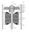
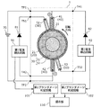
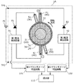
まず、実施の形態に係る電動機1の全体の構成について、図1及び図2を用いて説明する。図1は、実施の形態に係る電動機1の断面図である。図2は、同電動機1における通電ブラシ40及び追加ブラシ50と各種回路及び電子部品との接続関係を示す図である。なお、図2における電動機1の断面図は、図1のII−II線における断面、つまり通電ブラシ40及び追加ブラシ50を通る平面で切断したときの断面を示している。
(Embodiment)
First, the overall configuration of the electric motor 1 according to the embodiment will be described with reference to FIGS. 1 and 2. FIG. 1 is a cross-sectional view of the electric motor 1 according to the embodiment. FIG. 2 is a diagram showing a connection relationship between the energizing brush 40 and the additional brush 50 in the electric motor 1 and various circuits and electronic components. The cross-sectional view of the electric motor 1 in FIG. 2 shows a cross section taken along line II-II of FIG. 1, that is, a cross section when cut in a plane passing through the energizing brush 40 and the additional brush 50.

電動機1は、整流子電動機であり、図1及び図2に示すように、ステータ10と、ステータ10の磁力により回転するロータ20と、ロータ20のシャフト21に取り付けられた整流子30と、整流子30に接する通電ブラシ40と、整流子30に接する追加ブラシ50と、ステータ10及びロータ20を収納するフレーム60とを備える。 The electric motor 1 is a commutator electric motor, and as shown in FIGS. 1 and 2, the stator 10, the rotor 20 that rotates by the magnetic force of the stator 10, the commutator 30 attached to the shaft 21 of the rotor 20, and the commutator. An energizing brush 40 in contact with the child 30, an additional brush 50 in contact with the commutator 30, and a frame 60 for accommodating the stator 10 and the rotor 20 are provided.

本実施の形態における電動機1は、直流により駆動する直流電動機(DCモータ)であり、ステータ10として磁石11が用いられているとともに、ロータ20として巻線コイル22を有する電機子が用いられている。 The electric motor 1 in the present embodiment is a DC motor (DC motor) driven by direct current, and a magnet 11 is used as the stator 10 and an armature having a winding coil 22 is used as the rotor 20. ..

なお、本実施の形態における電動機1は、種々の電気機器に用いることができる。例えば、電動機1は、電気掃除機又はエアタオル等に搭載される電動送風機に用いることができる。また、電動機1は、自動車に搭載される電装機器又は電動工具等に用いることもできる。以下、電動機1の各構成部材について詳細に説明する。 The electric motor 1 in this embodiment can be used for various electric devices. For example, the electric motor 1 can be used for an electric blower mounted on a vacuum cleaner, an air towel, or the like. Further, the electric motor 1 can also be used for an electric device, an electric tool, or the like mounted on an automobile. Hereinafter, each component of the electric motor 1 will be described in detail.

ステータ10(固定子)は、ロータ20に作用する磁力を発生させる。ステータ10は、周方向に沿ってロータ20とのエアギャップ面にN極とS極とが交互に存在するように構成されている。本実施の形態において、ステータ10は、複数の磁石11(マグネット)によって構成されている。磁石11は、トルクを発生するための磁束を作る界磁石であり、例えばS極及びN極を有する永久磁石である。複数の磁石11の各々は、上面視において、厚さが略一定の円弧形状である。複数の磁石11は、フレーム60に固定されている。 The stator 10 (stator) generates a magnetic force acting on the rotor 20. The stator 10 is configured such that N poles and S poles alternately exist on the air gap surface with the rotor 20 along the circumferential direction. In the present embodiment, the stator 10 is composed of a plurality of magnets 11 (magnets). The magnet 11 is a field magnet that creates a magnetic flux for generating torque, and is, for example, a permanent magnet having an S pole and an N pole. Each of the plurality of magnets 11 has an arc shape having a substantially constant thickness when viewed from above. The plurality of magnets 11 are fixed to the frame 60.

ステータ10を構成する複数の磁石11は、周方向に沿ってN極とS極とが交互に均等に存在するように配置されている。したがって、ステータ10(磁石11)が発生する主磁束の向きは、シャフト21の軸心Cの方向と交差する方向である。本実施の形態において、複数の磁石11は、ロータ20を囲むようにして周方向に沿って等間隔で配置されており、ロータ20におけるロータコア23の径方向の外周側に位置している。具体的には、N極及びS極が着磁された複数の磁石11が、N極の磁極中心とS極の磁極中心とが周方向に沿って等間隔となるように配置されている。 The plurality of magnets 11 constituting the stator 10 are arranged so that the north poles and the south poles are alternately and evenly present along the circumferential direction. Therefore, the direction of the main magnetic flux generated by the stator 10 (magnet 11) is the direction intersecting the direction of the axis C of the shaft 21. In the present embodiment, the plurality of magnets 11 are arranged at equal intervals along the circumferential direction so as to surround the rotor 20, and are located on the outer peripheral side of the rotor core 23 in the radial direction of the rotor 20. Specifically, a plurality of magnets 11 in which the north pole and the south pole are magnetized are arranged so that the center of the magnetic pole of the north pole and the center of the magnetic pole of the south pole are evenly spaced along the circumferential direction.

ロータ20(回転子)は、ステータ10に作用する磁力を発生させる。本実施の形態において、ロータ20が発生する主磁束の向きは、シャフト21の軸心Cの方向と交差する方向である。ロータ20は、回転軸であるシャフト21を有する。また、ロータ20は、電機子であり、巻線コイル22及びロータコア23を有する。本実施の形態において、ロータ20は、インナーロータであり、ステータ10の内側に配置されている。具体的には、ロータ20は、ステータ10を構成する複数の磁石11に囲まれている。また、ロータ20は、ステータ10とエアギャップを介して配置されている。具体的には、ロータ20(ロータコア23)の外周面と各磁石11の内面との間には微小なエアギャップが存在する。 The rotor 20 (rotor) generates a magnetic force acting on the stator 10. In the present embodiment, the direction of the main magnetic flux generated by the rotor 20 is the direction intersecting the direction of the axis C of the shaft 21. The rotor 20 has a shaft 21 which is a rotation shaft. Further, the rotor 20 is an armature and has a winding coil 22 and a rotor core 23. In the present embodiment, the rotor 20 is an inner rotor and is arranged inside the stator 10. Specifically, the rotor 20 is surrounded by a plurality of magnets 11 constituting the stator 10. Further, the rotor 20 is arranged with the stator 10 via an air gap. Specifically, there is a minute air gap between the outer peripheral surface of the rotor 20 (rotor core 23) and the inner surface of each magnet 11.

シャフト21は、軸心Cを有する回転軸であり、ロータ20が回転する際の中心となる長尺状の棒状部材である。シャフト21の長手方向(延伸方向)は、軸心Cの方向(軸心方向)である。シャフト21は、ベアリング等の軸受けによって回転自在に保持されている。詳細は図示されていないが、例えば、シャフト21の一方の端部である第1端部21aは、フレーム60に固定されたブラケットに保持又はフレーム60に直接保持された第1軸受けに支持され、シャフト21の他方の端部である第2端部21bは、フレーム60に固定されたブラケットに保持又はフレーム60に直接保持された第2軸受けに支持されている。ブラケットは、例えば、フレーム60の開口部を覆うようにしてフレーム60に固定される。 The shaft 21 is a rotating shaft having an axis C, and is a long rod-shaped member that serves as a center when the rotor 20 rotates. The longitudinal direction (extension direction) of the shaft 21 is the direction of the axis C (axis direction). The shaft 21 is rotatably held by a bearing such as a bearing. Although details are not shown, for example, the first end 21a, which is one end of the shaft 21, is supported by a first bearing held by a bracket fixed to the frame 60 or directly held by the frame 60. The second end 21b, which is the other end of the shaft 21, is supported by a second bearing held by a bracket fixed to the frame 60 or directly held by the frame 60. The bracket is fixed to the frame 60 so as to cover the opening of the frame 60, for example.

シャフト21は、ロータ20の中心に固定されている。シャフト21は、例えば金属棒であり、ロータコア23を貫通する状態でロータコア23に固定されている。例えば、シャフト21は、ロータコア23の中心孔に圧入したり焼き嵌めしたりすることでロータコア23に固定されている。 The shaft 21 is fixed to the center of the rotor 20. The shaft 21 is, for example, a metal rod, and is fixed to the rotor core 23 in a state of penetrating the rotor core 23. For example, the shaft 21 is fixed to the rotor core 23 by press-fitting or shrink-fitting into the center hole of the rotor core 23.

巻線コイル22(ロータコイル)は、電流が流れることでステータ10に作用する磁力を発生するように巻回されている。巻線コイル22は、インシュレータ24を介してロータコア23に巻回されている。インシュレータ24は、絶縁樹脂材料等によって構成されており、巻線コイル22とロータコア23とを電気的に絶縁する。巻線コイル22は、ロータ20のスロットごとに設けられており、整流子30と電気的に接続されている。具体的には、巻線コイル22は、整流子30の整流子セグメント31と電気的に接続される。 The winding coil 22 (rotor coil) is wound so as to generate a magnetic force acting on the stator 10 when an electric current flows. The winding coil 22 is wound around the rotor core 23 via the insulator 24. The insulator 24 is made of an insulating resin material or the like, and electrically insulates the winding coil 22 and the rotor core 23. The winding coil 22 is provided for each slot of the rotor 20 and is electrically connected to the commutator 30. Specifically, the winding coil 22 is electrically connected to the commutator segment 31 of the commutator 30.

ロータコア23は、複数の電磁鋼板がシャフト21の長手方向に積層された積層体である。ロータコア23は、例えば、複数のティースを有する。複数のティースの各々に巻線コイル22が巻き回されている。つまり、巻線コイル22は、複数設けられている。なお、ロータコア23は、電磁鋼板の積層体に限るものではなく、磁性材料によって構成されたバルク体であってもよい。 The rotor core 23 is a laminated body in which a plurality of electromagnetic steel plates are laminated in the longitudinal direction of the shaft 21. The rotor core 23 has, for example, a plurality of teeth. A winding coil 22 is wound around each of the plurality of teeth. That is, a plurality of winding coils 22 are provided. The rotor core 23 is not limited to a laminated body of electromagnetic steel sheets, and may be a bulk body made of a magnetic material.

整流子30は、シャフト21に取り付けられている。したがって、整流子30は、ロータ20が回転することでシャフト21とともに回転する。本実施の形態において、整流子30は、シャフト21の第1端部21aに取り付けられている。 The commutator 30 is attached to the shaft 21. Therefore, the commutator 30 rotates together with the shaft 21 as the rotor 20 rotates. In this embodiment, the commutator 30 is attached to the first end 21a of the shaft 21.

図2に示すように、整流子30は、複数の整流子セグメント31を有する。複数の整流子セグメント31は、シャフト21の周方向に沿って設けられている。具体的には、複数の整流子セグメント31は、シャフト21を囲むように円環状に等間隔で配列されている。本実施の形態において、整流子30は、12個の整流子セグメント31を有する。 As shown in FIG. 2, the commutator 30 has a plurality of commutator segments 31. The plurality of commutator segments 31 are provided along the circumferential direction of the shaft 21. Specifically, the plurality of commutator segments 31 are arranged in an annular shape at equal intervals so as to surround the shaft 21. In this embodiment, the commutator 30 has twelve commutator segments 31.

図1に示すように、複数の整流子セグメント31の各々は、シャフト21の長手方向に延在する整流子片である。複数の整流子セグメント31の各々は、例えば、銅等の金属材料によって構成された導電端子であり、ロータ20の巻線コイル22と電気的に接続されている。一例として、整流子30は、モールド整流子であり、複数の整流子セグメント31が樹脂モールドされた構成になっている。この場合、複数の整流子セグメント31は、表面が露出するようにモールド樹脂32に埋め込まれている。 As shown in FIG. 1, each of the plurality of commutator segments 31 is a commutator piece extending in the longitudinal direction of the shaft 21. Each of the plurality of commutator segments 31 is a conductive terminal made of, for example, a metal material such as copper, and is electrically connected to the winding coil 22 of the rotor 20. As an example, the commutator 30 is a molded commutator, and a plurality of commutator segments 31 are resin-molded. In this case, the plurality of commutator segments 31 are embedded in the mold resin 32 so that the surface is exposed.

また、複数の整流子セグメント31は、互いに絶縁分離されているが、複数の整流子セグメント31のうちの少なくとも2つの整流子セグメント31は、均圧線によって互いに同電位(均圧)となるように電気的に接続されている。具体的には、複数の整流子セグメント31には、均圧線によって同電位になっている3つ以上の整流子セグメント31が複数組存在している。均圧線は、ロータ20のスロットごとに設けられた巻線コイル22(本巻線)と一体に構成されている。つまり、均圧線と巻線コイル22とは、途中でカットされることなく連続する一続きの1本の導電線である。 Further, although the plurality of commutator segments 31 are isolated from each other, at least two commutator segments 31 among the plurality of commutator segments 31 have the same potential (equal pressure) with each other by the pressure equalizing line. Is electrically connected to. Specifically, in the plurality of commutator segments 31, there are a plurality of sets of three or more commutator segments 31 having the same potential due to the pressure equalizing line. The pressure equalizing wire is integrally formed with a winding coil 22 (main winding) provided for each slot of the rotor 20. That is, the pressure equalizing wire and the winding coil 22 are a continuous continuous conductive wire without being cut in the middle.

整流子30には、通電ブラシ40及び追加ブラシ50が接している。具体的には、通電ブラシ40及び追加ブラシ50は、整流子30の整流子セグメント31に摺接する。図示されていないが、通電ブラシ40及び追加ブラシ50は、ブラシホルダによって保持されている。例えば、通電ブラシ40及び追加ブラシ50は、ブラシホルダに収納されている。この場合、通電ブラシ40及び追加ブラシ50は、ブラシホルダの内部を摺動する。また、図示されていないが、電動機1には、通電ブラシ40及び追加ブラシ50を整流子30に押し当てるためにコイルバネ又はトーションバネ等のブラシバネが設けられている。ブラシバネは、バネ弾性を利用して通電ブラシ40及び追加ブラシ50に押圧を付与する。通電ブラシ40及び追加ブラシ50の各々は、ブラシバネからの押圧力を受けて常に先端部の表面が整流子30の整流子セグメント31に接触する状態になっている。通電ブラシ40及び追加ブラシ50の各々と整流子セグメント31とが摺れ合う面は摺動面となる。なお、ブラシバネは、1つの通電ブラシ40ごと及び1つの追加ブラシ50ごとに設けられているが、これに限らない。 The commutator 30 is in contact with the energizing brush 40 and the additional brush 50. Specifically, the energizing brush 40 and the additional brush 50 are in sliding contact with the commutator segment 31 of the commutator 30. Although not shown, the energizing brush 40 and the additional brush 50 are held by a brush holder. For example, the energizing brush 40 and the additional brush 50 are housed in the brush holder. In this case, the energizing brush 40 and the additional brush 50 slide inside the brush holder. Further, although not shown, the electric motor 1 is provided with a brush spring such as a coil spring or a torsion spring for pressing the energizing brush 40 and the additional brush 50 against the commutator 30. The brush spring applies pressure to the energizing brush 40 and the additional brush 50 by utilizing the elasticity of the spring. Each of the energizing brush 40 and the additional brush 50 is in a state where the surface of the tip portion is always in contact with the commutator segment 31 of the commutator 30 under the pressing force from the brush spring. The surface on which each of the energizing brush 40 and the additional brush 50 and the commutator segment 31 slide is a sliding surface. The brush spring is provided for each energizing brush 40 and for each additional brush 50, but the present invention is not limited to this.

通電ブラシ40及び追加ブラシ50は、導電性を有する導電体である。一例として、通電ブラシ40及び追加ブラシ50は、カーボンによって構成された長尺状の略直方体のカーボンブラシである。具体的には、通電ブラシ40及び追加ブラシ50は、銅等の金属を含むカーボンブラシである。例えば、通電ブラシ40及び追加ブラシ50は、黒鉛粉と銅紛とバインダー樹脂と硬化剤とを混錬した混錬物を粉砕して直方体に圧縮成形して焼成することで作製することができる。 The energizing brush 40 and the additional brush 50 are conductive conductors. As an example, the energizing brush 40 and the additional brush 50 are long, substantially rectangular parallelepiped carbon brushes made of carbon. Specifically, the energizing brush 40 and the additional brush 50 are carbon brushes containing a metal such as copper. For example, the energizing brush 40 and the additional brush 50 can be produced by crushing a kneaded product obtained by kneading graphite powder, copper powder, a binder resin, and a curing agent, compression molding into a rectangular parallelepiped, and firing.

通電ブラシ40は、整流子30に接することでロータ20に電力を供給する給電ブラシである。具体的には、通電ブラシ40の先端部分が整流子30の整流子セグメント31に接する。したがって、通電ブラシ40には、電源70から供給される電流が流れる電線が接続されている。例えば、通電ブラシ40は、ピグテール線等の電線を介して、電源70からの電力を受電する電源端子と電気的に接続されている。具体的には、一方の端部が電極端子に接続されたピグテール線の他方の端部が通電ブラシ40の後端部に接続されており、通電ブラシ40が整流子セグメント31に接触することで、ピグテール線を介して通電ブラシ40に供給される電機子電流が整流子セグメント31を介してロータ20の各巻線コイル22に流れる。 The energizing brush 40 is a power feeding brush that supplies electric power to the rotor 20 by coming into contact with the commutator 30. Specifically, the tip portion of the energizing brush 40 comes into contact with the commutator segment 31 of the commutator 30. Therefore, an electric wire through which the current supplied from the power source 70 flows is connected to the energizing brush 40. For example, the energizing brush 40 is electrically connected to a power supply terminal that receives electric power from the power source 70 via an electric wire such as a pigtail wire. Specifically, the other end of the pigtail wire whose one end is connected to the electrode terminal is connected to the rear end of the energizing brush 40, and the energizing brush 40 comes into contact with the commutator segment 31. , The armature current supplied to the energizing brush 40 via the pigtail wire flows through each winding coil 22 of the rotor 20 via the commutator segment 31.

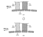
通電ブラシ40は、隣接する2つの整流子セグメント31を跨って接触する状態が存在するように構成されている。つまり、ロータ20の回転方向における通電ブラシ40の幅の長さは、隣接する2つの整流子セグメント31の間隔の長さよりも大きくなっている。これにより、通電ブラシ40は、2つの整流子セグメント31の間に接続された巻線コイル22を短絡させることができる。 The energizing brush 40 is configured so that there is a state in which the energizing brush 40 is in contact with the two adjacent commutator segments 31. That is, the width of the energizing brush 40 in the rotation direction of the rotor 20 is larger than the length of the distance between the two adjacent commutator segments 31. As a result, the energizing brush 40 can short-circuit the winding coil 22 connected between the two commutator segments 31.

例えば、図3の(a)に示すように、隣り合う2つの整流子セグメント31の両方に1つの通電ブラシ40が接している状態からロータ20の回転により整流子30の回転が進むと、図3の(b)に示すように、通電ブラシ40は、隣り合う2つの整流子セグメント31の一方から切り離されて、隣り合う2つの整流子セグメント31のうち回転方向の後方に位置する他方の整流子セグメント31のみに接する状態になる。この結果、隣り合う2つの整流子セグメント31の間の配線経路に接続された巻線コイル22を短絡させることができる。 For example, as shown in FIG. 3A, when one energizing brush 40 is in contact with both of two adjacent commutator segments 31, the rotation of the rotor 20 advances the rotation of the commutator 30. As shown in 3 (b), the energizing brush 40 is separated from one of the two adjacent commutator segments 31 and rectifies the other of the two adjacent commutator segments 31 located behind in the rotational direction. It comes into contact with only the child segment 31. As a result, the winding coil 22 connected to the wiring path between the two adjacent commutator segments 31 can be short-circuited.

図2に示すように、本実施の形態において、通電ブラシ40は、複数設けられている。複数の通電ブラシ40の各々が整流子30に接している。具体的には、複数の通電ブラシ40は、一対の通電ブラシ40として、第1通電ブラシ41と第2通電ブラシ42とを含んでいる。第1通電ブラシ41と第2通電ブラシ42とは、整流子30を挟持するように対向して配置される。つまり、第1通電ブラシ41と第2通電ブラシ42とは、シャフト21の軸心Cを中心に線対称に配置されている。第1通電ブラシ41及び第2通電ブラシ42の各々は、シャフト21の軸心Cと直交する方向(ラジアル方向)で整流子30の整流子セグメント31に接している。第1通電ブラシ41及び第2通電ブラシ42は、電源70に接続されている。本実施の形態において、電源70は、直流電源であり、第1通電ブラシ41と第2通電ブラシ42とは、直流電源である電源70を介して電気的に接続されている。一例として、第1通電ブラシ41は、直流電源である電極70の陽極側(正極側)に接続された陽極側ブラシであり、第2通電ブラシ42は、直流電源である電源70の陰極側(負極側)に接続された陰極側ブラシである。 As shown in FIG. 2, in the present embodiment, a plurality of energizing brushes 40 are provided. Each of the plurality of energizing brushes 40 is in contact with the commutator 30. Specifically, the plurality of energizing brushes 40 include a first energizing brush 41 and a second energizing brush 42 as a pair of energizing brushes 40. The first energizing brush 41 and the second energizing brush 42 are arranged so as to sandwich the commutator 30. That is, the first energizing brush 41 and the second energizing brush 42 are arranged line-symmetrically about the axis C of the shaft 21. Each of the first energizing brush 41 and the second energizing brush 42 is in contact with the commutator segment 31 of the commutator 30 in a direction (radial direction) orthogonal to the axis C of the shaft 21. The first energizing brush 41 and the second energizing brush 42 are connected to the power supply 70. In the present embodiment, the power source 70 is a DC power source, and the first energizing brush 41 and the second energizing brush 42 are electrically connected via the power source 70 which is a DC power source. As an example, the first energizing brush 41 is an anode side brush connected to the anode side (positive electrode side) of the electrode 70 which is a DC power source, and the second energizing brush 42 is a cathode side (cathode side) of the power source 70 which is a DC power source. It is a cathode side brush connected to the negative electrode side).

追加ブラシ50は、通電ブラシ40に対して追加された補助ブラシである。本実施の形態において、追加ブラシ50は、複数設けられている。複数の追加ブラシ50の各々が整流子30に接している。具体的には、複数の追加ブラシ50は、一対の追加ブラシ50として、第1追加ブラシ51と第2追加ブラシ52とを含んでいる。第1追加ブラシ51及び第2追加ブラシ52の各々が整流子30に接している。 The additional brush 50 is an auxiliary brush added to the energizing brush 40. In this embodiment, a plurality of additional brushes 50 are provided. Each of the plurality of additional brushes 50 is in contact with the commutator 30. Specifically, the plurality of additional brushes 50 include a first additional brush 51 and a second additional brush 52 as a pair of additional brushes 50. Each of the first additional brush 51 and the second additional brush 52 is in contact with the commutator 30.

第1追加ブラシ51は、複数の整流子セグメント31のうち第1通電ブラシ41が離れた直後の整流子セグメント31に接するように配置されている。つまり、第1追加ブラシ51は、第1通電ブラシ41が切り離されてスパークが発生する整流子セグメント31に接するように配置されている。 The first additional brush 51 is arranged so as to be in contact with the commutator segment 31 immediately after the first energizing brush 41 is separated from the plurality of commutator segments 31. That is, the first additional brush 51 is arranged so as to be in contact with the commutator segment 31 in which the first energizing brush 41 is separated and sparks are generated.

同様に、第2追加ブラシ52は、第1追加ブラシ51と同様に、複数の整流子セグメント31のうち第2通電ブラシ42が離れた直後の整流子セグメント31に接するように配置されている。つまり、第2追加ブラシ52は、第2通電ブラシ42が切り離されてスパークが発生する整流子セグメント31に接するように配置されている。 Similarly, like the first additional brush 51, the second additional brush 52 is arranged so as to be in contact with the commutator segment 31 immediately after the second energizing brush 42 is separated from the plurality of commutator segments 31. That is, the second additional brush 52 is arranged so as to be in contact with the commutator segment 31 in which the second energizing brush 42 is separated and sparks are generated.

なお、通電ブラシ40及び追加ブラシ50は、同一平面上に配置されている。具体的には、通電ブラシ40及び追加ブラシ50は、シャフト21の軸心Cの方向と直交する同一平面上に配置されている。本実施の形態では、第1通電ブラシ41、第2通電ブラシ42、第1追加ブラシ51及び第2追加ブラシ52が、フレーム60内において、シャフト21の軸心Cの方向にずれることなく、同一平面上に配置されている。 The energizing brush 40 and the additional brush 50 are arranged on the same plane. Specifically, the energizing brush 40 and the additional brush 50 are arranged on the same plane orthogonal to the direction of the axis C of the shaft 21. In the present embodiment, the first energizing brush 41, the second energizing brush 42, the first additional brush 51, and the second additional brush 52 are the same in the frame 60 without being displaced in the direction of the axis C of the shaft 21. It is arranged on a plane.

第1追加ブラシ51及び第2通電ブラシ42は、第1追加ブラシ51と第2通電ブラシ42との配線経路上に第1ダイオード81及び第1電流検出回路91が存在するように構成されている。 The first additional brush 51 and the second energizing brush 42 are configured such that the first diode 81 and the first current detection circuit 91 are present on the wiring path between the first additional brush 51 and the second energizing brush 42. ..

第1電流検出回路91は、第1ダイオード81に流れる電流の大きさを検出する。具体的には、第1電流検出回路91は、第1通電ブラシ41が離れた直後の整流子セグメント31と第1通電ブラシ41との間にスパークが発生したときに、このスパークに起因して第1追加ブラシ51を介して第1ダイオード81に流れる電流の大きさを検出する。つまり、第1電流検出回路91は、第1通電ブラシ41と整流子セグメント31との間に発生するスパークによるアーク電圧によって第1ダイオード81に流れる電流の大きさを検出する。このとき、第1通電ブラシ41付近のスパークによるアーク電圧は、第1ダイオード81で吸収されることになる。なお、このスパークが発生する際は、第1通電ブラシ41が低電位側となり、整流子セグメント31が高電位側となる。 The first current detection circuit 91 detects the magnitude of the current flowing through the first diode 81. Specifically, the first current detection circuit 91 is caused by this spark when a spark occurs between the commutator segment 31 and the first energizing brush 41 immediately after the first energizing brush 41 is separated. The magnitude of the current flowing through the first diode 81 via the first additional brush 51 is detected. That is, the first current detection circuit 91 detects the magnitude of the current flowing through the first diode 81 by the arc voltage generated by the spark generated between the first energizing brush 41 and the commutator segment 31. At this time, the arc voltage due to the spark near the first energizing brush 41 is absorbed by the first diode 81. When this spark is generated, the first energizing brush 41 is on the low potential side, and the commutator segment 31 is on the high potential side.

第1電流検出回路91の構成は、第1ダイオード81に流れる電流の大きさを検出できるものであれば、特に限定されるものではない。例えば、第1電流検出回路91は、パルストランスを用いて電流の大きさを検出する回路であってもよいし、フォトカプラを用いて電流の大きさを検出する回路であってもよいし、抵抗器を用いて電流の大きさを検出する回路であってもよい。 The configuration of the first current detection circuit 91 is not particularly limited as long as it can detect the magnitude of the current flowing through the first diode 81. For example, the first current detection circuit 91 may be a circuit that detects the magnitude of the current using a pulse transformer, a circuit that detects the magnitude of the current using a photocoupler, or a circuit that detects the magnitude of the current. The circuit may be a circuit that detects the magnitude of the current using a resistor.

本実施の形態において、第1ダイオード81及び第1電流検出回路91は、第1追加ブラシ51と第2通電ブラシ42との配線経路上において、直列に接続されている。具体的には、第1ダイオード81の一方は、第1追加ブラシ51に接続されており、第1ダイオード81の他方は、第1電流検出回路91に接続されている。また、第1電流検出回路91の一方側は、第1ダイオード81に接続されており、第1電流検出回路91の他方側は、第2通電ブラシ42に接続されている。 In the present embodiment, the first diode 81 and the first current detection circuit 91 are connected in series on the wiring path between the first additional brush 51 and the second energizing brush 42. Specifically, one of the first diodes 81 is connected to the first additional brush 51, and the other of the first diode 81 is connected to the first current detection circuit 91. Further, one side of the first current detection circuit 91 is connected to the first diode 81, and the other side of the first current detection circuit 91 is connected to the second energizing brush 42.

第2通電ブラシ42は、直流電源である電源70の陰極に接続されているので、第1追加ブラシ51から第1ダイオード81及び第1電流検出回路91を経由して第2通電ブラシ42までの配線経路上に、直流電源である電源70の負極側の定電位に設定された電位点が存在する。具体的には、直流電源である電源70の負極側の定電位は、グランド電位である。つまり、第1追加ブラシ51から第1ダイオード81及び第1電流検出回路91を経由して第2通電ブラシ42までの配線経路上にグランド電位が存在し、第1ダイオード81の電流を検出する回路がグランド電位を有する回路を構成している。 Since the second energizing brush 42 is connected to the cathode of the power source 70 which is a DC power source, the second energizing brush 42 reaches the second energizing brush 42 from the first additional brush 51 via the first diode 81 and the first current detection circuit 91. On the wiring path, there is a potential point set to a constant potential on the negative electrode side of the power supply 70, which is a DC power supply. Specifically, the constant potential on the negative electrode side of the power source 70, which is a DC power source, is the ground potential. That is, a circuit in which a ground potential exists on the wiring path from the first additional brush 51 to the second energizing brush 42 via the first diode 81 and the first current detection circuit 91, and the current of the first diode 81 is detected. Consists of a circuit having a ground potential.

また、本実施の形態において、第1ダイオード81及び第1電流検出回路91は、電動機1に内蔵されておらず、電動機1の外部に配置されている。例えば、第1ダイオード81及び第1電流検出回路91は、電動機1が搭載される電動送風機等の電気機器に、電動機1とともに内蔵される。 Further, in the present embodiment, the first diode 81 and the first current detection circuit 91 are not built in the electric motor 1 but are arranged outside the electric motor 1. For example, the first diode 81 and the first current detection circuit 91 are incorporated together with the electric motor 1 in an electric device such as an electric blower on which the electric motor 1 is mounted.

このため、電動機1は、外部接続端子として、第1追加ブラシ51に接続された第1追加ブラシ接続端子T51と、第2通電ブラシ42に接続された第2通電ブラシ接続端子T42とを備える。そして、第1ダイオード81及び第1電流検出回路91は、第1追加ブラシ接続端子T51と第2通電ブラシ接続端子T42との配線経路上に設けられている。具体的には、第1ダイオード81の一方が第1追加ブラシ接続端子T51に接続され、第1電流検出回路91の他方側が第2通電ブラシ42に接続されている。 Therefore, the electric motor 1 includes, as external connection terminals, a first additional brush connection terminal T51 connected to the first additional brush 51 and a second energization brush connection terminal T42 connected to the second energization brush 42. The first diode 81 and the first current detection circuit 91 are provided on the wiring path between the first additional brush connection terminal T51 and the second energizing brush connection terminal T42. Specifically, one of the first diodes 81 is connected to the first additional brush connection terminal T51, and the other side of the first current detection circuit 91 is connected to the second energizing brush 42.

なお、本実施の形態における電動機1は、電源70に接続される外部接続端子として、さらに、一対の第1電源端子TP1及び第2電源端子TP2とを備える。第1電源端子TP1は、直流電源である電源70の陽極に接続される陽極側給電端子であり、第2電源端子TP2は、直流電源である電源70の陰極に接続される陰極側給電端子である。第1電源端子TP1は、第1通電ブラシ41に接続される。つまり、電源70の陽極と第1通電ブラシ41とは第1電源端子TP1を介して接続されている。一方、第2電源端子TP2は、第2通電ブラシ42に接続される。つまり、電源70の陰極と第2通電ブラシ42とは第2電源端子TP2を介して接続されている。 The electric motor 1 in the present embodiment further includes a pair of first power supply terminals TP1 and second power supply terminals TP2 as external connection terminals connected to the power supply 70. The first power supply terminal TP1 is an anode-side power supply terminal connected to the anode of the power supply 70 which is a DC power supply, and the second power supply terminal TP2 is a cathode-side power supply terminal connected to the cathode of the power supply 70 which is a DC power supply. is there. The first power supply terminal TP1 is connected to the first energizing brush 41. That is, the anode of the power supply 70 and the first energizing brush 41 are connected via the first power supply terminal TP1. On the other hand, the second power supply terminal TP2 is connected to the second energizing brush 42. That is, the cathode of the power supply 70 and the second energizing brush 42 are connected via the second power supply terminal TP2.

また、第1電流検出回路91は、第1通電ブラシ41のダメージを判定する第1ブラシダメージ判定回路101に接続されている。第1ブラシダメージ判定回路101は、第1電流検出回路91によって検出された第1ダイオード81に流れる電流の大きさに基づいて第1通電ブラシ41が離れた直後の整流子セグメント31と第1通電ブラシ41との間に発生するスパークの回数をカウントし、カウントしたスパークの回数に基づいて第1通電ブラシ41のダメージを判定する。つまり、第1ブラシダメージ判定回路101は、第1電流検出回路91によって整流子セグメント31と第1通電ブラシ41との間に発生するスパークの回数をカウントすることで第1通電ブラシ41の摩耗状態を推定する。 Further, the first current detection circuit 91 is connected to the first brush damage determination circuit 101 that determines the damage of the first energizing brush 41. The first brush damage determination circuit 101 includes the commutator segment 31 and the first energization immediately after the first energization brush 41 is separated based on the magnitude of the current flowing through the first diode 81 detected by the first current detection circuit 91. The number of sparks generated between the brush 41 and the brush 41 is counted, and the damage of the first energizing brush 41 is determined based on the counted number of sparks. That is, the first brush damage determination circuit 101 counts the number of sparks generated between the commutator segment 31 and the first energizing brush 41 by the first current detection circuit 91, so that the first energizing brush 41 is in a worn state. To estimate.

例えば、第1ブラシダメージ判定回路101は、カウントしたスパークの回数が予め設定された閾値(基準値)を超えた場合に、第1通電ブラシ41が寿命に達する直前の状態になるまで第1通電ブラシ41がダメージを受けていると判定する。 For example, in the first brush damage determination circuit 101, when the number of counted sparks exceeds a preset threshold value (reference value), the first energization brush 41 is first energized until it reaches the state immediately before reaching the end of its life. It is determined that the brush 41 is damaged.

このとき、第1通電ブラシ41が寿命に達する直前の状態であることを示す信号が第1ブラシダメージ判定回路101から提示部110に出力される。これにより、提示部110は、第1通電ブラシ41が寿命に達する直前の状態であることをユーザに提示する。 At this time, a signal indicating that the first energizing brush 41 is in a state immediately before reaching the end of its life is output from the first brush damage determination circuit 101 to the presentation unit 110. As a result, the presenting unit 110 presents to the user that the first energizing brush 41 is in a state immediately before reaching the end of its life.

提示部110は、例えば、表示装置及び/又は警報装置等である。つまり、第1通電ブラシ41が寿命に達する直前の状態であることを示す文字又は映像が表示装置に表示されたり、第1通電ブラシ41が寿命に達する直前の状態であることを示す警告音が警報装置から報知されたりする。 The presentation unit 110 is, for example, a display device and / or an alarm device. That is, a character or an image indicating that the first energizing brush 41 is in the state immediately before reaching the end of its life is displayed on the display device, or a warning sound indicating that the first energizing brush 41 is in the state immediately before reaching the end of its life is emitted. It may be notified from the alarm device.

なお、本実施の形態では、第1ブラシダメージ判定回路101は、第1通電ブラシ41が寿命に達する直前の状態になったときをダメージ判定の閾値としたが、これに限らない。例えば、第1ブラシダメージ判定回路101は、第1通電ブラシ41が寿命に達したとき等をダメージ判定の閾値にしてもよい。 In the present embodiment, the first brush damage determination circuit 101 sets the threshold value for damage determination when the first energizing brush 41 is in a state immediately before reaching the end of its life, but the present invention is not limited to this. For example, the first brush damage determination circuit 101 may set the threshold value for damage determination when the first energizing brush 41 reaches the end of its life.

一方、第2追加ブラシ52及び第1通電ブラシ41は、第2追加ブラシ52と第1通電ブラシ41との配線経路上に第2ダイオード82及び第2電流検出回路92が存在するように構成されている。 On the other hand, the second additional brush 52 and the first energizing brush 41 are configured so that the second diode 82 and the second current detection circuit 92 are present on the wiring path between the second additional brush 52 and the first energizing brush 41. ing.

第2電流検出回路92は、第2ダイオード82に流れる電流の大きさを検出する。具体的には、第2電流検出回路92は、第2通電ブラシ42が離れた直後の整流子セグメント31と第2通電ブラシ42との間にスパークが発生したときに、このスパークに起因して第2追加ブラシ52を介して第2ダイオード82に流れる電流の大きさを検出する。つまり、第2電流検出回路92は、第2通電ブラシ42と整流子セグメント31との間に発生するスパークによるアーク電圧によって第2ダイオード82に流れる電流の大きさを検出する。このとき、第2通電ブラシ42付近のスパークによるアーク電圧は、第2ダイオード82で吸収されることになる。なお、このスパークが発生する際は、第2通電ブラシ42が高電位側となり、整流子セグメント31が低電位側となる。 The second current detection circuit 92 detects the magnitude of the current flowing through the second diode 82. Specifically, the second current detection circuit 92 is caused by this spark when a spark occurs between the commutator segment 31 and the second energizing brush 42 immediately after the second energizing brush 42 is separated. The magnitude of the current flowing through the second diode 82 via the second additional brush 52 is detected. That is, the second current detection circuit 92 detects the magnitude of the current flowing through the second diode 82 by the arc voltage generated by the spark generated between the second energizing brush 42 and the commutator segment 31. At this time, the arc voltage due to the spark near the second energizing brush 42 is absorbed by the second diode 82. When this spark is generated, the second energizing brush 42 is on the high potential side, and the commutator segment 31 is on the low potential side.

第2電流検出回路92の構成は、第2ダイオード82に流れる電流の大きさを検出できるものであれば、特に限定されるものではない。例えば、第2電流検出回路92は、パルストランスを用いて電流の大きさを検出する回路であってもよいし、フォトカプラを用いて電流の大きさを検出する回路であってもよい。 The configuration of the second current detection circuit 92 is not particularly limited as long as it can detect the magnitude of the current flowing through the second diode 82. For example, the second current detection circuit 92 may be a circuit that detects the magnitude of the current using a pulse transformer, or may be a circuit that detects the magnitude of the current using a photocoupler.

本実施の形態において、第2ダイオード82及び第2電流検出回路92は、第2追加ブラシ52と第1通電ブラシ41との配線経路上において、直列に接続されている。具体的には、第2ダイオード82の一方は、第1通電ブラシ41に接続されており、第2ダイオード82の他方は、第2電流検出回路92に接続されている。また、第2電流検出回路92の一方側は、第2ダイオード82に接続されており、第2電流検出回路92の他方側は、第2通電ブラシ42に接続されている。 In the present embodiment, the second diode 82 and the second current detection circuit 92 are connected in series on the wiring path between the second additional brush 52 and the first energizing brush 41. Specifically, one of the second diodes 82 is connected to the first energizing brush 41, and the other of the second diode 82 is connected to the second current detection circuit 92. Further, one side of the second current detection circuit 92 is connected to the second diode 82, and the other side of the second current detection circuit 92 is connected to the second energizing brush 42.

第2電流検出回路92側の回路では、第1電流検出回路91側の回路とは異なり、第1通電ブラシ41から第2ダイオード82及び第2電流検出回路92を経由して第1追加ブラシ51までの配線経路上に、直流電源である電源70の負極側の定電位に設定された電位点が存在しない。具体的には、第1通電ブラシ41から第2ダイオード82及び第2電流検出回路92を経由して第2追加ブラシ52までの配線経路上にグランド電位が存在しておらず、第2ダイオード82の電流を検出する回路がグランド電位を有しないフローティングの回路を構成している。 In the circuit on the second current detection circuit 92 side, unlike the circuit on the first current detection circuit 91 side, the first additional brush 51 is passed from the first energizing brush 41 via the second diode 82 and the second current detection circuit 92. There is no potential point set to a constant potential on the negative side of the power supply 70, which is a DC power supply, on the wiring path up to. Specifically, the ground potential does not exist on the wiring path from the first energizing brush 41 to the second additional brush 52 via the second diode 82 and the second current detection circuit 92, and the second diode 82 The circuit that detects the current constitutes a floating circuit that does not have a ground potential.

また、第1ダイオード81及び第1電流検出回路91と同様に、本実施の形態において、第2ダイオード82及び第2電流検出回路92は、電動機1に内蔵されておらず、電動機1の外部に配置されている。例えば、第2ダイオード82及び第2電流検出回路92は、電動機1が搭載される電動送風機等の電気機器に、電動機1とともに内蔵される。 Further, similarly to the first diode 81 and the first current detection circuit 91, in the present embodiment, the second diode 82 and the second current detection circuit 92 are not built in the electric motor 1 and are outside the electric motor 1. Have been placed. For example, the second diode 82 and the second current detection circuit 92 are incorporated together with the electric motor 1 in an electric device such as an electric blower on which the electric motor 1 is mounted.

このため、電動機1は、外部接続端子として、さらに、第2追加ブラシ52に接続された第2追加ブラシ接続端子T52と、第1通電ブラシ41に接続された第1通電ブラシ接続端子T41とを備える。そして、第2ダイオード82及び第2電流検出回路92は、第2追加ブラシ接続端子T52と第1通電ブラシ接続端子T41との配線経路上に設けられている。具体的には、第2ダイオード82の一方が第1通電ブラシ接続端子T41に接続され、第2電流検出回路92の他方側が第2追加ブラシ接続端子T52に接続されている。なお、第1通電ブラシ接続端子T41に接続される第1通電ブラシ41は、直流電源である電源70の陽極に接続されているので、第2ダイオード82は、第1通電ブラシ接続端子T41及び第1電源端子TP1を介して直流電源である電源70の陽極に接続されている。 Therefore, the electric motor 1 further serves as an external connection terminal with a second additional brush connection terminal T52 connected to the second additional brush 52 and a first energization brush connection terminal T41 connected to the first energization brush 41. Be prepared. The second diode 82 and the second current detection circuit 92 are provided on the wiring path between the second additional brush connection terminal T52 and the first energizing brush connection terminal T41. Specifically, one of the second diodes 82 is connected to the first energizing brush connection terminal T41, and the other side of the second current detection circuit 92 is connected to the second additional brush connection terminal T52. Since the first energizing brush 41 connected to the first energizing brush connection terminal T41 is connected to the anode of the power supply 70 which is a DC power supply, the second diode 82 is the first energizing brush connection terminal T41 and the first energizing brush connection terminal T41. 1 It is connected to the anode of the power supply 70, which is a DC power supply, via the power supply terminal TP1.

また、第2電流検出回路92は、第2通電ブラシ42のダメージを判定する第2ブラシダメージ判定回路102に接続されている。第2ブラシダメージ判定回路102は、第2電流検出回路92によって検出された第2ダイオード82に流れる電流の大きさに基づいて第2通電ブラシ42が離れた直後の整流子セグメント31と第2通電ブラシ42との間に発生するスパークの回数をカウントし、カウントしたスパークの回数に基づいて第2通電ブラシ42のダメージを判定する。つまり、第2ブラシダメージ判定回路102は、第2電流検出回路92によって整流子セグメント31と第2通電ブラシ42との間に発生するスパークの回数をカウントすることで第2通電ブラシ42の摩耗状態を推定する。 Further, the second current detection circuit 92 is connected to the second brush damage determination circuit 102 that determines the damage of the second energizing brush 42. The second brush damage determination circuit 102 includes the commutator segment 31 and the second energization immediately after the second energization brush 42 is separated based on the magnitude of the current flowing through the second diode 82 detected by the second current detection circuit 92. The number of sparks generated between the brush 42 and the brush 42 is counted, and the damage of the second energizing brush 42 is determined based on the counted number of sparks. That is, the second brush damage determination circuit 102 counts the number of sparks generated between the commutator segment 31 and the second energizing brush 42 by the second current detection circuit 92, so that the second energizing brush 42 is in a worn state. To estimate.

例えば、第2ブラシダメージ判定回路102は、カウントしたスパークの回数が予め設定された閾値(基準値)を超えた場合に、第2通電ブラシ42が寿命に達する直前の状態になるまで第2通電ブラシ42がダメージを受けていると判定する。 For example, in the second brush damage determination circuit 102, when the number of counted sparks exceeds a preset threshold value (reference value), the second energization brush 42 is energized until it reaches the state immediately before reaching the end of its life. It is determined that the brush 42 is damaged.

このとき、第2通電ブラシ42が寿命に達する直前の状態であることを示す信号が第2ブラシダメージ判定回路102から提示部110に出力される。これにより、提示部110は、第2通電ブラシ42が寿命に達する直前の状態であることをユーザに提示する。具体的には、上記のように、提示部110は表示装置及び/又は警報装置等であるので、第2通電ブラシ42が寿命に達する直前の状態であることを示す文字又は映像が表示装置に表示されたり、第2通電ブラシ42が寿命に達する直前の状態であることを示す警告音が警報装置から報知されたりする。 At this time, a signal indicating that the second energizing brush 42 is in a state immediately before reaching the end of its life is output from the second brush damage determination circuit 102 to the presentation unit 110. As a result, the presenting unit 110 presents to the user that the second energizing brush 42 is in a state immediately before reaching the end of its life. Specifically, as described above, since the presentation unit 110 is a display device and / or an alarm device or the like, characters or images indicating that the second energizing brush 42 is in a state immediately before reaching the end of its life are displayed on the display device. It is displayed, or a warning sound indicating that the second energizing brush 42 is in a state immediately before reaching the end of its life is notified from the alarm device.

なお、本実施の形態では、第2ブラシダメージ判定回路102は、第2通電ブラシ42が寿命に達する直前の状態になったときをダメージ判定の閾値としたが、これに限らない。例えば、第2ブラシダメージ判定回路102は、第2通電ブラシ42が寿命に達したとき等をダメージ判定の閾値にしてもよい。 In the present embodiment, the second brush damage determination circuit 102 sets the threshold value for damage determination when the second energizing brush 42 is in a state immediately before reaching the end of its life, but the present invention is not limited to this. For example, the second brush damage determination circuit 102 may set the threshold value for damage determination when the second energizing brush 42 reaches the end of its life.

以上、本実施の形態に係る電動機1では、第1追加ブラシ51が複数の整流子セグメント31のうち第1通電ブラシ41が離れた直後の整流子セグメント31に接するように配置されており、第1追加ブラシ51及び第2通電ブラシ42は、第1追加ブラシ51と第2通電ブラシ42との配線経路上に、第1ダイオード81及び第1電流検出回路91が存在するように構成されている。 As described above, in the electric motor 1 according to the present embodiment, the first additional brush 51 is arranged so as to be in contact with the commutator segment 31 immediately after the first energizing brush 41 is separated from the plurality of commutator segments 31. The 1 additional brush 51 and the 2nd energizing brush 42 are configured such that the 1st diode 81 and the 1st current detection circuit 91 are present on the wiring path between the 1st additional brush 51 and the 2nd energizing brush 42. ..

これにより、第1追加ブラシ51は、第1通電ブラシ41と整流子セグメント31とが切り離されて第1通電ブラシ41と整流子セグメント31との間にスパークが発生する際に、スパークのアーク電圧による電流が第1追加ブラシ51を介して第1ダイオード81に流れることになる。このとき、第1電流検出回路91によって第1ダイオード81に流れる電流の大きさが検出される。これにより、第1電流検出回路91の電流検出結果に基づいて、第1通電ブラシ41の摩耗状態を検知することができる。したがって、光学部材を用いたり第1通電ブラシ41を加工したりすることなく、第1通電ブラシ41の摩耗状態を検知することができる。つまり、第1通電ブラシ41の寿命を検知することができる。 As a result, in the first additional brush 51, when the first energizing brush 41 and the commutator segment 31 are separated and a spark is generated between the first energizing brush 41 and the commutator segment 31, the arc voltage of the spark is generated. Will flow to the first diode 81 via the first additional brush 51. At this time, the magnitude of the current flowing through the first diode 81 is detected by the first current detection circuit 91. As a result, the wear state of the first energizing brush 41 can be detected based on the current detection result of the first current detection circuit 91. Therefore, the wear state of the first energizing brush 41 can be detected without using an optical member or processing the first energizing brush 41. That is, the life of the first energizing brush 41 can be detected.

この場合、本実施の形態では、第1ブラシダメージ判定回路101を用いて、第1通電ブラシ41のダメージを判定している。具体的には、第1ブラシダメージ判定回路101は、第1電流検出回路91によって検出された第1ダイオード81に流れる電流の大きさに基づいてスパークの回数をカウントし、カウントしたスパークの回数に基づいて第1通電ブラシ41のダメージを判定している。 In this case, in the present embodiment, the damage of the first energizing brush 41 is determined by using the first brush damage determination circuit 101. Specifically, the first brush damage determination circuit 101 counts the number of sparks based on the magnitude of the current flowing through the first diode 81 detected by the first current detection circuit 91, and determines the number of sparks counted. Based on this, the damage of the first energizing brush 41 is determined.

さらに、本実施の形態に係る電動機1では、第1通電ブラシ41の摩耗状態を検知するだけではなく、第1通電ブラシ41と整流子セグメント31との間に発生するスパークによるアーク電圧を第1追加ブラシ51を介して第1ダイオード81で吸収することができる。つまり、第1追加ブラシ51及び第1ダイオード81は、第1通電ブラシ41と整流子セグメント31とが切り離されて発生するスパークを抑制するためのスパーク抑制部品である。 Further, in the electric motor 1 according to the present embodiment, not only the wear state of the first energizing brush 41 is detected, but also the arc voltage due to the spark generated between the first energizing brush 41 and the commutator segment 31 is first detected. It can be absorbed by the first diode 81 via the additional brush 51. That is, the first additional brush 51 and the first diode 81 are spark suppression components for suppressing sparks generated when the first energizing brush 41 and the commutator segment 31 are separated from each other.

このように、第1通電ブラシ41におけるスパークを抑制することで、このスパークによる第1通電ブラシ41の電気的摩耗を抑制することができる。これにより、第1通電ブラシ41の長寿命化、すなわち電動機1の長寿命化を図ることができる。この結果、第1通電ブラシ41が寿命に達するとの判定基準となる第1ブラシダメージ判定回路101におけるスパークの回数の閾値を高く設定することが可能となる。 By suppressing the sparks in the first energizing brush 41 in this way, it is possible to suppress the electrical wear of the first energizing brush 41 due to the sparks. As a result, the life of the first energizing brush 41 can be extended, that is, the life of the electric motor 1 can be extended. As a result, it is possible to set a high threshold value for the number of sparks in the first brush damage determination circuit 101, which is a criterion for determining that the first energizing brush 41 reaches the end of its life.

また、本実施の形態に係る電動機1では、第2追加ブラシ52が複数の整流子セグメント31のうち第2通電ブラシ42が離れた直後の整流子セグメント31に接するように配置されており、第2追加ブラシ52及び第1通電ブラシ41は、第2追加ブラシ52と第1通電ブラシ41との配線経路上に、第2ダイオード82及び第2電流検出回路92が存在するように構成されている。 Further, in the electric motor 1 according to the present embodiment, the second additional brush 52 is arranged so as to be in contact with the commutator segment 31 immediately after the second energizing brush 42 is separated from the plurality of commutator segments 31. The 2 additional brush 52 and the 1st energizing brush 41 are configured such that the 2nd diode 82 and the 2nd current detection circuit 92 are present on the wiring path between the 2nd additional brush 52 and the 1st energizing brush 41. ..

これにより、第2追加ブラシ52は、第2通電ブラシ42と整流子セグメント31とが切り離されて第2通電ブラシ42と整流子セグメント31との間にスパークが発生する際に、スパークのアーク電圧による電流が第2追加ブラシ52を介して第2ダイオード82に流れることになる。このとき、第2電流検出回路92によって第2ダイオード82に流れる電流の大きさが検出される。これにより、第2電流検出回路92の電流検出結果に基づいて、第2通電ブラシ42の摩耗状態を検知することができる。したがって、光学部材を用いたり第2通電ブラシ42を加工したりすることなく、第2通電ブラシ42の摩耗状態を検知することができる。つまり、第1通電ブラシ41だけではなく、第2通電ブラシ42の寿命を検知することもできる。 As a result, in the second additional brush 52, when the second energizing brush 42 and the commutator segment 31 are separated and a spark is generated between the second energizing brush 42 and the commutator segment 31, the arc voltage of the spark is generated. The current due to the above will flow to the second diode 82 via the second additional brush 52. At this time, the magnitude of the current flowing through the second diode 82 is detected by the second current detection circuit 92. As a result, the wear state of the second energizing brush 42 can be detected based on the current detection result of the second current detection circuit 92. Therefore, the wear state of the second energizing brush 42 can be detected without using an optical member or processing the second energizing brush 42. That is, not only the life of the first energizing brush 41 but also the life of the second energizing brush 42 can be detected.

この場合、本実施の形態では、第2ブラシダメージ判定回路102を用いて、第2通電ブラシ42のダメージを判定している。具体的には、第2ブラシダメージ判定回路102は、第2電流検出回路92によって検出された第2ダイオード82に流れる電流の大きさに基づいてスパークの回数をカウントし、カウントしたスパークの回数に基づいて第2通電ブラシ42のダメージを判定している。 In this case, in the present embodiment, the damage of the second energizing brush 42 is determined by using the second brush damage determination circuit 102. Specifically, the second brush damage determination circuit 102 counts the number of sparks based on the magnitude of the current flowing through the second diode 82 detected by the second current detection circuit 92, and determines the number of sparks counted. Based on this, the damage of the second energizing brush 42 is determined.

さらに、本実施の形態に係る電動機1では、第2通電ブラシ42と整流子セグメント31との間に発生するスパークによるアーク電圧を第2追加ブラシ52を介して第2ダイオード82で吸収することができる。つまり、第2追加ブラシ52及び第2ダイオード82は、第2通電ブラシ42と整流子セグメント31とが切り離されて発生するスパークを抑制するためのスパーク抑制部品である。 Further, in the electric motor 1 according to the present embodiment, the arc voltage generated by the spark generated between the second energizing brush 42 and the commutator segment 31 can be absorbed by the second diode 82 via the second additional brush 52. it can. That is, the second additional brush 52 and the second diode 82 are spark suppression components for suppressing sparks generated by the separation of the second energizing brush 42 and the commutator segment 31.

このように、第2通電ブラシ42におけるスパークを抑制することで、このスパークによる第2通電ブラシ42の電気的摩耗を抑制することができる。これにより、第2通電ブラシ42の長寿命化、すなわち電動機1の長寿命化を図ることができる。この結果、第2通電ブラシ42が寿命に達するとの判定基準となる第2ブラシダメージ判定回路102におけるスパークの回数の閾値を高く設定することが可能となる。 By suppressing the sparks in the second energizing brush 42 in this way, it is possible to suppress the electrical wear of the second energizing brush 42 due to the sparks. As a result, the life of the second energizing brush 42 can be extended, that is, the life of the electric motor 1 can be extended. As a result, it is possible to set a high threshold value for the number of sparks in the second brush damage determination circuit 102, which is a determination criterion for the second energizing brush 42 to reach the end of its life.

(変形例)
以上、本開示に係る電動機1について、実施の形態に基づいて説明したが、本開示は、上記実施の形態に限定されるものではない。
(Modification example)
Although the electric motor 1 according to the present disclosure has been described above based on the embodiment, the present disclosure is not limited to the above embodiment.

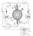
例えば、上記実施の形態では、第1電流検出回路91に対応する第1ブラシダメージ判定回路101と第2電流検出回路92に対応する第2ブラシダメージ判定回路102とを別々に設けたが、これに限るものではなく、第1ブラシダメージ判定回路101と第2ブラシダメージ判定回路102とが1つの回路で構成されていてもよい。具体的には、図4に示すように、第1電流検出回路91及び第2電流検出回路92に共通する1つのブラシダメージ判定回路103が設けられていてもよい。ブラシダメージ判定回路103は、第1電流検出回路91によって検出された第1ダイオード81に流れる電流の大きさに基づいて第1通電ブラシ41が離れた直後の整流子セグメント31と第1通電ブラシ41との間に発生するスパークの回数をカウントし、カウントしたスパークの回数に基づいて第1通電ブラシ41のダメージを判定する機能と、第2電流検出回路92によって検出された第2ダイオード82に流れる電流の大きさに基づいて第2通電ブラシ42が離れた直後の整流子セグメント31と第2通電ブラシ42との間に発生するスパークの回数をカウントし、カウントしたスパークの回数に基づいて第2通電ブラシ42のダメージを判定する機能とを有する。 For example, in the above embodiment, the first brush damage determination circuit 101 corresponding to the first current detection circuit 91 and the second brush damage determination circuit 102 corresponding to the second current detection circuit 92 are separately provided. The first brush damage determination circuit 101 and the second brush damage determination circuit 102 may be configured by one circuit. Specifically, as shown in FIG. 4, one brush damage determination circuit 103 common to the first current detection circuit 91 and the second current detection circuit 92 may be provided. The brush damage determination circuit 103 includes the commutator segment 31 and the first energizing brush 41 immediately after the first energizing brush 41 is separated based on the magnitude of the current flowing through the first diode 81 detected by the first current detecting circuit 91. The function of counting the number of sparks generated between the two and determining the damage of the first energizing brush 41 based on the counted number of sparks, and the function of flowing to the second diode 82 detected by the second current detection circuit 92. The number of sparks generated between the commutator segment 31 and the second energizing brush 42 immediately after the second energizing brush 42 is separated is counted based on the magnitude of the current, and the second is based on the counted number of sparks. It has a function of determining damage to the energizing brush 42.

また、上記実施の形態では、第1ダイオード81及び第1電流検出回路91は、電動機1の外部に配置されていたが、これに限らない。同様に、第2ダイオード82及び第2電流検出回路92は、電動機1の外部に配置されていたが、これに限らない。具体的には、図5に示される電動機1Aのように、第1ダイオード81及び第1電流検出回路91と第2ダイオード82及び第2電流検出回路92とは、電動機1Aの内部に配置されていてもよい。つまり、第1ダイオード81及び第1電流検出回路91と第2ダイオード82及び第2電流検出回路92とは、電動機1Aに内蔵されていてもよい。 Further, in the above embodiment, the first diode 81 and the first current detection circuit 91 are arranged outside the electric motor 1, but the present invention is not limited to this. Similarly, the second diode 82 and the second current detection circuit 92 are arranged outside the electric motor 1, but the present invention is not limited to this. Specifically, as in the electric motor 1A shown in FIG. 5, the first diode 81 and the first current detection circuit 91 and the second diode 82 and the second current detection circuit 92 are arranged inside the electric motor 1A. You may. That is, the first diode 81, the first current detection circuit 91, the second diode 82, and the second current detection circuit 92 may be built in the electric motor 1A.

また、図5に示される電動機1Aでは、第1電流検出回路91に接続された第1ブラシダメージ判定回路101及び第2電流検出回路92に接続された第2ブラシダメージ判定回路102は、電動機1Aの外部に配置されているが、これに限らない。具体的には、図示しないが、電動機1Aは、第1ブラシダメージ判定回路101及び第2ブラシダメージ判定回路102を備えていてもよい。つまり、第1ブラシダメージ判定回路101及び第2ブラシダメージ判定回路102は、電動機1Aに内蔵されていてもよい。なお、これらのことは、図4に示される電動機1においても適用することができる。 Further, in the electric motor 1A shown in FIG. 5, the first brush damage determination circuit 101 connected to the first current detection circuit 91 and the second brush damage determination circuit 102 connected to the second current detection circuit 92 are the electric motor 1A. It is located outside, but it is not limited to this. Specifically, although not shown, the electric motor 1A may include a first brush damage determination circuit 101 and a second brush damage determination circuit 102. That is, the first brush damage determination circuit 101 and the second brush damage determination circuit 102 may be built in the electric motor 1A. It should be noted that these things can also be applied to the electric motor 1 shown in FIG.

また、上記実施の形態において、ステータ10は、磁石11によって構成されていたが、これに限らない。例えば、ステータ10は、ステータコアとステータコアに巻回された巻線コイルとによって構成されていてもよい。 Further, in the above embodiment, the stator 10 is composed of the magnet 11, but the stator 10 is not limited to this. For example, the stator 10 may be composed of a stator core and a winding coil wound around the stator core.

また、上記実施の形態において、ロータ20は、コアを有していたが、これに限らない。つまり、上記実施の形態における電動機1は、コアを有さないコアレスモータに適用することもできる。例えば、上記実施の形態における電動機1は、ステータ10及びロータ20の磁束がシャフト21の軸心Cの方向に発生する扁平型のフラットモータであるコアレスモータに適用することができる。 Further, in the above embodiment, the rotor 20 has a core, but the rotor 20 is not limited to this. That is, the electric motor 1 in the above embodiment can also be applied to a coreless motor having no core. For example, the electric motor 1 in the above embodiment can be applied to a coreless motor which is a flat flat motor in which the magnetic fluxes of the stator 10 and the rotor 20 are generated in the direction of the axis C of the shaft 21.

その他、上記実施の形態に対して当業者が思い付く各種変形を施して得られる形態や、本開示の趣旨を逸脱しない範囲で実施の形態における構成要素及び機能を任意に組み合わせることで実現される形態も本開示に含まれる。 In addition, a form obtained by applying various modifications to the above embodiment that can be conceived by a person skilled in the art, or a form realized by arbitrarily combining the components and functions in the embodiment without departing from the gist of the present disclosure. Is also included in this disclosure.

本開示は、電気掃除機又は自動車等をはじめとして、電動機が搭載される種々の製品に利用することができる。 The present disclosure can be used for various products equipped with an electric motor, such as a vacuum cleaner or an automobile.

1、1A 電動機
10 ステータ
11 磁石
20 ロータ
21 シャフト
21a 第1端部
21b 第2端部
22 巻線コイル
23 ロータコア
24 インシュレータ
30 整流子
31 整流子セグメント
32 モールド樹脂
40 通電ブラシ
41 第1通電ブラシ
42 第2通電ブラシ
50 追加ブラシ
51 第1追加ブラシ
52 第2追加ブラシ
60 フレーム
70 電源
81 第1ダイオード
82 第2ダイオード
91 第1電流検出回路
92 第2電流検出回路
101 第1ブラシダメージ判定回路
102 第2ブラシダメージ判定回路
103 ブラシダメージ判定回路
110 提示部
1, 1A motor 10 stator 11 magnet 20 rotor 21 shaft 21a 1st end 21b 2nd end 22 winding coil 23 rotor core 24 insulator 30 commutator 31 commutator segment 32 mold resin 40 energizing brush 41 1st energizing brush 42nd 2 Energizing brush 50 Additional brush 51 1st additional brush 52 2nd additional brush 60 Frame 70 Power supply 81 1st diode 82 2nd diode 91 1st current detection circuit 92 2nd current detection circuit 101 1st brush damage judgment circuit 102 2nd Brush damage judgment circuit 103 Brush damage judgment circuit 110 Presentation unit

Claims (13)

回転軸を有するロータと、
前記回転軸に取り付けられた整流子と、
各々が前記整流子に接する第1通電ブラシ及び第2通電ブラシと、
前記整流子に接する第1追加ブラシとを備え、
前記整流子は、前記回転軸の周方向に沿って設けられた複数の整流子セグメントを有し、
前記第1追加ブラシは、前記複数の整流子セグメントのうち前記第1通電ブラシが離れた直後の整流子セグメントに接するように配置され、
前記第1追加ブラシ及び前記第2通電ブラシは、前記第1追加ブラシと前記第2通電ブラシとの配線経路上に第1ダイオード及び第1電流検出回路が存在するように構成されており、
前記第1電流検出回路は、前記第1ダイオードに流れる電流の大きさを検出する、
電動機。
A rotor with a rotating shaft and
With the commutator attached to the rotating shaft,
The first energizing brush and the second energizing brush, each of which is in contact with the commutator,
A first additional brush in contact with the commutator is provided.
The commutator has a plurality of commutator segments provided along the circumferential direction of the rotation axis.
The first additional brush is arranged so as to be in contact with the commutator segment immediately after the first energizing brush is separated from the plurality of commutator segments.
The first additional brush and the second energizing brush are configured such that a first diode and a first current detection circuit are present on a wiring path between the first additional brush and the second energizing brush.
The first current detection circuit detects the magnitude of the current flowing through the first diode.
Electric motor.
前記第1追加ブラシに接続された第1追加ブラシ接続端子と、
前記第2通電ブラシに接続された第2通電ブラシ接続端子とを備え、
前記第1ダイオード及び前記第1電流検出回路は、前記電動機の外部に配置されており、
前記第1ダイオード及び前記第1電流検出回路は、前記第1追加ブラシ接続端子と前記第2通電ブラシ接続端子との配線経路上に設けられている、
請求項1に記載の電動機。
The first additional brush connection terminal connected to the first additional brush,
A second energizing brush connection terminal connected to the second energizing brush is provided.
The first diode and the first current detection circuit are arranged outside the electric motor.
The first diode and the first current detection circuit are provided on a wiring path between the first additional brush connection terminal and the second energizing brush connection terminal.
The electric motor according to claim 1.
前記第1電流検出回路は、前記第1通電ブラシのダメージを判定する第1ブラシダメージ判定回路に接続されており、
前記第1ブラシダメージ判定回路は、前記第1電流検出回路によって検出された前記第1ダイオードに流れる電流の大きさに基づいて前記第1通電ブラシが離れた直後の整流子セグメントと前記第1通電ブラシとの間に発生するスパークの回数をカウントし、カウントしたスパークの回数に基づいて前記第1通電ブラシのダメージを判定する、
請求項2に記載の電動機。
The first current detection circuit is connected to a first brush damage determination circuit that determines damage to the first energizing brush.
The first brush damage determination circuit includes a commutator segment immediately after the first energizing brush is released and the first energizing circuit based on the magnitude of the current flowing through the first diode detected by the first current detecting circuit. The number of sparks generated between the brush and the brush is counted, and the damage of the first energizing brush is determined based on the counted number of sparks.
The electric motor according to claim 2.
前記第1ダイオード及び前記第1電流検出回路は、前記電動機に内蔵されている、
請求項1に記載の電動機。
The first diode and the first current detection circuit are built in the electric motor.
The electric motor according to claim 1.
さらに、前記第1電流検出回路に接続され、前記第1通電ブラシのダメージを判定する第1ブラシダメージ判定回路を備え、
前記第1ブラシダメージ判定回路は、前記第1電流検出回路によって検出された前記第1ダイオードに流れる電流の大きさに基づいて前記第1通電ブラシが離れた直後の整流子セグメントと前記第1通電ブラシとの間に発生するスパークの回数をカウントし、カウントしたスパークの回数に基づいて前記第1通電ブラシのダメージを判定する、
請求項4に記載の電動機。
Further, a first brush damage determination circuit connected to the first current detection circuit and determining damage to the first energizing brush is provided.
The first brush damage determination circuit includes a commutator segment immediately after the first energizing brush is released and the first energizing circuit based on the magnitude of the current flowing through the first diode detected by the first current detecting circuit. The number of sparks generated between the brush and the brush is counted, and the damage of the first energizing brush is determined based on the counted number of sparks.
The electric motor according to claim 4.
さらに、前記整流子に接する第2追加ブラシを備え、
前記第2追加ブラシは、前記複数の整流子セグメントのうち前記第2通電ブラシが離れた直後の整流子セグメントに接するように配置され、
前記第2追加ブラシ及び前記第1通電ブラシは、前記第2追加ブラシと前記第1通電ブラシとの配線経路上に第2ダイオード及び第2電流検出回路が存在するように構成されており、
前記第2電流検出回路は、前記第2ダイオードに流れる電流の大きさを検出する、
請求項1〜5のいずれか1項に記載の電動機。
Further, a second additional brush in contact with the commutator is provided.
The second additional brush is arranged so as to be in contact with the commutator segment immediately after the second energizing brush is separated from the plurality of commutator segments.
The second additional brush and the first energizing brush are configured so that a second diode and a second current detection circuit are present on the wiring path between the second additional brush and the first energizing brush.
The second current detection circuit detects the magnitude of the current flowing through the second diode.
The electric motor according to any one of claims 1 to 5.
前記第2追加ブラシに接続された第2追加ブラシ接続端子と、
前記第1通電ブラシに接続された第1通電ブラシ接続端子とを備え、
前記第2ダイオード及び前記第2電流検出回路は、前記電動機の外部に配置されており、
前記第2ダイオード及び前記第2電流検出回路は、前記第2追加ブラシ接続端子と前記第1通電ブラシ接続端子との配線経路上に設けられている、
請求項6に記載の電動機。
The second additional brush connection terminal connected to the second additional brush,
It is provided with a first energizing brush connection terminal connected to the first energizing brush.
The second diode and the second current detection circuit are arranged outside the electric motor.
The second diode and the second current detection circuit are provided on a wiring path between the second additional brush connection terminal and the first energizing brush connection terminal.
The electric motor according to claim 6.
前記第2電流検出回路は、前記第2通電ブラシのダメージを判定する第2ブラシダメージ判定回路に接続されており、
前記第2ブラシダメージ判定回路は、前記第2電流検出回路によって検出された前記第2ダイオードに流れる電流の大きさに基づいて前記第2通電ブラシが離れた直後の整流子セグメントと前記第2通電ブラシとの間に発生するスパークの回数をカウントし、カウントしたスパークの回数に基づいて前記第2通電ブラシのダメージを判定する、
請求項7に記載の電動機。
The second current detection circuit is connected to a second brush damage determination circuit that determines damage to the second energizing brush.
The second brush damage determination circuit includes a commutator segment immediately after the second energizing brush is released and the second energizing circuit based on the magnitude of the current flowing through the second diode detected by the second current detecting circuit. The number of sparks generated between the brush and the brush is counted, and the damage of the second energizing brush is determined based on the counted number of sparks.
The electric motor according to claim 7.
前記第2ダイオード及び前記第2電流検出回路は、前記電動機に内蔵されている、
請求項6に記載の電動機。
The second diode and the second current detection circuit are built in the electric motor.
The electric motor according to claim 6.
さらに、前記第2電流検出回路に接続され、前記第2通電ブラシのダメージを判定する第2ブラシダメージ判定回路を備え、
前記第2ブラシダメージ判定回路は、前記第2電流検出回路によって検出された前記第2ダイオードに流れる電流の大きさに基づいて前記第2通電ブラシが離れた直後の整流子セグメントと前記第2通電ブラシとの間に発生するスパークの回数をカウントし、カウントしたスパークの回数に基づいて前記第2通電ブラシのダメージを判定する、
請求項9に記載の電動機。
Further, a second brush damage determination circuit connected to the second current detection circuit and determining damage to the second energizing brush is provided.
The second brush damage determination circuit includes a commutator segment immediately after the second energizing brush is released and the second energizing circuit based on the magnitude of the current flowing through the second diode detected by the second current detecting circuit. The number of sparks generated between the brush and the brush is counted, and the damage of the second energizing brush is determined based on the counted number of sparks.
The electric motor according to claim 9.
前記第1通電ブラシと前記第2通電ブラシとは、直流電源を介して電気的に接続されており、
前記第1追加ブラシから前記第1ダイオード及び前記第1電流検出回路を経由して前記第2通電ブラシまでの配線経路上に、前記直流電源の負極側の定電位に設定された電位点が存在する、
前記第1通電ブラシから前記第2ダイオード及び前記第2電流検出回路を経由して前記第2追加ブラシまでの配線経路上に、前記直流電源の負極側の定電位に設定された電位点が存在しない、
請求項6〜10のいずれか1項に記載の電動機。
The first energizing brush and the second energizing brush are electrically connected via a DC power supply.
There is a potential point set to a constant potential on the negative electrode side of the DC power supply on the wiring path from the first additional brush to the second energizing brush via the first diode and the first current detection circuit. To do,
There is a potential point set to a constant potential on the negative electrode side of the DC power supply on the wiring path from the first energizing brush to the second additional brush via the second diode and the second current detection circuit. do not do,
The electric motor according to any one of claims 6 to 10.
前記直流電源の負極側の定電位は、グランド電位である、
請求項11に記載の電動機。
The constant potential on the negative electrode side of the DC power supply is the ground potential.
The electric motor according to claim 11.
請求項1〜12のいずれか1項に記載の電動機を用いた電気機器。
An electric device using the electric motor according to any one of claims 1 to 12.
JP2019162059A 2019-09-05 2019-09-05 Electric motor and electric apparatus Pending JP2021040468A (en)

Priority Applications (1)

Application Number Priority Date Filing Date Title
JP2019162059A JP2021040468A (en) 2019-09-05 2019-09-05 Electric motor and electric apparatus

Applications Claiming Priority (1)

Application Number Priority Date Filing Date Title
JP2019162059A JP2021040468A (en) 2019-09-05 2019-09-05 Electric motor and electric apparatus

Publications (1)

Publication Number Publication Date
JP2021040468A true JP2021040468A (en) 2021-03-11

Family

ID=74847292

Family Applications (1)

Application Number Title Priority Date Filing Date
JP2019162059A Pending JP2021040468A (en) 2019-09-05 2019-09-05 Electric motor and electric apparatus

Country Status (1)

Country Link
JP (1) JP2021040468A (en)

Similar Documents

Publication Publication Date Title
JP5026949B2 (en) motor
GB2236189A (en) Noise suppression in electric motor with frequency generator
US7969059B2 (en) Brush assembly having a brush wear detector and indicator for a D.C. motor
EP1180847B1 (en) Electric motor
JP2017192233A (en) Rotary electric machine with brush
WO2021049452A1 (en) Electric motor and electrical equipment
US10116191B2 (en) Electric motor having a protection structure for electronic components
JP2021040468A (en) Electric motor and electric apparatus
WO2021070458A1 (en) Electric motor and electrical apparatus
JPWO2021070458A5 (en)
WO2021049453A1 (en) Electric motor and electrical apparatus
US9142930B2 (en) Electric motor with spark suppression circuit
WO2023135955A1 (en) Electric motor and electrical device
JP4893706B2 (en) Rotating electric machine for vehicles
JP2007116813A (en) Dc motor
KR102510163B1 (en) Motor
JP2010063250A (en) Rotating electric machine for vehicle
WO2022050179A1 (en) Electric motor
KR20210085681A (en) DC motor for minimizing exposure of magnet for sensing RPM
WO2021090550A1 (en) Electric motor and electric apparatus
WO2023106006A1 (en) Electric motor
JP2018007489A (en) Dc motor with brush
US20170288516A1 (en) Stationary coil support for a brushless alternator and a brushless alternator comprising the same
JP2007274771A (en) Direct-current motor
JP4387716B2 (en) Magnet magnetizing apparatus for rotating electric machine and magnet magnetizing method for rotating electric machine