JP2017192233A - Rotary electric machine with brush - Google Patents
Rotary electric machine with brush Download PDFInfo
- Publication number
- JP2017192233A JP2017192233A JP2016080950A JP2016080950A JP2017192233A JP 2017192233 A JP2017192233 A JP 2017192233A JP 2016080950 A JP2016080950 A JP 2016080950A JP 2016080950 A JP2016080950 A JP 2016080950A JP 2017192233 A JP2017192233 A JP 2017192233A
- Authority
- JP
- Japan
- Prior art keywords
- brush
- additional
- positive
- zener diode
- negative
- Prior art date
- Legal status (The legal status is an assumption and is not a legal conclusion. Google has not performed a legal analysis and makes no representation as to the accuracy of the status listed.)
- Pending
Links
Images

Abstract
Description
本発明は、電機子コイルに流れる電流の向きを変えるための整流子とブラシを有するブラシ付き回転電機に関する。 The present invention relates to a brushed rotary electric machine having a commutator and a brush for changing the direction of a current flowing in an armature coil.
電機子の回転に伴って整流子上をブラシが摺動するブラシ付き回転電機では、ブラシが整流子片から離れる瞬間に電機子コイルの自己誘導作用によって逆起電力が発生し、その逆起電力による還流電圧がブラシと整流子片との間に印加されてアーク放電を発生させる。このアーク放電を抑制する従来技術として特許文献1がある。
特許文献1には、周方向に隣り合う整流子片同士を抵抗により電導接続する技術が開示されている。整流子片同士を接続する抵抗は、還流電圧に対して負荷になるため、ブラシと整流子片との間に印加される電圧が低減されてアークの発生を抑制できる。
In a rotating electrical machine with a brush in which the brush slides on the commutator as the armature rotates, the back electromotive force is generated by the self-inductive action of the armature coil at the moment when the brush leaves the commutator piece. Is applied between the brush and the commutator piece to generate arc discharge. There is
しかし、特許文献1の従来技術では、必要の無い電流が抵抗に流れ続けることで損失となるため、回転電機の効率が低下する問題を生じる。
本発明は、上記の課題を解決するために成されたものであり、その目的は、ブラシと整流子片との間に生じるアーク放電を低減でき、且つ、無駄なエネルギー消費による損失を抑制できるブラシ付き回転電機を提供することにある。
However, the conventional technique of
The present invention has been made in order to solve the above-described problems, and its object is to reduce arc discharge generated between the brush and the commutator piece and to suppress loss due to wasteful energy consumption. It is to provide a rotating electrical machine with a brush.
請求項1に係る本発明は、電機子軸の軸心と同心状に配置されて互いに絶縁される複数の整流子片を有し、この複数の整流子片がそれぞれ電機子コイルに接続される整流子と、前記電機子軸の回転に応じて前記整流子片の表面上を摺動するブラシと、このブラシが接触する或る一つの前記整流子片を当整流子片と呼ぶとき、前記ブラシが前記当整流子片から離れる際に前記電機子コイルに発生する逆起電力を吸収するアーク吸収部とを備えるブラシ付き回転電機であって、前記電機子軸の回転方向で前記ブラシより前側に配置されて前記整流子片の表面上を摺動すると共に、前記ブラシが前記当整流子片から離れる前に前記当整流子片に接触する追加ブラシを有し、前記電機子コイルに発生する逆起電力によって前記ブラシと前記当整流子片との間に生じる電圧を逆起電圧と呼ぶとき、前記アーク吸収部は、前記ブラシと前記追加ブラシとの間に接続されて前記逆起電圧以上の電圧が印加されると電流が流れる非直線性抵抗素子を有することを特徴とする。
The present invention according to
本発明のブラシ付き回転電機は、ブラシと追加ブラシとの間にアーク吸収部が接続され、且つ、ブラシが当整流子片から離れる前に追加ブラシが当整流子片に接触する構成を有する。アーク吸収部は、逆起電圧以上の電圧が印加されると電流が流れる非直線性抵抗素子であり、ブラシが当整流子片から離れる際に電機子コイルに逆起電力が発生すると、アーク吸収部を電流が流れる。このため、ブラシと当整流子片との間に逆起電圧以上の電圧が印加されることはないので、ブラシと当整流子片との間でアークの発生を抑制できる。
また、アーク吸収部に使用される非直線性抵抗素子は、印加される電圧が逆起電圧より小さくなると電流を遮断する。その結果、アーク吸収部を通ってブラシ側から追加ブラシ側へ電流が流れ続けることはなく、無駄なエネルギーを消費することが無いので、回転電機の効率が向上する。
The rotating electrical machine with a brush according to the present invention has a configuration in which an arc absorber is connected between the brush and the additional brush, and the additional brush comes into contact with the commutator piece before the brush leaves the commutator piece. The arc absorption part is a non-linear resistance element through which a current flows when a voltage equal to or higher than the counter electromotive voltage is applied, and arc absorption occurs when a counter electromotive force is generated in the armature coil when the brush is separated from the commutator piece. Current flows through the part. For this reason, since the voltage more than a back electromotive voltage is not applied between a brush and this commutator piece, generation | occurrence | production of an arc can be suppressed between a brush and this commutator piece.
Moreover, the non-linear resistance element used for the arc absorption part cuts off the current when the applied voltage becomes smaller than the counter electromotive voltage. As a result, current does not continue to flow from the brush side to the additional brush side through the arc absorber, and wasteful energy is not consumed, so that the efficiency of the rotating electrical machine is improved.
本発明を実施するための形態を以下の実施例により詳細に説明する。 The mode for carrying out the present invention will be described in detail with reference to the following examples.
〔実施例1〕
実施例1は、ブラシ付き直流モータ(以下、略してモータ1と呼ぶ)の一例である。
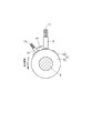
モータ1は、図2に示すように、磁界を発生する界磁子2と、この界磁子2の内周にギャップを有して配置される電機子3と、この電機子3の軸上に設けられる整流子4(図1参照)と、この整流子4の外周上に配置されるブラシ5等を含んで構成される。
界磁子2は、例えば、永久磁石あるいは電磁石によって構成され、図示しないモータハウジングに固定される。
電機子3は、図示しない軸受を介してモータハウジングに回転自在に支持される電機子軸6と、この電機子軸6に固定されて電機子軸6と一体に回転する電機子鉄心7と、この電機子鉄心7に巻装される電機子コイル8とを有する。
[Example 1]
The first embodiment is an example of a DC motor with a brush (hereinafter referred to as a
As shown in FIG. 2, the
The
The
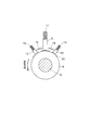
整流子4は、図1に示すように、絶縁体である整流子ベース9と、この整流子ベース9に保持される複数の整流子片10とを有する。
整流子ベース9は、例えば樹脂材料により円筒形状に形成されて、電機子軸6の外周に圧入等により嵌合して固定される。
整流子片10は、整流子ベース9の周方向に一定の隙間を空けて円筒状に配置され、個々の整流子片10がそれぞれ電機子コイル8に接続される(図2参照)。
ブラシ5は、例えばカーボン製であり、図示しないブラシホルダに摺動自在に保持され、且つ、ブラシスプリング11に付勢されて整流子片10に押圧されている。以下、直流電源のプラス端子に接続されるブラシ5を正ブラシ5と呼び、直流電源のマイナス端子に接続されるブラシ5を負ブラシ5と呼ぶ。
As shown in FIG. 1, the
The
The
The
実施例1のモータ1は、図1に示すように、電機子3の回転方向(図示矢印方向)で正ブラシ5より前側に配置されて整流子4上を摺動する追加ブラシ12を有し、この追加ブラシ12と正ブラシ5との間にアーク吸収部(後述する)が接続される。
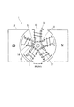
追加ブラシ12は、ブラシ5と同じくカーボン製であり、図示しないブラシホルダに保持され、且つ、追加スプリング13に付勢されて整流子片10に押圧されている。この追加ブラシ12は、正ブラシ5が接触する或る一つの整流子片10を当整流子片10と呼ぶときに、正ブラシ5が当整流子片10から離れる前に当整流子片10に接触する位置に配置される。すなわち、図3の展開図(左側の図)で示すように、整流子片10の周方向幅をAとし、正ブラシ5と追加ブラシ12との間の間隔をBとした時に、A>Bの関係を有する。正ブラシ5と追加ブラシ12との間の間隔Bは、整流子片10の表面に沿って測った周方向の距離である。
As shown in FIG. 1, the
The
アーク吸収部は、ツェナーダイオード14であり、図3に示すように、正ブラシ5と追加ブラシ12との間に逆接続される。つまり、カソードが正ブラシ5に接続され、アノードが追加ブラシ12に接続される。カソードと正ブラシ5との間およびアノードと追加ブラシ12との間は、例えば、電気抵抗が低い銅線によって接続される。
ツェナーダイオード14は、ある一定の電圧(ツェナー電圧と呼ぶ)以上の電圧が逆方向(カソード−アノード間)に印加されると、カソードからアノードに向かって急激に電流が流れる。すなわち、ツェナーダイオード14のカソード側にツェナー電圧以上の電圧が印加されると、図3の右側の図に矢印で示すように、カソードからアノードに向かって電流が流れることで、ツェナーダイオード14の両端の電圧は、略ツェナー電圧に維持される。
The arc absorbing portion is a Zener
In the
〔実施例1の作用及び効果〕
ブラシ付き直流モータ1では、正ブラシ5が当整流子片10から離れる瞬間に電機子コイル8の自己誘導作用によって逆起電力が発生する。この逆起電力によって電機子コイル8の両端に発生する電圧を逆起電圧と呼ぶとき、この逆起電圧は、図3の右側の図に示す電源記号で表されるように、図示右側の整流子片10に接続される電機子コイル8の一端側がプラス、図示左側の整流子片10に接続される電機子コイル8の他端側がマイナスとなり、ツェナーダイオード14に対し逆方向に印加される。
ツェナーダイオード14は、ツェナー電圧より大きい電圧(逆起電圧)が印加されると、カソードからアノードに向かって電流が流れることで、両端の電圧がツェナー電圧に維持される。このため、正ブラシ5と当整流子片10との間に印加される電圧が逆起電圧より低いツェナー電圧に維持されるため、正ブラシ5と当整流子片10との間でアークの発生を抑制できる。
[Operation and Effect of Example 1]
In the brushed
When a voltage (back electromotive voltage) greater than the Zener voltage is applied to the
また、ツェナーダイオード14は、正ブラシ5を介してカソード側に印加される電圧がツェナー電圧まで低下した時点で電流を遮断するため、ツェナーダイオード14に電流が流れ続けることはない。その結果、無駄なエネルギーが消費されることは無く、特許文献1の従来技術と比較してモータ効率が向上する。図4はアークの放電継続時間を計測した結果を示すグラフであり、同図(a)はアーク放電を抑制するための対策を全く実施していない事例(無対策事例と呼ぶ)、同図(b)は特許文献1の従来技術において10Ωの抵抗を使用した事例、同図(c)は実施例1に記載した事例である。
特許文献1の事例は、放電継続時間が67マイクロ秒であり、放電継続時間が87マイクロ秒の無体策事例と比較してアークエネルギーを42%低減できるが、モータ効率は2.8%低下する。これに対し、実施例1の事例は、放電継続時間がほぼ0であり、無体策事例と比較してアークエネルギーを100%低減でき、且つ、特許文献1の事例と比較してモータ効率を向上できる。
Further, since the Zener
In the case of
以下、本発明に係る他の実施例について説明する。
なお、実施例1と共通する部品および構成を示すものは、実施例1と同一の符号を付与して詳細な説明は省略(実施例1を参照)する。
〔実施例2〕
この実施例2は、負ブラシ5と追加ブラシ12との間にアーク吸収部を接続する事例である。追加ブラシ12は、電機子3の回転方向(図示矢印方向)で負ブラシ5より前側に配置され、且つ、負ブラシ5が当整流子片10から離れる前に当整流子片10に接触する位置に配置される。
アーク吸収部は、実施例1と同じくツェナーダイオード14であり、図5に示すように、アノードが負ブラシ5に接続され、カソードが追加ブラシ12に接続される。
Hereinafter, other embodiments according to the present invention will be described.
Components and configurations common to those in the first embodiment are denoted by the same reference numerals as those in the first embodiment, and detailed description thereof is omitted (see the first embodiment).
[Example 2]
The second embodiment is an example in which an arc absorber is connected between the
The arc absorber is a
上記の構成によれば、ツェナーダイオード14のカソード側にツェナー電圧より大きい電圧(逆起電圧)が印加されると、図5の右側の図に矢印で示すように、カソードからアノードに向かって電流が流れることで、両端の電圧がツェナー電圧に維持される。その結果、負ブラシ5と当整流子片10との間に印加される電圧が逆起電圧より低いツェナー電圧に維持されるため、負ブラシ5と当整流子片10との間でアークの発生を抑制できる。また、ツェナーダイオード14は、負ブラシ5を介してカソード側に印加される電圧がツェナー電圧まで低下した時点で電流を遮断するため、無駄なエネルギーが消費されることは無く、特許文献1の従来技術と比較してモータ効率が向上する。
According to the above configuration, when a voltage (back electromotive voltage) larger than the Zener voltage is applied to the cathode side of the
〔実施例3〕
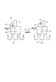
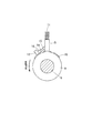
この実施例3は、図6に示すように、ブラシ5の両側に追加ブラシ12を配置して、それぞれブラシ5と追加ブラシ12との間にアーク吸収部を接続した事例である。
ブラシ5は、正ブラシ5と負ブラシ5のどちらか一方または両方に適用できる。
追加ブラシ12は、電機子3が正回転する時の回転方向(例えば図示矢印で示す反時計回転方向)に対してブラシ5より前側に配置される一方の追加ブラシ12と、電機子3が逆回転する時の回転方向に対してブラシ5より前側に配置される他方の追加ブラシ12とを有する。
Example 3
As shown in FIG. 6, the third embodiment is an example in which the
The
The
アーク吸収部は、実施例1、2と同じく、ツェナーダイオード14であり、ブラシ5と一方の追加ブラシ12との間およびブラシ5と他方の追加ブラシ12との間にそれぞれ逆接続される。
この実施例3の構成によれば、電機子3が正回転する時だけでなく、電機子3が逆回転する時にもブラシ5と当整流子片10との間でアークの発生を抑制でき、特許文献1の従来技術と比較してモータ効率が向上する。
As in the first and second embodiments, the arc absorber is a
According to the configuration of the third embodiment, it is possible to suppress the generation of arc between the
〔実施例4〕
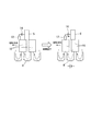
この実施例4は、図7に示すように、ブラシ5とアーク吸収部との間および追加ブラシ12とアーク吸収部との間をそれぞれ導体15、16によって接続する事例である。
導体15は、ブラシ5と電気的且つ機械的に結合される。
導体16は、追加ブラシ12と電気的且つ機械的に結合される。
なお、導体15および導体16は、必ずしも別部品として新たに設ける必要はなく、例えば、ブラシ5および追加ブラシ12の側面にそれぞれ導体15および導体16に相当する凸形状部を一体に設けても良い。
Example 4
In the fourth embodiment, as shown in FIG. 7, the
The
The
The
アーク吸収部は、実施例1と同じくツェナーダイオード14であり、例えば、カソード側が導体15に接続され、アノード側が導体16に接続されて、導体15、16と電気的且つ機械的に結合される。
この実施例4では、ブラシ5及び追加ブラシ12に対しツェナーダイオード14の両端を銅線等で接続することなく、導体15、16に接続して機械的に結合されるので、振動等によって断線することを防止できる。また、ブラシ5と追加ブラシ12との間隔を一定に保つことができるので、例えば、追加ブラシ12を保持するための専用のブラシホルダが不要であり、且つ、実施例1に記載した追加スプリング13を廃止することも可能である。
The arc absorber is a
In the fourth embodiment, both ends of the
〔変形例〕
実施例1〜4ではアーク吸収部にツェナーダイオード14を使用する事例を記載したが、ツェナーダイオード14に替えてバリスタを採用することもできる。
実施例1ではブラシ付き回転電機の一例として直流モータ1の事例を記載したが、本発明は直流発電機にも適用できる。
[Modification]
In the first to fourth embodiments, an example in which the
In the first embodiment, the example of the
1 モータ(ブラシ付き回転電機)
4 整流子
5 ブラシ
6 電機子軸
8 電機子コイル
10 整流子片(当整流子片)
12 追加ブラシ
14 ツェナーダイオード(アーク吸収部、非直線性抵抗素子)
1 Motor (Rotating electric machine with brush)
4
12
Claims (9)
前記電機子軸の回転に応じて前記整流子片の表面上を摺動するブラシ(5)と、
このブラシが接触する或る一つの前記整流子片を当整流子片と呼ぶとき、前記ブラシが前記当整流子片から離れる際に前記電機子コイルの自己誘導作用によって発生する逆起電力を吸収するアーク吸収部とを備えるブラシ付き回転電機(1)であって、
前記電機子軸の回転方向で前記ブラシより前側に配置されて前記整流子片の表面上を摺動すると共に、前記ブラシが前記当整流子片から離れる前に前記当整流子片に接触する追加ブラシ(12)を有し、
前記逆起電力によって前記電機子コイルの両端に発生する電圧を逆起電圧と呼ぶとき、
前記アーク吸収部は、前記ブラシと前記追加ブラシとの間に接続されて前記逆起電圧以上の電圧が印加されると電流が流れる非直線性抵抗素子(14)を有することを特徴とするブラシ付き回転電機。 It has a plurality of commutator pieces (10) arranged concentrically with the axis of the armature shaft (6) and insulated from each other, and each of the plurality of commutator pieces is connected to the armature coil (8). Commutator (4),
A brush (5) that slides on the surface of the commutator piece according to the rotation of the armature shaft;
When one of the commutator pieces in contact with the brush is called the commutator piece, the back electromotive force generated by the self-inductive action of the armature coil is absorbed when the brush is separated from the commutator piece. A rotating electric machine with a brush (1) comprising an arc absorber
The armature shaft is arranged on the front side of the brush in the rotation direction of the armature shaft and slides on the surface of the commutator piece, and the brush contacts the commutator piece before leaving the commutator piece. Having a brush (12),
When a voltage generated at both ends of the armature coil by the back electromotive force is called a back electromotive voltage,
The arc absorbing portion is connected between the brush and the additional brush, and has a non-linear resistance element (14) through which a current flows when a voltage higher than the counter electromotive voltage is applied. With rotating electric machine.
前記電機子軸が一方向に回転することを正回転と呼び、前記電機子軸が他方向に回転することを逆回転と呼ぶとき、
前記追加ブラシは、前記電機子軸が正回転する時の回転方向に対して前記ブラシより前側に配置される一方の追加ブラシと、前記電機子軸が逆回転する時の回転方向に対して前記ブラシより前側に配置される他方の追加ブラシとを有し、
前記ブラシと前記一方の追加ブラシとの間および前記ブラシと前記他方の追加ブラシとの間にそれぞれ前記アーク吸収部が接続されることを特徴とするブラシ付き回転電機。 In the rotating electrical machine with a brush according to claim 1,
When the armature shaft rotates in one direction is called forward rotation, and when the armature shaft rotates in the other direction, it is called reverse rotation.
The additional brush has one additional brush disposed on the front side of the brush with respect to the rotation direction when the armature shaft rotates in the forward direction, and the rotation direction when the armature shaft rotates in the reverse direction. The other additional brush arranged on the front side of the brush,
The rotating electrical machine with a brush, wherein the arc absorbing portion is connected between the brush and the one additional brush and between the brush and the other additional brush.
直流電源のプラス端子に接続される前記ブラシを正ブラシと呼ぶとき、
前記アーク吸収部は、前記正ブラシと前記追加ブラシとの間に接続されることを特徴とするブラシ付き回転電機。 In the rotating electrical machine with a brush according to claim 1 or 2,
When the brush connected to the positive terminal of the DC power supply is called a positive brush,
The rotating electric machine with a brush, wherein the arc absorbing portion is connected between the positive brush and the additional brush.
直流電源のプラス端子に接続される前記ブラシを正ブラシと呼び、前記直流電源のマイナス端子に接続される前記ブラシを負ブラシと呼ぶとき、
前記追加ブラシは、前記正ブラシより回転方向の前側に配置される正の追加ブラシと、前記負ブラシより回転方向の前側に配置される負の追加ブラシとを有し、
前記アーク吸収部は、前記正ブラシと前記正の追加ブラシとの間および前記負ブラシと前記負の追加ブラシとの間に接続されることを特徴とするブラシ付き回転電機。 In the rotating electrical machine with a brush according to claim 1 or 2,
When the brush connected to the positive terminal of the DC power supply is called a positive brush and the brush connected to the negative terminal of the DC power supply is called a negative brush,
The additional brush has a positive additional brush disposed on the front side in the rotational direction from the positive brush, and a negative additional brush disposed on the front side in the rotational direction from the negative brush,
The arc absorbing section is connected to the positive brush and the positive additional brush and between the negative brush and the negative additional brush.
直流電源のマイナス端子に接続される前記ブラシを負ブラシと呼ぶとき、
前記アーク吸収部は、前記負ブラシと前記追加ブラシとの間に接続されることを特徴とするブラシ付き回転電機。 In the rotating electrical machine with a brush according to claim 1 or 2,
When the brush connected to the negative terminal of the DC power source is called a negative brush,
The rotating electric machine with a brush, wherein the arc absorbing portion is connected between the negative brush and the additional brush.
前記非直線性抵抗素子は、ツェナーダイオード(14)であり、このツェナーダイオードのカソードが前記正ブラシに接続され、前記ツェナーダイオードのアノードが前記追加ブラシに接続されることを特徴とするブラシ付き回転電機。 In the rotating electrical machine with a brush according to claim 3,
The non-linear resistance element is a Zener diode (14), the cathode of the Zener diode is connected to the positive brush, and the anode of the Zener diode is connected to the additional brush. Electric.
前記非直線性抵抗素子は、ツェナーダイオード(14)であり、前記正ブラシと前記正の追加ブラシとの間に接続される前記ツェナーダイオードを一方のツェナーダイオードと呼び、前記負ブラシと前記負の追加ブラシとの間に接続される前記ツェナーダイオードを他方のツェナーダイオードと呼ぶとき、
前記一方のツェナーダイオードは、前記正ブラシにカソードが接続されて前記正の追加ブラシにアノードが接続され、
前記他方のツェナーダイオードは、前記負の追加ブラシにカソードが接続されて前記負ブラシにアノードが接続されることを特徴とするブラシ付き回転電機。 In the rotating electrical machine with a brush according to claim 4,
The non-linear resistance element is a Zener diode (14). The Zener diode connected between the positive brush and the positive additional brush is referred to as one Zener diode, and the negative brush and the negative brush are connected to each other. When the Zener diode connected between the additional brush is called the other Zener diode,
The one zener diode has a cathode connected to the positive brush and an anode connected to the positive additional brush,
The other rotating zener diode has a cathode connected to the negative additional brush and an anode connected to the negative brush.
前記非直線性抵抗素子は、ツェナーダイオード(14)であり、このツェナーダイオードのカソードが前記追加ブラシに接続され、前記ツェナーダイオードのアノードが前記負ブラシに接続されることを特徴とするブラシ付き回転電機。 In the rotating electrical machine with a brush according to claim 5,
The non-linear resistance element is a Zener diode (14), the cathode of the Zener diode is connected to the additional brush, and the anode of the Zener diode is connected to the negative brush. Electric.
前記非直線性抵抗素子は、バリスタであることを特徴とするブラシ付き回転電機。 In the rotating electrical machine with a brush according to any one of claims 1 to 8,
The brushless rotating electrical machine, wherein the non-linear resistance element is a varistor.
Priority Applications (1)
| Application Number | Priority Date | Filing Date | Title |
|---|---|---|---|
| JP2016080950A JP2017192233A (en) | 2016-04-14 | 2016-04-14 | Rotary electric machine with brush |
Applications Claiming Priority (1)
| Application Number | Priority Date | Filing Date | Title |
|---|---|---|---|
| JP2016080950A JP2017192233A (en) | 2016-04-14 | 2016-04-14 | Rotary electric machine with brush |
Publications (1)
| Publication Number | Publication Date |
|---|---|
| JP2017192233A true JP2017192233A (en) | 2017-10-19 |
Family
ID=60086079
Family Applications (1)
| Application Number | Title | Priority Date | Filing Date |
|---|---|---|---|
| JP2016080950A Pending JP2017192233A (en) | 2016-04-14 | 2016-04-14 | Rotary electric machine with brush |
Country Status (1)
| Country | Link |
|---|---|
| JP (1) | JP2017192233A (en) |
Cited By (4)
| Publication number | Priority date | Publication date | Assignee | Title |
|---|---|---|---|---|
| JP2020068653A (en) * | 2018-10-22 | 2020-04-30 | 株式会社Soken | Electric contact device and rotating electric machine |
| JP2020162276A (en) * | 2019-03-26 | 2020-10-01 | 株式会社Soken | Rotary electric machine, and noise reduction method of rotary electric machine |
| WO2021070458A1 (en) * | 2019-10-09 | 2021-04-15 | パナソニックIpマネジメント株式会社 | Electric motor and electrical apparatus |
| US11670901B2 (en) | 2018-10-22 | 2023-06-06 | Denso Corporation | Electrical contact device and rotating electric machine including the electrical contact device |
-
2016
- 2016-04-14 JP JP2016080950A patent/JP2017192233A/en active Pending
Cited By (6)
| Publication number | Priority date | Publication date | Assignee | Title |
|---|---|---|---|---|
| JP2020068653A (en) * | 2018-10-22 | 2020-04-30 | 株式会社Soken | Electric contact device and rotating electric machine |
| US11670901B2 (en) | 2018-10-22 | 2023-06-06 | Denso Corporation | Electrical contact device and rotating electric machine including the electrical contact device |
| JP7446070B2 (en) | 2018-10-22 | 2024-03-08 | 株式会社Soken | rotating electric machine |
| JP2020162276A (en) * | 2019-03-26 | 2020-10-01 | 株式会社Soken | Rotary electric machine, and noise reduction method of rotary electric machine |
| JP7131453B2 (en) | 2019-03-26 | 2022-09-06 | 株式会社デンソー | Rotating electric machine, noise reduction method for rotating electric machine |
| WO2021070458A1 (en) * | 2019-10-09 | 2021-04-15 | パナソニックIpマネジメント株式会社 | Electric motor and electrical apparatus |
Similar Documents
| Publication | Publication Date | Title |
|---|---|---|
| JP2017192233A (en) | Rotary electric machine with brush | |
| JP2011004569A (en) | Motor | |
| JP5777898B2 (en) | Electric motor and method for manufacturing electric motor | |
| US20060125345A1 (en) | Direct current motor | |
| WO2021049449A1 (en) | Electric motor and electrical device | |
| JP2011019382A (en) | Motor with brush | |
| US11670901B2 (en) | Electrical contact device and rotating electric machine including the electrical contact device | |
| JP2014155315A (en) | Ac rectifier motor and electric blower employing the same | |
| WO2021049452A1 (en) | Electric motor and electrical equipment | |
| JP4659585B2 (en) | DC motor | |
| JP2007282362A (en) | Brush for rotary electric machine, and rotary electric machine using the brush | |
| WO2021070458A1 (en) | Electric motor and electrical apparatus | |
| JPWO2021070458A5 (en) | ||
| JP2017034741A (en) | Rectification device and rotary electric machine | |
| JP7446070B2 (en) | rotating electric machine | |
| WO2023135955A1 (en) | Electric motor and electrical device | |
| JP2008131758A (en) | Rotary electric machine | |
| CN210927257U (en) | Plastic package motor | |
| CN114649910A (en) | Electrical machine | |
| WO2021049453A1 (en) | Electric motor and electrical apparatus | |
| WO2022050179A1 (en) | Electric motor | |
| JP3925643B2 (en) | Electric motor and fuel pump using the same | |
| JP6682919B2 (en) | motor | |
| JP2010098883A (en) | Brush | |
| JP2011061976A (en) | Dc motor |
Legal Events
| Date | Code | Title | Description |
|---|---|---|---|
| A711 | Notification of change in applicant |
Free format text: JAPANESE INTERMEDIATE CODE: A712 Effective date: 20180404 |
|
| A521 | Written amendment |
Free format text: JAPANESE INTERMEDIATE CODE: A523 Effective date: 20180413 |
|
| A621 | Written request for application examination |
Free format text: JAPANESE INTERMEDIATE CODE: A621 Effective date: 20180918 |
|
| A977 | Report on retrieval |
Free format text: JAPANESE INTERMEDIATE CODE: A971007 Effective date: 20190620 |
|
| A131 | Notification of reasons for refusal |
Free format text: JAPANESE INTERMEDIATE CODE: A131 Effective date: 20190625 |
|
| A521 | Written amendment |
Free format text: JAPANESE INTERMEDIATE CODE: A523 Effective date: 20190808 |
|
| A131 | Notification of reasons for refusal |
Free format text: JAPANESE INTERMEDIATE CODE: A131 Effective date: 20191105 |
|
| A521 | Written amendment |
Free format text: JAPANESE INTERMEDIATE CODE: A523 Effective date: 20191211 |
|
| A02 | Decision of refusal |
Free format text: JAPANESE INTERMEDIATE CODE: A02 Effective date: 20200218 |