JP2020501051A5 - - Google Patents
Download PDFInfo
- Publication number
- JP2020501051A5 JP2020501051A5 JP2019550542A JP2019550542A JP2020501051A5 JP 2020501051 A5 JP2020501051 A5 JP 2020501051A5 JP 2019550542 A JP2019550542 A JP 2019550542A JP 2019550542 A JP2019550542 A JP 2019550542A JP 2020501051 A5 JP2020501051 A5 JP 2020501051A5
- Authority
- JP
- Japan
- Prior art keywords
- module
- unitary structure
- rod
- panel
- modules
- Prior art date
- Legal status (The legal status is an assumption and is not a legal conclusion. Google has not performed a legal analysis and makes no representation as to the accuracy of the status listed.)
- Granted
Links
- 238000000465 moulding Methods 0.000 claims description 14
- 230000002093 peripheral Effects 0.000 claims description 5
- 230000000295 complement Effects 0.000 claims 1
- 238000010276 construction Methods 0.000 claims 1
- 230000000875 corresponding Effects 0.000 claims 1
- 238000010586 diagram Methods 0.000 description 6
- 238000003780 insertion Methods 0.000 description 4
- 240000004282 Grewia occidentalis Species 0.000 description 1
- 230000015572 biosynthetic process Effects 0.000 description 1
- 238000005755 formation reaction Methods 0.000 description 1
- 238000000034 method Methods 0.000 description 1
Images


Description
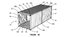
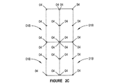
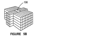
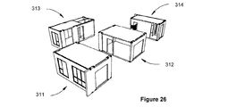
図26および27は、たとえば、互いに隣接して留置され、建物構造315を形成するようにコネクタを位置合わせすることを通して位置合わせされたモジュール311〜314の配列を示す。建造プロセスを完了するために、次いで、バインディング部材が、ユニット式建物構造を形成するようにモジュールを互いにバインディングするために、構造のまわりの重要な場所に留置される。先に略述されたように、この配置は、より大きな建物構造のモジュール式形成を可能にする。モジュールは、図1Aおよび図1Bに示される実施形態によれば、図4Aから図4Hおよび図5Aから図5Eに示される建物構造を潜在的に形成することができるが、同様に、図18に示される実施形態による建物モジュールは、それに応じて留置され、バインディング部材との結合時にユニット式建物構造になるとき、そのような建物構造を同様に形成することができる。
26 and 27 show an arrangement of modules 311-314, for example, placed next to each other and aligned through aligning connectors to form a
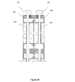
代替配置として、バインディング部材は、留置されたモジュールのパネルの周辺縁に設置された一連のアンカー・ブロックおよびポストストレス用(post−stressing)ケーブルを備えることがあり、アンカー・ブロックは、パネルの接続部分において位置決めされる。たとえば、隅部用成型部材は、隣接するモジュールを接続し前記モジュールをユニット式構造へとバインディングするポストストレスト(post−stressed)ケーブルに遅行するように配置された端部アンカーを備えることがある。そのような配置は、図29に示されており、図29は、図13に示される、バインディング部材としての接続用ロッドの使用に対する代替形態である。この代替実施形態の場合、端部接続322は、アンカー321を受け入れるように修正され、アンカー321は、ケーブル320のポストストレスに抵抗するために機能する。したがって、さまざまなモジュールが留置され、位置合わせされているとき、ケーブルは、ユニット式建物構造を形成するために留置された別個のモジュールを結合するように、応力がかけられる。
In an alternative arrangement, the binding member may comprise a series of anchor blocks and post-stressing cables located at the peripheral edge of the panel of the deployed module, the anchor blocks comprising a panel connection Positioned in the part. For example, a corner molding may include an end anchor positioned to lag a post-stressed cable that connects adjacent modules and binds the modules into a unitary structure. . Such an arrangement is shown in Figure 29, Figure 29 is shown in FIG. 13, an alternative embodiment to the use of the connecting rod as a binding member. In this alternative embodiment,
Claims (11)
互いに隣接するように/配置された複数のモジュールであって、その各々が、少なくとも1つの占有可能空間を有する複数のモジュールと、
隣接するモジュールにわたり、これを結合するように配置された少なくとも1つのバインディング部材と
を備え、
該複数のモジュールの各々が、複数の構造パネルをさらに備え、該複数の構造パネルの各々が、複数の機械的コネクタによって隣接する構造パネルと組み立てられ、
1つのモジュールの少なくとも1つの縁が、該隣接するモジュールの対応する縁と位置合わせされる、および、
該構造パネルの周辺縁が単一の位置係合を可能にするような形状である、ユニット式構造。 A unitary structure defining a plurality of internal occupied spaces,
A plurality of modules arranged / adjacent to each other, each having at least one occupied space;
At least one binding member arranged to couple over adjacent modules; and
Each of the plurality of modules further comprises a plurality of structural panels, each of the plurality of structural panels being assembled with an adjacent structural panel by a plurality of mechanical connectors;
At least one edge of one module is aligned with a corresponding edge of the adjacent module; and
A unitary structure, wherein a peripheral edge of the structural panel is shaped to allow a single position engagement.
該第2のロッドの該外部にねじ切りされた端部が、該第1のロッドの該内部にねじ切りされた端部に挿入されるように配置される、請求項3または4に記載のユニット式構造。 A first rod arranged to be inserted through at least one edge of the lower level module; and a first rod arranged to be inserted through at least one edge of the upper level module. A second rod disposed therein, wherein the first rod and the second rod have internally threaded ends and externally threaded ends and are internally threaded. The end and the externally threaded end are arranged to be complementary to each other;
5. The unit of claim 3 or 4, wherein the externally threaded end of the second rod is arranged to be inserted into the internally threaded end of the first rod. Construction.
Priority Applications (1)
| Application Number | Priority Date | Filing Date | Title |
|---|---|---|---|
| JP2021190004A JP7288031B2 (en) | 2016-12-02 | 2021-11-24 | Connection system and method for prefabricated volumetric building modules |
Applications Claiming Priority (5)
| Application Number | Priority Date | Filing Date | Title |
|---|---|---|---|
| SG10201610152QA SG10201610152QA (en) | 2016-12-02 | 2016-12-02 | Connection system and method for prefabricated volumetric construction modules |
| SG10201610152Q | 2016-12-02 | ||
| SG10201707728X | 2017-09-19 | ||
| SG10201707728X | 2017-09-19 | ||
| PCT/SG2017/050594 WO2018101891A1 (en) | 2016-12-02 | 2017-12-04 | Connection system and method for prefabricated volumetric construction modules |
Related Child Applications (1)
| Application Number | Title | Priority Date | Filing Date |
|---|---|---|---|
| JP2021190004A Division JP7288031B2 (en) | 2016-12-02 | 2021-11-24 | Connection system and method for prefabricated volumetric building modules |
Publications (3)
| Publication Number | Publication Date |
|---|---|
| JP2020501051A JP2020501051A (en) | 2020-01-16 |
| JP2020501051A5 true JP2020501051A5 (en) | 2020-03-05 |
| JP6983901B2 JP6983901B2 (en) | 2021-12-17 |
Family
ID=62242248
Family Applications (2)
| Application Number | Title | Priority Date | Filing Date |
|---|---|---|---|
| JP2019550542A Active JP6983901B2 (en) | 2016-12-02 | 2017-12-04 | Connectivity systems and methods for prefabricated volumetric construction modules |
| JP2021190004A Active JP7288031B2 (en) | 2016-12-02 | 2021-11-24 | Connection system and method for prefabricated volumetric building modules |
Family Applications After (1)
| Application Number | Title | Priority Date | Filing Date |
|---|---|---|---|
| JP2021190004A Active JP7288031B2 (en) | 2016-12-02 | 2021-11-24 | Connection system and method for prefabricated volumetric building modules |
Country Status (17)
| Country | Link |
|---|---|
| US (1) | US11525257B2 (en) |
| EP (2) | EP4234825A3 (en) |
| JP (2) | JP6983901B2 (en) |
| KR (3) | KR102334938B1 (en) |
| CN (1) | CN109642424B (en) |
| AU (1) | AU2017367555B2 (en) |
| BR (1) | BR112019011466B1 (en) |
| CA (1) | CA3045792C (en) |
| JO (1) | JOP20190124B1 (en) |
| MX (1) | MX2023007623A (en) |
| MY (1) | MY175837A (en) |
| PH (1) | PH12019501188A1 (en) |
| SA (1) | SA519401910B1 (en) |
| SG (1) | SG11201902795PA (en) |
| TR (1) | TR202109401A2 (en) |
| WO (1) | WO2018101891A1 (en) |
| ZA (2) | ZA201903583B (en) |
Families Citing this family (13)
| Publication number | Priority date | Publication date | Assignee | Title |
|---|---|---|---|---|
| US11225789B2 (en) * | 2018-05-17 | 2022-01-18 | Spanminx Limited | Structural module with vertical ties |
| CN109505368B (en) * | 2018-12-25 | 2024-05-14 | 湘潭远大住宅工业有限公司 | Wallboard connecting node for assembled building |
| GB2576964B (en) * | 2019-04-17 | 2020-09-09 | Peter Dann Ltd | Modular structure and connection method |
| CN111636570B (en) * | 2020-05-25 | 2021-10-22 | 浙江东新建设有限公司 | Modular beam frame of prefabricated building and variable floor height structure thereof |
| CN111827487A (en) * | 2020-06-08 | 2020-10-27 | 中建集成建筑有限公司 | Prestressed formwork block system and construction method thereof |
| GB2596130A (en) * | 2020-06-18 | 2021-12-22 | Portakabin Ltd | A modular building unit |
| CN111809889A (en) * | 2020-07-23 | 2020-10-23 | 广东海龙建筑科技有限公司 | Assembly method of prefabricated house of box-type modular factory |
| KR102318982B1 (en) | 2020-12-14 | 2021-10-29 | (주)유창이앤씨 | Modular frame combining system using multi-lock |
| US20220251829A1 (en) * | 2021-02-11 | 2022-08-11 | United States Gypsum Company | Modular construction including fire-suppressing gasket |
| KR102356035B1 (en) | 2021-06-21 | 2022-02-08 | (주)유창이앤씨 | Modular frame combining structure provided with post-tension |
| KR20230018841A (en) | 2021-07-30 | 2023-02-07 | (주)유창이앤씨 | The structure of modular building using functional modular unit |
| EP4177412A1 (en) * | 2021-11-03 | 2023-05-10 | Architekten Scheicher ZT GmbH | Multi-storey multiparty building |
| USD1021142S1 (en) * | 2022-11-30 | 2024-04-02 | Weibing Shan | Sunshade |
Family Cites Families (31)
| Publication number | Priority date | Publication date | Assignee | Title |
|---|---|---|---|---|
| US3500595A (en) * | 1967-10-27 | 1970-03-17 | Flehr Hohbach | Modular building construction unit and column |
| CA942210A (en) | 1970-08-17 | 1974-02-19 | Donald H. W. Dover | Insulated containers |
| US4599829A (en) * | 1983-08-25 | 1986-07-15 | Tandemloc, Inc. | Modular container building system |
| JP2540087Y2 (en) * | 1991-08-07 | 1997-07-02 | 大和ハウス工業株式会社 | Unit box |
| JPH06136833A (en) * | 1992-10-26 | 1994-05-17 | Sekisui Chem Co Ltd | Floor panel with ceiling, and room unit equipped with the panel |
| JPH06346515A (en) * | 1993-04-16 | 1994-12-20 | Daiwa House Ind Co Ltd | Unit building |
| JPH0967869A (en) * | 1995-08-31 | 1997-03-11 | Nisso Ind Co Ltd | Joint metal fitting of unit building |
| GB2329649B (en) | 1997-09-26 | 2001-07-25 | David Thomas Weller | Panel based construction kits and structures formed therefrom |
| JPH11131596A (en) * | 1997-10-28 | 1999-05-18 | Sekisui Chem Co Ltd | Building unit |
| JPH11269999A (en) * | 1998-03-26 | 1999-10-05 | Sekisui Chem Co Ltd | Fixing method of column and building unit |
| GB2398578B (en) * | 2003-02-18 | 2006-11-29 | Portakabin Ltd | Prefabricated building unit |
| US6871453B2 (en) * | 2003-03-19 | 2005-03-29 | Reginald A. J. Locke | Modular building connector |
| US7334377B2 (en) | 2003-08-14 | 2008-02-26 | Johnson Controls Technology Company | Raceway construction for an air handing unit |
| GB2438806B (en) | 2003-10-17 | 2008-05-28 | Big Steps Ltd | Building |
| GB0324363D0 (en) * | 2003-10-17 | 2003-11-19 | Verbus Ltd | Building modules |
| US20160160515A1 (en) * | 2006-08-26 | 2016-06-09 | Global Building Modules, Inc. | System for modular building construction |
| US20080216426A1 (en) | 2007-03-09 | 2008-09-11 | Tuff Shed, Inc. | Building with Interlocking Panels |
| US20110173907A1 (en) | 2008-09-18 | 2011-07-21 | Epaminondas Katsalidis | Unitised Building System |
| KR100923637B1 (en) * | 2009-07-13 | 2009-10-23 | 금강공업 주식회사 | Architectural modular unit with reinforced connecting structure |
| KR101152912B1 (en) * | 2009-11-30 | 2012-06-05 | 이현배쓰(주) | Wall panels of a prefabricated bathroom and connector and structure of wall panels thereby |
| JP5615036B2 (en) * | 2009-12-10 | 2014-10-29 | ミサワホーム株式会社 | How to transport building units |
| US20120279141A1 (en) * | 2011-05-06 | 2012-11-08 | Epsilon Industries Inc. | Modular building system and method |
| US9382703B2 (en) * | 2012-08-14 | 2016-07-05 | Premium Steel Building Systems, Inc. | Systems and methods for constructing temporary, re-locatable structures |
| WO2014074508A1 (en) * | 2012-11-06 | 2014-05-15 | FC+Skanska Modular, LLC | Modular building unit connection system |
| JP6235245B2 (en) * | 2013-03-14 | 2017-11-22 | 積水化学工業株式会社 | Building unit connection structure |
| CN203834666U (en) * | 2014-03-11 | 2014-09-17 | 沈阳瑞福工业住宅有限公司 | Modular building system and connection assembly for modular building |
| CN204163192U (en) | 2014-07-13 | 2015-02-18 | 广东一百集成房屋有限公司 | The syndeton of modularization mobile house and multiple-layer box type house |
| IL233641B (en) * | 2014-07-14 | 2019-03-31 | Klein Amos | Containers shelter |
| CN205116417U (en) | 2015-11-10 | 2016-03-30 | 张军 | Box -shaped fast -assembling house |
| CN105908840B (en) | 2016-05-10 | 2018-02-27 | 丁献忠 | The installation method of pure harden structure assembled house |
| CA3007085A1 (en) * | 2017-12-22 | 2019-06-22 | Patricia Dawn Russell | Building structure and kit therefor |
-
2017
- 2017-12-04 WO PCT/SG2017/050594 patent/WO2018101891A1/en unknown
- 2017-12-04 TR TR2021/009401A patent/TR202109401A2/en unknown
- 2017-12-04 JO JOP/2019/0124A patent/JOP20190124B1/en active
- 2017-12-04 CN CN201780040032.6A patent/CN109642424B/en active Active
- 2017-12-04 KR KR1020217026236A patent/KR102334938B1/en active IP Right Grant
- 2017-12-04 JP JP2019550542A patent/JP6983901B2/en active Active
- 2017-12-04 EP EP23180586.2A patent/EP4234825A3/en active Pending
- 2017-12-04 CA CA3045792A patent/CA3045792C/en active Active
- 2017-12-04 KR KR1020217039187A patent/KR102447901B1/en active IP Right Grant
- 2017-12-04 SG SG11201902795PA patent/SG11201902795PA/en unknown
- 2017-12-04 EP EP17876072.4A patent/EP3548674B1/en active Active
- 2017-12-04 BR BR112019011466-1A patent/BR112019011466B1/en active IP Right Grant
- 2017-12-04 KR KR1020197019073A patent/KR20190089971A/en active Application Filing
- 2017-12-04 US US16/322,687 patent/US11525257B2/en active Active
- 2017-12-04 MY MYPI2019000083A patent/MY175837A/en unknown
- 2017-12-04 AU AU2017367555A patent/AU2017367555B2/en active Active
-
2019
- 2019-05-29 PH PH12019501188A patent/PH12019501188A1/en unknown
- 2019-05-30 MX MX2023007623A patent/MX2023007623A/en unknown
- 2019-06-01 SA SA519401910A patent/SA519401910B1/en unknown
- 2019-06-04 ZA ZA2019/03583A patent/ZA201903583B/en unknown
-
2020
- 2020-12-23 ZA ZA2020/08056A patent/ZA202008056B/en unknown
-
2021
- 2021-11-24 JP JP2021190004A patent/JP7288031B2/en active Active
Similar Documents
| Publication | Publication Date | Title |
|---|---|---|
| JP2020501051A5 (en) | ||
| JP7288031B2 (en) | Connection system and method for prefabricated volumetric building modules | |
| KR20120011043A (en) | Half precast floor plank, and slab construction method using same | |
| US10941571B2 (en) | Set of modular timber hollow bricks with thermal insulation properties | |
| CA2537356A1 (en) | Drywall construction method and means therefor | |
| KR101705336B1 (en) | Box structure and box type modular using box structure | |
| WO2017048725A1 (en) | Methods and devices for modular construction | |
| US20110265403A1 (en) | Precast concrete structure and method of constructing the same | |
| KR102174760B1 (en) | Roof structure for culvert houses | |
| US20090056256A1 (en) | Structural panel system | |
| KR20160084692A (en) | Wall structure and construction method thereof | |
| JP3199083U (en) | Intermediate unit block body for civil engineering building blocks | |
| RU2819571C1 (en) | Building block | |
| KR19980019399A (en) | Architecture wall formwork assembly | |
| JP2003328495A (en) | Concrete panel and concrete structure | |
| KR100557276B1 (en) | A Dismonuting Wall And Floor Form | |
| JP3199085U (en) | Top-end unit block body of a civil engineering building block | |
| GB2109431A (en) | Modular building structure and module for it | |
| JP6224038B2 (en) | Floor structure construction method and floor structure | |
| CN112252511A (en) | On-spot assembled combination wall body | |
| CN110273505A (en) | Collar tie beam module, collar tie beam, building body and construction method | |
| JPS6326214B2 (en) | ||
| JPS58191838A (en) | Dry construction of concrete block | |
| JPH10102814A (en) | Box-like structure and constructing method thereof | |
| JPS6278339A (en) | Unbond pc small beam |