JP2020184853A - Synchronous rotary electric machine and discharge resistor - Google Patents
Synchronous rotary electric machine and discharge resistor Download PDFInfo
- Publication number
- JP2020184853A JP2020184853A JP2019088812A JP2019088812A JP2020184853A JP 2020184853 A JP2020184853 A JP 2020184853A JP 2019088812 A JP2019088812 A JP 2019088812A JP 2019088812 A JP2019088812 A JP 2019088812A JP 2020184853 A JP2020184853 A JP 2020184853A
- Authority
- JP
- Japan
- Prior art keywords
- discharge resistor
- rotor
- stator
- resistor
- electric machine
- Prior art date
- Legal status (The legal status is an assumption and is not a legal conclusion. Google has not performed a legal analysis and makes no representation as to the accuracy of the status listed.)
- Granted
Links
Images
Classifications
-
- H—ELECTRICITY
- H02—GENERATION; CONVERSION OR DISTRIBUTION OF ELECTRIC POWER
- H02K—DYNAMO-ELECTRIC MACHINES
- H02K9/00—Arrangements for cooling or ventilating
-
- H—ELECTRICITY
- H02—GENERATION; CONVERSION OR DISTRIBUTION OF ELECTRIC POWER
- H02K—DYNAMO-ELECTRIC MACHINES
- H02K11/00—Structural association of dynamo-electric machines with electric components or with devices for shielding, monitoring or protection
- H02K11/04—Structural association of dynamo-electric machines with electric components or with devices for shielding, monitoring or protection for rectification
- H02K11/042—Rectifiers associated with rotating parts, e.g. rotor cores or rotary shafts
-
- H—ELECTRICITY
- H02—GENERATION; CONVERSION OR DISTRIBUTION OF ELECTRIC POWER
- H02K—DYNAMO-ELECTRIC MACHINES
- H02K19/00—Synchronous motors or generators
- H02K19/02—Synchronous motors
-
- H—ELECTRICITY
- H02—GENERATION; CONVERSION OR DISTRIBUTION OF ELECTRIC POWER
- H02K—DYNAMO-ELECTRIC MACHINES
- H02K7/00—Arrangements for handling mechanical energy structurally associated with dynamo-electric machines, e.g. structural association with mechanical driving motors or auxiliary dynamo-electric machines
- H02K7/20—Structural association with auxiliary dynamo-electric machines, e.g. with electric starter motors or exciters
-
- H—ELECTRICITY
- H02—GENERATION; CONVERSION OR DISTRIBUTION OF ELECTRIC POWER
- H02K—DYNAMO-ELECTRIC MACHINES
- H02K9/00—Arrangements for cooling or ventilating
- H02K9/02—Arrangements for cooling or ventilating by ambient air flowing through the machine
- H02K9/04—Arrangements for cooling or ventilating by ambient air flowing through the machine having means for generating a flow of cooling medium
Landscapes
- Engineering & Computer Science (AREA)
- Power Engineering (AREA)
- Motor Or Generator Cooling System (AREA)
Abstract
【課題】同期回転電機において、簡易な構成により放電抵抗器の冷却機能を向上させる。【解決手段】同期回転電機は、ロータシャフト11と回転子鉄心と回転子巻線とを有する回転子と、固定子鉄心と固定子巻線とを有する固定子と、ロータシャフト11とともに回転する回転整流器および少なくとも一つの放電抵抗器60を有する励磁装置と、フレームと、冷却器とを備える。放電抵抗器60は、ロータシャフト11の周囲に巻き付けられた抵抗61と、抵抗61の間に配され抵抗61内に隙間61aを形成する複数の電気絶縁性のスペーサ62とを有する。【選択図】図4PROBLEM TO BE SOLVED: To improve a cooling function of a discharge resistor by a simple configuration in a synchronous rotary electric machine. SOLUTION: A synchronous rotary electric machine is a rotor having a rotor shaft 11, a rotor core and a rotor winding, a stator having a stator core and a stator winding, and a rotation rotating together with the rotor shaft 11. It includes an exciter having a rectifier and at least one discharge resistor 60, a frame, and a cooler. The discharge resistor 60 has a resistor 61 wound around the rotor shaft 11 and a plurality of electrically insulating spacers 62 arranged between the resistors 61 and forming a gap 61a in the resistor 61. [Selection diagram] Fig. 4
Description
本発明は、同期回転電機およびその放電抵抗器に関する。 The present invention relates to a synchronous rotary electric machine and its discharge resistor.
同期回転電機は、一般的に自己始動が困難で、同期回転電機が始動するための設備が設けられている場合が多い。 It is generally difficult to self-start the synchronous rotary electric machine, and in many cases, equipment for starting the synchronous rotary electric machine is provided.
ただし、ブラシレス同期回転電機においては、回転子において界磁巻線が閉回路を形成していることから、誘導機と同様の原理で、原理的に界磁巻線を用いた自己始動を行うことができる。この場合、始動時に誘導電圧の全てが整流回路に印加されるのを緩和するために、一般的に界磁巻線に並列に放電抵抗器が設置される。具体的には、放電抵抗器は、ロータシャフトに取り付けられる。 However, in a brushless synchronous rotary electric machine, since the field winding forms a closed circuit in the rotor, self-starting using the field winding is performed in principle by the same principle as that of the induction machine. Can be done. In this case, a discharge resistor is generally installed in parallel with the field winding in order to alleviate the application of all the induced voltage to the rectifier circuit at the time of starting. Specifically, the discharge resistor is attached to the rotor shaft.
放電抵抗器には、同期回転電機の始動時にその両端間に誘導電圧の一部が印加されるため、放電抵抗器内および放電抵抗器と外部との絶縁性能を確保する必要がある。また、放電抵抗器は、ロータシャフトとともに回転することから遠心力が作用する。このため、放電抵抗器は樹脂等の絶縁材によりモールドされている場合が多い。 Since a part of the induced voltage is applied to the discharge resistor when the synchronous rotary electric machine is started, it is necessary to secure the insulation performance inside the discharge resistor and between the discharge resistor and the outside. Further, since the discharge resistor rotates together with the rotor shaft, centrifugal force acts on it. For this reason, the discharge resistor is often molded with an insulating material such as resin.
ブラシレス同期回転電機の自己始動に際しては、放電抵抗器には大きな電流が流れるため、特に全閉形の回転電機においては、放電抵抗器の冷却が重要である。放電抵抗器の冷却を向上させる例としては、たとえば、鋼管被覆の放電抵抗器を、内周面に溝をつけた回転円筒内に組み込む技術が知られている(特許文献1参照)。あるいは、冷却ファンによる冷却用気体の通風路内に放電抵抗器を配置し、軸方向に2つの放電抵抗器に挟まれた通路を形成する技術が知られている(特許文献2参照)。 When a brushless synchronous rotary electric machine is self-started, a large current flows through the discharge resistor. Therefore, it is important to cool the discharge resistor, especially in a fully closed rotary electric machine. As an example of improving the cooling of the discharge resistor, for example, a technique of incorporating a discharge resistor coated with a steel pipe into a rotating cylinder having a groove on the inner peripheral surface is known (see Patent Document 1). Alternatively, there is known a technique of arranging a discharge resistor in a ventilation path of a cooling gas by a cooling fan to form a passage sandwiched between two discharge resistors in the axial direction (see Patent Document 2).
これらのいずれの例も、構造の複雑化、あるいは加工工程の増加をもたらすことは否めない。 It is undeniable that any of these examples results in a complicated structure or an increase in processing steps.
そこで、本発明は、同期回転電機において、簡易な構成により放電抵抗器の冷却機能を向上させることを目的とする。 Therefore, an object of the present invention is to improve the cooling function of the discharge resistor by a simple configuration in the synchronous rotary electric machine.
上述の目的を達成するため、本発明に係る同期回転電機は、軸方向に延びたロータシャフトと、前記ロータシャフトに取り付けられた回転子鉄心と、前記回転子鉄心に巻回された回転子巻線とを有する回転子と、前記回転子鉄心の径方向外側に配された固定子鉄心と、前記固定子鉄心を貫通する固定子巻線とを有する固定子と、前記ロータシャフトとともに回転する回転整流器および少なくとも一つの放電抵抗器を有する励磁装置と、前記回転子鉄心、前記固定子および前記励磁装置を収納するフレームと、前記フレームに取り付けられて、前記フレーム内の前記回転子、前記固定子、および前記励磁装置を冷却する冷却用気体を冷却する冷却器と、を備え、前記少なくとも一つの放電抵抗器は、前記ロータシャフトの周囲に巻き付けられた抵抗と、前記抵抗の間に配され前記抵抗内に隙間を形成する複数の電気絶縁性のスペーサと、を有することを特徴とする。 In order to achieve the above object, the synchronous rotary electric machine according to the present invention includes a rotor shaft extending in the axial direction, a rotor core attached to the rotor shaft, and a rotor winding wound around the rotor core. A rotor having a wire, a stator core arranged radially outside the rotor core, a stator having a stator winding penetrating the stator core, and a rotation rotating with the rotor shaft. An exciter having a rectifier and at least one discharge resistor, a frame for accommodating the rotor core, the stator and the exciter, and the rotor and the stator in the frame attached to the frame. , And a cooler that cools the cooling gas that cools the exciter, and the at least one discharge resistor is arranged between the resistor wound around the rotor shaft and the resistor. It is characterized by having a plurality of electrically insulating spacers that form a gap in the resistor.
また、本発明に係る放電抵抗器は、ロータシャフトと回転子鉄心と回転子巻線とを有する回転子と、固定子鉄心と固定子巻線とを有する固定子と、前記ロータシャフトとともに回転する回転整流器を有する励磁装置と、前記回転子鉄心、前記固定子および前記励磁装置を収納するフレームと、前記フレームに取り付けられて、前記フレーム内の前記回転子、前記固定子、および前記励磁装置を冷却する冷却用気体を冷却する冷却器とを備える同期回転電機の前記励磁装置の放電抵抗器であって、前記ロータシャフトの周囲に巻き付けられた抵抗と、前記抵抗の間に配され前記抵抗内に隙間を形成する複数の電気絶縁性のスペーサと、を有することを特徴とする。 Further, the discharge resistor according to the present invention rotates together with a rotor shaft, a rotor having a rotor core and a rotor winding, a stator having a stator core and a stator winding, and the rotor shaft. An exciter having a rotary rectifier, a frame for accommodating the rotor core, the stator and the exciter, and the rotor, the stator, and the exciter attached to the frame. It is a discharge resistor of the exciter of the synchronous rotary electric machine including a cooler for cooling the cooling gas to be cooled, and is arranged between the resistor wound around the rotor shaft and the resistor. It is characterized by having a plurality of electrically insulating spacers forming a gap in the space.
本発明によれば、同期回転電機において、簡易な構成により放電抵抗器の冷却機能を向上させることができる。 According to the present invention, in the synchronous rotary electric machine, the cooling function of the discharge resistor can be improved by a simple configuration.
以下、図面を参照して、本発明の実施形態に係る同期回転電機およびその放電抵抗器について説明する。 Hereinafter, the synchronous rotary electric machine and its discharge resistor according to the embodiment of the present invention will be described with reference to the drawings.
[第1の実施形態]
以下、同期回転電機として、全閉形ブラシレス同期回転電機の場合を例にとって説明する。
[First Embodiment]
Hereinafter, the case of a fully closed brushless synchronous rotary electric machine will be described as an example of the synchronous rotary electric machine.
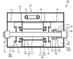
図1は、第1の実施形態に係る同期回転電機の立断面図である。 FIG. 1 is a vertical sectional view of a synchronous rotary electric machine according to the first embodiment.
同期回転電機100は、回転子10、固定子20、フレーム30、軸受32、冷却器40、および励磁装置50を有する。
The synchronous rotary
回転子10は、軸方向に延びたロータシャフト11、ロータシャフト11に取り付けられた回転子鉄心12、および回転子鉄心12に巻回された回転子巻線13を有する。ロータシャフト11は、回転子鉄心12を挟んだ軸方向の両側で、軸受32により回転可能に支持されている。なお、回転子鉄心12に巻回される回転子巻線13は、図1に示すように回転子鉄心12に形成された複数のスロット内(図示せず)に収納される部分を有する円筒型の場合、および、回転子鉄心12に形成された突極に巻回される突極型の場合のいずれの場合も含む。
The
固定子20は、回転子鉄心12の径方向の外側に空隙を介して配された円筒状の固定子鉄心21と、固定子鉄心21を貫通する固定子巻線22を有する。
The
固定子20を囲むように軸方向に筒状に延びたフレーム30が配されている。フレーム30の両側の端部にはそれぞれ軸受ブラケット34が取り付けられている。それぞれの軸受ブラケット34は、それぞれの軸受32を静止支持している。
A
冷却器40は、フレーム30の上部に設けられている。冷却器40は、外部の冷媒が通過する冷却管41と、冷却管41を収納する冷却器カバー42を有する。
The cooler 40 is provided on the upper part of the
フレーム30、2つの軸受ブラケット34、および冷却器カバー42は、互いに相まって閉空間30aを形成する。閉空間30a内には、たとえば空気などの冷却用気体が封入されている。
The
それぞれの軸受32と回転子鉄心12との間で、ロータシャフト11にはそれぞれ内扇15が取り付けられている。また、それぞれの内扇15の径方向外側にはフレーム30の内面にまで拡がる仕切り板15aが設けられている。内扇15は、軸流ファンであり、冷却用気体を、回転子鉄心12および固定子20の方向に移送駆動する。
An
フレーム30内の空間と、冷却器カバー42内の空間とは、冷却器入口開口43および2つの冷却器出口開口44を介して連通している。冷却器入口開口43は固定子20の上方に形成されている。また、2つの冷却器出口開口44のそれぞれは、2つの内扇15のそれぞれの入口側空間30b、30cの上方に形成されている。
The space in the
2つの内扇15の一方の入口側空間30bには、励磁装置50が設けられている。励磁装置50は、回転整流器51、励磁機回転部52、励磁機固定部53、第1の放電抵抗器60および第2の放電抵抗器70を有する。これらのうち、回転整流器51、励磁機回転部52、第1の放電抵抗器60、第2の放電抵抗器70は、ロータシャフト11に取り付けられ、ロータシャフト11とともに回転する。また、励磁機固定部53は、電磁石あるいは永久磁石であり、図示しない支持部により静止支持されている。
An
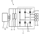
図2は、同期回転電機の励磁装置を示す回路図である。回転整流器51は、ダイオード51a、51bを有するブリッジ回路である。励磁機固定部53による磁場の中を回転する励磁機回転部52の各相に誘起される交流電圧が、ブリッジ回路である回転整流器51の各相に入力される。
FIG. 2 is a circuit diagram showing an exciter of a synchronous rotary electric machine. The
回転整流器51により生ずる一極性の電圧が、界磁巻線である回転子巻線13に印加される。第1の放電抵抗器60および第2の放電抵抗器70は、回転整流器51、および回転子鉄心12に巻回された回転子巻線13に並列に配されている。
A unipolar voltage generated by the
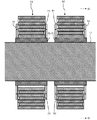
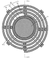
図3は、放電抵抗器の構成を示す図4のIII−III線矢視縦断面図であり、図4は、図3のIV−IV線矢視横断面図である。 FIG. 3 is a vertical cross-sectional view taken along the line III-III of FIG. 4 showing the configuration of the discharge resistor, and FIG. 4 is a cross-sectional view taken along the line IV-IV of FIG.
第1の放電抵抗器60および第2の放電抵抗器70は、軸方向に互いに間隔をあけて隣接してロータシャフト11に取り付けられている。第1の放電抵抗器60は、抵抗61、スペーサ62、ボス63および支持部64を有する。また、第2の放電抵抗器70は、抵抗71、スペーサ72、ボス73および支持部74を有する。ここで、スペーサ62、72、ボス63、73、および支持部64、74は、電気絶縁性、すなわちこれらの材質は、電気的な絶縁材である。
The
ボス63およびボス73は、ロータシャフト11の径方向外側にロータシャフト11を囲むようにロータシャフト11に取り付けられている。ボス63および支持部64は、抵抗61とスペーサ62を支持する。また、ボス73および支持部74は、抵抗71とスペーサ72を支持する。なお支持部の詳細の図示は省略している。支持部64および支持部74は、それぞれ抵抗61および抵抗71に印加される遠心力に耐える構造強度を有する。
The
抵抗61は、長く延びた板状であり、絶縁材による被覆はなされておらず、直接、冷却用気体に接する。抵抗61は、長手方向の一端がボス63に接続されており、渦巻き状に、ロータシャフト11の周囲に巻きつけられるように形成されている。渦巻き(スパイラル)状に形成されている長手方向の途中の位置には、抵抗61内の径方向の間隔を確保するためのスペーサ62が設けられている。
The
同様に、抵抗71は、長く延びた板状であり、絶縁材による被覆はなされておらず、直接、冷却用気体に接する。抵抗71は、長手方向の一端がボス73に接続されており、渦巻き状に、ロータシャフト11の周囲に巻きつけられるように形成されている。渦巻き(スパイラル)状に形成されている長手方向の途中の位置には、抵抗71内の径方向の間隔を確保するためのスペーサ72が設けられている。
Similarly, the
図4に示すように、回転子鉄心12側から軸方向に第1の放電抵抗器60を見ると、抵抗61の巻回方向、すなわち渦巻きの方向は、中心から外に向かって時計回り方向である。
As shown in FIG. 4, when the
一方、図示しないが、回転子鉄心12側から軸方向に第2の放電抵抗器70を見ると、抵抗71第2の放電抵抗器70については、中心から外側に向かって反時計回りに巻かれている。
On the other hand, although not shown, when the
このため、第1の放電抵抗器60に電流が流れたときに生ずる磁束と、第2の放電抵抗器70に電流が流れたときに生ずる磁束とは、互いに打ち消し合う。この結果、第1の放電抵抗器60と第2の放電抵抗器70とが設置されている外側には、大きな磁界を形成せず、大きな磁気的影響を生じない。
Therefore, the magnetic flux generated when the current flows through the
以上のように形成されていることから、渦巻き状の抵抗61には、隙間61aが形成され、隙間61aは、冷却用気体の軸方向の流路となる。渦巻き状の抵抗71についても、隙間71a(図5)が形成され、隙間71aは、冷却用気体の軸方向の流路となる。
Since it is formed as described above, a
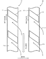
図5は、第1の実施形態に係る放電抵抗器の長手方向の展開図である。 FIG. 5 is a development view of the discharge resistor according to the first embodiment in the longitudinal direction.
第1の放電抵抗器60のそれぞれのスペーサ62は、軸方向に対して角度を持った方向に配置されている。ここで、スペーサ62の方向とは、スペーサ62の長手方向に沿った方向を言うものとする。このため、第1の放電抵抗器60の抵抗61とスペーサ62とによりファン効果を生ずる。また、第2の放電抵抗器70のそれぞれのスペーサ72は、軸方向に対して角度を持って配置されており、第2の放電抵抗器70の抵抗71とスペーサ72とによりファン効果を生ずる。
Each
第1の放電抵抗器60のそれぞれのスペーサ62と、第2の放電抵抗器70のそれぞれのスペーサ72は、互いに同じ方向に傾いている。なお、第1の放電抵抗器60のそれぞれのスペーサ62の軸方向に対する角度と、第2の放電抵抗器70のそれぞれのスペーサ72の軸方向に対する角度は、必ずしも同じ角度であることを要しない。また、抵抗71に沿ったスペーサ72の位置は、必ずしも、抵抗61に沿ってスペーサ62の位置と同じ位置あるいは近傍ではなくともよい。
The
この結果、第2の放電抵抗器70は、第1の放電抵抗器60と第2の放電抵抗器70の間の空間の径方向外側から冷却用気体を吸い込むとともに、第1の放電抵抗器60から流出する冷却用気体を吸い込むことになる。すなわち、冷却用気体は、軸方向の外側から第1の放電抵抗器60のそれぞれのスペーサ62の間に流入し、その後、第2の放電抵抗器70のそれぞれのスペーサ72の間を流れる。
As a result, the
このように、第1の放電抵抗器60と第2の放電抵抗器70が同じ方向に冷却用気体を駆動することから、両者のファン効果が重畳して、大きな駆動力を生ずる。
In this way, since the
さらに、第1の放電抵抗器60および第2の放電抵抗器70自体は、表面に絶縁材料のモールドがなされておらず、かつ、それぞれ隙間61aおよび隙間71aを冷却用気体が通過することから、さらに冷却効果が高まる。
Further, the
以上のように、本実施形態によれば、同期回転電機において、簡易な構成により放電抵抗器の冷却機能を向上させることができる。 As described above, according to the present embodiment, in the synchronous rotary electric machine, the cooling function of the discharge resistor can be improved by a simple configuration.
[第2の実施形態]
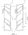
図6は、第2の実施形態に係る放電抵抗器の長手方向の展開図である。
[Second Embodiment]
FIG. 6 is a development view of the discharge resistor according to the second embodiment in the longitudinal direction.
本第2の実施形態は、第1の実施形態の変形である。本第2の実施形態においては、第1の放電抵抗器60のそれぞれのスペーサ62の方向が、第1の実施形態の場合とは逆方向となっている。この点を除いては、第2の実施形態は、第1の実施形態と同様である。
The second embodiment is a modification of the first embodiment. In the second embodiment, the direction of each
この結果、第1の放電抵抗器60を通過する冷却用気体の方向が、第1の実施形態とは逆となる。すなわち、冷却用気体は、第1の放電抵抗器60と第2の放電抵抗器70の間の空間から、第1の放電抵抗器60の隙間61aに吸い込まれて、隙間61aを通過して、軸方向に第1の放電抵抗器60の反対側に放出される。
As a result, the direction of the cooling gas passing through the
一方、第2の放電抵抗器70においては、スペーサ72は、第1の放電抵抗器60と第2の放電抵抗器70の間の空間に軸方向に垂直な平面を想定した場合に、この平面に対して対称の方向に形成されている。
On the other hand, in the
以上のような第1の放電抵抗器60および第2の放電抵抗器70の構成により、冷却用気体は、第1の放電抵抗器60と第2の放電抵抗器70の間の空間から、第2の放電抵抗器70の隙間71aに吸い込まれて、隙間71aを通過して、軸方向に第2の放電抵抗器70の反対側に放出される。
Due to the configuration of the
このように、第1の放電抵抗器60と第2の放電抵抗器70のそれぞれが、第1の放電抵抗器60と第2の放電抵抗器70の間の空間から冷却用気体を吸い込むことになる。この結果、励磁装置50の上方に形成されている冷却器出口開口44から励磁装置50側への冷却用気体の流入が加速され、励磁装置50全体の冷却効果が高まる。
In this way, each of the
以上のように、本実施形態によれば、同期回転電機において、簡易な構成により放電抵抗器の冷却機能を向上させることができる。 As described above, according to the present embodiment, in the synchronous rotary electric machine, the cooling function of the discharge resistor can be improved by a simple configuration.
[その他の実施形態]
以上、本発明の実施形態を説明したが、実施形態は、例として提示したものであり、発明の範囲を限定することは意図していない。
[Other Embodiments]
Although the embodiments of the present invention have been described above, the embodiments are presented as examples and are not intended to limit the scope of the invention.
さらに、これらの実施形態は、その他の様々な形態で実施されることが可能であり、発明の要旨を逸脱しない範囲で、種々の省略、置き換え、変更を行うことができる。これら実施形態やその変形は、発明の範囲や要旨に含まれると同様に、特許請求の範囲に記載された発明とその均等の範囲に含まれるものである。 Furthermore, these embodiments can be implemented in various other embodiments, and various omissions, replacements, and changes can be made without departing from the gist of the invention. These embodiments and modifications thereof are included in the scope and gist of the invention as well as the invention described in the claims and the equivalent scope thereof.
10…回転子、11…ロータシャフト、12…回転子鉄心、13…回転子巻線、15…内扇、15a…仕切り板、20…固定子、21…固定子鉄心、22…固定子巻線、30…フレーム、30a…閉空間、30b、30c…入口側空間、32…軸受、34…軸受ブラケット、40…冷却器、41…冷却管、42…冷却器カバー、43…冷却器入口開口、44…冷却器出口開口、50…励磁装置、51…回転整流器、51a、51b…ダイオード、52…励磁機回転部、53…励磁機固定部、60…第1の放電抵抗器、61…抵抗、61a…隙間、62…スペーサ、63…ボス、64…支持部、70…第2の放電抵抗器、71…抵抗、71a…隙間、72…スペーサ、73…ボス、74…支持部、100…同期回転電機 10 ... Rotor, 11 ... Rotor shaft, 12 ... Rotor core, 13 ... Rotor winding, 15 ... Inner fan, 15a ... Partition plate, 20 ... Stator, 21 ... Stator core, 22 ... Stator winding , 30 ... frame, 30a ... closed space, 30b, 30c ... inlet side space, 32 ... bearing, 34 ... bearing bracket, 40 ... cooler, 41 ... cooling pipe, 42 ... cooler cover, 43 ... cooler inlet opening, 44 ... cooler outlet opening, 50 ... exciter, 51 ... rotary rectifier, 51a, 51b ... diode, 52 ... exciter rotating part, 53 ... exciter fixing part, 60 ... first discharge resistor, 61 ... resistor, 61a ... Gap, 62 ... Spacer, 63 ... Boss, 64 ... Support, 70 ... Second discharge resistor, 71 ... Resistance, 71a ... Gap, 72 ... Spacer, 73 ... Boss, 74 ... Support, 100 ... Synchronous Rotor
Claims (6)
前記回転子鉄心の径方向外側に配された固定子鉄心と、前記固定子鉄心を貫通する固定子巻線とを有する固定子と、
前記ロータシャフトとともに回転する回転整流器および少なくとも一つの放電抵抗器を有する励磁装置と、
前記回転子鉄心、前記固定子および前記励磁装置を収納するフレームと、
前記フレームに取り付けられて、前記フレーム内の前記回転子、前記固定子、および前記励磁装置を冷却する冷却用気体を冷却する冷却器と、
を備え、
前記少なくとも一つの放電抵抗器は、
前記ロータシャフトの周囲に巻き付けられた抵抗と、
前記抵抗の間に配され前記抵抗内に隙間を形成する複数の電気絶縁性のスペーサと、
を有することを特徴とする同期回転電機。 A rotor shaft extending in the axial direction, a rotor core attached to the rotor shaft, and a rotor having a rotor winding wound around the rotor core.
A stator having a stator core arranged radially outside the rotor core, and a stator winding penetrating the stator core, and a stator.
An exciter with a rotary rectifier and at least one discharge resistor that rotates with the rotor shaft.
A frame for accommodating the rotor core, the stator, and the exciter,
A cooler attached to the frame to cool the rotor, the stator, and the cooling gas that cools the exciter in the frame.
With
The at least one discharge resistor is
The resistance wound around the rotor shaft and
A plurality of electrically insulating spacers arranged between the resistors and forming a gap in the resistors,
A synchronous rotating electric machine characterized by having.
前記第1の放電抵抗器の抵抗の巻回方向と、前記第2の放電抵抗器の抵抗の巻回方向は互いに逆方向であることを特徴とする請求項1または請求項2に記載の同期回転電機。 The at least one discharge resistor has a first discharge resistor and a second discharge resistor.
The synchronization according to claim 1 or 2, wherein the winding direction of the resistor of the first discharge resistor and the winding direction of the resistor of the second discharge resistor are opposite to each other. Rotating electric machine.
前記ロータシャフトの周囲に巻き付けられた抵抗と、
前記抵抗の間に配され前記抵抗内に隙間を形成する複数の電気絶縁性のスペーサと、
を有することを特徴とする放電抵抗器。 A rotor having a rotor shaft, a rotor core, and a rotor winding, a stator having a stator core and a stator winding, an exciter having a rotary rectifier that rotates with the rotor shaft, and the rotor. A frame that houses the iron core, the stator, and the exciter, and a cooler that is attached to the frame and cools the rotor, the stator, and the cooling gas that cools the exciter in the frame. The discharge resistor of the exciter of the synchronous rotary electric machine provided with the above.
The resistance wound around the rotor shaft and
A plurality of electrically insulating spacers arranged between the resistors and forming a gap in the resistors,
A discharge resistor characterized by having.
Priority Applications (2)
| Application Number | Priority Date | Filing Date | Title |
|---|---|---|---|
| JP2019088812A JP7189835B2 (en) | 2019-05-09 | 2019-05-09 | Synchronous rotating electrical machines and discharge resistors |
| CN202010385664.XA CN111917241B (en) | 2019-05-09 | 2020-05-09 | Synchronous rotating motor and discharge resistor |
Applications Claiming Priority (1)
| Application Number | Priority Date | Filing Date | Title |
|---|---|---|---|
| JP2019088812A JP7189835B2 (en) | 2019-05-09 | 2019-05-09 | Synchronous rotating electrical machines and discharge resistors |
Publications (2)
| Publication Number | Publication Date |
|---|---|
| JP2020184853A true JP2020184853A (en) | 2020-11-12 |
| JP7189835B2 JP7189835B2 (en) | 2022-12-14 |
Family
ID=73044758
Family Applications (1)
| Application Number | Title | Priority Date | Filing Date |
|---|---|---|---|
| JP2019088812A Active JP7189835B2 (en) | 2019-05-09 | 2019-05-09 | Synchronous rotating electrical machines and discharge resistors |
Country Status (2)
| Country | Link |
|---|---|
| JP (1) | JP7189835B2 (en) |
| CN (1) | CN111917241B (en) |
Families Citing this family (1)
| Publication number | Priority date | Publication date | Assignee | Title |
|---|---|---|---|---|
| CN112635140A (en) * | 2020-12-18 | 2021-04-09 | 广东意杰科技有限公司 | High-power high-pulse energy-absorbing resistor |
Citations (6)
| Publication number | Priority date | Publication date | Assignee | Title |
|---|---|---|---|---|
| JPS5361010U (en) * | 1976-10-27 | 1978-05-24 | ||
| JPS55121601A (en) * | 1979-03-14 | 1980-09-18 | Tokyo Shibaura Electric Co | Discharge resistor for rotary electric machine |
| JPS57170674U (en) * | 1981-04-23 | 1982-10-27 | ||
| JPS5961455A (en) * | 1982-09-30 | 1984-04-07 | Toshiba Corp | Brushless exciter |
| JPH06343250A (en) * | 1993-05-31 | 1994-12-13 | Toshiba Corp | Brushless synchronous motor |
| JPH07329740A (en) * | 1994-06-07 | 1995-12-19 | Meidensha Corp | Retarder for vehicle |
Family Cites Families (6)
| Publication number | Priority date | Publication date | Assignee | Title |
|---|---|---|---|---|
| JP4622475B2 (en) * | 2004-11-22 | 2011-02-02 | ウシオ電機株式会社 | Trance |
| EP2854140A1 (en) * | 2013-09-26 | 2015-04-01 | Siemens Aktiengesellschaft | Resistance module for increasing the starting torque of a rotor of an electric machine with a rotor winding |
| CN203690033U (en) * | 2013-12-31 | 2014-07-02 | 天津市先导倍尔电气有限公司 | Discharging resistor for high-rotating-speed synchronous motor brushless excitation device |
| CN203708124U (en) * | 2014-01-21 | 2014-07-09 | 天津市先导倍尔电气有限公司 | High-speed synchronous motor brushless excitation rotating rectifier |
| JP6637683B2 (en) * | 2015-06-19 | 2020-01-29 | 東芝三菱電機産業システム株式会社 | Rotating electric machine |
| JP6930177B2 (en) * | 2017-03-30 | 2021-09-01 | スミダコーポレーション株式会社 | Transformers and transformer manufacturing methods |
-
2019
- 2019-05-09 JP JP2019088812A patent/JP7189835B2/en active Active
-
2020
- 2020-05-09 CN CN202010385664.XA patent/CN111917241B/en active Active
Patent Citations (6)
| Publication number | Priority date | Publication date | Assignee | Title |
|---|---|---|---|---|
| JPS5361010U (en) * | 1976-10-27 | 1978-05-24 | ||
| JPS55121601A (en) * | 1979-03-14 | 1980-09-18 | Tokyo Shibaura Electric Co | Discharge resistor for rotary electric machine |
| JPS57170674U (en) * | 1981-04-23 | 1982-10-27 | ||
| JPS5961455A (en) * | 1982-09-30 | 1984-04-07 | Toshiba Corp | Brushless exciter |
| JPH06343250A (en) * | 1993-05-31 | 1994-12-13 | Toshiba Corp | Brushless synchronous motor |
| JPH07329740A (en) * | 1994-06-07 | 1995-12-19 | Meidensha Corp | Retarder for vehicle |
Also Published As
| Publication number | Publication date |
|---|---|
| CN111917241A (en) | 2020-11-10 |
| JP7189835B2 (en) | 2022-12-14 |
| CN111917241B (en) | 2023-05-09 |
Similar Documents
| Publication | Publication Date | Title |
|---|---|---|
| JP4999990B2 (en) | Rotating motor and blower using the same | |
| JP3400924B2 (en) | Electric pump | |
| JP6507723B2 (en) | Axial fan and fan unit | |
| US20130026868A1 (en) | Electric Machine With Enhanced Cooling | |
| JPWO2011042975A1 (en) | Fan motor and air conditioner equipped with the same | |
| JP6925502B2 (en) | Electric blower, vacuum cleaner and hand drying device | |
| JP2016146735A (en) | Single phase brushless motor | |
| US3719843A (en) | Dynamoelectric machine cooling arrangement | |
| JP2018007487A (en) | Rotary machine | |
| JP2024144650A (en) | Rotating Equipment | |
| JP2013046554A (en) | Rotary electric machine | |
| JP6993892B2 (en) | Axial gap type rotary electric machine | |
| JP7125864B2 (en) | Rotating electric machine | |
| CN111917241B (en) | Synchronous rotating motor and discharge resistor | |
| US12334795B2 (en) | Rotary electrical machine refrigerant flow passage partition wall gap | |
| JP6586436B2 (en) | Rotating electric machine and its rotor | |
| RU2360352C1 (en) | Electric machine | |
| JP2020010510A (en) | Rotary electric machine and rotor | |
| JP6172234B2 (en) | Electric motor and blower | |
| US2271981A (en) | Dynamoelectric machine | |
| TW201926856A (en) | Slotless electric motor, and electric blower or electric vacuum cleaner using same including a hollow cylindrical core, a stator, a permanent magnet rotor and a frame body | |
| JP2013215028A (en) | Single-phase induction motor | |
| JP2017200354A (en) | Brushless rotary electric machine | |
| JP6762238B2 (en) | motor | |
| KR102605219B1 (en) | Rotating electric machine |
Legal Events
| Date | Code | Title | Description |
|---|---|---|---|
| RD01 | Notification of change of attorney |
Free format text: JAPANESE INTERMEDIATE CODE: A7421 Effective date: 20200528 |
|
| A621 | Written request for application examination |
Free format text: JAPANESE INTERMEDIATE CODE: A621 Effective date: 20210623 |
|
| A977 | Report on retrieval |
Free format text: JAPANESE INTERMEDIATE CODE: A971007 Effective date: 20220526 |
|
| A131 | Notification of reasons for refusal |
Free format text: JAPANESE INTERMEDIATE CODE: A131 Effective date: 20220531 |
|
| A521 | Request for written amendment filed |
Free format text: JAPANESE INTERMEDIATE CODE: A523 Effective date: 20220801 |
|
| TRDD | Decision of grant or rejection written | ||
| A01 | Written decision to grant a patent or to grant a registration (utility model) |
Free format text: JAPANESE INTERMEDIATE CODE: A01 Effective date: 20221129 |
|
| A61 | First payment of annual fees (during grant procedure) |
Free format text: JAPANESE INTERMEDIATE CODE: A61 Effective date: 20221202 |
|
| R150 | Certificate of patent or registration of utility model |
Ref document number: 7189835 Country of ref document: JP Free format text: JAPANESE INTERMEDIATE CODE: R150 |
|
| R250 | Receipt of annual fees |
Free format text: JAPANESE INTERMEDIATE CODE: R250 |