JP5340332B2 - Rotating electric machine - Google Patents

Rotating electric machine Download PDF

Info

Publication number
JP5340332B2
JP5340332B2 JP2011045312A JP2011045312A JP5340332B2 JP 5340332 B2 JP5340332 B2 JP 5340332B2 JP 2011045312 A JP2011045312 A JP 2011045312A JP 2011045312 A JP2011045312 A JP 2011045312A JP 5340332 B2 JP5340332 B2 JP 5340332B2
Authority
JP
Japan
Prior art keywords
rotor
magnetic
stator
field
winding
Prior art date
Legal status (The legal status is an assumption and is not a legal conclusion. Google has not performed a legal analysis and makes no representation as to the accuracy of the status listed.)
Expired - Fee Related
Application number
JP2011045312A
Other languages
Japanese (ja)
Other versions
JP2012182943A (en
Inventor
一樹 外木
稔彦 吉田
紀元 蓑島
信行 松井
卓 小坂
Current Assignee (The listed assignees may be inaccurate. Google has not performed a legal analysis and makes no representation or warranty as to the accuracy of the list.)
Toyota Industries Corp
Original Assignee
Toyota Industries Corp
Priority date (The priority date is an assumption and is not a legal conclusion. Google has not performed a legal analysis and makes no representation as to the accuracy of the date listed.)
Filing date
Publication date
Application filed by Toyota Industries Corp filed Critical Toyota Industries Corp
Priority to JP2011045312A priority Critical patent/JP5340332B2/en
Priority to CN201210047825.XA priority patent/CN102655363B/en
Priority to EP20120157225 priority patent/EP2495851A2/en
Priority to US13/407,472 priority patent/US9083225B2/en
Publication of JP2012182943A publication Critical patent/JP2012182943A/en
Application granted granted Critical
Publication of JP5340332B2 publication Critical patent/JP5340332B2/en
Expired - Fee Related legal-status Critical Current
Anticipated expiration legal-status Critical

Links

Images

Abstract

<P>PROBLEM TO BE SOLVED: To equalize imbalance of radial force applied to a rotary shaft in a rotary electric machine where a magnetic field is applied to a rotor by field windings so as to make the rotor a single pole. <P>SOLUTION: In a rotary electric machine 10, a rotor 11 has magnetic salient poles 18 formed therein that are circumferentially arranged at regular intervals. A cylindrical stator 12 is arranged on an outer circumferential side of a rotor core 16, and has teeth 19 formed at regular intervals on an inner circumferential surface. Stator windings, which are concentrated windings, are wound around the teeth 19. The rotary electric machine 10 has a field yoke 13 provided on an outer circumference of the stator 12; and field windings 14 that form a magnetic circuit that makes the rotor 11 a single pole. Phase arrangement of the magnetic salient poles 18, the teeth 19, and the stator windings is set to be rotationally symmetric about a rotary shaft 15. The number Pn of the magnetic salient poles 18 and the number Ps of slots of the stator 12 have a common factor other than one. <P>COPYRIGHT: (C)2012,JPO&amp;INPIT

Description

本発明は、回転子が界磁巻線により界磁される回転電機に関する。   The present invention relates to a rotating electrical machine in which a rotor is fielded by a field winding.

回転子が界磁巻線により界磁される回転電動機として、回転軸が高速回転した際に回転軸の半径方向の振れが大きくなるのを抑制したホモポーラ形リラクタンスモータが提案されている(特許文献1参照)。このホモポーラ形リラクタンスモータは、図12に示すように、突極51を有する一対の回転子52A,52Bが所定の間隔を有して直列に、かつ各回転子52A,52Bの突極51同士が互いにずれた状態で回転軸53に固定されている。固定子54A,54Bは、それぞれ回転子52A,52Bを囲繞するように配置され、回転子52A,52Bにトルクを発生させるトルク発生用駆動コイル(図示せず)を備えている。固定子54A,54Bの外側には突極51を励磁する界磁コイル55が設けられている。そして、界磁コイル55に通電すると、図12に示すように一方の回転子52Aの突極51から他方の回転子52Bの突極51に通じる磁束が形成され、一方の回転子52Aの4個の突極51が例えばN極となり、他方の回転子52Bの4個の突極51が例えばS極になる。   A homopolar reluctance motor has been proposed as a rotary motor in which a rotor is fielded by a field winding, which suppresses an increase in radial deflection of the rotating shaft when the rotating shaft rotates at high speed (Patent Document). 1). In this homopolar reluctance motor, as shown in FIG. 12, a pair of rotors 52A and 52B having salient poles 51 are arranged in series with a predetermined interval, and the salient poles 51 of the rotors 52A and 52B are connected to each other. It is being fixed to the rotating shaft 53 in the state which mutually shifted | deviated. The stators 54A and 54B are arranged so as to surround the rotors 52A and 52B, respectively, and include torque generation drive coils (not shown) that generate torque in the rotors 52A and 52B. A field coil 55 for exciting the salient poles 51 is provided outside the stators 54A and 54B. When the field coil 55 is energized, a magnetic flux is formed from the salient pole 51 of one rotor 52A to the salient pole 51 of the other rotor 52B as shown in FIG. The salient poles 51 of the other rotor 52B are, for example, N poles, and the four salient poles 51 of the other rotor 52B are, for example, S poles.

特開平10−136622号公報JP-A-10-136622

特許文献1のホモポーラ形リラクタンスモータは、回転軸53に固定された一対の回転子52A,52Bのうちの一方の回転子52Aの全ての突極51がN極になり、他方の回転子52Bの全ての突極51がS極になる。そのため、回転軸53に作用するラジアル力のバランスが取り易い。しかし、回転子及び固定子をそれぞれ2個ずつ設ける必要があり、構成が複雑で小型化し難い。   In the homopolar reluctance motor of Patent Document 1, all the salient poles 51 of one rotor 52A of the pair of rotors 52A and 52B fixed to the rotating shaft 53 become N poles, and the other rotor 52B All salient poles 51 become S poles. Therefore, it is easy to balance the radial force acting on the rotating shaft 53. However, it is necessary to provide two rotors and two stators, and the configuration is complicated and it is difficult to reduce the size.

回転子が界磁巻線により界磁され、かつ単極となる回転電機で回転子及び固定子を1個ずつにした場合、構成が簡単になり小型化し易くなる。ところが、その際、固定子の巻線に集中巻を採用すると、固定子(ステータ)及び回転子(ロータ)の突極数の組み合わせにより、通電時に回転子に働くラジアル力が不均一に作用する状態となり、回転軸を支持するベアリングの負担が大きくなり、振動増や寿命低下を招くという問題が生じる。   When the rotor is fielded by the field winding and has only one rotor and one stator in the rotating electric machine having a single pole, the configuration is simplified and the size is easily reduced. However, if concentrated winding is employed for the stator winding, the radial force acting on the rotor when energized acts unevenly due to the combination of the number of salient poles of the stator (stator) and rotor (rotor). This causes a problem that the load on the bearing that supports the rotating shaft increases, resulting in increased vibration and reduced life.

本発明は前記の問題に鑑みてなされたものであって、その目的は、回転子が界磁巻線により単極となるように界磁される回転電機において、回転シャフトに加わるラジアル力のアンバランスをなくすことができる回転電機を提供することにある。   The present invention has been made in view of the above-described problems, and an object of the present invention is to reduce the radial force applied to the rotating shaft in a rotating electric machine in which a rotor is fielded so as to have a single pole by a field winding. An object of the present invention is to provide a rotating electrical machine that can eliminate the balance.

前記の目的を達成するため、請求項1に記載の発明は、回転子が界磁巻線により界磁される回転電機である。そして、回転シャフトに一体回転可能に固定され、かつ周方向に一定間隔で磁気的突極が形成されたロータコアを有する回転子と、筒状に形成されるとともに前記ロータコアの外周側に配置され、かつ三相交流電流で励磁される固定子巻線が集中巻で巻き付けられたティースが内周面に一定間隔で形成された固定子と、前記固定子の外側に設けられるとともに、軸方向両側においてベアリングを介して前記回転シャフトを回転可能に支持する界磁ヨークと、前記回転子が単極となる磁気回路を形成するための界磁巻線とを備えている。また、前記磁気的突極、前記ティースがそれぞれ前記回転シャフトを中心とした回転対称に配置され、前記固定子巻線の相配置が前記回転シャフトを中心とした回転対称に設定され、かつ前記磁気的突極の数をPn、前記固定子のスロットの数をPsとした場合、Pn及びPsが1以外の公約数を有し、且つPn:Psが4:9、5:12のいずれかを満足する。ここで、「回転子が単極となる」とは、ロータコアに複数形成された磁気的突極の固定子側端部が、界磁巻線に励磁電流が供給された状態では全てN極又はS極の同じ磁極になることを意味する。また、「磁気的突極」とは、ロータコアの内側から外面に向かって磁束が流れ易い部分を意味し、ロータコアとして突部を一定間隔で有する形状に限らず、磁性材で形成された突部の間が非磁性材で埋められる、もしくは磁気的突極性を有するようロータコアに非磁性部を配し、全体として平坦な形状のロータコアであってもよい。 In order to achieve the above object, an invention according to claim 1 is a rotating electrical machine in which a rotor is fielded by a field winding. And, a rotor having a rotor core fixed to the rotating shaft so as to be integrally rotatable and having magnetic salient poles formed at regular intervals in the circumferential direction, and formed in a cylindrical shape and disposed on the outer peripheral side of the rotor core, and a three-phase alternating current stator formed at regular intervals on the inner circumferential surface teeth which stator winding is wound in concentrated winding, which is energized by, Rutotomoni provided outside the stator, axial sides And a field yoke for rotatably supporting the rotating shaft via a bearing, and a field winding for forming a magnetic circuit in which the rotor has a single pole. The magnetic salient poles and the teeth are arranged rotationally symmetrical about the rotating shaft, the phase arrangement of the stator windings is set rotationally symmetrical about the rotating shaft, and the magnetic the number of Pn of saliency, if the number of the stator slots and the Ps, Pn and Ps are have a common divisor other than 1, and Pn: Ps 4: 9,5: 12 one of Satisfied . Here, “the rotor has a single pole” means that the stator side end of a plurality of magnetic salient poles formed on the rotor core is all N poles or when the exciting current is supplied to the field windings. It means that it becomes the same magnetic pole of S pole. The “magnetic salient pole” means a portion where magnetic flux easily flows from the inner side to the outer surface of the rotor core, and is not limited to the shape having the protruding portions at a constant interval as the rotor core, but the protruding portion formed of a magnetic material. A non-magnetic portion may be provided in the rotor core so that the gap is filled with a non-magnetic material or has magnetic saliency, and the rotor core may be flat as a whole.

この発明では、固定子(ステータ)のティースに集中巻で巻き付けられた固定子巻線が励磁されると回転磁界が発生し、回転磁界による磁束により回転子(ロータ)にトルクが作用する。一方、界磁巻線に励磁電流が供給された状態では、回転子のロータコアに複数形成された全ての磁気的突極の固定子側端部が同じ磁極になる。そして、回転磁界による磁束と、界磁巻線による磁束との相互作用によって回転シャフトにラジアル力が加わる。磁気的突極、ティースがそれぞれ回転シャフトを中心とした回転対称に配置され、前記固定子巻線の相配置が前記回転シャフトを中心とした回転対称に設定され、かつ前記磁気的突極の数をPn、前記固定子のスロットの数をPsとした場合、Pn及びPsが1以外の公約数を有するため、回転シャフトに加わるラジアル力のアンバランスがなくなる。   In this invention, when the stator winding wound by concentrated winding on the teeth of the stator (stator) is excited, a rotating magnetic field is generated, and torque acts on the rotor (rotor) by the magnetic flux generated by the rotating magnetic field. On the other hand, in a state in which the exciting current is supplied to the field winding, the stator side end portions of all the magnetic salient poles formed on the rotor core of the rotor become the same magnetic pole. A radial force is applied to the rotating shaft by the interaction between the magnetic flux generated by the rotating magnetic field and the magnetic flux generated by the field winding. Magnetic salient poles and teeth are arranged rotationally symmetrical around the rotating shaft, the phase arrangement of the stator windings is set rotationally symmetrical around the rotating shaft, and the number of magnetic salient poles Is Pn, and the number of slots of the stator is Ps, Pn and Ps have a common divisor other than 1, so that there is no unbalance of the radial force applied to the rotating shaft.

請求項2に記載の発明は、請求項1に記載の発明において、前記ロータコアは、複数枚積層された電磁鋼板で形成されている。 According to a second aspect of the present invention, in the first aspect of the present invention, the rotor core is formed of a plurality of laminated electromagnetic steel sheets.

請求項3に記載の発明は、請求項2に記載の発明において、前記回転シャフトは、外周側の磁気抵抗が内周側の磁気抵抗より小さい2重構造に形成されている。 According to a third aspect of the present invention, in the second aspect of the present invention, the rotary shaft is formed in a double structure in which the magnetic resistance on the outer peripheral side is smaller than the magnetic resistance on the inner peripheral side.

請求項4に記載の発明は、請求項2に記載の発明において、前記ロータコアは、筒状コアと前記筒状コアの外側に形成された積層コアとで構成され、前記筒状コアの材質は磁気抵抗が前記積層コアの材質より小さく構成されている。 The invention according to claim 4 is the invention according to claim 2 , wherein the rotor core is composed of a cylindrical core and a laminated core formed outside the cylindrical core, and the material of the cylindrical core is The magnetic resistance is configured to be smaller than the material of the laminated core.

本発明によれば、回転子が界磁巻線により単極となるように界磁される回転電機において、回転シャフトに加わるラジアル力のアンバランスをなくすことができる。   ADVANTAGE OF THE INVENTION According to this invention, the unbalance of the radial force added to a rotating shaft can be eliminated in the rotary electric machine by which a rotor is fielded so that it may become a single pole by a field winding.

(a)は回転電動機の模式断面図、(b)はロータの正面図。(A) is a schematic cross section of a rotary electric motor, (b) is a front view of a rotor. (a)は図1のII−II線模式断面図、(b)はロータが(a)の状態から回転した状態の模式断面図。FIG. 2A is a schematic cross-sectional view taken along the line II-II in FIG. 1, and FIG. 2B is a schematic cross-sectional view in a state where the rotor is rotated from the state of FIG. 参考例の回転電動機の模式断面図。The schematic cross section of the rotary electric motor of a reference example. ラジアル力の変化を示すグラフ。The graph which shows the change of radial force. 別の実施形態の図2(b)に対応する模式断面図。The schematic cross section corresponding to Drawing 2 (b) of another embodiment. 別の実施形態の回転電動機の模式断面図。The schematic cross section of the rotary electric motor of another embodiment. 別の実施形態の回転電動機の模式断面図。The schematic cross section of the rotary electric motor of another embodiment. 別の実施形態の回転電動機の模式断面図。The schematic cross section of the rotary electric motor of another embodiment. 別の実施形態の回転電動機の模式断面図。The schematic cross section of the rotary electric motor of another embodiment. (a)は別の実施形態の回転電動機の模式断面図、(b)は別の実施形態のロータの正面図。(A) is a schematic cross section of the rotary electric motor of another embodiment, (b) is a front view of the rotor of another embodiment. 別の実施形態のロータの正面図。The front view of the rotor of another embodiment. 従来技術の概略断面斜視図。The schematic cross-sectional perspective view of a prior art.

以下、本発明を三相の回転電動機に具体化した一実施形態を図1〜図4にしたがって説明する。なお、図2(a),(b)及び図3の模式断面図において図示の都合上、断面のハッチングを省略している。   Hereinafter, an embodiment in which the present invention is embodied in a three-phase rotary motor will be described with reference to FIGS. In addition, in the schematic cross-sectional views of FIGS. 2A and 2B and FIG. 3, the cross-sectional hatching is omitted for convenience of illustration.

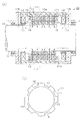
図1(a)に示すように、回転電機としての回転電動機10は、ロータ(回転子)11と、ロータ11の外側に配置された筒状のステータ(固定子)12と、ステータ12の外側に設けられた界磁ヨーク13と、ロータ11を界磁する界磁巻線14とを備えている。界磁ヨーク13は回転電動機10のケースとしても機能し、ステータ12の外周と対向する円筒部13aと、円筒部13aの両端に固定された一対の円板部13bとを有する。   As shown in FIG. 1A, a rotary electric motor 10 as a rotating electrical machine includes a rotor (rotor) 11, a cylindrical stator (stator) 12 disposed outside the rotor 11, and the outside of the stator 12. And a field winding 14 for fielding the rotor 11. The field yoke 13 also functions as a case of the rotary electric motor 10, and has a cylindrical portion 13a facing the outer periphery of the stator 12, and a pair of disk portions 13b fixed to both ends of the cylindrical portion 13a.

ロータ11は、回転シャフト15に一体回転可能に固定されたロータコア16を有し、回転シャフト15は円板部13bを貫通する状態でベアリング17を介して円板部13bに回転可能に支持されている。回転シャフト15は磁性材で形成されている。   The rotor 11 has a rotor core 16 fixed to the rotary shaft 15 so as to be integrally rotatable. The rotary shaft 15 is rotatably supported by the disc portion 13b via a bearing 17 in a state of passing through the disc portion 13b. Yes. The rotating shaft 15 is made of a magnetic material.

図1(b)に示すように、ロータコア16は、径方向に突出する突部が周方向に一定間隔で形成されており、突部が磁気的突極18を構成する。磁気的突極18は、ロータコア16を軸方向から見た場合に回転シャフト15を中心とした回転対称となるように配置されている。この実施形態では磁気的突極18は8個設けられ、各磁気的突極18はロータコア16の軸方向全長に亘って延設されている。ロータコア16は、電磁鋼板を複数枚(例えば数十枚)積層して構成されており、軸方向の磁気抵抗が、径方向及び周方向の磁気抵抗より大きくなっている。このため、ロータコア16内においては、磁束は軸方向に流れ難く、径方向及び周方向に流れ易くなる。   As shown in FIG. 1B, the rotor core 16 has protrusions that protrude in the radial direction at regular intervals in the circumferential direction, and the protrusions constitute magnetic salient poles 18. The magnetic salient poles 18 are arranged so as to be rotationally symmetric about the rotary shaft 15 when the rotor core 16 is viewed from the axial direction. In this embodiment, eight magnetic salient poles 18 are provided, and each magnetic salient pole 18 extends over the entire axial length of the rotor core 16. The rotor core 16 is configured by laminating a plurality of (for example, several tens) electromagnetic steel plates, and the axial magnetic resistance is larger than the radial and circumferential magnetic resistance. For this reason, in the rotor core 16, the magnetic flux hardly flows in the axial direction, and easily flows in the radial direction and the circumferential direction.

ステータ12は、電磁鋼板を積層して略円筒状に形成されており、ステータ12の径方向及び周方向の磁気抵抗は、軸方向の磁気抵抗より小さくなっている。このため、ステータ12内においては、磁束はステータ12の周方向及び径方向に流れ易く、軸方向に流れ難くなる。   The stator 12 is formed in a substantially cylindrical shape by laminating electromagnetic steel plates, and the radial and circumferential magnetic resistance of the stator 12 is smaller than the axial magnetic resistance. For this reason, in the stator 12, the magnetic flux easily flows in the circumferential direction and the radial direction of the stator 12, and hardly flows in the axial direction.

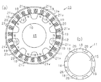
図2に示すように、ステータ12の内側には複数のティース19が周方向に一定間隔で形成されるようにスロット20が等間隔で設けられている。ティース19及びスロット20は、ステータ12を軸方向から見た場合に回転シャフト15を中心とした回転対称となるように配置されている。この実施形態ではティース19及びスロット20がそれぞれ18個設けられている。したがって、ロータコア16の磁気的突極18の数をPn、ステータ12のスロット20の数をPsとした場合、Pn=8、Ps=18となり、Pn及びPsが1以外の公約数を有し、かつPn:Psが4:9を満足する。   As shown in FIG. 2, slots 20 are provided at equal intervals inside the stator 12 such that a plurality of teeth 19 are formed at regular intervals in the circumferential direction. The teeth 19 and the slots 20 are arranged so as to be rotationally symmetric about the rotary shaft 15 when the stator 12 is viewed from the axial direction. In this embodiment, 18 teeth 19 and 18 slots 20 are provided. Therefore, when the number of the magnetic salient poles 18 of the rotor core 16 is Pn and the number of the slots 20 of the stator 12 is Ps, Pn = 8, Ps = 18, and Pn and Ps have a common divisor other than 1, And Pn: Ps satisfies 4: 9.

各ティース19には、固定子巻線としてのU相巻線21u、V相巻線21v、W相巻線21wがそれぞれ集中巻で巻き付けられている。U相巻線21u、V相巻線21v、W相巻線21wは、図2において時計方向にU相、V相、W相の順で、かつ同じ相の巻線が巻き付けられたティース19が3個ずつ隣り合うように巻き付けられている。即ち、固定子巻線を構成するU相巻線21u、V相巻線21v、W相巻線21wの相配置が回転シャフト15を中心とした回転対称に設定されている。   A U-phase winding 21u, a V-phase winding 21v, and a W-phase winding 21w as stator windings are wound around each tooth 19 in a concentrated manner. The U-phase winding 21u, the V-phase winding 21v, and the W-phase winding 21w are formed by the teeth 19 in which the windings of the same phase are wound in the order of the U phase, the V phase, and the W phase in the clockwise direction in FIG. It is wound around three by three. That is, the phase arrangement of the U-phase winding 21u, the V-phase winding 21v, and the W-phase winding 21w constituting the stator winding is set to be rotationally symmetric about the rotary shaft 15.

界磁ヨーク13の両円板部13bには、円環状の突条13cがロータコア16に向かって突出するように形成され、突条13cには外周部に界磁巻線14が巻き付けられたボビン23が嵌合固定されている。突条13c及びボビン23は、ロータ11が単極となる磁気回路を形成するための界磁巻線14が巻き付けられた界磁巻線巻回部を構成する。ロータ11が単極となるとは、ロータコア16に複数形成された磁気的突極18のステータ12側端部が、界磁巻線14に励磁電流が供給された状態では全てN極又はS極の同じ磁極になることを意味する。   An annular ridge 13c is formed on both disk portions 13b of the field yoke 13 so as to protrude toward the rotor core 16, and a bobbin having a field winding 14 wound around the outer periphery of the ridge 13c. 23 is fitted and fixed. The protrusion 13c and the bobbin 23 constitute a field winding winding portion around which the field winding 14 for forming a magnetic circuit in which the rotor 11 has a single pole is wound. The rotor 11 has a single pole when the stator 12 side ends of the plurality of magnetic salient poles 18 formed on the rotor core 16 are all N poles or S poles when the field winding 14 is supplied with an excitation current. Means the same magnetic pole.

この実施形態では、各界磁巻線14に電流が供給されると、界磁ヨーク13とロータコア16との間にロータコア16の磁気的突極が全て同じ磁極(N極)となる磁気回路が形成されるようになっている。詳述すると、図1(a)において左側に位置する一方の界磁巻線14においては、磁束が環状の界磁巻線14の左側から内周側に進入して右側から界磁巻線14の外部へ出るように発生する。また、図1(a)において右側に位置する他方の界磁巻線14においては、磁束が環状の界磁巻線14の右側から内周側に進入して左側から界磁巻線14の外部へ出るように発生する。その結果、両界磁巻線14から発生した磁束の経路は、回転シャフト15内を対向する方向に進んだ後、ロータコア16の内側から磁気的突極18内を通ってステータ12のティース19内へ進み、界磁ヨーク13の円筒部13a及び円板部13bを通って再び回転シャフト15内に進入する経路となる。   In this embodiment, when a current is supplied to each field winding 14, a magnetic circuit is formed in which the magnetic salient poles of the rotor core 16 are all the same magnetic pole (N pole) between the field yoke 13 and the rotor core 16. It has come to be. More specifically, in one field winding 14 located on the left side in FIG. 1A, the magnetic flux enters the inner peripheral side from the left side of the annular field winding 14 and the field winding 14 from the right side. Occurs to go outside. Further, in the other field winding 14 located on the right side in FIG. 1A, the magnetic flux enters the inner peripheral side from the right side of the annular field winding 14 and the outside of the field winding 14 from the left side. It occurs to go out. As a result, the path of the magnetic flux generated from both field windings 14 travels in the opposite direction in the rotary shaft 15, then passes through the magnetic salient pole 18 from the inside of the rotor core 16 and in the teeth 19 of the stator 12. , And a path for entering the rotary shaft 15 again through the cylindrical portion 13a and the disc portion 13b of the field yoke 13 is obtained.

次に前記のように構成された回転電動機10の作用を説明する。
回転電動機10は、U相巻線21u、V相巻線21v、W相巻線21wが三相インバータに接続され、界磁巻線14が直流電源に接続された状態で使用される。そして、制御装置により三相インバータから出力される制御電流量と、直流電源から界磁巻線14に供給される電流量が制御される。
Next, the operation of the rotary electric motor 10 configured as described above will be described.
The rotary motor 10 is used in a state where the U-phase winding 21u, the V-phase winding 21v, and the W-phase winding 21w are connected to a three-phase inverter and the field winding 14 is connected to a DC power source. The control device controls the amount of control current output from the three-phase inverter and the amount of current supplied from the DC power source to the field winding 14.

界磁巻線14に直流が供給されると、界磁巻線14から発生した磁束(磁力線)が、図1(a)に破線で示すように、界磁ヨーク13の円板部13b→回転シャフト15→ロータコア16→磁気的突極18→ステータ12→界磁ヨーク13の円筒部13a→界磁ヨーク13の円板部13bの経路で通過する磁気回路が形成される。その結果、界磁巻線14に励磁電流が供給された状態では、図2に示すように、ロータコア16に複数形成された磁気的突極18のステータ12側端部が、全てN極になってステータ12が単極となる。   When a direct current is supplied to the field winding 14, the magnetic flux (line of magnetic force) generated from the field winding 14 is rotated from the disk portion 13 b of the field yoke 13 as shown by a broken line in FIG. A magnetic circuit is formed that passes through the path of the shaft 15 → the rotor core 16 → the magnetic salient pole 18 → the stator 12 → the cylindrical portion 13 a of the field yoke 13 → the disk portion 13 b of the field yoke 13. As a result, in the state where the exciting current is supplied to the field winding 14, as shown in FIG. 2, all the end portions on the stator 12 side of the plurality of magnetic salient poles 18 formed on the rotor core 16 become N poles. The stator 12 becomes a single pole.

一方、ステータ12のU相巻線21u、V相巻線21v、W相巻線21wには所定周波数の三相交流が順次供給されてステータ12に回転磁界が発生し、ロータ11に回転磁界が作用する。そして、回転磁界と磁気的突極18の磁束との間の磁気的な吸引力及び反発力によりロータ11が回転磁界と同期して回転する。また、界磁巻線14に供給する電流量を調整することにより、生成する磁束量を調整することができる。そのため、界磁巻線14に供給する電流量を調整することにより、所謂「弱め界磁制御」や「強め界磁制御」、自在な界磁磁束制御を行うことができる。   On the other hand, the U-phase winding 21u, the V-phase winding 21v, and the W-phase winding 21w of the stator 12 are sequentially supplied with a three-phase alternating current having a predetermined frequency to generate a rotating magnetic field in the stator 12 and a rotating magnetic field in the rotor 11. Works. Then, the rotor 11 rotates in synchronization with the rotating magnetic field by the magnetic attractive force and the repulsive force between the rotating magnetic field and the magnetic flux of the magnetic salient pole 18. Further, the amount of magnetic flux to be generated can be adjusted by adjusting the amount of current supplied to the field winding 14. Therefore, by adjusting the amount of current supplied to the field winding 14, so-called “weak field control”, “strong field control”, and free field flux control can be performed.

図2(a)に示すように、Aで示す180度の機械角をなす一対の磁気的突極18が、U相巻線21uが巻き付けられた隣接する3個のティース19の中央のティース19と対向する状態において、それぞれ180度の機械角をなす他の3対の磁気的突極18のティース19との位置関係も、対毎に同じ状態となる。詳述すると、Bで示す磁気的突極18は、V相巻線21vが巻き付けられた隣接する3個のティース19のうちU相巻線21uが巻き付けられたティース19寄りのティース19と対向する。Cで示す磁気的突極18は、V相巻線21vが巻き付けられた隣接する3個のティース19のうちW相巻線21wが巻き付けられたティース19寄りのティース19と、W相巻線21wが巻き付けられた隣接する3個のティース19のうちV相巻線21vが巻き付けられたティース19寄りのティース19とに対向する。Dで示す磁気的突極18はW相巻線21wが巻き付けられた隣接する3個のティース19のうちU相巻線21uが巻き付けられたティース19寄りのティース19と対向する。したがって、この状態では180度の機械角をなすA,B,C,Dで示す各一対の磁気的突極18に作用するラジアル方向の力は、各一対の磁気的突極18毎に同じとなり、回転シャフト15に加わるラジアル力はバランスした状態になる。   As shown in FIG. 2A, a pair of magnetic salient poles 18 having a mechanical angle of 180 degrees indicated by A is formed at the center tooth 19 of three adjacent teeth 19 around which the U-phase winding 21u is wound. In the state facing each other, the positional relationship with the teeth 19 of the other three pairs of magnetic salient poles 18 each having a mechanical angle of 180 degrees is also the same for each pair. More specifically, the magnetic salient pole 18 indicated by B faces the tooth 19 near the tooth 19 around which the U-phase winding 21u is wound, among the three adjacent teeth 19 around which the V-phase winding 21v is wound. . The magnetic salient pole 18 indicated by C includes a tooth 19 near the tooth 19 around which the W-phase winding 21w is wound, and a W-phase winding 21w, among the three adjacent teeth 19 around which the V-phase winding 21v is wound. Of the three adjacent teeth 19 around which the V-phase winding 21v is wound is opposed to the teeth 19 near the teeth 19 around which the V-phase winding 21v is wound. The magnetic salient pole 18 indicated by D faces the tooth 19 near the tooth 19 around which the U-phase winding 21u is wound, among the three adjacent teeth 19 around which the W-phase winding 21w is wound. Therefore, in this state, the radial force acting on each pair of magnetic salient poles 18 indicated by A, B, C, D forming a mechanical angle of 180 degrees is the same for each pair of magnetic salient poles 18. The radial force applied to the rotary shaft 15 is in a balanced state.

また、図2(a)に示す状態からロータ11が任意の角度回転した場合、例えば、図2(b)に示す状態においても、180度の機械角をなすA,B,C,Dで示す各一対の磁気的突極18のティース19及び固定子巻線の相配置に対する位置関係は、各一対の磁気的突極18毎に同じとなり、回転シャフト15に加わるラジアル力はバランスした状態になる。   Further, when the rotor 11 is rotated at an arbitrary angle from the state shown in FIG. 2A, for example, in the state shown in FIG. 2B, it is indicated by A, B, C, and D that form a mechanical angle of 180 degrees. The positional relationship of each pair of magnetic salient poles 18 with respect to the phase arrangement of the teeth 19 and the stator windings is the same for each pair of magnetic salient poles 18, and the radial force applied to the rotating shaft 15 is balanced. .

一方、磁気的突極18、ティース19がそれぞれ回転シャフト15を中心とした回転対称に配置され、かつ固定子巻線の相配置が回転シャフト15を中心とした回転対称に設定されていても、磁気的突極18の数Pnとステータ12のスロット20の数Psとが1以外の公約数を有しない場合は、回転シャフト15に加わるラジアル力はアンバランスになる。   On the other hand, even if the magnetic salient poles 18 and the teeth 19 are arranged rotationally symmetrical about the rotating shaft 15 and the phase arrangement of the stator windings is set rotationally symmetrical about the rotating shaft 15, When the number Pn of the magnetic salient poles 18 and the number Ps of the slots 20 of the stator 12 do not have a common divisor other than 1, the radial force applied to the rotating shaft 15 becomes unbalanced.

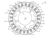
例えば、図3に、Pn=5、Ps=12の場合を示す。磁気的突極18は360/5度で回転対称であり、ティース19(相配置)は360/2度で回転対称であるが、PnとPsが1以外の公約数を有していない。図3に示す状態において、A、B、C、D、Eで示す各磁気的突極18は、U相巻線21u、V相巻線21v及びW相巻線21wが巻き付けられたティース19との位置関係がそれぞれ異なり、回転シャフト15に加わるラジアル力はアンバランスになる。   For example, FIG. 3 shows a case where Pn = 5 and Ps = 12. The magnetic salient pole 18 is rotationally symmetric at 360/5 degrees, and the teeth 19 (phase arrangement) are rotationally symmetric at 360/2 degrees, but Pn and Ps have no common divisor other than 1. In the state shown in FIG. 3, each of the magnetic salient poles 18 indicated by A, B, C, D, and E includes a tooth 19 around which a U-phase winding 21u, a V-phase winding 21v, and a W-phase winding 21w are wound. Are different from each other, and the radial force applied to the rotary shaft 15 is unbalanced.

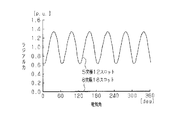
図4に、Pn=8、Ps=18の場合(8突極18スロットの場合)と、Pn=5、Ps=12の場合(5突極12スロットの場合)の回転シャフト15に加わるラジアル力のシミュレーション結果を示す。図4においてラジアル力を表す縦軸の値はラジアル力の平均値に対する相対的な値を示し、1.0が平均値となる。   FIG. 4 shows the radial force applied to the rotating shaft 15 when Pn = 8 and Ps = 18 (8 salient poles and 18 slots) and when Pn = 5 and Ps = 12 (5 salient poles and 12 slots). The simulation results are shown. In FIG. 4, the value on the vertical axis representing the radial force indicates a relative value with respect to the average value of the radial force, and 1.0 is the average value.

図4に示すように、実施形態の回転電動機10である8突極18スロットの場合は、電気角0〜360度の範囲に亘ってラジアル力は0、即ち回転シャフト15に特定方向へのラジアル力が作用しないこと、即ち回転シャフト15に加わるラジアル力のアンバランスがないこと確認された。一方、図3に示す比較例、即ち5突極12スロットの場合は、電気角0〜360度の範囲において、特定方向へのラジアル力が60度周期で変動することが確認された。   As shown in FIG. 4, in the case of the eight salient poles and 18 slots which are the rotary electric motor 10 of the embodiment, the radial force is 0 over the range of the electrical angle of 0 to 360 degrees, that is, the radial in the specific direction on the rotary shaft 15. It was confirmed that no force was applied, that is, there was no imbalance of radial force applied to the rotating shaft 15. On the other hand, in the comparative example shown in FIG. 3, that is, in the case of 5 salient poles and 12 slots, it was confirmed that the radial force in a specific direction fluctuates in a cycle of 60 degrees within an electrical angle range of 0 to 360 degrees.

この実施形態によれば、以下に示す効果を得ることができる。
(1)回転電動機10は、回転シャフト15に一体回転可能に固定され、かつ周方向に一定間隔で磁気的突極18が形成されたロータコア16を有するロータ11と、筒状に形成されるとともにロータコア16の外周側に配置され、かつ固定子巻線が集中巻で巻き付けられたティース19が内周面に一定間隔で形成されたステータ12とを備えている。また、回転電動機10は、ステータ12の外周に設けられた界磁ヨーク13と、ロータ11が単極となる磁気回路を形成するための界磁巻線14とを備えている。磁気的突極18、ティース19がそれぞれ回転対称に配置され、固定子巻線の相配置が回転対称に設定され、かつ磁気的突極18の数をPn及びステータ12のスロット20の数Psが1以外の公約数を有する。したがって、回転シャフト15に加わるラジアル力のアンバランスをなくすことができる。
According to this embodiment, the following effects can be obtained.
(1) The rotary electric motor 10 is fixed to the rotary shaft 15 so as to be integrally rotatable, and has a rotor 11 having a rotor core 16 in which magnetic salient poles 18 are formed at regular intervals in the circumferential direction. Teeth 19 disposed on the outer peripheral side of the rotor core 16 and having stator windings wound in a concentrated manner is provided with a stator 12 formed on the inner peripheral surface at regular intervals. The rotary electric motor 10 includes a field yoke 13 provided on the outer periphery of the stator 12 and a field winding 14 for forming a magnetic circuit in which the rotor 11 has a single pole. The magnetic salient poles 18 and the teeth 19 are arranged rotationally symmetrically, the phase arrangement of the stator windings is set rotationally symmetrical, and the number of the magnetic salient poles 18 is Pn and the number Ps of the slots 20 of the stator 12 is Has a common divisor other than 1. Therefore, the radial force unbalance applied to the rotating shaft 15 can be eliminated.

(2)固定子巻線(U相巻線21u、V相巻線21v及びW相巻線21w)は三相交流電流で励磁される。したがって、ロータコア16にトルクを発生させるための回転磁界を発生させる構成が一般に使用される三相回転電動機と同じで簡単になる。   (2) The stator windings (U-phase winding 21u, V-phase winding 21v and W-phase winding 21w) are excited by a three-phase alternating current. Therefore, the configuration for generating a rotating magnetic field for generating torque in the rotor core 16 is the same as that of a generally used three-phase rotating electric motor and is simplified.

(3)回転電動機10は、磁気的突極18の数Pnが8、ステータ12のスロット20の数Psが18であるため、Pn及びPsが1以外の公約数を有し、かつPn:Psが4:9を満足する。したがって、トルクバランスも良好になる。   (3) In the rotary motor 10, since the number Pn of the magnetic salient poles 18 is 8, and the number Ps of the slots 20 of the stator 12 is 18, Pn and Ps have a common divisor other than 1, and Pn: Ps Satisfies 4: 9. Therefore, the torque balance is also improved.

(4)界磁巻線14は界磁ヨーク13の両端部にそれぞれ設けられているため、各磁気的突極18に所望の量の磁束を円滑に流すために必要な円筒部13aの断面積を小さくすることができ、回転電動機10の小型化に寄与する。   (4) Since the field windings 14 are provided at both ends of the field yoke 13, the cross-sectional area of the cylindrical portion 13 a necessary for smoothly flowing a desired amount of magnetic flux to each magnetic salient pole 18. This contributes to reducing the size of the rotary electric motor 10.

(5)界磁巻線巻回部はボビン23を円板部13bに形成された円環状の突条13cに嵌合固定することで構成されている。したがって、界磁巻線14を巻き付けたボビン23を突条13cに固定することができ、界磁巻線14を円板部13bに突設された突条13cに直接巻き付ける場合に比べて、界磁巻線14の巻き付け作業が簡単になる。   (5) The field winding portion is configured by fitting and fixing the bobbin 23 to an annular ridge 13c formed on the disc portion 13b. Therefore, the bobbin 23 around which the field winding 14 is wound can be fixed to the protrusion 13c, and the field winding 14 can be compared with the case where the field winding 14 is directly wound around the protrusion 13c protruding from the disk portion 13b. The winding operation of the magnetic winding 14 is simplified.

実施形態は前記に限定されるものではなく、例えば、次のように具体化してもよい。
○ 磁気的突極18、ティース19がそれぞれ回転対称に配置され、固定子巻線の相配置が回転対称に設定され、かつ磁気的突極18の数Pn及びステータ12のスロットの数Psが1以外の公約数を有していれば、磁気的突極18の数Pnとスロット20の数Psとの組み合わせはPn=8、Ps=18に限らない。例えば、図3に示した磁気的突極18の数Pnが5、スロット20の数Psが12の回転電動機10ではPn及びPsが1以外の公約数を有せず、回転シャフト15に加わるラジアル力がアンバランスになったが、Pn及びPsが1以外の公約数を有する組み合わせにすると、回転シャフト15に加わるラジアル力のアンバランスをなくすことができる。例えば、Pn及びPsが1以外の公約数を有するように、Pn=10、Ps=24にすると、図5に示すように、180度の機械角をなすA,B,C,D,Eで示す各一対の磁気的突極18に作用するラジアル方向の力は、各一対の磁気的突極18毎に同じとなり、回転シャフト15に加わるラジアル力はバランスした状態になる。
The embodiment is not limited to the above, and may be embodied as follows, for example.
The magnetic salient poles 18 and the teeth 19 are arranged rotationally symmetrically, the phase arrangement of the stator windings is set rotationally symmetrical, and the number Pn of the magnetic salient poles 18 and the number Ps of slots of the stator 12 are 1. In other words, the combination of the number Pn of the magnetic salient poles 18 and the number Ps of the slots 20 is not limited to Pn = 8 and Ps = 18. For example, in the rotary motor 10 in which the number Pn of the magnetic salient poles 18 is 5 and the number Ps of the slots 20 is 12 shown in FIG. 3, there is no common divisor other than Pn and Ps, and the radial applied to the rotating shaft 15 Although the force is unbalanced, the combination of Pn and Ps having a common divisor other than 1 can eliminate the unbalance of the radial force applied to the rotating shaft 15. For example, when Pn = 10 and Ps = 24 so that Pn and Ps have a common divisor other than 1, as shown in FIG. 5, A, B, C, D, and E form a mechanical angle of 180 degrees. The radial force acting on each pair of magnetic salient poles 18 shown is the same for each pair of magnetic salient poles 18, and the radial force applied to the rotating shaft 15 is balanced.

○ 磁気的突極18の数Pnとスロット20の数Psとの組み合わせはPn=8、Ps=18及びPn=10、Ps=24に限らず、例えば、Pn及びPsが1以外の公約数を有し、かつPn:Psが1:3、2:3、4:3、4:9、5:3、5:6、5:9、5:12、8:9、8:15、8:21のいずれかを満足すればよい。しかし、そのうち、Pn:Psが1:3、4:3、5:3、5:6、5:9、8:9、8:15、8:21の組み合わせは、トルク変動が大きい。したがって、トルクバランスも良好になるPn:Psが2:3、4:9、5:12のいずれかの組み合わせが好ましい。   The combination of the number Pn of the magnetic salient poles 18 and the number Ps of the slots 20 is not limited to Pn = 8, Ps = 18, Pn = 10, and Ps = 24. For example, a common divisor other than Pn and Ps is 1 And Pn: Ps is 1: 3, 2: 3, 4: 3, 4: 9, 5: 3, 5: 6, 5: 9, 5:12, 8: 9, 8:15, 8: Any one of 21 may be satisfied. However, among them, the combinations of Pn: Ps of 1: 3, 4: 3, 5: 3, 5: 6, 5: 9, 8: 9, 8:15, and 8:21 have large torque fluctuations. Therefore, any combination of Pn: Ps of 2: 3, 4: 9, and 5:12 that provides good torque balance is preferable.

○ 回転電動機10は、界磁巻線14が界磁ヨーク13の片側(一端側)に設けられた構成でもよい。例えば、図6に示すように、界磁ヨーク13は円板部13bが円筒部13aの一端側にのみ設けられ、他端側には非磁性材で形成された支持円板24が設けられる。支持円板24は界磁ヨーク13と共に回転電動機10のケースを構成し、ベアリング17を介して回転シャフト15の他端を支持する。この実施形態では、界磁巻線14に電流が供給されると、磁束が界磁ヨーク13の円板部13b→回転シャフト15→ロータコア16→磁気的突極18→ステータ12→界磁ヨーク13の円筒部13a→界磁ヨーク13の円板部13bの経路で通過する磁気回路が形成され、各磁気的突極18がN極になる。この場合、界磁巻線14が円筒部13aの両側に設けられた実施形態と異なり、各磁気的突極18を流れた磁束が円筒部13aを経て円板部13bに戻るために必要な円筒部13aの断面積が2倍になる。   The rotary electric motor 10 may have a configuration in which the field winding 14 is provided on one side (one end side) of the field yoke 13. For example, as shown in FIG. 6, the field yoke 13 has a disc portion 13b provided only on one end side of the cylindrical portion 13a, and a support disc 24 formed of a nonmagnetic material on the other end side. The support disk 24 forms a case of the rotary electric motor 10 together with the field yoke 13, and supports the other end of the rotary shaft 15 via the bearing 17. In this embodiment, when a current is supplied to the field winding 14, the magnetic flux is changed from the disk portion 13 b of the field yoke 13 → the rotating shaft 15 → the rotor core 16 → the magnetic salient pole 18 → the stator 12 → the field yoke 13. A magnetic circuit passing through the path of the cylindrical portion 13a → the disk portion 13b of the field yoke 13 is formed, and each magnetic salient pole 18 becomes an N pole. In this case, unlike the embodiment in which the field winding 14 is provided on both sides of the cylindrical portion 13a, the cylinder necessary for the magnetic flux flowing through each magnetic salient pole 18 to return to the disk portion 13b through the cylindrical portion 13a. The cross-sectional area of the portion 13a is doubled.

○ 図7に示すように、ロータコア16を、円筒状に形成されて回転シャフト15に固設された筒状コア16aと、筒状コア16aの外周に設けられた積層ロータコア16bとで構成し、突条13cの先端を筒状コア16aの端面近傍まで延設するとともに突条13cの厚さを厚くして、その分、回転シャフト15の径を小さくしてもよい。磁気的突極18は積層ロータコア16bに形成する。筒状コア16aは、一体の磁性材料で形成されており、具体的には粉末成形磁性体(SMC:Soft Magnetic Composites)で形成されている。粉末成形磁性体の磁気抵抗は、積層ロータコア16bや回転シャフト15の材質より小さい。この場合、界磁巻線14で発生した磁束が回転シャフト15より筒状コア16a内を流れ易くなり、磁束が回転シャフト15を流れる場合に比べて磁束の経路長が短くなる。その結果、界磁電流量を低減させることができる。また、積層ロータコア16b内においては、磁束は、軸方向に流れ難く、径方向及び周方向に流れ易くなるのに対して、筒状コア16a内では積層ロータコア16b内より軸方向に磁束が流れ易くなる。このため、筒状コア16aが無い構成に比べて、磁束の経路が積層ロータコア16bを構成する全ての電磁鋼板に分散して流れ易くなる。   As shown in FIG. 7, the rotor core 16 is composed of a cylindrical core 16a formed in a cylindrical shape and fixed to the rotary shaft 15, and a laminated rotor core 16b provided on the outer periphery of the cylindrical core 16a. The tip of the ridge 13c may be extended to the vicinity of the end face of the cylindrical core 16a and the thickness of the ridge 13c may be increased so that the diameter of the rotating shaft 15 is reduced accordingly. The magnetic salient pole 18 is formed on the laminated rotor core 16b. The cylindrical core 16a is formed of an integral magnetic material, and specifically, is formed of a powder molded magnetic body (SMC: Soft Magnetic Composites). The magnetic resistance of the powder molded magnetic body is smaller than the material of the laminated rotor core 16b and the rotating shaft 15. In this case, the magnetic flux generated in the field winding 14 is more likely to flow through the cylindrical core 16 a than the rotary shaft 15, and the path length of the magnetic flux is shorter than when the magnetic flux flows through the rotary shaft 15. As a result, the amount of field current can be reduced. In the laminated rotor core 16b, the magnetic flux hardly flows in the axial direction and easily flows in the radial direction and the circumferential direction. On the other hand, in the cylindrical core 16a, the magnetic flux flows more easily in the axial direction than in the laminated rotor core 16b. Become. For this reason, compared with the structure without the cylindrical core 16a, the path of the magnetic flux is easily distributed to all the electromagnetic steel sheets constituting the laminated rotor core 16b.

○ ロータコア16、16bは電磁鋼板を積層して形成したが、鉄塊やSMCで形成しても良い。
○ 図8に示すように、回転シャフト15を、外周側の磁気抵抗が内周側の磁気抵抗より小さい2重構造に形成してもよい。この場合、界磁巻線14に電流が供給されて界磁巻線14から発生した磁束がロータコア16に向かって流れる際、磁束は磁気抵抗の小さい外周側を流れるため、磁束の経路長が短くなる。その結果、界磁電流量を低減させることができる。
The rotor cores 16 and 16b are formed by laminating electromagnetic steel plates, but may be formed by iron blocks or SMC.
As shown in FIG. 8, the rotary shaft 15 may be formed in a double structure in which the magnetic resistance on the outer peripheral side is smaller than the magnetic resistance on the inner peripheral side. In this case, when a current is supplied to the field winding 14 and the magnetic flux generated from the field winding 14 flows toward the rotor core 16, the magnetic flux flows on the outer peripheral side having a small magnetic resistance, so the path length of the magnetic flux is short. Become. As a result, the amount of field current can be reduced.

○ 図8に示すように、回転電動機10に専用のケース25を設け、ケース25で回転シャフト15をベアリング17を介して支持するようにしてもよい。この場合、界磁ヨーク13の円板部13bの形状が簡単になる。また、界磁ヨーク13がケースを兼用する場合に比べてケース25の形状や材質の自由度が大きくなる。図8では回転シャフト15が2重構造の場合を図示しているが、2重構造の場合に限らない。   As shown in FIG. 8, a dedicated case 25 may be provided in the rotary electric motor 10, and the rotary shaft 15 may be supported by the case 25 via a bearing 17. In this case, the shape of the disk portion 13b of the field yoke 13 is simplified. In addition, the shape and material of the case 25 are more flexible than when the field yoke 13 is also used as a case. Although FIG. 8 illustrates a case where the rotary shaft 15 has a double structure, the present invention is not limited to a double structure.

○ 図9に示すようにシャフトの径をそのベアリング部において細くするようにしても良い。この場合、ベアリングの小径化が可能になる。
○ ティース19に巻き付けられるU相巻線21u、V相巻線21v及びW相巻線21wの配置は、各巻線が巻き付けられたティース19がそれぞれ二つのグループ(360/2度で回転対称)に分けられる構成に限らない。例えば、図10(a)に示すように、Pn=10、Ps=24の回転電動機10において、各巻線が巻き付けられたティース19がそれぞれ四つのグループ(360/4度で回転対称)に分けられた構成にしてもよい。
As shown in FIG. 9, the shaft diameter may be reduced at the bearing portion. In this case, it is possible to reduce the diameter of the bearing.
○ The arrangement of the U-phase winding 21u, the V-phase winding 21v and the W-phase winding 21w wound around the teeth 19 is such that each of the teeth 19 around which the windings are wound is divided into two groups (rotation symmetry at 360/2 degrees). It is not restricted to the structure divided. For example, as shown in FIG. 10A, in the rotary motor 10 with Pn = 10 and Ps = 24, the teeth 19 around which the windings are wound are divided into four groups (360/4 degree rotational symmetry). A configuration may be used.

○ ロータコア16の形状は、磁気的突極18となるための突部を有する形状に限らない。例えば、図10(b)に示すように、ロータコア16として突部を一定間隔で有する形状の部分を磁性材で形成し、突部の間を非磁性材26で埋めて全体として平坦な形状としたものであってもよい。また、図11に示すように突部の先端のみを隣接する突部の先端とつなげても、実質的に磁気的突極になればよい。   The shape of the rotor core 16 is not limited to a shape having a protrusion for forming the magnetic salient pole 18. For example, as shown in FIG. 10 (b), the rotor core 16 is formed with a magnetic material in a portion having protrusions at regular intervals, and the space between the protrusions is filled with a non-magnetic material 26 to form a flat shape as a whole. It may be what you did. Moreover, as shown in FIG. 11, even if only the tip of the protrusion is connected to the tip of the adjacent protrusion, the magnetic salient pole may be substantially formed.

○ ボビン23を設けずに、突条13cの外周に界磁巻線14を直接巻き付けて、突条13cを界磁巻線巻回部としてもよい。
○ 固定子巻線としてのU相巻線21u、V相巻線21v及びW相巻線21wは、一つのスロット20に2本の巻線の一部がそれぞれ収容される状態ではなく、一つのスロット20に1本の固定子巻線の一部が収容される構成であってもよい。
O Without providing the bobbin 23, the field winding 14 may be directly wound around the outer periphery of the protrusion 13c, and the protrusion 13c may be used as the field winding winding portion.
○ The U-phase winding 21u, the V-phase winding 21v, and the W-phase winding 21w as the stator windings are not in a state in which a part of the two windings are accommodated in one slot 20, respectively. The slot 20 may be configured such that a part of one stator winding is accommodated.

○ ロータ11が単極となる場合、各磁気的突極18のステータ12側端部が、全てN極になるのではなく、全てS極になる構成にしてもよい。
○ 磁気的突極18はロータコア16の全長に亘って延設されずに、全長より短く形成されていてもよい。
When the rotor 11 has a single pole, the end portions of the magnetic salient poles 18 on the stator 12 side may not be all N poles but all S poles.
The magnetic salient pole 18 may be formed shorter than the entire length without extending over the entire length of the rotor core 16.

○ 回転電動機10は三相交流で駆動されるものに限らず、単相交流や二相交流あるいは四相以上の多相交流で駆動されるものであってもよい。
○ 電動機ではなく発電機に適用してもよい。
The rotary electric motor 10 is not limited to being driven by a three-phase alternating current, but may be driven by a single-phase alternating current, a two-phase alternating current, or a multiphase alternating current of four or more phases.
○ It may be applied to a generator instead of an electric motor.

以下の技術的思想(発明)は前記実施形態から把握できる。
(1)前記界磁巻線は前記界磁ヨークの両端部にそれぞれ設けられている。
The following technical idea (invention) can be understood from the embodiment.
(1) Before Symbol field winding are provided at both ends of the field magnet yoke.

(2)前記回転シャフトは、外周側の磁気抵抗が内周側の磁気抵抗より小さい2重構造に形成されている。 (2) pre-Symbol rotating shaft, the magnetic resistance of the outer peripheral side is formed on the magnetoresistive smaller double structure of the inner circumferential side.

(3)前記ロータコアは、筒状コアと前記筒状コアの外側に形成された積層コアとで構成され、前記筒状コアの材質は磁気抵抗が前記積層コアの材質より小さく構成されている。 (3) pre-Symbol rotor core is composed of a laminated core formed on the outside of the cylindrical core and the cylindrical core, the material of the tubular core is composed reluctance is smaller than the material of the laminated core .

10…回転電機としての回転電動機、11…ロータ(回転子)、12…ステータ(固定子)、13…界磁ヨーク、14…界磁巻線、15…回転シャフト、16…ロータコア、18…磁気的突極、19…ティース、20…スロット、21u…固定子巻線としてのU相巻線、21v…同じくV相巻線、21w…同じくW相巻線。   DESCRIPTION OF SYMBOLS 10 ... Rotary motor as a rotary electric machine, 11 ... Rotor (rotor), 12 ... Stator (stator), 13 ... Field yoke, 14 ... Field winding, 15 ... Rotating shaft, 16 ... Rotor core, 18 ... Magnetic Target salient poles, 19 ... teeth, 20 ... slots, 21u ... U-phase winding as a stator winding, 21v ... also V-phase winding, 21w ... also W-phase winding.

Claims (4)

回転子が界磁巻線により界磁される回転電機であって、
回転シャフトに一体回転可能に固定され、かつ周方向に一定間隔で磁気的突極が形成されたロータコアを有する回転子と、
筒状に形成されるとともに前記ロータコアの外周側に配置され、かつ三相交流電流で励磁される固定子巻線が集中巻で巻き付けられたティースが内周面に一定間隔で形成された固定子と、
前記固定子の外側に設けられるとともに、軸方向両側においてベアリングを介して前記回転シャフトを回転可能に支持する界磁ヨークと、
前記回転子が単極となる磁気回路を形成するための界磁巻線と
を備え、
前記磁気的突極、前記ティースがそれぞれ前記回転シャフトを中心とした回転対称に配置され、前記固定子巻線の相配置が前記回転シャフトを中心とした回転対称に設定され、かつ前記磁気的突極の数をPn、前記固定子のスロットの数をPsとした場合、Pn及びPsが1以外の公約数を有し、且つPn:Psが4:9、5:12のいずれかを満足する回転電機。
A rotating electric machine in which a rotor is fielded by a field winding,
A rotor having a rotor core fixed to a rotating shaft so as to be integrally rotatable and having magnetic salient poles formed at regular intervals in the circumferential direction;
A stator that is formed in a cylindrical shape and arranged on the outer peripheral side of the rotor core, and teeth in which a stator winding excited by a three-phase alternating current is wound in a concentrated manner is formed on the inner peripheral surface at regular intervals. When,
Rutotomoni provided outside the stator, the field yoke for rotatably supporting the rotary shaft via the bearing in the axial direction on both sides,
A field winding for forming a magnetic circuit in which the rotor has a single pole;
The magnetic salient poles and the teeth are arranged rotationally symmetrical about the rotary shaft, the phase arrangement of the stator windings is set rotationally symmetrical about the rotary shaft, and the magnetic salient when the number of poles Pn, the number of the stator slots and Ps, Pn and Ps are have a common divisor other than 1, and Pn: Ps 4: 9,5: 12 satisfies either Rotating electric machine.
前記ロータコアは、複数枚積層された電磁鋼板で形成されている請求項1に記載の回転電機。 The rotating electrical machine according to claim 1, wherein the rotor core is formed of a plurality of laminated electromagnetic steel plates . 前記回転シャフトは、外周側の磁気抵抗が内周側の磁気抵抗より小さい2重構造に形成されている請求項2に記載の回転電機。 The rotating electrical machine according to claim 2, wherein the rotary shaft is formed in a double structure in which an outer peripheral side magnetic resistance is smaller than an inner peripheral side magnetic resistance . 前記ロータコアは、筒状コアと前記筒状コアの外側に形成された積層コアとで構成され、前記筒状コアの材質は磁気抵抗が前記積層コアの材質より小さく構成されている請求項2に記載の回転電機。 The said rotor core is comprised by the cylindrical core and the laminated core formed in the outer side of the said cylindrical core, and the material of the said cylindrical core is comprised by the magnetic resistance smaller than the material of the said laminated core. The rotating electrical machine described.
JP2011045312A 2011-03-02 2011-03-02 Rotating electric machine Expired - Fee Related JP5340332B2 (en)

Priority Applications (4)

Application Number Priority Date Filing Date Title
JP2011045312A JP5340332B2 (en) 2011-03-02 2011-03-02 Rotating electric machine
CN201210047825.XA CN102655363B (en) 2011-03-02 2012-02-27 Rotary electric machine
EP20120157225 EP2495851A2 (en) 2011-03-02 2012-02-28 Rotary electric motor
US13/407,472 US9083225B2 (en) 2011-03-02 2012-02-28 Rotary electric machine

Applications Claiming Priority (1)

Application Number Priority Date Filing Date Title
JP2011045312A JP5340332B2 (en) 2011-03-02 2011-03-02 Rotating electric machine

Publications (2)

Publication Number Publication Date
JP2012182943A JP2012182943A (en) 2012-09-20
JP5340332B2 true JP5340332B2 (en) 2013-11-13

Family

ID=47013668

Family Applications (1)

Application Number Title Priority Date Filing Date
JP2011045312A Expired - Fee Related JP5340332B2 (en) 2011-03-02 2011-03-02 Rotating electric machine

Country Status (1)

Country Link
JP (1) JP5340332B2 (en)

Families Citing this family (1)

* Cited by examiner, † Cited by third party
Publication number Priority date Publication date Assignee Title
CN109417342A (en) * 2016-06-30 2019-03-01 安珀动力能源公司 Unipolar motor for flywheel energy storage system

Family Cites Families (2)

* Cited by examiner, † Cited by third party
Publication number Priority date Publication date Assignee Title
JPS4857113A (en) * 1971-11-18 1973-08-10
JPS4911207U (en) * 1972-05-02 1974-01-30

Also Published As

Publication number Publication date
JP2012182943A (en) 2012-09-20

Similar Documents

Publication Publication Date Title
JP5449892B2 (en) Permanent magnet excitation type radial magnetic bearing and magnetic bearing device including the radial magnetic bearing
JP4926107B2 (en) Rotating electric machine
US8847464B2 (en) Electrical machine with improved stator flux pattern across a rotor that permits higher torque density
JP4644832B2 (en) Rotating electrical machine
JP2010025342A6 (en) Permanent magnet excitation type radial magnetic bearing and magnetic bearing device including the radial magnetic bearing
JP2013005683A (en) Stator and motor
JP2013074743A (en) Rotary electric machine
JP5610989B2 (en) Rotating motor
JP6388611B2 (en) Hybrid field double gap synchronous machine
CN110268610B (en) Synchronous machine with magnetic rotating field reduction and flux concentration
JP2013215021A (en) Electromagnetic induction device
US9000648B2 (en) Asymmetrical reluctance machine
JP6327221B2 (en) Rotating electric machine
WO2014195999A1 (en) Synchronous motor
JP2009153305A (en) Brushless motor
JP2008252979A (en) Axial-gap type rotating machine
JP2018082600A (en) Double-rotor dynamoelectric machine
JP2012182942A (en) Rotary electric machine
JP5340332B2 (en) Rotating electric machine
JP2018148675A (en) Stator for rotary electric machine
JP2006025486A (en) Electric electric machine
JP6483300B1 (en) Synchronous reluctance motor
JP2017063594A (en) Brushless motor
JP2018516532A (en) Single pole composite type asynchronous motor
JP6830073B2 (en) Rotating machine

Legal Events

Date Code Title Description
A621 Written request for application examination

Free format text: JAPANESE INTERMEDIATE CODE: A621

Effective date: 20121206

A977 Report on retrieval

Free format text: JAPANESE INTERMEDIATE CODE: A971007

Effective date: 20130424

A131 Notification of reasons for refusal

Free format text: JAPANESE INTERMEDIATE CODE: A131

Effective date: 20130507

A521 Written amendment

Free format text: JAPANESE INTERMEDIATE CODE: A523

Effective date: 20130708

TRDD Decision of grant or rejection written
A01 Written decision to grant a patent or to grant a registration (utility model)

Free format text: JAPANESE INTERMEDIATE CODE: A01

Effective date: 20130730

A61 First payment of annual fees (during grant procedure)

Free format text: JAPANESE INTERMEDIATE CODE: A61

Effective date: 20130806

R150 Certificate of patent or registration of utility model

Free format text: JAPANESE INTERMEDIATE CODE: R150

LAPS Cancellation because of no payment of annual fees