JP2020184832A - Coil, stator member, stator, and motor - Google Patents
Coil, stator member, stator, and motor Download PDFInfo
- Publication number
- JP2020184832A JP2020184832A JP2019088141A JP2019088141A JP2020184832A JP 2020184832 A JP2020184832 A JP 2020184832A JP 2019088141 A JP2019088141 A JP 2019088141A JP 2019088141 A JP2019088141 A JP 2019088141A JP 2020184832 A JP2020184832 A JP 2020184832A
- Authority
- JP
- Japan
- Prior art keywords
- terminal
- coil
- stator
- spiral structure
- stator member
- Prior art date
- Legal status (The legal status is an assumption and is not a legal conclusion. Google has not performed a legal analysis and makes no representation as to the accuracy of the status listed.)
- Granted
Links
Images
Classifications
-
- H—ELECTRICITY
- H02—GENERATION; CONVERSION OR DISTRIBUTION OF ELECTRIC POWER
- H02K—DYNAMO-ELECTRIC MACHINES
- H02K3/00—Details of windings
- H02K3/04—Windings characterised by the conductor shape, form or construction, e.g. with bar conductors
- H02K3/18—Windings for salient poles
-
- H—ELECTRICITY
- H02—GENERATION; CONVERSION OR DISTRIBUTION OF ELECTRIC POWER
- H02K—DYNAMO-ELECTRIC MACHINES
- H02K3/00—Details of windings
- H02K3/04—Windings characterised by the conductor shape, form or construction, e.g. with bar conductors
- H02K3/28—Layout of windings or of connections between windings
-
- H—ELECTRICITY
- H02—GENERATION; CONVERSION OR DISTRIBUTION OF ELECTRIC POWER
- H02K—DYNAMO-ELECTRIC MACHINES
- H02K1/00—Details of the magnetic circuit
- H02K1/06—Details of the magnetic circuit characterised by the shape, form or construction
- H02K1/12—Stationary parts of the magnetic circuit
- H02K1/16—Stator cores with slots for windings
-
- H—ELECTRICITY
- H02—GENERATION; CONVERSION OR DISTRIBUTION OF ELECTRIC POWER
- H02K—DYNAMO-ELECTRIC MACHINES
- H02K3/00—Details of windings
- H02K3/04—Windings characterised by the conductor shape, form or construction, e.g. with bar conductors
- H02K3/12—Windings characterised by the conductor shape, form or construction, e.g. with bar conductors arranged in slots
-
- H—ELECTRICITY
- H02—GENERATION; CONVERSION OR DISTRIBUTION OF ELECTRIC POWER
- H02K—DYNAMO-ELECTRIC MACHINES
- H02K3/00—Details of windings
- H02K3/46—Fastening of windings on the stator or rotor structure
- H02K3/48—Fastening of windings on the stator or rotor structure in slots
Landscapes
- Engineering & Computer Science (AREA)
- Power Engineering (AREA)
- Windings For Motors And Generators (AREA)
- Manufacture Of Motors, Generators (AREA)
Abstract
【課題】 バスバーとコイルの端子とを接合(接続)する場合において、位置合わせ等の接合に係る制御を簡素化し、装置(溶接装置、またはステータの製造装置)の小型化を実現するとともに、接合作業の効率化を向上することができる、コイル、ステータ部材、ステータおよびモータを提供する。【解決手段】 コイルは、導体を巻回して構成され、その第一の端子と第二の端子とはコイルの一の面側に導出されている。【選択図】 図2PROBLEM TO BE SOLVED: To simplify control related to joining such as alignment when joining (connecting) a bus bar and a coil terminal, to realize miniaturization of an apparatus (welding apparatus or a stator manufacturing apparatus), and to join. Provided are coils, stator members, stators and motors capable of improving work efficiency. A coil is configured by winding a conductor, and a first terminal and a second terminal thereof are led out to one surface side of the coil. [Selection diagram] Fig. 2
Description
本発明は、コイル、ステータ部材、ステータおよびモータに関する。 The present invention relates to coils, stator members, stators and motors.
従来、プレス打ち抜きで製造された鋼板を積層して構成されたエッジワイズコイルが知られている。当該エッジワイズコイルは、一例を挙げるとモータのステータ(固定子)などに採用されている。 Conventionally, an edgewise coil formed by laminating steel plates manufactured by press punching is known. The edgewise coil is used in a motor stator (stator) or the like, for example.
この場合のステータは、環状のステータコアの内周面に設けられた複数のスロット(ティース)に、成形済みのコイル(エッジワイズコイル)を順次装着し、環状に配置されたコイルのそれぞれの一端を、バスバーに接続して形成される。 In this case, the stator is formed by sequentially mounting preformed coils (edgewise coils) in a plurality of slots (teeth) provided on the inner peripheral surface of the annular stator core, and one end of each of the coils arranged in an annular shape. , Formed by connecting to a bus bar.
より詳細には、環状に配置されたコイルはそれぞれ、一対の端子(長端末)を有している。一対の端子は、コイルの巻き始めと巻き終わりとなる一対の端部を螺旋進行方向に沿って螺旋構造部分(周回部分)より導出させた部分である。一対の端子は、コイルの周回部分の一辺側(例えば、一方の短辺側)に揃え、且つ、一方の端子は、環状に配置されたコイルの内周面となる側に、他方の端子は環状に配置されたコイルの外周面となる側に導出される。そして、両端子は、ステータコアの円周方向に延在する棒状(弧状)または環状のバスバーに溶接等により接続する(例えば、特許文献1参照)。 More specifically, each of the coils arranged in an annular shape has a pair of terminals (long terminals). The pair of terminals is a portion in which a pair of ends, which are the start and end of winding of the coil, are derived from the spiral structure portion (circular portion) along the spiral traveling direction. The pair of terminals are aligned on one side (for example, one short side) of the coil's circumferential portion, and one terminal is on the side that becomes the inner peripheral surface of the coil arranged in an annular shape, and the other terminal is. It is led out to the side that becomes the outer peripheral surface of the coils arranged in an annular shape. Then, both terminals are connected to a rod-shaped (arc-shaped) or annular bus bar extending in the circumferential direction of the stator core by welding or the like (see, for example, Patent Document 1).
しかしながら、従来のコイルでは、ステータコアに取り付けてバスバーと端子とを接合(接続)する場合、環状に配置されたコイル(ステータコア)の内周面となる側の端子と外周面となる側の端子の間で接合手段(例えば溶接装置、接合装置など)を移動させなければならず、位置合わせ等の接合に係る制御が煩雑となり、接合手段(溶接装置等)の可動域が大きくなることから装置(接合手段、、またはステータの製造装置)の小型化も阻む上、接合作業の効率化にも限界があった。 However, in the conventional coil, when the bus bar and the terminal are joined (connected) by attaching to the stator core, the terminal on the inner peripheral surface side and the terminal on the outer peripheral surface side of the coil (stator core) arranged in an annular shape Since the joining means (for example, welding device, joining device, etc.) must be moved between them, the control related to joining such as alignment becomes complicated, and the movable range of the joining means (welding device, etc.) becomes large. In addition to hindering the miniaturization of the joining means or the stator manufacturing device, there is a limit to the efficiency of the joining work.
本発明は、斯かる実情に鑑み,バスバーとコイルの端子とを接合(接続)する場合において、位置合わせ等の接合に係る制御を簡素化し、装置(接合手段)またはステータの製造装置)の小型化を実現するとともに、接合作業の効率化を向上することができる、コイル、ステータ部材、ステータおよびモータを提供しようとするものである。 In view of such circumstances, the present invention simplifies the control related to joining such as alignment when joining (connecting) the bus bar and the coil terminal, and reduces the size of the device (joining means) or the stator manufacturing device). It is an object of the present invention to provide a coil, a stator member, a stator and a motor capable of improving the efficiency of joining work as well as realizing the above.
本発明は、螺旋構造の導体からなる本体部と、該本体部から導出する第一の端子と、第二の端子とを有するコイルであって、前記第一の端子と前記第二の端子とを前記本体部の一の面側に導出させたことを特徴とするコイルである。 The present invention is a coil having a main body portion made of a conductor having a spiral structure, a first terminal derived from the main body portion, and a second terminal, the first terminal and the second terminal. Is a coil characterized in that is led out to one surface side of the main body portion.
また、本発明は、上記のコイルを複数並べたステータ部材である。 Further, the present invention is a stator member in which a plurality of the above coils are arranged.
また、本発明は、上記のコイルと、前記コイルを取り付けるステータコアと、を有するステータである。 Further, the present invention is a stator having the above coil and a stator core to which the coil is attached.
また、本発明は、上記のステータ部材を備えたモータである。 Further, the present invention is a motor provided with the above-mentioned stator member.
また、本発明は、上記のステータを備えたモータである。 Further, the present invention is a motor provided with the above-mentioned stator.
本発明によれば、バスバーとコイルの端子とを接合(接続)する場合において、位置合わせ等の接合に係る制御を簡素化し、装置(接合手段、またはステータの製造装置)の小型化を実現するとともに、接合作業の効率化を向上することができる、コイル、ステータ部材、ステータおよびモータを提供することができる。 According to the present invention, when joining (connecting) a bus bar and a coil terminal, control related to joining such as alignment is simplified, and a device (joining means or a stator manufacturing device) can be downsized. At the same time, it is possible to provide a coil, a stator member, a stator and a motor that can improve the efficiency of joining work.
以下、本発明の実施形態について図面を参照して説明する。 Hereinafter, embodiments of the present invention will be described with reference to the drawings.
<コイル>
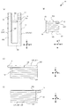
図1は、本実施形態のコイル10を示す図であり、同図(A)が螺旋構造の軸方向から見た正面図であり、同図(B)が端子の導出側(同図(A)の上方)から見た上面図であり、同図(C)が同図(A)を左方向から見た側面図であり、同図(D)が同図(A)を右方向から見た側面図である。
<Coil>
1A and 1B are views showing the
図1に示すように、本実実施形態のコイル10は、本体部11と、第一の端子12と、第二の端子13とを有する。本体部11は、螺旋構造の導体により構成される。また導体は、例えば螺旋構造の進行方向に直交する断面が略矩形状の平導体(平角導体)である。
As shown in FIG. 1, the
本体部11は、長尺の帯状の平導体を例えば巻回して螺旋構造体を形成したものであってもよいし、コイル10(完成形の螺旋構造体)より短い複数の帯状の平導体(単位平導体)を、帯長手方向に連続するように接続(圧接または溶接など)して螺旋構造体を形成したものであってもよい。具体的に、圧接により接続する場合には、例えば、接合螺旋構造体の1周分領域の長さ以下(または1周分領域を超える長さ)の複数の単位平導体の端面同士をそれぞれ直線部分において帯長手方向に沿って押圧して周分領域を形成し、これを連続させて螺旋構造体を形成することができる。
The
ここで、本明細書においては、螺旋構造の軸に沿う第一の方向をコイル10(螺旋構造体)の軸方向Cといい、軸方向Cに直交し螺旋構造の進行方向の一方向に沿う第二の方向をコイル10(螺旋構造体)の幅方向Wといい、第一の方向と第二の方向に直交し、螺旋構造の進行方向の他の方向に沿う第三の方向をコイル10(螺旋構造体)の長さ方向Lという。
Here, in the present specification, the first direction along the axis of the spiral structure is referred to as the axial direction C of the coil 10 (spiral structure), and is orthogonal to the axial direction C and follows one direction of the traveling direction of the spiral structure. The second direction is called the width direction W of the coil 10 (spiral structure), and the third direction orthogonal to the first direction and the second direction and along the other direction of the traveling direction of the spiral structure is the
本体部11の形状は、図1に示す例では、螺旋構造体(巻回)の軸方向Cから見た正面図(同図(A))において短辺SSと長辺LSを有する略矩形状であり、幅方向Wは短辺SSの延在方向であり、長さ方向Lは長辺LS方向である。
In the example shown in FIG. 1, the shape of the
また、螺旋構造体は、同図(A)に破線矢印で示す略矩形状の1周分の領域(以下、「1周分領域CR」という。)を複数、積層(重畳)した積層体ということもでき、軸方向Cは1周分領域CRの積層方向、または厚み方向である。 Further, the spiral structure is referred to as a laminated body in which a plurality of substantially rectangular one-round regions (hereinafter, referred to as “one-round region CR”) indicated by the broken line arrows in the figure (A) are laminated (superposed). Also, the axial direction C is the stacking direction or the thickness direction of the one-circle region CR.
このように、この例のコイル10は連続する帯状の平導体によって螺旋構造体を形成した本体部11を有するいわゆるエッジワイズコイルである。しかしこれに限らず、例えば螺旋構造の進行方向に直交する断面が略円形状の丸導体(丸線導体)を巻回し、または帯状の複数の丸導体を接続(圧接または溶接等)して螺旋構造体を形成したものであってもよい。つまり、本体部11の形状は、同図(A)に示す正面図において楕円形状(長円形状)であってもよい。
As described above, the
第一の端子12と第二の端子13は、1つの本体部11に対して一対で設けられる。第一の端子12と第二の端子13は、コイル10の巻き始めと巻き終わりとなる一対の端部を螺旋進行方向に沿って本体部11(螺旋構造部分、周回部分)より外側に導出させた部分(図1においてドットハッチングで示す部分)であり、いずれも本体部11の幅方向Wまたは長さ方向Lに沿う同じ一辺側に導出される。図1の例では、略矩形状の螺旋構造体の幅方向Wに沿う、一方の短辺SS側(同図(A)の上側の短辺SS側)に導出される。第二の端子13は延在部14(後述する)を含む。
The
この例では、第一の端子12および第二の端子13は、平導体(単位平導体)の一部として構成され、それぞれ本体部11と例えば圧接などにより接合される。つまり、第一の端子12および第二の端子13をそれぞれ含む平導体と本体部11(螺旋構造体)との接合部CPは、1周分領域CRの直線部分に設けられる。第一の端子12および第二の端子13は、それぞれ本体部11と溶接などにより接合されてもよい。溶接での接続の場合は、図1に示すように第一の端子12および第二の端子13は、平導体(単位平導体)の一部であってもよいし、第一の端子12および第二の端子13(ドットのハッチングで示す領域のみの導体)を螺旋構造体に接合する構成であってもよい。
In this example, the
さらに、本実施形態の第一の端子12と第二の端子13は、本体部11の幅方向Wと長さ方向Lで定義される一の面側に導出される。具体的には、螺旋構造体を1周分領域CRの積層体とした場合、第一の端子12と第二の端子13はいずれも、積層体の軸方向C(厚み方向)の一方の最外周となる1周分領域CRが存在する面側(同図(B)〜同図(D)に示す最上面側または最下面側)に位置するように、導出される。
Further, the
具体的に同図の例では、第一の端子12は、同図(B)〜同図(D)における軸方向Cの一方の最外面(例えば、最上層となる1周分領域CRが存在する面)側から導出するように構成され、第二の端子13は、他方の最外面(例えば、最下層となる1周分領域CRが存在する面)側から、本体部11の螺旋構造の軸方向Cに沿って延びる延在部14を介して、一方の最外面(最上層となる1周分領域CRが存在する面)側に導出する。つまり、延在部14は、積層される複数の1周分領域CRを軸方向C(厚み方向)に渡るように設けられ、本体部11(積層体)の積層方向の一方の最外面(以下、第一の面Sf1という)側から導出する第二の端子13を、積層方向の他方の最外周面(以下、第二の面Sf2という)側に引き出す部位である。なお、第一の端子12と第二の端子13とは説明の便宜上別称しているに過ぎず、これらを入れ替えても同様である。つまり第一の端子12が延在部14を有する構成であってもよい。
Specifically, in the example of the figure, the
同様に、積層体の最上層と最下層(上面と下面)とは説明の便宜上別称しているに過ぎず、これらを入れ替えても同様である。 Similarly, the uppermost layer and the lowermost layer (upper surface and lower surface) of the laminated body are merely referred to separately for convenience of explanation, and the same applies even if they are interchanged.
同図(D)に示すように、延在部14は、第一の面Sf1の1周分領域CRの一の長辺LSから導出するように設けられ、積層される複数の1周分領域CRを渡るように螺旋構造体の軸方向Cに延びるように曲折し、第二の面Sf2側で再び螺旋構造体の螺旋進行方向(周回方向)に延びるように曲折する。これにより第一の端子12と第二の端子13が第二の面Sf2側に並ぶように導出する。
As shown in FIG. 3D, the extending
<ステータ部材>
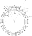
図2を参照して、本実施形態のステータ部材50について説明する。同図は環状のステータ部材50をその軸方向から見た上面概要図である。
<Stator member>
The
ステータ部材50は、図1に示すコイル10を複数、互いに長辺LS部分が隣接するように並べ、環状体を構成したものである。
The
具体的には各コイル10(10A、10B、10C・・・)は、それぞれの螺旋構造体の軸(仮想線として破線で示す)が、環状体の中心軸CC(紙面表裏方向に延びている)上の1点に収束するように配置される。 Specifically, in each coil 10 (10A, 10B, 10C ...), The axis of each spiral structure (indicated by a broken line as a virtual line) extends in the direction of the front and back of the paper surface as the central axis CC of the annular body. ) Arranged so as to converge to the above one point.
そして、各コイル10は上述の如く、第一の端子12と第二の端子13とが本体部11の一の面側(例えば、第二の面Sf2側)に導出されている。すなわち、複数のコイル10の全ての第一の端子12と第二の端子13は、環状体であるステータ部材50の同じ周面側(この例では外周面Sf2側)に、導出される。換言すると、各コイル10は、それぞれの第一の端子12と第二の端子13の導出方向が各コイル10の長さ方向L(環状体の中心軸CCに沿う方向)の同じ一方側(同図では外周側)に位置するように揃えて配置される。
Then, as described above, in each
従来のコイルおよびそれにより構成されたステータ部材は、第一の端子が環状体であるステータ部材の例えば外周面側に導出され、第二の端子がステータ部材の内周面側に導出されていた。従って、第一の端子および第二の端子を、バスバーなどに接続する際には、バスバーとの接続手段(例えば、接合(圧接)装置(溶接装置)など)をステータ部材の内周面側と外周面側に移動させなければならず、接続に係る制御(例えば位置合わせなどの制御)が複雑・煩雑になったり、接合装置(溶接装置)の可動域が大きくなるために装置(接合装置(溶接装置)や、ステータ(部材)の製造装置など)の小型化も阻む上、接続の作業効率が向上できない問題があった。 In the conventional coil and the stator member composed of the coil, the first terminal is led out to, for example, the outer peripheral surface side of the stator member which is an annular body, and the second terminal is led out to the inner peripheral surface side of the stator member. .. Therefore, when connecting the first terminal and the second terminal to the bus bar or the like, the connecting means with the bus bar (for example, a joining (pressure welding) device (welding device) or the like) is connected to the inner peripheral surface side of the stator member. Since it is necessary to move to the outer peripheral surface side, control related to connection (for example, control such as alignment) becomes complicated and complicated, and the movable range of the joining device (welding device) becomes large, so that the device (joining device (joining device)) In addition to hindering the miniaturization of welding equipment) and stator (member) manufacturing equipment), there is a problem that the work efficiency of connection cannot be improved.
しかしながら、本実施形態によれば、複数のコイル10の全ての第一の端子12と第二の端子13が、環状体であるステータ部材50の同じ周面側(例えば外周面Sf2側)に導出されるため、バスバーと接合(接続)する場合において、位置合わせ等の接合に係る制御を簡素化し、装置(接合装置(溶接装置)、またはステータ(部材)の製造装置など)の小型化を実現するとともに、接合作業の効率化を向上することができる。
However, according to the present embodiment, all the
更に、本実施形態では、複数のコイル10の周方向に隣り合う(周方向に並ぶ)全ての第一の端子12と第二の端子13とは、略等間隔となるように配置される。具体的には、一のコイル10の第一の端子12と第二の端子13間の距離が、当該一のコイル10の第一の端子12と、隣り合う他のコイル10の第二の端子13間の距離と同等(略等間隔)となるように設けられる。
Further, in the present embodiment, all the
例えば、図1(D)を参照して、第二の端子13は、延在部14が第一の面Sf1(ステータ部材50として環状に並べた場合の例えば内周面)の1周分領域CRの一の長辺LS2から、当該長辺LS2の延在方向(図1(D)の右方向)に導出するように設けられ、積層される複数の1周分領域CRを渡るように第二の面Sf2(ステータ部材50として環状に並べた場合の例えば外周面)側に向かって、螺旋構造体の軸方向Cに延びるように曲折し、外周面Sf2側で再び螺旋構造体の螺旋進行方向(周回方向)に延びるように(外周面側の1周分領域CRの対応する長辺LS2に沿って延びるように)曲折して、螺旋構造体から外部に導出される。
For example, referring to FIG. 1 (D), in the
また、図1(A),同図(C)に示すように第一の端子12は、第二の面(外周面)Sf2の1周分領域CRの一の長辺LS1(第二の端子13が導出している長辺LS2に対向する長辺LS1)から、当該長辺LS1の延在方向に導出する。
Further, as shown in FIGS. 1 (A) and 1 (C), the
そして、図2に示すように、或る一つのコイル10Bにおける第一の端子12Bと第二の端子13B間の距離(環状体の周方向に沿う距離)D2と、コイル10Bの第二の端子13Bと、これと隣り合うコイル10Aの第一の端子12A間の距離(環状体の外周の周方向に沿う距離)D1とが略等間隔になるように構成されている。同様に、コイル10Bにおける第一の端子12Bと、これと隣り合うコイル10Cの第二の端子13C間の距離(環状体の外周の周方向に沿う距離)D3が距離D1,D2と略等間隔になるように構成されている(全てのコイル10において同様)。
Then, as shown in FIG. 2, the distance D2 between the
このようにすることで、バスバーと接合(接続)する場合において、より一層、位置合わせ等の接合に係る制御を簡素化し、接合作業の効率化を向上することができる。 By doing so, when joining (connecting) with the bus bar, it is possible to further simplify the control related to joining such as alignment and improve the efficiency of joining work.
なお、上記の例における第一の端子12および第二の端子13の導出形状は一例であり、コイル10の形状に応じて適宜、ステータ部材50を構成するコイル10の第一の端子12と第二の端子13の間隔D1,D2、D3・・・が等間隔になるように構成すればよい。従って、例えば第一の端子12が、螺旋構造体の短辺SS方向に沿う延在部を有し、螺旋構造体の短変SSに沿って一端折り曲げられた後に螺旋構造体から導出させる構造にしてもよいし、第二の端子13の延在部14が第一の端子12に近接又は離間するように、短辺SS方向に沿って折り曲げた後に螺旋構造体から導出させるようにしてもよいし、第一の端子12と第二の端子13のそれぞれの延在部を互いに短辺SS方向に折り曲げてから螺旋構造体から導出させるようにしても良い。
The derived shapes of the
また、複数のコイル10の全ての第一の端子12と第二の端子13は、環状体であるステータ部材50の第一の面Sf2(内周面)側に導出するように構成してもよい。しかしながら、内周面Sf1側の場合、外周面Sf2側よりも円周が小さくなるため、第一の端子12と第二の端子13間の距離を同等に配置する場合の自由度が狭まる。そして第一の端子12と第二の端子13の間隔も狭まり、また、通常は、ステータ部材50の外側に配置されるバスバーとの接合手段(接合(圧接)装置、溶接装置)の移動距離も長くなる。このため、第一の端子12と第二の端子13は、ステータ部材50の外周面Sf2側に導出することが好ましい。一方、接合手段をステータ部材50の内側に配置する場合には、第一の端子12と第二の端子13をステータ部材50の内周面Sf1側に導出するようにしてもよい。
Further, all the
<ステータ>
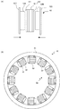
図3は、本実施形態のコイル10(ステータ部材50)を用いたステータ60の概略を示す図である。同図(A)はコイル10の取り付け方法の一例を示す図であり、コイル10をステータ60の周方向から見た側面図であり、同図(B)はステータ60の軸方向から見た上面概略図である。
る。
<Stator>
FIG. 3 is a diagram showing an outline of a
To.
本実施形態のステータ60は、ステータコア61に帯状の導体を巻回するのではなく、環状(円筒状)のステータコア61の内周面に設けられた複数のカセット(スロット、ティースともいう)62に、成形済みのコイル(エッジワイズコイル)10を順次装着し、あるいは、ステータ部材50を一体的に装着し、環状に配置されたコイル10のそれぞれの一端をバスバー(不図示)に接続して形成される。
The
具体的には、同図(A)に示すように複数のコイル10のそれぞれにカセット62を取り付ける。
Specifically, as shown in FIG. 6A, the
カセット62は、例えば、ステータ部材50を構成する複数のコイル10のそれぞれに対して(1つのコイル10に対して)2個1組で用意される。2個1組のカセット62(62A,62B)は、コイル10の第一の面Sf1側および第2の面Sf2側にそれぞれ、鍔部62C,62Dを有する。そして、一方のカセット62Aの鍔部62Cが形成されていない面側から1つのコイル10を挿入し、他方のカセット62Bを鍔部62Dが形成されていない面側から重ねて両者を係合し、コイル10にカセット62を取り付ける。ステータ部材50を構成するコイル10の全てに対して同様にカセット62を取り付ける。その後、同図(B)に示すようにカセット62付きのコイル10をステータコア61に取り付ける。カセット62は例えば、不図示の係合部(嵌合部)などによってステータコア61に係合(嵌合)される。
The
あるいは、例えば不図示のバスバーなどによって環状に並ぶ複数のコイル10が接続されて一体化されたステータ部材50において、各コイル10のそれぞれに上述のようにカセット62を取り付け、カセット62付きのステータ部材50をステータコア61に取り付ける。
Alternatively, in the
バスバーの図示は省略するが、例えば円環状の配線部と、コイル接続端部とが金属部材(例えば、銅板)などの打ち抜き加工にて一体的に構成される。そして、コイル接続端部とコイル10の第一の端子12および第二の端子13とが圧接、溶接、あるいはねじ止めなどにより接合される。
Although the illustration of the bus bar is omitted, for example, the annular wiring portion and the coil connection end portion are integrally formed by punching a metal member (for example, a copper plate). Then, the coil connection end and the
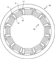
図4は、本実施形態のステータ部材50の他の形態を示す上面図である。なお、同図においてはカセット62の記載を省略している。本実施形態のコイル10の螺旋構造体の形状は、図1に示すものに限らない。例えば、図4に示すように上面視において略台形状、すなわち略四角錘台形状に構成されていてもよい。この場合コイル10は、螺旋進行方向に向かうにつれて、平導体の幅(螺旋進行方向に交差する方向の長さ)が徐々に狭くなる一方で厚み(螺旋構造体の軸方向の長さ)が徐々に厚くなり、且つ螺旋進行方向に垂直な断面積が螺旋進行方向において等しくなるような平導体で構成するとよい。
FIG. 4 is a top view showing another embodiment of the
また、この例では、第一の端子12と第二の端子13は環状体の同一の周面(例えば、外周面)に揃えて導出されていればよく、一のコイル10の第一の端子12と第二の端子13間の距離は、当該一のコイル10の第一の端子12と、隣り合う他のコイル10の第二の端子13間の距離と同等でなくてもよい。
Further, in this example, the
<モータ>
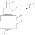
図5は、本実施形態のステータ60(またはステータ部材50)を用いたモータ70の概略を示す分解側面図である。
<Motor>
FIG. 5 is an exploded side view showing an outline of a
同図に示すように、上記のステータ60に対してロータ73が回転可能となるように組み付けられてモータ(単相モータ、三相モータなど)70が得られる。具体的には、モータ70は、例えば、シャフト71、ハウジング72、ロータ73、ステータ60(図3に示す)等を有する。シャフト71は柱状部材であり、例えばハウジング72に設けられたベアリング74に支持されながら、その中心軸を中心として回転する。シャフト71の一端には、ギア等の動力伝達機構を介して、駆動対象となる装置(不図示)が連結される。
As shown in the figure, a motor (single-phase motor, three-phase motor, etc.) 70 is obtained by assembling the
ロータ73はその周方向にマグネット(不図示)が配置され、シャフト71とともに回転する。ステータ60は例えば、ロータ73の径方向外側に配置され、ロータ73を回転させるための力を発生させる。ステータ60の外部端子(不図示)は、例えばリード線などを介してモータへ電力を供給する駆動回路あるいは電源(いずれも不図示)に接続される。
A magnet (not shown) is arranged in the circumferential direction of the
モータ70は、電源あるいは駆動回路から、バスバー(不図示)を介してコイル10に駆動電流を与えると、ステータ60のカセット62に磁束が生じる。そして、カセット62とマグネット(不図示)の間の磁束の作用により、周方向のトルクが発生する。その結果、ステータ60に対してロータ73が中心軸を中心として回転する。
When the
また、図示は省略するが、本実施形態のモータ70は、図3に示すステータ60により構成されるものに限らず、図1に示したコイル10または図2に示したステータ部材50を含んで構成されたものであればよい。
Although not shown, the
尚、本発明は、上記した実施の形態に限定されるものではなく、本発明の要旨を逸脱しない範囲内において種々変更を加え得ることは勿論である。 It should be noted that the present invention is not limited to the above-described embodiment, and it goes without saying that various modifications can be made without departing from the gist of the present invention.
本発明は、ステータ及びモータに適用することができる。 The present invention can be applied to stators and motors.
10(10A,10B、10C・・・) コイル
11 本体部
12、12A、12C 第一の端子
13,13A、13B 第二の端子
14 延在部
50 ステータ部材
60 ステータ
61 ステータコア
62、62A、62B カセット
62C,62D 鍔部
70 モータ
71 シャフト
72 ハウジング
73 ロータ
74 ベアリング
10 (10A, 10B, 10C ...)
Claims (11)
前記第一の端子と前記第二の端子とを前記本体部の一の面側に導出させた、
ことを特徴とするコイル。 A coil having a main body made of a conductor having a spiral structure, a first terminal derived from the main body, and a second terminal.
The first terminal and the second terminal are led out to one surface side of the main body portion.
A coil characterized by that.
ことを特徴とする請求項1に記載のコイル。 One of the first terminal and the second terminal has an extending portion extending in the axial direction of the spiral structure of the main body portion.
The coil according to claim 1.
ことを特徴とする請求項1または請求項2に記載のコイル。 The main body portion is formed by forming a spiral structure from continuous strip-shaped flat conductors, and the joints between the first terminal and the second terminal and the spiral structure are straight lines of the flat conductors. Provided in the part,
The coil according to claim 1 or 2, wherein the coil is characterized in that.
前記螺旋構造体の1周分領域の長さ以下の複数の単位平導体が、それぞれの前記直線部分において端面同士を帯長手方向に沿って押圧されることにより略矩形状の前記1周分領域が形成されている、
ことを特徴とする請求項3に記載のコイル。 The coil is
A plurality of unit flat conductors having a length equal to or less than the length of one circumferential region of the spiral structure are pressed against each other along the band longitudinal direction in each of the straight portions, so that the one circumferential region having a substantially rectangular shape is formed. Is formed,
The coil according to claim 3.
ことを特徴とする請求項5に記載のステータ部材。 The first terminal and the second terminal adjacent to each other of the plurality of coils are arranged at substantially equal intervals.
The stator member according to claim 5.
前記第一の端子と前記第二の端子は、前記環状体の内周面側または外周面側に導出される、
ことを特徴とする請求項5または請求項6に記載のステータ部材。 The plurality of coils are arranged so as to form an annular body.
The first terminal and the second terminal are led out to the inner peripheral surface side or the outer peripheral surface side of the annular body.
The stator member according to claim 5 or 6, wherein the stator member.
ことを特徴とする請求項7に記載のステータ部材。 The first terminal and the second terminal are led out to the outer peripheral surface side of the annular body.
The stator member according to claim 7.
前記コイルを取り付けるステータコアと、を有するステータ。 The coil according to any one of claims 1 to 4.
A stator having a stator core to which the coil is attached.
Priority Applications (5)
| Application Number | Priority Date | Filing Date | Title |
|---|---|---|---|
| JP2019088141A JP7417236B2 (en) | 2019-05-08 | 2019-05-08 | Stator parts, stator and motor |
| CN202080033860.9A CN113841319A (en) | 2019-05-08 | 2020-05-01 | Coils, stator components, stators and motors |
| US17/609,317 US12068653B2 (en) | 2019-05-08 | 2020-05-01 | Coil, stator member, stator, and motor |
| EP20802243.4A EP3968499A4 (en) | 2019-05-08 | 2020-05-01 | Coil, stator member, stator, and motor |
| PCT/JP2020/018415 WO2020226134A1 (en) | 2019-05-08 | 2020-05-01 | Coil, stator member, stator, and motor |
Applications Claiming Priority (1)
| Application Number | Priority Date | Filing Date | Title |
|---|---|---|---|
| JP2019088141A JP7417236B2 (en) | 2019-05-08 | 2019-05-08 | Stator parts, stator and motor |
Publications (2)
| Publication Number | Publication Date |
|---|---|
| JP2020184832A true JP2020184832A (en) | 2020-11-12 |
| JP7417236B2 JP7417236B2 (en) | 2024-01-18 |
Family
ID=73045281
Family Applications (1)
| Application Number | Title | Priority Date | Filing Date |
|---|---|---|---|
| JP2019088141A Active JP7417236B2 (en) | 2019-05-08 | 2019-05-08 | Stator parts, stator and motor |
Country Status (5)
| Country | Link |
|---|---|
| US (1) | US12068653B2 (en) |
| EP (1) | EP3968499A4 (en) |
| JP (1) | JP7417236B2 (en) |
| CN (1) | CN113841319A (en) |
| WO (1) | WO2020226134A1 (en) |
Cited By (1)
| Publication number | Priority date | Publication date | Assignee | Title |
|---|---|---|---|---|
| JP7170345B1 (en) | 2021-05-13 | 2022-11-14 | 株式会社アスター | Coil, stator, motor and coil manufacturing method |
Families Citing this family (1)
| Publication number | Priority date | Publication date | Assignee | Title |
|---|---|---|---|---|
| WO2020080479A1 (en) * | 2018-10-18 | 2020-04-23 | パナソニックIpマネジメント株式会社 | Coil device |
Citations (7)
| Publication number | Priority date | Publication date | Assignee | Title |
|---|---|---|---|---|
| JP2012110204A (en) * | 2010-10-29 | 2012-06-07 | Nippon Densan Corp | Motor and manufacturing method of motor |
| JP2012249344A (en) * | 2011-05-25 | 2012-12-13 | Toyota Motor Corp | Coaxial cassette type rotary electric machine stator |
| JP2013005541A (en) * | 2011-06-14 | 2013-01-07 | Toyota Motor Corp | Molding method of bus bar, and bus bar |
| JP2014090567A (en) * | 2012-10-30 | 2014-05-15 | Mitsubishi Electric Corp | Rotating electric machine stator |
| WO2015199044A1 (en) * | 2014-06-24 | 2015-12-30 | 株式会社オートネットワーク技術研究所 | Core member, reactor, and method for manufacturing core member |
| WO2019059295A1 (en) * | 2017-09-20 | 2019-03-28 | アイシン・エィ・ダブリュ株式会社 | Method for manufacturing armature for rotating electrical machine |
| WO2019065460A1 (en) * | 2017-09-28 | 2019-04-04 | アイシン・エィ・ダブリュ株式会社 | Coil |
Family Cites Families (12)
| Publication number | Priority date | Publication date | Assignee | Title |
|---|---|---|---|---|
| JP2003348782A (en) | 2002-05-23 | 2003-12-05 | Asmo Co Ltd | Stator, manufacturing method thereof and motor |
| JP4340740B2 (en) * | 2007-07-19 | 2009-10-07 | トヨタ自動車株式会社 | Connection wire used for stator of electric motor, stator provided with the connection wire, and method of bending the connection wire |
| JP3136235U (en) | 2007-08-08 | 2007-10-18 | 千如電機工業股▲ふん▼有限公司 | Breaker type electric shock absorber structure |
| JP4661849B2 (en) | 2007-09-27 | 2011-03-30 | トヨタ自動車株式会社 | Stator structure |
| JP5740930B2 (en) * | 2010-03-03 | 2015-07-01 | 日本電産株式会社 | Stator and motor |
| JP5729091B2 (en) | 2010-10-29 | 2015-06-03 | 日本電産株式会社 | Bus bar, motor and manufacturing method thereof |
| JP5554383B2 (en) * | 2012-09-11 | 2014-07-23 | 三菱電機株式会社 | Stator for rotating electric machine and method for manufacturing the stator |
| JP5592554B1 (en) | 2013-12-18 | 2014-09-17 | 武延 本郷 | Cold welding apparatus, coil manufacturing apparatus, coil and manufacturing method thereof |
| WO2015151202A1 (en) | 2014-03-31 | 2015-10-08 | 三菱電機株式会社 | Electric motor, fan, and compressor |
| EP3651319B1 (en) | 2017-09-20 | 2022-12-14 | Aisin Corporation | Rotary electric machine armature and method for manufacturing same |
| CN111095752B (en) | 2017-09-20 | 2022-06-21 | 株式会社爱信 | Method for manufacturing armature for rotating electrical machine |
| WO2019059297A1 (en) | 2017-09-20 | 2019-03-28 | アイシン・エィ・ダブリュ株式会社 | Method for manufacturing armature for dynamo-electrical machine |
-
2019
- 2019-05-08 JP JP2019088141A patent/JP7417236B2/en active Active
-
2020
- 2020-05-01 WO PCT/JP2020/018415 patent/WO2020226134A1/en not_active Ceased
- 2020-05-01 US US17/609,317 patent/US12068653B2/en active Active
- 2020-05-01 CN CN202080033860.9A patent/CN113841319A/en active Pending
- 2020-05-01 EP EP20802243.4A patent/EP3968499A4/en active Pending
Patent Citations (7)
| Publication number | Priority date | Publication date | Assignee | Title |
|---|---|---|---|---|
| JP2012110204A (en) * | 2010-10-29 | 2012-06-07 | Nippon Densan Corp | Motor and manufacturing method of motor |
| JP2012249344A (en) * | 2011-05-25 | 2012-12-13 | Toyota Motor Corp | Coaxial cassette type rotary electric machine stator |
| JP2013005541A (en) * | 2011-06-14 | 2013-01-07 | Toyota Motor Corp | Molding method of bus bar, and bus bar |
| JP2014090567A (en) * | 2012-10-30 | 2014-05-15 | Mitsubishi Electric Corp | Rotating electric machine stator |
| WO2015199044A1 (en) * | 2014-06-24 | 2015-12-30 | 株式会社オートネットワーク技術研究所 | Core member, reactor, and method for manufacturing core member |
| WO2019059295A1 (en) * | 2017-09-20 | 2019-03-28 | アイシン・エィ・ダブリュ株式会社 | Method for manufacturing armature for rotating electrical machine |
| WO2019065460A1 (en) * | 2017-09-28 | 2019-04-04 | アイシン・エィ・ダブリュ株式会社 | Coil |
Cited By (2)
| Publication number | Priority date | Publication date | Assignee | Title |
|---|---|---|---|---|
| JP7170345B1 (en) | 2021-05-13 | 2022-11-14 | 株式会社アスター | Coil, stator, motor and coil manufacturing method |
| JP2022175240A (en) * | 2021-05-13 | 2022-11-25 | 株式会社アスター | Coil, stator, motor, and manufacturing method of coil |
Also Published As
| Publication number | Publication date |
|---|---|
| EP3968499A1 (en) | 2022-03-16 |
| US20220224180A1 (en) | 2022-07-14 |
| WO2020226134A1 (en) | 2020-11-12 |
| US12068653B2 (en) | 2024-08-20 |
| CN113841319A (en) | 2021-12-24 |
| EP3968499A4 (en) | 2022-06-29 |
| JP7417236B2 (en) | 2024-01-18 |
Similar Documents
| Publication | Publication Date | Title |
|---|---|---|
| JP5986774B2 (en) | Rotating electric machine | |
| JPWO2019039518A1 (en) | Split core linked body and method of manufacturing armature | |
| JP6044382B2 (en) | Multi-gap rotating electric machine | |
| WO2008020471A1 (en) | Rotating electric machine | |
| JP6026021B2 (en) | Magnetic inductor type motor and method of manufacturing the same | |
| JP6276041B2 (en) | Rotating electrical machine stator | |
| JP4624421B2 (en) | Permanent magnet synchronous machine with rectangular wire winding | |
| CN107005135A (en) | Stator manufacturing method and coil | |
| TW201218577A (en) | Rotating electrical machine, manufacturing method of rotating electrical machine, and wind power generator system | |
| WO2018147392A1 (en) | Rotating electrical machine | |
| CN110492630A (en) | Rotating electric machine | |
| JP5911018B2 (en) | Armature and rotating electric machine equipped with the armature | |
| WO2016072299A1 (en) | Laminated core of armature, and armature | |
| JP5502533B2 (en) | Permanent magnet type motor | |
| CN103855819B (en) | Electric actuator | |
| WO2016035766A1 (en) | Stator assembling method and stator | |
| WO2022172594A1 (en) | Stator, method for manufacturing stator, and brushless motor | |
| WO2020226134A1 (en) | Coil, stator member, stator, and motor | |
| US20050264123A1 (en) | Stator of rotating electric machine and manufacturing method of the stator | |
| WO2012011352A1 (en) | Dynamo-electric machine armature | |
| JP2005080365A (en) | Stator for rotating electric machine | |
| JP2009268221A (en) | Method of manufacturing stator coil | |
| JP4057406B2 (en) | Stator core, core sheet manufacturing method, and stator manufacturing method | |
| JP2014050236A (en) | Rotary electric machine | |
| JP4568639B2 (en) | Stator |
Legal Events
| Date | Code | Title | Description |
|---|---|---|---|
| A621 | Written request for application examination |
Free format text: JAPANESE INTERMEDIATE CODE: A621 Effective date: 20220414 |
|
| A131 | Notification of reasons for refusal |
Free format text: JAPANESE INTERMEDIATE CODE: A131 Effective date: 20230620 |
|
| A521 | Request for written amendment filed |
Free format text: JAPANESE INTERMEDIATE CODE: A523 Effective date: 20230817 |
|
| A131 | Notification of reasons for refusal |
Free format text: JAPANESE INTERMEDIATE CODE: A131 Effective date: 20230926 |
|
| A521 | Request for written amendment filed |
Free format text: JAPANESE INTERMEDIATE CODE: A523 Effective date: 20231113 |
|
| TRDD | Decision of grant or rejection written | ||
| A01 | Written decision to grant a patent or to grant a registration (utility model) |
Free format text: JAPANESE INTERMEDIATE CODE: A01 Effective date: 20231205 |
|
| A61 | First payment of annual fees (during grant procedure) |
Free format text: JAPANESE INTERMEDIATE CODE: A61 Effective date: 20231225 |
|
| R150 | Certificate of patent or registration of utility model |
Ref document number: 7417236 Country of ref document: JP Free format text: JAPANESE INTERMEDIATE CODE: R150 |