WO2022172594A1 - Stator, method for manufacturing stator, and brushless motor - Google Patents
Stator, method for manufacturing stator, and brushless motor Download PDFInfo
- Publication number
- WO2022172594A1 WO2022172594A1 PCT/JP2021/046972 JP2021046972W WO2022172594A1 WO 2022172594 A1 WO2022172594 A1 WO 2022172594A1 JP 2021046972 W JP2021046972 W JP 2021046972W WO 2022172594 A1 WO2022172594 A1 WO 2022172594A1
- Authority
- WO
- WIPO (PCT)
- Prior art keywords
- stator
- insulating
- pair
- blocks
- insulating plates
- Prior art date
Links
- 238000004519 manufacturing process Methods 0.000 title claims description 25
- 238000000034 method Methods 0.000 title description 6
- 238000004804 winding Methods 0.000 claims abstract description 71
- 230000002093 peripheral effect Effects 0.000 claims abstract description 15
- 230000008878 coupling Effects 0.000 claims description 9
- 238000010168 coupling process Methods 0.000 claims description 9
- 238000005859 coupling reaction Methods 0.000 claims description 9
- 239000000463 material Substances 0.000 claims description 5
- 238000010292 electrical insulation Methods 0.000 claims description 4
- 238000006073 displacement reaction Methods 0.000 abstract description 6
- 230000004048 modification Effects 0.000 description 28
- 238000012986 modification Methods 0.000 description 28
- 239000011248 coating agent Substances 0.000 description 9
- 238000000576 coating method Methods 0.000 description 9
- 238000009413 insulation Methods 0.000 description 5
- 229920003002 synthetic resin Polymers 0.000 description 3
- 239000000057 synthetic resin Substances 0.000 description 3
- 238000003466 welding Methods 0.000 description 3
- 239000004020 conductor Substances 0.000 description 2
- 230000004907 flux Effects 0.000 description 2
- 239000012212 insulator Substances 0.000 description 2
- 239000000696 magnetic material Substances 0.000 description 2
- RYGMFSIKBFXOCR-UHFFFAOYSA-N Copper Chemical compound [Cu] RYGMFSIKBFXOCR-UHFFFAOYSA-N 0.000 description 1
- 229910000881 Cu alloy Inorganic materials 0.000 description 1
- 229910000976 Electrical steel Inorganic materials 0.000 description 1
- 229910000808 amorphous metal alloy Inorganic materials 0.000 description 1
- 238000005452 bending Methods 0.000 description 1
- 229910052802 copper Inorganic materials 0.000 description 1
- 239000010949 copper Substances 0.000 description 1
- 230000000694 effects Effects 0.000 description 1
- 238000010030 laminating Methods 0.000 description 1
- WABPQHHGFIMREM-UHFFFAOYSA-N lead(0) Chemical compound [Pb] WABPQHHGFIMREM-UHFFFAOYSA-N 0.000 description 1
- 239000002184 metal Substances 0.000 description 1
- 229910052751 metal Inorganic materials 0.000 description 1
- 239000000843 powder Substances 0.000 description 1
- 238000003825 pressing Methods 0.000 description 1
- 239000007858 starting material Substances 0.000 description 1
- 230000001629 suppression Effects 0.000 description 1
- 229910000859 α-Fe Inorganic materials 0.000 description 1
Images


Classifications
-
- H—ELECTRICITY
- H02—GENERATION; CONVERSION OR DISTRIBUTION OF ELECTRIC POWER
- H02K—DYNAMO-ELECTRIC MACHINES
- H02K3/00—Details of windings
- H02K3/32—Windings characterised by the shape, form or construction of the insulation
- H02K3/38—Windings characterised by the shape, form or construction of the insulation around winding heads, equalising connectors, or connections thereto
-
- H—ELECTRICITY
- H02—GENERATION; CONVERSION OR DISTRIBUTION OF ELECTRIC POWER
- H02K—DYNAMO-ELECTRIC MACHINES
- H02K1/00—Details of the magnetic circuit
- H02K1/06—Details of the magnetic circuit characterised by the shape, form or construction
- H02K1/22—Rotating parts of the magnetic circuit
- H02K1/27—Rotor cores with permanent magnets
- H02K1/2706—Inner rotors
- H02K1/272—Inner rotors the magnetisation axis of the magnets being perpendicular to the rotor axis
- H02K1/274—Inner rotors the magnetisation axis of the magnets being perpendicular to the rotor axis the rotor consisting of two or more circumferentially positioned magnets
- H02K1/2753—Inner rotors the magnetisation axis of the magnets being perpendicular to the rotor axis the rotor consisting of two or more circumferentially positioned magnets the rotor consisting of magnets or groups of magnets arranged with alternating polarity
- H02K1/276—Magnets embedded in the magnetic core, e.g. interior permanent magnets [IPM]
- H02K1/2766—Magnets embedded in the magnetic core, e.g. interior permanent magnets [IPM] having a flux concentration effect
- H02K1/2773—Magnets embedded in the magnetic core, e.g. interior permanent magnets [IPM] having a flux concentration effect consisting of tangentially magnetized radial magnets
-
- H—ELECTRICITY
- H02—GENERATION; CONVERSION OR DISTRIBUTION OF ELECTRIC POWER
- H02K—DYNAMO-ELECTRIC MACHINES
- H02K1/00—Details of the magnetic circuit
- H02K1/06—Details of the magnetic circuit characterised by the shape, form or construction
- H02K1/12—Stationary parts of the magnetic circuit
- H02K1/14—Stator cores with salient poles
- H02K1/146—Stator cores with salient poles consisting of a generally annular yoke with salient poles
- H02K1/148—Sectional cores
-
- H—ELECTRICITY
- H02—GENERATION; CONVERSION OR DISTRIBUTION OF ELECTRIC POWER
- H02K—DYNAMO-ELECTRIC MACHINES
- H02K15/00—Methods or apparatus specially adapted for manufacturing, assembling, maintaining or repairing of dynamo-electric machines
- H02K15/02—Methods or apparatus specially adapted for manufacturing, assembling, maintaining or repairing of dynamo-electric machines of stator or rotor bodies
- H02K15/022—Methods or apparatus specially adapted for manufacturing, assembling, maintaining or repairing of dynamo-electric machines of stator or rotor bodies with salient poles or claw-shaped poles
-
- H—ELECTRICITY
- H02—GENERATION; CONVERSION OR DISTRIBUTION OF ELECTRIC POWER
- H02K—DYNAMO-ELECTRIC MACHINES
- H02K15/00—Methods or apparatus specially adapted for manufacturing, assembling, maintaining or repairing of dynamo-electric machines
- H02K15/02—Methods or apparatus specially adapted for manufacturing, assembling, maintaining or repairing of dynamo-electric machines of stator or rotor bodies
- H02K15/024—Methods or apparatus specially adapted for manufacturing, assembling, maintaining or repairing of dynamo-electric machines of stator or rotor bodies with slots
- H02K15/026—Wound cores
-
- H—ELECTRICITY
- H02—GENERATION; CONVERSION OR DISTRIBUTION OF ELECTRIC POWER
- H02K—DYNAMO-ELECTRIC MACHINES
- H02K21/00—Synchronous motors having permanent magnets; Synchronous generators having permanent magnets
- H02K21/12—Synchronous motors having permanent magnets; Synchronous generators having permanent magnets with stationary armatures and rotating magnets
- H02K21/14—Synchronous motors having permanent magnets; Synchronous generators having permanent magnets with stationary armatures and rotating magnets with magnets rotating within the armatures
- H02K21/16—Synchronous motors having permanent magnets; Synchronous generators having permanent magnets with stationary armatures and rotating magnets with magnets rotating within the armatures having annular armature cores with salient poles
-
- H—ELECTRICITY
- H02—GENERATION; CONVERSION OR DISTRIBUTION OF ELECTRIC POWER
- H02K—DYNAMO-ELECTRIC MACHINES
- H02K3/00—Details of windings
- H02K3/32—Windings characterised by the shape, form or construction of the insulation
- H02K3/34—Windings characterised by the shape, form or construction of the insulation between conductors or between conductor and core, e.g. slot insulation
- H02K3/345—Windings characterised by the shape, form or construction of the insulation between conductors or between conductor and core, e.g. slot insulation between conductor and core, e.g. slot insulation
-
- H—ELECTRICITY
- H02—GENERATION; CONVERSION OR DISTRIBUTION OF ELECTRIC POWER
- H02K—DYNAMO-ELECTRIC MACHINES
- H02K3/00—Details of windings
- H02K3/46—Fastening of windings on the stator or rotor structure
- H02K3/52—Fastening salient pole windings or connections thereto
- H02K3/521—Fastening salient pole windings or connections thereto applicable to stators only
- H02K3/522—Fastening salient pole windings or connections thereto applicable to stators only for generally annular cores with salient poles
-
- H—ELECTRICITY
- H02—GENERATION; CONVERSION OR DISTRIBUTION OF ELECTRIC POWER
- H02K—DYNAMO-ELECTRIC MACHINES
- H02K2203/00—Specific aspects not provided for in the other groups of this subclass relating to the windings
- H02K2203/12—Machines characterised by the bobbins for supporting the windings
Definitions
- the present disclosure relates to a stator, a method of manufacturing the stator, and a brushless motor, and more particularly to a bobbinless type stator, a method of manufacturing the stator, and a brushless motor having the stator.
- the stator of the rotary electric machine described in Patent Document 1 is exemplified.
- the stator disclosed in Patent Document 1 includes a core sheet laminate, a coating film, a stator coil, and a bobbin.
- the core sheet laminate is constructed by laminating a plurality of core sheets made of metal.
- the coating film consists of an insulating coating applied to the surface of the core sheet laminate.
- a stator coil is composed of a conductive wire (winding) wound around a core sheet laminate with a coating film interposed therebetween.
- a bobbin is inserted between the coating film and the stator coil. The bobbin prevents the conductors of the stator coil from coming into contact with the coating film applied to the edges of the core sheet laminate. Alternatively, the bobbin relieves contact pressure.
- An object of the present disclosure is to provide a stator, a stator manufacturing method, and a brushless motor capable of suppressing deviation of windings.
- a stator includes a plurality of stator blocks arranged along a circumferential direction, and a plurality of coils provided by winding windings around each of the plurality of stator blocks.
- the stator includes a plurality of insulating members for electrically insulating the stator blocks and the coils for each set of the plurality of stator blocks and the plurality of coils.
- Each of the plurality of stator blocks includes a yoke portion located on the outermost periphery, a tooth portion protruding from an inner peripheral surface of the yoke portion, an insulating portion having electrical insulation and covering the surface of the tooth portion, have
- Each of the plurality of insulating members has a pair of insulating plates and an aligning portion provided on each of the pair of insulating plates to align the windings.
- the pair of insulating plates are arranged at positions facing each other with the tooth portion interposed therebetween.
- a method for manufacturing a stator according to an aspect of the present disclosure includes a step of winding a winding on each of the plurality of stator blocks to provide the coil, and disposing the plurality of stator blocks each provided with the coil in a circumferential direction. and coupling the plurality of stator blocks arranged along the circumferential direction.
- a brushless motor includes the stator and a rotor rotatably arranged inside the stator.
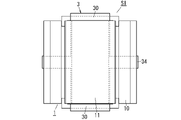
- FIG. 1 is a front view of a stator and brushless motor according to an embodiment of the present disclosure
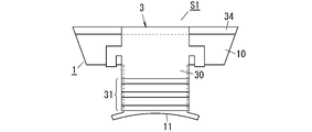
- FIG. 2 is a perspective view of the stator same as the above.
- FIG. 3 is a perspective view of the stator same as the above.
- FIG. 4 is a front view of a plate material in the stator of the same.
- FIG. 5 is a partially omitted front view of an insulating member in Modification 1 of the stator.
- FIG. 6 is a partially omitted front view of an insulating member in Modification Example 1 of the stator.
- FIG. 7 is a front view of a stator block and an insulating member in Modification 2 of the same stator.
- FIG. 8 is a plan view of the stator block and insulating member of the same.
- FIG. 9 is a side view of the stator block and insulating member of the same.
- FIG. 10 is a front view showing another configuration of the stator block in Modified Example 2 of the stator.
- FIG. 11 is a front view of a stator block and an insulating member in Modification 3 of the stator same as the above.
- FIG. 12 is a plan view of the stator block and insulating member of the same.
- FIG. 13 is a side view of the stator block and insulating member of the same.
- FIG. 14 is a partially omitted front view of the stator of Modification 3 of the same.
- FIG. 15 is a partially omitted front view of Modification 4 of the same stator.
- a brushless motor M1 (hereinafter abbreviated as brushless motor M1) according to an embodiment of the present disclosure includes a stator S1 (hereinafter abbreviated as stator S1) according to an embodiment of the present disclosure, as shown in FIG. ), and a rotor R1 rotatably arranged inside the stator S1.
- the rotor R1 has a cylindrical rotor core 50 made of a soft magnetic material and a plurality of (six in the illustrated example) permanent magnets 51 .
- a cylindrical shaft hole 500 penetrates through the center of the rotor core 50 .
- a rotary shaft (not shown) is inserted into this shaft hole 500 .
- Each of the six permanent magnets 51 is formed in a rectangular flat plate shape. These permanent magnets 51 are housed inside the rotor core 50 so as to be arranged at regular intervals along the circumferential direction of the rotor core 50 .
- the stator S1 includes a plurality (nine in the illustrated example) of stator blocks 1 arranged along the circumferential direction, and a plurality of coils 2 provided by winding windings 20 around each of the plurality of stator blocks 1 ( See Figure 1).
- the stator S1 also includes a plurality of (nine in the illustrated example) insulating members 3 for electrically insulating the stator blocks 1 and the coils 2 for each set of the plurality of stator blocks 1 and the plurality of coils 2 .
- Each of the plurality of stator blocks 1 includes a yoke portion 10 located on the outermost periphery, a tooth portion 11 protruding from the inner peripheral surface of the yoke portion 10, and an insulating portion having electrical insulation and covering the surface of the tooth portion 11. 12 and.
- Each of the plurality of insulating members 3 has a pair of insulating plates 30 and an aligning portion 31 provided on each of the pair of insulating plates 30 to align the windings 20 .
- a pair of insulating plates 30 are arranged at positions facing each other with the tooth portion 11 interposed therebetween.
- each stator Variations in the magnetic attractive force and the magnetic repulsive force generated in the block 1 also increase.
- the windings 20 can be wound in alignment with the tooth portions 11 by the alignment portions 31 provided in the insulating member 3 in the plurality of stator blocks 1 .
- the stator S1 can more easily align the windings 20 than in the case where the alignment portion 31 is not provided, and it is possible to suppress the displacement of the windings 20 .
- Stator Block 1 The plurality of stator blocks 1 all have the same configuration. In the following description, unless otherwise specified, the up-down, front-rear and left-right directions indicated by arrows in FIG.
- the stator block 1 has a yoke portion 10, a tooth portion 11, an insulating portion 12, and a flange portion 13, as shown in FIGS.
- the yoke portion 10 is formed in a quadrangular prism shape. More specifically, the yoke portion 10 has rectangular front, rear, left and right side surfaces and trapezoidal upper and lower surfaces. The upper and lower sides of the front surface of the yoke portion 10 are shorter than the upper and lower sides of the rear surface of the yoke portion 10, and the left and right sides of the front surface of the yoke portion 10 are the same length as the left and right sides of the rear surface of the yoke portion 10. .
- the tooth portion 11 is formed in a rectangular parallelepiped shape.
- the height of the tooth portion 11 is equal to the height of the yoke portion 10 . That is, the upper and lower surfaces of the tooth portion 11 are flush with the upper and lower surfaces of the yoke portion 10, respectively. Further, the tooth portion 11 protrudes forward from the center of the front surface of the yoke portion 10 in the left-right direction.
- the front surfaces of the teeth 11 are curved in a cylindrical shape (see FIGS. 1 and 2).
- the flange portion 13 is formed in a plate shape whose longitudinal direction is the vertical direction, and protrudes leftward and rightward from the front end portions of the left and right side surfaces of the tooth portion 11, respectively.
- the height of the flange portion 13 is equal to the height of the teeth portion 11 .
- the front surface of the flange portion 13 is curved like a cylindrical surface and is flush with the front surface of the tooth portion 11 .
- the yoke portion 10, the teeth portion 11, and the flange portion 13 are preferably integrally formed of a soft magnetic material such as silicon steel plate, ferrite, amorphous alloy, or the like.
- the yoke portion 10, the teeth portion 11 and the flange portion 13 may be formed separately and then joined together.
- the insulating portions 12 are provided on both left and right side surfaces of the tooth portion 11 (see FIGS. 2 and 3).
- the insulating portion 12 is a coating film applied to both left and right side surfaces of the tooth portion 11 .
- the coating film (insulating portion 12) is preferably formed of, for example, an electrically insulating synthetic resin powder coating.
- the insulating member 3 has a pair of insulating plates 30 and an alignment portion 31 . Moreover, the insulating member 3 further has a connecting portion 32 and a fixing portion 33 (see FIGS. 1 to 3).
- Each of the pair of insulating plates 30 is formed in a rectangular flat plate shape. However, the pair of insulating plates 30 are formed to have the same shape and size.
- the width dimension of the insulating plate 30 in the left-right direction (transverse direction) is larger than the width dimension of the teeth portion 11 in the left-right direction and smaller than the width dimension of the yoke portion 10 in the left-right direction.
- the width dimension in the front-rear direction (longitudinal direction) of the insulating member 3 is slightly smaller than the width dimension in the front-rear direction of the stator block 1 (see FIG. 1).
- One insulating plate 30 is arranged on the upper surface of the stator block 1 , and the other insulating plate 30 is arranged below the lower surface of the stator block 1 .
- the connecting part 32 is formed in a rectangular flat plate shape. One end (upper end) of the connecting portion 32 in the longitudinal direction is connected to the rear end of the insulating plate 30 arranged on the upper surface of the stator block 1 . The other end (lower end) of the connecting portion 32 in the longitudinal direction is connected to the rear end of the insulating plate 30 arranged under the lower surface of the stator block 1 . That is, the pair of insulating plates 30 are connected at their respective rear ends by connecting portions 32 (see FIGS. 2 and 3). Also, the connecting portion 32 is fitted into a groove portion 100 provided on the rear surface of the yoke portion 10 (see FIG. 3).
- the groove portion 100 is provided over the entire length of the yoke portion 10 in the vertical direction at the center of the rear surface of the yoke portion 10 in the horizontal direction. It is preferable that the pair of insulating plates 30 and the connecting portion 32 be integrally formed of an electrically insulating synthetic resin material.
- Each fixing portion 33 is formed in a hook shape when viewed in the horizontal direction (see FIG. 2).
- Each fixing portion 33 protrudes in the left-right direction from each of the left and right side surfaces of each insulating plate 30 from a position near the rear of the center of each insulating plate 30 in the front-rear direction.
- the tip portions of the two fixing portions 33 provided on the upper insulating plate 30 protrude downward.
- the tip portions of the two fixing portions 33 provided on the lower insulating plate 30 protrude upward (see FIG. 2).
- the alignment section 31 has a plurality of recesses 310 provided in the pair of insulating plates 30 (see FIGS. 1 to 3).
- a plurality of concave portions 310 (alignment portions 31) are provided on the upper surface of the upper insulating plate 30 and the lower surface of the lower insulating plate 30, respectively.
- the plurality of recesses 310 are formed by a plurality of ribs 3100 protruding upward from the upper surface of the upper insulating plate 30 . That is, on the upper surface of the upper insulating plate 30 and the lower surface of the lower insulating plate 30, a plurality of ribs 3100 are provided at regular intervals in the front-rear direction.
- a recess 310 is formed by a space sandwiched between a pair of ribs 3100 adjacent in the front-rear direction on the upper surface of the upper insulating plate 30 and the lower surface of the lower insulating plate 30 .
- the width of the recess 310 may be slightly larger than the wire diameter (diameter) of the winding 20 of the coil 2, or may be equal to or less than the wire diameter of the winding 20. good.
- the plurality of recesses 310 may be grooves provided in the upper surface of the upper insulating plate 30 and the lower surface of the lower insulating plate 30, respectively.
- the coil 2 has windings 20 made of a conductor such as copper or copper alloy.
- the coil 2 is constructed by winding a wire 20 around the teeth 11 and a pair of insulating plates 30 .
- the windings 20 are aligned by alignment portions 31 provided on the pair of insulating plates 30, respectively. That is, the windings 20 are accommodated in the plurality of recesses 310 provided on the upper surface of the upper insulating plate 30 and the plurality of recesses 310 provided on the lower surface of the lower insulating plate 30, respectively. are aligned (see FIGS. 1-3).
- each of the pair of insulating plates 30 is formed wider than the tooth portion 11 .
- each insulating plate 30 is preferably formed wider than the tooth portion 11 by about 0.3 mm.
- both left and right side surfaces of the tooth portion 11 are covered with the insulating portion 12 . Therefore, even if the width dimension of the pair of insulating plates 30 is equal to or less than the width dimension of the tooth portion 11, the pair of insulating plates 30 and the insulating portions 12 on the left and right side surfaces of the tooth portion 11 allow the winding 20 and the tooth portion 11 to be separated. It is possible to secure the insulation distance between Although the number of turns of the coil 2 is 3 (3 turns) in FIGS. 1 to 3, it may be 4 (4 turns) or more. Moreover, if the windings 20 are covered with an insulator, the windings 20 can be wound in a double or more overlapping manner.
- the manufacturing method of the stator S1 of the present embodiment includes at least a first step, a second step, a third step and a fourth step.
- the first step is to attach the insulating member 3 to the stator block 1 .
- the connecting portion 32 is bent to widen the distance between the pair of insulating plates 30, and the insulating member 3 is covered from behind the yoke portion 10 of the stator block 1.
- the connecting portion 32 is fitted in the groove portion 100 on the rear surface of the yoke portion 10, and the tips of the pair of fixing portions 33 of each insulating plate 30 are aligned with the yoke portion. 10 are fitted into recesses 101 provided on the left and right ends of the front surface of the device 10 (see FIGS. 2 and 3).
- the insulating member 3 is attached to the stator block 1 in this way.
- the second step is a step of winding windings 20 around each of a plurality of stator blocks 1 to provide coils 2 .
- the winding operation of the winding 20 is performed by, for example, a winding machine.
- the windings 20 are accommodated in the concave portions 310 of the alignment portions 31 respectively provided in the pair of insulating plates 30 and wound around the tooth portions 11 of the stator block 1 .
- the third step is a step of arranging a plurality of stator blocks 1 each provided with a coil 2 along the circumferential direction. As shown in FIG. 1, nine stator blocks 1 are arranged in a ring shape so that the left and right side surfaces of the yoke portions 10 are in contact with each other.
- the fourth step is to connect nine stator blocks 1 arranged along the circumferential direction. Specifically, the yoke portions 10 of two adjacent stator blocks 1 that are in contact with each other are joined by an appropriate method such as welding or adhesion. Then, the stator S1 is completed by combining all the nine stator blocks 1. As shown in FIG.
- the windings 20 are aligned by the aligning portions 31 provided on the pair of insulating plates 30. Therefore, even when the windings 20 are wound, there is no deviation of the windings 20. Suppression can be achieved.
- the stator block 1 may be configured by stacking a plurality of plate members 4 in the thickness direction of the plate members 4 .
- Each of the plurality of plate members 4 is formed in the same shape as the upper surface of the stator block 1, as shown in FIG. Note that the groove 100 and the recess 101 of the yoke portion 10 are each configured by a notch 40 provided in the plate member 4 .
- the stator block 1 is constructed by connecting a plurality of plate members 4 stacked in the thickness direction to each other by an appropriate method such as welding or adhesion.
- the grooves 100 and recesses 101 of the yoke portion 10 can be formed by the notches 40 of the plate members 4 . Therefore, the groove 100 and the recess 101 can be formed more easily than when the groove 100 and the recess 101 are directly provided in the yoke portion 10 .
- the stator S ⁇ b>1 of Modification 1 is characterized by the structure of the aligned portions 31 in each of the plurality of insulating members 3 .
- the alignment section 31 in Modification 1 has a plurality of protrusions 311 provided on each of the pair of insulating plates 30, as shown in FIGS.
- the plurality of protrusions 311 are arranged at regular intervals along the front-rear direction of each insulating plate 30 .
- the plurality of protrusions 311 are provided so as to protrude leftward and rightward from the left side and right side of each insulating plate 30, respectively.
- the plurality of protrusions 311 are provided so as to protrude upward and downward from both the left and right ends of the upper surface of the upper insulating plate 30 and the lower surface of the lower insulating plate 30, respectively. may be
- windings are accommodated between the plurality of protrusions 311 and wound around the teeth of the stator block.
- the alignment portion 31 can be easily provided on the insulating plate 30 because the alignment portion 31 has the plurality of protrusions 311 .
- the insulating member 3 in Modification 2 does not have a connecting portion that connects the pair of insulating plates 30, as shown in FIGS. Further, the insulating member 3 in Modification 2 has a pair of protrusions 35 protruding downward from the lower surface of the upper insulating plate 30 and protruding upward from the upper surface of the lower insulating plate 30 instead of the hook-shaped fixing portion 33. It has a fixing portion consisting of a pair of projections 35 that connect to each other.
- Each projection 35 is formed in a cylindrical shape. Each projection 35 protrudes from the upper surface or the lower surface of the insulating plate 30 so as to be spaced apart in the front-rear direction. It should be noted that each projection 35 is preferably formed integrally with the insulating plate 30 with a synthetic resin material.
- the stator block 1 in Modification 2 has two holes 110 in each of the upper surface and the lower surface of the tooth portion 11 into which the pair of projections 35 of each insulating plate 30 are fitted.
- the inner peripheral surfaces of these holes 110 are formed in the shape of a cylindrical surface.
- a pair of projections 35 provided on the upper insulating plate 30 is fitted into each of the two holes 110 provided on the upper surface of the tooth portion 11 .
- a pair of protrusions 35 provided on the lower insulating plate 30 are fitted into each of the two holes 110 provided on the lower surface of the tooth portion 11 .
- each projection 35 is preferably fixed to the tooth portion 11 by an appropriate method such as welding or adhesion.
- the insulating plate 30 may be fixed to the stator block 1 by projecting ribs from the peripheral surfaces of the projections 35 and pressing the projections 35 into the holes 110 so as to crush the ribs.
- stator S1 of Modification 2 can be made compact by simplifying the structure of the plurality of insulating members 3 .
- stator block 1 of Modified Example 2 when the yoke portion 10 and the tooth portion 11 are separated as shown in FIG. may be coupled with the yoke portion 10 .
- the stator S ⁇ b>1 of Modified Example 3 is characterized by the structure of the plurality of insulating members 3 .
- Each of the plurality of insulating members 3 in Modification 3 further has a connecting portion 34 that connects adjacent connecting portions 32 (see FIGS. 11 to 13).
- the coupling portion 34 is formed in a prism shape.
- the coupling portions 34 protrude leftward and rightward from the center position in the vertical direction on both left and right side surfaces of the connecting portion 32 . Further, the tip end surfaces (left side surface and right side surface) of the coupling portion 34 are inclined rearward so as to be flush with the left and right side surfaces of the yoke portion 10 (see FIG. 11).
- stator S1 of Modified Example 3 the connecting portions 34 of the adjacent insulating members 3 are connected by an appropriate method such as adhesion (see FIG. 14). That is, the stator S1 of Modification 3 can simplify the manufacturing process of the stator S1 as compared with the case where the yoke portions 10 of the adjacent stator blocks 1 are coupled to each other.
- the stator S ⁇ b>1 of Modification 4 is characterized by the structures of the plurality of stator blocks 1 and the insulating members 3 .
- the width dimension (the length dimension in the left-right direction) of the connecting portion 32 is larger than the width dimension (the width dimension in the left-right direction) of the teeth portion 11 of the stator block 1. It is made smaller (see FIG. 15). Further, in the stator S1 of Modification 4, the width dimension (width dimension in the left-right direction) of the groove portion 100 provided on the outer peripheral surface (rear surface) of the yoke portion 10 is smaller than the width dimension of the teeth portion 11, and the connecting portion 32 width dimension or more. Furthermore, in the stator S1 of Modified Example 4, the depth of the groove portion 100 (depth in the front-rear direction) is greater than or equal to the thickness of the connecting portion 32 (thickness in the front-rear direction).
- the width dimension of the coupling portion 32 and the width dimension of the groove portion 100 are smaller than the width dimension of the tooth portion 11, so that the magnetic flux passing through the stator block 1 is less susceptible to the coupling portion 32. .
- the depth of the groove portion 100 is greater than or equal to the thickness of the connecting portion 32 , so the connecting portion 32 does not protrude from the outer peripheral surface of the yoke portion 10 .
- the stator S1 of Modification 4 can be made smaller in the radial direction (the front-rear direction of the stator block 1).
- the pair of insulating plates 30 are formed wider than the tooth portions 11 and are arranged at positions facing each other with the tooth portions 11 interposed therebetween. That is, when the winding wire 20 is wound around the tooth portion 11 via the pair of insulating plates 30 , a gap is automatically formed between the winding wire 20 and the right and left side surfaces of the tooth portion 11 . Therefore, the stator S1 can secure the insulation distance between the teeth 11 and the windings 20 without using a bobbin.
- stator S1 has the insulating portions 12 on both left and right side surfaces of the tooth portions 11 facing the windings 20, so that the insulating portions 12 further increase the insulation distance between the teeth portions 11 and the windings 20. be able to. Since the stator S1 aligns the windings 20 by the aligning portion 31 of the insulating member 3, it is possible to improve the space factor of the coil 2 even though it is bobbinless.
- each insulating member 3 by connecting the pair of insulating plates 30 with the connecting portion 32 , it is possible to improve the workability of attaching the insulating member 3 to the stator block 1 .
- the connecting portion 32 is arranged at a position facing the outer peripheral surface of the yoke portion 10 . Therefore, the influence of the coupling portion 32 on the gap (see FIG. 1) between the stator S1 and the rotor R1 can be eliminated.
- the stator (S1) according to the first aspect of the present disclosure includes a plurality of stator blocks (1) arranged along the circumferential direction and windings (20) on each of the plurality of stator blocks (1). a plurality of coils (2) provided by winding.
- a stator (S1) according to a first aspect includes a plurality of insulators for electrically insulating a stator block (1) and a coil (2) for each set of a plurality of stator blocks (1) and a plurality of coils (2).
- a member (3) is provided.
- Each of the plurality of stator blocks (1) includes a yoke portion (10) located on the outermost periphery, teeth (11) projecting from the inner peripheral surface of the yoke portion (10), and teeth having electrical insulation.
- Each of the plurality of insulating members (3) has a pair of insulating plates (30) and an alignment portion (31) provided on each of the pair of insulating plates (30) for aligning the windings (20). .
- a pair of insulating plates (30) are arranged at positions facing each other with the teeth (11) interposed therebetween.
- a stator (S1) according to a first aspect includes a plurality of stator blocks (1) in which windings (20 ) can be aligned and wound.
- the windings (20) can be easily aligned compared to the case where the alignment part (31) is not provided, and the windings (20) are displaced. can be suppressed.
- the stator (S1) according to the second aspect of the present disclosure can be realized in combination with the first aspect.
- the aligning part (31) has a plurality of recesses (310) provided in the pair of insulating plates (30), and winds around each of the plurality of recesses (310). It is preferred to accommodate and align the lines (20).
- the stator (S1) according to the second aspect can easily align the windings (20) by the aligning portion (31).
- the stator (S1) according to the third aspect of the present disclosure can be realized by combining with the second aspect.
- each of the plurality of recesses (310) is formed in the shape of grooves arranged parallel to each other on the surfaces of the pair of insulating plates (30).
- the stator (S1) according to the third aspect can easily secure the insulation distance of the windings (20) accommodated in the plurality of recesses (310).
- a stator (S1) according to the fourth aspect of the present disclosure can be realized in combination with the first aspect.
- the alignment part (31) has a plurality of projections (311) provided on the pair of insulating plates (30), and the plurality of projections (311) It is preferable to accommodate and align the windings (20) therebetween.
- the stator (S1) according to the fourth aspect can improve the workability of aligning the windings (20).
- each of the plurality of insulating members (3) preferably further has a connecting portion (32) connecting the pair of insulating plates (30).
- the stator (S1) according to the fifth aspect can improve workability when attaching the insulating member (3) to the stator block (1).
- the stator (S1) according to the sixth aspect of the present disclosure can be realized in combination with the fifth aspect.
- the coupling portion (32) is arranged at a position facing the outer peripheral surface of the yoke portion (10).
- the connecting part (32) is not arranged between the stator block (1) and the rotor (R1), the gap between the stator (S1) and the rotor (R1) is Therefore, the influence of the connecting portion (32) can be eliminated.
- the stator (S1) according to the seventh aspect of the present disclosure can be realized in combination with the sixth aspect.
- the outer peripheral surface of the yoke portion (10) is provided with a groove portion (100) that engages with the connecting portion (32).
- stator (S1) according to the seventh aspect, at least part of the connecting portion (32) is fitted in the groove (100), so that the connecting portion (32) protrudes from the outer peripheral surface of the yoke portion (10). Projection dimensions can be reduced.
- the stator (S1) according to the eighth aspect of the present disclosure can be realized in combination with the seventh aspect.
- the magnetic flux passing through the stator block (1) is less affected by the connecting portion (32).
- each of the plurality of insulating members (3) is fixed to one or more corresponding stator blocks (1) among the plurality of stator blocks (1). It is preferable to have a fixing part (33) of
- the stator (S1) according to the ninth aspect can easily fix the insulating member (3) to the stator block (1) by having the fixing portion (33).
- the stator (S1) according to the tenth aspect of the present disclosure can be realized in combination with the ninth aspect.
- the fixed portion (33) is formed in a hook shape and hooked on the yoke portion (10).
- the stator (S1) according to the tenth aspect can easily fix the fixing portion (33) to the yoke portion (10).
- the stator (S1) according to the eleventh aspect of the present disclosure can be realized in combination with the tenth aspect.
- the yoke portion (10) preferably has a recess (101) for accommodating the fixing portion (33) at a portion on which the fixing portion (33) is hooked.
- the fixing part (33) is unlikely to be an obstacle when the winding (20) is wound. can be planned.
- each of the plurality of stator blocks (1) is preferably configured by stacking a plurality of plate members (4) in the thickness direction of the plate members (4).
- the recesses (101) are preferably configured by notches (40) provided in a plurality of plates (4).
- stator (S1) according to the twelfth aspect when the stator block (1) is configured as a laminate of a plurality of plate members (4), the recess (101) of the yoke portion (10) is replaced with the plate member (4). notch (40). Therefore, in the stator (S1) according to the twelfth aspect, the recesses (101) can be formed more easily than when the recesses (101) are provided directly in the yoke portion (10).
- the stator (S1) according to the thirteenth aspect of the present disclosure can be realized in combination with the ninth aspect.
- the fixing portions (protrusions 35) are configured to protrude from each of the pair of insulating plates (30) toward the tooth portions (11). It is preferable that the fixed portion is configured to fit into the hole (110) provided in the tooth portion (11).
- the stator (S1) according to the thirteenth aspect can easily fix the pair of insulating plates (30) to the teeth (11).
- each of the plurality of insulating members (3) further has a connecting portion (34) that connects adjacent connecting portions (32).
- the plurality of insulating members (3) can be easily connected by the connecting portion (34).
- the stator (S1) according to the fifteenth aspect of the present disclosure can be realized in combination with any one of the first to fourteenth aspects.
- the plurality of insulating plates (30) are preferably wider than the teeth (11).
- the stator (S1) according to the fifteenth aspect can easily secure the insulation distance between the teeth (11) and the windings (20).
- a stator manufacturing method is a manufacturing method for manufacturing the stator (S1) according to any one of the first to fifteenth aspects.
- a manufacturing method according to a sixteenth aspect includes the step of winding windings (20) around each of a plurality of stator blocks (1) to provide coils (2).
- a manufacturing method according to a sixteenth aspect comprises a step of circumferentially arranging a plurality of stator blocks (1) each provided with a coil (2), and a step of circumferentially arranging the plurality of stator blocks (1). and binding.
- the windings (20) can be aligned and wound around the teeth (11), so the windings (20) can be easily aligned. Therefore, it is possible to suppress displacement of the windings (20).
- a brushless motor (M1) includes a stator (S1) according to any one of the first to fifteenth aspects, and a rotor (R1) rotatably arranged inside the stator (S1). ) and
- the windings (20) can be aligned and wound around the teeth (11), so the windings (20) can be easily aligned. can be formed, and the displacement of the windings (20) can be suppressed.
Abstract
Description
本開示の実施形態に係るブラシレスモータM1(以下、ブラシレスモータM1と略す。)は、図1に示すように、本開示の実施形態に係るステータS1(以下、ステータS1と略す。)と、ステータS1の内部に回転可能に配置されるロータR1と、を備える。 (1) Overview A brushless motor M1 (hereinafter abbreviated as brushless motor M1) according to an embodiment of the present disclosure includes a stator S1 (hereinafter abbreviated as stator S1) according to an embodiment of the present disclosure, as shown in FIG. ), and a rotor R1 rotatably arranged inside the stator S1.
(2-1)ステータブロック
複数のステータブロック1は、すべて同一の構成を有している。なお、以下の説明においては、特に断りのない限り、図2に矢印で示す上下、前後及び左右の各方向を、ステータブロック1の上下、前後及び左右の各方向と規定する。 (2) Details of Stator (2-1) Stator Block The plurality of
絶縁部材3は、一対の絶縁板30と、整列部31と、を有する。また、絶縁部材3は、連結部32と、固定部33と、を更に有する(図1~図3参照)。 (2-2) Insulating Member The insulating
コイル2は、例えば、銅又は銅合金などの導体からなる巻線20を有する。コイル2は、ティース部11及び一対の絶縁板30に巻線20が巻回されて構成されている。巻線20は、一対の絶縁板30にそれぞれ設けられている整列部31によって整列させられる。すなわち、上方の絶縁板30の上面に設けられた複数の凹部310、及び下方の絶縁板30の下面に設けられた複数の凹部310のそれぞれに巻線20が収容されることにより、巻線20が整列させられる(図1~図3参照)。 (2-3) Coil The
次に、ステータS1の製造方法を説明する。ただし、以下に説明する製造方法は一例であり、一部の工程の順番が入れ替わっても構わない。なお、以下に説明する製造方法は、種々の製造装置によって自動化されているが、一部の工程が人の手で行われても構わない。また、ステータブロック1の製造方法の説明は省略する。 (3) Manufacturing Method of Stator Next, a manufacturing method of the stator S1 will be described. However, the manufacturing method described below is just an example, and the order of some steps may be changed. Although the manufacturing method described below is automated by various manufacturing apparatuses, some of the steps may be performed manually. Also, the description of the manufacturing method of the
次に、実施形態に係るステータS1の変形例を説明する。 (4) Modification of Stator Next, a modification of the stator S1 according to the embodiment will be described.
変形例1のステータS1は、複数の絶縁部材3のそれぞれにおける整列部31の構成に特徴がある。 (4-1)
The stator S<b>1 of
変形例2のステータS1は、ステータブロック1に対する絶縁部材3の取付構造に特徴がある。 (4-2)
The stator S<b>1 of
変形例3のステータS1は、複数の絶縁部材3の構造に特徴がある。変形例3における複数の絶縁部材3はそれぞれ、隣接する連結部32同士を結合する結合部34を更に有する(図11~図13参照)。 (4-3)
The stator S<b>1 of Modified Example 3 is characterized by the structure of the plurality of insulating
変形例4のステータS1は、複数のステータブロック1及び絶縁部材3の構造に特徴がある。 (4-4)
The stator S<b>1 of
ステータS1の複数の絶縁部材3において、一対の絶縁板30がティース部11よりも幅広に形成され、かつ、ティース部11を挟んで対向する位置に配置されている。つまり、一対の絶縁板30を介してティース部11の周囲に巻線20が巻回されると、自動的に巻線20とティース部11の左右両側面の間に隙間が形成される。したがって、ステータS1は、ボビンを用いずにティース部11と巻線20の絶縁距離を確保することかできる。また、ステータS1は、巻線20と対向しているティース部11の左右両側面に絶縁部12を有しているので、絶縁部12によってティース部11と巻線20の絶縁距離を更に大きく採ることができる。なお、ステータS1は、絶縁部材3の整列部31によって巻線20を整列させるので、ボビンレスでありながら、コイル2の占積率の向上を図ることができる。 (5) Other Advantages of Stator In the plurality of insulating
本開示の第1の態様に係るステータ(S1)は、周方向に沿って並ぶ複数のステータブロック(1)と、複数のステータブロック(1)のそれぞれに巻線(20)を巻回して設けられる複数のコイル(2)と、を備える。第1の態様に係るステータ(S1)は、複数のステータブロック(1)と複数のコイル(2)の組ごとに、ステータブロック(1)とコイル(2)を電気的に絶縁する複数の絶縁部材(3)を備える。複数のステータブロック(1)のそれぞれは、最外周に位置するヨーク部(10)と、ヨーク部(10)の内周面から突出するティース部(11)と、電気絶縁性を有してティース部(11)の表面を覆う絶縁部(12)と、を有する。複数の絶縁部材(3)のそれぞれは、一対の絶縁板(30)と、一対の絶縁板(30)のそれぞれに設けられて巻線(20)を整列させる整列部(31)と、を有する。一対の絶縁板(30)は、ティース部(11)を挟んで対向する位置に配置される。 (6) Summary The stator (S1) according to the first aspect of the present disclosure includes a plurality of stator blocks (1) arranged along the circumferential direction and windings (20) on each of the plurality of stator blocks (1). a plurality of coils (2) provided by winding. A stator (S1) according to a first aspect includes a plurality of insulators for electrically insulating a stator block (1) and a coil (2) for each set of a plurality of stator blocks (1) and a plurality of coils (2). A member (3) is provided. Each of the plurality of stator blocks (1) includes a yoke portion (10) located on the outermost periphery, teeth (11) projecting from the inner peripheral surface of the yoke portion (10), and teeth having electrical insulation. and an insulating portion (12) covering the surface of the portion (11). Each of the plurality of insulating members (3) has a pair of insulating plates (30) and an alignment portion (31) provided on each of the pair of insulating plates (30) for aligning the windings (20). . A pair of insulating plates (30) are arranged at positions facing each other with the teeth (11) interposed therebetween.
S1 ステータ
R1 ロータ
1 ステータブロック
2 コイル
3 絶縁部材
4 板材
10 ヨーク部
11 ティース部
12 絶縁部
20 巻線
30 絶縁板
31 整列部
32 連結部
33 固定部
34 結合部
35 突起(固定部)
40 切欠
100 溝部
101 凹所
110 穴
310 凹部
311 突部 M1 brushless motor S1
40
Claims (17)
- 周方向に沿って並ぶ複数のステータブロックと、
前記複数のステータブロックのそれぞれに巻線を巻回して設けられる複数のコイルと、
前記複数のステータブロックと前記複数のコイルの組ごとに、ステータブロックとコイルを電気的に絶縁する複数の絶縁部材と、
を備え、
前記複数のステータブロックのそれぞれは、
最外周に位置するヨーク部と、
前記ヨーク部の内周面から突出するティース部と、
電気絶縁性を有して前記ティース部の表面を覆う絶縁部と、
を有し、
前記複数の絶縁部材のそれぞれは、
一対の絶縁板と、
前記一対の絶縁板のそれぞれに設けられて前記巻線を整列させる整列部と、
を有し、
前記一対の絶縁板は、前記ティース部を挟んで対向する位置に配置される、
ステータ。 a plurality of stator blocks arranged along the circumferential direction;
a plurality of coils provided by winding windings around each of the plurality of stator blocks;
a plurality of insulating members for electrically insulating the stator block and the coil for each set of the plurality of stator blocks and the plurality of coils;
with
Each of the plurality of stator blocks includes:
a yoke portion located on the outermost periphery;
a tooth portion protruding from the inner peripheral surface of the yoke portion;
an insulating portion that has electrical insulation and covers the surface of the tooth portion;
has
each of the plurality of insulating members,
a pair of insulating plates;
an aligning unit provided on each of the pair of insulating plates for aligning the windings;
has
The pair of insulating plates are arranged at positions facing each other with the tooth portion interposed therebetween,
stator. - 前記整列部は、前記一対の絶縁板に設けられた複数の凹部を有し、前記複数の凹部のそれぞれに前記巻線を収容して整列させる、
請求項1記載のステータ。 The alignment section has a plurality of recesses provided in the pair of insulating plates, and the windings are accommodated and aligned in each of the plurality of recesses.
2. The stator of claim 1. - 前記複数の凹部はそれぞれ、前記一対の絶縁板の表面において、互いに平行に並ぶ溝状に形成されている、
請求項2記載のステータ。 each of the plurality of recesses is formed in the shape of a groove arranged parallel to each other on the surfaces of the pair of insulating plates,
3. The stator of claim 2. - 前記整列部は、前記一対の絶縁板に設けられた複数の突部を有し、前記複数の突部同士の間に前記巻線を収容して整列させる、
請求項1記載のステータ。 The aligning part has a plurality of protrusions provided on the pair of insulating plates, and the windings are accommodated and aligned between the plurality of protrusions.
2. The stator of claim 1. - 前記複数の絶縁部材のそれぞれは、
前記一対の絶縁板同士を連結する連結部を更に有する、
請求項1~4のいずれか1項に記載のステータ。 each of the plurality of insulating members,
further comprising a connecting portion that connects the pair of insulating plates;
The stator according to any one of claims 1-4. - 前記連結部は、前記ヨーク部の外周面と対向する位置に配置される、
請求項5記載のステータ。 The connecting portion is arranged at a position facing the outer peripheral surface of the yoke portion,
A stator according to claim 5 . - 前記ヨーク部の前記外周面に、前記連結部と嵌合する溝部が設けられる、
請求項6記載のステータ。 A groove portion that fits with the connecting portion is provided on the outer peripheral surface of the yoke portion,
7. A stator according to claim 6. - 前記連結部の前記周方向に沿った幅寸法が、前記ティース部の前記周方向に沿った幅寸法よりも小さい、
請求項7記載のステータ。 The width dimension along the circumferential direction of the connecting portion is smaller than the width dimension along the circumferential direction of the tooth portion,
A stator according to claim 7 . - 前記複数の絶縁部材のそれぞれは、前記複数のステータブロックのうちで一対一に対応するステータブロックに固定される1つ以上の固定部を有する、
請求項1~8のいずれか1項に記載のステータ。 Each of the plurality of insulating members has one or more fixing portions fixed to one-to-one corresponding stator blocks among the plurality of stator blocks,
A stator according to any one of claims 1-8. - 前記固定部は、鉤状に形成されて前記ヨーク部に引掛かけられる、
請求項9記載のステータ。 The fixing portion is formed in a hook shape and hooked on the yoke portion,
A stator according to claim 9 . - 前記ヨーク部は、前記固定部が引っ掛けられる部位に、前記固定部を収容する凹所を有する、
請求項10記載のステータ。 The yoke portion has a recess for accommodating the fixing portion at a portion where the fixing portion is hooked.
11. The stator of claim 10. - 前記複数のステータブロックのそれぞれは、複数枚の板材を前記板材の厚み方向に積層して構成され、
前記凹所は、前記複数枚の板材に設けられる切欠によって構成される、
請求項11記載のステータ。 Each of the plurality of stator blocks is configured by stacking a plurality of plate members in a thickness direction of the plate members,
The recess is configured by a notch provided in the plurality of plate materials,
12. The stator of claim 11. - 前記固定部は、前記一対の絶縁板のそれぞれから前記ティース部に向かって突出し、前記ティース部に設けられた穴と嵌合するように構成される、
請求項9記載のステータ。 The fixing portion protrudes from each of the pair of insulating plates toward the tooth portion and is configured to fit into a hole provided in the tooth portion,
A stator according to claim 9 . - 前記複数の絶縁部材のそれぞれは、
隣接する前記連結部同士を結合する結合部を更に有する、
請求項5~8のいずれか1項に記載のステータ。 each of the plurality of insulating members,
further comprising a connecting portion that connects the adjacent connecting portions;
The stator according to any one of claims 5-8. - 前記一対の絶縁板は、前記ティース部よりも幅広に形成されている、
請求項1~14のいずれか1項に記載のステータ。 The pair of insulating plates are formed wider than the teeth,
A stator according to any one of claims 1-14. - 請求項1~15のいずれかのステータを製造する製造方法であって、
前記複数のステータブロックのそれぞれに巻線を巻回して前記コイルを設ける工程と、
それぞれに前記コイルを設けた前記複数のステータブロックを周方向に沿って並べる工程と、
前記周方向に沿って並べた前記複数のステータブロックを結合する工程と、
を含む、
ステータの製造方法。 A manufacturing method for manufacturing the stator according to any one of claims 1 to 15,
providing the coils by winding windings around each of the plurality of stator blocks;
arranging the plurality of stator blocks each provided with the coil along the circumferential direction;
coupling the plurality of stator blocks arranged along the circumferential direction;
including,
A manufacturing method of a stator. - 請求項1~15のいずれかのステータと、
前記ステータの内部に回転可能に配置されるロータと、
を備える、
ブラシレスモータ。 A stator according to any one of claims 1 to 15;
a rotor rotatably disposed inside the stator;
comprising
brushless motor.
Priority Applications (4)
| Application Number | Priority Date | Filing Date | Title |
|---|---|---|---|
| EP21925837.3A EP4293878A1 (en) | 2021-02-15 | 2021-12-20 | Stator, method for manufacturing stator, and brushless motor |
| JP2022581214A JPWO2022172594A1 (en) | 2021-02-15 | 2021-12-20 | |
| US18/274,755 US20240097518A1 (en) | 2021-02-15 | 2021-12-20 | Stator, method for manufacturing stator, and brushless motor |
| CN202180091732.4A CN116802970A (en) | 2021-02-15 | 2021-12-20 | Stator, method for manufacturing stator, and brushless motor |
Applications Claiming Priority (2)
| Application Number | Priority Date | Filing Date | Title |
|---|---|---|---|
| JP2021022082 | 2021-02-15 | ||
| JP2021-022082 | 2021-02-15 |
Publications (1)
| Publication Number | Publication Date |
|---|---|
| WO2022172594A1 true WO2022172594A1 (en) | 2022-08-18 |
Family
ID=82838680
Family Applications (1)
| Application Number | Title | Priority Date | Filing Date |
|---|---|---|---|
| PCT/JP2021/046972 WO2022172594A1 (en) | 2021-02-15 | 2021-12-20 | Stator, method for manufacturing stator, and brushless motor |
Country Status (5)
| Country | Link |
|---|---|
| US (1) | US20240097518A1 (en) |
| EP (1) | EP4293878A1 (en) |
| JP (1) | JPWO2022172594A1 (en) |
| CN (1) | CN116802970A (en) |
| WO (1) | WO2022172594A1 (en) |
Citations (11)
| Publication number | Priority date | Publication date | Assignee | Title |
|---|---|---|---|---|
| JP2003018780A (en) * | 2001-07-03 | 2003-01-17 | Matsushita Electric Ind Co Ltd | Electric motor |
| JP2003111329A (en) * | 2001-10-03 | 2003-04-11 | Mitsubishi Electric Corp | Stator for rotating electric machine |
| JP2004357491A (en) * | 2003-05-08 | 2004-12-16 | Asmo Co Ltd | Stator of rotary electric machine and method for manufacturing same |
| JP2009044853A (en) * | 2007-08-08 | 2009-02-26 | Nsk Ltd | Coil structure of rotary motor |
| JP2010206887A (en) * | 2009-03-02 | 2010-09-16 | Nissan Motor Co Ltd | Insulator for rotary electric machine and rotary electric machine stator |
| WO2012114508A1 (en) | 2011-02-25 | 2012-08-30 | 三菱電機株式会社 | Stator for rotating electrical machine, and method for producing same |
| JP2013021880A (en) * | 2011-07-14 | 2013-01-31 | Mitsubishi Electric Corp | Stator of rotary electric machine |
| JP2015133808A (en) * | 2014-01-10 | 2015-07-23 | アスモ株式会社 | Insulator and stator |
| JP2017139838A (en) * | 2016-02-01 | 2017-08-10 | 三菱電機株式会社 | Stator and rotary electric machine including the same |
| WO2018235564A1 (en) * | 2017-06-22 | 2018-12-27 | 日本電産株式会社 | Stator pieces, stator, and motor |
| WO2021205708A1 (en) * | 2020-04-07 | 2021-10-14 | 日立Astemo株式会社 | Stator of rotating electrical machine |
-
2021
- 2021-12-20 WO PCT/JP2021/046972 patent/WO2022172594A1/en active Application Filing
- 2021-12-20 JP JP2022581214A patent/JPWO2022172594A1/ja active Pending
- 2021-12-20 CN CN202180091732.4A patent/CN116802970A/en active Pending
- 2021-12-20 EP EP21925837.3A patent/EP4293878A1/en active Pending
- 2021-12-20 US US18/274,755 patent/US20240097518A1/en active Pending
Patent Citations (11)
| Publication number | Priority date | Publication date | Assignee | Title |
|---|---|---|---|---|
| JP2003018780A (en) * | 2001-07-03 | 2003-01-17 | Matsushita Electric Ind Co Ltd | Electric motor |
| JP2003111329A (en) * | 2001-10-03 | 2003-04-11 | Mitsubishi Electric Corp | Stator for rotating electric machine |
| JP2004357491A (en) * | 2003-05-08 | 2004-12-16 | Asmo Co Ltd | Stator of rotary electric machine and method for manufacturing same |
| JP2009044853A (en) * | 2007-08-08 | 2009-02-26 | Nsk Ltd | Coil structure of rotary motor |
| JP2010206887A (en) * | 2009-03-02 | 2010-09-16 | Nissan Motor Co Ltd | Insulator for rotary electric machine and rotary electric machine stator |
| WO2012114508A1 (en) | 2011-02-25 | 2012-08-30 | 三菱電機株式会社 | Stator for rotating electrical machine, and method for producing same |
| JP2013021880A (en) * | 2011-07-14 | 2013-01-31 | Mitsubishi Electric Corp | Stator of rotary electric machine |
| JP2015133808A (en) * | 2014-01-10 | 2015-07-23 | アスモ株式会社 | Insulator and stator |
| JP2017139838A (en) * | 2016-02-01 | 2017-08-10 | 三菱電機株式会社 | Stator and rotary electric machine including the same |
| WO2018235564A1 (en) * | 2017-06-22 | 2018-12-27 | 日本電産株式会社 | Stator pieces, stator, and motor |
| WO2021205708A1 (en) * | 2020-04-07 | 2021-10-14 | 日立Astemo株式会社 | Stator of rotating electrical machine |
Also Published As
| Publication number | Publication date |
|---|---|
| CN116802970A (en) | 2023-09-22 |
| EP4293878A1 (en) | 2023-12-20 |
| JPWO2022172594A1 (en) | 2022-08-18 |
| US20240097518A1 (en) | 2024-03-21 |
Similar Documents
| Publication | Publication Date | Title |
|---|---|---|
| US7567010B1 (en) | Modular electric motor with stackable stator poles | |
| JP5083329B2 (en) | Stator and rotating electric machine using the same | |
| JP2015012679A (en) | Axial gap type rotary electric machine | |
| US11411447B2 (en) | Axial gap motor | |
| US20200169135A1 (en) | Rotary electric machine and manufacturing method thereof | |
| EP1341288B1 (en) | Electric rotary machine | |
| WO2022172594A1 (en) | Stator, method for manufacturing stator, and brushless motor | |
| JP6551819B2 (en) | Polyphase claw pole motor and stator constituting the polyphase claw pole motor | |
| JP4465396B2 (en) | Distribution connection structure for rotating electrical machine and method for manufacturing distribution connection structure for rotating electrical machine | |
| JP2020184832A (en) | Coil, stator member, stator, and motor | |
| WO2018220936A1 (en) | Motor | |
| WO2022172593A1 (en) | Stator and brushless motor | |
| WO2019225665A1 (en) | Electric motor, stator, and electric motor manufacturing method | |
| JP2929145B2 (en) | Method of manufacturing stator of motor and stator of series-wound motor | |
| JP6429400B2 (en) | Stator core, stator and rotating electric machine | |
| JP2020150753A (en) | Stator and brushless motor | |
| US20240128809A1 (en) | Stator and brushless motor | |
| CN214506713U (en) | Insulating skeleton, stator structure and motor | |
| JP2018207616A (en) | motor | |
| JP6968215B2 (en) | Rotating machine | |
| JP7205453B2 (en) | Stators, stator assemblies, converters between electrical and mechanical energy | |
| WO2022107713A1 (en) | Motor and stator manufacturing method | |
| WO2021230113A1 (en) | Rotary electrical machine | |
| JP2010504078A (en) | Synchronous machine | |
| WO2019146450A1 (en) | Insulator, stator provided with same, and motor |
Legal Events
| Date | Code | Title | Description |
|---|---|---|---|
| 121 | Ep: the epo has been informed by wipo that ep was designated in this application |
Ref document number: 21925837 Country of ref document: EP Kind code of ref document: A1 |
|
| WWE | Wipo information: entry into national phase |
Ref document number: 202180091732.4 Country of ref document: CN |
|
| WWE | Wipo information: entry into national phase |
Ref document number: 18274755 Country of ref document: US |
|
| WWE | Wipo information: entry into national phase |
Ref document number: 2022581214 Country of ref document: JP |
|
| WWE | Wipo information: entry into national phase |
Ref document number: 2021925837 Country of ref document: EP |
|
| NENP | Non-entry into the national phase |
Ref country code: DE |
|
| ENP | Entry into the national phase |
Ref document number: 2021925837 Country of ref document: EP Effective date: 20230915 |