JP2020181202A - Toner cartridge, toner supply mechanism, and shutter - Google Patents
Toner cartridge, toner supply mechanism, and shutter Download PDFInfo
- Publication number
- JP2020181202A JP2020181202A JP2020118093A JP2020118093A JP2020181202A JP 2020181202 A JP2020181202 A JP 2020181202A JP 2020118093 A JP2020118093 A JP 2020118093A JP 2020118093 A JP2020118093 A JP 2020118093A JP 2020181202 A JP2020181202 A JP 2020181202A
- Authority
- JP
- Japan
- Prior art keywords
- shutter
- toner cartridge
- toner
- opening
- developing unit
- Prior art date
- Legal status (The legal status is an assumption and is not a legal conclusion. Google has not performed a legal analysis and makes no representation as to the accuracy of the status listed.)
- Granted
Links
Images


Classifications
-
- G—PHYSICS
- G03—PHOTOGRAPHY; CINEMATOGRAPHY; ANALOGOUS TECHNIQUES USING WAVES OTHER THAN OPTICAL WAVES; ELECTROGRAPHY; HOLOGRAPHY
- G03G—ELECTROGRAPHY; ELECTROPHOTOGRAPHY; MAGNETOGRAPHY
- G03G15/00—Apparatus for electrographic processes using a charge pattern
- G03G15/06—Apparatus for electrographic processes using a charge pattern for developing
- G03G15/08—Apparatus for electrographic processes using a charge pattern for developing using a solid developer, e.g. powder developer
-
- G—PHYSICS
- G03—PHOTOGRAPHY; CINEMATOGRAPHY; ANALOGOUS TECHNIQUES USING WAVES OTHER THAN OPTICAL WAVES; ELECTROGRAPHY; HOLOGRAPHY
- G03G—ELECTROGRAPHY; ELECTROPHOTOGRAPHY; MAGNETOGRAPHY
- G03G21/00—Arrangements not provided for by groups G03G13/00 - G03G19/00, e.g. cleaning, elimination of residual charge
- G03G21/16—Mechanical means for facilitating the maintenance of the apparatus, e.g. modular arrangements
- G03G21/1642—Mechanical means for facilitating the maintenance of the apparatus, e.g. modular arrangements for connecting the different parts of the apparatus
- G03G21/1647—Mechanical connection means
-
- G—PHYSICS
- G03—PHOTOGRAPHY; CINEMATOGRAPHY; ANALOGOUS TECHNIQUES USING WAVES OTHER THAN OPTICAL WAVES; ELECTROGRAPHY; HOLOGRAPHY
- G03G—ELECTROGRAPHY; ELECTROPHOTOGRAPHY; MAGNETOGRAPHY
- G03G15/00—Apparatus for electrographic processes using a charge pattern
- G03G15/06—Apparatus for electrographic processes using a charge pattern for developing
- G03G15/08—Apparatus for electrographic processes using a charge pattern for developing using a solid developer, e.g. powder developer
- G03G15/0822—Arrangements for preparing, mixing, supplying or dispensing developer
- G03G15/0865—Arrangements for supplying new developer
- G03G15/0867—Arrangements for supplying new developer cylindrical developer cartridges, e.g. toner bottles for the developer replenishing opening
- G03G15/087—Developer cartridges having a longitudinal rotational axis, around which at least one part is rotated when mounting or using the cartridge
- G03G15/0872—Developer cartridges having a longitudinal rotational axis, around which at least one part is rotated when mounting or using the cartridge the developer cartridges being generally horizontally mounted parallel to its longitudinal rotational axis
-
- G—PHYSICS
- G03—PHOTOGRAPHY; CINEMATOGRAPHY; ANALOGOUS TECHNIQUES USING WAVES OTHER THAN OPTICAL WAVES; ELECTROGRAPHY; HOLOGRAPHY
- G03G—ELECTROGRAPHY; ELECTROPHOTOGRAPHY; MAGNETOGRAPHY
- G03G15/00—Apparatus for electrographic processes using a charge pattern
- G03G15/06—Apparatus for electrographic processes using a charge pattern for developing
- G03G15/08—Apparatus for electrographic processes using a charge pattern for developing using a solid developer, e.g. powder developer
- G03G15/0822—Arrangements for preparing, mixing, supplying or dispensing developer
- G03G15/0865—Arrangements for supplying new developer
- G03G15/0867—Arrangements for supplying new developer cylindrical developer cartridges, e.g. toner bottles for the developer replenishing opening
- G03G15/0868—Toner cartridges fulfilling a continuous function within the electrographic apparatus during the use of the supplied developer material, e.g. toner discharge on demand, storing residual toner, acting as an active closure for the developer replenishing opening
-
- G—PHYSICS
- G03—PHOTOGRAPHY; CINEMATOGRAPHY; ANALOGOUS TECHNIQUES USING WAVES OTHER THAN OPTICAL WAVES; ELECTROGRAPHY; HOLOGRAPHY
- G03G—ELECTROGRAPHY; ELECTROPHOTOGRAPHY; MAGNETOGRAPHY
- G03G15/00—Apparatus for electrographic processes using a charge pattern
- G03G15/06—Apparatus for electrographic processes using a charge pattern for developing
- G03G15/08—Apparatus for electrographic processes using a charge pattern for developing using a solid developer, e.g. powder developer
- G03G15/0822—Arrangements for preparing, mixing, supplying or dispensing developer
- G03G15/0877—Arrangements for metering and dispensing developer from a developer cartridge into the development unit
- G03G15/0881—Sealing of developer cartridges
- G03G15/0886—Sealing of developer cartridges by mechanical means, e.g. shutter, plug
-
- G—PHYSICS
- G03—PHOTOGRAPHY; CINEMATOGRAPHY; ANALOGOUS TECHNIQUES USING WAVES OTHER THAN OPTICAL WAVES; ELECTROGRAPHY; HOLOGRAPHY
- G03G—ELECTROGRAPHY; ELECTROPHOTOGRAPHY; MAGNETOGRAPHY
- G03G15/00—Apparatus for electrographic processes using a charge pattern
- G03G15/06—Apparatus for electrographic processes using a charge pattern for developing
- G03G15/08—Apparatus for electrographic processes using a charge pattern for developing using a solid developer, e.g. powder developer
- G03G15/0822—Arrangements for preparing, mixing, supplying or dispensing developer
- G03G15/0887—Arrangements for conveying and conditioning developer in the developing unit, e.g. agitating, removing impurities or humidity
- G03G15/0891—Arrangements for conveying and conditioning developer in the developing unit, e.g. agitating, removing impurities or humidity for conveying or circulating developer, e.g. augers
-
- G—PHYSICS
- G03—PHOTOGRAPHY; CINEMATOGRAPHY; ANALOGOUS TECHNIQUES USING WAVES OTHER THAN OPTICAL WAVES; ELECTROGRAPHY; HOLOGRAPHY
- G03G—ELECTROGRAPHY; ELECTROPHOTOGRAPHY; MAGNETOGRAPHY
- G03G21/00—Arrangements not provided for by groups G03G13/00 - G03G19/00, e.g. cleaning, elimination of residual charge
- G03G21/16—Mechanical means for facilitating the maintenance of the apparatus, e.g. modular arrangements
- G03G21/1661—Mechanical means for facilitating the maintenance of the apparatus, e.g. modular arrangements means for handling parts of the apparatus in the apparatus
- G03G21/1676—Mechanical means for facilitating the maintenance of the apparatus, e.g. modular arrangements means for handling parts of the apparatus in the apparatus for the developer unit
-
- G—PHYSICS
- G03—PHOTOGRAPHY; CINEMATOGRAPHY; ANALOGOUS TECHNIQUES USING WAVES OTHER THAN OPTICAL WAVES; ELECTROGRAPHY; HOLOGRAPHY
- G03G—ELECTROGRAPHY; ELECTROPHOTOGRAPHY; MAGNETOGRAPHY
- G03G21/00—Arrangements not provided for by groups G03G13/00 - G03G19/00, e.g. cleaning, elimination of residual charge
- G03G21/16—Mechanical means for facilitating the maintenance of the apparatus, e.g. modular arrangements
- G03G21/18—Mechanical means for facilitating the maintenance of the apparatus, e.g. modular arrangements using a processing cartridge, whereby the process cartridge comprises at least two image processing means in a single unit
- G03G21/1803—Arrangements or disposition of the complete process cartridge or parts thereof
- G03G21/1828—Prevention of damage or soiling, e.g. mechanical abrasion
- G03G21/1832—Shielding members, shutter, e.g. light, heat shielding, prevention of toner scattering
-
- G—PHYSICS
- G03—PHOTOGRAPHY; CINEMATOGRAPHY; ANALOGOUS TECHNIQUES USING WAVES OTHER THAN OPTICAL WAVES; ELECTROGRAPHY; HOLOGRAPHY
- G03G—ELECTROGRAPHY; ELECTROPHOTOGRAPHY; MAGNETOGRAPHY
- G03G2215/00—Apparatus for electrophotographic processes
- G03G2215/06—Developing structures, details
- G03G2215/066—Toner cartridge or other attachable and detachable container for supplying developer material to replace the used material
- G03G2215/0663—Toner cartridge or other attachable and detachable container for supplying developer material to replace the used material having a longitudinal rotational axis, around which at least one part is rotated when mounting or using the cartridge
- G03G2215/0665—Generally horizontally mounting of said toner cartridge parallel to its longitudinal rotational axis
- G03G2215/067—Toner discharging opening covered by arcuate shutter
-
- G—PHYSICS
- G03—PHOTOGRAPHY; CINEMATOGRAPHY; ANALOGOUS TECHNIQUES USING WAVES OTHER THAN OPTICAL WAVES; ELECTROGRAPHY; HOLOGRAPHY
- G03G—ELECTROGRAPHY; ELECTROPHOTOGRAPHY; MAGNETOGRAPHY
- G03G2215/00—Apparatus for electrophotographic processes
- G03G2215/06—Developing structures, details
- G03G2215/066—Toner cartridge or other attachable and detachable container for supplying developer material to replace the used material
- G03G2215/0663—Toner cartridge or other attachable and detachable container for supplying developer material to replace the used material having a longitudinal rotational axis, around which at least one part is rotated when mounting or using the cartridge
- G03G2215/0675—Generally cylindrical container shape having two ends
-
- G—PHYSICS
- G03—PHOTOGRAPHY; CINEMATOGRAPHY; ANALOGOUS TECHNIQUES USING WAVES OTHER THAN OPTICAL WAVES; ELECTROGRAPHY; HOLOGRAPHY
- G03G—ELECTROGRAPHY; ELECTROPHOTOGRAPHY; MAGNETOGRAPHY
- G03G2215/00—Apparatus for electrophotographic processes
- G03G2215/06—Developing structures, details
- G03G2215/066—Toner cartridge or other attachable and detachable container for supplying developer material to replace the used material
- G03G2215/0685—Toner cartridge or other attachable and detachable container for supplying developer material to replace the used material fulfilling a continuous function within the electrographic apparatus during the use of the supplied developer material, e.g. toner discharge on demand, storing residual toner, not acting as a passive closure for the developer replenishing opening
-
- G—PHYSICS
- G03—PHOTOGRAPHY; CINEMATOGRAPHY; ANALOGOUS TECHNIQUES USING WAVES OTHER THAN OPTICAL WAVES; ELECTROGRAPHY; HOLOGRAPHY
- G03G—ELECTROGRAPHY; ELECTROPHOTOGRAPHY; MAGNETOGRAPHY
- G03G2215/00—Apparatus for electrophotographic processes
- G03G2215/06—Developing structures, details
- G03G2215/066—Toner cartridge or other attachable and detachable container for supplying developer material to replace the used material
- G03G2215/0692—Toner cartridge or other attachable and detachable container for supplying developer material to replace the used material using a slidable sealing member, e.g. shutter
-
- G—PHYSICS
- G03—PHOTOGRAPHY; CINEMATOGRAPHY; ANALOGOUS TECHNIQUES USING WAVES OTHER THAN OPTICAL WAVES; ELECTROGRAPHY; HOLOGRAPHY
- G03G—ELECTROGRAPHY; ELECTROPHOTOGRAPHY; MAGNETOGRAPHY
- G03G2215/00—Apparatus for electrophotographic processes
- G03G2215/08—Details of powder developing device not concerning the development directly
- G03G2215/0802—Arrangements for agitating or circulating developer material
- G03G2215/085—Stirring member in developer container
Abstract
Description
電子写真画像形成用のトナーカートリッジ、トナー供給機構、シャッタに関する。 The present invention relates to a toner cartridge for forming an electrophotographic image, a toner supply mechanism, and a shutter.
電子写真方式の画像形成装置において、画像形成に関わる回転体としての感光ドラムや現像ローラなど要素をカートリッジとして一体化し、画像形成装置本体(以下、装置本体)へ着脱可能とした構成が知られている。 In an electrophotographic image forming apparatus, it is known that elements such as a photosensitive drum and a developing roller as rotating bodies involved in image forming are integrated as a cartridge and can be attached to and detached from the image forming apparatus main body (hereinafter referred to as the apparatus main body). There is.
このように画像形成装置にカートリッジを着脱可能に設ける構成の一つに、画像形成に伴い消費されていくトナー(現像剤)を収容したトナーカートリッジを感光ドラムや現像ローラとは別に交換可能にする構成も知られている。 One of the configurations in which the cartridge is detachably provided in the image forming apparatus in this way is that the toner cartridge containing the toner (developer) consumed in the image forming can be replaced separately from the photosensitive drum and the developing roller. The composition is also known.
このような構成では、現像ローラ等を有する現像装置へトナーカートリッジ内に収容したトナー(現像剤)を排出口から受け渡している。また、排出口からトナーが外部へ漏れることを防止するために、排出口を開閉するためのシャッタ等の開閉部材が設けられている構成が知られている。 In such a configuration, the toner (developer) contained in the toner cartridge is delivered from the discharge port to a developing apparatus having a developing roller or the like. Further, in order to prevent toner from leaking from the discharge port to the outside, there is known a configuration in which an opening / closing member such as a shutter for opening / closing the discharge port is provided.
例えば特許文献1には、円筒状のトナーカートリッジ(現像剤補給容器)を画像形成装置本体に装着される際に、トナーカートリッジを回転させることでシャッタを開放する構成が開示されている。
For example,
本発明の目的は、上述の従来技術を発展させるものである。 An object of the present invention is to develop the above-mentioned prior art.
本出願に係る第1の発明は、
受け入れ装置に着脱可能なトナーカートリッジであって、
トナーを収容するための収容部と、前記収容部から前記受け入れ装置へトナーを排出するための排出口と、を有する容器と、
前記排出口を閉じるための閉じ部と、前記閉じ部に対して移動可能な係合部と、を有する開閉部材であって、(a)前記閉じ部に前記排出口を開かせる開位置と、(b)前記閉じ部に前記排出口を閉めさせる閉位置と、の間を前記容器に対して回転し得る開閉部材とを有し、
前記係合部は(c)前記開閉部材を前記開位置から前記閉位置に動かすための力を前記トナーカートリッジが前記受け入れ装置から取り外される際に受けるべく前記受け入れ装置に係合するための係合位置と、(d)前記係合位置から退避した退避位置と、の間を前記閉じ部に対して移動可能であり、
前記開閉部材が前記閉位置から前記開位置へ回転することに伴って、前記係合部が前記退避位置から前記係合位置へ移動するように構成されたことを特徴とする。
The first invention according to the present application is
A toner cartridge that can be attached to and detached from the receiving device.
A container having an accommodating portion for accommodating toner and a discharge port for discharging toner from the accommodating portion to the receiving device.
An opening / closing member having a closing portion for closing the discharge port and an engaging portion that is movable with respect to the closing portion, and (a) an open position for allowing the closing portion to open the discharge port. (B) The closing portion has a closed position for closing the discharge port and an opening / closing member capable of rotating between the closed portion and the container.
The engaging portion (c) engages the receiving device to receive a force for moving the opening / closing member from the open position to the closed position when the toner cartridge is removed from the receiving device. It is possible to move between the position and (d) the retracted position retracted from the engaged position with respect to the closed portion.
It is characterized in that the engaging portion is configured to move from the retracted position to the engaging position as the opening / closing member rotates from the closed position to the open position.
また、第2の発明は、
受け入れ装置に着脱可能なトナーカートリッジであって、
トナーを収容するための収容部と、前記収容部から前記受け入れ装置へトナーを排出するための排出口と、を有する容器と、
前記排出口を閉じるための閉じ部と、前記閉じ部に対して移動可能な係合部と、を有する開閉部材であって、(a)前記閉じ部に前記排出口を開かせる開位置と、(b)前記閉じ部に前記排出口を閉めさせる閉位置と、の間を前記容器に対して回転し得る開閉部材とを有し、
前記係合部は(c)前記開閉部材を前記開位置から前記閉位置に動かすための力を前記トナーカートリッジが前記受け入れ装置から取り外される際に受けるべく前記受け入れ装置に係合するための係合位置と、(d)前記係合位置から退避した退避位置と、の間を前記閉じ部に対して移動可能であり、
前記開閉部材が前記開位置から前記閉位置へ回転することに伴って、前記係合部が前記係合位置から前記退避位置へ移動するように構成されたことを特徴とする。
Moreover, the second invention is
A toner cartridge that can be attached to and detached from the receiving device.
A container having an accommodating portion for accommodating toner and a discharge port for discharging toner from the accommodating portion to the receiving device.
An opening / closing member having a closing portion for closing the discharge port and an engaging portion that is movable with respect to the closing portion, and (a) an open position for allowing the closing portion to open the discharge port. (B) The closing portion has a closed position for closing the discharge port and an opening / closing member capable of rotating between the closed portion and the container.
The engaging portion (c) engages the receiving device to receive a force for moving the opening / closing member from the open position to the closed position when the toner cartridge is removed from the receiving device. It is possible to move between the position and (d) the retracted position retracted from the engaged position with respect to the closed portion.
It is characterized in that the engaging portion is configured to move from the engaging position to the retracted position as the opening / closing member rotates from the open position to the closed position.
第3の発明は、
回転動作を伴う装着動作により受け入れ装置に装着可能なトナーカートリッジであって、
トナーを収容するための収容部と、前記収容部から前記受け入れ装置へトナーを排出するための開口部と、を有する容器と、
前記開口部を閉じるための閉じ部と、前記閉じ部に対して移動可能な係合部と、を有する開閉部材であって、(a)前記閉じ部に前記開口部を開かせる開位置と、(b)前記閉じ部に前記開口部を閉めさせる閉位置と、の間を前記容器に対して移動し得る開閉部材と、
を有し、
前記係合部は、(c)前記開閉部材を前記開位置から前記閉位置に動かすための力を前記トナーカートリッジが前記受け入れ装置から取り外される際に受けるべく前記受け入れ装置に係合するための係合位置と、(d)前記係合位置から退避した退避位置と、の間を前記閉じ部に対して移動可能であり、
前記回転動作に伴って、前記係合部が前記退避位置から前記係合位置に移動するように構成されたことを特徴とする。
The third invention is
It is a toner cartridge that can be mounted on the receiving device by mounting operation that involves rotation.
A container having an accommodating portion for accommodating toner and an opening for discharging toner from the accommodating portion to the receiving device.
An opening / closing member having a closing portion for closing the opening portion and an engaging portion movable with respect to the closing portion, and (a) an opening position for causing the closing portion to open the opening portion. (B) An opening / closing member that can move with respect to the container between a closing position that causes the closing portion to close the opening.
Have,
The engaging portion (c) engages with the receiving device to receive a force for moving the opening / closing member from the open position to the closed position when the toner cartridge is removed from the receiving device. It is possible to move between the mating position and (d) the retracting position retracted from the engaging position with respect to the closed portion.
It is characterized in that the engaging portion is configured to move from the retracted position to the engaging position in accordance with the rotational operation.
第4の発明は、
回転動作を伴う取り外し動作により受け入れ装置から取り外し可能なトナーカートリッジであって、
トナーを収容するための収容部と、前記収容部から前記受け入れ装置へトナーを排出するための開口部と、を有する容器と、
前記開口部を閉じるための閉じ部と、前記閉じ部に対して移動可能な係合部と、を有する開閉部材であって、(a)前記閉じ部に前記開口部を開かせる開位置と、(b)前記閉じ部に前記開口部を閉めさせる閉位置と、の間を前記容器に対して移動し得る開閉部材と、
を有し、
前記係合部は、(c)前記開閉部材を前記開位置から前記閉位置に動かすための力を前記トナーカートリッジが前記受け入れ装置から取り外される際に受けるべく前記受け入れ装置に係合するための係合位置と、(d)前記係合位置から退避した退避位置と、の間を前記閉じ部に対して移動可能であり、
前記回転動作に伴って、前記係合部が前記係合位置から前記退避位置に移動するように構成されたことを特徴とする。
The fourth invention is
A toner cartridge that can be removed from the receiving device by a removal operation that involves a rotation operation.
A container having an accommodating portion for accommodating toner and an opening for discharging toner from the accommodating portion to the receiving device.
An opening / closing member having a closing portion for closing the opening portion and an engaging portion movable with respect to the closing portion, and (a) an opening position for causing the closing portion to open the opening portion. (B) An opening / closing member that can move with respect to the container between a closing position that causes the closing portion to close the opening.
Have,
The engaging portion (c) engages with the receiving device to receive a force for moving the opening / closing member from the open position to the closed position when the toner cartridge is removed from the receiving device. It is possible to move between the mating position and (d) the retracting position retracted from the engaging position with respect to the closed portion.
It is characterized in that the engaging portion is configured to move from the engaging position to the retracted position in accordance with the rotational operation.
第5の発明は、
受け入れ装置に着脱可能なトナーカートリッジであって、
トナーを収容するための収容部と、前記収容部から前記受け入れ装置へトナーを排出するための排出口と、を有する容器と、
前記排出口を閉じるための閉じ部と、前記閉じ部に対して移動可能な係合部と、を有し、(a)前記閉じ部に前記排出口を開かせる開位置と、(b)前記閉じ部に前記排出口を閉めさせる閉位置と、の間を前記容器に対して移動し得る開閉部材であって、前記係合部は(c)前記開閉部材を前記開位置から前記閉位置に動かすための力を前記トナーカートリッジが前記受け入れ装置から取り外される際に受けるべく前記受け入れ装置に係合するための係合位置と、(d)前記係合位置から退避した退避位置と、の間を前記閉じ部に対して移動可能な開閉部材と、
前記開閉部材が前記開位置から前記閉位置へ移動することに伴って、前記係合部を前記係合位置から前記退避位置へ移動させる、前記容器に設けられた退避位置移動部と、
を有することを特徴とする。
The fifth invention is
A toner cartridge that can be attached to and detached from the receiving device.
A container having an accommodating portion for accommodating toner and a discharge port for discharging toner from the accommodating portion to the receiving device.
It has a closing portion for closing the discharge port and an engaging portion that is movable with respect to the closing portion, and (a) an open position for allowing the closing portion to open the discharge port, and (b) the said. An opening / closing member that can move with respect to the container between a closing position that causes the closing portion to close the discharge port, and the engaging portion (c) moves the opening / closing member from the open position to the closed position. Between the engaging position for engaging the receiving device to receive the force for moving the toner cartridge when it is removed from the receiving device, and (d) the retracting position retracted from the engaging position. An opening / closing member that can be moved with respect to the closed portion,
A retractable position moving portion provided in the container that moves the engaging portion from the engaging position to the retracted position as the opening / closing member moves from the open position to the closed position.
It is characterized by having.
第6の発明は、
電子写真画像形成用のトナーカートリッジにおいて、
トナーを収容するための収容部と、前記収容部からトナーを排出するための排出口と、を有する容器と、
前記排出口を閉じるための閉じ部と、前記閉じ部に対して移動可能な係合部と、を有し、前記閉じ部に前記排出口を開かせるための開位置と、前記閉じ部に前記排出口を閉じさせるための閉位置と、の間を前記容器に対して回転し得る開閉部材と、
を有し、
前記開閉部材が前記閉位置と前記開位置の間を回転することに伴い、前記係合部が前記閉じ部に対して、少なくとも前記開閉部材の回転軸線方向に移動するように構成されたことを特徴とする。
The sixth invention is
In toner cartridges for forming electrophotographic images
A container having an accommodating portion for accommodating toner and a discharge port for discharging toner from the accommodating portion.
It has a closing portion for closing the discharge port and an engaging portion that can be moved with respect to the closing portion, an open position for opening the discharge port in the closing portion, and the closing portion in the closing portion. An opening / closing member that can rotate with respect to the container between a closed position for closing the discharge port and
Have,
As the opening / closing member rotates between the closed position and the opening position, the engaging portion is configured to move with respect to the closing portion at least in the direction of the rotation axis of the opening / closing member. It is a feature.
第7の発明は、
電子写真画像形成用のトナーカートリッジにおいて、
トナーを収容するための収容部と、前記収容部からトナーを排出するための排出口と、を有する容器と、
前記排出口を閉じるための閉じ部と、前記閉じ部に対して移動可能な係合部と、を有し、前記閉じ部に前記排出口を開かせるための開位置と、前記閉じ部に前記排出口を閉じさせるための閉位置と、の間を前記容器に対して回転し得る開閉部材と、
を有し、
前記係合部は、前記開閉部材の回転半径方向の外側に少なくとも露出しており、
前記開閉部材が前記閉位置と前記開位置の間を回転することに伴って、前記係合部が前記閉じ部に対して少なくとも前記開閉部材の回転半径方向に移動するように構成されたことを特徴とする。
The seventh invention is
In toner cartridges for forming electrophotographic images
A container having an accommodating portion for accommodating toner and a discharge port for discharging toner from the accommodating portion.
It has a closing portion for closing the discharge port and an engaging portion that can be moved with respect to the closing portion, an open position for opening the discharge port in the closing portion, and the closing portion in the closing portion. An opening / closing member that can rotate with respect to the container between a closed position for closing the discharge port and
Have,
The engaging portion is at least exposed to the outside in the radial direction of rotation of the opening / closing member.
As the opening / closing member rotates between the closed position and the opening position, the engaging portion is configured to move at least in the radial direction of rotation of the opening / closing member with respect to the closed portion. It is a feature.
第8の発明は、
電子写真画像形成用のトナーカートリッジにおいて、
トナーを収容するための収容部と、前記収容部からトナーを排出するための排出口と、を有する容器と、
前記排出口を閉じるための閉じ部と、前記閉じ部に対して移動可能な係合部と、を有し、前記閉じ部に前記排出口を開かせるための開位置と、前記閉じ部に前記排出口を閉じさせるための閉位置と、の間を前記容器に対して回転し得る開閉部材と、
を有し、
前記係合部は、
前記開閉部材の回転半径方向外側に少なくとも突出している第1の突起と、
前記開閉部材が前記容器に対して前記閉位置から前記開位置に回転する方向の下流側に向けて突出している、前記第1の突起に設けられた第2の突起と、
を有し、
前記係合部は、前記開閉部材が前記閉位置と前記開位置の間を回転することに伴い、前記閉じ部に対して移動することを特徴とするトナーカートリッジ。
The eighth invention is
In toner cartridges for forming electrophotographic images
A container having an accommodating portion for accommodating toner and a discharge port for discharging toner from the accommodating portion.
It has a closing portion for closing the discharge port and an engaging portion that can be moved with respect to the closing portion, an open position for opening the discharge port in the closing portion, and the closing portion in the closing portion. An opening / closing member that can rotate with respect to the container between a closed position for closing the discharge port and
Have,
The engaging portion is
A first protrusion that protrudes outward in the radial direction of the opening / closing member, and
A second protrusion provided on the first protrusion, wherein the opening / closing member projects toward the downstream side in the direction of rotation from the closed position to the open position with respect to the container.
Have,
The toner cartridge is characterized in that the engaging portion moves with respect to the closed portion as the opening / closing member rotates between the closed position and the open position.
第9の発明は、
電子写真画像形成用のトナーカートリッジにおいて、
トナーを収容するための収容部と、前記収容部からトナーを排出するための排出口と、を有する容器と、
前記排出口を閉じるための閉じ部と、前記閉じ部に対して移動可能な係合部と、を有し、前記閉じ部に前記排出口を開かせるための開位置と、前記閉じ部に前記排出口を閉じさせるための閉位置と、の間を前記容器に対して移動し得る開閉部材と、
前記開閉部材が前記開位置から前記閉位置に移動することに伴って、前記係合部を移動させる前記容器に設けられた移動部と、
を有することを特徴とする。
The ninth invention is
In toner cartridges for forming electrophotographic images
A container having an accommodating portion for accommodating toner and a discharge port for discharging toner from the accommodating portion.
It has a closing portion for closing the discharge port and an engaging portion that is movable with respect to the closing portion, and has an open position for opening the discharge port in the closing portion and the closing portion in the closing portion. An opening / closing member that can move with respect to the container between a closed position for closing the discharge port and
A moving portion provided in the container for moving the engaging portion as the opening / closing member moves from the open position to the closed position.
It is characterized by having.
第10の発明は、
トナーカートリッジに用いられるシャッタにおいて、
実質的に円弧形状である本体部と、
前記本体部の長手方向における端部に設けられた第1のアーム部であって、前記本体部の短手方向における端部側に向けて延びる第1のアーム部と、
前記第1のアーム部の先端側に設けられて、前記円弧形状の径方向において外側に突出している第1の突起と、
を有し、
前記第1の突起が前記本体部に対して、少なくとも前記本体部の前記長手方向に移動可能であることを特徴とする。
The tenth invention is
In the shutter used for toner cartridges
The main body, which is substantially arc-shaped,
A first arm portion provided at an end portion in the longitudinal direction of the main body portion, and a first arm portion extending toward the end portion side in the lateral direction of the main body portion.
A first protrusion provided on the tip end side of the first arm portion and protruding outward in the radial direction of the arc shape, and a first protrusion.
Have,
The first protrusion is movable with respect to the main body portion at least in the longitudinal direction of the main body portion.
上述の従来技術を発展することができた。 The above-mentioned prior art could be developed.
以下に図面を用いて、電子写真画像形成用の画像形成装置、トナー像形成部及びトナーカートリッジについて説明する。なお、画像形成装置とは、例えば電子写真画像形成プロセスを用いて記録媒体に画像を形成するものである。例えば、電子写真複写機、電子写真プリンタ(例えば、LEDプリンタ、レーザビームプリンタ等)、電子写真ファクシミリ装置等が含まれる。 An image forming apparatus for forming an electrophotographic image, a toner image forming unit, and a toner cartridge will be described below with reference to the drawings. The image forming apparatus is for forming an image on a recording medium by using, for example, an electrophotographic image forming process. For example, an electrophotographic copying machine, an electrophotographic printer (for example, an LED printer, a laser beam printer, etc.), an electrophotographic facsimile machine, and the like are included.
なお、以下の実施例では1個のトナー像形成部が設けられたモノクロの画像形成装置を例示している。しかし、画像形成装置に設けられるトナー像形成部の個数はこれに限定されるものではない。例えば画像形成装置が複数のトナー像形成部を有し、カラー画像を形成するようなものであってもよい。 In the following examples, a monochrome image forming apparatus provided with one toner image forming portion is illustrated. However, the number of toner image forming portions provided in the image forming apparatus is not limited to this. For example, the image forming apparatus may have a plurality of toner image forming portions to form a color image.
また同様に、実施例において開示する各構成について、特に限定的な記載をしない限り、材質、配置、寸法、その他の数値等を限定するものではない。また、特に明記しない限り上方とは画像形成装置を設置した際の重力方向上方を指すものとする。 Similarly, the materials, arrangements, dimensions, other numerical values, and the like are not limited to each configuration disclosed in the examples unless otherwise limited. Further, unless otherwise specified, the upper part means the upper part in the direction of gravity when the image forming apparatus is installed.
<実施例1>
本実施例ではユーザビリティ向上に寄与する構成について詳しく説明する。具体的には、ユーザがトナーカートリッジを現像ユニット(現像カートリッジ)へ装着する際の操作感の向上に関する。
<Example 1>
In this embodiment, a configuration that contributes to usability improvement will be described in detail. Specifically, the present invention relates to improving the operability when the user attaches the toner cartridge to the developing unit (development cartridge).
まず、画像形成装置全体の構成について説明した後、現像ユニットとトナーカートリッジについて詳しく説明する。なお、トナーカートリッジを現像ユニットへ装着する動作を装着動作、取り外す動作を取り外し動作と呼ぶ。 First, the configuration of the entire image forming apparatus will be described, and then the developing unit and the toner cartridge will be described in detail. The operation of attaching the toner cartridge to the developing unit is referred to as an attachment operation, and the operation of removing the toner cartridge is referred to as a removal operation.
[電子写真画像形成装置の説明]
図2は、本実施例に係る画像形成装置Aの構成を示す側断面構成図である。図2に示す画像形成装置Aは、通信可能に接続されたパーソナルコンピュータ等の外部機器からの画像情報を受け取る。そして、受け取った画像情報に応じて、画像形成装置Aは電子写真画像形成プロセスによって記録媒体P(例えば、記録紙、OHPシート、布等)に現像剤(トナー)による画像(トナー像)を形成するものである。
[Explanation of electrophotographic image forming apparatus]
FIG. 2 is a side sectional view showing the configuration of the image forming apparatus A according to the present embodiment. The image forming apparatus A shown in FIG. 2 receives image information from an external device such as a personal computer connected communicably. Then, according to the received image information, the image forming apparatus A forms an image (toner image) with a developer (toner) on a recording medium P (for example, recording paper, OHP sheet, cloth, etc.) by an electrophotographic image forming process. It is something to do.
画像形成装置Aは、トナー像形成部(トナー像形成ユニット)Bが装置本体に対して着脱可能に構成されている。本実施例のトナー像形成部(トナー像形成ユニット)Bは、ドラムユニット(ドラムカートリッジ)C、現像ユニット(現像装置、現像カートリッジ)D、トナーカートリッジEを有する。トナーカートリッジEは現像ユニットDに着脱可能である。つまり現像ユニットDはトナーカートリッジEを装着するための装着部を有しており、トナーカートリッジEを受入れる受け入れ装置(受入装置)となっている。 The image forming apparatus A is configured such that the toner image forming portion (toner image forming unit) B is detachably attached to and attached to the apparatus main body. The toner image forming unit (toner image forming unit) B of this embodiment includes a drum unit (drum cartridge) C, a developing unit (developing device, developing cartridge) D, and a toner cartridge E. The toner cartridge E is removable from the developing unit D. That is, the developing unit D has a mounting portion for mounting the toner cartridge E, and is a receiving device (receiving device) for receiving the toner cartridge E.
ここで、トナー像形成部(トナー像形成ユニット)とは感光ドラムおよび感光ドラムに対して作用する要素を含むユニットとみなすことができる。 Here, the toner image forming unit (toner image forming unit) can be regarded as a unit including a photosensitive drum and an element acting on the photosensitive drum.
本実施例のドラムユニットC、現像ユニットD、トナーカートリッジEはそれぞれが独自に装置本体に対して着脱可能に構成されたカートリッジである。このような構成の場合、特にドラムユニットCをドラムカートリッジ、現像ユニットDを現像カートリッジなどと呼ぶ場合がある。 The drum unit C, the developing unit D, and the toner cartridge E of this embodiment are cartridges that are independently detachable from the apparatus main body. In the case of such a configuration, the drum unit C may be referred to as a drum cartridge, the developing unit D may be referred to as a developing cartridge, or the like.
なおドラムユニットC、現像ユニットD、トナーカートリッジEがそれぞれ個別にカートリッジ化されている必要はない。例えば、感光ドラム(あるいは感光ドラムを有するドラムユニット)が装置本体に固定されており、現像ユニット(現像カートリッジ)DとトナーカートリッジEだけが着脱可能に構成される場合でもよい。 The drum unit C, the developing unit D, and the toner cartridge E do not need to be individually cartridged. For example, a photosensitive drum (or a drum unit having a photosensitive drum) may be fixed to the main body of the apparatus, and only the developing unit (development cartridge) D and the toner cartridge E may be detachably configured.
また、ドラムユニットCと現像ユニットDが一体化されて、一つのカートリッジとして装置本体に着脱可能となっていてもよい。ドラムユニットCと現像ユニットDが一体化されたカートリッジを特にプロセスカートリッジと呼ぶ場合がある。この構成の場合には、プロセスカートリッジに対してトナーカートリッジEが着脱される。この場合にはプロセスカートリッジを受け入れ装置とみなすことができる。プロセスカートリッジの構成を採用した画像形成装置については、実施例4で後述する。 Further, the drum unit C and the developing unit D may be integrated and can be attached to and detached from the apparatus main body as one cartridge. A cartridge in which the drum unit C and the developing unit D are integrated may be particularly called a process cartridge. In the case of this configuration, the toner cartridge E is attached to and detached from the process cartridge. In this case, the process cartridge can be regarded as a receiving device. An image forming apparatus adopting the configuration of the process cartridge will be described later in Example 4.
また感光体ドラムや現像ユニットが装置本体に固定されており、トナーカートリッジEのみが装置本体に着脱可能な構成であってもよい。この場合には画像形成装置本体自体がトナーカートリッジEの受け入れ装置とみなせる。 Further, the photoconductor drum and the developing unit may be fixed to the apparatus main body, and only the toner cartridge E may be detachable from the apparatus main body. In this case, the image forming apparatus main body itself can be regarded as a receiving apparatus for the toner cartridge E.
また受け入れ装置(現像ユニットD)とトナーカートリッジEとを合わせた構成部分を、トナー供給機構(トナー供給ユニット、トナー供給装置)などと呼ぶ場合がある。トナー供給機構において、トナーカートリッジEから受け入れ装置にトナーが供給(補給)される。 Further, a component in which the receiving device (development unit D) and the toner cartridge E are combined may be referred to as a toner supply mechanism (toner supply unit, toner supply device) or the like. In the toner supply mechanism, toner is supplied (supplied) from the toner cartridge E to the receiving device.
なお本実施例において、像担持体としての感光ドラムは感光層を有するシリンダにフランジ等を一体化した構成を指すものとする。 In this embodiment, the photosensitive drum as an image carrier refers to a structure in which a flange or the like is integrated with a cylinder having a photosensitive layer.
各カートリッジの取り付け、及び取り外しは使用者(操作者・ユーザ)によって行われる。また、装置本体(画像形成装置本体)とは、画像形成装置Aから各カートリッジ(ドラムユニットC、現像ユニットD、トナーカートリッジE)を除いた構成部分を指す。 Installation and removal of each cartridge is performed by the user (operator / user). Further, the apparatus main body (image forming apparatus main body) refers to a component portion obtained by removing each cartridge (drum unit C, developing unit D, toner cartridge E) from the image forming apparatus A.
ドラムユニットCは、感光ドラム(像担持体)16、帯電ローラ17、クリーニングブレード19等が一体的にユニット化したものであり、本実施例においては装置本体に着脱可能なカートリッジ(ドラムカートリッジ)である。また、現像ユニットDは、現像ローラ(現像剤担持体)24等が一体的にユニット化したものであり、本実施例においては装置本体に着脱可能なカートリッジ(現像カートリッジ)である。現像剤容器としてのトナーカートリッジEは、現像剤としてのトナーtを収容するトナー収容容器(現像剤収容容器、容器)47等が一体的にカートリッジ化されたものである。
The drum unit C is a unit in which a photosensitive drum (image carrier) 16, a charging
図2に図示した矢印aの方向に感光ドラム16は回転する。回転する感光ドラム16の表面は帯電手段としての帯電ローラ17によって一様に帯電される。この感光ドラム16にレーザスキャナ(露光手段)1から画像情報に応じたレーザ光Lが照射されることにより、感光ドラム16に画像情報に応じた静電潜像が形成される。そして、現像ローラ24に担持搬送されたトナーtが静電潜像を現像する。これにより、感光ドラム16上にトナー像が形成される。
The
ここで、図3を参照して、トナー像形成部Bにおける現像プロセスについて説明する。受入装置としての現像ユニットDの枠体35は現像ローラ24を回転可能に支持している。装置本体に設けられた不図示のモータ等の動力源から駆動力を受けて、現像ローラ24は感光ドラム16に対して順方向(図中矢印bの方向)に回転駆動される。
Here, the development process in the toner image forming unit B will be described with reference to FIG. The
現像室31内のトナーtは現像ローラ24の周面上に現像ブレード25によりその層厚が規制されて担持される。層厚が規制される際に、トナーに摩擦帯電により電荷が付与される。そして、帯電されたトナーは感光ドラム16の静電潜像をする。
The toner t in the developing
現像ユニットDにおいて、現像室31は第一開口部29を介して第一トナー収容部(現像剤収容部)28と連通している。不図示の駆動源によって回転駆動される第一トナー搬送手段27は第一トナー収容部28から現像室31へトナーtを供給する。
In the developing unit D, the developing
また、第二開口部(収容体開口・受入口、受入開口)30と第三開口部(容器開口・排出口、排出開口)49によって連通部58が形成される。この連通部58を介して、第一トナー収容部(収容体収容室)28は、トナーカートリッジEの第二トナー収容部(容器収容室)47tと連通している。
Further, the
第二トナー収容部47tとは、トナーを収容するため容器47の内部に設けられた空間である。第二トナー収容部47tは、容器47の枠体(容器枠体47a)によって形成される収容部(トナー収容部、現像剤収容部)である。
The second toner accommodating portion 47t is a space provided inside the
第三開口部49は、容器枠体47aに形成されており、第二トナー収容部47tからト容器47の外部(つまりは現像ユニットD)に向けてトナーを排出するための排出口である。第三開口部49から排出されたトナーは現像ユニットDの第二開口部30に受け入れられる。
The
第一トナー収容部28は、装置本体から現像ユニットDを介して入力される駆動力により回転する第二トナー搬送部材46により第二トナー収容部47tからトナーtが供給される。
In the first
再び、図2を参照して説明する。給送カセット2にセットした記録媒体Pは、ピックアップローラ3とこれに圧接する圧接部材5により一枚ずつ分離され給送される。そして、感光ドラム上に形成されたトナー像と同期して、記録媒体Pが搬送ガイド4に沿って転写手段としての転写ローラ6へと搬送される。
This will be described again with reference to FIG. The recording medium P set in the feeding
次いで、記録媒体Pは感光ドラム16と一定の電圧を印加された転写ローラ6により形成される転写ニップ部11を通る。このとき感光ドラム16上に形成されたトナー像は記録媒体Pに転写される。トナー像が転写された記録媒体Pは搬送ガイド7により定着手段8へ搬送される。
Next, the recording medium P passes through the transfer nip
この定着手段8は駆動ローラ8a及びヒータ8bを内蔵する定着ローラ8cを備える。記録媒体Pは、定着ローラ8cと駆動ローラ8aにより形成されるニップ部8dを通過する熱と圧力を受ける。これにより、記録媒体P上に転写されたトナー像は記録媒体Pに定着させる。その後、トナー像が定着された記録媒体Pは排出ローラ対9により搬送され、排出トレイ10へと排出される。
The fixing means 8 includes a fixing
クリーニングブレード19は、感光ドラム16の外周面に弾性的に接触するように設けられている。これにより、記録媒体Pに転写されなかった感光ドラム16に残留するトナーt(転写残トナー)はクリーニングブレード19により掻き落される。この掻き落とされたトナーtは、クリーニングブレード19が固定された枠体18の除去トナー収容部(廃トナー収容部)18aに収納される。
The
上述の通り、本実施例の画像形成装置は電子写真画像形成方式により現像剤(トナー)を用いて記録媒体(記録材)に画像を形成する構成について説明した。当然、画像形成装置として記録媒体上に画像を形成すればよく、電子写真複写機、電子写真プリンタ(レーザビームプリンタ、LEDプリンタ等)、電子写真ファクシミリ装置、電子写真ワードプロセッサ等その形態を限定する意図はない。 As described above, the configuration of the image forming apparatus of this embodiment for forming an image on a recording medium (recording material) using a developer (toner) by an electrophotographic image forming method has been described. Naturally, an image may be formed on a recording medium as an image forming apparatus, and the intention is to limit the form of an electrophotographic copying machine, an electrophotographic printer (laser beam printer, LED printer, etc.), an electrophotographic facsimile apparatus, an electrophotographic word processor, etc. There is no.
前述の通り、トナー像形成部Bは、像担持体である電子写真感光体(感光体)と、この感光体に作用するプロセス手段を有する。本実施例においてこのトナー像形成部は、1つ以上のカートリッジとして画像形成装置の装置本体に対して着脱可能に構成される。 As described above, the toner image forming unit B has an electrophotographic photosensitive member (photoreceptor) which is an image carrier, and a process means for acting on the photosensitive member. In this embodiment, the toner image forming portion is configured to be detachably attached to and detachable from the apparatus main body of the image forming apparatus as one or more cartridges.
プロセス手段としては、帯電手段(帯電部材、帯電装置)、現像手段(現像装置、現像ユニット)、クリーニング手段(クリーニング装置、クリーニング部材)などが含まれる。 The process means include charging means (charging member, charging device), developing means (developing device, developing unit), cleaning means (cleaning device, cleaning member) and the like.
現像装置とは、感光体上の静電潜像を現像するために用いられる装置である。本実施例では現像装置(現像ユニット)は、カートリッジ化され単体で画像形成装置に着脱可能である。一方、プロセスカートリッジの一部を現像装置が構成してもよい。 A developing device is a device used to develop an electrostatic latent image on a photoconductor. In this embodiment, the developing device (development unit) is made into a cartridge and can be attached to and detached from the image forming device by itself. On the other hand, a developing device may form a part of the process cartridge.
また、トナーカートリッジ(現像剤カートリッジ、トナーボトル、現像剤ボトル、トナー容器、現像剤容器)とは、感光体に形成された静電潜像を現像するために用いられる現像剤(トナー)を収納したカートリッジである。 Further, the toner cartridge (developer cartridge, toner bottle, developer bottle, toner container, developer container) stores the developer (toner) used for developing the electrostatic latent image formed on the photoconductor. It is a cartridge that has been processed.
[各カートリッジ(各ユニット)の構成について]
続いて、画像形成装置に着脱可能に設けられた各カートリッジ(各ユニット)の詳細構成について説明する。
[About the configuration of each cartridge (each unit)]
Subsequently, a detailed configuration of each cartridge (each unit) detachably provided in the image forming apparatus will be described.
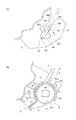
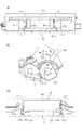
■(現像ユニットのトナーカートリッジ受け入れ部近辺の詳細説明)
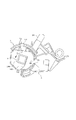
図4を用いて、本実施例に係る現像ユニット(現像カートリッジ)DのトナーカートリッジEの受け入れ部近辺の詳細な構成を説明する。図4は現像ユニットDのトナーカートリッジEの受け入れ部(装着部)近辺の斜視図である。図4(a)は第二開口部30が閉塞された状態(第一シャッタ37が閉位置)を説明するための図である。また、図4(b)は第二開口部30が開放された状態(第一シャッタ37が開位置)を説明するための図である。本実施例において、現像ユニットDの長手方向は現像ユニットDが備える現像ローラ24の回転軸線方向と平行な方向のことを指す。なおトナーカートリッジEが現像ユニットに装着された状態において、トナーカートリッジEの長手方向は、現像ユニットDの長手方向と実質的に平行である。
■ (Detailed explanation of the area around the toner cartridge receiving part of the developing unit)
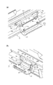
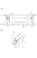
A detailed configuration of the development unit (development cartridge) D in the vicinity of the receiving portion of the toner cartridge E according to the present embodiment will be described with reference to FIG. FIG. 4 is a perspective view of the vicinity of the receiving portion (mounting portion) of the toner cartridge E of the developing unit D. FIG. 4A is a diagram for explaining a state in which the
現像ユニットDは、その枠体(現像枠体)35にトナーカートリッジEを受け入れ部に装着可能(取り外し可能)に構成されている。受け入れ部近辺において、現像ユニットDは第二開口部(収容体開口、受入口)30と、第一シャッタ(収容体シャッタ、受け入れ装置側シャッタ、受け入れ装置側開閉部材)37を有している。本実施例では、第二開口部30が現像ユニットDの長手方向中央部に設けられている。しかし、後述する第三開口部(容器開口)49と対向する位置であれば、第二開口部30の位置は、長手方向中央部にその位置を限定するものではない。
The developing unit D is configured such that the toner cartridge E can be mounted (removable) on the frame body (developing frame body) 35 in the receiving portion. In the vicinity of the receiving portion, the developing unit D has a second opening (accommodating body opening, receiving port) 30 and a first shutter (accommodating body shutter, receiving device side shutter, receiving device side opening / closing member) 37. In this embodiment, the
図4(a)に示すように、第二開口部30はトナーカートリッジEの外周面に沿った曲率を有した形状の第一シャッタ37により封止される。
As shown in FIG. 4A, the
第一シャッタ37は現像剤容器としてのトナーカートリッジEに設けられた凸部(容器側係合部、開閉部材移動部、容器側突起)45と係合する穴部37aを有する。この穴部37は第一シャッタ37が第二開口部30を封止する封止範囲の外側に設けられている。
The
また、第一シャッタ37の長手方向両端部は現像ユニットDの枠体35における第二開口部30の長手方向の両側に設けられた第一シャッタガイド部34と係合する。これにより、第一シャッタは第一シャッタガイド部34に沿ってスライド自在(移動可能)に構成されている。
Further, both ends in the longitudinal direction of the
これにより、第一シャッタ37は第二開口部30を閉塞する閉位置(受入口閉位置、図4(a))と、第二開口部30を開放する開位置(受入口開位置、図4b))との間を移動可能に構成されている。
As a result, the
また、現像ユニットDの枠体35に、第一シャッタ37と第二開口部30との間を封止するための第一封止シール32が、第二開口部30の周りを囲むように取り付けられている。
Further, a first sealing
現像ユニットDは、枠体35の長手方向両端に、トナーカートリッジEを装着(挿入)する際にトナーカートリッジの姿勢(装着姿勢)を維持しつつガイドする挿入ガイド部35d、36dを備える。
The developing unit D is provided with
また、現像ユニットDは、後述する挿入時にトナーカートリッジEの突き当て部42a、43aが突き当たる被突き当て部35a、36aを有する。
Further, the developing unit D has abutting
さらに、現像ユニットDは、枠体35の長手方向両端に、第一シャッタ37と第二シャッタ(容器シャッタ)53を開閉する際に、トナーカートリッジEの回転をガイドする回転ガイド部35b、36bを有する。
Further, the developing unit D provides rotation guide
挿入ガイド部35d、36dは、トナーカートリッジEの挿入方向f(図4(a))に沿って直線的かつ互いに平行に形成されている。なお、トナーカートリッジEの挿入方向を装着方向と考えれば、装着方向下流側は装着方向、装着方向上流側は取り外し方向とみなすことができる。
The
現像ユニットDは、非駆動側において被突き当て部35a、回転ガイド部35bが挿入ガイド部35dの挿入方向f下流側に、駆動側において被突き当て部36a、回転ガイド36bが挿入ガイド部36dの挿入方向f下流側にそれぞれ設けられている。
In the developing unit D, the abutting
なお現像ユニットDの長手方向の両端側において、ギア等の駆動部(例:第一駆動伝達部38)が配置されている側を以下、駆動側とよぶ。現像ユニットの非駆動側とはその駆動側と反対側という意味として用いている。 The side on both ends of the developing unit D in the longitudinal direction in which a drive unit such as a gear (example: first drive transmission unit 38) is arranged is hereinafter referred to as a drive side. The non-driving side of the developing unit is used to mean the side opposite to the driving side.
さらに、現像ユニットDは、後述のトナーカートリッジEの第二トナー搬送手段46に駆動を伝えるための第一駆動伝達部38が、枠体35の長手方向の一端部に設けられている。
Further, in the developing unit D, a first
第一駆動伝達部38は、ギア(歯車)であって、現像ユニットDの内部で画像形成装置本体の駆動機構と連結されている。第一駆動伝達部38はトナーカートリッジEの外部から、第二トナー搬送部材46を駆動させるための回転力を受ける回転力受け部(駆動力受け部)である。
The first
また、現像ユニットDは、枠体35における第二開口部30の長手方向の両端外側に穴部33が設けられている。穴部33は、後述するトナーカートリッジEの第二シャッタ53に設けた爪部53bと係合する。
Further, the developing unit D is provided with
爪部53bはアーム部53aの先端に設けられた係合部(開閉部材側係合部)である。これにより、第三開口部49を開閉する際に、第二シャッタ53が後述する容器枠体47aと供回りすることが防止される。
The
■(トナーカートリッジの詳細説明)
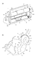
図5を用いて、本実施例に係るトナーカートリッジEの詳細な構成について説明する。
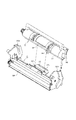
■ (Detailed explanation of toner cartridge)
The detailed configuration of the toner cartridge E according to the present embodiment will be described with reference to FIG.
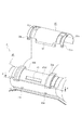
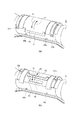
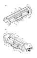
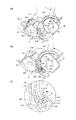
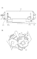
図5(a)はトナーカートリッジEを第二駆動伝達部48側(駆動側)から見たときの斜視図である。また、図5(b)はトナーカートリッジEを第二駆動伝達部48側とは反対側(非駆動側)から見たときの斜視図である。
FIG. 5A is a perspective view of the toner cartridge E as viewed from the second
図5(c)はトナーカートリッジEの第二駆動伝達部48側とは反対側から見たときの断面図である。また、図5(d)はトナーカートリッジEの第二シャッタ53が開位置(第三開口部49が開放された状態)のときの斜視図である。
FIG. 5C is a cross-sectional view of the toner cartridge E when viewed from the side opposite to the second
トナーカートリッジEは、容器47、容器47に対して移動可能な第二シャッタ(現像剤容器シャッタ)53、容器47の内部に設けられた第二トナー搬送部材46、第二トナー搬送部材46に取り付けられた第二駆動伝達部(ギア)48等を備える。
The toner cartridge E is attached to the
容器47は実質的な円筒形状である。すなわち容器47の本体部分(主要部分)を構成する枠体(容器枠体)47aが、ほぼ円筒形状である。また容器47は把持部材44を持つ。把持部材44は枠体47aと一体的に形成されたU型の突起である。なお把持部材44の形状はU字形状に限らないし、把持部材44が枠体47aと別の部材で構成されていて枠体47aに取り付けられていてもよい。
The
容器枠体(円筒部)47aは中空であって、その内側にトナーが収容される第二トナー収容部47tを形成する。また容器枠体47aは、その周面に第二トナー収容部47tのトナーを排出するための第三開口部49を形成する。
The container frame (cylindrical portion) 47a is hollow, and a second toner accommodating portion 47t for accommodating toner is formed inside the container frame body (cylindrical portion) 47a. Further, the
容器枠体47aには、容器枠体47aと第二シャッタ53の間を封止する第二封止シール54が第三開口部49を囲むように取り付けられている。
A
そして、容器枠体47aはその円筒形状の外周に、第一シャッタ37の穴部37aと係合可能に設けられた2つの凸部45を備える。2つの凸部45はほぼ同じ方向に突出している突起部である。また2つの凸部45を結ぶ線は、トナーカートリッジEの長手方向と実質的に平行である。
The
容器47の長手方向において、2つの凸部45は、第三開口部49の外側に配置される。より詳細にいうと、第二シャッタ53の回転軸線に平行な仮想線に2つの凸部45および第三開口部49を投影すると、2つの凸部に挟まれた領域の範囲内に第三開口部49の全体が位置する。
In the longitudinal direction of the
容器枠体47aの第二トナー収容部47tの内部には、トナーを搬送するための第二トナー搬送部材46が回転可能に設けられている。なお、突起や穴等が互いに係合する位置を係合位置、係合が解除される位置を非係合位置(係合解除位置)と呼ぶ。
Inside the second toner accommodating portion 47t of the
第二トナー搬送部材46の長手方向(回転軸線方向)の一端部には、第二トナー搬送部材46を回転駆動させる動力を受けるための第二駆動伝達部(ギア)48が設けられている。ここで、トナーカートリッジEの長手方向とは、第二トナー搬送部材46の回転軸線方向と平行な方向を指す。
A second drive transmission unit (gear) 48 for receiving power for rotationally driving the second
本実施例では、第三開口部49を容器枠体47aの外周面上におけるトナーカートリッジEの長手方向中央に設けている。なお、第三開口部49の位置は、第二開口部30と対向する位置であれば特定の位置に限定されるものではない。
In this embodiment, the
第二シャッタ53は、トナーカートリッジEの容器枠体47aの外周面に沿った曲率を有した形状である。第二シャッタ53の断面(容器枠体47aの中心軸線に垂直な断面)は、容器枠体47aの外周に沿った曲線形状(略円弧形状)を持つ。
The
容器枠体47aは少なくとも第三開口部49の周囲においてその表面が曲面形状(略円筒形状、略円弧形状)となっている。この第三開口部49周囲の曲面部(円弧部)に沿って、第二シャッタ53が容器枠体47aの周囲を回転(公転)可能である。これにより第二シャッタ53は第三開口部49を開閉し得る。
The surface of the
第二シャッタ53は、第三開口部49を閉じるためのシャッタ本体部53m(本体部分、閉じ部)を有する。第二シャッタ53には、アーム部53aと爪部53bを持つスナップフィットが2つ設けられている。
The
つまり第二シャッタ53は、シャッタ本体部53mの長手方向における両端部に設けられた2つのアーム部53aと、アーム部53aの先端にそれぞれ設けられた2つの爪部53bを有する。なおシャッタ本体部53mの長手方向はトナーカートリッジEの長手方向と実質的に平行である。
That is, the
爪部53bは現像ユニットDと係合するための被係合部(シャッタ側係合部、開へ売部材側係合部)である。爪部53bは円筒形状を持つ容器47(容器枠体47a)の外径側(外側)に少なくとも露出して(外径側に面して)いる。より詳細に言うと爪部53bは容器47(容器枠体47a)の外径側(外側)に少なくとも突出した突起(凸部、突出部)である。
The
またアーム部53aは、爪部53bを支持する支持部であり、爪部53bをシャッタ本体部53mと連結する連結部である。またアーム部53aは弾性変形可能な弾性部(変形可能部、移動可能部)を有する。つまりアーム部53a自体が弾性変形可能となっている。
Further, the
アーム部53aは第二シャッタ53の後端側から先端側に向けて延びる。なお第二シャッタ53の先端側とは、第二シャッタ53が第三開口部49を閉める際に容器枠体47aに対して移動する方向において下流側という意味である。第二シャッタ53の先端とは、第二シャッタ53の短手方向(第二シャッタ53の長手方向と直交する方向)における端部のことである。
The
アーム部53aの一部が弾性変形することで、爪部53bはシャッタ本体部53mに対して移動可能に構成されている。
The
第二シャッタ53(シャッタ本体部53m)の長手方向両端部は、容器枠体47aにおける第三開口部49の長手方向の両側に設けられた第二シャッタガイド部(開閉ガイド)52と係合する。そして、第二シャッタは第二シャッタガイド部52に沿って容器枠体47a外周面上を周方向にスライド自在に組み付けられている。これにより、第二シャッタ53は、トナーカートリッジEの外周面に沿って第三開口部49を開放する開位置(容器開位置、図5(d))と、第三開口部49を閉塞する閉位置(容器閉位置、図5(b))との間を移動できる。
Both ends in the longitudinal direction of the second shutter 53 (shutter
なお第二シャッタ53が開位置にある際には、図5(d)に示すように第三開口部49がシャッタ本体部53m(閉じ部)からすべて開放されることが望ましい。しかし第二シャッタ53が開位置にある際に第三開口部49からトナー排出可能であれば第三開口部49の一部がシャッタ本体部53m(閉じ部)によって覆われた構成を取ることも可能である。つまり第二シャッタ53が開位置にある際に、シャッタ本体部53mが第三開口部49を少なくとも一部開放しトナーカートリッジEから現像ユニットDに対してトナーを供給可能な構成であればよい。
When the
また、第二シャッタ53が閉位置にある際には、図5(b)に示すように第三開口部49が全てシャッタ本体部53mによって全て覆われていることが望ましい。しかし第三開口部49がわずかに開放されていても、シャッタ本体部53mによって第三開口部49が実質的に閉じられていて第三開口部49からトナーが漏れ出るのが十分に抑えられているのであれば、そのような構成を取ることも可能である。つまり第二シャッタ53が閉位置にある際に、シャッタ本体部53mが第三開口部49を実質的に閉じていればよい。
Further, when the
トナーカートリッジEは、容器枠体47aにおけるトナーカートリッジEの長手方向の両端部に被挿入ガイド部(被案内部、トナーカートリッジ側ガイド部)42、43が設けられている。そして、被挿入ガイド部(被案内部)42、43が現像ユニットDの挿入ガイド部35d、36dにガイドされることで、トナーカートリッジEの着脱時の姿勢が安定する。
The toner cartridge E is provided with guided guides (guided portions, toner cartridge side guide portions) 42 and 43 at both ends of the toner cartridge E in the
トナーカートリッジEは突き当て部42aを備える。この突き当て部42aは、トナーカートリッジEを現像ユニットDに挿入する際に現像ユニットDの被突き当て部35aと突き当たる、
また、トナーカートリッジEは被回転ガイド部42bを備える。この被回転ガイド部42bは、トナーカートリッジEを回転させて第一シャッタ37と第二シャッタ53を開閉する際に、容器枠体47aをガイドする。容器47は被回転ガイド部42bによってスムーズに回転できる。被回転ガイド部42bはトナーカートリッジEの回転をガイドする回転ガイド(トナーカートリッジ側回転ガイド)である。被回転ガイド部42bは曲面形状(略円弧形状)を持つ。
The toner cartridge E includes an
Further, the toner cartridge E includes a rotated
加えて、被挿入ガイド部42には、挿入時にトナーカートリッジEの挿入姿勢・抜き出し姿勢(挿入方向・抜き出し方向)を規制するための被規制部(被規制面、姿勢規制部、挿入方向規制部)42c1、42c2が設けられている。後述するが、被挿入ガイド42はその外形の一部に肉抜き等を施して外形を変更してもよい。
In addition, the inserted
被挿入ガイド部43は、トナーカートリッジEの挿入時に現像ユニットDの被突き当て部36aと突き当たる突き当て部43aを有する。被挿入ガイド部43は、突き当て部43aが第一シャッタ37と第二シャッタ53を開閉する際に、容器枠体47aをガイドする被回転ガイド部(トナーカートリッジ側回転ガイド部)を兼ねる構成となっている。
The inserted
なお、本実施例では、非駆動側において、突き当て部42a、被回転ガイド部42b、規制部42c1、及び、規制部42c2を、被挿入ガイド部42bと一体的に構成されている。しかし、各機能を満たす構成であれば、それぞれ別々の部材として設けてもよい。
In this embodiment, the abutting
同様に、駆動側において、被挿入ガイド部43bと突き当て部43aをそれぞれ別部材で構成してよい。また、被回転ガイド部を突き当て部43aとは別の部材として設けてもよい。このように、トナーカートリッジEと現像ユニットDの互いに当接しない部位(非機能部位・非接触部位)については、強度等を加味して適宜省略しても良い。
Similarly, on the drive side, the inserted guide portion 43b and the abutting
また、本実施例では、被挿入ガイド部43を第二トナー搬送部46の長手方向端部の第二駆動伝達部48の端部に設けている。しかし、被挿入ガイド部43を容器枠体47aに設けてもよい。また、容器枠体47aには、ユーザがトナーカートリッジEの装着操作時につかむための把手としての把持部材44が設けられている。この把持部材44は容器枠体47aの長手方向両端部に固定されている。この把持部材44については、容器枠体47aと一体成形されても良い。
Further, in this embodiment, the inserted
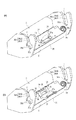
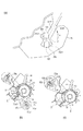
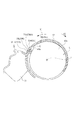
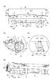
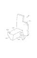
ここで、図1(a)を参照して、把持部材44の容器枠体47aにおける配置について説明する。図1(a)は、トナーカートリッジEにおける第二駆動伝達部48とは逆側を、第二トナー搬送部46の長手方向に見たときの側面図である。この図で、挿入方向に対する把持部材44と突き当て部42の位置関係を示している。
Here, the arrangement of the gripping
図1(a)に示すように、規制部42c1と規制部42c2により規制されたトナーカートリッジEの挿入方向fと平行、かつ、突き当て部42aと突き当て部43aを通る直線(容器枠体47aの回転中心Sを通る仮想線)を直線mとする。
As shown in FIG. 1A, a straight line (
把持部材44は、直線mよりも第三開口部49(図5(d)参照)の開放方向(図1(a)矢印e方向)下流側に設置されている。なお、第三開口部49の開放方向(矢印e方向)とはトナーカートリッジEを現像ユニットDへセットするためにトナーカートリッジEを回転させる方向(セット方向)である。
The gripping
[トナーカートリッジの現像ユニットへの装着]
続いて、トナーカートリッジEを現像ユニットDへ装着される過程について説明する。具体的には、トナーカートリッジEを現像ユニットDへ挿入された状態で、トナーカートリッジEを回転させることで、第二開口部30と第三開口部49が開閉する。
[Mounting the toner cartridge in the developing unit]
Subsequently, the process of mounting the toner cartridge E on the developing unit D will be described. Specifically, the
■(トナーカートリッジの現像ユニットへの挿入動作)
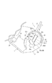
図1、図6(a)、図6(b)、図7を参照して、トナーカートリッジEの現像ユニットDへの挿入動作について説明する。
■ (Insert operation of toner cartridge into developing unit)
The operation of inserting the toner cartridge E into the developing unit D will be described with reference to FIGS. 1, 6 (a), 6 (b), and 7.
図1(b)は、トナーカートリッジEの装着方向に対する把持部材44、突き当て部43aの位置関係を示したトナーカートリッジE及び現像ユニットDの側面図である。
FIG. 1B is a side view of the toner cartridge E and the developing unit D showing the positional relationship between the gripping
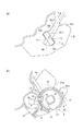
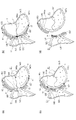
図6は、トナーカートリッジEを装着(挿入)する前の状態におけるトナーカートリッジEと現像ユニットDの様子を示す模式図であり、図6(a)は斜視図、図6(b)は側面図である。 6A and 6B are schematic views showing a state of the toner cartridge E and the developing unit D in a state before mounting (inserting) the toner cartridge E, FIG. 6A is a perspective view, and FIG. 6B is a side view. Is.
図7は、トナーカートリッジEの装着(挿入)途中の状態におけるトナーカートリッジEと現像ユニットDの様子を示す側面図である。 FIG. 7 is a side view showing the state of the toner cartridge E and the developing unit D in a state where the toner cartridge E is being installed (inserted).
トナーカートリッジEが現像ユニットDに装着される前、第一シャッタ37は収容体閉位置にあり、第二シャッタ53は容器閉位置にある。そのため、現像ユニットDの第二開口部30、トナーカートリッジEの第三開口部49はそれぞれ閉塞状態となっている。
Before the toner cartridge E is mounted on the developing unit D, the
トナーカートリッジEの現像ユニットDへの挿入方向は図6(b)のf方向である。f方向はトナーカートリッジEをトナーカートリッジEの長手側から見たときに、規制部42cの面に沿った方向となる。さらに詳しく述べると、規制部42cの面に沿った方向のうち、突き当て部42aが被挿入ガイド部42に対して下流側となる方向がf方向と言える。
The insertion direction of the toner cartridge E into the developing unit D is the f direction in FIG. 6B. The f direction is the direction along the surface of the regulating
図6(a)に示すように、ユーザは把持部材44を把持し、トナーカートリッジEを現像ユニットDに対して挿入方向fに移動させる。このとき、ユーザは、トナーカートリッジEの被挿入ガイド部42と現像ユニットDの挿入ガイド部35d、被挿入ガイド部43と挿入ガイド部36dがそれぞれ係合するようにトナーカートリッジEを移動させる。
As shown in FIG. 6A, the user grips the gripping
本実施例では、挿入方向fが重力方向g(図6(b))に対して斜めとなるように被挿入ガイド部42、43と挿入ガイド部35d、36dが構成されている。
In this embodiment, the inserted
言い換えると、トナーカートリッジEは重力方向gにおいて、被挿入ガイド部42の被規制部42c1の面と挿入ガイド部35dの面35d1が合わさって挿入される。同様に、トナーカートリッジEは被挿入ガイド部42の規制部42c2の面と挿入ガイド部35dの面35d2が合わさって挿入される。
In other words, the toner cartridge E is inserted by combining the surface of the regulated portion 42c1 of the inserted
そして、重力方向g下方側の規制部42c1の面が挿入ガイド部35dの面35d1に乗った状態となることで、回転ガイド部35bに対して被挿入ガイド部42が位置決めされる。これにより、トナーカートリッジEの現像ユニットDに対する姿勢が定まる(図7)。
Then, the surface of the regulation portion 42c1 on the lower side in the gravity direction g is placed on the surface 35d1 of the
ユーザはその姿勢のまま、さらに、トナーカートリッジEを挿入ガイド部35dと挿入ガイド部36dに沿って重力方向gの下方に移動させる。これにより、トナーカートリッジEは矢印f方向に沿って現像ユニットDに挿入される。矢印f方向に更に移動させていくと、突き当て部42aが被突き当て部35aに突き当たる。また、突き当て部43aが被突き当て部36aに突き当たる。これにより、トナーカートリッジEの挿入が完了する(図1(a)、図1(b)の状態)。
The user further moves the toner cartridge E downward in the gravity direction g along the
■(被挿入ガイド部の変形例について)
ここで、図8(a)、図8(b)、図8(c)、図8(d)を参照して、被挿入ガイド部42の構成の変形例について説明する。図8(a)〜(d)は、それぞれトナーカートリッジEの被挿入ガイド部42、突き当て部42a、規制部42cの様々な構成例を示す側面図である。本実施例では、図8(a)に示すように、トナーカートリッジEの被挿入ガイド部42を、長丸形状の単一の突起で構成している。しかし、同様の機能を発揮できるものであれば、図8(b)〜(d)に示すような、他の形状、構成を採用してもよい。ただし、突起の形状、数、配置を図示した構成に限定する意図はない。
■ (About the modified example of the inserted guide part)
Here, a modified example of the configuration of the inserted
すなわち、図8(b)に示すように、長丸形状の突起と円柱形状の突起とを組み合わせた構成でもよい。この構成では、長丸形状の突起の面42dが挿入ガイド部35dの面35d1と合わさり(当接し)、円柱形状の突起の面42c2が挿入ガイド部35dの面35d2とが合わさる(当接する)。これにより、トナーカートリッジEの挿入時における姿勢が規制される。また、長丸形状の突起の突き当て部42aが被突き当て部35aに突き当りトナーカートリッジEの挿入が完了する。
That is, as shown in FIG. 8B, an oval-shaped protrusion and a cylindrical-shaped protrusion may be combined. In this configuration, the
また、図8(c)、図8(d)に示すように、被挿入ガイド部が、複数の円柱形状の突起を組み合わせた構成でもよい。当然、突起の形状は円柱形状でなくてもよく、三角柱形状でもよい。つまり、被挿入ガイド部がトナーカートリッジEの挿入方向fに沿って配置されて、トナーカートリッジEの挿入姿勢を規制できるものであれば形状は問われない。同様に被挿入ガイド部が複数であるのか、単一であるのかも問われない。 Further, as shown in FIGS. 8 (c) and 8 (d), the inserted guide portion may have a configuration in which a plurality of cylindrical protrusions are combined. Naturally, the shape of the protrusion does not have to be a cylindrical shape, and may be a triangular prism shape. That is, the shape does not matter as long as the inserted guide portion is arranged along the insertion direction f of the toner cartridge E and the insertion posture of the toner cartridge E can be regulated. Similarly, it does not matter whether there are a plurality of guide portions to be inserted or a single guide portion.
図8(c)の構成では、挿入方向fに沿って並んだ円柱形状突起42e、42fが挿入ガイド部35dの面35d1と合わさる。また、円柱形状突起42の面42c2が挿入ガイド部35dの面35d2が合わさる。これにより、トナーカートリッジEの姿勢が規制される。同様に、挿入方向fの下流側に配置された円柱形状突起42fが突き当て部42aを有し、突き当て部42aが被突き当て部35aに突き当る。これにより、トナーカートリッジEの現像ユニットDへの挿入が完了する。
In the configuration of FIG. 8C, the
また、図8(d)の構成では、挿入方向fに沿って並んだ円柱形状突起42e、42fが、それぞれ、挿入ガイド部35dの面35d1と合わさる。また、円柱形状突起42e、42fは挿入ガイド部35dの面35d2と合わさる。これにより、トナーカートリッジEの姿勢が規制される。また、挿入方向fの下流側に配置された円柱形状突起42fが、突き当て部42aを有し、被突き当て部35aに突き当ることで、現像ユニットDへのトナーカートリッジEの挿入が完了する。
Further, in the configuration of FIG. 8D, the
このように、トナーカートリッジEの長手端部に設けられた突起が複数ある場合、現像ユニットDと接触する部位だけに着目すればよい。 As described above, when there are a plurality of protrusions provided on the longitudinal end portion of the toner cartridge E, it is sufficient to pay attention only to the portion in contact with the developing unit D.
■(トナーカートリッジの現像ユニットに対する位置決め)
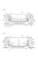
図10(a)、図10(b)、図11(a)、図11(b)、図11(c)を参照して、トナーカートリッジEの現像ユニットDに対する位置決めについて説明する。
■ (Positioning of toner cartridge with respect to developing unit)
The positioning of the toner cartridge E with respect to the developing unit D will be described with reference to FIGS. 10 (a), 10 (b), 11 (a), 11 (b), and 11 (c).
図10(a)は、突き当て部42aと被突き当て部35aが突き当たった状態におけるトナーカートリッジEの被挿入ガイド部42と現像ユニットDの枠体35の側面図である。図10(b)は、突き当て部42aと被突き当て部35aが突き当たった状態におけるトナーカートリッジE及び現像ユニットDの断面図である。
FIG. 10A is a side view of the inserted
図11(a)は、トナーカートリッジEが現像ユニットDに対して位置決めされた状態におけるトナーカートリッジEの被挿入ガイド部42と現像ユニットDの枠体35の側面図である。図11(b)は、位置決めされたトナーカートリッジEと現像ユニットDの係合関係を示す断面図である。より具体的には、図11(b)は、トナーカートリッジEと現像ユニットDを第二シャッタ53の位置で切った断面図である。
FIG. 11A is a side view of the inserted
図11(c)は、位置決めされたトナーカートリッジEと現像ユニットDの他の係合状態を示す断面図である。より具体的には、図11(c)は、トナーカートリッジEと現像ユニットDを爪部53bの位置で切った断面図である。
FIG. 11C is a cross-sectional view showing another engagement state between the positioned toner cartridge E and the developing unit D. More specifically, FIG. 11C is a cross-sectional view of the toner cartridge E and the developing unit D cut at the position of the
図10において反時計回り(図中矢印e方向)に容器枠体47aを回動させると、図11(a)に示すように、突き当て部42aと被回転ガイド42bがそれぞれ回転ガイド35bと係合する。これにより、トナーカートリッジEは現像ユニットDに対して相対的に位置決めされる。
When the
[シャッタの開閉動作について]
以下に、現像ユニット側のシャッタとトナーカートリッジ側のシャッタの開閉動作について詳しく説明する。
[Shutter opening / closing operation]
The opening / closing operation of the shutter on the developing unit side and the shutter on the toner cartridge side will be described in detail below.
本実施例では、トナーカートリッジEが現像ユニットDに装着される過程で、現像ユニット側の第一シャッタ37と、トナーカートリッジ側の第二シャッタ53が開放される(開位置に移動する)。逆にトナーカートリッジEが現像ユニットDから取り外される過程で、第一シャッタ37と第二シャッタ53が閉鎖される(閉位置に移動する)。
In this embodiment, in the process of mounting the toner cartridge E on the developing unit D, the
トナーカートリッジEは、現像ユニットDに対して少なくとも回転動作を伴う装着動作により装着される。より具体的には、トナーカートリッジEは直線的に現像ユニットDに略直線的に挿入された後、現像ユニットDに対して回転して装着される。トナーカートリッジE装着時の回転動作に連動して各シャッタ37、53は閉位置から開位置に移動するものである。
The toner cartridge E is attached to the developing unit D by at least an attachment operation accompanied by a rotation operation. More specifically, the toner cartridge E is linearly inserted into the developing unit D substantially linearly, and then is rotated and mounted with respect to the developing unit D. The
同様にトナーカートリッジEは、現像ユニットDから少なくとも回転動作を伴う取り外し動作によって取り外される。より具体的には、トナーカートリッジEは現像ユニットDに対して回転した後、ほぼ直線的に現像ユニットDから抜き出されて取り外される。 Similarly, the toner cartridge E is removed from the developing unit D by a removal operation that involves at least a rotational operation. More specifically, the toner cartridge E is rotated with respect to the developing unit D, and then is pulled out from the developing unit D substantially linearly and removed.
トナーカートリッジEの取り外し時の回転動作に伴って書くシャッタ37、53が開位置に移動するものである。
The
■(シャッタの開放動作)
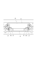
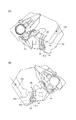
図1(a)、図11(a)、図11(b)、図11(c)、図12(a)、図12(b)を参照して、現像ユニットDの第一シャッタ37とトナーカートリッジEの第二シャッタ53の開放動作について説明する。図12(a)は、第二開口部30、第三開口部49が開放された状態におけるトナーカートリッジEの被挿入ガイド部42と現像ユニットDの枠体35の側面図である。図12(b)は第二開口部30、第三開口部49が開放された状態におけるトナーカートリッジEと現像ユニットDの断面図である。
■ (Shutter opening operation)
With reference to FIGS. 1 (a), 11 (a), 11 (b), 11 (c), 12 (a), and 12 (b), the
本実施例は、トナーカートリッジEが現像ユニットDに対して位置決めされた状態(装着状態)において、第二開口部30と第三開口部49の相対的な位置が異なる位置を取ることができる。言い換えれば、現像ユニットDにトナーカートリッジEを取り付けた状態で、トナーカートリッジEが回転することで少なくとも2つの位置(2つの状態)を取りえるように構成されている。
In this embodiment, when the toner cartridge E is positioned with respect to the developing unit D (mounted state), the relative positions of the
1つ目の位置は、第二開口部30と第三開口部49が重ならず、第一トナー収容部28と第二トナー収容部47tが非連通状態となる非連通位置である。この状態では、第一シャッタ37は第二開口部30を閉じる閉位置にある。
The first position is a non-communication position in which the
2つ目の位置は、第二開口部30と第三開口部49とが重なって、第一トナー収容部28と第二トナー収容部47tが連通状態となる連通位置である。この状態では、第一シャッタ37は第二開口部30を開く開位置にある。
The second position is a communication position in which the
つまり第一シャッタ37は第二開口部30を開閉する開閉部材である。第三開口部49は実質的に円弧形状状の曲面部に形成された開口であり、第一シャッタ37は曲面部に沿って移動(回転)することで第三開口部49を開閉する。
That is, the
図1(a)に示すように、トナーカートリッジEが現像ユニットDの所定の位置に挿入されると、容器枠体47aの凸部45と、第一シャッタ37の穴部37aとが係合する。また、このとき、第二シャッタ53の先端面53c(図5(d)参照)と現像ユニットDの衝突面(当接面)39(図4(b)参照)とが互いに対向する状態となる。つまり、被挿入ガイド部42が挿入ガイド部35dによってガイドされることで、凸部45が穴部37aに挿入し得るように、トナーカートリッジEの挿入姿勢が規制されている。同様に、先端面53cが衝突面39に対向するようにトナーカートリッジEの挿入姿勢が規制される。
As shown in FIG. 1A, when the toner cartridge E is inserted into a predetermined position of the developing unit D, the
図1(a)に示す装着位置から、トナーカートリッジEは、ユーザによる把持部材44の操作により容器枠体47aが矢印e方向に回転される。これにより、被挿入ガイド部42と枠体35との係合状態が、図11(a)に示す状態を経て図12(a)に示す状態となる。なおこの際、トナーカートリッジE(容器枠体47a)の回転軸線は、トナーカートリッジEの長手方向と実質的に平行となっている。
From the mounting position shown in FIG. 1A, the
容器枠体47aの回転の途中において、図11(b)に示すように、第二シャッタ53の先端面53c(図5(d)参照)と現像ユニットDの衝突面39(図4(b)参照)が突き当る。これにより、第二シャッタ53がトナーカートリッジEと一体に回動することが規制される。
During the rotation of the
すなわち、第二シャッタ53の先端面53cの移動が衝突面39によって規制されることで容器枠体47aのみが回転する。この状態から容器枠体47aをさらにトナーカートリッジEを現像ユニットDへ装着する方向(図11(b)の矢印e方向)へ回転をさせる。すると、トナーを現像ユニットへ補給するための第三開口部49が開かれる方向(開方向)へ容器枠体47aが移動する。
That is, only the
言い換えると、第三開口部49を開く方向に向けて第二シャッタが容器枠体47aに対して相対移動する。より詳細に述べると、第二シャッタの先端面53cが衝突面39から力(反力)を受けることで、第二シャッタ53は容器枠体47aの外周に沿って第三開口部49が開放される方向へ回転(公転)する。
In other words, the second shutter moves relative to the
図1(a)、図11(c)に示すように、容器枠体47aは、外周面におけるアーム部53aと対向する領域において、アーム部53aの側に向かって高さが高くなるように形成された面(斜面)47bを有している。言い換えると、容器枠体47aはその周面が外径側に突出した周面と、内径側に凹んだ周面を備える。外径側に突出した周面と内径側に凹んだ周面の境界部が面47bとなる。
As shown in FIGS. 1A and 11C, the
そして、容器枠体47a(面47b)に対して第二シャッタ53が相対移動をすると、容器枠体47aの外径側に突出した周面が第二シャッタに設けられたアーム部53aと当接し、アーム53aを外径側へ案内する。
Then, when the
なお容器枠体47aの外径側とは、第二シャッタ53が容器枠体47aに対して回転する際の回転半径方向外側である。また容器枠体47aの外径側とは、容器枠体47aの外に向う側(外側)であり、容器枠体47aの回転軸線(中心軸線)から遠ざかる側である。また容器枠体47aの外径側とは、容器枠体47aの内部に設けた第二トナー搬送部材46(あるいは第二トナー搬送部材46の回転軸線)から遠ざかる側である。
The outer diameter side of the
なお、本実施例では容器枠体47aが略円筒形状であるため、アーム53aを移動させる面を「外径側に突出した周面」と表現した。当然、「外径側に突出した周面」以外の形状であっても、アーム53aを案内可能な形状であればよく、アーム53aの案内部(ガイド部)の形状を特定する意図はない。
In this embodiment, since the
回転が規制された第二シャッタ53のアーム部53aに対し、容器枠体47aが回転すると、面47bの点Qが、アーム部53aの面53dに沿って移動する。そして、面47bの点Qが爪部53bの後ろ側の面53e(被当接部)と当接するようになる。このとき、アーム部53aは、面53eが点Qから矢印n方向の力を受けることで、爪部53bが面47bによって持ち上げられるように変形する。
When the
これにより、アーム部53aは、容器枠体47aの周面に設けられた凹部に沿って退避している状態から現像ユニット側に係合する状態に移行する。具体的には、アーム部53aの爪部53bが現像ユニットDの枠体35の穴部33と係合する。それにより、第二シャッタ53が枠体35に対して一時的に係合される。面47b(図6(b)参照)は、第二シャッタ53が開位置に移動する際(トナーカートリッジEが装着される際)に、爪部53bを付勢して爪部53bを外径側(容器枠体47aの外側)に移動させる移動部(係合位置移動部)である。つまり面47bによって爪部53bは穴部33と係合するための係合位置へと移動する。面47bによって爪部53bは、容器枠体47aの外側(容器枠体47aの中心(回転軸線)から遠ざかる側)つまり容器枠体47aの内部に設けられた第二搬送部材46の回転軸線から遠ざかる方向に移動する。
As a result, the
面47bは爪部53b、アーム部53a、爪部53bを容器枠体47aの外径側(つまりは係合位置)にガイド(案内)するガイド部でもあり、アーム53a、爪部53bを外径側に付勢・押圧する付勢部(押圧部)でもある。また面47bは、第二シャッタ53が開位置にある際に、係合部(爪部53b)を係合位置(穴部33と係合する位置)に保持する係合位置保持部である。面47bがスナップフィット(アーム部53aあるいは爪部53b)を支えることで、爪部53bが穴部33から退避した退避位置に移動しない。
The
また、容器枠体47aが図11(b)の矢印e方向に回転するとき、凸部45の面45aと穴部37aの面37a1が接触することで、第一シャッタ37は容器枠体47aの回転方向に押される。その結果、第一シャッタ37が容器枠体47aの回動と連動して、第二開口部30が開放される。容器枠体47aに設けられた凸部(突起部、突部)45は、第一シャッタ37に力を加えて第一シャッタ37を開位置に移動させる開放力付与部(開位置移動部、開閉部材移動部)である。
Further, when the
その後、図12(a)、図12(b)に示すように、第一トナー収容部28と第二トナー収容部47が第三開口部49、第二開口部30を介して連通した状態となる。これにより、第二開口部30と第三開口部49の開放動作が完了する。
After that, as shown in FIGS. 12A and 12B, the first
このとき、突き当て部42a及び被回転ガイド部42bと回転ガイド部35bが係合する。これにより、第二開口部30、第三開口部49が開放した状態で、トナーカートリッジEは現像ユニットDに対して相対的な移動が規制される。
At this time, the abutting
具体的には、トナーカートリッジEは、現像ユニットDから受ける力によるy方向、挿入方向fの逆方向kへの移動が規制される。この状態で、トナーカートリッジEの第二駆動伝達部48は現像ユニットDの駆動伝達部38と連結される。これにより、第二トナー搬送部材46を回転させる駆動力が現像ユニットDから伝達可能な状態となる。以上より、トナーカートリッジEの第二トナー収容部47tから現像ユニットDの第一トナー収容部28へトナーtの流通(供給)が可能となる。なお、本実施例では、トナーカートリッジEの第二駆動伝達部48へ駆動を伝達する駆動伝達部38は現像ユニットD側に設けた。しかし、後述する実施例のようにトナーカートリッジE側に第二駆動伝達部48と噛みあう駆動伝達部38を設けてもよい。なお、ギア同士の噛みあいを歯合と呼び、突起が設けられたベルト等が係合する場合も、歯合するとみなす。
Specifically, the toner cartridge E is restricted from moving in the y direction and the insertion direction f in the opposite direction k due to the force received from the developing unit D. In this state, the second
■(トナーカートリッジの挿入動作からシャッタ開放動作への切り替わり)
続いて、図1、図9(a)、図9(b)を参照して、本実施例の特徴であるトナーカートリッジEの挿入動作からシャッタ開放動作への切り替わり動作について説明をする。図9(a)は現像ユニットDへの挿入完了時にトナーカートリッジEに作用する力関係を示した側面図である。また、図9(b)は突き当て部42aの他の構成例におけるトナーカートリッジEに作用する力関係を示した側面図である。
■ (Switching from toner cartridge insertion operation to shutter release operation)
Subsequently, with reference to FIGS. 1, 9 (a), and 9 (b), a switching operation from the insertion operation of the toner cartridge E to the shutter release operation, which is a feature of this embodiment, will be described. FIG. 9A is a side view showing the force relationship acting on the toner cartridge E when the insertion into the developing unit D is completed. Further, FIG. 9B is a side view showing the force relationship acting on the toner cartridge E in another configuration example of the abutting
図9(a)に示すように、トナーカートリッジEがユーザによって現像ユニットDへ挿入され、突き当て部42aと被突き当て部35aが突き当たる。これにより、トナーカートリッジEには力F1と力F2が作用する。具体的には、ユーザによってトナーカートリッジEを挿入する際に加えられる力F1が、把持部材44に作用し、反作用として同等の力F2が、被挿入ガイド部42の突き当て部42aに作用する。
As shown in FIG. 9A, the toner cartridge E is inserted into the developing unit D by the user, and the abutting
ここで、トナーカートリッジEの回転軸線(第二シャッタ部材53の回転中心)Sを通るトナーカートリッジEの装着方向と平行な直線(仮想線)mを考える。仮想線mから把持部材44までの腕の長さをr1、回転軸線(回転中心)Sから突き当て部42aまでの腕の長さをr2とする。このとき、トナーカートリッジEの第三開口部49(図5(d)参照)の回転軸線Sに働くモーメントMは、以下の式で表すことができる。
M=F1×r1+F2×r2
また、図9(a)に示すように、第二開口部30、第三開口部49を開放する際のトナーカートリッジE(容器枠体47a)の回転方向は、トナーカートリッジEを容器枠体47aの回転の軸線方向に沿って見たときに、反時計回りの矢印e方向となる。ここで、本実施例では、突き当て部42aが容器枠体47aの回転中心Sを通り挿入方向(ガイド方向)fに平行な直線(仮想線)m上に位置するため、r2=0となる。さらに、把持部材44は、第二開口部30、第三開口部49の開放方向(矢印e方向)を正とすると、直線mよりも回転方向eの下流側に設けられている。
Here, consider a straight line (virtual line) m parallel to the mounting direction of the toner cartridge E passing through the rotation axis (rotation center of the second shutter member 53) S of the toner cartridge E. Let r1 be the length of the arm from the virtual line m to the gripping
M = F1 × r1 + F2 × r2
Further, as shown in FIG. 9A, the rotation direction of the toner cartridge E (
したがって、F1×r1>0となるため、M>0となる。 Therefore, since F1 × r1> 0, M> 0.
F1×r1>0、M>0となることにより、ユーザがトナーカートリッジEを現像ユニットDに挿入時に作用させる力F1は、第二開口部30、第三開口部49の開放方向eへ回転する力へ変換される。そのため、トナーカートリッジEを方向fに挿入する方向の力F1により、トナーカートリッジE全体が回動されることになる。
When F1 × r1> 0 and M> 0, the force F1 that the user acts on when the toner cartridge E is inserted into the developing unit D rotates in the opening direction e of the
ここで、モーメントMの値が大きいほどトナーカートリッジEは回動し易くなる。言い換えると、モーメントMの値が大きいほど、第二開口部30及び第三開口部49の開放動作がよりスムーズに操作し易くなる。
Here, the larger the value of the moment M, the easier it is for the toner cartridge E to rotate. In other words, the larger the value of the moment M, the smoother the opening operation of the
ここで、モーメントMをより大きくする構成としては、例えば、図9(b)に示すように、突き当て部42aを設ける位置を変更することが考えられる。具体的には、突き当て部42aを容器枠体47aの回転中心Sを通り装着方向fと平行な仮想線mに対し、把持部材44とは反対側に離れた位置とする構成が考えられる。
Here, as a configuration for increasing the moment M, for example, as shown in FIG. 9B, it is conceivable to change the position where the abutting
突き当て部42aに作用する力をF3、仮想線mから突き当て部42aまでの距離をr3とすると、回転中心Sに働くモーメントMは、図9(a)の構成と同様に、以下の式で表せる。
M=F1×r1+F3×r3
このとき、F3×r3は、第二開口部30及び第三開口部49の開放方向eへのモーメントとなる。そのため、モーメントMは大きくなり、容器枠体47aは開放方向eへ回動しやすくなる。なお、以上述べた突き当て部42aと把持部材44の位置関係は、突き当て部43aと把持部材44との関係に適用しても同様の効果を得ることができる。
Assuming that the force acting on the abutting
M = F1 × r1 + F3 × r3
At this time, F3 × r3 is a moment in the opening direction e of the
把持部材44の配置関係を、図64を用いてより詳細に述べる。図64は回転軸線Sと垂直な投影面にトナーカートリッジEを投影し、仮想線mによってトナーカートリッジEを2つの領域R1、領域R2に分割した状態をしめす。
The arrangement relationship of the gripping
この際、把持部材44は第三開口部(排出口)49と同じ領域R1に位置する。本実施例では把持部材44の全体が領域R1に位置する。つまり把持部材44の先端部(把持部)44tと根本部44sがともに領域R1に位置する。ただ特にユーザによって直接把持される先端部(操作部、把持部)44tが領域R1側にあるのが望ましい。なお把持部材44の根本部とは容器47と把持部材44の接続部分である。また凸部(容器側突起、開閉部材移動部)45および爪部53a(開閉部材側係合部)、面(係合位置移動部)47bも領域R1側にある。
At this time, the gripping
第1シャッタ37、第2シャッタ53の開閉動作に関連する凸部45および爪部53a、面47b、第三開口部49、把持部材44の全てを領域R1に配置する。このことで、第1シャッタ37、第2シャッタ53関連の構成が簡易化しトナーカートリッジEや現像カートリッジDの小型化につながる。
All of the
より詳細に把持部材44の配置関係を説明するため、仮想線mおよび仮想線nによって、トナーカートリッジEを4分割する。仮想線nは回転中心Sを通り仮想線mと垂直な直線である。この際、トナーカートリッジEは、領域R1a、領域R1b、領域R2a、領域R2bと4つの領域に分けられる。つまり矢印e方向に沿って、領域R1a、領域R1b、領域R2a、領域R2bの順に配置されている。なおトナーカートリッジEの装着時における容器47の回転方向である。あるいは矢印e方向とは第二シャッタ53が容器47に対して開位置から閉位置に回転する方向である。
In order to explain the arrangement relationship of the gripping
把持部材44(先端部44t、根本部44s)、面(係合位置移動部)47bは、第三開口部49と同じ領域R1aに配置される。
The gripping member 44 (tip portion 44t, root portion 44s) and surface (engagement position moving portion) 47b are arranged in the same region R1a as the
凸部45は矢印e方向において領域R1aよりも一つ下流側の領域R1bに配置されている。爪部53aは矢印e方向において凸部45と把持部材44の間に配置されている。爪部53aは仮想線n近傍に位置している。爪部53aの大部分が領域R1b側に配置されていが、爪部53aを領域R1aに配置することも可能である。
The
矢印e方向において順に、把持部材44、第三開口部49、面47b、爪部(係合部)53a、凸部45の順に配置されている。
In the direction of the arrow e, the gripping
■(シャッタの閉塞動作)
図10(a)、図10(b)、図11(b)、図11(c)、図12(b)を参照して、現像ユニットDの第一シャッタ37とトナーカートリッジEの第二シャッタ53の閉塞動作について説明する。第一シャッタ37と第二シャッタ53の閉塞動作は、先述した開放動作と逆の動作で行われる。なお、第一シャッタ37、第二シャッタ53の閉塞方向は、第二駆動伝達部48の設置側とは逆側から軸線方向にみて、容器枠体47aが時計回り(図12(b)矢印h方向)に回転する方向である。
■ (Shutter closing operation)
With reference to FIGS. 10 (a), 10 (b), 11 (b), 11 (c), and 12 (b), the
まず、図12(b)の状態において、ユーザが把持部材44を把持し容器枠体47aを閉塞方向(矢印h方向・閉方向)へ回動させる。すると、容器枠体47aの凸部45の面45bが第一シャッタ37の穴部37aの面37a2に突き当たる。これにより、第一シャッタ37は、面37a2から力を受けて容器47の回転動作と連動して回動する。そして第一シャッタ37は、第二開口部30を閉塞する閉位置にまで移動する。凸部45の面45bは、第一シャッタ37に力を加え第一シャッタ37を閉位置に移動させる閉塞力付与部である。
First, in the state of FIG. 12B, the user grips the gripping
さらに、このとき、図11(c)に示すように、第二シャッタ53の爪部53bは上記したように面47bによって係合位置に配置されていて、爪部53bと現像ユニットDの穴部33は係合している。そのため、爪部53bの面53fが穴部33の面33aに突き当り、第二シャッタ35は容器枠体47aと連れ回らない。つまり、爪部53bが穴部33と係合し、面53fが面33aから力を受けることで第二シャッタ35の回動が規制される。言い換えると、第二シャッタ35は容器枠体47aと一体的に移動しなくなり、第二シャッタ35と容器枠体47aは相対的な移動が可能となる。そのため、第二シャッタ53は容器枠体47aに対し相対的に移動して、第三開口部49を閉塞する閉位置に移動する。
Further, at this time, as shown in FIG. 11C, the
爪部53bは係合位置にある際に穴部(受入装置側係合部)33と係合することで、第二シャッタ53を閉位置に移動させる力を受け得るシャッタ側係合部である。特に穴部33と接触する爪部53bの面53fは、穴部33から力を受ける力受け部である。
The
そして、容器枠体47aを閉塞方向(矢印h方向)へさらに回動させると、図10(a)、図10(b)に示すようにトナーカートリッジEは現像ユニットDに対する係合状態が解除される。
Then, when the
つまり現像ユニットDの穴部33と係合していた第二シャッタ53の爪部53bは、面53eを容器枠体47aの面47bに沿わせるようにして、容器枠体47aの内径側(半径方向内側)に移動する。つまり爪部53bは面47bに沿って、穴部33から係合していた位置(係合位置)から退避して、退避位置へと移動する。これが図1(a)、図1(b)に示す状態である。
That is, the
より詳細に述べると、上記したように容器枠体47aの外周は、面47bを境に径の大きさが異なっている。容器枠体47aが回転して、面47bが爪部53bの位置に至ると、面47bに沿って容器枠体47aの径が徐々に小さくなる。そのため容器枠体47aによって、外径側に弾性変形されていたアーム部53aの形状が復元される。つまりアーム部53aの弾性変形が解消されてアーム部53aが内径側に移動する。
More specifically, as described above, the outer circumference of the
この結果、アーム部53a(図11(c)参照)の弾性力によって爪部53bも容器枠体47aの内径側に移動する。面47bは、爪部53bが容器枠体47aの内径側に移動するのを案内(ガイド)するガイド部である。
As a result, the
つまり面47bは、第二シャッタ53が閉位置から開位置に移動する際(トナーカートリッジEが装着される際)には、爪部53bを退避位置から係合位置に案内する。逆に、第二シャッタ53が開位置から閉位置に移動する際(トナーカートリッジEが取り外される際)には、爪部53bを係合位置から退避位置に案内(ガイド)する。
That is, when the
面47bは、容器枠体47aの内径側に窪んだ凹部を形成する面であり、面47aによって爪部53bが容器枠体47aの内径側に移動するのを許容するクリアランス(逃げ部)が形成される。つまり面47bは爪部53bが退避位置に移動するのを許容する許容部でもある。
The
なお、容器枠体47aの内径側とは、第二シャッタ53が容器枠体47aに対して回転ンする際の回転半径方向内側である。また内径側とは、容器枠体47aの内部に向かう側(内側)であり、容器枠体47aの回転軸線(中心軸線)に近づく側である。また内径側とは、容器枠体47aの内部に設けられた第二搬送部材46(またはその回転軸線)に近づく側である。
The inner diameter side of the
第二シャッタ53の爪部53bが係合位置(図11(c)参照)から退避位置(図1(b)参照)に移動し、穴部33との係合を解除した結果、トナーカートリッジEは、図10(b)矢印k方向への取り出しが可能となる。
As a result of the
なお、爪部53bが係合位置から退避位置に移動する際(あるいは退避位置から係合位置に移動する際)、容器枠体47aの径方向に沿って測った移動量が1.3mm以上となるようにした。1.3mm以上、爪部53bが径方向に移動するようにしたことで、爪部53bは穴部33と係合している状態と、係合を解除している状態を確実に切り替えることができる。
When the
なお、爪部53bは容器枠体47aの径方向(第二シャッタ53の回転半径方向)に移動し得る構成であるが、爪部53bが径方向と平行に移動することが必須であるわけではなく径方向と交差する方向に移動していてもよい。
The
つまり爪部53bが径方向のみに移動することが必須ではなく、爪部53bがシャッタ本体部53mに対して少なくとも径方向に移動すればよい。例えば、爪部53bが径方向に移動するのに伴って、爪部53bが容器枠体47aの軸線方向(第二シャッタ53の回転軸線方向)にも移動していてもよい。あるいは、爪部53bが径方向に移動するのに伴って、爪部53bがシャッタ本体部53mに対して容器枠体47aの周方向(第二シャッタ53の回転方向)に移動していてもよい。
That is, it is not essential that the
把持部材44は、トナーカートリッジEが現像ユニットDの装着位置に挿入された状態において、容器枠体47aの回転軸の方向に見て、回転中心を通りかつ挿入方向fに延びる仮想線に対し、容器枠体47a回転方向下流側に位置する。把持部材44は、この位置において、ユーザの操作による容器枠体47aを回転させる力を受けるように構成されている。この位置は、把持部材44が挿入方向fに作用する力を受けると、容器枠体47aを現像ユニットDに対して回転させるように働くモーメントが発生する位置である。
In a state where the toner cartridge E is inserted at the mounting position of the developing unit D, the gripping
別の見方をすれば、本実施例に係るトナーカートリッジEは、この位置において、容器枠体47aを回転させる際に把持部材44に作用する力(図9、矢印R)に、挿入方向fの分力(図9、矢印Rf)が含まれるように構成されている。ユーザが挿入時において把持部材44に対して挿入方向fに力を加えていることで、トナーカートリッジEが装着位置に到達した時点において、把持部材44には挿入方向fの力が作用している。すなわち、トナーカートリッジEが装着位置に到達した時点において、把持部材44には容器枠体47aを回転させるのに必要な力の一部が既に作用した状態となっている。したがって、ユーザが把持部材44を挿入方向fへ押し込める動作により、把持部材44には、トナーカートリッジEの装着位置への挿入に続いて容器枠体47aの回転時にも挿入方向fの力が作用し続けることになる。
From another point of view, the toner cartridge E according to the present embodiment has a force (FIG. 9, arrow R) acting on the gripping
これにより、ユーザが把持部材(ハンドル)44を握ってトナーカートリッジEを現像ユニットDの装着位置まで挿入し、その後、容器枠体47aを回転させる一連の装着動作において、挿入動作から回転動作への力の変換がスムーズに行われる。したがって、ユーザはトナーカートリッジEの現像ユニットDへの挿入と第一シャッタ37、第二シャッタ53の開放動作を直感的に操作することができ、操作性を大幅に向上させることができる。
As a result, in a series of mounting operations in which the user grasps the gripping member (handle) 44, inserts the toner cartridge E to the mounting position of the developing unit D, and then rotates the
また、本実施例は、容器枠体47aの回転軸の方向に見た場合に、把持部材(ハンドル)44が、トナーカートリッジEが装着位置にあるときにおいて、突き当て部42aよりも回転中心から遠い位置で力を受けるように構成されている。これにより、容器枠体47aの回転時において、突き当て部42aと被突き当て部35a、回転ガイド35bとの摺動抵抗に対し、梃子の原理により、少ない力で容器枠体47aを回転させることができる。突き当て部43aと被突き当て部36a、回転ガイド36bとの摺動抵抗に対しても同様である。
Further, in this embodiment, when viewed in the direction of the rotation axis of the
本実施例では、容器47(容器枠体47a)の周囲を第二シャッタ53が回転可能となるように構成した。これによりトナーカートリッジEが現像ユニットD(受入装置)に対して回転する動作で第二シャッタ53を開閉できた。トナーカートリッジEの回転動作で第二シャッタ53を開閉する場合、トナーカートリッジEの直線的な移動によって第二シャッタ53を開閉する場合と比べて、第二シャッタ53の開閉するために必要な空間(スペース)を小さくできる利点がある。
In this embodiment, the
つまり、トナーカートリッジEが現像ユニットDに対して回転する際には、トナーカートリッジEはその姿勢を変えるだけで、トナーカートリッジEの中心(回転軸線)が現像ユニットDに対してほとんど移動しない。つまり第二シャッタ53の開閉動作時に、トナーカートリッジEが現像ユニットDの中で占める領域はほとんど変化しない。その結果、第二シャッタ53の開閉のために現像ユニットDに大きなスペースを設ける必要がない。つまり本実施例のようなトナーカートリッジEを採用することで、トナーカートリッジEを受入れる受入装置(現像ユニットD)や、受入装置が設けられる画像形成装置の小型化を図ることができる。
That is, when the toner cartridge E rotates with respect to the developing unit D, the toner cartridge E only changes its posture, and the center (rotational axis) of the toner cartridge E hardly moves with respect to the developing unit D. That is, when the
またトナーカートリッジEの回転動作に伴って第二シャッタ53の係合部(爪部53b)を移動させる構成とした。つまりトナーカートリッジEの回転動作のタイミングにおいて、係合部が適切な位置に移動する構成とした。その結果、トナーカートリッジEの着脱の過程で係合部は、着脱の妨げにならない。そして係合部はトナーカートリッジEの取り外しの過程で開閉部材を閉めることができる。
Further, the engaging portion (claw
また、トナーカートリッジEの回転動作によって係合部を移動させる構成をとった。つまりトナーカートリッジEの回転動作を利用して係合部を移動させる構成を取った。そのため係合部を移動させるために装置本体からトナーカートリッジに駆動力を伝達させるなどの機構が不要である。つまりトナーカートリッジE、現像ユニットD、画像形成装置の構成を簡略化できる。 Further, the engaging portion is moved by the rotational operation of the toner cartridge E. That is, the engaging portion is moved by utilizing the rotational operation of the toner cartridge E. Therefore, a mechanism such as transmitting a driving force from the main body of the device to the toner cartridge is not required to move the engaging portion. That is, the configurations of the toner cartridge E, the developing unit D, and the image forming apparatus can be simplified.
(変形例)
本実施例ではアーム部(支持部)53c自身が弾性変形可能な弾性部を有し、アーム部53c自体の弾性力で爪部(係合部)53bが係合位置から退避位置へ移動する構成であった。
(Modification example)
In this embodiment, the arm portion (support portion) 53c itself has an elastic portion that can be elastically deformed, and the claw portion (engagement portion) 53b moves from the engagement position to the retracted position by the elastic force of the
しかしながら弾性部を支持部(アーム部53c)や係合部(爪部53b)とは別体の部材(別部材)として設けてもよい。例えばアーム部53c(支持部)をシャッタ本体部53mに対してスライド移動や回転移動可能に取り付ける。そのうえで、アーム部53cをアーム部53cとは別体の弾性部(弾性部材)で退避位置に付勢した状態とする。このような構成であればアーム部53c自体が弾性変形しなくても本実施例同様の作用を奏することが可能である。このような構成は実施例7で詳細に説明する。
However, the elastic portion may be provided as a member (separate member) separate from the support portion (
また本実施例では、シャッタ本体部53m、アーム部53a、爪部53bを含む第二シャッタ53の全体が樹脂で一体的に形成されている。しかしそれぞれ別の部材を組み合わせて第二シャッタ53が構成されていてもよい。例えば、樹脂で形成されたシャッタ本体部53mに金属製の板バネ(金属部材)を連結させて、これをシャッタ側係合部の支持部としてもよい。この際には板バネの先端を曲げてシャッタ側係合部(爪部53b)を形成するか、あるいは板バネの先端にシャッタ側係合部となる板バネとは別体の部材を固定するなどするとよい。
Further, in this embodiment, the entire
あるいは、アーム部53aが、樹脂や金属等の複数の部材を組み合わされて構成されていてもよい。
Alternatively, the
<実施例2>
(取手の中をレーザが走査する)
本実施例では画像形成装置内の省スペース化に寄与する構成について詳しく説明する。
<Example 2>
(Laser scans inside the handle)
In this embodiment, a configuration that contributes to space saving in the image forming apparatus will be described in detail.
以下に図面を参照して、実施例として開示する構成について詳しく説明する。ここで、前述の実施例と同様の機能や作用を有する構成部分については、前述の実施例と同名称を使用することで詳細な説明を省略する。また、図面については、一部の形状や部品を省略し簡略して記載している。また、本実施例中に記載する構成部品の寸法、材質、形状それらの相対配置などは、装置の構成や各種条件により適宜変更されるべきものである。そのため、実施例で開示した構成に限定する趣旨のものではない。 The configuration disclosed as an embodiment will be described in detail with reference to the drawings below. Here, detailed description of the components having the same functions and functions as those in the above-described embodiment will be omitted by using the same names as those in the above-described embodiment. In addition, some shapes and parts are omitted from the drawings for short description. In addition, the dimensions, materials, shapes, and relative arrangements of the components described in this embodiment should be appropriately changed depending on the configuration of the apparatus and various conditions. Therefore, the purpose is not limited to the configuration disclosed in the examples.
なお、電子写真画像形成装置の説明については、他の実施例と同様であるため省略する。以下に、現像ユニットDのトナーカートリッジE受け入れ部近辺の詳細な説明を行う。 The description of the electrophotographic image forming apparatus will be omitted because it is the same as in other embodiments. The vicinity of the toner cartridge E receiving portion of the developing unit D will be described in detail below.
図13(a)は、画像形成装置A内に設置されたトナーカートリッジEの把持部材44と静電潜像形成時のレーザ光Lの光路との位置関係を示した側断面図である。図13(b)は、画像形成装置A内に設置されたトナーカートリッジEの把持部材44と静電潜像形成時のレーザ光Lの照射範囲との位置関係を示した上断面図である。
FIG. 13A is a side sectional view showing the positional relationship between the gripping
本実施例は、把持部材44と容器枠体47aとの間に形成される開口部の中をレーザ光L(感光ドラム16に潜像を形成するための光)が通る構成である。
In this embodiment, the laser beam L (light for forming a latent image on the photosensitive drum 16) passes through the opening formed between the gripping
図13(b)に示すように、把持部材44は、ユーザが掴んで操作する操作部(把持部)44bが、トナーカートリッジEの長手方向に延びるように設けられている。その長手方向両端部が、支持部44aにより容器枠体47aに対して固定支持(一体成型)された構成となっている。したがって、トナーカートリッジEは、把持部材44の回転軸線Sと平行な操作部44bと容器枠体47aとの間に空間が空いた構成となっている。本実施例に係る画像形成装置Aは、レーザスキャナ1のレーザ光Lが、把持部材44の操作部44bと容器枠体47aとの間の空間(連通部)を通る。これにより、装置内部で省スペース化を図っている。
As shown in FIG. 13B, the gripping
すなわち、図13(a)に示すように、把持部材44が回動限界まで倒されて各シャッタが開位置となる装着完了状態とする。この装着完了状態において、把持部材44の操作部44bは、レーザ光Lの光路を遮らない位置となるように構成されている。また、図13(b)に示すように、把持部材44の支持部44aは、長手方向においてレーザ光Lの照射範囲(走査範囲)から外れた位置で、操作部44bを支持するように構成されている。これにより、ユーザの操作性を損なわず、画像形成装置A内にトナーカートリッジEを効率的に設置できる。そのため、省スペース化につながり画像形成装置Aの小型化が実現可能となる。
That is, as shown in FIG. 13A, the gripping
具体的には、装着した時に操作部44bの下側の面は、レーザ光が走査する際に形成される面略平行に成るように構成するとなお好ましい。具体的には、取手の根元におけるボトル周面に接する平面よりも取手下側はレーザに平行になる。言い換えると、開口側の下面と開口より装着方向に対して上流側の取手の下面を比べて、装着方向下流側の取手の下面がボトル周面よりも遠くなるように構成した。
Specifically, it is still preferable that the lower surface of the
<実施例3>
以下に図面を参照して、実施例として開示する構成について詳しく説明する。ここで、前述の実施例と同様の機能や作用を有する構成部分については、前述の実施例と同名称を使用することで詳細な説明を省略する。また、図面については、一部の形状や部品を省略し簡略して記載している。また、本実施例中に記載する構成部品の寸法、材質、形状それらの相対配置などは、装置の構成や各種条件により適宜変更されるべきものである。そのため、実施例で開示した構成に限定する趣旨のものではない。
<Example 3>
The configuration disclosed as an embodiment will be described in detail with reference to the drawings below. Here, detailed description of the components having the same functions and functions as those in the above-described embodiment will be omitted by using the same names as those in the above-described embodiment. In addition, some shapes and parts are omitted from the drawings for short description. In addition, the dimensions, materials, shapes, and relative arrangements of the components described in this embodiment should be appropriately changed depending on the configuration of the apparatus and various conditions. Therefore, the purpose is not limited to the configuration disclosed in the examples.
なお、電子写真画像形成装置の説明については、他の実施例と同様であるため省略し、現像ユニットDのトナーカートリッジE受け入れ部近辺の詳細説明から次に説明する。 The description of the electrophotographic image forming apparatus will be omitted because it is the same as in other embodiments, and will be described next from the detailed description of the vicinity of the toner cartridge E receiving portion of the developing unit D.
本実施例では、現像ユニットDからトナーカートリッジEを着脱する際の、第二開口部(収容体開口)30と第三開口部(容器開口)49の連通部58付近のトナーtの漏れを抑制する構成について詳しく説明する。
In this embodiment, when the toner cartridge E is attached / detached from the developing unit D, leakage of toner t near the
■(現像ユニット及びトナーカートリッジの概略説明)
図15を参照して、画像形成装置Aの装置本体に着脱可能な現像ユニットD、トナーカートリッジEについて説明する。図15(a)は、現像ユニットDとトナーカートリッジEが別々に分離した状態を模式的に表した側断面図である。図15(b)は、現像ユニットDにトナーカートリッジEが設置(装着)された状態を模式的に表した側断面図である。
■ (Outline explanation of developing unit and toner cartridge)
A developing unit D and a toner cartridge E that can be attached to and detached from the main body of the image forming apparatus A will be described with reference to FIG. FIG. 15A is a side sectional view schematically showing a state in which the developing unit D and the toner cartridge E are separately separated. FIG. 15B is a side sectional view schematically showing a state in which the toner cartridge E is installed (mounted) on the developing unit D.
トナーカートリッジ(現像剤容器)Eは、トナーtを収容する第二トナー収容部(容器収容室)47tが設けられた容器枠体47aを備える。また、容器枠体47aは第二トナー収容部47t内外を連通する第三開口部(容器開口)49をその周面に備える。同様に、容器枠体47aには、第三開口部49を開閉可能な第二シャッタ(容器シャッタ)53がその周面に移動可能に取り付けられている。また、容器枠体47aの第二トナー収容部47t内には、第二トナー搬送部材46が回転可能に支持されている。この第二トナー搬送部材46は第二トナー収容部に収容されたトナーを第三開口部49へ向かって搬送・排出する。
The toner cartridge (developer container) E includes a
これらを備えるトナーカートリッジEは、現像ユニットDに対して着脱可能に構成されている。容器枠体47aは、トナーカートリッジEが現像ユニットDに設置(装着)された状態において、現像ユニットD(枠体35)に対し、現像ローラ軸線方向zに平行な回転軸線回りに回転可能(相対移動可能)に構成されている。
The toner cartridge E including these is configured to be removable from the developing unit D. The
現像ユニット(収容体)Dは、現像手段としての現像ローラ(現像剤担持体)24や現像ブレード(規制部材)25を備える。また、現像ローラ24と現像ブレード25は現像ユニットDの枠体(現像枠体)35に組み付けられる。
The developing unit (accommodating body) D includes a developing roller (developing agent carrier) 24 and a developing blade (regulatory member) 25 as developing means. Further, the developing
枠体35には、トナーtを収容する第一トナー収容部(収容体収容室)28、現像室31、現像室31と第一トナー収容部28を連通する第一開口部29、第一トナー収容部28内外を連通する第二開口部(収容体開口)30が設けられている。第二開口部30は、現像ユニットDに装着されたトナーカートリッジEの第三開口部49と対向する位置に設けられている。また、枠体35には、第二開口部30を開閉可能な第一シャッタ(収容体シャッタ)37が移動可能に組み付けられている。また、枠体35の第一トナー収容部28内には、第一トナー搬送部材27が回転可能に支持されている。現像ローラ24は、現像室31内に周面の一部が露出するように枠体35に回転可能に設けられている。
The
トナーカートリッジEと現像ユニットDは、装着状態において、トナーカートリッジEの第三開口部49と現像ユニットDの第二開口部30とにより、連通部58が形成される。この連通部58を介して、第一トナー収容部28と第二トナー収容部47tが連通する。この状態において、トナーカートリッジEの第二トナー収容部47t内に回転可能に支持された第二トナー搬送部材46が矢印u1方向へ回転する。これにより、トナーカートリッジEの第二トナー収容部47tに収容されたトナーtは、第三開口部49を通り、第二トナー収容部47t外へ送り出される。トナーカートリッジEから第三開口部49を通り送り出されたトナーtは、連通部58を通り第二開口部30から現像ユニットDの第一トナー収容部28内へと送られる。このトナーtは、第一トナー収容部28内に回転可能に支持された第一トナー搬送部材27の矢印u2方向への回転により、第一開口部29を通り現像室31へ送り出される。
In the mounted state of the toner cartridge E and the developing unit D, a
現像室31にはマグネットローラ26を内蔵した現像ローラ24が設けられている。現像ローラ24は、マグネットローラ26の磁力によって、現像室31内のトナーtを現像ローラ24表面に引き寄せる。また、現像ブレード25は、現像ローラ24に対して一定の接触圧を持って弾性的に接触するように配置されている。そして、現像ローラ24が矢印b方向に回転することで、現像ローラ24の表面に付着するトナーtの量を規制し、トナーtに摩擦帯電電荷を付与する。これにより、現像ローラ24表面にトナー層が形成される。そして、画像形成装置A(不図示)から電圧が印加された現像ローラ24が矢印b方向に回転することで、感光ドラム16の現像領域へトナーtが供給される。これにより、感光ドラム16の静電潜像に応じてトナーtが転移して静電潜像が可視像化され、感光ドラム16にトナー像が形成される。なお、現像ローラ24、第一トナー搬送部材27、第二トナー搬送部材46は、装置本体に設けられた不図示のモータ等の動力源から動力が伝達されることにより回転駆動される。
The developing
■(現像ユニット及びトナーカートリッジのシャッタ構成)
図16、図17、図18、図19、図24(a)、図24(b)を参照して、トナーカートリッジEと現像ユニットDのシャッタ構成について説明する。図16は、トナーカートリッジEの第三開口部近辺の分解斜視図である。図17は、トナーカートリッジEのシャッタ開閉動作を示す斜視図である。図17(a)はシャッタ閉状態、図17(b)はシャッタ開状態を示す。図18は、現像ユニットDの第二開口部近辺の分解斜視図である。図19は、現像ユニットDのシャッタ開閉動作を示す分解斜視図である。図19(a)はシャッタ閉状態、図19(b)はシャッタ開状態を示す。図24(a)は、図16に示すトナーカートリッジEの枠体48のA1断面図である。図24(b)は、図18に示す現像ユニットDの枠体33のA2断面図である。
■ (Shutter configuration of developing unit and toner cartridge)
The shutter configurations of the toner cartridge E and the developing unit D will be described with reference to FIGS. 16, 17, 18, 19, 24 (a), and 24 (b). FIG. 16 is an exploded perspective view of the vicinity of the third opening of the toner cartridge E. FIG. 17 is a perspective view showing a shutter opening / closing operation of the toner cartridge E. FIG. 17A shows a shutter closed state, and FIG. 17B shows a shutter open state. FIG. 18 is an exploded perspective view of the vicinity of the second opening of the developing unit D. FIG. 19 is an exploded perspective view showing the shutter opening / closing operation of the developing unit D. FIG. 19A shows a shutter closed state, and FIG. 19B shows a shutter open state. FIG. 24A is an A1 cross-sectional view of the
トナーカートリッジEは、容器枠体47aと、容器枠体47aに設けられた第三開口部49と、第二シャッタ53と、第二シール部材157と、を備える。また、容器枠体47aは、第二シャッタ53をガイドするためのガイド部50a、ガイド部50bを備える。
The toner cartridge E includes a
また、第二シャッタ53には、容器枠体47aに設けられたガイド部50a、ガイド部50bそれぞれにガイドされる被ガイド部154a、被ガイド部154bが設けられている。第二シャッタ53に設けられた被ガイド部154aと被ガイド部154bは、容器枠体47aの外形部47a1とガイド部50a、ガイド部50bとの隙間50a1、隙間50b1に差し込まれる。これによって第二シャッタ53は容器枠体47aに設けられた第三開口部49を開放する開放状態(容器開位置、図17(b))と、第三開口部49を閉塞する閉塞状態(容器閉位置、図17(a))の間を移動可能である。
Further, the
図18に示すように、現像ユニットDは、枠体35と、枠体35に設けられた第二開口部30と、第一シャッタ37と、第一シール部材32と、を備える。また、図24(b)に示すように、枠体35には、第一シャッタ37をガイドするためのガイド部34a、開閉ガイド部34bが設けられている。また、第一シャッタ37には、枠体35に設けられたガイド部34a、開閉ガイド部34bそれぞれにガイドされる被ガイド部37s、被ガイド部37tが設けられている。第一シャッタ37に設けられた被ガイド部37s、被ガイド部37tは、枠体35の外形部35a、35bと開閉ガイド部34a、34bとの隙間34a1、隙間34b1に差し込まれる。これによって第一シャッタ37は枠体35に設けられた第二開口部30を開放する開放状態(収容体開位置、図19(b))と、第二開口部30を閉塞する閉塞状態(収容体閉位置、図19(a))の間を移動可能である。
As shown in FIG. 18, the developing unit D includes a
[シャッタの開閉動作に関する説明]
以下に、本実施例の現像ユニットD、トナーカートリッジEに設けられているシャッタの動作について詳しく説明する。
[Explanation of shutter opening / closing operation]
The operation of the shutters provided on the developing unit D and the toner cartridge E of this embodiment will be described in detail below.
図20、図21、図22、図23はトナーカートリッジEと現像ユニットDのシャッタ開放/閉塞動作を説明するための図である。図20は、トナーカートリッジEを現像ユニットDに係合させた状態の開口部周辺の構成を示す模式的側断面図であり、図20(a)は、開口部が閉塞した状態、図20(b)は、開口部が開放された状態を示す。図21は、トナーカートリッジEと現像ユニットDの斜視図である。図22は、現像ユニットDとトナーカートリッジEが係合した際の穴部33Lと突部56a、穴部33Rと突部56bを示す模式的断面図である。図23は、トナーカートリッジEを現像ユニットDに係合させた状態におけるシャッタ部を示す模式的側断面図である。
20, FIG. 21, FIG. 22, and FIG. 23 are diagrams for explaining the shutter opening / closing operation of the toner cartridge E and the developing unit D. FIG. 20 is a schematic side sectional view showing a configuration around an opening in a state where the toner cartridge E is engaged with the developing unit D, and FIG. 20A is a state in which the opening is closed, FIG. b) indicates a state in which the opening is open. FIG. 21 is a perspective view of the toner cartridge E and the developing unit D. FIG. 22 is a schematic cross-sectional view showing the
第二シャッタ部材53は、実施例1と同様に第三開口部39を閉じるためのシャッタ本体部(閉じ部)53mを有する。シャッタ本体部53mの両端部にはそれぞれアーム部(連結部、支持部、弾性部、変形可能部、移動可能部)56c、56dを有する。またアーム部56cに支持される爪部(凸部、突起部、シャッタ側係合部、被係合部)56a、アーム部56dに支持される爪部(突部、突起部、シャッタ側係合部、被係合部)56bを有する。
The
構成、作用は一部異なるが、爪部56a、56bは実施例1における爪部53bに対応する。同様にアーム部56c、56dは実施例1におけるアーム部53aに対応する。実施例1と異なる点については後述する。
Although the structure and operation are partially different, the
図20(a)に示すように、トナーカートリッジEと現像ユニットDを係合(装着)させたばかりの状態では、トナーカートリッジEに設けられた第三開口部49と現像ユニットDに設けられた第二開口部30は対向位置にはない。また、現像ユニットDにトナーカートリッジEが設置されるとき、図21に示すようにトナーカートリッジEの第二シャッタ53に設けられた突部(容器被係合部)56aと、現像ユニットDの枠体35に設けられた穴部33Lが対向(係合)する。同様に、トナーカートリッジEの第二シャッタ53に設けられた突部(容器被係合部)56bと、現像ユニットDの枠体35に設けられた穴部33Rが対向(係合)する。また、トナーカートリッジEの容器枠体47aに設けられた突部(容器係合部)45a、45bが現像ユニットDの第一シャッタ37に設けられた穴部37aL、37aRと対向(係合)する。
As shown in FIG. 20A, in a state where the toner cartridge E and the developing unit D have just been engaged (mounted), the
上述の実施例1では、トナーカートリッジEを現像ユニットDに挿入させた時点では、第二シャッタ部材53の爪部(シャッタ側係合部)53bは穴部33に進入しない(図1(a)参照)。つまりトナーカートリッジEの容器枠体47aが回転することで、はじめて爪部53bが穴部33の中に進入して係合する構成であった(図11(c)参照)。
In the first embodiment described above, when the toner cartridge E is inserted into the developing unit D, the claw portion (shutter side engaging portion) 53b of the
これに対して本実施例では、トナーカートリッジEの容器枠体47aを回動させる前に、第二シャッタ53の凸部(爪部、シャッタ側係合部)56a、56bが、現像ユニットDの穴部33(33R、33L)の中に進入する構成である。
On the other hand, in this embodiment, before the
また本実施例のシャッタ側係合部(爪部56a、56b)は、第二シャッタ53が閉位置から開位置に移動するための力、および開位置から閉位置に移動するための力を現像ユニットDから受ける。以下に説明する。
Further, the shutter-side engaging portions (claw
■(開放動作)
まず、トナーカートリッジEを現像ユニットDの所定の装着位置へ設置する。そして、トナーカートリッジEを回転させることで、トナーカートリッジEの第三開口部49を閉塞状態(非連通位置、図17(a))から開放状態(連通位置、図17(b))にすることができる。具体的には、図20に示すように、ユーザが点Fを中心に矢印k1方向にトナーカートリッジEの容器枠体47aを回転させる。このとき、容器枠体47aが点Fを中心に矢印k1方向に回転すると、第二シャッタ53に設けた突部56aの矢印k1方向下流側面56a1と穴部33Lの矢印k1方向下流面33L1が当接する(図22参照)。同様に、容器枠体47aが矢印k1方向に回転するとき、突部56bの矢印k1方向下流側面56b1と、穴部33Rの矢印k1方向下流面33R1が当接する。このため、トナーカートリッジEの容器枠体47aが矢印k1方向に回転するとき、第二シャッタ53は現像ユニットDの枠体35に設けられた穴部33L、穴部33Rに規制されて動かない。その結果、トナーカートリッジEの容器枠体47aと第二シャッタ53は相対的に移動し、容器枠体47aに設けられた第三開口部49が第二シャッタ53から露出し、開放される。
■ (Open operation)
First, the toner cartridge E is installed at a predetermined mounting position of the developing unit D. Then, by rotating the toner cartridge E, the
つまり、第二シャッタ53に設けられた爪部56a、56bが現像ユニットの穴部33(33L、33R)から力を受けることで、第二シャッタ53が容器枠体47aに対して相対的に移動する。言い換えると第二シャッタ53は爪部56a、56bが受けた力を用いて第三開口部49を少なくとも一部開放する開位置から、第三開口部49を実質的に閉める閉位置へと回転移動する。
That is, when the
そして、図23に示すように容器枠体47aが点Fを中心に矢印k1方向に回転する。この回転に伴って、容器枠体47aに設けられた突部45aの矢印k1方向下流面45a1が第一シャッタ37に設けられた穴部37aLの矢印k1方向下流面37aL1を矢印c1方向に押す。同様に、容器枠体47aに設けられた突部45bの矢印k1方向下流面45b1が、第一シャッタ37に設けられた穴部37aRの矢印k1方向下流面37aR1を矢印c1方向に押す。このため、トナーカートリッジEの容器枠体47aが点Fを中心に矢印k1方向に回転することに伴って、現像ユニットDの第一シャッタ37が枠体35に対して矢印c1方向に相対移動し、第二開口部30が開放される(図20(b))。
Then, as shown in FIG. 23, the
このように、第一シャッタ37は、トナーカートリッジEの容器枠体47aの矢印k1方向の回転変位に伴って、現像ユニットDの第二開口部30を閉塞状態から開放状態にする。そして、図20(b)に示すように、現像ユニットDの第一トナー収容部28とトナーカートリッジEの第二トナー収容部47tは、第二開口部30の一部と第三開口部49で形成される連通部58を介して連通する。これによってトナーカートリッジEの第二トナー収容部47tから、現像ユニットDの第一トナー収容部28へトナーtの供給が可能となる。
In this way, the
また、図27に示すように、トナーカートリッジEの容器枠体47aが回動することによって、容器枠体47aの面47bに設けられた点Qが爪部56a、56bに接触して爪部56a、56bを押す(付勢する)。爪部56a、56bが点Qから押された力によってアーム部56c、56dが、容器枠体47aの外径側に変形する。するとアーム部56cに支持された突部56aや、アーム部56dに支持された突部56a、56bが、それぞれ穴部33L、33Rにより深く入り込む。これは爪部56a、56bが穴部33L、33Rと係合する係合位置へ移動した状態である。つまり爪部56a、56bは、面47bによって係合位置に保持された状態となっている。
Further, as shown in FIG. 27, as the
ここで、図24(c)は、図20(b)に示すA3断面図であり、現像ユニットDの第二開口部30と、トナーカートリッジEの第三開口部49が連通したときの断面図である。トナーカートリッジEの容器枠体47aの矢印k1方向の回転が進むと、図24(c)に示すように、容器枠体47aに設けられたガイド部50a、50bが現像ユニットDの枠体35に設けられた隙間34a1、34b1にそれぞれ差し込まれる。また、現像ユニットDの枠体35に設けられた開閉ガイド部34a、34bは、トナーカートリッジEの容器枠体47aに設けられた隙間50a1、50b1に差し込まれる。これによって、現像ユニットDの第二開口部30とトナーカートリッジEの第三開口部49が連通したとき、トナーカートリッジEが矢印q1方向へ動くことが防止される(図20(b)、図24(c))。すなわち、現像ユニットDの第二開口部30とトナーカートリッジEの第三開口部49が連通した状態で、現像ユニットDとトナーカートリッジEが離れることはない。
Here, FIG. 24 (c) is a cross-sectional view taken along the line A3 shown in FIG. 20 (b), which is a cross-sectional view when the
■(閉塞動作)
現像ユニットDの第二開口部30とトナーカートリッジEの第三開口部49を、連通状態(図20(b))から閉塞状態(図20(a))にする閉塞動作は、開放動作のときとは逆方向に動作となる。すなわち、ユーザが第一シャッタ37と第二シャッタ53を開放状態に移動させるときと逆方向に操作させると、トナーカートリッジEの容器枠体47aは、点Fを中心に矢印k2方向に回転する(図20(b))。このとき、図23に示すように、トナーカートリッジEの容器枠体47aに設けられた突部45aと、現像ユニットDの第一シャッタ37に設けられた穴部37aLは、係合状態にある。同様に、トナーカートリッジEの容器枠体47aに設けられた突部45bと、現像ユニットDの第一シャッタ37に設けられた穴部37aRは、係合状態にある。
■ (blocking operation)
The closing operation of changing the
このため、トナーカートリッジEの容器枠体47aが点Fを中心に矢印k2方向に回転することに伴って、突部45aの矢印k2方向下流側面45a2が、第一シャッタ37に設けられた矢印k2方向下流面37aL2を矢印c2方向に押す。また、突部45bの矢印k2方向下流側面45b2が、第一シャッタ37に設けられた穴部37aRの矢印k2方向下流面37aR2を矢印c2方向に押す。このため、現像ユニットDの第一シャッタ37が矢印c2方向に移動する。
Therefore, as the
このように、現像ユニットDの第一シャッタ37は、第二開口部30を開放状態から閉塞状態にする(図14(d)、図20(a))。またこの時、トナーカートリッジEの第二シャッタ53は以下に説明するようにして第三開口部49を閉じる。
In this way, the
トナーカートリッジEの容器枠体47aが点Fを中心に矢印k2方向に回転する際に、図27に示すように第二シャッタ57に設けられた突部56aは現像ユニットDに設けられた穴部33Lに係合した状態である。また第二シャッタ57に設けられた突部56bが現像ユニットDに設けられた穴部33Rに係合した状態である。突部56aと突部56bが穴部33L、33Rに係止されることにより容器枠体47aが回動する際に第二シャッタ57は移動しない。そのため、容器枠体47aに設けられた第三開口部49が第二シャッタ57と対向する位置に移動して第三開口部49が閉じられる。
When the
第二シャッタ53に設けられた突部56a、突部56bは第二シャッタ57を閉位置に移動する力を受けるべく穴部33L、33Rに対して係合するシャッタ側の係合部(力受け部)である。つまり、突部56a、56bが穴部33L、33Rに係合して(引っかかって)、穴部33L、33Rから力を受けることで第二シャッタ57の移動が規制され、第二シャッタ57が容器枠体47aに対して相対的に移動する。つまり第二シャッタ53が容器枠体47aの外周に沿って回転することで、第三開口部49を少なくとも一部開放する開位置から第三開口部49を実質的に閉じる閉位置へと移動する。
The
このようにして容器枠体47aが第二シャッタ57に対して回転し、第三開口部49が第二シャッタ57によって閉じられた時点で、面47bの点Qが突部56a、56bから離れる。面47bは点Qを境にして段差形状になっているので、点Qが突部56aから離れると、面47bがアーム56cを弾性変形させていた状態が解消されて、突部56aの一部が穴部33Lから退避する。つまりアーム56cの弾性力によって突部56aは係合位置から退避位置へと移動する。
In this way, the
突部56aが退避位置に移動しても突部56aの一部は穴部33Lに進入している状態である。しかし穴部33Lに対して突部56aが進入している量は減少する。そのためユーザがトナーカートリッジEを現像ユニットDから取り外す際に、穴部33Lから突部56aをスムーズに抜くことができる。
Even if the
同様に点Qが突部56bから離れると、面47bによってアーム56dを弾性変形させていた状態が解消されて、突部56bの一部が穴部33Rから退避する。つまりアーム56dの弾性力によって突部56bは係合位置から退避位置へと移動する。
Similarly, when the point Q is separated from the
爪部56aが退避位置に移動しても突部56aの一部は穴部33Lに進入している状態である。しかし穴部33Lに対して突部56aが進入している量は減少する。そのためユーザがトナーカートリッジEを現像ユニットDから取り外す際に、穴部33Lから突部56aをスムーズに抜くことができる。
Even if the
これにより突部56a、56bがトナーカートリッジEの取り外しを規制することがない。突部56a、突部56bは、容器枠体47aの面47bに沿って係合位置と退避位置とに移動するものである。言い換えると面47bは、第二シャッタ47が開位置に移動する際に突部56a、56bを退避位置から係合位置にガイドするガイド部である。かつ、面47bは、第二シャッタ47が閉位置に移動する際に、突部56a、突部56bを係合位置から退避位置にガイドするガイド部である。
As a result, the
本実施例では、シャッタ側係合部(爪部56a、56b)が係合位置から退避位置に移動してもシャッタ側係合部と受入装置側係合部(穴部33L、33R)の係合がすべて解除されるわけではない。しかしながら、シャッタ側係合部が退避位置に移動することでユーザが係合を解除しやすくなる。
In this embodiment, even if the shutter-side engaging portions (claw
[シャッタを閉じる際のトナーこぼれ抑制構成について]
前述の通り、トナーカートリッジEと現像ユニットDの開口近傍の構成や関係について詳しく説明する。併せて、トナーカートリッジEの取り外しに伴い、現像ユニットとDトナーカートリッジEの開口部(受け渡し部)に滞留するトナーの動作について詳しく説明する。
[Toner spill suppression configuration when closing the shutter]
As described above, the configuration and relationship of the toner cartridge E and the development unit D near the openings will be described in detail. At the same time, the operation of the toner staying in the opening (delivery portion) of the developing unit and the D toner cartridge E with the removal of the toner cartridge E will be described in detail.
■(トナー回収動作の説明)
図14を参照して、シャッタ閉塞動作に伴ったトナーtのトナー収容部への回収動作について説明する。図14は、本実施例における現像ユニットDとトナーカートリッジEの連通部58周辺の構成を模式的に表した断面図である。図14(a)は、第二開口部30、第三開口部49が互いに重なった位置にある状態を示す図である。この状態で、現像ユニットDの第一トナー収容部28とトナーカートリッジEの第二トナー収容部47tは連通部58を介して連通した状態となる。このように連通した状態では、トナーカートリッジEから現像ユニットDへトナーtを搬送することが可能になる。
■ (Explanation of toner recovery operation)
With reference to FIG. 14, the operation of collecting the toner t to the toner accommodating portion accompanying the shutter closing operation will be described. FIG. 14 is a cross-sectional view schematically showing the configuration around the
図14(b)は、図14(a)の状態から容器枠体47aを枠体35に対して回転変位させた状態を示す図である。この状態では、第二開口部30と第三開口部49が互いに重なる領域が小さくなっている。図14(c)は、図14(b)の状態から容器枠体47aを枠体35に対してさらに回転変位させた状態を示す図である。この状態では、第二開口部30と第三開口部49が互いに重ならない位置となり、連通部58が閉塞(消滅)している。この状態において、第一シャッタ37は第二開口部30を完全には閉塞していない。同様に、第二シャッタ53は第三開口部49を完全には閉塞していない。
FIG. 14 (b) is a diagram showing a state in which the
図14(d)は、図14(c)の状態から、容器枠体47aを枠体35に対してさらに回転変位させた状態を示す図である。この状態で、第一シャッタ37と第二シャッタ53はそれぞれ、第二開口部30と第三開口部49を完全に閉塞している。この状態において、トナーカートリッジEは現像ユニットDから取り外すことが可能となる。
FIG. 14 (d) is a diagram showing a state in which the
図14(a)、図26に示すように、本実施例では、第二開口部30の第一シャッタ37閉塞方向(矢印c2方向)下流側に回収部30aを備える構成となっている。図26は、連通部58を第一トナー収容部28側から見たときの構成を示す模式図である。図14(a)、図26に示すように、本実施例では、容器枠体47aの変位方向k2(第一シャッタ37の移動方向c2)における第三開口部49の幅が、第二開口部30よりも狭く構成されている。そして、図14(a)に示す連通部58の開放状態において、容器枠体47aの回転動作による第三開口部49の第二開口部30に対する移動方向を変位方向と呼ぶ。この時、変位方向における、第三開口部49の下流側端部が、第二開口部30の下流側端部よりも上流側に位置するように構成されている。すなわち、連通部58を介してトナーtを搬送供給する際に、連通部58において第二開口部30により形成される空間領域が、第三開口部49により形成される空間領域に対し、反重力方向に開けた構成となっている。この第二開口部30と第三開口部49の大きさの違いによって連通部58の第二開口部30側に拡大して形成される空間が、回収部30aである。
As shown in FIGS. 14A and 26, in this embodiment, the
また、トナーカートリッジEの第三開口部49の重力方向Gの下方に在る上流面(上流側端部)49aは、現像ユニットDの第二開口部30が重力方向下方になるように傾斜した面となっている。すなわち、上流面49aは、第三開口部49の端面において矢印u1方向(容器枠体47aの回転方向)に面した面領域であり、第一トナー収容部28(第二開口部30)側が第二トナー収容部47側よりも重力方向G下方に下るように傾斜している。
Further, the upstream surface (upstream end portion) 49a of the
ここで、図14(a)に示すように、第二トナー収容部47tから第一トナー収容部28へのトナーt供給において、連通部58に第三開口部49の高さいっぱいまでトナーtが埋まるような供給状態(の重力方向G上方の)を想定する。第二トナー収容部47tから連通部58を介して第一トナー収容部28へ供給されるトナーtは、第三開口部49から第二開口部30の順で連通部58を通過する。そのため、その界面の高さは、第二開口部30よりも高さの低い第三開口部49によって規制される。図15(b)に示すように、トナーカートリッジEに設けられた矢印u1方向に回転する第二トナー搬送部材46は、第三開口部49に到達する際、トナーtを重力方向Gの反対方向(反重力方向)である矢印ua1方向に搬送する。第二トナー搬送部材46によって第三開口部49まで搬送されたトナーtは、第三開口部49がトナーtで詰まっていなければ、第一トナー収容室28側に下るように傾斜した上流面49aに沿って現像ユニットDに供給される。つまり、トナーカートリッジEの第二トナー搬送部材46は、トナーtを第三開口部30までくみ上げるものであり、現像ユニットDに詰め込むものではない。したがって、第三開口部49の高さいっぱいまでトナーtが埋まっている場合、第二トナー搬送部材46を回転させても、第二トナー収容室47tから第一トナー収容室28へトナーtは搬送されない。また、回収部30aは第三開口部49よりも重力方向G上流側(上方)に設けられている。このため、回収部30aにトナーtは存在していない。
Here, as shown in FIG. 14A, in the toner t supply from the second toner accommodating portion 47t to the first
ここで、図14(a)〜(d)に示すように、第二開口部30と第三開口部49を開放状態から閉塞状態(非連通状態)とするために、トナーカートリッジEの容器枠体47aを矢印k2方向(第一シャッタ37が矢印c2方向)に移動させる。このとき、トナーカートリッジEの容器枠体47aの第三開口部49のうち、容器枠体47aの移動方向(矢印k2方向)上流面49aは、連通部58に存在するトナーtをかき寄せながら、容器枠体47aの移動にともなって矢印k2方向に移動(上昇)する。トナーカートリッジEの容器枠体47aの移動が進むと、図14(b)に示すように、第三開口部49の上流面49aが、第二開口部30の回収部30aと同じ高さに到達する。この高さは、図14(a)の連通状態のときに第三開口部49の上流面49aに対向する下流面によって規制されたトナーtの界面高さよりも上方となる。図14(b)に示すように、第三開口部49の上流面49aは、この高さにおいて、重力方向Gと平行な矢印gy線分と、これに直交し第二トナー収容部47tから第一トナー収容部28に向かう矢印x線分とで合成される矢印g線分の方向に傾斜している。したがって、第三開口部49の上流面49aによって上方にかき寄せられたトナーtは、上流面49aの傾斜により、第二開口部30のトナーt界面上方に形成された空間である回収部30aを介して第一トナー収容部28に移動・収容される。
Here, as shown in FIGS. 14A to 14D, the container frame of the toner cartridge E is changed from the open state to the closed state (non-communication state) of the
第三開口部49の上流面49aによってかき寄せられたトナーtは、上流面49aが回収部30aの高さを越えて第一シール部材32付近へ到達するまでの間に、回収部30aに入る。そして、トナーtは第一トナー収容部28へと回収される(図14(c)参照)。したがって、トナーtが第一シール部材32の表面32a付着することが抑制される。すなわち、現像ユニットDに設けられた第一シール部材32とトナーカートリッジEの容器枠体47aの間にトナーtが入り込むことを防止することができる。
The toner t attracted by the
なお参考として、回収部30aを持たない現像ユニットD1と、それに対応したトナーカートリッジE1を図25に示す。現像ユニットD1は現像枠体935によって形成される第二開口部930を有し、トナーカートリッジE1は、枠体947aによって形成される第三開口部949を有する。そして第二開口930と第三開口949の大きさと形状が略同一となっている。また枠体947aによってトナーtの収容部947tが形成される。
For reference, FIG. 25 shows a developing unit D1 having no
図25(a)に示すように連通部958にトナーtが詰まった状態で容器枠体947aを軸線F1を中心に回転させると、トナーが連通部958を通れずに第三開口部949の上流面949a上に残ってしまう可能性がある(図25(b)参照)。
As shown in FIG. 25 (a), when the
この場合、図25(c)に示すように第一シャッタ937及び第二シャッタ953が各開口部を閉鎖した状態では、トナーがシール部材932の表面に付着してしまう。トナーカートリッジE1を現像ユニットD1から取り外すと、シール部材932に付着したトナーtaが現像ユニットD1やトナーカートリッジE1の外部に漏れ出る可能性がある(図25(d)参照)。
In this case, as shown in FIG. 25 (c), when the
これに対して本実施例によれば、回収部30aを用いることでこのようなトナーtの漏出を抑制することができる。具体的には、トナーtがトナーカートリッジEの容器枠体47aのk2方向の回転によりk2方向に移動する。これにより、現像ユニットDの枠体35、トナーカートリッジEの容器枠体47aの外部に漏れることを抑制することができる。
On the other hand, according to this embodiment, such leakage of toner t can be suppressed by using the
そして、図14(d)に示すように、第二開口部30と第三開口部49が互いに重ならない状態となってから、第三開口部49は第二シャッタ53によって、第二開口部30は第一シャッタ37によってそれぞれ閉塞される。
Then, as shown in FIG. 14D, after the
以上説明したように、実施例によれば、シャッタ移動方向と直交する方向から見たとき、第二開口部を第三開口部よりもシャッタ移動方向下流側に広く構成することで、開口部の閉塞時にトナーが開口部外部へ漏れることを抑制することができる。これにより、トナーを捕獲するための捕獲部(凹部)をシール部材に設けるなどの対応が不要となる。そのためシール部材等のサイズアップなどを要することなく、トナーカートリッジ交換時のトナー(現像剤)の漏れを、より簡易な構成でより効果的に抑制することができる。 As described above, according to the embodiment, when viewed from a direction orthogonal to the shutter moving direction, the second opening is wider on the downstream side in the shutter moving direction than the third opening, so that the opening can be widened. It is possible to prevent the toner from leaking to the outside of the opening at the time of closing. As a result, it is not necessary to provide a catching portion (recess) for catching the toner in the seal member. Therefore, it is possible to more effectively suppress leakage of toner (developer) when replacing the toner cartridge with a simpler configuration without requiring an increase in the size of the sealing member or the like.
なお本実施例を用いて回収部30aについて説明したが、実施例1、2においても現像ユニットDに回収部30aを設けてある(図3、図13(a)参照)。
Although the
■(その他)
本実施例では、第二開口部30と第三開口部49の大きさを異ならせることで、回収部30aを形成する構成とした。しかしながらこのような構成に限定するものではない。例えば、図1(a)に示す連通状態において、第二開口部30と第三開口部49が、互いにずれた位置で位置決めされることで回収部30aを形成しつつ、部分的に重なる領域で連通部58を形成するように構成してもよい。この場合、各開口部の大きさや形状は特定のものに限定されない。また、上記実施例では、各開口部の形をそれぞれ矩形としたが、適切な回収部を形成できるものであれば、矩形以外の形にしてもよいし、それぞれ異なる形にしてもよい。
■ (Other)
In this embodiment, the
上記実施例では、第三開口部49の上流面49aの形状を、上流面49における容器内部側の縁が容器外部側の縁よりも第三開口部49の第二開口部30に対する変位方向において下流側に位置するように傾斜させた。しかし、上述の構成に限定するものではない。連通部58の閉塞時において第三開口部49が第二開口部30に対して変位する。この際に、該変位方向における第三開口部49の上流側端部が、トナーを第三開口部49側から第二開口部30側へ押し出す力を発生させる形状であれば種々の形状を採用してよい。
In the above embodiment, the shape of the
ただし現像ユニットDに回収部30aが必須というわけではない。すなわち図25に示したような回収部30aがない構成を採用することも可能である。つまり図25において、トナーカートリッジE1を現像ユニットD1から取り外す際には、通常トナーカートリッジE1や現像ユニットD1内のトナーが消費されていてトナーカートリッジE1や現像ユニットD1の中にトナーが少ない。この際には連通部358にもトナーがあまり存在しておらず、回収部30aを設けない構成であっても、トナーカートリッジE1を取り外す際にトナーが漏れ出る可能性は低いためである。
However, the
ただ本実施例のように回収部30aを設けた構成の方が、トナー漏れを簡易な構成でより確実に抑制し得るのでより好ましい。トナーカートリッジEにトナーが残っている状態でトナーカートリッジEを取り外した際にもトナー漏れを抑制できる。
However, a configuration in which the
また後述する各実施例においても現像ユニットDに本実施例のような回収部を設けてもよい。 Further, in each of the examples described later, the developing unit D may be provided with a recovery unit as in the present embodiment.
<実施例4>
本実施例では、シャッタの開閉に関与する構成について詳しく説明する。具体的には、スナップフィット部271を有する第二シャッタ253の形状と、第二シャッタ253をガイドする構成について詳しく説明する。また、第二トナー収容部247tを構成する容器枠体(枠体、円筒部)247gの端部に設けたシール性を向上させる駆動伝達機構についても記載する。併せて、トナーカートリッジE内のトナーtを現像ユニットDへ安定してトナーを供給可能な搬送構成についても記載する。
<Example 4>
In this embodiment, the configuration involved in opening and closing the shutter will be described in detail. Specifically, the shape of the
以下に図面を参照して、実施例として開示する構成について詳しく説明する。ここで、前述の実施例と同様の機能や作用を有する構成部分については、前述の実施例と同名称を使用することで詳細な説明を省略する。また、図面については、一部の形状や部品を省略し簡略して記載している。また、本実施例中に記載する構成部品の寸法、材質、形状それらの相対配置などは、装置の構成や各種条件により適宜変更されるべきものである。そのため、実施例で開示した構成に限定する趣旨のものではない。 The configuration disclosed as an embodiment will be described in detail with reference to the drawings below. Here, detailed description of the components having the same functions and functions as those in the above-described embodiment will be omitted by using the same names as those in the above-described embodiment. In addition, some shapes and parts are omitted from the drawings for short description. In addition, the dimensions, materials, shapes, and relative arrangements of the components described in this embodiment should be appropriately changed depending on the configuration of the apparatus and various conditions. Therefore, the purpose is not limited to the configuration disclosed in the examples.
本実施例以降は、現像ユニットDがドラムユニットCと一体的にカートリッジ化されており、現像ユニットDがプロセスカートリッジの一部となっている構成を説明する(図29(a)(b)参照)。しかしながら上述の実施例と同様に、現像ユニットDが単体でカートリッジを構成していてもよいし、現像ユニットDが装置本体に固定されている場合であってもよい。 In the following examples, the development unit D is integrally formed into a cartridge with the drum unit C, and the development unit D is a part of the process cartridge (see FIGS. 29A and 29B). .. However, as in the above-described embodiment, the developing unit D may form a cartridge by itself, or the developing unit D may be fixed to the main body of the apparatus.
現像ユニットDとドラムユニットCが一体的にプロセスカートリッジを構成する場合には、プロセスカートリッジがトナーカートリッジEを受入れる受け入れ装置である。しかし、プロセスカートリッジの一部である現像ユニットDの部分のみを特に受け入れ装置と呼ぶ場合もある。 When the developing unit D and the drum unit C integrally form a process cartridge, the process cartridge is a receiving device that receives the toner cartridge E. However, only the part of the developing unit D, which is a part of the process cartridge, may be particularly referred to as a receiving device.
画像形成装置本体の構成については、他の実施例と実質的に同様であるため省略し、現像ユニットDのトナーカートリッジEの受け入れ部近辺から順次説明する。 Since the configuration of the image forming apparatus main body is substantially the same as that of the other embodiments, the configuration will be omitted, and the description will be given sequentially from the vicinity of the receiving portion of the toner cartridge E of the developing unit D.
[現像ユニットのトナーカートリッジ受け入れ部近辺の詳細説明]
本実施例に係る現像ユニットDのトナーカートリッジEの受け入れ部近辺の詳細構成について図29、図30、図31を用いて説明する。なお、本実施例において、現像ユニットDの長手方向とは、現像ユニットDの現像ローラ224の軸線方向のこと指す。
[Detailed explanation of the vicinity of the toner cartridge receiving part of the developing unit]
The detailed configuration of the development unit D according to this embodiment in the vicinity of the receiving portion of the toner cartridge E will be described with reference to FIGS. 29, 30, and 31. In this embodiment, the longitudinal direction of the developing unit D refers to the axial direction of the developing
■(カートリッジ、ユニットの概略構成について)
図29は、現像ユニットDのトナーカートリッジEの受け入れ部側からみた斜視図である。図29(a)は第二開口部(受入口)230が閉塞された状態(第一シャッタ237が閉位置)、図29(b)は第二開口部230が開放された状態(第一シャッタ237が開位置)を表している。図30は、現像ユニットDのトナーカートリッジEの受け入れ部近辺の拡大斜視図である。また、図30(a)は第二開口部230が閉塞された状態(第一シャッタ237が閉位置)を、図30(b)は第二開口部230が開放された状態(第一シャッタ237が開位置)をそれぞれ表している。
■ (About the outline configuration of the cartridge and unit)
FIG. 29 is a perspective view of the developing unit D as viewed from the receiving portion side of the toner cartridge E. FIG. 29 (a) shows a state in which the second opening (reception) 230 is closed (
さらに、図31は、現像ユニットDの第二開口部230近傍を示した断面図である。また、図31(a)は、駆動側から見た断面図、図31(b)は、非駆動側からみた断面図である。
Further, FIG. 31 is a cross-sectional view showing the vicinity of the
図29に示すように、現像ユニットDはトナーカートリッジ受け入れ部近辺に、第二開口部230、第一シャッタ237を備える。また、第二開口部230及び第一シャッタ237は、現像ユニットDの長手方向の略中央部に設けられている。なお、第二開口部230の位置は、後述する第三開口部(排出口)249と対向する位置であれば、特定の位置に限定するものではない。当然、第一シャッタ237についても第二開口部を覆うことができる位置であれば、その位置を中央部に限定されるものではない。
As shown in FIG. 29, the developing unit D includes a
第二開口部230は、図29(a)に示すように、後述するトナーカートリッジEの外周面に沿った曲率を有した形状の第一シャッタ237により封止される。
As shown in FIG. 29A, the
第一シャッタ237は、後述するトナーカートリッジEに設けられた凸部(容器側突起部、開閉部材移動部)245(図32参照)と係合する穴部237aが第二開口部230の封止範囲外側に設けられている。この第一シャッタ237は、第二開口部230の長手方向両端部に設けられた第一シャッタガイド部234と係合し、ガイドされる。第一シャッタ237は、第二開口部230を閉塞する閉位置(図29(a))第二開口部230と開放する開位置(図29(b)))との間を第一シャッタガイド部234に沿ってスライド自在に構成されている。
In the
さらに、現像ユニットDの長手方向で第一シャッタガイド部234と第二開口部230の間には、第一ロックアーム(受け入れ装置側ロック部材)261が設けられている(図30(b)参照)。第一ロックアーム261は第一シャッタ237が意図せず開いてしまうのを防止する機構である。図31に示すように、第一ロックアーム261は爪部261aを有する。この第一ロックアーム261の爪部261aは現像ユニットDの長手方向において、第一シャッタ237の穴部237aと同一位置に位置している。
Further, a first lock arm (reception device side lock member) 261 is provided between the first
そして、爪部261aの面261bが第一シャッタ237の穴部237aの面237bと突き当たる。これにより、爪部261aは第一シャッタ237が意図せず開くことを抑制する。また、現像ユニットDの第二開口部230近傍には、第一シャッタ237と第二開口部230との間を封止する第一封止シール232が設けられている。なお、第一封止シール232は第二開口部230の周りを囲むように取り付けられている。
Then, the
現像ユニットDの長手方向両端には、トナーカートリッジEの挿入軌跡をガイドする挿入ガイド(非)235dと挿入ガイド(駆)236dが設けられている。また、現像ユニットDは、トナーカートリッジEの突き当て部(非)242a、突き当て部(駆)243a(図32参照)と突き当たる被突き当て部(非)235a、被突き当て部(駆)236aを備える。 Insertion guides (non-) 235d and insertion guides (drives) 236d that guide the insertion locus of the toner cartridge E are provided at both ends of the developing unit D in the longitudinal direction. Further, in the developing unit D, the abutting portion (non) 242a, the abutting portion (drive) 243a (see FIG. 32) of the toner cartridge E, the abutting portion (non) 235a, and the abutting portion (drive) 236a. To be equipped.
なお、現像ユニットDの長手方向における両端側において、ギア等の駆動部(例:第一駆動伝達部238)が配置されている側を駆動側と呼ぶ。駆動側とは反対側を非駆動側と呼ぶ。特に断りがない場合、「(駆)」は駆動側に配置されていることを意味する。「(非)」は非駆動側に配置されていることを意味する。 The side on both ends of the developing unit D in the longitudinal direction in which a drive unit such as a gear (eg, first drive transmission unit 238) is arranged is referred to as a drive side. The side opposite to the driving side is called the non-driving side. Unless otherwise specified, "(drive)" means that it is located on the drive side. "(Non)" means that it is located on the non-driving side.
また、第一シャッタ237と後述する第二シャッタ(開閉部材)253を開閉する際に、トナーカートリッジEの回転移動をガイドする回転ガイド部(非)235b、回転ガイド部(駆)236bを有する。
Further, it has a rotation guide portion (non-) 235b and a rotation guide portion (drive) 236b that guide the rotational movement of the toner cartridge E when opening and closing the
挿入ガイド部235、236はトナーカートリッジEの装着と取り外しをガイドするガイド(受け入れ装置側ガイド部)である。挿入ガイド部(非)235dと挿入ガイド(駆)236dは、トナーカートリッジEの挿入方向f(図29(a))に沿って互いに平行な平面を備えるように構成されている。そして、被突き当て部(非)235aと回転ガイド部(非)235bは挿入ガイド部235d(非)の挿入方向f下流側に設けられている。また、被突き当て部236a(駆)と回転ガイド(駆)236bは挿入ガイド(駆)236dの挿入方向f下流側に設けられている。
The insertion guide portions 235 and 236 are guides (reception device side guide portions) that guide the installation and removal of the toner cartridge E. The insertion guide portion (non) 235d and the insertion guide (drive) 236d are configured to have planes parallel to each other along the insertion direction f (FIG. 29 (a)) of the toner cartridge E. The abutted portion (non) 235a and the rotation guide portion (non) 235b are provided on the downstream side of the
さらに、現像ユニットDは第一駆動伝達部238を現像ユニットDの長手方向の一端部に備える(図29(a))。この第一駆動伝達部238は、後述のトナーカートリッジEのアイドラギア(回転力受け部)250を介して、第二駆動伝達部248(図32参照)と第二トナー搬送手段246(図35参照)へ駆動を伝える。また、第一駆動伝達部238は、現像ユニットDの内部で画像形成装置本体の駆動機構と伝達手段としてのギアによって連結されている(不図示)。
Further, the developing unit D includes a first
第一駆動伝達部238はギア(歯車)であって、トナーカートリッジEに対して第二トナー搬送部材246を駆動させるための回転力を伝える回転力伝達部である。
The first
アイドラギア250は、トナーカートリッジEの外部(つまりは現像ユニットDの第一駆動伝達部238)から回転力を受ける回転力受け部である。第二駆動伝達部248は、アイドラギア250から回転力(駆動力)を受ける第2の回転力受け部である。
The
また、図30に示すように、現像ユニットDの第二開口部230の近傍には、第二シャッタ253のロックを解除するためのロック解除爪262とシャッタ保持部263を備える。また、シャッタ保持部263は、ロック穴263aを有している。
Further, as shown in FIG. 30, in the vicinity of the
ロック解除爪262は、後述する、トナーカートリッジEの第二シャッタ253が意図せず開くことを防止する第二ロックアーム270を解除するものである(図34参照)。
The
そして、シャッタ保持部263は、後述するトナーカートリッジEの第二シャッタ253に設けたスナップフィット部271の爪部(第1係合部)271aないし、突起部(第2係合部)271bと当接する(図42参照)。これにより、第二シャッタ253を閉塞する際に、第二シャッタ253が後述する容器(現像剤収容容器、トナー収容容器)247に連れ回ることをおさえる。
The
開閉に伴う第二シャッタ253の動作について、後で詳述する。
The operation of the
■(トナーカートリッジの詳細説明)
次に、本実施例に係るトナーカートリッジEの詳細構成について図32、図33、図34、図35、図36、図37を用いて説明する。
■ (Detailed explanation of toner cartridge)
Next, the detailed configuration of the toner cartridge E according to this embodiment will be described with reference to FIGS. 32, 33, 34, 35, 36, and 37.
図32はトナーカートリッジEの斜視図である。図32(a)は第二駆動伝達部248からみた斜視図、図32(b)は第二駆動伝達部248と逆側からみた斜視図である。図33は、トナーカートリッジEの第三開口部249が開放した状態図である。図33(a)は第三開口部249近辺の拡大図であり、図33(b)はトナーカートリッジEを非駆動側から見た第三開口部249近傍の断面図である。図34は、第二シャッタ253の図である。さらに、図35は、第二トナー搬送部材246と容器247の関係を示した図である。図35(a)は、第二トナー搬送部材246のシート246aの形状を示す図である。図35(b)は、撹拌軸シール264の断面を示した図である。また、図35(c)は第二駆動伝達部248と撹拌軸シール264の関係を示した断面拡大図である。図36は、トナーカートリッジEと第二シャッタ253を組み立てた状態で第二シャッタガイド部(開閉ガイド)252の穴部252aを第三開口部29の正面から切断した拡大断面図である。図36(a)は、第二シャッタ253が閉塞している状態を示し、図36(b)は、第二シャッタ253が開放している状態を示している。なお。図36において、第二ロックアーム270をわかりやすく説明するため、第二シャッタガイド部252は破線で表現している。図37は、トナーカートリッジEが現像ユニットDに挿入される前の状態を示した斜視図である。
FIG. 32 is a perspective view of the toner cartridge E. FIG. 32 (a) is a perspective view seen from the second
図32、図35(b)、図35(c)に示すように、トナーカートリッジEは、容器247、第三開口部249、第二シャッタ253、第二シール部材254、第二駆動伝達部(ギア)248、アイドラギア250、撹拌軸シール264を有する。ここで、トナーカートリッジEの長手方向とは、第二トナー搬送部材246の回転軸線方向を指す。トナーカートリッジEの長手方向は、容器247や第二シャッタ253の長手方向でもある。またトナーカートリッジEが装着される際に、容器247は回転する。トナーカートリッジEの長手方向は容器247の回転軸線方向である。また第二シャッタ253は、容器247の周囲を回転することで開口部を開閉する構成である。トナーカートリッジEの長手方向とは、第二シャッタ253の回転軸線方向でもある。
As shown in FIGS. 32, 35 (b) and 35 (c), the toner cartridge E includes a
容器247は中空の略円筒形状である。つまり容器247の本体部分(主要部分)を構成する枠体(容器枠体247g)が略円筒形状を持つ。トナーカートリッジEの長手方向は容器247を円筒と見たとき、その円筒の母線方向、あるいは円筒の中心軸線方向でもある。
The
容器枠体247gは平面部を有する一方で、少なくとも第三開口部249の周囲において略円筒形状(略円弧形状)の曲面部(円弧部)を有する(図33(b)等を参照)。この曲面部に沿って第二シャッタ253は回転し、第三開口部249を開閉する。
While the
容器枠体(円筒部)247gは中空体であって、トナーを収容するトナー収容部(トナー収容室)247tを形成する。 The container frame (cylindrical portion) 247 g is a hollow body, and forms a toner accommodating portion (toner accommodating chamber) 247t for accommodating toner.
容器247は、容器枠体247gの外周に、先述した第一シャッタ237の穴部237aと係合する凸部(容器側突起部、容器側凸部)245を備える。また、容器247(容器枠体247g)は、第一シャッタ237の開閉過程において、第一シャッタ237の被突き当て面237b(図30参照)と突き当たる突き当て面247cを有する。突き当て面247cは、容器247の枠体(容器枠体247g)に設けられた段差部によって形成され、トナーカートリッジEの回転方向(第二シャッタ252の回転方向)に対して交差する面である。トナーカートリッジEの長手方向(軸線方向)に延びる細長い面である。
The
詳細は後述するが、突き当て面247cは第一シャッタ237を開放させる力を第一シャッタ237に加えて第一シャッタ237を開位置に移動させる開放力付与部(開閉部材移動部)である。
Although the details will be described later, the abutting
突き当て面247cは、第二シャッタ253が閉位置に位置する際、第二シャッタ253(シャッタ本体部253m)の先端近傍に配置されている。
The
図33(b)、図35に示すように、第二トナー収容部247tには、トナーを搬送するための第二トナー搬送部材246、が設置されている。また、第二トナー搬送部材246の一端部は容器247に、他端部は第二トナー搬送部材246を駆動させるための第二駆動伝達部248によって回転可能に保持されている。このとき、撹拌軸シール264は、中空の円筒形状であり、その外径d1は容器枠体247gの内径d2よりも若干大きい。また、撹拌軸シール264の内径d3は、第二駆動伝達部248の円筒部248bの外径d4よりも若干小さく成形している。さらに、撹拌軸シール264の自然状態の幅w1は、第二駆動伝達部248が容器枠体247gに位置決めされた際の、第二駆動伝達部248のシールつぶし面248aと容器枠体247のシール突き当て面247fとの距離w2よりも大きい。
As shown in FIGS. 33 (b) and 35, a second
そして、撹拌軸シール264は、容器247の容器枠体247g内に第二駆動伝達部248のシールつぶし面248aと容器247のシール突き当て面247aに挟まれて設置されている。
The stirring
そして、容器247には、図32に示すように、第二駆動伝達部材248と駆動伝達可能にアイドラギア250が設置されている。なお、本実施例の第二駆動伝達部248、アイドラギア250は、はすばギア形状にし、駆動伝達時に第二駆動伝達部248がトナーカートリッジEの長手方向内側(図35(c)矢印r4方向)に寄せられる方向に設置している。
Then, as shown in FIG. 32, the
さらに、第二トナー搬送部材246は、搬送軸246aと可撓性のシート部材246bから構成される。シート部材246bは、容器247の第二トナー収容部247tに収容されたトナーを第三開口部249に寄せるためにスリットを設けられている(図35(a)参照)。詳しい構成については、後述する。
Further, the second
本実施例では、図32(b)に示すように、第三開口部249は、容器247(容器枠体247g)の円周上でトナーカートリッジEの長手方向中央に設けている。しかし、第三開口部249の位置は、現像ユニットDの第二開口部230と対向する位置に設けられていればこの限りではない。
In this embodiment, as shown in FIG. 32 (b), the
さらに、図32、図33(a)に示すようにトナーカートリッジEの第三開口部249の長手方向の両端には、第二シャッタ253の移動をガイドする第二シャッタガイド部252が設けられている。また、図32(b)、図36に示すように第二シャッタガイド部252の一部には穴部252aが設けられている。
Further, as shown in FIGS. 32 and 33 (a), second
図34に示すように、第二シャッタ253の本体部分(シャッタ本体部253m)は、トナーカートリッジEの外周面に沿った曲率を有した形状である。つまり第二シャッタ253(シャッタ本体部253m)は、容器247に沿った曲面形状(実質的に円弧形状)を持つ。
As shown in FIG. 34, the main body portion (shutter
つまり容器247(容器枠体247g)は、第三開口部249(図33(b)参照)の周囲において曲面状(略円筒形状、略円弧形状)の表面を持つ。この第三開口部249の周囲に設けられた容器247の曲面部(円弧部)に沿って、第二シャッタ253が往復移動可能である。すなわち第二シャッタ253が容器247の周囲を回転(公転)する。これによって第二シャッタ253は第三開口部249を開閉し得る。
That is, the container 247 (
また、第二シャッタ253は後述する第二封止シール254に対して長手方向外側(軸線方向)に第二ロックアーム(アーム部)270が、第二ロックアーム270よりも長手方向外側の両端部にはスナップフィット部(アーム部)271を備える。
Further, in the
第二ロックアーム270はシャッタ本体部253mとスナップフィット部271との間に配置されており、シャッタ本体部253mの後端側から先端側に延びる。第二ロックアームも弾性部を有し弾性変形可能である。
The
2つのスナップフィット部271は、第二シャッタ253の本体部分(シャッタ本体部253m)の両端に連結されている。同様に2つの第二ロックアーム270もシャッタ本体部253mの両端にそれぞれ連結されている。
The two snap-
なおシャッタ本体部253mは、第三開口部249を実質的に閉めるための部分(閉め部)である。スナップフィット部271は変形する事でシャッタ本体部253mに対して移動可能な構成である。同様に第二ロックアーム270も変形することでシャッタ本体部253mに対して移動可能な構成である。
The shutter
スナップフィット部271はシャッタ本体部253と一体的に樹脂で形成してもよいし、シャッタ本体部253mとは別の部材(例:金属の板バネ)で形成してもよい。
The snap-
第二ロックアーム270は、現像ユニットDのロック解除爪262(図30参照)と突き当たる被突き当て面270aを備える。また、第二ロックアーム270は、トナーカートリッジEの第二シャッタガイド部252の穴部252a(図32参照)に嵌る爪部270bを備える。
The
第二ロックアーム270もシャッタ本体部253mと一体的に樹脂で形成されているが、シャッタ本体部253mと異なる部材(例えば金属など)を取り付けることで、第二ロックアーム270を形成してもよい。
The
第二ロックアーム270の被突き当て面270aは、第二ロックアーム270の先端側に向かうにつれてシャッタ本体部253mに近づく側に傾斜した傾斜部(傾斜面)である。爪部270bはトナーカートリッジEの長手方向の外側に向けて少なくとも突出している突起部(凸部)である。
The abutting
スナップフィット部271は、第二シャッタ253及びトナーカートリッジEの長手方向に弾性変形するアーム部271cを備える。またスナップフィット部271は、アーム部271cの先端側に設けられて、第二シャッタ253の外径方向(半径方向外側)に突出している爪部(突起部、凸部、第1係合部)271aを備える。
The snap-
詳細は後述するが、爪部271aと突起部271bは現像ユニットDと係合するための係合部(開閉部材側係合部)である。スナップフィット部271のアーム部271cによって爪部271a(あるいは突起部271b)は、シャッタ本体部253mと連結される(図34参照)。
Although the details will be described later, the
スナップフィット部271のアーム部271cは、爪部271aや突起部271bをシャッタ本体部253と連結するための連結部である。
The
またスナップフィット部271のアーム部271cは、係合部(爪部271aおよび突起部271b)を支持するための支持部である。このアーム部271cは弾性変形可能な弾性部を有する。つまりアーム部271cは弾性的に変形し得る。
Further, the
スナップフィット部271(アーム部271c)は、シャッタ本体部253mの後端側から先端側に向けて延びる。ここでシャッタ本体部253の先端側とは、第二シャッタ253が開位置から閉位置に回転移動する回転方向(移動方向)の下流側に相当する。一方、シャッタ本体部253の後端側とは回転方向の上流側に相当する。
The snap-fit portion 271 (
爪部271aは少なくとも容器247の外径方向(第二シャッタ253の外径方向)に突出している。ここで第二シャッタ253の外形方向とは、容器247の外径方向でもあり、第二シャッタ253の回転軌跡における回転半径方向の外側でもある。
The
また外径方向は、容器247の外部に向かう側(容器247の外側)であり、容器247あるいは容器247の回転軸線(中心軸線)から離れる側である。あるいは外径方向とは第二トナー搬送部材246あるいは、第二トナー搬送部材246の回転軸線から離れる側である。
The outer diameter direction is the side toward the outside of the container 247 (outside of the container 247) and the side away from the rotation axis (central axis) of the
また突起部271bは、少なくとも容器247の周方向(第二シャッタ253の回転方向)に突出している突起部である。より詳細にいうと、第二シャッタ253が容器247に対して閉位置から開位置に移動する回転方向(開放方向)において、突起部271bは下流側に向けて突出している。
The
つまり第二シャッタ253は係合部として爪部(第1の係合部)271aと突起部(第2の係合部)271bを有し、爪部271aと突起部271bは互いに異なる方向(互いに交差する方向)に突出している。
That is, the
スナップフィット部271(アーム部271c)は先端側に近づくにつれて幅が広くなっている。つまり第二シャッタ253の長手方向端部側において、スナップフィット部271には、第一被規制面271dと第二被規制面271eと第三被規制面271fが設けられている。第一被規制面271dはアーム部271cの先端側に向かうにつれて長手方向の外側に向けて傾斜した斜面(傾斜部)である。第二、第三被規制面271e、271fは、アーム部271cが延びる方向と略平行な面である。規制面271eと規制面271fの間の距離は、アーム部271cの後端側(根本側)の幅よりも大きい。
The width of the snap-fit portion 271 (
ここで、第一、第二被規制面271d、271eは後述する容器247の第一規制面247d(図33(a))と当接する。また第三被規制面271fは、容器247の第二規制面247e(図33(a))と当接する。
Here, the first and second
第二シャッタ253は、トナーカートリッジEの第二シャッタガイド部(開閉ガイド)252と係合している。そして、トナーカートリッジEの外周面に沿って第三開口249を閉塞する状態(図32(a))と、第三開口部249を開放する状態(図32(b))との間を容器247の周方向に沿ってスライド自在に構成している。
The
なお、図36に示すように、第三開口249を閉塞する状態において、第二ロックアーム270の爪部270bは、トナーカートリッジEの第二シャッタガイド部252に設けられた穴部252aと係合する(嵌る)。また、爪部270bの面270cと第二シャッタガイド部252の穴部252aの面252bが当接する。その結果、第二シャッタ253は容器247に対して移動が規制され、第二シャッタ253が意図せず開くことを抑えている。
As shown in FIG. 36, in a state where the
爪部270bは、第二シャッタ253を閉位置にロックするロック部である。第二ロックアーム270によって爪部270bはシャッタ本体部253mに連結される。つまり第二ロックアーム270(より厳密に言うと爪部270bよりも第二ロックアーム270の後端側)は、爪部270bをシャッタ本体部253mに連結する連結部であり、爪部270bを支持する支持部でもある。
The
図32に示すように、トナーカートリッジEは、長手方向の両端にそれぞれ被挿入ガイド部(非)242と被挿入ガイド部(駆)243を備える。被挿入ガイド部(非)242と被挿入ガイド部(駆)243はそれぞれ現像ユニットDの挿入ガイド(非)235dと挿入ガイド(駆)236dにガイドされる(図37参照)。被挿入ガイド部242、243はトナーカートリッジ側ガイドである。
As shown in FIG. 32, the toner cartridge E includes an inserted guide portion (non) 242 and an inserted guide portion (drive) 243 at both ends in the longitudinal direction, respectively. The inserted guide portion (non) 242 and the inserted guide portion (drive) 243 are guided by the insertion guide (non) 235d and the insertion guide (drive) 236d of the developing unit D, respectively (see FIG. 37). The inserted
以下に、図32、図31を用いて現像ユニットDの挿入ガイド(非)235d、挿入ガイド(駆)236d、トナーカートリッジEの被挿入ガイド部(非)242、被挿入ガイド部(駆)243周辺部分及び把持部材244の同様な部分について簡単に説明する。なお、これらの詳細な動作や作用・機能については、実施例3と略同様であるため説明を省略する。
Below, using FIGS. 32 and 31, the insertion guide (non) 235d and the insertion guide (drive) 236d of the developing unit D, the insertion guide portion (non) 242 of the toner cartridge E, and the insertion guide portion (drive) 243. A peripheral portion and a similar portion of the gripping
被挿入ガイド部(非)242は、突き当て部(非)242aと被回転ガイド部(非)242bを備える。突き当て部(非)242aはトナーカートリッジEの挿入時に現像ユニットDの被突き当て部(非)235aと突き当たる。また、突き当て部(非)242aの周囲は曲面形状(略円弧形状)を持つ被回転ガイド部(トナーカートリッジ側の回転ガイド)となっている。被回転ガイド部は、第一シャッタ237と第二シャッタ253を開閉する際に、挿入ガイド(非)235dの回転ガイド部235bに対してスライドすることで、トナーカートリッジEの回転動作をガイドする。
The inserted guide portion (non) 242 includes an abutting portion (non) 242a and a rotated guide portion (non) 242b. The abutting portion (non) 242a abuts against the abutted portion (non) 235a of the developing unit D when the toner cartridge E is inserted. Further, the periphery of the abutting portion (non) 242a is a rotated guide portion (rotation guide on the toner cartridge side) having a curved surface shape (substantially arc shape). When opening and closing the
また、被挿入ガイド部(駆)243は、突き当て部(駆)243aを備える。突き当て部(駆)243aはトナーカートリッジEの挿入時に現像ユニットDの被突き当て部(駆)236aと突き当たる。 Further, the inserted guide portion (drive) 243 includes a contact portion (drive) 243a. The abutting portion (drive) 243a abuts with the abutting portion (drive) 236a of the developing unit D when the toner cartridge E is inserted.
加えて、被挿入ガイド部(非)242には、挿入時にトナーカートリッジEの挿入姿勢(抜き出し姿勢)を規制するための姿勢規制部として規制部242c1、規制部242c2を設けている。これら規制部242c1、規制部242c2は、トナーカートリッジEの挿入方向(装着方向)や抜き出し方向(抜き出し方向)を規制する挿入方向規制部(装着方向規制部、抜き出し方向規制部、取り外し方向規制部)でもある。 In addition, the inserted guide portion (non-) 242 is provided with a regulating portion 242c1 and a regulating portion 242c2 as posture regulating portions for regulating the insertion posture (pulling posture) of the toner cartridge E at the time of insertion. These regulation units 242c1 and 242c2 are insertion direction regulation units (mounting direction regulation unit, extraction direction regulation unit, removal direction regulation unit) that regulate the insertion direction (mounting direction) and extraction direction (extraction direction) of the toner cartridge E. But also.
また、容器247には、ユーザがトナーカートリッジEの装着操作時につかむための把手としての把持部材244を設けられている。なお、把持部材244は容器247の長手方向両端部で固定されたU字形状をしている。
Further, the
詳細に述べると、把持部材244はユーザが掴んで操作する操作部244bの両端部に固定部244aが設けられている。また、固定部244aはトナーカートリッジEの長手方向両端で第二トナー収容容器247に固定されたU字形状を持っている。なおユーザが把持可能であれば把持部材244の形状がこれに限られるわけではない。
More specifically, the gripping
[トナーカートリッジの現像ユニットへの着脱におけるシャッタの開閉動作]
次に、現像ユニットDの第一シャッタ237とトナーカートリッジEの第二シャッタ253の開放動作について、図28と図37〜図43を用いて説明する。
[Shutter opening / closing operation when attaching / detaching toner cartridge to / from developing unit]
Next, the opening operation of the
図28は、第三開口部249が露出するまでの一連の第二シャッタ253の動きとスナップフィット部271近傍の位置関係を示した図である。図28(a)、図28(d)は、トナーカートリッジEが現像ユニットDへ挿入される過程の状態を示した第二シャッタ253周辺の拡大図である。図28(a)は、第二シャッタ253を正面から見た図で、図28(d)は、第三開口部249を非駆動側からみた断面図である。図28(b)は、図28(a)の状態からさらにトナーカートリッジEを第三開口部249が露出する方向に回転させ、第二シャッタ253の先端面253cと現像ユニットDの衝突面239が突き当たった状態を示した第二シャッタ253周辺の拡大図である。図28(b)、図28(e)は、第二シャッタ253を正面から見た図で、図28(e)は、第三開口部249を非駆動側からみた断面図である。図28(c)、図28(f)は、図28(b)をさらに回転させて第二開口部230と第三開口部249が連通しトナーカートリッジEの装着が完了した状態を示した第二シャッタ253周辺の拡大図である。図28(c)は、第二シャッタ253を正面から見た図で、図28(f)は、第三開口部249を非駆動側からみた断面図である。
FIG. 28 is a diagram showing a series of movements of the
図38(a)は、トナーカートリッジEが現像ユニットDに挿入される直前の、現像ユニットDの第一ロックアーム261を非駆動側からみた断面図である。図38(b)図38(c)は、トナーカートリッジEが現像ユニットDに挿入された際の、現像ユニットDの第一ロックアーム261を非駆動側からみた断面図である。
FIG. 38A is a cross-sectional view of the
図39は、トナーカートリッジEが現像ユニットDに挿入される際の、第二シャッタ253の第二ロックアーム270の動きを第二シャッタガイド部252の穴部252aを第二シャッタ253の正面から切断した断面図である。図39(a)は、トナーカートリッジEが現像ユニットDに挿入された直後の状態を示した図である。また、図39(b)は、トナーカートリッジEが現像ユニットDに挿入され、さらにトナーカートリッジEを第三開口部249が露出する方向に回転させた状態を示した図である。
FIG. 39 shows the movement of the
図40は、第三開口部249が露出するまでの第二シャッタ253のスナップフィット部271近傍の位置関係を特化して示した図である。図40(a)は、図28(b)、図28(e)の状態におけるスナップフィット部270とシャッタ保持部263の関係を示した図である。図40(c)は、図28(c)、図28(f)の状態におけるスナップフィット部270とシャッタ保持部263の関係を示した図である。図40(b)は、図40(a)と図40(c)の間のタイミングにおけるスナップフィット部270とシャッタ保持部263の関係を示した図である。そして、図40(d)は、図40(a)の状態における、スナップフィット部270と容器247の第一規制部247dとの関係を示した図である。図40(e)は、図40(b)の状態における、スナップフィット部270と容器247の第一規制部247dとの関係を示した図である。図40(f)は、図40(c)の状態における、スナップフィット部270と容器247の第一規制部247dとの関係を示した図である。
FIG. 40 is a diagram specially showing the positional relationship in the vicinity of the snap-
また、図41は、図28(c)、図28(f)の状態における第二シャッタ253のスナップフィット部271近傍を示した図である。図42は、第二シャッタ253の先端面253cと現像ユニットDの衝突面239突き当たり第二シャッタ253が現像ユニットDによって移動が規制された状態を示した図である。図42(a)は、第二シャッタ253のスナップフィット部271と現像ユニットDのロック保持部263の長手関係を示した図である。図42(b)は、第二シャッタ253のスナップフィット部271と現像ユニットDのロック保持部263のトナーカートリッジEの回転方向の位置関係を示した図である。
Further, FIG. 41 is a diagram showing the vicinity of the snap-
図43はトナーカートリッジEの装着過程における現像ユニットDの第一駆動伝達部238とアイドラギア250の位置関係を示した駆動側から見た図である。図43(a)はトナーカートリッジEの挿入時で第二シャッタ253が閉塞状態で、図43(b)はトナーカートリッジEの装着が完了し、第二シャッタ253が開放状態を表している。
FIG. 43 is a view from the drive side showing the positional relationship between the first
図44は、図43(b)の状態における、第二開口部230と第三開口部249近傍を示した駆動側からみた断面図である。なお、図39及び、図40(a)、図40(b)、図42において、第二ロックアーム270やスナップフィット部271の動作の説明に関連の薄い他の部品を簡略化している。
FIG. 44 is a cross-sectional view taken from the drive side showing the vicinity of the
本実施例における、現像ユニットDへのトナーカートリッジEの挿入過程は、先述した実施例1と同様である。よって、本実施例では、トナーカートリッジEが現像ユニットDに位置決めされた後から第一シャッタ237、第二シャッタ253が開閉する動作について詳しく説明する。
The process of inserting the toner cartridge E into the developing unit D in this embodiment is the same as that of the first embodiment described above. Therefore, in this embodiment, the operation of opening and closing the
■(第一ロックアームと第二ロックアームの動作)
まず、トナーカートリッジEが現像ユニットDに位置決めされた状態における、現像ユニットDの第一ロックアーム261とトナーカートリッジEの第二ロックアーム270の状態について、図37、図38、図39を用いて説明する。
■ (Operation of 1st lock arm and 2nd lock arm)
First, the states of the
図37、図38に示すように、トナーカートリッジEが現像ユニットDに位置決めされた状態で、容器247の凸部245は、第一シャッタ237の穴部237aに係合する。
As shown in FIGS. 37 and 38, the
その際、現像ユニットDの第一ロックアーム261は、容器247の凸部245の面245cが第一ロックアーム261の面261cに当接する。それにより、第一ロックアーム261が容器247の凸部245から力F11を受け、矢印r1方向へ弾性変形する。そして、第一ロックアーム261の爪部261aは第一シャッタ237の穴部237aから脱落(係合解除)する。その結果、第一シャッタ237は、穴部237aの面237a2と第一ロックアーム261の面261bとの当接による矢印e方向の規制が解除され、第二開口部230に対し相対的に移動可能となる。
At that time, in the
凸部245は穴部237a第一ロックアーム261と接触(係合)して、第一シャッタ237がロックされた状態を解除するロック解除部である。
The
トナーカートリッジEは、現像ユニットDに挿入されることで、凸部245が穴部237aに係合(進入)して第一ロックアーム261と接触するように挿入姿勢、挿入方向が規制されている。つまり現像ユニットDに対するトナーカートリッジEの姿勢や挿入方向が、被挿入ガイド部(非)242と、挿入ガイド(非)235dによって規制されている。
When the toner cartridge E is inserted into the developing unit D, the insertion posture and insertion direction are regulated so that the
なお、トナーカートリッジEを現像ユニットDから抜き出すと、凸部245が第一ロックアーム261から離れる。そのため、第一ロックアーム261の弾性変形が解消され第一ロックアーム261は穴部237aと係合し、第一シャッタ237を再びロックするようになっている。
When the toner cartridge E is taken out from the developing unit D, the
トナーカートリッジEを現像ユニットDに挿入した後、トナーカートリッジEを矢印e方向に回動を進めると、図39(b)に示すように、第二シャッタ253の先端面253c(図34参照)と現像ユニットDの衝突面239(図30参照)が突き当たる。それによって、第二シャッタ253の矢印e方向の回動が規制される。このとき、図39に示すように、現像ユニットDのロック解除爪262は、第二シャッタ253の第二ロックアーム270の被突き当て面270aと突き当たり、第二ロックアーム270はロック解除爪(ロック解除部)262によって力F12を受ける。その力F12の分力であるF12xによって、第二ロックアーム270は矢印r2方向(トナーカートリッジEの長手内側方向)へ弾性変形する。その結果、第二ロックアーム270の爪部270bが、第二シャッタガイド部252の穴部252aから外れる。つまり突き当て面270aがロック解除爪362から受ける力によって、爪部270bは、第二シャッタ253を閉位置にロックするロック位置(図39(a))からロックを解除するロック解除位置(図39(b)に移動する。突き当て面270aは、トナーカートリッジEが装着時に回転動作することによって。現像ユニットDから爪部270b(ロック部)を移動させる力を受けるロック解除力受け部である。
After inserting the toner cartridge E into the developing unit D, when the toner cartridge E is rotated in the direction of the arrow e, as shown in FIG. 39 (b), the
突き当て面270aは、第二シャッタ253の先端側(第二ロックアーム270の先端側)に近づくにつれて、長手方向の内側に向けて傾斜する傾斜部(傾斜面)である。突き当て面270aは傾斜しているので、ロック解除爪262から受ける力(F12)が長手方向の内側に作用する成分(F12x)を有する。
The abutting
F12xによって爪部270bがロック解除位置に移動すると、第二ロックアーム270の爪部270bと第二シャッタガイド部252の穴部252aの面252bと当接による矢印e方向の規制が解除される。したがって容器247の第三開口部249に対し第二シャッタ253が矢印e方向に相対的に移動可能となる。より詳細に言うと、第二シャッタ253の先端面253cが現像ユニットDの衝突面(力付与部)239から力を受けることで、第二シャッタ253は容器247に対して相対的に回転し、閉位置から開位置へと回転移動する。
When the
第二シャッタ253の先端面235cは第二シャッタ253を閉位置から開位置へ動かすための力をトナーカートリッジEの外部(つまりは現像ユニットD)から受けるための開放力受け部である。
The tip surface 235c of the
第二ロックアーム270(爪部270b)は第二シャッタガイド部252によって実質的に覆われるため、ユーザによって第二ロックアーム270のロックが誤って解除されにくいようになっている。第二シャッタガイド部252は第二ロックアーム270(爪部270b)を覆うカバー部でもある。
Since the second lock arm 270 (claw
トナーカートリッジEが現像ユニットDに装着されると、現像ユニットDのロック解除爪662が第二シャッタガイド部252と容器枠体247gの間に入りこむ。ロック解除爪662が第二シャッタガイド部252と係合した状態となる。
When the toner cartridge E is mounted on the developing unit D, the unlocking claw 662 of the developing unit D enters between the second
■(シャッタ保持部とトナーカートリッジのスナップフィット部の関係)
次に、トナーカートリッジEが現像ユニットDに位置決めされた状態について詳しく説明する。
■ (Relationship between shutter holding part and snap-fit part of toner cartridge)
Next, the state in which the toner cartridge E is positioned on the developing unit D will be described in detail.
先端面253cと衝突面239が突き当たった状態で、スナップフィット部271の爪部271aは、現像ユニットDのシャッタ保持部263に対し、トナーカートリッジEの長手方向外側に位置している(図42(a)参照)。
With the
このとき、スナップフィット部271の爪部271aは、現像ユニットDのシャッタ保持部263のロック穴263aに対し、図42(b)に示すような配置関係となっている。つまり第三開口部249を開放する際のトナーカートリッジEの回転方向(図42(b)矢印e方向)において、爪部271aはロック穴263aの下流側に位置する。
At this time, the
■(第一シャッタと第二シャッタの動作)
次に、トナーカートリッジEの回動をさらに進めた時の、第一シャッタ237と第二シャッタ253の動作について図28、図40、図42を用いて説明する。
■ (Operation of 1st shutter and 2nd shutter)
Next, the operations of the
トナーカートリッジEの回動をさらに進めると、第一シャッタ237の被突き当て面237b(図30参照)は、容器247の突き当て面247c(図32、図38参照)に突き当たる。図28(e)に示すように、第一シャッタ237は、容器247に押されてトナーカートリッジEの回動方向に力F13を受ける。このとき、先に述べたが第一シャッタ237の動きを規制していた第一ロックアーム261は現像ユニットDに対しロックが解除されている。その結果、第一シャッタ237は、容器247と一体となって第二開口部230が開放する方向(図28矢印e方向)に回動する。そして、第一シャッタ237は、図28(d)→図28(e)→図28(f)の順に移動する。
When the rotation of the toner cartridge E is further advanced, the abutting
また、このとき、図39(b)に示すように、第二シャッタ253は先端面253cが現像ユニットDの衝突面239と突き当っている。そのため、容器247が回動すると、容器247は、第二シャッタ253と相対的に移動する。同時に、図40(d)に示すように、第二シャッタ253のスナップフィット部271の第一被規制面271dは、容器247の第一規制面247dの点247hと当接し力F14(長手方向内側に向けた力)を受ける。すると、スナップフィット部271は、スナップフィット部271のアーム部271cがトナーカートリッジEの長手方向内側(第三開口部249に近づく方向、図28および図40(d)の矢印r3方向)へ弾性変形する。
At this time, as shown in FIG. 39B, the
さらに、容器247の回動が進むと、第二シャッタ253のスナップフィット部271の第二被規制面271eは、容器247の第一規制面247dと当接する(図40(d)→図40(e))。図28(c)、図40(d)、図40(e)は、スナップフィット部271の第二被規制面271eと容器247の第一規制面247dとが当接した状態を示す図である。この状態で、スナップフィット部271の爪部271a及び突起部271bの位置は、シャッタ保持部263に対し、トナーカートリッジEの長手方向で重なるように位置する。これは爪部271a、突起部271bは係合位置に位置した状態である。
Further, as the rotation of the
スナップフィット部271の爪部271aは、現像ユニットDのシャッタ保持部263に対し、第三開口部249を開放する際のトナーカートリッジEの回転方向において下流側(矢印e方向)に位置している(図40(c)、図42(b)参照)。第二シャッタ253は、図28(a)→図28(b)→図28(c)の順にスナップフィット部271が弾性変形(動作)する。
The
第一規制面247dは爪部271aおよび突起部271bを長手方向内側(軸線方向内側)に移動させる移動部(係合位置移動部)である。第一規制面247dは、第二シャッタ253が開位置に移動する際(トナーカートリッジEが装着されるために回転動作する際)に、第一被規制面271dを付勢する。第一規制面247dから第一被規制面271dが加えられた力によって、爪部271aはシャッタ保持部263とするための係合位置に移動し、突起部271bもロック穴263aと係合するための係合位置へと移動する。
The
第一規制面247dは、第一被規制面271dを介して爪部271a、突起部271bを退避位置から係合位置に案内するガイド部である。第一規制面247dは第一被規制面271dを介して爪部271a、突起部271bを係合位置に向けて付勢・押圧する付勢部(押圧部)である。
The
また第一規制面247dは、第二シャッタ253が開位置に位置する際に、第二被規制面271eを長手方向内側に向けて付勢する。これにより第一規制面247dは係合部(爪部271a、突起部271b)を係合位置に保持する。第一規制面247dは係合位置保持部である。
Further, the first
なお第1規制面247dは、係合部(爪部271a、突起部271b)を支持する支持部(アーム部271c)に設けられた第一被規制面、第二被規制面271d、271eと接触し、アーム部271cを介して係合部を付勢している。
The first
しかし第1規制面247dが係合部(爪部271a、突起部271b)に直接接触することで係合部を付勢してもよい。
However, the engaging portion may be urged by the
第一規制面247dによって、第二シャッタ253の係合部(爪部271a、271b)が軸線方向内側に2.3mm以上移動するようにした。つまり係合部が退避位置から係合位置に移動する際の移動距離(移動量)を軸線方向(長手方向)に沿って測ると2.3mm以上である。
The engagement portion (claw
■(第二開口部と第三開口部とが連通するまでの動作)
そして、図28(e)と図28(f)に示すように、トナーカートリッジEを矢印e方向へ回転を進めると、第一シャッタ237は容器247と一体となって第二開口部230が開放する方向(矢印e方向)に回動する。また、容器247は、第二シャッタ253と相対的に移動する。このとき、トナーカートリッジEは、容器247の第二シャッタガイド部252が第一シャッタガイド部234に係合し容器247の円筒形状半径方向の移動をラフに規制しながら矢印e方向へ回動する。そして、図28(f)に示すように第三開口部249と第二開口部230が連通した状態で第二開口部230、第三開口部249の開放が完了する。
■ (Operation until the second opening and the third opening communicate with each other)
Then, as shown in FIGS. 28 (e) and 28 (f), when the toner cartridge E is rotated in the direction of the arrow e, the
このとき、被挿入ガイド242の両端の曲面部(被回転ガイド部)が、回転ガイド部235bが係合する。このことで、第二開口部230と第三開口部249が開放された状態で、トナーカートリッジEは移動が規制される。詳細の構成は実施例1と同様であるため、説明を省略する。
At this time, the curved surface portions (rotated guide portions) at both ends of the inserted
[現像ユニットからトナーカートリッジへの駆動伝達]
以下に、現像ユニットDからトナーカートリッジEへ駆動が伝達される際に、どのような力が生じるかについて説明する。
[Drive transmission from the developing unit to the toner cartridge]
Hereinafter, what kind of force is generated when the drive is transmitted from the developing unit D to the toner cartridge E will be described.
■(現像ユニットからトナーカートリッジへの駆動伝達構成)
次に、図43と図44を用いて、現像ユニットDからトナーカートリッジEへの駆動伝達構成について説明する。現像ユニットDからトナーカートリッジEへの駆動伝達はアイドラギア250と第一駆動伝達部238が係合する。
■ (Drive transmission configuration from the developing unit to the toner cartridge)
Next, the drive transmission configuration from the developing unit D to the toner cartridge E will be described with reference to FIGS. 43 and 44. The
ここで、トナーカートリッジEの現像ユニットDへの装着途中においては、アイドラギア250は第一駆動伝達部238とは連結しておらず、アイドラギア250は第二駆動伝達部248のみと連結している(図43(a))。
Here, while the toner cartridge E is being mounted on the developing unit D, the
また、トナーカートリッジEの装着過程における、アイドラギア250の位置は、第一駆動伝達部238に対してトナーカートリッジEの装着回動方向(図43矢印e方向)で上流側に位置している。また、トナーカートリッジEが装着によって装着方向(図43矢印e方向)に回動されることで、アイドラギア250は第一駆動伝達部238に近づく。そして、トナーカートリッジEが現像ユニットDへ装着完了した状態で、アイドラギア250が第一駆動伝達部238と連結(係合)されるように構成されている。そして、現像ユニットDから第二トナー搬送部材246への駆動伝達が可能となる(図43(b))。つまり、トナーカートリッジEの回転動作によってアイドラギア250が回転力を受け得る状態となる。
Further, the position of the
また、本実施例の第二駆動伝達部248、アイドラギア250は、はすばギア形状を採用している。そのため、駆動伝達時に生じるスラスト力によって、第二駆動伝達部248はトナーカートリッジEの長手方向内側(図35(c)矢印r4方向)に移動する。そのため、駆動伝達時に第二駆動伝達部248は、第二駆動伝達部248の位置決め面248cが容器枠体247gの面247g1と突き当たることで位置が決まるように構成されている。
Further, the second
このとき、撹拌軸シール264は、容器247のシール突き当て面247fと第二駆動伝達部248のシールつぶし面248aに挟まれる。そのため、撹拌軸シール264はトナーカートリッジEの長手方向に圧縮される。圧縮された撹拌軸シール264により、第二駆動伝達部248の円筒部248bと容器247の容器枠体247gの間の空間の気密性を高めることができる。このため、容器247内部のトナーが第二駆動伝達部248付近から外部へ漏れることを抑制することができる。
At this time, the stirring
ここで、トナーカートリッジEには、現像ユニットDの第一駆動伝達部238から駆動伝達される際に受ける外力(つまりはアイドラギア250が受ける回転力)によってトナーカートリッジE全体が回転するモーメントが発生する。本実施例では、現像ユニットDの第一駆動伝達部238は、図43(b)の矢印q方向に回転する。そして、現像ユニットDの第一駆動伝達部238から駆動伝達される際に受ける外力F16によってトナーカートリッジEにモーメントM1が発生する。この発生するモーメントM1の方向は、第三開口部249が開放する際の容器247の回転方向(矢印e)と同じ方向となる。
Here, in the toner cartridge E, a moment is generated in which the entire toner cartridge E is rotated by an external force (that is, a rotational force received by the idler gear 250) received when the drive is transmitted from the first
言い換えると、アイドラギア250の回転方向(矢印u)は、トナーカートリッジEの第三開口部249が開放する際の容器247の回転方向(矢印e)と同じ方向にしている。また別の言い換えをすると、アイドラギアの回転方向(矢印u)は、第二シャッタが容器247に対して開位置から閉位置に回転する回転方向(矢印e方向)と同じである。
In other words, the rotation direction (arrow u) of the
本実施例の構成を採用することで、現像ユニットDからトナーカートリッジEへ駆動が伝達されトナーを排出する際に、トナーカートリッジEに現像ユニットDに対し、第三開口部249を開放する方向(矢印e)に回動する力が働く。
By adopting the configuration of this embodiment, when the drive is transmitted from the developing unit D to the toner cartridge E and the toner is discharged, the direction in which the
これにより、トナーカートリッジEからトナーを排出している際に第一シャッタ237と第二シャッタ253が閉じてしまうことを抑制できる。また、本構成により、トナーカートリッジEの第三開口部249の露出が不完全状態であっても、トナーカートリッジEに働くモーメントM1により、トナーカートリッジE全体を矢印e方向に回転させ第三開口部249を完全に露出できる。
As a result, it is possible to prevent the
なお、このとき、第二駆動伝達部248及び第二トナー搬送部材246の回動方向は、トナー搬送の観点から第三開口部249を重力方向(矢印G方向)下方から上方(図44の矢印d方向)へトナーを持ちあげられる。
At this time, the rotation direction of the second
■(トナーカートリッジから現像ユニットへのトナーの搬送)
次に、図45を用いてトナーカートリッジEから現像ユニットDへのトナー搬送構成について説明する。図45(a)は、第二トナー搬送部材246のシート部材246bの形状と容器247との関係を示した長手断面図である。図45(b)は、第三開口部249近傍の第二トナー搬送部材246のシート部材246bの形状と容器247との関係を示した断面図である。図45(c)は、スリット形状のシート部材246bの一部の拡大図である。図45(d)は、第二トナー搬送部材246の回転時の動きを示した断面図である。
■ (Toner transfer from toner cartridge to developing unit)
Next, the toner transfer configuration from the toner cartridge E to the developing unit D will be described with reference to FIG. 45. FIG. 45A is a longitudinal sectional view showing the relationship between the shape of the
トナーカートリッジE内のトナーは、第二搬送部材246によって、連通した第三開口部249と第二開口部230を通じて現像ユニットDへ搬送される。
The toner in the toner cartridge E is conveyed to the developing unit D by the second conveying
第二搬送部材246は、現像ユニットDの第一駆動伝達部238、アイドラギア250、第二駆動伝達部248を通じて受けた駆動力によりトナーカートリッジEの内部で回動する。
The
先述したが、第二搬送部材246の回動方向は、第三開口部249を重力方向Gにおいて、下から上へトナーを持ちあげる方向(図45(b)の矢印d方向)にしている。このとき、第二トナー搬送部材246のシート部材246bは、トナーカートリッジEの長手方向にスリット形状を有する(図45(a))。第二トナー搬送部材246のシート部材246bのスリット形状は、第三開口部249の中心に対し長手で駆動側と非駆動側でほぼ対称形状にしている。
As described above, the rotation direction of the
このスリットは切り込みの向きがシート部材246bの短手方向中央から先端にかけてシート部材246bの長手方向内側に傾くような形状を採用した。詳しくは、図45(a)に示すように、シート部材246bの先端の点246b2が短手方向中央の点246b1よりも長手内側になるように構成している。
The slit has a shape in which the notch direction is inclined inward in the longitudinal direction of the
さらに、シート部材246bの長手方向における短手の形状は、容器247の内形に沿った形状で容器247に対し若干侵入する構成にしている。図45(a)、図45(b)に示すように、シート部材246bの第二トナー搬送部材246の回動中心Sから短手方向先端(246b3、246b4)までの幅w3とする。同様に、容器247の第二トナー搬送部材246の回動中心Sから長手方向に対し直交方向で容器247の内壁面の点247h1までの距離w5とする。このとき、幅w3はw5よりも大きくなるように構成した。
Further, the shape of the short side of the
さらに、シート部材246bの第二トナー搬送部材246の回動中心Sから短手方向先端246b7までの幅w4とする。また、容器247の第二トナー搬送部材246の回動中心Sから長手方向に対し直交方向で容器247の内壁面の点247h2までの距離w6とする。このとき、幅w4はw6よりも大きくなるように構成した。
Further, the width w4 from the rotation center S of the second
上述のように第二トナー搬送部材246の構成にすることで、第二搬送部材246は容器247内部のトナーもしくは、容器247の内壁と当接する。すると、シート部材246bの先端の点246b3に対し、長手方向で内側に位置する先端の点246b4のほうが矢印d方向(図45参照)でより変形する。以下にその根拠をシート部材246bの図45(c)を用いて説明する。シート部材246bの短手方向において、シート部材246bの先端の点を点246b3、点246b4とする。さらに、点246b4は、点246b3よりも長手方向で第三開口部249(図45(a)参照)に近い位置に位置している。また、シート部材246bの点246b3に紙面鉛直方向で下向きの力が加わった際に、力を受ける最も近い支持点を支持点246b5とし、点246b3と支持点246b5の距離をr10する。さらにシート部材246bの点246b4に力が加わった際に、力を受ける最も近い支持点を支持点246b6とし、点246b4と支持点246b6の距離をr11する。このとき、点246b3は、点246b3と支持点246b5が先端シート部材246bの長手方向で一致している領域w30の範囲の任意の点である。また、点246b4は、点246b4と支持点246b6が先端シート部材246bの長手方向で一致していない領域w30の範囲の任意の点である。
With the configuration of the second
すると、シート部材246bは、切り込みの向きがシート部材246bの短手方向中央から先端にかけてシート部材246bの長手方向内側に傾くような形状であるため、r10<r11の関係になる。そのため、点246b3と点246b4に同じ力が働いた際には、支持点までの距離が長い点246b4のほうが大きく変形する(撓む)。その結果、第二搬送部材246のシート部材246bは、長手方向中央方向(第三開口部249方向)へトナーを搬送することができる。さらに、第二搬送部材246を重力方向下方から上方へトナーを持ちあげる構成により、トナーカートリッジE内に排出しきれず残ってしまうトナーの量を減らした。
Then, since the
また、シート部材246bの長手方向で第三開口部249付近は、第三開口部249よりも長手方向広い範囲でスリット形状は設けていない。具体的には、図45(a)に示すように、第三開口部249付近のシート部材246bの長手幅w7は、第三開口部249の長手幅w8よりも大きくしている。これにより、シート部材246bが、第三開口部249から第二開口部230方向へ入り込むことを抑制している(図45(b)参照)。
Further, in the longitudinal direction of the
その結果、第三開口部249付近のトナーは、容器247の内壁によって適度にすりきられる。これにより、シート部材246bがトナーを現像ユニットD内へ押し込み、現像ユニットD内のトナーが凝集することによりトナーが劣化することを抑制することができる。
As a result, the toner near the
本実施例では、シート部材246bのスリット形状の角度θ2(図45(a)参照)は、シート部材246bの長手方向に対し、約70度傾けた形状を採用した。また、スリットの短手の形状は、容器247の内形に対し、約1.5mm侵入した形状を採用した(w3−w5=約1.5mm、w4−w6=約1.5mm)。
In this embodiment, the slit shape angle θ2 of the
なお、トナーカートリッジE内のトナーを現像ユニットD内へ安定的に搬送できるのであれば、シート部材246bの形状を限定するものではない。
The shape of the
このように第二搬送部材246を構成することにより、トナーを排出する開口が狭い構成であってもトナーを現像ユニットDへ安定的に排出可能とした。なお、第三開口部249の長手方向の幅を中央の一部となる寸法とすることで、第一シール部材232のサイズを小さくすることが出来る。その結果として、シールに要する材料を抑えることでコストダウンすることができる。また、第三開口部249を小さくすることで、トナーカートリッジEの着脱動作によるトナー洩れを軽減することができる。
By configuring the
なお本実施例において容器247は実質的に円筒形状の容器である一方、図45(a)を見てもわかるように、w5>w6となっていて、位置によって容器247の径(内径および外径)が異なっている。つまり容器247の中央部(つまり第三開口部249の周囲、近傍)の径よりも容器247の長手方向端部側の径が大きい。容器247の中央部には第二シャッタ253が取り付けられるため、その分のスペースを確保すべく容器247の径を小さくしている。一方、容器247の端部側ではトナーを収容するための容積を増やすべく径を大きくしている。
In this embodiment, the
なお容器247と同様、位置によって第二搬送部材246(シート部材246b)の径が異なっている。上記したように、第二搬送部材246の中央部(第三開口部249の近傍)の径より、第二搬送部246の軸線方向端部側の径が大きくなっている。
As with the
■(シャッタの閉塞動作)
次に、現像ユニットDの第一シャッタ237とトナーカートリッジEの第二シャッタ253の閉塞動作について図46、図47、図48を用いて説明する。
■ (Shutter closing operation)
Next, the closing operation of the
図46は、トナーカートリッジEの第二シャッタ253が閉塞される際の容器247の凸部245近傍を示した図であり、図46(a)は、非駆動側から見た断面図、図46(b)は、容器247の凸部245近傍の拡大断面図である。
FIG. 46 is a view showing the vicinity of the
図47は、トナーカートリッジEの第二シャッタ253が閉塞される際の第二シャッタ253のスナップフィット部271の状態を示した図である。図47(a)は、第二シャッタ253のスナップフィット部271とシャッタ保持部263の長手方向の関係を示した拡大図である。図47(b)は、第二シャッタ253のスナップフィット部271とシャッタ保持部263のトナーカートリッジEの回動方向の位置関係を示した非駆動側からみた断面図である。図47(c)は、第二シャッタ253のスナップフィット部271の突起部71bとシャッタ保持部263のロック穴の拡大図である。
FIG. 47 is a diagram showing a state of the snap-
図48は、トナーカートリッジEの第二シャッタ253が閉塞される過程を示した図である。図48(a)は、トナーカートリッジEの第二シャッタ253が開放している状態のスナップフィット部271近傍を示した図である。また、図48(b)は、トナーカートリッジEの第二シャッタ253が閉塞された状態のスナップフィット部271近傍を示した図である。さらに、図48(c)は、図48(a)の状態を非駆動側からみた断面図であり、図48(d)は、図48(b)の状態を非駆動側からみた断面図である。
FIG. 48 is a diagram showing a process in which the
第一シャッタ37と第二シャッタ253の閉塞動作は、先述した開放動作と逆の動作で行われる。なお、第一シャッタ237、第二シャッタ253の閉塞方向は、容器247が第二搬送部材246の駆動時の回転方向と逆回り(図46(a)、図47(b)、図48(c)、図48(d)の矢印h方向)に回転する方向である。
The closing operation of the
まず、図46の状態において、ユーザが把持部材244を把持し容器247を閉塞方向(矢印h方向)へ回動させる。すると、容器247の凸部245の面245bが第一シャッタ237の穴部237aの面237a2に突き当たる。これにより、第一シャッタ237は、面237a2から力F18を受けて容器247と連動して回動し、第二開口部230を閉塞する。
First, in the state of FIG. 46, the user grips the gripping
このとき、図47(a)に示すように、第二シャッタ253のスナップフィット部271の爪部271a及び突起部271bの位置は、現像ユニットDのシャッタ保持部263に対し、トナーカートリッジEの長手方向で重なる位置となる。さらに、図47(b)に示すように、スナップフィット部271の爪部271aは、現像ユニットDのシャッタ保持部263に対し、トナーカートリッジEの第三開口部249を開放する方向下流側(図47矢印e方向)に位置となる。
At this time, as shown in FIG. 47A, the positions of the
そのため、容器247を閉塞方向(矢印h方向)へ回動させると、第二シャッタ237のスナップフィット部271の爪部271aとシャッタ保持部263は、容器247の閉塞方向(矢印h方向)で当接する(図47(c))。
Therefore, when the
さらに、第二シャッタ253の突起部271bは、シャッタ保持部263のロック穴63aに嵌る(図47(c))。よって、第二シャッタ253は、ロック保持部262によって容器247の閉塞方向(矢印h方向)で規制される。そして、トナーカートリッジEが矢印h方向に回動するにつれて、第二シャッタ253と容器247が相対的に移動する。これにより、第二シャッタ253は第三開口部249を閉塞する(図38(図48(c)から図48(d)の状態になる)。
Further, the
つまり、爪部271aは第二シャッタ253の外径方向(回転半径方向外側)に少なくとも突出している。これによって爪部271aは容器247が回転する際にシャッタ保持部263と接触(係合)する。爪部271aはシャッタ保持部263から第二シャッタ253を閉位置に移動させるための力を受ける係合部(閉塞力受け部)である。爪部271aがシャッタ保持部263から受けた力により、容器247が回転する際に第二シャッタ253の移動が規制される。言い換えると、爪部271aが受けた力によって容器247に対して第二シャッタ253が相対的に回転移動し開位置から閉位置へと移動する。
That is, the
また、突起部271bは、矢印e(第二シャッタ253が容器247に対して開位置から閉位置に回転する回転方向)の少なくとも上流側に突出する。これによって突起部271bは、第二シャッタ253が開位置から閉位置に回転する際に、ロック穴263aと係合した状態を保つことができる。突起部271bがロック穴263aと係合することにより、爪部271aとシャッタ保持部263との係合状態(接触状態)が保たれる。
Further, the
つまり突起部271bはロック穴263aと係合する係合部(第二係合部)であり、かつ、爪部271aとシャッタ保持部263の係合状態を維持する係合維持部でもある。突起部271bは爪部271aよりも小さい突起である。つまり突起部271bの高さ(突起部271bが突出する方向に沿って測った高さ)は、爪部271aの高さ(爪部271aが突出する方向に沿って測った高さ)よりも小さい。爪部271aの高さが5.6mmに対して、突起部271bの高さは0.3mmとした。突起部271bの高さは0.1mm以上0.5mm以下が好適である。
That is, the
ここで、図48(a)、図48(b)に示すように、第二シャッタ253の第一被規制面271dもしくは第二被規制面271eは、第三開口部249が閉塞するまで、容器247の第一規制面247d、角部247hと当接する。これにより、第二シャッタ253の第一被規制面271dもしくは第二被規制面271eはスナップフィット部271の長手方向の位置が保持されている。第一規制面247dは、爪部271a、突起部271bを係合位置に保持する係合位置保持部である。
Here, as shown in FIGS. 48 (a) and 48 (b), the first
そして、第三開口部249が閉塞した後、さらにトナーカートリッジEが回動すると、スナップフィット部271は、第三被規制面271fが容器247の第二規制面247eと当接する。そして、スナップフィット部271の第三被規制面271fは、容器247の第二規制面247eから長手方向外側に力F17を受ける。このとき、第二被規制面271eと容器247の第一規制面247dとは当接していない。そして、スナップフィット部271の爪部271a及び突起部271bは、力F17により、シャッタ保持部263に対し長手方向外側に脱落する(図48(b)矢印r6方向)。その結果、第二シャッタ253のスナップフィット部271の爪部271a及び突起部271bの位置は、現像ユニットDのシャッタ保持部263に対し、装着前と同じ位置に位置する(図42の状態になる)。この状態で、トナーカートリッジEは現像ユニットDへの位置決めが解除され、トナーカートリッジEの取り出しが可能となる。
Then, when the toner cartridge E further rotates after the
第二規制面247eは爪部271aおよび突起部271bを長手方向外側(軸線方向外側)に移動させる移動部(退避位置移動部)である。第二規制面247eは、第二シャッタ253が閉位置に移動する際(トナーカートリッジEが取り外されるために回転動作する際)に、第三被規制面271fを付勢する。第二規制面247eから第三被規制面271fに加えられた力によって爪部271aはシャッタ保持部263との係合を解除する退避位置に移動する。これと同様に、突起部271bもロック穴263aと係合を解除する退避位置へと移動する。
The
第二規制面247eは、係合部(爪部271a、突起部271b)を係合位置から退避位置に案内するガイド部であり、第三被規制面271fを介して爪部271a、突起部271bを退避位置に向けて付勢・押圧する付勢部(押圧部)である。
The
第二規制面247bは、係合部(爪部271a、突起部271b)を支持するアーム部271cに設けて第三被規制面271fに接触することで、係合部を付勢する。しかし第二規制面247bが係合部(爪部271a、突起部271b)と直接接触する構成であってもよい。
The second regulation surface 247b is provided on the
第二規制面247bによって係合部(爪部271a、突起部271b)は、1.3mm以上、軸線方向外側に移動するようにした。つまり第二規制面247bによって係合部が退避位置に移動する際の移動距離(移動量)を軸線方向に沿って測ると1.3mm以上となるようにした。これにより、突起部271bがロック穴263aとの係合を確実に解除し得る。
The engaging portion (claw
また第二規制面247eは、第二シャッタ253が閉位置にある際に係合部を退避位置に保持する退避位置保持部である。第二規制面247eによって、係合部(271a、突起部271b)が係合位置に移動することが規制される。トナーカートリッジEを、現像ユニットDに対して略直線的に挿入・抜き出す際には、係合部が退避位置に保持されているので係合部がトナーカートリッジの挿入・抜き出しの邪魔になることはない。
Further, the
なお、爪部271a、突起部271bは退避位置に移動する際、スナップフィット271(アーム部271c)の弾性力も用いている。つまり第二シャッタ253が開位置から閉位置に移動する過程で、スナップフィット部271が第一規制面247dから離れる。すると弾性変形していたスナップフィット部271(アーム部271c)は変形を解消しようとする。この際の、スナップフィット271の動き(弾性力)によって爪部271a、突起部271bは退避位置へ移動する。
The
つまり、第二規制面247eがなくともスナップフィット部271(アーム部271c)の弾性力によって、爪部271a、突起部271bが退避位置に移動可能な場合があり得る。
That is, even without the
ただ、第二シャッタ253が開位置にあってスナップフィット部271が第一規制面247dによって長期にわたって変形したままだとスナップフィット部271が塑性変形してしまう。この場合には、スナップフィット部271の弾性力が小さくなって、爪部271aや突起部271bを退避位置に動かすのに不十分な場合があり得る。そこで本実施例ではスナップフィット部271に作用して、爪部271a、突起部271bを退避位置に移動させる退避位置移動部(第二規制面247e)を容器247に設け、爪部271a、突起部271bを確実に退避位置に移動させるようにしたものである。
However, if the
ただ爪部271aや突起部271bを支持するアーム部271c(支持部、連結部)の弾性力を確保できれば、退避位置移動部(第二規制面247e)はなくてもよい。
However, as long as the elastic force of the
例えばアーム部271cに金属製の板バネ等を支持部に用いれば、アーム部271cは塑性変形しにくく弾性力が変化しにくい。退避位置移動部(第二規制面247e)がなくても、爪部271a、突起部271bを退避位置に移動させることが可能である。
For example, if a metal leaf spring or the like is used for the
また支持部(アーム部271c)自体に弾性を持たせず、支持部とは別に弾性部材(弾性部)を設けてもよい。例えば軸を用いて、シャッタ本体部253mに支持部(アーム部)を回転可能に取り付ける。この軸にネジリバネ(弾性部材、弾性部)を設けて、ねじりバネの力で支持部を退避位置に付勢する構成をとることが考えられる。支持部自体が変形しなくても、支持部が回転することで係合部(爪部271a、突起部271b)は移動可能となる。また係合部はねじりバネの弾性力で係合位置から退避位置へと移動可能である。
Further, the support portion (
上述のように第二シャッタ253を構成することで、回転を伴う着脱動作でトナーカートリッジを現像ユニットへ装着する構成であっても、確実に互いのシャッタを開閉することができる。
By configuring the
以上説明したように本実施例では、第二シャッタの開閉動作によって、爪部271aおよび突起部271bがシャッタ本体部253mに対して容器枠体247gの長手方向(回転軸線方向、中心軸線方向)に移動する。これにより爪部271aおよび突起部271bが係合位置と退避位置の間を移動する構成である。ただしこれは、爪部271aおよび突起部271bが容器枠体の長手方向のみに移動することを意図しない。つまり爪部271aおよび突起部271bの移動方向が長手方向と平行であることに限定されるわけではない。
As described above, in the present embodiment, the
爪部271aおよび突起部271bが長手方向に移動する際に、それに合わせて爪部271aや突起部271bが容器枠体247gの径方向や容器枠体の周方向に移動していてもよい。
When the
実際に本実施例では爪部271aおよび突起部271bは、退避位置と係合位置の間に移動する際、シャッタ本体部に対して容器247の周方向にも移動している。つまり爪部271aおよび突起部271bは退避位置から係合位置に移動する際に、第二シャッタ253の後端側にも移動する。
Actually, in this embodiment, when the
なお本実施例では、第二シャッタ253の係合部(爪部271aおよび突起部271b)を係合位置に移動させる係合位置移動部(第一規制面247d)は、容器274に設けられた突起部(凸部)によって形成される面である。同様に、係合部(爪部271aおよび突起部271b)を退避位置に移動させる退避位置移動部(第二規制面247e)は、容器274に設けられた突起部(凸部)によって形成された面である。
In this embodiment, the engaging position moving portion (first regulating
しかしながら、係合位置移動部(第一規制面247d)や、退避位置移動部(第二規制面247e)を容器274に設けた凹部(窪み、溝)によって形成してもよい。たとえば、容器247に設けた溝(凹部)にスナップフィット部271を配置し、この溝に沿わせて係合部(爪部271aや突起部271b)を退避位置や係合位置に移動させる構成が考えられる。
However, the engaging position moving portion (first regulating
<実施例5>
本実施例では、現像ユニットDに設けられたシャッタ開閉に関する信頼性を向上させるための構成について詳しく説明する。
<Example 5>
In this embodiment, a configuration for improving the reliability of opening and closing the shutter provided in the developing unit D will be described in detail.
ここで、前述の実施例と同様の機能や作用を有する構成部分については、前述の実施例と同名称を使用することで詳細な説明を省略する。また、図面については、一部の形状や部品を省略し簡略して記載している。また、本実施例中に記載する構成部品の寸法、材質、形状それらの相対配置などは、装置の構成や各種条件により適宜変更されるべきものである。そのため、実施例で開示した構成に限定する趣旨のものではない。 Here, detailed description of the components having the same functions and functions as those in the above-described embodiment will be omitted by using the same names as those in the above-described embodiment. In addition, some shapes and parts are omitted from the drawings for short description. In addition, the dimensions, materials, shapes, and relative arrangements of the components described in this embodiment should be appropriately changed depending on the configuration of the apparatus and various conditions. Therefore, the purpose is not limited to the configuration disclosed in the examples.
[ガイド部について]
本実施例において、トナーカートリッジEにおける第二駆動伝達部348が配置されている側を駆動側、他端側を非駆動側と呼ぶ。また、駆動側に配置された被挿入ガイド部を被挿入ガイド部(駆)343と呼ぶ。非駆動側に配置された被挿入ガイド部を被挿入ガイド部(非)342と呼ぶ。
[About the guide section]
In this embodiment, the side of the toner cartridge E where the second
さらに、駆動側に配置された挿入ガイド部を挿入ガイド部(駆)336dと呼ぶ。また、非駆動側に配置された挿入ガイド部を挿入ガイド部(非)335dと呼ぶ。 Further, the insertion guide portion arranged on the drive side is referred to as an insertion guide portion (drive) 336d. Further, the insertion guide portion arranged on the non-driving side is referred to as an insertion guide portion (non) 335d.
以下、主要な部分について図49、図50、図51を用いて説明する。図49は、本実施例におけるトナーカートリッジEが現像ユニットDへの装着前の斜視図である。図50は、現像ユニットDの第二開口部330近傍を示した断面図である。また、図50(a)は、駆動側から見た断面図、図50(b)は、非駆動側からみた断面図である。なお、本実施例において、現像ユニットDの長手方向とは、現像ユニットDの現像ローラ324の軸線方向と平行な方向のことを指す。図51はトナーカートリッジEの斜視図であり、図51(a)は、第二駆動伝達部348からみた斜視図、図51(b)は、第二駆動伝達部348と逆側からみた斜視図である。
Hereinafter, the main parts will be described with reference to FIGS. 49, 50, and 51. FIG. 49 is a perspective view of the toner cartridge E in this embodiment before being mounted on the developing unit D. FIG. 50 is a cross-sectional view showing the vicinity of the second opening 330 of the developing unit D. Further, FIG. 50 (a) is a cross-sectional view seen from the driving side, and FIG. 50 (b) is a cross-sectional view seen from the non-driving side. In this embodiment, the longitudinal direction of the developing unit D refers to a direction parallel to the axial direction of the developing
また、図49、図50、図51に示すように本実施例のトナーカートリッジEの現像ユニットDへの挿入方向fは、挿入ガイド部(駆)336dおよび挿入ガイド部(非)335dの直線方向である。さらには、本実施例の挿入方向fは、トナーカートリッジEの容器347に設けられた凸部345が、断面方向から見て容器347に対して突出する方向(図51のJ方向)とほぼ同方向である。これは、容器347の凸部345は、トナーカートリッジEが現像ユニットDの所定の装着位置に挿入されると、第一シャッタ337の穴部337aに嵌る必要があるためである。
Further, as shown in FIGS. 49, 50, and 51, the insertion direction f of the toner cartridge E of this embodiment into the developing unit D is the linear direction of the insertion guide portion (drive) 336d and the insertion guide portion (non) 335d. Is. Further, the insertion direction f of this embodiment is substantially the same as the direction in which the
なお、容器347の凸部345の詳しい構成と作用については、先の実施例で述べたためここでは、省略する。
The detailed configuration and operation of the
先の実施例の繰り返しになるが、被挿入ガイド部(非)342には、トナーカートリッジEの挿入時に現像ユニットDの被突き当て部335a(図50(b)参照)と突き当たる突き当て部342aが設けられている。さらに、被挿入ガイド部(非)342は、第一シャッタ337(図49参照)と第二シャッタ353(図51(a)参照)を開閉する際に容器枠体347aをガイドする被回転ガイド部342bが設けられている。また、被挿入ガイド部(非)342には、挿入時にトナーカートリッジEの挿入姿勢・移動方向を規制するための被規制部(被規制面)342c1、342c2が設けられている。
To repeat the previous embodiment, the abutting portion 342a that abuts on the inserted guide portion (non-) 342 with the abutting
次に、被挿入ガイド部(駆)343は、トナーカートリッジEの長手方向端部の第二駆動伝達部348の端部に設けているが、容器347に設けてもよい。さらに、被挿入ガイド部(駆)343には、トナーカートリッジEの挿入時に現像ユニットDの被突き当て部336aと突き当たる突き当て部343aが設けられている。被挿入ガイド部(駆)343は、突き当て部343aが、第一シャッタ337と第二シャッタ353を開閉する際に容器枠体347aの回転をガイドする被回転ガイド部を兼ねる構成となっている。
Next, the inserted guide portion (drive) 343 is provided at the end of the second
なお、実施例では、被挿入ガイド部(非)342において、突き当て部342a、被回転ガイド部342b、規制部342c1、規制部342c2が、被挿入ガイド部(非)342bと一体のものとして構成されている。しかし、各機能を満たす構成であれば、これらを別々の部材として設けてもよい。 In the embodiment, in the inserted guide portion (non) 342, the abutting portion 342a, the rotated guide portion 342b, the regulating portion 342c1, and the regulating portion 342c2 are configured to be integrated with the inserted guide portion (non) 342b. Has been done. However, if the configuration satisfies each function, these may be provided as separate members.
■(被挿入ガイド部(駆)と挿入ガイド部(駆)の関係)
まず、本実施例における被挿入ガイド部(駆)343と挿入ガイド部(駆)336dの関係について図52、図53を用いて説明する。図52は、本実施例における被挿入ガイド部(駆)343と挿入ガイド部(駆)336d近傍を示した長手断面図である。
■ (Relationship between the insertion guide part (drive) and the insertion guide part (drive))
First, the relationship between the inserted guide portion (drive) 343 and the insertion guide portion (drive) 336d in this embodiment will be described with reference to FIGS. 52 and 53. FIG. 52 is a longitudinal sectional view showing the vicinity of the inserted guide portion (drive) 343 and the insertion guide portion (drive) 336d in this embodiment.
図53は、他の形態における被挿入ガイド部(駆)343と挿入ガイド部(駆)336dの形状を示した断面図である。 FIG. 53 is a cross-sectional view showing the shapes of the inserted guide portion (drive) 343 and the insertion guide portion (drive) 336d in another form.
本実施例では、被挿入ガイド部(駆)343の形状は円柱形状にしている。ここで、被挿入ガイド部(駆)343の直径をD1とする。さらに、挿入ガイド部(駆動)336dの幅(トナーカートリッジEの挿入方向fに交差する方向に測った寸法)を以下のように定義する。つまりトナーカートリッジEの現像ユニットDへの挿入途中において挿入ガイド部(駆動)336dの幅はw9であり、トナーカートリッジEの装着が完了した状態における挿入ガイド部(駆動)336dの幅がw10であるとする。 In this embodiment, the shape of the inserted guide portion (drive) 343 is a cylindrical shape. Here, the diameter of the inserted guide portion (drive) 343 is set to D1. Further, the width of the insertion guide portion (drive) 336d (dimensions measured in the direction intersecting the insertion direction f of the toner cartridge E) is defined as follows. That is, the width of the insertion guide portion (drive) 336d is w9 during the insertion of the toner cartridge E into the developing unit D, and the width of the insertion guide portion (drive) 336d in the state where the toner cartridge E is completely installed is w10. And.
被挿入ガイド部(駆)343は、トナーカートリッジEを現像ユニットDに挿入する際のユーザに対して挿入をガイドする役割を持つ。さらには、被挿入ガイド部(駆)343は、第二駆動伝達部348と一体であり、トナーカートリッジEが挿入完了し駆動伝達される際は、挿入ガイド部(駆)343は第二駆動伝達部348と一体に回転する。そのため、被挿入ガイド部(駆)343は、挿入ガイド部(駆動)336dとの間に、トナーカートリッジEの挿入過程では挿入ガイドの役割を持ちつつ、挿入が完了し第二駆動伝達部348に駆動伝達される際には、回転可能な関係を有する必要がある。よって、本実施例では、挿入ガイド部(駆)336dの形状は、トナーカートリッジEの現像ユニットDへの挿入途中の幅w9と、装着が完了した状態における幅w10は同じであり、D1<w9=w10の関係にしている。
The insertion guide unit (drive) 343 has a role of guiding the insertion to the user when the toner cartridge E is inserted into the developing unit D. Further, the inserted guide portion (drive) 343 is integrated with the second
なお、本実施例では、被挿入ガイド部(駆)343の形状は円筒形状であるが、この限りではなく、図53に示すような形状でもよい。図53に示す被挿入ガイド部(駆)343の形状は、トナーカートリッジEの挿入方向f(容器347の凸部345が容器347に対して突出する方向、図50参照)が挿入ガイド部(駆動)336dの幅方向よりも短辺にしている。被挿入ガイド部(駆)343の挿入方向fの幅をw12とし、被挿入ガイド部(駆動)336d幅方向の被挿入ガイド部(駆)343の幅をw13とすると、w12<w13の関係にしている。この形状でも、被挿入ガイド部(駆)343は、挿入ガイド部(駆動)336dとの間に、トナーカートリッジEの挿入過程では挿入ガイドの役割を持ちつつ、挿入が完了し第二駆動伝達部348に駆動伝達される際には、回転可能な関係が可能となる。
In this embodiment, the shape of the inserted guide portion (drive) 343 is a cylindrical shape, but the shape is not limited to this, and the shape as shown in FIG. 53 may be used. The shape of the inserted guide portion (drive) 343 shown in FIG. 53 is such that the insertion direction f of the toner cartridge E (the direction in which the
■(被挿入ガイド部(非)と挿入ガイド部(非)の関係)
次に、本実施例における被挿入ガイド部(非)342と挿入ガイド部(非)335dの関係について図54を用いて説明する。図54は、本実施例における被挿入ガイド部(非)342と挿入ガイド部(非)335d近傍を示した長手断面図である。
■ (Relationship between the inserted guide part (non) and the insertion guide part (non))
Next, the relationship between the inserted guide portion (non) 342 and the insertion guide portion (non) 335d in this embodiment will be described with reference to FIG. 54. FIG. 54 is a longitudinal sectional view showing the vicinity of the inserted guide portion (non) 342 and the insertion guide portion (non) 335d in this embodiment.
本実施例では、被挿入ガイド部(非)342は、装着方向f方向に長辺を有する形状にしている。被挿入ガイド部(非)342の装着方向f方向の長辺の長さをw16とし、挿入ガイド部(非)335dの幅方向での被挿入ガイド部(非)342の幅をw17とすると、w16>w17という関係にしている。また、挿入ガイド(非)335dのトナーカートリッジEの現像ユニットDへの挿入途中の幅をw14とすると、w17<w14という関係にしている。さらには、第一シャッタ337(図49参照)と第二シャッタ353(図51参照)を開閉する際に、トナーカートリッジEの回転をガイドする回転ガイド部(非)335bの幅をw15とすると、w16<w15という関係にしている。この関係にすることで、被挿入ガイド部(非)342の装着方向f方向に延びる長辺部分である被規制部(被規制面)342c1、342c2は、挿入ガイド(非)335dの幅に沿ってトナーカートリッジEの挿入姿勢・移動方向を規制する。そして、他の実施例と同様にトナーカートリッジEの装着動作が可能となる。 In this embodiment, the inserted guide portion (non-) 342 has a shape having a long side in the mounting direction f direction. Assuming that the length of the long side of the inserted guide portion (non) 342 in the mounting direction f direction is w16 and the width of the inserted guide portion (non) 335d in the width direction is w17. The relationship is w16> w17. Further, assuming that the width of the insertion guide (non-) 335d during insertion of the toner cartridge E into the developing unit D is w14, the relationship is w17 <w14. Further, assuming that the width of the rotation guide portion (non-) 335b that guides the rotation of the toner cartridge E when opening and closing the first shutter 337 (see FIG. 49) and the second shutter 353 (see FIG. 51) is w15. The relationship is w16 <w15. With this relationship, the regulated portions (regulated surfaces) 342c1 and 342c2, which are the long side portions extending in the mounting direction f direction of the inserted guide portion (non) 342, are along the width of the insertion guide (non) 335d. To regulate the insertion posture and moving direction of the toner cartridge E. Then, the toner cartridge E can be mounted as in the other embodiments.
[トナーカートリッジ端部のガイド形状について]
以下に、トナーカートリッジEの端部に設けられた突起(被ガイド部)について詳しく説明する。併せて、トナーカートリッジEの周面から装着方向に倣うように突出する突起(ロック解除突起)について説明する。
[About the guide shape at the end of the toner cartridge]
The protrusions (guided portions) provided at the ends of the toner cartridge E will be described in detail below. At the same time, a protrusion (unlocking protrusion) protruding from the peripheral surface of the toner cartridge E so as to follow the mounting direction will be described.
■(被挿入ガイド部(駆)343と被挿入ガイド部(非)342の関係について)
次に、被挿入ガイド部(駆)343と被挿入ガイド部(非)342の関係について図55を用いて説明する。図55は、トナーカートリッジEと現像ユニットDの長手方向の位置が正しい状態の図である。
(About the relationship between the inserted guide part (drive) 343 and the inserted guide part (non) 342)
Next, the relationship between the inserted guide portion (drive) 343 and the inserted guide portion (non) 342 will be described with reference to FIG. 55. FIG. 55 is a diagram showing the correct positions of the toner cartridge E and the developing unit D in the longitudinal direction.
ここで、被挿入ガイド部(駆)343のトナーカートリッジ長手方向で第二駆動伝達部348駆動側端面からの突出長さをw18(以後、被挿入ガイド部(駆)343の長さw18と称す)とする。このときの、挿入ガイド部(駆)336dのトナーカートリッジ長手方向の深さをw19(以後、挿入ガイド部(駆)336dの深さw19と称す)とする。
Here, the protruding length of the inserted guide portion (drive) 343 from the end surface on the drive side of the second
同様に、被挿入ガイド部(非)342のトナーカートリッジ長手方向で容器347の非駆動側端部からの突出長さをw20(以後、被挿入ガイド部(非)342の長さw20と称す)とする。このときの、挿入ガイド部(駆)336dのトナーカートリッジ長手方向の深さをw21(以後、挿入ガイド部(非)335dの深さw21と称す)とする。
Similarly, the protruding length from the non-driving side end of the
本実施では、被挿入ガイド部(駆)343の長さw18は、挿入ガイド部(駆)336dの深さw19に対し公差の範囲で嵌ることが出来る関係にしている。具体的には、被挿入ガイド部(駆)343の長さw18は、挿入ガイド部(駆)336dの深さw19に対し若干短い。また、同様に、被挿入ガイド部(非)342の長さw20は、挿入ガイド部(非)335dの深さw21に対し公差の範囲で嵌ることが出来る関係にしている。具体的には、被挿入ガイド部(非)342の長さw20は、挿入ガイド部(非)335dの深さw21に対し若干短い。そして、被挿入ガイド部(駆)343の長さw18と被挿入ガイド部(非)342の長さw20は異なった長さに設定している。またそれに応じて、挿入ガイド部(駆)336dの深さw19と挿入ガイド部(非)335dの深さw21も異なった深さにしている。これは、ユーザがトナーカートリッジEを現像ユニットDへ装着する際に、現像ユニットDに対しトナーカートリッジEの駆動側と非駆動側を間違えて装着することを防止するためである。本実施例では、具体的に被挿入ガイド部(駆)343の長さw18は、被挿入ガイド部(非)342の長さw20よりも長く設定している。それに応じて、挿入ガイド部(駆)336dの深さw19は、挿入ガイド部(非)335dの深さw21よりも深く設定している。 In this implementation, the length w18 of the inserted guide portion (drive) 343 can be fitted within the tolerance range with respect to the depth w19 of the insertion guide portion (drive) 336d. Specifically, the length w18 of the inserted guide portion (drive) 343 is slightly shorter than the depth w19 of the insertion guide portion (drive) 336d. Similarly, the length w20 of the inserted guide portion (non) 342 can be fitted within the tolerance range with respect to the depth w21 of the insertion guide portion (non) 335d. Specifically, the length w20 of the inserted guide portion (non) 342 is slightly shorter than the depth w21 of the insertion guide portion (non) 335d. The length w18 of the inserted guide portion (drive) 343 and the length w20 of the inserted guide portion (non) 342 are set to different lengths. Further, the depth w19 of the insertion guide portion (drive) 336d and the depth w21 of the insertion guide portion (non) 335d are also set to different depths accordingly. This is to prevent the user from mistakenly mounting the driving side and the non-driving side of the toner cartridge E on the developing unit D when the toner cartridge E is mounted on the developing unit D. In this embodiment, specifically, the length w18 of the inserted guide portion (drive) 343 is set to be longer than the length w20 of the inserted guide portion (non) 342. Correspondingly, the depth w19 of the insertion guide portion (drive) 336d is set deeper than the depth w21 of the insertion guide portion (non) 335d.
このように、被挿入ガイド部(駆)343、挿入ガイド部(駆)336d、被挿入ガイド部(非)342、挿入ガイド部(非)335dの形状および各要素の関係を調整した。これにより、トナーカートリッジEの現像ユニットDへの装着性を向上することができた。 In this way, the shapes of the inserted guide portion (drive) 343, the insertion guide portion (drive) 336d, the inserted guide portion (non) 342, and the insertion guide portion (non) 335d and the relationship between the elements were adjusted. As a result, the mountability of the toner cartridge E to the developing unit D could be improved.
<実施例6>
本実施例では、上記実施例4の第二シャッタ253などの構成を一部変更したトナーカートリッジEについて説明する。なおトナーカートリッジE以外の構成については実施例4と実質的に同様であるので説明を省略する。
<Example 6>
In this embodiment, the toner cartridge E in which the configuration of the
また、トナーカートリッジEの構成についても上記実施例と同様の構成については同じ名称を用いて説明を省略する場合がある。 Further, regarding the configuration of the toner cartridge E, the same names as those in the above embodiment may be used and the description thereof may be omitted.
図56(a)、(b)、(c)は第二シャッタが閉位置にある状態を示す説明図である。図57(a)、(b)、(c)は第二シャッタが開位置にある状態を示す説明図である。 56 (a), (b), and (c) are explanatory views showing a state in which the second shutter is in the closed position. 57 (a), (b), and (c) are explanatory views showing a state in which the second shutter is in the open position.
本実施例では、第二シャッタ553が容器547に対して移動することで第三開口部249を開閉可能な構成である。第二シャッタ553はシャッタ本体部553mにスナップフィット部(支持部、連結部、弾性部)571が連結されている。またスナップフィット部571の先端に、爪部(第1の係合部、第1の突起部)571aが設けられ、爪部571aには更に突起部(第2の係合部、第2の突起部)571bが設けられている。爪部571aと突起部571bは受け入れ装置(現像ユニットD)と係合するための係合部である。
In this embodiment, the
本実施例では、係合部(爪部571aと突起部571b)が退避位置にある際にスナップフィット部571のアーム部が、変形されるようになっている。つまり図56(a)、(b)(c)に開示があるように第二シャッタ553が開位置から閉位置に移動する際には、スナップフィット部571の被規制面571fが、規制面547eに接触する。これによってスナップフィット部571は規制面547eから力を受け軸線方向の外側に向けて変形する。これにより係合部(爪部571aと突起部571b)は退避位置に移動する。第二シャッタ553が開位置にある状態では、規制面571j(退避位置保持部)とスナップフィット部571が接触することで、係合部(爪部571aと突起部571b)は退避位置に保持される。
In this embodiment, the arm portion of the snap-
一方、図57(a)、(b)、(c)に示すように第二シャッタが開かれると、スナップフィット部571は規制面547eから離れることで変形が解消される(自然状態となる)。その結果、係合部(爪部571aと突起部571b)が係合位置に移動する。つまりスナップフィット部571の弾性力によって係合部は軸線方向の内側に移動する。これにより爪部571aはシャッタ保持部263と係合し、突起部571bはロック穴263aと係合する。
On the other hand, when the second shutter is opened as shown in FIGS. 57 (a), 57 (b) and 57 (c), the snap-
なお本実施例でも、係合部を係合位置に移動させるための係合位置移動部や、係合部を係合位置に保持する係合位置保持部を容器547に設けてもよい(実施例4の第一規制面247dを参照)。
In this embodiment as well, the
また本実施例では係合部を支持する支持部(スナップフィット部571のアーム部のこと)が弾性部を有している。つまり支持部(スナップフィット部571)自身の弾性力で係合部(爪部571a、突起部571b)が係合位置に移動した。しかしながら支持部自身が弾性部を持つ必要はない。
Further, in this embodiment, the support portion (the arm portion of the snap-fit portion 571) that supports the engaging portion has an elastic portion. That is, the engaging portion (claw
例えば軸を用いて、シャッタ本体部553mに係合部(爪部571a、突起部571b)を支持する支持部(支持部材、アーム部)を回転可能に取り付ける。この軸にネジリバネ(弾性部材、弾性部)を設けて、ねじりバネの力で支持部を係合位置に付勢する構成をとることが考えられる。この構成であれば、支持部自体が変形しなくても、支持部が回転することで係合部(爪部571a、突起部571b)は移動可能となる。また係合部はねじりバネの弾性力で退避位置から係合位置へと移動可能である。
For example, using a shaft, a support portion (support member, arm portion) that supports the engaging portion (claw
あるいは、支持部をシャッタ本体部553に対してスライド移動可能に構成して、支持部をコイルバネ(弾性部材)によって係合位置に付勢する構成が考えられる。この構成であれば支持部自体が変形しなくても、支持部がスライドすることで係合部が移動可能となる。
Alternatively, it is conceivable that the support portion is configured to be slidable with respect to the shutter
なお移動可能に設けた支持部(支持部材)を弾性部(弾性部材)で付勢する構成は以下の実施例7で詳しく説明する。 The configuration in which the movable support portion (support member) is urged by the elastic portion (elastic member) will be described in detail in the following Example 7.
<実施例7>
本実施例では、上記実施例4の第二シャッタ253などの構成を一部変更したトナーカートリッジEについて説明する。実施例4等は、第二シャッタの係合部(爪部271a、突起部271b等)を支持する支持部(アーム部271c)自体が弾性部であった。これに対して本実施例は、支持部(支持部)とは別に弾性部材(弾性部)を設けた実施例である。また支持部を移動可能に支持させる。
<Example 7>
In this embodiment, the toner cartridge E in which the configuration of the
なおトナーカートリッジE以外の構成については実施例4と実質的に同様であるので説明を省略する。また、トナーカートリッジEの構成についても上記各実施例と同様の構成については同じ名称を用いて説明を省略する場合がある。また、図面については、一部の形状や部品を省略し簡略して記載している。また、本実施例中に記載する構成部品の寸法、材質、形状それらの相対配置などは、装置の構成や各種条件により適宜変更されるべきものである。そのため、実施例で開示した構成に限定する趣旨のものではない。 Since the configurations other than the toner cartridge E are substantially the same as those in the fourth embodiment, the description thereof will be omitted. Further, regarding the configuration of the toner cartridge E, the same name may be used and the description may be omitted for the same configuration as in each of the above embodiments. In addition, some shapes and parts are omitted from the drawings for short description. In addition, the dimensions, materials, shapes, and relative arrangements of the components described in this embodiment should be appropriately changed depending on the configuration of the apparatus and various conditions. Therefore, the purpose is not limited to the configuration disclosed in the examples.
図58(a)、(b)、(c)は本実施例の第二シャッタを示す説明図である。図59は第二シャッタに設けられる係合部(係合部材)を説明する説明図である。 58 (a), (b), and (c) are explanatory views showing the second shutter of this embodiment. FIG. 59 is an explanatory diagram illustrating an engaging portion (engaging member) provided on the second shutter.
図60(a)、(b)および図61(a)、(b)は第二シャッタが閉位置にある状態を示す説明図である。図62(a)、(b)および図63(a)、(b)は第二シャッタが開位置にある状態を示す説明図である。 60 (a) and 60 (b) and 61 (a) and 61 (b) are explanatory views showing a state in which the second shutter is in the closed position. 62 (a) and 62 (b) and 63 (a) and 63 (b) are explanatory views showing a state in which the second shutter is in the open position.
本実施例では、第二シャッタ(開閉部材)653が容器647に対して移動することで第三開口部249を開閉可能な構成である。
In this embodiment, the
第二シャッタ653は、シャッタ本体部(閉じ部)653mや係合部材(支持部、支持部材)671、アーム部672、コイルバネ675等を有する。アーム部672はシャッタ本体部653mの下端側から先端側に延びるアーム部であり、アーム部672の先端側には係合部材671とコイルバネ(押しバネ)675が取り付けられている。
The
図59に示すように係合部材671は爪部(第1係合部)671a、突起部(第2係合部)671bを有する。爪部671a、突起部671bは第二シャッタ653に設けられた係合部(開閉部材側係合部)であり、実施例4における爪部271a、突起部271bと同様の形状を有する。爪部671aは第二シャッタ653の回転半径方向外側に向けて少なくとも突出している。また突起部671bは、第二シャッタ653が閉位置から開位置に移動する移動方向において少なくとも下流側に突出している。
As shown in FIG. 59, the engaging
係合部材671から係合部(爪部671a、671b)を除いた部分は、係合部を支持する支持部である。係合部材671はシャッタ本体部653mに対してスライド移動可能な移動可能部材(スライド部材)でもある。またコイルバネ(弾性部材、弾性部)675は係合部材671を付勢する付勢部である。コイルバネ675は、係合部材671に設けられたボス671hに取り付けられていて、係合部材671の面(被付勢部)671eを押圧し、係合部材671を所定の方向に付勢する。本実施例では、係合部材671(爪部671a、突起部671b)は、コイルバネ(弾性部材、弾性部)675によって軸線方向の内側に向けて付勢されている。言い換えるとコイルバネ675によって、係合部(爪部671a、671b)は係合位置に向けて付勢されている。
The portion excluding the engaging portion (claw
なお付勢部としてコイルバネ以外の弾性部材(弾性部)を用いてもよい。例えば板バネを使ってもよい。また本実施例の付勢部は押しバネであるが、係合部材671に対する付勢部の配置を異ならせれば、付勢部として引っ張りばねを使うことも可能である。つまり係合部材671をコイルバネで引っ張る力を用いて、係合部を係合位置に付勢する構成を取り得る。
An elastic member (elastic part) other than the coil spring may be used as the urging part. For example, a leaf spring may be used. Further, although the urging portion of the present embodiment is a push spring, it is also possible to use a tension spring as the urging portion if the arrangement of the urging portion with respect to the engaging
図60(a)、(b)および図61(a)、(b)に示すように、第二シャッタ653が閉位置にある際には、係合部材671は規制面に接触していて移動が規制されている。つまり係合部(爪部671a、突起部671b)は、コイルバネ675によって係合位置に向けて付勢されているものの、容器647に設けられた規制面647jによって退避位置に保持されている。規制面647jはコイルバネ675に抗して係合部を退避位置に保持する退避位置保持部である。
As shown in FIGS. 60 (a) and 60 (b) and 61 (a) and (b), when the
第二シャッタ653が閉位置にある際には、爪部671aはシャッタ保持部と係合しないし、突起部671bもロック穴と係合しない。
When the
この状態で容器647を図61(b)における矢印e方向に回転させる。すると、第二シャッタ653は容器647に対して相対的に矢印h方向に回転する。その結果、図62(a)、(b)、図63(a)、(b)に示すように第二シャッタ653が開位置に配置され、第三開口部(排出口)が開放される。
In this state, the
また、第二シャッタ653が閉位置から開位置に移動することに伴って、係合部材671(被規制面671f、671k)から規制面647jや規制面647eが離れる。すると係合部材671(爪部671a、突起部671b)は、コイルバネ675の力によって軸線方向内側に移動し係合位置に移動する。つまり爪部671aはシャッタ保持部263と係合可能な位置に配置され、突起部671bはロック穴263aと係合可能な位置に配置される。
Further, as the
コイルバネ675は爪部671aや、突起部671bを係合位置に移動させために第二シャッタ653に設けられた係合位置移動部である。
The
次に第二シャッタ653が開位置にある状態から、容器647が図63(b)に示す矢印e方向に回転することを考える。このとき、係合位置にある爪部671aはシャッタ保持部263と係合し、係合位置にある突起部671bはロック穴263aと係合する。この結果、第二シャッタ653の移動は規制され、容器647のみが矢印e方向に回転する。言い換えると、容器647に対して第二シャッタ653が相対的に矢印h方向に回転する。つまり第二シャッタ653は、爪部671aと突起部671bがシャッタ保持部263aから受ける力を利用して閉位置へと移動する。
Next, consider that the
第二シャッタ653が開位置に移動することに伴って、係合部材671(爪部671a)に設けられた被規制面671fに、容器に設けられた規制面647eが接触する。規制面647eは、第二シャッタ653の移動方向(回転方向)に対して傾斜した面(傾斜部)である。そのため、係合部材671は規制面647eと接触することで、規制面647eに沿って軸線方向の外側に移動する。言い換えると、係合部材671(爪部671a、突起部671b)は規制面647eから受ける力によって、コイルバネ675の弾性力に抗して退避位置に向かって移動する。
As the
その結果、突起部671bはロック穴263aとの係合が解除され、そののち爪部671aはシャッタ保持部263との係合を解除する。
As a result, the
規制面647eは第二シャッタ653に設けられた係合部(爪部671a、突起部671b)を退避位置に向けて移動させる退避位置移動部である。規制面647eは容器647に設けられた凸部(突起)によって形成された面である。その一方で、容器647に凹部(例えば溝)を設けて、その凹部によって規制面647eを設けてもよい。
The
また本実施例では、第二シャッタ653に設けた弾性部(コイルバネ、弾性部材)によって係合部を係合位置に向けて移動させ、容器に設けた規制面(退避位置移動部)によって係合部を退避位置に移動させる構成であった。
Further, in this embodiment, the engaging portion is moved toward the engaging position by the elastic portion (coil spring, elastic member) provided on the
しかしこれとは逆に、第二シャッタ653に設けた弾性部材(コイルバネ等)によって係合部を退避位置に移動させ、容器に設けた規制面(係合位置移動部)によって係合部を係合位置に移動させる構成でもよい。つまり上述の実施例6に、本実施例の弾性部材(コイルバネ等)を適用したような構成を取ることもできる。
However, on the contrary, the engaging portion is moved to the retracted position by an elastic member (coil spring or the like) provided on the
30 第二開口部
43 被挿入ガイド部
43a 突き当て部
43b 被回転ガイド部
44 把持部材
44a 固定部
44b 操作部
53 第二シャッタ
53a スナップフィット部
53b 爪部
53c 先端面
54 第二封止シール
58 連通部
61 第一ロックアーム
61a 爪部
62 ロック解除爪
63 シャッタ保持部
64 撹拌軸シール
30
Claims (12)
前記感光ドラムにトナーを供給し第1回転軸線を中心に回転する現像ローラと、前記現像ローラに供給するためのトナーを収容しトナーの供給を受けるための第1開口部が設けられた第1トナー収容部を有する第1フレームと、前記第1開口部を覆うように閉じた第1閉位置と前記第1開口部を露出するように開いた第1開位置との間で前記第1フレームに対して移動可能である第1シャッタと、を有する現像ユニットと、
前記現像ユニットに着脱可能に構成されたトナーカートリッジであって、トナーを収容し前記第1トナー収容部に前記第1開口部を介してトナーを供給するための第2開口部が設けられた第2トナー収容部を有する第2フレームと、前記第2開口部を覆うように閉じた第2閉位置と前記第2開口部を露出するように開いた第2開位置との間で前記第2フレームに対して移動可能な第2シャッタと、を有するトナーカートリッジと、
を有する画像形成装置において、
前記トナーカートリッジは、前記第1回転軸線と直交する装着方向に移動させられて前記現像ユニットに装着された第1姿勢と、前記第1姿勢から前記第1回転軸線の方向に延びる第2回転軸線を中心に回転した第2姿勢と、を取り得るように構成され、
前記トナーカートリッジの前記第1姿勢から前記第2姿勢への回転によって前記現像ユニットの前記第1シャッタが前記第1閉位置から前記第1開位置へ移動し、前記トナーカートリッジの前記第2シャッタが前記第2閉位置から前記第2開位置へ移動するように構成され、
前記トナーカートリッジは、前記第2回転軸線の方向の端面から前記第2回転軸線の方向に突出する被ガイド部を有し、
前記被ガイド部は、前記第2回転軸線の方向に見た時に、前記装着方向における前記被ガイド部の下流側の端面であって前記装着方向に突出する曲面状の当接面と、前記装着方向における上流側の端面であって前記装着方向と反対方向に突出する曲面状の被ガイド面と、を有し、前記装着方向における幅が前記装着方向と直交する方向の幅よりも大きく、
前記現像ユニットの前記第1フレームは、前記トナーカートリッジが前記現像ユニットに装着されたときに前記トナーカートリッジの前記被ガイド部をガイドするガイド孔部が設けられた側壁を有し、
前記ガイド孔部は、
前記トナーカートリッジが前記装着方向に移動させられて前記現像ユニットに装着される時に前記被ガイド部の前記当接面が当接する被当接面と、
前記トナーカートリッジが前記第1姿勢から前記第2姿勢に遷移するように回転させられた時に前記被ガイド部の前記当接面をガイドするように前記第1姿勢から前記第2姿勢へ回転する回転方向に前記当接面から延び前記トナーカートリッジが前記第2姿勢を取る時に前記被ガイド部の前記当接面に対向する第1ガイド面と、
前記トナーカートリッジが前記第1姿勢から前記第2姿勢に遷移するように回転させられた時に前記被ガイド部の前記被ガイド面をガイドし、前記トナーカートリッジが前記第2姿勢を取る時に前記被ガイド部の前記被ガイド面に対向する第2ガイド面と、
を有することを特徴とする画像形成装置。 Photosensitive drum and
A first opening provided with a developing roller that supplies toner to the photosensitive drum and rotates about the first rotation axis, and a first opening for accommodating the toner for supplying the toner to the developing roller and receiving the toner supply. The first frame between the first frame having the toner accommodating portion, the first closed position closed so as to cover the first opening, and the first open position opened so as to expose the first opening. A developing unit having a first shutter that is movable relative to the
A toner cartridge that is detachably configured in the developing unit and is provided with a second opening for accommodating toner and supplying toner to the first toner accommodating portion via the first opening. The second frame having the two toner accommodating portions, the second closed position closed so as to cover the second opening, and the second open position opened so as to expose the second opening. A toner cartridge having a second shutter that is movable relative to the frame, and
In the image forming apparatus having
The toner cartridge has a first posture that is moved in a mounting direction orthogonal to the first rotation axis and mounted on the development unit, and a second rotation axis that extends from the first posture in the direction of the first rotation axis. It is configured to take a second posture that is rotated around the
The rotation of the toner cartridge from the first posture to the second posture causes the first shutter of the developing unit to move from the first closed position to the first open position, and the second shutter of the toner cartridge is moved. It is configured to move from the second closed position to the second open position.
The toner cartridge has a guided portion that protrudes in the direction of the second rotation axis from an end surface in the direction of the second rotation axis.
The guided portion has a curved contact surface which is an end surface on the downstream side of the guided portion in the mounting direction and protrudes in the mounting direction when viewed in the direction of the second rotation axis, and the mounting. It has an end surface on the upstream side in the direction and has a curved guided surface that protrudes in the direction opposite to the mounting direction, and the width in the mounting direction is larger than the width in the direction orthogonal to the mounting direction.
The first frame of the developing unit has a side wall provided with a guide hole portion for guiding the guided portion of the toner cartridge when the toner cartridge is mounted on the developing unit.
The guide hole is
When the toner cartridge is moved in the mounting direction and mounted on the developing unit, the contact surface of the guided portion comes into contact with the contact surface.
Rotation that rotates from the first posture to the second posture so as to guide the contact surface of the guided portion when the toner cartridge is rotated so as to transition from the first posture to the second posture. A first guide surface extending from the contact surface in the direction and facing the contact surface of the guided portion when the toner cartridge takes the second posture.
When the toner cartridge is rotated so as to transition from the first posture to the second posture, the guided surface of the guided portion is guided, and when the toner cartridge takes the second posture, the guided surface is guided. A second guide surface facing the guided surface of the portion and
An image forming apparatus characterized by having.
前記ガイド孔部は、前記現像ユニットへの前記トナーカートリッジの装着時に前記被ガイド部の前記被規制面と接触することにより、前記装着方向及び前記第1回転軸線の方向との双方に直交する方向への前記トナーカートリッジの移動を規制する規制面を有し、
前記規制面は、前記装着方向及び前記第1回転軸線の方向の双方に延びていることを特徴とする請求項1乃至4のいずれか1項に記載の画像形成装置。 The guided portion of the toner cartridge is a regulated surface provided between the contact surface and the guided surface, and has a regulated surface extending in the mounting direction and the direction of the second rotation axis. And
The guide hole portion comes into contact with the regulated surface of the guided portion when the toner cartridge is mounted on the developing unit, so that the guide hole portion is orthogonal to both the mounting direction and the direction of the first rotation axis. Has a regulatory aspect that regulates the movement of the toner cartridge to
The image forming apparatus according to any one of claims 1 to 4, wherein the regulating surface extends in both the mounting direction and the direction of the first rotation axis.
前記トナーカートリッジの前記被ガイド部は、前記現像ユニットに装着される時に前記空間に挿入されることを特徴とする請求項5に記載の画像形成装置。 When the regulation surface of the guide hole portion is set as the first regulation surface, the guide hole portion faces the first regulation surface across a space when viewed from the direction of the first rotation axis, and faces the mounting direction and the mounting direction. It has a second regulatory surface extending in the direction of the first rotation axis,
The image forming apparatus according to claim 5, wherein the guided portion of the toner cartridge is inserted into the space when it is mounted on the developing unit.
前記把手は、前記第2回転軸線の方向から見た時に、前記被ガイド部の前記当接面よりも前記第2回転軸線から離れた位置に設けられていることを特徴とする請求項1乃至7のいずれか1項に記載の画像形成装置。 The toner cartridge has a handle protruding from the outer surface of the second frame.
Claims 1 to 1, wherein the handle is provided at a position away from the second rotation axis with respect to the contact surface of the guided portion when viewed from the direction of the second rotation axis. The image forming apparatus according to any one of 7.
前記トナー搬送部材の回転方向は、前記第1姿勢から前記第2姿勢へ前記トナーカートリッジが回転する回転方向と逆方向であることを特徴とする請求項1に記載の画像形成装置。 When the toner cartridge takes the second posture, the toner rotates so as to convey toner from the second toner accommodating portion to the first toner accommodating portion through the first opening and the second opening. Has a transport member
The image forming apparatus according to claim 1, wherein the rotation direction of the toner transport member is opposite to the rotation direction in which the toner cartridge rotates from the first posture to the second posture.
前記シートの前記第2回転軸線と直交する方向の一端部は前記回転軸に固定され、前記シートの前記第2回転軸線と直交する方向の他端部は前記第2トナー収容部を構成する壁の内面に接触して前記トナー搬送部材の回転方向と反対方向に撓んでいることを特徴とする請求項9に記載の画像形成装置。 The toner transport member has a rotating shaft and a sheet, and has a rotating shaft and a sheet.
One end of the sheet in the direction orthogonal to the second rotation axis is fixed to the rotation axis, and the other end of the sheet in the direction orthogonal to the second rotation axis is a wall constituting the second toner accommodating portion. The image forming apparatus according to claim 9, wherein the toner conveying member is bent in a direction opposite to the rotation direction in contact with the inner surface of the toner transporting member.
前記駆動力受け部材は、前記被ガイド部が前記第2回転軸線の方向に設けられた端部とは反対側の端部に設けられていることを特徴とする請求項9又は10に記載の画像形成装置。 The toner cartridge has a driving force receiving member that receives a driving force for rotating the toner conveying member.
The driving force receiving member according to claim 9 or 10, wherein the guided portion is provided at an end portion opposite to the end portion provided in the direction of the second rotation axis. Image forming device.
The image forming apparatus according to claim 11, wherein the driving force receiving member overlaps with the guided portion when viewed in the direction of the second rotation axis.
Priority Applications (1)
| Application Number | Priority Date | Filing Date | Title |
|---|---|---|---|
| JP2021093945A JP6953648B2 (en) | 2014-08-01 | 2021-06-03 | Development cartridge, process cartridge |
Applications Claiming Priority (7)
| Application Number | Priority Date | Filing Date | Title |
|---|---|---|---|
| JP2014158120 | 2014-08-01 | ||
| JP2014158119 | 2014-08-01 | ||
| JP2014158120 | 2014-08-01 | ||
| JP2014158119 | 2014-08-01 | ||
| JP2015032063 | 2015-02-20 | ||
| JP2015032063 | 2015-02-20 | ||
| JP2019112980A JP6746760B2 (en) | 2014-08-01 | 2019-06-18 | Toner cartridge and toner supply mechanism |
Related Parent Applications (1)
| Application Number | Title | Priority Date | Filing Date |
|---|---|---|---|
| JP2019112980A Division JP6746760B2 (en) | 2014-08-01 | 2019-06-18 | Toner cartridge and toner supply mechanism |
Related Child Applications (1)
| Application Number | Title | Priority Date | Filing Date |
|---|---|---|---|
| JP2021093945A Division JP6953648B2 (en) | 2014-08-01 | 2021-06-03 | Development cartridge, process cartridge |
Publications (2)
| Publication Number | Publication Date |
|---|---|
| JP2020181202A true JP2020181202A (en) | 2020-11-05 |
| JP6932822B2 JP6932822B2 (en) | 2021-09-08 |
Family
ID=55217722
Family Applications (6)
| Application Number | Title | Priority Date | Filing Date |
|---|---|---|---|
| JP2015152141A Active JP6548503B2 (en) | 2014-08-01 | 2015-07-31 | Toner cartridge, toner supply mechanism |
| JP2019112980A Active JP6746760B2 (en) | 2014-08-01 | 2019-06-18 | Toner cartridge and toner supply mechanism |
| JP2020118093A Active JP6932822B2 (en) | 2014-08-01 | 2020-07-08 | Toner cartridge, toner supply mechanism, shutter |
| JP2020131847A Active JP6980863B2 (en) | 2014-08-01 | 2020-08-03 | Toner cartridge and toner supply mechanism |
| JP2021093945A Active JP6953648B2 (en) | 2014-08-01 | 2021-06-03 | Development cartridge, process cartridge |
| JP2021182715A Active JP7187651B2 (en) | 2014-08-01 | 2021-11-09 | Toner cartridge, toner supply mechanism, shutter |
Family Applications Before (2)
| Application Number | Title | Priority Date | Filing Date |
|---|---|---|---|
| JP2015152141A Active JP6548503B2 (en) | 2014-08-01 | 2015-07-31 | Toner cartridge, toner supply mechanism |
| JP2019112980A Active JP6746760B2 (en) | 2014-08-01 | 2019-06-18 | Toner cartridge and toner supply mechanism |
Family Applications After (3)
| Application Number | Title | Priority Date | Filing Date |
|---|---|---|---|
| JP2020131847A Active JP6980863B2 (en) | 2014-08-01 | 2020-08-03 | Toner cartridge and toner supply mechanism |
| JP2021093945A Active JP6953648B2 (en) | 2014-08-01 | 2021-06-03 | Development cartridge, process cartridge |
| JP2021182715A Active JP7187651B2 (en) | 2014-08-01 | 2021-11-09 | Toner cartridge, toner supply mechanism, shutter |
Country Status (20)
| Country | Link |
|---|---|
| US (10) | US10761472B2 (en) |
| EP (4) | EP3537223B1 (en) |
| JP (6) | JP6548503B2 (en) |
| KR (4) | KR102422672B1 (en) |
| CN (5) | CN112650038A (en) |
| AU (4) | AU2015297380B2 (en) |
| BR (1) | BR112017001779B1 (en) |
| CA (2) | CA2956560A1 (en) |
| CL (3) | CL2017000228A1 (en) |
| CO (1) | CO2017001950A2 (en) |
| ES (2) | ES2907765T3 (en) |
| GB (1) | GB2558320A (en) |
| MA (1) | MA54115A (en) |
| MX (6) | MX2021000039A (en) |
| MY (1) | MY189688A (en) |
| PH (5) | PH12017500183B1 (en) |
| RU (4) | RU2697013C2 (en) |
| SG (2) | SG10201900974YA (en) |
| TW (4) | TWI655521B (en) |
| WO (1) | WO2016017828A1 (en) |
Families Citing this family (23)
| Publication number | Priority date | Publication date | Assignee | Title |
|---|---|---|---|---|
| TWI655521B (en) | 2014-08-01 | 2019-04-01 | 佳能股份有限公司 | Pigment |
| JP6682962B2 (en) * | 2016-03-31 | 2020-04-15 | ブラザー工業株式会社 | Toner cartridge |
| JP6210121B2 (en) * | 2016-03-31 | 2017-10-11 | ブラザー工業株式会社 | Toner cartridge |
| JP6834251B2 (en) * | 2016-08-26 | 2021-02-24 | ブラザー工業株式会社 | Developer |
| BR112019004673B1 (en) * | 2016-09-30 | 2023-12-26 | Canon Kabushiki Kaisha | TONER CARTRIDGE AND TONER SUPPLY MECHANISM |
| EP3521938A4 (en) * | 2016-09-30 | 2020-06-17 | C/o Canon Kabushiki Kaisha | Toner cartridge and toner supply mechanism |
| CN108614398A (en) * | 2016-12-12 | 2018-10-02 | 江西亿铂电子科技有限公司 | A kind of cartridge with carbon dust outlet to be opened/closed |
| JP6855284B2 (en) * | 2017-03-03 | 2021-04-07 | キヤノン株式会社 | Cartridge and image forming device |
| JP2018151534A (en) * | 2017-03-14 | 2018-09-27 | 富士ゼロックス株式会社 | Powder container, developing device, and image forming apparatus |
| WO2018199898A1 (en) * | 2017-04-24 | 2018-11-01 | Hewlett-Packard Development Company, L.P. | Low-profile tablet docking solution |
| US10310410B2 (en) * | 2017-07-21 | 2019-06-04 | Canon Kabushiki Kaisha | Development cartridge, process cartridge, and image forming apparatus |
| JP7051347B2 (en) * | 2017-09-21 | 2022-04-11 | キヤノン株式会社 | Developer replenishment container and developer replenishment system |
| KR20200025331A (en) | 2018-08-30 | 2020-03-10 | 휴렛-팩커드 디벨롭먼트 컴퍼니, 엘.피. | Shutter structure for toner refill cartridge |
| JP7255163B2 (en) * | 2018-12-18 | 2023-04-11 | 富士フイルムビジネスイノベーション株式会社 | Mounting structure of storage container, image forming unit, image forming apparatus |
| JP7225769B2 (en) * | 2018-12-18 | 2023-02-21 | 富士フイルムビジネスイノベーション株式会社 | Mounting structure of storage container, image forming unit, image forming apparatus |
| JP7225768B2 (en) * | 2018-12-18 | 2023-02-21 | 富士フイルムビジネスイノベーション株式会社 | Storage container, mounting structure of storage container, image forming unit, image forming apparatus |
| KR20200107454A (en) * | 2019-03-08 | 2020-09-16 | 휴렛-팩커드 디벨롭먼트 컴퍼니, 엘.피. | Structure to selectively expose grip portion of toner cartridge |
| BR112021015784A2 (en) | 2019-03-18 | 2021-10-05 | Canon Kabushiki Kaisha | ELECTROPHOTOGRAPHIC IMAGE FORMING APPARATUS AND CARTRIDGE |
| JP7433777B2 (en) * | 2019-04-26 | 2024-02-20 | キヤノン株式会社 | cartridge |
| JP7367476B2 (en) | 2019-11-13 | 2023-10-24 | ブラザー工業株式会社 | Image forming device |
| JP7338453B2 (en) | 2019-12-24 | 2023-09-05 | ブラザー工業株式会社 | image forming device |
| JP2021117473A (en) * | 2020-01-29 | 2021-08-10 | ブラザー工業株式会社 | Process cartridge and image forming apparatus |
| KR20220040553A (en) | 2020-09-23 | 2022-03-31 | 휴렛-팩커드 디벨롭먼트 컴퍼니, 엘.피. | developing device with sealing structure to seal shutter for developer inlet of developer supply portion |
Citations (12)
| Publication number | Priority date | Publication date | Assignee | Title |
|---|---|---|---|---|
| JP2005221831A (en) * | 2004-02-06 | 2005-08-18 | Fuji Xerox Co Ltd | Cartridge, developing device and image forming apparatus |
| JP2006139070A (en) * | 2004-11-12 | 2006-06-01 | Canon Inc | Developer supply container and image forming apparatus |
| JP2006243763A (en) * | 1997-09-30 | 2006-09-14 | Canon Inc | Toner supply container and electrophotographic image forming apparatus |
| JP2007178972A (en) * | 2005-03-04 | 2007-07-12 | Canon Inc | Developer replenishing container and developer supplying system |
| JP2008185827A (en) * | 2007-01-30 | 2008-08-14 | Brother Ind Ltd | Developing device and toner cartridge |
| JP2011076062A (en) * | 2009-09-04 | 2011-04-14 | Ricoh Co Ltd | Toner container and image forming apparatus |
| JP2013015826A (en) * | 2011-06-06 | 2013-01-24 | Canon Inc | Developer supply container and developer supply system |
| JP2013105113A (en) * | 2011-11-16 | 2013-05-30 | Fuji Xerox Co Ltd | Developer conveyance device and image forming apparatus |
| US20130259533A1 (en) * | 2012-04-02 | 2013-10-03 | Hideji Hayashi | Toner bottle, supply unit, and image forming apparatus |
| JP2013205441A (en) * | 2012-03-27 | 2013-10-07 | Fuji Xerox Co Ltd | Image forming apparatus and storage container |
| JP2013218276A (en) * | 2012-03-15 | 2013-10-24 | Ricoh Co Ltd | Powder housing container, powder supply device which supplies developer from the powder housing container, and image forming apparatus mounting the same |
| JP2014182265A (en) * | 2013-03-19 | 2014-09-29 | Canon Inc | Developer supply container and developer supply device |
Family Cites Families (61)
| Publication number | Priority date | Publication date | Assignee | Title |
|---|---|---|---|---|
| US4245623A (en) | 1978-06-06 | 1981-01-20 | Erb Robert A | Method and apparatus for the hysteroscopic non-surgical sterilization of females |
| EP0460200A4 (en) | 1989-12-21 | 1993-12-15 | Weirton Steel Corporation | Easy-access sheet metal container structures |
| JPH08320634A (en) * | 1994-08-17 | 1996-12-03 | Ricoh Co Ltd | Image carrier supporting device |
| JP3387596B2 (en) | 1993-12-28 | 2003-03-17 | キヤノン株式会社 | Toner cartridge and developer receiving device |
| JP3044997B2 (en) | 1994-02-16 | 2000-05-22 | ブラザー工業株式会社 | Developing device in image forming apparatus |
| JPH07306859A (en) | 1994-05-12 | 1995-11-21 | Nec Corp | Machine translation system |
| JPH07306589A (en) | 1994-05-12 | 1995-11-21 | Brother Ind Ltd | Developing device in image forming device |
| US5548384A (en) | 1995-04-06 | 1996-08-20 | International Communications Materials, Inc. | Toner supply cartridge |
| DE69600491T2 (en) | 1996-04-29 | 1999-01-28 | Brother Ind Ltd | Toner cartridge with protruding parts that can be connected to a developer housing flap |
| JP3869913B2 (en) | 1996-09-30 | 2007-01-17 | キヤノン株式会社 | Cylindrical member and process cartridge used in electrophotographic image forming apparatus |
| JP3408166B2 (en) | 1997-09-30 | 2003-05-19 | キヤノン株式会社 | Toner supply container and electrophotographic image forming apparatus |
| JP2005326869A (en) * | 1997-09-30 | 2005-11-24 | Canon Inc | Toner supply container and electrophotographic image forming apparatus |
| JP3450757B2 (en) | 1998-09-22 | 2003-09-29 | キヤノン株式会社 | Toner supply container |
| JP3554208B2 (en) * | 1998-10-29 | 2004-08-18 | キヤノン株式会社 | Developer supply device |
| US6400916B1 (en) | 1998-11-30 | 2002-06-04 | Canon Kabushiki Kaisha | Process cartridge and electrophotographic apparatus |
| JP3450741B2 (en) * | 1999-03-29 | 2003-09-29 | キヤノン株式会社 | Toner supply container |
| JP4458642B2 (en) | 1999-08-31 | 2010-04-28 | キヤノン株式会社 | Image forming apparatus |
| US6785497B1 (en) | 2003-03-24 | 2004-08-31 | Kabushiki Kaisha Toshiba | Toner cartridge and toner supply device |
| JP4693393B2 (en) | 2003-11-19 | 2011-06-01 | キヤノン株式会社 | Developer supply device |
| JP4652783B2 (en) * | 2003-12-10 | 2011-03-16 | キヤノン株式会社 | Developer supply container |
| JP2005211831A (en) | 2004-01-30 | 2005-08-11 | Kurita Water Ind Ltd | Scale prevention device |
| JP4579655B2 (en) | 2004-11-12 | 2010-11-10 | キヤノン株式会社 | Toner cartridge and image forming apparatus |
| JP2006189675A (en) | 2005-01-07 | 2006-07-20 | Canon Inc | Developer supply container |
| JP4635645B2 (en) * | 2005-02-28 | 2011-02-23 | ブラザー工業株式会社 | Image forming apparatus and toner cartridge |
| KR20150052352A (en) | 2005-03-04 | 2015-05-13 | 캐논 가부시끼가이샤 | Developer supply container and developer supplying system |
| US8190068B2 (en) | 2005-03-04 | 2012-05-29 | Canon Kabushiki Kaisha | Developer supply container with mounting attitude regulation and drive receiving member rotation suppression features |
| JP4701830B2 (en) | 2005-05-11 | 2011-06-15 | ブラザー工業株式会社 | Process cartridge and image forming apparatus |
| CN2849776Y (en) * | 2005-09-16 | 2006-12-20 | 珠海天威飞马打印耗材有限公司 | Carbon dust box |
| JP4386052B2 (en) | 2006-07-04 | 2009-12-16 | セイコーエプソン株式会社 | Developer cartridge and image forming apparatus |
| JP4714119B2 (en) * | 2006-09-28 | 2011-06-29 | 富士ゼロックス株式会社 | Developer cartridge and image forming apparatus |
| JP2008134526A (en) | 2006-11-29 | 2008-06-12 | Konica Minolta Business Technologies Inc | Toner supply mechanism, toner cartridge and image forming apparatus |
| JP4411554B2 (en) * | 2007-03-01 | 2010-02-10 | ブラザー工業株式会社 | Toner cartridge, developing device, and image forming apparatus |
| JP5018413B2 (en) | 2007-11-13 | 2012-09-05 | パナソニック株式会社 | Toner cartridge, recording device, process cartridge, and shutter opening / closing device |
| JP5029659B2 (en) * | 2009-06-30 | 2012-09-19 | ブラザー工業株式会社 | Developing device and developer cartridge |
| CA2772918C (en) | 2009-09-04 | 2014-12-02 | Ricoh Company, Limited | Toner container and image forming apparatus |
| JP2011186447A (en) | 2010-02-15 | 2011-09-22 | Canon Inc | Developing device and process cartridge |
| JP5413251B2 (en) | 2010-03-05 | 2014-02-12 | ブラザー工業株式会社 | Image forming apparatus |
| JP5177178B2 (en) * | 2010-06-03 | 2013-04-03 | ブラザー工業株式会社 | Image forming apparatus |
| CL2010000577A1 (en) | 2010-06-03 | 2011-03-11 | Lexmark Int Inc | Toner cartridge for use with an image forming device, with a main section that has an inner cavity; an extension with a front part; a stria located on one of the lateral sides of the extension; an exit; a shutter operatively connected to the output; a driving gear. |
| JP5549388B2 (en) | 2010-06-07 | 2014-07-16 | ブラザー工業株式会社 | Toner cartridge and image forming apparatus |
| JP2012037555A (en) | 2010-08-03 | 2012-02-23 | Brother Ind Ltd | Toner storage body |
| JP5777469B2 (en) * | 2010-09-29 | 2015-09-09 | キヤノン株式会社 | Developer supply container and developer supply system |
| JP5691391B2 (en) * | 2010-10-25 | 2015-04-01 | 富士ゼロックス株式会社 | Image forming apparatus |
| JP5514697B2 (en) * | 2010-11-02 | 2014-06-04 | 株式会社沖データ | Developing device, image forming unit, and image forming apparatus |
| JP5609559B2 (en) * | 2010-11-09 | 2014-10-22 | 富士ゼロックス株式会社 | Developer transport device and image forming apparatus |
| JP5614251B2 (en) * | 2010-11-10 | 2014-10-29 | 富士ゼロックス株式会社 | Developer container and image forming apparatus |
| US8886093B2 (en) | 2011-04-05 | 2014-11-11 | Kabushiki Kaisha Toshiba | Image forming apparatus, toner supply mechanism, and method of mounting and dismounting a toner cartridge |
| US9176418B2 (en) * | 2011-09-29 | 2015-11-03 | Canon Kabushiki Kaisha | Developer conveyance apparatus and process cartridge |
| US8867970B2 (en) | 2011-12-30 | 2014-10-21 | Lexmark International, Inc. | Toner cartridges having positional control features |
| US8867966B2 (en) | 2011-12-30 | 2014-10-21 | Lexmark International, Inc. | Toner cartridge for use in an image forming device |
| JP5901327B2 (en) | 2012-02-09 | 2016-04-06 | キヤノン株式会社 | Developing device, process cartridge, and image forming apparatus |
| US8958725B2 (en) | 2012-02-21 | 2015-02-17 | Fuji Xerox Co., Ltd. | Powder container having shield for shutter and image forming apparatus mounted with the same |
| JP5675888B2 (en) | 2012-05-17 | 2015-02-25 | キヤノン株式会社 | Developer storage unit, developing device, process cartridge, image forming apparatus |
| JP6202911B2 (en) | 2012-09-07 | 2017-09-27 | キヤノン株式会社 | Image forming apparatus, process cartridge |
| JP5980064B2 (en) | 2012-09-13 | 2016-08-31 | キヤノン株式会社 | Development device manufacturing method and process cartridge manufacturing method |
| JP6053428B2 (en) | 2012-09-27 | 2016-12-27 | キヤノン株式会社 | Developer container, developer cartridge, process cartridge, and image forming apparatus |
| US9377714B2 (en) | 2012-12-14 | 2016-06-28 | Canon Kabushiki Kaisha | Developer accommodating unit with frames for accommodating a developer accommodating member |
| JP6376782B2 (en) | 2014-03-10 | 2018-08-22 | キヤノン株式会社 | Cartridge and image forming apparatus |
| JP6159690B2 (en) | 2014-07-30 | 2017-07-05 | 京セラドキュメントソリューションズ株式会社 | Developer container and image forming apparatus provided with the same |
| TWI655521B (en) | 2014-08-01 | 2019-04-01 | 佳能股份有限公司 | Pigment |
| JP2017178972A (en) | 2014-08-07 | 2017-10-05 | 日立化成株式会社 | Cmp polishing liquid and polishing method using the same |
-
2015
- 2015-07-31 TW TW106115850A patent/TWI655521B/en active
- 2015-07-31 KR KR1020217019288A patent/KR102422672B1/en active IP Right Grant
- 2015-07-31 MX MX2021000039A patent/MX2021000039A/en unknown
- 2015-07-31 SG SG10201900974YA patent/SG10201900974YA/en unknown
- 2015-07-31 EP EP19164338.6A patent/EP3537223B1/en active Active
- 2015-07-31 MX MX2020006404A patent/MX2020006404A/en unknown
- 2015-07-31 SG SG11201700764XA patent/SG11201700764XA/en unknown
- 2015-07-31 CA CA2956560A patent/CA2956560A1/en active Pending
- 2015-07-31 RU RU2018136223A patent/RU2697013C2/en active
- 2015-07-31 CN CN202011559827.8A patent/CN112650038A/en active Pending
- 2015-07-31 CN CN202011558942.3A patent/CN112650035B/en active Active
- 2015-07-31 CN CN202011559730.7A patent/CN112650037A/en active Pending
- 2015-07-31 AU AU2015297380A patent/AU2015297380B2/en active Active
- 2015-07-31 BR BR112017001779-2A patent/BR112017001779B1/en active IP Right Grant
- 2015-07-31 TW TW108100624A patent/TWI703417B/en active
- 2015-07-31 ES ES19164338T patent/ES2907765T3/en active Active
- 2015-07-31 ES ES15826664T patent/ES2729161T3/en active Active
- 2015-07-31 EP EP23200453.1A patent/EP4290313A3/en active Pending
- 2015-07-31 EP EP22152641.1A patent/EP4020090B1/en active Active
- 2015-07-31 CA CA3006118A patent/CA3006118C/en active Active
- 2015-07-31 KR KR1020187017298A patent/KR102045167B1/en active IP Right Grant
- 2015-07-31 GB GB1702934.9A patent/GB2558320A/en not_active Withdrawn
- 2015-07-31 TW TW104124916A patent/TWI594089B/en active
- 2015-07-31 EP EP15826664.3A patent/EP3176642B1/en active Active
- 2015-07-31 MA MA054115A patent/MA54115A/en unknown
- 2015-07-31 RU RU2017106174A patent/RU2670567C2/en active
- 2015-07-31 MY MYPI2017700329A patent/MY189688A/en unknown
- 2015-07-31 CN CN202011560083.1A patent/CN112631096A/en active Pending
- 2015-07-31 CN CN201580052038.6A patent/CN107077086B/en active Active
- 2015-07-31 WO PCT/JP2015/072438 patent/WO2016017828A1/en active Application Filing
- 2015-07-31 JP JP2015152141A patent/JP6548503B2/en active Active
- 2015-07-31 MX MX2017001413A patent/MX2017001413A/en unknown
- 2015-07-31 TW TW109126504A patent/TWI748591B/en active
- 2015-07-31 MX MX2021000124A patent/MX2021000124A/en unknown
- 2015-07-31 KR KR1020177002635A patent/KR101871127B1/en active IP Right Grant
- 2015-07-31 KR KR1020197033171A patent/KR102270414B1/en active IP Right Grant
-
2017
- 2017-01-27 US US15/417,931 patent/US10761472B2/en active Active
- 2017-01-27 CL CL2017000228A patent/CL2017000228A1/en unknown
- 2017-01-31 MX MX2021000122A patent/MX2021000122A/en unknown
- 2017-01-31 MX MX2021000034A patent/MX2021000034A/en unknown
- 2017-01-31 PH PH12017500183A patent/PH12017500183B1/en unknown
- 2017-02-27 CO CONC2017/0001950A patent/CO2017001950A2/en unknown
-
2019
- 2019-01-09 AU AU2019200130A patent/AU2019200130A1/en not_active Abandoned
- 2019-02-07 AU AU2019200837A patent/AU2019200837A1/en not_active Abandoned
- 2019-05-31 US US16/427,877 patent/US11714374B2/en active Active
- 2019-06-18 JP JP2019112980A patent/JP6746760B2/en active Active
- 2019-07-09 CL CL2019001917A patent/CL2019001917A1/en unknown
- 2019-07-29 RU RU2019123845A patent/RU2720130C1/en active
- 2019-11-22 PH PH12019502641A patent/PH12019502641A1/en unknown
-
2020
- 2020-04-17 RU RU2020113698A patent/RU2736921C1/en active
- 2020-05-27 US US16/884,426 patent/US11022934B2/en active Active
- 2020-06-08 PH PH12020500547A patent/PH12020500547A1/en unknown
- 2020-06-08 PH PH12020500546A patent/PH12020500546A1/en unknown
- 2020-06-08 PH PH12020500545A patent/PH12020500545A1/en unknown
- 2020-07-08 JP JP2020118093A patent/JP6932822B2/en active Active
- 2020-08-03 JP JP2020131847A patent/JP6980863B2/en active Active
- 2020-09-29 US US17/036,406 patent/US11709453B2/en active Active
-
2021
- 2021-01-28 AU AU2021200529A patent/AU2021200529B2/en active Active
- 2021-03-10 CL CL2021000597A patent/CL2021000597A1/en unknown
- 2021-03-17 US US17/203,924 patent/US11609530B2/en active Active
- 2021-04-15 US US17/231,105 patent/US11650536B2/en active Active
- 2021-06-03 JP JP2021093945A patent/JP6953648B2/en active Active
- 2021-10-21 US US17/506,803 patent/US11703793B2/en active Active
- 2021-11-09 JP JP2021182715A patent/JP7187651B2/en active Active
-
2023
- 2023-03-22 US US18/124,675 patent/US20230221677A1/en active Pending
- 2023-09-20 US US18/370,472 patent/US20240004341A1/en active Pending
- 2023-09-20 US US18/370,478 patent/US20240004342A1/en active Pending
Patent Citations (13)
| Publication number | Priority date | Publication date | Assignee | Title |
|---|---|---|---|---|
| JP2006243763A (en) * | 1997-09-30 | 2006-09-14 | Canon Inc | Toner supply container and electrophotographic image forming apparatus |
| JP2005221831A (en) * | 2004-02-06 | 2005-08-18 | Fuji Xerox Co Ltd | Cartridge, developing device and image forming apparatus |
| JP2006139070A (en) * | 2004-11-12 | 2006-06-01 | Canon Inc | Developer supply container and image forming apparatus |
| JP2007178972A (en) * | 2005-03-04 | 2007-07-12 | Canon Inc | Developer replenishing container and developer supplying system |
| JP2008185827A (en) * | 2007-01-30 | 2008-08-14 | Brother Ind Ltd | Developing device and toner cartridge |
| JP2011076062A (en) * | 2009-09-04 | 2011-04-14 | Ricoh Co Ltd | Toner container and image forming apparatus |
| JP2013015826A (en) * | 2011-06-06 | 2013-01-24 | Canon Inc | Developer supply container and developer supply system |
| JP2013105113A (en) * | 2011-11-16 | 2013-05-30 | Fuji Xerox Co Ltd | Developer conveyance device and image forming apparatus |
| JP2013218276A (en) * | 2012-03-15 | 2013-10-24 | Ricoh Co Ltd | Powder housing container, powder supply device which supplies developer from the powder housing container, and image forming apparatus mounting the same |
| JP2013205441A (en) * | 2012-03-27 | 2013-10-07 | Fuji Xerox Co Ltd | Image forming apparatus and storage container |
| US20130259533A1 (en) * | 2012-04-02 | 2013-10-03 | Hideji Hayashi | Toner bottle, supply unit, and image forming apparatus |
| JP2013213910A (en) * | 2012-04-02 | 2013-10-17 | Konica Minolta Inc | Toner bottle, supply unit, and image forming apparatus |
| JP2014182265A (en) * | 2013-03-19 | 2014-09-29 | Canon Inc | Developer supply container and developer supply device |
Also Published As
Similar Documents
| Publication | Publication Date | Title |
|---|---|---|
| JP6953648B2 (en) | Development cartridge, process cartridge | |
| TWI673579B (en) | Toner cartridge and toner supplying mechanism | |
| TWI654502B (en) | Toner cartridge and toner supply mechanism | |
| JP6682284B2 (en) | Toner cartridge and toner supply mechanism | |
| JP7476285B2 (en) | Toner cartridge, toner supply mechanism, shutter | |
| KR102661370B1 (en) | Toner cartridge and toner supply mechanism | |
| JP6415254B2 (en) | Developer supply container | |
| CN112650036B (en) | Toner cartridge, toner supply mechanism, and shutter |
Legal Events
| Date | Code | Title | Description |
|---|---|---|---|
| A621 | Written request for application examination |
Free format text: JAPANESE INTERMEDIATE CODE: A621 Effective date: 20200708 |
|
| TRDD | Decision of grant or rejection written | ||
| A01 | Written decision to grant a patent or to grant a registration (utility model) |
Free format text: JAPANESE INTERMEDIATE CODE: A01 Effective date: 20210720 |
|
| A61 | First payment of annual fees (during grant procedure) |
Free format text: JAPANESE INTERMEDIATE CODE: A61 Effective date: 20210818 |
|
| R151 | Written notification of patent or utility model registration |
Ref document number: 6932822 Country of ref document: JP Free format text: JAPANESE INTERMEDIATE CODE: R151 |