JP7367476B2 - Image forming device - Google Patents
Image forming device Download PDFInfo
- Publication number
- JP7367476B2 JP7367476B2 JP2019205799A JP2019205799A JP7367476B2 JP 7367476 B2 JP7367476 B2 JP 7367476B2 JP 2019205799 A JP2019205799 A JP 2019205799A JP 2019205799 A JP2019205799 A JP 2019205799A JP 7367476 B2 JP7367476 B2 JP 7367476B2
- Authority
- JP
- Japan
- Prior art keywords
- toner
- cartridge
- process cartridge
- toner cartridge
- main body
- Prior art date
- Legal status (The legal status is an assumption and is not a legal conclusion. Google has not performed a legal analysis and makes no representation as to the accuracy of the status listed.)
- Active
Links
- 238000000034 method Methods 0.000 claims description 487
- 230000008569 process Effects 0.000 claims description 487
- 230000001105 regulatory effect Effects 0.000 claims description 12
- 238000007789 sealing Methods 0.000 claims description 5
- 230000002093 peripheral effect Effects 0.000 claims description 3
- 239000002699 waste material Substances 0.000 description 55
- 238000004891 communication Methods 0.000 description 31
- 230000032258 transport Effects 0.000 description 24
- 238000004140 cleaning Methods 0.000 description 16
- 210000000078 claw Anatomy 0.000 description 10
- 238000000926 separation method Methods 0.000 description 9
- 230000015572 biosynthetic process Effects 0.000 description 6
- 238000003780 insertion Methods 0.000 description 6
- 230000037431 insertion Effects 0.000 description 6
- 230000005484 gravity Effects 0.000 description 5
- 238000003825 pressing Methods 0.000 description 5
- 238000012546 transfer Methods 0.000 description 5
- 230000004308 accommodation Effects 0.000 description 2
- 230000008878 coupling Effects 0.000 description 2
- 238000010168 coupling process Methods 0.000 description 2
- 238000005859 coupling reaction Methods 0.000 description 2
- 238000011161 development Methods 0.000 description 2
- 238000010438 heat treatment Methods 0.000 description 2
- 238000013459 approach Methods 0.000 description 1
- 230000008901 benefit Effects 0.000 description 1
- 239000003086 colorant Substances 0.000 description 1
- 238000010586 diagram Methods 0.000 description 1
- 239000000428 dust Substances 0.000 description 1
- 230000005489 elastic deformation Effects 0.000 description 1
- 238000009434 installation Methods 0.000 description 1
- 230000007246 mechanism Effects 0.000 description 1
- 239000000843 powder Substances 0.000 description 1
Images


Classifications
-
- G—PHYSICS
- G03—PHOTOGRAPHY; CINEMATOGRAPHY; ANALOGOUS TECHNIQUES USING WAVES OTHER THAN OPTICAL WAVES; ELECTROGRAPHY; HOLOGRAPHY
- G03G—ELECTROGRAPHY; ELECTROPHOTOGRAPHY; MAGNETOGRAPHY
- G03G21/00—Arrangements not provided for by groups G03G13/00 - G03G19/00, e.g. cleaning, elimination of residual charge
- G03G21/16—Mechanical means for facilitating the maintenance of the apparatus, e.g. modular arrangements
- G03G21/18—Mechanical means for facilitating the maintenance of the apparatus, e.g. modular arrangements using a processing cartridge, whereby the process cartridge comprises at least two image processing means in a single unit
- G03G21/1803—Arrangements or disposition of the complete process cartridge or parts thereof
- G03G21/1817—Arrangements or disposition of the complete process cartridge or parts thereof having a submodular arrangement
- G03G21/1825—Pivotable subunit connection
-
- A—HUMAN NECESSITIES
- A61—MEDICAL OR VETERINARY SCIENCE; HYGIENE
- A61B—DIAGNOSIS; SURGERY; IDENTIFICATION
- A61B5/00—Measuring for diagnostic purposes; Identification of persons
- A61B5/01—Measuring temperature of body parts ; Diagnostic temperature sensing, e.g. for malignant or inflamed tissue
-
- A—HUMAN NECESSITIES
- A61—MEDICAL OR VETERINARY SCIENCE; HYGIENE
- A61B—DIAGNOSIS; SURGERY; IDENTIFICATION
- A61B5/00—Measuring for diagnostic purposes; Identification of persons
- A61B5/72—Signal processing specially adapted for physiological signals or for diagnostic purposes
- A61B5/7235—Details of waveform analysis
- A61B5/7246—Details of waveform analysis using correlation, e.g. template matching or determination of similarity
-
- A—HUMAN NECESSITIES
- A61—MEDICAL OR VETERINARY SCIENCE; HYGIENE
- A61B—DIAGNOSIS; SURGERY; IDENTIFICATION
- A61B5/00—Measuring for diagnostic purposes; Identification of persons
- A61B5/74—Details of notification to user or communication with user or patient ; user input means
- A61B5/7405—Details of notification to user or communication with user or patient ; user input means using sound
-
- A—HUMAN NECESSITIES
- A61—MEDICAL OR VETERINARY SCIENCE; HYGIENE
- A61B—DIAGNOSIS; SURGERY; IDENTIFICATION
- A61B5/00—Measuring for diagnostic purposes; Identification of persons
- A61B5/74—Details of notification to user or communication with user or patient ; user input means
- A61B5/742—Details of notification to user or communication with user or patient ; user input means using visual displays
-
- A—HUMAN NECESSITIES
- A61—MEDICAL OR VETERINARY SCIENCE; HYGIENE
- A61B—DIAGNOSIS; SURGERY; IDENTIFICATION
- A61B5/00—Measuring for diagnostic purposes; Identification of persons
- A61B5/74—Details of notification to user or communication with user or patient ; user input means
- A61B5/746—Alarms related to a physiological condition, e.g. details of setting alarm thresholds or avoiding false alarms
-
- G—PHYSICS
- G01—MEASURING; TESTING
- G01J—MEASUREMENT OF INTENSITY, VELOCITY, SPECTRAL CONTENT, POLARISATION, PHASE OR PULSE CHARACTERISTICS OF INFRARED, VISIBLE OR ULTRAVIOLET LIGHT; COLORIMETRY; RADIATION PYROMETRY
- G01J5/00—Radiation pyrometry, e.g. infrared or optical thermometry
- G01J5/0022—Radiation pyrometry, e.g. infrared or optical thermometry for sensing the radiation of moving bodies
- G01J5/0025—Living bodies
-
- G—PHYSICS
- G01—MEASURING; TESTING
- G01J—MEASUREMENT OF INTENSITY, VELOCITY, SPECTRAL CONTENT, POLARISATION, PHASE OR PULSE CHARACTERISTICS OF INFRARED, VISIBLE OR ULTRAVIOLET LIGHT; COLORIMETRY; RADIATION PYROMETRY
- G01J5/00—Radiation pyrometry, e.g. infrared or optical thermometry
- G01J5/02—Constructional details
- G01J5/025—Interfacing a pyrometer to an external device or network; User interface
-
- G—PHYSICS
- G01—MEASURING; TESTING
- G01J—MEASUREMENT OF INTENSITY, VELOCITY, SPECTRAL CONTENT, POLARISATION, PHASE OR PULSE CHARACTERISTICS OF INFRARED, VISIBLE OR ULTRAVIOLET LIGHT; COLORIMETRY; RADIATION PYROMETRY
- G01J5/00—Radiation pyrometry, e.g. infrared or optical thermometry
- G01J5/10—Radiation pyrometry, e.g. infrared or optical thermometry using electric radiation detectors
-
- G—PHYSICS
- G03—PHOTOGRAPHY; CINEMATOGRAPHY; ANALOGOUS TECHNIQUES USING WAVES OTHER THAN OPTICAL WAVES; ELECTROGRAPHY; HOLOGRAPHY
- G03G—ELECTROGRAPHY; ELECTROPHOTOGRAPHY; MAGNETOGRAPHY
- G03G21/00—Arrangements not provided for by groups G03G13/00 - G03G19/00, e.g. cleaning, elimination of residual charge
- G03G21/16—Mechanical means for facilitating the maintenance of the apparatus, e.g. modular arrangements
- G03G21/18—Mechanical means for facilitating the maintenance of the apparatus, e.g. modular arrangements using a processing cartridge, whereby the process cartridge comprises at least two image processing means in a single unit
- G03G21/1839—Means for handling the process cartridge in the apparatus body
- G03G21/1842—Means for handling the process cartridge in the apparatus body for guiding and mounting the process cartridge, positioning, alignment, locks
- G03G21/1846—Means for handling the process cartridge in the apparatus body for guiding and mounting the process cartridge, positioning, alignment, locks using a handle for carrying or pulling out of the main machine, legs of casings
-
- G—PHYSICS
- G06—COMPUTING; CALCULATING OR COUNTING
- G06T—IMAGE DATA PROCESSING OR GENERATION, IN GENERAL
- G06T7/00—Image analysis
- G06T7/70—Determining position or orientation of objects or cameras
-
- G—PHYSICS
- G07—CHECKING-DEVICES
- G07C—TIME OR ATTENDANCE REGISTERS; REGISTERING OR INDICATING THE WORKING OF MACHINES; GENERATING RANDOM NUMBERS; VOTING OR LOTTERY APPARATUS; ARRANGEMENTS, SYSTEMS OR APPARATUS FOR CHECKING NOT PROVIDED FOR ELSEWHERE
- G07C9/00—Individual registration on entry or exit
- G07C9/30—Individual registration on entry or exit not involving the use of a pass
-
- G—PHYSICS
- G08—SIGNALLING
- G08B—SIGNALLING OR CALLING SYSTEMS; ORDER TELEGRAPHS; ALARM SYSTEMS
- G08B21/00—Alarms responsive to a single specified undesired or abnormal condition and not otherwise provided for
- G08B21/02—Alarms for ensuring the safety of persons
-
- H—ELECTRICITY
- H04—ELECTRIC COMMUNICATION TECHNIQUE
- H04N—PICTORIAL COMMUNICATION, e.g. TELEVISION
- H04N5/00—Details of television systems
- H04N5/38—Transmitter circuitry for the transmission of television signals according to analogue transmission standards
-
- H—ELECTRICITY
- H04—ELECTRIC COMMUNICATION TECHNIQUE
- H04N—PICTORIAL COMMUNICATION, e.g. TELEVISION
- H04N5/00—Details of television systems
- H04N5/76—Television signal recording
-
- H—ELECTRICITY
- H04—ELECTRIC COMMUNICATION TECHNIQUE
- H04N—PICTORIAL COMMUNICATION, e.g. TELEVISION
- H04N7/00—Television systems
- H04N7/18—Closed-circuit television [CCTV] systems, i.e. systems in which the video signal is not broadcast
-
- H—ELECTRICITY
- H04—ELECTRIC COMMUNICATION TECHNIQUE
- H04R—LOUDSPEAKERS, MICROPHONES, GRAMOPHONE PICK-UPS OR LIKE ACOUSTIC ELECTROMECHANICAL TRANSDUCERS; DEAF-AID SETS; PUBLIC ADDRESS SYSTEMS
- H04R1/00—Details of transducers, loudspeakers or microphones
- H04R1/02—Casings; Cabinets ; Supports therefor; Mountings therein
- H04R1/028—Casings; Cabinets ; Supports therefor; Mountings therein associated with devices performing functions other than acoustics, e.g. electric candles
-
- G—PHYSICS
- G06—COMPUTING; CALCULATING OR COUNTING
- G06T—IMAGE DATA PROCESSING OR GENERATION, IN GENERAL
- G06T2207/00—Indexing scheme for image analysis or image enhancement
- G06T2207/30—Subject of image; Context of image processing
- G06T2207/30196—Human being; Person
-
- G—PHYSICS
- G06—COMPUTING; CALCULATING OR COUNTING
- G06T—IMAGE DATA PROCESSING OR GENERATION, IN GENERAL
- G06T2207/00—Indexing scheme for image analysis or image enhancement
- G06T2207/30—Subject of image; Context of image processing
- G06T2207/30242—Counting objects in image
Description
本発明は、画像形成装置に関する。 The present invention relates to an image forming apparatus.
従来、感光ドラムおよび現像ローラを有するプロセスカートリッジと、プロセスカートリッジに着脱可能に装着されトナーを収容可能なトナーカートリッジとを備え、トナーカートリッジが装着されたプロセスカートリッジを装置本体に着脱可能に装着した画像形成装置が知られている(例えば特許文献1参照)。 Conventionally, images include a process cartridge having a photosensitive drum and a developing roller, and a toner cartridge that is removably attached to the process cartridge and can contain toner, and the process cartridge with the toner cartridge attached is removably attached to an apparatus main body. A forming apparatus is known (for example, see Patent Document 1).
このような画像形成装置においては、プロセスカートリッジは、プロセスカートリッジの上方にトナーカートリッジが配置された姿勢にて筐体に装着されており、トナーカートリッジ内のトナーを、重力を利用してトナーカートリッジの下端部に形成されるトナー供給口からプロセスカートリッジに供給するように構成されている。 In such an image forming apparatus, the process cartridge is installed in the housing with the toner cartridge placed above the process cartridge, and the toner inside the toner cartridge is transferred to the toner cartridge using gravity. The toner is configured to be supplied to the process cartridge from a toner supply port formed at the lower end.
上述のようにトナーカートリッジを装着したプロセスカートリッジが装置本体に装着された画像形成装置において、ユーザーがトナーカートリッジのみを交換しようとした場合、ユーザーは、トナーカートリッジにアクセスしてトナーカートリッジのみを取り出すのか、またはプロセスカートリッジにアクセスしてプロセスカートリッジとともにトナーカートリッジを取り出すのかの判断に迷うことがあった。 If a user attempts to replace only the toner cartridge in an image forming apparatus in which a process cartridge with a toner cartridge is installed in the apparatus main body as described above, does the user access the toner cartridge and take out only the toner cartridge? Or, it may be difficult to decide whether to access the process cartridge and take out the toner cartridge together with the process cartridge.
また、上方に配置されたトナーカートリッジ内のトナーを、重力を利用して下方のプロセスカートリッジに供給するように構成した場合、装置本体に装着されたプロセスカートリッジからトナーカートリッジのみを取り出そうとすると、トナー供給口が下端部に位置する姿勢でトナーカートリッジがプロセスカートリッジから離脱することになるため、トナー供給口の周囲に溜まっているトナーが外部にこぼれるおそれがあった。 In addition, if the toner in the toner cartridge located above is supplied to the process cartridge below using gravity, if you try to take out only the toner cartridge from the process cartridge installed in the main body of the device, the toner will be removed. Since the toner cartridge is removed from the process cartridge with the supply port located at the lower end, there is a risk that toner accumulated around the toner supply port may spill outside.
そこで、本発明においては、トナーカートリッジをプロセスカートリッジから取り外すときに操作を迷うことがなく、トナーが外部にこぼれることを抑制可能な画像形成装置を提供する。 SUMMARY OF THE INVENTION Accordingly, the present invention provides an image forming apparatus that can prevent toner from spilling to the outside without confusing the operator when removing a toner cartridge from a process cartridge.
上記課題を解決する画像形成装置は、以下の特徴を有する。 An image forming apparatus that solves the above problems has the following features.
即ち、画像形成装置は、装置本体と、前記装置本体に着脱可能に装着される第1プロセスカートリッジと、前記第1プロセスカートリッジに着脱可能に装着されるトナーカートリッジとを備え、前記第1プロセスカートリッジは、第1感光ドラムと、第1現像ローラと、前記第1現像ローラを支持し内部にトナーを収納可能な現像フレームとを有し、前記トナーカートリッジは、前記第1プロセスカートリッジに着脱可能に支持され内部にトナーを収納可能なトナーカートリッジ筐体を有し、前記トナーカートリッジ筐体には、前記トナーカートリッジ筐体に収納されたトナーが通過可能なトナー供給口が設けられ、前記第1プロセスカートリッジには、前記トナー供給口から排出されたトナーを受け取ることが可能であり前記現像フレームの内部と連通するトナー受け入れ開口が設けられ、前記装置本体に前記第1プロセスカートリッジが装着され、前記第1プロセスカートリッジに前記トナーカートリッジが装着された状態において、前記トナーカートリッジは、前記トナー供給口と前記トナー受け入れ開口とが上下方向に対向して配置されるように、前記現像フレームの上下方向における上方に位置し、前記トナーカートリッジを装着した前記第1プロセスカートリッジが前記装置本体に装着された状態において、前記トナーカートリッジは前記第1プロセスカートリッジから離脱不可能であり、前記トナーカートリッジを装着した前記第1プロセスカートリッジが前記装置本体から離脱した状態において、前記トナーカートリッジは前記第1プロセスカートリッジから離脱可能である。 That is, the image forming apparatus includes an apparatus main body, a first process cartridge that is removably installed in the apparatus main body, and a toner cartridge that is removably installed in the first process cartridge. has a first photosensitive drum, a first developing roller, and a developing frame that supports the first developing roller and can store toner therein, and the toner cartridge is removably attached to the first process cartridge. a toner cartridge housing that is supported and capable of storing toner therein; the toner cartridge housing is provided with a toner supply port through which the toner stored in the toner cartridge housing can pass; The cartridge is provided with a toner receiving opening capable of receiving the toner discharged from the toner supply port and communicating with the inside of the developing frame, and the first process cartridge is installed in the apparatus main body, and the first process cartridge is installed in the apparatus main body. 1. When the toner cartridge is installed in a process cartridge, the toner cartridge is placed above the developing frame in the vertical direction so that the toner supply port and the toner receiving opening are arranged vertically opposite to each other. When the first process cartridge with the toner cartridge installed is installed in the apparatus main body, the toner cartridge cannot be removed from the first process cartridge, and the first process cartridge with the toner cartridge installed is In a state where the first process cartridge is detached from the apparatus main body, the toner cartridge can be detached from the first process cartridge.
これにより、トナーカートリッジを第1プロセスカートリッジから離脱させる際に、ユーザーが操作を迷うことがなく、操作ミスなどを生じ難くすることができる。また、トナーがトナー供給口からこぼれてしまうおそれを低減することができる。 Thereby, when the toner cartridge is removed from the first process cartridge, the user is not confused about the operation, and it is possible to make it difficult for the user to make an operation error. Furthermore, it is possible to reduce the possibility that toner will spill from the toner supply port.
また、前記トナーカートリッジは、前記第1プロセスカートリッジに装着された状態において、前記第1感光ドラムの回転軸方向に平行な回動軸を中心として、前記第1プロセスカートリッジからの離脱が規制される第1位置と、前記第1プロセスカートリッジからの離脱が許容される第2位置との間を回動可能に支持されている。 Further, when the toner cartridge is installed in the first process cartridge, separation from the first process cartridge is restricted about a rotation axis parallel to the rotation axis direction of the first photosensitive drum. The cartridge is supported so as to be rotatable between a first position and a second position where detachment from the first process cartridge is permitted.
これにより、トナーカートリッジを第1プロセスカートリッジに対して回動させるという簡単な操作で、トナーカートリッジが第1プロセスカートリッジから離脱しない第1位置と、トナーカートリッジが第1プロセスカートリッジから離脱可能となる第2位置とを容易に切り替えることができる。 As a result, by a simple operation of rotating the toner cartridge relative to the first process cartridge, the toner cartridge can be set to a first position where it does not come off from the first process cartridge, and a second position where the toner cartridge can be taken off from the first process cartridge. It is possible to easily switch between the two positions.
また、前記トナーカートリッジを装着した前記第1プロセスカートリッジが前記装置本体に装着された状態において、前記第1位置にある前記トナーカートリッジが前記第2位置へ向けて回動すると、前記トナーカートリッジは前記画像形成装置の一部と干渉して前記第2位置への回動が規制される。 Further, when the toner cartridge in the first position rotates toward the second position while the first process cartridge with the toner cartridge installed is installed in the apparatus main body, the toner cartridge is rotated toward the second position. Rotation to the second position is restricted by interference with a part of the image forming apparatus.
これにより、トナーカートリッジを装着した第1プロセスカートリッジが装置本体に装着された状態において、トナーカートリッジが単体で第1プロセスカートリッジから離脱することを、単純な構成で抑制することができる。 As a result, when the first process cartridge with the toner cartridge attached thereto is attached to the main body of the apparatus, it is possible to prevent the toner cartridge from detaching alone from the first process cartridge with a simple configuration.
また、前記装置本体に着脱可能に装着され、前記装置本体に装着された前記第1プロセスカートリッジに隣接して配置される第2プロセスカートリッジを備え、前記トナーカートリッジを装着した前記第1プロセスカートリッジが前記装置本体に装着された状態において、前記トナーカートリッジが第2位置に回動した際に干渉する前記画像形成装置の一部は、前記装置本体に装着された前記第2プロセスカートリッジである。 The apparatus further includes a second process cartridge that is removably attached to the apparatus main body and is disposed adjacent to the first process cartridge that is attached to the apparatus main body, and the first process cartridge that has the toner cartridge attached thereto. A part of the image forming apparatus that interferes when the toner cartridge rotates to the second position in the state where it is installed in the apparatus main body is the second process cartridge that is installed in the apparatus main body.
これにより、トナーカートリッジを装着した第1プロセスカートリッジが装置本体に装着された状態において、隣接する第2プロセスカートリッジによりトナーカートリッジを単体で第1プロセスカートリッジから離脱させることを防止できる。 As a result, when the first process cartridge with the toner cartridge attached thereto is attached to the apparatus main body, it is possible to prevent the toner cartridge from being removed alone from the first process cartridge by the adjacent second process cartridge.
また、前記トナーカートリッジは、前記トナー供給口を閉鎖する供給口閉鎖位置と前記トナー供給口を開放する供給口開放位置との間を移動可能なトナーカートリッジシャッタを有し、前記第1プロセスカートリッジは、前記トナー受け入れ開口を閉鎖する受け入れ開口閉鎖位置と前記トナー受け入れ開口を開放する受け入れ開口開放位置との間を移動可能なプロセスカートリッジシャッタを有し、前記トナーカートリッジが第1位置にあるときに、前記トナーカートリッジシャッタは前記供給口開放位置にあり、前記プロセスカートリッジシャッタは前記受け入れ開口開放位置にあり、トナーカートリッジが第2位置にあるときに、前記トナーカートリッジシャッタは前記供給口閉鎖位置にあり、前記プロセスカートリッジシャッタは前記受け入れ開口閉鎖位置にある。 Further, the toner cartridge has a toner cartridge shutter that is movable between a supply port closed position that closes the toner supply port and a supply port open position that opens the toner supply port, and the first process cartridge , a process cartridge shutter movable between a receiving opening closing position for closing the toner receiving opening and a receiving opening opening position for opening the toner receiving opening, when the toner cartridge is in a first position; the toner cartridge shutter is in the supply port open position, the process cartridge shutter is in the receiving port open position, and when the toner cartridge is in the second position, the toner cartridge shutter is in the supply port closed position; The process cartridge shutter is in the receiving opening closed position.
これにより、トナーカートリッジが第2位置にあって第1プロセスカートリッジから離脱可能となる状態においては、トナー供給口とトナー受け入れ開口とのいずれも、トナーカートリッジシャッタとプロセスカートリッジシャッタとにより閉鎖されているため、トナーがトナー供給口およびトナー受け入れ開口からこぼれることを抑制できる。 As a result, when the toner cartridge is in the second position and can be removed from the first process cartridge, both the toner supply port and the toner receiving opening are closed by the toner cartridge shutter and the process cartridge shutter. Therefore, toner can be prevented from spilling from the toner supply port and the toner receiving opening.
また、前記第1プロセスカートリッジは、前記第1感光ドラムの回転軸方向における一端を回転可能に支持し前記回転軸方向と直交する垂直方向に延びる第1サイドフレームと、前記第1感光ドラムの回転軸方向における他端を支持し前記回転軸方向と直交する垂直方向に延びる第2サイドフレームと、前記装置本体に装着された前記第1プロセスカートリッジの上端部において前記第1サイドフレームと前記第2サイドフレームとを連結する第1連結フレームとを有し、前記装置本体に前記第1プロセスカートリッジが装着され、前記第1プロセスカートリッジに前記トナーカートリッジが装着された状態において、前記第1連結フレームは、上下方向において前記トナーカートリッジを挟んで前記感光ドラムの反対側に位置する。 The first process cartridge also includes a first side frame that rotatably supports one end of the first photosensitive drum in the rotation axis direction and extends in a vertical direction perpendicular to the rotation axis direction, and a first side frame that rotates the first photosensitive drum. a second side frame that supports the other end in the axial direction and extends in a vertical direction perpendicular to the direction of the rotation axis; a first connection frame that connects to a side frame, and in a state in which the first process cartridge is installed in the apparatus main body and the toner cartridge is installed in the first process cartridge, the first connection frame , located on the opposite side of the photosensitive drum across the toner cartridge in the vertical direction.
これにより、トナーカートリッジを装着した第1プロセスカートリッジが装置本体に装着された状態において、トナーカートリッジを第1プロセスカートリッジから離脱しにくくすることができる。また、ユーザーが操作する際、トナーカートリッジが第1位置にある状態では第1プロセスカートリッジからそのままでは離脱不可能であり、トナーカートリッジを離脱させるためには、トナーカートリッジを第2位置に回動させる必要があることを視覚的にわかりやすくすることができる。 This makes it difficult for the toner cartridge to separate from the first process cartridge when the first process cartridge with the toner cartridge attached is attached to the apparatus main body. In addition, when a user operates, it is impossible to remove the toner cartridge from the first process cartridge while it is in the first position, and in order to remove the toner cartridge, the toner cartridge must be rotated to the second position. You can make it easier to visually understand what is needed.
また、前記トナーカートリッジは、前記トナーカートリッジが第1位置にあるときに前記第1連結フレームと対向し、前記トナーカートリッジが第2位置にあるときに前記第1連結フレームと対向しない位置にある。 Further, the toner cartridge faces the first connection frame when the toner cartridge is in the first position, and is not opposed to the first connection frame when the toner cartridge is in the second position.
これにより、ユーザーが操作する際に、トナーカートリッジが第1位置にある状態ではトナーカートリッジを第1プロセスカートリッジから離脱させることが困難であり、離脱させるためにはトナーカートリッジを第2位置に回動させる必要があることをより一層視覚的にわかりやすくすることができる。 As a result, when a user operates, it is difficult to remove the toner cartridge from the first process cartridge when the toner cartridge is in the first position, and in order to remove the toner cartridge, the toner cartridge must be rotated to the second position. This makes it easier to visually understand what needs to be done.
また、前記装置本体に着脱可能に装着され、第2感光ドラムと第2現像ローラとを有する第2プロセスカートリッジを備え、前記装置本体は、前記第1感光ドラムの回転軸方向に垂直な第1方向における一端に位置する一端側壁と、前記第1方向における前記一端とは反対の他端に位置する他端側壁とを有し、前記第2プロセスカートリッジは、前記装置本体に装着された前記第1プロセスカートリッジの前記第1方向に並設され、前記第2プロセスカートリッジを前記装置本体に装着した状態において、前記第2感光ドラムの回転軸は前記第1感光ドラムの回転軸と平行であり、前記装置本体の下部には、前記装置本体の前記他端側壁から前記第1方向に引き出し可能に装着される給紙トレイを設け、前記第1プロセスカートリッジには、プロセスカートリッジハンドルが設けられ、前記トナーカートリッジには、トナーカートリッジハンドルが設けられ、前記プロセスカートリッジハンドルの方が前記トナーカートリッジハンドルよりも、前記第1方向において前記他端側壁に近い位置にある。 The apparatus main body further includes a second process cartridge that is removably attached to the apparatus main body and has a second photosensitive drum and a second developing roller, and the apparatus main body has a first The second process cartridge has one end side wall located at one end in the first direction, and the other end side wall located at the other end opposite to the one end in the first direction, and the second process cartridge one process cartridge is arranged in parallel in the first direction, and when the second process cartridge is installed in the apparatus main body, the rotation axis of the second photosensitive drum is parallel to the rotation axis of the first photosensitive drum, A paper feed tray is provided at the lower part of the apparatus main body, and the paper feed tray is mounted so as to be pulled out in the first direction from the side wall of the other end of the apparatus main body, and the first process cartridge is provided with a process cartridge handle, and the first process cartridge is provided with a process cartridge handle, and the first process cartridge is provided with a process cartridge handle. The toner cartridge is provided with a toner cartridge handle, and the process cartridge handle is located closer to the other end side wall in the first direction than the toner cartridge handle.
これにより、ユーザーは、自然にプロセスカートリッジハンドルを持って、トナーカートリッジを装着した第1プロセスカートリッジを装置本体から離脱させることができる。したがって、ユーザーはトナーカートリッジと第1プロセスカートリッジの2つから、正しく第1プロセスカートリッジを選んで装置本体から離脱させることができる。 This allows the user to naturally hold the process cartridge handle and remove the first process cartridge with the toner cartridge attached from the apparatus main body. Therefore, the user can correctly select the first process cartridge from the toner cartridge and the first process cartridge and remove it from the apparatus main body.
また、前記第1プロセスカートリッジは、前記トナーカートリッジが前記第1位置から第2位置へ移動することを規制する規制位置と、前記トナーカートリッジが前記第1位置から前記第2位置へ移動することを許容する許容位置との間を移動可能な規制手段を有し、前記規制手段は、前記規制位置と前記許容位置との切り替えを操作する操作レバーを有する。 Further, the first process cartridge has a restriction position that restricts movement of the toner cartridge from the first position to a second position, and a restriction position that restricts movement of the toner cartridge from the first position to the second position. It has a restriction means that is movable between a permissible position and an operating lever that operates to switch between the restriction position and the permissible position.
これにより、ロックレバーを操作レバーによって規制位置に切り替えることで、トナーカートリッジが第1位置から第2位置へ移動することを規制することができ、トナーカートリッジが第1プロセスカートリッジから離脱することを抑制可能である。 As a result, by switching the lock lever to the restriction position using the operation lever, it is possible to restrict the toner cartridge from moving from the first position to the second position, and to prevent the toner cartridge from separating from the first process cartridge. It is possible.
また、前記装置本体に着脱可能に装着され、前記装置本体に装着された前記第1プロセスカートリッジと、前記第1感光ドラムの回転軸方向と垂直な方向に並んで配置される第2プロセスカートリッジを有し、前記操作レバーは、前記装置本体に装着された前記第1プロセスカートリッジと前記装置本体に装着された前記第2プロセスカートリッジとの間に挟まれた位置に配置される。 Further, the first process cartridge is removably attached to the apparatus main body, and the first process cartridge attached to the apparatus main body and the second process cartridge are arranged side by side in a direction perpendicular to the rotation axis direction of the first photosensitive drum. The operating lever is disposed at a position sandwiched between the first process cartridge installed in the apparatus main body and the second process cartridge installed in the apparatus main body.
これにより、ロックレバーの操作レバーは、第1プロセスカートリッジと第2プロセスカートリッジの間に挟まれた位置にあることとなり、ユーザーが容易に操作することができない。従って、ユーザーは、装置本体に装着されたトナーカートリッジと第1プロセスカートリッジから、トナーカートリッジのみを離脱させることが困難となる。よって、操作レバーはユーザーに誤操作されることがなく、正しい操作を促すことが可能である。 As a result, the operating lever of the lock lever is located between the first process cartridge and the second process cartridge, and cannot be easily operated by the user. Therefore, it becomes difficult for the user to remove only the toner cartridge from the toner cartridge and the first process cartridge installed in the apparatus main body. Therefore, the user is prevented from erroneously operating the operating lever, and it is possible to prompt the user to operate the operating lever correctly.
また、前記トナーカートリッジを装着した前記第1プロセスカートリッジが前記装置本体に装着された状態において、前記規制手段が前記規制位置にあるときの前記操作レバーは、前記規制手段が前記許容位置にあるときの前記操作レバーよりも上下方向における下方に位置する。 Further, when the first process cartridge with the toner cartridge installed is installed in the apparatus main body, the operation lever is pressed when the restriction means is in the restriction position, and when the restriction means is in the allowable position. is located below the operating lever in the vertical direction.
これにより、トナーカートリッジを装着した第1プロセスカートリッジが装置本体に装着された状態において、操作レバーを下方の規制位置から上方の許容位置へと移動させることが極めて困難となる。そのためユーザーは、装置本体に装着されたトナーカートリッジと第1プロセスカートリッジから、トナーカートリッジのみを離脱させることが容易ではない。したがって、操作レバーはユーザーによって誤操作されることがなく、正しい操作を促すことが可能である。 This makes it extremely difficult to move the operating lever from the lower restriction position to the upper permissible position when the first process cartridge with the toner cartridge installed is installed in the apparatus main body. Therefore, it is difficult for the user to remove only the toner cartridge from the toner cartridge and the first process cartridge installed in the apparatus main body. Therefore, the operating lever is not operated erroneously by the user, and it is possible to prompt the user to operate the operating lever correctly.
また、前記トナーカートリッジを装着した前記第1プロセスカートリッジが前記装置本体に装着された状態において、前記トナーカートリッジには上方に突出するトナーカートリッジハンドルが設けられており、前記トナーカートリッジハンドルは、前記第1プロセスカートリッジの上端部よりも上方に突出している。 Further, when the first process cartridge with the toner cartridge attached thereto is attached to the apparatus main body, the toner cartridge is provided with a toner cartridge handle that projects upward, and the toner cartridge handle is attached to the first process cartridge. 1 protrudes above the upper end of the process cartridge.
これにより、トナーカートリッジハンドルを持って装置本体からトナーカートリッジを離脱させることで、トナーカートリッジが第1プロセスカートリッジから離脱することがロックレバーにより規制された状態で、トナーカートリッジと第1プロセスカートリッジとを一緒に離脱させることが可能となる。この場合、ユーザーが把持するトナーカートリッジハンドルはトナーカートリッジと第1プロセスカートリッジとを併せてトナーカートリッジハンドルの1つしか存在しないため、ユーザーが持つハンドルを間違える余地がない。したがって、ユーザーは誤操作することなく、正しい操作を行うことが可能である。 As a result, by holding the toner cartridge handle and removing the toner cartridge from the main body of the apparatus, the toner cartridge and the first process cartridge can be connected while the lock lever restricts the toner cartridge from separating from the first process cartridge. It is possible to leave them together. In this case, since there is only one toner cartridge handle for the toner cartridge and the first process cartridge to be held by the user, there is no room for the user to make a mistake in which handle he or she is holding. Therefore, the user can perform correct operations without making mistakes.
また、前記現像フレームは、前記第1サイドフレームと前記第2サイドフレームとに移動可能に支持され、前記第1プロセスカートリッジは、前記第1感光ドラムの回転軸方向における一端を前記第1サイドフレームに連結され、前記回転軸方向の他端を前記第2サイドフレームに連結された第2連結フレームを有し、前記トナー受け入れ開口は、前記第2連結フレームに設けられ、前記現像フレームには、前記現像フレームの内部と連通し前記トナー受け入れ開口と対向して配置される開口部が設けられ、前記開口部と前記トナー受け入れ開口との間の周縁部には、シール部材が設けられている。 Further, the developing frame is movably supported by the first side frame and the second side frame, and the first process cartridge has one end of the first photosensitive drum in the rotation axis direction attached to the first side frame. and a second connecting frame connected to the second side frame at the other end in the rotation axis direction, the toner receiving opening is provided in the second connecting frame, and the developing frame includes: An opening communicating with the inside of the developing frame and disposed opposite to the toner receiving opening is provided, and a sealing member is provided at a peripheral portion between the opening and the toner receiving opening.
これにより、現像フレームが保持する第1現像ローラの第1感光ドラムに対する位置関係を、現像に適する適切な維持することが可能となる。また、第1サイドフレームおよび第2サイドフレームに固定されていない現像フレームにトナーカートリッジを装着させるのは、装着の操作がしにくくなりあまり好ましいことでないが、第2連結フレームにトナー受け入れ開口を設けることで、トナーカートリッジは、第1サイドフレームおよび第2サイドフレームに固定された第2連結フレームに装着されることとなり、装着の操作がしやすくなる。 This makes it possible to maintain an appropriate positional relationship of the first developing roller held by the developing frame with respect to the first photosensitive drum suitable for development. Furthermore, it is not preferable to install a toner cartridge in a developing frame that is not fixed to the first side frame and the second side frame because it makes the installation operation difficult, but a toner receiving opening is provided in the second connecting frame. As a result, the toner cartridge is attached to the second connecting frame fixed to the first side frame and the second side frame, making it easier to attach the toner cartridge.
本発明によれば、トナーカートリッジをプロセスカートリッジから離脱させる際に、ユーザーが操作を迷うことがなく、操作ミスなどを生じ難くすることができる。また、トナーがトナー供給口からこぼれてしまうおそれを低減することができる。 According to the present invention, when the toner cartridge is removed from the process cartridge, the user is not confused about the operation, and it is possible to make it difficult for the user to make an operation error. Furthermore, it is possible to reduce the possibility that toner will spill from the toner supply port.
次に、本発明を実施するための形態を、添付の図面を用いて説明する。 Next, embodiments for carrying out the present invention will be described using the accompanying drawings.
[画像形成装置の全体構成]
図1に示す画像形成装置1は、本発明に係る画像形成装置の一実施形態であり、用紙Sに複数色の画像を形成する電子写真式のタンデム型カラープリンタである。
[Overall configuration of image forming apparatus]
An image forming apparatus 1 shown in FIG. 1 is an embodiment of an image forming apparatus according to the present invention, and is an electrophotographic tandem color printer that forms images in multiple colors on a sheet S.
以下の説明では、図1における右側を画像形成装置1の前側、図1における左側を画像形成装置1の後側と規定し、図1における紙面手前側を画像形成装置1の左側、図1における紙面奥側を画像形成装置1の右側と規定する。また、図1における上側および下側を、それぞれ画像形成装置1の上側および下側と規定する。 In the following description, the right side in FIG. 1 is defined as the front side of the image forming apparatus 1, the left side in FIG. 1 is defined as the rear side of the image forming apparatus 1, and the front side in FIG. The back side of the page is defined as the right side of the image forming apparatus 1. Further, the upper side and the lower side in FIG. 1 are defined as the upper side and the lower side of the image forming apparatus 1, respectively.
画像形成装置1は、装置本体2と、用紙Sを支持する給紙トレイ10と、用紙Sに画像を形成する画像形成部5とを備えている。
The image forming apparatus 1 includes an apparatus
装置本体2は略直方体形状に形成されており、給紙トレイ10および画像形成部5を収容している。装置本体2は、前端に前面21を有し、後端に後面22を有し、上端に上面23を有している。装置本体2の後端は前後方向における一端の一例であり、後面22は装置本体の前後方向における一端に位置する一端側壁の一例である。装置本体2の前端は前後方向における他端の一例であり、前面21は装置本体の前後方向における他端に位置する他端側壁の一例である。
The apparatus
装置本体2の上面23には上面開口2Aが形成されている。装置本体2は、上面開口2Aを開閉可能なトップカバー231を有している。トップカバー231は、後端部の回動軸231aを中心として回動可能に構成されており、回動軸231aを中心として回動することにより、上面開口2Aを閉鎖する閉位置と、上面開口2Aを開放する開位置との間を移動可能である。装置本体2のトップカバー231には前側から後側へ向かうにつれて下方に傾斜する排紙トレイ231bが形成されている。
A
給紙トレイ10は、装置本体2の前面21から前後方向に引き出し可能なように、装置本体2の下部に装着されている。給紙トレイ10は、装置本体2に装着された装着位置(図1に示す位置)から前方へ引き出すことで、装置本体2から分離された分離位置にある状態とすることができる。また、給紙トレイ10は、分離位置から後方へ向けて装置本体2に押し込むことで、装着位置にある状態とすることができる。
The
装置本体2内には、給紙トレイ10から画像形成部5を経由して排紙トレイ231bへ至る用紙Sの搬送経路Pが構成されている。装置本体2内には、給紙ローラ11と、分離ローラ12と、分離パッド12aとが備えられている。給紙トレイ10に支持される用紙Sは、給紙ローラ11、分離ローラ12および分離パッド12aにより1枚ずつ分離されて搬送経路Pに送り出される。
Inside the apparatus
画像形成部5は給紙トレイ10の上方に配置されており、前後方向に並設される4つのプロセスユニット50を備えている。各プロセスユニット50は、装置本体2に着脱可能に装着されており、それぞれブラック、イエロー、マゼンタ、およびシアンの各色に対応して設けられている。
The
プロセスユニット50は、プロセスカートリッジ51およびトナーカートリッジ52を有している。プロセスカートリッジ51は、装置本体2に着脱可能に装着されており、トナーカートリッジ52はプロセスカートリッジ51に着脱可能に装着されている。
The
プロセスカートリッジ51は、感光ドラム54、ドラムクリーニング部60、および現像ユニット59を有している。感光ドラム54は、左右方向を軸方向とする略円筒形状に形成されており、プロセスカートリッジ51に回転可能に支持されている。ドラムクリーニング部60は、感光ドラム54の表面に接触するクリーニングブレード64(図8(a)参照)を有する。
The
現像ユニット59は、現像ローラ55、供給ローラ56、層厚規制ブレード62(図8(a)参照)、およびプロセスカートリッジ51に揺動可能に支持される現像フレーム591を有している。現像ローラ55は左右方向に延出しており、現像フレーム591に回転可能に支持されている。現像ローラ55は、感光ドラム54の前上部に接触している。供給ローラ56は左右方向に延出しており、現像フレーム591に回転可能に支持されている。供給ローラ56は、現像ローラ55の前上部に接触している。
The developing
トナーカートリッジ52は、現像剤となるトナーを収容するトナー収容部57を有している。トナー収容部57は、現像ユニット59の上方に配置されている。供給ローラ56にはトナー収容部57からトナーが供給され、供給ローラ56は現像ローラ55にトナーを供給する。現像ローラ55は、感光ドラム54にトナーを供給する。
The
トップカバー231は、感光ドラム54の表面を露光する露光ヘッド53を有している。露光ヘッド53は、各感光ドラム54に対応して4つ設けられており、各露光ヘッド53は前後方向に並設されている。露光ヘッド53はトップカバー231から下方へ延出しており、下端部に露光部53aを有している。露光部53aは、トップカバー231が閉じた状態において感光ドラム54の上方に近接して配置されている。露光部53aは、左右方向に並列される複数のLED素子を備えたLEDアレイにて構成されている。
The
感光ドラム54の搬送経路Pを挟んだ下方には、ベルト31が対向配置されている。ベルト31は、駆動ローラ32と駆動ローラ32の前方に配置される従動ローラ33との間に掛け渡されている。ベルト31を挟んで各感光ドラム54と対向する位置には、それぞれ転写ローラ34が配置されている。ベルト31、駆動ローラ32、従動ローラ33、および転写ローラ34によりベルトユニット30が構成されている。
The
画像形成部5においては、感光ドラム54の表面は、帯電ローラ63(図8(a)参照)により帯電された後、露光ヘッド53によって所定の画像データに基づいて選択的に露光される。これにより、感光ドラム54の表面には、画像データに基づく静電潜像が形成される。
In the
一方、トナー収容部57に収容されるトナーは、供給ローラ56と現像ローラ55との間で正極性に帯電され、現像ローラ55の表面に担持される。そして、現像ローラ55に担持されるトナーが感光ドラム54の表面における静電潜像に供給されることにより、感光ドラム54の表面にトナー像が担持される。
On the other hand, the toner stored in the
画像形成部5へ向けて搬送された用紙Sがベルト31上に到達すると、ベルト31により搬送されて、ベルト31と各感光ドラム54との間を順次通過する。そして、感光ドラム54の表面上のトナー像は、用紙Sと対向したときに、転写ローラ34に印加された転写バイアスによって用紙Sに転写される。このように、感光ドラム54が担持するトナー像は、ベルトユニット30により用紙Sに転写される。
When the sheet S conveyed toward the
このとき、感光ドラム54の表面には、用紙Sに転写されなかったトナーが残存する場合がある。感光ドラム54の表面に残存する廃トナーは、感光ドラム54の回転に伴ってドラムクリーニング部60のクリーニングブレード64により感光ドラム54の表面からかき落とされる。これにより、感光ドラム54の表面に残存した廃トナーがドラムクリーニング部60に回収される。
At this time, toner that has not been transferred to the paper S may remain on the surface of the
なお、本実施形態におけるベルト31は、トナー像が転写される用紙Sを搬送する搬送ベルトに構成されているが、トナー像がベルト自身に転写され、ベルトに転写されたトナー像がさらに用紙Sに転写される中間転写ベルトに構成することも可能である。
Note that the
トナー像が転写された用紙Sは、画像形成部5の下流側に配置される定着装置16に搬送される。定着装置16は加熱ローラ17と加熱ローラ17に圧接する加圧ローラ18とを備えており、定着装置16に搬送された用紙Sは、加熱ローラ17と加圧ローラ18との間を通過する間にトナー像が熱定着される。
The paper S onto which the toner image has been transferred is conveyed to a fixing
トナー像が熱定着された用紙Sは、定着装置16から搬送方向下流側に搬送され、さらに排紙ローラ19により搬送されて排紙トレイ231bに排紙される。
The sheet S on which the toner image has been thermally fixed is conveyed downstream in the conveying direction from the fixing
[トナーカートリッジ]
図2~図6に示すように、トナーカートリッジ52はトナーカートリッジ筐体521を有している。トナーカートリッジ筐体521には、内部にトナーを収容するトナー収容部57が形成されている。
[Toner cartridge]
As shown in FIGS. 2 to 6, the
トナーカートリッジ筐体521の上端部には、ユーザーがトナーカートリッジ52をプロセスカートリッジ51から取り外す際に把持することが可能なトナーカートリッジハンドル521aが形成されている。トナーカートリッジハンドル521aは、プロセスカートリッジ51が装置本体2に装着され、トナーカートリッジ52がプロセスカートリッジ51に装着された状態の前後方向において、トナーカートリッジ筐体521の後端部に配置されている。
A
トナーカートリッジ筐体521におけるトナー収容部57の下方には、トナーカートリッジ52をプロセスカートリッジ51に装着する際に、プロセスカートリッジ51に連結可能な連結部522が形成されている。トナーカートリッジ52においては、連結部522を通じて、トナー収容部57に収容されるトナーをプロセスカートリッジ51の供給ローラ56に供給することが可能となっている。
A connecting
連結部522の内部はトナー収容部57と連通されており、トナー収容部57に収容されるトナーが流入可能となっている。連結部522内には、スクリュー523が設けられている。スクリュー523は軸心方向が左右方向となるように配置されており、連結部522の内部に流入したトナーを左方へ搬送するように構成されている。
The inside of the connecting
連結部522の下部は、側面視において下方に凸となる円弧形状に形成されている。連結部522の左端部における下端部には、トナー収容部57に収容されるトナーが通過可能なトナー供給口522aが形成されている。トナー供給口522aは、左右方向を長手方向とする長孔形状に形成されている。
The lower part of the connecting
トナーカートリッジ52は、トナー供給口522aを開閉可能なトナーカートリッジシャッタ524を有している。トナーカートリッジシャッタ524は、連結部522の左端部に配置されている。トナーカートリッジシャッタ524は、略円筒状部材にて形成されており、軸心方向を左右方向に向けた姿勢で連結部522に環装されている。トナーカートリッジシャッタ524には、左右方向を長手方向とする長孔形状の連通口524aが形成されている。連通口524aは、トナー供給口522aに対応した大きさに形成されている。
The
トナーカートリッジシャッタ524におけるトナー供給口522aよりも左右外側には、下方へ突出する第1突起部524bが形成されている。図4に示すように、トナーカートリッジシャッタ524の周方向における第1突起部524bの形成位置と連通口524aの形成位置とは異なっており、連通口524aは第1突起部524bよりも周方向における後方位置に形成されている。
A
連結部522の下端におけるトナーカートリッジシャッタ524よりも左右外側には、下方へ突出する第2突起部525が形成されている。連結部522の周方向における第2突起部525の形成位置とトナー供給口522aの形成位置とは一致している。
A
連結部522の左右端部には、左右外側へ突出するガイド突起部526A、526Bが形成されている。ガイド突起部526Aは連結部522の左端部に配置され、ガイド突起部526Bは連結部522の右端部に配置されている。ガイド突起部526A、526Bは、側面視において上下方向を長手方向とする矩形状に形成されている。
トナーカートリッジシャッタ524は、トナーカートリッジ筐体521の連結部522に対して軸心を中心として回動することにより、トナー供給口522aを閉鎖する供給口閉鎖位置と、トナー供給口522aを開放する供給口開放位置との間を移動可能である。
The
例えば、図4(a)、図5(a)に示すように、トナーカートリッジシャッタ524の回動位置が、連結部522のトナー供給口522aとトナーカートリッジシャッタ524の連通口524aとの周方向における位相が異なる位置にあるときには、トナー供給口522aはトナーカートリッジシャッタ524により閉鎖された状態となる。
For example, as shown in FIGS. 4A and 5A, the rotational position of the
トナー供給口522aがトナーカートリッジシャッタ524により閉鎖された状態が、トナーカートリッジシャッタ524が供給口閉鎖位置にある状態である。この場合、トナーカートリッジシャッタ524の第1突起部524bと連結部522の第2突起部525との周方向における位相は一致している。
A state in which the
また、図4(b)、図5(b)に示すように、トナーカートリッジシャッタ524の回動位置が、連結部522のトナー供給口522aとトナーカートリッジシャッタ524の連通口524aとの周方向における位相が一致する位置にあるときには、トナー供給口522aと連通口524aとが連通して、トナー供給口522aがトナーカートリッジシャッタ524により開放された状態となる。
Further, as shown in FIGS. 4(b) and 5(b), the rotational position of the
トナー供給口522aがトナーカートリッジシャッタ524により開放された状態が、トナーカートリッジシャッタ524が供給口開放位置にある状態である。この場合、トナーカートリッジシャッタ524の第1突起部524bと連結部522の第2突起部525との周方向における位相は異なっており、第1突起部524bは第2突起部525よりも前方に位置している。
A state in which the
このように、トナーカートリッジ52においては、トナーカートリッジシャッタ524を連結部522に対して回動させて、トナーカートリッジシャッタ524と連結部522との位置を相対的に移動させることで、トナーカートリッジシャッタ524によりトナー供給口522aを開閉することが可能である。
In this way, in the
トナーカートリッジ筐体521には、ドラムクリーニング部60が感光ドラム54の表面から回収した廃トナーを収容する廃トナー収容部527が形成されている。廃トナー収容部527は、トナー収容部57の左方、かつトナーカートリッジシャッタ524の上方に位置している。
A waste
廃トナー収容部527の上面には、廃トナーを廃トナー収容部527の内部に受け入れる受入口527aが形成されている。トナーカートリッジ52は、受入口527aを開閉可能な受入口シャッタ528を有している。受入口シャッタ528は、廃トナー収容部527の上方に配置されている。
A
受入口シャッタ528は前後方向へ移動可能に構成されており、前後方向へ移動することにより、受入口527aを閉鎖する受入口閉鎖位置(図4(a)に示す位置)と、受入口閉鎖位置よりも後方の位置であって受入口527aを開放する受入口開放位置(図4(b)に示す位置)との間で移動可能である。
The
トナーカートリッジ52は、受入口シャッタ528を受入口閉鎖位置へ向けて付勢するバネ529を有している。バネ529は、受入口シャッタ528の上方に配置されている。受入口シャッタ528は、バネ529により付勢されることで受入口閉鎖位置に移動可能である。また、受入口シャッタ528は、バネ529の付勢力に抗して後方へ移動することにより、受入口開放位置に移動することが可能である。
The
[プロセスカートリッジ]
(サイドフレーム)
図7~図9に示すように、プロセスユニット50のプロセスカートリッジ51は、感光ドラム54を支持する第1サイドフレーム511Aと第2サイドフレーム511Bとを有している。
[Process cartridge]
(side frame)
As shown in FIGS. 7 to 9, the
感光ドラム54は、左右方向に延出する回転軸X1を中心として回転可能に構成されている。装置本体2における左右方向は、感光ドラム54の回転軸X1方向であり、装置本体2における前後方向は、感光ドラム54の回転軸X1方向に垂直な第1方向である。装置本体2の後端は、第1方向における一端であり、装置本体2の前端は、第1方向における一端とは反対の他端である。
The
感光ドラム54は、ドラム本体541と、ドラム本体541から左方に突出するドラム軸542A、およびドラム本体541から右方に突出するドラム軸542Bとを有している。ドラム軸542Aは、感光ドラム54の回転軸X1方向における第1端を構成しており、ドラム軸542Bは、感光ドラム54の回転軸X1方向における第2端を構成している。
The
第1サイドフレーム511Aは、回転軸X1方向と直交する垂直方向に延びており、ドラム軸542Aを回転可能に支持している。第2サイドフレーム511Bは、回転軸X1方向と直交する垂直方向に延びており、ドラム軸542Bを回転可能に支持している。
The
第1サイドフレーム511Aは、ドラム軸542Aを回転可能に支持する支持孔512Aを有しており、第2サイドフレーム511Bは、ドラム軸542Bを回転可能に支持する支持孔512Bを有している。
The
感光ドラム54は、第1サイドフレーム511Aの支持孔512Aにドラム軸542Aが支持されるとともに、第2サイドフレーム511Bの支持孔512Bにドラム軸542Bが支持されることにより、回転軸X1を中心として回転可能に構成されている。
The
(連結フレーム)
図7~図10に示すように、プロセスカートリッジ51は、第1サイドフレーム511Aと第2サイドフレーム511Bとを連結する第1連結フレーム517および第2連結フレーム514を有している。
(Connected frame)
As shown in FIGS. 7 to 10, the
第1連結フレーム517は左右方向に延出しており、装置本体2に装着されたプロセスカートリッジ51の上端部において第1サイドフレーム511Aと第2サイドフレーム511Bとの間に架け渡されている。
The
第1連結フレーム517は、プロセスカートリッジ51に装着されたトナーカートリッジ52の上方に位置している。つまり、第1連結フレーム517は、装置本体2にプロセスカートリッジ51が装着され、プロセスカートリッジ51にトナーカートリッジ52が装着された状態で、上下方向においてトナーカートリッジ52を挟んで感光ドラム54の反対側に位置している。
The
プロセスカートリッジ51は、第1連結フレーム517から上方へ突出するプロセスカートリッジハンドル518を有している。プロセスカートリッジハンドル518は、プロセスカートリッジ51が装置本体2に装着された状態の前後方向において、第1連結フレーム517の前端部に配置されている。プロセスカートリッジハンドル518は、ユーザーがプロセスカートリッジ51を装置本体2から取り外す際に把持することが可能な把持部である。
The
第2連結フレーム514は左右方向に延出しており、装置本体2に装着されたプロセスカートリッジ51の上下方向の途中部において第1サイドフレーム511Aと第2サイドフレーム511Bとの間に架け渡されている。
The
第2連結フレーム514は、感光ドラム54の回転軸X1方向における一端となる左端が第1サイドフレーム511Aに連結され、回転軸X1方向の他端となる右端が第2サイドフレームに511B連結されている。第2連結フレーム514は、プロセスカートリッジ51に装着されたトナーカートリッジ52の下方に位置している。
The second connecting
第2連結フレーム514は、支持面部514aと、開閉面部514bとを有している。開閉面部514bは、第2連結フレーム514の左部に配置されている。
支持面部514aは、開閉面部514bの左端部から第2連結フレーム514の左端部にかけて、および開閉面部514bの右端部から第2連結フレーム514の右端部にかけて配置されている。開閉面部514bは、左右方向において左方の第2連結フレーム514と右方の第2連結フレーム514との間に配置されている。
The
The
支持面部514aは、プロセスカートリッジ51に装着されるトナーカートリッジ52のトナーカートリッジ筐体521を着脱可能に支持する。支持面部514aは、トナーカートリッジ52を、トナー収容部57が上方に位置し、連結部522がトナー収容部57よりも下方に位置する姿勢で支持する。
The
支持面部514aは、トナーカートリッジ筐体521における連結部522の下部の形状に対応した、側面視において下方に凸となる円弧形状に形成されている。左右の支持面部514aの間に配置される開閉面部514bは、側面視において下方に凸となる円弧形状に形成されている。開閉面部514bの円弧形状は、支持面部514aの円弧形状よりも大径に形成されている。
The
開閉面部514bは、左右方向を長手方向とする長孔形状に形成されたトナー受け入れ開口514cを有している。トナー受け入れ開口514cは、連結部522のトナー供給口522aに対応した大きさに形成されている。トナー受け入れ開口514cは、トナーカートリッジ52のトナー供給口522aから排出されたトナーを受け取ることが可能であり、現像フレーム591の内部と連通する開口である。
The opening/
開閉面部514bにおけるトナー受け入れ開口514cの左右外側には、第1凹部514dが形成されている。第1凹部514dは、トナーカートリッジ52がプロセスカートリッジ51に装着されたときに、トナーカートリッジシャッタ524の第1突起部524bが嵌合する凹部である。
第1凹部514dは、第1突起部524bに対応した大きさおよび形状に形成されている。開閉面部514bの周方向における第1凹部514dの形成位置とトナー受け入れ開口514cの形成位置とは異なっており、トナー受け入れ開口514cは第1凹部514dよりも周方向における後方位置に形成されている。
The
プロセスカートリッジ51は、第2連結フレーム514のトナー受け入れ開口514cを開閉するプロセスカートリッジシャッタ515を有している。プロセスカートリッジシャッタ515は、開閉面部514bの上側に配置されている。
The
プロセスカートリッジシャッタ515は、側面視において下方に凸となる円弧形状に形成されている。プロセスカートリッジシャッタ515の左右端部は、支持面部514aによって周方向へ摺動可能に支持されている。これにより、プロセスカートリッジシャッタ515は、開閉面部514bに対して周方向へ摺動可能となっている。
The
プロセスカートリッジシャッタ515は、左右方向を長手方向とする長孔形状の連通口515aを有している。連通口515aは、連結部522のトナー供給口522aに対応した大きさに形成されている。プロセスカートリッジシャッタ515における連通口515aの左右外側には、第2凹部515bが形成されている。
The
第2凹部515bは、トナーカートリッジ52がプロセスカートリッジ51に装着されたときに、トナーカートリッジ52の第2突起部525が嵌合する凹部である。第2凹部515bは、第2突起部525に対応した大きさおよび形状に形成されている。プロセスカートリッジシャッタ515の周方向における第2凹部515bの形成位置と連通口515aの形成位置とは一致している。
The
プロセスカートリッジシャッタ515は、左右方向において連通口515aと第2凹部515bとの間に配置される挿通孔515cを有している。挿通孔515cは、周方向に延出する長孔形状に形成されており、トナーカートリッジシャッタ524の第1突起部524bが挿通可能に構成されている。
The
挿通孔515cは、開閉面部514bの第1凹部514dと位置を合わせて形成されており、第1突起部524bを挿通孔515cに挿通した状態で第1凹部514dに嵌合することが可能となっている。挿通孔515cの周方向の長さは第1突起部524bよりも大きく形成されており、第1突起部524bを挿通孔515cに挿通するとともに、第1凹部514dに嵌合した状態で、プロセスカートリッジシャッタ515を周方向に摺動させることが可能となっている。
The
プロセスカートリッジシャッタ515は、第2連結フレーム514に対して周方向に摺動することにより、第2連結フレーム514のトナー受け入れ開口514cを閉鎖する受け入れ開口閉鎖位置と、トナー受け入れ開口514cを開放する受け入れ開口開放位置との間を移動できる。
By sliding in the circumferential direction relative to the
例えば、図8(a)に示すように、プロセスカートリッジシャッタ515の回動位置が、第2連結フレーム514のトナー受け入れ開口514cとプロセスカートリッジシャッタ515の連通口515aとの周方向における位相が異なる位置にあるときには、トナー受け入れ開口514cはプロセスカートリッジシャッタ515により閉塞された状態となる。
For example, as shown in FIG. 8A, the rotational position of the
トナー受け入れ開口514cがプロセスカートリッジシャッタ515により閉塞された状態が、プロセスカートリッジシャッタ515が閉じた状態である。この場合、第2連結フレーム514の第1凹部514dとプロセスカートリッジシャッタ515の第2凹部515bとの周方向における位相は一致している。
A state in which the
また、図8(b)に示すように、プロセスカートリッジシャッタ515の回動位置が、第2連結フレーム514のトナー受け入れ開口514cとプロセスカートリッジシャッタ515の連通口515aとの周方向における位相が一致する位置にあるときには、トナー受け入れ開口514cと連通口515aとが連通して、トナー受け入れ開口514cがプロセスカートリッジシャッタ515により開放された状態となる。
Further, as shown in FIG. 8B, the rotational position of the
トナー受け入れ開口514cがプロセスカートリッジシャッタ515により開放された状態が、プロセスカートリッジシャッタ515が開いた状態である。この場合、第2連結フレーム514の第1凹部514dとプロセスカートリッジシャッタ515の第2凹部515bとの周方向における位相は異なっており、第2凹部515bは第1凹部514dよりも後方に位置している。
The state in which the
このように、プロセスカートリッジ51においては、プロセスカートリッジシャッタ515を第2連結フレーム514に対して回動させて、プロセスカートリッジシャッタ515と第2連結フレーム514との位置を相対的に移動させることで、プロセスカートリッジシャッタ515によりトナー受け入れ開口514cを開閉することが可能である。
In this way, in the
(ガイド溝)
図7~図9に示すように、第1サイドフレーム511Aにおける左右方向の内側面にはガイド溝513Aが形成され、第2サイドフレーム511Bにおける左右方向の内側面にはガイド溝513Bが形成されている。ガイド溝513A、513Bは、略上下方向に延びるとともに、上方から下方へ向かって前側に傾斜している。ガイド溝513A、513Bは、第2連結フレーム514の上方に形成されている。
(Guide groove)
As shown in FIGS. 7 to 9, a
ガイド溝513A、513Bの上端は開放されており、ガイド溝513A、513Bにはトナーカートリッジ52のガイド突起部526A、526Bが上方から挿入可能となっている。ガイド突起部526A、526Bをガイド溝513A、513Bに挿入することで、トナーカートリッジ52をプロセスカートリッジ51に装着することが可能である。
The upper ends of the
ガイド突起部526A、526Bをガイド溝513A、513Bに挿入するときには、ガイド突起部526A、526Bは、ガイド溝513A、513Bの傾斜姿勢に沿って下端部が上端部よりも前側に位置する傾斜姿勢で案内される。
When inserting the
ガイド溝513A、513Bに挿入されるガイド突起部526A、526Bがガイド溝513A、513Bの下端部にまで達すると、トナーカートリッジ52がプロセスカートリッジ51に装着された状態となる。ガイド溝513A、513Bの下端部には、ガイド溝513A、513Bの幅がガイド溝513A、513Bの延出方向と交差する方向に広がる係止溝5131A、5131Bが形成されている。
When the
プロセスカートリッジ51に装着された状態のトナーカートリッジ52は、上端部が後方に傾倒した姿勢となる第2位置(図8(a)に示す位置)と、上端部が第2位置から前方へ回動して直立した姿勢となる第1位置(図8(b)に示す位置)との間で、プロセスカートリッジ51に回動軸X2を中心として回動可能に支持されている。
The
回動軸X2は、感光ドラム54の回転軸X1方向に平行な回動軸である。第1位置は、トナーカートリッジ52のプロセスカートリッジ51からの離脱が規制される位置であり、第2位置は、トナーカートリッジ52のプロセスカートリッジ51からの離脱が許容される位置である。
The rotation axis X2 is a rotation axis parallel to the rotation axis X1 direction of the
つまり、ガイド溝513A、513Bに挿入されるガイド突起部526A、526Bは、下端部に達するまではガイド溝513A、513Bによりプロセスカートリッジ51に対する回動が規制されている。しかし、ガイド突起部526A、526Bがガイド溝513A、513Bの下端部に達すると、ガイド溝513A、513Bの下端部に形成される係止溝5131A、5131Bにより、ガイド突起部526A、526Bのプロセスカートリッジ51に対する回動が許容される。
That is, the
これにより、第2位置にあるトナーカートリッジ52がプロセスカートリッジ51に対して回動し、第1位置に移動することができる。なお、トナーカートリッジ52が第2位置から第1位置まで回動すると、ガイド突起部526A、526Bが係止溝5131A、5131Bに当接して、トナーカートリッジ52がそれ以上前方へ回動することが規制される。
As a result, the
また、トナーカートリッジ52が第1位置にあるときには、ガイド突起部526A、526B上面が係止溝5131A、5131Bに当接して、トナーカートリッジ52がプロセスカートリッジ51に対して上方へ移動することが規制される。これにより、第1位置にあるトナーカートリッジ52がプロセスカートリッジ51から抜け出ることが抑制される。
Further, when the
つまり、トナーカートリッジ52の第2位置は、トナーカートリッジ52がプロセスカートリッジ51に対して着脱可能な位置であり、トナーカートリッジ52の第1位置は、トナーカートリッジ52がプロセスカートリッジ51に固定される位置である。
That is, the second position of the
このように、トナーカートリッジ52がプロセスカートリッジ51に、回動軸X2を中心として第1位置と第2位置との間を回動可能に支持されていることで、トナーカートリッジ52をプロセスカートリッジ51に対して回動させるという簡単な操作で、トナーカートリッジ52がプロセスカートリッジ51から離脱しない第1位置と、トナーカートリッジ52がプロセスカートリッジ51から離脱可能となる第2位置とを容易に切り替えることが可能となっている。
As described above, since the
(現像ユニット)
図8(a)に示すように、現像ユニット59の現像フレーム591は現像室59aを有しており、現像室59aには現像ローラ55、層厚規制ブレード62、および供給ローラ56が収容されている。層厚規制ブレード62は、現像ローラ54の表面に接触するように配置されている。供給ローラ56は、現像ローラ54にトナーを供給する。層厚規制ブレード62は、回転する現像ローラ55の表面に接触することにより、現像ローラ55の表面に供給されたトナー層の厚みを所定の厚さに調整する。現像ローラ55はローラ軸55aを有している。ローラ軸55aは、現像フレーム591よりも左右外側に突出している(図7参照)。
(Developing unit)
As shown in FIG. 8A, the developing
第1サイドフレーム511Aにはガイド孔5113Aが形成されており、第2サイドフレーム511Bにはガイド孔5113Bが形成されている。ガイド孔5113A、5113Bにはローラ軸55aの左右端部が挿入されている。ガイド孔5113A、5113Bは長孔形状に形成されており、ローラ軸55aはガイド孔5113A、5113Bの長軸方向に沿って摺動可能に構成されている。
A
ガイド孔5113A、5113Bは、現像ローラ55のローラ軸55aが感光ドラム54に対して近接離間する方向を長軸方向とする長孔であり、ローラ軸55aはガイド孔5113A、5113Bの範囲内で摺動可能である。
The guide holes 5113A and 5113B are elongated holes whose long axis direction is the direction in which the
現像フレーム591は、ローラ軸55aがガイド孔5113A、5113Bの範囲内で摺動することで、現像ローラ55が感光ドラム54に圧接する方向および感光ドラム54から離間する方向に移動可能である。現像フレーム591は、現像フレーム591と第2連結フレーム514との間に介装されたバネ593によって、現像ローラ55が感光ドラム54に圧接する方向へ付勢されている。
The developing
現像フレーム591の上面には、左右方向を長手方向とする長孔形状に形成された開口部591bが形成されている。開口部591bは、現像フレーム591の内部と連通している。開口部591bは、開閉面部514bにおけるトナー受け入れ開口514cの下方に配置されている。開口部591bは、トナー受け入れ開口514cに対応した大きさに形成されている。
An
開口部591bとトナー受け入れ開口514cとは上下方向において重なった位置に対向して配置されており、互いに連通している。開口部591bおよびトナー受け入れ開口514cは、現像ユニット59に供給されるトナーが通過可能に構成されており、プロセスカートリッジシャッタ515が開いているときには、トナー受け入れ開口514cおよび開口部591bを通じて現像フレーム591内にトナーを供給可能である。現像フレーム591は、内部にトナーを収容可能である。
The
現像フレーム591内に供給されたトナーは、現像フレーム591内に配置されるスクリュー591c、591dによって現像室59a内の供給ローラ56に供給される。このように、現像ユニット59は現像室59aへトナーを受け入れる開口部591bを有している。
The toner supplied into the developing
スクリュー591cは、現像フレーム591よりも左右外側に突出している。第1サイドフレーム511Aにはガイド孔5114Aが形成されており、第2サイドフレーム511Bにはガイド孔5114Bが形成されている。ガイド孔5114A、5114Bには、スクリュー591cの左右端部が挿入されている。ガイド孔5114A、5114Bは長孔形状に形成されており、スクリュー591cはガイド孔5114A、5114Bの長軸方向に沿って摺動可能に構成されている。
The
ローラ軸55aがガイド孔5113A、5113Bに摺動可能に支持されるとともに、スクリュー591cがガイド孔5114A、5114Bに摺動可能に支持されることにより、現像フレーム591がプロセスカートリッジ51の第1サイドフレーム511Aおよび第2サイドフレーム511Bに移動可能に支持されている。
The
このように、現像フレーム591は、プロセスカートリッジ51に移動可能に支持されている。これにより、現像フレーム591に支持されている現像ローラ55も感光ドラム54に対して移動可能となり、現像ローラ55の感光ドラム54に対する圧接状態を安定させることができる。
In this way, the developing
また、現像フレーム591とともに移動する現像ローラ55の移動方向は、ガイド孔5114A、5114Bによって、現像ローラ55が感光ドラム54に圧接する方向および感光ドラム54から離間する方向に規制されている。従って、例えば現像ローラ55の一端部および他端部の位置が感光ドラム54の周方向にずれることが抑制され、現像ローラ55と感光ドラム54との平行度を保持することが可能となっている。
Further, the moving direction of the developing
また、現像フレーム591は、第1サイドフレーム511Aと第2サイドフレーム511Bとに移動可能に支持され、トナー受け入れ開口514cは第2連結フレーム514に設けられ、現像フレーム591には、現像フレーム591の内部と連通しトナー受け入れ開口514cと対向して配置される開口部591bが設けられている。
Further, the developing
このように構成することで、現像ユニット59の現像フレーム591に支持される現像ローラ55とプロセスカートリッジ51の第1サイドフレーム511Aおよび第2サイドフレーム511Bに支持される感光ドラム54との位置関係を、現像に適する適切な位置関係に維持することが可能となる。また、第1サイドフレーム511Aおよび第2サイドフレーム511Bに固定されていない現像フレーム591にトナーカートリッジ52を装着させるのは、装着の操作がしにくくなりあまり好ましいことではないが、第2連結フレーム514にトナー受け入れ開口514cを設けることで、トナーカートリッジ52は、第1サイドフレーム511Aおよび第2サイドフレーム511Bに固定された第2連結フレーム514に装着されることとなり、装着の操作がしやすくなる。
With this configuration, the positional relationship between the developing
(シール部材)
現像フレーム591の上面と、第2連結フレーム514の開閉面部514bとの間には、シール部材516が介装されている。シール部材516は、左右方向を長手方向とする長孔形状の連通口516aを有している。連通口516aは、開閉面部514bにおけるトナー受け入れ開口514cに対応した大きさに形成されている。
(Seal member)
A sealing
連通口516aは、上下方向においてトナー受け入れ開口514cおよび開口部591bと重なった位置に配置されており、連通口516aとトナー受け入れ開口514cおよび開口部591bとは連通している。
The
上下方向において現像フレーム591の上面と開閉面部514bとの間には隙間が形成されており、この隙間がシール部材516により埋められている。この場合、シール部材516には連通口516aが形成されているため、現像フレーム591の上面における開口部591bの周縁部と、開閉面部514bにおけるトナー受け入れ開口514cの周縁部との隙間がシール部材516により埋められている。つまり、開口部591bとトナー受け入れ開口514cとの間の周縁部には、シール部材516が設けられている。
A gap is formed between the top surface of the developing
シール部材516は、例えばスポンジ状部材により形成されており、弾性変形することにより伸縮可能である。従って、現像フレーム591がカートリッジフレーム511に対して揺動し、現像フレーム591と開閉面部514bとの隙間の大きさが変化した場合でも、この隙間をシール部材516により追従的に埋めることが可能となっている。
The
これにより、トナー受け入れ開口514cを通過したトナーが現像フレーム591と開閉面部514bとの隙間から外部に漏れることを抑制することが可能となっている。
This makes it possible to suppress the toner that has passed through the
(廃トナー搬送部)
プロセスカートリッジ51は、感光ドラム54からドラムクリーニング部60によって回収された廃トナーを、トナーカートリッジ52の廃トナー収容部527へ搬送する廃トナー搬送部61を有している。
(Waste toner transport section)
The
また、プロセスカートリッジ51は、感光ドラム54の後側上部に接触する帯電ローラ63を有している(図8(a)参照)。帯電ローラ63は感光ドラム54に接触することにより、感光ドラム54の表面を帯電させる。帯電ローラ63は左右方向に延出している。
The
プロセスカートリッジ51においては、感光ドラム54の表面は帯電ローラ58によって帯電された後に露光ユニット53によって選択的に露光され、感光ドラム54の表面に静電潜像が形成される。感光ドラム54の静電潜像に現像ローラ55からトナーが供給されることにより、感光ドラム54の表面にトナー像が担持され、感光ドラム54のトナー像は、ベルトユニット30により用紙Sに転写される。このとき、感光ドラム54の表面には、用紙Sに転写されなかったトナーが残存する場合がある。また、感光ドラム54の表面には紙粉等の異物が付着することがある。
In the
ドラムクリーニング部60は、感光ドラム54の表面に接触するクリーニングブレード64を有している(図8(a)参照)。クリーニングブレード64は左右方向を長手方向とする平板状部材にて形成されており、クリーニングブレード64の前下端部は感光ドラム54の表面における後部に接触している。クリーニングブレード64は、回転する感光ドラム54の表面に接触することにより、感光ドラム54の表面に残存するトナーおよび付着した紙粉等の異物を掻き落とすことが可能である。
The
プロセスカートリッジ51においては、感光ドラム54の表面に残存する廃トナーは、クリーニングブレード64によって掻き落とされた後に、ドラムクリーニング部60によって回収される。回収された廃トナーは、廃トナー搬送部61によって、トナーカートリッジ52の廃トナー収容部527へ搬送される。
In the
廃トナー搬送部61は、縦搬送ケース611と、横搬送ケース612と、コンベア613と、スクリュー614と、廃トナー搬送シャッタ615と、第1当接片616と、第2当接片617とを有している。
The waste
縦搬送ケース611は、プロセスカートリッジ51の左端部における下端部から上端部にかけて配置されている。横搬送ケース612は、プロセスカートリッジ51の左端部かつ上端部に配置されており、縦搬送ケース611と連結されている。横搬送ケース612の下端部には、廃トナーが通過可能な廃トナー排出口612aが形成されている。
The
コンベア613は縦搬送ケース611の内部に設けられており、上下方向において縦搬送ケース611の下端部に位置するドラムクリーニング部60によって回収された廃トナーを、縦搬送ケース611の上端部に搬送可能に構成されている。スクリュー614は、軸方向が左右方向となる姿勢で横搬送ケース612の内部に設けられている。スクリュー614は、コンベア613によって縦搬送ケース611の上端部に搬送された廃トナーを廃トナー排出口612aに向けて搬送可能に構成されている。
The
廃トナー搬送シャッタ615は、廃トナー排出口612aを開閉可能なシャッタである。廃トナー搬送シャッタ615は、略円筒状部材にて形成されており、横搬送ケース612の外周に環装されている。廃トナー搬送シャッタ615は、連通口615aを有しており、横搬送ケース612に対して回動可能に構成されている。
The waste
廃トナー搬送シャッタ615は横搬送ケース612に対して回動することにより、廃トナー排出口612aと連通口615aとが連通して廃トナー排出口612aが開放される排出口開放位置と、廃トナー排出口612aと連通口615aとが連通せずに廃トナー排出口612aが閉鎖される排出口閉鎖位置との間を移動可能である。
The waste
廃トナー搬送シャッタ615は、バネ618により、廃トナー搬送シャッタ615が排出口閉鎖位置に位置する側へ付勢されている。第1当接片616は廃トナー搬送シャッタ615に設けられており、廃トナー搬送シャッタ615と一体的に回動可能に構成されている。第1当接片616は、トナーカートリッジ52に当接可能に構成されている。
The waste
廃トナー搬送部61においては、プロセスカートリッジ51に装着されたトナーカートリッジ52が第2位置にあるときには、第1当接片616がトナーカートリッジ52に当接せずに、廃トナー搬送シャッタ615はバネ618の付勢力により排出口閉鎖位置に移動する。一方、プロセスカートリッジ51に装着されたトナーカートリッジ52が第1位置にあるときには、第1当接片616がトナーカートリッジ52に当接して、廃トナー搬送シャッタ615はバネ618の付勢力に抗して排出口開放位置に位置する。
In the waste
第2当接片617は廃トナー搬送シャッタ615に設けられており、廃トナー搬送シャッタ615と一体的に回動可能に構成されている。第2当接片617は、トナーカートリッジ52の受入口シャッタ528に当接可能に構成されている。
The
(脚部)
プロセスカートリッジ51は、プロセスカートリッジ51に収容される収容位置(図8において2点鎖線で示す位置)と、プロセスカートリッジ51から突出する突出位置(図8において実線で示す位置)との間で移動可能な脚部63を有している。脚部63は、図示しない付勢手段によって突出位置側へ付勢されている。脚部63は、プロセスカートリッジ51が装置本体2に装着された状態では、付勢手段の付勢力に抗して収容位置に移動し、プロセスカートリッジ51が装置本体2から離脱した状態では、付勢手段の付勢力により突出位置に移動する。
(leg)
The
[シャッタの開閉動作]
図11に示すように、トナーカートリッジ52がプロセスカートリッジ51から離脱した状態では、トナーカートリッジシャッタ524が供給口閉鎖位置に移動するとともに、プロセスカートリッジシャッタ515が閉じた状態となっている。また、受入口シャッタ528は受入口閉鎖位置に移動した状態となっており、廃トナー搬送シャッタ615は、排出口閉鎖位置に移動した状態となっている。
[Shutter opening/closing operation]
As shown in FIG. 11, when the
この状態から、トナーカートリッジ52のガイド突起部526A、526Bを第1サイドフレーム511Aおよび第2サイドフレーム511Bのガイド溝513A、513Bに挿入すると、トナーカートリッジ52が傾斜姿勢で案内されながら、ガイド突起部526A、526Bがガイド溝513A、513Bの下端部に達して、トナーカートリッジ52がプロセスカートリッジ51に装着される。
From this state, when the
この場合、トナーカートリッジシャッタ524の第1突起部524bとプロセスカートリッジ51の第1凹部514dとが嵌合するとともに、トナーカートリッジ52の第2突起部525とプロセスカートリッジシャッタ515の第2凹部515bとが嵌合する。
In this case, the
また、図12(a)に示すように、ガイド突起部526A、526Bをガイド溝513A、513Bに挿入することによりトナーカートリッジ52をプロセスカートリッジ51に装着したときには、トナーカートリッジ52は第2位置にある状態でプロセスカートリッジ51に装着されている。
Further, as shown in FIG. 12A, when the
プロセスカートリッジ51に装着されたトナーカートリッジ52は、プロセスカートリッジ51に対して連結部522の回動軸X2を中心として回動可能に構成されている。そして、図12(b)に示すように、第2位置にあるトナーカートリッジ52を前方へ回動することにより、トナーカートリッジ52を第1位置に移動させることができる。
The
プロセスユニット50においては、プロセスカートリッジ51に装着された状態のトナーカートリッジ52を第2位置と第1位置との間で回動することにより、トナーカートリッジシャッタ524およびプロセスカートリッジシャッタ515を開閉することが可能である。
In the
図12(a)に示すように、プロセスカートリッジ51に装着されたトナーカートリッジ52が第2位置にあるときには、トナーカートリッジ筐体521のトナー供給口522aはトナーカートリッジシャッタ524の連通口524aよりも前方に位置していて、トナーカートリッジシャッタ524は供給口閉鎖位置に移動している。また、プロセスカートリッジシャッタ515の連通口515aはカートリッジフレーム511のトナー受け入れ開口514cよりも前方に位置していて、プロセスカートリッジシャッタ515は受け入れ開口閉鎖位置に移動している。
As shown in FIG. 12A, when the
図12(b)に示すように、この状態から、トナーカートリッジ52をプロセスカートリッジ51に対して第1位置まで回動させると、トナーカートリッジ52とトナーカートリッジシャッタ524との位置が相対的に周方向へ移動してトナーカートリッジシャッタ524が供給口開放位置に移動するとともに、プロセスカートリッジ51とプロセスカートリッジシャッタ515との位置が相対的に周方向へ移動してプロセスカートリッジシャッタ515が受け入れ開口開放位置に移動する。
As shown in FIG. 12(b), when the
具体的には、トナーカートリッジ52が第2位置から第1位置に回動すると、トナーカートリッジ筐体521のトナー供給口522aは後方へ移動する。一方、トナーカートリッジシャッタ524は、トナーカートリッジシャッタ524の第1突起部524bがプロセスカートリッジ51の第1凹部514dに嵌合していて周方向への移動が規制されているため、回動しない。
Specifically, when the
従って、トナーカートリッジ筐体521のトナー供給口522aとトナーカートリッジシャッタ524の連通口524aとの位置が相対的に周方向へ移動することとなり、トナー供給口522aと連通口524aとが上下方向において重なる。これにより、トナー供給口522aと連通口524aとが連通してトナーカートリッジシャッタ524が開く。つまり、トナーカートリッジシャッタ524が供給口開放位置に移動して、トナー供給口522aが開放される。
Therefore, the positions of the
また、トナーカートリッジ52が第2位置から第1位置に回動すると、トナーカートリッジ筐体521の第2突起部525が後方へ移動する。第2突起部525はプロセスカートリッジシャッタ515の第2凹部515bに嵌合しているため、プロセスカートリッジシャッタ515は第2突起部525とともに後方へ移動する。一方、カートリッジフレーム511の開閉面部514bは移動しない。
Furthermore, when the
従って、プロセスカートリッジシャッタ515の連通口515aと開閉面部514bのトナー受け入れ開口514cとの位置が相対的に周方向へ移動することとなり、連通口515aとトナー受け入れ開口514cとが上下方向において重なる。これにより、連通口515aとトナー受け入れ開口514cとが連通してプロセスカートリッジシャッタ515が開く。つまり、プロセスカートリッジシャッタ515が受け入れ開口開放位置に移動して、トナー受け入れ開口514cが開放される。
Therefore, the positions of the
逆に、第1位置にあるトナーカートリッジ52をプロセスカートリッジ51に対して第2位置まで回動させると、トナーカートリッジ52とトナーカートリッジシャッタ524との位置が相対的に周方向へ移動してトナーカートリッジシャッタ524が閉じる。
Conversely, when the
つまり、トナーカートリッジシャッタ524が閉鎖位置に移動して、トナー供給口522aが閉鎖される。また、プロセスカートリッジ51とプロセスカートリッジシャッタ515との位置が相対的に周方向へ移動してプロセスカートリッジシャッタ515が閉じる。
That is, the
図12(a)に示すように、プロセスカートリッジ51に装着されたトナーカートリッジ52が第2位置にあるときには、受入口シャッタ528は付勢529の付勢力により受入口閉鎖位置に移動している。また、第1当接片616はトナーカートリッジ52に当接しておらず、廃トナー搬送シャッタ615は排出口閉鎖位置に移動している。
As shown in FIG. 12A, when the
図12(b)に示すように、この状態から、トナーカートリッジ52をプロセスカートリッジ51に対して第1位置まで回動させると、第2当接片617が受入口シャッタ528に当接して、受入口シャッタ528をバネ529の付勢力に抗して受入口開放位置に移動させる。これにより、受入口527aが開放される。
As shown in FIG. 12(b), when the
また、第1当接片616がトナーカートリッジ52に当接して、廃トナー搬送シャッタ615が付勢部材の付勢力に抗して排出口開放位置に移動され、廃トナー排出口612aが開放される。これにより、廃トナー排出口612aと受入口527aとが連通して、廃トナー排出口612aの位置まで搬送されてきた廃トナーが、廃トナー排出口612aおよび受入口527aを通じて廃トナー収容部527の内部に排出される。
Further, the
逆に、第1位置にあるトナーカートリッジ52をプロセスカートリッジ51に対して第2位置まで回動させると、第2当接片617が受入口シャッタ528から離間して、受入口シャッタ528がバネ529の付勢力により受入口閉鎖位置に移動し、受入口527aが閉鎖される。また、第1当接片616がトナーカートリッジ52から離間して、廃トナー搬送シャッタ615が付勢部材の付勢力により排出口閉鎖位置に移動し、廃トナー排出口612aが閉鎖される。
Conversely, when the
このように、画像形成装置1においては、トナーカートリッジ52が第1位置にあるときに、トナーカートリッジシャッタ524は供給口開放位置にあり、プロセスカートリッジシャッタ515は受け入れ開口開放位置にあり、トナーカートリッジ52が第2位置にあるときに、トナーカートリッジシャッタ524は供給口閉鎖位置にあり、プロセスカートリッジシャッタ515は受け入れ開口閉鎖位置にあるように構成されている。
As described above, in the image forming apparatus 1, when the
このように構成することで、トナーカートリッジ52が第2位置にあってプロセスカートリッジ51から離脱可能となる状態においては、トナー供給口522aとトナー受け入れ開口514cとのいずれも、トナーカートリッジシャッタ524とプロセスカートリッジシャッタ515とにより閉鎖されているため、トナーがトナー供給口522aおよびトナー受け入れ開口514cからこぼれることを抑制することが可能となっている。
With this configuration, when the
また、トナーカートリッジシャッタ524を閉鎖する際にトナー供給口522aの付近にトナーが多く存在すると、トナーカートリッジシャッタ524を閉鎖する動作によってトナーがこぼれるおそれがある。
Furthermore, if there is a large amount of toner near the
しかし、トナーカートリッジ52を装着したプロセスカートリッジ51を装置本体2から離脱させ、プロセスカートリッジ51の装置本体2への装着時の上下方向を水平方向にして水平面に置き、それからトナーカートリッジ52をプロセスカートリッジ51から離脱させるように誘導することで、重力によってトナー供給口522a付近に滞留したトナーを、トナー供給口522aから離れた位置に移動させることが可能となる。これにより、トナーカートリッジシャッタ524の閉鎖動作によって生じるトナーのこぼれを、低減することが可能となる。
However, the
[プロセスカートリッジおよびトナーカートリッジの離脱]
ここで、図1に示すように、画像形成部5に設けられる4つのプロセスユニット50について、前後方向における最も前方に位置するプロセスユニット50を第1プロセスユニット50-1とし、第1プロセスユニット50-1の後方に位置するプロセスユニット50を第2プロセスユニット50-2とし、第2プロセスユニット50-2の後方に位置するプロセスユニット50を第3プロセスユニット50-3とし、第3プロセスユニット50-3の後方に位置するプロセスユニット50を第4プロセスユニット50-4とする。
[Removal of process cartridge and toner cartridge]
Here, as shown in FIG. 1, among the four
第1プロセスユニット50-1は、第1プロセスカートリッジ51-1および第1トナーカートリッジ52-1を有している。第2プロセスユニット50-2は、第2プロセスカートリッジ51-2および第2トナーカートリッジ52-2を有している。第3プロセスユニット50-3は、第3プロセスカートリッジ51-3および第3トナーカートリッジ52-3を有している。第4プロセスユニット50-4は、第4プロセスカートリッジ51-4および第4トナーカートリッジ52-4を有している。 The first process unit 50-1 includes a first process cartridge 51-1 and a first toner cartridge 52-1. The second process unit 50-2 includes a second process cartridge 51-2 and a second toner cartridge 52-2. The third process unit 50-3 includes a third process cartridge 51-3 and a third toner cartridge 52-3. The fourth process unit 50-4 includes a fourth process cartridge 51-4 and a fourth toner cartridge 52-4.
第1プロセスカートリッジ51-1は第1感光ドラム54-1を有し、第2プロセスカートリッジ51-2は第2感光ドラム54-2を有し、第3プロセスカートリッジ51-3は第3感光ドラム54-3を有し、第4プロセスカートリッジ51-4は第4感光ドラム54-4を有している。 The first process cartridge 51-1 has a first photosensitive drum 54-1, the second process cartridge 51-2 has a second photosensitive drum 54-2, and the third process cartridge 51-3 has a third photosensitive drum. 54-3, and the fourth process cartridge 51-4 has a fourth photosensitive drum 54-4.
第1プロセスカートリッジ51-1が有する現像ローラ55は、第1現像ローラの一例であり、第2プロセスカートリッジ51-2が有する現像ローラ55は、第2現像ローラの一例である。第2プロセスカートリッジ51-2は、装置本体2に着脱可能に装着されるとともに、装置本体2に装着された第1プロセスカートリッジ51-1に隣接して配置されている。画像形成装置1は、第1プロセスユニット50-1に加えて、第2プロセスユニット50-2、第3プロセスユニット50-3、および第4プロセスユニット50-4を有することにより、多色画像を形成することが可能となっている。
The developing
このような構成において、装置本体2に装着された第2プロセスカートリッジ51-2、第3プロセスカートリッジ51-3、および第4プロセスカートリッジ51-4は、装置本体2に装着された第1プロセスカートリッジ51-1の前後方向に並設されている。また、第2プロセスカートリッジ51-2、第3プロセスカートリッジ51-3、および第4プロセスカートリッジ51-4を装置本体2に装着した状態において、第2感光ドラム54-2、第3感光ドラム54-3、および第4感光ドラム54-4の回転軸X1は、第1感光ドラム54-1の回転軸X1と平行に配置されている。
In such a configuration, the second process cartridge 51-2, third process cartridge 51-3, and fourth process cartridge 51-4 installed in the apparatus
プロセスカートリッジ51の上端部にはプロセスカートリッジハンドル518が配置され、トナーカートリッジ52の上端部にはトナーカートリッジハンドル521aが配置されている。前後方向において、プロセスカートリッジハンドル518はトナーカートリッジ52よりも前方に位置している。つまり、前後方向において、プロセスカートリッジハンドル518はトナーカートリッジ52よりも前面21に近い位置に配置されている。
A process cartridge handle 518 is arranged at the upper end of the
画像形成装置1においては、トップカバー231が開位置に移動した状態で、装置本体2に装着されたプロセスカートリッジ51を、装置本体2から離脱させることが可能である。
In the image forming apparatus 1, the
この場合、トナーカートリッジハンドル521aよりもプロセスカートリッジハンドル518の方が、前後方向において給紙トレイ10が分離位置へ引き出される前側となるユーザーの手前側に位置するため、ユーザーは、自然にプロセスカートリッジハンドル518を持って、トナーカートリッジ52を装着したプロセスカートリッジ51を装置本体2から離脱させることができる。したがって、ユーザーはトナーカートリッジ52とプロセスカートリッジ51の2つから、正しくプロセスカートリッジ51を選んで装置本体2から離脱させることが可能となっている。
In this case, the process cartridge handle 518 is located closer to the user in the front-rear direction than the
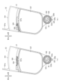
画像形成装置1においては、装置本体2にプロセスカートリッジ51が装着され、プロセスカートリッジ51にトナーカートリッジ52が装着された状態において、トナーカートリッジ52は、トナーカートリッジ52のトナー供給口522aとプロセスカートリッジ51のトナー受け入れ開口514cとが上下方向に対向して配置されるように、現像フレーム591の上下方向における上方に位置している。
In the image forming apparatus 1, when the
このように、トナーカートリッジ52を装着したプロセスカートリッジ51が装置本体2に装着された状態においては、トナーカートリッジ52はプロセスカートリッジ51から離脱不可能となっている。
In this manner, when the
例えば、図13に示すように、第1トナーカートリッジ52-1を装着した第1プロセスカートリッジ51-1が装置本体2に装着された状態において、第1位置にある第1トナーカートリッジ52-1が第2位置へ向けて回動すると、第1トナーカートリッジ52-1は画像形成装置1の一部である、装置本体2に装着された第2プロセスカートリッジ51-2と干渉して第2位置への回動が規制される。
For example, as shown in FIG. 13, when the first process cartridge 51-1 with the first toner cartridge 52-1 installed is installed in the apparatus
このように構成することで、第1トナーカートリッジ52-1を装着した第1プロセスカートリッジ51-1が装置本体2に装着された状態において、第1トナーカートリッジ52-1が単体で第1プロセスカートリッジ51-1から離脱することを、単純な構成で抑制することが可能となっている。
With this configuration, when the first process cartridge 51-1 with the first toner cartridge 52-1 installed is installed in the apparatus
特に、本実施形態の場合は、第1トナーカートリッジ52-1を装着した第1プロセスカートリッジ51-1が装置本体2に装着された状態において、隣接する第2プロセスカートリッジ51-2により第1トナーカートリッジ52-1を単体で第1プロセスカートリッジ51-1から離脱させることを防止することが可能となっている。
In particular, in the case of this embodiment, when the first process cartridge 51-1 with the first toner cartridge 52-1 installed is installed in the apparatus
一方、第1トナーカートリッジ52-1を装着した第1プロセスカートリッジ51-1が装置本体2から離脱した状態においては、第1トナーカートリッジ52-1は第2プロセスカートリッジ51-2と干渉することがなく、第1位置から第2位置へ回動することが許容され、第1プロセスカートリッジ51-1から離脱することが可能となる。このように、トナーカートリッジ52を装着したプロセスカートリッジ51が装置本体2から離脱した状態において、トナーカートリッジ52はプロセスカートリッジ51から離脱可能となっている。
On the other hand, when the first process cartridge 51-1 with the first toner cartridge 52-1 installed is detached from the apparatus
トナーカートリッジ52を装着したプロセスカートリッジ51を装置本体2に装着して使用する画像形成装置1において、ユーザーがトナーカートリッジ52のみを交換しようとした場合、ユーザーには、トナーカートリッジ52にアクセスしてトナーカートリッジ52のみを取り出す場合と、プロセスカートリッジ51にアクセスしてプロセスカートリッジ51とともにトナーカートリッジ52を取り出す場合との2通りの選択肢があり、いずれを操作して良いかの判断に迷うことがある。
In the image forming apparatus 1 in which the
また、トナーカートリッジ52を現像フレーム591の上方に配置した場合、トナーを供給する際に重力を利用できるため、トナーをトナーカートリッジ52から現像フレーム591へ供給するための供給機構が簡略化できるという利点がある。しかし、この状態のままトナーカートリッジ52をプロセスカートリッジ51から離脱させると、トナー供給口522aが上下方向における下方を向いた状態で離脱させることとなり、トナーがこぼれるおそれがある。
Furthermore, when the
しかし、本実施形態における画像形成装置1によれば、トナーカートリッジ52を装着したプロセスカートリッジ51が装置本体2に装着された状態で、トナーカートリッジ52を単体で離脱させることができない。したがって、トナーカートリッジ52をプロセスカートリッジ51から離脱させる場合には、トナーカートリッジ52を装着したプロセスカートリッジ51を一緒に装置本体2から離脱させ、その後、プロセスカートリッジ51からトナーカートリッジ51を離脱させるという手順を踏むこととなる。これにより、ユーザーが操作を迷うことがなく、操作ミスなどが生じ難くなっている。
However, according to the image forming apparatus 1 in this embodiment, the
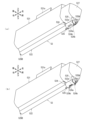
また、プロセスカートリッジ51からトナーカートリッジ51を離脱させる場合には、図14(a)に示すように、一旦プロセスカートリッジ51をトナーカートリッジ52と一緒に装置本体2から離脱させて、それから、プロセスカートリッジ51の装置本体2への装着時における上下方向を水平方向にして水平面に置いた状態とすることができる。この場合、プロセスカートリッジ51の脚部63は、突出位置に移動して先端部が接地した状態となり、プロセスカートリッジ51を支持している。これにより、水平姿勢で水平面に置いたプロセスカートリッジ51の姿勢を安定させることが可能となっている。
Furthermore, when removing the
図14(b)に示すように、その後トナーカートリッジ52を第1位置から第2位置に移動させてプロセスカートリッジ51から離脱させることで、トナー供給口522aとトナー受け入れ開口514cの対向方向を上下方向から水平方向へと移動させたうえで、トナー供給口522aをトナー受け入れ開口514cから離間させることができる。そのため、重力によりトナー供給口522a付近に溜まっていたトナーが、トナー供給口522a付近から遠ざかる方向に移動するため、トナーがトナー供給口522aからこぼれてしまうおそれを大きく低減することが可能となっている。
As shown in FIG. 14(b), by moving the
また、図13に示すように、画像形成装置1においては、装置本体2にプロセスカートリッジ51が装着され、プロセスカートリッジ51にトナーカートリッジ52が装着された状態において、プロセスカートリッジ51の第1連結フレーム517は、上下方向においてトナーカートリッジ52を挟んで感光ドラム54の反対側に位置している。
Further, as shown in FIG. 13, in the image forming apparatus 1, when the
このように構成することで、トナーカートリッジ52を装着したプロセスカートリッジ51が装置本体2に装着された状態において、トナーカートリッジ52をプロセスカートリッジ51から離脱しにくくすることができる。また、ユーザーが操作する際、トナーカートリッジ52が第1位置にある状態ではプロセスカートリッジ51からそのままでは離脱不可能であり、トナーカートリッジ52を離脱させるためには、トナーカートリッジ52を第2位置に回動させる必要があることを視覚的にわかりやすくすることができる。
With this configuration, it is possible to make it difficult for the
さらに、トナーカートリッジ52は、トナーカートリッジ52が第1位置にあるときに第1連結フレーム517と対向し、トナーカートリッジ52が第2位置にあるときに第1連結フレーム517と対向しない位置にあるように構成されている。
Further, the
このように構成することで、ユーザーが操作する際に、トナーカートリッジ52が第1位置にある状態ではトナーカートリッジ52をプロセスカートリッジ51から離脱させることが困難であり、離脱させるためにはトナーカートリッジ52を第2位置に回動させる必要があることをより一層視覚的にわかりやすくすることが可能となっている。
With this configuration, when a user operates, it is difficult to remove the
[規制手段]
図15に示すように、画像形成装置1のプロセスカートリッジ51は、ロックレバー70を有する構成とすることもできる。ロックレバー70は規制手段の一例である。ロックレバー70は、トナーカートリッジ52が第1位置から第2位置へ移動することを規制する規制位置と、トナーカートリッジ52が第1位置から第2位置へ移動することを許容する許容位置との間を移動可能である。
[Regulatory measures]
As shown in FIG. 15, the
図16、図20~図22に示すように、ロックレバー70は、プロセスカートリッジ51の第2サイドフレーム511Bに支持されている。ロックレバー70を有する構成においては、第2サイドフレーム511Bは左右方向に延出する回動軸519を有している。ロックレバー70は回動軸519に回動可能に支持されており、ロック爪71と、操作レバー72と、押圧レバー73とを有している。ロック爪71、操作レバー72、および押圧レバー73は、回動軸519を中心として一体的に回動可能に構成されている。
As shown in FIGS. 16 and 20 to 22, the
プロセスカートリッジ51は、ロックレバー70を回動方向に付勢するバネ74を有している。トナーカートリッジ52は、図16、図19に示すように、ロック爪71と係合可能な第1突起521bと、押圧レバー73に当接可能な第2突起521cとを有している。第1突起521bおよび第2突起521cは、トナーカートリッジ筐体521の右側面から左右外方へ突出している。
The
ロックレバー70は、回動軸519を中心として回動することにより、規制位置(図16において実線にて示した位置)と許容位置(図16において2点鎖線にて示した位置)との間を移動可能である。バネ74は、ロックレバー70を規制位置側へ向けて付勢している。
By rotating around the
ロックレバー70が規制位置にあるときには、ロック爪71と第1突起521bとが係合して、トナーカートリッジ52は第1位置から第2位置へ移動することを規制される。一方、ロックレバー70が許容位置にあるときには、ロック爪71と第1突起521bとの係合が解除されて、トナーカートリッジ52は第1位置から第2位置へ移動することを許容される。
When the
操作レバー72は、ロックレバー70の規制位置と許容位置との切り替えを操作する操作部材である。操作レバー72が操作されておらず、操作レバー72に回動方向の力が加わっていないときには、ロックレバー70はバネ74の付勢力により規制位置に移動する。また、規制位置にあるロックレバー70の操作レバー72を許容位置側へ向けて操作することにより、ロックレバー70はバネ74の付勢力に抗して許容位置に移動することが可能である。
The operating
このように、ロックレバー70が操作レバー72を有することで、ロックレバー70を操作レバー72によって規制位置に切り替えることにより、トナーカートリッジ52が第1位置から第2位置へ移動することを規制することができ、トナーカートリッジ52がプロセスカートリッジ51から離脱することを抑制可能となっている。
As described above, since the
プロセスカートリッジ51の第2サイドフレーム511Bは、ロックレバー70に当接可能なストッパ5115を有している。ストッパ5115は、ロック爪72に当接可能な第1当接面5115aと、押圧レバー73に当接可能な第2当接面5115bとを有している。
The
第1当接面5115aは、ロックレバー70が規制位置側へ向けて回動して規制位置に達すると、ロック爪71に当接してロックレバー70がそれ以上回動しないように規制する。第2当接面5115bは、ロックレバー70が許容位置側へ向けて回動して許容位置に達すると、押圧レバー73に当接してロックレバー70がそれ以上回動しないように規制する。これにより、ロックレバー70が規制位置と許容位置との間で移動可能となっている。
When the
プロセスカートリッジ51が装置本体2に装着された状態においては、操作レバー72は、プロセスカートリッジ51よりも後方に突出している。例えば、第1プロセスカートリッジ51-1に設けられた操作レバー72は、第1プロセスカートリッジ51-1よりも後方に突出しており、前後方向において、装置本体2に装着された第1プロセスカートリッジ51-1と、装置本体2に装着された第2プロセスカートリッジ51-2との間に挟まれた位置に配置されている。
When the
このように構成することで、ロックレバー70の操作レバー72は、隣り合った位置に配置される第1プロセスカートリッジ51-1と第2プロセスカートリッジ51-2の間に挟まれた位置にあることとなり、ユーザーが容易に操作することができない。従って、ユーザーは、装置本体2に装着されたトナーカートリッジ52と第1プロセスカートリッジ51-1から、トナーカートリッジ52のみを離脱させることが困難となる。よって、操作レバー72はユーザーに誤操作されることがなく、正しい操作を促すことが可能となっている。
With this configuration, the operating
また、トナーカートリッジ52を装着したプロセスカートリッジ51が装置本体2に装着された状態において、ロックレバー70が規制位置にあるときの操作レバー72は、ロックレバー70が許容位置にあるときの操作レバー72よりも上下方向における下方に位置している。つまり、ロックレバー70を規制位置から許容位置へ向けて操作する際には、ロックレバー70の操作レバー72を上方へ向かって移動させることになる。
Furthermore, when the
このように構成することで、トナーカートリッジ52を装着したプロセスカートリッジ51が装置本体2に装着された状態において、操作レバー72を下方の規制位置から上方の許容位置へと移動させることが極めて困難となる。そのためユーザーは、装置本体2に装着されたトナーカートリッジ52とプロセスカートリッジ51から、トナーカートリッジ52のみを離脱させることが容易ではない。したがって、操作レバー72はユーザーによって誤操作されることがなく、正しい操作を促すことが可能となっている。
With this configuration, it is extremely difficult to move the operating
また、図16、図20~図22に示すプロセスカートリッジ51は、プロセスカートリッジ51を装置本体2から離脱させるときに把持するハンドルを有していない。一方、図19に示すように、トナーカートリッジ52は、上方に突出するトナーカートリッジハンドル521aを有している。そして、トナーカートリッジ52を装着したプロセスカートリッジ51が装置本体2に装着された状態において、トナーカートリッジ52のトナーカートリッジハンドル521aは、プロセスカートリッジ51の上端部よりも上方に突出している。
Further, the
このように構成することで、トナーカートリッジハンドル521aを持って装置本体2からトナーカートリッジ52を離脱させることで、トナーカートリッジ52がプロセスカートリッジ51から離脱することがロックレバー70により規制された状態で、トナーカートリッジ52とプロセスカートリッジ51とを一緒に離脱させることが可能となる。この場合、ユーザーが把持するトナーカートリッジハンドル521aはトナーカートリッジ52とプロセスカートリッジ51とを併せてトナーカートリッジハンドル521aの1つしか存在しないため、ユーザーが持つハンドルを間違える余地がない。したがって、ユーザーは誤操作することなく、正しい操作を行うことが可能となっている。
With this configuration, by holding the
また、図17に示すように、ロックレバー70を規制位置から許容位置に切り替えて、トナーカートリッジ52をプロセスカートリッジ51から離脱させる場合には、トナーカートリッジ52を装着したプロセスカートリッジ51を装置本体2から離脱させ、プロセスカートリッジ51の装置本体2への装着時の上下方向を水平方向にして水平面に置き、それからトナーカートリッジ52をプロセスカートリッジ51から離脱させることができる。
Further, as shown in FIG. 17, when the
この場合、図17(a)に示すように、プロセスカートリッジ51を水平面に置いた状態で、規制位置にあるロックレバー70を操作レバー72の操作により許容位置に移動させると、ロックレバー70が規制位置から許容位置に移動する過程で、図17(b)に示すように、押圧レバー73が第2突起521cに当接して、第2突起521cを上方へ押し上げる。第2突起521cが上方へ押し上げられると、第1位置にあるトナーカートリッジ52が回動軸X2を中心として回動し、トナーカートリッジハンドル521aが上方へ移動する。
In this case, as shown in FIG. 17(a), when the
図18(a)に示すように、ユーザーは、上方へ移動したトナーカートリッジハンドル521aを把持して、トナーカートリッジ52をさらに上方へ回動させて第2位置に移動させた後に、トナーカートリッジ52をプロセスカートリッジ51から離脱させることができる。
As shown in FIG. 18A, the user grasps the
この場合、ロックレバー70を規制位置から許容位置に切り替えることで、トナーカートリッジハンドル521aを上方へ移動させることができるため、ユーザーがトナーカートリッジハンドル521aを把持してトナーカートリッジ52を第2位置に移動させ易くなり、トナーカートリッジ52のプロセスカートリッジ51からの離脱を容易にすることが可能となっている。
In this case, the
また、第2位置にあるトナーカートリッジ52を第1位置に移動させる場合は、図18(b)に示すように、トナーカートリッジ52が第2位置から第1位置へ移動する過程で、トナーカートリッジ52の第1突起521bがロックレバー70のロック爪71に当接する。ロック爪71に当接した第1突起521bは、ロック爪71をバネ74の付勢力に抗して規制位置から許容位置側へ向けて回動させる。これにより、トナーカートリッジ52が第1位置に移動した際に、ロック爪71と第1突起521bとが係合可能な状態とすることができる。
Further, when moving the
図19に示すように、第1突起521bおよび第2突起521cを有するトナーカートリッジ52においては、トナーカートリッジシャッタ524はトナーカートリッジ52の左右中央部に位置している。また、第1突起521bおよび第2突起521cを有するトナーカートリッジ52は、廃トナー収容部527を有していない。
As shown in FIG. 19, in the
図20、図21に示すように、ロックレバー70を有するプロセスカートリッジ51においては、プロセスカートリッジシャッタ515はプロセスカートリッジ51の左右中央部に位置している。また、ロックレバー70を有するプロセスカートリッジ51は、廃トナー搬送部61を有していない。
As shown in FIGS. 20 and 21, in the
図23に示すように、第1突起521bおよび第2突起521cを有するトナーカートリッジ52を、ロックレバー70を有するプロセスカートリッジ51に装着する場合においても、トナーカートリッジ52のガイド突起部526A、526Bを第1サイドフレーム511Aおよび第2サイドフレーム511Bのガイド溝513A、513Bに挿入することで、トナーカートリッジ52をプロセスカートリッジ51に装着することができる。
As shown in FIG. 23, even when the
この場合、トナーカートリッジシャッタ524の第1突起部524bとプロセスカートリッジ51の第1凹部514dとが嵌合するとともに、トナーカートリッジ52の第2突起部525とプロセスカートリッジシャッタ515の第2凹部515bとが嵌合する。
In this case, the
[変形例]
上述した実施形態の画像形成装置1は、トップカバー231が開閉可能であり、トップカバー231を開いた状態で、装置本体2に装着されたプロセスカートリッジ51を装置本体2から離脱させるように構成されているが、画像形成装置1は、次のように構成することもできる。
[Modified example]
The image forming apparatus 1 according to the embodiment described above is configured such that the
図24、図25に示す画像形成装置101においては、4つのプロセスカートリッジ51はドロア80を介して装置本体2に着脱可能に装着されている。つまり、画像形成装置101の装置本体2はドロア80を有しており、プロセスカートリッジ51はドロア80に着脱可能に装着されている。
In the
画像形成装置101における装置本体2は前面開口2Bを有しており、装置本体2の前面21は前面開口2Bを開閉可能に構成されている。画像形成装置101は、画像形成装置1における露光ヘッド53の代わりに、感光ドラム54の表面を露光する露光ユニット58を備えている。
The apparatus
ドロア80は、内側位置(図24に示す位置)と外側位置(図25に示す位置)との間を前後方向に沿って移動可能に構成されている。図24に示すように、ドロア80にプロセスカートリッジ51が装着されている状態でドロア80が内側位置にある場合には、プロセスカートリッジ51およびトナーカートリッジ52が筐体2内に収容されている。
The
また、図25に示すように、ドロア80にプロセスカートリッジ51が装着されている状態でドロア80が外側位置にある場合には、プロセスカートリッジ51およびトナーカートリッジ52の少なくとも一部が筐体2外に露出している。ドロア80が外側位置にある場合、筐体2外に露出しているプロセスカートリッジ51およびトナーカートリッジ52は、ドロア80に対して着脱可能となっている。
Further, as shown in FIG. 25, when the
このように、プロセスカートリッジ51がドロア80を介して装置本体2に装着されている場合においても、トナーカートリッジ52を装着したプロセスカートリッジ51が装置本体2に装着された状態において、トナーカートリッジ52がプロセスカートリッジ51から離脱不可能であり、トナーカートリッジ52を装着したプロセスカートリッジ51が装置本体2から離脱した状態において、トナーカートリッジ52がプロセスカートリッジ51から離脱可能となるように構成することができる。
In this way, even when the
例えば、画像形成装置101においては、ドロア80を外側位置に移動させて第1トナーカートリッジ52-1を第1プロセスカートリッジ51-1から離脱させようとした場合、第1プロセスカートリッジ51-1が装置本体2に装着された状態では、第1トナーカートリッジ52-1が第2プロセスカートリッジ51-2に干渉して、第2位置への回動が規制されている。一方、第1プロセスカートリッジ51-1を装置本体2から離脱させた状態では、第1トナーカートリッジ52-1を第2位置へ回動して第1プロセスカートリッジ51-1から離脱させることが可能である。
For example, in the
これにより、トナーカートリッジ52をプロセスカートリッジ51から離脱させる際に、ユーザーが操作を迷うことがなく、操作ミスなどを生じ難くすることができる。また、トナーカートリッジ52をプロセスカートリッジ51から離脱させる際に、トナーがトナー供給口522aからこぼれてしまうおそれを低減することが可能である。
As a result, when the
また、図26に示すように、プロセスカートリッジ51がドロア80を介して装置本体2に装着される画像形成装置101においても、プロセスカートリッジ51がロックレバー70を有する構成とすることができる。
Further, as shown in FIG. 26, even in an
この場合においても、プロセスカートリッジ51が装置本体2に装着された状態では、ロックレバー70の操作レバー72は、隣り合った位置に配置される第1プロセスカートリッジ51-1と第2プロセスカートリッジ51-2の間に挟まれた位置にあり、ユーザーが容易に操作することができなくなっている。また、ロックレバー70を規制位置から許容位置へ向けて操作する際には、操作レバー72を上方へ向かって移動させることになるため、操作レバー72の移動操作を行うことが困難となっている。
Even in this case, when the
1 画像形成装置
2 装置本体
10 給紙トレイ
21 前面
22 後面
51 プロセスカートリッジ
51-1 第1プロセスカートリッジ
51-2 第2プロセスカートリッジ
52 トナーカートリッジ
52-1 第1トナーカートリッジ
52-2 第2トナーカートリッジ
54 感光ドラム
54-1 第1感光ドラム
54-2 第2感光ドラム
55 現像ローラ
70 ロックレバー
72 操作レバー
511A 第1サイドフレーム
511B 第2サイドフレーム
514 第2連結フレーム
514c トナー受け入れ開口
515 プロセスカートリッジシャッタ
516 シール部材
517 第1連結フレーム
518 プロセスカートリッジハンドル
521 トナーカートリッジ筐体
521a トナーカートリッジハンドル
522a トナー供給口
524 トナーカートリッジシャッタ
591 現像フレーム
591b 開口部
X1 回転軸
X2 回動軸
1
Claims (12)
前記装置本体に着脱可能に装着される第1プロセスカートリッジと、
前記第1プロセスカートリッジに着脱可能に装着されるトナーカートリッジとを備え、
前記第1プロセスカートリッジは、第1感光ドラムと、第1現像ローラと、前記第1現像ローラを支持し内部にトナーを収納可能な現像フレームとを有し、
前記トナーカートリッジは、前記第1プロセスカートリッジに着脱可能に支持され内部にトナーを収納可能なトナーカートリッジ筐体を有し、
前記トナーカートリッジ筐体には、前記トナーカートリッジ筐体に収納されたトナーが通過可能なトナー供給口が設けられ、
前記第1プロセスカートリッジには、前記トナー供給口から排出されたトナーを受け取ることが可能であり前記現像フレームの内部と連通するトナー受け入れ開口が設けられ、
前記装置本体に前記第1プロセスカートリッジが装着され、前記第1プロセスカートリッジに前記トナーカートリッジが装着された状態において、前記トナーカートリッジは、前記トナー供給口と前記トナー受け入れ開口とが上下方向に対向して配置されるように、前記現像フレームの上下方向における上方に位置し、
前記トナーカートリッジを装着した前記第1プロセスカートリッジが前記装置本体に装着された状態において、前記トナーカートリッジは前記第1プロセスカートリッジから離脱不可能であり、
前記トナーカートリッジを装着した前記第1プロセスカートリッジが前記装置本体から離脱した状態において、前記トナーカートリッジは前記第1プロセスカートリッジから離脱可能であり、
前記トナーカートリッジは、前記第1プロセスカートリッジに装着された状態において、前記第1感光ドラムの回転軸方向に平行な回動軸を中心として、前記第1プロセスカートリッジからの離脱が規制される第1位置と、前記第1プロセスカートリッジからの離脱が許容される第2位置との間を回動可能に支持され、
前記トナーカートリッジを装着した前記第1プロセスカートリッジが前記装置本体に装着された状態において、前記第1位置にある前記トナーカートリッジが前記第2位置へ向けて回動すると、前記トナーカートリッジは前記画像形成装置の一部と干渉して前記第2位置への回動が規制されることを特徴とする画像形成装置。 The device body,
a first process cartridge that is removably attached to the apparatus main body;
a toner cartridge that is removably attached to the first process cartridge;
The first process cartridge includes a first photosensitive drum, a first developing roller, and a developing frame that supports the first developing roller and can store toner therein,
The toner cartridge has a toner cartridge housing that is removably supported by the first process cartridge and can store toner therein;
The toner cartridge housing is provided with a toner supply port through which the toner stored in the toner cartridge housing can pass,
The first process cartridge is provided with a toner receiving opening capable of receiving the toner discharged from the toner supply port and communicating with the inside of the developing frame,
In a state in which the first process cartridge is installed in the apparatus main body and the toner cartridge is installed in the first process cartridge, the toner cartridge has the toner supply port and the toner receiving opening facing each other in a vertical direction. located above the developing frame in the vertical direction so as to be arranged as
In a state in which the first process cartridge with the toner cartridge attached thereto is attached to the apparatus main body, the toner cartridge cannot be removed from the first process cartridge,
The toner cartridge is removable from the first process cartridge in a state where the first process cartridge with the toner cartridge attached thereto is removed from the apparatus main body ,
When the toner cartridge is installed in the first process cartridge, the toner cartridge is prevented from being removed from the first process cartridge about a rotation axis parallel to the rotation axis direction of the first photosensitive drum. and a second position in which detachment from the first process cartridge is permitted;
When the toner cartridge in the first position rotates toward the second position while the first process cartridge with the toner cartridge installed is installed in the apparatus main body, the toner cartridge starts forming the image. An image forming apparatus characterized in that rotation to the second position is restricted by interference with a part of the apparatus .
前記トナーカートリッジを装着した前記第1プロセスカートリッジが前記装置本体に装着された状態において、前記トナーカートリッジが第2位置に回動した際に干渉する前記画像形成装置の一部は、前記装置本体に装着された前記第2プロセスカートリッジであることを特徴とする、請求項1に記載の画像形成装置。 a second process cartridge removably attached to the apparatus main body and disposed adjacent to the first process cartridge attached to the apparatus main body;
When the first process cartridge with the toner cartridge attached thereto is attached to the apparatus main body, a part of the image forming apparatus that interferes when the toner cartridge rotates to the second position is attached to the apparatus main body. The image forming apparatus according to claim 1 , wherein the second process cartridge is installed.
前記第1プロセスカートリッジは、前記トナー受け入れ開口を閉鎖する受け入れ開口閉鎖位置と前記トナー受け入れ開口を開放する受け入れ開口開放位置との間を移動可能なプロセスカートリッジシャッタを有し、
前記トナーカートリッジが第1位置にあるときに、前記トナーカートリッジシャッタは前記供給口開放位置にあり、前記プロセスカートリッジシャッタは前記受け入れ開口開放位置にあり、
トナーカートリッジが第2位置にあるときに、前記トナーカートリッジシャッタは前記供給口閉鎖位置にあり、前記プロセスカートリッジシャッタは前記受け入れ開口閉鎖位置にあることを特徴とする請求項1または請求項2に記載の画像形成装置。 The toner cartridge has a toner cartridge shutter that is movable between a supply port closed position that closes the toner supply port and a supply port open position that opens the toner supply port,
The first process cartridge has a process cartridge shutter that is movable between a receiving opening closed position that closes the toner receiving opening and a receiving opening open position that opens the toner receiving opening.
When the toner cartridge is in the first position, the toner cartridge shutter is in the supply opening opening position, and the process cartridge shutter is in the receiving opening opening position,
3. When the toner cartridge is in the second position, the toner cartridge shutter is in the supply port closed position , and the process cartridge shutter is in the receiving opening closed position . image forming device.
前記装置本体に前記第1プロセスカートリッジが装着され、前記第1プロセスカートリッジに前記トナーカートリッジが装着された状態において、前記第1連結フレームは、上下方向において前記トナーカートリッジを挟んで前記第1感光ドラムの反対側に位置することを特徴とする、請求項1~請求項3の何れか一項に記載の画像形成装置。 The first process cartridge includes a first side frame that rotatably supports one end of the first photosensitive drum in the rotational axis direction and extends in a vertical direction perpendicular to the rotational axis direction; a second side frame that supports the other end of the cartridge and extends in a vertical direction perpendicular to the direction of the rotation axis; and the first side frame and the second side frame at the upper end of the first process cartridge mounted on the apparatus main body. and a first connection frame connecting the
When the first process cartridge is installed in the apparatus main body and the toner cartridge is installed in the first process cartridge, the first connection frame connects the first photosensitive drum with the toner cartridge in between in the vertical direction. The image forming apparatus according to any one of claims 1 to 3 , wherein the image forming apparatus is located on the opposite side of the image forming apparatus.
前記規制手段は、前記規制位置と前記許容位置との切り替えを操作する操作レバーを有することを特徴とする請求項1~請求項4の何れか一項に記載の画像形成装置。 The first process cartridge has a restriction position that restricts movement of the toner cartridge from the first position to a second position, and a restriction position that restricts movement of the toner cartridge from the first position to the second position. has a regulating means movable between permitted positions;
The image forming apparatus according to any one of claims 1 to 4 , wherein the regulating means includes an operation lever for switching between the regulating position and the permissible position.
前記操作レバーは、前記装置本体に装着された前記第1プロセスカートリッジと前記装置本体に装着された前記第2プロセスカートリッジとの間に挟まれた位置に配置されることを特徴とする請求項5に記載の画像形成装置。 The first process cartridge is removably attached to the apparatus main body, and includes the first process cartridge attached to the apparatus main body, and a second process cartridge arranged side by side in a direction perpendicular to the rotational axis direction of the first photosensitive drum. ,
5. The operating lever is disposed at a position sandwiched between the first process cartridge installed in the apparatus main body and the second process cartridge installed in the apparatus main body. The image forming apparatus described in .
前記装置本体に着脱可能に装着される第1プロセスカートリッジと、
前記第1プロセスカートリッジに着脱可能に装着されるトナーカートリッジとを備え、
前記第1プロセスカートリッジは、第1感光ドラムと、第1現像ローラと、前記第1現像ローラを支持し内部にトナーを収納可能な現像フレームとを有し、
前記トナーカートリッジは、前記第1プロセスカートリッジに着脱可能に支持され内部にトナーを収納可能なトナーカートリッジ筐体を有し、
前記トナーカートリッジ筐体には、前記トナーカートリッジ筐体に収納されたトナーが通過可能なトナー供給口が設けられ、
前記第1プロセスカートリッジには、前記トナー供給口から排出されたトナーを受け取ることが可能であり前記現像フレームの内部と連通するトナー受け入れ開口が設けられ、
前記装置本体に前記第1プロセスカートリッジが装着され、前記第1プロセスカートリッジに前記トナーカートリッジが装着された状態において、前記トナーカートリッジは、前記トナー供給口と前記トナー受け入れ開口とが上下方向に対向して配置されるように、前記現像フレームの上下方向における上方に位置し、
前記トナーカートリッジを装着した前記第1プロセスカートリッジが前記装置本体に装着された状態において、前記トナーカートリッジは前記第1プロセスカートリッジから離脱不可能であり、
前記トナーカートリッジを装着した前記第1プロセスカートリッジが前記装置本体から離脱した状態において、前記トナーカートリッジは前記第1プロセスカートリッジから離脱可能であり、
前記トナーカートリッジは、前記第1プロセスカートリッジに装着された状態において、前記第1感光ドラムの回転軸方向に平行な回動軸を中心として、前記第1プロセスカートリッジからの離脱が規制される第1位置と、前記第1プロセスカートリッジからの離脱が許容される第2位置との間を回動可能に支持され、
前記第1プロセスカートリッジは、前記第1感光ドラムの回転軸方向における一端を回転可能に支持し前記回転軸方向と直交する垂直方向に延びる第1サイドフレームと、前記第1感光ドラムの回転軸方向における他端を支持し前記回転軸方向と直交する垂直方向に延びる第2サイドフレームと、前記装置本体に装着された前記第1プロセスカートリッジの上端部において前記第1サイドフレームと前記第2サイドフレームとを連結する第1連結フレームとを有し、
前記装置本体に前記第1プロセスカートリッジが装着され、前記第1プロセスカートリッジに前記トナーカートリッジが装着された状態において、前記第1連結フレームは、上下方向において前記トナーカートリッジを挟んで前記第1感光ドラムの反対側に位置し、
前記トナーカートリッジは、前記トナーカートリッジが第1位置にあるときに前記第1連結フレームと対向し、前記トナーカートリッジが第2位置にあるときに前記第1連結フレームと対向しない位置にあることを特徴とする画像形成装置。 The device body,
a first process cartridge that is removably attached to the apparatus main body;
a toner cartridge that is removably attached to the first process cartridge;
The first process cartridge includes a first photosensitive drum, a first developing roller, and a developing frame that supports the first developing roller and can store toner therein,
The toner cartridge has a toner cartridge housing that is removably supported by the first process cartridge and can store toner therein;
The toner cartridge housing is provided with a toner supply port through which the toner stored in the toner cartridge housing can pass,
The first process cartridge is provided with a toner receiving opening capable of receiving the toner discharged from the toner supply port and communicating with the inside of the developing frame,
In a state in which the first process cartridge is installed in the apparatus main body and the toner cartridge is installed in the first process cartridge, the toner cartridge has the toner supply port and the toner receiving opening facing each other in a vertical direction. located above the developing frame in the vertical direction so as to be arranged as
In a state in which the first process cartridge with the toner cartridge attached thereto is attached to the apparatus main body, the toner cartridge cannot be removed from the first process cartridge,
The toner cartridge is removable from the first process cartridge in a state where the first process cartridge with the toner cartridge attached thereto is removed from the apparatus main body ,
When the toner cartridge is installed in the first process cartridge, the toner cartridge is prevented from being removed from the first process cartridge about a rotation axis parallel to the rotation axis direction of the first photosensitive drum. and a second position in which detachment from the first process cartridge is permitted;
The first process cartridge includes a first side frame that rotatably supports one end of the first photosensitive drum in the rotational axis direction and extends in a vertical direction perpendicular to the rotational axis direction; a second side frame that supports the other end of the cartridge and extends in a vertical direction perpendicular to the direction of the rotation axis; and the first side frame and the second side frame at the upper end of the first process cartridge mounted on the apparatus main body. and a first connection frame connecting the
When the first process cartridge is installed in the apparatus main body and the toner cartridge is installed in the first process cartridge, the first connection frame connects the first photosensitive drum with the toner cartridge in between in the vertical direction. located on the opposite side of
The toner cartridge is characterized in that it faces the first connection frame when the toner cartridge is in the first position, and is in a position that does not face the first connection frame when the toner cartridge is in the second position. image forming apparatus.
前記装置本体は、前記第1感光ドラムの回転軸方向に垂直な第1方向における一端に位置する一端側壁と、前記第1方向における前記一端とは反対の他端に位置する他端側壁とを有し、
前記第2プロセスカートリッジは、前記装置本体に装着された前記第1プロセスカートリッジの前記第1方向に並設され、
前記第2プロセスカートリッジを前記装置本体に装着した状態において、前記第2感光ドラムの回転軸は前記第1感光ドラムの回転軸と平行であり、
前記装置本体の下部には、前記装置本体の前記他端側壁から前記第1方向に引き出し可能に装着される給紙トレイを設け、
前記第1プロセスカートリッジには、プロセスカートリッジハンドルが設けられ、
前記トナーカートリッジには、トナーカートリッジハンドルが設けられ、
前記プロセスカートリッジハンドルの方が前記トナーカートリッジハンドルよりも、前記第1方向において前記他端側壁に近い位置にあることを特徴とする請求項9に記載の画像形成装置。 a second process cartridge that is removably attached to the apparatus main body and has a second photosensitive drum and a second developing roller;
The apparatus main body includes a side wall at one end located at one end in a first direction perpendicular to the rotation axis direction of the first photosensitive drum, and a side wall at the other end located at the other end opposite to the one end in the first direction. have,
The second process cartridge is arranged in parallel with the first process cartridge installed in the apparatus main body in the first direction,
When the second process cartridge is installed in the apparatus main body, the rotational axis of the second photosensitive drum is parallel to the rotational axis of the first photosensitive drum,
A paper feed tray is provided at the lower part of the apparatus main body, and is mounted so that it can be pulled out in the first direction from the other end side wall of the apparatus main body,
The first process cartridge is provided with a process cartridge handle;
The toner cartridge is provided with a toner cartridge handle;
The image forming apparatus according to claim 9 , wherein the process cartridge handle is located closer to the other end side wall in the first direction than the toner cartridge handle.
前記装置本体に着脱可能に装着される第1プロセスカートリッジと、
前記第1プロセスカートリッジに着脱可能に装着されるトナーカートリッジとを備え、
前記第1プロセスカートリッジは、第1感光ドラムと、第1現像ローラと、前記第1現像ローラを支持し内部にトナーを収納可能な現像フレームとを有し、
前記トナーカートリッジは、前記第1プロセスカートリッジに着脱可能に支持され内部にトナーを収納可能なトナーカートリッジ筐体を有し、
前記トナーカートリッジ筐体には、前記トナーカートリッジ筐体に収納されたトナーが通過可能なトナー供給口が設けられ、
前記第1プロセスカートリッジには、前記トナー供給口から排出されたトナーを受け取ることが可能であり前記現像フレームの内部と連通するトナー受け入れ開口が設けられ、
前記装置本体に前記第1プロセスカートリッジが装着され、前記第1プロセスカートリッジに前記トナーカートリッジが装着された状態において、前記トナーカートリッジは、前記トナー供給口と前記トナー受け入れ開口とが上下方向に対向して配置されるように、前記現像フレームの上下方向における上方に位置し、
前記トナーカートリッジを装着した前記第1プロセスカートリッジが前記装置本体に装着された状態において、前記トナーカートリッジは前記第1プロセスカートリッジから離脱不可能であり、
前記トナーカートリッジを装着した前記第1プロセスカートリッジが前記装置本体から離脱した状態において、前記トナーカートリッジは前記第1プロセスカートリッジから離脱可能であり、
前記トナーカートリッジは、前記第1プロセスカートリッジに装着された状態において、前記第1感光ドラムの回転軸方向に平行な回動軸を中心として、前記第1プロセスカートリッジからの離脱が規制される第1位置と、前記第1プロセスカートリッジからの離脱が許容される第2位置との間を回動可能に支持され、
前記第1プロセスカートリッジは、前記第1感光ドラムの回転軸方向における一端を回転可能に支持し前記回転軸方向と直交する垂直方向に延びる第1サイドフレームと、前記第1感光ドラムの回転軸方向における他端を支持し前記回転軸方向と直交する垂直方向に延びる第2サイドフレームと、前記装置本体に装着された前記第1プロセスカートリッジの上端部において前記第1サイドフレームと前記第2サイドフレームとを連結する第1連結フレームとを有し、
前記装置本体に前記第1プロセスカートリッジが装着され、前記第1プロセスカートリッジに前記トナーカートリッジが装着された状態において、前記第1連結フレームは、上下方向において前記トナーカートリッジを挟んで前記第1感光ドラムの反対側に位置し、
前記現像フレームは、前記第1サイドフレームと前記第2サイドフレームとに移動可能に支持され、
前記第1プロセスカートリッジは、前記第1感光ドラムの回転軸方向における一端を前記第1サイドフレームに連結され、前記回転軸方向の他端を前記第2サイドフレームに連結された第2連結フレームを有し、
前記トナー受け入れ開口は、前記第2連結フレームに設けられ、
前記現像フレームには、前記現像フレームの内部と連通し前記トナー受け入れ開口と対向して配置される開口部が設けられ、前記開口部と前記トナー受け入れ開口との間の周縁部には、シール部材が設けられていることを特徴とする画像形成装置。 The device body,
a first process cartridge that is removably attached to the apparatus main body;
a toner cartridge that is removably attached to the first process cartridge;
The first process cartridge includes a first photosensitive drum, a first developing roller, and a developing frame that supports the first developing roller and can store toner therein,
The toner cartridge has a toner cartridge housing that is removably supported by the first process cartridge and can store toner therein;
The toner cartridge housing is provided with a toner supply port through which the toner stored in the toner cartridge housing can pass,
The first process cartridge is provided with a toner receiving opening capable of receiving the toner discharged from the toner supply port and communicating with the inside of the developing frame,
In a state in which the first process cartridge is installed in the apparatus main body and the toner cartridge is installed in the first process cartridge, the toner cartridge has the toner supply port and the toner receiving opening facing each other in a vertical direction. located above the developing frame in the vertical direction so as to be arranged as
In a state in which the first process cartridge with the toner cartridge attached thereto is attached to the apparatus main body, the toner cartridge cannot be removed from the first process cartridge,
The toner cartridge is removable from the first process cartridge in a state where the first process cartridge with the toner cartridge attached thereto is removed from the apparatus main body ,
When the toner cartridge is installed in the first process cartridge, the toner cartridge is prevented from being removed from the first process cartridge about a rotation axis parallel to the rotation axis direction of the first photosensitive drum. and a second position in which detachment from the first process cartridge is permitted;
The first process cartridge includes a first side frame that rotatably supports one end of the first photosensitive drum in the rotational axis direction and extends in a vertical direction perpendicular to the rotational axis direction; a second side frame that supports the other end of the cartridge and extends in a vertical direction perpendicular to the direction of the rotation axis; and the first side frame and the second side frame at the upper end of the first process cartridge mounted on the apparatus main body. and a first connection frame connecting the
When the first process cartridge is installed in the apparatus main body and the toner cartridge is installed in the first process cartridge, the first connection frame connects the first photosensitive drum with the toner cartridge in between in the vertical direction. located on the opposite side of
The developing frame is movably supported by the first side frame and the second side frame,
The first process cartridge includes a second connecting frame in which one end of the first photosensitive drum in the direction of the rotation axis is connected to the first side frame, and the other end in the direction of the rotation axis is connected to the second side frame. have,
the toner receiving opening is provided in the second connection frame;
The developing frame is provided with an opening that communicates with the inside of the developing frame and is disposed opposite to the toner receiving opening, and a sealing member is provided at a peripheral portion between the opening and the toner receiving opening. An image forming apparatus characterized by being provided with .
Priority Applications (4)
| Application Number | Priority Date | Filing Date | Title |
|---|---|---|---|
| JP2019205799A JP7367476B2 (en) | 2019-11-13 | 2019-11-13 | Image forming device |
| US17/094,149 US11366422B2 (en) | 2019-11-13 | 2020-11-10 | Image forming apparatus permitting user to imagine clear detachment procedure of toner cartridge from process cartridge |
| US17/652,944 US11573522B2 (en) | 2019-11-13 | 2022-03-01 | Image forming apparatus permitting user to imagine clear detachment procedure of toner cartridge from process cartridge |
| US18/146,492 US20230125715A1 (en) | 2019-11-13 | 2022-12-27 | Image forming apparatus permitting user to imagine clear detachment procedure of toner cartridge from process cartridge |
Applications Claiming Priority (1)
| Application Number | Priority Date | Filing Date | Title |
|---|---|---|---|
| JP2019205799A JP7367476B2 (en) | 2019-11-13 | 2019-11-13 | Image forming device |
Publications (2)
| Publication Number | Publication Date |
|---|---|
| JP2021076813A JP2021076813A (en) | 2021-05-20 |
| JP7367476B2 true JP7367476B2 (en) | 2023-10-24 |
Family
ID=75847497
Family Applications (1)
| Application Number | Title | Priority Date | Filing Date |
|---|---|---|---|
| JP2019205799A Active JP7367476B2 (en) | 2019-11-13 | 2019-11-13 | Image forming device |
Country Status (2)
| Country | Link |
|---|---|
| US (3) | US11366422B2 (en) |
| JP (1) | JP7367476B2 (en) |
Families Citing this family (1)
| Publication number | Priority date | Publication date | Assignee | Title |
|---|---|---|---|---|
| JP7187886B2 (en) * | 2018-08-23 | 2022-12-13 | ブラザー工業株式会社 | image forming device |
Citations (7)
| Publication number | Priority date | Publication date | Assignee | Title |
|---|---|---|---|---|
| JP2007219268A (en) | 2006-02-17 | 2007-08-30 | Canon Inc | Image forming apparatus |
| JP2009151280A (en) | 2007-11-30 | 2009-07-09 | Canon Inc | Image forming apparatus |
| JP2010164991A (en) | 2010-03-19 | 2010-07-29 | Fuji Xerox Co Ltd | Image forming apparatus |
| JP2013041046A (en) | 2011-08-12 | 2013-02-28 | Fuji Xerox Co Ltd | Image forming apparatus, and cartridge |
| JP2016194539A (en) | 2015-03-31 | 2016-11-17 | ブラザー工業株式会社 | Developing device and image forming apparatus |
| JP2019148836A (en) | 2014-08-01 | 2019-09-05 | キヤノン株式会社 | Toner cartridge and toner supply mechanism |
| JP2019159130A (en) | 2018-03-14 | 2019-09-19 | 株式会社沖データ | Developer housing body, image forming unit, image forming apparatus and attaching/detaching unit |
Family Cites Families (9)
| Publication number | Priority date | Publication date | Assignee | Title |
|---|---|---|---|---|
| JP4692626B2 (en) * | 2008-12-26 | 2011-06-01 | ブラザー工業株式会社 | Image forming apparatus and developing cartridge |
| JP4674635B2 (en) * | 2008-12-26 | 2011-04-20 | ブラザー工業株式会社 | Image forming apparatus |
| JP4902688B2 (en) * | 2009-04-14 | 2012-03-21 | 株式会社沖データ | Image forming apparatus |
| JP5884343B2 (en) * | 2011-08-31 | 2016-03-15 | ブラザー工業株式会社 | Process cartridge and developer cartridge |
| JP6475148B2 (en) * | 2015-11-27 | 2019-02-27 | 株式会社沖データ | Image forming unit mismount prevention device, image forming unit, and image forming apparatus |
| JP2017146512A (en) | 2016-02-19 | 2017-08-24 | 株式会社沖データ | Developer container, image forming unit, and image forming apparatus |
| JP6630232B2 (en) * | 2016-05-26 | 2020-01-15 | 株式会社沖データ | Developing unit, image forming unit and image forming apparatus |
| JP6787031B2 (en) | 2016-10-18 | 2020-11-18 | ブラザー工業株式会社 | Image forming equipment and process cartridge |
| US10429760B2 (en) * | 2016-12-15 | 2019-10-01 | Brother Kogyo Kabushiki Kaisha | Image forming apparatus |
-
2019
- 2019-11-13 JP JP2019205799A patent/JP7367476B2/en active Active
-
2020
- 2020-11-10 US US17/094,149 patent/US11366422B2/en active Active
-
2022
- 2022-03-01 US US17/652,944 patent/US11573522B2/en active Active
- 2022-12-27 US US18/146,492 patent/US20230125715A1/en active Pending
Patent Citations (7)
| Publication number | Priority date | Publication date | Assignee | Title |
|---|---|---|---|---|
| JP2007219268A (en) | 2006-02-17 | 2007-08-30 | Canon Inc | Image forming apparatus |
| JP2009151280A (en) | 2007-11-30 | 2009-07-09 | Canon Inc | Image forming apparatus |
| JP2010164991A (en) | 2010-03-19 | 2010-07-29 | Fuji Xerox Co Ltd | Image forming apparatus |
| JP2013041046A (en) | 2011-08-12 | 2013-02-28 | Fuji Xerox Co Ltd | Image forming apparatus, and cartridge |
| JP2019148836A (en) | 2014-08-01 | 2019-09-05 | キヤノン株式会社 | Toner cartridge and toner supply mechanism |
| JP2016194539A (en) | 2015-03-31 | 2016-11-17 | ブラザー工業株式会社 | Developing device and image forming apparatus |
| JP2019159130A (en) | 2018-03-14 | 2019-09-19 | 株式会社沖データ | Developer housing body, image forming unit, image forming apparatus and attaching/detaching unit |
Also Published As
| Publication number | Publication date |
|---|---|
| JP2021076813A (en) | 2021-05-20 |
| US20230125715A1 (en) | 2023-04-27 |
| US11366422B2 (en) | 2022-06-21 |
| US20220183636A1 (en) | 2022-06-16 |
| US11573522B2 (en) | 2023-02-07 |
| US20210141335A1 (en) | 2021-05-13 |
Similar Documents
| Publication | Publication Date | Title |
|---|---|---|
| KR101030555B1 (en) | Storage container and image forming apparatus | |
| JP5413251B2 (en) | Image forming apparatus | |
| US9134695B2 (en) | Image forming apparatus with movable cartridge pressing member | |
| US9829828B2 (en) | Developer supplier with biasing member that biases a main unit shutter and causes a developer container to rotate, developing device including the same, and developer container included in the developer supplier | |
| US9684263B2 (en) | Developer supplier, developing device including the same, image forming apparatus, and developer container included in the developer supplier | |
| US11874626B2 (en) | Image forming apparatus including drum cartridge attachable to drawer and pressing member for pressing drum cartridge attached to drawer downward | |
| US9684262B2 (en) | Developer supplier, developing device including the same, image forming apparatus, and developer container included in the developer supplier | |
| JP7259598B2 (en) | image forming device | |
| CN110651229B (en) | Developer container and image forming apparatus including the same | |
| JP7367476B2 (en) | Image forming device | |
| CN106292222B (en) | The image forming apparatus of toner container can be assembled | |
| US9207576B2 (en) | Toner conveying unit and image forming apparatus including the same | |
| CN107894698B (en) | Image forming apparatus with a toner supply device | |
| US20160282759A1 (en) | Developer replenishment device and image forming apparatus | |
| US9665041B2 (en) | Developer supplier, developing device including the same, image forming apparatus, and developer container included in the developer supplier | |
| JP5492614B2 (en) | Image forming apparatus | |
| JP2019078987A (en) | Developer storage body, image forming unit, and image forming apparatus | |
| JP2010055126A (en) | Image forming apparatus and method for loading/unloading process cartridge | |
| US9785088B2 (en) | Image forming apparatus including developer container, and the developer container | |
| JP7347150B2 (en) | Image forming device | |
| JP2023003701A (en) | Cleaning unit and image forming apparatus | |
| JP2005266670A (en) | Image forming apparatus and method for loading/unloading process cartridge |
Legal Events
| Date | Code | Title | Description |
|---|---|---|---|
| A621 | Written request for application examination |
Free format text: JAPANESE INTERMEDIATE CODE: A621 Effective date: 20221018 |
|
| A977 | Report on retrieval |
Free format text: JAPANESE INTERMEDIATE CODE: A971007 Effective date: 20230726 |
|
| A131 | Notification of reasons for refusal |
Free format text: JAPANESE INTERMEDIATE CODE: A131 Effective date: 20230801 |
|
| A521 | Request for written amendment filed |
Free format text: JAPANESE INTERMEDIATE CODE: A523 Effective date: 20230905 |
|
| TRDD | Decision of grant or rejection written | ||
| A01 | Written decision to grant a patent or to grant a registration (utility model) |
Free format text: JAPANESE INTERMEDIATE CODE: A01 Effective date: 20230912 |
|
| A61 | First payment of annual fees (during grant procedure) |
Free format text: JAPANESE INTERMEDIATE CODE: A61 Effective date: 20230925 |
|
| R150 | Certificate of patent or registration of utility model |
Ref document number: 7367476 Country of ref document: JP Free format text: JAPANESE INTERMEDIATE CODE: R150 |