JP2020172824A - Drainage trap - Google Patents
Drainage trap Download PDFInfo
- Publication number
- JP2020172824A JP2020172824A JP2019076499A JP2019076499A JP2020172824A JP 2020172824 A JP2020172824 A JP 2020172824A JP 2019076499 A JP2019076499 A JP 2019076499A JP 2019076499 A JP2019076499 A JP 2019076499A JP 2020172824 A JP2020172824 A JP 2020172824A
- Authority
- JP
- Japan
- Prior art keywords
- drainage
- trap
- opening
- flow path
- path forming
- Prior art date
- Legal status (The legal status is an assumption and is not a legal conclusion. Google has not performed a legal analysis and makes no representation as to the accuracy of the status listed.)
- Granted
Links
- 230000002093 peripheral effect Effects 0.000 claims description 25
- 230000007423 decrease Effects 0.000 claims description 4
- 239000000428 dust Substances 0.000 description 5
- 238000012423 maintenance Methods 0.000 description 5
- 238000000034 method Methods 0.000 description 5
- XLYOFNOQVPJJNP-UHFFFAOYSA-N water Substances O XLYOFNOQVPJJNP-UHFFFAOYSA-N 0.000 description 5
- 238000004140 cleaning Methods 0.000 description 4
- 239000000463 material Substances 0.000 description 3
- 238000005516 engineering process Methods 0.000 description 2
- 230000009545 invasion Effects 0.000 description 2
- 238000007789 sealing Methods 0.000 description 2
- 230000001629 suppression Effects 0.000 description 2
- 101100204059 Caenorhabditis elegans trap-2 gene Proteins 0.000 description 1
- 241000238631 Hexapoda Species 0.000 description 1
- 241000699670 Mus sp. Species 0.000 description 1
- 241000607479 Yersinia pestis Species 0.000 description 1
- 238000009825 accumulation Methods 0.000 description 1
- 238000005452 bending Methods 0.000 description 1
- 230000000903 blocking effect Effects 0.000 description 1
- 239000000470 constituent Substances 0.000 description 1
- 238000010276 construction Methods 0.000 description 1
- 238000007599 discharging Methods 0.000 description 1
- 230000000694 effects Effects 0.000 description 1
- 239000010794 food waste Substances 0.000 description 1
- 239000007769 metal material Substances 0.000 description 1
- 235000019645 odor Nutrition 0.000 description 1
- 238000009428 plumbing Methods 0.000 description 1
- 239000007787 solid Substances 0.000 description 1
- 229910001220 stainless steel Inorganic materials 0.000 description 1
- 239000010935 stainless steel Substances 0.000 description 1
- 229920003002 synthetic resin Polymers 0.000 description 1
- 239000000057 synthetic resin Substances 0.000 description 1
- 238000011144 upstream manufacturing Methods 0.000 description 1
Images


Landscapes
- Sink And Installation For Waste Water (AREA)
Abstract
Description
この発明は、各種排水設備の配管の途中に配置される排水用トラップに関するものである。
より具体的には、キッチンの流し場や洗面所、風呂場など各種排水設備の下方に設けて、上方からの排水を側方に流通させる排水用トラップに関するもので、配管技術、さらには建造物の構築技術に属するものである。
The present invention relates to a drain trap arranged in the middle of piping of various drainage facilities.
More specifically, it is related to drainage traps that are installed below various drainage facilities such as kitchen sinks, washrooms, and bathrooms to circulate drainage from above to the side. Plumbing technology, and even buildings It belongs to the construction technology of.
従来、排水管には出口側からの悪臭や害虫などの侵入を防止する目的でS字トラップなどの封水式排水管トラップが設けられている。
しかしながら、この封水式排水管トラップにおいては、これが排水管の折曲部分に溜った排水の封鎖作用を利用するものであるため、折曲部分に常に一定量の排水が残留する上、固形物などが詰まり易いなどの問題があった。
Conventionally, the drain pipe is provided with a water-sealed drain pipe trap such as an S-shaped trap for the purpose of preventing the invasion of foul odors and pests from the outlet side.
However, in this water-sealed drainage pipe trap, since this utilizes the sealing action of the drainage accumulated in the bent portion of the drainage pipe, a certain amount of drainage always remains in the bent portion and solid matter. There was a problem that it was easy to get clogged.
さらに、排水の頻度が低い場合には、トラップ内の排水が蒸発し、封鎖作用が得られなくなるという問題もあった。 Further, when the frequency of drainage is low, there is a problem that the drainage in the trap evaporates and the blocking action cannot be obtained.
さらにまた、洗面所の場合において、設置される洗面器は、その下方に封水式排水管トラップが設けられる構造を有するものであるため、その利用者、特に車椅子使用者がその洗面器を利用しようとすると、利用者の足や車椅子が封水式排水管トラップに接触してしまい、利用者が十分に洗面器に近づくことができず、或いは封水式排水管トラップを避けるように無理な姿勢で洗面器に近づかざるをえないという問題もあった。 Furthermore, in the case of a washroom, the washbasin to be installed has a structure in which a water-sealing drainage pipe trap is provided below the washbasin, so that the user, especially the wheelchair user, uses the washbasin. If you try, your feet or wheelchair will come into contact with the water-sealed drain trap, and you will not be able to get close enough to the basin, or you will not be able to avoid the water-sealed trap. There was also the problem of having to approach the washbasin in a posture.
キッチンの流し場や洗面所、風呂場など各種排水設備に対して、封水式排水管トラップに代えて、揺動弁体にバランスウエイトを設け、排水が無い時はバランスウエイトによって揺動弁体を閉鎖し、排水時には該排水の重量或いは流水圧で弁体を開く排水用トラップ(弁トラップ)を設ける方法が知られている。 For various drainage facilities such as kitchen sinks, washrooms, and bathrooms, a balance weight is provided on the swing valve body instead of the water-sealed drain pipe trap, and when there is no drainage, the swing valve body is provided with the balance weight. There is known a method of providing a drainage trap (valve trap) that opens the valve body by the weight of the drainage or the running water pressure at the time of drainage.
例えば、実公昭63−23489号公報(特許文献1)においては、大きなスペースがなくても排水管に接続でき、しかも、生ごみなどが詰まるおそれがなく安心して使用でき、悪臭の上昇を確実に防ぐことができることは勿論、虫やねずみの侵入も完全に阻止できる排水用トラップが提案されている。 For example, in Japanese Patent Publication No. 63-23489 (Patent Document 1), it can be connected to a drain pipe even if there is no large space, and it can be used with peace of mind without the risk of clogging with food waste, etc. Drainage traps have been proposed that can prevent the invasion of insects and mice as well as prevent them.
この排水用トラップは、排水の流出口となる側の管口を傾斜させると共に、その傾斜面と鈍角をなす側の管壁に、該管口を傾斜面に沿って割円状に塞ぐ突出片を設け、この突出片に、該管口の外側へ向けて一対の支腕を設け、この両支腕に軸を架け渡し、一方、弁主体部と錘保持部とを側面形状がくの字形をなすように屈折した弁の、錘保持部に錘を固定し、この錘保持部を水平方向に位置して前記軸に該弁を揺動自在に取付け、錘によって弁主体部が突出片と一直線上に連なるようにして管口を塞ぐ方向に付勢したものである。 This drain trap has a protruding piece that inclines the pipe opening on the side that serves as the drainage outlet and closes the pipe opening in a split circle on the pipe wall on the side that forms an obtuse angle with the inclined surface. A pair of supporting arms are provided on the protruding piece toward the outside of the pipe opening, and a shaft is bridged between the two supporting arms. On the other hand, the valve main portion and the weight holding portion are shaped like a dogleg. A weight is fixed to the weight holding portion of the valve bent so as to form, the weight holding portion is positioned in the horizontal direction, the valve is swingably attached to the shaft, and the valve main portion is aligned with the protruding piece by the weight. It is urged in the direction of closing the pipe opening so as to be continuous on the line.
さらに、特開2004−197453号公報(特許文献2)においては、キャップを回動してケーシングの螺合部から外し、該キャップを上方に持ち上げることで、弁トラップユニットを取り出すことができ、メンテナンスや清掃を容易且つ確実に行うことができる排水用トラップが提案されている。 Further, in Japanese Patent Application Laid-Open No. 2004-197453 (Patent Document 2), the valve trap unit can be taken out by rotating the cap to remove it from the screwed portion of the casing and lifting the cap upward for maintenance. Drainage traps that can be easily and reliably cleaned have been proposed.
この排水用トラップは、上流側排水管の下端部に接続可能な管状体をなし該管状体の下端部に径方向外方に張出したフランジ部を形成したスリーブと、前記フランジ部と略同径の筒状体をなし下端部に下流側排水管の上端部に接続可能な管状部を有すると共に筒状体部の上端側外周面に螺合部を形成したケーシングと、短管状体の傾斜した管口に開閉可能な揺動弁体を設け且つ該揺動弁体を閉鎖方向に付勢するバランスウエイトを設けると共に上端部には径方向外方に張出し前記スリーブのフランジ部と略同径のフランジ部を形成した弁トラップユニットと、スリーブ管状体部を挿通可能な開口部を上端蓋部中央に有しその外周下側に連なる短円筒部にスリーブフランジ部及び弁トラップユニットフランジ部を収容可能であると共に該短円筒部下端内周面にケーシングの螺合部に対応する螺合部を形成したキャップとで構成されるものである。
This drainage trap has a sleeve having a tubular body that can be connected to the lower end of the upstream drainage pipe and a flange portion extending outward in the radial direction at the lower end portion of the tubular body, and a sleeve having substantially the same diameter as the flange portion. A casing having a tubular body at the lower end that can be connected to the upper end of the downstream drainage pipe and a threaded portion on the outer peripheral surface of the upper end side of the tubular body, and an inclined short tubular body. A swing valve body that can be opened and closed is provided at the pipe mouth, and a balance weight that urges the swing valve body in the closing direction is provided, and the upper end portion extends outward in the radial direction and has substantially the same diameter as the flange portion of the sleeve. A valve trap unit having a flange portion and an opening through which a sleeve tubular body portion can be inserted are provided in the center of the upper end lid portion, and a sleeve flange portion and a valve trap unit flange portion can be accommodated in a short cylindrical portion connected to the lower side of the outer periphery thereof. At the same time, it is composed of a cap having a screwed portion corresponding to the screwed portion of the casing formed on the inner peripheral surface of the lower end of the short cylindrical portion.
前記特許文献1および2に開示されている排水用トラップは、下方に排水するもので、各種排水設備の下方に備えられている排水管と床下に設けられる排水管との間に取り付けられるものであるため、排水設備の下方に、利用者の足や車椅子使用者の車椅子が近づくのに十分な空間を形成することは困難であった。
したがって、排水設備の利用者、特に車椅子使用者が利用しやすい点において、さらなる改善が求められている。
The drain traps disclosed in
Therefore, further improvement is required in terms of ease of use for drainage facility users, especially wheelchair users.
この発明はかかる現状に鑑み、排水用トラップを、各種排水設備に装着した際に、この排水設備の下方に所要の空間を形成可能に構成することによって、利用者、特に車椅子使用者が排水設備を楽に利用することを可能にし、排水設備の下方に設けられる収納スペースをより大きなものにすることを可能にする排水用トラップを提供せんとするものである。
In view of the present situation, the present invention allows users, especially wheelchair users, to form a required space under the drainage facility when the drain trap is attached to various drainage facilities. It is intended to provide a drainage trap that makes it easy to use and makes it possible to increase the storage space provided below the drainage facility.
前記目的を達成するため、この発明にかかる請求項1に記載の発明は、
上下端開放の筒状体で構成される管部材と、前記管部材内に着脱自在に装着される有底筒状の流路形成部材と、前記流路形成部材内に着脱自在に装着されるトラップ主体と、前記管部材の下端開口部に着脱自在に装着されるキャップ部材から構成される排水用トラップにおいて、
前記管部材は、
その上端部に排水管と接続可能な接続部を有するとともに、側面に貫通形成された開口部周縁から側方に延出することにより形成した排水管と接続可能な接続部を有し、
前記流路形成部材は、
その上部の、前記管部材の上部開口部に相当する位置と、側面の、前記管部材の側方開口部に相当する位置のそれぞれに開口部を有するとともに、内面の所要部位に、前記トラップ主体を装着するための装着部を有し、内底面が、前記側面の開口部下縁に向けて水平面又は下方に傾斜させた傾斜面に形成され、
前記トラップ主体は、
前記側方開口部側の端部を前端として、下部開口部が後方に向かって周面が減少する傾斜面を有し、上部開口部には一対の軸受け部を有するフランジが形成されたもので、前記下部開口部の後部側は遮蔽板によって閉塞され、前記遮蔽板によって閉塞されない部位を弁体によって開閉自在としたこと
を特徴とする排水用トラップである。
In order to achieve the above object, the invention according to
A tube member composed of a tubular body with open upper and lower ends, a bottomed tubular flow path forming member detachably mounted in the tube member, and a detachably mounted in the flow path forming member. In a drainage trap composed of a trap main body and a cap member detachably attached to the lower end opening of the pipe member.
The pipe member is
It has a connection part that can be connected to the drainage pipe at the upper end, and also has a connection part that can be connected to the drainage pipe formed by extending laterally from the peripheral edge of the opening formed through the side surface.
The flow path forming member is
The trap main body has openings at the upper part corresponding to the upper opening of the pipe member and at the side surface corresponding to the side opening of the pipe member, and at a required portion on the inner surface. The inner bottom surface is formed on a horizontal plane or an inclined surface inclined downward toward the lower edge of the opening on the side surface.
The trap subject is
With the end on the side opening side as the front end, the lower opening has an inclined surface whose peripheral surface decreases toward the rear, and the upper opening is formed with a flange having a pair of bearings. The drainage trap is characterized in that the rear side of the lower opening is closed by a shielding plate, and the portion not blocked by the shielding plate can be opened and closed by a valve body.
この発明の請求項2に記載の発明は、
請求項1に記載の排水用トラップにおいて、
前記内底面は、
前記側面の開口部下縁に向けて下方に傾斜させた傾斜面に形成されていること
を特徴とするものである。
The invention according to
In the drain trap according to
The inner bottom surface
It is characterized in that it is formed on an inclined surface that is inclined downward toward the lower edge of the opening on the side surface.
この発明の請求項3に記載の発明は、
請求項2に記載の排水用トラップにおいて、
前記傾斜面は、
前記管部材の側方接続部の下側の内周面との接続部位が、段差のない又は少ない状態で滑らかに繋がるように形成されていること
を特徴とするものである。
The invention according to
In the drain trap according to
The inclined surface is
It is characterized in that the connection portion with the inner peripheral surface on the lower side of the lateral connection portion of the pipe member is formed so as to be smoothly connected with no or few steps.
この発明の請求項4に記載の発明は、
請求項1〜3のいずれかに記載の排水用トラップにおいて、
前記流路形成部材は、
その頂部が前記管部材の内壁に当接し、かつその底面が前記キャップ部材の裏面と当接するよう構成されていること
を特徴とするものである。
The invention according to
In the drain trap according to any one of
The flow path forming member is
The top thereof is in contact with the inner wall of the pipe member, and the bottom surface thereof is in contact with the back surface of the cap member.
この発明の請求項5に記載の発明は、
請求項1〜4のいずれかに記載の排水用トラップにおいて、
前記トラップ主体は、
弁体を備え、
前記弁体は、
全体が楕円状の板状体で構成され、その基端側を、側面視へ字状になるよう折り曲げて屈曲部を形成し、最上部には、弁体を常時閉鎖方向に付勢するバランスウエイトを設け、屈曲部には、揺動のための支軸を保持する筒状の保持部を設けたものであること
を特徴とするものである。
The invention according to
In the drain trap according to any one of
The trap subject is
Equipped with a valve body
The valve body
It is composed entirely of an elliptical plate-like body, and its base end side is bent so as to form a lateral view to form a bent portion, and at the uppermost portion, a balance that constantly urges the valve body in the closing direction. It is characterized in that a weight is provided and the bent portion is provided with a tubular holding portion for holding a support shaft for swinging.
この発明の請求項6に記載の発明は、
請求項1〜5のいずれかに記載の排水用トラップにおいて、
前記流路形成部材は、
その内面の所要部位に、リング状の載置部と、この載置部の内側に突出形成されるリング状の段部と、この段部に、一方側の嵌合凹部を他方側の嵌合凹部に対して偏倚させて設けられる一対の嵌合凹部を備え、
前記トラップ主体は、
流入口を囲繞して外方に向かってフランジが一体的に形成され、かつこのフランジの下面の、前記嵌合凹部に相当する位置に、弁体を揺動自在に保持するための支軸の、両端部を係合保持する一対の軸受け部が設けられたものであること
を特徴とするものである。
The invention according to
In the drain trap according to any one of
The flow path forming member is
A ring-shaped mounting portion is formed on the required portion of the inner surface, a ring-shaped step portion is formed so as to project inside the mounting portion, and a fitting recess on one side is fitted to the step portion on the other side. It is provided with a pair of fitting recesses that are provided so as to be biased with respect to the recesses.
The trap subject is
A support shaft for swingably holding the valve body at a position corresponding to the fitting recess on the lower surface of the flange in which a flange is integrally formed so as to surround the inflow port and outward. It is characterized in that a pair of bearing portions for engaging and holding both end portions are provided.
この発明の排水用トラップは、上下端開放の筒状体で構成される管部材と、前記管部材内に着脱自在に装着される有底筒状の流路形成部材と、前記流路形成部材内に着脱自在に装着されるトラップ主体と、前記管部材の下端開口部に着脱自在に装着されるキャップ部材で構成したものであって、前記管部材を、その上端部に排水管と接続可能な接続部を備えるとともに、側面に貫通形成された開口部周縁から側方に延出することにより形成した排水管と接続可能な接続部を備えるように構成し、前記流路形成部材を、その上部の、前記管部材の上部開口部に相当する位置と、側面の、前記管部材の側方開口部に相当する位置のそれぞれに開口部が形成され、内面の所要部位に、前記トラップ主体を装着するための装着部が形成され、内底面が、前記側面の開口部下縁に向けて水平面又は下方に傾斜させた傾斜面に形成されるように構成し、前記トラップ主体を、前記側方開口部側の端部を前端として、下部開口部が後方に向かって周面が減少する傾斜面を有し、上部開口部には一対の軸受け部を有するフランジが形成されるよう構成するとともに、前記下部開口部の後部側を遮蔽板によって閉塞し、前記遮蔽板によって閉塞されない部位を弁体によって開閉自在となるよう構成したものである。
したがって、前記排水用トラップは、トラップ自体を小型化することができるので、極めてコンパクトに構成され、各種排水設備に装着した際に、この排水設備の下方に所要の空間を形成することができ、利用者が車椅子使用者の場合であっても、排水設備を楽に利用することを可能にし、さらに、排水設備の下方に設けられる収納スペースをより大きなものにすることを可能にするという利点を有している。
さらに、前記排水用トラップは、流路形成部材や弁体の着脱が容易であるので、その清掃、メンテナンス作業が容易なものである。
The drainage trap of the present invention includes a pipe member composed of a tubular body with open upper and lower ends, a bottomed tubular flow path forming member detachably mounted in the pipe member, and the flow path forming member. It is composed of a trap main body that is detachably attached inside and a cap member that is detachably attached to the lower end opening of the pipe member, and the pipe member can be connected to the drain pipe at the upper end portion thereof. The flow path forming member is provided with a connecting portion that can be connected to a drain pipe formed by extending laterally from the peripheral edge of the opening formed through the side surface. Openings are formed at each of the upper portion corresponding to the upper opening of the pipe member and the side surface corresponding to the lateral opening of the pipe member, and the trap main body is placed at a required portion on the inner surface. A mounting portion for mounting is formed, and the inner bottom surface is formed so as to be formed on a horizontal plane or an inclined surface inclined downward toward the lower edge of the opening on the side surface, and the trap main body is formed on the side opening. The lower opening has an inclined surface whose peripheral surface decreases toward the rear, with the end on the portion side as the front end, and the upper opening is configured to form a flange having a pair of bearings. The rear side of the lower opening is closed by a shielding plate, and the portion not blocked by the shielding plate is configured to be openable and closable by a valve body.
Therefore, since the drain trap itself can be miniaturized, the trap itself is extremely compact, and when attached to various drainage facilities, a required space can be formed below the drainage facility. Even if the user is a wheelchair user, it has the advantage of making it possible to use the drainage facility comfortably and further making it possible to increase the storage space provided below the drainage facility. are doing.
Further, since the flow path forming member and the valve body can be easily attached to and detached from the drain trap, cleaning and maintenance work thereof are easy.
さらに、前記排水用トラップにおいて、前記流路形成部材の内底面を、前記側面の開口部下縁に向けて下方に傾斜させた傾斜面に形成することができる。
このような構成によって、前記流路形成部材内を通過する排水は、対流を起こすことなく、円滑に流出することができ、さらに、前記流路形成部材内におけるゴミや髪の毛などの異物の堆積がないか又はその抑制に優れたものとすることができる。
その際、前記傾斜面を、前記流路形成部材が前記管部材内に装着された状態において、前記管部材の側方の接続部の下側の内周面との接続部位が、段差のない又は少ない状態で滑らかに繋がるように形成することが好ましい。
Further, in the drain trap, the inner bottom surface of the flow path forming member can be formed on an inclined surface inclined downward toward the lower edge of the opening on the side surface.
With such a configuration, the drainage passing through the flow path forming member can flow out smoothly without causing convection, and further, foreign matter such as dust and hair is accumulated in the flow path forming member. It can be absent or excellent in its suppression.
At that time, in a state where the flow path forming member is mounted in the pipe member, the inclined surface has no step at the connection portion with the inner peripheral surface on the lower side of the lateral connection portion of the pipe member. Alternatively, it is preferable to form them so that they are smoothly connected in a small amount.
さらに、前記排水用トラップにおいて、前記流路形成部材を、その頂部が前記管部材の内壁に当接し、かつその底面が前記キャップ部材の裏面と当接するよう構成することができる。
このような構成によって、前記流路形成部材の過剰な揺動を抑止することができる。
Further, in the drain trap, the flow path forming member can be configured such that the top thereof abuts on the inner wall of the pipe member and the bottom surface thereof abuts on the back surface of the cap member.
With such a configuration, excessive swinging of the flow path forming member can be suppressed.
さらに、前記流路形成部材の内面の所要部位に、リング状の載置部と、この載置部の内側に突出形成されるリング状の段部と、この段部に、一方側の嵌合凹部を他方側の嵌合凹部に対して偏倚させて設けられる一対の嵌合凹部を形成するとともに、前記トラップ主体を、流入口を囲繞して外方に向かってフランジが一体的に形成され、かつこのフランジの下面の、前記嵌合凹部に相当する位置に、弁体を揺動自在に保持するための支軸の、両端部を係合保持する一対の軸受け部が設けられるように構成することができる。
このような構成によって、前記トラップ主体を前記流路形成部材内に正確に装着することができる。
Further, a ring-shaped mounting portion is formed on the inner surface of the flow path forming member, a ring-shaped step portion is formed so as to project inside the mounting portion, and one side is fitted to the step portion. A pair of fitting recesses are formed by deviating the recesses from the fitting recesses on the other side, and the trap main body is integrally formed with a flange outwardly surrounding the inflow port. Further, at a position corresponding to the fitting recess on the lower surface of the flange, a pair of bearing portions for engaging and holding both ends of a support shaft for oscillatingly holding the valve body are provided. be able to.
With such a configuration, the trap main body can be accurately mounted in the flow path forming member.
さらにまた、この発明の排水用トラップは、これを構成するトラップ主体を管部材に対して着脱可能としているので、排水用トラップの清掃、メンテナンス作業を大幅に簡素化することができる。
Furthermore, since the trap main body constituting the drain trap of the present invention can be attached to and detached from the pipe member, the cleaning and maintenance work of the drain trap can be greatly simplified.
以下、この発明にかかる排水用トラップについて、添付の図面に基づいて具体的に説明する。
なお、この発明は開示された実施例にのみ限定されるものではなく、その要旨を変更しない範囲内において種々改良することができるものである。
Hereinafter, the drain trap according to the present invention will be specifically described with reference to the accompanying drawings.
It should be noted that the present invention is not limited to the disclosed examples, and various improvements can be made without changing the gist thereof.
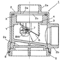
図1は、この発明にかかる排水用トラップの一例を示す断面図である。
この発明にかかる排水用トラップ1は、図1に示すように、排水をコントロールするトラップ主体4と、このトラップ主体4を着脱自在に装着し、かつ上方(排水設備)から流入した排水を横方向に流通させる流路形成部材3と、この流路形成部材を着脱自在に装着する管部材2と、この管部材2に、その下端開口部2eを閉止するよう着脱自在に装着されるキャップ部材5とから構成されるものである。
FIG. 1 is a cross-sectional view showing an example of a drain trap according to the present invention.
As shown in FIG. 1, the
なお、前記排水用トラップ1は、ステンレスなどの金属材料や合成樹脂材料などの適当な材料で構成することができ、これを構成する材料については特段の制限はない。
The
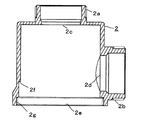
前記管部材2は、排水管として機能するもので、図1及び2に示すように、上下端開放の筒状体で構成されている。
なお、図1及び2において、管部材2は、前記流路形成部材3を収容すべく、その内径が前記流路形成部材3の外径とほぼ等しくなるよう構成されている。
The
In addition, in FIGS. 1 and 2, the
図1及び2において、前記筒状体は、横断面円形のものであり、その上部開口部2c側には、排水を流入させる排水管の下端部と接続可能な接続部2aが形成されている。
In FIGS. 1 and 2, the tubular body has a circular cross section, and a connecting
さらに、前記管部材2の側面には、側方開口部2dが貫通形成され、この開口部2d周縁から側方に延出させて、排水を流出させるための排水管の端部と接続可能な接続部2bが形成されている。
Further, a
さらにまた、前記管部材2の下端側内周面には、前記キャップ部材5との螺合のための螺合部2gが形成されている。
Furthermore, a screwed
なお、前記管部材2の内周面の所要部位には、後述する流路形成部材3の外周面に形成されたストッパ3iと係合して流路形成部材3の位置決めと固定を行うための係合部2fが形成されている。
It should be noted that the required portion of the inner peripheral surface of the
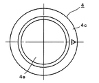
前記管部材2の内部に着脱自在に装着される流路形成部材3は、図1及び3に示すように、上部開口部3eを排水の流入口として有する有底筒状体で構成されたもので、その側面には、排水を横方向に排出する流出口としての開口部3fが貫通形成され、内面の所要部位には、後述するトラップ主体4を装着するための装着部が形成されている。
As shown in FIGS. 1 and 3, the flow
図1、3及び7において、前記流路形成部材3は、横断面円形の有底筒状体で構成されており、前記管部材2の内径とほぼ等しい外径を有するよう構成されている。
In FIGS. 1, 3 and 7, the flow
図1及び3に示すように、前記上部の開口部3eは、前記管部材2の上部開口部2cと連通するよう、前記管部材2の上部開口部2cに相当する位置に形成され、前記側面の開口部3fは、前記管部材2の側方開口部2dと連通するよう、前記管部材2の側方開口部2dに相当する位置に形成されている。
このような構成によって、前記流路形成部材3において、排水経路が形成される。
As shown in FIGS. 1 and 3, the
With such a configuration, a drainage path is formed in the flow
この実施例において、前記上部の開口部3eは、前記上部開口部2cよりも大きい平面視円形になるよう形成されている。
なお、前記側面の開口部3fは、前記側方開口部2dよりも大きい平面視矩形になるよう形成され、かつ開口部3f下縁と側方開口部2d下縁が水平に連なるようにされているが、開口部3f下縁側より側方開口部2d下縁側が低位置となるように形成してもよい。
In this embodiment, the
The
前記流路形成部材3の内底面3dは、排水誘導のため、前記管部材2の側方開口部2dに連通する側方開口部3fに向けて水平面又は下方に傾斜させた傾斜面に形成される。
The
図1及び3において、前記流路形成部材3は、その内底面3dを、側方開口部3f下縁に向けて下方に傾斜させた傾斜面を有する。
このような構成によって、前記流路形成部材3内を通過する排水は、対流を起こすことがないので、円滑に流出する。
さらに、前記流路形成部材3内にゴミや髪の毛などの異物が堆積しないか又はその堆積の抑制に優れているという作用効果も得られる。
In FIGS. 1 and 3, the flow
With such a configuration, the drainage passing through the flow
Further, it is possible to obtain an action effect that foreign matter such as dust and hair does not accumulate in the flow
なお、前記内底面3dを側方開口部3fに向けて下方に傾斜させる場合において、前記傾斜面は、前記流路形成部材3が前記管部材2内に装着された状態において、前記管部材2の接続部2bの下側の内周面との接続部位が、段差のない又は少ない状態で滑らかに繋がるように形成されることがより好ましい。
In addition, when the
前記流路形成部材3の上部内面の所要部位には、図3及び7に示すように、前記トラップ主体4を装着するための装着部が形成されている。
前記装着部は、リング状の載置部3aと、この載置部3aの内側に突出形成されるリング状の段部3bから構成されている。
前記段部3bには、一対の嵌合凹部3c,3cが、一方の嵌合凹部3cが相対する部位から偏倚した状態で形成されている。
As shown in FIGS. 3 and 7, a mounting portion for mounting the trap
The mounting portion is composed of a ring-shaped mounting
A pair of
したがって、後述するように、前記トラップ主体4を、その底部側から前記流路形成部材3内に、軸受け4d,4dが嵌合凹部3c,3cと嵌合するよう挿入すると、前記トラップ主体4は、前記流路形成部材3内に離脱不能に固定される。
Therefore, as will be described later, when the trap
図1において、前記流路形成部材3の中央に形成された凹部3gは、前記キャップ部材5の上面に形成された嵌合部5cと嵌合している。
したがって、前記流路形成部材3は、その頂部が前記管部材2の内壁に当接し、かつその底面が、前記キャップ部材5の裏面と当接するよう構成されているので、前記流路形成部材3の過剰な揺動が抑止される。
In FIG. 1, the
Therefore, the flow
なお、図1及び図3に示すように、前記流路形成部材3の上部開口部3eの周縁を所要の深さ切り欠いてリング状のフィルタ取付部3hを形成し、この取付部3hに、前記管部材2の上部開口部2c及び前記流路形成部材3の上部開口部3eを通過する排水中のゴミや髪の毛などを捕集する捕集部材としての網状のフィルタ部材(図示せず)を配してもよい。
As shown in FIGS. 1 and 3, a ring-shaped
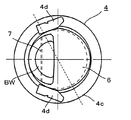
前記流路形成部材3に装着されるトラップ主体4は、図4に示すように、上部に流入口4aを有する短い筒状体からなるもので、前記流入口4aを囲繞して外方に向かってフランジ4cが一体的に形成されるとともに、側方開口部3f側の端部を前端として、その下部を、前端から後端に向かって斜め上方に傾斜するようカットして流出口4bとしたものである。
As shown in FIG. 4, the trap
前記フランジ4cの下面には、図6に示すように、弁体6を揺動自在に保持するための支軸7の、両端部を係合保持する一対の軸受け部4d,4dが設けられている。
As shown in FIG. 6, a pair of bearing
図6において、軸受け4d,4dは、前記嵌合凹部3c,3cに相当する位置に設けられているので、一方側が他方側に対して偏倚状態にある。
したがって、前記トラップ主体4を前記流路形成部材3に装着する際、図7に示すように、前記軸受け4d,4dと前記流路形成部材3の段部3bに形成された嵌合凹部3c,3cをそれぞれ嵌合させた状態で、前記フランジ4cを前記載置部3aに載置することによって、前記トラップ主体4が前記流路形成部材3内に正確に装着される。
In FIG. 6, since the
Therefore, when the trap
さらに、前記トラップ主体4の、下部開口部の後端側には、図4及び5で明らかなように、開口部に沿って半円状の遮蔽板4eが固定される。
なお、この実施例において、前記遮蔽板4eによって閉止される開口部は、前記トラップ主体4の下部開口部の直径の1/2以下としてある。
Further, as is clear from FIGS. 4 and 5, a
In this embodiment, the opening closed by the
前記トラップ主体2には、図4に示すように、弁体6が装着される。
前記弁体6は、図4及び6に示すように、前記遮蔽板4eで閉塞された以外の開口部を開閉するもので、全体が楕円状の板状体からなる弁体6の基端側を、側面視「へ」字状になるよう折り曲げて屈曲部6bを形成し、最上部6aには、弁体6を常時閉鎖方向に付勢するバランスウエイトBWを設け、屈曲部6bには、揺動のための支軸7を挿通する軸受け(保持部)6cを設けたものである。
As shown in FIG. 4, a
As shown in FIGS. 4 and 6, the
したがって、弁体6は、前記軸受け部4d,4d間に保持された支軸7の各端部を、前記軸受け6cに軸支することによって、揺動自在とするものである。
Therefore, the
前記バランスウエイトBWは、前記弁体6を常時閉方向に付勢するためのもので、排水の水圧もしくは流量がバランスウエイトBWの重量より多くなった場合には、バランスウエイトBWはその付勢力を失くすので、前記弁体6が開き、排水が、排水流出部としての開口部3fに流出する。
The balance weight BW is for urging the
前記管部材2の下部開口部2eには、図1に示すように、この開口部2eを閉止するよう、開口部2eの内径とほぼ等しい外径の端部を有するキャップ部材5が着脱自在に装着される。
As shown in FIG. 1, a
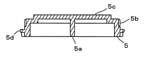
前記キャップ部材5の上端外周面には、前記管部材2の下端側内周面の螺合部2gに対応する螺合部5bが形成されている。
なお、前記管部材2と前記キャップ部材5の係合方法については、特段の制限はなく、いわゆるバヨネット方式などの公知の係合手段を採用することもできるが、好ましくは、気密性の観点から、螺合による方法が選択される。
A
The method of engaging the
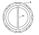
前記キャップ部材5は、図8及び9に示すように、その下面に、キャップ部材5を回動させるための把手5aが付設され、その上面に、前記流路形成部材3の凹部3gと嵌合可能な嵌合部5cが形成されている。
As shown in FIGS. 8 and 9, the
なお、図9において、前記キャップ部材5の下部外周には、円環状の段部5dが形成され、円環状のシール部材(Oリングなど)8がその段部5dに支持されている。
このような構成によれば、シール部材8は、前記管部材2と前記キャップ部材5との間を気密的にシールするので、前記管部材2の内部の気密性が向上し、トラップ主体4の開閉が、より正確に行われ得る。
In FIG. 9, an
According to such a configuration, since the
かかる構成部材からなる排水用トラップ1を構成するに際しては、まず、弁体6に支軸7を装着させたのち、両端の突出部を、前記トラップ主体4のフランジ4cの両端部に形成した軸受け部4d,4dにそれぞれ係合させて、弁体6をトラップ主体4に対して揺動自在に保持させて、トラップ主体4を構成する。
When constructing the
ついで、流路形成部材3の上部の開口部3eから、トラップ主体4を、軸受け4d,4dと嵌合凹部3c,3cをそれぞれ嵌合させた状態で挿入させて、トラップ主体4を流路形成部材3内に固定する。
その際、トラップ主体4は、弁体6が側方開口部3f側に位置する状態で、前記載置部3a上に固定保持される。
Then, the trap
At that time, the trap
さらに、管部材2の下端の開口部2eから、流路形成部材3を、側面の開口部3fが管部材2の側方開口部2dと連通するように挿入する。
Further, the flow
かくして管部材2内に、流路形成部材3を装着したのち、前記開口部2eをキャップ部材5で閉止したのち、各種排水設備の配管経路の途中に、排水用トラップ1を配置するものである。
その際、前記流路形成部材3は、管部材2の内面とキャップ部材5の裏面(下面)によって挟持されるので、前記流路形成部材3は、その上下方向への移動が阻止され、安定して管部材2内に強固に固定される。
In this way, after the flow
At that time, since the flow
かかる排水用トラップ1は、管部材2が、従来のS字トラップなどの封水式排水管トラップに比して小型で、排水設備の下方に所要の空間を形成可能な大きさの排水管として構成され、この管部材2の内部に、流路形成部材3を介して、トラップ主体4を装着する構成を有しているので、排水設備の構築に際し、排水設備の下方に、楽に利用し、より大きな収納スペースを設けるのに十分なスペースを確保することができる。
The
さらに、使用途中において、排水用トラップ1内に塵埃や異物などが溜ったり詰まったりした場合には、キャップ部材5を取外し、前記手順と逆の操作を行うことによって、内部を容易に清掃することができ、かつ部品の取替えもきわめて容易に実施することができるものである。
Further, if dust or foreign matter is accumulated or clogged in the
かかる構成からなる排水用トラップ1を配管経路の途中に配置すると、排水がない場合、あるいは、弁体6を揺動させるに必要な排水量がない場合には、図1に実線で示すように、弁体6は、バランスウエイトBWの作用によって常に流出口4bを閉止しているので、排水は接続部2b側には流れない。
When the
一方、排水設備からの排水が、排水流入部Xに所定量溜り、その水圧あるいは流圧でトラップ主体4の弁体6が排水流出部Y側に押圧されると、図1に示すように、弁体6は支軸7を支点として、図1の鎖線で示すように上方に揺動して、前記流通孔が開口する。
On the other hand, when a predetermined amount of drainage from the drainage facility is accumulated in the drainage inflow portion X and the
この流通孔が開口すると、排水流入部Xに流入した、あるいは溜まった排水は、流通孔を介して排水流出部Y側に流れ、弁体6に対する水圧が解消されると、弁体6は、付設したバランスウエイトBWの作用によって、再び流出口4bの端面と密着当接して、排水が、排水流出部Yから排水流入部Xに逆流するのを阻止する。
When the flow hole is opened, the drainage that has flowed into or accumulated in the drainage inflow section X flows to the drainage outflow section Y side through the flow hole, and when the water pressure on the
かかる構成の排水用トラップは、従来の封水式排水管トラップとは異なり、トラップ自体を小型化することができ、かつ構造を簡素化できるもので、メンテナンスや清掃が容易なものである。 Unlike the conventional water-sealed drainage pipe trap, the drainage trap having such a configuration can be miniaturized and the structure can be simplified, and maintenance and cleaning are easy.
さらに、前記排水用トラップは、配管経路の途中に配置することができるもので、各種排水設備、特に、キッチンの流し場や洗面所、風呂場などの配管経路の途中に配置された場合には、配管から床面までの距離を長くすることができるので、この排水設備の下方に所要の空間を形成し、利用者、特に車椅子使用者が、排水設備を楽に利用することを可能にするとともに、排水設備の下方に設けられる収納スペースをより大きなものにすることを可能にする。
Further, the drain trap can be arranged in the middle of the piping route, and when it is arranged in the middle of various drainage facilities, particularly a kitchen sink, a washroom, a bathroom, etc. Since the distance from the pipe to the floor can be increased, the required space is formed below this drainage facility, and users, especially wheelchair users, can easily use the drainage facility. It makes it possible to increase the storage space provided below the drainage system.
この発明にかかる排水用トラップは、キッチンの流し場や洗面所、風呂場などの設備から排出される水(排水)を、下方に排出する配管経路に装着して使用することができるもので、使用に際しては、その設備の下方に十分なスペースを形成することが可能であり、配管を取り外すことなくメンテナンスや清掃が可能である。
したがって、業務用または家庭用のキッチンの流し場や洗面所、風呂場などの各種排水設備の排水を必要とする部位に使用することが可能であるため、広い産業分野で利用される可能性を有するものである。
The drain trap according to the present invention can be used by attaching water (drainage) discharged from facilities such as a kitchen sink, a washroom, and a bathroom to a piping path for discharging downward. In use, it is possible to form a sufficient space under the equipment, and maintenance and cleaning are possible without removing the piping.
Therefore, it can be used in various drainage facilities such as sinks, washrooms, and bathrooms of commercial or household kitchens that require drainage, and may be used in a wide range of industrial fields. To have.
1 排水用トラップ
2 管部材
2a 排水流入側の接続部
2b 排水流出側の接続部
2c 上部開口部
2d 側方開口部
2e 下部開口部
2f 係合部
2g 螺合部
3 流路形成部材
3a 載置台
3b 段部
3c 嵌合凹部
3d 内底面
3e 上部開口部
3f 側方開口部
3g 凹部
3h フィルタ取付部
3i ストッパ
4 トラップ主体
4a 流入口
4b 流出口
4c フランジ
4d 軸受け部
4e 遮蔽板
5 キャップ部材
5a 把手
5b 螺合部
5c 嵌合部
5d 円環状の段部
6 弁体
6a 最上部
6b 屈曲部
6c 軸受け
BW バランスウエイト
7 支軸
8 シール部材
X 排水流入部
Y 排水流出部
1
前記目的を達成するため、この発明にかかる請求項1に記載の発明は、
上下端開放の筒状体で構成される管部材と、前記管部材内に着脱自在に装着される有底筒状の流路形成部材と、前記流路形成部材内に着脱自在に装着されるトラップ主体と、前記管部材の下端開口部に着脱自在に装着されるキャップ部材から構成される排水用トラップにおいて、
前記管部材は、
その上端部に排水管と接続可能な接続部を有するとともに、側面に貫通形成された開口部周縁から側方に延出することにより形成した排水管と接続可能な接続部を有し、
前記流路形成部材は、
その上部の、前記管部材の上部開口部に相当する位置と、側面の、前記管部材の側方開口部に相当する位置のそれぞれに開口部を有するとともに、内面の所要部位に、前記トラップ主体を装着するための装着部を有し、内底面が、前記側面の開口部下縁に向けて下方に傾斜させた傾斜面に形成され、
前記トラップ主体は、
前記側方開口部側の端部を前端として、下部開口部が後方に向かって周面が減少する傾斜面を有し、上部開口部には一対の軸受け部を有するフランジが形成されたもので、前記下部開口部の後部側は遮蔽板によって閉塞され、前記遮蔽板によって閉塞されない部位を弁体によって開閉自在としたこと
を特徴とする排水用トラップである。
In order to achieve the above object, the invention according to
A tube member composed of a tubular body with open upper and lower ends, a bottomed tubular flow path forming member detachably mounted in the tube member, and a detachably mounted in the flow path forming member. In a drainage trap composed of a trap main body and a cap member detachably attached to the lower end opening of the pipe member.
The pipe member is
It has a connection part that can be connected to the drainage pipe at its upper end, and also has a connection part that can be connected to the drainage pipe formed by extending laterally from the peripheral edge of the opening formed through the side surface.
The flow path forming member is
The trap main body has openings at the upper part corresponding to the upper opening of the pipe member and at the side surface corresponding to the lateral opening of the pipe member, and at a required portion on the inner surface. The inner bottom surface is formed on an inclined surface that is inclined downward toward the lower edge of the opening on the side surface.
The trap subject is
With the end on the side opening side as the front end, the lower opening has an inclined surface whose peripheral surface decreases toward the rear, and the upper opening is formed with a flange having a pair of bearings. The drainage trap is characterized in that the rear side of the lower opening is closed by a shielding plate, and the portion not blocked by the shielding plate can be opened and closed by a valve body.
この発明の請求項2に記載の発明は、
請求項1に記載の排水用トラップにおいて、
前記管部材の内周面の所要部位には、前記流路形成部材の位置決めと固定を行うため前記流路形成部材の外周面に形成されたストッパと係合する係合部が形成されていること
を特徴とするものである。
The invention according to
In the drain trap according to
An engaging portion that engages with a stopper formed on the outer peripheral surface of the flow path forming member is formed at a required portion of the inner peripheral surface of the pipe member in order to position and fix the flow path forming member. It is characterized by that.
この発明の請求項3に記載の発明は、
請求項1又は2に記載の排水用トラップにおいて、
前記傾斜面は、
前記管部材の側方接続部の下側の内周面との接続部位が、段差のない又は少ない状態で滑らかに繋がるように形成されていること
を特徴とするものである。
The invention according to
In the drain trap according to
The inclined surface is
It is characterized in that the connection portion with the inner peripheral surface on the lower side of the lateral connection portion of the pipe member is formed so as to be smoothly connected with no or few steps.
なお、前記排水用トラップにおいて、前記流路形成部材の内底面は、前記側面の開口部下縁に向けて下方に傾斜させた傾斜面に形成されている。
このような構成によって、前記流路形成部材内を通過する排水は、対流を起こすことなく、円滑に流出することができ、さらに、前記流路形成部材内におけるゴミや髪の毛などの異物の堆積がないか又はその抑制に優れたものとすることができる。
その際、前記傾斜面を、前記流路形成部材が前記管部材内に装着された状態において、前記管部材の側方の接続部の下側の内周面との接続部位が、段差のない又は少ない状態で滑らかに繋がるように形成することが好ましい。
Incidentally, in the drain trap, the inner bottom surface of the flow path forming member, toward the opening lower edge of the side that is formed on the inclined surface is inclined downward.
With such a configuration, the drainage passing through the flow path forming member can flow out smoothly without causing convection, and further, foreign matter such as dust and hair is accumulated in the flow path forming member. It can be absent or excellent in its suppression.
At that time, in a state where the flow path forming member is mounted in the pipe member, the inclined surface has no step at the connection portion with the inner peripheral surface on the lower side of the lateral connection portion of the pipe member. Alternatively, it is preferable to form them so that they are smoothly connected in a small amount.
Claims (6)
前記管部材は、
その上端部に排水管と接続可能な接続部を有するとともに、側面に貫通形成された開口部周縁から側方に延出することにより形成した排水管と接続可能な接続部を有し、
前記流路形成部材は、
その上部の、前記管部材の上部開口部に相当する位置と、側面の、前記管部材の側方開口部に相当する位置のそれぞれに開口部を有するとともに、内面の所要部位に、前記トラップ主体を装着するための装着部を有し、内底面が、前記側面の開口部下縁に向けて水平面又は下方に傾斜させた傾斜面に形成され、
前記トラップ主体は、
前記側方開口部側の端部を前端として、下部開口部が後方に向かって周面が減少する傾斜面を有し、上部開口部には一対の軸受け部を有するフランジが形成されたもので、前記下部開口部の後部側は遮蔽板によって閉塞され、前記遮蔽板によって閉塞されない部位を弁体によって開閉自在としたこと
を特徴とする排水用トラップ。 A tube member composed of a tubular body with open upper and lower ends, a bottomed tubular flow path forming member detachably mounted in the tube member, and a detachably mounted in the flow path forming member. In a drainage trap composed of a trap main body and a cap member detachably attached to the lower end opening of the pipe member.
The pipe member is
It has a connection part that can be connected to the drainage pipe at the upper end, and also has a connection part that can be connected to the drainage pipe formed by extending laterally from the peripheral edge of the opening formed through the side surface.
The flow path forming member is
The trap main body has openings at the upper part corresponding to the upper opening of the pipe member and at the side surface corresponding to the side opening of the pipe member, and at a required portion on the inner surface. The inner bottom surface is formed on a horizontal plane or an inclined surface inclined downward toward the lower edge of the opening on the side surface.
The trap subject is
With the end on the side opening side as the front end, the lower opening has an inclined surface whose peripheral surface decreases toward the rear, and the upper opening is formed with a flange having a pair of bearings. The drainage trap is characterized in that the rear side of the lower opening is closed by a shielding plate, and the portion not blocked by the shielding plate can be opened and closed by a valve body.
前記側面の開口部下縁に向けて下方に傾斜させた傾斜面に形成されていること
を特徴とする請求項1に記載の排水用トラップ。 The inner bottom surface
The drainage trap according to claim 1, wherein the drainage trap is formed on an inclined surface that is inclined downward toward the lower edge of the opening on the side surface.
前記管部材の側方接続部の下側の内周面との接続部位が、段差のない又は少ない状態で滑らかに繋がるように形成されていること
を特徴とする請求項2に記載の排水用トラップ。 The inclined surface is
The drainage product according to claim 2, wherein the connection portion with the inner peripheral surface on the lower side of the lateral connection portion of the pipe member is formed so as to be smoothly connected with no or few steps. trap.
その頂部が前記管部材の内壁に当接し、かつその底面が前記キャップ部材の裏面と当接するよう構成されていること
を特徴とする請求項1〜3のいずれかに記載の排水用トラップ。 The flow path forming member is
The drainage trap according to any one of claims 1 to 3, wherein the top thereof is in contact with the inner wall of the pipe member, and the bottom surface thereof is in contact with the back surface of the cap member.
弁体を備え、
前記弁体は、
全体が楕円状の板状体で構成され、その基端側を、側面視へ字状になるよう折り曲げて屈曲部を形成し、最上部には、弁体を常時閉鎖方向に付勢するバランスウエイトを設け、屈曲部には、揺動のための支軸を保持する筒状の保持部を設けたものであること
を特徴とする請求項1〜4のいずれかに記載の排水用トラップ。 The trap subject is
Equipped with a valve body
The valve body
The whole is composed of an elliptical plate-like body, and the base end side is bent so as to form a lateral view to form a bent portion, and at the uppermost portion, a balance that constantly urges the valve body in the closing direction. The drainage trap according to any one of claims 1 to 4, wherein a weight is provided and the bent portion is provided with a tubular holding portion for holding a support shaft for swinging.
その内面の所要部位に、リング状の載置部と、この載置部の内側に突出形成されるリング状の段部と、この段部に、一方側の嵌合凹部を他方側の嵌合凹部に対して偏倚させて設けられる一対の嵌合凹部を備え、
前記トラップ主体は、
流入口を囲繞して外方に向かってフランジが一体的に形成され、かつこのフランジの下面の、前記嵌合凹部に相当する位置に、弁体を揺動自在に保持するための支軸の、両端部を係合保持する一対の軸受け部が設けられたものであること
を特徴とする請求項1〜5のいずれかに記載の排水用トラップ。 The flow path forming member is
A ring-shaped mounting portion is formed on the required portion of the inner surface, a ring-shaped step portion is formed so as to project inside the mounting portion, and a fitting recess on one side is fitted to the step portion on the other side. It is provided with a pair of fitting recesses that are provided so as to be biased with respect to the recesses.
The trap subject is
A support shaft for oscillatingly holding the valve body at a position corresponding to the fitting recess on the lower surface of the flange in which a flange is integrally formed so as to surround the inflow port and outward. The drainage trap according to any one of claims 1 to 5, wherein a pair of bearing portions for engaging and holding both ends thereof are provided.
Priority Applications (1)
| Application Number | Priority Date | Filing Date | Title |
|---|---|---|---|
| JP2019076499A JP6871966B2 (en) | 2019-04-12 | 2019-04-12 | Drain trap |
Applications Claiming Priority (1)
| Application Number | Priority Date | Filing Date | Title |
|---|---|---|---|
| JP2019076499A JP6871966B2 (en) | 2019-04-12 | 2019-04-12 | Drain trap |
Publications (2)
| Publication Number | Publication Date |
|---|---|
| JP2020172824A true JP2020172824A (en) | 2020-10-22 |
| JP6871966B2 JP6871966B2 (en) | 2021-05-19 |
Family
ID=72830177
Family Applications (1)
| Application Number | Title | Priority Date | Filing Date |
|---|---|---|---|
| JP2019076499A Active JP6871966B2 (en) | 2019-04-12 | 2019-04-12 | Drain trap |
Country Status (1)
| Country | Link |
|---|---|
| JP (1) | JP6871966B2 (en) |
Citations (5)
| Publication number | Priority date | Publication date | Assignee | Title |
|---|---|---|---|---|
| JPH10183715A (en) * | 1996-12-25 | 1998-07-14 | Kirin Brewery Co Ltd | Trap of drain pit |
| JP2009057690A (en) * | 2007-08-29 | 2009-03-19 | Yamaha Livingtec Corp | Drain trap |
| JP2013014878A (en) * | 2011-06-30 | 2013-01-24 | Maruichi Corp | Drain piping |
| JP2014196605A (en) * | 2013-03-29 | 2014-10-16 | 丸一株式会社 | Piping device |
| JP2016084680A (en) * | 2014-10-29 | 2016-05-19 | 株式会社東栄工業 | Water discharge trap |
-
2019
- 2019-04-12 JP JP2019076499A patent/JP6871966B2/en active Active
Patent Citations (5)
| Publication number | Priority date | Publication date | Assignee | Title |
|---|---|---|---|---|
| JPH10183715A (en) * | 1996-12-25 | 1998-07-14 | Kirin Brewery Co Ltd | Trap of drain pit |
| JP2009057690A (en) * | 2007-08-29 | 2009-03-19 | Yamaha Livingtec Corp | Drain trap |
| JP2013014878A (en) * | 2011-06-30 | 2013-01-24 | Maruichi Corp | Drain piping |
| JP2014196605A (en) * | 2013-03-29 | 2014-10-16 | 丸一株式会社 | Piping device |
| JP2016084680A (en) * | 2014-10-29 | 2016-05-19 | 株式会社東栄工業 | Water discharge trap |
Also Published As
| Publication number | Publication date |
|---|---|
| JP6871966B2 (en) | 2021-05-19 |
Similar Documents
| Publication | Publication Date | Title |
|---|---|---|
| JP3915069B2 (en) | Drain pipe | |
| JP6871966B2 (en) | Drain trap | |
| KR200489327Y1 (en) | Smell block trap | |
| JP5446123B2 (en) | Drain trap | |
| JP2008196169A (en) | Drain trap | |
| JP2019218736A (en) | Deodorant cup | |
| JP6454841B2 (en) | Drainage structure with collecting member | |
| KR101401231B1 (en) | Drain apparatus for a washbowl | |
| JP2007120022A (en) | Drain trap | |
| KR200388695Y1 (en) | Drain cover assembly for deodorization | |
| KR101683577B1 (en) | Backflow prevention apparatus of drainage | |
| JP2008002217A (en) | Drain trap | |
| JP3244773U (en) | drainage basin | |
| JP2012211436A (en) | Catch basin | |
| KR200317103Y1 (en) | an apparatus to prvent stinks for a sewer | |
| KR100619180B1 (en) | Trap for Drainage | |
| JP2009068193A (en) | Drain trap | |
| EP3507427B1 (en) | Shower drain fitting | |
| JP6988038B2 (en) | Drainage port member | |
| JP5270881B2 (en) | Hair catcher | |
| JP2005133314A (en) | Drainage trap | |
| JP3190043U (en) | Drainage | |
| JP2024024834A (en) | Hair catcher and drain device | |
| KR200230642Y1 (en) | Lid for drain | |
| JP2021067062A (en) | Deodorant valve unit |
Legal Events
| Date | Code | Title | Description |
|---|---|---|---|
| A621 | Written request for application examination |
Free format text: JAPANESE INTERMEDIATE CODE: A621 Effective date: 20190530 |
|
| RD02 | Notification of acceptance of power of attorney |
Free format text: JAPANESE INTERMEDIATE CODE: A7422 Effective date: 20190530 |
|
| A977 | Report on retrieval |
Free format text: JAPANESE INTERMEDIATE CODE: A971007 Effective date: 20200212 |
|
| A131 | Notification of reasons for refusal |
Free format text: JAPANESE INTERMEDIATE CODE: A131 Effective date: 20200310 |
|
| A521 | Request for written amendment filed |
Free format text: JAPANESE INTERMEDIATE CODE: A523 Effective date: 20200408 |
|
| A131 | Notification of reasons for refusal |
Free format text: JAPANESE INTERMEDIATE CODE: A131 Effective date: 20200929 |
|
| TRDD | Decision of grant or rejection written | ||
| A01 | Written decision to grant a patent or to grant a registration (utility model) |
Free format text: JAPANESE INTERMEDIATE CODE: A01 Effective date: 20210413 |
|
| A61 | First payment of annual fees (during grant procedure) |
Free format text: JAPANESE INTERMEDIATE CODE: A61 Effective date: 20210416 |
|
| R150 | Certificate of patent or registration of utility model |
Ref document number: 6871966 Country of ref document: JP Free format text: JAPANESE INTERMEDIATE CODE: R150 |