JP2013014878A - Drain piping - Google Patents
Drain piping Download PDFInfo
- Publication number
- JP2013014878A JP2013014878A JP2011146147A JP2011146147A JP2013014878A JP 2013014878 A JP2013014878 A JP 2013014878A JP 2011146147 A JP2011146147 A JP 2011146147A JP 2011146147 A JP2011146147 A JP 2011146147A JP 2013014878 A JP2013014878 A JP 2013014878A
- Authority
- JP
- Japan
- Prior art keywords
- drain
- drainage
- trap
- pipe
- opening
- Prior art date
- Legal status (The legal status is an assumption and is not a legal conclusion. Google has not performed a legal analysis and makes no representation as to the accuracy of the status listed.)
- Granted
Links
Images


Landscapes
- Sink And Installation For Waste Water (AREA)
Abstract
Description
本発明は洗面台、シンク等の槽体に取り付けられる排水配管に関するものである。 The present invention relates to a drain pipe attached to a tank body such as a washstand and a sink.
従来においては、洗面台、シンク等、使用によって排水が発生する家庭用設備が知られている。これら家庭用設備においては、槽体下部に、使用によって生じた排水を排水口から床下配管へ導く排水配管が備えられている。 Conventionally, household equipment such as a wash basin, a sink, and the like that generates wastewater by use is known. In these household facilities, a drainage pipe for guiding drainage generated by use from the drainage port to the underfloor pipe is provided at the bottom of the tank body.
また、家庭用設備における排水配管では、単純に排水を下水側に繋ぐと、下水側と家庭用設備が連通していることにより、下水側より臭気や害虫が配管内部を通り、屋内に侵入することとなる。そのため、排水配管においては、排水配管の途中に、排水管と連結し、下水からの害虫、及び異臭を防ぐためのトラップが設けられていた。 Also, in the drainage pipes for household equipment, simply connecting the drainage to the sewage side, the sewage side and the household equipment are in communication, so that odors and pests enter the interior from the sewage side through the pipe. It will be. Therefore, in the drain pipe, a trap is provided in the middle of the drain pipe to connect with the drain pipe and prevent pests and odors from the sewage.
上記の様な排水配管は、使用者や施工者の必要に応じて、その都度種々のレイアウトに変更して使用されている。例えば、特許文献1に記載された排水配管においては排水口に設けられた弁体を開閉する、遠隔操作式排水栓装置のレリースワイヤが排水口の下方より差し込まれる構造であり、排水配管は排水口の直下よりすぐ湾曲し、ある程度略水平方向へ進んだ後に、下方へ延び、排水トラップを設ける構造となっている。
The drainage piping as described above is used by changing to various layouts each time according to the needs of the user and the installer. For example, in the drainage pipe described in
しかしながら、従来技術における排水配管において、排水トラップは、排水管の排水流路の上流、下流に対する向きが決まっていた。その為、装置の構成や排水トラップに合わせて排水配管のレイアウトを考えねばならず、自由に配管を組むことができなかった。 However, in the drainage pipe in the prior art, the direction of the drainage trap with respect to the upstream and downstream of the drainage channel of the drainage pipe is determined. Therefore, the layout of the drainage piping must be considered according to the configuration of the device and the drain trap, and the piping could not be assembled freely.
そこで本発明は、上述した従来技術の問題に鑑み、排水トラップの方向に関わりなく、配管を自由に組むことが可能である排水配管を提供することを課題とする。 Then, this invention makes it a subject to provide the drainage piping which can assemble piping freely regardless of the direction of a drainage trap in view of the problem of the prior art mentioned above.
上記課題を解決するための請求項1に記載の発明は、槽体の排水を行う排水配管であって、前記排水配管は、内部に排水流路を備えた排水管と、排水トラップと、排水管に対して排水トラップの位置、及び向きを固定する固定部材より構成され、前記排水管は内部に排水トラップを収納固定し、当該収納時、排水管の排水流路に対し、排水トラップの方向を反転自在に収納固定することが可能であることを特徴とする排水排管である。
Invention of
本発明の排水配管は、排水管内部において、排水トラップの、排水管の排水流路に対する方向を反転自在に収納することが可能である。したがって、本発明の排水配管は、排水管の上流と下流を反転・変更することが可能であり、排水トラップに合わせてレイアウトを選択する必要がなく、自由に配管を組むことができる。 The drainage pipe of the present invention can accommodate the drain trap so that the direction of the drain trap with respect to the drainage flow path of the drainage pipe can be reversed. Therefore, the drainage pipe of the present invention can reverse and change the upstream and downstream of the drainage pipe, and it is not necessary to select a layout according to the drainage trap, and the pipe can be assembled freely.
請求項2に記載の発明は、前記排水管が略L字状の曲がり管であることを特徴とする請求項1に記載の排水配管である。
The invention according to
本発明の排水配管では、前記排水管を略L字状の曲がり管としたことにより、例えば、横管を縦管と接続したい場合であっても、縦管を横管に接続したい場合であっても、本発明の排水配管を利用して接続することが可能となる。即ち、より自由に配管を組むことができる。 In the drainage pipe of the present invention, the drainage pipe is a substantially L-shaped bent pipe. For example, even when the horizontal pipe is desired to be connected to the vertical pipe, the vertical pipe is desired to be connected to the horizontal pipe. However, it becomes possible to connect using the drain piping of the present invention. That is, the piping can be assembled more freely.
請求項3に記載の発明は、前記排水管の外壁の一部が取り外し可能であり、該取り外しによって生じた空間より排水トラップを脱着可能であることを特徴とする請求項1又は請求項2に記載の排水配管である。
The invention according to
従来の排水配管においては、排水トラップの清掃、取り替え等の際には、前後の排水管との接続を解除し、排水トラップの清掃や交換をした後、再び前後の配管と接続させなければならなかった。しかし本発明の排水配管では、排水配管の内部に収納固定された排水トラップを、排水配管の外壁の一部を取り外すことによって脱着させることができる。その為、前後の配管との連結を解除することなく、排水トラップを脱着することができ、清掃性や施工性が大幅に向上する。 In conventional drainage pipes, when cleaning or replacing a drain trap, disconnect the front and rear drain pipes, clean and replace the drain trap, and then reconnect the front and rear pipes. There wasn't. However, in the drain pipe of the present invention, the drain trap housed and fixed inside the drain pipe can be detached by removing a part of the outer wall of the drain pipe. Therefore, the drain trap can be detached without releasing the connection with the front and rear pipes, and the cleaning performance and workability are greatly improved.
請求項4に記載の発明は、前記固定部材が、前記取り外し可能な排水管の外壁の一部であることを特徴とする請求項3に記載の排水配管である。
The invention according to
本発明の排水配管では、取り外し可能な排水管の外壁が、排水トラップの固定部材を兼ねている。その為、前記排水管の外壁を取り外すと、排水トラップの固定が解除される。したがって、外壁の取り外し行程のみによって排水トラップ脱着可能となり、さらに容易に清掃交換等が行うことができる。 In the drain pipe of the present invention, the outer wall of the removable drain pipe also serves as a fixing member for the drain trap. Therefore, when the outer wall of the drain pipe is removed, the drain trap is released. Therefore, the drain trap can be attached / detached only by the removal process of the outer wall, and cleaning and replacement can be performed more easily.
請求項5に記載の発明は、前記排水トラップが、内部に封水を有さない非封水式排水トラップであることを特徴とする請求項1乃至請求項4のいずれか一つに記載の排水配管である。 According to a fifth aspect of the present invention, the drain trap is a non-sealed drain trap having no sealed water inside, according to any one of the first to fourth aspects. It is a drainage pipe.
請求項6に記載の発明は、前記排水トラップが弾性体より成る自封トラップであることを特徴とする請求項5に記載の排水配管である。 A sixth aspect of the present invention is the drainage pipe according to the fifth aspect, wherein the drain trap is a self-sealing trap made of an elastic body.
請求項7に記載の発明は、前記排水トラップは内部にリング状部材を有し、該リング状部材は前記排水トラップの内壁を押圧して、前記排水トラップを固定することを特徴とする請求項6に記載の排水配管である。
The invention according to
本発明の排水配管では、排水トラップとして、弾性体からなる自封トラップを採用している。自封トラップとは、弾性体より成る、一方の端部が開口し、対向する他方の端部が閉塞した排水トラップであり、開口側より排水が流れた際にのみ、前記閉塞が拡開されて排水が流れる構成のものである。該自封トラップの固定方法として、自封トラップの内部にリング状の部材を挿入し、その状態のまま排水管内部に自封トラップを押入する。該方法によれば、自封トラップがリング状部材外部と排水管内部に挟持され、確実に水密固定される。 In the drainage pipe of the present invention, a self-sealing trap made of an elastic body is adopted as the drainage trap. A self-sealing trap is a drainage trap made of an elastic body with one end opened and the other opposite end closed, and the closure is expanded only when drainage flows from the opening side. It has a configuration in which drainage flows. As a method for fixing the self-sealing trap, a ring-shaped member is inserted into the self-sealing trap, and the self-sealing trap is pushed into the drain pipe in that state. According to this method, the self-sealing trap is sandwiched between the outside of the ring-shaped member and the inside of the drain pipe, and is securely fixed in a watertight manner.
請求項8に記載の発明は、前記排水トラップが、内部に封水を有する封水式排水トラップであることを特徴とする請求項1乃至請求項4のいずれか一つに記載の排水配管である。
The invention according to claim 8 is the drainage pipe according to any one of
本発明の排水配管では、排水管内部に排水トラップを収納し、且つ、収納に際し、排水トラップの排水流路に対する方向を反転させても収納固定することが可能であるために、1つの排水配管に複数種類のレイアウトのバリエーションを持たせることができる。また、排水管の外壁部の一部を脱着可能とすることにより、施工後においても、本発明の排水配管の前後の接続を解除せずに、内部の排水トラップのメンテナンスを行うことができる。 In the drain pipe of the present invention, the drain trap is housed inside the drain pipe, and can be stored and fixed even when the direction of the drain trap with respect to the drain flow path is reversed. Can have multiple types of layout variations. In addition, by making a part of the outer wall portion of the drain pipe removable, maintenance of the internal drain trap can be performed without releasing the connection before and after the drain pipe of the present invention even after construction.
以下に、本発明の第一実施例について、図面を参照しながら詳細に説明する。尚、以下の説明は、実施例の理解を容易にするためのものであり、これによって、本発明が制限して理解されるべきではない。また、以下の説明では、上下左右の位置関係は、特に断りのない限り、設置状態を基準として説明する。 Below, the 1st example of the present invention is described in detail, referring to drawings. In addition, the following description is for making an understanding of an Example easy, and, as a result, this invention should not be limited and understood. In the following description, the positional relationship between the upper, lower, left and right will be described based on the installation state unless otherwise specified.
以下、図1(一部図2、図3)を利用して、各部材を詳細に説明する。尚、以下図1〜4においては、図面を分かり易くする為ハッチングを省略している。 Hereinafter, each member will be described in detail with reference to FIG. 1 (partly FIGS. 2 and 3). In the following, in FIGS. 1 to 4, hatching is omitted for easy understanding of the drawings.
本実施例の排水配管1は、図1に示す様に、排水管2と、弾性体から成る排水トラップ10と、前記排水トラップ10を固定する固定部材15と、硬質材から成るケーシング20から構成されている。
As shown in FIG. 1, the
排水管2は略円筒状の配管であり、両端と側部に開口部3、4、5を備え、内周に突出部7を有する。開口部3と開口部4は排水管2の両端に配置された、同軸の開口である。開口部4は排水管2の端部に設けられた内フランジ6の内周より、更に下流側に向けて突設された開口であり、開口部5は排水管2の外周に突設された開口である。また、排水管2の外径は、中心付近において開口部3側より開口部4側が1段縮径しており、開口部3側の内周に凸状の突出部7を有する。また、排水管2は、単体では排水流路を備えておらず、後述する固定部材15、ケーシング20を嵌設することで内部に排水流路を形成する。
The
排水トラップ10は弾性体より形成されて成る排水トラップである。排水トラップ10は断面略三角形状であり、一端に流入口11を、対向する端部に流出口12を備えている。流入口11は円形の開口であり、流出口12は円筒の一端を押し潰し、軸上で重ね合わせた形状をしており、内部より圧力が掛からない限りにおいて閉塞している。従って、流入口11から流出口12に向けて排水が流れる際には、該排水の圧力により流出口12の閉塞が拡開され、下流へ排水が排出されるが、排水の無い場合において流出口12は閉塞されており、臭気や害虫の下流からの侵入を防ぐ。本明細書においては、上記排水トラップ10のように、内部に封水を有さず、弾性を利用し一端を閉塞して臭気や害虫の下流からの侵入を防ぐ形状の排水トラップのことを自封トラップという。
The
固定部材15は略円筒状であり、流路形成部16と、取り出し部17を備えている。流路形成部16においては、固定部材15の外壁の一部が欠落しており、前記排水管2と結合した際には、該欠落により流路を形成する。また、流路形成部16と取り出し部17との間は完全に区切られており、両部の間を水等が移動する空間はない。また、固定部材15の外周にはパッキン18と係合凹部19が設けられている。
The fixing
ケーシング20は硬質の外ケース21と内ケース22から成る。外ケース21は断面略凹状であり、一端の内周に溝23が設けられている。また、内ケース22は一端に外フランジを持つ略円筒状の部材であり、内ケース22の外径は、外ケース21の内径と略同一である。
The
上記のような部材によって構成された本発明の排水配管は、以下のようにして組み上げられる。 The drainage pipe of the present invention constituted by the members as described above is assembled as follows.
まず、排水トラップ10の流入口11を外ケース21の溝23と嵌合させた状態で、外ケース21の内部に内ケース22を挿入する。該挿入により、排水トラップ10は溝23と内ケース22の周縁によって挟止され、ケーシング20内部に固定される。
First, the
次に、ケーシング20(及び排水トラップ10)を開口部3より排水管2へ挿入するが、排水管2に対して反転自在に収納することが可能であり、収納する方向によって、排水管2内部における排水流路の上流、下流を決定することができる。排水トラップ10の流出口12が開口部4の方向を向いて固定された場合においては、排水管2の開口部5側が排水流路の上流、開口部4側が下流となる(以下、この状態を「第一形態」とする)。逆に、排水トラップ10の流入口11が開口部4の方向を向いて固定された場合においては、配管2の開口部4側が上流、開口部5側が下流となる(以下、この状態を第二形態とする)。
Next, the casing 20 (and the drain trap 10) is inserted into the
この時、ケーシング20は、硬質の外ケース21と、同じく硬質の内ケース22によって成る為、弾性体から成る自封トラップである排水トラップ10を排水管2に組み込む際において、排水トラップ10の変形が生じず、収納が容易である。
At this time, since the
次に、固定部材15を開口部3より押入する。該押入により、第一形態においては固定部材15の底面と外ケース21が当接し、ケーシング20、及び排水トラップ10が固定される(図2参照)。また、第二形態においては固定部材15と内ケース22が当接し、ケーシング20、及び排水トラップ10が固定される(図3参照)。そして排水管2の突出部7と固定部材15の係号凹部19は互いに係合し、固定部材15自体も固定される。
Next, the fixing
そしてこの時、第一形態及び第二形態のどちらの形態であっても、固定部材15の流路形成部16が開口部5とケーシング20の内周とを繋ぎ、排水の進行方向を約90度屈折させる排水流路が形成される。
At this time, the flow
また、流路形成部16と取り出し部17の間は区切られており、且つ、固定部材15、及びケーシング20(外ケース21)の外周にはそれぞれパッキン18、24が設けられているため、排水が流路を外れて外部に漏れることはない。
Further, the flow
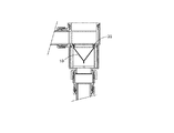
上記のように構成された本発明の排水配管1の第一形態は、図2に示すようにして接続される。 The 1st form of the drainage piping 1 of this invention comprised as mentioned above is connected as shown in FIG.
図2に示す排水配管1は、遠隔排水栓装置40と連結している横管43と接続されている。
A
遠隔操作式排水栓装置40は、図示しない槽体、及び弁体の下方に配置されている。遠隔排水操作式排水栓装置40は、操作部41とレリースワイヤ42を備え、前記操作部41の押動によりレリースワイヤ42を操作し、排水口の開閉を行う装置である。
The remote-operated
図2に示す配管構造に本発明を組み込む場合、水平方向(遠隔操作式排水栓装置40側)から排水が流入する。本発明の第一形態は、排水トラップ10の流出口12を開口部4の方向へ向けて固定されている。即ち、排水トラップ10の流入口11が排水流路の上流側に配置される形となり、横管43から流入した排水は開口部5、固定部材15の流路形成部16、流入口11、流出口12を順に通り、開口部4より縦管44へ排出される。一方、下流から上流へ侵入してくる臭気、及び害虫は流出口12側から侵入する形となるが、上流(流入口11)より圧力が掛からない限りにおいて流出口12は閉塞されており、臭気、害虫は屋内に侵入することができない。
When the present invention is incorporated in the piping structure shown in FIG. 2, drainage flows from the horizontal direction (remotely operated
第一形態において、排水トラップ10の清掃、交換等を行う際には、固定部材15の取り外し部17を掴み、引き上げることで、固定部材15を排水管2より取り外す。また、固定部材15を取り外したことにより、ケーシング20の固定が解除される。従って、排水トラップ10の清掃、交換等を行う際において、他の配管との接続を解除せずに排水トラップ10の清掃、交換等が出来、清掃性及び施工容易性に優れている。
In the first embodiment, when the
次に、本発明の排水配管1の第二形態を、図3を用いて説明する。図3は図示しない槽体に接続される排水口45と本発明の第二形態を接続したものである。
Next, the 2nd form of the
図3示す排水配管1は、排水口45の下方に開口部4を接続して成る。即ち、開口部4が上流側となる。本発明の第二形態における排水トラップ10は、前述した第一形態の排水トラップ10を内部に収納したケーシング20の上下を、配管2に対し、第一形態より反転させた状態で固定される。その為本発明の第二形態は、排水トラップ10の流入口11が開口部4の方向を向いて固定されている。即ち、排水口45から排出される排水は開口部4、流入口11、流出口12、流路形成部16、開口部5の順で流路を通り、横管46へ排水される。
The
第二形態において、排水トラップ10の清掃、交換等を行う際には、前述した第一形態と同様に、固定部材15の取り外し部17を掴み、引き下げることで、固定部材15を排水管2より取り外す。また、固定部材15を取り外したことにより、ケーシング20の固定が解除される。したがって、排水トラップ10の清掃、交換を行う際において、他の配管、及び排水口45との接続を解除せずに排水トラップ10の清掃、交換等ができ、清掃性、施工容易性を向上させている。
In the second embodiment, when the
次に、本発明の第二実施例について説明する。
上記第一実施例では、排水管の取り外し可能部分は、排水管の曲がり部分であったが、図5に示す第二実施例においては、直線部分が取り外し可能である。また、排水トラップ10は内部に封水を有さない自封トラップであったが、第二実施例における排水トラップ65は内部に封水部を有する排水トラップである。
Next, a second embodiment of the present invention will be described.
In the first embodiment, the detachable portion of the drain pipe is a bent portion of the drain pipe, but in the second embodiment shown in FIG. 5, the straight portion is removable. The
尚、封水式排水トラップは、排水流路中に封水と呼ばれる、排水が溜まる部分を設けており、該封水部分を臭気や害虫が通過できないことを利用して下水側からの侵入を防ぐものである。 In addition, the sealed drain trap has a portion of the drainage channel, called sealed water, in which drainage accumulates, and the intrusion from the sewage side using the fact that odors and pests cannot pass through the sealed water portion. It is something to prevent.
図5(a)、(b)に示す、第二実施例に係る排水配管50は、排水管51と、固定部材60と、封水式排水トラップ65から構成されている。尚、図5(b)においては、図面を分かり易くするため、封水部70を図示していない。
The
排水管51は断面略L字状の曲がり管であり、両端に開口部52、53を有する。排水管51は、開口部53側の直線部分に、後述する固定部材60の固定部61、62と係合することによって、排水トラップ65を挟圧固定する固定部54、55が設けられている。また、同直線部分において前記固定部54、55間と略同一の長さであり、円周方向約180度の切り欠きが設けられている。
The
固定部材60は前記排水管51に設けられた切り欠きと略同一の形状をしており、排水管51の固定部52、53と係合する固定部61、62を有する。
The fixing
排水トラップ65は、外観視略円筒状であり、内部の流路が略S字状に形成された封水式排水トラップである。排水トラップ65は、開口部52側に流入口66を、開口部53側に流出口67を備えている。流入口66は、排水流路の上流側に常に配置され、その径は排水トラップ65の外径と略等しい。一方、流出口67は排水流路の下流側に常に配置され、その径は流入口66に比べてかなり小径である。
The
上記のような部材によって構成された本実施例においては、排水管51の切り欠きより排水トラップ65を挿入した後、固定部材60を嵌合することによって、組み上げられる。この時、図5(b)に示すように、固定部54、55と固定部61、62は係合し、排水トラップ65が固定される。また、この時同時に排水流路が形成される。そして、上流から排出された排水が排水トラップ65の底部(封水部70)に溜まることにより、封水が形成される。
In the present embodiment configured by the members as described above, the
尚、本実施例においても、排水トラップ65の取付方向は反転可能であり、流入口66を開口部53側に向けることができる。
Also in this embodiment, the attachment direction of the
即ち、本発明は、排水トラップ、及び/またはケーシングの取付方向を反転しても収納固定が可能であるという構成により、開口部5(52)から排水が流入する場合と、開口部4(53)から排水が流入する場合のどちらの場合においても利用することが可能である。従って、縦(略垂直)方向に延びる配管等に対して接続し、流路を横(略水平)方向に変更すること、横(略水平)方向に延びる配管等に対して接続し、流路を縦(略垂直)方向に変更することの両方が可能である。また、排水管2(51)の一部を脱着可能とした構成により、排水管2(51)と他の配管との接続を解除することなく、排水トラップのメンテナンス等を行うことができる。これら本発明の特徴により、配管のレイアウトの自由度の幅が大きく広がり、配管を自由に組むことができる。 That is, according to the present invention, the drainage trap and / or the casing can be stored and fixed even if the mounting direction is reversed, so that the drainage flows from the opening 5 (52) and the opening 4 (53). ) Can be used in both cases where wastewater flows in. Therefore, it is connected to a pipe or the like extending in the longitudinal (substantially vertical) direction, and the flow path is changed to the horizontal (substantially horizontal) direction, or connected to a pipe or the like extending in the lateral (substantially horizontal) direction. It is possible to change both in the vertical (substantially vertical) direction. Further, with the configuration in which a part of the drain pipe 2 (51) is detachable, maintenance of the drain trap and the like can be performed without releasing the connection between the drain pipe 2 (51) and another pipe. These features of the present invention greatly expand the degree of freedom of piping layout, and the piping can be assembled freely.
尚、本発明は、上記第一、第二実施例に限定されるものでなく、主旨を変更しない範囲において自由に変更が可能である。例えば、上記第一実施例では、外ケース21と内ケース22で挟持することによって排水トラップ10をケーシング20内部に収納したが、排水トラップ10の収納方法として、図5に示す様に、リング状部材であるリング30を使用し、排水トラップ10の内側から外側に押圧を付与することによって収納する方法を採用しても良い。また、本発明において利用可能である排水トラップは、上記実施例に示すものに限られるものではなく、他の公知、周知の構成の排水トラップを使用しても良い。
The present invention is not limited to the first and second embodiments, and can be freely changed without departing from the spirit of the invention. For example, in the first embodiment, the
また、本発明によれば、使用者の都合に応じて内部の排水トラップを交換することも可能である。例えば、封水式排水トラップにおいては、出張や帰省等の理由により、長期に渡り家を空ける場合に、内部の封水が蒸発してしまう恐れがあるため、家を空ける間のみ、排水トラップを自封トラップ等の非封水式排水トラップに変更する、ということも可能である。 Moreover, according to this invention, it is also possible to replace | exchange an internal drain trap according to a user's convenience. For example, in a sealed drainage trap, when leaving a house for a long time due to a business trip or homecoming, the sealed water inside may evaporate. It is also possible to change to a non-sealed drainage trap such as a self-sealing trap.
1 排水配管
2 排水管
10 排水トラップ
11 流入口
12 流出口
15 固定部材
16 流路形成部
20 ケーシング
21 外ケース
22 内ケース
23 溝
30 リング
43 横管
44 縦管
45 排水口
46 横管
50 排水配管
51 排水管
52 開口部
53 開口部
60 固定部材
65 排水トラップ
66 流入口
67 流出口
70 封水部
DESCRIPTION OF
Claims (8)
前記排水配管は、
内部に排水流路を備えた排水管と、
排水トラップと、
排水管に対して排水トラップの位置、及び向きを固定する固定部材より構成され、
前記排水管は内部に排水トラップを収納固定し、
当該収納時、排水管の排水流路に対し、排水トラップの方向を反転自在に収納固定することが可能であることを特徴とする排水排管。 A drainage pipe for draining the tank body,
The drainage pipe is
A drain pipe with a drain channel inside,
Drain trap,
It consists of a fixing member that fixes the position and orientation of the drain trap with respect to the drain pipe,
The drain pipe stores and fixes a drain trap inside,
A drainage drainage pipe characterized in that the drain trapping direction can be stored and fixed in a reversible manner with respect to the drainage flow path of the drainage pipe during the storage.
Priority Applications (1)
| Application Number | Priority Date | Filing Date | Title |
|---|---|---|---|
| JP2011146147A JP5891483B2 (en) | 2011-06-30 | 2011-06-30 | Drain pipe |
Applications Claiming Priority (1)
| Application Number | Priority Date | Filing Date | Title |
|---|---|---|---|
| JP2011146147A JP5891483B2 (en) | 2011-06-30 | 2011-06-30 | Drain pipe |
Publications (2)
| Publication Number | Publication Date |
|---|---|
| JP2013014878A true JP2013014878A (en) | 2013-01-24 |
| JP5891483B2 JP5891483B2 (en) | 2016-03-23 |
Family
ID=47687793
Family Applications (1)
| Application Number | Title | Priority Date | Filing Date |
|---|---|---|---|
| JP2011146147A Active JP5891483B2 (en) | 2011-06-30 | 2011-06-30 | Drain pipe |
Country Status (1)
| Country | Link |
|---|---|
| JP (1) | JP5891483B2 (en) |
Cited By (4)
| Publication number | Priority date | Publication date | Assignee | Title |
|---|---|---|---|---|
| JP2014156754A (en) * | 2013-02-18 | 2014-08-28 | Maruichi Corp | Drain piping |
| JP2014196605A (en) * | 2013-03-29 | 2014-10-16 | 丸一株式会社 | Piping device |
| JP2020172824A (en) * | 2019-04-12 | 2020-10-22 | 株式会社東栄工業 | Drainage trap |
| JP7359357B2 (en) | 2019-10-21 | 2023-10-11 | 丸一株式会社 | Odor control valve unit |
Citations (5)
| Publication number | Priority date | Publication date | Assignee | Title |
|---|---|---|---|---|
| JPS53123862U (en) * | 1977-03-10 | 1978-10-02 | ||
| JPH0960076A (en) * | 1995-08-22 | 1997-03-04 | Inax Corp | Drain trap capable of performing water filling test |
| JP2008169575A (en) * | 2007-01-10 | 2008-07-24 | Bridgestone Corp | Drainage trap system and siphon drainage system using same |
| JP2009287329A (en) * | 2008-05-30 | 2009-12-10 | Bridgestone Corp | Drainage trap |
| JP2010007358A (en) * | 2008-06-26 | 2010-01-14 | Maruichi Corp | Drain pipe for draining device, and drain trap |
-
2011
- 2011-06-30 JP JP2011146147A patent/JP5891483B2/en active Active
Patent Citations (5)
| Publication number | Priority date | Publication date | Assignee | Title |
|---|---|---|---|---|
| JPS53123862U (en) * | 1977-03-10 | 1978-10-02 | ||
| JPH0960076A (en) * | 1995-08-22 | 1997-03-04 | Inax Corp | Drain trap capable of performing water filling test |
| JP2008169575A (en) * | 2007-01-10 | 2008-07-24 | Bridgestone Corp | Drainage trap system and siphon drainage system using same |
| JP2009287329A (en) * | 2008-05-30 | 2009-12-10 | Bridgestone Corp | Drainage trap |
| JP2010007358A (en) * | 2008-06-26 | 2010-01-14 | Maruichi Corp | Drain pipe for draining device, and drain trap |
Cited By (4)
| Publication number | Priority date | Publication date | Assignee | Title |
|---|---|---|---|---|
| JP2014156754A (en) * | 2013-02-18 | 2014-08-28 | Maruichi Corp | Drain piping |
| JP2014196605A (en) * | 2013-03-29 | 2014-10-16 | 丸一株式会社 | Piping device |
| JP2020172824A (en) * | 2019-04-12 | 2020-10-22 | 株式会社東栄工業 | Drainage trap |
| JP7359357B2 (en) | 2019-10-21 | 2023-10-11 | 丸一株式会社 | Odor control valve unit |
Also Published As
| Publication number | Publication date |
|---|---|
| JP5891483B2 (en) | 2016-03-23 |
Similar Documents
| Publication | Publication Date | Title |
|---|---|---|
| JP5891483B2 (en) | Drain pipe | |
| JP2011117229A (en) | Overflow device | |
| JP6031647B2 (en) | Tube joint | |
| JP6078720B2 (en) | Piping equipment | |
| JP6279451B2 (en) | Drain trap | |
| JP6564987B2 (en) | Drain trap | |
| JP2014196605A (en) | Piping device | |
| JP6194505B2 (en) | Self-sealing valve member and joint member | |
| JP5688529B2 (en) | Drain trap | |
| JP2004360263A (en) | Drain trap pipe | |
| JP2019027147A (en) | Joint member | |
| JP2012180656A (en) | Check valve | |
| KR20160003178U (en) | sink hose connector | |
| JP2017066604A (en) | Double valve mechanism | |
| JP5779759B2 (en) | Drain trap | |
| JP2009052350A (en) | Structure of seal water cylinder of drain trap, and seal water cylinder | |
| JP2006291611A (en) | Water-tight packing | |
| JP2019152062A (en) | Joint member | |
| JP7278897B2 (en) | piping material | |
| KR101361120B1 (en) | An apparatus for blocking offensive odor from waste pipe drain | |
| KR20050095067A (en) | Strench exclusion and sewbage trapper | |
| JP5909625B2 (en) | How to regenerate a damaged drain trap | |
| CN107386388B (en) | Sewer pipe sealing fitting and special joint thereof | |
| JP4206437B2 (en) | Drainage equipment | |
| KR100854423B1 (en) | Stink cutoff device |
Legal Events
| Date | Code | Title | Description |
|---|---|---|---|
| A621 | Written request for application examination |
Free format text: JAPANESE INTERMEDIATE CODE: A621 Effective date: 20140514 |
|
| A977 | Report on retrieval |
Free format text: JAPANESE INTERMEDIATE CODE: A971007 Effective date: 20150421 |
|
| A131 | Notification of reasons for refusal |
Free format text: JAPANESE INTERMEDIATE CODE: A131 Effective date: 20150512 |
|
| A521 | Written amendment |
Free format text: JAPANESE INTERMEDIATE CODE: A523 Effective date: 20150713 |
|
| TRDD | Decision of grant or rejection written | ||
| A01 | Written decision to grant a patent or to grant a registration (utility model) |
Free format text: JAPANESE INTERMEDIATE CODE: A01 Effective date: 20151222 |
|
| A61 | First payment of annual fees (during grant procedure) |
Free format text: JAPANESE INTERMEDIATE CODE: A61 Effective date: 20160106 |
|
| R150 | Certificate of patent or registration of utility model |
Ref document number: 5891483 Country of ref document: JP Free format text: JAPANESE INTERMEDIATE CODE: R150 |
|
| R250 | Receipt of annual fees |
Free format text: JAPANESE INTERMEDIATE CODE: R250 |
|
| R250 | Receipt of annual fees |
Free format text: JAPANESE INTERMEDIATE CODE: R250 |