JP2020158289A - forklift - Google Patents
forklift Download PDFInfo
- Publication number
- JP2020158289A JP2020158289A JP2019062550A JP2019062550A JP2020158289A JP 2020158289 A JP2020158289 A JP 2020158289A JP 2019062550 A JP2019062550 A JP 2019062550A JP 2019062550 A JP2019062550 A JP 2019062550A JP 2020158289 A JP2020158289 A JP 2020158289A
- Authority
- JP
- Japan
- Prior art keywords
- forklift
- vehicle body
- mast
- fork
- slide
- Prior art date
- Legal status (The legal status is an assumption and is not a legal conclusion. Google has not performed a legal analysis and makes no representation as to the accuracy of the status listed.)
- Granted
Links
Images


Classifications
-
- B—PERFORMING OPERATIONS; TRANSPORTING
- B66—HOISTING; LIFTING; HAULING
- B66F—HOISTING, LIFTING, HAULING OR PUSHING, NOT OTHERWISE PROVIDED FOR, e.g. DEVICES WHICH APPLY A LIFTING OR PUSHING FORCE DIRECTLY TO THE SURFACE OF A LOAD
- B66F9/00—Devices for lifting or lowering bulky or heavy goods for loading or unloading purposes
- B66F9/06—Devices for lifting or lowering bulky or heavy goods for loading or unloading purposes movable, with their loads, on wheels or the like, e.g. fork-lift trucks
- B66F9/075—Constructional features or details
- B66F9/0755—Position control; Position detectors
-
- B—PERFORMING OPERATIONS; TRANSPORTING
- B66—HOISTING; LIFTING; HAULING
- B66F—HOISTING, LIFTING, HAULING OR PUSHING, NOT OTHERWISE PROVIDED FOR, e.g. DEVICES WHICH APPLY A LIFTING OR PUSHING FORCE DIRECTLY TO THE SURFACE OF A LOAD
- B66F9/00—Devices for lifting or lowering bulky or heavy goods for loading or unloading purposes
- B66F9/06—Devices for lifting or lowering bulky or heavy goods for loading or unloading purposes movable, with their loads, on wheels or the like, e.g. fork-lift trucks
-
- B—PERFORMING OPERATIONS; TRANSPORTING
- B66—HOISTING; LIFTING; HAULING
- B66F—HOISTING, LIFTING, HAULING OR PUSHING, NOT OTHERWISE PROVIDED FOR, e.g. DEVICES WHICH APPLY A LIFTING OR PUSHING FORCE DIRECTLY TO THE SURFACE OF A LOAD
- B66F17/00—Safety devices, e.g. for limiting or indicating lifting force
- B66F17/003—Safety devices, e.g. for limiting or indicating lifting force for fork-lift trucks
-
- B—PERFORMING OPERATIONS; TRANSPORTING
- B66—HOISTING; LIFTING; HAULING
- B66F—HOISTING, LIFTING, HAULING OR PUSHING, NOT OTHERWISE PROVIDED FOR, e.g. DEVICES WHICH APPLY A LIFTING OR PUSHING FORCE DIRECTLY TO THE SURFACE OF A LOAD
- B66F9/00—Devices for lifting or lowering bulky or heavy goods for loading or unloading purposes
- B66F9/06—Devices for lifting or lowering bulky or heavy goods for loading or unloading purposes movable, with their loads, on wheels or the like, e.g. fork-lift trucks
- B66F9/07—Floor-to-roof stacking devices, e.g. "stacker cranes", "retrievers"
-
- B—PERFORMING OPERATIONS; TRANSPORTING
- B66—HOISTING; LIFTING; HAULING
- B66F—HOISTING, LIFTING, HAULING OR PUSHING, NOT OTHERWISE PROVIDED FOR, e.g. DEVICES WHICH APPLY A LIFTING OR PUSHING FORCE DIRECTLY TO THE SURFACE OF A LOAD
- B66F9/00—Devices for lifting or lowering bulky or heavy goods for loading or unloading purposes
- B66F9/06—Devices for lifting or lowering bulky or heavy goods for loading or unloading purposes movable, with their loads, on wheels or the like, e.g. fork-lift trucks
- B66F9/075—Constructional features or details
- B66F9/07559—Stabilizing means
-
- B—PERFORMING OPERATIONS; TRANSPORTING
- B66—HOISTING; LIFTING; HAULING
- B66F—HOISTING, LIFTING, HAULING OR PUSHING, NOT OTHERWISE PROVIDED FOR, e.g. DEVICES WHICH APPLY A LIFTING OR PUSHING FORCE DIRECTLY TO THE SURFACE OF A LOAD
- B66F9/00—Devices for lifting or lowering bulky or heavy goods for loading or unloading purposes
- B66F9/06—Devices for lifting or lowering bulky or heavy goods for loading or unloading purposes movable, with their loads, on wheels or the like, e.g. fork-lift trucks
- B66F9/075—Constructional features or details
- B66F9/08—Masts; Guides; Chains
- B66F9/10—Masts; Guides; Chains movable in a horizontal direction relative to truck
-
- B—PERFORMING OPERATIONS; TRANSPORTING
- B66—HOISTING; LIFTING; HAULING
- B66F—HOISTING, LIFTING, HAULING OR PUSHING, NOT OTHERWISE PROVIDED FOR, e.g. DEVICES WHICH APPLY A LIFTING OR PUSHING FORCE DIRECTLY TO THE SURFACE OF A LOAD
- B66F9/00—Devices for lifting or lowering bulky or heavy goods for loading or unloading purposes
- B66F9/06—Devices for lifting or lowering bulky or heavy goods for loading or unloading purposes movable, with their loads, on wheels or the like, e.g. fork-lift trucks
- B66F9/075—Constructional features or details
- B66F9/20—Means for actuating or controlling masts, platforms, or forks
- B66F9/24—Electrical devices or systems
-
- B—PERFORMING OPERATIONS; TRANSPORTING
- B66—HOISTING; LIFTING; HAULING
- B66F—HOISTING, LIFTING, HAULING OR PUSHING, NOT OTHERWISE PROVIDED FOR, e.g. DEVICES WHICH APPLY A LIFTING OR PUSHING FORCE DIRECTLY TO THE SURFACE OF A LOAD
- B66F9/00—Devices for lifting or lowering bulky or heavy goods for loading or unloading purposes
- B66F9/06—Devices for lifting or lowering bulky or heavy goods for loading or unloading purposes movable, with their loads, on wheels or the like, e.g. fork-lift trucks
- B66F9/075—Constructional features or details
- B66F9/07554—Counterweights
Abstract
Description
本発明は、フォークリフトに関する。 The present invention relates to a forklift.
一般に、荷役作業に用いられる機械として、フォークリフトが知られている。 Generally, a forklift is known as a machine used for cargo handling work.
例えば、特許文献1には、車体とフォークとを備えるフォークリフトが開示されている。 For example, Patent Document 1 discloses a forklift including a vehicle body and a fork.
特許文献1に開示されたフォークリフトは、車体中央のピニオンから突出させたフォークの先端に荷物を載せる機構であるため、フォークの先端に荷物を載せた時に、ピニオンに保持されるフォークの基端に大きなモーメントが発生する。
このため、機械強度が不足することがある。
Since the forklift disclosed in Patent Document 1 is a mechanism for loading a load on the tip of a fork protruding from a pinion in the center of the vehicle body, when the load is placed on the tip of the fork, the fork lift is held at the base end of the fork held by the pinion. A large moment is generated.
Therefore, the mechanical strength may be insufficient.
この発明は、機械強度が不足しにくいフォークリフトを提供することを目的とする。 An object of the present invention is to provide a forklift whose mechanical strength is less likely to be insufficient.
第1の態様は、車体と、先端が第一軸の一の方向に延びているフォークと、前記第一軸と交差する第二軸に沿って延在し、前記フォークを前記第二軸に沿ってスライドするように、前記フォークの基端を保持するマストと、前記車体から前記先端が突出するように、前記マストを前記第一軸に沿ってスライドさせる第一スライド機構と、を備えるフォークリフトである。 In the first aspect, the vehicle body, the fork whose tip extends in one direction of the first axis, and the fork extending along the second axis intersecting the first axis, and the fork on the second axis. A forklift including a mast that holds the base end of the fork so as to slide along the fork, and a first slide mechanism that slides the mast along the first axis so that the tip protrudes from the vehicle body. Is.
本態様によれば、フォークの基端を保持するマストが第一軸に沿う方向にスライドされることにより、車体に対しフォークの先端を突出させることができる。
このため、フォークリフト1は、荷物に向かってフォークの先端を突出させて、フォークの先端に荷物を載せた時でも、マストに保持されるフォークの基端に発生するモーメントを抑制することができる。
したがって、機械強度が不足しにくい。
According to this aspect, the mast holding the base end of the fork is slid in the direction along the first axis, so that the tip of the fork can be projected from the vehicle body.
Therefore, the forklift 1 can suppress the moment generated at the base end of the fork held by the mast even when the tip of the fork is projected toward the load and the load is placed on the tip of the fork.
Therefore, the mechanical strength is unlikely to be insufficient.
第2の態様は、前記フォークリフトの加速度に関連する加速度情報を取得する加速度情報取得部と、前記加速度情報を基に、前記マストの前記第一軸上でのスライドする量を制御する制御部と、をさらに備える第1の態様のフォークリフトである。 The second aspect is an acceleration information acquisition unit that acquires acceleration information related to the acceleration of the forklift, and a control unit that controls the amount of sliding of the mast on the first axis based on the acceleration information. The forklift of the first aspect further comprising.
本態様によれば、フォークリフトは、加速度に関連してマストの第一軸に沿う方向の位置を制御できる。
このため、フォークリフトは、加減速時にフォークリフトが倒れにくいようにマストのスライドを制御することができる。
According to this aspect, the forklift can control its position along the first axis of the mast in relation to acceleration.
Therefore, the forklift can control the slide of the mast so that the forklift does not easily fall during acceleration / deceleration.
第3の態様は、前記車体の加速時には、前記制御部が、進行方向に向かって、前記第一軸に沿って前記マストの位置をずらす第2の態様のフォークリフトである。 The third aspect is the forklift of the second aspect in which the control unit shifts the position of the mast along the first axis in the traveling direction when the vehicle body is accelerated.
本態様によれば、フォークリフトは、車体の加速時にフォークリフトの重心を進行方向にずらすことができる。
このため、フォークリフトは、車体の加速時における進行方向と反対側への倒れを抑制することができる。
According to this aspect, the forklift can shift the center of gravity of the forklift in the traveling direction when the vehicle body is accelerated.
Therefore, the forklift can suppress the fall to the side opposite to the traveling direction when the vehicle body is accelerated.
第4の態様は、前記車体の減速時には、前記制御部が、進行方向と反対方向に向かって、前記第一軸に沿って前記マストの位置をずらす第2の態様のフォークリフトである。 A fourth aspect is the forklift of the second aspect in which the control unit shifts the position of the mast along the first axis in a direction opposite to the traveling direction when the vehicle body is decelerated.
本態様によれば、フォークリフトは、車体の減速時に重心を進行方向と反対側にずらすことができる。
このため、フォークリフトは、車体の減速時における進行方向への倒れを抑制することができる。
According to this aspect, the forklift can shift the center of gravity to the side opposite to the traveling direction when the vehicle body decelerates.
Therefore, the forklift can suppress the fall in the traveling direction when the vehicle body is decelerated.
第5の態様は、前記第一軸の前記一の方向に延びているアウトリガーをさらに備え、前記制御部は、前記車体から前記フォークを突出させるときに、前記車体から前記アウトリガーを突出させる第2から第4のいずれかの態様のフォークリフトである。 A fifth aspect further comprises an outrigger extending in one direction of the first axis, and the control unit causes the outrigger to protrude from the vehicle body when the fork is projected from the vehicle body. It is a forklift of any 4th aspect.
本態様によれば、フォークを突出させた時、アウトリガーは、車体を支えることができる。
このため、フォークリフトは、フォークが突出される方向への倒れを抑制することができる。
According to this aspect, the outriggers can support the vehicle body when the forks are projected.
Therefore, the forklift can suppress the fork from falling in the direction in which the fork is projected.
第6の態様は、カウンタウェイトと、前記車体に対し、前記カウンタウェイトを前記第一軸に沿ってスライドさせる第三スライド機構と、を備え、前記制御部は、前記車体から前記フォークを突出させるときに、前記カウンタウェイトを前記車体から前記フォークを突出させる方向と反対方向に突出させる第2から第5のいずれかの態様のフォークリフトである。 A sixth aspect includes a counterweight and a third slide mechanism that slides the counterweight with respect to the vehicle body along the first axis, and the control unit projects the fork from the vehicle body. It is a forklift of any of the second to fifth aspects, in which the counterweight is sometimes projected in a direction opposite to the direction in which the fork is projected from the vehicle body.
本態様によれば、フォークリフトは、フォークを突出させた時、フォークを突出させる方向と反対方向に重心をずらすことができる。
このため、フォークリフトは、フォークが突出される方向への倒れを抑制することができる。
According to this aspect, when the fork is projected, the forklift can shift the center of gravity in the direction opposite to the direction in which the fork is projected.
Therefore, the forklift can suppress the fork from falling in the direction in which the fork is projected.
第7の態様は、荷物を含む前記フォークリフトの重心位置を算出し、算出された前記重心位置を維持するように、前記カウンタウェイトの前記第一軸に沿うスライド量を調整する第6の態様のフォークリフトである。 A seventh aspect is the sixth aspect of the sixth aspect, in which the position of the center of gravity of the forklift including luggage is calculated, and the slide amount of the counterweight along the first axis is adjusted so as to maintain the calculated position of the center of gravity. It is a forklift.
本態様によれば、荷物を持ち上げる又は収容する際のフォークリフトの重心位置を維持できるため、フォークリフトは、第軸に沿う方向への倒れを抑制することができる。 According to this aspect, since the position of the center of gravity of the forklift when lifting or accommodating the load can be maintained, the forklift can suppress the fall in the direction along the axis.
本発明によれば、機械強度が不足しにくい。 According to the present invention, the mechanical strength is unlikely to be insufficient.
以下、本発明に係る各実施形態について、図面を用いて説明する。すべての図面において同一または相当する構成には同一の符号を付し、共通する説明は省略する。 Hereinafter, each embodiment of the present invention will be described with reference to the drawings. The same or corresponding configurations are designated by the same reference numerals in all drawings, and common description will be omitted.
<第一実施形態>
第一実施形態に係るフォークリフトについて図1〜図4を参照しながら説明する。
<First Embodiment>
The forklift according to the first embodiment will be described with reference to FIGS. 1 to 4.
(構成)
第一実施形態に係るフォークリフト1の全体構成について説明する。
本実施形態において、フォークリフト1は、倉庫内の棚の荷物の積み下ろしを行うために用いられ、倉庫内の通路を走行することができる。
例えば、フォークリフト1は、無人フォークリフトである。
(Constitution)
The overall configuration of the forklift 1 according to the first embodiment will be described.
In the present embodiment, the forklift 1 is used for loading and unloading the luggage on the shelves in the warehouse, and can travel in the aisle in the warehouse.
For example, the forklift 1 is an unmanned forklift.
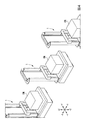
図1に示すように、フォークリフト1は、車体11と、フォーク12と、マスト13と、第一スライド機構14と、走行機構15と、を備える。
例えば、車体11の上面に、マスト13と、第一スライド機構14と、の各構成が設けられている。
As shown in FIG. 1, the forklift 1 includes a
For example, each configuration of the
フォークリフト1は、バッテリ30と、第一駆動部31と、昇降駆動部32と、車輪駆動部33と、ステアリング駆動部34と、をさらに備えてもよい。
The forklift 1 may further include a
フォーク12は、基端121と、先端122と、を有する。
基端121は、車体11の上下方向に延びていてもよい。
先端122は、ある軸(第一軸)の一の方向に延びている。
例えば、フォーク12は、第一方向D1に、基端121から先端122に向かって延びている。
例えば、フォーク12は、第一方向D1が車体11の前後方向となるように、マスト13を介して車体11に設けられてもよい。
フォーク12の先端122は、車体11の前方向を向いてもよい。
フォーク12は、平坦な上面123を有してもよい。
The
The
The
For example, the
For example, the
The
The
なお、以下、車体11の前後方向をX方向、車体11の幅方向をY方向、車体11の上下方向をZ方向ともいう。
特に、車体11の前方向を+X方向、車体11の後方向を−X方向ともいう。
また、車体11の左方向を+Y方向、車体11の右方向を−Y方向ともいう。
また、車体11の上方向を+Z方向、車体11の下方向を−Z方向ともいう。
また、第一方向D1と交差する方向を第二方向D2という。
例えば、第二方向D2は、車体11の上下方向であってもよい。
Hereinafter, the front-rear direction of the
In particular, the front direction of the
Further, the left direction of the
Further, the upward direction of the
The direction intersecting the first direction D1 is referred to as the second direction D2.
For example, the second direction D2 may be the vertical direction of the
マスト13は、第一軸と交差する軸である第二軸に沿って延在し、フォーク12を第二軸に沿ってスライドするように、フォーク12の基端を保持する。
例えば、マスト13は、第二方向D2に延びている。
例えば、マスト13は、車体11から鉛直上方向に向かって立ち上がるように設けられる。
例えば、マスト13は、フォーク12を第二方向D2にスライド可能に、フォーク12の基端121を保持する。
例えば、マスト13は、フォーク12を昇降可能に、フォーク12の基端121を保持する。
例えば、フォークリフト1は昇降スライド機構21をさらに備えてもよい。その際、マスト13は、昇降スライド機構21を介して、フォーク12を昇降可能に、フォーク12の基端121を保持する。
The
For example, the
For example, the
For example, the
For example, the
For example, the forklift 1 may further include an elevating
第一スライド機構14は、車体11から先端122が突出するように、マスト13を第一軸に沿ってスライドさせる。
例えば、第一スライド機構14は、マスト13を車体11に対し第一方向D1に移動可能に保持する。
例えば、第一スライド機構14は、車体11からフォーク12の先端122を突出させるようにマスト13を第一方向D1にスライド可能に保持する。
例えば、第一スライド機構14は、第一方向D1に延びるレール141を有する。マスト13の下端がレール141に嵌め込まれることにより、マスト13は、第二方向D2に延びる姿勢を維持しながら、第一方向D1に移動可能となっている。
例えば、レール141は、水平方向に延びており、マスト13は、水平方向に移動可能となっていてもよい。
The
For example, the
For example, the
For example, the
For example, the
走行機構15は、左前輪151と、右前輪152と、後輪153と、車軸154と、を備える。
車体11に対し、左前部に左前輪151、左前部に右前輪152、後部に後輪153がそれぞれ設けられている。
左前輪151、右前輪152、及び後輪153は、車体11に回転可能に支持されている。
左前輪151、右前輪152、及び後輪153の各外周面の一部は、車体11の下面から突出している。
車軸154は、車体11の左右に延びる軸である。
左前輪151及び右前輪152は、車軸154を介して、車体11に回転可能に支持されている。
例えば、車体11に回転可能に支持されている車軸154の左端に左前輪151、右端に右前輪152がそれぞれ固定されてもよい。
これにより、車体11は、左前輪151、右前輪152、及び後輪153を介して床の上を走行可能に構成されている。
The traveling
With respect to the
The left
A part of the outer peripheral surfaces of the left
The
The left
For example, the left
As a result, the
バッテリ30は、第一駆動部31と、昇降駆動部32と、車輪駆動部33と、ステアリング駆動部34と、の各駆動部に電力を供給する。
例えば、バッテリ30は、車体11内部に設けられてもよい。
The
For example, the
第一駆動部31は、第一スライド機構14を駆動する。
第一スライド機構14は、第一駆動部31から受ける駆動力により、マスト13を第一方向D1にスライドさせることができる。
例えば、第一駆動部31は、回転モータ、リニアモータ等のモータを含む。
例えば、第一駆動部31は、車体11内部に設けられてもよい。
The
The
For example, the
For example, the
昇降駆動部32は、昇降スライド機構21を駆動する。
昇降スライド機構21は、昇降駆動部32から受ける駆動力により、フォーク12を第二方向D2にスライドさせることができる。
例えば、昇降駆動部32は、回転モータ、リニアモータ等のモータを含む。
例えば、昇降駆動部32は、車体11内部に設けられてもよい。
The elevating
The elevating
For example, the elevating
For example, the elevating
車輪駆動部33は、走行機構15を駆動する。
走行機構15は、車輪駆動部33から受ける駆動力により、車体11を走行させることができる。
例えば、車輪駆動部33は、回転モータ、リニアモータ等のモータを含んでもよいし、エンジンを含んでもよい。
例えば、車輪駆動部33は、車軸154を軸周りに回転駆動し、左前輪151及び右前輪152を回転させてもよい。
例えば、車輪駆動部33は、車体11内部に設けられてもよい。
The
The traveling
For example, the
For example, the
For example, the
ステアリング駆動部34は、走行機構15の進行方向を変更させる。
走行機構15は、ステアリング駆動部34から受ける駆動力により、車体11の進行方向を左右に変更させることができる。
例えば、ステアリング駆動部34は、回転モータ、リニアモータ等のモータを含んでもよいし、エンジンを含んでもよい。
ステアリング駆動部34は、左前輪151及び右前輪152の回転軸を左右に旋回させることができる。
例えば、ステアリング駆動部34は、車軸154を左右に旋回させてもよい。
例えば、ステアリング駆動部34は、車体11内部に設けられてもよい。
The
The traveling
For example, the
The
For example, the
For example, the
(動作)
フォークリフト1が、荷物としてコンテナCNを載置する際の動作を説明する。
図2に示すように、第一スライド機構14によりマスト13が+X方向にスライドされると、フォーク12も+X方向にスライドされる。このため、車体11の前面からフォーク12の先端122が突出される。
車体11の前面からフォーク12の先端122が突出された後、又は突出されている最中に、昇降スライド機構21を介して、フォーク12は昇降されてもよい。
(motion)
The operation when the forklift 1 places the container CN as luggage will be described.
As shown in FIG. 2, when the
The
図3に示すように、例えば、マスト13が+X方向にスライドされることにより、トラックTRに載置されているコンテナCNに向かってフォーク12の先端122が突出され、コンテナCNが載っているパレットPLの底にフォーク12が挿入される。
その後、パレットPLの底に挿入されたフォーク12を上昇させ、フォーク12の上面123でパレットPLを持ち上げることにより、フォークリフト1は、コンテナCNを持ち上げることできる。
その後、マスト13が−X方向にスライドされることにより、フォークリフト1は、コンテナCNを車体11上方へ収容し、走行できる。
また、逆に、マスト13が+X方向にスライドされることによりフォーク12の先端122が突出され、フォーク12が下降されることにより、フォークリフト1は、トラックTRの荷台、倉庫の床等にコンテナCNを積み下ろすことできる。
As shown in FIG. 3, for example, when the
After that, the fork lift 1 can lift the container CN by raising the
After that, by sliding the
On the contrary, when the
コンテナCNを載せたフォークリフト1は、例えば倉庫内の通路を走行することができる。
例えば、複数のフォークリフト1は、倉庫内の通路を縦列走行してもよい。
例えば、図4に示すように、少なくとも3台のフォークリフト1が、倉庫内の通路を縦列走行してもよい。
The forklift 1 on which the container CN is mounted can run, for example, in a passage in a warehouse.
For example, the plurality of forklifts 1 may travel in tandem in the aisles in the warehouse.
For example, as shown in FIG. 4, at least three forklifts 1 may run in tandem in the aisles in the warehouse.
(作用及び効果)
本実施形態によれば、フォーク12の基端を保持するマスト13が第一方向D1にスライドされることにより、車体11に対しフォーク12の先端122を突出させることができる。
このため、フォークリフト1は、コンテナCNに向かってフォーク12の先端122を突出させて、フォーク12の先端122にコンテナCNを載せた時でも、マスト13に保持されるフォーク12の基端121に発生するモーメントを抑制することができる。
したがって、機械強度が不足しにくい。
(Action and effect)
According to the present embodiment, the
Therefore, the forklift 1 is generated at the
Therefore, the mechanical strength is unlikely to be insufficient.
また、実施形態によれば、車体11の上部に第一スライド機構14が設けられ、マスト13が車体上部を前後に移動できるように、フォークリフト1が構成されている。
フォークリフト1が旋回する場合、コンテナCNのサイズと車体11のサイズとを合わせたサイズ分の通路幅が必要である。
これに対し、本実施形態では、フォークリフト1は、コンテナCNを載せた後(荷取り後)、コンテナCN搬送時にマスト13を適切な位置まで後退させ、コンテナCNを収容することで、フォークリフト1の旋回中心と、コンテナCNの中心が近くなる。
このため、フォークリフト1は、旋回半径を小さくすることができる。同時に、コンテナCNの重心が車体11の中心に近くなる。
したがって、フォークリフト1は、走行時に安定な姿勢を取ることができる。
Further, according to the embodiment, the
When the forklift 1 turns, a passage width corresponding to the size of the container CN and the size of the
On the other hand, in the present embodiment, the forklift 1 is a forklift 1 by loading the container CN (after unloading), retracting the
Therefore, the forklift 1 can reduce the turning radius. At the same time, the center of gravity of the container CN becomes closer to the center of the
Therefore, the forklift 1 can take a stable posture during traveling.
<第二実施形態>
第二実施形態に係るフォークリフトについて図5〜図8を参照しながら説明する。
第二実施形態において、フォークリフト1は、第一実施形態に示した機能に加えて、加速度情報に関連して、マスト13の第一方向D1のスライドを制御する機能を有する。
なお、第二実施形態のフォークリフト1が備える各構成要素は、特に言及する場合を除き、第一実施形態と同様に構成され、同様に機能するので、重複する説明については省略する。
<Second embodiment>
The forklift according to the second embodiment will be described with reference to FIGS. 5 to 8.
In the second embodiment, the forklift 1 has a function of controlling the slide of the
Unless otherwise specified, each component of the forklift 1 of the second embodiment is configured in the same manner as that of the first embodiment and functions in the same manner. Therefore, duplicate description will be omitted.
(構成)
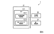
図5に示すように、本実施形態において、フォークリフト1は、第一制御部41をさらに備える。
例えば、フォークリフト1は、加速度センサ50をさらに備えてもよい。
(Constitution)
As shown in FIG. 5, in the present embodiment, the forklift 1 further includes a
For example, the forklift 1 may further include an
図6に示すように、第一制御部41は、CPU(Central Processing Unit)411を備える。
例えば、CPU411は、加速度情報取得部4111と、第一スライド制御部4112と、を機能的に備えてもよい。
As shown in FIG. 6, the
For example, the
加速度情報取得部4111は、フォークリフト1の加速度に関連する加速度情報を取得する。
例えば、加速度情報取得部4111は、フォークリフト1の加速度に関連する加速度情報として、加速度センサ50で検出された車体11の加速度を取得する。
加速度センサ50は、車体11に固定され、フォークリフト1の加速度として、車体11の加速度を検出し、検出した加速度を加速度情報取得部4111に出力する。
The acceleration
For example, the acceleration
The
第一スライド制御部4112(制御部)は、加速度情報を基に、マスト13の第一軸上でスライドする量を制御する。
車体11の加速時には、第一スライド制御部4112は、第一軸に沿ってマスト13の位置をずらすように構成されている。
車体11の減速時には、第一スライド制御部4112は、進行方向と反対方向に向かって、第一軸に沿ってマスト13の位置をずらすように構成されている。
例えば、第一スライド制御部4112は、取得した加速度情報に関連して、マスト13の第一方向D1のスライドを制御する。
例えば、第一スライド制御部4112は、取得した加速度情報に関連して第一駆動部31の駆動の制御を行うことによって、スライド量SLを制御してもよい。
例えば、車体11の加速時には、第一スライド制御部4112は、進行方向に向かって、第一方向D1にマスト13の位置をずらすように構成されている。
例えば、車体11の減速時には、第一スライド制御部4112が、進行方向と反対方向に向かって、第一方向D1にマスト13の位置をずらすように構成されている。
The first slide control unit 4112 (control unit) controls the amount of sliding on the first axis of the
When accelerating the
When the
For example, the first slide control unit 4112 controls the slide of the
For example, the first slide control unit 4112 may control the slide amount SL by controlling the drive of the
For example, when accelerating the
For example, when the
(動作)
図7に示すように、フォークリフト1の加速時には、第一スライド制御部4112は、フォークリフト1の進行方向に向かって、第一方向D1にマスト13の位置をずらす。
例えば、フォークリフト1が+X方向に対し加速するとする。すなわち、フォークリフト1の加速度Axは、+X方向に対しAx>0であるとする。
この場合、第一スライド制御部4112は、フォークリフト1の加速度Axに関連してスライド量SLを算出する。
第一スライド制御部4112は、算出したスライド量SLだけ、マスト13を、初期位置(加速度Ax=0時の位置)から+X方向にずらす。
例えば、第一スライド制御部4112は、加速度Axの大きさ(絶対値)ほど、スライド量SLが大きくなるように、スライド量SLを算出してもよい。
これにより、フォークリフト1は、初期位置(加速度Ax=0時の位置)における重心CGの位置を、+X方向にずらすことができる。
(motion)
As shown in FIG. 7, when the forklift 1 is accelerated, the first slide control unit 4112 shifts the position of the
For example, assume that the forklift 1 accelerates in the + X direction. That is, it is assumed that the acceleration Ax of the forklift 1 is Ax> 0 in the + X direction.
In this case, the first slide control unit 4112 calculates the slide amount SL in relation to the acceleration Ax of the forklift 1.
The first slide control unit 4112 shifts the
For example, the first slide control unit 4112 may calculate the slide amount SL so that the slide amount SL becomes larger as the acceleration Ax is larger (absolute value).
As a result, the forklift 1 can shift the position of the center of gravity CG at the initial position (position at acceleration Ax = 0) in the + X direction.
図8に示すように、フォークリフト1の減速時には、第一スライド制御部4112は、フォークリフト1の進行方向と反対方向に向かって、第一方向D1にマスト13の位置をずらす。
例えば、加速度Axの大きさ(絶対値)が大きいほどスライド量SLが大きくなるように、スライド量SLを算出してもよい。
例えば、フォークリフト1が+X方向に対し減速するとする。すなわち、フォークリフト1の加速度Axは、+X方向に対しAx<0であるとする。
この場合、第一スライド制御部4112は、フォークリフト1の加速度Axに関連してスライド量SLを算出する。
第一スライド制御部4112は、算出したスライド量SLだけ、マスト13を、初期位置(加速度Ax=0時の位置)から−X方向にずらす。
例えば、第一スライド制御部4112は、加速度Axの大きさ(絶対値)ほど、スライド量SLが大きくなるように、スライド量SLを算出してもよい。
これにより、フォークリフト1は、初期位置(加速度Ax=0時の位置)における重心CGの位置を、−X方向にずらすことができる。
As shown in FIG. 8, when the forklift 1 is decelerated, the first slide control unit 4112 shifts the position of the
For example, the slide amount SL may be calculated so that the slide amount SL increases as the magnitude (absolute value) of the acceleration Ax increases.
For example, assume that the forklift 1 decelerates in the + X direction. That is, it is assumed that the acceleration Ax of the forklift 1 is Ax <0 in the + X direction.
In this case, the first slide control unit 4112 calculates the slide amount SL in relation to the acceleration Ax of the forklift 1.
The first slide control unit 4112 shifts the
For example, the first slide control unit 4112 may calculate the slide amount SL so that the slide amount SL becomes larger as the acceleration Ax is larger (absolute value).
As a result, the forklift 1 can shift the position of the center of gravity CG at the initial position (position at acceleration Ax = 0) in the −X direction.
(作用及び効果)
本実施形態によれば、フォークリフト1は、加速度Axに関連してマスト13のスライドを制御できる。
このため、フォークリフト1は、加減速時にフォークリフト1が倒れにくいようにマスト13の第一方向D1の位置を制御することができる。
(Action and effect)
According to this embodiment, the forklift 1 can control the slide of the
Therefore, the forklift 1 can control the position of the
例えば、フォークリフト1は、加速時にフォークリフト1の重心を進行方向にずらすことができる。
このため、フォークリフト1は、加速時における進行方向と反対側への倒れを抑制することができる。
例えば、フォークリフト1は、減速時にフォークリフト1の重心を進行方向と反対側にずらすことができる。
このため、フォークリフト1は、減速時における進行方向への倒れを抑制することができる。
For example, the forklift 1 can shift the center of gravity of the forklift 1 in the traveling direction during acceleration.
Therefore, the forklift 1 can suppress the forklift 1 from falling in the direction opposite to the traveling direction during acceleration.
For example, the forklift 1 can shift the center of gravity of the forklift 1 to the side opposite to the traveling direction during deceleration.
Therefore, the forklift 1 can suppress the forklift 1 from falling in the traveling direction during deceleration.
一般にフォークリフトは、加速時は後方に倒れやすく、減速時は後方に倒れやすい。
これに対し、本実施形態では、上述のとおり、フォークリフト1は、加速度Axに関連してマスト13のスライドを制御できるため、フォークリフト1は、加速時はマスト13を前方寄りに、減速時はマスト13を後方寄りにずらすことができる。
In general, forklifts tend to fall backwards when accelerating and fall backwards when decelerating.
On the other hand, in the present embodiment, as described above, since the forklift 1 can control the slide of the
本実施形態のフォークリフト1は、コンテナCNの重量によって、マスト13のスライド量SLをさらに変えてもよい。
例えば、フォークリフト1は、フォーク12の先端122の上面に設けられた荷重センサ、マスト13に設けられた荷重センサ等が検出する各荷重を取得し、コンテナCNの重量に関連する情報を取得し、コンテナCNの重量によってマストのスライド量SLを変えてもよい。
In the forklift 1 of the present embodiment, the slide amount SL of the
For example, the forklift 1 acquires each load detected by a load sensor provided on the upper surface of the
本実施形態のフォークリフト1は、フォークリフト1の加速度に関連する加速度情報を取得するものであれば、どのような加速度情報を取得するものであってもよい。
例えば、フォークリフト1は、加速度情報として、単に加速か、減速か、を取得してもよい。
この場合、フォークリフト1は、マスト13のスライド制御として、加速時は、進行方向に向かってマスト13をスライドさせ、減速時は、進行方向と反対方向に向かってマスト13をスライドさせる制御を行ってもよい。
例えば、フォークリフト1は、予め決められた各スライド量で、マスト13をスライドさせる制御を行ってもよい。
例えば、フォークリフト1は、加速時は、マスト13を前方寄りに、減速時は、マスト13を後方寄りにずらすように、マスト13をスライドさせる制御を行ってもよい。
The forklift 1 of the present embodiment may acquire any acceleration information as long as it acquires acceleration information related to the acceleration of the forklift 1.
For example, the forklift 1 may simply acquire acceleration or deceleration as acceleration information.
In this case, the forklift 1 controls the slide of the
For example, the forklift 1 may control the
For example, the forklift 1 may control the
<第三実施形態>
第三実施形態に係るフォークリフトについて図9〜図11を参照しながら説明する。
第三実施形態において、フォークリフト1は、第一実施形態に示した機能に加えて、フォーク12の突出に合わせて、アウトリガーを突出させる機能を有する。
なお、第三実施形態のフォークリフト1が備える各構成要素は、特に言及する場合を除き、第一実施形態と同様に構成され、同様に機能するので、重複する説明については省略する。
<Third Embodiment>
The forklift according to the third embodiment will be described with reference to FIGS. 9 to 11.
In the third embodiment, the forklift 1 has a function of projecting outriggers in accordance with the protrusion of the
Unless otherwise specified, each component of the forklift 1 of the third embodiment is configured in the same manner as that of the first embodiment and functions in the same manner. Therefore, duplicate description will be omitted.
(構成)
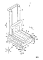
図9に示すように、本実施形態において、フォークリフト1は、アウトリガー60と、第二スライド機構61と、をさらに備える。
(Constitution)
As shown in FIG. 9, in the present embodiment, the forklift 1 further includes an
アウトリガー60は、第一軸の一の方向に延びている。
例えば、アウトリガー60は、第一方向D1に、基端601から先端602に向かって延びている。
例えば、アウトリガー60は、水平方向に延びていてもよい。
例えば、アウトリガー60の先端602は、車体11の前方向を向いてもよい。
アウトリガー60は、先端602において、下方向に向かって突出する接地部603を有する。
これにより、アウトリガー60は、車体11を支えることができる。
The
For example, the
For example, the
For example, the
The
As a result, the
フォークリフト1は、アウトリガー60を複数備えてもよい。
例えば、フォークリフト1は、複数のアウトリガー60として、左アウトリガー605と、右アウトリガー606と、を備えてもよい。
左アウトリガー605は、第二スライド機構61を介して、車体11の左側に設けられる。
右アウトリガー606は、第二スライド機構61を介して、車体11の右側に設けられる。
The forklift 1 may include a plurality of
For example, the forklift 1 may include a
The
The right outrigger 606 is provided on the right side of the
第二スライド機構61は、車体11に対し、アウトリガー60を第一方向D1にスライド可能に、アウトリガー60の基端601を保持する。
第二スライド機構61は、アウトリガー60に沿って第一方向D1に延びている。
フォークリフト1は、第二スライド機構61を複数備えてもよい。
例えば、フォークリフト1は、複数の第二スライド機構61として、左第二スライド機構611と、右第二スライド機構612と、を備えてもよい。
左第二スライド機構611は、車体11の左側面に設けられている。左第二スライド機構611は、左アウトリガー605を第一方向D1にスライド可能に保持する。
右第二スライド機構612は、車体11の右側面に設けられている。右第二スライド機構612は、右アウトリガー606を第一方向D1にスライド可能に保持する。
The
The
The forklift 1 may include a plurality of
For example, the forklift 1 may include a left
The left
The right
例えば、アウトリガー60は、機構的にマスト13と連結させることにより、マスト13のスライドに連動して、第一方向D1にスライドしてもよい。
その際、アウトリガー60は、機構的にマスト13と連結されていれば、どのように連結されてもよい。
例えば、アウトリガー60は、マスト13に直接固定又はリンク機構を介して固定され一体化されることにより、マスト13のスライドに連動して、マスト13が動く方向に動くように、第一方向D1にスライドしてもよい。この場合、第二スライド機構61がなくてもアウトリガー60が第一方向D1にスライド可能であれば、フォークリフト1は、第二スライド機構61を備えなくてもよい。
例えば、アウトリガー60は、ギアやプーリー等を介して、マスト13と機構的に連結されることにより、マスト13が動く方向に動くように、第一方向D1にスライドしてもよい。
For example, the
At that time, the
For example, the
For example, the
例えば、アウトリガー60は、電気制御されることにより、マスト13のスライドに連動して、マスト13が動く方向に動くように、第一方向D1にスライドしてもよい。
例えば、図10に示すように、フォークリフト1は、第二駆動部62と、第二制御部42をさらに備えてもよい。
例えば、第二駆動部62及び第二制御部42は、車体11内部に設けられてもよい。
For example, the
For example, as shown in FIG. 10, the forklift 1 may further include a
For example, the
第二駆動部62は、第二スライド機構61を駆動する。
バッテリ30は、第二駆動部62に電力を供給する。
例えば、第二駆動部62は、回転モータ、リニアモータ等のモータを含む。
第二スライド機構61は、第二駆動部62から受ける駆動力により、アウトリガー60を第一方向D1にスライドさせることができる。
The
The
For example, the
The
第二制御部42は、CPU421を備える。
CPU421は、第二スライド制御部4211を機能的に備える。
第二スライド制御部4211(制御部)は、車体11からフォーク12を突出させるときに、車体11からアウトリガー60を突出させる。
例えば、第二スライド制御部4211は、フォークリフト1がフォーク12を車体11の前部から突出させるのに合わせて、車体11の前部からアウトリガー60を突出させるように、第二スライド機構61を制御する。
例えば、第二スライド制御部4211は、第一駆動部31の制御に合わせて、第二駆動部62の駆動の制御を行うことによって、車体11の前部からアウトリガー60を突出させてもよい。
The
The
The second slide control unit 4211 (control unit) projects the
For example, the second
For example, the second
(動作)
図11に示すように、アウトリガー60は、マスト13のスライドに連動して、第一方向D1にスライドする。
これにより、フォークリフト1は、車体11からフォーク12を突出させるのに合わせて、車体11からアウトリガー60を突出させる。
(motion)
As shown in FIG. 11, the
As a result, the forklift 1 projects the
(作用及び効果)
本実施形態によれば、フォーク12を突出させた時、アウトリガー60は、車体11を支えることができる。
このため、フォークリフト1は、フォーク12が突出される方向への倒れを抑制することができる。
(Action and effect)
According to the present embodiment, the
Therefore, the forklift 1 can suppress the
<第四実施形態>
第四実施形態に係るフォークリフトについて図12〜図16を参照しながら説明する。
第四実施形態において、フォークリフト1は、第一実施形態に示した機能に加えて、フォーク12の突出に合わせて、カウンタウェイトを突出させる機能を有する。
なお、第四実施形態のフォークリフト1が備える各構成要素は、特に言及する場合を除き、第一実施形態と同様に構成され、同様に機能するので、重複する説明については省略する。
<Fourth Embodiment>
The forklift according to the fourth embodiment will be described with reference to FIGS. 12 to 16.
In the fourth embodiment, the forklift 1 has a function of projecting the counterweight in accordance with the protrusion of the
Unless otherwise specified, each component of the forklift 1 of the fourth embodiment is configured in the same manner as that of the first embodiment and functions in the same manner. Therefore, duplicate description will be omitted.
(構成)
図12に示すように、本実施形態において、フォークリフト1は、カウンタウェイト70と、第三スライド機構71と、をさらに備える。
(Constitution)
As shown in FIG. 12, in the present embodiment, the forklift 1 further includes a
カウンタウェイト70は、第一方向D1に、基端701から先端702に向かって延びている。
カウンタウェイト70の先端702は、第一方向D1に関し、フォーク12の先端702と逆方向を向いている。
例えば、カウンタウェイト70の先端702は、車体11の後方向を向いている。
The
The
For example, the
カウンタウェイト70は、先端702にウェイト部703を有する。
ウェイト部703は、フォークリフト1の転倒を抑制するための、車体11、各駆動部、コンテナCN等に対抗可能な重量を有する。
これにより、カウンタウェイト70は、フォークリフト1の重心を第一方向D1にずらすことができる。
The
The
As a result, the
第三スライド機構71は、車体11に対し、カウンタウェイト70を第一軸に沿ってスライドさせる。
例えば、第三スライド機構71は、車体11に対し、第一方向D1にスライド可能に、カウンタウェイト70の基端701を保持する。
例えば、第三スライド機構71は、カウンタウェイト70に沿って第一方向D1に延びている。
The
For example, the
For example, the
例えば、カウンタウェイト70は、マスト13と機構的に連結されることにより、マスト13のスライドに連動して、第一方向D1にスライドしてもよい。
その際、カウンタウェイト70は、マスト13と機構的に連結されるものであれば、どのように連結されてもよい。
例えば、カウンタウェイト70は、ギアやプーリー等を介して、マスト13と機構的に連結されることにより、マスト13が動く方向と逆方向に動くように、第一方向D1にスライドしてもよい。
For example, the
At that time, the
For example, the
例えば、カウンタウェイト70は、電気制御されることにより、マスト13のスライドに連動して、マスト13が動く方向と逆方向に動くように、第一方向D1にスライドしてもよい。
例えば、図13に示すように、フォークリフト1は、第三駆動部72と、第三制御部43をさらに備えてもよい。
例えば、第三駆動部72及び第三制御部43は、車体11内部に設けられてもよい。
For example, the
For example, as shown in FIG. 13, the forklift 1 may further include a
For example, the
第三駆動部72は、第三スライド機構71を駆動する。
バッテリ30は、第三駆動部72に電力を供給する。
第三スライド機構71は、第三駆動部72から受ける駆動力により、カウンタウェイト70を第一方向D1にスライドさせることができる。
例えば、第三駆動部72は、回転モータ、リニアモータ等のモータを含む。
The
The
The
For example, the
第三制御部43は、CPU431を備える。
CPU431は、第三スライド制御部4311を機能的に備える。
第三スライド制御部4311は、第三スライド機構71が、フォークリフト1がフォーク12を車体11の前部から突出させるのに合わせて、車体11の後部からカウンタウェイト70を突出させるように、第三スライド機構71を制御する。
例えば、第三スライド制御部4311は、第一駆動部31の制御に合わせて、第三駆動部72の駆動の制御を行うことによって、車体11の後部からカウンタウェイト70を突出させてもよい。
The
The
The third
For example, the third
(動作)
図14及び図15に示すように、カウンタウェイト70は、マスト13のスライドに連動して、第一方向D1にスライドする。
これにより、フォークリフト1は、車体11の前部からフォーク12を突出させるのに合わせて、車体11の後部からカウンタウェイト70を突出させる。
(motion)
As shown in FIGS. 14 and 15, the
As a result, the forklift 1 projects the
(作用及び効果)
本実施形態によれば、フォークリフト1は、フォーク12を突出させた時、重心をフォーク12が突出される方向と反対側にずらすことができる。
すなわち、フォークリフト1は、マスト13が前方に出ると、カウンタウェイト70が後方に張り出すように構成されている。
例えば、フォークリフト1は、重心CGの第一方向D1の位置である重心位置がフォークリフト1の中心近傍から変動しにくくなるように、マスト13の第一方向D1へのスライドに関連して、カウンタウェイト70の第一方向D1へのスライドを制御できる。
このため、フォークリフト1は、フォーク12が突出される方向への倒れを抑制することができる。
(Action and effect)
According to the present embodiment, when the
That is, the forklift 1 is configured such that when the
For example, the forklift 1 has a counterweight related to the slide of the
Therefore, the forklift 1 can suppress the
なお、本実施形態のフォークリフト1は、コンテナCNの重量によって、カウンタウェイト70のスライド量を変えてもよい。
例えば、フォークリフト1は、フォーク12の先端122の上面に設けられた荷重センサ、マスト13に設けられた荷重センサ等が検出する各荷重を取得し、コンテナCNの重量に関連する情報を取得し、コンテナCNの重量によってカウンタウェイト70のスライド量を変えてもよい。
例えば、図16に示すように、CPU431は、重心情報取得部4312を機能的にさらに備えてもよい。
重心情報取得部4312は、取得した各荷重に基づき、持ち上げる又は収容するコンテナCNを含む現在のフォークリフト1の重心位置を算出し、第三スライド制御部4311に出力する。
第三スライド制御部4311は、重心情報取得部4312から出力された重心位置を取得する。
第三スライド制御部4311は、算出された重心位置を維持するように、カウンタウェイト70の第一軸に沿うスライド量を調整する。
例えば、第三スライド制御部4311は、フィードバック制御により、フォークリフト1がコンテナCNを持ち上げる又は収容する前後にわたって、取得した重心位置を維持するように、カウンタウェイト70の第一方向D1のスライド量を調整する。
In the forklift 1 of the present embodiment, the slide amount of the
For example, the forklift 1 acquires each load detected by a load sensor provided on the upper surface of the
For example, as shown in FIG. 16, the
The center of gravity
The third
The third
For example, the third
これにより、フォークリフト1は、コンテナCNを含むフォークリフト1の重心位置を維持できる。このため、フォークリフト1は、第一方向D1への倒れを抑制することができる。 As a result, the forklift 1 can maintain the position of the center of gravity of the forklift 1 including the container CN. Therefore, the forklift 1 can suppress the forklift 1 from falling in the first direction D1.
<変形例>
上述の各実施形態において、フォークリフト1が備える各構成は、組み合わせられてもよい。
変形例として、フォークリフト1に、アウトリガー60と、カウンタウェイトとが、一緒に設けられてもよい。
他の変形例として、フォークリフト1に、第一制御部41、第二制御部42、及び第三制御部43の各制御部のうち、複数の制御部が一緒に設けられてもよい。
その際、各制御部は、統合されて一つの制御部やCPUで構成されてもよい。
<Modification example>
In each of the above-described embodiments, the configurations included in the forklift 1 may be combined.
As a modification, the forklift 1 may be provided with an
As another modification, the forklift 1 may be provided with a plurality of control units among the control units of the
At that time, each control unit may be integrated and composed of one control unit or a CPU.
上述の第二実施形態では、フォークリフト1は、検出した加速度Axに関連してマスト13の第一方向D1の位置を制御している。
変形例として、フォークリフト1は、予め走行経路に関連して、加速度Axを記憶しておき、記憶した加速度Axに関連して、マスト13の第一方向D1の位置を制御してもよい。
In the second embodiment described above, the forklift 1 controls the position of the
As a modification, the forklift 1 may store the acceleration Ax in advance in relation to the traveling path, and control the position of the
上述の第二実施形態では、フォークリフト1は、加速度Axに関連してマスト13の第一方向D1の位置を制御している。
変形例として、上述の第二実施形態のフォークリフト1にカウンタウェイト70がさらに設けられ、フォークリフト1は、加速度Axに関連して、マスト13の第一方向D1の位置に加えて、カウンタウェイト70の第一方向D1の位置を制御してもよい。
In the second embodiment described above, the forklift 1 controls the position of the
As a modification, a
上述の各実施形態では、フォークリフト1には、車輪として、左前輪151、右前輪152、及び後輪153と、の3輪の車輪が設けられている。
変形例として、後輪が左右に設けられ、フォークリフト1に、車輪として、4輪の車輪が設けられてもよいし、5輪以上の車輪が設けられてもよい。
In each of the above-described embodiments, the forklift 1 is provided with three wheels, a left
As a modification, rear wheels may be provided on the left and right, and the forklift 1 may be provided with four wheels as wheels, or may be provided with five or more wheels.
以上、本発明のいくつかの実施形態を説明したが、これらの実施形態は、例として提示したものであり、発明の範囲を限定することは意図していない。これら実施形態は、その他の様々な形態で実施されることが可能であり、発明の要旨を逸脱しない範囲で種々の省略、置き換え、変更を行うことができる。これら実施形態やその変形は、発明の範囲や要旨に含まれると同様に、特許請求の範囲に記載された発明とその均等の範囲に含まれるものとする。 Although some embodiments of the present invention have been described above, these embodiments are presented as examples and are not intended to limit the scope of the invention. These embodiments can be implemented in various other forms, and various omissions, replacements, and changes can be made without departing from the gist of the invention. These embodiments and modifications thereof shall be included in the scope of the invention described in the claims and the equivalent scope thereof, as well as in the scope and gist of the invention.
1 フォークリフト
11 車体
12 フォーク
13 マスト
14 第一スライド機構
15 走行機構
21 昇降スライド機構
30 バッテリ
31 第一駆動部
32 昇降駆動部
33 車輪駆動部
34 ステアリング駆動部
41 第一制御部
42 第二制御部
43 第三制御部
50 加速度センサ
60 アウトリガー
61 第二スライド機構
62 第二駆動部
70 カウンタウェイト
71 第三スライド機構
72 第三駆動部
121 基端
122 先端
123 上面
141 レール
151 左前輪
152 右前輪
153 後輪
154 車軸
601 基端
602 先端
603 接地部
605 左アウトリガー
606 右アウトリガー
611 左第二スライド機構
612 右第二スライド機構
701 基端
702 先端
703 ウェイト部
4111 加速度情報取得部
4112 第一スライド制御部
4211 第二スライド制御部
4311 第三スライド制御部
4312 重心情報取得部
Ax 加速度
CG 重心
CN コンテナ
D1 第一方向
D2 第二方向
PL パレット
SL スライド量
TR トラック
1
Claims (7)
先端が第一軸の一の方向に延びているフォークと、
前記第一軸と交差する第二軸に沿って延在し、前記フォークを前記第二軸に沿ってスライドするように、前記フォークの基端を保持するマストと、
前記車体から前記先端が突出するように、前記マストを前記第一軸に沿ってスライドさせる第一スライド機構と、
を備えるフォークリフト。 With the car body
A fork whose tip extends in one direction of the first axis,
A mast that extends along a second axis that intersects the first axis and holds the base end of the fork so that it slides along the second axis.
A first slide mechanism that slides the mast along the first axis so that the tip protrudes from the vehicle body.
Forklift equipped with.
前記加速度情報を基に、前記マストの前記第一軸上でスライドする量を制御する制御部と、
をさらに備える請求項1に記載のフォークリフト。 An acceleration information acquisition unit that acquires acceleration information related to the acceleration of the forklift, and
A control unit that controls the amount of sliding of the mast on the first axis based on the acceleration information.
The forklift according to claim 1.
前記制御部は、前記車体から前記フォークを突出させるときに、前記車体から前記アウトリガーを突出させる請求項2から4のいずれか一項に記載のフォークリフト。 Further comprising an outrigger extending in the one direction of the first axis
The forklift according to any one of claims 2 to 4, wherein the control unit projects the outrigger from the vehicle body when the fork is projected from the vehicle body.
前記車体に対し、前記カウンタウェイトを前記第一軸に沿ってスライドさせる第三スライド機構と、を備え、
前記制御部は、前記車体から前記フォークを突出させるときに、前記カウンタウェイトを前記車体から前記フォークを突出させる方向と反対方向に突出させる請求項2から5のいずれか一項に記載のフォークリフト。 Counterweight and
A third slide mechanism for sliding the counterweight along the first axis with respect to the vehicle body is provided.
The forklift according to any one of claims 2 to 5, wherein the control unit projects the counterweight from the vehicle body in a direction opposite to the direction in which the fork is projected from the vehicle body.
荷物を含む前記フォークリフトの重心位置を算出し、
算出された前記重心位置を維持するように、前記カウンタウェイトの前記第一軸に沿うスライド量を調整する
請求項6に記載のフォークリフト。 The control unit
Calculate the position of the center of gravity of the forklift including luggage,
The forklift according to claim 6, wherein the slide amount of the counterweight along the first axis is adjusted so as to maintain the calculated position of the center of gravity.
Priority Applications (4)
| Application Number | Priority Date | Filing Date | Title |
|---|---|---|---|
| JP2019062550A JP7215948B2 (en) | 2019-03-28 | 2019-03-28 | forklift |
| US16/775,826 US11370643B2 (en) | 2019-03-28 | 2020-01-29 | Forklift |
| DE102020000820.8A DE102020000820A1 (en) | 2019-03-28 | 2020-02-07 | Forklift |
| CN202010082150.7A CN111747340B (en) | 2019-03-28 | 2020-02-07 | Forklift truck |
Applications Claiming Priority (1)
| Application Number | Priority Date | Filing Date | Title |
|---|---|---|---|
| JP2019062550A JP7215948B2 (en) | 2019-03-28 | 2019-03-28 | forklift |
Publications (2)
| Publication Number | Publication Date |
|---|---|
| JP2020158289A true JP2020158289A (en) | 2020-10-01 |
| JP7215948B2 JP7215948B2 (en) | 2023-01-31 |
Family
ID=72603946
Family Applications (1)
| Application Number | Title | Priority Date | Filing Date |
|---|---|---|---|
| JP2019062550A Active JP7215948B2 (en) | 2019-03-28 | 2019-03-28 | forklift |
Country Status (4)
| Country | Link |
|---|---|
| US (1) | US11370643B2 (en) |
| JP (1) | JP7215948B2 (en) |
| CN (1) | CN111747340B (en) |
| DE (1) | DE102020000820A1 (en) |
Families Citing this family (6)
| Publication number | Priority date | Publication date | Assignee | Title |
|---|---|---|---|---|
| JP7114536B2 (en) * | 2019-09-10 | 2022-08-08 | 株式会社東芝 | Conveyor |
| EP3957597B1 (en) * | 2020-08-21 | 2023-03-08 | Tata Consultancy Services Limited | Automated unit load lifter mountable on an autonomous mobile robot for carrying a unit load |
| JP7395444B2 (en) * | 2020-09-07 | 2023-12-11 | 株式会社東芝 | Conveying device, control method, and program |
| CN112456372A (en) * | 2020-11-18 | 2021-03-09 | 株洲市东亨科技有限责任公司 | Material lifting device for road construction |
| EP4206115A1 (en) | 2022-01-04 | 2023-07-05 | Tata Consultancy Services Limited | Autonomous mobile robot with an adjustable counterweight and a forklift device |
| CN115215269A (en) * | 2022-07-20 | 2022-10-21 | 江西省华贡电子商务有限责任公司 | Clamping type intelligent e-commerce storage vehicle |
Citations (6)
| Publication number | Priority date | Publication date | Assignee | Title |
|---|---|---|---|---|
| JPS5170813U (en) * | 1974-11-29 | 1976-06-04 | ||
| JPS5867894U (en) * | 1981-10-31 | 1983-05-09 | 包行 良人 | Transport vehicle |
| JPH0715692U (en) * | 1993-08-25 | 1995-03-17 | 空閑自動車株式会社 | Forklift truck |
| JP2001019378A (en) * | 1999-07-01 | 2001-01-23 | Mitsui Eng & Shipbuild Co Ltd | Side fork type unmanned carrying truck |
| JP2012086971A (en) * | 2010-10-21 | 2012-05-10 | Jtekt Corp | Steering gear for vehicle |
| US20180305124A1 (en) * | 2017-04-24 | 2018-10-25 | Ching Qing Guo | Automatic Batch Picking Robot |
Family Cites Families (20)
| Publication number | Priority date | Publication date | Assignee | Title |
|---|---|---|---|---|
| JPS5310833B2 (en) | 1972-05-10 | 1978-04-17 | ||
| US5480275A (en) * | 1993-10-18 | 1996-01-02 | Taylor Iron-Machine Works, Inc. | Fork lift truck |
| JP4178665B2 (en) | 1999-05-31 | 2008-11-12 | 株式会社豊田自動織機 | forklift |
| JP2002080195A (en) | 2000-07-03 | 2002-03-19 | Masamitsu Nakano | Small sized forklift coping with large load |
| US20050042068A1 (en) * | 2003-08-18 | 2005-02-24 | Ronald Ehmen | Forklift with stabilizing forks |
| JP2008254877A (en) | 2007-04-04 | 2008-10-23 | Socead Giken:Kk | Forklift |
| DE102009029467A1 (en) * | 2009-09-15 | 2011-03-24 | Robert Bosch Gmbh | Cargo vehicle with height-adjustable lifting device |
| IT1396035B1 (en) * | 2009-10-19 | 2012-11-09 | Boat Eagle S R L | LIFTING VEHICLE, IN PARTICULAR FOR THE STORAGE OF BOATS |
| DE102010023069A1 (en) * | 2010-06-08 | 2011-12-08 | Robert Bosch Gmbh | Method for determining a probability of tipping on an industrial truck |
| CN101955141B (en) * | 2010-09-08 | 2015-01-14 | 陕西国力信息技术有限公司 | Push type high-efficiency and energy-saving forklift lifting structure |
| CN203402893U (en) | 2013-06-25 | 2014-01-22 | 国家电网公司 | Portable transformer lifting machine |
| CN104709847B (en) * | 2015-03-04 | 2017-04-05 | 中国人民解放军总后勤部建筑工程研究所 | A kind of self-balancing type Multifunctional carrier |
| JP2017036102A (en) | 2015-08-06 | 2017-02-16 | 株式会社豊田自動織機 | Forklift work assisting system |
| US9890025B2 (en) * | 2015-11-24 | 2018-02-13 | Amazon Technologies, Inc. | Mechanical tipping assembly for mobile drive unit of inventory system |
| CN105883675A (en) * | 2016-06-16 | 2016-08-24 | 苏州先锋物流装备科技有限公司 | Hydraulic power-assisted steering reach forklift |
| CN207090925U (en) | 2017-09-01 | 2018-03-13 | 四川川龙拖拉机制造有限公司 | A kind of lifting device and cargo transparting device |
| US10654697B2 (en) * | 2017-12-01 | 2020-05-19 | Hand Held Products, Inc. | Gyroscopically stabilized vehicle system |
| SE543484C2 (en) * | 2018-03-06 | 2021-03-02 | Cargotec Patenter Ab | Cargo handling vehicle for navigation in narrow aisles and method therefore |
| CN208394718U (en) | 2018-07-06 | 2019-01-18 | 穆红军 | Door frame movable type four-wheel car fork truck |
| US11807508B2 (en) * | 2018-08-31 | 2023-11-07 | Hyster-Yale Group, Inc. | Dynamic stability determination system for lift trucks |
-
2019
- 2019-03-28 JP JP2019062550A patent/JP7215948B2/en active Active
-
2020
- 2020-01-29 US US16/775,826 patent/US11370643B2/en active Active
- 2020-02-07 CN CN202010082150.7A patent/CN111747340B/en active Active
- 2020-02-07 DE DE102020000820.8A patent/DE102020000820A1/en active Pending
Patent Citations (6)
| Publication number | Priority date | Publication date | Assignee | Title |
|---|---|---|---|---|
| JPS5170813U (en) * | 1974-11-29 | 1976-06-04 | ||
| JPS5867894U (en) * | 1981-10-31 | 1983-05-09 | 包行 良人 | Transport vehicle |
| JPH0715692U (en) * | 1993-08-25 | 1995-03-17 | 空閑自動車株式会社 | Forklift truck |
| JP2001019378A (en) * | 1999-07-01 | 2001-01-23 | Mitsui Eng & Shipbuild Co Ltd | Side fork type unmanned carrying truck |
| JP2012086971A (en) * | 2010-10-21 | 2012-05-10 | Jtekt Corp | Steering gear for vehicle |
| US20180305124A1 (en) * | 2017-04-24 | 2018-10-25 | Ching Qing Guo | Automatic Batch Picking Robot |
Also Published As
| Publication number | Publication date |
|---|---|
| US20200307974A1 (en) | 2020-10-01 |
| DE102020000820A1 (en) | 2020-10-01 |
| CN111747340B (en) | 2022-03-15 |
| CN111747340A (en) | 2020-10-09 |
| JP7215948B2 (en) | 2023-01-31 |
| US11370643B2 (en) | 2022-06-28 |
Similar Documents
| Publication | Publication Date | Title |
|---|---|---|
| JP7215948B2 (en) | forklift | |
| JP7141040B2 (en) | traveling robot | |
| WO2017008544A1 (en) | Light bidirectional stacking truck | |
| US20060245893A1 (en) | Industrial truck | |
| JP2014530796A (en) | lift device | |
| US3825130A (en) | Material handling system | |
| CN213265594U (en) | Movable portal forklift | |
| CN210133850U (en) | Semi-electric fork truck | |
| JP6162201B2 (en) | Fork cover | |
| CN114477028A (en) | Electric carrier with double-layer loading function | |
| KR101626934B1 (en) | Elevated-up/down type transporting cart | |
| WO2014128897A1 (en) | Low-floor cargo vehicle | |
| CN216472064U (en) | Fork truck structure with adjustable axle distance | |
| KR101738810B1 (en) | A convertible stacker to an order picker | |
| CN219009839U (en) | Omnidirectional forklift | |
| CN220787975U (en) | Multi-layer forklift robot | |
| JP2019131354A (en) | Automatic warehouse system | |
| CN216862557U (en) | Storage system for preventing AGV from inclining laterally | |
| KR102006394B1 (en) | Forklift device for truck and functional truck integrated with forklift device | |
| CN220745292U (en) | Pallet fork configuration equipment | |
| CN218665275U (en) | Small-size fork truck is with preventing empting chassis | |
| CN219949345U (en) | Lifting robot, combined robot and warehousing system | |
| JP5459732B2 (en) | Side forklift | |
| KR20170060256A (en) | Self-elevator lift | |
| JP2005239335A (en) | Conveying trolley |
Legal Events
| Date | Code | Title | Description |
|---|---|---|---|
| A621 | Written request for application examination |
Free format text: JAPANESE INTERMEDIATE CODE: A621 Effective date: 20211220 |
|
| A977 | Report on retrieval |
Free format text: JAPANESE INTERMEDIATE CODE: A971007 Effective date: 20221005 |
|
| A131 | Notification of reasons for refusal |
Free format text: JAPANESE INTERMEDIATE CODE: A131 Effective date: 20221025 |
|
| A521 | Request for written amendment filed |
Free format text: JAPANESE INTERMEDIATE CODE: A523 Effective date: 20221212 |
|
| TRDD | Decision of grant or rejection written | ||
| A01 | Written decision to grant a patent or to grant a registration (utility model) |
Free format text: JAPANESE INTERMEDIATE CODE: A01 Effective date: 20221223 |
|
| A61 | First payment of annual fees (during grant procedure) |
Free format text: JAPANESE INTERMEDIATE CODE: A61 Effective date: 20230119 |
|
| R150 | Certificate of patent or registration of utility model |
Ref document number: 7215948 Country of ref document: JP Free format text: JAPANESE INTERMEDIATE CODE: R150 |