JP2020150102A - Component loading device and component loading method - Google Patents
Component loading device and component loading method Download PDFInfo
- Publication number
- JP2020150102A JP2020150102A JP2019045528A JP2019045528A JP2020150102A JP 2020150102 A JP2020150102 A JP 2020150102A JP 2019045528 A JP2019045528 A JP 2019045528A JP 2019045528 A JP2019045528 A JP 2019045528A JP 2020150102 A JP2020150102 A JP 2020150102A
- Authority
- JP
- Japan
- Prior art keywords
- component
- mounting
- mounted component
- imaging
- surface side
- Prior art date
- Legal status (The legal status is an assumption and is not a legal conclusion. Google has not performed a legal analysis and makes no representation as to the accuracy of the status listed.)
- Pending
Links
Images


Abstract
Description
本発明は、一の搭載部品の上に他の搭載部品を搭載する動作を繰り返し実行する部品搭載装置および部品搭載方法に関する。 The present invention relates to a component mounting device and a component mounting method for repeatedly executing an operation of mounting another mounted component on one mounted component.
従来、一の搭載部品の上に他の搭載部品を搭載する動作を繰り返し実行することで上下方向に複数の搭載部品を積層していく部品搭載装置が知られている。搭載部品は下面と上面のそれぞれに電極を備えており、部品搭載装置は、これから搭載しようとする搭載部品(上側部品と称する)の下面側に設けられた下面側電極が、直前に搭載された搭載部品(下側部品と称する)の上面側に設けられた上面側電極に接触するようにして上側部品を下側部品の上に搭載する。 Conventionally, there has been known a component mounting device that stacks a plurality of mounted components in the vertical direction by repeatedly executing an operation of mounting another mounted component on one mounted component. The mounted parts are provided with electrodes on the lower surface and the upper surface, respectively, and in the component mounting device, the lower surface side electrodes provided on the lower surface side of the mounted component (referred to as the upper component) to be mounted are mounted immediately before. The upper component is mounted on the lower component so as to come into contact with the upper surface electrode provided on the upper surface side of the mounted component (referred to as the lower component).
このような部品搭載装置では、下側部品の上面側に設けられたアライメントマークを上方から撮像してその位置を算出するとともに、上側部品の下面側に設けられたアライメントマークを下側から撮像してその位置を算出し、これらのアライメントマーク同士が合致するようにして上側部品を下側部品の上に搭載するようにしている(例えば、下記の特許文献1)。このような手順で搭載部品を搭載していくと、上下に隣接する搭載部品間では十分な大きさの電極接触面積が確保されるので、電気な接続信頼性の高い製品を製造することが可能である。
In such a component mounting device, the alignment mark provided on the upper surface side of the lower component is imaged from above to calculate the position, and the alignment mark provided on the lower surface side of the upper component is imaged from the lower side. The position of the upper component is calculated so that the alignment marks match each other so that the upper component is mounted on the lower component (for example,
しかしながら、上記のように、下側部品との間の位置関係に基づいて上側部品を搭載していくと、上層側にいくほど下側部品に対する上側部品の位置ずれが累積していき、各搭載部品の搭載精度(最下層の搭載部品を基準とした搭載精度)が大きく低下してしまうおそれがあるという問題点があった。 However, as described above, when the upper parts are mounted based on the positional relationship with the lower parts, the misalignment of the upper parts with respect to the lower parts accumulates toward the upper layer side, and each mounting There is a problem that the mounting accuracy of parts (mounting accuracy based on the mounting parts of the lowest layer) may be significantly lowered.
そこで本発明は、上下に隣接する搭載部品間における高い接続信頼性を保ちつつ、各搭載部品の搭載精度を向上させることができる部品搭載装置および部品搭載方法を提供することを目的とする。 Therefore, an object of the present invention is to provide a component mounting device and a component mounting method capable of improving the mounting accuracy of each mounted component while maintaining high connection reliability between vertically adjacent mounted components.
本発明の部品搭載装置は、一の搭載部品の上面側に設けられた上面側電極に他の搭載部品の下面側に設けられた下面側電極が接触するように前記一の搭載部品の上に前記他の搭載部品を搭載する動作を繰り返し実行する部品搭載装置であって、前記一の搭載部品を上方から撮像する第1の撮像部と、前記他の搭載部品を下方から撮像する第2の撮像部と、前記第1の撮像部により撮像した結果に基づいて前記一の搭載部品の位置を前記一の搭載部品の搭載後位置として算出するとともに、前記第2の撮像部により撮像した結果に基づいて前記他の搭載部品の位置を前記他の搭載部品の搭載前位置として算出する位置算出部と、前記位置算出部により算出された前記一の搭載部品の搭載後位置、前記位置算出部により算出された前記他の搭載部品の搭載前位置および前記一の搭載部品より下層側に位置する特定の搭載部品である基準搭載部品の搭載後位置に基づいて、前記一の搭載部品に対する前記他の搭載部品の位置合わせ量を設定する位置合わせ量設定部と、前記位置合わせ
量設定部で設定された前記位置合わせ量で前記他の搭載部品を前記一の搭載部品に対して位置合わせしたうえで、前記他の搭載部品を前記一の搭載部品の上に搭載させる搭載制御部とを備えた。
The component mounting device of the present invention is placed on the one mounted component so that the lower surface side electrode provided on the lower surface side of the other mounted component is in contact with the upper surface side electrode provided on the upper surface side of the one mounted component. A component mounting device that repeatedly executes the operation of mounting the other mounted components, the first imaging unit that images the one mounted component from above, and the second imaging unit that images the other mounted components from below. Based on the results of imaging by the imaging unit and the first imaging unit, the position of the one mounted component is calculated as the post-mounting position of the one mounted component, and the result of imaging by the second imaging unit is obtained. Based on the position calculation unit that calculates the position of the other mounted component as the pre-mounting position of the other mounted component, the post-mounting position of the one mounted component calculated by the position calculation unit, and the position calculation unit. Based on the calculated pre-mounting position of the other mounted component and the post-mounting position of the reference mounted component, which is a specific mounted component located on the lower layer side of the one mounted component, the other mounted component with respect to the one mounted component. After aligning the other mounted parts with respect to the one mounted component with the alignment amount setting unit for setting the alignment amount of the mounted parts and the alignment amount set by the alignment amount setting unit. , The mounting control unit for mounting the other mounting component on the one mounting component is provided.
本発明の部品搭載方法は、一の搭載部品の上面側に設けられた上面側電極に他の搭載部品の下面側に設けられた下面側電極が接触するように前記一の搭載部品の上に前記他の搭載部品を搭載する動作を繰り返し実行する部品搭載方法であって、前記一の搭載部品を上方から撮像する第1の撮像工程と、前記他の搭載部品を下方から撮像する第2の撮像工程と、前記第1の撮像工程で撮像した結果に基づいて前記一の搭載部品の位置を前記一の搭載部品の搭載後位置として算出するとともに、前記第2の撮像工程で撮像した結果に基づいて前記他の搭載部品の位置を前記他の搭載部品の搭載前位置として算出する位置算出工程と、前記位置算出工程で算出した前記一の搭載部品の搭載後位置、前記位置算出工程で算出した前記他の搭載部品の搭載前位置および前記一の搭載部品より下層側に位置する特定の搭載部品である基準搭載部品の搭載後位置に基づいて、前記一の搭載部品に対する前記他の搭載部品の位置合わせ量を設定する位置合わせ量設定工程と、前記位置合わせ量設定工程で設定した前記位置合わせ量で前記他の搭載部品を前記一の搭載部品に対して位置合わせしたうえで、前記他の搭載部品を前記一の搭載部品の上に搭載する搭載工程とを含む。 In the component mounting method of the present invention, the upper surface side electrode provided on the upper surface side of one mounted component is placed on the one mounted component so that the lower surface side electrode provided on the lower surface side of the other mounted component is in contact with the upper surface side electrode. A component mounting method for repeatedly executing the operation of mounting the other mounted components, wherein the first mounted component is imaged from above and the other mounted component is imaged from below. Based on the result of imaging in the imaging step and the first imaging step, the position of the one mounted component is calculated as the position after mounting of the one mounted component, and the result of imaging in the second imaging step is obtained. Based on this, the position calculation step of calculating the position of the other mounted component as the pre-mounting position of the other mounted component, the post-mounting position of the one mounted component calculated in the position calculation step, and the position calculation step are calculated. The other mounted component with respect to the one mounted component based on the position before mounting of the other mounted component and the post-mounted position of the reference mounted component which is a specific mounted component located on the lower layer side of the one mounted component. After aligning the other mounted parts with respect to the one mounted component by the alignment amount setting step for setting the alignment amount and the alignment amount set in the alignment amount setting step, the other Includes a mounting process of mounting the mounted component of the above on the one mounted component.
本発明によれば、上下に隣接する搭載部品間における高い接続信頼性を保ちつつ、各搭載部品の搭載精度を向上させることができる。 According to the present invention, it is possible to improve the mounting accuracy of each mounted component while maintaining high connection reliability between the mounted components adjacent to the top and bottom.
以下、図面を参照して本発明の実施の形態について説明する。図1は本発明の一実施の形態における部品搭載装置1を示している。部品搭載装置1は、複数の搭載部品2を上下方向に積層して積層型構造体3(図2)を製造する装置である。
Hereinafter, embodiments of the present invention will be described with reference to the drawings. FIG. 1 shows a
図1および図3において、部品搭載装置1は、作業ステージ11、搭載ヘッド12およびカメラ13を備えている。作業ステージ11の上面には複数の吸着開口(図示せず)が形成されており、作業ステージ11の内部にはそれら吸着開口と繋がる真空チャック機構(図示せず)が設けられている。作業ステージ11の上面に作業対象が載置された状態で真空チャック機構が吸着開口から真空吸引すると、作業ステージ11の上面に作業対象が吸着保持される。
In FIGS. 1 and 3, the
搭載ヘッド12は下方に延びたノズル12aを備えている。搭載ヘッド12は内部に設けられたノズル駆動機構(図示せず)によってノズル12aを昇降させ、また、内部に設けられた吸着機構(図示せず)によってノズル12aの下端に真空吸着力を発生させる。
搭載ヘッド12はヘッド移動機構12K(図1)の作動によって、作業ステージ11の上方を含む一定の領域を水平方向に移動する。
The
The
図1および図3において、カメラ13は下方に撮像視野を向けてカメラ13の下方領域を撮像する第1の撮像部13aと、上方に撮像視野を向けてカメラ13の上方領域を撮像する第2の撮像部13bを有している。第1の撮像部13aと第2の撮像部13bは上下方向に延びた同一の軸を共通の撮像光軸としている。カメラ13は第1の撮像部13aと第2の撮像部13bでカメラ13の下方に位置するものとカメラ13の上方に位置するものを順次または同時に撮像することができる。カメラ13はカメラ移動機構13K(図1)の作動によって、作業ステージ11の上方を含む一定の領域を水平方向に移動する。
In FIGS. 1 and 3, the
図2および図3において、部品搭載装置1によって製造される積層型構造体3は、いわゆるチップオンチップ型の電子部品であり、最下層の搭載部品2(最下層部品2Aと称する)の上に複数の搭載部品2が積層され、更にその上に最上層の搭載部品2(最上層部品2Bと称する)が積層された構成となっている。ここで、最下層部品2Aと最上層部品2Bとを除く各搭載部品2は、下面側に複数の電極(下面側電極21)を備えるとともに、上面側に複数の電極(上面側電極22)を備えたチップ部品から成る。ひとつの下面側電極21とその下面側電極21の上方に位置するひとつの上面側電極22とは搭載部品2を厚さ方向に貫通したひとつの部材から構成されている。このため、下面側電極21の位置と上面側電極22の位置は、搭載部品2を上方(或いは下方)から見た場合に互いに一致する。
In FIGS. 2 and 3, the laminated
最下層部品2Aは上面側に複数の電極(上面側電極22)を備えたチップ部品または基板から成る。最下層部品2Aは直下に他の搭載部品2がないために下面側電極21は備えていない(図2)。最上層部品2Bは下面側に複数の電極(下面側電極21)を備えたチップ部品から成る。最上層部品2Bは直上に他の搭載部品2がないために上面側電極22は備えていない(図2)。
The
図1において、部品搭載装置1が備える制御装置14は、作業ステージ11が備える前述の真空チャック機構による作業対象の保持動作と、ヘッド移動機構12Kによる搭載ヘッド12の移動動作をそれぞれ制御する。また制御装置14は、搭載ヘッド12によるノズル12aを介した吸着動作、カメラ移動機構13Kによるカメラ13の移動動作およびカメラ13による撮像動作をそれぞれ制御する。
In FIG. 1, the
カメラ13は、直前に搭載された一の搭載部品2(下側部品と称する)と、これから搭載しようとする他の搭載部品2(上側部品称する)とが上下に対向して配置された状態で、下側部品と上側部品との間に進出するようにカメラ移動機構13Kによって移動される。そして、下側部品と上側部品との間に進出したカメラ13は、第1の撮像部13aによって下側部品を上から撮像し、その撮像によって得られた画像データを制御装置14に送信する。また、カメラ13は、第2の撮像部13bによって上側部品を下方から撮像し、その撮像によって得られた画像データを制御装置14に送信する。
The
図1において、制御装置14は、位置算出部14a、記憶部14b、位置合わせ量設定部14cおよび搭載制御部14dを備えている。カメラ13より画像データを受け取った制御装置14は、位置算出部14aにおいて画像データの画像処理を行うことで、カメラ13が撮像した下側部品と上側部品それぞれの位置の算出を行う。
In FIG. 1, the
図4(a)は、下側部品の上面を上から見た図であり、図4(b)は上側部品を下面から見た図である。図4(b)では、下から見た図を上から見た図に変換して表している。各搭載部品2の上面側と下面側のそれぞれには相互に対応する2つのアライメントマーク
M1,M2が設けられている(図3も参照)。これら2つのアライメントマークM1,M2は搭載部品2のひとつの対角線上に設けられている。
FIG. 4A is a view of the upper surface of the lower component viewed from above, and FIG. 4B is a view of the upper component viewed from the bottom surface. In FIG. 4B, the view viewed from below is converted into the view viewed from above. Two alignment marks M1 and M2 corresponding to each other are provided on the upper surface side and the lower surface side of each mounted component 2 (see also FIG. 3). These two alignment marks M1 and M2 are provided on one diagonal line of the mounting
位置算出部14aは、第1の撮像部13aにより撮像した下側部品について、2つのアライメントマークM1,M2の中点の座標(X1,Y1)と、2つのアライメントマークM1,M2を結ぶ直線Lの傾きΘ1を求める(図4(a))。また、位置算出部14aは、第2の撮像部13bにより撮像した上側部品について、2つのアライメントマークM1,M2の中点の座標(X2,Y2)と、2つのアライメントマークM1,M2を結ぶ直線Lの傾きΘ2を求める(図4(b))。ここで、図4(a)および図4(b)における「X」及び「Y」は、部品搭載装置1に定められた共通のXY座標(水平面内の直交座標)を基準とした各座標であり、「Θ」はXY面内のX軸からの傾き角である。
The
位置算出部14aは、下側部品(直前に搭載された一の搭載部品2)を上から撮像した画像に基づいてその下側部品の位置(X1,Y1,Θ1)を「下側部品の搭載後位置」として算出する。また位置算出部14aは、上側部品(これから搭載しようとする他の搭載部品2)を下から撮像した画像に基づいてその上側部品の位置(X2,Y2,Θ2)を「上側部品の搭載前位置」として算出する。ここで算出された下側部品の搭載後位置(X1,Y1,Θ1)のデータは、記憶部14bに記憶される。
The
このように本実施の形態において、位置算出部14aは、第1の撮像部13aにより撮像した結果に基づいて一の搭載部品2(下側部品)の位置を一の搭載部品2の搭載後位置(X1,Y1,Θ1)として算出するとともに、第2の撮像部13bにより撮像した結果に基づいて他の搭載部品2(上側部品)の位置を他の搭載部品の搭載前位置(X2,Y2,Θ2)として算出するようになっている。
As described above, in the present embodiment, the
制御装置14の位置合わせ量設定部14cは、位置算出部14aにおいて算出された一の搭載部品2(下側部品)の搭載後位置(X1,Y1,Θ1)、位置算出部14aにおいて算出された他の搭載部品2(上側部品)の搭載前位置(X2,Y2,Θ2)および一の搭載部品2より下層側に位置する特定の搭載部品2として任意に設定される基準搭載部品(ここでは最下層部品2Aとする)の搭載後位置(X0,Y0,Θ0)に基づいて、一の搭載部品2に対する他の搭載部品2の位置合わせ量(ΔX,ΔY,ΔΘ)を設定する。基準搭載部品の搭載後位置(X0,Y0,Θ0)は、各搭載部品2の実際の搭載位置のばらつき範囲(平面視におけるばらつき範囲)の中心となる位置である。ここで、上記基準搭載部品としての最下層部品2Aの搭載後位置(X0,Y0,Θ0)のデータは、その基準搭載部品(最下層部品2A)の上面側が第1の撮像部13aによって撮像された際に、記憶部14bに記憶されたデータである。
The alignment
位置合わせ量設定部14cは、位置算出部14aにより算出された上側部品の搭載前位置(X2,Y2,Θ2)と下側部品の搭載後位置(X1,Y1,Θ1)とに基づいて、それぞれの差をとった
PX=X2−X1
PY=Y2−Y1
PΘ=Θ2−Θ1
から成る(PX,PY,PΘ)を、上側部品の搭載前位置と下側部品の搭載後位置との間の位置ずれ量(第1の位置ずれ量と称する)として算出する。
The alignment
PY = Y2-Y1
PΘ = Θ2-Θ1
(PX, PY, PΘ) consisting of (PX, PY, PΘ) is calculated as a misalignment amount (referred to as a first misalignment amount) between the position before mounting of the upper component and the position after mounting of the lower component.
また、位置合わせ量設定部14cは、位置算出部14aにより算出された上側部品の搭載前位置(X2,Y2,Θ2)と記憶部14bから読み出された基準搭載部品(最下層部品2A)の搭載後位置(X0,Y0,Θ0)とに基づいて、それぞれの差をとった
QX=X2−X0
QY=Y2−Y0
QΘ=Θ2−Θ0
から成る(QX,QY,QΘ)を、上側部品の搭載前位置と基準搭載部品の搭載後位置との間の位置ずれ量(第2の位置ずれ量と称する)として算出する。
Further, the alignment
QY = Y2-Y0
QΘ = Θ2-Θ0
(QX, QY, QΘ) is calculated as a misalignment amount (referred to as a second misalignment amount) between the pre-mounting position of the upper component and the post-mounting position of the reference mounting component.
位置合わせ量設定部14cは、上記のようにして第1の位置ずれ量(PX,PY,PΘ)と第2の位置ずれ量(QX,QY,QΘ)を算出したら、第1の位置ずれ量に重みmを乗じるとともに第2の位置ずれ量に重みn(m+m=1、m>0、n>0)を乗じてその和をとった
ΔX=mPX+nQX= m(X2−X1)+n(X2−X0)
ΔY=mPY+nQY= m(Y2−Y1)+n(Y2−Y0)
ΔΘ=mPΘ+nQΘ= m(Θ2−Θ1)+n(Θ2−Θ0)
から成る(ΔX,ΔY,ΔΘ)を、下側部品に対する上側部品の位置合わせ量として設定する。位置合わせ量設定部14cで設定された位置合わせ量(ΔX,ΔY,ΔΘ)は、記憶部14bに記憶される。
When the alignment
ΔY = mPY + nQY = m (Y2-Y1) + n (Y2-Y0)
ΔΘ = mPΘ + nQΘ = m (Θ2-Θ1) + n (Θ2-Θ0)
(ΔX, ΔY, ΔΘ) consisting of (ΔX, ΔY, ΔΘ) is set as the alignment amount of the upper component with respect to the lower component. The alignment amount (ΔX, ΔY, ΔΘ) set by the alignment
このように、本実施の形態において、位置合わせ量設定部14cは、他の搭載部品2の搭載前位置(X2,Y2,Θ2)と一の搭載部品2の搭載後位置(X1,Y1,Θ1)と間の第1の位置ずれ量(PX,PY,PΘ)および他の搭載部品の搭載後位置(X2,Y2,Θ2)と基準搭載部品の搭載後位置(X0,Y0,Θ0)との間の第2の位置ずれ量(QX,QY,QΘ)に基づいて位置合わせ量(ΔX,ΔY,ΔΘ)を設定するようになっている。
As described above, in the present embodiment, the alignment
ここで、上記位置合わせ量(ΔX,ΔY,ΔΘ)の中の重みm,nの値を変えることで、位置合わせ量(ΔX,ΔY,ΔΘ)における、第1の位置ずれ量による寄与分と第2の位置ずれ量による寄与分との割合を変更することができる。具体的には、mの値をnの値よりも大きくすると、第1の位置ずれ量による寄与分が大きくなり、これから搭載しようとする搭載部品2(上側部品)を近づける対象が主として直前に搭載した搭載部品2(下側部品)となる。このため、上下に隣接する搭載部品2間の電極同士の接触面積が大きくなって、上下に隣接する搭載部品2間の電気的接続信頼性が高められる。
Here, by changing the values of the weights m and n in the alignment amount (ΔX, ΔY, ΔΘ), the contribution of the first misalignment amount in the alignment amount (ΔX, ΔY, ΔΘ) can be obtained. The ratio of the second misalignment to the contribution can be changed. Specifically, when the value of m is made larger than the value of n, the contribution of the first misalignment amount becomes large, and the target to be mounted is mainly immediately before the mounting component 2 (upper component) to be mounted. It becomes the mounted part 2 (lower part). Therefore, the contact area between the electrodes between the vertically adjacent
一方、nの値をmの値よりも大きくすると、第2の位置ずれ量による寄与分が大きくなり、これから搭載しようとする搭載部品2(上側部品)を近づける対象が主として基準搭載部品となる。このため、各搭載部品2の搭載位置のばらつきを、基準搭載部品の搭載後位置を中心とした一定範囲内に収めるようにすることができ、各搭載部品2の搭載精度を高めるとともに、積層型構造体3の全体としての安定性を高めることができる。なお、重みm,nを等分に設定すると(m=n=0.5)、位置合わせ量(ΔX,ΔY,ΔΘ)は「第1の位置ずれ量」と「第2の位置ずれ量」の中間の値に設定され、両効果をバランスよく得ることができる。
On the other hand, when the value of n is made larger than the value of m, the contribution due to the second misalignment amount becomes large, and the target to be brought closer to the mounting component 2 (upper component) to be mounted is mainly the reference mounting component. For this reason, it is possible to keep the variation in the mounting position of each
制御装置14の搭載制御部14dは、ヘッド移動機構12Kおよび搭載ヘッド12を制御することによって、位置合わせ量設定部14cで設定された位置合わせ量(ΔX,ΔY,ΔΘ)で他の搭載部品2(上側部品)を位置合わせする。そして、そのうえで、一の搭載部品2(下側部品)の上に、他の搭載部品2(上側部品)を搭載させる。これにより下側部品の上面側電極22に上側部品の下面側電極21が接触し、下側部品と上側部品が電気的に接続された状態となる。
By controlling the
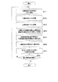
次に、図5のフローチャートを用いて、部品搭載装置1により搭載部品2を積層していく手順(部品搭載方法)を説明する。制御装置14は、搭載ヘッド12によりこれから搭載しようとする搭載部品2である上側部品をノズル12aに吸着させて、下側部品(最初
に搭載部品2の搭載を行う場合は最下層部品2A)の上方に移動させる(ステップST1)。そして、下側部品と上側部品との間にカメラ13を進出させたうえで、第1の撮像部13aによって下側部品を撮像するとともに(ステップST2。第1の撮像工程)、第2の撮像部13bによって上側部品を撮像する(ステップST3。第2の撮像工程)。ステップST2の下側部品の撮像とステップST3の上側部品の撮像は同時に行ってもよい。
Next, a procedure (component mounting method) for stacking the mounted
制御装置14は、ステップST2で下側部品を撮像し、ステップST3で上側部品を撮像したら、得られた結果(画像データ)に基づいて、下側部品の搭載後位置(X1,Y1,Θ1)と、上側部品の搭載前位置(X2,Y2,Θ2)を算出する。そして、それら算出した結果を記憶部14bに記憶させる(ステップST4。位置算出工程)。
The
制御装置14は、算出した下側部品の搭載後位置(X1,Y1,Θ1)と上側部品の搭載前位置(X2,Y2,Θ2)それぞれのデータを記憶部14bに記憶させたら、基準搭載部品(ここでは最下層部品2A)の搭載後位置(X0,Y0,Θ0)のデータを記憶部14bから読み出す(ステップST5)。ステップST5を最初に行う場合には、記憶部14bから読み出す基準搭載部品の搭載後位置(X0,Y0,Θ0)のデータは、直前のステップS4で算出して記憶した最下層部品2Aの搭載後位置のデータと同じものとなる。
When the
制御装置14は、ステップST4で算出して記憶した下側部品の搭載後位置(X1,Y1,Θ1)および上側部品の搭載前位置(X2,Y2,Θ2)と、ステップST5で読み出した基準搭載部品(最下層部品2A)の搭載後位置(X0,Y0,Θ0)とに基づいて、前述の要領により、下側部品に対する上側部品の位置合わせ量(ΔX,ΔY,ΔΘ)を設定する(ステップST6。位置合わせ量設定工程)。そして、制御装置14は、その設定した位置合わせ量(ΔX,ΔY,ΔΘ)で上側部品を下側部品に対して位置合わせしたうえで、上側部品を下側部品の上に搭載する(ステップST7。搭載工程)。
The
この搭載工程における上側部品の搭載では、位置合わせ量(ΔX,ΔY,ΔΘ)に、上側部品の搭載前位置と下側部品の搭載後位置と間の位置ずれ量(第1の位置ずれ量)が加味されているので、電極同士(下側部品の上面側電極22と上側部品の下面側電極21)の接触面積が過度に小さくならず、搭載部品2間の十分な電気的な接続信頼性を確保できる。また、位置合わせ量(ΔX,ΔY,ΔΘ)に、上側部品の搭載前位置と基準搭載部品(最下層部品2A)の搭載後位置との間の位置ずれ量(第2の位置ずれ量)が加味されているので、搭載される各搭載部品2は積層するごとに基準搭載部品から離れていくことはなく、搭載部品2を搭載する際の基準搭載部品(最下層部品2A)からのばらつきが小さくなって、その搭載部品2の搭載精度が向上する。
In the mounting of the upper component in this mounting process, the alignment amount (ΔX, ΔY, ΔΘ) is the amount of misalignment between the position before mounting the upper component and the position after mounting the lower component (first misalignment amount). Therefore, the contact area between the electrodes (the upper
制御装置14は、上側部品を下側部品の上に搭載したら、搭載すべき全ての搭載部品2を搭載したか(すなわち、最上層部品2Bを搭載したか)否かを判断する(ステップST8)。その結果、最上層部品2Bを搭載していない場合にはステップST1に戻り、最上層部品2Bを搭載した場合には、一連の作業を終了する。
When the upper component is mounted on the lower component, the
このように、本実施の形態における部品搭載装置1(部品搭載方法)では、これから搭載しようとする上側部品(他の搭載部品2)を直前に搭載した下側部品(一の搭載部品2)に対して位置合わせするための位置合わせ量を、下側部品の搭載後位置と、上側部品の搭載前位置と、基準搭載部品の搭載後位置とに基づいて設定するようにしている。すなわち、位置合わせ量を設定する要素として、上下に隣接する2つの搭載部品2間の電気的接続性に関連する上側部品と下側部品との間の位置関係だけでなく、各搭載部品2のばらつきを一定範囲内に収めることに関連する上側部品と基準搭載部品位との間の位置関係を加味するようになっている。このようにして設定された位置合わせ量で下側部品に上側部品
を搭載した場合、上下に隣接する搭載部品2間における接続信頼性は高く、各搭載部品2の搭載精度も非常に高いものとなる。
As described above, in the component mounting device 1 (component mounting method) in the present embodiment, the upper component (other mounted component 2) to be mounted is mounted on the lower component (one mounted component 2) immediately before. On the other hand, the alignment amount for alignment is set based on the position after mounting the lower component, the position before mounting the upper component, and the position after mounting the reference mounted component. That is, as an element for setting the alignment amount, not only the positional relationship between the upper component and the lower component related to the electrical connectivity between the two vertically adjacent
以上説明したように、本実施の形態における部品搭載装置1(部品搭載方法)では、これから搭載しようとする上側部品(他の搭載部品2)を直前に搭載した下側部品(一の搭載部品2)に対して位置合わせするための位置合わせ量が、下側部品の搭載後位置と、上側部品の搭載前位置と、下側部品より下層側に位置する特定の搭載部品2である基準搭載部品搭載後位置とに基づいて設定されるので、上下に隣接する搭載部品2間における高い接続信頼性を保ちつつ、各搭載部品2の搭載精度を向上させることができる。
As described above, in the component mounting device 1 (component mounting method) in the present embodiment, the lower component (one mounted component 2) on which the upper component (other mounted component 2) to be mounted is mounted immediately before is mounted. ), The amount of alignment for the lower component is the position after mounting the lower component, the position before mounting the upper component, and the
これまで本発明の実施の形態について説明してきたが、本発明は上述したものに限定されず、種々の変形等が可能である。例えば、上述の実施の形態では、最下層の搭載部品(最下層部品2A)を基準搭載部品(特定の搭載部品2)としていたが、基準搭載部品はこれから搭載しようとする一の搭載部品2よりも下層側に位置する搭載部品2であればよく、必ずしも最下層部品2Aである必要はない。
Although the embodiments of the present invention have been described so far, the present invention is not limited to those described above, and various modifications and the like are possible. For example, in the above-described embodiment, the lowest layer mounted component (
また、上述の実施の形態において示した、位置算出部14aが一の搭載部品2の搭載後位置と他の搭載部品2の搭載前位置とを算出する手順は一例であり、上述したものに限定されない。また、上述の形態において示した、位置合わせ量設定部14cが一の搭載部品2に対する他の搭載部品2の位置合わせ量を設定する手順は一例であり、上述したものに限定されない。
Further, the procedure in which the
上下に隣接する搭載部品間における高い接続信頼性を保ちつつ、各搭載部品の搭載精度を向上させることができる部品搭載装置および部品搭載方法を提供する。 Provided are a component mounting device and a component mounting method capable of improving the mounting accuracy of each mounted component while maintaining high connection reliability between vertically adjacent mounted components.
1 部品搭載装置
2 搭載部品
2A 最下層部品(最下層の搭載部品)
13a 第1の撮像部
13b 第2の撮像部
14a 位置算出部
14c 位置合わせ量設定部
14d 搭載制御部
21 下面側電極
22 上面側電極
1
13a
Claims (8)
前記一の搭載部品を上方から撮像する第1の撮像部と、
前記他の搭載部品を下方から撮像する第2の撮像部と、
前記第1の撮像部により撮像した結果に基づいて前記一の搭載部品の位置を前記一の搭載部品の搭載後位置として算出するとともに、前記第2の撮像部により撮像した結果に基づいて前記他の搭載部品の位置を前記他の搭載部品の搭載前位置として算出する位置算出部と、
前記位置算出部により算出された前記一の搭載部品の搭載後位置、前記位置算出部により算出された前記他の搭載部品の搭載前位置および前記一の搭載部品より下層側に位置する特定の搭載部品である基準搭載部品の搭載後位置に基づいて、前記一の搭載部品に対する前記他の搭載部品の位置合わせ量を設定する位置合わせ量設定部と、
前記位置合わせ量設定部で設定された前記位置合わせ量で前記他の搭載部品を前記一の搭載部品に対して位置合わせしたうえで、前記他の搭載部品を前記一の搭載部品の上に搭載させる搭載制御部とを備えた部品搭載装置。 The other mounted component is mounted on the one mounted component so that the lower surface side electrode provided on the lower surface side of the other mounted component contacts the upper surface side electrode provided on the upper surface side of the one mounted component. It is a component-mounted device that repeatedly executes operations.
A first imaging unit that images the one mounted component from above,
A second imaging unit that images the other mounted components from below,
The position of the one mounted component is calculated as the post-mounting position of the one mounted component based on the result of imaging by the first imaging unit, and the other is based on the result of imaging by the second imaging unit. A position calculation unit that calculates the position of the mounted component of the above as the position before mounting of the other mounted component,
The position after mounting of the one mounted component calculated by the position calculation unit, the position before mounting of the other mounted component calculated by the position calculating unit, and the specific mounting located on the lower layer side of the one mounted component. An alignment amount setting unit that sets the alignment amount of the other mounted component with respect to the one mounted component based on the post-mounting position of the reference mounted component which is a component.
After aligning the other mounted component with respect to the one mounted component with the alignment amount set by the alignment amount setting unit, the other mounted component is mounted on the one mounted component. A component mounting device equipped with a mounting control unit.
前記一の搭載部品を上方から撮像する第1の撮像工程と、
前記他の搭載部品を下方から撮像する第2の撮像工程と、
前記第1の撮像工程で撮像した結果に基づいて前記一の搭載部品の位置を前記一の搭載部品の搭載後位置として算出するとともに、前記第2の撮像工程で撮像した結果に基づいて前記他の搭載部品の位置を前記他の搭載部品の搭載前位置として算出する位置算出工程と、
前記位置算出工程で算出した前記一の搭載部品の搭載後位置、前記位置算出工程で算出した前記他の搭載部品の搭載前位置および前記一の搭載部品より下層側に位置する特定の搭載部品である基準搭載部品の搭載後位置に基づいて、前記一の搭載部品に対する前記他の搭載部品の位置合わせ量を設定する位置合わせ量設定工程と、
前記位置合わせ量設定工程で設定した前記位置合わせ量で前記他の搭載部品を前記一の搭載部品に対して位置合わせしたうえで、前記他の搭載部品を前記一の搭載部品の上に搭載する搭載工程とを含む部品搭載方法。 The other mounted component is mounted on the one mounted component so that the lower surface side electrode provided on the lower surface side of the other mounted component contacts the upper surface side electrode provided on the upper surface side of the one mounted component. It is a component mounting method that repeatedly executes operations.
The first imaging step of imaging the one mounted component from above, and
A second imaging step of imaging the other mounted components from below, and
The position of the one mounted component is calculated as the post-mounting position of the one mounted component based on the result of imaging in the first imaging step, and the other is based on the result of imaging in the second imaging step. The position calculation process of calculating the position of the mounted component of the above as the position before mounting of the other mounted component, and
With the post-mounting position of the one mounted component calculated in the position calculation process, the pre-mounting position of the other mounted component calculated in the position calculation process, and the specific mounted component located on the lower layer side of the one mounted component. An alignment amount setting process for setting the alignment amount of the other mounted component with respect to the one mounted component based on the post-mounting position of a certain reference mounted component.
After aligning the other mounted component with respect to the one mounted component with the alignment amount set in the alignment amount setting step, the other mounted component is mounted on the one mounted component. Parts mounting method including mounting process.
前記基準搭載部品の搭載後位置との間の第2の位置ずれ量に基づいて設定する請求項5または6に記載の部品搭載方法。 In the position calculation step, the alignment amount is determined by the first misalignment amount between the pre-mounting position of the other mounted component and the post-mounting position of the one mounted component and before mounting of the other mounted component. The component mounting method according to claim 5 or 6, which is set based on a second misalignment amount between the position and the post-mounting position of the reference mounting component.
Priority Applications (1)
| Application Number | Priority Date | Filing Date | Title |
|---|---|---|---|
| JP2019045528A JP2020150102A (en) | 2019-03-13 | 2019-03-13 | Component loading device and component loading method |
Applications Claiming Priority (1)
| Application Number | Priority Date | Filing Date | Title |
|---|---|---|---|
| JP2019045528A JP2020150102A (en) | 2019-03-13 | 2019-03-13 | Component loading device and component loading method |
Publications (1)
| Publication Number | Publication Date |
|---|---|
| JP2020150102A true JP2020150102A (en) | 2020-09-17 |
Family
ID=72429870
Family Applications (1)
| Application Number | Title | Priority Date | Filing Date |
|---|---|---|---|
| JP2019045528A Pending JP2020150102A (en) | 2019-03-13 | 2019-03-13 | Component loading device and component loading method |
Country Status (1)
| Country | Link |
|---|---|
| JP (1) | JP2020150102A (en) |
Citations (3)
| Publication number | Priority date | Publication date | Assignee | Title |
|---|---|---|---|---|
| JP2004228153A (en) * | 2003-01-20 | 2004-08-12 | Fujitsu Ltd | Method of aligning between pattern layers, alignment process apparatus, and method of manufacturing semiconductor device |
| JP2014187220A (en) * | 2013-03-25 | 2014-10-02 | Toshiba Corp | Semiconductor device manufacturing method |
| JP2016062958A (en) * | 2014-09-16 | 2016-04-25 | 株式会社東芝 | Semiconductor device manufacturing method and semiconductor manufacturing apparatus |
-
2019
- 2019-03-13 JP JP2019045528A patent/JP2020150102A/en active Pending
Patent Citations (3)
| Publication number | Priority date | Publication date | Assignee | Title |
|---|---|---|---|---|
| JP2004228153A (en) * | 2003-01-20 | 2004-08-12 | Fujitsu Ltd | Method of aligning between pattern layers, alignment process apparatus, and method of manufacturing semiconductor device |
| JP2014187220A (en) * | 2013-03-25 | 2014-10-02 | Toshiba Corp | Semiconductor device manufacturing method |
| JP2016062958A (en) * | 2014-09-16 | 2016-04-25 | 株式会社東芝 | Semiconductor device manufacturing method and semiconductor manufacturing apparatus |
Similar Documents
| Publication | Publication Date | Title |
|---|---|---|
| US7290331B2 (en) | Component mounting apparatus and component mounting method | |
| US7281322B2 (en) | Component mounting method | |
| US6931717B2 (en) | Apparatus for mounting an electronic part onto a circuit substrate | |
| JP2013065627A (en) | Die bonder and bonding method | |
| JP2019102771A (en) | Electronic component mounting device and electronic component mounting method | |
| JP3301347B2 (en) | Apparatus and method for mounting conductive ball | |
| US7897481B2 (en) | High throughput die-to-wafer bonding using pre-alignment | |
| JP2020150102A (en) | Component loading device and component loading method | |
| WO2020153204A1 (en) | Mounting device and mounting method | |
| JP6008419B2 (en) | Component stacking accuracy measurement jig set, method of using the same, component stacking accuracy measuring device of component mounting machine, and method of producing three-dimensional mounting board | |
| JP2007266425A (en) | Mounting device and mounting method | |
| JPH11289199A (en) | Electronic parts recognizing device | |
| WO2019097675A1 (en) | Component mounter, component inspection method, component inspection program, and recording medium | |
| KR102336342B1 (en) | Systems and methods for bonding semiconductor elements | |
| JPH0837209A (en) | Method of mounting electronic part with bump | |
| JP4852513B2 (en) | Component mounting system | |
| JP2000340998A (en) | Method of positioning and supplying electrical component and device thereof | |
| JP2006073814A (en) | Equipment and method for mounting semiconductor chip | |
| JP6902974B2 (en) | Electronic component mounting device and mounting method | |
| JP2005026499A (en) | Center-positioning carrier jig for substrate, method for positioning center and holding method after center positioning | |
| CN112331582A (en) | Chip mounting device and method for manufacturing semiconductor device | |
| WO2024057887A1 (en) | Mounting device | |
| KR20160054856A (en) | Method of adjusting a bonding position for a die bonder | |
| JP2003031994A (en) | Method and device for loading electronic component | |
| JP2003168892A (en) | Verification method for mounting accuracy, method and device for mounting, and fixture for verifying mounting accuracy |
Legal Events
| Date | Code | Title | Description |
|---|---|---|---|
| A621 | Written request for application examination |
Free format text: JAPANESE INTERMEDIATE CODE: A621 Effective date: 20220111 |
|
| RD01 | Notification of change of attorney |
Free format text: JAPANESE INTERMEDIATE CODE: A7421 Effective date: 20221020 |
|
| A977 | Report on retrieval |
Free format text: JAPANESE INTERMEDIATE CODE: A971007 Effective date: 20221209 |
|
| A131 | Notification of reasons for refusal |
Free format text: JAPANESE INTERMEDIATE CODE: A131 Effective date: 20221213 |
|
| A02 | Decision of refusal |
Free format text: JAPANESE INTERMEDIATE CODE: A02 Effective date: 20230606 |