JP2020137561A - Game machine - Google Patents
Game machine Download PDFInfo
- Publication number
- JP2020137561A JP2020137561A JP2019033273A JP2019033273A JP2020137561A JP 2020137561 A JP2020137561 A JP 2020137561A JP 2019033273 A JP2019033273 A JP 2019033273A JP 2019033273 A JP2019033273 A JP 2019033273A JP 2020137561 A JP2020137561 A JP 2020137561A
- Authority
- JP
- Japan
- Prior art keywords
- game
- display
- unit
- state
- winning
- Prior art date
- Legal status (The legal status is an assumption and is not a legal conclusion. Google has not performed a legal analysis and makes no representation as to the accuracy of the status listed.)
- Pending
Links
- 238000003860 storage Methods 0.000 claims abstract description 142
- 230000007704 transition Effects 0.000 claims description 145
- 230000001960 triggered effect Effects 0.000 claims description 9
- 230000005012 migration Effects 0.000 claims description 4
- 238000013508 migration Methods 0.000 claims description 4
- 230000000694 effects Effects 0.000 description 455
- 238000000034 method Methods 0.000 description 443
- 230000008569 process Effects 0.000 description 441
- 230000000875 corresponding effect Effects 0.000 description 201
- 230000006870 function Effects 0.000 description 112
- 238000012545 processing Methods 0.000 description 89
- 230000001186 cumulative effect Effects 0.000 description 68
- 238000004519 manufacturing process Methods 0.000 description 58
- 238000001514 detection method Methods 0.000 description 56
- 238000005034 decoration Methods 0.000 description 54
- 230000007246 mechanism Effects 0.000 description 47
- 230000008859 change Effects 0.000 description 36
- 238000009826 distribution Methods 0.000 description 35
- 238000012790 confirmation Methods 0.000 description 31
- 230000004048 modification Effects 0.000 description 31
- 238000012986 modification Methods 0.000 description 31
- 239000011521 glass Substances 0.000 description 26
- 238000010586 diagram Methods 0.000 description 25
- 239000000470 constituent Substances 0.000 description 19
- 239000000758 substrate Substances 0.000 description 18
- 230000008901 benefit Effects 0.000 description 17
- 238000007789 sealing Methods 0.000 description 17
- 230000004397 blinking Effects 0.000 description 15
- 230000002093 peripheral effect Effects 0.000 description 13
- 230000006872 improvement Effects 0.000 description 9
- 238000012546 transfer Methods 0.000 description 9
- 238000012544 monitoring process Methods 0.000 description 8
- 238000005192 partition Methods 0.000 description 8
- 239000003086 colorant Substances 0.000 description 7
- 230000001276 controlling effect Effects 0.000 description 7
- 239000002184 metal Substances 0.000 description 6
- 238000013459 approach Methods 0.000 description 5
- 230000003111 delayed effect Effects 0.000 description 5
- 238000006073 displacement reaction Methods 0.000 description 5
- 239000004973 liquid crystal related substance Substances 0.000 description 5
- 229920003002 synthetic resin Polymers 0.000 description 5
- 239000000057 synthetic resin Substances 0.000 description 5
- 230000009471 action Effects 0.000 description 4
- 238000011161 development Methods 0.000 description 4
- 230000018109 developmental process Effects 0.000 description 4
- 230000005281 excited state Effects 0.000 description 4
- 238000010304 firing Methods 0.000 description 4
- 230000000737 periodic effect Effects 0.000 description 4
- 230000002829 reductive effect Effects 0.000 description 4
- 230000004043 responsiveness Effects 0.000 description 4
- 238000011144 upstream manufacturing Methods 0.000 description 4
- 230000033228 biological regulation Effects 0.000 description 3
- 230000002349 favourable effect Effects 0.000 description 3
- 238000005286 illumination Methods 0.000 description 3
- 230000002452 interceptive effect Effects 0.000 description 3
- 239000002243 precursor Substances 0.000 description 3
- 230000001681 protective effect Effects 0.000 description 3
- 230000004044 response Effects 0.000 description 3
- 238000000926 separation method Methods 0.000 description 3
- 238000000638 solvent extraction Methods 0.000 description 3
- 230000001174 ascending effect Effects 0.000 description 2
- 230000003138 coordinated effect Effects 0.000 description 2
- 238000013461 design Methods 0.000 description 2
- 230000006866 deterioration Effects 0.000 description 2
- 210000003128 head Anatomy 0.000 description 2
- 238000003780 insertion Methods 0.000 description 2
- 230000037431 insertion Effects 0.000 description 2
- 238000007562 laser obscuration time method Methods 0.000 description 2
- 239000000463 material Substances 0.000 description 2
- NJPPVKZQTLUDBO-UHFFFAOYSA-N novaluron Chemical compound C1=C(Cl)C(OC(F)(F)C(OC(F)(F)F)F)=CC=C1NC(=O)NC(=O)C1=C(F)C=CC=C1F NJPPVKZQTLUDBO-UHFFFAOYSA-N 0.000 description 2
- 230000036961 partial effect Effects 0.000 description 2
- 230000002265 prevention Effects 0.000 description 2
- 230000001105 regulatory effect Effects 0.000 description 2
- 229920005989 resin Polymers 0.000 description 2
- 239000011347 resin Substances 0.000 description 2
- 230000002441 reversible effect Effects 0.000 description 2
- 239000002699 waste material Substances 0.000 description 2
- 229910000897 Babbitt (metal) Inorganic materials 0.000 description 1
- 241000287127 Passeridae Species 0.000 description 1
- 230000006399 behavior Effects 0.000 description 1
- 238000005452 bending Methods 0.000 description 1
- 230000005540 biological transmission Effects 0.000 description 1
- 230000015572 biosynthetic process Effects 0.000 description 1
- 230000008602 contraction Effects 0.000 description 1
- 230000007547 defect Effects 0.000 description 1
- 238000009795 derivation Methods 0.000 description 1
- 239000006185 dispersion Substances 0.000 description 1
- 210000000887 face Anatomy 0.000 description 1
- 230000012447 hatching Effects 0.000 description 1
- 230000001771 impaired effect Effects 0.000 description 1
- 230000000670 limiting effect Effects 0.000 description 1
- 238000012423 maintenance Methods 0.000 description 1
- 239000011159 matrix material Substances 0.000 description 1
- 230000001151 other effect Effects 0.000 description 1
- 230000000149 penetrating effect Effects 0.000 description 1
- 238000003825 pressing Methods 0.000 description 1
- 230000009993 protective function Effects 0.000 description 1
- 239000007787 solid Substances 0.000 description 1
- 230000006641 stabilisation Effects 0.000 description 1
- 238000011105 stabilization Methods 0.000 description 1
- 238000005728 strengthening Methods 0.000 description 1
- 239000000126 substance Substances 0.000 description 1
- 239000013585 weight reducing agent Substances 0.000 description 1
Images


Classifications
-
- Y—GENERAL TAGGING OF NEW TECHNOLOGICAL DEVELOPMENTS; GENERAL TAGGING OF CROSS-SECTIONAL TECHNOLOGIES SPANNING OVER SEVERAL SECTIONS OF THE IPC; TECHNICAL SUBJECTS COVERED BY FORMER USPC CROSS-REFERENCE ART COLLECTIONS [XRACs] AND DIGESTS
- Y02—TECHNOLOGIES OR APPLICATIONS FOR MITIGATION OR ADAPTATION AGAINST CLIMATE CHANGE
- Y02E—REDUCTION OF GREENHOUSE GAS [GHG] EMISSIONS, RELATED TO ENERGY GENERATION, TRANSMISSION OR DISTRIBUTION
- Y02E60/00—Enabling technologies; Technologies with a potential or indirect contribution to GHG emissions mitigation
- Y02E60/10—Energy storage using batteries
Abstract
Description
本発明は、遊技機に関するものである。 The present invention relates to a gaming machine.
パチンコ機等の遊技機には、表示画面にて絵柄を変動表示する絵柄表示装置を備えているものがある。この種の遊技機では、例えば遊技領域に設けられた作動口への入賞を契機として、当たり状態等の遊技者にとって有利な特別遊技状態を発生させるか否かの抽選が行われるとともに、絵柄の変動表示が開始される。この抽選に当選した場合には、表示画面に当選結果に対応した絵柄組合せ等が最終停止表示されるとともに、遊技状態が遊技者に有利な特別遊技状態に移行する(例えば特許文献1)。 Some gaming machines such as pachinko machines are equipped with a picture display device that displays a variable picture on the display screen. In this type of gaming machine, for example, when a prize is won in the operating port provided in the gaming area, a lottery is performed to determine whether or not to generate a special gaming state that is advantageous to the player, such as a hit state, and a pattern is drawn. The variable display is started. When this lottery is won, the pattern combination or the like corresponding to the winning result is finally stopped and displayed on the display screen, and the gaming state shifts to a special gaming state that is advantageous to the player (for example, Patent Document 1).
近年では、遊技への注目度を高めるべく様々な工夫がなされている。しかしながら、遊技機の構成においては遊技への注目度の向上を実現する上では未だ改善の余地がある。 In recent years, various measures have been taken to increase the degree of attention to games. However, there is still room for improvement in the configuration of the game machine in order to improve the degree of attention to the game.
本発明は、上記例示した事情等に鑑みてなされたものであり、遊技への注目度を好適に向上させることが可能な遊技機を提供することを目的とするものである。 The present invention has been made in view of the above-exemplified circumstances and the like, and an object of the present invention is to provide a game machine capable of suitably improving the degree of attention to the game.
本発明は、
遊技領域に設けられた始動入球部と、
前記始動入球部への入球に基づいて特別情報を取得する情報取得手段と、
前記情報取得手段により取得された特別情報を記憶可能な取得情報記憶手段と、
前記取得情報記憶手段に記憶されている特別情報が所定の移行情報と対応しているか否かを判定する移行判定手段と、
前記移行判定手段による判定の結果が前記所定の移行情報に対応しているとする移行対応結果となったことに基づいて、遊技状態を通常遊技状態よりも遊技者に有利な特別遊技状態に移行させる遊技状態移行手段と、
遊技球が入球可能な受入状態及び入球が不可となる非受入状態に切替可能な可変入球部と、
前記特別遊技状態となっている場合に、所定の切替条件が成立したことに基づいて前記可変入球部を前記非受入状態から前記受入状態に切り替える第1切替手段と、
前記第1切替手段によって前記可変入球部が前記受入状態に切り替えられた場合に、当該可変入球部への入球数が規定数となったこと又は前記受入状態への切り替え後に当該規定数に達することなく所定期間が経過したことに基づいて前記可変入球部を前記受入状態から前記非受入状態に切り替える第2切替手段と
を備え、
前記特別遊技状態においては、前記第1切替手段により前記可変入球部を前記受入状態とした後に前記第2切替手段により前記可変入球部を前記非受入状態とするように設定されたラウンド遊技がインターバルを挟んで複数回実行される構成となっており、
前記取得情報記憶手段に記憶されている所定の特別情報が前記移行判定手段による判定対象となった場合における判定結果に対応する情報を、当該所定の特別情報が前記判定の対象となるよりも前のタイミングにおいて先特定する先特定手段と、
前記特別遊技状態における前記ラウンド遊技にて前記規定数を超過した入球が発生した場合に、当該特別遊技状態中に前記先特定手段による先特定の結果を示唆する示唆手段と
を備えていることを特徴とする。
The present invention
The starting ball entry section provided in the game area and
An information acquisition means for acquiring special information based on the entry into the starting ball entry section,
An acquisition information storage means capable of storing special information acquired by the information acquisition means, and
A migration determination means for determining whether or not the special information stored in the acquired information storage means corresponds to the predetermined migration information, and
Based on the result of the determination by the transition determination means being the transition correspondence result that corresponds to the predetermined transition information, the gaming state is shifted to the special gaming state that is more advantageous to the player than the normal gaming state. The game state transition means to make
A variable ball entry section that can be switched between a reception state where game balls can enter and a non-acceptance state where entry is not possible,
In the case of the special gaming state, the first switching means for switching the variable input portion from the non-accepted state to the accepted state based on the satisfaction of the predetermined switching condition.
When the variable ball entry unit is switched to the receiving state by the first switching means, the number of balls entering the variable ball entry unit has reached a specified number, or the specified number after switching to the receiving state. A second switching means for switching the variable entry unit from the acceptance state to the non-acceptance state based on the elapse of a predetermined period without reaching
In the special gaming state, a round game is set so that the variable ball-entry portion is brought into the receiving state by the first switching means and then the variable ball-entry portion is put into the non-accepting state by the second switching means. Is configured to be executed multiple times with an interval in between.
The information corresponding to the determination result when the predetermined special information stored in the acquired information storage means is the determination target by the transition determination means is before the predetermined special information is the subject of the determination. And the destination identification means to identify ahead at the timing of
It is provided with a suggestion means for suggesting a pre-specific result by the pre-specific means during the special game state when the number of balls entered exceeds the specified number in the round game in the special game state. It is characterized by.
本発明によれば、遊技への注目度を好適に向上させることができる。 According to the present invention, the degree of attention to the game can be suitably improved.
<第1の実施の形態>
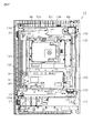
以下、遊技機の一種であるパチンコ遊技機(以下、「パチンコ機」という)の第1の実施の形態を、図面に基づいて詳細に説明する。図1はパチンコ機10の正面図、図2及び図3はパチンコ機10の主要な構成を展開して示す斜視図である。なお、図2では便宜上パチンコ機10の遊技領域内の構成を省略している。
<First Embodiment>
Hereinafter, a first embodiment of a pachinko gaming machine (hereinafter, referred to as a “pachinko machine”), which is a type of gaming machine, will be described in detail with reference to the drawings. FIG. 1 is a front view of the
図1に示すように、パチンコ機10は、当該パチンコ機10の外殻を形成する外枠11と、この外枠11に取り付けられた遊技機主部12とにより構成されている。
As shown in FIG. 1, the
図2に示すように、外枠11は長尺状のフレーム材を四辺に連結し構成されるものであって全体として矩形枠状をなすように形成されている。この外枠11を島設備に取り付け固定することにより、パチンコ機10が遊技ホールに設置される。なお、パチンコ機10において外枠11は必須の構成ではなく、遊技ホールの島設備等に外枠11が備え付けられた構成としてもよい。
As shown in FIG. 2, the
遊技機主部12は、外枠11によって開閉可能な状態で支持されている。具体的には、外枠11における上枠部と左枠部との連結部分に上側支持用金具17が固定されており、さらに外枠11における下枠部と左枠部との連結部分に下側支持用金具18が設けられている。これら上側支持用金具17及び下側支持用金具18により支持機構が構成され、当該支持機構により外枠11に対して遊技機主部12がパチンコ機10の正面視で左側を回動基端側、右側を回動先端側としてパチンコ機10の前方へ回動可能とされている(図3及び図4参照)。
The game machine
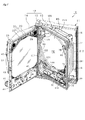
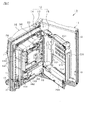
図3及び図4に示すように、遊技機主部12は、ベース体としての内枠13と、その内枠13の前方に配置される前扉枠14と、内枠13の後方に配置される裏パックユニット15とを備えている。なお、遊技機主部12のうち内枠13が外枠11に対して回動可能に支持されている。詳細には、遊技機正面視で左側を回動基端側とし右側を回動先端側として内枠13が前方へ回動可能とされている。
As shown in FIGS. 3 and 4, the game machine
内枠13には、前扉枠14が回動可能に支持されており、遊技機正面視で左側を回動基端側とし右側を回動先端側として前方へ回動可能とされている。また、内枠13には、裏パックユニット15が回動可能に支持されており、遊技機正面視で左側を回動基端側とし右側を回動先端側として後方へ回動可能とされている。
The
(前扉枠14)
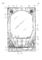
次に、前扉枠14について説明する。図1に示すように、前扉枠14は、外形が外枠11とほぼ同一形状をなす合成樹脂製の枠体20を主体に構成されており、内枠13における前面のほぼ全域を覆っている。枠体20の中央部分には後述する遊技領域PEのほぼ全域を前方から視認することができるようにした略楕円状の窓部21が形成されており、その窓部21はガラスユニット22によって同前扉枠14の背面側から塞がれている。
(Front door frame 14)
Next, the
ガラスユニット22は、透明性を有する複数のガラスパネル23と、それらガラスパネル23を保持するガラスホルダとを備えている。ガラスホルダには、ガラスパネル23の保持領域を前後に仕切る仕切り部が形成されており、両ガラスパネル23は仕切り部を挟んで前後に相対向している。つまり、両ガラスパネル23の間に所定の隙間を確保することにより、ガラスパネル23同士の干渉を回避しつつ、それらガラスパネル23によって遊技領域PEをパチンコ機10の正面側から2重に覆った状態となっている。
The
なお、必ずしも両ガラスパネル23をガラスホルダを用いてユニット化する必要は無く、各ガラスパネル23を枠体20に対して個々に取り付ける構成としてもよい。更には、ガラスパネルの枚数は任意であり、1枚としてもよいし、3枚以上としてもよい。但し、安全性及び防犯性向上に鑑みれば、複数のガラスパネルを採用し、それら各ガラスパネルを所定の隙間を挟んで前後に対向させることが好ましい。因みに、ガラスパネルに代えて透明性を有する合成樹脂性のパネル部材を採用することも可能である。
It is not always necessary to unitize both
ガラスユニット22(詳しくは窓部21)の周囲には、各種ランプ等の発光手段が設けられている。例えば、窓部21の周縁に沿ってLED等の発光手段を内蔵した環状電飾部26が設けられている。環状電飾部26では、大当たり時や所定のリーチ時等における遊技状態の変化に応じて点灯や点滅が行われる。また、環状電飾部26の中央であってパチンコ機10の最上部にはエラー等の不具合が発生した場合に点灯するエラー表示ランプ部27が設けられ、さらにその左右には賞球払出中に点灯する賞球ランプ部28が設けられている。また、左右の賞球ランプ部28に近接した位置には、遊技状態に応じた効果音やBGM等などが出力されるスピーカ部29が各々設けられている(図3参照)。スピーカ部29においては、遊技状態に応じてBGM等の切り替えを行うことにより、遊技の単調化を抑制している。
Light emitting means such as various lamps are provided around the glass unit 22 (specifically, the window portion 21). For example, an
前扉枠14(枠体20)における窓部21の下方には、手前側へ膨出した上側膨出部31と下側膨出部32とが上下に並設されている。上側膨出部31内側には上方に開口した上皿33が設けられており、下側膨出部32内側には同じく上方に開口した下皿34が設けられている(図2参照)。上皿33は、後述する払出装置より払い出された遊技球を一旦貯留し、一列に整列させながら後述する遊技球発射機構へ導くための機能を有する。また、下皿34は、上皿33内にて余剰となった遊技球を貯留する機能及び遊技球発射機構によって発射された遊技球のうち遊技領域PE(図3参照)に到達しなかった遊技球が遊技者に戻された場合に当該排出された遊技球を貯留する受け皿としての機能を有する。
Below the
下側膨出部32の右方には、手前側へ突出するようにして遊技球発射ハンドル41が設けられている。遊技球発射ハンドル41が操作されることにより、後述する遊技球発射機構から遊技球が発射される。なお、遊技球の発射速度は、遊技球発射ハンドル41の操作量(回動量)が大きくなるに従って速くなり、この操作量が遊技者により調整されて所定の量となった場合に遊技球が遊技領域PEへ到達することとなる。また、この操作量を遊技者が調整することで、後述する右ルートと左ルートへの遊技球の打ち分けが可能となる。
A game ball launch handle 41 is provided on the right side of the lower bulging
図3に示すように、前扉枠14の背面には、通路形成ユニット45が取り付けられている。通路形成ユニット45は、合成樹脂により成形されており、上皿33に通じる前扉側上皿通路と、下皿34に通じる前扉側下皿通路とを有してなる。通路形成ユニット45において、その上側隅部には後方に突出し上方に開放された受口部が形成されており、当該受口部を仕切壁によって左右に仕切ることで前扉側上皿通路の入口部分と前扉側下皿通路の入口部分とが区画形成されている。前扉側上皿通路及び前扉側下皿通路は上流側が後述する遊技球分配部に通じており、前扉側上皿通路に入った遊技球は上皿33に導かれ、前扉側下皿通路に入った遊技球は下皿34に導かれる。
As shown in FIG. 3, a
前扉枠14の背面における回動基端側には、その上端部及び下端部に突起軸が設けられている。これら突起軸は内枠13に対する組付機構を構成する。
On the rotation base end side on the back surface of the
次に、図5を参照して内枠13について詳細に説明する。図5は内枠13の正面図である。なお、図5においても図3と同様に便宜上パチンコ機10の遊技領域PE内の構成を省略している。
Next, the
(内枠13)
内枠13は、外形が外枠11と同様に略矩形状をなす内枠ベース体50を主体に構成されている。内枠ベース体50の高さ寸法は、外枠11の高さ寸法よりも若干小さく設定されている。また、内枠ベース体50は外枠11の上枠部に寄せて配置され、外枠11の下枠部と内枠ベース体50との間には若干の隙間が形成されている。外枠11にはこの隙間を塞ぐようにして幕板が装着されている。幕板は、内枠ベース体50(詳しくはその下端部)の下方に配置されており、内枠13が外枠11に対して閉じられた状態では内枠ベース体50が幕板の上に載ることとなる。なお、幕板と内枠ベース体50との間に相互干渉の防止等を目的として若干のクリアランスを設けてもよい。
(Inner frame 13)
The
内枠ベース体50の前面における回動基端側(図5の左側)には、その上端部及び下端部に支持金具71,72が取り付けられている。図示は省略するが、支持金具71,72は軸部を有しており、それら軸部に前扉枠14に設けられた軸受け部が挿入されることにより、内枠13に対して前扉枠14が回動可能に支持されている。
内枠ベース体50の回動先端側(図5の右側)には、内枠13や前扉枠14を施錠状態とするための施錠装置75が配設されている。施錠装置75は内枠ベース体50の右端部(後述する縦フレーム部材)に沿うようにして上下に延びており、その長手方向(上下方向)に散在して配置された前扉用鉤部材76を有している。内枠ベース体50には前扉枠14の背面に設けられた鉤受け部材49(図3参照)内枠13の正面側に突出させるためのスリットが各前扉用鉤部材76にそれぞれ対応するようにして形成されている。それらスリットを通じて突出した前扉用鉤部材76が、前扉枠14に各前扉用鉤部材76に1対1で対応させて設けられた鉤受け部材49に係止されることによって、前扉枠14が内枠13に対して開放不能に施錠される。また、施錠装置75は、内枠13の後方側に延出する内枠用鉤部材77を有している。これら内枠用鉤部材77が外枠11に固定された鉤受け部材19に引っ掛かることにより遊技機主部12が外枠11に対して閉じた状態で施錠される。
A locking
内枠ベース体50(施錠装置75)には、施錠装置75の解錠操作を行うためのシリンダ錠78が設置されている。シリンダ錠78は施錠装置75の主要部分を構成する施錠ユニット(各鉤部材76,77や連動杆等)とは別体で設けられており、当該施錠ユニットと隣接して配置されている。シリンダ錠78の鍵穴に差し込んだキーを右(時計回り)に回すと内枠13に対する前扉枠14の施錠が解除され、シリンダ錠78の鍵穴に差し込んだキーを左(反時計回り)に回すと外枠11に対する内枠13の施錠が解除されるように構成されている。
A
内枠ベース体50の中央部分には遊技盤ユニット80を収容する収容凹部51が形成されている。収容凹部は遊技盤ユニット80の外形に合わせて遊技機後方に窪んでおり、遊技盤ユニット80はこの収容凹部51に遊技機前方から嵌まった状態で手動式のロック機構によって固定されている。収容凹部51の底部には、略矩形状の窓孔52が形成されており、この窓孔52を通じて遊技盤ユニット80の背面構成(後述する背面ブロック80b)が内枠13の後方に突出している。なお、この窓孔52については、内枠ベース体50に装着された遊技盤ユニット80によってそのほぼ全域が遊技機前方から覆われた状態となっている。
A
(遊技盤ユニット80)
遊技盤ユニット80は、前面に遊技球が流下する遊技領域PEが形成され遊技盤80aと、遊技盤80aの背面側に設けられ、後述する各種遊技部品(例えば可変表示ユニット、制御装置、可動式の演出装置、装飾部材等)がベース体251に搭載されてなる背面ブロック80bとが一体化されてなる。
(Game board unit 80)
The
既に説明したように遊技領域PEはガラスユニット22(詳しくは後側のガラスパネル23)によって覆われている。ガラスユニット22は、後側のガラスパネル23と遊技盤80aの前面との隙間が遊技球の直径よりも僅かに大きくなるように、すなわち遊技領域PEを流下する遊技球が同遊技領域PEの同一箇所にて前後に並ばないように配置されている。これにより、遊技領域PEでの球詰まりを抑制している。
As described above, the game area PE is covered by the glass unit 22 (specifically, the rear glass panel 23). In the
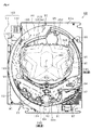
以下、図6〜図8に基づき遊技盤ユニット80(特に遊技盤80aの遊技領域PEに配された各種構成)について説明する。図6は遊技盤ユニット80の正面図、図7は遊技盤ユニット80を後方から見た斜視図である。
Hereinafter, the game board unit 80 (particularly, various configurations arranged in the game area PE of the game board 80a) will be described with reference to FIGS. 6 to 8. FIG. 6 is a front view of the
遊技盤80aには、自身の厚さ方向(前後方向)に貫通する大小複数の開口が形成されている。図6に示すように、各開口には、一般入賞口81、可変入賞装置82、作動口83a,83b、スルーゲート84等がそれぞれ配設されている。一般入賞口81、可変入賞装置82及び作動口83a,83bに遊技球が入ると、それら遊技球が各入球部に対応して設けられた検知センサ(図示略)により検知され、その検知結果に基づいて所定数の賞球(遊技球の払い出し)等の特典が遊技者に付与される。その他に、遊技盤80aの最下部にはアウト口89が設けられており、各種入球部等に入らなかった遊技球はアウト口89を通って遊技領域PEから排出される。以下の説明では、アウト口89への遊技球の入球と明確に区別するために、一般入賞口81、可変入賞装置82、作動口83a,83bへの遊技球の入球を「入賞」とも表現する。
The game board 80a is formed with a plurality of large and small openings penetrating in the thickness direction (front-back direction) of the game board 80a. As shown in FIG. 6, a general winning
また、遊技盤80aには、遊技球の流下経路を適宜分散,調整等するために多数の釘部材93が植設されているとともに、風車94等の各種部材(役物)が配設されている。これら釘部材93や風車94等の各種構成によって遊技球の流下経路が分化され、上述した一般入賞口81等への入賞が適度な確率で発生するように調整されている。
Further, in the game board 80a, a large number of
遊技盤80aの中央には中央開口85が形成されており、この中央開口85を遊技盤80aの前面側から覆うようにして透明な開口カバー(図示略)が取り付けられている。この中央開口85の背後には、背面ブロック80bに属する可変表示ユニット252等が位置しており、遊技機前方から当該中央開口85(開口カバー)を通じて可変表示ユニット252等を視認可能となっている。
A
中央開口85の周辺に作動口83a,83bやスルーゲート84等が配設されている。作動口83a,83bは、可変表示ユニット252の下方に配設された上作動口83aと、上作動口83aの直下に配設された下作動口83bとによって構成されており、特に下作動口(抽選契機入球部)83bには、開閉式の入球補助装置(入球補助手段)又は開閉部材(開閉手段)としての電動役物91が設けられている。電動役物91は、可動片と同可動片を駆動させるソレノイド式の駆動部とを有してなり、可動片の位置が駆動部によって変更されることにより、下作動口83bへの入球が可能又は容易となる開状態(補助状態)と、同入球が不可又は困難となる閉状態(非補助状態)とに切替可能となっている。
遊技領域PEにおいてこの下作動口83bよりも上流側(詳しくは可変表示ユニット252の側方)となる位置には上記スルーゲート84が配置されており、遊技球のスルーゲート84の通過をトリガとした抽選にて当選となった場合には、電動役物91が所定時間だけ閉状態から開状態に切り替えられることとなる。
In the game area PE, the through
なお、上作動口83aへの入球が発生した場合には3個の遊技球の払出が実行され、下作動口83bへの入球が発生した場合には4個の遊技球の払出が実行されるが、遊技球の払出個数は上記のものに限定されることはない。但し、例えば上作動口83aに対する下作動口83bの有利性を高める上では、上作動口83aに係る払出個数よりも下作動口83bに係る払出個数を多く設定することが好ましい。
In addition, when the ball enters the
可変入賞装置(特別入球装置又は特別入球手段)82には、遊技盤80aの背面側へと通じる大入賞口が上向きとなるように形成されており、当該大入賞口を開閉する開閉部材(開閉手段)としての開閉体が設けられている。開閉体は、遊技球の入球が可能又は容易となる開状態(補助状態)と、同入球が不可又は困難となる閉状態(非補助状態)とに切替可能となっている。また、同開閉体は、遊技盤80aの背面側に設けられた可変入賞駆動部(詳しくはソレノイド)と連結されており、通常時においては開閉体は閉状態のまま維持され、内部抽選において大当たり結果となって開閉実行モード(特別遊技状態)へ移行することで開状態に切り替えられるようになっている。本実施の形態に示す開閉体は板面が上下を向くように配置された平板であり、閉状態となっている場合には当該開閉体の上面を遊技領域PEの中央側に向かって遊技球が転動可能となるように構成されている。また、可変入賞装置82の内部において開閉体から離れた位置には大入賞口へ流入した遊技球を検知する検知センサが設けられている。この検知センサは後述する主制御装置に接続されており、主制御装置においてはこの検知センサからの検知情報(検知信号)に基づいて、可変入賞装置82への入賞数を把握する構成となっている。
The variable winning device (special winning device or special winning means) 82 is formed so that the large winning opening leading to the back side of the game board 80a faces upward, and is an opening / closing member that opens and closes the large winning opening. An opening / closing body is provided as (opening / closing means). The opening / closing body can be switched between an open state (auxiliary state) in which the game ball can be entered or easily, and a closed state (non-assisted state) in which the game ball cannot or is difficult to enter. Further, the opening / closing body is connected to a variable winning drive unit (specifically, a solenoid) provided on the back side of the game board 80a, and the opening / closing body is maintained in a closed state in a normal state, and a big hit in an internal lottery. As a result, it is possible to switch to the open state by shifting to the open / close execution mode (special game state). The opening / closing body shown in the present embodiment is a flat plate arranged so that the plate surface faces up and down, and when the opening / closing body is in the closed state, the upper surface of the opening / closing body is directed toward the center side of the game area PE. Is configured to be rollable. Further, a detection sensor for detecting a game ball flowing into the large winning opening is provided at a position away from the opening / closing body inside the variable winning
ここで、開閉実行モードとは、大当たり当選となった場合に移行することとなるモードである。当該開閉実行モードにおける可変入賞装置82の開放態様としては、例えば所定時間(例えば30sec)の経過又は所定個数(例えば10個)の入賞を1ラウンドとして、複数ラウンド(例えば8,16ラウンド)を上限とした開閉体の開放が繰り返されるように設定されている。
Here, the open / close execution mode is a mode that shifts when a big hit is won. As an opening mode of the variable winning
ここで、可変表示ユニット252について補足説明する。可変表示ユニット252は、作動口83a,83bへの入賞をトリガとして図柄を可変表示(変動表示)する図柄表示装置253を有している。図柄表示装置253は、液晶ディスプレイを備えた液晶表示装置として構成されており、後述する表示制御装置によりその表示内容が制御される。図柄表示装置253の表示画面253aにおいては、例えば上、中及び下に並べて図柄が表示され、これらの図柄が左右方向にスクロールされるようにして変動表示されるようになっている。そして、大当たりに当選した場合には、予め設定されている有効ライン上に所定の組み合わせの図柄が停止表示され、上記開閉実行モード(特別遊技状態又は大当たり)に移行することとなる。なお、図柄表示装置253については必ずしも液晶表示装置である必要はなく、ドットマトリクスや7セグタイプの表示装置であってもよい。
Here, the
遊技盤80aには、中央開口85を囲むようにしてセンターフレーム95が設けられている。センターフレーム95は、遊技盤80a(詳しくは板体)に対してその前面側から固定されており、このように固定された状態では遊技盤80aの前面から起立した状態となることで当該センターフレーム95と上記ガラスユニット22との間の隙間寸法が遊技球の直径寸法よりも小さくなるように構成されている。これにより、遊技領域PEを流下する遊技球が図柄表示装置253に衝突することが回避され、且つ遊技領域PEを流下する遊技球の流下経路が可変表示ユニット252(詳しくはセンターフレーム95)を右側から迂回する左ルートと、左側から迂回する右ルートに大別されている。
The game board 80a is provided with a
上述した作動口83aは左ルートに配設されており、右ルートへ発射された遊技球については作動口83aへの入球が回避される構成となっている。スルーゲート84、可変入賞装置82は右ルートに配設されており、左ルートへ発射された遊技球についてはそれらスルーゲート84、可変入賞装置82への入球が回避される構成となっている。なお、作動口83bについては左ルートへ発射された遊技球及び右ルートへ発射された遊技球の何れについても入球可能となっているものの、左ルートを流下する遊技球と比べて右ルートを流下する遊技球の入球確率が高くなるように差別化されている。なお、左ルートへ発射された遊技球については作動口83bへの入球が不可となるように、当該作動口83bを左ルートへ配設することも可能である。
The above-mentioned
センターフレーム95の下部を構成している枠部の上面には、遊技球が左右に転動可能なステージ部が形成されている。センターフレーム95の左右の左枠部に形成された流入口から流入した遊技球は、同じくセンターフレーム95に形成されたワープ通路を通じてステージ部上に排出される。ステージ部については、当該ステージ部に到達した遊技球が比較的上作動口83aへと流入しやすくなるように構成されており、このステージ部上での遊技球の動きに対する遊技者の注目度向上に貢献している。なお、本実施の形態においては上述したように透明な開口カバーによって中央開口85を覆っており、ステージ部上に到達した遊技球が背面ブロック80b(可変表示ユニット252)側へ移動しないように規制されている。
A stage portion on which the game ball can roll left and right is formed on the upper surface of the frame portion forming the lower portion of the
作動口83a,83bは、中央開口85(可変表示ユニット252)寄りとなる位置に配置されている。作動口83a,83bへの入賞をトリガとして特別遊技状態に移行し得るため、遊技者は作動口83a,83bに入賞するか否かに注目するとともに、特別遊技状態に移行するか否かを把握するため図柄表示装置253に注目するものと考えられる。作動口83a,83bを可変表示ユニット252寄りに設けたことは、遊技者が注目したい箇所を可変表示ユニット252周辺に集中させるための工夫である。
The operating
遊技盤80aにおける右側の端部(後述する遊技盤ユニット80の回動先端部)には後述する誘導レール100とともに遊技領域PEを区画形成する遊技領域区画部材99が配設されている。遊技領域区画部材99には、主表示ユニット87や誘導レール100に沿って飛翔した遊技球が衝突するストッパ部材が配設されている。ストッパ部材は誘導レール100の先端付近に配置された緩衝部材であり、当該ストッパ部材に衝突した遊技球はその勢いが弱められた後、遊技領域PEを流下することとなる。つまり、ストッパ部材には衝突した遊技球の勢いを弱める減勢機能が付与されている。
At the right end of the game board 80a (the rotating tip of the
ここで、主表示ユニット87について補足説明する。主表示ユニット87は遊技領域区画部材99に埋設されており、その一部がガラスユニット22と対向するように配置されている。この対向している部分には、所定の絵柄等が表示される主表示部が設けられている。主表示ユニット87については、後述する主制御装置に電気的に接続されており、主表示部の表示内容は当該主制御装置によって制御される構成となっている。
Here, the
主表示部は、上作動口83aへの入賞に基づいた抽選結果を表示する上作動口用表示部と、下作動口83bへの入賞に基づいて行われた抽選結果を表示する下作動口用表示部とを有してなる。上作動口用表示部では、上作動口83aへの入賞をトリガとして絵柄の変動表示が行われ、その変動表示の停止結果として、上作動口83aへの入賞に基づいて行われた内部抽選の結果が明示される。上作動口83aへの入賞に基づく内部抽選の結果が開閉実行モードへの移行に対応した当選結果であった場合には、上作動口用表示部にて変動表示が停止され、停止結果として所定の絵柄が表示された後に、上記開閉実行モードへ移行される。
The main display unit is for the upper operating port display unit that displays the lottery result based on the winning of the
下作動口用表示部では、下作動口83bへの入賞をトリガとして絵柄の変動表示が行われ、その変動表示の停止結果として、下作動口83bへの入賞に基づいて行われた内部抽選の結果が明示される。下作動口83bへの入賞に基づく内部抽選の結果が大当たりに対応した当選結果であった場合には、下作動口用表示部にて変動表示が停止され、停止結果として所定の絵柄が表示された後に、その結果に応じて上記開閉実行モードへ移行される。
In the display unit for the lower operating port, a variation display of the pattern is performed triggered by a winning of the
ここで、いずれかの作動口83a,83bへの入賞に基づいて、対応する作動口用表示部にて変動表示が開始され、抽選結果に対応する絵柄が停止表示された後、当該絵柄が停止表示されたまま所定の停止表示時間(確定表示時間)が経過するまで(確定表示が終了するまで)が遊技回の1回に相当する。但し、遊技回の1回は、上記の内容に限定されることはなく、例えば、単一の表示領域が設けられ、いずれの作動口83a,83bへの入賞が発生したとしてもその単一の表示領域にて変動表示が行われる構成においては、当該単一の表示領域にて変動表示が開始され、所定の停止結果を表示した状態で上記変動表示が停止された後確定表示が終了するまでを遊技回の1回とすることも可能である。
Here, based on the winning of any of the operating
また、主表示ユニット87の主表示部には上記両表示部以外に、スルーゲート84への入賞に基づいた抽選結果を表示するスルーゲート用表示部が併設されている。スルーゲート用表示部では、スルーゲート84への入賞をトリガとして絵柄の変動表示が行われ、その変動表示の停止結果として、スルーゲート84への入賞に基づいて行われた内部抽選の結果が明示される。スルーゲート84への入賞に基づく内部抽選の結果が電役開放状態への移行に対応した当選結果であった場合には、スルーゲート用表示部にて所定の停止結果が表示されて変動表示が停止された後に、電役開放状態へ移行する。電役開放状態では、下作動口83bに設けられた上記電動役物91が所定の態様で開放される。
Further, in addition to both of the above display units, the
更に、本実施の形態においては遊技球がスルーゲート84を通過した回数は最大4回まで保留される構成が採用されているが、主表示ユニット87の主表示部にはその保留個数(保留数)を表示する保留数用表示部が設けられている。
Further, in the present embodiment, the number of times the game ball has passed through the through
以上詳述した主表示部については、前扉枠14のガラスユニット22を通じてパチンコ機10前方から視認可能となっているとともに、これら各種表示部の前方を遊技球が移動することが回避されているため、その視認性が担保されている。
The main display unit described in detail above can be visually recognized from the front of the
再び図5を用いて内枠13の構成について説明すれば、内枠ベース体50における遊技盤ユニット80の下方には、上記遊技球発射ハンドル41の操作に基づいて遊技領域PEへ遊技球を発射する遊技球発射機構110が設けられている。
Explaining the configuration of the
(遊技球発射機構110)
遊技球発射機構110は、所定の発射待機位置に配置された遊技球を打ち出すソレノイド111と、同ソレノイド111によって打ち出された遊技球の発射方向を規定する発射レール112と、上記発射待機位置に遊技球を供給する球送装置113と、それら各種構成111〜113が装着されているベースプレート114とを主要な構成として備えており、同ベースプレート114が内枠ベース体50に固定されることで、同内枠ベース体50に対して一体化されている。
(Game ball launch mechanism 110)
The game
発射レール112は、遊技盤80a側に向けて上り傾斜となるように、斜めに傾いた状態でベースプレート114に固定されている。発射レール112には断面略V字状の溝部が形成されており、その溝状部分に遊技球が嵌ることにより当該遊技球の前後位置が規定されるように構成されている。
The
発射レール112の下流側の端部(すなわち下端部)寄りとなる位置には、球送装置113から供給された遊技球を上述した発射待機位置に留める球ストッパが配されている。球ストッパよりも更に下流側となる位置に、上記ソレノイド111が配置されている。
At a position closer to the downstream end (that is, the lower end) of the
ソレノイド111は、後述する電源・発射制御装置に対して電気的に接続されている。その電源・発射制御装置からの電気的な信号の出力に基づいてソレノイド111の出力軸が伸縮方向に往復動することにより、発射待機位置に置かれた遊技球が遊技盤80a側、詳しくは遊技盤80aに装着された誘導レール100に向けて打ち出される。
The solenoid 111 is electrically connected to a power supply / emission control device described later. The output shaft of the solenoid 111 reciprocates in the expansion / contraction direction based on the output of the electric signal from the power supply / launch control device, so that the game ball placed in the launch standby position is on the game board 80a side, in detail, the game. It is launched toward the
誘導レール100は、遊技盤80a(詳しくは板体の前面)に固定された遊技領域区画部材99とともに遊技領域PEを同遊技領域PEの外形が略円形状となるように区画形成している。また、誘導レール100は、遊技球の直径よりも大きな隙間を隔てて対峙するように配置された内レール101及び外レール102からなり、それら両レール101,102によって一条の誘導通路103が区画形成されている。誘導通路103は、発射レール112の先端側(斜め下方)に開放された入口部分104と、遊技領域PEの上部に位置する出口部分105とを有している。ソレノイド111の動作に基づいて発射された遊技球は、発射レール112→誘導レール100(入口部分104→出口部分105)の順に移動することにより遊技領域PEに導かれる。なお、遊技盤80aにおいて出口部分105の先側、詳しくは内レール101の先端付近には、遊技領域PEに到達した遊技球の同誘導通路103内への逆戻りを防止する逆戻り防止部材106が取り付けられており、先んじて遊技領域PEに至った遊技球によって後続する遊技球の打ち出しが妨げられることを抑制している。
The
誘導レール100を構成している各レール101,102は、遊技領域PEの略中央部分を中心とする円弧状をなしている。このため、誘導通路103を通過する遊技球は、自身に発生する遠心力により外レール102に沿って、すなわち外レール102に接触したまま移動(摺動又は転動)しやすくなっている。つまり、遊技領域PEへと遊技球を届けるようにして遊技球を発射した場合には誘導通路103において外レール102に沿った領域が実質的に遊技球が通過する通過領域(通過経路)を構成し、内レール101に沿う領域については実質的に遊技球が通過しない領域となる。
Each of the
同図5に示すように、誘導レール100及び発射レール112は、同誘導レール100の入口部分104と発射レール112の先端部分とが遊技盤80aの下端縁を挟んで斜めに対峙するように配置されている。つまり、それら両レール100,112は、同誘導レール100の入口部分104と発射レール112の先端部分とが遊技盤80aの下端縁近傍にて左右にずれるようにして配置されている。これにより両レール100,112を遊技盤80aの下端縁に近づけつつ、誘導レール100の入口部分104と発射レール112との間には所定間隔の隙間を形成している。
As shown in FIG. 5, the
このようにして形成された隙間よりも下側にはファール球通路が配設されている。ファール球通路は前扉枠14の通路形成ユニット45に一体成形されている。仮に遊技球発射機構110から発射された遊技球が遊技領域PEまで至らずファール球として誘導通路103内を逆戻りする場合には、それらファール球が上記隙間を介してファール球通路内に入ることとなる。ファール球通路は前扉側下皿通路に通じており、ファール球通路に入った遊技球は図1に示した下皿34に排出される。これにより、ファール球と次に発射される遊技球との干渉が抑制される。
A foul ball passage is arranged below the gap formed in this way. The foul ball passage is integrally molded with the
遊技盤80aの左端部には外レール102を側方から覆うようにしてレールカバー107が設けられている。遊技盤ユニット80については、製造時やメンテナンス作業時に単体で取り扱われることが多く、この際に外レール102が遊技台等に衝突し得る。レールカバー107はこのような事情に鑑みて搭載された部材であり、外レール102が上記要因等によって変形することを防止する保護機能が付与されている。
A
内枠ベース体50において発射レール112の左方(詳しくは前扉枠14を支持している側)には内枠ベース体50を前後方向に貫通する貫通孔が形成されており、この貫通孔に通路形成部材121が配設されている。通路形成部材121は、内枠ベース体50に対してネジ止めされており、本体側上皿通路122と本体側下皿通路123とを有している。それら本体側上皿通路122及び本体側下皿通路123の上流側は、後述する遊技球分配部に通じている。また、通路形成部材121の下方には前扉枠14に取り付けられた通路形成ユニットの受口部が入り込んでおり、本体側上皿通路122の下方には前扉側上皿通路が配置され、本体側下皿通路123の下方には前扉側上皿通路が配置されている。
In the inner
内枠ベース体50において通路形成部材121の下方には、本体側上皿通路122及び本体側下皿通路123を開閉する開閉部材124が取り付けられている。開閉部材124は本体側上皿通路122及び本体側下皿通路123を閉鎖する前方位置に付勢されており、前扉枠14が開放された場合には、この付勢力によって各開閉部材124が閉状態となることで、各通路122,123からの遊技球の脱落が回避されることとなる。これに対し、前扉枠14を閉じた状態では、前扉枠14の通路形成ユニット45に設けられた受口部により付勢力に抗して開閉部材124が押し開けられる。この状態では、本体側上皿通路122と前扉側上皿通路とが連通し、さらに本体側下皿通路123と前扉側下皿通路とが連通する。
In the inner
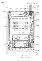
次に、図7及び図8に基づき内枠13(内枠ベース体50及び遊技盤ユニット80)の背面構成について説明する。図8は内枠13の背面図である。
Next, the rear surface configuration of the inner frame 13 (inner
図8に示すように内枠ベース体50の背面における回動基端側(図8の右側)には、軸受け金具132が取り付けられている。軸受け金具132には、上下に離間させて軸受け部133が形成されており、これら軸受け部133により内枠13に対して裏パックユニット15が回動可能に取り付けられている。また、内枠ベース体50の背面には、裏パックユニット15を閉じた状態で同内枠ベース体50に固定するための固定レバー134が複数設けられている。
As shown in FIG. 8, a bearing
既に説明したように内枠ベース体50における収容凹部(遊技盤収容部)51の底部分には内枠ベース体50の厚さ方向に貫通し同内枠ベース体50の背面側に開放された窓孔52が形成されており、その窓孔52が収容凹部51に収容された遊技盤ユニット80によって内枠13の正面側から覆われている。遊技盤ユニット80(背面ブロック80b)の背面には制御装置等の各種構成が搭載されており、それら各種構成は窓孔52を通じて内枠13の背側に露出した状態となっている。ここで、遊技盤ユニット80の背面の構成について説明する。
As described above, the bottom portion of the accommodating recess (game board accommodating portion) 51 in the inner
既に説明したように遊技盤80aの背面には、背面ブロック80bが取り付けられている。背面ブロック80bは、遊技盤80a側に開放された略箱状のベース体251を有してなり、このベース体251が遊技盤80aの背面に固定されることで、遊技盤80aと背面ブロック80bとが一体化されている。
As described above, the
ベース体251の前面側は、可動式の演出機構や発光可能な装飾部材等の配置領域となっており、その背面側はそれら各種構成を制御する制御装置や上記可変表示ユニット252(図柄表示装置253)の配置領域となっている。
The front side of the
より具体的には、ベース体251の一部が内枠ベース体50の背面側に突出しており、その突出した部分に対して上述した図柄表示装置253(図6参照)と、その図柄表示装置253を駆動するための表示制御装置とが取り付けられている。これら図柄表示装置253及び表示制御装置は前後方向(内枠ベース体50の厚さ方向)に図柄表示装置が前側且つ表示制御装置が後側となるように重ねて配置されている。さらに、ベース体251の背面部には、表示制御装置の後方に位置するようにして報知・演出制御装置140が搭載されている。
More specifically, a part of the
報知・演出制御装置140は、後述する主制御装置からの指示に従い音声の出力やランプ表示、可動式の演出装置及び表示制御装置の制御を司る報知・演出制御基板を具備しており、報知・演出制御基板が透明樹脂材料等よりなる基板ボックス141に収容されて構成されている。
The notification /
報知・演出制御装置140の下方には、ベース体96を後方から覆うようにして主制御装置ユニット160が設けられている。主制御装置ユニット160は、遊技盤ユニット80(詳しくは背面ブロック80b)の背面に固定された合成樹脂製の取付台161と、その取付台161に搭載された主制御装置162とを有している。主制御装置162は、遊技の主たる制御を司る機能(主制御回路)と、電源を監視する機能(停電監視回路)とを有する主制御基板を具備しており、当該主制御基板が透明樹脂材料等よりなる基板ボックス163に収容されて構成されている。
Below the notification /
基板ボックス163は、略直方体形状のボックスベース(表ケース体)とこのボックスベースの開口部を覆うボックスカバー(裏ケース体)とを備えている。これらボックスベースとボックスカバーとは封印手段としてのボックス封印部164によって開封不能に連結され、これにより基板ボックス163が封印されている。ボックス封印部164は、基板ボックス163の短辺部に複数設けられ、そのうち少なくとも1つが用いられて封印処理が行われる。
The
ボックス封印部164はボックスベースとボックスカバーとを開封不能に結合する構成であれば任意の構成が適用できるが、ボックス封印部164を構成する係止孔部に係止ピンを挿入することでボックスベースとボックスカバーとが開封不能に結合されるようになっている。ボックス封印部164による封印処理は、その封印後の不正な開封を防止し、また万一不正開封が行われてもそのような事態を早期に且つ容易に発見可能とするものであって、一旦開封した後でも再度封印処理を行うこと自体は可能である。すなわち、複数のボックス封印部164のうち、少なくとも1つの係止孔部に係止ピンを挿入することにより封印処理が行われる。そして、収容した主制御基板の不具合発生の際や主制御基板の検査の際など基板ボックス163を開封する場合には、係止ピンが挿入されたボックス封印部と基板ボックス163本体との連結部分を切断する。これにより、基板ボックス163のボックスベースとボックスカバーとが分離され、内部の主制御基板を取り出すことができる。その後、再度封印処理する場合は他の係止孔部に係止ピンを挿入する。基板ボックス163の開封を行った旨の履歴を当該基板ボックス163に残しておけば、基板ボックス163を見ることで不正な開封が行われた旨が容易に発見できる。
Any configuration can be applied to the
基板ボックス163と取付台161とは台座封印部165によって開封不能に連結されている。詳しくは、台座封印部165は、ボックス封印部164と同様に係止孔部及び係止ピンを有しており、係止孔部に対して係止ピンが挿入されることで基板ボックス163と取付台161とが分離不能に結合されるようになっている。これにより、基板ボックス163の不正な取り外しが行われた場合に、その事実を把握しやすくなっている。
The
主制御装置162の正面部(遊技機後方を向いている部分)にて後述する裏パック201との重なりが回避されている部分には、設定変更キーが挿通されるキー穴167と、設定変更スイッチ166と、設定値表示部168とが設けられている。詳細については後述するが、本実施の形態におけるパチンコ機10においては、大当たり確率が複数段階(詳しくは3段階)設けられており、上記キー穴167に挿通された設定変更キーがON位置に配置された状態(ON状態)にて、設定変更スイッチ166が操作されることで設定値が変更される構成となっている。設定変更キーがON位置に配置されている間は、現在選択されている設定値が設定値表示部168に表示され、作業者が設定値を目視にて確認しながら設定変更を行うことが可能となっている。
In the front part of the main control device 162 (the part facing the rear of the game machine) where the overlap with the
ベース体251の前面部において遊技盤80aの背面下部と対向している部分には、前記一般入賞口81,可変入賞装置82、作動口83a,83bの遊技盤開口部に対応し且つ下流側で1カ所に集合する回収通路(図示略)が形成されている。これにより、一般入賞口81等に入賞した遊技球は何れも回収通路を介して遊技盤ユニット80の下方に集合する構成となっている。つまり、ベース体251には各種入賞口に入賞した遊技球を回収する機能が付与されている。
The portion of the front surface of the
遊技盤ユニット80の下方には後述する排出通路が配されており、回収通路によって遊技盤ユニット80の下方に集合した遊技球は排出通路内に導出される。なお、アウト口89についても同様に排出通路に通じており、何れの入賞口にも入賞しなかった遊技球はアウト口89を介して排出通路内に導出される。
A discharge passage, which will be described later, is arranged below the
また、背面ブロック80bを構成するベース体251には、上述した各入球部用の検知センサとして、上記一般入賞口81に入賞した遊技球を検知する一般入賞口用検知センサと、作動口83a,83bに入った遊技球を検知する作動口用検知センサとが装着されており、それら各種検知センサによって入賞検知機構が構成されている。これら各種検知センサは主制御装置162に対して電気的に接続されており、各検知センサから検知情報(検知信号)が同主制御装置162に出力される構成となっている。
Further, in the
次に、図9及び図10に基づき裏パックユニット15について説明する。図9はパチンコ機10の背面図、図10は裏パックユニット15の正面図である。
Next, the
図9に示すように、内枠13は裏パックユニット15によって後方から覆われている。裏パックユニット15は、裏パックユニット15の本体部としての裏パック201を備えており、当該裏パック201に対して、払出機構部202、排出通路盤及び制御装置集合ユニット204が取り付けられている。
As shown in FIG. 9, the
裏パック201は、透明性を有する合成樹脂により成形されており、図10に示すように払出機構部202等が取り付けられるベース部211と、パチンコ機10後方に突出し略直方体形状をなす保護カバー部212とを有してなる。保護カバー部212は左右側面及び上面が閉鎖され且つ下面のみが開放された形状をなし、少なくとも可変表示ユニット252を囲むのに十分な大きさを有する(図9参照)。
The
ベース部211の上部には、外部出力端子板213が設けられている。外部出力端子板213には各種の出力端子が設けられており、それら出力端子に遊技ホール側の管理制御装置(ホールコンピュータHC)とパチンコ機10とを繋ぐ配線WH1が接続されている。パチンコ機10の外部出力端子板213(出力端子)から出力された各種信号は、配線WH1を通じてホールコンピュータHCに伝わり、ホールコンピュータHCではこれら各種信号に基づいてパチンコ機10の状態や遊技状況等を把握する構成となっている。
An external
また、図10に示すように、ベース部211にはパチンコ機10後方からみて右端部に上下一対の掛止ピン214が設けられており、掛止ピン214を内枠13に設けられた前記軸受け部133に挿通させることで、裏パックユニット15が内枠13に対して回動可能に支持されている。ベース部211には、内枠13に設けられた固定レバー134が挿通される複数の挿通部が形成されており、固定レバー134が挿通部に挿通された状態にてベース部211に後方から当接することにより内枠13に対して裏パックユニット15が固定されている。
Further, as shown in FIG. 10, the
ベース部211には、保護カバー部212を迂回するようにして払出機構部202が配設されている。払出機構部202には、裏パック201の最上部に配されているとともに上方に開口したタンク221が設けられており、遊技ホールの島設備から供給される遊技球がそのタンク221に逐次補給される。タンク221の側方には、下流側に向けて緩やかに傾斜するタンクレール222が連結され、タンクレール222の下流側には上下方向に延びるケースレール223が連結されている。ケースレール223の最下流部には払出装置224が設けられている。払出装置224より払い出された遊技球は、当該払出装置224の下流側に設けられた図示しない払出通路を通じて、裏パック201のベース部211に設けられた遊技球分配部225に供給される。
The
遊技球分配部225は、払出装置224より払い出された遊技球を上皿33、下皿34又は後述する排出通路の何れかに振り分けるための機能を有し、内側の開口部が上述した本体側上皿通路122及び前扉側上皿通路を介して上皿33に通じ、外側の開口部が本体側下皿通路123及び前扉側下皿通路を介して下皿34に通じるように形成されている。
The game
ベース部211の下端部には、当該下端部を前後に挟むようにして排出通路盤及び制御装置集合ユニット204が取り付けられている。排出通路盤には、制御装置集合ユニット204と対向する面に後方に開放された排出通路が形成されており、当該排出通路の開放部は制御装置集合ユニット204によって塞がれている。排出通路は、遊技ホールの島設備等へ遊技球を排出するように形成されており、上述した回収通路等から排出通路に導出された遊技球は当該排出通路を通ることでパチンコ機10外部に排出される。
A discharge passage board and a control
制御装置集合ユニット204は、横長形状をなす取付台241を有し、取付台241に払出制御装置242と電源・発射制御装置243とが搭載されている。これら払出制御装置242と電源・発射制御装置243とは、払出制御装置242がパチンコ機10後方となるように前後に重ねて配置されている。
The control
払出制御装置242においては基板ボックス244内に払出装置224を制御する払出制御基板が収容されており、当該払出制御基板に設けられた状態復帰スイッチ245が基板ボックス244外に突出している。例えば、払出装置224における球詰まり等、払出エラーの発生時において状態復帰スイッチ245が押されると、球詰まりの解消が図られるようになっている。
In the
電源・発射制御装置243は、基板ボックス246内に電源・発射制御基板が収容されている。電源・発射制御基板により、各種制御装置等で要する所定の電源が生成されて出力され、さらに遊技者による遊技球発射ハンドル41の操作に伴う遊技球の打ち出しの制御が行われる。具体的には、遊技球発射機構110を構成しているソレノイド111の駆動制御や球送装置113の駆動制御が実行される。
In the power supply /
また、電源・発射制御装置243には電源スイッチ247が設けられている。電源スイッチ247を操作することにより、パチンコ機10の電源を投入状態(オン状態)又は遮断状態(オフ状態)に切り替え可能となっている。
Further, the power supply /
ここで、本パチンコ機10は各種データの記憶保持機能を有しており、万一停電が発生した際でも停電時の状態を保持し、停電からの復帰の際には停電時の状態に復帰できるようになっている。例えば遊技ホールの営業終了の場合のように通常手順で電源を遮断すると遮断前の状態が記憶保持される。一方、主制御装置162に設けられたRAM消去スイッチ(図示略)を押しながら電源を投入すると、RAMデータが初期化されるようになっている。
Here, the
これら各種スイッチや上述した設定変更スイッチ166等については、遊技機主部12(内枠13)を開放して内枠13の背面部を露出させることで遊技機正面側から操作可能となる。一方で、上記施錠装置75によって遊技機主部12の開放が規制されている状態では、遊技機正面側からそれらスイッチ等を操作することができない。つまり、上記各種スイッチについては遊技機主部12を閉じた状態では操作されにくくなっており、施錠装置75用のキーを所有していないもの(例えば不正行為者)による遊技機正面側からの操作を困難なものとしている。
These various switches and the above-mentioned
ここで、遊技盤ユニット80の背面ブロック80bには遊技進行に伴い図柄表示装置253における図柄の変動表示に連動した連動演出を行う可動演出装置として第1可動演出装置300及び第2可動演出装置380が配設されており、遊技盤80aと図柄表示装置253との間にはそれら演出装置300,380の動作領域が確保されている。本実施の形態においては、これら可動演出装置300,380に係る構成が特徴的なものとなっているため、以下、図6及び図11を参照して、各可動演出装置300,380について説明する。図11は第1可動演出装置300の正面図である。
Here, on the
(第2可動演出装置380)
図6に示すように、第2可動演出装置380は、図柄表示装置253の表示画面253aに対して遊技機前方から重なる演出位置及び当該重なりが回避された待機位置に移動可能(昇降可能)な装飾体385と、当該装飾体385を昇降させる駆動部としてのソレノイド386とを有している。ソレノイド386は、報知・演出制御装置140に接続されており、当該報知・演出制御装置140からの駆動信号が入力されることで非励磁状態から励磁状態に切り替わる。装飾体385は、上記連動演出が実行されない状況下においては自重によって待機位置に留まっており、ソレノイド386が励磁状態に切り替わることで待機位置から演出位置へ移動する。待機位置に配置されている状態では遊技盤80aの裏側に装飾体385が隠れており、遊技機前方から視認不可となっているものの、当該待機位置から演出位置へ移動することにより装飾体385が遊技機前方から視認可能となる。なお、装飾体385は有色不透明となるように構成されており、装飾体385が演出位置に配置された状態では当該装飾体385の背後に表示される図柄等が視認不可となる。
(Second movable production device 380)
As shown in FIG. 6, the second
遊技進行に伴い所定の実行条件が成立した場合に装飾体385が演出位置に配置されることで表示画面253aにおける表示と連動(連携)した連動演出(連携演出)が実行される。第2可動演出装置380については単独で連動演出を実行する場合と、上述した第1可動演出装置300とともに連動演出を実行する場合とがある。以下の説明では、図柄表示装置253、第1可動演出装置300及び第2可動演出装置380が併用される連動演出を「特殊演出」と称する。
When a predetermined execution condition is satisfied as the game progresses, the
(第1可動演出装置300)
第2可動演出装置380よりも後側には上述した第1可動演出装置300が配設されている。図11に示すように、第1可動演出装置300は、遊技盤80a側に開放された略箱状のハウジング310を有している。ハウジング310は遊技盤80aの背面に隙間を隔てて対向する底板部311と当該底板部311の外周に沿って形成された周壁部315とを有してなり、第1可動演出装置300はそれら底板部311及び周壁部315によって囲まれた領域に演出ブロック320が収容されてなる。このハウジング310が背面ブロック80bのベース体251(図7参照)に固定されることで第1可動演出装置300が背面ブロック80bと一体化されている。
(1st movable production device 300)
The above-mentioned first
底板部311は図柄表示装置253の前方に位置しており、底板部311の中央部分、詳しくは図柄表示装置253の表示画面253aに遊技機前方から対向している部分には、前後に貫通する円形の開口313が形成されている。図柄表示装置253の表示画面253aは、遊技盤80aの中央開口85及びハウジング310の開口313を通じて遊技機前方から視認可能となっている。
The
演出ブロック320は、後述する装飾ユニット350が搭載される平板状のベース板330を有している。ベース板330は、円環状(ドーナツ状)をなしており、その中心軸線が開口313の中心軸線と一致し且つ一方の板面が底板部311の前面に重ね合わされた状態となるようにしてハウジング310に搭載されている。以下の説明においては、ベース板330の中心軸線を「中心軸線CL」と称する。
The
ハウジング310の底板部311にはベース板330を中心軸線CLを中心として回転可能に保持する保持部312が形成されている。ハウジング310にはベース板330用の駆動部としてステッピングモータ371が配設されている。ステッピングモータ371は報知・演出制御装置140に接続されており、報知・演出制御装置140からの駆動信号に基づいて動作する。ステッピングモータ371が動作することで、ベース板330(演出ブロック320)が開口313の周りを周回することとなる。
The
なお、ハウジング310にはベース板330の回転位置を検知するための回転位置検知センサが配設されている。この回転位置検知センサについては報知・演出制御装置140に接続されており、報知・演出制御装置140においては回転検知センサからの検知信号(検知情報)に基づいてベース板330(演出ブロック320)の回転位置を把握可能となっている。
The
ベース板330の前面側には装飾ユニット350が取り付けられている。装飾ユニット350は、ベース板330の周回方向に配列された複数のユニット構成体355が組み合わされることで開口313を囲む環状をなしている。各ユニット構成体355は上記中心軸線CLを中心とした仮想円の接線方向に延びる長尺状をなしており、それらユニット構成体355の端部同時が連結されている。これにより、装飾ユニット350の外観は遊技機前方から見てユニット構成体355同士の連結箇所を頂点とした五角形となっている。以下、図11及び図12(a)を参照して、装飾ユニット350及びそれに関連する構成について補足説明する。図12(a)は図11のA−A線部分断面図である。
A decorative unit 350 is attached to the front side of the
図11に示すように、ユニット構成体355は、上記接線方向に並ぶ一対の装飾部材356とそれら装飾部材356を連結する連結部358とを有している。装飾部材356には複数の発光体357aが実装された発光基板357が固定されており、当該発光基板357の発光体実装面が装飾部材356の前面部によって遊技機前方から覆われている(図12(a)参照)。発光基板357は報知・演出制御装置140に接続されており、当該報知・演出制御装置140から電力が供給されることで発光体357aが発光する。装飾部材356は光透過性を有しており、発光体357aからの光は装飾部材356の前面部を通過して遊技機前方に照射される。
As shown in FIG. 11, the
ユニット構成体355は、上述した連結部358を中心に折曲可能(屈曲可能)となっている。詳しくは、一対の装飾部材356が直列となっている初期状態と、連結部358が中心軸線CL側に凸となるように屈曲した屈曲状態とに変形可能となっている。
The
全てのユニット構成体355が初期状態となっている場合には、それらユニット構成体355が遊技盤80aの背後に隠れることとなり、遊技機前方から視認不可となる。これに対して、ユニット構成体355が屈曲状態となっている場合には、それらユニット構成体355が表示画面253aに対して遊技機前方から重なることとなり、遊技機前方から視認可能となるように構成されている。以下の説明では、各ユニット構成体355が初期状態となっている場合の装飾ユニット350の表示形態を「第1形態」(図11参照)、各ユニット構成体355が屈曲状態となっている場合の装飾ユニット350の表示形態を「第2形態」(図6参照)と称する。
When all the
次に、装飾ユニット350を第1形態/第2形態に切り替えるリンク機構340について説明する。図11に示すように、リンク機構340は、上記中心軸線CLを中心とした円環状のリング部材341と、リング部材341とユニット構成体355の連結部358とを繋ぐ連結部材345とを有している。このリング部材341は、中心軸線CLを中心に回動可能な状態となるようにしてベース板330に取り付けられている。ベース板330には、リング部材341の回動範囲(初期位置〜最大回動位置)を規定するストッパと、リング部材341を初期位置へ付勢する付勢部材と、リング部材341が付勢部材の付勢力に抗して初期位置から最大回動位置へ移動した場合にリング部材341の初期位置への復帰を規制する規制部とが設けられている。
Next, the
また、ハウジング310には、リング部材341用の駆動部であるステッピングモータ375が設けられている。ステッピングモータ375は報知・演出制御装置140に接続されており、当該報知・演出制御装置140から駆動信号が入力されることで動作する。ステッピングモータ375が正方向に回動することでリング部材341が付勢部材の付勢力に抗して初期位置から最大回動位置へ移動する。リング部材341が最大回動位置へ待機している状態にてステッピングモータ375が逆方向に回動することで上記規制部による規制が解除され、付勢部材の付勢力によってリング部材341が初期位置へ復帰する構成となっている。
Further, the
連結部材345は、長尺状をなしており、その一端部がベース板330に固定され、他端部がユニット構成体355(連結部358)に固定されている。連結部材345は、ベース板330側への固定箇所(上記一端部)を中心に回動可能となっており、当該一端部の外周部には上記リング部材341の内周部に配列された歯部に係合する歯部が配列されている。リング部材341が回動することで当該リング部材341の歯部によって連結部材345が押されることで、連結部材345が上記固定箇所を中心に回動して、当該連結部材345の姿勢が変化する。
The connecting
リング部材341が初期位置から最大回動位置へ回動する場合にはそれに追従するようにして連結部材345が回動するが、その際、連結部材345の他端部が中心軸線CLに近づく側に変位する。この他端部についてはユニット構成体355の連結部358に固定されているため、連結部材345の姿勢の変化に伴って連結部358が中心軸線CLに近づくこととなる。これにより、ユニット構成体が初期状態から屈曲状態に切り替わり、装飾ユニット350の表示形態が第1形態から第2形態に切り替わることとなる。
When the ring member 341 rotates from the initial position to the maximum rotation position, the connecting
第1可動演出装置300のハウジング310には中継基板305が設けられている。この中継基板305は配線群306によって報知・演出制御装置140と接続されている。また、中継基板305は配線307,308を介してステッピングモータ371,375に接続されている。報知・演出制御装置140からの駆動信号(電力)は、配線307,308を通じてステッピングモータ371,375に入力され、報知・演出制御装置140によって装飾ユニット350の表示形態及び周回動作が制御される。
A
既に説明したように、報知・演出制御装置140については、表示形態及び周回動作の制御のみならず、装飾ユニット350の発光制御を行う構成となっている。装飾ユニット350が電力供給を受けて発光する構成においては、装飾ユニット350を単に周回させるだけの構成と比較して第1可動演出装置300による連動演出の見栄えの向上やインパクトの強化が期待できる。しかしながら、単に中継基板305と装飾ユニット350とを配線で接続した場合には、周回動作が繰り返されることで配線の巻きつきが生じる。つまり、上記各種効果が期待できる反面、周回動作等に回数等の制限が生じると想定される。これは、遊技への注目度の向上を図る上で好ましくない。
As described above, the notification /
本実施の形態においては、上述した事情に鑑みて、装飾ユニット350の周回動作を妨げることなく当該装飾ユニット350(発光基板357)へ電力供給を行うための工夫がなされていることを特徴の1つとしている。以下、図11、図12(b)及び図13を参照して当該工夫について説明する。図12(b)は装飾ユニット350への電力供給経路を示す概略図、図13は特殊演出中の電力供給経路を示す概略図である。 In view of the above-mentioned circumstances, the present embodiment is characterized in that the decorative unit 350 (light emitting substrate 357) is devised to supply electric power without interfering with the orbiting operation of the decorative unit 350. I'm trying. Hereinafter, the device will be described with reference to FIGS. 11, 12 (b) and 13. FIG. 12B is a schematic view showing a power supply path to the decorative unit 350, and FIG. 13 is a schematic view showing a power supply path during the special effect.
中継基板305は、装飾ユニット350へ電力を供給する電力供給機構360に配線309を介して接続されており、これら中継基板305、配線309及び電力供給機構360によって報知・演出制御装置140から装飾ユニット350への電力供給経路の一部が構築されている。
The
電力供給機構360は、ハウジング310(底板部311)に取り付けられた第1アーム部材361と、装飾ユニット350(ユニット構成体355)に取り付けられた第2アーム部材365とを有している。ハウジング310側に属する第1アーム部材361及び装飾ユニット350側に属する第2アーム部材365については何れも遊技機正面視にて時計回り方向及び反時計回り方向に回動可能となるように軸支されており、回動中心軸線が上記中心軸線CLと平行となるように配置されている。
The
第1アーム部材361及び第2アーム部材365は回動先端側の端部にて連結されている。具体的には、図12(b)に示すように、第2アーム部材365の端部には前後方向に延びる円柱条の軸部366が形成されており、この軸部366が第1アーム部材361の端部に形成された軸受け部362に係合している。
The
本実施の形態においては、特殊演出が実行されていない状況下においては、第2アーム部材365が取り付けられているユニット構成体355が上記開口313の下方(第2可動演出装置380と同じ側)に待機する構成となっている。第2アーム部材365の取付箇所は、ユニット構成体355にて初期状態/屈曲状態の切り替えに伴って中心軸線CLに近づく側及び遠ざかる側に変位する(詳しくは変位量が最も大きい)連結部358となっている。
In the present embodiment, under the situation where the special effect is not executed, the
装飾ユニット350の表示形態の切り替えに伴いユニット構成体355が初期状態/屈曲状態に切り替わる場合には、連結部358が中心軸線CLに近づく側及び遠ざかる側に変位することとなる。この際、上記軸部366を中心として第1アーム部材361及び第2アーム部材365の角度が変化することにより、電力供給機構360の存在が表示形態の切り替えの妨げになることが回避されている。
When the
第1アーム部材361に形成された軸受け部362は前後方向に貫通しており、軸受け部362から軸部366の先端が突出している。この突出している部分の外周には、軸部366の中心軸線を中心とした円環状の接続端子367(スリップリング)が設けられている。接続端子367は第2アーム部材365に内蔵された配線を介して上記発光基板357に接続されている。
The bearing
第1アーム部材361には、軸部366の中心軸線と交差する方向に延びる線状の接続端子363(ブラシ)が設けられている。接続端子363は第1アーム部材361に内蔵された配線を介して上記中継基板305に接続されている。接続端子363は片持ちとなるようにして第1アーム部材361に固定されており、先端部分(自由端)が接続端子367に押し付けられている。つまり、接続端子363については、接続端子367と非固定となっており、当該接続端子367との摺動が許容されている。第1アーム部材361と第2アーム部材365とのなす角が変化する場合には、接続端子367が接続端子363との接触を維持しながら摺動することで当該接続端子367における接触箇所は変化する。このようになす角が変化したとしても両接続端子363,367の相対距離は一定となるため、両接続端子363,367の接触状態が解除されることがない。
The
ユニット構成体355が初期状態から屈曲状態に切り替わる場合には、ユニット構成体355の連結部358が中心軸線CLに近づく側に変位する。この際、第2アーム部材365の一端部が中心軸線CL上に配置される。より詳しくは、軸部366の中心軸線が中心軸線CLと一致する位置へ配置されることとなる。このようにして装飾ユニット350において周回時に中心軸線CL上に位置する部分に接続端子を配設することにより、周回動作中も接続状態を好適に維持することができる(図13(a)→図13(b)参照)。
When the unit
なお、第2アーム部材365が取り付けられているユニット構成体355とそれ以外のユニット構成体355とは各ユニット構成体355に内蔵された配線(図示略)を介して接続されており、電力供給機構360を介して1のユニット構成体355に供給された電力は、当該配線を介して全ユニット構成体355に供給される。
The
次に、図13を参照して、特殊演出実行時の可動演出装置300,380の動きについて説明する。
Next, with reference to FIG. 13, the movements of the
特殊演出に係る遊技回においては先ず、報知・演出制御装置140からステッピングモータ375に駆動信号が出力され、第1可動演出装置300の装飾ユニット350の表示形態が第1形態(5角形)から第2形態(星型)に切り替わる。この表示形態の切り替えにより、装飾ユニット350が図柄表示装置253の表示画面253aに遊技機前方から重なることとなり、当該装飾ユニット350を遊技機前方から視認可能となる。この際、発光基板357への電力供給が開始され、第2形態となった装飾ユニット350が明るく発光することにより、特殊演出への注目が促されている。
In the game round related to the special effect, first, a drive signal is output from the notification /
本実施の形態において遊技盤80aに形成された中央開口85は略矩形状となっている。第1形態においては、上記電力供給機構360は中央開口85よりも下側に位置し遊技盤80aの背後に隠れた状態となっているものの、第2形態への切り替えによって表示画面253aの前方に移動することで電力供給機構360を遊技機前方から視認可能となる。ここで、第2形態への切り替えの直後のタイミングでは、第2可動演出装置380のソレノイド386に駆動信号が出力され、装飾体385が待機位置から演出位置へと移動する。演出位置に配置された装飾体385によって電力供給機構360の大部分が遊技機前方から覆われることにより、電力供給機構360が目立ちにくくなるように工夫されている。
In the present embodiment, the
第2可動演出装置380の装飾体385が演出位置に配置された直後のタイミングにて、ステッピングモータ371への駆動信号の出力が開始される。これにより、装飾ユニット350が第2形態を維持したまま周回動作を開始することとなる。ここで、第2アーム部材365と第1アーム部材361とのなす角は装飾ユニット350の周回位置に応じて変化するものの接続端子363,367の接触状態は維持されることとなり、発光基板357への電力供給は継続される。
Immediately after the
特殊演出が終了する際には、予め設定された回転位置に装飾ユニット350を停止させるようにしてステッピングモータ371への駆動信号の出力が停止されるとともに、表示形態を第1形態に復帰させるべくステッピングモータ375へ駆動信号が出力される。これに合わせて、発光基板357への電力供給を停止し、第2可動演出装置380のソレノイド386への駆動信号の出力が停止される。これにより、両可動演出装置300,380は特殊演出開始前の状態に復帰することとなる。
When the special effect is finished, the output of the drive signal to the stepping
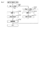
(パチンコ機10の電気的構成)
次に、図14のブロックを参照してパチンコ機10の電気的構成について説明する。
(Electrical configuration of pachinko machine 10)
Next, the electrical configuration of the
主制御装置162に設けられた主制御基板401には、MPU402が搭載されている。MPU402は、当該MPU402により実行される各種の制御プログラムや固定値データを記憶したROM403と、そのROM403内に記憶される制御プログラムの実行に際して各種のデータ等を一時的に記憶するためのメモリであるRAM404と、割込回路、タイマ回路、データ入出力回路、乱数発生器としての各種カウンタ回路などが内蔵された素子である。なお、MPU402が有する機能の一部、例えば、ROM403の機能やRAM404の機能などを別の素子として有する構成としてもよい。
The
MPU402には、入力ポート及び出力ポートがそれぞれ設けられている。MPU402の入力側には、主制御装置162に設けられた停電監視基板405、払出制御装置242及び各種検知センサなどが接続されている。停電監視基板405には電源・発射制御装置243が接続されており、MPU402には停電監視基板405を介して電力が供給される。
The
各種検知センサの一部として、一般入賞口81への入球(入賞)を検知する入球検知センサ391a、可変入賞装置82への入球(入賞)を検知する入球検知センサ391b、可変入賞装置82(大入賞口)への入球(入賞)を検知する入球検知センサ391c、上作動口83aへの入球(入賞)を検知する入球検知センサ391d、下作動口83bへの入球(入賞)を検知する入球検知センサ391e、スルーゲート84への入球(入賞)を検知する入球検知センサ391fが接続されており、主制御装置162のMPU402において各入球部への入賞判定(入球判定)が行われる。また、MPU402では、上作動口83a及び下作動口83bへの入賞に基づいて大当たり発生抽選を実行するとともに、スルーゲート84への入賞に基づいてサポート発生抽選を実行する。
As a part of various detection sensors, a ball entry detection sensor 391a that detects a ball entry (winning) into the general winning
MPU402の出力側には、停電監視基板405、払出制御装置242及び報知・演出制御装置140が接続されている。払出制御装置242には、例えば、上述した作動口83a,83b等の入賞対応入球部への入賞判定結果に基づいて賞球コマンドが出力される。この場合、賞球コマンドの出力に際しては、ROM403のコマンド情報記憶エリア425が参照される。そして、一般入賞口81への入賞を特定した場合には10個の遊技球の払出に対応した賞球コマンドが出力され、可変入賞装置82への入賞を特定した場合には15個の遊技球の払出に対応した賞球コマンドが出力され、上作動口83aへの入賞を特定した場合には3個の遊技球の払出に対応した賞球コマンドが出力され、下作動口83bへの入賞を特定した場合には4個の遊技球の払出に対応した賞球コマンドが出力される。
A power
報知・演出制御装置140には、主制御装置162から変動用コマンド、種別コマンド、変動終了コマンド、オープニングコマンド及びエンディングコマンドなどの各種コマンドが出力される。この場合、これら各種コマンドの出力に際しては、ROM403のコマンド情報記憶エリア425が参照される。これら各種コマンドの詳細については、後に説明する。なお、上記各コマンドは、所定のバイト数の情報として構成されており、当該所定のバイト数の情報として各種情報が含まれている。
Various commands such as a change command, a type command, a change end command, an opening command, and an ending command are output from the
また、MPU402の出力側には、可変入賞装置82の開閉体(例えばシャッタ部材88)を開閉動作させる可変入賞駆動部、下作動口83bの電動役物91を開閉動作させる電動役物駆動部及び主表示ユニット87が接続されている。主制御基板401には各種ドライバ回路が設けられており、当該ドライバ回路を通じてMPU402は各種駆動部の駆動制御を実行する。
Further, on the output side of the
つまり、開閉実行モードにおいては可変入賞装置82が開閉されるように、MPU402において可変入賞駆動部の駆動制御が実行される。また、電動役物91のサポート抽選に当選した場合には、電動役物91が開閉されるように、MPU402において電動役物駆動部の駆動制御が実行される。また、MPU402によって主表示ユニット87の主表示部の表示制御が実行される。
That is, the drive control of the variable winning drive unit is executed in the
さらには、MPU402の出力側に外部出力端子板213が接続されており、この外部出力端子板213を通じて遊技ホール側の管理制御装置(ホールコンピュータHC)に対して各種入球部への入球情報や大当たり等の抽選結果に関する情報が出力される。これにより、ホールコンピュータHCにてパチンコ機10の状態や遊技状況等を把握することが可能となっている。
Further, an external
停電監視基板405は主制御基板401と電源・発射制御装置243とを中継しており、同停電監視基板405には電源・発射制御装置243から出力される最大電圧である直流安定24ボルトの電圧を監視する機能が付与されている。払出制御装置242は、主制御装置162から入力した賞球コマンドに基づいて、払出装置224により賞球や貸し球の払出制御を行うものである。
The power
電源・発射制御装置243は、例えば、遊技場等における商用電源(外部電源)に接続されている。そして、その商用電源から供給される外部電力に基づいて主制御基板401や払出制御装置242等に対して各々に必要な動作電力を生成するとともに、その生成した動作電力を所定の電力経路を通じて供給する。また、電源・発射制御装置243は、遊技球発射機構110の発射制御を担うものであり、遊技球発射機構110は所定の発射条件が整っている場合に駆動される。
The power supply /
報知・演出制御装置140には、MPUが搭載された報知・演出制御基板が設けられている。MPUには、当該MPUにより実行される各種の制御プログラムや固定値データを記憶したROMと、そのROM内に記憶される制御プログラムの実行に際して各種のデータ等を一時的に記憶するためのメモリであるRAMと、割込回路、タイマ回路、データ入出力回路等の各種回路等が内蔵されている。なお、MPUに対してROM及びRAMが1チップ化されていることは必須の構成ではなく、それぞれが個別にチップ化された構成としてもよい。報知・演出制御装置140のMPUは、主制御装置162から入力された各種コマンドに基づいて、前扉枠14に設けられたランプ部26〜28、スピーカ部29、第1可動演出装置300、第2可動演出装置380を駆動制御するとともに、表示制御装置410を制御するものである。
The notification /
表示制御装置410では、報知・演出制御装置140から入力したコマンドに基づいて、図柄表示装置253の表示制御を実行する。この場合に、報知・演出制御装置140では、主制御装置162から入力した各種コマンドに基づいて、図柄表示装置253における図柄の変動表示態様(例えばリーチ発生の有無及びリーチ演出の内容等)や図柄の停止表示態様(変動表示の終了に伴い最終的に停止表示させる図柄の組み合わせの種類)を決定する。
The
ここで、各遊技回の図柄の変動表示に係る構成及び同変動表示の内容について説明する。なお、以下の説明においては適宜図15及び図16を参照する。図15及び図16は図柄表示装置253の表示画面253aにおける表示内容を説明するための概略図である。
Here, the configuration related to the variable display of the symbol of each game and the content of the variable display will be described. In the following description, FIGS. 15 and 16 will be referred to as appropriate. 15 and 16 are schematic views for explaining the display contents on the
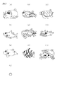
表示制御装置410には、キャラクタROMが設けられている。当該キャラクタROMには、「1」〜「9」の数字が付された9種類の主図柄のデータ(図15(a)〜(i)参照)と、数字が付されていない副図柄のデータ(図15(j)参照)とが予め記憶されている。
The
図16(a)に示すように、図柄表示装置253の表示画面253aには、上段・中段・下段の3つの図柄列Z1,Z2,Z3が設定されている。各図柄列Z1〜Z3は、主図柄と副図柄が所定の順序で配列されて構成されている。そして、表示画面253aでは、これら各図柄列Z1〜Z3の図柄が周期性をもって所定の向き(具体的には、右から左)にスクロールするように変動表示される。
As shown in FIG. 16A, on the
上図柄列Z1には、「1」〜「9」の9種類の主図柄が数字の降順に配列されるとともに、各主図柄の間に副図柄が1つずつ配されている。下図柄列Z3には、「1」〜「9」の9種類の主図柄が数字の昇順に配列されるとともに、各主図柄の間に副図柄が1つずつ配されている。つまり、上図柄列Z1と下図柄列Z3は18個の図柄により構成されている。これに対し、中図柄列Z2には、数字の昇順に「1」〜「9」の9種類の主図柄が配列された上で「9」の主図柄と「1」の主図柄との間に「4」の主図柄が付加的に配列され、これら各主図柄の間に副図柄が1つずつ配されている。つまり、中図柄列Z2に限っては、10個の主図柄が配されて20個の図柄により構成されている。 In the upper symbol row Z1, nine types of main symbols "1" to "9" are arranged in descending order of numbers, and one sub symbol is arranged between each main symbol. In the lower symbol row Z3, nine types of main symbols "1" to "9" are arranged in ascending order of numbers, and one sub symbol is arranged between each main symbol. That is, the upper symbol row Z1 and the lower symbol row Z3 are composed of 18 symbols. On the other hand, in the middle symbol string Z2, nine types of main symbols "1" to "9" are arranged in ascending order of numbers, and then between the main symbol of "9" and the main symbol of "1". The main symbol of "4" is additionally arranged in the above, and one sub symbol is arranged between each of these main symbols. That is, only in the middle symbol row Z2, 10 main symbols are arranged and composed of 20 symbols.
また、図16(b)に示すように、表示画面253aは、図柄列毎に3個の図柄が停止表示されるようになっており、結果として3×3の計9個の図柄が停止表示されるようになっている。また、表示画面253aには、5つの有効ライン、すなわち左ラインL1、中ラインL2、右ラインL3、右下がりラインL4、右上がりラインL5が設定されている。そして、上図柄列Z1→下図柄列Z3→中図柄列Z2の順に変動表示が停止し、いずれかの有効ラインに所定の図柄の組み合わせ(例えば同一の数字が付された図柄の組み合わせ)が形成された状態で全図柄列Z1〜Z3の変動表示が終了すれば、通常大当たり結果又は確変大当たり結果の発生として大当たり動画が表示されるようになっている。
Further, as shown in FIG. 16B, on the
なお、上記のように各図柄列の変動表示が停止されることに鑑みれば、上図柄列Z1を第1図柄列(又は第1絵柄列)、下図柄列Z3を第2図柄列(又は第2絵柄列)、中図柄列Z2を第3図柄列(又は第3絵柄列)と称することができる。 In view of the fact that the variable display of each symbol row is stopped as described above, the upper symbol row Z1 is the first symbol row (or the first symbol row), and the lower symbol row Z3 is the second symbol row (or the second symbol row). 2 symbol row), middle symbol row Z2 can be referred to as 3rd symbol row (or 3rd symbol row).
上記各主図柄のうち、奇数番号(1,3,5,7,9)が付された主図柄は「特定図柄」に相当し、確変大当たり結果が発生する場合には、例えば同一の特定図柄の組み合わせが停止表示される。また、偶数番号(2,4,6,8)が付された主図柄は「非特定図柄」に相当し、通常大当たり結果が発生する場合には、例えば同一の非特定図柄の組み合わせが停止表示される。 Of the above main symbols, the main symbols with odd numbers (1, 3, 5, 7, 9) correspond to "specific symbols", and when a probability variation jackpot result occurs, for example, the same specific symbol The combination of is stopped and displayed. In addition, the main symbols with even numbers (2, 4, 6, 8) correspond to "non-specific symbols", and when a normal jackpot result occurs, for example, the same combination of non-specific symbols is stopped and displayed. Will be done.
なお、図柄表示装置253における図柄の変動表示の態様は上記のものに限定されることはなく任意であり、図柄列の数、図柄列における図柄の変動表示の方向、各図柄列の図柄数などは適宜変更可能である。例えば、複数の図柄列を横並びとなるように設定し、図柄列における図柄の変動表示の方向を縦方向に設定してもよい。
The mode of variable display of symbols in the
表示画面253aにおいて、上図柄列の変動表示領域、中図柄の変動表示領域、下図柄の変動表示領域を有してなる変動表示領域MEの下方となる部分には、保留表示領域NEが設定されている。保留表示領域NEには、遊技球が作動口83a,83bに入賞した場合の最大保留個数(最大保留数)と同一の数の単位保留表示領域Da1〜Da8が左右方向に並ぶようにして区画された保留数表示領域Daが設けられている。
On the
具体的には、遊技球が上作動口83aに入球した場合の最大保留個数(最大保留数)は4個であり、下作動口83bに入球した場合の最大保留個数(最大保留数)は4個である。詳細については後述するが、本実施の形態では上作動口83a及び下作動口83bへの入賞順となるようにして合計で8個の保留情報が記憶される構成となっている。これに対応させて保留数表示領域Daには、第1単位保留表示領域Da1、第2単位保留表示領域Da2、第3単位保留表示領域Da3、第4単位保留表示領域Da4、第5単位保留表示領域Da5、第6単位保留表示領域Da6、第7単位保留表示領域Da7、第8単位保留表示領域Da8が設定されている。これら単位保留表示領域に所定の保留表示用画像として保留アイコンMPが表示される。
Specifically, the maximum number of holdings (maximum number of holdings) when the game ball enters the
例えば、遊技球が作動口83a,83bに入賞した時点で保留個数(保留数)が0の場合、すなわち今回の入賞によって保留数が1個となる場合には、第1単位保留表示領域Da1のみにて保留アイコンMPが表示される。遊技球が作動口83a,83bに入賞することで保留個数が4個となる場合には、第1単位保留表示領域Da1〜第4単位保留表示領域Da4にて保留アイコンMPが表示される構成となっている。なお、図16(b)では保留個数が3個である場合について例示している。
For example, if the number of holdings (number of holdings) is 0 when the game ball wins the operating
また、保留表示領域NEには、保留数表示領域Da(詳しくは第1単位保留表示領域Da1)と横並びとなるようにして、実行される(実行中の)遊技回に対応した保留アイコンMPが表示される実行対象表示領域Dbが設けられている。本実施の形態においては、実行対象表示領域Dbを保留数表示領域Daの左側に配しているが、これらの位置関係等については任意である。例えば、実行対象表示領域Dbを保留数表示領域Daの右側に配してもよい。 Further, in the hold display area NE, a hold icon MP corresponding to the game times to be executed (executed) is arranged side by side with the hold number display area Da (specifically, the first unit hold display area Da1). The execution target display area Db to be displayed is provided. In the present embodiment, the execution target display area Db is arranged on the left side of the hold number display area Da, but the positional relationship and the like thereof are arbitrary. For example, the execution target display area Db may be arranged on the right side of the hold number display area Da.
遊技回が終了して次の遊技回に移行する場合には、保留数表示領域Da(詳しくは第1単位保留表示領域Da1)に表示されている保留アイコンMPが実行対象表示領域Dbにシフト(移動)することとなる。保留数表示領域Daに表示中の他の保留アイコンMPが存在している場合には、当該シフトに併せてそれら保留アイコンMPが実行対象表示領域Dbに近い側の(隣の)単位保留表示領域へシフトする。なお、以降は説明の便宜上、実行対象表示領域Dbに近い側を「下流側」、実行対象表示領域Dbとは反対側を「上流側」と表現する。 When the game round ends and the game round shifts to the next game round, the hold icon MP displayed in the hold number display area Da (specifically, the first unit hold display area Da1) shifts to the execution target display area Db ( Will move). If there are other hold icon MPs being displayed in the hold number display area Da, the hold icon MPs are placed in the unit hold display area (next to) closer to the execution target display area Db in accordance with the shift. Shift to. Hereinafter, for convenience of explanation, the side close to the execution target display area Db will be referred to as "downstream side", and the side opposite to the execution target display area Db will be referred to as "upstream side".
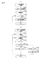
(各種カウンタについて)
次に、上記の如く構成されたパチンコ機10の動作について説明する。
(About various counters)
Next, the operation of the
MPU402は遊技に際し各種カウンタ情報を用いて、大当たり発生抽選、主表示ユニット87(主表示部)の表示の設定、図柄表示装置253の図柄表示の設定などを行うこととしており、具体的には、図17に示すように、大当たり発生の抽選に使用する当たり乱数カウンタC1と、確変大当たり結果や通常大当たり結果等の大当たり種別を判定する際に使用する当たり種別カウンタC2と、図柄表示装置253が外れ変動する際のリーチ抽選に使用するリーチ乱数カウンタC3と、当たり乱数カウンタC1の初期値設定に使用する乱数初期値カウンタCINIと、主表示ユニット87の作動口用表示部及び図柄表示装置253における変動表示時間を決定する変動種別カウンタCSとを用いることとしている。さらに、下作動口83bの電動役物91を電役開放状態とするか否かの抽選に使用する電動役物開放カウンタC4を用いることとしている。
The
各カウンタC1〜C3,CINI,CS,C4は、その更新の都度前回値に1が加算され、最大値に達した後0に戻るループカウンタとなっている。各カウンタは短時間間隔で更新され、その更新値がRAM404の所定領域に設定された抽選カウンタ用バッファ431に適宜格納される。RAM404には、作動口用保留エリアREと、実行エリアAEと、総保留数記憶領域とよりなる保留球格納エリア432が設けられている。そして、この保留球格納エリア432に、上作動口83a又は下作動口83bへの遊技球の入賞履歴に合わせて、当たり乱数カウンタC1、当たり種別カウンタC2及びリーチ乱数カウンタC3の各値が時系列的に格納されるようになっている。
Each of the counters C1 to C3, CINI, CS, and C4 is a loop counter in which 1 is added to the previous value each time the counter is updated, and the counter returns to 0 after reaching the maximum value. Each counter is updated at short intervals, and the updated value is appropriately stored in the
各カウンタについて詳しくは、当たり乱数カウンタC1は、例えば0〜599の範囲内で順に1ずつ加算され、最大値(つまり599)に達した後0に戻る構成となっている。特に当たり乱数カウンタC1が1周した場合、その時点の乱数初期値カウンタCINIの値が当該当たり乱数カウンタC1の初期値として読み込まれる。なお、乱数初期値カウンタCINIは、当たり乱数カウンタC1と同様のループカウンタである(値=0〜599)。当たり乱数カウンタC1は定期的に更新され、遊技球が上作動口83a又は下作動口83bに入賞したタイミングで保留球格納エリア432の作動口用保留エリアREに格納される。
More specifically, the hit random number counter C1 is configured to add 1 in order within the range of 0 to 599, reach the maximum value (that is, 599), and then return to 0. In particular, when the hit random number counter C1 makes one round, the value of the random number initial value counter CINI at that time is read as the initial value of the hit random number counter C1. The random number initial value counter CINI is a loop counter similar to the hit random number counter C1 (value = 0 to 599). The winning random number counter C1 is periodically updated, and is stored in the operating port holding area RE of the holding
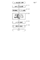
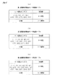
大当たり当選となる乱数の値は、ROM403における当否情報群記憶手段としての当否テーブル記憶エリア421に当否テーブル(当否情報群)として記憶されている。当否テーブルとしては、低確率モード用の当否テーブル(低確率用当否情報群)と、高確率モード用の当否テーブル(高確率用当否情報群)とが設定されている。つまり、本パチンコ機10は、当否抽選手段における抽選モードとして、低確率モード(低確率状態)と高確率モード(高確率状態)とが設定されている。
The value of the random number that wins the jackpot is stored as a hit / miss table (hit / miss information group) in the hit / miss
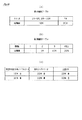
上記抽選に際して低確率モード用の当否テーブル(図18(a))が参照されることとなる遊技状態下では、大当たり当選となる乱数の値(すなわち、当選情報)は「7」,「307」,「507」の3個である。つまり、「0〜599」の当たり乱数カウンタC1の値のうち「7」,「307」,「507」が大当たり結果に対応しており、それらの乱数の値以外は外れ結果に対応している。これにより、大当たり確率が1/200となっている。 In the gaming state in which the winning / failing table for the low probability mode (FIG. 18A) is referred to in the lottery, the random number values (that is, winning information) for winning the jackpot are "7" and "307". , "507". That is, among the values of the hit random number counter C1 of "0 to 599", "7", "307", and "507" correspond to the jackpot results, and the values other than those random numbers correspond to the outlier results. .. As a result, the jackpot probability is 1/200.
上記抽選に際して高確率モード用の当否テーブル(図18(b))が参照されることとなる遊技状態下では、大当たり当選となる乱数の値(すなわち、当選情報)は「7」,「36」,「107」,「307」・・・「407」,「507」.「598」の30個である。つまり、「0〜599」の当たり乱数カウンタC1の値のうち「7」,「36」,「107」,「307」・・・「407」,「507」.「598」が大当たり結果に対応しており、それらの乱数の値以外は外れ結果に対応している。これにより、大当たり確率が約1/20となっている。 Under the gaming state in which the winning / failing table for the high probability mode (FIG. 18B) is referred to in the lottery, the random number values (that is, winning information) for winning the jackpot are "7" and "36". , "107", "307" ... "407", "507". There are 30 of "598". That is, among the values of the hit random number counter C1 of "0 to 599", "7", "36", "107", "307" ... "407", "507". "598" corresponds to the jackpot result, and other than those random numbers, it corresponds to the outlier result. As a result, the jackpot probability is about 1/20.
因みに、低確率モードよりも高確率モードの方の当選確率が高くなるのであれば、上記当選となる乱数の数及び値は任意である。 Incidentally, if the winning probability in the high probability mode is higher than that in the low probability mode, the number and value of the random numbers to be won are arbitrary.
当たり種別カウンタC2は、0〜29の範囲内で順に1ずつ加算され、最大値(つまり29)に達した後0に戻る構成となっている。ここで、本実施の形態では、複数の大当たり結果が設定されている。これら複数の大当たり結果は、(1)開閉実行モード終了後の電動役物91によるサポートモード、(2)開閉実行モード終了後の抽選モード、(3)開閉実行モード中の開閉態様という3つの条件に差異が設けられている。
The hit type counter C2 is configured to be incremented by 1 in order within the range of 0 to 29, reach the maximum value (that is, 29), and then return to 0. Here, in the present embodiment, a plurality of jackpot results are set. These multiple jackpot results are three conditions: (1) support mode by the
下作動口83bの電動役物91におけるサポートモードとしては、遊技領域PEに対して同様の態様で遊技球の発射が継続されている状況で比較した場合に、下作動口83bの電動役物91が単位時間当たりに開放状態となる頻度が相対的に高低となるように、低頻度サポートモード(低頻度サポート状態又は低頻度ガイド状態)と高頻度サポートモード(高頻度サポート状態又は高頻度ガイド状態)とが設定されている。
As the support mode in the
具体的には、低頻度サポートモードと高頻度サポートモードとでは、電動役物開放カウンタC4を用いた電動役物開放抽選における電役開放状態当選となる確率は同一となっているが、高頻度サポートモードでは低頻度サポートモードよりも、電役開放状態当選となった際に電動役物91が開放状態となる回数が多く設定されており、さらに1回の開放時間が長く設定されている。この場合、高頻度サポートモードにおいて電役開放状態当選となり電動役物91の開放状態が複数回発生する場合において、1回の開放状態が終了してから次の開放状態が開始されるまでの閉鎖時間は、1回の開放時間よりも短く設定されている。さらにまた、高頻度サポートモードでは低頻度サポートモードよりも、1回の電動役物開放抽選が行われてから次の電動役物開放抽選が行われる上で最低限確保される確保時間が短く設定されている。
Specifically, in the low-frequency support mode and the high-frequency support mode, the probability of winning the electric role open state in the electric accessory open lottery using the electric accessory release counter C4 is the same, but the probability is high. In the support mode, the number of times the
上記のように高頻度サポートモードでは、低頻度サポートモードよりも下作動口83bへの入賞が発生する確率が高くなる。換言すれば、低頻度サポートモードでは、下作動口83bよりも上作動口83aへの入賞が発生する確率が高くなるが、高頻度サポートモードでは、上作動口83aよりも下作動口83bへの入賞が発生する確率が高くなる。そして、下作動口83bへの入賞が発生した場合には、所定個数の遊技球の払出が実行されるため、高頻度サポートモードでは、遊技者は持ち球をあまり減らさないようにしながら遊技を行うことができる。
As described above, in the high frequency support mode, the probability that the
なお、高頻度サポートモードを低頻度サポートモードよりも単位時間当たりに電役開放状態となる頻度を高くする上での構成は、上記のものに限定されることはなく、例えば電動役物開放抽選における電役開放状態当選となる確率を高くする構成としてもよい。さらには、回数、開放時間及び当選確率のうち、いずれか1条件又は任意の組み合わせの条件を相違させることで、高頻度サポートモードと低頻度サポートモードとの設定を行う構成としてもよい。 The configuration for increasing the frequency of the high-frequency support mode to be in the electric service open state per unit time is not limited to the above, for example, the electric accessory open lottery. It may be configured to increase the probability of winning the electric service open state in. Further, the high frequency support mode and the low frequency support mode may be set by differentiating any one condition or any combination of the number of times, the opening time, and the winning probability.
当たり種別カウンタC2は定期的に更新され、遊技球が、上作動口83a又は下作動口83bに入賞したタイミングで保留球格納エリア432の作動口用保留エリアREに格納される。
The hit type counter C2 is periodically updated, and the game ball is stored in the operating port holding area RE of the holding
当たり種別カウンタC2に対する遊技結果の振分先は、ROM403における振分情報群記憶手段としての振分テーブル記憶エリア422に振分テーブル(振分情報群)として記憶されている。ここで、振分テーブルの内容について図19の概略図を用いて説明する。振分テーブルとしては、図19(a)に示す上作動口用の振分テーブル(第1振分情報群)と、図19(b)に示す下作動口用の振分テーブル(第2振分情報群)とが設定されている。
The distribution destination of the game result with respect to the hit type counter C2 is stored as a distribution table (distribution information group) in the distribution
上作動口用の振分テーブルでは、遊技結果の振分先として、8R確変大当たり結果A、8R確変大当たり結果B、8R通常大当たり結果が設定されている。具体的には、上作動口用の振分テーブルでは、「0〜29」の当たり種別カウンタC2の値のうち、「0〜8」が8R確変大当たり結果Aに対応しており、「9〜14」が8R確変大当たり結果Bに対応しており、「15〜29」が8R通常大当たり結果に対応している。 In the distribution table for the upper operating port, the 8R probability variation jackpot result A, the 8R probability variation jackpot result B, and the 8R normal jackpot result are set as the distribution destinations of the game results. Specifically, in the distribution table for the upper working port, among the values of the hit type counter C2 of "0 to 29", "0 to 8" corresponds to the 8R probability variation jackpot result A, and "9 to" "14" corresponds to the 8R probability variation jackpot result B, and "15 to 29" corresponds to the 8R normal jackpot result.
下作動口用の振分テーブルでは、遊技結果の振分先として、16R確変大当たり結果、8R確変大当たり結果A、8R確変大当たり結果B、16通常大当たり結果が設定されている。具体的には、下作動口用の振分テーブルでは、「0〜29」の当たり種別カウンタC2の値のうち、「0〜4」が16R確変大当たり結果に対応しており、「5〜9」が8R確変大当たり結果Aに対応しており、「10〜14」が8R確変大当たり結果Bに対応しており、「15〜29」が16R通常大当たり結果に対応している。 In the distribution table for the lower operating port, 16R probability variation jackpot result, 8R probability variation jackpot result A, 8R probability variation jackpot result B, and 16 normal jackpot results are set as distribution destinations of the game results. Specifically, in the distribution table for the lower operating port, among the values of the hit type counter C2 of "0 to 29", "0 to 4" corresponds to the 16R probability variation jackpot result, and "5 to 9". Corresponds to the 8R probability variation jackpot result A, "10 to 14" corresponds to the 8R probability variation jackpot result B, and "15 to 29" corresponds to the 16R normal jackpot result.
16R確変大当たり結果、8R確変大当たり結果A及び8R確変大当たり結果Bは、開閉実行モードの終了後に抽選モードが高確率モードとなり且つサポートモードが高頻度サポートモードとなる大当たり結果である。これらの大当たり結果を契機として移行した通常遊技状態については、次回大当たり結果となるまで継続される(図19(c)参照)。 The 16R probability variation jackpot result, the 8R probability variation jackpot result A, and the 8R probability variation jackpot result B are jackpot results in which the lottery mode becomes the high probability mode and the support mode becomes the high frequency support mode after the end of the open / close execution mode. The normal game state shifted by these jackpot results as an opportunity is continued until the next jackpot result is obtained (see FIG. 19 (c)).
これに対して、8R通常大当たり結果又は16R通常大当たり結果は、開閉実行モードの終了後に抽選モードが低確率モードとなり且つサポートモードが高頻度サポートモードとなる大当たり結果である。これらの大当たり結果を契機として移行した通常遊技状態については、当該通常遊技状態への移行後に実行された遊技回数が終了基準回数(具体的には、100回)に達した場合又は当該終了基準回数到達前に大当たり結果となった場合(詳しくは開閉実行モードが開始される場合)に終了する(図19(c)参照)。 On the other hand, the 8R normal jackpot result or the 16R normal jackpot result is a jackpot result in which the lottery mode becomes the low probability mode and the support mode becomes the high frequency support mode after the end of the open / close execution mode. Regarding the normal game state shifted by these jackpot results as an opportunity, when the number of games executed after the transition to the normal game state reaches the end reference number (specifically, 100 times) or the end reference number of times. It ends when a big hit result is obtained before reaching (for details, when the open / close execution mode is started) (see FIG. 19 (c)).
以下の説明では、低頻度サポートモード且つ低確率モード対応の通常遊技状態を「第1通常遊技状態」、高頻度サポートモード且つ低確率モード対応の通常遊技状態を「第2通常遊技状態」、高頻度サポートモード且つ高確率モード対応の通常遊技状態を「第3通常遊技状態」と称し適宜区別する。 In the following description, the normal game state corresponding to the low frequency support mode and the low probability mode is the "first normal game state", and the normal game state corresponding to the high frequency support mode and the low probability mode is the "second normal game state". The normal game state corresponding to the frequency support mode and the high probability mode is referred to as a "third normal game state" and is appropriately distinguished.
次に図20を参照して、開閉実行モード中の可変入賞装置82の開閉態様について補足説明する。本実施の形態においては、開閉実行モード中の遊技の単調化を抑制すべく、大当たり結果に応じて可変入賞装置82の開閉態様が異なる構成となっている。具体的には、16R確変大当たり結果、8R確変大当たり結果A、16R通常大当たり結果、8R通常大当たり結果については、各ラウンドの最大開放時間として「30sec」が設定され、ラウンド間のインターバル時間として「2sec」が設定される。これに対して、8R確変大当たり結果Bについては、各ラウンドの最大開放時間として「30eec」が設定される点では他の大当たり結果と同様であるものの、インターバル時間として「2sec」及び「5sec」が設定される構成となっている点で相違している。
Next, with reference to FIG. 20, the opening / closing mode of the variable winning
既に説明したように、右ルートへ遊技球が連続して発射される場合の発射周期については0.6secである。可変入賞装置82に到達した遊技球が開閉体82b上を転動して大入賞口82aの上方を通過(素通り)する場合に要する所要時間はおよそ「2sec」となっている。このため、インターバル時間が「2sec」となっている場合には、遊技球の発射を継続したとしてもそのほとんどが可変入賞装置82に入賞することとなる。つまり、ラウンドの終了タイミングを見計らって遊技球の発射を停止しなくても、持ち球が無駄に消費されることを抑制される。
As described above, the firing cycle when the game balls are continuously launched to the right route is 0.6 sec. The time required for the game ball that has reached the variable winning
これに対して、インターバル時間が「5sec」となっている場合には、遊技球の発射を継続した場合に、可変入賞装置82に入賞することなくアウト口89に向かう遊技球が多くなる。つまり、ラウンドの終了タイミングを見計らって遊技球の発射を停止することで持ち球の無駄な消費を抑制するという技術介入が可能となる。
On the other hand, when the interval time is "5 sec", when the firing of the game balls is continued, many game balls head toward the
ここで、8R確変大当たり結果Bにおいては、当たり種別カウンタC2の値に応じて、インターバル時間として「5sec」を設定するラウンド(特定ラウンド)が異なる構成となっている。例えば当たり種別カウンタC2の値が「9」の場合には、第3ラウンド及び第4ラウンドにて「5sec」が設定され、「10」の場合には、第3ラウンド及び第5ラウンドにて「5sec」が設定され、「11」の場合には第3ラウンド及び第6ラウンドにて「5sec」が設定され、「12」の場合には第3ラウンド及び第7ラウンドにて「5sec」が設定され、「13」の場合には第3ラウンド及び第8ラウンドにて「5sec」が設定され、「14」の場合には第3ラウンドにて「5sec」が設定される。 Here, in the 8R probability variation jackpot result B, the rounds (specific rounds) in which "5 sec" is set as the interval time are different depending on the value of the hit type counter C2. For example, when the value of the hit type counter C2 is "9", "5 sec" is set in the third and fourth rounds, and when it is "10", "5 sec" is set in the third and fifth rounds. "5sec" is set, in the case of "11", "5sec" is set in the third and sixth rounds, and in the case of "12", "5sec" is set in the third and seventh rounds. In the case of "13", "5 sec" is set in the third and eighth rounds, and in the case of "14", "5 sec" is set in the third round.
このようにして、開閉実行モード中の開閉態様を多様化することにより、開閉実行モード中の遊技の単調化を抑制し、開閉実行モード中に可変入賞装置82への注目を促す構成が実現されている。
By diversifying the opening / closing modes in the opening / closing execution mode in this way, a configuration is realized in which the monotonousness of the game in the opening / closing execution mode is suppressed and the variable winning
リーチ乱数カウンタC3は、例えば0〜238の範囲内で順に1ずつ加算され、最大値(つまり238)に達した後0に戻る構成となっている。リーチ乱数カウンタC3は定期的に更新され、遊技球が上作動口83a又は下作動口83bに入賞したタイミングで保留球格納エリア432の作動口用保留エリアREに格納される。そして、ROM403のリーチ用テーブル記憶エリアに記憶されたリーチ用テーブルに基づいてリーチを発生させるか否かを決定することとしている。
The reach random number counter C3 is configured to be incremented by 1 in order within the range of 0 to 238, and return to 0 after reaching the maximum value (that is, 238). The reach random number counter C3 is periodically updated, and is stored in the operating port holding area RE of the holding
但し、開閉実行モードに移行する遊技回においては、MPU402では、リーチ乱数カウンタC3の値に関係なくリーチ発生の決定を行う。なお、リーチ表示の発生に対応したリーチ乱数カウンタC3の数は、各遊技状態において同一となっているが、遊技状態に応じて各々個別に設定されるものであってもよい。例えば、サポートモードが高頻度サポートモードである場合の方が、低頻度サポートモードよりも、リーチ表示の発生に対応したリーチ乱数カウンタC3の数が多く設定された構成としてもよい。
However, in the game round to shift to the open / close execution mode, the
ここで、リーチ表示(リーチ状態)とは、図柄(絵柄)の変動表示(又は可変表示)を行うことが可能な図柄表示装置253(表示画面253a)を備え、遊技結果が開閉実行モード対応の遊技結果となった遊技回では変動表示後の停止表示結果が特別表示結果となり得る遊技機において、図柄表示装置253における図柄(絵柄)の変動表示(又は可変表示)が開始されてから停止表示結果が導出表示される前段階で、前記特別表示結果となり易い変動表示状態であると遊技者に思わせるための表示状態をいう。
Here, the reach display (reach state) is provided with a symbol display device 253 (
換言すれば、図柄表示装置253の表示画面253aに表示される複数の図柄列のうち一部の図柄列について図柄を停止表示させることで、開閉実行モードの発生に対応した図柄の組み合わせが成立する可能性があるリーチ図柄の組み合わせを表示し、その状態で残りの図柄列において図柄の変動表示を行う表示状態のことである。
In other words, by stopping and displaying some of the symbol strings among the plurality of symbol rows displayed on the
より具体的には、図柄の変動表示を終了させる前段階として、図柄表示装置253の表示画面253a内の予め設定された有効ライン上に、開閉実行モードの発生に対応した図柄の組み合わせが成立する可能性のあるリーチ図柄の組み合わせを停止表示させることによりリーチラインを形成させ、当該リーチラインが形成されている状況下において最終停止図柄列により図柄の変動表示を行うことである。
More specifically, as a pre-stage for ending the variable display of the symbol, a combination of symbols corresponding to the occurrence of the open / close execution mode is established on the preset effective line in the
表示画面253aにおける表示内容について更に詳しく説明すると、最初に上図柄列Z1において図柄の変動表示が終了され、さらに下図柄列Z3において図柄の変動表示が終了された状態において、いずれかの有効ラインに当たり図柄の組み合わせを構成する数字が付された主図柄が停止表示されることでリーチラインが形成され、当該リーチラインが形成されている状況化において中図柄列Z2にて図柄の変動表示が行われることでリーチ表示となる。そして、大当たり発生時には、リーチラインを形成している主図柄とともに当たり図柄の組み合わせを構成する数字が付された主図柄がリーチライン上に停止表示されるようにして中図柄列Z2における図柄の変動表示が終了される。
Explaining the display contents on the
また、リーチ表示には、上記のようにリーチ図柄の組み合わせを表示した状態で、残りの図柄列において図柄の変動表示を行うとともに、その背景画面において所定のキャラクタなどを動画として表示することによりリーチ演出を行うものや、リーチ図柄の組み合わせを縮小表示させる又は非表示とした上で、表示画面253aの略全体において所定のキャラクタなどを動画として表示することによりリーチ演出を行うものが含まれる。また、リーチ表示が行われている場合又はリーチ表示の前に所定のキャラクタといった所定画像を用いた予告表示を行うか否かの決定を、リーチ乱数カウンタC3やその他のカウンタを用いて行うようにしてもよい。
Further, in the reach display, in the state where the combination of reach symbols is displayed as described above, the remaining symbol rows are displayed in a variable manner, and a predetermined character or the like is displayed as a moving image on the background screen to reach the reach. Includes those that perform an effect, and those that perform a reach effect by displaying a predetermined character or the like as a moving image on substantially the
変動種別カウンタCSは、例えば0〜198の範囲内で順に1ずつ加算され、最大値(つまり198)に達した後0に戻る構成となっている。変動種別カウンタCSは、主表示ユニット87(主表示部)の上作動口用表示部及び下作動口用表示部における変動表示時間と、図柄表示装置253における図柄の変動表示時間とをMPU402において決定する上で用いられる。変動種別カウンタCSは、後述する通常処理が1回実行される毎に1回更新され、当該通常処理内の残余時間内でも繰り返し更新される。そして、上作動口用表示部及び下作動口用表示部における変動表示の開始時及び図柄表示装置253による図柄の変動開始時における変動パターン決定に際して変動種別カウンタCSのバッファ値が取得される。
The variation type counter CS is configured to be incremented by 1 in order within the range of 0 to 198, and return to 0 after reaching the maximum value (that is, 198). The variation type counter CS determines in the
電動役物開放カウンタC4は、例えば、0〜250の範囲内で順に1ずつ加算され、最大値(つまり250)に達した後0に戻る構成となっている。電動役物開放カウンタC4は定期的に更新され、スルーゲート84に遊技球が入賞したタイミングでRAM404の電役保留エリア433に格納される。そして、所定のタイミングにおいて、その格納された電動役物開放カウンタC4の値によって下作動口83bの電動役物91を開放状態に制御するか否かの抽選が行われる。例えば、C4=0〜190であれば、電動役物91を開放状態に制御し、C4=191〜250であれば、電動役物91を開放状態に制御しない。
The electric accessory release counter C4 is configured to be incremented by 1 in order within the range of 0 to 250, reach the maximum value (that is, 250), and then return to 0. The electric accessory opening counter C4 is periodically updated, and is stored in the electric
既に説明したように、MPU402では、少なくとも変動種別カウンタCSのバッファ値を用いて、上作動口用表示部及び下作動口用表示部における変動表示時間が決定されるが、その決定に際してはROM403の変動表示時間テーブル記憶エリア423が用いられる。また、MPU402では、実行エリアAEに格納されている当たり乱数カウンタC1の値及び当たり種別カウンタC2の値を用いて、上作動口用表示部及び下作動口用表示部における停止結果が決定されるが、その決定に際してはROM403の停止結果テーブル記憶エリア424が用いられる。
As described above, in the
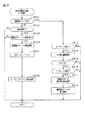
(主制御装置162にて実行される各種処理について)
次に、主制御装置162内のMPU402にて各遊技回での遊技を進行させる上で実行されるタイマ割込み処理及び通常処理を説明する。なお、MPU402では、上記タイマ割込み処理及び通常処理の他に、電源投入に伴い起動されるメイン処理やNMI端子(ノンマスカブル端子)への停電信号の入力により起動されるNMI割込み処理が実行されるが、これらの各種処理については説明を省略する。
(About various processes executed by the main controller 162)
Next, the timer interrupt processing and the normal processing executed in order to advance the game in each game time by the
(タイマ割込み処理)
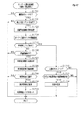
先ず、図21のフローチャートを参照し、タイマ割込み処理について説明する。本処理はMPU402により定期的に(例えば2msec周期で)起動される。
(Timer interrupt processing)
First, the timer interrupt processing will be described with reference to the flowchart of FIG. This process is periodically (for example, every 2 msec) started by the
ステップS101では、各種入球検知センサ(例えば上記検知センサ391a〜391f)の読み込み処理を実行する。すなわち、主制御装置162に接続されている各種入球検知センサの状態を読み込み、当該入球検知センサの状態を判定して検出情報(入賞検知情報)を保存する。
In step S101, reading processing of various ball entry detection sensors (for example, the detection sensors 391a to 391f) is executed. That is, the state of various ball entry detection sensors connected to the
その後、ステップS102では、乱数初期値カウンタCINIの更新を実行する。具体的には、乱数初期値カウンタCINIを1インクリメントするとともに、そのカウンタ値が最大値に達した際に0にクリアする。そして、乱数初期値カウンタCINIの更新値を、RAM404の該当するバッファ領域に格納する。
After that, in step S102, the random number initial value counter CINI is updated. Specifically, the random number initial value counter CINI is incremented by 1 and cleared to 0 when the counter value reaches the maximum value. Then, the updated value of the random number initial value counter CINI is stored in the corresponding buffer area of the
続くステップS103では、当たり乱数カウンタC1、当たり種別カウンタC2、リーチ乱数カウンタC3及び電動役物開放カウンタC4の更新を実行する。具体的には、当たり乱数カウンタC1、当たり種別カウンタC2、リーチ乱数カウンタC3及び電動役物開放カウンタC4をそれぞれ1インクリメントするとともに、それらのカウンタ値が最大値に達した際それぞれ0にクリアする。そして、各カウンタC1〜C4の更新値を、RAM404の該当するバッファ領域に格納する。
In the following step S103, the hit random number counter C1, the hit type counter C2, the reach random number counter C3, and the electric accessory release counter C4 are updated. Specifically, the hit random number counter C1, the hit type counter C2, the reach random number counter C3, and the electric accessory release counter C4 are each incremented by 1, and when the counter values reach the maximum values, they are cleared to 0, respectively. Then, the updated values of the counters C1 to C4 are stored in the corresponding buffer area of the
続くステップS104では、スルーゲート84への入賞に伴うスルー用の入賞処理を実行する。スルー用の入賞処理では、RAM404の各種フラグ格納エリア435にスルーゲート用の入賞検知フラグが格納されているか否かを判定し、同フラグが格納されている場合には電役保留エリア433に記憶されている役物保留記憶数が4未満であることを条件として、前記ステップS103にて更新した電動役物開放カウンタC4の値を電役保留エリアに格納する。そして、各種フラグ格納エリア435にスルーゲート用の入賞検知フラグが格納されている場合には、同入賞検知フラグを消去して当該スルーゲート用の入賞処理を終了する。
In the following step S104, a winning process for thru accompanying the winning of the thru
ステップS104のスルーゲート用の入賞処理を実行した後はステップS105に進み、当該ステップS105にて作動口83a,83bへの入賞に伴う作動口用の入賞処理を実行し、本タイマ割込み処理を終了する。
After executing the winning process for the through gate in step S104, the process proceeds to step S105, and in the step S105, the winning process for the operating port accompanying the winning of the operating
(作動口用の入賞処理)
ここで、図22及び図23のフローチャートを参照して作動口用の入賞処理について説明する。
(Prize processing for operating port)
Here, the winning process for the operating port will be described with reference to the flowcharts of FIGS. 22 and 23.
ステップS201では、遊技球が上作動口83aに入球(入賞)したか否かを判定する。遊技球が上作動口83aに入球したと判定した場合には、ステップS202に進み、払出制御装置242に遊技球を3個払い出させるための賞球コマンドをセットする。
In step S201, it is determined whether or not the game ball has entered (winned) the
続くステップS203では、上作動口83aに遊技球が入球した旨を示す情報を遊技ホール側のホールコンピュータHCに対して信号出力すべく外部信号設定処理を行う。これにより、上作動口83aへの入球が発生した旨がホールコンピュータHCにて把握される。その後、ステップS204では、当たり乱数カウンタC1や当たり種別カウンタC2等の各値を格納する情報取得処理を行い、本入賞処理を終了する。
In the following step S203, an external signal setting process is performed so as to output a signal indicating that the game ball has entered the
一方、ステップS201にて遊技球が上作動口83aに入賞していないと判定した場合にはステップS205に進む。ステップS205では、遊技球が下作動口83bに入球(入賞)したか否かを判定する。遊技球が下作動口83bに入球したと判定した場合には、ステップS206に進み、払出制御装置242に遊技球を4個払い出させるための賞球コマンドをセットする。なお、ステップS202,S206にてセットした賞球コマンドは、後述する通常処理の外部出力処理S401にて払出制御装置242に対して送信される。
On the other hand, if it is determined in step S201 that the game ball has not won the
続くステップS207では、下作動口83bに遊技球が入球した旨を示す情報を遊技ホール側のホールコンピュータHCに対して信号出力すべく外部信号設定処理を行う。これにより、下作動口83bへの入球が発生した旨がホールコンピュータHCにて把握される。その後、ステップS204にて情報取得処理を行い、本入賞処理を終了する。
In the following step S207, an external signal setting process is performed so as to output a signal indicating that the game ball has entered the
なお、ステップS201,S205の両処理にてそれぞれ否定判定をした場合、すなわち上作動口83a及び下作動口83bのいずれにも入球がなかった場合には、そのまま本入賞処理を終了する。
If a negative determination is made in both the processes of steps S201 and S205, that is, if there is no ball in any of the
ここで、図23を参照して、ステップS204の情報取得処理について説明する。 Here, the information acquisition process in step S204 will be described with reference to FIG. 23.
(情報取得処理)
情報取得処理においては先ずステップS301にて、保留球格納エリア432の保留数記憶領域に格納された作動保留記憶数N、詳しくは上作動口83a及び下作動口83bのうち当該情報取得処理の契機となった入球部に係る作動保留記憶数Nが上限値(本実施の形態では「4」)未満であるか否かを判定する。作動保留記憶数Nが上限値である場合にはそのまま本情報取得処理を終了し、上限値未満である場合には、ステップS302にて対応する作動口の作動保留記憶数Nを1インクリメントするとともに、ステップS303にて保留数記憶領域に格納された総保留数(以下、共通保留数CRNと言う)を1インクリメントする。
(Information acquisition process)
In the information acquisition process, first, in step S301, the operation hold storage number N stored in the hold number storage area of the hold
続くステップS304では、上記ステップS103にて更新した当たり乱数カウンタC1、当たり種別カウンタC2、リーチ乱数カウンタC3及び変動種別カウンタCSの各値を、作動口用保留エリアREの空き記憶領域エリアのうち最初の記憶エリア、すなわち上記ステップS302にて1インクリメントした共通保留数CRNと対応する記憶エリアに格納する。格納処理を実行した後は、ステップS305に進む。 In the following step S304, the values of the hit random number counter C1, the hit type counter C2, the reach random number counter C3, and the variable type counter CS updated in step S103 are set to the first of the free storage area areas of the operation port hold area RE. Is stored in the storage area of, that is, the storage area corresponding to the common hold number CRN incremented by 1 in step S302. After executing the storage process, the process proceeds to step S305.
続くステップS305及びステップS306では、作動口83a,83bへの入賞が発生したことをサブ側(副側)の制御装置である報知・演出制御装置140及び表示制御装置410に認識させるとともに該当する遊技回が開始される前に予告演出(保留予告)を実行させるための処理である保留予告用の確認処理及び保留コマンドの設定処理を実行し、本情報取得処理を終了する。なお、保留コマンドには上作動口83a及び下作動口83bのうちいずれの入球部への入賞に基づくものであるかの情報が含まれる。
In the following steps S305 and S306, the notification /
ステップS307の保留コマンドの設定処理にて設定された保留コマンドは後述する通常処理の外部出力処理(ステップS401)にて報知・演出制御装置140及び表示制御装置410に送信されることとなる。
The hold command set in the hold command setting process in step S307 is transmitted to the notification /
(通常処理)
次に、通常処理の流れを図24のフローチャートを参照しながら説明する。通常処理は電源投入に伴い起動されるメイン処理が実行された後に開始される処理であり、通常処理では遊技の主要な処理が実行される。その概要として、ステップS401〜S406の処理が4msec周期の定期処理として実行され、その残余時間でステップS408,S409のカウンタ更新処理が実行される構成となっている。
(Normal processing)
Next, the flow of normal processing will be described with reference to the flowchart of FIG. The normal process is a process that is started after the main process that is started when the power is turned on is executed, and in the normal process, the main process of the game is executed. As an outline, the processes of steps S401 to S406 are executed as periodic processes having a cycle of 4 msec, and the counter update processes of steps S408 and S409 are executed in the remaining time.
通常処理においては先ず、ステップS401にて外部信号出力処理を実行する。ステップS401の外部信号出力処理では、タイマ割込み処理又は前回の通常処理で設定したコマンド等の出力データをサブ側の各制御装置及びホールコンピュータHCに送信する。 In the normal processing, first, the external signal output processing is executed in step S401. In the external signal output process of step S401, output data such as a timer interrupt process or a command set in the previous normal process is transmitted to each control device on the sub side and the hall computer HC.
具体的には、賞球コマンドの有無を判定し、賞球コマンドが設定されていればそれを払出制御装置242に対して送信する。また、変動開始コマンド、種別コマンド、変動終了コマンド等の演出用コマンドや保留コマンドや後述するシフトコマンド等の各種コマンドが設定されている場合にはそれを報知・演出制御装置140に対して送信する。
Specifically, the presence or absence of the prize ball command is determined, and if the prize ball command is set, it is transmitted to the
また、詳細については後述するが、例えば主表示部の作動口用表示部にて図柄の変動表示が終了する毎にホールコンピュータHCに図柄確定を示す外部信号を出力し、開閉実行モード中は開閉実行モード中であることを示す外部信号をホールコンピュータHCに出力し、高頻度サポートモード中である場合には高頻度サポートモード中であることを示す外部信号をホールコンピュータHCに出力する。 Further, as will be described in detail later, for example, an external signal indicating that the symbol is confirmed is output to the hall computer HC every time the variation display of the symbol is completed on the display unit for the operation port of the main display unit, and the display is opened / closed during the open / close execution mode. An external signal indicating that the execution mode is in progress is output to the hall computer HC, and when the high frequency support mode is in effect, an external signal indicating that the high frequency support mode is in progress is output to the hall computer HC.
次に、ステップS402では、変動種別カウンタCSの更新を実行する。具体的には、変動種別カウンタCSを1インクリメントするとともに、カウンタ値が最大値に達した際にはカウンタ値を0にクリアする。そして、変動種別カウンタCSの更新値を、RAM404の該当するバッファ領域に格納する。
Next, in step S402, the variation type counter CS is updated. Specifically, the fluctuation type counter CS is incremented by 1, and when the counter value reaches the maximum value, the counter value is cleared to 0. Then, the update value of the variation type counter CS is stored in the corresponding buffer area of the
続くステップS403では、各遊技回における遊技を制御するための遊技回制御処理を実行する。この遊技回制御処理では、大当たり判定、図柄表示装置253による図柄の変動表示の設定、主表示ユニット87の表示制御などを行う。
In the following step S403, a game turn control process for controlling the game in each game turn is executed. In this game turn control process, a jackpot determination, a setting of a symbol variation display by the
ステップS403の遊技回制御処理を実行した後は、ステップS404に進み、遊技状態移行処理を実行する。詳細は後述するが、この遊技状態移行処理により、遊技状態が開閉実行モード、高確率モード、高頻度サポートモードなどに移行する。なお、ステップS403の遊技回制御処理及びステップS404の遊技状態移行処理についての詳細は後述する。 After executing the game times control process in step S403, the process proceeds to step S404 to execute the game state transition process. Although the details will be described later, the game state shifts to the open / close execution mode, the high probability mode, the high frequency support mode, and the like by this game state transition process. The details of the game turn control process in step S403 and the game state transition process in step S404 will be described later.
続くステップS405では、下作動口83bに併設された電動役物91を駆動制御するための電役サポート用処理を実行する。この電役サポート用処理では、RAM404の電役保留エリア433に格納されている電動役物開放カウンタC4から取得した数値情報を用いて電動役物91を開放状態とするか否かの電役開放抽選を行うとともに、電役開放状態当選となった場合には電動役物91の開閉処理を実行する。また、電役開放抽選の抽選結果を教示するように、主表示部におけるスルーゲート用表示部の表示制御などを行う。
In the following step S405, an electric service support process for driving and controlling the
既に説明したとおり、電動役物91によるサポートの態様として、低頻度サポートモードと高頻度サポートモードとが設定されており、遊技状態移行処理にていずれかのサポートモードへの移行が行われる。この処理を経てRAM404の各種フラグ格納エリア435に高頻度サポートフラグがセットされている場合は高頻度サポートモードとなり、当該フラグがセットされていない場合には低頻度サポートモードとなる。
As described above, the low-frequency support mode and the high-frequency support mode are set as the support modes by the
電役サポート用処理では、RAM404の各種フラグ格納エリア435に高頻度サポートフラグがセットされているか否かを判定することで、高頻度サポートモードであるか否かを判定する。そして、高頻度サポートモードである場合には低頻度サポートモードの場合よりも、電役開放状態当選となった際に、電動役物91が開放状態となる回数を多く設定するとともに、1回の開放時間を長く設定する。また、高頻度サポートモードである場合は、電役開放状態当選となり電動役物91の開放状態が複数回発生する場合において、1回の開放状態が終了してから次の開放状態が開始されるまでの閉鎖時間が、1回の開放時間よりも短くなるように設定する。
In the electric service support process, it is determined whether or not the high frequency support mode is set by determining whether or not the high frequency support flag is set in the various
ちなみに、開閉実行モードに移行した場合には、RAM404の各種フラグ格納エリア435に高頻度サポートフラグがセットされていたとしても、サポートモードは強制的に低頻度サポートモードに設定される。
By the way, when the mode shifts to the open / close execution mode, the support mode is forcibly set to the low frequency support mode even if the high frequency support flag is set in the various
その後、ステップS406では、遊技球発射制御処理を実行する。遊技球発射制御処理では、電源・発射制御装置243から発射許可信号を入力していることを条件として、所定の発射インターバル時間(例えば、0.6sec)に1回、遊技球発射機構110のソレノイドを励磁する。これにより、遊技球が遊技領域PEに向けて打ち出される。
After that, in step S406, the game ball launch control process is executed. In the game ball launch control process, the solenoid of the game
続くステップS407にて次の通常処理の実行タイミングに至ったか否か、すなわち前回の通常処理の開始から1周期(本実施の形態では4msec)が経過したか否かを判定する。そして、次の通常処理の実行タイミングに至るまでの残余時間内において、乱数初期値カウンタCINI及び変動種別カウンタCSの更新を繰り返し実行する。 In the following step S407, it is determined whether or not the execution timing of the next normal process has been reached, that is, whether or not one cycle (4 msec in the present embodiment) has elapsed from the start of the previous normal process. Then, the random number initial value counter CINI and the variation type counter CS are repeatedly updated within the remaining time until the execution timing of the next normal process.
つまり、ステップS408では、乱数初期値カウンタCINIの更新を実行する。具体的には、乱数初期値カウンタCINIを1加算するとともに、そのカウンタ値が最大値に達した際0にクリアする。そして、乱数初期値カウンタCINIの更新値を、RAM404の該当するエリアに格納する。また、ステップS409では、変動種別カウンタCSの更新を実行する。具体的には、変動種別カウンタCSを1加算するとともに、それらのカウンタ値が最大値に達した際に0にクリアする。そして、変動種別カウンタCSの更新値を、RAM404の該当するエリアに格納する。
That is, in step S408, the random number initial value counter CINI is updated. Specifically, the random number initial value counter CINI is added by 1, and when the counter value reaches the maximum value, it is cleared to 0. Then, the updated value of the random number initial value counter CINI is stored in the corresponding area of the
ステップS401〜S406の各処理の実行時間は遊技の状態に応じて変化するため、次の通常処理の実行タイミングに至るまでの残余時間は一定でなく変動する。故に、かかる残余時間を使用して乱数初期値カウンタCINIの更新を繰り返し実行することにより、乱数初期値カウンタCINI(すなわち、当たり乱数カウンタC1の初期値)をランダムに更新することができ、同様に変動種別カウンタCSについてもランダムに更新することができる。 Since the execution time of each process of steps S401 to S406 changes according to the state of the game, the remaining time until the execution timing of the next normal process is not constant and fluctuates. Therefore, by repeatedly updating the random number initial value counter CINI using the remaining time, the random number initial value counter CINI (that is, the initial value of the hit random number counter C1) can be updated at random, and similarly. The variable type counter CS can also be updated at random.
(遊技回制御処理)
次に、ステップS403の遊技回制御処理を図25〜図28のフローチャート等を参照して説明する。
(Game times control process)
Next, the game rotation control process in step S403 will be described with reference to the flowcharts of FIGS. 25 to 28.
遊技回制御処理においては先ず、図25のフローチャートに示すように、ステップS501にて開閉実行モード中か否かを判定する。開閉実行モード中である場合には、ステップS502以降の処理、すなわちステップS503〜ステップS505の遊技回開始用処理及びステップS506〜ステップS509の遊技回進行処理のいずれも実行することなく、本遊技回制御処理を終了する。 In the game time control process, first, as shown in the flowchart of FIG. 25, it is determined in step S501 whether or not the opening / closing execution mode is in progress. When the opening / closing execution mode is in progress, the main game rotation is performed without executing any of the processes after step S502, that is, the game rotation start processing of steps S503 to S505 and the game rotation progress processing of steps S506 to S509. End the control process.
開閉実行モード中でない場合には、ステップS502にて遊技回中であるか否かを判定する。具体的には、主表示ユニット87の作動口用表示部が変動表示中又は確定表示中であるか否かを判定する。遊技回中ではない場合には、ステップS503〜ステップS505の遊技回開始用処理に進む。遊技回開始用処理では、先ずステップS503にて、始動保留球の総数(共通保留数CRN)が「0」か否かを判定する。共通保留数CRNが「0」である場合とは、保留球格納エリア432に保留情報が記憶されていないことを意味する。したがって、そのまま本遊技回制御処理を終了する。
If it is not in the open / close execution mode, it is determined in step S502 whether or not the game is in progress. Specifically, it is determined whether or not the operation port display unit of the
一方、共通保留数CRNが「0」でない場合には、ステップS504にて保留球格納エリア432の作動口用保留エリアREに記憶されているデータを変動表示用に設定するためのデータ設定処理を実行し、さらにステップS505にて主表示ユニット87における作動口用表示部の変動表示及び図柄表示装置253の変動表示を開始させるための変動開始処理を実行した後に、本遊技回制御処理を終了する。
On the other hand, when the common hold number CRN is not "0", the data setting process for setting the data stored in the hold area RE for the operation port of the hold
ここで、ステップS504のデータ設定処理及びステップS505の変動開始処理について詳細に説明する。先ず、ステップS504のデータ設定処理について、図26のフローチャートを参照して説明する。 Here, the data setting process in step S504 and the fluctuation start process in step S505 will be described in detail. First, the data setting process in step S504 will be described with reference to the flowchart of FIG.
(データ設定処理)
データ設定処理では、先ずステップS601にて、保留数記憶領域FEに記憶されている作動保留記憶数Nのうち今回の設定処理の対象となっているもの及び共通保留数CRNを1ディクリメントする。続くステップS602にて、作動口用保留エリアREの第1エリアに記憶されているデータ(最も古いデータ)を今回実行する遊技回用のデータとして実行エリアAEへ移動させる。その後は、ステップS603にて、第2エリア〜第8エリアに格納されているデータを下位エリア側に順にシフトさせる。つまり、第1エリアのデータの実行エリアAEへの移動に伴って、第2エリア→第1エリア、第3エリア→第2エリア、第4エリア→第3エリア、第5エリア→第4エリア、第6エリア→第5エリア、第7エリア→第6エリア、第8エリア→第7エリアといった具合に各エリア内のデータがシフトされる。
(Data setting process)
In the data setting process, first, in step S601, among the operation hold storage numbers N stored in the hold number storage area FE, the one that is the target of the current setting process and the common hold number CRN are decremented by one. In the following step S602, the data (oldest data) stored in the first area of the operation port holding area RE is moved to the execution area AE as the data for the game round to be executed this time. After that, in step S603, the data stored in the second area to the eighth area are sequentially shifted to the lower area side. That is, as the data in the first area moves to the execution area AE, the second area → the first area, the third area → the second area, the fourth area → the third area, the fifth area → the fourth area, The data in each area is shifted in the order of 6th area → 5th area, 7th area → 6th area, 8th area → 7th area.
続くステップS604では、作動口用保留エリアREのデータのシフトが行われたことを報知・演出制御装置140に認識させるための情報であるシフトコマンドを設定する。その後、本データ設定処理を終了する。ステップS604にて設定されたシフトコマンドは、通常処理(図24)におけるステップS401にて、報知・演出制御装置140に送信される。そして、このシフトコマンドについては報知・演出制御装置140を経由して表示制御装置410に送信されることとなる。
In the following step S604, a shift command is set, which is information for causing the notification /
(変動開始処理)
次に、ステップS505の変動開始処理について、図27のフローチャートを参照して説明する。
(Fluctuation start processing)
Next, the fluctuation start processing in step S505 will be described with reference to the flowchart of FIG. 27.
変動開始処理では、先ずステップS701にて、今回の変動開始処理にて参照した保留情報が大当たり当選に対応しているか否かを判定するための当否判定処理を実行する。具体的には、実行エリアAEに格納された情報のうち大当たり判定用の情報、すなわち当たり乱数カウンタC1によって更新された情報から取得した情報を把握する。そして、当否抽選モードが低確率モードである場合には、ROM403の当否テーブル記憶エリア421に記憶された低確率モード用の当否テーブルを参照して、上記把握した情報が大当たり当選に対応した情報に含まれているかを特定し、当否抽選モードが高確率モードである場合には、ROM403の当否テーブル記憶エリア421に記憶された高確率モード用の当否テーブルを参照して、上記把握した情報が大当たり当選に対応した情報に含まれているかを特定する。
In the variation start process, first, in step S701, a win / fail determination process for determining whether or not the hold information referred to in the current variation start process corresponds to the jackpot winning is executed. Specifically, among the information stored in the execution area AE, the information for jackpot determination, that is, the information acquired from the information updated by the hit random number counter C1 is grasped. Then, when the winning / failing lottery mode is the low-probability mode, the winning / failing table for the low-probability mode stored in the winning / losing
続くステップS702では、ステップS701における当否判定処理の結果が大当たり当選に対応した結果であるか否かを判定する。大当たり当選に対応した結果である場合には、ステップS703にて種別判定処理を実行する。 In the following step S702, it is determined whether or not the result of the winning / failing determination process in step S701 is the result corresponding to the jackpot winning. If the result corresponds to the jackpot winning, the type determination process is executed in step S703.
種別判定処理では、実行エリアAEに格納された情報のうち種別判定用の情報、すなわち当たり種別カウンタC2によって更新された情報から取得した情報を把握する。また、ROM403の振分テーブル記憶エリア422に記憶された振分テーブルを参照して、上記把握した種別判定用の情報が確変大当たり結果に対応した情報に含まれているかを特定する。詳しくは、当該保留情報が上作動口83aへの入球に対応している場合には上作動口83a用の振分テーブルを参照し、当該保留情報が下作動口83bへの入球に対応している場合には下作動口83b用の振分テーブルを参照して種別判定を行う。
In the type determination process, the information for type determination among the information stored in the execution area AE, that is, the information acquired from the information updated by the hit type counter C2 is grasped. Further, with reference to the distribution table stored in the distribution
続くステップS704では、ステップS703における種別判定処理において特定した情報に基づいて今回の大当たり当選の種別が確変大当たり結果であるか否かを判定する。確変大当たり結果である場合には、ステップS705にて確変大当たり用の停止結果設定処理を実行し、確変大当たり結果でない場合には、ステップS706にて通常大当たり用の停止結果設定処理を実行する。また、ステップS702にて大当たり当選ではないと判定した場合には、ステップS707にて外れ時用の停止結果設定処理を実行する。 In the following step S704, it is determined whether or not the type of the current jackpot winning is the probability variation jackpot result based on the information specified in the type determination process in step S703. If it is a probability variation jackpot result, the stop result setting process for the probability variation jackpot is executed in step S705, and if it is not the probability variation jackpot result, the stop result setting process for the normal jackpot is executed in step S706. If it is determined in step S702 that the jackpot is not won, the stop result setting process for the case of a loss is executed in step S707.
なお、確変大当たり結果は、16R確変大当たり結果、8R確変大当たり結果A、8R確変大当たり結果Bに大別される。ステップS705の処理では、16R確変大当たり結果の場合には16R確変大当たり結果に対応する停止結果の設定処理を行い、8R確変大当たり結果Aの場合には8R確変大当たり結果Aに対応する停止結果の設定処理を行い、8R確変大当たり結果Bの場合には8R確変大当たり結果Bに対応する停止結果の設定処理を行う。特に、8R確変大当たり結果Bについては、当たり種別カウンタC2の値に応じて異なる停止結果が設定される。また、通常大当たり結果は、16R通常大当たり結果及び8R通常大当たり結果に大別される。ステップS706の処理では、16R通常大当たり結果の場合には16R通常大当たり結果に対応する停止結果の設定処理を行い、8R通常大当たり結果の場合には8R通常大当たり結果に対応する停止結果の設定処理を行う。 The probability variation jackpot results are roughly classified into 16R probability variation jackpot results, 8R probability variation jackpot results A, and 8R probability variation jackpot results B. In the process of step S705, in the case of the 16R probability variation jackpot result, the stop result setting process corresponding to the 16R probability variation jackpot result is performed, and in the case of the 8R probability variation jackpot result A, the stop result corresponding to the 8R probability variation jackpot result A is set. The process is performed, and in the case of the 8R probability variation jackpot result B, the stop result setting process corresponding to the 8R probability variation jackpot result B is performed. In particular, for the 8R probability variation jackpot result B, different stop results are set according to the value of the hit type counter C2. Further, the normal jackpot result is roughly classified into a 16R normal jackpot result and an 8R normal jackpot result. In the process of step S706, in the case of the 16R normal jackpot result, the stop result setting process corresponding to the 16R normal jackpot result is performed, and in the case of the 8R normal jackpot result, the stop result setting process corresponding to the 8R normal jackpot result is performed. Do.
ステップS705〜ステップS707の各停止結果設定処理では、主表示ユニット87に最終的に停止表示させる絵柄の態様の情報を、ROM403の停止結果テーブル記憶エリア424に記憶されている停止結果テーブルを参照して特定し、その特定した情報をRAM404に記憶する。また、ステップS705及びステップS706では、今回の遊技回の当否判定結果が、確変大当たり結果又は通常大当たり結果であることをMPU402にて特定するための情報をRAM404の各種フラグ格納エリア435に格納する。具体的には、ステップS705では16R確変大当たりフラグ、8R確変大当たりAフラグ、8R確変大当たりBフラグ(詳しくは8R確変大当たりB1フラグ〜8R確変大当たりB10フラグの何れか)の何れかを格納し、ステップS706では16R通常大当たりフラグ、8R通常大当たりフラグのいずれかを格納する。
In each stop result setting process of steps S705 to S707, the stop result table stored in the stop result
ステップS705〜ステップS707のいずれかの処理を実行した後は、ステップS708にて、変動表示時間の設定処理を実行する。 After executing any of the processes of steps S705 to S707, the variable display time setting process is executed in step S708.
(変動表示時間の設定処理)
変動表示時間の設定処理では、図28のフローチャートに示すように、先ずステップS801にて、上記当否抽選に当選しているか否かを判定する。具体的には、RAM404の各種フラグ格納エリア435に16R確変大当たりフラグ、8R確変大当たりAフラグ、8R確変大当たりBフラグ、16R通常大当たりフラグ、8R通常大当たりフラグの何れかが格納されているか否かを判定する。
(Variable display time setting process)
In the variable display time setting process, as shown in the flowchart of FIG. 28, first, in step S801, it is determined whether or not the winning or losing lottery has been won. Specifically, whether or not any of the 16R probability variation jackpot flag, the 8R probability variation jackpot A flag, the 8R probability variation jackpot B flag, the 16R normal jackpot flag, and the 8R normal jackpot flag is stored in the various
ステップS801にて否定判定をした場合、すなわち上記当否抽選の結果が外れ結果である場合には、ステップS802に進む。ステップS802では、今回の遊技回において図柄表示装置253にてリーチ表示が発生するか否かを判定する。具体的には、実行エリアAEに格納されているリーチ乱数カウンタC3の値がリーチ発生に対応した値である場合には、リーチ表示の発生として、ステップS802にて肯定判定をする。リーチ乱数カウンタC3の値を用いたリーチ発生の有無の特定に際しては、ROM403のリーチ判定用テーブル記憶エリアに記憶されているリーチ判定用テーブルを参照する。
If a negative determination is made in step S801, that is, if the result of the winning / failing lottery is a wrong result, the process proceeds to step S802. In step S802, it is determined whether or not the reach display is generated by the
ステップS801及びステップS802の何れか一方にて肯定判定をした場合にはステップS803に進み、ROM403の変動表示時間テーブル記憶エリア423に記憶されているリーチ発生用変動表示時間テーブルを参照して今回の変動種別カウンタCSの値等に対応した変動表示時間情報を取得し、続くステップS804にてその変動表示時間情報をRAM404の各種カウンタエリア434に設けられた変動表示時間カウンタエリア(変動表示時間計測手段)にセットする。その後、本設定処理を終了する。
If an affirmative determination is made in either step S801 or step S802, the process proceeds to step S803, and the current variation display time table for reach generation is referred to in the variation display time
つまり、本実施の形態においては、当否抽選の結果が大当たり当選結果である場合又は同当否抽選の結果が外れ結果となり且つリーチ発生用の抽選に当選した場合に、リーチ表示を実行する構成となっている。 That is, in the present embodiment, the reach display is executed when the result of the winning / failing lottery is the jackpot winning result or when the result of the winning / failing lottery is a wrong result and the lottery for generating reach is won. ing.
ここで、リーチ表示には、変動表示態様が互いに異なるノーマルリーチ表示(詳しくはノーマルリーチA〜B)とスーパーリーチ表示(詳しくはスーパーリーチA〜C)とが設けられている。リーチ発生用変動表示時間テーブルには、ノーマルリーチ表示及びスーパーリーチ表示それぞれに対応した変動表示時間情報が設定されており、当該テーブルを参照することによって、それぞれのリーチ表示に対応した変動表示時間情報が取得される。なお、リーチ表示の種類の決定に関しては、リーチ表示の種類と変動種別カウンタCSの値とが対応したテーブルが設けられており、当該テーブルを参照することで、今回の変動種別カウンタCSの値に対応したリーチ表示が決定される。 Here, the reach display is provided with a normal reach display (specifically, normal reach A to B) and a super reach display (specifically, super reach A to C) in which variable display modes are different from each other. In the variation display time table for reach generation, variation display time information corresponding to each of the normal reach display and the super reach display is set, and by referring to the table, the variation display time information corresponding to each reach display can be obtained. To be acquired. Regarding the determination of the reach display type, a table corresponding to the reach display type and the value of the variable type counter CS is provided, and by referring to the table, the value of the variable type counter CS this time can be used. The corresponding reach display is determined.
なお、より詳細には、リーチ発生用変動表示時間テーブルは、大当たりの種別に対応している。具体的には、確変大当たり結果の場合に、特定図柄の組み合わせを停止表示できるように、変動表示時間が設定されているとともに、通常大当たり結果の場合に、非特定図柄の組み合わせを停止表示できるように、変動表示時間が設定されている。 More specifically, the variation display time table for reach generation corresponds to the type of jackpot. Specifically, the variable display time is set so that the combination of specific symbols can be stopped and displayed in the case of the probability variation jackpot result, and the combination of non-specific symbols can be stopped and displayed in the case of the normal jackpot result. The variable display time is set to.
一方、ステップS802にて否定判定をした場合には、ステップS805にて変動表示時間テーブル記憶エリア423に記憶されているリーチ非発生用変動表示時間テーブルを参照して今回の変動種別カウンタCSの値に対応した変動表示時間を取得し、ステップS806にてその変動表示時間情報を上記変動表示時間カウンタエリアにセットする。その後、本設定処理を終了する。
On the other hand, when a negative determination is made in step S802, the value of the fluctuation type counter CS this time is referred to in the fluctuation display time table for non-reach generation stored in the fluctuation display time
リーチ非発生時における変動表示時間情報は、共通保留数CRNの数が多いほど変動表示時間が短くなるように設定されている。但し、これに限定されることはなく、例えば、共通保留数CRNの数に依存しない構成としてもよく、共通保留数CRNの数が少ないほど変動表示時間が短くなるように設定されていてもよい。また、サポートモードが高頻度サポートモードである状況においては低頻度サポートモードである状況よりも、保留情報の数が同一である場合で比較して、短い変動表示時間が選択されるようにリーチ非発生用変動表示時間テーブルが設定されているが、これに限定されることはなく、選択される変動表示時間が同一であってもよく、上記の関係とは逆であってもよい。さらには、リーチ発生時における変動表示時間に対して、上記構成を適用してもよく、大当たり当選時と外れリーチ時とで選択され易い変動表示時間と選択され難い変動表示時間とが異なっている構成としてもよい。また、確変大当たり用の変動表示時間テーブル、通常大当たり用の変動表示時間テーブル、外れリーチ用の変動表示時間テーブル及び完全外れ用の変動表示時間テーブルがそれぞれ個別に設定されている構成としてもよい。以上のとおり、各遊技回の変動表示時間は、リーチ発生の有無、リーチ表示の種類、保留情報の数及び変動種別カウンタCSの値等をパラメータとして決定される。 The variable display time information when reach does not occur is set so that the larger the number of common hold number CRNs, the shorter the variable display time. However, the present invention is not limited to this, and for example, a configuration that does not depend on the number of common hold number CRNs may be used, and the variable display time may be set to be shorter as the number of common hold number CRNs is smaller. .. Also, in the situation where the support mode is the high frequency support mode, the reach is not selected so that the shorter variable display time is selected as compared with the case where the number of pending information is the same as in the situation where the support mode is the low frequency support mode. A variable display time table for generation is set, but the present invention is not limited to this, and the selected variable display time may be the same, or the above relationship may be reversed. Furthermore, the above configuration may be applied to the variable display time when reach occurs, and the variable display time that is easy to be selected and the variable display time that is difficult to be selected are different between when the jackpot is won and when the reach is lost. It may be configured. Further, the variable display time table for the probabilistic jackpot, the variable display time table for the normal jackpot, the variable display time table for the missed reach, and the variable display time table for the complete miss may be set individually. As described above, the variation display time of each game is determined by using the presence / absence of reach occurrence, the type of reach display, the number of reserved information, the value of the variation type counter CS, and the like as parameters.
変動開始処理(図27)の説明に戻り、ステップS708にて変動表示時間の設定処理を実行した後は、ステップS709にて、変動開始コマンド及び種別コマンドを設定する。変動開始コマンドには、リーチ発生の有無の情報及び変動表示時間の情報が含まれる。また、種別コマンドには、遊技結果の情報が含まれる。つまり、種別コマンドには、遊技結果の情報として、16R確変大当たり結果の情報、8R確変大当たり結果Aの情報、8R確変大当たり結果Bの情報、16R通常大当たり結果の情報、8R通常大当たり結果の情報、外れ結果の情報などが含まれる。 Returning to the description of the variation start process (FIG. 27), after executing the variation display time setting process in step S708, the variation start command and the type command are set in step S709. The fluctuation start command includes information on whether or not reach has occurred and information on the fluctuation display time. In addition, the type command includes information on the game result. That is, in the type command, as game result information, 16R probability variation jackpot result information, 8R probability variation jackpot result A information, 8R probability variation jackpot result B information, 16R normal jackpot result information, 8R normal jackpot result information, Information on the result of deviation is included.
ステップS709にて設定された変動開始コマンド及び種別コマンドは、通常処理(図24)におけるステップS401にて、報知・演出制御装置140に送信される。報知・演出制御装置140では、受信した変動開始コマンド及び種別コマンドに基づいて、その遊技回における表示ランプ部26の発光パターンやスピーカ部29からの音の出力パターンを決定し、その決定した演出の内容が実行されるように表示ランプ部26及びスピーカ部29を制御する。また、報知・演出制御装置140は、上記変動開始コマンド及び種別コマンドをその情報形態を維持したまま表示制御装置410に送信する。表示制御装置410では、受信した変動開始コマンド及び種別コマンドに基づいて、その遊技回における図柄表示装置253での変動表示パターンを決定し、その決定した変動表示パターンが実行されるように図柄表示装置253を表示制御する。その後、ステップS710にて主表示ユニット87の上作動口用表示部及び下作動口用表示部のうち該当する一方にて絵柄の変動表示を開始させた後に、本変動開始処理を終了する。
The fluctuation start command and the type command set in step S709 are transmitted to the notification /
遊技回制御処理(図25)の説明に戻り、主表示ユニット87が変動表示中である場合には、ステップS506〜ステップS509の遊技回進行用処理を実行する。遊技回進行用処理では、先ずステップS506にて、今回の遊技回の変動表示時間が経過したか否かを判定する。具体的には、RAM404の変動表示時間カウンタエリアに格納されている変動表示時間情報の値が「0」となったか否かを判定する。当該変動表示時間情報の値は、上述したように、変動表示時間の設定処理(図28)においてセットされる。また、このセットされた変動表示時間情報の値は、タイマ割込み処理(図21)が起動される度に、1ディクリメント(減算)される。
Returning to the description of the game round control process (FIG. 25), when the
変動表示時間が経過していない場合には、ステップS507にて変動表示用処理を実行する。変動表示用処理では、主表示ユニット87の入上作動口用表示部及び下作動口用表示部のうち該当する一方における表示態様を変更する。その後、本遊技回制御処理を終了する。
If the variation display time has not elapsed, the variation display process is executed in step S507. In the variable display process, the display mode of the
変動表示時間が経過している場合には、ステップS508にて変動終了処理を実行する。変動終了処理では、上記ステップS705〜ステップS707のいずれかの処理にてRAM404に記憶した情報を特定し、その情報に対応した絵柄が上作動口用表示部及び下作動口用表示部のうち該当する一方にて停止表示されるように当該作動口用表示部を制御する。
If the variation display time has elapsed, the variation end process is executed in step S508. In the variable end processing, the information stored in the
続くステップS509では、変動終了コマンドを設定する。その後、本遊技回制御処理を終了する。ステップS509にて設定された変動終了コマンドは、通常処理(図24)におけるステップS401にて、報知・演出制御装置140に送信される。報知・演出制御装置140では、受信した変動終了コマンドをその情報形態を維持したまま表示制御装置410に送信する。表示制御装置410では、当該変動終了コマンドを受信することにより、その遊技回における最終停止図柄の組み合わせを確定表示(最終停止表示)させる。
In the following step S509, a variable end command is set. After that, the game round control process is terminated. The variation end command set in step S509 is transmitted to the notification /
(遊技状態移行処理)
次に、ステップS404の遊技状態移行処理を図29のフローチャートを参照して説明する。
(Game state transition process)
Next, the game state transition process in step S404 will be described with reference to the flowchart of FIG.
遊技状態移行処理においては先ず、ステップS901にて開閉実行モード中であるか否かを判定する。開閉実行モード中でない場合にはステップS902に進み、1の遊技回の上作動口用表示部又は下作動口用表示部における絵柄の変動表示が終了したタイミングか否かを判定する。変動表示が終了したタイミングでない場合には、そのまま本遊技状態移行処理を終了する。 In the game state transition process, first, in step S901, it is determined whether or not the opening / closing execution mode is in progress. If it is not in the open / close execution mode, the process proceeds to step S902, and it is determined whether or not it is the timing at which the variation display of the pattern on the display unit for the upper operation port or the display unit for the lower operation port of 1 game times is completed. If it is not the timing when the variation display is finished, the game state transition process is finished as it is.
変動表示が終了している場合には、より詳しくは変動表示が終了してから予め設定された停止表示時間(インターバル時間:確定表示時間)が経過している場合には、ステップS903に進み、今回の遊技回の遊技結果(上記当否抽選の結果)が開閉実行モードへの移行に対応したものであるか否かを判定する。具体的には、RAM404の各種フラグ格納エリア435に、16R確変大当たりフラグ、8R確変大当たりAフラグ、8R確変大当たりBフラグ、16R通常大当たりフラグ、8R通常大当たりフラグの何れかが格納されているか否かを判定する。上記各フラグのいずれもが格納されていない場合には、そのまま本遊技状態移行処理を終了する。
If the variable display has ended, more specifically, if the preset stop display time (interval time: fixed display time) has elapsed since the variable display ended, the process proceeds to step S903. It is determined whether or not the game result of the current game times (the result of the above-mentioned winning / losing lottery) corresponds to the transition to the open / close execution mode. Specifically, whether or not any of the 16R probability variation jackpot flag, the 8R probability variation jackpot A flag, the 8R probability variation jackpot B flag, the 16R normal jackpot flag, and the 8R normal jackpot flag is stored in the various
上記各フラグのいずれかが格納されている場合には、ステップS904にて開閉実行モードの開始処理を実行する。当該開始処理により、ロック装置による可変入賞装置82の動作規制が解除され、開閉実行モードが終了するまで当該可変入賞装置82の開閉動作が許容されることとなる。また、ステップS904の開始処理においてはRAM404の各種フラグ格納エリア435に開閉実行モード開始フラグをセットする。詳細については後述するが、これにより、ホールコンピュータHCへ開閉実行モードへ移行したことを示す外部信号の出力が開始されることとなる。
If any of the above flags is stored, the opening / closing execution mode start processing is executed in step S904. By the start processing, the operation restriction of the variable winning
続くステップS905ではRAM404の各種カウンタエリア434に設けられた開放数カウンタOCに「8」及び「16」の何れかをセットする。具体的には、RAM404の各種フラグ格納エリア435に16R確変大当たりフラグ又は16R通常大当たりフラグが格納されている場合には開放数カウンタOCに「16」をセットし、RAM404の各種フラグ格納エリア435に8R確変大当たりAフラグ、8R確変大当たりBフラグ又は8R通常大当たりフラグが格納されている場合には開放数カウンタOCに「8」をセットする。開放数カウンタOCは、可変入賞装置82が開放された回数を把握する手段として機能する。ステップS905の処理を実行した後はステップS506に進み、オープニングコマンドを設定する。
In the following step S905, either "8" or "16" is set in the open number counter OC provided in the
この設定されたオープニングコマンドは、通常処理(図24)におけるステップS401にて、報知・演出制御装置140及び表示制御装置410に送信される。報知・演出制御装置140では、受信したオープニングコマンドに基づいて、開閉実行モードに対応した演出の内容を決定し、その決定した演出の内容が実行されるように各種機器を制御する。この演出の内容としては、図柄表示装置253における表示態様が含まれており、この決定された表示態様は報知・演出制御装置140から表示制御装置410に表示内容コマンドとして出力される。表示制御装置410では、主制御装置162から受信したオープニングコマンドや報知・演出制御装置140から受信した表示内容コマンドに基づいて、今回の開閉実行モードに対応した表示、例えば大当たりに対応する表示内容としてのキャラクタ等の動画表示、背景画像等の切り替えがなされるように図柄表示装置253の表示制御を実行する。ステップS906の処理を実行した後は、本遊技状態移行処理を終了する。
This set opening command is transmitted to the notification /
なお、8R確変大当たり結果Aに対応したオープニングと、8R確変大当たり結果Bに対応したオープニングとは共通となっており、オープニングの内容等から何れの確変大当たり結果であるかを識別すること、更には8R確変大当たり結果Bの詳細な種類を識別することは困難となっている。 In addition, the opening corresponding to the 8R probability variation jackpot result A and the opening corresponding to the 8R probability variation jackpot result B are common, and it is possible to identify which probability variation jackpot result is from the contents of the opening, and further. It is difficult to identify the detailed type of 8R probability variation jackpot result B.
ステップS901の説明に戻り、当該ステップS901にて開閉実行モード中であると判定した場合には、ステップS907に進む。ステップS907では、オープニング用の待機時間が経過したか否かを判定する。オープニング用の待機時間が経過していない場合には、そのまま本遊技状態移行処理を終了する。オープニング用の待機時間が経過している場合には、ステップS908にて大入賞口開閉処理を実行する。 Returning to the description of step S901, if it is determined in step S901 that the opening / closing execution mode is in progress, the process proceeds to step S907. In step S907, it is determined whether or not the waiting time for the opening has elapsed. If the waiting time for the opening has not elapsed, the game state transition process is terminated as it is. If the waiting time for the opening has elapsed, the large winning opening opening / closing process is executed in step S908.
大入賞口開閉処理においては先ず、可変入賞装置82の大入賞口が開放中であるか否かを判定する。具体的には、可変入賞装置82の可変入賞駆動部の駆動状態に基づいてかかる判定を行う。大入賞口が開放中でない場合には、開放数カウンタOCの値が「0」か否かを判定する。開放数カウンタOCの値が「0」である場合には、そのまま本大入賞口開閉処理を終了する。
In the large winning opening opening / closing process, first, it is determined whether or not the large winning opening of the variable winning
開放数カウンタOCの値が「0」でない場合には、開放タイマカウンタTCの値が「0」か否かを判定する。開放タイマカウンタTCは、大入賞口の開放時間及び閉鎖時間(インターバル時間)を把握する際に参照されるカウンタであり、タイマ割込み処理(図21)が実行される度にその値が「1」づつ減算される。開放タイマカウンタTCの値が「0」でない場合には本大入賞口開閉処理を終了する。 If the value of the open number counter OC is not "0", it is determined whether or not the value of the open timer counter TC is "0". The open timer counter TC is a counter that is referred to when grasping the open time and close time (interval time) of the winning opening, and its value is "1" each time the timer interrupt process (FIG. 21) is executed. It is subtracted one by one. If the value of the open timer counter TC is not "0", the opening / closing process of the winning opening is terminated.
開放数カウンタOCの値が「0」ではなく且つ開放タイマカウンタTCの値が「0」である場合には、大入賞口の開放処理を実行する。具体的には、大入賞口を開放すべく可変入賞駆動部を駆動状態とする。その後、可変入賞装置82(大入賞口)対応の閉鎖条件の設定処理(開放時用設定処理)を行う。具体的には、開放タイマカウンタTCに「15000」(30secに相当)をセットし、入賞カウンタPCに「10」をセットする。この設定処理を実行した後は、可変入賞装置82(大入賞口)が開放されたことを示す開放コマンド設定して、本大入賞口開閉処理を終了する。この設定された開放コマンドは、通常処理(図24)におけるステップS401にて、報知・演出制御装置140に送信される。報知・演出制御装置140においては、開放コマンドを受信したことに基づいて、開放に対応した演出の内容を決定し、その決定した演出の内容が実行されるように各種機器を制御する。
When the value of the open number counter OC is not "0" and the value of the open timer counter TC is "0", the opening process of the large winning opening is executed. Specifically, the variable winning drive unit is set to the driving state in order to open the large winning opening. After that, the closing condition setting process (opening setting process) corresponding to the variable winning device 82 (large winning opening) is performed. Specifically, "15000" (corresponding to 30 sec) is set in the open timer counter TC, and "10" is set in the winning counter PC. After executing this setting process, an open command indicating that the variable winning device 82 (large winning opening) has been opened is set, and the opening / closing process of the large winning opening is completed. This set release command is transmitted to the notification /
一方、可変入賞装置82の大入賞口が開放中であると判定した場合には、開放タイマカウンタTCの値が「0」か否かを判定する。開放タイマカウンタTCの値が「0」でない場合には、大入賞口に遊技球が入賞したか否かを可変入賞装置82に対応した入球検知センサ391cからの検知信号に基づいて判定する。入賞が発生していない場合には、そのまま本大入賞口開閉処理を終了する。
On the other hand, when it is determined that the large winning opening of the variable winning
入賞が発生している場合には、入賞コマンドの出力処理を実行する。入賞コマンドは払出制御装置242及び報知・演出制御装置140に出力される。払出制御装置242では当該入賞コマンドを受信したことに基づいて予め設定された数の遊技球を払い出す処理を行う。報知・演出制御装置140では、開閉実行モード中に入賞コマンドした場合には当該入賞を教示すべく例えば図柄表示装置253の表示画面253aにて実行される開閉実行モード中の演出を変化させる処理を行う。
If a prize has been won, the output process of the prize command is executed. The winning command is output to the
コマンドの出力処理を実行した後は、入賞カウンタPCの値を1ディクリメントした後に、入賞カウンタPCの値が「0」か否かを判定し、「0」でない場合にはそのまま本大入賞口開閉処理を終了する。入賞カウンタPCの値が「0」である場合、又は開放タイマカウンタTCの値が「0」であると判定した場合には、大入賞口閉鎖条件が成立したことを意味する。この場合には、大入賞口を閉鎖すべく可変入賞駆動部を非駆動状態とする。 After executing the command output processing, after decrementing the value of the winning counter PC by 1, it is determined whether or not the value of the winning counter PC is "0", and if it is not "0", this large winning opening is used as it is. The opening / closing process is completed. When the value of the winning counter PC is "0", or when it is determined that the value of the opening timer counter TC is "0", it means that the big winning opening closing condition is satisfied. In this case, the variable winning drive unit is set to the non-driving state in order to close the large winning opening.
続いて開放数カウンタOCの更新処理を実行する。具体的には、開放数カウンタOCの値が「0」でない場合には同開放数カウンタOCを1ディクリメントするとともに開放数カウンタOCの値が「0」である場合には同開放数カウンタOCの値を「0」のまま維持する。その後、更新された開放数カウンタOCの値が「0」であるか否かを判定する。
開放数カウンタOCの値が「0」でないと判定した場合には、開放タイマカウンタTCに「1000」(2secに相当)又は「2500」(5secに相当)をセットし、閉鎖コマンドを設定した後に、本大入賞口開閉処理を終了する。この設定された閉鎖コマンドは、通常処理(図24)におけるステップS401にて、報知・演出制御装置140に送信される。報知・演出制御装置140では、閉鎖コマンドを受信した場合に、当該閉鎖コマンドに対応した演出の内容を決定し、その決定した演出の内容が実行されるように各種機器を制御する。
Subsequently, the update process of the open number counter OC is executed. Specifically, when the value of the open number counter OC is not "0", the open number counter OC is decremented by 1, and when the value of the open number counter OC is "0", the open number counter OC is performed. Keep the value of "0". After that, it is determined whether or not the value of the updated open number counter OC is "0".
If it is determined that the value of the open number counter OC is not "0", set "1000" (corresponding to 2 sec) or "2500" (corresponding to 5 sec) to the open timer counter TC, and after setting the close command. , Finish the opening and closing process of this big prize opening. This set closing command is transmitted to the notification /
一方、開放数カウンタの値が「0」であると判定した場合には、エンディングの開始処理を実行する。当該開始処理では、開閉実行モードのエンディング用に次の遊技回を開始することなく待機するためのエンディング用待機時間を設定する。具体的には、RAM404の各種カウンタエリア434に設けられた待機時間用カウンタエリアに、ROM403に予め記憶されているエンディング用の待機時間情報をセットする。
On the other hand, when it is determined that the value of the open number counter is "0", the ending start processing is executed. In the start process, an ending waiting time for waiting without starting the next game round for the ending of the open / close execution mode is set. Specifically, the waiting time information for ending stored in advance in the
その後、エンディングコマンドを設定した後に、本大入賞口開閉処理を終了する。この設定されたエンディングコマンドは、通常処理(図24)におけるステップS401にて、報知・演出制御装置140に送信される。
After that, after setting the ending command, the opening / closing process of the winning opening is completed. The set ending command is transmitted to the notification /
遊技状態移行処理(図29)の説明に戻り、ステップS908にて大入賞口開閉処理を実行した後は、ステップS909にて開放数カウンタOCの値が「0」か否かを判定し、ステップS910にてエンディング用の待機時間が経過したか否かを判定する。開放数カウンタOCの値が「0」でない場合又はエンディング用の待機時間が経過していない場合には、そのまま本遊技状態移行処理を終了する。一方、開放数カウンタOCの値が「0」であり、且つエンディング用の待機時間が経過している場合には、ステップS911にて、開閉実行モード終了時の移行処理を実行する。 Returning to the explanation of the game state transition process (FIG. 29), after executing the large winning opening opening / closing process in step S908, it is determined in step S909 whether or not the value of the open number counter OC is "0", and the step In S910, it is determined whether or not the waiting time for the ending has elapsed. If the value of the open number counter OC is not "0" or the waiting time for the ending has not elapsed, the game state transition process is terminated as it is. On the other hand, when the value of the open number counter OC is "0" and the waiting time for the ending has elapsed, the transition process at the end of the open / close execution mode is executed in step S911.
開閉実行モード終了時の移行処理においては先ず、今回の開閉実行モードの契機となった大当たり結果が16R確変大当たり結果、8R確変大当たり結果A、8R確変大当たり結果Bの何れかであるか否かを判定する。具体的には、RAM404の各種フラグ格納エリア435に16R確変大当たりフラグ、8R確変大当たりAフラグ、8R確変大当たりBフラグが格納されているか否かを判定する。
In the transition process at the end of the open / close execution mode, first, whether or not the jackpot result that triggered the open / close execution mode this time is either the 16R probability variation jackpot result, the 8R probability variation jackpot result A, or the 8R probability variation jackpot result B. judge. Specifically, it is determined whether or not the 16R probability variation jackpot flag, the 8R probability variation jackpot A flag, and the 8R probability variation jackpot B flag are stored in the various
今回の開閉実行モードの契機となった大当たり結果が16R確変大当たり結果、8R確変大当たり結果A、8R確変大当たり結果Bである場合には、遊技状態の移行にかかるフラグを消去する。消去処理を実行した後は遊技状態の設定処理を実行する。具体的には、先ずRAM404の各種フラグ格納エリア435に高確率モードフラグをセットする。このようにしてセットされた高確率モードフラグに基づいて、その後の遊技回における当否抽選においては高確率モード用の当否テーブルが参照されることとなる。
When the jackpot result that triggered the opening / closing execution mode is the 16R probability variation jackpot result, the 8R probability variation jackpot result A, and the 8R probability variation jackpot result B, the flag related to the transition of the gaming state is deleted. After executing the erasing process, the game state setting process is executed. Specifically, first, the high probability mode flag is set in the various
その後、RAM404の各種フラグ格納エリア435に高頻度サポートモードフラグをセットする。このようにしてセットされた高頻度サポートモードフラグに基づいて、その後の電役サポート処理においてはサポート抽選にて高頻度サポートモード用の当否テーブルが参照され、サポート抽選時の絵柄の変動表示時間が短縮され(詳しくは2.0secに設定され)、更には1度の開放により開放状態となる期間が延長される(詳しくは5.0secに設定される)。
After that, the high frequency support mode flag is set in the various
一方、今回の開閉実行モードの契機となった大当たり結果が16R通常大当たり結果又は8R通常大当たり結果である場合、すなわちRAM404の各種フラグ格納エリア435に16R通常大当たりフラグ又は8R通常大当たりフラグが格納されている場合には、遊技状態の移行にかかるフラグを消去する。消去処理を実行した後は遊技状態の設定処理を実行する。具体的には、先ずRAM404の各種フラグ格納エリア435に高頻度サポートモードフラグをセットする。このようにしてセットされた高頻度サポートモードフラグに基づいて、その後の電役サポート処理においてはサポート抽選にて高頻度サポートモード用の当否テーブルが参照され、サポート抽選時の絵柄の変動表示時間が短縮され(詳しくは2.0secに設定され)、更には1度の開放により開放状態となる期間が延長される(詳しくは5.0secに設定される)。
On the other hand, when the jackpot result that triggered the opening / closing execution mode this time is the 16R normal jackpot result or the 8R normal jackpot result, that is, the 16R normal jackpot flag or the 8R normal jackpot flag is stored in the various
上述した確変大当たり結果の場合とは異なり、通常大当たり結果後に移行する高頻度サポートモードについてはサポート回数に上限が設定される。具体的には、RAM404の各種カウンタエリア434に格納されている遊技回数カウンタに「100」をセットする。これにより、開閉実行モード終了後に遊技回が100回行われるまで高頻度サポートモードが維持され、「100」に達したことを契機として高頻度サポートモードから低頻度サポートモードに移行されることとなる。
Unlike the case of the probability variation jackpot result described above, an upper limit is set for the number of times of support for the high frequency support mode that normally shifts after the jackpot result. Specifically, "100" is set in the game count counter stored in
遊技状態の設定処理を行った後は、ステップS912にてRAM404の各種フラグ格納エリア435に開閉実行モード終了フラグをセットし、本開閉実行モード終了時の移行処理を終了する。詳細については後述するが、ステップS512の処理を実行することにより、大当たりに対応した外部信号の出力が停止されることとなる。
After performing the game state setting process, the open / close execution mode end flag is set in the various
(報知・演出制御装置140及び表示制御装置410に係る電気的構成について)
次に、図30のブロック図を参照して、報知・演出制御装置140及び表示制御装置410に係る電気的構成について補足説明する。
(Regarding the electrical configuration of the notification /
Next, with reference to the block diagram of FIG. 30, the electrical configuration of the notification /
報知・演出制御装置140に設けられた報知・演出制御基板441には、MPU442が搭載されている。MPU442には、当該MPU442により実行される各種の制御プログラムや固定値データを記憶したROM443と、そのROM443内に記憶される制御プログラムの実行に際して各種のデータ等を一時的に記憶するためのメモリであるRAM444と、割込回路、タイマ回路、データ入出力回路等の各種回路等が内蔵されている。なお、MPU442に対してROM443及びRAM444が1チップ化されていることは必須の構成ではなく、それぞれが個別にチップ化された構成としてもよい。これは、他の制御装置のMPUにおいても同様である。
The
MPU442には、入力ポート及び出力ポートがそれぞれ設けられている。MPU442の入力側には主制御装置162が接続されており、当該主制御装置162から上述した変動開始コマンド、種別コマンド及び変動終了コマンドといった遊技回制御用コマンド(遊技回制御用情報)を受信する。また、シフトコマンドや保留コマンドといった保留表示制御用コマンド(保留表示制御用情報)、更には、オープニングコマンドやエンディングコマンドといった開閉実行モード用コマンド(開閉実行モード用情報)等を受信する。
The
MPU442の出力側には、既に説明したように、前扉枠14に設けられた表示ランプ部26〜28及びスピーカ部29、第1可動演出装置300、第2可動演出装置380、表示制御装置410が接続されている。主制御装置162から報知・演出制御装置140に入力された各種コマンドの一部は、情報形態をそのまま維持した状態で表示制御装置410に送信される。
On the output side of the
表示制御装置410は、プログラムROM473及びワークRAM474が複合的にチップ化された素子であるMPU472と、ビデオディスプレイプロセッサ(VDP)475と、キャラクタROM476と、ビデオRAM477とがそれぞれ搭載された表示制御基板471を備えている。なお、MPU472に対してプログラムROM473及びワークRAM474が1チップ化されていることは必須の構成ではなく、それぞれが個別にチップ化された構成としてもよい。
The
表示制御装置410のMPU472は、報知・演出制御装置140を経由して主制御装置162から受信した各種コマンドを解析し又は受信した各種コマンドに基づき所定の演算処理を行ってVDP475の制御(具体的にはVDP475に対する内部コマンドの生成)を実施する。より具体的には、MPU472では、報知・演出制御装置140から送信されたコマンドに基づいて図柄表示装置253における各遊技回の変動表示パターンを特定する処理を実行するとともに後述する保留予告に係る処理を実行し、その処理結果に対応してVDP475に対する描画処理を実行する。これにより、図柄表示装置253の表示画面253aにて各種画像が表示されることとなる。
The
プログラムROM473は、MPU472により実行される各種の制御プログラムや固定値データを記憶するためのメモリであり、背景画像用のJPEG形式画像データも併せて記憶保持されている。ワークRAM474は、MPU472による各種プログラムの実行時に使用されるワークデータやフラグ等を一時的に記憶するためのメモリである。これらワークデータやフラグ等はワークRAM474の各エリアに記憶される。
The
VDP475は、図柄表示装置253に組み込まれた液晶表示部ドライバとしての画像処理デバイスを直接操作する一種の描画回路である。VDP475はICチップ化されているため「描画チップ」とも呼ばれ、その実体は、描画処理専用のファームウェアを内蔵したマイコンチップとでも言うべきものである。VDP475は、MPU472、ビデオRAM477等のそれぞれのタイミングを調整してデータの読み書きに介在するとともに、ビデオRAM477に記憶させる画像データを、キャラクタROM476から所定のタイミングで読み出して図柄表示装置253に表示させる。
The VDP475 is a kind of drawing circuit that directly operates an image processing device as a liquid crystal display unit driver incorporated in the
キャラクタROM476は、図柄表示装置253に表示される図柄などのキャラクタデータを記憶するための画像データライブラリとしての役割を担うものである。このキャラクタROM476には、各種の表示図柄のビットマップ形式画像データ、ビットマップ画像の各ドットでの表現色を決定する際に参照する色パレットテーブル等が保持されている。
The character ROM 476 serves as an image data library for storing character data such as a symbol displayed on the
なお、キャラクタROM476を複数設け、各キャラクタROM476に分担して画像データ等を記憶させておくことも可能である。また、前記プログラムROM473に記憶した背景画像用のJPEG形式画像データをキャラクタROM476に記憶する構成とすることも可能である。
It is also possible to provide a plurality of character ROMs 476 and to share the image data and the like with each character ROM 476. Further, it is also possible to have a configuration in which the JPEG format image data for the background image stored in the
ビデオRAM477は、図柄表示装置253に表示させる表示データを記憶するためのメモリであり、ビデオRAM477の内容を書き替えることにより図柄表示装置253の表示内容が変更される。
The video RAM 477 is a memory for storing display data to be displayed on the
既に説明したように本実施の形態では、表示画面253aにおける図柄の変動表示態様の概要が主制御装置162からのコマンドを参照して報知・演出制御装置140により特定され、その特定結果に基づいて変動表示態様の詳細が表示制御装置410によって決定される構成となっている。具体的には、報知・演出制御装置140のMPU442では、所定の周期(例えば2msec)で起動される定期処理の一環として変動表示制御処理が実行され、この変動表示制御処理にて図柄の変動表示態様の概要等が特定される。ここで、図31のフローチャートを参照して変動表示制御処理について説明する。
As described above, in the present embodiment, the outline of the variation display mode of the symbol on the
(変動表示制御処理)
変動表示制御処理においては、先ずステップS1001にて遊技回中であるか否か、すなわち図柄表示装置253にて1遊技回分の図柄の変動表示又は確定表示が実行されているか否かを判定する。遊技回中でないと判定した場合にはステップS1002に進み、主制御装置162から送信された変動開始コマンドを受信しているか否かを判定する。
(Variable display control processing)
In the variation display control process, first, in step S1001, it is determined whether or not the game is being played, that is, whether or not the
ステップS1002にて否定判定をした場合には、そのまま本変動表示制御処理を終了する。一方、ステップS1002にて肯定判定をした場合には、ステップS1003にて後述の変動開始用処理を実行した後に、本変動表示制御処理を終了する。 If a negative determination is made in step S1002, the variation display control process is terminated as it is. On the other hand, if an affirmative determination is made in step S1002, the variation display control process ends after executing the variation start process described later in step S1003.
ステップS1001の説明に戻り、当該ステップS1001にて肯定判定をした場合、すなわち遊技回中であると判定した場合には、ステップS1004に進む。ステップS1004では主制御装置162から送信された変動終了コマンドを受信しているか否かを判定する。ステップS1004にて否定判定をした場合には、ステップS1005にて変動中用処理を実行した後に、本変動表示制御処理を終了する。変動中用処理は、変動開始用処理によって開始された遊技回において各種演出の実行や決定された演出の変更を行う処理である。
Returning to the description of step S1001, if an affirmative determination is made in step S1001, that is, if it is determined that the game is in progress, the process proceeds to step S1004. In step S1004, it is determined whether or not the fluctuation end command transmitted from the
ステップS1004にて肯定判定をした場合にはステップS1006に進み、当該ステップS1006にて変動終了用処理を実行した後に、本変動表示制御処理を終了する。変動終了用処理では、図柄の変動表示や実行されている演出を当該遊技回に係る保留情報に対応するようにして終了させる(確定停止させる)。かかる処理では、スピーカ部29やランプ部26を駆動制御することで確定停止に対応する演出を行う。そして、確定コマンドを表示制御装置410に出力してから、本変動終了用処理を終了する。表示制御装置410のMPU472では、受信した確定コマンドに基づき図柄表示装置253にて図柄を確定停止させるよう制御する。
If an affirmative determination is made in step S1004, the process proceeds to step S1006, the variation end process is executed in step S1006, and then the variation display control process ends. In the variation end processing, the variation display of the symbol and the effect being executed are terminated (fixed and stopped) so as to correspond to the hold information related to the game times. In such a process, the
(変動開始用処理)
ここで、図32のフローチャートを参照して、ステップS1003の変動開始用処理について補足説明する。変動開始用処理は、主制御装置162から送信された変動開始コマンドを受信したことに基づき、遊技回用の演出を開始させるための処理である。変動開始用処理では、遊技回用の演出としてリーチ表示や後述する保留予告演出等の設定を行う。ここでは、リーチ表示の設定に関する処理を説明し、保留予告演出の設定に関する処理については後述する。
(Process for starting fluctuation)
Here, with reference to the flowchart of FIG. 32, the variation start processing in step S1003 will be supplementarily described. The variation start process is a process for starting the effect for game rounds based on the reception of the variation start command transmitted from the
変動開始処理においては、先ずステップS1101にて今回受信した変動開始コマンドを読み出し、当該コマンドからリーチ発生の有無の情報及び変動表示時間の情報を特定する。また、既に説明したように主制御装置162から変動開始コマンドが送信される場合には種別コマンドも併せて送信される。ステップS1101では、今回受信した変動開始コマンドとともに受信している種別コマンドを読み出し、当該コマンドから、確変大当たり結果の情報、通常大当たり結果の情報又は外れ結果の情報といった遊技結果の情報を特定する。そして、ステップS1101では、上記特定した情報から、大当たり当選の有無の情報、大当たり当選である場合には大当たり種別の情報、大当たり非当選である場合にはリーチ発生の有無の情報、及び変動表示時間の情報を把握し、その把握した情報をMPU442のレジスタに記憶する。
In the fluctuation start processing, first, the fluctuation start command received this time in step S1101 is read, and the information on the presence / absence of reach occurrence and the information on the fluctuation display time are specified from the command. Further, as described above, when the fluctuation start command is transmitted from the
続くステップS1102では、ステップS1101にて把握した情報に基づいて、今回開始する遊技回の遊技結果が大当たり結果に対応する遊技結果であるか否かを判定する。大当たり結果である場合、すなわち確変大当たり結果又は通常大当たり結果である場合には、続くステップS1103にて、大当たり用の演出設定処理を実行する。 In the following step S1102, based on the information grasped in step S1101, it is determined whether or not the game result of the game times started this time is the game result corresponding to the jackpot result. In the case of a jackpot result, that is, a probabilistic jackpot result or a normal jackpot result, the effect setting process for the jackpot is executed in the following step S1103.
大当たり用の演出設定処理では大当たり用の図柄の停止結果を決定する(停止結果決定処理を行う)。停止結果決定処理においては、確変大当たり結果である場合に、一の有効ラインL1〜L5上に同一の特定図柄(奇数が付された主図柄)の組合せが成立する停止結果を、本遊技回の停止結果として決定する。また、通常大当たり結果である場合には、一の有効ラインL1〜L5上に同一の非特定図柄(偶数が付された主図柄)の組合せが成立する停止結果を、本遊技回の停止結果として決定する。 In the effect setting process for the jackpot, the stop result of the symbol for the jackpot is determined (the stop result determination process is performed). In the stop result determination process, when the probability variation jackpot result is obtained, the stop result in which the same combination of specific symbols (main symbols with odd numbers) is established on one effective line L1 to L5 is obtained in this game. Determined as a stop result. Further, in the case of a normal jackpot result, a stop result in which the same combination of non-specific symbols (main symbols with even numbers) is established on one effective line L1 to L5 is used as the stop result of this game. decide.
大当たり結果となった場合に停止表示される主図柄の種類や有効ラインL1〜L5は抽選等によってランダムに決定される。ROM443の各種テーブルエリアに記憶された最終停止ラインテーブルには、各有効ラインL1〜L5とアドレス情報とが記憶されており、上記処理にて決定された最終停止ラインはRAM444に設けられた最終停止ラインアドレス記憶エリアにアドレス情報として記憶される。またこの際、決定した停止結果の情報を停止結果アドレス記憶エリアに記憶する処理を実行する。なお、以下の説明でも各種停止結果決定処理にて決定した停止結果のアドレス情報がRAM444の停止結果アドレス記憶エリアに記憶される。
The type of main symbol and the effective lines L1 to L5 that are stopped and displayed when a big hit result is obtained are randomly determined by lottery or the like. Each effective line L1 to L5 and address information are stored in the final stop line table stored in the various table areas of the
また、大当たり用の演出設定処理では大当たり用の図柄の変動表示態様を決定する(変動表示態様決定処理(演出パターン決定処理)を行う)。既に説明したとおり、大当たり結果となった場合、その結果はリーチ表示を経て報知される構成となっている。リーチ表示用の変動表示態様決定処理では、ROM443の各種テーブルエリアに記憶されているリーチ表示用の変動表示パターンテーブルを取得し、今回受信している変動開始コマンドの変動表示時間及び種別コマンドにおける遊技結果に対応したノーマルリーチ表示又はスーパーリーチ表示の演出パターンを決定する。また、決定した変動表示態様のアドレス情報をRAM444のパターンアドレス記憶エリアに記憶する処理を実行する。なお、以下に示す変動表示態様決定処理においてもROM443の変動表示パターンテーブル記憶エリアから対応する変動表示パターンテーブルを取得して変動表示時間及び遊技結果に対応した演出パターンを決定する。そして、演出パターン決定処理にて決定した演出パターンのアドレス情報をRAM444のパターンアドレス記憶エリアに記憶する。
Further, in the effect setting process for the jackpot, the variable display mode of the symbol for the jackpot is determined (the variable display mode determination process (effect pattern determination process) is performed). As already explained, when a big hit result is obtained, the result is notified via a reach display. In the variation display mode determination process for reach display, the variation display pattern table for reach display stored in various table areas of
ステップS1102にて大当たり結果ではないと判定した場合にはステップS1104に進む。ステップS1104では、今回の遊技回にてリーチが発生するか否かを把握する。リーチが発生する場合にはステップS1105に進み、リーチ発生用の演出設定処理を実行する。リーチ発生用の演出設定処理では演出の概要と最終停止させる図柄の組み合わせ等を決定する。前者については、上記ステップS1103の処理と同様であるため説明を援用する。本処理は外れリーチに対応するものなので、大当たり結果に対応する図柄組合せとならないように停止図柄を決定する。すなわち、一の有効ラインL1〜L5上に外れリーチ図柄の組合せが成立する停止結果を、今回の停止結果として決定する。この場合、外れリーチ図柄の組み合わせの種類や有効ラインL1〜L5は抽選などによってランダムに決定される。また、この決定に際しては、いずれの有効ラインL1〜L5上にも同一の図柄の組合せが成立することなく、且つ、リーチラインを形成する図柄と同じ中図柄列Z2の図柄をリーチラインに対して前又は後にずれた停止位置で最終停止させるように有効ライン上の停止結果を決定する。その後、決定した停止結果の情報を停止結果アドレス記憶エリアに記憶する処理を実行する。 If it is determined in step S1102 that the result is not a big hit, the process proceeds to step S1104. In step S1104, it is grasped whether or not reach occurs in this game round. When reach occurs, the process proceeds to step S1105, and the effect setting process for generating reach is executed. In the effect setting process for generating reach, the outline of the effect and the combination of the symbols to be finally stopped are determined. Since the former is the same as the process of step S1103, the description is incorporated. Since this process corresponds to the out-of-reach, the stop symbol is determined so that the symbol combination does not correspond to the jackpot result. That is, the stop result in which the combination of the off-reach symbols is established on one effective line L1 to L5 is determined as the stop result of this time. In this case, the type of combination of the out-of-reach symbols and the effective lines L1 to L5 are randomly determined by lottery or the like. Further, in this determination, the same symbol combination is not established on any of the effective lines L1 to L5, and the symbol of the middle symbol row Z2, which is the same as the symbol forming the reach line, is set with respect to the reach line. The stop result on the effective line is determined so that the final stop is made at the stop position shifted before or after. After that, the process of storing the determined stop result information in the stop result address storage area is executed.
ステップS1104にてリーチ発生ではないと判定した場合は、ステップS1106に進む。ステップS1106では、完全外れ用の演出の概要と最終停止させる図柄の組み合わせ等を決定する。本処理は完全外れに対応するものなので、大当たり結果に対応する図柄組合せが形成されないようにして停止図柄を決定する。 If it is determined in step S1104 that no reach has occurred, the process proceeds to step S1106. In step S1106, the outline of the effect for complete removal and the combination of the symbols to be finally stopped are determined. Since this process corresponds to complete deviation, the stop symbol is determined so that the symbol combination corresponding to the jackpot result is not formed.
ステップS1103、ステップS1105、ステップS1106のいずれかの処理を実行した後は、ステップS1107に進む。ステップS1107では、ステップS1103、ステップS1105、ステップS1106にて決定した停止結果及び演出パターンの情報を含むコマンドを、それぞれ停止結果コマンド、パターンコマンドとして表示制御装置410へ出力する処理を実行する。表示制御装置410のMPU472では、その受信した停止結果コマンド及びパターンコマンドに基づき、今回の遊技回における演出を実行するべく図柄表示装置253の表示制御を行う。
After executing any of the processes of step S1103, step S1105, and step S1106, the process proceeds to step S1107. In step S1107, a process of outputting commands including stop result and effect pattern information determined in steps S1103, S1105, and S1106 to the
ステップS1107の処理を実行した後は、続くステップS1108にて、遊技回用の演出を開始する処理を実行した後、本変動開始用処理を終了する。具体的には、上記ステップS1103、ステップS1105、ステップS1106にて決定した演出パターンに基づいてスピーカ部29やランプ部26の駆動制御を開始して、遊技回用の演出を開始する。
After executing the process of step S1107, in the following step S1108, after executing the process of starting the effect for the game round, the process for starting the variation is ended. Specifically, the drive control of the
ここで、図33に基づき図柄表示装置253(表示画面253a)にて表示される図柄の変動表示態様について補足説明する。図33(a)は変動表示態様の種類を示す概略図、図33(b)群は各変動表示態様の概要を示す概略図である。
Here, a variation display mode of the symbol displayed on the symbol display device 253 (
(変動表示態様)
図33(a)に示すように、表示画面253aにて実行される図柄の変動表示態様は、完全外れ,ノーマルリーチA,ノーマルリーチB,スーパーリーチA,スーパーリーチB,スーパーリーチCの5つに大別される。これら各変動表示態様については、変動表示時間が異なるように設定されており、主制御装置162からのコマンドに付与され変動表示時間に係る情報に基づいて遊技回毎の変動表示態様の概要を把握可能となっている。
(Variable display mode)
As shown in FIG. 33A, the variation display mode of the symbol executed on the
具体的には、完全外れの変動表示時間については「3sec〜8sec」(保留数に応じて差が設定されている)、ノーマルリーチAの変動表示時間については「10sec」、ノーマルリーチBの変動表示時間についてはノーマルリーチAの変動表示時間よりも長い「15sec」、スーパーリーチAの変動表示時間についてはノーマルリーチA,Bの変動表示時間よりも長い「16sec」、スーパーリーチBの変動表示時間についてはスーパーリーチAの変動表示時間よりも長い「17sec」、スーパーリーチCの変動表示時間については他のスーパーリーチA,Bの変動表示時間よりも長い「18sec」となっている。例えば、主制御装置162からのコマンドに付与された変動表示時間に関する情報が「15sec」である場合には、報知・演出制御装置140にてノーマルリーチBを実行すべき旨が把握されることとなる。
Specifically, the fluctuation display time of complete deviation is "3 sec to 8 sec" (the difference is set according to the number of holds), the fluctuation display time of normal reach A is "10 sec", and the fluctuation display time of normal reach B is. Is longer than the fluctuation display time of normal reach A "15 sec", the fluctuation display time of super reach A is longer than the fluctuation display time of normal reach A and B "16 sec", and the fluctuation display time of super reach B is super reach. The variable display time of A is longer than "17 sec", and the variable display time of Super Reach C is "18 sec", which is longer than the variable display time of other Super Reach A and B. For example, when the information regarding the fluctuation display time given to the command from the
なお、大当たり結果に対応する遊技回では、スーパーリーチC > スーパーリーチB > スーパーリーチA > ノーマルリーチB > ノーマルリーチA の順に選択されやすくなるようになっており、外れ結果に対応する遊技回では、完全外れ > ノーマルリーチA > ノーマルリーチB > スーパーリーチA > スーパーリーチB > スーパーリーチC の順に選択されやすい構成となっている。つまり、変動表示時間が長くなるにつれて大当たりの当選期待度が高くなる設定となっている。 In addition, in the game times corresponding to the jackpot result, it is easier to select in the order of Super Reach C> Super Reach B> Super Reach A> Normal Reach B> Normal Reach A, and in the game times corresponding to the off result, it is complete. It is easy to select in the order of Off> Normal Reach A> Normal Reach B> Super Reach A> Super Reach B> Super Reach C. In other words, the higher the variable display time, the higher the expectation of winning the jackpot.
ここで、図33(b1)を参照してノーマルリーチA,Bの変動表示態様について説明する。ノーマルリーチA,Bが選択された場合には、先ず停止表示されている全ての図柄列の変動表示(スクロール表示)を開始し、その後、上段の図柄列Z1において図柄の変動表示を終了し(停止表示させ)、さらに下段の図柄列Z3において図柄の変動表示を終了する(停止表示させる)。このようにして上下の図柄列Z1,Z3を停止表示した状態において、いずれかの有効ラインL1〜L5(図16(a)参照)に同一の数字が付された主図柄が停止表示されることでリーチラインが形成される。そして、当該リーチラインが形成されている状況下において中段の図柄列Z2の変動表示が行われることでリーチ表示(リーチ変動表示)となる。リーチ表示となった後、中段の図柄列Z2を停止表示することにより、変動表示が終了する。そして、リーチライン上に当該リーチ表示を構成している図柄と同一の図柄が停止することで大当たりに当選した旨が報知され、同リーチライン上にそれ以外の図柄が停止することで大当たりに当選していない旨が報知されることとなる。このようにして、最終停止表示された図柄の組み合わせについては所定時間に亘ってそのまま維持される。つまり、停止表示時間(確定表示時間)が経過するまでは今回の遊技回が続いており、当該停止表示時間が経過することにより次の遊技回への移行が許容されることとなる。 Here, the variation display mode of the normal reach A and B will be described with reference to FIG. 33 (b1). When normal reach A and B are selected, first, the variation display (scroll display) of all the symbol columns that are stopped and displayed is started, and then the variation display of the symbols in the upper symbol sequence Z1 is ended (stop). (Display), and end (stop display) the variation display of the symbol in the lower symbol column Z3. In this way, in the state where the upper and lower symbol rows Z1 and Z3 are stopped and displayed, the main symbols with the same numbers are stopped and displayed on any of the effective lines L1 to L5 (see FIG. 16A). A reach line is formed at. Then, in the situation where the reach line is formed, the variation display of the symbol string Z2 in the middle row is performed, so that the reach display (reach variation display) is obtained. After the reach display is displayed, the variable display ends by stopping and displaying the symbol column Z2 in the middle row. Then, when the same symbol as the symbol constituting the reach display stops on the reach line, it is notified that the jackpot has been won, and when the other symbols stop on the reach line, the jackpot is won. You will be notified that you have not done so. In this way, the combination of the symbols displayed as the final stop is maintained as it is for a predetermined time. That is, the current game round continues until the stop display time (fixed display time) elapses, and the transition to the next game round is allowed when the stop display time elapses.
本実施の形態においてはリーチラインが形成された後の中図柄列Z2の変動表示時間に差を設定することにより、ノーマルリーチAとノーマルリーチBとの変動表示時間の差が確保されているが、両者の差の設定の仕方については任意である。例えば、変動表示が開始されてからリーチラインが形成されるまでの時間に差を設定することにより、上記変動表示時間の差を確保することも可能である。 In the present embodiment, the difference in the variable display time between the normal reach A and the normal reach B is secured by setting the difference in the variable display time of the middle symbol row Z2 after the reach line is formed. The method of setting the difference between the two is arbitrary. For example, it is possible to secure the difference in the fluctuation display time by setting the difference in the time from the start of the fluctuation display to the formation of the reach line.
次に、上述したノーマルリーチA,Bの変動表示態様を踏まえてスーパーリーチA,B,Cの変動表示態様について説明する。図33(b2)〜(b4)に示すように、スーパーリーチA,B,Cについては、ノーマルリーチA,Bと同様の過程を経て上述したリーチラインを形成する。そして、リーチラインを形成した後、中図柄列Z2の変動表示に併せて、所定のキャラクタを動画として表示することによりリーチ演出を行う構成となっている。具体的には、スーパーリーチAにおいてはリーチラインが形成された後、中図柄列Z2の変動表示領域の中央(変動表示領域MEの中央)に妖精を模したキャラクタが表示され、スーパーリーチBにおいてはリーチラインが形成された後、中図柄列Z2の変動表示領域の中央(変動表示領域MEの中央)に男の子を模したキャラクタが表示され、スーパーリーチCにおいてはリーチラインが形成された後、中図柄列Z2の変動表示領域の中央(変動表示領域MEの中央)に女の子を模したキャラクタが表示されることとなる。 Next, the variable display modes of the super reach A, B, and C will be described based on the variable display modes of the normal reach A and B described above. As shown in FIGS. 33 (b2) to 33 (b4), the above-mentioned reach lines are formed for the super reach A, B, and C through the same process as the normal reach A and B. Then, after forming the reach line, the reach effect is performed by displaying a predetermined character as a moving image in addition to the variable display of the middle symbol row Z2. Specifically, in Super Reach A, after the reach line is formed, a character imitating a fairy is displayed in the center of the variable display area (center of the variable display area ME) of the middle symbol sequence Z2, and in Super Reach B. After the reach line is formed, a character imitating a boy is displayed in the center of the variable display area of the middle symbol row Z2 (the center of the variable display area ME), and in Super Reach C, after the reach line is formed, A character imitating a girl is displayed in the center of the variable display area (center of the variable display area ME) of the middle symbol sequence Z2.
本実施の形態においては、上述したスーパーリーチA〜Cにおけるチャンスアップ演出の一つとして上記第1可動演出装置300や第2可動演出装置380を用いた連動演出が実行される場合がある。連動演出については、第2可動演出装置380が単独で動作する連動演出と、第1可動演出装置300及び第2可動演出装置380とが併用される連動演出(上記特殊演出)とに大別され、前者が実行された場合よりも後者の方が実行された場合の方が大当たり結果が報知される期待度が高くなるように構成されている。以下、報知・演出制御装置140のMPU442にて実行される特殊演出用の処理(特殊演出用処理)について図34のフローチャートを参照して説明する。特殊演出用処理は、上記変動表示制御処理(図31参照)における変動中用処理の一環として実行される処理である。
In the present embodiment, as one of the chance-up effects in the above-mentioned Super Reach A to C, an interlocking effect using the first
(特殊演出用処理)
特殊演出用処理においては先ずステップS1201にて今回の遊技回が特殊演出に係る遊技回であるか否かを判定する。ステップS1201にて否定判定をした場合にはそのまま本特殊演出用処理を終了する。ステップS1201にて肯定判定をした場合には、ステップS1202に進む。
(Processing for special production)
In the special effect processing, first, in step S1201, it is determined whether or not the current game time is a game time related to the special effect. If a negative determination is made in step S1201, the special effect processing is terminated as it is. If an affirmative determination is made in step S1201, the process proceeds to step S1202.
ステップS1202では、第1可動演出装置300における装飾ユニット350の表示形態が第2形態となっているか否かを判定する。ステップS1202にて否定判定をした場合には、ステップS1203に進む。ステップS1203では装飾ユニット350の表示形態を第1形態から第2形態に切り替えるタイミングであるか否かを判定する。具体的には、スーパーリーチA〜Cにて上述した各種キャラクタが表示された後にリーチラインを形成している図柄と同一の図柄が当該リーチライン上に到達するタイミングであるか否かを判定する。
In step S1202, it is determined whether or not the display form of the decoration unit 350 in the first
ステップS1203にて否定判定をした場合にはそのまま本特殊演出用処理を終了する。ステップS1203にて肯定判定をした場合にはステップS1204に進み第2形態への切替処理を実行する。具体的には、表示形態切替用駆動部としてのステッピングモータ375に駆動信号を出力する。この駆動信号によりステッピングモータ375が動作することで装飾ユニット350の表示形態が第1形態から第2形態に切り替わることとなる。
If a negative determination is made in step S1203, the special effect processing is terminated as it is. If an affirmative determination is made in step S1203, the process proceeds to step S1204 to execute the switching process to the second mode. Specifically, a drive signal is output to the stepping
続くステップS1205では発光制御開始処理を実行する。発光制御開始処理では装飾ユニット350に設けられた発光基板357への電力供給が開始される。この電力は、上述した中継基板305や電力供給機構360を通じて各ユニット構成体355に付属の発光基板357へ供給されることとなる。
In the following step S1205, the light emission control start process is executed. In the light emission control start process, power supply to the
ステップS1202の説明に戻り、第1可動演出装置300における装飾ユニット350の表示形態が第2形態となっている場合には、ステップS1202にて肯定判定をしてステップS1206に進む。ステップS1206では、第2可動演出装置380の装飾体385が演出位置に配置されているか否かを判定する。ステップS1206にて否定判定をした場合には、ステップS1207に進む。
Returning to the description of step S1202, when the display form of the decoration unit 350 in the first
ステップS1207では第2可動演出装置380の動作タイミングとなった否かを判定する。具体的には装飾ユニット350について第2形態への切り替え及び発光表示が開始された直後のタイミングであるか否かを判定する。ステップS1207にて否定判定をした場合にはそのまま本特殊演出用処理を終了する。ステップS1207にて肯定判定をした場合には、ステップS1208にて第2可動演出装置380のソレノイド386へ駆動信号を出力する。これにより、第2可動演出装置380の装飾体385が待機位置から演出位置へ移動することとなる。
In step S1207, it is determined whether or not the operation timing of the second
ステップS1206の説明に戻り、当該ステップS1206にて肯定判定をした場合にはステップS1209に進む。ステップS1209では装飾ユニット350が周回中であるか否かを判定する。ステップS1209にて否定判定をした場合にはステップS1210に進む。ステップS1210では装飾ユニット350の周回動作を開始させるタイミングであるか否かを判定する。具体的には、第2可動演出装置380の装飾体385が演出位置に配置された直後のタイミングであるか否かを判定する。ステップS1210にて否定判定をした場合にはそのまま本特殊演出用処理を終了する。ステップS1210にて肯定判定をした場合にはステップS1211へ進む。ステップS1211では、第1可動演出装置300における周回用駆動部としてのステッピングモータ371への駆動信号の出力を開始する。ステッピングモータ371の動作によって装飾ユニット350(演出ブロック320)が周回を開始することとなる。
Returning to the description of step S1206, if an affirmative determination is made in step S1206, the process proceeds to step S1209. In step S1209, it is determined whether or not the decoration unit 350 is orbiting. If a negative determination is made in step S1209, the process proceeds to step S1210. In step S1210, it is determined whether or not it is the timing to start the orbital operation of the decoration unit 350. Specifically, it is determined whether or not the timing is immediately after the
ステップS1209の説明に戻り、当該ステップS1209にて肯定判定をした場合、すなわち装飾ユニット350が周回中である場合にはステップS1212に進む。ステップS1212では特殊演出の終了タイミングであるか否かを判定する。ステップS12121にて否定判定をした場合にはそのまま本特殊演出用処理を終了する。ステップS1212にて肯定判定をした場合にはステップS1213〜ステップS1216の特殊演出終了処理を実行する。 Returning to the description of step S1209, if an affirmative determination is made in step S1209, that is, if the decoration unit 350 is in the orbit, the process proceeds to step S1212. In step S1212, it is determined whether or not it is the end timing of the special effect. If a negative determination is made in step S12121, the special effect processing is terminated as it is. If an affirmative determination is made in step S1212, the special effect end processing of steps S1213 to S1216 is executed.
特殊演出終了処理においては先ず、ステップS1213にて周回動作の停止処理を実行する。具体的には、電力供給用の第2アーム部材365が付属しているユニット構成体355が表示画面253a下側の所定位置に停止するようにして装飾ユニット350の周回動作を終了させるように周回動作用駆動部であるステッピングモータ371への駆動信号の出力を停止させる。
In the special effect end process, first, in step S1213, the lap operation stop process is executed. Specifically, the
ステップS1214では装飾ユニット350の表示形態を第1形態から第2形態に切り替える処理を実行する。具体的には、ステップS1213における周回動作停止処理により装飾ユニット350の周回動作が終了したことを契機としてステッピングモータ375へ駆動信号を出力してリング部材341を逆回転させる。これにより、装飾ユニット350が第1形態に切り替わることとなる。
In step S1214, a process of switching the display form of the decoration unit 350 from the first form to the second form is executed. Specifically, a drive signal is output to the stepping
ステップS1215では発光制御の終了処理を実行する。具体的には、ステップS1213における周回動作停止処理により装飾ユニット350の周回動作が終了したことを契機として発光基板357への電力供給を停止する。これにより、装飾ユニット350が消灯した状態となる。
In step S1215, the light emission control termination process is executed. Specifically, the power supply to the
その後は、ステップS1216にて第2可動演出装置380のソレノイド386を非励磁状態に切り替えることで装飾体385を演出位置から待機位置へ復帰させる。
After that, in step S1216, the solenoid 386 of the second
ここで、図35のタイミングチャートを参照して特殊演出に係る遊技回の流れについて説明する。なお、図35に例示している遊技回については外れ結果対応のスーパーリーチAに対応している。 Here, the flow of the game times related to the special effect will be described with reference to the timing chart of FIG. In addition, the game times illustrated in FIG. 35 correspond to Super Reach A corresponding to the off-result result.
ta1のタイミングでは、図柄表示装置253の表示画面253aに停止表示されていた各図柄列の変動表示が開始されている。上図柄列→下図柄列の順に停止表示され、ta2のタイミングにて有効ラインL4,L5(図16参照)にてリーチラインが形成されたリーチ表示(ダブルリーチ)が開始されている。その後、ta3のタイミングにてスーパーリーチAに対応するキャラクタが表示され、スーパーリーチAへの発展が遊技者に明示される。
At the timing of ta1, the variable display of each symbol string that has been stopped and displayed on the
スーパーリーチAへの発展後のta4のタイミングでは特殊演出が開始されている。具体的には、リーチラインを形成している図柄と同一の中図柄がリーチラインを横切る(到達した)ta4のタイミングにて第1可動演出装置300の装飾ユニット350が第1形態から第2形態に切り替わる。これにより、遊技盤80aの背後に隠れていた装飾ユニット350が図柄表示装置253の表示画面253aの前方へ移動し、遊技機前方から装飾ユニット350を視認可能となる。ここで、装飾ユニット350によってリーチラインの交差箇所(図柄の停止箇所)が囲まれた状態となる。また、ta4のタイミングでは発光基板357への電力供給が開始され、装飾ユニット350が消灯状態から発光状態に切り替わる。
Special production has started at the timing of ta4 after the development to Super Reach A. Specifically, the decorative unit 350 of the first
装飾ユニット350の表示形態の切り替えが完了した直後のta5のタイミングでは第2可動演出装置380の装飾体385が待機位置から演出位置へと移動する。これにより、当該装飾体385によって電力供給機構360が覆われることとなる。そして、装飾体385が演出位置に配置された直後のta6のタイミングでは、装飾ユニット350が周回動作を開始する。
At the timing of ta5 immediately after the switching of the display form of the decoration unit 350 is completed, the
ta4のタイミングから所定の動作時間を経過したta7のタイミングでは、装飾ユニット350が周回動作開始前の位置に停止する。装飾ユニット350が周回を終えた直後のta8のタイミングでは、装飾ユニット350の表示形態が第1形態に切り替えられる。これに合わせて、当該装飾ユニット350への電力供給が停止されることで装飾ユニット350が発光状態から消灯状態に切り替わり、第2可動演出装置380の装飾体385が演出位置から待機位置へと移動する。これにより特殊演出が完了する。
At the timing of ta7 when a predetermined operation time has elapsed from the timing of ta4, the decoration unit 350 stops at the position before the start of the orbiting operation. At the timing of ta8 immediately after the decoration unit 350 finishes the lap, the display form of the decoration unit 350 is switched to the first form. In accordance with this, when the power supply to the decorative unit 350 is stopped, the decorative unit 350 is switched from the light emitting state to the extinguished state, and the
特殊演出完了後のta9のタイミングでは、中図柄列の変動表示が終了し、表示画面253aに外れ結果に対応した図柄組合せが停止表示(確定表示)されることとなる。
At the timing of ta9 after the completion of the special effect, the variable display of the middle symbol string ends, and the symbol combination corresponding to the deviation result is stopped and displayed (confirmed display) on the
以上詳述した第1の実施の形態によれば、以下の優れた効果が期待できる。 According to the first embodiment described in detail above, the following excellent effects can be expected.
本実施の形態に示した第1可動演出装置300においては、周回中であっても装飾ユニット350への電力供給経路が確保されており、装飾ユニット350を周回中に発光等させて当該装飾ユニット350による特殊演出の見栄えを向上が図られている。
In the first
電力供給機構360は、ハウジング310側の接続端子363(「ベース体側端子」に相当)と装飾ユニット350側の接続端子367(「装飾体側端子」に相当)とを有してなり、それら接続端子363,367が接触することで報知・演出制御装置140から発光基板357への電力供給経路の一部が形成されている。装飾ユニット350が周回する場合には接続端子363が接続端子367の外周部分を摺動することにより、接触状態を維持するようにして接触位置が移り変わる。このような構成とすることで、電力供給用の配線が装飾ユニット350の周回動作に伴って当該装飾ユニット350やハウジング310等に巻きつくことを抑制し、配線の長さ等との関係から装飾ユニット350の周回数等に制約が生じることを回避している。このようにして装飾ユニット350の動きの自由度を高めることは、演出の見栄えの向上を図り、遊技への注目度の向上を実現する上で好ましい。
The
特に、本実施の形態では装飾ユニット350の回転中心に接続端子363,367を配設することにより、例えば装飾ユニット350の外周部分に接続端子を配設する場合と比較して端子(特に装飾ユニット350側の接続端子)の小型化を促進できる。これは、装飾ユニット350の軽量化を実現し周回動作の応答性の向上を図る上で有利であり、上述した注目度向上効果を好適に発揮させる上で好ましい。
In particular, in the present embodiment, by disposing the
装飾ユニット350側に設けられた接続端子367は、装飾ユニット350が第2形態となって周回する際の中心軸線CLと中心軸線が一致する円環状をなしている。このような構成とすることでハウジング310側の接続端子363との接触状態を周回中であっても安定させることが可能となっている。
The
ユニット構成体355から中心軸線CL側へ延びる第2アーム部材365に装飾体側端子である接続端子367が配設されており、第2アーム部材365は初期状態から屈曲状態への切り替えにより中心軸線CL側へ凸となる部分に設けられている。このような構造とすることで第2アーム部材365の全長を短くすることができる。これは、電力供給経路の確保によって第2形態の見栄えが低下することを抑制する上で好ましい。
A
接続端子363,367の接触状態については、装飾ユニット350の表示形態が第1形態及び第2形態の何れであっても維持され、更には表示形態の切替中も維持される。このように電力供給経路が常時確保される構成とすれば、表示形態の切り替えに伴って装飾ユニット350を点灯/消灯等する上で表現の自由度を好適に向上させることができる。
Regarding the contact state of the
装飾ユニット350は中心軸線CLを中心とした環状をなしており、当該中心軸線CLを中心に周回する構成となっている。このような構成とすれば装飾ユニット350における重量バランスの過度の偏りを抑え、周回時の姿勢のぶれを抑制できる。これにより、周回時の接続端子363,367の離れを抑制し、接触状態の安定化が実現されている。
The decoration unit 350 has an annular shape centered on the central axis CL, and is configured to orbit around the central axis CL. With such a configuration, it is possible to suppress an excessive bias of the weight balance in the decorative unit 350 and to suppress a fluctuation of the posture during laps. As a result, the separation of the
<変形例1>
上記第1の実施の形態では、ハウジング310に取り付けられた第1アーム部材361の接続端子363を線状とし、装飾ユニット350に取り付けられた第2アーム部材365の接続端子367を円環状としたが、これに限定されるものでは無い。例えば、第1アーム部材361に軸部を設け且つ第2アーム部材365に軸受け部を設ける場合には、第1アーム部材361の接続端子363を円環状とし、装飾ユニット350に取り付けられた第2アーム部材365の接続端子367を線状とすることも可能である。
<Modification example 1>
In the first embodiment, the
<変形例2>
上記第1の実施の形態では、装飾ユニット350の表示形態が第1形態から第2形態に切り替わる場合にユニット構成体355に付属の第2アーム部材365が中心軸線CL上に配置される構成とした。例えば、ユニット構成体355の装飾部材356の特定部分が中心軸線CL上に配置される場合には第2アーム部材365に相当する構成を省略し、当該装飾部材356における上記特定部分に第1アーム部材361を連結させてもよい。この場合、当該特定部分に接続端子367に相当する構成を配設することで、報知・演出制御装置140から装飾ユニット350への電力供給経路を好適に形成できる。
<
In the first embodiment, when the display form of the decorative unit 350 is switched from the first form to the second form, the
<変形例3>
上記第1の実施の形態では、装飾ユニット350が第1形態から第2形態に切り替えられる場合に、ユニット構成体355の一部(連結部358)が中心軸線CL側に凸となるように構成し、この連結部358に第2アーム部材365を取り付ける構成としたが、第2アーム部材365をユニット構成体355における他の部分に取り付ける構成とすることも可能である。但し、第2アーム部材365の全長を極力短くして電力供給経路を目立ちにくくする上では、第2アーム部材365の取付部分を連結部358とすることには技術的意義がある。
<Modification example 3>
In the first embodiment, when the decorative unit 350 is switched from the first form to the second form, a part of the unit component 355 (connecting portion 358) is configured to be convex toward the central axis CL side. Although the
<変形例4>
上記第1の実施の形態では、特殊演出が実行される場合に装飾ユニット350の第2形態への切り替えが完了した後に発光基板357への電力供給が開始される構成としたが、これに限定されるものではない。装飾ユニット350が第2形態に切り替わる前(例えば第1形態中に)発光基板357への電力供給が開始される構成とすることも可能である。
<Modification example 4>
In the first embodiment described above, when the special effect is executed, the power supply to the
また、上記第1の実施の形態では装飾ユニット350が第2形態となる場合に発光基板357へ電力が供給される構成としたが、これに加えて、装飾ユニット350が第1形態となっている場合に発光基板357へ電力が供給される構成とすることも可能である。このような変更を行う場合には、装飾ユニット350が第1形態となっている場合には当該装飾ユニット350が遊技盤80aの背後に隠れる構成に代えて、第1形態においても装飾ユニット350が遊技盤80aの中央開口側に露出する構成とすることが好ましい。第1形態にて発光基板357へ電力供給を行うことで装飾ユニット350を発光させることで第1可動演出装置300による演出パターンを好適に多様化できる。
Further, in the first embodiment, power is supplied to the
<変形例5>
上記第1の実施の形態に示した第2可動演出装置380の装飾体385に第1アーム部材361に設けられた接続端子363に相当する構成を配設してもよい。すなわち、第1可動演出装置300の装飾ユニット350が第2形態となっている状況下にて装飾体385が演出位置に配置されることで、装飾ユニット350への電力供給経路が形成される構成とすることも可能である。
<
The
<変形例6>
上記第1の実施の形態では、装飾ユニット350が第1形態となっている場合には当該装飾ユニット350が遊技機前方から視認不可となるように構成したが、これに限定されるものではない。第2形態と比べて第1形態の方が表示画面253a(詳しくは変動表示領域ME)との重なりが抑えられているのであれば足り、第1形態においても遊技機前方から視認可能となる構成とすることも可能である。この場合、第1形態となっている状況下にて装飾ユニット350に電力を供給し装飾ユニット350を発光状態(点灯状態又は点滅状態)とすることで特殊演出の発生を示唆する構成としてもよい。
<Modification 6>
In the first embodiment, when the decoration unit 350 is in the first form, the decoration unit 350 is configured to be invisible from the front of the game machine, but the present invention is not limited to this. .. It suffices if the overlap with the
<第2の実施の形態>
本実施の形態においては、特別遊技状態(開閉実行モード)中の遊技への注目度の向上を図るための構成が第1の実施の形態と相違している。以下、図36及び図37を参照して特別遊技状態中の注目度向上に係る前提構成について補足説明し、その後、第1の実施の形態との相違点を中心に本実施の形態における特徴的な構成について説明する。図36は第2の実施の形態における遊技盤ユニット80Xを示す正面図、図37は可変入賞装置82X及びその周辺を示す図36の部分拡大図である。
<Second Embodiment>
In the present embodiment, the configuration for improving the degree of attention to the game in the special game state (open / close execution mode) is different from that of the first embodiment. Hereinafter, the premise configuration for improving the degree of attention during the special gaming state will be supplementarily explained with reference to FIGS. 36 and 37, and then the characteristics of the present embodiment will be focused on the differences from the first embodiment. The configuration will be described. FIG. 36 is a front view showing the
図36に示すように、遊技盤80aの中央開口85を右側から迂回する右ルートの下流位置、詳しくは図柄表示装置253の表示画面253aに対して右斜め下方となる位置には特別遊技状態(開閉実行モード)への移行によって入賞が許容されることとなる可変入賞装置82Xが配設されている。
As shown in FIG. 36, a special gaming state (more specifically, a position diagonally downward to the right with respect to the
可変入賞装置82Xは遊技盤80aの前面から遊技機前方に張り出すようにして当該遊技盤80aに固定されたハウジング82cXを有してなり、このハウジング82cXの上面には上方に開放された横長の大入賞口82aが形成されている。ハウジング82cXには、大入賞口82aを上方から覆うようにして平板状の開閉体82bが配設されている。この開閉体82bはハウジング82cXによって前後にスライド移動可能に保持されており、この開閉体82bが遊技盤80aXの前面からの突出が回避されるようにして後退することで大入賞口82aへの遊技球の入球が許容される構成となっている。なお、第1の実施の形態にて説明したように、可変入賞装置82Xが閉状態となっている状況下にて開閉体82bへ到達した遊技球は当該開閉体82bの上面に沿って遊技領域PEの中央側へ移動することとなる。
The
ここで、可変入賞装置82Xには大入賞口82aを通過した遊技球を遊技盤80aの背面側へ案内する球通路が形成されており、この球通路の途中位置に入球検知センサが配設されている。入球検知センサを大入賞口82aから離すことにより、不正具等を用いた入球検知センサへの不正なアクセスを難しくしている。但し、このような離れにより、大入賞口82aを通過した遊技球が入球検知センサによる検知領域DEに到達するまでに若干の時間が必要となる。つまり、実際に大入賞口82aへの入賞が発生してから当該入賞が主制御装置162にて検出(把握)されるまでの間には若干のタイムラグが生じる。このため、特別遊技状態における各ラウンドにて大入賞口82aへの入賞数が終了基準数(10個)に達して可変入賞装置82Xが開状態から閉状態に切り替わる場合には、閉状態への切替間際に大入賞口82aへの更なる入賞が発生する可能性がある。本実施の形態においては、ラウンド終了時に発生する終了基準数を超える入賞(所謂オーバー入賞)が発生したことを契機として特別遊技状態中に特別演出が実行される構成となっている。以下、図36を参照してこの特別演出に係る構成について説明する。
Here, the
図柄表示装置253の表示画面253aにおける下部、すなわち作動口83a,83b寄りとなる部分は、作動口83a,83bに係る保留表示を行う保留表示領域NEとなっている。この保留表示領域NEには、作動口83a,83bに係る保留数と同一の数の保留アイコンMPが表示される保留数表示領域Daと、実行中の遊技回に対応した保留アイコンMPが表示される実行対象表示領域Dbとが設けられている。なお、保留数表示領域Da及び実行対象表示領域Dbについては第1の実施の形態と同様であるため詳細な説明を省略する。
The lower part of the
保留アイコンMPの色については、白、青、赤の3色が設けられている。保留アイコンMPの色は、基本的には白が設定されるが、保留情報が取得されたタイミングや保留情報のシフトが発生するタイミングにて他の色が設定される場合がある。具体的には、保留アイコンMPの色には、白 < 青 < 赤の順に大当たり結果となる期待度が高くなるように差が設けられており、保留アイコンMPの色変化により当該保留アイコンMPに対応した遊技回(該当遊技回)が開始される前に大当たりとなる期待度が示唆される場合がある。このような構成とすることで、実行中の遊技回にてリーチ表示等が発生しない場合であっても後に実行される遊技機にて大当たりへの期待が示唆されることとなる。これは、遊技への遊技者の注目の向上を図る上で好ましい。 As for the color of the hold icon MP, three colors of white, blue, and red are provided. The color of the hold icon MP is basically set to white, but another color may be set at the timing when the hold information is acquired or when the hold information shift occurs. Specifically, the colors of the hold icon MP are different in the order of white <blue <red so that the expectation of a jackpot result increases, and the color change of the hold icon MP causes the hold icon MP to change. Expectations for a big hit may be suggested before the corresponding game times (corresponding game times) are started. With such a configuration, even if the reach display or the like does not occur in the game time being executed, the expectation for a big hit is suggested in the game machine executed later. This is preferable in order to increase the player's attention to the game.
本実施の形態においては、表示画面253aの保留表示領域NE以外にも作動口83a,83bに係る保留数を表示する保留表示部が設けられていることを特徴の1つとしている。具体的には、図37に示すように、可変入賞装置82Xのハウジング82cXには複数の発光体(LED)が実装された発光基板である保留表示部500Xが内蔵されている。当該保留表示部500Xからの光はハウジング82cXの前面部を通じて遊技機前方へ放出され、可変入賞装置82Xに表示される保留数を遊技機前方から視認可能となっている。
One of the features of the present embodiment is that a hold display unit for displaying the number of holds related to the
保留表示部500Xは、実行中の遊技回の保留情報に対応した実行対象表示部501Xと、後続となる遊技回の保留情報に対応した保留数表示部502Xとで構成されている。実行対象表示部501Xは1個の発光体からなり、保留数表示部502Xは実行対象表示部501Xの右側に左右に並べて設けられた8個の発光体(単位保留表示部)からなる。
The
保留数表示部502Xは、左側から、作動口用保留エリアREの第1エリアに対応する第1単位保留表示部502aX、作動口用保留エリアREの第2エリアに対応する第2単位保留表示部502bX、作動口用保留エリアREの第3エリアに対応する第3単位保留表示部502cX、作動口用保留エリアREの第4エリアに対応する第4単位保留表示部502dX、作動口用保留エリアREの第5エリアに対応する第5単位保留表示部502eX、作動口用保留エリアREの第6エリアに対応する第6単位保留表示部502fX、作動口用保留エリアREの第7エリアに対応する第7単位保留表示部502gX、作動口用保留エリアREの第8エリアに対応する第8単位保留表示部502hXの順に並んでいる。つまり、実行対象表示部501Xと保留数表示部502Xとの並びや保留数表示部502Xにおける単位保留表示部の並びについては上記保留表示領域NEにおける実行対象表示領域Db及び保留数表示領域Daと同様となっている。
From the left side, the hold
図38に例示しているように、主制御装置162の作動口用保留エリアREに記憶されている保留情報の数(保留数)が3つの場合には第1単位保留表示部502aX〜第3単位保留表示部502cXが点灯状態且つ第4単位保留表示部502dX〜第8単位保留表示部502hXが消灯状態となる。主制御装置162の作動口用保留エリアREに記憶されている保留情報の数(保留数)が4つの場合には第1単位保留表示部502aX〜第4単位保留表示部502dXが点灯状態且つ第5単位保留表示部502eX〜第8単位保留表示部502hXが消灯状態となる。主制御装置162の作動口用保留エリアREに記憶されている保留情報の数(保留数)が2つの場合には第1単位保留表示部502aX〜第2単位保留表示部502bXが点灯状態且つ第3単位保留表示部502cX〜第8単位保留表示部502hXが消灯状態となる。なお、図38においては、作動口用保留エリアREにて保留情報が格納されている各エリアにドットハッチングを付与し、点灯状態となっている単位保留表示部を実線且つ消灯状態となっている単位保留表示部を破線で表示している。
As illustrated in FIG. 38, when the number of hold information (hold number) stored in the hold area RE for the operation port of the
単位保留表示部502aX〜502hXについても上記保留表示領域NEに表示される保留アイコンMPと同様に、個別に発光色を切替可能となっている。具体的には、白、青、赤の3色に発光色を切替可能となっている。単位保留表示部502aX〜502hXの発光色についても、基本は白となっており所定の変更条件が成立した場合に青や赤に変更される。これらの発光色についても、保留アイコンMPの色と同様に、白 < 青 < 赤の順に大当たり結果となる期待度が高くなるように差が設けられている。 Similarly to the hold icon MP displayed in the hold display area NE, the unit hold display units 502aX to 502hX can individually switch the emission color. Specifically, the emission color can be switched to three colors of white, blue, and red. The emission color of the unit hold display units 502aX to 502hX is also basically white, and is changed to blue or red when a predetermined change condition is satisfied. Similar to the colors of the hold icon MP, these emission colors are also different so that the expectation of a jackpot result increases in the order of white <blue <red.
本実施の形態では、表示画面253aの保留表示領域NE及び可変入賞装置82Xの保留数表示部502Xの両方に予告演出(保留予告)を実行する機能が付与されているが、保留表示領域NEにおける予告演出については基本的に通常遊技状態である場合に実行される構成となっているのに対して、保留数表示部502Xにおける予告演出については基本的に特別遊技状態である場合に実行される構成となっている。
In the present embodiment, both the hold display area NE of the
上記第1の実施の形態に示したように、一部の大当たり結果に対応した特別遊技状態においては特別遊技状態中に右ルートへの遊技球の発射を継続した場合に無駄球が発生する可能性がある。詳しくは、遊技球が可変入賞装置82Xが閉状態となっている間に当該可変入賞装置82Xを素通りしてアウト口89へ向かうことがある。このような無駄球の発生を抑えたり上述したオーバー入賞を狙ったりする上では、特別遊技状態中は遊技者の注目が可変入賞装置82Xに向きやすくなると想定される。
As shown in the first embodiment, in the special game state corresponding to some jackpot results, a waste ball may occur when the game ball is continuously launched to the right route during the special game state. There is sex. Specifically, the game ball may pass through the
ここで、可変入賞装置82Xの開閉体82b(大入賞口82a)と保留表示部500X(詳しくは保留数表示部502X)との距離(L2)は、可変入賞装置82Xの開閉体82b(大入賞口82a)と保留表示領域NEの保留数表示領域Daとの距離(L1)よりも短くなっている。特別遊技状態中は可変入賞装置82Xの近く(近傍)に配設された保留表示部500Xを用いて予告演出を実行することにより、当該予告演出の見逃しの機会を抑制することができる。
Here, the distance (L2) between the opening /
保留表示部500Xにおける予告演出が上述した特別演出の一部を構成している。以下、主制御装置162のMPU402及び報知・演出制御装置140のMPU442にて実行される当該特別演出に係る各種制御処理について説明する。先ず図39のフローチャートを参照して主制御装置162のMPU402にて遊技状態移行処理(図29参照)の一環として実行される大入賞口開閉処理(ステップS908)について説明する。
The notice effect on the
(大入賞口開閉処理)
大入賞口開閉処理においては先ず、ステップS1301にて入賞コマンド出力制御処理を実行する。
(Opening and closing of the winning opening)
In the large winning opening opening / closing process, first, the winning command output control process is executed in step S1301.
(入賞コマンド出力制御処理)
図39(b)に示すように、入賞コマンド出力制御処理においては先ず、ステップS1401にて、可変入賞装置82Xに付属の入球検知センサからの検知情報に基づいて大入賞口82aへの入賞が発生したか否かを判定する。ステップS1401にて否定判定をした場合にはそのまま本入賞コマンド出力制御処理を終了する。ステップS1401にて肯定判定をした場合にはステップS1402に進む。ステップS1402では可変入賞装置82Xへの入賞が有効となる有効期間中であるか否かを判定する。可変入賞装置82Xが閉状態から開状態となったタイミングで可変入賞装置82Xへの入賞が有効化され、可変入賞装置82Xが開状態から閉状態に切り替わった後も一定の猶予時間が経過するまで当該可変入賞装置82Xへの入賞が有効化されたままとなる。この猶予時間については、大入賞口82aを通過した遊技球が上記検知領域DEに到達するまでに要する所要時間(1sec)よりも長い時間(1.5sec)となるように規定されている。今回の入賞が有効期間中ではない場合にはそのまま本入賞コマンド出力制御処理を終了する。今回の入賞が有効期間中である場合には、ステップS1403に進み、入賞カウンタPCの値を「1」インクリメントする。
(Winning command output control processing)
As shown in FIG. 39B, in the winning command output control process, first, in step S1401, a winning prize is made to the large winning
なお、本実施の形態では、有効時間をラウンド毎に区切る構成としたがこれに限定されるものではない。特別遊技状態の開始に伴って以降の可変入賞装置82Xへの入賞を有効とし、特別遊技状態の終了に伴って以降の可変入賞装置82Xへの入賞を無効とする構成としてもよい。
In the present embodiment, the effective time is divided into rounds, but the present embodiment is not limited to this. A configuration may be configured in which the subsequent winning of the
続くステップS1404では、入賞カウンタPCの値が「10」を上回っているか否かを判定する。入賞カウンタPCの値が「0」〜「10」である場合にはステップS1404にて否定判定をしてステップS1405に進み、第1入賞コマンドをセットする。一方、入賞カウンタPCの値が「11」以上である場合にはステップS1404にて肯定判定をしてステップS1406に進み、第2入賞コマンドをセットする。これら第1入賞コマンド及び第2入賞コマンドは、通常処理の外部出力処理(ステップS401)にて払出制御装置242及び報知・演出制御装置140に出力される。
In the following step S1404, it is determined whether or not the value of the winning counter PC exceeds "10". If the value of the winning counter PC is "0" to "10", a negative determination is made in step S1404, the process proceeds to step S1405, and the first winning command is set. On the other hand, if the value of the winning counter PC is "11" or more, an affirmative determination is made in step S1404, the process proceeds to step S1406, and the second winning command is set. These first winning command and second winning command are output to the
ステップS1406の処理を実行した後は、ステップS1407にてRAM404の各種フラグ格納エリア435にオーバー入賞フラグを格納して、本入賞コマンド出力制御処理を終了する。
After executing the process of step S1406, the over-winning flag is stored in the various
大入賞口開閉処理の説明に戻り、ステップS1301の入賞コマンド出力制御処理を終了した後は、ステップS1302にて開閉制御処理を実行する。以下、図40のフローチャートを参照して、開閉制御処理について説明する。 Returning to the description of the large winning opening opening / closing process, after completing the winning command output control process in step S1301, the opening / closing control process is executed in step S1302. Hereinafter, the opening / closing control process will be described with reference to the flowchart of FIG. 40.
(開閉制御処理)
開閉制御処理においては先ず、ステップS1501にて可変入賞装置82Xの大入賞口82aが開放中であるか否かを判定する。具体的には、可変入賞装置82Xの可変入賞駆動部の駆動状態に基づいてかかる判定を行う。大入賞口82aが開放中でない場合には、ステップS1502にて開放数カウンタOCの値が「0」か否かを判定する。ステップS1502にて肯定判定をした場合には、そのまま本大入賞口開閉処理を終了する。
(Open / close control process)
In the opening / closing control process, first, in step S1501, it is determined whether or not the large winning
ステップS1502にて否定判定をした場合にはステップS1503に進む。ステップS1503では開放タイマカウンタTCの値が「0」か否かを判定する。開放タイマカウンタTCは、大入賞口82aの開放時間及び閉鎖時間(インターバル時間)を把握する際に参照されるカウンタであり、タイマ割込み処理(図21)が実行される度にその値が「1」づつ減算される。ステップS1503にて否定判定をした場合には本開閉制御処理を終了する。
If a negative determination is made in step S1502, the process proceeds to step S1503. In step S1503, it is determined whether or not the value of the open timer counter TC is “0”. The open timer counter TC is a counter that is referred to when grasping the open time and the closing time (interval time) of the large winning
開放数カウンタOCの値が「0」ではなく且つ開放タイマカウンタTCの値が「0」である場合には、ステップS1504に進み、大入賞口82aの開放処理を実行する。具体的には、大入賞口82aを開放すべく可変入賞駆動部を駆動状態とする。その後、可変入賞装置82X(大入賞口82a)対応の閉鎖条件の設定処理(開放時用設定処理)として、ステップS1505〜S1506の処理を実行する。具体的には、ステップS1505では、開放タイマカウンタTCに「15000」(30secに相当)をセットし、ステップS1506では入賞カウンタPCに「0」をセットする。ステップS1506の処理を実行した後はステップS1507に進み、可変入賞装置82X(大入賞口82a)が開放されたことを示す開放コマンド設定して、本開閉制御処理を終了する。この設定された開放コマンドは、通常処理(図24)におけるステップS401にて、報知・演出制御装置140に送信される。報知・演出制御装置140においては、開放コマンドを受信したことに基づいて、開放に対応した演出の内容を決定し、その決定した演出の内容が実行されるように各種機器を制御する。
If the value of the open number counter OC is not "0" and the value of the open timer counter TC is "0", the process proceeds to step S1504, and the opening process of the large winning
ステップS1501の説明に戻り、当該ステップS1501にて大入賞口82aが開放中であると判定した場合にはステップS1508に進み、開放タイマカウンタTCの値が「0」か否かを判定する。開放タイマカウンタTCの値が「0」でない場合にはステップS1509に進み、入賞カウンタPCの値が「10」以上となっているか否かを判定する。
Returning to the description of step S1501, if it is determined in step S1501 that the large winning
ステップS1509にて肯定判定をした場合、すなわち入賞カウンタPCの値が「10」に達している場合、又はステップS1508にて肯定判定をした場合(すなわち開放タイマカウンタTCの値が「0」であると判定した場合)には、大入賞口閉鎖条件が成立したことを意味する。この場合にはステップS1510にて大入賞口82aを閉鎖すべく可変入賞駆動部を非駆動状態とする。
When an affirmative judgment is made in step S1509, that is, when the value of the winning counter PC has reached "10", or when a positive judgment is made in step S1508 (that is, the value of the open timer counter TC is "0". If it is determined that), it means that the conditions for closing the large winning opening are satisfied. In this case, in step S1510, the variable winning drive unit is set to the non-driving state in order to close the large winning
続くステップS1511では開放数カウンタOCの更新処理を実行する。具体的には、開放数カウンタOCの値が「0」でない場合には同開放数カウンタOCを1ディクリメントするとともに開放数カウンタOCの値が「0」である場合には同開放数カウンタOCの値を「0」のまま維持する。 In the following step S1511, the update processing of the open number counter OC is executed. Specifically, when the value of the open number counter OC is not "0", the open number counter OC is decremented by 1, and when the value of the open number counter OC is "0", the open number counter OC is performed. Keep the value of "0".
その後、ステップS1512では更新された開放数カウンタOCの値が「0」であるか否かを判定する。ステップS1512にて否定判定をした場合にはステップS1513に進み、開放タイマカウンタTCに「1000」(2secに相当)又は「2500」(5secに相当)をセットする。ステップS1513の処理を実行した後は、ステップS1514にて閉鎖コマンドを設定し、本大入賞口開閉処理を終了する。この設定された閉鎖コマンドは、通常処理(図24)におけるステップS401にて、報知・演出制御装置140に送信される。報知・演出制御装置140では、閉鎖コマンドを受信した場合に、当該閉鎖コマンドに対応した演出の内容を決定し、その決定した演出の内容が実行されるように各種機器を制御する。
After that, in step S1512, it is determined whether or not the value of the updated open number counter OC is “0”. If a negative determination is made in step S1512, the process proceeds to step S1513, and "1000" (corresponding to 2 sec) or "2500" (corresponding to 5 sec) is set in the open timer counter TC. After executing the process of step S1513, the closing command is set in step S1514, and the opening / closing process of the main winning opening is completed. This set closing command is transmitted to the notification /
ステップS1512の説明に戻り、当該ステップS1512にて、開放数カウンタOCの値が「0」であると判定した場合には、ステップS1515に進む。ステップS1515では、エンディングの開始処理を実行する。当該開始処理では、開閉実行モードのエンディング用に次の遊技回を開始することなく待機するためのエンディング用待機時間を設定する。具体的には、RAM404の各種カウンタエリア434に設けられた待機時間用カウンタエリアに、ROM403に予め記憶されているエンディング用の待機時間情報をセットする。
Returning to the description of step S1512, if it is determined in step S1512 that the value of the open number counter OC is “0”, the process proceeds to step S1515. In step S1515, the ending process is executed. In the start process, an ending waiting time for waiting without starting the next game round for the ending of the open / close execution mode is set. Specifically, the waiting time information for ending stored in advance in the
その後、ステップS1516にて、エンディングコマンドを設定した後に、本大入賞口開閉処理を終了する。この設定されたエンディングコマンドは、通常処理(図24)におけるステップS401にて、報知・演出制御装置140に送信される。
Then, in step S1516, after setting the ending command, the opening / closing process of the main winning opening is completed. The set ending command is transmitted to the notification /
図39(a)の説明に戻り、開閉制御処理を終了した後は、ステップS1303にてオーバー入賞が発生したか否かを判定する。具体的には、RAM404の各種フラグ格納エリア435のオーバー入賞フラグが格納されているか否かを判定する。ステップS1303にて否定判定をした場合にはそのまま本大入賞口開閉処理を終了する。ステップS1303にて肯定判定をした場合にはステップS1304にて保留予告用の確認処理を実行した後、本大入賞口開閉処理を終了する。以下、図41のフローチャートを参照して保留予告用の確認処理について説明する。
Returning to the description of FIG. 39 (a), after the opening / closing control process is completed, it is determined in step S1303 whether or not an over-winning has occurred. Specifically, it is determined whether or not the over winning flag of the various
(保留予告用の確認処理)
保留予告用の確認処理においては先ずステップS1601にて、保留球格納エリア432の保留数記憶領域に記憶された作動保留記憶数Nと共通保留数CRNとを読み出し、かかる保留個数の情報をMPU402のレジスタに記憶する。その後、ステップS1602〜S1606にて、作動口用保留エリアREに現在記憶されている保留情報に大当たり当選の情報が含まれているか否か等を該当する遊技回が開始される前に確認(特定)する。具体的には、先ずステップS1602にて、ステップS304にて取得→記憶した保留情報のうち大当たり判定用の情報、すなわち取得済みの当たり乱数カウンタC1の値を把握する。
(Confirmation process for hold notice)
In the confirmation process for the hold notice, first, in step S1601, the operation hold storage number N and the common hold number CRN stored in the hold number storage area of the hold
続くステップS1603では、低確率モードであるか否かを判定する。具体的には、RAM404の各種フラグ格納エリア435に格納されている大当たりフラグの種類に基づいて特別遊技状態の終了後に移行する遊技状態について抽選モードが低確率モードとなるか否かを判定する。低確率モードである場合にはステップS1604に進み、低確率モード用の当否テーブル(図18(a))を参照してステップS1602にて把握した大当たり判定用の情報(当たり乱数カウンタC1の値)が大当たり当選に対応する情報群に含まれているかを続くステップS1606にて判定する。また、高確率モードである場合にはステップS1605に進み、高確率モード用の当否テーブル(図18(b))を参照して、ステップS1602にて把握した大当たり判定用の情報(当たり乱数カウンタC1の値)が大当たり当選として設定された情報に含まれているかをステップS1606にて判定する。
In the following step S1603, it is determined whether or not the mode is in the low probability mode. Specifically, it is determined whether or not the lottery mode becomes the low probability mode for the game state that shifts after the end of the special game state based on the type of the jackpot flag stored in the various
ステップS1606の判定処理においては、記憶されている保留情報について古い順に上記確認を行い、大当たりに対応するものが確認された場合にはそれよりも新しい保留情報については上記確認の対象とすることなく当該処理を終了する。例えば、記憶されている保留情報の数(共通保留数CRN)が2つ、すなわち、作動口用保留エリアREの第1エリア及び第2エリアに保留情報が記憶されている場合には、先ず第1エリアに記憶されている保留情報について上記確認を行う。第1エリアに記憶されている保留情報が大当たりに対応している場合には、他の保留情報についての上記確認を行うことなくステップS1606の判定処理を終了する。これに対して、第1エリアに記憶されている保留情報が外れに対応している場合には第2エリアに記憶されている保留情報について判定を行う。第2エリアに記憶されている保留情報が大当たりに対応している場合には、他の保留情報についての上記確認を行うことなくステップS1606の判定処理を終了する。 In the determination process of step S1606, the above confirmation is performed for the stored hold information in the order of oldest, and when the one corresponding to the jackpot is confirmed, the newer hold information is not subject to the above confirmation. The process is terminated. For example, when the number of stored hold information (common hold number CRN) is two, that is, the hold information is stored in the first area and the second area of the operation port hold area RE, first, the first The above confirmation is performed for the hold information stored in one area. If the hold information stored in the first area corresponds to a jackpot, the determination process in step S1606 ends without performing the above confirmation of the other hold information. On the other hand, when the hold information stored in the first area corresponds to the deviation, the hold information stored in the second area is determined. If the hold information stored in the second area corresponds to a jackpot, the determination process in step S1606 ends without performing the above confirmation of the other hold information.
大当たり当選に対応している場合には、ステップS1607にてMPU402のレジスタに大当たり情報を記憶する。ステップS1607の処理においては、大当たり結果に対応する保留情報のうち大当たり種別判定用の情報、すなわち取得済みの当たり種別カウンタC2の値を把握し、振分テーブルを参照して大当たりの種別を判定する。ステップS1607にてMPU402のレジスタに記憶される情報には大当たりの種別に係る情報が含まれることとなる。
When the jackpot winning is supported, the jackpot information is stored in the register of the
一方、ステップS1606にて否定判定をした場合には、すなわち記憶されている何れの保留情報についても外れ結果に対応している場合には、ステップS1608に進む。ステップS1608では、作動口用保留エリアREに記憶されている保留情報について外れリーチ判定用の情報及びリーチ種別決定用の情報、すなわち取得済みのリーチ乱数カウンタC3及び変動種別カウンタCSの値を把握する。 On the other hand, if a negative determination is made in step S1606, that is, if any of the stored pending information corresponds to the outlier result, the process proceeds to step S1608. In step S1608, regarding the hold information stored in the hold area RE for the operation port, the information for determining the out-of-reach and the information for determining the reach type, that is, the values of the acquired reach random number counter C3 and the variable type counter CS are grasped. ..
続くステップS1609ではROM403のリーチ判定用テーブル記憶エリア(リーチ判定用情報群記憶手段)に記憶されているリーチ判定用テーブル(リーチ判定用情報群)と変動表示時間テーブル記憶エリアに記憶されている変動表示時間テーブルとのうち特別遊技状態終了後に移行する通常遊技状態(第1通常遊技状態〜第3通常遊技状態)に対応したリーチ判定用テーブル及び変動表示時間テーブルを参照し、ステップS1408にて把握したリーチ判定用の情報(リーチ乱数カウンタC3の値)がリーチ当選として設定された情報に含まれているか、リーチ当選の場合にはその種類がスーパーリーチであるか否かをステップS1610にて判定する。
In the following step S1609, the reach determination table (reach determination information group) stored in the reach determination table storage area (reach determination information group storage means) and the variation display time table storage area of the
第1通常遊技状態対応のリーチ判定用テーブルにおいてはリーチ乱数カウンタC3の値が「7」,「37」,「57」、・・・、「237」の計10個となっており、リーチ発生確率が約1/24となっている(図42(a)参照)。第2通常遊技状態対応のリーチ判定用テーブルにおいてはリーチ乱数カウンタC3の値が「7」,「17」,「37」,「57」、・・・、「237」の計15個となっており、リーチ発生確率が約1/16となっている(図42(b)参照)。第3通常遊技状態対応のリーチ判定用テーブルにおいてはリーチ乱数カウンタC3の値が「7」,「17」,「27」,「37」,「47」,「57」、・・・、「237」の計18個となっており、リーチ発生確率が約1/13となっている(図42(c)参照)。つまり、第1通常遊技状態 < 第2通常遊技状態 < 第3通常遊技状態の順にリーチ発生確率が高くなるように構成されている。 In the reach determination table corresponding to the first normal game state, the value of the reach random number counter C3 is "7", "37", "57", ..., "237", which is a total of 10 values, and reach occurs. The probability is about 1/24 (see FIG. 42 (a)). In the reach determination table corresponding to the second normal game state, the value of the reach random number counter C3 is "7", "17", "37", "57", ..., "237", for a total of 15 pieces. The reach occurrence probability is about 1/16 (see FIG. 42 (b)). In the reach determination table corresponding to the third normal game state, the value of the reach random number counter C3 is "7", "17", "27", "37", "47", "57", ..., "237". The total number is 18, and the reach occurrence probability is about 1/13 (see FIG. 42 (c)). That is, it is configured so that the reach occurrence probability increases in the order of the first normal game state <the second normal game state <the third normal game state.
これに対して、外れリーチ用の変動表示時間テーブルが共通化されており、各通常遊技状態にて共通となっている。つまり、リーチ発生時のノーマルリーチA、ノーマルリーチB、スーパーリーチA、スーパーリーチB、スーパーリーチCの振分確率は同一となっている。 On the other hand, the variable display time table for the out-of-reach is standardized, and is common in each normal game state. That is, the distribution probabilities of normal reach A, normal reach B, super reach A, super reach B, and super reach C when reach occurs are the same.
ステップS1610の判定処理においては、記憶されている保留情報について古い順に上記確認を行い、スーパーリーチ発生に対応するものが確認された場合にはそれよりも新しい保留情報については上記確認の対象とすることなく当該処理を終了する。例えば、記憶されている保留情報の数(共通保留数CRN)が2つ、すなわち、作動口用保留エリアREの第1エリア及び第2エリアに保留情報が記憶されている場合には、先ず第1エリアに記憶されている保留情報について上記確認を行う。第1エリアに記憶されている保留情報がスーパーリーチ発生に対応している場合には、他の保留情報についての上記確認を行うことなくステップS1610の判定処理を終了する。これに対して、第1エリアに記憶されている保留情報が外れに対応している場合には第2エリアに記憶されている保留情報について判定を行う。第2エリアに記憶されている保留情報が大当たりに対応している場合には、他の保留情報についての上記確認を行うことなくステップS1610の判定処理を終了する。 In the determination process of step S1610, the above confirmation is performed for the stored hold information in the order of oldest, and when the one corresponding to the occurrence of super reach is confirmed, the newer hold information is subject to the above confirmation. The process is terminated without any notice. For example, when the number of stored hold information (common hold number CRN) is two, that is, the hold information is stored in the first area and the second area of the operation port hold area RE, first, the first The above confirmation is performed for the hold information stored in one area. When the hold information stored in the first area corresponds to the occurrence of super reach, the determination process in step S1610 ends without performing the above confirmation of the other hold information. On the other hand, when the hold information stored in the first area corresponds to the deviation, the hold information stored in the second area is determined. If the hold information stored in the second area corresponds to a jackpot, the determination process in step S1610 ends without performing the above confirmation of the other hold information.
スーパーリーチ発生に対応している場合には、ステップS1611にて、MPU402のレジスタに外れスーパーリーチ発生情報を記憶した後に、本確認処理を終了する。一方、リーチ発生に対応していない場合には、そのまま本確認処理を終了する。
When the super reach generation is supported, in step S1611, the confirmation process is terminated after the
ステップS1607及びステップS1611の処理を実行した後は、上記ステップS1406にてセットされた第2入賞コマンドに上記大当たり情報や外れスーパーリーチ発生情報を追加すべくコマンドの更新処理を行う。その後は、ステップS1603にてRAM404の各種フラグ格納エリアに記憶されているオーバー入賞フラグを消去して本保留予告用の確認処理を終了する。
After executing the processes of step S1607 and step S1611, the command update process is performed in order to add the jackpot information and the loss super reach occurrence information to the second winning command set in step S1406. After that, in step S1603, the over-winning flag stored in the various flag storage areas of the
特別遊技状態中にオーバー入賞が発生した場合には、記憶されている特別情報に対応する情報を含んだ第2入賞コマンドが主制御装置162から報知・演出制御装置140に送信される。報知・演出制御装置140のMPU442では、この第2入賞コマンドに対応したオーバー入賞対応処理が特別遊技状態中の定期的の一環として実行される。以下、図43のフローチャートを参照して、オーバー入賞対応処理について説明する。
When an over-winning occurs during the special game state, a second winning command including information corresponding to the stored special information is transmitted from the
(オーバー入賞対応処理)
オーバー入賞対応処理においては先ず、ステップS1701にて開閉実行モード中であるか否かを判定する。ステップS1701にて否定判定をした場合には、そのままオーバー入賞対応処理を終了する。ステップS1701にて肯定判定をした場合には、ステップS1702に進む。ステップS1702では主制御装置162から第2入賞コマンドを受信しているか否かを判定する。ステップS1702にて否定判定をした場合には、そのまま本オーバー入賞対応処理を終了する。ステップS1702にて肯定判定をした場合には、ステップS1703に進み、保留予告用情報の更新処理を行う。
(Over prize processing)
In the over-winning handling process, first, in step S1701, it is determined whether or not the opening / closing execution mode is in progress. If a negative determination is made in step S1701, the over-winning processing is terminated as it is. If an affirmative determination is made in step S1701, the process proceeds to step S1702. In step S1702, it is determined whether or not the second winning command is received from the
保留予告用情報の更新処理においては、RAM444の保留情報格納エリア467の第1エリアRc1〜第8エリアRc8(図30参照)のうち対応するエリアに、第2入賞コマンドに追加された上記大当たり情報や外れスーパーリーチ発生情報が追加される。なお、通常遊技状態中に記憶された大当たり情報や外れスーパーリーチ発生情報については開閉実行モードへの移行後の遊技状態によって実際と異なる挙動になり得るため、当該開閉実行モードへの移行時に消去される構成となっている。 In the process of updating the hold notice information, the jackpot information added to the second prize command in the corresponding area of the first area Rc1 to the eighth area Rc8 (see FIG. 30) of the hold information storage area 467 of the RAM 444. The information on the occurrence of super reach is added. Note that the jackpot information and the loss super reach occurrence information stored during the normal game state may behave differently depending on the game state after the transition to the open / close execution mode, and therefore are deleted when the transition to the open / close execution mode is performed. It has a structure of
ステップS1703の情報更新処理を実行した後はステップS1704に進む。ステップS1704では、RAM444の各種カウンタエリア465に設けられたオーバー入賞の累積数(総数)を記憶するための手段であるオーバー入賞カウンタの更新処理を行う。具体的には、オーバー入賞カウンタの値を「1」インクリメントする。 After executing the information update process in step S1703, the process proceeds to step S1704. In step S1704, the over-winning counter, which is a means for storing the cumulative number (total number) of over-winning provided in the various counter areas 465 of the RAM 444, is updated. Specifically, the value of the over-winning counter is incremented by "1".
続くステップS1705では、RAM444の各種フラグ格納エリア466に特別演出フラグが格納されているか否かを判定する。ステップS1705にて否定判定をした場合には、ステップS1706に進む。詳細については後述するが、特別演出フラグは、開閉実行モード中のオーバー入賞に基づいて特別演出を実行する旨が決定された場合に格納されるフラグである。 In the following step S1705, it is determined whether or not the special effect flag is stored in the various flag storage areas 466 of the RAM 444. If a negative determination is made in step S1705, the process proceeds to step S1706. Although the details will be described later, the special effect flag is a flag stored when it is determined to execute the special effect based on the over winning in the open / close execution mode.
ステップS1706では、ステップS1703にて更新された情報に基づいて作動口83a,83bに係る保留情報が記憶されているか否かを判定する。保留情報が記憶されていない場合にはステップS1706にて否定判定をしてそのまま本オーバー入賞対応処理を終了する。保留情報が記憶されている場合にはステップS1706にて肯定判定をして、ステップS1707及びステップS1708の特別演出用の抽選処理を実行する。本実施の形態においては、オーバー入賞が発生した場合には、2つの異なる態様にて特別演出の発生抽選が実行される。
In step S1706, it is determined whether or not the hold information related to the
具体的には、ステップS1707にて実行される特別演出用第1抽選処理においては、ROM443の抽選用テーブル記憶エリア451に記憶されている第1抽選用テーブルを参照して特別演出の発生抽選を行う。第1抽選用テーブルにおいては、第7ラウンドとそれ以外のラウンドとで特別演出当選となる確率が異なっている。具体的には、図44(a)に示すように、第7ラウンド以外の各ラウンドについては当選確率が10%となっているのに対して、第7ラウンドにおいては当選確率が20%となっている。つまり、第7ラウンドにてオーバー入賞が発生した場合には他のラウンドにてオーバー入賞が発生した場合よりも特別演出が発生しやすい構成となっている。
Specifically, in the first lottery process for special effects executed in step S1707, the lottery for generating special effects is performed with reference to the first lottery table stored in the lottery
ステップS1708にて実行される特別演出用第2抽選処理においては、ROM443の抽選用テーブル記憶エリア451に記憶されている第2抽選用テーブルを参照して特別演出の発生抽選を行う。第2抽選用テーブルにおいては、オーバー入賞の累積数が多くなるほど特別演出当選となる確率が高くなるように設定されている。具体的には図44(b)に示すように、オーバー入賞の累積数(オーバー入賞カウンタの値)が「0」の場合には当選確率が0%、「2」の場合には当選確率が5%、「3」の場合には10%、「4」以上の場合には20%となるように設定されている。
In the special effect second lottery process executed in step S1708, the special effect generation lottery is performed with reference to the second lottery table stored in the lottery
なお、特別演出用第1抽選処理にて当選となった場合には特別演出用第2抽選処理はキャンセルされる。 If the winner is won in the first lottery process for special production, the second lottery process for special production is cancelled.
ステップS1707,S1708の抽選処理にて非当選となった場合にはステップS1709にて否定判定をして本オーバー入賞対応処理を終了する。ステップS1707,S1708にて当選となった場合にはステップS1709にて肯定判定をしてステップS1710に進み演出態様決定処理を実行し、続くステップS1711にてRAM444の各種フラグ格納エリア466に上記特別演出フラグをセットして本オーバー入賞対応処理を終了する。 If the lottery process in steps S1707 and S1708 is not successful, a negative determination is made in step S1709 to end the over-winning process. If the winners are won in steps S1707 and S1708, an affirmative judgment is made in step S1709, the process proceeds to step S1710 to execute the effect mode determination process, and in the following step S1711, the above special effect is applied to the various flag storage areas 466 of the RAM 444. Set the flag and end the over-winning process.
ここで、図44(c)の概略図を参照して演出態様決定処理について説明する。本実施の形態における特別演出では可変入賞装置82Xに設けられた保留表示部500Xにて単位保留表示部の発光色を変化させることで該当遊技回が開始される前に大当たりとなる可能性が高い旨が示唆される構成となっている。演出態様決定処理においては、各単位保留表示部の発光色を白色のまま維持するかそれとも白色から青色又は赤色に変更するかを個別に決定する。この決定に際しては、完全外れ又は外れノーマルリーチに対応しているものについては90%の割合いで変更無し(白のまま)が選択され且つ10%の割合いで白色から青色への変更が選択され、外れスーパーリーチに対応しているものについては80%の割合いで白色から青色への変更が選択され20%の割合いで白色から赤色への変更が選択され、大当たりに対応しているものについては20%の割合いで白色から青色への変更が選択され、80%の割合いで白色から赤色への変更が選択される。
Here, the effect mode determination process will be described with reference to the schematic diagram of FIG. 44 (c). In the special effect of the present embodiment, there is a high possibility that a big hit will be made before the corresponding game round is started by changing the emission color of the unit hold display unit with the
なお、この変更の優先順については、完全外れ及び外れノーマルリーチ < 外れスーパーリーチ < 大当たりの順となっており、大当たりに対応する保留情報が含まれている場合には、最も古い大当たり対応の保留情報についてのみ上記発光色が変更され、他の大当たり対応の保留情報や外れスーパーリーチ対応の保留情報等については発光色の変更対象から除外される。また、大当たり対応の保留情報が記憶されておらず且つ外れスーパーリーチ対応の保留情報が記憶されている場合には、完全外れ対応の保留情報や外れノーマルリーチ対応の保留情報については発光色の変更対象から除外される。 Regarding the priority order of this change, the order is complete off and off normal reach <out of super reach <big hit, and if the hold information corresponding to the big hit is included, the oldest hold information for the big hit The above emission color is changed only for, and other pending information corresponding to the jackpot and the pending information corresponding to the missed super reach are excluded from the change target of the emission color. In addition, if the hold information for jackpot correspondence is not stored and the hold information for out-of-order super reach is stored, the hold information for complete out-of-order correspondence and the hold information for out-of-normal reach are subject to change in emission color. Is excluded from.
ステップS1705の説明に戻り、当該ステップS1705にて肯定判定をした場合、すなわちRAM444の各種フラグ格納エリア466に特別演出フラグが格納されている場合にはステップS1712に進む。ステップS1712では該当遊技回が外れリーチに対応しているか否かを判定する。ステップS1712にて否定判定をした場合には、そのまま本オーバー入賞対応処理を終了する。ステップS1712にて肯定判定をした場合には、ステップS1713に進む。ステップS1713ではステップS1703の情報更新処理にて大当たり結果対応の保留情報が新たに追加されたか否か、すなわち先の特別演出の決定から今回の第2入賞コマンドの受信までの間に発生した作動口83a,83bへの新たな入賞が発生し、その入賞によって大当たり結果に対応する保留情報が新たに取得されたか否かを判定する。ステップS1713にて否定判定をした場合にはそのまま本オーバー入賞対応処理を終了する。ステップS1713にて肯定判定をした場合にはステップS1714に進む。ステップS1714では先の特別演出の決定時に対象となった遊技回(保留情報)から新たに取得された大当たり結果対応の遊技回(保留情報)に特別演出における発光色の変更対象を変更する。つまり、このようなケースにおいては新たに特別演出の発生抽選が実行されのではなく発生抽選における当選結果が引き継がれるとともに発光色の変更対象が大当たり結果に対応するものに変更される構成となっている。 Returning to the description of step S1705, if an affirmative determination is made in step S1705, that is, if the special effect flag is stored in the various flag storage areas 466 of the RAM 444, the process proceeds to step S1712. In step S1712, it is determined whether or not the corresponding game times are out of order and correspond to the reach. If a negative determination is made in step S1712, the over-winning correspondence process is terminated as it is. If an affirmative determination is made in step S1712, the process proceeds to step S1713. In step S1713, whether or not the pending information corresponding to the jackpot result is newly added in the information update process of step S1703, that is, the operation port generated between the determination of the previous special effect and the reception of the second winning command this time. It is determined whether or not a new prize is generated for 83a and 83b, and the hold information corresponding to the jackpot result is newly acquired by the prize. If a negative determination is made in step S1713, the over-winning processing is terminated as it is. If an affirmative determination is made in step S1713, the process proceeds to step S1714. In step S1714, the target for changing the emission color in the special effect is changed to the game time (hold information) corresponding to the jackpot result newly acquired from the game time (hold information) that was the target when the special effect was determined. In other words, in such a case, the special production lottery is not newly executed, but the winning result in the generated lottery is taken over and the emission color change target is changed to correspond to the jackpot result. There is.
次に、図45のフローチャートを参照して、報知・演出制御装置140のMPU442にて実行される特別演出実行処理について説明する。特別演出実行処理は、上記オーバー入賞対応処理の結果を受けて特別遊技状態中に定期処理の一環として実行される処理である。
Next, the special effect execution process executed by the
(特別演出実行処理)
特別演出実行処理においては先ず、ステップS1801にて開閉実行モード中であるか否かを判定する。ステップS1801にて否定判定をした場合にはそのまま本特別演出実行処理を終了する。ステップS1801にて肯定判定をした場合にはステップS1802にて特別演出中であるか否かを判定する。ステップS1802にて否定判定をした場合には、ステップS1803に進む。
(Special production execution process)
In the special effect execution process, first, in step S1801, it is determined whether or not the opening / closing execution mode is in progress. If a negative determination is made in step S1801, the special effect execution process is terminated as it is. If an affirmative determination is made in step S1801, it is determined in step S1802 whether or not a special effect is being performed. If a negative determination is made in step S1802, the process proceeds to step S1803.
ステップS1803ではRAM444の各種カウンタエリア465に設けられたオーバー入賞カウンタの値が「7」であるか否かを判定する。ステップS1803にて否定判定をした場合にはそのまま本特別演出実行処理を終了する。ステップS1803にて肯定判定をした場合にはステップS1804に進み、RAM444の各種フラグ格納エリア466に特別演出フラグが格納されているか否かを判定する。ステップS1804にて否定判定をした場合には、そのまま本特別演出実行処理を終了する。ステップS1804にて肯定判定をした場合にはステップS1805に進む。 In step S1803, it is determined whether or not the value of the over-winning counter provided in the various counter areas 465 of the RAM 444 is "7". If a negative determination is made in step S1803, the special effect execution process is terminated as it is. If an affirmative determination is made in step S1803, the process proceeds to step S1804, and it is determined whether or not the special effect flag is stored in the various flag storage areas 466 of the RAM 444. If a negative determination is made in step S1804, the special effect execution process is terminated as it is. If an affirmative determination is made in step S1804, the process proceeds to step S1805.
ステップS1805では、ラウンド遊技中であるか否か、すなわち開閉実行モードの最終パートであるエンディングへ移行するよりも前(最終ラウンドにおける有効期間が経過する前)であるか否かを判定する。本実施の形態においては、エンディングの実行時間が特別演出の最短実行時間よりも長くなっている。このため、特別演出の開始条件がエンディングの開始前に成立した場合には、特別演出の実行時間が不足することはない。ステップS1805にて否定判定をした場合にはそのまま本特別演出実行処理を終了する。 In step S1805, it is determined whether or not the game is in a round game, that is, before the transition to the ending, which is the final part of the open / close execution mode, (before the valid period in the final round has elapsed). In the present embodiment, the execution time of the ending is longer than the shortest execution time of the special effect. Therefore, if the start condition of the special effect is satisfied before the start of the ending, the execution time of the special effect is not insufficient. If a negative determination is made in step S1805, the special effect execution process is terminated as it is.
ステップS1805にて肯定判定をした場合には、ステップS1806に進み特別演出開始処理を実行する。つまり、本実施の形態においては、オーバー入賞発生時の特別演出発生抽選に当選し且つ実行中の開閉実行モードにて累積されたオーバー入賞の数(累積数)がエンディング前に「7」に達した場合に特別演出が開始される。言い換えれば、エンディング前にオーバー入賞の累積数が「7」となった場合であっても特別演出の発生抽選に当選していない場合には特別演出は実行されず、特別演出の発生抽選に当選している場合であってもオーバー入賞の累積数がエンディング前に「7」に達しなかった場合には特別演出は実行されない構成となっている。因みに、エンディング開始後にオーバー入賞の累積数が「7」に達したとしてもそれに基づいて特別演出が実行されることはない。 If an affirmative determination is made in step S1805, the process proceeds to step S1806 to execute the special effect start process. That is, in the present embodiment, the number of over-winnings (cumulative number) accumulated in the open / close execution mode during the opening / closing execution mode in which the special effect generation lottery at the time of over-winning occurs reaches "7" before the ending. If you do, the special production will start. In other words, even if the cumulative number of over-winnings is "7" before the ending, if the special production lottery is not won, the special production will not be executed and the special production lottery will be won. Even if it is, if the cumulative number of over prizes does not reach "7" before the ending, the special effect will not be executed. By the way, even if the cumulative number of over prizes reaches "7" after the start of the ending, no special production will be executed based on that.
特別演出開始処理においては、可変入賞装置82Xの保留数表示部502Xにて点灯中の単位保留表示部の表示態様を点灯表示から点滅表示に切り替える。点滅表示への切り替え時や点滅表示中は保留数表示部502Xの発光色が変更されることはなく、点滅表示への切り替え前の発光色のままとなる。以上詳述した点滅表示が発光色変更の前兆表示となっている。
In the special effect start process, the display mode of the unit hold display unit that is lit on the hold
なお、点滅表示中に作動口83a,83bへの入賞が発生し保留情報が新たに取得された場合には、当該新たに取得された保留情報に対応した単位保留表示部が消灯表示から点灯表示に切り替わり、点滅表示への切り替えが回避される。これは、後で追加された保留情報と特別演出開始までに記憶された保留情報(特別演出の対象となっている保留情報)とを区別するための工夫である。
If a prize is awarded to the operating
ステップS1802の説明に戻り、当該ステップS1802にて肯定判定をした場合、すなわち特別演出中である場合には、ステップS1807に進む。ステップS1807では前兆表示の終了タイミングであるか否かを判定する。ステップS1807にて肯定判定をした場合にはステップS1808に進む。ステップS1808では、単位保留表示部の表示態様を点滅表示から点灯表示に切り替えるとともに発光色を事前に決定された色となるように制御する。 Returning to the description of step S1802, if an affirmative determination is made in step S1802, that is, if a special effect is being performed, the process proceeds to step S1807. In step S1807, it is determined whether or not it is the end timing of the precursor display. If an affirmative determination is made in step S1807, the process proceeds to step S1808. In step S1808, the display mode of the unit hold display unit is switched from the blinking display to the lighting display, and the emission color is controlled to be a predetermined color.
ステップS1807にて否定判定をした場合、すなわち前兆表示の終了タイミングではない場合には、ステップS1809に進む。ステップS1809では開閉実行モードの終了目の引継タイミングであるか否かを判定する。開閉実行モード終了前の引継タイミングではない場合にはそのまま本特別演出実行処理を終了する。開閉実行モード前の引継タイミングである場合には、ステップS1810にて表示引継処理を実行した後、本特別演出実行処理を終了する。 If a negative determination is made in step S1807, that is, if it is not the end timing of the precursor display, the process proceeds to step S1809. In step S1809, it is determined whether or not it is the takeover timing of the end of the open / close execution mode. If it is not the takeover timing before the end of the open / close execution mode, the special effect execution process is terminated as it is. If the takeover timing is before the open / close execution mode, the display takeover process is executed in step S1810, and then the special effect execution process is terminated.
表示引継処理においては、開閉実行モードへの移行時に非表示とされた図柄表示装置253(保留表示領域NE)における保留アイコンMPの表示を再開させ(但し、開閉実行モード移行前の色については引き継がない)、その後、可変入賞装置82Xの保留表示部500Xの表示を保留表示領域NEに引き継ぐ処理を行う。例えば、保留表示部500Xの単位保留表示部の発光色が「青」や「赤」に変更されている場合には、その変更された色を、保留表示領域NEに表示される保留アイコンMPに引き継ぐようにして、発光色及び保留アイコンMPの表示を変更する。
In the display takeover process, the display of the hold icon MP in the symbol display device 253 (hold display area NE), which was hidden at the time of transition to the open / close execution mode, is resumed (however, the colors before the shift to the open / close execution mode are inherited. After that, the process of handing over the display of the
以下、図46〜図49の概略図を参照して特別演出の流れについて説明する。図46及び図47においては、特別遊技状態(開閉実行モード)中に特別演出の発生抽選に当選しエンディング開始前にオーバー入賞の累積数が「7」に達することで特別演出の実行条件が全て成立した場合について例示している。 Hereinafter, the flow of the special effect will be described with reference to the schematic views of FIGS. 46 to 49. In FIGS. 46 and 47, the execution conditions for the special effect are all set when the lottery for generating the special effect is won during the special game state (open / close execution mode) and the cumulative number of over prizes reaches "7" before the ending starts. The case where it is established is illustrated.
開閉実行モードへの移行後はラウンド毎にオーバー入賞が発生し、第8ラウンドの終了時にオーバー入賞の累積数が「5」となっている。5個目のオーバー入賞時の抽選にて特別演出の発生抽選に当選している。図46に示す例では、この時点での保留数は4つとなっており、保留表示部500Xの単位保留表示部のうち第1単位保留表示部〜第4単位保留表示部が発光表示され、第5単位保留表示部〜第8単位保留表示部については消灯表示されている。特別演出の発生抽選に当選したタイミングにて特別演出の演出態様(各単位保留表示部における発光色の変更パターン)が決定される。但し、この時点では未だオーバー入賞の累積数が「7」に達していないため、特別演出の開始は留保されることとなる。
After the transition to the open / close execution mode, over-winning occurs for each round, and the cumulative number of over-winning is "5" at the end of the eighth round. In the lottery at the time of the 5th over prize, the special production generation lottery was won. In the example shown in FIG. 46, the number of holds at this point is four, and among the unit hold display units of the
なお、本実施の形態においては、通常遊技状態中は表示画面253aの保留表示領域NEと保留表示部500Xの両方にて保留数が明示される構成となっている。但し、通常遊技状態においては保留表示領域NEにて保留アイコンMPの色を変化させる演出(予告演出)が実行される一方、保留表示部500Xにおいてはそのような予告演出は実行されることはない(図48参照)。このため、開閉実行モードへの移行後に特別演出が実行され発光色が変更されるまでは全ての発光色は「白」となる。
In the present embodiment, the number of holds is clearly indicated in both the hold display area NE and the
図46に示す例では、第12ラウンドの有効期間にてオーバー入賞が発生し、オーバー入賞の累積数が「7」となっており、これを契機として特別演出の前兆表示が開始されている。具体的には、保留表示部500Xの表示態様が点灯表示から点滅表示に切り替わっている。これにより、発光色が変更される可能性がある旨が遊技者に示唆される。
In the example shown in FIG. 46, over-winning occurs during the valid period of the twelfth round, and the cumulative number of over-winning is "7", and the precursor display of the special effect is started with this as an opportunity. Specifically, the display mode of the
第12ラウンドのインターバル時間が経過するタイミングに合わせて単位保留表示部の表示態様が点滅表示から点灯表示に切り替わる。ここで、例えば、記憶されている4つの保留情報のうち3つ目の保留情報が大当たり結果に対応し且つ第3単位保留表示部の発光色を白から赤に変更する旨が決定されている場合には、点灯表示への切り替えに合わせて第3単位保留表示部の発光色が白から赤に変更される。これに対して、記憶されている4つの保留情報のいずれもが完全外れ又は外れノーマルリーチに対応し且つ発光色を変更しない旨が決定されている場合には点灯表示への切り替え後も各発光色が白のままとなる。 The display mode of the unit hold display unit is switched from the blinking display to the lighting display according to the timing when the interval time of the twelfth round elapses. Here, for example, it is determined that the third hold information out of the four stored hold information corresponds to the jackpot result and the emission color of the third unit hold display unit is changed from white to red. In this case, the emission color of the third unit hold display unit is changed from white to red in accordance with the switching to the lighting display. On the other hand, if it is determined that all of the four stored hold information correspond to the complete deviation or the normal reach and the emission color is not changed, each emission color even after switching to the lighting display. Remains white.
第16ラウンドが終了してラウンド遊技からエンディングへ移行した後の所定のタイミングにて表示画面253a(保留表示領域NE)に保留アイコンMPが表示される。このタイミングでは、全ての保留アイコンMPの色が基本色である白となっている。この時点でも、保留表示部500Xにおける発光色は変更されたままの状態に維持されている。
The hold icon MP is displayed on the
エンディング終了(開閉実行モード終了)前の引継タイミングでは、保留表示部500Xの第3単位保留表示部の発光色が赤から白に変更されるとともに保留数表示領域Daにおける第3単位保留表示領域Da3に表示中の保留アイコンMPの色が白から赤に変更される。これにより、保留予告が保留表示部500Xから図柄表示装置253(保留表示領域NE)に引き継がれることとなる。これにより、通常遊技状態移行後は、遊技者の注目が可変入賞装置82X側に残ったままになることを抑制し、図柄表示装置253における表示演出の見逃しを抑制している。
At the takeover timing before the end of the ending (end of open / close execution mode), the emission color of the third unit hold display unit of the
図46〜図47に示した例では、オーバー入賞の累積数が「5」となったタイミングにて特別演出の発生抽選に当選している。図48に示すように、この当選時点では、特別演出による発光色の変更対象となる保留情報は、当該当選のタイミングまでに記憶済みとなっていた保留情報に限られる。但し、特別演出については、この時点で開始されるのではなく、少なくともオーバー入賞の累積数が「7」となるまで遅延される。この遅延中に作動口83a,83bへの入賞が発生して保留情報が新たに取得された場合には、これらの保留情報についても発光色の変更対象に加えられることとなる。このようにして対象を増やすことにより、特別演出を経て大当たりとなる機会を増やしている。これは、特別演出への期待感の低下を抑えて、遊技への注目度の向上を図る上で好ましい。
In the examples shown in FIGS. 46 to 47, the special effect generation lottery is won at the timing when the cumulative number of over prizes reaches "5". As shown in FIG. 48, at the time of winning, the holding information for which the emission color is changed by the special effect is limited to the holding information stored by the timing of the winning. However, the special production is not started at this point, but is delayed until at least the cumulative number of over prizes reaches "7". If a prize is generated in the operating
以上詳述した第2の実施の形態によれば、以下の優れた効果が期待できる。 According to the second embodiment described in detail above, the following excellent effects can be expected.
特別遊技状態においては可変入賞装置82Xが開状態となった後に当該可変入賞装置82Xへの入賞数が上限数である終了基準数(「規定数)に相当」に達したことに基づいて可変入賞装置82Xが閉状態に切り替わる。ラウンド終了間際(閉状態への切り替え間際)に可変入賞装置82Xへの入賞が発生した場合には、当該ラウンドにおける入賞数が上記終了基準数を超過することとなる。本実施の形態に示す構成によれば、終了基準数を超過した入球(オーバー入賞)が発生したことに基づいて記憶中の保留情報に係る先特定の結果を示唆する特別演出が実行される。このような構成とすれば、特別遊技状態における遊技の単調化を抑制し、保留情報の示唆に期待する遊技者に対して可変入賞装置82X及び当該可変入賞装置82Xへ向けた遊技球の動きへの注目を促すことができる。
In the special gaming state, after the
上述したようにオーバー入賞に基づいて特別演出を実行する構成(保留情報に係る先特定の結果を示唆する構成)においては、遊技者の注目が可変入賞装置82Xに向くためオーバー入賞発生→即座に特別演出開始となった場合には、当該特別演出の開始が見逃される可能性が高くなると想定される。これは、特別演出のインパクトを低下させる要因になると懸念される。この点、本実施の形態に示したように、特別演出が仮決定されてから実際に特別演出が開始されるまでに猶予を設けることにより、可変入賞装置82X等に注目している遊技者が特別演出の開始を見逃す可能性を減らし、当該特別演出のインパクトの低下を抑制できる。
As described above, in the configuration in which the special effect is executed based on the over-winning (the configuration that suggests the specific result related to the hold information), the player's attention is directed to the
また、オーバー入賞に基づいて特別演出の発生抽選を行う構成においては、例えばオーバー入賞に基づいて特別演出の発生が仮決定された場合であっても保留情報が記憶されていなければ、特別演出を行う前提が崩れることになる。この点、本実施の形態に示したように特別演出の開始が遅延されている最中に新たに取得された特別情報について先特定を行い、特別演出開始時に記憶されている保留情報に基づいて演出の態様を決定する構成とすることにより上記不都合の発生を好適に抑制できる。 Further, in a configuration in which a lottery for generating a special effect is performed based on an over prize, for example, even if the occurrence of a special effect is tentatively determined based on the over prize, if the hold information is not stored, the special effect is performed. The premise to do will be broken. In this regard, as shown in the present embodiment, the special information newly acquired while the start of the special effect is delayed is specified in advance, and based on the hold information stored at the start of the special effect. The occurrence of the above-mentioned inconvenience can be suitably suppressed by configuring the configuration to determine the mode of the effect.
本実施の形態ではオーバー入賞に基づいて特別演出が仮決定され、当該仮決定された特別演出が開始される構成となっている。このように、特別演出に係る各種条件については可変入賞装置82Xを狙うことで成立し得る構成とすることにより、特別演出に期待して遊技を行う場合であっても特別遊技状態における本来の遊技の流れを損なうことがない。故に、遊技の円滑な進行を図りつつ特別遊技状態における遊技の単調化を抑制するという効果を好適に発揮させることができる。
In the present embodiment, the special effect is tentatively determined based on the over prize, and the tentatively determined special effect is started. In this way, by configuring the various conditions related to the special effect to be established by aiming at the
上述したように特別遊技状態においては賞球獲得に期待する遊技者は可変入賞装置82Xに注目するものと想定される。本実施の形態においては、可変入賞装置82X(大入賞口82aの近傍)に設けられた保留表示部500X(「示唆手段」に相当)によって特別演出が実行される(特別遊技状態中に実行された先特定の結果が示唆される)。このような構成とすれば、特別遊技状態中に示唆を行った場合に当該示唆が可変入賞装置82Xに注目している遊技者の目に入りやすくなり、当該示唆の見逃しを抑制できる。これにより、保留表示部500Xにおける特別演出によって遊技への注目度を向上させるという効果を好適に発揮させることができる。
As described above, in the special gaming state, it is assumed that the player who expects to win the prize ball pays attention to the
<変形例1>
上記第2の実施の形態に示したオーバー入賞対応処理ではオーバー入賞を契機として特別演出の発生抽選を行う構成としたが、これに限定されるものではない。例えば、オーバー入賞の数(例えば累積数)が特定数となった場合に特別演出の発生が仮決定される構成とすることも可能である。この特定数については、特別演出が開始される契機となっているオーバー入賞の累積数(7個)と同じ数としてもよいし、それよりも少ない数としてもよい。
<Modification example 1>
In the over-winning handling process shown in the second embodiment, the lottery for generating a special effect is performed with the over-winning as an opportunity, but the present invention is not limited to this. For example, it is possible to tentatively determine the occurrence of a special effect when the number of over prizes (for example, the cumulative number) becomes a specific number. This specific number may be the same as the cumulative number of over prizes (7) that triggers the start of the special production, or may be less than that.
なお、特別演出の開始契機となるオーバー入賞の数については任意である。例えば、1個としてもよいし、2個〜6個としてもよいし、8個としてもよい。また、大当たりの種別(特にラウンド数)に応じて所定数を個別に設定してもよい。例えば、8R大当たり結果にて設定される第1所定数よりも16R大当たり結果にて設定される第2所定数の方が多くなるように差を設けてもよいし、この第1所定数よりも第2所定数の方が少なくなるように差を設けてもよい。 The number of over-winnings that trigger the start of the special production is arbitrary. For example, it may be one, two to six, or eight. Further, a predetermined number may be set individually according to the type of jackpot (particularly the number of rounds). For example, a difference may be provided so that the second predetermined number set in the 16R jackpot result is larger than the first predetermined number set in the 8R jackpot result, or the difference may be provided more than the first predetermined number. The difference may be provided so that the second predetermined number is smaller.
<変形例2>
上記第2の実施の形態ではオーバー入賞発生時に保留情報が記憶されていることを前提として特別演出の発生抽選を行う構成としたが、これに限定されるものではない。例えば、オーバー入賞発生時には保留情報が記憶されているか否かに関係なく当別演出の発生抽選を行う構成としてもよい。但し、特別遊技状態への移行時には保留情報が記憶されていない可能性を否定できないため、上記変更を行う場合には、特別演出の開始条件の1つとして少なくとも1つの保留情報が記憶されていることを追加するとよい。本変形例に示す構成によれば、特別演出の発生機会が上手く確保できなくなることを抑制できる。特に、低頻度サポートモード対応の第1通常遊技状態にて大当たりとなった場合には、記憶されている保留情報の数が0である可能性が高いため、本変形例に示す構成による効果は顕著となる。
<
In the second embodiment described above, the lottery for generating special effects is performed on the premise that the hold information is stored when the over-winning occurs, but the present invention is not limited to this. For example, when an over-winning occurs, a lottery for generating the Tobetsu effect may be performed regardless of whether or not the hold information is stored. However, since it cannot be denied that the hold information may not be stored at the time of transition to the special game state, at least one hold information is stored as one of the start conditions of the special effect when the above change is made. You should add that. According to the configuration shown in this modification, it is possible to prevent the opportunity for the special effect from being generated from being poorly secured. In particular, when a big hit occurs in the first normal game state corresponding to the low frequency support mode, the number of stored information is likely to be 0, so the effect of the configuration shown in this modification is effective. It becomes remarkable.
<変形例3>
上記第2の実施の形態に示した保留予告用の確認処理(図41)においては、記憶されている保留情報の中に大当たりに対応する保留情報が含まれていることを確認した場合には、当該保留情報よりも後に記憶された保留情報については当否の確認等を行わない構成としたが、これに限定されるものではない。大当たりに対応する保留情報について大当たりの種別についても確認されるため、当該保留情報に係る遊技回の後に移行する通常遊技状態の種類についても特定することが可能である。そこで、その特定した遊技状態に基づいて上記後に記憶された保留情報についても当否の確認を行う構成とすることも可能である。
<Modification example 3>
In the confirmation process for hold notice (FIG. 41) shown in the second embodiment, when it is confirmed that the hold information corresponding to the jackpot is included in the stored hold information, , The hold information stored after the hold information is not limited to this, although the confirmation of the validity is not performed. Since the type of jackpot is also confirmed for the hold information corresponding to the jackpot, it is possible to specify the type of the normal gaming state that shifts after the game times related to the hold information. Therefore, it is also possible to confirm the validity of the hold information stored after the above based on the specified gaming state.
<変形例4>
上記第2の実施の形態では、第1通常遊技状態に対応するリーチ判定用テーブルと、第2通常遊技状態に対応するリーチ判定用テーブルと、第3通常遊技状態に対応するリーチ判定用テーブルとを併用し、各通常遊技状態にてリーチ発生確率を相違させる構成としたがこれに限定されるものではない。何れの通常遊技状態においてもリーチ発生確率が同一となるように構成することも可能である。
<Modification example 4>
In the second embodiment, the reach determination table corresponding to the first normal gaming state, the reach determination table corresponding to the second normal gaming state, and the reach determination table corresponding to the third normal gaming state Is used in combination to make the reach occurrence probability different in each normal game state, but the present invention is not limited to this. It is also possible to configure the reach occurrence probabilities to be the same in any of the normal gaming states.
また、上記第2の実施の形態では、リーチ種別の振り分けを何れの通常遊技状態についても同一となるように構成したが、通常遊技状態の種類に応じてリーチ種別の振り分け相違させる構成とすることも可能である。例えば、第1通常遊技状態に対応するリーチ種別振分テーブル、第2通常遊技状態に対応するリーチ種別振分テーブル、第3通常遊技状態に対応するリーチ種別振分テーブルを個別に設け、第1通常遊技状態 < 第2通常遊技状態 < 第3通常遊技状態の順にスーパーリーチの振り分けが多くなるように差を設けることも可能である。 Further, in the second embodiment described above, the distribution of reach types is configured to be the same for all normal gaming states, but the distribution of reach types is configured to be different depending on the type of normal gaming state. Is also possible. For example, a reach type distribution table corresponding to the first normal game state, a reach type distribution table corresponding to the second normal game state, and a reach type distribution table corresponding to the third normal game state are individually provided, and the first It is also possible to make a difference so that the distribution of super reach increases in the order of normal game state <second normal game state <third normal game state.
<変形例5>
上記第2の実施の形態においては、特別遊技状態中は上述した引継が発生する場合を除いて表示画面253a(保留表示領域NE)における保留表示(保留アイコンMPの表示)を行わない構成とした。少なくとも特別遊技状態においては保留予告の実行対象が図柄表示装置253から保留表示部500Xに切り替わるのであれば足り、特別遊技状態においても図柄表示装置253による保留表示を続行する構成を否定するものではない。
<
In the second embodiment, the hold display (display of the hold icon MP) on the
<変形例6>
上記第2の実施の形態では、保留表示部500Xを開閉体82bの下方に配設したが、これに限定されるものではない。少なくとも開閉体82bの近傍に配設されるのであれば足り、開閉体82bの上方や側方に配設することも可能である。但し、このような配置の変更を行う場合であっても図柄表示装置253にて保留アイコンMPが表示される保留数表示領域Da(詳しくは第8単位保留表示領域Da8)からの距離よりも保留表示部500Xまでの距離の方が短くなるように差を設けることが好ましい。なお、保留表示部500Xを可変入賞装置82Xに搭載する必要は必ずしもない。例えばセンターフレーム等に保留表示部500Xを搭載することも可能である。
<Modification 6>
In the second embodiment, the
<変形例7>
上記第2の実施の形態では、特別遊技状態においてはオーバー入賞が発生した場合には記憶されている保留情報が大当たりに当選しているか否か等を当該オーバー入賞を契機として確認をする構成とした。これを変更し、特別遊技状態中の作動口83a,83bへの入賞に基づいて保留情報が取得された際に当該保留情報が大当たりに当選しているか否か等を確認を行う構成とすることも可能である。このような構成においては、確認結果を当該保留情報に対応した保留コマンドに追加して報知・演出制御装置140に送信するとよい。
<Modification 7>
In the second embodiment described above, when an over-winning occurs in the special gaming state, it is confirmed whether or not the stored pending information is a big hit, etc., triggered by the over-winning. did. This shall be changed so that when the hold information is acquired based on the winning of the operating
<変形例8>
上記第2の実施の形態では、オーバー入賞に基づいて特別演出が開始される構成としたが、これに限定されるものでは無い。特別演出の開始条件をオーバー入賞以外とすることも可能である。例えば、所定のラウンドが終了したことや開始したことに基づいて特別演出が開始される構成とすることも可能である。
<
In the second embodiment described above, the special effect is started based on the over prize, but the present invention is not limited to this. It is also possible to set the start condition of the special production to something other than over-winning. For example, it is possible to have a configuration in which a special effect is started based on the completion or start of a predetermined round.
<変形例9>
オーバー入賞発生時の抽選によって特別演出の実行が仮決定された場合に、その旨を示唆する構成とすることも可能である。例えば、仮決定がなされた時点で保留表示部500Xの表示態様を点灯表示から低速点滅表示に切り替えることで仮決定を示唆し、予兆演出においては高速点滅表示に切り替える構成とすることも可能である。なお、低速点滅表示を行うか否かについては抽選により決定してもよいし、仮決定時には低速点滅表示が確定する構成としてもよい。更には、記憶されている保留情報に大当たり結果に対応するものが含まれているか否かに応じて示唆の態様を変化させる構成とすることも可能である。例えば、保留表示部500Xの発光レベルとして、大当たりの期待度が相対的に高い発光レベルと大当たりの期待度が相対的に低い発光レベルとを設けてもよい。
<
If the execution of the special effect is tentatively decided by the lottery when the over-winning occurs, it is possible to have a configuration that suggests that fact. For example, it is possible to suggest a tentative decision by switching the display mode of the
<変形例10>
オーバー入賞発生時の特別演出の発生抽選にて当選したタイミングから特別演出の開始タイミングを遅らせるための具体的構成については任意である。例えば特別演出の発生抽選に当選したタイミングにて特別演出の開始条件を設定することも可能である。具体的には、特別演出の発生抽選に当選したラウンドの後に実行されるラウンド(例えば次のラウンド)にて特別演出が開始されるように開始条件を設定してもよいし、特別演出の発生抽選に当選した後に可変入賞装置82Xにおける入賞数が特定数となった場合に特別演出が開始されるように開始条件を設定してもよいし、エンディング開始時に特別演出が開始されるように開始条件を設定してもよい。
<Modification example 10>
Occurrence of special effects when over-winning occurs The specific configuration for delaying the start timing of special effects from the timing of winning in the lottery is arbitrary. For example, it is possible to set the start condition of the special effect at the timing when the lottery for generating the special effect is won. Specifically, the start condition may be set so that the special effect is started in the round (for example, the next round) executed after the round in which the special effect is generated lottery, or the special effect is generated. The start condition may be set so that the special effect is started when the number of prizes in the
<変形例11>
上記第2の実施の形態では、第1通常遊技状態 < 第2通常遊技状態 < 第3通常遊技状態の順に外れリーチが発生する確率が高くなるように構成したが、これに限定されるものではない。第1通常遊技状態〜第3通常遊技状態にて外れリーチの発生確率にどのような差を設けるかは任意である。例えば、第3通常遊技状態 < 第2通常遊技状態 < 第1通常遊技状態の順に外れリーチが発生する確率が高くなるように構成してもよい。また、第1通常遊技状態〜第3通常遊技状態にて外れリーチの発生確率が同一となるように構成してもよい。
<
In the second embodiment described above, the probability of out-of-reach occurring in the order of the first normal gaming state <second normal gaming state <third normal gaming state is increased, but the present invention is not limited to this. Absent. It is arbitrary what kind of difference is provided in the probability of occurrence of the out-of-reach in the first normal game state to the third normal game state. For example, it may be configured so that the probability that the reach will occur is higher in the order of the third normal game state <second normal game state <first normal game state. Further, the probability of occurrence of the out-of-reach may be the same in the first normal gaming state to the third normal gaming state.
<変形例12>
上記第2の実施の形態では、通常遊技状態においては表示画面253aの保留表示領域NEにて保留予告(演出)を行い、特別遊技状態においては可変入賞装置82Xの保留表示部500Xにて保留予告(演出)を行う構成としたが、2つの異なる遊技状態にて保留予告を行う対象を切り替えることができるのであれば具体的構成については任意に変更してもよい。例えば、第1通常遊技状態においては表示画面253aの保留表示領域NEにて保留予告(演出)を行い、第2通常遊技状態及び第3通常遊技状態においては可変入賞装置82Xの保留表示部500Xにて保留予告(演出)を行う構成とすることも可能である。
<Modification example 12>
In the second embodiment, the hold notice (directing) is given in the hold display area NE of the
<変形例13>
上記第2の実施の形態では、オーバー入賞を契機として特別演出を実行する構成としたが、特別演出の実行契機については任意である。例えば、所定のラウンドとなった場合に特別演出が実行される構成としたが、所定の期間中に可変入賞装置82Xへの入賞が発生した場合に特別演出が実行される構成としたりすることも可能である。
<Modification example 13>
In the second embodiment described above, the special effect is executed with the over-winning as a trigger, but the execution trigger of the special effect is arbitrary. For example, the special effect is executed when a predetermined round is reached, but the special effect may be executed when a prize is awarded to the
<変形例14>
上記第2の実施の形態では、インターバル中に保留表示部500Xの発光色が変更される構成としたが、これに限定されるものではない。少なくとも特別遊技状態中に保留表示部500Xの発光色が変更されるのであれば足り、その変更のタイミングについては任意である。
<
In the second embodiment, the emission color of the
<変形例15>
上記第2の実施の形態では、保留情報が記憶されている状況下におけるオーバー入賞に基づいて特別演出の発生抽選を行う構成としたが、これに限定されるものではない。保留情報が記憶されていない状況下におけるオーバー入賞に基づいて特別演出の発生抽選を行う構成とすることも可能である。この場合、特別演出の実行が仮決定された後に保留情報が取得されたことを条件の1つとして当該特別演出が開始される構成とするとよい。
<
In the second embodiment described above, a lottery for generating a special effect is performed based on an over-winning in a situation where the hold information is stored, but the present invention is not limited to this. It is also possible to have a configuration in which a lottery for generating a special effect is performed based on an over-winning in a situation where the hold information is not stored. In this case, it is preferable that the special effect is started on the condition that the hold information is acquired after the execution of the special effect is tentatively decided.
<第3の実施の形態>
上記第2の実施の形態においては、特別遊技状態中に可変入賞装置82X等の入球部へ入球が発生して遊技者に賞球が付与された場合には、その賞球の総数が図柄表示装置253の表示画面253a(詳しくは右上部分)に表示される構成とした。しかしながら、右ルートへ発射された遊技球については、可変入賞装置82Xのみならず、下作動口83bや一般入賞口81へ入球し得るため、賞球の総数からオーバー入賞の累積数を把握することは困難(実質的不可)となっている。オーバー入賞の累積数によって特別演出の抽選確率が変動(上昇)したり、特別演出が開始されたりするため、これらの挙動を把握する上で遊技者は累積数を自身でカウントする必要が生じる。しかしながら、オーバー入賞については刹那のタイミングで発生することがほとんどであり、遊技球の動きを完全に把握することは実質的に困難である。
<Third embodiment>
In the second embodiment described above, when a prize ball is given to the player due to a ball entering the ball entry portion of the
本実施の形態に示すパチンコ機ではオーバー入賞の累積数を遊技者が識別可能となるようにして報知するための報知手段として表示装置300Yが設けられている点で上記第2の実施の形態と構成が相違している。以下、図50を参照して第2の実施の形態との相違点を中心に本実施の形態における特徴的な構成について説明する。図50(a)は第3の実施の形態における可変入賞装置82Y及びその周辺を示す遊技盤ユニット80Yの部分拡大図、図50(b)は表示ユニット350Yの概略図である。
The pachinko machine shown in the present embodiment is different from the second embodiment in that the display device 300Y is provided as a notification means for notifying the cumulative number of over prizes so that the player can identify them. The configuration is different. Hereinafter, the characteristic configuration in the present embodiment will be described with reference to FIG. 50, focusing on the differences from the second embodiment. FIG. 50 (a) is a partially enlarged view of the
本実施の形態における可変入賞装置82Yには上記表示装置300Yが配設されている。表示装置300Yは開閉体82b(大入賞口82a)の近傍に位置しており、可変入賞装置82Yの前面部を通じて遊技機前方から視認可能となっている。つまり、開閉体82bの動きに注目している遊技者の視界に入りやすい構成となっており、開閉体82bと表示装置300Yを同時に視認可能としている。
The display device 300Y is arranged in the
表示装置300Yは基本構成が上記第1の実施の形態に示した第1可動演出装置300と同様となっており、複数のユニット構成体355Yが環状に配列されてなる表示ユニット350Yを有してなる。ユニット構成体355Yについては、可変入賞装置82Yに付属の入球検知センサの検知領域DEを囲むようにして配置されており、当該検知領域DEを通過する遊技球の視認を妨げない構成となっている。詳細については後述するが、本実施の形態に示す表示ユニット350Yについても第1の実施の形態に示した表示ユニット350Yと同様に表示形態を切替可能となっているが、何れの表示形態となっている場合であっても検知領域DEとの重なりは回避され、上述した検知領域DEの視認性は担保されている。
The display device 300Y has the same basic configuration as the first
ここで、第1の実施の形態に示した装飾ユニット350についてはリンク機構340を用いて全てのユニット構成体355を一度に初期状態/屈曲状態に切り替える構成となっていたのに対して、本実施の形態に示す表示ユニット350Yについては各ユニット構成体355Yを個別に初期状態/屈曲状態に切り替える構成となっている点で相違している。
Here, the decorative unit 350 shown in the first embodiment has a configuration in which all the
具体的には、表示ユニット350Yについては、第1ユニット構成体355aY、第2ユニット構成体355bY、第3ユニット構成体355cY、第4ユニット構成体355dY、第5ユニット構成体355eYが環状となるようにして配列されている点では第1の実施の形態と同様であるものの、表示装置300Yのベース板に第1ユニット構成体355aY用の駆動部、第2ユニット構成体355bY用の駆動部、第3ユニット構成体355cY用の駆動部、第4ユニット構成体355dY用の駆動部、第5ユニット構成体355eY用の駆動部が個別に搭載されており、それら駆動部を制御することで各ユニット構成体355aY〜355eYを初期状態/屈曲状態に個別に切り替える構成が実現されている点で相違している。なお、上記実施の形態では、隣り合うユニット構成体355の端部同士を連結したが、本実施の形態においては各ユニット構成体355aY〜355eYを非連結としている点においても相違している。
Specifically, for the display unit 350Y, the first unit component 355aY, the second unit component 355bY, the third unit component 355cY, the fourth unit component 355dY, and the fifth unit component 355eY are annular. Although it is the same as that of the first embodiment in that it is arranged in the above manner, the drive unit for the first unit configuration 355aY, the drive unit for the second unit configuration 355bY, and the second unit are arranged on the base plate of the display device 300Y. A drive unit for the 3-unit configuration 355cY, a drive unit for the 4th unit configuration 355dY, and a drive unit for the 5th unit configuration 355eY are individually mounted, and each unit configuration is performed by controlling these drive units. The difference is that a configuration is realized in which the bodies 355aY to 355eY are individually switched to the initial state / bent state. In the above embodiment, the ends of the
本実施の形態に示す表示ユニット350Yについては「6」つの表示形態に切替可能となっており、これらの表示形態についてはRAM444の各種カウンタエリア465に設けられたオーバー入賞数カウンタの値に対応付けられている。 The display unit 350Y shown in the present embodiment can be switched to "6" display modes, and these display modes are associated with the values of the over-winning counters provided in the various counter areas 465 of the RAM 444. Has been done.
具体的には、図52に示すように、各ユニット構成体355aY〜355eYが初期状態となっており外観が5角形となる初期形態と、第1ユニット構成体355aYが屈曲状態且つ第2ユニット構成体355bY〜第5ユニット構成体355eYが初期状態となっている第1表示形態と、第1ユニット構成体355aY〜第2ユニット構成体355bYが屈曲状態且つ第3ユニット構成体355cY〜第5ユニット構成体355eYが初期状態となっている第2表示形態と、第1ユニット構成体355aY〜第3ユニット構成体355cYが屈曲状態且つ第4ユニット構成体355dY〜第5ユニット構成体355eYが初期状態となっている第3表示形態と、第1ユニット構成体355aY〜第4ユニット構成体355dYが屈曲状態且つ第5ユニット構成体355eYが初期状態となっている第4表示形態と、各ユニット構成体355aY〜355eYが屈曲状態となっており外観が星型となる第5表示形態とに切替可能となっている。初期形態についてはオーバー入賞の累積数が「0」に対応しており、第1表示形態についてはオーバー入賞の累積数が「1」に対応しており、第2表示形態についてはオーバー入賞の累積数が「2」に対応しており、第3表示形態についてはオーバー入賞の累積数が「3」に対応しており、第4表示形態についてはオーバー入賞の累積数が「4」に対応しており、第5表示形態についてはオーバー入賞の累積数が「5」に対応している。オーバー入賞の累積数が加算されることで、表示形態が初期形態→第1表示形態→第2表示形態→第3表示形態→第4表示形態→第5表示形態→第6表示形態に切り替わる。このような構成とすることで、遊技者は表示ユニット350Yの表示形態(外観)から現在のオーバー入賞の累積数を即座に識別することが可能となっている。なお、オーバー入賞の累積数が「7」を超えた場合には、オーバー入賞に基づく表示形態の切り替えは行われない構成となっている。 Specifically, as shown in FIG. 52, the initial form in which each unit component 355aY to 355eY is in the initial state and the appearance is pentagonal, and the first unit component 355aY in the bent state and the second unit configuration. The first display form in which the bodies 355bY to the fifth unit constituents 355eY are in the initial state, and the first unit constituents 355aY to the second unit constituents 355bY are in the bent state and the third unit constituents 355cY to the fifth unit configurations. The second display mode in which the body 355eY is in the initial state, the first unit component 355aY to the third unit component 355cY are in the bent state, and the fourth unit component 355dY to the fifth unit component 355eY are in the initial state. The third display form, the first unit component 355aY to the fourth unit component 355dY are in a bent state, and the fifth unit component 355eY is in the initial state, and each unit component 355aY to It is possible to switch to the fifth display form in which the 355eY is in a bent state and the appearance is star-shaped. The cumulative number of over prizes corresponds to "0" for the initial form, the cumulative number of over prizes corresponds to "1" for the first display form, and the cumulative number of over prizes corresponds to "1" for the second display form. The number corresponds to "2", the cumulative number of over prizes corresponds to "3" for the third display form, and the cumulative number of over prizes corresponds to "4" for the fourth display form. As for the fifth display form, the cumulative number of over-winnings corresponds to "5". By adding the cumulative number of over prizes, the display form is switched from the initial form → the first display form → the second display form → the third display form → the fourth display form → the fifth display form → the sixth display form. With such a configuration, the player can immediately identify the current cumulative number of over prizes from the display form (appearance) of the display unit 350Y. When the cumulative number of over prizes exceeds "7", the display form is not switched based on the over prizes.
ここで、本実施の形態においては、少なくとも1つの保留情報が記憶されている状況下にてエンディング開始前にオーバー入賞の累積数が「6」(以下、基準数という)に達した場合には、特別演出が開始される構成となっている。オーバー入賞の累積数が基準数に達した場合には、表示ユニット350Yが周回動作を開始することで特別演出が開始されることが遊技者に明示されることとなる。 Here, in the present embodiment, when the cumulative number of over prizes reaches "6" (hereinafter referred to as the reference number) before the start of the ending under the condition that at least one hold information is stored. , The special production is started. When the cumulative number of over prizes reaches the reference number, it is clearly shown to the player that the special effect is started by starting the lap operation of the display unit 350Y.
次に、図51のフローチャートを参照して、報知・演出制御装置140のMPU442にて実行されるオーバー入賞数の報知用の処理(オーバー入賞数報知用処理)について説明する。オーバー入賞数報知用処理は、特別遊技状態中に定期処理の一環として実行される処理である。
Next, with reference to the flowchart of FIG. 51, a process for notifying the number of over-winnings (process for notifying the number of over-winnings) executed by the
(オーバー入賞数報知用処理)
オーバー入賞数報知用処理においては先ず、ステップS1901にて開閉実行モード中であるか否かを判定する。ステップS1901にて否定判定をした場合には、そのまま本オーバー入賞数報知用処理を終了する。ステップS1901にて肯定判定をした場合には、ステップS1902に進む。ステップS1902においては開閉実行モードの終了タイミングであるか否かを判定する。ステップS1902にて否定判定をした場合には、ステップS1903に進む。ステップS1903では主制御装置162から第2入賞コマンドを受信しているか否かを判定する。ステップS1903にて否定判定をした場合には、そのまま本オーバー入賞数報知用処理を終了する。ステップS1903にて肯定判定をした場合には、ステップS1904に進む。
(Processing for notifying the number of over prizes)
In the process for notifying the number of over winnings, first, in step S1901, it is determined whether or not the opening / closing execution mode is in progress. If a negative determination is made in step S1901, the processing for notifying the number of over-winning prizes is terminated as it is. If an affirmative determination is made in step S1901, the process proceeds to step S1902. In step S1902, it is determined whether or not it is the end timing of the open / close execution mode. If a negative determination is made in step S1902, the process proceeds to step S1903. In step S1903, it is determined whether or not a second winning command has been received from the
ステップS1904ではRAM444の各種カウンタエリア465に設けられたオーバー入賞数カウンタの値を更新する(具体的には1インクリメントする)。続くステップS1905では、オーバー入賞数カウンタの値が基準数よりも少ないか否かを判定する。ステップS1905にて肯定判定をした場合にはステップS1906に進む。ステップS1906では表示ユニット350Yの表示形態切替処理を実行する。具体的には、初期状態から屈曲状態に切り替えるユニット構成体355Yを特定し、そのユニット構成体355Yに対応する駆動部へ駆動信号を出力する。これにより、当該ユニット構成体355が初期状態から許容状態に切り替わり、表示ユニット350Yの表示形態についても切り替わることとなる。このようにして出力が開始された駆動信号については、特別遊技状態の終了に伴い表示ユニット350Yの表示形態が初期形態に復帰するまで出力が継続されることとなる。
In step S1904, the value of the over-winning counter provided in the various counter areas 465 of the RAM 444 is updated (specifically, it is incremented by 1). In the following step S1905, it is determined whether or not the value of the over winning number counter is less than the reference number. If an affirmative determination is made in step S1905, the process proceeds to step S1906. In step S1906, the display form switching process of the display unit 350Y is executed. Specifically, the unit component 355Y that switches from the initial state to the bent state is specified, and a drive signal is output to the drive unit corresponding to the unit structure 355Y. As a result, the
図52のステップS1905の説明に戻り、オーバー入賞の累積数が基準数以上となっている場合にはステップS1907に進む。ステップS1907ではオーバー入賞の累積数が基準数と一致しているか否かを判定する。ステップS1907にて否定判定をした場合にはそのまま本オーバー入賞数報知用処理を終了する。ステップS1907にて否定判定をした場合には、ステップS1908に進む。 Returning to the description of step S1905 of FIG. 52, if the cumulative number of over prizes is equal to or greater than the reference number, the process proceeds to step S1907. In step S1907, it is determined whether or not the cumulative number of over prizes matches the reference number. If a negative determination is made in step S1907, the processing for notifying the number of over-winning prizes is terminated as it is. If a negative determination is made in step S1907, the process proceeds to step S1908.
ステップS1908では回転開始処理を実行する。具体的には、表示装置300Yのステッピングモータ371への駆動信号の出力を開始して、表示ユニット350Yの周回動作を開始させる。ステッピングモータ371への駆動信号の出力については、特別遊技状態が終了するまで継続されることとなる。続くステップS1909では演出態様決定処理を実行する。この演出態様決定処理についての詳細は、ステップS1710の演出態様決定処理と同様であるため、説明を省略する。
In step S1908, the rotation start process is executed. Specifically, the output of the drive signal to the stepping
ここで、上述したように各ユニット構成体355Y用の駆動部についてはベース板330に搭載されており、表示ユニット350Yの周回時にはベース板330とともに周回することとなる。表示装置300Yの電力供給機構360においては、各駆動部へ電力を供給するための接続端子が個別に設けられており、周回中もそれら駆動部への電力供給経路が確保される構成となっている。なお、上記第2の実施の形態に示した第2アーム部材365の取付対象は、第5ユニット構成体355eYとなっているが、当該第5ユニット構成体355eYについては最後の表示形態の切り替え時に変形する構成となっており、第2可動演出装置380の装飾体385が併設されていないことに起因した見栄えの低下を抑制している。
Here, as described above, the drive unit for each unit component 355Y is mounted on the
ステップS1902の説明に戻り、当該ステップS1902にて肯定判定をした場合、すなわち開閉実行モードの終了タイミングである場合には、ステップS1910に進む。ステップS1910では表示ユニット350Yを初期状態に復帰させる処理を行う。すなわち、表示形態を初期形態とし周回動作を終了させるべく、各駆動部への駆動信号の出力を停止する。 Returning to the description of step S1902, if an affirmative determination is made in step S1902, that is, if it is the end timing of the open / close execution mode, the process proceeds to step S1910. In step S1910, a process of returning the display unit 350Y to the initial state is performed. That is, the output of the drive signal to each drive unit is stopped in order to set the display form as the initial form and end the lap operation.
ここで、図53のタイミングチャートを参照して特別演出の流れについて例示する。なお、図53においては、オーバー入賞の累積数が「2」となる場合について例示している。 Here, the flow of the special effect will be illustrated with reference to the timing chart of FIG. 53. In addition, in FIG. 53, the case where the cumulative number of over prizes is “2” is illustrated.
tb1のタイミングにて特別演出へ移行した後は、tb2のタイミングで可変入賞装置82Yが閉状態から開状態に切り替わり大入賞口82aへの入球が許容されている。第1ラウンドが開始してから可変入賞装置82Yに付属の入球検知センサにより検知された遊技球の数が「10」となったtb3のタイミングにて第1ラウンドが終了している。この直後、詳しくは第1ラウンド終了後のインターバル中であるtb4のタイミングにて1つ目のオーバー入賞が発生すると、第1ユニット構成体355aY用の駆動への駆動信号の出力が開始され、表示ユニット350Yの表示形態が初期形態から第1表示形態に切り替わることとなる。これにより、オーバー入賞の累積数が「1」となった旨が遊技者に報知されることとなる。
After shifting to the special effect at the timing of tb1, the
tb5のタイミングでは可変入賞装置82Yが再び開状態に切り替わり、第2ラウンドが開始されている。第2ラウンド開始後に入球検知センサにより検知された遊技球の数が「10」となったtb6のタイミングにて当該第2ラウンドが終了している。この直後、詳しくは第2ラウンド終了後のインターバル中であるtb7のタイミングにて2つ目のオーバー入賞が発生すると、第2ユニット構成体355bY用の駆動への駆動信号の出力が開始される。第1ラウンド終了時に出力が開始された第1ユニット構成体355aY用の駆動部への駆動信号とともに第2ユニット構成体355bY用の駆動部への駆動信号が表示ユニット350Yに入力されることで、当該表示ユニット350Yの表示形態が第1表示形態から第2表示形態に切り替わる。これにより、オーバー入賞の累積数が「2」となった旨が遊技者に報知されている。
At the timing of tb5, the
第1表示形態から第2表示形態への切り替えが行われる際には、オーバー入賞の累積数「1」に対応した第1ユニット構成体355aYが変形後の状態に維持される。つまり、「2」つ目のオーバー入賞が発生したとしても、「1」つ目のオーバー入賞を示す表示が継続されることとなる。これにより、表示形態の外観が段階的に切り替わる構成において、先の切り替わりが見逃される等した場合であっても、事後的に現在のオーバー入賞の累積数を容易に把握することが可能となっている。 When the first display form is switched to the second display form, the first unit component 355aY corresponding to the cumulative number of over prizes "1" is maintained in the deformed state. That is, even if the "2nd" over-winning occurs, the display indicating the "1st" over-winning will continue. As a result, in a configuration in which the appearance of the display form is gradually switched, even if the previous switch is overlooked, it is possible to easily grasp the current cumulative number of over-winning after the fact. There is.
その後は、tb14のタイミングにてエンディングへ移行しているが、その間のオーバー入賞の累積数は「2」のままとなっており、当該エンディングへの移行まで表示ユニット350Yの表示形態は第2表示形態のまま維持されている。その後は、tb14のタイミングにて特別遊技状態が終了することに合わせて、表示ユニット350Yの表示形態が第2表示形態から初期形態に復帰している。 After that, it shifts to the ending at the timing of tb14, but the cumulative number of over prizes during that period remains "2", and the display form of the display unit 350Y is the second display until the transition to the ending. It is maintained in its morphology. After that, the display form of the display unit 350Y has returned from the second display form to the initial form in accordance with the end of the special gaming state at the timing of tb14.
以上詳述した第3の実施の形態によれば、以下の優れた効果が期待できる。 According to the third embodiment described in detail above, the following excellent effects can be expected.
特別遊技状態においては可変入賞装置82Yの開閉動作が繰り返されることとなる。ここで、可変入賞装置82Yが開状態となった後に当該可変入賞装置82Yへの入賞数が上限である終了基準数(「規定数」に相当)に達した場合には、それを契機として当該可変入賞装置82Yが閉状態に切り替わることとなる。このようにして閉状態への切替条件が成立してから実際に閉状態への切り替えが完了するまでの間に可変入賞装置82Yへの入賞が発生した場合には本来の賞球(特典)よりも多くの賞球(特典)が遊技者に付与されることとなる。これは少しでも多くの賞球を得たい遊技者にとって好ましい事象である。しかしながら、上記終了基準数に到達する前の入球によっても賞球が付与される点に鑑みれば、それらの通常の賞球に紛れることで余分な賞球が付与されたことが見逃される可能性が高くなる。特に、開状態→閉状態への切り替えが速やかに行われる場合には、上述した間際の入球を把握することは困難になり得る。ここで、本実施の形態によれば、終了基準数を超過した入賞の累積数(オーバー入賞数)を記憶し、その累積数を遊技者が識別可能となるように報知することにより、上述した各種不都合の発生を抑制できる。これは、単調になりがちな特別遊技状態において遊技への注目度の向上を図る上で好ましい。
In the special game state, the opening / closing operation of the
オーバー入賞の累積数が増加する場合には所定の順序で表示装置300Y(表示ユニット350Y)の表示形態が切り替わる。このように表示形態と累積数とをリンクさせる構成とすれば、遊技者は任意のタイミングにて表示ユニット350Yの表示形態を確認することで累積数を容易に把握することができる。 When the cumulative number of over prizes increases, the display form of the display device 300Y (display unit 350Y) is switched in a predetermined order. With the configuration in which the display form and the cumulative number are linked in this way, the player can easily grasp the cumulative number by checking the display form of the display unit 350Y at an arbitrary timing.
先の表示形態の切り替えにて初期状態から屈曲状態に切り替えられたユニット構成体355Yについてはその後も屈曲状態に維持されることとなる。このようにして先の表示形態の切り替えの結果が後の表示形態の切り替えの影響を受けることなく維持される(引き継がれる)構成とすることにより、累積数の把握を容易とする効果を一層好適に発揮させることができる。 The unit component 355Y, which has been switched from the initial state to the bent state by switching the display form, will be maintained in the bent state thereafter. In this way, the effect of facilitating the grasp of the cumulative number is more preferable by forming the configuration in which the result of switching the previous display form is maintained (taken over) without being affected by the switching of the later display form. Can be demonstrated.
終了基準数を超過する入賞が複数まとめて発生した場合に、ユニット構成体355Yの屈曲状態への切り替えを順次行っていては表示形態の切り替えに要する所要時間が間延びする。この点、本実施の形態に示したように、複数のユニット構成体355Yについて屈曲状態への切り替えを同時並列で行うことができれば、上述した所要期間の間延びを抑制できる。特にラウンド遊技がインターバルを挟んで複数回実行される構成においては可変入賞装置82Yが開状態となっている間は入賞によって賞球(特典)を享受できるチャンスとなるため遊技者の注目が可変入賞装置82Yに向きやすい。そこで、上述したように表示形態の切り替えの所要期間を短くすれば、表示形態の切り替えがインターバルを超えて次のラウンドにかかることを抑制できる。これは、表示形態の切替動作の見逃し機会を減らす上で好ましい。
When a plurality of winning prizes exceeding the end reference number are collectively generated, the time required for switching the display form is extended if the unit constituent 355Y is sequentially switched to the bent state. In this regard, as shown in the present embodiment, if the plurality of unit components 355Y can be switched to the bent state in parallel at the same time, the extension during the required period described above can be suppressed. In particular, in a configuration in which a round game is executed multiple times with an interval in between, while the
本実施の形態に示す表示ユニット350Yについては、各ユニット構成体355Yが屈曲状態に切り替わる際にそれらユニット構成体355Yが中心軸線CL側へ近づくように構成されている。これにより、遊技者が先に動作を開始したユニット構成体355Yに注目している場合であっても、後に動作を開始するユニット構成体355Yを視界から外れにくくし、表示形態の切り替えが連続する場合に切替動作が見逃されることを好適に抑制できる。 The display unit 350Y shown in the present embodiment is configured so that when each unit component 355Y is switched to the bent state, the unit component 355Y approaches the central axis CL side. As a result, even when the player pays attention to the unit component 355Y that starts the operation first, the unit structure 355Y that starts the operation later is hard to be out of sight, and the display form is continuously switched. In some cases, it is possible to preferably prevent the switching operation from being overlooked.
<変形例1>
上記第3の実施の形態では、切替可能な表示ユニット350Yの表示形態の数を基準数よりも少ない数としたが、これに限定されるものではない。切替可能な表示ユニット350Yの表示形態の数を基準数と同数としてもよいし、基準数よりも多い数としてもよい。但し、切替可能な表示形態の数を多くすると表示ユニット350Yの構造が複雑化したり、表示形態間の見た目の差が小さくなったりすることが懸念される。これでは、表示ユニット350Yを可変入賞装置82Yに近づけて配置することが困難になる。このような事情に鑑みれば、切替可能な表示ユニット350Yの表示形態の数の上限を基準数に基づいて設定し、基準数に到達した旨を表示形態の切り替えとは異なる態様にて明示する構成とすることには技術的意義がある。
<Modification example 1>
In the third embodiment, the number of display forms of the switchable display unit 350Y is set to be smaller than the reference number, but the number is not limited to this. The number of display forms of the switchable display unit 350Y may be the same as the reference number, or may be larger than the reference number. However, if the number of switchable display forms is increased, there is a concern that the structure of the display unit 350Y may become complicated or the difference in appearance between the display forms may become small. This makes it difficult to arrange the display unit 350Y close to the
<変形例2>
上記第3の実施の形態では、第1ユニット構成体355aY→第2ユニット構成体355bY→第3ユニット構成体355cY→第4ユニット構成体355dY→第5ユニット構成体355eYの順序で屈曲状態に切り替える構成としたが、少なくとも切替順序が定めれらているのであれば具体的な切り替えの順序については任意である。但し、電力供給機構360を構成する第2アーム部材365が取り付けられたユニット構成体(第5ユニット構成体355eY)については、上記順序の最後に配することには表示装置300Yの見栄えの低下を抑制できるという技術的意義がある。
<
In the third embodiment, the bending state is switched in the order of the first unit configuration 355aY → the second unit configuration 355bY → the third unit configuration 355cY → the fourth unit configuration 355dY → the fifth unit configuration 355eY. Although it is configured, the specific switching order is arbitrary as long as the switching order is at least defined. However, for the unit configuration (fifth unit configuration 355eY) to which the
<変形例3>
各ユニット構成体355aY〜355eYを予め設定された順序で屈曲状態に切り替えることができるのであれば足り、各ユニット構成体355aY〜355eYに対応する駆動部を個別に設ける必要はない。例えば、1の駆動部とリンク機構とを用いて各ユニット構成体355aY〜355eYを予め設定された順序で屈曲状態に切り替える構成を否定することも可能である。
<Modification example 3>
It suffices if each unit component 355aY to 355eY can be switched to the bent state in a preset order, and it is not necessary to individually provide a drive unit corresponding to each unit component 355aY to 355eY. For example, it is possible to deny the configuration in which each unit component 355aY to 355eY is switched to the bent state in a preset order by using the
<変形例4>
上記第3の実施の形態では、表示装置300Y(表示ユニット350Y)の表示形態を切り替えることによりオーバー入賞の累積数を間接的に報知する構成としたが、オーバー入賞の累積数を数字や記号によって直接的に報知する構成とすることも可能である。例えば、上記表示装置300Yに代えて累積数の増加に応じて加算されるカウンタタイプの表示部を設けることも可能である。
<Modification example 4>
In the third embodiment described above, the cumulative number of over-winnings is indirectly notified by switching the display form of the display device 300Y (display unit 350Y), but the cumulative number of over-winnings is indicated by numbers or symbols. It is also possible to have a configuration for directly notifying. For example, instead of the display device 300Y, it is possible to provide a counter type display unit that is added according to an increase in the cumulative number.
<変形例5>
上記第3の実施の形態では、オーバー入賞の累積数を遊技者が識別可能となるようにして報知するための報知手段としての表示装置300Yを可変入賞装置82Yに配設したが、表示装置300Yの表示ユニット350Yを遊技者が遊技機前方から視認可能となっているのであれば足り、例えば表示装置300Yを遊技盤80aに直接配設してもよいし、遊技盤80aに配設された装飾等に配設してもよいし、前扉枠14等に配設してもよい。
<
In the third embodiment, the display device 300Y as a notification means for notifying the cumulative number of over-winnings so that the player can be identified is arranged in the
<変形例6>
上記第3の実施の形態に示した表示装置300Y(表示ユニット350Y)に相当する画像を液晶装置等の表示画面にて表示する構成とすることも可能である。この場合、当該表示画面を図柄表示装置253の表示画面253aとは別に設けてもよいし、図柄表示装置253の表示画面253aに表示装置300Y(表示ユニット350Y)に相当する画像を表示してもよい。
<Modification 6>
It is also possible to display an image corresponding to the display device 300Y (display unit 350Y) shown in the third embodiment on a display screen of a liquid crystal device or the like. In this case, the display screen may be provided separately from the
<変形例7>
上記第3の実施の形態では、特別遊技状態中に切り替えられた表示ユニット350Yの表示形態については特別遊技状態が終了するまで維持される構成としたが、これに限定されるものではない。少なくとも可変入賞装置82Yが開閉されるラウンド遊技中にオーバー入賞の累積数を報知することができるのであれば足り、当該ラウンド遊技の終了時、すなわちエンディングへの移行時まで切り替え後の表示形態に維持される構成とすることも可能である。
<Modification 7>
In the third embodiment, the display mode of the display unit 350Y switched during the special gaming state is maintained until the special gaming state ends, but the present invention is not limited to this. It is sufficient if at least the cumulative number of over-winnings can be notified during the round game in which the
また、オーバー入賞を契機として特別演出が実行される点に鑑みれば、当該特別演出の開始時まで切り替え後の表示形態に維持される構成としてもよいし、特別演出の終了時まで切り替え後の表示形態に維持される構成としてもよい。 Further, in view of the fact that the special effect is executed when the over-winning is given, the display form may be maintained after switching until the start of the special effect, or the display after switching may be performed until the end of the special effect. It may be a configuration maintained in a form.
<変形例8>
上記第3の実施の形態では、表示装置300Yを大入賞口82a(開閉体82b)の下方に配設したが、当該表示装置300Yの配置については任意である。例えば、大入賞口82a(開閉体82b)の上方に配設したり、大入賞口82a(開閉体82b)の側方に配設したりすることも可能である。
<
In the third embodiment, the display device 300Y is arranged below the large winning
また、図柄表示装置253の表示画面253aと大入賞口82a(開閉体82b)との間に表示装置300Yを配設することも可能である。特に、表示画面253aにて特別遊技状態中の賞球の総数を表示する構成においては、当該総数の表示箇所と大入賞口82a(開閉体82b)との間に表示装置300Yを配設することにより実用上好ましい構成を実現できる。
Further, it is also possible to dispose the display device 300Y between the
<その他の実施の形態>
なお、上述した各実施の形態の記載内容に限定されず例えば次のように実施してもよい。ちなみに、以下の各構成を個別に上記各実施の形態に対して適用してもよく、一部又は全部を組み合わせて上記各実施の形態に対して適用してもよい。また、上記各実施の形態に示した各種構成の全て又は一部を任意に組み合わせることも可能である。この場合、組み合わせの対象となる各構成の技術的意義(発揮される効果)が担保されることが好ましい。実施の形態の組み合わせからなる新たな構成に対して以下の各構成を個別に適用してもよく、一部又は全部を組み合わせて適用することも可能である。
<Other embodiments>
The content is not limited to the description of each of the above-described embodiments, and may be implemented as follows, for example. Incidentally, each of the following configurations may be individually applied to each of the above embodiments, or a part or all of them may be combined and applied to each of the above embodiments. Further, it is also possible to arbitrarily combine all or a part of the various configurations shown in each of the above embodiments. In this case, it is preferable that the technical significance (effect to be exerted) of each configuration to be combined is guaranteed. Each of the following configurations may be applied individually to a new configuration consisting of a combination of embodiments, or may be partially or wholly applied in combination.
(1)上記各実施の形態では、遊技領域PEにおける右ルートへ発射された遊技球については上作動口83aへの入球が回避される構成としたが、これに限定されるものではない。右ルートに発射された遊技球についても上作動口83aへの入球が許容される構成とすることも可能である。
(1) In each of the above embodiments, the game ball launched to the right route in the game area PE is configured to avoid entering the
また、遊技領域PEにおける左ルートへ発射された遊技球については下作動口83bへの入球し得る構成としたが、これに限定されるものではない。左ルートに発射された遊技球については下作動口83bへの入球が回避される構成とすることも可能である。
Further, the game ball launched to the left route in the game area PE is configured to be able to enter the
(2)上作動口83aへの入球に基づく遊技回と、下作動口83bへの入球に基づく遊技回とを並行して行う構成としてもよい。例えば、上作動口83aへの入球に基づく保留情報と下作動口83bへの入球に基づく保留情報とが併存している場合には、上作動口83aにかかる保留情報に対応した図柄の変動表示領域と、下作動口83bにかかる保留情報に対応した図柄の変動表示領域とを表示画面253a中にそれぞれ形成し、それら各変動表示領域にて両変動表示を並行して行う構成としてもよい。
(2) A game rotation based on the ball entering the
(3)上記各実施の形態では、主制御装置162にて作動口83a,83bに係る保留情報に基づいて抽選を行う場合に当該抽選と同時(詳しくは抽選の直後)に主表示ユニット87の作動口用表示部における絵柄の変動表示及び図柄表示装置253における図柄の変動表示を開始する構成としたが、これに限定されるものではない。当該抽選に先立って作動口用表示部における絵柄の変動表示や図柄表示装置253における図柄の変動表示を開始する構成とすることも可能である。
(3) In each of the above embodiments, when a lottery is performed by the
(4)上記各実施の形態では、上作動口83a(「入球部」に相当)に係る保留情報と下作動口83b(「入球部」に相当)に係る保留情報とを入球が発生した順番で消化する構成としたが、これに限定されるものではない。例えば、上作動口83aに係る保留情報を優先的に消化する構成としてもよいし、下作動口83bに係る保留情報を優先的に消化する構成としてもよい。
(4) In each of the above embodiments, the ball enters the hold information related to the
なお、上記各実施の形態では、「入球部」として上作動口83a及び下作動口83bを有する構成としたが、作動口の数については必ずしも複数である必要はなく、1つであってもよい。
In each of the above embodiments, the
(5)上記各実施の形態においては、上作動口83aに係る抽選と、下作動口83bに係る抽選とに有利度の差を設けたが、各抽選に有利度の差を設けない構成としてもよい。また、下作動口83bに係る抽選よりも上作動口83aに係る抽選の方が遊技者に有利となるように有利不利の関係を逆とすることも可能である。
(5) In each of the above embodiments, a difference in advantage is provided between the lottery related to the
(6)上記各実施の形態では、特別遊技状態終了後に回数制限のない高確率モード且つ高頻度サポートモード対応の通常遊技状態又は回数制限のある低頻度サポートモード且つ高頻度サポートモード対応の通常遊技状態へ移行する構成(所謂確変機)について例示したが、これに限定されるものではない。上記各実施の形態に示した技術的思想を、特別遊技状態終了後に回数制限付の高確率モード且つ高頻度サポートモード対応の通常遊技状態へ移行する構成(所謂ST機)に適用することも可能である。 (6) In each of the above embodiments, a normal game state corresponding to a high probability mode and a high frequency support mode with no limit on the number of times or a normal game corresponding to a low frequency support mode and a high frequency support mode with a limited number of times after the end of the special game state The configuration for shifting to the state (so-called probability change machine) has been illustrated, but the present invention is not limited to this. It is also possible to apply the technical idea shown in each of the above embodiments to a configuration (so-called ST machine) that shifts to a normal gaming state corresponding to a high probability mode with a limited number of times and a high frequency support mode after the end of the special gaming state. Is.
(7)上記各実施の形態では、図柄表示装置253の表示画面253aにて右上の隅部に特別遊技状態中に払い出された遊技球の総数(総獲得数)を表示する構成としたが、当該総数の表示位置については任意である。また、一般入賞口81や作動口83a,83bへの入賞に基づいて払い出された遊技球の数を上記総数に含む構成としたが、これに限定されるものではない。上記総数については可変入賞装置82への入賞に基づいて払い出された遊技球の数の総数とすることも可能である。但し、特別遊技状態における遊技者の満足度を高める上では、可変入賞装置82以外の入球部への入球に基づいて払い出された遊技球の数を含むようにして総数を表示することには技術的意義がある。
(7) In each of the above embodiments, the total number of game balls (total number of acquisitions) paid out during the special game state is displayed in the upper right corner on the
(8)上記各実施の形態に示した可変入賞装置82においては、大入賞口82aが上向きとなるように形成したが、大入賞口82aの向きについては任意である。例えば、横向きとなるように形成してもよいし、前向きとなるように形成してもよい。
(8) In the variable winning
また、可変入賞装置82の開閉体82bについては前後方向にスライド移動することで大入賞口82aを開閉する構成としたが、前後方向に回動することで大入賞口82aを開閉する構成とすることも可能である。
Further, the opening /
(9)上記各実施の形態では、主制御装置162にて図柄表示装置253における変動表示態様(演出)の概要を決定し、報知・演出制御装置140にて変動表示態様(演出)の詳細を決定する構成としたが、これに限定されるものではない。変動表示態様(演出)の詳細を決定する機能を報知・演出制御装置140から主制御装置162に移すことも可能である。
(9) In each of the above embodiments, the
(10)上記各実施の形態では、報知・演出制御装置140と表示制御装置410とを別々に設けたが、これら各制御装置140,410の機能を統合した1の制御装置を設けてもよい。
(10) In each of the above embodiments, the notification /
(11)上記各実施の形態とは異なる他のタイプのパチンコ機等、例えば特別装置の特定領域に遊技球が入ると電動役物が所定回数開放するパチンコ機や、特別装置の特定領域に遊技球が入ると権利が発生して大当たりとなるパチンコ機、他の役物を備えたパチンコ機、アレンジボール機、雀球等の遊技機にも、本発明を適用できる。 (11) Other types of pachinko machines different from the above embodiments, for example, pachinko machines in which the electric accessory opens a predetermined number of times when a game ball enters a specific area of the special device, or a game in a specific area of the special device. The present invention can also be applied to pachinko machines that generate a right when a ball enters and become a big hit, pachinko machines equipped with other accessories, arrange ball machines, and game machines such as sparrow balls.
また、弾球式でない遊技機、例えば、複数種の図柄が周方向に付された複数のリールを備え、メダルの投入及びスタートレバーの操作によりリールの回転を開始し、ストップスイッチが操作されることでリールが停止した後に、表示窓から視認できる有効ライン上に特定図柄又は特定図柄の組み合わせが成立していた場合にはメダルの払い出し等といった特典を遊技者に付与するスロットマシンにも本発明を適用できる。 In addition, a non-bullet type gaming machine, for example, a plurality of reels having a plurality of types of symbols attached in the circumferential direction is provided, the reels are started to rotate by inserting medals and operating the start lever, and the stop switch is operated. As a result, the present invention is also used in a slot machine that gives a player a privilege such as paying out a medal when a specific symbol or a combination of specific symbols is established on an effective line that can be visually recognized from a display window after the reel is stopped. Can be applied.
更に、外枠に開閉可能に支持された遊技機本体に貯留部及び取込装置を備え、貯留部に貯留されている所定数の遊技球が取込装置により取り込まれた後にスタートレバーが操作されることによりリールの回転を開始する、パチンコ機とスロットマシンとが融合された遊技機にも本発明を適用できる。 Further, the gaming machine body supported to be opened and closed by the outer frame is provided with a storage unit and a take-in device, and the start lever is operated after a predetermined number of game balls stored in the storage unit are taken in by the take-in device. The present invention can also be applied to a gaming machine in which a pachinko machine and a slot machine are fused, which starts the rotation of the reel.
<上記各実施の形態から抽出される発明群について>
以下、上述した各実施の形態から抽出される発明群の特徴について、必要に応じて効果等を示しつつ説明する。なお以下においては、理解の容易のため、上記実施の形態において対応する構成を括弧書き等で適宜示すが、この括弧書き等で示した具体的構成に限定されるものではない。
<About the invention group extracted from each of the above embodiments>
Hereinafter, the characteristics of the invention group extracted from each of the above-described embodiments will be described while showing the effects and the like as necessary. In the following, for the sake of easy understanding, the corresponding configurations in the above-described embodiment are appropriately shown in parentheses or the like, but the present invention is not limited to the specific configurations shown in the parentheses or the like.
<特徴A群>
以下の特徴A群は、「パチンコ機等の遊技機には、表示画面にて絵柄を変動表示する絵柄表示装置を備えているものがある。この種の遊技機では、例えば遊技領域に設けられた作動口への入賞を契機として、当たり状態等の遊技者にとって有利な特別遊技状態を発生させるか否かの抽選が行われるとともに、絵柄の変動表示が開始される。この抽選に当選した場合には、表示画面に当選結果に対応した絵柄組合せ等が最終停止表示されるとともに、遊技状態が遊技者に有利な特別遊技状態に移行する(例えば特許文献1)。」という背景技術について、「近年では、遊技への注目度を高めるべく様々な工夫がなされている。しかしながら、遊技機の構成においては遊技への注目度の向上を実現する上では未だ改善の余地がある。」という発明が解決しようとする課題をもってなされたものである。
<Characteristic A group>
The following feature A group is described in "Some game machines such as pachinko machines are provided with a picture display device that displays a variable picture on a display screen. In this type of game machine, for example, it is provided in a game area. With the winning of the operating port as an opportunity, a lottery is held to determine whether or not to generate a special gaming state that is advantageous to the player, such as a winning state, and a variable display of the pattern is started. If this lottery is won On the display screen, a final stop display of a pattern combination or the like corresponding to the winning result is displayed, and the gaming state shifts to a special gaming state that is advantageous to the player (for example, Patent Document 1). In recent years, various measures have been taken to increase the degree of attention to games. However, there is still room for improvement in the configuration of game machines in order to increase the degree of attention to games. " It was made with the problem to be solved.
特徴A1.可動体(装飾ユニット350)と、当該可動体を周回可能に保持するベース体(ハウジング310)と、前記可動体側に設けられた可動体側端子(接続端子367)及び前記ベース体側に設けられたベース体側端子(接続端子363)を有しそれら可動体側端子及びベース体側端子の接触により電源部(報知・演出制御装置140)から前記可動体への電力供給経路(供給ラインSL)の少なくとも一部を形成する供給経路形成手段(電力供給機構360)とを備え、
前記供給経路形成手段は、前記可動体の回転中心に配設されており、前記可動体が周回する場合に、当該周回に応じて前記可動体側端子及び前記ベース体側端子の一方が他方の外周部分に沿うようにして摺動することによりそれら可動体側端子とベース体側端子との接触状態を維持するように構成されていることを特徴とする遊技機。
Features A1. A movable body (decorative unit 350), a base body (housing 310) that rotatably holds the movable body, a movable body side terminal (connection terminal 367) provided on the movable body side, and a base provided on the base body side. It has body side terminals (connection terminal 363), and at least a part of the power supply path (supply line SL) from the power supply unit (notification / effect control device 140) to the movable body is provided by contact between the movable body side terminals and the base body side terminals. It is equipped with a supply path forming means (power supply mechanism 360) to be formed.
The supply path forming means is arranged at the center of rotation of the movable body, and when the movable body orbits, one of the movable body side terminal and the base body side terminal is an outer peripheral portion of the other according to the orbit. A gaming machine characterized in that it is configured to maintain a contact state between the movable body side terminals and the base body side terminals by sliding along the above.
特徴A1によれば、周回中であっても可動体への電力供給経路が確保される。このようにして周回中の電力供給が可能となれば、可動体を周回中に発光等させて当該可動体を用いた演出の見栄えを向上させることができる。また、摺動タイプの端子によって電力供給経路が形成されることにより、電力供給用の配線が周回動作に伴って可動体やベース体へ巻きつくことを抑制し、配線の長さ等との関係から可動体の周回数等に制約が生じることを回避できる。このようにして可動体の動きの自由度を高めることは、演出の見栄えの向上を図り、遊技への注目度の向上を実現する上で好ましい。特に、本特徴に示すように、可動体の回転中心に可動体側端子及びベース体側端子を配設することにより、例えば可動体の外周部分に接続用の端子を配設する場合と比較して端子(特に可動体側端子)の小型化を促進できる。これは、可動体の軽量化を実現し周回動作の応答性の向上を図る上で有利であり、上述した注目度向上効果を好適に発揮させる上で好ましい。 According to the feature A1, the power supply path to the movable body is secured even during the orbit. If the electric power can be supplied during the lap in this way, the movable body can be made to emit light during the lap, and the appearance of the effect using the movable body can be improved. In addition, by forming a power supply path with the sliding type terminals, it is possible to prevent the wiring for power supply from wrapping around the movable body or the base body due to the orbiting operation, and the relationship with the length of the wiring, etc. Therefore, it is possible to avoid restrictions on the number of laps of the movable body. Increasing the degree of freedom of movement of the movable body in this way is preferable in order to improve the appearance of the production and to improve the degree of attention to the game. In particular, as shown in this feature, by disposing the movable body side terminal and the base body side terminal at the center of rotation of the movable body, the terminals are compared with the case where the terminals for connection are arranged, for example, on the outer peripheral portion of the movable body. It is possible to promote miniaturization of (particularly the terminal on the movable body side). This is advantageous in achieving weight reduction of the movable body and improving the responsiveness of the orbiting operation, and is preferable in achieving the above-mentioned effect of improving the degree of attention.
特徴A2.遊技進行に伴って遊技演出(特別演出)を行う演出装置(第1可動演出装置300)を備えている遊技機であって、
前記演出装置は、
ベース体(ハウジング310)と、
前記ベース体に搭載され、第1表示形態(第1形態)及び当該第1表示形態とは外形が異なる第2表示形態(第2形態)に切替可能な装飾体(装飾ユニット350)と、
前記装飾体が前記第2表示形態となっている場合に、所定位置(中心軸線CL)を中心に当該装飾体を周回させる駆動部(周回動作用のステッピングモータ371)と、
前記装飾体において前記第1表示形態から前記第2表示形態への切り替えに伴い前記所定位置に配置される所定部分(第2アーム部材365)に設けられた装飾体側端子(接続端子367)と、前記ベース体に設けられ前記装飾体側端子に接触するベース体側端子(接続端子363)とを有し、それら装飾体側端子及びベース体側端子の接触により電源部(報知・演出制御装置140)から前記装飾体への電力供給経路(供給ラインSL)の少なくとも一部を形成するように構成された供給経路形成手段(電力供給機構360)と
を有し、
前記供給経路形成手段は、前記第2表示形態となった前記装飾体が前記所定位置を中心に周回する場合に、当該周回に応じて前記装飾体側端子及び前記ベース体側端子の一方が他方の外周部分に沿うようにして摺動することによりそれら装飾体側接続端子とベース体側接続端子との接触状態を維持するように構成されていることを特徴とする遊技機。
Feature A2. It is a game machine equipped with a production device (first movable production device 300) that performs a game production (special production) as the game progresses.
The production device is
With the base body (housing 310)
A decorative body (decorative unit 350) mounted on the base body and switchable between a first display form (first form) and a second display form (second form) having an outer shape different from that of the first display form.
When the decorative body is in the second display form, a drive unit (stepping
The decorative body side terminal (connection terminal 367) provided in the predetermined portion (second arm member 365) arranged at the predetermined position in accordance with the switching from the first display form to the second display form in the decorative body. It has a base body side terminal (connection terminal 363) provided on the base body and contacts the decorative body side terminal, and the decoration is performed from the power supply unit (notification / effect control device 140) by contact between the decorative body side terminal and the base body side terminal. It has a supply path forming means (power supply mechanism 360) configured to form at least a part of a power supply path (supply line SL) to the body.
In the supply path forming means, when the decorative body in the second display form orbits around the predetermined position, one of the decorative body side terminal and the base body side terminal circulates around the predetermined position, and the other outer circumference thereof. A gaming machine characterized in that it is configured to maintain a contact state between the decorative body side connection terminal and the base body side connection terminal by sliding along the portion.
特徴A2によれば、周回中であっても装飾体への電力供給経路が確保される。このようにして周回中の電力供給が可能となれば、装飾体を周回中に発光等させて当該装飾体を用いた演出の見栄えを向上させることができる。また、摺動タイプの端子によって電力供給経路が形成されることにより、電力供給用の配線が周回動作に伴って装飾体やベース体へ巻きつくことを抑制し、配線の長さ等との関係から装飾体の周回数等に制約が生じることを回避できる。このようにして装飾体の動きの自由度を高めることは、演出の見栄えの向上を図り、遊技への注目度の向上を実現する上で好ましい。特に、本特徴に示すように、装飾体の回転中心に装飾体側端子及びベース体側端子を配設することにより、例えば装飾体の外周部分に接続用の端子を配設する場合と比較して端子(特に装飾体側端子)の小型化を促進できる。これは、装飾体の軽量化を実現し周回動作の応答性の向上を図る上で有利であり、上述した注目度向上効果を好適に発揮させる上で好ましい。 According to the feature A2, the power supply path to the decoration is secured even during the orbit. If the electric power can be supplied during the lap in this way, the decorative body can be made to emit light during the lap, and the appearance of the effect using the decorative body can be improved. In addition, by forming a power supply path with the sliding type terminals, it is possible to prevent the wiring for power supply from wrapping around the decorative body or the base body due to the orbiting operation, and the relationship with the length of the wiring, etc. Therefore, it is possible to avoid restrictions on the number of laps of the decorative body. Increasing the degree of freedom of movement of the decorative body in this way is preferable in order to improve the appearance of the production and to improve the degree of attention to the game. In particular, as shown in this feature, by arranging the decorative body side terminal and the base body side terminal at the center of rotation of the decorative body, the terminals are compared with the case where the connection terminals are arranged on the outer peripheral portion of the decorative body, for example. It is possible to promote miniaturization of (particularly the terminal on the decorative body side). This is advantageous in reducing the weight of the decorative body and improving the responsiveness of the orbiting operation, and is preferable in achieving the above-mentioned effect of improving the degree of attention.
特徴A3.所定の取得条件が成立したこと(作動口83a,83bへの入賞)に基づいて特別情報(保留情報)を取得する情報取得手段(主制御装置162のMPU402にて保留情報を取得する機能)と、
前記情報取得手段により取得された特別情報を記憶可能な取得情報記憶手段(主制御装置162のMPU402にて保留情報を記憶する機能)と、
前記取得情報記憶手段に記憶されている特別情報が所定の移行情報(例えば当選情報)と対応しているか否かを判定する移行判定手段(主制御装置162のMPU402にて当否判定処理等を実行する機能)と、
前記移行判定手段による判定の結果が前記所定の移行情報に対応しているとする移行対応結果となったことに基づいて、遊技状態を通常遊技状態よりも遊技者に有利な特別遊技状態(開閉実行モード)に移行させる遊技状態移行手段(主制御装置162のMPU402にて遊技状態移行処理を実行する機能)と、
前記移行判定手段による判定結果に基づいて遊技演出(特別演出)を実行する演出装置(第1可動演出装置300)と
を備えている遊技機であって、
前記演出装置は、
ベース体(ハウジング310)と、
前記ベース体に搭載され、第1表示形態(第1形態)及び当該第1表示形態とは外形が異なる第2表示形態(第2形態)に切替可能な装飾体(装飾ユニット350)と、
前記装飾体が前記第2表示形態となっている場合に、所定位置(中心軸線CL)を中心に当該装飾体を周回させる駆動部(周回動作用のステッピングモータ371)と、
前記装飾体において前記第1表示形態から前記第2表示形態への切り替えに伴い前記所定位置に配置される所定部分(第2アーム部材365)に設けられた装飾体側端子(接続端子367)と、前記ベース体に設けられ前記装飾体側端子に接触するベース体側端子(接続端子363)とを有し、それら装飾体側端子及びベース体側端子の接触により電源部(報知・演出制御装置140)から前記装飾体への電力供給経路(供給ラインSL)の少なくとも一部を形成するように構成された供給経路形成手段(電力供給機構360)と
を有し、
前記供給経路形成手段は、前記第2表示形態となった前記装飾体が前記所定位置を中心に周回する場合に、当該周回に応じて前記装飾体側端子及び前記ベース体側端子の一方が他方の外周部分に沿うようにして摺動することによりそれら装飾体側接続端子とベース体側接続端子との接触状態を維持するように構成されていることを特徴とする遊技機。
Feature A3. Information acquisition means (function to acquire hold information by
An acquisition information storage means (a function of storing reserved information in the
The transition determination means (
Based on the fact that the result of the determination by the transition determination means is the transition correspondence result that corresponds to the predetermined transition information, the gaming state is changed to a special gaming state (opening / closing) that is more advantageous to the player than the normal gaming state. Game state transition means (function to execute game state transition processing in
A game machine including an effect device (first movable effect device 300) that executes a game effect (special effect) based on a determination result by the transition determination means.
The production device is
With the base body (housing 310)
A decorative body (decorative unit 350) mounted on the base body and switchable between a first display form (first form) and a second display form (second form) having an outer shape different from that of the first display form.
When the decorative body is in the second display form, a drive unit (stepping
The decorative body side terminal (connection terminal 367) provided in the predetermined portion (second arm member 365) arranged at the predetermined position in accordance with the switching from the first display form to the second display form in the decorative body. It has a base body side terminal (connection terminal 363) provided on the base body and contacts the decorative body side terminal, and the decoration is performed from the power supply unit (notification / effect control device 140) by contact between the decorative body side terminal and the base body side terminal. It has a supply path forming means (power supply mechanism 360) configured to form at least a part of a power supply path (supply line SL) to the body.
In the supply path forming means, when the decorative body in the second display form orbits around the predetermined position, one of the decorative body side terminal and the base body side terminal circulates around the predetermined position, and the other outer circumference thereof. A gaming machine characterized in that it is configured to maintain a contact state between the decorative body side connection terminal and the base body side connection terminal by sliding along the portion.
特徴A3によれば、周回中であっても装飾体への電力供給経路が確保される。このようにして周回中の電力供給が可能となれば、装飾体を周回中に発光等させて当該装飾体を用いた演出の見栄えを向上させることができる。また、摺動タイプの端子によって電力供給経路が形成されることにより、電力供給用の配線が周回動作に伴って装飾体やベース体へ巻きつくことを抑制し、配線の長さ等との関係から装飾体の周回数等に制約が生じることを回避できる。このようにして装飾体の動きの自由度を高めることは、演出の見栄えの向上を図り、遊技への注目度の向上を実現する上で好ましい。特に、本特徴に示すように、装飾体の回転中心に装飾体側端子及びベース体側端子を配設することにより、例えば装飾体の外周部分に接続用の端子を配設する場合と比較して端子(特に装飾体側端子)の小型化を促進できる。これは、装飾体の軽量化を実現し周回動作の応答性の向上を図る上で有利であり、上述した注目度向上効果を好適に発揮させる上で好ましい。 According to the feature A3, the power supply path to the decoration is secured even during the orbit. If the electric power can be supplied during the lap in this way, the decorative body can be made to emit light during the lap, and the appearance of the effect using the decorative body can be improved. In addition, by forming a power supply path with the sliding type terminals, it is possible to prevent the wiring for power supply from wrapping around the decorative body or the base body due to the orbiting operation, and the relationship with the length of the wiring, etc. Therefore, it is possible to avoid restrictions on the number of laps of the decorative body. Increasing the degree of freedom of movement of the decorative body in this way is preferable in order to improve the appearance of the production and to improve the degree of attention to the game. In particular, as shown in this feature, by arranging the decorative body side terminal and the base body side terminal at the center of rotation of the decorative body, the terminals are compared with the case where the connection terminals are arranged on the outer peripheral portion of the decorative body, for example. It is possible to promote miniaturization of (particularly the terminal on the decorative body side). This is advantageous in reducing the weight of the decorative body and improving the responsiveness of the orbiting operation, and is preferable in achieving the above-mentioned effect of improving the degree of attention.
特徴A4.前記装飾体側端子及び前記ベース体側端子の前記他方については前記外周部分が前記所定位置を中心とした円環状をなしていることを特徴A2又は特徴A3に記載の遊技機。 Feature A4. The gaming machine according to feature A2 or feature A3, wherein the outer peripheral portion of the decorative body side terminal and the base body side terminal has an annular shape centered on the predetermined position.
特徴A4に示すように装飾体の周回中心となる所定位置を中心とした円環状をなすように他方の端子を形成することにより、接続端子の小型化を好適に実現し、特徴A2等に示した各種効果を好適に発揮させることができる。 As shown in feature A4, by forming the other terminal so as to form an annular shape centered on a predetermined position centered on the circumference of the decorative body, the connection terminal can be suitably miniaturized, and is shown in feature A2 and the like. Various effects can be suitably exhibited.
特徴A5.前記装飾体は、前記供給経路形成手段における前記装飾体側端子と前記ベース体側端子との接触状態が維持されたまま前記第1表示形態及び前記第2表示形態に切り替わる構成となっていることを特徴とする特徴A2乃至特徴A4のいずれか1つに記載の遊技機。 Feature A5. The decorative body is characterized in that it switches to the first display form and the second display form while maintaining the contact state between the decorative body side terminal and the base body side terminal in the supply path forming means. The gaming machine according to any one of the feature A2 to the feature A4.
第1表示形態/第2表示形態の切替時であっても電力供給経路が形成されたままとなる。このため、表示形態の切り替えに伴って例えば装飾体を発光/消灯等する上で表現の自由度を好適に向上させることができる。また、両表示形態における電力供給経路の共用化により、演出装置に係る電力供給経路の簡素化を促進できる。 Even when switching between the first display mode and the second display mode, the power supply path remains formed. Therefore, it is possible to preferably improve the degree of freedom of expression in, for example, emitting / extinguishing the decorative body as the display form is switched. Further, by sharing the power supply path in both display forms, it is possible to promote the simplification of the power supply path related to the effect device.
特徴A6.前記装飾体は、環状をなす本体部(連結された5つのユニット構成体355)を有してなり、
前記所定位置は、前記本体部の中心を通過する軸線(中心軸線CL)上の位置であることを特徴とする特徴A2乃至特徴A5のいずれか1つに記載の遊技機。
Feature A6. The decorative body has an annular main body portion (five connected unit constituents 355).
The gaming machine according to any one of features A2 to A5, wherein the predetermined position is a position on an axis (central axis CL) passing through the center of the main body.
本特徴に示すように、本体部を環状としその中心を通過する軸線上に上記所定位置を設定することにより周回時の装飾体の姿勢のぶれを抑制できる。これにより、周回時の装飾体側端子とベース体側端子との離れ等を抑制し、接触状態の安定化に寄与できる。 As shown in this feature, by making the main body annular and setting the predetermined position on the axis passing through the center thereof, it is possible to suppress the fluctuation of the posture of the decorative body at the time of lap. As a result, it is possible to suppress the separation between the decorative body side terminal and the base body side terminal during the lap, and to contribute to the stabilization of the contact state.
特徴A7.前記装飾体は、前記本体部から当該本体部の中心側へ延出するアーム部(第2アーム部材365)を有し、
前記アーム部の先端部分が前記所定部分となっていることを特徴とする特徴A6に記載の遊技機。
Feature A7. The decorative body has an arm portion (second arm member 365) extending from the main body portion toward the center side of the main body portion.
The gaming machine according to feature A6, wherein the tip end portion of the arm portion is the predetermined portion.
本特徴に示すように、本体部から中心側へ延びるアーム部に装飾体側端子を配設する構成とすれば、中心付近に装飾体側端子の配設箇所を確保する上で第2表示形態の形が制限されることを抑制できる。これは、表示形態の切り替えによって演出のインパクトを強化する上で有利である。 As shown in this feature, if the decorative body side terminal is arranged on the arm portion extending from the main body portion to the center side, the shape of the second display form is used to secure the arrangement portion of the decorative body side terminal near the center. Can be suppressed from being restricted. This is advantageous in strengthening the impact of the effect by switching the display form.
特徴A8.前記本体部は、前記第1表示形態から前記第2表示形態に切り替わることにより当該本体部の中心側へ凸となる部分が設けられており、この凸となる部分に前記アーム部が配設されていることを特徴とする特徴A7に記載の遊技機。 Feature A8. The main body portion is provided with a portion that becomes convex toward the center side of the main body portion by switching from the first display form to the second display form, and the arm portion is arranged in the convex portion. The gaming machine according to feature A7, which is characterized in that it is used.
本特徴に示すように第2表示形態への切り替えに伴って中心側へ凸となる部分にアーム部を設けることでアーム部の全長を短くすることができる。これは、電力供給経路の確保によって第2表示形態の見栄えが低下することを抑制する上で好ましい。 As shown in this feature, the total length of the arm portion can be shortened by providing the arm portion in the portion that is convex toward the center side with the switching to the second display mode. This is preferable in order to prevent the appearance of the second display form from being deteriorated by securing the power supply path.
特徴A9.前記アーム部は先端部に前記装飾体側接続端子が設けられた第1アーム部(第2アーム部材365)であり、
前記ベース体には、先端部に前記ベース体側接続端子が設けられた第2アーム部(第1アーム部材361)が取り付けられており、
前記第1アーム部の前記先端部及び前記第2アーム部の前記先端部の何れか一方に形成された軸部(軸部366)が他方に形成された軸受け部(軸受け部362)に係合することでそれら第1アーム部及び第2アーム部が回動可能に連結されていることを特徴とする特徴A7又は特徴A8に記載の遊技機。
Feature A9. The arm portion is a first arm portion (second arm member 365) provided with the decorative body side connection terminal at the tip portion.
A second arm portion (first arm member 361) provided with a base body side connection terminal at the tip end portion is attached to the base body.
A shaft portion (shaft portion 366) formed on either one of the tip portion of the first arm portion and the tip portion of the second arm portion engages with a bearing portion (bearing portion 362) formed on the other. The gaming machine according to feature A7 or feature A8, wherein the first arm portion and the second arm portion are rotatably connected to each other.
本特徴に示すように、装飾体側の第1アーム部とベース体側の第2アーム部とを回動可能に連結する構成とすれば、特徴A7等に示した技術的思想を好適に具現化できる。 As shown in this feature, if the first arm portion on the decorative body side and the second arm portion on the base body side are rotatably connected, the technical idea shown in the feature A7 or the like can be suitably embodied. ..
特徴A10.前記装飾体側端子及び前記ベース体側端子の前記他方は、前記軸部に取り付けられており、前記外周部分が当該軸部を中心とする円環状なしていることを特徴とする特徴A9に記載の遊技機。 Feature A10. The game according to feature A9, wherein the decorative body side terminal and the other side of the base body side terminal are attached to the shaft portion, and the outer peripheral portion has an annular shape centered on the shaft portion. Machine.
本特徴に示す構成によれば、装飾体の周回に伴って第1アーム部と第2アーム部との相対角度が変化する場合であっても、装飾体側端子とベース体側端子との距離の変化を抑え、両端子の接触状態を好適に維持させることが可能となる。 According to the configuration shown in this feature, even when the relative angle between the first arm portion and the second arm portion changes with the rotation of the decorative body, the distance between the decorative body side terminal and the base body side terminal changes. It is possible to maintain a suitable contact state between both terminals.
特徴A11.前記装飾体は第1装飾体、前記演出装置は第1演出装置であり、
遊技進行に伴って遊技演出を実行する第2演出装置(第2可動演出装置380)を備え、
前記第2演出装置は、前記所定位置に遊技機前方から重なる第1位置(演出位置)と前記所定位置に重ならない第2位置(待機位置)とに移動可能な第2装飾体(装飾体385)を有し、
前記第1装飾体の表示形態が前記第1表示形態から前記第2表示形態に切り替えられる場合に、前記第2装飾体を前記第2位置から前記第1位置へ移動させる移動手段を備えていることを特徴とする特徴A2乃至特徴A10のいずれか1つに記載の遊技機。
Feature A11. The decorative body is a first decorative body, and the effect device is a first effect device.
Equipped with a second production device (second movable production device 380) that executes a game production as the game progresses.
The second effect device is a second decorative body (decorative body 385) that can be moved to a first position (effect position) that overlaps the predetermined position from the front of the game machine and a second position (standby position) that does not overlap the predetermined position. )
A moving means for moving the second decorative body from the second position to the first position when the display form of the first decorative body is switched from the first display form to the second display form is provided. The gaming machine according to any one of the feature A2 to the feature A10.
特徴A11によれば、供給経路形成手段の少なくとも一部が第2装飾体によって遊技機前方から覆われることとなり、第1演出装置及び第2演出装置による連携を図りつつ第1演出装置による遊技演出の見栄えの低下を抑制することができる。 According to the feature A11, at least a part of the supply path forming means is covered from the front of the game machine by the second decorative body, and the game effect by the first effect device while coordinating with the first effect device and the second effect device. It is possible to suppress the deterioration of the appearance of the.
特徴A12.前記移動手段は、前記第1装飾体の周回動作が開始される前に前記第2装飾体を前記第1位置へ配置することを特徴とする特徴A11に記載の遊技機。 Feature A12. The gaming machine according to feature A11, wherein the moving means arranges the second decorative body at the first position before the orbital operation of the first decorative body is started.
周回動作の開始前に第2装飾体を第1位置に配置することにより、特徴A11に示した効果を好適に発揮させることができる。 By arranging the second decorative body in the first position before the start of the orbiting operation, the effect shown in the feature A11 can be suitably exhibited.
特徴A13.遊技進行に伴って遊技演出(特別演出)を行う演出装置(第1可動演出装置300)を備えている遊技機であって、
前記演出装置は、
装飾体(装飾ユニット350)と、
前記装飾体を所定位置(中心軸線CL)を中心に周回可能に保持するベース体(ハウジング310)と、
前記装飾体を前記所定位置を中心に周回させる駆動部(周回動作用のステッピングモータ371)と、
前記装飾体側に設けられた装飾体側端子(接続端子367)及び前記ベース体側に設けられたベース体側端子(接続端子363)を有し、それら装飾体側端子及びベース体側端子の接触により電源部(報知・演出制御装置140)から前記装飾体への電力供給経路(供給ラインSL)の少なくとも一部を形成するように構成された供給経路形成手段(電力供給機構360)と
を有し、
前記装飾体が周回する場合には前記装飾体側端子と前記ベース体側端子との接触を維持した状態で前記供給経路形成手段を前記所定位置に配置し、前記装飾体が周回しない場合には前記装飾体側端子と前記ベース体側端子との接触を維持した状態で前記供給経路形成手段を前記所定位置から外れた位置に配置する配置変更手段を備えていることを特徴とする遊技機。
Feature A13. It is a game machine equipped with a production device (first movable production device 300) that performs a game production (special production) as the game progresses.
The production device is
Decorative body (decorative unit 350) and
A base body (housing 310) that rotatably holds the decorative body around a predetermined position (central axis CL), and
A drive unit (stepping
It has a decorative body side terminal (connection terminal 367) provided on the decorative body side and a base body side terminal (connection terminal 363) provided on the base body side, and a power supply unit (notification) is provided by contact between the decorative body side terminal and the base body side terminal. The effect control device 140) has a supply path forming means (power supply mechanism 360) configured to form at least a part of the power supply path (supply line SL) to the decorative body.
When the decorative body orbits, the supply path forming means is arranged at the predetermined position while maintaining contact between the decorative body side terminal and the base body side terminal, and when the decorative body does not orbit, the decoration A gaming machine characterized in that it includes an arrangement changing means for arranging the supply path forming means at a position deviating from the predetermined position while maintaining contact between the body side terminal and the base body side terminal.
特徴A13によれば、周回中における電力供給経路及び停止中における電力供給経路の共用化により演出装置に係る電力供給経路の簡素化を促進できる。ここで、周回中は供給経路形成手段が所定位置に配置されることにより、電気的接続構造が周回動作の妨げになることを抑制できる。他方で、装飾体が停止している場合には、供給経路形成手段が周回中心となる所定位置から外れた位置に配置されることにより、周回中と比べて供給経路形成手段を目立ちにくくすることができる。これらの理由から、本特徴に示す構成によれば、可動式の装飾体を用いた遊技演出による注目度向上効果を好適に発揮させることが可能となる。 According to the feature A13, the simplification of the power supply path related to the effect device can be promoted by sharing the power supply path during the lap and the power supply path during the stop. Here, by arranging the supply path forming means at a predetermined position during the lap, it is possible to prevent the electrical connection structure from interfering with the lap operation. On the other hand, when the decorative body is stopped, the supply path forming means is arranged at a position deviated from the predetermined position which is the center of the orbit, so that the supply path forming means is less noticeable than during the orbit. Can be done. For these reasons, according to the configuration shown in this feature, it is possible to suitably exert the effect of improving the degree of attention by the game effect using the movable decorative body.
特徴A14.所定の取得条件が成立したこと(作動口83a,83bへの入賞)に基づいて特別情報(保留情報)を取得する情報取得手段(主制御装置162のMPU402にて保留情報を取得する機能)と、
前記情報取得手段により取得された特別情報を記憶可能な取得情報記憶手段(主制御装置162のMPU402にて保留情報を記憶する機能)と、
前記取得情報記憶手段に記憶されている特別情報が所定の移行情報(例えば当選情報)と対応しているか否かを判定する移行判定手段(主制御装置162のMPU402にて当否判定処理等を実行する機能)と、
前記移行判定手段による判定の結果が前記所定の移行情報に対応しているとする移行対応結果となったことに基づいて、遊技状態を通常遊技状態よりも遊技者に有利な特別遊技状態(開閉実行モード)に移行させる遊技状態移行手段(主制御装置162のMPU402にて遊技状態移行処理を実行する機能)と、
前記移行判定手段による判定結果に基づいて遊技演出(特別演出)を実行する演出装置(第1可動演出装置300)と
を備えている遊技機であって、
前記演出装置は、
装飾体(装飾ユニット350)と、
前記装飾体を所定位置(中心軸線CL)を中心に周回可能に保持するベース体(ハウジング310)と、
前記装飾体を前記所定位置を中心に周回させる駆動部(周回動作用のステッピングモータ371)と、
前記装飾体側に設けられた装飾体側端子(接続端子367)及び前記ベース体側に設けらたベース体側端子(接続端子363)を有し、それら装飾体側端子及びベース体側端子の接触により電源部(報知・演出制御装置140)から前記装飾体への電力供給経路(供給ラインSL)の少なくとも一部を形成するように構成された供給経路形成手段(電力供給機構360)と
を有し、
前記装飾体が周回する場合には前記装飾体側端子と前記ベース体側端子との接触を維持した状態で前記供給経路形成手段を前記所定位置に配置し、前記装飾体が周回しない場合には前記装飾体側端子と前記ベース体側端子との接触を維持した状態で前記供給経路形成手段を前記所定位置から外れた位置に配置する配置変更手段を備えていることを特徴とする遊技機。
Feature A14. Information acquisition means (function to acquire hold information by
An acquisition information storage means (a function of storing reserved information in the
The transition determination means (
Based on the fact that the result of the determination by the transition determination means is the transition correspondence result that corresponds to the predetermined transition information, the gaming state is changed to a special gaming state (opening / closing) that is more advantageous to the player than the normal gaming state. Game state transition means (function to execute game state transition processing in
A game machine including an effect device (first movable effect device 300) that executes a game effect (special effect) based on a determination result by the transition determination means.
The production device is
Decorative body (decorative unit 350) and
A base body (housing 310) that rotatably holds the decorative body around a predetermined position (central axis CL), and
A drive unit (stepping
It has a decorative body side terminal (connection terminal 367) provided on the decorative body side and a base body side terminal (connection terminal 363) provided on the base body side, and a power supply unit (notification) is provided by contact between the decorative body side terminal and the base body side terminal. The effect control device 140) has a supply path forming means (power supply mechanism 360) configured to form at least a part of the power supply path (supply line SL) to the decorative body.
When the decorative body orbits, the supply path forming means is arranged at the predetermined position while maintaining contact between the decorative body side terminal and the base body side terminal, and when the decorative body does not orbit, the decoration A gaming machine characterized in that it includes an arrangement changing means for arranging the supply path forming means at a position deviating from the predetermined position while maintaining contact between the body side terminal and the base body side terminal.
特徴A14によれば、周回中における電力供給経路及び停止中における電力供給経路の共用化により演出装置に係る電力供給経路の簡素化を促進できる。ここで、周回中は供給経路形成手段が所定位置に配置されることにより、電気的接続構造が周回動作の妨げになることを抑制できる。他方で、装飾体が停止している場合には、供給経路形成手段が周回中心となる所定位置から外れた位置に配置されることにより、周回中と比べて供給経路形成手段を目立ちにくくすることができる。これらの理由から、本特徴に示す構成によれば、可動式の装飾体を用いた遊技演出による注目度向上効果を好適に発揮させることが可能となる。 According to the feature A14, the simplification of the power supply path related to the effect device can be promoted by sharing the power supply path during the lap and the power supply path during the stop. Here, by arranging the supply path forming means at a predetermined position during the lap, it is possible to prevent the electrical connection structure from interfering with the lap operation. On the other hand, when the decorative body is stopped, the supply path forming means is arranged at a position deviated from the predetermined position which is the center of the orbit, so that the supply path forming means is less noticeable than during the orbit. Can be done. For these reasons, according to the configuration shown in this feature, it is possible to suitably exert the effect of improving the degree of attention by the game effect using the movable decorative body.
特徴A15.前記装飾体は、
環状をなす本体部と、
前記本体部から当該本体部の中心側へ延出し、先端部に前記装飾体側端子が設けられた第1アーム部(第2アーム部材365)と
を有し、
前記ベース体には、先端部に前記ベース体側端子が設けられた第2アーム部(第1アーム部材361)が取り付けられており、
前記第1アーム部の前記先端部及び前記第2アーム部の前記先端部の何れか一方に形成された軸部(軸部366)が他方に形成された軸受け部(軸受け部362)に係合することでそれら第1アーム部及び第2アーム部が回動可能に連結される構成となっており、
前記装飾体が周回する場合に前記軸部が前記所定位置に位置するように構成されていることを特徴とする特徴A13又は特徴A14に記載の遊技機。
Feature A15. The decorative body is
The main body that forms a ring and
It has a first arm portion (second arm member 365) extending from the main body portion to the center side of the main body portion and having the decorative body side terminal provided at the tip portion.
A second arm portion (first arm member 361) provided with a terminal on the base body side at the tip thereof is attached to the base body.
A shaft portion (shaft portion 366) formed on either one of the tip portion of the first arm portion and the tip portion of the second arm portion engages with a bearing portion (bearing portion 362) formed on the other. By doing so, the first arm portion and the second arm portion are rotatably connected to each other.
The gaming machine according to feature A13 or feature A14, wherein the shaft portion is configured to be positioned at the predetermined position when the decorative body orbits.
本特徴に示すように、装飾体側の第1アーム部とベース体側の第2アーム部とを回動可能に連結する構成とすれば、装飾体の周回に伴って第1アーム部と第2アーム部との相対角度が変化する場合であっても、装飾体側端子とベース体側端子との距離の変化を抑え、両端子の接触状態を好適に維持することが可能となる。これは、接続端子を摺動タイプとする上で好ましい。 As shown in this feature, if the first arm portion on the decorative body side and the second arm portion on the base body side are rotatably connected, the first arm portion and the second arm portion are rotatably connected as the decorative body goes around. Even when the relative angle with the portion changes, it is possible to suppress the change in the distance between the decorative body side terminal and the base body side terminal and maintain the contact state of both terminals suitably. This is preferable for making the connection terminal a sliding type.
特徴A16.前記装飾体は、第1表示形態(第1形態)及び当該第1表示形態とは外形が異なる第2表示形態(第2形態)に切替可能となっており、
前記駆動部は、前記装飾体が前記第2表示形態となっている場合に前記所定位置を中心に当該装飾体を周回させる構成となっており、
前記供給経路形成手段は、前記第1表示形態となっている場合には前記外れた位置に配置され、前記第2表示形態への切り替えに伴って前記所定位置へ配置される構成となっていることを特徴とする特徴A13乃至特徴A15のいずれか1つに記載の遊技機。
Feature A16. The decorative body can be switched between a first display form (first form) and a second display form (second form) having a different outer shape from the first display form.
The drive unit is configured to orbit the decorative body around the predetermined position when the decorative body is in the second display form.
The supply path forming means is arranged at the detached position when the first display form is used, and is arranged at the predetermined position when the second display form is switched to. The gaming machine according to any one of the feature A13 to the feature A15.
本特徴に示すように装飾体の第1表示形態から第2表示形態への切り替えに伴って供給経路形成手段が所定位置に配置される構成とすれば供給経路形成手段の移動が目立つことを抑制できる。 As shown in this feature, if the supply path forming means is arranged at a predetermined position when the decorative body is switched from the first display form to the second display form, the movement of the supply path forming means is suppressed from being conspicuous. it can.
なお、以上詳述した特徴A13〜特徴A16に特徴A1〜特徴A12に示した各技術的思想を適用することも可能である。 It is also possible to apply the technical ideas shown in the features A1 to A12 to the features A13 to A16 described in detail above.
また、以上詳述した特徴A2〜特徴A12に示す各技術的思想を特徴A1に適用してもよい。この場合、特徴A1に示した「可動体」を特徴A2等に示す「装飾体」と同一のものとするとよい。 Further, each technical idea shown in the features A2 to A12 described in detail above may be applied to the feature A1. In this case, the "movable body" shown in the feature A1 may be the same as the "decorative body" shown in the feature A2 and the like.
<特徴B群>
以下の特徴B群は、「パチンコ機等の遊技機には、表示画面にて絵柄を変動表示する絵柄表示装置を備えているものがある。この種の遊技機では、例えば遊技領域に設けられた作動口への入賞を契機として、当たり状態等の遊技者にとって有利な特別遊技状態を発生させるか否かの抽選が行われるとともに、絵柄の変動表示が開始される。この抽選に当選した場合には、表示画面に当選結果に対応した絵柄組合せ等が最終停止表示されるとともに、遊技状態が遊技者に有利な特別遊技状態に移行する(例えば特許文献1)。」という背景技術について、「近年では、遊技への注目度を高めるべく様々な工夫がなされている。しかしながら、遊技機の構成においては遊技への注目度の向上を実現する上では未だ改善の余地がある。」という発明が解決しようとする課題をもってなされたものである。
<Characteristic B group>
The following feature B group is described in "Some game machines such as pachinko machines are provided with a picture display device that displays a variable picture on a display screen. In this type of game machine, for example, it is provided in a game area. A lottery is held to determine whether or not to generate a special gaming state that is advantageous to the player, such as a winning state, and a variable display of the pattern is started. If the lottery is won In the display screen, a final stop display of a pattern combination or the like corresponding to the winning result is displayed, and the gaming state shifts to a special gaming state that is advantageous to the player (for example, Patent Document 1). In recent years, various measures have been taken to increase the degree of attention to games. However, there is still room for improvement in the configuration of game machines in order to increase the degree of attention to games. " It was made with the problem to be solved.
特徴B1.遊技領域(遊技領域PE)に設けられた始動入球部(作動口83a,83b)と、
前記始動入球部への入球に基づいて特別情報(保留情報)を取得する情報取得手段(主制御装置162のMPU402にて保留情報を取得する機能)と、
前記情報取得手段により取得された特別情報を記憶可能な取得情報記憶手段(主制御装置162のMPU402にて保留情報を記憶する機能)と、
前記取得情報記憶手段に記憶されている特別情報が所定の移行情報(例えば当選情報)と対応しているか否かを判定する移行判定手段(主制御装置162のMPU402にて当否判定処理等を実行する機能)と、
前記移行判定手段による判定の結果が前記所定の移行情報に対応しているとする移行対応結果(大当たり結果)となったことに基づいて、遊技状態を通常遊技状態よりも遊技者に有利な特別遊技状態(開閉実行モード)に移行させる遊技状態移行手段(主制御装置162のMPU402にて遊技状態移行処理を実行する機能)と、
遊技球が入球可能な受入状態(開状態)及び入球が不可となる非受入状態(閉状態)に切替可能な可変入球部(可変入賞装置82)と、
前記可変入球部への入球に基づいて遊技者に特典(例えば賞球)を付与する特典付与手段(払出装置242)と、
前記特別遊技状態となっている場合に、所定条件が成立したことに基づいて前記可変入球部を前記非受入状態から前記受入状態に切り替える第1切替手段(主制御装置162のMPU402にて開放処理を実行する機能)と、
前記第1切替手段によって前記可変入球部が前記受入状態に切り替えられた場合に、当該可変入球部への入球数が規定数(例えば10個)となったこと又は前記受入状態への切り替え後に当該規定数に達することなく所定期間(例えば30sec)が経過したことに基づいて前記可変入球部を前記受入状態から前記非受入状態に切り替える第2切替手段(主制御装置162のMPU402にて閉鎖処理を実行する機能)と、
前記特別遊技状態にて前記規定数を超過した入球(オーバー入賞)が発生した場合にその累積数を記憶する累積数記憶手段(報知・演出制御装置140のRAM444)と、
前記特別遊技状態となっている場合に、前記累積数記憶手段に記憶されている累積数を遊技者が識別可能となるように報知する報知手段(表示装置300Y)と
を備えていることを特徴とする遊技機。
Feature B1. Starting ball entry portions (operating
Information acquisition means (function of acquiring hold information by
An acquisition information storage means (a function of storing reserved information in the
The transition determination means (
Based on the fact that the result of the determination by the transition determination means is the transition correspondence result (big hit result) that corresponds to the predetermined transition information, the gaming state is specially advantageous to the player over the normal gaming state. Game state transition means (function to execute game state transition processing by
A variable ball entry unit (variable winning device 82) that can be switched between an acceptance state (open state) in which a game ball can enter and a non-acceptance state (closed state) in which entry is not possible.
A privilege giving means (payout device 242) that grants a privilege (for example, a prize ball) to a player based on the entry into the variable entry portion,
In the special gaming state, the variable ball entry unit is opened by the
When the variable ball-entry unit is switched to the receiving state by the first switching means, the number of balls entering the variable ball-entry unit has reached a specified number (for example, 10) or the receiving state is entered. A second switching means (to the
Cumulative number storage means (RAM 444 of the notification / effect control device 140) that stores the cumulative number of balls (over winning) that exceed the specified number in the special game state.
It is characterized in that it is provided with a notification means (display device 300Y) that notifies the cumulative number stored in the cumulative number storage means so that the player can identify it when the special game state is set. A game machine to be.
特別遊技状態においては可変入球部の受入状態/非受入状態への切り替えが繰り返されることとなる。ここで、受入状態にて可変入球部への入球数が規定数に達した場合には、それを契機として当該可変入球部が非受入状態に切り替わることとなる。このようにして非受入状態への切替条件が成立してから実際に非受入状態への切り替えが完了するまでの間に可変入球部への入球が発生した場合には本来の特典よりも多くの特典が遊技者に付与されることとなる。これは少しでも多くの特典を享受したい遊技者にとって好ましい事象である。しかしながら、規定数に到達する前の入球によっても特典が付与される点に鑑みれば、それらの通常の特典に紛れることで余分な特典が付与されたことが見逃される可能性が高くなる。特に、受入状態→非受入状態への切り替えが速やかに行われる場合には、上述した間際の入球を把握することは困難になり得る。ここで、本特徴によれば、規定数を超過した入球の累積数を記憶し、その累積数を遊技者が識別可能となるように報知することにより、上述した各種不都合の発生を抑制できる。これは、単調になりがちな特別遊技状態において遊技への注目度の向上を図る上で好ましい。 In the special game state, switching between the accepted state and the non-accepted state of the variable ball entry portion is repeated. Here, when the number of balls entered into the variable ball entry section reaches the specified number in the accepted state, the variable ball entry section is switched to the non-accepted state as a trigger. In this way, if the ball enters the variable entry section between the time when the condition for switching to the non-acceptance state is satisfied and the time when the switching to the non-acceptance state is actually completed, the original privilege will be increased. Many benefits will be given to the player. This is a favorable event for players who want to enjoy as many benefits as possible. However, considering that the benefits are given even if the ball is entered before the specified number is reached, there is a high possibility that it will be overlooked that the extra benefits have been given by being mixed with those normal benefits. In particular, when the switching from the accepted state to the non-accepted state is performed promptly, it may be difficult to grasp the ball entering just before the above-mentioned. Here, according to this feature, the occurrence of the above-mentioned various inconveniences can be suppressed by storing the cumulative number of incoming balls exceeding the specified number and notifying the cumulative number so that the player can identify it. .. This is preferable in order to improve the degree of attention to the game in the special game state which tends to be monotonous.
特徴B2.遊技領域(遊技領域PE)に設けられた始動入球部(作動口83a,83b)と、
前記始動入球部への入球に基づいて特別情報(保留情報)を取得する情報取得手段(主制御装置162のMPU402にて保留情報を取得する機能)と、
前記情報取得手段により取得された特別情報を記憶可能な取得情報記憶手段(主制御装置162のMPU402にて保留情報を記憶する機能)と、
前記取得情報記憶手段に記憶されている特別情報が所定の移行情報(例えば当選情報)と対応しているか否かを判定する移行判定手段(主制御装置162のMPU402にて当否判定処理等を実行する機能)と、
前記移行判定手段による判定の結果が前記所定の移行情報に対応しているとする移行対応結果(大当たり結果)となったことに基づいて、遊技状態を通常遊技状態よりも遊技者に有利な特別遊技状態(開閉実行モード)に移行させる遊技状態移行手段(主制御装置162のMPU402にて遊技状態移行処理を実行する機能)と、
遊技球が入球可能な受入状態(開状態)及び入球が不可となる非受入状態(閉状態)に切替可能な可変入球部(可変入賞装置82)と、
前記可変入球部への入球に基づいて遊技者に特典(例えば賞球)を付与する特典付与手段(払出装置242)と、
前記特別遊技状態となっている場合に、所定条件が成立したことに基づいて前記可変入球部を前記非受入状態から前記受入状態に切り替える第1切替手段(主制御装置162のMPU402にて開放処理を実行する機能)と、
前記第1切替手段によって前記可変入球部が前記受入状態に切り替えられた場合に、当該可変入球部への入球数が規定数(例えば10個)となったこと又は前記受入状態への切り替え後に当該規定数に達することなく所定期間(例えば30sec)が経過したことに基づいて前記可変入球部を前記受入状態から前記非受入状態に切り替える第2切替手段(主制御装置162のMPU402にて閉鎖処理を実行する機能)と
を備え、
前記特別遊技状態においては、前記第1切替手段により前記可変入球部を前記受入状態とした後に前記第2切替手段により前記可変入球部を前記非受入状態とするように設定されたラウンド遊技がインターバルを挟んで複数回実行される構成となっており、
前記特別遊技状態における前記ラウンド遊技にて前記規定数を超過した入球(オーバー入賞)が発生した場合に、その累積数を記憶する累積数記憶手段(報知・演出制御装置140のRAM444)と、
前記特別遊技状態となっている場合に、前記累積数記憶手段に記憶されている累積数を遊技者が識別可能となるように報知する報知手段(表示装置300Y)と
を備えていることを特徴とする遊技機。
Feature B2. Starting ball entry portions (operating
Information acquisition means (function of acquiring hold information by
An acquisition information storage means (a function of storing reserved information in the
The transition determination means (
Based on the fact that the result of the determination by the transition determination means is the transition correspondence result (big hit result) that corresponds to the predetermined transition information, the gaming state is specially advantageous to the player over the normal gaming state. Game state transition means (function to execute game state transition processing by
A variable ball entry unit (variable winning device 82) that can be switched between an acceptance state (open state) in which a game ball can enter and a non-acceptance state (closed state) in which entry is not possible.
A privilege giving means (payout device 242) that grants a privilege (for example, a prize ball) to a player based on the entry into the variable entry portion,
In the special gaming state, the variable ball entry unit is opened by the
When the variable ball-entry unit is switched to the receiving state by the first switching means, the number of balls entering the variable ball-entry unit has reached a specified number (for example, 10) or the receiving state is entered. A second switching means (to the
In the special gaming state, a round game is set so that the variable ball-entry portion is brought into the receiving state by the first switching means and then the variable ball-entry portion is put into the non-accepting state by the second switching means. Is configured to be executed multiple times with an interval in between.
Cumulative number storage means (RAM 444 of the notification / effect control device 140) for storing the cumulative number of balls (over winning) exceeding the specified number in the round game in the special game state.
It is characterized in that it is provided with a notification means (display device 300Y) that notifies the cumulative number stored in the cumulative number storage means so that the player can identify it when the special game state is set. A game machine to be.
特別遊技状態においては可変入球部の受入状態/非受入状態への切り替えが繰り返されることとなる。ここで、受入状態にて可変入球部への入球数が規定数に達した場合には、それを契機として当該可変入球部が非受入状態に切り替わることとなる。このようにして非受入状態への切替条件が成立してから実際に非受入状態への切り替えが完了するまでの間に可変入球部への入球が発生した場合には本来の特典よりも多くの特典が遊技者に付与されることとなる。これは少しでも多くの特典を享受したい遊技者にとって好ましい事象である。しかしながら、規定数に到達する前の入球によっても特典が付与される点に鑑みれば、それらの通常の特典に紛れることで余分な特典が付与されたことが見逃される可能性が高くなる。特に、受入状態→非受入状態への切り替えが速やかに行われる場合には、上述した間際の入球を把握することは困難になり得る。ここで、本特徴によれば、規定数を超過した入球の累積数を記憶し、その累積数を遊技者が識別可能となるように報知することにより、上述した各種不都合の発生を抑制できる。これは、単調になりがちな特別遊技状態において遊技への注目度の向上を図る上で好ましい。 In the special game state, switching between the accepted state and the non-accepted state of the variable ball entry portion is repeated. Here, when the number of balls entered into the variable ball entry section reaches the specified number in the accepted state, the variable ball entry section is switched to the non-accepted state as a trigger. In this way, if the ball enters the variable entry section between the time when the condition for switching to the non-acceptance state is satisfied and the time when the switching to the non-acceptance state is actually completed, the original privilege will be increased. Many benefits will be given to the player. This is a favorable event for players who want to enjoy as many benefits as possible. However, considering that the benefits are given even if the ball is entered before the specified number is reached, there is a high possibility that it will be overlooked that the extra benefits have been given by being mixed with those normal benefits. In particular, when the switching from the accepted state to the non-accepted state is performed promptly, it may be difficult to grasp the ball entering just before the above-mentioned. Here, according to this feature, the occurrence of the above-mentioned various inconveniences can be suppressed by storing the cumulative number of incoming balls exceeding the specified number and notifying the cumulative number so that the player can identify it. .. This is preferable in order to improve the degree of attention to the game in the special game state which tends to be monotonous.
特徴B3.前記報知手段は、
各累積数に対応付られた複数段階の表示状態(初期形態、第1表示形態〜第5表示形態)に切替可能な表示部(表示装置300Y)と、
前記累積数記憶手段に記憶されている累積数に対応した表示状態となるように前記表示部の表示状態を所定の順序で切り替える表示状態切替手段(報知・演出制御装置140のMPU442にて表示装置300Yの駆動制御を実行する機能)と
を有していることを特徴とする特徴B1又は特徴B2に記載の遊技機。
Feature B3. The notification means is
A display unit (display device 300Y) that can be switched to a plurality of stages of display states (initial form, first display form to fifth display form) corresponding to each cumulative number, and
Display state switching means for switching the display state of the display unit in a predetermined order so that the display state corresponds to the cumulative number stored in the cumulative number storage means (display device by
特徴B3によれば、累積数が増加する場合には所定の順序で表示部の表示状態が切り替わる。このように表示状態と累積数とをリンクさせる構成とすれば、遊技者は任意のタイミングにて表示手段の表示状態を確認することで累積数を容易に把握することができる。 According to the feature B3, when the cumulative number increases, the display state of the display unit is switched in a predetermined order. With the configuration in which the display state and the cumulative number are linked in this way, the player can easily grasp the cumulative number by checking the display state of the display means at an arbitrary timing.
特徴B4.前記表示部は、第1位置(初期状態)及び第2位置(屈曲状態)へ個別に変位可能な複数の可動部(ユニット構成体355Y)が設けられており、前記可動部の前記第1位置から前記第2位置への変位によって前記表示部の表示状態が切り替わる構成となっており、
前記表示状態切替手段は、先の表示状態の切り替えにて前記第2位置へ変位させた可動部を当該第2位置に維持したまま次の表示状態への切り替えを行うことを特徴とする特徴B3に記載の遊技機。
Feature B4. The display unit is provided with a plurality of movable portions (unit components 355Y) that can be individually displaced to the first position (initial state) and the second position (bent state), and the first position of the movable portion. The display state of the display unit is switched depending on the displacement from the second position to the second position.
The display state switching means is characterized in that it switches to the next display state while maintaining the movable portion displaced to the second position by the previous switching of the display state at the second position. The gaming machine described in.
特徴B4によれば、先の表示状態の切り替えにて第2位置へ配置された可動部についてはその後も第2位置に留まることとなる。このようにして先の表示状態の切り替えの結果が後の表示状態の切り替えの影響を受けることなく維持される(引き継がれる)構成とすることにより、特徴B3に示した効果を一層好適に発揮させることができる。 According to the feature B4, the movable portion arranged to the second position by the previous switching of the display state will remain in the second position thereafter. By adopting a configuration in which the result of switching the previous display state is maintained (taken over) without being affected by the switching of the later display state in this way, the effect shown in feature B3 is more preferably exhibited. be able to.
特徴B5.前記表示状態切替手段は、前記複数の可動部のうち1の可動部の前記第2位置への変位中に他の可動部を前記第2位置へ変位させることが可能となっていることを特徴とする特徴B4に記載の遊技機。 Feature B5. The display state switching means is characterized in that it is possible to displace another movable portion to the second position while one of the plurality of movable portions is displaced to the second position. The gaming machine according to the feature B4.
規定数を超過する入球が複数まとめて発生した場合に、可動部の第2位置への配置を順次行っていては表示状態の切り替えに要する所要期間が間延びする。この点、本特徴に示すように、複数の可動部について報知位置への変位を同時並列で行うことができれば、所要期間の間延びを抑制できる。特徴B2に示したようにラウンド遊技がインターバルを挟んで複数回実行される構成においては、可変入球部が受入状態となっている間は入球によって特典を享受できるチャンスとなるため遊技者の注目が可変入球部に向きやすい。そこで、上述したように表示状態の切り替えの所要期間を短くすれば、表示状態の切替動作がインターバルを超えて次のラウンドにかかることを抑制できる。これは、表示状態の切替動作の見逃し機会を減らす上で好ましい。 When a plurality of incoming balls exceeding the specified number are collectively generated, the period required for switching the display state is extended if the movable parts are sequentially arranged at the second position. In this regard, as shown in this feature, if the displacement to the notification position can be performed simultaneously in parallel for a plurality of movable parts, the extension can be suppressed for the required period. In the configuration in which the round game is executed multiple times with an interval as shown in the feature B2, the player has a chance to enjoy the privilege by entering the ball while the variable entry section is in the accepting state. It is easy to pay attention to the variable ball entry part. Therefore, if the period required for switching the display state is shortened as described above, it is possible to prevent the display state switching operation from exceeding the interval and taking the next round. This is preferable in reducing the chance of overlooking the display state switching operation.
特徴B6.前記複数の可動部は、所定領域を囲むように配置されており、前記第2位置へ変位することにより前記所定領域の中央へ近づくように変位方向が規定されていることを特徴とする特徴B5に記載の遊技機。 Feature B6. The plurality of movable portions are arranged so as to surround a predetermined region, and the displacement direction is defined so as to approach the center of the predetermined region by being displaced to the second position. Feature B5 The gaming machine described in.
本特徴に示す構成によれば、報知位置への変位によって各可動部が所定領域の中央へ近づくこととなる。これにより、遊技者が先に動作を開始した可動部に注目している場合であっても後に動作を開始する可動部を視界から外れにくくし、表示状態の切り替えが連続する際に後の切替動作が見逃されることを抑制している。 According to the configuration shown in this feature, each movable portion approaches the center of the predetermined region due to the displacement to the notification position. As a result, even when the player is paying attention to the movable part that starts the operation first, the movable part that starts the operation later is hard to be out of the field of view, and the display state is switched later when the display state is continuously switched. It suppresses the operation from being overlooked.
特徴B7.前記表示状態切替手段は、前記インターバル中に切り替えた前記表示部の表示状態を少なくとも次のラウンドに引き継ぐように構成されていることを特徴とする特徴B5又は特徴B6に記載の遊技機。 Feature B7. The gaming machine according to feature B5 or feature B6, wherein the display state switching means is configured to take over the display state of the display unit switched during the interval to at least the next round.
特徴B7に示すようにインターバル中に切り替えられた表示部の表示状態が少なくとも次のラウンドに引き継がれる構成とすれば、累積数の確認が可能な期間を好適に確保できる。 As shown in feature B7, if the display state of the display unit switched during the interval is inherited to at least the next round, a period during which the cumulative number can be confirmed can be suitably secured.
特徴B8.表示画面(表示画面253a)を有し、当該表示画面にて複数の絵柄(図柄列Z1〜Z3)を表示可能な絵柄表示装置(図柄表示装置253)と、
前記絵柄を変動表示させた後、前記移行判定手段による判定結果に対応した絵柄組合せとなるようにして前記絵柄を停止表示させる表示制御手段(報知・演出制御装置140及び表示制御装置410)と
を備え、
前記表示部から前記可変入球部の入球口(大入賞口82a)までの距離は、前記表示画面から前記可変入球部の入球口までの距離よりも小さくなっていることを特徴とする特徴B3乃至特徴B7のいずれか1つに記載の遊技機。
Feature B8. A symbol display device (symbol display device 253) having a display screen (
After the pattern is variablely displayed, the display control means (notification /
The distance from the display unit to the ball entry port (large winning
特別遊技状態においては可変入球部が受入状態に切り替わり当該可変入球部への入球に基づいて特典が付与されるため、特典付与に期待する遊技者は可変入球部へ注目するものと想定される。このような事情に鑑みた場合、仮に絵柄表示用の表示画面にて上記報知を行ったとしても遊技者の注目が向かない可能性が高くなる。これでは報知手段による報知機能が上手く発揮されなくなると懸念される。この点、本特徴に示すように、表示部から可変入球部までの距離を表示画面から可変入球部までの距離よりも小さくすることにより、可変入球部に注目している遊技者の視界に表示部が入りやすくなり、上記不都合の発生を好適に抑制できる。 In the special game state, the variable entry section is switched to the acceptance state and the privilege is given based on the entry into the variable entry section, so the player who expects the privilege grant should pay attention to the variable entry section. is assumed. In view of such circumstances, even if the above notification is performed on the display screen for displaying the pattern, there is a high possibility that the player's attention will not be directed. In this case, there is a concern that the notification function by the notification means will not be exhibited well. In this regard, as shown in this feature, by making the distance from the display unit to the variable ball entry section smaller than the distance from the display screen to the variable ball entry section, the player paying attention to the variable ball entry section. The display unit can easily enter the field of view, and the occurrence of the above inconvenience can be suitably suppressed.
特徴B9.前記特典付与手段は、前記特典として所定数の遊技球を払い出す払出手段であり、
表示画面(表示画面253a)を有し、当該表示画面にて複数の絵柄(図柄列Z1〜Z3)を表示可能な絵柄表示装置(図柄表示装置253)と、
前記絵柄を変動表示させた後、前記移行判定手段による判定結果に対応した絵柄組合せとなるようにして前記絵柄を停止表示させる表示制御手段(報知・演出制御装置140及び表示制御装置410)と、
前記払出手段によって払い出された遊技球の数に対応した対応情報を前記表示画面における所定箇所(表示画面253aの右上部)に表示させる対応情報表示手段(報知・演出制御装置140のMPU442にて総数を表示させる機能)と
を備え、
前記表示部から前記可変入球部の入球口(大入賞口82a)までの距離は、前記所定箇所から前記可変入球部の入球口までの距離よりも小さくなっていることを特徴とする特徴B3乃至特徴B7のいずれか1つに記載の遊技機。
Feature B9. The privilege granting means is a payout means for paying out a predetermined number of game balls as the privilege.
A symbol display device (symbol display device 253) having a display screen (
Display control means (notification /
Corresponding information display means (
The distance from the display unit to the ball entry port (large winning
特徴B9によれば、特別遊技状態においては可変入球部が受入状態に切り替わり当該可変入球部への入球に基づいて特典が付与されるため、特典付与に期待する遊技者は可変入球部へ注目するものと想定される。このような事情に鑑みた場合、仮に遊技球の払出数に対応した対応情報が表示される表示画面にて上記報知を行ったとしても遊技者の注目が向かない可能性が高くなる。これでは報知手段による報知機能が上手く発揮されなくなると懸念される。この点、本特徴に示すように、表示部から可変入球部(入球口)までの距離を表示画面における対応情報の表示箇所(所定箇所)から可変入球部までの距離よりも小さくすることにより、可変入球部に注目している遊技者の視界に表示部が入りやすくなり、上記不都合の発生を好適に抑制できる。 According to the feature B9, in the special game state, the variable entry section is switched to the acceptance state and the privilege is given based on the entry into the variable entry section, so that the player who expects the benefit is given the variable entry. It is expected to pay attention to the department. In view of such circumstances, there is a high possibility that the player's attention will not be directed even if the above notification is given on the display screen on which the correspondence information corresponding to the number of game balls paid out is displayed. In this case, there is a concern that the notification function by the notification means will not be exhibited well. In this regard, as shown in this feature, the distance from the display unit to the variable ball entry unit (ball entry port) is made smaller than the distance from the display location (predetermined location) of the corresponding information on the display screen to the variable ball entry portion. This makes it easier for the display unit to enter the field of view of the player who is paying attention to the variable ball entry unit, and the occurrence of the above inconvenience can be suitably suppressed.
特徴B10.前記表示部は、前記可変入球部と前記所定箇所との間に配されていることを特徴とする特徴B9に記載の遊技機。 Feature B10. The gaming machine according to feature B9, wherein the display unit is arranged between the variable ball entry unit and the predetermined location.
表示画面の所定箇所にて遊技球の払出数に対応した対応情報が表示される場合には、特別遊技状態中に当該対応情報が確認され得る。そこで、本特徴に示すように可変入球部と所定箇所との間に表示部を配する構成とすれば、可変入球部と対応情報とを交互に見ようとした場合に、視線が表示部上を通過しやすくなる。これにより、特徴B10に示した効果を好適に発揮させることができる。 When the correspondence information corresponding to the number of payouts of the game balls is displayed at a predetermined position on the display screen, the correspondence information can be confirmed during the special game state. Therefore, if the display unit is arranged between the variable ball entry unit and the predetermined location as shown in this feature, the line of sight is the display unit when the variable ball entry unit and the corresponding information are to be viewed alternately. It will be easier to pass over. As a result, the effect shown in feature B10 can be suitably exhibited.
なお、以上詳述した特徴B群に特徴A群に示した各技術的思想を適用することも可能である。 It is also possible to apply the technical ideas shown in the feature A group to the feature B group described in detail above.
<特徴C群>
以下の特徴C群は、「パチンコ機等の遊技機には、表示画面にて絵柄を変動表示する絵柄表示装置を備えているものがある。この種の遊技機では、例えば遊技領域に設けられた作動口への入賞を契機として、当たり状態等の遊技者にとって有利な特別遊技状態を発生させるか否かの抽選が行われるとともに、絵柄の変動表示が開始される。この抽選に当選した場合には、表示画面に当選結果に対応した絵柄組合せ等が最終停止表示されるとともに、遊技状態が遊技者に有利な特別遊技状態に移行する(例えば特許文献1)。」という背景技術について、「近年では、遊技への注目度を高めるべく様々な工夫がなされている。しかしながら、遊技機の構成においては遊技への注目度の向上を実現する上では未だ改善の余地がある。」という発明が解決しようとする課題をもってなされたものである。
<Characteristic C group>
The following feature C group is described in "Some game machines such as pachinko machines are provided with a picture display device that displays a variable picture on a display screen. In this type of game machine, for example, it is provided in a game area. With the winning of the operating port as an opportunity, a lottery is held to determine whether or not to generate a special gaming state that is advantageous to the player, such as a winning state, and a variable display of the pattern is started. If this lottery is won On the display screen, a final stop display of a pattern combination or the like corresponding to the winning result is displayed, and the gaming state shifts to a special gaming state that is advantageous to the player (for example, Patent Document 1). In recent years, various measures have been taken to increase the degree of attention to games. However, there is still room for improvement in the configuration of game machines in order to increase the degree of attention to games. " It was made with the problem to be solved.
特徴C1.遊技領域(遊技領域PE)に設けられた始動入球部(作動口83a,83b)と、
前記始動入球部への入球に基づいて特別情報(保留情報)を取得する情報取得手段(主制御装置162のMPU402にて保留情報を取得する機能)と、
前記情報取得手段により取得された特別情報を記憶可能な取得情報記憶手段(主制御装置162のMPU402にて保留情報を記憶する機能)と、
前記取得情報記憶手段に記憶されている特別情報が所定の移行情報(例えば当選情報)と対応しているか否かを判定する移行判定手段(主制御装置162のMPU402にて当否判定処理等を実行する機能)と、
前記移行判定手段による判定の結果が前記所定の移行情報に対応しているとする移行対応結果(大当たり結果)となったことに基づいて、遊技状態を通常遊技状態よりも遊技者に有利な特別遊技状態(開閉実行モード)に移行させる遊技状態移行手段(主制御装置162のMPU402にて遊技状態移行処理を実行する機能)と、
遊技球が入球可能な受入状態(開状態)及び入球が不可となる非受入状態(閉状態)に切替可能な可変入球部(可変入賞装置82X)と、
前記特別遊技状態となっている場合に、所定の切替条件が成立したことに基づいて前記可変入球部を前記非受入状態から前記受入状態に切り替える第1切替手段(主制御装置162のMPU402にて開状態への切り替えを行う機能)と、
前記第1切替手段によって前記可変入球部が前記受入状態に切り替えられた場合に、当該可変入球部への入球数が規定数(例えば10個)となったこと又は前記受入状態への切り替え後に当該規定数に達することなく所定期間(例えば30sec)が経過したことに基づいて前記可変入球部を前記受入状態から前記非受入状態に切り替える第2切替手段(主制御装置162のMPU402にて閉状態への切り替えを行う機能)と
を備え、
前記特別遊技状態においては、前記第1切替手段により前記可変入球部を前記受入状態とした後に前記第2切替手段により前記可変入球部を前記非受入状態とするように設定されたラウンド遊技がインターバルを挟んで複数回実行される構成となっており、
前記取得情報記憶手段に記憶されている所定の特別情報が前記移行判定手段による判定対象となった場合における判定結果に対応する情報を、当該所定の特別情報が前記判定の対象となるよりも前のタイミングにおいて先特定する先特定手段(主制御装置162のMPU402にて確認処理を実行する機能)と、
前記特別遊技状態における前記ラウンド遊技にて前記規定数を超過した入球(オーバー入賞)が発生した場合に、当該特別遊技状態中に前記先特定手段による先特定の結果を示唆する示唆手段(保留表示部500X及び報知・演出制御装置140のMPU442にて特別演出実行処理を実行する機能)と
を備えていることを特徴とする遊技機。
Feature C1. Starting ball entry portions (operating
Information acquisition means (function of acquiring hold information by
An acquisition information storage means (a function of storing reserved information in the
The transition determination means (
Based on the fact that the result of the determination by the transition determination means is the transition correspondence result (big hit result) that corresponds to the predetermined transition information, the gaming state is specially advantageous to the player over the normal gaming state. Game state transition means (function to execute game state transition processing by
A variable ball entry unit (variable winning
In the case of the special gaming state, the first switching means (to the
When the variable ball-entry unit is switched to the receiving state by the first switching means, the number of balls entering the variable ball-entry unit has reached a specified number (for example, 10) or the receiving state is entered. A second switching means (to the
In the special gaming state, a round game is set so that the variable ball-entry portion is brought into the receiving state by the first switching means and then the variable ball-entry portion is put into the non-accepting state by the second switching means. Is configured to be executed multiple times with an interval in between.
The information corresponding to the determination result when the predetermined special information stored in the acquired information storage means is the determination target by the transition determination means is before the predetermined special information is the subject of the determination. (A function to execute the confirmation process in the
When the number of balls (over winning) exceeding the specified number occurs in the round game in the special game state, a suggestion means (holding) suggesting a pre-specific result by the pre-specific means during the special game state. A gaming machine characterized in that it is provided with a
特別遊技状態においては可変入球部への入球数が規定数(上限数)に達したことに基づいて可変入球部が非受入状態に切り替わる。ラウンド終了間際(非受入状態への切り替え間際)に可変入球部への入球が発生した場合には、当該ラウンドにおける入球数が上記規定数を超過することとなる。本特徴に示す構成によれば、規定数を超過した入球(オーバー入賞)が発生したことに基づいて先特定の結果が示唆される。このような構成とすれば、特別遊技状態における遊技の単調化を抑制し、先特定の結果が示唆されることに期待する遊技者に対して可変入球部及び遊技球の動きへの注目を促すことができる。 In the special game state, the variable ball entry section is switched to the non-acceptance state based on the number of balls entering the variable ball entry section reaching the specified number (upper limit number). If a ball enters the variable entry section just before the end of the round (immediately before switching to the non-accepted state), the number of balls entered in the round will exceed the above-mentioned specified number. According to the configuration shown in this feature, a specific result is suggested based on the occurrence of over-winning balls (over-winning) in excess of the specified number. With such a configuration, the monotonization of the game in the special game state is suppressed, and the player who expects to suggest a specific result in advance pays attention to the variable entry section and the movement of the game ball. Can be prompted.
特徴C2.前記示唆手段は、前記規定数を超過した入球に基づいて前記示唆を行う旨を決定する決定手段を有し、当該決定手段により前記示唆を行う旨を決定した後は所定の開始条件が成立するまで当該示唆の開始を遅延させることが可能となっていることを特徴とする特徴C1に記載の遊技機。 Feature C2. The suggestion means has a decision means for determining that the suggestion is to be made based on the number of incoming balls exceeding the specified number, and after the decision means decides to make the suggestion, a predetermined start condition is satisfied. The gaming machine according to feature C1, characterized in that the start of the suggestion can be delayed until
特徴C1に示したように規定数を超過した入球に基づいて先特定の結果を示唆する構成においては、遊技者の注目が可変入球部や当該可変入球部に向かう遊技球に向きやすくなる。このため、超過→即座に示唆開始となった場合には、示唆の開始を見逃す可能性が高くなる。これは、示唆のインパクトを低下させる要因になると懸念される。この点、本特徴に示す構成によれば、示唆を行う旨の決定がなされてから実際に示唆が開始されるまで猶予を設けることができる。これにより、可変入球部や当該可変入球部に向かう遊技球に注目している遊技者が示唆の開始を見逃す可能性を減らし、示唆のインパクトの低下を抑制できる。 In the configuration that suggests a specific result based on the number of balls that exceed the specified number as shown in feature C1, the player's attention tends to be directed to the variable ball entry section or the game ball heading toward the variable ball entry section. Become. For this reason, if the suggestion starts immediately after the excess, there is a high possibility that the suggestion start will be overlooked. It is feared that this will reduce the impact of the suggestions. In this regard, according to the configuration shown in this feature, a grace period can be provided from the decision to make a suggestion to the actual start of the suggestion. As a result, it is possible to reduce the possibility that the player paying attention to the variable ball entry portion or the game ball toward the variable entry section misses the start of the suggestion, and suppresses the decrease in the impact of the suggestion.
特徴C3.前記先特定手段は、前記決定手段により示唆を行う旨が決定されてから前記示唆が開始されるまでの間に前記取得情報記憶手段に特別情報が追加された場合に、当該特別情報について前記先特定を行う構成となっており、
前記示唆手段は、前記示唆が開始される場合に記憶されている特別情報に基づいて前記先特定手段による先特定の結果の示唆の態様を決定する手段を有していることを特徴とする特徴C2に記載の遊技機。
Feature C3. When special information is added to the acquired information storage means between the time when the determination means determines that the suggestion is to be made and the time when the suggestion is started, the destination-specific means refers to the special information. It is configured to specify
The suggestion means has a means for determining the mode of suggestion of the pre-specific result by the pre-specific means based on the special information stored when the suggestion is started. The gaming machine described in C2.
特徴C1に示したようにオーバー入賞に基づいて先特定の結果を示唆する構成においては、例えばオーバー入賞に基づいて示唆を行う旨が決定された場合であっても特別情報が記憶されていなければ、示唆を行う前提が崩れることになる。この点、本特徴に示すように開始が遅延されている最中に新たに取得された特別情報について先特定を行い、示唆開始時に記憶されている特別情報に基づいて示唆の態様を決定する構成とすることにより上記不都合の発生を好適に抑制できる。 In the configuration that suggests a specific result based on the over-winning as shown in feature C1, for example, even if it is decided to make a suggestion based on the over-winning, if special information is not stored. , The premise of making suggestions will be broken. In this regard, as shown in this feature, the special information newly acquired while the start is delayed is identified in advance, and the mode of the suggestion is determined based on the special information stored at the start of the suggestion. By doing so, the occurrence of the above inconvenience can be suitably suppressed.
特徴C4.前記示唆手段は、前記規定数よりも多い特定数を超過した入球が発生した場合に前記所定の開始条件成立とし、前記示唆を開始する構成となっていることを特徴とする特徴C2又は特徴C3に記載の遊技機。 Feature C4. The suggestion means is characterized in that the predetermined start condition is satisfied and the suggestion is started when a specific number of balls exceeding the specified number is generated. The gaming machine described in C3.
規定数よりも多い特定数を超過した入球が発生した場合に示唆が開始される構成とすることにより、特徴C2に示した遅延機能を好適に発揮させることができる。また、示唆の決定条件及び示唆の開始条件が何れもオーバー入賞に基づいて成立し得る構成となっているため、可変入球部への入球を狙うという特別遊技状態における遊技の流れを損なうことがない。故に、遊技の円滑な進行を図りつつ特別遊技状態における遊技の単調化を抑制するという効果を好適に発揮させることができる。 The delay function shown in feature C2 can be suitably exerted by the configuration in which the suggestion is started when the number of incoming balls exceeds a specific number, which is larger than the specified number. In addition, since both the suggestion determination condition and the suggestion start condition can be established based on the over-winning, the flow of the game in the special gaming state of aiming to enter the variable ball entry section is impaired. There is no. Therefore, it is possible to suitably exert the effect of suppressing the monotonization of the game in the special game state while aiming at the smooth progress of the game.
特徴C5.前記示唆手段は、前記取得情報記憶手段に特別情報が記憶されていない状況下にて、前記決定手段により前記示唆を行う旨が決定された場合には、前記取得情報記憶手段に特別情報が記憶されることが前記所定の開始条件の1つとなるようにして前記示唆を遅延させる構成となっていることを特徴とする特徴C2又は特徴C3に記載の遊技機。 Feature C5. In the situation where the special information is not stored in the acquired information storage means, the suggestion means stores the special information in the acquired information storage means when the determination means determines that the suggestion is to be performed. The gaming machine according to feature C2 or feature C3, characterized in that the suggestion is delayed so that it becomes one of the predetermined start conditions.
本特徴に示す構成によれば、特別情報が記憶されているか否かに関係なく示唆を行う旨が決定され得るため、折角オーバー入賞が発生したにも関わらず当該オーバー入賞が無視されるといった事象を回避できる。これにより、オーバー入賞→示唆を期待する遊技者の満足度を好適に高めることができる。 According to the configuration shown in this feature, it can be determined that the suggestion is made regardless of whether or not the special information is stored, so that the over-winning is ignored even though the over-winning has occurred. Can be avoided. As a result, it is possible to suitably increase the satisfaction level of the player who expects over-winning → suggestion.
特徴C6.前記示唆は前記インターバル中に開始される構成となっていることを特徴とする特徴C1乃至特徴C5のいずれか1つに記載の遊技機。 Feature C6. The gaming machine according to any one of features C1 to C5, wherein the suggestion is configured to start during the interval.
可変入球部が受入状態となっている間は、遊技者の注目が可変入球部へ向きやすい。このような状況下にて上述した示唆を開始した場合には、当該示唆の開始が見逃される可能性が高くなる。そこで、可変入球部が非受入状態となるインターバル中に示唆を開始する構成とすれば、示唆の開始が見逃されて当該示唆のインパクトが低下することを抑制できる。 While the variable ball entry section is in the accepting state, the player's attention tends to be directed to the variable ball entry section. When the above-mentioned suggestion is started under such a situation, there is a high possibility that the start of the suggestion is overlooked. Therefore, if the variable entry portion is configured to start the suggestion during the non-accepting state, it is possible to prevent the suggestion from being overlooked and the impact of the suggestion from being reduced.
特徴C7.前記通常遊技状態が複数種設けられており、
前記特別遊技状態終了後に遊技状態をそれら複数種の通常遊技状態の何れかに移行させる手段を備え、
前記先特定手段は、少なくとも前記特別遊技状態においては当該特別遊技状態の終了後に移行する通常遊技状態の種類に基づいて前記先特定を行うことを特徴とする特徴C1乃至特徴C6のいずれか1つに記載の遊技機。
Feature C7. A plurality of types of the normal game states are provided,
A means for shifting the gaming state to any of the plurality of types of normal gaming states after the end of the special gaming state is provided.
The destination identification means is any one of the feature C1 to the feature C6, which is characterized in that at least in the special gaming state, the destination identification is performed based on the type of the normal gaming state that shifts after the end of the special gaming state. The game machine described in.
特別遊技状態中に先特定を行う場合に当該特別遊技状態の終了後に移行する通常遊技状態の種類を考慮して先特定を行うことにより、特別遊技状態にて実行された示唆と、通常遊技状態への移行後にその示唆に対応する遊技回の遊技結果等とがミスマッチになることを抑制できる。 When the prior identification is performed during the special gaming state, the suggestion executed in the special gaming state and the normal gaming state are obtained by performing the prior identification in consideration of the type of the normal gaming state that shifts after the end of the special gaming state. After the transition to, it is possible to prevent a mismatch with the game results of the game times corresponding to the suggestion.
特徴C8.前記示唆手段は、前記特別遊技状態中に前記示唆を開始した後は、その開始の契機となった特別情報に対応する遊技回まで当該示唆を継続する手段を有していることを特徴とする特徴C1乃至特徴C7のいずれか1つに記載の遊技機。 Feature C8. After starting the suggestion during the special gaming state, the suggestion means has a means for continuing the suggestion until the game times corresponding to the special information that triggered the start. The gaming machine according to any one of feature C1 to feature C7.
特徴C8によれば、特別遊技状態にて開始された示唆については通常遊技状態移行後に該当する遊技回となるまで継続されるため、一連の示唆による遊技への注目度向上効果を好適に発揮させることができる。 According to the feature C8, since the suggestion started in the special game state is continued until the corresponding game number is reached after the transition to the normal game state, the effect of improving the attention to the game by the series of suggestions is suitably exhibited. be able to.
特徴C9.遊技領域(遊技領域PE)に設けられた始動入球部(作動口83a,83b)と、
前記始動入球部への入球に基づいて特別情報(保留情報)を取得する情報取得手段(主制御装置162のMPU402にて保留情報を取得する機能)と、
前記情報取得手段により取得された特別情報を記憶可能な取得情報記憶手段(主制御装置162のMPU402にて保留情報を記憶する機能)と、
前記取得情報記憶手段に記憶されている特別情報が所定の移行情報(例えば当選情報)と対応しているか否かを判定する移行判定手段(主制御装置162のMPU402にて当否判定処理等を実行する機能)と、
前記移行判定手段による判定の結果が前記所定の移行情報に対応しているとする移行対応結果(大当たり結果)となったことに基づいて、遊技状態を通常遊技状態よりも遊技者に有利な特別遊技状態(開閉実行モード)に移行させる遊技状態移行手段(主制御装置162のMPU402にて遊技状態移行処理を実行する機能)と、
遊技球が入球可能な受入状態(開状態)及び入球が不可となる非受入状態(閉状態)に切替可能な可変入球部(可変入賞装置82X)と、
前記特別遊技状態となっている場合に、所定の切替条件が成立したことに基づいて前記可変入球部を前記非受入状態から前記受入状態に切り替える第1切替手段(主制御装置162のMPU402にて開状態への切り替えを行う機能)と、
前記第1切替手段によって前記可変入球部が前記受入状態に切り替えられた場合に、当該可変入球部への入球数が規定数(例えば10個)となったこと又は前記受入状態への切り替え後に当該規定数に達することなく所定期間(例えば30sec)が経過したことに基づいて前記可変入球部を前記受入状態から前記非受入状態に切り替える第2切替手段(主制御装置162のMPU402にて閉状態への切り替えを行う機能)と
を備え、
前記特別遊技状態においては、前記第1切替手段により前記可変入球部を前記受入状態とした後に前記第2切替手段により前記可変入球部を前記非受入状態とするように設定されたラウンド遊技がインターバルを挟んで複数回実行される構成となっており、
前記特別遊技状態における前記ラウンド遊技にて前記規定数を超過した入球(オーバー入賞)が発生した場合に、前記取得情報記憶手段に記憶されている所定の特別情報が前記移行判定手段による判定対象となった場合における判定結果に対応する情報を先特定する先特定手段(主制御装置162のMPU402にて確認処理を実行する機能)と、
前記特別遊技状態中に前記先特定手段による先特定の結果を示唆する示唆手段(保留表示部500X及び報知・演出制御装置140のMPU442にて特別演出実行処理を実行する機能)と
を備えていることを特徴とする遊技機。
Feature C9. Starting ball entry portions (operating
Information acquisition means (function of acquiring hold information by
An acquisition information storage means (a function of storing reserved information in the
The transition determination means (
Based on the fact that the result of the determination by the transition determination means is the transition correspondence result (big hit result) that corresponds to the predetermined transition information, the gaming state is specially advantageous to the player over the normal gaming state. Game state transition means (function to execute game state transition processing by
A variable ball entry unit (variable winning
In the case of the special gaming state, the first switching means (to the
When the variable ball-entry unit is switched to the receiving state by the first switching means, the number of balls entering the variable ball-entry unit has reached a specified number (for example, 10) or the receiving state is entered. A second switching means (to the
In the special gaming state, a round game is set so that the variable ball-entry portion is brought into the receiving state by the first switching means and then the variable ball-entry portion is put into the non-accepting state by the second switching means. Is configured to be executed multiple times with an interval in between.
When the number of balls (over winning) exceeding the specified number occurs in the round game in the special game state, the predetermined special information stored in the acquired information storage means is to be determined by the transition determination means. The destination identification means (the function of executing the confirmation process in the
It is provided with a suggestion means (a function of executing a special effect execution process by the
特別遊技状態においては可変入球部への入球数が規定数(上限数)に達したことに基づいて可変入球部が非受入状態に切り替わる。ラウンド終了間際(非受入状態への切り替え間際)に可変入球部への入球が発生した場合には、当該ラウンドにおける入球数が上記規定数を超過することとなる。本特徴に示す構成によれば、規定数を超過した入球(オーバー入賞)が発生したことに基づいて先特定が実行される。このような構成とすれば、特別遊技状態における遊技の単調化を抑制し、先特定に期待する遊技者に対して可変入球部及び遊技球の動きへの注目を促すことができる。 In the special game state, the variable ball entry section is switched to the non-acceptance state based on the number of balls entering the variable ball entry section reaching the specified number (upper limit number). If a ball enters the variable entry section just before the end of the round (immediately before switching to the non-accepted state), the number of balls entered in the round will exceed the above-mentioned specified number. According to the configuration shown in this feature, the advance identification is executed based on the occurrence of a ball winning (over winning) exceeding the specified number. With such a configuration, it is possible to suppress the monotonization of the game in the special game state, and to encourage the player who expects the prior identification to pay attention to the movement of the variable ball entry portion and the game ball.
特徴C10.前記先特定手段は、前記取得情報記憶手段に前記特別情報が記憶されていない状況下にて前記規定数を上回る入球が発生した場合には、新たに特別情報が取得されるまで前記先特定を留保する構成となっていることを特徴とする特徴C9に記載の遊技機。 Feature C10. When the number of balls entered exceeds the specified number in a situation where the special information is not stored in the acquired information storage means, the destination identification means specifies the destination until new special information is acquired. The gaming machine according to feature C9, which is characterized in that it is configured to reserve.
特徴C9に示したようにオーバー入賞を契機として先特定を行う構成においては、オーバー入賞が発生したタイミングにて特別情報が記憶されているとは限らない。仮に、オーバー入賞が発生したにも関わらず、特別情報が記憶されていないとの理由から先特定が行われない場合には、遊技者に損失感を与える可能性が高くなる。この点、本特徴に示すように、特別情報が記憶されていない状況下にてオーバー入賞が発生した場合には、新たに特別情報が取得された場合に先特定が実行される構成とすることで、上記懸念を払拭できる。 As shown in feature C9, in the configuration in which the over-winning is used as an opportunity to specify the destination, the special information is not always stored at the timing when the over-winning occurs. If the player is not identified in advance because the special information is not stored even though the over-winning has occurred, there is a high possibility that the player will feel a loss. In this regard, as shown in this feature, if an over-winning occurs in a situation where special information is not stored, prior identification will be executed when new special information is acquired. So, the above concerns can be dispelled.
なお、本特徴に示す構成を「前記先特定手段は、前記取得情報記憶手段に前記特別情報が記憶されていない状況下にて前記規定数を上回る入球が発生した場合には、前記特別遊技状態中に新たに特別情報が取得されたことに基づいて当該特別情報を対象として前記先特定を行う手段を有していることを特徴とする特徴C8に記載の遊技機。」とすることも可能である。 In addition, the configuration shown in this feature is described as "the special game when the number of balls entered exceeds the specified number in a situation where the acquired information storage means does not store the special information." The gaming machine according to feature C8, which is characterized by having means for performing the above-mentioned prior identification for the special information based on the acquisition of new special information during the state. " It is possible.
なお、以上詳述した特徴C群に特徴A群〜特徴B群に示した各技術的思想を適用することも可能である。 It is also possible to apply the technical ideas shown in the features A to B to the feature C group described in detail above.
<特徴D群>
以下の特徴D群は、「パチンコ機等の遊技機には、表示画面にて絵柄を変動表示する絵柄表示装置を備えているものがある。この種の遊技機では、例えば遊技領域に設けられた作動口への入賞を契機として、当たり状態等の遊技者にとって有利な特別遊技状態を発生させるか否かの抽選が行われるとともに、絵柄の変動表示が開始される。この抽選に当選した場合には、表示画面に当選結果に対応した絵柄組合せ等が最終停止表示されるとともに、遊技状態が遊技者に有利な特別遊技状態に移行する(例えば特許文献1)。」という背景技術について、「近年では、遊技への注目度を高めるべく様々な工夫がなされている。しかしながら、遊技機の構成においては遊技への注目度の向上を実現する上では未だ改善の余地がある。」という発明が解決しようとする課題をもってなされたものである。
<Feature D group>
The following feature D group is described in "Some game machines such as pachinko machines are provided with a picture display device that displays a variable picture on a display screen. In this type of game machine, for example, it is provided in a game area. With the winning of the operating port as an opportunity, a lottery is held to determine whether or not to generate a special gaming state that is advantageous to the player, such as a winning state, and a variable display of the pattern is started. If this lottery is won On the display screen, a final stop display of a pattern combination or the like corresponding to the winning result is displayed, and the gaming state shifts to a special gaming state that is advantageous to the player (for example, Patent Document 1). In recent years, various measures have been taken to increase the degree of attention to games. However, there is still room for improvement in the configuration of game machines in order to increase the degree of attention to games. " It was made with the problem to be solved.
特徴D1.遊技領域(遊技領域PE)に設けられた始動入球部(作動口83a,83b)と、
前記始動入球部への入球に基づいて特別情報(保留情報)を取得する情報取得手段(主制御装置162のMPU402にて保留情報を取得する機能)と、
前記情報取得手段により取得された特別情報を記憶可能な取得情報記憶手段(主制御装置162のMPU402にて保留情報を記憶する機能)と、
前記取得情報記憶手段に記憶されている特別情報が所定の移行情報(例えば当選情報)と対応しているか否かを判定する移行判定手段(主制御装置162のMPU402にて当否判定処理等を実行する機能)と、
前記移行判定手段による判定の結果が前記所定の移行情報に対応しているとする移行対応結果(大当たり結果)となったことに基づいて、遊技状態を通常遊技状態よりも遊技者に有利な特別遊技状態(開閉実行モード)に移行させる遊技状態移行手段(主制御装置162のMPU402にて遊技状態移行処理を実行する機能)と、
遊技球が入球可能な受入状態(開状態)及び入球が不可となる非受入状態(閉状態)に切替可能な可変入球部(可変入賞装置82X)と、
前記特別遊技状態となっている場合に、前記可変入球部を前記受入状態及び前記非受入状態に切り替える切替手段(主制御装置162のMPU402にて開閉処理を実行する機能)と、
前記可変入球部への入球に基づいて遊技者に特典(例えば賞球)を付与する特典付与手段(払出装置242)と、
前記取得情報記憶手段に記憶されている所定の特別情報が前記移行判定手段による判定対象となった場合における判定結果に対応する情報を、当該所定の特別情報が前記判定の対象となるよりも前のタイミングにおいて先特定する先特定手段(主制御装置162のMPU402にて確認処理を実行する機能)と、
前記可変入球部の周辺に設けられ、前記所定の特別情報が前記判定の対象となるよりも前のタイミングにて、前記先特定手段による先特定の結果を示唆する示唆手段(保留表示部500X及び報知・演出制御装置140のMPU442にて特別演出実行処理を実行する機能)と
を備えていることを特徴とする遊技機。
Feature D1. Starting ball entry portions (operating
Information acquisition means (function of acquiring hold information by
An acquisition information storage means (a function of storing reserved information in the
The transition determination means (
Based on the fact that the result of the determination by the transition determination means is the transition correspondence result (big hit result) that corresponds to the predetermined transition information, the gaming state is specially advantageous to the player over the normal gaming state. Game state transition means (function to execute game state transition processing by
A variable ball entry unit (variable winning
When the special gaming state is reached, switching means for switching the variable ball entry unit between the acceptance state and the non-acceptance state (a function of executing opening / closing processing by the
A privilege giving means (payout device 242) that grants a privilege (for example, a prize ball) to a player based on the entry into the variable entry portion,
The information corresponding to the determination result when the predetermined special information stored in the acquired information storage means is the determination target by the transition determination means is before the predetermined special information is the subject of the determination. (A function to execute the confirmation process in the
Suggesting means (hold
特別遊技状態においては可変入球部の受入状態となり可変入球部への入球に基づいて遊技者に特典が付与される。このため、特別遊技状態における遊技者の注目は可変入球部に向きやすくなる。本特徴に示す構成においては、可変入球部の周辺に設けられた示唆手段によって先特定の結果が示唆される。このような構成とすれば、特別遊技状態中に示唆を行った場合に当該示唆が可変入球部に注目している遊技者の目に入りやすくなり、当該示唆の見逃しを抑制できる。これにより、示唆手段によって遊技への注目度を向上させるという効果を好適に発揮させることができる。 In the special game state, the variable ball entry section is accepted and the player is given a privilege based on the ball entry into the variable ball entry section. Therefore, the player's attention in the special game state tends to be directed to the variable ball entry portion. In the configuration shown in this feature, a pre-specific result is suggested by the suggestion means provided around the variable ball entry portion. With such a configuration, when a suggestion is made during the special gaming state, the suggestion is easily seen by the player who is paying attention to the variable ball entry portion, and the oversight of the suggestion can be suppressed. As a result, the effect of increasing the degree of attention to the game by the suggestion means can be suitably exerted.
特徴D2.遊技領域(遊技領域PE)に設けられた始動入球部(作動口83a,83b)と、
前記始動入球部への入球に基づいて特別情報(保留情報)を取得する情報取得手段(主制御装置162のMPU402にて保留情報を取得する機能)と、
前記情報取得手段により取得された特別情報を記憶可能な取得情報記憶手段(主制御装置162のMPU402にて保留情報を記憶する機能)と、
前記取得情報記憶手段に記憶されている特別情報が所定の移行情報(例えば当選情報)と対応しているか否かを判定する移行判定手段(主制御装置162のMPU402にて当否判定処理等を実行する機能)と、
前記移行判定手段による判定の結果が前記所定の移行情報に対応しているとする移行対応結果(大当たり結果)となったことに基づいて、遊技状態を通常遊技状態よりも遊技者に有利な特別遊技状態(開閉実行モード)に移行させる遊技状態移行手段(主制御装置162のMPU402にて遊技状態移行処理を実行する機能)と、
遊技球が入球可能な受入状態(開状態)及び入球が不可となる非受入状態(閉状態)に切替可能な可変入球部(可変入賞装置82X)と、
前記特別遊技状態となっている場合に、前記可変入球部を前記受入状態及び前記非受入状態に切り替える切替手段(主制御装置162のMPU402にて開閉処理を実行する機能)と、
前記可変入球部への入球に基づいて遊技者に特典(例えば賞球)を付与する特典付与手段(払出装置242)と、
前記特別遊技状態が終了した後に前記移行判定手段による判定対象となる所定の特別情報が前記取得情報記憶手段に記憶されている場合に、前記所定の特別情報が前記移行判定手段による判定対象となった場合における判定結果に対応する情報を、当該所定の特別情報が前記判定の対象となるよりも前のタイミングにおいて先特定する先特定手段(主制御装置162のMPU402にて確認処理を実行する機能)と、
前記可変入球部の近傍に設けられ、前記所定の特別情報について前記先特定手段による先特定の結果を前記特別遊技状態中に示唆する示唆手段(保留表示部500X及び報知・演出制御装置140のMPU442にて特別演出実行処理を実行する機能)と
を備えていることを特徴とする遊技機。
Feature D2. Starting ball entry portions (operating
Information acquisition means (function of acquiring hold information by
An acquisition information storage means (a function of storing reserved information in the
The transition determination means (
Based on the fact that the result of the determination by the transition determination means is the transition correspondence result (big hit result) that corresponds to the predetermined transition information, the gaming state is specially advantageous to the player over the normal gaming state. Game state transition means (function to execute game state transition processing by
A variable ball entry unit (variable winning
When the special gaming state is reached, switching means for switching the variable ball entry unit between the acceptance state and the non-acceptance state (a function of executing opening / closing processing by the
A privilege giving means (payout device 242) that grants a privilege (for example, a prize ball) to a player based on the entry into the variable entry portion,
When the predetermined special information to be determined by the transition determination means is stored in the acquired information storage means after the special game state is completed, the predetermined special information becomes the determination target by the transition determination means. A function of executing confirmation processing by the destination identification means (
Suggesting means (hold
特別遊技状態においては可変入球部が受入状態に切り替わり当該可変入球部への入球に基づいて特典が付与されるため、特典付与に期待する遊技者は可変入球部へ注目するものと想定される。本特徴に示す構成においては、可変入球部の周辺に設けられた示唆手段によって先特定の結果が示唆される。このような構成とすれば、特別遊技状態中に示唆を行った場合に当該示唆が可変入球部に注目している遊技者の目に入りやすくなり、当該示唆の見逃しを抑制できる。これにより、示唆手段によって遊技への注目度を向上させるという効果を好適に発揮させることができる。 In the special game state, the variable entry section is switched to the acceptance state and the privilege is given based on the entry into the variable entry section, so the player who expects the privilege grant should pay attention to the variable entry section. is assumed. In the configuration shown in this feature, a pre-specific result is suggested by the suggestion means provided around the variable ball entry portion. With such a configuration, when a suggestion is made during the special gaming state, the suggestion is easily seen by the player who is paying attention to the variable ball entry portion, and the oversight of the suggestion can be suppressed. As a result, the effect of increasing the degree of attention to the game by the suggestion means can be suitably exerted.
特徴D3.表示画面(表示画面253a)を有し、当該表示画面にて複数の絵柄(図柄列Z1〜Z3)を表示可能な絵柄表示装置(図柄表示装置253)と、
前記絵柄を変動表示させた後、前記移行判定手段による判定結果に対応した絵柄組合せとなるようにして前記絵柄を停止表示させる表示制御手段(報知・演出制御装置140及び表示制御装置410)と
を備え、
前記示唆手段は、当該示唆手段から前記可変入球部までの距離が、当該可変入球部と前記表示画面との距離よりも小さくなる位置に配置されていることを特徴とする特徴D2に記載の遊技機。
Feature D3. A symbol display device (symbol display device 253) having a display screen (
After the pattern is variablely displayed, the display control means (notification /
The suggestion means is described in feature D2, wherein the suggestion means is arranged at a position where the distance from the suggestion means to the variable ball entry portion is smaller than the distance between the variable ball entry portion and the display screen. Game machine.
絵柄表示用の表示画面を有する遊技機においては、例えば当該表示画面にて上記示唆を行うことも可能である。しかしながら、特徴D2に示したように、可変入球部へ遊技者の注目が向いている場合には、当該示唆を行ったとしてもそれが見逃される可能性が高くなる。これでは示唆手段による示唆機能が上手く発揮されなくなると懸念される。この点、本特徴に示すように、表示部から可変入球部までの距離を表示画面から可変入球部までの距離よりも小さくすることにより、可変入球部に注目している遊技者の視界に表示部が入りやすくなり、上記不都合の発生を好適に抑制できる。 In a gaming machine having a display screen for displaying a picture, for example, the above suggestion can be made on the display screen. However, as shown in feature D2, when the player's attention is directed to the variable ball entry portion, there is a high possibility that the suggestion will be overlooked. In this case, it is feared that the suggestion function by the suggestion means will not be exhibited well. In this regard, as shown in this feature, by making the distance from the display unit to the variable ball entry section smaller than the distance from the display screen to the variable ball entry section, the player paying attention to the variable ball entry section. The display unit can easily enter the field of view, and the occurrence of the above inconvenience can be suitably suppressed.
特徴D4.遊技領域(遊技領域PE)に設けられた始動入球部(作動口83a,83b)と、
前記始動入球部への入球に基づいて特別情報(保留情報)を取得する情報取得手段(主制御装置162のMPU402にて保留情報を取得する機能)と、
前記情報取得手段により取得された特別情報を記憶可能な取得情報記憶手段(主制御装置162のMPU402にて保留情報を記憶する機能)と、
前記取得情報記憶手段に記憶されている特別情報が所定の移行情報(例えば当選情報)と対応しているか否かを判定する移行判定手段(主制御装置162のMPU402にて当否判定処理等を実行する機能)と、
表示画面(表示画面253a)を有し、当該表示画面にて複数の絵柄(図柄列Z1〜Z3)を表示可能な絵柄表示装置(図柄表示装置253)と、
前記絵柄を変動表示させた後、前記移行判定手段による判定結果に対応した絵柄組合せとなるようにして前記絵柄を停止表示させる表示制御手段(報知・演出制御装置140及び表示制御装置410)と、
前記移行判定手段による判定の結果が前記所定の移行情報に対応しているとする移行対応結果(大当たり結果)となったことに基づいて、遊技状態を通常遊技状態よりも遊技者に有利な特別遊技状態(開閉実行モード)に移行させる遊技状態移行手段(主制御装置162のMPU402にて遊技状態移行処理を実行する機能)と、
遊技球が入球可能な受入状態(開状態)及び入球が不可となる非受入状態(閉状態)に切替可能な可変入球部(可変入賞装置82X)と、
前記特別遊技状態となっている場合に、前記可変入球部を前記受入状態及び前記非受入状態に切り替える切替手段(主制御装置162のMPU402にて開閉処理を実行する機能)と、
前記可変入球部への入球に基づいて遊技者に特典(例えば賞球)を付与する特典付与手段(払出装置242)と、
前記特別遊技状態が終了した後に前記移行判定手段による判定対象となる所定の特別情報が前記取得情報記憶手段に記憶されている場合に、前記所定の特別情報が前記移行判定手段による判定対象となった場合における判定結果に対応する情報を、当該所定の特別情報が前記判定の対象となるよりも前のタイミングにおいて先特定する先特定手段(主制御装置162のMPU402にて確認処理を実行する機能)と、
前記可変入球部までの距離が、当該可変入球部と前記表示画面との距離よりも小さくなる位置に配置され、前記所定の特別情報について前記先特定手段による先特定の結果を前記特別遊技状態中に示唆する示唆手段(保留表示部500X及び報知・演出制御装置140のMPU442にて特別演出実行処理を実行する機能)と
を備えていることを特徴とする遊技機。
Feature D4. Starting ball entry portions (operating
Information acquisition means (function of acquiring hold information by
An acquisition information storage means (a function of storing reserved information in the
The transition determination means (
A symbol display device (symbol display device 253) having a display screen (
Display control means (notification /
Based on the fact that the result of the determination by the transition determination means is the transition correspondence result (big hit result) that corresponds to the predetermined transition information, the gaming state is specially advantageous to the player over the normal gaming state. Game state transition means (function to execute game state transition processing by
A variable ball entry unit (variable winning
When the special gaming state is reached, switching means for switching the variable ball entry unit between the acceptance state and the non-acceptance state (a function of executing opening / closing processing by the
A privilege giving means (payout device 242) that grants a privilege (for example, a prize ball) to a player based on the entry into the variable entry portion,
When the predetermined special information to be determined by the transition determination means is stored in the acquired information storage means after the special game state is completed, the predetermined special information becomes the determination target by the transition determination means. A function of executing confirmation processing by the destination identification means (
The distance to the variable ball entry unit is arranged at a position smaller than the distance between the variable ball entry unit and the display screen, and the special game is obtained with the result of prior identification by the prior identification means for the predetermined special information. A gaming machine characterized in that it is provided with suggestion means (a function of executing a special effect execution process by the
特別遊技状態においては可変入球部が受入状態に切り替わり当該可変入球部への入球に基づいて特典が付与されるため、特典付与に期待する遊技者は可変入球部へ注目するものと想定される。本特徴に示す構成においては、可変入球部の周辺に設けられた示唆手段によって先特定の結果が示唆される。このような構成とすれば、特別遊技状態中に示唆を行った場合に当該示唆が可変入球部に注目している遊技者の目に入りやすくなり、当該示唆の見逃しを抑制できる。これにより、示唆手段によって遊技への注目度を向上させるという効果を好適に発揮させることができる。 In the special game state, the variable entry section is switched to the acceptance state and the privilege is given based on the entry into the variable entry section, so the player who expects the privilege grant should pay attention to the variable entry section. is assumed. In the configuration shown in this feature, a pre-specific result is suggested by the suggestion means provided around the variable ball entry portion. With such a configuration, when a suggestion is made during the special gaming state, the suggestion is easily seen by the player who is paying attention to the variable ball entry portion, and the oversight of the suggestion can be suppressed. As a result, the effect of increasing the degree of attention to the game by the suggestion means can be suitably exerted.
特徴D5.前記特典付与手段は、前記特典として所定数の遊技球を払い出す払出手段であり、
前記払出手段によって払い出された遊技球の数に対応した対応情報を前記表示画面の所定箇所(右上部)に表示させる対応情報表示手段(報知・演出制御装置140のMPU442にて総数を表示させる機能)を備え、
前記示唆手段は、前記可変入球部の入球口(大入賞口82a)と前記所定箇所との間に配置されていることを特徴とする特徴D3又は特徴D4に記載の遊技機。
Feature D5. The privilege granting means is a payout means for paying out a predetermined number of game balls as the privilege.
Corresponding information corresponding to the number of game balls paid out by the payout means is displayed at a predetermined position (upper right part) of the display screen. Corresponding information display means (
The gaming machine according to feature D3 or feature D4, wherein the suggestion means is arranged between a ball entry port (large winning
表示画面(所定箇所)にて遊技球の払出数に対応した対応情報が表示される場合には、特別遊技状態中に当該対応情報が確認され得る。そこで、本特徴に示すように可変入球部と所定箇所との間に表示部を配する構成とすれば、可変入球部(入球口)と対応情報とを交互に見ようとした場合に、視線が表示部上を通過しやすくなる。これにより、特徴3等に示した効果を好適に発揮させることができる。
When the correspondence information corresponding to the number of payouts of the game balls is displayed on the display screen (predetermined location), the correspondence information can be confirmed during the special game state. Therefore, if the display unit is arranged between the variable ball entry unit and the predetermined location as shown in this feature, when the variable ball entry unit (ball entry port) and the corresponding information are to be viewed alternately. , The line of sight can easily pass over the display unit. As a result, the effects shown in the
なお、本特徴に示す構成を「前記特典付与手段は、前記特典として所定数の遊技球を払い出す払出手段であり、前記払出手段によって払い出された遊技球の数に対応した対応情報を前記表示画面の所定箇所(右上部)に表示させる対応情報表示手段(報知・演出制御装置140のMPU442にて総数を表示させる機能)を備え、前記示唆手段は、前記可変入球部の開閉体(開閉体82b)と前記所定箇所との間に配置されていることを特徴とする特徴D3又は特徴D4に記載の遊技機。」とすることも可能である。
In addition, the configuration shown in this feature is described as "the privilege granting means is a payout means for paying out a predetermined number of game balls as the privilege, and the corresponding information corresponding to the number of game balls paid out by the payout means is provided. The corresponding information display means (a function of displaying the total number on the
特徴D6.前記可変入球部は、上向きとなるように形成された入球口(大入賞口82a)と、当該入球口を上方から覆うようにして配置された開閉体(開閉体82b)とを有してなり、
前記示唆手段は、前記開閉体の下方に配設されていることを特徴とする特徴D2乃至特徴D4のいずれか1つに記載の遊技機。
Feature D6. The variable ball entry portion has a ball entry port (large winning
The gaming machine according to any one of the feature D2 to the feature D4, wherein the suggestion means is arranged below the opening / closing body.
特徴D6によれば、可変入球部の入球口へ流入する遊技球の落下先となる位置に示唆手段が位置することにより、入球口周辺での遊技球の動きを目で追う際に示唆手段が目に入りやすくなる。これにより、示唆手段による示唆の見逃しを好適に抑制できる。 According to the feature D6, when the suggestion means is located at the position where the game ball flowing into the ball entry port of the variable entry port becomes the drop destination, the movement of the game ball around the ball entry port is visually followed. Suggestions are easier to see. Thereby, the oversight of the suggestion by the suggestion means can be suitably suppressed.
特徴D7.前記通常遊技状態が複数種設けられており、
前記特別遊技状態終了後に遊技状態をそれら複数種の通常遊技状態の何れかに移行させる手段を備え、
前記先特定手段は、前記特別遊技状態の終了後に移行する通常遊技状態の種類に基づいて前記先特定を行うことを特徴とする特徴D2乃至特徴D6のいずれか1つに記載の遊技機。
Feature D7. A plurality of types of the normal game states are provided,
A means for shifting the gaming state to any of the plurality of types of normal gaming states after the end of the special gaming state is provided.
The gaming machine according to any one of the feature D2 to the feature D6, wherein the destination specifying means performs the destination identification based on the type of the normal gaming state that shifts after the end of the special gaming state.
特徴D7によれば、特別遊技状態中に先特定手段による先特定が実行される場合には、当該特別遊技状態の終了後に移行する通常遊技状態の種類に基づいて先特定を行うことにより、先特定に基づく示唆が該当遊技回からかけ離れたものになることを好適に回避できる。 According to the feature D7, when the first identification by the first identification means is executed during the special game state, the first identification is performed based on the type of the normal game state that shifts after the end of the special game state. It can be preferably avoided that the specific suggestion is far from the relevant game.
特徴D8.前記先特定手段は、前記特別遊技状態中に所定条件が成立したことに基づいて前記先特定を行うことを特徴とする特徴D7に記載の遊技機。 Feature D8. The gaming machine according to feature D7, wherein the destination identification means performs the destination identification based on the fact that a predetermined condition is satisfied during the special gaming state.
特徴D8に示すように特別遊技状態中に所定条件が成立したことに基づいて先特定が行われる構成とすれば、示唆手段による示唆に期待する遊技者に対して当該所定条件の成立の可否への注目を促すことができる。 As shown in feature D8, if the predetermined condition is satisfied during the special gaming state, the player who expects the suggestion by the suggestion means can be determined whether or not the predetermined condition is satisfied. Can attract the attention of.
特徴D9.前記示唆手段は、前記示唆を前記特別遊技状態が終了するまで維持することを特徴とする特徴D2乃至特徴D8のいずれか1つに記載の遊技機。 Feature D9. The gaming machine according to any one of features D2 to D8, wherein the suggestion means maintains the suggestion until the end of the special gaming state.
特徴D9に示すように、特別遊技状態にて開始された示唆が当該特別遊技状態の終了まで維持することにより、当該示唆の見逃しの機会を好適に減らすことができる。 As shown in feature D9, by maintaining the suggestion started in the special gaming state until the end of the special gaming state, the chance of overlooking the suggestion can be suitably reduced.
特徴D10.前記通常遊技状態においては、前記示唆手段による示唆が開始されない構成となっていることを特徴とする特徴D2乃至特徴D9のいずれか1つに記載の遊技機。 Feature D10. The gaming machine according to any one of features D2 to D9, characterized in that the suggestion by the suggestion means is not started in the normal gaming state.
特徴D10に示すように、通常遊技状態中に可変入球部の周辺(近傍)に位置する示唆手段による示唆が行われる場合には、遊技者が注目すべき箇所が散在する等して遊技者の目の負担が増加すると懸念される。この点、可変入球部が開状態にならない通常遊技状態においては上記示唆手段による示唆を敢えて行わない構成とすることで、そのような不都合の発生を好適に抑制できる。 As shown in feature D10, when a suggestion is made by a suggestion means located in the vicinity (neighborhood) of the variable ball entry portion during the normal game state, the player may have scattered points to be noted by the player. There is concern that the burden on the eyes will increase. In this respect, in the normal gaming state in which the variable ball entry portion is not in the open state, the occurrence of such inconvenience can be suitably suppressed by adopting a configuration in which the suggestion by the suggestion means is not intentionally performed.
なお、以上詳述した特徴D2〜特徴D10に示す各技術的思想を特徴D1に適用してもよい。 The technical ideas shown in the features D2 to D10 described in detail above may be applied to the feature D1.
また、以上詳述した特徴D群に特徴A群〜特徴C群に示した各技術的思想を適用することも可能である。 It is also possible to apply the technical ideas shown in the features A to C to the feature D group described in detail above.
<特徴E群>
以下の特徴E群は、「パチンコ機等の遊技機には、表示画面にて絵柄を変動表示する絵柄表示装置を備えているものがある。この種の遊技機では、例えば遊技領域に設けられた作動口への入賞を契機として、当たり状態等の遊技者にとって有利な特別遊技状態を発生させるか否かの抽選が行われるとともに、絵柄の変動表示が開始される。この抽選に当選した場合には、表示画面に当選結果に対応した絵柄組合せ等が最終停止表示されるとともに、遊技状態が遊技者に有利な特別遊技状態に移行する(例えば特許文献1)。」という背景技術について、「近年では、遊技への注目度を高めるべく様々な工夫がなされている。しかしながら、遊技機の構成においては遊技への注目度の向上を実現する上では未だ改善の余地がある。」という発明が解決しようとする課題をもってなされたものである。
<Feature E group>
The following feature group E is described as follows: "Some gaming machines such as pachinko machines are provided with a pattern display device for variablely displaying a pattern on a display screen. In this type of gaming machine, for example, it is provided in a gaming area. With the winning of the operating port as an opportunity, a lottery is held to determine whether or not to generate a special gaming state that is advantageous to the player, such as a winning state, and a variable display of the pattern is started. If this lottery is won On the display screen, a final stop display of a pattern combination or the like corresponding to the winning result is displayed, and the gaming state shifts to a special gaming state that is advantageous to the player (for example, Patent Document 1). In recent years, various measures have been taken to increase the degree of attention to games. However, there is still room for improvement in the configuration of game machines in order to increase the degree of attention to games. " It was made with the problem to be solved.
特徴E1.遊技領域(遊技領域PE)に設けられた始動入球部(作動口83a,83b)と、
前記始動入球部への入球に基づいて特別情報(保留情報)を取得する情報取得手段(主制御装置162のMPU402にて保留情報を取得する機能)と、
前記情報取得手段により取得された特別情報を複数記憶可能な取得情報記憶手段(主制御装置162のMPU402にて保留情報を記憶する機能)と、
前記取得情報記憶手段に記憶されている特別情報の数に対応した対応情報(保留数)を遊技者に報知する報知手段(保留表示領域NE及び保留表示部500X)と、
前記取得情報記憶手段に記憶されている特別情報が所定情報(例えば当選情報)と対応しているか否かを判定する抽選手段(主制御装置162のMPU402にて当否判定処理等を実行する機能)と、
前記抽選手段による抽選結果が前記所定情報に対応する結果となった場合に遊技者に特典を付与する特典付与手段(主制御装置162のMPU402にて開閉実行モードへの移行処理を実行する機能)と、
前記特別遊技状態が終了した後に前記移行判定手段による判定対象となる所定の特別情報が前記取得情報記憶手段に記憶されている場合に、前記所定の特別情報が前記移行判定手段による判定対象となった場合における判定結果に対応する情報を、当該所定の特別情報が前記判定の対象となるよりも前のタイミングにおいて先特定する先特定手段(主制御装置162のMPU402にて確認処理を実行する機能)と、
前記報知手段における報知態様を変更することにより前記先特定手段による先特定の結果を示唆する示唆手段(報知・演出制御装置140のMPU442にて保留表示領域NE及び保留表示部500Xの表示制御を実行する機能)と
を備え、
遊技状態として、第1遊技状態及び第2遊技状態が設けられており、
前記報知手段として第1報知部(保留表示領域NE)と当該第1報知部から離れた位置に配された第2報知部(保留表示部500X)とを有し、
前記示唆手段は、前記第1遊技状態となっている場合には前記第1報知部における前記対応情報の報知態様を変更することで前記先特定手段による先特定の結果を示唆し、前記第2遊技状態となっている場合には前記第2報知部における前記対応情報の報知態様を変更することで前記先特定手段による先特定の結果を示唆することを特徴とする遊技機。
Feature E1. Starting ball entry portions (operating
Information acquisition means (function of acquiring hold information by
An acquisition information storage means (a function of storing reserved information in the
Notification means (hold display area NE and hold
A lottery means for determining whether or not the special information stored in the acquired information storage means corresponds to predetermined information (for example, winning information) (a function of executing a winning / failing determination process or the like with the
A privilege giving means for giving a privilege to a player when the lottery result by the lottery means corresponds to the predetermined information (a function of executing a transition process to the opening / closing execution mode by the
When the predetermined special information to be determined by the transition determination means is stored in the acquired information storage means after the special game state is completed, the predetermined special information becomes the determination target by the transition determination means. A function of executing confirmation processing by the destination identification means (
Suggesting means (
As a game state, a first game state and a second game state are provided.
As the notification means, it has a first notification unit (hold display area NE) and a second notification unit (
When the suggestion means is in the first gaming state, the suggestion means suggests the result of the prior identification by the prior identification means by changing the notification mode of the corresponding information in the first notification unit, and the second suggestion means. A gaming machine characterized in that when it is in a gaming state, the notification mode of the corresponding information in the second notification unit is changed to suggest a destination-specific result by the destination-identifying means.
特徴E1によれば、第1遊技状態中は第1報知部における対応情報の報知態様を変更することで先特定の結果が示唆され、第2遊技状態中は第2報知部における対応情報の報知態様を変更することで先特定の結果が示唆される。このように、遊技状態に応じて先特定の結果を示唆する対象を第1報知部/第2報知部に切り替えることにより、遊技の単調化を抑制し、遊技への注目度の向上に寄与できる。 According to the feature E1, a specific result is suggested by changing the notification mode of the correspondence information in the first notification unit during the first game state, and the notification of the correspondence information in the second notification unit during the second game state. By changing the aspect, a specific result is suggested. In this way, by switching the target that suggests the specific result according to the game state to the first notification unit / the second notification unit, it is possible to suppress the monotony of the game and contribute to the improvement of the degree of attention to the game. ..
なお、本特徴における「遊技状態として、第1遊技状態及び第2遊技状態が設けられており」との記載を「遊技状態として第1遊技状態と当該第1遊技状態よりも遊技者に有利な第2遊技状態とが設けられており」とすることも可能である。 In addition, the description that "a first game state and a second game state are provided as game states" in this feature is more advantageous to the player than the first game state and the first game state as a game state. A second gaming state is provided. "
特徴E2.遊技領域(遊技領域PE)に設けられた始動入球部(作動口83a,83b)と、
前記始動入球部への入球に基づいて特別情報(保留情報)を取得する情報取得手段(主制御装置162のMPU402にて保留情報を取得する機能)と、
前記情報取得手段により取得された特別情報を複数記憶可能な取得情報記憶手段(主制御装置162のMPU402にて保留情報を記憶する機能)と、
前記取得情報記憶手段に記憶されている特別情報の数に対応した対応情報(保留数)を遊技者に報知する報知手段(保留表示領域NE、保留表示部500X)と、
前記取得情報記憶手段に記憶されている特別情報が所定の移行情報(例えば当選情報)と対応しているか否かを判定する移行判定手段(主制御装置162のMPU402にて当否判定処理等を実行する機能)と、
前記移行判定手段による判定の結果が前記所定の移行情報に対応しているとする移行対応結果(大当たり結果)となったことに基づいて、遊技状態を通常遊技状態よりも遊技者に有利な特別遊技状態(開閉実行モード)に移行させる遊技状態移行手段(主制御装置162のMPU402にて遊技状態移行処理を実行する機能)と、
前記取得情報記憶手段に記憶されている所定の特別情報が前記移行判定手段による判定対象となった場合における判定結果に対応する情報を、当該所定の特別情報が前記判定の対象となるよりも前のタイミングにおいて先特定する先特定手段と、
前記報知手段における報知態様を変更することにより前記先特定手段による先特定の結果を示唆する示唆手段(報知・演出制御装置140のMPU442にて保留表示領域NE及び保留表示部500Xの表示制御を実行する機能)と
を備え、
前記報知手段として第1報知部(保留表示領域NE)と当該第1報知部から離れた位置に配された第2報知部(保留表示部500X)とを有し、
前記示唆手段は、前記通常遊技状態となっている場合には前記第1報知部における前記対応情報の報知態様を変更することで前記先特定手段による先特定の結果を示唆し、前記特別遊技状態となっている場合には前記第2報知部における前記対応情報の報知態様を変更することで前記先特定手段による先特定の結果を示唆することを特徴とする遊技機。
Feature E2. Starting ball entry portions (operating
Information acquisition means (function of acquiring hold information by
An acquisition information storage means (a function of storing reserved information in the
A notification means (hold display area NE,
The transition determination means (
Based on the fact that the result of the determination by the transition determination means is the transition correspondence result (big hit result) that corresponds to the predetermined transition information, the gaming state is specially advantageous to the player over the normal gaming state. Game state transition means (function to execute game state transition processing by
The information corresponding to the determination result when the predetermined special information stored in the acquired information storage means is the determination target by the transition determination means is before the predetermined special information is the subject of the determination. And the destination identification means to identify ahead at the timing of
Suggesting means (
As the notification means, it has a first notification unit (hold display area NE) and a second notification unit (
When the suggestion means is in the normal gaming state, the suggestion means suggests the result of the prior identification by the prior identification means by changing the notification mode of the corresponding information in the first notification unit, and the special gaming state. In the case of, the gaming machine is characterized in that the notification mode of the corresponding information in the second notification unit is changed to suggest the destination identification result by the destination identification means.
特徴E2によれば、通常遊技状態中は第1報知部における対応情報の報知態様を変更することで先特定の結果が示唆され、特別遊技状態中は第2報知部における対応情報の報知態様を変更することで先特定の結果が示唆される。このように、遊技状態に応じて先特定の結果を示唆する対象を第1報知部/第2報知部に切り替えることにより、遊技の単調化を抑制し、遊技への注目度の向上に寄与できる。 According to the feature E2, a specific result is suggested by changing the notification mode of the correspondence information in the first notification unit during the normal gaming state, and the notification mode of the correspondence information in the second notification unit during the special gaming state. The change suggests a specific result. In this way, by switching the target that suggests the specific result according to the game state to the first notification unit / the second notification unit, it is possible to suppress the monotony of the game and contribute to the improvement of the degree of attention to the game. ..
特徴E3.遊技球が入球可能な受入状態(開状態)及び入球が不可となる非受入状態(閉状態)に切替可能な可変入球部(可変入賞装置82X)と、
前記特別遊技状態となっている場合に、前記可変入球部を前記受入状態及び前記非受入状態に切り替える切替手段(主制御装置162のMPU402にて開閉処理を実行する機能)と
を備え、
前記第2報知部と前記可変入球部の入球口(大入賞口83a)との距離は、前記第1報知部と前記可変入球部の入球口との距離よりも小さくなっていることを特徴とする特徴E2に記載の遊技機。
Feature E3. A variable ball entry unit (variable winning
It is provided with a switching means (a function of executing opening / closing processing by the
The distance between the second notification unit and the entry port (large winning
特徴E3によれば、特別遊技状態においては可変入球部に相対的に近い第2報知部にて先特定の結果を示唆することができる。特別遊技状態中は遊技者の注目が可変入球部に向きやすい点に鑑みれば、特別遊技状態中は第2報知部にて先特定の結果を示唆することで当該示唆の見逃しを抑制できる。これは、示唆手段による示唆機能を発揮させる上で好ましい。 According to the feature E3, in the special gaming state, the second notification unit, which is relatively close to the variable ball entry unit, can suggest a specific result. Considering that the player's attention tends to be directed to the variable ball entry portion during the special gaming state, it is possible to suppress the oversight of the suggestion by suggesting a specific result in the second notification unit during the special gaming state. This is preferable in order to exert the suggestion function by the suggestion means.
特徴E4.遊技球が入球可能な受入状態(開状態)及び入球が不可となる非受入状態(閉状態)に切替可能な可変入球部(可変入賞装置82X)と、
前記特別遊技状態となっている場合に、前記可変入球部を前記受入状態及び前記非受入状態に切り替える切替手段(主制御装置162のMPU402にて開閉処理を実行する機能)と
を備え、
前記第1報知部は前記始動入球部及び前記可変入球部のうち前記始動入球部寄りとなる位置に配されており、前記第2報知部は前記始動入球部及び前記可変入球部のうち前記可変入球部寄りとなる位置に配されていることを特徴とする特徴E2に記載の遊技機。
Feature E4. A variable ball entry unit (variable winning
It is provided with a switching means (a function of executing opening / closing processing by the
The first notification section is arranged at a position closer to the start entry section of the start entry section and the variable entry section, and the second notification section is the start entry section and the variable entry section. The gaming machine according to feature E2, which is arranged at a position closer to the variable ball entry portion of the portions.
特徴E4によれば、特別遊技状態においては可変入球部に相対的に近い第2報知部にて先特定の結果が示唆される。特別遊技状態中は遊技者の注目が可変入球部に向きやすい点に鑑みれば、特別遊技状態中は第2報知部にて先特定の結果を示唆することで当該示唆の見逃しを抑制できる。また、通常遊技状態においては始動入球部に相対的に近い第1報知部にて先特定の結果が示唆される。通常遊技状態中は遊技者の注目が始動入球部に向きやすい点に鑑みれば、通常遊技状態中は第1報知部にて先特定の結果を示唆することで当該示唆の見逃しを抑制できる。以上の構成によれば、示唆手段による示唆機能を発揮させることができる。 According to the feature E4, in the special game state, the first specific result is suggested by the second notification unit which is relatively close to the variable ball entry unit. Considering that the player's attention tends to be directed to the variable ball entry portion during the special gaming state, it is possible to suppress the oversight of the suggestion by suggesting a specific result in the second notification unit during the special gaming state. Further, in the normal gaming state, the first notification unit, which is relatively close to the starting ball entry unit, suggests a specific result. Considering that the player's attention tends to be directed to the starting ball entry portion during the normal gaming state, it is possible to suppress the oversight of the suggestion by suggesting the first specific result in the first notification unit during the normal gaming state. According to the above configuration, the suggestion function by the suggestion means can be exerted.
特徴E5.前記特別遊技状態となっている場合に前記第1報知部による報知を規制する手段を備えていることを特徴とする特徴E2乃至特徴E4のいずれか1つに記載の遊技機。 Feature E5. The gaming machine according to any one of the feature E2 to the feature E4, characterized in that the means for regulating the notification by the first notification unit is provided when the special gaming state is set.
特徴E5によれば、特別遊技状態中に第1報知部及び第2報知部による報知が実行され得る場合には、注目すべき箇所が分散されることで以下の不都合が生じる。すなわち可変入球部の動きに目を配ってより多くの特典を得ようとする遊技者に対して、上記示唆機能が煩わしとの印象を与える可能性が高くなる。そこで、特別遊技状態においては第1報知部による報知を規制して、報知の対象を第2報知部に限定することにより、そのような不都合の発生を抑制できる。 According to the feature E5, when the notification by the first notification unit and the second notification unit can be executed during the special gaming state, the following inconveniences occur due to the dispersion of notable points. That is, it is highly possible that the suggestion function gives the impression that the suggestion function is troublesome to the player who pays attention to the movement of the variable ball entry portion and tries to obtain more benefits. Therefore, in the special gaming state, the occurrence of such inconvenience can be suppressed by restricting the notification by the first notification unit and limiting the notification target to the second notification unit.
特徴E6.前記報知手段は、前記特別遊技状態にて前記第2報知部における報知態様を変更した場合に、その変更された報知態様を当該特別遊技状態の終了まで維持する手段を有していることを特徴とする特徴E2乃至特徴E5のいずれか1つに記載の遊技機。 Feature E6. When the notification mode in the second notification unit is changed in the special gaming state, the notification means has a means for maintaining the changed notification mode until the end of the special gaming state. The gaming machine according to any one of the feature E2 to the feature E5.
特徴E6によれば、特別遊技状態中に第2報知部における報知態様が変更された場合には、その変更された報知態様が当該特別遊技状態の終了まで維持されるため、示唆の見逃しの機会を好適に減らすことができる。 According to the feature E6, when the notification mode in the second notification unit is changed during the special gaming state, the changed notification mode is maintained until the end of the special gaming state, so that there is an opportunity to overlook the suggestion. Can be preferably reduced.
特徴E7.前記報知手段は、前記特別遊技状態から前記通常遊技状態へ移行する場合に、前記第2報知部にて変更された報知態様を前記第1報知部に引き継ぐ構成となっていることを特徴とする特徴E2乃至特徴E6のいずれか1つに記載の遊技機。 Feature E7. The notification means is characterized in that, when shifting from the special gaming state to the normal gaming state, the notification mode changed by the second notification unit is inherited by the first notification unit. The gaming machine according to any one of feature E2 to feature E6.
特徴E7によれば、第1報知部及び第2報知部にて報知態様の引き継ぎを行い注目すべき箇所を変更することにより、先特定の対象となった遊技回に向けて遊技者の期待感を好適に煽ることができる。 According to the feature E7, the first notification unit and the second notification unit take over the notification mode and change the points to be noted, so that the player's expectation toward the game time that is the target of the advance is expected. Can be preferably fanned.
特徴E8.遊技領域(遊技領域PE)に設けられた始動入球部(作動口83a,83b)と、
前記始動入球部への入球に基づいて特別情報(保留情報)を取得する情報取得手段(主制御装置162のMPU402にて保留情報を取得する機能)と、
前記情報取得手段により取得された特別情報を複数記憶可能な取得情報記憶手段(主制御装置162のMPU402にて保留情報を記憶する機能)と、
前記取得情報記憶手段に記憶されている特別情報の数に対応した対応情報(保留数)を遊技者に報知する報知手段(保留表示領域NE、保留表示部500X)と、
前記取得情報記憶手段に記憶されている特別情報が所定の移行情報(例えば当選情報)と対応しているか否かを判定する移行判定手段(主制御装置162のMPU402にて当否判定処理等を実行する機能)と、
前記移行判定手段による判定の結果が前記所定の移行情報に対応しているとする移行対応結果(大当たり結果)となったことに基づいて、遊技状態を通常遊技状態よりも遊技者に有利な特別遊技状態(開閉実行モード)に移行させる遊技状態移行手段(主制御装置162のMPU402にて遊技状態移行処理を実行する機能)と、
前記取得情報記憶手段に記憶されている所定の特別情報が前記移行判定手段による判定対象となった場合における判定結果に対応する情報を、当該所定の特別情報が前記判定の対象となるよりも前のタイミングにおいて先特定する先特定手段と、
前記報知手段における報知態様を変更することにより前記先特定手段による先特定の結果を示唆する示唆手段(報知・演出制御装置140のMPU442にて保留表示領域NE及び保留表示部500Xの表示制御を実行する機能)と
を備え、
前記報知手段として第1報知部(保留表示領域NE)と当該第1報知部から離れた位置に配された第2報知部(保留表示部500X)とを有し、
前記示唆手段は、前記通常遊技状態となっている場合には前記第1報知部における前記対応情報の報知態様を変更することで前記先特定手段による先特定の結果を示唆する一方で前記第2報知部における報知態様の変更を行わない構成となっており、前記特別遊技状態となっている場合には前記第2報知部における前記対応情報の報知態様を変更することで前記先特定手段による先特定の結果を示唆する一方で前記第1報知部における報知態様の変更を行わない構成となっていることを特徴とする遊技機。
Feature E8. Starting ball entry portions (operating
Information acquisition means (function of acquiring hold information by
An acquisition information storage means (a function of storing reserved information in the
A notification means (hold display area NE,
The transition determination means (
Based on the fact that the result of the determination by the transition determination means is the transition correspondence result (big hit result) that corresponds to the predetermined transition information, the gaming state is specially advantageous to the player over the normal gaming state. Game state transition means (function to execute game state transition processing by
The information corresponding to the determination result when the predetermined special information stored in the acquired information storage means is the determination target by the transition determination means is before the predetermined special information is the subject of the determination. And the destination identification means to identify ahead at the timing of
Suggesting means (
As the notification means, it has a first notification unit (hold display area NE) and a second notification unit (
In the case of the normal gaming state, the suggestion means suggests a pre-specific result by the pre-identification means by changing the notification mode of the corresponding information in the first notification unit, while the second suggestion means. The notification mode is not changed in the notification unit, and when the special gaming state is reached, the notification mode of the corresponding information in the second notification unit is changed so that the destination by the destination identification means can be used. A gaming machine characterized in that the notification mode is not changed in the first notification unit while suggesting a specific result.
特徴E8によれば、通常遊技状態中は第1報知部における対応情報の報知態様を変更することで先特定の結果が示唆され、特別遊技状態中は第2報知部における対応情報の報知態様を変更することで先特定の結果が示唆される。このように、遊技状態に応じて先特定の結果を示唆する対象を第1報知部/第2報知部で区別することにより、遊技の単調化を抑制し、遊技への注目度の向上に寄与できる。 According to the feature E8, a specific result is suggested by changing the notification mode of the correspondence information in the first notification unit during the normal gaming state, and the notification mode of the correspondence information in the second notification unit during the special gaming state. The change suggests a specific result. In this way, by distinguishing the target that suggests the specific result according to the game state between the first notification unit and the second notification unit, the monotonization of the game is suppressed and the degree of attention to the game is improved. it can.
なお、以上詳述した特徴E2〜特徴E7に示す各技術的思想を特徴E1及び特徴E8に適用してもよい。 The technical ideas shown in the features E2 to E7 described in detail above may be applied to the features E1 and E8.
また、以上詳述した特徴E群に特徴A群〜特徴D群に示した各技術的思想を適用することも可能である。 It is also possible to apply the technical ideas shown in the features A to D to the feature E group described in detail above.
<特徴F群>
以下の特徴F群は、「パチンコ機等の遊技機には、表示画面にて絵柄を変動表示する絵柄表示装置を備えているものがある。この種の遊技機では、例えば遊技領域に設けられた作動口への入賞を契機として、当たり状態等の遊技者にとって有利な特別遊技状態を発生させるか否かの抽選が行われるとともに、絵柄の変動表示が開始される。この抽選に当選した場合には、表示画面に当選結果に対応した絵柄組合せ等が最終停止表示されるとともに、遊技状態が遊技者に有利な特別遊技状態に移行する(例えば特許文献1)。」という背景技術について、「近年では、遊技への注目度を高めるべく様々な工夫がなされている。しかしながら、遊技機の構成においては遊技への注目度の向上を実現する上では未だ改善の余地がある。」という発明が解決しようとする課題をもってなされたものである。
<Characteristic F group>
The following feature F group is described as follows: "Some gaming machines such as pachinko machines are provided with a pattern display device for variablely displaying a pattern on a display screen. In this type of gaming machine, for example, it is provided in a gaming area. With the winning of the operating port as an opportunity, a lottery is held to determine whether or not to generate a special gaming state that is advantageous to the player, such as a winning state, and a variable display of the pattern is started. If this lottery is won On the display screen, a final stop display of a pattern combination or the like corresponding to the winning result is displayed, and the gaming state shifts to a special gaming state that is advantageous to the player (for example, Patent Document 1). In recent years, various measures have been taken to increase the degree of attention to games. However, there is still room for improvement in the configuration of game machines in order to increase the degree of attention to games. " It was made with the problem to be solved.
特徴F1.遊技領域(遊技領域PE)に設けられた始動入球部(作動口83a,83b)と、
前記始動入球部への入球に基づいて特別情報(保留情報)を取得する情報取得手段(主制御装置162のMPU402にて保留情報を取得する機能)と、
前記情報取得手段により取得された特別情報を複数記憶可能な取得情報記憶手段(主制御装置162のMPU402にて保留情報を記憶する機能)と、
前記取得情報記憶手段に記憶されている特別情報の数に対応した対応情報(保留数)を遊技者に報知する報知手段(保留表示領域NE及び保留表示部500X)と、
前記取得情報記憶手段に記憶されている特別情報が所定情報(例えば当選情報)と対応しているか否かを判定する抽選手段(主制御装置162のMPU402にて当否判定処理等を実行する機能)と、
前記抽選手段による抽選結果が前記所定情報に対応する結果となった場合に遊技者に特典を付与する特典付与手段(主制御装置162のMPU402にて開閉実行モードへの移行処理を実行する機能)と、
前記特別遊技状態が終了した後に前記移行判定手段による判定対象となる所定の特別情報が前記取得情報記憶手段に記憶されている場合に、前記所定の特別情報が前記移行判定手段による判定対象となった場合における判定結果に対応する情報を、当該所定の特別情報が前記判定の対象となるよりも前のタイミングにおいて先特定する先特定手段(主制御装置162のMPU402にて確認処理を実行する機能)と、
前記報知手段における報知態様を変更することにより前記先特定手段による先特定の結果を示唆する示唆手段(報知・演出制御装置140のMPU442にて保留表示領域NE及び保留表示部500Xの表示制御を実行する機能)と
を備え、
前記報知手段として第1報知部(保留表示領域NE)と当該第1報知部から離れた位置に配された第2報知部(保留表示部500X)とを有し、
前記示唆手段は、
前記第1報知部における前記対応情報の報知態様を変更することで前記先特定手段による先特定の結果を示唆する第1変更手段と、
前記第2報知部における前記対応情報の報知態様を変更することで前記先特定手段による先特定の結果を示唆する第2変更手段と、
所定の引継条件が成立した場合に、前記第1変更手段により変更されている前記第1報知部の報知態様を前記第2報知部に引き継ぐ引継手段と
を有していることを特徴とする遊技機。
Features F1. Starting ball entry portions (operating
Information acquisition means (function of acquiring hold information by
An acquisition information storage means (a function of storing reserved information in the
Notification means (hold display area NE and hold
A lottery means for determining whether or not the special information stored in the acquired information storage means corresponds to predetermined information (for example, winning information) (a function of executing a winning / failing determination process or the like with the
A privilege giving means for giving a privilege to a player when the lottery result by the lottery means corresponds to the predetermined information (a function of executing a transition process to the opening / closing execution mode by the
When the predetermined special information to be determined by the transition determination means is stored in the acquired information storage means after the special game state is completed, the predetermined special information becomes the determination target by the transition determination means. A function of executing confirmation processing by the destination identification means (
Suggesting means (
As the notification means, it has a first notification unit (hold display area NE) and a second notification unit (
The suggestion means
A first changing means that suggests a first-specific result by the first-identifying means by changing the notification mode of the corresponding information in the first notification unit.
A second changing means that suggests a first-specific result by the first-identifying means by changing the notification mode of the corresponding information in the second notification unit.
A game characterized in that it has a transfer means for transferring the notification mode of the first notification unit changed by the first change means to the second notification unit when a predetermined transfer condition is satisfied. Machine.
特徴F1によれば、報知部における対応情報の報知態様を変更することで先特定の結果が示唆される。ここで、第1報知部にて報知態様が変更されている状況下にて所定の引継条件が成立した場合には変更された報知態様が第2報知部に引き継がれることとなる。このように第1報知部と第2報知部との連携を図ることで、複数の報知部を併用して先特定の結果を示唆して遊技の単調化を抑制する効果を発揮させつつ、それが遊技者を困惑させる要因になることを抑制できる。 According to the feature F1, the prior specific result is suggested by changing the notification mode of the corresponding information in the notification unit. Here, if a predetermined takeover condition is satisfied in a situation where the notification mode is changed in the first notification unit, the changed notification mode is taken over by the second notification unit. By coordinating the first notification unit and the second notification unit in this way, a plurality of notification units are used in combination to suggest a specific result and suppress the monotony of the game. Can be prevented from becoming a factor that confuses the player.
特徴F2.前記引継手段による引き継ぎが行われる場合には、前記第1報知部にて報知態様が変更された状態となる期間と前記第2報知部にて報知態様が変更された状態となる期間とが一部重複するように構成されていることを特徴とする特徴F1に記載の遊技機。 Feature F2. When the transfer is performed by the transfer means, the period in which the notification mode is changed by the first notification unit and the period in which the notification mode is changed by the second notification unit are one. The gaming machine according to feature F1, which is configured to overlap parts.
特徴F2によれば、引き継ぎ時には各報知部にて報知態様が変更された状態となる期間が一部で重複することとなる。このような構成とすることで、引き継が行われたことに対する遊技者の理解を促進できる。 According to the feature F2, at the time of taking over, the period in which the notification mode is changed in each notification unit partially overlaps. With such a configuration, it is possible to promote the player's understanding of the succession.
特徴F3.前記抽選手段により前記抽選が行われる場合に絵柄表示手段において絵柄の可変表示を開始させ、前記抽選の結果に対応した停止結果を表示し前記絵柄の可変表示が終了されることを遊技回の1回として、前記取得情報記憶手段に記憶されている特別情報に応じて各遊技回の絵柄の可変表示が行われるように前記絵柄表示手段を制御する遊技回制御手段を備え、
前記遊技回制御手段により遊技回が開始される場合に前記取得情報記憶手段に記憶されている特別情報のうち先の遊技回に対応する特別情報が消去される構成となっており、
前記引継手段は、前記引き継ぎが行われる引継期間が前記特別情報の消去のタイミングと重ならないように構成されていることを特徴とする特徴F1又は特徴F2に記載の遊技機。
Feature F3. When the lottery is performed by the lottery means, the pattern display means starts the variable display of the pattern, displays the stop result corresponding to the result of the lottery, and ends the variable display of the pattern. As the times, a game time control means for controlling the picture display means so that the picture of each game time is variably displayed according to the special information stored in the acquired information storage means is provided.
When the game round is started by the game round control means, the special information corresponding to the previous game round is deleted from the special information stored in the acquired information storage means.
The gaming machine according to feature F1 or feature F2, wherein the takeover means is configured so that the takeover period in which the takeover is performed does not overlap with the timing of erasing the special information.
特徴F1等に示した引き継ぎと、特別情報が消去されるタイミングとが重なってしまうと、第1報知部から第2報知部への引き継が行われたとしても、引き継ぎ前後の関係が分かりづらくなると想定される。この点、本特徴によれば、引き継ぎが行われる引継期間が特別情報の消去のタイミングと重ならない構成となっているため、そのような懸念を好適に払拭できる。 Feature If the takeover shown in F1 etc. overlaps with the timing when the special information is deleted, it is assumed that even if the takeover is performed from the first notification unit to the second notification unit, it will be difficult to understand the relationship before and after the transfer. Will be done. In this respect, according to this feature, since the transfer period in which the transfer is performed does not overlap with the timing of erasing the special information, such a concern can be preferably dispelled.
特徴F4.前記特典付与手段は、前記抽選手段による抽選結果が前記所定情報に対応する結果となった場合に、前記特典として遊技状態を通常遊技状態よりも遊技者に有利な特別遊技状態(開閉実行モード)に移行させる遊技状態移行手段(主制御装置162のMPU402にて遊技状態移行処理を実行する機能)であり、
遊技球が入球可能な受入状態(開状態)及び入球が不可となる非受入状態(閉状態)に切替可能な可変入球部(可変入賞装置82X)と、
前記特別遊技状態となっている場合に、前記可変入球部を前記受入状態及び前記非受入状態に切り替える切替手段(主制御装置162のMPU402にて開閉処理を実行する機能)と
を備え、
前記第1報知部は、前記始動入球部及び前記可変入球部のうち前記可変入球部寄りとなる位置に配されており、
前記第2報知部は、前記始動入球部及び前記可変入球部のうち前記始動入球部寄りとなる位置に配されており、
前記第1変更手段は、前記特別遊技状態中に前記第1報知部における前記対応情報の報知態様を変更することで前記先特定手段による先特定の結果を示唆する構成となっており、
前記引継手段は、前記特別遊技状態から前記通常遊技状態に移行する場合に前記所定の引継条件成立とし、前記第1報知部から前記第2報知部への前記引き継ぎを行う構成となっていることを特徴とする特徴F1乃至特徴F3のいずれか1つに記載の遊技機。
Feature F4. When the lottery result by the lottery means corresponds to the predetermined information, the privilege granting means sets the gaming state as the privilege to a special gaming state (open / close execution mode) which is more advantageous to the player than the normal gaming state. It is a game state transition means (a function of executing the game state transition process in the
A variable ball entry unit (variable winning
It is provided with a switching means (a function of executing opening / closing processing by the
The first notification unit is arranged at a position closer to the variable ball entry section of the start ball entry section and the variable ball entry section.
The second notification unit is arranged at a position closer to the start ball entry portion of the start ball entry portion and the variable ball entry portion.
The first changing means has a configuration in which the first specifying means suggests a first-specific result by changing the notification mode of the corresponding information in the first notification unit during the special gaming state.
The takeover means is configured to satisfy the predetermined takeover condition when shifting from the special gaming state to the normal gaming state, and to take over from the first notification unit to the second notification unit. The gaming machine according to any one of the feature F1 to the feature F3.
特徴F4によれば、特別遊技状態中は相対的に可変入球部寄りとなるように配設された第1報知部にて先特定の結果が示唆され、特別遊技状態から通常遊技状態へ切り替わる場合には相対的に始動入球部寄りとなる位置に配設された第2報知部にて先特定の結果が示唆される。特別遊技状態においては遊技者の注目が可変入球部に向きやすく、通常遊技状態においては遊技者の注目が始動入球部に向きやすいため、第1報知部から第2報知部への引き継ぎを行うことで示唆の多様化に起因した遊技者の疲労を軽減できる。 According to the feature F4, a specific result is suggested by the first notification unit arranged so as to be relatively closer to the variable ball entry portion during the special gaming state, and the special gaming state is switched to the normal gaming state. In the case, the first specific result is suggested by the second notification unit arranged at a position relatively close to the starting ball entry unit. In the special game state, the player's attention tends to be directed to the variable ball entry section, and in the normal game state, the player's attention tends to be directed to the start ball entry section. Therefore, the first notification section is transferred to the second notification section. By doing so, the fatigue of the player due to the diversification of suggestions can be reduced.
特徴F5.所定の引継回避条件が成立した場合には、前記所定の引継条件が成立した場合であっても前記第1報知部から前記第2報知部への報知態様の引き継ぎが行われない構成となっていることを特徴とする特徴F1乃至特徴F4のいずれか1つに記載の遊技機。 Feature F5. When the predetermined takeover avoidance condition is satisfied, the notification mode is not taken over from the first notification unit to the second notification unit even if the predetermined transfer condition is satisfied. The gaming machine according to any one of the feature F1 to the feature F4, which is characterized by being present.
本特徴に示すように、敢えて引き継ぎが発生しない場合を設けることにより、第1報知部と第2報知部との連携パターンが単調になることを抑制できる。 As shown in this feature, it is possible to prevent the cooperation pattern between the first notification unit and the second notification unit from becoming monotonous by providing a case where the takeover does not occur.
また、以上詳述した特徴F群に特徴A群〜特徴D群に示した各技術的思想を適用することも可能である。 It is also possible to apply the technical ideas shown in the features A to D to the feature F group described in detail above.
以下に、以上の各特徴を適用し得る遊技機の基本構成を示す。 The basic configuration of the gaming machine to which each of the above features can be applied is shown below.
パチンコ遊技機:遊技者が操作する操作手段(遊技球発射ハンドル41)と、その操作手段の操作に基づいて遊技球を発射する遊技球発射手段(遊技球発射機構110)と、その発射された遊技球を所定の遊技領域に導く球通路(誘導通路103)と、遊技領域(遊技領域PE)内に配置された各遊技部品(遊技釘38等)とを備え、それら各遊技部品のうち所定の通過部(一般入賞口81等)を遊技球が通過した場合に遊技者に特典を付与する遊技機。
Pachinko game machine: An operating means operated by a player (game ball launching handle 41), a game ball launching means for launching a game ball based on the operation of the operating means (game ball launching mechanism 110), and the launching thereof. A ball passage (guidance passage 103) that guides a game ball to a predetermined game area and each game part (game nail 38, etc.) arranged in the game area (game area PE) are provided, and among these game parts, a predetermined one is provided. A gaming machine that gives a privilege to a player when a gaming ball passes through a passing portion (general winning
スロットマシン等の回胴式遊技機:複数の図柄からなる図柄列を変動表示した後に図柄列を最終停止表示する可変表示手段を備え、始動用操作手段の操作に起因して図柄の変動が開始され、停止用操作手段の操作に起因して又は所定時間経過することにより図柄の変動が停止され、その停止時の最終停止図柄が特定図柄であることを必要条件として遊技者に有利な特別遊技状態(ボーナスゲーム等)を発生させるようにした遊技機。 Rotating game machine such as a slot machine: Equipped with a variable display means that displays a variable display of a symbol sequence consisting of a plurality of symbols and then displays the final stop display of the symbol sequence, and the symbol changes start due to the operation of the starting operation means. A special game that is advantageous to the player on the condition that the fluctuation of the symbol is stopped due to the operation of the stopping operation means or the predetermined time elapses, and the final stop symbol at the time of the stop is a specific symbol. A game machine that generates a state (bonus game, etc.).
球使用ベルト式遊技機:複数の図柄からなる図柄列を変動表示した後に図柄列を最終停止表示する可変表示手段を備え、始動用操作手段の操作に起因して図柄の変動が開始され、停止用操作手段の操作に起因して又は所定時間経過することにより図柄の変動が停止され、その停止時の最終停止図柄が特定図柄であることを必要条件として遊技者に有利な特別遊技状態(ボーナスゲーム等)を発生させるようにし、さらに、球受皿を設けてその球受皿から遊技球を取り込む投入処理を行う投入装置と、前記球受皿に遊技球の払出を行う払出装置とを備え、投入装置により遊技球が投入されることにより前記始動用操作手段の操作が有効となるように構成した遊技機。 Belt-type game machine using a ball: Equipped with a variable display means for displaying the symbol sequence consisting of a plurality of symbols in a variable manner and then displaying the symbol row in the final stop, the symbol variation is started and stopped due to the operation of the starting operation means. A special gaming state (bonus) that is advantageous to the player on the condition that the fluctuation of the symbol is stopped due to the operation of the operation means or the predetermined time elapses, and the final stop symbol at the time of the stop is a specific symbol. (Game, etc.) is generated, and further, a throwing device provided with a ball saucer and a throwing device for taking in a game ball from the ball saucer and a payout device for paying out the game ball to the ball saucer is provided. A game machine configured so that the operation of the starting operation means becomes effective when the game ball is thrown in.
10…遊技機としてのパチンコ機、80…遊技盤ユニット、80a…遊技領域形成体、81…一般入賞口、82…可変入賞装置、82a…大入賞口、82b…開閉体、83a…上作動口、83b…下作動口、140…報知・演出制御装置、162…主制御装置、253…図柄表示装置、253a…表示画面、300…第1可動演出装置、305…中継基板、310…ハウジング、313…開口、320…演出ブロック、330…ベース板、340…リンク機構、341…リング部材、345…連結部材、350…装飾ユニット、355…ユニット構成体、356…装飾部材、357…発光基板、358…連結部、360…電力供給機構、361…第1アーム部材、362…軸受け部、363…接続端子、365…第2アーム部材、366…軸部、367…接続端子、371…駆動部、375…駆動部、380…第2可動演出装置、385…装飾体、386…駆動部、401…MPU、403…ROM、404…RAM、442…MPU、443…ROM、444…RAM、500X…保留表示部、501X…実行対象表示部、502X…保留数表示部、502aX〜502hX…単位保留表示部、CL…中心軸線、DE…検知領域、NE…保留表示領域、PE…遊技領域。 10 ... Pachinko machine as a game machine, 80 ... Game board unit, 80a ... Game area forming body, 81 ... General winning opening, 82 ... Variable winning device, 82a ... Large winning opening, 82b ... Opening and closing body, 83a ... Upper operating port , 83b ... Lower actuating port, 140 ... Notification / effect control device, 162 ... Main control device, 253 ... Symbol display device, 253a ... Display screen, 300 ... First movable effect device, 305 ... Relay board, 310 ... Housing, 313 ... Opening, 320 ... Production block, 330 ... Base plate, 340 ... Link mechanism, 341 ... Ring member, 345 ... Connecting member, 350 ... Decorative unit, 355 ... Unit component, 356 ... Decorative member, 357 ... Light emitting substrate, 358 ... Connection part, 360 ... Power supply mechanism, 361 ... First arm member, 362 ... Bearing part, 363 ... Connection terminal, 365 ... Second arm member, 366 ... Shaft part, 376 ... Connection terminal, 371 ... Drive unit, 375 ... Drive unit, 380 ... Second movable production device, 385 ... Decorative body, 386 ... Drive unit, 401 ... MPU, 403 ... ROM, 404 ... RAM, 442 ... MPU, 443 ... ROM, 444 ... RAM, 500X ... Hold display Unit, 501X ... Execution target display unit, 502X ... Hold number display unit, 502aX to 502hX ... Unit hold display unit, CL ... Central axis, DE ... Detection area, NE ... Hold display area, PE ... Game area.
Claims (6)
前記始動入球部への入球に基づいて特別情報を取得する情報取得手段と、
前記情報取得手段により取得された特別情報を記憶可能な取得情報記憶手段と、
前記取得情報記憶手段に記憶されている特別情報が所定の移行情報と対応しているか否かを判定する移行判定手段と、
前記移行判定手段による判定の結果が前記所定の移行情報に対応しているとする移行対応結果となったことに基づいて、遊技状態を通常遊技状態よりも遊技者に有利な特別遊技状態に移行させる遊技状態移行手段と、
遊技球が入球可能な受入状態及び入球が不可となる非受入状態に切替可能な可変入球部と、
前記特別遊技状態となっている場合に、所定の切替条件が成立したことに基づいて前記可変入球部を前記非受入状態から前記受入状態に切り替える第1切替手段と、
前記第1切替手段によって前記可変入球部が前記受入状態に切り替えられた場合に、当該可変入球部への入球数が規定数となったこと又は前記受入状態への切り替え後に当該規定数に達することなく所定期間が経過したことに基づいて前記可変入球部を前記受入状態から前記非受入状態に切り替える第2切替手段と
を備え、
前記特別遊技状態においては、前記第1切替手段により前記可変入球部を前記受入状態とした後に前記第2切替手段により前記可変入球部を前記非受入状態とするように設定されたラウンド遊技がインターバルを挟んで複数回実行される構成となっており、
前記取得情報記憶手段に記憶されている所定の特別情報が前記移行判定手段による判定対象となった場合における判定結果に対応する情報を、当該所定の特別情報が前記判定の対象となるよりも前のタイミングにおいて先特定する先特定手段と、
前記特別遊技状態における前記ラウンド遊技にて前記規定数を超過した入球が発生した場合に、当該特別遊技状態中に前記先特定手段による先特定の結果を示唆する示唆手段と
を備えていることを特徴とする遊技機。 The starting ball entry section provided in the game area and
An information acquisition means for acquiring special information based on the entry into the starting ball entry section,
An acquisition information storage means capable of storing special information acquired by the information acquisition means, and
A migration determination means for determining whether or not the special information stored in the acquired information storage means corresponds to the predetermined migration information, and
Based on the result of the determination by the transition determination means being the transition correspondence result that corresponds to the predetermined transition information, the gaming state is shifted to the special gaming state that is more advantageous to the player than the normal gaming state. The game state transition means to make
A variable ball entry section that can be switched between a reception state where game balls can enter and a non-acceptance state where entry is not possible,
In the case of the special gaming state, the first switching means for switching the variable input portion from the non-accepted state to the accepted state based on the satisfaction of the predetermined switching condition.
When the variable ball entry unit is switched to the receiving state by the first switching means, the number of balls entering the variable ball entry unit has reached a specified number, or the specified number after switching to the receiving state. A second switching means for switching the variable entry unit from the acceptance state to the non-acceptance state based on the elapse of a predetermined period without reaching
In the special gaming state, a round game is set so that the variable ball-entry portion is brought into the receiving state by the first switching means and then the variable ball-entry portion is put into the non-accepting state by the second switching means. Is configured to be executed multiple times with an interval in between.
The information corresponding to the determination result when the predetermined special information stored in the acquired information storage means is the determination target by the transition determination means is before the predetermined special information is the subject of the determination. And the destination identification means to identify ahead at the timing of
It is provided with a suggestion means for suggesting a pre-specific result by the pre-specific means during the special game state when the number of balls entered exceeds the specified number in the round game in the special game state. A game machine featuring.
前記示唆手段は、前記示唆が開始される場合に記憶されている特別情報に基づいて前記先特定手段による先特定の結果の示唆の態様を決定する手段を有していることを特徴とする請求項2に記載の遊技機。 When special information is added to the acquired information storage means between the time when the determination means determines that the suggestion is to be made and the time when the suggestion is started, the destination-specific means refers to the special information. It is configured to specify
The claim is characterized in that the suggestion means has means for determining the mode of suggestion of the pre-specific result by the pre-specific means based on the special information stored when the suggestion is started. Item 2. The gaming machine according to item 2.
前記特別遊技状態終了後に遊技状態をそれら複数種の通常遊技状態の何れかに移行させる手段を備え、
前記先特定手段は、少なくとも前記特別遊技状態においては当該特別遊技状態の終了後に移行する通常遊技状態の種類に基づいて前記先特定を行うことを特徴とする請求項1乃至請求項4のいずれか1つに記載の遊技機。 A plurality of types of the normal game states are provided,
A means for shifting the gaming state to any of the plurality of types of normal gaming states after the end of the special gaming state is provided.
Any of claims 1 to 4, wherein the prior identification means performs the prior identification based on the type of the normal gaming state that shifts after the end of the special gaming state, at least in the special gaming state. The gaming machine described in one.
Priority Applications (2)
| Application Number | Priority Date | Filing Date | Title |
|---|---|---|---|
| JP2019033273A JP2020137561A (en) | 2019-02-26 | 2019-02-26 | Game machine |
| JP2023134019A JP2023153265A (en) | 2019-02-26 | 2023-08-21 | Game machine |
Applications Claiming Priority (1)
| Application Number | Priority Date | Filing Date | Title |
|---|---|---|---|
| JP2019033273A JP2020137561A (en) | 2019-02-26 | 2019-02-26 | Game machine |
Related Child Applications (1)
| Application Number | Title | Priority Date | Filing Date |
|---|---|---|---|
| JP2023134019A Division JP2023153265A (en) | 2019-02-26 | 2023-08-21 | Game machine |
Publications (1)
| Publication Number | Publication Date |
|---|---|
| JP2020137561A true JP2020137561A (en) | 2020-09-03 |
Family
ID=72279431
Family Applications (2)
| Application Number | Title | Priority Date | Filing Date |
|---|---|---|---|
| JP2019033273A Pending JP2020137561A (en) | 2019-02-26 | 2019-02-26 | Game machine |
| JP2023134019A Pending JP2023153265A (en) | 2019-02-26 | 2023-08-21 | Game machine |
Family Applications After (1)
| Application Number | Title | Priority Date | Filing Date |
|---|---|---|---|
| JP2023134019A Pending JP2023153265A (en) | 2019-02-26 | 2023-08-21 | Game machine |
Country Status (1)
| Country | Link |
|---|---|
| JP (2) | JP2020137561A (en) |
Citations (2)
| Publication number | Priority date | Publication date | Assignee | Title |
|---|---|---|---|---|
| JP2016150093A (en) * | 2015-02-17 | 2016-08-22 | 京楽産業.株式会社 | Game machine |
| JP2017185014A (en) * | 2016-04-05 | 2017-10-12 | 株式会社サンセイアールアンドディ | Game machine |
-
2019
- 2019-02-26 JP JP2019033273A patent/JP2020137561A/en active Pending
-
2023
- 2023-08-21 JP JP2023134019A patent/JP2023153265A/en active Pending
Patent Citations (2)
| Publication number | Priority date | Publication date | Assignee | Title |
|---|---|---|---|---|
| JP2016150093A (en) * | 2015-02-17 | 2016-08-22 | 京楽産業.株式会社 | Game machine |
| JP2017185014A (en) * | 2016-04-05 | 2017-10-12 | 株式会社サンセイアールアンドディ | Game machine |
Also Published As
| Publication number | Publication date |
|---|---|
| JP2023153265A (en) | 2023-10-17 |
Similar Documents
| Publication | Publication Date | Title |
|---|---|---|
| JP7110687B2 (en) | game machine | |
| JP6939933B2 (en) | Pachinko machine | |
| JP2022132520A (en) | game machine | |
| JP2023178399A (en) | Game machine | |
| JP2022145963A (en) | game machine | |
| JP6766453B2 (en) | Game machine | |
| JP6780304B2 (en) | Game machine | |
| JP6780303B2 (en) | Game machine | |
| JP6716889B2 (en) | Amusement machine | |
| JP2020137561A (en) | Game machine | |
| JP2020137562A (en) | Game machine | |
| JP2020137560A (en) | Game machine | |
| JP2020137559A (en) | Game machine | |
| JP2020048959A (en) | Game machine | |
| JP2019048191A (en) | Game machine | |
| JP2020199026A (en) | Game machine | |
| JP2020199028A (en) | Game machine | |
| JP7283608B2 (en) | game machine | |
| JP7136154B2 (en) | game machine | |
| JP7435707B2 (en) | gaming machine | |
| JP2008055066A (en) | Game machine | |
| JP6930341B2 (en) | Pachinko machine | |
| JP6769101B2 (en) | Game machine | |
| JP2021120124A (en) | Game machine | |
| JP6341244B2 (en) | Game machine |
Legal Events
| Date | Code | Title | Description |
|---|---|---|---|
| A621 | Written request for application examination |
Free format text: JAPANESE INTERMEDIATE CODE: A621 Effective date: 20220221 |
|
| A131 | Notification of reasons for refusal |
Free format text: JAPANESE INTERMEDIATE CODE: A131 Effective date: 20221220 |
|
| A977 | Report on retrieval |
Free format text: JAPANESE INTERMEDIATE CODE: A971007 Effective date: 20221223 |
|
| A601 | Written request for extension of time |
Free format text: JAPANESE INTERMEDIATE CODE: A601 Effective date: 20230208 |
|
| A521 | Request for written amendment filed |
Free format text: JAPANESE INTERMEDIATE CODE: A523 Effective date: 20230417 |
|
| A02 | Decision of refusal |
Free format text: JAPANESE INTERMEDIATE CODE: A02 Effective date: 20230523 |
|
| A521 | Request for written amendment filed |
Free format text: JAPANESE INTERMEDIATE CODE: A523 Effective date: 20230821 |
|
| A911 | Transfer to examiner for re-examination before appeal (zenchi) |
Free format text: JAPANESE INTERMEDIATE CODE: A911 Effective date: 20230829 |
|
| A912 | Re-examination (zenchi) completed and case transferred to appeal board |
Free format text: JAPANESE INTERMEDIATE CODE: A912 Effective date: 20231006 |