JP2020131911A - Tire air pressure monitoring system - Google Patents
Tire air pressure monitoring system Download PDFInfo
- Publication number
- JP2020131911A JP2020131911A JP2019027697A JP2019027697A JP2020131911A JP 2020131911 A JP2020131911 A JP 2020131911A JP 2019027697 A JP2019027697 A JP 2019027697A JP 2019027697 A JP2019027697 A JP 2019027697A JP 2020131911 A JP2020131911 A JP 2020131911A
- Authority
- JP
- Japan
- Prior art keywords
- tire
- unit
- wheel load
- data
- pressure
- Prior art date
- Legal status (The legal status is an assumption and is not a legal conclusion. Google has not performed a legal analysis and makes no representation as to the accuracy of the status listed.)
- Pending
Links
Images


Classifications
-
- B—PERFORMING OPERATIONS; TRANSPORTING
- B60—VEHICLES IN GENERAL
- B60C—VEHICLE TYRES; TYRE INFLATION; TYRE CHANGING; CONNECTING VALVES TO INFLATABLE ELASTIC BODIES IN GENERAL; DEVICES OR ARRANGEMENTS RELATED TO TYRES
- B60C23/00—Devices for measuring, signalling, controlling, or distributing tyre pressure or temperature, specially adapted for mounting on vehicles; Arrangement of tyre inflating devices on vehicles, e.g. of pumps or of tanks; Tyre cooling arrangements
- B60C23/001—Devices for manually or automatically controlling or distributing tyre pressure whilst the vehicle is moving
- B60C23/002—Devices for manually or automatically controlling or distributing tyre pressure whilst the vehicle is moving by monitoring conditions other than tyre pressure or deformation
-
- G—PHYSICS
- G01—MEASURING; TESTING
- G01M—TESTING STATIC OR DYNAMIC BALANCE OF MACHINES OR STRUCTURES; TESTING OF STRUCTURES OR APPARATUS, NOT OTHERWISE PROVIDED FOR
- G01M17/00—Testing of vehicles
- G01M17/007—Wheeled or endless-tracked vehicles
- G01M17/02—Tyres
- G01M17/025—Tyres using infrasonic, sonic or ultrasonic vibrations
-
- B—PERFORMING OPERATIONS; TRANSPORTING
- B60—VEHICLES IN GENERAL
- B60C—VEHICLE TYRES; TYRE INFLATION; TYRE CHANGING; CONNECTING VALVES TO INFLATABLE ELASTIC BODIES IN GENERAL; DEVICES OR ARRANGEMENTS RELATED TO TYRES
- B60C23/00—Devices for measuring, signalling, controlling, or distributing tyre pressure or temperature, specially adapted for mounting on vehicles; Arrangement of tyre inflating devices on vehicles, e.g. of pumps or of tanks; Tyre cooling arrangements
- B60C23/02—Signalling devices actuated by tyre pressure
- B60C23/04—Signalling devices actuated by tyre pressure mounted on the wheel or tyre
- B60C23/0408—Signalling devices actuated by tyre pressure mounted on the wheel or tyre transmitting the signals by non-mechanical means from the wheel or tyre to a vehicle body mounted receiver
-
- B—PERFORMING OPERATIONS; TRANSPORTING
- B60—VEHICLES IN GENERAL
- B60C—VEHICLE TYRES; TYRE INFLATION; TYRE CHANGING; CONNECTING VALVES TO INFLATABLE ELASTIC BODIES IN GENERAL; DEVICES OR ARRANGEMENTS RELATED TO TYRES
- B60C23/00—Devices for measuring, signalling, controlling, or distributing tyre pressure or temperature, specially adapted for mounting on vehicles; Arrangement of tyre inflating devices on vehicles, e.g. of pumps or of tanks; Tyre cooling arrangements
- B60C23/02—Signalling devices actuated by tyre pressure
- B60C23/04—Signalling devices actuated by tyre pressure mounted on the wheel or tyre
- B60C23/0486—Signalling devices actuated by tyre pressure mounted on the wheel or tyre comprising additional sensors in the wheel or tyre mounted monitoring device, e.g. movement sensors, microphones or earth magnetic field sensors
-
- B—PERFORMING OPERATIONS; TRANSPORTING
- B60—VEHICLES IN GENERAL
- B60C—VEHICLE TYRES; TYRE INFLATION; TYRE CHANGING; CONNECTING VALVES TO INFLATABLE ELASTIC BODIES IN GENERAL; DEVICES OR ARRANGEMENTS RELATED TO TYRES
- B60C23/00—Devices for measuring, signalling, controlling, or distributing tyre pressure or temperature, specially adapted for mounting on vehicles; Arrangement of tyre inflating devices on vehicles, e.g. of pumps or of tanks; Tyre cooling arrangements
- B60C23/06—Signalling devices actuated by deformation of the tyre, e.g. tyre mounted deformation sensors or indirect determination of tyre deformation based on wheel speed, wheel-centre to ground distance or inclination of wheel axle
- B60C23/064—Signalling devices actuated by deformation of the tyre, e.g. tyre mounted deformation sensors or indirect determination of tyre deformation based on wheel speed, wheel-centre to ground distance or inclination of wheel axle comprising tyre mounted deformation sensors, e.g. to determine road contact area
-
- G—PHYSICS
- G01—MEASURING; TESTING
- G01B—MEASURING LENGTH, THICKNESS OR SIMILAR LINEAR DIMENSIONS; MEASURING ANGLES; MEASURING AREAS; MEASURING IRREGULARITIES OF SURFACES OR CONTOURS
- G01B17/00—Measuring arrangements characterised by the use of infrasonic, sonic or ultrasonic vibrations
-
- G—PHYSICS
- G01—MEASURING; TESTING
- G01L—MEASURING FORCE, STRESS, TORQUE, WORK, MECHANICAL POWER, MECHANICAL EFFICIENCY, OR FLUID PRESSURE
- G01L17/00—Devices or apparatus for measuring tyre pressure or the pressure in other inflated bodies
-
- G—PHYSICS
- G01—MEASURING; TESTING
- G01L—MEASURING FORCE, STRESS, TORQUE, WORK, MECHANICAL POWER, MECHANICAL EFFICIENCY, OR FLUID PRESSURE
- G01L5/00—Apparatus for, or methods of, measuring force, work, mechanical power, or torque, specially adapted for specific purposes
Abstract
Description
本発明は、タイヤ空気圧の低下などを検出するタイヤ空気圧監視システム(以下、TPMSという)に関するものである。 The present invention relates to a tire pressure monitoring system (hereinafter referred to as TPMS) that detects a decrease in tire pressure or the like.
従来より、TPMSの1つとして、ダイレクト式のものがある。このタイプのTPMSでは、タイヤが取り付けられた車輪側に、圧力センサ等の空気圧検知部が備えられた送信機が直接取り付けられている。また、車体側には、アンテナおよび受信機が備えられており、送信機から空気圧検知部での検出結果を示すデータ送信されると、アンテナを介して受信機にその検知結果を示すデータが受信され、タイヤ空気圧の検出が行われる。このようなTPMSでは、一人乗車時の推奨圧に対して、タイヤ空気圧が所定割合、例えば25%減圧したときに警報するように、警報閾値が設定されている。 Conventionally, as one of the TPMS, there is a direct type. In this type of TPMS, a transmitter equipped with an air pressure detection unit such as a pressure sensor is directly attached to the wheel side to which the tire is attached. In addition, an antenna and a receiver are provided on the vehicle body side, and when data indicating the detection result of the air pressure detection unit is transmitted from the transmitter, data indicating the detection result is received by the receiver via the antenna. And the tire pressure is detected. In such a TPMS, an alarm threshold value is set so as to give an alarm when the tire air pressure is reduced by a predetermined ratio, for example, 25% with respect to the recommended pressure when riding alone.
ただし、タイヤ空気圧の推奨圧はタイヤの種類などに応じて異なっている。このため、タイヤの種類に応じた警報閾値を設定し、タイヤの種類に応じて、警報閾値の切替えを行うようにする技術が提案されている(特許文献1参照)。 However, the recommended tire pressure differs depending on the type of tire and the like. Therefore, a technique has been proposed in which an alarm threshold value is set according to the type of tire and the alarm threshold value is switched according to the type of tire (see Patent Document 1).
しかしながら、従来のTPMSで設定されている推奨圧は、一人乗車時において設定された値であり、乗車人数の増減や荷物積載の有無に対応したものになっていない。このため、乗車人数の増減や荷物積載の有無にかかわらず、一定の警報閾値に基づいてタイヤ空気圧の低下が判定されることになり、精度良くタイヤ空気圧の低下を判定することができず、安全性の低下に繋がり得る。 However, the recommended pressure set in the conventional TPMS is a value set when one person is on board, and does not correspond to an increase or decrease in the number of passengers or the presence or absence of luggage loading. Therefore, regardless of the increase or decrease in the number of passengers or the presence or absence of luggage loading, the decrease in tire pressure is determined based on a certain warning threshold value, and the decrease in tire pressure cannot be accurately determined, which is safe. It can lead to a decrease in sex.
本発明は上記点に鑑みて、より精度良くタイヤ空気圧の低下を判定することができるTPMSを提供することを目的とする。 In view of the above points, an object of the present invention is to provide a TPMS capable of determining a decrease in tire pressure more accurately.
上記目的を達成するため、請求項1に記載のTPMSでは、タイヤ側装置(1)は、タイヤ(3)の振動の大きさに応じた検出信号を出力する振動検出部(11)と、タイヤ内の圧力であるタイヤ空気圧を検知する空気圧検知部(12)と、検出信号に基づいてタイヤにおける路面との接地長を算出し、該接地長に基づいて輪荷重に関するデータである輪荷重データを取得するデータ取得部(13b、13d)と、タイヤ空気圧に関するデータと輪荷重に関するデータである輪荷重データを送信するデータ送信部(14)と、を有している。また、車両側装置(2)は、タイヤ空気圧に関するデータおよび輪荷重データを受信する受信部(21)と、輪荷重データに基づいてタイヤ空気圧の警報閾値を設定する閾値設定部(22a)と、タイヤ空気圧に関するデータが示すタイヤ空気圧が警報閾値より低下すると、タイヤ空気圧が低下したと判定する警報判定部(22b)と、タイヤ空気圧が低下したと判定されると、警報を行う警報部(23)と、を有している。
In order to achieve the above object, in the TPMS according to
このように、タイヤ側装置において、タイヤ空気圧および接地長に基づいて輪荷重データを取得し、それを車両側装置に送信している。また、それを車両側装置で受信して輪荷重データに基づいて警報閾値を設定し、輪荷重に対応した警報閾値となるようにしている。これにより、輪荷重に対して警報閾値を可変に設定することが可能となり、タイヤ空気圧を輪荷重に対応した警報閾値と比較することで、タイヤ空気圧の低下を判定できる。したがって、精度良くタイヤ空気圧の低下を判定することが可能となる。 In this way, in the tire side device, wheel load data is acquired based on the tire pressure and the contact length, and the wheel load data is transmitted to the vehicle side device. Further, it is received by the vehicle side device and an alarm threshold value is set based on the wheel load data so that the alarm threshold value corresponding to the wheel load is obtained. This makes it possible to variably set the alarm threshold value for the wheel load, and by comparing the tire air pressure with the alarm threshold value corresponding to the wheel load, it is possible to determine the decrease in the tire air pressure. Therefore, it is possible to accurately determine the decrease in tire pressure.
請求項2に記載のTPMSでは、タイヤ側装置(1)は、タイヤ(3)の振動の大きさに応じた検出信号を出力する振動検出部(11)と、タイヤ内の圧力であるタイヤ空気圧を検知する空気圧検知部(12)と、検出信号に基づいてタイヤにおける路面との接地長を算出し、該接地長に基づいて輪荷重に関するデータである輪荷重データを取得するデータ取得部(13b、13d)と、輪荷重データに基づいてタイヤ空気圧の警報閾値を設定する閾値設定部(13f)と、タイヤ空気圧に関するデータが示すタイヤ空気圧が警報閾値より低下すると、タイヤ空気圧が低下したと判定する警報判定部(13e)と、タイヤ空気圧が低下したことを示すデータを送信するデータ送信部(14)と、を有している。また、車両側装置(2)は、タイヤ空気圧が低下したことを示すデータを受信する受信部(21)と、タイヤ空気圧が低下したことを示すデータが受信されると、警報を行う警報部(23)と、を有している。
In the TPMS according to
このように、タイヤ側装置に閾値設定部や警報判定部というタイヤ空気圧の低下の判定を行う機能を備えるようにすることもできる。これにより、請求項1に記載の発明と同様の効果を奏することができる。
In this way, the tire-side device may be provided with a function of determining a decrease in tire air pressure, such as a threshold value setting unit and an alarm determination unit. As a result, the same effect as that of the invention according to
なお、各構成要素等に付された括弧付きの参照符号は、その構成要素等と後述する実施形態に記載の具体的な構成要素等との対応関係の一例を示すものである。 The reference reference numerals in parentheses attached to each component or the like indicate an example of the correspondence between the component or the like and the specific component or the like described in the embodiment described later.
以下、本発明の実施形態について図に基づいて説明する。なお、以下の各実施形態相互において、互いに同一もしくは均等である部分には、同一符号を付して説明を行う。 Hereinafter, embodiments of the present invention will be described with reference to the drawings. In each of the following embodiments, parts that are the same or equal to each other will be described with the same reference numerals.
(第1実施形態)
本実施形態にかかるTPMSについて説明する。本実施形態にかかるTPMSは、車両の各車輪に備えられるタイヤの接地長、つまりタイヤの接地面のうちのタイヤ進行方向の長さが示す輪荷重に基づいてタイヤ空気圧の警報閾値を設定し、タイヤ空気圧の低下を検出する。
(First Embodiment)
The TPMS according to this embodiment will be described. The TPMS according to the present embodiment sets a tire pressure warning threshold based on the tire contact patch provided on each wheel of the vehicle, that is, the wheel load indicated by the length of the tire contact patch in the tire traveling direction. Detects a drop in tire pressure.
図1に示すようにTPMS100は、タイヤ側に備えられたタイヤ側装置1と、タイヤが装着された車体側に備えられた車両側装置2とを有する構成とされている。TPMS100は、タイヤ側装置1より自身が備えられた車輪のタイヤ空気圧に関するデータを送信すると共に、車両側装置2がタイヤ側装置1から送信されたデータを受信し、そのデータに基づいてタイヤ空気圧を検出する。具体的には、タイヤ側装置1および車両側装置2は、以下のように構成されている。
As shown in FIG. 1, the TPMS 100 has a tire-
タイヤ側装置1は、図1に示すように、振動センサ部11、空気圧検知部12、信号処理部13およびデータ送信部14を備えた構成とされ、例えば、図2に示されるように、タイヤ3のトレッド31の裏面側に設けられる。
As shown in FIG. 1, the tire-
振動センサ部11は、センシング部を構成するものであり、タイヤ3に加わる振動を検出するための振動検出部を構成するものである。例えば、振動センサ部11は、加速度センサによって構成される。振動センサ部11は、加速度センサとされる場合、例えばタイヤ3が回転する際にタイヤ側装置1が描く円軌道に対して接する方向、つまり図2中の矢印Xで示すタイヤ接線方向の振動の大きさに応じた検出信号として、加速度の検出信号を出力する。より詳しくは、振動センサ部11は、矢印Xで示す二方向のうちの一方向を正、反対方向を負とする出力電圧などを検出信号として発生させる。例えば、振動センサ部11は、タイヤ3が1回転するよりも短い周期に設定される所定のサンプリング周期ごとに加速度検出を行い、それを検出信号として信号処理部13に出力している。なお、振動センサ部11の検出信号は、出力電圧もしくは出力電流として表されるが、ここでは出力電圧として表される場合を例に挙げる。
The
空気圧検知部12は、タイヤ3内の圧力であるタイヤ空気圧を検知するためのものであり、圧力センサ12aおよび温度センサ12bを備えた構成とされている。圧力センサ12aは、タイヤ空気圧を示す検出信号を出力し、温度センサ12bはタイヤ内温度を示す検出信号を出力する。これら圧力センサ12aおよび温度センサ12bの検出信号が示すタイヤ空気圧やタイヤ内温度のデータは、タイヤ空気圧に関するデータとして用いられる。 信号処理部13は、CPU、ROM、RAM、I/Oなどを備えたマイクロコンピュータによって構成され、ROMなどのメモリに記憶されたプログラムに従って各種処理を行う制御部として機能する。例えば、信号処理部13は、振動センサ部11の検出信号から車速を推定したり、タイヤ3の接地長を求めてその結果と圧力センサ12aで検出されたタイヤ空気圧とから輪荷重を推定したりしている。また、信号処理部13は、タイヤ空気圧に関するデータおよび輪荷重に関するデータをデータ送信部14に伝える処理も行っている。
The air
具体的には、信号処理部13は、車速推定部13a、接地長算出部13b、空気圧算出部13cおよび輪荷重推定部13dを有した構成とされている。
Specifically, the
車速推定部13aは、振動センサ部11の検出信号をタイヤ接線方向の振動データを表す検出信号として用いて、この検出信号が示す振動波形の波形処理を行うことで、車速を推定する。同様に、接地長算出部13bは、振動センサ部11の検出信号が示す振動波形の波形処理を行うことで、タイヤ3の接地長を算出する。
The vehicle
タイヤ回転時における振動センサ部11の出力電圧波形は例えば図3に示す波形となる。この図に示されるように、タイヤ3の回転に伴ってトレッド31のうち振動センサ部11の配置箇所と対応する部分(以下、装置搭載部という)が接地し始めた接地開始時に、振動センサ部11の出力電圧が極大値をとる。信号処理部13では、この振動センサ部11の出力電圧が極大値をとる接地開始時を第1ピーク値のタイミングとして検出している。さらに、図3に示されるように、装置搭載部が接地していた状態から接地しなくなる接地終了時に、振動センサ部11の出力電圧が極小値をとる。信号処理部13では、この振動センサ部11の出力電圧が極小値をとる接地終了時を第2ピーク値のタイミングとして検出している。
The output voltage waveform of the
振動センサ部11が上記のようなタイミングでピーク値をとるのは、以下の理由による。すなわち、タイヤ3の回転に伴って装置搭載部が接地する際、振動センサ部11の近傍においてタイヤ3のうちそれまで略円筒面であった部分が押圧されて平面状に変形する。このときの衝撃を受けることで、振動センサ部11の出力電圧が第1ピーク値をとる。また、タイヤ3の回転に伴って装置搭載部が接地面から離れる際には、振動センサ部11の近傍においてタイヤ3は押圧が解放されて平面状から略円筒状に戻る。このタイヤ3の形状が元に戻るときの衝撃を受けることで、振動センサ部11の出力電圧が第2ピーク値をとる。このようにして、振動センサ部11が接地開始時と接地終了時でそれぞれ第1、第2ピーク値をとるのである。また、タイヤ3が押圧される際の衝撃の方向と、押圧から開放される際の衝撃の方向は逆方向であるため、出力電圧の符号も逆方向となる。
The reason why the
車速推定部13aは、振動センサ部11の検出信号から、第1ピーク値同士の時間間隔、もしくは第2ピーク値同士の時間間隔を算出し、この時間間隔から車速を推定する。具体的には、第1ピーク値同士の時間間隔、もしくは第2ピーク値同士の時間間隔は、タイヤ3の1回転分に相当する時間である。このため、車速推定部13aは、その時間間隔と予め記憶してあるタイヤ3の1回転分の長さとから車速を推定する。
The vehicle
また、接地長算出部13bは、振動センサ部11の検出信号を用いて第1ピーク値から第2ピーク値に至るまでの期間に相当する接地期間を算出する。そして、接地長算出部13bは、車速推定部13aで推定した車速と接地期間とから接地長を算出し、その接地長を表した接地長データをデータ送信部14に出力している。
Further, the ground contact
空気圧算出部13cは、空気圧検知部12から伝えられるタイヤ空気圧を示す検出信号やタイヤ内温度を示す検出信号に基づいて、基準温度下でのタイヤ空気圧を換算し、タイヤ空気圧に関するデータとしてデータ送信部14に伝える役割を果たす。空気圧算出部13cでは、所定の定期送信周期毎に空気圧検知部12の検出信号に基づいてタイヤ空気圧に関するデータを作成している。
The air
なお、ここでは空気圧算出部13cによって基準温度下でのタイヤ空気圧を換算しているが、空気圧検知部12の検出信号が示すタイヤ空気圧およびタイヤ内温度のデータをそのままタイヤ空気圧に関するデータとしてデータ送信部14に伝えるようにしても良い。
Here, the tire air pressure under the reference temperature is converted by the air
輪荷重推定部13dは、圧力センサ12aで検出されたタイヤ空気圧と接地長算出部13bで算出された接地長とに基づいて、タイヤ3に加わる輪荷重を推定し、それを表す輪荷重データをデータ送信部14に伝える。接地長は、同じタイヤ空気圧であっても輪荷重が大きくなるほど長くなる。しかしながら、タイヤ空気圧が低い場合にも、輪荷重が大きくなくても接地長が長くなる。このため、タイヤ空気圧と接地長と輪荷重の相関関係を予め調べておき、その相関関係に基づいて、タイヤ空気圧と接地長とから、輪荷重を推定することができる。
The wheel
図4Aおよび図4Bは、それぞれタイヤ空気圧を230kPa、270kPaで一定とした条件で、積載重量を変えることで輪荷重を変化させたときのタイヤ1回転中での接地時間の変化、つまり接地長の変化を調べた結果を示している。これらの図に示されるように、タイヤ空気圧が一定である場合、輪荷重が大きくなるほど接地時間が長く、つまり接地長が長くなるという関係となっていた。この関係は、タイヤ空気圧が230kPaや270kPaと異なっていても同様となっていた。したがって、異なるタイヤ空気圧毎に接地長と輪荷重の相関関係を予め調べておき、それを信号処理部13のROM等のメモリに記憶しておくことができる。
4A and 4B show changes in the contact time during one rotation of the tire when the wheel load is changed by changing the load weight under the condition that the tire pressure is constant at 230 kPa and 270 kPa, respectively, that is, the contact length. It shows the result of examining the change. As shown in these figures, when the tire pressure is constant, the larger the wheel load, the longer the contact time, that is, the longer the contact length. This relationship was the same even if the tire pressure was different from 230 kPa or 270 kPa. Therefore, the correlation between the contact length and the wheel load can be investigated in advance for each different tire pressure, and this can be stored in a memory such as a ROM of the
例えば、異なるタイヤ空気圧毎の接地長と輪荷重の相関関係として、図5に示すような相関関係を表したマップを用いることができる。この場合、図5に示すマップの中から、圧力センサ12aで検出されたタイヤ空気圧と対応するマップを選択し、接地長算出部13bで算出された接地長とに対応する輪荷重を得ることで、各タイヤ側装置1が備えられた車輪の輪荷重を推定することができる。そして、このようにして算出される輪荷重は、車輪毎の個別の輪荷重である。このため、車両に対して偏った積載が行われているような場合など、すべての車輪で一定の輪荷重でない場合についても、輪荷重推定部13dにより正確な輪荷重を推定することが可能となる。
For example, as a correlation between the contact length and the wheel load for each different tire pressure, a map showing the correlation as shown in FIG. 5 can be used. In this case, from the map shown in FIG. 5, a map corresponding to the tire air pressure detected by the
なお、輪荷重の推定に用いるタイヤ空気圧は、圧力センサ12aで検出された実際のタイヤ空気圧である。これは、そのときの実際のタイヤ空気圧の場合の接地長が輪荷重に対応した長さになっているためである。基準温度のタイヤ空気圧として換算した値を用いることもできるが、実際のタイヤ空気圧を用いれば良い。このため、本実施形態のように、輪荷重の推定やタイヤ空気圧に関するデータの取得を行うだけであれば、空気圧算出部13cにて基準温度かでのタイヤ空気圧を算出する空気圧算出部13cについてはなくても良い。
The tire air pressure used for estimating the wheel load is the actual tire air pressure detected by the
また、信号処理部13は、データ送信部14からのデータ送信を制御しており、データ送信を行わせたいタイミングでデータ送信部14に対して輪荷重データやタイヤ空気圧に関するデータを伝えることで、データ送信部14からデータ通信が行われるようにする。
Further, the
例えば、信号処理部13は、空気圧算出部13cや輪荷重推定部13dより、所定の定期送信周期毎にタイヤ空気圧に関するデータや輪荷重データをデータ送信部14に伝えている。
For example, the
データ送信部14は、車両側装置2との間においてデータ通信を行う。データ送信部14は、少なくともタイヤ空気圧に関するデータや輪荷重データなどのデータを車両側装置2に対して送信できる役割を果している。また、データ送信部14が受信機との間で双方向通信を行うことができるものとされていても良い。
The
データ送信部14は、例えば、空気圧算出部13cや輪荷重推定部13dからタイヤ空気圧に関するデータや輪荷重データが伝えられると、そのタイミングでデータ送信を行う。上記したように、データ送信部14からのデータ送信のタイミングについては、信号処理部13によって制御され、所定の定期送信周期毎に空気圧算出部13cや輪荷重推定部13dからデータが送られてくるたびに、データ送信部14からのデータ送信が行われる。
When, for example, the air
なお、タイヤ空気圧に関するデータや輪荷重データについては、車両に備えられたタイヤ3毎に予め備えられている車輪の固有認識情報(以下、ID情報という)と共に車両側装置2に送られる。そして、各車輪の位置については、車輪が車両のどの位置に取り付けられているかを検出する車輪位置検出装置によって特定できることから、車両側装置2にID情報と共に各種データを伝えることで、どの車輪のデータであるかが判別可能になる。
The tire pressure data and the wheel load data are sent to the
一方、車両側装置2は、タイヤ側装置1より送信されたID情報が付されたタイヤ空気圧に関するデータや輪荷重に関するデータを受信し、このデータに基づいて各種処理を行うことで各車輪のタイヤ空気圧を検出する。具体的には、車両側装置2は、受信部21、演算処理部22および警報表示部23を備えた構成とされており、各輪のタイヤ空気圧が低下したか否かを判定し、タイヤ空気圧が低下していると判定すると、それを報知する。
On the other hand, the vehicle-
受信部21は、タイヤ側装置1が送信したID情報が付されたタイヤ空気圧に関するデータや輪荷重に関するデータを受信する。受信部21で受信したID情報が付されたタイヤ空気圧に関するデータや輪荷重に関するデータは、受信するたびに演算処理部22に逐次出力される。
The receiving
演算処理部22は、CPU、ROM、RAM、I/Oなどを備えたマイクロコンピュータによって構成され、ROMなどに記憶されたプログラムに従って上記各種処理を行う制御部として機能する。そして、演算処理部22は、それらの処理を行う機能部として閾値設定部22aおよび警報判定部22bを有した構成とされている。
The
閾値設定部22aは、受信部21が受信した輪荷重に関するデータに基づいて、輪荷重に対応する警報閾値を設定する。ここでの警報閾値は、基準温度におけるタイヤ空気圧に対応する値とされる。
The threshold
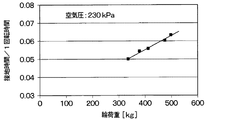
タイヤ空気圧としては、輪荷重が高いほど高い圧力が必要になる。このため、輪荷重に対応して警報閾値を変化させることが好ましく、輪荷重が高くなるほど警報閾値が高い値になるようにする。例えば、図6に示すように、輪荷重の増加に対して警報閾値と直線的に増加する関係となるようにすることができる。 As for the tire pressure, the higher the wheel load, the higher the pressure required. Therefore, it is preferable to change the alarm threshold value according to the wheel load, and the higher the wheel load, the higher the alarm threshold value. For example, as shown in FIG. 6, it is possible to have a relationship in which the alarm threshold value increases linearly with the increase in the wheel load.
警報判定部22bは、閾値設定部22aで設定された輪荷重に対応したタイヤ空気圧の警報閾値と、タイヤ側装置1から送信されたタイヤ空気圧に関するデータが示すタイヤ空気圧とを比較し、タイヤ空気圧が低下しているか否かを判定する。このとき、タイヤ空気圧に関するデータが示すタイヤ空気圧としては、基準温度におけるタイヤ空気圧を用いている。タイヤ側装置1からタイヤ空気圧に関するデータとして、空気圧検知部12の検出信号が示すタイヤ空気圧およびタイヤ内温度のデータがそのまま伝えられている場合、それらのデータから基準温度下でのタイヤ空気圧を換算する。そして、基準温度におけるタイヤ空気圧が警報閾値よりも低下すると、警報判定部22bは、タイヤ空気圧が低下していると判定する。これにより、警報判定部22bは、タイヤ空気圧が低下していると判定すると、タイヤ空気圧が低下したことを示すデータを警報表示部23に伝える。
The
警報表示部23は、例えばインストルメントパネルに備えられたディスプレイなどで構成され、警報判定部22bからタイヤ空気圧が低下したことを示すデータが伝えられると、その旨の表示を行う。これにより、ドライバにタイヤ空気圧が低下したことを認識させることができる。
The
このとき、タイヤ側装置1から送られたデータに含まれる車輪毎のID情報を用いて、タイヤ空気圧が低下したのがどの車輪であるかを特定した形態で警報を行うようにしても良い。
At this time, the ID information for each wheel included in the data sent from the tire-
以上説明したように、本実施形態にかかるTPMS100では、タイヤ側装置1において、タイヤ空気圧および接地長に基づいて輪荷重を推定し、その輪荷重の推定結果を示す輪荷重データを車両側装置2に送信している。また、それを車両側装置2で受信して輪荷重データに基づいて警報閾値を設定し、輪荷重に対応した警報閾値となるようにしている。これにより、輪荷重に対して警報閾値を可変に設定することが可能となり、タイヤ空気圧を輪荷重に対応した警報閾値と比較することで、タイヤ空気圧の低下を判定できる。したがって、精度良くタイヤ空気圧の低下を判定することが可能となる。
As described above, in the TPMS100 according to the present embodiment, in the
(第2実施形態)
第2実施形態について説明する。本実施形態は、第1実施形態に対して閾値設定部や警報判定部をタイヤ側装置1に備えるようにしたものであり、その他については第1実施形態と同様であるため、第1実施形態と異なる部分についてのみ説明する。
(Second Embodiment)
The second embodiment will be described. In the present embodiment, a threshold value setting unit and an alarm determination unit are provided in the
図7に示すように、本実施形態にかかるTPMS100においては、タイヤ側装置1における信号処理部13に、閾値設定部13eおよび警報判定部13fを備えてある。閾値設定部13eは、第1実施形態で説明した閾値設定部22aの機能をタイヤ側装置1に備えたものであり、輪荷重推定部13dでの推定結果に基づいて警報閾値を設定するものである。警報判定部13fは、第1実施形態で説明した警報判定部22bの機能をタイヤ側装置1に備えたものであり、輪荷重に対応して設定された警報閾値と空気圧算出部13cで算出されたタイヤ空気圧とを比較して、タイヤ空気圧が低下したか否かを判定する。そして、警報判定部13fは、タイヤ空気圧が低下したと判定すると、その旨を示すデータをデータ送信部14に送り、データ送信部14から車両側装置2に送信させる。
As shown in FIG. 7, in the
一方、車両側装置2には、受信部21と警報表示部23のみが備えられており、受信部21でデータ送信部14から送られてくるタイヤ空気圧が低下したことを示すデータを受信すると、それを警報表示部23に伝える。これにより、警報表示部23で、タイヤ空気圧が低下したことを表示し、ドライバにタイヤ空気圧が低下したことを認識させる。
On the other hand, the vehicle-
このように、警報閾値の設定やタイヤ空気圧の低下の判定を行う機能をタイヤ側装置1に備えるようにしても良い。このようにすれば、タイヤ空気圧に関するデータを送るタイミングではないときにも、タイヤ空気圧検出を行うようにし、タイヤ空気圧が低下したことが判定されたら直ぐにそれを車両側装置2に伝え、警報表示部23を介してユーザに伝えることが可能となる。
In this way, the tire-
そして、このように、タイヤ空気圧の低下の判定を行う機能をタイヤ側装置1に備えるようにすれば、例えば、警報閾値よりも高い閾値を設定するなどにより、より早い段階でタイヤ空気圧の低下の可能性を判定することも可能となる。そして、タイヤ空気圧の低下の可能性がある場合には、定期送信周期よりも短い周期でタイヤ空気圧検出を行うようにすれば、タイヤ空気圧が低下しつつあることをより早期に報知することが可能となる。
Then, if the
(第3実施形態)
第3実施形態について説明する。本実施形態は、第1実施形態に対してタイヤの種類別に警報閾値を設定できるようにしたものであり、その他については第1実施形態と同様であるため、第1実施形態と異なる部分についてのみ説明する。
(Third Embodiment)
The third embodiment will be described. In this embodiment, the alarm threshold value can be set for each type of tire with respect to the first embodiment, and the other parts are the same as those in the first embodiment. Therefore, only the portion different from the first embodiment is used. explain.
図8に示すように、本実施形態のTPMS100では、タイヤ側装置1にタイヤ識別情報(以下、タイヤIDという)を保存したID保存部15を備えている。タイヤIDは、タイヤの種類などのタイヤに関する各種情報を示す識別情報である。
As shown in FIG. 8, the TPMS100 of the present embodiment includes an
また、輪荷重推定部13dには、タイヤIDに応じたタイヤ空気圧と接地長と輪荷重の相関関係が記憶されている。例えば、図9に示すように、同じタイヤ空気圧であったとしても、タイヤIDごとに、接地長と輪荷重との相関関係が変化する。例えば、ラジアルタイヤをIDAとすると、それよりも剛性の低い冬用タイヤなどのIDBは、ラジアルタイヤと同じ接地長であっても輪荷重が低い値となるような接地長と輪荷重との相関関係となる。逆に、同じラジアルタイヤであっても、剛性の高いものをIDCとすると、IDAのラジアルタイヤと同じ接地長であっても、輪荷重が高い値となるような接地長と輪荷重との相関関係となる。このため、輪荷重推定部13dは、タイヤID毎の補正係数を記憶しており、タイヤ空気圧と接地長と輪荷重の相関関係から求められる輪荷重をタイヤIDに対応する補正係数で補正することで、タイヤ3の種類に対応した輪荷重を推定できるようになっている。例えば、ラジアルタイヤに対してタイヤ3の剛性が高い場合には1より大きな補正係数、剛性が低い場合には1より小さい補正係数とし、求めた輪荷重に対して補正係数を掛け算することで、タイヤ3の種類に対応した輪荷重が推定できるようにしている。
Further, the wheel
このため、輪荷重推定部13dは、ID保存部15に記憶されたタイヤIDを読み出し、そのタイヤIDと対応する補正係数を用いて、タイヤ空気圧と接地長と輪荷重の相関関係から求めた輪荷重を補正することで、タイヤ3の種類に対応した輪荷重を推定する。
Therefore, the wheel
このように、タイヤIDごとに補正係数を記憶しておき、タイヤ空気圧と接地長と輪荷重の相関関係から求めた輪荷重を補正するようにしても良い。このようにすれば、タイヤの種類に対応した警報閾値を的確に設定することが可能となる。これにより、より精度良くタイヤ空気圧の低下を判定することが可能となる。 In this way, the correction coefficient may be stored for each tire ID, and the wheel load obtained from the correlation between the tire pressure, the contact length, and the wheel load may be corrected. In this way, it is possible to accurately set the alarm threshold value corresponding to the type of tire. This makes it possible to determine the decrease in tire pressure more accurately.
なお、ここでは補正係数を用いているが、タイヤIDごとにタイヤ空気圧と接地長と輪荷重の相関関係を示すマップや関数式を記憶しておき、ID保存部15に記憶したタイヤIDと対応する相関関係を選択して、輪荷重を推定できるようにしても良い。このようにしても、上記と同様の効果が得られる。
Although the correction coefficient is used here, a map or a function formula showing the correlation between the tire pressure, the contact length, and the wheel load is stored for each tire ID, and corresponds to the tire ID stored in the
(他の実施形態)
本発明は上記した実施形態に限定されるものではなく、特許請求の範囲に記載した範囲内において適宜変更が可能である。
(Other embodiments)
The present invention is not limited to the above-described embodiment, and can be appropriately modified within the scope of the claims.
例えば、タイヤ側装置1と車両側装置2とが双方向通信できるようにしても良い。この場合、車両側装置2で車速を取得し、それをタイヤ側装置1に伝えることも可能となる。具体的には、上記各実施形態では、タイヤ側装置1に、車速取得部として、振動センサ部11の検出信号に基づいて車速を推定する車速推定部を備えるようにしている。これに対して、双方向通信可能とする場合、車速推定部を車両側装置2に備えるようにし、車速推定結果をタイヤ側装置1に伝えるようにすれば良い。車速推定については、車両側装置2は、例えば車速センサの検出信号に基づいて車載ECU(電子制御装置)で演算された車速データを車載ネットワークであるCAN(Controller Area Network)通信を通じて取得することなどによって行うことができる。そして、タイヤ側装置1は、車両側装置2から送信される車速推定結果を受信することで、車速を取得できる。この場合、タイヤ側装置1のうち車速を取得する部分が車速取得部を構成することになる。
For example, the tire-
また、上記第1、第3実施形態では、輪荷重推定部13dでの輪荷重の推定結果を輪荷重データとして車両側装置2に送るようにしている。これに対して、接地時間もしくは接地長そのものなどの接地長に関するデータと圧力センサ12aで検出したタイヤ空気圧を輪荷重データとして車両側装置2に送り、送られてきた輪荷重データを用いて車両側装置2で輪荷重を推定しても良い。すなわち、上記各実施形態では、タイヤ側装置1に接地長算出部13bと輪荷重推定部13dを備えるようにしたが、タイヤ側装置1では接地長に基づいて輪荷重に関するデータである輪荷重データを取得するデータ取得部としての機能があれば良い。
Further, in the first and third embodiments, the estimation result of the wheel load by the wheel
また、警報部として、表示によって警報を行う警報表示部23を例に挙げたが、警報部は視覚的な警報に限るものではなく、音声などによって警報を行うものであっても良い。
Further, as the alarm unit, the
なお、本開示に記載の制御部及びその手法は、コンピュータプログラムにより具体化された一つ乃至は複数の機能を実行するようにプログラムされたプロセッサ及びメモリを構成することによって提供された専用コンピュータにより、実現されてもよい。あるいは、本開示に記載の制御部及びその手法は、一つ以上の専用ハードウエア論理回路によってプロセッサを構成することによって提供された専用コンピュータにより、実現されてもよい。もしくは、本開示に記載の制御部及びその手法は、一つ乃至は複数の機能を実行するようにプログラムされたプロセッサ及びメモリと一つ以上のハードウエア論理回路によって構成されたプロセッサとの組み合わせにより構成された一つ以上の専用コンピュータにより、実現されてもよい。また、コンピュータプログラムは、コンピュータにより実行されるインストラクションとして、コンピュータ読み取り可能な非遷移有形記録媒体に記憶されていてもよい。 The control unit and its method described in the present disclosure are provided by a dedicated computer provided by configuring a processor and memory programmed to execute one or more functions embodied by a computer program. , May be realized. Alternatively, the controls and methods thereof described in the present disclosure may be implemented by a dedicated computer provided by configuring the processor with one or more dedicated hardware logic circuits. Alternatively, the control unit and method thereof described in the present disclosure may be a combination of a processor and memory programmed to perform one or more functions and a processor composed of one or more hardware logic circuits. It may be realized by one or more dedicated computers configured. Further, the computer program may be stored in a computer-readable non-transitional tangible recording medium as an instruction executed by the computer.
1 タイヤ側装置
2 車両側装置
3 タイヤ
11 振動センサ部
12 空気圧検知部
13 信号処理部
13d 輪荷重推定部
21 受信部
22a 閾値設定部
22b 警報判定部
1
Claims (6)
前記タイヤ側装置は、
前記タイヤの振動の大きさに応じた検出信号を出力する振動検出部(11)と、
前記タイヤ内の圧力であるタイヤ空気圧を検知する空気圧検知部(12)と、
前記検出信号に基づいて前記タイヤにおける路面との接地長を算出し、該接地長に基づいて輪荷重に関するデータである輪荷重データを取得するデータ取得部(13b、13d)と、
前記タイヤ空気圧に関するデータと前記輪荷重データを送信するデータ送信部(14)と、を有し、
前記車両側装置は、
前記タイヤ空気圧に関するデータおよび前記輪荷重データを受信する受信部(21)と、
前記輪荷重データに基づいて前記タイヤ空気圧の警報閾値を設定する閾値設定部(22a)と、
前記タイヤ空気圧に関するデータが示すタイヤ空気圧が前記警報閾値より低下すると、前記タイヤ空気圧が低下したと判定する警報判定部(22b)と、
前記タイヤ空気圧が低下したと判定されると、警報を行う警報部(23)と、を有しているタイヤ空気圧監視システム。 A tire pressure monitoring system having a tire-side device (1) provided on the tire (3) side and a vehicle-side device (2) provided on the vehicle body side on which the tire is mounted.
The tire side device is
A vibration detection unit (11) that outputs a detection signal according to the magnitude of the tire vibration, and
An air pressure detection unit (12) that detects the tire pressure, which is the pressure inside the tire,
Data acquisition units (13b, 13d) that calculate the contact length of the tire with the road surface based on the detection signal and acquire wheel load data that is data related to the wheel load based on the contact length.
It has a data transmission unit (14) for transmitting data related to the tire pressure and the wheel load data.
The vehicle-side device
A receiving unit (21) that receives the data on the tire pressure and the wheel load data, and
A threshold value setting unit (22a) for setting an alarm threshold value for the tire pressure based on the wheel load data,
When the tire air pressure indicated by the data on the tire air pressure falls below the alarm threshold value, the alarm determination unit (22b) determines that the tire air pressure has decreased.
A tire pressure monitoring system including an alarm unit (23) that gives an alarm when it is determined that the tire pressure has dropped.
前記タイヤ側装置は、
前記タイヤの振動の大きさに応じた検出信号を出力する振動検出部(11)と、
前記タイヤ内の圧力であるタイヤ空気圧を検知する空気圧検知部(12)と、
前記検出信号に基づいて前記タイヤにおける路面との接地長を算出し、該接地長に基づいて輪荷重に関するデータである輪荷重データを取得するデータ取得部(13b、13d)と、
前記輪荷重データに基づいて前記タイヤ空気圧の警報閾値を設定する閾値設定部(13f)と、
前記タイヤ空気圧に関するデータが示すタイヤ空気圧が前記警報閾値より低下すると、前記タイヤ空気圧が低下したと判定する警報判定部(13e)と、
前記タイヤ空気圧が低下したことを示すデータを送信するデータ送信部(14)と、を有し、
前記車両側装置は、
前記タイヤ空気圧が低下したことを示すデータを受信する受信部(21)と、
前記タイヤ空気圧が低下したことを示すデータが受信されると、警報を行う警報部(23)と、を有しているタイヤ空気圧監視システム。 A tire pressure monitoring system having a tire-side device (1) provided on the tire (3) side and a vehicle-side device (2) provided on the vehicle body side on which the tire is mounted.
The tire side device is
A vibration detection unit (11) that outputs a detection signal according to the magnitude of the tire vibration, and
An air pressure detection unit (12) that detects the tire pressure, which is the pressure inside the tire,
Data acquisition units (13b, 13d) that calculate the contact length of the tire with the road surface based on the detection signal and acquire wheel load data that is data related to the wheel load based on the contact length.
A threshold value setting unit (13f) for setting an alarm threshold value for the tire pressure based on the wheel load data,
When the tire air pressure indicated by the data on the tire pressure drops below the warning threshold value, the warning determination unit (13e) determines that the tire pressure has dropped, and
It has a data transmission unit (14) for transmitting data indicating that the tire pressure has decreased.
The vehicle-side device
A receiving unit (21) that receives data indicating that the tire pressure has decreased, and
A tire pressure monitoring system including an alarm unit (23) that gives an alarm when data indicating that the tire pressure has dropped is received.
前記検出信号に基づいて前記タイヤにおける路面との接地長を算出する接地長算出部(13b)と、
前記接地長と前記タイヤ空気圧とに基づいて前記タイヤに加わる輪荷重を推定する輪荷重推定部(13d)と、を有している、請求項1または2に記載のタイヤ空気圧監視システム。 The data acquisition unit
A ground contact length calculation unit (13b) that calculates the ground contact length of the tire with the road surface based on the detection signal, and
The tire pressure monitoring system according to claim 1 or 2, further comprising a wheel load estimation unit (13d) that estimates a wheel load applied to the tire based on the contact length and the tire pressure.
前記振動検出部は、前記タイヤにおけるトレッドの裏面に取り付けられることで、前記タイヤの振動の大きさに応じた検出信号を出力するものであり、
前記接地長算出部は、前記振動検出部の検出信号から前記タイヤの1回転中における前記トレッドのうちの前記振動検出部の配置箇所と対応する部分の接地開始時と接地終了時の2つのピークを抽出し、該2つのピークの時間間隔と前記車速とに基づいて前記接地長を算出する、請求項3に記載のタイヤ空気圧監視システム。 The tire-side device has a vehicle speed acquisition unit (13a) for acquiring the vehicle speed.
The vibration detection unit is attached to the back surface of the tread of the tire to output a detection signal according to the magnitude of the vibration of the tire.
From the detection signal of the vibration detection unit, the ground contact length calculation unit has two peaks at the start and end of ground contact of the portion of the tread corresponding to the location of the vibration detection unit during one rotation of the tire. The tire pressure monitoring system according to claim 3, wherein the ground contact length is calculated based on the time interval between the two peaks and the vehicle speed.
前記輪荷重推定部は、タイヤID毎の補正係数を記憶し、前記ID保存部に保存された前記タイヤIDに対応する前記補正係数を用いて、前記相関関係から求めた前記輪荷重を補正する、請求項5に記載のタイヤ空気圧監視システム。 The tire-side device has an ID storage unit (15) that stores a tire ID that is identification information of the tire.
The wheel load estimation unit stores a correction coefficient for each tire ID, and corrects the wheel load obtained from the correlation by using the correction coefficient corresponding to the tire ID stored in the ID storage unit. , The tire pressure monitoring system according to claim 5.
Priority Applications (3)
| Application Number | Priority Date | Filing Date | Title |
|---|---|---|---|
| JP2019027697A JP2020131911A (en) | 2019-02-19 | 2019-02-19 | Tire air pressure monitoring system |
| PCT/JP2020/006277 WO2020171062A1 (en) | 2019-02-19 | 2020-02-18 | Tire air pressure monitoring system |
| US17/381,574 US11833862B2 (en) | 2019-02-19 | 2021-07-21 | Tire pressure monitoring system including tire side and vehicle side devices |
Applications Claiming Priority (1)
| Application Number | Priority Date | Filing Date | Title |
|---|---|---|---|
| JP2019027697A JP2020131911A (en) | 2019-02-19 | 2019-02-19 | Tire air pressure monitoring system |
Publications (2)
| Publication Number | Publication Date |
|---|---|
| JP2020131911A true JP2020131911A (en) | 2020-08-31 |
| JP2020131911A5 JP2020131911A5 (en) | 2021-02-12 |
Family
ID=72144595
Family Applications (1)
| Application Number | Title | Priority Date | Filing Date |
|---|---|---|---|
| JP2019027697A Pending JP2020131911A (en) | 2019-02-19 | 2019-02-19 | Tire air pressure monitoring system |
Country Status (3)
| Country | Link |
|---|---|
| US (1) | US11833862B2 (en) |
| JP (1) | JP2020131911A (en) |
| WO (1) | WO2020171062A1 (en) |
Cited By (2)
| Publication number | Priority date | Publication date | Assignee | Title |
|---|---|---|---|---|
| WO2024053432A1 (en) * | 2022-09-05 | 2024-03-14 | 本田技研工業株式会社 | Suspension control system and suspension control method |
| WO2024062826A1 (en) * | 2022-09-22 | 2024-03-28 | 住友ゴム工業株式会社 | Tire condition monitoring system |
Families Citing this family (1)
| Publication number | Priority date | Publication date | Assignee | Title |
|---|---|---|---|---|
| CN115179693B (en) * | 2022-07-09 | 2023-12-22 | 江苏路必达物联网技术有限公司 | Early warning method for vehicle water skid |
Citations (7)
| Publication number | Priority date | Publication date | Assignee | Title |
|---|---|---|---|---|
| JP2006084424A (en) * | 2004-09-17 | 2006-03-30 | Sumitomo Rubber Ind Ltd | Load distribution determining method |
| JP2007106243A (en) * | 2005-10-13 | 2007-04-26 | Toyota Motor Corp | Tire information acquisition device and tire information acquisition method |
| JP2007106324A (en) * | 2005-10-14 | 2007-04-26 | Toyota Motor Corp | Wheel information processor and wheel information processing method |
| JP2008006941A (en) * | 2006-06-28 | 2008-01-17 | Auto Network Gijutsu Kenkyusho:Kk | Tire air pressure monitoring system |
| JP2012218682A (en) * | 2011-04-13 | 2012-11-12 | Honda Motor Co Ltd | Wheel load value calculating device |
| JP2016022761A (en) * | 2014-07-16 | 2016-02-08 | 株式会社日本自動車部品総合研究所 | Tire state detection device |
| DE102015223970A1 (en) * | 2015-12-02 | 2017-06-08 | Continental Automotive Gmbh | Method and device for determining a wheel load on a vehicle wheel |
Family Cites Families (5)
| Publication number | Priority date | Publication date | Assignee | Title |
|---|---|---|---|---|
| JP3980975B2 (en) | 2002-09-10 | 2007-09-26 | 住友ゴム工業株式会社 | Tire pressure drop alarm method and apparatus, and threshold value change program |
| DE10352539B4 (en) * | 2003-11-11 | 2007-04-12 | Siemens Ag | System for monitoring a pneumatic vehicle, signal evaluation method and vehicle tires |
| JP5250754B2 (en) * | 2003-12-11 | 2013-07-31 | コンティ テミック マイクロエレクトロニック ゲゼルシャフト ミット ベシュレンクテル ハフツング | Sensor transponder, tire contact length and tire load measuring method |
| DE102008046269B3 (en) * | 2008-09-08 | 2009-12-24 | Continental Automotive Gmbh | Wheel load determining method for passenger car, involves comparing calculated wheel load with detected wheel load, and performing adaptation of equations and/or equation parameters based on comparison |
| EP2364865B1 (en) * | 2010-01-29 | 2018-03-21 | Sumitomo Rubber Industries, Ltd. | Method and apparatus for detecting tire having decreased internal pressure, and program for detecting tire having decreased internal pressure |
-
2019
- 2019-02-19 JP JP2019027697A patent/JP2020131911A/en active Pending
-
2020
- 2020-02-18 WO PCT/JP2020/006277 patent/WO2020171062A1/en active Application Filing
-
2021
- 2021-07-21 US US17/381,574 patent/US11833862B2/en active Active
Patent Citations (7)
| Publication number | Priority date | Publication date | Assignee | Title |
|---|---|---|---|---|
| JP2006084424A (en) * | 2004-09-17 | 2006-03-30 | Sumitomo Rubber Ind Ltd | Load distribution determining method |
| JP2007106243A (en) * | 2005-10-13 | 2007-04-26 | Toyota Motor Corp | Tire information acquisition device and tire information acquisition method |
| JP2007106324A (en) * | 2005-10-14 | 2007-04-26 | Toyota Motor Corp | Wheel information processor and wheel information processing method |
| JP2008006941A (en) * | 2006-06-28 | 2008-01-17 | Auto Network Gijutsu Kenkyusho:Kk | Tire air pressure monitoring system |
| JP2012218682A (en) * | 2011-04-13 | 2012-11-12 | Honda Motor Co Ltd | Wheel load value calculating device |
| JP2016022761A (en) * | 2014-07-16 | 2016-02-08 | 株式会社日本自動車部品総合研究所 | Tire state detection device |
| DE102015223970A1 (en) * | 2015-12-02 | 2017-06-08 | Continental Automotive Gmbh | Method and device for determining a wheel load on a vehicle wheel |
Cited By (2)
| Publication number | Priority date | Publication date | Assignee | Title |
|---|---|---|---|---|
| WO2024053432A1 (en) * | 2022-09-05 | 2024-03-14 | 本田技研工業株式会社 | Suspension control system and suspension control method |
| WO2024062826A1 (en) * | 2022-09-22 | 2024-03-28 | 住友ゴム工業株式会社 | Tire condition monitoring system |
Also Published As
| Publication number | Publication date |
|---|---|
| WO2020171062A1 (en) | 2020-08-27 |
| US20210347214A1 (en) | 2021-11-11 |
| US11833862B2 (en) | 2023-12-05 |
Similar Documents
| Publication | Publication Date | Title |
|---|---|---|
| US11833862B2 (en) | Tire pressure monitoring system including tire side and vehicle side devices | |
| US11565704B2 (en) | Road surface condition estimation device | |
| JP4876888B2 (en) | Wheel position detecting device, tire air pressure detecting device and transmitter / receiver provided with the same | |
| US10946861B2 (en) | Hydroplaning determination device | |
| US10726714B2 (en) | Wheel position detecting device | |
| JP6318835B2 (en) | Tire pressure detector | |
| US11034356B2 (en) | Tire-mounted sensor and road surface condition estimation apparatus including the same | |
| US9061662B2 (en) | Method and device for continuously determining wheel state variables of a wheel | |
| JP6547793B2 (en) | Tire mount sensor, diagnosis history storage device and diagnosis notification device | |
| JP2018009974A (en) | Tire-mounted sensor and road surface state estimation device including the same | |
| KR101351920B1 (en) | Tire pressure monitoring apparatus and method | |
| WO2019103095A1 (en) | Road surface conditions determination device | |
| JP2012140069A (en) | Tire air pressure monitoring device | |
| JP2019127253A (en) | Tire system | |
| EP1670653A1 (en) | Real-time signal processing for vehicle tire load monitoring | |
| KR101352734B1 (en) | Tire pressure detection apparatus | |
| JP2019026218A (en) | Tire air pressure monitoring system | |
| WO2019142870A1 (en) | Tire system | |
| JP2023075447A (en) | Tire position determination system | |
| WO2017187927A1 (en) | Road surface condition detecting device | |
| WO2018003693A1 (en) | Tire mounted sensor and road surface condition estimating device including same | |
| KR20150022448A (en) | Method for Determining the Location of TPMS Sensors and the Device of Determining TPMS Location Using the Method of | |
| JP5459625B2 (en) | Tire information detection device | |
| JP2020179752A (en) | Tire air pressure monitoring system | |
| WO2018012251A1 (en) | Wheel position detecting device |
Legal Events
| Date | Code | Title | Description |
|---|---|---|---|
| A521 | Request for written amendment filed |
Free format text: JAPANESE INTERMEDIATE CODE: A523 Effective date: 20201225 |
|
| A621 | Written request for application examination |
Free format text: JAPANESE INTERMEDIATE CODE: A621 Effective date: 20211202 |
|
| A131 | Notification of reasons for refusal |
Free format text: JAPANESE INTERMEDIATE CODE: A131 Effective date: 20220823 |
|
| A02 | Decision of refusal |
Free format text: JAPANESE INTERMEDIATE CODE: A02 Effective date: 20230228 |