JP2020101432A - Radiation reduction structure - Google Patents
Radiation reduction structure Download PDFInfo
- Publication number
- JP2020101432A JP2020101432A JP2018239338A JP2018239338A JP2020101432A JP 2020101432 A JP2020101432 A JP 2020101432A JP 2018239338 A JP2018239338 A JP 2018239338A JP 2018239338 A JP2018239338 A JP 2018239338A JP 2020101432 A JP2020101432 A JP 2020101432A
- Authority
- JP
- Japan
- Prior art keywords
- radiation
- shielding
- space
- outer space
- shielding structure
- Prior art date
- Legal status (The legal status is an assumption and is not a legal conclusion. Google has not performed a legal analysis and makes no representation as to the accuracy of the status listed.)
- Granted
Links
Images


Classifications
-
- Y—GENERAL TAGGING OF NEW TECHNOLOGICAL DEVELOPMENTS; GENERAL TAGGING OF CROSS-SECTIONAL TECHNOLOGIES SPANNING OVER SEVERAL SECTIONS OF THE IPC; TECHNICAL SUBJECTS COVERED BY FORMER USPC CROSS-REFERENCE ART COLLECTIONS [XRACs] AND DIGESTS
- Y02—TECHNOLOGIES OR APPLICATIONS FOR MITIGATION OR ADAPTATION AGAINST CLIMATE CHANGE
- Y02E—REDUCTION OF GREENHOUSE GAS [GHG] EMISSIONS, RELATED TO ENERGY GENERATION, TRANSMISSION OR DISTRIBUTION
- Y02E30/00—Energy generation of nuclear origin
- Y02E30/30—Nuclear fission reactors
Landscapes
- Radiation-Therapy Devices (AREA)
Abstract
Description
本発明は、放射線発生装置が設置された放射線照射室の外側に設けた空間(例えば、免震層などの空間)における放射線管理区域を小さくする放射線低減構造を提供する。 The present invention provides a radiation reducing structure that reduces a radiation control area in a space (for example, a space such as a seismic isolation layer) provided outside a radiation irradiation chamber in which a radiation generator is installed.
例えば、X線などの放射線の照射室においては、放射線が当該照射室から外部に漏洩することを低減する構造が採用されている。 For example, in a radiation irradiation chamber for radiation such as X-rays, a structure that reduces the leakage of radiation from the irradiation chamber to the outside is adopted.
例えば、特許文献1(特開2004−45338号公報)では、通路に屈曲部分(12)を設けることにより、照射室の被照射物から反射されて外部に漏洩する放射線の線量を低減する技術が開示されている。
電子リニアック(直線加速器)等の放射線発生装置が設置された放射線照射室では、管理区域外への放射線の漏洩を抑え、管理区域境界の実効線量を法令で定める値以下にするため、コンクリートや鉄を使った厚い遮蔽壁が設けられる。 In a radiation irradiation room where a radiation generator such as an electronic linac (linear accelerator) is installed, concrete or iron is used in order to prevent radiation from leaking out of the controlled area and keep the effective dose at the boundary of the controlled area below the value specified by law. A thick shielding wall using is provided.
ところで、免震構造の普及により、放射線照射室が免震層の直上に作られる案件が増えている。放射線照射室を免震層の直上に設けるとき、免震層の一部(放射線照射室の直下付近)を放射線管理区域としてしまい、放射線発生装置の稼働中においては当該管理区域内への立ち入りを制限することで、免震層に放射線管理区域を設けない場合に比べ、照射室の床部の遮蔽性能を下げ、建設コストを下げることが考えられる。 By the way, due to the spread of seismic isolation structure, the number of projects where the radiation irradiation room is made directly above the seismic isolation layer is increasing. When the radiation irradiation room is installed directly above the seismic isolation layer, part of the seismic isolation layer (around the area directly below the radiation irradiation room) becomes the radiation control area, and access to the control area is required while the radiation generator is operating. It is conceivable that the restriction will lower the shielding performance of the floor of the irradiation room and lower the construction cost compared to the case where no radiation control area is provided in the seismic isolation layer.
上記のように、放射線照射室直下の免震層内に放射線管理区域を設ける施設について、免震層のメンテナンス等により当該管理区域内に人が立ち入る場合、放射線発生装置の稼働状況とスケジュールを調整する必要がある。そこで、免震層内の放射線管理区域については可能な限り小さいことが望ましいが、これまで、免震層内の当該管理区域を小さくするための放射線低減構造については提案がされておらず問題であった。 As described above, regarding facilities that have a radiation control area within the seismic isolation layer directly below the radiation irradiation room, when a person enters the control area due to maintenance of the seismic isolation layer, the operation status and schedule of the radiation generator are adjusted. There is a need to. Therefore, it is desirable that the radiation control area in the seismic isolation layer be as small as possible, but so far no radiation reduction structure to reduce the control area in the seismic isolation layer has been proposed, and there is no problem. there were.
この発明は、上記課題を解決するものであって、本発明に係る放射線低減構造は、放射線照射範囲に対して放射線を照射する放射線発生装置が設置された設置空間の外周囲に設けられ、前記放射線発生装置で発生する放射線を遮蔽する第1遮蔽構造物と、前記第1遮蔽構造物の外側に配される外側空間と、前記外側空間の外周囲に設けられる第2遮蔽構造物と、からなる放射線低減構造であって、少なくとも前記第2遮蔽構造物で前記放射線照射範囲に該当する箇所は、他の箇所より凹んだ凹構造部を有することを特徴とする。 The present invention is to solve the above-mentioned problems, and a radiation reducing structure according to the present invention is provided in the outer periphery of an installation space in which a radiation generation device that irradiates a radiation irradiation range is installed. From a first shielding structure that shields the radiation generated by the radiation generation device, an outer space arranged outside the first shielding structure, and a second shielding structure provided around the outer space. The radiation reducing structure according to claim 1, wherein at least a portion corresponding to the radiation irradiation range in the second shielding structure has a concave structure portion that is recessed from other portions.
また、本発明に係る放射線低減構造は、前記凹構造部の奥側には、前記凹構造部の開口部の面積より、大きい面積の断面部を有することを特徴とする。 Further, the radiation reducing structure according to the present invention is characterized in that, on the inner side of the concave structure portion, a cross-sectional portion having an area larger than the area of the opening of the concave structure portion is provided.
また、本発明に係る放射線低減構造は、前記外側空間が免震層であることを特徴とする。 Further, the radiation reducing structure according to the present invention is characterized in that the outer space is a seismic isolation layer.
また、本発明に係る放射線低減構造は、前記外側空間が通路であることを特徴とする。 The radiation reducing structure according to the present invention is characterized in that the outer space is a passage.
本発明に係る放射線低減構造は、少なくとも第2遮蔽構造物で放射線照射範囲に該当する箇所は、他の箇所より凹んだ凹構造部を有しており、このような放射線低減構造によれば、例えば、放射線照射室の下に設けた免震層における管理区域を小さくすることができる。 Radiation reduction structure according to the present invention, at least a portion corresponding to the radiation irradiation range in the second shielding structure has a concave structure portion recessed from the other portions, according to such a radiation reduction structure, For example, the control area in the seismic isolation layer provided below the radiation irradiation room can be made small.
以下、本発明の実施の形態を図面を参照しつつ説明する。図1は本発明の実施形態に係る放射線低減構造1の適用先の一つである免震層を下部に有する放射線照射室2の一例を示す図である。
Hereinafter, embodiments of the present invention will be described with reference to the drawings. FIG. 1 is a diagram showing an example of a
放射線照射室2には、放射線発生装置が設置されている。本実施形態においては、このような放射線発生装置における放射線源3のみを示すこととする。放射線発生装置の一例としては、X線照射を行う電子リニアック(直線加速器)を挙げることできる。ただし、本発明に係る放射線低減構造1は、放射線源3としてX線を照射するものを含め、α線、β線、γ線、イオンなどの各放射線を照射する線源にも対応することができるものである。
A radiation generator is installed in the
ここで、放射線発生装置が設置される空間である放射線照射室2を、設置空間Aとして定義する。また、放射線源3は、放射線照射範囲Rに対して放射線を照射するものとする。放射線照射室2においては、放射線照射範囲R内に治療台5が載置され、当該治療台5上で患者(不図示)が放射線照射による治療を受けることが想定されている。
Here, the
設置空間Aの下部には、放射線源3で発生する放射線を遮蔽するために配されている第1遮蔽構造物Bが設けられる。この第1遮蔽構造物Bとしては、一般的にはコンクリートや鉄などが用いられる。この第1遮蔽構造物Bの外側には、免震装置7が収容された免震層などの空間が配される。この免震層などの空間を、外側空間Cとして定義する。この外側空間Cの外周囲には、免震装置7の基礎となると共に、放射線の遮蔽役としても機能する第2遮蔽構造物Dが設けられている。
Below the installation space A, a first shielding structure B arranged to shield the radiation generated by the
本発明に係る放射線低減構造1は、放射線源3が配されてなる設置空間Aと、この設置空間Aから離れる順に、第1遮蔽構造物Bと、主として空洞の外側空間Cと、第2遮蔽構造物Dとがレイアウトされた構造物に適用されることが前提となる。
The radiation reducing structure 1 according to the present invention includes an installation space A in which a
以上のような前提の下、本発明に係る放射線低減構造1では、第2遮蔽構造物Dにおいて凹構造部10を設けることによって、外側空間Cにおける実効線量を低減させるようにしている。このような凹構造部10を有する本発明に係る構造物について、図1に示した従来の構造物との相違に基づいて説明する。
Under the above premise, the radiation reducing structure 1 according to the present invention reduces the effective dose in the outer space C by providing the
図2は本発明の実施形態に係る放射線低減構造1を説明する図であり、図2(A)は従来の放射線照射室2周辺の構造を示しており、図2(B)は本発明に係る放射線低減構造1が適用された放射線照射室2周辺の構造を示している。なお、図において免震装置7については図示省略している。
FIG. 2 is a diagram illustrating a radiation reducing structure 1 according to an embodiment of the present invention, FIG. 2(A) shows a structure around a conventional
本発明に係る放射線低減構造1は、図2(B)に示すように、少なくとも第2遮蔽構造物Dにおいて放射線照射範囲Rに該当する箇所(両矢印に示される箇所)は、他の箇所より凹んだ凹構造部10を有することを特徴としている。第2遮蔽構造物Dが他の箇所より凹んでいる凹構造部10は、通常の高さの床の底面より低い底面を有する構造を言う。
In the radiation reducing structure 1 according to the present invention, as shown in FIG. 2(B), at least the portion corresponding to the radiation irradiation range R (the portion indicated by the double-headed arrow) in the second shielding structure D is more than other portions. It is characterized by having a
設置空間Aから放射線源3により放射線を照射すると、第1遮蔽構造物Bを透過した放射線のうち、一部は第1遮蔽構造物B内で散乱し、外側空間Cに広がるが、第1遮蔽構造物Bを透過した放射線は、第2遮蔽構造物Dにおける床の窪みである凹構造部10を通してさらに下方側の底面に到達する。さらに、床面に到達した放射線は、凹構造部10の内部で一部が反射を繰り返し、減衰され、外側空間Cにおける線量を低減させることができる。
When the
なお、凹構造部10には、放射線を比較的通しやすいグレーチング等を設置することで、足場を設けることもできる。
A scaffold can be provided in the
本発明に係る放射線低減構造1の凹構造部10による実効線量の低減効果についてモンテカルロ計算によるシミュレーションにより評価を行った。計算コードとしては、3次元モンテカルロ計算コードMCNP5を用いた。
The effect of reducing the effective dose by the
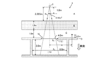
当該計算において、放射線源3の第1遮蔽構造物Bの底面から2.295mとした。第1遮蔽構造物Bは普通コンクリート製とした。また、第1遮蔽構造物Bの厚さを1.6m、外側空間Cの高さを1.0mとした。
In the calculation, the distance was set to 2.295 m from the bottom surface of the first shielding structure B of the
また、放射線源3からは、円錐状のX線ビームを、線源から1.0m離れた地点で照射面積が0.16m2、同地点での水に対する吸収線量が360Gy/hになるように下向きに照射した。
In addition, the irradiation area of the conical X-ray beam from the
第2遮蔽構造物Dの床には遮蔽構造として、X線ビームの中心軸と中心を合わせた直径3m、深さ0.4mの平面視円形状の凹構造部10を設けた。
On the floor of the second shielding structure D, as a shielding structure, a
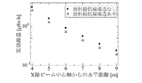
外側空間C内であって、第2遮蔽構造物Dの床上高さ0.5m、X線ビームの軸からの水平距離(H)が4〜9mの位置(×印にて図示した位置)にて、凹構造部10が設けられていない従来の場合、本発明に係る放射線低減構造1の凹構造部10が設けられた場合のそれぞれの実効線量を距離Hで1m毎にモンテカルロ計算によって求めた。この結果を図3に示す。
In the outer space C, at a position where the height of the second shielding structure D on the floor is 0.5 m and the horizontal distance (H) from the axis of the X-ray beam is 4 to 9 m (the position shown by a cross mark). In the conventional case in which the
図3に示すように、モンテカルロ計算で1m毎に実効線量をそれぞれの場合で求めたところ、本発明に係る放射線低減構造1の凹構造部10がありの場合は、凹構造部10なしの場合に比べて平均して実効線量を20%低減させることが確認できた。
As shown in FIG. 3, when the effective dose was calculated for each 1 m by Monte Carlo calculation in each case, the case where the radiation reducing structure 1 according to the present invention has the
以上のように、本発明に係る放射線低減構造1は、少なくとも第2遮蔽構造物Dで放射線照射範囲に該当する箇所は、他の箇所より凹んだ凹構造部10を有しており、このような放射線低減構造1によれば、例えば、放射線照射室の下に設けた免震層における管理区域を小さくすることができる。
As described above, in the radiation reducing structure 1 according to the present invention, at least the portion corresponding to the radiation irradiation range in the second shielding structure D has the
次に、本発明の他の実施形態について説明する。図4は本発明の第2の実施形態に係る放射線低減構造1の概要を説明する模式図である。図4に示す実施形態では、凹構造部10として、奥側(鉛直下方側)に、凹構造部10の開口部12の面積(S0)より、大きい面積(S1。ただし、S1>S0)の断面部15を有することを特徴としている。
Next, another embodiment of the present invention will be described. FIG. 4 is a schematic diagram illustrating an outline of the radiation reducing structure 1 according to the second embodiment of the present invention. In the embodiment shown in FIG. 4, as the recessed
このような第2の実施形態の場合、第1遮蔽構造物Bを透過した放射線は、凹構造部10の開口部12を通してさらに奥の空間に到達する。断面部15の広さが十分にあるとき、その内部で放射線が反射を繰り返し、減衰され、外側空間Cの線量を低減させることができる。第2の実施形態の場合、先の第1の実施形態に比べて、開口部12の奥側に広い空間を有すると共に、断面部15の面積(S1)が、開口部12の面積(S0)より大きく設定されているため、外側空間Cにおけるより大きな線量低減効果を期待できる。
In the case of such a second embodiment, the radiation that has passed through the first shielding structure B reaches the space further inside through the
第2の実施形態についても、実効線量をモンテカルロ計算によって求めた。図4において、平面視円形の開口部12の直径は4.0mとし、平面視円形の断面部15の直径は6.0mとした。
Also in the second embodiment, the effective dose was obtained by Monte Carlo calculation. In FIG. 4, the diameter of the
第2遮蔽構造物Dの床上高さ0.5m、X線ビームの軸からの水平距離(H)が4〜9mの位置(×印にて図示した位置)にて、凹構造部10が設けられていない従来の場合、第2の実施形態に係る放射線低減構造1の凹構造部10が設けられた場合のそれぞれの実効線量を距離Hで1m毎にモンテカルロ計算によって求めた。この結果、第2の実施形態に係る放射線低減構造1の凹構造部10がある場合は、凹構造部10なしの場合に比べて平均して実効線量を37%低減させることが確認できた。
The recessed
外側空間Cの実効線量が、管理区域境界の実効線量限度1300μSv/3月の1/10である130μSv/3月となる範囲を平面視正方形で囲んで管理区域とした場合、以下のようになる。
・図2(A)に示した凹構造部10がないケースでは、X線ビーム中心軸から管理区域境界までの最短距離が6.3m、正方形の面積が159m2、面積比が100%(本ケースを基準とする)。
・図2(B)に示した第1の実施形態に係る凹構造部10を有するケースでは、X線ビーム中心軸から管理区域境界までの最短距離が5.8m、正方形の面積が135m2、面積比が85%。
・図4に示した第2の実施形態に係る凹構造部10を有するケースでは、X線ビーム中心軸から管理区域境界までの最短距離が5.4m、正方形の面積が117m2、面積比が73%。
When the effective dose of the outer space C is 130 μSv/March, which is 1/10 of the effective dose limit of 1300 μSv/March at the boundary of the control area, it is as follows when the area is surrounded by a square in plan view. ..
In the case where the
In the case having the
In the case having the
以上のように、特に第2の実施形態に係る放射線低減構造1によれば、凹構造部10がない場合、管理区域の面積を27%低減することができた。
As described above, particularly in the radiation reducing structure 1 according to the second embodiment, the area of the management area can be reduced by 27% when the
次に、本発明に係る放射線低減構造1を他の状況に適用した例を示す。図5は本発明の実施形態に係る放射線低減構造1の他の適用例を説明する図である。図5は放射線照射室2周辺の構造の平面図を示している。
Next, examples in which the radiation reducing structure 1 according to the present invention is applied to other situations will be shown. FIG. 5: is a figure explaining the other application example of the radiation reduction structure 1 which concerns on embodiment of this invention. FIG. 5 shows a plan view of the structure around the
これまで説明した本発明の適用例では、鉛直下方に向かって、放射線源3の設置空間A、第1遮蔽構造物B、外側空間C、第2遮蔽構造物Dが順に配されていた。これに対して、図5に示す適用例では、放射線源3の設置空間A、第1遮蔽構造物B、外側空間C、第2遮蔽構造物Dが順に水平方向に配されており、外側空間Cは通路20として利用される空間に相当している。このような場合でも、第2遮蔽構造物Dにおける放射線照射範囲Rに該当する箇所には、他の箇所より凹んだ凹構造部10を設けるようにする。このような図5に示す適用例では、通路20における実効線量を低減することなどが可能となる。
In the application example of the present invention described so far, the installation space A of the
以上、本発明に係る放射線低減構造は、少なくとも第2遮蔽構造物で放射線照射範囲に該当する箇所は、他の箇所より凹んだ凹構造部を有しており、このような放射線低減構造によれば、例えば、放射線照射室の下に設けた免震層における管理区域を小さくすることができる。 As described above, in the radiation reducing structure according to the present invention, at least the portion corresponding to the radiation irradiation range in the second shielding structure has the concave structure portion that is recessed from other portions. For example, for example, the control area in the seismic isolation layer provided below the radiation irradiation chamber can be reduced.
1・・・放射線低減構造
2・・・放射線照射室
3・・・放射線源
5・・・治療台
7・・・免震装置
10・・・凹構造部
12・・・開口部
15・・・断面部
20・・・通路
A・・・設置空間
B・・・第1遮蔽構造物
C・・・外側空間
D・・・第2遮蔽構造物
R・・・放射線照射範囲
H・・・X線ビーム中心軸からの水平距離
1...
Claims (4)
前記第1遮蔽構造物の外側に配される外側空間と、
前記外側空間の外周囲に設けられる第2遮蔽構造物と、からなる放射線低減構造であって、
少なくとも前記第2遮蔽構造物で前記放射線照射範囲に該当する箇所は、他の箇所より凹んだ凹構造部を有することを特徴とする放射線低減構造。 A first shielding structure which is provided on the outer periphery of an installation space in which a radiation generator for irradiating a radiation range is installed, and which shields radiation generated by the radiation generator.
An outer space arranged outside the first shielding structure,
A radiation reducing structure comprising: a second shielding structure provided on the outer periphery of the outer space;
At least a portion of the second shielding structure that corresponds to the radiation irradiation range has a concave structure portion that is recessed from other portions.
Priority Applications (1)
| Application Number | Priority Date | Filing Date | Title |
|---|---|---|---|
| JP2018239338A JP7175184B2 (en) | 2018-12-21 | 2018-12-21 | Radiation reduction structure |
Applications Claiming Priority (1)
| Application Number | Priority Date | Filing Date | Title |
|---|---|---|---|
| JP2018239338A JP7175184B2 (en) | 2018-12-21 | 2018-12-21 | Radiation reduction structure |
Publications (2)
| Publication Number | Publication Date |
|---|---|
| JP2020101432A true JP2020101432A (en) | 2020-07-02 |
| JP7175184B2 JP7175184B2 (en) | 2022-11-18 |
Family
ID=71139462
Family Applications (1)
| Application Number | Title | Priority Date | Filing Date |
|---|---|---|---|
| JP2018239338A Active JP7175184B2 (en) | 2018-12-21 | 2018-12-21 | Radiation reduction structure |
Country Status (1)
| Country | Link |
|---|---|
| JP (1) | JP7175184B2 (en) |
Citations (4)
| Publication number | Priority date | Publication date | Assignee | Title |
|---|---|---|---|---|
| JPH0355599U (en) * | 1989-10-04 | 1991-05-29 | ||
| JP2005049352A (en) * | 1998-06-23 | 2005-02-24 | Titan Corp | Article irradiation system having intermediate wall made of radiation shielding material within loop of conveyor system for conveying article |
| JP2017223088A (en) * | 2016-06-17 | 2017-12-21 | 株式会社大林組 | Building |
| JP2018100550A (en) * | 2016-12-21 | 2018-06-28 | 大成建設株式会社 | Medical base-isolated building comprising radiation irradiating chamber |
-
2018
- 2018-12-21 JP JP2018239338A patent/JP7175184B2/en active Active
Patent Citations (4)
| Publication number | Priority date | Publication date | Assignee | Title |
|---|---|---|---|---|
| JPH0355599U (en) * | 1989-10-04 | 1991-05-29 | ||
| JP2005049352A (en) * | 1998-06-23 | 2005-02-24 | Titan Corp | Article irradiation system having intermediate wall made of radiation shielding material within loop of conveyor system for conveying article |
| JP2017223088A (en) * | 2016-06-17 | 2017-12-21 | 株式会社大林組 | Building |
| JP2018100550A (en) * | 2016-12-21 | 2018-06-28 | 大成建設株式会社 | Medical base-isolated building comprising radiation irradiating chamber |
Also Published As
| Publication number | Publication date |
|---|---|
| JP7175184B2 (en) | 2022-11-18 |
Similar Documents
| Publication | Publication Date | Title |
|---|---|---|
| US10500419B2 (en) | Radiation shields for LINAC head and system | |
| JP6241008B2 (en) | Neutron shielding structure and neutron shielding method using the same | |
| JP2020101432A (en) | Radiation reduction structure | |
| JP2018179851A (en) | Radiation shielding structure | |
| JP4307379B2 (en) | Shield room for ion therapy for neutrons up to energy region GeV | |
| JP6994917B2 (en) | Radiation shielding structure | |
| TW201501743A (en) | Particle beam irradiation chamber | |
| JP6839572B2 (en) | Radiation shielding wall | |
| JPH02173600A (en) | Medical radiation shielding chamber | |
| JPH0452598A (en) | Medical radiation shielding chamber | |
| Olšovcová et al. | Bulk shielding for laser research centre ELI Beamlines | |
| JP7061867B2 (en) | Radiation shielding structure | |
| KR100704699B1 (en) | A shield door for radiation clinic and making method therefore | |
| JP2019113415A (en) | Method and body for shielding from radiation | |
| KR200406766Y1 (en) | Scattered Radiation Attenuation Panel | |
| CN111276271A (en) | Combined structure for shielding and absorbing x-ray | |
| JPH05188192A (en) | Medical radiation shielding chamber | |
| JP6944035B1 (en) | Radiation shielding tsuitate and its design method | |
| JP2024010440A (en) | Radiotherapy room | |
| KR20200082994A (en) | Scattered radiation shielding structures using slits or girds | |
| JP2020110367A (en) | Dose calculation method and dose calculation program | |
| JP2023030639A (en) | Radiation shielding structure | |
| TWI623336B (en) | Particle line therapy facility | |
| JP2022089464A (en) | Radiation shield structure for piping | |
| JP2022089463A (en) | Radiation shield structure |
Legal Events
| Date | Code | Title | Description |
|---|---|---|---|
| A621 | Written request for application examination |
Free format text: JAPANESE INTERMEDIATE CODE: A621 Effective date: 20211028 |
|
| A977 | Report on retrieval |
Free format text: JAPANESE INTERMEDIATE CODE: A971007 Effective date: 20220727 |
|
| A131 | Notification of reasons for refusal |
Free format text: JAPANESE INTERMEDIATE CODE: A131 Effective date: 20220803 |
|
| A521 | Request for written amendment filed |
Free format text: JAPANESE INTERMEDIATE CODE: A523 Effective date: 20220930 |
|
| TRDD | Decision of grant or rejection written | ||
| A01 | Written decision to grant a patent or to grant a registration (utility model) |
Free format text: JAPANESE INTERMEDIATE CODE: A01 Effective date: 20221102 |
|
| A61 | First payment of annual fees (during grant procedure) |
Free format text: JAPANESE INTERMEDIATE CODE: A61 Effective date: 20221108 |
|
| R150 | Certificate of patent or registration of utility model |
Ref document number: 7175184 Country of ref document: JP Free format text: JAPANESE INTERMEDIATE CODE: R150 |