JP2020093618A - Vehicle security device - Google Patents
Vehicle security device Download PDFInfo
- Publication number
- JP2020093618A JP2020093618A JP2018231750A JP2018231750A JP2020093618A JP 2020093618 A JP2020093618 A JP 2020093618A JP 2018231750 A JP2018231750 A JP 2018231750A JP 2018231750 A JP2018231750 A JP 2018231750A JP 2020093618 A JP2020093618 A JP 2020093618A
- Authority
- JP
- Japan
- Prior art keywords
- vehicle
- abnormal state
- drone
- security device
- camera
- Prior art date
- Legal status (The legal status is an assumption and is not a legal conclusion. Google has not performed a legal analysis and makes no representation as to the accuracy of the status listed.)
- Pending
Links
- 230000002159 abnormal effect Effects 0.000 claims abstract description 79
- 238000001514 detection method Methods 0.000 claims abstract description 27
- 238000004891 communication Methods 0.000 claims description 9
- 238000003384 imaging method Methods 0.000 claims description 3
- 238000000034 method Methods 0.000 description 26
- 230000005540 biological transmission Effects 0.000 description 9
- RZVHIXYEVGDQDX-UHFFFAOYSA-N 9,10-anthraquinone Chemical compound C1=CC=C2C(=O)C3=CC=CC=C3C(=O)C2=C1 RZVHIXYEVGDQDX-UHFFFAOYSA-N 0.000 description 3
- 238000010586 diagram Methods 0.000 description 3
- 230000000694 effects Effects 0.000 description 2
- 238000013459 approach Methods 0.000 description 1
- 230000007423 decrease Effects 0.000 description 1
- NJPPVKZQTLUDBO-UHFFFAOYSA-N novaluron Chemical compound C1=C(Cl)C(OC(F)(F)C(OC(F)(F)F)F)=CC=C1NC(=O)NC(=O)C1=C(F)C=CC=C1F NJPPVKZQTLUDBO-UHFFFAOYSA-N 0.000 description 1
Images


Abstract
Description
本発明は、車両に搭載した無人飛行体を用いた車両用警備装置に関する。 The present invention relates to a vehicle security device using an unmanned aerial vehicle mounted on a vehicle.
近年、ドローン(無人飛行体)の利用方法として、車両とドローンとを連携する技術が各種提案されている。例えば、特許文献1には、走行中の車両の上空に位置するようにドローンを飛行させ、車両の周辺を撮影して撮影画像を随時車両に提供する技術が開示されている。これにより、特許文献1の車両では、車両から見えない位置の障害物を運転者が確認することができ、走行安全性を向上させることができる。 In recent years, various techniques for linking a vehicle and a drone have been proposed as methods of using a drone (unmanned aerial vehicle). For example, Patent Document 1 discloses a technique of flying a drone so as to be located above the moving vehicle, photographing the periphery of the vehicle, and providing the photographed image to the vehicle as needed. As a result, in the vehicle disclosed in Patent Document 1, the driver can check the obstacle at a position invisible from the vehicle, and the traveling safety can be improved.
また、特許文献2には、ドローンによって上空から車両の周辺を撮影し、撮影画像を車両に提供する技術が開示されており、例えば駐車場においた空いたスペースを運転者が車両から確認することができ、駐車を容易に行うことが可能となる。 Further, Patent Document 2 discloses a technique of photographing the surroundings of a vehicle from the sky by a drone and providing the photographed image to the vehicle. For example, a driver can confirm an empty space in a parking lot from the vehicle. Therefore, it becomes possible to park easily.
ところで、従来より、駐車場等に駐車している車両に対して、傷をつけられたり当て逃げされたりするような危害を加えられる行為が問題となっている。
このような問題に対し、近年では車両に搭載したドライブレコーダーを駐車時においても作動させるようにした技術が開発されている。しかし、ドライブレコーダーでは、車両の全周囲を撮影することは困難であり、また車両の周囲を撮影するだけでは車両への危害を抑制することは困難でもあった。
By the way, conventionally, there has been a problem in that a vehicle parked in a parking lot or the like is injured by being damaged or hit and run away.
In response to such a problem, in recent years, a technique has been developed in which a drive recorder mounted on a vehicle is operated even during parking. However, it is difficult for the drive recorder to photograph the entire periphery of the vehicle, and it is also difficult to suppress the harm to the vehicle only by photographing the periphery of the vehicle.
本発明はこのような問題点を解決するためになされたもので、車両に対する警備能力を向上させる車両用警備装置を提供することにある。 The present invention has been made to solve such a problem, and an object of the present invention is to provide a vehicle security device that improves a vehicle security capability.
上記の目的を達成するために、本発明の車両用警備装置は、車両に離着陸可能に搭載され、周囲を撮影するカメラを備えた無人飛行体と、前記車両に設けられ、前記車両の異常状態を検出する異常状態検出部と、前記異常状態検出部により前記異常状態が検出された場合に、前記無人飛行体を前記車両から離陸させ、前記カメラにより前記車両及び車両周辺を撮影させる制御部と、を備えたことを特徴とする。 In order to achieve the above object, the vehicle security device of the present invention is an unmanned aerial vehicle equipped with a camera for taking a picture of the surroundings, which is mounted on the vehicle so that it can take off and land, and an abnormal state of the vehicle provided in the vehicle. An abnormal state detection unit that detects the abnormal state, and a control unit that, when the abnormal state is detected by the abnormal state detection unit, causes the unmanned aerial vehicle to take off from the vehicle, and causes the camera to capture an image of the vehicle and the vicinity of the vehicle. , Is provided.
これにより、異常状態検出部により前記異常状態が検出された場合に、無人飛行体が車両から離陸し、カメラにより車両及び車両周辺を撮影するので、不審物をカメラによって撮影することができる。更に、無人飛行体に設けたカメラで車両周辺全体を撮影することができ、不審物の撮影漏れを低減することができる。また、例えば不審者が車両に危害を加えるような車両の異常状態では、無人飛行体が車両から離陸することで、不審者に警告をすることと同様な作用を与え、不審者が車両に危害を加えることを抑制することができる。 As a result, when the abnormal state is detected by the abnormal state detection unit, the unmanned aerial vehicle takes off from the vehicle and the camera and the surroundings of the vehicle are photographed, so that the suspicious object can be photographed by the camera. Further, the entire vehicle surroundings can be photographed by the camera provided on the unmanned aerial vehicle, and the photographing omission of a suspicious object can be reduced. In addition, for example, in an abnormal vehicle condition where a suspicious individual causes harm to the vehicle, the unmanned air vehicle takes off from the vehicle, which has the same effect as giving a warning to the suspicious individual. Can be suppressed.
また、好ましくは、少なくとも前記車両周辺に警告を行う警告部を備え、前記制御部は、前記異常状態検出部により前記異常状態が検出された場合に、更に前記警告部により警告を行うとよい。
これにより、不審者が車両に危害を加えるような車両の異常状態では、不審者に対して警告が行われることで、不審者が車両に危害を加えることを更に抑制することができる。
Further, it is preferable that at least the warning unit is provided around the vehicle, and the control unit may further issue a warning by the warning unit when the abnormal condition detection unit detects the abnormal condition.
Thereby, in an abnormal state of the vehicle in which the suspicious individual damages the vehicle, a warning is given to the suspicious individual, thereby further suppressing the suspicious individual from damaging the vehicle.
また、好ましくは、少なくとも前記車両の所有者の携帯機器に連絡する連絡部を備え、前記制御部は、前記異常状態検出部により前記異常状態が検出された場合に、更に、前記連絡部により前記所有者に対して前記異常状態を連絡するとよい。
これにより、車両から離れた位置にいる所有者に対して異常状態を知らせることができ、所有者が車両に戻って対処することが可能となる。
Further, preferably, at least a contact unit for contacting the portable device of the owner of the vehicle is provided, and the control unit is further provided by the contact unit when the abnormal condition is detected by the abnormal condition detection unit. The owner may be notified of the abnormal condition.
As a result, the owner located far from the vehicle can be notified of the abnormal state, and the owner can return to the vehicle and deal with it.
また、好ましくは、前記連絡部は、前記所有者に対して異常状態を連絡する際に、前記携帯機器に前記カメラが撮影した画像を送信するとよい。
これにより、車両から離れた位置にいる所有者に対して異常状態が連絡された際に、車両周辺の画像が携帯機器に送信されるので、所有者が異常状態の内容の確認をその場で行うことができる。
Further, preferably, the contact unit may transmit an image taken by the camera to the portable device when notifying the owner of an abnormal state.
With this, when an abnormal condition is reported to the owner who is away from the vehicle, the image around the vehicle is sent to the mobile device, so the owner can confirm the contents of the abnormal condition on the spot. It can be carried out.
また、好ましくは、前記異常状態は、前記車両が駐車状態において、前記車両に危害が加えられた場合、前記車両周辺に不審物を検出した場合を含み、前記車両が走行状態において、前記車両に接触した移動する不審物を検出した場合を含むとよい。
これにより、車両が駐車状態においては、車両に危害を加えた不審物、あるいは車両周辺の不審物をカメラによって撮影することができる。また、車両が走行状態においては、車両に接触した移動する不審物をカメラによって撮影することができる。
Further, preferably, the abnormal state includes a case where the vehicle is in a parked state, when the vehicle is damaged, and when a suspicious object is detected around the vehicle, and when the vehicle is in a traveling state, It is preferable to include the case where a moving suspicious object that has come into contact is detected.
As a result, when the vehicle is parked, a suspicious object that damages the vehicle or a suspicious object around the vehicle can be photographed by the camera. Further, when the vehicle is in a traveling state, a moving suspicious object that comes into contact with the vehicle can be photographed by the camera.
また、好ましくは、前記制御部は、前記異常状態検出部により異常状態が検出された際に、前記カメラにより撮影した画像に映った前記不審物を前記無人飛行体によって追跡させるとよい。
これにより、不審物を無人飛行体が追跡するので、不審物の撮影時間を長く確保することができるとともに、不審物が逃亡した方向を確認することができる。
Further, preferably, the control unit causes the unmanned air vehicle to trace the suspicious object shown in the image captured by the camera when the abnormal state is detected by the abnormal state detection unit.
As a result, since the unmanned air vehicle tracks the suspicious object, it is possible to secure a long shooting time for the suspicious object and to confirm the direction in which the suspicious object escaped.
また、好ましくは、前記制御部は、前記異常状態検出部により前記異常状態が検出された際に、前記カメラの撮影範囲から外方に前記不審物が移動した場合に、前記無人飛行体を上方に移動させるとよい。
これにより、無人飛行体が上方に移動することでカメラの撮影範囲が広がるので、不審物が車両から離れても撮影範囲を広げて、不審物の撮影時間を長く確保することができるとともに、不審物の逃亡した方向を確認することができる。
Further, preferably, the control unit raises the unmanned aerial vehicle when the suspicious object moves outward from the imaging range of the camera when the abnormal state is detected by the abnormal state detection unit. It is better to move to.
As a result, the unmanned air vehicle moves upward to increase the shooting range of the camera, so that even if the suspicious object moves away from the vehicle, the shooting range can be expanded and the shooting time of the suspicious object can be secured for a long time. You can check the direction in which the object escaped.
また、好ましくは、前記制御部は、前記不審物が前記車両より所定距離以上離間した場合、または、前記無人飛行体のバッテリの充電率が所定値以下となった場合には、前記無人飛行体を前記車両に帰還させて着陸させるとよい。
これにより、無人飛行体によって不審物を追跡させた場合に、飛行可能時間を超える前に無人飛行体を車両に帰還させて、無人飛行体を回収することができる。
Further, preferably, the control unit, when the suspicious object is separated from the vehicle by a predetermined distance or more, or when the charging rate of the battery of the unmanned aerial vehicle is equal to or less than a predetermined value, the unmanned aerial vehicle. May be returned to the vehicle for landing.
Thus, when a suspicious object is tracked by an unmanned aerial vehicle, the unmanned aerial vehicle can be returned to the vehicle before the flight time is exceeded, and the unmanned aerial vehicle can be collected.
本発明の車両用警備装置によれば、不審者や不審車両等の不審物が車両に危害を加えるような異常状態を検出した場合に、車両から離陸した無人飛行体のカメラによって不審物が撮影されるので、不審物の撮影もれを低減し、不審物の特定を行うことが容易に可能となり、車両の警備能力を向上させることができる。 According to the vehicle security device of the present invention, when a suspicious object such as a suspicious person or a suspicious vehicle detects an abnormal state that damages the vehicle, the suspicious object is photographed by the camera of the unmanned air vehicle that has taken off from the vehicle. Therefore, it is possible to reduce the image leakage of the suspicious object, easily identify the suspicious object, and improve the security capability of the vehicle.
以下、図面に基づき本発明の実施形態について説明する。
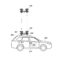
図1は、本発明の実施形態の車両用警備装置に使用するドローンの作動イメージ図である。
図1に示すように、本実施形態の車両用警備装置は、ドローン100(無人飛行体)、車両200に搭載した制御機器である車載機300(制御部)、車両200に搭載した異常状態検出部314により構成される。
Embodiments of the present invention will be described below with reference to the drawings.
FIG. 1 is an operation image diagram of a drone used in a vehicle security device according to an embodiment of the present invention.
As illustrated in FIG. 1, the vehicle security device according to the present embodiment includes a drone 100 (unmanned air vehicle), an in-vehicle device 300 (control unit) that is a control device installed in the
ドローン100は、車両200のルーフ上に設けられた車頂架台400に格納されている。
車頂架台400には、ドローン100の離着陸を行う基地としての離着陸ポート401、ドローン100のバッテリ109を非接触充電するための充電部402が備えられている。
The
The vehicle
ドローン100は、図示しない電気モータによりプロペラを駆動して上下左右方向に移動可能であり、また上空で停止可能であるとともに、上空より下方を撮影可能である。ドローン100は、例えば車載機300において目的地の位置が指示されることで、目的地上空まで自動的に飛行して撮影を行い、撮影後に自動的に車両200に戻り、車頂架台400に自動的に着陸可能となっている。
The
なお、ドローン100が車両200に搭載可能となっているので、ドローン100を搭載した状態で車両200を目的地付近まで走行させることで、目的地が遠隔地であってもドローン100によって撮影可能である。また、ドローン100の移動用の飛行時間を短縮させ、ドローン100の目的地付近での撮影時間を増加させることが可能となっている。
Since the
図2は、本発明の第1の実施形態の車両用警備装置の構成を示すブロック図である。
ドローン100は、カメラ101、第1のGPSセンサ102、機体制御コントローラ103、通信制御部104、映像データ用無線送信部105、送信アンテナ106、機体制御用無線受信部107、受信アンテナ108、バッテリ109、警告音出力部110(警告部)を備えている。
FIG. 2 is a block diagram showing the configuration of the vehicle security device according to the first embodiment of the present invention.
The
カメラ101は、ドローン100の下部に設置され、少なくともドローン100の下方を撮影可能となっている。
第1のGPSセンサ102は、ドローン100の位置を取得する機能を有する。
機体制御コントローラ103は、ドローン100の各プロペラの回転制御により飛行制御を行うものであり、例えばプロポーショナルシステム(プロポ)を用いたドローン100の機体制御信号に基づいて飛行制御を行う機能を有する。
The
The
The
通信制御部104は、映像情報や機体制御情報を車載機300と通信するための情報の変復調、符号化・復号化を行う機能を有する。
映像データ用無線送信部105は、カメラ101で撮影した画像情報を、送信アンテナ106を介して無線によって車載機300に送信する機能を有する。
機体制御用無線受信部107は、受信アンテナ108を介して車載機300から発信した機体制御信号を受信する機能を有する。
The
The video data
The machine control
バッテリ109は、ドローン100に搭載したプロペラ駆動用の電気モータ等の電気機器に電力を供給する機能を有するとともに、充電可能な構成となっている。
警告音出力部110は、例えばスピーカーより警告音や警告音声を出力する機能を有する。警告音声としては、例えば「車両に接触しています」や「車両に異常接近しています」と出力すればよい。
The
The warning
車両200には、車載機300(制御部)、車頂架台400、異常状態検出部314が備えられている。
車載機300は、受信アンテナ301、映像データ用無線受信部302、機体制御用無線送信部303、送信アンテナ304、通信制御部305、録画部306、音声認識部308、マイクロフォン309、所有者連絡部310、制御部312を備えている。
The
The vehicle-mounted
映像データ用無線受信部302は、受信アンテナ301を介してドローン100からの映像データを受信する機能を有する。
機体制御用無線送信部303は、ドローン100を遠隔制御するための機体制御信号をドローン100に送信する機能を有する。
通信制御部305は、送信アンテナ304を介してドローン100との無線通信を行うための情報の変復調、符号化・復号化を行う機能を有する。
The video data
The machine control
The
録画部306は、ドローン100のカメラ101で撮影した画像データを録画する機能を有する。
音声認識部308は、マイクロフォン309を介して入力した作業者等の音声から指示を認識する機能を有する。
所有者連絡部310は、車両200の所有者が携帯しているスマートフォン等の携帯機器に車両200の異常状態を連絡する機能を有する。
The
The
The
制御部312は、入出力装置、記憶装置(ROM、RAM、不揮発性RAM等)、時計、タイマ及び中央演算処理装置(CPU)等を含んで構成され、通信制御部305を介してドローン100の飛行制御を行うとともに、車両200の警備制御を行う機能を有する。
異常状態検出部314は、車両200に対して、傷をつけられたり、衝撃を与えられたりするような異常状態、言い換えると車両200に危害が加えられるような異常状態を検出する機能を有する。異常状態検出部314は、車両200のボディに適宜備えられた振動センサによって車両の異常振動を検出したり、マイクロフォンによって異音を検出したりすればよい。また、車両200の周囲を撮影するカメラがある場合には、このカメラの画像から車両200に接触する程度に異常接近している人や物を検出したり、車両200に危害を加える虞のあるような異常な行動をしている人や物を検出したりしてもよい。
The
The abnormal
また、車載機300には、車両200に設けられた第2のGPSセンサ313より、車両200の現在位置情報が入力される。なお、第2のGPSセンサ313については、例えば車両200に搭載したナビゲーションシステムから車両200の現在位置情報を取得してもよい。
図3は、第1の実施形態の車両用警備装置において実行する車両警備制御要領を示すフローチャートである。
Further, the current position information of the
FIG. 3 is a flowchart showing a vehicle security control procedure executed in the vehicle security device of the first embodiment.
本制御は、車載機300及びドローン100が共同して実行するものであり、例えば車両駐車時に実行される。
図3に示すように、始めにステップS10では、異常状態検出部314より異常状態検出があるか否かを判別する。異常状態の検出があった場合には、ステップS20に進む。異常状態検出がない場合には、ステップS10を繰り返す。
This control is executed jointly by the vehicle-mounted
As shown in FIG. 3, first, in step S10, the abnormal
ステップS20では、ドローン100が離陸必要であるか否かを判別する。ドローン100が離陸必要であるか否かについては、異常状態検出部314において検出した振動や異音等から、車両200が傷をつけられたり衝撃を与えられたりするような異常状態であると判定した場合には、離陸必要であると判定する。また、車両200の所有者が車両200に搭乗している場合や車両200の近くにいる場合には、ドローン100の離陸不要と判別してもよい。車両200の所有者の位置については、車両200のリモートキーの位置等から推定すればよい。ドローン100が離陸必要である場合には、ステップS30に進む。ドローン100が離陸不要である場合には、ステップS10に戻る。
In step S20, it is determined whether the
ステップS30では、ドローン100を車両200から離陸させる。ドローン100を車両の上方数mに位置するように制御すればよい。そして、ステップS40に進む。
ステップS40では、ドローン100のカメラ101により、車両200及び車両200の周囲を自動的に撮影する。なお、カメラ101によって撮影した画像は、映像データ用無線送信部105、映像データ用無線受信部302等を介して、車載機300の録画部306に録画される。そして、ステップS50に進む。
In step S30, the
In step S40, the
ステップS50では、ドローン100に備えられた警告音出力部110より、警告音あるいは警告音声を出力させる。なお、車両200に搭載したスピーカー等から車外に向けて警告音や警告音声を出力してもよい。そして、ステップS60に進む。
ステップS60では、所有者連絡部310よって、車両200の所有者の携帯機器に車両200が異常状態であることを連絡する。なお、車両200が異常状態であることを連絡する際に、カメラ101によって撮影した車両周辺の画像を携帯機器に逐次送信するとよい。更に、車両200の所有者とともに警備会社等に連絡してもよい。なお、本ステップにおける携帯機器への連絡については、後述するステップS80の異常状態対応制御終了まで、所定時間毎に繰り返し行ってもよいし1回のみ行ってもよい。そして、ステップS70に進む。
In step S50, the warning sound or warning sound is output from the warning
In step S60, the
なお、ステップS40の自動撮影、ステップS50の警告出力、ステップS60の所有者への連絡については、ドローン100が離陸した後に、順次に時間を置かずに実行してもよいし、ステップ毎に数秒程度時間を置いて実行してもよい。時間を置いて実行する場合には、ステップS40において自動撮影を開始してすぐに異常状態検知が解除された際に、ステップS50及びステップS60の制御を実行せずにステップS80に進んでもよい。
Note that the automatic shooting in step S40, the warning output in step S50, and the contact to the owner in step S60 may be sequentially executed without any time after the
ステップS70では、異常状態検出部314よる異常状態検出が解除されたか否かを判別する。異常状態検出が解除された場合には、ステップS80に進む。異常状態検出が解除されない場合には、ステップS40に戻る。
ステップS80では、ステップS40における自動撮影及びステップS50における警告出力といった異常状態対応制御を終了させる。そして、ステップS90に進む。
In step S70, it is determined whether the abnormal state detection by the abnormal
In step S80, the abnormal state response control such as the automatic shooting in step S40 and the warning output in step S50 is ended. Then, the process proceeds to step S90.
ステップS90では、ドローン100を車両200の離着陸ポート401に自動的に着陸させて、ドローン100を車両200の車頂架台400に収納させる。なお、ドローンの自動着陸制御については、第1のGPSセンサ102によって検出したドローン100の位置と、第2のGPSセンサ313によって検出した車両200の位置とが一致するようにドローン100を飛行制御すればよい。あるいは、ドローン100に設けたカメラ101の画像に基づいて、ドローン100を車両200の離着陸ポート401に誘導させるように制御してもよい。そして、本ルーチンを終了する。
In step S90, the
以上の制御により、本発明の第1の実施形態の車両用警備装置では、車両駐車時において、不審者等の不審物が車両200に対して傷をつけたり衝撃を与えたりして異常状態が検知された場合に、車両200に搭載しているドローン100が離陸し、自動的に車両200及び車両200の周辺を撮影するので、不審物をカメラ101によって撮影することができる。
With the above control, the vehicle security device according to the first embodiment of the present invention detects an abnormal state when a suspicious object such as a suspicious person scratches or impacts the
特に、車両上方に離陸させたドローン100のカメラ101によって車両周辺を撮影するので、1つのカメラ101で車両周辺全体を撮影することができ、不審物の撮影漏れを低減し、不審物、特に不審者の特定を容易にすることができる。これにより、車両200の警備能力を向上させることができる。
また、不審者が車両200に危害を加えているような場合には、ドローン100が車両200から離陸することで、不審者に対して警告をすることと同様の作用を与えることができ、不審者が車両200に危害を加え続けることを抑制することができる。
In particular, since the
In addition, when the suspicious person is damaging the
また、異常状態を検出した場合に、ドローン100の警告音出力部110によって警告がされるので、不審者が車両200に危害を加え続けることを更に抑制することができる。
また、異常状態を検出した場合に、車両200の所有者の携帯機器に異常状態を連絡するので、所有者がすぐに車両200に戻って対処することが可能となる。
Further, when the abnormal state is detected, the warning
Further, when the abnormal state is detected, the portable device of the owner of the
更に、異常状態を検出して車両200の所有者の携帯機器に異常状態を連絡する際に、カメラ101によって撮影した車両200周辺の画像を携帯機器に送信することで、不審者の確認等の異常状態の内容の確認を、所有者がその場で行うことができる。
次に、図4を用いて、本発明の第2の実施形態の車両用警備装置について説明する。
図4は、本発明の第2の実施形態の車両用警備装置において実行する車両警備制御要領を示すフローチャートである。
Furthermore, when an abnormal condition is detected and the portable device of the owner of the
Next, a vehicle security device according to a second embodiment of the present invention will be described with reference to FIG.
FIG. 4 is a flowchart showing a vehicle security control procedure executed in the vehicle security device according to the second embodiment of the present invention.
本発明の第2の実施形態の車両用警備装置は、車両駐車時以外、例えば車両走行時において実行してもよい。
第2の実施形態の車両用警備装置は、第1の実施形態と構成は同一であるが、車両警備制御の内容が一部異なる。
図4に示すように、第2の実施形態における車両警備制御では、第1の実施形態の車両警備制御のステップS40の後にステップS100に進む。
The vehicle security device according to the second embodiment of the present invention may be executed when the vehicle is running, for example, other than when the vehicle is parked.
The vehicle security device of the second embodiment has the same configuration as that of the first embodiment, but the content of the vehicle security control is partly different.
As shown in FIG. 4, in the vehicle security control according to the second embodiment, the process proceeds to step S100 after step S40 of the vehicle security control according to the first embodiment.
ステップS100では、車両200に接触あるいは異常接近した不審者あるいは不審車両等の不審物をドローン100により追跡する。ドローン100の追跡方法としては、カメラ101で上方から撮影した画像から不審物が逸脱しようとした場合、即ちカメラ101の撮影範囲から外方に不審物が移動した場合に、カメラ101の撮影範囲から不審物が逸脱しないようにドローン100を移動させる。ここで、不審物を追跡する場合に、始めにドローン100の高度を上げるとよい。そして、ステップS110に進む。
In step S100, the
ステップS110では、追跡条件が解除されたか否かを判別する。追跡対象である不審物が車両200より所定距離以上離間した場合や、所有者より車載機300のマイクロフォン309や携帯機器を介して追跡の中止指示を受けた場合に、追跡条件が解除されたものとする。所定距離については、例えばドローン100のバッテリ109の充電率が低くなるに伴って所定距離を短くするように変化させるとよい。追跡条件が解除された場合には、ステップS120に進む。追跡条件が解除されていない場合には、ステップS40に戻る。
In step S110, it is determined whether or not the tracking condition has been canceled. The tracking condition is canceled when the suspicious object to be tracked is separated from the
ステップS120では、ドローン100のカメラ101による自動撮影を終了する。そして、上記第1の実施形態の車両警備制御におけるステップS90に進む。
以上のように、本発明の第2の実施形態の車両用警備装置では、不審者あるいは不審車両等の不審物が車両200に対して傷をつけたり衝撃を与えたりして異常状態が検出された場合に、車両200に搭載しているドローン100が離陸し、自動的に車両200の周辺を撮影するので、第1の実施形態と同様に、不審物をカメラ101によって撮影することができる。
In step S120, the automatic shooting by the
As described above, in the vehicle security device according to the second embodiment of the present invention, an abnormal state is detected when a suspicious person or a suspicious object such as a suspicious vehicle damages or impacts the
第2の実施形態においては、ドローン100が不審物を追跡するので、不審物の撮影時間を長く確保することができるとともに、不審物の逃亡方向を確認することができる。
また、このようにドローン100によって追跡し、逃亡した不審物を追跡して長時間撮影することで、不審物を特定する証拠資料を多く確保することができる。
また、例えば車両200の走行中に当て逃げされた場合のように、車両2の走行中において異常状態を検出した場合には、ドローン100によって逃亡車両を追跡させることで、逃亡車両を長時間撮影することができ、逃亡車両を特定する証拠資料を多く確保することができる。
In the second embodiment, since the
Further, as described above, by tracking with the
Further, when an abnormal state is detected while the vehicle 2 is running, such as when the
また、車両200に危害を加えた不審物を追跡する際に、始めにドローン100の高度を上げることで、カメラ101による撮影範囲が広がるので、不審物が撮影範囲から逸脱し難くなる。
また、車両200に危害を加えた不審物を追跡する際に、追跡条件が解除された場合に追跡を中止してドローンを車両200に帰還させ自動着陸させるので、必要以上の追跡を防止することができる。例えば不審物が車両200より所定距離以上離間した場合に、ドローン100を車両に自動着陸させることで、ドローン100が回収できなくなることを防止することができる。
Further, when tracking a suspicious object that has damaged the
Also, when tracking a suspicious object that has caused damage to the
なお、本願発明は、上記実施形態に限定するものではない。例えば、上記第1の実施形態の車両警備制御において、ステップS50の警告出力、ステップS60の所有者への連絡については、適宜選択して行うようにしてもよい。また、第2の実施形態の車両警備制御において、自動撮影とともに第1の実施形態と同様に、ステップS50の警告出力、ステップS60の所有者への連絡を行ってもよい。 The present invention is not limited to the above embodiment. For example, in the vehicle security control of the first embodiment, the warning output in step S50 and the contact to the owner in step S60 may be appropriately selected and performed. Further, in the vehicle security control of the second embodiment, the warning output of step S50 and the contact of the owner of step S60 may be performed together with the automatic shooting, as in the first embodiment.
また、上記の第1の実施形態の車両警備制御は車両駐車時に実行されるが、第2の実施形態と同様に車両走行時に実行してもよい。 Further, the vehicle security control of the first embodiment described above is executed when the vehicle is parked, but it may be executed when the vehicle is traveling as in the second embodiment.
100 ドローン(無人飛行体)
101 カメラ
314 異常状態検出部
200 車両
300 車載機(制御部)
110 警告音出力部(警告部)
310 所有者連絡部(連絡部)
100 drone (unmanned aerial vehicle)
101
110 Warning sound output section (warning section)
310 Owner Contact (Contact)
Claims (8)
前記車両に設けられ、前記車両の異常状態を検出する異常状態検出部と、
前記異常状態検出部により前記異常状態が検出された場合に、前記無人飛行体を前記車両から離陸させ、前記カメラにより前記車両及び車両周辺を撮影させる制御部と、
を備えたことを特徴とする車両用警備装置。 An unmanned aerial vehicle equipped with a camera that takes a picture of the surroundings, which is mounted on the vehicle so that it can take off and land,
An abnormal state detection unit provided in the vehicle for detecting an abnormal state of the vehicle;
When the abnormal state is detected by the abnormal state detection unit, a control unit for taking off the unmanned aerial vehicle from the vehicle and photographing the vehicle and the vehicle surroundings by the camera,
A vehicle security device comprising:
前記制御部は、前記異常状態検出部により前記異常状態が検出された場合に、更に前記警告部により警告を行うことを特徴とする請求項1に記載の車両用警備装置。 At least equipped with a warning part that warns around the vehicle,
The vehicle security device according to claim 1, wherein the control unit further issues a warning by the warning unit when the abnormal state is detected by the abnormal state detection unit.
前記制御部は、前記異常状態検出部により前記異常状態が検出された場合に、更に前記連絡部により前記所有者に対して前記異常状態を連絡することを特徴とする請求項1または2に記載の車両用警備装置。 At least a contact unit for contacting a mobile device of the owner of the vehicle,
The control unit further informs the owner of the abnormal state by the communication unit when the abnormal state is detected by the abnormal state detection unit. Vehicle security device.
Priority Applications (1)
| Application Number | Priority Date | Filing Date | Title |
|---|---|---|---|
| JP2018231750A JP2020093618A (en) | 2018-12-11 | 2018-12-11 | Vehicle security device |
Applications Claiming Priority (1)
| Application Number | Priority Date | Filing Date | Title |
|---|---|---|---|
| JP2018231750A JP2020093618A (en) | 2018-12-11 | 2018-12-11 | Vehicle security device |
Publications (1)
| Publication Number | Publication Date |
|---|---|
| JP2020093618A true JP2020093618A (en) | 2020-06-18 |
Family
ID=71084392
Family Applications (1)
| Application Number | Title | Priority Date | Filing Date |
|---|---|---|---|
| JP2018231750A Pending JP2020093618A (en) | 2018-12-11 | 2018-12-11 | Vehicle security device |
Country Status (1)
| Country | Link |
|---|---|
| JP (1) | JP2020093618A (en) |
Cited By (2)
| Publication number | Priority date | Publication date | Assignee | Title |
|---|---|---|---|---|
| WO2022208677A1 (en) * | 2021-03-30 | 2022-10-06 | 三菱電機株式会社 | Vehicle exterior monitoring device, monitoring service center, and vehicle exterior monitoring method |
| WO2023223251A1 (en) * | 2022-05-18 | 2023-11-23 | De Wet Christoffel Johannes Henze | Security system and method |
Citations (5)
| Publication number | Priority date | Publication date | Assignee | Title |
|---|---|---|---|---|
| JP2001061129A (en) * | 1999-08-20 | 2001-03-06 | Fujitsu General Ltd | Drive recorder system |
| JP2010257249A (en) * | 2009-04-24 | 2010-11-11 | Autonetworks Technologies Ltd | On-vehicle security device |
| JP2016138853A (en) * | 2015-01-29 | 2016-08-04 | 株式会社ゼンリンデータコム | Navigation system, on-vehicle navigation device, flying object, navigation method, cooperation program for on-vehicle navigation device, and cooperation program for flying object |
| JP2017007603A (en) * | 2015-06-25 | 2017-01-12 | 三菱自動車工業株式会社 | Operation support controlling apparatus |
| JP6405444B1 (en) * | 2017-12-27 | 2018-10-17 | 勝浩 渡辺 | Model aircraft for emergency reports |
-
2018
- 2018-12-11 JP JP2018231750A patent/JP2020093618A/en active Pending
Patent Citations (5)
| Publication number | Priority date | Publication date | Assignee | Title |
|---|---|---|---|---|
| JP2001061129A (en) * | 1999-08-20 | 2001-03-06 | Fujitsu General Ltd | Drive recorder system |
| JP2010257249A (en) * | 2009-04-24 | 2010-11-11 | Autonetworks Technologies Ltd | On-vehicle security device |
| JP2016138853A (en) * | 2015-01-29 | 2016-08-04 | 株式会社ゼンリンデータコム | Navigation system, on-vehicle navigation device, flying object, navigation method, cooperation program for on-vehicle navigation device, and cooperation program for flying object |
| JP2017007603A (en) * | 2015-06-25 | 2017-01-12 | 三菱自動車工業株式会社 | Operation support controlling apparatus |
| JP6405444B1 (en) * | 2017-12-27 | 2018-10-17 | 勝浩 渡辺 | Model aircraft for emergency reports |
Cited By (2)
| Publication number | Priority date | Publication date | Assignee | Title |
|---|---|---|---|---|
| WO2022208677A1 (en) * | 2021-03-30 | 2022-10-06 | 三菱電機株式会社 | Vehicle exterior monitoring device, monitoring service center, and vehicle exterior monitoring method |
| WO2023223251A1 (en) * | 2022-05-18 | 2023-11-23 | De Wet Christoffel Johannes Henze | Security system and method |
Similar Documents
| Publication | Publication Date | Title |
|---|---|---|
| US10558218B2 (en) | Vehicle surroundings monitoring apparatus, monitoring system, remote monitoring apparatus, and monitoring method | |
| US11265508B2 (en) | Recording control device, recording control system, recording control method, and recording control program | |
| US20170233097A1 (en) | Unmanned aerial vehicle flying method and unmanned aerial vehicle flying system | |
| CN106537900B (en) | Video system and method for data communication | |
| JP4996453B2 (en) | Sniper detection device | |
| CN103625477A (en) | Method and system for operating vehicle | |
| WO2015174017A1 (en) | In-vehicle apparatus and travel image storage system | |
| JP6705470B2 (en) | Recording/reproducing apparatus, recording/reproducing method, and program | |
| JP2020093618A (en) | Vehicle security device | |
| CN104850124B (en) | Adaptive motion device and adaptive motion system | |
| KR20150042566A (en) | Black Box for Clouding Service and Image Process Method Thereof | |
| JP2018070010A (en) | Unmanned aircraft controlling system, controlling method and program thereof | |
| JP6140436B2 (en) | Shooting system | |
| CN111369708A (en) | Vehicle driving information recording method and device | |
| US20210407227A1 (en) | On-vehicle recording control apparatus, on-vehicle recording apparatus, on-vehicle recording control method, and non-transitory computer-readable recording medium | |
| KR101746579B1 (en) | Car black box system using the drones | |
| JP2022027772A (en) | Base device, controlling method for base device, and control program for base device | |
| JP5979602B2 (en) | Video imaging system for vehicles | |
| US10587845B2 (en) | Information processing system | |
| JP6495562B1 (en) | Aerial imaging system, method and program using unmanned air vehicle | |
| JP6664411B2 (en) | Security device, security control method, program, and storage medium | |
| KR20150121775A (en) | Method for Service Real-Time Security of Vehicle using Vehicle Black Box and System thereof | |
| KR20190007277A (en) | Apparatus for recording vehicle black box image using unmanned aerial vehicle and method for the same | |
| JP7259369B2 (en) | Vehicle control device and information processing system | |
| KR20130012660A (en) | Blackbox for vehicel and information managing method thereof |
Legal Events
| Date | Code | Title | Description |
|---|---|---|---|
| A621 | Written request for application examination |
Free format text: JAPANESE INTERMEDIATE CODE: A621 Effective date: 20211126 |
|
| A977 | Report on retrieval |
Free format text: JAPANESE INTERMEDIATE CODE: A971007 Effective date: 20221012 |
|
| A131 | Notification of reasons for refusal |
Free format text: JAPANESE INTERMEDIATE CODE: A131 Effective date: 20221019 |
|
| A02 | Decision of refusal |
Free format text: JAPANESE INTERMEDIATE CODE: A02 Effective date: 20230412 |