JP2020066965A - Planar structure of beam - Google Patents
Planar structure of beam Download PDFInfo
- Publication number
- JP2020066965A JP2020066965A JP2018201874A JP2018201874A JP2020066965A JP 2020066965 A JP2020066965 A JP 2020066965A JP 2018201874 A JP2018201874 A JP 2018201874A JP 2018201874 A JP2018201874 A JP 2018201874A JP 2020066965 A JP2020066965 A JP 2020066965A
- Authority
- JP
- Japan
- Prior art keywords
- assembled
- flange
- beams
- joined
- beam member
- Prior art date
- Legal status (The legal status is an assumption and is not a legal conclusion. Google has not performed a legal analysis and makes no representation as to the accuracy of the status listed.)
- Granted
Links
Images


Abstract
Description
本発明は、形鋼を上下方向に積み重ねてなる組立梁を備えた梁の平面構造に関する。 TECHNICAL FIELD The present invention relates to a planar structure of a beam provided with an assembled beam in which shaped steels are vertically stacked.
住宅の建物を支持する基礎の一例として、H形鋼で形成された連続フーチング基礎が知られている(例えば特許文献1参照)。この連続フーチング基礎を使用した基礎構造は、地盤を地盤面から所定の深さだけ掘削し、掘削底面に敷き詰めた砕石や捨てコンクリートによって形成される基礎底面にH形鋼で形成された基礎梁の下フランジを設置することによって構成されている。
H形鋼等の梁部材を用いて床面や基礎面等の梁の平面構造を構成する場合、梁部材どうしを平面視において直交させ、この直交部において梁部材どうしを接合することがある。この場合(例えば、大梁と小梁を直交部において接合する場合)、一方の梁部材は1本の連続的な通し梁として構成され、これに直交する他方の梁部材は前記通し梁を挟んで2つに分割される分割梁として構成されるのが一般的である。
また、特許文献2には、コンクリートに形鋼によって形成された埋込み基礎鉄骨を埋設し、当該基礎鉄骨上に、形鋼によって形成された腰部用鉄骨を平面視において直交させて設け、この腰部用鉄骨上に壁枠パネルを設置した構造が記載されている。
As an example of a foundation for supporting a residential building, a continuous footing foundation formed of H-shaped steel is known (see, for example, Patent Document 1). The foundation structure using this continuous footing foundation excavates the ground to a predetermined depth from the ground surface, and the foundation beam made of H-shaped steel is formed on the bottom surface of the foundation formed by crushed stone and discarded concrete laid on the excavation bottom. It is constructed by installing a lower flange.
When a beam member such as an H-shaped steel is used to form a planar structure of a beam such as a floor surface or a foundation surface, the beam members may be orthogonal to each other in a plan view, and the beam members may be joined to each other at the orthogonal portion. In this case (for example, when a large beam and a small beam are joined at an orthogonal portion), one beam member is configured as one continuous through beam, and the other beam member orthogonal to this one beam member sandwiches the through beam. It is generally configured as a split beam that is split into two.
Further, in Patent Document 2, an embedded basic steel frame formed of shaped steel is embedded in concrete, and a lumbar steel frame formed of shaped steel is provided on the basic steel frame so as to be orthogonal to each other in a plan view. A structure in which a wall frame panel is installed on a steel frame is described.
ところで、上述したような連続的な通し梁と、これに直交する分割梁との接合には、金物等を介して両者のウェブを接合するのが一般的である。このため分割梁の接合部(通し梁に対する接合部)における梁端部では、せん断力を負担することはできるが、曲げモーメントの負担は期待できない。
したがって、このような通し梁と分割梁とによる梁の平面構造に対して上部の柱や耐力壁から引き抜き力/圧縮力が作用した場合、荷重はすべて連続的な通し梁へと伝達され、分割梁に荷重負担を期待することができない。このため前記荷重を十分に負担することが困難となる、つまり梁の平面構造としての剛性、耐力が不足する虞がある。
また、分割梁に積載荷重等の鉛直荷重が作用する場合、分割梁は単純支持梁のように挙動し、たわみが大きくなるという問題もある。
By the way, in order to join a continuous through beam as described above and a divided beam orthogonal to the continuous beam, it is general to join the webs of both through a metal or the like. Therefore, the beam end portion of the joint portion (joint portion to the through beam) of the split beam can bear the shearing force, but cannot expect the burden of the bending moment.
Therefore, when a pulling / compressing force acts from the upper column or load bearing wall on the planar structure of the beam composed of such through beams and split beams, all the loads are transmitted to the continuous through beams and the split beams are divided. You cannot expect a load on the beam. For this reason, it may be difficult to sufficiently bear the load, that is, the rigidity and proof stress of the planar structure of the beam may be insufficient.
In addition, when a vertical load such as a load is applied to the split beam, the split beam behaves like a simple support beam, resulting in a large deflection.
本発明は、上記事情に鑑みてなされたもので、上部の柱や耐力壁からの荷重を十分に負担できるとともに、分割梁の撓みを抑制できる梁の平面構造を提供することを目的としている。 The present invention has been made in view of the above circumstances, and an object thereof is to provide a planar structure of a beam that can sufficiently bear a load from an upper column or a load bearing wall and can suppress the bending of a split beam.
前記目的を達成するために、本発明の梁の平面構造は、形鋼によって形成された梁部材を上下に積み重ねてなる組立梁を備えた梁の平面構造であって、
前記組立梁が平面視において互いに直交して設けられ、
前記組立梁が直交する直交部において、
一方の前記組立梁の上側の前記梁部材は連続した上側通し梁となっており、他方の前記組立梁の上側の前記梁部材は前記上側通し梁を挟んで分割された上側分割梁となっており、
他方の前記組立梁の下側の前記梁部材は連続した下側通し梁となっており、一方の前記組立梁の下側の前記梁部材は前記下側通し梁を挟んで分割された下側分割梁となっていることを特徴とする。
In order to achieve the above-mentioned object, the plane structure of the beam of the present invention is a plane structure of a beam including an assembled beam formed by vertically stacking beam members formed of shaped steel,
The assembled beams are provided so as to be orthogonal to each other in a plan view,
In the orthogonal portion where the assembled beam is orthogonal,
The beam member on the upper side of one of the assembled beams is a continuous upper through beam, and the beam member on the upper side of the other assembled beam is an upper split beam divided by sandwiching the upper through beam. Cage,
The beam member on the lower side of the other assembly beam is a continuous lower through beam, and the beam member on the lower side of the one assembly beam is a lower side divided by sandwiching the lower through beam. It is characterized by being a divided beam.
前記形鋼は、例えば、H形鋼、溝形鋼の他に、断面ロ字形の角形鋼管も含む。
また、組手梁の上側および/または下側に、形鋼等で形成された補強梁を前記梁部材に沿って設けてもよい。
The shaped steel includes, for example, H-shaped steel and channel steel, as well as square steel pipes having a square cross-section.
In addition, a reinforcing beam formed of shaped steel or the like may be provided on the upper side and / or the lower side of the assembled beam along the beam member.
本発明においては、組立梁が直交する直交部において、一方の組立梁の上側通し梁と他方の組立梁の下側通し梁とが平面視において直交し、かつ、他方の組立梁の上側分割梁と一方の組立梁の下側分割梁とが平面視において直交するので、上部の柱や耐力壁から作用する荷重は、上側通し梁に直接伝達されるとともに下側通し梁に上側分割梁を介して伝達される。このため、上部の柱や耐力壁からの荷重を十分に負担できるとともに、分割梁の撓みを抑制できる。
また、上側分割梁および下側分割梁は、それぞれ梁部材をその長手方向に分割してなるものであるから、梁長が短くなる。このため、施工現場での上側分割梁および下側分割梁の取り回しが容易になり、施工負荷を軽減することができる。
In the present invention, in the orthogonal portion where the assembled beams are orthogonal to each other, the upper through beam of one assembled beam and the lower through beam of the other assembled beam are orthogonal to each other in a plan view, and the upper split beam of the other assembled beam is orthogonal to each other. Since the lower split beam of one of the assembled beams and the lower split beam of the one assembly are orthogonal to each other in a plan view, the load acting from the upper column or the load bearing wall is directly transmitted to the upper through beam and is also transmitted to the lower through beam through the upper split beam. Be transmitted. For this reason, it is possible to sufficiently bear the load from the upper pillar and the bearing wall and to suppress the bending of the split beam.
Moreover, since the upper split beam and the lower split beam are each formed by splitting the beam member in the longitudinal direction, the beam length is shortened. Therefore, it becomes easy to handle the upper split beam and the lower split beam at the construction site, and the construction load can be reduced.
また、本発明の梁の平面構造は、形鋼によって形成された梁部材を上下に積み重ねてなる組立梁を備えた梁の平面構造であって、
前記組立梁が平面視において直角に接合され、
前記組立梁が接合される接合部において、
一方の前記組立梁の上側の梁部材は、他方の前記組立梁の上側の梁部材に勝ち状態で接合された上側通し梁となっており、
他方の前記組立梁の下側の梁部材は、一方の前記組立梁の下側の梁部材に勝ち状態で接合された下側通し梁となっていることを特徴とする。
The plane structure of the beam of the present invention is a plane structure of a beam including an assembled beam formed by vertically stacking beam members formed of shaped steel,
The assembled beam is joined at a right angle in a plan view,
At the joint where the assembled beams are joined,
The upper beam member of the one assembly beam is an upper through beam joined to the upper beam member of the other assembly beam in a winning state,
The lower beam member of the other assembled beam is a lower through beam joined to the lower beam member of the one assembled beam in a winning state.
なお、上側通し梁および下側通し梁は、上側の梁部材および下側の梁部材を貫通または通過していないが、本発明では、上側の梁部材に勝ち状態で直角に接合された梁を上側通し梁、下側の梁部材に勝ち状態で直角に接合された梁を下側通し梁と言う。 Although the upper through beam and the lower through beam do not penetrate or pass through the upper beam member and the lower beam member, in the present invention, a beam joined at a right angle to the upper beam member in a winning state is used. The upper through beam and the beam joined to the lower beam member at a right angle in a winning state are called the lower through beam.
本発明においては、組立梁が接合される接合部において、一方の組立梁の上側通し梁と他方の組立梁の下側通し梁とが平面視において直交し、かつ、他方の組立梁の上側の梁部材と一方の組立梁の下側の梁部材とが平面視において直角に配置されるので、上部の柱や耐力壁から作用する荷重は、一方の組立梁の上側通し梁に直接伝達されるとともに他方の組立梁の下側通し梁に上側の梁部材を介して伝達される。このため、上部の柱や耐力壁からの荷重を十分に負担できるとともに、梁部材の撓みを抑制できる。 In the present invention, in the joint portion where the assembled beams are joined, the upper through beam of one assembled beam and the lower through beam of the other assembled beam are orthogonal to each other in a plan view, and the upper through beam of the other assembled beam is Since the beam member and the lower beam member of one of the assembled beams are arranged at a right angle in a plan view, the load acting from the upper column or the load bearing wall is directly transmitted to the upper through beam of the one assembled beam. At the same time, it is transmitted to the lower through beam of the other assembled beam through the upper beam member. For this reason, it is possible to sufficiently bear the load from the upper pillar and the bearing wall and to suppress the bending of the beam member.
また、本発明の前記構成において、前記組立梁が、建物の基礎梁の少なくとも一部を構成していてもよいし、建物の床梁の少なくとも一部を構成してもよい。
このような構成によれば、本発明の梁の平面構造を建物の基礎梁や床梁の平面構造に適用できる。
Moreover, in the said structure of this invention, the said assembly beam may comprise at least one part of the foundation beam of a building, and may comprise at least one part of the floor beam of a building.
According to such a configuration, the planar structure of the beam of the present invention can be applied to the planar structure of the foundation beam or floor beam of the building.
本発明によれば、上部の柱や耐力壁からの荷重を十分に負担できるとともに、分割梁の撓みを抑制できる。 According to the present invention, it is possible to sufficiently bear the load from the upper pillar and the load bearing wall and suppress the bending of the split beam.
以下、図面を参照して本発明に係る梁の平面構造の実施の形態について説明する。なお、本発明に係る梁の平面構造は、組立梁の配置構造とも言える。
図1は本実施の形態の梁の平面構造を示す基礎梁の平面図であり、(a)は組立梁の上側の梁部材の配置形態を示し、(b)は組立梁の下側の梁部材の配置形態を示す。なお、このような基礎梁はH形鋼によって形成されており、当該基礎梁は、例えば図示しないコンクリート基礎によって支持される。
図1に示すように、このような梁の平面構造(組立梁の配置構造)において、A円部では組立梁が平面視において互いに直交しており、B円部では組立梁が平面視においてコ字形に直角に接合されており、C円部およびD縁部では組立梁が平面視においてT字形に直角に接合されている。
Embodiments of a planar structure of a beam according to the present invention will be described below with reference to the drawings. The planar structure of the beam according to the present invention can be said to be an arrangement structure of the assembled beam.
FIG. 1 is a plan view of a basic beam showing a planar structure of a beam according to the present embodiment. (A) shows an arrangement form of a beam member on an upper side of an assembled beam, (b) shows a beam on a lower side of the assembled beam. The arrangement | positioning form of a member is shown. It should be noted that such a foundation beam is formed of H-shaped steel, and the foundation beam is supported by, for example, a concrete foundation (not shown).
As shown in FIG. 1, in such a plane structure of beams (arrangement structure of assembled beams), the assembled beams are orthogonal to each other in a plan view in the A circle portion, and the assembled beams are in a plan view in a B circle portion. The assembly beams are joined at a right angle to the character shape, and the assembled beams are joined at a right angle to the T shape in a plan view at the C circle portion and the D edge portion.
まず、A円部の構造について説明する。
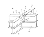
図1および図2に示すように、組立梁10,20が平面視において互いに直交して設けられている。一方の組立梁10は、H形鋼によって形成された上側の梁部材11および下側の梁部材12,12を上下に積み重ねることによって形成されている。
他方の組立梁20は一方の組立梁10に平面視において直交して設けられるとともに、H形鋼によって形成された上側の梁部材21,21および下側の梁部材22を上下に積み重ねることによって形成されている。
First, the structure of the A circle portion will be described.
As shown in FIGS. 1 and 2, the assembled beams 10 and 20 are provided so as to be orthogonal to each other in a plan view. One of the assembled beams 10 is formed by vertically stacking an
The other assembled
また、一方の組立梁10の上側の梁部材11と下側の梁部材12とは、梁成および梁幅(フランジ幅)が等しくなっているが、異なっていてもよい。
また、他方の組立梁20の上側の梁部材21と下側の梁部材22とは、梁成および梁幅(フランジ幅)が等しくなっているが、異なっていてもよい。
さらに、一方の組立梁10の上側の梁部材11と他方の組立梁20の上側の梁部材21とは梁成および梁幅(フランジ幅)が等しくなっているが、異なっていてもよい。
また、一方の組立梁10の下側の梁部材12と他方の組立梁20の下側の梁部材22とは梁成および梁幅(フランジ幅)が等しくなっているが、異なっていてもよい。
Further, the
Further, the
Further, the
Further, the
組立梁10,20が直交する直交部J1において、一方の組立梁10の上側の梁部材11は連続した上側通し梁11となっており、他方の組立梁20の上側の梁部材21,21は上側通し梁11を挟んで分割された上側分割梁21,21となっている。また、他方の組立梁20の下側の梁部材22は連続した下側通し梁22となっており、一方の組立梁10の下側の梁部材12,12は下側通し梁22を挟んで分割された下側分割梁12,12となっている。
そして、上側通し梁11と下側通し梁22とは平面視において互いに直交し、上側分割梁21,21と下側分割梁12,12とは平面視において互いに直交している。
In the orthogonal portion J1 where the assembled beams 10 and 20 are orthogonal to each other, the
The upper through
また、上側通し梁11の上フランジ11aには、上側分割梁21の上フランジ21aの端面が接合され、上側通し梁11の下フランジ11bには、上側分割梁21の下フランジ21bが接合されている。また、上側通し梁11のウェブ11cには、上側分割梁21のウェブ21cの端面は接合されておらす、当該端面とウェブ11cとの間には隙間がある。なお、上側分割梁21のウェブ21cを梁軸方向に延出して、当該延出部の端面をウェブ11cに接合させてもよい。
Further, the end surface of the
また、下側通し梁22の上フランジ22aには、下側分割梁12の上フランジ12aの端面が接合され、下側通し梁22の下フランジ22bには、下側分割梁12の下フランジ12bが接合されている。また、下側通し梁22のウェブ22cには、下側分割梁12のウェブ12cの端面は接合されておらす、当該端面とウェブ22cとの間には隙間がある。なお、下側分割梁12のウェブ12cを梁軸方向に延出して、当該延出部の端面をウェブ22cに接合させてもよい。
Further, the end face of the
次に、前記B円部の構造について説明する。
図1および図3に示すように、組立梁30,40が平面視においてコ字形に直角に接合されている。一方の組立梁30は、H形鋼によって形成された上側の梁部材31および下側の梁部材32を上下に積み重ねることによって形成されている。
他方の組立梁40は一方の組立梁10に平面視において直角に設けられるとともに、H形鋼によって形成された上側の梁部材41および下側の梁部材42を上下に積み重ねることによって形成されている。
Next, the structure of the B circle portion will be described.
As shown in FIGS. 1 and 3, the assembly beams 30 and 40 are joined at a right angle in a U shape in a plan view. One of the assembled beams 30 is formed by vertically stacking an
The other assembled
また、一方の組立梁30の上側の梁部材31と下側の梁部材32とは、梁成および梁幅(フランジ幅)が等しくなっているが、異なっていてもよい。
また、他方の組立梁40の上側の梁部材41と下側の梁部材42とは、梁成および梁幅(フランジ幅)が等しくなっているが、異なっていてもよい。
さらに、一方の組立梁30の上側の梁部材31と他方の組立梁40の上側の梁部材41とは梁成および梁幅(フランジ幅)が等しくなっているが、異なっていてもよい。
また、一方の組立梁30の下側の梁部材32と他方の組立梁40の下側の梁部材42とは梁成および梁幅(フランジ幅)が等しくなっているが、異なっていてもよい。
Further, the
Further, the
Further, the
Further, the
組立梁30,40が接合される接合部J2において、一方の組立梁30の上側の梁部材31は、他方の組立梁40の上側の梁部材41に勝ち状態で接合された上側通し梁31となっており、他方の組立梁40の下側の梁部材42は、一方の組立梁30の下側の梁部材32に勝ち状態で接合された下側通し梁42となっている。
At the joint portion J2 where the assembled beams 30 and 40 are joined, the
すなわち、一方の組立梁30の上側通し梁31は、接合部J2において、下側の梁部材32よりも平面視において梁長手方向に突出しており、この突出している部分において他方の組立梁40の上側の梁部材41の端部が上側通し梁31に当接されて接合されている。具体的には、上側通し梁31の上フランジ31aに、上側の梁部材41の上フランジ41aの端面が接合され、上側通し梁31の下フランジ31bに上側の梁部材41の下フランジ41bの端面が接合されている。また、上側通し梁31のウェブ31cには、上側の梁部材41のウェブ41cの端面は接合されておらす、当該端面とウェブ31cとの間には隙間がある。なお、上側の梁部材41のウェブ41cを梁軸方向に延出して、当該延出部の端面をウェブ31cに接合させてもよい。
That is, the upper through
また、他方の組立梁40の下側通し梁42は、接合部J2において、上側の梁部材41よりも平面視において梁長手方向に突出しており、この突出している部分において一方の組立梁30の下側の梁部材32の端部が下側通し梁42に当接されて接合されている。具体的には、下側通し梁42の上フランジ42aに、下側の梁部材32の上フランジ32aの端面が接合され、下側通し梁42の下フランジ42bに下側の梁部材32の下フランジ32bの端面が接合されている。また、下側通し梁42のウェブ42cには、下側の梁部材32のウェブ32cの端面は接合されておらす、当該端面とウェブ42cとの間には隙間がある。なお、下側の梁部材32のウェブ32cを梁軸方向に延出して、当該延出部の端面をウェブ42cに接合させてもよい。
そして、一方の組立梁30の上側通し梁31と他方の組立梁40の下側通し梁42とが平面視において直交し、かつ、他方の組立梁40の上側の梁部材41と一方の組立梁30の下側の梁部材32とが平面視において直角に配置されている。
In addition, the lower through
The upper through
次に、前記C円部の構造について説明する。
図1および図4に示すように、組立梁50,60が平面視においてT字形に直角に接合されている。一方の組立梁50は、H形鋼によって形成された上側の梁部材51および下側の梁部材52を上下に積み重ねることによって形成されている。
他方の組立梁60は一方の組立梁50に平面視において直角に設けられるとともに、H形鋼によって形成された上側の梁部材61および下側の梁部材62を上下に積み重ねることによって形成されている。
Next, the structure of the C circle portion will be described.
As shown in FIGS. 1 and 4, the assembled beams 50 and 60 are joined to each other in a T-shape at right angles in a plan view. One assembled
The
また、一方の組立梁50の上側の梁部材51と下側の梁部材52とは、梁成および梁幅(フランジ幅)が等しくなっているが、異なっていてもよい。
また、他方の組立梁60の上側の梁部材61と下側の梁部材62とは、梁成および梁幅(フランジ幅)が等しくなっているが、異なっていてもよい。
さらに、一方の組立梁50の上側の梁部材51と他方の組立梁60の上側の梁部材61とは梁成および梁幅(フランジ幅)が等しくなっているが、異なっていてもよい。
また、一方の組立梁50の下側の梁部材52と他方の組立梁60の下側の梁部材62とは梁成および梁幅(フランジ幅)が等しくなっているが、異なっていてもよい。
Further, the
Further, the
Further, the
Further, the
組立梁50,60,60が接合される接合部J3において、一方の組立梁50の上側の梁部材51は、他方の組立梁60,60の上側の梁部材61,61に勝ち状態で接合された上側通し梁51となっており、他方の組立梁60の下側の梁部材62は、一方の組立梁50の下側の梁部材52に勝ち状態で接合された下側通し梁62となっている。
At the joint portion J3 where the assembled beams 50, 60, 60 are joined, the
すなわち、一方の組立梁50の上側通し梁51は、接合部J3において、下側の梁部材52よりも平面視において梁長手方向に突出しており、この突出している部分において他方の組立梁60の上側の梁部材61の端部が上側通し梁51に当接されて接合されている。具体的には、上側通し梁51の上フランジ51aに、上側の梁部材61の上フランジ61aの端面が接合され、上側通し梁51の下フランジ51bに上側の梁部材61の下フランジ61bの端面が接合されている。また、上側通し梁51のウェブ51cには、上側の梁部材61のウェブ61cの端面は接合されておらす、当該端面とウェブ51cとの間には隙間がある。なお、上側の梁部材61のウェブ61cを梁軸方向に延出して、当該延出部の端面をウェブ51cに接合させてもよい。
That is, the upper through
また、他方の組立梁60の下側通し梁62には、接合部J3において、一方の組立梁50の下側の梁部材52の端部が当接されて接合されている。具体的には、下側通し梁62の上フランジ62aに、下側の梁部材52の上フランジ52aの端面が接合され、下側通し梁62の下フランジ62bに下側の梁部材52の下フランジ52bの端面が接合されている。また、下側通し梁62のウェブ62cには、下側の梁部材52のウェブ52cの端面は接合されておらす、当該端面とウェブ62cとの間には隙間がある。なお、下側の梁部材52のウェブ52cを梁軸方向に延出して、当該延出部の端面をウェブ62cに接合させてもよい。
そして、一方の組立梁50の上側通し梁51と他方の組立梁60の下側通し梁62とが平面視において直交し、かつ、他方の組立梁60の上側の梁部材61と一方の組立梁50の下側の梁部材52とが平面視において直角に配置されている。
In addition, the lower through
The upper through
次に、前記D円部の構造について説明する。
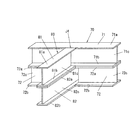
図1および図5に示すように、組立梁70,80が平面視においてT字形に直角に接合されている。一方の組立梁70は、H形鋼によって形成された上側の梁部材71および下側の梁部材72を上下に積み重ねることによって形成されている。
他方の組立梁80は一方の組立梁70に平面視において直角に設けられるとともに、H形鋼によって形成された上側の梁部材81および下側の梁部材82を上下に積み重ねることによって形成されている。
Next, the structure of the D circle portion will be described.
As shown in FIGS. 1 and 5, the assembly beams 70 and 80 are joined at a right angle in a T shape in a plan view. One of the assembled beams 70 is formed by vertically stacking an
The other assembled
また、一方の組立梁70の上側の梁部材71と下側の梁部材72とは、梁成および梁幅(フランジ幅)が等しくなっているが、異なっていてもよい。
また、他方の組立梁80の上側の梁部材81と下側の梁部材82とは、梁成および梁幅(フランジ幅)が等しくなっているが、異なっていてもよい。
さらに、一方の組立梁70の上側の梁部材71と他方の組立梁80の上側の梁部材81とは梁成および梁幅(フランジ幅)が等しくなっているが、異なっていてもよい。
また、一方の組立梁70の下側の梁部材72と他方の組立梁80の下側の梁部材82とは梁成および梁幅(フランジ幅)が等しくなっているが、異なっていてもよい。
Further, the
Further, the
Further, the
Further, the
組立梁70,80が接合される接合部J4において、一方の組立梁70の上側の梁部材71は、他方の組立梁80の上側の梁部材81に勝ち状態で接合された上側通し梁71となっており、他方の組立梁80の下側の梁部材82は、一方の組立梁70の下側の梁部材72に勝ち状態で接合された下側通し梁82となっている。
At the joint portion J4 where the assembled beams 70 and 80 are joined, the
すなわち、他方の組立梁80の下側通し梁82は、接合部J4において、上側の梁部材81よりも平面視において梁長手方向に突出しており、この突出している部分において一方の組立梁70の下側の梁部材72の端部が下側通し梁82に当接されて接合されている。また、一方の組立梁70の上側通し梁71には、接合部J4において、他方の組立梁80の上側の梁部材81の端部が当接されて接合されている。具体的には、上側通し梁71の上フランジ71aに、上側の梁部材81の上フランジ81aの端面が接合され、上側通し梁71の下フランジ71bに上側の梁部材81の下フランジ81bの端面が接合されている。また、上側通し梁71のウェブ71cには、上側の梁部材81のウェブ81cの端面は接合されておらす、当該端面とウェブ71cとの間には隙間がある。なお、上側の梁部材81のウェブ81cを梁軸方向に延出して、当該延出部の端面をウェブ71cに接合させてもよい。
That is, the lower through
また、他方の組立梁80の下側通し梁82には、接合部J4において、一方の組立梁70の下側の梁部材72の端部が当接されて接合されている。具体的には、下側通し梁72の上フランジ72aに、下側の梁部材82の上フランジ82aの端面が接合され、下側通し梁72の下フランジ72bに下側の梁部材82の下フランジ82bの端面が接合されている。また、下側通し梁72のウェブ72cには、下側の梁部材82のウェブ82cの端面は接合されておらす、当該端面とウェブ82cとの間には隙間がある。なお、下側の梁部材82のウェブ82cを梁軸方向に延出して、当該延出部の端面をウェブ72cに接合させてもよい。
そして、一方の組立梁70の上側通し梁71と他方の組立梁80の下側通し梁72とが平面視において直交し、かつ、他方の組立梁80の上側の梁部材81と一方の組立梁70の下側の梁部材72とが平面視において直角に配置されている。
Further, the lower side through
The upper through-
図1に示すように、本実施の形態では、基礎梁は、組立梁10,20,30,40,50,60,70,80によって形成された梁の平面構造を有しているが、当該梁の平面構造は基礎梁の少なくとも一部に設けられていればよい。 As shown in FIG. 1, in the present embodiment, the foundation beam has a planar structure of a beam formed by the assembled beams 10, 20, 30, 40, 50, 60, 70, 80. The planar structure of the beam may be provided on at least a part of the foundation beam.
本実施の形態によれば、組立梁10,20が直交する直交部において、一方の組立梁20の上側通し梁11と他方の組立梁20の下側通し梁22とが平面視において直交し、かつ、他方の組立梁20の上側分割梁21,21と一方の組立梁10の下側分割梁12,12とが平面視において直交するので、上部の柱や耐力壁から作用する荷重は、上側通し梁11に直接伝達されるとともに下側通し梁22に上側分割梁21,21を介して伝達される。このため、上部の柱や耐力壁からの荷重を十分に負担できるとともに、上側分割梁21,21および下側分割梁12,12の撓みを抑制できる。
また、上側分割梁21および下側分割梁12は、それぞれ梁部材をその長手方向に分割してなるものであるから、梁長が短くなる。このため、施工現場での上側分割梁21および下側分割梁12の取り回しが容易になり、施工負荷を軽減することができる。
According to the present embodiment, in the orthogonal portion where the assembled beams 10 and 20 are orthogonal to each other, the upper through
Further, since the
また、組立梁30,40、組立梁50,60および組立梁70,80がそれぞれ接合される接合部J2,J3,J4において、一方の組立梁30,50,70の上側通し梁31,51,71と他方の組立梁40,60,80の下側通し梁42,62,82とが平面視において直交し、かつ、他方の組立梁40,60,80の上側の梁部材41,61,81と一方の組立梁30,50,70の下側の梁部材32,62,72とが平面視において直角に配置されるので、上部の柱や耐力壁から作用する荷重は、一方の組立梁30,50,70の上側通し梁31,51,71に直接伝達されるとともに他方の組立梁40,60,80の下側通し梁42,62,82に上側の梁部材41,61,81を介して伝達される。このため、上部の柱や耐力壁からの荷重を十分に負担できるとともに、梁部材32,41,52,61,62,72,81の撓みを抑制できる。
In addition, at the joints J2, J3, J4 where the assembled beams 30, 40, the assembled beams 50, 60 and the assembled beams 70, 80 are respectively joined, the upper through
また、組立梁10,20の直交部において、上側通し梁11と下側通し梁22とを結合する場合、例えば、図2Aに示すように、上側通し梁11の下フランジ11bと、下側通し梁22の上フランジ22aとをボルト15によって結合してもよいし、図2Bに示すように、上側通し梁11の下フランジ11bと、下側通し梁22の上フランジ22aとを溶接16によって結合してもよい。なお、このような結合は上側通し梁11のウェブ11cを挟む両側の下フランジ11b,11bによって行われる。
Further, when the upper through
また、組立梁10,20の直交部において、上側通し梁11と上側分割梁21とを結合する場合、例えば、図2Cに示すように、上側通し梁11のウェブ11cと上側分割梁21のウェブ21cとを結合金物17によって結合してもよい。結合金物17は板状の第1結合板17aと、この第1結合板17aに直角に固定された板状の第2結合板17bとを備えている。そして、第1結合板17aを上側通し梁11のウェブ11cにボルト止めするとともに、第2結合板17bを上側分割梁21のウェブ21cにボルト止めすることによって、上側通し梁11と上側分割梁21とを結合する。
なお、このような結合は、上側通し梁11のウェブ11cを挟む両側にそれぞれ結合金物17を設けることによって行われる。
また、図示は省略するが、下側通し梁22と下側分割梁12とを結合金物17によって同様にして結合してもよい。
Further, when the upper through
In addition, such coupling is performed by providing
Although not shown, the lower through
また、図2Dに示すように、上側通し梁11と上側分割梁21とを結合する場合、上側通し梁11の上フランジ11aと上側分割梁21の上フランジ21aとを溶接16によって結合するとともに、上側通し梁11の下フランジ11bと上側分割梁21の下フランジ21bとを溶接16によって結合してもよい。
なお、図示は省略するが、下側通し梁22と下側分割梁12とを溶接によって同様にして結合してもよい。
Further, as shown in FIG. 2D, when the upper through
Although not shown, the lower through
さらに、図2Eに示すように、上側通し梁11と上側分割梁21とを結合する場合、上側通し梁11の上フランジ11aと上側分割梁21の上フランジ21aとを結合金物18によって結合するとともに、上側通し梁11の下フランジ11bと上側分割梁21の下フランジ21bとを結合金物19によって結合してもよいし、結合金物18だけで結合してもよいし、結合金物19だけで結合してもよい。
Further, as shown in FIG. 2E, when the upper through
結合金物18は矩形板状に形成されており、当該結合金物18の一側部を上フランジ11aにボルト止めするとともに他側部を上フランジ21aにボルト止めすることによって、上側通し梁11と上側分割梁21とを結合する。
また、結合金物19は、板状の第1結合板19aと、この第1結合板19aに直角に固定された板状の第2結合板19bとを備えている。そして、第1結合板17aを上側通し梁11のウェブ11cにボルト止めするとともに、第2結合板19bを上側通し梁11の下フランジ11bおよび上側分割梁21の下フランジ21bにボルト止めすることによって、上側通し梁11と上側分割梁21とを結合する。
なお、図示は省略するが、下側通し梁22と下側分割梁12とを結合金物19によって同様にして結合してもよい。
The
Further, the combined
Although illustration is omitted, the lower through
また、上側分割梁21と下側通し梁22とを結合する場合、図2Fに示すように、上側分割梁21の下フランジ21bと下側通し梁22の上フランジ22aとをボルト15によって結合してもよいし、図2Gに示すように、上側分割梁21の下フランジ21bと下側通し梁22の上フランジ22aとを溶接16によって結合してもよい。なお、このような結合は上側分割梁21のウェブ21cを挟む両側の下フランジ21b,21bおよび下側通し梁22のウェブ22cを挟む両側の上フランジ22a,22aによって行われる。
また、溶接16は、下フランジ21bおよび上フランジ22aの長さ方向に沿って間欠的に行ってもよいし、連続的に行ってもよい。
また、図示は省略するが、上側通し梁11と下側分割梁12との結合も、上記と同様にしてボルト15によって行うか、または溶接16によって行えばよい。
なお、上述したボルト15、溶接16、結合金物17,18,19による梁部材どうしの結合は、図3〜図5に示す構造に同様にして適用してもよい。
In addition, when the
Moreover, the
Although illustration is omitted, the upper through
The connection of the beam members with the
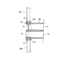
上述した実施の形態では、本発明に係る梁の平面構造を住宅等の建物の基礎梁の平面構造に適用したが、建物の床梁に適用してもよい。この場合、図2Hおよび図2Iに示すように、例えば複数階建ての建物では、その平面における外周側に配置される組立梁30,40は、下階の壁100や下階の柱200の上端面によって支持されるとともに、平面視においてコ字形に直角に接合されている。
In the embodiment described above, the planar structure of the beam according to the present invention is applied to the planar structure of the foundation beam of a building such as a house, but it may be applied to a floor beam of a building. In this case, as shown in FIG. 2H and FIG. 2I, for example, in a multi-storey building, the assembly beams 30 and 40 arranged on the outer peripheral side in the plane are above the
一方の組立梁30は、H形鋼によって形成された上側の梁部材31および下側の梁部材32を上下に積み重ねることによって形成されている。
他方の組立梁40は一方の組立梁10に平面視において直角に設けられるとともに、H形鋼によって形成された上側の梁部材41および下側の梁部材42を上下に積み重ねることによって形成されている。
One of the assembled beams 30 is formed by vertically stacking an
The other assembled
組立梁30,40が接合される接合部において、一方の組立梁30の上側の梁部材31は、他方の組立梁40の上側の梁部材41に勝ち状態で接合された上側通し梁31となっており、他方の組立梁40の下側の梁部材42は、一方の組立梁30の下側の梁部材32に勝ち状態で接合された下側通し梁42となっている。そして、一方の組立梁30の上側通し梁31と他方の組立梁40の下側通し梁42とが平面視において直交し、かつ、他方の組立梁40の上側の梁部材41と一方の組立梁30の下側の梁部材32とが平面視において直角に配置されている。
At the joint where the assembled beams 30 and 40 are joined, the
建物がツーバイフォー工法によって施工されている場合、図2Hに示すように、下階の壁パネル100の上端面に、下側通し梁42および下側の梁部材32が設置され、上側通し梁31と上側の梁部材41に上階の壁パネル101が設置されている。上下階の壁パネル101,100はホールドダウン金物等の連結金物110によって連結されている。連結金物110は上下の固定部110a,110bと、これら固定部110a,110bを連結するPC鋼棒等の連結棒110cとを備えている。
When the building is constructed by the two-by-four construction method, as shown in FIG. 2H, the lower through
そして、上の固定部110aが上階の壁パネル101に固定され、下の固定部110bが下階の壁パネル100に固定されている。また、連結棒110cは上階の壁パネル101、上側通し梁31の上下のフランジ、下側通し梁31の上下のフランジ、および下階の壁パネル100を貫通している。そして、連結棒110cは上下の固定部110a,110bに締め付け固定されている。したがって、組立梁30,40は上下の壁パネル101,100によって挟み付けられるようにして固定されている。
The
また、建物が在来の軸組工法によって施工されている場合、図2Iに示すように、下階の柱200の上端面にベースプレート210が設置固定されている。このベースプレート210は紙面と直交する方向に延在しており、当該方向に所定間隔で設けられた複数の柱200の上端面に設置されている。このベースプレート210に下側通し梁42の梁長手方向の端部および下側の梁部材32が設置され、下側通し梁42の下フランジとベースプレート210とがボルト211によって結合されている。
また、上側通し梁31の上フランジにベースプレート210が設置され、このベースプレート210に上階の柱201が固定されている。そして、上側通し梁31の下フランジとベースプレート210とがボルト211によって結合されている。したがって、組立梁30,40は上下の柱201,200にベースプレート210を介してボルト211によって固定されている。
Further, when the building is constructed by the conventional frame construction method, as shown in FIG. 2I, the
The
なお、本実施の形態では、組立梁10,20,30,40,50,60,70,80を、それぞれ上下に重ねられ、かつ梁幅(フランジ幅)が等しいH形鋼によって形成したが、組立梁10,20,30,40,50,60,70,80は以下のように形成してもよい。
すなわち、図6(a)に示すように、上側のH形鋼の上フランジh1を下フランジh2より幅広に形成するとともに、下側のH形鋼の上フランジd1を下フランジd2より幅狭に形成し、さらに、上側のH形鋼の上フランジh1と下側のH形鋼の下フランジd2とを同幅に形成するとともに、上側のH形鋼の下フランジh2と下側のH形鋼の上フランジd1とを同幅に形成してもよい。
また、図6(b)に示すように、上側のH形鋼の上フランジh1を下フランジh2より幅狭に形成するとともに、下側のH形鋼の上フランジd1と下フランジd2とを同幅に形成し、さらに、上側のH形鋼の下フランジh2と下側のH形鋼の上フランジd1とを同幅に形成してもよい。
さらに、図6(c)に示すように、上側のH形鋼の上フランジh1と下フランジh2とを同幅広に形成するとともに、下側のH形鋼の上フランジd1を下フランジd2より幅狭に形成し、さらに、下側のH形鋼の下フランジd2と上側のH形鋼の下フランジh2とを同幅に形成してもよい。
In the present embodiment, the assembled beams 10, 20, 30, 40, 50, 60, 70, 80 are made of H-shaped steel which is vertically stacked and has the same beam width (flange width). The assembled beams 10, 20, 30, 40, 50, 60, 70, 80 may be formed as follows.
That is, as shown in FIG. 6A, the upper flange h1 of the upper H-section steel is formed wider than the lower flange h2, and the upper flange d1 of the lower H-section steel is narrower than the lower flange d2. Further, the upper flange h1 of the upper H-section steel and the lower flange d2 of the lower H-section steel are formed to have the same width, and the lower flange h2 of the upper H-section steel and the lower H-section steel of the lower H-section steel are formed. The upper flange d1 may be formed to have the same width.
Further, as shown in FIG. 6B, the upper flange h1 of the upper H-section steel is formed narrower than the lower flange h2, and the upper flange d1 and the lower flange d2 of the lower H-section steel are the same. The lower flange h2 of the upper H-section steel and the upper flange d1 of the lower H-section steel may be formed to have the same width.
Further, as shown in FIG. 6C, the upper flange h1 and the lower flange h2 of the upper H-section steel are formed to have the same width, and the upper flange d1 of the lower H-section steel is wider than the lower flange d2. Alternatively, the lower flange d2 of the lower H-section steel and the lower flange h2 of the upper H-section steel may be formed to have the same width.
また、図7に示すように、下側の形鋼を角形鋼管kによって形成したうえで、図7(a)に示すように、上側のH形鋼の上フランジh1と下フランジh2とを同幅に形成するととともに、角形鋼管kの上面の幅と、下フランジh2とを同幅に形成してもよい。
また、図7(b)に示すように、上側のH形鋼の上フランジh1を下フランジh2より幅広に形成するととともに、角形鋼管kの上面の幅と、上フランジh1とを同幅に形成してもよい。
さらに、図7(c)に示すように、上側のH形鋼の上フランジh1を下フランジh2より幅狭に形成するととともに、角形鋼管kの上面の幅と、下フランジh2とを同幅に形成してもよい。
Further, as shown in FIG. 7, after the lower shaped steel is formed by the rectangular steel pipe k, the upper flange h1 and the lower flange h2 of the upper H-shaped steel are made the same as shown in FIG. 7 (a). In addition to forming the width, the width of the upper surface of the rectangular steel pipe k and the lower flange h2 may be formed to have the same width.
Further, as shown in FIG. 7B, the upper flange h1 of the upper H-section steel is formed wider than the lower flange h2, and the width of the upper surface of the rectangular steel pipe k and the upper flange h1 are formed to be the same width. You may.
Furthermore, as shown in FIG. 7 (c), the upper flange h1 of the upper H-section steel is formed to be narrower than the lower flange h2, and the width of the upper surface of the rectangular steel pipe k is made equal to that of the lower flange h2. You may form.
また、図8に示すように、下側の形鋼を溝形鋼mによって形成したうえで、図8(a)に示すように、上側のH形鋼の上フランジh1と下フランジh2とを同幅に形成するととともに、溝形鋼mの上フランジm1の幅と、下フランジh2とを同幅に形成してもよい。
また、図8(b)に示すように、上側のH形鋼の上フランジh1を下フランジh2より幅広に形成するととともに、溝形鋼mの上フランジm1と上フランジh1とを同幅に形成してもよい。
さらに、図8(c)に示すように、上側のH形鋼の上フランジh1を下フランジh2より幅狭に形成するととともに、溝形鋼mの上フランジm1と下フランジh2とを同幅に形成してもよい。
Further, as shown in FIG. 8, after the lower shaped steel is formed by the channel steel m, the upper flange h1 and the lower flange h2 of the upper H-shaped steel are formed as shown in FIG. 8 (a). While forming the same width, the width of the upper flange m1 of the channel steel m and the lower flange h2 may be formed to be the same width.
Further, as shown in FIG. 8B, the upper flange h1 of the upper H-section steel is formed wider than the lower flange h2, and the upper flange m1 and the upper flange h1 of the channel steel m are formed to have the same width. You may.
Further, as shown in FIG. 8C, the upper flange h1 of the upper H-section steel is formed narrower than the lower flange h2, and the upper flange m1 and the lower flange h2 of the channel steel m have the same width. You may form.
また、図9に示すように、下側の形鋼を2つの溝形鋼を背中合わせに接合した接合溝形鋼smとしたうえで、図9(a)に示すように、上側のH形鋼の上フランジh1と下フランジh2とを同幅に形成するととともに、接合溝形鋼smの上フランジと、下フランジh2とを同幅に形成してもよい。
また、図9(b)に示すように、上側のH形鋼の上フランジh1を下フランジh2より幅広に形成するととともに、接合溝形鋼smの上フランジと上フランジh1とを同幅に形成してもよい。
さらに、図9(c)に示すように、上側のH形鋼の上フランジh1を下フランジh2より幅狭に形成するととともに、接合溝形鋼smの上フランジと下フランジh2とを同幅に形成してもよい。
Further, as shown in FIG. 9, the lower shaped steel is a joined grooved steel sm in which two grooved steels are joined back-to-back, and then, as shown in FIG. The upper flange h1 and the lower flange h2 may be formed to have the same width, and the upper flange and the lower flange h2 of the joint groove steel sm may be formed to have the same width.
Further, as shown in FIG. 9B, the upper flange h1 of the upper H-section steel is formed wider than the lower flange h2, and the upper flange and the upper flange h1 of the joint groove steel sm are formed to have the same width. You may.
Further, as shown in FIG. 9C, the upper flange h1 of the upper H-section steel is formed to be narrower than the lower flange h2, and the upper flange and the lower flange h2 of the joint groove steel sm have the same width. You may form.
10,30,50,70 一方の組立梁
20,40,60,80 他方の組立梁
11,31,51,71 上側通し梁(梁部材)
22,42,62,82 下側通し梁(梁部材)
12 下側分割梁(梁部材)
21 上側分割梁(梁部材)
32,41,52,61,72,81 梁部材
10, 30, 50, 70 One assembled
22, 42, 62, 82 Lower through beam (beam member)
12 Lower split beam (beam member)
21 Upper split beam (beam member)
32, 41, 52, 61, 72, 81 Beam member
Claims (4)
前記組立梁が平面視において互いに直交して設けられ、
前記組立梁が直交する直交部において、
一方の前記組立梁の上側の前記梁部材は連続した上側通し梁となっており、他方の前記組立梁の上側の前記梁部材は前記上側通し梁を挟んで分割された上側分割梁となっており、
他方の前記組立梁の下側の前記梁部材は連続した下側通し梁となっており、一方の前記組立梁の下側の前記梁部材は前記下側通し梁を挟んで分割された下側分割梁となっていることを特徴とする梁の平面構造。 A plane structure of a beam including an assembled beam formed by vertically stacking beam members formed of shaped steel,
The assembled beams are provided so as to be orthogonal to each other in a plan view,
In the orthogonal portion where the assembled beam is orthogonal,
The beam member on the upper side of one of the assembled beams is a continuous upper through beam, and the beam member on the upper side of the other assembled beam is an upper split beam divided by sandwiching the upper through beam. Cage,
The beam member on the lower side of the other assembly beam is a continuous lower through beam, and the beam member on the lower side of the one assembly beam is a lower side divided by sandwiching the lower through beam. Planar structure of beams characterized by being divided beams.
前記組立梁が平面視において直角に接合され、
前記組立梁が接合される接合部において、
一方の前記組立梁の上側の梁部材は、他方の前記組立梁の上側の梁部材に勝ち状態で接合された上側通し梁となっており、
他方の前記組立梁の下側の梁部材は、一方の前記組立梁の下側の梁部材に勝ち状態で接合された下側通し梁となっていることを特徴とする梁の平面構造。 A plane structure of a beam including an assembled beam formed by vertically stacking beam members formed of shaped steel,
The assembled beam is joined at a right angle in a plan view,
At the joint where the assembled beams are joined,
The upper beam member of the one assembly beam is an upper through beam joined to the upper beam member of the other assembly beam in a winning state,
The plane structure of the beam, wherein the lower beam member of the other assembled beam is a lower through beam joined to the lower beam member of the one assembled beam in a winning state.
Priority Applications (1)
| Application Number | Priority Date | Filing Date | Title |
|---|---|---|---|
| JP2018201874A JP7103158B2 (en) | 2018-10-26 | 2018-10-26 | Planar structure of the beam |
Applications Claiming Priority (1)
| Application Number | Priority Date | Filing Date | Title |
|---|---|---|---|
| JP2018201874A JP7103158B2 (en) | 2018-10-26 | 2018-10-26 | Planar structure of the beam |
Publications (2)
| Publication Number | Publication Date |
|---|---|
| JP2020066965A true JP2020066965A (en) | 2020-04-30 |
| JP7103158B2 JP7103158B2 (en) | 2022-07-20 |
Family
ID=70389842
Family Applications (1)
| Application Number | Title | Priority Date | Filing Date |
|---|---|---|---|
| JP2018201874A Active JP7103158B2 (en) | 2018-10-26 | 2018-10-26 | Planar structure of the beam |
Country Status (1)
| Country | Link |
|---|---|
| JP (1) | JP7103158B2 (en) |
Citations (9)
| Publication number | Priority date | Publication date | Assignee | Title |
|---|---|---|---|---|
| JPH06173341A (en) * | 1992-12-08 | 1994-06-21 | Hauza In:Kk | Construction for wooden house |
| JPH0999388A (en) * | 1995-08-02 | 1997-04-15 | Amada Co Ltd | Bracket used for connection member of column for building structure and its production as well as column for building structure having plural connection members and production of this column as weel as method for connecting connection member of column for building structure and beam member and method for connecting beam member to main beam member for building structure |
| JP2004211451A (en) * | 2003-01-07 | 2004-07-29 | Takenaka Komuten Co Ltd | Mechanical coupling method for steel structure beam-column joint portion |
| JP2004339728A (en) * | 2003-05-14 | 2004-12-02 | Daiwa Kosho Lease Co Ltd | Recyclable continuous footing and recycling method for continuous footing |
| WO2011093533A1 (en) * | 2010-02-01 | 2011-08-04 | 株式会社アークリエイト | Continuous minor steel beam structure |
| JP2012107424A (en) * | 2010-11-17 | 2012-06-07 | Takenaka Komuten Co Ltd | Beam member, structure for continuously providing main beam and auxiliary beam, and beam combination structure |
| KR20130073626A (en) * | 2011-12-23 | 2013-07-03 | 박종면 | Cross-section stiffiness enhancement and lining board installation area reduction having steel girder used temporary bridge and construction method of the same |
| JP2018031143A (en) * | 2016-08-23 | 2018-03-01 | 日新製鋼株式会社 | Steel member |
| JP2018162645A (en) * | 2017-03-27 | 2018-10-18 | 大和ハウス工業株式会社 | Column beam joint structure |
-
2018
- 2018-10-26 JP JP2018201874A patent/JP7103158B2/en active Active
Patent Citations (9)
| Publication number | Priority date | Publication date | Assignee | Title |
|---|---|---|---|---|
| JPH06173341A (en) * | 1992-12-08 | 1994-06-21 | Hauza In:Kk | Construction for wooden house |
| JPH0999388A (en) * | 1995-08-02 | 1997-04-15 | Amada Co Ltd | Bracket used for connection member of column for building structure and its production as well as column for building structure having plural connection members and production of this column as weel as method for connecting connection member of column for building structure and beam member and method for connecting beam member to main beam member for building structure |
| JP2004211451A (en) * | 2003-01-07 | 2004-07-29 | Takenaka Komuten Co Ltd | Mechanical coupling method for steel structure beam-column joint portion |
| JP2004339728A (en) * | 2003-05-14 | 2004-12-02 | Daiwa Kosho Lease Co Ltd | Recyclable continuous footing and recycling method for continuous footing |
| WO2011093533A1 (en) * | 2010-02-01 | 2011-08-04 | 株式会社アークリエイト | Continuous minor steel beam structure |
| JP2012107424A (en) * | 2010-11-17 | 2012-06-07 | Takenaka Komuten Co Ltd | Beam member, structure for continuously providing main beam and auxiliary beam, and beam combination structure |
| KR20130073626A (en) * | 2011-12-23 | 2013-07-03 | 박종면 | Cross-section stiffiness enhancement and lining board installation area reduction having steel girder used temporary bridge and construction method of the same |
| JP2018031143A (en) * | 2016-08-23 | 2018-03-01 | 日新製鋼株式会社 | Steel member |
| JP2018162645A (en) * | 2017-03-27 | 2018-10-18 | 大和ハウス工業株式会社 | Column beam joint structure |
Also Published As
| Publication number | Publication date |
|---|---|
| JP7103158B2 (en) | 2022-07-20 |
Similar Documents
| Publication | Publication Date | Title |
|---|---|---|
| JP3782817B1 (en) | Structural type and construction method of steel house | |
| JP4710067B2 (en) | Beam-column joint structure | |
| JP6769549B2 (en) | Beam joining method, beam joining structure, and support members | |
| JP6752599B2 (en) | Seismic structure and seismic retrofitting method | |
| JP7205256B2 (en) | Wall panel installation method | |
| CN111094673B (en) | Building and building construction method thereof | |
| JP5123602B2 (en) | Unit type building and construction method of unit type building | |
| JP6645328B2 (en) | Joint structure of H-section steel and H-section steel used therefor | |
| JP7103158B2 (en) | Planar structure of the beam | |
| JP4095534B2 (en) | Joint structure of column and beam in ramen structure and its construction method | |
| JP3787348B2 (en) | Steel house panel structure and panel construction method | |
| JP7058158B2 (en) | How to install outdoor stairs structure and outdoor stairs structure | |
| JP3346364B2 (en) | Beam-column joint structure | |
| JP2003105861A (en) | Medium-rise and high-rise building using hfc column and hfc beam or the like | |
| JP2008156971A (en) | Framework structure of wooden building | |
| JP5004434B2 (en) | Steel house | |
| JP6565543B2 (en) | Column and beam joint structure, building with column and beam joint structure | |
| KR20090102599A (en) | Reinforcement | |
| JP5142575B2 (en) | Seismic reinforcement method for wooden buildings and wooden buildings | |
| JP2007284918A (en) | Horizontally laid body and wooden structure | |
| JP6739175B2 (en) | Bonding structure of building structural material and face material | |
| JP2883655B2 (en) | Horizontal bearing members for construction | |
| JP6324765B2 (en) | Load-bearing wall-type installation structure in steel-framed buildings | |
| JP7394256B1 (en) | Joint structure | |
| JP7420984B1 (en) | How to join floor joists on floors above 2nd floor |
Legal Events
| Date | Code | Title | Description |
|---|---|---|---|
| A621 | Written request for application examination |
Free format text: JAPANESE INTERMEDIATE CODE: A621 Effective date: 20210603 |
|
| A977 | Report on retrieval |
Free format text: JAPANESE INTERMEDIATE CODE: A971007 Effective date: 20220527 |
|
| TRDD | Decision of grant or rejection written | ||
| A01 | Written decision to grant a patent or to grant a registration (utility model) |
Free format text: JAPANESE INTERMEDIATE CODE: A01 Effective date: 20220607 |
|
| A61 | First payment of annual fees (during grant procedure) |
Free format text: JAPANESE INTERMEDIATE CODE: A61 Effective date: 20220620 |
|
| R151 | Written notification of patent or utility model registration |
Ref document number: 7103158 Country of ref document: JP Free format text: JAPANESE INTERMEDIATE CODE: R151 |