JP2020046292A - Flowrate measuring device - Google Patents
Flowrate measuring device Download PDFInfo
- Publication number
- JP2020046292A JP2020046292A JP2018174663A JP2018174663A JP2020046292A JP 2020046292 A JP2020046292 A JP 2020046292A JP 2018174663 A JP2018174663 A JP 2018174663A JP 2018174663 A JP2018174663 A JP 2018174663A JP 2020046292 A JP2020046292 A JP 2020046292A
- Authority
- JP
- Japan
- Prior art keywords
- flow
- opening
- flow path
- fluid
- plate
- Prior art date
- Legal status (The legal status is an assumption and is not a legal conclusion. Google has not performed a legal analysis and makes no representation as to the accuracy of the status listed.)
- Pending
Links
Images


Classifications
-
- G—PHYSICS
- G01—MEASURING; TESTING
- G01F—MEASURING VOLUME, VOLUME FLOW, MASS FLOW OR LIQUID LEVEL; METERING BY VOLUME
- G01F1/00—Measuring the volume flow or mass flow of fluid or fluent solid material wherein the fluid passes through a meter in a continuous flow
- G01F1/68—Measuring the volume flow or mass flow of fluid or fluent solid material wherein the fluid passes through a meter in a continuous flow by using thermal effects
- G01F1/684—Structural arrangements; Mounting of elements, e.g. in relation to fluid flow
Landscapes
- Measuring Volume Flow (AREA)
- Physics & Mathematics (AREA)
- Fluid Mechanics (AREA)
- General Physics & Mathematics (AREA)
Abstract
Description
本開示は、流量測定装置に関する。 The present disclosure relates to a flow measurement device.
従来から、管路を流れる被計測流体の流量を計測する種々の流量測定装置が提案されている。例えば、下記の特許文献1には、被計測流体をハウジング内に取り込み、ハウジング内の流路の分岐構造によって被計測流体から異物が分離させ、異物が分離された被計測流体の流量を検出部において測定する流量測定装置が開示されている。そうした流量計測装置では、通常、ハウジングに、被計測流体から分離させた異物を排出させるための開口と、検出部を通過した被計測流体をハウジングの外部へと排出させるための開口と、が設けられる。 2. Description of the Related Art Conventionally, various flow rate measuring devices for measuring a flow rate of a fluid to be measured flowing through a pipeline have been proposed. For example, in Japanese Patent Application Laid-Open No. H11-216, the fluid to be measured is taken into a housing, foreign matter is separated from the fluid to be measured by a branch structure of a flow path in the housing, and a flow rate of the fluid to be measured from which the foreign matter is separated is detected by a detecting unit. Discloses a flow rate measuring device for measuring. In such a flow rate measuring device, an opening for discharging foreign substances separated from the fluid to be measured and an opening for discharging the fluid to be measured that has passed through the detection unit to the outside of the housing are usually provided in the housing. Can be
ここで、例えば、内燃機関に接続された吸気配管などの管路では、被計測流体が、一時的に、通常の主流方向とは反対の逆流方向に流れる場合がある。そうした管路に取り付けられる流量計測装置は、主流方向に流れる被計測流体の流量のみならず、逆流方向に流れる被計測流体の流量も精度よく計測できることが望ましい。 Here, for example, in a pipeline such as an intake pipe connected to the internal combustion engine, the fluid to be measured may temporarily flow in the reverse flow direction opposite to the normal main flow direction. It is desirable that the flow rate measuring device attached to such a pipe can accurately measure not only the flow rate of the fluid to be measured flowing in the main flow direction but also the flow rate of the fluid to be measured flowing in the reverse flow direction.
しかしながら、上記の特許文献1のように、ハウジング内の流路に異物を分離させるための分岐構造を設けている場合、被計測流体が逆流したときに、異物を排出するための開口から検出部の方へと逆流の動圧が伝達される可能性がある。こうした逆流の動圧は、検出部付近で予期せぬ渦を生じさせ、検出部に計測誤差を生じさせる原因となる。また、被計測流体が逆流すると、被計測流体が主流方向に流れているときにハウジング外部に排出された異物が、被計測流体の逆流によって、その異物を排出した開口の方へと押し返されて、検出部まで進入し、計測誤差を生じさせる可能性もある。管路において被計測流体が逆流するときの流量測定装置における計測誤差の発生を抑制することについては依然として改良の余地がある。 However, in the case where a branch structure for separating foreign matter is provided in the flow path in the housing as in Patent Literature 1 described above, when the fluid to be measured flows backward, the detecting unit is opened from the opening for discharging the foreign matter. May be transmitted to the counter pressure. Such a backflow dynamic pressure causes an unexpected vortex in the vicinity of the detection unit, and causes a measurement error in the detection unit. When the fluid to be measured flows backward, the foreign matter discharged to the outside of the housing when the fluid to be measured flows in the main flow direction is pushed back toward the opening from which the foreign matter has been discharged by the backflow of the fluid to be measured. As a result, there is a possibility that the sensor may enter the detection unit and cause a measurement error. There is still room for improvement in suppressing the occurrence of measurement errors in the flow measurement device when the fluid to be measured flows backward in the pipeline.
本開示の技術は、以下の形態として実現することが可能である。 The technology of the present disclosure can be realized as the following embodiments.
本開示の一形態は、管路(111)において被計測流体が、主流方向(Y)に流れるときの流量と、前記主流方向とは反対の逆流方向に流れるときの流量と、をそれぞれ測定する流量測定装置(10A,10B.10C,10D,10E,10G,10H,10I,10J,10K,10L)として提供される。この形態の流量測定装置は、前記管路内に配置されるハウジング(50)であって、前記主流方向の上流側に向かって開口する第1開口(55)と、前記主流方向において前記第1開口と対向する位置に設けられ、前記被計測流体が流通する第2開口(56)と、前記第2開口とは異なる位置に設けられ、前記被計測流体が流通する第3開口(57)と、を有するハウジングと、前記ハウジングの内部に設けられ、前記第1開口と前記第2開口とを接続する第1流路(61)と、前記第1流路から分岐し、前記第1流路と前記第3開口とを接続する第2流路(70)と、前記第2流路に配置され、前記第2流路を流れる前記被計測流体の流量を検出する検出部(75)と、前記主流方向において前記第1流路の一部に配置され、少なくとも一部が前記第1流路において前記第1開口よりも前記第2開口に近い位置に配置される板状部材(81,82,83,85,86,87,88,89,90)と、を備える。 According to an embodiment of the present disclosure, a flow rate when the fluid to be measured flows in the main flow direction (Y) and a flow rate when the measured fluid flows in the reverse flow direction opposite to the main flow direction are measured in the pipeline (111). It is provided as a flow measurement device (10A, 10B.10C, 10D, 10E, 10G, 10H, 10I, 10J, 10K, 10L). The flow rate measuring device of this aspect is a housing (50) arranged in the conduit, the first opening (55) opening toward the upstream side in the main flow direction, and the first opening (55) in the main flow direction. A second opening (56) provided at a position facing the opening and through which the fluid to be measured flows, and a third opening (57) provided at a position different from the second opening and through which the fluid to be measured flows A first flow path (61) provided inside the housing and connecting the first opening and the second opening; and a first flow path branched from the first flow path. A second flow path (70) connecting the first flow path and the third opening; a detection unit (75) disposed in the second flow path and detecting a flow rate of the fluid to be measured flowing through the second flow path; At least one of the first flow paths is disposed in the main flow direction. Includes a plate-like member (81, 82, 83, 85, 86, 87, 88, 89, 90) disposed at a position closer to the second opening than the first opening in the first flow path. .
この形態の流量測定装置によれば、管路において被計測流体が逆流したときに、その逆流の動圧が、第2開口を通じて第2流路の検出部の方へと伝達されることが、板状部材によって抑制される。また、ハウジング外部の異物が、被計測流体の逆流によって第2開口を通じて検出部の方へと入り込むことが、板状部材によって抑制される。よって、管路において被計測流体が逆流したときの計測誤差の発生を抑制することができる。 According to the flow measurement device of this aspect, when the fluid to be measured flows backward in the pipeline, the dynamic pressure of the backward flow is transmitted to the detection unit of the second flow path through the second opening. It is suppressed by the plate-like member. The plate-like member prevents foreign matter outside the housing from entering the detection unit through the second opening due to the backflow of the fluid to be measured. Therefore, it is possible to suppress occurrence of a measurement error when the fluid to be measured flows backward in the pipeline.
1.第1実施形態:
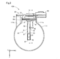
図1を参照する。第1実施形態における流量測定装置10Aは、例えば、燃焼システム100において用いられる。燃焼システム100は、車両等に搭載されて当該車両の駆動力を発生する。燃焼システム100は、吸気部110と、内燃機関120と、排気部130と、ECU140と、を備える。流量測定装置10Aは吸気部110に含まれる。
1. First embodiment:
Please refer to FIG. The
吸気部110は、流量測定装置10Aの他に、管路111と、エアクリーナ112と、スロットルバルブ113と、を備える。管路111は、内燃機関120に接続されている。管路111には、内燃機関120に供給される吸入空気が流れる。吸入空気には、後述するように排気ガスが混合されていてもよい。以下では、管路111において管路111の中心軸に沿った燃焼室121に向かう吸入空気の流れ方向を「主流方向」と呼ぶ。また、主流方向とは逆の吸入空気の流れ方向を「逆流方向」と呼ぶ。
The
エアクリーナ112と、流量測定装置10Aと、スロットルバルブ113とは、主流方向の上流側から、この順で、管路111に取り付けられている。エアクリーナ112は、吸入空気に含まれる塵や埃を除去する。流量測定装置10Aは、吸入空気の流量を計測する。流量測定装置10Aは、被計測流体が管路111において主流方向に流れるときの流量と、逆流方向に流れるときの流量と、をそれぞれ区別して計測する。燃焼システム100では、吸入空気が流量測定装置10Aの被計測流体であり、流量測定装置10Aの測定結果は吸気量を表す。スロットルバルブ113は、内燃機関120に供給される吸気量を調整する。
The
内燃機関120は、燃焼室121と、吸気通路122と、インジェクタ123と、吸気弁124と、点火プラグ125と、ピストン126と、排気通路127と、排気弁128と、を備える。燃焼室121は、吸気通路122を介して、吸気部110の管路111に接続されている。
The
吸気通路122には、インジェクタ123と吸気弁124とが設けられている。インジェクタ123は、管路111から吸気通路122に流入した吸入空気に、燃料を噴射して混合する。燃焼室121には、吸入空気に燃料が混合された混合ガスが流入する。吸気弁124は、吸気通路122の出口に設けられている。燃焼室121への混合ガスの流入は吸気弁124の開閉によって制御される。
An
点火プラグ125は、燃焼室121に流入した混合ガスに着火する。内燃機関120では、燃焼室121における混合ガスの燃焼圧によってピストン126が押されて運動する。燃焼室121は、排気通路127を通じて排気部130に接続されている。排気通路127の入口には排気弁128が設けられている。燃焼室121から排気通路127への排気ガスの排出は、排気弁128の開閉によって制御される。
The
排気部130は、排ガス管路131と、空燃比センサ132と、を備える。排ガス管路131は、排気通路127に接続されており、燃焼室121から排出された排気ガスを車両の外部へと導く。なお、排ガスの一部は、図示しない循環路を通じて、管路111の吸入空気に混合されてもよい。空燃比センサ132は、排ガス管路131に取り付けられており、排ガスに含まれる酸素量を検出する。
The
ECU140は、燃焼システム100の動作を制御する。ECU140は、マイクロコンピュータと電源回路等によって構成される演算処理回路である。マイクロコンピュータは、例えば、プロセッサ(CPU)と、RAM、ROM、および、フラッシュメモリ等の記憶媒体と、入出力部と、を含む。ECU140は、CPUがRAM上に読み込んだプログラムや命令を実行することによって、燃焼システム100を制御するための種々の機能を発揮する。ECU140の機能の少なくとも一部は、ECU140を構成するアナログ回路によって実現されていてもよい。
ECU140は、例えば、流量測定装置10Aや、空燃比センサ132、図示されていない燃焼圧センサ等から取得される計測結果を用いて、スロットルバルブ113の開度や、インジェクタ123から噴射される燃料噴射量を制御する。また、ECU140は、吸気弁124および排気弁128の開閉や、点火プラグ125による混合ガスの点火を制御する。その他に、ECU140は、EGR量の制御をおこなってもよい。なお、流量測定装置10Aは、上述したように、被計測流体が主流方向に流れるときの流量と逆流方向に流れるときの流量とを区別して計測できるため、管路111での被計測流体の流れ方向の変化を上述の制御に適切に反映させることができる。
The
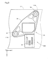
図2および図3を参照する。図2および図3には、互いに直交するX,Y,Z軸が図示されている。以下では、X軸、Y軸、および、Z軸のそれぞれの正方向を、X軸方向、Y軸方向、および、Z軸方向と呼び、それぞれの負の方向を、−X軸方向、−Y軸方向、および、−Z軸方向と呼ぶ。X軸方向は、流量測定装置10Aの取り付け位置における管路111の中心軸に直交する。X軸方向は、Z軸方向を下としてY軸方向に見たときに右方向を向いている。Y軸方向は、流量測定装置10Aの取り付け位置における管路111の中心軸に平行であり、流量測定装置10Aの取り付け位置における被計測流体の主流方向に一致する。Z軸方向は、管路111に対する流量測定装置10Aの本体部20の挿入方向に一致する。X軸、Y軸、および、Z軸は、他の参照図においても、適宜、図示されている。
Please refer to FIG. 2 and FIG. 2 and 3 show X, Y, and Z axes orthogonal to each other. Hereinafter, the positive directions of the X-axis, the Y-axis, and the Z-axis will be referred to as the X-axis direction, the Y-axis direction, and the Z-axis direction, respectively, and the negative directions will be referred to as the -X-axis direction, -Y It is referred to as the axial direction and the −Z-axis direction. The X-axis direction is orthogonal to the central axis of the
図2を参照する。流量測定装置10Aは、管路111内に配置されて被計測流体に曝される本体部20と、管路111に固定される固定部30と、管路111の外部に配置されるコネクタ部40と、を備える。本体部20は、管路111に設けられた開口部111oを通じて、管路111内に、Z軸方向に挿入される。本体部20の構成の詳細については後述する。
Please refer to FIG. The
図2に示すように、固定部30は、本体部20における管路111の開口部111o側の基端部21に連結されている。固定部30が、管路111の開口部111oに固定されることによって、本体部20の挿入方向における先端部22は、管路111の内壁面から離間した位置に保持される。第1実施形態では、流量測定装置10Aは、本体部20の基端部21が重力方向上側となり、先端部22が重力方向下側となるように管路111に取り付けられる。第1実施形態では、Z軸方向として示される本体部20の挿入方向は、重力方向上側から下側に向かう方向である。なお、本体部20の挿入方向は、重力方向に平行な方向には限定されず、重力方向に対して斜めに、重力方向上側から下側に向かう方向であってもよい。
As shown in FIG. 2, the fixing
固定部30は、封止部32と、フランジ33と、を備える。封止部32は、管路111の開口部111oを気密に封止する。Z軸方向に平行な方向に見たときに封止部32の外周形状は、開口部111oの開口形状とほぼ一致する。封止部32の外周には、開口部111oの内周面に気密に接触するOリング32rが嵌められている。なお、図4では、便宜上、Oリング32rの図示は省略されている。封止部32の−Z軸方向側にはフランジ33が設けられている。
The fixing
図3に示すように、フランジ33は、X軸方向およびY軸方向に沿って張り出した平板状の部位である。フランジ33は、ボルト34によって管路111に締結される。フランジ33には、ボルト34が挿入されるボルト孔が設けられている。また、管路111のボルト孔に対応する位置にはボルト34を受け入れる図2に示すボス111bが設けられている。図3では、便宜上、ボス111bの位置を破線で図示してある。フランジ33がボルト34によって管路111に固定されることによって、本体部20のハウジング50が管路111内の予め決められた位置に固定される。
As shown in FIG. 3, the
図2および図3に示すように、コネクタ部40は、フランジ33からX軸方向に延び出た位置に設けられている。図2に示すように、コネクタ部40は、フランジ33によって管路111の外周面から離間した位置に保持されている。コネクタ部40は、図示しない信号線を介して本体部20内に配置されている図4に示す検出部75に電気的に接続されている。コネクタ部40は、図示しないケーブルを介して、ECU140に電気的に接続されており、測定結果を表す信号をECU140に出力する。
As shown in FIGS. 2 and 3, the
図2を参照する。第1実施形態では、流量測定装置10Aは、さらに、温度センサ41を備えている。温度センサ41は、封止部32に固定されており、本体部20からX軸方向に離間した位置において、本体部20と平行に封止部32からZ軸方向に延び出ている。温度センサ41は、管路111を流れる被計測流体の温度を計測し、その計測結果を、コネクタ部40を通じてECU140に出力する。他の実施形態では、温度センサ41は、省略されてもよい。
Please refer to FIG. In the first embodiment, the
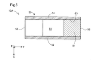
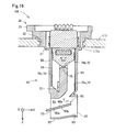
図2、図4、および、図5を参照して流量測定装置10Aの本体部20の構成を説明する。本体部20は、内部空間を有する中空のハウジング50を備える。図2および図4に示すように、第1実施形態では、ハウジング50は、平板な直方体形状を有している。図2に示すように、ハウジング50は、管路111での被計測流体の主流方向であるY軸方向に交差する方向に互いに対向する第1側壁部51と第2側壁部52とを有している。第1実施形態では、第1側壁部51と第2側壁部52とはX軸方向および−X軸方向に互いに対向している。第1実施形態では、固定部30によって本体部20が管路111に固定されているときに、第1側壁部51は−X軸方向側に位置し、第2側壁部52はX軸方向側に位置している。また、第1側壁部51と第2側壁部52とは、図5に示すように、全体として管路111での被計測流体の主流方向であるY軸方向に沿って配置される。
The configuration of the
なお、本明細書において、ある主体がある方向に「沿って」いる、と言うときは、その主体の姿勢は、その対象とする方向に平行な姿勢には限定されない。その主体は、その対象とする方向に対してある程度の傾斜角を有する姿勢を有していてもよい。例えば、その主体は、対象とする方向に対して、概ね10°以下の角度で傾斜する姿勢を有していてもよい。また、その主体の全体が対象とする方向に直線的に沿っていなくともよい。従って、例えば、その主体の一部または全体が湾曲していても、凹凸していても、その主体を全体として見たときに概ね、その対象とする方向に沿っていればよい。 In this specification, when it is said that a certain subject is “along” in a certain direction, the posture of the subject is not limited to a posture parallel to the target direction. The subject may have a posture having a certain inclination angle with respect to the target direction. For example, the subject may have a posture inclined at an angle of about 10 ° or less with respect to a target direction. Further, the whole of the subject does not have to be linearly along the target direction. Therefore, for example, even if a part or the whole of the main body is curved or uneven, it is sufficient if the main body is viewed as a whole, generally along the target direction.
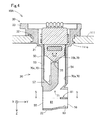
図4に示すように、ハウジング50は、正面壁部53と背面壁部54とを有する。図2および図3に示すように、正面壁部53と背面壁部54とは、第1側壁部51と第2側壁部52との間に位置し、第1側壁部51と第2側壁部52のそれぞれに交差する。図4に示すように、ハウジング50のZ軸方向の長さは、Y軸方向の長さより大きい。また、図5に示すように、ハウジング50のX軸方向の長さはY軸方向の長さよりも小さい。
As shown in FIG. 4, the
図2を参照する。ハウジング50は、正面壁部53と第2側壁部52との間の角部からX軸方向に突起している軸状の保護突起部42を有している。保護突起部42は省略されてもよい。
Please refer to FIG. The
図2、図4、および、図5を参照する。ハウジング50には、主流方向に流れる被計測流体をハウジング50の内部に取り込むための第1開口55が設けられている。第1開口55は、固定部30によって本体部20が管路111に固定されているときに、−Y軸方向、つまり、管路111での被計測流体の主流方向の上流側に向かって開口する。第1実施形態では、第1開口55は、正面壁部53において開口している。第1開口55は、図2に示すように、正面壁部53のZ軸方向における端部に設けられている。第1開口55は、管路111の中心軸に近い位置に配置されるように設けられていることが望ましい。
Please refer to FIG. 2, FIG. 4, and FIG. The
図4および図5を参照する。ハウジング50には、被計測流体の主流方向において第1開口55に対向する位置に第2開口56が設けられている。第2開口56は、背面壁部54に設けられている。第2開口56は、後述するように、第1開口55から取り込まれた被計測流体に含まれる異物をハウジング50の外部に排出するための排出口として機能する。
Please refer to FIG. 4 and FIG. The
第1実施形態では、第2開口56の開口面積は、第1開口55の開口面積とほぼ等しい。ここでの第2開口56の開口面積は、後述の板状部材81が配置されていない状態での第2開口56の外周によって規定される開口領域の面積を意味する。また、「ほぼ等しい」とは、ある程度の差が許容されることを意味する。「ある程度の差」とは、例えば、製造誤差や公差としてもよいし、±5%程度の差としてもよい。
In the first embodiment, the opening area of the
図2および図5を参照する。ハウジング50には、第2開口56とは異なる位置に、被計測流体が流通する第3開口57が設けられている。第3開口57は、後述する第2流路70に接続されている。第1実施形態では、第3開口57は、第1側壁部51において、−X軸方向に開口している。
Please refer to FIG. 2 and FIG. A
ハウジング50の内部には、第1開口55と第2開口56とを接続する第1流路61が設けられている。第1実施形態では、第1流路61は、第1開口55からY軸方向に沿って概ね直線状に延びている。
A
図4を参照する。ハウジング50の内部には、第1流路61から分岐する第2流路70が設けられている。第1実施形態では、第2流路70は、第1流路61から−Z軸方向側に分岐している。
Please refer to FIG. Inside the
第2流路70は、第1流路61から背面壁部54側に向かって斜めに分岐して、本体部20の基端部21側に向かって−Z軸方向に直線状に延びている入口側流路70aを有している。また、第2流路70は、入口側流路70aに接続され、入口側流路70aから正面壁部53側に向かって−Y軸方向に延びている中間流路70bを有している。さらに、第2流路70は、中間流路70bの−Y方向側の端部から本体部20の先端部22側に向かって、第1流路61の手前まで、Z軸方向に直線状に延びている出口側流路70cを有している。出口側流路70cは、第1側壁部51において開口している第3開口57に接続されている。
The
第2流路70の途中には、被計測流体の流量を検出する検出部75が設けられている。第1実施形態では、検出部75は中間流路70bに設けられている。第1実施形態では、検出部75は、温度差方式によって被計測流体の流量を検出する。検出部75は、被計測流体を加熱する図示しない加熱ヒータと、被計測流体の流れ方向に沿って配置された図示しない複数の温度センサと、を有している。温度センサは、例えば、感温抵抗体によって構成され、加熱ヒータは、例えば、発熱抵抗体によって構成される。温度センサは、加熱ヒータの上流側と下流側の両方に配置されている。検出部75は、加熱ヒータの上流側と下流側との温度差から被計測流体の流量を検出する。
In the middle of the
検出部75は、第2流路70において被計測流体が第1流路61から第3開口57に向かう方向に流れる被計測流体の流量を順流での流量として出力する。また、検出部75は、第2流路70において被計測流体が第3開口57から第1流路61に向かう方向に流れているときの被計測流体の流量を逆流での流量として出力する。上述した温度差方式を採用している第1実施形態の検出部75は、温度勾配の向きによって、第2流路70での被計測流体の流れ方向が、順流の方向であるのか逆流の方向であるのかを判別することができる。
The
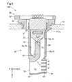
図4および図5を参照する。第1流路61の一部には、板状部材81が配置されている。第1実施形態では、板状部材81は、第1流路61の第2開口56側の端部に配置されている。板状部材81は、第1流路61の下流側流路部位63に配置されている。下流側流路部位63は、第1流路61において開口している第2流路70の開口端部71よりも被計測流体の主流方向における下流側に位置する第1流路の一部位である。板状部材81は、Y軸方向において下流側流路部位63全体にわたって配置されており、そのY軸方向側の端部が第2開口56に位置している。第1実施形態では、板状部材81は、平板状であり、X軸方向およびY軸方向に沿って配置されている。図5に示すように、板状部材81は、下流側流路部位63においてX軸方向にわたって配置されており、第1側壁部51と第2側壁部52とを連結している。板状部材81の機能については後述する。
Please refer to FIG. 4 and FIG. A plate-
図4を参照して、流量測定装置10Aのハウジング50内での被計測流体の流れを説明する。まず、被計測流体が管路111を主流方向に流れている場合を説明する。この場合には、被計測流体は、第1開口55を通じてハウジング50内の第1流路61に導入される。流量測定装置10Aでは、第1開口55が−Y軸方向に向かって開口しているため、管路111を主流方向に流れる被計測流体をハウジング50内へと円滑に導入することができる。
With reference to FIG. 4, the flow of the fluid to be measured in the
第1開口55から導入された被計測流体は、第1流路61に沿ってY軸方向に流れ、一部が、検出部75が配置されている第2流路70へと分流する。被計測流体に含まれる塵や水分など、被計測流体の分子よりも重い質量を有する異物は、第1流路61に沿って流れる被計測流体とともに、第2開口56へと導かれ、そのままハウジング50の外部へと排出される。
The fluid to be measured introduced from the
異物が分離され、第2流路70の方へと流入した被計測流体は、第2流路70の端部に設けられている第3開口57からハウジング50の外部へと流出する。検出部75は、第2流路70を通過する被計測流体の流量を計測する。
The foreign matter is separated, and the fluid to be measured that has flowed into the
流量測定装置10Aでは、被計測流体が主流方向に流れているときには、第1流路61と第2流路70の分岐構造によって被計測流体中の異物が第2流路70に進入することが抑制される。そのため、検出部75は、異物が分離された被計測流体の流量を精度よく計測することができる。
In the
第1実施形態では、第2流路70が第1流路61より重力方向上側に位置しているため、重力の作用により、異物が第2流路70へと進入することが抑制される。また、第1実施形態では、上述したように、第1開口55と第2開口56の開口面積がほぼ等しいため、第2開口56から異物がより一層、排出されやすい。
In the first embodiment, since the
次に、管路111において被計測流体が逆流する場合について説明する。この場合には、管路111の被計測流体は、第3開口57を通じて第2流路70の出口側流路70cに流入し、中間流路70bおよび出口側流路70cを経て、第1流路61へと流れる。検出部75は、第3開口57から流入した第2流路70を流れる被計測流体の流量を計測する。第1実施形態では、第3開口57が第1側壁部51に設けられており、管路111での被計測流体の流れ方向に交差する方向に開口している。そのため、気体分子よりも質量が高く大きい慣性力が働く異物が、逆流の被計測流体とともに第3開口57に流入することが抑制される。
Next, a case where the fluid to be measured flows backward in the
ここで、流量測定装置10Aでは、第1流路61の第2開口56近傍に板状部材81が配置されている。管路111において被計測流体が逆流したときには、板状部材81が、その逆流に対する邪魔板として機能するため、第2開口56を通じてハウジング50内部の第1流路61へと流入する被計測流体の逆流の動圧が、第2流路70へと伝達されることが抑制される。よって、そうした逆流の動圧が、第3開口57から第1流路61に向かう第2流路70での被計測流体の流れに作用して、検出部75の近傍で、予期せぬ渦が生じることが抑制される。そのため、検出部75の計測誤差の発生が抑制される。
Here, in the flow measurement device 10 </ b> A, the
また、被計測流体の流れ方向が主流方向から逆流方向に切り替わった直後には、第2開口56から排出されたばかりの異物が、被計測流体の逆流によってハウジング50内に戻ってしまう場合がある。そうした場合でも、板状部材81が邪魔板として機能するため、第2開口56を通じてハウジング50内へと戻った異物が、第1流路61で開口している開口端部71を通じて第2流路70へと入り込むことが抑制される。よって、そうした異物による計測誤差の発生が抑制される。
Immediately after the flow direction of the fluid to be measured is switched from the main flow direction to the reverse flow direction, the foreign matter that has just been discharged from the
第1実施形態では、板状部材81はX軸方向およびY軸方向に沿って配置されており、Z軸方向に向く面を有している。そのため、−Z軸方向側からの逆流の動圧の伝達や異物を、より効果的に遮ることができる。
In the first embodiment, the plate-
第1実施形態では、第2開口56を通じて第1流路61に流入した被計測流体の逆流は、板状部材81によって−Y軸方向に沿って流れるように誘導される。そのため、第1流路61へと流入した被計測流体および異物が、第1流路61の−Z軸方向側にある第2流路70へと流入してしまうことが抑制される。また、板状部材81が主流方向に沿って配置されていれば、被計測流体が主流方向に流れているときの第1流路61での被計測流体の流れが円滑化されるため、第2開口56を通じた異物の排出性が向上する。
In the first embodiment, the reverse flow of the fluid to be measured flowing into the
第1実施形態では、第1流路61の下流側流路部位63にのみ配置されているため、第1流路61の流路抵抗の増加が抑制されている。加えて、第1実施形態では、板状部材81のY軸方向側の端部が第2開口56に位置しており、ハウジング50の外部へと延び出ておらず、流量測定装置10Aの本体部20が小型に構成されている。
In the first embodiment, since it is arranged only in the
以上のように、第1実施形態の流量測定装置10Aによれば、第1流路61に配置された板状部材81によって、被計測流体に逆流が生じたときの計測誤差の発生が抑制されている。その他に、第1実施形態の流量測定装置10Aによれば、第1実施形態中で説明した種々の作用効果を奏することができる。
As described above, according to the
2.種々の実施形態:
以下では、第1実施形態の流量測定装置10Aの構成を一部改変した構成を第2実施形態〜第12実施形態として説明する。以下の各実施形態の構成は、特段の説明を設けていない構成については、第1実施形態で説明した構成と共通する。また、第1実施形態と共通する構成部には、第1実施形態と共通する符号を付して説明する。以下の各実施形態の構成においても、第1実施形態と共通する構成を有していることによって、第1実施形態で説明した種々の作用効果を奏することができる。
2. Various embodiments:
Hereinafter, configurations obtained by partially modifying the configuration of the
2−1.第2実施形態:
図6を参照する。第2実施形態の流量測定装置10Bでは、第1流路61の下流側流路部位63に、複数の板状部材81がZ軸方向に配列されている。各板状部材81は並列に並んでいる。第2実施形態の流量測定装置10Bによれば、邪魔板として機能する板状部材81が多い分だけ、開口端部71を通じた第2流路70への逆流の動圧の伝達や異物の進入がより一層抑制される。また、各板状部材81が並列に配列されているため、複数の板状部材81が設けられていることによる第1流路61の流路抵抗の増大が抑制されている。
2-1. Second embodiment:
Please refer to FIG. In the flow rate measuring device 10B of the second embodiment, a plurality of
2−2.第3実施形態:
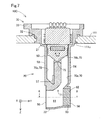
図7および図8を参照する。第3実施形態の流量測定装置10Cは、第1実施形態の板状部材81とは異なる配置角度で設置された1枚の板状部材82を有している。第3実施形態の板状部材82は、下流側流路部位63においてY軸方向およびZ軸方向に沿って配置されている点以外は、第1実施形態の板状部材81とほぼ同じである。板状部材82は、下流側流路部位63においてZ軸方向にわたって架設されている。第3実施形態の流量測定装置10Cによれば、板状部材82がX軸方向および−X軸方向に向く面を有しているため、板状部材82のX軸方向側や−X軸方向側から第2流路70の開口端部71に向かう方向への逆流の動圧の伝達や異物の進入を効果的に遮ることができる。
2-2. Third embodiment:
Please refer to FIG. 7 and FIG. The flow measuring device 10C according to the third embodiment has one plate-shaped
2−3.第4実施形態:
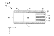
図9を参照する。第4実施形態の流量測定装置10Dは、第3実施形態で説明した板状部材82が複数、第1流路61の下流側流路部位63に配置されている。第4実施形態では、複数の板状部材82は、X軸方向に並列に配列されている。第4実施形態の流量測定装置10Dによれば、邪魔板として機能する板状部材82が多い分だけ、開口端部71を通じた第2流路70への逆流の動圧の伝達や異物の進入がより一層抑制される。また、各板状部材82が並列に配列されているため、複数の板状部材82が設けられていることによる第1流路61の流路抵抗の増大が抑制されている。
2-3. Fourth embodiment:
Please refer to FIG. In the flow measurement device 10D according to the fourth embodiment, a plurality of the plate-
2−4.第5実施形態:
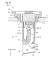
図10を参照する。第5実施形態の流量測定装置10Eは、第1実施形態の板状部材81とは異なる配置角度で設置された1枚の板状部材83を有している。第5実施形態の板状部材83は、第1の面83aが−Z軸方向側かつ−Y軸方向側に向き、第2の面83bがZ軸側かつY軸方向側に向くように、被計測流体の主流方向に対して傾斜した状態で下流側流路部位63に配置されている。流量測定装置10Eによれば、板状部材83の第2開口56側に向く傾斜面83bによって、逆流方向に流れる被計測流体の動圧や異物を受け止めることができる。そのため、その動圧が第2流路70の開口端部71へと伝達されることや異物が開口端部71を通じて第2流路70に入り込むことが抑制される。また、流量測定装置10Eでは、第2開口56から第1流路61に流入した逆流の被計測流体および異物が、板状部材83の傾斜面83bに沿って、第2流路70の開口端部71から離れる方向へと誘導される。よって、管路111において被計測流体が逆流するときに、第2流路70内に渦が発生することや異物が入り込むことが抑制され、計測誤差の発生が抑制される。なお、他の実施形態では、第1流路61の下流側流路部位63において複数の板状部材83が、第2実施形態の板状部材81のように、Z軸方向に並列に配列されていてもよい。
2-4. Fifth embodiment:
Please refer to FIG. The
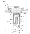
2−5.第6実施形態:
図11を参照する。第6実施形態の流量測定装置10Gは、第1実施形態の板状部材81の代わりに、第6実施形態の板状部材85を備えている。第6実施形態の板状部材85の構成は、Y軸方向側の端部に、−Z軸方向側に斜めに折れ曲がった傾斜部位85tを有している点以外は、第1実施形態の板状部材81とほぼ同じである。傾斜部位85tは、−Z方向側かつ−Y軸方向側に向く傾斜面85aと、Z方向側かつY軸方向側に向く傾斜面85bと、を有している。流量測定装置10Gによれば、傾斜部位85tの第2開口56側に向く傾斜面85bが、逆流方向に流れる被計測流体の動圧や異物を受け止めることができる。そのため、第2流路70の開口端部71への動圧の伝達や異物の進入が抑制される。また、傾斜部位85tの傾斜面85bによって、第2開口56から第1流路61に流入した逆流の被計測流体および異物が、板状部材85よりZ軸方向側の領域へと、第2流路70の開口端部71から離れる方向に誘導される。よって、管路111において被計測流体が逆流するときに、第2流路70内に乱流が発生することや異物が入り込むことが抑制され、計測誤差の発生が抑制される。なお、他の実施形態では、第1流路61の下流側流路部位63において複数の板状部材85が、第2実施形態の板状部材81のように、Z軸方向に並列に配列されていてもよい。
2-5. Sixth embodiment:
Please refer to FIG. The
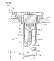
2−6.第7実施形態:
図12を参照する。第7実施形態の流量測定装置10Hは、第1実施形態の板状部材81の代わりに、第7実施形態の板状部材86を備えている。第7実施形態の板状部材86の構成は、Y軸方向側の部位ほど−Z軸方向側に位置するように湾曲している点以外は、第1実施形態の板状部材81とほぼ同じである。板状部材86は、−Y軸方向側に向く内周側湾曲面86aと、Y軸方向側に向く外周側湾曲面86bと、を有している。これらの湾曲面86a,86bは、被計測流体の主流方向に対して斜めに配置される傾斜面であると解釈できる。第7実施形態の流量測定装置10Hによれば、第2開口56側に外周側湾曲面86bによって、逆流する被計測流体の動圧および異物を受け止めることができる。また、逆流する被計測流体およびそれに含まれる異物を外周側湾曲面86bに沿って、第2流路70の開口端部71から離れる方向に誘導することができる。よって、管路111において被計測流体が逆流するときに、第2流路70内に乱流が発生することや異物が入り込むことが抑制され、計測誤差の発生が抑制される。他の実施形態では、複数の板状部材86が、下流側流路部位63において、第2実施形態の板状部材81のように、Z軸方向に並列に配列されていてもよい。
2-6. Seventh embodiment:
Referring to FIG. The flow measuring device 10H of the seventh embodiment includes a
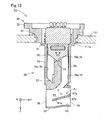
2−7.第8実施形態:
図13を参照する。第8実施形態の流量測定装置10Iが備える板状部材87の構成は、第1流路61の下流側流路部位63より−Y軸方向側の領域に延長された延長部位87eが追加されている点以外は、第5実施形態の板状部材83とほぼ同じである。延長部位87eは、第2流路70の開口端部71とZ軸方向および−Z軸方向に対向する位置に配置されている。板状部材87は、第1開口55よりもY軸方向側の領域から第2開口56まで配置されている。つまり、板状部材87は、被計測流体の主流方向において第1流路61の全体にわたっては配置されておらず、被計測流体の主流方向において第1流路61の一部に配置されている。
2-7. Eighth embodiment:
Please refer to FIG. The configuration of the plate-
第8実施形態の流量測定装置10Iでは、板状部材87は、第5実施形態の板状部材83と同様に、板状部材87の−Y軸方向側に向く傾斜面87aと、Y軸方向側に向く傾斜面87bと、を有している。傾斜面87bは、第2開口56側に向いており、第5実施形態で説明した板状部材83の傾斜面83bと同様の作用効果を奏することができる。また、板状部材87の延長部位87eは、第2流路70の開口端部71の下方にまで延び出ており、開口端部71とZ軸方向および−Z軸方向に対向している。流量測定装置10Iによれば、その延長部位87eによって、板状部材87よりZ方向側の領域を流れる被計測流体や異物が、第2流路70へと進入することを遮ることができる。その他に、流量測定装置10Iによれば、第2流路70の開口端部71に対向する延長部位87eの傾斜面87aによって、主流方向に流れる被計測流体に含まれる異物を第2開口56へと誘導することができる。なお、他の実施形態では、複数の板状部材87がZ軸方向に並列に配列されていてもよい。この場合に、板状部材87のそれぞれのY軸方向における長さは、一部または全部が異なっていてもよい。
In the flow rate measuring device 10I of the eighth embodiment, the plate-
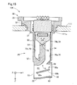
2−8.第9実施形態:
図14を参照する。第9実施形態の流量測定装置10Jが備える板状部材88の構成は、Y軸方向側の端部に第2開口56から延び出る延出部位88exを有している点以外は、第8実施形態の板状部材87とほぼ同じである。板状部材88は、板状部材87の−Y軸方向側に向く傾斜面88aと、Y軸方向側に向く傾斜面88bと、を有している。また、第1流路61の下流側流路部位63から−Y軸方向側の領域に延び出ている延長部位88eを有している。第2開口56側に向く傾斜面88bや延長部位88eは、第8実施形態で説明した板状部材87の傾斜面87bや延長部位87eと同様な作用効果を奏することができる。流量測定装置10Jでは、板状部材88が延出部位88exを有している分だけ、逆流する被計測流体の動圧や異物が第2流路70の開口端部71へと進入することが、さらに抑制される。なお、他の実施形態では、複数の板状部材88がZ軸方向に並列に配列されていてもよい。この場合に、板状部材87のそれぞれのY軸方向における長さは、一部または全部が異なっていてもよい。
2-8. Ninth embodiment:
Please refer to FIG. The configuration of the
2−9.第10実施形態:
図15を参照する。第10実施形態の流量測定装置10Kが備える板状部材89の構成は、Y軸方向側の端部が第2開口56より−Y軸方向側に位置するように、Y軸方向の長さが短縮されている点以外は、第8実施形態の板状部材87とほぼ同じである。板状部材89は、−Y軸方向側に向く傾斜面89aと、Y軸方向側に向く傾斜面89bと、を有している。また、第1流路61の下流側流路部位63から−Y軸方向側の領域に延び出ている延長部位89eを有している。第2開口56側に向く傾斜面89bや延長部位89eは、第8実施形態で説明した板状部材87の傾斜面87bや延長部位87eと同様な作用効果を奏することができる。なお、他の実施形態では、複数の板状部材89がZ軸方向に並列に配列されていてもよい。この場合に、板状部材89のそれぞれのY軸方向における長さは、一部または全部が異なっていてもよい。
2-9. Tenth embodiment:
Referring to FIG. The configuration of the plate-
2−10.第11実施形態:
図16を参照する。第11実施形態の流量測定装置10Lが備える板状部材90の構成は、−Y軸方向側の端部が第1開口55からハウジング50の外部に延出するように、−Y軸方向側に延長されている点以外は、第10実施形態の板状部材89とほぼ同じである。板状部材90は、−Y軸方向側に向く傾斜面90aと、Y軸方向側に向く傾斜面90bと、を有している。また、板状部材90は、第2流路70の開口端部71と、Z軸方向および−Z軸方向に対向する部位を有している。第11実施形態の流量測定装置10Lによれば、被計測流体が主流方向に流れているときに、被計測流体に含まれる異物を、−Z軸方向側の傾斜面90aに沿って下流側流路部位63まで誘導することができる。そのため、第2流路70への異物の進入が抑制される。また、被計測流体が逆流方向に流れるときに、Z軸方向側の傾斜面90bに沿って被計測流体を第1開口55の方へと誘導することができる。そのため、逆流する被計測流体が第2流路70の開口端部71に流入することが抑制される。また、被計測流体が逆流方向に流れるときに、板状部材90よりZ軸方向側の領域にある異物が、第2流路70の開口端部71へと進入することが抑制される。なお、他の実施形態では、複数の板状部材90がZ軸方向に並列に配列されていてもよい。この場合に、板状部材90のそれぞれのY軸方向における長さは、一部または全部が異なっていてもよい。
2-10. Eleventh embodiment:
Please refer to FIG. The configuration of the plate-
3.他の実施形態:
上記の各実施形態で説明した種々の構成は、例えば、以下のように改変することも可能である。以下に説明する他の実施形態はいずれも、上記の各実施形態と同様に、本開示の技術を実施するための形態の一例として位置づけられる。
3. Other embodiments:
The various configurations described in the above embodiments can be modified, for example, as follows. Each of the other embodiments described below is positioned as an example of an embodiment for implementing the technology of the present disclosure, similarly to the above embodiments.
(1)他の実施形態1:
流量計測装置において、主流方向において第1流路61の一部に配置され、少なくとも一部が第1流路61において第1開口55よりも第2開口56に近い位置に配置される板状部材は、上記の各実施形態の板状部材81〜90には限定されない。板状部材は、例えば、X軸方向に対して斜めに配置されていてもよいし、凹部や凸部、スリットなどを有していてもよい。また、上記の各実施形態の板状部材81〜90の構成は適宜組み合わせることが可能である。例えば、第1実施形態の板状部材81と第2実施形態の板状部材82とが互いに交差する状態で第1流路61に配置されてもよい。また、第1実施形態の板状部材81と第6実施形態の板状部材85の両方が第1流路61の下流側流路部位63に配置されてもよい。第6実施形態の板状部材85の−Y軸方向側の端部に、第8実施形態の板状部材87が有する延長部位87eのように、第2流路70の開口端部71とZ軸方向において対向する延長部位が設けられてもよい。
(1) Other Embodiment 1:
In the flow measurement device, a plate-shaped member that is disposed in a part of the
(2)他の実施形態2:
上記の各実施形態において、ハウジング50は直方体形状以外の形状を有していてもよい。例えば、ハウジング50は、Y軸方向を長手方向とする楕円断面を有する楕円柱状の形状を有していてもよい。上記の各実施形態において、第1側壁部51がX軸方向側となり、第2側壁部52が−X軸方向側となるように入れ替えられてもよい。
(2) Other Embodiment 2:
In each of the above embodiments, the
(3)他の実施形態3:
上記の各実施形態において、検出部75は、温度差方式の代わりに、他の方式の流量センサが用いられてもよい。検出部75は、例えば、コリオリ式やカルマン渦式のセンサが採用されてもよい。検出部75は、順流方向の流量と逆流方向の流量とを区別して検出しなくてもよい。
(3) Other Embodiment 3:
In each of the above embodiments, the
(4)他の実施形態4:
上記の各実施形態の流量測定装置10A〜10E,10G〜10Lは、車両に搭載される燃焼システム100の管路111以外に取り付けられてもよい。各実施形態の流量測定装置10A〜10E,10G〜10Lは、例えば、燃料電池システムにおいて燃料電池に発電に用いられる反応ガスを供給する配管に取り付けられてもよい。
(4) Other Embodiment 4:
The flow
本開示の技術は、流量測定装置以外の種々の形態で実現することも可能である。例えば、流量測定装置に用いられるハウジングや、流量測定装置における流路構造、流量測定システム等の形態で実現することができる。 The technology of the present disclosure can be realized in various forms other than the flow measurement device. For example, the present invention can be realized in the form of a housing used for a flow measurement device, a flow channel structure in the flow measurement device, a flow measurement system, and the like.
本開示の技術は、上述の実施形態や他の実施形態に限られるものではなく、その趣旨を逸脱しない範囲において種々の構成で実現することができる。例えば、発明の概要の欄に記載した各形態中の技術的特徴に対応する実施形態、実施例、変形例中の技術的特徴は、上述の課題の一部又は全部を解決するために、あるいは、上述の効果の一部又は全部を達成するために、適宜、差し替えや、組み合わせを行うことが可能である。また、その技術的特徴が本明細書中に必須ではないと説明されているものに限らず、その技術的特徴が本明細書中に必須であると説明されていなければ、適宜、削除することが可能である。 The technology of the present disclosure is not limited to the above-described embodiment and other embodiments, and can be implemented with various configurations without departing from the spirit thereof. For example, the technical features in the embodiments, examples, and modifications corresponding to the technical features in each mode described in the summary of the invention are for solving some or all of the problems described above, or In order to achieve some or all of the above-described effects, replacement and combination can be appropriately performed. In addition, the technical features are not limited to those described as not essential in the present specification, and may be appropriately deleted unless the technical features are described as essential in the present specification. Is possible.
10A 流量測定装置、10B 流量測定装置、10C 流量測定装置、10D 流量測定装置、10E 流量測定装置、10G 流量測定装置、10H 流量測定装置、10I 流量測定装置、10J 流量測定装置、10K 流量測定装置、10L 流量測定装置、50 ハウジング、55 第1開口、56 第2開口、57 第3開口、61 第1流路、70 第2流路、75 検出部、81 板状部材、82 板状部材、83 板状部材、85 板状部材、86 板状部材、87 板状部材、88 板状部材、89 板状部材、90 板状部材、111 管路 10A flow measurement device, 10B flow measurement device, 10C flow measurement device, 10D flow measurement device, 10E flow measurement device, 10G flow measurement device, 10H flow measurement device, 10I flow measurement device, 10J flow measurement device, 10K flow measurement device, 10L flow rate measuring device, 50 housing, 55 first opening, 56 second opening, 57 third opening, 61 first flow path, 70 second flow path, 75 detector, 81 plate member, 82 plate member, 83 Plate member, 85 Plate member, 86 Plate member, 87 Plate member, 88 Plate member, 89 Plate member, 90 Plate member, 111 Pipe
Claims (7)
前記管路内に配置されるハウジング(50)であって、前記主流方向の上流側に向かって開口する第1開口(55)と、前記主流方向において前記第1開口と対向する位置に設けられ、前記被計測流体が流通する第2開口(56)と、前記第2開口とは異なる位置に設けられ、前記被計測流体が流通する第3開口(57)と、を有するハウジングと、
前記ハウジングの内部に設けられ、前記第1開口と前記第2開口とを接続する第1流路(61)と、
前記第1流路から分岐し、前記第1流路と前記第3開口とを接続する第2流路(70)と、
前記第2流路に配置され、前記第2流路を流れる前記被計測流体の流量を検出する検出部(75)と、
前記主流方向において前記第1流路の一部に配置され、少なくとも一部が前記第1流路において前記第1開口よりも前記第2開口に近い位置に配置される板状部材(81,82,83,85,86,87,88,89,90)と、
を備える、流量測定装置。 Flow rate measuring devices (10A, 10B) for measuring a flow rate when a fluid to be measured flows in a main flow direction (Y) and a flow rate when flowing in a reverse flow direction opposite to the main flow direction in a pipeline (111). .10C, 10D, 10E, 10G, 10H, 10I, 10J, 10K, 10L)
A housing (50) disposed in the conduit, provided at a first opening (55) opening toward an upstream side in the main flow direction, and at a position facing the first opening in the main flow direction. A housing provided with a second opening (56) through which the fluid to be measured flows, and a third opening (57) provided at a position different from the second opening and through which the fluid to be measured flows;
A first flow path (61) provided inside the housing and connecting the first opening and the second opening;
A second flow path (70) branched from the first flow path and connecting the first flow path and the third opening;
A detection unit (75) disposed in the second flow path and detecting a flow rate of the fluid to be measured flowing through the second flow path;
A plate-like member (81, 82) which is arranged at a part of the first flow path in the main flow direction and at least a part of which is arranged at a position closer to the second opening than the first opening in the first flow path. , 83, 85, 86, 87, 88, 89, 90);
A flow measurement device comprising:
前記第1流路には、複数の前記板状部材(81,82)が配置されている、流量測定装置。 The flow measurement device according to claim 1,
The flow measurement device, wherein a plurality of the plate members (81, 82) are arranged in the first flow path.
前記板状部材は、前記主流方向に対して斜めに配置される傾斜面(83a,83b,85a,85b,86a,86b,87a,87b,88a,88b,89a,89b)を有する、流量測定装置。 The flow measurement device according to claim 1 or claim 2,
The flow rate measuring device, wherein the plate-shaped member has an inclined surface (83a, 83b, 85a, 85b, 86a, 86b, 87a, 87b, 88a, 88b, 89a, 89b) arranged obliquely with respect to the main flow direction. .
前記板状部材は、前記第1流路において開口している前記第2流路の開口端部と対向する部位(87e,88e,89e,90e)を有する、流量測定装置。 It is a flow measuring device according to any one of claims 1 to 3,
The flow rate measuring device, wherein the plate-shaped member has a portion (87e, 88e, 89e, 90e) facing an open end of the second flow path that is open in the first flow path.
前記板状部材は、前記第2開口から前記ハウジングの外部へと延び出ている部位(88ex)を有する、流量測定装置。 The flow measurement device according to any one of claims 1 to 4, wherein:
The flow measurement device, wherein the plate-shaped member has a portion (88ex) extending from the second opening to the outside of the housing.
前記板状部材は、前記第1流路において開口している前記第2流路の開口端部より前記主流方向における下流側に設けられ、
前記板状部材の前記主流方向における下流側の端部は、前記第2開口に位置している、流量測定装置。 It is a flow measuring device according to any one of claims 1 to 3,
The plate-shaped member is provided on the downstream side in the main flow direction from an open end of the second flow path that is open in the first flow path,
The flow measurement device, wherein a downstream end of the plate-shaped member in the main flow direction is located at the second opening.
前記第2開口の開口面積は、前記第1開口の開口面積以上である、流量測定装置。 The flow measurement device according to any one of claims 1 to 6, wherein:
The flow measurement device, wherein an opening area of the second opening is equal to or larger than an opening area of the first opening.
Priority Applications (2)
| Application Number | Priority Date | Filing Date | Title |
|---|---|---|---|
| JP2018174663A JP2020046292A (en) | 2018-09-19 | 2018-09-19 | Flowrate measuring device |
| PCT/JP2019/035187 WO2020059540A1 (en) | 2018-09-19 | 2019-09-06 | Flow rate measurement device |
Applications Claiming Priority (1)
| Application Number | Priority Date | Filing Date | Title |
|---|---|---|---|
| JP2018174663A JP2020046292A (en) | 2018-09-19 | 2018-09-19 | Flowrate measuring device |
Publications (1)
| Publication Number | Publication Date |
|---|---|
| JP2020046292A true JP2020046292A (en) | 2020-03-26 |
Family
ID=69887314
Family Applications (1)
| Application Number | Title | Priority Date | Filing Date |
|---|---|---|---|
| JP2018174663A Pending JP2020046292A (en) | 2018-09-19 | 2018-09-19 | Flowrate measuring device |
Country Status (2)
| Country | Link |
|---|---|
| JP (1) | JP2020046292A (en) |
| WO (1) | WO2020059540A1 (en) |
Family Cites Families (6)
| Publication number | Priority date | Publication date | Assignee | Title |
|---|---|---|---|---|
| JP3950578B2 (en) * | 1999-04-23 | 2007-08-01 | 株式会社日立製作所 | Flow measuring device |
| DE10245965B4 (en) * | 2002-09-30 | 2021-06-02 | Robert Bosch Gmbh | Device for determining at least one parameter of a medium flowing in a line |
| KR101060137B1 (en) * | 2003-07-14 | 2011-08-29 | 로베르트 보쉬 게엠베하 | Device for determining at least one parameter of the medium flowing in the tube |
| DE102004022271A1 (en) * | 2003-07-14 | 2005-02-03 | Robert Bosch Gmbh | Device for determining at least one parameter of a medium flowing in a conduit |
| DE102004035893B4 (en) * | 2004-07-23 | 2013-03-14 | Robert Bosch Gmbh | Device for determining at least one parameter of a medium flowing in a conduit |
| JP5168223B2 (en) * | 2009-05-01 | 2013-03-21 | 株式会社デンソー | Air flow measurement device |
-
2018
- 2018-09-19 JP JP2018174663A patent/JP2020046292A/en active Pending
-
2019
- 2019-09-06 WO PCT/JP2019/035187 patent/WO2020059540A1/en not_active Ceased
Also Published As
| Publication number | Publication date |
|---|---|
| WO2020059540A1 (en) | 2020-03-26 |
Similar Documents
| Publication | Publication Date | Title |
|---|---|---|
| US8701474B2 (en) | Air flow measuring device | |
| US10520343B2 (en) | Thermal flowmeter | |
| US20220065671A1 (en) | Physical quantity measurement device for measuring a physical quantity of a fluid | |
| WO2020202791A1 (en) | Physical quantity detection device | |
| JP6995020B2 (en) | Physical quantity detector | |
| CN108139248B (en) | Thermal Flow Meter | |
| CN113597538B (en) | Physical quantity detection device | |
| JP2020046292A (en) | Flowrate measuring device | |
| CN113924467B (en) | Physical quantity detecting device | |
| JP7168390B2 (en) | Flow measurement device | |
| US11391610B2 (en) | Flow rate measurement device | |
| CN109196311B (en) | Thermal flowmeter | |
| JP7629112B2 (en) | Physical quantity detection device | |
| JP6876018B2 (en) | Physical quantity detector | |
| WO2016027551A1 (en) | Thermal flow meter | |
| US10718647B2 (en) | Thermal flowmeter including an inclined passage | |
| JP7204370B2 (en) | Flow measuring device | |
| JP2020098179A (en) | Physical quantity measurement device | |
| WO2021045120A1 (en) | Air flow rate measurement device | |
| WO2019142565A1 (en) | Thermal flowmeter |