JP2020043655A - motor - Google Patents

motor Download PDF

Info

Publication number
JP2020043655A
JP2020043655A JP2018168051A JP2018168051A JP2020043655A JP 2020043655 A JP2020043655 A JP 2020043655A JP 2018168051 A JP2018168051 A JP 2018168051A JP 2018168051 A JP2018168051 A JP 2018168051A JP 2020043655 A JP2020043655 A JP 2020043655A
Authority
JP
Japan
Prior art keywords
coil
stator
rotor
armature
magnetic flux
Prior art date
Legal status (The legal status is an assumption and is not a legal conclusion. Google has not performed a legal analysis and makes no representation as to the accuracy of the status listed.)
Pending
Application number
JP2018168051A
Other languages
Japanese (ja)
Inventor
和彦 松並
Kazuhiko Matsunami
和彦 松並
Current Assignee (The listed assignees may be inaccurate. Google has not performed a legal analysis and makes no representation or warranty as to the accuracy of the list.)
Suzuki Motor Corp
Original Assignee
Suzuki Motor Corp
Priority date (The priority date is an assumption and is not a legal conclusion. Google has not performed a legal analysis and makes no representation as to the accuracy of the date listed.)
Filing date
Publication date
Application filed by Suzuki Motor Corp filed Critical Suzuki Motor Corp
Priority to JP2018168051A priority Critical patent/JP2020043655A/en
Publication of JP2020043655A publication Critical patent/JP2020043655A/en
Pending legal-status Critical Current

Links

Images

Classifications

    • YGENERAL TAGGING OF NEW TECHNOLOGICAL DEVELOPMENTS; GENERAL TAGGING OF CROSS-SECTIONAL TECHNOLOGIES SPANNING OVER SEVERAL SECTIONS OF THE IPC; TECHNICAL SUBJECTS COVERED BY FORMER USPC CROSS-REFERENCE ART COLLECTIONS [XRACs] AND DIGESTS
    • Y02TECHNOLOGIES OR APPLICATIONS FOR MITIGATION OR ADAPTATION AGAINST CLIMATE CHANGE
    • Y02TCLIMATE CHANGE MITIGATION TECHNOLOGIES RELATED TO TRANSPORTATION
    • Y02T10/00Road transport of goods or passengers
    • Y02T10/60Other road transportation technologies with climate change mitigation effect
    • Y02T10/64Electric machine technologies in electromobility

Abstract

To provide a motor that can prevent a magnetic flux from being weakened by the other magnetic flux because the interfering magnetic flux can be released from a yoke portion to the first rotor side or the second rotor side even when the magnetic fluxes of coils that generate different magnetic fluxes in a stator interfere with each other.SOLUTION: A motor includes a stator 10 having an excitation coil 13 supplied with power from a first power supply circuit and an armature coil 12 supplied with power from a second power supply, and an outer rotor 20 and an inner rotor 30 rotatable relative to the stator 10, and the stator 10 includes a plurality of first stator teeth 15A protruding toward the outer rotor 20 side and an annular yoke portion 14 in which the plurality of first stator teeth 15A are arranged in a circumferential direction, the excitation coil 13 is wound around the first stator teeth 15A, and the armature coil 12 is wound around the yoke portion 14.SELECTED DRAWING: Figure 2

Description

本発明は、モータに関する。   The present invention relates to a motor.

特許文献1には、多相の内側電機子巻線を含む内側固定子と内側固定子に対向して設けられた内側回転子とを有する永久磁石式駆動部と、多相の外側電機子巻線および界磁巻線を含む外側固定子と外側固定子に対向して設けられ複数の突極を含む外側回転子とを有し、永久磁石式駆動部よりも径方向の外側に設けられた電磁石式駆動部と、を備えたハイブリッド界磁式ダブルギャップ同期機が開示されている。   Patent Literature 1 discloses a permanent magnet drive unit having an inner stator including a polyphase inner armature winding and an inner rotor provided to face the inner stator, and a polyphase outer armature winding. An outer stator including a wire and a field winding, and an outer rotor including a plurality of salient poles provided to face the outer stator and provided radially outside the permanent magnet drive unit. A hybrid field type double gap synchronous machine including an electromagnetic drive unit is disclosed.

このハイブリッド界磁式ダブルギャップ同期機において、内側固定子と内側回転子との間には内側ギャップが形成されており、外側固定子と外側回転子との間には外側ギャップが形成されている。   In this hybrid field double gap synchronous machine, an inner gap is formed between the inner stator and the inner rotor, and an outer gap is formed between the outer stator and the outer rotor. .

内側ギャップでは、永久磁石による主磁束と内側電機子巻線に供給される電機子電流との間に永久磁石式同期機としてのトルクが発生する。外側ギャップでは、界磁巻線に界磁電流が供給され、18極の起磁力が作られると、これが外側回転子の15極の突極によって変調され、12極の回転磁束が作られる。この回転磁束と外側電機子巻線に供給されている電機子電流との間に電磁石式同期機としてのトルクが発生する。   In the inner gap, torque as a permanent magnet type synchronous machine is generated between the main magnetic flux by the permanent magnet and the armature current supplied to the inner armature winding. In the outer gap, a field current is supplied to the field winding, and when a magnetomotive force of 18 poles is generated, this is modulated by the 15 salient poles of the outer rotor to generate a rotating magnetic flux of 12 poles. A torque as an electromagnetic synchronous machine is generated between the rotating magnetic flux and the armature current supplied to the outer armature winding.

特開2017−135863号公報JP 2017-135863 A

しかしながら、特許文献1に記載のハイブリッド界磁式ダブルギャップ同期機は、外側固定子において1つのティースに外側電機子巻線と界磁巻線とを配置した構成である。このため、外側電機子巻線の磁化方向が界磁巻線の磁化方向に対して反対となる電気角の区間においては、外側電機子巻線の磁束と界磁巻線から発生する直流磁束とがティースにおいて干渉してしまう。これにより、外側電機子巻線の磁束の一部が界磁巻線の直流磁束によって打ち消されてしまう。   However, the hybrid field double gap synchronous machine described in Patent Literature 1 has a configuration in which an outer armature winding and a field winding are arranged on one tooth in an outer stator. Therefore, in a section of the electrical angle where the magnetization direction of the outer armature winding is opposite to the magnetization direction of the field winding, the magnetic flux of the outer armature winding and the DC magnetic flux generated from the field winding are Will interfere with the teeth. As a result, a part of the magnetic flux of the outer armature winding is canceled by the DC magnetic flux of the field winding.

この結果、特許文献1に記載のハイブリッド界磁式ダブルギャップ同期機にあっては、外側電機子巻線の磁束が界磁巻線の直流磁束によって弱められてしまう。このように、特許文献1に記載のハイブリッド界磁式ダブルギャップ同期機では、外側固定子において互いに異なる磁束を発生させる巻線同士で互いの磁束が対向するように干渉してしまい、一方の磁束が他方の磁束によって弱められてしまうという課題がある。   As a result, in the hybrid field type double gap synchronous machine described in Patent Document 1, the magnetic flux of the outer armature winding is weakened by the DC magnetic flux of the field winding. As described above, in the hybrid field type double gap synchronous machine described in Patent Literature 1, the windings that generate different magnetic fluxes on the outer stator interfere with each other so that the magnetic fluxes face each other. Is weakened by the other magnetic flux.

本発明は、上述のような事情に鑑みてなされたもので、ステータにおいて互いに異なる磁束を発生させるコイル同士で互いの磁束が干渉した場合であっても、干渉した磁束をヨーク部から第1のロータ側又は第2のロータ側に逃がすことができるので、一方の磁束が他方の磁束によって弱められることを防止することができるモータを提供することを目的とする。   The present invention has been made in view of the above-described circumstances, and even when mutual magnetic fluxes interfere with each other in coils generating different magnetic fluxes in the stator, the interfering magnetic fluxes are transmitted from the yoke portion to the first coil. An object of the present invention is to provide a motor capable of preventing one magnetic flux from being weakened by the other magnetic flux since the motor can be released to the rotor side or the second rotor side.

本発明は、上記目的を達成するため、第1の電源から電力が供給される第1のコイルと第2の電源から電力が供給される第2のコイルとを有するステータと、前記ステータに対して相対回転可能な第1のロータと、前記ステータに対して前記第1のロータと異なる方向から対面するよう配置され、前記ステータに対して相対回転可能な第2のロータと、を備え、前記ステータは、前記第1のロータ側に突出した複数のステータティースと、前記複数のステータティースが周方向に並んで配置された環状のヨーク部と、を有し、前記第1のコイルは、前記ステータティースに巻かれており、前記第2のコイルが前記ヨーク部に巻かれている構成を有する。   To achieve the above object, the present invention provides a stator having a first coil to which power is supplied from a first power supply and a second coil to which power is supplied from a second power supply. A first rotor rotatable relative to the first rotor, and a second rotor arranged to face the stator from a different direction from the first rotor and rotatable relative to the stator, The stator includes a plurality of stator teeth protruding toward the first rotor and an annular yoke portion in which the plurality of stator teeth are arranged in a circumferential direction. The second coil is wound around a stator tooth and the second coil is wound around the yoke.

本発明によれば、ステータにおいて互いに異なる磁束を発生させるコイル同士で互いの磁束が干渉した場合であっても、干渉した磁束をヨーク部から第1のロータ側又は第2のロータ側に逃がすことができるので、一方の磁束が他方の磁束によって弱められることを防止することができるモータを提供することができる。   According to the present invention, even when coils that generate different magnetic fluxes in the stator interfere with each other, the interfering magnetic flux is released from the yoke to the first rotor side or the second rotor side. Therefore, it is possible to provide a motor that can prevent one magnetic flux from being weakened by the other magnetic flux.

図1は、本発明の一実施例に係るモータを回転軸に直交する平面で切断した断面図である。FIG. 1 is a cross-sectional view of a motor according to an embodiment of the present invention, cut along a plane perpendicular to a rotation axis. 図2は、本発明の一実施例に係るモータの一部を拡大した断面図である。FIG. 2 is an enlarged sectional view of a part of the motor according to one embodiment of the present invention. 図3は、本発明の一実施例に係るモータにおける第二次空間高調波の分布を示す図である。FIG. 3 is a diagram showing the distribution of second spatial harmonics in the motor according to one embodiment of the present invention. 図4は、本発明の一実施例に係るモータのロータ巻線回路の結線図である。FIG. 4 is a connection diagram of a rotor winding circuit of a motor according to one embodiment of the present invention. 図5は、本発明の一実施例に係るモータの車両への搭載例を示す図である。FIG. 5 is a diagram illustrating an example of mounting a motor according to an embodiment of the present invention on a vehicle.

本発明の一実施の形態に係るモータは、第1の電源から電力が供給される第1のコイルと第2の電源から電力が供給される第2のコイルとを有するステータと、ステータに対して相対回転可能な第1のロータと、ステータに対して第1のロータと異なる方向から対面するよう配置され、ステータに対して相対回転可能な第2のロータと、を備え、ステータは、第1のロータ側に突出した複数のステータティースと、複数のステータティースが周方向に並んで配置された環状のヨーク部と、を有し、第1のコイルは、ステータティースに巻かれており、第2のコイルがヨーク部に巻かれていることを特徴とする。これにより、本発明の一実施の形態に係るモータは、ステータにおいて互いに異なる磁束を発生させるコイル同士で互いの磁束が干渉した場合であっても、干渉した磁束をヨーク部から第1のロータ側又は第2のロータ側に逃がすことができるので、一方の磁束が他方の磁束によって弱められることを防止することができる。   A motor according to an embodiment of the present invention includes a stator having a first coil to which power is supplied from a first power supply and a second coil to which power is supplied from a second power supply. A first rotor that is relatively rotatable relative to the first rotor, and a second rotor that is disposed so as to face the stator from a different direction from the first rotor and is relatively rotatable with respect to the stator. A plurality of stator teeth protruding toward one rotor side, and an annular yoke portion in which the plurality of stator teeth are arranged side by side in the circumferential direction; the first coil is wound around the stator teeth; The second coil is wound around the yoke. Thus, the motor according to the embodiment of the present invention is configured such that, even when the coils that generate different magnetic fluxes in the stator interfere with each other, the interfering magnetic flux is transferred from the yoke to the first rotor side. Alternatively, since the magnetic flux can escape to the second rotor side, it is possible to prevent one magnetic flux from being weakened by the other magnetic flux.

以下、本発明の一実施例に係るモータについて説明する。   Hereinafter, a motor according to an embodiment of the present invention will be described.

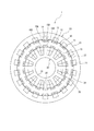
図1に示すように、モータ1は、ステータ10と、ステータ10に対して相対回転可能なアウタロータ20と、ステータ10を挟んでアウタロータ20と反対側に配置され、ステータ10に対して相対回転可能なインナロータ30と、を備えている。アウタロータ20は第1のロータを構成し、インナロータ30は第2のロータを構成する。   As shown in FIG. 1, the motor 1 includes a stator 10, an outer rotor 20 rotatable relative to the stator 10, and a motor 1 disposed on a side opposite to the outer rotor 20 with the stator 10 interposed therebetween, and rotatable relative to the stator 10. And the inner rotor 30. The outer rotor 20 constitutes a first rotor, and the inner rotor 30 constitutes a second rotor.

以下においては、インナロータ30の回転軸30A(図5参照)が延伸する方向を軸方向という。径方向とは、インナロータ30の回転軸30Aが延伸する方向と直交する方向を示す。径方向の内方側とは、径方向においてインナロータ30の回転軸30Aに近い側を示す。径方向の外方側とは、径方向においてインナロータ30の回転軸30Aから遠い側を示す。周方向とは、インナロータ30の回転軸30Aを中心とする円周方向を示す。なお、径方向は、回転軸30Aを中心として放射方向に示される。   Hereinafter, the direction in which the rotation shaft 30A of the inner rotor 30 (see FIG. 5) extends is referred to as an axial direction. The radial direction indicates a direction orthogonal to the direction in which the rotation axis 30A of the inner rotor 30 extends. The inner side in the radial direction indicates a side closer to the rotation axis 30A of the inner rotor 30 in the radial direction. The outer side in the radial direction indicates a side farther from the rotation axis 30A of the inner rotor 30 in the radial direction. The circumferential direction indicates a circumferential direction around the rotation axis 30A of the inner rotor 30. Note that the radial direction is shown in a radial direction about the rotation axis 30A.

(ステータ)
ステータ10は、図示しないモータケースに固定されている。ステータ10は、複数の電磁鋼板を軸方向に積層させたものからなる環状のステータコア11と、通電により磁束を発生させるW相、V相、U相の三相の電機子コイル12と、励磁コイル13と、を含んで構成されている。ステータ10は、電機子コイル12に三相交流が供給されることで、周方向に回転する回転磁界を発生させる。電機子コイル12は第2のコイルを構成し、励磁コイル13は第1のコイルを構成する。
(Stator)
Stator 10 is fixed to a motor case (not shown). The stator 10 includes an annular stator core 11 formed by stacking a plurality of electromagnetic steel sheets in the axial direction, a W-phase, V-phase, and U-phase three-phase armature coils 12 that generate a magnetic flux when energized, and an excitation coil. 13 are included. The stator 10 generates a rotating magnetic field that rotates in the circumferential direction when the three-phase alternating current is supplied to the armature coil 12. The armature coil 12 forms a second coil, and the excitation coil 13 forms a first coil.

ステータコア11は、環状のヨーク部14と、ヨーク部14から径方向の外方側、すなわちアウタロータ20側に向けて突出した複数の第1のステータティース15Aと、ヨーク部14から径方向の内方側、すなわちインナロータ30側に向けて突出した複数の第2のステータティース15Bと、を有している。第1のステータティース15Aは、ステータティースを構成する。ここで、第1のステータティース15Aと第2のステータティース15Bとは、径方向で重なる位置に配置されている。   The stator core 11 includes an annular yoke portion 14, a plurality of first stator teeth 15 </ b> A protruding radially outward from the yoke portion 14, that is, toward the outer rotor 20, and radially inward from the yoke portion 14. Side, that is, a plurality of second stator teeth 15B protruding toward the inner rotor 30 side. The first stator teeth 15A constitute a stator tooth. Here, the first stator teeth 15A and the second stator teeth 15B are arranged at positions overlapping in the radial direction.

複数の第1のステータティース15Aは、ヨーク部14の外周面において、周方向に沿って所定の間隔を空けて並ぶように配置されている。周方向に隣り合う第1のステータティース15Aの間には、溝状の空間である第1のスロット16Aが形成されている。   The plurality of first stator teeth 15A are arranged on the outer peripheral surface of the yoke portion 14 at predetermined intervals along the circumferential direction. A first slot 16A, which is a groove-like space, is formed between the first stator teeth 15A that are adjacent in the circumferential direction.

複数の第2のステータティース15Bは、ヨーク部14の内周面において、周方向に沿って所定の間隔を空けて並ぶように配置されている。周方向に隣り合う第2のステータティース15Bの間には、溝状の空間である第2のスロット16Bが形成されている。   The plurality of second stator teeth 15B are arranged on the inner peripheral surface of the yoke portion 14 at predetermined intervals along the circumferential direction. A second slot 16B, which is a groove-like space, is formed between the second stator teeth 15B adjacent in the circumferential direction.

第1のスロット16A及び第2のスロット16Bには、電機子コイル12が配置される。第1のスロット16Aには、電機子コイル12に加えて励磁コイル13が配置される。   The armature coil 12 is disposed in the first slot 16A and the second slot 16B. In the first slot 16A, an exciting coil 13 is arranged in addition to the armature coil 12.

W相、V相、U相の電機子コイル12は、それぞれ集中巻によりステータ10のヨーク部14にトロイダル巻されている。トロイダル巻とは、ヨーク部14の環の内側と外側を交互に通って巻方向が径方向となるよう、ヨーク部14に巻線を周回させて巻回す方法である。本実施例のトロイダル巻では、電機子コイル12の磁化方向が周方向となる。   The W-phase, V-phase, and U-phase armature coils 12 are each toroidally wound around the yoke portion 14 of the stator 10 by concentrated winding. The toroidal winding is a method in which a winding is wound around the yoke portion 14 so that the winding direction is radial by alternately passing the inside and outside of the ring of the yoke portion 14. In the toroidal winding of the present embodiment, the magnetization direction of the armature coil 12 is the circumferential direction.

W相、V相、U相の電機子コイル12には、後述する第2の電源としての第2の電源回路82から電力が供給されるようになっている。本実施例において、電機子コイル12には、所定周波数Fth[Hz]の交流電流が通電されるようになっている。   Power is supplied to the W-phase, V-phase, and U-phase armature coils 12 from a second power supply circuit 82 as a second power supply described later. In this embodiment, an alternating current having a predetermined frequency Fth [Hz] is supplied to the armature coil 12.

励磁コイル13は、各第1のステータティース15Aに巻かれている。具体的には、励磁コイル13は、周方向に隣り合う励磁コイル13同士で巻方向が同じ向きとなるよう各第1のステータティース15Aに巻かれている(図2参照)。励磁コイル13は、第1のスロット16Aにおいて電機子コイル12よりも径方向の外方側に配置されている。   The exciting coil 13 is wound around each first stator tooth 15A. Specifically, the exciting coils 13 are wound around the first stator teeth 15A so that the winding directions of the exciting coils 13 adjacent in the circumferential direction are the same (see FIG. 2). The exciting coil 13 is disposed radially outward of the armature coil 12 in the first slot 16A.

励磁コイル13は、通電により磁束を発生させるW相、V相、U相の三相の励磁コイルからなる。W相、V相、U相の励磁コイル13には、後述する第1の電源としての第1の電源回路81から電力が供給されるようになっている。   The excitation coil 13 is composed of three phases of W-phase, V-phase, and U-phase excitation coils that generate a magnetic flux when energized. Electric power is supplied to the W-phase, V-phase, and U-phase excitation coils 13 from a first power supply circuit 81 as a first power supply described later.

W相、V相、U相の各励磁コイル13は、同一の第1のステータティース15Aを挟んで配置される電機子コイル12と同相となるよう配置されている。例えば、W相の電機子コイル12が配置される第1のステータティース15Aには、W相の励磁コイル13が配置される。   The W-phase, V-phase, and U-phase excitation coils 13 are arranged so as to have the same phase as the armature coils 12 arranged with the same first stator teeth 15A interposed therebetween. For example, the W-phase excitation coil 13 is disposed on the first stator teeth 15A on which the W-phase armature coil 12 is disposed.

本実施例において、励磁コイル13には、電機子コイル12に通電される所定周波数Fth[Hz]と異なる周波数の交流電流が通電されるようになっている。具体的には、励磁コイル13には、電機子コイル12に通電される所定周波数Fth[Hz]の交流電流に対して2倍の周波数2Fth[Hz]の交流電流が通電されるようになっている。   In this embodiment, an alternating current having a frequency different from the predetermined frequency Fth [Hz] applied to the armature coil 12 is applied to the exciting coil 13. Specifically, the exciting coil 13 is supplied with an alternating current having a frequency 2Fth [Hz] which is twice as high as the alternating current having a predetermined frequency Fth [Hz] applied to the armature coil 12. I have.

図2に示すように、電機子コイル12は、W相、V相、U相ごとにそれぞれ一対の電機子巻線12A,12Bからなる。例えば、W相の電機子コイル12は、W+相の電機子巻線12AとW−相の電機子巻線12Bとからなる。各相の電機子コイル12を構成する電機子巻線12Aと電機子巻線12Bとは、第1のステータティース15Aを挟んで周方向に隣り合うように配置されている。本実施例における一対の電機子巻線12A,12Bは、一対の巻線を構成する。   As shown in FIG. 2, the armature coil 12 includes a pair of armature windings 12A and 12B for each of the W, V, and U phases. For example, the W-phase armature coil 12 includes a W + -phase armature winding 12A and a W--phase armature winding 12B. The armature winding 12A and the armature winding 12B constituting the armature coil 12 of each phase are arranged so as to be circumferentially adjacent to each other with the first stator teeth 15A interposed therebetween. The pair of armature windings 12A and 12B in the present embodiment constitute a pair of windings.

一対の電機子巻線12A,12Bは、巻方向が互いに逆向きとなるよう周方向に隣り合う第1のステータティース15A間においてヨーク部14に巻かれている。また、一対の電機子巻線12A,12Bは、図2に示す向きに同相の電流が流れた場合に、互いの磁化方向が対向するように、すなわち電機子巻線12Aの磁化方向と電機子巻線12Bの磁化方向とがともに第1のステータティース15Aに向かうように巻方向が設定されている。   The pair of armature windings 12A and 12B are wound around the yoke portion 14 between the first stator teeth 15A adjacent in the circumferential direction so that the winding directions are opposite to each other. When a current having the same phase flows in the direction shown in FIG. 2, the pair of armature windings 12 </ b> A and 12 </ b> B have their magnetization directions facing each other, that is, the magnetization direction of the armature winding 12 </ b> A and the armature winding The winding direction is set so that the magnetization direction of the winding 12B is directed toward the first stator teeth 15A.

これにより、電機子巻線12Aから発生する電機子磁束と電機子巻線12Bから発生する電機子磁束とが互いに反発し、第1のステータティース15A及び第2のステータティース15Bを介してアウタロータ20及びインナロータ30に流れる。   Thereby, the armature magnetic flux generated from the armature winding 12A and the armature magnetic flux generated from the armature winding 12B repel each other, and the outer rotor 20 through the first stator teeth 15A and the second stator teeth 15B. And flows to the inner rotor 30.

一対の電機子巻線12A,12Bは、周方向に隣り合う該一対の電機子巻線12A,12Bごとに互いに異なる相の電流が通電されるように配線されている。また、電機子巻線12A及び電機子巻線12Bのそれぞれは、周方向に隣り合う電機子巻線同士で巻方向が互いに逆向きである。例えば、W+相の電機子巻線12AとU−相の電機子巻線12Bとは、互いに巻方向が逆向きである。   The pair of armature windings 12A and 12B are wired such that currents of different phases are supplied to the pair of armature windings 12A and 12B adjacent in the circumferential direction. Further, each of the armature windings 12A and 12B has the winding directions opposite to each other between the circumferentially adjacent armature windings. For example, the winding directions of the W + phase armature winding 12A and the U− phase armature winding 12B are opposite to each other.

電機子コイル12に三相交流が供給されている場合、1相の電機子コイル12に流れる電流が最大となるとき、他の2相の電機子コイル12に流れる電流は当該1相と逆方向となり、かつ電流値の絶対値が当該1相に流れる電流の電流値の半分となる。   When the three-phase alternating current is supplied to the armature coil 12, when the current flowing through the one-phase armature coil 12 is maximized, the current flowing through the other two-phase armature coil 12 is in the opposite direction to the one phase. And the absolute value of the current value is half of the current value of the current flowing in the one phase.

本実施例においては、上述したように電機子巻線12A及び電機子巻線12Bのそれぞれが、周方向に隣り合う電機子巻線同士で巻方向が互いに逆向きである。このため、例えばW相の電機子コイル12に流れる電流が最大となるとき、V相、U相のそれぞれの電機子コイル12に流れる電流はW相と逆方向で、かつ電流値の絶対値がW相に流れる電流の電流値の半分となる。   In the present embodiment, as described above, the winding directions of the armature windings 12A and 12B are opposite to each other between the circumferentially adjacent armature windings. Therefore, for example, when the current flowing through the W-phase armature coil 12 is maximum, the current flowing through each of the V-phase and U-phase armature coils 12 is in the opposite direction to the W-phase, and the absolute value of the current value is It is half the current value of the current flowing in the W phase.

したがって、本実施例のモータ1においては、W相の電機子コイル12に流れる電流が最大となるとき、W+相の電機子巻線12Aとこれに隣接するU−相の電機子巻線12Bとで磁化方向を一致させることができる。また、本実施例のモータ1は、W−相の電機子巻線12Bとこれに隣接するV+相の電機子巻線12Aとにおいても磁化方向を一致させることができる。   Therefore, in the motor 1 of the present embodiment, when the current flowing through the W-phase armature coil 12 is maximized, the W + -phase armature winding 12A and the adjacent U-phase armature winding 12B , The magnetization directions can be matched. In the motor 1 of the present embodiment, the magnetization directions of the W- phase armature winding 12B and the adjacent V + phase armature winding 12A can be matched.

W相の電機子コイル12に流れる電流が最大となるときの例について説明したが、V相、U相のそれぞれの電機子コイル12に流れる電流が最大となるときも同様に、第1のスロット16A及び第2のスロット16Bにおいて周方向に隣接する電機子巻線同士で磁化方向を一致させることができる。   Although the example in which the current flowing through the W-phase armature coil 12 is maximum has been described, the same applies to the case where the current flowing through each of the V-phase and U-phase armature coils 12 is maximum. The magnetization directions of the armature windings adjacent to each other in the circumferential direction in the slot 16A and the second slot 16B can be matched.

これにより、本実施例のモータ1は、各相の電機子コイル12に流れる電流が最大となるときに、ステータ10からアウタロータ20及びインナロータ30に鎖交させる電機子磁束の磁束量を大幅に増やすことができる。   Thus, in the motor 1 of the present embodiment, when the current flowing through the armature coil 12 of each phase is maximized, the amount of armature magnetic flux linked from the stator 10 to the outer rotor 20 and the inner rotor 30 is greatly increased. be able to.

ステータ10は、アウタロータ20又はインナロータ30が回転している状態で電機子コイル12に三相交流を供給した場合、ステータ10には、電機子コイル12から発生する電機子磁束がアウタロータ20又はインナロータ30の回転による磁気的な歪みに起因して、インナロータ30の回転と同期して回転する回転磁界の他に、インナロータ30の回転と非同期の高調波回転磁界が発生する。この高調波回転磁界には、静止座標系における第2次空間高調波(同期回転座標系における第3次時間高調波)が含まれる。したがって、ステータ10で発生する磁束は、電機子コイル12から発生する電機子磁束に高調波成分が重畳したものとなる。   When three-phase alternating current is supplied to the armature coil 12 while the outer rotor 20 or the inner rotor 30 is rotating, the stator 10 receives the armature magnetic flux generated from the armature coil 12 on the outer rotor 20 or the inner rotor 30. Due to the magnetic distortion caused by the rotation of the inner rotor 30, in addition to the rotating magnetic field that rotates in synchronization with the rotation of the inner rotor 30, a harmonic rotating magnetic field that is asynchronous with the rotation of the inner rotor 30 is generated. The harmonic rotating magnetic field includes a second spatial harmonic in the stationary coordinate system (a third time harmonic in the synchronous rotating coordinate system). Therefore, the magnetic flux generated in the stator 10 is obtained by superimposing a harmonic component on the armature magnetic flux generated from the armature coil 12.

(アウタロータ)
図1及び図2に示すように、アウタロータ20は、環状のアウタロータコア21と、環状のアウタロータコア21から径方向の内側に向かって突出した複数のアウタロータティース22とを備えている。アウタロータ20は、複数の電磁鋼板を軸方向に積層させたものからなる。アウタロータ20は、径方向の一方向、すなわち径方向の外方側から内方側に向かう方向からステータ10に対して対面するよう配置されている。周方向に隣り合うアウタロータティース22の間には、溝状の空間であるスロット23が形成されている。
(Outer rotor)
As shown in FIGS. 1 and 2, the outer rotor 20 includes an annular outer rotor core 21 and a plurality of outer rotor teeth 22 projecting radially inward from the annular outer rotor core 21. The outer rotor 20 is formed by stacking a plurality of electromagnetic steel plates in the axial direction. The outer rotor 20 is disposed so as to face the stator 10 in one radial direction, that is, in a direction from the outer side to the inner side in the radial direction. A slot 23 which is a groove-shaped space is formed between the outer rotor teeth 22 adjacent in the circumferential direction.

アウタロータ20は、ステータ10の極対数Ps(本実施例では、6極対)と励磁コイル13の極対数(本実施例では、6極対)と励磁コイル13に通電される交流電流の周波数とに応じて、アウタロータティース22の数が設定されるようになっている。   The outer rotor 20 includes the number of pole pairs Ps of the stator 10 (six pole pairs in the present embodiment), the number of pole pairs of the exciting coil 13 (six pole pairs in the present embodiment), and the frequency of the alternating current supplied to the exciting coil 13. , The number of outer rotor teeth 22 is set.

具体的には、本実施例のように、ステータ10の極対数Psが6極対で、かつ6極対で配置された励磁コイル13に所定周波数Fth[Hz]の2倍の周波数2Fth[Hz]の交流電流を通電した場合には、アウタロータティース22の数が「(6+12=)18」となるよう、アウタロータティース22が周方向に所定の間隔で複数形成されている。上述のように、アウタロータティース22の数を設定した理由は次の通りである。   Specifically, as in the present embodiment, the number of pole pairs Ps of the stator 10 is 6 pole pairs, and the frequency 2Fth [Hz], which is twice the predetermined frequency Fth [Hz], is applied to the exciting coils 13 arranged in 6 pole pairs. ], A plurality of outer rotor teeth 22 are formed at predetermined intervals in the circumferential direction such that the number of outer rotor teeth 22 becomes “(6 + 12 =) 18”. The reason for setting the number of outer rotor teeth 22 as described above is as follows.

本実施例のモータ1においては、電機子コイル12の磁束(以下、「電機子磁束」という)を励磁コイル13の磁束(以下、「励磁磁束」という)によって磁束変調することにより、電機子磁束と励磁磁束とが合成された磁束の成分に、ステータ10の極対数Ps(本実施例では、6極対)と励磁コイル13の極対数(本実施例では、6極対)を2倍した値(本実施例では、12)との和で示される極数の成分(本実施例では、18極)が現れる。   In the motor 1 of the present embodiment, the magnetic flux of the armature coil 12 (hereinafter, referred to as “armature magnetic flux”) is modulated by the magnetic flux of the exciting coil 13 (hereinafter, referred to as “exciting magnetic flux”), so that the armature magnetic flux is changed. The number of pole pairs Ps of the stator 10 (six pole pairs in the present embodiment) and the number of pole pairs of the excitation coil 13 (six pole pairs in the present embodiment) are doubled to the component of the magnetic flux obtained by combining the magnetic flux and the exciting magnetic flux. A component of the number of poles (18 poles in the present embodiment) represented by the sum of the value (12 in the present embodiment) appears.

このため、本実施例のモータ1においては、ステータ10の極対数「6」と励磁コイル13の極対数「6」を2倍した値「12」との和である「18」極の成分と同期するように、アウタロータティース22の数を「18」に設定している。アウタロータティース22の数は、ステータ10の極対数、励磁コイル13の極対数及び励磁コイル13に通電される交流電流の周波数に応じて決まるもので、本実施例の「18」に限定されるものではない。   For this reason, in the motor 1 of the present embodiment, the “18” pole component, which is the sum of the pole pair number “6” of the stator 10 and the value “12” obtained by doubling the pole pair number “6” of the excitation coil 13, The number of the outer rotor teeth 22 is set to “18” so as to synchronize. The number of the outer rotor teeth 22 is determined according to the number of pole pairs of the stator 10, the number of pole pairs of the exciting coil 13, and the frequency of the alternating current supplied to the exciting coil 13, and is limited to "18" in the present embodiment. is not.

これにより、本実施例のモータ1においては、上述した磁束変調原理によってステータ10の回転磁界と非同期でアウタロータ20を回転させることができる。これに対して、インナロータ30は、後述するようにステータ10の回転磁界と同期して回転する。したがって、本実施例のモータ1においては、インナロータ30の回転と非同期でアウタロータ20を回転させることができる。   Thereby, in the motor 1 of the present embodiment, the outer rotor 20 can be rotated asynchronously with the rotating magnetic field of the stator 10 by the above-described principle of the magnetic flux modulation. On the other hand, the inner rotor 30 rotates in synchronization with the rotating magnetic field of the stator 10 as described later. Therefore, in the motor 1 of the present embodiment, the outer rotor 20 can be rotated asynchronously with the rotation of the inner rotor 30.

本実施例のモータ1においては、励磁コイル13及び電機子コイル12のコイル相数が同一であり、すべての第1のステータティース15Aに励磁コイル13及び電機子コイル12を配置している。   In the motor 1 of the present embodiment, the exciting coil 13 and the armature coil 12 have the same number of coil phases, and the exciting coil 13 and the armature coil 12 are arranged on all the first stator teeth 15A.

このように、同一のコイル相数の励磁コイル13及び電機子コイル12がすべての第1のステータティース15Aに配置されている場合、励磁コイル13及び電機子コイル12に通電されるそれぞれの交流電流の周波数が同一であると、磁束変調することができない。   As described above, when the exciting coil 13 and the armature coil 12 having the same number of coil phases are arranged in all the first stator teeth 15A, the respective AC currents applied to the exciting coil 13 and the armature coil 12 If the frequency is the same, magnetic flux modulation cannot be performed.

本実施例のモータ1では、上述したように、励磁コイル13に通電される交流電流の周波数と電機子コイル12に通電される交流電流の周波数とが異なるため、同一のコイル相数の励磁コイル13及び電機子コイル12がすべての第1のステータティース15Aに配置されている場合であっても磁束変調することができる。   In the motor 1 according to the present embodiment, as described above, the frequency of the AC current applied to the excitation coil 13 and the frequency of the AC current applied to the armature coil 12 are different from each other. Even when the armature coils 13 and the armature coils 12 are arranged on all the first stator teeth 15A, the magnetic flux can be modulated.

(インナロータ)
図1及び図2に示すように、インナロータ30は、環状のインナロータコア31と、環状のインナロータコア31から径方向の外側、すなわちステータ10側に向かって突出した複数のインナロータティース32とを備えている。インナロータ30は、複数の電磁鋼板を軸方向に積層させたものからなり、回転軸30Aに対して一体回転可能に固定されている。インナロータ30は、アウタロータ20と異なる方向である径方向の他方向、すなわち径方向の内方側から外方側に向かう方向からステータ10に対して対面するよう配置されている。周方向に隣り合うインナロータティース32の間には、溝状の空間であるスロット33が形成されている。本実施例のインナロータティース32は、ロータティースを構成する。
(Inner rotor)
As shown in FIGS. 1 and 2, the inner rotor 30 includes an annular inner rotor core 31 and a plurality of inner rotor teeth 32 projecting radially outward from the annular inner rotor core 31, that is, toward the stator 10 side. ing. The inner rotor 30 is formed by laminating a plurality of electromagnetic steel plates in the axial direction, and is fixed to the rotating shaft 30A so as to be integrally rotatable. The inner rotor 30 is disposed so as to face the stator 10 from another direction in the radial direction that is different from the direction of the outer rotor 20, that is, a direction from the inner side to the outer side in the radial direction. Between the inner rotor teeth 32 adjacent in the circumferential direction, a slot 33 which is a groove-shaped space is formed. The inner rotor teeth 32 of the present embodiment constitute a rotor tooth.

各インナロータティース32には、それぞれ誘導コイル34と界磁コイル35とが巻かれている。誘導コイル34は、スロット33において界磁コイル35よりも径方向の外側、すなわちステータ10側に配置されている。   An induction coil 34 and a field coil 35 are wound around each inner rotor tooth 32, respectively. The induction coil 34 is disposed outside the field coil 35 in the slot 33 in the radial direction, that is, on the stator 10 side.

誘導コイル34は、ステータ10側で発生した磁束に重畳された高調波成分に基づいて誘導電流を発生するようになっている。具体的には、三相交流が電機子コイル12に供給されてステータ10に回転磁界が発生すると、ステータ10側で発生した高調波成分の磁束が誘導コイル34に鎖交する。これにより、誘導コイル34は、誘導電流を誘起させる。   The induction coil 34 generates an induction current based on a harmonic component superimposed on a magnetic flux generated on the stator 10 side. Specifically, when the three-phase alternating current is supplied to the armature coil 12 and a rotating magnetic field is generated in the stator 10, the magnetic flux of the harmonic component generated on the stator 10 is linked to the induction coil 34. Thereby, the induction coil 34 induces an induced current.

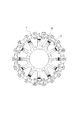
図3は、ステータ10側から各インナロータティース32に鎖交する高調波成分の磁束の分布を示したものである。図3に示すように、ステータ10側で発生した高調波成分の磁束は、各インナロータティース32の径方向の外側に鎖交する。このため、本実施例では、上述したように誘導コイル34を界磁コイル35よりも径方向の外側に配置することによって、ステータ10側で発生した高調波成分の磁束を効率的に誘導コイル34に鎖交させることができる。   FIG. 3 shows the distribution of the magnetic flux of the harmonic component linked to each inner rotor tooth 32 from the stator 10 side. As shown in FIG. 3, the magnetic flux of the higher harmonic component generated on the side of the stator 10 interlinks radially outside of each inner rotor tooth 32. For this reason, in the present embodiment, by arranging the induction coil 34 outside the field coil 35 in the radial direction as described above, the magnetic flux of the harmonic component generated on the stator 10 side can be efficiently reduced. Can be linked.

ここで、ステータ10は、上述の通り、電機子コイル12が集中巻されており、さらに電機子コイル12を構成する電機子巻線12A及び電機子巻線12Bのそれぞれが、周方向に隣り合う電機子巻線同士で巻方向が互いに逆向きとなるようにトロイダル巻されているため、第1のステータティース15A及び第2のステータティース15Bから発生する電機子磁束の磁束量が大きい。このため、アウタロータ20又はインナロータ30の回転により磁気的に歪む電機子磁束の磁束量が大きいことから、空間高調波が発生しやすく、誘導コイル34に鎖交する高調波成分の磁束量を増やすことができる。   Here, as described above, the armature coil 12 is concentratedly wound on the stator 10, and the armature windings 12A and 12B constituting the armature coil 12 are adjacent to each other in the circumferential direction. Since the armature windings are toroidally wound such that the winding directions are opposite to each other, the amount of the armature magnetic flux generated from the first stator teeth 15A and the second stator teeth 15B is large. For this reason, since the amount of magnetic flux of the armature magnetic flux that is magnetically distorted by the rotation of the outer rotor 20 or the inner rotor 30 is large, spatial harmonics are likely to be generated, and the amount of magnetic flux of harmonic components linked to the induction coil 34 is increased. Can be.

図1及び図2に示すように、界磁コイル35は、誘導コイル34よりも径方向の内側、すなわちインナロータコア31側に配置されている。界磁コイル35は、誘導コイル34で発生した誘導電流が後述するダイオード41によって整流されて供給されることにより磁界を発生させるようになっている。   As shown in FIGS. 1 and 2, the field coil 35 is disposed radially inward of the induction coil 34, that is, on the inner rotor core 31 side. The field coil 35 generates a magnetic field when an induction current generated by the induction coil 34 is rectified and supplied by a diode 41 described later.

これにより、インナロータティース32が電磁石として機能し、第2のステータティース15Bとインナロータティース32とが対向する面がトルク発生面として機能する。   As a result, the inner rotor teeth 32 function as electromagnets, and the surfaces of the second stator teeth 15B and the inner rotor teeth 32 facing each other function as torque generating surfaces.

(ロータ巻線回路)
モータ1は、誘導コイル34によって誘起された交流の誘導電流を直流に整流して界磁コイル35に供給するロータ巻線回路40(図4参照)を備えている。
(Rotor winding circuit)
The motor 1 includes a rotor winding circuit 40 (see FIG. 4) that rectifies an alternating current induced by the induction coil 34 into a direct current and supplies the direct current to the field coil 35.

図4に示すように、ロータ巻線回路40は、2つのダイオード41を整流素子として備え、これらダイオード41と2つの誘導コイル34及び2つの界磁コイル35とを結線した回路として構成されている。本実施例のモータ1は、ロータ巻線回路40を6つ備えている。   As shown in FIG. 4, the rotor winding circuit 40 includes two diodes 41 as rectifying elements, and is configured as a circuit in which these diodes 41 are connected to two induction coils 34 and two field coils 35. . The motor 1 of this embodiment includes six rotor winding circuits 40.

ダイオード41は、例えば図示しないダイオードケースに収納された状態でインナロータ30に設けられている。ダイオード41は、インナロータ30の内部に実装するようにしてもよい。   The diode 41 is provided on the inner rotor 30 in a state housed in, for example, a diode case (not shown). The diode 41 may be mounted inside the inner rotor 30.

ロータ巻線回路40において、誘導コイル34で発生した交流の誘導電流は、ダイオード41により整流され、整流後の直流電流は、直列接続されている界磁コイル35に界磁電流として供給される。界磁コイル35は、直流電流が供給されることにより誘導磁束を発生させる。   In the rotor winding circuit 40, the AC induced current generated by the induction coil 34 is rectified by the diode 41, and the rectified DC current is supplied to the field coil 35 connected in series as a field current. The field coil 35 generates an induced magnetic flux when a direct current is supplied.

本実施例では、ロータ巻線回路40として、誘導コイル34とダイオード41と界磁コイル35とを結線した構成を用いたが、これに限らず、例えば誘導コイル34とダイオード41とを結線した構成としてもよい。   In this embodiment, as the rotor winding circuit 40, a configuration in which the induction coil 34, the diode 41, and the field coil 35 are connected is used. However, the configuration is not limited to this, and, for example, a configuration in which the induction coil 34 and the diode 41 are connected. It may be.

(車両への搭載例)
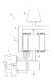
次に、図5を参照して、上述のように構成されたモータ1の車両500への搭載例について説明する。車両500は、エンジン200を発電機の動力源として用い、車両の駆動力源としてモータを用いる、レンジエクステンダー式の電動車両である。
(Example of mounting on a vehicle)
Next, an example of mounting the motor 1 configured as described above on the vehicle 500 will be described with reference to FIG. Vehicle 500 is a range extender type electric vehicle that uses engine 200 as a power source of a generator and uses a motor as a driving force source of the vehicle.

図5に示すように、本実施例のモータ1は、車両500において、インナロータ30の回転軸30Aがエンジン200に接続され、アウタロータ20の回転軸20Aがトランスミッション300に接続されている。   As shown in FIG. 5, in the motor 1 of the present embodiment, in a vehicle 500, the rotation shaft 30 </ b> A of the inner rotor 30 is connected to the engine 200, and the rotation shaft 20 </ b> A of the outer rotor 20 is connected to the transmission 300.

車両500には、電源80が搭載されている。電源80は、第1の電源回路81と、第2の電源回路82と、第1の電源回路81及び第2の電源回路82に接続されたバッテリ83とを含んで構成されている。第1の電源回路81及び第2の電源回路82としては、それぞれ三相交流を出力可能なインバータが用いられる。   The power supply 80 is mounted on the vehicle 500. The power supply 80 includes a first power supply circuit 81, a second power supply circuit 82, and a battery 83 connected to the first power supply circuit 81 and the second power supply circuit 82. As the first power supply circuit 81 and the second power supply circuit 82, inverters each capable of outputting a three-phase alternating current are used.

第1の電源回路81には、W相、V相、U相の励磁コイル13が接続されるようになっている。第1の電源回路81は、バッテリ83から入力された直流を交流に変換して三相交流としてW相、V相、U相の励磁コイル13に供給するものである。   The W-phase, V-phase, and U-phase excitation coils 13 are connected to the first power supply circuit 81. The first power supply circuit 81 converts direct current input from the battery 83 into alternating current, and supplies the alternating current to the W-phase, V-phase, and U-phase excitation coils 13 as three-phase alternating current.

第2の電源回路82には、W相、V相、U相の電機子コイル12が接続されるようになっている。第2の電源回路82は、バッテリ83から入力された直流を交流に変換して三相交流としてW相、V相、U相の電機子コイル12に供給するものである。   The W-phase, V-phase, and U-phase armature coils 12 are connected to the second power supply circuit 82. The second power supply circuit 82 converts a direct current input from the battery 83 into an alternating current and supplies it to the W-phase, V-phase, and U-phase armature coils 12 as a three-phase alternating current.

第1の電源回路81及び第2の電源回路82は、コントローラ100に接続されており、当該コントローラ100によってそれぞれの電源周波数が制御されるようになっている。   The first power supply circuit 81 and the second power supply circuit 82 are connected to the controller 100, and the respective power supply frequencies are controlled by the controller 100.

車両500において、磁束変調原理によりアウタロータ20を例えば1000[r/min]で駆動させているとき、アウタロータ20の電気的駆動周波数は「1000×9/60=150[Hz]」となる。このとき、ステータ10の回転磁界は、アウタロータ20の電気的駆動周波数の1.5倍の225[Hz]で励磁することとなる。   In the vehicle 500, when the outer rotor 20 is driven at, for example, 1000 [r / min] based on the principle of magnetic flux modulation, the electrical drive frequency of the outer rotor 20 is "1000 × 9/60 = 150 [Hz]". At this time, the rotating magnetic field of the stator 10 is excited at 225 [Hz] which is 1.5 times the electric driving frequency of the outer rotor 20.

ステータ10の回転磁界を225[Hz]で励磁すると、インナロータ30はステータ10の回転磁界と同期して回転するため、「(225/6)×60=2250[r/min]」でインナロータ30を回転させることができる。   When the rotating magnetic field of the stator 10 is excited at 225 [Hz], the inner rotor 30 rotates in synchronization with the rotating magnetic field of the stator 10, so that the inner rotor 30 is driven by “(225/6) × 60 = 2250 [r / min]”. Can be rotated.

これにより、車両500においては、アウタロータ20からトランスミッション300に入力される回転を走行に適した回転速度としつつ、エンジン200を高回転領域で駆動させることができる。   Thus, in vehicle 500, engine 200 can be driven in a high rotation range while the rotation input to transmission 300 from outer rotor 20 is set to a rotation speed suitable for traveling.

このため、モータ1を搭載した車両500では、最適燃費となるような運転効率のよい動作点でエンジン200を駆動させて発電を行い、その発電電力を第2の電源回路82を介してバッテリ83に充電することができる。一方で、バッテリ83から第2の電源回路82を介して供給される三相交流によってアウタロータ20をインナロータ30よりも低い回転速度で回転させて、トランスミッション300を介して車両500を走行させることができる。このように、モータ1を搭載した車両500では、モータ1において、インナロータ30を回生駆動させつつ、アウタロータ20を力行駆動させることができる。   For this reason, in the vehicle 500 equipped with the motor 1, the engine 200 is driven at an operating point with high driving efficiency to achieve optimum fuel efficiency to generate power, and the generated power is transferred to the battery 83 through the second power supply circuit 82. Can be charged. On the other hand, the three-phase alternating current supplied from battery 83 via second power supply circuit 82 causes outer rotor 20 to rotate at a lower rotation speed than inner rotor 30, allowing vehicle 500 to travel via transmission 300. . As described above, in the vehicle 500 on which the motor 1 is mounted, the outer rotor 20 can be driven by the motor 1 while the inner rotor 30 is regeneratively driven.

(制御例)
次に、本実施例のモータ1を上述した車両500に搭載した場合における、アウタロータ20及びインナロータ30の回転とトルクの制御例について説明する。
(Control example)
Next, an example of controlling the rotation and torque of the outer rotor 20 and the inner rotor 30 when the motor 1 of the present embodiment is mounted on the above-described vehicle 500 will be described.

車両500は、走行状態や運転状態に応じて例えば第1の制御モードから第4の制御モードを有し、これら4つの制御モードに応じてアウタロータ20及びインナロータ30の回転とトルクが制御される。以下において、アウタロータ20及びインナロータ30の正転方向とは、燃料噴射時のエンジン200の回転方向と同一の回転方向をいう。   The vehicle 500 has, for example, a first control mode to a fourth control mode according to the running state and the driving state, and the rotation and torque of the outer rotor 20 and the inner rotor 30 are controlled according to these four control modes. Hereinafter, the forward rotation direction of the outer rotor 20 and the inner rotor 30 refers to the same rotation direction as the rotation direction of the engine 200 during fuel injection.

以下に説明する各制御モードにおいては、第1の電源回路81及び第2の電源回路82によって、励磁コイル13及び電機子コイル12の電流周波数が制御されることによりアウタロータ20の回転方向が制御される。具体的には、アウタロータ20を正転させる場合、電機子磁束と励磁磁束とが合成された磁束の成分によりアウタロータ20が正転する磁束成分となるように、励磁コイル13及び電機子コイル12の電流周波数を設定する。反対に、アウタロータ20を逆転させる場合、電機子磁束と励磁磁束とが合成された磁束の成分によりアウタロータ20が逆転するような磁束の成分となるように、励磁コイル13及び電機子コイル12の電流周波数を設定する。そして、インナロータ30がステータ10の回転磁界と同期回転することから、アウターロータ20およびインナロータ30が所望の回転速度あるいはトルクが得られるように、電機子コイル12に通電する電流の周波数に応じて、励磁コイル13に通電する電流の周波数を変化させている。また、第1の電源回路81及び第2の電源回路82によって、励磁コイル13及び電機子コイル12に通電される電流位相や電流波高値(振幅)が制御されることによりアウタロータ20及びインナロータ30に発生するトルクが制御される。   In each control mode described below, the rotation direction of the outer rotor 20 is controlled by controlling the current frequency of the excitation coil 13 and the armature coil 12 by the first power supply circuit 81 and the second power supply circuit 82. You. Specifically, when the outer rotor 20 is rotated forward, the excitation coil 13 and the armature coil 12 are rotated so that the outer rotor 20 becomes a magnetic flux component that rotates forward by a component of the magnetic flux obtained by combining the armature magnetic flux and the exciting magnetic flux. Set the current frequency. Conversely, when the outer rotor 20 is rotated in reverse, the current of the exciting coil 13 and the armature coil 12 is changed so that the component of the magnetic flux in which the armature magnetic flux and the exciting magnetic flux are reversed to form a magnetic flux component that causes the outer rotor 20 to rotate in the reverse direction. Set the frequency. Since the inner rotor 30 rotates synchronously with the rotating magnetic field of the stator 10, the outer rotor 20 and the inner rotor 30 obtain a desired rotation speed or torque in accordance with the frequency of the current supplied to the armature coil 12 according to the frequency. The frequency of the current flowing through the exciting coil 13 is changed. Further, the first power supply circuit 81 and the second power supply circuit 82 control the current phase and the current peak value (amplitude) supplied to the excitation coil 13 and the armature coil 12 so that the outer rotor 20 and the inner rotor 30 are controlled. The generated torque is controlled.

第1の制御モードは、車両500を前進させつつ、エンジン200を始動するモードである。この第1の制御モードでは、アウタロータ20及びインナロータ30がともに力行状態で正転方向にトルクを発生するように、コントローラ100によって第1の電源回路81及び第2の電源回路82が制御される。   The first control mode is a mode in which the engine 200 is started while the vehicle 500 is moving forward. In the first control mode, the first power supply circuit 81 and the second power supply circuit 82 are controlled by the controller 100 such that both the outer rotor 20 and the inner rotor 30 generate torque in the normal rotation direction in a power running state.

第2の制御モードは、車両500を前進させつつ、エンジン200の動力により発電を行うモードである。第2の制御モードでエンジン200の動力を用いて発電された発電電力は、アウタロータ20を力行させるための電力として電機子コイル12に供給される。   The second control mode is a mode in which power is generated by the power of the engine 200 while the vehicle 500 is moving forward. The generated power generated using the power of engine 200 in the second control mode is supplied to armature coil 12 as power for powering outer rotor 20.

この第2の制御モードでは、アウタロータ20が力行状態で正転方向にトルクを発生し、かつインナロータ30が回生状態で反転方向にトルクを発生するように、コントローラ100によって第1の電源回路81及び第2の電源回路82が制御される。   In the second control mode, the controller 100 causes the first power supply circuit 81 and the first power supply circuit 81 to generate torque in the forward direction when the outer rotor 20 is in the power running state and generates torque in the reverse direction when the inner rotor 30 is in the regenerative state. The second power supply circuit 82 is controlled.

第3の制御モードは、車両500を後進させつつ、エンジン回転数を調整するモードである。エンジン回転数を調整する場合としては、例えばバッテリ83のSOC(State Of Charge)が高く、発電による回生トルクを発生させることができない場合などがあり、この場合、エンジン200の回転数が抑制される。   The third control mode is a mode for adjusting the engine speed while moving the vehicle 500 backward. When adjusting the engine speed, for example, there is a case where the SOC (State Of Charge) of the battery 83 is high and it is not possible to generate regenerative torque due to power generation. In this case, the speed of the engine 200 is suppressed. .

この第3の制御モードでは、アウタロータ20が力行状態で反転方向にトルクを発生し、かつインナロータ30が力行状態で反転方向にトルクを発生するように、コントローラ100によって第1の電源回路81及び第2の電源回路82が制御される。   In the third control mode, the first power supply circuit 81 and the first power supply circuit 81 are controlled by the controller 100 such that the outer rotor 20 generates torque in the reverse direction in the power running state and the inner rotor 30 generates torque in the reverse direction in the power running state. The second power supply circuit 82 is controlled.

ここで、第3の制御モードでは、アウタロータ20の回転方向が第1の制御モードと反対となる。アウタロータ20の回転方向を第1の制御モードに対して反転させる場合には、第1の電源回路81によって励磁コイル13の電流の周波数を、電機子磁束と励磁磁束とが合成された磁束の成分がアウタロータ20を逆転させるような磁束の成分となるよう制御する。これにより、ステータ10からアウタロータ20に鎖交する回転磁界が第1の制御モード時と反対となり、アウタロータ20の回転方向が第1の制御モードに対して反転する。   Here, in the third control mode, the rotation direction of the outer rotor 20 is opposite to that in the first control mode. When the rotation direction of the outer rotor 20 is reversed with respect to the first control mode, the frequency of the current of the exciting coil 13 by the first power supply circuit 81 is changed to the component of the magnetic flux obtained by combining the armature magnetic flux and the exciting magnetic flux. Is a component of a magnetic flux that causes the outer rotor 20 to rotate in the reverse direction. Accordingly, the rotating magnetic field interlinking from the stator 10 to the outer rotor 20 is opposite to that in the first control mode, and the rotation direction of the outer rotor 20 is reversed with respect to the first control mode.

第4の制御モードは、例えば減速時に車輪から伝達される逆駆動トルク等の外力によってアウタロータ20を介して発電しつつ、エンジン回転数を調整するモードである。   The fourth control mode is a mode in which the engine speed is adjusted while generating electric power via the outer rotor 20 by an external force such as a reverse driving torque transmitted from the wheels during deceleration.

この第4の制御モードでは、アウタロータ20が回生状態で反転方向にトルクを発生し、かつインナロータ30が回生状態で反転方向にトルクを発生するように、コントローラ100によって第1の電源回路81及び第2の電源回路82が制御される。   In the fourth control mode, the first power supply circuit 81 and the first power supply circuit 81 are controlled by the controller 100 such that the outer rotor 20 generates torque in the reverse direction in the regenerative state and the inner rotor 30 generates torque in the reverse direction in the regenerative state. The second power supply circuit 82 is controlled.

なお、上述の第1から第4の制御モードは、逆転することが想定されていないエンジン200をインナロータ30に接続しているため、インナロータ30は常に正転していることを前提としている。しかしながら、逆転が許容される負荷がインナロータ30に接続される場合、電機子コイル12から発生する回転磁界の回転方向を逆方向とさせてインナロータ30を逆転させてもよい。この場合、インナロータ30を反転させるために、電機子コイル12から発生する回転磁界の回転方向が逆相となるように、電機子コイル12に通電する電流の電流位相を制御(変更)すればよい。   Note that the above-described first to fourth control modes are based on the assumption that the engine 200, which is not expected to reverse, is connected to the inner rotor 30, so that the inner rotor 30 is always rotating forward. However, when a load that allows reverse rotation is connected to the inner rotor 30, the rotation direction of the rotating magnetic field generated from the armature coil 12 may be reversed so that the inner rotor 30 is reversed. In this case, in order to reverse the inner rotor 30, the current phase of the current flowing through the armature coil 12 may be controlled (changed) so that the rotation direction of the rotating magnetic field generated from the armature coil 12 is reversed. .

ただし、電機子コイル12に通電する電流の電流位相が変化すると、電機子磁束と励磁磁束とが合成された磁束の成分が変化することから、これに応じて、電機子磁束と励磁磁束とが合成された磁束の成分がアウタロータ20を正転又は逆転するような磁束の成分となるように、励磁コイル13に通電する電流の周波数を変更する必要がある。   However, when the current phase of the current flowing through the armature coil 12 changes, the component of the magnetic flux obtained by combining the armature magnetic flux and the exciting magnetic flux changes, and accordingly, the armature magnetic flux and the exciting magnetic flux change accordingly. It is necessary to change the frequency of the current supplied to the exciting coil 13 so that the component of the combined magnetic flux becomes a component of the magnetic flux that rotates the outer rotor 20 forward or backward.

(発明の作用効果)
以上のように、本実施例のモータ1によれば、電機子コイル12がステータ10のヨーク部14に巻かれ、かつ励磁コイル13が第1のステータティース15Aに巻かれているので、電機子コイル12から発生する電機子磁束と励磁コイル13から発生する励磁磁束とが第1のステータティース15Aやヨーク部14において干渉しても、これら磁束をアウタロータ20及びインナロータ30のいずれかに流すことができる。加えて、第1のステータティース15Aと第2のステータティース15Bとが径方向で重なるようにヨーク部14に配置されることにより、より一層干渉した磁束をアウタロータ20及びインナロータ30のいずれかに流すことができる。このため、本実施例のモータ1は、電機子コイル12から発生する電機子磁束が励磁コイル13から発生する励磁磁束によって打ち消されて弱められてしまうことを防止することができる。
(Effects of the Invention)
As described above, according to the motor 1 of the present embodiment, the armature coil 12 is wound around the yoke portion 14 of the stator 10 and the exciting coil 13 is wound around the first stator teeth 15A. Even if the armature magnetic flux generated from the coil 12 and the exciting magnetic flux generated from the exciting coil 13 interfere with each other in the first stator teeth 15A and the yoke portion 14, these magnetic fluxes can flow to either the outer rotor 20 or the inner rotor 30. it can. In addition, the first stator teeth 15A and the second stator teeth 15B are arranged on the yoke portion 14 so as to overlap in the radial direction, so that the further interfering magnetic flux flows to either the outer rotor 20 or the inner rotor 30. be able to. For this reason, the motor 1 of the present embodiment can prevent the armature magnetic flux generated from the armature coil 12 from being canceled and weakened by the excitation magnetic flux generated from the excitation coil 13.

また、本実施例のモータ1によれば、励磁コイル13及び電機子コイル12のそれぞれに通電する電流を供給する電源回路がそれぞれ異なるので、励磁コイル13及び電機子コイル12のそれぞれに通電する電流を別々に制御することができる。このため、本実施例のモータ1によれば、励磁コイル13に通電される電流の周波数、電流波高値(振幅)及び電流位相と、電機子コイル12に通電される電流の周波数、電流波高値(振幅)及び電流位相と、を別々に制御することができ、磁気変調モータとしてのモータ出力の範囲を拡大することができる。   In addition, according to the motor 1 of the present embodiment, since the power supply circuits that supply the currents that flow through the excitation coil 13 and the armature coil 12 are different, the currents that flow through the excitation coil 13 and the armature coil 12 are different. Can be controlled separately. For this reason, according to the motor 1 of the present embodiment, the frequency, the current peak value (amplitude) and the current phase of the current supplied to the exciting coil 13, the frequency of the current supplied to the armature coil 12, and the current peak value (Amplitude) and current phase can be controlled separately, and the range of motor output as a magnetic modulation motor can be expanded.

また、本実施例のモータ1によれば、励磁コイル13及び電機子コイル12がそれぞれ独立の第1の電源回路81及び第2の電源回路82によって制御されるので、例えば励磁コイル13及び電機子コイル12のそれぞれに通電される電流の周波数を、電機子磁束と励磁磁束とが合成された磁束の成分がアウタロータ20を逆転させるような磁束の成分となるような周波数に変更することにより、アウタロータ20の回転方向を反転させることができる。このため、本実施例のモータ1は、モータ出力の範囲を拡大することができる。   Further, according to the motor 1 of the present embodiment, the exciting coil 13 and the armature coil 12 are controlled by the independent first power supply circuit 81 and the second power supply circuit 82, respectively. By changing the frequency of the current supplied to each of the coils 12 to a frequency such that the component of the magnetic flux obtained by combining the armature magnetic flux and the exciting magnetic flux becomes a magnetic flux component that causes the outer rotor 20 to reverse. 20 can be reversed. Therefore, the motor 1 of the present embodiment can expand the range of the motor output.

また、本実施例のモータ1によれば、電機子コイル12を構成する一対の電機子巻線12A,12Bが互いの磁化方向が反対方向となるように、例えば図2に示す向きに電流が流れた場合に互いの磁化方向が対向するように、電機子巻線12A,12Bの巻方向が設定されている。このため、本実施例のモータ1によれば、電機子巻線12Aから発生する電機子磁束と電機子巻線12Bから発生する電機子磁束とが互いに反発し、第1のステータティース15A及び第2のステータティース15Bを介してアウタロータ20及びインナロータ30に流すことができる。この結果、電機子磁束をアウタロータ20及びインナロータ30にバランスよく鎖交させることができる。   Further, according to the motor 1 of the present embodiment, the current is supplied in the direction shown in FIG. 2, for example, such that the magnetization directions of the pair of armature windings 12A and 12B constituting the armature coil 12 are opposite to each other. The winding directions of the armature windings 12A and 12B are set so that the magnetization directions of the armature windings 12A and 12B are opposite to each other when flowing. Therefore, according to the motor 1 of the present embodiment, the armature magnetic flux generated from the armature winding 12A and the armature magnetic flux generated from the armature winding 12B repel each other, and the first stator teeth 15A and the It can flow to the outer rotor 20 and the inner rotor 30 via the second stator teeth 15B. As a result, the armature magnetic flux can be linked to the outer rotor 20 and the inner rotor 30 with good balance.

また、本実施例のモータ1によれば、インナロータ30が誘導コイル34及び界磁コイル35を有し、誘導コイル34に整流素子としてダイオード41を介して界磁コイル35が接続されている。これにより、本実施例のモータ1は、ステータ10で不可避に発生する第2次空間高調波を利用してインナロータ30を自励することができ、モータ出力を向上させることができる。   According to the motor 1 of the present embodiment, the inner rotor 30 has the induction coil 34 and the field coil 35, and the field coil 35 is connected to the induction coil 34 via the diode 41 as a rectifying element. As a result, the motor 1 of the present embodiment can self-excit the inner rotor 30 by using the second spatial harmonic that is inevitably generated in the stator 10, and can improve the motor output.

また、本実施例のモータ1によれば、高価な磁石を使用しないため、低コスト化を図ることができ、モータ1の重量も低減させることができる。   Further, according to the motor 1 of the present embodiment, since an expensive magnet is not used, the cost can be reduced, and the weight of the motor 1 can be reduced.

また、本実施例のモータ1によれば、電機子コイル12を集中巻によりステータ10のヨーク部14にトロイダル巻したので、電機子巻線の周長を短くでき、組立性を向上させることができ、ステータ10の機械的強度を向上させることができる。   Further, according to the motor 1 of the present embodiment, since the armature coil 12 is toroidally wound around the yoke portion 14 of the stator 10 by concentrated winding, the circumferential length of the armature winding can be shortened, and assemblability can be improved. As a result, the mechanical strength of the stator 10 can be improved.

また、本実施例のモータ1によれば、アウタロータ20とインナロータ30とで1つのステータ10を共用する構造のため、ステータの体積及び質量を削減でき、コンパクトで軽量かつ低コストな駆動システムを実現することができる。   Further, according to the motor 1 of the present embodiment, since the outer rotor 20 and the inner rotor 30 share one stator 10, the volume and mass of the stator can be reduced, and a compact, lightweight and low-cost drive system is realized. can do.

なお、本実施例においては、上述した構成のステータ10をラジアルギャップモータとしてのモータ1に適用したが、上述した構成のステータ10は後述するようにアキシャルギャップモータのステータとしても用いることができる。   In the present embodiment, the stator 10 having the above-described configuration is applied to the motor 1 as a radial gap motor. However, the stator 10 having the above-described configuration can be used as a stator of an axial gap motor as described later.

また、本実施例においては、インナロータ30として自己励磁可能な巻線界磁形のロータを用いたが、これに限らず、インナロータ30として、磁石式同期モータに用いられるような永久磁石を有するロータを用いてもよい。   In the present embodiment, a self-excitable winding field type rotor is used as the inner rotor 30. However, the present invention is not limited to this, and the inner rotor 30 may be a rotor having a permanent magnet as used in a magnet type synchronous motor. May be used.

また、本実施例においては、ステータ10のヨーク部14に電機子コイル12が巻かれ、第1のステータティース15Aに励磁コイル13が巻かれた構成について説明したが、これに限らず、ステータ10のヨーク部14に励磁コイル13がトロイダル巻で巻かれ、かつ第1のステータティース15Aに電機子コイル12が巻かれた構成としてもよい。   In this embodiment, the configuration in which the armature coil 12 is wound around the yoke portion 14 of the stator 10 and the exciting coil 13 is wound around the first stator teeth 15A is described. The exciting coil 13 may be wound in a toroidal winding around the yoke portion 14 and the armature coil 12 may be wound around the first stator teeth 15A.

この場合、励磁コイル13は、周方向に隣り合う励磁コイル同士で巻方向が逆向きで、かつ磁化方向が第1のステータティース15A及び第2のステータティース15Bに向かうよう巻方向が設定される。これにより、周方向に隣り合う一対の励磁コイル13に挟まれた第1のステータティース15A及び第2のステータティース15Bに、当該一対の励磁コイル13からそれぞれの励磁磁束を対向するように向かわせることができる。この結果、当該一対の励磁コイル13の励磁磁束を、当該一対の励磁コイル13に挟まれた第1のステータティース15Aに巻かれた電機子コイル12の電機子磁束と合成されてアウタロータ20及びインナロータ30のいずれかに流すことができる。したがって、電機子コイル12から発生する電機子磁束が励磁コイル13から発生する励磁磁束によって打ち消されて弱められてしまうことが防止される。   In this case, the winding direction of the exciting coil 13 is set such that the winding directions of the exciting coils adjacent to each other in the circumferential direction are opposite, and the magnetization directions are directed to the first stator teeth 15A and the second stator teeth 15B. . Thus, the first stator teeth 15A and the second stator teeth 15B sandwiched between the pair of circumferentially adjacent exciting coils 13 cause the respective exciting magnetic fluxes from the pair of exciting coils 13 to face each other. be able to. As a result, the exciting magnetic flux of the pair of exciting coils 13 is combined with the armature magnetic flux of the armature coil 12 wound around the first stator teeth 15A sandwiched between the pair of exciting coils 13, and the outer rotor 20 and the inner rotor 30. Therefore, the armature magnetic flux generated from the armature coil 12 is prevented from being canceled and weakened by the exciting magnetic flux generated from the exciting coil 13.

(第1の変形例)
本実施例に係るモータ1としては、励磁コイル13及び電機子コイル12のそれぞれに交流電流が通電される構成に限らず、例えば励磁コイル13に交流電流が通電され、電機子コイル12に直流電流が通電される構成としてもよい。
(First Modification)
The motor 1 according to the present embodiment is not limited to a configuration in which an alternating current is applied to each of the exciting coil 13 and the armature coil 12. For example, an alternating current is applied to the exciting coil 13 and a direct current is applied to the armature coil 12. May be configured to be energized.

この場合、電機子コイル12に直流電流を通電する第2の電源回路82としては、直流入力直流出力の電源回路であるDC/DCコンバータを用いる。   In this case, a DC / DC converter that is a DC input / DC output power supply circuit is used as the second power supply circuit 82 that supplies a DC current to the armature coil 12.

この第1の変形例に係るモータ1では、励磁コイル13の回転磁界によって発生する磁束を電機子磁束として、この電機子磁束を電機子コイル12の静止磁界から発生する静止磁束によって磁束変調させた磁束によりアウタロータ20を回転させることができる。また、第1の変形例に係るモータ1は、上記電機子磁束をインナロータ30に鎖交させることによりインナロータ30をアウタロータ20の回転速度と異なる回転速度で回転させることができる。   In the motor 1 according to the first modification, the magnetic flux generated by the rotating magnetic field of the exciting coil 13 is used as the armature magnetic flux, and the armature magnetic flux is modulated by the static magnetic flux generated from the static magnetic field of the armature coil 12. The outer rotor 20 can be rotated by the magnetic flux. Further, the motor 1 according to the first modification can rotate the inner rotor 30 at a rotation speed different from the rotation speed of the outer rotor 20 by linking the armature magnetic flux to the inner rotor 30.

(第2の変形例)
本実施例に係るモータ1としては、励磁コイル13及び電機子コイル12のそれぞれに交流電流が通電される構成に限らず、例えば励磁コイル13に直流電流が通電され、電機子コイル12に交流電流が通電される構成としてもよい。この場合、励磁コイル13は、周方向に隣り合う励磁コイル13同士で巻方向が逆向きとなるよう各第1のステータティース15Aに巻かれる。
(Second Modification)
The motor 1 according to the present embodiment is not limited to a configuration in which an alternating current is applied to each of the exciting coil 13 and the armature coil 12. For example, a direct current is applied to the exciting coil 13 and an alternating current is applied to the armature coil 12. May be configured to be energized. In this case, the exciting coils 13 are wound around the first stator teeth 15A so that the winding directions of the exciting coils 13 adjacent to each other in the circumferential direction are opposite to each other.

この場合、励磁コイル13に直流電流を通電する第1の電源回路81としては、直流入力直流出力の電源回路であるDC/DCコンバータを用いる。   In this case, a DC / DC converter which is a DC input / DC output power supply circuit is used as the first power supply circuit 81 for supplying a DC current to the exciting coil 13.

この第2の変形例に係るモータ1では、電機子コイル12の回転磁界によって発生する電機子磁束を励磁コイル13の静止磁界から発生する静止磁束によって磁束変調させた磁束によりアウタロータ20を回転させることができる。また、第2の変形例に係るモータ1は、上記電機子磁束をインナロータ30に鎖交させることによりインナロータ30をアウタロータ20の回転速度と異なる回転速度で回転させることができる。   In the motor 1 according to the second modification, the outer rotor 20 is rotated by a magnetic flux obtained by modulating the armature magnetic flux generated by the rotating magnetic field of the armature coil 12 with the static magnetic flux generated from the static magnetic field of the exciting coil 13. Can be. Further, the motor 1 according to the second modification can rotate the inner rotor 30 at a rotation speed different from the rotation speed of the outer rotor 20 by linking the armature magnetic flux to the inner rotor 30.

本実施例及び上述の各変形例では、ラジアルギャップモータを例に説明したが、本発明をアキシャルギャップモータに適用してもよい。この場合、アウタロータ20及びインナロータ30は、ステータ10を挟んで軸方向に配置される。具体的には、アウタロータ20は、ステータ10に対して軸方向の一方向から対面するよう配置され、インナロータ30は、ステータ10に対してアウタロータ20と異なる方向である軸方向の他方向から対面するよう配置される。本実施例では、第1のステータティース15Aと第2のステータティース15Bとは、径方向で重なる位置に配置した。しかし、上述したように、アウタロータ20及びインナロータ30がいずれもステータ10を挟んで軸方向に対面するアキシャルギャップロータである場合、第1のステータティース15Aと第2のステータティース15Bとを軸方向で重なる位置に配置することが好ましい。   In the present embodiment and each of the above-described modifications, the radial gap motor has been described as an example. However, the present invention may be applied to an axial gap motor. In this case, the outer rotor 20 and the inner rotor 30 are arranged in the axial direction with the stator 10 interposed therebetween. Specifically, the outer rotor 20 is disposed so as to face the stator 10 from one axial direction, and the inner rotor 30 faces the stator 10 from another axial direction that is a different direction from the outer rotor 20. It is arranged as follows. In this embodiment, the first stator teeth 15A and the second stator teeth 15B are arranged at positions overlapping in the radial direction. However, as described above, when both the outer rotor 20 and the inner rotor 30 are axial gap rotors facing each other in the axial direction with the stator 10 interposed therebetween, the first stator teeth 15A and the second stator teeth 15B are connected in the axial direction. It is preferable to arrange them at overlapping positions.

また、アウタロータ20及びインナロータ30のいずれか一方をラジアルギャップモータとし、他方をアキシャルギャップモータとしてもよい。この場合、アウタロータ20及びインナロータ30のうちラジアルギャップモータとなる側のロータがステータ10の径方向の外方側又は径方向の内方側に配置され、アキシャルギャップモータとなる側のロータがステータ10の軸方向の一端側又は軸方向の他端側に配置される。したがって、アウタロータ20とインナロータ30とは、互いに異なる方向からステータ10に対して対面するよう配置される。   Further, one of the outer rotor 20 and the inner rotor 30 may be a radial gap motor, and the other may be an axial gap motor. In this case, of the outer rotor 20 and the inner rotor 30, the rotor on the side serving as the radial gap motor is disposed radially outward or radially inward of the stator 10, and the rotor serving as the axial gap motor is disposed on the stator 10. At one axial end or the other axial end. Therefore, the outer rotor 20 and the inner rotor 30 are arranged so as to face the stator 10 from different directions.

この場合における、アウタロータ20側に突出する第1のステータティース15Aの突出方向及びインナロータ30側に突出する第2のステータティース15Bの突出方向は、それぞれアウタロータ20及びインナロータ30の配置によって変化する。例えば、アウタロータ20がステータ10の軸方向の一端側に配置される場合、第1のステータティース15Aの突出方向は、軸方向の一端側となる。つまり、第1のステータティース15Aと第2のステータティース15Bとは、ヨーク部14において互いに異なる方向に突出している。   In this case, the protruding direction of the first stator teeth 15A protruding toward the outer rotor 20 and the protruding direction of the second stator teeth 15B protruding toward the inner rotor 30 vary depending on the arrangement of the outer rotor 20 and the inner rotor 30, respectively. For example, when the outer rotor 20 is disposed at one end in the axial direction of the stator 10, the projecting direction of the first stator teeth 15A is at one end in the axial direction. That is, the first stator teeth 15 </ b> A and the second stator teeth 15 </ b> B protrude from the yoke part 14 in directions different from each other.

本発明の実施例を開示したが、当業者によっては本発明の範囲を逸脱することなく変更
が加えられうることは明白である。すべてのこのような修正および等価物が次の請求項に
含まれることが意図されている。
While embodiments of the present invention have been disclosed, it will be apparent that modifications may be made by those skilled in the art without departing from the scope of the invention. All such modifications and equivalents are intended to be included in the following claims.

1 モータ
10 ステータ
12 電機子コイル(第2のコイル)
12A,12B 電機子巻線(一対の巻線)
13 励磁コイル(第1のコイル)
14 ヨーク部
15A 第1のステータティース(ステータティース)
15B 第2のステータティース
20 アウタロータ(第1のロータ)
30 インナロータ(第2のロータ)
32 インナロータティース(ロータティース)
34 誘導コイル
35 界磁コイル
40 ロータ巻線回路
41 ダイオード(整流素子)
81 第1の電源回路(第1の電源)
82 第2の電源回路(第2の電源)
100 コントローラ

Reference Signs List 1 motor 10 stator 12 armature coil (second coil)
12A, 12B armature winding (pair of windings)
13 Excitation coil (first coil)
14 Yoke 15A First stator teeth (stator teeth)
15B Second stator teeth 20 Outer rotor (first rotor)
30 inner rotor (second rotor)
32 Inner Lotus Teeth (Rota Teeth)
34 induction coil 35 field coil 40 rotor winding circuit 41 diode (rectifying element)
81 First power supply circuit (first power supply)
82 Second power supply circuit (second power supply)
100 controller

Claims (7)

第1の電源から電力が供給される第1のコイルと第2の電源から電力が供給される第2のコイルとを有するステータと、
前記ステータに対して相対回転可能な第1のロータと、
前記ステータに対して前記第1のロータと異なる方向から対面するよう配置され、前記ステータに対して相対回転可能な第2のロータと、を備え、
前記ステータは、
前記第1のロータ側に突出した複数のステータティースと、
前記複数のステータティースが周方向に並んで配置された環状のヨーク部と、を有し、
前記第1のコイルは、前記ステータティースに巻かれており、
前記第2のコイルが前記ヨーク部に巻かれていることを特徴とするモータ。
A stator having a first coil supplied with power from a first power supply and a second coil supplied with power from a second power supply;
A first rotor rotatable relative to the stator;
A second rotor that is arranged to face the stator from a different direction from the first rotor, and that is rotatable relative to the stator.
The stator is
A plurality of stator teeth protruding toward the first rotor,
An annular yoke portion in which the plurality of stator teeth are arranged side by side in the circumferential direction,
The first coil is wound around the stator teeth,
A motor, wherein the second coil is wound around the yoke portion.
前記第2のコイルは、前記第2の電源から所定周波数の交流電流が通電され、
前記第1のコイルは、前記第1の電源から前記所定周波数と異なる周波数の交流電流が通電されることを特徴とする請求項1に記載のモータ。
The second coil is supplied with an alternating current having a predetermined frequency from the second power supply,
The motor according to claim 1, wherein an AC current having a frequency different from the predetermined frequency is supplied from the first power supply to the first coil.
前記第1のコイルは、前記第1の電源から交流電流が通電され、
前記第2のコイルは、前記第2の電源から直流電流が通電されることを特徴とする請求項1に記載のモータ。
The first coil is supplied with an alternating current from the first power supply,
The motor according to claim 1, wherein a DC current is supplied to the second coil from the second power supply.
前記第1のコイルは、前記第1の電源から直流電流が通電され、
前記第2のコイルは、前記第2の電源から交流電流が通電されることを特徴とする請求項1に記載のモータ。
The first coil is supplied with DC current from the first power supply,
The motor according to claim 1, wherein the second coil receives an alternating current from the second power supply.
前記第2のコイルには、三相交流が通電され、
前記第2のコイルは、前記ステータティースを挟んで周方向に隣り合う一対の巻線からなり、
前記一対の巻線は、同相の電流が流れ、かつ巻方向が互いに逆向きとなるよう周方向に隣り合うステータティース間において前記ヨーク部に巻かれていることを特徴とする請求項1、請求項2、又は請求項4のいずれか1項に記載のモータ。
A three-phase alternating current is supplied to the second coil,
The second coil includes a pair of windings that are adjacent to each other in the circumferential direction with the stator teeth interposed therebetween,
The pair of windings are wound around the yoke portion between stator teeth circumferentially adjacent to each other so that currents having the same phase flow and winding directions are opposite to each other. The motor according to any one of claims 2 and 4.
前記一対の巻線は、周方向に隣り合う該一対の巻線ごとに互いに異なる相の電流が通電されるよう配線されており、
前記巻線は、周方向に隣り合う巻線同士で巻方向が互いに逆向きであることを特徴とする請求項5に記載のモータ。
The pair of windings are wired so that currents of different phases are supplied to each of the pair of windings adjacent in the circumferential direction,
The motor according to claim 5, wherein the winding directions of the windings adjacent to each other in the circumferential direction are opposite to each other.
前記第2のロータは、前記ステータ側に突出した複数のロータティースを有し、
前記ロータティースには誘導コイルが巻かれており、
前記誘導コイルには整流素子が接続されていることを特徴とする請求項1から請求項6のいずれか1項に記載のモータ。

The second rotor has a plurality of rotor teeth protruding toward the stator,
An induction coil is wound around the rotor teeth,
The motor according to claim 1, wherein a rectifying element is connected to the induction coil.

JP2018168051A 2018-09-07 2018-09-07 motor Pending JP2020043655A (en)

Priority Applications (1)

Application Number Priority Date Filing Date Title
JP2018168051A JP2020043655A (en) 2018-09-07 2018-09-07 motor

Applications Claiming Priority (1)

Application Number Priority Date Filing Date Title
JP2018168051A JP2020043655A (en) 2018-09-07 2018-09-07 motor

Publications (1)

Publication Number Publication Date
JP2020043655A true JP2020043655A (en) 2020-03-19

Family

ID=69798954

Family Applications (1)

Application Number Title Priority Date Filing Date
JP2018168051A Pending JP2020043655A (en) 2018-09-07 2018-09-07 motor

Country Status (1)

Country Link
JP (1) JP2020043655A (en)

Cited By (1)

* Cited by examiner, † Cited by third party
Publication number Priority date Publication date Assignee Title
CN116207892A (en) * 2023-05-04 2023-06-02 成都理工大学 Mixed excitation motor

Cited By (2)

* Cited by examiner, † Cited by third party
Publication number Priority date Publication date Assignee Title
CN116207892A (en) * 2023-05-04 2023-06-02 成都理工大学 Mixed excitation motor
CN116207892B (en) * 2023-05-04 2023-07-11 成都理工大学 Mixed excitation motor

Similar Documents

Publication Publication Date Title
US10090742B2 (en) Rotating electric machine
JP5477161B2 (en) Double stator type motor
JP5261539B2 (en) Electromagnetic rotating electric machine
JP5827026B2 (en) Rotating electric machine and rotating electric machine drive system
JP6446932B2 (en) Rotating electric machine
US10320271B2 (en) Electric machine
JP2010022185A (en) Synchronous machine
JP2007124755A (en) Hybrid excitation dynamo-electric machine, and vehicle with hybrid excitation dynamo-electric machine
JP6668844B2 (en) Rotating electric machine
EP3422541B1 (en) Self-exciting synchronous reluctance generators
US11863018B2 (en) Reluctance motor
JP5760895B2 (en) Rotating electrical machine control system
JP6424729B2 (en) Electric rotating machine
CN106487176B (en) Rotating electrical machine
JP2020043654A (en) motor
JP6017992B2 (en) Rotating electrical machine system
JP2020043655A (en) motor
US20130234554A1 (en) Transverse flux machine apparatus
JP2019193352A (en) Rotary electric machine
JP6555019B2 (en) Rotating electric machine
JP6485073B2 (en) Rotating electric machine
WO2019009195A1 (en) Consequent motor
JP2014007788A (en) Rotary electric machine and system for driving rotary electric machine
JP2013039020A (en) Transverse flux machine
CN110391701B (en) Rotating electrical machine