JP2014007788A - Rotary electric machine and system for driving rotary electric machine - Google Patents
Rotary electric machine and system for driving rotary electric machine Download PDFInfo
- Publication number
- JP2014007788A JP2014007788A JP2012139747A JP2012139747A JP2014007788A JP 2014007788 A JP2014007788 A JP 2014007788A JP 2012139747 A JP2012139747 A JP 2012139747A JP 2012139747 A JP2012139747 A JP 2012139747A JP 2014007788 A JP2014007788 A JP 2014007788A
- Authority
- JP
- Japan
- Prior art keywords
- rotor
- pole
- stator
- salient
- magnetic
- Prior art date
- Legal status (The legal status is an assumption and is not a legal conclusion. Google has not performed a legal analysis and makes no representation as to the accuracy of the status listed.)
- Pending
Links
Images


Classifications
-
- Y—GENERAL TAGGING OF NEW TECHNOLOGICAL DEVELOPMENTS; GENERAL TAGGING OF CROSS-SECTIONAL TECHNOLOGIES SPANNING OVER SEVERAL SECTIONS OF THE IPC; TECHNICAL SUBJECTS COVERED BY FORMER USPC CROSS-REFERENCE ART COLLECTIONS [XRACs] AND DIGESTS
- Y02—TECHNOLOGIES OR APPLICATIONS FOR MITIGATION OR ADAPTATION AGAINST CLIMATE CHANGE
- Y02T—CLIMATE CHANGE MITIGATION TECHNOLOGIES RELATED TO TRANSPORTATION
- Y02T10/00—Road transport of goods or passengers
- Y02T10/60—Other road transportation technologies with climate change mitigation effect
- Y02T10/64—Electric machine technologies in electromobility
Abstract
Description
本発明は、ステータとロータとが対向配置された回転電機及びこの回転電機を含む回転電機駆動システムに関する。 The present invention relates to a rotating electrical machine in which a stator and a rotor are arranged to face each other, and a rotating electrical machine drive system including the rotating electrical machine.
従来から、特許文献1、特許文献2に記載されているように、ロータの複数の突極にロータ巻線が巻装され、各ロータ巻線がダイオードにより選択された極性で短絡される回転電機が知られている。すなわち、この回転電機では、ステータとロータとが対向配置され、ロータの周方向複数個所に設けられた突極に互いに分断されるロータ巻線が巻装され、各ロータ巻線ごとにダイオードが接続されている。各ダイオードは、各ロータ巻線に流れる電流を整流し、ロータの周方向に隣り合う突極同士で磁化方向が逆になる。ステータは、ステータコアの周方向複数個所にティースが設けられる。各ティースに複数相のステータ巻線が集中巻きで巻装される。複数相のステータ巻線に複数相の交流電流を流すことで、ステータに、周方向に回転する回転磁界が生成される。そして、ステータで発生した起磁力分布に生じる高調波成分である空間高調波によりロータ巻線に誘導電流を生じさせている。この結果、複数の突極において、ロータの周方向に関して交互にN極とS極とが形成され、ロータにトルクが発生する。このとき、各ダイオードで整流された電流が各ロータ巻線に流れることで、各突極が磁化して所望のロータ磁極が得られる。 Conventionally, as described in Patent Document 1 and Patent Document 2, a rotating electrical machine in which a rotor winding is wound around a plurality of salient poles of a rotor and each rotor winding is short-circuited with a polarity selected by a diode It has been known. That is, in this rotating electrical machine, the stator and the rotor are arranged opposite to each other, and rotor windings that are separated from each other are wound around salient poles provided at a plurality of locations in the circumferential direction of the rotor, and a diode is connected to each rotor winding. Has been. Each diode rectifies the current flowing through each rotor winding, and the magnetization direction is reversed between salient poles adjacent in the circumferential direction of the rotor. The stator is provided with teeth at a plurality of locations in the circumferential direction of the stator core. A multi-phase stator winding is wound around each tooth in a concentrated manner. A rotating magnetic field that rotates in the circumferential direction is generated in the stator by passing a plurality of phases of alternating current through the stator windings of the plurality of phases. An induction current is generated in the rotor winding by spatial harmonics that are harmonic components generated in the magnetomotive force distribution generated in the stator. As a result, in the plurality of salient poles, N poles and S poles are alternately formed in the circumferential direction of the rotor, and torque is generated in the rotor. At this time, a current rectified by each diode flows through each rotor winding, whereby each salient pole is magnetized to obtain a desired rotor magnetic pole.
このような回転電機では、突極がステータの回転磁界と相互作用してロータにトルクが作用する。また、ステータにより形成される磁界の高調波成分を利用してロータに作用するトルクを増大させることができる。また、特許文献1、特許文献2には、各磁極部の周囲に、ダイオードで短絡されたロータ巻線が巻装された構成が記載されている。また、円筒面状のロータ外周面の複数個所の磁極部に永久磁石が配置された構成も記載されている。これらの構成では、ロータ巻線とダイオードによる磁極部の磁化方向と、対応する永久磁石の磁化方向とが一致している。 In such a rotating electrical machine, the salient poles interact with the rotating magnetic field of the stator, and torque acts on the rotor. Further, the torque acting on the rotor can be increased by utilizing the harmonic component of the magnetic field formed by the stator. Patent Documents 1 and 2 describe a configuration in which a rotor winding short-circuited with a diode is wound around each magnetic pole part. Moreover, the structure by which the permanent magnet is arrange | positioned in the magnetic pole part of several places of a cylindrical surface-shaped rotor outer peripheral surface is also described. In these configurations, the magnetization direction of the magnetic pole portion formed by the rotor winding and the diode coincides with the magnetization direction of the corresponding permanent magnet.
また、特許文献3には、ロータコアの複数のティースにロータ巻線が巻装されており、ロータコアの径方向内側の周方向連続部の複数個所に永久磁石が配置された回転電機が記載されている。ステータ側に配置された1次コイルとロータ側に配置された2次コイルとによる非接触給電によりロータ巻線が給電され、給電時に永久磁石により、ロータ巻線による磁気回路に沿った磁界が形成されている。また、非給電時に周方向連続部に回転する磁気回路が形成されるとされている。 Patent Document 3 describes a rotating electrical machine in which a rotor winding is wound around a plurality of teeth of a rotor core, and permanent magnets are arranged at a plurality of locations in a circumferentially continuous portion on the radially inner side of the rotor core. Yes. The rotor winding is fed by non-contact power feeding by the primary coil arranged on the stator side and the secondary coil arranged on the rotor side, and a magnetic field along the magnetic circuit is formed by the permanent magnet during feeding. Has been. In addition, a magnetic circuit that rotates in the circumferentially continuous portion when no power is supplied is formed.
上記の特許文献1,2に記載のように、ロータの各突極にロータ巻線が巻装され、複数の突極に生じる磁気特性を周方向に交互に異ならせる磁気特性調整部であるダイオードを備える回転電機において、さらなるトルクの増大を図ることが望まれている。このため、、特許文献1、2に記載された別の構成のようにロータに永久磁石を固定するとともに、ロータ巻線による磁化方向と永久磁石の磁化方向とを一致させることも考えられる。ただし、この構成では、ロータに突極を配置している場合に、ステータ巻線で生成され突極に向かう主磁束の磁気方向と、ロータ巻線による突極の磁化方向とが逆になる場合に、突極に主磁束が流れることが永久磁石により妨げられる可能性がある。このため、ステータとロータの突極との間で作用する磁気的吸引力を効果的に利用してロータトルクを大きくする面から改良の余地がある。 As described in Patent Documents 1 and 2 above, a diode that is a magnetic characteristic adjustment unit in which a rotor winding is wound around each salient pole of a rotor and magnetic characteristics generated in a plurality of salient poles are alternately varied in the circumferential direction. It is desired to further increase the torque in a rotating electrical machine including the above. For this reason, it is conceivable to fix the permanent magnet to the rotor as in other configurations described in Patent Documents 1 and 2, and to match the magnetization direction of the rotor winding with the magnetization direction of the permanent magnet. However, in this configuration, when salient poles are arranged on the rotor, the magnetic direction of the main magnetic flux generated by the stator winding and going to the salient poles is opposite to the magnetization direction of the salient poles due to the rotor windings. In addition, the permanent magnet may prevent the main magnetic flux from flowing through the salient pole. For this reason, there is room for improvement in terms of increasing the rotor torque by effectively utilizing the magnetic attractive force acting between the stator and the salient poles of the rotor.
本発明の目的は、回転電機において、ロータの各突極に巻かれたロータ巻線と、複数の突極に生じる磁気特性を周方向に交互に異ならせる磁気特性調整部とを備える構成において、ロータトルクを大きくすることである。 An object of the present invention is to provide a rotating electrical machine having a rotor winding wound around each salient pole of the rotor and a magnetic property adjusting unit that alternately changes the magnetic properties generated in the plurality of salient poles in the circumferential direction. Increasing the rotor torque.
本発明に係る回転電機は、上記の目的を達成するために以下の手段を採用する。 The rotating electrical machine according to the present invention employs the following means in order to achieve the above object.
本発明に係る回転電機は、回転磁界を生成する複数相のステータ巻線を含むステータと、ロータコアと、前記ロータコアの周方向複数個所に設けられた突極と、前記各突極に巻かれたロータ巻線と、前記各ロータ巻線に発生する誘導起電力によって前記複数の突極に生じる磁気特性を周方向に交互に異ならせる磁気特性調整部とを含み、前記ステータに対向配置されるロータとを備える回転電機であって、前記ロータは、前記各突極の先端部に設けられ、前記各ロータ巻線を流れる誘導電流によって生じる前記各突極の磁化方向に対し直交するロータ円周方向に沿って磁化された永久磁石を含むことを特徴とする回転電機である。 A rotating electrical machine according to the present invention includes a stator including a plurality of stator windings that generate a rotating magnetic field, a rotor core, salient poles provided at a plurality of circumferential positions of the rotor core, and wound around each salient pole. A rotor that includes a rotor winding and a magnetic property adjusting unit that alternately changes magnetic properties generated in the plurality of salient poles in the circumferential direction by an induced electromotive force generated in each rotor winding, and is disposed to face the stator The rotor is provided at the tip of each salient pole, and the rotor circumferential direction orthogonal to the magnetization direction of each salient pole generated by an induced current flowing through each rotor winding A rotating electric machine including a permanent magnet magnetized along the axis.
また、本発明に係る回転電機において、好ましくは、前記各永久磁石は、前記各突極の最先端に配置されている。 In the rotating electrical machine according to the present invention, preferably, each permanent magnet is arranged at the forefront of each salient pole.
また、本発明に係る回転電機において、好ましくは、前記ロータは、前記各突極の先端部に、前記永久磁石とロータ周方向に対向するように配置され、前記永久磁石の磁化方向と同軸ではあるが逆極性に磁化された第2永久磁石を含む。なお、「永久磁石とロータ周方向に対向するように配置され」とは、永久磁石と第2永久磁石とが空隙を介して直接周方向に対向する場合と、永久磁石と第2永久磁石とが突極の一部を介して周方向に対向する場合とを含む(本明細書全体及び特許請求の範囲で同じである。)。 In the rotating electrical machine according to the present invention, preferably, the rotor is disposed at the tip of each salient pole so as to face the permanent magnet in the circumferential direction of the rotor, and is coaxial with the magnetization direction of the permanent magnet. It includes a second permanent magnet that is magnetized with a reverse polarity. Note that “arranged so as to oppose the permanent magnet in the circumferential direction of the rotor” means that the permanent magnet and the second permanent magnet are directly opposed in the circumferential direction through a gap, and the permanent magnet and the second permanent magnet. Including the case of facing in the circumferential direction via part of the salient poles (the same applies throughout the present specification and claims).
また、本発明に係る回転電機において、好ましくは、前記ロータ巻線によって前記突極の先端に生成される磁極がN極となる場合に、前記突極に前記永久磁石と前記第2永久磁石とが、互いにN極が周方向に対向するように配置され、前記ロータ巻線によって前記突極の先端に生成される磁極がS極となる場合に、前記突極に前記永久磁石と前記第2永久磁石とが、互いにS極が周方向に対向するように配置されている。 In the rotating electrical machine according to the present invention, preferably, when the magnetic pole generated at the tip of the salient pole by the rotor winding is an N pole, the permanent magnet and the second permanent magnet are provided on the salient pole. Are arranged such that the N poles face each other in the circumferential direction, and when the magnetic pole generated at the tip of the salient pole by the rotor winding is the S pole, the permanent magnet and the second Permanent magnets are arranged such that the south poles face each other in the circumferential direction.
また、本発明に係る回転電機駆動システムは、上記の本発明に係る回転電機と、前記回転電機の駆動を制御する制御装置と、を備え、前記制御装置は、前記ロータ巻線に誘導電流が発生した場合に前記突極の先端に形成される磁極と、前記突極に対向し前記ステータに設けられるティースに形成される磁極とが逆になる場合に前記ロータ巻線に誘導電流が発生するように、前記ステータ巻線に流れるステータ電流にパルス電流を重畳させるパルス重畳部を有することを特徴とする回転電機駆動システムである。 A rotating electrical machine drive system according to the present invention includes the above-described rotating electrical machine according to the present invention and a control device that controls driving of the rotating electrical machine, and the control device generates an induced current in the rotor winding. When this occurs, an induction current is generated in the rotor winding when the magnetic pole formed at the tip of the salient pole and the magnetic pole formed on the teeth provided on the stator opposite to the salient pole are reversed. Thus, the rotating electrical machine drive system includes a pulse superimposing unit that superimposes a pulse current on the stator current flowing through the stator winding.
また、本発明に係る回転電機駆動システムにおいて、好ましくは、前記パルス重畳部は、前記ロータ巻線に誘導電流が発生した場合に前記突極先端に形成される磁極と、前記突極に対向し前記ステータに設けられるティースに形成される磁極とが同じになる場合に前記ロータ巻線に誘導電流を発生させないように、前記ステータ巻線に流れるステータ電流にパルス電流を重畳させない。 In the rotating electrical machine drive system according to the present invention, it is preferable that the pulse superimposing unit is opposed to the magnetic pole formed at the tip of the salient pole when an induced current is generated in the rotor winding. In order not to generate an induced current in the rotor winding when the magnetic poles formed on the teeth provided in the stator are the same, a pulse current is not superimposed on the stator current flowing in the stator winding.
本発明の回転電機及び回転電機駆動システムによれば、ロータの各突極と対向するまたは対向直前のステータの磁極がN極またはS極のいづれの場合でも、各突極の先端部に設けられた永久磁石により、各突極とステータの磁極との引き合う力を大きくできる。このため、ステータとロータとの磁気的吸引力を効果的に利用してロータトルクを大きくできる。したがって、ロータの各突極に巻かれたロータ巻線と、複数の突極に生じる磁気特性を周方向に交互に異ならせる磁気特性調整部とを備える回転電機でロータトルクを大きくできる。 According to the rotating electrical machine and the rotating electrical machine drive system of the present invention, even when the magnetic pole of the stator facing or just before facing the respective salient poles of the rotor is either the N pole or the S pole, it is provided at the tip of each salient pole. The permanent magnet can increase the attractive force between each salient pole and the stator magnetic pole. For this reason, the rotor torque can be increased by effectively using the magnetic attractive force between the stator and the rotor. Therefore, the rotor torque can be increased by a rotating electrical machine including a rotor winding wound around each salient pole of the rotor and a magnetic characteristic adjusting unit that alternately varies the magnetic characteristics generated in the plurality of salient poles in the circumferential direction.
以下、本発明の実施形態を、図面を用いて説明する。なお、以下では、回転電機を構成するステータコアとロータコアとを、それぞれ電磁鋼板を積層して形成されるものとして説明するが、これは例示であって、電磁鋼板以外の板材を積層したものでもよい。また、これ以外のステータコア及びロータコアであってもよい。たとえば、板材の積層型ではなく、鋼材を加工した一体型コアでも、磁性粉末の圧粉加工により形成されるコアでもよい。また、各コアは、周方向に分割される複数の要素を環状に連結してなる分割型コアとしてもよい。 Hereinafter, embodiments of the present invention will be described with reference to the drawings. In the following, the stator core and the rotor core constituting the rotating electrical machine will be described as being formed by laminating electromagnetic steel plates, but this is an example, and a laminate of plate materials other than the electromagnetic steel plates may be used. . Other stator cores and rotor cores may be used. For example, instead of a laminated type of plate material, an integrated core obtained by processing a steel material or a core formed by compacting magnetic powder may be used. Moreover, each core is good also as a split-type core formed by connecting the some element divided | segmented into the circumferential direction cyclically | annularly.
以下で述べるステータのティースの数、ロータの突極の数等は説明のための例示であって、適宜変更可能である。また、以下ではすべての図面において同様の要素には同一の符号を付して、重複する説明を省略または簡略化する。 The number of teeth of the stator and the number of salient poles of the rotor described below are examples for explanation, and can be changed as appropriate. Further, in the following, the same elements are denoted by the same reference symbols in all the drawings, and redundant description is omitted or simplified.
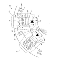
図1は、モータまたは発電機として使用される本発明の実施形態の回転電機において、そのロータの回転軸方向に見たステータ及びロータの概略構成を示す図である。図2は、図1の回転電機において、ステータの概略構成を示す図である。図3は、図1の回転電機において、ロータの概略構成を示す図である。図4は、図1のA部拡大図である。 FIG. 1 is a diagram showing a schematic configuration of a stator and a rotor as viewed in the direction of the rotation axis of a rotor in a rotating electrical machine according to an embodiment of the present invention used as a motor or a generator. FIG. 2 is a diagram showing a schematic configuration of a stator in the rotating electric machine of FIG. FIG. 3 is a diagram showing a schematic configuration of the rotor in the rotating electric machine of FIG. FIG. 4 is an enlarged view of part A in FIG.
回転電機10は、図示しないケーシングに固定されたステータ12と、ステータ12と所定の空隙をあけて径方向内側に対向配置され、ステータ12に対し回転可能なロータ14とを備える。なお、単に「径方向」という場合、ロータ14の回転中心軸に対し直交する放射方向をいう(本明細書全体及び特許請求の範囲で同じである。)。ロータ14は、回転軸16に固定され回転軸16と一体に回転する。
The rotating
また、ステータ12は、ステータコア18(図2)と、ステータコア18の周方向複数個所の等間隔位置に配置されたティース19と、各ティース19に巻かれた複数相(より具体的にはu相、v相、w相の3相)のステータ巻線20u,20v,20wとを含む。すなわち、ステータコア18の内周面には、径方向内側へ(ロータ14へ向けて)突出する複数のティース19がステータ12の周方向に沿って互いに間隔をおいて配列されている。各ティース19間にスロット22が形成されている。ステータコア18及び複数のティース19は、磁性鋼板を複数積層した積層体等の磁性材により、一体に形成されている。
Further, the
各相のステータ巻線20u,20v,20wは、スロット22を通ってティース19に短節集中巻で巻装されている。このように、ティース19にステータ巻線20u,20v,20wが巻装されることで磁極が構成される。そして、複数相のステータ巻線20u,20v,20wに複数相の交流電流を流すことで、周方向に複数配置されたティース19が磁化し、周方向に回転する回転磁界をステータ12に生成する。すなわち、複数相のステータ巻線20u,20v,20wは、ステータ12に回転磁界を生成する。なお、ステータ巻線は、このようにステータ12のティース19に巻線する構成に限定するものではない。例えばステータコア18の環状部分の周方向複数個所に複数相のステータ巻線を巻線するトロイダル巻きとし、ステータ12に回転磁界を生じさせることもできる。
The
ティース19に形成された回転磁界は、ロータ14に作用する。図2に示す例では、3相(u相、v相、w相)のステータ巻線20u,20v,20wがそれぞれ巻装された3つのティース19により1つの極対が構成されている。
The rotating magnetic field formed on the
一方、ロータ14は、円筒状のロータヨークであるロータコア24(図3)と、ロータコア24の外周面の周方向の等間隔複数個所に、径方向外側に向けて(ステータ12に向けて)突出して設けられた突部である突極26と、複数のロータ巻線28n、28sとを含む。なお、単に「周方向」という場合、ロータ14の回転中心軸を中心として描かれる円形に沿う方向をいう(本明細書全体及び特許請求の範囲で同じである。)。ロータコア24及び複数の突極26は、磁性鋼板を複数積層した積層体等の磁性材により、一体に形成されている。ロータ14の周方向に関して1つおきの突極26に第1ロータ巻線28nがそれぞれ集中巻きで巻かれて、第1ロータ巻線28nが巻かれた突極26と隣り合う別の突極26であって、周方向1つおきの突極26に、第2ロータ巻線28sがそれぞれ集中巻きで巻かれている。また、各第1ロータ巻線28nを1方向に短絡するように磁気特性調整部である第1ダイオード38が接続され、各第2ロータ巻線28sを反対方向に短絡するように磁気特性調整部である第2ダイオード40が接続されている。
On the other hand, the
このような構成では、第1ロータ巻線28n及び第2ロータ巻線28sに整流された電流が流れることで突極26が磁化し、少なくとも先端部が磁極部として機能する。ステータ巻線20u,20v,20wに交流電流を流すことで、ステータ12が回転磁界を生成するが、この回転磁界は、基本波成分の磁界だけでなく、基本波よりも高い次数の高調波成分の磁界を含んでいる。
In such a configuration, the
より詳しくは、ステータ12に回転磁界を発生させる起磁力の分布は、各相のステータ巻線20u,20v,20wの配置や、ティース19及びスロット22によるステータコア18の形状に起因して、(基本波のみの)正弦波分布にはならず、高調波成分を含むものとなる。特に、集中巻においては、各相のステータ巻線20u,20v,20wが互いに重なり合わないため、ステータ12の起磁力分布に生じる高調波成分の振幅レベルが増大する。例えばステータ巻線20u,20v,20wが3相集中巻の場合は、高調波成分として、入力電気周波数の時間的3次成分である、空間的な2次成分の振幅レベルが増大する。このようにステータ巻線20u,20v,20wの配置やステータコア18の形状に起因して起磁力に生じる高調波成分は空間高調波と呼ばれている。
More specifically, the distribution of magnetomotive force that generates a rotating magnetic field in the
ステータ12からロータ14に、この空間高調波成分を含む回転磁界が作用すると、空間高調波の磁束変動により、ロータ14の突極26間の空間に漏れ出す漏れ磁束の変動が発生し、その変動が十分に大きい場合には各ロータ巻線28n,28sの少なくともいづれかのロータ巻線28n(または28s)に誘導起電力が発生する。
When a rotating magnetic field including this spatial harmonic component acts on the
そして、各ロータ巻線28n,28sに誘導起電力が発生すると、図4の矢印Ia、Ibで示すように、各ロータ巻線28n,28sに対応するダイオード38,40の整流方向に応じた直流電流が流れ、ロータ巻線28n、28sが巻装された突極26が磁化する。このため、この突極26が所望の極性の磁極部として機能する。すなわち、ロータ巻線28n,28sを流れる誘導電流により生成される磁束が突極26を流れることで突極26に起磁力が発生し、磁極が形成される。また、誘導電流によって突極26に生じる起磁力を巻線起磁力と呼ぶことにすると、巻線起磁力の方向は誘導電流の方向で決まる。この巻線起磁力は、回転電機10のトルクの向上に寄与する。また、巻線起磁力の方向を、対応するダイオード38,40の整流方向により、ロータ14の周方向に関して交互に異ならせる。図3の例では、各ロータ巻線28n,28sに誘導電流が流れると仮定した場合に、第1ロータ巻線28nが巻装された突極26の先端部にN極が生成され、第2ロータ巻線28sが巻装された突極26の先端部にS極が生成される。図3では、各ロータ巻線28n,28sに誘導電流が流れると仮定した場合に、各突極26の先端部に形成される磁極を各突極26の外径側のN,Sにより示している。この場合、ロータ14の周方向においてN極とS極とが交互に配置される。このように、各ダイオード38,40(図3)は、各ロータ巻線28n、28sに発生する誘導起電力によって複数の突極26に生じる磁気特性を、周方向に交互に異ならせている。
When an induced electromotive force is generated in each of the
また、図3に示すように、ロータ14の周方向に関する各ロータ巻線28n,28sの幅θは、ロータ14の電気角で180°に相当する幅よりも短く設定している。より好ましくは、ロータ14の周方向に関する各ロータ巻線28n,28sの幅θは、ロータ14の電気角で90°に相当する幅に等しく、あるいはほぼ等しくしている。ここでの各ロータ巻線28n,28sの幅θについては、各ロータ巻線28n,28sの断面積を考慮して、各ロータ巻線28n,28sの断面の中心幅で表すことができる。
Further, as shown in FIG. 3, the width θ of each rotor winding 28n, 28s in the circumferential direction of the
本実施形態の回転電機10の場合、図4に示すように、ロータ14は、各突極26の先端部に埋め込まれるように設けられる永久磁石42と第2永久磁石44とを含んでいる。各永久磁石42,44の磁化方向は、ロータ14の周方向に一致させている。すなわち、各永久磁石42,44は、各ロータ巻線28n,28sを流れる誘導電流によって生じる各突極26の磁化方向である径方向(図4の矢印α方向、矢印β方向)に対し直交する方向であるロータ円周方向に磁化されている。各永久磁石42,44はフェライト等により構成されている。
In the case of the rotating
また、各突極26において、永久磁石42と第2永久磁石44とは、周方向両側に互いに離れて配置され、互いに同じ極が周方向に対向するように配置されている。例えば図3、図4にPnで示すように、第1ロータ巻線28nの誘導電流Iaにより突極26の先端に生成される磁極がN極となる場合には、突極26の先端部に永久磁石42及び第2永久磁石44が、互いにN極が周方向に対向するように配置される。また、図3、図4にPsで示すように、第2ロータ巻線28sの誘導電流Ibにより突極26の先端に生成される磁極がS極となる場合には、突極26の先端部に永久磁石42及び第2永久磁石44が、互いにS極が周方向に対向するように配置される。
In each
永久磁石42及び第2永久磁石44は、それぞれ軸方向(図4の表裏方向)に長い棒状として、各突極26の先端面に周方向に離れて形成された軸方向に長い溝内に埋め込んで配置することができる。この場合、各永久磁石42,44の径方向外側に向く側面はステータ12に対向するように外部に露出する。また、各永久磁石42,44は、各突極26の先端面と同一平面上または同一の断面円弧形の曲面上に位置する径方向外側面60,62を有する。すなわち、各永久磁石42,44は、各突極26の最先端に配置されている。なお、各突極26の先端部に軸方向に貫通し、周方向に離れた2つの磁石孔を形成することもできる。そして各突極26において、永久磁石42と第2永久磁石44とを、磁化方向が周方向に向き、かつ、互いに同じ極がそれぞれ周方向に対向するように、2つの磁石孔のそれぞれに挿入配置することもできる。
The
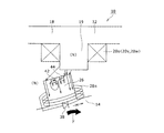
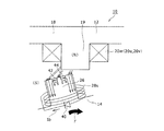
このような回転電機10は、図5の回転電機駆動システム46により駆動される。図5は、図1の回転電機10を駆動する回転電機駆動システム46の概略構成を示す図である。回転電機駆動システム46は、回転電機10と、回転電機10を駆動する駆動部であるインバータ48と、インバータ48を制御する制御装置50と、電源である蓄電装置52とを備え、回転電機10を駆動する。
Such a rotating
蓄電装置52は、直流電源として設けられ、充放電可能であり、例えば二次電池により構成する。インバータ48は、U相、V相、W相の3相のアームAu,Av,Awを備える。各相アームAu,Av,Awは、それぞれ2個のスイッチング素子Swを直列に接続している。スイッチング素子Swは、トランジスタ、IGBT等である。各スイッチング素子Swに逆並列にダイオードDiを接続している。各アームAu,Av,Awの中点は、回転電機10を構成する対応する相のステータ巻線20u,20v,20wの一端側に接続されている。ステータ巻線20u,20v,20wはステータ12の対応する各ティース19において、同じ相のステータ巻線20u(または20vまたは20w)同士が互いに直列に接続されている。ステータ巻線20u,20v,20wの他端は中性点で接続されている。
The
蓄電装置52の正極側及び負極側は、インバータ48の正極側と負極側とにそれぞれ接続されており、蓄電装置52とインバータ48との間にコンデンサ54が、インバータ48に対し並列に接続されている。制御装置50は、例えば本発明の回転電機が車両の駆動モータとして利用された場合、車両のアクセルペダルセンサ(図示せず)等から入力される加速指令信号に応じて回転電機10のトルク目標を算出し、トルク目標等に応じた電流指令値に応じて各スイッチング素子Swのスイッチング動作を制御する。制御装置50には、3相のうち、少なくとも2相のステータ巻線(例えば20v、20w)側に設けられた電流センサ56で検出された電流値を表す信号と、レゾルバ等の回転角度検出部(図示せず)で検出された回転電機10のロータ14の回転角度を表す信号とがそれぞれ入力される。制御装置50は、CPU,メモリ等を有するマイクロコンピュータを含むもので、インバータ48のスイッチング素子Swのスイッチングを制御することにより、回転電機10のトルク、回転数等を制御する。すなわち、制御装置50は、回転電機10の駆動を制御する。制御装置50は、機能ごとに分割された複数の制御装置により構成することもできる。
The positive electrode side and the negative electrode side of the
このような制御装置50は、インバータ48を構成する各スイッチング素子Swのスイッチング動作により蓄電装置52からの直流電力を、u相、v相、w相の3相の交流電力に変換して、ステータ巻線20u,20v,20wの各相に対応する相の電力を供給することを可能とする。また、制御装置50は、ステータ巻線20u,20v,20wに流れるステータ電流にパルス電流を重畳させるパルス重畳部58を有するが、これについては後述する。
Such a
また、図5の回転電機駆動システム46は、例えば、車両用走行動力発生装置として、エンジンと走行用モータとを駆動源として備えるハイブリッド車、燃料電池車、電気自動車等に搭載して使用される。また、蓄電装置52とインバータ48との間に電圧変換部であるDC/DCコンバータを接続して、蓄電装置52の電圧を昇圧してインバータ48に供給可能とすることもできる。
In addition, the rotating electrical
次に、回転電機駆動システム46により駆動される回転電機10の基本的な動作を説明する。3相のステータ巻線20u、20v、20wに3相の交流電流が流れることでステータ12に形成された回転磁界(基本波成分)がロータ14に作用し、これに応じて、ロータ14の磁気抵抗が小さくなるように、突極26がステータ12のティース19に吸引される。これによって、ロータ14にトルク(リラクタンストルク)が作用する。
Next, the basic operation of the rotating
また、ステータ12に形成された空間高調波を含む回転磁界がロータ14の各ロータ巻線28n、28sに鎖交すると、各ロータ巻線28n、28sには、空間高調波に起因するロータ14の回転周波数(回転磁界の基本波成分)と異なる周波数の磁束変動によって、各ロータ巻線28n、28sに誘導起電力が発生する。この誘導起電力の発生に伴って各ロータ巻線28n、28sに流れる電流は、各ダイオード38,40により整流されることで所定の一方向となる。そして、各ダイオード38,40で整流された電流が各ロータ巻線28n、28sに流れるのに応じて各突極26が磁化し、各突極26に磁極が形成され、磁極の先端側がN極かS極のいづれかになる。この場合、ダイオード38,40の整流方向の違いにより、各突極26の巻線起磁力による磁極として、周方向においてN極とS極とが交互に配置されたものとなる。
Further, when the rotating magnetic field including the spatial harmonics formed on the
そして、各突極26の巻線起磁力による磁界がステータ12により生成される回転磁界(基本波成分)と相互作用して、後述するように吸引作用が生じる。このステータ12により生成される回転磁界(基本波成分)と突極26の磁界との電磁気相互作用(吸引作用)によっても、ロータ14にトルクを作用させることができ、ロータ14がステータ12で生成される回転磁界(基本波成分)に同期して回転駆動される。このように回転電機10は、ステータ巻線20u,20v,20wへの供給電力を利用してロータ14に動力(機械的動力)を発生させる電動機として機能させることができる。
Then, the magnetic field generated by the magnetomotive force of each
また、制御装置50はパルス重畳部58を有する。回転電機10では、ロータ巻線28n、28sに誘導電流が発生した場合に、突極26の先端に形成される磁極と、突極26に対向し、ステータ12のティース19に形成される磁極とが逆極性になる場合を想定する。パルス重畳部58は、この場合に突極26にティース19が対向する直前から対向時までに、対応するロータ巻線28n、28sに誘導電流が発生するように、ステータ巻線20u、20v、20wに流れるステータ電流にパルス電流を重畳させる。図6は、図4のB部であって、ロータ14の突極26にステータ12のS極となるティース19が対向する場合において、突極26とティース19の間、及び突極26内での磁束の流れを示す図である。例えば、図6に示すように、ステータ12の1つのティース19とロータ14の1つの突極26との周方向の反対側端部同士のみが径方向に対向し、そのティース19の先端に、ステータ電流によりS極が形成される場合を考える。図6ではティース19の先端にS極が形成されることを、ティース19内の(S)で示している(後述する他の図面でも同様である。)。この場合、突極26に巻かれた第1ロータ巻線28nにダイオード38の整流方向により誘導電流Iaが流れたとすると、突極26の先端にはN極が形成される。すなわち、ロータ巻線28nに誘導電流が発生した場合に突極26の先端に形成される磁極と、ステータ12のティース19に形成される磁極とが逆極性になる。この場合、パルス重畳部58(図5)は、突極26にティース19が対向する直前から対向時までに、その突極26に巻かれたロータ巻線28nに誘導電流Iaが発生するように、ステータ電流にパルス電流を重畳させる。例えば、制御装置50(図5)は、ステータ電流をdq軸座標系に変換してd軸電流成分及びq軸電流成分とし、フィードバック制御を含むベクトル制御により、目標トルクに対応して各相のステータ電流が得られるようにインバータ48を制御する。そして制御装置50のパルス重畳部58により、q軸電流に電気的1周期の中の適切なタイミングで、または周期的にパルス電流を重畳させる。パルス電流は、例えば、電流値が急激に減少した後、急激に増大するいわゆる減少パルス電流、または、電流値が急激に増大した後、急激に減少するいわゆる増大パルス電流とすることができる。
Further, the
この結果、パルス電流の重畳により空間高調波のレベルが増大して、ロータ巻線28nに誘導起電力が発生し、図6の例では突極26の先端の周方向両端部にN極が形成されるように突極26に磁束が流れる。このため、永久磁石42及び第2永久磁石44の磁束が突極26の周方向両端部からティース19側に流れてその磁路を縮めるように突極26とティース19との間で磁気的吸引力が作用する。更に、図6のように、突極26の先端部に、互いのN極同士が周方向に対向するように永久磁石42及び第2永久磁石44が配置されている。永久磁石42及び第2の永久磁石44から流出する磁束が突極26の周方向中央部からティース19側に流れて、その磁路を縮めるように突極26とティース19との間で磁気的吸引力が作用する。この場合、突極26内で磁束が広い範囲で流れてティース19との間で大きな吸引力を発生させる。したがって、ロータ14に図6の矢印γ方向、すなわちティース19と突極26とを近づける方向にロータ14を回転させる力が作用する。
As a result, the level of the spatial harmonics increases due to the superposition of the pulse current, and an induced electromotive force is generated in the rotor winding 28n, and N poles are formed at both ends in the circumferential direction at the tip of the
一方、図7は、突極26に対向するティース19がN極となる場合を示す図である。図7のように、突極26とティース19との周方向反対側端部同士が径方向に対向し、そのティース19にN極が形成されている。突極26に巻かれたロータ巻線28nに誘導電流Iaが流れたとすると、ダイオード38の整流方向により突極26の先端にはN極が形成される。すなわち、ロータ巻線28nに誘導電流が発生した場合に突極26の先端に形成される磁極と、ティース19に形成される磁極とが同極性になる。パルス重畳部58(図5)は、この場合に、ロータ巻線28n、28sに誘導電流を発生させないように、ステータ巻線20u、20v、20wに流れるステータ電流にパルス電流を重畳させないようにする。このため、空間高調波のレベルが低下して、ロータ巻線28nには誘導起電力が発生しない。すなわち、ステータ電流へのパルス電流の重畳の有無に応じてロータ巻線28nの誘導起電力の発生、そして磁極の形成の有無を切り換えられる。一方、突極26の先端部に永久磁石42及び第2永久磁石44が、互いのN極同士を周方向に対向させるように配置されているので、突極26の周方向両端部はS極と成る。このため、ティース19で発生するN極の磁束が突極26の周方向両端部に流れ、その磁路を縮めるように突極26とティース19との間で磁気的吸引力が作用する。この場合も、ロータ14に図7の矢印γ方向、すなわちティース19と突極26とを近づける方向にロータ14を回転させる力が作用する。
On the other hand, FIG. 7 is a diagram showing a case where the
上記では、第1ロータ巻線28nにより先端側にN極が形成される突極26について説明したが、その突極26と周方向に隣り合う別の突極26では、第2ロータ巻線28sにより突極26の先端側にS極が形成される。この突極26では、永久磁石42,44の向きが上記の図4で説明したように隣の突極26とは異なっている。図8は、図4のC部に対応する図であって、ロータ14の突極26にステータ12のN極となるティース19が対向する場合において、突極26とティース19の間、及び突極26内での磁束の流れを示す図である。図9は、突極26に対向するティース19がS極となる場合を示す図である。図8、図9の場合、第2ロータ巻線28sに誘導電流が発生した場合に突極26の先端にS極が形成される。また、図8では、ロータ巻線28sに誘導電流が発生した場合に突極26の先端に形成される磁極(S極)と、ステータ12のティース19に形成される磁極(N極)とが逆極性になる。図8では、ステータ12の1つのティース19とロータ14の1つの突極26との周方向の反対側端部同士のみが径方向に対向している。この場合、パルス重畳部58(図5)は、突極26にティース19が対向する直前から対向時までに、ロータ巻線28sに誘導電流Ibが発生するように、ステータ電流にパルス電流を重畳させる。したがって、ティース19で発生するN極の磁束が突極26の周方向両端部に流れ、その磁路を縮めるように突極26とティース19との間で磁気的吸引力が作用する。
In the above description, the
更に、図8のように、突極26の先端部に、互いのS極同士が周方向に対向するように永久磁石42及び第2永久磁石44が配置されている。このため、ティース19で発生するN極の磁束が突極26の周方向中央部にも流れ、その磁路を縮めるように突極26とティース19との間で磁気的吸引力が作用する。したがって、ロータ14にティース19と突極26とを近づける方向(図8の矢印γ方向)にロータ14を回転させる力が作用する。
Further, as shown in FIG. 8, the
一方、図9に示すように、ロータ巻線28sに誘導電流が発生した場合に突極26の先端に形成される磁極(S極)と、ティース19に形成される磁極(S極)とが同極性になる場合もある。パルス重畳部58(図5)は、この場合に、ロータ巻線28n、28sに誘導電流を発生させないように、ステータ巻線20u、20v、20wに流れるステータ電流にパルス電流を重畳させないようにする。この場合、突極26の先端部には、永久磁石42及び第2永久磁石44が、互いのS極同士が周方向に対向するように配置されているので、突極26の周方向両端部はN極と成る。このため、突極26の周方向両端部から流出する磁束がティース19に流れ、その磁路を縮めるように突極26とティース19との間で磁気的吸引力が作用する。この場合も、ロータ14にティース19と突極26とを近づける方向(図9の矢印γ方向)にロータ14を回転させる力が作用する。
On the other hand, as shown in FIG. 9, when an induced current is generated in the rotor winding 28s, a magnetic pole (S pole) formed at the tip of the
このように、本発明の回転電機10では、ロータ14は、各突極26の磁化方向に対し直交するロータ円周方向に磁化された永久磁石42を含んでいる。このため、ロータ14の各突極26と対向するまたは対向直前のティース19に形成される磁極がN極またはS極のいづれの場合でも、各突極26の先端部に設けられた永久磁石42により、各突極26とティース19の磁極との引き合う力を大きくできる。すなわち、ロータ巻線28n,28sに誘導電流が流れる場合に突極26に生成される磁極(例えばN極)と逆の磁極(例えばS極)が必要な場合に、永久磁石42でその磁極(例えばS極)の機能を持たせることができる。このため、突極26に永久磁石がない場合、及び、永久磁石があってもその磁化方向が径方向に一致している場合のいづれに比べても、ティース19との間で大きな吸引力を発生させることができる。このため、ステータ12とロータ14との磁気的吸引力を効果的に利用してロータトルクを大きくできる。
Thus, in the rotating
一方、本発明と異なり、ロータの突極に永久磁石が配置され、しかも永久磁石の磁化方向がロータの径方向と一致する場合、突極の磁路をほぼ塞ぐように永久磁石が広がっていると、ステータが永久磁石の磁化方向とは逆方向に突極を励磁しようとしても磁束の行き場がなくなり、磁気回路を有効に成立させることが難しくなる可能性がある。本実施形態ではこのような不都合がない。 On the other hand, unlike the present invention, when the permanent magnet is disposed on the salient pole of the rotor and the magnetization direction of the permanent magnet coincides with the radial direction of the rotor, the permanent magnet spreads so as to substantially block the magnetic path of the salient pole. Then, even if the stator tries to excite the salient pole in the direction opposite to the magnetization direction of the permanent magnet, there is a possibility that the magnetic flux is lost and it is difficult to establish the magnetic circuit effectively. In this embodiment, there is no such inconvenience.
また、上記の特許文献1、2には、ロータに永久磁石が固定された構成が記載されている。ただし、この構成では、上記で説明したように、ロータ巻線とダイオードによる磁化方向と永久磁石の磁化方向とが一致している。このため、ステータとロータとの磁気的吸引力を効果的に利用してロータトルクを大きくする面から改良の余地がある。また、ロータの磁極部のほとんどが永久磁石で占められると、逆方向の磁束が磁極部の永久磁石以外の狭い部分を通過しようとしてもすぐに磁気飽和を生じて通過することができない。このため、上記の磁気的吸引力を発生させることができない可能性がある。また、上記の特許文献3では、ロータコアの径方向内側の周方向連結部に永久磁石が配置されている。このため、永久磁石の磁束は磁気抵抗の低い部分に流れようとするので、ステータとロータとの間のギャップを通過する磁束の形成に寄与しない。このように特許文献1〜3に記載された構成では、ロータのトルクを大きくする面から改良の余地がある。これに対して、本実施形態の回転電機10によれば、このような不都合を生じず、トルク向上を図れる。
Moreover, the above Patent Documents 1 and 2 describe a configuration in which a permanent magnet is fixed to a rotor. However, in this configuration, as described above, the magnetization direction of the rotor winding and the diode coincides with the magnetization direction of the permanent magnet. For this reason, there is room for improvement in terms of increasing the rotor torque by effectively using the magnetic attractive force between the stator and the rotor. Further, when most of the magnetic pole part of the rotor is occupied by permanent magnets, magnetic flux in the opposite direction cannot be passed due to magnetic saturation immediately even if trying to pass through a narrow part other than the permanent magnets of the magnetic pole part. For this reason, there is a possibility that the magnetic attractive force described above cannot be generated. Moreover, in said patent document 3, a permanent magnet is arrange | positioned at the circumferential direction connection part inside the radial direction of a rotor core. For this reason, since the magnetic flux of the permanent magnet tends to flow in a portion having a low magnetic resistance, it does not contribute to the formation of the magnetic flux passing through the gap between the stator and the rotor. As described above, in the configurations described in Patent Documents 1 to 3, there is room for improvement in terms of increasing the torque of the rotor. On the other hand, according to the rotating
また、各永久磁石42,44は、各突極26の最先端に配置することができる。このため、各永久磁石42,44を最もステータ12に近づけて突極26に配置でき、ステータ12との間での磁気的吸引力をより効果的に発揮できる。また、ロータ14は、突極26の先端部に、永久磁石42と対向するように配置された第2永久磁石44を含んでいる。永久磁石42と第2永久磁石44とは、周方向に同じ磁極が対向するように配置されている。このため、突極26に永久磁石が1つのみ配置されている場合と異なり、突極26に巻かれたロータ巻線28n,28sに誘導電流が流れない場合でも、突極26の周方向に対称的に、または後述する図10、図11の実施形態で説明するように突極26の周方向の中央部に磁極を形成できる。このため、正回転時及び逆回転時の回転性能をバランスよく改善しやすい。
Further, each
ただし、本発明では、上記のように各突極26に永久磁石が1つのみ配置されている構成を採用することもできる。例えば、本実施形態において、各突極26に第2永久磁石44(図4等参照)が配置されず、その代わりに、各突極26において永久磁石42を周方向中央部に配置して、その周方向長さを大きくすることもできる。また、複数の突極26において、複数の永久磁石の磁化方向を周方向に同じとすることも異ならせることもできる。更に永久磁石の磁化方向を周方向に交互に逆にすることもできる。このように各突極26に永久磁石が1つのみ配置されている構成では、本実施形態の場合に比べて効果は劣るが、永久磁石42により、各突極26と各ティース19との引き合う力を大きくでき、ロータトルクを大きくできる。また、各突極26の先端部に配置する永久磁石の数を3個以上とすることもできる。
However, in the present invention, a configuration in which only one permanent magnet is disposed on each
図7、図9を用いて説明したように、ロータ巻線28n、28sに誘導電流を発生させない場合でも、各突極26の周方向両端部に永久磁石42,44により、ティース19と引き合う磁極を形成できる。このため、ロータ14において磁極の発生個所を多くでき、ロータ14の回転をより滑らかにできる。また、ロータ14の回転停止時のロータ14とステータ12との位置関係にはよるが、突極26とティース19との位置がずれた場合でも吸引力を発生させやすくなり、正回転時及び逆回転時のいづれの場合でも、ロータ14の始動時のトルクを大きくできる。
As described with reference to FIGS. 7 and 9, even when no induced current is generated in the
なお、制御装置50(図5)は、使用時のステータ12とロータ14との位置関係が異なるすべての場合で、ステータ電流にパルス電流を重畳させない構成とすることもできる。この場合でも、上記の実施形態のように各突極26に、磁化方向が周方向と一致する永久磁石42,44が配置されていると、突極26と対向するまたは対向直前のティース19がN極またはS極のいづれの場合でも、突極26とティース19との間で磁気的吸引力を発生させることができ、回転電機10のトルクを増大できる。
Note that the control device 50 (FIG. 5) may be configured not to superimpose the pulse current on the stator current in all cases where the positional relationship between the
また、上記の実施形態では、パルス重畳部58は、ロータ巻線28n(または28s)に誘導電流が流れる場合に突極26の先端側に形成される磁極と、これに対向するステータ12のティース19とが同じ磁極となる場合にロータ巻線28n(または28s)に誘導電流が流れないようにステータ電流にパルス電流を重畳させないようにしている。ただし、別の実施形態として、パルス重畳部58は、突極26とティース19とが引き付け合った後で、対応するロータ巻線28n(または28s)に誘導電流が流れるように、ステータ電流にパルス電流を重畳させる構成とすることもできる。この構成によれば、ティース19と突極26との磁気的吸引力と磁気的反発力とを利用して回転電機10のトルクを大きくできる。
Further, in the above-described embodiment, the
なお、上記の回転電機10の構成において、ロータ14に設けられた各突極26において、周方向の片側面または両側面から先端に向かうほど径方向外側になるように傾斜または湾曲させた磁性材製の補助突極を突出させることもできる。この構成によれば、ステータ12で発生する回転磁界の起磁力成分に含まれ、突極26同士の間の空間に漏れ出す空間高調波の磁束を効果的に突極26に導くことができる。このため、突極26に巻かれたロータ巻線28n,28sに誘導電流をより効果的に流すことができ、回転電機10のトルクを向上できる。
In the configuration of the rotating
また、本発明の各突極26での磁石配置は、上記の実施形態に限定するものではなく、種々の形態を採用できる。図10は、本発明の実施形態の別例において、図4のB部に対応する図であって、ロータの突極にステータのN極となるティースが対向する場合において、突極とティースの間、及び突極内での磁束の流れを示す図である。図11は、実施形態の別例において、図4のC部に対応する図であって、ロータの突極にステータのS極となるティースが対向する場合において、突極とティースの間、及び突極内での磁束の流れを示す図である。
Moreover, the magnet arrangement | positioning in each
図10、図11に示す実施形態の別例では、各突極26において、永久磁石42,44の対向関係が上記の図1から図9に示した実施形態と逆になっている。すなわち、図10のように、ロータ巻線28nによって突極26の先端に生成される磁極がN極となる場合に、突極26の先端部に永久磁石42と第2永久磁石44とが、互いのS極が周方向に対向するように配置されている。また、図11のように、ロータ巻線28sによって突極26の先端に生成される磁極がS極となる場合に、突極26に永久磁石42と第2永久磁石44とが、互いのN極が周方向に対向するように配置されている。また、上記の実施形態と同様に、ロータ巻線28n,28sによって突極26の先端側に生成される磁極と、この突極26に対向するティース19に形成される磁極とが同じになる場合に、ロータ巻線28n,28sに誘導電流が流れないようにする。ただし、図10、図11のいづれの場合でも、永久磁石42及び第2永久磁石44によりティース19に対し異極となる磁極が突極26の周方向中央部に形成される。このため、突極26の周方向中央部とティース19との間で磁気的吸引力が作用する。このため、突極26とティース19との位置関係によっては、ロータ14の始動時のトルクが上記の実施形態よりも劣る可能性はある。ただし、このような別例でも、永久磁石42及び第2永久磁石44により、各突極26と各ティース19との引き合う力を大きくでき、ロータトルクを大きくできる。また、突極26に巻かれたロータ巻線28n,28sに誘導電流が流れない場合でも、突極26の周方向の中央部に磁極を形成できるので、正回転時及び逆回転時の回転性能をバランスよく改善しやすい。その他の構成及び作用は、上記の図1から図9に示した実施形態と同様である。
In another example of the embodiment shown in FIGS. 10 and 11, in each
なお、別の実施形態として、図1から図9の実施形態において、ロータ14のすべての突極26において、永久磁石42と第2永久磁石44とをN極同士あるいはS極同士が対向するように配置することもできる。この場合でも、ロータ14とステータ12との磁気的吸引力を大きくして、ロータトルクを大きくできる。
As another embodiment, in the embodiment shown in FIGS. 1 to 9, the N poles or the S poles of the
以上、本発明を実施するための形態について説明したが、本発明はこうした実施形態に何ら限定されるものではなく、本発明の要旨を逸脱しない範囲内において、種々なる形態で実施し得ることは勿論である。例えば、上記では、ステータの径方向内側にロータが対向配置された場合を説明したが、ステータの径方向外側にロータが対向配置された構成でも本発明を実施できる。また、ステータとロータとが径方向に対向配置されるいわゆるラジアル型の回転電機を説明したが、ステータとロータとが軸方向に対向配置されるいわゆるアキシャル型の回転電機でも本発明を実施できる。この場合、ロータの周方向複数個所に設けられて軸方向に突出する複数の突極の先端部に、各ロータ巻線を流れる誘導電流によって生じる各突極の磁化方向である軸方向に対し直交する方向である周方向に磁化された1つまたは複数の永久磁石を設けることができる。 As mentioned above, although the form for implementing this invention was demonstrated, this invention is not limited to such embodiment at all, and it can implement with a various form in the range which does not deviate from the summary of this invention. Of course. For example, in the above description, the case where the rotor is disposed opposite to the inner side in the radial direction of the stator has been described. Further, a so-called radial type rotating electrical machine in which the stator and the rotor are arranged to face each other in the radial direction has been described. However, the present invention can also be implemented in a so-called axial type rotating electrical machine in which the stator and the rotor are arranged to face each other in the axial direction. In this case, orthogonal to the axial direction, which is the magnetization direction of each salient pole generated by the induced current flowing through each rotor winding, at the tip of the plurality of salient poles provided in the circumferential direction of the rotor and projecting in the axial direction One or more permanent magnets can be provided that are magnetized in the circumferential direction, which is the direction of movement.
また、ステータ巻線はステータに集中巻きで巻線する場合を説明したが、例えばステータで空間高調波を含む回転磁界を生成できるのであればステータにステータ巻線を分布巻きで巻線する構成でも本発明を実施できる。また、上記の各実施形態では、磁気特性調整部をダイオードとした場合を説明したが、ロータ巻線に発生する誘導起電力によって前記複数の主突極に生じる磁気特性を周方向で異ならせる機能を有するものであれば、他の構成を採用することもできる。 In addition, the case where the stator winding is wound on the stator by concentrated winding has been described, but for example, if the stator can generate a rotating magnetic field including spatial harmonics, the stator winding may be wound on the stator by distributed winding. The present invention can be implemented. In each of the above embodiments, the case where the magnetic characteristic adjusting unit is a diode has been described. However, the function of varying the magnetic characteristics generated in the plurality of main salient poles in the circumferential direction by the induced electromotive force generated in the rotor windings. Any other configuration can be adopted as long as it has the following.
更に、上記では、ロータの各突極にロータ巻線が巻装され、複数の突極に生じる磁気特性を周方向に交互に異ならせる磁気特性調整部であるダイオードを備える回転電機を説明した。ただし、その他の回転電機でも、ロータコアの周方向複数個所に配置された突極を備える構成で、上記の実施形態と同様に、各突極の先端部に、各ロータ巻線を流れる誘導電流によって生じる各突極の磁化方向に対し直交する方向に磁化された永久磁石を設けることもできる。例えば、ステータの径方向内側にロータが配置された構成で、ロータの周方向複数個所に突極が突出形成される場合に、ロータは、各突極の先端部に、各ロータ巻線によって各突極が磁化される場合の磁化方向である径方向に対し直交する方向である周方向に磁化された永久磁石を設ける構成とすることもできる。その場合も、突極と対向するステータの磁極にかかわらず、永久磁石の磁力によりステータと突極との引き合う力が大きくなり、ステータとロータとの磁気的吸引力を効果的に利用してロータトルクを大きくできる効果を得られる。 Furthermore, in the above description, a rotating electrical machine has been described in which a rotor winding is wound around each salient pole of the rotor and a diode that is a magnetic characteristic adjusting unit that alternately changes the magnetic characteristics generated in the plurality of salient poles in the circumferential direction. However, other rotating electrical machines also have salient poles arranged at a plurality of locations in the circumferential direction of the rotor core, and in the same manner as in the above-described embodiment, by the induced current flowing through each rotor winding at the tip of each salient pole. It is also possible to provide a permanent magnet magnetized in a direction orthogonal to the magnetization direction of each salient pole generated. For example, in the configuration in which the rotor is arranged on the radially inner side of the stator, and the salient poles are projected and formed at a plurality of locations in the circumferential direction of the rotor, the rotor is provided at the tip of each salient pole by each rotor winding. A configuration may be employed in which a permanent magnet magnetized in a circumferential direction that is a direction orthogonal to a radial direction that is a magnetization direction when the salient pole is magnetized is provided. Even in this case, regardless of the magnetic pole of the stator facing the salient pole, the attracting force between the stator and the salient pole is increased by the magnetic force of the permanent magnet, and the rotor can be effectively utilized by the magnetic attractive force between the stator and the rotor. An effect of increasing the torque can be obtained.
10 回転電機、12 ステータ、14 ロータ、16 回転軸、18 ステータコア、19 ティース、20u,20v,20w ステータ巻線、22 スロット、24 ロータコア、26 突極、28n 第1ロータ巻線、28s 第2ロータ巻線、38 第1ダイオード、40 第2ダイオード、42 永久磁石、44 第2永久磁石、46 回転電機駆動システム、48 インバータ、50 制御装置、52 蓄電装置、54 コンデンサ、56 電流センサ、58 パルス重畳部、60,62 径方向外側面。 10 Rotating machine, 12 Stator, 14 Rotor, 16 Rotating shaft, 18 Stator core, 19 Teeth, 20u, 20v, 20w Stator winding, 22 Slot, 24 Rotor core, 26 Salient pole, 28n First rotor winding, 28s Second rotor Winding, 38 1st diode, 40 2nd diode, 42 Permanent magnet, 44 2nd permanent magnet, 46 Rotating electric machine drive system, 48 Inverter, 50 Control device, 52 Power storage device, 54 Capacitor, 56 Current sensor, 58 Pulse superposition Part, 60, 62 Radial outside surface.
Claims (6)
ロータコアと、前記ロータコアの周方向複数個所に設けられた突極と、前記各突極に巻かれたロータ巻線と、前記各ロータ巻線に発生する誘導起電力によって前記複数の突極に生じる磁気特性を周方向に交互に異ならせる磁気特性調整部とを含み、前記ステータに対向配置されるロータとを備える回転電機であって、
前記ロータは、前記各突極の先端部に設けられ、前記各ロータ巻線を流れる誘導電流によって生じる前記各突極の磁化方向に対し直交するロータ円周方向に沿って磁化された永久磁石を含むことを特徴とする回転電機。 A stator including a multi-phase stator winding that generates a rotating magnetic field;
A rotor core, salient poles provided at a plurality of locations in the circumferential direction of the rotor core, a rotor winding wound around each salient pole, and an induced electromotive force generated in each rotor winding are generated in the plurality of salient poles. A rotating electrical machine including a magnetic property adjusting unit that alternately varies magnetic properties in a circumferential direction, and a rotor disposed to face the stator,
The rotor is a permanent magnet provided at the tip of each salient pole and magnetized along the circumferential direction of the rotor perpendicular to the magnetization direction of each salient pole generated by an induced current flowing through each rotor winding. A rotating electric machine comprising:
前記各永久磁石は、前記各突極の最先端に配置されていることを特徴とする回転電機。 In the rotating electrical machine according to claim 1,
Each of the permanent magnets is disposed at the forefront of each of the salient poles.
前記ロータは、前記各突極の先端部に、前記永久磁石とロータ周方向に対向するように配置され、前記永久磁石の磁化方向と同軸ではあるが逆極性に磁化された第2永久磁石を含むことを特徴とする回転電機。 In the rotating electrical machine according to claim 1 or 2,
The rotor is disposed at the tip of each salient pole so as to face the permanent magnet in the circumferential direction of the rotor, and has a second permanent magnet that is coaxial with the magnetization direction of the permanent magnet but magnetized in the opposite polarity. A rotating electric machine comprising:
前記ロータ巻線によって前記突極の先端に生成される磁極がN極となる場合に、前記突極に前記永久磁石と前記第2永久磁石とが、互いにN極が周方向に対向するように配置され、
前記ロータ巻線によって前記突極の先端に生成される磁極がS極となる場合に、前記突極に前記永久磁石と前記第2永久磁石とが、互いにS極が周方向に対向するように配置されていることを特徴とする回転電機。 In the rotating electrical machine according to claim 3,
When the magnetic pole generated at the tip of the salient pole by the rotor winding is N pole, the permanent magnet and the second permanent magnet are opposed to the salient pole in the circumferential direction. Arranged,
When the magnetic pole generated at the tip of the salient pole by the rotor winding is the S pole, the permanent magnet and the second permanent magnet are opposed to the salient pole in the circumferential direction. A rotating electric machine characterized by being arranged.
前記回転電機の駆動を制御する制御装置と、を備え、
前記制御装置は、前記ロータ巻線に誘導電流が発生した場合に前記突極の先端に形成される磁極と、前記突極に対向し前記ステータに設けられるティースに形成される磁極とが逆になる場合に前記ロータ巻線に誘導電流が発生するように、前記ステータ巻線に流れるステータ電流にパルス電流を重畳させるパルス重畳部を有することを特徴とする回転電機駆動システム。 The rotating electrical machine according to any one of claims 1 to 4,
A control device for controlling the driving of the rotating electrical machine,
In the control device, when an induced current is generated in the rotor winding, the magnetic pole formed at the tip of the salient pole and the magnetic pole formed on the teeth provided on the stator facing the salient pole are reversed. A rotating electrical machine drive system comprising a pulse superimposing unit that superimposes a pulse current on a stator current flowing through the stator winding so that an induced current is generated in the rotor winding.
前記パルス重畳部は、前記ロータ巻線に誘導電流が発生した場合に前記突極の先端に形成される磁極と、前記突極に対向し前記ステータに設けられるティースに形成される磁極とが同じになる場合に前記ロータ巻線に誘導電流を発生させないように、前記ステータ巻線に流れるステータ電流にパルス電流を重畳させないことを特徴とする回転電機駆動システム。 In the rotating electrical machine drive system according to claim 5,
In the pulse superimposing portion, when an induced current is generated in the rotor winding, the magnetic pole formed at the tip of the salient pole is the same as the magnetic pole formed on the teeth provided on the stator facing the salient pole. In order to prevent an induction current from being generated in the rotor winding, a rotating electric machine drive system is characterized in that a pulse current is not superimposed on the stator current flowing in the stator winding.
Priority Applications (1)
| Application Number | Priority Date | Filing Date | Title |
|---|---|---|---|
| JP2012139747A JP2014007788A (en) | 2012-06-21 | 2012-06-21 | Rotary electric machine and system for driving rotary electric machine |
Applications Claiming Priority (1)
| Application Number | Priority Date | Filing Date | Title |
|---|---|---|---|
| JP2012139747A JP2014007788A (en) | 2012-06-21 | 2012-06-21 | Rotary electric machine and system for driving rotary electric machine |
Publications (1)
| Publication Number | Publication Date |
|---|---|
| JP2014007788A true JP2014007788A (en) | 2014-01-16 |
Family
ID=50105084
Family Applications (1)
| Application Number | Title | Priority Date | Filing Date |
|---|---|---|---|
| JP2012139747A Pending JP2014007788A (en) | 2012-06-21 | 2012-06-21 | Rotary electric machine and system for driving rotary electric machine |
Country Status (1)
| Country | Link |
|---|---|
| JP (1) | JP2014007788A (en) |
Cited By (2)
| Publication number | Priority date | Publication date | Assignee | Title |
|---|---|---|---|---|
| WO2019204501A1 (en) * | 2018-04-17 | 2019-10-24 | The Regents Of The University Of Michigan | Brushless, self-excited synchronous field-winding machine |
| KR20200099776A (en) * | 2019-02-15 | 2020-08-25 | 한양대학교 에리카산학협력단 | Motor |
-
2012
- 2012-06-21 JP JP2012139747A patent/JP2014007788A/en active Pending
Cited By (6)
| Publication number | Priority date | Publication date | Assignee | Title |
|---|---|---|---|---|
| WO2019204501A1 (en) * | 2018-04-17 | 2019-10-24 | The Regents Of The University Of Michigan | Brushless, self-excited synchronous field-winding machine |
| US10770999B2 (en) | 2018-04-17 | 2020-09-08 | The Regents Of The University Of Michigan | Brushless, self-excited synchronous field-winding machine |
| GB2587926A (en) * | 2018-04-17 | 2021-04-14 | Univ Michigan Regents | Brushless, self-excited synchronous field-winding machine |
| GB2587926B (en) * | 2018-04-17 | 2022-05-11 | Univ Michigan Regents | Brushless, self-excited synchronous field-winding machine |
| KR20200099776A (en) * | 2019-02-15 | 2020-08-25 | 한양대학교 에리카산학협력단 | Motor |
| KR102188707B1 (en) * | 2019-02-15 | 2020-12-08 | 한양대학교 에리카산학협력단 | Motor |
Similar Documents
| Publication | Publication Date | Title |
|---|---|---|
| JP5261539B2 (en) | Electromagnetic rotating electric machine | |
| US9006949B2 (en) | Synchronous motor | |
| JP5827026B2 (en) | Rotating electric machine and rotating electric machine drive system | |
| JP5363913B2 (en) | Rotating electric machine drive system | |
| JP2009112091A (en) | Rotating electrical machine and drive controller therefor | |
| JP5272831B2 (en) | Rotating electric machine | |
| JP2012170252A (en) | Rotary electric machine drive system | |
| JP2012222941A (en) | Rotating electric machine | |
| JP6668844B2 (en) | Rotating electric machine | |
| JP2013021749A (en) | Rotary electric machine system | |
| JP2017169281A (en) | Rotary electric machine | |
| JP5782850B2 (en) | Electromagnetic rotating electric machine | |
| JP5760895B2 (en) | Rotating electrical machine control system | |
| JP2014007837A (en) | Rotary electric machine and system for driving rotary electric machine | |
| JP2010136523A (en) | Drive control device for rotary electric machine | |
| JP6657940B2 (en) | Rotating electric machine | |
| JP6645351B2 (en) | Rotating electric machine | |
| JP5694062B2 (en) | Electromagnetic rotating electric machine | |
| JP2015096022A (en) | Rotary electric machine | |
| JP2014007788A (en) | Rotary electric machine and system for driving rotary electric machine | |
| JP6589703B2 (en) | Rotating electric machine | |
| JP2014030293A (en) | Rotor of rotary electric machine | |
| JP5784992B2 (en) | Electromagnetic rotating electric machine | |
| JP5494574B2 (en) | Electromagnetic rotating electric machine | |
| JP2014007787A (en) | Rotary electric machine and system for driving rotary electric machine |