JP2020040480A - Control method for vehicle, vehicle system and control device for vehicle - Google Patents
Control method for vehicle, vehicle system and control device for vehicle Download PDFInfo
- Publication number
- JP2020040480A JP2020040480A JP2018168655A JP2018168655A JP2020040480A JP 2020040480 A JP2020040480 A JP 2020040480A JP 2018168655 A JP2018168655 A JP 2018168655A JP 2018168655 A JP2018168655 A JP 2018168655A JP 2020040480 A JP2020040480 A JP 2020040480A
- Authority
- JP
- Japan
- Prior art keywords
- vehicle
- steering
- torque
- steering wheel
- deceleration
- Prior art date
- Legal status (The legal status is an assumption and is not a legal conclusion. Google has not performed a legal analysis and makes no representation as to the accuracy of the status listed.)
- Granted
Links
- 238000000034 method Methods 0.000 title claims abstract description 51
- 230000001133 acceleration Effects 0.000 claims description 278
- 230000007423 decrease Effects 0.000 claims description 15
- 230000003247 decreasing effect Effects 0.000 claims description 6
- 230000000694 effects Effects 0.000 abstract description 17
- 230000008859 change Effects 0.000 abstract description 12
- 230000009467 reduction Effects 0.000 abstract description 2
- 239000008186 active pharmaceutical agent Substances 0.000 description 68
- 230000008569 process Effects 0.000 description 26
- 230000000052 comparative effect Effects 0.000 description 24
- 238000010586 diagram Methods 0.000 description 11
- 230000003111 delayed effect Effects 0.000 description 9
- 239000000446 fuel Substances 0.000 description 9
- 230000005484 gravity Effects 0.000 description 8
- 238000002347 injection Methods 0.000 description 6
- 239000007924 injection Substances 0.000 description 6
- 230000006399 behavior Effects 0.000 description 5
- 238000001514 detection method Methods 0.000 description 4
- 239000012530 fluid Substances 0.000 description 4
- 230000004048 modification Effects 0.000 description 4
- 238000012986 modification Methods 0.000 description 4
- 230000001172 regenerating effect Effects 0.000 description 4
- 230000004044 response Effects 0.000 description 4
- 230000005540 biological transmission Effects 0.000 description 2
- 238000002474 experimental method Methods 0.000 description 2
- 230000006870 function Effects 0.000 description 2
- 238000004519 manufacturing process Methods 0.000 description 2
- 230000007246 mechanism Effects 0.000 description 2
- 238000004088 simulation Methods 0.000 description 2
- 239000000725 suspension Substances 0.000 description 2
- 230000009471 action Effects 0.000 description 1
- 230000008901 benefit Effects 0.000 description 1
- 238000002485 combustion reaction Methods 0.000 description 1
- 230000036461 convulsion Effects 0.000 description 1
- 238000010248 power generation Methods 0.000 description 1
- 230000002265 prevention Effects 0.000 description 1
- 230000004043 responsiveness Effects 0.000 description 1
Images


Classifications
-
- B—PERFORMING OPERATIONS; TRANSPORTING
- B60—VEHICLES IN GENERAL
- B60W—CONJOINT CONTROL OF VEHICLE SUB-UNITS OF DIFFERENT TYPE OR DIFFERENT FUNCTION; CONTROL SYSTEMS SPECIALLY ADAPTED FOR HYBRID VEHICLES; ROAD VEHICLE DRIVE CONTROL SYSTEMS FOR PURPOSES NOT RELATED TO THE CONTROL OF A PARTICULAR SUB-UNIT
- B60W30/00—Purposes of road vehicle drive control systems not related to the control of a particular sub-unit, e.g. of systems using conjoint control of vehicle sub-units, or advanced driver assistance systems for ensuring comfort, stability and safety or drive control systems for propelling or retarding the vehicle
- B60W30/18—Propelling the vehicle
- B60W30/18009—Propelling the vehicle related to particular drive situations
- B60W30/18145—Cornering
-
- B—PERFORMING OPERATIONS; TRANSPORTING
- B60—VEHICLES IN GENERAL
- B60W—CONJOINT CONTROL OF VEHICLE SUB-UNITS OF DIFFERENT TYPE OR DIFFERENT FUNCTION; CONTROL SYSTEMS SPECIALLY ADAPTED FOR HYBRID VEHICLES; ROAD VEHICLE DRIVE CONTROL SYSTEMS FOR PURPOSES NOT RELATED TO THE CONTROL OF A PARTICULAR SUB-UNIT
- B60W30/00—Purposes of road vehicle drive control systems not related to the control of a particular sub-unit, e.g. of systems using conjoint control of vehicle sub-units, or advanced driver assistance systems for ensuring comfort, stability and safety or drive control systems for propelling or retarding the vehicle
- B60W30/02—Control of vehicle driving stability
- B60W30/045—Improving turning performance
-
- B—PERFORMING OPERATIONS; TRANSPORTING
- B60—VEHICLES IN GENERAL
- B60W—CONJOINT CONTROL OF VEHICLE SUB-UNITS OF DIFFERENT TYPE OR DIFFERENT FUNCTION; CONTROL SYSTEMS SPECIALLY ADAPTED FOR HYBRID VEHICLES; ROAD VEHICLE DRIVE CONTROL SYSTEMS FOR PURPOSES NOT RELATED TO THE CONTROL OF A PARTICULAR SUB-UNIT
- B60W10/00—Conjoint control of vehicle sub-units of different type or different function
- B60W10/04—Conjoint control of vehicle sub-units of different type or different function including control of propulsion units
- B60W10/06—Conjoint control of vehicle sub-units of different type or different function including control of propulsion units including control of combustion engines
-
- B—PERFORMING OPERATIONS; TRANSPORTING
- B60—VEHICLES IN GENERAL
- B60W—CONJOINT CONTROL OF VEHICLE SUB-UNITS OF DIFFERENT TYPE OR DIFFERENT FUNCTION; CONTROL SYSTEMS SPECIALLY ADAPTED FOR HYBRID VEHICLES; ROAD VEHICLE DRIVE CONTROL SYSTEMS FOR PURPOSES NOT RELATED TO THE CONTROL OF A PARTICULAR SUB-UNIT
- B60W10/00—Conjoint control of vehicle sub-units of different type or different function
- B60W10/18—Conjoint control of vehicle sub-units of different type or different function including control of braking systems
- B60W10/184—Conjoint control of vehicle sub-units of different type or different function including control of braking systems with wheel brakes
-
- B—PERFORMING OPERATIONS; TRANSPORTING
- B60—VEHICLES IN GENERAL
- B60W—CONJOINT CONTROL OF VEHICLE SUB-UNITS OF DIFFERENT TYPE OR DIFFERENT FUNCTION; CONTROL SYSTEMS SPECIALLY ADAPTED FOR HYBRID VEHICLES; ROAD VEHICLE DRIVE CONTROL SYSTEMS FOR PURPOSES NOT RELATED TO THE CONTROL OF A PARTICULAR SUB-UNIT
- B60W10/00—Conjoint control of vehicle sub-units of different type or different function
- B60W10/20—Conjoint control of vehicle sub-units of different type or different function including control of steering systems
-
- B—PERFORMING OPERATIONS; TRANSPORTING
- B60—VEHICLES IN GENERAL
- B60W—CONJOINT CONTROL OF VEHICLE SUB-UNITS OF DIFFERENT TYPE OR DIFFERENT FUNCTION; CONTROL SYSTEMS SPECIALLY ADAPTED FOR HYBRID VEHICLES; ROAD VEHICLE DRIVE CONTROL SYSTEMS FOR PURPOSES NOT RELATED TO THE CONTROL OF A PARTICULAR SUB-UNIT
- B60W2520/00—Input parameters relating to overall vehicle dynamics
- B60W2520/06—Direction of travel
-
- B—PERFORMING OPERATIONS; TRANSPORTING
- B60—VEHICLES IN GENERAL
- B60W—CONJOINT CONTROL OF VEHICLE SUB-UNITS OF DIFFERENT TYPE OR DIFFERENT FUNCTION; CONTROL SYSTEMS SPECIALLY ADAPTED FOR HYBRID VEHICLES; ROAD VEHICLE DRIVE CONTROL SYSTEMS FOR PURPOSES NOT RELATED TO THE CONTROL OF A PARTICULAR SUB-UNIT
- B60W2520/00—Input parameters relating to overall vehicle dynamics
- B60W2520/10—Longitudinal speed
- B60W2520/105—Longitudinal acceleration
-
- B—PERFORMING OPERATIONS; TRANSPORTING
- B60—VEHICLES IN GENERAL
- B60W—CONJOINT CONTROL OF VEHICLE SUB-UNITS OF DIFFERENT TYPE OR DIFFERENT FUNCTION; CONTROL SYSTEMS SPECIALLY ADAPTED FOR HYBRID VEHICLES; ROAD VEHICLE DRIVE CONTROL SYSTEMS FOR PURPOSES NOT RELATED TO THE CONTROL OF A PARTICULAR SUB-UNIT
- B60W2540/00—Input parameters relating to occupants
- B60W2540/10—Accelerator pedal position
-
- B—PERFORMING OPERATIONS; TRANSPORTING
- B60—VEHICLES IN GENERAL
- B60W—CONJOINT CONTROL OF VEHICLE SUB-UNITS OF DIFFERENT TYPE OR DIFFERENT FUNCTION; CONTROL SYSTEMS SPECIALLY ADAPTED FOR HYBRID VEHICLES; ROAD VEHICLE DRIVE CONTROL SYSTEMS FOR PURPOSES NOT RELATED TO THE CONTROL OF A PARTICULAR SUB-UNIT
- B60W2540/00—Input parameters relating to occupants
- B60W2540/12—Brake pedal position
-
- B—PERFORMING OPERATIONS; TRANSPORTING
- B60—VEHICLES IN GENERAL
- B60W—CONJOINT CONTROL OF VEHICLE SUB-UNITS OF DIFFERENT TYPE OR DIFFERENT FUNCTION; CONTROL SYSTEMS SPECIALLY ADAPTED FOR HYBRID VEHICLES; ROAD VEHICLE DRIVE CONTROL SYSTEMS FOR PURPOSES NOT RELATED TO THE CONTROL OF A PARTICULAR SUB-UNIT
- B60W2540/00—Input parameters relating to occupants
- B60W2540/18—Steering angle
-
- B—PERFORMING OPERATIONS; TRANSPORTING
- B60—VEHICLES IN GENERAL
- B60W—CONJOINT CONTROL OF VEHICLE SUB-UNITS OF DIFFERENT TYPE OR DIFFERENT FUNCTION; CONTROL SYSTEMS SPECIALLY ADAPTED FOR HYBRID VEHICLES; ROAD VEHICLE DRIVE CONTROL SYSTEMS FOR PURPOSES NOT RELATED TO THE CONTROL OF A PARTICULAR SUB-UNIT
- B60W2710/00—Output or target parameters relating to a particular sub-units
- B60W2710/06—Combustion engines, Gas turbines
- B60W2710/0666—Engine torque
- B60W2710/0672—Torque change rate
-
- B—PERFORMING OPERATIONS; TRANSPORTING
- B60—VEHICLES IN GENERAL
- B60W—CONJOINT CONTROL OF VEHICLE SUB-UNITS OF DIFFERENT TYPE OR DIFFERENT FUNCTION; CONTROL SYSTEMS SPECIALLY ADAPTED FOR HYBRID VEHICLES; ROAD VEHICLE DRIVE CONTROL SYSTEMS FOR PURPOSES NOT RELATED TO THE CONTROL OF A PARTICULAR SUB-UNIT
- B60W2710/00—Output or target parameters relating to a particular sub-units
- B60W2710/18—Braking system
- B60W2710/182—Brake pressure, e.g. of fluid or between pad and disc
Abstract
Description
本発明は、操舵に応じて車両の姿勢を制御する車両の制御方法、車両システム及び車両の制御装置に関する。 The present invention relates to a vehicle control method, a vehicle system, and a vehicle control device that control the attitude of a vehicle in accordance with steering.
従来、スリップ等により車両の挙動が不安定になった場合に安全方向に車両の挙動を制御するもの(横滑り防止装置等)が知られている。具体的には、車両のコーナリング時等に、車両にアンダーステアやオーバーステアの挙動が生じたことを検出し、それらを抑制するように車輪に適切な減速度を付与するようにした技術が知られている。 2. Description of the Related Art Conventionally, there has been known a device that controls the behavior of a vehicle in a safe direction when the behavior of the vehicle becomes unstable due to a slip or the like (a side slip prevention device or the like). Specifically, a technique is known that detects understeer or oversteer behavior in a vehicle, for example, at the time of cornering of the vehicle, and applies an appropriate deceleration to wheels so as to suppress them. ing.
他方で、車両の挙動が不安定になるような走行状態における安全性向上のための制御とは別に、ステアリングホイール(以下では単に「ステアリング」とも呼ぶ。)の操作時にトルクを変化させることで、コーナリング時におけるドライバの操作が自然で安定したものとなるように車両挙動を制御する技術が知られている(例えば、特許文献1参照)。以下では、このようなドライバによるステアリング操作に応じて車両の姿勢を制御することを適宜「車両姿勢制御」と呼ぶ。 On the other hand, apart from the control for improving safety in a running state where the behavior of the vehicle becomes unstable, by changing the torque at the time of operating a steering wheel (hereinafter, also simply referred to as “steering”), 2. Description of the Related Art There is known a technique of controlling vehicle behavior so that a driver's operation during cornering is natural and stable (for example, see Patent Document 1). Hereinafter, controlling the attitude of the vehicle in accordance with such a steering operation by the driver is appropriately referred to as “vehicle attitude control”.
ところで、本件発明者は、運転席の車幅方向取り付け位置(換言するとステアリングの車幅方向取り付け位置)、及び車両の旋回方向(換言するとステアリングの操作方向)に応じて、車両姿勢制御により運転席において発生する前後加速度に差が生じることを発見した。特に、車両が右ハンドル車であるか又は左ハンドル車であるかに応じて、また、車両が右旋回するか又は左旋回するかに応じて、車両姿勢制御による運転席での前後加速度(つまりドライバが感じる前後加速度)の立ち上がりに差が生じることを発見した。 By the way, the present inventor has determined that the driver's seat is controlled by the vehicle attitude control according to the mounting position of the driver's seat in the vehicle width direction (in other words, the mounting position of the steering in the vehicle width direction) and the turning direction of the vehicle (in other words, the steering operation direction). It was discovered that there was a difference in the longitudinal acceleration that occurred in. In particular, depending on whether the vehicle is a right-hand drive vehicle or a left-hand drive vehicle, and depending on whether the vehicle turns right or left, the longitudinal acceleration at the driver's seat by the vehicle attitude control ( In other words, they found that there was a difference in the rise of the driver's longitudinal acceleration).
ここで、車両姿勢制御として、ステアリングの切り込み操作時に減速度を車両に付加することで車両の姿勢を制御する構成を想定する。この構成においては、車両が左旋回を行うときには、車両姿勢制御により運転席において発生する前後加速度の立ち上がりが、右ハンドル車では左ハンドル車よりも遅れる傾向にある。これは、車両が左旋回を行うときには、右ハンドル車では左ハンドル車よりも旋回時に運転席において発生する前後加速度が大きくなるので(典型的には右ハンドル車では加速度が発生するのに対して左ハンドル車では減速度が発生する)、このような前後加速度に対して車両姿勢制御による減速度を適用したときの運転席での前後加速度が、右ハンドル車では左ハンドル車よりも大きくなるからである。 Here, as the vehicle attitude control, a configuration is assumed in which the attitude of the vehicle is controlled by adding a deceleration to the vehicle at the time of turning the steering wheel. In this configuration, when the vehicle makes a left turn, the rise of the longitudinal acceleration generated in the driver's seat by the vehicle attitude control tends to be delayed in a right-hand drive vehicle than in a left-hand drive vehicle. This is because when the vehicle makes a left turn, the front-rear acceleration generated in the driver's seat when turning is larger in a right-hand drive vehicle than in a left-hand drive vehicle (typically, acceleration is generated in a right-hand drive vehicle). A deceleration occurs in a left-hand drive vehicle), and the longitudinal acceleration in the driver's seat when the deceleration by the vehicle attitude control is applied to such longitudinal acceleration is larger in a right-hand drive vehicle than in a left-hand drive vehicle. It is.
他方で、車両が右旋回を行うときには、車両姿勢制御により運転席において発生する前後加速度の立ち上がりが、左ハンドル車では右ハンドル車よりも遅れる傾向にある。これは、車両が右旋回を行うときには、左ハンドル車では右ハンドル車よりも旋回時に運転席において発生する前後加速度が大きくなるので(典型的には左ハンドル車では加速度が発生するのに対して右ハンドル車では減速度が発生する)、このような前後加速度に対して車両姿勢制御による減速度を適用したときの運転席での前後加速度が、左ハンドル車では右ハンドル車よりも大きくなるからである。 On the other hand, when the vehicle makes a right turn, the rise of the longitudinal acceleration generated in the driver's seat by the vehicle attitude control tends to be delayed in a left-hand drive vehicle compared to a right-hand drive vehicle. This is because when the vehicle makes a right turn, the front-rear acceleration generated in the driver's seat when turning is larger in a left-hand drive car than in a right-hand drive car (typically, acceleration is generated in a left-hand drive car. The deceleration occurs in a right-hand drive vehicle), and the longitudinal acceleration in the driver's seat when the deceleration by the vehicle attitude control is applied to such a longitudinal acceleration becomes larger in a left-hand drive vehicle than in a right-hand drive vehicle. Because.
通常、車両姿勢制御によれば、ステアリング操作時に適切な加減速度を車両に付加することにより、ステアリング操作に対する操縦安定性や車両応答性やリニア感を向上させることができる。また、このような車両姿勢制御によれば、ドライバの運転の疲労を軽減するという効果も得られる。具体的には、旋回時に車両姿勢制御により所望の前後加速度を発生させることで、ドライバは旋回により変化する横加速度に対して適切に身構えることができるので、つまり横加速度に対して適切な姿勢を事前に取ることができるので、ドライバの疲労を軽減できるのである。 Normally, according to the vehicle attitude control, by adding an appropriate acceleration / deceleration to the vehicle at the time of steering operation, it is possible to improve steering stability, vehicle responsiveness, and linear feeling with respect to steering operation. Further, according to such vehicle attitude control, an effect of reducing driver's driving fatigue can be obtained. Specifically, by generating a desired longitudinal acceleration by controlling the vehicle attitude during a turn, the driver can appropriately prepare for the lateral acceleration that changes due to the turn, that is, an appropriate attitude for the lateral acceleration. Since it can be taken in advance, driver fatigue can be reduced.
しかしながら、上述したように車両姿勢制御時に運転席において発生する前後加速度に差が生じると、車両姿勢制御によるドライバの疲労軽減効果を適切に確保できなくなってしまう。すなわち、ステアリングホイールの車幅方向取り付け位置(つまり車両が右ハンドル車であるか又は左ハンドル車であるか)、及びステアリングホイールの操作方向(つまり車両が右旋回するか又は左旋回するか)に応じて、車両姿勢制御時に運転席に発生する前後加速度の立ち上がりに差が生じることで、特に前後加速度の立ち上がりが遅れることで、車両姿勢制御によってドライバの疲労を適切に軽減できなくなってしまう。 However, as described above, if there is a difference in the longitudinal acceleration generated in the driver's seat during the vehicle attitude control, the effect of reducing the driver's fatigue by the vehicle attitude control cannot be appropriately secured. That is, the mounting position of the steering wheel in the vehicle width direction (that is, whether the vehicle is a right-hand drive vehicle or a left-hand drive vehicle), and the operation direction of the steering wheel (that is, whether the vehicle turns right or left) Accordingly, a difference is generated in the rise of the longitudinal acceleration generated in the driver's seat during the vehicle posture control, and particularly, the rise of the longitudinal acceleration is delayed, so that the driver's fatigue cannot be appropriately reduced by the vehicle posture control.
本発明は、上述した問題点を解決するためになされたものであり、ステアリングホイールの車幅方向取り付け位置及びステアリングホイールの操作方向を考慮して車両姿勢制御を行うことで、車両姿勢制御によるドライバの疲労軽減効果を適切に確保することができる車両の制御方法、車両システム及び車両の制御装置を提供することを目的とする。 SUMMARY OF THE INVENTION The present invention has been made to solve the above-described problems, and performs a vehicle attitude control in consideration of a mounting position of a steering wheel in a vehicle width direction and an operation direction of a steering wheel. It is an object of the present invention to provide a vehicle control method, a vehicle system, and a vehicle control device that can appropriately secure the fatigue reduction effect of the vehicle.
上記の目的を達成するために、本発明は、原動機により前輪が駆動される車両を制御する方法(車両の制御方法)であって、車両の運転状態に基づき、原動機が発生すべき基本トルクを設定する基本トルク設定工程と、車両に搭載された操舵装置の操舵角の増加に基づいて、減速トルクを設定する減速トルク設定工程と、基本トルク及び減速トルクに基づくトルクが発生するように原動機を制御するトルク発生工程と、操舵装置のステアリングホイールの車幅方向取り付け位置と、操舵角の増加時におけるステアリングホイールの操作方向とに基づき、減速トルクを変更する減速トルク変更工程と、を有することを特徴とする。 In order to achieve the above object, the present invention provides a method for controlling a vehicle in which front wheels are driven by a prime mover (vehicle control method), wherein a basic torque to be generated by the prime mover is determined based on a driving state of the vehicle. A basic torque setting step to set, a deceleration torque setting step to set a deceleration torque based on an increase in a steering angle of a steering device mounted on the vehicle, and a motor so that a torque based on the basic torque and the deceleration torque is generated. Controlling a torque generating step, and a deceleration torque changing step of changing a deceleration torque based on a vehicle width direction mounting position of the steering wheel of the steering device and an operation direction of the steering wheel when the steering angle is increased. Features.
このように構成された本発明では、操舵装置の操舵角が増加したときに、つまりステアリングホイールが切り込み操作されたときに、車両を減速させるための減速トルクを付加することで車両の姿勢を制御するようにする。そして、本発明では、車両姿勢制御による減速トルクを、ステアリングの車幅方向取り付け位置(典型的には車両が右ハンドル車であるか又は左ハンドル車であるか)、及び、操舵角増大時のステアリングの操作方向(換言すると車両が右旋回するか又は左旋回するか)に応じて変更する。
これにより、ステアリングの取り付け位置及び操作方向によらずに、車両姿勢制御による運転席での前後加速度の立ち上がりをほぼ一定にすることができる。すなわち、本発明によれば、車両姿勢制御による運転席での前後加速度の立ち上がりの遅れを適切に解消することができる。以上より、本発明によれば、操舵角増加時において、車両姿勢制御により発生する前後加速度と横加速度との連動(バランス)を確保することができ、車両姿勢制御によるドライバの疲労軽減効果を適切に確保することが可能となる。
According to the present invention configured as described above, when the steering angle of the steering device increases, that is, when the steering wheel is turned, the vehicle attitude is controlled by adding a deceleration torque for decelerating the vehicle. To do it. Then, in the present invention, the deceleration torque due to the vehicle attitude control is set to the vehicle width direction mounting position of the steering (typically, whether the vehicle is a right-hand drive vehicle or a left-hand drive vehicle), and an increase in the steering angle. It is changed according to the steering operation direction (in other words, whether the vehicle turns right or left).
Thus, the rise of the longitudinal acceleration at the driver's seat by the vehicle attitude control can be made substantially constant regardless of the mounting position and the operation direction of the steering. That is, according to the present invention, it is possible to appropriately eliminate the delay in the rise of the longitudinal acceleration in the driver's seat due to the vehicle attitude control. As described above, according to the present invention, when the steering angle increases, the interlock (balance) between the longitudinal acceleration and the lateral acceleration generated by the vehicle attitude control can be ensured, and the effect of reducing the driver's fatigue by the vehicle attitude control can be appropriately reduced. Can be secured.
本発明において、好ましくは、車両は、ステアリングホイールが当該車両の幅方向中心よりも右側に取り付けられた右ハンドル車であり、減速トルク変更工程では、操舵角の増加時において、ステアリングホイールが車両を左旋回させる方向に操作されたときには、ステアリングホイールが車両を右旋回させる方向に操作されたときよりも、減速トルクを大きくする。
このように構成された本発明によれば、操舵角増加時において、右ハンドル車の運転席において車両姿勢制御による前後加速度を適切に発生させることができる。
In the present invention, preferably, the vehicle is a right-hand drive vehicle in which a steering wheel is mounted on the right side of the center in the width direction of the vehicle. In the deceleration torque changing step, the steering wheel moves the vehicle when the steering angle increases. When the steering wheel is operated to turn left, the deceleration torque is made larger than when the steering wheel is operated to turn the vehicle right.
According to the present invention thus configured, it is possible to appropriately generate the longitudinal acceleration by the vehicle attitude control in the driver's seat of the right-hand drive vehicle when the steering angle increases.
本発明において、好ましくは、車両は、ステアリングホイールが当該車両の幅方向中心よりも左側に取り付けられた左ハンドル車であり、減速トルク変更工程では、操舵角の増加時において、ステアリングホイールが車両を左旋回させる方向に操作されたときには、ステアリングホイールが車両を右旋回させる方向に操作されたときよりも、減速トルクを小さくする。
このように構成された本発明によれば、操舵角増加時において、左ハンドル車の運転席において車両姿勢制御による前後加速度を適切に発生させることができる。
In the present invention, preferably, the vehicle is a left-hand drive vehicle in which a steering wheel is mounted on the left side of the center in the width direction of the vehicle, and in the deceleration torque changing step, the steering wheel moves the vehicle when the steering angle increases. When the steering wheel is operated in the direction of turning left, the deceleration torque is made smaller than when the steering wheel is operated in the direction of turning the vehicle right.
According to the present invention configured as described above, when the steering angle is increased, it is possible to appropriately generate the longitudinal acceleration by the vehicle attitude control in the driver's seat of the left-hand drive vehicle.
本発明において、好ましくは、操舵装置の操舵角の減少に基づいて、加速トルクを設定する加速トルク設定工程を更に有し、トルク発生工程は、基本トルク及び加速トルクに基づくトルクが発生するように原動機を制御する。
このように構成された本発明では、操舵装置の操舵角が減少したときに、つまりステアリングホイールが切り戻し操作されたときに、車両を加速させるための加速トルクを付加することで車両の姿勢を適切に制御することができる。
In the present invention, preferably, the method further includes an acceleration torque setting step of setting an acceleration torque based on a decrease in the steering angle of the steering device, wherein the torque generation step generates a torque based on the basic torque and the acceleration torque. Control the prime mover.
In the present invention configured as described above, when the steering angle of the steering device decreases, that is, when the steering wheel is turned back, the acceleration of the vehicle is increased by adding an acceleration torque to accelerate the vehicle. Can be properly controlled.
本発明において、好ましくは、ステアリングホイールの車幅方向取り付け位置と、操舵角の減少時におけるステアリングホイールの操作方向とに基づき、加速トルクを変更する加速トルク変更工程を更に有する。
このように構成された本発明では、操舵角減少時において車両姿勢制御により付加する加速トルクを、ステアリングの車幅方向取り付け位置及びステアリングの操作方向に応じて変更する。よって、この車両姿勢制御による運転席での前後加速度の立ち上がりの遅れを適切に解消することができる。したがって、本発明によれば、操舵角減少時において、車両姿勢制御により発生する前後加速度と横加速度との連動(バランス)を確保することができ、車両姿勢制御によるドライバの疲労軽減効果を適切に確保することが可能となる。
The present invention preferably further includes an acceleration torque changing step of changing the acceleration torque based on the mounting position of the steering wheel in the vehicle width direction and the operation direction of the steering wheel when the steering angle is reduced.
In the present invention configured as described above, the acceleration torque to be added by the vehicle attitude control when the steering angle decreases is changed according to the mounting position of the steering in the vehicle width direction and the steering operation direction. Therefore, the delay in the rise of the longitudinal acceleration in the driver's seat due to the vehicle attitude control can be appropriately eliminated. Therefore, according to the present invention, when the steering angle decreases, the interlocking (balance) between the longitudinal acceleration and the lateral acceleration generated by the vehicle attitude control can be ensured, and the effect of reducing the driver fatigue by the vehicle attitude control can be appropriately reduced. It is possible to secure.
本発明において、好ましくは、車両は、ステアリングホイールが当該車両の幅方向中心よりも右側に取り付けられた右ハンドル車であり、加速トルク変更工程では、操舵角の減少時において、ステアリングホイールが車両を左旋回させる方向に操作されたときには、ステアリングホイールが車両を右旋回させる方向に操作されたときよりも、加速トルクを小さくする。
このように構成された本発明によれば、操舵角減少時において、右ハンドル車の運転席において車両姿勢制御による前後加速度を適切に発生させることができる。
In the present invention, preferably, the vehicle is a right-hand drive vehicle in which a steering wheel is mounted on the right side of the center in the width direction of the vehicle, and in the acceleration torque changing step, the steering wheel moves the vehicle when the steering angle is reduced. When the steering wheel is operated to turn left, the acceleration torque is made smaller than when the steering wheel is operated to turn the vehicle right.
According to the present invention thus configured, it is possible to appropriately generate the longitudinal acceleration by the vehicle posture control in the driver's seat of the right-hand drive vehicle when the steering angle is reduced.
本発明において、好ましくは、車両は、ステアリングホイールが当該車両の幅方向中心よりも左側に取付けられた左ハンドル車であり、加速トルク変更工程では、操舵角の減少時において、ステアリングホイールが車両を左旋回させる方向に操作されたときには、ステアリングホイールが車両を右旋回させる方向に操作されたときよりも、加速トルクを大きくする。
このように構成された本発明によれば、操舵角減少時において、左ハンドル車の運転席において車両姿勢制御による前後加速度を適切に発生させることができる。
In the present invention, preferably, the vehicle is a left-hand drive vehicle in which a steering wheel is mounted on the left side of the center in the width direction of the vehicle, and in the acceleration torque changing step, the steering wheel moves the vehicle when the steering angle decreases. When the steering wheel is operated to turn left, the acceleration torque is made larger than when the steering wheel is operated to turn the vehicle right.
According to the present invention configured as described above, when the steering angle decreases, it is possible to appropriately generate the longitudinal acceleration by the vehicle attitude control in the driver's seat of the left-hand drive vehicle.
他の観点では、上記の目的を達成するために、本発明は、車輪に制動トルクを付加する制動装置を有する車両を制御する方法(車両の制御方法)であって、車両に搭載された操舵装置の操舵角の増加に基づいて、減速トルクを設定する減速トルク設定工程と、減速トルクに基づく制動トルクが発生するように制動装置を制御するトルク発生工程と、操舵装置のステアリングホイールの車幅方向取り付け位置と、操舵角の増加時におけるステアリングホイールの操作方向とに基づき、減速トルクを変更する減速トルク変更工程と、を有することを特徴とする。 In another aspect, in order to achieve the above object, the present invention relates to a method of controlling a vehicle having a braking device for applying a braking torque to wheels (vehicle control method), comprising: A deceleration torque setting step of setting a deceleration torque based on an increase in the steering angle of the device, a torque generation step of controlling the brake device to generate a braking torque based on the deceleration torque, and a vehicle width of a steering wheel of the steering device. A deceleration torque changing step of changing the deceleration torque based on the direction mounting position and the operation direction of the steering wheel when the steering angle is increased.
更に他の観点では、上記の目的を達成するために、本発明は、車両を制御するシステム(車両システム)であって、車両の前輪を駆動する原動機と、車両を操舵するためのステアリングホイールを備える操舵装置と、操舵装置の操舵角を検出する操舵角センサと、車両の運転状態を検出する運転状態センサと、原動機を制御する制御器と、を有し、制御器は、運転状態センサにより検出された運転状態に基づき、原動機が発生すべき基本トルクを設定し、操舵角センサにより検出された操舵角の増加に基づいて、減速トルクを設定し、基本トルク及び減速トルクに基づくトルクが発生するように原動機を制御し、ステアリングホイールの車幅方向取り付け位置と、操舵角の増加時におけるステアリングホイールの操作方向とに基づき、減速トルクを変更するよう構成されている、ことを特徴とする。 In still another aspect, to achieve the above object, the present invention provides a system for controlling a vehicle (vehicle system), comprising: a motor that drives a front wheel of the vehicle; and a steering wheel that steers the vehicle. A steering device provided with a steering angle sensor that detects a steering angle of the steering device, a driving state sensor that detects a driving state of the vehicle, and a controller that controls the prime mover, wherein the controller is configured by the driving state sensor A basic torque to be generated by the prime mover is set based on the detected operating state, and a deceleration torque is set based on an increase in the steering angle detected by the steering angle sensor, and a torque based on the basic torque and the deceleration torque is generated. Control the prime mover to reduce the speed based on the mounting position of the steering wheel in the vehicle width direction and the operating direction of the steering wheel when the steering angle increases. Is configured to change the click, characterized in that.
更に他の観点では、上記の目的を達成するために、本発明は、車両を制御するシステム(車両システム)であって、車両の車輪に制動トルクを付加する制動装置と、車両を操舵するためのステアリングホイールを備える操舵装置と、操舵装置の操舵角を検出する操舵角センサと、制動装置を制御する制御器と、を有し、制御器は、操舵角センサにより検出された操舵角の増加に基づいて、減速トルクを設定し、減速トルクに基づく制動トルクが発生するように制動装置を制御し、ステアリングホイールの車幅方向取り付け位置と、操舵角の増加時におけるステアリングホイールの操作方向とに基づき、減速トルクを変更するよう構成されている、ことを特徴とする。 In still another aspect, to achieve the above object, the present invention provides a system for controlling a vehicle (vehicle system), comprising: a braking device for applying a braking torque to wheels of the vehicle; A steering device having a steering wheel, a steering angle sensor for detecting a steering angle of the steering device, and a controller for controlling the braking device, wherein the controller increases the steering angle detected by the steering angle sensor. Based on the deceleration torque, the braking device is controlled so that a braking torque based on the deceleration torque is generated, and the position of the steering wheel in the vehicle width direction and the operation direction of the steering wheel when the steering angle increases are changed. And wherein the deceleration torque is changed based on the deceleration torque.
更に他の観点では、上記の目的を達成するために、本発明は、ステアリングホイールを備える操舵装置を有し、このステアリングホイールが車両の幅方向中心よりも右側に取り付けられた右ハンドル車として構成された車両を制御する装置(車両の制御装置)であって、操舵装置の操舵角が増加したときに、車両に減速度を付加して車両姿勢を制御する車両姿勢制御手段と、操舵角の増加時におけるステアリングホイールの操作方向に基づき、車両姿勢制御手段により付加される減速度を変更する減速度変更手段と、を有することを特徴とする。 In still another aspect, in order to achieve the above object, the present invention has a steering device including a steering wheel, and the steering wheel is configured as a right-hand drive vehicle attached to the right side of the width direction center of the vehicle. A vehicle attitude control means for controlling the vehicle attitude by adding deceleration to the vehicle when the steering angle of the steering apparatus increases, Deceleration changing means for changing the deceleration added by the vehicle attitude control means based on the operating direction of the steering wheel at the time of increase.
更に他の観点では、上記の目的を達成するために、本発明は、ステアリングホイールを備える操舵装置を有し、このステアリングホイールが車両の幅方向中心よりも左側に取り付けられた左ハンドル車として構成された車両を制御する装置(車両の制御装置)であって、操舵装置の操舵角が増加したときに、車両に減速度を付加して車両姿勢を制御する車両姿勢制御手段と、操舵角の増加時におけるステアリングホイールの操作方向に基づき、車両姿勢制御手段により付加される減速度を変更する減速度変更手段と、を有することを特徴とする。 In still another aspect, in order to achieve the above object, the present invention has a steering device including a steering wheel, and the steering wheel is configured as a left-hand drive vehicle mounted on the left side of a width direction center of the vehicle. A vehicle attitude control means for controlling the vehicle attitude by adding deceleration to the vehicle when the steering angle of the steering apparatus increases, Deceleration changing means for changing the deceleration added by the vehicle attitude control means based on the operating direction of the steering wheel at the time of increase.
上述した他の観点に係る本発明によっても、車両姿勢制御によるドライバの疲労軽減効果を適切に確保することができる。 According to the present invention according to the other aspects described above, the effect of reducing the driver's fatigue by the vehicle attitude control can be appropriately secured.
本発明の車両の制御方法、車両システム及び車両の制御装置によれば、ステアリングホイールの車幅方向取り付け位置及びステアリングホイールの操作方向を考慮して車両姿勢制御を行うことで、車両姿勢制御によるドライバの疲労軽減効果を適切に確保することができる。 ADVANTAGE OF THE INVENTION According to the control method of a vehicle, the vehicle system, and the control apparatus of a vehicle of this invention, the driver by vehicle attitude control performs vehicle attitude control in consideration of the vehicle width direction mounting position of a steering wheel and the operation direction of a steering wheel. The effect of reducing fatigue can be appropriately secured.
以下、添付図面を参照して、本発明の実施形態による車両の制御方法、車両システム及び車両の制御装置について説明する。
<車両の構成>
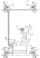
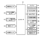
まず、図1及び図2を参照して、本発明の実施形態による車両の制御方法、車両システム及び車両の制御装置が適用された車両について説明する。図1は、本発明の実施形態による車両の全体構成を概略的に示すブロック図であり、図2は、本発明の実施形態による車両の電気的構成を示すブロック図である。
Hereinafter, a vehicle control method, a vehicle system, and a vehicle control device according to an embodiment of the present invention will be described with reference to the accompanying drawings.
<Vehicle configuration>
First, a vehicle to which a vehicle control method, a vehicle system, and a vehicle control device according to an embodiment of the present invention are applied will be described with reference to FIGS. 1 and 2. FIG. 1 is a block diagram schematically illustrating an overall configuration of a vehicle according to an embodiment of the present invention, and FIG. 2 is a block diagram illustrating an electrical configuration of the vehicle according to an embodiment of the present invention.
図1に示すように、車両1の車体前部には、左右の前輪2(駆動輪)を駆動する原動機として、エンジン4が搭載されている。この車両1は、所謂FF車として構成されている。車両1の各車輪は、弾性部材(典型的にはスプリング)やサスペンションアームなどを含むサスペンション30を介して、車体に懸架されている。
As shown in FIG. 1, an
エンジン4は、ガソリンエンジンやディーゼルエンジンなどの内燃エンジンであり、本実施形態では点火プラグ43(図2参照)を有するガソリンエンジンである。エンジン4は、変速機9を介して前輪2との間で力が伝達され、また、コントローラ14により制御される。エンジン4は、吸入空気量を調整するスロットルバルブ41と、燃料を噴射するインジェクタ42と、点火プラグ43と、吸排気弁の開閉時期を変化させる可変動弁機構44と、エンジン4の回転数を検出するエンジン回転数センサ46と、を有する(図2参照)。エンジン回転数センサ46は、その検出値をコントローラ14に出力する。
The
また、車両1は、ステアリングホイール6(以下では単に「ステアリング6」とも表記する。)やステアリングコラム7などを含む操舵装置5と、ステアリングコラム7の回転角度やステアリングラック(不図示)の位置などから操舵装置5における操舵角を検出する操舵角センサ8と、アクセルペダルの開度に相当するアクセルペダル踏込量を検出するアクセル開度センサ10と、ブレーキペダルの踏込量を検出するブレーキ踏込量センサ11と、車速を検出する車速センサ12と、加速度を検出する加速度センサ13と、を有する。アクセル開度センサ10や車速センサ12などは、車両1の運転状態を検出する運転状態センサに相当する。これらの各センサは、それぞれの検出値をコントローラ14に出力する。このコントローラ14は、例えばPCM(Power-train Control Module)などを含んで構成される。
The
更に、車両1は、各車輪に設けられたブレーキ装置(制動装置)16のブレーキキャリパにブレーキ液圧を供給するブレーキ制御システム18を備えている。ブレーキ制御システム18は、各車輪に設けられたブレーキ装置16において制動トルクを発生させるために必要なブレーキ液圧を生成する液圧ポンプ20と、各車輪のブレーキ装置16への液圧供給ラインに設けられた、液圧ポンプ20から各車輪のブレーキ装置16へ供給される液圧を制御するためのバルブユニット22(具体的にはソレノイド弁)と、液圧ポンプ20から各車輪のブレーキ装置16へ供給される液圧を検出する液圧センサ24と、を備えている。液圧センサ24は、例えば各バルブユニット22とその下流側の液圧供給ラインとの接続部に配置され、各バルブユニット22の下流側の液圧を検出し、検出値をコントローラ14に出力する。
Further, the
ブレーキ制御システム18は、コントローラ14から入力された制動トルク指令値や液圧センサ24の検出値に基づき、各車輪のホイールシリンダやブレーキキャリパのそれぞれに独立して供給する液圧を算出し、それらの液圧に応じて液圧ポンプ20の回転数やバルブユニット22の開度を制御する。
The
次に、図2に示すように、本実施形態によるコントローラ14は、上述したセンサ8、10、11、12、13の検出信号の他、車両1の運転状態を検出する各種センサが出力した検出信号に基づいて、エンジン4の各部(例えば、スロットルバルブ41、インジェクタ42、点火プラグ43、可変動弁機構44のほか、ターボ過給機やEGR装置等)や、ブレーキ制御システム18の液圧ポンプ20及びバルブユニット22などに対する制御を行うべく、制御信号を出力する。
Next, as shown in FIG. 2, the
コントローラ14(ブレーキ制御システム18も含めてよい)は、それぞれ、1つ以上のプロセッサ、当該プロセッサ上で解釈実行される各種のプログラム(OSなどの基本制御プログラムや、OS上で起動され特定機能を実現するアプリケーションプログラムを含む)、及びプログラムや各種のデータを記憶するためのROMやRAMの如き内部メモリを備えるコンピュータにより構成される。 The controller 14 (which may also include the brake control system 18) includes one or more processors, various programs interpreted and executed on the processors (basic control programs such as an OS, and specific functions activated on the OS. And a computer having an internal memory such as a ROM or a RAM for storing programs and various data.
コントローラ14は、本発明における「制御器」に相当する。また、エンジン4、操舵装置5、操舵角センサ8、アクセル開度センサ10、車速センサ12、ブレーキ装置16、及びコントローラ14を含むシステムは、本発明における「車両システム」に相当する。更に、コントローラ14は、本発明における「車両の制御装置」に相当し、「車両姿勢制御手段」及び「減速度変更手段」として機能する。
The
<車両姿勢制御>
次に、本発明の実施形態による車両姿勢制御について説明する。
<Vehicle attitude control>
Next, vehicle attitude control according to the embodiment of the present invention will be described.
(全体処理)
まず、図3を参照して、この車両姿勢制御の全体的な流れについて説明する。図3は、本発明の実施形態による車両姿勢制御処理のフローチャートである。
(Whole process)
First, the overall flow of the vehicle attitude control will be described with reference to FIG. FIG. 3 is a flowchart of the vehicle attitude control process according to the embodiment of the present invention.
図3の車両姿勢制御処理は、車両1のイグニッションがオンにされ、車両システムに電源が投入された場合に起動され、所定周期(例えば50ms)で繰り返し実行される。
3 is started when the ignition of the
車両姿勢制御処理が開始されると、図3に示すように、ステップS1において、コントローラ14は車両1の運転状態に関する各種センサ情報を取得する。具体的には、コントローラ14は、操舵角センサ8が検出した操舵角、アクセル開度センサ10が検出したアクセル開度、ブレーキ踏込量センサ11が検出したブレーキペダル踏込量、車速センサ12が検出した車速、加速度センサ13が検出した加速度、液圧センサ24が検出した液圧、エンジン回転数センサ46が検出したエンジン回転数、車両1の変速機9に現在設定されているギヤ段等を含む、上述した各種センサが出力した検出信号を運転状態に関する情報として取得する。
When the vehicle attitude control process is started, as shown in FIG. 3, in step S1, the
次に、ステップS2において、コントローラ14は、ステップS1において取得された車両1の運転状態に基づき、目標加速度(正の加速度だけでなく、負の加速度(減速度)も含むものとする。以下同様とする。)を設定する。具体的には、コントローラ14は、典型的にはアクセルペダルが操作されている場合には、正の目標加速度を設定する。この場合、コントローラ14は、種々の車速及び種々のギヤ段について規定された加速度特性マップ(予め作成されてメモリなどに記憶されている)の中から、現在の車速及びギヤ段に対応する加速度特性マップを選択し、選択した加速度特性マップを参照して現在のアクセル開度に対応する正の目標加速度を設定する。他方で、コントローラ14は、典型的にはブレーキペダルが操作されている場合には、負の目標加速度を設定する。例えば、コントローラ14は、ブレーキペダル踏込量に基づき負の目標加速度を設定する。
Next, in step S2, the
次に、ステップS3において、コントローラ14は、ステップS2において設定した目標加速度を実現するための基本トルクを決定する。この基本トルクは、車両1を駆動するためのエンジン4による駆動トルク(正のトルク)と、車両1を制動させるためのブレーキ装置16による制動トルク(負のトルク)と、を含む。コントローラ14は、ステップS2において正の目標加速度が設定された場合には、原則、エンジン4の駆動トルクを基本トルクとして設定する。この場合、コントローラ14は、現在の車速、ギヤ段、路面勾配、路面μなどに基づき、エンジン4が出力可能なトルクの範囲内で、基本トルクを決定する。これに対して、コントローラ14は、ステップS2において負の目標加速度(減速度)が設定された場合には、原則、ブレーキ装置16による制動トルクを基本トルクとして設定する。
Next, in step S3, the
また、ステップS2及びS3の処理と並行して、ステップS4において、コントローラ14は、ステアリング操作に基づき車両1に減速度を付加するためのトルク(減速トルク)を設定する減速トルク設定処理を実行する。このステップS4においては、コントローラ14は、操舵装置5の操舵角の増加に応じて、つまりステアリング6の切り込み操作に応じて、基本トルクを低減させるための減速トルクを設定する。本実施形態では、コントローラ14は、ステアリング6が切り込み操作されたときに、車両1に減速度を付加することにより車両姿勢を制御するようにする。以下では、このようなステアリング6の切り込み時に実施される車両姿勢制御を適宜「第1車両姿勢制御」と呼ぶ。なお、減速トルク設定処理については、詳細は後述する。
In parallel with the processing in steps S2 and S3, in step S4, the
次に、ステップS5において、コントローラ14は、ステアリング操作に基づき車両1に加速度を付加するためのトルク(加速トルク)を設定する加速トルク設定処理を実行する。このステップS5においては、コントローラ14は、操舵装置5の操舵角の減少に応じて、つまりステアリング6の切り戻しに応じて、基本トルクを増加させるための加速トルクを設定する。本実施形態では、コントローラ14は、ステアリング6が切り戻し操作されたときに、車両1に加速度を付加することにより、車両姿勢を制御するようにする。以下では、このようなステアリング6の切り戻し時において実施される車両姿勢制御を適宜「第2車両姿勢制御」と呼ぶ。典型的には、この第2車両姿勢制御は、上述した第1車両姿勢制御の後に実施される傾向にある。なお、加速トルク設定処理については、詳細は後述する。
Next, in step S5, the
ステップS2及びS3の処理並びにステップS4の減速トルク設定処理及びS5の加速トルク設定処理を実行した後、ステップS6において、コントローラ14は、ステップS3において設定した基本トルクと、ステップS4において設定した減速トルク及びステップS5において設定した加速トルクとに基づき、最終目標トルクを設定する。基本的には、コントローラ14は、基本トルクに対して加速トルクを加算するか、或いは基本トルクから減速トルクを減算することにより、最終目標トルクを算出する。
After executing the processing of steps S2 and S3, the deceleration torque setting processing of step S4, and the acceleration torque setting processing of S5, in step S6, the
次に、ステップS7において、コントローラ14は、ステップS6において設定した最終目標トルクを実現するためのアクチュエータ制御量を設定する。具体的には、コントローラ14は、ステップS6において設定した最終目標トルクに基づき、最終目標トルクを実現するために必要となる各種状態量を決定し、それらの状態量に基づき、エンジン4の各構成要素を駆動する各アクチュエータの制御量を設定する。この場合、コントローラ14は、状態量に応じた制限値や制限範囲を設定し、状態値が制限値や制限範囲による制限を遵守するような各アクチュエータの制御量を設定する。続いて、ステップS8において、コントローラ14は、ステップS7において設定した制御量に基づき各アクチュエータへ制御指令を出力する。
Next, in step S7, the
具体的には、ステップS8において、コントローラ14は、ステップS6において基本トルクから減速トルクを減算することにより最終目標トルクが設定された場合、つまり第1車両姿勢制御を実行する場合には、点火プラグ43の点火時期を、基本トルクを発生させるための点火時期よりも遅角させる(リタードする)。また、点火時期の遅角に代えて、あるいはそれと共に、コントローラ14は、スロットル開度を小さくしたり、下死点後に設定されている吸気弁の閉時期を遅角させたりすることによって、吸入空気量を減少させる。この場合、コントローラ14は、所定の空燃比が維持されるように、吸入空気量の増加に対応して、インジェクタ42による燃料噴射量を減少させる。
Specifically, in step S8, when the final target torque is set by subtracting the deceleration torque from the basic torque in step S6, that is, when executing the first vehicle attitude control, the
他方で、コントローラ14は、ステップS6において基本トルクに加速トルクを加算することにより最終目標トルクが設定された場合、つまり第2車両姿勢制御を実行する場合には、点火プラグ43の点火時期を、基本トルクを発生させるための点火時期よりも進角させる。また、点火時期の進角に代えて、あるいはそれと共に、コントローラ14は、スロットル開度を大きくしたり、下死点後に設定されている吸気弁の閉時期を進角させたりすることによって、吸入空気量を増加させる。この場合、コントローラ14は、所定の空燃比が維持されるように、吸入空気量の増加に対応して、インジェクタ42による燃料噴射量を増加させる。
On the other hand, when the final target torque is set by adding the acceleration torque to the basic torque in step S6, that is, when executing the second vehicle attitude control, the
以上のステップS8の後、コントローラ14は、車両姿勢制御処理を終了する。
After the above step S8, the
(減速トルク設定処理)
次に、図4及び図5を参照して、本発明の実施形態による減速トルク設定処理について説明する。図4は、本発明の実施形態による減速トルク設定処理のフローチャートであり、図5は、本発明の実施形態による付加減速度と操舵速度との関係を示したマップである。
(Deceleration torque setting processing)
Next, a deceleration torque setting process according to the embodiment of the present invention will be described with reference to FIGS. FIG. 4 is a flowchart of the deceleration torque setting process according to the embodiment of the present invention, and FIG. 5 is a map showing the relationship between the additional deceleration and the steering speed according to the embodiment of the present invention.
減速トルク設定処理が開始されると、ステップS11において、コントローラ14は、操舵装置5の操舵角(絶対値)が増加しているか否か(即ちステアリング6の切り込み操作中であるか否か)を判定する。その結果、操舵角が増加している場合(ステップS11:Yes)、ステップS12に進み、コントローラ14は、操舵速度が所定の閾値S1以上か否かを判定する。即ち、コントローラ14は、図3のステップS1において操舵角センサ8から取得した操舵角に基づき操舵速度を算出し、その値が閾値S1以上か否かを判定する。
When the deceleration torque setting process is started, in step S11, the
その結果、操舵速度が閾値S1以上である場合(ステップS12:Yes)、ステップS13に進み、コントローラ14は、操舵速度に基づき付加減速度を設定する。この付加減速度は、ドライバの意図に沿って車両姿勢を制御するために、ステアリング操作に応じて車両1に付加すべき減速度である。
As a result, when the steering speed is the threshold value S 1 or more (step S12: Yes), the process proceeds to step S13, the
具体的には、コントローラ14は、図5のマップに示す付加減速度と操舵速度との関係に基づき、ステップS12において算出した操舵速度に対応する付加減速度を設定する。図5における横軸は操舵速度を示し、縦軸は付加減速度を示す。図5に示すように、操舵速度が閾値S1以下である場合、対応する付加減速度は0である。即ち、操舵速度が閾値S1以下である場合、コントローラ14は、ステアリング操作に基づき車両1に減速度を付加するための制御を実行しない。
Specifically, the
一方、操舵速度が閾値S1を超えている場合には、操舵速度が増大するに従って、この操舵速度に対応する付加減速度は、所定の上限値Dmaxに漸近する。即ち、操舵速度が増大するほど付加減速度は増大し、且つ、その増大量の増加割合は小さくなる。この上限値Dmaxは、ステアリング操作に応じて車両1に減速度を付加しても、制御介入があったとドライバが感じない程度の減速度に設定される(例えば0.5m/s2≒0.05G)。さらに、操舵速度が閾値S1よりも大きい閾値S2以上の場合には、付加減速度は上限値Dmaxに維持される。
On the other hand, if the steering speed exceeds the threshold value S 1 in accordance with the steering speed increases, additional deceleration corresponding to the steering speed is asymptotic to a predetermined upper limit value D max. That is, the additional deceleration increases as the steering speed increases, and the rate of increase in the increase decreases. This upper limit value Dmax is set to a deceleration that does not cause the driver to feel that control intervention has been performed even if deceleration is added to the
次に、ステップS14において、コントローラ14は、ステアリング6の車幅方向取り付け位置(つまり車両1が右ハンドル車であるか又は左ハンドル車であるか)、及び、操舵角増大時のステアリング6の操作方向(つまり車両1が右旋回するか又は左旋回するか)に応じて、ステップS13で設定した付加減速度を変更する。ここで、図6及び図7を参照して、このように付加減速度を変更する理由について説明する。
Next, in step S14, the
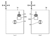
図6は、右ハンドル車及び左ハンドル車の概略平面図である。図6(a)において、符号1aを付した車両は、ステアリング6及び運転席DSが車幅方向中心(重心位置Gに対応する)よりも右側に取り付けられた右ハンドル車である。一方、図6(b)において、符号1bを付した車両は、ステアリング6及び運転席DSが車幅方向中心(重心位置Gに対応する)よりも左側に取り付けられた左ハンドル車である。
FIG. 6 is a schematic plan view of a right-hand drive vehicle and a left-hand drive vehicle. In FIG. 6A, a vehicle denoted by
図7は、ステアリング6の切り込み時に運転席DSにおいて発生する前後加速度の一例を示している。図7(a)は、左旋回方向へのステアリング切り込み時において、左ハンドル車の運転席DSにおいて発生する前後加速度(実線)と、右ハンドル車の運転席DSにおいて発生する前後加速度(破線)と、を示している。図7(b)は、右旋回方向へのステアリング切り込み時において、左ハンドル車の運転席DSにおいて発生する前後加速度(実線)と、右ハンドル車の運転席DSにおいて発生する前後加速度(破線)と、を示している。
FIG. 7 shows an example of the longitudinal acceleration generated in the driver seat DS when the
図7(a)及び(b)に示すように、車両1が右ハンドル車であるか又は左ハンドル車であるかに応じて、また、車両1が右旋回するか又は左旋回するかに応じて、運転席DSにおいて発生する前後加速度が変わる。具体的には、図7(a)に示すように、車両1が左旋回を行うときには、右ハンドル車では左ハンドル車よりも旋回時に運転席DSにおいて発生する前後加速度が大きくなる。具体的には、右ハンドル車では加速度が発生するのに対して、左ハンドル車では減速度が発生する。これに対して、図7(b)に示すように、車両1が右旋回を行うときには、左ハンドル車では右ハンドル車よりも旋回時に運転席DSにおいて発生する前後加速度が大きくなる。具体的には、左ハンドル車では加速度が発生するのに対して、右ハンドル車では減速度が発生する。
As shown in FIGS. 7A and 7B, depending on whether the
このようなことから、ステアリング6の切り込み時に減速度を付加する車両姿勢制御(第1車両姿勢制御)を実行したときに、車両1が右ハンドル車であるか又は左ハンドル車であるかに応じて、また、車両1が右旋回するか又は左旋回するかに応じて、この第1車両姿勢制御により運転席DSにおいて発生する前後加速度の立ち上がりに差が生じてしまう。具体的には、車両1が左旋回を行うときには、右ハンドル車では左ハンドル車よりも運転席DSでの前後加速度が大きくなるので(図7(a)参照)、この前後加速度に対して第1車両姿勢制御による付加減速度を適用すると、当該制御による運転席DSでの前後加速度の立ち上がりが右ハンドル車では左ハンドル車よりも遅れる傾向にある。他方で、車両1が右旋回を行うときには、左ハンドル車では右ハンドル車よりも運転席DSでの前後加速度が大きくなるので(図7(b)参照)、この前後加速度に対して第1車両姿勢制御による付加減速度を適用すると、当該制御による運転席DSでの前後加速度の立ち上がりが左ハンドル車では右ハンドル車よりも遅れる傾向にある。
Therefore, when the vehicle attitude control (first vehicle attitude control) for adding the deceleration at the time of turning of the
本実施形態では、このような第1車両姿勢制御により運転席DSにおいて発生する前後加速度の立ち上がりの遅れを抑制すべく、ステアリング6の車幅方向取り付け位置及び操舵角増大時のステアリング6の操作方向に応じて、操舵速度に基づき設定された付加減速度(図4のステップS13及び図5)を変更する。すなわち、ステアリング6の取り付け位置及び操作方向によらずに、第1車両姿勢制御により運転席DSにおいて発生する前後加速度が同様に立ち上がるように、操舵速度に基づき設定された付加減速度を変更する。
In the present embodiment, in order to suppress the delay of the rise of the longitudinal acceleration generated in the driver's seat DS by the first vehicle attitude control, the mounting position of the
具体的には、コントローラ14は、車両1が左旋回を行うときには、右ハンドル車では左ハンドル車よりも付加減速度(絶対値)を大きくする。例えば、コントローラ14は、右ハンドル車については、操舵速度に基づき設定された付加減速度に対して1よりも大きな所定のゲインを乗算した値を新たな付加減速度として用い、左ハンドル車については、操舵速度に基づき設定された付加減速度に対して1未満の所定のゲインを乗算した値を新たな付加減速度として用いる。他方で、コントローラ14は、車両1が右旋回を行うときには、左ハンドル車では右ハンドル車よりも付加減速度(絶対値)を大きくする。例えば、コントローラ14は、左ハンドル車については、操舵速度に基づき設定された付加減速度に対して1よりも大きな所定のゲインを乗算した値を新たな付加減速度として用い、右ハンドル車については、操舵速度に基づき設定された付加減速度に対して1未満の所定のゲイン(固定値)を乗算した値を新たな付加減速度として用いる。
Specifically, when the
これらのゲインは、事前に定められて、車両1内のメモリに記憶されている。具体的には、ステアリング6の車幅方向取り付け位置及びステアリング6の操作方向によらずに、第1車両姿勢制御により運転席DSにおいて発生する前後加速度が一定になるようにする観点から、事前の実験やシミュレーションなどからゲインが定められる。1つの例では、ゲインには固定値が適用される。
These gains are determined in advance and stored in a memory in the
なお、ステアリング6の車幅方向取り付け位置に関する情報、つまり車両1が右ハンドル車であるか又は左ハンドル車であるかを示す情報は、車両1内のメモリに事前に(例えば製造時に)記憶されており、コントローラ14は、そのようにメモリに記憶された情報に基づき付加減速度を変更する。ステアリング6の取り付け位置は固定であるので(換言すると車両1が右ハンドル車と左ハンドル車との間で変化することはないので)、コントローラ14は、結局のところ、実際の制御においては、ステアリング6の取り付け位置に応じて付加減速度を適宜変更する処理を行うことはなく、ステアリング6の操作方向のみに応じて付加減速度を変更することになる。
The information on the mounting position of the
図4に戻ると、コントローラ14は、上記のステップS14の後、ステップS15に進む。ステップS15において、コントローラ14は、ステップS14で変更した付加減速度に基づき、減速トルクを設定する。具体的には、コントローラ14は、基本トルクの低減により付加減速度を実現するために必要となる減速トルクを、図3のステップS1において取得された現在の車速、ギヤ段、路面勾配等に基づき決定する。ステップS15の後、コントローラ14は減速トルク設定処理を終了し、メインルーチンに戻る。
Returning to FIG. 4, the
また、ステップS11において操舵角が増加していない場合(ステップS11:No)、又は、ステップS12において操舵速度が閾値S1未満である場合(ステップS12:No)、コントローラ14は、減速トルクの設定を行うことなく減速トルク設定処理を終了し、図3のメインルーチンに戻る。この場合、減速トルクは0となる。
Also, when the steering angle is not increased in step S11 (step S11: No), or when the steering speed in step S12 is less than the threshold value S 1 (Step S12: No), the
(加速トルク設定処理)
次に、図8及び図9を参照して、本発明の実施形態による加速トルク設定処理について説明する。図8は、本発明の実施形態による加速トルク設定処理のフローチャートであり、図9は、本発明の実施形態による付加加速度と操舵速度との関係を示したマップである。
(Acceleration torque setting processing)
Next, an acceleration torque setting process according to the embodiment of the present invention will be described with reference to FIGS. FIG. 8 is a flowchart of the acceleration torque setting process according to the embodiment of the present invention, and FIG. 9 is a map showing the relationship between the additional acceleration and the steering speed according to the embodiment of the present invention.
加速トルク設定処理が開始されると、ステップS21において、コントローラ14は、操舵装置5の操舵角(絶対値)が減少しているか否か(即ちステアリング6の切り戻し操作中であるか否か)を判定する。その結果、操舵角が減少中である場合(ステップS21:Yes)、ステップS22に進み、コントローラ14は、操舵速度が所定の閾値S1以上か否かを判定する。即ち、コントローラ14は、図3のステップS1において操舵角センサ8から取得した操舵角に基づき操舵速度を算出し、その値が閾値S1以上か否かを判定する。
When the acceleration torque setting process is started, in step S21, the
その結果、操舵速度が閾値S1以上である場合(ステップS22:Yes)、ステップS23に進み、コントローラ14は、操舵速度に基づき付加加速度を設定する。この付加加速度は、ドライバの意図に沿って車両姿勢を制御するために、ステアリング操作に応じて車両1に付加すべき加速度である。
As a result, when the steering speed is the threshold value S 1 or more (step S22: Yes), the process proceeds to step S23, the
具体的には、コントローラ14は、図9のマップに示す付加加速度と操舵速度との関係に基づき、ステップS22において算出した操舵速度に対応する付加加速度を設定する。図9における横軸は操舵速度を示し、縦軸は付加加速度を示す。図9に示すように、操舵速度が閾値S1以下である場合、対応する付加加速度は0である。即ち、操舵速度が閾値S1以下である場合、コントローラ14は、ステアリング操作に基づき車両1に加速度を付加するための制御を実行しない。
Specifically, the
一方、操舵速度が閾値S1を超えている場合には、操舵速度が増大するに従って、この操舵速度に対応する付加加速度は、所定の上限値Amaxに漸近する。即ち、操舵速度が増大するほど付加加速度は増大し、且つ、その増大量の増加割合は小さくなる。この上限値Amaxは、ステアリング操作に応じて車両1に加速度を付加しても、制御介入があったとドライバが感じない程度の加速度に設定される(例えば0.5m/s2≒0.05G)。さらに、操舵速度が閾値S1よりも大きい閾値S2以上の場合には、付加加速度は上限値Amaxに維持される。
On the other hand, if the steering speed exceeds the threshold value S 1 in accordance with the steering speed increases, the additional acceleration corresponding to the steering speed is asymptotic to a predetermined upper limit value A max. That is, the additional acceleration increases as the steering speed increases, and the rate of increase of the additional amount decreases. The upper limit value Amax is set to an acceleration level at which the driver does not feel that control intervention has occurred even if acceleration is added to the
次に、ステップS24において、コントローラ14は、ステアリング6の車幅方向取り付け位置(つまり車両1が右ハンドル車であるか又は左ハンドル車であるか)、及び、操舵角減少時のステアリング6の操作方向(つまり車両1が右旋回するか又は左旋回するか)に応じて、ステップS23で設定した付加加速度を変更する。ここで、図10を参照して、このように付加加速度を変更する理由について説明する。
Next, in step S24, the
図10は、ステアリング6の切り戻し時に運転席DSにおいて発生する前後加速度の一例を示している。図10(a)は、左旋回方向へのステアリング切り戻し時において、左ハンドル車の運転席DSにおいて発生する前後加速度(実線)と、右ハンドル車の運転席DSにおいて発生する前後加速度(破線)と、を示している。図10(b)は、右旋回方向へのステアリング切り戻し時において、左ハンドル車の運転席DSにおいて発生する前後加速度(実線)と、右ハンドル車の運転席DSにおいて発生する前後加速度(破線)と、を示している。
FIG. 10 shows an example of longitudinal acceleration generated in the driver's seat DS when the
図10(a)及び(b)に示すように、車両1が右ハンドル車であるか又は左ハンドル車であるかに応じて、また、車両1が右旋回するか又は左旋回するかに応じて、運転席DSにおいて発生する前後加速度が変わる。具体的には、図10(a)に示すように、左旋回方向へのステアリング切り戻し時には、左ハンドル車では右ハンドル車よりも旋回時に運転席DSにおいて発生する前後加速度が小さくなる。具体的には、左ハンドル車では減速度が発生するのに対して、右ハンドル車では加速度が発生する。これに対して、図10(b)に示すように、右旋回方向へのステアリング切り戻し時には、右ハンドル車では左ハンドル車よりも旋回時に運転席DSにおいて発生する前後加速度が小さくなる。具体的には、右ハンドル車では減速度が発生するのに対して、左ハンドル車では加速度が発生する。
As shown in FIGS. 10A and 10B, depending on whether the
このようなことから、ステアリング6の切り戻し時に加速度を付加する車両姿勢制御(第2車両姿勢制御)を実行したときに、車両1が右ハンドル車であるか又は左ハンドル車であるかに応じて、また、車両1が右旋回するか又は左旋回するかに応じて、この第2車両姿勢制御により運転席DSにおいて発生する前後加速度の立ち上がりに差が生じてしまう。具体的には、ステアリング6が左旋回方向に切り戻された場合には(つまり車両1が左旋回を行う場合)、左ハンドル車では右ハンドル車よりも運転席DSでの前後加速度が小さくなるので(図10(a)参照)、この前後加速度に対して第2車両姿勢制御による付加加速度を適用すると、当該制御による運転席DSでの前後加速度の立ち上がりが左ハンドル車では右ハンドル車よりも遅れる傾向にある。他方で、ステアリング6が右旋回方向に切り戻された場合には(つまり車両1が右旋回を行う場合)、右ハンドル車では左ハンドル車よりも運転席DSでの前後加速度が小さくなるので(図10(b)参照)、この前後加速度に対して第2車両姿勢制御による付加加速度を適用すると、当該制御による運転席DSでの前後加速度の立ち上がりが右ハンドル車では左ハンドル車よりも遅れる傾向にある。
Accordingly, when the vehicle attitude control (second vehicle attitude control) for adding acceleration when the
本実施形態では、このような第2車両姿勢制御により運転席DSにおいて発生する前後加速度の立ち上がりの遅れを抑制すべく、ステアリング6の車幅方向取り付け位置及び操舵角減少時のステアリング6の操作方向に応じて、操舵速度に基づき設定された付加加速度(図8のステップS23及び図9)を変更する。すなわち、ステアリング6の取り付け位置及び操作方向によらずに、第2車両姿勢制御により運転席DSにおいて発生する前後加速度が同様に立ち上がるように、操舵速度に基づき設定された付加加速度を変更する。
In the present embodiment, in order to suppress a delay in the rise of the longitudinal acceleration generated in the driver's seat DS by the second vehicle attitude control, the mounting position of the
具体的には、コントローラ14は、ステアリング6が左旋回方向に切り戻されたときには(つまり車両1が左旋回を行うとき)、左ハンドル車では右ハンドル車よりも付加加速度を大きくする。例えば、コントローラ14は、左ハンドル車については、操舵速度に基づき設定された付加加速度に対して1よりも大きな所定のゲインを乗算した値を新たな付加加速度として用い、右ハンドル車については、操舵速度に基づき設定された付加加速度に対して1未満の所定のゲインを乗算した値を新たな付加加速度として用いる。他方で、コントローラ14は、ステアリング6が右旋回方向に切り戻されたときには(つまり車両1が右旋回を行うとき)、右ハンドル車では左ハンドル車よりも付加加速度を大きくする。例えば、コントローラ14は、右ハンドル車については、操舵速度に基づき設定された付加加速度に対して1よりも大きな所定のゲインを乗算した値を新たな付加加速度として用い、左ハンドル車については、操舵速度に基づき設定された付加加速度に対して1未満の所定のゲイン(固定値)を乗算した値を新たな付加加速度として用いる。
Specifically, when the
これらのゲインは、事前に定められて、車両1内のメモリに記憶されている。具体的には、ステアリング6の車幅方向取り付け位置及びステアリング6の操作方向によらずに、第2車両姿勢制御により運転席DSにおいて発生する前後加速度が一定になるようにする観点から、事前の実験やシミュレーションなどからゲインが定められる。1つの例では、ゲインには固定値が適用される。
These gains are determined in advance and stored in a memory in the
なお、ステアリング6の車幅方向取り付け位置に関する情報、つまり車両1が右ハンドル車であるか又は左ハンドル車であるかを示す情報は、車両1内のメモリに事前に(例えば製造時に)記憶されており、コントローラ14は、そのようにメモリに記憶された情報に基づき付加加速度を変更する。ステアリング6の取り付け位置は固定であるので(換言すると車両1が右ハンドル車と左ハンドル車との間で変化することはないので)、コントローラ14は、結局のところ、実際の制御においては、ステアリング6の取り付け位置に応じて付加加速度を適宜変更する処理を行うことはなく、ステアリング6の操作方向のみに応じて付加加速度を変更することになる。
The information on the mounting position of the
図8に戻ると、コントローラ14は、上記のステップS24の後、ステップS25に進む。ステップS25において、コントローラ14は、ステップS24で変更した付加加速度に基づき、加速トルクを設定する。具体的には、コントローラ14は、基本トルクの増加により付加加速度を実現するために必要となる加速トルクを、ステップS1において取得された現在の車速、ギヤ段、路面勾配等に基づき決定する。ステップS24の後、コントローラ14は加速トルク設定処理を終了し、図3のメインルーチンに戻る。
Returning to FIG. 8, after the above-described step S24, the
また、ステップS21において操舵角が減少していない場合(ステップS21:No)、又は、ステップS22において操舵速度が閾値S1未満である場合(ステップS22:No)、コントローラ14は、加速トルクの設定を行うことなく加速トルク設定処理を終了し、図3のメインルーチンに戻る。この場合、加速トルクは0となる。
Also, when the steering angle is not decreased in the step S21 (step S21: No), or when the steering speed is less than the threshold value S 1 in step S22 (step S22: No), the
<作用及び効果>
次に、上述した本発明の実施形態による作用及び効果について説明する。
<Action and effect>
Next, the operation and effect of the above-described embodiment of the present invention will be described.
(本実施形態による第1車両姿勢制御の作用)
まず、本発明の実施形態による第1車両姿勢制御の作用について説明する。ここでは、本実施形態に対する比較例を挙げて、本実施形態の作用について具体的に説明する。上述したように、本実施形態では、ステアリング6の車幅方向取り付け位置及びステアリング6の操作方向に応じて、第1車両姿勢制御による減速トルクを変更していた、換言すると付加減速度を変更していた(図4のステップS14参照)。これに対して、比較例では、ステアリング6の取り付け位置及び操作方向に応じて、第1車両姿勢制御による付加減速度及び減速トルクを変更しない。
(Operation of First Vehicle Posture Control According to the Present Embodiment)
First, the operation of the first vehicle attitude control according to the embodiment of the present invention will be described. Here, the operation of the present embodiment will be specifically described with reference to a comparative example of the present embodiment. As described above, in the present embodiment, the deceleration torque by the first vehicle attitude control is changed according to the mounting position of the
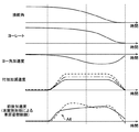
図11は、比較例による第1車両姿勢制御を行った場合の結果を説明するためのタイムチャートである。図11は、上から順に、操舵角、ヨーレート、ヨー角加速度、第1車両姿勢制御を行わなかった場合の運転席DSでの前後加速度、及び、比較例による第1車両姿勢制御を行った場合の運転席DSでの前後加速度を示している。図11において、実線は左ハンドル車の結果を示し、破線は右ハンドル車の結果を示している。 FIG. 11 is a time chart for explaining a result when the first vehicle attitude control according to the comparative example is performed. FIG. 11 shows, in order from the top, the steering angle, the yaw rate, the yaw angular acceleration, the longitudinal acceleration in the driver's seat DS when the first vehicle attitude control is not performed, and the case where the first vehicle attitude control according to the comparative example is performed. In the driver's seat DS. In FIG. 11, the solid line indicates the result of the left-hand drive vehicle, and the broken line indicates the result of the right-hand drive vehicle.
ここでは、ステアリング6が左旋回方向に切り込まれる場合について例示する。ステアリング6が左旋回方向に切り込まれると、図11に示すように、操舵角、ヨーレート及びヨー角加速度が変化して、車両1が左旋回することとなる。このように車両1が左旋回する場合、図11に示すように、右ハンドル車(破線参照)では、左ハンドル車(実線参照)よりも、運転席DSでの前後加速度が大きくなる。具体的には、右ハンドル車では加速度が発生するのに対して、左ハンドル車では減速度が発生する(図7(a)と同様である)。旋回時に車両1内で発生する前後加速度は、車両1内での位置(詳しくは重心位置Gからの距離)及びヨー角加速度の大きさに応じて決まる。特に、旋回時に運転席DSで発生する前後加速度は、「重心位置Gから運転席DSまでの左右距離×ヨー角加速度」により得られる。重心位置Gから運転席DSまでの左右距離は、右ハンドル車では正値と定義され、左ハンドル車では負値と定義される。また、左旋回時においては、ヨー角加速度は正値となる。これらのことから、左旋回方向へのステアリング切り込み時には、右ハンドル車では正の前後加速度が発生するのに対して、左ハンドル車では負の前後加速度(減速度)が発生するのである。
Here, a case where the
比較例では、図11の一点鎖線で示すような付加減速度を第1車両姿勢制御において適用する。より具体的には、比較例では、右ハンドル車と左ハンドル車とで付加減速度を変更しない。つまり、右ハンドル車及び左ハンドル車の両方とも、同一の付加減速度を適用する。その結果、比較例による第1車両姿勢制御によれば、図11中の矢印A1に示すように、運転席DSでの前後加速度の立ち上がりが右ハンドル車(破線参照)では左ハンドル車(実線参照)よりも遅れる。すなわち、上述したように、左旋回時には右ハンドル車では左ハンドル車よりも運転席DSでの前後加速度が大きくなるので、この前後加速度に対して第1車両姿勢制御により右及び左ハンドル車で同一の付加減速度を適用すると、当該制御による運転席DSでの前後加速度の立ち上がりが右ハンドル車では左ハンドル車よりも遅れるのである。なお、図11中の矢印A1に示すような前後加速度の変化は、厳密に言うと「立ち下り」となるが、前後加速度が負の方向に立ち上がっているとも言えるので、本明細書では、そのような前後加速度の変化を「立ち上がり」と表現している。 In the comparative example, the additional deceleration as shown by the one-dot chain line in FIG. 11 is applied in the first vehicle attitude control. More specifically, in the comparative example, the additional deceleration is not changed between the right-hand drive vehicle and the left-hand drive vehicle. That is, the same additional deceleration is applied to both the right-hand drive vehicle and the left-hand drive vehicle. As a result, according to the first vehicle attitude control according to the comparative example, as shown by the arrow A1 in FIG. 11, the rise of the longitudinal acceleration in the driver's seat DS increases with the right-hand drive vehicle (see the broken line) and the left-hand drive vehicle (see the solid line). ) Later. That is, as described above, when turning left, the right-hand drive vehicle has a larger longitudinal acceleration in the driver's seat DS than the left-hand drive vehicle. When the additional deceleration is applied, the rise of the longitudinal acceleration in the driver's seat DS by the control is delayed in the right-hand drive vehicle compared to the left-hand drive vehicle. Note that the change in the longitudinal acceleration as indicated by the arrow A1 in FIG. 11 is strictly speaking “fall”, but since the longitudinal acceleration can be said to rise in the negative direction, in this specification, Such a change in the longitudinal acceleration is expressed as “rise”.
次に、図12は、比較例による第1車両姿勢制御を行った場合の横加速度(横軸)と前後加速度(縦軸)との関係についての説明図である。図12は、図11の矢印A1で示す部分を拡大した図に相当する。したがって、実線、破線及び一点鎖線が意味するものは図11と同じである。この図12にも示されるように、左旋回時に右ハンドル車の運転席DSにおいて発生する前後加速度(破線参照)は、左旋回時に左ハンドル車の運転席DSにおいて発生する前後加速度(実線参照)よりも立ち上がりが遅れる。具体的には、横加速度との関係において前後加速度の立ち上がりが遅れる。このような立ち上がりの遅れにより、第1車両姿勢制御により発生する前後加速度と横加速度との連動(バランス)が崩れてしまう。その結果、比較例によれば、第1車両姿勢制御によるドライバの疲労軽減効果が適切に確保されなくなる。 Next, FIG. 12 is an explanatory diagram illustrating the relationship between the lateral acceleration (horizontal axis) and the longitudinal acceleration (vertical axis) when the first vehicle attitude control according to the comparative example is performed. FIG. 12 is an enlarged view of a portion indicated by an arrow A1 in FIG. Therefore, the meanings of the solid line, the broken line, and the dashed line are the same as those in FIG. As shown in FIG. 12, the longitudinal acceleration (see the broken line) generated in the driver seat DS of the right-hand drive vehicle when turning left is the longitudinal acceleration (see the solid line) generated in the driver seat DS of the left-hand drive vehicle when turning left. The rise is later than that. Specifically, the rise of the longitudinal acceleration is delayed in relation to the lateral acceleration. Due to such a delay in the rise, the interlocking (balance) between the longitudinal acceleration and the lateral acceleration generated by the first vehicle attitude control is broken. As a result, according to the comparative example, the effect of reducing the driver's fatigue by the first vehicle attitude control is not properly secured.
次に、図13は、本発明の実施形態による第1車両姿勢制御を行った場合の結果を説明するためのタイムチャートである。図13は、上から順に、操舵角、ヨーレート、ヨー角加速度、本実施形態による第1車両姿勢制御により適用される付加減速度、及び、本実施形態による第1車両姿勢制御を行った場合の運転席DSでの前後加速度を示している。図13において、実線は左ハンドル車の結果を示し、破線は右ハンドル車の結果を示している。 Next, FIG. 13 is a time chart for explaining a result when the first vehicle attitude control according to the embodiment of the present invention is performed. FIG. 13 shows, in order from the top, a steering angle, a yaw rate, a yaw angular acceleration, an additional deceleration applied by the first vehicle attitude control according to the present embodiment, and a case where the first vehicle attitude control according to the present embodiment is performed. The longitudinal acceleration at the driver's seat DS is shown. In FIG. 13, the solid line indicates the result for a left-hand drive vehicle, and the dashed line indicates the result for a right-hand drive vehicle.
ここでは、ステアリング6が左旋回方向に切り込まれる場合について例示する。ステアリング6が左旋回方向に切り込まれると、図13に示すように、操舵角、ヨーレート及びヨー角加速度が変化して、車両1が左旋回することとなる。本実施形態では、このように車両1が左旋回するときに第1車両姿勢制御を行う場合、図13に示すように、右ハンドル車に適用する付加減速度(絶対値)を、左ハンドル車に適用する付加減速度(絶対値)よりも大きくする。具体的には、コントローラ14は、右ハンドル車については、操舵速度に基づき設定された付加減速度(一点鎖線参照)に対して1よりも大きな所定のゲインを乗算した値を新たな付加減速度(破線参照)として用い、左ハンドル車については、操舵速度に基づき設定された付加減速度(一点鎖線参照)に対して1未満の所定のゲインを乗算した値を新たな付加減速度(実線参照)として用いる。
Here, a case where the
このような本実施形態によれば、右ハンドル車では左ハンドル車よりも大きな付加減速度(絶対値)を適用することで、図13中の矢印A2に示すように、第1車両姿勢制御による運転席DSでの前後加速度の立ち上がりが右ハンドル車と左ハンドル車とでほぼ同じになる。すなわち、本実施形態によれば、比較例で述べたような前後加速度の立ち上がりの遅れ(図11参照)を適切に解消することができる。これにより、第1車両姿勢制御により発生する前後加速度と横加速度との連動(バランス)を確保することができる。よって、本実施形態によれば、第1車両姿勢制御によるドライバの疲労軽減効果を適切に確保することができる。 According to this embodiment, by applying an additional deceleration (absolute value) larger in a right-hand drive vehicle than in a left-hand drive vehicle, as shown by an arrow A2 in FIG. The rise of the longitudinal acceleration in the driver's seat DS is substantially the same for right-hand drive vehicles and left-hand drive vehicles. That is, according to the present embodiment, the delay in the rise of the longitudinal acceleration (see FIG. 11) as described in the comparative example can be appropriately eliminated. Thereby, the interlock (balance) between the longitudinal acceleration and the lateral acceleration generated by the first vehicle attitude control can be secured. Therefore, according to the present embodiment, the effect of reducing the driver's fatigue by the first vehicle attitude control can be appropriately secured.
なお、図11〜図13では、ステアリング6が左旋回方向に切り込まれたときに第1車両姿勢制御を行う場合について例示したが、ステアリング6が右旋回方向に切り込まれたときに第1車両姿勢制御を行う場合にも同様の結果が得られる。
Although FIGS. 11 to 13 illustrate the case where the first vehicle attitude control is performed when the
(本実施形態による第2車両姿勢制御の作用)
次に、本発明の実施形態による第2車両姿勢制御の作用について説明する。ここでは、本実施形態に対する比較例を挙げて、本実施形態の作用について具体的に説明する。上述したように、本実施形態では、ステアリング6の車幅方向取り付け位置及びステアリング6の操作方向に応じて、第2車両姿勢制御による加速トルクを変更していた、換言すると付加加速度を変更していた(図8のステップS24参照)。これに対して、比較例では、ステアリング6の取り付け位置及び操作方向に応じて、第2車両姿勢制御による付加加速度及び加速トルクを変更しない。
(Operation of the second vehicle attitude control according to the present embodiment)
Next, the operation of the second vehicle attitude control according to the embodiment of the present invention will be described. Here, the operation of the present embodiment will be specifically described with reference to a comparative example of the present embodiment. As described above, in the present embodiment, the acceleration torque by the second vehicle attitude control is changed according to the mounting position of the
図14は、比較例による第2車両姿勢制御を行った場合の結果を説明するためのタイムチャートである。図14は、上から順に、操舵角、ヨーレート、ヨー角加速度、第2車両姿勢制御を行わなかった場合の運転席DSでの前後加速度、及び、比較例による第2車両姿勢制御を行った場合の運転席DSでの前後加速度を示している。図14において、実線は左ハンドル車の結果を示し、破線は右ハンドル車の結果を示している。 FIG. 14 is a time chart for explaining the result when the second vehicle attitude control according to the comparative example is performed. FIG. 14 shows, in order from the top, the steering angle, the yaw rate, the yaw angular acceleration, the longitudinal acceleration in the driver's seat DS when the second vehicle attitude control is not performed, and the case where the second vehicle attitude control according to the comparative example is performed. In the driver's seat DS. In FIG. 14, the solid line indicates the result of the left-hand drive vehicle, and the broken line indicates the result of the right-hand drive vehicle.
ここでは、左旋回方向に切り込まれたステアリング6が右旋回方向に切り戻される場合について例示する。ステアリング6が右旋回方向に切り戻されると、図14に示すように、操舵角、ヨーレート及びヨー角加速度が変化して、車両1が右旋回することとなる。このように車両1が右旋回する場合、図14に示すように、右ハンドル車(破線参照)では、左ハンドル車(実線参照)よりも、運転席DSでの前後加速度が小さくなる。具体的には、右ハンドル車では減速度が発生するのに対して、左ハンドル車では加速度が発生する(図10(b)と同様である)。上述したように、旋回時において運転席DSで発生する前後加速度は、「重心位置Gから運転席DSまでの左右距離×ヨー角加速度」により得られる。この重心位置Gから運転席DSまでの左右距離は、右ハンドル車では正値と定義され、左ハンドル車では負値と定義される。また、右旋回時においては、ヨー角加速度は負値となる。これらのことから、右旋回方向へのステアリング切り戻し時には、右ハンドル車では負の前後加速度(減速度)が発生するのに対して、左ハンドル車では正の前後加速度が発生するのである。
Here, a case where the
比較例では、図14の一点鎖線で示すような付加加速度を第2車両姿勢制御において適用する。より具体的には、比較例では、右ハンドル車と左ハンドル車とで付加加速度を変更しない。つまり、右ハンドル車及び左ハンドル車の両方とも、同一の付加加速度を適用する。その結果、比較例による第2車両姿勢制御によれば、図14中の矢印A3に示すように、運転席DSでの前後加速度の立ち上がりが右ハンドル車(破線参照)では左ハンドル車(実線参照)よりも遅れる。すなわち、上述したように、右旋回時には右ハンドル車では左ハンドル車よりも運転席DSでの前後加速度が小さくなるので、この前後加速度に対して第2車両姿勢制御により右及び左ハンドル車で同一の付加加速度を適用すると、当該制御による運転席DSでの前後加速度の立ち上がりが右ハンドル車では左ハンドル車よりも遅れるのである。 In the comparative example, an additional acceleration as shown by a dashed line in FIG. 14 is applied in the second vehicle attitude control. More specifically, in the comparative example, the additional acceleration is not changed between the right-hand drive vehicle and the left-hand drive vehicle. That is, the same additional acceleration is applied to both the right-hand drive vehicle and the left-hand drive vehicle. As a result, according to the second vehicle attitude control according to the comparative example, as shown by an arrow A3 in FIG. 14, the rise of the longitudinal acceleration in the driver's seat DS is a left-hand drive vehicle (see the broken line) and a left-hand drive vehicle (see the solid line). ) Later. That is, as described above, when turning right, the right-hand drive vehicle has a smaller longitudinal acceleration in the driver seat DS than the left-hand drive vehicle. When the same additional acceleration is applied, the rise of the longitudinal acceleration in the driver's seat DS by the control is delayed in a right-hand drive vehicle as compared with a left-hand drive vehicle.
次に、図15は、比較例による第2車両姿勢制御を行った場合の横加速度(横軸)と前後加速度(縦軸)との関係についての説明図である。図15は、図14の最下段の図に相当する。したがって、実線、破線及び一点鎖線が意味するものは図14と同じである。この図15にも示されるように、右旋回時に右ハンドル車の運転席DSにおいて発生する前後加速度(破線参照)は、右旋回時に左ハンドル車の運転席DSにおいて発生する前後加速度(実線参照)よりも立ち上がりが遅れる。具体的には、横加速度との関係において前後加速度の立ち上がりが遅れる。このような立ち上がりの遅れにより、第2車両姿勢制御により発生する前後加速度と横加速度との連動(バランス)が崩れてしまう。その結果、比較例によれば、第2車両姿勢制御によるドライバの疲労軽減効果が適切に確保されなくなる。 Next, FIG. 15 is an explanatory diagram illustrating the relationship between the lateral acceleration (horizontal axis) and the longitudinal acceleration (vertical axis) when the second vehicle attitude control according to the comparative example is performed. FIG. 15 corresponds to the lowermost diagram in FIG. Therefore, the meanings of the solid line, the broken line, and the dashed line are the same as those in FIG. As shown in FIG. 15, the longitudinal acceleration (see the broken line) generated in the driver seat DS of the right-hand drive vehicle during a right turn is the longitudinal acceleration (solid line) generated in the driver seat DS of the left-hand drive vehicle during a right turn. See)). Specifically, the rise of the longitudinal acceleration is delayed in relation to the lateral acceleration. Due to such a delay in the rise, the interlocking (balance) between the longitudinal acceleration and the lateral acceleration generated by the second vehicle attitude control is broken. As a result, according to the comparative example, the effect of reducing the driver's fatigue by the second vehicle attitude control is not properly secured.
次に、図16は、本発明の実施形態による第2車両姿勢制御を行った場合の結果を説明するためのタイムチャートである。図16は、上から順に、操舵角、ヨーレート、ヨー角加速度、本実施形態による第2車両姿勢制御により適用される付加加速度、及び、本実施形態による第2車両姿勢制御を行った場合の運転席DSでの前後加速度を示している。図16において、実線は左ハンドル車の結果を示し、破線は右ハンドル車の結果を示している。 Next, FIG. 16 is a time chart for explaining a result when the second vehicle attitude control according to the embodiment of the present invention is performed. FIG. 16 shows, in order from the top, a steering angle, a yaw rate, a yaw angular acceleration, an additional acceleration applied by the second vehicle attitude control according to the present embodiment, and driving when the second vehicle attitude control according to the present embodiment is performed. The longitudinal acceleration at the seat DS is shown. In FIG. 16, the solid line indicates the result for a left-hand drive vehicle, and the dashed line indicates the result for a right-hand drive vehicle.
ここでは、左旋回方向に切り込まれたステアリング6が右旋回方向に切り戻される場合について例示する。ステアリング6が右旋回方向に切り戻されると、図16に示すように、操舵角、ヨーレート及びヨー角加速度が変化して、車両1が右旋回することとなる。本実施形態では、このように車両1が右旋回するときに第2車両姿勢制御を行う場合、図16に示すように、右ハンドル車に適用する付加加速度を、左ハンドル車に適用する付加加速度よりも大きくする。具体的には、コントローラ14は、右ハンドル車については、操舵速度に基づき設定された付加加速度(一点鎖線参照)に対して1よりも大きな所定のゲインを乗算した値を新たな付加加速度(破線参照)として用い、左ハンドル車については、操舵速度に基づき設定された付加加速度(一点鎖線参照)に対して1未満の所定のゲインを乗算した値を新たな付加加速度(実線参照)として用いる。
Here, a case where the
このような本実施形態によれば、右ハンドル車では左ハンドル車よりも大きな付加加速度を適用することで、図16中の矢印A4に示すように、第2車両姿勢制御による運転席DSでの前後加速度の立ち上がりが右ハンドル車と左ハンドル車とでほぼ同じになる。すなわち、本実施形態によれば、比較例で述べたような前後加速度の立ち上がりの遅れ(図14参照)を適切に解消することができる。これにより、第2車両姿勢制御により発生する前後加速度と横加速度との連動(バランス)を確保することができる。よって、本実施形態によれば、第2車両姿勢制御によるドライバの疲労軽減効果を適切に確保することができる。 According to this embodiment, by applying a larger additional acceleration to the right-hand drive vehicle than to the left-hand drive vehicle, as shown by an arrow A4 in FIG. The rise of the longitudinal acceleration is almost the same for right-hand drive cars and left-hand drive cars. That is, according to the present embodiment, the delay in the rise of the longitudinal acceleration (see FIG. 14) as described in the comparative example can be appropriately eliminated. Thereby, the interlock (balance) between the longitudinal acceleration and the lateral acceleration generated by the second vehicle attitude control can be secured. Therefore, according to the present embodiment, the effect of reducing the driver's fatigue by the second vehicle attitude control can be appropriately secured.
なお、図14〜図16では、ステアリング6が右旋回方向に切り戻されたときに第2車両姿勢制御を行う場合について例示したが、ステアリング6が左旋回方向に切り戻されたときに第2車両姿勢制御を行う場合にも同様の結果が得られる。
Although FIGS. 14 to 16 illustrate the case where the second vehicle attitude control is performed when the
(本実施形態による効果)
以上述べたように、本実施形態では、操舵角の増加(つまりステアリング6の切り込み操作)に応じて減速トルクを付加する第1車両姿勢制御を行うときに、ステアリング6の車幅方向取り付け位置及び操舵角増加時のステアリング6の操作方向に基づき、第1車両姿勢制御による減速トルクを変更する。これにより、ステアリング6の取り付け位置及び操作方向によらずに、第1車両姿勢制御による運転席DSでの前後加速度の立ち上がりをほぼ一定にすることができる。すなわち、本実施形態によれば、第1車両姿勢制御による運転席DSでの前後加速度の立ち上がりの遅れを適切に解消することができる。したがって、本実施形態によれば、第1車両姿勢制御により発生する前後加速度と横加速度との連動(バランス)を確保することができ、第1車両姿勢制御によるドライバの疲労軽減効果を適切に確保することが可能となる。
(Effects of the present embodiment)
As described above, in the present embodiment, when performing the first vehicle attitude control for adding the deceleration torque in accordance with the increase in the steering angle (that is, the turning operation of the steering 6), the mounting position of the
より具体的には、本実施形態では、車両1が右ハンドル車である場合には、操舵角増加時にステアリング6が左旋回方向に操作されたときには右旋回方向に操作されたときよりも減速トルクを大きくするので、右ハンドル車の運転席DSにおいて第1車両姿勢制御による前後加速度を適切に発生させることができる。
More specifically, in the present embodiment, when the
また、本実施形態では、車両1が左ハンドル車である場合には、操舵角増加時にステアリング6が左旋回方向に操作されたときには右旋回方向に操作されたときよりも減速トルクを小さくするので、左ハンドル車の運転席DSにおいて第1車両姿勢制御による前後加速度を適切に発生させることができる。
Further, in this embodiment, when the
更に、本実施形態では、操舵角の減少(つまりステアリング6の切り戻し操作)に応じて加速トルクを付加する第2車両姿勢制御を行うときに、ステアリング6の車幅方向取り付け位置及び操舵角減少時のステアリング6の操作方向に基づき、第2車両姿勢制御による加速トルクを変更する。これにより、ステアリング6の取り付け位置及び操作方向によらずに、第2車両姿勢制御による運転席DSでの前後加速度の立ち上がりをほぼ一定にすることができる。すなわち、本実施形態によれば、第2車両姿勢制御による運転席DSでの前後加速度の立ち上がりの遅れを適切に解消することができる。したがって、本実施形態によれば、第2車両姿勢制御により発生する前後加速度と横加速度との連動(バランス)を確保することができ、第2車両姿勢制御によるドライバの疲労軽減効果を適切に確保することが可能となる。
Furthermore, in the present embodiment, when performing the second vehicle attitude control for adding the acceleration torque in accordance with the decrease in the steering angle (that is, the turning back operation of the steering 6), the mounting position of the
より具体的には、本実施形態では、車両1が右ハンドル車である場合には、操舵角減少時においてステアリング6が左旋回方向に操作されたときには右旋回方向に操作されたときよりも加速トルクを小さくするので、右ハンドル車の運転席DSにおいて第2車両姿勢制御による前後加速度を適切に発生させることができる。
More specifically, in the present embodiment, when the
また、本実施形態では、車両1が左ハンドル車である場合には、操舵角減少時においてステアリング6が左旋回方向に操作されたときには右旋回方向に操作されたときよりも加速トルクを大きくするので、左ハンドル車の運転席DSにおいて第2車両姿勢制御による前後加速度を適切に発生させることができる。
Further, in the present embodiment, when the
<変形例>
以下では、上述した実施形態の変形例について説明する。
<Modification>
Hereinafter, a modified example of the above-described embodiment will be described.
(変形例1)
上述した実施形態では、エンジン4がガソリンエンジンである場合について述べたが、他の例では、本発明はディーゼルエンジン(当該エンジンは点火プラグ43などを有しない)にも適用可能である。この例では、コントローラ14は、図3のステップS6において基本トルクから減速トルクを減算することにより最終目標トルクが設定された場合、つまり第1車両姿勢制御を行う場合には、ディーゼルエンジンのインジェクタによる燃料噴射量を、基本トルクを発生させるための燃料噴射量よりも減少させればよい。これに対して、コントローラ14は、ステップS6において基本トルクに加速トルクを加算することにより最終目標トルクが設定された場合、つまり第2車両姿勢制御を行う場合には、インジェクタによる燃料噴射量を、基本トルクを発生させるための燃料噴射量よりも増加させればよい。
(Modification 1)
In the above-described embodiment, the case where the
更に他の例では、本発明は、モータジェネレータを有する車両1にも適用可能である。つまり、原動機としてモータジェネレータ(単なるモータ(電動機)でもよい)を適用してもよい。この例では、上述のようなエンジン4の制御に代えて、あるいはそれと共に、図3のステップS6において設定した最終目標トルクを実現するようにモータジェネレータを制御すればよい。具体的には、コントローラ14は、減速トルクを車両1に付加する第1車両姿勢制御を行う場合には、モータジェネレータが発生するトルクを低減させればよい。これに対して、コントローラ14は、加速トルクを車両1に付加する第2車両姿勢制御を行う場合には、モータジェネレータが発生するトルクを増加させればよい。
In yet another example, the present invention is also applicable to a
更に他の例では、コントローラ14は、第1車両姿勢制御を行う場合に、減速トルクに対応する制動トルクが車両1に付加されるようにブレーキ装置16を制御してもよい。或いは、コントローラ14は、モータジェネレータによる回生トルク(制動トルクとなる)が車両1に付加されるように、モータジェネレータに回生発電を行わせてもよい。
In still another example, when performing the first vehicle attitude control, the
更に他の例では、コントローラ14は、第2車両姿勢制御を行うときにおいて車両1がブレーキ装置16により制動されている場合には、車両1に付加される制動トルクが低減されるようにブレーキ装置16を制御して、第2車両姿勢制御による加速トルクを実現してもよい。加えて、コントローラ14は、第2車両姿勢制御を行うときにおいて車両1がモータジェネレータの回生トルクにより制動されている場合には、車両1に付加される回生トルクが低減されるようにモータジェネレータを制御して、第2車両姿勢制御による加速トルクを実現してもよい。
In still another example, when the
(変形例2)
上述した実施形態では、ステアリング6の車幅方向取り付け位置及びステアリング6の操作方向に応じて、付加減速度及び付加加速度を変更して、変更後の付加減速度及び付加加速度に基づき減速トルク及び加速トルクを設定していた。この実施形態では、ステアリング6の取り付け位置及び操作方向に応じて、減速トルク及び加速トルクを間接的に変更していたことになる。他の例では、付加減速度及び付加加速度を変更せずに、ステアリング6の取り付け位置及び操作方向に応じて、減速トルク及び加速トルクを直接的に変更してもよい。
(Modification 2)
In the above-described embodiment, the additional deceleration and the additional acceleration are changed according to the vehicle width direction mounting position of the
(変形例3)
上述した実施形態では、操舵角及び操舵速度に基づき車両姿勢制御を実行していたが、他の例では、操舵角及び操舵速度の代わりに、ヨーレートや横加速度やヨー加速度や横ジャークに基づき車両姿勢制御を実行してもよい。
(Modification 3)
In the above-described embodiment, the vehicle attitude control is performed based on the steering angle and the steering speed. However, in another example, the vehicle attitude is controlled based on the yaw rate, the lateral acceleration, the yaw acceleration, and the lateral jerk instead of the steering angle and the steering speed. Posture control may be performed.
1 車両
4 エンジン
5 操舵装置
6 ステアリングホイール
8 操舵角センサ
10 アクセル開度センサ
12 車速センサ
13 加速度センサ
14 コントローラ
16 ブレーキ装置
18 ブレーキ制御システム
41 スロットルバルブ
42 インジェクタ
43 点火プラグ
DS 運転席
G 重心位置
Claims (12)
前記車両の運転状態に基づき、前記原動機が発生すべき基本トルクを設定する基本トルク設定工程と、
前記車両に搭載された操舵装置の操舵角の増加に基づいて、減速トルクを設定する減速トルク設定工程と、
前記基本トルク及び前記減速トルクに基づくトルクが発生するように前記原動機を制御するトルク発生工程と、
前記操舵装置のステアリングホイールの車幅方向取り付け位置と、前記操舵角の増加時における前記ステアリングホイールの操作方向とに基づき、前記減速トルクを変更する減速トルク変更工程と、
を有することを特徴とする車両の制御方法。 A method for controlling a vehicle in which a front wheel is driven by a prime mover,
A basic torque setting step of setting a basic torque to be generated by the prime mover based on the driving state of the vehicle;
A deceleration torque setting step of setting a deceleration torque based on an increase in a steering angle of a steering device mounted on the vehicle;
A torque generating step of controlling the prime mover to generate a torque based on the basic torque and the deceleration torque,
A deceleration torque changing step of changing the deceleration torque based on an attachment position of the steering wheel of the steering device in a vehicle width direction and an operation direction of the steering wheel when the steering angle is increased;
A control method for a vehicle, comprising:
前記減速トルク変更工程では、前記操舵角の増加時において、前記ステアリングホイールが前記車両を左旋回させる方向に操作されたときには、前記ステアリングホイールが前記車両を右旋回させる方向に操作されたときよりも、前記減速トルクを大きくする、
請求項1に記載の車両の制御方法。 The vehicle is a right-hand drive vehicle in which the steering wheel is mounted on the right side of a center in the width direction of the vehicle,
In the deceleration torque changing step, when the steering wheel is operated in a direction to turn the vehicle to the left when the steering angle is increased, the steering wheel is operated in a direction to turn the vehicle to the right. Also increase the deceleration torque,
The vehicle control method according to claim 1.
前記減速トルク変更工程では、前記操舵角の増加時において、前記ステアリングホイールが前記車両を左旋回させる方向に操作されたときには、前記ステアリングホイールが前記車両を右旋回させる方向に操作されたときよりも、前記減速トルクを小さくする、
請求項1に記載の車両の制御方法。 The vehicle is a left-hand drive vehicle in which the steering wheel is mounted on the left side of a center in the width direction of the vehicle,
In the deceleration torque changing step, when the steering wheel is operated in a direction to turn the vehicle to the left when the steering angle is increased, the steering wheel is operated in a direction to turn the vehicle to the right. Also reduce the deceleration torque,
The vehicle control method according to claim 1.
前記トルク発生工程は、前記基本トルク及び前記加速トルクに基づくトルクが発生するように前記原動機を制御する、
請求項1乃至3のいずれか一項に記載の車両の制御方法。 An acceleration torque setting step of setting an acceleration torque based on a decrease in the steering angle of the steering device,
The torque generating step controls the prime mover to generate a torque based on the basic torque and the acceleration torque,
The method for controlling a vehicle according to claim 1.
前記加速トルク変更工程では、前記操舵角の減少時において、前記ステアリングホイールが前記車両を左旋回させる方向に操作されたときには、前記ステアリングホイールが前記車両を右旋回させる方向に操作されたときよりも、前記加速トルクを小さくする、
請求項5に記載の車両の制御方法。 The vehicle is a right-hand drive vehicle in which the steering wheel is mounted on the right side of a center in the width direction of the vehicle,
In the acceleration torque changing step, when the steering wheel is operated in the direction of turning the vehicle to the left at the time of decreasing the steering angle, the steering wheel is operated in the direction of turning the vehicle to the right. Also reduce the acceleration torque,
A vehicle control method according to claim 5.
前記加速トルク変更工程では、前記操舵角の減少時において、前記ステアリングホイールが前記車両を左旋回させる方向に操作されたときには、前記ステアリングホイールが前記車両を右旋回させる方向に操作されたときよりも、前記加速トルクを大きくする、
請求項5に記載の車両の制御方法。 The vehicle is a left-hand drive vehicle in which the steering wheel is mounted on the left side of a center in the width direction of the vehicle,
In the acceleration torque changing step, when the steering wheel is operated in the direction of turning the vehicle to the left at the time of decreasing the steering angle, the steering wheel is operated in the direction of turning the vehicle to the right. Also increase the acceleration torque,
A vehicle control method according to claim 5.
前記車両に搭載された操舵装置の操舵角の増加に基づいて、減速トルクを設定する減速トルク設定工程と、
前記減速トルクに基づく制動トルクが発生するように前記制動装置を制御するトルク発生工程と、
前記操舵装置のステアリングホイールの車幅方向取り付け位置と、前記操舵角の増加時における前記ステアリングホイールの操作方向とに基づき、前記減速トルクを変更する減速トルク変更工程と、
を有することを特徴とする車両の制御方法。 A method for controlling a vehicle having a braking device that applies a braking torque to wheels,
A deceleration torque setting step of setting a deceleration torque based on an increase in a steering angle of a steering device mounted on the vehicle;
A torque generating step of controlling the braking device such that a braking torque based on the deceleration torque is generated,
A deceleration torque changing step of changing the deceleration torque based on an attachment position of the steering wheel of the steering device in a vehicle width direction and an operation direction of the steering wheel when the steering angle is increased;
A control method for a vehicle, comprising:
前記車両の前輪を駆動する原動機と、
前記車両を操舵するためのステアリングホイールを備える操舵装置と、
前記操舵装置の操舵角を検出する操舵角センサと、
前記車両の運転状態を検出する運転状態センサと、
前記原動機を制御する制御器と、を有し、
前記制御器は、
前記運転状態センサにより検出された運転状態に基づき、前記原動機が発生すべき基本トルクを設定し、
前記操舵角センサにより検出された操舵角の増加に基づいて、減速トルクを設定し、
前記基本トルク及び前記減速トルクに基づくトルクが発生するように前記原動機を制御し、
前記ステアリングホイールの車幅方向取り付け位置と、前記操舵角の増加時における前記ステアリングホイールの操作方向とに基づき、前記減速トルクを変更するよう構成されている、
ことを特徴とする車両システム。 A system for controlling a vehicle,
A prime mover that drives the front wheels of the vehicle;
A steering device including a steering wheel for steering the vehicle,
A steering angle sensor that detects a steering angle of the steering device;
A driving state sensor for detecting a driving state of the vehicle,
A controller for controlling the prime mover,
The controller is
Based on the operating state detected by the operating state sensor, set a basic torque to be generated by the prime mover,
Based on the increase in the steering angle detected by the steering angle sensor, set a deceleration torque,
Controlling the prime mover to generate a torque based on the basic torque and the deceleration torque,
The deceleration torque is configured to be changed based on a vehicle width direction mounting position of the steering wheel and an operation direction of the steering wheel when the steering angle is increased.
A vehicle system characterized by the above-mentioned.
前記車両の車輪に制動トルクを付加する制動装置と、
前記車両を操舵するためのステアリングホイールを備える操舵装置と、
前記操舵装置の操舵角を検出する操舵角センサと、
前記制動装置を制御する制御器と、を有し、
前記制御器は、
前記操舵角センサにより検出された操舵角の増加に基づいて、減速トルクを設定し、
前記減速トルクに基づく制動トルクが発生するように前記制動装置を制御し、
前記ステアリングホイールの車幅方向取り付け位置と、前記操舵角の増加時における前記ステアリングホイールの操作方向とに基づき、前記減速トルクを変更するよう構成されている、
ことを特徴とする車両システム。 A system for controlling a vehicle,
A braking device for applying a braking torque to wheels of the vehicle,
A steering device including a steering wheel for steering the vehicle,
A steering angle sensor that detects a steering angle of the steering device;
A controller for controlling the braking device,
The controller is
Based on the increase in the steering angle detected by the steering angle sensor, set a deceleration torque,
Controlling the braking device such that a braking torque based on the deceleration torque is generated,
The deceleration torque is configured to be changed based on a vehicle width direction mounting position of the steering wheel and an operation direction of the steering wheel when the steering angle is increased.
A vehicle system characterized by the above-mentioned.
前記操舵装置の操舵角が増加したときに、前記車両に減速度を付加して車両姿勢を制御する車両姿勢制御手段と、
前記操舵角の増加時における前記ステアリングホイールの操作方向に基づき、前記車両姿勢制御手段により付加される前記減速度を変更する減速度変更手段と、
を有することを特徴とする車両の制御装置。 A device for controlling a vehicle having a steering device including a steering wheel, wherein the steering wheel is configured as a right-hand drive vehicle attached to the right side of a width direction center of the vehicle,
When the steering angle of the steering device increases, vehicle attitude control means for controlling the vehicle attitude by adding deceleration to the vehicle,
Deceleration changing means for changing the deceleration added by the vehicle attitude control means based on an operation direction of the steering wheel when the steering angle is increased;
A control device for a vehicle, comprising:
前記操舵装置の操舵角が増加したときに、前記車両に減速度を付加して車両姿勢を制御する車両姿勢制御手段と、
前記操舵角の増加時における前記ステアリングホイールの操作方向に基づき、前記車両姿勢制御手段により付加される前記減速度を変更する減速度変更手段と、
を有することを特徴とする車両の制御装置。 A device for controlling a vehicle having a steering device including a steering wheel, wherein the steering wheel is configured as a left-hand drive vehicle attached to a left side of a width direction center of the vehicle,
When the steering angle of the steering device increases, vehicle attitude control means for controlling the vehicle attitude by adding deceleration to the vehicle,
Deceleration changing means for changing the deceleration added by the vehicle attitude control means based on an operation direction of the steering wheel when the steering angle is increased;
A control device for a vehicle, comprising:
Priority Applications (5)
| Application Number | Priority Date | Filing Date | Title |
|---|---|---|---|
| JP2018168655A JP7185218B2 (en) | 2018-09-10 | 2018-09-10 | VEHICLE CONTROL METHOD, VEHICLE SYSTEM, AND VEHICLE CONTROL DEVICE |
| CN201980058197.5A CN112654542B (en) | 2018-09-10 | 2019-09-04 | Vehicle control method, vehicle system, and vehicle control device |
| PCT/JP2019/034753 WO2020054534A1 (en) | 2018-09-10 | 2019-09-04 | Vehicle control method, vehicle system and vehicle control device |
| DE112019004518.0T DE112019004518T5 (en) | 2018-09-10 | 2019-09-04 | Vehicle control or regulating method, vehicle system and vehicle control or regulating device |
| US17/273,719 US20210316717A1 (en) | 2018-09-10 | 2019-09-04 | Vehicle control method, vehicle system, and vehicle control apparatus |
Applications Claiming Priority (1)
| Application Number | Priority Date | Filing Date | Title |
|---|---|---|---|
| JP2018168655A JP7185218B2 (en) | 2018-09-10 | 2018-09-10 | VEHICLE CONTROL METHOD, VEHICLE SYSTEM, AND VEHICLE CONTROL DEVICE |
Publications (2)
| Publication Number | Publication Date |
|---|---|
| JP2020040480A true JP2020040480A (en) | 2020-03-19 |
| JP7185218B2 JP7185218B2 (en) | 2022-12-07 |
Family
ID=69777636
Family Applications (1)
| Application Number | Title | Priority Date | Filing Date |
|---|---|---|---|
| JP2018168655A Active JP7185218B2 (en) | 2018-09-10 | 2018-09-10 | VEHICLE CONTROL METHOD, VEHICLE SYSTEM, AND VEHICLE CONTROL DEVICE |
Country Status (5)
| Country | Link |
|---|---|
| US (1) | US20210316717A1 (en) |
| JP (1) | JP7185218B2 (en) |
| CN (1) | CN112654542B (en) |
| DE (1) | DE112019004518T5 (en) |
| WO (1) | WO2020054534A1 (en) |
Families Citing this family (1)
| Publication number | Priority date | Publication date | Assignee | Title |
|---|---|---|---|---|
| WO2021212274A1 (en) * | 2020-04-20 | 2021-10-28 | 南京天擎汽车电子有限公司 | Fatigue driving state detection method and apparatus, computer device, and storage medium |
Citations (10)
| Publication number | Priority date | Publication date | Assignee | Title |
|---|---|---|---|---|
| JP2006335171A (en) * | 2005-06-01 | 2006-12-14 | Toyota Motor Corp | Driving/braking force control device for vehicle |
| US20090030574A1 (en) * | 2007-07-26 | 2009-01-29 | Hitachi, Ltd. | Drive Controlling Apparatus For A Vehicle |
| US20090272592A1 (en) * | 2008-05-05 | 2009-11-05 | Gm Global Technology Operations, Inc. | System and method for integrating a torque vectoring differential with a stability control system |
| JP5143103B2 (en) * | 2009-09-30 | 2013-02-13 | 日立オートモティブシステムズ株式会社 | Vehicle motion control device |
| JP2016068649A (en) * | 2014-09-29 | 2016-05-09 | 日立オートモティブシステムズ株式会社 | Motion control method of vehicle, device, and vehicle mounted with the same |
| JP2017193316A (en) * | 2016-04-22 | 2017-10-26 | マツダ株式会社 | Vehicle behavior control device |
| JP2017193317A (en) * | 2016-04-22 | 2017-10-26 | マツダ株式会社 | Vehicle behavior control device |
| JP2017193318A (en) * | 2016-04-22 | 2017-10-26 | マツダ株式会社 | Vehicle behavior control device |
| JP2017194045A (en) * | 2016-04-22 | 2017-10-26 | マツダ株式会社 | Vehicular behavior control device |
| JP2019142469A (en) * | 2018-02-19 | 2019-08-29 | マツダ株式会社 | Controller of vehicle |
Family Cites Families (4)
| Publication number | Priority date | Publication date | Assignee | Title |
|---|---|---|---|---|
| JP4729907B2 (en) * | 2004-11-22 | 2011-07-20 | 日産自動車株式会社 | Vehicle steering apparatus and steering torque control method thereof |
| JP5251216B2 (en) * | 2007-07-31 | 2013-07-31 | 日産自動車株式会社 | Vehicle travel control device and vehicle travel control method |
| JP5286027B2 (en) * | 2008-10-28 | 2013-09-11 | 株式会社アドヴィックス | Vehicle stabilization control device |
| JP5710386B2 (en) * | 2011-06-02 | 2015-04-30 | 日立建機株式会社 | Electric drive dump truck |
-
2018
- 2018-09-10 JP JP2018168655A patent/JP7185218B2/en active Active
-
2019
- 2019-09-04 DE DE112019004518.0T patent/DE112019004518T5/en active Pending
- 2019-09-04 WO PCT/JP2019/034753 patent/WO2020054534A1/en active Application Filing
- 2019-09-04 US US17/273,719 patent/US20210316717A1/en active Pending
- 2019-09-04 CN CN201980058197.5A patent/CN112654542B/en active Active
Patent Citations (10)
| Publication number | Priority date | Publication date | Assignee | Title |
|---|---|---|---|---|
| JP2006335171A (en) * | 2005-06-01 | 2006-12-14 | Toyota Motor Corp | Driving/braking force control device for vehicle |
| US20090030574A1 (en) * | 2007-07-26 | 2009-01-29 | Hitachi, Ltd. | Drive Controlling Apparatus For A Vehicle |
| US20090272592A1 (en) * | 2008-05-05 | 2009-11-05 | Gm Global Technology Operations, Inc. | System and method for integrating a torque vectoring differential with a stability control system |
| JP5143103B2 (en) * | 2009-09-30 | 2013-02-13 | 日立オートモティブシステムズ株式会社 | Vehicle motion control device |
| JP2016068649A (en) * | 2014-09-29 | 2016-05-09 | 日立オートモティブシステムズ株式会社 | Motion control method of vehicle, device, and vehicle mounted with the same |
| JP2017193316A (en) * | 2016-04-22 | 2017-10-26 | マツダ株式会社 | Vehicle behavior control device |
| JP2017193317A (en) * | 2016-04-22 | 2017-10-26 | マツダ株式会社 | Vehicle behavior control device |
| JP2017193318A (en) * | 2016-04-22 | 2017-10-26 | マツダ株式会社 | Vehicle behavior control device |
| JP2017194045A (en) * | 2016-04-22 | 2017-10-26 | マツダ株式会社 | Vehicular behavior control device |
| JP2019142469A (en) * | 2018-02-19 | 2019-08-29 | マツダ株式会社 | Controller of vehicle |
Also Published As
| Publication number | Publication date |
|---|---|
| US20210316717A1 (en) | 2021-10-14 |
| CN112654542A (en) | 2021-04-13 |
| WO2020054534A1 (en) | 2020-03-19 |
| CN112654542B (en) | 2023-06-23 |
| JP7185218B2 (en) | 2022-12-07 |
| DE112019004518T5 (en) | 2021-06-02 |
Similar Documents
| Publication | Publication Date | Title |
|---|---|---|
| JP7038971B2 (en) | Vehicle control method, vehicle system and vehicle control device | |
| JP6521491B1 (en) | Vehicle control device | |
| US20210039624A1 (en) | Control method for vehicle, vehicle system, and vehicle controller | |
| JP2019123305A (en) | Control device for vehicle | |
| WO2020054534A1 (en) | Vehicle control method, vehicle system and vehicle control device | |
| WO2020054535A1 (en) | Vehicle control method, vehicle system and vehicle control device | |
| JP7008944B2 (en) | Vehicle system | |
| US11529991B2 (en) | Control system for vehicle | |
| JP7080443B2 (en) | Vehicle control method, vehicle system and vehicle control device | |
| JP6999092B2 (en) | Vehicle control device | |
| JP7038972B2 (en) | Vehicle control method, vehicle system and vehicle control device | |
| JP7034438B2 (en) | Vehicle control method and vehicle system | |
| US20210197797A1 (en) | Control system for vehicle | |
| JP2019188905A (en) | Control device of vehicle | |
| JP7138847B2 (en) | VEHICLE CONTROL METHOD, VEHICLE SYSTEM, AND VEHICLE CONTROL DEVICE | |
| JP6988557B2 (en) | Vehicle control method, vehicle system and vehicle control device | |
| JP6940816B2 (en) | Vehicle control device | |
| JP6997413B2 (en) | Vehicle control device | |
| JP7008945B2 (en) | Vehicle control method and vehicle system | |
| JP7026886B2 (en) | Vehicle control device | |
| JP7069523B2 (en) | Vehicle control device | |
| JP2020019382A (en) | Method for controlling vehicle and vehicle system | |
| JP2020019383A (en) | Method for controlling vehicle and vehicle system |
Legal Events
| Date | Code | Title | Description |
|---|---|---|---|
| A621 | Written request for application examination |
Free format text: JAPANESE INTERMEDIATE CODE: A621 Effective date: 20210906 |
|
| TRDD | Decision of grant or rejection written | ||
| A01 | Written decision to grant a patent or to grant a registration (utility model) |
Free format text: JAPANESE INTERMEDIATE CODE: A01 Effective date: 20221017 |
|
| A61 | First payment of annual fees (during grant procedure) |
Free format text: JAPANESE INTERMEDIATE CODE: A61 Effective date: 20221116 |
|
| R150 | Certificate of patent or registration of utility model |
Ref document number: 7185218 Country of ref document: JP Free format text: JAPANESE INTERMEDIATE CODE: R150 |