JP5286027B2 - Vehicle stabilization control device - Google Patents
Vehicle stabilization control device Download PDFInfo
- Publication number
- JP5286027B2 JP5286027B2 JP2008277467A JP2008277467A JP5286027B2 JP 5286027 B2 JP5286027 B2 JP 5286027B2 JP 2008277467 A JP2008277467 A JP 2008277467A JP 2008277467 A JP2008277467 A JP 2008277467A JP 5286027 B2 JP5286027 B2 JP 5286027B2
- Authority
- JP
- Japan
- Prior art keywords
- vehicle
- curve
- pass
- target
- stably
- Prior art date
- Legal status (The legal status is an assumption and is not a legal conclusion. Google has not performed a legal analysis and makes no representation as to the accuracy of the status listed.)
- Expired - Fee Related
Links
Images


Classifications
-
- B—PERFORMING OPERATIONS; TRANSPORTING
- B60—VEHICLES IN GENERAL
- B60T—VEHICLE BRAKE CONTROL SYSTEMS OR PARTS THEREOF; BRAKE CONTROL SYSTEMS OR PARTS THEREOF, IN GENERAL; ARRANGEMENT OF BRAKING ELEMENTS ON VEHICLES IN GENERAL; PORTABLE DEVICES FOR PREVENTING UNWANTED MOVEMENT OF VEHICLES; VEHICLE MODIFICATIONS TO FACILITATE COOLING OF BRAKES
- B60T8/00—Arrangements for adjusting wheel-braking force to meet varying vehicular or ground-surface conditions, e.g. limiting or varying distribution of braking force
- B60T8/17—Using electrical or electronic regulation means to control braking
- B60T8/1755—Brake regulation specially adapted to control the stability of the vehicle, e.g. taking into account yaw rate or transverse acceleration in a curve
-
- B—PERFORMING OPERATIONS; TRANSPORTING
- B60—VEHICLES IN GENERAL
- B60T—VEHICLE BRAKE CONTROL SYSTEMS OR PARTS THEREOF; BRAKE CONTROL SYSTEMS OR PARTS THEREOF, IN GENERAL; ARRANGEMENT OF BRAKING ELEMENTS ON VEHICLES IN GENERAL; PORTABLE DEVICES FOR PREVENTING UNWANTED MOVEMENT OF VEHICLES; VEHICLE MODIFICATIONS TO FACILITATE COOLING OF BRAKES
- B60T2201/00—Particular use of vehicle brake systems; Special systems using also the brakes; Special software modules within the brake system controller
- B60T2201/16—Curve braking control, e.g. turn control within ABS control algorithm
-
- B—PERFORMING OPERATIONS; TRANSPORTING
- B60—VEHICLES IN GENERAL
- B60T—VEHICLE BRAKE CONTROL SYSTEMS OR PARTS THEREOF; BRAKE CONTROL SYSTEMS OR PARTS THEREOF, IN GENERAL; ARRANGEMENT OF BRAKING ELEMENTS ON VEHICLES IN GENERAL; PORTABLE DEVICES FOR PREVENTING UNWANTED MOVEMENT OF VEHICLES; VEHICLE MODIFICATIONS TO FACILITATE COOLING OF BRAKES
- B60T2210/00—Detection or estimation of road or environment conditions; Detection or estimation of road shapes
- B60T2210/30—Environment conditions or position therewithin
- B60T2210/36—Global Positioning System [GPS]
Description
本発明は、車両の安定化制御装置に関し、特に、車両のアンダステアを抑制するために各車輪の制動力を制御するものに係わる。 The present invention relates to a vehicle stabilization control device, and more particularly to a device that controls braking force of each wheel in order to suppress understeer of the vehicle.
従来より、車両がカーブを走行中において、車両のアンダステアの程度がしきい値を超えた場合、車両が減速するように、及び/又は、アンダステアを抑制する方向のヨーモーメントが車両に発生するように各車輪の制動力を制御するアンダステア抑制制御を実行する車両安定化制御装置(アンダステア抑制制御装置)が広く知られている(例えば、特許文献1を参照)。
アンダステア抑制制御において、「アンダステアの程度に対する各車輪の制動力の特性」(具体的には、上記しきい値そのもの、アンダステアの程度の増加に対する各車輪の制動力の増加態様、車両減速とヨーモーメント付与との優先度合等)は、種々の実験、シミュレーション等を通して、種々の状況を想定した上で決定される。一般には、「アンダステアの程度に対する各車輪の制動力の特性」は、一律の特性(通常特性)に決定される場合が多い。 In the understeer suppression control, “the characteristics of the braking force of each wheel with respect to the degree of understeer” (specifically, the threshold value itself, the manner in which the braking force of each wheel increases with the degree of understeer, vehicle deceleration and yaw moment) The degree of priority with respect to grant) is determined by assuming various situations through various experiments, simulations, and the like. In general, the “characteristic of the braking force of each wheel with respect to the degree of understeer” is often determined to be a uniform characteristic (normal characteristic).
ところで、車両がカーブに進入する前後において、ナビゲーション装置の地図情報に基づくカーブ情報(カーブ形状)を利用すれば、このカーブ形状と現在の車速とに基づいて、車両がカーブを安定して通過できる可能性を判定することができる。 By the way, if the curve information (curve shape) based on the map information of the navigation device is used before and after the vehicle enters the curve, the vehicle can pass through the curve stably based on the curve shape and the current vehicle speed. The possibility can be determined.
この判定により、車両がカーブを安定して通過できない、或いは通過できる可能性が低いことが予め予測できる場合、車両を早期に減速しておくことが好ましい。この減速をアンダステア抑制制御で達成するためには、「アンダステアの程度に対する各車輪に付与される制動力の特性」を、通常特性に代えて、制御がより早期に開始される特性、及び/又は、ヨーモーメント付与に対する車両減速の優先度合がより高い特性に変更されることが好ましいと考えられる。 If it is predicted in advance that the vehicle cannot pass the curve stably or the possibility that the vehicle cannot pass is low, it is preferable to decelerate the vehicle early. In order to achieve this deceleration by the understeer suppression control, the characteristic of the braking force applied to each wheel with respect to the degree of understeer is replaced with the normal characteristic, the characteristic that the control is started earlier, and / or Therefore, it is considered preferable to change the priority of the vehicle deceleration with respect to the yaw moment application to a higher characteristic.
本発明の目的は、車両がカーブを安定して通過できないと予測される場合において車両を効果的に減速し得るアンダステア抑制制御を達成する車両安定化制御装置を提供することにある。 An object of the present invention is to provide a vehicle stabilization control device that achieves understeer suppression control capable of effectively decelerating a vehicle when it is predicted that the vehicle cannot pass through a curve stably.
本発明に係る車両安定化制御装置は、車両の実際の旋回状態を表す実旋回状態量(Ta,Yr)を取得する実旋回状態量取得手段と、前記実旋回状態量(Ta,Yr)に基づいて前記車両のアンダステアが抑制されるように前記車両の各車輪(WH**)の制動力を制御するための前記各車輪の目標制御量(Bt**)を演算する制御量演算手段と、前記各車輪の目標制御量(Bt**)に基づいて前記各車輪の制動力を制御する制御手段とを備える。 The vehicle stabilization control device according to the present invention includes an actual turning state amount acquisition means for acquiring an actual turning state amount (Ta, Yr) representing an actual turning state of the vehicle, and the actual turning state amount (Ta, Yr). Control amount calculating means for calculating a target control amount (Bt **) of each wheel for controlling the braking force of each wheel (WH **) of the vehicle so that understeer of the vehicle is suppressed based on And control means for controlling the braking force of each wheel based on the target control amount (Bt **) of each wheel.
本発明に係る車両安定化制御装置は、更に、前記車両の進行方向前方にあるカーブの形状(Rc)を取得するカーブ情報取得手段と、前記車両の速度(Vx)を取得する車速取得手段と、前記カーブ形状(Rc)と前記車両の速度(Vx)とに基づいて、前記車両が前記カーブを安定して通過できる可能性(Fg)を判定するカーブ通過可否判定手段とを備える。この判定は、車両が直線路からカーブに進入する前後(車両がカーブ入口を通過する前後)において実行され得る。 The vehicle stabilization control device according to the present invention further includes curve information acquisition means for acquiring a curve shape (Rc) ahead of the traveling direction of the vehicle, and vehicle speed acquisition means for acquiring the speed (Vx) of the vehicle. And a curve passage availability determination means for determining a possibility (Fg) that the vehicle can pass through the curve stably based on the curve shape (Rc) and the speed (Vx) of the vehicle. This determination can be performed before and after the vehicle enters the curve from the straight road (before and after the vehicle passes through the curve entrance).
ここにおいて、前記カーブ通過可否判定手段は、前記カーブ形状(Rc)と前記車両の速度(Vx)とに基づいて、前記車両に作用する横加速度(Gye)を演算するとともに、前記演算された横加速度(Gye)に基づいて前記車両が前記カーブを安定して通過できる可能性(Fg)を判定するように構成され得る。ここで、横加速度の演算において、「車両の速度」としては、現在の速度が使用され得、「カーブ形状」としては、カーブ内の最小曲率半径が使用され得る。 Here, the curve passability determination means calculates a lateral acceleration (Gye) acting on the vehicle based on the curve shape (Rc) and the vehicle speed (Vx), and calculates the calculated lateral acceleration. The vehicle may be configured to determine a possibility (Fg) that the vehicle can pass through the curve stably based on an acceleration (Gye). Here, in the calculation of the lateral acceleration, the current speed can be used as the “vehicle speed”, and the minimum radius of curvature in the curve can be used as the “curve shape”.
この場合、具体的には、前記カーブ通過可否判定手段は、前記演算された横加速度(Gye)が第1所定値(Gy1)以下の場合、前記車両が前記カーブを安定して通過できる(Fg=0)と判定し、前記演算された横加速度(Gye)が前記第1所定値(Gy1)よりも大きい場合、前記演算された横加速度(Gye)と前記第1所定値(Gy1)との差が大きいほど前記車両が前記カーブを安定して通過できる可能性が低くなるように前記可能性(0<Fg<1)を判定し、前記演算された横加速度(Gye)が前記第1所定値(Gy1)よりも大きい第2所定値(Gy2)以上の場合、前記車両が前記カーブを安定して通過できない(Fg=1)と判定するように構成されることが好適である。 In this case, specifically, the curve passage permission / inhibition determining means can stably pass the vehicle through the curve when the calculated lateral acceleration (Gye) is equal to or less than a first predetermined value (Gy1) (Fg = 0), and when the calculated lateral acceleration (Gye) is larger than the first predetermined value (Gy1), the calculated lateral acceleration (Gye) and the first predetermined value (Gy1) The possibility (0 <Fg <1) is determined such that the greater the difference is, the less likely the vehicle can pass through the curve stably, and the calculated lateral acceleration (Gye) is the first predetermined value. It is preferable that the vehicle is determined to be unable to pass the curve stably (Fg = 1) when the vehicle is equal to or greater than a second predetermined value (Gy2) greater than the value (Gy1).
また、前記カーブ通過可否判定手段は、前記演算された横加速度(Gye)が第3所定値(Gy3)以下の場合、前記車両が前記カーブを安定して通過できる(Fg=0)と判定し、前記演算された横加速度(Gye)が前記第3所定値(Gy3)よりも大きい場合、前記車両が前記カーブを安定して通過できない(Fg=1)と判定するように構成され得る。 In addition, when the calculated lateral acceleration (Gye) is equal to or less than a third predetermined value (Gy3), the curve passage availability determination unit determines that the vehicle can pass through the curve stably (Fg = 0). When the calculated lateral acceleration (Gye) is larger than the third predetermined value (Gy3), the vehicle may be determined to be unable to pass the curve stably (Fg = 1).
また、前記カーブ情報取得手段が前記カーブ形状(Rc)に対応する前記カーブ内の位置(Pc)を取得するように構成される場合においては、車両安定化制御装置が、前記車両の位置(Pvh)を取得する車両位置取得手段と、前記カーブ形状(Rc)に対応する位置(Pc)、前記カーブ形状(Rc)、及び前記車両位置(Pvh)に基づいて、前記車両が前記カーブを安定して通過するための目標車速(Vt)を演算する目標車速演算手段とを備え、前記カーブ通過可否判定手段は、前記目標車速(Vt)と前記車両の速度(Vx)との比較結果に基づいて、前記車両が前記カーブを安定して通過できる可能性(Fg)を判定するように構成され得る。 In the case where the curve information acquisition unit is configured to acquire a position (Pc) in the curve corresponding to the curve shape (Rc), the vehicle stabilization control device is configured to acquire the position (Pvh) of the vehicle. ), And the vehicle stabilizes the curve based on the position (Pc) corresponding to the curve shape (Rc), the curve shape (Rc), and the vehicle position (Pvh). A target vehicle speed calculation means for calculating a target vehicle speed (Vt) for passing the vehicle, and the curve passage availability determination means is based on a comparison result between the target vehicle speed (Vt) and the vehicle speed (Vx). The vehicle may be configured to determine a possibility (Fg) that the vehicle can pass through the curve stably.
この場合、具体的には、前記カーブ通過可否判定手段は、前記車両の速度(Vx)から前記目標車速(Vt)を減じて得られる車速偏差(ΔV)が第4所定値(V1)以下の場合、前記車両が前記カーブを安定して通過できる(Fg=0)と判定し、前記車速偏差(ΔV)が前記第4所定値(V1)よりも大きい場合、前記車速偏差(ΔV)が大きいほど前記車両が前記カーブを安定して通過できる可能性が低くなるように前記可能性(0<Fg<1)を判定し、前記車速偏差(ΔV)が前記第4所定値(V1)よりも大きい第5所定値(V2)以上の場合、前記車両が前記カーブを安定して通過できない(Fg=1)と判定するように構成されることが好適である。 In this case, specifically, the curve passage propriety determining means has a vehicle speed deviation (ΔV) obtained by subtracting the target vehicle speed (Vt) from the vehicle speed (Vx) being equal to or less than a fourth predetermined value (V1). The vehicle speed deviation (ΔV) is large when it is determined that the vehicle can pass the curve stably (Fg = 0) and the vehicle speed deviation (ΔV) is greater than the fourth predetermined value (V1). The possibility (0 <Fg <1) is determined so that the possibility that the vehicle can pass the curve stably becomes low, and the vehicle speed deviation (ΔV) is more than the fourth predetermined value (V1). It is preferable that the vehicle is determined to be unable to pass through the curve stably (Fg = 1) when it is equal to or greater than a large fifth predetermined value (V2).
また、前記カーブ通過可否判定手段は、前記車両の速度(Vx)から前記目標車速(Vt)を減じて得られる車速偏差(ΔV)が第6所定値(V3)以下の場合、前記車両が前記カーブを安定して通過できる(Fg=0)と判定し、前記車速偏差(ΔV)が前記第6所定値(V3)よりも大きい場合、前記車両が前記カーブを安定して通過できない(Fg=1)と判定するように構成され得る。 In addition, when the vehicle speed deviation (ΔV) obtained by subtracting the target vehicle speed (Vt) from the speed (Vx) of the vehicle is equal to or less than a sixth predetermined value (V3), the vehicle can be When it is determined that the vehicle can pass through the curve stably (Fg = 0) and the vehicle speed deviation (ΔV) is larger than the sixth predetermined value (V3), the vehicle cannot pass through the curve stably (Fg = 1) may be configured to determine.
本発明に係る車両安定化制御装置の特徴は、前記制御量演算手段が、前記車両が前記カーブを安定して通過できる可能性(Fg)に応じて前記各車輪の目標制御量(Bt**)を調整するように構成されたことにある。これによれば、車両がカーブを安定して通過できない、或いは、通過できる可能性が低いことが予め予測できる場合において、アンダステア抑制制御を利用して、車両を効果的に減速することができる。 The vehicle stabilization control device according to the present invention is characterized in that the control amount calculation means has a target control amount (Bt **) for each wheel according to a possibility (Fg) that the vehicle can pass the curve stably. ) To adjust. According to this, when it can be predicted in advance that the vehicle cannot pass the curve stably or the possibility that the vehicle cannot pass is low, the vehicle can be effectively decelerated using the understeer suppression control.
具体的には、例えば、車両安定化制御装置が、前記車両の操向車輪(WHf*)の舵角に相当する値(θsw,δf)を取得する舵角取得手段と、前記車両の速度(Vx)と前記舵角に相当する値(θsw,δf)とに基づいて前記実旋回状態量(Ta,Yr)に対応する目標旋回状態量(Td,Yrd)を演算する目標旋回状態量演算手段と、前記目標旋回状態量(Td,Yrd)と前記実旋回状態量(Ta,Yr)とを比較することで前記車両のステア特性を表すステア特性値(Sch,ΔYr)を演算するステア特性値演算手段とを備えていて、前記制御量演算手段が、前記ステア特性値(Sch,ΔYr)がしきい値(Kj)以下の場合に前記各車輪の目標制御量(Bt**)をゼロに演算し、前記ステア特性値(Sch,ΔYr)が前記しきい値(Kj)よりも大きい場合に前記各車輪の目標制御量(Bt**)をゼロより大きい値に演算するように構成されている場合において、前記制御量演算手段が、前記車両が前記カーブを安定して通過できる可能性(Fg)が低いほど、前記しきい値(Kj)をより小さい値に設定するように構成されることが好適である。 Specifically, for example, the vehicle stabilization control device acquires a steering angle acquisition unit that acquires a value (θsw, δf) corresponding to the steering angle of the steering wheel (WHf *) of the vehicle, and the speed of the vehicle ( Vx) and a target turning state quantity calculating means for calculating a target turning state quantity (Td, Yrd) corresponding to the actual turning state quantity (Ta, Yr) based on the value (θsw, δf) corresponding to the steering angle. And a steer characteristic value for calculating a steer characteristic value (Sch, ΔYr) representing the steer characteristic of the vehicle by comparing the target turning state quantity (Td, Yrd) and the actual turning state quantity (Ta, Yr). And the control amount calculation means sets the target control amount (Bt **) of each wheel to zero when the steering characteristic value (Sch, ΔYr) is equal to or less than a threshold value (Kj). The steer characteristic value (Sch, ΔYr) is calculated as the threshold. When the vehicle is configured to calculate the target control amount (Bt **) of each wheel to a value greater than zero when the value is greater than the value (Kj), the control amount calculation means is configured to make the vehicle It is preferable that the threshold value (Kj) is set to a smaller value as the possibility (Fg) of being able to pass through is reduced.
これによれば、車両がカーブを安定して通過できる可能性が低いほど、アンダステア抑制制御が開始され易くなり、従って、アンダステア抑制制御がより早期に開始される。この結果、アンダステア抑制制御を利用して、車両を効果的に減速することができる。 According to this, the lower the possibility that the vehicle can pass the curve stably, the easier it is to start the understeer suppression control, and therefore the understeer suppression control is started earlier. As a result, the vehicle can be decelerated effectively using the understeer suppression control.
或いは、前記制御量演算手段は、前記各車輪の目標制御量(Bt**)の演算について、前記車両の減速よりも前記車両へのヨーモーメントの付与を優先する第1演算特性(Bm**演算特性)と、前記車両へのヨーモーメントの付与よりも前記車両の減速を優先する第2演算特性(Bg**演算特性)とを備えるとともに、前記車両が前記カーブを安定して通過できる可能性(Fg)が高い場合(或いは、安定して通過できると判定された場合)(Fg≦F0)には前記第1演算特性(Bm**演算特性)を使用して前記各車輪の目標制御量(Bt**)を演算し、前記車両が前記カーブを安定して通過できる可能性(Fg)が低い場合(或いは、安定して通過できないと判定された場合)(Fg>F0)には前記第2演算特性(Bg**演算特性)を使用して前記各車輪の目標制御量(Bt**)を演算するように構成されることが好適である。 Alternatively, the control amount calculation means calculates the target control amount (Bt **) of each wheel by using a first calculation characteristic (Bm **) that prioritizes giving a yaw moment to the vehicle over deceleration of the vehicle. Calculation characteristics) and second calculation characteristics (Bg ** calculation characteristics) that prioritize deceleration of the vehicle over the yaw moment applied to the vehicle, and the vehicle can pass through the curve stably. When the performance (Fg) is high (or when it is determined that the vehicle can pass stably) (Fg ≦ F0), the first control characteristic (Bm ** calculation characteristic) is used to control the target of each wheel. When the amount (Bt **) is calculated and the possibility that the vehicle can pass the curve stably (Fg) is low (or when it is determined that the vehicle cannot pass stably) (Fg> F0) Use the second calculation characteristic (Bg ** calculation characteristic) Is preferably configured so that said calculates the target control amount of each wheel (Bt **) Te.
これによれば、車両がカーブを安定して通過できる可能性が低い場合(或いは、安定して通過できない)と判定された場合、ヨーモーメント付与よりも車両減速を優先する特性をもってアンダステア制御が実行される。この結果、アンダステア抑制制御を利用して、車両を効果的に減速することができる。 According to this, when it is determined that the possibility that the vehicle can pass the curve stably is low (or the vehicle cannot pass stably), the understeer control is executed with the characteristic that the vehicle deceleration is prioritized over the yaw moment application. Is done. As a result, the vehicle can be decelerated effectively using the understeer suppression control.
以下、本発明による車両安定化制御装置の実施形態について図面を参照しつつ説明する。 Hereinafter, embodiments of a vehicle stabilization control device according to the present invention will be described with reference to the drawings.
(構成)
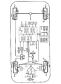
図1は、本発明の実施形態に係る車両安定化制御装置(以下、「本装置」と称呼する。)を搭載した車両の概略構成を示している。本装置は、車両の動力源であるエンジンEGと、自動変速機TMと、ブレーキアクチュエータBRKと、電子制御ユニットECUと、ナビゲーション装置NAVとを備えている。
(Constitution)
FIG. 1 shows a schematic configuration of a vehicle equipped with a vehicle stabilization control device (hereinafter referred to as “this device”) according to an embodiment of the present invention. This device includes an engine EG that is a power source of the vehicle, an automatic transmission TM, a brake actuator BRK, an electronic control unit ECU, and a navigation device NAV.
エンジンEGは、例えば、内燃機関である。即ち、運転者によるアクセルペダル(加速操作部材)APの操作に応じてスロットルアクチュエータTHによりスロットル弁TVの開度が調整される。スロットル弁TVの開度に応じて調整される吸入空気量に応じた量の燃料が燃料噴射アクチュエータFI(インジェクタ)により噴射される。これにより、運転者によるアクセルペダルAPの操作に応じた出力トルクが得られるようになっている。 The engine EG is, for example, an internal combustion engine. That is, the opening degree of the throttle valve TV is adjusted by the throttle actuator TH according to the operation of the accelerator pedal (acceleration operation member) AP by the driver. An amount of fuel corresponding to the amount of intake air that is adjusted according to the opening of the throttle valve TV is injected by a fuel injection actuator FI (injector). Thereby, the output torque according to the operation of the accelerator pedal AP by the driver can be obtained.
自動変速機TMは、複数の変速段を有する多段自動変速機、或いは、変速段を有さない無段自動変速機である。自動変速機TMは、エンジンEGの運転状態、及びシフトレバー(変速操作部材)SFの位置に応じて、減速比(EG出力軸(=TM入力軸)の回転速度/TM出力軸の回転速度)を自動的に(運転者によるシフトレバーSFの操作によることなく)変更可能となっている。 The automatic transmission TM is a multi-stage automatic transmission having a plurality of shift stages or a continuously variable automatic transmission having no shift stages. The automatic transmission TM has a reduction ratio (the rotational speed of the EG output shaft (= TM input shaft) / the rotational speed of the TM output shaft) depending on the operating state of the engine EG and the position of the shift lever (transmission operation member) SF. Can be automatically changed (without operation of the shift lever SF by the driver).
ブレーキアクチュエータBRKは、複数の電磁弁、液圧ポンプ、モータ等を備えた周知の構成を有している。ブレーキアクチュエータBRKは、非制御時では、運転者によるブレーキペダル(制動操作部材)BPの操作に応じた制動圧力(ブレーキ液圧)を車輪WH**のホイールシリンダWC**にそれぞれ供給し、制御時では、ブレーキペダルBPの操作(及びアクセルペダルAPの操作)とは独立してホイールシリンダWC**内の制動圧力を車輪毎に調整できるようになっている。 The brake actuator BRK has a known configuration including a plurality of solenoid valves, a hydraulic pump, a motor, and the like. The brake actuator BRK supplies the brake pressure (brake hydraulic pressure) according to the operation of the brake pedal (brake operation member) BP by the driver to the wheel cylinder WC ** of the wheel WH ** and controls when not controlled. Sometimes, the braking pressure in the wheel cylinder WC ** can be adjusted for each wheel independently of the operation of the brake pedal BP (and the operation of the accelerator pedal AP).
なお、各種記号等の末尾に付された「**」は、各種記号等が何れの車輪に関するものであるかを示していて、「fl」は左前輪、「fr」は右前輪、「rl」は左後輪、「rr」は右後輪を示している。例えば、ホイールシリンダWC**は、左前輪ホイールシリンダWCfl, 右前輪ホイールシリンダWCfr, 左後輪ホイールシリンダWCrl, 右後輪ホイールシリンダWCrrを包括的に示している。 “**” at the end of various symbols, etc., indicates which wheel the various symbols relate to, “fl” is the front left wheel, “fr” is the front right wheel, “rl” "Represents the left rear wheel, and" rr "represents the right rear wheel. For example, the wheel cylinder WC ** comprehensively indicates a left front wheel wheel cylinder WCfl, a right front wheel wheel cylinder WCfr, a left rear wheel wheel cylinder WCrl, and a right rear wheel wheel cylinder WCrr.
本装置は、車輪WH**の車輪速度を検出する車輪速度センサWS**と、ホイールシリンダWC**内の制動圧力を検出する制動圧力センサPW**と、ステアリングホイールSWの(中立位置からの)角度を検出するステアリングホイール角度センサSAと、前輪(操向車輪)の舵角を検出する前輪舵角センサFSと、車体のヨーレイトを検出するヨーレイトセンサYRと、車体前後方向の加速度(減速度)を検出する前後加速度センサGXと、車体横方向の加速度を検出する横加速度センサGYと、エンジンEGの出力軸の回転速度を検出するエンジン回転速度センサNEと、アクセルペダル(加速操作部材)APの操作量を検出する加速操作量センサASと、ブレーキペダルBPの操作量を検出する制動操作量センサBSと、シフトレバーSFの位置を検出するシフト位置センサHSと、スロットル弁TVの開度を検出するスロットル弁開度センサTSと、操舵輪(前輪)のセルフアライニングトルクを検出するセルフアライニングトルクセンサATf*と、ステアリングホイールSWの操舵トルクを検出する操舵トルクセンサSTと、を備えている。 This device consists of a wheel speed sensor WS ** that detects the wheel speed of the wheel WH **, a braking pressure sensor PW ** that detects the braking pressure in the wheel cylinder WC **, and the steering wheel SW (from the neutral position). Steering wheel angle sensor SA for detecting the angle, front wheel steering angle sensor FS for detecting the steering angle of the front wheel (steering wheel), yaw rate sensor YR for detecting the yaw rate of the vehicle body, and acceleration (decreasing in the vehicle longitudinal direction). Speed acceleration sensor GX, lateral acceleration sensor GY to detect vehicle body lateral acceleration, engine rotational speed sensor NE to detect the rotational speed of the output shaft of the engine EG, and accelerator pedal (acceleration operation member) Acceleration operation amount sensor AS that detects the operation amount of AP, braking operation amount sensor BS that detects the operation amount of brake pedal BP, shift position sensor HS that detects the position of shift lever SF, and slot A throttle valve opening sensor TS that detects the opening of the valve TV, a self-aligning torque sensor ATf * that detects the self-aligning torque of the steering wheel (front wheel), and a steering torque sensor that detects the steering torque of the steering wheel SW ST.
セルフアライニングトルクセンサATf*は、例えば、操舵輪のホイールリムに固着されて、ホイールリムの歪を検出することで、この歪に関する情報と歪が検出されたホイールリムの位置とに基づいて、セルフアライニングトルクを検出する。 For example, the self-aligning torque sensor ATf * is fixed to the wheel rim of the steered wheel and detects the distortion of the wheel rim, and based on the information on the distortion and the position of the wheel rim where the distortion is detected, Detect self-aligning torque.
電子制御ユニットECUは、パワートレイン系及びシャシー系を電子制御するマイクロコンピュータである。電子制御ユニットECUは、上述の各種アクチュエータ、上述の各種センサ、及び自動変速機TMと、電気的に接続され、又はネットワークで通信可能となっている。電子制御ユニットECUは、互いに通信バスCBで接続された複数の制御ユニット(ECU1〜ECU4)から構成される。 The electronic control unit ECU is a microcomputer that electronically controls the powertrain system and the chassis system. The electronic control unit ECU is electrically connected to the various actuators described above, the various sensors described above, and the automatic transmission TM, or can communicate with each other via a network. The electronic control unit ECU is composed of a plurality of control units (ECU1 to ECU4) connected to each other via a communication bus CB.
電子制御ユニットECU内のECU1は、車輪ブレーキ制御ユニットであり、車輪速度センサWS**、前後加速度センサGX、横加速度センサGY、ヨーレイトセンサYR等からの信号に基づいてブレーキアクチュエータBRKを制御することで、周知の車両安定化制御(ESC制御)、アンチスキッド制御(ABS制御)、トラクション制御(TCS制御)等の制動圧力制御(車輪ブレーキ制御)を実行するようになっている。また、ECU1は、車輪速度センサWS**の検出結果(車輪速度Vw**)に基づいて車両速度(車速)Vxを演算するようになっている。
ECU1 in the electronic control unit ECU is a wheel brake control unit and controls the brake actuator BRK based on signals from the wheel speed sensor WS **, longitudinal acceleration sensor GX, lateral acceleration sensor GY, yaw rate sensor YR, etc. Thus, braking pressure control (wheel brake control) such as well-known vehicle stabilization control (ESC control), anti-skid control (ABS control), traction control (TCS control) and the like is executed. Further, the
電子制御ユニットECU内のECU2は、エンジン制御ユニットであり、加速操作量センサAS等からの信号に基づいてスロットルアクチュエータTH及び燃料噴射アクチュエータFIを制御することでエンジンEGの出力トルク制御(エンジン制御)を実行するようになっている。 The ECU 2 in the electronic control unit ECU is an engine control unit that controls the throttle actuator TH and the fuel injection actuator FI based on signals from the acceleration operation amount sensor AS and the like, thereby controlling the output torque of the engine EG (engine control). Is supposed to run.
電子制御ユニットECU内のECU3は、自動変速機制御ユニットであり、シフト位置センサHS等からの信号に基づいて自動変速機TMを制御することで減速比制御(変速機制御)を実行するようになっている。 The ECU 3 in the electronic control unit ECU is an automatic transmission control unit, and executes a reduction ratio control (transmission control) by controlling the automatic transmission TM based on a signal from the shift position sensor HS or the like. It has become.
電子制御ユニットECU内のECU4は、電動パワーステアリング制御ユニットであり、操舵トルクセンサST等からの信号に基づいて電動パワーステアリング装置EPSを制御することでパワーステアリング制御を実行するようになっている。 The ECU 4 in the electronic control unit ECU is an electric power steering control unit, and executes power steering control by controlling the electric power steering device EPS based on a signal from the steering torque sensor ST or the like.
ナビゲーション装置NAVは、ナビゲーション処理装置PRCを備えていて、ナビゲーション処理装置PRCは、車両位置検出手段(グローバル・ポジショニング・システム)GPS、ヨーレイトジャイロGYR、入力部INP、記憶部MAP、及び表示部(ディスプレー)MTRと電気的に接続されている。ナビゲーション装置NAVは、電子制御ユニットECUと、電気的に接続され、又は無線で通信可能となっている。 The navigation device NAV includes a navigation processing device PRC. The navigation processing device PRC includes vehicle position detection means (global positioning system) GPS, yaw rate gyro GYR, input unit INP, storage unit MAP, and display unit (display). ) Electrically connected to MTR. The navigation device NAV is electrically connected to the electronic control unit ECU or can communicate wirelessly.
車両位置検出手段GPSは、人工衛星からの測位信号を利用した周知の手法の一つにより車両の位置(緯度、経度等)を検出可能となっている。ヨーレイトジャイロGYRは、車体の角速度(ヨーレイト)を検出可能となっている。入力部INPは、運転者によるナビゲーション機能に係わる操作を入力するようになっている。記憶部MAPは、地図情報、道路情報等の各種情報を記憶している。 The vehicle position detection means GPS can detect the position (latitude, longitude, etc.) of the vehicle by one of the well-known methods using positioning signals from artificial satellites. The yaw rate gyro GYR can detect the angular velocity (yaw rate) of the vehicle body. The input unit INP is configured to input an operation related to the navigation function by the driver. The storage unit MAP stores various information such as map information and road information.
ナビゲーション処理装置PRCは、車両位置検出手段GPS、ヨーレイトジャイロGYR、入力部INP、及び記憶部MAPからの信号を総合的に処理し、その処理結果(ナビゲーション機能に係わる情報)を表示部MTRに表示するようになっている。 The navigation processing device PRC comprehensively processes signals from the vehicle position detection means GPS, yaw rate gyro GYR, input unit INP, and storage unit MAP, and displays the processing results (information related to the navigation function) on the display unit MTR. It is supposed to be.
以下、図2に示す形状を有するカーブを想定しながら、上記のように構成された本装置の説明を続ける。図2に示す(1つの)カーブは、カーブ開始地点Ci(カーブ入口)からカーブ終了地点Cd(カーブ出口)に向けて順に、進入緩和曲線区間Zci(車両の進行に伴い曲率半径が徐々に小さくなる)、一定曲率半径区間Zit、及び退出緩和曲線区間Zcd(車両の進行に伴い曲率半径が徐々に大きくなる)から構成されている。緩和曲線は、例えば、クロソイド曲線で構成される。緩和曲線区間が設けられているのは、運転者に急激なステアリングホイール操作を要求することなく、運転者がステアリングホイールを徐々に切り込み、その後徐々に切り戻すことで車両がカーブを円滑に通過できるようにするためである。 Hereinafter, the description of the apparatus configured as described above will be continued while assuming a curve having the shape shown in FIG. The (one) curve shown in FIG. 2 has a gradually decreasing curvature radius as the vehicle progresses in order from the curve start point Ci (curve entrance) to the curve end point Cd (curve exit). A constant curvature radius section Zit and an exit relaxation curve section Zcd (the curvature radius gradually increases as the vehicle advances). The relaxation curve is composed of a clothoid curve, for example. The relaxation curve section is provided so that the driver can smoothly turn the steering wheel and then gradually turn it back without requiring the driver to operate the steering wheel suddenly. It is for doing so.
図3に示すように、このカーブでは、曲率半径は、カーブ開始地点Ci(即ち、直線路の終了地点)にて無限大であり、その後、徐々に小さくなり、一定曲率半径区間Zitの開始地点CsでRm(カーブ内の最小曲率半径)となる。その後、曲率半径は、一定曲率半径区間Zitの終了地点CeまでRmに維持された後、徐々に大きくなり、カーブ終了地点Cd(即ち、直線路の開始地点)にて無限大となる。このカーブを一定の車速で車両が走行すると、旋回状態量(例えば、横加速度)は、カーブ開始地点Ciにおいて「0(直線走行)」から増大を開始し、進入緩和曲線区間Zciでは概ね比例的に増加し、一定曲率半径区間Zitでは一定の値(最大値)となる。その後、旋回状態量は、退出緩和曲線区間Zcdにて概ね比例的に減少し、カーブ終了地点Cdにおいて「0(直線走行)」となる。 As shown in FIG. 3, in this curve, the radius of curvature is infinite at the curve start point Ci (that is, the end point of the straight road) and then gradually decreases to the start point of the constant curvature radius section Zit. Cs is Rm (the minimum radius of curvature in the curve). Thereafter, the radius of curvature is maintained at Rm until the end point Ce of the constant curvature radius section Zit, and then gradually increases and becomes infinite at the curve end point Cd (that is, the start point of the straight road). When the vehicle travels on this curve at a constant vehicle speed, the turning state amount (for example, lateral acceleration) starts to increase from “0 (straight travel)” at the curve start point Ci, and is approximately proportional in the approach relaxation curve section Zci. In the constant curvature radius section Zit, it becomes a constant value (maximum value). Thereafter, the turning state quantity decreases approximately proportionally in the exit relaxation curve section Zcd, and becomes “0 (straight running)” at the curve end point Cd.
車両が過剰な車速をもってカーブへ進入した場合を考える。運転者はカーブの進入緩和曲線に沿ってステアリングホイール角度を徐々に増大させていく。これにより、車両にアンダステアが発生するとともにアンダステアの程度が増大していく。この結果、車両が進入緩和曲線上をトレースできなくなると、運転者は更にステアリングホイールを切り増して行く。このような状況は、カーブ入口Ciではなく、カーブの一定曲率半径区間Zitの入口Cs付近で発生し易い。 Consider the case where a vehicle enters a curve with excessive vehicle speed. The driver gradually increases the steering wheel angle along a curve approaching relaxation curve. As a result, understeer occurs in the vehicle and the degree of understeer increases. As a result, when the vehicle cannot trace on the approach relaxation curve, the driver further increases the steering wheel. Such a situation is likely to occur near the entrance Cs of the constant curvature radius section Zit of the curve, not the curve entrance Ci.
(車両安定化制御の概要)
以下、図4を参照しながら、本装置により実行される車両安定化制御の概要について説明する。
(Outline of vehicle stabilization control)
Hereinafter, the outline of the vehicle stabilization control executed by the present apparatus will be described with reference to FIG.
先ず、実旋回状態量取得手段A1では、実際の車両のヨー運動状態量(実旋回状態量Ta)が取得される。実旋回状態量Taは、車両に対して実際に発生しているヨー運動状態量であり、例えば、実ヨーレイトYr、実横加速度Gy、実車体スリップ角βa、実車体スリップ角速度dβaである。また、実旋回状態量Taとして、これらのうちから2つ以上の状態量を組み合わせて得られる値が使用され得る。 First, the actual turning state quantity acquisition means A1 acquires the actual yaw motion state quantity (actual turning state quantity Ta) of the vehicle. The actual turning state amount Ta is a yaw motion state amount actually generated with respect to the vehicle, and is, for example, an actual yaw rate Yr, an actual lateral acceleration Gy, an actual vehicle body slip angle βa, and an actual vehicle body slip angular velocity dβa. Further, as the actual turning state quantity Ta, a value obtained by combining two or more of these state quantities can be used.
目標旋回状態量演算手段A2では、目標とする車両のヨー運動状態量(目標旋回状態量ともいう)Tdが取得される。目標旋回状態量Tdとしては、実旋回状態量Taに対応した同じ次元の値(目標ヨーレイトYrd、目標横加速度Gyd、目標スリップ角βd、目標スリップ角速度dβd)が演算される。目標旋回状態量Tdは、車速Vx及びステアリングホイール角度θsw(或いは、前輪舵角δf)に基づいて演算され得る。 In the target turning state quantity calculation means A2, a target yaw motion state quantity (also referred to as a target turning state quantity) Td of the vehicle is acquired. As the target turning state amount Td, values of the same dimension (target yaw rate Yrd, target lateral acceleration Gyd, target slip angle βd, target slip angular velocity dβd) corresponding to the actual turning state amount Ta are calculated. The target turning state amount Td can be calculated based on the vehicle speed Vx and the steering wheel angle θsw (or the front wheel steering angle δf).
ステア特性演算手段A3では、実旋回状態量Taと目標旋回状態量Tdとに基づいて車両のステア特性(アンダステア、ニュートラルステア、オーバステア)が演算され、その演算結果(ステア特性値)Schが演算される。ステア特性値Schは、車両のステア特性の程度を表す値であり、目標旋回状態量Tdと実旋回状態量Taとを比較することで得演算され得る。ステア特性値Schとしては、TdとTaとの偏差(=Td−Ta)が使用され得る。ここで、目標旋回状態量Tdを使用することなくステア特性を演算することができる。例えば、実スリップ角速度dβa、実スリップ角βa等に基づいてステア特性を演算することができる。 In the steer characteristic calculation means A3, the vehicle steer characteristics (understeer, neutral steer, oversteer) are calculated based on the actual turning state quantity Ta and the target turning state quantity Td, and the calculation result (steer characteristic value) Sch is calculated. The The steering characteristic value Sch is a value representing the degree of the steering characteristic of the vehicle, and can be obtained and calculated by comparing the target turning state quantity Td with the actual turning state quantity Ta. As the steering characteristic value Sch, a deviation (= Td−Ta) between Td and Ta can be used. Here, the steer characteristic can be calculated without using the target turning state amount Td. For example, the steer characteristic can be calculated based on the actual slip angular velocity dβa, the actual slip angle βa, and the like.
目標制御量演算手段A4では、ステア特性値Schに基づいて、車両のアンダステア、オーバステアを抑制するための、各車輪に付与される制動力の目標制御量Bt**、動力源(エンジン等)の目標出力Otが演算される。目標制御量演算手段A4では、後述する判定結果Fgに基づいて目標制御量Bt**が調整される。目標制御量演算手段A4には、車両のアンダステアを抑制するアンダステア抑制制御ブロックと、車両のオーバステアを抑制するオーバステア抑制制御ブロックとが含まれる。 In the target control amount calculation means A4, based on the steering characteristic value Sch, the target control amount Bt ** of the braking force applied to each wheel and the power source (engine, etc.) for suppressing understeer and oversteer of the vehicle. A target output Ot is calculated. In the target control amount calculation means A4, the target control amount Bt ** is adjusted based on a determination result Fg described later. The target control amount calculation means A4 includes an understeer suppression control block that suppresses vehicle understeer and an oversteer suppression control block that suppresses vehicle oversteer.
アンダステア抑制制御ブロックでは、ステア特性値Schに基づいてアンダステア抑制制御を開始する制御開始条件(制御開始しきい値Kj)が設定される。しきい値Kjは、後述するカーブ通過可否判定手段A8による判定結果Fgに基づいて調整される。判定結果Fgが「カーブ通過が可能(判定結果Fgが「0」、或いは、相対的に小さい値)」となった場合、しきい値Kjが大きい値に設定されて、アンダステア抑制制御が開始され難くなる。一方、判定結果Fgが「カーブ通過が不可(判定結果Fgが「1」、或いは、相対的に大きい値)」となった場合、しきい値Kjが小さい値に修正されて、アンダステア抑制制御が小さいステア特性値Schで開始されるように調整される。この結果、アンダステア抑制制御が開始され易くなる。 In the understeer suppression control block, a control start condition (control start threshold value Kj) for starting understeer suppression control is set based on the steer characteristic value Sch. The threshold value Kj is adjusted based on a determination result Fg by a curve passage permission / non-permission determining unit A8 described later. When the determination result Fg becomes “a curve can be passed (the determination result Fg is“ 0 ”or a relatively small value)”, the threshold value Kj is set to a large value, and understeer suppression control is started. It becomes difficult. On the other hand, when the determination result Fg is “curve passing is impossible (the determination result Fg is“ 1 ”or a relatively large value)”, the threshold value Kj is corrected to a small value, and the understeer suppression control is performed. It is adjusted so as to start with a small steer characteristic value Sch. As a result, understeer suppression control is easily started.
また、目標制御量演算手段A4では、ステア特性値Schに基づいて、目標制御量Bt**の演算について、車両のヨー特性を重視する(減速よりもヨーモーメント付与を優先する)第1特性(目標制御量Bm**を演算する特性)と、車両の減速特性を重視する(ヨーモーメント付与よりも減速を優先する)第2特性(目標制御量Bg**を演算する特性)の2種類の特性が備えられている。 Further, in the target control amount calculation means A4, on the basis of the steer characteristic value Sch, the calculation of the target control amount Bt ** places importance on the yaw characteristic of the vehicle (priority is given to giving yaw moment over deceleration) (first characteristic) Two types of characteristics (characteristics for calculating the target control amount Bg **) and second characteristics (characteristics for calculating the target control amount Bg **) that place importance on the deceleration characteristics of the vehicle (priority is given to deceleration over giving the yaw moment). Features are provided.
第1特性では、旋回内向きに作用するヨーイングモーメントが増大して車両が進行する向きが変わり易くなるように各輪の制動力が配分される。一方、第2特性では、車両の旋回を維持するヨーイングモーメントが確保できる範囲内で各輪の制動力の総和が最大となって車両が十分に減速され得るように各輪の制動力が配分される。 In the first characteristic, the braking force of each wheel is distributed so that the yawing moment acting inward of the turn increases and the direction in which the vehicle travels is easily changed. On the other hand, in the second characteristic, the braking force of each wheel is distributed so that the sum of the braking forces of the respective wheels can be maximized and the vehicle can be sufficiently decelerated within a range in which the yawing moment for maintaining the turning of the vehicle can be secured. The
後述するカーブ通過可否判定手段A8による判定結果Fgが「カーブ通過可能」となったとき(判定結果Fgが「0」、或いは、相対的に小さい値のとき)、目標制御量Bt**の演算特性として第1特性が選択される。この結果、アンダステア抑制制御が開始された場合において車両のヨー運動特性が向上する。一方、判定結果Fgが「カーブ通過不可」となったとき(判定結果Fgが「1」、或いは、相対的に大きい値のとき)、目標制御量Bt**の演算特性として第2特性が選択される。この結果、アンダステア抑制制御が開始された場合において、車両の減速が優先されて、カーブの旋回半径を維持しつつ最大限の車両減速度が得られる。 Calculation of target control amount Bt ** when determination result Fg by curve passability determination means A8, which will be described later, becomes "curve passable" (when determination result Fg is "0" or a relatively small value). The first characteristic is selected as the characteristic. As a result, the yaw motion characteristic of the vehicle is improved when the understeer suppression control is started. On the other hand, when the determination result Fg is “impossible to pass the curve” (when the determination result Fg is “1” or a relatively large value), the second characteristic is selected as the calculation characteristic of the target control amount Bt **. Is done. As a result, when understeer suppression control is started, vehicle deceleration is prioritized, and the maximum vehicle deceleration is obtained while maintaining the turning radius of the curve.
制御手段A5では、目標制御量演算手段A4により演算された目標制御量に基づいて、動力源の出力が低減され、各車輪の制動力が独立して制御される。具体的には、目標制御量Bt**に基づいて、各車輪の制動力を制御する車輪ブレーキ制御手段A51が制御される。また、目標制御量Otに基づいて、エンジン等の動力源の出力を制御する動力源出力制御手段A52が制御される。 In the control means A5, based on the target control amount calculated by the target control amount calculation means A4, the output of the power source is reduced and the braking force of each wheel is controlled independently. Specifically, the wheel brake control means A51 for controlling the braking force of each wheel is controlled based on the target control amount Bt **. Further, based on the target control amount Ot, the power source output control means A52 for controlling the output of the power source such as the engine is controlled.
カーブ情報取得手段A6では、車両の前方にあるカーブの情報Rc(カーブ形状であり、例えば曲率半径)が取得される。このとき、カーブ曲率半径Rcに併せて、カーブ曲率半径Rcに対応する位置Pcを取得することができる。これらのカーブ情報Rc,Pcは、記憶部MAPの地図データベースに記憶されている。カーブ情報として、位置Pc(例えば、緯度・経度)と、その位置におけるカーブ曲率半径Rcとが直接的に記憶されていてもよいし、これらが演算できる書式が記憶されていてもよい。 In the curve information acquisition means A6, information Rc (curve shape, for example, a radius of curvature) of a curve ahead of the vehicle is acquired. At this time, the position Pc corresponding to the curve curvature radius Rc can be acquired together with the curve curvature radius Rc. These curve information Rc and Pc are stored in the map database of the storage unit MAP. As the curve information, a position Pc (for example, latitude / longitude) and a curve curvature radius Rc at the position may be directly stored, or a format in which these can be calculated may be stored.
車速取得手段A7では、車両の速度Vxが取得される。 The vehicle speed acquisition means A7 acquires the vehicle speed Vx.
カーブ通過可否判断手段A8では、車両の進行方向前方にあるカーブの形状Rc(特に、カーブの曲率半径)と、車両の速度Vxとに基づいて、車両がカーブを安定して通過できるか否かが判定される。具体的には、カーブの形状(曲率半径)から最小曲率半径Rmが決定され、この最小曲率半径Rmと現在の車速Vxとに基づいて、横加速度Gye(=Vx2/Rm)が演算される。この場合、横加速度Gyeは、車両が対象とされるカーブを車速Vx一定で通過した場合に生ずる横加速度の最大値(計算値)に相当する。 Whether or not the vehicle can pass the curve stably is determined based on the curve shape Rc (particularly, the radius of curvature of the curve) ahead of the vehicle in the traveling direction and the vehicle speed Vx. Is determined. Specifically, the minimum curvature radius Rm is determined from the curve shape (curvature radius), and the lateral acceleration Gye (= Vx 2 / Rm) is calculated based on the minimum curvature radius Rm and the current vehicle speed Vx. . In this case, the lateral acceleration Gye corresponds to the maximum value (calculated value) of the lateral acceleration that occurs when the vehicle passes through the target curve at a constant vehicle speed Vx.
横加速度Gyeが所定値(例えば、0.8G)未満の場合、車両はカーブを安定して通過できると判定され得る。一方、横加速度Gyeが前記所定値以上の場合、車両はカーブを安定して通過できないと判定され得る。この所定値として、予め設定された定数を使用することもできるが、路面摩擦係数μmaxに基づいて決定される値を使用することもできる。 When the lateral acceleration Gye is less than a predetermined value (for example, 0.8 G), it can be determined that the vehicle can pass the curve stably. On the other hand, when the lateral acceleration Gye is equal to or greater than the predetermined value, it can be determined that the vehicle cannot pass the curve stably. As the predetermined value, a preset constant can be used, but a value determined based on the road surface friction coefficient μmax can also be used.
このカーブ通過可否判定手段A8により、カーブ通過可否の判定値Fgが演算され、この判定値Fgが目標制御量演算手段A4に出力される。判定値Fgは、Fg=0のとき「カーブ通過可能」を表し、Fg=1のときに「カーブ通過不能」を表す。また、判定値Fgは、「0」又は「1」のみではなく、それらの中間の値(0<Fg<1)に演算されることもできる。 The curve passage availability determination means A8 calculates a curve passage availability determination value Fg and outputs the determination value Fg to the target control amount calculation means A4. The determination value Fg represents “curve passing is possible” when Fg = 0, and “curve cannot be passed” when Fg = 1. Further, the determination value Fg can be calculated not only to “0” or “1” but also to an intermediate value (0 <Fg <1).
上述の説明では、カーブの最小曲率半径Rmと実際の車速Vxとから演算される、「カーブを通過できたならば車両に作用するであろう最大横加速度Gye」に基づいてカーブ通過可否判定が行われる。以下に述べるように、この方法とは異なる方法によってカーブ通過の可否を判定することができる。 In the above description, whether or not to pass the curve is determined based on the “maximum lateral acceleration Gye that will act on the vehicle if it can pass the curve” calculated from the minimum curvature radius Rm of the curve and the actual vehicle speed Vx. Done. As described below, it is possible to determine whether or not the vehicle can pass the curve by a method different from this method.
即ち、車両の位置Pvhを取得する車両位置取得手段A9が設けられる。これにより、車両位置Pvhが取得される。車両位置Pvhは、グローバル・ポジショニング・システムGPSを用いて検出される。 That is, vehicle position acquisition means A9 for acquiring the vehicle position Pvh is provided. Thereby, the vehicle position Pvh is acquired. The vehicle position Pvh is detected using the global positioning system GPS.
この場合、カーブ情報取得手段A6では、カーブ形状Rcと、そのカーブ形状Rcに対応したカーブ内の位置Pcが取得される。カーブ形状Rc、カーブ位置Pc、及び、取得された車両位置Pvhに基づいて目標車速Vtが演算される。具体的には、カーブ情報Rc,Pcに基づいてカーブを安定して通過するための適正車速Vqが演算され、この適正車速Vqと車両位置Pvhとに基づいて、現在の車両位置Pvhにおける目標車速Vtが演算される。目標車速Vtと車速Vxとが比較され、この比較結果に基づいて、車両がカーブを安定して通過できるか否かが判定される。 In this case, the curve information acquisition unit A6 acquires the curve shape Rc and the position Pc in the curve corresponding to the curve shape Rc. A target vehicle speed Vt is calculated based on the curve shape Rc, the curve position Pc, and the acquired vehicle position Pvh. Specifically, an appropriate vehicle speed Vq for stably passing the curve is calculated based on the curve information Rc, Pc, and the target vehicle speed at the current vehicle position Pvh is calculated based on the appropriate vehicle speed Vq and the vehicle position Pvh. Vt is calculated. The target vehicle speed Vt and the vehicle speed Vx are compared, and based on the comparison result, it is determined whether or not the vehicle can pass the curve stably.
車両位置Pvhにおいて、車速Vxが目標車速Vt以下の場合、車両はカーブを安定して通過できると判定され得る。一方、車速Vxが目標車速Vtを超過している場合、車両はカーブを安定して通過できないと判定され得る。この場合も前述と同様、カーブ通過可否判定手段A8により、カーブ通過可否の判定値Fgが演算され、この判定値Fgが目標制御量演算手段A4に出力される。判定値Fgは、Fg=0のとき「カーブ通過可能」を表し、Fg=1のときに「カーブ通過不能」を表す。また、判定値Fgは、「0」又は「1」のみではなく、それらの中間の値(0<Fg<1)に演算されることもできる。 When the vehicle speed Vx is equal to or lower than the target vehicle speed Vt at the vehicle position Pvh, it can be determined that the vehicle can pass the curve stably. On the other hand, when the vehicle speed Vx exceeds the target vehicle speed Vt, it can be determined that the vehicle cannot pass the curve stably. In this case as well, as described above, the curve passage availability determination unit A8 calculates the curve passage availability determination value Fg, and the determination value Fg is output to the target control amount calculation unit A4. The determination value Fg represents “curve passing is possible” when Fg = 0, and “curve cannot be passed” when Fg = 1. Further, the determination value Fg can be calculated not only to “0” or “1” but also to an intermediate value (0 <Fg <1).
(カーブ通過可否の判定値Fgの演算の一例)
次に、図5を参照しながら、カーブ通過可否判定手段A8によるカーブ通過可否の判定値Fgの演算の一例について詳細に説明する。図5は、前述の横加速度Gyeを使用して判定値Fgが演算される場合の一例を示す。
(Example of calculation of judgment value Fg of whether or not to pass through curve)
Next, with reference to FIG. 5, an example of the calculation of the curve passability determination value Fg by the curve passability determination means A8 will be described in detail. FIG. 5 shows an example in which the determination value Fg is calculated using the lateral acceleration Gye described above.
最小曲率半径演算ブロックB1では、車両の進行方向前方にあるカーブ形状(カーブ曲率半径)Rcに基づいて、カーブの最小曲率半径Rmが演算される。 In the minimum curvature radius calculation block B1, the minimum curvature radius Rm of the curve is calculated based on the curve shape (curve curvature radius) Rc ahead of the traveling direction of the vehicle.
横加速度演算ブロックB2では、最小曲率半径(一定曲率半径一定区間Zitの曲率半径)Rm、及び、現在の車速Vxに基づいて、以下の式を用いて、横加速度Gyeが演算される。ここで、横加速度Gyeは、車両が現在の車速Vx一定でカーブを通過できたならば車両に作用するであろう横加速度の最大値である。
Gye=Vx2/Rm
In the lateral acceleration calculation block B2, the lateral acceleration Gye is calculated using the following equation based on the minimum curvature radius (the curvature radius of the constant curvature radius constant section Zit) Rm and the current vehicle speed Vx. Here, the lateral acceleration Gye is the maximum value of the lateral acceleration that will act on the vehicle if the vehicle can pass the curve at the current vehicle speed Vx constant.
Gye = Vx 2 / Rm
カーブ通過可否判定演算ブロックB3では、車両がカーブを安定して通過可能か否かを表す判定値Fgが、横加速度Gyeに基づいて演算される。具体的には、横加速度Gyeが所定値Gy1以下の場合、車両がカーブを安定して通過できることを表すFg=0が演算される。横加速度Gyeが所定値Gy1より大きく且つ所定値Gy2未満の場合、横加速度GyeのGy1からの増加に従って判定値Fgが「0」から増加するように判定値Fgが演算される。横加速度Gyeが所定値Gy2以上の場合、車両がカーブを安定して通過できないことを表すFg=1が演算される。判定値Fgが「0」より大きく「1」未満の場合、車両がカーブを安定して通過できる(通過できない)可能性の程度を表す。具体的には、判定値Fgが大きいほど(「1」に近いほど)カーブ通過の可能性が低く、判定値Fgが小さいほど(「0」に近いほど)カーブ通過の可能性が高いことを表す。 In the curve passability determination calculation block B3, a determination value Fg indicating whether or not the vehicle can pass through the curve stably is calculated based on the lateral acceleration Gye. Specifically, when the lateral acceleration Gye is equal to or less than a predetermined value Gy1, Fg = 0 representing that the vehicle can pass through the curve stably is calculated. When the lateral acceleration Gye is greater than the predetermined value Gy1 and less than the predetermined value Gy2, the determination value Fg is calculated such that the determination value Fg increases from “0” as the lateral acceleration Gye increases from Gy1. When the lateral acceleration Gye is equal to or greater than the predetermined value Gy2, Fg = 1 representing that the vehicle cannot pass the curve stably is calculated. When the determination value Fg is greater than “0” and less than “1”, it represents the degree of possibility that the vehicle can pass (cannot pass) the curve stably. Specifically, the larger the determination value Fg (closer to “1”), the lower the possibility of passing through the curve, and the smaller the determination value Fg (closer to “0”), the higher the possibility of passing through the curve. Represent.
また、図中の一転鎖線で示すように、判定値Fgは、横加速度Gyeが所定値Gy3以下の場合にFg=0(カーブ通過可能)に、横加速度Gyeが所定値Gy3より大きい場合にFg=1(カーブ通過不可)になるように演算され得る。 Further, as indicated by a chain line in the figure, the determination value Fg is Fg = 0 (the curve can be passed) when the lateral acceleration Gye is equal to or less than the predetermined value Gy3, and when the lateral acceleration Gye is greater than the predetermined value Gy3. = 1 (cannot pass through the curve).
車両がタイヤと路面との摩擦係数に基づいて決定される横加速度を超えた横加速度をもって旋回することは物理的に不可能である。このため、所定値Gy1、或いは、Gy3は、タイヤと路面との摩擦係数を考慮して、0.8G程度に設定され得る。また、路面摩擦係数μmaxを演算して、これに基づいて所定値Gy1、Gy2、Gy3を調整することができる。路面摩擦係数μmaxが小さい値に演算される場合、所定値Gy1、Gy2、Gy3が相対的に小さい値に調整され、路面摩擦係数μmaxが大きい値に演算される場合、所定値Gy1、Gy2、Gy3が相対的に大きい値に調整され得る。 It is physically impossible for a vehicle to turn with a lateral acceleration exceeding a lateral acceleration determined based on a friction coefficient between a tire and a road surface. For this reason, the predetermined value Gy1 or Gy3 can be set to about 0.8 G in consideration of the friction coefficient between the tire and the road surface. Further, the road surface friction coefficient μmax can be calculated, and the predetermined values Gy1, Gy2, and Gy3 can be adjusted based on this. When the road surface friction coefficient μmax is calculated to a small value, the predetermined values Gy1, Gy2, and Gy3 are adjusted to relatively small values, and when the road surface friction coefficient μmax is calculated to a large value, the predetermined values Gy1, Gy2, and Gy3 Can be adjusted to a relatively large value.
(カーブ通過可否の判定値Fgの演算の他の例)
次に、図6を参照しながら、カーブ通過可否判定手段A8によるカーブ通過可否の判定値Fgの演算の他の例について詳細に説明する。図6は、前述の目標車速Vtを使用して判定値Fgが演算される場合の一例を示す。
(Another example of the calculation of the judgment value Fg of whether or not the vehicle can pass a curve)
Next, another example of the calculation of the curve passability determination value Fg by the curve passability determination means A8 will be described in detail with reference to FIG. FIG. 6 shows an example in which the determination value Fg is calculated using the target vehicle speed Vt described above.
適正車速演算ブロックB4では、上述のカーブ情報Rc,Pc(カーブ形状(カーブの曲率半径)Rcと、これに対応するカーブの位置Pc)に基づいて、車両がカーブを安定して通過するための適正車速Vqが演算される。カーブ情報Rc,Pcに基づいて、カーブ内の曲率半径が一定となる区間(一定曲率半径区間Zit)の曲率半径Rmが決定される。この曲率半径Rmに基づいて適正車速Vqが演算される。曲率半径Rmとして、カーブ内の最小曲率半径が使用されてもよい。カーブ曲率半径Rmが大きいほど適正車速Vqがより大きい値に演算され、曲率半径Rmが小さいほど適正車速Vqがより小さい値に演算される。 In the appropriate vehicle speed calculation block B4, based on the above-described curve information Rc, Pc (curve shape (curvature radius of curvature) Rc and the corresponding curve position Pc), the vehicle can pass through the curve stably. An appropriate vehicle speed Vq is calculated. Based on the curve information Rc, Pc, the curvature radius Rm of the section (constant curvature radius section Zit) in which the curvature radius in the curve is constant is determined. An appropriate vehicle speed Vq is calculated based on the curvature radius Rm. As the curvature radius Rm, the minimum curvature radius in the curve may be used. The appropriate vehicle speed Vq is calculated to be larger as the curve curvature radius Rm is larger, and the appropriate vehicle speed Vq is calculated to be smaller as the curvature radius Rm is smaller.
更に、適正車速Vqは登降坂勾配Kud、道幅(幅員)Wrd、前方の見通しMsk、及び、車速Vxのうちの少なくとも1つ以上に基づいて調整することができる。登降坂勾配Kudが、降り坂のときには平坦路の場合に比較して適正車速Vqが小さく調整され、登り坂のときは平坦路の場合に比較して適正車速Vqが大きく調整される。道幅Wrdが狭い場合には、広い場合に比較して適正車速Vqが小さく調整され、道幅Wrdが広い場合には、狭い場合に比較して適正車速Vqが大きく調整される。前方の見通しMskが悪い場合には、良い場合に比較して適正車速Vqが小さく調整され、前方の見通しMskが良い場合には、悪い場合に比較して適正車速Vqが大きく調整される。車速Vxが高い場合には、低い場合に比較して適正車速Vqが小さく調整され、車速Vxが低い場合には、高い場合に比較して適正車速Vqが大きく調整される。 Furthermore, the appropriate vehicle speed Vq can be adjusted based on at least one of the uphill / downhill gradient Kud, the road width (width) Wrd, the forward view Msk, and the vehicle speed Vx. When the uphill / downhill gradient Kud is downhill, the appropriate vehicle speed Vq is adjusted to be smaller than that on a flat road, and when uphill, the appropriate vehicle speed Vq is adjusted to be higher than that on a flat road. When the road width Wrd is narrow, the appropriate vehicle speed Vq is adjusted smaller than when it is wide, and when the road width Wrd is wide, the appropriate vehicle speed Vq is adjusted larger than when it is narrow. When the forward view Msk is poor, the appropriate vehicle speed Vq is adjusted smaller than when it is good, and when the forward view Msk is good, the appropriate vehicle speed Vq is adjusted larger than when it is bad. When the vehicle speed Vx is high, the appropriate vehicle speed Vq is adjusted smaller than when it is low, and when the vehicle speed Vx is low, the appropriate vehicle speed Vq is adjusted larger than when it is high.
路面摩擦係数μmaxに基づいて、適正車速Vqを調整することもできる。路面摩擦係数μmaxが大きいときには適正車速Vqが大きい値に調整され、路面摩擦係数μmaxが小さいときには適正車速Vqが小さい値に調整される。 The appropriate vehicle speed Vq can also be adjusted based on the road surface friction coefficient μmax. When the road surface friction coefficient μmax is large, the appropriate vehicle speed Vq is adjusted to a large value, and when the road surface friction coefficient μmax is small, the appropriate vehicle speed Vq is adjusted to a small value.
基準位置設定演算ブロックB5では、基準地点Pcrが決定される。基準地点Pcrは、車両がカーブを適正に通過できるか否かの判定の基準となる地点であり、車速が適正車速Vqまで減少すべき目標となる地点である。基準地点Pcrは、カーブ内の曲率半径が一定となる入口地点Cs(一定曲率半径区間Zitにおける車両に最も近い地点)に設定することができる。また、カーブ内の曲率半径が最小となる地点Csを、基準地点Pcrとして設定することができる。地点Csは、カーブ形状Rc、及び、カーブ位置Pcに基づいて決定される。 In the reference position setting calculation block B5, the reference point Pcr is determined. The reference point Pcr is a point serving as a reference for determining whether or not the vehicle can properly pass the curve, and is a target point where the vehicle speed should be reduced to the appropriate vehicle speed Vq. The reference point Pcr can be set to an entrance point Cs (a point closest to the vehicle in the constant curvature radius section Zit) where the curvature radius in the curve is constant. Further, the point Cs where the radius of curvature in the curve is minimum can be set as the reference point Pcr. The point Cs is determined based on the curve shape Rc and the curve position Pc.
地点Pcrは、一定曲率半径区間の入口地点Cs、或いは、曲率半径最小地点よりも距離Lprだけ車両に近い地点(車両に近い側のカーブへの進入部に当たる緩和曲線の終了部付近)に設定することができる。距離Lprは一定値とすることができる。 The point Pcr is set to the entrance point Cs of the constant curvature radius section or a point closer to the vehicle by the distance Lpr than the minimum curvature radius point (near the end of the relaxation curve corresponding to the entry part to the curve closer to the vehicle). be able to. The distance Lpr can be a constant value.
また、距離Lprは車速Vxに応じて演算することができる。具体的には、車速Vxが所定値Vx1以下では距離Lprが「0」とされ(即ち、地点PcrがCsと一致し)、Vx>Vx1(所定値)では、車速VxのVx1からの増加に従って距離Lprが「0」から増大するように距離Lprが決定され得る。ここで、車速Vxを適正車速Vqに置き換えて、適正車速Vqに基づいて距離Lprを決定することができる。 The distance Lpr can be calculated according to the vehicle speed Vx. Specifically, when the vehicle speed Vx is equal to or less than a predetermined value Vx1, the distance Lpr is “0” (that is, the point Pcr coincides with Cs), and when Vx> Vx1 (predetermined value), the vehicle speed Vx increases as Vx1 increases. The distance Lpr can be determined such that the distance Lpr increases from “0”. Here, the vehicle speed Vx can be replaced with the appropriate vehicle speed Vq, and the distance Lpr can be determined based on the appropriate vehicle speed Vq.
この場合、地点Pcrは、地点Csから距離Lprだけカーブ開始地点Ciに近いカーブ上の地点に設定される。即ち、地点Pcrは、距離Lpr、カーブ形状Rc、及び、地点Cs(カーブ位置Pc)に基づいて設定される。 In this case, the point Pcr is set to a point on the curve close to the curve start point Ci by the distance Lpr from the point Cs. That is, the point Pcr is set based on the distance Lpr, the curve shape Rc, and the point Cs (curve position Pc).
上述のように、地点Pcrは車速が適正車速Vqまで減少すべき目標とされる地点である。ここで、地図情報等には誤差が含まれる場合がある。上記のように地点Pcrを地点Csよりもカーブ入口Ciに距離Lprだけ近い地点に設定することで、その誤差が吸収され得る。 As described above, the point Pcr is a target point where the vehicle speed should be reduced to the appropriate vehicle speed Vq. Here, the map information or the like may include an error. As described above, by setting the point Pcr to a point closer to the curve entrance Ci than the point Cs by the distance Lpr, the error can be absorbed.
目標車速演算ブロックB6では、目標車速Vtが演算される。具体的には、先ず、基準地点Pcr、及び、適正車速Vqに基づいて、車両位置Pvhにおける目標車速Vt(Vt[Pvh])を演算するための目標車速演算特性Vtchが決定される。この目標車速演算特性Vtchとしては、カーブ入口側から基準地点Pcrまで車速が減速度Gm(例えば、予め設定された定数)をもって減少していき、基準地点Pcrで車速が適正車速Vqとなる特性が採用される。 In the target vehicle speed calculation block B6, the target vehicle speed Vt is calculated. Specifically, first, the target vehicle speed calculation characteristic Vtch for calculating the target vehicle speed Vt (Vt [Pvh]) at the vehicle position Pvh is determined based on the reference point Pcr and the appropriate vehicle speed Vq. The target vehicle speed calculation characteristic Vtch is a characteristic in which the vehicle speed decreases with a deceleration Gm (for example, a preset constant) from the curve entrance side to the reference point Pcr, and the vehicle speed becomes the appropriate vehicle speed Vq at the reference point Pcr. Adopted.
減速度Gmは、路面摩擦係数μmaxに基づいて調整することができる。具体的には、路面摩擦係数μmaxが大きいときには減速度Gmが大きい値に調整され、路面摩擦係数μmaxが小さいときには減速度Gmが小さい値に調整される。そして、基準地点Pcr、及び、適正車速Vqに基づいて決定された目標車速演算特性Vtchに、車両位置取得手段(グローバル・ポジショニング・システムGPS)によって取得された車両位置Pvhを入力することで、車両位置Pvhにおける目標車速Vtが演算される。 The deceleration Gm can be adjusted based on the road surface friction coefficient μmax. Specifically, when the road surface friction coefficient μmax is large, the deceleration Gm is adjusted to a large value, and when the road surface friction coefficient μmax is small, the deceleration Gm is adjusted to a small value. Then, the vehicle position Pvh acquired by the vehicle position acquisition means (global positioning system GPS) is input to the target vehicle speed calculation characteristic Vtch determined based on the reference point Pcr and the appropriate vehicle speed Vq. A target vehicle speed Vt at the position Pvh is calculated.
カーブ通過可否判定演算ブロックB7では、車両が前方のカーブを安定して通過可能か否かを表す判定値Fgが演算する。具体的には、車速取得手段A7により取得された車速Vxと目標車速Vtとが比較され、この車速偏差ΔV(=Vx−Vt)に基づいて判定値Fgが演算される。 In the curve passability determination calculation block B7, a determination value Fg indicating whether or not the vehicle can stably pass the curve ahead is calculated. Specifically, the vehicle speed Vx acquired by the vehicle speed acquisition means A7 is compared with the target vehicle speed Vt, and the determination value Fg is calculated based on this vehicle speed deviation ΔV (= Vx−Vt).
車速偏差ΔVが所定値V1以下の場合、車両がカーブを安定して通過できることを表すFg=0が演算される。車速偏差ΔVが所定値V1より大きく且つ所定値V2未満の場合、ΔVのV1からの増加に従って判定値Fgが「0」から増加するように判定値Fgが演算される。車速偏差ΔVが所定値V2以上の場合、車両がカーブを安定して通過できないことを表すFg=1が演算される。判定値Fgが「0」より大きく、「1」未満の場合、車両がカーブを安定して通過できる(通過できない)可能性の程度を表す。具体的には、判定値Fgが大きいほど(「1」に近いほど)カーブ通過の可能性が低く、判定値Fgが小さいほど(「0」に近いほど)カーブ通過の可能性が高いことを表す。 When the vehicle speed deviation ΔV is equal to or less than the predetermined value V1, Fg = 0 representing that the vehicle can pass through the curve stably is calculated. When the vehicle speed deviation ΔV is greater than the predetermined value V1 and less than the predetermined value V2, the determination value Fg is calculated so that the determination value Fg increases from “0” as ΔV increases from V1. When the vehicle speed deviation ΔV is equal to or greater than the predetermined value V2, Fg = 1 representing that the vehicle cannot pass the curve stably is calculated. When the determination value Fg is larger than “0” and smaller than “1”, it represents the degree of possibility that the vehicle can pass (cannot pass) the curve stably. Specifically, the larger the determination value Fg (closer to “1”), the lower the possibility of passing through the curve, and the smaller the determination value Fg (closer to “0”), the higher the possibility of passing through the curve. Represent.
また、図中の一転鎖線で表すように、判定値Fgは、車速偏差ΔVが所定値V3以下の場合にFg=0(カーブ通過可能)に、ΔVが所定値V3より大きい場合にFg=1(カーブ通過不可)になるように演算され得る。 Further, as indicated by a chain line in the figure, the determination value Fg is Fg = 0 (the curve can be passed) when the vehicle speed deviation ΔV is equal to or smaller than the predetermined value V3, and Fg = 1 when ΔV is larger than the predetermined value V3. It can be calculated so as to be (cannot pass the curve).
(目標制御量Bt**演算)
次に、図7を参照しながら、目標制御量演算手段A4による目標制御量Bt**の演算の一例について詳細に説明する。
(Target control amount Bt ** calculation)
Next, an example of calculation of the target control amount Bt ** by the target control amount calculation means A4 will be described in detail with reference to FIG.
目標旋回状態量演算ブロック(目標ヨーレイト演算ブロック、目標旋回状態量演算手段A2に対応)B8では、上述の実旋回状態量Taに対応する同じ次元の目標旋回状態量Tdが演算される。例えば、実旋回状態量TaがヨーレイトセンサYRによって検出された実際のヨーレイトYrである場合、車速Vx、及び、ステアリングホイール角度θsw(或いは、操向車輪の舵角δf)に基づいて目標ヨーレイトYrdが演算される。 In the target turning state quantity calculation block (target yaw rate calculation block, corresponding to the target turning state quantity calculation means A2) B8, the target turning state quantity Td of the same dimension corresponding to the above-described actual turning state quantity Ta is calculated. For example, when the actual turning state amount Ta is the actual yaw rate Yr detected by the yaw rate sensor YR, the target yaw rate Yrd is determined based on the vehicle speed Vx and the steering wheel angle θsw (or the steering angle δf of the steered wheel). Calculated.
比較演算ブロック(ステア特性演算ブロック、ステア特性演算手段A3に対応)B9では、目標旋回状態量Tdと実旋回状態量Taとが比較され、ステア特性値Sch(=Td−Ta)が演算される。ステア特性値Schは、車両のステア特性(アンダステア、オーバステア)の程度を表す値である。ステア特性値Schが概ね「0」の場合、車両はニュートラルステアである。Sch<0である場合、車両はオーバステアであり、ステア特性値Schの絶対値が大きいほどオーバステアの程度が大きい。一方、Sch>0である場合、車両はアンダステアであり、ステア特性値Schが大きいほどアンダステアの程度が大きい。 In the comparison calculation block (steer characteristic calculation block, corresponding to the steer characteristic calculation means A3) B9, the target turning state amount Td and the actual turning state amount Ta are compared, and the steer characteristic value Sch (= Td−Ta) is calculated. . The steer characteristic value Sch is a value representing the degree of the steer characteristic (understeer, oversteer) of the vehicle. When the steer characteristic value Sch is approximately “0”, the vehicle is neutral steer. When Sch <0, the vehicle is oversteered, and the degree of oversteer increases as the absolute value of the steer characteristic value Sch increases. On the other hand, when Sch> 0, the vehicle is understeer, and the degree of understeer increases as the steer characteristic value Sch increases.
例えば、ステア特性値Schがヨーレイトで表される場合、目標ヨーレイトYrdと実ヨーレイトYrとが比較され、車両のステア特性(アンダステア、オーバステア等)を表すヨーレイト偏差ΔYr(=Yrd−Yr)が出力される。ヨーレイト偏差ΔYrが概ね「0」である場合、車両はニュートラルステアである。ΔYr<0である場合、車両はオーバステアであり、ΔYrの絶対値が大きいほどオーバステアの程度が大きい。一方、ΔYr>0である場合、車両はアンダステアであり、ΔYrが大きいほどアンダステアの程度が大きい。 For example, when the steer characteristic value Sch is expressed in yaw rate, the target yaw rate Yrd and the actual yaw rate Yr are compared, and a yaw rate deviation ΔYr (= Yrd−Yr) representing the vehicle steer characteristic (understeer, oversteer, etc.) is output. The When the yaw rate deviation ΔYr is approximately “0”, the vehicle is neutral steer. When ΔYr <0, the vehicle is oversteered, and the greater the absolute value of ΔYr, the greater the degree of oversteer. On the other hand, when ΔYr> 0, the vehicle is understeer, and the degree of understeer increases as ΔYr increases.
車両がオーバステアの場合、ステア特性値Sch(例えば、ヨーレイト偏差ΔYr)は、公知のオーバステア抑制制御の目標制御量演算ブロックB10に入力される。一方、車両がアンダステアの場合、ステア特性値Sch(例えば、ヨーレイト偏差ΔYr)は、本発明に係るアンダステア抑制制御の目標制御量演算ブロックB11に入力される。この目標制御量演算ブロックB11が目標制御量演算手段A4の一部に対応する。 When the vehicle is oversteer, the steer characteristic value Sch (for example, yaw rate deviation ΔYr) is input to a target control amount calculation block B10 for known oversteer suppression control. On the other hand, when the vehicle is understeer, the steer characteristic value Sch (for example, yaw rate deviation ΔYr) is input to the target control amount calculation block B11 for understeer suppression control according to the present invention. This target control amount calculation block B11 corresponds to a part of the target control amount calculation means A4.
アンダステア抑制制御の目標制御量演算ブロックB11内における制御開始しきい値演算ブロックB12では、上述の判定結果(判定値)Fgに基づいて、しきい値Kjが演算される。判定結果Fgが所定値F1(0<F1<1)以下の場合、しきい値Kjが所定値K2に設定される。所定値K2は、デフォルト値(初期値)として通常設定される値である。また、判定結果Fgが所定値F2(F1<F2<1)以上の場合、しきい値Kjが所定値K1(<K2)に演算される。判定結果Fgが所定値F1より大きく且つ所定値F2より小さい場合、判定結果Fgが増加するほどしきい値Kjがより小さい値に演算される。 In the control start threshold value calculation block B12 in the target control amount calculation block B11 for understeer suppression control, the threshold value Kj is calculated based on the determination result (determination value) Fg. When the determination result Fg is equal to or smaller than the predetermined value F1 (0 <F1 <1), the threshold value Kj is set to the predetermined value K2. The predetermined value K2 is a value that is normally set as a default value (initial value). When the determination result Fg is equal to or greater than the predetermined value F2 (F1 <F2 <1), the threshold value Kj is calculated to be the predetermined value K1 (<K2). When the determination result Fg is larger than the predetermined value F1 and smaller than the predetermined value F2, the threshold value Kj is calculated to a smaller value as the determination result Fg increases.
また、図中の一転鎖線で示すように、判定結果Fgが所定値F3以下の場合にKj=K2に、判定結果Fgが所定値F3よりも大きい場合にKj=K1(<K2)になるようにしきい値Kjが演算され得る。 Further, as indicated by a chain line in the figure, Kj = K2 when the determination result Fg is equal to or smaller than the predetermined value F3, and Kj = K1 (<K2) when the determination result Fg is larger than the predetermined value F3. A threshold value Kj can be calculated.
以上のように、車両がカーブを適切に通過できると判定された場合、しきい値Kjが大きい値(通常のデフォルト値K2)に設定される。一方、車両がカーブを適切に通過できないと判定された場合、しきい値Kjが相対的に小さい値に調整される。これにより、アンダステア抑制制御が開始され易くなる。 As described above, when it is determined that the vehicle can appropriately pass the curve, the threshold value Kj is set to a large value (normal default value K2). On the other hand, when it is determined that the vehicle cannot appropriately pass the curve, the threshold value Kj is adjusted to a relatively small value. Thereby, understeer suppression control is easily started.
このように判定結果Fgに基づいて演算されたしきい値Kjは、目標制御量演算ブロックB11内における制御量特性選択演算ブロックB13に対して出力される。制御量特性選択演算ブロックB13では、「旋回内向きに作用するヨーイングモーメントが増大して車両が進行する向きが変わり易くなるように各輪の制動力が配分される」第1特性(モーメント重視特性)演算ブロックB14と、「車両の旋回を維持するヨーイングモーメントが確保できる範囲内で各輪の制動力の総和が最大となって車両が十分に減速され得るように各輪の制動力が配分される」第2特性(減速度重視特性)演算ブロックB15と、の2つの演算ブロックが含まれている。しきい値Kjに基づいて、第1、第2特性の制御開始しきい値が設定される。本例では、第1、第2特性の制御開始しきい値が共に、しきい値Kjと等しい値に設定される。 Thus, the threshold value Kj calculated based on the determination result Fg is output to the control amount characteristic selection calculation block B13 in the target control amount calculation block B11. In the control amount characteristic selection calculation block B13, “the braking force of each wheel is distributed so that the yawing moment acting in the turning inward increases and the direction in which the vehicle advances is easily changed” is the first characteristic (moment emphasis characteristic) ) Calculation block B14 and “the braking force of each wheel is distributed so that the sum of the braking force of each wheel is maximized and the vehicle can be sufficiently decelerated within a range in which the yawing moment for maintaining the turning of the vehicle can be secured. The second characteristic (deceleration emphasis characteristic) calculation block B15 and two calculation blocks are included. Based on the threshold value Kj, control start threshold values for the first and second characteristics are set. In this example, the control start threshold values of the first and second characteristics are both set to a value equal to the threshold value Kj.
第1特性では、ステア特性値Sch(例えば、ヨーレイト偏差ΔYr)に基づいて、車両のヨー特性を重視する(減速よりもヨーモーメント付与を優先する)目標制御量Bm**が演算される。車両に旋回内向きのヨーイングモーメントを増大するため、旋回内側後輪(図中で「ri」で表す)について、ステア特性値Sch(例えば、ヨーレイト偏差ΔYr)の増加に応じて目標制御量Bm**が増加するように目標制御量Bm**が演算される。また、旋回内側前輪(図中で「fi」で表す)について、ステア特性値Sch(例えば、ヨーレイト偏差ΔYr)の増加に応じて目標制御量Bm**が増加するように目標制御量Bm**が演算される。この第1特性が、デフォルト特性(初期特性)として、通常設定されている。 In the first characteristic, based on the steer characteristic value Sch (for example, the yaw rate deviation ΔYr), a target control amount Bm ** that places importance on the yaw characteristic of the vehicle (priority of giving yaw moment over deceleration) is calculated. In order to increase the inward turning yawing moment of the vehicle, the target control amount Bm * for the turning inner rear wheel (indicated by “ri” in the figure) according to the increase in the steering characteristic value Sch (for example, yaw rate deviation ΔYr). The target control amount Bm ** is calculated so that * increases. Further, the target control amount Bm ** is increased so that the target control amount Bm ** increases as the steering characteristic value Sch (for example, yaw rate deviation ΔYr) increases with respect to the turning inner front wheel (indicated by “fi” in the figure). Is calculated. This first characteristic is normally set as a default characteristic (initial characteristic).
第2特性では、ステア特性値Sch(例えば、ヨーレイト偏差ΔYr)に基づいて、車両の減速特性を重視する(ヨーモーメント付与よりも減速を優先する)目標制御量Bg**が演算される。車両のヨーイングモーメントを確保しつつ、減速度を増大するため、旋回外側前輪(図中で「fo」で表す)、旋回外側後輪(図中で「fi」で表す)、及び、旋回内側後輪(図中で「ri」で表す)において、ヨーレイト偏差ΔYrの増加に応じて目標制御量Bg**が増加するように目標制御量Bg**が演算される。 In the second characteristic, based on the steer characteristic value Sch (for example, yaw rate deviation ΔYr), a target control amount Bg ** that places importance on the deceleration characteristic of the vehicle (prior to deceleration over giving yaw moment) is calculated. In order to increase the deceleration while ensuring the yawing moment of the vehicle, the outer front wheel (represented by “fo” in the figure), the rear outer wheel (represented by “fi” in the figure), and the rear inner part of the turn In the wheel (represented by “ri” in the figure), the target control amount Bg ** is calculated so that the target control amount Bg ** increases as the yaw rate deviation ΔYr increases.
目標制御量演算ブロックB11内における切替演算ブロックB16では、判定結果Fgに基づいて目標制御量Bm**、及び目標制御量Bg**の何れか一方が、最終的な目標制御量Bt**として選択される。具体的には、判定結果Fgが「0」、或いは、所定値F0以下である場合、即ち、車両が安定して前方のカーブを通過できる(或いは、その可能性が高い)と判定された場合、目標制御量Bm**が、目標制御量Bt**として選択される。一方、判定結果Fgが「1」、或いは、所定値F0よりも大きい場合、即ち、車両が安定して前方のカーブを通過できない(或いは、できる可能性が低い)と判定された場合、目標制御量Bg**が、目標制御量Bt**として選択される。 In the switching calculation block B16 in the target control amount calculation block B11, one of the target control amount Bm ** and the target control amount Bg ** is set as the final target control amount Bt ** based on the determination result Fg. Selected. Specifically, when the determination result Fg is “0” or less than or equal to the predetermined value F0, that is, when it is determined that the vehicle can stably pass the forward curve (or the possibility is high). The target control amount Bm ** is selected as the target control amount Bt **. On the other hand, when the determination result Fg is “1” or larger than the predetermined value F0, that is, when it is determined that the vehicle cannot stably pass the forward curve (or is less likely), the target control is performed. The amount Bg ** is selected as the target control amount Bt **.
このように、車両がカーブを適切に通過できない(或いは、できる可能性が低い)と判定された場合、目標制御量を演算する特性が第1特性から第2特性に変更される。そのため、アンダステア抑制制御が開始され易くなり、更には、より大きい減速度が得られる特性に変更される。このため、車両がカーブを安定して通過することができる。 As described above, when it is determined that the vehicle cannot appropriately pass through the curve (or the possibility that the vehicle can do so is low), the characteristic for calculating the target control amount is changed from the first characteristic to the second characteristic. Therefore, the understeer suppression control is easily started, and further, the characteristics are changed to obtain a larger deceleration. For this reason, the vehicle can pass through the curve stably.
(目標制御量Bt**に基づく車輪ブレーキの制御)
次に、図8を参照しながら、制御手段A5の車輪ブレーキ制御手段A52による車輪ブレーキ制御について詳細に説明する。
(Control of wheel brake based on target control amount Bt **)
Next, wheel brake control by the wheel brake control means A52 of the control means A5 will be described in detail with reference to FIG.
車輪ブレーキ制御手段A52では、目標制御量Bt**に基づいて車輪ブレーキ手段A6が制御される。車輪ブレーキ制御手段A52として、例えば、制動圧力を制御する電気モータ、ポンプ、ソレノイドバルブ等で構成される公知の手段を用いることができる。車輪ブレーキ手段A6として、例えば、ブレーキキャリパ、ロータ、パッド等で構成される公知の手段を用いることができる。 In the wheel brake control means A52, the wheel brake means A6 is controlled based on the target control amount Bt **. As the wheel brake control means A52, for example, a well-known means composed of an electric motor, a pump, a solenoid valve, etc. for controlling the braking pressure can be used. As wheel brake means A6, the well-known means comprised by a brake caliper, a rotor, a pad, etc. can be used, for example.
車輪ブレーキ手段A6、或いは、車輪ブレーキ制御手段A52には、目標制御量Bt**に対応した実際値を検出するセンサが備えられる。例えば、目標制御量Bt**が車輪スリップで与えられる場合には車輪速度センサ、制動圧力で与えられる場合には圧力センサ、制動トルクで与えられる場合にはトルクセンサが備えられる。車輪ブレーキ制御手段A52により、前記センサで検出された実際の制御量Ba**と目標制御量Bt**とに基づいて、各車輪の制動力(制動トルク)が制御される。 The wheel brake means A6 or the wheel brake control means A52 is provided with a sensor that detects an actual value corresponding to the target control amount Bt **. For example, a wheel speed sensor is provided when the target control amount Bt ** is given by wheel slip, a pressure sensor when given by braking pressure, and a torque sensor when given by braking torque. The wheel brake control means A52 controls the braking force (braking torque) of each wheel based on the actual control amount Ba ** and the target control amount Bt ** detected by the sensor.
以上、本発明の実施形態に係る車両安定化制御装置によれば、ナビゲーション装置NAVの地図情報MAPに基づくカーブ情報(カーブ形状)Rcと、現在の車速Vxとに基づいて、カーブ進入前後において、車両がカーブを安定して通過できる可能性(Fg)が判定される。車両がカーブを適切に通過できると判定された場合(Fg=0)、アンダステア抑制制御の開始しきい値Kjが大きい値(デフォルト値K2)に設定され、且つ、車両のヨー特性が重視される(減速よりもヨーモーメント付与が優先される)ように各車輪の制動力が配分される第1特性(デフォルト特性Bm**)が選択される。これにより、アンダステア抑制制御が開始され難くなり、アンダステア抑制制御が不必要に頻繁に開始されることが抑制される。また、アンダステア抑制制御開始後には、車両のヨー運動特性が向上し、アンダステアが効果的に抑制され得る。 As described above, according to the vehicle stabilization control device according to the embodiment of the present invention, based on the curve information (curve shape) Rc based on the map information MAP of the navigation device NAV and the current vehicle speed Vx, before and after entering the curve, The possibility (Fg) that the vehicle can pass the curve stably is determined. When it is determined that the vehicle can appropriately pass the curve (Fg = 0), the start threshold value Kj of the understeer suppression control is set to a large value (default value K2), and the yaw characteristic of the vehicle is emphasized. The first characteristic (default characteristic Bm **) to which the braking force of each wheel is distributed is selected so that the yaw moment is given priority over the deceleration. Thereby, it is difficult to start understeer suppression control, and it is suppressed that understeer suppression control is started unnecessarily frequently. In addition, after the start of the understeer suppression control, the yaw motion characteristics of the vehicle are improved, and the understeer can be effectively suppressed.
一方、車両がカーブを適切に通過できないと判定された場合(Fg=1)、しきい値Kjが相対的に小さい値(K1)に調整され、且つ、車両の減速特性が重視される(ヨーモーメント付与よりも減速が優先される)ように各車輪の制動力が配分される第2特性(Bg**)が選択される。これにより、車両がカーブを適切に通過できないと判定された場合、アンダステア抑制制御が開始され易くなり、更には、アンダステア抑制制御開始後には、より大きい減速度が得られる。このため、車両が効果的に減速され得、この結果、車両がカーブを安定して通過することができる。 On the other hand, when it is determined that the vehicle cannot properly pass the curve (Fg = 1), the threshold value Kj is adjusted to a relatively small value (K1), and the deceleration characteristics of the vehicle are emphasized (yaw) The second characteristic (Bg **) to which the braking force of each wheel is distributed is selected so that deceleration is given priority over moment application). Thereby, when it is determined that the vehicle cannot appropriately pass the curve, the understeer suppression control is easily started, and further, a larger deceleration is obtained after the start of the understeer suppression control. For this reason, the vehicle can be effectively decelerated, and as a result, the vehicle can pass the curve stably.
本発明は上記実施形態に限定されることはなく、本発明の範囲内において種々の変形例を採用することができる。例えば、上記実施形態では、カーブ情報が正確であることが前提とされてきた。しかしながら、カーブ情報が地図データベースに格納された後、道路の改修等により道路形状が変更されたにもかかわらず地図データベースが更新されない場合が発生し得る。そのため、カーブ通過可否判定の精度が低下する場合がある。 The present invention is not limited to the above embodiment, and various modifications can be employed within the scope of the present invention. For example, in the above embodiment, it has been assumed that the curve information is accurate. However, after the curve information is stored in the map database, there may occur a case where the map database is not updated even though the road shape is changed due to road repair or the like. For this reason, the accuracy of determining whether or not the vehicle can pass a curve may be reduced.
そこで、カーブ通過可否判定を精度良く行うため、車両の実旋回状態量Taに基づいてカーブ情報(カーブの曲率半径)を評価し、カーブ情報が適切である場合にのみ、しきい値Kjの調整、並びに、目標制御量Bt(添字「**」は記号が何れの車輪に関するものであるかを示し、「fl」は左前輪、「fr」は右前輪、「rl」は左後輪、「rr」は右後輪を示す)の演算特性(Bm**,Bg**)の切り替え(以下、「制御パラメータ調整」と称呼する。)を行うことが好ましい。以下、図9を参照しながら、この場合の処理について詳細に説明する。 Therefore, in order to accurately determine whether or not the vehicle can pass the curve, the curve information (the curvature radius of the curve) is evaluated based on the actual turning state amount Ta of the vehicle, and the threshold value Kj is adjusted only when the curve information is appropriate. In addition, the target control amount Bt (subscript “**” indicates which wheel the symbol relates to, “fl” is the left front wheel, “fr” is the right front wheel, “rl” is the left rear wheel, “ It is preferable to switch the calculation characteristics (Bm **, Bg **) of the right rear wheel (hereinafter referred to as “control parameter adjustment”). Hereinafter, the processing in this case will be described in detail with reference to FIG.
カーブ曲率半径演算ブロックB17では、車両位置Pvhにおけるカーブの曲率半径Rvhが演算される。具体的には、先ず、前述のカーブ情報Rc,Pcに基づいてカーブ内における位置Pcと曲率半径Rcとの関係(曲率半径演算特性)Rchが演算される。曲率半径演算特性Rchは、予め記憶された道路上の複数の点(ノード点)の位置を幾何学的に滑らかに繋いで得られる曲線に基づいて推定することができる(例えば、特許3378490号公報を参照)。或いは、曲率半径演算特性Rchは、緩和曲線(例えば、クロソイド曲線)を表す関数、及び、パラメータ等を用いて地図情報のデータベース内に記憶することができる。 In the curve curvature radius calculation block B17, the curvature radius Rvh of the curve at the vehicle position Pvh is calculated. Specifically, first, a relationship (curvature radius calculation characteristic) Rch between the position Pc in the curve and the curvature radius Rc is calculated based on the curve information Rc and Pc described above. The radius-of-curvature calculation characteristic Rch can be estimated based on a curve obtained by connecting geometrically and smoothly the positions of a plurality of points (node points) on a road stored in advance (for example, Japanese Patent No. 3378490). See). Alternatively, the radius-of-curvature calculation characteristic Rch can be stored in a map information database using a function representing a relaxation curve (for example, a clothoid curve), a parameter, and the like.
曲率半径演算特性Rchに基づいて、車両位置Pvhにおけるカーブ曲率半径Rvhが演算される。即ち、位置と曲率半径との関係で定義される曲率半径演算特性Rchに車両位置Pvhを入力することによって、車両位置Pvhにおけるカーブ曲率半径Rvhが演算される。 Based on the curvature radius calculation characteristic Rch, the curve curvature radius Rvh at the vehicle position Pvh is calculated. That is, by inputting the vehicle position Pvh to the curvature radius calculation characteristic Rch defined by the relationship between the position and the curvature radius, the curve curvature radius Rvh at the vehicle position Pvh is calculated.
計算旋回状態量演算ブロックB18では、演算された曲率半径Rvhに基づいて計算旋回状態量Teが演算される。計算旋回状態量Teとして、以下の状態量を演算することができる。
計算横加速度 Gye=Vx2/Rvh
計算ヨーレイト Yre=Vx/Rvh
計算操舵角度 δfe=〔L・(1+Kh・Vx2)〕/Rvh
計算ステアリングホイール角度 θswe=〔SG・L・(1+Kh・Vx2)〕/Rvh
計算車輪速度差 ΔVwe=(Tr・Vx)/Rvh
計算方位角Yae(カーブ入口手前の直線部の方向に対する車両位置Pvhにおけるカーブの接線方向)
ここで、Khはスタビリティファクタ、Lは車両のホイールベース、Trは車両のトレッド、SGは車両のステアリングギア比である。
In the calculated turning state quantity calculation block B18, the calculated turning state quantity Te is calculated based on the calculated curvature radius Rvh. The following state quantities can be calculated as the calculated turning state quantity Te.
Calculated lateral acceleration Gye = Vx 2 / Rvh
Calculation Yaw Rate Yre = Vx / Rvh
Calculated steering angle δfe = [L · (1 + Kh · Vx 2 )] / Rvh
Calculated steering wheel angle θswe = [SG · L · (1 + Kh · Vx 2 )] / Rvh
Calculated wheel speed difference ΔVwe = (Tr · Vx) / Rvh
Calculated azimuth angle Yae (the tangential direction of the curve at the vehicle position Pvh relative to the direction of the straight line portion before the curve entrance)
Here, Kh is a stability factor, L is a vehicle wheelbase, Tr is a vehicle tread, and SG is a vehicle steering gear ratio.
計算旋回指標演算ブロックB19では、計算旋回状態量Teに基づいて計算旋回指標Seが演算される。上述のように演算されたカーブ曲率半径Rvhそのものを計算旋回指標Seとすることができる。更には、上述のそれぞれの計算旋回指標Seのうちで、2つ以上を組み合わせて計算旋回指標Seを演算することができる。 In the calculated turning index calculation block B19, the calculated turning index Se is calculated based on the calculated turning state amount Te. The curve curvature radius Rvh itself calculated as described above can be used as the calculated turning index Se. Furthermore, the calculated turning index Se can be calculated by combining two or more of the calculated turning indices Se described above.
実旋回指標演算ブロックB20では、実旋回状態量Taに基づいて実旋回指標Saが演算される。実旋回指標Sa及び計算旋回指標Seとして、同じ(次元の)物理量(状態量)が演算される。例えば、計算旋回指標Seがカーブ曲率半径Rvhである場合、計算旋回指標Seに対応する実旋回指標Saとして、実旋回状態量Taに基づいてカーブ曲率半径Rtaが演算される。Rtaは、以下の何れかの演算により取得され得る。
Rta=Vx2/Gya
Rta=Vx/Yra
Rta=〔L・(1+Kh・Vx2)〕/δfa
Rta=〔SG・L・(1+Kh・Vx2)〕/θswa
ここで、Khはスタビリティファクタ、Lは車両のホイールベース、SGは車両のステアリングギア比である。
In the actual turning index calculation block B20, the actual turning index Sa is calculated based on the actual turning state amount Ta. The same (dimensional) physical quantity (state quantity) is calculated as the actual turning index Sa and the calculated turning index Se. For example, when the calculated turning index Se is the curve curvature radius Rvh, the curve curvature radius Rta is calculated based on the actual turning state amount Ta as the actual turning index Sa corresponding to the calculated turning index Se. Rta can be acquired by any of the following operations.
Rta = Vx 2 / Gya
Rta = Vx / Yra
Rta = [L · (1 + Kh · Vx 2 )] / δfa
Rta = [SG · L · (1 + Kh · Vx 2 )] / θswa
Here, Kh is a stability factor, L is a wheel base of the vehicle, and SG is a steering gear ratio of the vehicle.
比較演算ブロックB21では、計算旋回指標Seと実旋回指標Saとが比較される。比較結果Shとして、実旋回指標Saと計算旋回指標Seとの偏差の絶対値(旋回指標偏差)を使用することができる。 In the comparison calculation block B21, the calculated turning index Se and the actual turning index Sa are compared. As the comparison result Sh, the absolute value of the deviation between the actual turning index Sa and the calculated turning index Se (turning index deviation) can be used.
可否判定演算ブロックB22では、旋回指標偏差Shに基づいて、上述の「制御パラメータ調整」を許可するか否かが判定される。 In the propriety determination calculation block B22, it is determined whether or not the above-mentioned “control parameter adjustment” is permitted based on the turning index deviation Sh.
具体的には、旋回指標偏差Shが所定値Sh1以下である場合、カーブ情報が適切であると判断され、制御フラグSm,Snに「1(実行許可)」が出力される。この結果、「制御パラメータ調整」の実行が許可される。一方、偏差Shが所定値Sh1より大きくなった場合、カーブ情報が不適切と判断され、制御フラグSm,Snに「0(実行禁止)」が出力される。この結果、「制御パラメータ調整」の実行が禁止される。ここで、Sm,Snは、「制御パラメータ調整」の実行の禁止・許可を表す制御フラグであり、「0」は調整の実行の禁止、「1」は調整の実行の許可を表す。 Specifically, when the turning index deviation Sh is equal to or smaller than the predetermined value Sh1, it is determined that the curve information is appropriate, and “1 (execution permission)” is output to the control flags Sm and Sn. As a result, execution of “control parameter adjustment” is permitted. On the other hand, when the deviation Sh is larger than the predetermined value Sh1, it is determined that the curve information is inappropriate, and “0 (execution prohibited)” is output to the control flags Sm and Sn. As a result, execution of “control parameter adjustment” is prohibited. Here, Sm and Sn are control flags representing prohibition / permission of execution of “control parameter adjustment”, “0” represents prohibition of execution of adjustment, and “1” represents permission of execution of adjustment.
「制御パラメータ調整」の実行が既に許可されている場合については、偏差Shが所定値Sh2以下である場合、カーブ情報が適切である判断され、制御フラグSm,Snに「1(実行許可)」が出力される。この結果、「制御パラメータ調整」の実行が継続して許可される。一方、偏差Shが所定値Sh2より大きくなった場合、カーブ情報が不適切と判断され、制御フラグSm,Snに「0(実行禁止)」が出力される。この結果、「制御パラメータ調整」の実行が禁止される。 When execution of “control parameter adjustment” is already permitted, if the deviation Sh is equal to or smaller than the predetermined value Sh2, it is determined that the curve information is appropriate, and the control flags Sm and Sn are set to “1 (execution permitted)”. Is output. As a result, the execution of “control parameter adjustment” is continuously permitted. On the other hand, when the deviation Sh becomes larger than the predetermined value Sh2, it is determined that the curve information is inappropriate, and “0 (execution prohibited)” is output to the control flags Sm and Sn. As a result, execution of “control parameter adjustment” is prohibited.
可否判定演算ブロックB22からは、制御フラグSmが、目標制御量演算ブロックB11内における制御開始条件演算ブロックB23内のしきい値Kjの切替演算ブロックB24に出力される。制御フラグSnは、目標制御量演算ブロックB11内における制御量特性選択演算ブロックB25内の目標制御量の切替演算ブロックB26に出力される。 The control flag Sm is output from the availability determination calculation block B22 to the threshold value Kj switching calculation block B24 in the control start condition calculation block B23 in the target control amount calculation block B11. The control flag Sn is output to the target control amount switching calculation block B26 in the control amount characteristic selection calculation block B25 in the target control amount calculation block B11.
しきい値Kjの切替演算ブロックB24では、Sm=0(禁止)のときには、Kj=K2(デフォルト値)が選択され、Sm=1(許可)のときには、判定結果Fgに基づいてブロックB12(図7を参照)で演算されるしきい値Kjが選択され、選択されたしきい値Kjが制御量特性選択演算ブロックB25に出力される。 In the threshold value Kj switching calculation block B24, when Sm = 0 (prohibited), Kj = K2 (default value) is selected, and when Sm = 1 (permitted), block B12 (see FIG. 7) is selected, and the selected threshold value Kj is output to the control amount characteristic selection calculation block B25.
目標制御量の切替演算ブロックB26では、Sn=0(禁止)のときには、第1特性(デフォルト特性、ヨーモーメント重視の特性)が選択され、Sn=1(許可)のときには、判定結果Fgに基づいて選択される特性が選択される。 In the target control amount switching calculation block B26, when Sn = 0 (prohibited), the first characteristic (default characteristic, yaw moment emphasis characteristic) is selected, and when Sn = 1 (permitted), based on the determination result Fg. The characteristic to be selected is selected.
以上のように、実旋回状態量Taから得られる実旋回指標Saと、カーブ情報Rc,Pcに基づいて推定される計算旋回状態量Teから得られる計算旋回指標Seとを比較することで、地図情報等から得られるカーブ情報の適否が確認され得る。そして、カーブ情報が適切な場合(Sm,Sn=1の場合)にのみ、「制御パラメータ調整」(具体的には、しきい値Kjの調整、並びに、目標制御量Bt**の演算特性の切り替え)が許可される。従って、カーブ情報が不適切な場合において、「制御パラメータ調整」がなされて車両が不必要に減速される事態の発生が抑制され得る。 As described above, by comparing the actual turning index Sa obtained from the actual turning state quantity Ta with the calculated turning index Se obtained from the calculated turning state quantity Te estimated based on the curve information Rc and Pc, the map The suitability of the curve information obtained from the information or the like can be confirmed. Only when the curve information is appropriate (when Sm, Sn = 1), “control parameter adjustment” (specifically, adjustment of the threshold value Kj and calculation characteristics of the target control amount Bt **). Switching) is permitted. Therefore, when the curve information is inappropriate, the occurrence of a situation where the “control parameter adjustment” is performed and the vehicle is unnecessarily decelerated can be suppressed.
また、上記実施形態においては、図10に示すように、セルフアライニングトルク取得手段A8(セルフアライニングトルクセンサATf*)によって取得される車輪のセルフアライニングトルクSatに基づいて、路面摩擦係数演算ブロックB27にて、路面摩擦係数μmaxの演算を行うことができる。 In the above embodiment, as shown in FIG. 10, the road surface friction coefficient is calculated based on the wheel self-aligning torque Sat acquired by the self-aligning torque acquisition means A8 (self-aligning torque sensor ATf *). In block B27, the road surface friction coefficient μmax can be calculated.
車輪の横力が増大していく過程において、セルフアライニングトルクSatも増大していく。この過程において、横力が飽和する状態(即ち、旋回限界状態)に達する前にセルフアライニングトルクSatが最大値となる。このため、車両の旋回が限界に達する前に路面摩擦係数μmaxを推定することができる。 In the process in which the lateral force of the wheel increases, the self-aligning torque Sat also increases. In this process, the self-aligning torque Sat becomes the maximum value before reaching the state where the lateral force is saturated (that is, the turning limit state). For this reason, the road surface friction coefficient μmax can be estimated before the turning of the vehicle reaches the limit.
セルフアライニングトルクSatの検出については、例えば、特開2008−24073号公報、特開2007−245901号公報、特開2004−233331号公報等に記載された公知の手法の1つを用いることができる。また、セルフアライニングトルクに基づく路面摩擦係数μmaxの演算についても、例えば、特開2007−245901号公報等に記載された公知の手法の1つを利用することができる。 For detection of the self-aligning torque Sat, for example, one of known methods described in Japanese Patent Application Laid-Open Nos. 2008-24073, 2007-245901, and 2004-233331 is used. it can. Further, for the calculation of the road surface friction coefficient μmax based on the self-aligning torque, for example, one of known methods described in Japanese Patent Application Laid-Open No. 2007-245901 can be used.
路面摩擦係数演算ブロックB27にて、取得されたセルフアライニングトルクSatに基づいて路面摩擦係数μmaxが演算される。演算された路面摩擦係数μmaxは、適正車速演算ブロックB28での適正車速Vq(図6を参照)の演算や、目標車速演算ブロックB29での減速特性(減速度)Gm(図6を参照)の演算に利用され得る。 In the road surface friction coefficient calculation block B27, the road surface friction coefficient μmax is calculated based on the acquired self-aligning torque Sat. The calculated road surface friction coefficient μmax is calculated by calculating an appropriate vehicle speed Vq (see FIG. 6) in the appropriate vehicle speed calculation block B28 and a deceleration characteristic (deceleration) Gm in the target vehicle speed calculation block B29 (see FIG. 6). Can be used for computation.
AP…アクセルペダル、BP…ブレーキペダル、WS**…車輪速度センサ、PW**…制動圧力センサ、SA…ステアリングホイール角度センサ、YR…ヨーレイトセンサ、GY…横加速度センサ、EG…エンジン、TM…変速機、BRK…ブレーキアクチュエータ、ECU…電子制御ユニット、NAV…ナビゲーション装置、GPS…グローバル・ポジショニング・システム、MAP…記憶部 AP ... accelerator pedal, BP ... brake pedal, WS ** ... wheel speed sensor, PW ** ... braking pressure sensor, SA ... steering wheel angle sensor, YR ... yaw rate sensor, GY ... lateral acceleration sensor, EG ... engine, TM ... Transmission, BRK ... Brake actuator, ECU ... Electronic control unit, NAV ... Navigation device, GPS ... Global positioning system, MAP ... Memory
Claims (8)
前記実旋回状態量に基づいて、前記車両のアンダステアが抑制されるように前記車両の各車輪の制動力を制御するための前記各車輪の目標制御量を演算する制御量演算手段と、
前記各車輪の目標制御量に基づいて前記各車輪の制動力を制御する制御手段と、
を備えた車両安定化制御装置であって、
前記車両の進行方向前方にあるカーブの形状を取得するカーブ情報取得手段と、
前記車両の速度を取得する車速取得手段と、
前記カーブ形状と前記車両の速度とに基づいて、前記車両が前記カーブを安定して通過できる可能性を判定するカーブ通過可否判定手段と、
を備え、
前記制御量演算手段は、
前記車両が前記カーブを安定して通過できる可能性に応じて前記各車輪の目標制御量を調整するように構成され、
前記制御量演算手段は、
前記各車輪の目標制御量の演算について、前記車両の減速よりも前記車両へのヨーモーメントの付与を優先する第1演算特性と、前記車両へのヨーモーメントの付与よりも前記車両の減速を優先する第2演算特性と、を備えるとともに、
前記車両が前記カーブを安定して通過できる可能性が高い場合には前記第1演算特性を使用して前記各車輪の目標制御量を演算し、前記車両が前記カーブを安定して通過できる可能性が低い場合には前記第2演算特性を使用して前記各車輪の目標制御量を演算するように構成された、車両安定化制御装置。 An actual turning state quantity obtaining means for obtaining an actual turning state quantity representing an actual turning state of the vehicle;
Control amount calculation means for calculating a target control amount of each wheel for controlling the braking force of each wheel of the vehicle so that understeer of the vehicle is suppressed based on the actual turning state amount;
Control means for controlling the braking force of each wheel based on the target control amount of each wheel;
A vehicle stabilization control device comprising:
Curve information acquisition means for acquiring the shape of a curve ahead of the vehicle in the traveling direction;
Vehicle speed acquisition means for acquiring the speed of the vehicle;
Based on the curve shape and the speed of the vehicle, a curve passability determination unit that determines the possibility that the vehicle can pass through the curve stably;
With
The control amount calculation means includes
The vehicle is configured to adjust the target control amount of each wheel according to the possibility that the vehicle can pass through the curve stably ,
The control amount calculation means includes
For the calculation of the target control amount of each wheel, the first calculation characteristic that gives priority to the yaw moment applied to the vehicle over the vehicle deceleration, and the vehicle deceleration prior to the yaw moment applied to the vehicle And a second calculation characteristic to be
When it is highly possible that the vehicle can pass the curve stably, the target control amount of each wheel is calculated using the first calculation characteristic, and the vehicle can pass the curve stably. A vehicle stabilization control device configured to calculate the target control amount of each wheel using the second calculation characteristic when the performance is low .
前記カーブ通過可否判定手段は、
前記カーブ形状と前記車両の速度とに基づいて、前記車両に作用する横加速度を演算するとともに、前記演算された横加速度に基づいて前記車両が前記カーブを安定して通過できる可能性を判定するように構成された車両安定化制御装置。 The vehicle stabilization control device according to claim 1,
The curve passage propriety judging means is
The lateral acceleration acting on the vehicle is calculated based on the curve shape and the vehicle speed, and the possibility that the vehicle can pass through the curve stably is determined based on the calculated lateral acceleration. A vehicle stabilization control device configured as described above.
前記カーブ通過可否判定手段は、
前記演算された横加速度が第1所定値以下の場合、前記車両が前記カーブを安定して通過できると判定し、
前記演算された横加速度が前記第1所定値よりも大きい場合、前記演算された横加速度と前記第1所定値との差が大きいほど前記車両が前記カーブを安定して通過できる可能性が低くなるように前記可能性を判定し、
前記演算された横加速度が前記第1所定値よりも大きい第2所定値以上の場合、前記車両が前記カーブを安定して通過できないと判定するように構成された車両安定化制御装置。 The vehicle stabilization control device according to claim 2,
The curve passage propriety judging means is
If the calculated lateral acceleration is less than or equal to a first predetermined value, it is determined that the vehicle can pass through the curve stably;
If the calculated lateral acceleration is greater than the first predetermined value, the greater the difference between the calculated lateral acceleration and the first predetermined value, the lower the possibility that the vehicle can pass through the curve stably. Determine the possibility to be,
A vehicle stabilization control device configured to determine that the vehicle cannot stably pass through the curve when the calculated lateral acceleration is equal to or greater than a second predetermined value that is greater than the first predetermined value.
前記カーブ通過可否判定手段は、
前記演算された横加速度が第3所定値以下の場合、前記車両が前記カーブを安定して通過できると判定し、
前記演算された横加速度が前記第3所定値よりも大きい場合、前記車両が前記カーブを安定して通過できないと判定するように構成された車両安定化制御装置。 The vehicle stabilization control device according to claim 2,
The curve passage propriety judging means is
When the calculated lateral acceleration is equal to or less than a third predetermined value, it is determined that the vehicle can pass through the curve stably;
A vehicle stabilization control device configured to determine that the vehicle cannot stably pass through the curve when the calculated lateral acceleration is greater than the third predetermined value.
前記カーブ情報取得手段は、前記カーブ形状に対応する前記カーブ内の位置を取得するように構成されていて、
前記車両の位置を取得する車両位置取得手段と、
前記カーブ形状に対応する位置、前記カーブ形状、及び前記車両位置に基づいて、前記車両が前記カーブを安定して通過するための目標車速を演算する目標車速演算手段と、
を備え、
前記カーブ通過可否判定手段は、
前記目標車速と前記車両の速度との比較結果に基づいて、前記車両が前記カーブを安定して通過できる可能性を判定するように構成された車両安定化制御装置。 The vehicle stabilization control device according to claim 1,
The curve information acquisition means is configured to acquire a position in the curve corresponding to the curve shape,
Vehicle position acquisition means for acquiring the position of the vehicle;
Target vehicle speed calculation means for calculating a target vehicle speed for the vehicle to pass through the curve stably based on the position corresponding to the curve shape, the curve shape, and the vehicle position;
With
The curve passage propriety judging means is
A vehicle stabilization control device configured to determine a possibility that the vehicle can pass through the curve stably based on a comparison result between the target vehicle speed and the vehicle speed.
前記カーブ通過可否判定手段は、
前記車両の速度から前記目標車速を減じて得られる車速偏差が第4所定値以下の場合、前記車両が前記カーブを安定して通過できると判定し、
前記車速偏差が前記第4所定値よりも大きい場合、前記車速偏差が大きいほど前記車両が前記カーブを安定して通過できる可能性が低くなるように前記可能性を判定し、
前記車速偏差が前記第4所定値よりも大きい第5所定値以上の場合、前記車両が前記カーブを安定して通過できないと判定するように構成された車両安定化制御装置。 In the vehicle stabilization control device according to claim 5,
The curve passage propriety judging means is
If the vehicle speed deviation obtained by subtracting the target vehicle speed from the vehicle speed is a fourth predetermined value or less, it is determined that the vehicle can pass the curve stably;
When the vehicle speed deviation is larger than the fourth predetermined value, the possibility is determined such that the greater the vehicle speed deviation, the lower the possibility that the vehicle can pass the curve stably.
A vehicle stabilization control device configured to determine that the vehicle cannot stably pass through the curve when the vehicle speed deviation is equal to or greater than a fifth predetermined value greater than the fourth predetermined value.
前記カーブ通過可否判定手段は、
前記車両の速度から前記目標車速を減じて得られる車速偏差が第6所定値以下の場合、前記車両が前記カーブを安定して通過できると判定し、
前記車速偏差が前記第6所定値よりも大きい場合、前記車両が前記カーブを安定して通過できないと判定するように構成された車両安定化制御装置。 In the vehicle stabilization control device according to claim 5,
The curve passage propriety judging means is
When a vehicle speed deviation obtained by subtracting the target vehicle speed from the vehicle speed is a sixth predetermined value or less, it is determined that the vehicle can pass the curve stably;
A vehicle stabilization control device configured to determine that the vehicle cannot stably pass through the curve when the vehicle speed deviation is larger than the sixth predetermined value.
前記車両の操向車輪の舵角に相当する値を取得する舵角取得手段と、
前記車両の速度と前記舵角に相当する値とに基づいて、前記実旋回状態量に対応する目標旋回状態量を演算する目標旋回状態量演算手段と、
前記目標旋回状態量と前記実旋回状態量とを比較することで前記車両のステア特性を表すステア特性値を演算するステア特性値演算手段と、
を備え、
前記制御量演算手段は、
前記ステア特性値がしきい値以下の場合に前記各車輪の目標制御量をゼロに演算し、前記ステア特性値が前記しきい値よりも大きい場合に前記各車輪の目標制御量をゼロより大きい値に演算するとともに、
前記車両が前記カーブを安定して通過できる可能性が低いほど、前記しきい値をより小さい値に設定するように構成された車両安定化制御装置。 The vehicle stabilization control device according to any one of claims 1 to 7,
Rudder angle obtaining means for obtaining a value corresponding to the rudder angle of the steering wheel of the vehicle;
Target turning state amount calculating means for calculating a target turning state amount corresponding to the actual turning state amount based on the speed of the vehicle and a value corresponding to the rudder angle;
Steer characteristic value calculating means for calculating a steer characteristic value representing the steer characteristic of the vehicle by comparing the target turning state quantity and the actual turning state quantity;
With
The control amount calculation means includes
When the steering characteristic value is less than or equal to a threshold value, the target control amount of each wheel is calculated to be zero, and when the steering characteristic value is greater than the threshold value, the target control amount of each wheel is greater than zero. While calculating on the value,
A vehicle stabilization control device configured to set the threshold value to a smaller value as the vehicle is less likely to pass the curve more stably.
Priority Applications (4)
| Application Number | Priority Date | Filing Date | Title |
|---|---|---|---|
| JP2008277467A JP5286027B2 (en) | 2008-10-28 | 2008-10-28 | Vehicle stabilization control device |
| EP09011936A EP2181903B1 (en) | 2008-10-28 | 2009-09-18 | Vehicle stabilization control device |
| US12/570,722 US8224526B2 (en) | 2008-10-28 | 2009-09-30 | Vehicle stabilization control device |
| CN200910206076.9A CN101722952B (en) | 2008-10-28 | 2009-10-20 | Vehicle stabilization control device |
Applications Claiming Priority (1)
| Application Number | Priority Date | Filing Date | Title |
|---|---|---|---|
| JP2008277467A JP5286027B2 (en) | 2008-10-28 | 2008-10-28 | Vehicle stabilization control device |
Publications (2)
| Publication Number | Publication Date |
|---|---|
| JP2010105453A JP2010105453A (en) | 2010-05-13 |
| JP5286027B2 true JP5286027B2 (en) | 2013-09-11 |
Family
ID=41571451
Family Applications (1)
| Application Number | Title | Priority Date | Filing Date |
|---|---|---|---|
| JP2008277467A Expired - Fee Related JP5286027B2 (en) | 2008-10-28 | 2008-10-28 | Vehicle stabilization control device |
Country Status (4)
| Country | Link |
|---|---|
| US (1) | US8224526B2 (en) |
| EP (1) | EP2181903B1 (en) |
| JP (1) | JP5286027B2 (en) |
| CN (1) | CN101722952B (en) |
Families Citing this family (29)
| Publication number | Priority date | Publication date | Assignee | Title |
|---|---|---|---|---|
| JP2009040308A (en) * | 2007-08-10 | 2009-02-26 | Denso Corp | Road surface gradient estimation device, control device for vehicle, and control system for vehicle |
| JP4636062B2 (en) * | 2007-08-27 | 2011-02-23 | トヨタ自動車株式会社 | Vehicle behavior control device |
| JP5126371B2 (en) | 2009-01-15 | 2013-01-23 | トヨタ自動車株式会社 | Vehicle stabilization control device |
| DE112009005073B4 (en) * | 2009-07-17 | 2018-06-21 | Toyota Jidosha Kabushiki Kaisha | Vehicle behavior control device |
| EP3290310B1 (en) * | 2009-12-25 | 2021-08-18 | Yamaha Hatsudoki Kabushiki Kaisha | Rider characteristics determining method |
| JP5378318B2 (en) * | 2010-07-30 | 2013-12-25 | 日立オートモティブシステムズ株式会社 | Vehicle motion control device |
| JP5429126B2 (en) * | 2010-10-01 | 2014-02-26 | トヨタ自動車株式会社 | Driving support apparatus and method |
| EP2627525B1 (en) * | 2010-10-15 | 2015-08-26 | Robert Bosch GmbH | Continuous correction for steering wheel angle offset |
| JP5588388B2 (en) * | 2011-03-25 | 2014-09-10 | 株式会社豊田中央研究所 | Steering device |
| DE102012212616A1 (en) * | 2011-07-19 | 2013-01-24 | Continental Teves Ag & Co. Ohg | Method for improving the driving stability |
| KR20140121845A (en) * | 2012-01-13 | 2014-10-16 | 펄스 펑션 에프6 리미티드 | Telematics system with 3d inertial sensors |
| JP5668746B2 (en) * | 2012-12-26 | 2015-02-12 | トヨタ自動車株式会社 | Vehicle control device |
| JP6036371B2 (en) * | 2013-02-14 | 2016-11-30 | 株式会社デンソー | Vehicle driving support system and driving support method |
| EP3734816A1 (en) * | 2013-05-09 | 2020-11-04 | Rockwell Automation Technologies, Inc. | Controlled motion system having an improved track configuration |
| EP2853458B1 (en) * | 2013-09-30 | 2019-12-18 | Hitachi, Ltd. | Method and apparatus for performing driving assistance |
| JP6330465B2 (en) * | 2014-05-12 | 2018-05-30 | 株式会社デンソー | Driving assistance device |
| JP6350003B2 (en) * | 2014-06-19 | 2018-07-04 | 三菱自動車工業株式会社 | Vehicle control device |
| JP6546199B2 (en) * | 2015-01-13 | 2019-07-17 | 本田技研工業株式会社 | Drive control device and control method, and recording medium |
| DE102016204018A1 (en) * | 2016-03-11 | 2017-09-14 | Robert Bosch Gmbh | Method and device for determining the bank of a road |
| US10029679B2 (en) * | 2016-08-09 | 2018-07-24 | Ford Global Technologies, Llc | Controlling skidding vehicles |
| JP6565054B2 (en) * | 2016-08-23 | 2019-08-28 | 株式会社 三英技研 | Traveling track creation device, method and program, and driving support device and system |
| US20200242938A1 (en) | 2017-08-08 | 2020-07-30 | Pioneer Corporation | Determination device, determination method and program |
| EP3674154B1 (en) * | 2017-08-24 | 2021-10-27 | Nissan Motor Co., Ltd. | Method and apparatus for controlling travel of driving-assisted vehicle |
| JP6962076B2 (en) * | 2017-09-01 | 2021-11-05 | 株式会社デンソー | Vehicle driving control device and its control method |
| JP6990622B2 (en) * | 2018-04-26 | 2022-01-12 | 日立Astemo株式会社 | Controlling force control device, vehicle control method and vehicle control system |
| JP7185218B2 (en) * | 2018-09-10 | 2022-12-07 | マツダ株式会社 | VEHICLE CONTROL METHOD, VEHICLE SYSTEM, AND VEHICLE CONTROL DEVICE |
| JP6734905B2 (en) * | 2018-11-07 | 2020-08-05 | 本田技研工業株式会社 | Vehicle behavior stabilization device |
| US11130483B2 (en) * | 2018-12-07 | 2021-09-28 | Hyundai Motor Company | System and method for controlling turning of vehicle |
| JP7310169B2 (en) * | 2019-02-25 | 2023-07-19 | 株式会社アドヴィックス | vehicle braking controller |
Family Cites Families (24)
| Publication number | Priority date | Publication date | Assignee | Title |
|---|---|---|---|---|
| JPH08205306A (en) * | 1995-01-27 | 1996-08-09 | Fuji Heavy Ind Ltd | Alarm device for car |
| JPH10141102A (en) * | 1996-11-12 | 1998-05-26 | Honda Motor Co Ltd | Vehicle control device |
| JP3425727B2 (en) * | 1997-03-14 | 2003-07-14 | 三菱ふそうトラック・バス株式会社 | Automatic braking system for vehicles |
| JP3378490B2 (en) | 1998-01-29 | 2003-02-17 | 富士重工業株式会社 | Road information recognition device |
| JP4037506B2 (en) * | 1998-03-12 | 2008-01-23 | 富士重工業株式会社 | Vehicle motion control device |
| US6269308B1 (en) * | 1998-08-20 | 2001-07-31 | Honda Giken Kogyo Kabushiki Kaisha | Safety running system for vehicle |
| JP3349120B2 (en) * | 1999-09-09 | 2002-11-20 | 富士重工業株式会社 | Curve approach control device |
| JP2001312798A (en) * | 2000-04-28 | 2001-11-09 | Honda Motor Co Ltd | Safety traveling device for vehicle |
| EP2165895A3 (en) * | 2002-08-06 | 2010-04-28 | Advics Co., Ltd | Motion control apparatus for a vehicle |
| JP4219126B2 (en) | 2002-08-06 | 2009-02-04 | 株式会社アドヴィックス | Vehicle motion control device |
| JP3990623B2 (en) * | 2002-11-19 | 2007-10-17 | 富士重工業株式会社 | Vehicle behavior control device |
| JP2004233331A (en) | 2002-12-04 | 2004-08-19 | Sumitomo Rubber Ind Ltd | Device for detecting wheel force, and wheel force detection method |
| JP2005104346A (en) * | 2003-09-30 | 2005-04-21 | Mitsubishi Fuso Truck & Bus Corp | Learning method and device of stability factor of vehicle, and control device for vehicle |
| JP2005271822A (en) * | 2004-03-25 | 2005-10-06 | Mitsubishi Fuso Truck & Bus Corp | Vehicular automatic deceleration control device |
| JP4326390B2 (en) * | 2004-03-31 | 2009-09-02 | 本田技研工業株式会社 | Vehicle motion control device |
| JP4252487B2 (en) * | 2004-04-23 | 2009-04-08 | 日産自動車株式会社 | Deceleration control device |
| JP3979400B2 (en) * | 2004-04-23 | 2007-09-19 | 日産自動車株式会社 | Front road control system |
| JP4762528B2 (en) * | 2004-11-10 | 2011-08-31 | 本田技研工業株式会社 | Vehicle travel safety device |
| JP2006175898A (en) * | 2004-12-20 | 2006-07-06 | Fuji Heavy Ind Ltd | Behavior control device of vehicle |
| JP4742818B2 (en) * | 2005-11-07 | 2011-08-10 | 日産自動車株式会社 | Vehicle deceleration control device |
| JP2007245901A (en) | 2006-03-15 | 2007-09-27 | Hitachi Ltd | Vehicular motion control apparatus |
| JP2008024073A (en) | 2006-07-19 | 2008-02-07 | Nsk Ltd | Electric power steering device |
| JP4860391B2 (en) * | 2006-07-27 | 2012-01-25 | 本田技研工業株式会社 | Vehicle travel safety device |
| JP2008277467A (en) | 2007-04-27 | 2008-11-13 | Mitsui Chemicals Inc | Organic transistor |
-
2008
- 2008-10-28 JP JP2008277467A patent/JP5286027B2/en not_active Expired - Fee Related
-
2009
- 2009-09-18 EP EP09011936A patent/EP2181903B1/en not_active Not-in-force
- 2009-09-30 US US12/570,722 patent/US8224526B2/en not_active Expired - Fee Related
- 2009-10-20 CN CN200910206076.9A patent/CN101722952B/en not_active Expired - Fee Related
Also Published As
| Publication number | Publication date |
|---|---|
| CN101722952A (en) | 2010-06-09 |
| JP2010105453A (en) | 2010-05-13 |
| CN101722952B (en) | 2014-03-12 |
| EP2181903B1 (en) | 2013-03-20 |
| US8224526B2 (en) | 2012-07-17 |
| US20100106374A1 (en) | 2010-04-29 |
| EP2181903A1 (en) | 2010-05-05 |
Similar Documents
| Publication | Publication Date | Title |
|---|---|---|
| JP5286027B2 (en) | Vehicle stabilization control device | |
| JP5468549B2 (en) | Vehicle travel control device | |
| JP5257923B2 (en) | Vehicle motion control device | |
| JP5363906B2 (en) | Vehicle speed control device | |
| JP5137764B2 (en) | Vehicle speed control device | |
| US8195371B2 (en) | Motion control device for vehicle | |
| US8428842B2 (en) | Speed control device for vehicle | |
| US9823111B2 (en) | Method and device for estimating loading state of vehicle | |
| JP5546106B2 (en) | Vehicle motion control device | |
| JP2003312319A (en) | Conjoint control device of vehicle | |
| JP5341469B2 (en) | Vehicle control device | |
| JP2003312465A (en) | Device for estimating gripping degree for wheel, and motion controller for vehicle provided with the device | |
| JP5572184B2 (en) | Vehicle motion control device | |
| JP5420263B2 (en) | Vehicle seat control device | |
| JP5122307B2 (en) | Vehicle motion control device | |
| JP5363907B2 (en) | Vehicle speed control device | |
| JP4929196B2 (en) | Vehicle motion control device | |
| JP2006117154A (en) | Motion controller for vehicle |
Legal Events
| Date | Code | Title | Description |
|---|---|---|---|
| A621 | Written request for application examination |
Free format text: JAPANESE INTERMEDIATE CODE: A621 Effective date: 20110808 |
|
| A131 | Notification of reasons for refusal |
Free format text: JAPANESE INTERMEDIATE CODE: A131 Effective date: 20121113 |
|
| A977 | Report on retrieval |
Free format text: JAPANESE INTERMEDIATE CODE: A971007 Effective date: 20121115 |
|
| A521 | Written amendment |
Free format text: JAPANESE INTERMEDIATE CODE: A523 Effective date: 20130115 |
|
| TRDD | Decision of grant or rejection written | ||
| A01 | Written decision to grant a patent or to grant a registration (utility model) |
Free format text: JAPANESE INTERMEDIATE CODE: A01 Effective date: 20130528 |
|
| A61 | First payment of annual fees (during grant procedure) |
Free format text: JAPANESE INTERMEDIATE CODE: A61 Effective date: 20130603 |
|
| R150 | Certificate of patent or registration of utility model |
Ref document number: 5286027 Country of ref document: JP Free format text: JAPANESE INTERMEDIATE CODE: R150 |
|
| R250 | Receipt of annual fees |
Free format text: JAPANESE INTERMEDIATE CODE: R250 |
|
| R250 | Receipt of annual fees |
Free format text: JAPANESE INTERMEDIATE CODE: R250 |
|
| R250 | Receipt of annual fees |
Free format text: JAPANESE INTERMEDIATE CODE: R250 |
|
| R250 | Receipt of annual fees |
Free format text: JAPANESE INTERMEDIATE CODE: R250 |
|
| R250 | Receipt of annual fees |
Free format text: JAPANESE INTERMEDIATE CODE: R250 |
|
| LAPS | Cancellation because of no payment of annual fees |