JP2020027693A - Battery pack - Google Patents

Battery pack Download PDF

Info

Publication number
JP2020027693A
JP2020027693A JP2018150503A JP2018150503A JP2020027693A JP 2020027693 A JP2020027693 A JP 2020027693A JP 2018150503 A JP2018150503 A JP 2018150503A JP 2018150503 A JP2018150503 A JP 2018150503A JP 2020027693 A JP2020027693 A JP 2020027693A
Authority
JP
Japan
Prior art keywords
battery
band
cell
stacking direction
supports
Prior art date
Legal status (The legal status is an assumption and is not a legal conclusion. Google has not performed a legal analysis and makes no representation as to the accuracy of the status listed.)
Pending
Application number
JP2018150503A
Other languages
Japanese (ja)
Other versions
JP2020027693A5 (en
Inventor
啓善 山本
Hiroyoshi Yamamoto
啓善 山本
柴田 大輔
Daisuke Shibata
大輔 柴田
久 梅本
Hisashi Umemoto
久 梅本
大樹 内山
Daiki Uchiyama
大樹 内山
諒 太田
Ryo Ota
諒 太田
周平 吉田
Shuhei Yoshida
周平 吉田
雅貴 内山
Masaki Uchiyama
雅貴 内山
Current Assignee (The listed assignees may be inaccurate. Google has not performed a legal analysis and makes no representation or warranty as to the accuracy of the list.)
Denso Corp
Original Assignee
Denso Corp
Priority date (The priority date is an assumption and is not a legal conclusion. Google has not performed a legal analysis and makes no representation as to the accuracy of the date listed.)
Filing date
Publication date
Application filed by Denso Corp filed Critical Denso Corp
Priority to JP2018150503A priority Critical patent/JP2020027693A/en
Priority to PCT/JP2019/027740 priority patent/WO2020031620A1/en
Publication of JP2020027693A publication Critical patent/JP2020027693A/en
Publication of JP2020027693A5 publication Critical patent/JP2020027693A5/ja
Pending legal-status Critical Current

Links

Images

Classifications

    • HELECTRICITY
    • H01ELECTRIC ELEMENTS
    • H01MPROCESSES OR MEANS, e.g. BATTERIES, FOR THE DIRECT CONVERSION OF CHEMICAL ENERGY INTO ELECTRICAL ENERGY
    • H01M50/00Constructional details or processes of manufacture of the non-active parts of electrochemical cells other than fuel cells, e.g. hybrid cells
    • H01M50/20Mountings; Secondary casings or frames; Racks, modules or packs; Suspension devices; Shock absorbers; Transport or carrying devices; Holders
    • H01M50/204Racks, modules or packs for multiple batteries or multiple cells
    • H01M50/207Racks, modules or packs for multiple batteries or multiple cells characterised by their shape
    • H01M50/209Racks, modules or packs for multiple batteries or multiple cells characterised by their shape adapted for prismatic or rectangular cells
    • HELECTRICITY
    • H01ELECTRIC ELEMENTS
    • H01MPROCESSES OR MEANS, e.g. BATTERIES, FOR THE DIRECT CONVERSION OF CHEMICAL ENERGY INTO ELECTRICAL ENERGY
    • H01M10/00Secondary cells; Manufacture thereof
    • H01M10/60Heating or cooling; Temperature control
    • H01M10/61Types of temperature control
    • H01M10/613Cooling or keeping cold
    • HELECTRICITY
    • H01ELECTRIC ELEMENTS
    • H01MPROCESSES OR MEANS, e.g. BATTERIES, FOR THE DIRECT CONVERSION OF CHEMICAL ENERGY INTO ELECTRICAL ENERGY
    • H01M10/00Secondary cells; Manufacture thereof
    • H01M10/60Heating or cooling; Temperature control
    • H01M10/61Types of temperature control
    • H01M10/615Heating or keeping warm
    • HELECTRICITY
    • H01ELECTRIC ELEMENTS
    • H01MPROCESSES OR MEANS, e.g. BATTERIES, FOR THE DIRECT CONVERSION OF CHEMICAL ENERGY INTO ELECTRICAL ENERGY
    • H01M10/00Secondary cells; Manufacture thereof
    • H01M10/60Heating or cooling; Temperature control
    • H01M10/62Heating or cooling; Temperature control specially adapted for specific applications
    • H01M10/625Vehicles
    • HELECTRICITY
    • H01ELECTRIC ELEMENTS
    • H01MPROCESSES OR MEANS, e.g. BATTERIES, FOR THE DIRECT CONVERSION OF CHEMICAL ENERGY INTO ELECTRICAL ENERGY
    • H01M10/00Secondary cells; Manufacture thereof
    • H01M10/60Heating or cooling; Temperature control
    • H01M10/64Heating or cooling; Temperature control characterised by the shape of the cells
    • H01M10/647Prismatic or flat cells, e.g. pouch cells
    • HELECTRICITY
    • H01ELECTRIC ELEMENTS
    • H01MPROCESSES OR MEANS, e.g. BATTERIES, FOR THE DIRECT CONVERSION OF CHEMICAL ENERGY INTO ELECTRICAL ENERGY
    • H01M10/00Secondary cells; Manufacture thereof
    • H01M10/60Heating or cooling; Temperature control
    • H01M10/65Means for temperature control structurally associated with the cells
    • H01M10/653Means for temperature control structurally associated with the cells characterised by electrically insulating or thermally conductive materials
    • HELECTRICITY
    • H01ELECTRIC ELEMENTS
    • H01MPROCESSES OR MEANS, e.g. BATTERIES, FOR THE DIRECT CONVERSION OF CHEMICAL ENERGY INTO ELECTRICAL ENERGY
    • H01M10/00Secondary cells; Manufacture thereof
    • H01M10/60Heating or cooling; Temperature control
    • H01M10/65Means for temperature control structurally associated with the cells
    • H01M10/655Solid structures for heat exchange or heat conduction
    • H01M10/6556Solid parts with flow channel passages or pipes for heat exchange
    • HELECTRICITY
    • H01ELECTRIC ELEMENTS
    • H01MPROCESSES OR MEANS, e.g. BATTERIES, FOR THE DIRECT CONVERSION OF CHEMICAL ENERGY INTO ELECTRICAL ENERGY
    • H01M10/00Secondary cells; Manufacture thereof
    • H01M10/60Heating or cooling; Temperature control
    • H01M10/65Means for temperature control structurally associated with the cells
    • H01M10/656Means for temperature control structurally associated with the cells characterised by the type of heat-exchange fluid
    • H01M10/6561Gases
    • HELECTRICITY
    • H01ELECTRIC ELEMENTS
    • H01MPROCESSES OR MEANS, e.g. BATTERIES, FOR THE DIRECT CONVERSION OF CHEMICAL ENERGY INTO ELECTRICAL ENERGY
    • H01M10/00Secondary cells; Manufacture thereof
    • H01M10/60Heating or cooling; Temperature control
    • H01M10/65Means for temperature control structurally associated with the cells
    • H01M10/656Means for temperature control structurally associated with the cells characterised by the type of heat-exchange fluid
    • H01M10/6567Liquids
    • HELECTRICITY
    • H01ELECTRIC ELEMENTS
    • H01MPROCESSES OR MEANS, e.g. BATTERIES, FOR THE DIRECT CONVERSION OF CHEMICAL ENERGY INTO ELECTRICAL ENERGY
    • H01M50/00Constructional details or processes of manufacture of the non-active parts of electrochemical cells other than fuel cells, e.g. hybrid cells
    • H01M50/20Mountings; Secondary casings or frames; Racks, modules or packs; Suspension devices; Shock absorbers; Transport or carrying devices; Holders
    • H01M50/262Mountings; Secondary casings or frames; Racks, modules or packs; Suspension devices; Shock absorbers; Transport or carrying devices; Holders with fastening means, e.g. locks
    • H01M50/264Mountings; Secondary casings or frames; Racks, modules or packs; Suspension devices; Shock absorbers; Transport or carrying devices; Holders with fastening means, e.g. locks for cells or batteries, e.g. straps, tie rods or peripheral frames
    • HELECTRICITY
    • H01ELECTRIC ELEMENTS
    • H01MPROCESSES OR MEANS, e.g. BATTERIES, FOR THE DIRECT CONVERSION OF CHEMICAL ENERGY INTO ELECTRICAL ENERGY
    • H01M50/00Constructional details or processes of manufacture of the non-active parts of electrochemical cells other than fuel cells, e.g. hybrid cells
    • H01M50/20Mountings; Secondary casings or frames; Racks, modules or packs; Suspension devices; Shock absorbers; Transport or carrying devices; Holders
    • H01M50/289Mountings; Secondary casings or frames; Racks, modules or packs; Suspension devices; Shock absorbers; Transport or carrying devices; Holders characterised by spacing elements or positioning means within frames, racks or packs
    • H01M50/291Mountings; Secondary casings or frames; Racks, modules or packs; Suspension devices; Shock absorbers; Transport or carrying devices; Holders characterised by spacing elements or positioning means within frames, racks or packs characterised by their shape
    • HELECTRICITY
    • H01ELECTRIC ELEMENTS
    • H01MPROCESSES OR MEANS, e.g. BATTERIES, FOR THE DIRECT CONVERSION OF CHEMICAL ENERGY INTO ELECTRICAL ENERGY
    • H01M50/00Constructional details or processes of manufacture of the non-active parts of electrochemical cells other than fuel cells, e.g. hybrid cells
    • H01M50/30Arrangements for facilitating escape of gases
    • YGENERAL TAGGING OF NEW TECHNOLOGICAL DEVELOPMENTS; GENERAL TAGGING OF CROSS-SECTIONAL TECHNOLOGIES SPANNING OVER SEVERAL SECTIONS OF THE IPC; TECHNICAL SUBJECTS COVERED BY FORMER USPC CROSS-REFERENCE ART COLLECTIONS [XRACs] AND DIGESTS
    • Y02TECHNOLOGIES OR APPLICATIONS FOR MITIGATION OR ADAPTATION AGAINST CLIMATE CHANGE
    • Y02EREDUCTION OF GREENHOUSE GAS [GHG] EMISSIONS, RELATED TO ENERGY GENERATION, TRANSMISSION OR DISTRIBUTION
    • Y02E60/00Enabling technologies; Technologies with a potential or indirect contribution to GHG emissions mitigation
    • Y02E60/10Energy storage using batteries

Landscapes

  • Chemical & Material Sciences (AREA)
  • Chemical Kinetics & Catalysis (AREA)
  • Electrochemistry (AREA)
  • General Chemical & Material Sciences (AREA)
  • Engineering & Computer Science (AREA)
  • Manufacturing & Machinery (AREA)
  • Battery Mounting, Suspending (AREA)
  • Secondary Cells (AREA)
  • Gas Exhaust Devices For Batteries (AREA)

Abstract

To provide a battery pack capable of improving a strength against a vibration or an impact.SOLUTION: A battery pack 1 comprises: a battery lamination body containing a plurality of battery cells 2 which is laminated and provided; and a binding band 5 and a binding band 6 that support the battery lamination body and apply a binding force to a lamination direction of a battery to the battery lamination body. The binding band 5 supports a side wall 10c and a side wall 10d as a prescribed confrontation from a surface along a lamination direction in the battery lamination body to a lamination direction length of the battery lamination body. The binding band 6 supports an upper wall 10a as one adjacent surface which is adjacent to the prescribed confrontation to the lamination direction length of the battery lamination body.SELECTED DRAWING: Figure 2

Description

この明細書における開示は、組電池に関する。   The disclosure in this specification relates to an assembled battery.

特許文献1には、電池積層体における積層方向の両面部を積層方向に押圧した状態で電池積層体を拘束する拘束部材を有する電池モジュールが開示されている。拘束部材は、電池積層体の側壁部に接触する面を有するバンド状の部材である。拘束部材は、電池積層体において対辺となる2つの側壁部のそれぞれを積層方向全体にわたって覆っている。   Patent Literature 1 discloses a battery module having a restraining member that restrains the battery stack in a state where both sides in the stacking direction of the battery stack are pressed in the stacking direction. The restraining member is a band-shaped member having a surface that contacts the side wall of the battery stack. The restraining member covers each of two opposite side walls in the battery stack over the entire stacking direction.

特許第6245048号公報Japanese Patent No. 624048

特許文献1によれば、振動や衝撃に対する強度確保の観点において電池モジュールにはさらなる改良が求められている。   According to Patent Literature 1, further improvement is required for the battery module from the viewpoint of securing strength against vibration and impact.

この明細書における開示の目的は、振動や衝撃に対する強度向上が図れる組電池を提供することである。   An object of the disclosure in this specification is to provide an assembled battery capable of improving strength against vibration and impact.

この明細書に開示された複数の態様は、それぞれの目的を達成するために、互いに異なる技術的手段を採用する。また、特許請求の範囲およびこの項に記載した括弧内の符号は、一つの態様として後述する実施形態に記載の具体的手段との対応関係を示す一例であって、技術的範囲を限定するものではない。   The embodiments disclosed in this specification employ different technical means from each other in order to achieve the respective objects. Further, the reference numerals in the parentheses described in the claims and this section are examples showing the correspondence with specific means described in the embodiment described below as one aspect, and limit the technical scope. is not.

開示された組電池の一つは、積層設置されている複数の電池セル(2)を含む電池積層体(10)と、電池積層体を支持する支持部(50,60;150;160)を有し電池積層体に対して電池の積層方向に拘束力を与える拘束バンド(5,6;105,106;5,206)と、を備え、支持部は、電池積層体において積層方向に沿う面のうち、所定の対面(10c,10d)と対面に隣接する少なくとも一つの隣接面(10a)とについて電池積層体の積層方向の長さにわたって支持している。   One of the disclosed assembled batteries includes a battery stack (10) including a plurality of battery cells (2) stacked and installed, and a support (50, 60; 150; 160) supporting the battery stack. And a restraining band (5, 6; 105, 106; 5, 206) for applying a restraining force to the battery stack in the stacking direction of the battery. Among them, the predetermined facing surface (10c, 10d) and at least one adjacent surface (10a) adjacent to the facing surface are supported over the length in the stacking direction of the battery stack.

この組電池によれば、拘束バンドは電池積層体に対して積層方向の拘束力を与え、かつ所定の対面とその隣接面とを支持する。これにより、電池積層体の対面と隣接面の両方について、積層方向の端部が中央部に対して反るような振動や衝撃が働いた場合に、電池積層体のたわみ量を抑え、このような力に対する電池積層体の強度を高めることができる。したがって、この組電池によれは、振動や衝撃に対する強度向上が図れる。   According to this assembled battery, the restraining band applies a restraining force in the stacking direction to the battery stack, and supports a predetermined facing surface and its adjacent surface. This suppresses the amount of deflection of the battery stack when vibration or impact acts on both the facing face and the adjacent face of the battery stack such that the ends in the stacking direction warp with respect to the center. It is possible to increase the strength of the battery laminate with respect to a strong force. Therefore, according to this assembled battery, the strength against vibration and impact can be improved.

第1実施形態の組電池を示した斜視図である。FIG. 2 is a perspective view showing the battery pack of the first embodiment. 組電池の平面図である。It is a top view of an assembled battery. 組電池の側面図である。It is a side view of an assembled battery. 図2におけるIV−IV切断面を矢視した断面図である。FIG. 4 is a cross-sectional view taken along a line IV-IV in FIG. 2. 組電池を積層方向に見た図である。It is the figure which looked at the assembled battery in the lamination direction. 組電池に関する分解図である。It is an exploded view regarding a battery pack. 電池セルと第1支持部材との組立品を熱媒体の通路部材に一体に組み付けることを説明する図である。It is a figure explaining assembling an assembly of a battery cell and a 1st support member into a passage member of a heat carrier integrally. 電池セルと第2支持部材との組立品を組み付けて、電池積層体を形成することを説明する図である。It is a figure explaining assembling the assembly of a battery cell and a 2nd support member, and forming a battery laminated body. 電池積層体と拘束プレートとを一体に形成することを説明する図である。It is a figure explaining forming a battery laminated body and a restraint plate integrally. 組電池における各面に対する支持力と拘束力とを提供できる拘束バンドを装着することを説明する図である。It is a figure explaining attaching | wearing with the restraint band which can provide the support force and restraint force with respect to each surface in an assembled battery. 拘束バンドと第1支持部材や第2支持部材との嵌合状態を示した部分断面図である。It is the fragmentary sectional view which showed the fitting state of the restraint band and the 1st support member or the 2nd support member. 第1支持部材を示した斜視図である。It is the perspective view which showed the 1st support member. 電池セルを第1支持部材によって支持した状態を一方側から見た斜視図である。It is the perspective view which looked at the state where the battery cell was supported by the 1st support member from one side. 電池セルを第1支持部材によって支持した状態を他方側から見た斜視図である。It is the perspective view which looked at the state where the battery cell was supported by the 1st support member from the other side. 第2支持部材を示した斜視図である。It is the perspective view which showed the 2nd support member. 電池セルを第2支持部材によって支持した状態を一方側から見た斜視図である。It is the perspective view which looked at the state where the battery cell was supported by the 2nd support member from one side. 電池セルを第2支持部材によって支持した状態を他方側から見た斜視図である。It is the perspective view which looked at the state where the battery cell was supported by the 2nd support member from the other side. 電池セルおよび第1支持部材の組立品と電池セルおよび第2支持部材の組立品とを一体に組み立てた状態を一方側から見た斜視図である。It is the perspective view which looked at the state which assembled the assembly of a battery cell and a 1st support member, and the assembly of a battery cell and a 2nd support member from one side. 電池セルおよび第1支持部材の組立品と電池セルおよび第2支持部材の組立品とを一体に組み立てた状態を他方側から見た斜視図である。It is the perspective view which looked at the state which assembled the assembly of a battery cell and a 1st support member, and the assembly of a battery cell and a 2nd support member from the other side. 第2実施形態の組電池を示した斜視図である。It is the perspective view which showed the battery pack of 2nd Embodiment. 組電池の平面図である。It is a top view of an assembled battery. 図21におけるXXII−XXII切断面を矢視した断面図である。FIG. 22 is a cross-sectional view taken along a line XXII-XXII in FIG. 21. 図21におけるXXIII−XXIII切断面を矢視した断面図である。FIG. 22 is a cross-sectional view taken along a line XXIII-XXIII in FIG. 21. 組電池を積層方向に見た図である。It is the figure which looked at the assembled battery in the lamination direction. 組電池に関する分解図である。It is an exploded view regarding a battery pack. 組電池における各面に対する支持力と拘束力とを提供できる拘束バンドを装着することを説明する図である。It is a figure explaining attaching | wearing with the restraint band which can provide the support force and restraint force with respect to each surface in an assembled battery. 第2実施形態の組電池におけるセル支持部材を一方側から見た斜視図である。It is the perspective view which looked at the cell support member in the assembled battery of 2nd Embodiment from one side. セル支持部材を他方側から見た斜視図である。It is the perspective view which looked at the cell support member from the other side. 電池セルをセル支持部材によって支持した状態を一方側から見た斜視図である。It is the perspective view which looked at the state where the battery cell was supported by the cell support member from one side. 電池セルをセル支持部材によって支持した状態を他方側から見た斜視図である。It is the perspective view which looked at the state where the battery cell was supported by the cell support member from the other side. 第3実施形態の組電池を示した斜視図である。It is the perspective view which showed the battery pack of 3rd Embodiment. 組電池の平面図である。It is a top view of an assembled battery. 組電池の側面図である。It is a side view of an assembled battery. 図32におけるXXXIV−XXXIV切断面を矢視した断面図である。FIG. 43 is a cross-sectional view taken along the line XXXIV-XXXIV in FIG. 32. 組電池を積層方向に見た図である。It is the figure which looked at the assembled battery in the lamination direction. 組電池に関する分解図である。It is an exploded view regarding a battery pack. 組電池における各面に対する支持力と拘束力とを提供できる拘束バンドを装着することを説明する図である。It is a figure explaining attaching | wearing with the restraint band which can provide the support force and restraint force with respect to each surface in an assembled battery. 第3実施形態の第2支持部材を一方側から見た斜視図である。It is the perspective view which looked at the 2nd support member of a 3rd embodiment from one side. 電池セルを第2支持部材によって支持した状態を一方側から見た斜視図である。It is the perspective view which looked at the state where the battery cell was supported by the 2nd support member from one side. 第3実施形態の第2支持部材を他方側から見た斜視図である。It is the perspective view which looked at the 2nd support member of a 3rd embodiment from the other side. 電池セルを第2支持部材によって支持した状態を他方側から見た斜視図である。It is the perspective view which looked at the state where the battery cell was supported by the 2nd support member from the other side.

以下に、図面を参照しながら本開示を実施するための複数の形態を説明する。各形態において先行する形態で説明した事項に対応する部分には同一の参照符号を付して重複する説明を省略する場合がある。各形態において構成の一部のみを説明している場合は、構成の他の部分については先行して説明した他の形態を適用することができる。各実施形態で具体的に組み合わせが可能であることを明示している部分同士の組み合わせばかりではなく、特に組み合わせに支障が生じなければ、明示していなくても実施形態同士を部分的に組み合せることも可能である。   Hereinafter, a plurality of embodiments for carrying out the present disclosure will be described with reference to the drawings. In each embodiment, portions corresponding to the items described in the preceding embodiment are denoted by the same reference numerals, and redundant description may be omitted. When only a part of the configuration is described in each embodiment, the other embodiments described above can be applied to other parts of the configuration. Not only the combination of the parts that clearly indicate that a combination is possible in each embodiment, but also the embodiments can be partially combined without being specified, unless there is any particular problem with the combination. It is also possible.

(第1実施形態)
第1実施形態の組電池1は、積層設置された複数の電池セル2を有する電池積層体10と、電池積層体10を積層方向に拘束し電池積層体10を形成する面を支持する拘束バンド5,6とを備える装置である。組電池1は、例えば内燃機関と電池に充電された電力によって駆動されるモータとを組み合わせて走行駆動源とするハイブリッド自動車、モータを走行駆動源とする電気自動車等の電動車に搭載される。組電池1に含まれる複数の電池セル2は、例えばニッケル水素二次電池、リチウムイオン二次電池、有機ラジカル電池、全固体電池などである。
(1st Embodiment)
The battery pack 1 according to the first embodiment includes a battery stack 10 having a plurality of battery cells 2 stacked and installed, and a restraint band that restrains the battery stack 10 in the stacking direction and supports a surface on which the battery stack 10 is formed. 5 and 6. The battery pack 1 is mounted on an electric vehicle such as a hybrid vehicle using a combination of an internal combustion engine and a motor driven by electric power charged in a battery as a driving source, and an electric vehicle using a motor as a driving source. The plurality of battery cells 2 included in the assembled battery 1 are, for example, a nickel hydrogen secondary battery, a lithium ion secondary battery, an organic radical battery, an all-solid battery, and the like.

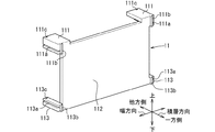
第1実施形態について図1〜図19を参照して説明する。各図において、電池セル2の厚さ方向は電池積層体10における電池セル2の積層方向であり、電池積層方向ともいう。積層方向と上下方向との両方に直交する方向は、電池セル2の幅方向または横方向である。 組電池1は、複数個の電池セル2の充電および放電または温度調節に用いられる電子部品によって制御されている。組電池1は、通電可能に接続されかつ積層設置された複数の電池セル2を積層方向に拘束して一体にして形成されている。また、組電池1は筐体内に収納するようにしてもよい。前述の電子部品は、例えばDC/DCコンバータ、熱媒体を流動させる流体駆動装置を駆動するモータ、インバータによって制御される電子部品、各種の電子式制御装置等である。組電池1は、このような電子部品を含めた装置であってもよい。   The first embodiment will be described with reference to FIGS. In each of the drawings, the thickness direction of the battery cell 2 is the stacking direction of the battery cells 2 in the battery stack 10, and is also referred to as the battery stacking direction. The direction orthogonal to both the stacking direction and the vertical direction is the width direction or the lateral direction of the battery cell 2. The assembled battery 1 is controlled by electronic components used for charging and discharging the plurality of battery cells 2 or controlling the temperature. The battery pack 1 is formed integrally by constraining a plurality of battery cells 2 that are connected to be able to conduct electricity and are stacked and installed in the stacking direction. Further, the battery pack 1 may be stored in a housing. The above-mentioned electronic components are, for example, a DC / DC converter, a motor driving a fluid driving device for flowing a heat medium, an electronic component controlled by an inverter, various electronic control devices, and the like. The assembled battery 1 may be a device including such electronic components.

電池積層体10を構成する電池セル2は、角形状の外装ケースを有する単電池である。この角形状の単電池は、例えばアルミニウム、アルミニウム合金等からなる外装ケースによってその外周面を被覆された直方体状である。各電池セル2には、正極端子および負極端子からなる二つの電極端子20のそれぞれが外装ケースの上面21から突出しており、この突出方向は、電池積層方向に対して垂直な上方向である。電池セル2の外装ケースは、例えば、金属の他に、樹脂で形成される構成でもよい。また電池セル2は、樹脂とアルミ箔をラミネートしたフィルムを外装ケースとして備えるものでもよい。   The battery cells 2 constituting the battery stack 10 are unit cells having a rectangular outer case. The rectangular unit cell has a rectangular parallelepiped shape whose outer peripheral surface is covered by an outer case made of, for example, aluminum, an aluminum alloy, or the like. In each battery cell 2, each of two electrode terminals 20 composed of a positive electrode terminal and a negative electrode terminal protrudes from the upper surface 21 of the outer case, and the direction of the protrusion is an upward direction perpendicular to the battery stacking direction. The outer case of the battery cell 2 may be formed of, for example, resin in addition to metal. Further, the battery cell 2 may include a film in which a resin and an aluminum foil are laminated as an outer case.

電池積層体10は、電池セル2と熱媒体通路部材4のセル間部44とを交互に所定個数積層した集合体を積層方向の両端部から一組のエンドプレート3によって挟むことにより、内側に向かう拘束力を作用させて一体に形成されている。エンドプレート3は厚さ方向寸法が上下方向長さや幅方向長さよりも小さい扁平状の箱体に形成されている。組電池1は、積層設置された複数の電池セル2と熱媒体通路部材4の内部通路を流通する熱媒体とが熱交換する構成を備える装置である。熱媒体は、冷却したり加熱したりして電池セルを温度調節可能な温調流体である。熱媒体は、気体、液体または気液混合の流体であり、あるいは使用時に状態変化を伴わない流体でもよいし相変化を伴う流体であってもよい。組電池1は、複数の電池セル2と一体に設置された熱媒体通路部材4を備えている。熱媒体通路部材4は、熱伝導性を有する材料、例えばアルミニウムを含む金属、銅を含む金属、金属を含有する樹脂材料、カーボン樹脂材料等で形成されている。   The battery stack 10 is formed by sandwiching a set in which a predetermined number of battery cells 2 and inter-cell portions 44 of the heat medium passage member 4 are alternately stacked by a pair of end plates 3 from both ends in the stacking direction. It is formed integrally by applying a restraining force toward it. The end plate 3 is formed in a flat box having a thickness dimension smaller than a vertical length or a width length. The assembled battery 1 is a device having a configuration in which a plurality of stacked battery cells 2 and a heat medium flowing through an internal passage of the heat medium passage member 4 exchange heat. The heat medium is a temperature-regulating fluid that can cool and heat the battery cells to adjust the temperature. The heat medium is a gas, a liquid, or a gas-liquid mixed fluid, or may be a fluid that does not undergo a state change during use or a fluid that undergoes a phase change. The assembled battery 1 includes a heat medium passage member 4 provided integrally with the plurality of battery cells 2. The heat medium passage member 4 is formed of a material having thermal conductivity, for example, a metal containing aluminum, a metal containing copper, a resin material containing a metal, a carbon resin material, or the like.

組電池1の拘束構造について説明する。図1〜図4に示すように、組電池1は、複数の電池セル2、隣接する電池セル2間に介在するセル間部44、隣接するセル間部44間を連結する連結部43、一組のエンドプレート3、一組のエンドプレート3に両側から圧縮するような拘束力を提供する拘束バンド5,6を備える。拘束バンド5、拘束バンド6のそれぞれは、電池積層体10と一組のエンドプレート3とを合わせた積層体の外面を支持する帯状部材である。拘束バンド5,6のそれぞれは、電池積層体10に対して圧縮力を提供している状態を維持できるように端部がリベットによって一組のエンドプレート3に固定されている。エンドプレート3は、上面30と、上面30に対向する下面32と、上面30および下面32に隣り合い上下方向に細長い一組の側面33と、隣接する電池セル2に対面する内側の幅面31と、幅面31に対向する外側の幅面34とを備えて形成されている。また、リベットは、ボルトナット、ねじ等の締結固定手段、溶接等の固定手段に置き換えることができる。拘束バンド5,6のそれぞれは、複数の電池セル2等を安定した力で押圧して一体化できるように金属、硬質の樹脂材料等の強度に優れた材料で形成されている。   The restraining structure of the battery pack 1 will be described. As shown in FIGS. 1 to 4, the battery pack 1 includes a plurality of battery cells 2, an inter-cell portion 44 interposed between the adjacent battery cells 2, a connecting portion 43 connecting the adjacent inter-cell portions 44, A pair of end plates 3 and a pair of end plates 3 are provided with restraining bands 5 and 6 for providing a restraining force to compress the end plates 3 from both sides. Each of the restraint bands 5 and 6 is a band-shaped member that supports the outer surface of the laminate in which the battery laminate 10 and the set of end plates 3 are combined. Each of the restraint bands 5 and 6 has its end fixed to the set of end plates 3 by rivets so as to maintain a state of providing a compressive force to the battery stack 10. The end plate 3 includes an upper surface 30, a lower surface 32 opposed to the upper surface 30, a pair of vertically elongated side surfaces 33 adjacent to the upper surface 30 and the lower surface 32, and an inner width surface 31 facing the adjacent battery cell 2. , And an outer width surface 34 facing the width surface 31. The rivets can be replaced with fastening means such as bolts and nuts and screws, and fixing means such as welding. Each of the restraint bands 5 and 6 is formed of a material having excellent strength such as a metal or a hard resin material so that the plurality of battery cells 2 and the like can be pressed and integrated with a stable force.

拘束バンド5と拘束バンド6は、電池積層体10を積層方向に圧縮するような拘束力を与える点について共通しているが、電池積層体10において異なる面を支持している。電池積層体10は、一組の対面をなす上壁10aおよび下壁10bと、一組の対面をなす側壁10cおよび側壁10dと、一組の対面をなす側壁10eおよび側壁10fとを含む複数の面を形成している。拘束バンド5は、電池積層体10における一側面を積層方向の全体にわたって支持するとともに、電池積層体10に対して電池の積層方向に拘束力を与えている。拘束バンド5は、電池積層体10を支持する支持部50と、支持部50の両端に位置する固定部51とを備えている。固定部51は、拘束バンド5が組電池1に対して固定されている部位である。固定部51は、支持部50における長手方向の両端部において支持部50に対して直交するように延びる板状部である。拘束バンド5は、拘束バンド5の固定部51が各エンドプレート3にリベット等によって固定されていることにより、電池積層体10に対して必要な拘束力を提供している状態を維持している。固定部51は、各エンドプレート3の下部に固定されている。   The restraint bands 5 and 6 are common in that a restraining force is applied to compress the battery stack 10 in the stacking direction, but support different surfaces in the battery stack 10. The battery stack 10 includes a plurality of pairs including an upper wall 10a and a lower wall 10b forming a pair of facing sides, a side wall 10c and a side wall 10d forming a pair of facing sides, and a pair of facing side walls 10e and 10f. Forming a surface. The restraining band 5 supports one side surface of the battery stack 10 over the entire stacking direction and applies a restraining force to the battery stack 10 in the battery stacking direction. The restraining band 5 includes a support portion 50 that supports the battery stack 10, and fixing portions 51 located at both ends of the support portion 50. The fixing part 51 is a part where the restraining band 5 is fixed to the battery pack 1. The fixing portion 51 is a plate-like portion that extends perpendicular to the supporting portion 50 at both ends in the longitudinal direction of the supporting portion 50. The restraining band 5 maintains a state in which a necessary restraining force is provided to the battery stack 10 by fixing the fixing portion 51 of the restraining band 5 to each end plate 3 by a rivet or the like. . The fixing portion 51 is fixed to a lower portion of each end plate 3.

組電池1は、少なくとも2個の拘束バンド5を備えている。拘束バンド5は、電池積層体10において電池セル2が積層設置されて形成された面のうち、対面関係にあるそれぞれの面を支持する支持部50を有している。一組の拘束バンド5は、電池積層体10において対面を支持する第1の拘束バンドである。支持部50は、電池積層体10において積層方向に沿う面のうち、対面をなす側壁10cと側壁10dとのそれぞれに沿って延びる形状である。側壁10cと側壁10dは、電池積層体10において互いに対向し上下方向および積層方向に沿うように形成された面である。上壁10aと下壁10bは、電池積層体10において電池セル2が積層設置されて形成された面であり、互いに対向し積層方向および幅方向に沿うように形成された面である。上壁10aと下壁10bは、それぞれが側壁10cと側壁10dとに交差しかつ隣接する隣接面である。上壁10aと下壁10bは、それぞれが側壁10eと側壁10fとに交差しかつ隣接する隣接面である。側壁10cと側壁10dは、それぞれが側壁10eと側壁10fとに交差しかつ隣接する隣接面である。   The battery pack 1 includes at least two restraining bands 5. The constraining band 5 has a support portion 50 that supports each of the surfaces in a face-to-face relationship among the surfaces formed by stacking the battery cells 2 in the battery stack 10. The set of restraint bands 5 is a first restraint band that supports the facing surface of the battery stack 10. The support portion 50 has a shape extending along each of the facing side walls 10c and 10d among the surfaces of the battery stack 10 along the stacking direction. The side wall 10c and the side wall 10d are surfaces formed in the battery stack 10 so as to face each other and to extend in the vertical direction and the stacking direction. The upper wall 10a and the lower wall 10b are surfaces formed by stacking the battery cells 2 in the battery stack 10, and are surfaces that face each other and are formed along the stacking direction and the width direction. The upper wall 10a and the lower wall 10b are adjacent surfaces that intersect and are adjacent to the side walls 10c and 10d, respectively. The upper wall 10a and the lower wall 10b are adjacent surfaces that intersect and are adjacent to the side walls 10e and 10f, respectively. The side walls 10c and 10d are adjacent surfaces that intersect and are adjacent to the side walls 10e and 10f, respectively.

支持部50は、電池積層体10に含まれる電池セル2の側面23の一部を覆って電池積層体10の積層方向長さ全体にわたって配されている。支持部50は、電池積層体10における側壁10cと側壁10dにおいて、熱媒体通路部材4に干渉しない箇所を外側から支持している。換言すれば、支持部50は、側壁10cと側壁10dにおいて、熱媒体通路部材4が露出する部位を除く箇所を外側から支持している。図1、図3、図5に示すように、支持部50は、側壁10cと側壁10dにおいて、熱媒体通路部材4よりも、拘束バンド6から離れた箇所である、下方の位置を、下壁10b側の位置を支持している。換言すれば、支持部50は、側壁10cと側壁10dにおいて、拘束バンド6が支持している上壁10aに対して最も離れた下壁10b寄りの下部を支持している。   The support 50 covers a part of the side surface 23 of the battery cell 2 included in the battery stack 10 and is disposed over the entire length of the battery stack 10 in the stacking direction. The support portion 50 supports, from the outside, portions of the side walls 10c and 10d of the battery stack 10 that do not interfere with the heat medium passage member 4. In other words, the support portion 50 supports the portions of the side walls 10c and 10d other than the portions where the heat medium passage member 4 is exposed, from the outside. As shown in FIGS. 1, 3, and 5, the support portion 50 moves the lower position, which is farther away from the restraining band 6 than the heat medium passage member 4, on the side walls 10 c and 10 d from the lower wall. The position on the 10b side is supported. In other words, the support part 50 supports the lower part near the lower wall 10b farthest from the upper wall 10a supported by the restraining band 6 on the side walls 10c and 10d.

支持部50は、対面をなす側壁10cと側壁10dのそれぞれについて積層方向長さの全体にわたって支持しているため、積層方向の端部が中央部に対して反るような動作を抑えるように電池積層体10を補強している。拘束バンド5は、電極端子20に関する幅方向の変位を抑制することにも寄与し、電極端子20と電極端子20とを連結するバスバなどの電装部品の品質確保に貢献している。さらに、複数の拘束バンド5は、側壁10cと側壁10dとの両方を支持しているため、側壁10cに近い側に位置する電極端子20の変位抑制と、側壁10dに近い側に位置する電極端子20の変位抑制との両方に貢献している。このように拘束バンド5は、電池積層体10の対面について積層方向の端部が中央部に対して幅方向に反るような外力に対して、電池積層体10の強度向上に寄与している。   Since the support portion 50 supports each of the side walls 10c and 10d facing each other over the entire length in the stacking direction, the battery is controlled so that the end in the stacking direction warps with respect to the central portion. The laminate 10 is reinforced. The restraining band 5 also contributes to suppressing displacement of the electrode terminal 20 in the width direction, and contributes to ensuring the quality of electrical components such as bus bars connecting the electrode terminal 20 to each other. Further, since the plurality of constraint bands 5 support both the side wall 10c and the side wall 10d, the displacement of the electrode terminal 20 located on the side closer to the side wall 10c is suppressed, and the electrode terminal located on the side closer to the side wall 10d. 20 displacement suppression. As described above, the restraining band 5 contributes to the improvement of the strength of the battery stack 10 against an external force such that the end in the stacking direction of the facing surface of the battery stack 10 warps in the width direction with respect to the center. .

拘束バンド5は、支持部50における幅方向の両端部のそれぞれから支持部50に対して直交するようにまたは厚さ方向に延びる係合片部52を備えている。係合片部52は、支持部50において長手方向長さの全体にわたって突出する板状の突出片部である。2個の係合片部52は、支持部50において長手方向長さの全体にわたって対向する一組の突出片部をなしている。係合片部52は、拘束バンド5が電池積層体10を支持している状態において、図11に示すように電池積層体10側の部材に嵌りこんで嵌合する部分である。係合片部52は、セル支持部材に係合する係合部である。   The restraining band 5 includes an engagement piece 52 extending from each of both ends in the width direction of the support 50 so as to be orthogonal to the support 50 or in the thickness direction. The engaging piece 52 is a plate-like projecting piece projecting over the entire length of the support 50 in the longitudinal direction. The two engaging pieces 52 form a pair of projecting pieces facing each other over the entire length of the support 50 in the longitudinal direction. The engaging piece 52 is a part that fits into a member on the battery stack 10 side in a state where the restraining band 5 supports the battery stack 10 as shown in FIG. 11. The engagement piece 52 is an engagement portion that engages with the cell support member.

図1、図2に示すように、組電池1は、幅方向に間隔をあけて設けられた2個の拘束バンド6によって上壁10aを支持されているとともに積層方向に拘束されている。拘束バンド6は、電池積層体10における一側面を積層方向の全体にわたって支持するとともに、電池積層体10に対して電池の積層方向に拘束力を与えている。拘束バンド6は、電池積層体10を支持する支持部60と、支持部60の両端に位置する固定部61とを備えている。固定部61は、拘束バンド6が組電池1に対して固定されている部位である。固定部61は、支持部60における長手方向の両端部において支持部60に対して直交するように延びる板状部である。拘束バンド6は、固定部61が各エンドプレート3にリベット等によって固定されていることにより、電池積層体10に対して必要な拘束力を提供している状態を維持している。固定部61は、各エンドプレート3の上部に固定されている。   As shown in FIGS. 1 and 2, the assembled battery 1 has an upper wall 10 a supported by two restraining bands 6 provided at intervals in the width direction and is restrained in the stacking direction. The restraint band 6 supports one side surface of the battery stack 10 over the entire stacking direction and applies a restraining force to the battery stack 10 in the battery stacking direction. The restraining band 6 includes a support portion 60 that supports the battery stack 10 and fixing portions 61 located at both ends of the support portion 60. The fixing portion 61 is a portion where the restraining band 6 is fixed to the battery pack 1. The fixing portion 61 is a plate-like portion that extends perpendicular to the supporting portion 60 at both ends in the longitudinal direction of the supporting portion 60. The restraining band 6 maintains a state of providing a required restraining force to the battery stack 10 by fixing the fixing portion 61 to each end plate 3 with a rivet or the like. The fixing portion 61 is fixed to an upper portion of each end plate 3.

組電池1は、少なくとも1個の拘束バンド6を備えている。拘束バンド6は、電池積層体10において電池セル2が積層設置されて形成された面のうち、対面関係にある壁部に隣接する壁面の少なくとも一つを支持する支持部60を有している。拘束バンド6は、電池積層体10において対面の隣接面を支持する第2の拘束バンドである。支持部60は、電池積層体10において積層方向に沿う面のうち、対面関係にある側壁10cと側壁10dとに隣接する上壁10aに沿って延びる形状である。上壁10aは、電池積層体10において、拘束バンド5が支持している側壁10cと側壁10dとに隣接し、互いに対向し幅方向および積層方向に沿うように形成された面である。   The battery pack 1 includes at least one restraining band 6. The restraining band 6 has a supporting portion 60 that supports at least one of the wall surfaces adjacent to the facing wall portion among the surfaces formed by stacking the battery cells 2 in the battery stack 10. . The constraining band 6 is a second constraining band that supports the opposing face of the battery stack 10. The support portion 60 has a shape extending along the upper wall 10a adjacent to the side wall 10c and the side wall 10d in a facing relationship among the surfaces along the stacking direction in the battery stack 10. The upper wall 10a is a surface adjacent to the side wall 10c and the side wall 10d supported by the restraining band 5 in the battery stack 10, and is formed to face each other and to extend along the width direction and the stacking direction.

支持部60は、電池積層体10に含まれる電池セル2の上面21の一部を覆って電池積層体10の積層方向長さ全体にわたって配されている。支持部60は、電池積層体10における上壁10aにおいて、電極端子20に干渉しない箇所を外側から支持している。換言すれば、支持部60は、上壁10aにおいて、電極端子20が露出する部位を除く箇所を外側から支持している。図1、図2、図5に示すように、支持部60は、上壁10aにおいて、電極端子20よりも幅方向の端部側の箇所を支持している。組電池1は、このような構成を有する拘束バンド6を2個備えている。また、支持部60は、上壁10aにおいて、電極端子20と電極端子20との間の箇所を支持している構成でもよい。   The support portion 60 is disposed over the entire length of the battery stack 10 in the stacking direction so as to cover a part of the upper surface 21 of the battery cell 2 included in the battery stack 10. The support portion 60 supports a portion of the upper wall 10a of the battery stack 10 that does not interfere with the electrode terminal 20 from outside. In other words, the support portion 60 supports the portion of the upper wall 10a excluding the portion where the electrode terminal 20 is exposed from the outside. As shown in FIGS. 1, 2, and 5, the support portion 60 supports a portion of the upper wall 10 a closer to the widthwise end than the electrode terminal 20. The assembled battery 1 includes two restraining bands 6 having such a configuration. Further, the support portion 60 may be configured to support a portion between the electrode terminals 20 on the upper wall 10a.

支持部60は、対面である側壁10cと側壁10dとの隣接面である上壁10aについて積層方向長さの全体にわたって支持しているため、積層方向の端部が中央部に対して反るような動作を抑えるように電池積層体10を補強している。拘束バンド6は、電極端子20に関する上下方向の変位を抑制することにも寄与し、電極端子20と電極端子20とを連結するバスバなどの電装部品の品質確保に貢献している。さらに、拘束バンド6は、上壁10aにおいて幅方向の両端部のそれぞれを支持しているため、側壁10cに近い側に位置する電極端子20の変位抑制と、側壁10dに近い側に位置する電極端子20の変位抑制との両方に貢献している。このように拘束バンド6は、電池積層体10において拘束バンド5が支持する面の隣接面について積層方向の端部が中央部に対して上下方向に反るような外力に対して、電池積層体10の強度向上に寄与している。   The support portion 60 supports the upper wall 10a, which is the adjacent surface between the facing side walls 10c and 10d, over the entire length in the stacking direction, so that the ends in the stacking direction warp with respect to the central portion. The battery stack 10 is reinforced so as to suppress undesired operations. The constraining band 6 also contributes to suppressing the vertical displacement of the electrode terminal 20 and contributes to ensuring the quality of electrical components such as bus bars connecting the electrode terminal 20 to each other. Further, since the restraining band 6 supports each of both ends in the width direction on the upper wall 10a, the displacement of the electrode terminal 20 located on the side closer to the side wall 10c and the electrode located on the side closer to the side wall 10d are suppressed. This contributes to both the displacement suppression of the terminal 20. As described above, the restraining band 6 is configured such that the battery stack 10 is not subjected to an external force in which the end in the stacking direction is warped vertically with respect to the center on the surface adjacent to the surface supported by the restraining band 5 in the battery stack 10. 10 contributes to the strength improvement.

拘束バンド6は、支持部60における幅方向の両端部から支持部60に対して直交するようにまたは厚さ方向に延びる一組の係合片部62を備えている。係合片部62は、支持部60において長手方向長さの全体にわたって突出する板状の突出片部である。2個の係合片部62は、支持部60において長手方向長さの全体にわたって対向する一組の突出片部をなしている。係合片部62は、拘束バンド6が電池積層体10を支持している状態において、図11に示すように電池積層体10側の部材に嵌りこんで嵌合する部分である。係合片部62は、セル支持部材に係合する係合部である。   The restraining band 6 is provided with a pair of engaging pieces 62 extending from both ends in the width direction of the support portion 60 so as to be orthogonal to the support portion 60 or in the thickness direction. The engaging piece 62 is a plate-shaped projecting piece projecting over the entire length in the longitudinal direction in the support part 60. The two engaging pieces 62 form a set of protruding pieces facing each other over the entire length in the longitudinal direction in the support section 60. The engagement piece 62 is a part that fits into a member on the battery stack 10 side in a state where the restraining band 6 supports the battery stack 10 as shown in FIG. 11. The engagement piece 62 is an engagement portion that engages with the cell support member.

また、拘束バンド6は、拘束バンド5が支持している側壁10cと側壁10dとに隣接し、互いに対向し幅方向および積層方向に沿うように形成された面をなす下壁10bを支持する構成でもよい。さらに組電池1は、上壁10aと下壁10bの片方だけでなく両方を支持するように設けられた拘束バンド6を有する構成でもよい。   In addition, the restraining band 6 is adjacent to the side walls 10c and 10d supported by the restraining band 5, and supports the lower wall 10b which is opposed to each other and forms a surface formed along the width direction and the laminating direction. May be. Further, the battery pack 1 may have a configuration having a restraining band 6 provided to support not only one of the upper wall 10a and the lower wall 10b but also both of them.

熱媒体通路部材4は、熱媒体が積層方向の一方側から他方側に流下する第1通路部4aと、熱媒体が積層方向の他方側から一方側に流下する第2通路部4bとを備えている。第1通路部4aと第2通路部4bとは、他方側に設けられた中継タンク部41において連結されている。第1通路部4aは一方側に流入タンク部40を有し、第2通路部4bは一方側に流出タンク部42を有している。第1通路部4aは熱媒体通路部材4において上側に位置し、第2通路部4bは下側に位置し、第1通路部4aと第2通路部4bは上下に重なるように並んでいる。   The heat medium passage member 4 includes a first passage portion 4a through which the heat medium flows down from one side in the stacking direction to the other side, and a second passage portion 4b through which the heat medium flows down from the other side in the stacking direction to one side. ing. The first passage portion 4a and the second passage portion 4b are connected at a relay tank portion 41 provided on the other side. The first passage portion 4a has an inflow tank portion 40 on one side, and the second passage portion 4b has an outflow tank portion 42 on one side. The first passage portion 4a is located on the upper side in the heat medium passage member 4, the second passage portion 4b is located on the lower side, and the first passage portion 4a and the second passage portion 4b are arranged so as to overlap vertically.

第1通路部4a、第2通路部4bは、積層方向に隣り合う電池セル2と電池セル2との間に介在するセル間部44を複数備えている。セル間部44の内部通路には熱媒体が流通する。複数のセル間部44は、積層方向に並ぶように設置されている。積層方向に隣り合うセル間部44とセル間部44とには、電池セル2の積層方向の厚さ寸法と同等の間隔が設けられている。セル間部44は、幅方向と上下方向とに面をなす電池セル2の幅面22と接触した状態で設置されている。幅面22は電池セル2において最も面積の大きい腹面でもある。また、電池セル2とセル間部44との間に熱伝導性を有するスペーサ部材を介在させて、スペーサ部材を電池セル2とセル間部44とによって挟み込むように構成してもよい。   The first passage portion 4a and the second passage portion 4b include a plurality of inter-cell portions 44 interposed between the battery cells 2 adjacent in the stacking direction. A heat medium flows through the internal passage of the inter-cell portion 44. The plurality of inter-cell portions 44 are provided so as to be arranged in the stacking direction. An interval equivalent to the thickness dimension of the battery cell 2 in the stacking direction is provided between the inter-cell portions 44 adjacent to each other in the stacking direction. The inter-cell portion 44 is installed in contact with the width surface 22 of the battery cell 2 which is in the width direction and the vertical direction. The width surface 22 is also the belly surface having the largest area in the battery cell 2. Further, a spacer member having thermal conductivity may be interposed between the battery cell 2 and the inter-cell portion 44 so that the spacer member is sandwiched between the battery cell 2 and the inter-cell portion 44.

第1通路部4a、第2通路部4bは、積層方向に隣り合うセル間部44とセル間部44とを連結する連結部43を備えている。連結部43の内部通路には熱媒体が流通する。連結部43は、電池セル2の幅方向について、電池セル2よりも外側に位置するように設けられている。連結部43は、上面21と幅面22との両方に直交する電池セル2の側面23に対向するように設けられている。   Each of the first passage portion 4a and the second passage portion 4b includes a connecting portion 43 that connects the inter-cell portions 44 adjacent to each other in the stacking direction. The heat medium flows through the internal passage of the connecting portion 43. The connecting portion 43 is provided so as to be located outside the battery cell 2 in the width direction of the battery cell 2. The connecting portion 43 is provided so as to face the side surface 23 of the battery cell 2 orthogonal to both the upper surface 21 and the width surface 22.

連結部43は、熱媒体通路部材4の内部を流れる熱媒体が折り返されてその流れの向きを変えて互いに対向する折返し流路を形成するターン部であり、折返し部でもある。連結部43は、流路の向きを逆向きに変更する折返し部であり、第1通路部4a、第2通路部4bのそれぞれにおいて少なくとも1箇所設けられている。第1通路部4a、第2通路部4bは、連結部43を介して折返し流路を連続的に積層することにより、図2、図6に示すような蛇行流路を形成している。   The connection part 43 is a turn part that turns the heat medium flowing inside the heat medium passage member 4 and changes the direction of the flow to form turned flow paths facing each other, and is also a turn part. The connecting portion 43 is a folded portion for changing the direction of the flow path to the opposite direction, and is provided at at least one position in each of the first passage portion 4a and the second passage portion 4b. The first passage portion 4a and the second passage portion 4b form a meandering flow passage as shown in FIGS. 2 and 6 by continuously laminating the folded flow passage via the connecting portion 43.

第1通路部4aは、折返し流路の積層方向、すなわち積層方向の一方端部に熱媒体が流入する流入タンク部40を備えている。流入タンク部40は、組電池1の外部からの熱媒体を熱媒体通路部材4内に導入する流入部である。積層方向の端部であり熱媒体の上流端部に位置するセル間部44の内部通路は、通路端部46および折返し部400の内部通路を介して、流入タンク部40の内部通路に連通している。流入タンク部40には、組電池1の外部から熱媒体を導入する配管が接続されている。この通路端部46は、電池積層体10のうち一方側の端部に位置する電池セル2と内部通路を流通する熱媒体とが熱交換するように、この電池セル2に対して熱伝達可能に設けられている。   The first passage portion 4a includes an inflow tank portion 40 into which a heat medium flows into one end of the folded flow path in the stacking direction, that is, one end in the stacking direction. The inflow tank portion 40 is an inflow portion that introduces a heat medium from outside the battery pack 1 into the heat medium passage member 4. The internal passage of the inter-cell portion 44 located at the end in the stacking direction and located at the upstream end of the heat medium communicates with the internal passage of the inflow tank portion 40 via the passage end 46 and the internal passage of the folded portion 400. ing. A pipe for introducing a heat medium from outside the battery pack 1 is connected to the inflow tank section 40. The passage ends 46 are capable of transferring heat to the battery cells 2 such that the battery cells 2 located at one end of the battery stack 10 exchange heat with the heat medium flowing through the internal passage. It is provided in.

第1通路部4aは、積層方向の他方端部において中継タンク部41の上部に折返し部410を介して連通している。第2通路部4bは、積層方向の他方端部において中継タンク部41の下部に折返し部411を介して連通している。中継タンク部41は、熱媒体が第1通路部4aから第2通路部4bに移行して逆向きの流れになる内部空間を形成する。第1通路部4aにおいて積層方向の他方端部に位置するセル間部44の内部通路は、第1通路部4aの通路端部46および折返し部410の内部通路を介して、中継タンク部41の内部通路に連通している。第1通路部4aの通路端部46は、電池積層体10のうち他方側の端部に位置する電池セル2と内部通路を流通する熱媒体とが熱交換するように、この電池セル2に対して熱伝達可能に設けられている。第2通路部4bにおいて積層方向の他方端部に位置するセル間部44の内部通路は、第2通路部4bの通路端部46および折返し部411の内部通路を介して、中継タンク部41の内部通路に連通している。第2通路部4bの通路端部46は、電池積層体10のうち他方側の端部に位置する電池セル2と内部通路を流通する熱媒体とが熱交換するように、この電池セル2に対して熱伝達可能に設けられている。   The first passage portion 4a communicates with the upper portion of the relay tank portion 41 via the folded portion 410 at the other end in the stacking direction. The second passage portion 4b communicates with the lower portion of the relay tank portion 41 via the folded portion 411 at the other end in the stacking direction. The relay tank portion 41 forms an internal space in which the heat medium transfers from the first passage portion 4a to the second passage portion 4b and flows in the opposite direction. The internal passage of the inter-cell portion 44 located at the other end in the stacking direction in the first passage portion 4a is connected to the relay tank portion 41 via the passage end portion 46 of the first passage portion 4a and the internal passage of the folded portion 410. It communicates with the internal passage. The passage end 46 of the first passage portion 4a is connected to the battery cell 2 so that the battery cell 2 located at the other end of the battery stack 10 and the heat medium flowing through the internal passage exchange heat. It is provided to be able to transfer heat. The internal passage of the inter-cell portion 44 located at the other end in the stacking direction in the second passage portion 4b is connected to the relay tank portion 41 via the passage end 46 of the second passage portion 4b and the internal passage of the folded portion 411. It communicates with the internal passage. The passage end 46 of the second passage portion 4b is connected to the battery cell 2 such that the battery cell 2 located at the other end of the battery stack 10 and the heat medium flowing through the internal passage exchange heat. It is provided to be able to transfer heat.

第2通路部4bは、積層方向の一方端部から熱媒体が流出する流出タンク部42を備えている。流出タンク部42は、熱媒体通路部材4内から組電池1の外部へ熱媒体が流出する流出部である。熱媒体通路部材4の下流端部に位置するセル間部44の内部通路は、第2通路部4bの通路端部46および折返し部420の内部通路を介して、流出タンク部42の内部通路に連通している。流出タンク部42には、組電池1の外部へ熱媒体が流出する配管が接続されている。第2通路部4bの通路端部46は、電池積層体10のうち一方側の端部に位置する電池セル2と内部通路を流通する熱媒体とが熱交換するように、この電池セル2に対して熱伝達可能に設けられている。   The second passage portion 4b includes an outflow tank portion 42 through which the heat medium flows out from one end in the stacking direction. The outflow tank portion 42 is an outflow portion where the heat medium flows out of the heat medium passage member 4 to the outside of the battery pack 1. The internal passage of the inter-cell portion 44 located at the downstream end of the heat medium passage member 4 is connected to the internal passage of the outflow tank portion 42 via the passage end 46 of the second passage portion 4b and the internal passage of the folded portion 420. Communicating. A pipe through which the heat medium flows out of the battery pack 1 is connected to the outflow tank portion 42. The passage end 46 of the second passage portion 4b is connected to the battery cell 2 such that the battery cell 2 located at one end of the battery stack 10 and the heat medium flowing through the internal passage exchange heat. It is provided to be able to transfer heat.

第1通路部4a、第2通路部4bは、熱媒体が電池セル2と熱交換するときの流れ方向、すなわち幅方向と積層方向との両方に直交する上下方向に細長い扁平管である。第1通路部4a、第2通路部4bは、この扁平管を曲げたサーペンタイン管によって形成することができる。この扁平管は、内部に複数の通路を有し、押し出し成形により形成された扁平状多穴管であってもよい。   The first passage portion 4a and the second passage portion 4b are flat tubes that are elongated in the flow direction when the heat medium exchanges heat with the battery cells 2, that is, in the vertical direction orthogonal to both the width direction and the stacking direction. The first passage portion 4a and the second passage portion 4b can be formed by a serpentine tube obtained by bending the flat tube. The flat tube may have a plurality of passages therein and may be a flat multi-hole tube formed by extrusion.

熱媒体は、電池積層体10の積層方向について一方端側の上部に位置する流入タンク部40から上側のサーペンタイン管内に流入し、上半分の各セル間部44を蛇行しながら他方端側に位置する中継タンク部41内の上部に流入する。このように第1通路部4aは、一方端側から他方端側への電池セル2の上半分を沿うように蛇行する流路を形成する。熱媒体は、さらに中継タンク部41内において上部から下部に流下し、中継タンク部41内の下部から下側のサーペンタイン管内に流入し、下半分の各セル間部44を蛇行しながら流下した後、一方端側の下部に位置する流出タンク部42内へ流出する。このように第2通路部4bは、他方端側から一方端側への電池セル2の下半分を沿うように蛇行する流路を形成する。   The heat medium flows into the upper serpentine pipe from the inflow tank portion 40 located at the upper end on one end side in the stacking direction of the battery stack 10, and is located at the other end side while meandering through the upper half inter-cell portions 44. Flows into the upper portion of the relay tank portion 41. In this way, the first passage portion 4a forms a flow passage that meanders along the upper half of the battery cell 2 from one end to the other end. The heat medium further flows down from the upper part to the lower part in the relay tank part 41, flows into the lower serpentine pipe from the lower part in the relay tank part 41, and flows down while meandering in each lower cell inter-part part 44. , And flows into the outflow tank portion 42 located at the lower portion on one end side. As described above, the second passage portion 4b forms a flow passage meandering along the lower half of the battery cell 2 from the other end to the one end.

このように組電池1において熱媒体通路部材4に内部通路に熱媒体が流通することにより、セル間部44を介して電池セル2の熱が熱媒体に吸熱されて各電池セル2を冷却することができる。また熱媒体通路部材4に内部通路に熱媒体が流通することにより、セル間部44を介して熱媒体の熱を電池セル2へ放熱して各電池セル2を暖めることができる。組電池1は、熱媒体通路部材4の流入タンク部40から流入した熱媒体が、流出タンク部42に至るまでの間に、積層方向に並ぶすべてのセル間部44において電池セル2と熱交換するように構成されている。   In this way, in the battery pack 1, the heat medium flows through the heat medium passage member 4 through the internal passage, so that the heat of the battery cells 2 is absorbed by the heat medium via the inter-cell portions 44 to cool the battery cells 2. be able to. In addition, since the heat medium flows through the heat medium passage member 4 through the internal passage, the heat of the heat medium is radiated to the battery cells 2 through the inter-cell portions 44, so that each battery cell 2 can be warmed. In the battery pack 1, the heat medium flowing from the inflow tank portion 40 of the heat medium passage member 4 reaches the outflow tank portion 42 and exchanges heat with the battery cells 2 in all the inter-cell portions 44 arranged in the stacking direction. It is configured to be.

第1通路部4aの他の形態として、一方端部に位置する上流側のセル間部44と他方端部に位置する下流側のセル間部44とは、その間にセル間部44を介さないで連結されている構成でもよい。また、一方端部のセル間部44と他方端部のセル間部44とは、電池積層体10において部分的に設けられたセル間部44を介して連結されている構成でもよい。このような構成である場合、一方端部のセル間部44と他方端部のセル間部44とは熱媒体が一方端部から他方端部へ内部通路を流下するように連通している。第2通路部4bの他の形態として、他方端部に位置する上流側のセル間部44と一方端部に位置する下流側のセル間部44とは、その間にセル間部44を介さないで連結されている構成でもよい。また、他方端部のセル間部44と一方端部のセル間部44とは、電池積層体10において部分的に設けられたセル間部44を介して連結されている構成でもよい。このような構成である場合、他方端部のセル間部44と一方端部のセル間部44とは熱媒体が他方端部から一端部へ内部通路を流下するように連通している。   As another form of the first passage portion 4a, the upstream inter-cell portion 44 located at one end and the downstream inter-cell portion 44 located at the other end do not interpose the inter-cell portion 44 therebetween. May be connected. Further, the configuration may be such that the inter-cell portion 44 at one end and the inter-cell portion 44 at the other end are connected via the inter-cell portion 44 provided partially in the battery stack 10. In such a configuration, the inter-cell portion 44 at one end and the inter-cell portion 44 at the other end communicate with each other so that the heat medium flows down the internal passage from one end to the other end. As another form of the second passage portion 4b, the upstream inter-cell portion 44 located at the other end and the downstream inter-cell portion 44 located at one end do not interpose the inter-cell portion 44 therebetween. May be connected. Further, the inter-cell portion 44 at the other end and the inter-cell portion 44 at the one end may be connected via the inter-cell portion 44 provided partially in the battery stack 10. In such a configuration, the inter-cell portion 44 at the other end and the inter-cell portion 44 at the one end communicate with each other so that the heat medium flows down the internal passage from the other end to the one end.

図6〜図10を参照して組電池1の組立てに関して説明する。図6の分解図や図9に示すように、電池積層体10には、積層方向の両端部にシート状の弾性部材9を介してエンドプレート3が装着される。弾性部材9は、弾性変形可能な材質によって形成されて、エンドプレート3と電池セル2との両方に対する接触面積を高める機能をもつ。エンドプレート3と一体になった電池積層体10には、図10に示すように、前述のように一組の拘束バンド5と一組の拘束バンド6とが装着されて所定の支持面に対する支持力と積層方向の拘束力とが電池積層体10に付与される。   The assembly of the battery pack 1 will be described with reference to FIGS. As shown in the exploded view of FIG. 6 and FIG. 9, the end plate 3 is attached to the battery stack 10 via sheet-like elastic members 9 at both ends in the stacking direction. The elastic member 9 is formed of an elastically deformable material and has a function of increasing a contact area with both the end plate 3 and the battery cell 2. As shown in FIG. 10, a set of restraining bands 5 and a set of restraining bands 6 are attached to the battery stack 10 integrated with the end plate 3 as described above, and are supported on a predetermined supporting surface. The force and the restraining force in the stacking direction are applied to the battery stack 10.

電池積層体10は、複数の電池セル2と熱媒体通路部材4とを一体に形成するために、図7および図8に示す組付け手順にしたがって組立てられる。各電池セル2は、図12に図示された第1支持部材7または図14に図示された第2支持部材8に装着されて、積層方向、上下方向および幅方向について支持されている。図7に示すように、第2支持部材8に支持された状態の電池セル2を、第1通路部4aと第2通路部4bのそれぞれに対して隣り合うセル間部44とセル間部44の間に一つ置きに挿入して熱媒体通路部材4に装着する。この装着時に第2支持部材8と電池セル2との一体品を移動させる方向は幅方向である。図7に示す組立てを経て熱媒体通路部材4に組み付けられた電池セル2は、図8に示す状態である。図8に示すように、第2支持部材8の上壁支持部81の積層方向長さは、電池セル2の厚さや隣り合う2つのセル間部44の間隔よりも長いため、上壁支持部81は、電池セル2が熱媒体通路部材4から下方向に脱落することを防ぐ機能を有する。   The battery stack 10 is assembled according to an assembly procedure shown in FIGS. 7 and 8 to integrally form the plurality of battery cells 2 and the heat medium passage member 4. Each battery cell 2 is mounted on the first support member 7 shown in FIG. 12 or the second support member 8 shown in FIG. 14, and is supported in the stacking direction, the vertical direction, and the width direction. As shown in FIG. 7, the battery cells 2 supported by the second support member 8 are separated from each other by the inter-cell portions 44 and the inter-cell portions 44 adjacent to the first passage portion 4a and the second passage portion 4b, respectively. And inserted into the heat medium passage member 4. The direction in which the integrated product of the second support member 8 and the battery cell 2 is moved in this mounting is the width direction. The battery cell 2 assembled to the heat medium passage member 4 through the assembly shown in FIG. 7 is in a state shown in FIG. As shown in FIG. 8, the length in the stacking direction of the upper wall support portion 81 of the second support member 8 is longer than the thickness of the battery cell 2 and the interval between two adjacent cell inter-portions 44. Reference numeral 81 has a function of preventing the battery cell 2 from dropping downward from the heat medium passage member 4.

次に図8に示すように、第1支持部材7に支持された状態の電池セル2を、第2支持部材8および電池セル2が一体になった熱媒体通路部材4に対して隣り合う電池セル2と電池セル2の間に挿入し、第1支持部材7と第2支持部材8とを係合させる。この組み付け時に第1支持部材7と電池セル2との一体品を移動させる方向は、第1通路部4aと第2通路部4bとが並んでいる上下方向である。図8に示す組立てを経て熱媒体通路部材4、セル支持枠および電池セル2が一体になった電池積層体10は、図9に示す状態である。次に図9に示すように弾性部材9とエンドプレート3とを電池積層体10の両端部のそれぞれに装着し、さらに図10に示すように拘束バンド5と拘束バンド6を所定の位置に装着する。これらの組み付け工程により、図1に図示する組電池1を組み立てることができる。   Next, as shown in FIG. 8, the battery cell 2 supported by the first support member 7 is connected to the heat medium passage member 4 in which the second support member 8 and the battery cell 2 are integrated. It is inserted between the cell 2 and the battery cell 2, and the first support member 7 and the second support member 8 are engaged. The direction in which the integrated product of the first support member 7 and the battery cell 2 is moved at the time of this assembly is the vertical direction in which the first passage portion 4a and the second passage portion 4b are arranged. The battery stack 10 in which the heat medium passage member 4, the cell support frame, and the battery cells 2 are integrated through the assembly shown in FIG. 8 is in a state shown in FIG. Next, as shown in FIG. 9, the elastic member 9 and the end plate 3 are mounted on both ends of the battery stack 10, and furthermore, the restraining bands 5 and 6 are mounted at predetermined positions as shown in FIG. I do. By these assembling steps, the assembled battery 1 shown in FIG. 1 can be assembled.

図12に示すように、第1支持部材7は電池セル2の側面23をそれぞれ支持する一組の側壁支持部72と、側壁支持部72の下部に設けられた一組のバンド支持部74と、一組の上壁支持部71と、スペーサ部73とを備え、これらが一体に形成されたセル支持部材である。一組の側壁支持部72は、電池セル2の幅方向長さと同等寸法、離間している。図13は、電池セル2を第1支持部材7によって支持した状態を一方側から示している。図14は、電池セル2を第1支持部材7によって支持した状態を他方側から示している。側壁支持部72は、電池セル2の厚さ寸法と同等の積層方向長さを有した板状部である。側壁支持部72とバンド支持部74とを合わせた上下方向長さは、電池セル2の上下方向寸法と同等である。   As shown in FIG. 12, the first support member 7 includes a pair of side wall support portions 72 each supporting the side surface 23 of the battery cell 2, and a pair of band support portions 74 provided below the side wall support portion 72. , A pair of upper wall support portions 71 and spacer portions 73, which are integrally formed as a cell support member. The pair of side wall support portions 72 are spaced apart from each other by the same size as the length of the battery cell 2 in the width direction. FIG. 13 shows a state where the battery cell 2 is supported by the first support member 7 from one side. FIG. 14 shows a state where the battery cell 2 is supported by the first support member 7 from the other side. The side wall support portion 72 is a plate-like portion having a length in the stacking direction equivalent to the thickness dimension of the battery cell 2. The vertical length of the side wall support portion 72 and the band support portion 74 is equal to the vertical size of the battery cell 2.

上壁支持部71は、側壁支持部72の上端から側壁支持部72に対して直交するように内側に突出する板状部であり、電池セル2の上面21に接触して支持する。一組の上壁支持部71は、電池セル2の上面21の幅方向両端部において電極端子20に接触しない範囲に設けられて上面21を上側から支持している。上壁支持部71の積層方向長さは、電池セル2の厚さ寸法と同等である。   The upper wall support portion 71 is a plate-shaped portion that protrudes inward from the upper end of the side wall support portion 72 so as to be orthogonal to the side wall support portion 72, and contacts and supports the upper surface 21 of the battery cell 2. The pair of upper wall support portions 71 are provided in a range that does not contact the electrode terminals 20 at both ends in the width direction of the upper surface 21 of the battery cell 2 and support the upper surface 21 from above. The length of the upper wall support 71 in the stacking direction is equal to the thickness of the battery cell 2.

上壁支持部71には、幅方向に離間する一組の溝部71aが設けられている。一組の溝部71aは、拘束バンド6が備える一組の係合片部62が嵌合する位置、溝幅および溝深さを満たすように設けられている。溝部71aは、上壁支持部71の上面において積層方向長さ全体を貫くように形成されている。図11に示すように、溝部71aは、開口側よりも底側の方が溝幅寸法が小さくなるように形成されている。溝部71aは、開口端から溝底に向かって溝幅寸法が狭くなるテーパ面71a1を有していることが好ましい。例えば、溝部71aは、溝底における溝幅寸法が係合片部62の厚さ寸法と同等以下であることが好ましい。また、係合片部62は先端に向けて先細り状であることが好ましい。このような構成によれば、セル支持部材に対する拘束バンド6の嵌合動作を確実かつ円滑に実施することができる。上壁支持部71には、積層方向の一方端部において一方側に突出する突部71bと、積層方向の他方端部において一方側に凹む凹部71cとが設けられている。   The upper wall support 71 is provided with a pair of grooves 71a that are separated in the width direction. The set of groove portions 71a is provided so as to satisfy the position, groove width, and groove depth where the set of engagement pieces 62 provided in the restraining band 6 fit. The groove portion 71a is formed on the upper surface of the upper wall support portion 71 so as to penetrate the entire length in the stacking direction. As shown in FIG. 11, the groove 71a is formed such that the groove width dimension is smaller on the bottom side than on the opening side. The groove portion 71a preferably has a tapered surface 71a1 in which the groove width dimension decreases from the opening end toward the groove bottom. For example, the groove 71a preferably has a groove width at the groove bottom that is equal to or less than the thickness of the engagement piece 62. Further, the engagement piece 62 is preferably tapered toward the tip. According to such a configuration, the fitting operation of the restraining band 6 to the cell support member can be reliably and smoothly performed. The upper wall support portion 71 is provided with a protrusion 71b projecting to one side at one end in the stacking direction and a concave portion 71c recessed to one side at the other end in the stacking direction.

バンド支持部74には、上下方向に離間する一組の溝部74aが設けられている。一組の溝部74aは、拘束バンド5が備える一組の係合片部52が嵌合する位置、溝幅および溝深さを満たすように設けられている。溝部74aは、バンド支持部74の表面において積層方向長さ全体を貫くように形成されている。図11に示すように、溝部74aは、開口側よりも底側の方が溝幅寸法が小さくなるように形成されている。溝部74aは、開口端から溝底に向かって溝幅寸法が狭くなるテーパ面74a1を有していることが好ましい。例えば、溝部74aは、溝底における溝幅寸法が係合片部52の厚さ寸法と同等以下であることが好ましい。また、係合片部52は先端に向けて先細り状であることが好ましい。このような構成によれば、セル支持部材に対する拘束バンド5の嵌合動作を確実かつ円滑に実施することができる。バンド支持部74には、積層方向の一方端部において一方側に突出する突部74bと、積層方向の他方端部において一方側に凹む凹部74cとが設けられている。   The band support 74 is provided with a pair of grooves 74a that are vertically separated from each other. The set of groove portions 74a is provided so as to satisfy the position, groove width, and groove depth where the set of engagement pieces 52 included in the restraining band 5 are fitted. The groove portion 74a is formed so as to penetrate the entire length in the stacking direction on the surface of the band support portion 74. As shown in FIG. 11, the groove 74a is formed such that the groove width dimension is smaller on the bottom side than on the opening side. The groove portion 74a preferably has a tapered surface 74a1 in which the groove width dimension decreases from the opening end toward the groove bottom. For example, the groove 74 a preferably has a groove width at the groove bottom that is equal to or less than the thickness of the engagement piece 52. Further, the engagement piece 52 is preferably tapered toward the tip. According to such a configuration, the fitting operation of the restraining band 5 to the cell support member can be reliably and smoothly performed. The band support portion 74 is provided with a protrusion 74b protruding to one side at one end in the stacking direction and a concave portion 74c recessed to one side at the other end in the stacking direction.

スペーサ部73は、上下方向に所定の長さを有して幅方向に延びて一組の側壁支持部72を連結する板状部材である。スペーサ部73は、幅方向に離間している側壁支持部72の下部と側壁支持部72の下部とを連結する板状部材である。スペーサ部73は、幅方向に離間しているバンド支持部74とバンド支持部74とを連結する板状部材でもある。スペーサ部73は、隣り合う電池セル2と電池セル2の間に介在して、セル間部44を設置するスペースを確保する機能を有する。スペーサ部73は、第1支持部材7によって支持された電池セル2の下部に接触して電池セル2の積層方向の変位を規制する規制壁としても機能する。   The spacer portion 73 is a plate-like member having a predetermined length in the up-down direction and extending in the width direction to connect a pair of side wall support portions 72. The spacer portion 73 is a plate-like member that connects a lower portion of the side wall support portion 72 and a lower portion of the side wall support portion 72 that are separated in the width direction. The spacer portion 73 is also a plate-like member that connects the band support portions 74 separated from each other in the width direction. The spacer portion 73 has a function of interposing between the adjacent battery cells 2 and securing a space for installing the inter-cell portion 44. The spacer portion 73 also functions as a regulating wall that contacts the lower part of the battery cell 2 supported by the first support member 7 and regulates the displacement of the battery cell 2 in the stacking direction.

図15に示すように、第2支持部材8は電池セル2の側面23をそれぞれ支持する一組の側壁支持部82と、側壁支持部82の下部に設けられた一組のバンド支持部84と、一組の上壁支持部81と、スペーサ部83とを備え、これらが一体に形成されたセル支持部材である。一組の側壁支持部82は、電池セル2の幅方向長さと同等寸法、離間している。図16は、電池セル2を第2支持部材8によって支持した状態を一方側から示している。図17は、電池セル2を第2支持部材8によって支持した状態を他方側から示している。側壁支持部82は、電池セル2の厚さ寸法と同等の積層方向長さを有した板状部である。側壁支持部82とバンド支持部84とを合わせた上下方向長さは、電池セル2の上下方向寸法と同等である。   As shown in FIG. 15, the second support member 8 includes a pair of side wall support portions 82 respectively supporting the side surfaces 23 of the battery cell 2, and a pair of band support portions 84 provided below the side wall support portions 82. , A pair of upper wall support portions 81 and a spacer portion 83, which are integrally formed as a cell support member. The pair of side wall supporting portions 82 are spaced apart from each other by the same size as the length of the battery cell 2 in the width direction. FIG. 16 shows a state where the battery cell 2 is supported by the second support member 8 from one side. FIG. 17 shows a state where the battery cell 2 is supported by the second support member 8 from the other side. The side wall support portion 82 is a plate-like portion having a length in the stacking direction equivalent to the thickness dimension of the battery cell 2. The vertical length of the side wall supporting portion 82 and the band supporting portion 84 is equal to the vertical dimension of the battery cell 2.

上壁支持部81は、側壁支持部82の上端から側壁支持部82に対して直交するように内側に突出する板状部であり、電池セル2の上面21に接触して支持する。一組の上壁支持部81は、電池セル2の上面21の幅方向両端部において電極端子20に接触しない範囲に設けられて上面21を上側から支持している。上壁支持部81の積層方向長さは、電池セル2の厚さ寸法とセル間部44の厚さ寸法の2倍とを合わせた寸法と同等である。   The upper wall support portion 81 is a plate-like portion that protrudes inward from the upper end of the side wall support portion 82 so as to be orthogonal to the side wall support portion 82, and contacts and supports the upper surface 21 of the battery cell 2. The pair of upper wall support portions 81 are provided in a range that does not contact the electrode terminals 20 at both ends in the width direction of the upper surface 21 of the battery cell 2 and support the upper surface 21 from above. The length in the stacking direction of the upper wall support portion 81 is equal to the combined size of the thickness of the battery cell 2 and twice the thickness of the inter-cell portion 44.

上壁支持部81には、幅方向に離間する一組の溝部81aが設けられている。一組の溝部81aは、拘束バンド6が備える一組の係合片部62が嵌合する位置、溝幅および溝深さを満たすように設けられている。溝部81aは、上壁支持部81の上面において、積層方向長さ全体を貫くように形成されている。図11に示すように、溝部81aは、開口側よりも底側の方が溝幅寸法が小さくなるように形成されている。溝部81aは、開口端から溝底に向かって溝幅寸法が狭くなるテーパ面81a1を有していることが好ましい。例えば、溝部81aは、溝底における溝幅寸法が係合片部62の厚さ寸法と同等以下であることが好ましい。上壁支持部81には、積層方向の一方端部において一方側に突出する突部81bと、積層方向の他方端部において一方側に凹む凹部81cとが設けられている。   The upper wall support portion 81 is provided with a pair of grooves 81a that are separated in the width direction. The set of groove portions 81a is provided so as to satisfy the position, groove width, and groove depth where the set of engagement pieces 62 provided in the restraining band 6 fit. The groove portion 81a is formed on the upper surface of the upper wall support portion 81 so as to penetrate the entire length in the stacking direction. As shown in FIG. 11, the groove 81a is formed such that the groove width dimension is smaller on the bottom side than on the opening side. The groove portion 81a preferably has a tapered surface 81a1 in which the groove width decreases from the opening end toward the groove bottom. For example, the groove 81a preferably has a groove width at the groove bottom equal to or less than the thickness of the engagement piece 62. The upper wall support portion 81 is provided with a protrusion 81b projecting to one side at one end in the stacking direction and a concave portion 81c recessed to one side at the other end in the stacking direction.

バンド支持部84には、上下方向に離間する一組の溝部84aが設けられている。一組の溝部84aは、拘束バンド5が備える一組の係合片部52が嵌合する位置、溝幅および溝深さを満たすように設けられている。溝部84aは、バンド支持部84の表面において積層方向長さ全体を貫くように形成されている。図11に示すように、溝部84aは、開口側よりも底側の方が溝幅寸法が小さくなるように形成されている。溝部84aは、開口端から溝底に向かって溝幅寸法が狭くなるテーパ面84a1を有していることが好ましい。例えば、溝部84aは、溝底における溝幅寸法が係合片部52の厚さ寸法と同等以下であることが好ましい。バンド支持部84には、積層方向の一方端部において一方側に突出する突部84bと、積層方向の他方端部において一方側に凹む凹部84cとが設けられている。   The band support portion 84 is provided with a pair of grooves 84a that are vertically separated from each other. The set of groove portions 84a is provided so as to satisfy the position, the groove width, and the groove depth where the set of engagement pieces 52 provided in the restraining band 5 are fitted. The groove portion 84a is formed on the surface of the band support portion 84 so as to penetrate the entire length in the stacking direction. As shown in FIG. 11, the groove portion 84a is formed such that the groove width dimension is smaller on the bottom side than on the opening side. The groove portion 84a preferably has a tapered surface 84a1 in which the groove width dimension decreases from the opening end toward the groove bottom. For example, the groove 84 a preferably has a groove width dimension at the groove bottom that is equal to or less than the thickness dimension of the engagement piece 52. The band support portion 84 is provided with a protrusion 84b projecting to one side at one end in the stacking direction and a concave portion 84c recessed to one side at the other end in the stacking direction.

スペーサ部83は、上下方向に所定の長さを有して幅方向に延びて一組の側壁支持部82を連結する板状部材である。スペーサ部83は、幅方向に離間している側壁支持部82の下部と側壁支持部82の下部とを連結する板状部材である。スペーサ部83は、幅方向に離間しているバンド支持部84とバンド支持部84とを連結する板状部材でもある。スペーサ部83は、隣り合う電池セル2と電池セル2の間に介在して、セル間部44を設置するスペースを確保する機能を有する。スペーサ部83は、第2支持部材8によって支持された電池セル2の下部に接触して電池セル2の積層方向の変位を規制する規制壁としても機能する。   The spacer portion 83 is a plate-like member having a predetermined length in the up-down direction and extending in the width direction and connecting a pair of side wall support portions 82. The spacer portion 83 is a plate-like member that connects a lower portion of the side wall support portion 82 and a lower portion of the side wall support portion 82 that are separated in the width direction. The spacer portion 83 is also a plate-like member that connects the band support portions 84 that are separated in the width direction. The spacer portion 83 has a function of interposing between the adjacent battery cells 2 and securing a space for installing the inter-cell portion 44. The spacer portion 83 contacts the lower part of the battery cell 2 supported by the second support member 8 and also functions as a regulating wall that regulates displacement of the battery cell 2 in the stacking direction.

第1支持部材7、第2支持部材8は、樹脂によって形成された樹脂製である。第1支持部材7と第2支持部材8は、積層方向に交互に組み合わされることにより、電池積層体10に含まれる電池セル2を支持するセル支持枠を構成する。第1支持部材7、第2支持部材8は、絶縁性を有する樹脂材料によって形成されている。第1支持部材7、第2支持部材8は、例えば、ポリプロピレン、ポリエチレン、ポリスチレン、塩化ビニル、フッ素系樹脂、PBT、ポリアミド、ポリアミドイミド、ABS樹脂、ポリアセタール、ポリカーボネート、ポリブチレンテレフタレート、ポリエチレンテレフタレート、ポリフェニレンスルファイド、フェノール、エポキシ、アクリル等によって形成することができる。   The first support member 7 and the second support member 8 are made of resin formed of resin. The first support members 7 and the second support members 8 are alternately combined in the stacking direction to form a cell support frame that supports the battery cells 2 included in the battery stack 10. The first support member 7 and the second support member 8 are formed of an insulating resin material. The first support member 7 and the second support member 8 are made of, for example, polypropylene, polyethylene, polystyrene, vinyl chloride, fluorine resin, PBT, polyamide, polyamide imide, ABS resin, polyacetal, polycarbonate, polybutylene terephthalate, polyethylene terephthalate, polyphenylene It can be formed of sulfide, phenol, epoxy, acrylic, or the like.

図18は、電池セル2および第1支持部材7の組立品と電池セル2および第2支持部材8の組立品とを一体に組み立てた状態を一方側から示している。図19は、図18と同じ組立品を他方側から示している。図18および図19に示したものは、熱媒体通路部材4を除いた状態を示している。実際の電池積層体10においては、スペーサ部73やスペーサ部83よりも上方に形成されたスペースにセル間部44が設置されることになる。図18および図19に示すように、上壁支持部71と上壁支持部81は、突部71bと凹部81cとが嵌合し、かつ互いの端面が当接することにより一体に連結されている。この連結状態において溝部71aと溝部81aは一本の連続する溝部を形成している。   FIG. 18 shows a state where the assembly of the battery cell 2 and the first support member 7 and the assembly of the battery cell 2 and the second support member 8 are integrally assembled from one side. FIG. 19 shows the same assembly from FIG. 18 from the other side. 18 and 19 show a state in which the heat medium passage member 4 has been removed. In the actual battery stack 10, the inter-cell portion 44 is provided in a space formed above the spacer 73 and the spacer 83. As shown in FIGS. 18 and 19, the upper wall support portion 71 and the upper wall support portion 81 are integrally connected by fitting the protrusion 71b and the concave portion 81c and abutting their end surfaces. . In this connected state, the groove 71a and the groove 81a form one continuous groove.

さらにバンド支持部74とバンド支持部84は、突部74bと凹部84cとが嵌合し、かつ互いの端面が当接することにより一体に連結されている。この連結状態において溝部74aと溝部84aは一本の連続する溝部を形成している。図18に示す組立品が積層方向に所定の個数組み合わされることにより、電池積層体10を形成している。電池積層体10は、溝部71aと溝部81aとが交互に連なって積層方向全体にわたって延びて係合片部62が嵌合する溝部を備え、溝部74aと溝部84aとが交互に連なって積層方向全体にわたって延びて係合片部52が嵌合する溝部を備えることになる。   Further, the band support portion 74 and the band support portion 84 are integrally connected by fitting the projection 74b and the concave portion 84c and abutting their end surfaces. In this connected state, the groove 74a and the groove 84a form one continuous groove. The battery stack 10 is formed by combining a predetermined number of the assemblies shown in FIG. 18 in the stacking direction. The battery stack 10 includes grooves in which the grooves 71a and the grooves 81a are alternately connected and extend over the entire stacking direction, and the engaging pieces 62 are fitted. The groove 74a and the groove 84a are alternately connected in the entire stacking direction. The engaging portion 52 is provided with a groove extending therethrough.

第1実施形態の組電池1がもたらす作用、効果について説明する。組電池1は、積層設置されている複数の電池セル2を含む電池積層体10と、電池積層体10を支持する支持部50,60を有し電池積層体10に対して電池の積層方向に拘束力を与える拘束バンド5,6とを備える。支持部50,60は、電池積層体10において積層方向に沿う面のうち、所定の対面と対面に隣接する少なくとも一つの隣接面とについて電池積層体10の積層方向の長さにわたって支持している。   The operation and effect provided by the battery pack 1 of the first embodiment will be described. The assembled battery 1 has a battery stack 10 including a plurality of battery cells 2 stacked and installed, and support portions 50 and 60 that support the battery stack 10 in the battery stacking direction with respect to the battery stack 10. And restraining bands (5, 6) for providing a restraining force. The support portions 50 and 60 support a predetermined facing surface and at least one adjacent surface adjacent to the facing surface of the battery stack 10 along the stacking direction over the length of the battery stack 10 in the stacking direction. .

この組電池1によれば、拘束バンド5と拘束バンド6は電池積層体10に対して積層方向の拘束力を与え、かつ拘束バンド5は所定の対面を支持し、拘束バンド6は対面の隣接面を支持する。これにより、電池積層体10において対面と隣接面の両方について積層方向の端部が中央部に対して反るような振動や衝撃が働いた場合に、電池積層体10のたわみ量を抑えることができるので、外力に対する電池積層体10の強度を向上できる。この組電池1によれは、振動や衝撃に対する強度向上を図ることができる。   According to the battery pack 1, the restraining bands 5 and 6 apply a restraining force in the stacking direction to the battery stack 10, and the restraining band 5 supports a predetermined facing surface, and the restraining band 6 is adjacent to the facing surface. Support surface. Thereby, in the case where vibrations or shocks in which the ends in the stacking direction warp with respect to the center in both the facing surface and the adjacent surface in the battery laminate 10 act, the amount of deflection of the battery laminate 10 can be suppressed. Therefore, the strength of the battery stack 10 against external force can be improved. According to the battery pack 1, the strength against vibration and impact can be improved.

電池積層体10は、電池セル2を対面と隣接面とにおいて支持して積層されたセル支持部材を含んでいる。拘束バンドは、対面においてセル支持部材を支持する第1の拘束バンドと、隣接面においてセル支持部材を支持する第2の拘束バンドとを含んでいる。この構成によれば、対面を支持する第1の拘束バンドと隣接面を支持する第2の拘束バンドとがセル支持部材を介して一体につながっているため、拘束バンド全体の強度を高めることができ、組電池の振動等に対する強度をさらに向上できる。   The battery stack 10 includes a cell support member that supports and stacks the battery cells 2 on the facing surface and the adjacent surface. The restraining band includes a first restraining band that supports the cell supporting member on the facing surface, and a second restraining band that supports the cell supporting member on the adjacent surface. According to this configuration, since the first restraining band supporting the facing surface and the second restraining band supporting the adjacent surface are integrally connected via the cell supporting member, the strength of the entire restraining band can be increased. Thus, the strength of the battery pack against vibrations and the like can be further improved.

第1の拘束バンドは、対面において中央部よりも隣接面から遠い位置を支持している。この構成によれば、対面を支持する第2の拘束バンドから第1の拘束バンドに至る沿面距離を長くすることができる。これにより、第1の拘束バンドと第2の拘束バンドとによる電池積層体10への支持力を、電池積層体10の対面と隣接面とにおいて広範囲に及ぼすことができるので、電池積層体10の剛性を高める支持ができ、振動等に対する強度をさらに高めた組電池1を提供できる。   The first restraining band supports a position farther from the adjacent surface than the central portion in the opposite surface. According to this configuration, the creepage distance from the second restraining band supporting the facing surface to the first restraining band can be increased. Thereby, the supporting force of the first constraining band and the second constraining band on the battery stack 10 can be exerted in a wide range on the facing surface and the adjacent surface of the battery stack 10. It is possible to provide the assembled battery 1 which can support to increase the rigidity and further enhance the strength against vibration and the like.

第1の拘束バンドは、対面において、第2の拘束バンドによって支持されている隣接面から遠い側の端部を電池積層体10の積層方向長さにわたって支持している。この構成によれば、第2の拘束バンドから第1の拘束バンドに至る沿面距離が最も長くなるように第1の拘束バンドによって電池積層体10を支持することができる。これにより、第1の拘束バンドの幅寸法を抑えつつ電池積層体10の剛性を高めることができる組電池1を提供できる。   The first constraining band supports an end farther from the adjacent surface supported by the second constraining band over the length of the battery stack 10 in the stacking direction. According to this configuration, the battery stack 10 can be supported by the first constraint band such that the creepage distance from the second constraint band to the first constraint band is the longest. Thereby, it is possible to provide the battery pack 1 that can increase the rigidity of the battery stack 10 while suppressing the width dimension of the first restraining band.

第1の拘束バンドは、対面において、第2の拘束バンドによって支持されている隣接面から遠い側の端部を電池積層体10の積層方向長さにわたって支持し、電池セル2は、隣接面において露出する電極端子20を有していることが好ましい。この構成によれば、対面において第1の拘束バンドが干渉しない隣接面寄りの位置に、電池セル2の温調に係る熱媒体通路を設置することができる。これにより、発熱量が大きい電極端子20に近い位置において電池セル2の温調効果が高い組電池1を提供できるので、電池積層体10の強度向上と、電池温調との両立を図ることができる。   The first constraining band supports, on the opposite surface, an end remote from the adjacent surface supported by the second constraining band over the length of the battery stack 10 in the stacking direction. It is preferable to have the electrode terminals 20 exposed. According to this configuration, the heat medium passage relating to the temperature control of the battery cell 2 can be provided at a position near the adjacent surface where the first constraint band does not interfere with the facing surface. Thereby, the battery pack 1 with a high temperature control effect of the battery cell 2 can be provided at a position close to the electrode terminal 20 where the calorific value is large. Therefore, it is possible to achieve both improvement in the strength of the battery stack 10 and battery temperature control. it can.

第1の拘束バンドおよび第2の拘束バンドは、セル支持部材に係合する係合部を有している。この構成によれば、第1の拘束バンドと第2の拘束バンドとのそれぞれについて、セル支持部材との結合力が高まるので、セル支持部材を介して一体につながった拘束バンド全体の剛性を高めることができる。   The first restraining band and the second restraining band have an engaging portion that engages with the cell support member. According to this configuration, for each of the first restraint band and the second restraint band, the coupling force between the first restraint band and the second restraint band is increased, so that the rigidity of the entire restraint band integrally connected via the cell support member is increased. be able to.

組電池1は、内部通路を流通する熱媒体と電池セル2とが熱交換するように設けられた熱媒体通路部材4を備える。熱媒体通路部材4は、積層方向に隣り合う電池セル2と電池セル2の間に介在し内部通路を流通する熱媒体と電池セル2とが熱交換するセル間部44と、積層方向に隣り合うセル間部44とセル間部44とを連結し内部通路を熱媒体が流れる連結部43とを備える。セル間部44と連結部43は、電池積層体10における積層方向の一方端部から他方端部にかけてすべての電池セル2と熱交換する熱媒体が流下する一連の内部通路を形成するように設けられている。この構成によれば、電池セル2と熱媒体通路部材4とを一体に形成した電池積層体10において、対面と隣接面の両方について積層方向の端部が中央部に対して反るような振動や衝撃に対する電池積層体10の強度を向上できる。   The battery pack 1 includes a heat medium passage member 4 provided so that the heat medium flowing through the internal passage and the battery cells 2 exchange heat. The heat medium passage member 4 is provided between the battery cells 2 adjacent to each other in the stacking direction, and the inter-cell portion 44 in which the heat medium flowing through the internal passage and exchanging heat with the battery cells 2 is adjacent to each other in the stacking direction. There is provided a connecting portion 43 that connects the inter-cell portions 44 and the inter-cell portions 44 that match each other and through which the heat medium flows through the internal passage. The inter-cell portion 44 and the connecting portion 43 are provided so as to form a series of internal passages through which a heat medium that exchanges heat with all the battery cells 2 flows from one end to the other end in the stacking direction of the battery stack 10. Have been. According to this configuration, in the battery stack 10 in which the battery cells 2 and the heat medium passage member 4 are integrally formed, the vibration in which the ends in the stacking direction of both the facing surface and the adjacent surface warp with respect to the center portion. And the strength of the battery stack 10 against shocks and shocks can be improved.

拘束バンドは、対面において電池積層体10を支持する第1の拘束バンドと、隣接面において電池積層体10を支持する第2の拘束バンドとを含んでいる。第1の拘束バンドは、対面において連結部43に重ならない位置を支持している。この構成によれば、対面において第1の拘束バンドが干渉しない位置に、熱媒体通路部材4を設置することができる。これにより、電池セル2の温調機能を確保しつつ、電池積層体10の強度向上が図れる組電池1を提供できる。   The restraining band includes a first restraining band supporting the battery stack 10 on the facing surface and a second restraining band supporting the battery stack 10 on the adjacent face. The first restraining band supports a position where the first restraining band does not overlap with the connecting portion 43. According to this configuration, the heat medium passage member 4 can be installed at a position where the first constraint band does not interfere with the facing surface. Thereby, it is possible to provide the battery pack 1 that can improve the strength of the battery stack 10 while ensuring the temperature control function of the battery cell 2.

(第2実施形態)
第2実施形態について図20〜図30を参照して説明する。各図において前述の実施形態と同様の構成であるものは同一の符号を付し、同様の作用、効果を奏し、第2実施形態で特に説明しない構成、作用、効果については、第1実施形態と同様であり、第1実施形態と異なる点についてのみ説明する。
(2nd Embodiment)
A second embodiment will be described with reference to FIGS. In each of the drawings, components having the same configurations as those of the above-described embodiment are denoted by the same reference numerals, and have the same functions and effects. The configurations, operations, and effects not particularly described in the second embodiment are described in the first embodiment. Only the points different from the first embodiment will be described.

第2実施形態の組電池101は、第1実施形態に対して、熱媒体が流通する熱媒体通路と拘束バンドとが相違している。図20〜図24に示すように、組電池101は、電池積層体10を形成する側壁10cと側壁10dと下壁10bのそれぞれに対して外側から覆うように支持する熱交換器13を備えている。熱交換器13は、全体として厚さの薄い矩形状であり、内部に熱媒体が流通する熱媒体通路を有するように構成され、電池積層体10に対して熱伝達可能に設置されている。組電池101は、積層設置された複数の電池セル2と熱交換器13の内部通路を流通する熱媒体とが熱交換する構成を備える装置である。熱媒体は、第1実施形態と同様である、電池セル2を温度調節可能な温調流体である。熱交換器13は、熱伝導性を有する材料、例えばアルミニウムを含む金属、銅を含む金属、金属を含有する樹脂材料、カーボン樹脂材料等で形成されている。   The assembled battery 101 of the second embodiment is different from the first embodiment in the heat medium passage through which the heat medium flows and the restraining band. As shown in FIGS. 20 to 24, the battery pack 101 includes a heat exchanger 13 that supports the side walls 10 c, the side walls 10 d, and the lower wall 10 b that form the battery stack 10 so as to cover each of the side walls 10 c, 10 d, and the lower wall 10 b from the outside. I have. The heat exchanger 13 has a thin rectangular shape as a whole, is configured to have a heat medium passage through which a heat medium flows, and is installed so as to be able to transfer heat to the battery stack 10. The battery pack 101 is a device having a configuration in which a plurality of battery cells 2 stacked and exchanged heat with a heat medium flowing through an internal passage of the heat exchanger 13. The heat medium is a temperature-regulating fluid capable of controlling the temperature of the battery cell 2 as in the first embodiment. The heat exchanger 13 is formed of a material having thermal conductivity, for example, a metal containing aluminum, a metal containing copper, a resin material containing a metal, a carbon resin material, or the like.

図21に示すように、隣り合う電池セル2間には熱媒体通路が設けられていない。組電池101は、電池セル2と熱媒体とに関して電池セル2の側面23、下面を介して熱伝達が行われる構成を有する。電池積層体10の側壁10c、側壁10dおよび下壁10bのそれぞれを外側から支持する熱交換器13は、熱交換器13を外側から覆う拘束バンド105と拘束バンド106によって電池積層体10側に拘束されている。側壁10cと側壁10dは対面であり、下壁10bは対面の隣接面である。   As shown in FIG. 21, no heat medium passage is provided between adjacent battery cells 2. The assembled battery 101 has a configuration in which heat transfer is performed between the battery cell 2 and the heat medium via the side surface 23 and the lower surface of the battery cell 2. The heat exchanger 13 that supports each of the side walls 10c, 10d, and the lower wall 10b of the battery stack 10 from the outside is restrained toward the battery stack 10 by the restraining bands 105 and 106 that cover the heat exchanger 13 from the outside. Have been. The side wall 10c and the side wall 10d face each other, and the lower wall 10b is a face adjacent to the face.

組電池101の拘束構造について説明する。図20〜図24に示すように、組電池101は、複数の電池セル2、セル支持部材11、一組のエンドプレート3、電池積層体10の少なくとも3面を外側から拘束する拘束バンド105,106を備える。拘束バンド105,106のそれぞれは、電池積層体10の外面を支持する矩形状の部材である。拘束バンド105,106のそれぞれは、複数の電池セル2と熱交換器13を安定した力で押圧して一体化できるように金属、硬質の樹脂材料等の強度に優れた材料で形成されている。   The restraining structure of the battery pack 101 will be described. As shown in FIGS. 20 to 24, the battery pack 101 includes a plurality of battery cells 2, a cell support member 11, a set of end plates 3, a restraining band 105 for restraining at least three surfaces of the battery stack 10 from the outside, 106 is provided. Each of the restraint bands 105 and 106 is a rectangular member that supports the outer surface of the battery stack 10. Each of the restraint bands 105 and 106 is formed of a material having excellent strength such as a metal or a hard resin material so that the plurality of battery cells 2 and the heat exchanger 13 can be pressed and integrated with a stable force. .

図24〜図26を参照して組電池101の組立てに関して説明する。図23、図25の分解図、図26に示すように、電池積層体10の側壁10c、側壁10dのそれぞれには、外側に向けて積層された熱伝導性部材12、熱交換器13および弾性部材14を介して拘束バンド105が装着されている。電池積層体10の下壁10bには、外側に向けて積層された熱伝導性部材12、熱交換器13および弾性部材14を介して拘束バンド106が装着されている。熱伝導性部材12は、各電池セル2と熱交換器13との熱伝達性を高める機能をもつ。弾性部材14は、弾性変形する材質で形成されて、拘束バンドと熱交換器13の両方に対する接触面積を高め、拘束力が伝達しやすい状態を確保する機能をもつ。図26に示すように、電池積層体10には、一組の拘束バンド105と拘束バンド106とが装着されている構成により、所定の対面と隣接面とに対する支持力が電池積層体10に付与されている。   The assembly of the battery pack 101 will be described with reference to FIGS. As shown in the exploded views of FIGS. 23 and 25 and FIG. 26, the side wall 10c and the side wall 10d of the battery stack 10 have a heat conductive member 12, a heat exchanger 13, The restraining band 105 is mounted via the member 14. A restraining band 106 is attached to the lower wall 10b of the battery stack 10 via a heat conductive member 12, a heat exchanger 13, and an elastic member 14 that are stacked outward. The heat conductive member 12 has a function of improving the heat transfer between each battery cell 2 and the heat exchanger 13. The elastic member 14 is formed of a material that is elastically deformed, and has a function of increasing a contact area with both the restraining band and the heat exchanger 13 and ensuring a state in which the restraining force is easily transmitted. As shown in FIG. 26, the battery stack 10 has a structure in which a pair of restraining bands 105 and 106 are attached, so that a supporting force for a predetermined facing surface and an adjacent surface is applied to the battery stack 10. Have been.

各エンドプレート3は、ボルトとナットにより、組電池101を固定するための設置部に固定されている。これにより、組電池101は設置部に固定されている。この構成によれば、電池積層体10に対して積層方向に圧縮するような拘束力を与えることができる。   Each end plate 3 is fixed to an installation portion for fixing the assembled battery 101 by bolts and nuts. Thus, the battery pack 101 is fixed to the installation section. According to this configuration, it is possible to apply a restraining force to the battery stack 10 such that the battery stack 10 is compressed in the stacking direction.

拘束バンド105と拘束バンド106は、電池積層体10において異なる面を支持している。拘束バンド105は、電池積層体10の側壁10c,10dの全体を支持する大きさの支持部150と、支持部150の両端のそれぞれにおいて積層方向に延びる係合片部52とを備えている。係合片部52は、電池積層体10に対する拘束バンド105の固定力に寄与している。一組の拘束バンド105は、電池積層体10において対面を支持する第1の拘束バンドである。   The constraint bands 105 and 106 support different surfaces in the battery stack 10. The restraining band 105 includes a support portion 150 having a size to support the entire side walls 10 c and 10 d of the battery stack 10, and engagement pieces 52 extending in the stacking direction at both ends of the support portion 150. The engagement pieces 52 contribute to the fixing force of the restraint band 105 to the battery stack 10. One set of the restraint bands 105 is a first restraint band that supports the facing surface in the battery stack 10.

拘束バンド106は、電池積層体10の下壁10bの全体を支持する大きさの支持部160と、支持部160の両端のそれぞれにおいて積層方向に延びる係合片部62とを備えている。拘束バンド106は、電池積層体10において対面の隣接面を支持する第2の拘束バンドである。係合片部62は、電池積層体10に対する拘束バンド106の固定力に寄与している。係合片部62は、拘束バンド106が電池積層体10を支持している状態において、図11に示す例と同様に、電池積層体10側の部材に嵌りこんで嵌合する部分である。組電池101は、拘束バンド106の係合片部62が、セル支持部材11に設けられた、溝部111aや溝部113aと同様の溝部113dに嵌合する構成を有している。   The restraining band 106 includes a support portion 160 having a size to support the entire lower wall 10 b of the battery stack 10, and engagement pieces 62 extending in the stacking direction at both ends of the support portion 160. The constraining band 106 is a second constraining band that supports the opposing face of the battery stack 10. The engagement pieces 62 contribute to the fixing force of the restraint band 106 to the battery stack 10. The engagement piece portion 62 is a portion that fits into the member on the battery stack 10 side in a state where the restraining band 106 supports the battery stack 10, similarly to the example illustrated in FIG. 11. The assembled battery 101 has a configuration in which the engagement piece 62 of the restraining band 106 fits into a groove 113d provided in the cell support member 11 and is similar to the groove 111a or the groove 113a.

支持部150は、対面をなす側壁10cと側壁10dのそれぞれに関してほぼ全体を支持しているため、積層方向の端部が中央部に対して反って電池積層体10が幅方向に撓むような動作を抑えるように電池積層体10を補強している。拘束バンド105は、電極端子20に関する幅方向の変位を抑制することにも寄与し、電極端子20と電極端子20とを連結するバスバなどの電装部品の品質確保に貢献している。さらに、複数の拘束バンド105は、側壁10cと側壁10dとの両方を支持しているため、側壁10cに近い側に位置する電極端子20の変位抑制と、側壁10dに近い側に位置する電極端子20の変位抑制との両方に貢献している。   Since the supporting portion 150 substantially supports the entire side wall 10c and the side wall 10d facing each other, the operation in which the end in the stacking direction is warped with respect to the center and the battery stack 10 is bent in the width direction. The battery stack 10 is reinforced so as to suppress the above. The restraining band 105 also contributes to suppressing displacement of the electrode terminals 20 in the width direction, and contributes to securing the quality of electrical components such as bus bars connecting the electrode terminals 20 to each other. Furthermore, since the plurality of restraining bands 105 support both the side wall 10c and the side wall 10d, the displacement of the electrode terminal 20 located on the side closer to the side wall 10c is suppressed, and the electrode terminal located on the side closer to the side wall 10d. 20 displacement suppression.

支持部160は、側壁10cと側壁10dとに隣接する下壁10bに関してほぼ全体を支持しているため、積層方向の端部が中央部に対して反って電池積層体10が上下方向に撓むような動作を抑えるように電池積層体10を補強している。拘束バンド106は、電極端子20に関する上下方向の変位を抑制することにも寄与し、電極端子20と電極端子20とを連結するバスバなどの電装部品の品質確保に貢献している。   Since the supporting portion 160 supports substantially the entirety of the lower wall 10b adjacent to the side wall 10c and the side wall 10d, the end in the stacking direction is warped with respect to the center and the battery stack 10 is bent in the vertical direction. The battery stack 10 is reinforced so as to suppress undesired operations. The constraining band 106 also contributes to suppressing the vertical displacement of the electrode terminal 20 and contributes to ensuring the quality of electrical components such as a bus bar connecting the electrode terminal 20 to each other.

各電池セル2は、図27、図28に図示されたセル支持部材11に装着されて、積層方向、上下方向および幅方向について支持されている。電池積層体10は、図29に示すセル支持部材11と電池セル2との一体品を、積層方向に組み合わせることによって形成されている。   Each battery cell 2 is mounted on the cell support member 11 shown in FIGS. 27 and 28, and is supported in the stacking direction, the vertical direction, and the width direction. The battery stack 10 is formed by combining, in the stacking direction, an integrated product of the cell support member 11 and the battery cell 2 shown in FIG.

図27、図28に示すように、セル支持部材11は、電池セル2の側面23の上部と上面21とをそれぞれ支持する一組の上壁支持部111と、電池セル2の側面23の下部をそれぞれ支持する一組の側壁支持部113と、スペーサ部112とを備え、これらが一体に形成されたセル支持部材である。スペーサ部112は、上下方向と幅方向とについて電池セル2の幅面22と同じ大きさであり、一組の上壁支持部111を連結するとともに一組の側壁支持部113を連結する板状部材である。スペーサ部112は、隣り合う電池セル2と電池セル2の間に介在して、幅面22の全体を支持し、電池セル2の積層方向の変位を規制する規制壁としても機能する。   As shown in FIGS. 27 and 28, the cell support member 11 includes a pair of upper wall support portions 111 that support the upper portion 21 and the upper surface 21 of the side surface 23 of the battery cell 2, respectively, and the lower portion of the side surface 23 of the battery cell 2. Are provided as a pair of side wall support portions 113 and a spacer portion 112, each of which is integrally formed. The spacer portion 112 is the same size as the width surface 22 of the battery cell 2 in the up-down direction and the width direction, and is a plate-like member that connects the pair of upper wall support portions 111 and connects the pair of side wall support portions 113. It is. The spacer portion 112 is interposed between the adjacent battery cells 2, supports the entire width surface 22, and also functions as a regulating wall that regulates displacement of the battery cells 2 in the stacking direction.

上壁支持部111は、スペーサ部112における上部の角部のそれぞれから積層方向に延びる横断面L字状の部分である。一組の上壁支持部111は、電池セル2の幅方向長さと同等寸法、離間している。図29は、電池セル2をセル支持部材11によって支持した状態を一方側から示している。図30は、電池セル2をセル支持部材11によって支持した状態を他方側から示している。上壁支持部111は、電池セル2の厚さ寸法と同等の積層方向長さを有している。上壁支持部111は、スペーサ部112の角部から内側に突出する板状部分において電池セル2の上面21に接触して支持する。この板状部分は、電池セル2の上面21の幅方向両端部において電極端子20に接触しない範囲に設けられて上面21を上側から支持している。上壁支持部111の積層方向長さは、電池セル2の厚さ寸法と同等である。   The upper wall support portion 111 is a portion having an L-shaped cross section that extends in the stacking direction from each of the upper corners of the spacer portion 112. The pair of upper wall support portions 111 are spaced apart from each other by the same size as the length of the battery cell 2 in the width direction. FIG. 29 shows a state where the battery cell 2 is supported by the cell support member 11 from one side. FIG. 30 shows a state where the battery cells 2 are supported by the cell support members 11 from the other side. The upper wall support 111 has a length in the stacking direction equivalent to the thickness of the battery cell 2. The upper wall support portion 111 is in contact with and supports the upper surface 21 of the battery cell 2 at a plate-like portion protruding inward from a corner of the spacer portion 112. The plate-shaped portion is provided in a range that does not contact the electrode terminal 20 at both ends in the width direction of the upper surface 21 of the battery cell 2 and supports the upper surface 21 from above. The length of the upper wall support 111 in the stacking direction is equal to the thickness of the battery cell 2.

上壁支持部111には、側面23を支持する部分において、幅方向に離間する溝部111aが設けられている。溝部111aは、拘束バンド105における上側の係合片部62が嵌合する位置、溝幅および溝深さを満たすように設けられている。溝部111aは、上壁支持部111において積層方向長さ全体を貫くように形成されている。溝部111aは、図11に示す実施例と同様に、開口側よりも底側の方が溝幅寸法が小さくなるように形成されている。溝部111aは、図11と同様に、開口端から溝底に向かって溝幅寸法が狭くなるテーパ面を有していることが好ましい。例えば、溝部111aは、溝底における溝幅寸法が係合片部52の厚さ寸法と同等以下であることが好ましい。このような構成によれば、セル支持部材に対する拘束バンド105の嵌合動作を確実かつ円滑に実施することができる。上壁支持部111には、積層方向の一方端部において一方側に突出する突部111bと、積層方向の他方端部において一方側に凹む凹部111cとが設けられている。   The upper wall support portion 111 is provided with a groove portion 111a that is spaced apart in the width direction in a portion that supports the side surface 23. The groove 111a is provided so as to satisfy the position, groove width and groove depth where the upper engagement piece 62 in the restraining band 105 fits. The groove 111a is formed so as to penetrate the entire length in the stacking direction in the upper wall support 111. Similar to the embodiment shown in FIG. 11, the groove 111a is formed such that the groove width is smaller on the bottom side than on the opening side. The groove portion 111a preferably has a tapered surface in which the groove width decreases from the opening end toward the groove bottom, as in FIG. For example, the groove 111a preferably has a groove width at the groove bottom that is equal to or less than the thickness of the engagement piece 52. According to such a configuration, the fitting operation of the restraint band 105 to the cell support member can be reliably and smoothly performed. The upper wall support portion 111 is provided with a protrusion 111b protruding to one side at one end in the stacking direction and a concave portion 111c recessed to one side at the other end in the stacking direction.

側壁支持部113には、溝部113aが設けられている。溝部113aは、拘束バンド105における下側の係合片部52が嵌合する位置、溝幅および溝深さを満たすように設けられている。溝部113aは、側壁支持部113の表面において積層方向長さ全体を貫くように形成されている。溝部113aは、図11に示す実施例と同様に、開口側よりも底側の方が溝幅寸法が小さくなるように形成されている。溝部113aは、図11と同様に、開口端から溝底に向かって溝幅寸法が狭くなるテーパ面を有していることが好ましい。例えば、溝部113aは、溝底における溝幅寸法が係合片部52の厚さ寸法と同等以下であることが好ましい。側壁支持部113には、溝部113dが設けられている。溝部113dは、拘束バンド106における係合片部62が嵌合する位置、溝幅および溝深さを満たすように設けられている。溝部113dは、側壁支持部113の下面において積層方向長さ全体を貫くように形成されている。溝部113dは、図11に示す実施例と同様に、開口側よりも底側の方が溝幅寸法が小さくなるように形成されている。溝部113dは、図11と同様に、開口端から溝底に向かって溝幅寸法が狭くなるテーパ面を有していることが好ましい。例えば、溝部113dは、溝底における溝幅寸法が係合片部62の厚さ寸法と同等以下であることが好ましい。側壁支持部113には、積層方向の一方端部において一方側に突出する突部113bと、積層方向の他方端部において一方側に凹む凹部113cとが設けられている。   The side wall support 113 has a groove 113a. The groove 113a is provided so as to satisfy the position where the lower engagement piece 52 of the restraining band 105 is fitted, the groove width and the groove depth. The groove 113a is formed on the surface of the side wall support 113 so as to penetrate the entire length in the stacking direction. Similar to the embodiment shown in FIG. 11, the groove 113a is formed such that the groove width dimension is smaller on the bottom side than on the opening side. As in FIG. 11, the groove 113a preferably has a tapered surface in which the groove width decreases from the opening end toward the groove bottom. For example, the groove 113a preferably has a groove width at the groove bottom that is equal to or less than the thickness of the engagement piece 52. The side wall support 113 is provided with a groove 113d. The groove 113d is provided so as to satisfy the position, the groove width, and the groove depth of the restraining band 106 where the engagement piece 62 is fitted. The groove 113d is formed on the lower surface of the side wall support 113 so as to penetrate the entire length in the stacking direction. Similar to the embodiment shown in FIG. 11, the groove 113d is formed such that the groove width dimension is smaller on the bottom side than on the opening side. The groove 113d preferably has a tapered surface in which the groove width decreases from the opening end toward the groove bottom, as in FIG. For example, the groove 113d preferably has a groove width at the groove bottom equal to or less than the thickness of the engagement piece 62. The side wall support portion 113 is provided with a protrusion 113b protruding to one side at one end in the stacking direction and a concave portion 113c recessed to one side at the other end in the stacking direction.

第2実施形態の組電池101は、内部通路を流通する熱媒体とすべての電池セル2とが熱交換するように電池積層体10に対して対面と隣接面とのそれぞれに沿って設けられた熱交換器13を備える。拘束バンドは、対面において熱交換器13を覆って支持する第1の拘束バンドと、隣接面において熱交換器13を覆って支持する第2の拘束バンドとを含んでいる。   The assembled battery 101 of the second embodiment is provided along the facing surface and the adjacent surface with respect to the battery stack 10 so that the heat medium flowing through the internal passage and all the battery cells 2 exchange heat. The heat exchanger 13 is provided. The constraining band includes a first constraining band that supports the heat exchanger 13 over the opposite surface and a second constraining band that supports the heat exchanger 13 on the adjacent surface.

この構成によれば、対面と隣接面とのそれぞれに熱交換器13が一体に設けられた電池積層体10において、対面と隣接面の両方について積層方向の端部が中央部に対して反るような振動や衝撃に対する電池積層体10の強度を向上できる。組電池101は、各電池セル2と熱交換器13との密着度合いを高めて熱交換性能を確保でき、外力による熱交換器13の形状変化や電池セル2の位置変化を抑制することができる。   According to this configuration, in the battery stack 10 in which the heat exchanger 13 is integrally provided on each of the facing surface and the adjacent surface, the ends in the stacking direction of both the facing surface and the adjacent surface warp with respect to the central portion. The strength of the battery stack 10 against such vibration and impact can be improved. The assembled battery 101 can secure the heat exchange performance by increasing the degree of adhesion between each battery cell 2 and the heat exchanger 13, and can suppress a change in shape of the heat exchanger 13 and a change in position of the battery cell 2 due to an external force. .

(第3実施形態)
第3実施形態について図31〜図41を参照して説明する。各図において前述の実施形態と同様の構成であるものは同一の符号を付し、同様の作用、効果を奏し、第3実施形態で特に説明しない構成、作用、効果については、第1実施形態と同様であり、第1実施形態と異なる点についてのみ説明する。
(Third embodiment)
A third embodiment will be described with reference to FIGS. In each of the drawings, components having the same configuration as that of the above-described embodiment are denoted by the same reference numerals, and have the same functions and effects. The configurations, operations, and effects not particularly described in the third embodiment are described in the first embodiment. Only the points different from the first embodiment will be described.

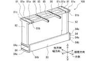
第3実施形態の組電池201は、第1実施形態に対して、拘束バンド206が相違している。組電池201は、1個の拘束バンド206を備えている。拘束バンド206は、第1実施形態と同様の作用効果を奏する、支持部60、固定部61および係合片部62を備えている。第2実施形態の拘束バンド206は、電池積層体10を拘束する状態において、電池積層体10との間に排出通路63を形成する。拘束バンド206は、積層配置された各電池セル2の上面の中央部を覆い、電池積層体10における積層方向の全長にわたって設けられている。この排出通路63は、各電池セル2の安全弁からガスが噴出した場合にガスの排気路として機能する。排出通路63は、拘束バンド206の長手方向に沿うように設けられている。拘束バンド206における積層方向の一方端部には外部への排出口が形成され、拘束バンド206の他方端部は閉塞されている。   The battery pack 201 of the third embodiment is different from the first embodiment in the restraining band 206. The assembled battery 201 includes one restraining band 206. The restraining band 206 includes the support portion 60, the fixing portion 61, and the engaging piece portion 62, which have the same operation and effect as the first embodiment. The restraint band 206 of the second embodiment forms the discharge passage 63 between the restraint band 206 and the battery stack 10 in a state where the battery stack 10 is restrained. The restraining band 206 covers a central portion of the upper surface of each of the battery cells 2 arranged in a stacked manner, and is provided over the entire length of the battery stack 10 in the stacking direction. The discharge passage 63 functions as a gas exhaust passage when gas is ejected from the safety valve of each battery cell 2. The discharge passage 63 is provided along the longitudinal direction of the restraining band 206. A discharge port to the outside is formed at one end of the restraining band 206 in the stacking direction, and the other end of the restraining band 206 is closed.

各電池セル2における上面21には、安全弁が設けられている。安全弁は、上面21における中央部に設けられており、電池セル2の内部圧力が異常な圧力になるときに破断するように設定されている。安全弁は、例えば、電池セル2の上面21に開口した孔に薄い金属膜を貼り付けて塞いで構成されている。この場合には電池セル2の内部圧力が異常な圧力になったときに、当該金属膜が破断して上面21に開口されている孔が開放されて電池セル2の内部のガスがセル外部に放出されることにより、セル内圧が低下し、電池セル2自身の破裂を防止することができる。   A safety valve is provided on the upper surface 21 of each battery cell 2. The safety valve is provided at the center of the upper surface 21 and is set to break when the internal pressure of the battery cell 2 becomes abnormal. The safety valve is configured by, for example, attaching a thin metal film to a hole opened on the upper surface 21 of the battery cell 2 and closing the hole. In this case, when the internal pressure of the battery cell 2 becomes an abnormal pressure, the metal film is broken and the hole opened on the upper surface 21 is opened, and the gas inside the battery cell 2 flows to the outside of the cell. The release reduces the internal pressure of the cell and prevents the battery cell 2 itself from bursting.

拘束バンド206は、電池セル2の上面21において、電極端子20を除く部位であって少なくとも安全弁を覆うように設けられている。したがって、拘束バンド206と電池積層体10との間に形成された通路には、各電池セル2の安全弁が露出するようになっている。このように拘束バンド206は、前述の拘束バンド6や拘束バンド206と同様の作用効果を奏するとともに、電池セル2から噴出したガスを組電池201の外部に案内する排煙用ダクトとしての機能を有する。拘束バンド206は、電池積層体10において対面の隣接面を支持する第2の拘束バンドである。   The restraining band 206 is provided on the upper surface 21 of the battery cell 2 except for the electrode terminal 20 and at least covers the safety valve. Therefore, the safety valve of each battery cell 2 is exposed in the passage formed between the restraining band 206 and the battery stack 10. As described above, the restraining band 206 has the same operation and effect as the restraining band 6 and the restraining band 206 described above, and also functions as a smoke exhaust duct for guiding gas ejected from the battery cells 2 to the outside of the battery pack 201. Have. The restraining band 206 is a second restraining band that supports an adjacent face of the battery stack 10.

拘束バンド206は、耐熱性を有する材料で形成する。例えば、拘束バンド206は、ポリフェニレンサルファイド樹脂(PPS)、ポリエチレン樹脂(PE)、難燃剤を添加した各種樹脂、金属等で形成されている。拘束バンド206の有する耐熱性は、電池セル2の内部が異常な高圧状態になって内部のガスが安全弁の破断によって噴き出しても、ダクト部分が溶けないで破損しない耐熱能力を有することである。   The restraining band 206 is formed of a material having heat resistance. For example, the restraining band 206 is formed of polyphenylene sulfide resin (PPS), polyethylene resin (PE), various resins to which a flame retardant is added, metal, or the like. The heat resistance of the restraint band 206 is such that even if the inside of the battery cell 2 is in an abnormally high pressure state and the gas inside blows out due to the breakage of the safety valve, the duct portion does not melt and is not damaged.

拘束バンド206は、積層方向に延びる一組の係合片部62が第2支持部材108の溝部86に嵌っている構成により、電池積層体10のセル支持枠に密着する。これにより、安全弁から電池セル2の外部に噴出したガスは、拘束バンド206内の排出通路63を流下して一方側端部の排出口から外部に排出されるようになっている。   The restraining band 206 is in close contact with the cell support frame of the battery stack 10 due to the configuration in which the pair of engaging pieces 62 extending in the stacking direction is fitted in the groove 86 of the second support member 108. Thus, the gas ejected from the safety valve to the outside of the battery cell 2 flows down the discharge passage 63 in the restraining band 206 and is discharged to the outside from the discharge port at one end.

拘束バンド206は、電池積層体10を支持する支持部60と、支持部60の両端に位置する固定部61とを備えている。固定部61は、拘束バンド206が組電池201に対して固定されている部位である。拘束バンド206は、固定部61が各エンドプレート3にリベット等によって固定されていることにより、電池積層体10に対して必要な拘束力を提供している状態を維持している。拘束バンド206の固定部61は、各エンドプレート3の上部に固定されている。   The restraining band 206 includes a support portion 60 that supports the battery stack 10 and fixing portions 61 located at both ends of the support portion 60. The fixing portion 61 is a portion where the restraining band 206 is fixed to the battery pack 201. The restraining band 206 maintains a state of providing a required restraining force to the battery stack 10 by fixing the fixing portion 61 to each end plate 3 with a rivet or the like. The fixing portion 61 of the restraining band 206 is fixed to an upper portion of each end plate 3.

各電池セル2は、図12に図示された第1支持部材7または図38に図示された第2支持部材108に装着されて、積層方向、上下方向および幅方向について支持されている。第1支持部材7と第2支持部材108は、積層方向に交互に組み合わされることにより、電池積層体10に含まれる電池セル2を支持するセル支持枠を構成する。第2支持部材108は、第1実施形態の第2支持部材8と同様に、絶縁性を有する樹脂材料によって形成されている。   Each battery cell 2 is mounted on the first support member 7 shown in FIG. 12 or the second support member 108 shown in FIG. 38, and is supported in the stacking direction, the vertical direction, and the width direction. The first support members 7 and the second support members 108 are alternately combined in the stacking direction to form a cell support frame that supports the battery cells 2 included in the battery stack 10. The second support member 108 is formed of a resin material having an insulating property, like the second support member 8 of the first embodiment.

図38、図40に示すように、第2支持部材108は、一組の側壁支持部82と、一組のバンド支持部84と、一組の上壁支持部81と、スペーサ部83と、一組の連絡橋部85と、一組の溝部86とを備え、これらが一体に形成されたセル支持部材である。連絡橋部85は、一組の上壁支持部81を連絡する幅方向に延びる板状部である。一組の連絡橋部85のうちの一方側は、一組の上壁支持部81における一方側端部の間を連絡する橋部に相当し、他方側は、一組の上壁支持部81における他方側端部の間を連絡する橋部に相当する。図39は、電池セル2を第2支持部材108によって支持した状態を一方側から示している。図41は、電池セル2を第2支持部材108によって支持した状態を他方側から示している。連絡橋部85は、その下端が電池セル2の上面21に接触するように設けられている。一組の連絡橋部85は、電極端子20を内側に収めるような間隔寸法で積層方向に離間している。   As shown in FIGS. 38 and 40, the second support member 108 includes a set of side wall support portions 82, a set of band support portions 84, a set of upper wall support portions 81, a spacer portion 83, The cell support member is provided with a pair of connecting bridge portions 85 and a pair of groove portions 86, which are integrally formed. The connecting bridge portion 85 is a plate-like portion extending in the width direction connecting the pair of upper wall support portions 81. One side of one set of connecting bridge portions 85 corresponds to a bridge portion connecting one end of one pair of upper wall support portions 81, and the other side corresponds to one set of upper wall support portions 81. It is equivalent to a bridge that connects between the other side ends of the bridge. FIG. 39 shows a state where the battery cell 2 is supported by the second support member 108 from one side. FIG. 41 shows a state where the battery cell 2 is supported by the second support member 108 from the other side. The connecting bridge 85 is provided such that the lower end thereof contacts the upper surface 21 of the battery cell 2. The pair of connecting bridge portions 85 are spaced apart in the laminating direction with a spacing dimension that accommodates the electrode terminal 20 inside.

一組の溝部86は、拘束バンド206の一組の係合片部62が嵌合可能な溝幅、溝深さを有している。一組の溝部86は、電池セル2の安全弁を内側に収めるような間隔寸法で幅方向に離間している。溝部86は、積層方向に延びる横断面U字状の部分によって形成されている。溝部86は、一方側端部が一方側の連絡橋部85を越えて一方側に位置し、他方側端部が他方側の連絡橋部85に重なる位置するように積層方向に延びている。電池積層体10において、溝部86は、第1支持部材7をまたいで、一方側端部が隣接する第2支持部材8の溝部86の他方側端部に連結するように構成されている。この構成により、第1支持部材7と第2支持部材108とが積層方向に交互に組み合わされて形成されたセル支持枠において、一組の溝部86が電池積層体10の積層方向長さの全体にわたって設けられることになる。   The set of grooves 86 has a groove width and a groove depth to which the set of engagement pieces 62 of the restraint band 206 can be fitted. The set of grooves 86 is spaced apart in the width direction with a spacing dimension that accommodates the safety valve of the battery cell 2 inside. The groove 86 is formed by a U-shaped portion extending in the laminating direction. The groove portion 86 extends in the stacking direction such that one end portion is located on one side beyond the connection bridge portion 85 on one side, and the other end portion is located so as to overlap the connection bridge portion 85 on the other side. In the battery stack 10, the groove 86 is configured so that one end is connected to the other end of the groove 86 of the adjacent second support member 8 across the first support member 7. With this configuration, in the cell support frame formed by alternately combining the first support members 7 and the second support members 108 in the stacking direction, one set of the groove portions 86 has the entire length of the battery stack 10 in the stacking direction. To be provided.

第3実施形態によれば、拘束バンドは、対面において電池積層体10を支持する第1の拘束バンドと、隣接面において電池積層体10を支持する第2の拘束バンドとを含んでいる。第2の拘束バンドと隣接面との間には、電池セル2に設けられた安全弁に連通するガスの排出通路63が設けられている。この構成によれば、ガスの排出通路63および拘束部材としての機能を併せ持つ第2の拘束バンドが隣接面に一体に設けられた電池積層体10を提供できる。この組電池201によれば、部品点数の抑制と部品の多機能性とを図ることができる。   According to the third embodiment, the restraint band includes a first restraint band that supports the battery stack 10 on the facing surface, and a second restraint band that supports the battery stack 10 on the adjacent face. A gas discharge passage 63 communicating with a safety valve provided in the battery cell 2 is provided between the second restraining band and the adjacent surface. According to this configuration, it is possible to provide the battery stack 10 in which the gas discharge passage 63 and the second restraining band having both functions as the restraining member are integrally provided on the adjacent surface. According to the assembled battery 201, it is possible to reduce the number of components and achieve multi-functionality of components.

(他の実施形態)
この明細書の開示は、例示された実施形態に制限されない。開示は、例示された実施形態と、それらに基づく当業者による変形態様を包含する。例えば、開示は、実施形態において示された部品、要素の組み合わせに限定されず、種々変形して実施することが可能である。開示は、多様な組み合わせによって実施可能である。開示は、実施形態に追加可能な追加的な部分をもつことができる。開示は、実施形態の部品、要素が省略されたものを包含する。開示は、一つの実施形態と他の実施形態との間における部品、要素の置き換え、または組み合わせを包含する。開示される技術的範囲は、実施形態の記載に限定されない。開示される技術的範囲は、特許請求の範囲の記載によって示され、さらに特許請求の範囲の記載と均等の意味および範囲内でのすべての変更を含むものと解されるべきである。
(Other embodiments)
The disclosure of this specification is not limited to the illustrated embodiments. The disclosure includes the illustrated embodiments and variations thereon based on those skilled in the art. For example, the disclosure is not limited to the combination of the components and elements shown in the embodiment, and can be implemented with various modifications. The disclosure can be implemented in various combinations. The disclosure may have additional parts that can be added to the embodiments. The disclosure includes those in which the components and elements of the embodiments are omitted. The disclosure encompasses the replacement or combination of parts, elements between one embodiment and another embodiment. The disclosed technical scope is not limited to the description of the embodiments. The technical scope disclosed is indicated by the description of the claims, and should be construed to include all modifications within the meaning and scope equivalent to the description of the claims.

明細書に開示の目的を達成可能な組電池は、第1実施形態において拘束バンド5と拘束バンド6とが一体に形成された一つの拘束バンドによって構成される形態であってもよい。第2実施形態における拘束バンド105と拘束バンド106とは一体に形成された一つの拘束バンドによって構成される形態でもよい。第3実施形態における拘束バンド5と拘束バンド206とが一体に形成された一つの拘束バンドによって構成される形態でもよい。   The battery pack capable of achieving the object disclosed in the specification may have a form in which the restraint band 5 and the restraint band 6 are formed by one restraint band integrally formed in the first embodiment. The restraint band 105 and the restraint band 106 in the second embodiment may be configured as one integrally formed restraint band. A configuration in which the restraining band 5 and the restraining band 206 in the third embodiment are configured by one restraining band integrally formed may be adopted.

前述の実施形態における組電池は、熱媒体が熱媒体通路部材の内部を全体的に積層方向における一方側から他方側に向けて一方通行に流れる流路構成を有するものでもよい。また、組電池は、熱媒体通路部材の内部を全体的に積層方向における一方側から他方側に向けて一方通行に流れる流路が上下2個に並ぶ構成を有するものでもよい。このように、熱媒体通路部材4は、電池積層体10に含まれる複数の電池セル2における積層方向の一方端部から他方端部にかけて熱媒体がすべての電池セル2と熱交換するように一続きの内部通路を形成する構成でもよい。電池積層体10において一方端部は熱媒体流れの上流側であり他方端部は下流側である。   The battery pack in the above-described embodiment may have a flow path configuration in which the heat medium flows in one direction from the one side in the stacking direction to the other side in the heat medium passage member as a whole. Further, the battery pack may have a configuration in which the flow paths that flow in one direction from one side to the other side in the stacking direction in the entire heat medium passage member are arranged vertically in two rows. In this manner, the heat medium passage member 4 is arranged such that the heat medium exchanges heat with all the battery cells 2 from one end to the other end in the stacking direction of the plurality of battery cells 2 included in the battery stack 10. A configuration in which a continuous internal passage is formed may be used. In battery stack 10, one end is on the upstream side of the flow of the heat medium and the other end is on the downstream side.

前述の実施形態における組電池は、電池セル2とセル間部44とを交互に積層した形成された電池の積層体であるが、明細書に開示の目的を達成可能な組電池は、この形態に限定されない。この組電池は、電池積層体10を構成する隣り合う電池セル2間のすべてのうち、セル間部44が特定の電池セル2間のみに介在する構成を備えるものを含んでいる。また、組電池1には、少なくとも1個のセル間部44を備えている。   The assembled battery in the above-described embodiment is a stacked body of batteries formed by alternately stacking the battery cells 2 and the inter-cell portions 44, and the assembled battery capable of achieving the object disclosed in the specification is in this form. It is not limited to. The battery pack includes one having a configuration in which the inter-cell portion 44 is interposed only between specific battery cells 2 among all the adjacent battery cells 2 constituting the battery stack 10. In addition, the battery pack 1 includes at least one inter-cell portion 44.

明細書に開示の目的を達成可能な組電池が備える拘束バンドは、電池積層体10において電池セル2が積層設置されて形成された面のうち対面関係にある各面を支持する構成を有していればよく、支持する面は前述の実施形態に限定されない。例えば、前述の第1実施形態の組電池1が備える拘束バンドは、対面関係にある上壁10aと下壁10bのそれぞれを支持する構成でもよい。   The constraining band included in the battery pack that can achieve the object disclosed in the specification has a configuration that supports each of the faces facing each other among the faces formed by stacking the battery cells 2 in the battery stack 10. The supporting surface is not limited to the above-described embodiment. For example, the constraining band included in the battery pack 1 of the above-described first embodiment may be configured to support each of the upper wall 10a and the lower wall 10b that face each other.

1,101,201…組電池、 2…電池セル
5,105…拘束バンド(第1の拘束バンド)
6,106,206…拘束バンド(第2の拘束バンド)
7…第1支持部材(セル支持部材)、 8,108…第2支持部材(セル支持部材)
10…電池積層体、 10a…上壁(隣接面)、 10c,10d…側壁(対面)
11…セル支持部材、 50,60…支持部
52,62…係合片部(係合部)
1, 101, 201: assembled battery, 2: battery cell 5, 105: restraint band (first restraint band)
6, 106, 206 ... restraint band (second restraint band)
7 ... first support member (cell support member), 8,108 ... second support member (cell support member)
10: Battery stack, 10a: Upper wall (adjacent surface), 10c, 10d: Side wall (facing surface)
11: Cell support member, 50, 60 ... Support portion 52, 62 ... Engagement piece (engagement portion)

Claims (10)

積層設置されている複数の電池セル(2)を含む電池積層体(10)と、
前記電池積層体を支持する支持部(50,60;150;160)を有し前記電池積層体に対して電池の積層方向に拘束力を与える拘束バンド(5,6;105,106;5,206)と、
を備え、
前記支持部は、前記電池積層体において前記積層方向に沿う面のうち、所定の対面(10c,10d)と前記対面に隣接する少なくとも一つの隣接面(10a)とについて前記電池積層体の積層方向長さにわたって支持している組電池。
A battery stack (10) including a plurality of battery cells (2) arranged in a stack;
A restraining band (5, 6; 105, 106; 5, 5) having a support portion (50, 60; 150; 160) for supporting the battery stack and applying a restraining force to the battery stack in the battery stacking direction. 206),
With
The support portion is configured such that, of the surfaces of the battery stack along the stacking direction, a predetermined facing surface (10c, 10d) and at least one adjacent surface (10a) adjacent to the facing surface have a stacking direction of the battery stack. Battery pack supporting over the length.
前記電池積層体は、前記電池セルを前記対面と前記隣接面とにおいて支持して、積層されたセル支持部材(7,8;11;7,108)を含み、
前記拘束バンドは、前記対面において前記セル支持部材を支持する第1の拘束バンド(5;105)と、前記隣接面において前記セル支持部材を支持する第2の拘束バンド(6;106;206)とを含む請求項1に記載の組電池。
The battery stack includes a cell support member (7, 8; 11; 7, 108) that supports the battery cell on the facing surface and the adjacent surface, and is stacked.
The constraint band includes a first constraint band (5; 105) that supports the cell support member on the facing surface, and a second constraint band (6; 106; 206) that supports the cell support member on the adjacent surface. The battery pack according to claim 1, comprising:
前記第1の拘束バンドは、前記対面において中央部よりも前記隣接面から遠い位置を支持している請求項2に記載の組電池。   3. The battery pack according to claim 2, wherein the first restraining band supports a position farther from the adjacent surface than a central portion on the facing surface. 4. 前記第1の拘束バンドは、前記対面において、前記第2の拘束バンドによって支持されている前記隣接面から遠い側の端部を前記電池積層体の積層方向長さにわたって支持している請求項3に記載の組電池。   The said 1st restraint band supports the edge part by the side opposite to the said adjacent surface supported by the said 2nd restraint band over the stacking direction length of the said battery laminated body in the said facing. The battery pack according to item 1. 前記電池セルは、前記隣接面において露出する電極端子(20)を有する請求項4に記載の組電池。   The assembled battery according to claim 4, wherein the battery cell has an electrode terminal (20) exposed on the adjacent surface. 前記第1の拘束バンドおよび前記第2の拘束バンドは、前記セル支持部材に係合する係合部(52,62)を有している請求項2から請求項5のいずれか一項に記載の組電池。   The said 1st restraint band and the said 2nd restraint band have the engaging part (52,62) which engages with the said cell support member, The Claim 2 any one of Claims 2-5. Battery pack. 前記拘束バンドは、前記対面において前記電池積層体を支持する第1の拘束バンド(5)と、前記隣接面において前記電池積層体を支持する第2の拘束バンド(206)とを含み、
前記第2の拘束バンドと前記隣接面との間には、前記電池セルに設けられた安全弁に連通するガスの排出通路(63)が設けられている請求項1に記載の組電池。
The constraining band includes a first constraining band (5) for supporting the battery stack on the facing surface, and a second constraining band (206) for supporting the battery stack on the adjacent surface.
The battery pack according to claim 1, wherein a gas discharge passage (63) communicating with a safety valve provided in the battery cell is provided between the second restraining band and the adjacent surface.
内部通路を流通する熱媒体と前記電池セルとが熱交換するように設けられた熱媒体通路部材(4)を備え、
前記熱媒体通路部材は、積層方向に隣り合う前記電池セルと前記電池セルの間に介在し前記内部通路を流通する熱媒体と前記電池セルとが熱交換するセル間部(44)と、前記積層方向に隣り合う前記セル間部と前記セル間部とを連結し内部通路を前記熱媒体が流れる連結部(43)と、を備え、
前記セル間部と前記連結部は、前記電池積層体における前記積層方向の一方端部から他方端部にかけてすべての前記電池セルと熱交換する前記熱媒体が流下する一連の前記内部通路を形成するように設けられている請求項1から請求項7のいずれか一項に記載の組電池。
A heat medium passage member (4) provided so that the heat medium flowing through the internal passage and the battery cells exchange heat;
The heat medium passage member includes an inter-cell portion (44) interposed between the battery cells adjacent to each other in the stacking direction and exchanging heat with the heat medium flowing through the internal passage and the battery cells. A connecting portion (43) connecting the inter-cell portions adjacent to each other in the stacking direction and the inter-cell portion, and through which the heat medium flows through an internal passage;
The inter-cell portion and the connection portion form a series of the internal passages through which the heat medium that exchanges heat with all the battery cells flows from one end to the other end of the battery stack in the stacking direction. The assembled battery according to any one of claims 1 to 7, wherein the assembled battery is provided as follows.
前記拘束バンドは、前記対面において前記電池積層体を支持する第1の拘束バンド(5)と、前記隣接面において前記電池積層体を支持する第2の拘束バンド(6;206)とを含み、
前記第1の拘束バンドは、前記対面において前記連結部に重ならない位置を支持している請求項8に記載の組電池。
The restraint band includes a first restraint band (5) that supports the battery stack on the facing surface, and a second restraint band (6; 206) that supports the battery stack on the adjacent face,
9. The battery pack according to claim 8, wherein the first restraining band supports a position on the facing surface that does not overlap the connecting portion. 10.
内部通路を流通する熱媒体とすべての前記電池セルとが熱交換するように前記電池積層体に対して前記対面と前記隣接面とのそれぞれに沿って設けられた熱交換器(13)を備え、
前記拘束バンドは、前記対面において前記熱交換器を覆って支持する第1の拘束バンド(105)と、前記隣接面において前記熱交換器を覆って支持する第2の拘束バンド(106)とを含む請求項1に記載の組電池。
A heat exchanger (13) provided along each of the facing surface and the adjacent surface with respect to the battery stack so that the heat medium flowing through the internal passage and all of the battery cells exchange heat. ,
The constraining band includes a first constraining band (105) that covers and supports the heat exchanger on the facing surface, and a second constraining band (106) that supports and supports the heat exchanger on the adjacent surface. The battery pack according to claim 1, comprising:
JP2018150503A 2018-08-09 2018-08-09 Battery pack Pending JP2020027693A (en)

Priority Applications (2)

Application Number Priority Date Filing Date Title
JP2018150503A JP2020027693A (en) 2018-08-09 2018-08-09 Battery pack
PCT/JP2019/027740 WO2020031620A1 (en) 2018-08-09 2019-07-12 Battery pack

Applications Claiming Priority (1)

Application Number Priority Date Filing Date Title
JP2018150503A JP2020027693A (en) 2018-08-09 2018-08-09 Battery pack

Publications (2)

Publication Number Publication Date
JP2020027693A true JP2020027693A (en) 2020-02-20
JP2020027693A5 JP2020027693A5 (en) 2020-09-03

Family

ID=69414744

Family Applications (1)

Application Number Title Priority Date Filing Date
JP2018150503A Pending JP2020027693A (en) 2018-08-09 2018-08-09 Battery pack

Country Status (2)

Country Link
JP (1) JP2020027693A (en)
WO (1) WO2020031620A1 (en)

Families Citing this family (1)

* Cited by examiner, † Cited by third party
Publication number Priority date Publication date Assignee Title
WO2022030449A1 (en) * 2020-08-07 2022-02-10 株式会社Gsユアサ Power storage device

Citations (6)

* Cited by examiner, † Cited by third party
Publication number Priority date Publication date Assignee Title
JP2011119222A (en) * 2009-12-04 2011-06-16 Sb Limotive Co Ltd Battery module, and battery pack equipped with two or more battery modules
US20110293974A1 (en) * 2010-06-01 2011-12-01 Ji-Hyoung Yoon Battery pack
JP2012129282A (en) * 2010-12-14 2012-07-05 Sumitomo Heavy Ind Ltd Power storage module and work machine
JP2014082042A (en) * 2012-10-15 2014-05-08 Toyota Motor Corp Power storage module and heat transfer member
JP2014099354A (en) * 2012-11-15 2014-05-29 Toyota Industries Corp Power storage device module
JP2016054108A (en) * 2014-09-04 2016-04-14 株式会社Gsユアサ Power storage device

Patent Citations (6)

* Cited by examiner, † Cited by third party
Publication number Priority date Publication date Assignee Title
JP2011119222A (en) * 2009-12-04 2011-06-16 Sb Limotive Co Ltd Battery module, and battery pack equipped with two or more battery modules
US20110293974A1 (en) * 2010-06-01 2011-12-01 Ji-Hyoung Yoon Battery pack
JP2012129282A (en) * 2010-12-14 2012-07-05 Sumitomo Heavy Ind Ltd Power storage module and work machine
JP2014082042A (en) * 2012-10-15 2014-05-08 Toyota Motor Corp Power storage module and heat transfer member
JP2014099354A (en) * 2012-11-15 2014-05-29 Toyota Industries Corp Power storage device module
JP2016054108A (en) * 2014-09-04 2016-04-14 株式会社Gsユアサ Power storage device

Also Published As

Publication number Publication date
WO2020031620A1 (en) 2020-02-13

Similar Documents

Publication Publication Date Title
JP6920660B2 (en) Battery module
JP7223954B2 (en) Battery modules and battery packs
JP5823532B2 (en) Secondary battery module
WO2020188948A1 (en) Battery module
JP5535794B2 (en) Assembled battery
JP6494754B2 (en) Battery module
WO2020166182A1 (en) Battery module
JP6063933B2 (en) Rechargeable electric battery
JP2003036819A (en) Square battery and cooling structure of battery pack
CN118486950A (en) Battery pack
EP4020668A1 (en) Battery pack and device including same
KR20120099063A (en) Battery pack
WO2019049760A1 (en) Battery module
US20150064523A1 (en) Battery module
WO2019065152A1 (en) Binding member, and battery module
US20220376340A1 (en) Battery Module and Battery Pack Including the Same
JP2015201288A (en) Power storage device, holder, and assembly method of power storage device
US20130266839A1 (en) Thermal conductive mechanism for battery pack made up of stack of battery modules
WO2020174804A1 (en) Battery module
WO2020110447A1 (en) Battery module
WO2020031620A1 (en) Battery pack
WO2019065197A1 (en) Binding member, and battery module
WO2020179355A1 (en) Battery pack
JP7483302B2 (en) Battery pack with improved battery cell life and device including same
WO2021153523A1 (en) Electrical storage module

Legal Events

Date Code Title Description
A521 Request for written amendment filed

Free format text: JAPANESE INTERMEDIATE CODE: A523

Effective date: 20200724

A621 Written request for application examination

Free format text: JAPANESE INTERMEDIATE CODE: A621

Effective date: 20200724

A131 Notification of reasons for refusal

Free format text: JAPANESE INTERMEDIATE CODE: A131

Effective date: 20210706

A521 Request for written amendment filed

Free format text: JAPANESE INTERMEDIATE CODE: A523

Effective date: 20210823

A131 Notification of reasons for refusal

Free format text: JAPANESE INTERMEDIATE CODE: A131

Effective date: 20211109

A02 Decision of refusal

Free format text: JAPANESE INTERMEDIATE CODE: A02

Effective date: 20220524