JP6063933B2 - Rechargeable electric battery - Google Patents
Rechargeable electric battery Download PDFInfo
- Publication number
- JP6063933B2 JP6063933B2 JP2014517652A JP2014517652A JP6063933B2 JP 6063933 B2 JP6063933 B2 JP 6063933B2 JP 2014517652 A JP2014517652 A JP 2014517652A JP 2014517652 A JP2014517652 A JP 2014517652A JP 6063933 B2 JP6063933 B2 JP 6063933B2
- Authority
- JP
- Japan
- Prior art keywords
- battery
- cooling air
- cell
- adjacent
- stack
- Prior art date
- Legal status (The legal status is an assumption and is not a legal conclusion. Google has not performed a legal analysis and makes no representation as to the accuracy of the status listed.)
- Expired - Fee Related
Links
Images


Classifications
-
- H—ELECTRICITY
- H01—ELECTRIC ELEMENTS
- H01M—PROCESSES OR MEANS, e.g. BATTERIES, FOR THE DIRECT CONVERSION OF CHEMICAL ENERGY INTO ELECTRICAL ENERGY
- H01M10/00—Secondary cells; Manufacture thereof
- H01M10/60—Heating or cooling; Temperature control
- H01M10/62—Heating or cooling; Temperature control specially adapted for specific applications
- H01M10/625—Vehicles
-
- H—ELECTRICITY
- H01—ELECTRIC ELEMENTS
- H01M—PROCESSES OR MEANS, e.g. BATTERIES, FOR THE DIRECT CONVERSION OF CHEMICAL ENERGY INTO ELECTRICAL ENERGY
- H01M10/00—Secondary cells; Manufacture thereof
- H01M10/04—Construction or manufacture in general
- H01M10/0413—Large-sized flat cells or batteries for motive or stationary systems with plate-like electrodes
-
- B—PERFORMING OPERATIONS; TRANSPORTING
- B60—VEHICLES IN GENERAL
- B60L—PROPULSION OF ELECTRICALLY-PROPELLED VEHICLES; SUPPLYING ELECTRIC POWER FOR AUXILIARY EQUIPMENT OF ELECTRICALLY-PROPELLED VEHICLES; ELECTRODYNAMIC BRAKE SYSTEMS FOR VEHICLES IN GENERAL; MAGNETIC SUSPENSION OR LEVITATION FOR VEHICLES; MONITORING OPERATING VARIABLES OF ELECTRICALLY-PROPELLED VEHICLES; ELECTRIC SAFETY DEVICES FOR ELECTRICALLY-PROPELLED VEHICLES
- B60L50/00—Electric propulsion with power supplied within the vehicle
- B60L50/50—Electric propulsion with power supplied within the vehicle using propulsion power supplied by batteries or fuel cells
- B60L50/60—Electric propulsion with power supplied within the vehicle using propulsion power supplied by batteries or fuel cells using power supplied by batteries
- B60L50/64—Constructional details of batteries specially adapted for electric vehicles
-
- H—ELECTRICITY
- H01—ELECTRIC ELEMENTS
- H01M—PROCESSES OR MEANS, e.g. BATTERIES, FOR THE DIRECT CONVERSION OF CHEMICAL ENERGY INTO ELECTRICAL ENERGY
- H01M10/00—Secondary cells; Manufacture thereof
- H01M10/04—Construction or manufacture in general
- H01M10/0431—Cells with wound or folded electrodes
-
- H—ELECTRICITY
- H01—ELECTRIC ELEMENTS
- H01M—PROCESSES OR MEANS, e.g. BATTERIES, FOR THE DIRECT CONVERSION OF CHEMICAL ENERGY INTO ELECTRICAL ENERGY
- H01M10/00—Secondary cells; Manufacture thereof
- H01M10/42—Methods or arrangements for servicing or maintenance of secondary cells or secondary half-cells
- H01M10/4207—Methods or arrangements for servicing or maintenance of secondary cells or secondary half-cells for several batteries or cells simultaneously or sequentially
-
- H—ELECTRICITY
- H01—ELECTRIC ELEMENTS
- H01M—PROCESSES OR MEANS, e.g. BATTERIES, FOR THE DIRECT CONVERSION OF CHEMICAL ENERGY INTO ELECTRICAL ENERGY
- H01M10/00—Secondary cells; Manufacture thereof
- H01M10/60—Heating or cooling; Temperature control
-
- H—ELECTRICITY
- H01—ELECTRIC ELEMENTS
- H01M—PROCESSES OR MEANS, e.g. BATTERIES, FOR THE DIRECT CONVERSION OF CHEMICAL ENERGY INTO ELECTRICAL ENERGY
- H01M10/00—Secondary cells; Manufacture thereof
- H01M10/60—Heating or cooling; Temperature control
- H01M10/61—Types of temperature control
- H01M10/613—Cooling or keeping cold
-
- H—ELECTRICITY
- H01—ELECTRIC ELEMENTS
- H01M—PROCESSES OR MEANS, e.g. BATTERIES, FOR THE DIRECT CONVERSION OF CHEMICAL ENERGY INTO ELECTRICAL ENERGY
- H01M10/00—Secondary cells; Manufacture thereof
- H01M10/60—Heating or cooling; Temperature control
- H01M10/64—Heating or cooling; Temperature control characterised by the shape of the cells
- H01M10/647—Prismatic or flat cells, e.g. pouch cells
-
- H—ELECTRICITY
- H01—ELECTRIC ELEMENTS
- H01M—PROCESSES OR MEANS, e.g. BATTERIES, FOR THE DIRECT CONVERSION OF CHEMICAL ENERGY INTO ELECTRICAL ENERGY
- H01M10/00—Secondary cells; Manufacture thereof
- H01M10/60—Heating or cooling; Temperature control
- H01M10/65—Means for temperature control structurally associated with the cells
- H01M10/653—Means for temperature control structurally associated with the cells characterised by electrically insulating or thermally conductive materials
-
- H—ELECTRICITY
- H01—ELECTRIC ELEMENTS
- H01M—PROCESSES OR MEANS, e.g. BATTERIES, FOR THE DIRECT CONVERSION OF CHEMICAL ENERGY INTO ELECTRICAL ENERGY
- H01M10/00—Secondary cells; Manufacture thereof
- H01M10/60—Heating or cooling; Temperature control
- H01M10/65—Means for temperature control structurally associated with the cells
- H01M10/655—Solid structures for heat exchange or heat conduction
- H01M10/6553—Terminals or leads
-
- H—ELECTRICITY
- H01—ELECTRIC ELEMENTS
- H01M—PROCESSES OR MEANS, e.g. BATTERIES, FOR THE DIRECT CONVERSION OF CHEMICAL ENERGY INTO ELECTRICAL ENERGY
- H01M10/00—Secondary cells; Manufacture thereof
- H01M10/60—Heating or cooling; Temperature control
- H01M10/65—Means for temperature control structurally associated with the cells
- H01M10/655—Solid structures for heat exchange or heat conduction
- H01M10/6556—Solid parts with flow channel passages or pipes for heat exchange
- H01M10/6557—Solid parts with flow channel passages or pipes for heat exchange arranged between the cells
-
- H—ELECTRICITY
- H01—ELECTRIC ELEMENTS
- H01M—PROCESSES OR MEANS, e.g. BATTERIES, FOR THE DIRECT CONVERSION OF CHEMICAL ENERGY INTO ELECTRICAL ENERGY
- H01M10/00—Secondary cells; Manufacture thereof
- H01M10/60—Heating or cooling; Temperature control
- H01M10/65—Means for temperature control structurally associated with the cells
- H01M10/656—Means for temperature control structurally associated with the cells characterised by the type of heat-exchange fluid
- H01M10/6561—Gases
-
- H—ELECTRICITY
- H01—ELECTRIC ELEMENTS
- H01M—PROCESSES OR MEANS, e.g. BATTERIES, FOR THE DIRECT CONVERSION OF CHEMICAL ENERGY INTO ELECTRICAL ENERGY
- H01M50/00—Constructional details or processes of manufacture of the non-active parts of electrochemical cells other than fuel cells, e.g. hybrid cells
- H01M50/20—Mountings; Secondary casings or frames; Racks, modules or packs; Suspension devices; Shock absorbers; Transport or carrying devices; Holders
- H01M50/204—Racks, modules or packs for multiple batteries or multiple cells
- H01M50/207—Racks, modules or packs for multiple batteries or multiple cells characterised by their shape
- H01M50/209—Racks, modules or packs for multiple batteries or multiple cells characterised by their shape adapted for prismatic or rectangular cells
-
- H—ELECTRICITY
- H01—ELECTRIC ELEMENTS
- H01M—PROCESSES OR MEANS, e.g. BATTERIES, FOR THE DIRECT CONVERSION OF CHEMICAL ENERGY INTO ELECTRICAL ENERGY
- H01M50/00—Constructional details or processes of manufacture of the non-active parts of electrochemical cells other than fuel cells, e.g. hybrid cells
- H01M50/20—Mountings; Secondary casings or frames; Racks, modules or packs; Suspension devices; Shock absorbers; Transport or carrying devices; Holders
- H01M50/249—Mountings; Secondary casings or frames; Racks, modules or packs; Suspension devices; Shock absorbers; Transport or carrying devices; Holders specially adapted for aircraft or vehicles, e.g. cars or trains
-
- H—ELECTRICITY
- H01—ELECTRIC ELEMENTS
- H01M—PROCESSES OR MEANS, e.g. BATTERIES, FOR THE DIRECT CONVERSION OF CHEMICAL ENERGY INTO ELECTRICAL ENERGY
- H01M50/00—Constructional details or processes of manufacture of the non-active parts of electrochemical cells other than fuel cells, e.g. hybrid cells
- H01M50/20—Mountings; Secondary casings or frames; Racks, modules or packs; Suspension devices; Shock absorbers; Transport or carrying devices; Holders
- H01M50/289—Mountings; Secondary casings or frames; Racks, modules or packs; Suspension devices; Shock absorbers; Transport or carrying devices; Holders characterised by spacing elements or positioning means within frames, racks or packs
-
- Y—GENERAL TAGGING OF NEW TECHNOLOGICAL DEVELOPMENTS; GENERAL TAGGING OF CROSS-SECTIONAL TECHNOLOGIES SPANNING OVER SEVERAL SECTIONS OF THE IPC; TECHNICAL SUBJECTS COVERED BY FORMER USPC CROSS-REFERENCE ART COLLECTIONS [XRACs] AND DIGESTS
- Y02—TECHNOLOGIES OR APPLICATIONS FOR MITIGATION OR ADAPTATION AGAINST CLIMATE CHANGE
- Y02E—REDUCTION OF GREENHOUSE GAS [GHG] EMISSIONS, RELATED TO ENERGY GENERATION, TRANSMISSION OR DISTRIBUTION
- Y02E60/00—Enabling technologies; Technologies with a potential or indirect contribution to GHG emissions mitigation
- Y02E60/10—Energy storage using batteries
-
- Y—GENERAL TAGGING OF NEW TECHNOLOGICAL DEVELOPMENTS; GENERAL TAGGING OF CROSS-SECTIONAL TECHNOLOGIES SPANNING OVER SEVERAL SECTIONS OF THE IPC; TECHNICAL SUBJECTS COVERED BY FORMER USPC CROSS-REFERENCE ART COLLECTIONS [XRACs] AND DIGESTS
- Y02—TECHNOLOGIES OR APPLICATIONS FOR MITIGATION OR ADAPTATION AGAINST CLIMATE CHANGE
- Y02P—CLIMATE CHANGE MITIGATION TECHNOLOGIES IN THE PRODUCTION OR PROCESSING OF GOODS
- Y02P70/00—Climate change mitigation technologies in the production process for final industrial or consumer products
- Y02P70/50—Manufacturing or production processes characterised by the final manufactured product
-
- Y—GENERAL TAGGING OF NEW TECHNOLOGICAL DEVELOPMENTS; GENERAL TAGGING OF CROSS-SECTIONAL TECHNOLOGIES SPANNING OVER SEVERAL SECTIONS OF THE IPC; TECHNICAL SUBJECTS COVERED BY FORMER USPC CROSS-REFERENCE ART COLLECTIONS [XRACs] AND DIGESTS
- Y02—TECHNOLOGIES OR APPLICATIONS FOR MITIGATION OR ADAPTATION AGAINST CLIMATE CHANGE
- Y02T—CLIMATE CHANGE MITIGATION TECHNOLOGIES RELATED TO TRANSPORTATION
- Y02T10/00—Road transport of goods or passengers
- Y02T10/60—Other road transportation technologies with climate change mitigation effect
- Y02T10/70—Energy storage systems for electromobility, e.g. batteries
Description
本発明は、積層方向に一列に隣接配置された少なくとも2つのバッテリセルスタックを備え、このスタック同士が隣接して且つ積層方向に対して垂直に配置され、隣接配置された少なくとも2つのスタックが互いに対して積層方向にずらして配置された再充電可能電気バッテリ、好ましくは電気自動車用であり、特に高電圧バッテリに関する。 The present invention includes at least two battery cell stacks arranged adjacent to each other in a line in the stacking direction, the stacks being adjacent to each other and perpendicular to the stacking direction, and the at least two stacks positioned adjacent to each other. In contrast, the present invention relates to a rechargeable electric battery, preferably an electric vehicle, which is shifted in the stacking direction, and particularly to a high voltage battery.
複数のリチウムイオンバッテリセルによって構成されたバッテリパックは、これらに加えて、セル締結システム、セル冷却システム、セル監視システム、セル接続システムなどの一連の他のサブシステムを含む。これらサブシステムの一体化のために、セル(電池)化学よって包囲された体積をはるかに超過する更なる設置空間が必要になる。これは、既に化石燃料の体積エネルギー密度よりも低い体積エネルギー密度に悪影響を及ぼす。 In addition to these, a battery pack constituted by a plurality of lithium ion battery cells includes a series of other subsystems such as a cell fastening system, a cell cooling system, a cell monitoring system, and a cell connection system. The integration of these subsystems requires additional installation space that far exceeds the volume enclosed by the cell (battery) chemistry. This adversely affects the volumetric energy density already lower than that of fossil fuels.
プラスチックのセルケーシングが活性セル化学の周囲に伸びる連続的な横方向のシーリングシームによって封止された多くの様々な既知のリチウムイオンポーチセルの構造的形状のため、複数のセルが隣接している場合、空の空間が形成される。これらの囲繞された空間は、バッテリセルの製造公差の結果として非常に大雑把にしか寸法を設定することができず、突出したシーリングシームによって別々の空間に分割されることがあるため、技術的に活用することが難しい。 Due to the structural shape of many different known lithium ion pouch cells in which a plastic cell casing is sealed by a continuous lateral sealing seam extending around the active cell chemistry, multiple cells are adjacent If so, an empty space is formed. Technically because these enclosed spaces can only be dimensioned very roughly as a result of manufacturing tolerances of the battery cells and may be divided into separate spaces by protruding sealing seams. Difficult to use.
独国特許出願公開第102009035463号明細書(特許文献1)は、複数のフラットな略プレート状の個別のバッテリセルを備えるバッテリを開示している。個別のバッテリセルは、セルスタックを形成するように積層され、バッテリハウジングによって包囲される。バッテリの個別のセルは、金属シートと絶縁材料のフレームによって、フラットにフレームに包囲されるように形成される。 German Patent Application No. 102009035463 (Patent Document 1) discloses a battery comprising a plurality of flat, substantially plate-like individual battery cells. Individual battery cells are stacked to form a cell stack and are surrounded by a battery housing. The individual cells of the battery are formed so as to be flatly surrounded by a frame of metal sheet and insulating material.
また、国際公開第2008/048751号明細書(特許文献2)は、ハウジングに収容されたスタックにおいて隣接配置された複数のプレート状バッテリセルを備えるバッテリモジュールを開示している。 Moreover, the international publication 2008/048751 (patent document 2) is disclosing the battery module provided with the several plate-shaped battery cell arrange | positioned adjacently in the stack accommodated in the housing.
国際公開第2010/053689号明細書(特許文献3)は、ハウジングと、隣接配置された複数のリチウムイオンセルを備えるバッテリ装置を開示している。熱伝導性の電気的に絶縁する流体が冷却目的でハウジングを流れる。 International Publication No. 2010/053689 (Patent Document 3) discloses a battery device including a housing and a plurality of adjacent lithium ion cells. A thermally conductive, electrically insulating fluid flows through the housing for cooling purposes.
国際公開第2010/067944号明細書(特許文献4)は、バッテリセルが冷却空気によって冷却される、隣接配置されたバッテリセルのスタックを備えるバッテリを開示する。 WO 2010/067944 discloses a battery comprising a stack of adjacent battery cells, where the battery cells are cooled by cooling air.
特開2007−109546号公報(特許文献5)は、積層方向に互いにずれて隣接配置された2つのモジュールを備える再充電可能バッテリを記述している。 Japanese Patent Application Laid-Open No. 2007-109546 (Patent Document 5) describes a rechargeable battery comprising two modules arranged adjacent to each other in the stacking direction.
本発明の目的は、上述の欠点を回避すること、及び冒頭で言及したタイプの電気バッテリの体積エネルギー密度を改善することである。 The object of the present invention is to avoid the above-mentioned drawbacks and to improve the volumetric energy density of an electric battery of the type mentioned at the outset.
本発明によれば、この目的は、スタックの少なくとも1つのバッテリセルが、隣接するスタックの少なくとも1つのバッテリセルと少なくとも部分的に重なり合うように配置されることによって達成される。 According to the present invention, this object is achieved by arranging at least one battery cell of a stack to at least partially overlap with at least one battery cell of an adjacent stack.
2つのスタックのずれは、バッテリセルの厚みの約半分である。これにより、より密度の高いパッキングが容易になる。 The deviation between the two stacks is about half the thickness of the battery cell. This facilitates packing with higher density.
残りの空隙を活用するために、隣接するスタックのバッテリセルの少なくとも1つの重なる領域間に少なくとも第1の冷却空気チャネルが形成される。 To take advantage of the remaining air gap, at least a first cooling air channel is formed between at least one overlapping region of adjacent stack battery cells.
少なくとも1つのバッテリセルは、プラスチックセルケーシングに封止され、プラスチックセルケーシングは、バッテリセルの短辺側に沿うように配置された(好ましくはセル中間平面の領域に)突出シーリングシームを有する。スタックの隣接するバッテリセルのシーリングシーム間にはその都度空間が画定される。この空間は第1及び/又は第2の冷却空気チャネルを形成することができる。これに関連して、少なくとも1つの第1の冷却空気チャネルはバッテリの縦軸の方向に、少なくとも第2の冷却空気チャネルは縦軸に対して及び積層方向に対して垂直に延出する、バッテリの横軸の方向に配置され得る。 At least one battery cell is sealed in a plastic cell casing, and the plastic cell casing has a protruding sealing seam disposed along the short side of the battery cell (preferably in the region of the cell midplane). A space is defined between the sealing seams of adjacent battery cells in the stack. This space may form first and / or second cooling air channels. In this connection, the battery in which at least one first cooling air channel extends in the direction of the longitudinal axis of the battery and at least the second cooling air channel extends perpendicular to the longitudinal axis and to the stacking direction. Can be arranged in the direction of the horizontal axis.
製造を容易にするため、部分的に重なるバッテリセルを備える2つのスタックがその都度1つのバッテリモジュールを形成し、各バッテリモジュールが2つの好ましくは熱的且つ/又は電気的に絶縁するプレート間に配置されると有利である。 For ease of manufacture, two stacks with partially overlapping battery cells each form one battery module, each battery module being between two preferably thermally and / or electrically insulating plates. It is advantageous if arranged.
空気は第1の冷却空気チャネルを介して2つの隣接するスタック間の領域を流れて冷却する。冷却空気流を誘導する第2の冷却空気チャネルは、バッテリの上側に配置され、セル端子及び/又は電気セルコネクタを冷却する。後者は、2つの隣接するバッテリセルを電気的に接続するための好ましくは1つのU字形のプロファイル又はY字形のプロファイルを備える少なくとも1つのセルコネクタが第2の冷却空気チャネル内に突出する場合、特に良好に冷却され得る。第1及び/又は第2の冷却空気チャネルは、バッテリを冷却するための閉冷却空気回路の一部であり得、好ましくは冷却空気回路が少なくとも1つの冷却空気ファン及び少なくとも1つの熱交換器を有する。閉冷却空気回路によって、バッテリは、温度及び湿度の変動、大気汚染などの不利となる環境の影響をほとんど受けることなく冷却され得る。これにより、バッテリに関して一定の最適な動作条件が保証され、バッテリの寿命が延長される。 Air flows and cools through the first cooling air channel in the region between two adjacent stacks. A second cooling air channel that induces a cooling air flow is disposed on the upper side of the battery and cools the cell terminals and / or the electrical cell connectors. The latter is preferably when at least one cell connector with a preferably U-shaped profile or Y-shaped profile for electrically connecting two adjacent battery cells protrudes into the second cooling air channel; It can be cooled particularly well. The first and / or second cooling air channel may be part of a closed cooling air circuit for cooling the battery, preferably the cooling air circuit includes at least one cooling air fan and at least one heat exchanger. Have. With the closed cooling air circuit, the battery can be cooled with little adverse environmental effects such as temperature and humidity fluctuations, air pollution and the like. This ensures certain optimal operating conditions for the battery and extends the life of the battery.
第1のスタックのバッテリセルの少なくとも1つのシーリングシームは、第2のスタックの2つの隣接するバッテリセルのシーリングシームによって画定される空間内に突出し得る。この空間の境界を形成する又はこの空間内に突出するシーリングシームは、冷却空気流のための案内表面を形成する。このように、冷却空気の搬送が改善される一方、冷却領域に接触する表面が拡大される。 At least one sealing seam of the battery cells of the first stack may project into a space defined by the sealing seams of two adjacent battery cells of the second stack. A sealing seam that forms the boundary of this space or protrudes into this space forms a guide surface for the cooling air flow. In this way, the conveyance of cooling air is improved while the surface in contact with the cooling region is enlarged.
隣接するバッテリセルの過熱を可能な限り防止するため、少なくとも1つのスタックの2つの隣接するバッテリセル間に熱的且つ電気的な絶縁層が設けられ、好ましくはこの絶縁層は絶縁箔によって形成される。 In order to prevent overheating of adjacent battery cells as much as possible, a thermal and electrical insulating layer is provided between two adjacent battery cells of at least one stack, preferably this insulating layer is formed by an insulating foil. The
上述した手段によれば、必要な設置空間は減少され、体積エネルギー密度は増加され得る。 According to the means described above, the required installation space can be reduced and the volumetric energy density can be increased.
本発明を、図面を参照して以下により詳細に記述する。 The invention is described in more detail below with reference to the drawings.
本実施形態における再充電可能バッテリ1は、7つのバッテリモジュール2を備え、各バッテリモジュール2は、隣接配置された締結されたバッテリセル5の2つのスタック3,4を有する。各バッテリモジュール2のスタック3,4は、例えばアルミニウム、又はプラスチック製の2枚の構造的に強固な波形プレート6間に配置され、プレート6はダイカスト部品から形成され得る。プレート6自体は、バッテリ1の前面及び後面上の2つの保定プレート7,8間に固定され、前面上の保定プレート7は、止めねじ9によって後面上の保定プレート8にしっかりと接続される。止めねじ9は、プレート6の領域内に配置される。保定プレート7,8とともに、プレート6はバッテリモジュール2用の保持フレーム10を形成する。保定プレート7,8は、可能な限り重量を最小に抑えるために開口を備える。止めねじ9間に画定された(積層方向yに見られる)間隙によって、バッテリセル5が、正確な位置に、バッテリ1の寿命を通して略一定の特定のプリテンション力(初荷重)によって設置される。各プレート6と隣接するバッテリセル5との間には例えば発泡体で作られた弾性的な絶縁層6aが配置され、圧力が均等に且つ徐々に分散される。
The
バッテリ1は、底面プレート11によって下方から封止されている。
The
取付けフレーム10を含むバッテリ1は、ハウジング12とバッテリ1の間に冷却空気流路が形成されるように、ハウジング12内に配置される。冷却空気のフローを案内するために、図2及び4に示すように、ハウジング床面12aにフローガイド表面13を一体化する。
The
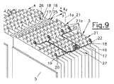
各バッテリセル5は、プラスチックのケーシング14に封止され、プラスチックのケーシング14は、ほぼセルの中間平面15の領域内で短辺側5aに沿う封止目的の突出シーリングシーム16を有する。その都度スタック3,4の隣接するバッテリセル5のシーリングシーム16間には空間17が画定される。
Each
設置空間を節約するため、隣接配置された各バッテリモジュール2の2つのスタック3,4は、互いに対して重なり且つずれるように設置される。ずれVは、バッテリセル5の厚みDの約半分である。一方のスタック3,4のバッテリセル5のシーリングシーム16は、他方のスタック4,3の2つの隣接するバッテリセル5のシーリングシーム16によって画定された空間17内に突出する。このように、シーリングシーム16の一部を収容することによって空間17が少なくとも部分的に使用され得る。これは、構成された空間と体積エネルギー密度に対して非常に有益な効果を有する。2つのスタック3,4間のずれVは、プレート6がバッテリ1の長手方向中間平面1aの領域に段差24を形成することを意味する。
In order to save the installation space, the two
U字形及びY字形のセルコネクタ19,20を介して接続されるセル端子18は、上方の短辺側5aでプラスチックケーシング14から突出する。セルコネクタ19,20とセル端子18との接続部は、クリンチング処理において1つ以上のクリンチ点21aを備えるクリンチ接続部21として形成され得る。これにより、複数の接続点の結果としての特に高い通電性能だけでなく、更なる構造的要素を用いずに、気密に封止された接続点と、異なる材質とのセル端子18の単純な接触(銅からアルミニウム及びその逆)による長期間の耐腐食性接続が容易になる。クリンチングによって同一のツールを用いて2つ乃至4つのシートを電気的に接続することができ、特に適切には、銅、アルミニウム、及び鋼材料の壁圧は、0.1mm乃至0.5mmである。結果、必要に応じて、クリンチング処理における付加的な作業で同時にセルコネクタ19,20によってセル端子18にセル電圧モニタリングケーブル22が接続され得る。クリンチ接続部21のクリンチ点21aの位置は例えばレーザ溶接された接続部よりも変動が可能であるため、比較的大きな公差補償能力が得られる。パラレルで多目的なツールを使用することによって、材料の壁厚や押圧などの数個の容易に制御可能な入力変数のみを伴う、より大規模な生産運転に対してより単純且つコスト効果の高い生産が可能になる。冷却空気チャネル27内に突出したクリンチ点21aによってバッテリ1の放熱表面積が増し、これは、セル端子18を直接空気冷却する場合、特別な意味を持つ。突出クリンチ点21aは、特に空気冷却の場合、乱流を増大させること、つまり熱伝達を改善することにも寄与する。結果、冷却に対するクリンチ点21aの好影響は、設置空間の効率的活用の結果として体積エネルギー密度の増加にも寄与する。
The
特に良好な体積エネルギー密度を達成するためには、バッテリセル5を可能な限り近くに位置決めする必要がある。更に、隣接するバッテリセル5の熱的過負荷の際の「ドミノ効果」発生を防止するために、バッテリセル5間に可能な限り薄い熱的及び電気的な絶縁層23、例えば絶縁箔が配置される。
In order to achieve a particularly good volumetric energy density, it is necessary to position the
それと共に、空間17は、冷却空気チャネル26,27を作り出す。空間17は、2つのスタック3,4の重なり部25の領域、即ち、バッテリ1の長手方向中間平面1aの領域に第1の冷却空気チャネル26を形成し、前記チャネルは、バッテリ1の縦軸zの方向に配置される。シーリングシーム16は、空気流のフロー案内表面及び放熱表面を形成する。縦軸zに対して及び積層方向yに対して垂直な横軸xの方向に、バッテリセル5の上側に、空間17によってセル端子18の領域には第2の冷却空気チャネル27が形成される。
Along with that, the
第1及び第2の冷却空気チャネル26,27は、バッテリ1を冷却するための閉冷却空気回路28の一部であり、冷却空気回路28は、少なくとも1つの冷却空気ファン29と、少なくとも1つの熱交換器30を有する。冷却空気(冷却空気ファン29及び熱交換器30から来る)は、バッテリ1の後部及び/又は上部の保定プレート9の領域又はセル端子18の領域でハウジング12内に搬入される。冷却空気は、第2の冷却空気チャネル27を通過して流れ、セル端子18及びセルコネクタ19,20を冷却する。その後、冷却空気の少なくとも一部は、縦軸zの方向に冷却空気を下方案内する第1の冷却空気チャネル26に達する。空気はバッテリ1の全空隙及び空間17を流れ、蓄積された熱が取り出される。残りの冷却空気は、バッテリ1の前側の保定プレート8とハウジング12との間を流れてハウジング12のハウジング床12aに到達し、そこでフローガイド表面13によって車両の長手方向中間平面εまで案内され、収集される。冷却空気は、次に、冷却空気ファンによって再び吸引され、バッテリ1の閉冷却回路28内に再び送り込まれる前に熱交換器30によって冷却される。
The first and second
Claims (15)
Applications Claiming Priority (3)
| Application Number | Priority Date | Filing Date | Title |
|---|---|---|---|
| ATA957/2011A AT511668B1 (en) | 2011-06-30 | 2011-06-30 | RECHARGEABLE ELECTRIC BATTERY |
| ATA957/2011 | 2011-06-30 | ||
| PCT/EP2012/062338 WO2013000900A1 (en) | 2011-06-30 | 2012-06-26 | Rechargeable electric battery |
Publications (3)
| Publication Number | Publication Date |
|---|---|
| JP2014525118A JP2014525118A (en) | 2014-09-25 |
| JP2014525118A5 JP2014525118A5 (en) | 2015-08-13 |
| JP6063933B2 true JP6063933B2 (en) | 2017-01-18 |
Family
ID=46397245
Family Applications (1)
| Application Number | Title | Priority Date | Filing Date |
|---|---|---|---|
| JP2014517652A Expired - Fee Related JP6063933B2 (en) | 2011-06-30 | 2012-06-26 | Rechargeable electric battery |
Country Status (7)
| Country | Link |
|---|---|
| US (1) | US20140141311A1 (en) |
| EP (1) | EP2727169B1 (en) |
| JP (1) | JP6063933B2 (en) |
| KR (1) | KR20140042850A (en) |
| CN (1) | CN103918102B (en) |
| AT (1) | AT511668B1 (en) |
| WO (1) | WO2013000900A1 (en) |
Families Citing this family (13)
| Publication number | Priority date | Publication date | Assignee | Title |
|---|---|---|---|---|
| DE102013011895A1 (en) | 2013-07-16 | 2015-01-22 | Audi Ag | Receiving device for receiving at least one energy storage component |
| DE102013011894A1 (en) * | 2013-07-16 | 2015-01-22 | Audi Ag | Receiving device for receiving at least one energy storage component |
| US20160233502A1 (en) * | 2014-02-27 | 2016-08-11 | Nokomis, Inc. | Lithium ion Battery Cell With Single Crystal Li+- Intercalated Titanium Dioxide As An Anode Material |
| EP3523840B1 (en) * | 2016-10-07 | 2020-12-02 | Constellium Automotive USA, LLC | Battery box for automotive battery temperature management |
| KR102088477B1 (en) * | 2017-05-16 | 2020-03-12 | 주식회사 엘지화학 | Battery module |
| KR102640329B1 (en) | 2018-10-19 | 2024-02-22 | 삼성에스디아이 주식회사 | Battery module |
| KR102646853B1 (en) | 2018-10-19 | 2024-03-11 | 삼성에스디아이 주식회사 | Battery module |
| KR102646854B1 (en) * | 2018-10-19 | 2024-03-11 | 삼성에스디아이 주식회사 | Battery module |
| KR102640327B1 (en) | 2018-10-19 | 2024-02-22 | 삼성에스디아이 주식회사 | Large module of battery |
| KR20200044582A (en) | 2018-10-19 | 2020-04-29 | 삼성에스디아이 주식회사 | Large module of battery |
| KR102640328B1 (en) | 2018-10-19 | 2024-02-22 | 삼성에스디아이 주식회사 | Large module of battery |
| CN110120479A (en) * | 2019-04-17 | 2019-08-13 | 上海空间电源研究所 | A kind of high-pressure sealed insulation lithium-ions battery group structure of aerospace |
| DE102022001135A1 (en) | 2022-04-01 | 2023-10-05 | Mercedes-Benz Group AG | Traction battery and vehicle |
Family Cites Families (16)
| Publication number | Priority date | Publication date | Assignee | Title |
|---|---|---|---|---|
| DE3133773C1 (en) * | 1981-08-26 | 1982-12-09 | Daimler-Benz Ag, 7000 Stuttgart | Housing for individual cells which can be assembled to form high-power batteries |
| DE4407156C1 (en) * | 1994-03-04 | 1995-06-08 | Deutsche Automobilgesellsch | Electric storage battery housing for electrically-driven automobile |
| DE19504687C1 (en) * | 1995-02-13 | 1996-03-14 | Deutsche Automobilgesellsch | Battery casing housing electrochemical battery cells |
| JP4572019B2 (en) * | 1999-10-08 | 2010-10-27 | パナソニック株式会社 | Assembled battery |
| JP4593056B2 (en) * | 2002-05-07 | 2010-12-08 | 富士重工業株式会社 | Plate battery connection structure |
| JP4203261B2 (en) * | 2002-05-21 | 2008-12-24 | 日産自動車株式会社 | Secondary battery module |
| JP4029819B2 (en) * | 2003-10-16 | 2008-01-09 | 日産自動車株式会社 | Assembled battery |
| JP4483489B2 (en) * | 2004-09-02 | 2010-06-16 | 日産自動車株式会社 | Assembled battery |
| JP2007042453A (en) * | 2005-08-03 | 2007-02-15 | Fuji Heavy Ind Ltd | Aligned structure of storage body cell |
| JP5162089B2 (en) * | 2005-10-14 | 2013-03-13 | 日本電気株式会社 | Cooling structure |
| US7531270B2 (en) | 2006-10-13 | 2009-05-12 | Enerdel, Inc. | Battery pack with integral cooling and bussing devices |
| JP2008171802A (en) * | 2006-12-13 | 2008-07-24 | Matsushita Electric Ind Co Ltd | Negative electrode for nonaqueous electrolyte secondary battery and its manufacturing method, and nonaqueous electrolyte secondary battery using the same |
| DE102008034699B4 (en) * | 2008-07-26 | 2011-06-09 | Daimler Ag | Battery with several battery cells |
| US20100104927A1 (en) | 2008-10-29 | 2010-04-29 | Scott Albright | Temperature-controlled battery configuration |
| KR100937897B1 (en) | 2008-12-12 | 2010-01-21 | 주식회사 엘지화학 | Middle or large-sized battery pack of novel air cooling structure |
| DE102009035463A1 (en) | 2009-07-31 | 2011-02-03 | Daimler Ag | Battery with a large number of plate-shaped battery cells |
-
2011
- 2011-06-30 AT ATA957/2011A patent/AT511668B1/en not_active IP Right Cessation
-
2012
- 2012-06-26 EP EP12730511.8A patent/EP2727169B1/en active Active
- 2012-06-26 CN CN201280032756.3A patent/CN103918102B/en active Active
- 2012-06-26 JP JP2014517652A patent/JP6063933B2/en not_active Expired - Fee Related
- 2012-06-26 US US14/129,977 patent/US20140141311A1/en not_active Abandoned
- 2012-06-26 KR KR1020147000735A patent/KR20140042850A/en not_active Application Discontinuation
- 2012-06-26 WO PCT/EP2012/062338 patent/WO2013000900A1/en active Application Filing
Also Published As
| Publication number | Publication date |
|---|---|
| CN103918102B (en) | 2017-11-28 |
| CN103918102A (en) | 2014-07-09 |
| EP2727169A1 (en) | 2014-05-07 |
| US20140141311A1 (en) | 2014-05-22 |
| EP2727169B1 (en) | 2018-06-13 |
| AT511668A1 (en) | 2013-01-15 |
| AT511668B1 (en) | 2015-05-15 |
| KR20140042850A (en) | 2014-04-07 |
| WO2013000900A1 (en) | 2013-01-03 |
| JP2014525118A (en) | 2014-09-25 |
Similar Documents
| Publication | Publication Date | Title |
|---|---|---|
| JP6063933B2 (en) | Rechargeable electric battery | |
| JP6169571B2 (en) | Rechargeable electric battery | |
| US11444353B2 (en) | Battery pack | |
| JP6047234B2 (en) | Battery module | |
| JP5916500B2 (en) | Assembled battery | |
| US10586952B2 (en) | Battery module comprising cartridge having gripping part | |
| EP2515361B1 (en) | Battery unit | |
| JP6494754B2 (en) | Battery module | |
| KR101252936B1 (en) | Battery pack | |
| US20100151299A1 (en) | Battery module, and middle or large-sized battery pack containing the same | |
| EP2456004A1 (en) | Battery pack device | |
| WO2013018283A1 (en) | Battery pack | |
| CN110959224A (en) | Battery module, battery pack, and combined battery pack | |
| CN105322248A (en) | Battery module, battery pack, and device including battery pack | |
| JP2012014962A (en) | Battery pack | |
| KR20120099063A (en) | Battery pack | |
| JP2010113888A (en) | Battery device and vehicle | |
| JP2016225249A (en) | Battery pack | |
| JP2015069872A (en) | Battery unit | |
| JP7136014B2 (en) | fuel cell unit | |
| JP2022062288A (en) | Battery module | |
| JP6533694B2 (en) | Power supply | |
| JP6111911B2 (en) | Assembled battery | |
| JP6743576B2 (en) | Battery pack structure | |
| KR20200073721A (en) | Battery Pack |
Legal Events
| Date | Code | Title | Description |
|---|---|---|---|
| A521 | Request for written amendment filed |
Free format text: JAPANESE INTERMEDIATE CODE: A523 Effective date: 20150626 |
|
| A621 | Written request for application examination |
Free format text: JAPANESE INTERMEDIATE CODE: A621 Effective date: 20150626 |
|
| A977 | Report on retrieval |
Free format text: JAPANESE INTERMEDIATE CODE: A971007 Effective date: 20160420 |
|
| A131 | Notification of reasons for refusal |
Free format text: JAPANESE INTERMEDIATE CODE: A131 Effective date: 20160426 |
|
| A521 | Request for written amendment filed |
Free format text: JAPANESE INTERMEDIATE CODE: A523 Effective date: 20160726 |
|
| TRDD | Decision of grant or rejection written | ||
| A01 | Written decision to grant a patent or to grant a registration (utility model) |
Free format text: JAPANESE INTERMEDIATE CODE: A01 Effective date: 20161122 |
|
| A61 | First payment of annual fees (during grant procedure) |
Free format text: JAPANESE INTERMEDIATE CODE: A61 Effective date: 20161219 |
|
| R150 | Certificate of patent or registration of utility model |
Ref document number: 6063933 Country of ref document: JP Free format text: JAPANESE INTERMEDIATE CODE: R150 |
|
| R250 | Receipt of annual fees |
Free format text: JAPANESE INTERMEDIATE CODE: R250 |
|
| R250 | Receipt of annual fees |
Free format text: JAPANESE INTERMEDIATE CODE: R250 |
|
| R250 | Receipt of annual fees |
Free format text: JAPANESE INTERMEDIATE CODE: R250 |
|
| LAPS | Cancellation because of no payment of annual fees |