JP2020012317A - Junction structure of wooden member and junction method of wooden member - Google Patents
Junction structure of wooden member and junction method of wooden member Download PDFInfo
- Publication number
- JP2020012317A JP2020012317A JP2018135678A JP2018135678A JP2020012317A JP 2020012317 A JP2020012317 A JP 2020012317A JP 2018135678 A JP2018135678 A JP 2018135678A JP 2018135678 A JP2018135678 A JP 2018135678A JP 2020012317 A JP2020012317 A JP 2020012317A
- Authority
- JP
- Japan
- Prior art keywords
- wooden
- joining structure
- wood
- protrusion
- hole
- Prior art date
- Legal status (The legal status is an assumption and is not a legal conclusion. Google has not performed a legal analysis and makes no representation as to the accuracy of the status listed.)
- Granted
Links
- 238000000034 method Methods 0.000 title claims description 14
- 230000000149 penetrating effect Effects 0.000 claims abstract description 58
- 239000002023 wood Substances 0.000 claims description 102
- 238000005304 joining Methods 0.000 claims description 72
- 239000000463 material Substances 0.000 claims description 14
- 230000002093 peripheral effect Effects 0.000 claims description 12
- 230000035515 penetration Effects 0.000 abstract description 9
- 238000003780 insertion Methods 0.000 description 5
- 230000037431 insertion Effects 0.000 description 5
- 238000005452 bending Methods 0.000 description 2
- 238000006073 displacement reaction Methods 0.000 description 2
- 230000000694 effects Effects 0.000 description 2
- 238000010030 laminating Methods 0.000 description 2
- 229910000831 Steel Inorganic materials 0.000 description 1
- 230000003466 anti-cipated effect Effects 0.000 description 1
- 238000010276 construction Methods 0.000 description 1
- 238000003475 lamination Methods 0.000 description 1
- 238000004519 manufacturing process Methods 0.000 description 1
- 239000000203 mixture Substances 0.000 description 1
- 239000010959 steel Substances 0.000 description 1
Images


Landscapes
- Joining Of Building Structures In Genera (AREA)
Abstract
Description
本発明は、木質部材の接合構造及び木質部材の接合方法に関する。 The present invention relates to a joining structure for wood members and a joining method for wood members.
木質部材の接合構造としては、例えば、木材同士をボルト及びドリフトピンなどの曲げ降伏型接合具を用いて接合する接合構造が知られている(例えば、非特許文献1参照)。この接合構造では、一方側に延びる1本の木質部材を両面から挟むように、他方側に延びる2本の木質部材を重ね合わせ、重なり合う方向にボルトやドリフトピン等の貫通部材(曲げ降伏型接合具)を貫通させ、支圧で応力を伝達している。このような接合構造では、接合されている木質部材のうちの、挟まれている内側の木質部材と、両面側から挟んでいる木質部材が長手方向に相対移動する際に生じるせん断変形により木材の圧潰や破壊の前に貫通部材が降伏することを推奨し、貫通部材の径長比を定めている。 As a joining structure of wood members, for example, a joining structure in which wood is joined to each other by using a bending yield type joining tool such as a bolt and a drift pin is known (for example, see Non-Patent Document 1). In this joining structure, two wood members extending to the other side are overlapped so as to sandwich one wood member extending to one side from both sides, and penetrating members (bending yield type joining) such as bolts and drift pins are overlapped. Tool) penetrates and transmits stress by bearing pressure. In such a joining structure, of the joined wood members, the wood member sandwiched between the wood members sandwiched from both sides and the wood members sandwiched from both sides are caused by shear deformation generated in the longitudinal direction relative to each other. It is recommended that the penetrating member yield before crushing or breaking, and the diameter ratio of the penetrating member is determined.
上記のような接合構造では、貫通部材が降伏する際には、貫通部材の変形により、貫通部材が木質部材にめり込みながら降伏する脆性的かつ残留変形の大きな破壊形式を示してしまう。このため、木質板材への貫通部材のめり込み量を抑えるために、貫通部材の外径をさらに小さくする必要があり、貫通部材の降伏耐力が小さくなるという課題がある。
本発明は、このような事情に鑑みてなされたものであり、貫通部材による木質部材の損傷を抑えつつも貫通部材を降伏させることが可能な木質部材の接合構造及び木質部材の接合方法を提供することを目的とする。
In the joint structure as described above, when the penetrating member yields, the deformation of the penetrating member presents a brittle and large residual deformation type in which the penetrating member yields while sinking into the wooden member. For this reason, it is necessary to further reduce the outer diameter of the penetrating member in order to suppress the amount of penetration of the penetrating member into the wooden board, and there is a problem that the yield strength of the penetrating member is reduced.
The present invention has been made in view of such circumstances, and provides a joining structure of a wooden member and a joining method of a wooden member capable of yielding the penetrating member while suppressing damage to the wooden member by the penetrating member. The purpose is to do.
かかる目的を達成するために本発明の木質部材の接合構造は、
所定方向の所定長さにおいて突出した第1突出部と、前記第1突出部の前記所定方向と交差する交差方向に位置し、前記所定長さにおいて形成された第1凹部と、を有する第1木質部材と、
前記第1突出部が前記所定方向に入り込んで当接し、前記所定長さにおいて形成された第2凹部と、前記第2凹部に入り込んだ前記第1突出部と前記交差方向に重なり、前記所定長さにおいて突出して前記第1凹部と当接した第2突出部と、を有する第2木質部材と、
重なった前記第1突出部と前記第2突出部とを貫通している貫通部材と、
を有し、
前記貫通部材は、前記第1木質部材と前記第2木質部材との相対移動により降伏する降伏部が、前記第1突出部と前記第2突出部との境界部分に設けられていることを特徴とする木質部材の接合構造である。
In order to achieve such an object, the joining structure of the wooden member of the present invention is:
A first projection having a first projection projecting at a predetermined length in a predetermined direction, and a first recess formed at the predetermined length and located in an intersecting direction intersecting the predetermined direction of the first projection. Wooden members,
The first protrusion enters the predetermined direction and abuts thereon, and the second protrusion formed at the predetermined length overlaps with the first protrusion in the second recess in the cross direction, and the predetermined length A second wood member having a second protrusion protruding at the same time and abutting on the first recess;
A penetrating member penetrating the overlapped first protrusion and the second protrusion;
Has,
The penetrating member is characterized in that a yielding portion that yields by a relative movement between the first wood member and the second wood member is provided at a boundary between the first protrusion and the second protrusion. It is a joining structure of a wooden member.
このような木質部材の接合構造によれば、第1木質部材と第2木質部材とが相対移動した際に、第1突出部と第2突出部とを貫通する貫通部材は降伏部が降伏するので、第1木質部材と第2木質部材とが相対移動するエネルギーを吸収することが可能である。このとき、貫通部材の降伏部は、第1突出部と第2突出部との境界部分にて降伏するので、第1木質部材と第2木質部材とは貫通部材の降伏に伴って相対移動し易い。このため、第1木質部材と第2木質部材との損傷を抑えることが可能である。 According to such a joining structure of the wood members, when the first wood member and the second wood member relatively move, the yielding portion of the penetrating member that passes through the first protrusion and the second protrusion is yielded. Therefore, it is possible to absorb the energy of the relative movement of the first wood member and the second wood member. At this time, since the yielding portion of the penetrating member yields at the boundary between the first projecting portion and the second projecting portion, the first wooden member and the second wooden member relatively move with the yielding of the penetrating member. easy. For this reason, it is possible to suppress damage to the first wood member and the second wood member.
かかる木質部材の接合構造であって、
前記降伏部は、前記第1木質部材と前記第2木質部材とが相対移動したときに、当該降伏部が前記第1木質部材または前記第2木質部材にめり込む前に降伏することを特徴とする。
このような木質部材の接合構造によれば、第1木質部材と第2木質部材とが相対移動したとき、第1木質部材または第2木質部材に降伏部がめり込まないので、第1木質部材及び第2木質部材の損傷を防止することが可能である。
The joint structure of such a wooden member,
When the first wood member and the second wood member move relative to each other, the yielding portion yields before the yielding portion sinks into the first wood member or the second wood member. .
According to such a joint structure of wood members, when the first wood member and the second wood member move relative to each other, the yielding portion does not sink into the first wood member or the second wood member, so that the first wood member is In addition, it is possible to prevent the second wooden member from being damaged.
かかる木質部材の接合構造であって、
前記第1突出部は、前記交差方向に貫通する第1貫通孔を有し、
前記第2突出部は、前記交差方向に貫通する第2貫通孔を有し、
前記貫通部材は、前記第1貫通孔に貫入される第1嵌入部と、前記第2貫通孔に貫入される第2嵌入部とを有し、
前記降伏部は、前記第1嵌入部と前記第2嵌入部との間に設けられていることを特徴とすることを特徴とする。
The joint structure of such a wooden member,
The first protrusion has a first through hole penetrating in the cross direction,
The second protrusion has a second through hole penetrating in the cross direction,
The penetrating member has a first fitting portion penetrating into the first through hole, and a second fitting portion penetrating into the second through hole.
The yielding portion is provided between the first fitting portion and the second fitting portion.
このような木質部材の接合構造によれば、第1嵌入部は第1貫通孔に貫入されているので、第1突出部と一体となって移動し、第2嵌入部は第2貫通孔に貫入されるので第2突出部と一体となって移動する。このため、第1木質部材と第2木質部材とが相対移動した際には、第1嵌入部と第2嵌入部との間に設けられている降伏部をより確実に降伏させることが可能である。 According to such a joining structure of the wooden members, since the first fitting portion penetrates the first through hole, the first fitting portion moves integrally with the first projecting portion, and the second fitting portion moves into the second through hole. Since it penetrates, it moves integrally with the second protrusion. For this reason, when the first wood member and the second wood member relatively move, the yielding portion provided between the first fitting portion and the second fitting portion can be more reliably yielded. is there.
かかる木質部材の接合構造であって、
前記降伏部は、前記第1嵌入部及び前記第2嵌入部よりも外径が小さいことを特徴とする。
このような木質部材の接合構造によれば、降伏部の外径は、第1嵌入部及び第2嵌入部の外径よりも小さいので、降伏部と第1及び第2木質部材との間には、空隙が設けられている。このため、貫通部材の降伏部が降伏した場合であっても、貫通部材は第1及び第2木質部材に接触し難いので、貫通部材が降伏した際に、第1木質部材及び第2木質部材の損傷をより確実に抑えることが可能である。
The joint structure of such a wooden member,
The yielding portion has a smaller outer diameter than the first fitting portion and the second fitting portion.
According to such a joining structure of the wooden members, since the outer diameter of the yielding portion is smaller than the outer diameters of the first fitting portion and the second fitting portion, the outer diameter of the yielding portion is smaller than that of the first and second woody members. Are provided with voids. For this reason, even when the yielding portion of the penetrating member yields, the penetrating member hardly comes into contact with the first and second wood members. Therefore, when the penetrating member yields, the first wood member and the second wood member are used. Can be more reliably suppressed.
かかる木質部材の接合構造であって、
前記第1嵌入部は、前記第2貫通孔に嵌入しておらず、前記第2嵌入部は、前記第1貫通孔に嵌入していないことを特徴とする。
このような木質部材の接合構造によれば、第1嵌入部及び第2嵌入部は、いずれも第1木質部材及び第2木質部材に跨がっていないので、第1木質部材と第2木質部材とが相対移動した際には、貫通部材をより確実に降伏させることが可能である。
The joint structure of such a wooden member,
The first fitting portion is not fitted in the second through hole, and the second fitting portion is not fitted in the first through hole.
According to such a joining structure of the wood members, the first fitting portion and the second fitting portion do not straddle the first wood member and the second wood member, so that the first wood member and the second wood member are not straddled. When the member relatively moves, the penetrating member can be more reliably yielded.
かかる木質部材の接合構造であって、
前記降伏部は、前記第1木質部材と前記第2木質部材との相対移動にて降伏した前記降伏部が、前記第1貫通孔及び前記第2貫通孔の内周面に接触しないことを特徴とする。
このような木質部材の接合構造によれば、第1木質部材と第2木質部材との相対移動にて降伏部が降伏したときに、当該降伏部は第1嵌入部及び第2嵌入部の内周面に接触しないので、第1木質部材と第2木質部材との相対移動により第1木質部材及び第2木質部材が損傷することを防止することが可能である。
The joint structure of such a wooden member,
The yielding portion is characterized in that the yielding portion yielded by the relative movement between the first wood member and the second wood member does not contact the inner peripheral surfaces of the first through hole and the second through hole. And
According to such a joining structure of the wood members, when the yielding portion yields due to the relative movement between the first wood member and the second wood member, the yielding portion is formed between the first fitting portion and the second fitting portion. Since it does not contact the peripheral surface, it is possible to prevent the first wood member and the second wood member from being damaged by the relative movement between the first wood member and the second wood member.
かかる木質部材の接合構造であって、
前記第1貫通孔内において前記第1嵌入部が接触している部位の、前記交差方向における長さは、
前記第2貫通孔内において前記第2嵌入部が接触している部位の、前記交差方向における長さより長いことを特徴とする。
The joint structure of such a wooden member,
The length in the cross direction of the portion where the first fitting portion is in contact with the first through hole is:
A length of the portion in the second through hole in contact with the second fitting portion is longer than a length in the cross direction.
このような木質部材の接合構造によれば、第2貫通孔を有する第2突出部は、第1貫通孔を有する第1突出部を両面から挟んでいるので、貫通部材は第1嵌入部を1箇所有しており、第2嵌入部を2箇所有している。このため、1箇所で接触する第1嵌入部が接触している部位の長さを、2箇所で接触する第2嵌入部が接触している部位の長さより長くすることにより、第1木質部材と第2木質部材とが相対移動する際に作用する力のバランスを取ることが可能である。 According to such a joining structure of the wooden members, since the second projection having the second through hole sandwiches the first projection having the first through hole from both sides, the penetration member has the first fitting portion. It has one place and has two second fitting portions. For this reason, by making the length of the portion where the first fitting portion that contacts at one location is in contact longer than the length of the portion where the second fitting portion that contacts at two locations is in contact, the first wood member It is possible to balance the forces acting when the and the second wood member move relative to each other.
かかる木質部材の接合構造であって、
前記降伏部は、前記第2貫通孔に配置されていることを特徴とする。
このような木質部材の接合構造によれば、降伏部が第2貫通孔に配置されているので、第1嵌入部において第1貫通孔の内周面と接触する部位の長さをより長く確保することが可能である。
The joint structure of such a wooden member,
The yield part is arranged in the second through-hole.
According to such a joining structure of the wooden members, since the yielding portion is disposed in the second through hole, the length of a portion in contact with the inner peripheral surface of the first through hole in the first fitting portion is secured longer. It is possible to
かかる木質部材の接合構造であって、
前記第1木質部材は、前記第1突出部を有する第1突出板材と、前記第1突出板材における前記第1突出部を除く部位に重合されている第1重合板材と、を有していることを特徴とする。
このような木質部材の接合構造によれば、第1突出板材と第1重合板材とが重ねられた第1木質部材の、貫通部材による損傷を抑えつつも貫通部材を降伏させることが可能に接合することが可能である。
The joint structure of such a wooden member,
The first wood member includes a first protruding plate having the first protruding portion, and a first superposed plate that is superimposed on a portion of the first protruding plate except for the first protruding portion. It is characterized by the following.
According to such a joining structure of the wooden members, the first wooden member in which the first protruding plate member and the first superposed plate member are overlapped can be yielded while suppressing damage to the penetrating member by the penetrating member. It is possible to
かかる木質部材の接合構造であって、
前記第1木質部材は、前記第1突出板材の両面に各々重合されている2枚の前記第1重合板材を有していることを特徴とする。
このような木質部材の接合構造によれば、第1突出板材の両面に各々第1重合板材が重合されている第1木質部材の、貫通部材による損傷を抑えつつも貫通部材を降伏させることが可能に接合することが可能である。
The joint structure of such a wooden member,
The first wood member has two first superposed plate members superposed on both surfaces of the first protruding plate member, respectively.
According to such a joint structure of wooden members, it is possible to yield the penetrating member while suppressing damage by the penetrating member of the first wooden member in which the first superposed plate member is superposed on both surfaces of the first protruding plate member. It is possible to join as much as possible.
かかる木質部材の接合構造であって、
前記第2木質部材は、前記第2突出部を有する第2突出板材と、前記第2突出板材における前記第2突出部を除く部位に重合されている第2重合板材と、を有していることを特徴とする。
このような木質部材の接合構造によれば、第2突出板材と第2重合板材とが重ねられた第2木質部材の、貫通部材による損傷を抑えつつも貫通部材を降伏させることが可能に接合することが可能である。
The joint structure of such a wooden member,
The second wood member includes a second protruding plate having the second protruding portion, and a second superposed plate that is superimposed on a portion of the second protruding plate except for the second protruding portion. It is characterized by the following.
According to such a joining structure of the wooden members, it is possible to join the second wooden member in which the second projecting plate member and the second superposed plate member are overlapped with each other so that the penetrating member can be yielded while suppressing damage by the penetrating member. It is possible to
かかる木質部材の接合構造であって、
前記第2木質部材は、前記第2重合板材の両面に各々重合されている2枚の前記第2突出板材を有していることを特徴とする。
このような木質部材の接合構造によれば、第2重合板材の両面に各々第2突出板材が重合されている第2木質部材の、貫通部材による損傷を抑えつつも貫通部材を降伏させることが可能に接合することが可能である。
The joint structure of such a wooden member,
The second wood member has two second protruding plate members superposed on both surfaces of the second superposed plate member, respectively.
According to such a joint structure of the wooden members, it is possible to yield the penetrating member while suppressing damage by the penetrating member of the second wooden member in which the second projecting plate members are superposed on both surfaces of the second superposed plate member. It is possible to join as much as possible.
また、上記木質部材の接合構造により前記第1木質部材と前記第2木質部材とを接合する木質部材の接合方法であって、
木質部材とを接合する木質部材の接合方法であって、
前記第1木質部材の前記第1突出部と、
前記第2木質部材の前記第2突出部と、
を前記交差方向に重ねて配置する配置ステップと、
前記降伏部を備えた前記貫通部材を、前記第1突出部と前記第2突出部とに貫通させる貫通ステップと、
を有することを特徴とする木質部材の接合方法である。
Also, a method for joining wood members, wherein the first wood member and the second wood member are joined by the wood member joining structure,
A method of joining a wooden member to join the wooden member,
The first protrusion of the first wood member;
The second protrusion of the second wood member;
An arrangement step of arranging the above in the cross direction,
A penetrating step of penetrating the penetrating member having the yielding portion through the first projecting portion and the second projecting portion;
It is a joining method of the wooden member characterized by having.
このような木質部材の接合方法によれば、第1木質部材の第1突出部と第2木質部材の第2突出部とを交差方向に重ねて配置し、降伏部を備えた貫通部材を、第1突出部と第2突出部とに貫通させるだけで、第1木質部材と第2木質部材とを、貫通部材による損傷を抑えつつも、第1木質部材と第2木質部材との相対移動時に貫通部材を降伏させることができるように接合することが可能である。 According to such a method of joining wood members, the first protrusion of the first wood member and the second protrusion of the second wood member are arranged so as to overlap in the cross direction, and the penetrating member having the yielding portion is provided. The relative movement between the first wood member and the second wood member while preventing damage to the first wood member and the second wood member only by penetrating the first protrusion portion and the second protrusion portion. Sometimes it is possible to join so that the penetrating members can be yielded.
本発明によれば、貫通部材による木質部材の損傷を抑えつつも貫通部材を降伏させることが可能な木質部材の接合構造及び木質部材の接合方法を提供することが可能である。 Advantageous Effects of Invention According to the present invention, it is possible to provide a joining structure of a wood member and a joining method of a wood member capable of yielding the penetration member while suppressing damage to the wood member by the penetration member.
以下、本発明の木質部材の接合構造を、図を用いて説明する。
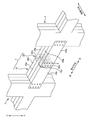
本実施形態では、第1木質部材としての第1梁材10と第2木質部材としての第2梁材20とを、各梁材10、20の長手方向(所定方向)に沿わせて繋ぐように接合する接合構造を例に挙げて説明する。本実施形態にて接合されている2本の梁材10、20は、例えば、図1に示すように、断面が略矩形状をなし、製材、集成材、LVL等の板状をなす3枚の木質の板部材10a、10b、20a、20bが積層され、積層されている積層方向、すなわち、梁1の長手方向と交差する方向に、例えばシネジック株式会社製パネリード(登録商標)ビス等の綴り材が貫入されて一体化されている。尚、3枚の板部材10a、10b、20a、20bを綴る綴り材についての説明、及び、図示は省略する。
Hereinafter, the joining structure of the wooden member of the present invention will be described with reference to the drawings.
In this embodiment, the
以下の説明においては、第1梁材(図1では左側)を構成する3枚の板部材10a、10bのうちの真ん中に配置される板部材を第1突出板材としての第1内板部材10aと称し、第1内板部材10aを両面から挟む一対の板部材を第1重合板材としての第1外板部材10bと称することとする。また、第2梁材(図1では右側)を構成する3枚の板部材20a、20bのうちの真ん中に配置される板部材を第2重合板材としての第2内板部材20aと称し、第2内板部材20aを両面から挟む一対の板部材を第2突出板材としての第2外板部材20bと称することとする。本実施形態においては、第1梁材10及び第2梁材20を構成する3枚の板部材10a、10b、20a、20bはいずれも、単板積層材(LVL)であり、同じ厚みをなしている。
In the following description, the plate member disposed in the middle of the three
また、以下の説明においては、互いに間隔を隔てて立設されている2本の柱3、4間に、第1梁材10と第2梁材20とが接合された梁1が掛け渡されている状態で、上下となる方向を上下方向、掛け渡されている梁1の長手方向を長手方向、掛け渡されている梁1の長手方向と交差する方向であって3枚の板部材10a、10b、20a、20bが積層されている方向を積層方向として示す。
Further, in the following description, a
図1、図2に示すように、第1梁材10は、長手方向における一方の端部が柱(図1においては左側の柱)3に接合されており、他方の端部は、第1内板部材10aが、一対の第1外板部材10bよりも長手方向に所定長さにおいて突出した第1突出部10cを有している。すなわち、第1梁材10は、第1突出部10cを有する第1内板部材10aと、第1内板部材10aにおける第1突出部10cを除く部位に重合されている第1外板部材10bと、を有している。このため、第1梁材10における第1突出部10cの、長手方向と交差する交差方向における両側に所定長さにおいて形成された第1凹部10dが設けられている。
As shown in FIGS. 1 and 2, one end of the
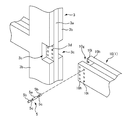
また、第2梁材20は、長手方向における一方の端部が柱(図1においては右側の柱)4に接合されており、他方の端部は、一対の第2外板部材20bが、第2内板部材20aよりも長手方向に所定長さにおいて突出した第2突出部20cを有している。すなわち、第2梁材20は、第2突出部20cを有する一対の第2外板部材20bと、第2外板部材20bにおける第2突出部20cを除く部位の間に重合されている第2内板部材20aと、を有している。このため、交差方向において対面する一対の第2梁材20の第2突出部20cの間に所定長さに形成された第2凹部20dが設けられている。
The
第1梁材10と第2梁材20とは、第1梁材10の第1突出部10cが、第2梁材20の凹部20dに挿入された状態で貫通部材としてのドリフトピン5により接合される。第1梁材10の長手方向における第1突出部10cの突出長さと、第2梁材20の長手方向における第2突出部20の突出長さとは、等しく形成されている。このため、第1梁材10と第2梁材20とが接合された状態では、第1突出部10cの先端が、第2凹部20dに当接し、第2突出部20cの先端が第1凹部10dに当接されている。
The
第1梁材10の第1突出部10cには、積層方向に貫通しドリフトピン5が嵌入される第1貫通孔10eが複数設けられており、第2梁材20の2つの第2突出部20cには、積層方向に貫通しドリフトピン5が嵌入される第2貫通孔20eが複数設けられている。第1貫通孔10eと第2貫通孔20eとは、内径D1がいずれもドリフトピン5の外径D2と同一、または、ドリフトピン5の外径より僅かに小さく形成されている。図3(a)に示すように、第1突出部10cが第2凹部20dに挿入された状態では、第1突出部10cに設けられた第1貫通孔10eと第1突出部10cの両側に配置される第2突出部20cにそれぞれ設けられた第2貫通孔20eとが積層方向に連通して貫通するように配置される。
The first projecting
ドリフトピン5は、第1貫通孔10eに嵌入される第1嵌入部5aと、第2貫通孔20eに嵌入される2つの第2嵌入部5bとを有している。第1嵌入部5aの両側にそれぞれ設けられる第2嵌入部5bと第1嵌入部5aとは、第1嵌入部5a及び第2嵌入部5bの外径D2よりも小さな外径D3の縮径部5cにより繋がっている。ここで、ドリフトピン5の外径D2は、例えば、20〜30mmであり、縮径部5cの外径D3は、例えば、10〜15mmである。
The
第1突出部10cが第2凹部20dに挿入されて第1貫通孔10eと第2貫通孔20eとが連通している状態でドリフトピン5が第1貫通孔10e内及び第2貫通孔20e内に嵌入されている。嵌入されたドリフトピン5は、積層方向において梁1の全幅に亘っており、第1嵌入部5aの積層方向における長さL1は、第1突出部10cの積層方向における厚みtとほぼ一致している。すなわち、第1嵌入部5aは、第1突出部10cの厚み方向における全長tに亘って第1貫通孔10eに嵌入されている。このため、第1嵌入部5aと繋がっている縮径部5c、及び、縮径部5cを介して第1嵌入部5aと繋がっている第2嵌入部5bは、第1貫通孔10eの外側に位置し、第2貫通孔20e内に配置される。すなわち、縮径部5cは、第1突出部10cと第2突出部20cとの境界部分に配置され、第1嵌入部5a及び第2嵌入部5bは、いずれも第1突出部10c及び第2突出部20cに跨がっていない。
When the
各々の第2嵌入部5bの積層方向における長さL2は、第1嵌入部5aの積層方向における長さL1より短く形成されている。例えば、各々の第2嵌入部5bの積層方向における長さL2は、第1嵌入部5aの積層方向における長さL1の半分に形成されている。すなわち、2つの第2嵌入部5bの積層方向の長さL2×2と、第1嵌入部5aの積層方向の長さL1とが等しくなるように形成されている。このように第1嵌入部5a及び第2嵌入部5bの積層方向の長さL1、L2を設定しておくことにより、地震等により第1突出部10cと第2突出部20cとの間にて相対変位が生じる場合には、第1梁材10と第2梁材20とに同様の支圧力が作用するように構成されている。
The length L2 of each second
本実施形態の木質部材の接合構造にて接合された梁1は、地震等により第1梁材10と第2梁材20とに相対変位が生じると、第1突出部10cと第2突出部20cとを貫通しているドリフトピン5にせん断力が作用する。このとき、第1梁材10と第2梁材20との、互いに離れる方向への相対移動に伴ってドリフトピン5は、図3(b)に示すように、第1突出部10cと第2突出部20cとの境界部分、より具体的には、第2突出部20cに設けられた第2貫通孔20e内の第1突出部10c側の位置に配置されている縮径部5cがせん断変形により降伏して、第1梁材10と第2梁材20とが相対変位するエネルギーを吸収する。本実施形態においては、想定される第1梁材10と第2梁材20とが相対変位が生じたときに、縮径部5cが第1貫通孔10eの内周面10f及び第2貫通孔20eの内周面20fにめり込む前に降伏するように設定されている。ここで、縮径部5cが降伏部に相当する。
When the
第1梁材10と第2梁材20とを接合する木質部材の接合方法は、まず、工場等において、第1突出部10c及び第1貫通孔10eを備えた第1梁材10と、第2突出部20c及び第2貫通孔20eを備えた第2梁材20とを製造する(梁材製造ステップ)。
The method of joining the wooden members for joining the
次に、工場にて製造した第1梁材10及び第2梁材20を施工現場に搬入し、図4に示すように、第1梁材10の第1突出部10cを第2梁材20の第2凹部20dに挿入するとともに、第2梁材20の第2突出部20cを第1梁材10の第1凹部10dに挿入し、第1突出部10cと第2突出部20cとを重合させる。このとき、重合させた第1突出部10cの第1貫通孔10eと第2突出部20cの第2貫通孔20eとが連通するように第1梁材10と第2梁材20とを配置する(配置ステップ、図4(a)〜図4(b))。
Next, the
次に、連通している第1貫通孔10eと第2貫通孔20eとに、縮径部5cを備えたドリフトピン5を打ち込んで第1突出部10cと第2突出部20cとに貫通させ、第1梁材10と第2梁材20とを接合する(貫通ステップ、図4(b)〜図4(c))。このとき、ドリフトピン5は、打ち込んだ先端が、ドリフトピン5が打ち込まれる面1aと反対側の面1bとが面一に揃う位置で、第1貫通孔10eの全長に第1嵌入部5aが亘るように形成しておく。ドリフトピン5を打ち込む際には、ドリフトピン5が打ち込まれる面1aと反対側の面1bにストッパーとなる鋼板(不図示)等をあてがってドリフトピン5を打ち込むことにより、ドリフトピン5を適切な位置に配置することが可能である。
Next, the
第1梁材10と第2梁材20とが接合された梁1の両端を立設している2本の柱3、4とそれぞれ接合して柱3、4間に梁1を掛け渡す。ここで、第1梁材10と第2梁材20とは、各々予め柱3、4と接合した状態で、第1突出部10cと第2突出部20cとを重ね合わせ、ドリフトピン5にて接合しても構わない。
The
本実施形態の木質部材の接合構造によれば、第1梁材10と第2梁材20とが相対移動した際には、第1突出部10cと第2突出部20cとを貫通するドリフトピン5は、第1嵌入部5a及び第2嵌入部5bよりも外径D3が小さな縮径部5cが降伏するので、第1梁材10と第2梁材20とが相対移動するエネルギーを吸収することが可能である。
According to the joining structure of the wood members of the present embodiment, when the
また、縮径部5cは、第1梁材10と第2梁材20とが相対移動したときに、当該縮径部5cが第1梁材10または第2梁材20にめり込む前に降伏するので、第1梁材10と第2梁材20とが相対移動しても第1梁材10または第2梁材20に縮径部5cがめり込まない。このため、第1梁材10及び第2梁材20の、相対移動により降伏する縮径部5cによる損傷を防止することが可能である。
When the
また、第1嵌入部5aは第1貫通孔10eに貫入されているので第1突出部10cと一体となって移動し、第2嵌入部5bは第2貫通孔20eに貫入されるので第2突出部20cと一体となって移動する。このため、第1梁材10と第2梁材20とが相対移動した際には、第1嵌入部5aと第2嵌入部5bとの間に設けられている縮径部5cをより確実に降伏させることが可能である。
Further, since the first
また、縮径部5cの外径D3は、第1嵌入部5a及び第2嵌入部5bの外径D2よりも小さく形成されている。このため、縮径部5cと第2梁材20との間、すなわち、第2貫通孔20eの内周面20fと縮径部5cとの間には、空隙Sが設けられる。このため、ドリフトピン5の縮径部5cが降伏した場合であっても、ドリフトピン5は第1貫通孔10eの内周面10f及び第2貫通孔20eの内周面20fとは接触し難いので、ドリフトピン5が降伏した際に、第1梁材10及び第2梁材20の損傷をより確実に抑えることが可能である。このため、縮径部5cの外径D3は、想定される地震動により第1梁材10と第2梁材20とが相対変位したときに縮径部5cが降伏しても縮径部5cが第1貫通孔10eの内周面10f及び第2貫通孔20eの内周面20fに接触しない外径D3に設定しておくことが望ましい。さらには、縮径部5cは、第1梁材10と第2梁材20とが相対移動したときに、当該縮径部5cが第1梁材10または第2梁材20にめり込む前に降伏するように設定しておくことが望ましい。
The outer diameter D3 of the reduced
また、第1嵌入部5a及び第2嵌入部5bは、いずれも第1梁材10及び第2梁材20に跨がっていないので、第1梁材10と第2梁材20とが相対移動した際には、縮径部5cをより確実に降伏させてドリフトピン5を屈曲させることが可能である。
Further, since neither the first
また、第2外板部材20bは、第1内板部材10aを両面から挟んでいるので、ドリフトピン5は第1嵌入部5aを1箇所有しており、第2嵌入部5bを2箇所有している。このため、2箇所で接触する第2嵌入部5bが接触している部位の長さL2を、1箇所で接触する第1嵌入部5aが接触している部位の長さL1の半分に設定することにより、第1梁材10と第2梁材20とが相対移動したときに、第1梁材10と第2梁材20とに同様に力を負担させることが可能である。
Also, since the second
このとき、第2嵌入部5bが接触している部位の長さL2は、第1嵌入部5aが接触している部位の長さL1の半分に限らない。例えば、第2嵌入部5bが接触している部位の長さL2を、第1嵌入部5aが接触している部位の長さL1よりも短くすることにより、第1梁材10と第2梁材20とが相対移動する際に作用する力のバランスを取ることが可能である。このとき、第1嵌入部5aを第1貫通孔10eと同じ長さに設定し縮径部5cを第2貫通孔20e内に配置すると、第1嵌入部5aにおいて第1貫通孔10eの内周面10fと接触する部位の長さL1をより長く確保することが可能である。
At this time, the length L2 of the portion where the second
また、本実施形態の木質部材の接合方法によれば、第1梁材10の第1突出部10cと第2梁材20の第2突出部20cとを交差方向に重ねて配置し、縮径部5cを備えたドリフトピン5を、第1突出部10cと第2突出部20cとに貫通させるだけで、第1梁材10と第2梁材20とを、ドリフトピン5による損傷を抑えつつも、第1梁材10と第2梁材20との相対移動時にドリフトピン5を降伏させることができるように接合することが可能である。
Moreover, according to the joining method of the woody member of the present embodiment, the first projecting
上記実施形態においては、第1貫通孔10eの積層方向の長さ、すなわち第1突出部10cの厚みtと、第1嵌入部5aの積層方向の長さL1とを同じに設定した例について説明したが、これに限るものではない。例えば、第1嵌入部が第1貫通孔よりも長く突出することがなく、縮径部が第1貫通孔内と第2貫通孔内とに跨がって配置されるなどして、第1梁材と第2梁材とが相対変位したときに、第1突出部と第2突出部との境界部分にて縮径部が降伏する形態であれば構わない。
In the above-described embodiment, an example will be described in which the length of the first through
上記実施形態においては、接合する木質部材として3枚の板部材10a、10b、20a、20bを積層した第1梁材10及び第2梁材20を例に挙げて説明したが、梁材は、各々1本の木材の端部に突出部と凹部とを備えた形態であっても、2枚の板部材または4枚以上の板部材を積層した梁材であっても、一方の端部に突出部を設け、他方の端部に凹部を備え、凹部に突出部を挿入して縮径部を備えた貫通部材を嵌入させて接合する接合構造であれば構わない。また、接合する2本の梁材の組み合わせは、同じ木材同士であっても、また、1本の木材でなる梁材と積層された板部材との組み合わせであっても構わない。
In the said embodiment, although the
また、上記実施形態においては、木質部材の接合構造及び木質部材の接合方法を、木質部材としての第1梁材10と第2梁材20とを接合する例を挙げて説明したが、これに限るものではない。例えば、図1に示すように、柱3と、梁1とを本発明の木質部材の接合構造にて接合しても構わない。この場合には、例えば、図5に示すように、梁1の柱3側の端部に、上記実施形態と同様の凹部10gを備え、凹部10gの両側に設けられた一対の突出部10hに貫通孔10iを備えておく。一方、3枚の板部材3a、3bが積層された柱3の積層方向における両側に設けられている外板部材3bには、梁1の突出部10hが挿入可能な凹部3cを設け、凹部3cにより露出した柱3の真ん中の内板部材3aに貫通孔3dを備えておく。そして、梁1の突出部10hを柱3の凹部3cに挿入して、積層方向に重なった柱3の内板部材3aと梁1の突出部10hに設けられている、連通する貫通孔10i、3dに縮径部5cを備えたドリフトピン5を打ち込んで、柱3と梁1とを接合してもよい。
Further, in the above-described embodiment, the joining structure of the wooden member and the joining method of the wooden member have been described with an example in which the
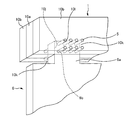
また、図6に示すように、例えば、梁1と木質壁6とを本発明の木質部材の接合構造にて接合しても構わない。例えば、3枚の板部材10a、10bが積層された梁1の真ん中の内板部材10aに、切り欠き部を設けることにより梁1の下方に開放された凹部10jを設け、凹部10jの積層方向における両側の部位10kに積層方向に貫通する貫通孔10lを備え、木質壁6には上方に突出して梁1の凹部10jに挿入される突出部6aと、突出部6aに積層方向に貫通する貫通孔6bを備えておく。そして、木質壁6の突出部6aを梁1の凹部10jに挿入し、積層方向に重なった梁1の両側の外板部材10bと木質壁6の突出部6aに設けられている、連通する貫通孔10l、6bに縮径部を備えたドリフトピン5を打ち込んで、梁1と木質壁6とを接合してもよい。
Further, as shown in FIG. 6, for example, the
以上、上記実施形態は、本発明の理解を容易にするためのものであり、本発明を限定して解釈するためのものではない。本発明は、その趣旨を逸脱することなく、変更、改良され得ると共に、本発明にはその等価物が含まれることはいうまでもない。 As described above, the above embodiments are for facilitating the understanding of the present invention, and are not intended to limit and interpret the present invention. The present invention can be changed and improved without departing from the spirit thereof, and it goes without saying that the present invention includes equivalents thereof.
1 梁、5 ドリフトピン(貫通部材)、5a 第1嵌入部、 5b 第2嵌入部、
5c 縮径部(降伏部)、10 第1梁材(第1木質部材)、10a 第1内板部材(第1突出板材)、
10b 第1外板部材(第1重合板材)、10c 第1突出部、10d 第1凹部、10e 第1貫通孔、
20 第2梁材(第2木質部材)、20a 第2内板部材(第2重合板材)、
20b 第2外板部材(第2突出板材)、20c 第2突出部、20d 第2凹部、20e 第2貫通孔、
20g 第2貫通孔の内周面、D2 第1嵌入部及び第2嵌入部の外径、D3 降伏部の外径、
L1 第1嵌入部の長さ、L2 第2嵌入部の長さ、
1 beam, 5 drift pins (penetrating member), 5a first fitting portion, 5b second fitting portion,
5c reduced diameter portion (yield portion), 10 first beam member (first wood member), 10a first inner plate member (first protruding plate member),
10b first outer plate member (first superposed plate material), 10c first projecting portion, 10d first concave portion, 10e first through hole,
20 second beam member (second wood member), 20a second inner plate member (second superposed plate member),
20b second outer plate member (second protruding plate material), 20c second protruding portion, 20d second concave portion, 20e second through hole,
20g inner peripheral surface of the second through hole, outer diameter of D2 first fitting portion and second fitting portion, outer diameter of D3 yielding portion,
L1 Length of first fitting portion, L2 Length of second fitting portion,
Claims (13)
前記第1突出部が前記所定方向に入り込んで当接し、前記所定長さにおいて形成された第2凹部と、前記第2凹部に入り込んだ前記第1突出部と前記交差方向に重なり、前記所定長さにおいて突出して前記第1凹部と当接した第2突出部と、を有する第2木質部材と、
重なった前記第1突出部と前記第2突出部とを貫通している貫通部材と、
を有し、
前記貫通部材は、前記第1木質部材と前記第2木質部材との相対移動により降伏する降伏部が、前記第1突出部と前記第2突出部との境界部分に設けられていることを特徴とする木質部材の接合構造。 A first projection having a first projection projecting at a predetermined length in a predetermined direction, and a first recess formed at the predetermined length and located in an intersecting direction intersecting the predetermined direction of the first projection. Wooden members,
The first protrusion enters the predetermined direction and abuts thereon, and the second protrusion formed at the predetermined length overlaps with the first protrusion entering the second recess in the cross direction, and the first protrusion overlaps the predetermined length. A second wood member having a second protrusion protruding at the same time and abutting on the first recess;
A penetrating member penetrating the overlapped first protrusion and the second protrusion;
Has,
The penetrating member is characterized in that a yielding portion that yields by a relative movement between the first wood member and the second wood member is provided at a boundary between the first protrusion and the second protrusion. And the joining structure of the wooden members.
前記降伏部は、前記第1木質部材と前記第2木質部材とが相対移動したときに、当該降伏部が前記第1木質部材または前記第2木質部材にめり込む前に降伏することを特徴とする木質部材の接合構造。 It is a joining structure of the wooden member according to claim 1,
When the first wood member and the second wood member move relative to each other, the yielding portion yields before the yielding portion sinks into the first wood member or the second wood member. Joining structure of wood members.
前記第1突出部は、前記交差方向に貫通する第1貫通孔を有し、
前記第2突出部は、前記交差方向に貫通する第2貫通孔を有し、
前記貫通部材は、前記第1貫通孔に貫入される第1嵌入部と、前記第2貫通孔に貫入される第2嵌入部とを有し、
前記降伏部は、前記第1嵌入部と前記第2嵌入部との間に設けられていることを特徴とする木質部材の接合構造。 It is a joining structure of the wooden member according to claim 1 or 2,
The first protrusion has a first through hole penetrating in the cross direction,
The second protrusion has a second through hole penetrating in the cross direction,
The penetrating member has a first fitting portion penetrating into the first through hole, and a second fitting portion penetrating into the second through hole.
The joining structure for wood members, wherein the yielding portion is provided between the first fitting portion and the second fitting portion.
前記降伏部は、前記第1嵌入部及び前記第2嵌入部よりも外径が小さいことを特徴とする木質部材の接合構造。 It is a joining structure of the wood member according to claim 3,
The joining structure of a wooden member, wherein the yielding portion has a smaller outer diameter than the first fitting portion and the second fitting portion.
前記第1嵌入部は、前記第2貫通孔に嵌入しておらず、前記第2嵌入部は、前記第1貫通孔に嵌入していないことを特徴とする木質部材の接合構造。 It is a joining structure of the wooden member according to claim 3 or 4,
The said 1st fitting part is not fitted in the said 2nd through-hole, The said 2nd fitting part is not fitted in the said 1st through-hole, The joining structure of the wooden member characterized by the above-mentioned.
前記降伏部は、前記第1木質部材と前記第2木質部材との相対移動にて降伏した前記降伏部が、前記第1貫通孔及び前記第2貫通孔の内周面に接触しないことを特徴とする木質部材の接合構造。 It is a joining structure of the wooden member according to any one of claims 3 to 5,
The yielding portion is characterized in that the yielding portion yielded by the relative movement between the first wood member and the second wood member does not contact the inner peripheral surfaces of the first through hole and the second through hole. And the joining structure of the wooden members.
前記第1貫通孔内において前記第1嵌入部が接触している部位の、前記交差方向における長さは、
前記第2貫通孔内において前記第2嵌入部が接触している部位の、前記交差方向における長さより長いことを特徴とする木質部材の接合構造。 It is a joining structure of the wooden member according to any one of claims 3 to 6,
The length in the cross direction of the portion where the first fitting portion is in contact with the first through hole is:
A joining structure of a wooden member, wherein a length of a portion of the second through hole in contact with the second fitting portion is longer than a length in the cross direction.
前記降伏部は、前記第2貫通孔に配置されていることを特徴とする木質部材の接合構造。 It is a joining structure of the wooden member according to any one of claims 3 to 7,
The said yield part is arrange | positioned at the said 2nd through-hole, The joining structure of the wooden member characterized by the above-mentioned.
前記第1木質部材は、前記第1突出部を有する第1突出板材と、前記第1突出板材における前記第1突出部を除く部位に重合されている第1重合板材と、を有していることを特徴とする木質部材の接合構造。 It is a joining structure of the wooden member according to any one of claims 1 to 8,
The first wood member includes a first protruding plate having the first protruding portion, and a first superposed plate that is superimposed on a portion of the first protruding plate except for the first protruding portion. What is claimed is: A joining structure of a wooden member.
前記第1木質部材は、前記第1突出板材の両面に各々重合されている2枚の前記第1重合板材を有していることを特徴とする木質部材の接合構造。 It is a joining structure of a wooden member according to claim 9,
The said 1st wood member has the 2nd said 1st superposition board material respectively superimposed on both surfaces of the 1st protruding board material, The joining structure of the wood member characterized by the above-mentioned.
前記第2木質部材は、前記第2突出部を有する第2突出板材と、前記第2突出板材における前記第2突出部を除く部位に重合されている第2重合板材と、を有していることを特徴とする木質部材の接合構造。 It is a joining structure of the wooden member according to any one of claims 1 to 10,
The second wood member includes a second protruding plate having the second protruding portion, and a second superposed plate that is superimposed on a portion of the second protruding plate except for the second protruding portion. What is claimed is: A joining structure of a wooden member.
前記第2木質部材は、前記第2重合板材の両面に各々重合されている2枚の前記第2突出板材を有していることを特徴とする木質部材の接合構造。 It is a joining structure of the wooden member according to claim 11,
The said 2nd wood member has two said 2nd projecting board materials superimposed on both surfaces of the said 2nd superposition board material, respectively, The joining structure of the wood member characterized by the above-mentioned.
前記第1木質部材の前記第1突出部と、
前記第2木質部材の前記第2突出部と、
を前記交差方向に重ねて配置する配置ステップと、
前記降伏部を備えた前記貫通部材を、前記第1突出部と前記第2突出部とに貫通させる貫通ステップと、
を有することを特徴とする木質部材の接合方法。
A wood member joining method for joining the first wood member and the second wood member by the wood member joining structure according to any one of claims 1 to 12,
The first protrusion of the first wood member;
The second protrusion of the second wood member;
An arrangement step of arranging the above in the cross direction,
A penetrating step of penetrating the penetrating member having the yielding portion through the first projecting portion and the second projecting portion;
A method for joining wooden members, comprising:
Priority Applications (1)
| Application Number | Priority Date | Filing Date | Title |
|---|---|---|---|
| JP2018135678A JP7318181B2 (en) | 2018-07-19 | 2018-07-19 | Joining structure of wooden members and joining method of wooden members |
Applications Claiming Priority (1)
| Application Number | Priority Date | Filing Date | Title |
|---|---|---|---|
| JP2018135678A JP7318181B2 (en) | 2018-07-19 | 2018-07-19 | Joining structure of wooden members and joining method of wooden members |
Publications (2)
| Publication Number | Publication Date |
|---|---|
| JP2020012317A true JP2020012317A (en) | 2020-01-23 |
| JP7318181B2 JP7318181B2 (en) | 2023-08-01 |
Family
ID=69170425
Family Applications (1)
| Application Number | Title | Priority Date | Filing Date |
|---|---|---|---|
| JP2018135678A Active JP7318181B2 (en) | 2018-07-19 | 2018-07-19 | Joining structure of wooden members and joining method of wooden members |
Country Status (1)
| Country | Link |
|---|---|
| JP (1) | JP7318181B2 (en) |
Citations (10)
| Publication number | Priority date | Publication date | Assignee | Title |
|---|---|---|---|---|
| JPS5323130B1 (en) * | 1975-04-28 | 1978-07-13 | ||
| JPH0571423U (en) * | 1992-03-07 | 1993-09-28 | 大成建設株式会社 | Plastically deformable timber bolts |
| JP2006022614A (en) * | 2004-07-09 | 2006-01-26 | Nojima Kakusei Seisakusho:Kk | Connecting pin for wooden building |
| JP2007120181A (en) * | 2005-10-28 | 2007-05-17 | Porasu Kurashi Kagaku Kenkyusho:Kk | Wooden joint member, wooden joint structure, and wooden joint construction method |
| JP2009091848A (en) * | 2007-10-11 | 2009-04-30 | Kiyoshi Hanadate | Shafting |
| JP2011117191A (en) * | 2009-12-03 | 2011-06-16 | Norimine Okura | Drift pin |
| JP2015014155A (en) * | 2013-07-05 | 2015-01-22 | 株式会社大林組 | Joining structure of wooden member |
| JP2016132868A (en) * | 2015-01-15 | 2016-07-25 | 義邦 大倉 | Bar-form metal fitting |
| JP2018035642A (en) * | 2016-09-02 | 2018-03-08 | 大倉 憲峰 | Connector |
| JP2019203321A (en) * | 2018-05-24 | 2019-11-28 | 株式会社大林組 | Column-beam joint structure and column-beam joint method |
-
2018
- 2018-07-19 JP JP2018135678A patent/JP7318181B2/en active Active
Patent Citations (10)
| Publication number | Priority date | Publication date | Assignee | Title |
|---|---|---|---|---|
| JPS5323130B1 (en) * | 1975-04-28 | 1978-07-13 | ||
| JPH0571423U (en) * | 1992-03-07 | 1993-09-28 | 大成建設株式会社 | Plastically deformable timber bolts |
| JP2006022614A (en) * | 2004-07-09 | 2006-01-26 | Nojima Kakusei Seisakusho:Kk | Connecting pin for wooden building |
| JP2007120181A (en) * | 2005-10-28 | 2007-05-17 | Porasu Kurashi Kagaku Kenkyusho:Kk | Wooden joint member, wooden joint structure, and wooden joint construction method |
| JP2009091848A (en) * | 2007-10-11 | 2009-04-30 | Kiyoshi Hanadate | Shafting |
| JP2011117191A (en) * | 2009-12-03 | 2011-06-16 | Norimine Okura | Drift pin |
| JP2015014155A (en) * | 2013-07-05 | 2015-01-22 | 株式会社大林組 | Joining structure of wooden member |
| JP2016132868A (en) * | 2015-01-15 | 2016-07-25 | 義邦 大倉 | Bar-form metal fitting |
| JP2018035642A (en) * | 2016-09-02 | 2018-03-08 | 大倉 憲峰 | Connector |
| JP2019203321A (en) * | 2018-05-24 | 2019-11-28 | 株式会社大林組 | Column-beam joint structure and column-beam joint method |
Also Published As
| Publication number | Publication date |
|---|---|
| JP7318181B2 (en) | 2023-08-01 |
Similar Documents
| Publication | Publication Date | Title |
|---|---|---|
| JP6202465B2 (en) | Joint structure of wood members | |
| JP6823950B2 (en) | Joining structure and method of joining columns and beams | |
| JP7059788B2 (en) | Wood structure | |
| JP7063111B2 (en) | Column-beam joining structure and column-beam joining method | |
| JP2018204397A (en) | Wood-steel hybrid structure and method for constructing the same | |
| JP2022144037A (en) | Construction method of ligneous earthquake resisting wall and ligneous earthquake resisting wall | |
| JP2023126339A (en) | Reinforcement structure of wooden member | |
| JP6241097B2 (en) | Wood structure member, joining structure of wood structure member and construction method thereof | |
| JP2020012317A (en) | Junction structure of wooden member and junction method of wooden member | |
| JP2017128981A (en) | Wooden composite beam and construction method for the same | |
| JP6816513B2 (en) | Wood members and fireproof members | |
| JP2021055260A (en) | Buckling restriction brace | |
| JP7322648B2 (en) | Column-beam connection structure and column-beam connection method | |
| JP6150480B2 (en) | Wooden beams | |
| JP2012237160A (en) | Woody earthquake-proof wall | |
| JP5417489B2 (en) | Joint structure of wooden building components | |
| JP6895080B2 (en) | Floor structure and its construction method | |
| JP7552075B2 (en) | Joint structure, column-beam joint structure, and construction method of joint structure | |
| WO2022024558A1 (en) | Wall surface structure and method for constructing wall surface structure | |
| JP6414261B2 (en) | Wood ramen moment resistance structure | |
| JP7428014B2 (en) | Structure | |
| JP7406434B2 (en) | Column beam joint | |
| JP7510272B2 (en) | Wall structure and construction method of wall structure | |
| JP5032388B2 (en) | Column connection structure and laminated lumber | |
| JP5480482B2 (en) | Precast member joint structure |
Legal Events
| Date | Code | Title | Description |
|---|---|---|---|
| A621 | Written request for application examination |
Free format text: JAPANESE INTERMEDIATE CODE: A621 Effective date: 20210621 |
|
| A977 | Report on retrieval |
Free format text: JAPANESE INTERMEDIATE CODE: A971007 Effective date: 20220426 |
|
| A131 | Notification of reasons for refusal |
Free format text: JAPANESE INTERMEDIATE CODE: A131 Effective date: 20220517 |
|
| A521 | Request for written amendment filed |
Free format text: JAPANESE INTERMEDIATE CODE: A523 Effective date: 20220617 |
|
| A131 | Notification of reasons for refusal |
Free format text: JAPANESE INTERMEDIATE CODE: A131 Effective date: 20220920 |
|
| A521 | Request for written amendment filed |
Free format text: JAPANESE INTERMEDIATE CODE: A523 Effective date: 20221110 |
|
| A131 | Notification of reasons for refusal |
Free format text: JAPANESE INTERMEDIATE CODE: A131 Effective date: 20230131 |
|
| A521 | Request for written amendment filed |
Free format text: JAPANESE INTERMEDIATE CODE: A523 Effective date: 20230327 |
|
| TRDD | Decision of grant or rejection written | ||
| A01 | Written decision to grant a patent or to grant a registration (utility model) |
Free format text: JAPANESE INTERMEDIATE CODE: A01 Effective date: 20230620 |
|
| A61 | First payment of annual fees (during grant procedure) |
Free format text: JAPANESE INTERMEDIATE CODE: A61 Effective date: 20230703 |
|
| R150 | Certificate of patent or registration of utility model |
Ref document number: 7318181 Country of ref document: JP Free format text: JAPANESE INTERMEDIATE CODE: R150 |