JP2020006652A - Method for manufacturing film-attached component - Google Patents

Method for manufacturing film-attached component Download PDF

Info

Publication number
JP2020006652A
JP2020006652A JP2018132184A JP2018132184A JP2020006652A JP 2020006652 A JP2020006652 A JP 2020006652A JP 2018132184 A JP2018132184 A JP 2018132184A JP 2018132184 A JP2018132184 A JP 2018132184A JP 2020006652 A JP2020006652 A JP 2020006652A
Authority
JP
Japan
Prior art keywords
film
frame
decorative film
work
decorative
Prior art date
Legal status (The legal status is an assumption and is not a legal conclusion. Google has not performed a legal analysis and makes no representation as to the accuracy of the status listed.)
Pending
Application number
JP2018132184A
Other languages
Japanese (ja)
Inventor
晶 田中
Akira Tanaka
晶 田中
横田 徹
Toru Yokota
徹 横田
正裕 山口
Masahiro Yamaguchi
正裕 山口
Current Assignee (The listed assignees may be inaccurate. Google has not performed a legal analysis and makes no representation or warranty as to the accuracy of the list.)
Toyota Motor Corp
O Well Corp
Original Assignee
Toyota Motor Corp
O Well Corp
Priority date (The priority date is an assumption and is not a legal conclusion. Google has not performed a legal analysis and makes no representation as to the accuracy of the date listed.)
Filing date
Publication date
Application filed by Toyota Motor Corp, O Well Corp filed Critical Toyota Motor Corp
Priority to JP2018132184A priority Critical patent/JP2020006652A/en
Publication of JP2020006652A publication Critical patent/JP2020006652A/en
Pending legal-status Critical Current

Links

Images

Abstract

To suppress an excessive elongation of a film caused by a frame body in a step for attaching the film onto a component body.SOLUTION: A film-attached component E is manufactured by an attachment of a decorative film 30 onto a workpiece 31. A method for manufacturing the film-attached component includes the steps of: heating the decorative film 30 (S100); thrusting up the decorative film 30 with a frame body 19 disposed so as to surround the workpiece 31 to stretch the decorative film 30 (S110); and generating a pressure difference between upper and lower spaces partitioned by the decorative film 30 to attach the decorative film 30 onto the workpiece 31 (S120). In the step (S120) for attaching the decorative film 30 onto the workpiece 31, a height 19b of the frame body 19 is lowered.SELECTED DRAWING: Figure 7

Description

本発明は、フィルム付き部品の製造方法に関する。   The present invention relates to a method for manufacturing a component with a film.

特許文献1は、被着させるフィルムがドローダウン状態となった場合でも型当り現象が生じることのないよう、被着体の周囲外方に枠部を設け、枠部が被着体よりも先にフィルムと接触するようにした、真空成型方法を開示している。具体的には、枠部が被着体よりも先にフィルムと接触することで、フィルムが被着体に接触する前にフィルムが張り拡げられ、フィルムの撓みや波打ちが解消されるとしている。   Patent Document 1 discloses that a frame portion is provided outside the periphery of an adherend so that a mold contact phenomenon does not occur even when the film to be adhered is in a draw-down state, and the frame portion is positioned ahead of the adherend. Discloses a vacuum molding method that is brought into contact with a film. Specifically, it is stated that, when the frame portion comes into contact with the film before the adherend, the film is stretched and spread before the film comes into contact with the adherend, and bending and waving of the film are eliminated.

特開2012−96416号公報JP 2012-96416 A

特許文献1のように、被着体の周囲外方に枠部を設けると、フィルムが枠部にも貼り付くことになるので、被着体の周囲外方におけるフィルムの貼付面積が増大し、被着体の周囲外方においてフィルムが過度に伸長してしまい、フィルムの厚みが小さくなる課題が新たに発生する。   As in Patent Document 1, when a frame portion is provided on the outer periphery of the adherend, the film also adheres to the frame portion, so that the area of the film attached on the outer periphery of the adherend increases, The film is excessively stretched outside the periphery of the adherend, and a new problem that the thickness of the film is reduced occurs.

フィルムの厚みが小さくなると、フィルムが有色フィルムである場合は、フィルムの顔料密度が低下して被着体に対する下地色隠蔽力が低下することで、フィルム付き成形品の意図した発色を達成できなくなる。また、フィルムの厚みが小さくなると、被着体の表面の粗さがそのままフィルムに転写してしまい、完成品の外観品質の低下を招く。   When the thickness of the film is small, if the film is a colored film, the pigment density of the film is reduced and the underlying color hiding power for the adherend is reduced, so that the intended color development of the molded article with a film cannot be achieved. . Also, when the thickness of the film is reduced, the roughness of the surface of the adherend is transferred to the film as it is, and the appearance quality of the finished product is reduced.

そこで、本発明の目的は、部品本体を取り囲むように枠体を設けた場合において、フィルムの過度な伸長を抑制するための新しい技術を提供することにある。   Therefore, an object of the present invention is to provide a new technique for suppressing excessive elongation of a film when a frame is provided so as to surround a component body.

本願発明の観点によれば、部品本体にフィルムを貼り付けることでフィルム付き部品を製造する、フィルム付き部品の製造方法であって、前記フィルムを加熱する工程と、前記部品本体を取り囲むように配置した枠体で前記フィルムを突き上げることで前記フィルムを張り拡げる工程と、前記フィルムで仕切られた上下の空間に気圧差を発生させることで前記フィルムを前記部品本体に貼り付ける工程と、を含み、前記フィルムを前記部品本体に貼り付ける工程において、前記枠体の少なくとも一部の高さを低くするか、又は、前記枠体の少なくとも一部の表面積を小さくするか、又は、前記枠体の少なくとも一部の体積を小さくするか、又は、前記枠体の少なくとも一部を倒すか、又は、前記枠体の少なくとも一部を取り除くか、又は、前記枠体の少なくとも一部を脱落させる、フィルム付き部品の製造方法が提供される。以上の方法によれば、前記フィルムを前記部品本体に貼り付ける工程における、前記枠体に起因した前記フィルムの過度な伸長を抑制することができる。   According to an aspect of the present invention, there is provided a method of manufacturing a component with a film, by manufacturing a component with a film by attaching a film to the component main body, wherein the step of heating the film, and disposed so as to surround the component main body. A step of stretching the film by pushing up the film with the frame, and a step of attaching the film to the component body by generating a pressure difference between the upper and lower spaces partitioned by the film, In the step of attaching the film to the component body, at least part of the height of the frame is reduced, or, at least part of the surface area of the frame is reduced, or at least the frame To reduce a part of the volume, or to lay down at least a part of the frame, or to remove at least a part of the frame, or Thereby dropping at least a portion of the frame, the production method of the film with components is provided. According to the above method, in the step of attaching the film to the component main body, excessive elongation of the film caused by the frame can be suppressed.

本発明によれば、前記フィルムを前記部品本体に貼り付ける工程における、前記枠体に起因した前記フィルムの過度な伸長を抑制することができる。   According to the present invention, in the step of attaching the film to the component main body, excessive elongation of the film caused by the frame can be suppressed.

真空成形装置の概略図である。It is the schematic of a vacuum forming apparatus. 枠体の斜視図である。It is a perspective view of a frame. フィルム付き部品の製造フローである。It is a manufacturing flow of parts with a film. 張り拡げ工程を示す図である。It is a figure which shows a stretching process. 張り拡げ工程を示す図である。It is a figure which shows a stretching process. 貼付工程を示す図である。It is a figure which shows a sticking process. 貼付工程を示す図である。It is a figure which shows a sticking process. 貼付工程を示す図である。It is a figure which shows a sticking process. 枠体の高さ変化のタイミングを示すタイムチャートである。It is a time chart which shows the timing of the height change of a frame. 枠体の高さ変化のタイミングを示すタイムチャートである。It is a time chart which shows the timing of the height change of a frame. 枠体の高さ変化のタイミングを示すタイムチャートである。It is a time chart which shows the timing of the height change of a frame. 枠体の変形例を示す斜視図である。It is a perspective view showing a modification of a frame. 発泡体の斜視図である。It is a perspective view of a foam. 発泡体の斜視図である。It is a perspective view of a foam.

以下、図1から図9を参照して、本願発明の実施形態を説明する。   Hereinafter, an embodiment of the present invention will be described with reference to FIGS.

(真空成形装置1)
図1には、真空成形装置1を示している。真空成形装置1は、上チャンバーボックス2と、下チャンバーボックス3と、上真空ユニット4と、下真空ユニット5と、を備えている。
(Vacuum forming device 1)
FIG. 1 shows a vacuum forming apparatus 1. The vacuum forming apparatus 1 includes an upper chamber box 2, a lower chamber box 3, an upper vacuum unit 4, and a lower vacuum unit 5.

上チャンバーボックス2は、上チャンバー6を画定する略直方体状の箱型であって、下方に開口する開口7を有する。   The upper chamber box 2 has a substantially rectangular parallelepiped box shape that defines an upper chamber 6, and has an opening 7 that opens downward.

下チャンバーボックス3は、下チャンバー8を画定する略直方体状の箱型であって、上方に開口する開口9と、開口9を取り囲むフランジ10と、を有する。   The lower chamber box 3 has a substantially rectangular parallelepiped box shape that defines the lower chamber 8, and has an opening 9 opening upward and a flange 10 surrounding the opening 9.

そして、図示しない駆動機構によって上チャンバーボックス2を下チャンバーボックス3に対して進退可能となっている。また、上チャンバーボックス2の下端を下チャンバーボックス3のフランジ10に着座させることで、上チャンバー6と下チャンバー8が開口7と開口9を介して連通するように構成されている。   The upper chamber box 2 can be moved forward and backward with respect to the lower chamber box 3 by a drive mechanism (not shown). In addition, the lower end of the upper chamber box 2 is seated on the flange 10 of the lower chamber box 3 so that the upper chamber 6 and the lower chamber 8 communicate with each other through the openings 7 and 9.

真空成形装置1は、更に、近赤外線ヒーター15と、フィルムクランプ16と、ステージ17と、ステージ駆動機構18と、枠体19と、ワーク受け治具20と、を備えている。   The vacuum forming apparatus 1 further includes a near-infrared heater 15, a film clamp 16, a stage 17, a stage driving mechanism 18, a frame 19, and a work receiving jig 20.

近赤外線ヒーター15は、加飾フィルム30を加熱するものである。近赤外線ヒーター15は、上チャンバーボックス2の上チャンバー6内であって、上チャンバーボックス2の天板2aに取り付けられる。なお、図1等において加飾フィルム30の断面には図面の都合上、ハッチングを施していない。   The near infrared heater 15 heats the decorative film 30. The near-infrared heater 15 is attached to the top plate 2 a of the upper chamber box 2 inside the upper chamber 6 of the upper chamber box 2. 1 and the like, the cross section of the decorative film 30 is not hatched for convenience of the drawing.

フィルムクランプ16は、加飾フィルム30をクランプするものである。フィルムクランプ16は、上クランプ16aと下クランプ16bを有する。加飾フィルム30は、上クランプ16aと下クランプ16bの間に挟まれることでフィルムクランプ16にクランプされる。フィルムクランプ16は、下チャンバーボックス3のフランジ10に設けられた位置決めピンを用いてフランジ10上の所望の位置に容易に位置決め可能に構成されている。   The film clamp 16 clamps the decorative film 30. The film clamp 16 has an upper clamp 16a and a lower clamp 16b. The decorative film 30 is clamped by the film clamp 16 by being sandwiched between the upper clamp 16a and the lower clamp 16b. The film clamp 16 is configured to be easily positioned at a desired position on the flange 10 by using a positioning pin provided on the flange 10 of the lower chamber box 3.

ステージ17は、加飾フィルム30が貼り付けられるワーク31(部品本体)を支持するものである。具体的には、ワーク31自体の底面形状が平坦とは限らないので、ワーク31は、ワーク受け治具20を介してステージ17に載せられる。ワーク31は、加飾フィルム30が貼り付けられる面が上方を向くような姿勢でステージ17に支持される。   The stage 17 supports a workpiece 31 (component body) to which the decorative film 30 is attached. Specifically, since the bottom shape of the work 31 itself is not always flat, the work 31 is placed on the stage 17 via the work receiving jig 20. The work 31 is supported by the stage 17 such that the surface to which the decorative film 30 is attached faces upward.

ステージ駆動機構18は、ステージ17を下チャンバーボックス3の下チャンバー8内で上下方向に駆動するための機構である。ステージ駆動機構18は、例えば、電動リニアアクチュエータやエアシリンダーによって構成される。   The stage driving mechanism 18 is a mechanism for vertically driving the stage 17 in the lower chamber 8 of the lower chamber box 3. The stage drive mechanism 18 is configured by, for example, an electric linear actuator or an air cylinder.

枠体19は、加飾フィルム30がワーク31に接触する前に加飾フィルム30に接触して突き上げることにより、加飾フィルム30のドローダウン状態を解消しておくことで、加飾フィルム30とワーク31との間にエアー溜まりが残ったり、加飾フィルム30に皺が出てしまうことを防止するためのものである。   The frame 19 contacts the decorative film 30 and pushes up before the decorative film 30 contacts the work 31, thereby eliminating the drawdown state of the decorative film 30, and This is for preventing the air pool from remaining between the workpiece 31 and the decorative film 30 from being wrinkled.

枠体19は、ステージ17に載せられたワーク31を取り囲むように矩形環状に形成されている。枠体19が加飾フィルム30に接触する前の段階で、ステージ17のワーク搭載面17aを基準とした枠体19の頂部19aの高さ19bは、ステージ17のワーク搭載面17aを基準としたワーク31の頂部31aの高さ31bよりも高い。   The frame 19 is formed in a rectangular ring shape so as to surround the work 31 placed on the stage 17. Before the frame 19 contacts the decorative film 30, the height 19 b of the top 19 a of the frame 19 with respect to the work mounting surface 17 a of the stage 17 is based on the work mounting surface 17 a of the stage 17. It is higher than the height 31b of the top 31a of the work 31.

枠体19の断面形状は、本実施形態において直角三角形としている。具体的には、図2に示すように、枠体19の内側側面19pはワーク31に近づくにつれてステージ17に近づくように傾斜しており、枠体19の外側側面19qは直立している。しかしながら、枠体19の断面形状は直角三角形に限定されず、四角形でも五角形でも円形でもよい。   The cross-sectional shape of the frame body 19 is a right triangle in the present embodiment. Specifically, as shown in FIG. 2, the inner side surface 19p of the frame 19 is inclined so as to approach the stage 17 as it approaches the work 31, and the outer side surface 19q of the frame 19 is upright. However, the cross-sectional shape of the frame 19 is not limited to a right triangle, and may be a quadrangle, a pentagon, or a circle.

枠体19は、例えば、独立気泡型又は連続気泡型の発泡プラスチックにより構成されている。枠体19の原料は、例えば、ポリウレタン(PUR)、ポリスチレン(PS)、ポリオレフィン(主にポリエチレン(PE)やポリプロピレン (PP))、フェノール樹脂(PF)、ポリ塩化ビニル(PVC)、ユリア樹脂(UF)、シリコーン(SI)、ポリイミド(PI)、メラミン樹脂(MF)である。本実施形態では、メラミン樹脂を原料とする発泡プラスチック、即ち、メラミンフォームを採用している。なお、枠体19の原料を適宜選択することで、枠体19の圧縮変形のし易さを調整することができる。   The frame 19 is made of, for example, a closed-cell or open-cell foam plastic. The raw material of the frame body 19 is, for example, polyurethane (PUR), polystyrene (PS), polyolefin (mainly polyethylene (PE) or polypropylene (PP)), phenol resin (PF), polyvinyl chloride (PVC), urea resin ( UF), silicone (SI), polyimide (PI), and melamine resin (MF). In the present embodiment, a foamed plastic using a melamine resin as a raw material, that is, a melamine foam is used. By appropriately selecting the raw material of the frame 19, the ease with which the frame 19 is compressed and deformed can be adjusted.

図1に戻り、上真空ユニット4は、上チャンバーボックス2の上チャンバー6の雰囲気を減圧したり、大気圧に戻したりするユニットである。上真空ユニット4は、減圧タンク40と方向制御弁41により構成されている。減圧タンク40は、図示しない電動モータにより駆動される減圧ポンプに接続されており、タンク内が減圧されている。方向制御弁41は、本実施形態において3ポート2位置方向制御弁である。   Returning to FIG. 1, the upper vacuum unit 4 is a unit for reducing the pressure in the upper chamber 6 of the upper chamber box 2 or returning the atmosphere to the atmospheric pressure. The upper vacuum unit 4 includes a pressure reducing tank 40 and a direction control valve 41. The decompression tank 40 is connected to a decompression pump driven by an electric motor (not shown), and the pressure in the tank is reduced. The direction control valve 41 is a 3-port 2-position direction control valve in the present embodiment.

下真空ユニット5は、下チャンバーボックス3の下チャンバー8の雰囲気を減圧したり、大気圧に戻したりするユニットである。下真空ユニット5は、同様に、減圧タンク50と方向制御弁51により構成されている。   The lower vacuum unit 5 is a unit for reducing the atmosphere in the lower chamber 8 of the lower chamber box 3 or returning the atmosphere to the atmospheric pressure. Similarly, the lower vacuum unit 5 includes a pressure reducing tank 50 and a direction control valve 51.

<作動>
次に、図3から図9を参照して、真空成形装置1の作動を説明する。
<Operation>
Next, the operation of the vacuum forming apparatus 1 will be described with reference to FIGS.

(前準備)
まず、図1に示すように、ステージ17にワーク受け治具20とワーク31、枠体19を載せる。このとき、予めステージ17を開口9近傍まで上昇させておき、ワーク受け治具20等をステージ17に載せたら、ステージ17を図1に示す位置まで下降すると作業性がよい。
(Preparation)
First, as shown in FIG. 1, the work receiving jig 20, the work 31, and the frame 19 are placed on the stage 17. At this time, if the stage 17 is previously raised to the vicinity of the opening 9 and the work receiving jig 20 is placed on the stage 17, the stage 17 is lowered to the position shown in FIG.

また、加飾フィルム30をフィルムクランプ16でクランプした上で、フィルムクランプ16を下チャンバーボックス3のフランジ10に位置決めする。または、フランジ10に対して位置決めされた下クランプ16bに加飾フィルム30をセットし、その後に上クランプ16aを用いて加飾フィルム30をクランプするようにしてもよい。   After the decorative film 30 is clamped by the film clamp 16, the film clamp 16 is positioned on the flange 10 of the lower chamber box 3. Alternatively, the decorative film 30 may be set on the lower clamp 16b positioned with respect to the flange 10, and then the decorative film 30 may be clamped using the upper clamp 16a.

そして、上チャンバーボックス2を下チャンバーボックス3のフランジ10に着座させることで、上チャンバー6と下チャンバー8を密閉空間とする。なお、上チャンバー6と下チャンバー8は加飾フィルム30によって空間的に区分けされている。   Then, the upper chamber box 2 is seated on the flange 10 of the lower chamber box 3 to make the upper chamber 6 and the lower chamber 8 a closed space. The upper chamber 6 and the lower chamber 8 are spatially separated by the decorative film 30.

この状態で、上真空ユニット4の方向制御弁41を操作することで、上チャンバー6の雰囲気を減圧する。同様に、下真空ユニット5の方向制御弁51を操作することで、下チャンバー8の雰囲気を減圧する。   In this state, the atmosphere in the upper chamber 6 is depressurized by operating the direction control valve 41 of the upper vacuum unit 4. Similarly, the atmosphere in the lower chamber 8 is depressurized by operating the direction control valve 51 of the lower vacuum unit 5.

(加熱工程:S100)
次に、近赤外線ヒーター15に通電することで加飾フィルム30の加熱を開始し、加飾フィルム30の温度が所定温度に到達したら加飾フィルム30の加熱を終了する。加熱工程は、近赤外線ヒーター15による加飾フィルム30の加熱の開始時点から、近赤外線ヒーター15による加飾フィルム30の加熱の終了時点までの期間で規定される。なお、加飾フィルム30の温度の測定方法は、例えば非接触式温度計が好適である。
(Heating step: S100)
Next, the heating of the decorative film 30 is started by energizing the near-infrared heater 15, and the heating of the decorative film 30 is terminated when the temperature of the decorative film 30 reaches a predetermined temperature. The heating step is defined as a period from the start of heating of the decorative film 30 by the near-infrared heater 15 to the end of heating of the decorative film 30 by the near-infrared heater 15. As a method for measuring the temperature of the decorative film 30, for example, a non-contact type thermometer is suitable.

図1に示すように、近赤外線ヒーター15によって加熱された加飾フィルム30は、加熱による軟化と膨張により、中央が垂れ下がったドローダウン状態となる。   As shown in FIG. 1, the decorative film 30 heated by the near-infrared heater 15 is in a drawdown state in which the center hangs down due to softening and expansion due to heating.

(張り拡げ工程:S110)
次に、図4及び図5に示すように、ステージ17を上昇させることで、枠体19によって加飾フィルム30を突き上げ、加飾フィルム30を張り拡げることで、加飾フィルム30のドローダウン状態を解消する。具体的には、まず、図4に示すように、ステージ17を上昇させると、ワーク31が加飾フィルム30に接触するよりも先に枠体19の頂部19aが加飾フィルム30に接触し、次に、図5に示すようにステージ17が上昇するにつれて加飾フィルム30が突き上げられて、張り拡がる。これにより、加飾フィルム30のドローダウン状態が概ね解消される。図5に示すように、枠体19が加飾フィルム30を突き上げた状態で、枠体19の頂部19aはフィルムクランプ16よりも上方に位置し、ステージ17はフィルムクランプ16よりも下方に位置している。
(Stretching process: S110)
Next, as shown in FIGS. 4 and 5, the decorative film 30 is pushed up by the frame body 19 by raising the stage 17, and the decorative film 30 is stretched and expanded, so that the decorative film 30 is drawn down. To eliminate. Specifically, first, as shown in FIG. 4, when the stage 17 is raised, the top 19 a of the frame 19 contacts the decorative film 30 before the work 31 contacts the decorative film 30, Next, as shown in FIG. 5, as the stage 17 moves up, the decorative film 30 is pushed up and spreads. Thereby, the drawdown state of the decorative film 30 is substantially eliminated. As shown in FIG. 5, in a state where the decorative frame 30 is pushed up by the frame 19, the top 19 a of the frame 19 is located above the film clamp 16, and the stage 17 is located below the film clamp 16. ing.

なお、張り拡げ工程は、図4に示すように枠体19が加飾フィルム30に接触した時点から、図5に示すようにステージ17が上死点に至った時点までの期間で規定される。   The stretching process is defined as a period from the time when the frame 19 contacts the decorative film 30 as shown in FIG. 4 to the time when the stage 17 reaches the top dead center as shown in FIG. .

(貼付工程:S120)
次に、図6から図8に示すように、加飾フィルム30で仕切られた上チャンバー6と下チャンバー8の間に気圧差を発生させることで加飾フィルム30をワーク31に貼り付ける。
(Attaching step: S120)
Next, as shown in FIGS. 6 to 8, the decorative film 30 is attached to the work 31 by generating a pressure difference between the upper chamber 6 and the lower chamber 8 partitioned by the decorative film 30.

具体的には、図6に示すように、まず、方向制御弁41を操作することで、上チャンバー6の雰囲気を大気圧に戻す。すると、加飾フィルム30よりも上側の上チャンバー6の雰囲気が、加飾フィルム30よりも下側の下チャンバー8の雰囲気よりも高圧となる。この気圧差により加飾フィルム30にはワーク31に向かう下向きの圧力が作用し、加飾フィルム30は押し下げられる。即ち、図6から図8に順に示すように、加飾フィルム30は押し下げられることでワーク31に近づき、ワーク31に到達して、ワーク31に貼り付けられる。図6の状態では、加飾フィルム30はワーク31に向かって近づきつつあるが、加飾フィルム30はワーク31に接触していない。図7の状態では、加飾フィルム30がワーク31に到達して、加飾フィルム30がワーク31の頂部31aに接触している。図8の状態では、加飾フィルム30がワーク31に満遍なく貼り付けられている。   Specifically, as shown in FIG. 6, first, the direction control valve 41 is operated to return the atmosphere of the upper chamber 6 to the atmospheric pressure. Then, the atmosphere in the upper chamber 6 above the decorative film 30 has a higher pressure than the atmosphere in the lower chamber 8 below the decorative film 30. Due to this pressure difference, a downward pressure toward the workpiece 31 acts on the decorative film 30, and the decorative film 30 is pushed down. That is, as shown in order from FIG. 6 to FIG. 8, the decorative film 30 approaches the work 31 by being pushed down, reaches the work 31 and is attached to the work 31. In the state of FIG. 6, the decorative film 30 is approaching the work 31, but the decorative film 30 is not in contact with the work 31. In the state of FIG. 7, the decorative film 30 has reached the work 31, and the decorative film 30 is in contact with the top 31 a of the work 31. In the state of FIG. 8, the decorative film 30 is evenly attached to the work 31.

図6から図8に示すように、加飾フィルム30のワーク31に対する貼付けが進行する際、枠体19が上下方向において圧縮変形する。具体的には、気圧差によって加飾フィルム30に作用する圧力の一部又は全部が枠体19に対して下向きに作用することで、枠体19が上下方向において圧縮変形する。換言すれば、加飾フィルム30のワーク31に対する貼付けが進行する際、枠体19の体積が小さくなり、枠体19の表面積が小さくなり、枠体19の高さ19b(図1参照)が低くなる。図8の状態では、枠体19の高さ19bがワーク31の高さ31bよりも低くなっている。従って、加飾フィルム30の枠体19に対する貼付面積が小さくなるので、枠体19に起因して加飾フィルム30が過度に伸長することが抑えられ、もって、フィルム付き部品Eの外観品質の低下を抑制することができる。   As shown in FIGS. 6 to 8, when the decorative film 30 is attached to the work 31, the frame 19 is compressed and deformed in the vertical direction. More specifically, part or all of the pressure acting on the decorative film 30 due to the pressure difference acts downward on the frame 19, so that the frame 19 is compressed and deformed in the vertical direction. In other words, when the decorative film 30 is attached to the work 31, the volume of the frame 19 decreases, the surface area of the frame 19 decreases, and the height 19b of the frame 19 (see FIG. 1) decreases. Become. In the state shown in FIG. 8, the height 19b of the frame 19 is lower than the height 31b of the work 31. Therefore, since the area of the decorative film 30 to be attached to the frame 19 is reduced, the decorative film 30 is prevented from being excessively stretched due to the frame 19, and the appearance quality of the component E with a film is degraded. Can be suppressed.

なお、貼付工程は、張り拡げ工程が完了した時点から、加飾フィルム30のワーク31に対する貼付面積が飽和した時点までを言う。   Note that the sticking step refers to a period from the time when the stretching and spreading step is completed to the time when the sticking area of the decorative film 30 to the work 31 is saturated.

また、フィルム付き部品Eを真空成形装置1から取り出すには、下チャンバー8の雰囲気を大気圧に戻し、上チャンバーボックス2を上昇させればよい。フィルム付き部品Eをフィルムクランプ16と共に取り出し、フィルムクランプ16によるクランプを解除し、加飾フィルム30のうち不要な部分を切断する。または、フィルム付き部品Eをフィルムクランプ16と共に真空成形装置1から取り出すことなく、フィルムクランプ16が下チャンバーボックス3にセットされた状態で加飾フィルム30のうち不要な部分を切断することでフィルム付き部品Eのみを真空成形装置1から取り出すようにしてもよい。   Further, in order to remove the component with film E from the vacuum forming apparatus 1, the atmosphere in the lower chamber 8 may be returned to the atmospheric pressure, and the upper chamber box 2 may be raised. The film-equipped component E is taken out together with the film clamp 16, the clamp by the film clamp 16 is released, and an unnecessary portion of the decorative film 30 is cut. Alternatively, an unnecessary portion of the decorative film 30 may be cut in a state where the film clamp 16 is set in the lower chamber box 3 without removing the component E with the film together with the film clamp 16 from the vacuum forming apparatus 1. Only the part E may be taken out from the vacuum forming apparatus 1.

(高さ変化のタイミング)
次に、図9から図11を参照して、枠体19の高さが変化するタイミングについて説明する。
(Timing of height change)
Next, the timing at which the height of the frame 19 changes will be described with reference to FIGS.

本実施形態では、上チャンバー6と下チャンバー8との間の気圧差により枠体19が上下方向で圧縮変形するようにしている。従って、枠体19は、外力によって変形する弾性体であればその素材を問わない。例えば、枠体19は、圧縮コイルスプリングを内包する袋体であってもよい。図9には、貼付工程において上チャンバー6の雰囲気が大気圧に戻された時点で枠体19の高さ19bが減じる方向に変化し始めている様子を示している。   In the present embodiment, the frame 19 is compressed and deformed in the vertical direction due to a pressure difference between the upper chamber 6 and the lower chamber 8. Therefore, the frame body 19 may be made of any material as long as it is an elastic body deformed by an external force. For example, the frame 19 may be a bag containing a compression coil spring. FIG. 9 shows a state in which the height 19b of the frame 19 starts to decrease in a direction in which the atmosphere of the upper chamber 6 is returned to the atmospheric pressure in the attaching step.

また、上チャンバー6と下チャンバー8との間の気圧差により枠体19が受動的に上下方向で圧縮変形することに代えて、例えばエアシリンダや電動シリンダを用いて枠体19を上下方向で能動的に駆動するようにしてもよい。この場合、枠体19の高さ19bが減じる方向に変化し始めるタイミングは自在に決定することができる。図10の例では、張り拡げ工程中に枠体19の高さ19bが減じる方向に変化し始めている。図11の例では、加熱工程中に枠体19の高さ19bが減じる方向に変化し始めている。図9から図11の何れの場合においても、少なくとも、加飾フィルム30をワーク31に貼り付ける貼付工程において、枠体19の高さ19bが低くなれば、枠体19に起因する加飾フィルム30の過度な伸長を抑制することができる。   In addition, instead of passively compressing and deforming the frame 19 in the vertical direction due to the pressure difference between the upper chamber 6 and the lower chamber 8, the frame 19 is moved in the vertical direction using, for example, an air cylinder or an electric cylinder. You may make it drive actively. In this case, the timing at which the height 19b of the frame 19 starts to change in the decreasing direction can be freely determined. In the example of FIG. 10, the height 19b of the frame 19 starts to change in the direction of decreasing during the stretching process. In the example of FIG. 11, the height 19b of the frame 19 starts to decrease in the heating process. 9 to 11, in at least the attaching step of attaching the decorative film 30 to the work 31, if the height 19b of the frame 19 is reduced, the decorative film 30 caused by the frame 19 Excessive elongation can be suppressed.

以上に、本願発明の好適な実施形態を説明したが、上記実施形態は以下の特徴を有する。   The preferred embodiment of the present invention has been described above. The above embodiment has the following features.

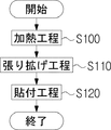
即ち、ワーク31(部品本体)に加飾フィルム30(フィルム)を貼り付けることでフィルム付き部品Eを製造する、フィルム付き部品Eの製造方法は、加飾フィルム30を加熱する工程(S100)と、ワーク31を取り囲むように配置した枠体19で加飾フィルム30を突き上げることで加飾フィルム30を張り拡げる工程(S110)と、加飾フィルム30で仕切られた上下の空間に気圧差を発生させることで加飾フィルム30をワーク31に貼り付ける工程(S120)と、を含む。加飾フィルム30をワーク31に貼り付ける工程(S120)において、枠体19の高さ19bを低くする。以上の方法によれば、加飾フィルム30をワーク31に貼り付ける工程における、枠体19に起因した加飾フィルム30の過度な伸長を抑制することができる。   That is, the method of manufacturing the component E with a film by attaching the decorative film 30 (film) to the workpiece 31 (the component main body) includes a step of heating the decorative film 30 (S100). A step of extending the decorative film 30 by pushing up the decorative film 30 with the frame body 19 arranged so as to surround the work 31 (S110), and generating a pressure difference in the upper and lower spaces partitioned by the decorative film 30. And attaching the decorative film 30 to the work 31 (S120). In the step of attaching the decorative film 30 to the work 31 (S120), the height 19b of the frame 19 is reduced. According to the above-described method, in the step of attaching the decorative film 30 to the work 31, excessive extension of the decorative film 30 due to the frame 19 can be suppressed.

なお、上述したように、貼付工程において枠体19の高さ19bを低くすることに代えて、貼付工程において枠体19の表面積を小さくするようにしてもよい。また、貼付工程において枠体19の体積を小さくするようにしてもよい。これらの場合でも、枠体19に起因する加飾フィルム30の過度な伸長を抑制することができる。   As described above, instead of reducing the height 19b of the frame 19 in the attaching step, the surface area of the frame 19 may be reduced in the attaching step. Further, the volume of the frame 19 may be reduced in the attaching step. Even in these cases, excessive elongation of the decorative film 30 due to the frame 19 can be suppressed.

なお、「枠体19の高さ19bを低くする」とは、「枠体19の高さ19bが低くなる方向へ変化する」ことを意味する。また、「枠体19の表面積を小さくする」とは、「枠体19の表面積が小さくなる方向へ変化する」を意味する。また、「枠体19の体積を小さくする」とは、「枠体19の体積が小さくなる方向へ変化する」を意味する。   Note that “reducing the height 19b of the frame 19” means “changing in a direction in which the height 19b of the frame 19 decreases”. Further, "reducing the surface area of the frame 19" means "change in a direction in which the surface area of the frame 19 decreases". Further, “reducing the volume of the frame 19” means “change in a direction in which the volume of the frame 19 decreases”.

更に、貼付工程において枠体19の高さ19bを低くすることに代えて、貼付工程において枠体19を横倒しになるように倒してもよいし、或いは、貼付工程において枠体19をステージ17から取り除いたり、貼付工程において枠体19をステージ17から脱落させるようにしてもよい。これらの場合でも、枠体19に起因する加飾フィルム30の過度な伸長を抑制することができる。   Further, instead of lowering the height 19b of the frame 19 in the attaching step, the frame 19 may be laid down sideways in the attaching step, or the frame 19 may be moved from the stage 17 in the attaching step. The frame 19 may be removed from the stage 17 in the removing step or the attaching step. Even in these cases, excessive elongation of the decorative film 30 due to the frame 19 can be suppressed.

また、上記実施形態では、上チャンバー6の雰囲気を大気圧に戻すことで上チャンバー6と下チャンバー8との間に気圧差を発生させている。しかし、これに代えて、上チャンバー6の雰囲気に圧縮空気を供給することで、上チャンバー6と下チャンバー8との間に大きな気圧差を発生させるようにしてもよい。また、上チャンバー6の雰囲気を加圧状態とし、下チャンバー8の雰囲気を大気圧状態としてもよい。即ち、上チャンバー6の雰囲気の気圧を下チャンバー8の雰囲気の気圧よりも高くすれば、加飾フィルム30がワーク31に貼り付けられることになる。   In the above embodiment, the pressure difference between the upper chamber 6 and the lower chamber 8 is generated by returning the atmosphere of the upper chamber 6 to the atmospheric pressure. However, instead of this, a large pressure difference may be generated between the upper chamber 6 and the lower chamber 8 by supplying compressed air to the atmosphere in the upper chamber 6. Further, the atmosphere in the upper chamber 6 may be in a pressurized state, and the atmosphere in the lower chamber 8 may be in an atmospheric pressure state. That is, if the atmospheric pressure of the upper chamber 6 is higher than the atmospheric pressure of the lower chamber 8, the decorative film 30 is attached to the work 31.

(変形例)
図12には、枠体19の変形例を示している。図12に示す変形例では、平面視で枠体19の3辺が例えばFRPや木片などの剛体壁60によって構成されており、1辺がメラニンフォーム61によって構成されている。メラニンフォーム61は、更に、複数のメラニンフォームブロック62によって構成されている。
(Modification)
FIG. 12 shows a modification of the frame 19. In the modification shown in FIG. 12, three sides of the frame body 19 are formed by rigid walls 60 such as FRP and wood pieces, and one side is formed by the melanin foam 61 in a plan view. The melanin foam 61 further includes a plurality of melanin foam blocks 62.

図13には、メラニンフォームブロック62の斜視図を示している。図13に示すように、各メラニンフォームブロック62は直方体状に形成されており、中央に1つの空洞63が形成されている。このようにメラニンフォームブロック62に空洞63を形成することで、メラニンフォームブロック62の上下方向における圧縮変形のし易さを容易に調整することができる。即ち、メラニンフォームブロック62に空洞63を形成することで、上チャンバー6と下チャンバー8との間に気圧差を発生させてから実際にメラニンフォーム61が上下方向に圧縮変形し始めるタイミング、圧縮変形の単位時間あたりの体積変化量、圧縮変形が完了するタイミングを自在に調整することが可能となる。   FIG. 13 shows a perspective view of the melanin foam block 62. As shown in FIG. 13, each melanin foam block 62 is formed in a rectangular parallelepiped shape, and one cavity 63 is formed in the center. By forming the cavity 63 in the melanin foam block 62 in this manner, the ease with which the melanin foam block 62 is compressed and deformed in the vertical direction can be easily adjusted. That is, by forming the cavity 63 in the melanin foam block 62, a pressure difference between the upper chamber 6 and the lower chamber 8 is generated, and then the timing at which the melanin foam 61 actually starts to be vertically compressed and deformed, It is possible to freely adjust the volume change amount per unit time and the timing at which the compression deformation is completed.

また、図14に示すように、各メラニンフォームブロック62の上半分に複数の空隙64を形成してもよい。この場合、メラニンフォームブロック62の上半分は圧縮変形し易く、下半分は相対的に圧縮変形し難くなる。   Further, as shown in FIG. 14, a plurality of voids 64 may be formed in the upper half of each melanin foam block 62. In this case, the upper half of the melanin foam block 62 is easily compressed and deformed, and the lower half is relatively hardly compressed and deformed.

また、図2には枠体19の全体が圧縮変形可能な構成を示したが、図12に示すように、枠体19の一部のみを圧縮変形可能としてもよい。この場合、図12に示すように、ワーク31に貼り付けられた加飾フィルム30のうち最も延伸量の多い領域に対向する部分のみを圧縮変形可能とし、その他の部分を圧縮変形不能とすることが考えられる。   Although FIG. 2 shows a configuration in which the entire frame 19 can be compressed and deformed, as shown in FIG. 12, only a part of the frame 19 may be compressed and deformable. In this case, as shown in FIG. 12, only the portion of the decorative film 30 attached to the work 31 that faces the region with the largest amount of stretching can be compressed and deformed, and the other portions cannot be compressed and deformed. Can be considered.

要するに、貼付工程において枠体19全体の高さ19bを低くすることに代えて、貼付工程において枠体19の少なくとも一部の高さ19bを低くするようにしてもよい。枠体19の表面積を小さくすること、枠体19の体積を小さくすること、枠体19を倒すこと、枠体19を取り除くこと、枠体19を脱落させることについても同様である。   In short, instead of reducing the height 19b of the entire frame 19 in the attaching step, the height 19b of at least a part of the frame 19 may be decreased in the attaching step. The same applies to reducing the surface area of the frame 19, reducing the volume of the frame 19, defeating the frame 19, removing the frame 19, and dropping the frame 19.

1 真空成形装置
2 上チャンバーボックス
2a 天板
3 下チャンバーボックス
4 上真空ユニット
5 下真空ユニット
6 上チャンバー
7 開口
8 下チャンバー
9 開口
10 フランジ
15 近赤外線ヒーター
16 フィルムクランプ
16a 上クランプ
16b 下クランプ
17 ステージ
17a ワーク搭載面
18 ステージ駆動機構
19 枠体
19a 頂部
19b 高さ
19p 内側側面
19q 外側側面
20 ワーク受け治具
30 加飾フィルム
31 ワーク
31a 頂部
31b 高さ
40 減圧タンク
41 方向制御弁
50 減圧タンク
51 方向制御弁
60 剛体壁
61 メラニンフォーム
62 メラニンフォームブロック
63 空洞
64 空隙
E フィルム付き部品
DESCRIPTION OF SYMBOLS 1 Vacuum forming apparatus 2 Upper chamber box 2a Top plate 3 Lower chamber box 4 Upper vacuum unit 5 Lower vacuum unit 6 Upper chamber 7 Opening 8 Lower chamber 9 Opening 10 Flange 15 Near infrared heater 16 Film clamp 16a Upper clamp 16b Lower clamp 17 Stage 17a Work mounting surface 18 Stage drive mechanism 19 Frame 19a Top 19b Height 19p Inside side 19q Outside side 20 Work receiving jig 30 Decorative film 31 Work 31a Top 31b Height 40 Decompression tank 41 Direction control valve 50 Decompression tank 51 Direction Control valve 60 Rigid body wall 61 Melanin foam 62 Melanin foam block 63 Cavity 64 Void E Parts with film

Claims (1)

部品本体にフィルムを貼り付けることでフィルム付き部品を製造する、フィルム付き部品の製造方法であって、
前記フィルムを加熱する工程と、
前記部品本体を取り囲むように配置した枠体で前記フィルムを突き上げることで前記フィルムを張り拡げる工程と、
前記フィルムで仕切られた上下の空間に気圧差を発生させることで前記フィルムを前記部品本体に貼り付ける工程と、
を含み、
前記フィルムを前記部品本体に貼り付ける工程において、
前記枠体の少なくとも一部の高さを低くするか、又は、
前記枠体の少なくとも一部の表面積を小さくするか、又は、
前記枠体の少なくとも一部の体積を小さくするか、又は、
前記枠体の少なくとも一部を倒すか、又は、
前記枠体の少なくとも一部を取り除くか、又は、
前記枠体の少なくとも一部を脱落させる、
フィルム付き部品の製造方法。
A method of manufacturing a component with a film, which manufactures a component with a film by pasting a film to a component body,
Heating the film,
A step of expanding the film by pushing up the film with a frame disposed so as to surround the component body;
Affixing the film to the component body by generating a pressure difference in the upper and lower spaces partitioned by the film,
Including
In the step of attaching the film to the component body,
Reduce the height of at least a part of the frame, or
Reduce the surface area of at least a part of the frame, or
Reduce the volume of at least a part of the frame, or
Defeat at least a part of the frame, or
Remove at least a part of the frame, or
Dropping at least a part of the frame,
Manufacturing method of parts with film.
JP2018132184A 2018-07-12 2018-07-12 Method for manufacturing film-attached component Pending JP2020006652A (en)

Priority Applications (1)

Application Number Priority Date Filing Date Title
JP2018132184A JP2020006652A (en) 2018-07-12 2018-07-12 Method for manufacturing film-attached component

Applications Claiming Priority (1)

Application Number Priority Date Filing Date Title
JP2018132184A JP2020006652A (en) 2018-07-12 2018-07-12 Method for manufacturing film-attached component

Publications (1)

Publication Number Publication Date
JP2020006652A true JP2020006652A (en) 2020-01-16

Family

ID=69150012

Family Applications (1)

Application Number Title Priority Date Filing Date
JP2018132184A Pending JP2020006652A (en) 2018-07-12 2018-07-12 Method for manufacturing film-attached component

Country Status (1)

Country Link
JP (1) JP2020006652A (en)

Cited By (1)

* Cited by examiner, † Cited by third party
Publication number Priority date Publication date Assignee Title
TWI822050B (en) * 2022-05-13 2023-11-11 大陸商業泓科技(成都)有限公司 Method for three-dimensional pasting and forming objects and device using the same

Cited By (1)

* Cited by examiner, † Cited by third party
Publication number Priority date Publication date Assignee Title
TWI822050B (en) * 2022-05-13 2023-11-11 大陸商業泓科技(成都)有限公司 Method for three-dimensional pasting and forming objects and device using the same

Similar Documents

Publication Publication Date Title
EP2520411B1 (en) Device and method for thermoforming by hot-plate heating
US5820813A (en) Method for producing multilayer molded article
KR101210708B1 (en) Device for manufacturing inner board of vehicle
KR20180131028A (en) Forming device of base material and skin layer, and formig method
JP5957131B1 (en) Thermoforming apparatus and thermoforming method
KR101666510B1 (en) Manufacturing apparatus and method of interior for vehicle
JP2015212050A (en) Thermoforming device by hot plate heating
JP2020006652A (en) Method for manufacturing film-attached component
US3535740A (en) Apparatus for producing embossed thermoplastic sheet
JP2015058547A (en) Vacuum molding device and vacuum molding method
KR101192521B1 (en) Method for manufacturing inner board of vehicle
JP2005125736A (en) Interior part with foamed layer
KR20180055464A (en) Manufacturing apparatus for bed panel
KR200408359Y1 (en) Mold for vacuum molding
TWI460065B (en) Vacuum forming method and device thereof
KR20180055465A (en) Functional bed panel and manufacturing method thereof
JP2001138389A (en) Method for vacuum forming
JP4799328B2 (en) Vacuum forming method and mold
JP2002018882A (en) Method and equipment for manufacturing plastic molded article having foamed resin layer
JP2003326576A (en) Method for sheet-laminated injection compression molding and apparatus for the same
KR20040100733A (en) Die apparatus for interior panel of vehicle and manufacturing method of interior panel using the same
JP7268855B2 (en) thermoforming method
JP2019031018A (en) Thermoforming apparatus and thermoforming method
JPH03138114A (en) Manufacture of stamping molded product
JPS59118424A (en) Forming method of surfacing material for vehicle