JP2020004879A - Sample positioning device - Google Patents
Sample positioning device Download PDFInfo
- Publication number
- JP2020004879A JP2020004879A JP2018123797A JP2018123797A JP2020004879A JP 2020004879 A JP2020004879 A JP 2020004879A JP 2018123797 A JP2018123797 A JP 2018123797A JP 2018123797 A JP2018123797 A JP 2018123797A JP 2020004879 A JP2020004879 A JP 2020004879A
- Authority
- JP
- Japan
- Prior art keywords
- sample
- stage
- unit
- positioning device
- sample stage
- Prior art date
- Legal status (The legal status is an assumption and is not a legal conclusion. Google has not performed a legal analysis and makes no representation as to the accuracy of the status listed.)
- Pending
Links
Images
Landscapes
- Length Measuring Devices By Optical Means (AREA)
- Testing Or Measuring Of Semiconductors Or The Like (AREA)
- Container, Conveyance, Adherence, Positioning, Of Wafer (AREA)
Abstract
Description
本発明は、試料位置決め装置に関する。 The present invention relates to a sample positioning device.
半導体チップ等の電子素子の検査を行う場合、測定台上において検査体となる半導体チップを正しい位置に位置決めする必要がある。例えば、半導体チップに対してプローブを接触させて電気特性を測定する場合、プローブの先端を半導体チップに設けられた電極に正しく接触させるように半導体チップの位置を決める必要がある。 When inspecting an electronic element such as a semiconductor chip, it is necessary to position a semiconductor chip to be inspected at a correct position on a measuring table. For example, when a probe is brought into contact with a semiconductor chip to measure electrical characteristics, it is necessary to determine the position of the semiconductor chip so that the tip of the probe correctly contacts an electrode provided on the semiconductor chip.
検査体を作業面上において位置決めする技術として、位置規制板を動かして検査体の縁を位置規制板の枠に沿うようにすることで検査体を正しい位置に定める技術が開示されている(特許文献1,2)。 As a technique for positioning a test object on a work surface, a technique has been disclosed in which a position restricting plate is moved so that an edge of the test object follows a frame of the position restricting plate, thereby setting the test object at a correct position (Patent) Literatures 1 and 2).
また、トレイに載置された半導体チップを光学装置によって撮像し、所定の位置とのずれ量を画像処理によって検出し、ずれ量に応じてトレイの位置を制御して半導体チップの位置を決定する技術が開示されている(特許文献3)。また、検査対象である半導体チップの近傍にモニタチップを配置し、モニタチップの位置を画像処理によって検出することによって検査対象である半導体チップの位置を検出する技術が開示されている(特許文献4)。 Further, the semiconductor chip mounted on the tray is imaged by an optical device, the amount of deviation from a predetermined position is detected by image processing, and the position of the tray is controlled according to the amount of deviation to determine the position of the semiconductor chip. A technique is disclosed (Patent Document 3). Further, there is disclosed a technology in which a monitor chip is arranged near a semiconductor chip to be inspected, and the position of the semiconductor chip to be inspected is detected by detecting the position of the monitor chip by image processing (Patent Document 4). ).
また、予備認識ステージに載置された電子部品を撮像装置によって撮像して得られる位置データに基づいて角錐コレットの位置を修正し、位置修正された角錐コレットによって電子部品をピックアップして搭載ステージ上に位置決めして載せ置く技術が開示されている(特許文献5)。 Further, the position of the pyramid collet is corrected based on the position data obtained by imaging the electronic component mounted on the preliminary recognition stage by the imaging device, and the electronic component is picked up by the corrected pyramid collet and mounted on the mounting stage. (Patent Document 5).
ところで、規制爪や位置規制板を半導体チップの縁に接触させて位置決めする構成では、検査体の外形の大きさや形状に応じて位置決めの再現性が低下するおそれがある。また、検査体に応じて規制爪や位置規制板を変更する必要があり、検査における作業が煩雑になる。 By the way, in a configuration in which the regulating claw or the position regulating plate is brought into contact with the edge of the semiconductor chip for positioning, the reproducibility of the positioning may be reduced according to the size and shape of the outer shape of the test object. In addition, it is necessary to change the control claws and the position control plate according to the test object, which complicates the work in the test.
また、規制爪や位置規制板との接触による半導体チップの割れや欠けが発生するおそれがある。さらに、接触による破片等の飛散により、検査装置が汚染されてしまうおそれがある。また、ステージ上で半導体チップを動かすことによって、ステージが摩耗したり、半導体チップに傷が生じたりするおそれもある。 Further, there is a possibility that the semiconductor chip may be cracked or chipped due to contact with the regulating claw or the position regulating plate. Furthermore, the inspection device may be contaminated by scattering of fragments and the like due to contact. In addition, moving the semiconductor chip on the stage may cause the stage to be worn or the semiconductor chip to be damaged.
また、検査体の位置を定めた後にプローブ等の接触により位置がずれてしまった場合、その位置ずれの補正ができないという問題がある。 Further, when the position of the test object is shifted due to contact with a probe or the like after the position of the test object is determined, there is a problem that the position shift cannot be corrected.
本発明の1つの態様は、試料が載せ置かれ、独立して移動可能な試料ステージと、試料を前記試料ステージ上に搬送して載せ置く搬送部と、前記試料ステージに載せ置かれる前に試料の画像を撮像する第1撮像部と、を備え、前記第1撮像部において撮像された前記画像から試料の姿勢を求め、当該姿勢に応じて前記試料ステージを移動させて試料の位置決めを行ったうえで前記搬送部を用いて試料を前記試料ステージ上に載せ置くことを特徴とする試料位置決め装置である。 One embodiment of the present invention includes a sample stage on which a sample is placed and which can be independently moved, a transport unit that transports and places the sample on the sample stage, and a sample unit that is placed on the sample stage before being placed on the sample stage. A first imaging unit that captures an image of the sample, the orientation of the sample is obtained from the image captured by the first imaging unit, and the sample stage is moved according to the orientation to position the sample. A sample positioning apparatus characterized in that a sample is placed on the sample stage using the transport unit.
ここで、試料の特性を測定するための特性検査部をさらに備え、前記特性検査部は、前記試料ステージを移動させて試料の位置決めを行ったうえで前記試料ステージに載せ置かれた試料を測定することが好適である。 Here, the apparatus further comprises a characteristic inspection unit for measuring characteristics of the sample, wherein the characteristic inspection unit measures the sample placed on the sample stage after positioning the sample by moving the sample stage. It is preferred to do so.
また、さらに、前記試料ステージに載せ置かれた後、前記特性検査部を用いた測定の前に試料の画像を撮像する第2撮像部を備え、前記第2撮像部において撮像された前記画像から試料の姿勢を求め、当該姿勢に応じて前記試料ステージを移動させて試料の位置決めを行ったうえで前記特性検査部を用いて試料の検査を行うことが好適である。 Furthermore, after being placed on the sample stage, the apparatus further includes a second imaging unit that captures an image of the sample before measurement using the characteristic inspection unit, and includes a second imaging unit that captures an image of the sample from the image captured by the second imaging unit. It is preferable that the attitude of the sample is determined, the sample stage is moved according to the attitude, the sample is positioned, and then the sample is inspected using the characteristic inspection unit.
また、前記試料ステージを複数備え、前記特性検査部及び前記第2撮像部が前記試料ステージ毎にそれぞれ設けられていることが好適である。 It is preferable that a plurality of the sample stages are provided, and the characteristic inspection section and the second imaging section are provided for each of the sample stages.
また、さらに、前記試料ステージとは独立に移動可能なテーブルを備え、前記試料ステージは、前記テーブル上に配置されていることが好適である。 Further, it is preferable that a table that can be moved independently of the sample stage is further provided, and the sample stage is disposed on the table.
また、前記テーブルは、前記試料ステージを回転軸周りに旋回させる回転テーブルであることが好適である。 Further, it is preferable that the table is a rotary table for rotating the sample stage around a rotation axis.
また、前記試料ステージは、試料の載置面に対して垂直な回転軸及び平行な少なくとも1つの移動軸について移動可能であることが好適である。 Further, it is preferable that the sample stage is movable about a rotation axis perpendicular to the sample mounting surface and at least one movement axis parallel to the rotation axis.
また、前記搬送部は、前記試料ステージの載置面に対して平行な少なくとも1つの移動軸について試料を移動させることが好適である。 Further, it is preferable that the transport section moves the sample about at least one movement axis parallel to the mounting surface of the sample stage.
また、前記試料ステージは、温度調整手段を備えることが好適である。 Further, it is preferable that the sample stage includes a temperature adjusting unit.
また、前記試料ステージを移動させるためのモータ及びドライバは前記テーブルに配置されていることが好適である。 Further, it is preferable that a motor and a driver for moving the sample stage are arranged on the table.
本発明によれば、試料の破損を抑制しつつ、試料を正しい位置に配置することを可能とする試料位置決め装置を提供することができる。 ADVANTAGE OF THE INVENTION According to this invention, the sample positioning apparatus which can arrange | position a sample in a correct position while suppressing damage of a sample can be provided.
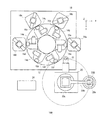
本発明の実施の形態における検査装置100は、図1の平面図に示すように、支持台10、テーブル12、試料ステージ14(14a〜14f)、撮像部(第2撮像部)16(16a〜16f)、特性検査部18(18a〜18d)、チップ供給ユニット20、撮像部(第1撮像部)22及び制御部24を含んで構成される。
As shown in the plan view of FIG. 1, the
支持台10は、検査装置100のテーブル12、試料ステージ14及び撮像部16を装備するための台である。支持台10は、これらの構成要素を機械的に支持できるような強度を有する材料で構成される。
The support table 10 is a table for mounting the table 12, the sample stage 14, and the imaging unit 16 of the
テーブル12は、支持台10の上面に配置され、試料ステージ14が載置される平板上の構成要素を含む。テーブル12は、支持台10の周囲に配置された撮像部16及び特性検査部18に対して試料ステージ14を相対的に移動させるための駆動手段を備える。すなわち、テーブル12は、後述する試料ステージ14の駆動機構とは独立した駆動機構を備える。本実施の形態では、テーブル12は中心軸(Z軸)を回転軸として回転する円盤状の回転テーブルとされている。
The table 12 is arranged on the upper surface of the
試料ステージ14は、試料200を載せ置くためのステージである。検査装置100では、6つの試料ステージ14a〜14fがテーブル12の周方向に沿って60°毎の等間隔に配置された例を示している。ただし、試料ステージ14の個数は、これに限定されるものではなく、検査項目に応じて増減させてもよい。
The sample stage 14 is a stage on which the
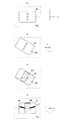
試料ステージ14は、図2に示すように、半導体チップ等の特性検査の対象物である試料200を載せ置くステージ本体30を備える。ステージ本体30は、試料200を載せ置くための平坦な上面30aを有する。試料ステージ14は、上面30aに載せ置かれた試料200をステージ本体30に固定できる手段、例えば、真空チャック手段を備えることが好適である。
As shown in FIG. 2, the sample stage 14 includes a stage
また、試料ステージ14は、テーブル12及び特性検査部18に対してステージ本体30を相対的に移動させるためのステージ駆動手段を備える。試料ステージ14は、ステージを複数の軸方向に沿って駆動できることが好ましい。本実施の形態では、図2に示すように、試料ステージ14aにおける試料200の載置面に平行なX軸方向(テーブル12の周の接線方向)に沿った平行移動と試料200の載置面に垂直なZ軸を中心軸とした回転移動とが可能なステージ駆動手段を備えるものとする。
Further, the sample stage 14 includes a stage driving unit for relatively moving the stage
但し、ステージ駆動手段は、これに限定されるものではなく、後述する画像処理によって試料200の位置決めが正しくできるものであればよい。例えば、試料ステージ14aにおいて試料200の載置面に平行なX軸方向(テーブル12の周の接線方向)とY軸方向(テーブル12の径方向)に沿った平行移動と試料200の載置面に垂直なZ軸を中心軸とした回転移動とが可能なステージ駆動手段を備えるものとしてもよい。また、さらに、試料200の載置面に垂直なZ軸方向へ平行移動が可能なステージ駆動手段を備えてもよい。
However, the stage driving means is not limited to this, but may be any as long as it can correctly position the
なお、試料ステージ14はテーブル12の回転と共に旋回させられるので、図1において試料ステージ14b〜14fのステージの駆動方向は図示したX軸方向及びY軸方向からずれるが、いずれもテーブル12の周の接線方向(及び/又は径方向)に沿った平行移動とZ軸を中心軸とした回転移動とが可能な状態となる。
Since the sample stage 14 is rotated with the rotation of the table 12, the driving directions of the
ステージ駆動手段は、例えば、ボールネジや回転シャフト等の駆動力伝達部によってステージ本体30に接続されたモータやドライバ等の駆動部によって構成することができる。本実施の形態における検査装置100では、テーブル12と共に旋回可能な試料ステージ14を駆動するためにステージ駆動手段の駆動部や駆動力伝達部はテーブル12と共に旋回可能なように配置することが好適である。これにより、検査装置100を小型化及び高速化することができる。
The stage driving unit can be configured by a driving unit such as a motor or a driver connected to the stage
撮像部16は、試料ステージ14のステージ本体30に載せ置かれた試料200を撮像する撮像手段を備える。撮像部16は、例えば、CCDカメラやCMOSカメラ等の撮像手段によってステージ本体30に載せ置かれた試料200の画像を上面方向から撮像して取得する。撮像部16で撮像された試料200の画像は、制御部24へ入力されて、試料ステージ14における試料200の位置決め処理に利用される。当該位置決め処理については後述する。なお、この撮像部16によって撮像された試料200の画像を用いて、試料200の表面状態や寸法・形状などの外観を検査することも可能である。
The imaging section 16 includes imaging means for imaging the
なお、本実施の形態における検査装置100では、6つの撮像部16a〜16fがテーブル12の周方向に沿って60°毎の等間隔に配置された例を示している。
In the
特性検査部18は、試料200の電気特性、光学特性、温度特性等の特性を検査する手段である。特性検査部18aは、試料ステージ14aに載せ置かれた試料200に設けられた電極パッドに対して電気的に接触するプローブ針を備え、該プローブ針を介して試料200に電流を印加してそのときの試料200の光出力を測定する光学特性検査手段である。特性検査部18bは、上記と同様のプローブ針を備え該プローブ針を介して試料ステージ14bに載せ置かれた試料200に電流を印加して、そのときの試料200のリーク電流を測定する電気特性検査手段と発光波長を測定する光学特性検査手段とを備える。特性検査部18cは、上記と同様のプローブ針を備え該プローブ針を介して試料ステージ14cに載せ置かれた試料200に電流を印加して、そのときに試料200から放射される光の水平方向の広がりを測定する光学特性検査手段である。特性検査部18dは、上記と同様のプローブ針を備え該プローブ針を介して試料ステージ14dに載せ置かれた試料200に電流を印加して、そのときに試料200から放射される光の垂直方向の広がりを測定する光学特性検査手段である。また、特性検査部18a〜18dのいずれかに温度調整手段を設けて、試料ステージ14に載せ置かれた試料200の温度を変化させつつ上記電気特性又は光学特性を測定する温度特性検査手段としてもよい。特性検査部18a〜18dは、上記の検査手段を複数組み合わせて試料200の特性を測定するものとしてもよいし、試料200の外観上の傷やコンタミネーション又はパターン等の外観を検査する外観検査手段としてもよい。特性検査部を外観検査手段のみとする場合には、試料に電流を印加する必要が無いのでプローブ針は不要となる。さらに、特性検査部18aにおいては、試料200に一定電流を印加してその光出力を測定していたが、パルス電流を印加して光出力を測定してもよい。
The characteristic inspection section 18 is a means for inspecting characteristics of the
なお、本実施の形態における検査装置100では、4つの特性検査部18a〜18dがテーブル12の周囲に沿って60°毎の間隔に配置された例を示している。テーブル12を回転させることによって、テーブル12上に配置された6つの試料ステージ14a〜14fに載せ置かれた試料200が順に特性検査部18a〜18dに搬送されて、各々において試料200の検査が行われる。ただし、特性検査部18の個数は4つに限定されるものではなく、必要に応じて増減させてもよい。
In addition, in the
チップ供給ユニット20は、試料200を試料ステージ14へ搬送するための搬送部である。試料トレイ20a、チップ供給アーム20b及びアーム移動手段20cを含んで構成される。試料トレイ20aは、検査前の試料200を載せ置くための台である。試料トレイ20aには、例えば、ウエハからダイシングで切り出された半導体チップ等の試料200が載せ置かれる。チップ供給アーム20bは、試料200を試料トレイ20aから試料ステージ14(14a〜14f)へ順に搬送して載せ置くためのアームである。チップ供給アーム20bの先端部には、試料トレイ20a上の試料200を1つずつ取り上げ、試料ステージ14(14a〜14f)のステージ本体30の上面30aまで搬送して載せ置くためのヘッド部が設けられている。ヘッド部は、例えば、真空吸引によって試料200をチャックすることができる真空チャック手段を有するものとすればよい。アーム移動手段20cは、チップ供給アーム20bを移動及び回転させる手段である。本実施の形態では、アーム移動手段20cは、少なくとも試料200の載置面に垂直な回転軸を中心としてチップ供給アーム20bを旋回するための回転機構を備えるものとする。ただし、アーム移動手段20cは、回転機構のみならず、チップ供給アーム20bを試料200の載置面に平行な方向に平行移動させる移動機構を備えてもよい。例えば、アーム移動手段20cは、チップ供給アーム20bの延設方向(回転の径方向)に沿ってヘッド部を移動することができる移動機構を備えてもよい。
The
撮像部(第1撮像部)22は、試料200を撮像する撮像手段を備える。撮像部22は、チップ供給ユニット20によって試料トレイ20aから試料ステージ14のステージ本体30に搬送される途中において試料200を撮像する。すなわち、撮像部22は、チップ供給ユニット20のチップ供給アーム20bが旋回して試料トレイ20aから試料ステージ14へ試料200を搬送する途中経路において試料200を撮像できる位置に配置される。撮像部22は、例えば、CCDカメラやCMOSカメラ等の撮像手段によって試料200の画像を下面方向から撮像して取得する。撮像部22で撮像された試料200の画像は、制御部24へ入力されて、試料ステージ14における試料200の位置決め処理に利用される。当該位置決め処理については後述する。なお、この撮像部22によって撮像された試料200の画像を用いて、試料200の裏面(下面)状態や寸法・形状などの外観を検査することも可能である。
The imaging unit (first imaging unit) 22 includes an imaging unit that images the
図1においては、試料200を試料ステージ14に供給するチップ供給ユニット20に撮像部22が設けられている。しかしながら、これに限らず、試料200が取り出される試料ステージ14に同様の撮像部16を設けるとともに試料ステージ14から試料200を取り出すユニットにも同様の撮像部22を設けることによって、取り出される試料200の次の装置への位置決めを行うことも可能である。例えば、取り出された試料200を外部のシートに貼りつける場合に、その位置を正確に制御することができる。
In FIG. 1, an
制御部24は、検査装置100における試料200の搬送制御及び位置決め制御、試料ステージ14の移動・回転制御、テーブル12の回転制御、特性検査部18の測定制御を行う。制御部24は、これらの制御のためのプログラムによって動くコンピュータとすることができる。
The
以下、図2及び図3を参照しつつ、本実施の形態の検査装置100における試料200の位置決め処理について説明する。まず、チップ供給ユニット20を用いて試料トレイ20aから試料ステージ14へ試料200を搬送する際の試料200の位置決め処理について説明する。
Hereinafter, the positioning process of the
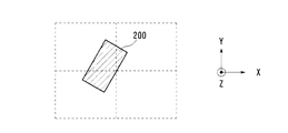
図2(図2(a)〜図2(d))は、位置決め処理における試料ステージ14でのステージ本体30の駆動状態を示す。図3は、撮像部22において撮像された試料200の撮像画像を示す。ここで、図2及び図3では、試料200の姿勢(位置及び角度)を示すために十字の中心線を有する枠を併せて表している。試料ステージ14のステージ本体30に試料200が載せ置かれた際に、試料200の中心が中心線の交点に位置すると共に試料200の外縁の各辺が中心線に沿った状態であるときに特性検査部18において検査を行う際に正しい位置にあることを示している。ただし、試料200の正しい位置は、これに限定されるものではなく、試料200の外形及び大きさに応じてステージ本体30との位置関係が予め定められた正しい位置となるようなものであればよい。
FIG. 2 (FIGS. 2A to 2D) shows a driving state of the stage
制御部24は、チップ供給アーム20bによって試料トレイ20aに置かれた検査前の試料200を1つ取り上げ、チップ供給アーム20bを旋回させて撮像部22によって試料200を撮像する。例えば、図3に示すように、試料200の姿勢(位置及び角度)を写した画像が得られる。図3は、試料200が中心線に対してずれた姿勢で撮像された例を示している。
The
制御部24は、撮像部22の撮像画像を受けて、試料200の姿勢を求めて当該姿勢に応じて試料ステージ14における試料200の位置決めを行ったうえでチップ供給ユニット20によって試料200を試料ステージ14のステージ本体30上に載せ置く制御を行う。このとき、撮像画像に対する画像解析によって得られた試料200の姿勢に合わせてステージ本体30の移動及び/又は回転させたうえで試料200が載せ置かれるように制御を行う。
The
図2(a)は、試料ステージ14のステージ本体30の基準姿勢(角度及び位置)を示している。制御部24は、撮像部22で撮像された試料200の姿勢に応じて、ステージ本体30が基本姿勢にあるときに試料200の中心が中心線の交点に位置すると共に試料200の外縁の各辺が中心線に沿った状態となるようにステージ本体30を移動及び回転させる。図2(b)は、図3に示した撮像画像の例に対して位置決め制御によって試料200が載せ置かれる前にステージ本体30を移動及び回転させた状態を示す。制御部24は、このようにステージ本体30を移動及び回転させた状態において、図2(c)に示すように、チップ供給ユニット20を制御して試料200をステージ本体30上に搬送して上面30aに載せ置かせる。そして、試料200をステージ本体30に固定(真空チャック等)した後、ステージ本体30を再び基準姿勢に戻す制御を行う。
FIG. 2A shows the reference posture (angle and position) of the stage
その後、制御部24は、テーブル12を回転させて試料200を載せ置いた試料ステージ14を所望の検査を行うための特性検査部18の位置まで搬送する。
Thereafter, the
上記のような試料200の位置決め処理によって、図2(d)に示すように、特性検査部18において正しい位置でプローブ針40を接触させる等して試料200の特性を高い精度で測定することができる。
By the positioning process of the
なお、さらに、試料200が試料ステージ14に載せ置かれた後、特性検査部18における検査の前に特性検査部18毎に設けられた撮像部16において試料200の画像を撮像し、当該撮像画像に基づいてステージ本体30の姿勢を微調整するようにしてもよい。この場合、制御部24は、ステージ本体30の姿勢を制御することで、特性検査部18に対する試料200の位置決めの微調整をしたうえで試料200の検査を行うことができる。
Further, after the
以上のように、本実施の形態によれば、規制爪等の試料200の縁に接触する部材を用いることなく、試料200の位置決め処理を行うことができる。したがって、接触による試料200の縁の欠けや割れ等の発生を抑制することができる。また、接触による装置の汚染を防ぐことができる。
As described above, according to the present embodiment, the positioning process of the
また、試料ステージ14のステージ本体30自体を移動・回転させることによって位置決めを行うので、ステージ本体30上において試料200を動かすことがなく、ステージ本体30の上面30aの摩耗や傷の発生を抑制することができる。
Further, since the positioning is performed by moving and rotating the stage
また、試料200の形状や大きさによらず、試料200を撮像した画像に基づいた画像処理によって試料200の姿勢を求め、試料200がステージ本体30上において正しい姿勢となるように位置決めすることができる。また、ステージ本体30を動かす構成としたことで、テーブル12を移動中等においても位置決めの補正が可能であり、試料200の検査を高速で行うことが可能になる。
Further, regardless of the shape and size of the
また、撮像部16を複数設けることによって、試料ステージ14の各々において位置ずれ補正が可能となり、検査の再現性をより高めることができる。特に、試料ステージ14がテーブル12によって移動させられるような構成において、テーブル12の駆動精度によらず、特性検査部18の各々の位置において試料200の位置決めの微調整を行うことができる。
In addition, by providing a plurality of imaging units 16, it is possible to correct the positional deviation in each of the sample stages 14, and it is possible to further improve the reproducibility of the inspection. In particular, in a configuration in which the sample stage 14 is moved by the table 12, fine adjustment of the positioning of the
なお、本実施の形態では、試料200の検査を行う検査装置100を例として試料位置決め装置の説明を行ったが、本願発明は検査装置100以外にも適用することができる。すなわち、本願発明は、半導体チップ等の試料を所望の位置及び角度で位置決めする装置や処理であれば適用することができる。
In the present embodiment, the sample positioning device has been described by taking the
10 支持台、12 テーブル、14(14a〜14f) 試料ステージ、16(16a〜16f) 撮像部、18(18a〜18d) 特性検査部、20 チップ供給ユニット、20a 試料トレイ、20b チップ供給アーム、20c アーム移動手段、22 撮像部、24 制御部、30 ステージ本体、30a 上面、40 プローブ針、100 検査装置、200 試料。
Claims (10)
試料を前記試料ステージ上に搬送して載せ置く搬送部と、
前記試料ステージに載せ置かれる前に試料の画像を撮像する第1撮像部と、
を備え、
前記第1撮像部において撮像された前記画像から試料の姿勢を求め、当該姿勢に応じて前記試料ステージを移動させて試料の位置決めを行ったうえで前記搬送部を用いて試料を前記試料ステージ上に載せ置くことを特徴とする試料位置決め装置。 A sample stage on which the sample is placed and which can move independently,
A transport unit that transports and places the sample on the sample stage,
A first imaging unit that captures an image of the sample before being placed on the sample stage;
With
The attitude of the sample is determined from the image captured by the first imaging unit, the sample stage is moved according to the attitude, the sample is positioned, and then the sample is placed on the sample stage using the transport unit. A sample positioning apparatus characterized by being placed on a sample.
試料の特性を測定するための特性検査部をさらに備え、
前記特性検査部は、前記試料ステージを移動させて試料の位置決めを行ったうえで前記試料ステージに載せ置かれた試料を測定することを特徴とする試料位置決め装置。 The sample positioning device according to claim 1,
It further comprises a characteristic inspection unit for measuring the characteristics of the sample,
The sample positioning apparatus according to claim 1, wherein the characteristic inspection section moves the sample stage to position the sample, and then measures the sample placed on the sample stage.
さらに、前記試料ステージに載せ置かれた後、前記特性検査部を用いた測定の前に試料の画像を撮像する第2撮像部を備え、
前記第2撮像部において撮像された前記画像から試料の姿勢を求め、当該姿勢に応じて前記試料ステージを移動させて試料の位置決めを行ったうえで前記特性検査部を用いて試料の検査を行うことを特徴とする試料位置決め装置。 The sample positioning device according to claim 2,
Furthermore, after being placed on the sample stage, a second imaging unit that captures an image of the sample before measurement using the characteristic inspection unit,
The attitude of the sample is determined from the image captured by the second imaging unit, the sample stage is moved according to the attitude, the sample is positioned, and then the sample is inspected using the characteristic inspection unit. A sample positioning device, comprising:
前記試料ステージを複数備え、
前記特性検査部及び前記第2撮像部が前記試料ステージ毎にそれぞれ設けられていることを特徴とする試料位置決め装置。 The sample positioning device according to claim 3, wherein
Comprising a plurality of the sample stages,
The sample positioning device, wherein the characteristic inspection unit and the second imaging unit are provided for each of the sample stages.
さらに、前記試料ステージとは独立に移動可能なテーブルを備え、
前記試料ステージは、前記テーブル上に配置されていることを特徴とする試料位置決め装置。 It is a sample positioning device according to any one of claims 1 to 4,
Furthermore, a table that can be moved independently of the sample stage is provided,
The sample positioning device, wherein the sample stage is arranged on the table.
前記テーブルは、前記試料ステージを回転軸周りに旋回させる回転テーブルであることを特徴とする試料位置決め装置。 It is a sample positioning device of Claim 5, Comprising:
The sample positioning device according to claim 1, wherein the table is a rotary table for rotating the sample stage around a rotation axis.
前記試料ステージは、試料の載置面に対して垂直な回転軸及び平行な少なくとも1つの移動軸について移動可能であることを特徴とする試料位置決め装置。 It is a sample positioning device according to any one of claims 1 to 6,
The sample positioning apparatus according to claim 1, wherein the sample stage is movable about a rotation axis perpendicular to a sample mounting surface and at least one movement axis parallel to the rotation axis.
前記搬送部は、前記試料ステージの載置面に対して平行な少なくとも1つの移動軸について試料を移動させることが可能であることを特徴とする試料位置決め装置。 It is a sample positioning device according to any one of claims 1 to 7,
The sample positioning apparatus according to claim 1, wherein the transport unit is capable of moving the sample about at least one movement axis parallel to a mounting surface of the sample stage.
前記試料ステージは、温度調整手段を備えることを特徴とする試料位置決め装置。 It is a sample positioning device according to any one of claims 1 to 8,
The sample positioning apparatus according to claim 1, wherein the sample stage includes a temperature adjusting unit.
前記試料ステージを移動させるためのモータ及びドライバは前記テーブルに配置されていることを特徴とする試料位置決め装置。 It is a sample positioning device of Claim 5, Comprising:
A sample positioning device, wherein a motor and a driver for moving the sample stage are arranged on the table.
Priority Applications (1)
| Application Number | Priority Date | Filing Date | Title |
|---|---|---|---|
| JP2018123797A JP2020004879A (en) | 2018-06-29 | 2018-06-29 | Sample positioning device |
Applications Claiming Priority (1)
| Application Number | Priority Date | Filing Date | Title |
|---|---|---|---|
| JP2018123797A JP2020004879A (en) | 2018-06-29 | 2018-06-29 | Sample positioning device |
Publications (1)
| Publication Number | Publication Date |
|---|---|
| JP2020004879A true JP2020004879A (en) | 2020-01-09 |
Family
ID=69100416
Family Applications (1)
| Application Number | Title | Priority Date | Filing Date |
|---|---|---|---|
| JP2018123797A Pending JP2020004879A (en) | 2018-06-29 | 2018-06-29 | Sample positioning device |
Country Status (1)
| Country | Link |
|---|---|
| JP (1) | JP2020004879A (en) |
Cited By (3)
| Publication number | Priority date | Publication date | Assignee | Title |
|---|---|---|---|---|
| CN114322853A (en) * | 2021-12-31 | 2022-04-12 | 上海果纳半导体技术有限公司 | Air-floating platform dynamic levelness detection method and wafer transmission system applying same |
| WO2022191124A1 (en) * | 2021-03-11 | 2022-09-15 | 上野精機株式会社 | Electronic component inspection apparatus |
| JP7486715B1 (en) | 2023-01-27 | 2024-05-20 | ダイトロン株式会社 | Appearance inspection device and appearance inspection method |
Citations (7)
| Publication number | Priority date | Publication date | Assignee | Title |
|---|---|---|---|---|
| JPH02278166A (en) * | 1989-04-19 | 1990-11-14 | Tokyo Electron Ltd | Apparatus for inspecting semiconductor |
| JPH02281159A (en) * | 1989-04-21 | 1990-11-16 | Tokyo Electron Ltd | Semiconductor inspection apparatus |
| JPH0357974A (en) * | 1989-07-27 | 1991-03-13 | Tokyo Electron Ltd | Apparatus and method for inspecting semiconductor |
| JP2002246448A (en) * | 2000-12-13 | 2002-08-30 | Nec Machinery Corp | Composite processing method and composite processor for leadless semiconductor element |
| JP2008277760A (en) * | 2007-03-30 | 2008-11-13 | Toray Eng Co Ltd | Suction switching device |
| JP2010135574A (en) * | 2008-12-05 | 2010-06-17 | Alpha- Design Kk | Transfer apparatus |
| JP2012235054A (en) * | 2011-05-09 | 2012-11-29 | Daitron Technology Co Ltd | Joining method and joining device |
-
2018
- 2018-06-29 JP JP2018123797A patent/JP2020004879A/en active Pending
Patent Citations (7)
| Publication number | Priority date | Publication date | Assignee | Title |
|---|---|---|---|---|
| JPH02278166A (en) * | 1989-04-19 | 1990-11-14 | Tokyo Electron Ltd | Apparatus for inspecting semiconductor |
| JPH02281159A (en) * | 1989-04-21 | 1990-11-16 | Tokyo Electron Ltd | Semiconductor inspection apparatus |
| JPH0357974A (en) * | 1989-07-27 | 1991-03-13 | Tokyo Electron Ltd | Apparatus and method for inspecting semiconductor |
| JP2002246448A (en) * | 2000-12-13 | 2002-08-30 | Nec Machinery Corp | Composite processing method and composite processor for leadless semiconductor element |
| JP2008277760A (en) * | 2007-03-30 | 2008-11-13 | Toray Eng Co Ltd | Suction switching device |
| JP2010135574A (en) * | 2008-12-05 | 2010-06-17 | Alpha- Design Kk | Transfer apparatus |
| JP2012235054A (en) * | 2011-05-09 | 2012-11-29 | Daitron Technology Co Ltd | Joining method and joining device |
Cited By (4)
| Publication number | Priority date | Publication date | Assignee | Title |
|---|---|---|---|---|
| WO2022191124A1 (en) * | 2021-03-11 | 2022-09-15 | 上野精機株式会社 | Electronic component inspection apparatus |
| JP2022139163A (en) * | 2021-03-11 | 2022-09-26 | 上野精機株式会社 | Electronic component inspection device |
| CN114322853A (en) * | 2021-12-31 | 2022-04-12 | 上海果纳半导体技术有限公司 | Air-floating platform dynamic levelness detection method and wafer transmission system applying same |
| JP7486715B1 (en) | 2023-01-27 | 2024-05-20 | ダイトロン株式会社 | Appearance inspection device and appearance inspection method |
Similar Documents
| Publication | Publication Date | Title |
|---|---|---|
| KR102735299B1 (en) | Chuck table and inspection apparatus | |
| CN117192342B (en) | probe station | |
| TWI732933B (en) | Processing device | |
| KR102824795B1 (en) | Cutting apparatus and wafer processing method using cutting apparatus | |
| US20080225281A1 (en) | Visual inspection apparatus | |
| JP2008203280A (en) | Defect inspection apparatus | |
| US11232551B2 (en) | Wafer inspecting apparatus | |
| KR20200121727A (en) | Inspection apparatus, and machining apparatus | |
| TW202114009A (en) | Method of processing wafer, and chip measuring apparatus | |
| WO2014080525A1 (en) | Method for discerning cause of mounting displacement and device for mounting electronic circuit components | |
| CN106596555B (en) | Optical inspection equipment using a multi-axis arm | |
| KR20190119803A (en) | Apparatus for inspecting edge area of wafer and method using the same | |
| JP2020004879A (en) | Sample positioning device | |
| KR20190134275A (en) | System for inspecting edge area of wafer and method using the same | |
| KR101467121B1 (en) | Apparatus for inspecting wafer surface | |
| JP5530261B2 (en) | Current test method for test object | |
| CN101680929A (en) | Integrated circuit probe card analyzer | |
| KR100809600B1 (en) | Wafer Inspection Device | |
| JP4981703B2 (en) | Appearance inspection apparatus and appearance inspection method | |
| JP4334917B2 (en) | Alignment device | |
| US10324126B2 (en) | Method and apparatus for aligning probe pins with respect to positions of electronic devices | |
| JPH09326426A (en) | Wafer inspection apparatus and method | |
| CN113276104A (en) | Mechanical arm calibration device of wafer transfer mechanism and calibration method thereof | |
| JP2004253716A (en) | Probe unit | |
| JP2024135911A (en) | Workpiece visual inspection device and method |
Legal Events
| Date | Code | Title | Description |
|---|---|---|---|
| A621 | Written request for application examination |
Free format text: JAPANESE INTERMEDIATE CODE: A621 Effective date: 20200317 |
|
| A977 | Report on retrieval |
Free format text: JAPANESE INTERMEDIATE CODE: A971007 Effective date: 20210331 |
|
| A131 | Notification of reasons for refusal |
Free format text: JAPANESE INTERMEDIATE CODE: A131 Effective date: 20210406 |
|
| A521 | Request for written amendment filed |
Free format text: JAPANESE INTERMEDIATE CODE: A523 Effective date: 20210521 |
|
| A131 | Notification of reasons for refusal |
Free format text: JAPANESE INTERMEDIATE CODE: A131 Effective date: 20210810 |
|
| A02 | Decision of refusal |
Free format text: JAPANESE INTERMEDIATE CODE: A02 Effective date: 20220215 |