JP2020003324A - Prism holder and measurement tool using the same - Google Patents
Prism holder and measurement tool using the same Download PDFInfo
- Publication number
- JP2020003324A JP2020003324A JP2018122627A JP2018122627A JP2020003324A JP 2020003324 A JP2020003324 A JP 2020003324A JP 2018122627 A JP2018122627 A JP 2018122627A JP 2018122627 A JP2018122627 A JP 2018122627A JP 2020003324 A JP2020003324 A JP 2020003324A
- Authority
- JP
- Japan
- Prior art keywords
- prism
- pole
- surveying
- target
- bearing
- Prior art date
- Legal status (The legal status is an assumption and is not a legal conclusion. Google has not performed a legal analysis and makes no representation as to the accuracy of the status listed.)
- Granted
Links
- 238000005259 measurement Methods 0.000 title 1
- 238000000034 method Methods 0.000 description 24
- 239000004575 stone Substances 0.000 description 8
- 101100148606 Caenorhabditis elegans pst-1 gene Proteins 0.000 description 7
- 101150108487 pst2 gene Proteins 0.000 description 6
- 125000002066 L-histidyl group Chemical group [H]N1C([H])=NC(C([H])([H])[C@](C(=O)[*])([H])N([H])[H])=C1[H] 0.000 description 5
- 238000010586 diagram Methods 0.000 description 4
- 238000004891 communication Methods 0.000 description 3
- 238000009434 installation Methods 0.000 description 3
- 230000007246 mechanism Effects 0.000 description 3
- 230000008859 change Effects 0.000 description 2
- 239000000470 constituent Substances 0.000 description 2
- 238000013461 design Methods 0.000 description 2
- 230000000149 penetrating effect Effects 0.000 description 2
- 230000008901 benefit Effects 0.000 description 1
- 230000008602 contraction Effects 0.000 description 1
- 230000001678 irradiating effect Effects 0.000 description 1
- 238000012986 modification Methods 0.000 description 1
- 230000004048 modification Effects 0.000 description 1
- 230000008569 process Effects 0.000 description 1
- 238000012545 processing Methods 0.000 description 1
- 230000004044 response Effects 0.000 description 1
Images


Abstract
Description
本発明は、プリズム保持器、及び、当該プリズム保持器を用いる測量ツールに関する。 The present invention relates to a prism holder and a surveying tool using the prism holder.
例えば、測量作業は、測量対象物であるプリズムターゲットが取り付けられたポールを任意の地点に配置し、三次元計測装置で装置からプリズムターゲットまでの距離と角度を特定して、プリズムターゲットの三次元座標を算出することで行われていた。三次元計測装置は、例えば、公知のトータルステーション等が用いられる。 For example, in the surveying work, a pole on which a prism target to be surveyed is attached is arranged at an arbitrary point, a distance and an angle from the device to the prism target are specified by a three-dimensional measuring device, and the three-dimensional prism target is measured. This was done by calculating the coordinates. As the three-dimensional measuring device, for example, a known total station or the like is used.
このような測量作業において、ポールの配置は、以下の第1手法と第2手法のいずれか一方によって行われていた。
(第1手法)測量作業を行う作業者が手でポールを把持する手法。
(第2手法)機械的な器具(例えば、特許文献1参照)にポールを保持させる手法。
In such a surveying work, the arrangement of the poles has been performed by one of the following first method and second method.
(First method) A method in which a worker performing surveying work holds a pole with his / her hand.
(Second method) A method in which a pole is held by a mechanical instrument (for example, see Patent Document 1).
上記の第1手法(作業者が手でポールを把持する手法)では、作業者は、以下のような作業を行う。
(作業1a)ポールの下端部に設けられた石突きを任意の測量すべき地点に突き当てるとともに、ポールの向きを鉛直方向に向ける作業。又は、順序を逆にして、ポールの向きを鉛直方向に向けるとともに、ポールの下端部に設けられた石突きを任意の測量すべき地点に突き当てる作業。
(作業1b)測量が終了するまで鉛直方向に向けられたポールを手で保持し続ける作業。
In the first method (a method in which an operator grips a pole with his / her hand), the operator performs the following operation.
(Work 1a) A work in which a stone end provided at the lower end of the pole is brought into contact with an arbitrary point to be measured, and the pole is oriented vertically. Alternatively, the order is reversed, and the pole is oriented in the vertical direction, and the stone bump provided at the lower end of the pole is hit against an arbitrary surveying point.
(Work 1b) Work to keep the pole that is vertically oriented by hand until the survey is completed.
作業者は、上記の作業1bの後に測量すべき地点が残っている場合に、ポールを移動させて、上記の作業1a及び作業1bを繰り返し行う。その際に、作業者は、不整地面のような凸凹な場所や整地面のような比較的平坦な場所に拘わらず、上記の作業1a及び作業1bを繰り返し行う。 When a point to be surveyed remains after the operation 1b, the worker moves the pole and repeats the operations 1a and 1b. At this time, the worker repeats the above-mentioned work 1a and work 1b regardless of the uneven place such as the uneven ground or the relatively flat place such as the uneven ground.
一方、上記の第2手法(機械的な器具にポールを保持させる手法)では、作業者は、以下のような作業を行う。
(作業2a)ポールを器具に取り付ける作業。
(作業2b)器具を任意の地点に配置して、ポールの下端部に設けられた石突きを任意の測量すべき地点に突き当てるとともに、ポールの向きを鉛直方向に向ける作業。又は、順序を逆にして、ポールの向きを鉛直方向に向けるとともに、器具を任意の地点に配置して、ポールの下端部に設けられた石突きを任意の測量すべき地点に突き当てる作業。
On the other hand, in the above-mentioned second method (method of holding a pole by a mechanical instrument), an operator performs the following operation.
(Work 2a) Work to attach the pole to the instrument.
(Operation 2b) An operation of arranging the device at an arbitrary point, hitting a ram provided at the lower end of the pole with an arbitrary point to be measured, and turning the pole in a vertical direction. Or, the operation of reversing the order, turning the pole in the vertical direction, arranging the instrument at an arbitrary point, and abutting the stone set provided at the lower end of the pole to an arbitrary point to be measured.
作業者は、上記の作業2bの後に測量すべき地点が残っている場合に、器具を移動させて、上記の作業2bを繰り返し行う。その際に、作業者は、不整地面のような凸凹な場所や整地面のような比較的平坦な場所に拘わらず、上記の作業2bを繰り返し行う。 When the point to be surveyed remains after the operation 2b, the operator moves the instrument and repeats the operation 2b. At this time, the worker repeatedly performs the above-described operation 2b regardless of the uneven place such as the uneven ground or the relatively flat place such as the uneven ground.
なお、上記の第1手法(作業者が手でポールを把持する手法)及び上記の第2手法(機械的な器具にポールを保持させる手法)において、測量すべき地点は、予め定まっている場合と定まっていない場合とがある。測量すべき地点が予め定まっている場合に、作業者は、事前に、例えば「X」印等の目印をその地点に記しておき、ポールの石突きをその目印に突き当てて、ポールの石突きの位置を目印の位置に一致させる。一方、測量すべき地点が予め定まっていない場合に、作業者は、任意の地点の測量後に、例えば「X」印等の目印を測量した地点に記す。 In the first method (the method in which the operator holds the pole by hand) and the second method (the method in which the mechanical instrument holds the pole), the point to be surveyed is determined in advance. There is a case that is not fixed. When a point to be surveyed is predetermined, the operator writes a mark such as an “X” mark at the point in advance, and hits a pole sword against the mark to make a pole stone. The position of the thrust coincides with the position of the mark. On the other hand, if the point to be surveyed is not determined in advance, the worker marks a mark such as “X” at the surveyed point after surveying an arbitrary point.
しかしながら、上記の第1手法による測量作業及び上記の第2手法による測量作業は、ともに、以下に説明するように、測量作業において作業者に多大な負担を強いる、という課題があった。 However, there is a problem that both the surveying operation by the first method and the surveying operation by the second method impose a great burden on an operator in the surveying operation, as described below.
例えば、上記の第1手法(測量作業を行う作業者が手でポールを把持する手法)による測量作業では、作業者は、ポールを手で保持した状態で、上記の作業1a及び作業1bを繰り返し行う。その際に、作業者は、ポールを移動させる度に、ポールの石突きを「X」印等の目印に一致させる作業とポールの向きを鉛直方向に向ける作業、又は、ポールの向きを鉛直方向に向ける作業と測量後に「X」印等の目印を測量した地点に記す作業、を行う。そのため、上記の第1手法による測量作業は、作業量が多く、多大な負担を作業者に強いていた。 For example, in a surveying operation using the first method (a method in which an operator performing a surveying operation holds a pole with his / her hand), the operator repeats the operations 1a and 1b while holding the pole with his hand. Do. At this time, every time the worker moves the pole, the worker must make the pole of the pole coincide with a mark such as an “X” mark and work to turn the pole in the vertical direction, or change the pole direction to the vertical direction. And marking a mark such as an “X” mark at the surveyed point after the survey. Therefore, the surveying work according to the above-described first method requires a large amount of work and places a great burden on the operator.
また、作業者は、ポールを手で保持した状態で、ポールの石突きを「X」印等の目印に一致させる作業とポールの向きを鉛直方向に向ける作業とを行う場合に、双方の作業を並行して正確に行うことが困難であった。また、作業者は、ポールを手で保持した状態で、測量後に「X」印等の目印を測量した地点に記す作業を行う場合に、片手が塞がっているため、目印を記す作業行うことが困難であった。これらの要因によっても、上記の第1手法による測量作業は、多大な負担を作業者に強いていた。 In addition, when the worker holds the pole with his / her hand and performs both the work of matching the stone end of the pole with a mark such as an “X” mark and the work of turning the pole in the vertical direction, both work is performed. It was difficult to carry out accurately in parallel. Further, when the worker holds the pole with his / her hand and writes a mark such as an “X” mark at the surveyed point after the survey, the worker may perform the work of marking the mark because one hand is blocked. It was difficult. Due to these factors, the surveying work according to the above-described first method puts a heavy burden on the worker.
また、例えば、上記の第2手法(機械的な器具にポールを保持させる手法)による測量作業では、器具を移動させる度にポールの向きが変動するため、作業者は、器具を移動させる度にポールの向きを鉛直方向に向ける作業を行う。そのため、上記の第2手法による測量作業は、作業量が多く、多大な負担を作業者に強いていた。 Also, for example, in the surveying operation by the above-described second method (method of holding a pole on a mechanical instrument), the direction of the pole changes every time the instrument is moved, so that the operator needs to move the instrument every time the instrument is moved. Work to orient the pole vertically. Therefore, the surveying work by the above-described second method requires a large amount of work and places a great burden on the operator.
上記の課題について、本発明の発明者は、測量する場所が整地面のような比較的平坦な場所である場合に、プリズムターゲットの向きを水平方向に維持した状態でプリズムターゲットを移動することができれば、作業者の負担を軽減することができる、と考えた。 With respect to the above problems, the inventor of the present invention may move the prism target while maintaining the orientation of the prism target in a horizontal direction when the place to be measured is a relatively flat place such as a level ground. We thought that if possible, the burden on workers could be reduced.
本発明は、前記した課題を解決するためになされたものであり、測量作業における作業者の負担を軽減するプリズム保持器、及び、当該プリズム保持器を用いる測量ツールを提供することを主な目的とする。 The present invention has been made to solve the above-described problems, and has as its main objects to provide a prism holder that reduces the burden on an operator in a surveying operation, and a surveying tool using the prism holder. And
前記目的を達成するため、本発明は、プリズム保持器であって、プリズムターゲットと水準器とが取り付けられたポールを保持する保持部と、前記保持部の下に配置され、かつ、床面と接する脚部と、を備え、前記保持部は、前記ポールを回動自在に保持する軸受部を有し、前記脚部は、前記床面と接する部位に回転自在な移動部を有する構成とする。
その他の手段は、後記する。
In order to achieve the above object, the present invention is a prism holder, and a holding unit for holding a pole to which a prism target and a level are attached, and disposed below the holding unit, and a floor surface. And a leg portion that contacts the floor, wherein the holding portion has a bearing portion that rotatably holds the pawl, and the leg portion has a rotatable moving portion at a portion that contacts the floor surface. .
Other means will be described later.
本発明によれば、測量作業における作業者の負担を軽減することができる。 ADVANTAGE OF THE INVENTION According to this invention, the burden of the operator in surveying work can be reduced.
以下、図面を参照して、本発明の実施の形態(以下、「本実施形態」と称する)について詳細に説明する。なお、各図は、本発明を十分に理解できる程度に、概略的に示してあるに過ぎない。よって、本発明は、図示例のみに限定されるものではない。また、各図において、共通する構成要素や同様な構成要素については、同一の符号を付し、それらの重複する説明を省略する。 Hereinafter, an embodiment of the present invention (hereinafter, referred to as “the present embodiment”) will be described in detail with reference to the drawings. It should be noted that the drawings are only schematically shown to the extent that the present invention can be sufficiently understood. Therefore, the present invention is not limited only to the illustrated example. In addition, in each drawing, common constituent elements and similar constituent elements are denoted by the same reference numerals, and redundant description thereof will be omitted.
[実施形態]
<測量ツールと、その測量ツールに用いるプリズム保持器の構成>
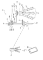
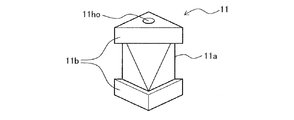
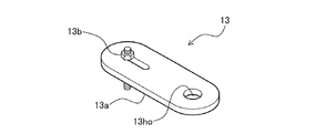
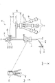
以下、図1乃至図5を参照して、本実施形態に係る測量ツール10と、その測量ツール10に用いるプリズム保持器20の構成について説明する。図1は、本実施形態に係る測量ツール10と、その測量ツール10に用いるプリズム保持器20の構成を示す概略図である。図2は、プリズム保持器20の保持部21の構成を示す斜視図である。図3は、本実施形態で用いるプリズムターゲット11の構成を示す正面図である。図4は、本実施形態で用いる水準器12の構成を示す斜視図である。図5は、本実施形態で用いるバランサ13の構成を示す斜視図である。
[Embodiment]
<Structure of surveying tool and prism holder used for the surveying tool>
Hereinafter, the configuration of the
測量ツール10は、測量作業に用いるツールである。測量ツール10は、三次元計測装置の測量対象物である後記するプリズムターゲット11を備えている。ここでは、三次元計測装置が後記するトータルステーションTSによって構成されているものとして説明する。
The surveying
図1に示すように、本実施形態では、作業者は、トータルステーションTSと、モバイル装置MBと、測量ツール10とを用いて、測量作業を行う。
As shown in FIG. 1, in the present embodiment, an operator performs a surveying operation using the total station TS, the mobile device MB, and the
トータルステーションTSは、自身から測量対象物(後記するプリズムターゲット11)までの距離と角度を測量する測距測角儀である。トータルステーションTSは、周囲にレーザ光を照射して、後記するプリズムターゲット11で反射した反射光を受光することで、自身から後記するプリズムターゲット11までの距離と角度とを測量する。トータルステーションTSは、ブルートゥース(登録商標)等の無線通信機能を有している。
The total station TS is a distance measuring angle measuring device for measuring a distance and an angle from the total station TS to an object to be measured (a
モバイル装置MBは、作業者によって所持された携帯型の装置である。モバイル装置MBは、例えば、スマートフォンやタブレット等で構成される。ここでは、モバイル装置MBがブルートゥース等の無線通信機能を有するスマートフォンで構成されているものとして説明する。トータルステーションTSは、モバイル装置MBとの間で無線通信することで、測量すべき地点(測量点)の場所等を作業者に指示する。 The mobile device MB is a portable device carried by a worker. The mobile device MB is composed of, for example, a smartphone or a tablet. Here, a description will be given assuming that the mobile device MB is configured by a smartphone having a wireless communication function such as Bluetooth. The total station TS wirelessly communicates with the mobile device MB, thereby instructing a worker on a place to be surveyed (a surveying point) and the like.
測量ツール10は、プリズムターゲット11と、水準器12と、バランサ13と、プリズム保持器20と、を備えている。また、測量ツール10は、これらに加え、高さ調整リング14を備えるようにしてもよい。高さ調整リング14は、プリズムポール15に取り付けることが可能なリング状の部材であり、取り付け高さを調整することができる。
The surveying
プリズムターゲット11は、トータルステーションTS(三次元計測装置)から照射されたレーザ光を反射するための部材である。プリズムターゲット11としては、例えば、ライカ社製のミニ360°ピンポールプリズム「GRZ101」等を用いることができる。
The
水準器12は、プリズムターゲット11の向きが水平方向であるか否かを(つまり、プリズムターゲット11が取り付けられた後記するプリズムポール15の向きが鉛直方向であるか否かを)確認するための器具である。
The
バランサ13は、プリズムターゲット11の向きを水平方向に設定するための部材である。バランサ13は、プリズムポール15に対して、プリズムポール15の軸周りに回転自在に取り付けられている。バランサ13は、水準器12の上に配置されている。測量ツール10は、バランサ13をプリズムポール15の軸周りに回転させることにより、プリズムターゲット11の向きを水平方向に設定すること(つまり、プリズムターゲット11が取り付けられた後記するプリズムポール15の向きを鉛直方向に設定すること)ができる。
The
プリズムターゲット11と水準器12とバランサ13と高さ調整リング14は、プリズムポール15に取り付けられている。プリズムポール15の下端部には、円錐状の石突き15aが配置されている。石突き15aは、床面に突き当てられる部位である。
The
プリズム保持器20は、プリズムターゲット11等が取り付けられたプリズムポール15を保持する器具である。プリズム保持器20は、プリズムポール15を回動自在に保持するとともに、プリズムターゲット11の向きを水平方向に維持した状態でプリズムターゲット11を自在に移動させることができる。
The
プリズム保持器20は、保持部21と、三脚部22と、を備えている。
保持部21は、プリズムポール15を回動自在に保持する機構である。
三脚部22は、保持部21を支持する機構である。
The
The holding
The
保持部21は、取付台31と、L字型ブラケット32と、ロッドエンドベアリング33と、を有している。
取付台31は、L字型ブラケット32が取り付けられる台である。
L字型ブラケット32は、ロッドエンドベアリング33が取り付けられる部材である。
ロッドエンドベアリング33は、プリズムポール15を回動自在に保持する軸受部である。
取付台31とL字型ブラケット32とロッドエンドベアリング33の詳細については後記する。
The holding
The mounting table 31 is a table to which the L-shaped
The L-shaped
The rod end bearing 33 is a bearing part that holds the
Details of the mounting
三脚部22は、3本の脚部22a(ただし、4本以上であってもよい)で保持部21を支持する機構である。各脚部22aの下端部には、回転自在に構成されたボールキャスタ41が配置されている。これにより、プリズム保持器20は、自在に移動させることができる。また、各脚部22aの途中部分には、伸縮可能に構成された伸縮部42が配置されている。これにより、プリズム保持器20は、各脚部22aを自在に伸縮させることができる。
The
図2に示すように、L字型ブラケット32は、短手部分32aと長手部分32bとを有している。短手部分32aと長手部分32bは、直角に配置されている。これにより、L字型ブラケット32は、短手部分32aと長手部分32bでL字の形状を呈している。
As shown in FIG. 2, the L-shaped
短手部分32aの中央部には、短手部分32aの延在方向に延びる長孔32hoが形成されている。同様に、長手部分32bの中央部には、長手部分32bの延在方向に延びる長孔32hoが形成されている。
A long hole 32ho extending in the extending direction of the
図示例では、短手部分32aが鉛直方向に配置されており、長手部分32bが水平方向に配置されている。短手部分32aの長孔32hoには、ロッドエンドベアリング33のロッド33aが通される。一方、長手部分32bの長孔32hoには、固定ネジ38aが通される。短手部分32aは、固定ネジ38bでロッドエンドベアリング33を固定している。また、長手部分32bは、固定ネジ38aで取付台31に固定されている。
In the illustrated example, the
ロッドエンドベアリング33は、雄ネジ加工されたロッド33aと、球面状に形成された球面軸受33bと、プリズムポール15を保持する円筒ホルダー33cと、を有している。球面軸受33bは、ロッド33aの先端部に配置されている。円筒ホルダー33cは、球面軸受33bの内部に配置されている。
The rod end bearing 33 includes a
ロッド33aは、ナット34とワッシャ35が取り付けられる。そして、ロッド33aは、L字型ブラケット32の短手部分32aの長孔32hoに通された後、固定ネジ38aが取り付けられる。これにより、ロッドエンドベアリング33は、L字型ブラケット32に取り付けられる。
The
ただし、L字型ブラケット32は、短手部分32aを水平方向に配置し、長手部分32bを鉛直方向に配置することができる。この場合に、長手部分32bは、固定ネジ38bでロッドエンドベアリング33を固定する。また、短手部分32aは、固定ネジ38aで取付台31に固定される。
However, in the L-shaped
ロッドエンドベアリング33の円筒ホルダー33cには、プリズムポール15が取り付けられる。ロッドエンドベアリング33は、球面軸受33bでプリズムポール15を回動自在に保持する。そのプリズムポール15には、プリズムターゲット11と水準器12とバランサ13と高さ調整リング14が取り付けられる。
The
図3に示すように、プリズムターゲット11は、レーザ光を反射するプリズム11aと、プリズム11aの上面と下面とを覆う枠体11bと、を有している。プリズムターゲット11には、上下方向に貫通する貫通孔11hoが形成されている。プリズムターゲット11は、貫通孔11hoを介してプリズムポール15に取り付けられる。
As shown in FIG. 3, the
図4に示すように、水準器12は、他の部位よりも低く形成された段差部12aに、透明パネル12bを備えている。透明パネル12bには、円形枠12ciが形成されている。円形枠12ciは、円形状に形成された図柄である。透明パネル12bの内部には、気泡12aiが封止されている。気泡12aiは、水準器12が水平に配置されている場合に、円形枠12ciの内部に入り、一方、水準器12が水平に配置されていない場合に、円形枠12ciの外部に外れるように、移動する。水準器12には、上下方向に貫通する貫通孔12hoが形成されている。水準器12は、貫通孔12hoを介してプリズムポール15に取り付けられる。
As shown in FIG. 4, the
図5に示すように、バランサ13は、板状部材13aと、錘13bと、を有している。図示例では、錘13bは、板状部材13aに締結されたネジ部材で構成されている。バランサ13には、上下方向に貫通する貫通孔13hoが形成されている。バランサ13は、貫通孔13hoを介してプリズムポール15に取り付けられる。
As shown in FIG. 5, the
<測量ツールを用いた測量作業の一例>
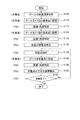
以下、図6乃至図8を参照して、測量ツール10を用いた測量作業の一例について説明する。図6は、測量ツール10を用いた測量作業の一例を示すフローチャートである。図7は、測量ツール10におけるプリズムポール15の鉛直設定の説明図である。図8は、測量ツール10の使用例を示す説明図である。
<Example of surveying work using surveying tool>
Hereinafter, an example of a surveying operation using the
ここでは、測量作業を行う場所の床面が整地面のような比較的平坦な面であるものとして説明する。つまり、測量ツール10が比較的平坦な場所で使用されるものとして説明する。
Here, a description will be given assuming that the floor surface at the place where the surveying work is performed is a relatively flat surface such as a level ground. That is, the description will be made assuming that the
また、ここでは、測量作業を行う場所に関する設計図等のデータが、事前にトータルステーションTSに登録されているものとして説明する。また、測量作業を行う場所には、各位置の三次元座標を特定するための2つの基準点Pst1,Pst2(図8参照)が予め設定されているものとして説明する。なお、2つの基準点Pst1,Pst2(図8参照)は、測量作業を行う場所に関する設計図等から特定される、既知の地点である。 In addition, here, description will be made on the assumption that data such as a design drawing regarding a place where the surveying work is performed is registered in the total station TS in advance. Also, a description will be given assuming that two reference points Pst1 and Pst2 (see FIG. 8) for specifying the three-dimensional coordinates of each position are set in advance at the place where the surveying work is performed. Note that the two reference points Pst1 and Pst2 (see FIG. 8) are known points specified from a design drawing or the like relating to a place where the surveying work is performed.
また、ここでは、トータルステーションTSが測量対象物であるプリズムターゲット11を自動的に認識して追尾する自動視準・追尾型の装置であるものとして説明する。このようなトータルステーションTSは、作業者がプリズム保持器20を移動させても、プリズム保持器20に保持されたプリズムターゲット11を自動的に認識して追尾する。そして、トータルステーションTSは、自身からプリズムターゲット11(測量対象物)までの距離と角度を自動的に測量する。
Also, here, the description will be given assuming that the total station TS is an automatic collimation / tracking type device that automatically recognizes and tracks the
測量作業を行う場合に、作業者は、測量ツール10を組み立てる。すなわち、図1に示すように、作業者は、プリズムポール15をプリズム保持器20で保持させて、プリズムターゲット11と水準器12とバランサ13と高さ調整リング14をプリズムポール15に取り付ける。
When performing surveying work, the operator assembles the
このとき、比較的重量物であるプリズムターゲット11と水準器12とバランサ13が、プリズムポール15のロッドエンドベアリング33(軸受部)よりも下方の位置に取り付けられる。そのため、プリズム保持器20で保持されたプリズムポール15は、ロッドエンドベアリング33(軸受部)によって自由に回動して、自ずと鉛直方向に向いた状態になる。
At this time, the
この後、作業者は、トータルステーションTSを任意の場所に配置して、トータルステーションTSを起動させる。これにより、測量作業が開始される。 Thereafter, the operator places the total station TS at an arbitrary location and activates the total station TS. Thereby, the surveying operation is started.
図6に示すように、測量作業を行う場合に、まず、作業者は、プリズムポール15の鉛直調整操作を行う(ステップS105)。鉛直調整操作は、プリズムポール15の向きを鉛直方向に設定する(つまり、プリズムターゲット11の向きを水平方向に設定する)操作である(図7の矢印A15参照)。
As shown in FIG. 6, when performing the surveying work, first, the operator performs a vertical adjustment operation of the prism pole 15 (step S105). The vertical adjustment operation is an operation of setting the direction of the
前記した通り、プリズム保持器20で保持されたプリズムポール15は、ロッドエンドベアリング33(軸受部)によって自由に回動して、自ずと鉛直方向に向いた状態になる。鉛直調整操作では、作業者は、水準器12の気泡12ai(図4参照)が水準器12の円形枠12ci(図4参照)の内部に入るように、プリズムポール15の軸周りにバランサ13を回転させる(図7の矢印A13参照)。
As described above, the
このとき、バランサ13の位置に応じて、ロッドエンドベアリング33の球面軸受33bが微小に回動する(図7の矢印A33参照)。これにより、プリズムポール15の向きが微細に変動する。その結果、プリズムターゲット11の向きが微細に変動する。そして、作業者は、水準器12の気泡12ai(図4参照)が水準器12の円形枠12ci(図4参照)の内部に入ったときに、バランサ13の回転を停止する。これにより、作業者は、バランサ13をプリズムポール15の軸周りに回転させるだけで、水準器12の水平出し(水準器12を水平位置に調整する作業)を行うことができる。その結果、作業者は、プリズムポール15の向きを正確に鉛直方向に設定することができる(図7の矢印A15参照)。つまり、作業者は、プリズムターゲット11の向きを正確に水平方向に設定することができる。
At this time, the
ステップS105の後、作業者は、測量ツール10を1つ目の基準点Pst1(図8参照)付近に移動させて、プリズムポール15を1つ目の基準点Pst1(図8参照)に配置する(ステップS110)。これにより、プリズムターゲット11(測量対象物)が1つ目の基準点Pst1(図8参照)の上に配置される。
After step S105, the operator moves the
このとき、測量ツール10は、プリズム保持器20の各脚部22aに配置されたボールキャスタ41が回動することにより、プリズムポール15の向きを鉛直方向に維持した状態で移動する。すなわち、測量ツール10は、バランサ13が動かないように、プリズムターゲット11(測量対象物)の向きを水平方向に維持した状態で移動する(以下、同様)。
At this time, the
トータルステーションTSは、プリズムターゲット11(測量対象物)を自動的に認識して追尾し、トータルステーションTSからプリズムターゲット11(測量対象物)までの距離と角度(方向)を特定する(ステップS115)。 The total station TS automatically recognizes and tracks the prism target 11 (object to be surveyed), and specifies the distance and angle (direction) from the total station TS to the prism target 11 (object to be surveyed) (step S115).
ステップS115の後、作業者は、測量ツール10を2つ目の基準点Pst2(図8参照)付近に移動させて、プリズムポール15を2つ目の基準点Pst2(図8参照)に配置する(ステップS120)。これにより、プリズムターゲット11(測量対象物)が2つ目の基準点Pst2(図8参照)の上に配置される。
After step S115, the operator moves the
トータルステーションTSは、プリズムターゲット11(測量対象物)を自動的に認識して追尾し、トータルステーションTSからプリズムターゲット11(測量対象物)までの距離と角度(方向)を特定する(ステップS125)。 The total station TS automatically recognizes and tracks the prism target 11 (object to be surveyed), and specifies the distance and angle (direction) from the total station TS to the prism target 11 (object to be surveyed) (step S125).
ステップS125の後、トータルステーションTSは、ステップS115で特定された距離と角度、並びに、ステップS125で特定された距離と角度に基づいて、トータルステーションTSが設置されている地点(設置点Pts(図8参照))の位置を特定する(ステップS130)。トータルステーションTSが設置点Pts(図8参照))の位置を特定した後、作業者は、測量ツール10を任意の地点に自由に移動させることができる(図8の矢印A10参照))。
After step S125, based on the distance and the angle specified in step S115, and the distance and the angle specified in step S125, the total station TS determines a point where the total station TS is installed (an installation point Pts (see FIG. 8). )) Is specified (step S130). After the total station TS specifies the position of the installation point Pts (see FIG. 8), the operator can freely move the
ステップS130の後、トータルステーションTSは、モバイル装置MBを介して無線通信で測量ツール10を測量すべき地点(例えば、測量点P1(図8参照))に移動させることを作業者に指示する(ステップS135)。
After step S130, the total station TS instructs the worker to move the
指示に応じて、作業者は、測量ツール10を測量点P1(図8参照)付近に移動させて(図8の矢印A10参照))、プリズムポール15を測量点P1(図8参照)に配置する(ステップS140)。これにより、プリズムターゲット11(測量対象物)が測量点P1(図8参照)の上に配置される。このとき、プリズムポール15は、ステップS105の鉛直調整操作で設定された状態が維持されている。そのため、プリズムポール15の向きは、鉛直方向に維持されている(図8の矢印A15参照)。
In response to the instruction, the operator moves the
トータルステーションTSは、プリズムターゲット11(測量対象物)を自動的に認識して追尾し、トータルステーションTSからプリズムターゲット11(測量対象物)までの距離と角度(方向)を特定する(ステップS145)。 The total station TS automatically recognizes and tracks the prism target 11 (object to be surveyed), and specifies the distance and angle (direction) from the total station TS to the prism target 11 (object to be surveyed) (step S145).
そして、トータルステーションTSは、1つ目の基準点Pst1(図8参照)を三次元座標の基準とし、ステップS145で特定された距離と角度に基づいて、測量点P1(図8参照)の三次元座標を算出する(ステップS150)。 Then, the total station TS uses the first reference point Pst1 (see FIG. 8) as a reference for the three-dimensional coordinates, and based on the distance and the angle specified in step S145, determines the three-dimensional position of the survey point P1 (see FIG. 8). The coordinates are calculated (step S150).
ステップS150の後、トータルステーションTSは、予め設定された全ての測量点の測量が終了したか否かを判定する(ステップS155)。ステップS155の判定で、予め設定された全ての測量点の測量が終了していないと判定された場合(“No”の場合)に、処理は、ステップS135に戻る。一方、ステップS155の判定で、予め設定された全ての測量点の測量が終了したと判定されたか、又は、作業者よりモバイル装置MB(図1参照)を介して測量作業中止の指示があった場合(“Yes”の場合)に、一連のルーチンの処理は終了する。 After step S150, the total station TS determines whether or not the surveying of all preset surveying points has been completed (step S155). If it is determined in step S155 that the surveying of all the preset surveying points has not been completed ("No"), the process returns to step S135. On the other hand, in the determination of step S155, it is determined that the surveying of all the preset surveying points has been completed, or an instruction has been issued by the operator to stop the surveying work via the mobile device MB (see FIG. 1). In this case (in the case of “Yes”), the processing of the series of routines ends.
<プリズム保持器及び測量ツールの主な特徴>
(1)本実施形態に係るプリズム保持器20は、プリズムターゲット11と水準器12とが取り付けられたプリズムポール15(ポール)を保持する保持部21と、保持部21の下に配置され、かつ、床面と接する脚部22aと、を備えている。保持部21は、プリズムポール15を回動自在に保持するロッドエンドベアリング33(軸受部)を有している。また、脚部22aは、床面と接する部位に回転自在なボールキャスタ41(移動部)を有している。
<Main features of prism holder and survey tool>
(1) The
このようなプリズム保持器20は、ロッドエンドベアリング33(軸受部)でプリズムポール15(ポール)を回動自在に保持することにより、プリズムポール15(ポール)を鉛直方向に向いた状態にすることができる。したがって、プリズム保持器20は、プリズムポール15(ポール)の向きを鉛直方向に容易に設定することができる。つまり、プリズム保持器20は、プリズムターゲット11の向きを水平方向に容易に設定することができる。また、プリズム保持器20は、ボールキャスタ41(移動部)が回動することにより、バランサ13が動かないように、プリズムポール15の向きを鉛直方向に維持した状態で(すなわち、プリズムターゲット11(測量対象物)の向きを水平方向に維持した状態で)移動することができる。このようなプリズム保持器20は、測量作業における作業者の負担を軽減することができる。また、プリズム保持器20は、測量作業の時間を短縮することもできる。
In such a
なお、本実施形態では、軸受部は、球面軸受33bを有するロッドエンドベアリング33で構成されている。しかしながら、軸受部は、球面軸受33b単体で構成することができる。
In the present embodiment, the bearing portion is constituted by a rod end bearing 33 having a
(2)本実施形態に係るプリズム保持器20の保持部21は、ロッドエンドベアリング33(軸受部)と、ロッドエンドベアリング33を保持するL字型ブラケット32と、L字型ブラケット32を保持する取付台31と、を有している。
(2) The holding
このようなプリズム保持器20は、L字型ブラケット32の向き(短手部分32aと長手部分32bの方向)を変更することで、取付台31とプリズムポール15(ポール)との距離やプリズムポール15の高さの変更量を増加させることができる。そのため、プリズム保持器20は、測量作業のし易さを向上することができる。
By changing the direction of the L-shaped bracket 32 (the direction of the
(3)本実施形態に係るプリズム保持器20は、各脚部22aの途中部分に、伸縮可能に構成された伸縮部42を有している。
(3) The
このようなプリズム保持器20は、伸縮部42で各脚部22aの長さを伸縮することができるため、プリズムポール15の高さを容易に変更することができる。そのため、プリズム保持器20は、測量作業のし易さを向上することができる。
In such a
(4)本実施形態に係る測量ツール10は、プリズムターゲット11と水準器12とバランサ13とが取り付けられたプリズムポール15と、前記したプリズム保持器20と、を備えている。バランサ13は、プリズムポール15に対して、プリズムポール15の軸周りに回転自在に取り付けられている。
(4) The
プリズム保持器20で保持されたプリズムポール15は、ロッドエンドベアリング33(軸受部)によって自由に回動して、自ずと鉛直方向に向いた状態になる。作業者は、バランサ13をプリズムポール15の軸周りに回転させる。これにより、作業者は、バランサ13をプリズムポール15の軸周りに回転させるだけで、水準器12の水平出し(水準器12を水平位置に調整する作業)を行うことができる。その結果、測量ツール10は、プリズムポール15の向きを微細に変動させて正確に鉛直方向に設定すること(つまり、プリズムターゲット11の向きを微細に変動させて正確に水平方向に設定すること)ができる。
The
(5)本実施形態に係る測量ツール10において、プリズムターゲット11と水準器12とバランサ13とは、プリズムポール15(ポール)を回動自在に保持するプリズム保持器20のロッドエンドベアリング33(軸受部)よりも下方の位置に配置されている。
(5) In the
このような測量ツール10は、重量物がロッドエンドベアリング33(軸受部)よりも下方の位置に配置されている。そのため、測量ツール10は、自ずとプリズムポール15を鉛直方向に向かせること(つまり、プリズムターゲット11を水平方向に向かせること)ができる。また、測量ツール10は、構造を単純化することもできる。
In such a
以上の通り、本実施形態に係るプリズム保持器20によれば、測量作業における作業者の負担を軽減することができる。
As described above, according to the
本発明は、前記した実施形態に限定されるものではなく、様々な変形例が含まれる。例えば、前記した実施形態は、本発明を分かり易く説明するために詳細に説明したものであり、必ずしも説明した全ての構成を備えるものに限定されるものではない。また、実施形態の構成の一部を他の構成に置き換えることが可能であり、また、実施形態の構成に他の構成を加えることも可能である。また、各構成の一部について、他の構成の追加・削除・置換をすることが可能である。 The present invention is not limited to the embodiments described above, and includes various modifications. For example, the above-described embodiments have been described in detail for easy understanding of the present invention, and are not necessarily limited to those having all the configurations described above. Further, a part of the configuration of the embodiment can be replaced with another configuration, and another configuration can be added to the configuration of the embodiment. Further, it is possible to add / delete / replace another configuration with respect to a part of each configuration.
10 測量ツール
11 プリズムターゲット
11a プリズム
11b 枠体
11ho,12ho,13ho 貫通孔
12 水準器
12a 段差部
12b 透明パネル
12ai 気泡
12ci 円形枠
13 バランサ
13a 板状部材
13b 錘
14 高さ調整リング
15 プリズムポール(ポール)
15a 石突き
20 プリズム保持器
21 保持部
22 三脚部
22a 脚部
31 取付台
32 L字型ブラケット
32a 短手部分
32b 長手部分
32ho 長孔
33 ロッドエンドベアリング(軸受部)
33a ロッド
33b 球面軸受
33c 円筒ホルダー
34 ナット
35 ワッシャ
38a,38b 固定ネジ
41 ボールキャスタ(移動部)
42 伸縮部
MB モバイル装置(スマートフォン)
P1 測量点
Pst1,Pst2 基準点
Pts 設置点
TS トータルステーション(測距測角儀、三次元計測装置)
42 Telescopic part MB Mobile device (smartphone)
P1 Survey point Pst1, Pst2 Reference point Pts Installation point TS Total station (ranging angle measuring instrument, 3D measuring device)
Claims (5)
前記保持部の下に配置され、かつ、床面と接する脚部と、を備え、
前記保持部は、前記ポールを回動自在に保持する軸受部を有し、
前記脚部は、前記床面と接する部位に回転自在な移動部を有する
ことを特徴とするプリズム保持器。 A holding unit that holds a pole on which a prism target and a level are attached,
Legs disposed below the holding portion and in contact with the floor surface,
The holding portion has a bearing portion that rotatably holds the pawl,
A prism holder, wherein the leg has a rotatable moving part at a position in contact with the floor surface.
前記軸受部は、ロッドエンドベアリング又は球面軸受で構成され、
前記移動部は、ボールキャスタで構成されている
ことを特徴とするプリズム保持器。 The prism holder according to claim 1,
The bearing unit is configured by a rod end bearing or a spherical bearing,
The prism holder according to claim 1, wherein the moving unit includes a ball caster.
前記保持部は、
前記軸受部と、
前記軸受部を保持するL字型ブラケットと、
前記L字型ブラケットを保持する取付台と、を有する
ことを特徴とするプリズム保持器。 The prism holder according to claim 1 or 2,
The holding unit,
The bearing portion,
An L-shaped bracket for holding the bearing portion,
A mount for holding the L-shaped bracket.
前記プリズムターゲットが水平か否かを確認する水準器と、
前記プリズムターゲットの向きを水平方向に設定するバランサと、
前記プリズムターゲットと前記水準器と前記バランサとが取り付けられたポールと、
請求項1乃至請求項3のいずれか一項に記載のプリズム保持器と、を備え、
前記バランサは、前記ポールに対して、前記ポールの軸周りに回転自在に取り付けられている
ことを特徴とする測量ツール。 A prism target irradiated with light,
A level to check whether the prism target is horizontal,
A balancer that sets the orientation of the prism target in the horizontal direction,
A pole on which the prism target, the level, and the balancer are mounted;
A prism holder according to any one of claims 1 to 3,
The surveying tool according to claim 1, wherein the balancer is rotatably attached to the pole around an axis of the pole.
前記プリズムターゲットと前記水準器と前記バランサとは、前記ポールを回動自在に保持する前記プリズム保持器の軸受部よりも下方の位置に配置されている
ことを特徴とする測量ツール。 The surveying tool according to claim 4,
A surveying tool, wherein the prism target, the level, and the balancer are arranged at a position lower than a bearing of the prism holder that rotatably holds the pole.
Priority Applications (1)
| Application Number | Priority Date | Filing Date | Title |
|---|---|---|---|
| JP2018122627A JP7201346B2 (en) | 2018-06-28 | 2018-06-28 | Prism retainer and surveying tool using the prism retainer |
Applications Claiming Priority (1)
| Application Number | Priority Date | Filing Date | Title |
|---|---|---|---|
| JP2018122627A JP7201346B2 (en) | 2018-06-28 | 2018-06-28 | Prism retainer and surveying tool using the prism retainer |
Publications (2)
| Publication Number | Publication Date |
|---|---|
| JP2020003324A true JP2020003324A (en) | 2020-01-09 |
| JP7201346B2 JP7201346B2 (en) | 2023-01-10 |
Family
ID=69099700
Family Applications (1)
| Application Number | Title | Priority Date | Filing Date |
|---|---|---|---|
| JP2018122627A Active JP7201346B2 (en) | 2018-06-28 | 2018-06-28 | Prism retainer and surveying tool using the prism retainer |
Country Status (1)
| Country | Link |
|---|---|
| JP (1) | JP7201346B2 (en) |
Citations (14)
| Publication number | Priority date | Publication date | Assignee | Title |
|---|---|---|---|---|
| US4339880A (en) * | 1978-10-23 | 1982-07-20 | Beverly J. Hall | Device for holding surveyor's instrument |
| US4402108A (en) * | 1981-02-17 | 1983-09-06 | Pannwitz Hans U | Reduced static castor |
| JPS61135213U (en) * | 1985-02-13 | 1986-08-23 | ||
| DE3827459A1 (en) * | 1988-08-12 | 1990-02-15 | Michael H Dipl Ing Korte | Method and equipment for setting up and generating a spatial orthogonal measuring network, especially for setting up dimensions in the framework of structural surveys |
| JPH0494511U (en) * | 1990-12-27 | 1992-08-17 | ||
| JPH06265093A (en) * | 1993-03-10 | 1994-09-20 | Sony Corp | Tripod device |
| JPH06281461A (en) * | 1993-03-26 | 1994-10-07 | Seikosha Co Ltd | Prism support device for light wave distance meter |
| JPH0843099A (en) * | 1994-07-26 | 1996-02-16 | Toshiba Eng & Constr Co Ltd | Marking device and marking method of building using it |
| JPH1019571A (en) * | 1996-07-04 | 1998-01-23 | Taihei Sangyo:Kk | Apparatus for holding survey pole |
| US20050151035A1 (en) * | 2004-01-13 | 2005-07-14 | Crain Enterprises, Inc. | Multiple function geomatics pole support device |
| JP2005521011A (en) * | 2002-03-19 | 2005-07-14 | ファロ テクノロジーズ インコーポレーテッド | Tripod and its usage |
| JP2009025084A (en) * | 2007-07-18 | 2009-02-05 | Kansai Koji Sokuryo Kk | Tripod for survey |
| CN203274758U (en) * | 2013-05-16 | 2013-11-06 | 东北林业大学 | Quick inspection device for total station prism bar |
| JP2017209894A (en) * | 2016-05-26 | 2017-11-30 | 理想科学工業株式会社 | Printer |
-
2018
- 2018-06-28 JP JP2018122627A patent/JP7201346B2/en active Active
Patent Citations (14)
| Publication number | Priority date | Publication date | Assignee | Title |
|---|---|---|---|---|
| US4339880A (en) * | 1978-10-23 | 1982-07-20 | Beverly J. Hall | Device for holding surveyor's instrument |
| US4402108A (en) * | 1981-02-17 | 1983-09-06 | Pannwitz Hans U | Reduced static castor |
| JPS61135213U (en) * | 1985-02-13 | 1986-08-23 | ||
| DE3827459A1 (en) * | 1988-08-12 | 1990-02-15 | Michael H Dipl Ing Korte | Method and equipment for setting up and generating a spatial orthogonal measuring network, especially for setting up dimensions in the framework of structural surveys |
| JPH0494511U (en) * | 1990-12-27 | 1992-08-17 | ||
| JPH06265093A (en) * | 1993-03-10 | 1994-09-20 | Sony Corp | Tripod device |
| JPH06281461A (en) * | 1993-03-26 | 1994-10-07 | Seikosha Co Ltd | Prism support device for light wave distance meter |
| JPH0843099A (en) * | 1994-07-26 | 1996-02-16 | Toshiba Eng & Constr Co Ltd | Marking device and marking method of building using it |
| JPH1019571A (en) * | 1996-07-04 | 1998-01-23 | Taihei Sangyo:Kk | Apparatus for holding survey pole |
| JP2005521011A (en) * | 2002-03-19 | 2005-07-14 | ファロ テクノロジーズ インコーポレーテッド | Tripod and its usage |
| US20050151035A1 (en) * | 2004-01-13 | 2005-07-14 | Crain Enterprises, Inc. | Multiple function geomatics pole support device |
| JP2009025084A (en) * | 2007-07-18 | 2009-02-05 | Kansai Koji Sokuryo Kk | Tripod for survey |
| CN203274758U (en) * | 2013-05-16 | 2013-11-06 | 东北林业大学 | Quick inspection device for total station prism bar |
| JP2017209894A (en) * | 2016-05-26 | 2017-11-30 | 理想科学工業株式会社 | Printer |
Also Published As
| Publication number | Publication date |
|---|---|
| JP7201346B2 (en) | 2023-01-10 |
Similar Documents
| Publication | Publication Date | Title |
|---|---|---|
| CA2817240C (en) | Device for measuring and marking space points along horizontally running contour lines | |
| CN107339981B (en) | Engineering measurement electric tripod and rapid centering and leveling method | |
| JP6285276B2 (en) | Radiation measurement apparatus for ground surface and radiation measurement method using the apparatus | |
| US7797846B2 (en) | Reference beam generator for generating guide beams for marking machines | |
| KR101464162B1 (en) | Numerical map updating system according to point of gps applied ground image | |
| JP2001227950A (en) | Positioning marking device for surveying | |
| CN103076000B (en) | three-dimensional range finder | |
| KR101103356B1 (en) | Installation for measurement with auto control function | |
| JP2020003324A (en) | Prism holder and measurement tool using the same | |
| US3911589A (en) | Adjustable support base for a field measurement device | |
| GB1156072A (en) | Improvements in or relating to Survey Reference Apparatus and the Methods of Control Thereof. | |
| US7797845B2 (en) | Levelling device | |
| KR101752796B1 (en) | Apparatus for protecting UV and visual of surveying device | |
| KR101910433B1 (en) | Apparatus for fixing leveling equipment and triangle stand | |
| JP3465188B2 (en) | Surveying tripod | |
| CN210154582U (en) | Quick leveling type total station based on BIM technology | |
| JP2022055525A (en) | Marking system and marking method | |
| KR100623653B1 (en) | Mobile system for obtaining precise map data using differential global positioning system | |
| CN104949650A (en) | Distance meter | |
| CN205037897U (en) | Engineering survey equipment supporting seat adjustable in multiple directions | |
| US11674800B2 (en) | Laser level meter and use method therefor | |
| US3588014A (en) | Instrument mount | |
| TWM454534U (en) | Electronic type laser leveler | |
| JP2002228446A (en) | Automatic level for surveying instrument | |
| CN106969744B (en) | Space attitude measuring instrument and method for fighter plane body |
Legal Events
| Date | Code | Title | Description |
|---|---|---|---|
| A621 | Written request for application examination |
Free format text: JAPANESE INTERMEDIATE CODE: A621 Effective date: 20210311 |
|
| A977 | Report on retrieval |
Free format text: JAPANESE INTERMEDIATE CODE: A971007 Effective date: 20220225 |
|
| A131 | Notification of reasons for refusal |
Free format text: JAPANESE INTERMEDIATE CODE: A131 Effective date: 20220308 |
|
| A521 | Request for written amendment filed |
Free format text: JAPANESE INTERMEDIATE CODE: A523 Effective date: 20220427 |
|
| A131 | Notification of reasons for refusal |
Free format text: JAPANESE INTERMEDIATE CODE: A131 Effective date: 20220823 |
|
| A521 | Request for written amendment filed |
Free format text: JAPANESE INTERMEDIATE CODE: A523 Effective date: 20221018 |
|
| TRDD | Decision of grant or rejection written | ||
| A01 | Written decision to grant a patent or to grant a registration (utility model) |
Free format text: JAPANESE INTERMEDIATE CODE: A01 Effective date: 20221206 |
|
| A61 | First payment of annual fees (during grant procedure) |
Free format text: JAPANESE INTERMEDIATE CODE: A61 Effective date: 20221222 |
|
| R150 | Certificate of patent or registration of utility model |
Ref document number: 7201346 Country of ref document: JP Free format text: JAPANESE INTERMEDIATE CODE: R150 |