JP2020002397A - Electrolysis apparatus and electrode manufacturing method - Google Patents
Electrolysis apparatus and electrode manufacturing method Download PDFInfo
- Publication number
- JP2020002397A JP2020002397A JP2018120823A JP2018120823A JP2020002397A JP 2020002397 A JP2020002397 A JP 2020002397A JP 2018120823 A JP2018120823 A JP 2018120823A JP 2018120823 A JP2018120823 A JP 2018120823A JP 2020002397 A JP2020002397 A JP 2020002397A
- Authority
- JP
- Japan
- Prior art keywords
- powder
- cathode
- anode
- metal
- metal powder
- Prior art date
- Legal status (The legal status is an assumption and is not a legal conclusion. Google has not performed a legal analysis and makes no representation as to the accuracy of the status listed.)
- Pending
Links
- 238000005868 electrolysis reaction Methods 0.000 title claims abstract description 67
- 238000004519 manufacturing process Methods 0.000 title claims description 36
- 239000000843 powder Substances 0.000 claims abstract description 623
- 229910052723 transition metal Inorganic materials 0.000 claims abstract description 257
- 150000003624 transition metals Chemical class 0.000 claims abstract description 257
- 229910052751 metal Inorganic materials 0.000 claims abstract description 239
- 239000002184 metal Substances 0.000 claims abstract description 239
- 239000000203 mixture Substances 0.000 claims abstract description 164
- BASFCYQUMIYNBI-UHFFFAOYSA-N platinum Chemical group [Pt] BASFCYQUMIYNBI-UHFFFAOYSA-N 0.000 claims abstract description 130
- 239000000956 alloy Substances 0.000 claims abstract description 97
- 229910045601 alloy Inorganic materials 0.000 claims abstract description 97
- 239000002131 composite material Substances 0.000 claims abstract description 15
- 238000003825 pressing Methods 0.000 claims abstract description 9
- 238000002844 melting Methods 0.000 claims description 32
- 230000008018 melting Effects 0.000 claims description 32
- 239000007864 aqueous solution Substances 0.000 claims description 25
- 239000011230 binding agent Substances 0.000 claims description 23
- 239000002245 particle Substances 0.000 claims description 17
- 238000010304 firing Methods 0.000 claims description 10
- 238000002156 mixing Methods 0.000 claims description 10
- 230000005611 electricity Effects 0.000 claims description 7
- 238000002360 preparation method Methods 0.000 claims description 7
- 238000006722 reduction reaction Methods 0.000 claims description 4
- 238000000034 method Methods 0.000 claims description 3
- 238000007254 oxidation reaction Methods 0.000 claims description 3
- 230000008569 process Effects 0.000 claims description 3
- 239000010419 fine particle Substances 0.000 claims 1
- 239000000155 melt Substances 0.000 claims 1
- 238000006555 catalytic reaction Methods 0.000 abstract description 38
- 230000003197 catalytic effect Effects 0.000 abstract description 37
- 229910052697 platinum Inorganic materials 0.000 abstract description 31
- XEEYBQQBJWHFJM-UHFFFAOYSA-N iron Substances [Fe] XEEYBQQBJWHFJM-UHFFFAOYSA-N 0.000 description 173
- PXHVJJICTQNCMI-UHFFFAOYSA-N nickel Substances [Ni] PXHVJJICTQNCMI-UHFFFAOYSA-N 0.000 description 149
- 239000010949 copper Substances 0.000 description 147
- 239000011701 zinc Substances 0.000 description 62
- 239000011572 manganese Substances 0.000 description 45
- UFHFLCQGNIYNRP-UHFFFAOYSA-N Hydrogen Chemical compound [H][H] UFHFLCQGNIYNRP-UHFFFAOYSA-N 0.000 description 44
- 239000010936 titanium Substances 0.000 description 43
- 239000000446 fuel Substances 0.000 description 39
- 229910052802 copper Inorganic materials 0.000 description 34
- 229910052742 iron Inorganic materials 0.000 description 34
- XLYOFNOQVPJJNP-UHFFFAOYSA-N water Substances O XLYOFNOQVPJJNP-UHFFFAOYSA-N 0.000 description 34
- RYGMFSIKBFXOCR-UHFFFAOYSA-N Copper Chemical compound [Cu] RYGMFSIKBFXOCR-UHFFFAOYSA-N 0.000 description 29
- 239000011651 chromium Substances 0.000 description 29
- 229910052759 nickel Inorganic materials 0.000 description 29
- 239000010955 niobium Substances 0.000 description 27
- 239000007788 liquid Substances 0.000 description 25
- 239000005518 polymer electrolyte Substances 0.000 description 23
- HCHKCACWOHOZIP-UHFFFAOYSA-N Zinc Chemical compound [Zn] HCHKCACWOHOZIP-UHFFFAOYSA-N 0.000 description 20
- 239000001257 hydrogen Substances 0.000 description 20
- 229910052739 hydrogen Inorganic materials 0.000 description 20
- 229910052709 silver Inorganic materials 0.000 description 20
- 239000004332 silver Substances 0.000 description 20
- 229910052725 zinc Inorganic materials 0.000 description 20
- 239000012528 membrane Substances 0.000 description 17
- ZOKXTWBITQBERF-UHFFFAOYSA-N Molybdenum Chemical compound [Mo] ZOKXTWBITQBERF-UHFFFAOYSA-N 0.000 description 16
- RTAQQCXQSZGOHL-UHFFFAOYSA-N Titanium Chemical compound [Ti] RTAQQCXQSZGOHL-UHFFFAOYSA-N 0.000 description 16
- 239000003054 catalyst Substances 0.000 description 16
- 229910052750 molybdenum Inorganic materials 0.000 description 16
- 239000011733 molybdenum Substances 0.000 description 16
- 229910052719 titanium Inorganic materials 0.000 description 16
- 238000006243 chemical reaction Methods 0.000 description 15
- QVGXLLKOCUKJST-UHFFFAOYSA-N atomic oxygen Chemical compound [O] QVGXLLKOCUKJST-UHFFFAOYSA-N 0.000 description 14
- 239000001301 oxygen Substances 0.000 description 14
- 229910052760 oxygen Inorganic materials 0.000 description 14
- PWHULOQIROXLJO-UHFFFAOYSA-N Manganese Chemical compound [Mn] PWHULOQIROXLJO-UHFFFAOYSA-N 0.000 description 13
- 229910052804 chromium Inorganic materials 0.000 description 13
- 229910052748 manganese Inorganic materials 0.000 description 13
- VYZAMTAEIAYCRO-UHFFFAOYSA-N Chromium Chemical compound [Cr] VYZAMTAEIAYCRO-UHFFFAOYSA-N 0.000 description 12
- 229910017052 cobalt Inorganic materials 0.000 description 12
- 239000010941 cobalt Substances 0.000 description 12
- GUTLYIVDDKVIGB-UHFFFAOYSA-N cobalt atom Chemical compound [Co] GUTLYIVDDKVIGB-UHFFFAOYSA-N 0.000 description 12
- 239000007789 gas Substances 0.000 description 12
- 229910052758 niobium Inorganic materials 0.000 description 12
- GUCVJGMIXFAOAE-UHFFFAOYSA-N niobium atom Chemical compound [Nb] GUCVJGMIXFAOAE-UHFFFAOYSA-N 0.000 description 12
- 239000007787 solid Substances 0.000 description 12
- 238000003860 storage Methods 0.000 description 11
- 229910044991 metal oxide Inorganic materials 0.000 description 8
- 150000004706 metal oxides Chemical class 0.000 description 8
- 238000010586 diagram Methods 0.000 description 7
- HEMHJVSKTPXQMS-UHFFFAOYSA-M Sodium hydroxide Chemical compound [OH-].[Na+] HEMHJVSKTPXQMS-UHFFFAOYSA-M 0.000 description 6
- 238000006356 dehydrogenation reaction Methods 0.000 description 6
- 238000009792 diffusion process Methods 0.000 description 6
- FAPWRFPIFSIZLT-UHFFFAOYSA-M Sodium chloride Chemical compound [Na+].[Cl-] FAPWRFPIFSIZLT-UHFFFAOYSA-M 0.000 description 4
- 238000010349 cathodic reaction Methods 0.000 description 4
- 239000012530 fluid Substances 0.000 description 4
- 230000006835 compression Effects 0.000 description 3
- 238000007906 compression Methods 0.000 description 3
- 230000007423 decrease Effects 0.000 description 3
- 230000000694 effects Effects 0.000 description 3
- -1 hydrogen ions Chemical class 0.000 description 3
- 150000002500 ions Chemical class 0.000 description 3
- 239000011159 matrix material Substances 0.000 description 3
- 101710134784 Agnoprotein Proteins 0.000 description 2
- 150000002431 hydrogen Chemical class 0.000 description 2
- 239000003014 ion exchange membrane Substances 0.000 description 2
- 238000005304 joining Methods 0.000 description 2
- 239000011148 porous material Substances 0.000 description 2
- 238000000926 separation method Methods 0.000 description 2
- 239000011780 sodium chloride Substances 0.000 description 2
- 239000000243 solution Substances 0.000 description 2
- 239000000758 substrate Substances 0.000 description 2
- 125000000542 sulfonic acid group Chemical group 0.000 description 2
- 230000002378 acidificating effect Effects 0.000 description 1
- 238000007743 anodising Methods 0.000 description 1
- 230000008901 benefit Effects 0.000 description 1
- PCHJSUWPFVWCPO-UHFFFAOYSA-N gold Chemical compound [Au] PCHJSUWPFVWCPO-UHFFFAOYSA-N 0.000 description 1
- 229910052737 gold Inorganic materials 0.000 description 1
- 239000010931 gold Substances 0.000 description 1
- 238000002347 injection Methods 0.000 description 1
- 239000007924 injection Substances 0.000 description 1
- 230000001788 irregular Effects 0.000 description 1
- 238000005259 measurement Methods 0.000 description 1
- 239000002923 metal particle Substances 0.000 description 1
- 150000002739 metals Chemical class 0.000 description 1
- 229910000510 noble metal Inorganic materials 0.000 description 1
- CLSUSRZJUQMOHH-UHFFFAOYSA-L platinum dichloride Chemical compound Cl[Pt]Cl CLSUSRZJUQMOHH-UHFFFAOYSA-L 0.000 description 1
- 229920000642 polymer Polymers 0.000 description 1
- 238000010298 pulverizing process Methods 0.000 description 1
- 239000012495 reaction gas Substances 0.000 description 1
- 230000009467 reduction Effects 0.000 description 1
- 230000035939 shock Effects 0.000 description 1
- 238000005245 sintering Methods 0.000 description 1
- 239000000126 substance Substances 0.000 description 1
Images


Classifications
-
- Y—GENERAL TAGGING OF NEW TECHNOLOGICAL DEVELOPMENTS; GENERAL TAGGING OF CROSS-SECTIONAL TECHNOLOGIES SPANNING OVER SEVERAL SECTIONS OF THE IPC; TECHNICAL SUBJECTS COVERED BY FORMER USPC CROSS-REFERENCE ART COLLECTIONS [XRACs] AND DIGESTS
- Y02—TECHNOLOGIES OR APPLICATIONS FOR MITIGATION OR ADAPTATION AGAINST CLIMATE CHANGE
- Y02E—REDUCTION OF GREENHOUSE GAS [GHG] EMISSIONS, RELATED TO ENERGY GENERATION, TRANSMISSION OR DISTRIBUTION
- Y02E60/00—Enabling technologies; Technologies with a potential or indirect contribution to GHG emissions mitigation
- Y02E60/30—Hydrogen technology
- Y02E60/50—Fuel cells
-
- Y—GENERAL TAGGING OF NEW TECHNOLOGICAL DEVELOPMENTS; GENERAL TAGGING OF CROSS-SECTIONAL TECHNOLOGIES SPANNING OVER SEVERAL SECTIONS OF THE IPC; TECHNICAL SUBJECTS COVERED BY FORMER USPC CROSS-REFERENCE ART COLLECTIONS [XRACs] AND DIGESTS
- Y02—TECHNOLOGIES OR APPLICATIONS FOR MITIGATION OR ADAPTATION AGAINST CLIMATE CHANGE
- Y02P—CLIMATE CHANGE MITIGATION TECHNOLOGIES IN THE PRODUCTION OR PROCESSING OF GOODS
- Y02P70/00—Climate change mitigation technologies in the production process for final industrial or consumer products
- Y02P70/50—Manufacturing or production processes characterised by the final manufactured product
Abstract
Description
本発明は、電気を利用して所定の水溶液を化学分解する電気分解装置に関するとともに、電気分解装置に使用する陽極および陰極の電極製造方法に関する。 The present invention relates to an electrolyzer for chemically decomposing a predetermined aqueous solution using electricity, and also relates to a method for producing an anode and a cathode used in the electrolyzer.
反応管と、反応管内に収容された触媒体と、流体入口および流体出口を有する筒状体とを備え、流体入口と流体出口とが筒状体の内部を流路として互いに連通し、反応管が流路内に配置され、触媒体が軸線を反応管の長手方向に平行にする向きに反応管に挿入され、触媒体が一定の軸線に沿って延在する基材と脱水素触媒を含む脱水素触媒層とを備え、基材が軸線を中心として回転する方向にねじれながら軸線に沿って延在する板状部を含み、板状部の表面上に脱水素触媒層が設けられている水素発生装置が開示されている(特許文献1参照)。 A reaction tube, a catalyst body accommodated in the reaction tube, and a tubular body having a fluid inlet and a fluid outlet, wherein the fluid inlet and the fluid outlet communicate with each other using the inside of the tubular body as a flow path; Are arranged in the flow path, the catalyst body is inserted into the reaction tube in a direction in which the axis is parallel to the longitudinal direction of the reaction tube, and the catalyst body includes a substrate and a dehydrogenation catalyst extending along a certain axis. A dehydrogenation catalyst layer, wherein the substrate includes a plate-shaped portion extending along the axis while being twisted in the direction of rotation about the axis, and the dehydrogenation catalyst layer is provided on the surface of the plate-shaped portion A hydrogen generator has been disclosed (see Patent Document 1).
前記特許文献1に開示の水素発生装置の触媒体は、金属の成形体の表面を陽極酸化して金属の酸化物を含む金属酸化物膜を形成する工程と、金属酸化物膜に脱水素触媒を担持させる工程とから作られる。金属酸化物膜に脱水素触媒を担持させる工程では、 ヘキサクロロ白金(IV)酸イオンを含む酸性の塩化白金水溶液を金属酸化物膜と接触させることによって金属酸化物膜にヘキサクロロ白金(IV)酸イオンを付着させるとともに、ヘキサクロロ白金(IV)酸イオンが付着している金属酸化物膜を焼成して金属酸化物膜に脱水素触媒として白金を担持させる。
The catalyst of the hydrogen generator disclosed in
電気分解装置の電極として各種の白金担持カーボンが広く利用されている。しかし、白金族元素は、貴金属であり、その生産量に限りがある希少な資源であることから、その使用量を抑えることが求められている。さらに、今後の電気分解装置の普及に向けて高価な白金以外の金属を利用した非白金触媒を有する廉価な電極の開発が求められている。 Various platinum-carrying carbons are widely used as electrodes of electrolyzers. However, the platinum group element is a noble metal, and is a scarce resource with a limited production amount. Therefore, it is required to suppress the amount of the platinum group element used. Further, development of inexpensive electrodes having a non-platinum catalyst using a metal other than expensive platinum is required for the spread of electrolyzers in the future.
本発明の目的は、白金族元素を利用することなく触媒活性(触媒作用)を有する陽極および陰極を備え、非白金の陽極および陰極を使用して電気分解を効率よく行うことができ、短時間に多量の水素ガスを発生させることができる電気分解装置を提供することにある。本発明の他の目的は、白金族元素を利用することなく、廉価に作ることができ、十分な触媒活性(触媒作用)を有する電気分解装置の陽極および陰極を製造する電極製造方法を提供することにある。 An object of the present invention is to provide an anode and a cathode having catalytic activity (catalysis) without using a platinum group element, and to perform electrolysis efficiently using a non-platinum anode and a cathode. Another object of the present invention is to provide an electrolysis apparatus capable of generating a large amount of hydrogen gas. Another object of the present invention is to provide an electrode manufacturing method for manufacturing an anode and a cathode of an electrolysis apparatus which can be manufactured at low cost without using a platinum group element and have sufficient catalytic activity (catalysis). It is in.
前記課題を解決するための本発明の第1の前提は、陽極および陰極と、陽極と陰極との間に位置してそれら極を接合する電極接合体膜とを備え、陽極および陰極に電気を通電し、陽極で酸化反応を起こすとともに陰極で還元反応を起こすことで所定の水溶液を化学分解する電気分解装置である。 A first premise of the present invention for solving the above problems is to provide an anode and a cathode, and an electrode assembly film located between the anode and the cathode and joining the electrodes, and electricity is supplied to the anode and the cathode. It is an electrolyzer that chemically decomposes a predetermined aqueous solution by causing an oxidation reaction at the anode and a reduction reaction at the cathode when electricity is supplied.
前記第1の前提における本発明の電気分解装置の特徴は、陽極および陰極が、各種の遷移金属から選択された少なくとも3種類の遷移金属から形成され、選択された少なくとも3種類のそれら遷移金属の粉体を均一に混合・分散した金属粉体混合物を所定面積の薄板状に圧縮した後に焼成して多数の微細な流路を形成したポーラス構造のアロイ薄板電極であり、陽極および陰極では、選択された少なくとも3種類の遷移金属の仕事関数の合成仕事関数が白金族元素の仕事関数に近似するように、各種の遷移金属の中から少なくとも3種類の遷移金属が選択されていることにある。 The feature of the electrolyzer of the present invention based on the first premise is that the anode and the cathode are formed from at least three kinds of transition metals selected from various transition metals, and at least three kinds of the selected transition metals are used. This is a porous alloy sheet electrode with a porous structure in which a metal powder mixture obtained by uniformly mixing and dispersing powder is compressed into a thin plate having a predetermined area and then fired to form a number of fine channels. That is, at least three types of transition metals are selected from various types of transition metals so that the calculated work function of the work functions of the at least three types of transition metals approximates the work function of the platinum group element.
本発明の電気分解装置の一例としては、陽極および陰極の厚み寸法が、0.03mm〜0.3mmの範囲にある。 As one example of the electrolyzer of the present invention, the thickness of the anode and the cathode is in the range of 0.03 mm to 0.3 mm.
本発明の電気分解装置の他の一例としては、陽極および陰極が、Niの粉体を主成分として0.03mm〜0.3mmの範囲の厚み寸法に成形されたポーラス構造のアロイ薄板電極であり、ポーラス構造のアロイ薄板電極では、Niの仕事関数とNiを除く他の少なくとも2種類の遷移金属の仕事関数との合成仕事関数が白金族元素の仕事関数に近似するように、各種の遷移金属の中からNiの粉体を除く他の少なくとも2種類の遷移金属の粉体が選択されている。 Another example of the electrolysis apparatus of the present invention is an alloy thin plate electrode having a porous structure in which the anode and the cathode are formed to have a thickness of 0.03 mm to 0.3 mm with Ni powder as a main component. In the case of an alloy thin plate electrode having a porous structure, various transition metals are used so that the work function of Ni and the work function of at least two types of transition metals other than Ni approximates the work function of a platinum group element. Among them, at least two types of transition metal powder other than the Ni powder are selected.
本発明の電気分解装置の他の一例としては、Niの粉体の金属粉体混合物の全重量に対する重量比が、30%〜50%の範囲、Niの粉体を除く1種類の遷移金属の粉体の金属粉体混合物の全重量に対する重量比が、20%〜50%の範囲にあり、Niの粉体を除く他の少なくとも1種類の遷移金属の粉体の金属粉体混合物の全重量に対する重量比が、3%〜20%の範囲にある。 As another example of the electrolyzer of the present invention, the weight ratio of Ni powder to the total weight of the metal powder mixture is in the range of 30% to 50%, and one type of transition metal excluding Ni powder is used. The weight ratio of the powder to the total weight of the metal powder mixture is in the range of 20% to 50%, and the total weight of the metal powder mixture of at least one other transition metal powder excluding the Ni powder. Is in the range of 3% to 20%.
本発明の電気分解装置の他の一例としては、陽極および陰極が、Feの粉体を主成分として0.03mm〜0.3mmの範囲の厚み寸法に成形されたポーラス構造のアロイ薄板電極であり、ポーラス構造のアロイ薄板電極では、Feの仕事関数とFeを除く他の少なくとも2種類の遷移金属の仕事関数との合成仕事関数が白金族元素の仕事関数に近似するように、各種の遷移金属の中からFeの粉体を除く他の少なくとも2種類の遷移金属の粉体が選択されている。 Another example of the electrolyzer of the present invention is an alloy thin plate electrode having a porous structure in which an anode and a cathode are formed to have a thickness in a range of 0.03 mm to 0.3 mm with Fe powder as a main component. In the case of an alloy thin plate electrode having a porous structure, various types of transition metals are used so that the work function of Fe and the work function of at least two types of transition metals other than Fe approximates the work function of a platinum group element. Among them, at least two types of transition metal powders other than the Fe powder are selected.
本発明の電気分解装置の他の一例としては、Feの粉体の金属粉体混合物の全重量に対する重量比が、30%〜50%の範囲、Feの粉体を除く1種類の遷移金属の粉体の金属粉体混合物の全重量に対する重量比が、20%〜50%の範囲にあり、Feの粉体を除く他の少なくとも1種類の遷移金属の粉体の金属粉体混合物の全重量に対する重量比が、3%〜20%の範囲にある。 As another example of the electrolysis apparatus of the present invention, the weight ratio of Fe powder to the total weight of the metal powder mixture is in the range of 30% to 50%, and one type of transition metal excluding Fe powder is used. The weight ratio of the powder to the total weight of the metal powder mixture is in the range of 20% to 50%, and the total weight of the metal powder mixture of at least one other transition metal powder excluding the Fe powder Is in the range of 3% to 20%.
本発明の電気分解装置の他の一例としては、陽極および陰極が、Cuの粉体を主成分として0.03mm〜0.3mmの範囲の厚み寸法に成形されたポーラス構造のアロイ薄板電極であり、ポーラス構造のアロイ薄板電極では、Crの仕事関数とCuを除く他の少なくとも2種類の遷移金属の仕事関数との合成仕事関数が白金族元素の仕事関数に近似するように、各種の遷移金属の中からCuの粉体を除く他の少なくとも2種類の遷移金属の粉体が選択されている。 Another example of the electrolyzer of the present invention is an alloy thin plate electrode having a porous structure in which an anode and a cathode are formed to have a thickness of 0.03 mm to 0.3 mm with a Cu powder as a main component. In the case of an alloy thin plate electrode having a porous structure, various types of transition metals are used such that the work function of Cr and the work function of at least two types of transition metals other than Cu are close to the work function of a platinum group element. Among them, at least two types of transition metal powders other than the Cu powder are selected.
本発明の電気分解装置の他の一例としては、Cuの粉体の金属粉体混合物の全重量に対する重量比が、30%〜50%の範囲、Cuの粉体を除く1種類の遷移金属の粉体の金属粉体混合物の全重量に対する重量比が、20%〜50%の範囲にあり、Cuの粉体を除く他の少なくとも1種類の遷移金属の粉体の金属粉体混合物の全重量に対する重量比が、3%〜20%の範囲にある。 As another example of the electrolysis apparatus of the present invention, the weight ratio of Cu powder to the total weight of the metal powder mixture is in a range of 30% to 50%, and one type of transition metal excluding Cu powder is used. The weight ratio of the powder to the total weight of the metal powder mixture is in the range of 20% to 50%, and the total weight of the metal powder mixture of at least one other transition metal powder excluding the Cu powder Is in the range of 3% to 20%.
本発明の電気分解装置の他の一例としては、陽極および陰極の空隙率が、15%〜30%の範囲にあり、陽極および陰極の密度が、5.0g/cm2〜7.0g/cm2の範囲にある。 As another example of the electrolyzer of the present invention, the porosity of the anode and the cathode is in a range of 15% to 30%, and the density of the anode and the cathode is 5.0 g / cm 2 to 7.0 g / cm. 2 range.
本発明の電気分解装置の他の一例としては、遷移金属の粉体の粒径が、10μm〜200μmの範囲にある。 As another example of the electrolysis apparatus of the present invention, the transition metal powder has a particle size in a range of 10 μm to 200 μm.
本発明の電気分解装置の他の一例として、陽極および陰極では、所定面積の薄板状に圧縮した金属粉体混合物の焼成時に最も融点の低い遷移金属の粉体が溶融し、溶融した遷移金属をバインダーとして他の遷移金属の粉体が接合され、バインダーとなる遷移金属の粉体の金属粉体混合物の全重量に対する重量比が、3%〜20%の範囲にある。 As another example of the electrolysis apparatus of the present invention, in the anode and the cathode, the powder of the transition metal having the lowest melting point is melted during firing of the metal powder mixture compressed into a thin plate having a predetermined area, and the molten transition metal is melted. Powder of another transition metal is joined as a binder, and the weight ratio of the transition metal powder serving as the binder to the total weight of the metal powder mixture is in the range of 3% to 20%.
前記課題を解決するための本発明の第2の前提は、電気分解装置に使用する陽極および陰極を製造する電極製造方法である。 A second premise of the present invention for solving the above problem is an electrode manufacturing method for manufacturing an anode and a cathode used in an electrolyzer.
前記第2の前提における本発明の電極製造方法の特徴は、電極製造方法が、各種の遷移金属から選択する少なくとも3種類の遷移金属の仕事関数の合成仕事関数が白金族元素の仕事関数に近似するように、各種の遷移金属の中から少なくとも3種類の遷移金属を選択する遷移金属選択工程と、遷移金属選択工程によって選択された少なくとも3種類の遷移金属の粉体を均一に混合・分散した金属粉体混合物を作る金属粉体混合物作成工程と、金属粉体混合物作成工程によって作られた金属粉体混合物を所定圧力で加圧して金属薄板を作る金属薄板作成工程と、金属薄板作成工程によって作られた金属薄板を所定温度で焼成して多数の微細な流路を形成したポーラス構造のアロイ薄板電極を作るポーラス構造アロイ薄板電極作成工程とを有することにある。 The feature of the electrode manufacturing method of the present invention based on the second premise is that the electrode manufacturing method is such that the work function of at least three types of transition metals selected from various transition metals is close to the work function of a platinum group element. A transition metal selection step of selecting at least three types of transition metals from various transition metals, and powder of at least three types of transition metals selected in the transition metal selection step are uniformly mixed and dispersed. A metal powder mixture producing step of producing a metal powder mixture, a metal sheet producing step of pressing the metal powder mixture produced by the metal powder mixture producing step at a predetermined pressure to produce a metal sheet, and a metal sheet producing step. Baking the formed metal sheet at a predetermined temperature to form a porous alloy sheet electrode having a number of fine channels, and forming a porous alloy sheet electrode. In the door.
本発明の電極製造方法の一例としては、金属粉体混合物作成工程が、遷移金属選択工程によって選択された少なくとも3種類の遷移金属を10μm〜200μmの粒径に微粉砕する。 As an example of the electrode manufacturing method of the present invention, in the metal powder mixture preparation step, at least three types of transition metals selected in the transition metal selection step are finely pulverized to a particle size of 10 μm to 200 μm.
本発明の電極製造方法の他の一例としては、金属薄板作成工程が、金属粉体混合物作成工程によって作られた金属粉体混合物を500Mpa〜800Mpaの圧力で加圧し、0.03mm〜0.3mmの厚み寸法を有して多数の微細な流路を形成した金属薄板を作る。 As another example of the electrode manufacturing method of the present invention, the metal sheet preparing step includes pressing the metal powder mixture produced in the metal powder mixture producing step at a pressure of 500 MPa to 800 MPa, and applying a pressure of 0.03 mm to 0.3 mm. A thin metal plate having a thickness dimension of and having a number of fine channels formed therein is produced.
本発明の電極製造方法の他の一例としては、ポーラス構造アロイ薄板電極作成工程が、遷移金属選択工程によって選択された少なくとも3種類の遷移金属のうちの融点が最も低い遷移金属の粉体を溶融させる温度で金属薄板を焼成する。 As another example of the electrode manufacturing method of the present invention, the step of forming a porous alloy thin plate electrode includes melting a transition metal powder having the lowest melting point among at least three types of transition metals selected in the transition metal selection step. The thin metal plate is fired at the temperature to be heated.
本発明に係る電気分解装置によれば、それに使用される陽極および陰極が各種の遷移金属から選択された少なくとも3種類の遷移金属から形成され、選択された少なくとも3種類のそれら遷移金属の粉体を均一に混合・分散した金属粉体混合物を所定面積の薄板状に圧縮した後に焼成して多数の微細な流路(通路孔)を形成したポーラス構造のアロイ薄板電極であり、選択された少なくとも3種類の遷移金属の仕事関数の合成仕事関数が白金族元素の仕事関数に近似するように、各種の遷移金属の中から少なくとも3種類の遷移金属が選択されているから、陽極および陰極が白金族元素を含む電極と略同一の仕事関数を備え、陽極や陰極が白金族元素を含む電極と略同様の触媒活性(触媒作用)を発揮することで、非白金の陽極および陰極を使用して電気分解を効率よく行うことができ、多量の水素ガスを発生させることができる。 ADVANTAGE OF THE INVENTION According to the electrolysis apparatus which concerns on this invention, the anode and cathode used for it are formed from at least 3 types of transition metals selected from various transition metals, and the powder of at least 3 types of these selected transition metals Is a porous alloy sheet electrode having a porous structure in which a metal powder mixture obtained by uniformly mixing and dispersing is compressed into a thin plate having a predetermined area and then fired to form a large number of fine channels (passage holes). Since at least three types of transition metals are selected from various types of transition metals so that the work function of the three types of transition metals is close to the work function of the platinum group element, the anode and the cathode are made of platinum. A non-platinum anode and cathode have the same work function as an electrode containing a group-group element, and the anode and cathode exhibit almost the same catalytic activity (catalysis) as an electrode containing a platinum-group element. And use can be effectively performed electrolysis, it is possible to generate a large amount of hydrogen gas.
陽極および陰極の厚み寸法が0.03mm〜0.3mmの範囲にある電気分解装置は、陽極および陰極の厚み寸法を前記範囲にすることで、陽極および陰極の電気抵抗を小さくすることができ、陽極や陰極に電流をスムースに流すことができる。電気分解装置は、前記範囲の厚み寸法を有する非白金の陽極および陰極を使用することで、電気分解装置において電気分解を効率よく行うことができ、短時間に多量の水素ガスを発生させることができる。 An electrolyzer in which the thickness of the anode and the cathode is in the range of 0.03 mm to 0.3 mm can reduce the electrical resistance of the anode and the cathode by setting the thickness of the anode and the cathode in the above range, A current can be smoothly passed through the anode and the cathode. The electrolyzer uses a non-platinum anode and cathode having a thickness dimension in the above range, so that electrolysis can be efficiently performed in the electrolyzer, and a large amount of hydrogen gas can be generated in a short time. it can.
陽極および陰極がNiの粉体を主成分として0.03mm〜0.3mmの範囲の厚み寸法に成形されたポーラス構造のアロイ薄板電極であり、ポーラス構造のアロイ薄板電極においてNiの仕事関数とNiを除く他の少なくとも2種類の遷移金属の仕事関数との合成仕事関数が白金族元素の仕事関数に近似するように、各種の遷移金属の中からNiの粉体を除く他の少なくとも2種類の遷移金属の粉体が選択されている電気分解装置は、ポーラス構造のアロイ薄板電極においてNiの仕事関数とNiを除く他の少なくとも2種類の遷移金属の仕事関数との合成仕事関数が白金族元素の仕事関数に近似するように、各種の遷移金属の中からNiの粉体を除く他の少なくとも2種類の遷移金属の粉体が選択されているから、Niの粉体を主成分とした陽極および陰極が白金族元素を含む電極と略同一の仕事関数を備え、陽極や陰極が白金族元素を含む電極と略同様の触媒活性(触媒作用)を発揮するとともに、Niを主成分とした陽極および陰極の厚み寸法が0.03mm〜0.3mmの範囲にあるから、陽極や陰極の電気抵抗が小さく、陽極や陰極に電流がスムースに流れ、非白金の廉価な陽極および陰極を使用したとしても、電気分解装置において電気分解を効率よく行うことができ、短時間に多量の水素ガスを発生させることができる。 The anode and the cathode are porous alloy thin-plate electrodes having a thickness in the range of 0.03 mm to 0.3 mm containing Ni powder as a main component. And at least two other transition metals excluding Ni powder from various transition metals such that the work function of the transition metal and the work function of at least two other transition metals other than the above are close to the work function of the platinum group element. In the electrolyzer in which transition metal powder is selected, a composite work function of a work function of Ni and a work function of at least two types of transition metals other than Ni in a porous alloy thin plate electrode is a platinum group element. Since at least two types of transition metal powders other than the Ni powder are selected from various transition metals so as to approximate the work function of Ni, the Ni powder is used as a main component. The anode and the cathode have substantially the same work function as the electrode containing the platinum group element, and the anode and the cathode exhibit substantially the same catalytic activity (catalysis) as the electrode containing the platinum group element, and contain Ni as the main component. Since the thickness of the anode and cathode is in the range of 0.03 mm to 0.3 mm, the electric resistance of the anode and cathode is small, current flows smoothly to the anode and cathode, and non-platinum inexpensive anode and cathode are used. Even so, the electrolysis can be efficiently performed in the electrolyzer, and a large amount of hydrogen gas can be generated in a short time.
Niの粉体の金属粉体混合物の全重量に対する重量比が30%〜50%の範囲、Niの粉体を除く1種類の遷移金属の粉体の金属粉体混合物の全重量に対する重量比が20%〜50%の範囲にあり、Niの粉体を除く他の少なくとも1種類の遷移金属の粉体の金属粉体混合物の全重量に対する重量比が3%〜20%の範囲にある電気分解装置は、Niの仕事関数とNiを除く他の少なくとも2種類の遷移金属の仕事関数との合成仕事関数が白金族元素の仕事関数に近似するように、各種の遷移金属の中からNiの粉体を除く他の少なくとも2種類の遷移金属の粉体が選択されているとともに、Niの粉体の重量比やNiの粉体を除く少なくとも1種類の遷移金属の粉体の重量比、Niの粉体を除く他の少なくとも1種類の遷移金属の粉体の重量比を前記範囲にすることで、Niの粉体を主成分とした陽極や陰極が白金族元素を含む電極と略同一の仕事関数を備え、陽極や陰極が白金族元素を含む電極と略同様の触媒活性(触媒作用)を発揮し、非白金の廉価な陽極および陰極を使用した電気分解装置において電気分解を効率よく行うことができ、短時間に多量の水素ガスを発生させることができる。 The weight ratio of the Ni powder to the total weight of the metal powder mixture is in the range of 30% to 50%, and the weight ratio of one transition metal powder excluding the Ni powder to the total weight of the metal powder mixture is Electrolysis wherein the weight ratio of at least one other transition metal powder excluding Ni powder to the total weight of the metal powder mixture is in the range of 20% to 50% and 3% to 20%. The apparatus is provided with Ni powder from various transition metals so that a composite work function of a work function of Ni and a work function of at least two types of transition metals other than Ni approximates a work function of a platinum group element. At least two other transition metal powders other than the body are selected, and the weight ratio of the Ni powder, the weight ratio of at least one transition metal powder excluding the Ni powder, Weight of at least one other transition metal powder excluding the powder By setting the ratio to the above range, the anode and the cathode mainly composed of Ni powder have substantially the same work function as the electrode containing the platinum group element, and the anode and the cathode are substantially the same as the electrode containing the platinum group element. The catalyst activity (catalysis) can be exhibited, electrolysis can be efficiently performed in an electrolysis apparatus using inexpensive non-platinum anodes and cathodes, and a large amount of hydrogen gas can be generated in a short time.
陽極および陰極がFeの粉体を主成分として0.03mm〜0.3mmの範囲の厚み寸法に成形されたポーラス構造のアロイ薄板電極であり、ポーラス構造のアロイ薄板電極においてFeの仕事関数とFeを除く他の少なくとも2種類の遷移金属の仕事関数との合成仕事関数が白金族元素の仕事関数に近似するように、各種の遷移金属の中からFeの粉体を除く他の少なくとも2種類の遷移金属の粉体が選択されている電気分解装置は、ポーラス構造のアロイ薄板電極においてFeの仕事関数とFeを除く他の少なくとも2種類の遷移金属の仕事関数との合成仕事関数が白金族元素の仕事関数に近似するように、各種の遷移金属の中からFeの粉体を除く他の少なくとも2種類の遷移金属の粉体が選択されているから、Feの粉体を主成分とした陽極および陰極が白金族元素を含む電極と略同一の仕事関数を備え、陽極や陰極が白金族元素を含む電極と略同様の触媒活性(触媒作用)を発揮するとともに、Feを主成分とした陽極および陰極の厚み寸法が0.03mm〜0.3mmの範囲にあるから、陽極や陰極の電気抵抗が小さく、陽極や陰極に電流がスムースに流れ、非白金の廉価な陽極および陰極を使用したとしても、電気分解装置において電気分解を効率よく行うことができ、短時間に多量の水素ガスを発生させることができる。 The anode and the cathode are porous alloy thin-plate electrodes in which the thickness is in the range of 0.03 mm to 0.3 mm with Fe powder as a main component. And at least two other transition metals excluding Fe powder from various transition metals such that the work function of the transition metal and the work function of at least two other transition metals except for the metal is close to the work function of the platinum group element. An electrolyzer in which transition metal powder is selected has a composite work function of a work function of Fe and a work function of at least two types of transition metals other than Fe in a porous alloy sheet electrode having a platinum group element. Since at least two types of transition metal powders other than the Fe powder are selected from various transition metals to approximate the work function of Fe, the Fe powder is the main component. The anode and the cathode have substantially the same work function as the electrode containing the platinum group element, and the anode and the cathode exhibit substantially the same catalytic activity (catalysis) as the electrode containing the platinum group element, and contain Fe as a main component. Since the thickness of the anode and cathode is in the range of 0.03 mm to 0.3 mm, the electric resistance of the anode and cathode is small, current flows smoothly to the anode and cathode, and non-platinum inexpensive anode and cathode are used. Even so, the electrolysis can be efficiently performed in the electrolyzer, and a large amount of hydrogen gas can be generated in a short time.
Feの粉体の金属粉体混合物の全重量に対する重量比が30%〜50%の範囲、Feの粉体を除く1種類の遷移金属の粉体の金属粉体混合物の全重量に対する重量比が20%〜50%の範囲にあり、Feの粉体を除く他の少なくとも1種類の遷移金属の粉体の金属粉体混合物の全重量に対する重量比が3%〜20%の範囲にある電気分解装置は、Feの仕事関数とFeを除く他の少なくとも2種類の遷移金属の仕事関数との合成仕事関数が白金族元素の仕事関数に近似するように、各種の遷移金属の中からFeの粉体を除く他の少なくとも2種類の遷移金属の粉体が選択されているとともに、Feの粉体の重量比やFeの粉体を除く少なくとも1種類の遷移金属の粉体の重量比、Feの粉体を除く他の少なくとも1種類の遷移金属の粉体の重量比を前記範囲にすることで、Feの粉体を主成分とした陽極や陰極が白金族元素を含む電極と略同一の仕事関数を備え、陽極や陰極が白金族元素を含む電極と略同様の触媒活性(触媒作用)を発揮し、非白金の廉価な陽極および陰極を使用した電気分解装置において電気分解を効率よく行うことができ、短時間に多量の水素ガスを発生させることができる。 The weight ratio of the Fe powder to the total weight of the metal powder mixture is in the range of 30% to 50%, and the weight ratio of one transition metal powder excluding the Fe powder to the total weight of the metal powder mixture is Electrolysis wherein the weight ratio of at least one other transition metal powder excluding Fe powder to the total weight of the metal powder mixture is in the range of 3% to 20%; The apparatus is provided with a powder of Fe from various transition metals such that the composite work function of the work function of Fe and the work function of at least two types of transition metals other than Fe approximates the work function of the platinum group element. At least two types of transition metal powders other than the body are selected, and the weight ratio of the Fe powder, the weight ratio of at least one transition metal powder excluding the Fe powder, Weight of at least one other transition metal powder excluding the powder By setting the ratio to the above range, the anode or the cathode mainly composed of Fe powder has substantially the same work function as the electrode containing the platinum group element, and the anode or the cathode is almost the same as the electrode containing the platinum group element. The catalyst activity (catalysis) can be exhibited, electrolysis can be efficiently performed in an electrolysis apparatus using inexpensive non-platinum anodes and cathodes, and a large amount of hydrogen gas can be generated in a short time.
陽極および陰極がCuの粉体を主成分として0.03mm〜0.3mmの範囲の厚み寸法に成形されたポーラス構造のアロイ薄板電極であり、ポーラス構造のアロイ薄板電極においてCrの仕事関数とCuを除く他の少なくとも2種類の遷移金属の仕事関数との合成仕事関数が白金族元素の仕事関数に近似するように、各種の遷移金属の中からCuの粉体を除く他の少なくとも2種類の遷移金属の粉体が選択されている電気分解装置は、ポーラス構造のアロイ薄板電極においてCuの仕事関数とCuを除く他の少なくとも2種類の遷移金属の仕事関数との合成仕事関数が白金族元素の仕事関数に近似するように、各種の遷移金属の中からCuの粉体を除く他の少なくとも2種類の遷移金属の粉体が選択されているから、Cuの粉体を主成分とした陽極および陰極が白金族元素を含む電極と略同一の仕事関数を備え、陽極や陰極が白金族元素を含む電極と略同様の触媒活性(触媒作用)を発揮するとともに、Cuを主成分とした陽極および陰極の厚み寸法が0.03mm〜0.3mmの範囲にあるから、陽極や陰極の電気抵抗が小さく、陽極や陰極に電流がスムースに流れ、非白金の廉価な陽極および陰極を使用したとしても、電気分解装置において電気分解を効率よく行うことができ、短時間に多量の水素ガスを発生させることができる。 The anode and the cathode are porous alloy thin-plate electrodes in which the thickness is in the range of 0.03 mm to 0.3 mm with a Cu powder as a main component, and the work function of Cr and Cu And at least two other types of transition metals excluding Cu powder from various transition metals such that the work function thereof with the work function of at least two other types of transition metals other than that of the transition metal approximates the work function of the platinum group element. In the electrolyzer in which transition metal powder is selected, a composite work function of a work function of Cu and a work function of at least two types of transition metals other than Cu in a porous alloy thin plate electrode is a platinum group element. Since at least two types of transition metal powders other than the Cu powder are selected from various transition metals so as to approximate the work function of Cu, the Cu powder is used as a main component. The anode and the cathode have substantially the same work function as the electrode containing the platinum group element, and the anode and the cathode exhibit substantially the same catalytic activity (catalysis) as the electrode containing the platinum group element. Since the thickness of the anode and cathode is in the range of 0.03 mm to 0.3 mm, the electric resistance of the anode and cathode is small, current flows smoothly to the anode and cathode, and non-platinum inexpensive anode and cathode are used. Even so, the electrolysis can be efficiently performed in the electrolyzer, and a large amount of hydrogen gas can be generated in a short time.
Cuの粉体の金属粉体混合物の全重量に対する重量比が30%〜50%の範囲、Cuの粉体を除く1種類の遷移金属の粉体の金属粉体混合物の全重量に対する重量比が20%〜50%の範囲にあり、Cuの粉体を除く他の少なくとも1種類の遷移金属の粉体の金属粉体混合物の全重量に対する重量比が3%〜20%の範囲にある電気分解装置は、Cuの仕事関数とCuを除く他の少なくとも2種類の遷移金属の仕事関数との合成仕事関数が白金族元素の仕事関数に近似するように、各種の遷移金属の中からCuの粉体を除く他の少なくとも2種類の遷移金属の粉体が選択されているとともに、Cuの粉体の重量比やCuの粉体を除く少なくとも1種類の遷移金属の粉体の重量比、Cuの粉体を除く他の少なくとも1種類の遷移金属の粉体の重量比を前記範囲にすることで、Cuの粉体を主成分とした陽極や陰極が白金族元素を含む電極と略同一の仕事関数を備え、陽極や陰極が白金族元素を含む電極と略同様の触媒活性(触媒作用)を発揮し、非白金の廉価な陽極および陰極を使用した電気分解装置において電気分解を効率よく行うことができ、短時間に多量の水素ガスを発生させることができる。 The weight ratio of the Cu powder to the total weight of the metal powder mixture is in the range of 30% to 50%, and the weight ratio of one transition metal powder excluding the Cu powder to the total weight of the metal powder mixture is An electrolysis wherein the weight ratio of at least one other transition metal powder excluding Cu powder to the total weight of the metal powder mixture is in the range of 3% to 20%; The apparatus includes a powder of Cu from various transition metals such that a composite work function of a work function of Cu and a work function of at least two types of transition metals other than Cu approximates a work function of a platinum group element. At least two other transition metal powders excluding the body are selected, and the weight ratio of the Cu powder and the weight ratio of at least one transition metal powder excluding the Cu powder, Weight of at least one other transition metal powder excluding the powder By setting the ratio to the above range, the anode and the cathode mainly composed of Cu powder have substantially the same work function as the electrode containing the platinum group element, and the anode and the cathode are almost the same as the electrode containing the platinum group element. The catalyst activity (catalysis) can be exhibited, electrolysis can be efficiently performed in an electrolysis apparatus using inexpensive non-platinum anodes and cathodes, and a large amount of hydrogen gas can be generated in a short time.
陽極および陰極の空隙率が15%〜30%の範囲にあり、陽極および陰極の密度が5.0g/cm2〜7.0g/cm2の範囲にある電気分解装置は、陽極や陰極の空隙率を前記範囲にし、陽極や陰極の密度を前記範囲にすることで、ポーラス構造のアロイ薄板電極である陽極および陰極が多数の微細な流路(通路孔)を有する多孔質に成形され、陽極や陰極の比表面積を大きくすることができ、それら流路を水溶液(液体)が通流しつつ水溶液(液体)を陽極や陰極の接触面に広く接触させることが可能となり、白金族元素を含む電極と略同様の陽極や陰極の触媒活性(触媒作用)を最大限に利用することができる。電気分解装置は、非白金の廉価な陽極および陰極を使用した電気分解装置において電気分解を効率よく行うことができ、短時間に多量の水素ガスを発生させることができる。 In the range porosity of 15% to 30% of the anode and the cathode, electrolysis device density of the anode and the cathode is in the range of 5.0g / cm 2 ~7.0g / cm 2, the anode and cathode gap By setting the ratio in the above range and the density of the anode and the cathode in the above range, the anode and the cathode, which are porous thin-plate electrodes having a porous structure, are formed into a porous body having a large number of fine channels (passage holes). And the specific surface area of the cathode and cathode can be increased, and the aqueous solution (liquid) can be made to come into wide contact with the contact surface of the anode and the cathode while the aqueous solution (liquid) flows through the flow path. The catalytic activity (catalytic action) of the anode or the cathode, which is substantially the same as that described above, can be used to the maximum. The electrolyzer can efficiently perform electrolysis in an electrolyzer using an inexpensive non-platinum anode and cathode, and can generate a large amount of hydrogen gas in a short time.
遷移金属の粉体の粒径が10μm〜200μmの範囲にある電気分解装置は、遷移金属の粒径を前記範囲にすることで、ポーラス構造のアロイ薄板電極である陽極および陰極が多数の微細な流路(通路孔)を有する多孔質に成形され、陽極および陰極の比表面積を大きくすることができ、それら流路を水溶液(液体)が通流しつつ水溶液(液体)を陽極や陰極の接触面に広く接触させることが可能となり、白金族元素を含む電極と略同様の陽極や陰極の触媒活性(触媒作用)を最大限に利用することができる。電気分解装置は、非白金の廉価な陽極および陰極を使用した電気分解装置において電気分解を効率よく行うことができ、短時間に多量の水素ガスを発生させることができる。 The electrolyzer in which the transition metal powder has a particle diameter in the range of 10 μm to 200 μm has a large number of fine anodes and cathodes, which are porous alloy thin plate electrodes, by setting the transition metal particle diameter in the above range. It is formed into a porous material having a flow path (passage hole), and the specific surface area of the anode and the cathode can be increased. The aqueous solution (liquid) flows through the flow path while the aqueous solution (liquid) is in contact with the anode and the cathode. And the catalytic activity (catalytic action) of the anode or cathode, which is substantially the same as that of the electrode containing the platinum group element, can be maximized. The electrolyzer can efficiently perform electrolysis in an electrolyzer using an inexpensive non-platinum anode and cathode, and can generate a large amount of hydrogen gas in a short time.
所定面積の薄板状に圧縮した金属粉体混合物の焼成時に最も融点の低い遷移金属の粉体が溶融し、溶融した遷移金属をバインダーとして他の遷移金属の粉体が接合され、バインダーとなる遷移金属の粉体の金属粉体混合物の全重量に対する重量比が3%〜20%の範囲にある電気分解装置は、最も融点の低い粉状の金属をバインダーとして他の粉状の金属を接合することで、陽極および陰極が高い強度を有してその形状を維持することができ、陽極や陰極に衝撃が加えられたときの陽極や陰極の破損や損壊を防ぐことができる。電気分解装置は、バインダーとなる遷移金属の粉体の重量比を前記範囲にすることで、バインダーとなる遷移金属が溶融したとしても、ポーラス構造のアロイ薄板電極である陽極および陰極の微細な流路(通路孔)が塞がれることはなく、陽極や陰極の多孔質構造を維持することができ、陽極や陰極の触媒機能を十分かつ確実に利用することが可能であり、非白金の廉価な陽極および陰極を使用した電気分解装置において電気分解を効率よく行うことができ、短時間に多量の水素ガスを発生させることができる。 The transition metal powder having the lowest melting point is melted at the time of firing the metal powder mixture compressed into a thin plate having a predetermined area, and the transition metal powder is joined with the other transition metal powder using the molten transition metal as a binder. The electrolyzer in which the weight ratio of the metal powder to the total weight of the metal powder mixture is in the range of 3% to 20% joins the other powdery metals using the powdery metal having the lowest melting point as a binder. This allows the anode and the cathode to have high strength and maintain their shapes, and prevent the anode and the cathode from being damaged or damaged when a shock is applied to the anode or the cathode. The electrolysis apparatus sets the weight ratio of the transition metal powder serving as the binder to the above range, so that even when the transition metal serving as the binder is melted, the fine flow of the anode and the cathode, which are the alloy thin plate electrodes having the porous structure, is performed. The passage (passage hole) is not blocked, the porous structure of the anode and the cathode can be maintained, and the catalytic function of the anode and the cathode can be sufficiently and reliably used. Electrolysis can be performed efficiently in an electrolysis apparatus using a suitable anode and cathode, and a large amount of hydrogen gas can be generated in a short time.
本発明に係る電気分解装置に使用する陽極および陰極を製造する電極製造方法によれば、各種の遷移金属から選択する少なくとも3種類の遷移金属の仕事関数の合成仕事関数が白金族元素の仕事関数に近似するように、各種の遷移金属の中から少なくとも3種類の遷移金属を選択する遷移金属選択工程と、遷移金属選択工程によって選択された少なくとも3種類の遷移金属の粉体を均一に混合・分散した金属粉体混合物を作る金属粉体混合物作成工程と、金属粉体混合物作成工程によって作られた金属粉体混合物を所定圧力で加圧して金属薄板を作る金属薄板作成工程と、金属薄板作成工程によって作られた金属薄板を所定温度で焼成して多数の微細な流路を形成したポーラス構造のアロイ薄板電極を作るポーラス構造アロイ薄板電極作成工程とから陽極および陰極を作るから、白金族元素を利用しない非白金の電気分解装置に使用する陽極および陰極を廉価に作ることができ、触媒活性(触媒作用)を有して触媒機能を十分かつ確実に利用することが可能な電気分解装置用の陽極および陰極を作ることができる。 According to the electrode manufacturing method for manufacturing the anode and the cathode used in the electrolyzer according to the present invention, the work function of at least three types of transition metals selected from various transition metals is a work function of a platinum group element. A transition metal selection step of selecting at least three types of transition metals from various transition metals, and powders of at least three types of transition metals selected in the transition metal selection step. A metal powder mixture forming step of forming a dispersed metal powder mixture, a metal sheet forming step of pressing a metal powder mixture formed by the metal powder mixture forming step at a predetermined pressure to form a metal sheet, and a metal sheet forming Porous-structured alloy thin-plate electrode fabrication process in which a metal thin plate made by the process is fired at a predetermined temperature to form a porous-structured alloy thin-plate electrode with many fine channels formed Since the anode and the cathode are made from the above, the anode and the cathode used for the non-platinum electrolyzer which does not utilize the platinum group element can be manufactured at a low cost, and have sufficient catalytic function with catalytic activity (catalysis). An anode and a cathode for an electrolyzer that can be reliably used can be made.
金属粉体混合物作成工程が遷移金属選択工程によって選択された少なくとも3種類の遷移金属を10μm〜200μmの粒径に微粉砕する電極製造方法は、遷移金属を前記範囲の粒径に微粉砕することで、多数の微細な流路(通路孔)を有する多孔質に成形されて比表面積が大きいポーラス構造のアロイ薄板電極である陽極および陰極を作ることができ、それら流路を水溶液(液体)が通流しつつ水溶液(液体)を陽極や陰極の接触面に広く接触させることが可能となり、白金族元素を含む電極と略同様の触媒活性(触媒作用)を確実に発揮することが可能な電気分解装置用の陽極および陰極を作ることができる。電極製造方法は、触媒活性(触媒作用)を有して陽極および陰極の触媒機能を十分かつ確実に利用することが可能な電気分解装置用の陽極および陰極を廉価に作ることができる。 The electrode manufacturing method in which the metal powder mixture preparation step pulverizes at least three kinds of transition metals selected in the transition metal selection step into a particle diameter of 10 μm to 200 μm, comprises pulverizing the transition metal to a particle diameter in the above range. Thus, an anode and a cathode, which are porous alloy thin-plate electrodes having a large specific surface area and formed into a porous material having a large number of fine flow paths (passage holes), can be produced. Electrolysis that allows an aqueous solution (liquid) to come into wide contact with the contact surface of the anode and cathode while flowing, and can reliably exhibit almost the same catalytic activity (catalysis) as an electrode containing a platinum group element Anode and cathode for the device can be made. According to the method for producing an electrode, an anode and a cathode for an electrolyzer capable of sufficiently and reliably utilizing the catalytic functions of the anode and the cathode having catalytic activity (catalysis) can be produced at low cost.
金属薄板作成工程が金属粉体混合物作成工程によって作られた金属粉体混合物を500Mpa〜800Mpaの圧力で加圧し、0.03mm〜0.3mmの厚み寸法を有して多数の微細な流路を形成した金属薄板を作る電極製造方法は、金属粉体混合物を前記範囲の圧力で加圧(圧縮)することで、厚み寸法が0.03mm〜0.3mmであって多数の微細な流路(通路孔)を有する金属薄板を作ることができ、白金族元素を利用しない非白金のポーラス構造のアロイ薄板電極である陽極および陰極を廉価に作ることができる。電極製造方法は、触媒活性(触媒作用)を有して陽極および陰極の触媒機能を十分かつ確実に利用することが可能な電気分解装置用の陽極および陰極を廉価に作ることができる。電極製造方法は、陽極および陰極の厚み寸法が0.03mm〜0.3mmの範囲であって陽極や陰極に多数の微細な流路(通路孔)を形成することで、陽極や陰極の電気抵抗を小さくすることができ、陽極や陰極を電流がスムースに流れ、電気分解装置において電気分解を効率よく行うことができるとともに電気分解装置において短時間に多量の水素ガスを発生させることが可能な陽極および陰極を作ることができる。 The thin metal plate making step presses the metal powder mixture produced by the metal powder mixture producing step at a pressure of 500 Mpa to 800 Mpa to form a large number of fine channels having a thickness of 0.03 mm to 0.3 mm. The electrode manufacturing method for forming the formed metal sheet is such that a metal powder mixture is pressurized (compressed) at a pressure in the above range, so that the thickness is 0.03 mm to 0.3 mm and a large number of fine channels ( A metal thin plate having a passage hole) can be produced, and an anode and a cathode, which are non-platinum porous thin alloy electrodes using no platinum group element, can be produced at low cost. According to the method for producing an electrode, an anode and a cathode for an electrolyzer capable of sufficiently and reliably utilizing the catalytic functions of the anode and the cathode having catalytic activity (catalysis) can be produced at low cost. In the electrode manufacturing method, the thickness of the anode and the cathode is in a range of 0.03 mm to 0.3 mm, and a large number of fine flow paths (passage holes) are formed in the anode and the cathode. A current that flows smoothly through the anode and cathode, anodes that can perform electrolysis efficiently in the electrolyzer and generate a large amount of hydrogen gas in the electrolyzer in a short time And a cathode can be made.
ポーラス構造アロイ薄板電極作成工程が遷移金属選択工程によって選択された少なくとも3種類の遷移金属のうちの融点が最も低い遷移金属の粉体を溶融させる温度で金属薄板を焼成する電極製造方法は、最も融点の低い遷移金属の粉体をバインダーとして他の遷移金属の粉体を接合することで、陽極および陰極が高い強度を有してその形状を維持することができ、陽極や陰極に衝撃が加えられたときの陽極や陰極の破損や損壊を防ぐことが可能な陽極および陰極を作ることができる。電極製造方法は、陽極および陰極の形状を維持することができるから、触媒活性(触媒作用)を有して陽極や陰極の触媒機能を十分かつ確実に利用することが可能な電気分解装置用の陽極および陰極を廉価に作ることができる。 The electrode manufacturing method of firing a metal sheet at a temperature at which a powder of a transition metal having the lowest melting point among the at least three types of transition metals selected in the transition metal selection step in the porous structure alloy sheet electrode preparing step is the most By joining another transition metal powder with a transition metal powder having a low melting point as a binder, the anode and cathode have high strength and can maintain their shapes, and impact is applied to the anode and cathode. An anode and a cathode that can prevent the anode and the cathode from being damaged or damaged when they are used can be manufactured. Since the electrode manufacturing method can maintain the shapes of the anode and the cathode, the electrode manufacturing method has a catalytic activity (catalysis) and is capable of sufficiently and reliably utilizing the catalytic function of the anode and the cathode. The anode and cathode can be made inexpensively.
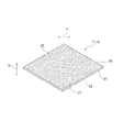
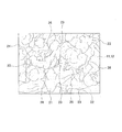
一例として示す電気分解装置10の側面図である図1等の添付の図面を参照し、本発明に係る電気分解装置および電気分解装置に使用する陽極および陰極の製造方法の詳細を説明すると、以下のとおりである。なお、図2は、一例として示す陽極11および陰極12の斜視図であり、図3は、陽極11および陰極12の一例として示す部分拡大正面図である。図4は、陽極11および陰極12の他の一例として示す部分拡大正面図である。
With reference to the accompanying drawings such as FIG. 1 which is a side view of the
電気分解装置10(水素ガス発生装置)は、陽極11(アノード)と、陰極12(カソード)と、陽極11および陰極12の間に位置(介在)する固体高分子電解質膜13(スルホン酸基を有するフッ素系イオン交換膜)と、陽極給電部材14および陰極給電部材15と、陽極用貯水槽16および陰極用貯水槽17と、陽極主電極18および陰極主電極19とから形成されている。
The electrolyzer 10 (hydrogen gas generator) includes an anode 11 (anode), a cathode 12 (cathode), and a solid polymer electrolyte membrane 13 (containing a sulfonic acid group) located (interposed) between the
電気分解装置10は、陽極11および陰極12に電気を通電し、陽極11で酸化反応を起こすとともに陰極12で還元反応を起こすことで所定の水溶液を化学分解する。電気分解装置10では、陽極11および陰極12、固体高分子電解質膜13が厚み方向へ重なり合って一体化し、膜/電極接合体20 (Membrane Electrode Assembly, MEA)を構成し、膜/電極接合体20を陽極給電部材14と陰極給電部材15とが挟み込んでいる。固体高分子電解質膜13は、プロトン導電性があり、電子導電性がない。
The
陽極給電部材14は、陽極11の外側に位置して陽極11に密着し、陽極11に+の電流を給電する。陽極用貯水槽16は、陽極給電部材14の外側に位置して陽極給電部材14に密着している。陽極主電極18は、陽極用貯水槽16の外側に位置して陽極給電部材14に+の電流を給電する。陰極給電部材15は、陰極12の外側に位置して陰極12に密着し、陰極12に−の電流を給電する。陰極用貯水槽17は、陰極給電部材15の外側に位置して陰極給電部材15に密着している。陰極主電極19は、陰極用貯水槽17の外側に位置して陰極給電部材15に−の電流を給電する。
The anode
電気分解装置10(水素ガス発生装置)に使用する陽極11および陰極12は、前面21および後面22を有するとともに、所定の面積および所定の厚み寸法L1を有し、その平面形状が四角形に成形されている。陽極11および陰極12は、多数の微細な流路23(通路孔)を有するポーラス構造のアロイ薄板電極24である。流路23には、水溶液(液体)が通流する。なお、陽極11や陰極12の平面形状に特に制限はなく、四角形の他に、その用途にあわせて円形や楕円形等の他のあらゆる平面形状に成形することができる。
The
陽極11および陰極12は、粉状に加工された遷移金属の中から選択された少なくとも3種類の遷移金属から形成されている。遷移金属としては、3d遷移金属や4d遷移金属が使用される。3d遷移金属には、Ti(チタン)、Cr(クロム)、Mn(マンガン)、Fe(鉄)、Co(コバルト)、Ni(ニッケル)、Cu(銅)、Zn(亜鉛)が使用される。4d遷移金属には、Nb(ニオブ)、Mo(モリブデン)、Ag(銀)が使用される。
The
陽極11および陰極12(ポーラス構造のアロイ薄板電極24)では、選択された少なくとも3種類の遷移金属の仕事関数(物質から電子を取り出すのに必要なエネルギー)の合成仕事関数が白金族元素の仕事関数に近似するように、遷移金属の中から少なくとも3種類の遷移金属が選択されている。Tiの仕事関数は、4.14(eV)、Crの仕事関数は、4.5(eV)、Mnの仕事関数は、4.1(eV)、Feの仕事関数は、4.67(eV)、Coの仕事関数は、5.0(eV)、Niの仕事関数は、5.22(eV)、Cuの仕事関数は、5.10(eV)、Znの仕事関数は、3.63(eV)、Nbの仕事関数は、4.01(eV)、Moの仕事関数は、4.45(eV)、Agの仕事関数は、4.31(eV)である。なお、白金の仕事関数は、5.65(eV)である。
In the
陽極11および陰極12には、各種の遷移金属から選択された少なくとも3種類のそれら遷移金属の粉体(粉状に加工されたTi(チタン)、粉状に加工されたCr(クロム)、粉状に加工されたMn(マンガン)、粉状に加工されたFe(鉄)、粉状に加工されたCo(コバルト)、粉状に加工されたNi(ニッケル)、粉状に加工されたCu(銅)、粉状に加工されたZn(亜鉛)、粉状に加工されたNb(ニオブ)、粉状に加工されたMo(モリブデン)、粉状に加工されたAg(銀))を均一に混合・分散した金属粉体混合物25(図10参照)を所定面積の薄板状に圧縮し、その後に所定温度で焼成(焼結)することで、径が異なる多数の微細な流路23(通路孔)が形成されている。
The
それら流路23(通路孔)は、陽極11や陰極12の前面21に開口する複数の通流口26と陽極11や陰極12の後面22に開口する複数の通流口26とを有し、陽極11および陰極12の前面21から後面22に向かって陽極11および陰極12を貫通している。それら流路23は、陽極11および陰極12の前面21と後面22との間において陽極11や陰極12の厚み方向へ不規則に曲折しながら延びているとともに、陽極11や陰極12の外周縁27から中心に向かって陽極11や陰極12の径方向へ不規則に曲折しながら延びている。径方向へ隣接して厚み方向へ曲折して延びるそれら流路23は、径方向において部分的につながり、一方の流路23と他方の流路23とが互いに連通している。厚み方向へ隣接して径方向へ曲折して延びるそれら流路23は、厚み方向において部分的につながり、一方の流路23と他方の流路23とが互いに連通している。
These flow paths 23 (passage holes) have a plurality of
それら流路23(通路孔)の開口面積(開口径)は、厚み方向に向かって一様ではなく、厚み方向に向かって不規則に変化しているとともに、径方向に向かって一様ではなく、径方向に向かって不規則に変化している。それら流路23は、その開口面積(開口径)が大きくなったり、小さくなったりしながら厚み方向と径方向とへ不規則に開口している。また、前面21に開口する複数の通流口26と後面22に開口する複数の通流口26とは、その開口面積(開口径)が一様ではなく、その面積が相違している。それら流路23(通路孔)の開口径や前後面21,22の通流口26の開口径は、1μm〜100μmの範囲にある。
The opening areas (opening diameters) of the flow paths 23 (passage holes) are not uniform in the thickness direction, are irregularly changed in the thickness direction, and are not uniform in the radial direction. , Changing irregularly in the radial direction. The
陽極11および陰極12(ポーラス構造のアロイ薄板電極24)は、その厚み寸法L1が0.03mm〜0.3mmの範囲、好ましくは、0.05mm〜0.1mmの範囲にある。陽極11および陰極12(ポーラス構造のアロイ薄板電極24)の厚み寸法L1が0.03mm未満では、その強度が低下し、衝撃が加えられたときに陽極11や陰極12が容易に破損または損壊し、その形状を維持することができない場合がある。陽極11および陰極12(ポーラス構造のアロイ薄板電極24)の厚み寸法L1が0.3mmを超過すると、陽極11や陰極12の電気抵抗が大きくなり、陽極11や陰極12を電流がスムースに流れず、電気分解装置10において効率よく電気分解を行うことができず、電気分解装置10において短時間に多量の水素ガスを発生させることができない。
The
陽極11および陰極12(ポーラス構造のアロイ薄板電極24)は、その厚み寸法L1が0.03mm〜0.3mmの範囲、好ましくは、0.05mm〜0.1mmの範囲にあるから、陽極11や陰極12が高い強度を有してその形状を維持することができ、陽極11や陰極12に衝撃が加えられたときの陽極11や陰極12の破損や損壊を防ぐことができる。さらに、厚み寸法L1を前記範囲にすることで、陽極11および陰極12の電気抵抗を小さくすることができ、陽極11や陰極12を電流がスムースに流れ、電気分解装置10において効率よく電気分解を行うことができ、電気分解装置10において短時間に多量の水素ガスを発生させることができる。
The
陽極11および陰極12(ポーラス構造のアロイ薄板電極24)は、その空隙率が15%〜30%の範囲にあり、その相対密度が70%〜85%の範囲にある。陽極11および陰極12(ポーラス構造のアロイ薄板電極24)の空隙率が15%未満であって相対密度が85%を超過すると、陽極11や陰極12に多数の微細な流路23(通路孔)が形成されず、陽極11および陰極12の比表面積を大きくすることができない。陽極11および陰極12(ポーラス構造のアロイ薄板電極24)の空隙率が30%を超過し、相対密度が70%未満では、流路23(通路孔)の開口面積(開口径)が必要以上に大きくなり、陽極11および陰極12の強度が低下し、衝撃が加えられたときに陽極11や陰極12が容易に破損または損壊し、その形状を維持することができない場合がある。
The porosity of the
陽極11および陰極12(ポーラス構造のアロイ薄板電極24)は、その空隙率および相対密度が前記範囲にあるから、陽極11や陰極12が開口面積(開口径)の異なる多数の微細な流路23(通路孔)を有する多孔質に成形され、陽極11や陰極12の比表面積を大きくすることができ、それら流路23(通路孔)を水溶液(液体)が通流しつつ水溶液(液体)を陽極11および陰極12(ポーラス構造のアロイ薄板電極24)の接触面に広く接触させることができ、陽極11や陰極12の触媒活性(触媒作用)を最大限に利用することができる。
Since the porosity and the relative density of the
陽極11および陰極12(ポーラス構造のアロイ薄板電極24)は、その密度が5.0g/cm2〜7.0g/cm2の範囲にある。陽極11および陰極12(ポーラス構造のアロイ薄板電極24)の密度が5.0g/cm2未満では、陽極11や陰極12の強度が低下し、衝撃が加えられたときに陽極11や陰極12が容易に破損または損壊し、その形状を維持することができない場合がある。陽極11および陰極12(ポーラス構造のアロイ薄板電極24)の密度が7.0g/cm2を超過すると、陽極11や陰極12に多数の微細な流路23(通路孔)が形成されず、陽極11や陰極12の比表面積を大きくすることができない。
The
陽極11および陰極12(ポーラス構造のアロイ薄板電極24)は、その密度が前記範囲にあるから、陽極11や陰極12が多数の微細な流路23(通路孔)を有する多孔質に成形され、陽極11や陰極12の比表面積を大きくすることができ、それら流路23(通路孔)を水溶液(液体)が通流しつつ水溶液(液体)を陽極11および陰極12(ポーラス構造のアロイ薄板電極24)の接触面に広く接触させることができ、陽極11や陰極12の触媒活性(触媒作用)を最大限に利用することができる。
Since the
Tiの粉体(粉状に加工されたTi)やCrの粉体(粉状に加工されたCr)、Mnの粉体(粉状に加工されたMn)、Feの粉体(粉状に加工されたFe)、Coの粉体(粉状に加工されたCo)、Niの粉体(粉状に加工されたNi)、Cuの粉体(粉状に加工されたCu)、Znの粉体(粉状に加工されたZn)、Nbの粉体(粉状に加工されたNb)、Moの粉体(粉状に加工されたMo)、Agの粉体(粉状に加工されたAg)の粒径は、10μm〜200μmの範囲にある。 Ti powder (powder processed Ti), Cr powder (powder processed Cr), Mn powder (powder processed Mn), Fe powder (powder processed) Processed Fe), Co powder (Co processed into powder), Ni powder (Ni processed into powder), Cu powder (Cu processed into powder), Zn powder Powder (Zn processed into powder), Nb powder (Nb processed into powder), Mo powder (Mo processed into powder), Ag powder (processed into powder) Ag) has a particle size in the range of 10 μm to 200 μm.
それら遷移金属の粉体の粒径が10μm未満では、遷移金属によって陽極11および陰極12の流路23(通路孔)が塞がれ、陽極11および陰極12に多数の微細な流路23を形成することができず、陽極11や陰極12(ポーラス構造のアロイ薄板電極24)の比表面積を大きくすることができない。それら遷移金属の粉体の粒径が200μmを超過すると、流路23(通路孔)の開口面積(開口径)が必要以上に大きくなり、陽極11および陰極12(ポーラス構造のアロイ薄板電極24)に多数の微細な流路23を形成することができず、陽極11や陰極12の比表面積を大きくすることができない。
If the particle size of the transition metal powder is less than 10 μm, the transition metal blocks the flow passages 23 (passage holes) of the
陽極11および陰極12(ポーラス構造のアロイ薄板電極24)は、それら遷移金属の粉体の粒径が前記範囲にあるから、陽極11や陰極12が多数の微細な流路23(通路孔)を有する多孔質に成形され、陽極11や陰極12の比表面積を大きくすることができ、それら流路23を水溶液(液体)が通流しつつ水溶液(液体)を陽極11や陰極12(ポーラス構造のアロイ薄板電極24)の接触面に広く接触させることができ、陽極11や陰極12の触媒活性(触媒作用)を最大限に利用することができる。
In the
遷移金属から形成された陽極11および陰極12の一例としては、粉状に加工されたNi(ニッケル)の粉体を主成分とし、Niの粉体とNiを除く粉状に加工されたその他の遷移金属(粉状のTi(チタン)、粉状のCr(クロム)、粉状のMn(マンガン)、粉状のFe(鉄)、粉状のCo(コバルト)、粉状のCu(銅)、粉状のZn(亜鉛)、粉状のNb(ニオブ)、粉状のMo(モリブデン)、粉状のAg(銀)のうちの少なくとも2種類)の粉体とを均一に混合・分散した金属粉体混合物25を所定面積の薄板状に圧縮し、その金属粉体混合物25を所定温度で焼成することで多数の微細な流路23(通路孔)が形成されたポーラス構造のアロイ薄板電極24である。
As an example of the
Ni(ニッケル)の粉体を主成分とした陽極11および陰極12(ポーラス構造のアロイ薄板電極24)は、多数の微細な流路23(通路孔)を有する多孔質の薄板状に成形され、その厚み寸法L1が0.03mm〜0.3mmの範囲、好ましくは、0.05mm〜0.1mmの範囲にある。Niの粉体を主成分とした陽極11および陰極12(ポーラス構造のアロイ薄板電極24)は、Niの仕事関数とNiを除く他の少なくとも2種類の遷移金属の仕事関数との合成仕事関数が白金族元素の仕事関数に近似するように、各種の遷移金属の中からNiの粉体を除く他の少なくとも2種類の遷移金属の粉体が選択されている。Niの粉体を主成分とした陽極11および陰極12(ポーラス構造のアロイ薄板電極24)では、所定面積の薄板状に圧縮した金属粉体混合物25の焼成時に最も融点の低い遷移金属の粉体が溶融し、溶融した遷移金属をバインダーとして他の遷移金属の粉体が接合されている。
The
Ni(ニッケル)の粉体を主成分とした陽極11および陰極12(ポーラス構造のアロイ薄板電極24)では、粉状に加工されたNiの金属粉体混合物25の全重量に対する重量比が30%〜50%の範囲、Niを除く粉状に加工された少なくとも1種類の遷移金属(粉状のTi(チタン)、粉状のCr(クロム)、粉状のMn(マンガン)、粉状のFe(鉄)、粉状のCo(コバルト)、粉状のCu(銅)、粉状のZn(亜鉛)、粉状のNb(ニオブ)、粉状のMo(モリブデン)、粉状のAg(銀)のうちの少なくとも1種類)の金属粉体混合物25の全重量に対する重量比が20%〜50%の範囲にあり、Niを除く粉状に加工された少なくとも他の1種類の遷移金属(粉状のTi(チタン)、粉状のCr(クロム)、粉状のMn(マンガン)、粉状のFe(鉄)、粉状のCo(コバルト)、粉状のCu(銅)、粉状のZn(亜鉛)、粉状のNb(ニオブ)、粉状のMo(モリブデン)、粉状のAg(銀)のうちの少なくとも他の1種類)の金属粉体混合物25の全重量に対する重量比が3%〜20%の範囲にある。なお、バインダーとなる遷移金属の粉体の金属粉体混合物25の全重量に対する重量比が、3%〜20%の範囲にある。
In the
Ni(ニッケル)の粉体を主成分とした陽極11および陰極12の具体例としては、Niの粉体、Cuの粉体、ZNの粉体を均一に混合・分散した金属粉体混合物25を所定面積の薄板状に圧縮し、その金属粉体混合物25を所定温度で焼成することで多数の微細な流路23(通路孔)が形成されたポーラス構造のアロイ薄板電極24である。この陽極11および陰極12(ポーラス構造のアロイ薄板電極24)は、金属粉体混合物25の全重量に対するNiの粉体の重量比が48%、金属粉体混合物25の全重量に対するCuの粉体重量比が42%、金属粉体混合物25の全重量に対するZnの粉体重量比が10%である。Niの融点が1455℃、Cuの融点が1084.5℃、Znの融点が419.85℃であるから、Znの粉体が溶融し、溶融したZnがバインダーとなってNiの粉体とCuの粉体とを接合している。
As a specific example of the
Ni(ニッケル)の粉体を主成分とした陽極11および陰極12の他の具体例としては、Niの粉体、Mnの粉体、Moの粉体を均一に混合・分散した金属粉体混合物25を所定面積の薄板状に圧縮し、その金属粉体混合物25を所定温度で焼成することで多数の微細な流路23(通路孔)が形成されたポーラス構造のアロイ薄板電極24である。この陽極11および陰極12(ポーラス構造のアロイ薄板電極24)は、金属粉体混合物25の全重量に対するNiの粉体の重量比が48%、金属粉体混合物25の全重量に対するMnの粉体重量比が7%、金属粉体混合物25の全重量に対するMoの粉体重量比が45%である。Niの融点が1455℃、Mnの融点が1246℃、Moの融点が2623℃であるから、Mnの粉体が溶融し、溶融したMnがバインダーとなってNiの粉体とMoの粉体とを接合している。
Another specific example of the
Ni(ニッケル)の粉体を主成分として0.03mm〜0.3mmの範囲の厚み寸法L1に成形された陽極11および陰極12(ポーラス構造のアロイ薄板電極24)は、Niの仕事関数とNiを除く他の少なくとも2種類の遷移金属の仕事関数との合成仕事関数が白金族元素の仕事関数に近似するように、各種の遷移金属の中からNiの粉体を除く他の少なくとも2種類の遷移金属の粉体が選択されているから、白金族元素を含む電極と略同一の仕事関数を備え、陽極11および陰極12が白金族元素を含む電極と略同様の触媒活性(触媒作用)を発揮することができるとともに、Niを主成分とした陽極11および陰極12の厚み寸法L1が0.03mm〜0.3mmの範囲、好ましくは、0.05mm〜0.1mmの範囲にあるから、陽極11や陰極12の電気抵抗を小さくすることができ、陽極11や陰極12を電流がスムースに流れ、電気分解装置10の電極として好適に使用することができる。Niを主成分とした陽極11および陰極12を使用した電気分解装置10は、陽極11や陰極12が白金族元素を含む電極と略同様の触媒活性(触媒作用)を発揮することで、非白金の陽極11および陰極12を使用して効率よく電気分解を行うことができ、電気分解装置10において短時間に多量の水素ガスを発生させることができる。
The
遷移金属から形成された陽極11および陰極12の他の一例としては、粉状に加工されたFe(鉄)の粉体を主成分とし、Feの粉体とFeを除く粉状に加工されたその他の遷移金属(粉状のTi(チタン)、粉状のCr(クロム)、粉状のMn(マンガン)、粉状のCo(コバルト)、粉状のNi(ニッケル)、粉状のCu(銅)、粉状のZn(亜鉛)、粉状のNb(ニオブ)、粉状のMo(モリブデン)、粉状のAg(銀)のうちの少なくとも2種類)の粉体とを均一に混合・分散した金属粉体混合物25を所定面積の薄板状に圧縮し、その金属粉体混合物25を所定温度で焼成することで多数の微細な流路23(通路孔)が形成されたポーラス構造のアロイ薄板電極24である。
As another example of the
Fe(鉄)の粉体を主成分とした陽極11および陰極12(ポーラス構造のアロイ薄板電極24)は、多数の微細な流路23(通路孔)を有する多孔質の薄板状に成形され、その厚み寸法L1が0.03mm〜0.3mmの範囲、好ましくは、0.05mm〜0.1mmの範囲にある。Feの粉体を主成分とした陽極11および陰極12(ポーラス構造のアロイ薄板電極24)は、Feの仕事関数とFeを除く他の少なくとも2種類の遷移金属の仕事関数との合成仕事関数が白金族元素の仕事関数に近似するように、各種の遷移金属の中からFeの粉体を除く他の少なくとも2種類の遷移金属の粉体が選択されている。Feの粉体を主成分とした陽極11および陰極12(ポーラス構造のアロイ薄板電極24)では、所定面積の薄板状に圧縮した金属粉体混合物25の焼成時に最も融点の低い遷移金属の粉体が溶融し、溶融した遷移金属をバインダーとして他の遷移金属の粉体が接合されている。
The
Fe(鉄)の粉体を主成分とした陽極11および陰極12(ポーラス構造のアロイ薄板電極24)では、粉状に加工されたFeの金属粉体混合物25の全重量に対する重量比が30%〜50%の範囲、Feを除く粉状に加工された少なくとも1種類の遷移金属(粉状のTi(チタン)、粉状のCr(クロム)、粉状のMn(マンガン)、粉状のCo(コバルト)、粉状のNi(ニッケル)、粉状のCu(銅)、粉状のZn(亜鉛)、粉状のNb(ニオブ)、粉状のMo(モリブデン)、粉状のAg(銀)のうちの少なくとも1種類)の金属粉体混合物25の全重量に対する重量比が20%〜50%の範囲にあり、Feを除く粉状に加工された少なくとも他の1種類の遷移金属(粉状のTi(チタン)、粉状のCr(クロム)、粉状のMn(マンガン)、粉状のCo(コバルト)、粉状のNi(ニッケル)、粉状のCu(銅)、粉状のZn(亜鉛)、粉状のNb(ニオブ)、粉状のMo(モリブデン)、粉状のAg(銀)のうちの少なくとも他の1種類)の金属粉体混合物25の全重量に対する重量比が3%〜20%の範囲にある。なお、バインダーとなる遷移金属の粉体の金属粉体混合物25の全重量に対する重量比が、3%〜20%の範囲にある。
In the
Fe(鉄)の粉体を主成分とした陽極11および陰極12の具体例としては、Feの粉体、Niの粉体、Cuの粉体を均一に混合・分散した金属粉体混合物25を所定面積の薄板状に圧縮し、その金属粉体混合物25を所定温度で焼成することで多数の微細な流路23(通路孔)が形成されたポーラス構造のアロイ薄板電極24である。この陽極11および陰極12(ポーラス構造のアロイ薄板電極24)は、金属粉体混合物25の全重量に対するFeの粉体の重量比が48%、金属粉体混合物25の全重量に対するNiの粉体重量比が48%、金属粉体混合物25の全重量に対するCuの粉体重量比が4%である。Feの融点が1536℃、Niの融点が1455℃、Cuの融点が1084.5℃であるから、Cuの粉体が溶融し、溶融したCuがバインダーとなってFeの粉体とNiの粉体とを接合している。
Specific examples of the
Fe(鉄)の粉体を主成分とした陽極11および陰極12の他の具体例としては、Feの粉体、Tiの粉体、Agの粉体を均一に混合・分散した金属粉体混合物25を所定面積の薄板状に圧縮し、その金属粉体混合物25を所定温度で焼成することで多数の微細な流路23(通路孔)が形成されたポーラス構造のアロイ薄板電極24である。この陽極11および陰極12(ポーラス構造のアロイ薄板電極24)は、金属粉体混合物25の全重量に対するFeの粉体の重量比が48%、金属粉体混合物25の全重量に対するTiの粉体重量比が46%、金属粉体混合物25の全重量に対するAgの粉体重量比が6%である。Feの融点が1536℃、Tiの融点が1666℃、Agの融点が961.93℃であるから、Agの粉体が溶融し、溶融したAgがバインダーとなってFeの粉体とTiの粉体とを接合している。
Another specific example of the
Fe(鉄)の粉体を主成分として0.03mm〜0.3mmの範囲の厚み寸法L1に成形された陽極11および陰極12(ポーラス構造のアロイ薄板電極24)は、Feの仕事関数とFeを除く他の少なくとも2種類の遷移金属の仕事関数との合成仕事関数が白金族元素の仕事関数に近似するように、各種の遷移金属の中からFeの粉体を除く他の少なくとも2種類の遷移金属の粉体が選択されているから、白金族元素を含む電極と略同一の仕事関数を備え、陽極11および陰極12が白金族元素を含む電極と略同様の触媒活性(触媒作用)を発揮することができるとともに、Feを主成分とした陽極11および陰極12の厚み寸法L1が0.03mm〜0.3mmの範囲、好ましくは、0.05mm〜0.1mmの範囲にあるから、陽極11および陰極12の電気抵抗を小さくすることができ、陽極11や陰極12を電流がスムースに流れ、電気分解装置10の電極として好適に使用することができる。Feを主成分とした陽極11および陰極12を使用した電気分解装置10は、陽極11や陰極12が白金族元素を含む電極と略同様の触媒活性(触媒作用)を発揮することで、非白金の陽極11および陰極12を使用して効率よく電気分解を行うことができ、電気分解装置10において短時間に多量の水素ガスを発生させることができる。
The
遷移金属から形成された陽極11および陰極12の他の一例としては、粉状に加工されたCu(銅)の粉体を主成分とし、Cuの粉体とCuを除く粉状に加工されたその他の遷移金属(粉状のTi(チタン)、粉状のCr(クロム)、粉状のMn(マンガン)、粉状のFe(鉄)、粉状のCo(コバルト)、粉状のNi(ニッケル)、粉状のZn(亜鉛)、粉状のNb(ニオブ)、粉状のMo(モリブデン)、粉状のAg(銀)のうちの少なくとも2種類)の粉体とを均一に混合・分散した金属粉体混合物25を所定面積の薄板状に圧縮し、その金属粉体混合物25を所定温度で焼成することで多数の微細な流路23(通路孔)が形成されたポーラス構造のアロイ薄板電極24である。
As another example of the
Cu(銅)の粉体を主成分とした陽極11および陰極12(ポーラス構造のアロイ薄板電極24)は、多数の微細な流路23(通路孔)を有する多孔質の薄板状に成形され、その厚み寸法L1が0.03mm〜0.3mmの範囲、好ましくは、0.05mm〜0.1mmの範囲にある。Cuの粉体を主成分とした陽極11および陰極12(ポーラス構造のアロイ薄板電極24)は、Cuの仕事関数とCuを除く他の少なくとも2種類の遷移金属の仕事関数との合成仕事関数が白金族元素の仕事関数に近似するように、各種の遷移金属の中からCuの粉体を除く他の少なくとも2種類の遷移金属の粉体が選択されている。Cuの粉体を主成分とした陽極11および陰極12(ポーラス構造のアロイ薄板電極23)では、所定面積の薄板状に圧縮した金属粉体混合物25の焼成時に最も融点の低い遷移金属の粉体が溶融し、溶融した遷移金属をバインダーとして他の遷移金属の粉体が接合されている。
The
Cu(銅)の粉体を主成分とした陽極11および陰極12(ポーラス構造のアロイ薄板電極24)では、粉状に加工されたCuの金属粉体混合物25の全重量に対する重量比が30%〜50%の範囲、Cuを除く粉状に加工された少なくとも1種類の遷移金属(粉状のTi(チタン)、粉状のCr(クロム)、粉状のMn(マンガン)、粉状のFe(鉄)、粉状のCo(コバルト)、粉状のNi(ニッケル)、粉状のZn(亜鉛)、粉状のNb(ニオブ)、粉状のMo(モリブデン)、粉状のAg(銀)のうちの少なくとも1種類)の金属粉体混合物25の全重量に対する重量比が20%〜50%の範囲にあり、Cuを除く粉状に加工された少なくとも他の1種類の遷移金属(粉状のTi(チタン)、粉状のCr(クロム)、粉状のMn(マンガン)、粉状のFe(鉄)、粉状のCo(コバルト)、粉状のNi(ニッケル)、粉状のZn(亜鉛)、粉状のNb(ニオブ)、粉状のMo(モリブデン)、粉状のAg(銀)のうちの少なくとも他の1種類)の金属粉体混合物25の全重量に対する重量比が3%〜20%の範囲にある。なお、バインダーとなる遷移金属の粉体の金属粉体混合物25の全重量に対する重量比が、3%〜20%の範囲にある。
In the
Cu(銅)の粉体を主成分とした陽極11および陰極12の具体例としては、Cuの粉体、Feの粉体、Znの粉体を均一に混合・分散した金属粉体混合物25を所定面積の薄板状に圧縮し、その金属粉体混合物25を所定温度で焼成することで多数の微細な流路23(通路孔)が形成されたポーラス構造のアロイ薄板電極24である。この陽極11および陰極12(ポーラス構造のアロイ薄板電極24)は、金属粉体混合物25の全重量に対するCuの粉体の重量比が48%、金属粉体混合物25の全重量に対するFeの粉体重量比が48%、金属粉体混合物25の全重量に対するZnの粉体重量比が4%である。Cuの融点が1084.5℃、Feの融点が1536℃、Znの融点が419.58℃であるから、Znの粉体が溶融し、溶融したZnがバインダーとなってCuの粉体とFeの粉体とを接合している。
As a specific example of the
Cu(銅)の粉体を主成分とした陽極11および陰極12の他の具体例としては、Cuの粉体、Feの粉体、Agの粉体を均一に混合・分散した金属粉体混合物25を所定面積の薄板状に圧縮し、その金属粉体混合物25を所定温度で焼成することで多数の微細な流路23(通路孔)が形成されたポーラス構造のアロイ薄板電極24である。この陽極11および陰極12(ポーラス構造のアロイ薄板電極24)は、金属粉体混合物25の全重量に対するCuの粉体の重量比が48%、金属粉体混合物25の全重量に対するFeの粉体重量比が46%、金属粉体混合物25の全重量に対するAgの粉体重量比が6%である。Cuの融点が1084.5℃、Feの融点が1536℃、Agの融点が961.93℃であるから、Agの粉体が溶融し、溶融したAgがバインダーとなってCuの粉体とFeの粉体とを接合している。
Another specific example of the
Cu(銅)の粉体を主成分として0.03mm〜0.3mmの範囲の厚み寸法L1に成形された陽極11および陰極12(ポーラス構造のアロイ薄板電極24)は、Cuの仕事関数とCuを除く他の少なくとも2種類の遷移金属の仕事関数との合成仕事関数が白金族元素の仕事関数に近似するように、各種の遷移金属の中からCuの粉体を除く他の少なくとも2種類の遷移金属の粉体が選択されているから、白金族元素を含む電極と略同一の仕事関数を備え、陽極11および陰極12が白金族元素を含む電極と略同様の触媒活性(触媒作用)を発揮することができるとともに、Cuを主成分とした陽極11および陰極12の厚み寸法L1が0.03mm〜0.3mmの範囲、好ましくは、0.05mm〜0.1mmの範囲にあるから、陽極11や陰極12の電気抵抗を小さくすることができ、陽極11や陰極12を電流がスムースに流れ、電気分解装置10の電極として好適に使用することができる。Cuを主成分とした陽極11および陰極12を使用した電気分解装置10は、陽極11や陰極12が白金族元素を含む電極と略同様の触媒活性(触媒作用)を発揮することで、非白金の陽極11および陰極12を使用して効率よく電気分解を行うことができ、電気分解装置10において短時間に多量の水素ガスを発生させることができる。
図5は、電気分解装置10を使用した電気分解の一例を説明する図であり、図6は、電気分解装置10を利用した水素ガス生成システム28の一例を示す図である。図5に示す電気分解では、水(水溶液)を電気分解し、水素と酸素とを発生させているが、水(H2O)の他に、電気分解装置10を使用してNaOH水溶液、H2SO4水溶液、NaCl水溶液、AgNO3水溶液、CuSO4水溶液の電気分解が行われる。
FIG. 5 is a diagram illustrating an example of electrolysis using the
電気分解装置10における水の電気分解では、図5に矢印で示すように、陽極用貯水槽16および陰極用貯水槽17に水(H2O)が給水され、陽極主電極18に電源から+の電流が給電されるとともに、陰極主電極19に電源から−の電流が給電される。陽極主電極18に給電された+の電流が陽極給電部材14から陽極11(アノード)に給電され、陰極主電極19に給電された−の電流が陰極給電部材15から陰極12(カソード)に給電される。
In the electrolysis of water in the
陽極11(電極)では、2H2O→4H++4e−+O2の陽極反応(触媒作用)によって酸素が生成され、陰極12(電極)では、4H++4e−→2H2の陰極反応(触媒作用)によって水素が生成される。プロトン(水素イオン:H+)は、固体高分子電解質膜13内を通って陽極11から陰極12(電極)へ移動する。固体高分子電解質膜12には、陽極11で生成されたプロトンが通流する。少なくとも3種類の遷移金属の仕事関数の合成仕事関数が白金族元素の仕事関数に近似するように、遷移金属の中から選択された少なくとも3種類の遷移金属から陽極11(電極)や陰極12(電極)が形成されているから、陽極11や陰極12が優れた触媒活性(触媒作用)を示し、電気分解装置10において効率よく電気分解が行われ、短時間に多量の水素ガスが発生する。
At the anode 11 (electrode), oxygen is generated by the anodic reaction (catalysis) of 2H 2 O → 4H + + 4e − + O 2 , and at the cathode 12 (electrode), the cathode reaction of 4H + + 4e − → 2H 2 (catalysis) ) Produces hydrogen. Protons (hydrogen ions: H + ) move from the
なお、NaOH水溶液の電気分解では、陽極11において4OH−→2H2O+O2+4e−の陽極反応(触媒作用)が起こり、陰極12において2H2O+2e−→2OH−+H2の陰極反応(触媒作用)が起こる。H2SO4水溶液の電気分解では、陽極11において2H2O→O2+4H++4e−の陽極反応(触媒作用)が起こり、陰極12において2H++2e−→H2の陰極反応(触媒作用)が起こる。
In the electrolysis of the aqueous NaOH solution, an anodic reaction (catalysis) of 4OH − → 2H 2 O + O 2 + 4e − occurs at the
NaCl水溶液の電気分解では、陽極11において2Cl−→Cl2+2e−の陽極反応(触媒作用)が起こり、陰極12において2H2O+2e−→2OH−+H2の陰極反応(触媒作用)が起こる。AgNO3水溶液の電気分解では、陽極11において2H2O→O2+4H++4e−の陽極反応(触媒作用)が起こり、陰極12においてAg++e−→Agの陰極反応(触媒作用)が起こる。CuSO4水溶液の電気分解では、陽極11において2H2O→O2+4H++4e−の陽極反応(触媒作用)が起こり、陰極12においてCu2++2e−→Cuの陰極反応(触媒作用)が起こる。
In the electrolysis of the aqueous NaCl solution, an anodic reaction (catalysis) of 2Cl − → Cl 2 + 2e − occurs at the
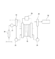
水素ガス生成システム28は、電気分解装置10と、電気分解装置10の陽極と陰極とに電気を給電する直流電源29と、水(純水)を貯水する貯水タンク30と、水(純水)を給水する給水ポンプ31と、酸素気液分離器32と、水(純水)を給水する2台の循環ポンプ33,34と、水素気液分離器35と、水素を貯めるボンベ36(水素タンク)とから形成されている。
The hydrogen gas generation system 28 includes an
水素ガス生成システム28は、貯水タンク30に貯水された水(純水)が給水ポンプ31によって酸素気液分離器32に給水され、酸素気液分離器32から流出した水が電気分解装置10に給水される。直流電源29から電気分解装置10に電気が給電され、電気分解装置10において電気分解が行われることで水が水素と酸素とに分解される。酸素は、酸素気液分離器32に流入し、気液分離された後、大気に放出される。酸素気液分離器32において気液分離された水は循環ポンプ33によって再び電気分解装置10に給水される。水素は、水素気液分離器35に流入し、気液分離された後、ボンベ36(水素タンク)に流入する。水素気液分離器35において気液分離された水は循環ポンプ34によって再び電気分解装置10に給水される。
In the hydrogen gas generation system 28, water (pure water) stored in a
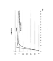
図7は、陽極11(空気極39)および陰極12(燃料極38)を使用した固体高分子形燃料電池37の側面図であり、図8は、陽極11(空気極39)および陰極12(燃料極38)の起電圧試験の結果を示す図である。図9は、陽極11(空気極39)および陰極12(燃料極38)のI−V特性試験の結果を示す図である。図7では、負荷47が接続された状態を示しているが、起電圧試験では、負荷47が存在せず、無負荷である。起電圧試験およびI−V特性試験では、図7に示す固体高分子形燃料電池37に電気分解装置10において使用した陽極11(空気極)および陰極12(燃料極)を使用し、無負荷においてその起電圧を測定し、固体高分子形燃料電池37に負荷47を接続し、そのI−V特性を測定した。
FIG. 7 is a side view of a polymer
固体高分子形燃料電池37は、図7に示すように、燃料極38(陰極)および空気極39(陽極)と、燃料極38および空気極39の間に位置(介在)する固体高分子電解質膜13(スルホン酸基を有するフッ素系イオン交換膜)と、燃料極38の厚み方向外側に位置するセパレータ40(バイポーラプレート)と、空気極39の厚み方向外側に位置するセパレータ41(バイポーラプレート)とから形成されている。
As shown in FIG. 7, the polymer
それらセパレータ40,41には、反応ガス(水素や酸素等)の供給流路が刻設されている(彫り込まれている)。燃料極38や空気極39、固体高分子電解質膜13が厚み方向へ重なり合って一体化し、膜/電極接合体(Membrane Electrode Assembly, MEA)を構成し、膜/電極接合体をそれらセパレータ40,41が挟み込んでいる。固体高分子電解質膜13は、プロトン導電性があり、電子導電性がない。燃料極38とセパレータ40との間には、ガス拡散層42が形成され、空気極39とセパレータ41との間には、ガス拡散層43が形成されている。燃料極38とセパレータ40との間であってガス拡散層42の上部および下部には、ガスシール44が設置されている。空気極39とセパレータ41との間であってガス拡散層43の上部および下部には、ガスシール45が設置されている。
In the
固体高分子形燃料電池37では、燃料極38(陰極12)に水素(燃料)が供給され、空気極39(陽極11)に空気(酸素)が供給される。燃料極38では、水素がH2→2H++2e−の反応(触媒作用)によってプロトン(水素イオン、H+)と電子とに分解される。その後、プロトンが固体高分子電解質膜13内を通って燃料極38から空気極39へ移動し、電子が導線46内を通って空気極39へ移動する。固体高分子電解質膜13には、燃料極38で生成されたプロトンが通流する。空気極39では、固体高分子電解質膜13から移動したプロトンと導線46を移動した電子とが空気中の酸素と反応し、4H++O2+4e→2H2Oの反応によって水が生成される。少なくとも3種類の遷移金属の仕事関数の合成仕事関数が白金族元素の仕事関数に近似するように、遷移金属の中から選択された少なくとも3種類の遷移金属から燃料極38(陰極12)や空気極39(陽極11)が形成されているから、燃料極38(陰極12)や空気極39(陽極11)が優れた触媒活性(触媒作用)を示し、水素がプロトンと電子とに効率よく分解される。
In the polymer
起電圧試験では、水素ガスを注入してから15分の間、燃料極38(陰極12)と空気極39(陽極11)との間(電極間)の電圧(V)を測定した。図8の起電圧試験の結果を示す図では、横軸に測定時間(min)を表し、縦軸に燃料極38(陰極12)と空気極39(陽極11)との間(電極間)の電圧(V)を表す。白金族元素を利用した(担持させた)電極(白金電極)を使用した場合、固体高分子形燃料電池では、図8の起電圧試験の結果を示す図から分かるように、電極間の電圧が1.079(V)前後であったのに対し、燃料極38(非白金電極)および空気極39(非白金電極)を使用した固体高分子形燃料電池37では、燃料極38(陰極12)と空気極39(陽極11)との間(電極間)の電圧(起電力)が1.01(V)〜1.02(V)であった。
In the electromotive voltage test, the voltage (V) between the fuel electrode 38 (cathode 12) and the air electrode 39 (anode 11) (between the electrodes) was measured for 15 minutes after hydrogen gas injection. In the diagram showing the results of the electromotive force test in FIG. 8, the horizontal axis represents the measurement time (min), and the vertical axis represents the distance between the fuel electrode 38 (cathode 12) and the air electrode 39 (anode 11) (between the electrodes). Indicates voltage (V). When an electrode (platinum electrode) utilizing (supporting) a platinum group element is used, in the polymer electrolyte fuel cell, as can be seen from the diagram showing the results of the electromotive force test in FIG. In contrast to 1.079 (V), in the polymer
I−V特性試験では、燃料極38(陰極12)と空気極39(陽極11)との間(電極間)に負荷47を接続し、電圧と電流との関係を測定した。図9のI−V特性試験の結果を示す図では、横軸に電流(A)を表し、縦軸に電圧(V)を表す。燃料極38(非白金電極)および空気極39(非白金電極)を使用した固体高分子形燃料電池37では、図9のI−V特性試験の結果を示す図から分かるように、白金族元素を利用した(担持させた)電極(白金電極)を使用した固体高分子形燃料電池の電圧降下率と大差のない結果が得られた。図8の起電圧試験の結果や図9のI−V特性試験の結果に示すように、白金族元素を利用していない非白金の燃料極38(陰極12)および空気極39(陽極11)が電子を放出させて水素イオンとなる反応を促進させる優れた触媒作用を有するとともに、白金を利用した電極と略同様の酸素還元機能(触媒作用)を有することが確認された。
In the IV characteristic test, a
電気分解装置10は、それに使用される陽極11および陰極12が各種の遷移金属から選択された少なくとも3種類の遷移金属から形成され、選択された少なくとも3種類のそれら遷移金属の粉体を均一に混合・分散した金属粉体混合物25を所定面積の薄板状に圧縮した後に焼成して多数の微細な流路23(通路孔)を形成したポーラス構造のアロイ薄板電極24であり、選択された少なくとも3種類の遷移金属の仕事関数の合成仕事関数が白金族元素の仕事関数に近似するように、各種の遷移金属の中から少なくとも3種類の遷移金属が選択されているから、陽極11および陰極12が白金族元素を含む電極と略同一の仕事関数を備え、陽極11や陰極12が白金族元素を含む電極と略同様の触媒活性(触媒作用)を発揮することで、非白金の陽極11および陰極12を使用して電気分解を効率よく行うことができ、多量の水素ガスを発生させることができる。電気分解装置10は、陽極11および陰極12の厚み寸法が0.03mm〜0.3mmの範囲、好ましくは、0.05mm〜0.1mmの範囲にあるから、陽極11および陰極12の電気抵抗を小さくすることができ、陽極11や陰極12に電流をスムースに流すことができ、陽極11や陰極12を利用して電気分解を確実に行うことができる。
In the
図10は、陽極11および陰極12の製造方法を説明する図である。陽極11(電極)および陰極12(電極)は、図10に示すように、遷移金属選択工程S1、金属粉体混合物作成工程S2、金属薄板作成工程S3、ポーラス構造アロイ薄板電極作成工程S4を有する電極製造方法によって製造される。遷移金属選択工程S1では、各種の遷移金属36から選択する少なくとも3種類の遷移金属48の仕事関数の合成仕事関数が白金族元素の仕事関数に近似するように、各種の遷移金属48の中から少なくとも3種類の遷移金属48(Ti(チタン)、Cr(クロム)、Mn(マンガン)、Fe(鉄)、Co(コバルト)、Ni(ニッケル)、Cu(銅)、Zn(亜鉛)、Nb(ニオブ)、Mo(モリブデン)、Ag(銀))を選択する。
FIG. 10 is a diagram illustrating a method of manufacturing the
遷移金属選択工程S1において、既述のように、Ni(ニッケル)を主成分とした陽極11や陰極12では、Cu(銅)およびZN(亜鉛)を選択し、または、Mn(マンガン)およびMo(モリブデン)を選択する。Fe(鉄)を主成分とした陽極11や陰極12では、Ni(ニッケル)およびCu(銅)を選択し、または、Ti(チタン)およびAg(銀)を選択する。Cu(銅)を主成分とした陽極11や陰極12では、Fe(鉄)およびZn(亜鉛)を選択し、または、Fe(鉄)およびAg(銀)を選択する。
In the transition metal selection step S1, as described above, Cu (copper) and ZN (zinc) are selected for the
金属粉体混合物作成工程S2では、遷移金属選択工程S1によって選択された少なくとも3種類の遷移金属48の粉体49を均一に混合・分散した金属粉体混合物25を作る。金属粉体混合物作成工程S2において、Ni(ニッケル)を主成分とした陽極11や陰極12では、遷移金属選択工程S1によって選択されたNi、Cu(銅)、ZN(亜鉛)のそれぞれを微粉砕機によって10μm〜200μmの粒径に微粉砕してNiの粉体49、Cuの粉体49、Znの粉体49を作成する。次に、Niの粉体49やCuの粉体49、Znの粉体49を混合機に投入して混合機によってNiの粉体49、Cuの粉体49、Znの粉体49を攪拌・混合し、Niの粉体49、Cuの粉体49、Znの粉体49が均一に混合・分散した金属粉体混合物25を作る。
In the metal powder mixture preparation step S2, a
または、遷移金属選択工程S1によって選択されたNi(ニッケル)、Mn(マンガン)、Mo(モリブデン)のそれぞれを微粉砕機によって10μm〜200μmの粒径に微粉砕してNiの粉体49、Mnの粉体49、Moの粉体49を作成する。次に、Niの粉体49やMnの粉体49、Moの粉体49を混合機に投入して混合機によってNiの粉体49、Mnの粉体49、Moの粉体49を攪拌・混合し、Niの粉体49、Mnの粉体49、Moの粉体49が均一に混合・分散した金属粉体混合物25を作る。
Alternatively, each of Ni (nickel), Mn (manganese), and Mo (molybdenum) selected in the transition metal selection step S1 is finely pulverized by a fine pulverizer to a particle size of 10 μm to 200 μm to obtain a
金属粉体混合物作成工程S2において、Fe(鉄)を主成分とした陽極11や陰極12では、遷移金属選択工程S1によって選択されたFe、Ni(ニッケル)、Cu(銅)のそれぞれを微粉砕機によって10μm〜200μmの粒径に微粉砕してFeの粉体49、Niの粉体49、Cuの粉体49を作成する。次に、Feの粉体49やNiの粉体49、Cuの粉体49を混合機に投入して混合機によってFeの粉体49、Niの粉体49、Cuの粉体49を攪拌・混合し、Feの粉体49、Niの粉体49、Cuの粉体49が均一に混合・分散した金属粉体混合物25を作る。
In the metal powder mixture preparation step S2, each of the
または、遷移金属選択工程S1によって選択されたFe(鉄)、Ti(チタン)、Ag(銀)のそれぞれを微粉砕機によって10μm〜200μmの粒径に微粉砕してFeの粉体49、Tiの粉体49、Agの粉体49を作成する。次に、Feの粉体49やTiの粉体49、Agの粉体49を混合機に投入して混合機によってFeの粉体49、Tiの粉体49、Agの粉体49を攪拌・混合し、Feの粉体49、Tiの粉体49、Agの粉体49が均一に混合・分散した金属粉体混合物25を作る。
Alternatively, each of Fe (iron), Ti (titanium), and Ag (silver) selected in the transition metal selection step S1 is finely pulverized to a particle size of 10 μm to 200 μm by a fine pulverizer, and the
金属粉体混合物作成工程S2において、Cu(銅)を主成分とした陽極11や陰極12では、遷移金属選択工程S1によって選択されたCu、Fe(鉄)、Zn(亜鉛)のそれぞれを微粉砕機によって10μm〜200μmの粒径に微粉砕してCuの粉体49、Feの粉体49、Znの粉体49を作成する。次に、Cuの粉体49やFeの粉体49、Znの粉体49を混合機に投入して混合機によってCuの粉体49、Feの粉体49、Znの粉体49を攪拌・混合し、Cuの粉体49、Feの粉体49、Znの粉体49が均一に混合・分散した金属粉体混合物25を作る。
In the metal powder mixture preparation step S2, each of Cu, Fe (iron), and Zn (zinc) selected in the transition metal selection step S1 is finely pulverized in the
または、遷移金属選択工程S1によって選択されたCu(銅)、Fe(鉄)、Ag(銀)のそれぞれを微粉砕機によって10μm〜200μmの粒径に微粉砕してCuの粉体49、Feの粉体49、Agの粉体49を作成する。次に、Cuの粉体49やFeの粉体49、Agの粉体49を混合機に投入して混合機によってCuの粉体49、Feの粉体49、Agの粉体49を攪拌・混合し、Cuの粉体49、Feの粉体49、Agの粉体49が均一に混合・分散した金属粉体混合物25を作る。
Alternatively, each of Cu (copper), Fe (iron), and Ag (silver) selected in the transition metal selection step S1 is finely pulverized to a particle size of 10 μm to 200 μm by a fine pulverizer, and the
金属薄板作成工程S3では、金属粉体混合物作成工程S2によって作られた金属粉体混合物25を所定圧力で加圧し、金属粉体混合物25を所定面積の薄板状に圧縮した金属薄板50を作る。金属薄板作成工程S3では、金属粉体混合物25を金型に入れ、金型をプレス機によって加圧(プレス)するプレス加工によって金属薄板50を作る。プレス加工時におけるプレス圧(圧力)は、500Mpa〜800Mpaの範囲にある。
In the metal sheet forming step S3, the
プレス圧(圧力)が500Mpa未満では、金属薄板50に形成される流路23(通路孔)の開口径が大きくなり、金属薄板50の厚み寸法L1を0.03mm〜0.3mmにしつつ開口径が1μm〜100μmの範囲の多数の微細な流路23(通路孔)を金属薄板50に形成することができない。プレス圧(圧力)が800Mpaを超過すると、金属薄板50に形成される流路23(通路孔)の開口径が必要以上に小さくなり、金属薄板50の厚み寸法L1を0.03mm〜0.3mmにしつつ開口径が1μm〜100μmの範囲の多数の微細な流路23(通路孔)を金属薄板50に形成することができない。電極製造方法は、金属粉体混合物25を前記範囲の圧力で加圧(圧縮)することで、金属薄板50の厚み寸法L1を0.03mm〜0.3mmにしつつ開口径が1μm〜100μmの範囲の多数の微細な流路23(通路孔)を形成した金属薄板50を作ることができる。
When the pressing pressure (pressure) is less than 500 MPa, the opening diameter of the flow path 23 (passage hole) formed in the
金属薄板作成工程S3において、Ni(ニッケル)を主成分とした陽極11や陰極12では、Niの粉体49、Cu(銅)の粉体49、ZN(亜鉛)粉体49を混合した金属粉体混合物25の所定量を金型に投入し、その金属粉体混合物25をプレス加工によって加圧(圧縮)して金属粉体混合物25を所定面積の薄板状に圧縮し、厚み寸法L1が0.03mm〜0.3mmであって開口径が1μm〜100μmの範囲の多数の微細な流路23(通路孔)を形成した金属薄板50を作る。
In the metal sheet forming step S3, the
または、Niの粉体49、Mn(マンガン)の粉体49、Mo(モリブデン)の粉体49を混合した金属粉体混合物25の所定量を金型に投入し、その金属粉体混合物25をプレス加工によって加圧(圧縮)して金属粉体混合物25を所定面積の薄板状に圧縮し、厚み寸法L1が0.03mm〜0.3mmであって開口径が1μm〜100μmの範囲の多数の微細な流路23(通路孔)を形成した金属薄板50を作る。
Alternatively, a predetermined amount of the
金属薄板作成工程S3において、Fe(鉄)を主成分とした陽極11や陰極12では、Feの粉体49、Ni(ニッケル)の粉体49、Cu(銅)の粉体49を混合した金属粉体混合物25の所定量を金型に投入し、その金属粉体混合物25をプレス加工によって加圧(圧縮)して金属粉体混合物25を所定面積の薄板状に圧縮し、厚み寸法L1が0.03mm〜0.3mmであって開口径が1μm〜100μmの範囲の多数の微細な流路23(通路孔)を形成した金属薄板50を作る。
In the metal thin plate forming step S3, the
または、Feの粉体49、Ti(チタン)の粉体49、Ag(銀)の粉体49を混合した金属粉体混合物25の所定量を金型に投入し、その金属粉体混合物25をプレス加工によって加圧(圧縮)して金属粉体混合物25を所定面積の薄板状に圧縮し、厚み寸法L1が0.03mm〜0.3mmであって開口径が1μm〜100μmの範囲の多数の微細な流路23(通路孔)を形成した金属薄板50を作る。
Alternatively, a predetermined amount of a
金属薄板作成工程S3において、Cu(銅)を主成分とした燃料極11や空気極12では、Cuの粉体49、Fe(鉄)の粉体49、Zn(亜鉛)の粉体49を混合した金属粉体混合物25の所定量を金型に投入し、その金属粉体混合物25をプレス加工によって加圧(圧縮)して金属粉体混合物25を所定面積の薄板状に圧縮し、厚み寸法L1が0.03mm〜0.3mmであって開口径が1μm〜100μmの範囲の多数の微細な流路23(通路孔)を形成した金属薄板50を作る。
In the metal thin plate forming step S3, the
または、Cuの粉体49、Fe(鉄)の粉体49、Ag(銀)の粉体49を混合した金属粉体混合物25の所定量を金型に投入し、その金属粉体混合物25をプレス加工によって加圧(圧縮)して金属粉体混合物25を所定面積の薄板状に圧縮し、厚み寸法L1が0.03mm〜0.3mmであって開口径が1μm〜100μmの範囲の多数の微細な流路23(通路孔)を形成した金属薄板50を作る。
Alternatively, a predetermined amount of a
ポーラス構造アロイ薄板電極作成工程S4では、金属薄板作成工程S3によって作られた金属薄板50を炉(電気炉等)に投入し、金属薄板50を炉において所定温度で焼成(焼結)して多数の微細な流路23(通路孔)を形成したポーラス構造のアロイ薄板電極24を作る。ポーラス構造アロイ薄板電極作成工程S4では、遷移金属選択工程S1によって選択された少なくとも3種類の遷移金属48のうちの融点が最も低い遷移金属48の粉体49を溶融させる温度で金属薄板50を長時間焼成する。焼成(焼結)時間は、3時間〜6時間である。ポーラス構造アロイ薄板電極作成工程S4では、所定面積の薄板状に圧縮した金属薄板50(金属粉体混合物25)の焼成時において、最も融点の低い遷移金属48の粉体49が溶融し、溶融した遷移金属48をバインダーとして他の遷移金属48の粉体49を接合(固着)する。
In the porous structure thin metal plate electrode forming step S4, the metal
ポーラス構造アロイ薄板電極作成工程S4において、Ni(ニッケル)を主成分とした陽極11(電極)や陰極12(電極)では、Niの粉体49、Cu(銅)の粉体49、ZN(亜鉛)粉体49を混合した金属粉体混合物25を圧縮した金属薄板50を炉において長時間焼成し、開口径が1μm〜100μmの範囲の多数の微細な流路23(通路孔)を形成したポーラス構造のアロイ薄板電極24を作る。Niの粉体49、Cuの粉体49、Znの粉体49から形成された金属薄板50では、Znの粉体49を溶融させる温度(例えば、500℃〜800℃)で金属薄板50を焼成し、溶融したZnの粉体49によってNiの粉体49とCuの粉体49とが接合(固着)される。
In the porous structure alloy thin plate electrode forming step S4,
また、Ni(ニッケル)を主成分とした陽極11(電極)や陰極12(電極)では、Niの粉体49、Mn(マンガン)の粉体49、Mo(モリブデン)の粉体49を混合した金属粉体混合物25を圧縮した金属薄板50を炉において長時間焼成し、開口径が1μm〜100μmの範囲の多数の微細な流路23(通路孔)を形成したポーラス構造のアロイ薄板電極24を作る。Niの粉体49、Mnの粉体49、Moの粉体49から形成された金属薄板50では、Mnの粉体49を溶融させる温度(例えば、1200℃〜1400℃)で金属薄板50を焼成し、溶融したMnの粉体49によってMnの粉体49とMoの粉体49とが接合(固着)される。
In the anode 11 (electrode) and the cathode 12 (electrode) mainly composed of Ni (nickel),
ポーラス構造アロイ薄板電極作成工程S4において、Fe(鉄)を主成分とした陽極11(電極)や陰極12(電極)では、Feの粉体49、Ni(ニッケル)の粉体49、Cu(銅)の粉体49を混合した金属粉体混合物25を圧縮した金属薄板50を炉において長時間焼成し、開口径が1μm〜100μmの範囲の多数の微細な流路23(通路孔)を形成したポーラス構造のアロイ薄板電極24を作る。Feの粉体49、Niの粉体49、Cuの粉体49から形成された金属薄板50では、Cuの粉体49を溶融させる温度(例えば、1100℃〜1300℃)で金属薄板50を焼成し、溶融したCuの粉体49によってFeの粉体49とNiの粉体49とが接合(固着)される。
In the porous alloy thin plate electrode forming step S4, the anode 11 (electrode) and the cathode 12 (electrode) mainly composed of Fe (iron) have
また、Fe(鉄)を主成分とした陽極11(電極)や陰極12(電極)では、Feの粉体49、Ti(チタン)の粉体49、Ag(銀)の粉体49を混合した金属粉体混合物25を圧縮した金属薄板50を炉において長時間焼成し、開口径が1μm〜100μmの範囲の多数の微細な流路23(通路孔)を形成したポーラス構造のアロイ薄板電極24を作る。Feの粉体49、Tiの粉体49、Agの粉体49から形成された金属薄板50では、Agの粉体49を溶融させる温度(例えば、1000℃〜1200℃)で金属薄板50を焼成し、溶融したAgの粉体49によってFeの粉体49とTiの粉体49とが接合(固着)される。
In the anode 11 (electrode) and the cathode 12 (electrode) mainly containing Fe (iron), a
ポーラス構造アロイ薄板電極作成工程S4において、Cu(銅)を主成分とした陽極11(電極)や陰極12(電極)では、Cuの粉体49、Fe(鉄)の粉体49、Zn(亜鉛)の粉体49を混合した金属粉体混合物25を圧縮した金属薄板50を炉において長時間焼成し、開口径が1μm〜100μmの範囲の多数の微細な流路23(通路孔)を形成したポーラス構造のアロイ薄板電極24を作る。Cuの粉体49、Feの粉体49、Znの粉体49から形成された金属薄板50では、Znの粉体49を溶融させる温度(例えば、500℃〜800℃)で金属薄板50を焼成し、溶融したZnの粉体49によってCuの粉体49とFeの粉体49とが接合(固着)される。
In the porous structure alloy thin plate electrode forming step S4,
また、Cu(銅)を主成分とした陽極11(電極)や陰極12(電極)では、Cuの粉体49、Fe(鉄)の粉体49、Ag(銀)の粉体49を混合した金属粉体混合物25を圧縮した金属薄板50を炉において長時間焼成し、開口径が1μm〜100μmの範囲の多数の微細な流路23(通路孔)を形成したポーラス構造のアロイ薄板電極24を作る。Cuの粉体49、Feの粉体49、Agの粉体49から形成された金属薄板50では、Agの粉体49を溶融させる温度(例えば、1000℃〜1100℃)で金属薄板50を焼成し、溶融したAgの粉体49によってCuの粉体49とFeの粉体49とが接合(固着)される。
In the anode 11 (electrode) and the cathode 12 (electrode) mainly composed of Cu (copper),
電極製造方法は、遷移金属選択工程S1や金属粉体混合物作成工程S2、金属薄板作成工程S3、ポーラス構造アロイ薄板電極作成工程S4によって厚み寸法L1が0.03mm〜0.3mmの範囲、好ましくは、0.05mm〜0.1mmの範囲であって多数の微細な流路23(通路孔)を形成した陽極11(電極)や陰極12(電極)を作ることができ、白金族元素を利用しない非白金の陽極11や陰極12を廉価に作ることができるとともに、触媒機能を十分かつ確実に利用することが可能であって触媒活性(触媒作用)を有して電気分解装置10に使用する陽極11や陰極12を作ることができる。
The electrode manufacturing method is such that the thickness dimension L1 is in the range of 0.03 mm to 0.3 mm by the transition metal selection step S1, the metal powder mixture creation step S2, the metal sheet creation step S3, and the porous structure alloy sheet electrode creation step S4, preferably. , The anode 11 (electrode) and the cathode 12 (electrode) having a large number of fine channels 23 (passage holes) in the range of 0.05 mm to 0.1 mm can be formed without using a platinum group element. The
電極製造方法は、厚み寸法L1が0.03mm〜0.3mmの範囲、好ましくは、0.05mm〜0.1mmの範囲であって多数の微細な流路23(通路孔)が形成された陽極11(電極)や陰極12(電極)を作ることができるから、陽極11や陰極12の電気抵抗を小さくすることができるとともに、陽極11や陰極12を電流がスムースに流れ、電気分解装置10において効率よく電気分解を行うことができ、電気分解装置10において短時間に多量の水素ガスを発生させることが可能な陽極11や陰極12を作ることができる。
The electrode manufacturing method includes an anode having a thickness L1 in a range of 0.03 mm to 0.3 mm, preferably 0.05 mm to 0.1 mm, and a large number of fine channels 23 (passage holes) formed therein. 11 (electrode) and the cathode 12 (electrode) can be made, so that the electric resistance of the
10 電気分解装置
11 陽極(電極)
12 陰極(電極)
13 固体高分子電解質膜
14 陽極給電部材
15 陰極給電部材
16 陽極用貯水槽
17 陰極用貯水槽
18 陽極主電極
19 陰極主電極
20 膜/電極接合体
21 前面
22 後面
23 流路(通路孔)
24 ポーラス構造のアロイ薄板電極
25 金属粉体混合物
26 通流口
27 外周縁
28 水素ガス生成システム
29 直流電源
30 貯水タンク
31 給水ポンプ
32 酸素気液分離器
33 循環ポンプ
34 循環ポンプ
35 水素気液分離器
36 ボンベ
37 固体高分子形燃料電池
38 燃料極
39 空気極
40 セパレータ
41 セパレータ
42 ガス拡散層
43 ガス拡散層
44 ガスシール
45 ガスシール
46 導線
47 負荷
48 遷移金属
49 粉体
50 金属薄板
L1 厚み寸法
10
12 Cathode (electrode)
24 Alloy thin plate electrode having a
Claims (15)
前記陽極および前記陰極が、各種の遷移金属から選択された少なくとも3種類の遷移金属から形成され、前記選択された少なくとも3種類のそれら遷移金属の粉体を均一に混合・分散した金属粉体混合物を所定面積の薄板状に圧縮した後に焼成して多数の微細な流路を形成したポーラス構造のアロイ薄板電極であり、前記陽極および前記陰極では、前記選択された少なくとも3種類の遷移金属の仕事関数の合成仕事関数が白金族元素の仕事関数に近似するように、前記各種の遷移金属の中から少なくとも3種類の遷移金属が選択されていることを特徴とする電気分解装置。 An anode and a cathode, and an electrode assembly film that is located between the anode and the cathode and joins the electrodes; electricity is supplied to the anode and the cathode to cause an oxidation reaction at the anode; In an electrolysis device that chemically decomposes a predetermined aqueous solution by causing a reduction reaction at the cathode,
A metal powder mixture in which the anode and the cathode are formed from at least three types of transition metals selected from various transition metals, and the at least three types of selected transition metal powders are uniformly mixed and dispersed. Is an alloy thin plate electrode having a porous structure in which a large number of fine channels are formed by compressing and compressing into a thin plate having a predetermined area. In the anode and the cathode, the work of the selected at least three types of transition metals is performed. An electrolysis apparatus, wherein at least three types of transition metals are selected from the various transition metals so that the composite work function of the functions is close to the work function of the platinum group element.
前記電極製造方法が、各種の遷移金属から選択する少なくとも3種類の遷移金属の仕事関数の合成仕事関数が白金族元素の仕事関数に近似するように、前記各種の遷移金属の中から少なくとも3種類の遷移金属を選択する遷移金属選択工程と、前記遷移金属選択工程によって選択された少なくとも3種類の遷移金属の粉体を均一に混合・分散した金属粉体混合物を作る金属粉体混合物作成工程と、前記金属粉体混合物作成工程によって作られた金属粉体混合物を所定圧力で加圧して金属薄板を作る金属薄板作成工程と、前記金属薄板作成工程によって作られた金属薄板を所定温度で焼成して多数の微細な流路を形成した前記ポーラス構造のアロイ薄板電極を作るポーラス構造アロイ薄板電極作成工程とを有することを特徴とする電極製造方法。 In an electrode manufacturing method for manufacturing an anode and a cathode used in an electrolyzer,
The electrode manufacturing method may be configured such that at least three types of transition metals are selected from the various transition metals so that a work function of at least three types of transition metals selected from various types of transition metals approximates a work function of a platinum group element. A transition metal selecting step of selecting a transition metal, and a metal powder mixture forming step of uniformly mixing and dispersing at least three types of transition metal powders selected in the transition metal selecting step. A metal sheet preparing step of pressing the metal powder mixture produced in the metal powder mixture producing step at a predetermined pressure to produce a metal sheet, and firing the metal sheet produced in the metal sheet producing step at a predetermined temperature. Producing a porous alloy thin plate electrode having the porous structure in which a large number of fine flow paths are formed.
The said porous structure alloy thin plate electrode preparation process sinters the said metal thin plate at the temperature which fuse | melts the powder of the transition metal with the lowest melting point among at least three types of transition metals selected by the said transition metal selection process. An electrode manufacturing method according to any one of claims 12 to 14.
Priority Applications (1)
| Application Number | Priority Date | Filing Date | Title |
|---|---|---|---|
| JP2018120823A JP2020002397A (en) | 2018-06-26 | 2018-06-26 | Electrolysis apparatus and electrode manufacturing method |
Applications Claiming Priority (1)
| Application Number | Priority Date | Filing Date | Title |
|---|---|---|---|
| JP2018120823A JP2020002397A (en) | 2018-06-26 | 2018-06-26 | Electrolysis apparatus and electrode manufacturing method |
Publications (1)
| Publication Number | Publication Date |
|---|---|
| JP2020002397A true JP2020002397A (en) | 2020-01-09 |
Family
ID=69098964
Family Applications (1)
| Application Number | Title | Priority Date | Filing Date |
|---|---|---|---|
| JP2018120823A Pending JP2020002397A (en) | 2018-06-26 | 2018-06-26 | Electrolysis apparatus and electrode manufacturing method |
Country Status (1)
| Country | Link |
|---|---|
| JP (1) | JP2020002397A (en) |
Citations (4)
| Publication number | Priority date | Publication date | Assignee | Title |
|---|---|---|---|---|
| JP2003041390A (en) * | 1995-10-18 | 2003-02-13 | Tosoh Corp | Cathode with low hydrogen overvoltage |
| JP2016030844A (en) * | 2014-07-28 | 2016-03-07 | 株式会社日本触媒 | Cell for water vapor electrolysis |
| JP2016519214A (en) * | 2013-03-28 | 2016-06-30 | セーウーエフィ − クイミコス インドゥストリアイス エスィ.アー. | Electrode / electrolyte assemblies, reactors and methods for direct amination of hydrocarbons |
| JP2017095746A (en) * | 2015-11-20 | 2017-06-01 | 鈴木 健治 | Hydrogen generator and hot-water feed system |
-
2018
- 2018-06-26 JP JP2018120823A patent/JP2020002397A/en active Pending
Patent Citations (4)
| Publication number | Priority date | Publication date | Assignee | Title |
|---|---|---|---|---|
| JP2003041390A (en) * | 1995-10-18 | 2003-02-13 | Tosoh Corp | Cathode with low hydrogen overvoltage |
| JP2016519214A (en) * | 2013-03-28 | 2016-06-30 | セーウーエフィ − クイミコス インドゥストリアイス エスィ.アー. | Electrode / electrolyte assemblies, reactors and methods for direct amination of hydrocarbons |
| JP2016030844A (en) * | 2014-07-28 | 2016-03-07 | 株式会社日本触媒 | Cell for water vapor electrolysis |
| JP2017095746A (en) * | 2015-11-20 | 2017-06-01 | 鈴木 健治 | Hydrogen generator and hot-water feed system |
Similar Documents
| Publication | Publication Date | Title |
|---|---|---|
| WO2019244840A1 (en) | Electrode | |
| WO2017026291A1 (en) | Metallic porous body, fuel cell, and method for manufacturing metallic porous body | |
| EP3041082A1 (en) | Air battery and battery pack | |
| JP7281157B2 (en) | Polymer electrolyte fuel cell and electrode manufacturing method | |
| WO2020080530A1 (en) | Electrode and electrode manufacturing method | |
| JP6653313B2 (en) | Method for producing porous nickel alloy | |
| JP7199080B2 (en) | Electrolyzer and electrode manufacturing method | |
| JP7171030B2 (en) | Manufacturing method for anode and cathode of electrolyzer | |
| JP7193109B2 (en) | Electrode and electrode manufacturing method | |
| JP2020002397A (en) | Electrolysis apparatus and electrode manufacturing method | |
| JP7171024B2 (en) | Method for manufacturing fuel electrode and air electrode for polymer electrolyte fuel cell | |
| JP7179314B2 (en) | Manufacturing method for anode and cathode of electrolyzer | |
| JP2020004527A (en) | Solid polymer electrolyte fuel cell and electrode manufacturing method | |
| JP7281158B2 (en) | Polymer electrolyte fuel cell and electrode manufacturing method | |
| JP7141695B2 (en) | Manufacturing method for anode and cathode of electrolyzer | |
| JP2020064786A (en) | Polymer electrolyte fuel cell | |
| JP7171027B2 (en) | Method for manufacturing fuel electrode and air electrode for polymer electrolyte fuel cell | |
| JP2020019980A (en) | Electrolysis device, and method of producing electrode | |
| JP7262739B2 (en) | Manufacturing method for anode and cathode of electrolyzer | |
| JP7193111B2 (en) | Carbon nanotube electrode or carbon nanohorn electrode and electrode manufacturing method | |
| JP7235284B2 (en) | polymer electrolyte fuel cell | |
| WO2020045643A1 (en) | Electrode | |
| JP7411920B2 (en) | Method for manufacturing anode and cathode of electrolyzer | |
| JP2020087812A (en) | Electrode and electrode manufacturing method | |
| WO2020059783A1 (en) | Electrode |
Legal Events
| Date | Code | Title | Description |
|---|---|---|---|
| A711 | Notification of change in applicant |
Free format text: JAPANESE INTERMEDIATE CODE: A711 Effective date: 20200407 |
|
| A521 | Request for written amendment filed |
Free format text: JAPANESE INTERMEDIATE CODE: A821 Effective date: 20200408 |
|
| A521 | Request for written amendment filed |
Free format text: JAPANESE INTERMEDIATE CODE: A523 Effective date: 20200617 |
|
| A711 | Notification of change in applicant |
Free format text: JAPANESE INTERMEDIATE CODE: A711 Effective date: 20210511 |
|
| A621 | Written request for application examination |
Free format text: JAPANESE INTERMEDIATE CODE: A621 Effective date: 20210611 |
|
| A521 | Request for written amendment filed |
Free format text: JAPANESE INTERMEDIATE CODE: A821 Effective date: 20210512 |
|
| A977 | Report on retrieval |
Free format text: JAPANESE INTERMEDIATE CODE: A971007 Effective date: 20220422 |
|
| A131 | Notification of reasons for refusal |
Free format text: JAPANESE INTERMEDIATE CODE: A131 Effective date: 20220510 |
|
| A601 | Written request for extension of time |
Free format text: JAPANESE INTERMEDIATE CODE: A601 Effective date: 20220706 |
|
| A521 | Request for written amendment filed |
Free format text: JAPANESE INTERMEDIATE CODE: A523 Effective date: 20220906 |
|
| A131 | Notification of reasons for refusal |
Free format text: JAPANESE INTERMEDIATE CODE: A131 Effective date: 20230110 |
|
| A601 | Written request for extension of time |
Free format text: JAPANESE INTERMEDIATE CODE: A601 Effective date: 20230309 |
|
| A02 | Decision of refusal |
Free format text: JAPANESE INTERMEDIATE CODE: A02 Effective date: 20230704 |