JP2019535495A - Combination centrifuge - Google Patents
Combination centrifuge Download PDFInfo
- Publication number
- JP2019535495A JP2019535495A JP2019521814A JP2019521814A JP2019535495A JP 2019535495 A JP2019535495 A JP 2019535495A JP 2019521814 A JP2019521814 A JP 2019521814A JP 2019521814 A JP2019521814 A JP 2019521814A JP 2019535495 A JP2019535495 A JP 2019535495A
- Authority
- JP
- Japan
- Prior art keywords
- negative pressure
- thin tube
- storage chamber
- centrifuge
- pressure storage
- Prior art date
- Legal status (The legal status is an assumption and is not a legal conclusion. Google has not performed a legal analysis and makes no representation as to the accuracy of the status listed.)
- Granted
Links
Images


Classifications
-
- G—PHYSICS
- G01—MEASURING; TESTING
- G01N—INVESTIGATING OR ANALYSING MATERIALS BY DETERMINING THEIR CHEMICAL OR PHYSICAL PROPERTIES
- G01N33/00—Investigating or analysing materials by specific methods not covered by groups G01N1/00 - G01N31/00
- G01N33/48—Biological material, e.g. blood, urine; Haemocytometers
- G01N33/483—Physical analysis of biological material
- G01N33/487—Physical analysis of biological material of liquid biological material
- G01N33/49—Blood
- G01N33/491—Blood by separating the blood components
-
- B—PERFORMING OPERATIONS; TRANSPORTING
- B01—PHYSICAL OR CHEMICAL PROCESSES OR APPARATUS IN GENERAL
- B01L—CHEMICAL OR PHYSICAL LABORATORY APPARATUS FOR GENERAL USE
- B01L3/00—Containers or dishes for laboratory use, e.g. laboratory glassware; Droppers
- B01L3/50—Containers for the purpose of retaining a material to be analysed, e.g. test tubes
- B01L3/502—Containers for the purpose of retaining a material to be analysed, e.g. test tubes with fluid transport, e.g. in multi-compartment structures
- B01L3/5021—Test tubes specially adapted for centrifugation purposes
- B01L3/50215—Test tubes specially adapted for centrifugation purposes using a float to separate phases
-
- A—HUMAN NECESSITIES
- A61—MEDICAL OR VETERINARY SCIENCE; HYGIENE
- A61J—CONTAINERS SPECIALLY ADAPTED FOR MEDICAL OR PHARMACEUTICAL PURPOSES; DEVICES OR METHODS SPECIALLY ADAPTED FOR BRINGING PHARMACEUTICAL PRODUCTS INTO PARTICULAR PHYSICAL OR ADMINISTERING FORMS; DEVICES FOR ADMINISTERING FOOD OR MEDICINES ORALLY; BABY COMFORTERS; DEVICES FOR RECEIVING SPITTLE
- A61J1/00—Containers specially adapted for medical or pharmaceutical purposes
- A61J1/14—Details; Accessories therefor
- A61J1/20—Arrangements for transferring or mixing fluids, e.g. from vial to syringe
- A61J1/2096—Combination of a vial and a syringe for transferring or mixing their contents
-
- A—HUMAN NECESSITIES
- A61—MEDICAL OR VETERINARY SCIENCE; HYGIENE
- A61M—DEVICES FOR INTRODUCING MEDIA INTO, OR ONTO, THE BODY; DEVICES FOR TRANSDUCING BODY MEDIA OR FOR TAKING MEDIA FROM THE BODY; DEVICES FOR PRODUCING OR ENDING SLEEP OR STUPOR
- A61M1/00—Suction or pumping devices for medical purposes; Devices for carrying-off, for treatment of, or for carrying-over, body-liquids; Drainage systems
- A61M1/02—Blood transfusion apparatus
- A61M1/029—Separating blood components present in distinct layers in a container, not otherwise provided for
-
- B—PERFORMING OPERATIONS; TRANSPORTING
- B01—PHYSICAL OR CHEMICAL PROCESSES OR APPARATUS IN GENERAL
- B01D—SEPARATION
- B01D21/00—Separation of suspended solid particles from liquids by sedimentation
- B01D21/26—Separation of sediment aided by centrifugal force or centripetal force
- B01D21/262—Separation of sediment aided by centrifugal force or centripetal force by using a centrifuge
-
- B—PERFORMING OPERATIONS; TRANSPORTING
- B01—PHYSICAL OR CHEMICAL PROCESSES OR APPARATUS IN GENERAL
- B01L—CHEMICAL OR PHYSICAL LABORATORY APPARATUS FOR GENERAL USE
- B01L3/00—Containers or dishes for laboratory use, e.g. laboratory glassware; Droppers
- B01L3/50—Containers for the purpose of retaining a material to be analysed, e.g. test tubes
- B01L3/502—Containers for the purpose of retaining a material to be analysed, e.g. test tubes with fluid transport, e.g. in multi-compartment structures
- B01L3/5021—Test tubes specially adapted for centrifugation purposes
-
- B—PERFORMING OPERATIONS; TRANSPORTING
- B01—PHYSICAL OR CHEMICAL PROCESSES OR APPARATUS IN GENERAL
- B01L—CHEMICAL OR PHYSICAL LABORATORY APPARATUS FOR GENERAL USE
- B01L3/00—Containers or dishes for laboratory use, e.g. laboratory glassware; Droppers
- B01L3/50—Containers for the purpose of retaining a material to be analysed, e.g. test tubes
- B01L3/505—Containers for the purpose of retaining a material to be analysed, e.g. test tubes flexible containers not provided for above
-
- A—HUMAN NECESSITIES
- A61—MEDICAL OR VETERINARY SCIENCE; HYGIENE
- A61J—CONTAINERS SPECIALLY ADAPTED FOR MEDICAL OR PHARMACEUTICAL PURPOSES; DEVICES OR METHODS SPECIALLY ADAPTED FOR BRINGING PHARMACEUTICAL PRODUCTS INTO PARTICULAR PHYSICAL OR ADMINISTERING FORMS; DEVICES FOR ADMINISTERING FOOD OR MEDICINES ORALLY; BABY COMFORTERS; DEVICES FOR RECEIVING SPITTLE
- A61J1/00—Containers specially adapted for medical or pharmaceutical purposes
- A61J1/14—Details; Accessories therefor
- A61J1/1462—Containers with provisions for hanging, e.g. integral adaptations of the container
-
- A—HUMAN NECESSITIES
- A61—MEDICAL OR VETERINARY SCIENCE; HYGIENE
- A61J—CONTAINERS SPECIALLY ADAPTED FOR MEDICAL OR PHARMACEUTICAL PURPOSES; DEVICES OR METHODS SPECIALLY ADAPTED FOR BRINGING PHARMACEUTICAL PRODUCTS INTO PARTICULAR PHYSICAL OR ADMINISTERING FORMS; DEVICES FOR ADMINISTERING FOOD OR MEDICINES ORALLY; BABY COMFORTERS; DEVICES FOR RECEIVING SPITTLE
- A61J1/00—Containers specially adapted for medical or pharmaceutical purposes
- A61J1/14—Details; Accessories therefor
- A61J1/20—Arrangements for transferring or mixing fluids, e.g. from vial to syringe
- A61J1/2003—Accessories used in combination with means for transfer or mixing of fluids, e.g. for activating fluid flow, separating fluids, filtering fluid or venting
- A61J1/202—Separating means
- A61J1/2034—Separating means having separation clips
-
- A—HUMAN NECESSITIES
- A61—MEDICAL OR VETERINARY SCIENCE; HYGIENE
- A61M—DEVICES FOR INTRODUCING MEDIA INTO, OR ONTO, THE BODY; DEVICES FOR TRANSDUCING BODY MEDIA OR FOR TAKING MEDIA FROM THE BODY; DEVICES FOR PRODUCING OR ENDING SLEEP OR STUPOR
- A61M1/00—Suction or pumping devices for medical purposes; Devices for carrying-off, for treatment of, or for carrying-over, body-liquids; Drainage systems
- A61M1/36—Other treatment of blood in a by-pass of the natural circulatory system, e.g. temperature adaptation, irradiation ; Extra-corporeal blood circuits
- A61M1/3693—Other treatment of blood in a by-pass of the natural circulatory system, e.g. temperature adaptation, irradiation ; Extra-corporeal blood circuits using separation based on different densities of components, e.g. centrifuging
-
- B—PERFORMING OPERATIONS; TRANSPORTING
- B01—PHYSICAL OR CHEMICAL PROCESSES OR APPARATUS IN GENERAL
- B01L—CHEMICAL OR PHYSICAL LABORATORY APPARATUS FOR GENERAL USE
- B01L2200/00—Solutions for specific problems relating to chemical or physical laboratory apparatus
- B01L2200/02—Adapting objects or devices to another
- B01L2200/026—Fluid interfacing between devices or objects, e.g. connectors, inlet details
-
- B—PERFORMING OPERATIONS; TRANSPORTING
- B01—PHYSICAL OR CHEMICAL PROCESSES OR APPARATUS IN GENERAL
- B01L—CHEMICAL OR PHYSICAL LABORATORY APPARATUS FOR GENERAL USE
- B01L2200/00—Solutions for specific problems relating to chemical or physical laboratory apparatus
- B01L2200/06—Fluid handling related problems
- B01L2200/0621—Control of the sequence of chambers filled or emptied
-
- B—PERFORMING OPERATIONS; TRANSPORTING
- B01—PHYSICAL OR CHEMICAL PROCESSES OR APPARATUS IN GENERAL
- B01L—CHEMICAL OR PHYSICAL LABORATORY APPARATUS FOR GENERAL USE
- B01L2300/00—Additional constructional details
- B01L2300/08—Geometry, shape and general structure
- B01L2300/0832—Geometry, shape and general structure cylindrical, tube shaped
-
- B—PERFORMING OPERATIONS; TRANSPORTING
- B01—PHYSICAL OR CHEMICAL PROCESSES OR APPARATUS IN GENERAL
- B01L—CHEMICAL OR PHYSICAL LABORATORY APPARATUS FOR GENERAL USE
- B01L2300/00—Additional constructional details
- B01L2300/08—Geometry, shape and general structure
- B01L2300/0861—Configuration of multiple channels and/or chambers in a single devices
- B01L2300/087—Multiple sequential chambers
-
- B—PERFORMING OPERATIONS; TRANSPORTING
- B01—PHYSICAL OR CHEMICAL PROCESSES OR APPARATUS IN GENERAL
- B01L—CHEMICAL OR PHYSICAL LABORATORY APPARATUS FOR GENERAL USE
- B01L2300/00—Additional constructional details
- B01L2300/12—Specific details about materials
- B01L2300/123—Flexible; Elastomeric
-
- B—PERFORMING OPERATIONS; TRANSPORTING
- B01—PHYSICAL OR CHEMICAL PROCESSES OR APPARATUS IN GENERAL
- B01L—CHEMICAL OR PHYSICAL LABORATORY APPARATUS FOR GENERAL USE
- B01L2400/00—Moving or stopping fluids
- B01L2400/04—Moving fluids with specific forces or mechanical means
- B01L2400/0403—Moving fluids with specific forces or mechanical means specific forces
- B01L2400/0409—Moving fluids with specific forces or mechanical means specific forces centrifugal forces
-
- B—PERFORMING OPERATIONS; TRANSPORTING
- B01—PHYSICAL OR CHEMICAL PROCESSES OR APPARATUS IN GENERAL
- B01L—CHEMICAL OR PHYSICAL LABORATORY APPARATUS FOR GENERAL USE
- B01L2400/00—Moving or stopping fluids
- B01L2400/04—Moving fluids with specific forces or mechanical means
- B01L2400/0475—Moving fluids with specific forces or mechanical means specific mechanical means and fluid pressure
- B01L2400/0478—Moving fluids with specific forces or mechanical means specific mechanical means and fluid pressure pistons
-
- B—PERFORMING OPERATIONS; TRANSPORTING
- B01—PHYSICAL OR CHEMICAL PROCESSES OR APPARATUS IN GENERAL
- B01L—CHEMICAL OR PHYSICAL LABORATORY APPARATUS FOR GENERAL USE
- B01L2400/00—Moving or stopping fluids
- B01L2400/04—Moving fluids with specific forces or mechanical means
- B01L2400/0475—Moving fluids with specific forces or mechanical means specific mechanical means and fluid pressure
- B01L2400/0481—Moving fluids with specific forces or mechanical means specific mechanical means and fluid pressure squeezing of channels or chambers
-
- B—PERFORMING OPERATIONS; TRANSPORTING
- B01—PHYSICAL OR CHEMICAL PROCESSES OR APPARATUS IN GENERAL
- B01L—CHEMICAL OR PHYSICAL LABORATORY APPARATUS FOR GENERAL USE
- B01L2400/00—Moving or stopping fluids
- B01L2400/04—Moving fluids with specific forces or mechanical means
- B01L2400/0475—Moving fluids with specific forces or mechanical means specific mechanical means and fluid pressure
- B01L2400/0487—Moving fluids with specific forces or mechanical means specific mechanical means and fluid pressure fluid pressure, pneumatics
- B01L2400/049—Moving fluids with specific forces or mechanical means specific mechanical means and fluid pressure fluid pressure, pneumatics vacuum
-
- B—PERFORMING OPERATIONS; TRANSPORTING
- B01—PHYSICAL OR CHEMICAL PROCESSES OR APPARATUS IN GENERAL
- B01L—CHEMICAL OR PHYSICAL LABORATORY APPARATUS FOR GENERAL USE
- B01L2400/00—Moving or stopping fluids
- B01L2400/06—Valves, specific forms thereof
- B01L2400/0633—Valves, specific forms thereof with moving parts
- B01L2400/0655—Valves, specific forms thereof with moving parts pinch valves
-
- B—PERFORMING OPERATIONS; TRANSPORTING
- B01—PHYSICAL OR CHEMICAL PROCESSES OR APPARATUS IN GENERAL
- B01L—CHEMICAL OR PHYSICAL LABORATORY APPARATUS FOR GENERAL USE
- B01L3/00—Containers or dishes for laboratory use, e.g. laboratory glassware; Droppers
- B01L3/02—Burettes; Pipettes
- B01L3/021—Pipettes, i.e. with only one conduit for withdrawing and redistributing liquids
Abstract
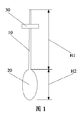
組合せ式遠心分離装置は、細管(10)と、負圧保存チャンバ(20)と、を備え、前記負圧保存チャンバ(20)は、細管(10)と連通し、負圧の発生及び懸濁液の保存に用いられ、負圧が発生した際に、細管(10)を介して懸濁液を負圧保存チャンバ(20)及び細管(10)内に吸い込むように構成され、細管(10)には、組合せ式遠心装置を遠心機に固定する固定装置(30)が設けられている。【選択図】図1The combination centrifuge comprises a capillary (10) and a negative pressure storage chamber (20), said negative pressure storage chamber (20) communicating with the capillary (10) for generating and suspending a negative pressure. The capillary (10) is used to store a liquid, and is configured to suck the suspension into the negative pressure storage chamber (20) and the capillary (10) through the capillary (10) when a negative pressure is generated. Is provided with a fixing device (30) for fixing the combination centrifugal device to the centrifuge. [Selection diagram] Fig. 1
Description
本発明は、医療技術分野に関し、特に細胞成分の分層に適用する組合せ式遠心装置に関する。 The present invention relates to the medical technical field, and more particularly, to a combination centrifugal device applied to cell component separation.
遠心技術は、細胞生物学、分子生物学、生物化学及びその他の関連分野において幅広く応用されている。遠心力の作用によって、懸濁液における比重が異なる細胞が分層されて分離濃縮されるようにする。 Centrifugal technology is widely applied in cell biology, molecular biology, biochemistry and other related fields. Cells having different specific gravity in the suspension are separated and concentrated by the action of centrifugal force.
伝統の遠心管は、分層前の懸濁液を上から下へ注ぎ、上部の直径が中部及び底部の直径以上であるように構成される注入式のものである。 Traditional centrifuge tubes are of the pouring type that is constructed such that the pre-splitting suspension is poured from top to bottom and the top diameter is equal to or greater than the middle and bottom diameters.
伝統の遠心操作によって、懸濁液における比重が異なる細胞は、遠心された後、遠心管において異なる層になり、一部の含有量が極めて少ない細胞成分により伝統の遠心管に形成された層が非常に薄いので、吸出し、分離することが比較的困難になる。末梢血を例とすると、抗凝固性の末梢血は、赤血球、顆粒球及び単球を含む血球と、血漿とからなる。各血球は、その比重が異なるので、自然沈殿又は遠心を経て、遠心管において異なる層に位置するようになる。そのうち、末梢血における単球は、血球成分の僅か千分の一ほどを占めている。遠心後の赤血球及び顆粒球が遠心管の下層に位置し、血漿が遠心管の上層に位置し、単球により形成された層が遠心管の中層に位置するが、単球の含有量が極めて少ないので、吸出しが非常に困難になる。 Cells with different specific gravity in the suspension due to the traditional centrifugation operation, after being centrifuged, become a different layer in the centrifuge tube, and the layer formed in the traditional centrifuge tube by some cellular components with very little content Because it is very thin, it is relatively difficult to suck and separate. Taking peripheral blood as an example, anticoagulant peripheral blood consists of blood cells containing red blood cells, granulocytes and monocytes, and plasma. Since each blood cell has a different specific gravity, it goes through natural sedimentation or centrifugation, and is located in a different layer in the centrifuge tube. Of these, monocytes in peripheral blood account for only a thousandth of the blood cell component. Red blood cells and granulocytes after centrifugation are located in the lower layer of the centrifuge tube, plasma is located in the upper layer of the centrifuge tube, and a layer formed by monocytes is located in the middle layer of the centrifuge tube. Since there are few, sucking out becomes very difficult.
本発明は、懸濁液における含有量が極めて少ない成分を有効に分離できる組合せ式遠心装置を提供することを主な解決しようとする技術課題とする。 The main object of the present invention is to provide a combination centrifugal device capable of effectively separating components having a very small content in a suspension.
上記の技術課題を解決するために、本発明の技術方案は、組合せ式遠心装置を提供し、細管と、負圧保存チャンバと、を備え、前記負圧保存チャンバは、細管と連通し、負圧の発生及び懸濁液の保存に用いられ、負圧が発生した際に、細管を介して懸濁液を負圧保存チャンバ及び細管内に吸い込むように構成され、細管には、遠心機で組合せ式遠心装置における懸濁液を遠心するように、組合せ式遠心装置を遠心機に固定する固定装置が設けられている。 In order to solve the above technical problem, the technical solution of the present invention provides a combination centrifugal device, and includes a thin tube and a negative pressure storage chamber, and the negative pressure storage chamber communicates with the thin tube and is negative. It is used to generate pressure and store suspensions. When negative pressure is generated, the suspension is sucked into the negative pressure storage chamber and the narrow tubes via the narrow tubes. A fixing device for fixing the combined centrifugal device to the centrifuge is provided so as to centrifuge the suspension in the combined centrifugal device.
そのうち、固定装置は、組合せ式遠心装置を遠心機に固定するように、遠心機と係合される係合機構である。 Among them, the fixing device is an engagement mechanism that is engaged with the centrifuge so as to fix the combination centrifugal device to the centrifuge.
そのうち、固定装置は、組合せ式遠心装置を遠心管内に固定するように、遠心管と接続され且つ細管が挿設される遠心蓋である。 Among them, the fixing device is a centrifuge lid that is connected to the centrifuge tube and into which a thin tube is inserted so as to fix the combined centrifuge in the centrifuge tube.
そのうち、負圧保存チャンバは、押圧されて負圧を発生させる弾性容器を含む。 Among them, the negative pressure storage chamber includes an elastic container that is pressed to generate a negative pressure.
そのうち、負圧保存チャンバは、そのうちの一方が押圧されて負圧を発生させる少なくとも2つの互いに連通する弾性容器を含む。 Among them, the negative pressure storage chamber includes at least two mutually elastic elastic containers, one of which is pressed to generate a negative pressure.
そのうち、組合せ式遠心装置は、少なくとも2つの互いに連通する弾性容器の間に設置される締付け部品をさらに含む。 Among them, the combination centrifugal device further includes a fastening part installed between at least two elastic containers communicating with each other.
そのうち、締付け部品は、ピンチ弁を含む。 Among them, the tightening part includes a pinch valve.
そのうち、負圧保存チャンバには、負圧を発生させる注射式針管又は真空ポンプである負圧発生器に接続される開口が設けられている。 Among them, the negative pressure storage chamber is provided with an opening connected to a negative pressure generator which is an injection needle tube or a vacuum pump for generating a negative pressure.
そのうち、細管の内径は、2mm以下に形成され、負圧保存チャンバの幅方向における横断面積は、細管の幅方向における横断面積の3倍〜20倍である。 Among them, the inner diameter of the narrow tube is formed to be 2 mm or less, and the cross-sectional area in the width direction of the negative pressure storage chamber is 3 to 20 times the cross-sectional area in the width direction of the thin tube.
そのうち、細管は、透明又は半透明となり、負圧保存チャンバは、透明又は半透明となり、細管は負圧保存チャンバと一体成型されている。 Among them, the thin tube is transparent or translucent, the negative pressure storage chamber is transparent or translucent, and the thin tube is integrally formed with the negative pressure storage chamber.
本発明の有益な効果は、以下のようである。
従来技術と異なって、本発明により公開された組合せ式遠心装置は、細管と、負圧保存チャンバと、を備え、前記負圧保存チャンバは、細管と連通し、負圧の発生及び懸濁液の保存に用いられ、負圧が発生した際に、細管を介して懸濁液を負圧保存チャンバ及び細管内に吸い込むように構成され、細管には、組合せ式遠心装置を遠心機に構成する固定装置が設けられている。以上により、本発明は、固定装置で組合せ式遠心装置が遠心機に直接固定され、遠心機による遠心中に、細管で懸濁液における含有量が極めて少ない成分を保存でき、且つ直接に懸濁液における含有量が極めて少ない成分の細管における厚みを増加させることできるので、懸濁液における含有量が極めて少ない成分をよりよく分離でき、効率を大幅に向上させ、分層及び分離の効果がよりよくなる。
The beneficial effects of the present invention are as follows.
Unlike the prior art, the combination centrifugal device disclosed by the present invention includes a thin tube and a negative pressure storage chamber, and the negative pressure storage chamber communicates with the thin tube, and generates and suspensions of negative pressure. When the negative pressure is generated, the suspension is sucked into the negative pressure storage chamber and the thin tube through the thin tube. The thin tube has a combination centrifugal device in the centrifuge. A fixing device is provided. As described above, in the present invention, the combination centrifugal device is directly fixed to the centrifuge by the fixing device, and the component having a very small content in the suspension can be stored in the thin tube and can be directly suspended during the centrifugation by the centrifuge. Since the thickness in the thin tube of the component with very little content in the liquid can be increased, the component with very little content in the suspension can be separated better, the efficiency is greatly improved, and the effect of layer separation and separation is more Get better.
以下、図面及び実施形態を参照しながら本発明を詳しく説明する。 Hereinafter, the present invention will be described in detail with reference to the drawings and embodiments.
図1に示すように、図1は、本発明の組合せ式遠心装置の構成1の模式図である。該組合せ式遠心装置は、細管10、負圧保存チャンバ20及び固定装置30を備えている。
As shown in FIG. 1, FIG. 1 is a schematic diagram of the configuration 1 of the combination centrifugal device of the present invention. The combination centrifugal device includes a
細管10は、懸濁液を吸い込むためのものである。懸濁液は、血液、末梢血又はその他の生体混合懸濁成分であってもよい。
The
本実施例において、細管10の内径は、2mm以下である。細管10の内径が2mm以下に形成されたので、細管において希有成分の厚さが厚くなり、分層及び分離により有利である。また、懸濁液において粒子が存在し、且つ懸濁液自身が一定の粘度を有するので、細管10の内径が2mm以下に形成された場合、懸濁液は、無圧力の状態で細管10内に留まることができるようになり、これによって細管10を密封することができる。
In this embodiment, the inner diameter of the
負圧保存チャンバ20は、懸濁液を保存するためのものであり、細管10と連通されている。本実施例において、負圧保存チャンバ20は、負圧を発生することができるので、負圧が発生した際に、細管10を介して懸濁液を負圧保存チャンバ20及び/又は細管10内に吸い込むことができる。
The negative
本実施例において、負圧保存チャンバ20は、押圧されて負圧を発生させる弾性容器20を含んでいる。なお、本発明において、弾性容器の形状は限定されず、球状、円柱状、矩形状、楕円形状又はその他の不規則形状に形成されてもよい。
In this embodiment, the negative
具体的には、負圧保存チャンバ20は、押圧の際に原形状に復元することができる弾性材料からなる弾性容器を含んでいる。使用する際に、細管10を懸濁液に入れて、手動で弾性容器を押圧することで、弾性容器の内部で負圧が発生するように弾性容器の内部の残留空気を排出させる。これによって、細管10で懸濁液を弾性容器及び/又は細管10内に吸い込むことができる。また、細管10により懸濁液を吸い込んだ後、少量の気泡が存在することがある。これに対して、負圧保存チャンバ20が弾性容器であるので、弾性容器を揺らすとともに押圧して懸濁液を吸い込み、さらに上記操作を繰り返すことによって、完全に残留する気泡を排出することができる。
Specifically, the negative
一部の実施例において、負圧保存チャンバ20は、少なくとも2つの互いに連通する弾性容器を含み、少なくとも2つの互いに連通する弾性容器のうちの一方を押圧することで負圧を発生させるものである。また、組合せ式遠心装置は、少なくとも2つの互いに連通する弾性容器の間に設置される締付け部品20aをさらに有している。締付け部品20aは、ピンチ弁を含んでもよいが、ピンチ弁に限らず、その他実施例において、その他の締付け部品を含んでもよい。また、本発明において、少なくとも2つの互いに連通する弾性容器の形状及び数量が限定されていない。具体的には、図3に示すように、少なくとも2つの互いに連通する弾性容器は、第1球状弾性容器201及びそれと連通する第2球状弾性容器202を備え、締付け部品20aが第1球状弾性容器201と第2球状弾性容器202との間を挟んで設置されている。第1球状弾性容器201と第2球状弾性容器202とは、1つの小さな細管で連通され、締付け部品20aが小さな細管を挟むように設置されている。または、図4に示すように、少なくとも2つの互いに連通する弾性容器は、第1楕円形状弾性容器203、第1楕円形状弾性容器203と連通する第2楕円形状弾性容器204及び第2楕円形状弾性容器204と連通する第3楕円形状弾性容器205を備え、締付け部品20aが、第1楕円形状弾性容器203と第2楕円形状弾性容器204と第3楕円形状弾性容器205との間を挟んで設置されている。具体的には、締付け部品20aは、第2楕円形状弾性容器204と第3楕円形状弾性容器205との間を挟むように設置されている。第1楕円形状弾性容器203と第2楕円形状弾性容器204と第3楕円形状弾性容器205とはそれぞれ1つの小さな細管で連通され、締付け部品20aが小さな細管を挟んで設置されている。
In some embodiments, the negative
具体的には、少なくとも2つの互いに連通する弾性容器は、いずれも押圧される際に負圧が発生する弾性材料からなる弾性容器である。使用する際に、細管10を懸濁液に入れて、手動で少なくとも2つの互いに連通する弾性容器中のうちの一方を押圧することで、少なくとも2つの互いに連通する弾性容器の内部で負圧が発生するように少なくとも2つの互いに連通する弾性容器の内部の残留空気を排出させる。これによって、細管10で懸濁液を少なくとも2つの互いに連通する弾性容器内に吸い込むことができる。また、細管10で懸濁液を吸い込む際に、負圧保存チャンバ20の内部において少量の空気が残留することがある。これに対して、少なくとも2つの互いに連通する弾性容器が設けられ、締付け部品20aで2つの互いに連通する弾性容器の間を締め付けることによって、残留する少量の空気が少なくとも2つの互いに連通する弾性容器の一方に収容されるように隔離され(即ち、細管10から最も離間する一方)、少なくとも2つの互いに連通する弾性容器の残りのものが懸濁液の保存に用いられるので、懸濁液に気泡が存在しないよう保証することができる。本実施例において、2つ以上の弾性容器及び締付け部品20aで便利且つ素早く気泡を弾性容器の後部又はその他の位置に収容されるように隔離することができる。さらに、弾性容器を繰り返して揺らすとともに押圧して懸濁液を吸い込むことで残留の気泡をさらに排出させる方法に合わせて、複数の手段で気泡を排出させることができるので、負圧保存チャンバ20内の懸濁液に気泡が存在しないよう保証することができる。
Specifically, at least two elastic containers communicating with each other are elastic containers made of an elastic material that generates a negative pressure when pressed. In use, the
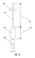
また、一部の実施例において、図2に示すように、負圧保存チャンバ20には、負圧を発生させる負圧発生器と接続される開口が設けられている。本実施例において、負圧保存チャンバ20の開口の位置は限定されず、該開口が、負圧保存チャンバ20の底部、側部又はその他の位置等に設けられても良い。具体的には、負圧発生器は、負圧を発生させる注射式針管50又は真空ポンプであってもよい。また、開口の内径が2mm以下に形成され、これによって注射式針管50又は真空ポンプを介して懸濁液を硬質容器内に吸い込むことができる。また、負圧保存チャンバ20には、開口を密封するためのシール蓋が設けられても良い。より具体的には、負圧保存チャンバ20は、硬質容器であって、該硬質容器には、負圧を発生させる負圧発生器と接続される開口が設けられ、さらに硬質容器には開口を密封するためのシール蓋が設けられるように構成されている。
In some embodiments, as shown in FIG. 2, the negative
本実施例において、細管10は、透明又は半透明となり、つまり透明又は半透明の材料からなり、これによって懸濁液の細管10の内部における状態、つまり懸濁液における希有成分の細管10における厚みを観察することができるようになる。また、細管10には、懸濁液の細管10における厚みを読み取るための目盛りが設けられても良い。
In the present embodiment, the
本実施例において、負圧保存チャンバ20は、透明又は半透明となり、つまり透明な材料からなり、これによって懸濁液の負圧保存チャンバ20の内部における状態、つまり懸濁液の負圧保存チャンバ20における厚みを観察することができるようになる。また、負圧保存チャンバ20には、懸濁液の負圧保存チャンバ20における厚みを読み取るための目盛りが設けられても良い。
In the present embodiment, the negative
本実施例において、細管10は負圧保存チャンバ20と一体成形されたので、構成が簡単であり、設計コストを低減させることができる。なお、その他の実施例において、細管10は、着脱可能に負圧保存チャンバ20に設けられている。具体的には、細管10は、負圧保存チャンバ20とネジ接続され、つまり細管10に雄ネジが設けられ、負圧保存チャンバ20に雌ネジが設けられ、雄ネジと雌ネジとのネジ接続によって、細管10と負圧保存チャンバ20との着脱可能な接続を実現した。
In this embodiment, since the
本実施例において、細管10の内径は、均一になっている。なお、その他の実施例において、細管10の内径は、徐々に小さくなるように変化し、つまり細管10の内径が、負圧保存チャンバ20と接続される一端から負圧保存チャンバ20の他端へ離間することに伴って徐々に小さくなるので、含有量が極めて少ない成分であっても、細管10では拡大して表示されることが可能になる。
In this embodiment, the inner diameter of the
本実施例において、細管10の内径と負圧保存チャンバ20の内径とは円弧状に接続されているので、懸濁液における含有量が極めて少ない成分を素早く細管10に分離することができる。好ましくは、細管10と負圧保存チャンバ20との接続箇所の円弧状接続の角度は30°〜60°である。
In the present embodiment, since the inner diameter of the
また、細管10には、組合せ式遠心装置を遠心機に固定するための固定装置30が設けられ、遠心機で組合せ式遠心装置における懸濁液を遠心することによって、負圧保存チャンバ20の懸濁液における含有量が極めて少ない成分を細管10に分離することができる。これによって、構成が簡単な組合せ式遠心装置を利用して懸濁液を遠心することで、操作の時間及び設計コストを大幅に低減させることができる。
Further, the
本実施例において、負圧保存チャンバ20の内径は、均一になり、負圧保存チャンバ20の幅方向における横断面積は、細管10の幅方向における横断面積の3倍〜20倍となる。具体的には、負圧保存チャンバ20の幅方向における横断面積は、細管10の幅方向における横断面積の10倍(即ち、細管10の内径が均一となる状態)となる。これによって、負圧保存チャンバ20の懸濁液に存在する含有量が極めて少ない成分であっても、細管10では拡大して表示されることができる。従って、細管10における成分を直接吸出し又は細管10を切断してから細管10における成分を吸い出すことが可能になり、懸濁液における含有量が極めて少ない成分を分離することが可能となる。また、細管10の長さH1は、負圧保存チャンバ20の長さの10倍〜20倍となる。なお、その他の実施例において、負圧保存チャンバ20の内径が均一でなくてもよい。つまり、負圧保存チャンバ20の形状が、球形、ヒョウタン形状又は不規則形状に形成されてもよい。
In this embodiment, the inner diameter of the negative
本実施例において、固定装置30は、細管10と一体成型されている。なお、その他の実施例において、固定装置30は、着脱可能に細管10に設けられている。
In this embodiment, the fixing
本実施例において、固定装置30は、遠心機と係合され、組合せ式遠心装置を遠心機に固定する係合機構30である。具体的には、係合機構30が細管10に固定され、係合機構30に突起が設けられ、遠心機のプレート又は栓体に凹溝が設けられ、突起と凹溝との係合且つ突起と凹溝の隙間嵌めによって、組合せ式遠心装置を遠心機に係合させる。
In the present embodiment, the fixing
一部の実施例において、図5に示すように、固定装置30は、組合せ式遠心装置を遠心管40に固定するための、遠心管40と接続され且つ細管10が挿設される遠心蓋である。これによって、遠心管40で組合せ式遠心装置を遠心機に固定するようになる。なお、細管10が着脱可能に遠心蓋に設けられ、具体的には、遠心蓋に開口が設けられ、細管10が開口に挿設されるように設けられても良い。また、細管10の外径が負圧保存チャンバ20と接続される一端から負圧保存チャンバ20の他端へ離間することに伴って徐々に小さくなる場合、細管10の外径と開口の内径が等しくなる際に、遠心蓋が細管10に係合され、遠心蓋で細管10を遠心管に固定することができる。なお、その他の実施例において、細管10が遠心蓋と一体成型されている。
In some embodiments, as shown in FIG. 5, the fixing
また、細管10と負圧保存チャンバ20との合計長さは、遠心管20の長さより長く形成されている。つまり、組合せ式遠心装置が遠心管40内に固定されたとき、負圧保存チャンバ20が遠心管40の底部に位置し、負圧保存チャンバ20が遠心中に移動しないように、遠心管40の底部で負圧保存チャンバ20が支持されている。また、組合せ式遠心装置が遠心管40内に固定されたとき、細管10の端部が固定装置30の水平高さより高くなるようにする。このように、遠心される際に、細管10が遠心作用で若干移動しても、分層及び増厚の効果に影響しない。
The total length of the
本実施例において、負圧を発生する方法で混合された懸濁液を吸い込むので、伝統技術と従来技術における懸濁液を遠心管に注入する操作方法を避けて、汚染及び気泡の生成を低減させることができる。また、本発明において、組合せ式遠心装置に長手状の細管が設けられることによって、同体積の懸濁液、特に少量又は微量の成分を含む懸濁液に対して、遠心機で遠心された後、組合せ式遠心装置の細管で、懸濁液における含有量が極めて少ない成分の負圧保存チャンバにおける厚みを拡大することができるので、含有量が極めて少ない細胞成分の遠心分離がより便利となる。 In this embodiment, since the mixed suspension is sucked by a method of generating a negative pressure, the operation method of injecting the suspension into the centrifuge tube in the conventional technique and the conventional technique is avoided, and the generation of contamination and bubbles is reduced. Can be made. Further, in the present invention, by providing the combination centrifugal device with a long thin tube, the suspension of the same volume, particularly a suspension containing a small amount or a small amount of a component, is centrifuged with a centrifuge. The thin tube of the combination centrifugal device can increase the thickness of the negative pressure storage chamber of the component having a very small content in the suspension, so that the centrifugation of the cell component having a very small content becomes more convenient.
以上により、本発明により公開された組合せ式遠心装置は、細管と、負圧保存チャンバと、を備え、前記負圧保存チャンバは、細管と連通し、負圧の発生及び懸濁液の保存に用いられ、負圧が発生した際に、細管を介して懸濁液を負圧保存チャンバ及び細管内に吸い込むように構成され、細管には、組合せ式遠心装置を遠心機に固定する固定装置が設けられている。以上により、本発明は、固定装置で組合せ式遠心装置が遠心機に直接固定され、遠心機による遠心中に、細管で懸濁液における含有量が極めて少ない成分を保存でき、且つ直接に懸濁液における含有量が極めて少ない成分の細管における厚みを増加させることができるので、懸濁液における含有量が極めて少ない成分をよりよく分離でき、効率を大幅に向上させ、分層及び分離の効果がよりよくなる。 As described above, the combined centrifugal device disclosed by the present invention includes a thin tube and a negative pressure storage chamber, and the negative pressure storage chamber communicates with the thin tube to generate a negative pressure and store a suspension. When a negative pressure is generated, the suspension is sucked into the negative pressure storage chamber and the thin tube through the thin tube, and the thin tube has a fixing device for fixing the combination centrifugal device to the centrifuge. Is provided. As described above, in the present invention, the combination centrifugal device is directly fixed to the centrifuge by the fixing device, and the component having a very small content in the suspension can be stored in the thin tube and can be directly suspended during the centrifugation by the centrifuge. Since the thickness in the capillary tube of the component with a very small content in the liquid can be increased, the component with a very small content in the suspension can be separated better, the efficiency is greatly improved, and the effect of layer separation and separation is improved. Get better.
以上の記載は、本発明の実施形態に過ぎず、本発明の保護範囲を限定するものではない。本発明の明細書及び図面に基づいてなされた均等な構成、均等な流れの変換、又は直接或いは間接にその他の関連技術分野に組み込むことは、何れも本発明の保護範囲内に属する。 The above description is only an embodiment of the present invention and does not limit the protection scope of the present invention. Any equivalent structure made based on the specification and drawings of the present invention, equivalent flow conversion, or directly or indirectly incorporated into other related technical fields are all within the protection scope of the present invention.
Claims (10)
前記負圧保存チャンバは、前記細管と連通し、負圧の発生及び懸濁液の保存に用いられ、負圧が発生した際に、前記細管を介して前記懸濁液を前記負圧保存チャンバ及び細管内に吸い込むように構成され、
前記細管には、遠心機で前記組合せ式遠心装置における前記懸濁液を遠心するように、前記組合せ式遠心装置を前記遠心機に固定する固定装置が設けられている
ことを特徴とする組合せ式遠心装置。 A thin tube and a negative pressure storage chamber,
The negative pressure storage chamber communicates with the thin tube and is used for generation of negative pressure and storage of a suspension. When negative pressure is generated, the negative pressure storage chamber passes the suspension through the thin tube. And configured to inhale into the tubule,
The thin tube is provided with a fixing device for fixing the combination centrifugal device to the centrifuge so that the suspension in the combination centrifugal device is centrifuged by a centrifuge. Centrifugal device.
Applications Claiming Priority (3)
| Application Number | Priority Date | Filing Date | Title |
|---|---|---|---|
| CN201610936523.6A CN106475164B (en) | 2016-10-24 | 2016-10-24 | A kind of combined centrifugal device |
| CN201610936523.6 | 2016-10-24 | ||
| PCT/CN2017/107091 WO2018077120A1 (en) | 2016-10-24 | 2017-10-20 | Combination-type centrifugal device |
Publications (2)
| Publication Number | Publication Date |
|---|---|
| JP2019535495A true JP2019535495A (en) | 2019-12-12 |
| JP7117014B2 JP7117014B2 (en) | 2022-08-12 |
Family
ID=58272825
Family Applications (1)
| Application Number | Title | Priority Date | Filing Date |
|---|---|---|---|
| JP2019521814A Active JP7117014B2 (en) | 2016-10-24 | 2017-10-20 | centrifuge unit |
Country Status (6)
| Country | Link |
|---|---|
| US (1) | US20190271682A1 (en) |
| EP (1) | EP3530354A4 (en) |
| JP (1) | JP7117014B2 (en) |
| CN (1) | CN106475164B (en) |
| DE (1) | DE202017007384U1 (en) |
| WO (1) | WO2018077120A1 (en) |
Families Citing this family (4)
| Publication number | Priority date | Publication date | Assignee | Title |
|---|---|---|---|---|
| CN106475164B (en) * | 2016-10-24 | 2019-01-11 | 深圳市孔雀生物科技有限公司 | A kind of combined centrifugal device |
| TWM606339U (en) | 2020-07-02 | 2021-01-11 | 新加坡商克雷多診斷生物醫學私人有限公司 | Quantitative transfer pipette structure |
| CN112146926A (en) * | 2020-08-13 | 2020-12-29 | 广东电网有限责任公司 | Transformer oil sampling tool and sampling test method thereof |
| CN114887778B (en) * | 2022-05-13 | 2024-02-02 | 湖南淼泉生物技术有限公司 | IIII type recombinant collagen hydrogel preparation equipment and application method thereof |
Citations (12)
| Publication number | Priority date | Publication date | Assignee | Title |
|---|---|---|---|---|
| US3494508A (en) * | 1968-05-10 | 1970-02-10 | Peter Stauton Hoefer | Fractionator |
| JPS5019791B1 (en) * | 1970-08-03 | 1975-07-09 | ||
| JPS5178086A (en) * | 1974-11-29 | 1976-07-07 | Zarusuteeto Baruteru | |
| JPS6328140U (en) * | 1986-08-05 | 1988-02-24 | ||
| JPH0560542U (en) * | 1992-01-14 | 1993-08-10 | 日本石油株式会社 | Protective cover for centrifuge sample container |
| JPH0731153U (en) * | 1993-09-30 | 1995-06-13 | 日立工機株式会社 | Centrifuge cup |
| JP2008237310A (en) * | 2007-03-26 | 2008-10-09 | Japan Medical Materials Corp | Device for centrifugal separation |
| WO2008143570A1 (en) * | 2007-05-23 | 2008-11-27 | Ge Healthcare Bio-Sciences Ab | Separation device |
| JP2009189280A (en) * | 2008-02-13 | 2009-08-27 | Olympus Corp | Centrifugal separation container and centrifugal separation apparatus |
| KR100953998B1 (en) * | 2008-07-09 | 2010-04-21 | 이희영 | A centrige installing the front of injector |
| EP2638968A2 (en) * | 2010-10-12 | 2013-09-18 | Snu R&DB Foundation | Centrifugation method and centrifugation device |
| CN104884602A (en) * | 2012-12-27 | 2015-09-02 | 全玫墉 | Buffy coat extraction kit |
Family Cites Families (16)
| Publication number | Priority date | Publication date | Assignee | Title |
|---|---|---|---|---|
| US3914985A (en) * | 1974-03-29 | 1975-10-28 | American Hospital Supply Corp | Centrifuging device and method |
| US4483825A (en) * | 1982-07-09 | 1984-11-20 | Fatches Keith R | Pipette and filter combination |
| US6280400B1 (en) * | 1998-12-05 | 2001-08-28 | Becton Dickinson And Company | Device and method for separating component of a liquid sample |
| CA2419714A1 (en) * | 1999-08-05 | 2001-02-15 | Brian William King | Direct aspiration-reaction and injection device and methods of use |
| JP5019791B2 (en) | 2006-06-05 | 2012-09-05 | 昭和電工株式会社 | Pipe expansion processing equipment |
| US8419705B2 (en) * | 2007-07-30 | 2013-04-16 | Jms Co., Ltd. | Apparatus for separating and storing blood components |
| WO2009067518A1 (en) * | 2007-11-20 | 2009-05-28 | 3M Innovative Properties Company | Sample preparation container and method |
| US8309343B2 (en) * | 2008-12-01 | 2012-11-13 | Baxter International Inc. | Apparatus and method for processing biological material |
| CN202699644U (en) * | 2012-04-24 | 2013-01-30 | 祁小平 | Recovery filtering device for blood serum or cell culture supernatant |
| CN102847571A (en) * | 2012-09-21 | 2013-01-02 | 北京上惠好生物技术有限公司 | Device of medical injector type centrifuge tube and projecting jacket |
| CN104918703B (en) * | 2012-12-28 | 2017-10-10 | 阿赛斯生物股份有限公司 | Pipette |
| SG11201601547RA (en) * | 2013-09-05 | 2016-04-28 | Miyabi Co Ltd | Bodily Fluid Sampler, Bodily Fluid Container And Bodily Fluid Sampling Device |
| CN203916691U (en) * | 2014-05-08 | 2014-11-05 | 玉锋实业集团有限公司 | A kind of novel centrifugal test tube |
| US20170036203A1 (en) * | 2015-08-07 | 2017-02-09 | Nalge Nunc International Corporation | Slow draw transfer pipettes and related methods |
| CN206121784U (en) * | 2016-10-24 | 2017-04-26 | 深圳市孔雀生物科技有限公司 | Modular centrifugal device |
| CN106475164B (en) * | 2016-10-24 | 2019-01-11 | 深圳市孔雀生物科技有限公司 | A kind of combined centrifugal device |
-
2016
- 2016-10-24 CN CN201610936523.6A patent/CN106475164B/en active Active
-
2017
- 2017-10-20 US US16/344,723 patent/US20190271682A1/en not_active Abandoned
- 2017-10-20 WO PCT/CN2017/107091 patent/WO2018077120A1/en active Application Filing
- 2017-10-20 DE DE202017007384.6U patent/DE202017007384U1/en active Active
- 2017-10-20 EP EP17865582.5A patent/EP3530354A4/en active Pending
- 2017-10-20 JP JP2019521814A patent/JP7117014B2/en active Active
Patent Citations (12)
| Publication number | Priority date | Publication date | Assignee | Title |
|---|---|---|---|---|
| US3494508A (en) * | 1968-05-10 | 1970-02-10 | Peter Stauton Hoefer | Fractionator |
| JPS5019791B1 (en) * | 1970-08-03 | 1975-07-09 | ||
| JPS5178086A (en) * | 1974-11-29 | 1976-07-07 | Zarusuteeto Baruteru | |
| JPS6328140U (en) * | 1986-08-05 | 1988-02-24 | ||
| JPH0560542U (en) * | 1992-01-14 | 1993-08-10 | 日本石油株式会社 | Protective cover for centrifuge sample container |
| JPH0731153U (en) * | 1993-09-30 | 1995-06-13 | 日立工機株式会社 | Centrifuge cup |
| JP2008237310A (en) * | 2007-03-26 | 2008-10-09 | Japan Medical Materials Corp | Device for centrifugal separation |
| WO2008143570A1 (en) * | 2007-05-23 | 2008-11-27 | Ge Healthcare Bio-Sciences Ab | Separation device |
| JP2009189280A (en) * | 2008-02-13 | 2009-08-27 | Olympus Corp | Centrifugal separation container and centrifugal separation apparatus |
| KR100953998B1 (en) * | 2008-07-09 | 2010-04-21 | 이희영 | A centrige installing the front of injector |
| EP2638968A2 (en) * | 2010-10-12 | 2013-09-18 | Snu R&DB Foundation | Centrifugation method and centrifugation device |
| CN104884602A (en) * | 2012-12-27 | 2015-09-02 | 全玫墉 | Buffy coat extraction kit |
Also Published As
| Publication number | Publication date |
|---|---|
| EP3530354A4 (en) | 2019-09-25 |
| EP3530354A1 (en) | 2019-08-28 |
| WO2018077120A1 (en) | 2018-05-03 |
| DE202017007384U1 (en) | 2021-02-08 |
| JP7117014B2 (en) | 2022-08-12 |
| US20190271682A1 (en) | 2019-09-05 |
| CN106475164A (en) | 2017-03-08 |
| CN106475164B (en) | 2019-01-11 |
Similar Documents
| Publication | Publication Date | Title |
|---|---|---|
| JP2019535495A (en) | Combination centrifuge | |
| JP4983204B2 (en) | Centrifuge container and centrifuge method | |
| US20150104824A1 (en) | Fixed Chamber Separator With Adjustment Withdrawal Member | |
| US20130259951A1 (en) | Apparatus and Method for Separating and Concentrating a Component of a Fluid | |
| US20130011311A1 (en) | Blood Component Separator | |
| US20180353954A1 (en) | Dual Piston Centrifuge Tube | |
| WO2017045354A1 (en) | Bubble removing system | |
| JP2010075066A5 (en) | ||
| JP2014014817A (en) | Centrifugal separation vessel assembly | |
| RU2352625C1 (en) | Device for processing and distillation of liquid product | |
| CN206121784U (en) | Modular centrifugal device | |
| JP2008279195A (en) | Blood separation filter device | |
| JP7322384B2 (en) | MEDIUM FILLING LIQUID, MEDIUM FILLING METHOD, CULTURE CONTAINER, AND AIR BUBBLE REMOVAL DEVICE FOR MEDIUM FILLING | |
| JP2010188197A (en) | Blood component dispenser | |
| CN208641859U (en) | A kind of platelet rich plasma extraction element | |
| CN108543328B (en) | Supercritical extraction method of traditional Chinese medicine | |
| CN216337618U (en) | Adipose sample cell centrifuge tube | |
| CN209872948U (en) | Cell separation tube for separating and extracting PBMC | |
| JP2001299730A (en) | Plasma collecting instrument | |
| KR101953868B1 (en) | Centrifugation-kit for divide extraction easy by ingredient specific and grab of sample | |
| CN211189271U (en) | Purification suction filtration device | |
| CN209009230U (en) | A kind of albumen composite sheet Packaging Bottle | |
| CN101038283B (en) | Method for maintaining stabilization of perfusate pH value, oxygen partial pressure and carbon dioxide partial pressure | |
| CN217189667U (en) | Simple separating funnel type centrifuge tube | |
| CN213708343U (en) | Container capable of efficiently and conveniently concentrating sperm concentration |
Legal Events
| Date | Code | Title | Description |
|---|---|---|---|
| A621 | Written request for application examination |
Free format text: JAPANESE INTERMEDIATE CODE: A621 Effective date: 20190515 |
|
| A871 | Explanation of circumstances concerning accelerated examination |
Free format text: JAPANESE INTERMEDIATE CODE: A871 Effective date: 20190515 |
|
| A975 | Report on accelerated examination |
Free format text: JAPANESE INTERMEDIATE CODE: A971005 Effective date: 20191003 |
|
| A131 | Notification of reasons for refusal |
Free format text: JAPANESE INTERMEDIATE CODE: A131 Effective date: 20191023 |
|
| A521 | Request for written amendment filed |
Free format text: JAPANESE INTERMEDIATE CODE: A523 Effective date: 20200122 |
|
| A131 | Notification of reasons for refusal |
Free format text: JAPANESE INTERMEDIATE CODE: A131 Effective date: 20200317 |
|
| A521 | Request for written amendment filed |
Free format text: JAPANESE INTERMEDIATE CODE: A523 Effective date: 20200611 |
|
| A02 | Decision of refusal |
Free format text: JAPANESE INTERMEDIATE CODE: A02 Effective date: 20200818 |
|
| A521 | Request for written amendment filed |
Free format text: JAPANESE INTERMEDIATE CODE: A523 Effective date: 20201218 |
|
| C60 | Trial request (containing other claim documents, opposition documents) |
Free format text: JAPANESE INTERMEDIATE CODE: C60 Effective date: 20201218 |
|
| A521 | Request for written amendment filed |
Free format text: JAPANESE INTERMEDIATE CODE: A821 Effective date: 20201218 |
|
| A911 | Transfer to examiner for re-examination before appeal (zenchi) |
Free format text: JAPANESE INTERMEDIATE CODE: A911 Effective date: 20210114 |
|
| C21 | Notice of transfer of a case for reconsideration by examiners before appeal proceedings |
Free format text: JAPANESE INTERMEDIATE CODE: C21 Effective date: 20210119 |
|
| A912 | Re-examination (zenchi) completed and case transferred to appeal board |
Free format text: JAPANESE INTERMEDIATE CODE: A912 Effective date: 20210326 |
|
| C211 | Notice of termination of reconsideration by examiners before appeal proceedings |
Free format text: JAPANESE INTERMEDIATE CODE: C211 Effective date: 20210330 |
|
| C22 | Notice of designation (change) of administrative judge |
Free format text: JAPANESE INTERMEDIATE CODE: C22 Effective date: 20211116 |
|
| C22 | Notice of designation (change) of administrative judge |
Free format text: JAPANESE INTERMEDIATE CODE: C22 Effective date: 20220510 |
|
| C23 | Notice of termination of proceedings |
Free format text: JAPANESE INTERMEDIATE CODE: C23 Effective date: 20220607 |
|
| C03 | Trial/appeal decision taken |
Free format text: JAPANESE INTERMEDIATE CODE: C03 Effective date: 20220712 |
|
| C30A | Notification sent |
Free format text: JAPANESE INTERMEDIATE CODE: C3012 Effective date: 20220712 |
|
| A61 | First payment of annual fees (during grant procedure) |
Free format text: JAPANESE INTERMEDIATE CODE: A61 Effective date: 20220725 |
|
| R150 | Certificate of patent or registration of utility model |
Ref document number: 7117014 Country of ref document: JP Free format text: JAPANESE INTERMEDIATE CODE: R150 |