JP2019213719A - Game machine - Google Patents
Game machine Download PDFInfo
- Publication number
- JP2019213719A JP2019213719A JP2018112806A JP2018112806A JP2019213719A JP 2019213719 A JP2019213719 A JP 2019213719A JP 2018112806 A JP2018112806 A JP 2018112806A JP 2018112806 A JP2018112806 A JP 2018112806A JP 2019213719 A JP2019213719 A JP 2019213719A
- Authority
- JP
- Japan
- Prior art keywords
- game
- ball
- symbol
- state
- display
- Prior art date
- Legal status (The legal status is an assumption and is not a legal conclusion. Google has not performed a legal analysis and makes no representation as to the accuracy of the status listed.)
- Pending
Links
Images


Abstract
Description
本発明は、パチンコ機に代表される遊技機に関するものである。 The present invention relates to a gaming machine represented by a pachinko machine.
パチンコ機等の遊技機には、始動入賞口への遊技球の入賞に基づいて行われる抽選の結果が当たりだった場合に、当たり遊技を実行するものがある。かかる遊技機の中には、遊技者にとって有利度合いが異なる複数の状態を設定可能にし、様々な状態において当たり遊技を目指す遊技を行わせることにより遊技者の遊技に対する興趣向上を図っているものがある。 Some gaming machines, such as pachinko machines, execute a hit game when a result of a lottery performed based on winning of a game ball in a starting winning port is a hit. Among such gaming machines, there are those in which a plurality of states having different degrees of advantage for the player can be set, and a game aiming at a hit game is performed in various states, thereby improving the interest of the player in the game. is there.
しかしながら、更なる興趣の向上が求められている。 However, further improvement of interest is required.
本発明は、上記例示した問題点等を解決するためになされたものであり、遊技者の遊技に対する興趣を向上させることができる遊技機を提供することを目的としている。 The present invention has been made to solve the above-described problems and the like, and an object of the present invention is to provide a gaming machine capable of improving a player's interest in playing a game.
この目的を達成するために請求項1記載の遊技機は、遊技者が操作可能な操作手段と、その操作手段に対する操作内容に応じて遊技球を発射することが可能な発射手段と、を備えたものであり、所定の設定条件の成立に基づいて、遊技者にとって不利な第1遊技状態と、その第1遊技状態よりも遊技者にとって有利な第2遊技状態と、を少なくとも含む複数の遊技状態の中から1の遊技状態を設定することが可能な遊技状態設定手段と、を備え、前記遊技機は、前記第2遊技状態において、少なくとも予め定められた特定条件が成立している間、前記発射手段により第1の発射間隔で遊技球が発射され易くなる第1の操作内容で前記操作手段を操作するよりも、前記第1の発射間隔よりも長い発射間隔で遊技球が発射され易くなる第2の操作内容で前記操作手段を操作した場合の方が有利となり易くなるように構成されているものである。
In order to achieve this object, a gaming machine according to
請求項2記載の遊技機は、請求項1記載の遊技機において、遊技球が入球可能な入球手段と、その入球手段へと遊技球が入球したことに基づいて所定の判別情報を取得することが可能な判別情報取得手段と、その判別情報取得手段によって取得された前記判別情報に基づいて判別を実行する判別手段と、その判別手段の判別結果が予め定められた特定の判別結果になったことに基づいて遊技者に有利な特典遊技を実行する特典遊技実行手段と、を備え、前記遊技機は、前記特定条件が成立している間、前記第1の操作内容で前記操作手段を操作するよりも、前記第2の操作内容で前記操作手段を操作した場合の方が、前記第2遊技状態において取得された全ての前記判別情報を用いた判別が終了するまでの間における前記判別手段の判別回数が多くなり易く構成されている。 According to a second aspect of the present invention, there is provided the gaming machine according to the first aspect, wherein predetermined discrimination information is based on a ball-in means capable of entering a game ball and a game ball having entered the ball-in means. Determination information obtaining means capable of obtaining the information, a determination means for performing a determination based on the determination information obtained by the determination information obtaining means, and a specific determination in which a determination result of the determination means is predetermined. Bonus game execution means for executing a bonus game advantageous to the player based on the result, wherein the gaming machine performs the first operation content while the specific condition is satisfied. Until the operation using the second operation content is performed until the determination using all of the determination information obtained in the second game state is completed, the case where the operation means is operated with the second operation content is compared with the case where the operation means is operated. Number of discrimination by the discriminating means in Is configured tends to be many.
請求項3記載の遊技機は、請求項2記載の遊技機において、遊技球が入球可能な第2入球手段と、その第2入球手段に遊技球が入球したことに基づいて前記判別情報を取得することが可能な第2判別情報取得手段と、前記第2判別情報取得手段によって取得された前記判別情報を、所定の情報数を上限として、前記判別手段の判別に用いられるまで記憶可能な記憶手段と、を備え、前記判別手段は、前記判別情報取得手段によって取得された前記判別情報を用いて判別を実行する第1判別手段と、前記第2判別情報取得手段によって取得された前記判別情報を用いて判別を実行する第2判別手段と、で少なくとも構成されているものであり、前記第1判別手段の判別は、前記第2判別手段の判別よりも有利な判別結果になり易く構成されているものであり、前記遊技機は、前記特定条件が成立している間、前記第1の操作内容で前記操作手段を操作するよりも、前記第2の操作内容で前記操作手段を操作した場合の方が、前記第2遊技状態において取得された全ての前記判別情報を用いた判別が終了するまでの間における前記第1判別手段の判別回数が多くなり易く構成されているものである。 According to a third aspect of the present invention, in the gaming machine according to the second aspect, based on the second ball entry means capable of entering a game ball, and a game ball entering the second ball entry means. A second discrimination information acquisition unit capable of acquiring discrimination information, and the discrimination information acquired by the second discrimination information acquisition unit, up to a predetermined number of information, until the discrimination unit uses the discrimination information. A storage unit capable of storing, wherein the determination unit is configured to perform a determination using the determination information obtained by the determination information obtaining unit, and to be obtained by the second determination information obtaining unit. And a second discriminating means for performing discrimination using the discrimination information, wherein the discrimination by the first discriminating means is a more advantageous discrimination result than the discrimination by the second discriminating means. It is easy to be configured Wherein the gaming machine operates the operation means with the second operation content, rather than operating the operation means with the first operation content, while the specific condition is satisfied. It is configured such that the number of determinations by the first determination unit until the determination using all the determination information acquired in the second game state is completed is likely to increase.
請求項4記載の遊技機は、請求項3記載の遊技機において、前記第2判別手段の判別は、前記第1判別手段の判別よりも優先して実行されるように構成されているものである。 According to a fourth aspect of the present invention, in the gaming machine according to the third aspect, the determination by the second determination unit is performed prior to the determination by the first determination unit. is there.
請求項5記載の遊技機は、請求項3又は4記載の遊技機において、前記遊技状態設定手段は、前記第2遊技状態において、前記特典遊技が実行されずに予め定められた第1回数の前記第1判別手段の判別が終了したことに基づいて前記第1遊技状態を設定するものであり、前記遊技状態設定手段は、前記第2遊技状態において、前記特典遊技が実行されずに前記第1回数よりも多い第2回数の前記第2判別手段の判別が終了したことに基づいて前記第1遊技状態を設定するものである。 According to a fifth aspect of the present invention, in the gaming machine according to the third or fourth aspect, the gaming state setting means performs the first predetermined number of times without executing the privilege game in the second gaming state. The first game state is set based on the end of the judgment by the first judgment means, and the game state setting means sets the second game state without executing the privilege game in the second game state. The first game state is set based on the completion of the second number of discriminations by the second discrimination means that is greater than one.
請求項1記載の遊技機によれば、遊技者が操作可能な操作手段と、その操作手段に対する操作内容に応じて遊技球を発射することが可能な発射手段と、を備えたものであり、所定の設定条件の成立に基づいて、遊技者にとって不利な第1遊技状態と、その第1遊技状態よりも遊技者にとって有利な第2遊技状態と、を少なくとも含む複数の遊技状態の中から1の遊技状態を設定することが可能な遊技状態設定手段と、を備え、前記遊技機は、前記第2遊技状態において、少なくとも予め定められた特定条件が成立している間、前記発射手段により第1の発射間隔で遊技球が発射され易くなる第1の操作内容で前記操作手段を操作するよりも、前記第1の発射間隔よりも長い発射間隔で遊技球が発射され易くなる第2の操作内容で前記操作手段を操作した場合の方が有利となり易くなるように構成されているものである。 According to the gaming machine of the first aspect, the game machine includes: an operating means operable by the player; and a firing means capable of firing a game ball in accordance with the operation content of the operating means, Based on the establishment of the predetermined setting condition, one of a plurality of gaming states including at least a first gaming state disadvantageous to the player and a second gaming state more advantageous to the player than the first gaming state. Game state setting means capable of setting a game state of the game machine, wherein the gaming machine uses the firing means by the firing means while at least a predetermined condition is satisfied in the second game state. A second operation in which a game ball is easily fired at a firing interval longer than the first firing interval, compared to operating the operating means with a first operation content in which a game ball is easily fired at a first firing interval. The contents of the operation means In which better in the case of operation it is configured to be liable to be advantageous.
これにより、遊技者の遊技に対する興趣を向上させることができるという効果がある。 Thereby, there exists an effect that the interest with respect to a player's game can be improved.
請求項2記載の遊技機によれば、請求項1記載の遊技機の奏する効果に加え、遊技球が入球可能な入球手段と、その入球手段へと遊技球が入球したことに基づいて所定の判別情報を取得することが可能な判別情報取得手段と、その判別情報取得手段によって取得された前記判別情報に基づいて判別を実行する判別手段と、その判別手段の判別結果が予め定められた特定の判別結果になったことに基づいて遊技者に有利な特典遊技を実行する特典遊技実行手段と、を備え、前記遊技機は、前記特定条件が成立している間、前記第1の操作内容で前記操作手段を操作するよりも、前記第2の操作内容で前記操作手段を操作した場合の方が、前記第2遊技状態において取得された全ての前記判別情報を用いた判別が終了するまでの間における前記判別手段の判別回数が多くなり易く構成されている。 According to the gaming machine of the second aspect, in addition to the effects achieved by the gaming machine of the first aspect, in addition to the ball entry means capable of entering a game ball and the game ball entering the ball entry means, Discriminating information acquiring means capable of acquiring predetermined discriminating information based on the discriminating information, discriminating means for performing discrimination based on the discriminating information acquired by the discriminating information acquiring means, A bonus game execution means for executing a bonus game advantageous to the player based on the result of the determined specific determination, wherein the gaming machine is configured to execute the special game while the specific condition is satisfied. The discrimination using all of the discrimination information acquired in the second game state is better when the operation means is operated with the second operation content than when the operation means is operated with the first operation content. Said judgment until the end of Determination count means is constituted easily increases.
これにより、遊技者の遊技に対する興趣を向上させることができるという効果がある。 Thereby, there exists an effect that the interest with respect to a player's game can be improved.
請求項3記載の遊技機によれば、請求項2記載の遊技機の奏する効果に加え、遊技球が入球可能な第2入球手段と、その第2入球手段に遊技球が入球したことに基づいて前記判別情報を取得することが可能な第2判別情報取得手段と、前記第2判別情報取得手段によって取得された前記判別情報を、所定の情報数を上限として、前記判別手段の判別に用いられるまで記憶可能な記憶手段と、を備え、前記判別手段は、前記判別情報取得手段によって取得された前記判別情報を用いて判別を実行する第1判別手段と、前記第2判別情報取得手段によって取得された前記判別情報を用いて判別を実行する第2判別手段と、で少なくとも構成されているものであり、前記第1判別手段の判別は、前記第2判別手段の判別よりも有利な判別結果になり易く構成されているものであり、前記遊技機は、前記特定条件が成立している間、前記第1の操作内容で前記操作手段を操作するよりも、前記第2の操作内容で前記操作手段を操作した場合の方が、前記第2遊技状態において取得された全ての前記判別情報を用いた判別が終了するまでの間における前記第1判別手段の判別回数が多くなり易く構成されているものである。 According to the gaming machine of the third aspect, in addition to the effect of the gaming machine of the second aspect, the second ball entry means capable of entering a game ball, and the game ball entering the second ball entry means A second discrimination information acquisition unit capable of acquiring the discrimination information based on the determination performed, and determining the discrimination information acquired by the second discrimination information acquisition unit with a predetermined number of information as an upper limit. Storage means that can be stored until used in the determination of the first determination means, wherein the determination means performs a determination using the determination information acquired by the determination information acquisition means, the second determination And a second determining means for performing a determination using the determination information obtained by the information obtaining means. The determination by the first determining means is made by the determination by the second determining means. Also gives a favorable judgment result The gaming machine is configured such that, while the specific condition is satisfied, the operating means is operated with the second operation content rather than operating the operating means with the first operation content. Is operated, the number of determinations by the first determination means is more likely to be increased until the determination using all the determination information acquired in the second game state is completed. It is.
これにより、遊技者の遊技に対する興趣をより向上させることができるという効果がある。 Thereby, there is an effect that the interest of the player in the game can be further improved.
請求項4記載の遊技機によれば、請求項3記載の遊技機の奏する効果に加え、前記第2判別手段の判別は、前記第1判別手段の判別よりも優先して実行されるように構成されているものである。 According to the gaming machine of the fourth aspect, in addition to the effect achieved by the gaming machine of the third aspect, the determination of the second determination unit is performed with higher priority than the determination of the first determination unit. It is configured.
これにより、遊技者の遊技に対する興趣を向上させることができるという効果がある。 Thereby, there exists an effect that the interest with respect to a player's game can be improved.
請求項5記載の遊技機によれば、請求項3又は4記載の遊技機の奏する効果に加え、前記遊技状態設定手段は、前記第2遊技状態において、前記特典遊技が実行されずに予め定められた第1回数の前記第1判別手段の判別が終了したことに基づいて前記第1遊技状態を設定するものであり、前記遊技状態設定手段は、前記第2遊技状態において、前記特典遊技が実行されずに前記第1回数よりも多い第2回数の前記第2判別手段の判別が終了したことに基づいて前記第1遊技状態を設定するものである。 According to the gaming machine of the fifth aspect, in addition to the effect of the gaming machine of the third or fourth aspect, the gaming state setting means determines in advance that the privilege game is not executed in the second gaming state. The first game state is set based on the completion of the first number of determinations made by the first determination means, and the game state setting means sets the privilege game in the second game state. The first game state is set based on the fact that the determination by the second determination means has been completed a second number of times greater than the first number without being executed.
これにより、遊技者の遊技に対する興趣を向上させることができるという効果がある。 Thereby, there exists an effect that the interest with respect to a player's game can be improved.
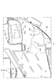
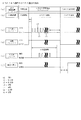
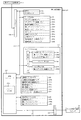
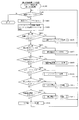
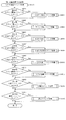
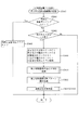
以下、本発明の実施形態について、添付図面を参照して説明する。まず、図1から図81を参照し、第1実施形態として、本発明をパチンコ遊技機(以下、単に「パチンコ機」という)10に適用した場合の一実施形態について説明する。図1は、第1実施形態におけるパチンコ機10の正面図であり、図2はパチンコ機10の遊技盤13の正面図であり、図3はパチンコ機10の遊技盤13の正面視右下領域を拡大した拡大図であり、図4〜図7はパチンコ機10の遊技盤13に設けられたV入賞装置650の構造を模式的に示した模式図であり、図8はパチンコ機10の後面図である。
Embodiments of the present invention will be described below with reference to the accompanying drawings. First, an embodiment in which the present invention is applied to a pachinko gaming machine (hereinafter, simply referred to as "pachinko machine") 10 will be described as a first embodiment with reference to FIGS. FIG. 1 is a front view of the
図1に示すように、パチンコ機10は、略矩形状に組み合わせた木枠により外殻が形成される外枠11と、その外枠11と略同一の外形形状に形成され外枠11に対して開閉可能に支持された内枠12とを備えている。外枠11には、内枠12を支持するために正面視(図1参照)左側の上下2カ所に金属製のヒンジ18が取り付けられ、そのヒンジ18が設けられた側を開閉の軸として内枠12が正面手前側へ開閉可能に支持されている。
As shown in FIG. 1, the
内枠12には、多数の釘や球が入球可能な入球口63,64,640等を有する遊技盤13(図2参照)が裏面側から着脱可能に装着される。この遊技盤13の正面を球(遊技球)が流下することにより弾球遊技が行われる。なお、内枠12には、球を遊技盤13の正面領域に発射する球発射ユニット112a(図9参照)やその球発射ユニット112aから発射された球を遊技盤13の正面領域まで誘導する発射レール(図示せず)等が取り付けられている。尚、遊技盤13に設けられた多数の入球口の内容については、図2を参照して後述する。
A game board 13 (see FIG. 2) having ball entrances 63, 64, 640, etc., into which a large number of nails and balls can enter, is detachably attached to the
内枠12の正面側には、その正面上側を覆う正面枠14と、その下側を覆う下皿ユニット15とが設けられている。正面枠14及び下皿ユニット15を支持するために正面視(図1参照)左側の上下2カ所に金属製のヒンジ19が取り付けられ、そのヒンジ19が設けられた側を開閉の軸として正面枠14及び下皿ユニット15が正面手前側へ開閉可能に支持されている。なお、内枠12の施錠と正面枠14の施錠とは、シリンダ錠20の鍵穴21に専用の鍵を差し込んで所定の操作を行うことでそれぞれ解除される。
On the front side of the
正面枠14は、装飾用の樹脂部品や電気部品等を組み付けたものであり、その略中央部には略楕円形状に開口形成された窓部14cが設けられている。正面枠14の裏面側には2枚の板ガラスを有するガラスユニット16が配設され、そのガラスユニット16を介して遊技盤13の正面がパチンコ機10の正面側に視認可能となっている。
The
正面枠14には、球を貯留する上皿17が正面側へ張り出して上面を開放した略箱状に形成されており、この上皿17に賞球や貸出球などが排出される。上皿17の底面は正面視(図1参照)右側に下降傾斜して形成され、その傾斜により上皿17に投入された球が球発射ユニット112a(図9参照)へと案内される。また、上皿17の上面には、枠ボタン22が設けられている。この枠ボタン22は、例えば、第3図柄表示装置81(図2参照)で表示される演出のステージを変更したり、スーパーリーチの演出内容を変更したりする場合などに、遊技者により操作される。
On the
正面枠14には、その周囲(例えばコーナー部分)に各種ランプ等の発光手段が設けられている。これら発光手段は、大当たり時や所定のリーチ時等における遊技状態の変化に応じて、点灯又は点滅することにより発光態様が変更制御され、遊技中の演出効果を高める役割を果たす。窓部14cの周縁には、LED等の発光手段を内蔵した電飾部29〜33が設けられている。パチンコ機10においては、これら電飾部29〜33が大当たりランプ等の演出ランプとして機能し、大当たり時やリーチ演出時等には内蔵するLEDの点灯や点滅によって各電飾部29〜33が点灯または点滅して、大当たり中である旨、或いは大当たり一歩手前のリーチ中である旨が報知される。また、正面枠14の正面視(図1参照)左上部には、LED等の発光手段が内蔵され賞球の払い出し中とエラー発生時とを表示可能な表示ランプ34が設けられている。
The
また、右側の電飾部32下側には、正面枠14の裏面側を視認できるように裏面側より透明樹脂を取り付けて小窓35が形成され、遊技盤13正面の貼着スペースK1(図2参照)に貼付される証紙等がパチンコ機10の正面から視認可能とされている。また、パチンコ機10においては、より煌びやかさを醸し出すために、電飾部29〜33の周りの領域にクロムメッキを施したABS樹脂製のメッキ部材36が取り付けられている。
In addition, a
窓部14cの下方には、貸球操作部40が配設されている。貸球操作部40には、度数表示部41と、球貸しボタン42と、返却ボタン43とが設けられている。パチンコ機10の側方に配置されるカードユニット(球貸しユニット)(図示せず)に紙幣やカード等を投入した状態で貸球操作部40が操作されると、その操作に応じて球の貸出が行われる。具体的には、度数表示部41はカード等の残額情報が表示される領域であり、内蔵されたLEDが点灯して残額情報として残額が数字で表示される。球貸しボタン42は、カード等(記録媒体)に記録された情報に基づいて貸出球を得るために操作されるものであり、カード等に残額が存在する限りにおいて貸出球が上皿17に供給される。返却ボタン43は、カードユニットに挿入されたカード等の返却を求める際に操作される。なお、カードユニットを介さずに球貸し装置等から上皿17に球が直接貸し出されるパチンコ機、いわゆる現金機では貸球操作部40が不要となるが、この場合には、貸球操作部40の設置部分に飾りシール等を付加して部品構成は共通のものとしても良い。カードユニットを用いたパチンコ機と現金機との共通化を図ることができる。
A ball
上皿17の下側に位置する下皿ユニット15には、その中央部に上皿17に貯留しきれなかった球を貯留するための下皿50が上面を開放した略箱状に形成されている。下皿50の右側には、球を遊技盤13の正面へ打ち込むために遊技者によって操作される操作ハンドル51が配設される。
In the
操作ハンドル51の内部には、球発射ユニット112aの駆動を許可するためのタッチセンサ51aと、押下操作している期間中には球の発射を停止する発射停止スイッチ51bと、操作ハンドル51の回動操作量(回動位置)を電気抵抗の変化により検出する可変抵抗器(図示せず)などが内蔵されている。操作ハンドル51が遊技者によって右回りに回動操作されると、タッチセンサ51aがオンされると共に可変抵抗器の抵抗値が回動操作量に対応して変化し、その可変抵抗器の抵抗値に対応した強さ(発射強度)で球が発射され、これにより遊技者の操作に対応した飛び量で遊技盤13の正面へ球が打ち込まれる。また、操作ハンドル51が遊技者により操作されていない状態においては、タッチセンサ51aおよび発射停止スイッチ51bがオフとなっている。
Inside the
具体的には、90%〜100%の発射強度で発射された球は必ず可変表示装置ユニット80の右側の領域を通過し、40%〜50%の発射強度で発射された球は必ず可変表示装置ユニット80の左側の領域を通過するように構成され、50%〜60%の発射強度で発射された球は、殆どが可変表示装置ユニット80の左側の領域を通過し、一部が可変表示装置ユニット80の右側の領域を通過する。また、70%〜90%の発射強度で発射された球は、殆どが可変表示装置ユニット80の右側の領域を通過し、一部が可変表示装置ユニット80の左側の領域を通過するように構成されている。
Specifically, a ball fired at a firing intensity of 90% to 100% always passes through the area on the right side of the
下皿50の正面下方部には、下皿50に貯留された球を下方へ排出する際に操作するための球抜きレバー52が設けられている。この球抜きレバー52は、常時、右方向に付勢されており、その付勢に抗して左方向へスライドさせることにより、下皿50の底面に形成された底面口が開口して、その底面口から球が自然落下して排出される。この球抜きレバー52の操作は、通常、下皿50の下方に下皿50から排出された球を受け取る箱(一般に「千両箱」と称される)を置いた状態で行われる。下皿50の右方には、上述したように操作ハンドル51が配設され、下皿50の左方には灰皿53が取り付けられている。
In the lower part of the front of the
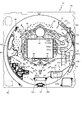
図2に示すように、遊技盤13は、正面視略正方形状に切削加工したベース板60に、球案内用の多数の釘(図示せず)や風車の他、レール61,62、一般入賞口63、第1入球口64、第2入球口640、第1可変入賞装置65、V入賞装置650、普通図柄始動口(スルーゲート)67、可変表示装置ユニット80等を組み付けて構成され、その周縁部が内枠12(図1参照)の裏面側に取り付けられる。ベース板60は光透過性の樹脂材料からなり、その正面側からベース板60の後面側に配設された各種構造体を遊技者に視認させることが可能に形成される。一般入賞口63、第1入球口64、第2入球口640、第1可変入賞装置65、V入賞装置650、可変表示装置ユニット80は、ルータ加工によってベース板60に形成された貫通穴に配設され、遊技盤13の正面側からタッピングネジ等により固定されている。
As shown in FIG. 2, the
遊技盤13の正面中央部分は、正面枠14の窓部14c(図1参照)を通じて内枠12の正面側から視認することができる。以下に、主に図2を参照して、遊技盤13の構成について説明する。
The front center portion of the
遊技盤13の正面には、帯状の金属板を略円弧状に屈曲加工して形成した外レール62が植立され、その外レール62の内側位置には外レール62と同様に帯状の金属板で形成した円弧状の内レール61が植立される。この内レール61と外レール62とにより遊技盤13の正面外周が囲まれ、遊技盤13とガラスユニット16(図1参照)とにより前後が囲まれることにより、遊技盤13の正面には、球の挙動により遊技が行われる遊技領域が形成される。遊技領域は、遊技盤13の正面であって2本のレール61,62とレール間を繋ぐ樹脂製の外縁部材とにより区画して形成される領域(入賞口等が配設され、発射された球が流下する領域)である。
An
2本のレール61,62は、球発射ユニット112a(図9参照)から発射された球を遊技盤13上部へ案内するために設けられたものである。内レール61の先端部分(図2の左上部)には戻り球防止部材68が取り付けられ、一旦、遊技盤13の上部へ案内された球が再度球案内通路内に戻ってしまうといった事態が防止される。外レール62の先端部(図2の右上部)には、球の最大飛翔部分に対応する位置に返しゴム69が取り付けられ、所定以上の勢いで発射された球は、返しゴム69に当たって、勢いが減衰されつつ中央部側へ跳ね返される。
The two
遊技領域の正面視右側上部(図2の右側上部)には、発光手段である複数のLED及び7セグメント表示器を備える第1図柄表示装置37a,37bが配設されている。第1図柄表示装置37a,37bは、主制御装置110(図9参照)で行われる各制御に応じた表示がなされるものであり、主にパチンコ機10の遊技状態の表示が行われる。本実施形態では、第1図柄表示装置37a,37bは、球が、第1入球口64へ入賞したか、第2入球口640へ入賞したかに応じて使い分けられるように構成されている。具体的には、球が、第1入球口64へ入賞した場合には、第1図柄表示装置37aが作動し、一方で、球が、第2入球口640へ入賞した場合には、第1図柄表示装置37bが作動するように構成されている。
First
また、第1図柄表示装置37a,37bは、LEDにより、パチンコ機10が時短中か通常中であるかを点灯状態により示したり、変動中であるか否かを点灯状態により示したり、停止図柄が時短大当たり(大当たり遊技終了後に遊技状態として時短状態が設定される大当たり)に対応した図柄か普通大当たり(大当たり遊技終了後に遊技状態として通常状態が設定される大当たり)に対応した図柄か外れ図柄であるかを点灯状態により示したり、保留球数を点灯状態により示すと共に、7セグメント表示装置により、大当たり中のラウンド数やエラー表示を行う。なお、複数のLEDは、それぞれのLEDの発光色(例えば、赤、緑、青)が異なるよう構成され、その発光色の組み合わせにより、少ないLEDでパチンコ機10の各種遊技状態を示唆することができる。
In addition, the first
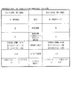
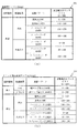
尚、本パチンコ機10では、第1入球口64及び第2入球口640へ入賞があったことを契機として抽選が行われる。パチンコ機10は、その抽選において、大当たりか否かの当否判定(大当たり抽選)を行うと共に、大当たりと判定した場合はその大当たり種別の判定も行う。ここで判定される大当たり種別としては、大当たり遊技のラウンド数が15ラウンドで大当たり終了後に時短状態が付与される15R時短大当たり(15R時短有大当たり)、大当たり遊技のラウンド数が5ラウンドで大当たり終了後に時短状態が付与される5R時短大当たり(5R時短有大当たり)、大当たり遊技のラウンド数が5Rで大当たり終了後に時短状態が付与されない5R通常大当たり(5R時短無大当たり)が用意されている。
In the
また、大当たり抽選の抽選結果として上述した大当たりでは無い外れと判定された場合の一部において、上述した大当たりよりも遊技者に付与される特典が少ない(例えば、1ラウンドのみV入賞装置650を開放させる特典)小当たりが用意されている。第1図柄表示装置37a,37bには、変動終了後の停止図柄として抽選の結果が大当たりであるか否か(小当たりであるか否か)が示されるだけでなく、大当たりである場合はその大当たり種別に応じた図柄が示される。
In addition, in some cases where it is determined that the hit is not a jackpot as described above as a result of the jackpot lottery, the privilege given to the player is smaller than the jackpot described above (for example, the
ここで、「15R時短大当たり」とは、最大ラウンド数が15ラウンドの大当たりの後に時短状態へ移行する大当たりのことであり、「5R時短大当たり」とは、最大ラウンド数が5ラウンドの大当たりの後に時短状態へ移行する大当たりのことである。また、「5R通常大当たり」は、最大ラウンド数が5ラウンドの大当たりの後に時短状態へと移行せずに通常状態へと移行する大当たりのことである。 Here, “15R time-saving jackpot” means a jackpot in which the maximum number of rounds shifts to the time-saving state after 15 rounds of jackpot, and “5R time-saving jackpot” means that the maximum number of rounds is after 5 rounds of jackpot. It is a jackpot that shifts to a time reduction state. The “5R normal jackpot” is a jackpot in which the maximum number of rounds shifts to the normal state without shifting to the time saving state after the five rounds of jackpots.
つまり、本パチンコ機10では、特別図柄の大当たりに当選した場合に提供される大当たり遊技として、遊技者に最も多くの特典を付与可能な「15R時短大当たり」と、その次に多い特典を付与可能な「5R時短大当たり」と、大当たり遊技のうち最も遊技者に付与される特典が少ない「5R通常大当たり」と、のうち、何れかの大当たり遊技が提供されるように構成されている。これにより、特別図柄の抽選において大当たりに当選した場合であっても付与され得る特典が異なる大当たり遊技のうち、最も多くの特典が付与される大当たり遊技が提供されることを期待させながら遊技を行わせることができる。
In other words, with the
なお、本実施形態では、大当たり遊技のラウンド数(大当たり遊技中に獲得可能な賞球数)と、大当たり遊技終了後に設定される遊技状態の内容と、に応じて遊技者に付与される特典の大小を定義しているが、これに限ること無く、上述した条件以外を用いて遊技者に付与される特典の大小を定義しても良いし、特典に大小を定義付けることなく、異なる特典が付与されるように大当たり遊技の内容を異ならせるだけでも良い。 In the present embodiment, the bonus given to the player according to the number of rounds of the jackpot game (the number of prize balls that can be acquired during the jackpot game) and the content of the game state set after the jackpot game ends. The size is defined, but the size is not limited to this, and the size of the privilege given to the player may be defined using conditions other than the above conditions, or different benefits may be provided without defining the size of the benefit. The content of the jackpot game may be different so as to be performed.
また、「時短状態」とは、大当たり終了後に遊技者に付与される付加価値(特典)として、大当たり確率は通常状態と同じであるが、第2入球口640へ球が入球し易い遊技状態である。この第2入球口640へ球が入球し易い状態とするために、本実施形態では、第2図柄の変動時間を通常状態よりも短くし、且つ、第2図柄の抽選結果が当たりの場合に動作させる電動役物640aの動作態様を通常状態よりも第2入球口640へ球が入球し易い期間が長くなるように設定している。なお、第2入球口640へ球が入球し易い遊技状態を設定するためにそれ以外の構成を用いても良く、上述した設定内容の一部のみを用いても良いし、上述した内容以外にも、第2図柄の当たり確率を通常状態よりも高く設定するように構成しても良い。
In addition, the “time reduction state” is a game in which a ball is likely to enter the
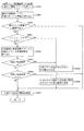
さらに、詳細は後述するが、本実施形態では「時短状態」が終了する条件として、第1特別図柄および第2特別図柄の変動回数(合計変動回数)が第1所定回数(100回)に到達した場合(第1終了条件)、或いは、特別図柄の抽選において小当たりに当選した回数が第2所定回数(例えば、1回)に到達した場合(第2終了条件)の何れかの終了条件が成立した場合に、遊技状態を時短状態から通常状態へと移行するように構成している。このように、遊技状態を時短状態から通常状態へと移行させるための終了条件を複数用意し、その複数の終了条件のうち何れかの終了条件が成立した場合に時短状態から通常状態へと移行させることで、時短状態が終了するタイミングを複数設定することが可能となり、遊技者に対して、通常状態よりも遊技者に有利な時短状態がいつまで継続するのかドキドキさせながら遊技を行わせることができる。 Further, as will be described later in detail, in the present embodiment, as a condition for terminating the "time saving state", the number of times of change (total number of times of change) of the first special symbol and the second special symbol reaches the first predetermined number of times (100 times). Either (the first end condition), or if the number of wins for the small hit in the special symbol lottery reaches the second predetermined number (for example, once) (the second end condition), When the game is established, the game state is shifted from the time saving state to the normal state. In this way, a plurality of end conditions for shifting the gaming state from the time saving state to the normal state are prepared, and when any one of the plurality of end conditions is satisfied, the state shifts from the time saving state to the normal state. By doing so, it is possible to set a plurality of timings at which the time saving state ends, and it is possible to make the player play the game while pounding on how long the time saving state advantageous to the player than the normal state continues it can.
さらに、本実施形態では特別図柄の抽選において当選し得る小当たりとして、複数の小当たり種別(例えば、小当たりA〜小当たりC)が用意されており、各小当たり種別に対してそれぞれ第2終了条件が成立する回数が異ならせて設定されている。このように構成することで、時短状態中に当選した小当たり回数だけで時短状態が終了するか否かを予測することが困難となるため、遊技者に対して常に緊張感を持たせて時短遊技を行わせることができる。 Further, in the present embodiment, a plurality of small hit types (for example, small hits A to small hits C) are prepared as small hits that can be won in the special symbol lottery, and a second type for each small hit type is provided. The number of times the end condition is satisfied is set differently. With this configuration, it is difficult to predict whether or not the time-saving state will be completed only by the number of small hits that have been won during the time-saving state. A game can be played.
また、本実施形態では、小当たり遊技中に開放されるV入賞装置650内に特定領域を設け、小当たり遊技中に球が特定領域を通過することで(特定領域である特別排出流路650e2に設けられたVスイッチ650e3が球を検知することで)大当たり(所謂、2種当たり)となるように構成されている(図6参照)。加えて、詳細は後述するが、当選した小当たりの小当たり種別に応じて小当たり遊技中に球が特定領域を通過する期待度(V入賞期待度)が異なるように構成している。そして、各小当たり種別に対して設定される第2終了条件が成立する回数(小当たり回数)を、V入賞期待度が高い小当たり遊技が実行される小当たり種別の方が少なくなるように構成している。
Further, in the present embodiment, a specific area is provided in the
このように構成することで、時短遊技中において小当たりに当選した場合に2種当たりを獲得するためのV入賞期待度と、時短状態が終了するかもしれない不安感とを関連付けることができ、遊技者により意欲的に遊技を行わせることができる。 With this configuration, it is possible to associate a V winning award expectation for obtaining two kinds of wins when a small hit is won during a time-saving game with an anxiety that the time-saving state may end, A player can be motivated to play a game.
なお、本実施形態では、特別図柄(第1特別図柄、第2特別図柄)の変動回数に対して、上述した通り第1所定回数(100回)を終了条件(第1終了条件)として設定しているが、特別図柄の変動回数に対してそれ以外の終了条件を設定しても良く、例えば、第1特別図柄のみの変動回数が第3所定回数(例えば、50回)となった場合や、第2特別図柄のみの変動回数が第4所定回数(例えば、80回)となった場合に時短状態の終了条件が成立するように構成しても良い。また、上述した多数の終了条件の一部のみを用いても良いし、それぞれを適宜組み合わせても良い。 In the present embodiment, the first predetermined number (100 times) is set as an end condition (first end condition) as described above with respect to the number of times the special symbol (first special symbol, second special symbol) changes. However, other end conditions may be set for the number of times the special symbol changes, for example, when the number of changes of only the first special symbol becomes a third predetermined number (for example, 50). Alternatively, the end condition of the time saving state may be satisfied when the number of changes of only the second special symbol reaches a fourth predetermined number (for example, 80). Further, only some of the above-mentioned many termination conditions may be used, or each of them may be appropriately combined.
遊技領域には、球が入賞することにより10個の球が賞球として払い出される複数の一般入賞口63が配設されている。また、遊技領域の中央部分には、可変表示装置ユニット80が配設されている。可変表示装置ユニット80には、第1入球口64及び第2入球口640への球の入賞(始動入賞)をトリガとして、第1図柄表示装置37a,37bにおける変動表示と同期させながら、第3図柄の変動表示を行う液晶ディスプレイ(以下単に「表示装置」と略す)で構成された第3図柄表示装置81と、普通図柄始動口(スルーゲート)67への球の通過をトリガとして第2図柄を変動表示するLEDで構成される第2図柄表示装置(図示せず)とが設けられている。また、可変表示装置ユニット80には、第3図柄表示装置81の外周を囲むようにして、センターフレーム86が配設されている。
In the game area, a plurality of general winning
第3図柄表示装置81は15インチサイズの大型の液晶ディスプレイで構成されるものであり、表示制御装置114(図9参照)によって表示内容が制御されることにより、例えば左、中及び右の3つの図柄列が表示される(図10参照)。各図柄列は複数の図柄(第3図柄)によって構成され、これらの第3図柄が図柄列毎に縦スクロールして第3図柄表示装置81の表示画面上にて第3図柄が可変表示されるようになっている。本実施形態の第3図柄表示装置81は、主制御装置110(図9参照)の制御に伴った遊技状態の表示が第1図柄表示装置37a,37bで行われるのに対して、その第1図柄表示装置37a,37bの表示に応じた装飾的な表示を行うものである。
The third
つまり、第1図柄表示装置37a,37bにおいて第1図柄が可変表示(変動表示)されている期間(動的表示期間)に対応させて第3図柄表示装置81にて第3図柄が可変表示(変動表示)され、第1図柄表示装置37a,37bにおいて特別図柄の抽選結果を示す表示態様で第1図柄が停止表示されるタイミングに対応させて第3図柄表示装置81にて第3図柄が特別図柄の抽選結果に応じた表示態様で停止表示される。
That is, the third
即ち、判別条件(第1入球口64或いは第2入球口640への球の入賞)が成立することに基づいて判別手段による判別が実行され(特別図柄の抽選が実行され)、所定の動的表示期間が経過するまで識別情報(第3図柄)が動的表示(変動表示)された後に、判別手段の判別結果(特別図柄の抽選結果)を示した表示態様(図柄の組み合わせ)で、識別情報(第3図柄)が停止表示される。これにより、遊技者は第3図柄表示装置81に表示される第3図柄を把握することで特別図柄の抽選結果を把握することができる。よって、遊技者に分かり易い遊技を提供することができる。
That is, the determination by the determination means is performed based on the determination conditions (the winning of the ball to the
なお、第3図柄表示装置81に停止表示される第3図柄は、特別図柄の抽選結果に応じた表示態様であれば良く、特別図柄の抽選結果の一部(例えば、大当たり或いは外れといった当否判定結果のみ)に対応した表示態様でも良いし、特別図柄の抽選結果の詳細(例えば、当選した大当たりの種別)に対応した表示態様でも良い。また、特別図柄の抽選結果として、3種類の抽選結果(例えば、大当たり、小当たり、外れ)を有する場合には、第3図柄の表示態様として、特別図柄の抽選結果が上述した3種類の抽選結果のうち特定の2種類(例えば、大当たり或いは小当たり)の何れかであることを示す表示態様を用いても良い。
It should be noted that the third symbol stopped and displayed on the third
また、本実施形態で用いられる表示装置に代えて、例えばリール等を用いて第3図柄表示装置81を構成するようにしても良いし、パチンコ機10に複数の表示装置を設けても良い。
Further, instead of the display device used in the present embodiment, the third
第2図柄表示装置83は、球が普通図柄始動口(スルーゲート)67を通過する毎に表示図柄(第2図柄(図示せず))としての「○」の図柄と「×」の図柄とを所定時間交互に点灯させる動的表示(変動表示)を行うものである。パチンコ機10では、球が普通図柄始動口(スルーゲート)67を通過したことが検出されると、当たり抽選が行われる。その当たり抽選の結果、当たりであれば、第2図柄表示装置83において、第2図柄の変動表示後に「○」の図柄が停止表示される。また、当たり抽選の結果、外れであれば、第2図柄表示装置83において、第2図柄の変動表示後に「×」の図柄が停止表示される。
The second
パチンコ機10は、第2図柄表示装置83における変動表示が所定図柄(本実施形態においては「○」の図柄)で停止した場合に、第2入球口640に付随された電動役物640aが所定時間だけ作動状態となる(突出する)ように構成されている。詳細は後述するが、電動役物640aが作動状態に可変されることにより、球が第2入球口640に入球可能となる。
In the case of the
第2図柄の変動表示にかかる時間は、遊技状態が通常状態である場合よりも、時短状態である方が短くなるように設定される。これにより、時短状態中は、第2図柄の変動表示が短い時間で行われるので、当たり抽選を通常状態である場合よりも多く行うことができる。よって、当たり抽選において当たりとなる機会が増えるので、第2入球口640の電動役物640aが作動状態となる機会を遊技者に多く与えることができる。よって、時短状態中を、第2入球口640へ球が入賞し易い状態とすることができる。
The time required for the variable display of the second symbol is set to be shorter in the time reduction state than in the normal game state. Accordingly, during the time reduction state, the fluctuation display of the second symbol is performed in a short time, so that the winning lottery can be performed more than in the normal state. Therefore, the chance of winning in the winning lottery increases, so that the player can be given many opportunities to activate the
さらに、本実施形態では時短状態中に第2図柄(普通図柄)の当たりに当選した場合には、通常状態中に第2図柄(普通図柄)の当たりに当選した場合よりも電動役物640aを作動させる期間(電動役物640aを突出させて球が第2入球口640に入球し易くする期間)が長くなるように構成している。これにより、時短状態中を第2入球口640へ球が入賞し易い状態とすることができる。
Furthermore, in the present embodiment, when the player wins the second symbol (normal symbol) during the time saving state, the
なお、時短状態中を第2入球口640へ球が入賞し易い状態とするための構成は上述した内容に限られる物では無く、例えば、第2図柄の当たり確率を高める、1回に当たりに対する電動役物640aの開放時間や開放回数を増やすといった構成を用いても良い。また、電動役物640aの作動パターンを異ならせることにより時短状態を第2入球口640へ球が入賞しやすい状態としている場合は、第2図柄の変動表示にかかる時間を遊技状態にかかわらず一定としてもよい。一方、第2図柄の変動表示にかかる時間を、時短中において通常中よりも短く設定する場合は、当たり確率を遊技状態にかかわらず一定にしてもよいし、また、1回の当たりに対する電動役物640aの開放時間や開放回数を遊技状態にかかわらず一定にしてもよい。
In addition, the configuration for making the ball easily enter the
さらに、設定される遊技状態に応じて第2図柄の変動表示にかかる時間を可変させ、且つ、電動役物640aの開放時間や開放回数を可変させる場合において、第2図柄の変動表示が開始される時点にて設定されている遊技状態に応じて第2図柄の変動表示時間を決定し、第2図柄の変動表示が停止し、当たりを示す第2図柄が表示されたタイミング(第2図柄の当たり遊技、即ち、電動役物640aを作動させるタイミング)において設定されている遊技状態に応じて電動役物640aの開放時間や開放回数を決定するように構成しても良い。このように構成することで、例えば、時短状態中に変動が開始された第2図柄が通常状態中に当たりを示す表示態様で停止表示された場合に、通常状態中に対応する電動役物640aの作動パターンで作動させることができる。よって、設定されている遊技状態と実行される電動役物の作動パターンとをより正確に対応付けることができる。
Further, in the case where the time required for the variable display of the second symbol is changed according to the set game state and the opening time and the number of times of opening the
なお、遊技状態と第2図柄の変動時間および電動役物640aの作動パターンの関係は上述した内容以外を規定しても良く、例えば、第2図柄の変動開始タイミングと、電動役物640aの作動開始タイミングとの何れか一方のタイミングにおいて遊技状態として時短状態が設定されていると判別した場合には、電動役物640aの作動パターンとして遊技者に有利な作動パターン(時短状態中に実行される作動パターン)を設定するように構成しても良い。
The relationship between the game state, the variation time of the second symbol, and the operation pattern of the
普通図柄始動口(スルーゲート)67は、図2に示したように可変表示装置ユニット80の下側の領域における右方において遊技盤13に組み付けられ、遊技盤に発射された球のうち、遊技盤の右方を流下する球の一部(殆ど)が通過可能に構成されている。普通図柄始動口(スルーゲート)67を球が通過すると、第2図柄の当たり抽選が行われる。当たり抽選の後、第2図柄表示装置83にて変動表示を行い、当たり抽選の結果が当たりであれば、変動表示の停止図柄として「○」の図柄を表示し、当たり抽選の結果が外れであれば、変動表示の停止図柄として「×」の図柄を表示する。
The normal symbol starting port (through gate) 67 is assembled to the
なお、本実施形態では、球が普通図柄始動口(スルーゲート)67を通過したことを保留する機能を有していないが、普通図柄始動口(スルーゲート)67を球が通過したことを保留する機能を有する場合は、例えば、合計で最大4回まで保留され、その保留球数を示すための第2図柄保留表示手段を遊技者が視認可能な箇所(例えば、第3図柄表示装置81の一部分)に設けると良い。 In this embodiment, the ball does not have a function of retaining that the ball has passed through the normal symbol starting port (through gate) 67. In the case where the player has the function of performing the game, for example, the game is held up to a total of four times, and the second symbol holding display means for indicating the number of held balls can be visually recognized by the player (for example, the third symbol display device 81). Part).
なお、第2図柄の変動表示は、本実施形態のように、第2図柄表示装置において複数のランプの点灯と非点灯を切り換えることにより行うものの他、第1図柄表示装置37a,37b及び第3図柄表示装置81の一部を使用して行うようにしても良い。同様に、第2図柄保留ランプの点灯を第3図柄表示装置81の一部で行うようにしても良い。また、普通図柄始動口(スルーゲート)67を球が通過したことを保留する機能を有する場合には、その保留数は4回に限定されるものでなく、3回以下、又は、5回以上の回数(例えば、8回)に設定しても良い。また、普通図柄始動口(スルーゲート)67の組み付け数は1つに限定されるものではなく、複数(例えば、2つ)であっても良い。また、普通図柄始動口(スルーゲート)67の組み付け位置は可変表示装置ユニット80の右方に限定されるものではなく、例えば、可変表示装置ユニット80の左方でも良い。また、第1図柄表示装置37a,37bにより保留球数が示されるので、第2図柄保留ランプにより点灯表示を行わないものとしてもよい。
The variable display of the second symbol is performed by switching on and off of a plurality of lamps in the second symbol display device as in the present embodiment, as well as the first
可変表示装置ユニット80の下方には、球が入球し得る第1入球口64が配設されている。この第1入球口64へ球が入球すると遊技盤13の裏面側に設けられる第1入球口スイッチ(図示せず)がオンとなり、その第1入球口スイッチのオンに起因して主制御装置110(図9参照)で大当たりの抽選がなされ、その抽選結果に応じた表示が第1図柄表示装置37aで示される。
Below the variable
図2に示した通り、第1入球口64は可変表示装置ユニット80の左側を球が流下するように行われる遊技(所謂、左打ち遊技)の方が、可変表示装置ユニット80の右側を球が流下するように行われる遊技(所謂、右打ち遊技)よりも球が入球し易くなるように遊技盤13上に釘が植設されている。よって、第2入球口640に球が入球し難い遊技状態(通常状態)が設定されている場合には、第1入球口64に球を入球させるために左打ち遊技が実行される。
As shown in FIG. 2, the
一方、第1入球口64の正面視右方には、球が入球し得る第2入球口640が配設されている。この第2入球口640へ球が入球すると遊技盤13の裏面側に設けられる第2入球口スイッチ(図示せず)がオンとなり、その第2入球口スイッチのオンに起因して主制御装置110(図9参照)で大当たりの抽選がなされ、その抽選結果に応じた表示が第1図柄表示装置37bで示される。
On the other hand, a
また、第1入球口64および第2入球口640は、それぞれ、球が入賞すると5個の球が賞球として払い出される入賞口の1つにもなっている。なお、本実施形態においては、第1入球口64へ球が入賞した場合に払い出される賞球数と第2入球口640へ球が入賞した場合に払い出される賞球数とを同じに構成したが、第1入球口64へ球が入賞した場合に払い出される賞球数と第2入球口640へ球が入賞した場合に払い出される賞球数とを異なる数、例えば、第1入球口64へ球が入賞した場合に払い出される賞球数を3個とし、第2入球口640へ球が入賞した場合に払い出される賞球数を5個として構成してもよい。
The
加えて、本実施形態では特別図柄の抽選契機(大当たりの抽選契機)となる球を検知するスイッチ(第1入球口スイッチ、第2入球口スイッチ)を入球口内に設けているため、特別図柄の抽選契機を獲得すると共に、賞球を獲得できる構成としているが、それ以外の構成を用いても良く、例えば、球が通過可能な領域(ゲート)を設け、その領域(ゲート)を通過する球を検知するスイッチ(検知手段)が球の通過を検知した場合に、特別図柄の抽選契機を獲得し得るように構成しても良い。なお、この場合、特別図柄の抽選契機となり得る領域(ゲート)を通過した球の少なくとも一部が入球可能となり、球が入球した場合に所定数(例えば5個)の賞球が払い出される入球口を設けると良い。このように構成することで、特別図柄の抽選契機の獲得回数と、賞球獲得回数とを異ならせることができるため、多様な遊技性を提供することができる。 In addition, in the present embodiment, a switch (first entrance switch, second entrance switch) for detecting a ball serving as a special symbol lottery trigger (big hit lottery trigger) is provided in the entrance. Although it is configured to be able to acquire a prize ball while acquiring a lottery opportunity of a special symbol, other configurations may be used. For example, an area (gate) through which a ball can pass is provided, and the area (gate) is provided. When a switch (detection means) for detecting a passing ball detects the passage of the ball, a special symbol lottery opportunity may be obtained. In this case, at least a part of the ball that has passed through the area (gate) that can be a chance to win a special symbol lottery can be entered, and when the ball is entered, a predetermined number (for example, five) of prize balls are paid out. It is good to provide a ball entrance. With this configuration, the number of times the special symbol lottery opportunity is obtained and the number of times the prize ball is obtained can be made different, so that various game characteristics can be provided.
第2入球口640には電動役物640aが付随されている。この電動役物640aは遊技盤13から手前側(図2の視点で手前側)に突出した突出状態(許容状態)と、遊技盤13側に待避した待避状態(規制状態)と、に可変可能に構成されており、通常(第2図柄の当たりに当選していない場合)は電動役物640aが待避状態(規制状態)となって、球が第2入球口640へ入球し難い状態となっている。一方、普通図柄始動口(スルーゲート)67への球の通過を契機として行われる第2図柄の変動表示の結果、「○」の図柄が第2図柄表示装置に表示された場合、即ち、第2図柄の抽選において当たりに当選した場合は、電動役物640aが突出状態(許容状態)となり、球が第2入球口640へ入球し易い状態となる。
The
ここで、本実施形態のパチンコ機10に設けられた第2入球口640への球流れについて説明をする。本実施形態では図2に示した通り、遊技盤13の遊技領域の略中央位置に可変表示装置ユニット80を配設し、遊技領域を可変表示装置ユニット80の左方側(左打ち領域)と右方側(右打ち領域)とに区画しており、遊技者が操作ハンドル51の操作量を調整することで発射された球の行き先を右打ち領域或いは左打ち領域へと打ち分けることが可能に構成している。以下、遊技者が操作ハンドル51を操作して遊技領域のうち左打ち領域へと球を発射させる遊技を左打ち遊技、右打ち領域へと球を発射させる遊技を右打ち遊技と称す。
Here, the ball flow to the
本実施形態では、図2に示した通り、第2入球口640と、第2入球口640に付随する電動役物640a、及び、電動役物640aを動作させるか否かの抽選のトリガとなる普通図柄始動口(スルーゲート)67が右打ち領域に配設されており、遊技状態として時短状態が設定されている場合には右打ち遊技が行われるように構成している。
In the present embodiment, as shown in FIG. 2, the
左打ち遊技により発射された球が第2入球口640に入球することが無いように可変表示装置ユニット80の下方には釘が植設されており、左打ち遊技中に第2入球口640に球が入球することが無いように構成している。このように構成することで、左打ち遊技では第1特別図柄を変動させるために球を第1入球口64へと入球させる遊技を行わせ、右打ち遊技では第2特別図柄を変動させるために球を第2入球口640へと入球させる遊技を行わせることができ、遊技方法に応じて異なる遊技性を適切に提供することができる。
A nail is planted below the variable
本実施形態のパチンコ機10では、図2に示した通り、右打ち領域には、その上面が左下方向(図2の正面視で左下方向)に向けて下り傾斜しているV入賞装置650が配設され、そのV入賞装置650の上面を流下した球が普通図柄始動口(スルーゲート)67を通過し、電動役物640aに向けて流下するように各機構が配設されている。
In the
そして、電動役物640aが待避状態に位置している場合は、待機状態の電動役物640aを通過し可変入賞装置65に向けて球が流下する。一方、電動役物640aが突出状態に位置している場合は、電動役物640aに到達した球が右下方向(図2の正面視で右下方向)に向けて流下する。そして、電動役物640aの右端まで到達した球は第2入球口640へ入球し、電動役物640aの右端に到達するまでに電動役物640aが待避状態へと可変した場合は、電動役物640aの下方に配設された一般入賞口63に入球するように構成している。
Then, when the
さらに、本パチンコ機10は上述した電動役物640a、第2入球口640、一般入賞口63を覆うように透過性のカバー部材655を設けている。このカバー部材655は入射する光を乱反射させるためのカット加工が表面に施されている。このカバー部材655を設けることで、遊技中はパチンコ機10に設けられた発光手段(LED等)や第3図柄表示装置81から発せられる様々な光によってカバー部材655の内部を遊技者に視認させ難くすることができる。よって、電動役物640aの動作タイミングを図って右打ち遊技を行う行為を抑制することができる。
Further, the
また、遊技が行われていない状態(遊技機の電源がオフになっている状態)では、カバー部材への入射光が抑えられるため、カバー部材655の内部を容易に視認することができ、パチンコ機10のメンテナンスを容易に行うことができる。なお、このようにカバー部材655を用いて内部の視認性を可変させる構成を用いる場合には、上述したように装飾用に発光する発光手段を利用可能に構成することで発光手段を共有することができ、パチンコ機10を構成する部品点数を削減することができるが、カバー部材655の内部を視認困難とするための発光手段を専用に設けても良い。
In addition, in a state where the game is not performed (a state in which the power of the gaming machine is turned off), the incident light to the cover member is suppressed, so that the inside of the
また、電動役物640aの動作が行われる期間を含む所定期間の間カバー部材655の内部を視認困難にすればよく、例えば、電動役物640aの動作が実行されると判別した場合(即ち、普通図柄の抽選により当たりに当選した場合)に、カバー部材655の表面に電動役物640aが動作する旨を報知する文字(例えば、「オープン」)が表示されるように発光手段を制御し、その表示された文字により、カバー部材655の内部を視認困難にするように構成しても良い。これにより、電動役物640aが動作することを遊技者に把握させるとともに、その詳細な動作タイミングを把握させ難くすることができる。
In addition, the inside of the
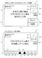
ここで、図3を参照して、本パチンコ機10の右打ち領域の構成について説明をする。図3に示した通り、右打ち遊技により発射された球のうち、スルーゲート67を通過した球は、電動役物640aが配設されている領域に向けて流下する。具体的に説明をすると、電動役物640aは、50mmの長さを有し、その上面を球が流下可能な板状部材で構成され、右下方向(図3の正面視で右下方向)に向けて下り傾斜となるように遊技盤13に配設されている。そして、スルーゲート67を通過した球は電動役物640aの左端から20mmの範囲に該当する領域a(図3参照)に流下する。
Here, the configuration of the right-handed area of the
領域aに到達した球は、電動役物640aが待避状態に位置している場合は電動役物640aを通過し可変入賞装置65に向けて流下する。一方、電動役物640aが突出位置に位置している場合は電動役物640aの上面を右端位置に向けて球が流下する。そして、領域b(電動役物640aの左端から20mmから40mmが該当する領域)に球が到達した状態で電動役物640aが待避状態へと可変した場合には、電動役物640aの下方に設けられた一般入賞口63に向けて球が流下するように構成されている。最後に、領域c(電動役物640aの右端から20mmが該当する領域)に球が到達すると、その球は第2入球口640へ入球するように構成されている。
The ball that has reached the area a passes through the
なお、詳細については図45を参照して後述するが、本実施形態では、遊技状態において電動役物640aが連続して動作する期間が異なる様に構成されており、遊技状態として通常状態が設定されている状態で電動役物640aが動作する場合には、突出状態に位置する電動役物640a上を流下する球が領域b(図3参照)に到達するまでに電動役物640aが待避状態へと可変し、時短状態が設定されている状態では、電動役物640a上を流下する球が領域c(図3参照)に到達するのに十分な期間の間、電動役物640aが突出位置に位置するように構成されている。
Although details will be described later with reference to FIG. 45, in the present embodiment, the period during which the
具体的には、電動役物640aの動作期間(継続して突出状態に位置される期間)が、時短状態中は2秒、通常状態中は0.2秒となるように構成している。そして、電動役物640aは図3に示した領域(領域aから領域cまでの範囲)を球が流下するための流下期間が0.2秒よりも長く、且つ2秒よりも短くなるように構成されている(本実施形態では、0.8秒)。このように構成することで、通常状態中に右打ち遊技を行い、普通図柄の当たりに当選し、動作中の電動役物640aの上面を球が流下する状態になった場合であっても、電動役物640aの上面を流下する球が第2入球口640に到達するまでに電動役物640aの動作が終了するため、通常状態において第2特別図柄の抽選が実行されることを確実に防止することができる。
Specifically, the operation period of the
また、時短状態中においては、電動役物640aの上面を球が流下し第2入球口640へと球が到達する期間(0.4秒)よりも長い期間電動役物640aを動作させるため、誘導状態(突出状態)である電動役物640aの上面を流下した球が第2入球口640へ到達し易くし、第2特別図柄の抽選を実行され易くすることができる。
In addition, during the time saving state, the
さらに、時短状態中において、例えば、電動役物640aが作動してから1.5秒後に電動役物640aに到達した球は電動役物640aの上面を流下し、領域bに到達したタイミングで電動役物640aの作動が終了する(電動役物640aが作動してから2秒経過する)ことになる。このような球は図3に示した通り、電動役物640aの下方に配設された一般入賞口63に入球し、10個の球が賞球として払い出される。このように、時短状態中において右打ち遊技をした場合には、電動役物640aの作動タイミングと、電動役物640aへの球の到達タイミングとによって、異なる入球口(第2入球口640或いは一般入賞口63)へと球を誘導することができるように構成することで、遊技者に対して時短状態中に継続して右打ち遊技を行わせることができる。
Further, during the time-saving state, for example, a ball that arrives at the
なお、詳細は後述するが、本パチンコ機10は第2入球口640への球の入球を起因(トリガ)として第2特別図柄(特図2)の抽選が実行されるように構成されているが、第2入球口640への球の入球を保留記憶する手段(特図2の抽選を実行する権利を保留記憶する手段)を有していないため、特別図柄の変動が実行されている最中に第2入球口640に球が入球したとしても、入球に応じた賞球(5個)が払い出される特典のみが遊技者に付与される。
As will be described in detail later, the
上述したように、一般入賞口63への入球に応じた賞球数が10個で、第2入球口640への入球に応じた賞球数が5個となるように構成しているため、第2特別図柄(特図2)の抽選を実行し得る状態であれば、第2入球口640へ球が入球するほうが一般入賞口63に球が入球するよりも遊技者に有利な特典(即ち、特図2の抽選および5個の賞球)を付与することができ、第2特別図柄(特図2)の抽選を実行し得ない状態(特別図柄変動中)であれば、第2入球口640よりも一般入賞口63に球が入球するほうが遊技者に有利な特典(即ち、10個の賞球)を付与することができるように構成している。
As described above, the number of prize balls according to the ball entering the general winning
これにより、遊技の状況(特別図柄の変動の有無)に応じて、遊技者が入球を所望する入球口(多くの特典を獲得可能な入球口)が可変させることができるため、時短状態中における右打ち遊技を遊技者に楽しませることができる。また、電動役物640aの一回の動作中に第2入球口640と、一般入賞口63との両方に球を入球させるためには、右打ち遊技を継続して実行する必要があるため遊技の稼働を高めることができる。
This allows the player to change the entrance (the entrance through which many benefits can be obtained) in which the player desires to enter the ball in accordance with the situation of the game (whether or not special symbols have changed). The player can enjoy a right-handed game in the state. In addition, in order to make the ball enter both the
尚、本実施形態では時短状態中における電動役物640aの動作期間を電動役物640aの上面を球が流下し第2入球口640へと到達する期間(0.8秒)よりも十分に長い期間(2秒)を設定し、電動役物640aが動作した場合に第2入球口640へ球を確実に入球させるように構成しているが、それ以外に、例えば、時短状態中における電動役物640aの動作期間を電動役物640aの上面を球が流下し第2入球口640へと球が到達する期間(0.8秒)よりも若干長い期間(例えば、0.9秒)となるように構成しても良い。このように構成することで、時短状態中においてスルーゲート67に球を通過させた後、球の打ち出しを止め、電動役物640aが動作したことを確認した後に再度球の打ち出しを開始する行為(所謂、止め打ち)を抑制することができるため、時短状態中において右打ち遊技を継続して行わせ遊技の稼働を向上させることができる。
In the present embodiment, the operation period of the
図2に戻り説明を続ける。図3を参照して上述した通り、右打ち遊技により発射された球は、まずV入賞装置650に到達する。次に、V入賞装置650の構成について説明をする。V入賞装置650は、球が入賞可能な開放状態と入賞困難な閉鎖状態とに可変可能に構成されているものであり、第2特別図柄の抽選結果が「小当たり」である場合にV入賞装置650の開閉扉650f1が動作し特定入賞口(V入賞口)650aに球が入賞可能な開放状態へと可変するように構成されている。
Returning to FIG. 2, the description will be continued. As described above with reference to FIG. 3, the ball fired by the right-handed game first reaches the
また、詳細は図25を参照して後述するが、特別図柄の「大当たり」に当選したうちの一部(大当たり種別が大当たりDの大当たり)においても、V入賞装置650の開閉扉650f1を、上述した「小当たり」に当選した場合と同様に動作させるように構成している。これにより、V入賞装置650の開閉扉650f1が動作した場合に特別図柄の「大当たり」に当選したのか「小当たり」に当選したのかを把握し難くすることができる。
In addition, although details will be described later with reference to FIG. 25, in some of the special jackpots (jackpots of the jackpot type of jackpot D) that have been won, the opening / closing door 650f1 of the
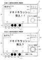
ここで、図3〜図7を参照してV入賞装置650の構成について詳細に説明をする。まず、図3に示した通り、V入賞装置650の開閉扉650f1が特定入賞口(V入賞口)650aを閉鎖している閉鎖状態である場合は、閉鎖状態である開閉扉650f1の上面を球が流下可能に構成されており、V入賞装置650が閉鎖状態中にV入賞装置650に到達した球は、開閉扉650f1上を左下側(図3の正面視で左下側)に向けて流下し、スルーゲート67に向けて流出される。一方、V入賞装置650が開放状態(即ち、小当たり遊技中)である場合は、球がV入賞装置650内へと入賞する。
Here, the configuration of the
本実施形態では、小当たり遊技中におけるV入賞装置650の開放期間が0.1秒×12回となるように構成されており(図25参照)、V入賞装置650が開放するタイミングにおいて開閉扉650f1上を流下している球が、V入賞装置650へと入賞する。V入賞装置650に入賞した球は、第1規制部材651或いは第2規制部材652上を流下しながら検出口650a1(図6(a)参照)に向けて整列して流下するように構成されている。このように構成することで、開閉扉650f1上を流下している球が開閉扉650f1のどの位置からV入賞装置650の特定入賞口(V入賞口)650aに入賞したとしても、円滑に球を流下させることができる。
In the present embodiment, the opening period of the
なお、本実施形態ではV入賞装置650の開閉扉650f1が継続して開放される期間を0.1秒に設定しているが、開閉扉650f1の開放期間中に開閉扉650f1上を流下している球がV入賞装置650へと入賞可能な期間であればその他の期間を設定しても良い。また、本実施形態では1回の小当たり遊技においてV入賞装置650の開閉扉650f1を開放する回数を12回としているが、それ以外の回数を設定しても良い。
In the present embodiment, the period during which the open / close door 650f1 of the
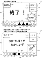
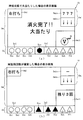
詳細は後述するが、本実施形態では小当たり遊技においてV入賞装置650の開閉扉650f1を1回開放させてから次に開放させるまでの期間(開放間インターバル期間)として、小当たり遊技中の5回目と10回目の開放動作後には5秒が設定され、それ以外のタイミングでは0.5秒が設定されている。これは、小当たり遊技が行われている期間中にV入賞装置650へ球を入賞させ易くさせるためのものである。具体的には、小当たり遊技中において5回目の開放動作が終了した時点でVスイッチ650e3が球を検知していないと判別した場合には、5回目の開放動作終了後の開放間インターバル期間中に、遊技者に右打ち遊技を強調して促す遊技案内表示を第3図柄表示装置81に表示するように構成している。
Although details will be described later, in the present embodiment, the period from the time when the opening / closing door 650f1 of the
そして、第3図柄表示装置81に表示された遊技案内表示を把握することで右打ち遊技を開始した場合にも、V入賞装置650へ球を入球させることができるように、開放間インターバル期間を通常よりも長く設定している。また、小当たり遊技中の10回目の開放動作が終了した時点でVスイッチ650e3が球を検知していないと判別した場合にも同様の制御処理が実行される。
Then, even when a right-handed game is started by grasping the game guidance display displayed on the third
このように構成することで、小当たり遊技中に適切な遊技をしていない遊技者(右打ち遊技をしていない遊技者)に対しても適切な遊技を実行させ易くすることができる。このように、複数回の開放動作が実行される特定遊技(小当たり遊技)中において、一部の開放間インターバル期間を他よりも長く設定し、適正な遊技を行っていないと判別した場合に、適正な遊技内容を促すための遊技案内表示を表示可能とすることで、誤った遊技を行っている遊技者に対して、安心して遊技を行わせることができる。 With this configuration, it is possible to make it easier for a player who is not playing an appropriate game during the small hitting game (a player who is not playing a right-handed game) to execute an appropriate game. In this way, during a specific game (small hitting game) in which a plurality of opening operations are executed, when the interval period between some openings is set longer than the other, and it is determined that an appropriate game is not performed, By making it possible to display a game guidance display for prompting appropriate game content, a player who is playing an incorrect game can play a game with peace of mind.
本実施形態では、小当たり遊技中の5回目と10回目の開放動作後に他よりも長い特別開放間インターバル期間を設定している。このように1回の小当たり遊技中に遊技者に遊技案内表示を表示させるタイミングを複数回設けることで、遊技者に適切な遊技をより行わせ易くすることができる。なお、遊技案内表示を表示させるタイミングを複数回設ける場合では少なくとも2回目移行の報知タイミングを、正常に遊技を行っている遊技者が到達し得ないタイミングに設定するとよい。即ち、詳細は後述するが、本実施形態では小当たり遊技中に継続して右打ち遊技を行うことにより、V入賞装置650の開閉扉650f1の1回の開放動作において少なくとも1個の球が入球し得るように構成されているため、正常な遊技(継続して右打ち遊技)を行っていれば、10回目の開放動作中に小当たり遊技の終了条件となる入賞個数(10個)に到達し、小当たり遊技が終了されることになる。
In this embodiment, after the fifth and tenth opening operations during the small hitting game, a longer special opening interval period is set. By providing a plurality of times for displaying the game guidance display to the player during one small hitting game in this manner, it is possible to make the player more appropriately play a game. In the case where the timing for displaying the game guidance display is provided a plurality of times, the notification timing of at least the second transition may be set to a timing at which a player who normally plays the game cannot reach. That is, as will be described later in detail, in the present embodiment, by performing a right-handed game continuously during the small hitting game, at least one ball is inserted in one opening operation of the opening / closing door 650f1 of the
つまり、小当たり遊技中の開放動作10回目以降に実行される開放間インターバル期間は正常な遊技(継続して右打ち遊技)を行っている場合には到達し得ないタイミングとなる。よって、このタイミングを利用して遊技案内表示を表示させるタイミングを設定することで、正常な遊技(継続して右打ち遊技)を行っている遊技者に対して無用に長い特別開放間インターバル期間が実行されることが無くなり、小当たり遊技を円滑に実行することができる。 That is, the opening interval period executed after the tenth opening operation during the small hit game is a timing that cannot be reached when a normal game (continuous right-handed game) is performed. Therefore, by setting the timing for displaying the game guidance display using this timing, an unnecessary long special opening interval period is provided for a player who is playing a normal game (continuous right-handed game). It is not executed, and the small hit game can be executed smoothly.
なお、本実施形態のように1回目の特別開放間インターバル期間を、正常な遊技(継続して右打ち遊技)を行っても到達するタイミング(5回目の開放動作終了後)に設定する場合は、1回目の特別開放間インターバル期間が開始されるタイミング(5回目の開放動作終了タイミング)、或いは、1回目の特別開放間インターバル期間が開始されてから所定期間経過したタイミング(5回目の開放動作中に入球した球がV入賞装置650から排出されるまでに要する期間を経過したタイミング)においてVスイッチ650e3が球を検知しているかを判別し、Vスイッチ650e3が球を検知していると判別した場合は、1回目の特別開放間インターバル期間中にその旨を報知する報知演出を表示し、Vスイッチ650e3が球を検知していないと判別した場合は、上述したように遊技案内表示を表示するように構成すると良い。これにより、小当たり遊技中に設定した特別開放間インターバル期間を遊技内容に応じて有効に用いることができる。 In the case where the first special opening interval period is set to the timing to reach even after performing a normal game (continuous right-handed game) (after the end of the fifth opening operation) as in the present embodiment, Timing at which the first special opening interval period starts (fifth opening operation end timing), or timing at which a predetermined period has elapsed since the first special opening interval period started (fifth opening operation) It is determined whether or not the V switch 650e3 detects the ball at a timing (elapsed time required for the ball that has entered the ball to be ejected from the V winning device 650), and that the V switch 650e3 detects the ball. When it is determined, a notification effect for notifying that is displayed during the first special opening interval, and the V switch 650e3 detects the ball. If the Most is determined, it may be configured to display the game information display as described above. As a result, the special opening interval period set during the small hit game can be used effectively according to the game content.
さらに、2回目の特別開放間インターバル期間においては、既にVスイッチ650e3が球を検知している場合にも遊技案内表示を表示するように構成すると良い。これにより、小当たり遊技中に所定個数(10個)の球をV入賞装置650へ入賞させることなく小当たり遊技が終了してしまう事態が発生することを抑制することができる。
Further, during the second special opening interval, the game guidance display may be displayed even when the V switch 650e3 has already detected a ball. Thereby, it is possible to suppress occurrence of a situation in which the small hitting game is ended without causing the
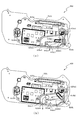
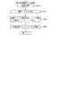
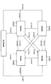
次に、図4を参照してV入賞装置650の構造について詳細に説明をする。図4は、このV入賞装置650の分解斜視図である。V入賞装置650は、図4に示すように、遊技盤13の前面側に突出して配置される開口部形成部材650b、その開口部形成部材650bの背面側に組み合わされて、V入賞装置650を遊技盤13にビス留めするためのベース部材650cと、そのベース部材650cの背面側に配置されてベース部材650cの背面側よりパチンコ機10の前面側に対してLEDを点灯させるためのLEDが複数配置されたLED基板650dと、そのLED基板650dをベース部材650cと狭持する裏カバー体650eと、開口部形成部材650bに形成されている特定入賞口(V入賞口)650aを開閉するための開閉扉650f1を有した開閉ユニット650fと、裏カバー体650eの背面側に組み合わされて流路を形成する流路カバー体650gと、裏カバー体650eと流路カバー体650gとで形成された流路に突出して遊技球の流路を切り替える切替部材650hと、その切替部材650hと係止されるリンク部材650iと、流路カバー体650gの背面側に配置される背面カバー体650jと、その背面カバー体650jの背面側に固定されて、リンク部材650iを作動させる流路ソレノイド650kと、その流路ソレノイド650kを背面側から覆って背面カバー体650jにビスにより固定するための固定用カバー体650mとで構成されている。
Next, the structure of the
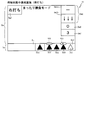
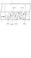
図5は、V入賞装置650の断面図である。図5(c)はV入賞装置650の上面図であり、図5(b)は、V入賞装置650のLb−Lb断面図である。図5(b)に示すように、V入賞装置650には、遊技球が入球可能な開口部である特定入賞口(V入賞口)650aが形成されている。特定入賞口(V入賞口)650aは、パチンコ機10の上方を略長方形状の開口が形成されており、その開口を通過した遊技球が図5(b)の左方向に誘導されるように左下方に傾斜した底面が形成されている。底面の左端部には、遊技球の入賞を検知するための磁気センサ(球検知スイッチ)650c1で構成された検出口650a1が配置されている。この検出口650a1を通過した遊技球は、図5(a)で示す裏カバー体650eの背面側に形成された振り分け流路へと誘導される。
FIG. 5 is a sectional view of the
なお、図5(b)に示すように特定入賞口(V入賞口)650aの開口は、遊技盤13側より出没可能なシャッター機構で構成された開閉扉650f1により遊技球が入球可能な開放状態と入球不可能(入球困難)な閉鎖状態とに可変される。閉鎖状態では、開口が完全に開閉扉650f1によって覆われ、開閉扉の上部を遊技球が転動可能に構成される。また、開放状態では、開閉扉650f1は、ベース部材650cの内側(遊技盤13の内部)に退避されることにより特定入賞口(V入賞口)650a内から退避されるように構成されている。
As shown in FIG. 5 (b), the opening of the specific winning opening (V winning opening) 650a is an opening through which a game ball can enter by an opening / closing door 650f1 constituted by a shutter mechanism which can come and go from the
このように構成することで、時短遊技中と、大当たり遊技中と、小当たり遊技中とを継続して右打ち遊技させることができるため、遊技状態に応じて遊技方法を変更させる手間を軽減することができる。従って、より楽に遊技を行うことができる。 With such a configuration, during the time saving game, during the big hit game, and during the small hit game, it is possible to continuously make a right-handed game, thereby reducing the trouble of changing the game method according to the game state. be able to. Therefore, the game can be performed more easily.
また、開閉扉650f1の開放状態においては、遊技球が流下する方向と直交する面をV入賞装置650の開口として構成できるので、遊技球を効率よく特定入賞口(V入賞口)650a内に入賞させることができる。よって、小当たり遊技に要する時間を短くすることができ、遊技の効率化をはかることができる。
In addition, in the open state of the opening / closing door 650f1, a surface orthogonal to the direction in which the game ball flows down can be configured as the opening of the
図5(a)は、図5(b)に示すLa−La断面図である。図5(a)に示すように検出口650a1を有する磁気センサ650c1は、裏カバー体650eの振り分け流路側へと検出口650a1が傾くようにベース部材650cに固定されている。
FIG. 5A is a sectional view taken along the line La-La shown in FIG. As shown in FIG. 5A, the magnetic sensor 650c1 having the detection port 650a1 is fixed to the
次に、図6を参照して、裏カバー体650eの振り分け流路に誘導された遊技球が後述する通常排出流路650e1と特別排出流路650e2とに振り分けられる構成について説明する。
Next, with reference to FIG. 6, a configuration will be described in which game balls guided to the distribution channels of the
図6(a)は、遊技球が特別排出流路650e2に振り分けられるように切替部材650hが作動された状態を示す裏カバー体650eの背面図である。図6(a)に示すように、切替部材650hは、リンク部材650iの突部が挿入される係止穴650h1と遊技球を誘導する誘導片650h2とを有しており、流路カバー体650gに背面側より回動可能に軸支されている。ここで、流路カバー体650gには、この誘導片650h2を挿通することが可能な開口部が設けられており、流路カバー体650gの背面側より振り分け流路内に誘導片650hを回動可能に配置することが可能に構成されている。
FIG. 6A is a rear view of the
図6(a)に示すように、検出口650a1より振り分け流路内に誘導された遊技球は、左斜め下方に配置された誘導片650h2の上面に誘導されて特別排出流路650e2に誘導される。特別排出流路650e2を通過した遊技球は特別排出流路650e2に設けられた遊技球の通過を検出可能な磁気センサで構成されたVスイッチ650e3により検出されてアウト球としてパチンコ機10外へ排出される。
As shown in FIG. 6 (a), the game ball guided into the distribution channel from the detection port 650a1 is guided to the upper surface of the guide piece 650h2 disposed diagonally below left and guided to the special discharge channel 650e2. You. The game ball that has passed through the special discharge channel 650e2 is detected by the V switch 650e3, which is a magnetic sensor provided in the special discharge channel 650e2 and that can detect the passage of the game ball, and is discharged out of the
ここで、詳細については後述するが、本実施形態におけるパチンコ機10では、小当たり遊技中に上記したVスイッチ650e3を遊技球が通過することにより、小当たり遊技後に大当たり遊技が設定される。即ち、Vスイッチ650e3は、大当たり遊技を開始させるためのトリガとして構成されている。また、切替部材650hは、小当たり中にV入賞装置650に入賞した球がVスイッチ650e3を通過可能な流路(特別排出流路650e2)、或いはVスイッチ650e3を通過不可能(困難)な流路(通常排出流路650e1)の何れかを連通させるためのものであって、流路ソレノイド650kをオンに設定することでV入賞装置650に入賞した球が特別排出流路650e2を流下するように流路を切り替える(図6(b)参照)ように構成している。
Here, although the details will be described later, in the
本実施形態で用いられるパチンコ機10は、通常に遊技を行っている間は流路ソレノイド650kがオフに設定されており、V入賞装置650に入賞した球が通常排出流路650e1を流下するように構成している。そして、小当たりに当選した場合に、図25を参照して後述する開放シナリオテーブル202gに規定されている内容に従って流路ソレノイド650kをオンに設定し、V入賞装置650に入賞した球が特別排出流路650e2を流下可能となるように構成している。このように、流路ソレノイド650kをオフに設定している場合に、パチンコ機10において長期間維持される状態、即ち、V入賞装置650に入賞した球が通常排出流路650e1を流下するように切替部材650hを維持する状態(図6(a)参照)を提供するように構成することで、パチンコ機10の使用電力を抑えることが出来る。
In the
このように、小当たり遊技中にV入賞装置650に入賞した遊技球の流下ルートにより小当たり遊技後に設定される遊技状態が可変されるので、小当たり遊技中にも遊技者の興趣を向上させることができる。なお、V入賞装置650の開口(特定入賞口)から特別排出流路650e2の入り口(切替部材650hの誘導片650h2により閉鎖される開口面)を通過するのに必要な時間は、最短でも1秒で構成されている。このように構成することで、小当たりに当選していないにも関わらず開閉扉650f1が開放されたことを検知してから切替部材650hにより球の流下ルートを切り替えたとしても、確実に球が特別排出流路650e2を流下する事態を抑制することができる。
As described above, since the game state set after the small hit game is changed by the flow-down route of the game ball that has won the
また、通常排出流路650e1の端部には球の通過を検出可能な磁気センサで構成された排出確認スイッチ650e4が設けられている。これにより、V入賞装置650内に入球した遊技球が全て排出されたかを排出確認スイッチ650e4とVスイッチ650e3との合計により判別できる。なお、小当たり遊技の終了タイミング(小当たり遊技の終了条件(V入賞装置650に所定数(10個)の入賞があった場合、或いは、V入賞装置650の開放シナリオが終了した場合)が成立した後に実行される小当たりエンディング期間を経過したタイミング)において、V入賞装置650内に入球した遊技球が全て排出されていない場合には、V入賞装置650内部の異常と判別し、外部に異常を報知したり、大当たり遊技や通常遊技が開始されないように遊技を停止させたりするように構成すると良い。これにより、パチンコ機10の一部において異常が発生している状態で遊技が進行してしまい2次的な異常が発生してしまうことを抑制することができる。
At the end of the normal discharge channel 650e1, a discharge confirmation switch 650e4 composed of a magnetic sensor capable of detecting passage of a sphere is provided. Thus, it can be determined whether or not all the game balls that have entered the
このように、V入賞装置650の特定入賞口(V入賞口)650aに入賞した遊技球が磁気センサ650c1により検出され、それに基づいて、遊技者に特典として賞球(本実施形態では1球入賞に対して10個の賞球)を払い出すことができる。また、その検出された後の遊技球を利用して、Vスイッチ650e3に通過するか否かを振り分け可能に構成することで、小当たり遊技終了後に大当たり遊技が実行されるか否かを振り分けることができる。よって、大当たり遊技を付与するための専用の入賞口(特定領域)をV入賞装置650とは別に設ける必要がなく、遊技盤13のスペースを有効に利用することができる。
As described above, the game ball that has won the specific winning opening (V winning opening) 650a of the
さらに、本実施形態では、小当たりに当選した場合に設定される小当たり種別(小当たりA〜小当たりC)に応じて、流路ソレノイド650kをオンに設定する期間やタイミングが異なる小当たり遊技が実行されるように構成している。このように構成することで、小当たりに当選した場合に実行される小当たり遊技の内容によって、その小当たり遊技中に球がVスイッチ650e3を通過する期待度(V入賞期待度)を異ならせることができる。よって、遊技者は小当たりに当選することだけではなく、V入賞期待度が高い小当たり遊技が実行されることを期待させながら遊技を行わせることができる。
Further, in the present embodiment, a small hit game in which the period and timing for setting the
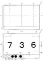
次に、図7を参照して、V入賞装置650のV入賞口650aを開閉する開閉扉650f1の球流下面の構造について説明をする。図7(a)は、V入賞装置650のV入賞口650aを開閉扉650f1が閉鎖している状態を平面視した模式図である。本実施形態の開閉扉650f1は、図7(a)に示した通り、V入賞装置650の上面に到達した球は、V入賞装置650上面の傾斜(図2参照)に沿って、V入賞装置650の右側上面650y1から開閉扉650f1の上面を介して左側上面650y2を流下し、可変入賞装置65に向けて流出するように構成されている。
Next, with reference to FIG. 7, the structure of the lower surface of the ball flow of the opening / closing door 650f1 that opens and closes the
そして、開閉扉650f1の上面には、球の流下を遅延させるための遅延部材として第1遅延部材650fa、第2遅延部材650fb、第3遅延部材650fcが設けられており、球が開閉扉650f1上面を流下する流下期間が0.6秒となるように構成している。この流下期間(0.6秒)は、V入賞装置650の特定入賞口(V入賞口)650aが小当たり遊技によって複数回開放される際の間隔(閉鎖期間(0.5秒))よりも長くなるように構成されている。このように構成することで、開閉扉650f1上を流下している球が、小当たり遊技により特定入賞口(V入賞口)650aが開放された場合に確実に入賞するように構成している。
A first delay member 650fa, a second delay member 650fb, and a third delay member 650fc are provided on the upper surface of the opening / closing door 650f1 as delay members for delaying the flow of the ball. Is configured to have a flow-down period of 0.6 seconds. This falling period (0.6 seconds) is longer than the interval (closed period (0.5 seconds)) when the specific winning opening (V winning opening) 650a of the
図7(a)に示した状態で、小当たり遊技が実行され、開閉扉650f1が開放状態に可変すると、図7(b)に示した状態へと移行する。図7(b)は、V入賞装置650のV入賞口650aが開放している状態を平面視した模式図である。図7(b)に示した通り、開閉扉650f1は開放状態になると、遊技盤13の内部に待避するように可動し、右側上面650y1を流下した球が特定入賞口(V入賞口)650aに入賞可能となるように特定入賞口(V入賞口)650aが開放状態となる。また、開閉扉650f1上を流下中の球も、開閉扉650f1が待避位置に位置することで、特定入賞口(V入賞口)650aへ入賞する。
When the small hit game is executed in the state shown in FIG. 7A and the opening / closing door 650f1 is changed to the open state, the state shifts to the state shown in FIG. 7B. FIG. 7B is a schematic view of a state where the
また、V入賞装置650には、開閉扉650f1上を流下していた球がどの位置から特定入賞口(V入賞口)650aに入賞したとしても、入賞後の球流れを円滑にするための第1規制部材651と、第2規制部材652が設けられており(図2参照)、開閉扉650f1上面上流側で特定入賞口(V入賞口)650aに入賞した球は第1規制部材651、第2規制部材652を介して一列に整列させてから、球1個分の通路幅である検出口650a1に向けて流下するように構成されている。このように第1規制部材651、第2規制部材652を設けることで、第1規制部材の下方位置に検出口650a1を設けたとしても、開閉扉650f1から勢いよく入賞した球が直接検出口650a1に衝突することを防止することができるため、検出口650a1に設けられた球検知スイッチ650c1が故障することを抑制することができる。加えて、球1個分の通路幅の検出口650a1を球が通過するまでに球を整列させるための流路(第1規制部材651、第2規制部材652上を流下する流路)を確保することができるため、V入賞装置650内で球詰まりが発生し、遊技に支障を来す事態が発生することを抑制することができる。
In addition, the
以上、説明をしたように、本実施形態では判別手段の判別結果(特別図柄の抽選の結果)が所定の判別結果(小当たり)である場合に付与される特典遊技(小当たり遊技)において作動する可変部材(開閉扉650f1)の開放間インターバル期間(0.5秒)よりも、その可変部材(開閉扉650f1)上を球が流下するのに要する流下期間(0.6秒)が長くなるように構成しているため、小当たり遊技中の開放間インターバル(開閉扉650f1が閉鎖状態のタイミング)中に可変部材上を流下する球を確実に次の開放タイミングでV入賞装置650へ入賞させることができる。
As described above, in the present embodiment, the present embodiment operates in the bonus game (small hit game) given when the judgment result of the judgment means (the result of the special symbol lottery) is a predetermined judgment result (small hit). The falling period (0.6 seconds) required for the ball to flow down the variable member (opening / closing door 650f1) is longer than the interval period (0.5 seconds) between opening of the variable member (opening / closing door 650f1). With such a configuration, the ball flowing down on the variable member during the opening interval (timing when the opening / closing door 650f1 is in the closed state) during the small hit game is reliably made to win the
また、可変部材上を流下中の球のみを小当たり遊技中にV入賞装置650へ入賞させるだけでも小当たり遊技中に所定個数(10個)を入賞させることができるように、1回の小当たり遊技における開放動作回数(12回)を、小当たり遊技の終了条件入賞個数(10個)よりも多く設定しているため、1回の開放期間(0.1秒)を短く設定したとしても、充分の入賞個数を確保することができる。加えて、1回の開放期間を長く設定しまうことにより、小当たり遊技中に過剰な個数の球をV入賞装置650へ入賞させてしまうという事態が発生することを抑制することができる。
In addition, a small number of balls (10 pieces) can be won during the small hitting game by simply causing the
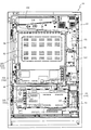
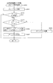
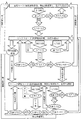
図8に示すように、パチンコ機10の後面側には、制御基板ユニット90,91と、裏パックユニット94とが主に備えられている。制御基板ユニット90は、主基板(主制御装置110)と音声ランプ制御基板(音声ランプ制御装置113)と表示制御基板(表示制御装置114)とが搭載されてユニット化されている。制御基板ユニット91は、払出制御基板(払出制御装置111)と発射制御基板(発射制御装置112)と電源基板(電源装置115)とカードユニット接続基板116とが搭載されてユニット化されている。
As shown in FIG. 8, on the rear side of the
裏パックユニット94は、保護カバー部を形成する裏パック92と払出ユニット93とがユニット化されている。また、各制御基板には、各制御を司る1チップマイコンとしてのMPU、各種機器との連絡をとるポート、各種抽選の際に用いられる乱数発生器、時間計数や同期を図る場合などに使用されるクロックパルス発生回路等が、必要に応じて搭載されている。
The
なお、主制御装置110、音声ランプ制御装置113及び表示制御装置114、払出制御装置111及び発射制御装置112、電源装置115、カードユニット接続基板116は、それぞれ基板ボックス100〜104に収納されている。基板ボックス100〜104は、ボックスベースと該ボックスベースの開口部を覆うボックスカバーとを備えており、そのボックスベースとボックスカバーとが互いに連結されて、各制御装置や各基板が収納される。
The
また、基板ボックス100(主制御装置110)及び基板ボックス102(払出制御装置111及び発射制御装置112)は、ボックスベースとボックスカバーとを封印ユニット(図示せず)によって開封不能に連結(かしめ構造による連結)している。また、ボックスベースとボックスカバーとの連結部には、ボックスベースとボックスカバーとに亘って封印シール(図示せず)が貼着されている。この封印シールは、脆性な素材で構成されており、基板ボックス100,102を開封するために封印シールを剥がそうとしたり、基板ボックス100,102を無理に開封しようとすると、ボックスベース側とボックスカバー側とに切断される。よって、封印ユニット又は封印シールを確認することで、基板ボックス100,102が開封されたかどうかを知ることができる。
Further, the substrate box 100 (main control device 110) and the substrate box 102 (dispensing
払出ユニット93は、裏パックユニット94の最上部に位置して上方に開口したタンク130と、タンク130の下方に連結され下流側に向けて緩やかに傾斜するタンクレール131と、タンクレール131の下流側に縦向きに連結されるケースレール132と、ケースレール132の最下流部に設けられ、払出モータ216(図9参照)の所定の電気的構成により球の払出を行う払出装置133とを備えている。タンク130には、遊技ホールの島設備から供給される球が逐次補給され、払出装置133により必要個数の球の払い出しが適宜行われる。タンクレール131には、当該タンクレール131に振動を付加するためのバイブレータ134が取り付けられている。
The dispensing
また、払出制御装置111には状態復帰スイッチ120が設けられ、発射制御装置112には可変抵抗器の操作つまみ121が設けられ、電源装置115にはRAM消去スイッチ122が設けられている。状態復帰スイッチ120は、例えば、払出モータ216(図9参照)部の球詰まり等、払出エラーの発生時に球詰まりを解消(正常状態への復帰)するために操作される。操作つまみ121は、発射ソレノイドの発射力を調整するために操作される。RAM消去スイッチ122は、パチンコ機10を初期状態に戻したい場合に電源投入時に操作される。
The
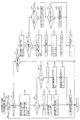
次に、図9を参照して、本パチンコ機10の電気的構成について説明する。図9は、パチンコ機10の電気的構成を示すブロック図である。
Next, an electrical configuration of the
主制御装置110には、演算装置である1チップマイコンとしてのMPU201が搭載されている。MPU201には、該MPU201により実行される各種の制御プログラムや固定値データを記憶したROM202と、そのROM202内に記憶される制御プログラムの実行に際して各種のデータ等を一時的に記憶するためのメモリであるRAM203と、そのほか、割込回路やタイマ回路、データ送受信回路などの各種回路が内蔵されている。主制御装置110では、MPU201によって、大当たり抽選や第1図柄表示装置37a,37b及び第3図柄表示装置81における表示の設定、第2図柄表示装置における表示結果の抽選といったパチンコ機10の主要な処理を実行する。
The
なお、払出制御装置111や音声ランプ制御装置113などのサブ制御装置に対して動作を指示するために、主制御装置110から該サブ制御装置へ各種のコマンドがデータ送受信回路によって送信されるが、かかるコマンドは、主制御装置110からサブ制御装置へ一方向にのみ送信される。
Various commands are transmitted from the
RAM203は、各種エリア、カウンタ、フラグのほか、MPU201の内部レジスタの内容やMPU201により実行される制御プログラムの戻り先番地などが記憶されるスタックエリアと、各種のフラグおよびカウンタ、I/O等の値が記憶される作業エリア(作業領域)とを有している。なお、RAM203は、パチンコ機10の電源の遮断後においても電源装置115からバックアップ電圧が供給されてデータを保持(バックアップ)できる構成となっており、RAM203に記憶されるデータは、すべてバックアップされる。
The
停電などの発生により電源が遮断されると、その電源遮断時(停電発生時を含む。以下同様)のスタックポインタや、各レジスタの値がRAM203に記憶される。一方、電源投入時(停電解消による電源投入を含む。以下同様)には、RAM203に記憶される情報に基づいて、パチンコ機10の状態が電源遮断前の状態に復帰される。RAM203への書き込みはメイン処理(図示せず)によって電源遮断時に実行され、RAM203に書き込まれた各値の復帰は電源投入時の立ち上げ処理(図示せず)において実行される。なお、MPU201のNMI端子(ノンマスカブル割込端子)には、停電等の発生による電源遮断時に、停電監視回路252からの停電信号SG1が入力されるように構成されており、その停電信号SG1がMPU201へ入力されると、停電時処理としてのNMI割込処理(図示せず)が即座に実行される。
When the power is shut down due to the occurrence of a power failure or the like, the stack pointer and the value of each register when the power is shut off (including when the power failure occurs, the same applies hereinafter) are stored in the
主制御装置110のMPU201には、アドレスバス及びデータバスで構成されるバスライン204を介して入出力ポート205が接続されている。入出力ポート205には、払出制御装置111、音声ランプ制御装置113、第1図柄表示装置37a,37b、第2図柄表示装置、第2図柄保留ランプ、特定入賞口65aの開閉板の下辺を軸として正面側に開閉駆動するための大開放口ソレノイドや電動役物を駆動するためのソレノイドなどからなるソレノイド209が接続され、MPU201は、入出力ポート205を介してこれらに対し各種コマンドや制御信号を送信する。
An input /
また、入出力ポート205には、図示しないスイッチ群およびスライド位置検出センサSや回転位置検出センサRを含むセンサ群などからなる各種スイッチ208、電源装置115に設けられた後述のRAM消去スイッチ回路253が接続され、MPU201は各種スイッチ208から出力される信号や、RAM消去スイッチ回路253より出力されるRAM消去信号SG2に基づいて各種処理を実行する。
The input /
払出制御装置111は、払出モータ216を駆動させて賞球や貸出球の払出制御を行うものである。演算装置であるMPU211は、そのMPU211により実行される制御プログラムや固定値データ等を記憶したROM212と、ワークメモリ等として使用されるRAM213とを有している。
The
払出制御装置111のRAM213は、主制御装置110のRAM203と同様に、MPU211の内部レジスタの内容やMPU211により実行される制御プログラムの戻り先番地などが記憶されるスタックエリアと、各種のフラグおよびカウンタ、I/O等の値が記憶される作業エリア(作業領域)とを有している。RAM213は、パチンコ機10の電源の遮断後においても電源装置115からバックアップ電圧が供給されてデータを保持(バックアップ)できる構成となっており、RAM213に記憶されるデータは、すべてバックアップされる。なお、主制御装置110のMPU201と同様、MPU211のNMI端子にも、停電等の発生による電源遮断時に停電監視回路252から停電信号SG1が入力されるように構成されており、その停電信号SG1がMPU211へ入力されると、停電時処理としてのNMI割込処理(図49参照)が即座に実行される。
The
払出制御装置111のMPU211には、アドレスバス及びデータバスで構成されるバスライン214を介して入出力ポート215が接続されている。入出力ポート215には、主制御装置110や払出モータ216、発射制御装置112などがそれぞれ接続されている。また、図示はしないが、払出制御装置111には、払い出された賞球を検出するための賞球検出スイッチが接続されている。なお、該賞球検出スイッチは、払出制御装置111に接続されるが、主制御装置110には接続されていない。
An input /
発射制御装置112は、主制御装置110により球の発射の指示がなされた場合に、操作ハンドル51の回動操作量に応じた球の打ち出し強さとなるよう球発射ユニット112aを制御するものである。球発射ユニット112aは、図示しない発射ソレノイドおよび電磁石を備えており、その発射ソレノイドおよび電磁石は、所定条件が整っている場合に駆動が許可される。具体的には、遊技者が操作ハンドル51に触れていることをタッチセンサ51aにより検出し、球の発射を停止させるための発射停止スイッチ51bがオフ(操作されていないこと)を条件に、操作ハンドル51の回動操作量(回動位置)に対応して発射ソレノイドが励磁され、操作ハンドル51の操作量に応じた強さで球が発射される。
The
音声ランプ制御装置113は、音声出力装置(図示しないスピーカなど)226における音声の出力、ランプ表示装置(電飾部29〜33、表示ランプ34など)227における点灯および消灯の出力、変動演出(変動表示)や予告演出といった表示制御装置114で行われる第3図柄表示装置81の表示態様の設定などを制御するものである。演算装置であるMPU221は、そのMPU221により実行される制御プログラムや固定値データ等を記憶したROM222と、ワークメモリ等として使用されるRAM223とを有している。
The sound
音声ランプ制御装置113のMPU221には、アドレスバス及びデータバスで構成されるバスライン224を介して入出力ポート225が接続されている。入出力ポート225には、主制御装置110、表示制御装置114、音声出力装置226、ランプ表示装置227、その他装置228、第1枠ボタン22、第2枠ボタン23などがそれぞれ接続されている。その他装置228には、パチンコ機10に設けられる演出用の駆動役物を動作させるための各種駆動モータが含まれる。
An input /
音声ランプ制御装置113は、主制御装置110から受信した各種のコマンド(変動パターンコマンド、停止種別コマンド等)に基づいて、第3図柄表示装置81の表示態様を決定し、決定した表示態様をコマンド(表示用変動パターンコマンド、表示用停止種別コマンド等)によって表示制御装置114へ通知する。また、音声ランプ制御装置113は、第1枠ボタン22、第2枠ボタン23(以下、第1枠ボタン22および第2枠ボタン23の両方を示す場合は枠ボタン22と称す。)からの入力を監視し、遊技者によって枠ボタン22が操作された場合は、第3図柄表示装置81で表示されるステージを変更したり、スーパーリーチ時の演出内容を変更したりするように、表示制御装置114へ指示する。ステージが変更される場合は、変更後のステージに応じた後面画像を第3図柄表示装置81に表示させるべく、変更後のステージに関する情報を含めた後面画像変更コマンドを表示制御装置114へ送信する。ここで、後面画像とは、第3図柄表示装置81に表示させる主要な画像である第3図柄の後面側に表示される画像のことである。表示制御装置114は、この音声ランプ制御装置113から送信されるコマンドに従って、第3図柄表示装置81に各種の画像を表示する。
The sound
なお、遊技者によって枠ボタン22が操作された場合に、図示しない演出用の役物を駆動させるためにその他装置228へ役物駆動コマンドを送信したり、枠ボタン22への操作内容に対応した音声を音声出力装置226に出力させるための音声出力コマンドを設定したり、枠ボタン22への操作内容に対応した発光態様でランプ表示装置227を発光させるためのランプ出力コマンドを設定したりするように構成しても良い。
In addition, when the
また、音声ランプ制御装置113は、表示制御装置114から第3図柄表示装置81の表示内容を表すコマンド(表示コマンド)を受信する。音声ランプ制御装置113では、表示制御装置114から受信した表示コマンドに基づき、第3図柄表示装置81の表示内容に合わせて、その表示内容に対応する音声を音声出力装置226から出力し、また、その表示内容に対応させてランプ表示装置227の点灯および消灯を制御する。
Further, the sound
表示制御装置114は、音声ランプ制御装置113及び第3図柄表示装置81が接続され、音声ランプ制御装置113より受信したコマンドに基づいて、第3図柄表示装置81における第3図柄の変動演出などの表示を制御するものである。また、表示制御装置114は、第3図柄表示装置81の表示内容を通知する表示コマンドを適宜音声ランプ制御装置113へ送信する。音声ランプ制御装置113は、この表示コマンドによって示される表示内容にあわせて音声出力装置226から音声を出力することで、第3図柄表示装置81の表示と音声出力装置226からの音声出力とをあわせることができる。
The
電源装置115は、パチンコ機10の各部に電源を供給するための電源部251と、停電等による電源遮断を監視する停電監視回路252と、RAM消去スイッチ122(図8参照)が設けられたRAM消去スイッチ回路253とを有している。電源部251は、図示しない電源経路を通じて、各制御装置110〜114等に対して各々に必要な動作電圧を供給する装置である。その概要としては、電源部251は、外部より供給される交流24ボルトの電圧を取り込み、各種スイッチ208などの各種スイッチや、ソレノイド209などのソレノイド、モータ等を駆動するための12ボルトの電圧、ロジック用の5ボルトの電圧、RAMバックアップ用のバックアップ電圧などを生成し、これら12ボルトの電圧、5ボルトの電圧及びバックアップ電圧を各制御装置110〜114等に対して必要な電圧を供給する。
The
停電監視回路252は、停電等の発生による電源遮断時に、主制御装置110のMPU201及び払出制御装置111のMPU211の各NMI端子へ停電信号SG1を出力するための回路である。停電監視回路252は、電源部251から出力される最大電圧である直流安定24ボルトの電圧を監視し、この電圧が22ボルト未満になった場合に停電(電源断、電源遮断)の発生と判断して、停電信号SG1を主制御装置110及び払出制御装置111へ出力する。停電信号SG1の出力によって、主制御装置110及び払出制御装置111は、停電の発生を認識し、NMI割込処理を実行する。なお、電源部251は、直流安定24ボルトの電圧が22ボルト未満になった後においても、NMI割込処理の実行に充分な時間の間、制御系の駆動電圧である5ボルトの電圧の出力を正常値に維持するように構成されている。よって、主制御装置110及び払出制御装置111は、NMI割込処理(図49)を正常に実行し完了することができる。
The power
RAM消去スイッチ回路253は、RAM消去スイッチ122(図8参照)が押下された場合に、主制御装置110へ、バックアップデータをクリアさせるためのRAM消去信号SG2を出力するための回路である。主制御装置110は、パチンコ機10の電源投入時に、RAM消去信号SG2を入力した場合に、バックアップデータをクリアすると共に、払出制御装置111においてバックアップデータをクリアさせるための払出初期化コマンドを払出制御装置111に対して送信する。
The RAM
次に、本実施形態における第3図柄表示装置81の表示内容について図10〜図17を参照して説明する。図10(a)および(b)は本実施形態における第3図柄表示装置81の表示内容を模式的に示した模式図である。第3図柄表示装置81は、15インチサイズの液晶ディスプレイで構成されるものであり、後述する表示制御装置114によって表示内容が制御されることにより、例えば左、中及び右の3つの図柄列が表示される。図10(a)に示した通り、第3図柄表示装置81の表示画面に表示される第3図柄(特別図柄1または特別図柄2)は、「0」から「9」の数字を模した10種類の主図柄によりそれぞれ構成されている。また、本実施形態のパチンコ機10においては、後述する主制御装置110による抽選結果が大当たりであった場合に、同一の主図柄が揃う(例えば「777」)変動表示が行われ、その変動表示が終わった後に大当たりが発生するよう構成されている。つまり、第3図柄は、主制御装置110による特別図柄の抽選結果を示すための図柄として第3図柄表示装置81に表示されるものである。
Next, display contents of the third
具体的には、主表示領域Dmは、左・中・右のそれぞれ3つの図柄列Z1,Z2,Z3が表示される。各図柄列Z1〜Z3には、上述した第3図柄が規定の順序で表示される。即ち、各図柄列Z1〜Z3には、数字の昇順または降順に主図柄が配列され、図柄列Z1〜Z3毎に周期性をもって上から下へとスクロールして変動表示が行われる。 Specifically, in the main display area Dm, three symbol rows Z1, Z2, and Z3 for left, middle, and right are displayed. In each symbol row Z1 to Z3, the above-described third symbols are displayed in a prescribed order. That is, the main symbols are arranged in ascending or descending numbers in the symbol rows Z1 to Z3, and the symbols are scrolled from top to bottom with a periodicity for each symbol row Z1 to Z3.
また、主表示領域Dmには、有効ラインL1上に第3図柄が停止表示される。その第3図柄が有効ライン上に大当たり図柄の組合せ(本第1実施形態では、同一の主図柄の組合せ)で揃って停止されれば、大当たりとして大当たり動画が表示される。 In the main display area Dm, the third symbol is stopped and displayed on the activated line L1. If the third symbol is stopped on the activated line with a combination of big hit symbols (in the first embodiment, a combination of the same main symbols), the big hit video is displayed as a big hit.
なお、第3図柄表示装置81における第3図柄の変動表示の態様は、上記のものに限定されることはなく任意であり、図柄列の数、図柄列における図柄の変動表示の方向、各図柄列の図柄数などは適宜変更可能である。また、第3図柄表示装置81にて変動表示される図柄は上記に限られることはなく、例えば図形やキャラクタ等の画像と数字とを組み合わせた図柄を第3図柄として構成してもよい。さらに、第3図柄が変動表示される領域を可変させる構成にしてもよく、例えば、第3図柄表示装置81の表示画面上で特定の演出が実行される場合は、第3図柄の変動表示領域を小さくしたり、変動表示領域を遊技者が視認し難い位置(例えば、表示画面の隅部)へと移動させたりすることで、第3図柄が変動しているか否かを遊技者が分かり難くするようにしてもよい。また、特別図柄が変動している期間中に、第3図柄の変動を一旦停止(仮停止)させ、再度変動させるように構成してもよい。
In addition, the mode of the variable display of the third symbol in the third
さらに、本実施形態では、第1特別図柄の変動に対応した第3図柄の表示態様と、第2特別図柄の変動に対応した第3図柄の表示態様とが同一(遊技者が識別困難な程度の相違も含む)となるように構成しているが、変動している特別図柄の種別に対応するように第3図柄の表示態様や表示領域を異ならせても良い。 Further, in the present embodiment, the display mode of the third symbol corresponding to the change of the first special symbol and the display mode of the third symbol corresponding to the change of the second special symbol are the same (to the extent that it is difficult for the player to discriminate). (Including the difference of the third symbol), but the display mode and the display area of the third symbol may be changed so as to correspond to the type of the special symbol that is changing.
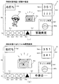
次に、第3図柄表示装置81に実際に表示される内容について図10(b)を参照して説明をする。図10(b)に示した通り、主表示領域Dmにおける正面視左上には、小表示領域Dm2が形成されている。この小表示領域Dm2は、遊技者に対して球を発射させる方向(遊技方向)を案内するための案内表示態様が表示される(図11(a)参照)。つまり、本実施形態では、小表示領域Dm2を案内表示領域として用いている。このように構成することで、遊技者は案内表示領域に表示されている案内表示態様を視認するだけで、遊技盤13のどの領域に向けて球を発射すれば良いのかを容易に把握することができるため、遊技者に分かり易い遊技機を提供することができる。
Next, the content actually displayed on the third
なお、詳細な説明は省略するが、本パチンコ機10では、小表示領域Dm2に表示される案内表示態様が可変する場合に、音声出力装置226を用いた音声案内と、ランプ表示装置227を用いた発光案内とが実行されるように構成されている。ここで、音声出力装置226を用いた音声案内としては「右打ち」を示す音声のように小表示領域Dm2に表示される表示内容を示す音声が出力される。
Although the detailed description is omitted, the
また、ランプ表示装置227を用いた発光案内としては、例えば、「右打ち」を案内する場合には、発光手段として用いられる複数のLED(図示せず)を左側から右側へと順に点灯させるように発光制御する。このように構成することで遊技盤13に設けられた発光手段の点灯パターンを視認することで遊技盤13のどの領域に向けて球を発射すれば良いのかを容易に把握することができる。加えて、遊技者に対して球を発射させる方向(遊技方向)が切り替わったことを第3図柄表示装置81の表示内容だけではなく、音声案内と発光案内とで遊技者に報知することができるため、遊技方向が切り替わったことを遊技者に即座に気付かせることができる。
Further, as the light emission guidance using the lamp display device 227, for example, in the case of guiding “right-handed”, a plurality of LEDs (not shown) used as light emission means are sequentially lit from left to right. The light emission is controlled. With this configuration, it is possible to easily recognize to which area of the
主表示領域Dmにおける正面視右上には、小表示領域Dm1が形成されている。この小表示領域Dm1は、第3図柄の変動表示を簡易的に表示させることが可能に構成されている。ここで、小表示領域Dm1において変動表示を実行する場合とは、例えば、主表示領域Dmにおいて、所定のキャラクタがアクションを行う演出や、枠ボタン22の押下を促す演出等の表示演出を実行している場合である。表示演出の実行中は、より大きな主表示領域Dmで演出を表示させることによって、より分かり易い演出を提供することができる。また、表示演出の実行中に、第3図柄の変動表示を小表示領域Dm1に簡易的に表示させておくことで、第3図柄の変動表示が継続していることを遊技者に対して容易に理解させることができる。
A small display area Dm1 is formed at the upper right of the main display area Dm in front view. The small display area Dm1 is configured to be able to easily display the variable display of the third symbol. Here, the case where the variable display is executed in the small display area Dm1 means that, for example, in the main display area Dm, a display effect such as an effect in which a predetermined character performs an action or an effect in which the user presses the
なお、詳細は後述するが小表示領域Dm1は、第1特別図柄の変動表示に対応した第3図柄が表示される特図1変動表示領域Dm1aと、第2特別図柄の変動表示に対応した第3図柄が表示される特図2変動表示領域Dm1bとから形成されている(図11(a)参照)。これにより、主表示領域Dmで表示演出が実行されている場合であっても、何れの特別図柄に対応した第3図柄が変動しているのかを遊技者に対して容易に把握させることができる。なお、本パチンコ機10では、特図1変動表示領域Dm1aと、特図2変動表示領域Dm1bと、それぞれ形成する構成を用いているが、これに限ることなく、小表示領域Dm1に1つの変動表示領域を設け、第1特別図柄と第2特別図柄のうち変動表示中の特別図柄のみを表示するように構成しても良い。
Although the details will be described later, the small display area Dm1 includes a special figure 1 variable display area Dm1a in which a third symbol corresponding to the variable display of the first special symbol is displayed, and a small display area Dm1a corresponding to the variable display of the second special symbol. It is formed from a special figure 2 variable display area Dm1b on which three symbols are displayed (see FIG. 11A). Thereby, even when the display effect is being executed in the main display area Dm, it is possible for the player to easily understand which special symbol corresponding to the third symbol is fluctuating. . In this
主表示領域Dmにおける正面視右下には小表示領域Dm3が形成されている。詳細は後述するが、この小表示領域Dm3は、パチンコ機10の遊技状態が特定の遊技状態(時短状態)である場合に、その時短状態が終了するか否かを示唆するための状況(状態)表示態様Dm3a(図11(a)参照)が表示される領域である。これにより小表示領域Dm3に表示される状況(状態)表示態様Dm3aによって、時短状態が終了するタイミングを予測させながら遊技者に遊技を行わせることができる。
A small display area Dm3 is formed at the lower right of the main display area Dm in front view. Although the details will be described later, when the gaming state of the
さらに、主表示領域Dmの下方には、副表示領域Dsが形成される。この副表示領域Dsには、図10(b)に示すように、黒色の円形からなる保留図柄が表示される。上述した通り、第1図柄表示装置37において変動表示が行われている間に球が第1入球口64へ入球すると、その入球回数は最大4回まで保留される。副表示領域Dsに対して表示される保留図柄は、保留された入球回数と同一の個数が表示される。本第1実施形態では、第1特別図柄の保留球数の最大値が4個で、第2特別図柄は保留球を確保することが出来ないように設定されているので、副表示領域Dsには、第1特別図柄に対応する保留図柄が最大4個表示される。
Further, a sub display area Ds is formed below the main display area Dm. As shown in FIG. 10 (b), a reserved symbol consisting of a black circle is displayed in the sub-display area Ds. As described above, if a ball enters the
なお、本実施形態では、保留球数に対応させて保留図柄の表示態様を可変させていたが、保留球数を表示する方法はこれに限られるものではない。例えば、保留球数を数字で表示させる構成としても良い。また、保留球数の増減に対応してキャラクタの態様を可変させることで視覚的に保留球数の大小を遊技者に報知するように構成しても良い。 In the present embodiment, the display pattern of the reserved symbols is changed in accordance with the number of reserved balls, but the method of displaying the number of reserved balls is not limited to this. For example, a configuration may be adopted in which the number of reserved balls is displayed by a number. Further, the size of the number of reserved balls may be visually notified to the player by changing the character mode in accordance with the increase or decrease in the number of reserved balls.
さらに、本実施形態では、その他に、遊技者に対して遊技結果(各図柄の抽選結果)を示唆するための遊技結果示唆態様や、主表示領域Dmにて実行されている演出表示の内容を説明するための演出説明態様や、枠ボタン22を操作するタイミングや操作した結果を示すための枠ボタン関連表示態様や、大当たり遊技に関する情報が表示される当たり関連情報表示態様が副表示領域Dsに表示されるように構成されており、副表示領域Dsに表示する内容によって、主表示領域Dmと副表示領域Dsとの表示領域の割合が異なるように設定されている。
Furthermore, in the present embodiment, in addition to the above, the game result suggestion mode for suggesting a game result (lottery result of each symbol) to the player and the contents of the effect display executed in the main display area Dm are described. The effect explanation mode for explaining, the frame button-related display mode for indicating the timing of operating the
また、停止表示された第3図柄の組み合わせが外れに対応する組み合わせであって、保留球が存在する場合は、1秒間の停止表示後(図柄確定期間経過後)に、保留球に基づく抽選に対応する変動表示が開始される。なお、複数の保留球が存在する場合は、時間的に最も古い入球に対応する保留球に基づいて抽選が実行される。このように、1つの特別図柄に対応した抽選結果が停止表示された後に、その停止表示状態を予め定められた所定期間継続させた後に、次の特別図柄変動を開始するように構成することで、遊技者に対して新たな特別図柄の変動が開始されたことを理解させやすくすることができる。なお、本実施形態では、図柄の変動時間経過後に上述した図柄確定期間を必ず設けるように構成しているが、その詳細な説明を省略する。 In addition, when the combination of the third symbols stopped and displayed is a combination corresponding to the departure, and there is a reserved ball, after the stop display for one second (after the symbol confirmation period has elapsed), the lottery based on the reserved ball is performed. The corresponding variable display is started. If there are a plurality of holding balls, a lottery is executed based on the holding ball corresponding to the oldest entry in time. As described above, after the lottery result corresponding to one special symbol is stopped and displayed, the stop display state is continued for a predetermined period, and then the next special symbol change is started. This makes it easier for the player to understand that the change of the new special symbol has started. In the present embodiment, the above-described symbol determination period is always provided after the symbol change time has elapsed, but a detailed description thereof will be omitted.
一方、保留球が存在しない状態で、特別図柄の外れに対応する組み合わせの第3図柄が1秒間停止表示された場合は、その後も第3図柄が停止表示された状態が継続する。この状態は、所定時間(例えば、30秒)が経過するか、または、第1入球口64或いは第2入球口640に対して新たに球が入球するまで継続する。そして、第3図柄が停止表示されてから所定時間(例えば、30秒)が経過した場合は、遊技が実行されていないことを示すデモ演出が表示される。遊技者が球を所定時間(例えば、30秒)連続して発射させているにも関わらず、第1入球口64、第2入球口640のいずれにも入球が無いという状況は稀であり、第3図柄が停止表示された状態が所定時間(例えば、30秒)継続する場合の多くは、遊技者が遊技を辞めたことで、パチンコ機10による遊技が全く行われていないことに起因する。
On the other hand, when the third symbol of the combination corresponding to the departure of the special symbol is stopped and displayed for one second in a state where the reserved ball does not exist, the state where the third symbol is stopped and displayed is continued thereafter. This state continues until a predetermined time (for example, 30 seconds) elapses or until a new ball enters the
よって、本実施形態のパチンコ機10では、第3図柄が停止表示されてから所定時間(例えば、30秒)が経過した時点で、遊技者が遊技を行っていないと判断し、デモ演出を開始する。これにより、遊技を開始するためにパチンコ機10を選択しようとしている遊技者が、デモ演出の表示の有無に基づいて遊技が行われているか否かを容易に判断することができる。一方、所定時間(例えば、30秒)が経過する前に第1入球口64、第2入球口640のいずれかに対して新たに球が入球した場合は、その新たな入球に対応する第3図柄の変動表示が実行される。
Therefore, in the
図10(b)に示した通り、副表示領域Dsのうち第1表示領域Ds1は、主表示領域Dmよりも下方に横長に設けられており、第1入球口64に入球された球のうち変動が未実行である球(保留球)の数である保留図柄を表示する保留表示領域として形成されている。この第1表示領域Ds1には、第1入球口64に球が入賞した際に獲得した入賞情報が記憶された順に(保留記憶されたタイミングが古い順に)、第1保留図柄Dsb、第2保留図柄Dsc、第3保留図柄Dsd、第4保留図柄Dseが表示される。そして、現在実行中の変動に対応した保留図柄が実行中図柄Dsaとして副表示領域Dsの中央位置に表示される。
As shown in FIG. 10B, the first display area Ds <b> 1 of the sub-display area Ds is provided horizontally below the main display area Dm, and the ball inserted into the
この第1表示領域Ds1に表示された保留図柄は、実行中の変動表示が終了し、次の変動が開始される場合には、次の変動に対応する保留図柄(図10(b)の正面視で一番右に表示される第1保留図柄Dsb)を消去し、残りの保留図柄(Dsc〜Dse)が右方向にシフトして表示される。そして、消去された第1保留図柄Dsbは実行中図柄Dsaとして表示される。これにより、実行中の変動表示がどの保留図柄に対応した変動表示であるのかを遊技者に報知することができるため、例えば、保留図柄の表示態様を可変させその保留図柄に対応する特別図柄の抽選が大当たりである期待度を高める演出(所謂、先読み演出)を実行した場合において、先読み演出により表示態様を可変させた保留図柄に対応した変動表示が実行されていることを遊技者が容易に認識することができる。 When the display of the pending symbol displayed in the first display area Ds1 is finished and the next variation is started, the pending symbol corresponding to the next variation (the front of FIG. 10B) The first reserved symbol (Dsb) displayed on the rightmost side is erased, and the remaining reserved symbols (Dsc to Dse) are shifted rightward and displayed. Then, the deleted first reserved symbol Dsb is displayed as the symbol Dsa being executed. With this, it is possible to notify the player which variable display corresponds to the variable display being executed, so that, for example, the display mode of the reserved symbol can be changed and the special symbol corresponding to the reserved symbol can be changed. In the case of performing an effect that increases the degree of expectation that the lottery is a big hit (so-called pre-reading effect), the player easily recognizes that the variable display corresponding to the reserved symbol whose display mode has been changed by the pre-reading effect is being executed. Can be recognized.
さらに、本実施形態では、第1表示領域Ds1に表示される各保留図柄(第1保留図柄Dsb〜第2保留図柄Dse)が新たな特別図柄変動が開始される場合に移動(シフト)する方向(図10(b)視点で右方向)に実行中図柄Dsaを表示するように構成しているため、保留図柄(第1保留図柄Dsb〜第2保留図柄Dse)と実行中図柄Dsaとを遊技者が一連の並びで把握することができるため、実行中の変動表示がどの保留図柄に対応した変動表示であるのかを遊技者に容易に把握させることができる。 Furthermore, in the present embodiment, the direction in which each reserved symbol (first reserved symbol Dsb to second reserved symbol Dse) displayed in the first display area Ds1 moves (shifts) when a new special symbol change is started. Since the running symbol Dsa is configured to be displayed (rightward from the viewpoint of FIG. 10B), the holding symbol (first holding symbol Dsb to second holding symbol Dse) and the running symbol Dsa are played. Since the player can comprehend in a series of arrangements, it is possible for the player to easily comprehend which pending symbol the variable display in execution corresponds to the variable display.
なお、本実施形態においては、第1入球口64への入球のみ最大4回まで保留可能に構成したが、保留球数の上限値は4回に限定されるものでなく、3回以下、又は、5回以上の回数(例えば、8回)に設定しても良い。また、第2入球口640への入球も所定数を上限に保留可能に構成しても良いし、第1入球口64への入球に対する保留球数の上限値と、第2入球口640への入球に対する保留球数の上限値とを異ならせても良く、第1入球口64への入球に対する保留球数の上限値を第2入球口640への入球に対する保留球数の上限値よりも多くしてもよいし、逆に少なくしてもよい。また、副表示領域Dsにおける保留図柄の表示に代えて、保留球数を第3図柄表示装置81の一部に数字で、或いは、4つに区画された領域を保留球数分だけ異なる態様(例えば、色や点灯パターン)にして表示するようにしても良い。また、第1図柄表示装置37により保留球数が示されるので、第3図柄表示装置81に保留球数を表示させないものとしてもよい。更に、可変表示装置ユニット80に、保留球数を示す保留ランプを最大保留数分の4つ設け、点灯状態の保留ランプの数に応じて、保留球数を表示するものとしても良い。
In the present embodiment, only up to four balls can be held up to the
副表示領域Dsの右側には第2表示領域Ds2が形成されており、主表示領域Dmにて実行される演出(表示演出)の内容を補足するための演出説明が表示される(図11(b)参照)。このように、第3図柄表示装置81の表示画面にて表示される複数の情報、即ち、特別図柄の変動表示に対応した第3図柄の変動表示情報、現在実行されている特別図柄の変動表示に対応する抽選結果が特定の抽選結果(大当たり当選)である期待度を示すための表示演出情報、その表示演出情報の内容を補足する演出説明情報、特別図柄の保留記憶数を示す保留図柄情報、実行中図柄を示す実行中図柄情報等を予め規定されている区画(領域)に表示することで、同時に表示される様々な情報を遊技者に分かり易く報知することができる。
A second display area Ds2 is formed on the right side of the sub display area Ds, and an effect explanation for supplementing the contents of the effect (display effect) executed in the main display area Dm is displayed (FIG. 11 ( b)). Thus, a plurality of information displayed on the display screen of the third
次に、図11〜図17を参照して本実施形態のパチンコ機10における第3図柄表示装置81にて表示される演出内容について説明をする。この第3図柄表示装置81は、第1図柄表示装置37の表示に応じた装飾的な表示を行うものである。例えば、第1入球口64または第2入球口640へ球が入球(始動入賞)すると、それをトリガとして、第1図柄表示装置37において第1特別図柄または第2特別図柄(第1図柄)の変動表示が実行される。更に、第3図柄表示装置81では、第1特別図柄または第2特別図柄の変動表示に同期して、特別図柄の変動表示に対応する第3図柄の変動表示が行われる。
Next, the effect contents displayed on the third
なお、第3図柄は、第1特別図柄と第2特別図柄との変動表示に対して、共通して変動表示が行われる。また、第1特別図柄よりも遊技者に有利な抽選結果となり易い第2特別図柄は、第1特別図柄よりも優先して、変動表示されるように構成されており、第1特別図柄と第2特別図柄とが同時に変動表示することがないように構成されている。 Note that the 3rd symbol is displayed in common with the 1st special symbol and the 2nd special symbol. Further, the second special symbol which is more likely to be a lottery result more advantageous to the player than the first special symbol is configured to be displayed in a variable manner prior to the first special symbol, and the first special symbol and the second special symbol are displayed in a variable manner. It is configured such that two special symbols are not simultaneously displayed in a variable manner.
しかしながら、本第1実施形態では第2特別図柄は保留球を確保することが出来ないように設定されているので、実質的には、第1特別図柄の保留球が順に消化されるように特別図柄の変動が実行されるものであるが、例えば、新たな特別図柄の変動を開始させるタイミングにおいて、第1特別図柄と第2特別図柄とが共に変動可能な状態となる場合、即ち、第1特別図柄の保留球に対応する新たな変動を開始させるタイミングと、第2入球口640に球が入球(始動入賞)するタイミングと、が一致した場合には、第2特別図柄の変動が優先して実行されるように構成している。 However, in the first embodiment, since the second special symbol is set so as not to be able to secure the reserved ball, it is practically special that the reserved ball of the first special symbol is sequentially digested. The change of the symbol is executed. For example, at the timing when the change of the new special symbol is started, when the first special symbol and the second special symbol are both changeable, that is, the first special symbol is changed. If the timing of starting a new change corresponding to the reserved ball of the special symbol coincides with the timing of the ball entering the second entrance 640 (start winning), the change of the second special symbol is changed. It is configured to be executed with priority.
これにより、遊技者に有利な抽選を受ける機会(第2特別図柄の抽選を実行する機会)を、それよりも不利な抽選(第1特別図柄の抽選)が実行されることにより失ってしまうことを確実に防止することができる。 As a result, an opportunity to receive a lottery advantageous to the player (an opportunity to execute the second special symbol lottery) is lost due to the execution of a more disadvantageous lottery (the first special symbol lottery). Can be reliably prevented.
第3図柄表示装置81にて実行される表示演出としては、特別図柄の抽選に基づいて成立し得る様々な内容の成立の有無を示唆する演出が実行される。具体的には、特別図柄の抽選によって大当たりに当選したか否かを示唆する大当たり当選示唆演出や、特別図柄の抽選によって大当たりに当選しなかった(外れに当選した)場合の一部であり、大当たりよりも少ない特典(例えば賞球の払出し)を遊技者に付与する小当たりに当選したか否かを示唆する小当たり当選示唆演出や、特別図柄の抽選結果によって遊技状態が遊技者に有利な時短状態へと移行することを示唆するための遊技状態移行示唆演出や、遊技状態として時短状態が設定されている場合において、特別図柄の抽選結果や特別図柄の変動表示に応じて時短状態が終了することを示唆するための時短状態終了示唆演出などが実行される。
As the display effect performed by the third
また、特別図柄の抽選結果を示唆する演出(大当たり当選示唆演出、小当たり当選示唆演出等)は、第3図柄表示装置81に第3図柄が変動表示されてから停止表示される第3図柄の組み合わせによって抽選結果が報知されるまでの期間(動的表示期間)を用いた演出が実行されるものであり、例えば、動的表示期間中に第3図柄が大当たりに当選したことを示す停止表示態様(例えば、「777」の組み合わせ)のうち、一部の組み合わせのみを停止表示させたリーチ表示態様(例えば、3つの第3図柄のうち2つの第3図柄のみ「77」で停止表示させ、残りの第3図柄を変動させたままの表示態様)を表示し、その後、リーチ表示態様を示した第3図柄を小表示領域Dm1にて表示した状態で、主表示領域Dmにてストーリー性を持たせた演出を実行し、そのストーリーが正しく完結した場合に第3図柄を「777」で停止表示させる演出を実行する。
In addition, the effects that suggest the lottery result of the special symbol (eg, a jackpot winning suggestion effect, a small jackpot winning suggestion effect, etc.) are displayed in the third
なお、上述した例では、第3図柄の組み合わせの一部を、抽選結果が当たり(大当たり)であることを示す組み合わせと合致する態様で停止表示させた状態をリーチ表示態様としているが、それ以外の表示態様をリーチ表示態様としても良く、例えば、第3図柄のうちの一部の図柄を、リーチ状態を示すための専用の表示態様で表示したり、第3図柄のうち、一部の組み合わせを、大当たりに当選したことを示す組み合わせでは無く、リーチ状態を示すための専用の表示態様で表示したりしても良い。このようにリーチ状態が成立していることを第3図柄の一部の停止表示態様を確認することで遊技者が把握することができるように構成することで、遊技者に対して大当たりに当選したことに対する期待感を徐々に高めさせることができ、演出効果を高めることができる。 In the example described above, the reach display mode is a state in which a part of the combination of the third symbols is stopped and displayed in a mode that matches the combination indicating that the lottery result is a win (big hit). May be displayed as a reach display mode. For example, some of the third symbols may be displayed in a dedicated display mode for indicating the reach state, or some of the third symbols may be combined. May be displayed in a special display mode for indicating the reach state instead of the combination indicating that the jackpot has been won. In this way, the configuration in which the player can grasp that the reach state has been established by confirming a part of the stop display mode of the third symbol allows the player to win the jackpot. It is possible to gradually increase the sense of expectation for the effect, and enhance the effect of the production.
さらに、本パチンコ機10では、特別図柄の抽選結果を示唆する演出として、複数の特別図柄変動を跨いで実行される連続演出を設定可能に構成している。この連続演出は、球が第1入球口64に入球した際に取得した各種カウンタ値(抽選結果)を示すための入賞情報コマンドを音声ランプ制御装置113に送信した際に、その入賞情報コマンドに対応する特別図柄変動の抽選結果を、その特別図柄変動に対応する変動表示が実行されるまでの期間(対象となる特別図柄変動よりも前に実行される特別図柄変動に対応した変動表示が実行される期間)を用いて、遊技者に示唆するための演出である。
Further, the
このように、対象となる特別図柄の抽選結果を、その対象となる特別図柄よりも前に実行される特別図柄の変動期間を用いて示唆することで、遊技者に対してより長期間の演出を提供することができ演出効果を高めることができる。また、特別図柄の抽選結果(例えば、外れ)を、毎変動強調表示することなく、連続演出を実行することができるため、遊技者の遊技意欲が低下する事態が発生することを抑制することができる。 In this way, by suggesting the lottery result of the target special symbol using the fluctuation period of the special symbol executed before the target special symbol, a longer-term effect for the player is provided. Can be provided to enhance the production effect. In addition, since it is possible to execute a continuous effect without highlighting the result of the lottery of the special symbol (for example, a miss) every time, it is possible to suppress the occurrence of a situation in which the player's willingness to play decreases. it can.
さらに、本第1実施形態では、特別図柄の抽選結果が大当たりであるか否かを示唆するための演出以外に、特別図柄の抽選回数(変動回数)に応じて遊技状態が移行されることを示唆する演出(時短状態終了示唆演出)も実行するように構成されている。この時短状態終了示唆演出は、パチンコ機10の遊技状態が時短状態である場合に継続して実行される演出であり、特別図柄の抽選回数(特別図柄変動が実行される回数)や、特別図柄の抽選結果が特定抽選結果(例えば、小当たり当選)となった回数に応じて時短状態が終了する可能性を示唆するための演出である。
Further, in the first embodiment, in addition to the effect for suggesting whether or not the special symbol lottery result is a big hit, the gaming state is shifted according to the number of special symbol lotteries (the number of fluctuations). It is also configured to execute a suggestion effect (a time reduction state end suggestion effect). The time saving state end suggestion effect is an effect that is continuously executed when the gaming state of the
ここで、上述した時短状態終了示唆演出の演出内容について説明をする。本実施形態のパチンコ機10は、図2に示した通り、第2入球口640に電動役物640aが付設されており、電動役物640aの動作状態(可変状態)に応じて第2入球口640に球が入球し難い状態(第1状態)と球が入球し易い状態(第2状態)とが設定されるように構成している。さらに、第2入球口640に球が入球したことに基づいて第2特別図柄の抽選が実行され、小当たりに当選した場合には、V入賞装置650を開放する小当たり遊技が実行される。V入賞装置650内にはV入賞装置650に入賞した球が通過し得る特定領域として特別排出流路650e2を有しており、球が特別排出流路650e2を通過(流下)したことをVスイッチ650e3が検知した場合に大当たり(2種当たり)が設定されるように構成している。そして、遊技状態として設定される時短状態は、電動役物640aが第2状態(第2入球口640に球が入球し易い状態)へと動作(可変)し易くなる遊技者に有利な遊技状態となるため、時短状態中は第2入球口640に球を入球させる右打ち遊技が行われる。
Here, the effect contents of the effect of suggesting the end of the time saving state described above will be described. As shown in FIG. 2, the
上述したように遊技者に有利となる時短状態は、終了条件(時短終了条件)が成立した場合に終了するように構成されている。詳細は後述するが、本実施形態のパチンコ機10では、特別図柄抽選において大当たりに当選した場合、特別図柄抽選に基づく特別図柄変動が所定回数(例えば、100回)実行された場合、特別図柄抽選により所定回数(例えば3回)小当たりに当選した場合の何れかの条件が成立した場合に時短状態が終了する(遊技状態が時短状態から通常状態へと移行する)ように構成している。
As described above, the time-saving state advantageous to the player is configured to end when an end condition (time-saving end condition) is satisfied. Although the details will be described later, in the
このように、複数の時短終了条件を設定可能とすることにより、遊技者に有利な時短状態がどれくらい継続するのかを遊技者に把握させ難くすることができる。一方で、時短終了条件の成立の有無や、時短終了条件の成立に向けて更新される時短情報(例えば、時短状態中に当選した小当たりの回数を示す情報)を遊技者に何ら示唆(報知)しないと、遊技者に有利な時短状態が急に終了してしまい、遊技者に不満感を与えてしまうという問題があった。 In this way, by making it possible to set a plurality of time saving end conditions, it is possible to make it difficult for the player to grasp how long the time saving state advantageous to the player continues. On the other hand, the presence / absence of the time-saving end condition and the time-saving information (for example, information indicating the number of small hits won during the time-saving state) updated toward the satisfaction of the time-saving end condition are not suggested to the player (notification). Otherwise, there is a problem that the time-saving state advantageous to the player ends suddenly and the player is dissatisfied.
そこで、本実施形態では、時短状態中において、時短終了条件の成立の有無や、時短終了条件の成立に向けて更新される時短情報(例えば、時短状態中に当選した小当たりの回数を示す情報)を時短状態終了示唆演出として遊技者に示唆(報知)することで、遊技者に対して時短状態が継続して設定される期間を予測させながら遊技を行わせることができるように構成している。これにより、遊技者に有利な時短状態が急に終了してしまい、遊技者に不満感を与えてしまうという問題が発生することを抑制することができる。 Therefore, in the present embodiment, during the time reduction state, whether or not the time reduction end condition is satisfied or the time reduction information updated toward the satisfaction of the time reduction end condition (for example, information indicating the number of small hits won during the time reduction state) ) Is suggested (notified) to the player as a time-saving state end suggesting effect, so that the player can perform a game while predicting a period in which the time-saving state is continuously set. I have. Thus, it is possible to suppress the occurrence of the problem that the time saving state advantageous to the player is suddenly ended and the player is dissatisfied.
加えて、上述した時短終了条件には、遊技者にとって有利な時短終了条件(大当たりに当選したことにより成立する時短終了条件)と、それ以外の不利な時短終了条件が設定されていることから、時短状態中に実行される時短状態終了示唆演出では、単に時短終了条件の成立の有無や、時短終了条件の成立に向けて更新される時短情報(例えば、時短状態中に当選した小当たりの回数を示す情報)に基づいた演出を実行するのではなく、成立する時短終了条件や成立し易い時短終了条件が遊技者に有利なものか否かを判別し、その判別結果にも基づいた演出を実行するように構成している。 In addition, the above-mentioned time-saving end conditions include a time-saving end condition that is advantageous to the player (a time-saving end condition that is satisfied by winning a jackpot) and other disadvantageous time-saving end conditions. In the time-saving state end suggestion effect that is executed during the time-saving state, the time-saving end condition is simply satisfied or not, and the time-saving information updated toward the establishment of the time-saving end condition (for example, the number of small hits that are won during the time-saving state) Rather than performing an effect based on the information), it is determined whether or not the time-saving end condition that is satisfied or the time-saving end condition that is easy to be satisfied is advantageous to the player, and an effect based on the determination result is performed. It is configured to run.
このように構成することで、遊技者に対して時短状態が終了するタイミングが近づいているか否かを予測させるだけではなく、遊技者にとって有利な時短終了条件が成立するか否かを予測させることができるため、実行される演出(時短状態終了示唆演出)に興味を持たせることができ、演出効果を高めることができる。 With this configuration, it is possible not only to make the player predict whether the time at which the time saving state ends is approaching, but also to predict whether or not an advantageous time saving ending condition for the player is satisfied. Therefore, it is possible to give an interest to the effect to be executed (the effect of suggesting the end of the time saving state), and it is possible to enhance the effect of the effect.
さらに、本実施形態のパチンコ機10は、特別図柄抽選で小当たりに当選した場合に、複数種類の小当たり遊技が実行されるように構成しており、実行される小当たり遊技に応じて(設定される小当たり種別に応じて)、小当たり遊技中に2種当たりが設定される期待度を異ならせている。そして、上述した時短終了条件のうち、特別図柄抽選で小当たりに所定回数当選したことに基づいて成立する時短終了条件として、小当たり当選時に設定される小当たり種別毎にそれぞれ回数(時短終了条件が成立する当選回数)を設定するように構成している。
Furthermore, the
このように構成することで、特別図柄の小当たり当選により時短終了条件が成立した場合において、今回成立した時短終了条件が遊技者に有利な時短終了条件(2種当たりし易い小当たり種別が設定されたことにより成立した時短終了条件)なのか、遊技者に不利な時短終了条件(2種当たりし難い小当たり種別が設定されたことにより成立した時短終了条件)なのかを時短状態終了示唆演出により遊技者に示唆(報知)することができる。よって、小当たりに当選したことにより時短終了条件が成立する場合であっても、時短状態終了示唆演出にて実行される演出を遊技者に注視させることができる。 With such a configuration, when the time saving end condition is established by the special symbol small hit winning, the time saving end condition that is established this time is advantageous to the player. A time-saving state end effect that indicates whether the time-saving end condition has been established due to the fact that the game has been performed, or a time-saving end condition that is disadvantageous to the player (the time-saving end condition that has been established by setting two types of small hits that are difficult to hit). Can be suggested (notified) to the player. Therefore, even if the time saving end condition is satisfied by winning the small hit, the player can watch the effect executed in the time saving state end suggesting effect.
加えて、上述した小当たり種別毎に設定される回数(小当たり種別毎に設定される時短終了条件成立回数)は、各小当たり種別の2種当たり期待度に応じて異なる回数が設定されるように構成している。具体的には、2種当たり期待度の高い小当たり種別(例えば、小当たりA)のほうが、2種当たり期待度の低い小当たり種別(例えば、小当たりC)よりも少ない当選回数で時短終了条件が成立するように構成している。 In addition, the number of times set for each of the above-mentioned small hit types (the number of times that the time-saving termination condition is set for each small hit type) is set to a different number according to the degree of expectation per two types of each small hit type. It is configured as follows. More specifically, the small hit type with a high degree of expectation per type (for example, small hit A) is shorter in the number of winning times than the small type with a low expectation per type (for example, small hit C). It is configured so that the condition is satisfied.
このように構成することで、例えば、時短状態が設定された直後に時短状態終了示唆演出にて、特別図柄の小当たり当選に基づいて時短状態が終了する、或いは、時短状態が終了する直前まで時短情報が更新されたことを示す演出が実行された場合に、今回当選した小当たりは2種当たり期待度が高い小当たりなのではと遊技者に予測させることが可能となる。つまり、時短状態終了示唆演出の演出内容と、時短状態が継続している期間とに基づいて遊技者に様々な遊技結果を予測させることができ演出効果を高めることができる。 By configuring in this manner, for example, immediately after the time saving state is set, in the effect of suggesting the end of the time saving state, the time saving state ends based on the small hit winning of the special symbol, or until immediately before the time saving state ends When an effect indicating that the time saving information has been updated is executed, it is possible to make the player predict that the small hit that has been won this time is a small hit with a high degree of expectation per two types. That is, it is possible to make the player predict various game results based on the effect content of the effect of suggesting the end of the time saving state and the period during which the time saving state is continued, so that the effect of the effect can be enhanced.
なお、本実施形態では遊技者にとって有利な時短終了条件として、上述したように大当たりに当選した場合に成立する時短終了条件と、小当たり遊技のうち2種当たりし易い小当たり種別が設定された場合に成立する時短終了条件を設けているが、これに限ることはなく、複数ある時短終了条件のうち、その時短終了条件が成立した場合に他の時短終了条件が成立した場合よりも遊技者に有利となるもので有れば良い。例えば、特別図柄の変動回数が所定回数(例えば100回)に到達し、時短終了条件が成立した場合に、それ以降に実行される特別図柄抽選が遊技者に有利となる特別状態が設定される機能を有した遊技機においては、遊技者に有利な時短終了条件を、特別図柄の変動回数が所定回数(例えば100回)となった場合に成立する時短終了条件とすれば良い。 In this embodiment, as the time-saving end conditions advantageous to the player, a time-saving end condition that is satisfied when a big hit is won as described above, and a small hit type that is easy to hit two of the small hit games are set. The time-saving end condition that is established in the case is provided, but the present invention is not limited to this. Among the plurality of time-saving end conditions, when the time-saving end condition is satisfied, the player is shorter than when the other time-saving end conditions are satisfied. What is necessary is just to be advantageous. For example, when the number of times the special symbol changes reaches a predetermined number (for example, 100 times) and the time saving end condition is satisfied, a special state in which the special symbol lottery executed thereafter is advantageous to the player is set. In a gaming machine having a function, the time-saving end condition that is advantageous to the player may be the time-saving end condition that is satisfied when the number of times the special symbol changes reaches a predetermined number (for example, 100).
具体的には、例えば、特別図柄の大当たりに当選し易い特別図柄高確率状態、或いは、それよりも大当たりに当選し難い特別図柄低確率状態の何れかを設定し、普通図柄の当たりに当選し易い普通図柄高確率状態、或いは、それよりも当たりに当選し難い普通図柄低確率状態の何れかを設定することで、設定される複数の遊技状態として、通常状態(特別図柄低確率状態、普通図柄低確率状態)と、確変状態(特別図柄高確率状態、普通図柄高確率状態)と、時短状態(特別図柄低確率状態、普通図柄高確率状態)と、潜確状態(特別図柄高確率状態、普通図柄低確率状態)と、の4つの遊技状態を設け、各遊技状態における遊技者の有利度合いとして、少なくとも、確変状態よりも潜確状態のほうが遊技者に有利となるように構成する。 Specifically, for example, a special symbol high probability state that is easy to win a special symbol jackpot, or a special symbol low probability state that is more difficult to win a jackpot than it is set, and a normal symbol is won. By setting either the normal symbol high-probability state that is easy to perform or the normal symbol low-probability state that is less likely to be won per hit, the normal state (special symbol low-probability state, normal Symbol low-probability state), probable state (special symbol high-probability state, normal symbol high-probability state), time-saving state (special symbol low-probability state, normal symbol high-probability state), and latent state (special symbol high-probability state) , A normal symbol low-probability state), and a configuration is such that at least the latent state is more advantageous to the player than the probable state as the degree of advantage of the player in each game state.
そして、確変状態が設定されている状態において、特別図柄の変動回数が所定回数(例えば100回)に到達し、時短終了条件が成立した場合にのみ、普通図柄高確率状態から普通図柄低確率状態へと移行することで、潜確状態が設定されるように構成する。このように構成することで、確変状態が設定されている状態において大当たりに当選し、その大当たり終了後に潜確状態以外の遊技状態が設定されるよりも、確変状態が設定されている状態で大当たりに当選することなく、特別図柄の変動回数が所定回数(例えば100回)に到達したことにより時短終了条件が成立し、潜確状態が設定されたほうが遊技者に有利な遊技状態を提供することができる。 Then, in the state in which the probable change state is set, only when the number of times of the change of the special symbol reaches a predetermined number (for example, 100) and the time saving end condition is satisfied, the normal symbol high probability state to the normal symbol low probability state By shifting to, the latent state is set. With this configuration, the jackpot is won in the state where the probability change state is set, and the jackpot is set in the state where the probability change state is set, rather than a game state other than the latent state is set after the end of the jackpot. When the number of times the special symbol changes reaches a predetermined number (for example, 100) without winning, the time saving end condition is satisfied, and providing a latent state is more advantageous for the player. Can be.
なお、上述した例では、遊技状態として遊技者に有利となる潜確状態が設定される条件を、確変状態が設定されている状態で特別図柄の変動回数が所定回数に到達した場合に成立する時短終了条件を満たした場合のみとすることで、特別図柄の変動回数が所定回数に到達した場合に成立する時短終了条件を、遊技者に有利な時短終了条件としているが、それ以外にも、上述した例の構成に、確変状態が設定されている状態で特別図柄の大当たりに当選した場合のごく一部(例えば、1%)で潜確状態が設定される構成を追加しても良い。 In the above-described example, the condition for setting the latent state that is advantageous to the player as the game state is satisfied when the number of times the special symbol changes reaches a predetermined number in the state where the probable state is set. By setting only when the time reduction end condition is satisfied, the time reduction end condition that is satisfied when the number of times of the change of the special symbol reaches the predetermined number is set as the time reduction end condition advantageous to the player. In addition to the configuration of the above-described example, a configuration may be added in which a latent state is set at a very small portion (for example, 1%) when a special symbol jackpot is won in a state where the probable change state is set.
これにより、確変状態が設定されている状態において、特別図柄の大当たりに当選する場合も、特別図柄の変動回数が所定回数に到達した場合も、遊技者に有利となる潜確状態を設定し得ることになるが、この場合は、潜確状態が設定され易い時短終了条件のほうが遊技者に有利な時短終了条件となる。 With this, in the state where the probability change state is set, even when the special symbol jackpot is won or when the number of times the special symbol changes reaches a predetermined number, the latent probability state that is advantageous to the player can be set. In this case, however, the time-saving end condition in which the latent state is easily set is the time-saving end condition that is more advantageous for the player.
図11〜図15を参照して、本実施形態において時短状態終了示唆演出中の第3図柄表示装置81の表示内容について具体的に説明をする。図11(a)は、特別図柄の抽選で大当たりに当選し、その大当たり後に時短状態が設定された場合における表示内容を模式的に示した模式図である。図11(a)に示した通り、時短状態が設定されると、主表示領域Dmに時短状態が設定されたことを示す「ドキドキラッシュ突入」の文字が表示される。この「ドキドキラッシュ」は時短状態が設定されている期間に対応して実行される演出であり、遊技者に現在の遊技状態が時短状態であることを示すための報知態様となる。
With reference to FIGS. 11 to 15, the display contents of the third
そして、小表示領域(案内表示領域)Dm2には時短状態中に実行すべき遊技を案内するために「右打ち」の文字が表示され、時短状態中は右打ち遊技を行うことが報知される。また、ドキドキラッシュ中は小表示領域Dm1にて第3図柄が表示され、主表示領域Dmの中央部では少年を模したキャラクタ801(図12(a)参照)が宝箱802(図12(a)参照)を探す演出が実行される。図11に戻り説明を続ける。主表示領域Dmの小表示領域Dm3には、時短状態が終了するか否かを示唆するための状況(状態)表示態様Dm3aが表示される。この状況(状態)表示態様Dm3aは、現在実行されている特別図柄変動に対応する特別図柄抽選が大当たりに当選しているか否か、及び、現在実行されている特別図柄変動に基づいて時短状態が終了するか否か、或いは、現在実行されている特別図柄変動に基づいて時短状態が終了する条件に対する情報が更新されたか否かの判別結果に応じて様々な表示態様(図15参照)に可変されるように構成している。
Then, in the small display area (guidance display area) Dm2, the character "Right-handed" is displayed to guide a game to be executed during the time reduction state, and it is notified that the right-handed game is performed during the time reduction state. . During the pounding, the third symbol is displayed in the small display area Dm1, and in the center of the main display area Dm, a
図11(a)では、現在実行されている特別図柄変動が大当たり及び小当たりに当選していないことを示す表示態様「表示態様1」(図15参照)が表示されている。なお、図11(a)に示した表示画面は、大当たり終了後に時短状態が設定された場合であって、大当たり当選時に既に保留記憶されていた第1特別図柄の変動が実行されている状態であるため、小表示領域Dm2のうち特図1変動表示領域Dm1aにて第1特別図柄の変動表示に対応した第3図柄が表示され、実行中図柄Dsaとして第1特別図柄に対応した保留図柄の表示態様「丸印」が表示されている。
In FIG. 11A, a display mode “
ここで、大当たり当選時に既に保留記憶されていた第1特別図柄(保留図柄)内に大当たりに当選する保留図柄が存在していた場合の表示画面について図11(b)を参照して説明をする。図11(b)は、大当たり後に時短状態が設定された場合において、大当たりに当選した保留図柄が存在する場合における表示内容を模式的に示した模式図である。図11(b)では、第1保留図柄Dsbに対応する入賞情報に大当たりに当選する入賞情報が含まれており、小表示領域Dm3には特別図柄当たり(図柄当たり)することを示す表示態様「表示態様3」(図15参照)が状況表示態様Dm3bとして表示される。
Here, a display screen in a case where a reserved symbol for winning a jackpot exists in the first special symbol (reserved symbol) already reserved and stored at the time of winning the jackpot will be described with reference to FIG. . FIG. 11B is a schematic diagram schematically showing display contents in a case where a time-saving state is set after a jackpot and there is a reserved symbol that has won the jackpot. In FIG. 11B, the winning information corresponding to the first reserved symbol Dsb includes winning information for winning a big hit, and the small display area Dm3 indicates a special symbol (symbol winning) display mode “ The “
そして、第2表示領域Ds2には、状況表示態様Dm3bの内容を示す「期待してね」の文字が表示される。さらに、図11(b)で示した状態は時短状態が設定された直後(時短状態が設定されてから特図1変動が3回実行された後)に大当たりに当選するため、上述した時短状態中に実行されるドキドキラッシュを実行することなく、図11(b)に示した表示画面を維持したまま大当たりに当選するように設定している。このように構成することで、ドキドキラッシュが短期間だけ実行されてしまうことを抑制することができる。 Then, in the second display area Ds2, the characters "Please expect" indicating the contents of the situation display mode Dm3b are displayed. Further, in the state shown in FIG. 11B, the jackpot is won immediately after the time saving state is set (after the special figure 1 change is executed three times after the time saving state is set), so that the above-described time saving state is set. The setting is made such that the jackpot is won while the display screen shown in FIG. 11B is maintained without executing the pounding rush executed during the game. With such a configuration, it is possible to suppress that the pounding rush is executed only for a short period of time.
この場合、主表示領域Dmには「ドキドキラッシュ突入?」という通常(図11(a)参照)とは異なる態様の表示画面(時短状態中演出開始画面)が表示される。なお、図11(b)に示した表示画面を、例えば、大当たり遊技終了後に遊技状態として通常状態が設定される場合にも表示するように構成すると良い。これにより、大当たり遊技終了後に図11(a)に示した「ドキドキラッシュ突入!!」の表示態様が表示された場合は、時短状態が設定されたことを遊技者に確実に報知することができ、遊技者に安心して遊技を行わせることができる。また、大当たり遊技終了後に図11(b)に示した「ドキドキラッシュ突入?」の表示態様が表示された場合は、大当たり遊技終了後に通常状態が設定された、或いは、保留内で大当たりに当選することの何れかであることを遊技者に報知することができ、遊技者に期待感を持たせることができる。 In this case, in the main display area Dm, a display screen (an effect start screen in a time-saving state) that is different from normal (see FIG. 11 (a)), such as “Pull throat rush?”, Is displayed. The display screen shown in FIG. 11B may be configured to be displayed, for example, also when the normal state is set as the game state after the end of the big hit game. Thereby, when the display mode of “pounding rush rush!” Shown in FIG. 11A is displayed after the end of the jackpot game, it is possible to reliably notify the player that the time saving state has been set. Therefore, the player can play the game with peace of mind. In addition, when the display mode of “pounding rush rush?” Shown in FIG. 11 (b) is displayed after the jackpot game ends, the normal state is set after the jackpot game ends, or the jackpot is won in the hold. It is possible to notify the player of any of the above, and to give the player a sense of expectation.
なお、上述した構成以外にも、大当たり遊技終了後に存在する保留図柄内に大当たりに当選する入賞情報があるか否かを判別する判別手段を設け、その判別手段により大当たりに当選する入賞情報があると判別した場合には、大当たり遊技終了後に設定される遊技状態(通常状態或いは時短状態)に関わらず同一の表示態様(例えば、「大チャンス」の文字)を表示するように構成しても良い。さらに、上述した判別手段により判別された大当たり情報を解析し、解析された大当たり情報(先読み大当たり情報)に対応する大当たり遊技の終了後に設定される遊技状態を判別し、その判別結果に基づいて大当たり遊技終了後の表示態様を設定するように構成しても良い。 In addition, in addition to the above-described configuration, a determination means for determining whether or not there is winning information for winning a jackpot is provided in a reserved symbol present after the end of the jackpot game, and there is winning information for winning a jackpot by the determining means. If it is determined, the same display mode (for example, "Large Chance" characters) may be displayed regardless of the game state (normal state or time saving state) set after the end of the big hit game. . Further, the jackpot information determined by the determination means described above is analyzed, a game state set after the end of the jackpot game corresponding to the analyzed jackpot information (pre-read jackpot information) is determined, and the jackpot is determined based on the determination result. The display mode after the end of the game may be set.
この場合、例えば、先読み大当たり情報に対応する大当たり遊技の終了後に時短状態が設定されると判別した場合は、大当たり遊技終了後の表示態様として「ドキドキラッシュ突入!!」の文字(即ち、時短状態に突入したことを報知する表示態様)を表示し、先読み大当たり情報に対応する大当たり遊技の終了後に通常状態が設定されると判別した場合は、大当たり遊技終了後の表示態様として「ドキドキラッシュ突入?」の文字(即ち、時短状態に突入したことを報知しない表示態様)を表示するように構成すると良い。 In this case, for example, when it is determined that the time-saving state is set after the jackpot game corresponding to the pre-reading jackpot information, the display mode after the end of the jackpot game is the character “Pounding rush in!” Is displayed, and when it is determined that the normal state is set after the end of the jackpot game corresponding to the pre-read jackpot information, the display mode after the end of the jackpot game is “Pounding rush? (That is, a display mode that does not notify that the user has entered the time-saving state).
このように構成することで、今回の大当たり遊技終了後に存在する保留図柄内に大当たりに当選する入賞情報が含まれている場合は、今回の大当たり遊技終了後に設定される遊技状態ではなく、保留図柄に含まれる大当たり(次の大当たり)に対応する大当たり遊技の終了後に設定される遊技状態に基づいて今回の大当たり遊技終了後に表示される表示態様を設定することができる。よって、例えば、今回の大当たり遊技終了後に遊技者に有利な時短状態が設定され、その時短状態中に保留図柄に含まれていた大当たりに当選し、その大当たり遊技終了後に時短状態よりも遊技者に不利な通常状態が設定される場合には、遊技者に対して時短状態が設定されたことを報知しない表示態様が表示されるため、遊技者に有利な時短状態が短期間で終了してしまい遊技意欲が低下してしまうことを抑制することができる。 With this configuration, if the winning symbol that wins the jackpot is included in the holding symbol present after the end of the current jackpot game, the holding symbol is not the game state set after the end of the current jackpot game. Can be set based on the game state set after the end of the jackpot game corresponding to the jackpot (the next jackpot) included in the game. Therefore, for example, a time-saving state that is advantageous to the player is set after the current jackpot game, and the jackpot that was included in the hold symbol during that time-saving state is won. When the disadvantageous normal state is set, a display mode that does not notify the player that the time saving state has been set is displayed, so that the time saving state advantageous to the player ends in a short period of time. It is possible to suppress a decrease in willingness to play.
ここで、小表示領域Dm3に表示される状況表示態様の表示態様について図15を参照して説明をする。図15は小表示領域Dm3に表示される状況(状態)表示態様Dm3aの種別を説明するための模式図である。本実施形態では図15に示した通り、9種類の状況表示態様を小表示領域Dm3に表示することができるように構成されており、変動中の特別図柄の抽選結果(大当たり当選、小当たり当選)や、成立することで時短状態が終了する時短終了条件に対して特別図柄が変動することにより更新される内容(小当たり当選回数、特別図柄変動回数)に応じて状況表示態様が設定され小表示領域Dm3に表示される。 Here, the display mode of the status display mode displayed in the small display area Dm3 will be described with reference to FIG. FIG. 15 is a schematic diagram for explaining the type of the status (state) display mode Dm3a displayed in the small display area Dm3. In the present embodiment, as shown in FIG. 15, nine types of status display modes are configured to be displayed in the small display area Dm3, and the lottery results of the special symbols that are changing (big hits win, small hits win) ) Or the status display mode is set according to the content (special winning number, special symbol change frequency) updated by the special symbol fluctuating with respect to the time saving end condition in which the time saving state ends when the condition is satisfied. It is displayed in the display area Dm3.
これにより、小表示領域Dm3に表示される状況表示態様を把握することで実行中の特別図柄変動によって時短状態がどのように進行していくのかを遊技者に予測させることができるため、分かり易い遊技を提供することができる。 Thus, by grasping the situation display mode displayed in the small display area Dm3, it is possible to make the player predict how the time reduction state will progress due to the special symbol change being executed, so that it is easy to understand. Games can be offered.
小表示領域Dm3に表示される状況表示態様について具体的に説明をすると、「表示態様1(1番目の表示態様)」は、「白色の丸印」で表示される(図11(a)参照)表示態様である。この「表示態様1」は、大当たりに当選することなく、且つ、時短状態が終了する条件、及び時短状態が終了する条件に関する内容(例えば、特別図柄変動回数や小当たり当選回数)が所定段階まで更新されていない場合に設定される表示態様である。この「表示態様1」が表示された場合は、今回の特別図柄変動で時短遊技(時短状態)が終了しないことを確認でき、遊技者は安心して次以降の特別図柄変動に期待することができる。
The situation display mode displayed in the small display area Dm3 will be specifically described. “Display mode 1 (first display mode)” is displayed as a “white circle” (see FIG. 11A). ) Display mode. In the "
次に、「表示態様2(2番目の表示態様)」は、「黒色の丸印」で表示される表示態様である。この「表示態様2」は、小当たりに当選したことを示し、且つ、時短状態が終了する条件、及び時短状態が終了する条件が所定段階まで更新されていない場合に設定される表示態様である。ここで、本実施形態は上述したように小当たり遊技を契機に大当たり(2種当たり)が設定されるように構成しており、実行される小当たり遊技の内容(当選した小当たりの小当たり種別)に応じて2種当たりが設定される期待度(小当たり遊技中にVスイッチ650e3が球を検出する確率)が異なるように構成されている。
Next, “display mode 2 (second display mode)” is a display mode displayed with “black circles”. This “
この「表示態様2」は、小当たりに当選したことを遊技者に報知するものであるが、当選した小当たりの小当たり種別までを報知するものでは無いため、遊技者は今回当選した小当たりの小当たり種別が2種当たりを設定し易い小当たり種別(例えば、小当たりA)であることを期待しながら遊技を行うことになる。また、小当たりに当選したことにより時短状態の終了条件が更新(所定段階に到達する前段階の範囲で更新)される可能性を感じながら遊技を行うことになるため、緊張感を持たせて遊技を行わせることができる。
This “
なお、本実施形態では、上述したように複数の小当たり種別を、2種当たりが設定され易い小当たり種別(小当たりA)と、小当たりAよりも2種当たりが設定され難い小当たり種別(小当たりB、小当たりC)と設定し、小当たり当選に基づいて成立し得る時短状態の終了条件(時短終了条件)として、2種当たりが設定され易い小当たり種別ほど少ない当選回数が設定されるように構成している。つまり、複数の小当たり種別のそれぞれに対して、遊技者への有利具合に応じて時短終了条件を異ならせて設定するように構成しており、遊技者に有利な抽選結果ほど時短終了条件が成立し易くなるように構成している。 In the present embodiment, as described above, the plurality of small hit types are a small hit type (small hit A) in which two types are easily set, and a small hit type in which two types are harder to be set than the small hit A. (Small jackpot B, small jackpot C) are set, and as the end condition of the time saving state (hour saving end condition) that can be established based on the small jackpot winning, the smaller the number of wins is set for the small jackpot type in which the two types are easily set. It is configured to be. In other words, for each of the plurality of small hit types, the time reduction termination condition is configured to be set differently according to the degree of advantage to the player. It is configured to be easily established.
よって、例えば、時短状態が設定された直後に「表示態様2」が表示された場合は、全ての小当たり種別の何れかに当選したと予測し、時短状態が設定されて所定期間が経過した後(時短状態中に既に小当たりに複数回当選した後)に「表示態様2」が表示された場合は、時短終了条件として当選回数が多く設定されている小当たり、即ち、2種当たりが設定され難い小当たり種別が設定された小当たりに当選したと予測することができる。このように、小表示領域Dm3に表示される表示態様の種別と、時短状態の経過期間とに基づいて今回の特別図柄の抽選結果を詳細に予測することができるため、遊技者に予測する楽しみを提供することができる。
Therefore, for example, when “
「表示態様3(3番目の表示態様)」は、「白い丸を用いた太陽印」で表示される表示態様である(図11(b)参照)。この「表示態様3」は、特別図柄の大当たり(図柄当たり)に当選したことを示す表示態様である。これにより、本実施形態のように複数の契機で大当たり(大当たり遊技)が設定される場合において、大当たり(大当たり遊技)が設定された契機を遊技者に分かり易く報知することができる。
"Display mode 3 (third display mode)" is a display mode displayed by "sun mark using white circle" (see FIG. 11B). This "
「表示態様4(4番目の表示態様)」は、「白い丸の中にチャンスの文字」で表示される表示態様である(図14(a)参照)。この「表示態様4」は、小当たり種別として小当たりB或いは小当たりC(即ち、2種当たりの期待度が低い小当たり)に当選し、且つ、時短状態が終了する条件、及び時短状態が終了する条件が所定段階まで更新される場合に設定される表示態様である。
"Display mode 4 (fourth display mode)" is a display mode displayed as "character of chance in a white circle" (see FIG. 14A). In the “
「表示態様5(5番目の表示態様)」は、「白い丸の中にラストチャンスの文字」で表示される表示態様である(図13(a)参照)。この「表示態様5」は、小当たりに当選し、且つ、時短状態が終了する条件が成立した場合に設定される表示態様である。この「表示態様5」が表示されることにより、遊技者に対して時短条件が終了したことが報知される。
“Display mode 5 (fifth display mode)” is a display mode displayed as “the character of the last chance in a white circle” (see FIG. 13A). This “
このように構成することで、今回当選した小当たりに対応する小当たり遊技にて2種当たりを獲得しないと時短状態が終了してしまうことを、小当たり遊技が実行されるよりも前の段階(小当たりに当選したことを示す特別図柄が停止表示されるよりも前の段階)にて遊技者に報知することができるため、遊技者に対していつも以上に意欲的に小当たり遊技を行わせることができる。 With this configuration, the time saving state ends unless the two types of wins are obtained in the small hit game corresponding to the small hit that has been won this time. This is a step before the small hit game is executed. (Before the special symbol indicating that the small hit has been won is displayed before the stop is displayed), the player can be notified, and the small hit game is more eagerly performed on the player than usual. Can be made.
「表示態様6(6番目の表示態様)」は、「白い丸の中に大ピンチの文字」で表示される表示態様である(図14(b)参照)。この「表示態様6」は、小当たり種別として最も2種当たり期待度が低い小当たりCに当選し、且つ、時短状態が終了する条件が成立した場合に設定される表示態様である。「表示態様6」は、小当たり(小当たりC)に当選したことにより時短状態が終了してしまうことを遊技者に示唆するためのものである。このように、今回の特別図柄変動が時短状態中の再度の時短変動であることを遊技者に示唆することにより、遊技者に有利な遊技状態である時短状態が急に終了し、遊技者を困惑させてしまう事態が発生することを抑制することができる。
“Display mode 6 (sixth display mode)” is a display mode displayed as “a character with a large pinch in a white circle” (see FIG. 14B). This "
「表示態様7(7番目の表示態様)」は、「白い丸の中に激アツの文字」で表示される表示態様である。この「表示態様7」は、小当たり種別のうち、最も2種当たり期待が高い小当たりAに当選し、且つ、時短状態が終了する条件が成立する場合に設定される表示態様である。
The “display mode 7 (seventh display mode)” is a display mode displayed as “a character in a white circle with intense heat”. This "
なお、本第1実施形態では、小当たりに当選した場合に成立し得る時短終了条件(当選回数終了条件)として、最も2種当たり期待度が高い小当たりAに対して「1回」が設定される場合があるため、「表示態様7」の説明として、時短状態が終了する条件が成立する場合に設定するものであると説明しているが、これに限ること無く、複数の小当たり種別のうち、最も2種当たり期待度が高い小当たりAに当選したことのみを示すための表示態様として用いても良い。
In the first embodiment, “one time” is set for the small hit A having the highest degree of expectation per two types as the time saving end condition (winning number end condition) that can be satisfied when the small hit is won. In the description of the “
「表示態様8(8番目の表示態様)」は、「白い丸の中に終了の文字」で表示される表示態様である。この「表示態様8」は、大当たり及び小当たりに当選することなく、特別図柄の変動回数が所定回数に到達した場合に成立する時短終了条件(変動回数終了条件)を満たした場合に設定される表示態様である。この「表示態様8」を表示することにより、確実に時短状態が終了するタイミングを遊技者に報知することができる。
“Display mode 8 (eighth display mode)” is a display mode displayed as “the character ending in a white circle”. This "
なお、本第1実施形態では、時短状態が終了する条件として当選回数終了条件と変動回数終了条件とが同一の特別図柄変動(抽選)で成立する場合には、変動回数終了条件が成立したと判別するように構成している。つまり、変動回数終了条件が成立した特別図柄変動において、小当たりAに当選した場合には、小表示領域Dm3に「表示態様8」が表示されるように構成している。
In the first embodiment, when the winning number end condition and the change number end condition are satisfied by the same special symbol change (lottery) as a condition for ending the time saving state, the change number end condition is satisfied. It is configured to determine. That is, in the special symbol variation in which the variation number ending condition is satisfied, when the small hit A is won, the “
このように構成することで、遊技者に対して、時短状態が終了したと思わせた後に、小当たりに当選していたことを報知することができるため、遊技者に意外性のある遊技を提供することができる。 With this configuration, the player can be notified that the time saving state has ended, and then can be notified that the small hit has been won. Can be provided.
「表示態様9(9番目の表示態様)」は、「白い丸の中に?の文字」で表示される表示態様である。この「表示態様9」は、特別図柄の抽選結果や時短状態の更新情報に関わること無く設定される表示態様である。この「表示態様9」は、特別図柄の抽選結果や、時短状態の進捗状況に関わらず、所定の抽選により設定される表示態様である。このように、遊技状態や遊技状況について何ら遊技者に報知し得ない表示態様を設定可能にすることで、遊技者に対して、特別図柄変動が実行される度に、今回の特別図柄変動に関する情報(更新情報)を提供する必要が無くなる。
The “display mode 9 (ninth display mode)” is a display mode displayed as “characters in white circles?”. This “
なお、本第1実施形態では、「表示態様9」を表示することにより、遊技者に対して時短状態中における遊技内容を分かり難くさせる(把握させ難くさせる)ように構成しているが、これ以外にも、小表示領域Dm3に表示態様1〜9を表示させるか否かを判別する判別手段を設け、その判別結果に基づいて、表示内容を決定するように構成も良い。
In the first embodiment, the
次に、図12を参照して、時短状態中に第3図柄表示装置にて実行されるドキドキラッシュの内容について説明をする。図12(a)は、遊技状態として時短状態が設定されている期間中に実行されるドキドキラッシュの演出内容の一例を示した模式図であって、小当たり種別として小当たりAが設定された小当たりに当選している第2特別図柄が変動している最中に表示される演出内容の一例を示した模式図である。 Next, with reference to FIG. 12, a description will be given of the content of the pounding rush executed by the third symbol display device during the time saving state. FIG. 12A is a schematic diagram illustrating an example of the content of a thrilling rush effect performed during a period in which the time-saving state is set as the gaming state, and a small hitting A is set as the small hitting type. It is the schematic diagram which showed an example of the effect content displayed while the 2nd special symbol which has won the small hit is changing.
図12(a)に示した通り、小表示領域Dm1では、特図2変動表示領域Dm1bにて第2特別図柄に対応する第3図柄が変動表示され、実行中図柄Dsaとして第2特別図柄(特図2)を示す「三角印」が表示されている。この状態は、図11(a)に示した時短状態において保留記憶されている第1特別図柄(特図1)を全て消化した後に(新たに実行される特別図柄の保留記憶が無い状態で)、右打ち遊技によって発射された球が第2入球口640に入球したことを起因(トリガ)に第2特別図柄の変動が開始された場合を示した状態である。
As shown in FIG. 12A, in the small display area Dm1, a third symbol corresponding to the second special symbol is variably displayed in the
詳細は後述するが、本実施形態では小当たりAが設定される小当たりに1回当選すると時短終了条件(当選回数終了条件)が成立するように構成しているため、今回の特別図柄変動によって、小当たりに当選し、且つ、時短終了条件が成立したことを示す状況(状態)表示態様Dm3aとして、「表示態様5」が表示され、第2表示領域Ds2には、小当たりに当選したことを示唆する「宝箱発見」の文字が表示される。
Although details will be described later, the present embodiment is configured so that the time saving end condition (winning number end condition) is satisfied when one win is made in the small hit in which the small hit A is set. In the second display area Ds2, "
そして、第2特別図柄の変動時間(動的表示期間)が経過し、第2特別図柄が小当たりを示す図柄で停止表示すると、第3図柄表示装置81の表示画面には図12(b)に示した表示内容が表示される。図12(b)は、図12(a)にて変動表示中の第2特別図柄が停止表示した際における表示内容を模式的に示した模式図である。図12(b)に示した通り、小表示領域Dm1の特図2変動表示領域Dm1bには第2特別図柄の抽選結果(小当たり)を示すための組み合わせ「341」で第3図柄が停止表示され、主表示領域Dmには宝箱802が拡大表示され、第2表示領域Ds2には今後の演出の展開を案内するための「(宝箱の)中身は・・・」の文字が表示される。
When the fluctuation time (dynamic display period) of the second special symbol elapses and the second special symbol is stopped and displayed with the symbol indicating the small hit, the display screen of the third
この宝箱802は直後に実行される小当たり遊技の遊技結果を示す際に用いられるものであり、小当たり遊技の結果に応じて宝箱802の開放を成功したり、失敗したりする演出が実行される。なお、小当たり遊技の結果に応じて実行される演出の内容については、図13(a)、および図13(b)を参照して後述する。
The
ここで、図13(a)を参照して、小当たりAが設定された小当たり遊技中に2種当たりを獲得した場合における演出内容について説明をする。図13(a)は、時短状態中に実行された小当たりAが設定された小当たり遊技において2種当たりを獲得した(V入賞した)場合の表示内容を模式的に示した模式図である。図13(a)に示した通り、小当たり遊技中にV入賞した場合(V入賞装置650に入賞した球が特別排出流路650e2を流下し、Vスイッチ650e3が球を検知した場合)には、宝箱802の開放に成功した演出が実行され、大当たり遊技が設定されることを示すV表示803が表示される。そして、第2表示領域Ds2に大当たり(2種当たり)を獲得したことを示す「大当たり」の文字が表示される。
Here, with reference to FIG. 13 (a), a description will be given of the effect contents in the case where two kinds of wins are obtained during the small hit game in which the small hit A is set. FIG. 13A is a schematic diagram schematically showing display contents when two types of wins are obtained (V wins) in the small hit game in which the small hit A executed during the time saving state is set. . As shown in FIG. 13 (a), when a V prize is made during the small hit game (when the ball that has won the
一方、小当たりAが設定された小当たり遊技中において2種当たりを獲得出来なかった場合は、図13(b)に示した表示画面が表示される。図13(b)は、時短状態中に実行された小当たりAが設定された小当たり遊技において2種当たりを獲得しなかった(V入賞しなかった)場合の表示内容を模式的に示した模式図である。上述したように本実施形態では、小当たりAが設定された小当たりに1回当選することで時短状態の終了条件が成立するように構成されているため、小当たりAの小当たり遊技にてV入賞できなかった場合は、時短状態が終了し通常状態が設定される。 On the other hand, when the two kinds of wins cannot be obtained during the small hit game in which the small hit A is set, the display screen shown in FIG. 13B is displayed. FIG. 13 (b) schematically shows the display contents when two types of wins are not obtained (the V prize is not won) in the small hit game in which the small hit A executed during the time saving state is set. It is a schematic diagram. As described above, in the present embodiment, since the small hit A is won once in the set small hit, the end condition of the time saving state is satisfied, so that the small hit A is a small hit game. If the V prize cannot be won, the time saving state ends and the normal state is set.
よって、図13(b)に示した通り、小当たりAの小当たり遊技にてV入賞できなかった場合は、宝箱802が爆発した失敗表示態様803が表示され、第2表示領域Ds2に時短状態が終了することを示す「残念、ラッシュ終了」の文字が表示される。この画面が表示された後は、小表示領域Dm2に通常状態に応じた遊技案内として「左打ち」の文字が表示され、通常状態に対応した画面が表示される。
Therefore, as shown in FIG. 13 (b), when the small win game of the small win A cannot win V, the
次に、時短状態中に小当たりBが設定された小当たりに当選した場合における演出について図14(a)を参照して説明をする。図14(a)は、時短状態中において小当たりBが設定された小当たりに初めて当選した場合の表示内容を模式的に示した模式図である。詳細は図21(d)を参照して後述するが、本実施形態では時短状態が終了する時短終了条件の1つとして、「小当たりBが設定された小当たりに3回当選」を設定可能に構成している。ここで、時短状態中に小当たりBが設定された小当たりに初めて当選した場合には、図14(a)に示した通り、小表示領域Dm3には表示態様4が表示され、主表示領域Dmに宝箱804が表示される。
Next, a description will be given, with reference to FIG. 14A, of an effect in a case where a small hit is set in the small hit B during the time saving state. FIG. 14A is a schematic diagram schematically showing display contents when a small win in which the small win B is set is first won in the time saving state. Although details will be described later with reference to FIG. 21D, in the present embodiment, “three wins in small hits in which small hit B is set” can be set as one of the time saving end conditions in which the time saving state ends. It is composed. Here, when the small hit is set for the first time in the time saving state and the small hit B is set, as shown in FIG. 14A, the
この宝箱804は図12(b)に示した宝箱802と表示態様が異ならせてあり、今回当選した小当たりにおける2種当たり期待度を遊技者に示唆可能に構成している。具体的には、2種当たり期待度が高い小当たり(小当たりA)に当選したほうが、豪華な表示態様の宝箱(宝箱802)が表示され易くなるように構成している。これにより、小表示領域Dm3に表示される状況(状態)表示態様Dm3aの表示態様と、主表示領域Dmに表示される宝箱の表示態様とによって遊技者に2種当たり期待度を予測させることができる。
This
図14(a)の表示画面が表示された後に実行される小当たり遊技(小当たりBに対応する小当たり遊技)において、V入賞した場合は、図13(a)と同様の演出表示画面が表示され(開放される宝箱の表示態様が宝箱804に変更される点のみ相違)、一方、V入賞しなかった場合は、開放した宝箱804の中身が空であることを示す演出表示画面が表示され、その後、図12(a)に示した表示画面が表示され、少年801が再度宝箱を探す演出が実行される。
In the small hit game executed after the display screen of FIG. 14A is displayed (small hit game corresponding to the small hit B), when a V prize is won, an effect display screen similar to that of FIG. 13A is displayed. It is displayed (the only difference is that the display mode of the opened treasure box is changed to the treasure box 804). On the other hand, if no V prize is won, an effect display screen indicating that the contents of the opened
次に、時短状態中に小当たりCが設定された小当たりに当選した場合における演出について図14(b)を参照して説明をする。図14(b)は、時短状態中において小当たりCが設定された小当たりに5回当選した場合の表示内容を模式的に示した模式図である。詳細は図21(d)を参照して後述するが、本実施形態では時短状態が終了する時短終了条件の1つとして、「小当たりCが設定された小当たりに5回当選」を設定可能に構成している。ここで、時短状態中に小当たりCが設定された小当たりに5回当選した場合には、図14(b)に示した通り、小表示領域Dm3には表示態様6が表示され、主表示領域Dmに宝箱805が表示される。
Next, a description will be given, with reference to FIG. 14 (b), of an effect in a case where a small hit is set in the small hit C during the time saving state. FIG. 14B is a schematic diagram schematically showing display contents in a case where five small wins are set in the small hit C during the time saving state. Although details will be described later with reference to FIG. 21D, in the present embodiment, “5 wins in small hits in which small hit C is set” can be set as one of the time saving end conditions at which the time saving state ends. It is composed. Here, in the case of winning five times in the small hit in which the small hit C is set during the time saving state, the
この宝箱805は、上述した宝箱802,804bと表示態様が異ならせてあり、今回当選した小当たりにおける2種当たり期待度を遊技者に示唆可能に構成している。具体的には、2種当たり期待度が最も低い小当たり(小当たりC)に当選したほうが、貧相な表示態様の宝箱(宝箱805)が表示され易くなるように構成している。これにより、小表示領域Dm3に表示される状況(状態)表示態様Dm3aの表示態様と、主表示領域Dmに表示される宝箱の表示態様とによって遊技者に2種当たり期待度を予測させることができる。
The display mode of the
即ち、図14(b)に示した表示画面が表示された場合は、2種当たり期待度が最も低い小当たり(小当たりC)に当選したことにより時短終了条件が成立した可能性が高くなることから、遊技者はこの後に実行される小当たり遊技において、V入賞することを祈りながら遊技を行うことになる。 That is, when the display screen shown in FIG. 14B is displayed, it is highly likely that the time-saving termination condition is satisfied because the small hit (small hit C) having the lowest expectation per two kinds is won. Therefore, in the small hitting game to be executed thereafter, the player plays the game while praying for the V prize.
以上、説明をしたように、本実施形態は時短状態中に実行される特別図柄の抽選(変動)に基づいて成立し得る時短終了条件を複数設定可能に構成しており、設定された複数の時短終了条件の成立の有無や、時短終了条件が成立するまでの更新状況に基づいて時短状態の状況を遊技者が把握可能な演出(状況(状態)表示態様Dm3aの表示)を実行することができるため、複数の時短終了条件を設定した場合であっても、急に時短状態が終了してしまい遊技者が困惑してしまう事態を抑制することができる。 As described above, the present embodiment is configured to be able to set a plurality of time-saving end conditions that can be satisfied based on a special symbol lottery (variation) executed during the time-saving state. It is possible to execute an effect (display of the status (state) display mode Dm3a) that allows the player to grasp the status of the time reduction state based on whether or not the time reduction end condition is satisfied and the update status until the time reduction end condition is satisfied. Therefore, even when a plurality of time saving end conditions are set, it is possible to suppress a situation in which the time saving state is suddenly ended and the player is confused.
次に、図16および図17を参照して、本実施形態のパチンコ機10において小当たり遊技中に第3図柄表示装置81に表示される表示内容について説明をする。図16(a)は、小当たり種別として小当たりAが設定されている小当たり遊技が実行されてから所定期間経過した時点で2種当たりの権利を獲得していない場合に表示される表示画面の一例を示した模式図であり、図16(b)は、小当たり種別として小当たりAが設定されている小当たり遊技が実行されてから所定期間経過後に2種当たりの権利を獲得した場合に表示される表示画面の一例を示した模式図である。また、図17(a)は、小当たり種別として小当たりB又はCが設定されている小当たり遊技が実行されてから所定期間経過した時点で2種当たりの権利を獲得していない場合に表示される表示画面の一例を示した模式図であり、図17(b)は、小当たり種別として小当たりB又はCが設定されている小当たり遊技が実行されてから所定期間経過後に2種当たりの権利を獲得した場合に表示される表示画面の一例を示した模式図である。
Next, display contents displayed on the third
本第1実施形態では、小当たり遊技中にV入賞装置650の開閉扉650f1を12回開放させる小当たり遊技を実行するように構成しており、且つ、5回目或いは10回目の開放タイミングにおいて、Vスイッチ650e3が球を検知していない場合に指示コマンドを出力するように構成している(図54のS1609参照)。この指示コマンドを受信したと判別した場合は、第3図柄表示装置81に、V入賞装置650に球を入賞させることを強調して案内する強調案内表示態様(図16(a)参照)を表示させるための表示用指示コマンドを設定する。
In the first embodiment, a small hitting game in which the opening / closing door 650f1 of the
そして、強調案内表示態様が表示されている状態でVスイッチ650e3が球を検知すると、図16(b)に示した通り、遊技者を祝福するための達成表示態様を表示させるための表示用達成コマンドを設定する。つまり、本実施形態では小当たり遊技が実行されV入賞装置650の開放動作が実行された状態であれば、右打ち遊技を行うことで確実に球がV入賞装置650に入賞するように構成されており、且つ、小当たり遊技中にV入賞装置650に入賞した球は、Vスイッチ650e3が設けられている特別排出流路650e2へと流下するように構成している。このように構成されているにも関わらず、開閉扉650f1の5回目の開放タイミングにおいてVスイッチ650e3が球を検知していないと判別した場合は、小当たり遊技が開始された場合に第3図柄表示装置81の案内表示領域Dm2(図10(b)参照)に右打ちを案内する表示に気付かずに、左打ち遊技を実行している。或いは、遊技を止めていることが考えられる。
Then, when the V switch 650e3 detects a ball in a state in which the emphasized guidance display mode is displayed, as shown in FIG. 16B, a display achievement for displaying the achievement display mode for blessing the player. Set the command. That is, in the present embodiment, if the small hitting game is executed and the opening operation of the
このような場合において、案内表示領域Dm2に表示される右打ちを案内する表示をより強調した表示に可変することで、遊技者に右打ち遊技を行わせ易くすることができる。さらに、強調案内表示態様(図16(a)参照)を表示させるタイミングとして、第3図柄表示装置81に強調案内表示態様が表示されてから右打ち遊技を行った場合に、その右打ち遊技で発射された球が小当たり遊技中にV入賞装置650に到達するタイミングとしている。よって、強調案内表示態様Dy1の表示に従って右打ち遊技を実行した遊技者が小当たり遊技中に特別排出流路650e2に球を流下させられない事態を抑制することができる。
In such a case, by changing the display for guiding right-handing displayed in the guidance display area Dm2 to a more emphasized display, it is possible to make it easier for the player to perform a right-handed game. Further, as a timing for displaying the emphasized guidance display mode (see FIG. 16A), when a right-handed game is performed after the emphasized guidance display mode is displayed on the third
さらに、本第1実施形態では、当選した小当たり種別によって、2種当たりとなる期待度が異なるように構成されており、2種当たり期待度の高い小当たり遊技(小当たりA)が実行されている場合と、2種当たり期待度の低い小当たり遊技(小当たりB,C)が実行されている場合とで、5回目、或いは、10回目の開放タイミングにおいて実行される演出表示の内容を異ならせている。 Further, in the first embodiment, the small hit type that has been won is configured such that the degree of expectation of the two kinds is different, and a small hit game (small hit A) with a high degree of expectation per two kinds is executed. And the case where the small hit game (small hit B, C) having a low expectation per two kinds is executed, the content of the effect display executed at the fifth or tenth opening timing is described. Different.
<第1実施形態におけるパチンコ機10の電気的構成について>
次に、図9を参照して、本パチンコ機10の電気的構成について説明する。図9は、パチンコ機10の電気的構成を示すブロック図である。
<Electrical Configuration of
Next, an electrical configuration of the
主制御装置110には、演算装置である1チップマイコンとしてのMPU201が搭載されている。MPU201には、該MPU201により実行される各種の制御プログラムや固定値データを記憶したROM202と、そのROM202内に記憶される制御プログラムの実行に際して各種のデータ等を一時的に記憶するためのメモリであるRAM203と、そのほか、割込回路やタイマ回路、データ送受信回路などの各種回路が内蔵されている。なお、払出制御装置111や音声ランプ制御装置113などのサブ制御装置に対して動作を指示するために、主制御装置110から該サブ制御装置へ各種のコマンドがデータ送受信回路によって送信されるが、かかるコマンドは、主制御装置110からサブ制御装置へ一方向にのみ送信される。
The
主制御装置110では、特別図柄の抽選、普通図柄の抽選、第1図柄表示装置37における表示の設定、第2図柄表示装置83における表示の設定、および、第3図柄表示装置81における表示の設定といったパチンコ機10の主要な処理を実行する。そして、RAM203には、これらの処理を制御するための各種カウンタが設けられている。ここで、図18を参照して、主制御装置110のRAM203内に設けられるカウンタ等について説明する。これらのカウンタ等は、特別図柄の抽選、普通図柄の抽選、第1図柄表示装置37における表示の設定、第2図柄表示装置83における表示の設定、および、第3図柄表示装置81における表示の設定などを行うために、主制御装置110のMPU201で使用される。
In
特別図柄の抽選や、第1図柄表示装置37および第3図柄表示装置81の表示の設定には、特別図柄の抽選に使用する第1当たり乱数カウンタC1と、特別図柄の大当たり種別を選択するために使用する第1当たり種別カウンタC2と、特別図柄における外れの停止種別を選択するために使用する停止種別選択カウンタC3と、特別図柄の小当たり種別を選択するために使用する小当たり種別カウンタC5と、第1当たり乱数カウンタC1の初期値設定に使用する第1初期値乱数カウンタCINI1と、変動パターン選択に使用する変動種別カウンタCS1とが用いられる。また、普通図柄の抽選には、第2当たり乱数カウンタC4が用いられ、第2当たり乱数カウンタC4の初期値設定には第2初期値乱数カウンタCINI2が用いられる。これら各カウンタは、更新の都度、前回値に1が加算され、最大値に達した後0に戻るループカウンタとなっている。
In order to select the special symbol lottery and to set the display of the first
各カウンタは、例えば、タイマ割込処理(図37参照)の実行間隔である2ミリ秒間隔で更新され、また、一部のカウンタは、メイン処理(図51参照)の中で不定期に更新されて、その更新値がRAM203の所定領域に設定されたカウンタ用バッファに適宜格納される。RAM203には、4つの保留エリア(保留第1〜第4エリア)とからなる第1入球口64への入球に対応する特別図柄1保留球格納エリア203aが設けられており、このエリアには、第1入球口64への入球タイミングに合わせて、第1当たり乱数カウンタC1、第1当たり種別カウンタC2、停止種別選択カウンタC3、小当たり種別カウンタC5及び変動種別カウンタCS1の各値がそれぞれ格納される。
Each counter is updated, for example, at an interval of 2 milliseconds, which is the execution interval of the timer interrupt processing (see FIG. 37), and some counters are updated irregularly in the main processing (see FIG. 51). Then, the updated value is appropriately stored in a counter buffer set in a predetermined area of the
そして、第1特別図柄の始動条件(変動条件)が成立した場合に、特別図柄1保留球格納エリア203aの保留第1エリアに格納されている各種値を特別図柄保留球実行エリアへシフトし、格納されている各種値に基づいた特別図柄変動が開始される。なお、本実施形態では第2入球口640への入球を保留して格納する構成、および、スルーゲート67を通過したことを保留して格納する構成を有していないが、それらの構成に対しても、所定数(例えば、4つ)の保留エリア(保留第1〜第4エリア)として、特別図柄2保留球格納エリアや普通図柄保留球格納エリアを設けても良い。
Then, when the start condition (variation condition) of the first special symbol is satisfied, various values stored in the reserved first area of the
続けて、図18を参照して、各カウンタについて詳しく説明する。第1当たり乱数カウンタC1は、所定の範囲(例えば、0〜999)内で順に1ずつ加算され、最大値(例えば、0〜999の値を取り得るカウンタの場合は999)に達した後0に戻る構成となっている。特に、第1当たり乱数カウンタC1が1周した場合、その時点の第1初期値乱数カウンタCINI1の値が当該第1当たり乱数カウンタC1の初期値として読み込まれる。 Subsequently, each counter will be described in detail with reference to FIG. The first per-random number counter C1 is incremented by 1 within a predetermined range (for example, 0 to 999) and reaches 0 after reaching the maximum value (for example, 999 in the case of a counter that can take a value of 0 to 999). It is the composition which returns to. In particular, when the first random number counter C1 makes one round, the value of the first initial value random number counter CINI1 at that time is read as the initial value of the first random number counter C1.
また、第1初期値乱数カウンタCINI1は、第1当たり乱数カウンタC1と同一範囲で更新されるループカウンタとして構成される。即ち、例えば、第1当たり乱数カウンタC1が0〜999の値を取り得るループカウンタである場合には、第1初期値乱数カウンタCINI1もまた、0〜999の範囲のループカウンタである。この第1初期値乱数カウンタCINI1は、タイマ割込処理(図37参照)の実行毎に1回更新されると共に、メイン処理(図51参照)の残余時間内で繰り返し更新される。 The first initial value random number counter CINI1 is configured as a loop counter that is updated in the same range as the first random number counter C1. That is, for example, when the first random number counter C1 is a loop counter that can take a value of 0 to 999, the first initial value random number counter CINI1 is also a loop counter in the range of 0 to 999. The first initial value random number counter CINI1 is updated once each time the timer interrupt processing (see FIG. 37) is executed, and is repeatedly updated within the remaining time of the main processing (see FIG. 51).
第1当たり乱数カウンタC1の値は、例えば定期的に(本実施形態ではタイマ割込処理毎に1回)更新され、球が第1入球口64または第2入球口640に入賞したタイミングでRAM203の特別図柄1保留球格納エリア203aや、特別図柄保留球実行エリアに格納される。そして、特別図柄の大当たりとなる乱数の値は、主制御装置110のROM202に格納される第1当たり乱数テーブル202aによって設定されており、第1当たり乱数カウンタC1の値が、第1当たり乱数テーブル202aによって設定された大当たりとなる乱数の値と一致する場合に、特別図柄の大当たりと判定する。
The value of the first random number counter C1 is, for example, updated periodically (once for each timer interrupt process in the present embodiment), and the timing at which the ball wins the
また、この第1当たり乱数テーブル202aには、第1特別図柄用の特別図柄1乱数テーブル202a1と、第2特別図柄用の特別図柄2乱数テーブル202a2との2種類が設けられており、大当たりとなる乱数の個数は同一であるが、小当たりとなる乱数の個数を異ならせて設定している(図20参照)。このように、小当たりとなる乱数の個数を異ならせることにより、第1特別図柄の抽選と、第2特別図柄の抽選とで、遊技者への特典(大当たり又は小当たり)付与に対する期待度を異ならせることができる。この特別図柄1乱数テーブル202a1と、特別図柄2乱数テーブル202a2とは、主制御装置110のROM202内に設けられている。
The first random number table 202a has two types of
ここで、図20を参照して、第1当たり乱数テーブル202aについて説明する。図20(a)は、第1当たり乱数テーブル202aに規定されている内容を模式的に示した模式図であり、図20(b)は、特別図柄1乱数テーブル202a1に規定されている内容を模式的に示した模式図であり、図20(c)は、特別図柄2乱数テーブル202a2に規定されている内容を模式的に示した模式図である。この第1当たり乱数テーブル202aは、第1特別図柄または第2特別図柄の抽選において、大当たりと判定される乱数値(判定値)と小当たりと判定される乱数値(判定値)が設定されたテーブルである。
Here, the first random number table 202a will be described with reference to FIG. FIG. 20A is a schematic diagram schematically showing the contents defined in the first random number table 202a, and FIG. 20B is a diagram showing the contents defined in the
具体的には、第1特別図柄の抽選を実行する場合には特別図柄1乱数テーブル202a1が参照される。図20(b)に示した通り、特別図柄1乱数テーブル202a1は、乱数カウンタC1の値のうち「0〜4」が大当たり判定値として規定されており、それ以外の値が大当たり以外(即ち、外れ)の判定値として規定されている。そして、第1特別図柄の抽選において第1当たり乱数カウンタC1の値が判別され、その値が「0〜4」のいずれかである場合に大当たりであると判別される。
Specifically, when performing the lottery of the first special symbol, the
第2特別図柄の抽選を実行する場合には特別図柄2乱数テーブル202a2が参照される。図20(c)に示した通り、特別図柄2乱数テーブル202a2は、乱数カウンタC1の値のうち「0〜4」が大当たり判定値として規定されており、「5〜989」が小当たり判定値として規定されており、「990〜999」がそれ以外(即ち、外れ)の判定値として規定されている。そして、第2特別図柄の抽選において第1当たり乱数カウンタC1の値が判別され、その値が「0〜4」のいずれかである場合に大当たりと判別され、「5〜989」のいずれかである場合に小当たりと判別される。
When the lottery of the second special symbol is executed, the
第1当たり種別カウンタC2は、特別図柄の大当たりとなった場合に、第1図柄表示装置37の表示態様を決定するものであり、所定の範囲(例えば、0〜99)内で順に1ずつ加算され、最大値(例えば、0〜99の値を取り得るカウンタの場合は99)に達した後0に戻る構成となっている。第1当たり種別カウンタC2の値は、例えば、定期的に(本実施形態ではタイマ割込処理毎に1回)更新され、球が第1入球口64に入賞したタイミングでRAM203の特別図柄1保留球格納エリア203aに格納される。また、特別図柄の抽選(変動)を実行可能な状態(即ち、特別図柄の変動中及び大当たり遊技、小当たり遊技中以外の状態)では球が第1入球口64或いは第2入球口640に入球したタイミングでRAM203の特別図柄保留球実行エリアに格納される。
The first hit type counter C2 determines the display mode of the first
ここで、特別図柄1保留球格納エリア203aまたは特別図柄保留球実行エリアに格納された第1当たり乱数カウンタC1の値が、特別図柄の大当たりや小当たりであると判別される乱数でなければ、即ち、特別図柄の外れであると判別される乱数であれば、第1図柄表示装置37に表示される停止図柄に対応した表示態様は、特別図柄の外れ時のものとなる。
Here, if the value of the first random number counter C1 stored in the
一方で、特別図柄1保留球格納エリア203aまたは特別図柄保留球実行エリアに格納された第1当たり乱数カウンタC1の値が、特別図柄の大当たりとなる乱数であれば、第1図柄表示装置37に表示される停止図柄に対応した表示態様は、特別図柄の大当たり時のものとなる。この場合、その大当たり時の具体的な表示態様は、同じ特別図柄1保留球格納エリア203aまたは特別図柄保留球実行エリアに格納されている第1当たり種別カウンタC2の値が示す表示態様となる。
On the other hand, if the value of the first random number counter C1 stored in the
本実施形態のパチンコ機10における第1当たり乱数カウンタC1は、0〜999の範囲の2バイトのループカウンタとして構成されている。この第1当たり乱数カウンタC1において、第1特別図柄、第2特別図柄の抽選時に、特別図柄の大当たりとなる乱数値は5個あり、その乱数値である「0〜4」は、前述したように第1当たり乱数テーブル202aの特別図柄1乱数テーブル202a1、特別図柄2乱数テーブル202a2に格納されている。このように本実施形態のパチンコ機10では乱数値の総数が1000ある中で、大当たりとなる乱数値の総数が5なので、特別図柄の大当たりとなる確率は、「1/200」となる。
The first random number counter C1 in the
本実施形態のパチンコ機10における第1当たり種別カウンタC2の値は、0〜99の範囲のループカウンタとして構成されている。本実施形態では取得した第1当たり種別カウンタC2の値を用いて、第1当たり種別選択テーブル202bを参照して大当たりに当選した場合の大当たり種別を判別するように構成している。ここで、図21を参照して第1当たり種別選択テーブル202bの内容について説明をする。
The value of the first hit type counter C2 in the
図21(a)は、第1当たり種別選択テーブル202bに規定されている内容を模式的に示した模式図である。図21(a)に示した通り、本実施形態では、第1特別図柄(特図1)の抽選時に、取得した第1当たり種別カウンタC2の値を判定する際に用いられる特図1大当たり種別選択テーブル202b1と、第2特別図柄(特図2)の抽選時に、取得した第1当たり種別カウンタC2の値を判定する際に用いられる特図2大当たり種別選択テーブル202b2と、を有している。これにより、特図1の抽選により大当たりに当選した場合の大当たり種別と、特図2の抽選により大当たりに当選した場合の大当たり種別とを異ならせる、或いは、複数種類の大当たり種別のそれぞれが選択される割合を異ならせることができるため、第1特別図柄(特図1)を用いた遊技と、第2特別図柄(特図2)を用いた遊技とで異なる遊技性を遊技者に提供することができ遊技の興趣を向上することができる。 FIG. 21A is a schematic diagram schematically showing the contents defined in the first hit type selection table 202b. As shown in FIG. 21A, in the present embodiment, at the time of drawing the first special symbol (special figure 1), the special figure 1 big hit type used when determining the value of the acquired first hit type counter C2. There is a selection table 202b1 and a special figure 2 big hit type selection table 202b2 used when determining the value of the first hit type counter C2 acquired at the time of drawing the second special symbol (special figure 2). . Thereby, the jackpot type when the jackpot is won by the lottery of the special figure 1 is different from the jackpot type when the jackpot is won by the lottery of the special figure 2, or each of a plurality of types of the jackpot is selected. To provide different game characteristics to the game using the first special symbol (special figure 1) and the game using the second special symbol (special figure 2). Can improve the interest of the game.
次に、図21(b)を参照して第1特別図柄(特図1)の抽選時に用いられる特図1大当たり種別選択テーブル202b1について説明をする。図21(b)は特図1大当たり種別選択テーブル202b1に規定されている内容を模式的に示した模式図である。図21(b)に示した通り、第1当たり種別カウンタC2において、乱数値が「0〜9」のいずれかであった場合の大当たり種別は「大当たりA」となり、「10〜49」のいずれかであった場合の大当たり種別は「大当たりB」となり、「50〜99」のいずれかであった場合の大当たり種別は「大当たりC」となる。 Next, the special figure 1 big hit type selection table 202b1 used at the time of the lottery of the first special symbol (special figure 1) will be described with reference to FIG. FIG. 21B is a schematic diagram schematically showing the contents defined in the special figure 1 big hit type selection table 202b1. As shown in FIG. 21B, in the first hit type counter C2, if the random value is any one of “0 to 9”, the big hit type becomes “big hit A”, and any of “10 to 49” The jackpot type in the case of the hit is "big hit B", and the hit type in the case of any of "50 to 99" is "the big hit C".
「大当たりA」は、大当たり遊技としてラウンド数が15ラウンドで、大当たり終了後の遊技状態が時短状態(時短回数1回)に設定される大当たり種別である。ラウンド数が多い上に、大当たり後の遊技状態が遊技者にとって有利な時短状態に設定されるので、「大当たりA」は、遊技者にとって最も有利な大当たり種別である。第1当たり種別カウンタC2の取り得る100個のカウンタ値(乱数値)のうち、「大当たりA」が選択される乱数値が10個なので、第1特別図柄(特図1)の抽選で大当たりとなった場合に「大当たりA」が選択される割合は10%である。 “Big hit A” is a big hit type in which the number of rounds is 15 rounds as a big hit game and the game state after the end of the big hit is set to a time reduction state (one time reduction). Since the number of rounds is large and the game state after the jackpot is set to a time saving state that is advantageous to the player, the “big hit A” is the most advantageous jackpot type for the player. Of the 100 counter values (random numbers) that the first hit type counter C2 can take, there are 10 random numbers for which "big hit A" is selected. In this case, the rate at which "big hit A" is selected is 10%.
「大当たりB」は、大当たり遊技としてラウンド数が5ラウンドで、大当たり終了後の遊技状態が時短状態(時短回数1回)に設定される大当たり種別である。ラウンド数は上述した「大当たりA」よりも少ないが、大当たり後の遊技状態が遊技者にとって有利な時短状態に設定されるので、「大当たりB」は、遊技者にとって有利な大当たり種別である。第1当たり種別カウンタC2の取り得る100個のカウンタ値(乱数値)のうち、「大当たりB」が選択される乱数値が40個なので、第1特別図柄(特図1)の抽選で大当たりとなった場合に「大当たりB」が選択される割合は40%である。 “Big hit B” is a big hit type in which the number of rounds is 5 as a big hit game, and the game state after the end of the big hit is set to the time reduction state (one time reduction). Although the number of rounds is smaller than the above "big hit A", since the game state after the big hit is set to a time saving state advantageous to the player, "big hit B" is a big hit type advantageous to the player. Of the 100 counter values (random number values) that the first hit type counter C2 can take, there are 40 random numbers for which "big hit B" is selected. In this case, the rate at which "big hit B" is selected is 40%.
「大当たりC」は、大当たり遊技としてラウンド数が5ラウンドで、大当たり終了後の遊技状態が通常状態(非時短状態)に設定される大当たり種別である。ラウンド数も少なく、大当たり後に通常状態が設定されるので、「大当たりC」は、遊技者にとって不利な大当たり種別である。第1当たり種別カウンタC2の取り得る100個のカウンタ値(乱数値)のうち、「大当たりC」が選択される乱数値が50個なので、第1特別図柄(特図1)の抽選で大当たりとなった場合に「大当たりC」が選択される割合は50%である。 “Big hit C” is a big hit type in which the number of rounds is 5 as a big hit game, and the game state after the end of the big hit is set to a normal state (non-time saving state). Since the number of rounds is small and the normal state is set after the jackpot, the "jackpot C" is a jackpot type disadvantageous to the player. Of the 100 counter values (random number values) that the first hit type counter C2 can take, there are 50 random numbers from which the "big hit C" is selected. In this case, the rate at which "big hit C" is selected is 50%.
以上、説明をしたように、本実施形態のパチンコ機10では、第1特別図柄(特図1)の抽選において大当たりに当選した場合の10%の割合で15ラウンドの大当たり遊技が選択され、90%の割合で5ラウンドの大当たり遊技が選択される。また、50%の割合で大当たり遊技終了後の遊技状態が時短状態へと移行する大当たりが選択される。
As described above, in the
次に、図21(c)を参照して、第2特別図柄(特図2)の抽選時に用いられる特図2大当たり種別選択テーブル202b2について説明をする。図21(c)は特図2大当たり種別選択テーブル202b2に規定されている内容を模式的に示した模式図である。図21(c)に示した通り、第1当たり種別カウンタC2において、乱数値が「0〜99」のいずれかであった場合の大当たり種別は「大当たりD」となる。即ち、第2特別図柄(特図2)の抽選において大当たりに当選した場合は、大当たり種別として遊技者にとって最も有利な「大当たりD」が必ず選択されるように構成している。 Next, the special figure 2 big hit type selection table 202b2 used at the time of the lottery of the second special symbol (special figure 2) will be described with reference to FIG. FIG. 21C is a schematic diagram schematically showing the contents specified in the special figure 2 big hit type selection table 202b2. As shown in FIG. 21C, in the first hit type counter C2, if the random value is any one of “0 to 99”, the big hit type is “big hit D”. That is, when a big hit is won in the lottery of the second special symbol (special figure 2), the "big hit D" which is the most advantageous for the player as the big hit type is always selected.
次に、図21(d)を参照して、大当たり種別毎の時短付与内容について説明する。 Next, with reference to FIG. 21 (d), a description will be given of the time saving content for each jackpot type.
本実施形態では、大当たりの種類は4種類としたが、それに限らず、1種類でもよいし、5種類以上設けるように構成してもよい。また、第1特別図柄と第2特別図柄とで、同じ第1当たり種別カウンタC2の値であっても、異なる大当たり種別が選択されるように構成してもよい。このように構成することで、例えば、第2特別図柄で大当たりした場合に、よりラウンド数が多く実行される大当たり種別を設定しておくことで、第2特別図柄での当たりをより遊技者に期待させることができる。よって、高確率遊技状態での当たりをより遊技者に有利にすることができ、高確率状態中における遊技の趣向性を向上させることができる。従って、高確率状態へ移行させたいと遊技者に強く思わせることができ、より長く遊技を行わせることができる。 In the present embodiment, four types of jackpots are used. Also, different jackpot types may be selected for the first special symbol and the second special symbol even if they are the same value of the first hit type counter C2. By configuring in this way, for example, by setting a jackpot type that is executed with a larger number of rounds when a big hit is made with the second special symbol, the player with the second special symbol can be more successful It can be expected. Therefore, hitting in the high-probability gaming state can be made more advantageous to the player, and the game preference in the high-probability state can be improved. Therefore, it is possible to make the player strongly think that the player wants to shift to the high probability state, and the game can be performed for a longer time.
また、第1特別図柄と第2特別図柄とで選択される大当たり種別の種類と、各大当たり種別の選択率(振分率)を同一にし、各大当たり種別に対応させる第1当たり種別カウンタC2の範囲のみを異ならせるように構成しても良い。これにより特定のカウンタ値を狙って第1当たり種別カウンタC2の値を取得する不正行為が第1特別図柄と第2特別図柄との両方で実行されることを抑制することができる。 In addition, the type of the jackpot type selected in the first special symbol and the second special symbol and the selection rate (distribution rate) of each jackpot type are the same, and the first hit type counter C2 corresponding to each jackpot type is set. You may comprise so that only a range may differ. Thereby, it is possible to suppress a fraudulent act of acquiring the value of the first hit type counter C2 aiming at a specific counter value from being executed in both the first special symbol and the second special symbol.
停止種別選択カウンタC3は、例えば0〜99の範囲内で順に1ずつ加算され、最大値(つまり99)に達した後0に戻る構成となっている。本実施形態では、停止種別選択カウンタC3によって、第3図柄表示装置81で表示される外れ時の停止種別が選択され、リーチが発生した後、最終停止図柄としてリーチが掛かっている図柄とは異なる図柄が停止する「リーチ外れ」(例えば90〜99の範囲)と、リーチが発生しない「完全外れ」(例えば0〜89の範囲)との2つの停止(演出)パターンが選択される。停止種別選択カウンタC3の値は、例えば定期的に(本実施形態ではタイマ割込処理毎に1回)更新され、球が第1入球口64に入球した場合は、その値がRAM203の第1特別図柄保留球格納エリア203aに格納される。また、球が第2入球口640に入球した場合は、その値がRAM203の第2特別図柄保留球格納エリア203bに格納される。
For example, the stop type selection counter C3 is incremented by 1 within a range of 0 to 99, for example, and reaches a maximum value (that is, 99) and then returns to 0. In this embodiment, the stop type at the time of detachment displayed on the third
なお、停止種別選択カウンタC3の値(乱数値)から、特別図柄の停止種別を決定するための乱数値は、停止種別選択テーブル(図示せず)により設定されており、このテーブルは、主制御装置110のROM202内に設けられている。また、本実施形態ではこのテーブルを、通常状態用と、時短状態用とに分けており、テーブルに応じて、外れの停止種別ごとに設定される乱数値の範囲を変えている。これは、パチンコ機10の遊技状態が通常状態であるか、その通常状態よりも遊技者に有利となる時短状態であるか等に応じて、停止種別の選択比率を変更するためである。
The random value for determining the stop type of the special symbol from the value (random number value) of the stop type selection counter C3 is set by a stop type selection table (not shown). It is provided in the
例えば、時短状態では、大当たりが発生し易いため必要以上にリーチ演出が選択されないように、「完全外れ」の停止種別に対応した乱数値の範囲が0〜89と広い高確率時用のテーブルが選択され、「完全外れ」が選択され易くなると共に、「リーチ外れ」が90〜99と狭くなるため、「リーチ外れ」が選択され難くなる。また、特別図柄の低確率状態であれば、第1入球口64への球の入球時間を確保するために「完全外れ」の停止種別に対応した乱数値の範囲が0〜79と狭い低確率時用のテーブルが選択され、「完全外れ」が選択され難くなると共に、「リーチ外れ」の停止種別に対応した乱数値の範囲が80〜99と広くなる。よって、低確率状態では、演出時間の長いリーチ表示を多く行うことできるので、第1入球口64への球の入球時間を確保でき、第3図柄表示装置81による変動表示が継続して行われ易くなる。
For example, in the time saving state, a large hit range is likely to occur, so that a reach effect is not selected more than necessary. It is easy to select “completely out of range” and “reach out of reach” is narrowed to 90 to 99, so that it is difficult to select “out of reach”. In addition, if the special symbol is in a low probability state, the range of the random number value corresponding to the stop type of “completely out” is as narrow as 0 to 79 in order to secure the ball entry time to the
なお、本実施形態では遊技状態に応じて停止種別の選択比率を変更するために、停止種別選択テーブル(図示せず)として通常状態用と、時短状態用とを設けているが、それ以外の遊技状態に対応させて専用のテーブルを設けても良く、例えば、遊技状態として特別図柄の当たり(大当たり)に当選し易くなる(通常状態よりも当選し易くなる)高確率状態(特別図柄の高確率状態、確変状態)を有している遊技機においては、確変状態用の停止種別選択テーブルを設けても良い。 In this embodiment, in order to change the selection ratio of the stop type according to the game state, a stop type selection table (not shown) is provided for the normal state and for the time reduction state. A special table may be provided in correspondence with the game state. For example, as a game state, it is easy to win a special symbol hit (big hit) (it becomes easier to win than the normal state). In a gaming machine having a probability state and a probability change state, a stop type selection table for the probability change state may be provided.
小当たり種別カウンタC5は、特別図柄の小当たりとなった場合に、小当たり種別を決定して、第1図柄表示装置37の表示態様を決定するものであり、所定の範囲(例えば、0〜99)内で順に1ずつ加算され、最大値(例えば、0〜99の値を取り得るカウンタの場合は99)に達した後0に戻る構成となっている。小当たり種別カウンタC5の値は、例えば、定期的に(本実施形態ではタイマ割込処理毎に1回)更新され、球が第1入球口64に入球したタイミングでRAM203の特別図柄1保留球格納エリア203aに格納され、特別図柄の抽選(変動)を実行可能な状態(即ち、特別図柄の変動中及び大当たり遊技、小当たり遊技中以外の状態)において球が第1入球口64或いは第2入球口640に入球したタイミングでRAM203の特別図柄保留球実行エリアに格納される。
The small hit type counter C5 determines a small hit type and determines a display mode of the first
本実施形態のパチンコ機10における小当たり種別カウンタC5の値は、0〜99の範囲のループカウンタとして構成されている。そして、第2特別図柄に対する大当たり抽選の結果が小当たりである場合に、実行される小当たりの種別を決定するための小当たり種別選択テーブル202f(図22参照)が主制御装置110のROM202に設定されている。
The value of the small hit type counter C5 in the
ここで、図22を参照して小当たり種別選択テーブル202fの内容について説明をする。図22は小当たり種別選択テーブル202fに規定されている内容を模式的に示した模式図である。図22に示した通り、小当たり種別選択テーブル202fには第2特別図柄の小当たり種別として小当たりA〜小当たりCの3種類が小当たり種別カウンタC5の値により選択されるように規定されている。具体的には、取得している小当たり種別カウンタC5の値が「0」である場合の小当たり種別は、「小当たりA(V通過時大当たりA)」となり、「1〜10」のいずれかであった場合の小当たり種別は、「小当たりB(V通過時大当たりB)」となり、「11〜99」のいずれかであった場合の小当たり種別は、「小当たりC(V通過時大当たりA)」となる。 Here, the contents of the small hit type selection table 202f will be described with reference to FIG. FIG. 22 is a schematic diagram schematically showing the contents specified in the small hit type selection table 202f. As shown in FIG. 22, the small hit type selection table 202f specifies that three types of the small hits A to C are selected as the small hit types of the second special symbol according to the value of the small hit type counter C5. ing. Specifically, when the acquired value of the small hit type counter C5 is "0", the small hit type is "small hit A (big hit A when passing V)", and any of "1 to 10" Is a small hit B (big hit B at the time of passing V), and a small hit type of any of "11 to 99" is "small hit C (the V passing) Jackpot A) ".
ここで、各小当たり種別(小当たりA〜小当たりC)には、それぞれ小当たり遊技においてV入賞装置650内のVスイッチ650e3を球が通過した場合に、その小当たり遊技終了後に実行される大当たり遊技の種別が設定されている。小当たりAの場合には、大当たりA(15R時短有大当たり)が設定されており、小当たりAの実行後に、可変入賞装置65が15R開放状態に設定される大当たりが実行され、その後に時短状態として1回の時短遊技(特別図柄の変動が100回或いは、第2特別図柄の変動が1回実行され停止表示されるまでの期間)が設定されるように構成されている。また、小当たりBの場合には、大当たりB(5R時短有大当たり)5R時短1回大当たりが設定されており、小当たりBの実行後に、可変入賞装置65が5R開放状態に設定される大当たりが実行され、その後に時短状態として1回の時短遊技(特別図柄の変動が100回或いは、第2特別図柄の変動が1回実行され停止表示されるまでの期間)が設定されるように構成されている。小当たりCの場合には、小当たりAの場合と同様に大当たりA(15R時短有大当たり)が設定されており、小当たりCの実行後に、可変入賞装置65が5R開放状態に設定される大当たりが実行されるが、大当たり遊技後には、時短状態が設定されず、通常状態が設定されるように構成されている。
Here, in each of the small hit types (small hit A to small hit C), when a ball passes through the V switch 650e3 in the
このように、選択される小当たり種別によって、小当たり遊技終了後に実行される大当たり遊技の内容およびその大当たり遊技後に設定される遊技状態を異ならせることができる。具体的には、小当たりAは、大当たり遊技において実行されるラウンド数が多く(15R)、且つ、大当たり遊技終了後に遊技者に有利となる時短状態が設定されるため、遊技者にとって最も有利な小当たりとして設定されており、小当たりBは、大当たり遊技において実行されるラウンド数は少なく(5R)、上述した小当たりAよりも不利に設定されているが、大当たり遊技後に時短状態が設定される。小当たりCは、大当たり遊技において実行されるラウンド数は少なく(5R)、且つ、大当たり遊技後に時短状態が設定されないことから、遊技者にとって最も不利な小当たりとして設定される。 As described above, the content of the big hit game executed after the small hit game ends and the game state set after the big hit game can be made different depending on the selected small hit type. Specifically, the small hit A is most advantageous to the player because the number of rounds executed in the big hit game is large (15R) and a time-saving state that is advantageous to the player after the end of the big hit game is set. The small hit B is set as a small hit, and the small hit B has a smaller number of rounds executed in the big hit game (5R) and is set to be disadvantageous than the small hit A described above, but the time saving state is set after the big hit game. You. The small hit C is set as the most disadvantageous small hit for the player because the number of rounds executed in the big hit game is small (5R), and the time saving state is not set after the big hit game.
なお、本実施形態では、時短状態の終了条件として、第2特別図柄の変動回数が1回(第1終了条件)、或いは、特別図柄(第1特別図柄および第2特別図柄)の変動回数が合計で100回(第2終了条件)を設定している。このように構成することで、第1特別図柄の保留球数が1以上ある状態で大当たりに当選し、大当たり終了後に時短状態が設定された場合において、大当たり終了後に第1特別図柄(特図1)の変動が実行されたとしても時短状態が終了することが無い。また、第2特別図柄(特図2)の変動が実行された場合には上述した第2終了条件が成立し時短状態を終了させることができるため、時短状態中に任意の特別図柄(第2特別図柄)を確実に所定回数変動させることができる。 In the present embodiment, as the end condition of the time saving state, the number of times of change of the second special symbol is one (first end condition) or the number of times of change of the special symbol (first special symbol and second special symbol) is A total of 100 times (second end condition) are set. With this configuration, the jackpot is won in a state where the number of reserved balls of the first special symbol is one or more, and when the time saving state is set after the end of the jackpot, the first special symbol (special figure 1) is set after the end of the jackpot. Even if the fluctuation of ()) is executed, the time saving state does not end. In addition, when the fluctuation of the second special symbol (special figure 2) is executed, the above-described second end condition is satisfied and the time saving state can be ended. (Special symbol) can be reliably changed a predetermined number of times.
変動種別カウンタCS1は、例えば0〜198の範囲内で順に1ずつ加算され、最大値(つまり198)に達した後0に戻る構成となっている。変動種別カウンタCS1によって、いわゆる短時間外れ、長時間外れ、ノーマルリーチ、スーパーリーチ等の大まかな表示態様が決定される。表示態様の決定は、具体的には、図柄変動の変動時間の決定である。変動種別カウンタCS1により決定された変動時間に基づいて、音声ランプ制御装置113や表示制御装置114により第3図柄表示装置81で表示される第3図柄のリーチ種別や細かな図柄変動態様が決定される。変動種別カウンタCS1の値は、後述するメイン処理(図51参照)が1回実行される毎に1回更新され、当該メイン処理内の残余時間内でも繰り返し更新される。尚、変動種別カウンタCS1の値(乱数値)から、図柄変動の変動時間を一つ決定する乱数値を格納した変動パターンテーブル202d(図23(a)参照)は、主制御装置110のROM202内に設けられている。
The variation type counter CS1 is, for example, incremented by 1 within a range of 0 to 198, and returns to 0 after reaching the maximum value (that is, 198). The variation type counter CS1 determines a rough display mode such as so-called short-time out, long-time out, normal reach, super reach, and the like. Specifically, the display mode is determined by determining the variation time of the symbol variation. Based on the fluctuation time determined by the fluctuation type counter CS1, the voice
ここで、図23(a)を参照して変動パターンテーブル202dの内容について説明をする。図23(a)は変動パターンテーブル202dに規定されている内容を模式的に示した模式図である。図23(a)に示した通り、変動パターンテーブル202dには、遊技状態として通常状態を設定している状態で用いられる通常用変動パターンテーブル202d1と、時短状態を設定している状態で用いられる時短用変動パターンテーブル202d2とが規定されている。詳細については後述するが、本実施形態では遊技状態に応じて変動パターンを選択するために用いるデータテーブルを異ならせているため、遊技状態に応じて選択される変動パターン(変動時間)を異ならせることができる。 Here, the contents of the variation pattern table 202d will be described with reference to FIG. FIG. 23A is a schematic diagram schematically showing the contents defined in the fluctuation pattern table 202d. As shown in FIG. 23A, the fluctuation pattern table 202d is used in a state where a normal state is set as a game state and a normal fluctuation pattern table 202d1 used in a state where a time reduction state is set. A time-saving variation pattern table 202d2 is defined. Although the details will be described later, in the present embodiment, since the data table used to select the variation pattern differs according to the game state, the variation pattern (variation time) selected according to the game state varies. be able to.
図23(b)は、変動パターンテーブル202dに設けられる通常用変動パターンテーブル202d1に規定された内容を模式的に示した模式図である。図23(b)に示した通り、通常用変動パターンテーブル202d1には、図柄種別、抽選結果、および変動種別カウンタCS1の値の範囲と、変動パターンとが対応付けて規定されている。 FIG. 23B is a schematic diagram schematically showing the contents defined in the normal use variation pattern table 202d1 provided in the variation pattern table 202d. As shown in FIG. 23 (b), in the normal fluctuation pattern table 202d1, the symbol type, the lottery result, and the range of the value of the fluctuation type counter CS1 are associated with the fluctuation pattern.
具体的には、図23(b)に示した通り、図柄種別が第1特別図柄(特図1)、抽選結果が「外れ」であって、変動種別カウンタCS1の値が「0〜139」の範囲に変動時間が7秒の短外れが対応付けて規定され、「140〜149」の範囲に変動時間が20秒のガセ外れが対応付けて規定され、「150〜179」の範囲に変動時間が40秒のノーマルリーチ各種が対応付けて規定され、「180〜198」の範囲に変動時間が80秒のスーパーリーチaが対応付けて規定されている。 More specifically, as shown in FIG. 23 (b), the symbol type is the first special symbol (special figure 1), the lottery result is “missing”, and the value of the variation type counter CS1 is “0 to 139”. Is defined in association with a variation time of 7 seconds, a variation time of 20 seconds is defined in a range of “140 to 149”, and a variation time of 20 seconds is defined in association with a range of “150 to 179”. Various types of normal reach with a time of 40 seconds are defined in association with each other, and a super reach a with a variation time of 80 seconds is defined in a range of “180 to 198”.
また、図柄種別が第1特別図柄(特図1)、抽選結果が「大当たり」であって、変動種別カウンタCS1の値が「0〜29」の範囲に変動時間が40秒のノーマルリーチ各種が対応付けて規定され、「30〜189」の範囲に変動時間が80秒のスーパーリーチが対応付けて規定され、「190〜198」の範囲に変動時間が140秒のスペシャルリーチ各種が対応付けて規定されている。 In addition, the symbol type is the first special symbol (special figure 1), the lottery result is "big hit", and the value of the variation type counter CS1 is in the range of "0 to 29". A super reach with a variation time of 80 seconds is associated with a range of “30 to 189”, and a special reach with a variation time of 140 seconds is associated with a range of “190 to 198”. Have been.
次に、図柄種別が第2特別図柄(特図2)、抽選結果が「外れ」である場合は、変動種別カウンタCS1の値が「0〜198」の範囲、即ち、全範囲に変動時間が180秒のロング外れが規定され、抽選結果が「大当たり、または小当たり」である場合は、変動種別カウンタCS1の値が「0〜198」の範囲、即ち、全範囲に変動時間が180秒のロング外れが規定されている。 Next, when the symbol type is the second special symbol (special symbol 2) and the lottery result is “missing”, the value of the variation type counter CS1 is in the range of “0 to 198”, that is, the variation time is in the entire range. If a long departure of 180 seconds is specified and the lottery result is “big hit or small hit”, the value of the variation type counter CS1 is in the range of “0 to 198”, that is, the variation time is 180 seconds in the entire range. Long off is specified.
このように、特別図柄の抽選結果に応じて、変動時間が7秒〜180秒の変動パターンのうち何れかの変動パターンが設定され、この変動パターンを示すコマンドを音声ランプ制御装置113へと送信することで、変動時間に対応する変動演出が第3図柄表示装置81にて実行される。
In this manner, one of the fluctuation patterns of the fluctuation time of 7 seconds to 180 seconds is set according to the result of the special symbol lottery, and a command indicating this fluctuation pattern is transmitted to the sound
ここで、本実施形態では、上述した通り、遊技状態として通常状態が設定されている状態において右打ち遊技を実行した場合には第2入球口640に球が入球しないように構成されていることから、通常状態中は第1入球口64に球を入球させる遊技、即ち、第1特別図柄の抽選を実行する遊技が行われるように構成されている。このように構成されている通常状態中において第2特別図柄の抽選が実行される場合としては、遊技者が不正に球を第2入球口640に入球させた場合であるため、通常状態における第2特別図柄の変動は長い変動時間を有する変動パターンが選択される。これにより、短期間の間に不正に第2特別図柄の抽選が行われる事態を抑制することができる。なお、通常状態中に第2特別図柄の抽選(変動)が実行されたと判別した場合は、その抽選結果が表示されるまでの期間(180秒間)を用いて、不正に第2特別図柄の抽選(変動)が実行されたことを外部に報知するように構成しても良い。また、不正に第2特別図柄の抽選(変動)が実行された場合には、その不正に実行された第2特別図柄の抽選(変動)結果として、外れの抽選(変動)結果を強制的に創出し、表示するように構成しても良い。
Here, in the present embodiment, as described above, when a right-handed game is executed in a state where the normal state is set as the game state, the ball is not inserted into the
図23(b)に示した通り、通常用変動パターンテーブル202d1にて選択される変動パターン(変動時間)は、図柄種別が特図1で抽選結果が外れの場合には7秒(選択割合が約70%)、40秒(選択割合が約15%)、80秒(選択割合が約10%)、20秒(選択割合が約5%)の順で選択され易くなるように規定されている。また、抽選結果が大当たりの場合には80秒(選択割合が約80%)、40秒(選択割合が約15%)、140秒(選択割合が約5%)の順で選択され易くなるように規定されている。 As shown in FIG. 23 (b), the fluctuation pattern (variation time) selected in the normal fluctuation pattern table 202d1 is 7 seconds when the symbol type is the special figure 1 and the lottery result is out of order (the selection ratio is It is stipulated that selection is facilitated in the order of about 70%), 40 seconds (selection ratio is approximately 15%), 80 seconds (selection ratio is approximately 10%), and 20 seconds (selection ratio is approximately 5%). . In addition, when the lottery result is a big hit, it is easy to select in order of 80 seconds (the selection ratio is about 80%), 40 seconds (the selection ratio is about 15%), and 140 seconds (the selection ratio is about 5%). Stipulated.
このように、特別図柄の抽選結果と選択される変動パターン(変動時間)には関連性があり、特別図柄の抽選結果が大当たりの場合に選択される変動時間(変動パターン)の割合と、特別図柄の抽選結果が外れの場合に選択される変動時間(変動パターン)の割合とによって、特定の変動時間(変動パターン)が選択された場合における大当たり期待度を示唆することができるように構成している。このように構成することで、選択される変動時間(変動パターン)によって大当たりに当選しているか否かを遊技者に予測させることができる。 As described above, the special symbol lottery result and the selected fluctuation pattern (variation time) are related, and the ratio of the fluctuation time (variation pattern) selected when the special symbol lottery result is a big hit and the special The ratio of the variation time (fluctuation pattern) selected when the lottery result of the symbol is out of order is configured to indicate the jackpot expectation degree when the specific variation time (fluctuation pattern) is selected. ing. With this configuration, it is possible to make the player predict whether or not a jackpot has been won based on the selected change time (change pattern).
なお、本実施形態では当選した大当たり種別に関わらず、同一の変動パターンテーブルを用いる構成としているが、これに限ること無く、大当たり種別が遊技者に有利となる大当たり(例えば、大当たりA)を示す大当たり種別である場合と、それ以外の大当たり(大当たりB、大当たりC)を示す大当たり種別である場合とで、異なる変動パターンテーブルを用いる構成としても良い。この場合、例えば、有利大当たり(大当たりA)を示す大当たり種別に当選した場合に用いられる変動パターンテーブルよりも、それ以外の大当たりを示す大当たり種別に当選した場合に用いられる変動パターンテーブルのほうが短い変動時間の変動パターンが選択され易くなるように構成すると良い。これにより、実行される変動パターンに設定される変動時間が長ければ長いほど遊技者に有利となる遊技結果に期待することができるため、遊技者に対して特別図柄の変動時間に興味を持たせることができる。 In this embodiment, the same variation pattern table is used irrespective of the type of the winning jackpot, but the present invention is not limited to this. Different types of variation pattern tables may be used depending on whether the type is the jackpot type or the jackpot type indicating other jackpots (jackpot B and jackpot C). In this case, for example, the fluctuation pattern table used when the big hit type indicating the other big hit is won is shorter than the fluctuation pattern table used when the big hit type indicating the big hit (big hit A) is won. It is preferable that the time fluctuation pattern is configured to be easily selected. This makes it possible to expect a game result that is more advantageous to the player as the fluctuation time set in the fluctuation pattern to be executed is longer, so that the player is interested in the fluctuation time of the special symbol. be able to.
また、確変大当たりを示す大当たり種別に当選した場合に用いられる変動パターンテーブルよりも、通常大当たりを示す大当たり種別に当選した場合に用いられる変動パターンテーブルのほうが長い変動時間の変動パターンが選択され易くなるように構成しても良い、これにより、短い変動時間で大当たりに当選した場合に、遊技者に意外性のある遊技結果を提供することができ、短い変動時間が選択された場合であっても、最後まで期待を持たせることができる。 In addition, the fluctuation pattern table used when the normal jackpot type indicating the big hit is won is more easily selected as the fluctuation pattern table used when the big hit type indicating the big hit is won than the fluctuation pattern table used when the big hit type indicating the positive jackpot is selected. It is also possible to provide a game result that is surprising to the player when a jackpot is won with a short fluctuation time, even if a short fluctuation time is selected. , You can have expectations to the end.
次に、図24を参照して変動パターンテーブル202dに設けられた時短用変動パターンテーブル202d2の内容について説明をする。図24は時短用変動パターンテーブル202d2に規定された内容を模式的に示した模式図である。図24に示した通り、時短用変動パターンテーブル202d2には、図柄種別、変動回数、抽選結果、および変動種別カウンタCS1の値の範囲と、変動パターンとが対応付けて規定されている。 Next, the contents of the variation pattern table 202d2 for time saving provided in the variation pattern table 202d will be described with reference to FIG. FIG. 24 is a schematic diagram schematically showing the contents defined in the time-saving variation pattern table 202d2. As shown in FIG. 24, in the time-saving variation pattern table 202d2, the symbol type, the number of variations, the lottery result, and the range of the value of the variation type counter CS1 are associated with the variation pattern.
具体的には、図24に示した通り、図柄種別が第1特別図柄(特図1)、変動回数が1〜4回、抽選結果が「外れ」である場合は、変動種別カウンタCS1の値が「0〜198」の範囲、即ち、全範囲に変動時間が2秒の短外れが規定され、抽選結果が「大当たり」である場合は、変動種別カウンタCS1の値が「0〜198」の範囲、即ち、全範囲に変動時間が2秒の短当たりが規定されている。図柄種別が第1特別図柄(特図1)、変動回数が5回以上、抽選結果が「外れ」である場合は、変動種別カウンタCS1の値が「0〜198」の範囲、即ち、全範囲に変動時間が20秒の外れが規定され、抽選結果が「大当たり」である場合は、変動種別カウンタCS1の値が「0〜198」の範囲、即ち、全範囲に変動時間が20秒の当たりが規定されている。また、図柄種別が第2特別図柄(特図2)、変動回数が1回以上、抽選結果が「外れ」である場合は、変動種別カウンタCS1の値が「0〜198」の範囲、即ち、全範囲に変動時間が30秒の中外れが規定され、抽選結果が「小当たり」である場合は、変動種別カウンタCS1の値が「0〜160」の範囲に変動時間が10秒の短小当たりが規定され、「161〜198」の範囲に変動時間が30秒の中小当たりが規定され、抽選結果が「大当たり」である場合は、変動時間が30秒の中大当たりが規定されている。 Specifically, as shown in FIG. 24, when the symbol type is the first special symbol (special figure 1), the number of times of change is 1 to 4 times, and the lottery result is “out”, the value of the change type counter CS1 is Is in the range of “0 to 198”, that is, the variation time is set to be short or longer than 2 seconds in the entire range, and when the lottery result is “big hit”, the value of the variation type counter CS1 is “0 to 198”. A range, that is, a short hit of 2 seconds is defined in the entire range. When the symbol type is the first special symbol (special symbol 1), the number of fluctuations is 5 or more, and the lottery result is "out of range", the value of the fluctuation type counter CS1 is in the range of "0 to 198", that is, the entire range. If the fluctuation time is out of 20 seconds and the lottery result is "big hit", the value of the fluctuation type counter CS1 is in the range of "0 to 198", that is, the fluctuation time is 20 seconds in the entire range. Is stipulated. When the symbol type is the second special symbol (special symbol 2), the number of fluctuations is one or more, and the lottery result is "out", the value of the fluctuation type counter CS1 is in the range of "0 to 198", that is, If the fluctuation time is within 30 seconds in the entire range and the lottery result is "small hit", the value of the fluctuation type counter CS1 is "0 to 160" and the fluctuation time is 10 seconds. Is defined, and a small / medium hit of 30 seconds is specified in the range of “161 to 198”. If the lottery result is “big hit”, a medium / big hit of 30 seconds is specified.
図18に戻り説明を続ける。第2当たり乱数カウンタC4は、例えば0〜239の範囲内で順に1ずつ加算され、最大値(つまり239)に達した後0に戻るループカウンタとして構成されている。また、第2当たり乱数カウンタC4が1周した場合、その時点の第2初期値乱数カウンタCINI2の値が当該第2当たり乱数カウンタC4の初期値として読み込まれる。第2当たり乱数カウンタC4の値は、本実施形態ではタイマ割込処理(図37参照)毎に、例えば定期的に更新され、球が普通始動口(スルーゲート)67を通過したことが検知された時に取得され、RAM203の第2図柄保留球実行エリアに格納される。
Returning to FIG. 18, the description will be continued. The second random number counter C4 is configured as a loop counter that is incremented one by one within a range of, for example, 0 to 239 and returns to 0 after reaching the maximum value (that is, 239). Further, when the second random number counter C4 makes one round, the value of the second initial value random number counter CINI2 at that time is read as the initial value of the second random number counter C4. In the present embodiment, the value of the second hit random number counter C4 is updated, for example, periodically at each timer interruption process (see FIG. 37), and it is detected that the ball has passed the normal starting port (through gate) 67. And stored in the second symbol holding ball execution area of the
そして、普通図柄の当たりとなる乱数の値は、主制御装置のROM202に格納される第2当たり乱数テーブル202cによって設定されており、第2当たり乱数カウンタC4の値が、第2当たり乱数テーブル202cによって設定された当たりとなる乱数の値と一致する場合に、普通図柄(第2図柄)の当たりと判定する。なお、本実施形態では、普通図柄の当たりに当選する確率がパチンコ機10の遊技状態に関わらず常に一定となるように構成しているが、それ以外の構成を用いても良い。
Then, the value of the random number which is a hit for the ordinary symbol is set by the second random number table 202c stored in the
例えば、第2当たり乱数テーブル202cとして、普通図柄の低確率時(普通図柄の通常状態である期間)用と、その低確率時より普通図柄の当たりとなる確率の高い高確率時(普通図柄の時短状態である期間)用との2種類を設けても良い。この場合、それぞれに含まれる当たりとなる乱数の個数が異なるように設定する。このように、当たりとなる乱数の個数を異ならせることにより、普通図柄の低確率時と普通図柄の高確率時とで、当たりとなる確率を変更することができる。 For example, the second hit random number table 202c is used for a low probability of a normal symbol (a period during which the normal symbol is in a normal state) and a high probability of a normal symbol being hit more than the low probability (a normal symbol is used). Two types of time-saving periods. In this case, the number of hit random numbers included in each is set to be different. Thus, by making the number of winning random numbers different, the probability of winning can be changed between a low probability of a normal symbol and a high probability of a normal symbol.
球が普通始動口67を通過すると、第2当たり乱数カウンタC4の値が取得されると共に、現在の遊技状態が時短状態であるかを判別し、遊技状態が時短状態であれば第2図柄表示装置83において普通図柄の変動表示が3秒間実行される。一方、遊技状態が時短状態では無ければ第2図柄表示装置83において普通図柄の変動表示が30秒間実行される。
When the ball passes the
取得された第2当たり乱数カウンタC4の値が「5〜204」の範囲であれば当選と判定されて、第2図柄表示装置83における変動表示が終了した後に、停止図柄(第2図柄)として「○」の図柄が点灯表示される。そして、第2図柄が停止表示(確定表示)された時点における遊技状態が時短状態であるかを判別し、第2図柄が停止表示(確定表示)された時点が時短状態であって、且つ、第2図柄の変動開始時点も時短状態である場合には第2入球口640が「2秒間×2回」開放されるように電動役物640aを動作制御(ロング開放制御)する。一方、それ以外の場合は、第2入球口640が「0.2秒間×1回」だけ開放されるように電動役物640aを動作制御(ショート開放制御)する。尚、第2入球口640開放時間や回数は任意に設定すれば良い。
If the acquired value of the second random number counter C4 is in the range of “5 to 204”, it is determined that the winning has been achieved, and after the variable display on the second
このように、普通図柄の変動時間、及び、当たり当選時における電動役物640aの動作内容(第2入球口640の開放期間、開放回数)は、設定されている遊技状態によって可変されように構成されており、普通図柄の変動開始時における遊技状態が時短状態の場合は、通常状態の場合と比較して、変動表示の時間が「30秒→3秒」と非常に短くなり、更に、時短状態が設定されている期間中に変動を開始した第2図柄の抽選結果が当たりであって電動役物640aが動作を開始する時点も時短状態が設定されている場合は、それ以外の場合と比較して、第2入球口640の開放期間が「0.2秒×1回→2秒間×2回」と非常に長くなるので、第2入球口640へ球が入球し易い状態となる。尚、第2当たり乱数カウンタC4の値(乱数値)から、普通図柄の当たりか否かを判定する乱数値を格納したテーブル(図示せず)は、ROM202内に設けられている。
As described above, the fluctuation time of the ordinary symbol and the operation content of the
尚、本実施形態では、普通図柄(第2図柄)の変動開始時における遊技状態と、普通図柄の当たり当選に基づいて実行される電動役物640aの動作開始タイミングにおける遊技状態とに応じて、第2図柄の変動時間、及び電動役物640aの動作内容を異ならせて設定するように構成しているが、それ以外の構成を用いても良く、例えば、普通図柄(第2図柄)の変動開始タイミングから電動役物640aの動作開始タイミングまでの間、継続して時短状態が設定されていることを判別する判別手段を設け、その判別手段の判別結果を用いて第2図柄の変動時間、及び電動役物640aの動作内容を設定するように構成しても良い。
In the present embodiment, according to the game state at the start of the fluctuation of the normal symbol (second symbol) and the game state at the operation start timing of the
上述したように、本実施形態では電動役物640aの動作として遊技者に有利となる動作(ロング開放)を実行するためには、普通図柄変動開始時、及び電動役物640aの動作開始時の何れタイミングにおいても時短状態が設定されている必要がある。このように構成することで、例えば、通常状態が設定されているタイミングで変動を開始した第2図柄が、時短状態が設定されているタイミングにて当たりを示す識別情報で停止表示した場合、或いは、時短状態が設定されているタイミングで変動を開始した第2図柄が、時短状態が設定されているタイミングにて当たりを示す識別情報で停止表示した場合といった、一つの第2図柄の抽選に基づいて実行される第2図柄の変動及び電動役物640aの動作が複数の遊技状態を跨ぐ場合において、遊技者に有利となる電動役物640aの動作制御(ロング開放)が実行されてしまうことを抑制することができる。よって、遊技者に対して過剰に有利な状態を提供することを防止することができる。
As described above, in the present embodiment, in order to execute an operation (long opening) that is advantageous to the player as the operation of the
第2初期値乱数カウンタCINI2は、第2当たり乱数カウンタC4と同一範囲で更新されるループカウンタとして構成され(値=0〜239)、タイマ割込処理(図37参照)毎に1回更新されると共に、メイン処理(図52参照)の残余時間内で繰り返し更新される。 The second initial value random number counter CINI2 is configured as a loop counter that is updated in the same range as the second random number counter C4 (value = 0 to 239), and is updated once every timer interrupt processing (see FIG. 37). At the same time, it is repeatedly updated within the remaining time of the main processing (see FIG. 52).
このように、RAM203には種々のカウンタ等が設けられており、主制御装置110では、このカウンタ等の値に応じて大当たり抽選や第1図柄表示装置37および第3図柄表示装置81における表示の設定、第2図柄表示装置83における表示結果の抽選といったパチンコ機10の主要な処理を実行することができる。
As described above, the
次に、図19(a)を参照して、本実施形態のパチンコ機10に設けられる主制御装置110ROM202の内容について、説明する。図19(a)に示した通り、主制御装置110のROM202には、固定値データの一部として、第1当たり乱数テーブル202a、第1当たり種別選択テーブル202b、第2当たり乱数テーブル202c、および変動パターンテーブル202d、時短付与テーブル202e、小当たり種別選択テーブル202f、開放シナリオテーブル202gが少なくとも記憶されている。
Next, with reference to FIG. 19A, the contents of the
尚、ROM202に記憶されている固定値データのうち、第1当たり乱数テーブル202、第1当たり種別選択テーブル202b、第2当たり乱数テーブル202c、変動パターンテーブル202d、小当たり種別選択テーブル202fについては、既にその詳細な内容について説明をしているため説明を省略する。
In the fixed value data stored in the
時短付与テーブル202eは、時短状態を終了させる複数の時短終了条件を、当選した大当たりの大当たり種別毎に異ならせて設定する際に参照されるデータテーブルであり、大当たり遊技が終了(大当たり遊技のエンディング期間が終了)した場合に(図52のS1612:Yes)参照され、大当たり種別に応じて異なる時短回数(時短終了条件)が設定される。 The time-saving grant table 202e is a data table that is referred to when a plurality of time-saving termination conditions for terminating the time-saving state are set differently for each jackpot type of the jackpot that has been won. When the period is over (S1612 in FIG. 52: Yes), a different number of time savings (time saving end conditions) is set according to the type of big hit.
ここで、図21(d)を参照して時短付与テーブル202eに規定されている内容について説明をする。図21(d)は時短付与テーブル202eに規定されている内容を模式的に示した模式図である。本実施形態では大当たり終了後に時短状態が設定される大当たり種別(大当たりA,B,D)と、大当たり終了後に時短状態が設定されない(通常状態が設定される)大当たり種別(大当たりC)とを有しており、図21(d)に示した通り、各大当たり種別に対応させて複数の時短終了条件が規定されている。 Here, with reference to FIG. 21 (d), the contents specified in the time saving provision table 202e will be described. FIG. 21D is a schematic diagram schematically showing the contents defined in the time saving table 202e. In the present embodiment, there are a jackpot type (jackpot A, B, D) in which the time-saving state is set after the jackpot ends, and a jackpot type (jackpot C) in which the time-saving state is not set (the normal state is set) after the jackpot ends. As shown in FIG. 21 (d), a plurality of time-saving termination conditions are defined corresponding to each jackpot type.
本実施形態では特別図柄の変動回数に応じて成立する第1時短終了条件と、特別図柄の抽選で小当たりAに当選した回数に応じて成立する第2時短終了条件と、特別図柄の抽選で小当たりBに当選した回数に応じて成立する第3時短終了条件と、特別図柄の抽選で小当たりCに当選した回数に応じて成立する第4時短終了条件と、を有している。 In the present embodiment, the first time-saving end condition that is established according to the number of times the special symbol changes, the second time-saving end condition that is established according to the number of wins of the small win A in the special symbol lottery, and the special symbol lottery There are a third time reduction end condition that is satisfied according to the number of wins of the small win B, and a fourth time reduction end condition that is satisfied according to the number of wins of the small win C in the special symbol lottery.
図21(d)に示した通り、時短付与テーブル202eには複数の時短終了条件のそれぞれに対応した各種カウンタに設定する値が規定されており、上述した第1時短終了条件として設定する値は時短中カウンタ203kにセットされ、第2時短終了条件として設定する値は小当たりAカウンタ203mにセットされ、第3時短終了条件として設定する値は小当たりBカウンタ203nにセットされ、第4時短終了条件として設定する値は小当たりCカウンタ203pにセットされる。
As shown in FIG. 21D, values set in various counters corresponding to each of the plurality of time reduction termination conditions are defined in the time reduction granting table 202e, and the values set as the first time reduction termination conditions described above are The value set as the second time saving end condition is set in the small
具体的には、大当たり種別が大当たりA及びBの場合には、時短終了条件として、時短中カウンタ203k(第1時短終了条件)に「100」、小当たりAカウンタ203mに「1」、小当たりBカウンタ203nに「3」、小当たりCカウンタ203pに「5」の値をセットするように規定され、大当たりDの場合には、時短終了条件として、時短中カウンタ203k(第1時短終了条件)に「100」、小当たりAカウンタ203mに「2」、小当たりBカウンタ203nに「10」、小当たりCカウンタ203pに「50」の値をセットするように規定されている。
Specifically, when the jackpot types are the jackpots A and B, “100” is set to the medium-
なお、上述した通り、本実施形態では、大当たり種別が大当たりCの場合では、大当たり遊技の終了後に時短状態が設定されないため、時短付与テーブル202eの大当たりCには上述した各種カウンタに対して設定する値が規定されていない。このように、当選した大当たり種別毎に大当たり遊技終了後に設定される時短状態の終了条件を異ならせることで、大当たり遊技終了後に時短状態が設定される旨を事前に報知したとしても、具体的な時短内容を把握させ難くすることができるため、最後まで(時短状態が終了するまで)遊技意欲を高めた状態で遊技を行うことができる。 As described above, in the present embodiment, if the jackpot type is the jackpot C, the time saving state is not set after the end of the jackpot game, so the jackpot C of the time saving grant table 202e is set for the various counters described above. Value is not specified. In this way, by differentiating the conditions for terminating the time-saving state set after the end of the jackpot game for each of the winning jackpot types, even if it is notified in advance that the time-saving state will be set after the end of the jackpot game, a specific Since it is possible to make it difficult to grasp the time saving contents, it is possible to play the game with the motivation to play until the end (until the time saving state ends).
なお、本実施形態では時短付与テーブル202eを用いて設定される時短終了状態以外にも特別図柄の大当たりに当選した場合にも時短状態が終了するように構成しているが、この大当たり当選に基づいて成立する時短終了条件は、設定される大当たり種別に応じて異なるものでは無いため、時短付与テーブル202eからは省略しているが、上述した時短終了条件(特図の大当たり当選に基づいて成立する時短終了条件)についても時短付与テーブル202eに値を規定するように構成しても良い。 In this embodiment, in addition to the time saving end state set using the time saving grant table 202e, the time saving state is configured to end when a special symbol jackpot is won. Since the time-saving termination conditions that are satisfied do not differ according to the set jackpot type, they are omitted from the time-saving giving table 202e, but are described above. The time saving termination condition) may also be configured to define a value in the time saving grant table 202e.
また、本実施形態では複数の時短終了条件として、上述した第1時短終了条件〜第4時短終了条件を有する構成を用いているが、それ以外の条件を時短終了条件として設定しても良く、例えば、第1特別図柄の変動回数が所定回数(例えば50回)となった場合に成立する時短終了条件や、第2特別図柄の変動回数が所定回数(例えば80回)となった場合に成立する時短終了条件や、小当たりに当選しV入賞装置が作動した回数(小当たりAカウンタ203m、小当たりBカウンタ203n、小当たりCカウンタ203pの値を合算した回数)が所定回数(例えば、10回)となった場合に成立する時短終了条件を設定しても良い。
Further, in the present embodiment, a configuration having the above-described first to fourth time-saving termination conditions is used as a plurality of time-saving termination conditions, but other conditions may be set as the time-saving termination conditions. For example, the time saving end condition that is satisfied when the number of times of the change of the first special symbol becomes a predetermined number of times (for example, 50 times), or when the number of times of change of the second special symbol becomes the predetermined number of times (for example, 80 times) A predetermined number of times (for example, 10 times the sum of the values of the small hit A
さらに、特別図柄の変動回数や抽選結果に基づかず、別の要因によって成立する時短終了条件を設定しても良く、例えば、普通図柄の変動回数や普通図柄の当たり当選回数(電動役物640aの作動回数)が所定回数となった場合に成立する時短終了条件や、特定の入球口(例えば、一般入賞口63)に入球した球数が所定個数(例えば、50個)となった場合に成立する時短終了条件等を予め設定するように構成しても良い。 Furthermore, the time reduction termination condition that is established by another factor may be set without being based on the number of times of the special symbol and the lottery result. When the number of actuations) reaches a predetermined number, or when a predetermined number of balls (for example, 50) enter a specific entrance (for example, a general winning opening 63). May be set in advance.
上述したように、遊技者に有利な遊技状態である時短状態を終了させるための時短終了条件を複数設定し、その時短終了条件の何れかが設定した場合に時短状態が終了するように構成することで、時短状態がどれくらいの期間継続するのかを遊技者が事前に把握することが困難となるため単調な遊技が行われることを抑制することができる。 As described above, a plurality of time-saving end conditions for terminating the time-saving state which is a gaming state advantageous to the player are set, and the time-saving state is ended when any of the time-saving end conditions is set. This makes it difficult for the player to know in advance how long the time saving state will continue, so that a monotonous game can be suppressed.
さらに、本実施形態では複数の時短終了条件のうち何れかの時短終了条件が成立した場合に時短状態を終了させる制御を用いているが、これ以外にも例えば、複数の時短終了条件が所定数(例えば2つ)成立した場合に時短終了条件が成立するように構成しても良い。この場合、成立した時短終了条件の数を判別する成立数判別手段と、成立数判別手段により判別された成立数が所定数(例えば2つ)に到達したかを判別する条件到達判別手段と、を設け、条件到達判別手段により成立数が所定数(例えば2つ)に到達したと判別された場合に時短状態を終了(通常状態を設定)するように構成すると良い。 Further, in the present embodiment, the control for terminating the time saving state when any one of the plurality of time saving terminating conditions is satisfied is used. The configuration may be such that the time saving end condition is satisfied when the conditions are satisfied (for example, two). In this case, a number-of-established-number determining means for determining the number of the time-saving termination conditions that have been satisfied, and a condition-arriving determining means for determining whether the number of satisfied cases determined by the number-of-established-number determining means has reached a predetermined number (for example, two); The time saving state may be terminated (the normal state is set) when the condition reaching determination means determines that the number of fulfillment has reached a predetermined number (for example, two).
また、最初に成立した時短終了条件の内容を判別する内容判別手段を設け、その内容判別手段の判別結果に基づいて、条件到達判別手段の判別基準となる所定数(例えば2つ)を可変させる判別基準数可変手段を設けても良い。これにより、最初に成立した時短終了条件の種類に応じて、終了し易い時短状態や、終了し難い時短状態を設定することができるため、時短状態が設定された後でも遊技者に意欲的に遊技を行わせることができる。 Further, there is provided a content discriminating means for discriminating the content of the time saving termination condition which is first established, and a predetermined number (for example, two) serving as a discrimination reference of the condition reaching discriminating means is varied based on the discrimination result of the content discriminating means. A determination reference number variable unit may be provided. With this, it is possible to set a time-saving state that is easy to end or a time-saving state that is difficult to end according to the type of the time-saving end condition that is first established, so that even after the time-saving state is set, the player is motivated. A game can be played.
上述した内容に加え、時短状態が設定されてからの所定期間(例えば、特別図柄の変動回数が10回に到達するまで)を計測する所定期間計測手段と、その所定期間計測手段の計測結果を判別する結果判別手段とを設け、結果判別手段により、現在が所定期間内であると判別した場合には、上述した時短終了条件が成立したとしても所定期間が経過するまでは時短状態の終了を遅延させる時短終了遅延手段を設けても良いし、結果判別手段により現在が所定期間内であると判別した場合に成立した時短終了条件を無効にする終了条件無効手段を設けても良い。また、結果判別手段により、現在が所定期間内であると判別している間は時短終了条件の成立の有無判別や、各時短終了条件に対応して設定された各種カウンタの値を更新(減算)する処理を実行しないようにしても良い。 In addition to the contents described above, a predetermined period measuring unit that measures a predetermined period (for example, until the number of times the special symbol changes reaches 10 times) after the time saving state is set, and a measurement result of the predetermined period measuring unit. And a result discriminating means for discriminating. If the result discriminating means determines that the present time is within the predetermined period, the termination of the time-saving state is continued until the predetermined period elapses even if the above-described time-saving termination condition is satisfied. A time-saving termination delay means for delaying the time may be provided, or an end condition invalidating means for invalidating the time-saving termination condition established when the result is determined to be within a predetermined period by the result determination means may be provided. While the result determination means determines that the current time is within the predetermined period, it determines whether the time reduction termination condition is satisfied or not, and updates (subtracts) the values of various counters set corresponding to each time reduction termination condition. ) May not be executed.
このように構成することで、時短状態が設定された直後に時短状態が終了してしまう事態を確実に防止することが出来ると共に、時短状態の終了タイミングを複雑に設定することができる。また、上述したように複数の時短終了条件が成立したことに基づいて時短状態を終了させる処理を用いる場合においては、複数の時短終了条件を、優先時短終了条件(例えば、特別図柄の変動回数が100回に到達した場合に成立する時短終了条件)と、非優先時短終了条件(例えば、小当たり回数が3回に到達した場合に成立する時短終了条件)とを設定しておき、優先時短終了条件が成立した場合は直ちに時短状態を終了させ、非優先時短終了条件のみ複数成立した場合に時短状態を終了させるように構成すると良い。このように優先時短終了条件を設けることで、遊技者に対して過剰に時短状態を提供してしまうことを抑制することができる。 With this configuration, it is possible to reliably prevent a situation where the time-saving state ends immediately after the time-saving state is set, and it is possible to complicatedly set the end timing of the time-saving state. Also, as described above, in the case of using the process of terminating the time-saving state based on the establishment of the plurality of time-saving termination conditions, the plurality of time-saving termination conditions are set to the priority time-saving termination condition (for example, A time-saving ending condition that is satisfied when the number of times reaches 100 times) and a non-priority time-saving ending condition (for example, a time-saving ending condition that is satisfied when the number of small hits reaches three) are set in advance, and priority time saving is ended. It is preferable that the time-saving state is ended immediately when the condition is satisfied, and the time-saving state is ended when only a plurality of non-priority time-saving end conditions are satisfied. By providing the priority time-saving termination condition in this way, it is possible to prevent the time-saving state from being excessively provided to the player.
開放シナリオテーブル202gは、特別図柄の抽選によって大当たり或いは小当たりに当選した場合に実行される当たり遊技(大当たり遊技、小当たり遊技)において、可変入賞装置65、或いは、V入賞装置650の開放パターン(各入賞装置に設けられた各種ソレノイドを動作させるパターン)をシナリオ化した開放シナリオが記憶されるデータテーブルであって、当選した大当たりに設定されている大当たり種別、或いは、当選した小当たりに設定されている小当たり種別に対応させて開放シナリオの内容が規定されている。
The open scenario table 202g indicates the open pattern of the
ここで、図25を参照して、開放シナリオテーブル202gの内容について説明をする。図25は開放シナリオテーブル202gに規定されている内容を模式的に示した模式図である。なお、図25に示した模式的に示した開放シナリオテーブル202gでは同一のシナリオが設定される期間をまとめて記載しているが、実際には、各開放シナリオが設定された時点からの経過期間を計測する計測カウンタを設け、現在設定されている開放シナリオのうち、計測カウンタの計測値に対応して規定されている内容の動作が実行されるように構成しているがその詳細な説明は省略する。 Here, the contents of the release scenario table 202g will be described with reference to FIG. FIG. 25 is a schematic diagram schematically showing the contents defined in the release scenario table 202g. Although the open scenario table 202g schematically shown in FIG. 25 collectively describes the period in which the same scenario is set, actually, the elapsed period from the time when each open scenario is set is described. Is provided so that the operation of the contents specified according to the measurement value of the measurement counter is executed in the currently set open scenario, but the detailed description thereof is as follows. Omitted.
ここで、図25を参照して、開放シナリオテーブル202gの内容について説明をする。図25は開放シナリオテーブル202gに規定されている内容を模式的に示した模式図である。この開放シナリオテーブル202gは、特別図柄の抽選結果が大当たり或いは小当たりであった場合に実行される特典遊技(大当たり遊技、小当たり遊技)において球が入球可能となる入賞装置(可変入賞装置65、V入賞装置650)の開放動作を当選した当たり種別(大当たり種別、小当たり種別)に応じて異ならせるための動作データ(開放シナリオ)が規定されている。 Here, the contents of the release scenario table 202g will be described with reference to FIG. FIG. 25 is a schematic diagram schematically showing the contents defined in the release scenario table 202g. The open scenario table 202g includes a prize device (variable prize device 65) in which a ball can enter in a bonus game (big hit game, small hit game) executed when the special symbol lottery result is a big hit or a small hit. , V winning device 650) is defined in accordance with the winning type (big hit type, small hit type) according to the winning type (open scenario).
このように、当選結果(大当たり或いは小当たり)および当たり種別(大当たり種別、小当たり種別)に応じて開放動作される入賞装置(可変入賞装置65、V入賞装置650)や開放動作内容(開放シナリオ)を異ならせることで、特典遊技の有利度合を複数段階設定することができるため、大当たり又は小当たりに当選した後も、遊技者に対してどの種別の当たりに当選したのかを楽しませることができる。
As described above, the prize devices (
開放シナリオテーブル202gには、当選した当たり種別(大当たり種別、小当たり種別)に対応して当たり遊技中の開始インターバル期間(当たり遊技が開始されてから最初に入賞装置が開放動作するまでの期間)と、入賞装置の開放動作態様(開放動作される入賞装置の種別、1回の開放動作(ラウンド遊技)の秒数、総開放動作回数(ラウンド数))と、ラウンド間インターバル期間(ラウンド遊技間に設定される入賞装置が閉鎖される期間)と、終了インターバル期間(全てのラウンド遊技が終了してから、当たり遊技が終了するまでの期間(新たな特別図柄変動の開始を許容するまでの期間))と、V入賞装置650に入賞した球が通常排出流路650e1あるいは特別排出流路650e2を流下するように流路を切り替えるための流路ソレノイド650kのオンオフ切替動作態様が、それぞれ規定されている。
In the opening scenario table 202g, a start interval period during the hit game (a period from the start of the hit game to the first opening operation of the prize device) corresponding to the winning type (big hit type, small hit type) that has been won. Opening operation mode of the winning device (the type of the winning device to be opened, the number of seconds of one opening operation (round game), the total number of opening operations (round number)), and the interval period between rounds (between round games) And the end interval period (the period from the end of all round games to the end of the winning game (the period until the start of a new special symbol change) )) And to switch the flow path so that the ball that has won the
具体的には、当選した当たり種別が大当たりAに対応して、開始インターバル期間として「2秒」が、入賞装置の開放動作態様として「可変入賞装置65」を「15ラウンド」、1回のラウンド遊技として「継続して29秒」開放する開放動作態様が、ラウンド間インターバル期間として「1秒」が、終了インターバル期間として「4秒」が規定されている。よって、大当たり種別が大当たりAの大当たりに当選した場合は、可変入賞装置65が15ラウンド分開放される大当たり遊技が実行されることになり、遊技者に多くの賞球が払い出される大当たり遊技となる。さらに、大当たり種別が大当たりAの場合には、大当たり遊技終了後に遊技者に有利となる遊技状態である時短状態が設定される大当たりであるため、大当たりAは遊技者にとって最も有利となる特典が付与される大当たりである。
Specifically, the winning type corresponding to the big hit A is "2 seconds" as the start interval period, and "variable winning
次に、当たり種別が大当たりB,Cに対応して、開始インターバル期間として「2秒」が、入賞装置の開放動作態様として「可変入賞装置65」を「5ラウンド」、1回のラウンド遊技として「継続して29秒」開放する開放動作態様が、ラウンド間インターバル期間として「1秒」が、終了インターバル期間として「4秒」が規定されている。よって、大当たり種別が大当たりB,Cの大当たりに当選した場合は、可変入賞装置65が5ラウンド分開放される大当たり遊技が実行されることになり、遊技者に対して大当たりAに対応する大当たり遊技の約1/3の賞球が払い出される大当たり遊技となる。また、大当たり種別が大当たりBの場合には、大当たり遊技終了後に遊技者に有利となる遊技状態である時短状態が設定され、大当たりCの場合には、大当たり遊技終了後に時短状態が設定されないように構成されているため、大当たりBは大当たりAよりも不利で大当たりCよりも有利な特典が付与される大当たりとなる。
Next, corresponding to the jackpot types B and C, "2 seconds" is set as the start interval period, and "variable winning
当たり種別が大当たりDに対応して、開始インターバル期間として「1秒」が、入賞装置の開放動作態様として「V入賞装置650」を「1ラウンド目」に開放動作し、「可変入賞装置65」を「2〜15ラウンド目」に開放動作し、1回のラウンド遊技として、1ラウンド目は「0.1秒開放を0.5秒間の開放間インターバルを設けて12回」開放し、2〜15ラウンド目は「29秒間継続開放」する開放動作態様が、ラウンド間インターバル期間として、1ラウンド目終了後は「10秒」、それ以外は「1秒」が、終了インターバル期間として「4秒」が規定されている。
In response to the hit type of the jackpot D, “1 second” is set as the start interval period, “
つまり、詳細は後述するが、大当たりDの開始インターバル期間と2ラウンド目が実行されるまでの期間(1ラウンド目のラウンド遊技内容(開閉動作態様)、及び、1ラウンド目終了後のラウンド間インターバル期間)に規定されている内容が、後述する小当たり遊技に規定されている内容と同一となるように構成している。このように構成することで、今回実行されている当たり遊技が大当たり遊技であるか小当たり遊技であるかを、1ラウンド目が終了するタイミングまで(小当たり遊技であればその小当たり遊技が終了するタイミングまで)遊技者に把握させ難くすることができる。これにより、小当たりに当選して小当たり遊技が実行されていると認識していた遊技者に対して意外性のある当たり遊技を提供することができる。 In other words, although the details will be described later, the start interval period of the jackpot D and the period until the second round is executed (the round game contents (opening / closing operation mode) of the first round, and the inter-round interval after the end of the first round) The content specified in (period) is configured to be the same as the content specified in the small hit game described later. With this configuration, it is determined whether the hit game being executed this time is a big hit game or a small hit game until the timing when the first round ends (if the small hit game is, the small hit game is ended). It is possible to make it difficult for the player to grasp. As a result, it is possible to provide a surprising hit game to a player who has recognized that the small hit game has been executed by winning the small hit.
なお、本実施形態では、大当たりDは第2特別図柄によって大当たりに当選した場合に必ず選択される大当たり種別であり、且つ、第2特別図柄の抽選では殆どが小当たりに当選するように設定されている(図20(c)参照)。よって、遊技状態として時短状態が設定され、第2特別図柄の変動を主に行う期間中は、特別図柄の変動が停止表示された後に何らかの当たり遊技が開始される。この場合において、大当たりに当選した場合も、小当たりに当選した場合も、同一の開放動作から開始される当たり遊技を実行するため、遊技者により何れの当たり(大当たり又は小当たり)に当選したのかを把握させ難くすることができる。 In the present embodiment, the jackpot D is a jackpot type that is always selected when the jackpot is won by the second special symbol, and is set so that almost all the small jackpots are won in the second special symbol lottery. (See FIG. 20C). Therefore, the time saving state is set as the gaming state, and during a period in which the change of the second special symbol is mainly performed, a certain win game is started after the change of the special symbol is stopped and displayed. In this case, in order to execute the winning game started from the same opening operation regardless of whether the jackpot has been won or the small jackpot, which of the jackpot (small jackpot or small jackpot) has been won by the player? Can be difficult to grasp.
加えて、第2特別図柄の抽選においては、大当たりに当選する確率の方が小当たりに当選する場合よりも低くなるように設定されており、又、大当たりDに対応する大当たり遊技の終了後には時短状態が付与されるように設定されている。よって、大当たりに当選した遊技者に対して、小当たりに当選した場合よりも不利な特典が提供されることが無いため、意外性のある遊技(大当たりDに対応した大当たり遊技)を、遊技者に有利な遊技とすることができるため、遊技者をより興奮させることができる。 In addition, in the second special symbol lottery, the probability of winning a jackpot is set to be lower than the case of winning a small jackpot, and after the jackpot game corresponding to the jackpot D is completed. It is set so that the time saving state is given. Therefore, the player who wins the jackpot is not provided with a disadvantage that is more disadvantageous than when the player wins the small jackpot, so that a surprising game (a jackpot game corresponding to the jackpot D) is provided to the player. Since the game can be made more advantageous, the player can be more excited.
なお、大当たりDに当選した場合と、各種小当たりに当選した場合とでは、第3図柄表示装置81にて表示される変動表示(変動演出)として同一の演出態様が実行されるようにし、且つ、特別図柄の抽選結果を示す第1図柄表示装置37a,37bの表示態様により遊技者に抽選結果を識別され難くするために、特別図柄の停止表示タイミングと、第3図柄表示装置81に表示される第3図柄の停止表示タイミングを異ならせたり、特別図柄の停止表示タイミングと第3図柄の停止表示タイミングは同期させるが、その停止表示タイミング或いはその前後の期間において、第3図柄の表示をそれ以外の期間よりも遊技者が識別し難くするために、表示態様や表示領域を可変させたり、特別図柄の停止表示タイミングにおいて、第3図柄表示装置81の主表示領域Dmに表示される演出用の図柄を第3図柄から普通図柄の変動表示に対応させた演出用普通図柄に切り替えたりすると良い。
It should be noted that in the case where the big hit D is won and in the case where various small hits are won, the same effect mode is executed as the variable display (variable effect) displayed on the third
加えて、当たり遊技が実行された場合に開放動作する入賞装置(V入賞装置650)と第1図柄表示装置37a,37bを離れて配設し、特別図柄の停止表示タイミング(何れかの当たりに当選したことを遊技者に報知するタイミング)に第3図柄表示装置81にてV入賞装置650を遊技者に注目させる演出表示を実行したり、本実施形態のように第1図柄表示装置37a,37bの表示領域を第3図柄表示装置81の表示領域よりも小さくし、第3図柄よりも第1図柄が視認し難くなるように構成すると良い。これにより、今回の特別図柄の抽選結果が大当たりであるか小当たりであるかを第1図柄表示装置37a,37bの停止表示態様により識別され難くすることができ、当たり遊技中も継続して大当たりに当選したことを期待させることができる。
In addition, a prize device (V prize device 650) that opens when a win game is executed and the first
図25に戻り説明を続ける。当たり種別が小当たりA〜Cに対応して規定される内容には、小当たり遊技(1ラウンド遊技)に加え、その小当たり遊技中にVスイッチ650e3が球を検知することにより、小当たり遊技終了後に継続して実行される大当たり遊技(2〜15ラウンド遊技)の開放シナリオも併せて規定されている。これにより、当選した小当たり種別の小当たり遊技内容と、その小当たり遊技終了後に実行し得る大当たり遊技内容とを確実に対応付けすることができるため、適正な遊技を提供することができる。 Returning to FIG. 25, the description will be continued. The content defined in accordance with the hit type corresponding to the small hits A to C includes, in addition to the small hit game (one round game), the V hit switch 650e3 detects a ball during the small hit game, and the small hit game is performed. An opening scenario of a jackpot game (2 to 15 round games) that is continuously executed after the end is also defined. Thus, the small hit game content of the winning small hit type can be reliably associated with the big hit game content that can be executed after the small hit game ends, so that an appropriate game can be provided.
具体的には、当たり種別が小当たりAに対して、小当たり遊技として、開始インターバル期間「1秒」が、入賞装置の開放動作態様「V入賞装置650」を「1ラウンド」開放が、1回のラウンド遊技「0.1秒開放を12回」、開放間インターバル期間「5回目と10回目の開放終了後以外に0.5秒(開放間インターバル1)、5回目と10回目の開放終了後に5秒(開放間インターバル2)」が規定されている。
Specifically, for the small hit A, the start interval period “1 second” is set as the small hit game, and the opening operation mode of the winning device “
そして、小当たり遊技終了後に実行され得る大当たり遊技として「可変入賞装置65」が、「2〜15ラウンド目」に開放動作し、1回のラウンド遊技「29秒間継続開放」が、ラウンド間インターバル期間として、1ラウンド目終了後は「10秒」、それ以外は「1秒」が、開始インターバル「2秒」、終了インターバル期間「8秒」が規定されている。
Then, as a big hit game that can be executed after the small hit game ends, the “variable winning
また、当たり種別が小当たりB,Cに対して、小当たり遊技として、開始インターバル期間「1秒」が、入賞装置の開放動作態様「V入賞装置650」を「1ラウンド」開放が、1回のラウンド遊技「0.1秒開放を12回」、開放間インターバル期間「5回目と10回目の開放終了後以外に0.5秒(開放間インターバル1)、5回目と10回目の開放終了後に5秒(開放間インターバル2)」が規定されている。
In addition, for the small hits B and C, the start interval period "1 second" is set as the small hit game, and the opening operation mode of the winning device "
そして、小当たり遊技終了後に実行され得る大当たり遊技として「可変入賞装置65」が、「2〜5ラウンド目」に開放動作し、1回のラウンド遊技「29秒間継続開放」が、ラウンド間インターバル期間として、1ラウンド目終了後は「10秒」、それ以外は「1秒」が、開始インターバル「2秒」、終了インターバル期間「8秒」が規定されている。
Then, as a big hit game that can be executed after the small hit game ends, the “
つまり、小当たりB,Cに対応する小当たり遊技終了後に実行され得る大当たり遊技は、上述した小当たりAに対応する大当たり遊技よりもラウンド遊技数が少なくなるように設定されている。また、小当たり種別が小当たりBの場合には、対応する大当たり遊技終了後に遊技者に有利となる遊技状態である時短状態が設定され、小当たりCの場合には、対応する大当たり遊技終了後に時短状態が設定されないように構成されているため、小当たりBは小当たりAよりも不利で小当たりCよりも有利な特典が付与される小当たりとなる。 That is, the big hit game that can be executed after the small hit game corresponding to the small hits B and C is set so that the number of round games is smaller than that of the big hit game corresponding to the small hit A described above. In addition, when the small hit type is the small hit B, a time-saving state that is a gaming state that is advantageous to the player after the corresponding big hit game is set, and in the case of the small hit C, after the corresponding big hit game ends. Since the time saving state is configured not to be set, the small hit B is smaller than the small hit A and is a small hit in which a privilege more advantageous than the small hit C is given.
図18に戻り、説明を続ける。RAM203は、図18に図示した各種カウンタのほか、MPU201の内部レジスタの内容やMPU201により実行される制御プログラムの戻り先番地などが記憶されるスタックエリアと、各種のフラグおよびカウンタ、I/O等の値が記憶される作業エリア(作業領域)とを有している。
Returning to FIG. 18, the description will be continued. The
なお、RAM203は、パチンコ機10の電源の遮断後においても電源装置115からバックアップ電圧が供給されてデータを保持(バックアップ)できる構成となっており、RAM203に記憶されるデータは、すべてバックアップされる。
Note that the
停電などの発生により電源が遮断されると、その電源遮断時(停電発生時を含む。以下同様)のスタックポインタや、各レジスタの値がRAM203に記憶される。一方、電源投入時(停電解消による電源投入を含む。以下同様)には、RAM203に記憶される情報に基づいて、パチンコ機10の状態が電源遮断前の状態に復帰される。RAM203への書き込みはメイン処理(図51参照)によって電源遮断時に実行され、RAM203に書き込まれた各値の復帰は電源投入時の立ち上げ処理(図50参照)において実行される。なお、MPU201のNMI端子(ノンマスカブル割込端子)には、停電等の発生による電源遮断時に、停電監視回路252からの停電信号SG1が入力されるように構成されており、その停電信号SG1がMPU201へ入力されると、停電時処理としてのNMI割込処理(図49参照)が即座に実行される。
When the power is shut down due to the occurrence of a power failure or the like, the stack pointer and the value of each register when the power is shut off (including when the power failure occurs, the same applies hereinafter) are stored in the
また、RAM203は、図19(b)に示すように、特別図柄1保留球格納エリア203a、特別図柄1保留球数カウンタ203b、大当たり開始フラグ203c、大当たり中フラグ203d、小当たり種別格納エリア203e、小当たり開始フラグ203f、小当たり中フラグ203g、V通過大当たり種別格納エリア203h、Vフラグ203i、V通過フラグ203j、時短中カウンタ203k、小当たりAカウンタ203m、小当たりBカウンタ203n、小当たりCカウンタ203p、普図短変動フラグ203q、その他メモリエリア203zを有している。
As shown in FIG. 19B, the
特別図柄1保留球格納エリア203aは、図18に示すように4つの保留エリア(保留第1エリア〜保留第4エリア)を有しており、これらの各エリアには、第1入球口64に入球したことに基づいて取得された第1当たり乱数カウンタC1、第1当たり種別カウンタC2、停止種別選択カウンタC3、変動種別カウンタCS1の各値がそれぞれ格納される。
As shown in FIG. 18, the
より具体的には、球が第1入球口64へ入球(始動入賞)したタイミングで、各カウンタC1〜C3、CS1の各値が取得され、その取得されたデータが、4つの保留エリア(保留第1エリア〜保留第4エリア)の空いているエリアの中で、エリア番号(第1〜第4)の小さいエリアから順番に記憶される。つまり、エリア番号の小さいエリアほど、時間的に古い入賞に対応するデータが記憶され、保留第1エリアには、時間的に最も古い入賞に対応するデータが記憶される。尚、4つの保留エリアの全てにデータが記憶されている場合には、新たに何も記憶されない。 More specifically, the values of the counters C1 to C3 and CS1 are acquired at the timing when the ball enters the first entrance 64 (start winning prize), and the acquired data is stored in four holding areas. Of the vacant areas (the first reserved area to the fourth reserved area), the areas are stored in order from the area having the smallest area number (first to fourth). That is, as the area number is smaller, the data corresponding to the winning that is older in time is stored, and the data corresponding to the winning that is older in time is stored in the first reserved area. If data is stored in all four reserved areas, nothing is newly stored.
その後、主制御装置110において、第1特別図柄の抽選が行われる場合には、特別図柄1保留球格納エリア203aの保留第1エリアに記憶されている各カウンタC1〜C3の各値が、実行エリアへシフトされ(移動させられ)、その実行エリアに記憶された各カウンタC1〜C3の各値に基づいて、特別図柄の抽選などの判定が行われる。
Thereafter, when the first special symbol lottery is performed in the
そして、保留第1エリアから実行エリアへデータをシフトすると、保留第1エリアが空き状態となる。そこで、他の保留エリア(保留第2エリア〜保留第4エリア)に記憶されている入賞のデータを、エリア番号の1小さい保留エリア(保留第1エリア〜保留第3エリア)に詰めるシフト処理が行われる。本実施形態では、特別図柄1保留球格納エリア203aにおいて、入賞のデータが記憶されている保留エリア(第2保留エリア〜第4保留エリア)についてのみデータのシフトが行われる。
Then, when data is shifted from the reserved first area to the execution area, the reserved first area becomes empty. Therefore, a shift process is performed in which winning data stored in other reserved areas (holding second area to holding fourth area) is packed into a holding area having a smaller area number (holding first area to holding third area). Done. In the present embodiment, in the
なお、本実施形態のパチンコ機10では、第2特別図柄を保留する機能を有していないため、新たな特別図柄変動を実行可能な状態で球が第2入球口640へ入球(始動入賞)すると、そのタイミングで各カウンタC1〜C3、C5、CS1の各値が取得され、その取得されたデータがそのまま特別図柄保留球実行エリアに格納される。
Since the
加えて、本実施形態のパチンコ機10では、普通図柄(第2図柄)を保留する機能も有していないため、新たな普通図柄変動を実行可能な状態で球が普通始動口67を通過すると、そのタイミングで第2当たり乱数カウンタC4の値が取得され、その取得されたデータがそのまま普通図柄保留球実行エリアに格納される。
In addition, since the
特別図柄1保留球数カウンタ203bは、第1入球口64への入球(始動入賞)に基づいて第1図柄表示装置37で行われる第1特別図柄(第1図柄)の変動表示(第3図柄表示装置81で行われる変動表示)の保留球数(待機回数)を最大4回まで計数するカウンタである。この特別図柄1保留球数カウンタ203bは、初期値がゼロに設定されており、第1入球口64へ球が入球して変動表示の保留球数が増加する毎に、最大値4まで1加算される(図43のS704参照)。一方、特別図柄1保留球数カウンタ203bは、新たに特別図柄の変動表示が実行される毎に、1減算される(図38のS207参照)。
The
この特別図柄1保留球数カウンタ203bの値(特別図柄における変動表示の保留回数N)は、特図1保留球数コマンドによって音声ランプ制御装置113に通知される(図38のS208、図43のS705参照)。特図1保留球数コマンドは、特別図柄1保留球数カウンタ203bの値が変更される度に、主制御装置110から音声ランプ制御装置113に対して送信されるコマンドである。
The value of the
音声ランプ制御装置113は、特別図柄1保留球数カウンタ203bの値が変更される度に、主制御装置110より送信される特図1保留球数コマンドによって、主制御装置110に保留された変動表示の保留球数そのものの値を取得することができる。これにより、音声ランプ制御装置113の特別図柄1保留球数カウンタ223bによって管理される変動表示の保留球数が、ノイズ等の影響によって、主制御装置110に保留された実際の変動表示の保留球数からずれてしまった場合であっても、次に受信する保留球数コマンドによって、そのずれを修正することができる。
Each time the value of the
なお、音声ランプ制御装置113は、保留球数コマンドに基づいて保留球数を管理し、保留球数が変化する度に表示制御装置114に対して、保留球数を通知するための表示用保留球数コマンドを送信する。表示制御装置114は、この表示用保留球数コマンドによって通知された保留球数を基に、第3図柄表示装置81の保留球数図柄(保留図柄)を表示する。
The voice
大当たり開始フラグ203cは、大当たり遊技の開始タイミングであることを示すフラグである。抽選結果が大当たりと判定されている特別図柄の変動が停止する場合に、大当たり開始フラグ203cがオンに設定される(図38のS216)。大当たり開始フラグ203cがオンであることが判別されて、大当たりの開始タイミングであることが識別されると、オフに設定される(図52のS1603)。なお、大当たり開始フラグ203cは、初期状態ではオフに設定されるものであり、電源断等が発生した場合には、バックアップされて電源断直前の状態が保持されるように構成されている。
The
大当たり中フラグ203dは、大当たり遊技中であることを示すフラグである。判定結果が大当たりである特別図柄の変動が停止されるタイミングでオンに設定される(図38のS216)。一方、大当たりの終了タイミングであると判別された場合(設定されている大当たり種別に対応するラウンド数の遊技が終了したと判別した場合)に、オフに設定される(図52のS1620)。この大当たり中フラグ203dは、RAMクリア等の初期状態では、オフに設定されるフラグであり、電断等が発生した場合には、電断等の発生直前の状態がバックアップされることにより保持されるように構成されている。
The
小当たり種別格納エリア203eは、当選した小当たりに設定される小当たり種別を一時的に格納するための記憶領域であって、小当たりに当選したと判別した場合に(図39のS307:Yes)、取得した小当たり種別が一時的に格納される(図39のS311)。そして、小当たり遊技中においてV入賞装置650の開放数が所定数に到達し(図53のS1707:Yes)、Vフラグ203iがオンに設定されていないと判別した場合(図53のS1708;No)に、格納されている小当たり種別が参照され(図53のS1709)、参照した小当たり種別に対応した指示コマンドが設定される。なお、詳細な説明は省略するが、小当たり種別格納エリア203eに格納された情報(小当たり種別を示すための情報)は、小当たり遊技終了時にクリアされるように構成されている。
The small hit
小当たり開始フラグ203fは、小当たり遊技の開始タイミングであることを示すフラグである。判定結果が小当たりである特別図柄の変動が停止されるタイミングでオンに設定される(図40のS404)。小当たり開始フラグ203fがオンであることが判別されて、小当たり遊技の開始タイミングであると識別されるとオフに設定される(図53のS1703)。この小当たり開始フラグ203fは、RAMクリア等の初期状態では、オフに設定されるフラグであり、電断等が発生した場合には、電断等の発生直前の状態がバックアップされることにより保持されるように構成されている。
The small
小当たり中フラグ203gは、小当たり遊技中であることを示すフラグである。判定結果が小当たりである特別図柄の変動が停止されるタイミングでオンに設定される(図40のS404)。一方、小当たりの終了タイミングであると判別された場合(設定されている小当たりのラウンド数の遊技が終了したと判別した場合)に、オフに設定される(図53のS1720)。この小当たり中フラグ203gは、RAMクリア等の初期状態では、オフに設定されるフラグであり、電断等が発生した場合には、電断等の発生直前の状態がバックアップされることにより保持されるように構成されている。
The small hitting
V通過大当たり種別格納エリア203hは、小当たり遊技が実行されている場合に、V入賞装置650に入賞した球がVスイッチ650e3により検知された場合に設定される大当たり種別を判別するためのデータが記憶される記憶エリアである。V通過大当たり種別格納エリア203hは、判定結果が小当たりとなる特別図柄の変動が停止する場合に、判定されている小当たり種別に対応した大当たり種別に対応するデータ値が記憶される(図40のS402)。V入賞装置650内の特別排出流路650e2を球が流下し、Vスイッチ650e3により球を検知すると、V通過大当たり種別格納エリア203hに記憶されているデータ値に対応する大当たり種別に対応するVフラグ203iがオンに設定されるように構成されている。小当たり遊技の終了時に、V通過大当たり種別格納エリア203hに記憶されているデータ値がクリアされるように構成されている。このV通過大当たり種別格納エリア203hは、RAMクリア等の初期状態では、オフに設定されるフラグであり、電断等が発生した場合には、電断等の発生直前の状態がバックアップされることにより保持されるように構成されている。
The V passing jackpot
Vフラグ203iは、小当たり遊技中にV入賞装置650内の特別排出流路650e2を球が流下し、Vスイッチ650e3により球が検知された場合に、実行している小当たり遊技の種別に対応した大当たり種別に対応したフラグがオンに設定されるものである。小当たり遊技の終了時に、このVフラグ203iがオンであるかを判別し(図53のS1715)、Vフラグ203iがオンであると判別した場合に(図53のS1715:Yes)、オンに設定されているフラグより実行される大当たり種別が判別されて対応する大当たり遊技の開始が設定される(図53のS1716)。このVフラグ203iは、RAMクリア等の初期状態では、オフに設定されるフラグであり、電断等が発生した場合には、電断等の発生直前の状態がバックアップされることにより保持されるように構成されている。
The
V通過フラグ203jは、小当たり遊技中において、Vフラグ203iがオンに設定されている状態を判別するために用いられるフラグであって、Vフラグ203iがオンに設定されている場合にオンに設定される。本実施形態では、小当たり遊技中においてV入賞装置650に入賞した球の殆どが特別排出流路650e2を流下するように構成されており、特別排出流路650e2に最初に入賞した球に対応したV通過処理(図48参照)においてオンに設定される(図48のS1207)。
The
そして、V通過処理(図48参照)では、V通過フラグ203jがオンに設定しているか判別し(図48のS1201)、オンに設定していると判別した場合は(図48のS1201:Yes)、V通過処理(図48の参照)のうちS1202〜S1208の処理をスキップするように構成している。これにより、1回の小当たり遊技中にVスイッチ650e3が複数の球を検知した場合であっても、最初に検知した球に対応したV通過処理のみが実行されることになる。よって、小当たり遊技中に実行される処理を簡素化することが出来ると共に、音声ランプ制御装置113へV通過コマンドを複数回送信してしまい、音声ランプ制御装置113側でのV通過管理は煩雑になることを抑制することができる。
Then, in the V passage processing (see FIG. 48), it is determined whether the
時短中カウンタ203kは、時短状態中に設定される時短終了条件の一つが成立するまでの特別図柄の変動回数を計測するためのカウンタであって、大当たり制御処理(図52のS1504)において、エンディング演出の終了タイミング(大当たりの終了タイミング)であると判別された場合に(図52のS1612:Yes)、時短付与テーブル202eに規定されている値(100)が設定される(図52のS1614)。
The time
そして、特別図柄変動処理(図38のS104)にて実行される時短回数更新処理(図42のS219)においてカウンタの値が参照され(図42のS601)、カウンタの値が0よりも大きいと判別した場合に(図42のS601:Yes)、カウンタの値が1減算される。減算した後の時短中カウンタ203kの値が0であると判別すると(図42のS604:Yes)、時短終了条件が成立するため、遊技状態として通常状態が設定される(図42のS605)。なお、本実施形態は、時短状態を終了させるための時短終了条件を複数設定しており、その何れの時短終了条件が成立した場合であっても(例えば、小当たり当選回数に基づく時短終了条件が成立した場合であっても)、カウンタの値が0に設定(リセット)される(図41のS505)。このように、複数の時短終了条件のうち、時短中カウンタ203kの値を参照した時短終了条件(第1時短終了条件)以外の時短終了条件が成立した場合であっても、時短中カウンタ203kの値が0に設定(リセット)されるため、時短状態が終了したにも関わらず時短中カウンタ203kの値を減算する処理が継続されてしまう事態を抑制することができる。また、複数の時短終了条件のうちどの時短終了条件が成立したとしても、時短状態を終了させる際に時短終了条件の成立を判別する際に用いる各種カウンタの値を初期値(0)に設定するように構成しているため、時短状態を終了させた後の処理が煩雑になることを抑制することができる。
Then, the value of the counter is referred to (S601 in FIG. 42) in the time saving number update process (S219 in FIG. 42) executed in the special symbol change process (S104 in FIG. 38), and if the counter value is larger than 0, If it is determined (S601: Yes in FIG. 42), the value of the counter is decremented by one. When it is determined that the value of the counter 203k during time saving after the subtraction is 0 (S604: Yes in FIG. 42), the normal state is set as the gaming state (S605 in FIG. 42) because the time saving end condition is satisfied. In the present embodiment, a plurality of time-saving termination conditions for terminating the time-saving state are set, and even if any of the time-saving termination conditions is satisfied (for example, the time-saving termination condition based on the number of wins per small hit). Is established), the counter value is set to 0 (reset) (S505 in FIG. 41). As described above, even when a time-saving termination condition other than the time-saving termination condition (first time-saving termination condition) referring to the value of the time-saving medium-
小当たりAカウンタ203mは、時短状態中に設定される時短終了条件の一つが成立するまでの小当たり種別として小当たりAが設定された小当たりの当選回数の計測するためのカウンタであって、大当たり制御処理(図52のS1504)において、エンディング演出の終了タイミング(大当たりの終了タイミング)であると判別された場合に(図52のS1612:Yes)、時短付与テーブル202eに規定されている値(1)が設定される(図52のS1614)。
The small hit A
そして、特別図柄変動処理(図38のS104)の小当たり開始設定処理(図40のS221)にて実行される小当たり用時短更新処理(図41のS405)に今回当選した小当たりの小当たり種別が小当たりAであると判別した場合に(図41のS502:Yes)、カウンタの値が1減算される。減算した後の小当たりAカウンタ203mの値が0であると判別すると(図41のS504:Yes)、時短終了条件が成立するため、遊技状態として通常状態が設定される(図41のS507)。なお、本実施形態は、時短状態を終了させるための時短終了条件を複数設定しており、その何れの時短終了条件が成立した場合であっても(例えば、特別図柄変動回数に基づく時短終了条件が成立した場合であっても)、カウンタの値が0に設定(リセット)される(図42のS606)。このように、複数の時短終了条件のうち、小当たりAカウンタ203mの値を参照した時短終了条件(第2時短終了条件)以外の時短終了条件が成立した場合であっても、小当たりAカウンタ203mの値が0に設定(リセット)されるため、時短状態が終了したにも関わらず小当たりAカウンタ203mの値を減算する処理が継続されてしまう事態を抑制することができる。また、複数の時短終了条件のうちどの時短終了条件が成立したとしても、時短状態を終了させる際に時短終了条件の成立を判別する際に用いる各種カウンタの値を初期値(0)に設定するように構成しているため、時短状態を終了させた後の処理が煩雑になることを抑制することができる。
Then, in the small hit start setting process (S221 in FIG. 40) of the special symbol change process (S104 in FIG. 38), the small hit for the small hit which is currently won in the small hit time saving update process (S405 in FIG. 41) is executed. When it is determined that the type is the small hit A (S502 in FIG. 41: Yes), the value of the counter is decremented by one. When it is determined that the value of the small
小当たりBカウンタ203nは、時短状態中に設定される時短終了条件の一つが成立するまでの小当たり種別として小当たりBが設定された小当たりの当選回数の計測するためのカウンタであって、大当たり制御処理(図52のS1504)において、エンディング演出の終了タイミング(大当たりの終了タイミング)であると判別された場合に(図52のS1612:Yes)、時短付与テーブル202eに規定されている値(3)が設定される(図52のS1614)。
The small
そして、特別図柄変動処理(図38のS104)の小当たり開始設定処理(図40のS221)にて実行される小当たり用時短更新処理(図41のS405)に今回当選した小当たりの小当たり種別が小当たりBであると判別した場合に(図41のS510:Yes)、カウンタの値が1減算される。減算した後の小当たりBカウンタ203nの値が0であると判別すると(図41のS512:Yes)、時短終了条件が成立するため、遊技状態として通常状態が設定される(図41のS507)。なお、本実施形態は、時短状態を終了させるための時短終了条件を複数設定しており、その何れの時短終了条件が成立した場合であっても(例えば、特別図柄変動回数に基づく時短終了条件が成立した場合であっても)、カウンタの値が0に設定(リセット)される(図42のS606)。このように、複数の時短終了条件のうち、小当たりBカウンタ203nの値を参照した時短終了条件(第3時短終了条件)以外の時短終了条件が成立した場合であっても、小当たりBカウンタ203nの値が0に設定(リセット)されるため、時短状態が終了したにも関わらず小当たりBカウンタ203nの値を減算する処理が継続されてしまう事態を抑制することができる。また、複数の時短終了条件のうちどの時短終了条件が成立したとしても、時短状態を終了させる際に時短終了条件の成立を判別する際に用いる各種カウンタの値を初期値(0)に設定するように構成しているため、時短状態を終了させた後の処理が煩雑になることを抑制することができる。
Then, in the small symbol start processing (S221 in FIG. 40) of the special symbol change processing (S104 in FIG. 38), the small jackpot of the small jackpot which is currently won in the small jackpot time saving update processing (S405 in FIG. 41) is executed. When it is determined that the type is the small hit B (S510 in FIG. 41: Yes), the value of the counter is decremented by one. When it is determined that the value of the small
小当たりCカウンタ203pは、時短状態中に設定される時短終了条件の一つが成立するまでの小当たり種別として小当たりCが設定された小当たりの当選回数の計測するためのカウンタであって、大当たり制御処理(図52のS1504)において、エンディング演出の終了タイミング(大当たりの終了タイミング)であると判別された場合に(図52のS1612:Yes)、時短付与テーブル202eに規定されている値(5)が設定される(図52のS1614)。
The small
そして、特別図柄変動処理(図38のS104)の小当たり開始設定処理(図40のS221)にて実行される小当たり用時短更新処理(図41のS405)に今回当選した小当たりの小当たり種別が小当たりCであると判別した場合に(図41のS510:No)、カウンタの値が1減算される。減算した後の小当たりCカウンタ203pの値が0であると判別すると(図41のS514:Yes)、時短終了条件が成立するため、遊技状態として通常状態が設定される(図41のS515)。なお、本実施形態は、時短状態を終了させるための時短終了条件を複数設定しており、その何れの時短終了条件が成立した場合であっても(例えば、特別図柄変動回数に基づく時短終了条件が成立した場合であっても)、カウンタの値が0に設定(リセット)される(図42のS606)。このように、複数の時短終了条件のうち、小当たりCカウンタ203pの値を参照した時短終了条件(第4時短終了条件)以外の時短終了条件が成立した場合であっても、小当たりCカウンタ203pの値が0に設定(リセット)されるため、時短状態が終了したにも関わらず小当たりCカウンタ203pの値を減算する処理が継続されてしまう事態を抑制することができる。また、複数の時短終了条件のうちどの時短終了条件が成立したとしても、時短状態を終了させる際に時短終了条件の成立を判別する際に用いる各種カウンタの値を初期値(0)に設定するように構成しているため、時短状態を終了させた後の処理が煩雑になることを抑制することができる。
Then, in the small symbol start processing (S221 in FIG. 40) of the special symbol change processing (S104 in FIG. 38), the small jackpot of the small jackpot which is currently won in the small jackpot time saving update processing (S405 in FIG. 41) is executed. When it is determined that the type is the small hit C (S510 in FIG. 41: No), the value of the counter is decremented by one. If it is determined that the value of the small
普図短変動フラグ203qは、普通図柄(第2図柄)の変動が短変動(3秒間変動)であったことを示すためのフラグであって、オンに設定されることで普通図柄(第2図柄)の短変動が実行されたことを示すものである。この普図短変動フラグ203qは、普通図柄変動処理(図45のS106参照)において普通図柄の変動時間を設定するタイミングが時短状態中(時短中)であると判別し(図45のS909:Yes)、3秒の変動時間(短変動)が設定された場合にオンに設定され(図45のS911)、普通図柄(第2図柄)の変動時間が経過したと判別し(図45のS913)、今回の普通図柄(第2図柄)の抽選結果が当たりであると判別した場合(図45のS915:Yes)に参照される(図45のS916)。 The general symbol short variation flag 203q is a flag for indicating that the variation of the ordinary symbol (second symbol) is a short variation (variation for 3 seconds), and is turned on to set the ordinary symbol (second symbol). (A symbol) is executed. The normal figure short fluctuation flag 203q determines that the timing of setting the fluctuation time of the normal symbol in the normal symbol fluctuation processing (see S106 in FIG. 45) is during the time reduction state (during time reduction) (S909 in FIG. 45: Yes). When the variation time (short variation) of 3 seconds is set, it is set to ON (S911 in FIG. 45), and it is determined that the variation time of the ordinary symbol (second symbol) has elapsed (S913 in FIG. 45). It is referred to when the lottery result of the current ordinary symbol (second symbol) is determined to be a hit (S915 in FIG. 45: Yes) (S916 in FIG. 45).
ここで、普図短変動フラグ203qがオンに設定されていると判別した場合は(図45のS916:Yes)、現在が時短状態中(時短中)であるかを判別し(図45のS918)、時短状態中(時短中)であると判別した場合は(図45のS918:Yes)、電動役物640aの開放動作として遊技者に有利な開放動作(ロング開放)が設定される(図45のS919)。なお、普図短変動フラグ203qは、普通図柄変動処理(図45のS106)においてオンに設定されていると判別された後に、オフに設定される(図45のS917)。
Here, when it is determined that the normal figure short fluctuation flag 203q is set to ON (S916 in FIG. 45: Yes), it is determined whether the present time is in the time reduction state (middle time reduction) (S918 in FIG. 45). ), When it is determined that the vehicle is in the time saving state (medium time saving) (S918: Yes in FIG. 45), an opening operation (long opening) advantageous to the player is set as the opening operation of the
このように、普通図柄(第2図柄)の変動開始時(変動時間設定時)における遊技状態と、普通図柄(第2図柄)の変動時間が経過した後の電動役物640a開放動作設定時における遊技状態と、が共に時短状態である場合にのみ電動役物640aの開放動作として遊技者に有利な開放動作(ロング開放)を設定するように構成しているため、複数の遊技状態(通常状態と時短状態)を跨いで実行される普通図柄の変動(抽選)によって、電動役物640aがロング開放することを確実に防止することができ、遊技者に有利な特典(電動役物640aのロング開放)を遊技者に過剰に提供してしまうことを抑制することができる。
As described above, the game state at the start of the fluctuation of the normal symbol (second symbol) (when the fluctuation time is set) and the opening state of the
その他メモリエリア203zは、遊技に必要なその他のデータや、カウンタ、フラグ等が設定(記憶)される。
In the
図9に戻り説明を続ける。主制御装置110のMPU201には、アドレスバス及びデータバスで構成されるバスライン204を介して入出力ポート205が接続されている。入出力ポート205には、払出制御装置111、音声ランプ制御装置113、第1図柄表示装置37、第2図柄表示装置83、第2図柄保留ランプ84、特定入賞口65aの開閉板の下辺を軸として前方側に開閉駆動するための大開放口ソレノイドや、V入賞装置650の開閉扉650f1を開閉駆動するためのV開放口ソレノイドや、V入賞装置650内に設けられた切替部材650hを駆動させるための流路ソレノイド650kや電動役物を駆動するためのソレノイド(その他ソレノイド209z)などからなるソレノイド209が接続され、MPU201は、入出力ポート205を介してこれらに対し各種コマンドや制御信号を送信する。
Returning to FIG. 9, the description will be continued. An input /
また、入出力ポート205には、図示しないスイッチ群やセンサ群などからなる各種スイッチ208や、電源装置115に設けられた後述のRAM消去スイッチ回路253が接続され、MPU201は各種スイッチ208から出力される信号や、RAM消去スイッチ回路253より出力されるRAM消去信号SG2に基づいて各種処理を実行する。
The input /
払出制御装置111は、払出モータ216を駆動させて賞球や貸出球の払出制御を行うものである。演算装置であるMPU211は、そのMPU211により実行される制御プログラムや固定値データ等を記憶したROM212と、ワークメモリ等として使用されるRAM213とを有している。
The
払出制御装置111のRAM213は、主制御装置110のRAM203と同様に、MPU211の内部レジスタの内容やMPU211により実行される制御プログラムの戻り先番地などが記憶されるスタックエリアと、各種のフラグおよびカウンタ、I/O等の値が記憶される作業エリア(作業領域)とを有している。RAM213は、パチンコ機10の電源の遮断後においても電源装置115からバックアップ電圧が供給されてデータを保持(バックアップ)できる構成となっており、RAM213に記憶されるデータは、すべてバックアップされる。なお、主制御装置110のMPU201と同様、MPU211のNMI端子にも、停電等の発生による電源遮断時に停電監視回路252から停電信号SG1が入力されるように構成されており、その停電信号SG1がMPU211へ入力されると、停電時処理としてのNMI割込処理(図49参照)が即座に実行される。
The
払出制御装置111のMPU211には、アドレスバス及びデータバスで構成されるバスライン214を介して入出力ポート215が接続されている。入出力ポート215には、主制御装置110や払出モータ216、発射制御装置112などがそれぞれ接続されている。また、図示はしないが、払出制御装置111には、払い出された賞球を検出するための賞球検出スイッチが接続されている。なお、該賞球検出スイッチは、払出制御装置111に接続されるが、主制御装置110には接続されていない。
An input /
発射制御装置112は、主制御装置110により球の発射の指示がなされた場合に、操作ハンドル51の回転操作量に応じた球の打ち出し強さとなるよう球発射ユニット112aを制御するものである。球発射ユニット112aは、図示しない発射ソレノイドおよび電磁石を備えており、その発射ソレノイドおよび電磁石は、所定条件が整っている場合に駆動が許可される。具体的には、遊技者が操作ハンドル51に触れていることをタッチセンサ51aにより検出し、球の発射を停止させるための打ち止めスイッチ51bがオフ(操作されていないこと)を条件に、操作ハンドル51の回動量に対応して発射ソレノイドが励磁され、操作ハンドル51の操作量に応じた強さで球が発射される。
The
音声ランプ制御装置113は、音声出力装置(図示しないスピーカなど)226における音声の出力、ランプ表示装置(電飾部29〜33、表示ランプ34など)227における点灯および消灯の出力、変動演出(変動表示)や予告演出といった表示制御装置114で行われる第3図柄表示装置81の表示態様の設定などを制御するものである。演算装置であるMPU221は、そのMPU221により実行される制御プログラムや固定値データ等を記憶したROM222と、ワークメモリ等として使用されるRAM223とを有している。
The sound
音声ランプ制御装置113のMPU221には、アドレスバス及びデータバスで構成されるバスライン224を介して入出力ポート225が接続されている。入出力ポート225には、主制御装置110、表示制御装置114、音声出力装置226、ランプ表示装置227、枠ボタン22などがそれぞれ接続されている。
An input /
音声ランプ制御装置113は、枠ボタン22や枠ボタン23からの入力を監視し、遊技者によって枠ボタン22が操作された場合は、第3図柄表示装置81で表示されるステージを変更したり、スーパーリーチ時の演出内容を変更したりするように、音声出力装置226、ランプ表示装置227を制御し、また、表示制御装置114へ指示する。ステージが変更される場合は、変更後のステージに応じた背面画像を第3図柄表示装置81に表示させるべく、変更後のステージに関する情報を含めた背面画像変更コマンドを表示制御装置114へ送信する。ここで、背面画像とは、第3図柄表示装置81に表示させる主要な画像である第3図柄の背面側に表示される画像のことである。
The sound
音声ランプ制御装置113は、主制御装置110からのコマンドや、音声ランプ制御装置113に接続された各種装置等の状況に応じてエラーを判定し、そのエラーの種別を含めてエラーコマンドを表示制御装置114へ送信する。表示制御装置114では、受信したエラーコマンドによって示されるエラー種別(例えば、振動エラー)に応じたエラーメッセージ画像を第3図柄表示装置81に遅滞無く表示させる制御が行われる。
The sound
音声ランプ制御装置113のROM222には、図26(a)に示すように、変動パターン選択テーブル222a、状態表示選択テーブル222b、最終状態表示選択テーブル222c、その他、遊技の制御に必要な各種データやプログラム等が記憶されている。
As shown in FIG. 26 (a), the
変動パターン選択テーブル222aは、図示しない変動パターン選択用のカウンタ値に各変動パターンの種別(ど外れ、リーチ外れ、リーチ各種等)の変動パターンがそれぞれ設定されている。なお、変動パターン選択用のカウンタとは、更新の都度(音声ランプ制御装置113のメイン処理にて1ミリ秒間隔で実行される各種カウンタ更新処理(図55のS2111参照)が実行される都度)前回値に1が加算され、最大値(例えば、299)に達した後0に戻るループカウンタで構成されるカウンタである。また、音声ランプ制御装置113は、主制御装置110より受信した変動パターンコマンドが示す変動パターン種別、当否判定結果、取得した選択用のカウンタ値に基づいて、詳細な変動パターンを選択する。これにより、変動時間や変動パターンの種別等の大まかな情報は厳守しつつ、音声ランプ制御装置113が多種多様の変動態様を選択することができる。よって、同じ変動表示態様等が頻繁に表示されることが防止でき、遊技者が早期に飽きてしまう不具合を抑制できる。
In the variation pattern selection table 222a, variation patterns of variation pattern types (out of reach, out of reach, various types of reach, etc.) are set as counter values for variation pattern selection (not shown). It should be noted that the counter for selecting a variation pattern means each time of updating (every time various counter updating processes (see S2111 in FIG. 55) executed at 1 millisecond intervals in the main process of the sound ramp control device 113). This is a counter composed of a loop counter in which 1 is added to the previous value and the value returns to 0 after reaching the maximum value (for example, 299). In addition, the sound
なお、変動パターン選択用のカウンタ値を、上述した音声ランプ制御装置113のメイン処理にて実行される各種カウンタ更新処理(図55のS2111参照)以外の処理で更新させるように構成しても良く、例えば、音声ランプ制御装置113のメイン処理のうち、前回処理が実行されてから1ミリ秒が経過してない場合に繰り返し処理が実行される期間(例えば、図55のS2114の処理が実行されてからS2115の処理が実行されるまでの間の期間)にカウンタの値を更新する処理を追加しても良い。このように構成することで、音声ランプ制御装置113のメイン処理(図55参照)において、一部の処理(図55のS2102〜S2112の処理)を実行するために費やした期間によって、1ミリ秒中に変動パターン選択用のカウンタの値を更新する処理が実行される回数を不定数(ランダム)にすることができる。よって、音声ランプ制御装置113によって設定され、第3図柄表示装置81の表示画面で表示される表示演出(変動パターン選択222aを用いて選択した変動パターンに対応する演出)の内容に基づいて、音声ランプ制御装置113の制御に対する法則性を遊技者に把握されてしまうことを抑制することができる。
The counter value for selecting the variation pattern may be updated by processing other than the various counter updating processing (see S2111 in FIG. 55) executed in the main processing of the audio
状態表示選択テーブル222bは、遊技状態として時短状態が設定されている場合に第3図柄表示装置81の表示画面に表示される状態表示の表示態様(図11の状況(状態)表示態様Dm3a参照)を選択する際に用いられるデータテーブルである。この、状態表示選択テーブル222bは、時短状態が設定されている状態のうち、時短状態が終了する変動(時短状態の最終変動)以外の変動表示に対応した状態表示態様を選択する際に用いられる。
The state display selection table 222b displays the state of the state display displayed on the display screen of the third
この状態表示選択テーブル222bは、当該変動における大当たり期待度(特別図柄の大当たり抽選に当選する期待度と、特別図柄の抽選で小当たりに当選し、その小当たり中(小当たり遊技中)に2種当たりが設定される期待度)と、時短状態の更新具合(時短終了条件が成立するか否か、或いは、時短終了条件として設定される各種要素(特別図柄の変動回数、小当たり当選回数等)の更新状況)とに基づいて異なる状態表示態様を選択するように構成している。よって、第3図柄表示装置81の表示画面の小表示領域Dm3に表示される状態(状況)表示態様Dm3aの内容を把握することにより、現在設定されている時短状態の状況を遊技者に把握させることができる。
The state display selection table 222b displays the jackpot expectation degree in the variation (the expectation degree of winning the special symbol jackpot lottery and the special symbol lottery winning small hit, and during the small hit (during the small hit game), 2 The degree of expectation that the seed hit is set, and the degree of update of the time saving state (whether the time saving end condition is satisfied or not, or various elements set as the time saving end condition (the number of times the special symbol changes, the number of small hits, etc.) ) Is selected so as to select a different state display mode on the basis of the update status). Therefore, by grasping the contents of the state (situation) display mode Dm3a displayed in the small display area Dm3 of the display screen of the third
ここで、図27(a)を参照して状態表示選択テーブル222bに規定されている内容について具体的に説明をする。図27(a)は状態表示選択テーブル222bの内容を模式的に示した模式図である。図27(a)に示した通り、状態表示選択テーブル222bは、特別図柄の抽選結果(当否判定結果)と、時短下限フラグ223kの設定状況(オンに設定されているか否かの判別結果)と、準終了条件フラグ223mの設定状況(オンに設定されているか否かの判別結果)と、状態演出カウンタ223oの値とに対応させて、様々な状態表示態様が規定されている。
Here, the contents specified in the state display selection table 222b will be specifically described with reference to FIG. FIG. 27A is a schematic diagram schematically showing the contents of the state display selection table 222b. As shown in FIG. 27A, the status display selection table 222b includes a special symbol lottery result (result determination result) and a setting status of the time reduction
ここで、状態表示選択テーブル222bにて参照される各種フラグ及びカウンタについて簡単に説明をすると、時短下限フラグ223kと準終了条件フラグ223mとは、時短状態が所定期間経過したことを示すためのフラグであって、時短状態が所定期間経過した場合にオンに設定される。この各フラグの設定状況に応じて、即ち、時短状態の経過状況に応じて状態表示態様を異ならせることができる。 Here, the various flags and counters referred to in the state display selection table 222b will be briefly described. And is set to ON when the time reduction state has elapsed for a predetermined period. The status display mode can be changed according to the setting status of each flag, that is, according to the progress status of the time saving state.
時短下限フラグ223kは、時短状態を終了させるための終了条件のうち、特別図柄の変動回数に基づいてオンに設定されるものである。即ち、時短状態が設定されてから所定回数(例えば、70回)の特別図柄変動が実行された場合に、状態(状況)表示態様Dm3aの表示態様を異ならせて設定することができる。よって、遊技者に対して特別図柄の変動が実行されることで成立し得る終了条件が近づいていることを示唆することができ、緊張感を持たせて時短状態中の遊技を行わせることができる。また、継続的に設定される時短状態において様々な演出を実行することができるため、演出効果を高めることができる。なお、本実施形態では、時短状態中に実行された特別図柄変動の回数が所定回数(例えば、70回)に到達した場合に時短下限フラグ223kをオンに設定し、状態(状況)表示態様Dm3aの表示態様を異ならせるようにしているが、状態(状況)表示態様Dm3aの表示態様として様々な表示態様を遊技者に表示するために、例えば、時短状態中に実行された特別図柄変動の回数が奇数回目と偶数回目とで異なる状態(状況)表示態様Dm3aが表示されるようにしても良いし、時短状態が設定されてから所定期間(例えば、特別図柄が10回変動するまでの期間)のみ、他の期間とは異なる状態(状況)表示態様Dm3aを設定するようにしても良い。
The time-saving
準終了条件フラグ223mは、時短状態を終了させるための終了条件のうち、小当たりに当選した回数(小当たりに当選し、V入賞装置650に対して動作制御を実行した回数)に基づいてオンに設定されるものである。即ち、時短状態が設定されてから小当たりに所定回数(例えば、3回)の当選した場合に、状態(状況)表示態様Dm3aの表示態様を異ならせて設定することができる。よって、遊技者に対して小当たりに当選することで成立し得る終了条件が近づいていることを示唆することができ、緊張感を持たせて時短状態中の遊技を行わせることができる。また、継続的に設定される時短状態において様々な演出を実行することができるため、演出効果を高めることができる。
The
状態演出カウンタ223oは、定期的に「0〜99」の値が更新されるループカウンタであり、音声ランプ制御装置113のメイン処理(図55参照)にて1ミリ秒の間隔で実行される各種カウンタ更新処理(図55のS2111)を実行する度に値が1更新されるように構成している。
The state effect counter 223o is a loop counter in which the value of “0 to 99” is periodically updated, and is executed at intervals of 1 millisecond in the main process (see FIG. 55) of the sound
次に、図27(a)を参照して、状態表示選択テーブル222bに規定されている内容について具体的に説明をする。図27(a)は、状態表示選択テーブル222bの内容を模式的に示した模式図である。状態表示選択テーブル222bは、図27(a)に示した通り、当否判定結果と、時短下限フラグ223kと、準終了条件フラグ223mと、状態演出カウンタ223oの値とに対応して実行される演出の状態表示態様(具体的な表示態様の内容は図15参照)が規定されている。
Next, the contents specified in the state display selection table 222b will be specifically described with reference to FIG. FIG. 27A is a schematic diagram schematically showing the contents of the state display selection table 222b. As shown in FIG. 27A, the state display selection table 222b is an effect that is executed in accordance with the result of determination of the success / failure, the time reduction
具体的には、当否判定結果が大当たりであって、時短下限フラグ223kおよび準終了条件フラグ223mがオンである場合においては、取得した状態演出カウンタ223oの値が「0〜69」の範囲に状態表示態様「3」が規定され、「70〜79」の範囲に状態表示態様「1」が規定され、「80〜99」の範囲に状態表示態様「9」が規定される。また、時短下限フラグ223kがオンで、準終了条件フラグ223mがオフである場合は、取得した状態演出カウンタ223oの値が「0〜49」の範囲に状態表示態様「3」が規定され、「50〜69」の範囲に状態表示態様「1」が規定され、「70〜79」の範囲に状態表示態様「4」が規定され、「80〜99」の範囲に状態表示態様「9」が規定される。
Specifically, when the result of the success / failure determination is a big hit and the time-saving
さらに、当否判定結果が大当たりであって、時短下限フラグ223kがオフで、準終了条件フラグ223mがオンである場合には、取得した状態演出カウンタ223oの値が「0〜69」の範囲に状態表示態様「1」が規定され、「70〜79」の範囲に状態表示態様「3」が規定され、「80〜99」の範囲に状態表示態様「9」が規定され、時短下限フラグ223kおよび準終了条件フラグ223mがオフである場合には、取得した状態演出カウンタ223oの値が「0〜69」の範囲に状態表示態様「3」が規定され、「70〜79」の範囲に状態表示態様「1」が規定され、「80〜99」の範囲に状態表示態様「9」が規定される。
Further, when the result of the hit determination is a big hit and the time-saving
つまり、特別図柄の当否判定結果が大当たりである場合に、設定されている時短状態の進捗状況に応じて(時短下限フラグ223k、準終了条件フラグ223mの設定状況)に応じて選択される状態表示態様を異ならせることができる。よって、時短状態中に様々な状態表示態様を表示させることができ、演出効果を高めることができる。
In other words, when the result of the special symbol win / fail determination is a big hit, the state display selected according to the progress of the set time saving state (the setting of the time saving
また、時短下限フラグ223kおよび準終了条件フラグ223mが共にオフに設定されている期間(時短状態の前半期間)と、時短下限フラグ223k或いは準終了条件フラグ223mの何れかがオンに設定されている期間(時短状態の中盤期間)とで状態表示態様として選択され易い表示態様を異ならせることができるため、第3図柄表示装置81の第3表示領域Ds3に表示される状態(状況)表示態様Dm3aを遊技者に把握させることで、時短状態の進捗状況を予測させることができる。
In addition, a period in which both the time reduction
さらに、時短下限フラグ223kがオンに設定され、準終了条件フラグ223mがオフに設定されている場合であって、取得した状態演出カウンタ223oの値が「70〜79」の場合には、状態表示態様「4」が設定されるように構成している。この状態表示態様「4」は図15を参照して上述した通り、遊技者に小当たりに当選した旨を示唆するための状態表示態様であるが、本実施形態では、当否判定結果が大当たりである場合、即ち、当否判定が小当たりでは無い場合(小当たり当選よりも遊技者に有利な当否判定結果である場合)にも選択されるように構成している。これにより、遊技者に対して意外性のある演出を実行することができ、早期に飽きのこない演出を提供することができる。
Further, when the time reduction
次に、当否判定結果が小当たりA(複数の小当たり種別のうち、最も2種当たりし易い小当たり遊技が実行される小当たり)であって、時短下限フラグ223kおよび準終了条件フラグ223mがオンである場合においては、取得した状態演出カウンタ223oの値が「0〜79」の範囲に状態表示態様「5」が規定され、「80〜99」の範囲に状態表示態様「9」が規定される。また、時短下限フラグ223kがオンで、準終了条件フラグ223mがオフである場合は、取得した状態演出カウンタ223oの値が「0〜49」の範囲に状態表示態様「7」が規定され、「50〜69」の範囲に状態表示態様「5」が規定され、「70〜79」の範囲に状態表示態様「7」が規定され、「80〜99」の範囲に状態表示態様「9」が規定される。
Next, the result of the hit determination is the small hit A (small hit in which the small hit game in which the two hits are most likely to be executed among the plurality of small hit types), and the time-saving
次に、当否判定結果が小当たりAであって、時短下限フラグ223kがオフで、準終了条件フラグ223mがオンである場合は、取得した状態演出カウンタ223oの値が「0〜69」の範囲に状態表示態様「5」が規定され、「70〜79」の範囲に状態表示態様「6」が規定され、「80〜99」の範囲に状態表示態様「9」が規定される。時短下限フラグ223kと準終了条件フラグ223mが共にオフである場合には、取得した状態演出カウンタ223oの値が「0〜79」の範囲に状態表示態様「7」が規定され、「80〜99」の範囲に状態表示態様「9」が規定される。
Next, when the result of the hit determination is small hit A, the time reduction
そして、当否判定結果が小当たりB或いはC(複数の小当たり種別のうち、2種当たりし難い小当たり遊技が実行される小当たり)であって、時短下限フラグ223kおよび準終了条件フラグ223mがオンである場合においては、取得した状態演出カウンタ223oの値が「0〜69」の範囲に状態表示態様「5」が規定され、「70〜79」の範囲に状態表示態様「6」が規定され、「80〜99」の範囲に状態表示態様「9」が規定される。また、時短下限フラグ223kがオンで、準終了条件フラグ223mがオフである場合は、取得した状態演出カウンタ223oの値が「0〜69」の範囲に状態表示態様「4」が規定され、「70〜79」の範囲に状態表示態様「2」が規定され、「80〜99」の範囲に状態表示態様「9」が規定される。
Then, the result of the success / failure determination is the small hit B or C (small hit in which a small hit game that is difficult to hit among two or more small hit types is executed), and the time reduction
さらに、当否判定結果が小当たりB或いはCであって、時短下限フラグ223kがオフで準終了条件フラグ223mがオンである場合においては、取得した状態演出カウンタ223oの値が「0〜49」の範囲に状態表示態様「6」が規定され、「50〜69」の範囲に状態表示態様「5」が規定され、「70〜79」の範囲に状態表示態様「6」が規定され、「80〜99」の範囲に状態表示態様「9」が規定される。また、時短下限フラグ223kおよび準終了条件フラグ223mが共にオフである場合は、取得した状態演出カウンタ223oの値が「0〜49」の範囲に状態表示態様「2」が規定され、「50〜69」の範囲に状態表示態様「4」が規定され、「70〜79」の範囲に状態表示態様「4」が規定され、「80〜99」の範囲に状態表示態様「9」が規定される。
Further, when the result is the small hit B or C, and the time reduction
上述した通り、本実施形態では、当選した小当たりに設定される小当たり種別に応じて(実行される小当たり遊技中の2種当たり期待度に応じて)異なる状態表示態様が表示されるように構成しているため、時短状態中に表示される状態表示態様を遊技者が把握することにより、時短状態が終了するタイミングを予測させる以外に、現在実行中の特別図柄の変動表示(動的表示)の結果(特別図柄の抽選結果)をも予測させることが可能となる。よって、時短状態中に表示される状態表示態様に対して遊技者に興味を持たせることができ、遊技の興趣を向上させることができる。 As described above, in the present embodiment, different state display modes are displayed according to the small hit type set for the winning small hit (in accordance with the degree of expectation per two types during the executed small hit game). Since the player knows the state display mode displayed during the time reduction state, the player can predict the timing at which the time reduction state ends, and also displays the fluctuation of the special symbol currently being executed (dynamic Display) (the special symbol lottery result) can also be predicted. Therefore, the player can be interested in the state display mode displayed during the time saving state, and the interest of the game can be improved.
また、小当たりAに当選した場合であって、時短下限フラグ223kがオフで、準終了条件フラグ223mがオンに設定されている場合において、取得した状態演出カウンタ223oの値が「70〜79」である場合には、状態表示態様「6」が選択されるように状態表示選択テーブル222bの内容が規定されている。この状態表示態様「6」は、図15に示した通り、小当たり当選に基づいて時短状態が終了することを示唆するための「大ピンチ」の文字が表示される状態表示態様である。この状態表示態様「6」を例外的に小当たりAに当選した場合にも表示することにより、遊技者に意外性のある演出を提供することができると共に、状態表示態様「6」が表示された後に実行される小当たり遊技において、2種当たりを獲得する可能性を高めることができるため、2種当たりの可能性が低い小当たりB或いは小当たりCに当選したことに基づいて状態表示態様「6」が表示された場合であっても、小当たり遊技が終了するまでの間、遊技者に2種当たりへの期待を継続して持たせることができる。
Further, when the small hit A is won and the time reduction
当否判定結果が外れであって、時短下限フラグ223kおよび準終了条件フラグ223mがオンである場合においては、取得した状態演出カウンタ223oの値が「0〜49」の範囲に状態表示態様「1」が規定され、「50〜69」の範囲に状態表示態様「4」が規定され、「70〜79」の範囲に「3」が規定され、「80〜99」の範囲に状態表示態様「9」が規定される。また、時短下限フラグ223kがオンで、準終了条件フラグ223mがオフである場合は、取得した状態演出カウンタ223oの値が「0〜69」の範囲に状態表示態様「1」が規定され、「70〜79」の範囲に状態表示態様「3」が規定され、「80〜99」の範囲に状態表示態様「9」が規定される。
If the result of determination is out of order and the time reduction
さらに、当否判定結果が外れであって、時短下限フラグ223kがオフで準終了条件フラグ223mがオンである場合は、取得した状態演出カウンタ223oの値が「0〜69」の範囲に状態表示態様「6」が規定され、「70〜79」の範囲に状態表示態様「3」が規定され、「80〜99」の範囲に状態表示態様「9」が規定される。また、時短下限フラグ223kおよび準終了条件フラグ223mが共にオフである場合には、取得した状態演出カウンタ223oの値が「0〜79」の範囲に状態表示態様「1」が規定され、「80〜99」の範囲に状態表示態様「9」が規定される。
Further, when the result of the determination is incorrect and the time reduction
このように、当否判定結果が外れの場合、即ち、小当たり当選や大当たり当選に基づいて時短終了条件が成立することが無い特別図柄変動が実行される場合には、準終了条件フラグ223mがオンに設定されている場合には、あたかも小当たりに当選し時短終了条件が成立したのではと遊技者に思わせる状態表示態様が選択されるように構成している。これにより、準終了条件フラグ223mがオンに設定されている状態、即ち、時短状態が設定されてから所定回数の小当たり遊技が実行された状態において、遊技者に危機感を持たせながら遊技を行わせることができる。
As described above, when the result of the winning / fail determination is out of order, that is, when a special symbol change in which the time-saving end condition is not satisfied based on the small hit winning or the big hit winning is executed, the
また、本実施形態では、準終了条件フラグ223mがオンに設定されている場合に、準終了条件フラグ223mがオフに設定されている場合よりも、小当たりに当選したと思わせる状態表示態様(状態表示態様「2,4〜7」)が選択され易く構成されている。このように構成することで、当否判定結果が外れである場合に無用に小当たりに当選した旨を疑似的に示唆する演出が実行されてしまうことを抑制することができる。具体的には、準終了条件フラグ223mがオンに設定されている状態においては、小当たりに当選した場合に時短の終了条件が成立したと思わせる演出態様(状態表示態様)が選択され易く、準終了条件フラグ223mがオフに設定されている状態においては、小当たりに当選した場合に時短の終了条件が成立したと思わせる演出態様(状態表示態様)が選択され難くなるように構成している。
Further, in the present embodiment, when the
このように構成されていることから、準終了条件フラグ223mがオンに設定されている期間中に実行される複数の特別図柄変動に対する状態表示態様の表示態様を一連の流れで設定することができるため、遊技者が時短状態中に実行される遊技に対して違和感を覚えてしまい、演出効果が低下してしまうことを抑制することができる。
With such a configuration, it is possible to set the display mode of the state display mode for a plurality of special symbol variations executed during the period in which the
また、当否判定結果や各種フラグの設定状況に基づくことなく、状態演出カウンタ223oの値に応じて状態表示態様「9」が選択されるように構成している。これにより、遊技者に現在の時短状態の進捗状況を把握させ難くすることができる。さらに、当否判定結果が外れの場合の一部において、状態表示態様「3」が選択されるように構成している。これにより、第3図柄表示装置81に表示画面に状態表示態様「3」の表示態様が表示された場合には、動的表示中の特別図柄の抽選結果が、大当たりか外れの何れかであることを示唆する演出が実行される。
In addition, the state display mode “9” is selected according to the value of the state effect counter 223o without being based on the result of determination of the success or failure or the setting states of various flags. This makes it difficult for the player to grasp the progress of the current time saving state. Further, the configuration is such that the state display mode “3” is selected in a part of the case where the result of the determination is incorrect. Thereby, when the display mode of the status display mode “3” is displayed on the display screen on the third
ここで、本実施形態では、第2特別図柄の抽選結果が外れ(大当たり、小当たり以外)となる確率が1/100(図20(c)参照)であり、さらに、状態演出カウンタ223oの値が「70〜79」、つまり、「0〜99」の範囲で更新されるカウンタの値のうちの1/10の範囲において、状態表示態様「3」が表示されるように構成している(第2特別図柄が抽選される場合において、1/1000の確率で抽選結果「外れ」で状態表示態様「3」が選択されるように構成している)。 Here, in the present embodiment, the probability that the lottery result of the second special symbol is out of the range (other than the big hit and the small hit) is 1/100 (see FIG. 20 (c)), and the value of the state effect counter 223o. Is configured to display the status display mode "3" in a range of "70 to 79", that is, 1/10 of the counter value updated in the range of "0 to 99" ( When the second special symbol is selected, the state display mode "3" is selected based on the lottery result "missing" with a probability of 1/1000).
よって、状態表示態様「3」は殆どが大当たりに当選した場合に表示されるが、外れに当選した場合にも表示される可能性があるため、遊技者に最後まで(特別図柄の抽選結果が停止表示されるまで)ドキドキ感を持たせた遊技を行わせることができる。なお、本実施形態では、現在の時短状態の進捗状況(各時短終了条件が成立するまでの残数)や特別図柄の抽選結果を、遊技者が予測可能となるように複数の状態表示態様が選択されるように構成しているが、現在の時短状態の進捗状況(各時短終了条件が成立するまでの残数)や特別図柄の抽選結果を確実に報知することができる状態表示態様が選択できるように構成しても良い。 Therefore, the state display mode "3" is displayed when most of the jackpots are won, but may be displayed when the player wins the jackpot. It is possible to play a game with a thrilling feeling (until the stop is displayed). In the present embodiment, a plurality of state display modes are provided so that the progress of the current time saving state (the number of remaining times until each time saving end condition is satisfied) and the result of the lottery of the special symbol can be predicted by the player. Although it is configured to be selected, the status display mode that can reliably notify the current progress status of the time saving state (the number remaining until each time saving end condition is satisfied) and the lottery result of the special symbol are selected. You may comprise so that it may be possible.
また、本実施形態では、時短状態の進捗状況(時短下限フラグ223k、準終了条件フラグ223mの設定状況)及び、状態演出カウンタ223oの値に基づいて、各当否判定結果に対して状態表示態様を異ならせて選択するように構成しているが、それ以外の条件を用いて状態表示態様を選択するように構成しても良く、例えば、遊技者が操作可能な操作手段(例えば、枠ボタン22)に対して、遊技者が所定の操作を実行したか否かを判別する操作判別手段を設け、その操作判別手段の判別結果に基づいて、状態表示態様を異ならせて選択するように構成しても良い。さらに、この場合は、操作判別手段により所定の操作を実行したと判別された場合に、現在の時短状態の進捗状況(各時短終了条件が成立するまでの残数)や特別図柄の抽選結果を明確に示す状態表示態様が選択され易くなるように構成すると良い。これにより、遊技者が積極的に操作手段を操作することになり、遊技者を意欲的に遊技に参加させることができる。
In the present embodiment, based on the progress of the time-saving state (the setting state of the time-saving
さらに、本実施形態では、時短状態が設定されている状態において、演出設定処理が実行される度に(第3図柄の変動表示を設定する度に)、状態表示選択テーブル222bを用いて状態表示態様を選択するように構成しているが、例えば、継続して時短状態が設定されている間において設定された状態表示態様を記憶する記憶手段を設け、その記憶手段に記憶されている内容に基づいて新たに設定(選択)する状態表示態様を決定するように構成しても良い。このように構成することで、時短状態中に状態表示態様を均等に表示させたり、ランダムで設定された(状態演出カウンタ223oの値に基づいて選択された)状態表示態様が一方に偏っている場合において、残りの時短状態中に設定される状態表示態様を意図的に一方に偏らせたりすることができる。 Further, in the present embodiment, in the state where the time saving state is set, every time the effect setting process is executed (every time when the variable display of the third symbol is set), the state display is made using the state display selection table 222b. Although it is configured to select the mode, for example, a storage unit that stores the status display mode set while the time saving state is continuously set is provided, and the content stored in the storage unit is A state display mode to be newly set (selected) may be determined based on the status display mode. With such a configuration, the state display mode is uniformly displayed during the time saving state, or the state display mode set randomly (selected based on the value of the state effect counter 223o) is biased to one side. In this case, the state display mode set during the remaining time-saving state can be intentionally biased toward one.
また、時短状態が繰り返し設定される回数(時短状態中に大当たりに当選(2種当たりが設定)し、その大当たり遊技後に再度時短状態が設定される回数)や、その期間中に獲得した賞球数に応じて選択される状態表示態様を異ならせるように構成しても良い。 In addition, the number of times the time reduction state is repeatedly set (the number of times the jackpot is won during the time reduction state (two types are set) and the time reduction state is set again after the jackpot game), and the prize balls acquired during the period. The state display mode selected according to the number may be configured to be different.
次に、図27(b)を参照し、最終状態表示選択テーブル222cの内容について説明をする。図27(b)は、最終状態表示選択テーブル222cの内容を模式的に示した模式図である。この最終状態表示選択テーブル222cは、上述した状態表示選択テーブル222bと同じく、時短状態中に第3表示領域Ds3に表示される状態表示態様を選択するために参照されるデータテーブルである。この最終状態表示選択テーブル222cは、上述した状態表示選択テーブル222bとは異なり、時短状態が終了することとなる特別図柄の変動(特別図柄の変動回数が時短終了条件を満たす変動回数となった場合における特別図柄の変動、或いは、特別図柄の小当たり当選回数が時短終了条件を満たす当選回数となった場合における特別図柄の変動)に対して変動表示(演出表示)を設定する際に参照されるものである。 Next, the contents of the final state display selection table 222c will be described with reference to FIG. FIG. 27B is a schematic diagram schematically showing the contents of the final state display selection table 222c. The final state display selection table 222c is a data table referred to for selecting a state display mode displayed in the third display area Ds3 during the time saving state, similarly to the above-described state display selection table 222b. The final state display selection table 222c is different from the above-mentioned state display selection table 222b in that the special symbol change in which the time saving state ends (when the number of changes in the special symbol becomes the number of changes satisfying the time saving end condition) Of the special symbol, or the special symbol when the number of small hits of the special symbol becomes the number of winnings that satisfies the time-saving ending condition). Things.
この最終状態表示選択テーブル222cは、後述する演出設定処理(図63参照)において、時短終了前変動フラグ223nがオンであると判別した場合(図63のS2905:Yes)に参照される(図63のS2907)。この最終状態表示選択テーブル222cに規定されている内容について、図27(b)を参照して具体的に説明すると、当否判定結果が大当たりの場合においては、取得した状態演出カウンタ223oの値が「0〜69」の範囲に状態表示態様「7」が規定され、「70〜89」の範囲に状態表示態様「3」が規定され、「90〜99」の範囲に状態表示態様「8」が規定される。当否判定結果が小当たりAの場合においては、取得した状態演出カウンタ223oの値が「0〜69」の範囲に状態表示態様「7」が規定され、「70〜89」の範囲に状態表示態様「5」が規定され、「90〜99」の範囲に状態表示態様「8」が規定される。
This final state display selection table 222c is referred to when it is determined in the effect setting process (see FIG. 63) that will be described later that the fluctuation flag before
また、当否判定結果が小当たりB或いはCの場合においては、取得した状態演出カウンタ223oの値が「0〜69」の範囲に状態表示態様「6」が規定され、「70〜89」の範囲に状態表示態様「5」が規定され、「90〜99」の範囲に状態表示態様「8」が規定される。当否判定結果が外れの場合においては、取得した状態演出カウンタ223oの値が「0〜99」の範囲に状態表示態様「8」が規定される。 Further, when the result of the hit determination is small hit B or C, the state display mode “6” is defined in the range of the obtained state effect counter 223o of “0 to 69”, and the range of “70 to 89”. , A state display mode “5” is defined, and a state display mode “8” is defined in a range of “90 to 99”. In the case where the result is incorrect, the state display mode “8” is defined in a range where the acquired value of the state effect counter 223o is “0 to 99”.
上述した通り、本実施形態では、時短状態が継続して設定される期間中に表示される状態表示態様と、時短状態が終了する場合(時短状態が終了することとなる特別図柄の最終変動表示が行われる場合)に表示される状態表示態様と、を異なるデータテーブルを参照して選択するように構成しているため、時短状態が終了する場合において、あたかも時短状態が継続することを示唆する状態表示態様が表示されてしまうことを確実に防止することができる。 As described above, in the present embodiment, the state display mode displayed during the period in which the time reduction state is continuously set, and the case where the time reduction state ends (the final variation display of the special symbol in which the time reduction state ends) ) Is selected by referring to a different data table, which suggests that the time saving state is continued when the time saving state ends. It is possible to reliably prevent the state display mode from being displayed.
また、上述した通り、大当たりに当選した場合の一部において、状態表示態様「8」が表示されるように構成している。これにより、遊技者に時短状態が終了したと思わせた後に大当たりに当選したことを第3図柄の停止表示で報知することができるため、遊技者に意外性のある演出を提供することができる。 Further, as described above, the status display mode “8” is configured to be displayed in a part of the case where the jackpot is won. This allows the player to be notified that the jackpot has been won after making the player think that the time-saving state has ended, so that the stop display of the third symbol can be used to notify the player of a surprising effect. .
なお、上述した通り、外れに当選した場合は、必ず状態表示態様「8」が表示されるように構成している。これにより、遊技者に過度な期待を持たせてしまい、後の遊技結果に対して不満感を与えてしまうことを抑制することができる。 Note that, as described above, in the case of winning, the state display mode “8” is always displayed. As a result, it is possible to prevent a player from having excessive expectations and giving a dissatisfaction with a later game result.
次に、図26(b)を参照して、音声ランプ制御装置113のMPU221のRAM223について説明する。図26(b)に示すように、音声ランプ制御装置113のRAM223には、入賞情報格納エリア223a、特別図柄1保留球数カウンタ223b、変動開始フラグ223c、停止種別選択フラグ223d、演出カウンタ223e、遊技状態格納エリア223f、時短情報更新エリア223g、仮当たり判定フラグ223h、仮時短情報更新エリア223i、仮時短終了フラグ223j、時短下限フラグ223k、準終了条件フラグ223m、時短終了前変動フラグ223n、状態演出カウンタ223o、その他メモリエリア223z、が少なくとも設けられている。
Next, the
入賞情報格納エリア223aは、1つの実行エリアと、4つのエリア(第1エリア〜第4エリア)とを有しており、これらの各エリアには、入賞情報がそれぞれ格納される。この入賞情報格納エリア223aに格納される情報により、保留球の抽選結果等が変動開始前に音声ランプ制御装置113により判別できる。この入賞情報格納エリア223aには、音声ランプ制御装置113の入賞情報関連処理(図57のS2301参照)が実行される場合に、主制御装置110から送信された入賞情報コマンドに基づいた入賞情報が第1エリアから順に格納されていく、なお、主制御装置110から送信される入賞情報コマンドは、主制御装置110の先読み処理(図44のS707)が実行された場合に設定され、主制御装置110のメイン処理(図51参照)にて実行される外部出力処理(図51のS1501)によって音声ランプ制御装置113へと送信される。
The winning
この入賞情報格納エリア223aの第1エリア〜第4エリアに格納された各入賞情報は、音声ランプ制御装置113の変動表示設定処理(図62のS2114参照)が実行される毎に、1つずつシフト(第2エリアに格納されていた入賞情報を第1エリアに移行)される(図62のS2806参照)。これにより、主制御装置110から送信された入賞情報コマンドに対応する特別図柄変動が何時実行されるのかを、音声ランプ制御装置113側で確実に把握することができる。
Each of the winning information stored in the first to fourth areas of the winning
また、入賞情報コマンドによって送信された入賞情報(特別図柄の先読み情報)を実行エリア(現在実行中の特別図柄変動に対応するエリア)までシフトさせることを可能に構成しているため、例えば、入賞情報コマンドを受信したことに基づいて、次に実行される特別図柄変動の開始タイミングから当該入賞情報コマンドに対応する特別図柄変動が終了するまでのタイミングまでの期間を用いた演出(所謂、先読み連続演出)を実行する際に、当該入賞情報コマンドに対応する入賞情報を上述した先読み連続演出が終了するまでの間、保持することができる。 In addition, since the winning information (the pre-reading information of the special symbol) transmitted by the winning information command can be shifted to the execution area (the area corresponding to the special symbol variation currently being executed), for example, the winning is achieved. Based on the reception of the information command, an effect using a period from the start timing of the next special symbol change to be executed to the timing until the end of the special symbol change corresponding to the winning information command (so-called continuous pre-reading). When performing the effect, the winning information corresponding to the winning information command can be held until the above-described continuous prefetching effect is completed.
なお、本実施形態では入賞情報(第1入球口64に球が入球した場合に取得し得る情報)を4つまで保留記憶可能に構成しているため、入賞情報格納エリア223aが実行エリア以外に、第1エリア〜第4エリアを有するように構成しているが、例えば、第2入球口640に球が入球した場合に取得し得る入賞情報(第2特別図柄に関わる入賞情報)も4つまで保留記憶可能に構成した場合には、入賞情報格納エリア223aに、実行エリア以外に、第1特別図柄用の4つのエリア(保留情報エリア)と、第2特別図柄用の4つのエリア(保留情報エリア)を設けるように構成すれば良い。
In the present embodiment, up to four pieces of winning information (information that can be obtained when a ball enters the first entrance 64) can be held and stored, so that the winning
特別図柄1保留球数カウンタ223bは、主制御装置110の特別図柄1保留球数カウンタ203bと同様に、第1図柄表示装置37(および第3図柄表示装置81)で行われる変動演出(変動表示)であって、主制御装置110において保留されている変動演出の保留球数(待機回数)を最大4回まで計数するカウンタである。即ち、第1特別図柄に対応する保留球の数が、主制御装置110より出力される保留球数コマンドに基づいて設定される。
The
上述したように、音声ランプ制御装置113は、主制御装置110に直接アクセスして、主制御装置110のRAM203に格納されている特別図柄1保留球数カウンタ203bの値を取得することができない。よって、音声ランプ制御装置113では、主制御装置110から送信される保留球数コマンドに基づいて保留球数をカウントし、特別図柄1保留球数カウンタ223bにて、その第1特別図柄の保留球数を管理するようになっている。
As described above, the sound
具体的には、主制御装置110では、第1入球口64への入球によって変動表示の保留球数が加算された場合、又は、主制御装置110において特別図柄における変動表示が実行されて保留球数が減算された場合に、加算後または減算後の特別図柄1保留球数カウンタ203bの値を示す保留球数コマンドを、音声ランプ制御装置113へ送信する。
Specifically, in the
音声ランプ制御装置113は、主制御装置110より送信される保留球数コマンドを受信すると、その保留球数コマンドから、主制御装置110の特別図柄1保留球数カウンタ203bの値を取得して、特別図柄1保留球数カウンタ223bに格納する(図56のS2208参照)。このように、音声ランプ制御装置113では、主制御装置110より送信される保留球数コマンドに従って、特別図柄1保留球数カウンタ223bの値を更新するので、主制御装置110の特別図柄1保留球数カウンタ203bと同期させながら、その値を更新することができる。
When receiving the reserved ball count command transmitted from the
特別図柄1保留球数カウンタ223bの値は、第3図柄表示装置81における保留球数図柄の表示に用いられる。即ち、音声ランプ制御装置113は、保留球数コマンドの受信に応じて、そのコマンドにより示される保留球数を特別図柄1保留球数カウンタ223bに格納すると共に、格納後の特別図柄1保留球数カウンタ223bの値を表示制御装置114に通知するべく、表示用保留球数コマンドを表示制御装置114に対して送信する。
The value of the
表示制御装置114では、この表示用保留球数コマンドを受信すると、そのコマンドにより示される保留球数の値、即ち、音声ランプ制御装置113の特別図柄1保留球数カウンタ223bの値分の保留球数図柄を第3図柄表示装置81の小領域Ds1に表示するように、画像の描画を制御する。上述したように、特別図柄1保留球数カウンタ223bは、主制御装置110の特別図柄保留球数カウンタ203aと同期しながら、その値が変更される。従って、第3図柄表示装置81に表示される保留球数図柄の数も、主制御装置110の特別図柄保留球数カウンタ203aの値に同期させながら、変化させることができる。よって、第3図柄表示装置81には、変動表示が保留されている保留球の数を正確に表示させることができる。
When the
なお、主制御装置から送信される保留球数コマンドに含まれる情報としては、実際の保留球数、即ち、特別図柄保留球数カウンタ203aの値を示す情報でも良いし、特別図柄保留球数カウンタ203aの値が1加算、或いは1減算されたことを示す情報でも良い。なお、保留球数コマンドとして特別図柄保留球数カウンタ203aの値が1加算、或いは1減算されたことを示す情報を送信する場合には、音声ランプ制御装置113に受信した保留球数コマンドに含まれる情報に基づいて現在の保留球数を演算管理する演算手段を設ければ良い。
The information included in the reserved ball count command transmitted from the main controller may be the actual reserved ball count, that is, information indicating the value of the special symbol reserved
変動開始フラグ223cは、主制御装置110から送信される変動パターンコマンドを受信した場合にオンされ(図56のS2202参照)、第3図柄表示装置81における変動表示の設定がなされるときにオフされる(図62のS2802参照)。変動開始フラグ223cがオンになると、受信した変動パターンコマンドから抽出された変動パターンに基づいて、表示用変動パターンコマンドが設定される。
The
ここで設定された表示用変動パターンコマンドは、RAM223に設けられたコマンド送信用のリングバッファに記憶され、MPU221により実行されるメイン処理(図55参照)のコマンド出力処理(図55のS2102)の中で、表示制御装置114に向けて送信される。表示制御装置114では、この表示用変動パターンコマンドを受信することによって、この表示用変動パターンコマンドによって示される変動パターンで、第3図柄表示装置81において第3図柄の変動表示が行われるように、その変動演出の表示制御が開始される。
The display variation pattern command set here is stored in the command transmission ring buffer provided in the
停止種別選択フラグ223dは、主制御装置110から送信される停止種別コマンドを受信した場合にオンされ(図56のS2205参照)、第3図柄表示装置81における停止種別の設定がなされるときにオフされる(図62のS2808参照)。停止種別選択フラグ223dがオンになると、受信した停止種別コマンドから抽出された停止種別(大当たりの場合には大当たり種別)に基づいて、表示用停止種別が設定される(図62のS2810)。
The stop
演出カウンタ223eは、第3図柄表示装置81の表示画面にて実行される各種演出の演出内容を決定する際の抽選に使用されるカウンタであって、図示は省略したが、音声ランプ制御装置113のMPU221が実行するメイン処理(図56参照)が実行される毎に更新される。本実施形態では、演出カウンタ223eとして複数のループカウンタ(例えば、0〜99の範囲で繰り返し更新されるカウンタ)を有しており、各カウンタの値が同期すること無く更新するように構成されている。
The
具体的には、例えば、メイン処理(図56参照)が実行される毎に更新される値が異なるカウンタを複数設け、各カウンタの更新後の値が同期しないように構成している。さらに、各カウンタの値を演算することで別の値を算出し、その算出した値を用いて各種演出の演出内容を決定する際の抽選に使用する値として用いても良い。 Specifically, for example, a plurality of counters having different values updated each time the main process (see FIG. 56) is executed are provided, and the updated values of the respective counters are not synchronized. Further, another value may be calculated by calculating the value of each counter, and the calculated value may be used as a value used for a lottery when determining the effect content of various effects.
遊技状態格納エリア223fは、主制御装置110から遊技状態に関する状態コマンドを受信した場合に、その状態コマンドに対応する遊技状態を格納するための領域である。この遊技状態格納エリア223fに格納された情報(遊技状態)を参照することで、音声ランプ制御装置113側で現在の遊技状態を識別可能に構成している。
The game
なお、本実施形態では、音声ランプ制御装置113のRAM223は、パチンコ機10の電源が遮断された場合にデータが消去されるため、停電等の発生による電源遮断時には遊技状態格納エリア223fに格納されている現在の遊技状態を示す情報も消去されることとなる。しかしながら、本実施形態では電源投入後に実行される主制御装置110の立ち上げ処理(図50参照)にて状態コマンドが設定されるため(図50のS1412)、電源復旧後、直ちに遊技状態格納エリア223fに電源遮断前に設定されていた遊技状態を示す情報が格納されることになる。よって、パチンコ機10に電源が投入されている状態では音声ランプ制御装置113側で常に遊技状態を識別することができる。また、主制御装置110において遊技状態を可変設定する場合にも、可変設定された後の遊技状態を示す状態コマンドが設定される(図41のS509、図42のS607、図52のS1616等)。
In the present embodiment, the
時短情報更新エリア223gは、時短状態の終了条件と、各終了条件に対する進捗状況(終了条件の対象となる事象(例えば、特別図柄の変動や小当たり、大当たりの当選)が実行された回数)とを格納するためのデータ領域である。この時短情報更新エリア223aに格納される情報(時短状態の終了条件及び進捗状況)に基づいて第3図柄表示装置81の表示画面に表示される状態(状況)表示態様Dm3aが選択される。この時短情報更新エリア223gは、主制御装置110から時短設定情報を含む時短関連コマンド、即ち、主制御装置110の大当たり制御処理(図52のS1504)にてエンディング演出の終了タイミングと判別し(図52のS1612)、時短状態の終了条件を設定した場合に(図52のS1613)設定される時短設定情報コマンドを受信した場合に、今回の時短状態を終了させるための終了条件が設定される。
The time saving
そして、音声ランプ制御装置113の時短更新処理(図60のS2216参照)において、時短情報を更新させるための更新情報(特別図柄変動が実行されたことを示すための変動情報や、小当たりに当選したことを示すための小当たり情報)を受信したと判別した場合に(図60のS2604:Yes、図60のS2615:Yes)、受信した更新情報に対応させて現在の時短状況が更新される。
Then, in the time saving update process (see S2216 in FIG. 60) of the sound
この時短情報更新エリア223g内のデータ領域について具体的に説明をすると、時短情報更新エリア223gには、時短状態の終了条件になり得る各項目(例えば、第1特別図柄の変動回数、第2特別図柄の変動回数、第1特別図柄の変動回数と第2特別図柄の変動回数とを合算した合算変動回数、小当たり種別(小当たりA〜C)毎の当選回数(V入賞装置600の動作を開始した回数)、小当たり当選回数(各小当たり種別の当選回数を合算した合算当選回数)等)に対応して情報を一時的に格納できるように形成されており、各項目に対して、時短設定情報(時短状態の終了条件が成立する回数)と、時短状態が継続して設定されている期間中における各項目の更新情報(実際に実行された回数を示す情報)と、がそれぞれ格納されるように構成されている。
The data area in the time saving
本実施形態では、この時短情報更新エリア223gに格納されている情報を用いて、複数の終了条件の中から他の終了条件よりも成立し易い終了条件を判別したり、各終了条件が成立するまでの残実行回数を判別したりするように構成している。さらに、時短情報更新エリア223gに格納されている時短設定情報や更新情報を用いて、例えば、時短設定情報に含まれる各項目の終了条件を示す値に対する更新情報が示す値の割合を算出し、時短進行度合いを数値(例えばパーセント)で表示するように構成しても良い。
In the present embodiment, using the information stored in the time saving
また、本実施形態では、時短情報更新エリア223gに格納される情報として、更新情報(既に実行された回数(変動回数、当選回数)を示す情報)を格納するように構成しているが、これに限ること無く、時短状態の終了条件が成立するまでの残回数を算出し、算出した残回数を示す情報を時短情報更新エリア223gに格納するように構成しても良い。
Further, in the present embodiment, as the information stored in the time saving
上述した通り、本実施形態では、時短設定情報と、更新情報と、を区分けして記憶(格納)するように構成しているが、これに限ること無く、例えば、時短設定情報として記憶した情報を直接更新するように構成しても良い。このように構成することで、時短情報更新エリア223gの容量を削減することができる。
As described above, in the present embodiment, the time saving setting information and the update information are configured to be separately stored (stored). However, the present invention is not limited to this. May be configured to be directly updated. With this configuration, the capacity of the time saving
仮当たり判定フラグ223hは、特別図柄の抽選(変動)が実行される前の入賞情報(保留記憶されている入賞情報)に大当たりに当選する入賞情報が含まれていることを示すためのフラグであって、オンに設定されることで保留記憶されている入賞情報に大当たりに当選する入賞情報が含まれていることを示すものである。この仮当たり判定フラグ223hは、主制御装置110の先読み処理(図44のS707)にて取得された入賞情報コマンドを、音声ランプ制御装置113側で受信した場合に実行される入賞情報関連処理(図57のS2210参照)において、主制御装置110から受信した入賞情報コマンドの入賞情報に当たり情報があると判別した場合に(図57のS2305:Yes)、オンに設定される(図57のS2306)。
The temporary
そして、入賞情報関連処理(図57参照)において参照され(図57のS2303)、オンに設定されていると判別した場合は(図57のS2303:Yes)、以降に受信した入賞情報コマンドに対する各種判別処理をスキップするように構成している。また、変動表示設定処理(図62のS2114参照)にて実行される演出設定処理(図63のS2804参照)においても参照され(図63のS2903)、オンに設定されていると判別した場合は(図63のS2903:Yes)、状態表示態様を示す表示用状態表示コマンドを設定するための処理をスキップするように構成している。 Then, it is referred to in the prize information related processing (see FIG. 57) (S2303 in FIG. 57), and when it is determined that it is set to ON (S2303 in FIG. 57: Yes), various types of prize information commands received thereafter are received. The configuration is such that the determination process is skipped. Also, in the effect setting process (see S2804 in FIG. 63) executed in the variable display setting process (see S2114 in FIG. 62) (S2903 in FIG. 63), and when it is determined that it is set to ON, (S2903 in FIG. 63: Yes), the processing for setting the display status display command indicating the status display mode is skipped.
さらに、本実施形態では、大当たり終了時処理(図59参照)において、主制御装置110から受信した入賞情報コマンドの入賞情報に当たり情報があると判別した場合にも(図59のS2504:Yes)、仮当たり判定フラグ223hがオンに設定される(図59のS2506)。
Further, in the present embodiment, even if it is determined that the winning information of the winning information command received from the
以上、説明をしたように、受信した入賞情報コマンドに含まれる入賞情報や、大当たり終了時点において保留記憶されている入賞情報の中に、大当たりに当選する入賞情報が含まれている場合には、それ以降に新たに受信した入賞情報コマンドに含まれる入賞情報に対して大当たりに当選する入賞情報が含まれているかの判別や、現在設定されている遊技状態の終了条件が成立するか否かの判別を実行しないように構成している。つまり、大当たりに当選したことにより時短状態が終了すると判別された場合は、それ以降に獲得した入賞情報に基づいて、現在設定している時短状態が終了するか否かの判別が不要となるため、その不要な処理をスキップするように構成している。よって、音声ランプ制御装置113が実行する処理の処理負荷を軽減させることができる。
As described above, if the winning information included in the received winning information command or the winning information held and stored at the end of the jackpot includes the winning information for winning the jackpot, Thereafter, it is determined whether or not the winning information included in the newly received winning information command includes winning information for winning a jackpot, and whether or not the end condition of the currently set gaming state is satisfied. It is configured not to execute the determination. In other words, if it is determined that the time-saving state ends due to the jackpot, it is not necessary to determine whether the currently set time-saving state ends based on the winning information acquired thereafter. , The unnecessary processing is skipped. Therefore, the processing load of the processing executed by the sound
なお、本実施形態では、新たな入賞情報コマンドを受信した場合と、大当たり遊技の終了した場合とで入賞情報の内容を判別する処理を実行するように構成しているが、それ以外のタイミングとして、例えば、停電等でパチンコ機10の電源がオフとなった後に、主制御装置110の立ち上げ処理(図50参照)において、特別図柄1保留球格納エリア203aに格納されている各入賞情報を示すための復帰時入賞情報コマンドを設定し、全て音声ランプ制御装置113へと送信するように構成し、音声ランプ制御装置113側で上述した復帰時入賞情報コマンドを受信した場合に、上述した入賞情報の内容を判別する処理を実行するように構成しても良い。
In the present embodiment, the processing for determining the content of the winning information is performed when a new winning information command is received and when the big hit game is finished. For example, after the power of the
また、本実施形態では、新たな入賞情報コマンドを受信した場合や、大当たり遊技が終了した場合に、必ず入賞情報の内容を判別する処理を実行するように構成しているが、これに限ること無く、所定の禁止条件が成立している場合には入賞情報の内容を判別しないように構成しても良い。この場合、所定の禁止条件としては、例えば、パチンコ機10が複数の演出モードを有しており、そのうちの1の演出モードが設定されている場合に成立する演出モード禁止条件や、特別図柄の抽選結果として大当たり以外(外れ)が所定回数(例えば、500回)連続した場合に成立するハマリ中禁止条件や、入賞情報に含まれる大当たり抽選結果(当否判定結果)に基づいて複数の特別図柄変動に跨がって実行される連続演出が実行されている間に成立する連続演出中禁止条件や、その連続演出が終了してからの所定期間(例えば、特別図柄の変動が2回実行されるまでの期間)の間に成立する多発禁止条件等を設けると良い。
Further, in the present embodiment, when a new winning information command is received, or when the big hit game is completed, the processing for always determining the content of the winning information is executed, but the present invention is not limited to this. Alternatively, the content of the winning information may not be determined when a predetermined prohibition condition is satisfied. In this case, as the predetermined prohibition condition, for example, the
このように構成することで、入賞情報に基づいて事前に判別された内容に応じた演出(所謂、先読み演出)を実行可能な期間と、実行不能な期間とを設定することができるため、遊技者に対して先読み演出が実行されなかった場合であっても大当たりへの期待感を維持することができる。なお、上述した禁止条件が成立している場合に、入賞情報の内容を判別する頻度を低くするように構成しても良いし、禁止条件が成立していない場合に、必ず入賞情報の内容を判別するのでは無く、入賞情報の内容を判別する頻度を高くするように構成しても良い。さらに、上述した禁止条件が成立しているか否かは遊技者に把握されないように構成すると良い。 With this configuration, it is possible to set a period in which an effect (so-called pre-reading effect) can be executed and a period in which the effect cannot be executed according to the content determined in advance based on the winning information. Even if the look-ahead effect is not executed for the person, the expectation of the jackpot can be maintained. When the above-described prohibition condition is satisfied, the frequency of determining the content of the winning information may be reduced, or when the prohibition condition is not satisfied, the content of the winning information is always determined. Instead of the determination, the frequency of determining the content of the winning information may be increased. Further, it is preferable that the player does not know whether or not the above-described prohibition condition is satisfied.
仮時短情報更新エリア223iは、入賞情報コマンドに含まれる入賞情報に応じて事前に更新させた時短情報(仮時短情報)を一時的に格納するためのデータ領域である。本実施形態では、この仮時短情報更新エリア223iに格納されている仮時短情報を参照して、時短状態が終了するタイミングを事前に判別する。
The temporary time reduction
この仮時短情報更新エリア223iは、上述した時短情報更新エリア223gと同様に主制御装置110から時短設定情報を含む時短関連コマンド、即ち、主制御装置110の大当たり制御処理(図52のS1504)にてエンディング演出の終了タイミングと判別し(図52のS1612)、時短状態の終了条件を設定した場合に(図52のS1613)設定される時短設定情報コマンドを受信した場合に(図60のS2602:Yes)、今回の時短状態を終了させるための終了条件(時短情報)が設定される(図60のS2603)。そして、音声ランプ制御装置113の入賞情報関連処理(図57のS2210参照)において、受信した入賞情報に対応させた更新情報が格納される(図57のS2307)。 仮時短終了フラグ223jは、仮時短情報更新エリア223iに格納された仮時短情報に基づいて時短終了条件が成立したことを示すためのフラグであって、オンに設定された場合に仮時短情報に基づいて時短終了条件が成立したことを示すものである。この仮時短終了フラグ223jは、音声ランプ制御装置113の入賞情報関連処理(図57のS2210参照)において、更新された仮時短情報更新エリア223iの情報(仮時短情報)が時短終了条件を満たしていると判別した場合にオンに設定される(図57のS2309)。
The temporary time saving
そして、入賞情報関連処理(図57のS2210)において参照され(図57のS2304)、オンに設定されていると判別した場合には(図57のS2304:Yes)、以降に受信した入賞情報コマンドに対する各種判別処理をスキップするように構成している。 Then, it is referred to in the prize information related processing (S2210 in FIG. 57) (S2304 in FIG. 57), and when it is determined that it is set to ON (S2304 in FIG. 57: Yes), the prize information command received thereafter is received. Is configured to skip various determination processes for.
以上、説明をしたように、受信した入賞情報コマンドに含まれる入賞情報によって、時短終了条件が成立する場合には、それ以降に新たに受信した入賞情報コマンドに含まれる入賞情報に対して大当たりに当選する入賞情報が含まれているかの判別や、現在設定されている遊技状態の終了条件が成立するか否かの判別を実行しないように構成している。つまり、大当たりに当選したことにより時短状態が終了すると判別された場合は、それ以降に獲得した入賞情報に基づいて、現在設定している時短状態が終了するか否かの判別が不要となるため、その不要な処理をスキップするように構成している。よって、音声ランプ制御装置113が実行する処理の処理負荷を軽減させることができる。
As described above, when the time saving end condition is satisfied by the winning information included in the received winning information command, the winning information included in the newly received winning information command after that is a big hit. It is configured not to determine whether or not winning information to be won is included, or to determine whether or not the currently set gaming state end condition is satisfied. In other words, if it is determined that the time-saving state ends due to the jackpot, it is not necessary to determine whether the currently set time-saving state ends based on the winning information acquired thereafter. , The unnecessary processing is skipped. Therefore, the processing load of the processing executed by the sound
時短下限フラグ223kは、特別図柄の変動回数に基づいて成立する終了条件に対して、特別図柄の変動回数が所定回数に到達したことを示すためのフラグであって、オンに設定されることで、時短状態中の特別図柄の変動回数が所定回数に到達したことを示すためのものである。この時短下限フラグ223kは、音声ランプ制御装置113の時短更新処理(図60のS2216)において、時短状態を終了させる終了条件(時短終了条件)のうち、特別図柄の変動回数(第1特別図柄の変動回数と第2特別図柄の変動回数とを合算した合算変動回数)に対応して設定された終了条件(特別図柄の変動回数が100回)に対して、時短状態中に実行された特別図柄の変動回数が所定回数(70回)を超えた(時短状態が終了するまでの残時短回数が30回未満となった)と判別した場合に(図60のS2608:Yes)、オンに設定される。そして、音声ランプ制御装置113の演出設定処理(図63のS2804参照)において状態表示選択テーブル222bを用いて状態表示態様を選択する際に参照される(図63のS2906)。そして、残時短回数が0回であると判定した場合(図60のS2612:Yes)、或いは、時短更新処理(図60参照)にて実行される小当たり関連更新処理(図61参照)において、終了条件が成立したと判定した場合(図61のS2706:Yes)に、オフに設定される(図60のS2613、図61のS2708)。
The time reduction
このように、時短終了条件が成立するまでの進行具合に応じてオンに設定されるフラグを設け、そのフラグの設定状況に応じて演出態様を可変させるように構成することで、遊技者に対して、時短終了条件が成立するタイミングを予測させることが可能となる。よって、時短状態の終了タイミングを示唆する演出の演出効果を高めることができる。 In this way, by providing a flag that is set to ON in accordance with the degree of progress until the time reduction end condition is satisfied, and by varying the effect mode according to the setting state of the flag, the player Thus, it is possible to predict the timing at which the time reduction end condition is satisfied. Therefore, it is possible to enhance the effect of the effect of suggesting the end timing of the time saving state.
なお、本第1実施形態では、時短終了条件が成立するまでの進行具合を2段階で判別するように構成しているが、より多くの段階を設けても良い。この場合、例えば、時短状態が設定されている状態において特別図柄の変動が10回実行される毎にその状態を識別可能なフラグ(カウンタ)を設け、そのフラグ(カウンタ)に応じて演出態様を可変するように構成すれば良い。 In the first embodiment, the progress until the time saving end condition is satisfied is determined in two stages, but more stages may be provided. In this case, for example, a flag (counter) capable of identifying the state is provided every time the special symbol is changed 10 times in a state where the time saving state is set, and the effect mode is set according to the flag (counter). What is necessary is just to make it variable.
準終了条件フラグ223mは、特別図柄の抽選によって小当たりに当選したこと基づいて成立する終了条件に対して、特別図柄の変動回数が所定回数に到達したことを示すためのフラグであって、オンに設定されることで、時短状態中の特別図柄の変動回数が所定回数に到達したことを示すためのものである。準終了条件フラグ223mは、時短更新処理(図60参照)にて実行される小当たり関連更新処理(図61参照)において参照され(図61のS2703)、準終了条件フラグ223mがオフであり(図61のS2703:No)、準終了条件が成立したと判別した場合(図61のS2704:Yes)、オンに設定される(図61のS2705)。そして、終了条件が成立したと判別した場合(図61のS2706:Yes)、オフに設定される(図61のS2707)。
The
時短終了前変動フラグ223nは、時短状態が終了する(時短終了条件が成立する)前の変動が実行されることを示すためのフラグであって、オンに設定されることで、時短状態が終了する1つ前の変動が実行されることを示すものである。具体的には、複数設定される時短状態の終了条件のうち、特別図柄の変動回数に基づいて設定される時短終了条件が成立するまでの期間(変動回数)が残り1回となった場合にオンに設定される。この時短終了前変動フラグ223nがオンに設定されている状態で変動表示設定処理(図62参照)を実行することで、当該変動が時短状態の最終変動と判別することが可能となり、時短状態の最終変動に対応した演出を実行することができる。
The time-shortening
この時短終了前変動フラグ223nは、時短更新処理(図60参照)において残時短回数が1回であると判定した場合(図60のS2610:Yes)に、オンに設定される(図60のS2611)。そして、残時短回数が0回であると判定した場合(図60のS2612:Yes)、或いは、時短更新処理(図60参照)にて実行される小当たり関連更新処理(図61参照)において、終了条件が成立したと判定した場合(図61のS2706:Yes)に、オフに設定される(図60のS2614、図61のS2709)。また、変動表示設定処理(図62参照)にて実行される演出設定処理(図63参照)において参照され(図63のS2905)、オンに設定されていると判別した場合は(図63のS2905:Yes)、状態表示態様を示す表示用状態表示コマンドを設定するために最終状態表示選択テーブル222cを用いる処理(時短状態の最終変動用の処理)を実行し、オンに設定されていない(オフに設定されている)と判別した場合は(図63のS2905:No)、状態表示選択テーブル222bを用いる処理(時短状態における最終変動以外の変動用の処理)を実行するように構成している。
The time-shortening
なお、本実施形態では、時短が終了する前の変動が完了した(実行された)ことを判別するために、時短終了前変動フラグ223nを設定するようにしているが、それ以外にも、例えば、第2特別図柄の入賞情報を保留記憶可能な構成を設け、保留記憶されている入賞情報に対しても先読み処理(図44参照)を実行するように構成し、その先読み処理の結果を示す入賞コマンドを受信するように構成し、受信した入賞コマンドに基づいて、小当たり当選する第2特別図柄の入賞情報を事前に判別するように構成する。そして、事前判別の結果に基づいて、時短状態の終了条件が成立する小当たり当選が実行される特別図柄変動の前の変動が実行される場合に、時短終了前変動フラグ223nがオンになるような構成を追加しても良い。これにより、複数の時短終了条件を有する遊技機において、確実に時短終了条件が成立する1つ前の特別図柄変動を判別することができる。
In the present embodiment, in order to determine that the change before the end of the time saving is completed (executed), the
状態演出カウンタ223oは、音声ランプ制御装置113によって実行される各種演出の演出態様を設定する際に用いられる各種抽選に使用されるカウンタであって、図示は省略したが、音声ランプ制御装置113のMPU221が実行するメイン処理(図55参照)が実行される毎に1ずつ更新される。状態演出カウンタ223oは、上述した演出カウンタ223eと同一のループカウンタで構成されている。なお、詳細な構成については、上述した演出カウンタ223eと同一であるため省略する。この状態演出カウンタ223oの値は、状態表示選択テーブル222bや最終状態表示選択テーブル222cを用いて、状態表示態様を選択する際に参照される(図63参照)。
The state effect counter 223o is a counter used for various lotteries used when setting the effect form of various effects executed by the sound
このように、特定の規則性(当否判定結果、各種フラグの設定状況)に応じて特定の表示態様を選択する場合において、ランダムに更新される値(状態演出カウンタ223oの値)に基づいて選択される表示態様を更に詳細に区分けするように構成することで、表示態様の多様化を図るとともに、選択される表示態様(第3図柄表示装置81に表示される表示態様)によって現在の遊技状態(時短状態の更新状況)を遊技者に容易に把握されてしまうことを抑制することができる。 As described above, when a specific display mode is selected according to a specific regularity (whether the result of the determination as to whether or not each flag is set), the selection is performed based on a value that is randomly updated (the value of the state effect counter 223o). The display mode is further divided into more detailed display modes, so that the display modes are diversified, and the current game state is determined by the selected display mode (display mode displayed on the third symbol display device 81). It is possible to prevent the player from easily recognizing the (time-saving state update status).
その他メモリエリア223zは上述したデータ以外のデータを格納する領域として設けられており、音声ランプ制御装置113のMPU221が使用するその他カウンタ値などを一時的に記憶しておくための領域である。
The
RAM223は、その他、主制御装置110より受信したコマンドを、そのコマンドに対応した処理が行われるまで一時的に記憶するコマンド記憶領域(図示せず)などを有している。なお、コマンド記憶領域はリングバッファで構成され、FIFO(First In First Out)方式によってデータの読み書きが行われる。音声ランプ処理装置113のコマンド判定処理(図56参照)が実行されると、コマンド記憶領域に記憶された未処理のコマンドのうち、最初に格納されたコマンドが読み出され、コマンド判定処理によって、そのコマンドが解析されて、そのコマンドに応じた処理が行われる。
In addition, the
表示制御装置114は、音声ランプ制御装置113及び第3図柄表示装置81が接続され、音声ランプ制御装置113より受信したコマンドに基づいて、第3図柄表示装置81における第3図柄の変動表示(変動演出)や予告演出を制御するものである。この表示制御装置114の詳細については、詳細について後述する。
The
電源装置115は、パチンコ機10の各部に電源を供給するための電源部251と、停電等による電源遮断を監視する停電監視回路252と、RAM消去スイッチ122(図8参照)が設けられたRAM消去スイッチ回路253とを有している。電源部251は、図示しない電源経路を通じて、各制御装置110〜114等に対して各々に必要な動作電圧を供給する装置である。その概要としては、電源部251は、外部より供給される交流24ボルトの電圧を取り込み、各種スイッチ208などの各種スイッチや、ソレノイド209などのソレノイド、モータ等を駆動するための12ボルトの電圧、ロジック用の5ボルトの電圧、RAMバックアップ用のバックアップ電圧などを生成し、これら12ボルトの電圧、5ボルトの電圧及びバックアップ電圧を各制御装置110〜114等に対して必要な電圧を供給する。
The
停電監視回路252は、停電等の発生による電源遮断時に、主制御装置110のMPU201及び払出制御装置111のMPU211の各NMI端子へ停電信号SG1を出力するための回路である。停電監視回路252は、電源部251から出力される最大電圧である直流安定24ボルトの電圧を監視し、この電圧が22ボルト未満になった場合に停電(電源断、電源遮断)の発生と判断して、停電信号SG1を主制御装置110及び払出制御装置111へ出力する。停電信号SG1の出力によって、主制御装置110及び払出制御装置111は、停電の発生を認識し、NMI割込処理を実行する。なお、電源部251は、直流安定24ボルトの電圧が22ボルト未満になった後においても、NMI割込処理の実行に充分な時間の間、制御系の駆動電圧である5ボルトの電圧の出力を正常値に維持するように構成されている。よって、主制御装置110及び払出制御装置111は、NMI割込処理(図49参照)を正常に実行し完了することができる。
The power
RAM消去スイッチ回路253は、RAM消去スイッチ122(図8参照)が押下された場合に、主制御装置110へ、バックアップデータをクリアさせるためのRAM消去信号SG2を出力するための回路である。主制御装置110は、パチンコ機10の電源投入時に、RAM消去信号SG2を入力した場合に、バックアップデータをクリアすると共に、払出制御装置111においてバックアップデータをクリアさせるための払出初期化コマンドを払出制御装置111に対して送信する。
The RAM
次に図28を参照して、本実施形態におけるパチンコ機10の遊技の流れについて説明をする。図28は、本実施形態におけるパチンコ機10の遊技の流れを模式的に示した模式図である。図28に示した通り、本実施形態におけるパチンコ機10は、上述したように通常遊技状態中(通常状態中)は、左打ち遊技が行われ第1入球口64を狙う特1遊技が実行される。ここで、第1特別図柄の大当たりに当選すると、当選した大当たり種別によって大当たり終了後に異なる遊技状態へと移行する。
Next, a game flow of the
具体的には、当選した大当たりの大当たり種別が大当たりC(全体の50%)である場合は、大当たり終了後に再度通常状態が設定され、大当たり種別が大当たりAまたは大当たりBである場合は、大当たり終了後に通常状態よりも遊技者に有利な遊技状態である時短遊技状態(時短状態)へと移行するように構成されている。 Specifically, if the jackpot type of the winning jackpot is the jackpot C (50% of the whole), the normal state is set again after the jackpot ends, and if the jackpot type is the jackpot A or the jackpot B, the jackpot ends. It is configured to shift to a time-saving game state (time-saving state) which is a game state more advantageous to the player than the normal state later.
なお、通常状態中において第2入球口640に球を入球させて第2特別図柄の抽選を実行し、大当たりに当選した場合はその大当たり終了後に遊技状態として、通常状態が設定されるように構成している。これは、図3を参照して上述した通り、本実施形態のパチンコ機10は通常状態中(通常遊技中)に右打ち遊技を行ったとしても第2入球口640に球が入球しない(し難い)ように構成していることから、通常状態において第2特別図柄の抽選が実行される行為を不正行為とみなし、不正行為を行った遊技者に対して有利な遊技を行わせないための対策である。後述するように、本実施形態では時短状態中では第1特別図柄の抽選よりも第2特別図柄の抽選の方が遊技者に有利な抽選(遊技)を行わせることができるように構成しているため、不正行為を行って第2特別図柄の抽選を行われる虞があった。そこで、上述した対策を施すことにより、不正行為により第2特別図柄の抽選が行わせることを抑制することができる。
During the normal state, a ball is inserted into the
さらに、本実施形態では、第2特別図柄の入賞情報(第2入球口640に球が入球した場合に取得される入賞情報)を保留記憶する構成を有していないため、例えば、時短状態中(電動役物640aが突出位置に動作され易い状態中)に第2特別図柄の入賞情報を保留記憶し、その保留記憶された入賞情報に基づいて通常状態中の第2特別図柄の抽選(変動)が実行されてしまうことが無い。これにより、正常な遊技を行っている場合に、遊技状態として通常状態が設定されている状態において、第2特別図柄の抽選(変動)が実行されることを確実に防止することができる。
Further, in the present embodiment, since there is no configuration for holding the winning information of the second special symbol (winning information acquired when the ball enters the second entrance 640), for example, The winning information of the second special symbol is held and stored during the state (while the
遊技状態として時短遊技状態(時短状態)が設定されると、第2入球口640に付随する電動役物640aの開放動作(突出動作)により第2入球口640に容易に球を入球させることができるようになるため、右打ち遊技が行われ第2入球口640を狙う特2遊技が実行される。
When the time-saving game state (time-saving state) is set as the gaming state, the ball easily enters the
ここで、第2特別図柄の抽選によって、小当たりに当選した場合は、小当たり遊技としてV入賞装置650が開放動作され、V入賞装置650内のVスイッチ650e3が球を検知することで(球が特定領域を通過することで)、大当たり遊技が開始される。本実施形態では、小当たり遊技経由で大当たり遊技が設定(実行)された場合には、その大当たり遊技終了後に、遊技状態として時短状態が設定されるように構成している。このように構成することで、小当たり遊技経由の大当たりを獲得した遊技者に対して不快感を与えることを無くすことができる。
Here, when a small hit is won by lottery of the second special symbol, the
なお、本実施形態では第2特別図柄の抽選によって、小当たりに当選した場合に設定される小当たり種別(小当たりA〜C)によって、その小当たり遊技中に球が特定領域を通過する可能性(Vスイッチ650e3が球を検知する可能性)が異なる小当たり遊技が実行されるように構成されている。 In the present embodiment, the ball can pass through the specific area during the small hit game depending on the small hit type (small hit A to C) set when the small hit is won by the lottery of the second special symbol. It is configured to execute a small hit game having different characteristics (the possibility that the V switch 650e3 detects a ball).
加えて、本実施形態では、遊技者に有利な遊技状態(通常状態よりも有利な遊技状態)である時短状態を終了させる終了条件(時短終了条件)として、特別図柄(第1特別図柄或いは第2特別図柄)の変動回数(抽選回数)が規定変動回数(100回)に到達した場合に成立する変動回数終了条件(第1時短終了条件)と、特別図柄(第2特別図柄)の抽選の結果、小当たりに当選した当選回数(小当たり当選に基づいて動作されるV入賞装置650の動作回数)が規定動作回数に到達した場合に成立する動作回数終了条件(第2時短終了条件)と、が設定されている。
In addition, in the present embodiment, a special symbol (a first special symbol or a special symbol) is set as an end condition (time saving end condition) for ending a time-saving state that is a gaming state advantageous to the player (a gaming state more advantageous than the normal state). (2 special symbols) the number of times of change (number of lotteries) reaches the specified number of times of change (100 times). As a result, the number-of-operations termination condition (second time-saving termination condition) that is satisfied when the number of wins of the small win (the number of operations of the
また、詳細は後述するが、第2時短終了条件は、更に、小当たりに当選した場合に設定される小当たり種別(実行される小当たり遊技)に応じてそれぞれ設定されるように構成している。 Although details will be described later, the second time-saving end condition is further configured to be set according to the small hit type (small hit game to be executed) set when the small hit is won. I have.
そして、時短状態が設定されている状態(状況)において、上述した第1時短終了条件、或いは、第2時短終了条件が成立するよりも前に、特別図柄の大当たり抽選に当選(1種当たりに当選)、或いは、特別図柄の抽選にて小当たりに当選し、当選した小当たりに応じた小当たり遊技(小当たり種別に応じた小当たり遊技)中に、球を特定領域に通過させ大当たりを獲得(2種当たりを獲得)した場合には、時短状態が繰り返し設定される。 Then, in a state (situation) in which the time reduction state is set, before the first time reduction end condition or the second time reduction end condition described above is satisfied, the special symbol jackpot lottery is won (per kind). Win), or win a small hit by a special pattern lottery, and during the small hit game (small hit game according to the small hit type) according to the winning small hit, pass the ball to the specific area and win the big hit In the case of acquiring (winning two types), the time saving state is repeatedly set.
一方、時短状態が設定されている状態(状況)において、1種当たり、或いは2種当たりを獲得する前に上述した第1時短終了条件(特別図柄の変動回数に応じた終了条件)或いは第2時短終了条件(小当たり当選(V入賞装置650の動作)に応じた終了条件)の何れかが成立した場合には、遊技状態が時短状態から通常状態へと移行(設定)される。 On the other hand, in the state (situation) in which the time saving state is set, the first time saving end condition (the end condition according to the number of times of the special symbol change) or the second time saving condition before acquiring one or two types. When any of the time reduction end conditions (end conditions according to the small hit win (operation of the V winning device 650)) is satisfied, the gaming state is shifted (set) from the time reduction state to the normal state.
このように構成された本実施形態のパチンコ機10は、時短状態が設定されている場合に実行される第2特別図柄の抽選において小当たりに当選した場合に、時短状態を終了させる可能性(第2時短終了条件が成立する可能性)と、2種当たりを獲得する可能性の両方を遊技者に提供することができる。よって、時短状態中に実行される遊技(第2特別図柄の抽選)に対する遊技者の興味を高め、遊技の興趣を向上させることができる。
The
さらに、本実施形態では図28に示した通り、時短状態が設定されている場合に第1特別図柄の抽選で大当たりに当選した場合には、大当たり遊技終了後に遊技状態として時短状態が設定されるように構成している。このように構成することで、遊技状態として通常状態が設定されている状態、即ち、左打ち遊技が行われている状態であって、第1特別図柄の保留球数(保留記憶数)が上限数(4個)である場合に大当たりに当選し、その大当たり遊技終了後に時短状態が設定された場合に実行され得る「時短状態中における第1特別図柄変動(抽選)」において、大当たりに当選したとしても、遊技者に不利となる結果を遊技者に提供することを抑制することができる。 Further, in the present embodiment, as shown in FIG. 28, when a time-saving state is set and a jackpot is won by lottery of the first special symbol, the time-saving state is set as a gaming state after the end of the jackpot game. It is configured as follows. With this configuration, the normal state is set as the game state, that is, the state in which the left-handed game is being performed, and the number of balls to be retained (the number of stored memories) of the first special symbol is the upper limit. In the case of a number (4), a jackpot is won, and in the “first special symbol change (lottery) during the time saving state” which can be executed when the time saving state is set after the jackpot game is over, the jackpot is won. Also, it is possible to suppress providing a result that is disadvantageous to the player to the player.
次に図29および図30を参照して、本実施形態におけるパチンコ機10の小当たり遊技中の流れについて説明をする。図29(a)〜(f)は小当たり遊技中の各種構成の流れを模式的に示した図である。図29(a)〜(f)に示した通り、主制御装置110の制御処理によって小当たり遊技が実行されると、表示制御装置114によって第3図柄表示装置81の表示画面に小当たり遊技演出が実行される。そして、小当たり遊技が開始されてからt1(1秒)経過するとV入賞口ソレノイドが予め定められたシナリオに沿って駆動する(図27参照)。また、流路ソレノイド650kは常時OFFに設定されておりV入賞装置650に入賞した球が特別排出流路650e2へと流下する。特別排出流路650e2を流下した球はV入賞スイッチ(Vスイッチ)650e3により検知され、小当たり遊技が開始されてから1秒後からの17秒間(V有効期間t5)の間にVスイッチ650e3が球を検知することで、小当たり遊技終了後に大当たり遊技が実行され、大当たり遊技が開始されてからオープニング期間t6(2秒)が経過すると、1ラウンド目のラウンド遊技が開始され特定入賞口65が開放される。
Next, with reference to FIG. 29 and FIG. 30, a flow during the small hit game of the
このように、本実施形態では、正常に右打ち遊技を実行するだけで小当たり遊技中にV入賞装置650へ球を入賞させることができ、且つ、Vスイッチ650e3に球を検知させることができるように構成している。このように構成することで、たとえ、遊技者に有利な遊技状態である時短状態が、第2特別図柄の抽選が1回行われたことで終了するように構成したとしても、不都合なく遊技を行わせることができる。また、第2特別図柄の抽選が1回行われたことで時短状態が終了するように構成しているため、例えば、第2特別図柄の抽選で当選した小当たりの種別を識別し、遊技者に不利な小当たり(例えば、小当たり種別が小当たりCの小当たり)に当選した場合に、V入賞装置650へ球を入賞させずに、次の第2特別図柄の抽選を狙う遊技を防止することができる。
As described above, in the present embodiment, it is possible to cause the
<第1実施形態における表示制御装置の電気的構成について>
次に、図31〜図36を参照して、本第1実施形態における表示制御装置114の電気的構成について説明する。図31は、表示制御装置114の電気的構成を示すブロック図である。表示制御装置114は、MPU231と、ワークRAM233と、キャラクタROM234と、常駐用ビデオRAM235と、通常用ビデオRAM236と、画像コントローラ237と、入力ポート238と、出力ポート239と、バスライン240,241とを有している。
<Electrical Configuration of Display Control Device According to First Embodiment>
Next, an electrical configuration of the
入力ポート238の入力側には音声ランプ制御装置113の出力側が接続され、入力ポート238の出力側には、MPU231、ワークRAM233、キャラクタROM234、画像コントローラ237がバスライン240を介して接続されている。画像コントローラ237には、常駐用ビデオRAM235及び通常用ビデオRAM236が接続されると共に、バスライン241を介して出力ポート239が接続されている。また、出力ポート239の出力側には、第3図柄表示装置81が接続されている。
The input side of the
なお、パチンコ機10は、特別図柄の大当たりとなる抽選確率や、1回の特別図柄の大当たりで払い出される賞球数が異なる別機種であっても、第3図柄表示装置81で表示される図柄構成が全く同じ仕様の機種があるので、表示制御装置114は共通部品化されコスト低減が図られている。
It should be noted that the
以下では、先にMPU231、キャラクタROM234、画像コントローラ237、常駐用ビデオRAM235、通常用ビデオRAM236について説明し、次いで、ワークRAM233について説明する。
In the following, the
まず、MPU231は、主制御装置110の変動パターンコマンドに基づく音声ランプ制御装置113から出力された表示用変動パターンコマンドに基づいて、第3図柄表示装置81の表示内容を制御するものである。MPU231は、命令ポインタ231aを内蔵しており、命令ポインタ231aで示されるアドレスに格納された命令コードを読み出してフェッチし、その命令コードに従って各種処理を実行する。MPU231には、電源投入(停電からの復電を含む。以下、同じ。)直後に、電源装置115からシステムリセットがかけられるようになっており、そのシステムリセットが解除されると、命令ポインタ231aは、MPU231のハードウェアによって自動的に「0000H」に設定される。そして、命令コードがフェッチされる度に、命令ポインタ231aは、その値が1ずつ加算される。また、MPU231が命令ポインタの設定命令を実行した場合は、その設定命令により指示されたポインタの値が命令ポインタ231aにセットされる。
First, the
なお、詳細については後述するが、本実施形態において、MPU231によって実行される制御プログラムや、その制御プログラムで使用される各種の固定値データは、従来の遊技機のように専用のプログラムROMを設けて記憶させるのではなく、第3図柄表示装置81に表示させる画像のデータを記憶させるために設けられたキャラクタROM234に記憶させている。
Although details will be described later, in this embodiment, the control program executed by the
詳細については後述するが、キャラクタROM234は、小面積で大容量化を図ることが可能なNAND型フラッシュメモリ234aによって構成されている。これにより、画像データだけでなく制御プログラム等を十分に記憶させておくことができる。そして、キャラクタROM234に制御プログラム等を記憶させておけば、制御プログラム等を記憶する専用のプログラムROMを設ける必要がない。よって、表示制御装置114における部品点数を削減することができ、製造コストを削減できるほか、部品数増加による故障発生率の増加を抑制することができる。
As will be described in detail later, the
一方で、NAND型フラッシュメモリは、特にランダムアクセスを行う場合において読み出し速度が遅くなるという問題点がある。例えば、複数のページに連続して並んだデータの読み出しを行う場合において、2ページ目以降のデータは高速読み出しが可能であるが、最初の1ページ目のデータの読み出しには、アドレスが指定されてからデータが出力されるまでに大きな時間を要する。また、連続していないデータを読み出す場合は、そのデータを読み出す度に大きな時間を要する。このように、NAND型フラッシュメモリは、その読み出しに係る速度が遅いため、MPU231が直接キャラクタROM234から制御プログラムを読み出して各種処理を実行するように構成すると、制御プログラムを構成する命令の読み出しに時間がかかる場合が発生し、MPU231として高性能のプロセッサを用いても、表示制御装置114の処理性能を悪化させてしまうおそれがある。
On the other hand, the NAND flash memory has a problem that the reading speed becomes slow particularly when random access is performed. For example, in the case of reading data arranged continuously on a plurality of pages, the data on the second and subsequent pages can be read at high speed, but an address is specified for reading the first page of data. After that, it takes a long time to output data. Further, when reading non-continuous data, a long time is required every time the data is read. As described above, since the NAND flash memory is slow in reading, if the
そこで、本実施形態では、MPU231のシステムリセットが解除されると、まず、キャラクタROM234のNAND型フラッシュメモリ234aに記憶されている制御プログラムを、各種データの一時記憶用に設けたワークRAM233に転送して格納する。そして、MPU231はワークRAM233に格納された制御プログラムに従って、各種処理を実行する。ワークRAM233は、後述するようにDRAM(Dynamic RAM)によって構成され、高速でデータの読み書きが行われるので、MPU231は遅滞なく制御プログラムを構成する命令の読み出しを行うことができる。よって、表示制御装置114において高い処理性能を保つことができ、第3図柄表示装置81を用いて、多様化、複雑化させた演出を容易に実行することができる。
Therefore, in this embodiment, when the system reset of the
キャラクタROM234は、MPU231において実行される制御プログラムや、第3図柄表示装置81に表示される画像のデータを記憶したメモリであり、MPU231とバスライン240を介して接続されている。MPU231は、バスライン240を介してシステムリセット解除後にキャラクタROM234に直接アクセスし、そのキャラクタROM234の後述する第2プログラム記憶エリア234a1に記憶された制御プログラムを、ワークRAM233のプログラム格納エリア233aへ転送する。また、バスライン240には画像コントローラ237も接続されており、画像コントローラ237はキャラクタROM234の後述するキャラクタ記憶エリア234a2に格納された画像データを、画像コントローラ237に接続されている常駐用ビデオRAM235や通常用ビデオRAM236へ転送する。
The
このキャラクタROM234は、NAND型フラッシュメモリ234a、ROMコントローラ234b、バッファRAM234c、NOR型ROM234dをモジュール化して構成されている。
The
NAND型フラッシュメモリ234aは、キャラクタROM234におけるメインの記憶部として設けられる不揮発性のメモリであり、MPU231によって実行される制御プログラムの大部分や第3図柄表示装置81を駆動させるための固定値データを記憶する第2プログラム記憶エリア234a1と、第3図柄表示装置81に表示させる画像(キャラクタ等)のデータを格納するキャラクタ記憶エリア234a2とを少なくとも有している。
The
ここで、NAND型フラッシュメモリは、小さな面積で大きな記憶容量が得られる特徴を有しており、キャラクタROM234を容易に大容量化することができる。これにより、本パチンコ機において、例えば2ギガバイトの容量を持つNAND型フラッシュメモリ234aを用いることにより、第3図柄表示装置81に表示させる画像として、多くの画像をキャラクタ記憶エリア234a2に記憶させることができる。よって、遊技者の興趣をより高めるために、第3図柄表示装置81に表示される画像を多様化、複雑化することができる。
Here, the NAND flash memory has a feature that a large storage capacity can be obtained with a small area, and the capacity of the
また、NAND型フラッシュメモリ234aは、多くの画像データをキャラクタ記憶エリア234a2に記憶させた状態で、更に、制御プログラムや固定値データも第2プログラム記憶エリア234a1に記憶させることができる。このように、制御プログラムや固定値データを、従来の遊技機のように専用のプログラムROMを設けて記憶させることなく、第3図柄表示装置81に表示させる画像のデータを記憶させるために設けられたキャラクタROM234に記憶させることができるので、表示制御装置114における部品点数を削減することができ、製造コストを削減できるほか、部品数増加による故障発生率の増加を抑制することができる。
In addition, the
ROMコントローラ234bは、キャラクタROM234の動作を制御するためのコントローラであり、例えば、バスライン240を介してMPU231や画像コントローラ237から伝達されたアドレスに基づいて、NAND型フラッシュメモリ234a等から該当するデータを読み出し、バスライン240を介してMPU231又は画像コントローラ237へ出力する。
The
ここで、NAND型フラッシュメモリ234aは、その性質上、データの書き込み時にエラービット(誤ったデータが書き込まれたビット)が比較的多く発生したり、データを書き込むことができない不良データブロックが発生したりする。そこで、ROMコントローラ234bは、NAND型フラッシュメモリ234aから読み出したデータに対して公知の誤り訂正を施し、また、不良データブロックを避けてNAND型フラッシュメモリ234aへのデータの読み書きが行われるように公知のデータアドレスの変換を実行する。
Here, because of the nature of the
このROMコントローラ234bにより、エラービットを含むNAND型フラッシュメモリ234aから読み出されたデータに対して誤り訂正が行われるので、キャラクタROM234としてNAND型フラッシュメモリ234aを用いたとしても、誤ったデータに基づいてMPU231が処理を行ったり、画像コントローラ237が各種画像を生成したりすることを抑制することができる。
The
また、ROMコントローラ234bによってNAND型フラッシュメモリ234aの不良データブロックが解析され、その不良データブロックへのアクセスが回避されるので、MPU231や画像コントローラ237は、個々のNAND型フラッシュメモリ234aで異なる不良データブロックのアドレス位置を考慮することなく、キャラクタROM234へのアクセスを容易に行うことができる。よって、キャラクタROM234にNAND型フラッシュメモリ234aを用いても、キャラクタROM234へのアクセス制御が複雑化することを抑制することができる。
In addition, since the
バッファRAM234cは、NAND型フラッシュメモリ234aから読み出したデータを一時的に記憶するバッファとして用いられるメモリである。MPU231や画像コントローラ237からバスライン240を介してキャラクタROM234に割り振られたアドレスが指定されると、ROMコントローラ234bは、その指定されたアドレスに対応するデータを含む1ページ分(例えば、2キロバイト)のデータがバッファRAM234cにセットされているか否かを判断する。そして、セットされていなければ、その指定されたアドレスに対応するデータを含む1ページ分(例えば、2キロバイト)のデータをNAND型フラッシュメモリ234a(またはNOR型ROM234d)より読み出してバッファRAM234cに一旦セットする。そして、ROMコントローラ234bは、公知の誤り訂正処理を施した上で、指定されたアドレスに対応するデータを、バスライン240を介してMPU231や画像コントローラ237に出力する。
The
このバッファRAM234cは、2バンクで構成されており、1バンク当たりNAND型フラッシュメモリ234aの1ページ分のデータがセットできるようになっている。これにより、ROMコントローラ234bは、例えば、一方のバンクにデータをセットした状態のまま他方のバンクを使用して、NAND型フラッシュメモリ234aのデータを外部に出力したり、MPU231や画像コントローラ237より指定されたアドレスに対応するデータを含む1ページ分のデータをNAND型フラッシュメモリ234aから一方のバンクに転送してセットする処理と、MPU231や画像コントローラ237によって指定されたアドレスに対応するデータを他方のバンクから読み出してMPU231や画像コントローラ237に対して出力する処理とを、並列して処理したりすることができる。よって、キャラクタROM234の読み出しにおける応答性を向上させることができる。
The
NOR型ROM234dは、キャラクタROM234におけるサブの記憶部として設けられる不揮発性のメモリであり、NAND型フラッシュメモリ234aを補完することを目的にそのNAND型フラッシュメモリ234aよりも極めて小容量(例えば、2キロバイト)に構成されている。このNOR型ROM234dには、キャラクタROM234に記憶される制御プログラムのうち、NAND型フラッシュメモリ234aの第2プログラム記憶エリア234a1に記憶されていないプログラム、具体的には、MPU231においてシステムリセット解除後に最初に実行されるブートプログラムの一部を格納する第1プログラム記憶エリア234d1が少なくとも設けられている。
The NOR
ブートプログラムは、第3図柄表示装置81に対する各種制御が実行可能となるように表示制御装置114を起動するための制御プログラムであり、システムリセット解除後にMPU231が先ずこのブートプログラムを実行する。これにより、表示制御装置114において各種制御が実行可能に状態とすることができる。第1プログラム記憶エリア234d1は、このブートプログラムのうち、バッファRAM234cの1バンク分(即ち、NAND型フラッシュメモリ234aの1ページ分)の容量の範囲で、システムリセット解除後にMPU231によって最初に処理すべき命令から所定数の命令(例えば、1ページの容量が2キロバイトであれば、1024ワード(1ワード=2バイト)分の命令)を格納する。なお、第1プログラム記憶エリア234d1に格納されるブートプログラムの命令数は、バッファRAM234cの1バンク分の容量以下に収まっていればよく、表示制御装置114の仕様に合わせて適宜設定されるものであってもよい。
The boot program is a control program for starting up the
MPU231は、システムリセットが解除されると、ハードウェアによって命令ポインタ231aの値を「0000H」に設定すると共に、バスライン240に対して命令ポインタ231aにて示されるアドレス「0000H」を指定するように構成されている。一方、キャラクタROM234のROMコントローラ234bは、バスライン240にアドレス「0000H」が指定されたことを検知すると、NOR型ROM234dの第1プログラム記憶エリア234d1に記憶されたブートプログラムをバッファRAM234cの一方のバンクにセットして、対応するデータ(命令コード)をMPU231へ出力する。
When the system reset is released, the
MPU231は、キャラクタROM234から受け取った命令コードをフェッチすると、そのフェッチした命令コードに従って各種処理を実行するとともに、命令ポインタ231aを1だけ加算し、命令ポインタ231aにて示されるアドレスをバスライン240に対して指定する。そして、キャラクタROM234のROMコントローラ234bは、バスライン240によって指定されたアドレスがNOR型ROM234dに記憶されたプログラムを指し示すアドレスである間、先にNOR型ROM234dからバッファRAM234cにセットされたプログラムの中から、対応するアドレスの命令コードをバッファRAM234cより読み出して、MPU231に対して出力する。
When the
ここで、本実施形態において、制御プログラムを全てNAND型フラッシュメモリ234aに格納するのではなく、ブートプログラムのうち、システムリセット解除後にMPU231によって最初に処理すべき命令から所定数の命令をNOR型ROM234dに格納するのは、次の理由による。即ち、NAND型フラッシュメモリ234aは、上述したように、最初の1ページ目のデータの読み出しにおいて、アドレスを指定してからデータが出力されるまでに大きな時間を要する、というNAND型フラッシュメモリ特有の問題がある。
Here, in this embodiment, instead of storing all the control programs in the
このようなNAND型フラッシュメモリ234aに対して制御プログラムを全て格納すると、システムリセット解除後にMPU231が最初に実行すべき命令コードをフェッチするためにMPU231からバスライン240を介してアドレス「0000H」が指定された場合、キャラクタROM234はアドレス「0000H」に対応するデータ(命令コード)を含む1ページ分のデータをNAND型フラッシュメモリ234aから読み出してバッファRAM234cにセットしなければならい。そして、NAND型フラッシュメモリ234aの性質上、その読み出しからバッファRAM234cへのセットに多大な時間を要することになるので、MPU231は、アドレス「0000H」を指定してからアドレス「0000H」に対応する命令コードを受け取るまでに多くの待ち時間を消費する。よって、MPU231の起動にかかる時間が長くなるので、結果として、表示制御装置114における第3図柄表示装置81の制御が即座に開始されないおそれがあるという問題点が生じる。
When all the control programs are stored in such a
これに対し、NOR型ROMは高速にデータを読み出すことが可能なメモリであるので、ブートプログラムのうち、システムリセット解除後にMPU231によって最初に処理すべき命令から所定数の命令をNOR型ROM234dに格納することによって、システムリセット解除後にMPU231からバスライン240を介してアドレス「0000H」が指定されると、キャラクタROM234は即座にNOR型ROM234dの第1プログラム記憶エリア234d1に記憶されたブートプログラムをバッファRAM234cにセットして、対応するデータ(命令コード)をMPU231へ出力することができる。よって、MPU231は、アドレス「0000H」を指定してから短い時間でアドレス「0000H」に対応する命令コードを受け取ることができ、MPU231の起動を短時間で行うことができる。従って、読み出し速度の遅いNAND型フラッシュメモリ234aで構成されたキャラクタROM234に制御プログラムを格納しても、表示制御装置114における第3図柄表示装置81の制御を即座に開始することができる。
On the other hand, since the NOR-type ROM is a memory that can read data at high speed, a predetermined number of instructions from the first instruction to be processed by the
さて、ブートプログラムは、NAND型フラッシュメモリ234aの第2プログラム記憶エリア234a1に記憶されている制御プログラム、即ち、NOR型ROM234dの第1プログラム記憶エリア234d1に記憶されているブートプログラムを除く制御プログラムや、その制御プログラムで用いられる固定値データ(例えば、後述する表示データテーブル、転送データテーブルなど)を、所定量(例えば、NAND型フラッシュメモリ234aの1ページ分の容量)ずつワークRAM233のプログラム格納エリア233aやデータテーブル格納エリア233bへ転送するようにプログラミングされている。そして、MPU231は、まず、システムリセット解除後に第1プログラム記憶エリア234d1から読み出したブートプログラムに従って、第2プログラム記憶エリア234a1に記憶されている制御プログラムを、第1プログラム記憶エリア234d1のブートプログラムがセットされているバッファRAM234cのバンクとは異なるバンクを使用しながら、所定量だけプログラム格納エリア233aに転送し、格納する。
The boot program is a control program other than the control program stored in the second program storage area 234a1 of the
ここで、第1プログラム記憶エリア234d1に記憶されているブートプログラムは、上述したように、バッファRAM234cの1バンク分に相当する容量で構成されているので、内部バスのアドレスが「0000H」に指定されたことを受けて第1プログラム記憶エリア234d1のブートプログラムがバッファRAM234cにセットされる場合、そのブートプログラムはバッファRAM234cの一方のバンクにのみセットされる。よって、第1プログラム記憶エリア234d1のブートプログラムに従って、第2プログラム記憶エリア234a1に記憶されている制御プログラムをプログラム格納エリア233aに転送する場合は、バッファRAM234cの一方のバンクにセットされた第1プログラム記憶エリア234d1のブートプログラムを残したまま、他方のバンクを使用してその転送処理を実行することができる。従って、その転送処理後に、第1プログラム記憶エリア234d1のブートプログラムを再度バッファRAM234cにセットし直すといった処理が不要であるので、ブート処理に係る時間を短くすることができる。
Here, since the boot program stored in the first program storage area 234d1 has a capacity corresponding to one bank of the
第1プログラム記憶エリア234d1に記憶されているブートプログラムは、第2プログラム記憶エリア234a1に記憶されている制御プログラムを所定量だけプログラム格納エリア233aに転送すると、命令ポインタ231aをプログラム格納エリア233a内の第1の所定番地に設定するようにプログラミングされている。これにより、システムリセット解除後、MPU231によって第2プログラム記憶エリア234a1に記憶されている制御プログラムが所定量だけプログラム格納エリア233aに転送されると、命令ポインタ231aがプログラム格納エリア233aの第1の所定番地に設定される。
When the boot program stored in the first program storage area 234d1 transfers the control program stored in the second program storage area 234a1 by a predetermined amount to the program storage area 233a, the
よって、第2プログラム記憶エリア234a1に記憶されている制御プログラムのうち所定量のプログラムがプログラム格納エリア233aに格納されると、MPU231は、そのプログラム格納エリア233aに格納された制御プログラムを読み出して、各種処理を実行することができる。即ち、MPU231は、第2プログラム記憶エリア234a1を有するNAND型フラッシュメモリ234aから制御プログラムを読み出して命令フェッチするのではなく、プログラム格納エリア233aを有するワークRAM233に転送された制御プログラムを読み出して命令フェッチし、各種処理を実行することになる。後述するように、ワークRAM233はDRAMによって構成されるため、高速に読み出し動作が行われる。よって、制御プログラムの殆どを読み出し速度の遅いNAND型フラッシュメモリ234aに記憶させた場合であっても、MPU231は高速に命令をフェッチし、その命令に対する処理を実行することができる。
Therefore, when a predetermined amount of programs stored in the second program storage area 234a1 is stored in the program storage area 233a, the
ここで、第2プログラム記憶エリア234a1に記憶されている制御プログラムには、第1プログラム記憶エリア234d1に記憶されていない残りのブートプログラムが含まれている。一方、第1プログラム記憶エリア234d1に記憶されているブートプログラムは、ワークRAM233のプログラム格納エリア233aに所定量だけ第2プログラム記憶エリア234a1から転送される制御プログラムの中に、その残りのブートプログラムが含まれるようにプログラミングされていると共に、プログラム格納エリア233aに格納されたその残りのブートプログラムの先頭アドレスを第1の所定番地として命令ポインタ231aを設定するようにプログラミングされている。
Here, the control program stored in the second program storage area 234a1 includes the remaining boot programs that are not stored in the first program storage area 234d1. On the other hand, the boot program stored in the first program storage area 234d1 is the control program transferred from the second program storage area 234a1 by a predetermined amount to the program storage area 233a of the
これにより、MPU231は、第1プログラム記憶エリア234d1に記憶されているブートプログラムによって、第2プログラム記憶エリア234a1に記憶されている制御プログラムを所定量だけプログラム格納エリア233aに転送した後、その転送した制御プログラムに含まれる残りのブートプログラムを実行する。
Thereby, the
この残りのブートプログラムでは、プログラム格納エリア233aに転送されていない残りの制御プログラムやその制御プログラムで用いられる固定値データ(例えば、後述する表示データテーブル、転送データテーブルなど)を全て第2プログラム記憶エリア234a1から所定量ずつプログラム格納エリア233a又はデータテーブル格納エリア233bに転送する処理を実行する。また、ブートプログラムの最後で、命令ポインタ231aをプログラム格納エリア233a内の第2の所定番地に設定する。具体的には、この第2の所定番地として、プログラム格納エリア233aに格納された、ブートプログラムによるブート処理(図64のS4001参照)の終了後に実行される初期化処理(図64のS4002参照)に対応するプログラムの先頭アドレスを設定する。
In this remaining boot program, the remaining control program that has not been transferred to the program storage area 233a and fixed value data (for example, a display data table and a transfer data table described later) that are used in the control program are all stored in the second program. A process of transferring a predetermined amount from the area 234a1 to the program storage area 233a or the data
MPU231は、この残りのブートプログラムを実行することによって、第2プログラム記憶エリア234a1に記憶されている制御プログラムや固定値データが全てプログラム格納エリア233a又はデータテーブル格納エリア233bに転送される。そして、ブートプログラムがMPU231により最後まで実行されると、命令ポインタ231aが第2の所定番地に設定され、以後、MPU231は、NAND型フラッシュメモリ234aを参照することなく、プログラム格納エリア233aに転送された制御プログラムを用いて各種処理を実行する。
By executing this remaining boot program, the
よって、制御プログラムの殆どを読み出し速度の遅いNAND型フラッシュメモリ234aによって構成されるキャラクタROM234に記憶させた場合であっても、システムリセット解除後にその制御プログラムをワークRAM233のプログラム格納エリア233aに転送することで、MPU231は、読み出し速度が高速なDRAMによって構成されるワークRAMから制御プログラムを読み出して各種制御を行うことができる。従って、表示制御装置114において高い処理性能を保つことができ、第3図柄表示装置81を用いて、多様化、複雑化させた演出を容易に実行することができる。
Therefore, even when most of the control program is stored in the
また、上述したように、NOR型ROM234dにブートプログラムを全て格納せずに、システムリセット解除後にMPU231によって最初に処理すべき命令から所定数の命令を格納しておき、残りのブートプログラムについては、NAND型フラッシュメモリ234aの第2プログラム記憶エリア234a1に記憶させても、第2プログラム記憶エリア234a1に記憶されている制御プログラムを確実にプログラム格納エリア233aに転送することができる。よって、キャラクタROM234は、極めて小容量のNOR型ROM234dを追加するだけで、MPU231の起動を短時間で行うことができるようになるので、その短時間化に伴うキャラクタROM234のコスト増加を抑制することができる。
In addition, as described above, not all boot programs are stored in the NOR-
画像コントローラ237は、画像を描画し、その描画した画像を所定のタイミングで第3図柄表示装置81に表示させるデジタル信号プロセッサ(DSP)である。画像コントローラ237は、MPU231から送信される後述の描画リスト(図36参照)に基づき1フレーム分の画像を描画して、後述する第1フレームバッファ236bおよび第2フレームバッファ236cのいずれか一方のフレームバッファに描画した画像を展開すると共に、他方のフレームバッファにおいて先に展開された1フレーム分の画像情報を第3図柄表示装置81へ出力することによって、第3図柄表示装置81に画像を表示させる。画像コントローラ237は、この1フレーム分の画像の描画処理と1フレーム分の画像の表示処理とを、第3図柄表示装置81における1フレーム分の画像表示時間(本実施形態では、20ミリ秒)の中で並列処理する。
The
画像コントローラ237は、1フレーム分の画像の描画処理が完了する20ミリ秒毎に、MPU231に対して垂直同期割込信号(以下、「V割込信号」と称す)を送信する。MPU231は、このV割込信号を検出する度に、V割込処理(図66(b)参照)を実行し、画像コントローラ237に対して、次の1フレーム分の画像の描画を指示する。この指示により、画像コントローラ237は、次の1フレーム分の画像の描画処理を実行すると共に、先に描画によって展開された画像を第3図柄表示装置81に表示させる処理を実行する。
The
このように、MPU231は、画像コントローラ237からのV割込信号に伴ってV割込処理を実行し、画像コントローラ237に対して描画指示を行うので、画像コントローラ237は、画像の描画処理および表示処理間隔(20ミリ秒)毎に、画像の描画指示をMPU231より受け取ることができる。よって、画像コントローラ237では、画像の描画処理や表示処理が終了していない段階で、次の画像の描画指示を受け取ることがないので、画像の描画途中で新たな画像の描画を開始したり、表示中の画像情報が格納されているフレームバッファに、新たな描画指示に伴って画像が展開されたりすることを防止することができる。
As described above, the
画像コントローラ237は、また、MPU231からの転送指示や、描画リストに含まれる転送データ情報に基づいて、画像データをキャラクタROM234から常駐用ビデオRAM235や通常用ビデオRAM236に転送する処理も実行する。
The
尚、画像の描画は、常駐用ビデオRAM235および通常用ビデオRAM236に格納された画像データを用いて行われる。即ち、描画の際に必要となる画像データは、その描画が行われる前に、MPU231からの指示に基づき、キャラクタROM234から常駐用ビデオRAM235または通常用ビデオRAM236へ転送される。
The image drawing is performed using image data stored in the
ここで、NAND型フラッシュメモリは、ROMの大容量化を容易にする一方、読み出し速度がその他のROM(マスクROMやEEPROMなど)と比して遅い。これに対し、表示制御装置114では、MPU231が、キャラクタROM234に格納されている画像データのうち一部の画像データを電源投入後に常駐用ビデオRAM235に転送するように、画像コントローラ237に対して指示するよう構成されている。そして、後述するように、常駐用ビデオRAM235に格納された画像データは、上書きされることなく常駐されるように制御される。
Here, the NAND flash memory facilitates an increase in the capacity of the ROM, while the reading speed is slower than other ROMs (mask ROM, EEPROM, etc.). On the other hand, in the
これにより、電源が投入されてから常駐用ビデオRAM235に常駐すべき画像データの転送が終了した後は、常駐用ビデオRAM235に常駐された画像データを使用しながら、画像コントローラ237にて画像の描画処理を行うことができる。よって、描画処理に使用する画像データが常駐用ビデオRAM235に常駐されていれば、画像描画時に読み出し速度の遅いNAND型フラッシュメモリ234aで構成されたキャラクタROM234から対応する画像データを読み出す必要がないため、その読み出しにかかる時間を省略でき、画像の描画を即座に行って第3図柄表示装置81に描画した画像を表示することができる。
Thus, after the transfer of the image data to be resident in the
特に、常駐用ビデオRAM235には、頻繁に表示される画像の画像データや、主制御装置110または表示制御装置114によって表示が決定された後、即座に表示すべき画像の画像データを常駐させるので、キャラクタROM234をNAND型フラッシュメモリ234aで構成しても、第3図柄表示装置81に何らかの画像を表示させるまでの応答性を高く保つことができる。
In particular, the
また、表示制御装置114は、常駐用ビデオRAM235に非常駐の画像データを用いて画像の描画を行う場合は、その描画が行われる前に、キャラクタROM234から通常用ビデオRAM236に対して描画に必要な画像データを転送するように、MPU231が画像コントローラ237に対して指示するよう構成されている。後述するように、通常用ビデオRAM236に転送された画像データは、画像の描画に用いられた後、上書きによって削除される可能性はあるものの、画像描画時には、読み出し速度の遅いNAND型フラッシュメモリ234aで構成されたキャラクタROM234から対応する画像データを読み出す必要がなく、その読み出しにかかる時間を省略できるので、画像の描画を即座に行って第3図柄表示装置81に描画した画像を表示することができる。
Further, when the image is drawn using the non-resident image data in the
また、通常用ビデオRAM236にも画像データを格納することによって、全ての画像データを常駐用ビデオRAM235に常駐させておく必要がないため、大容量の常駐用ビデオRAM235を用意する必要がない。よって、常駐用ビデオRAM235を設けたことによるコスト増大を抑えることができる。
Further, by storing the image data in the
画像コントローラ237は、NAND型フラッシュメモリ234aの1ブロック分の容量である132キロバイトのSRAMによって構成されたバッファRAM237aを有している。
The
MPU231が、転送指示や描画リストの転送データ情報によって画像コントローラ237に対して行う画像データの転送指示には、転送すべき画像データが格納されているキャラクタROM234の先頭アドレス(格納元先頭アドレス)と最終アドレス(格納元最終アドレス)、転送先の情報(常駐用ビデオRAM235及び通常用ビデオRAM236のいずれに転送するかを示す情報)、及び転送先(常駐用ビデオRAM235又は通常用ビデオRAM236)の先頭アドレスが含まれる。なお、格納元最終アドレスに代えて、転送すべき画像データのデータサイズを含めてもよい。
In the image data transfer instruction that the
画像コントローラ237は、この転送指示の各種情報に従って、キャラクタROM234の所定アドレスから1ブロック分のデータを読み出して一旦バッファRAM237aに格納し、常駐用ビデオRAM235または通常用ビデオRAM236の未使用時に、バッファRAM237aに格納された画像データを常駐RAM235または通常用ビデオRAM236に転送する。そして、転送指示により示された格納元先頭アドレスから格納元最終アドレスに格納された画像データが全て転送されるまで、その処理を繰り返し実行する。
The
これにより、キャラクタROM234から時間をかけて読み出された画像データを一旦そのバッファRAM237aに格納し、その後、その画像データをバッファRAM237aから常駐用ビデオRAM235又は通常用ビデオRAM236へ短時間で転送することができる。よって、キャラクタROM234から画像データが常駐用ビデオRAM235又は通常用ビデオRAM236へ転送される間に、常駐用ビデオRAM235又は通常用ビデオRAM236が、その画像データの転送で長時間占有されるのを防止することができる。従って、画像データの転送により常駐用ビデオRAM235や通常用ビデオRAM236が占有されることで、画像の描画処理にそれらのビデオRAM235,236が使用できず、結果として必要な時間までに画像の描画や、第3図柄表示装置81への表示が間に合わないことを防止することができる。
Thus, the image data read from the
また、バッファRAM234cから常駐用ビデオRAM235又は通常用ビデオRAM236への画像データへの転送は、画像コントローラ237によって行われるので、常駐用ビデオRAM235及び通常用ビデオRAM236が画像の描画処理や第3図柄表示装置81への表示処理に未使用である期間を容易に判定することができ、処理の単純化を図ることができる。
Further, the image data is transferred from the
常駐用ビデオRAM235は、キャラクタROM234より転送された画像データが、電源投入中、上書きされることがなく保持され続けるように用いられ、電源投入時主画像エリア235a、背面画像エリア235c、キャラクタ図柄エリア235e、エラーメッセージ画像エリア235fが設けられているほか、電源投入時変動画像エリア235b、第3図柄エリア235dが少なくとも設けられている。
The
電源投入時主画像エリア235aは、電源が投入されてから常駐用ビデオRAM235に常駐すべき全ての画像データが格納されるまでの間に第3図柄表示装置81に表示する電源投入時主画像に対応するデータを格納する領域である。また、電源投入時変動画像エリア235bは、第3図柄表示装置81に電源投入時主画像が表示されている間に遊技者によって遊技が開始され、第1入球口64への入球が検出された場合に、主制御装置110において行われた抽選結果を変動演出によって表示する電源投入時変動画像に対応する画像データを格納する領域である。
The power-on
MPU231は、電源部251から電源供給が開始されたときに、キャラクタROM234から電源投入時主画像および電源投入時変動画像に対応する画像データを電源投入時主画像エリア235aへ転送するように、画像コントローラ237へ転送指示を送信する(図64のS4003,S4004参照)。
The MPU 231 transfers the image data corresponding to the power-on main image and the power-on fluctuation image from the
ここで、図32を参照して、電源投入時変動画像について説明する。図32は、表示制御装置114が電源投入直後において、常駐用ビデオRAM235に対して格納すべき画像データをキャラクタROM234から転送している間に、第3図柄表示装置81にて表示される電源投入時画像を説明する説明図である。
Here, the power-on fluctuation image will be described with reference to FIG. FIG. 32 shows the power-on displayed on the third
表示制御装置114は、電源投入直後に、キャラクタROM234から電源投入時主画像および電源投入時変動画像に対応する画像データを、電源投入時主画像エリア235aおよび電源投入時変動画像エリア235bへ転送すると、続いて、常駐用ビデオRAM235に格納すべき残りの画像データを、キャラクタROM234から常駐用ビデオRAM235に対して転送する。この残りの画像データの転送が行われている間、表示制御装置114は、先に電源投入時主画像エリア235aに格納された画像データを用いて、図32(a)に示す電源投入時主画像を第3図柄表示装置81に表示させる(第3図柄表示装置81に「○」と「×」の表示)。
When the
このとき、変動開始の指示コマンドである主制御装置110からの変動パターンコマンドに基づき音声ランプ制御装置113から送信される表示用変動パターンコマンドを受信すると、表示制御装置114は、図32(b)に示すように、電源投入時主画像の表示画面上に、画面に向かって右下の位置に「○」図柄の電源投入時変動画像と、図32(c)に示すように、「○」図柄と同位置に「×」図柄の電源投入時変動画像とを、変動期間中、交互に繰り返して表示する。そして、主制御装置110からの変動パターンコマンドや停止種別コマンドに基づき音声ランプ制御装置113から送信される表示用変動パターンコマンドおよび表示用停止種別コマンドから、主制御装置110にて行われた抽選の結果を判断し、「特別図柄の大当たり」である場合は図32(b)に示す画像を変動演出の停止後に一定期間表示させ、「特別図柄の外れ」である場合は、図32(c)に示す画像を変動演出の停止後に一定期間表示させる。
At this time, when the
MPU231は、常駐用ビデオRAM235に常駐すべき全ての画像データが常駐用ビデオRAM235に対して転送されるまで、画像コントローラ237に対し、電源投入時主画像エリア235aに格納された画像データを用いて電源投入時主画像の描画を行うよう指示する。これにより、残りの常駐すべき画像データが常駐用ビデオRAM235に転送されている間、遊技者やホール関係者は、第3図柄表示装置81に表示された電源投入時主画像を確認することができる。よって、表示制御装置114は、電源投入時主画像を第3図柄表示装置81に表示させている間に、時間をかけて残りの常駐すべき画像データをキャラクタROM234から常駐用ビデオRAM235に転送することができる。また、遊技者等は、電源投入時主画像が第3図柄表示装置81に表示されている間、何らかの処理が行われていることを認識できるので、残りの常駐用ビデオRAM235に常駐すべき画像データが、キャラクタROM234から常駐用ビデオRAM235に転送されるまでの間、動作が停止していないか、といった不安を持つことなく、常駐用ビデオRAM235への画像データの転送が完了するまで待機することができる。
The MPU 231 uses the image data stored in the
また、製造時の工場等における動作チェックにおいても、電源投入時主画像がすぐに第3図柄表示装置81に表示されることによって、第3図柄表示装置81が電源投入によって問題なく動作が開始されていることをすぐに確認することができ、更に、キャラクタROM234に読み出し速度の遅いNAND型フラッシュメモリ234aを用いることにより動作チェックの効率が悪化することを抑制できる。
Also, in an operation check at a factory or the like at the time of manufacture, the main image at power-on is immediately displayed on the third
また、電源投入時主画像が第3図柄表示装置81に表示されている間に遊技者が遊技を開始し、第1入口球64に入球が検出された場合は、電源投入時変動画像エリア235bに常駐された電源投入時変動画像に対応する画像データを用いて電源投入時変動画像が描画され、図32(b)及び(c)に示す画像が交互に第3図柄表示装置81に表示されるように、MPU231から画像コントローラ237に対して指示される。これにより、電源投入時変動画像を用いて簡単な変動演出を行うことができる。よって、遊技者は、電源投入時主画像が第3図柄表示装置81に表示されている間であっても、その簡単な変動演出によって確実に抽選が行われたことを確認することができる。
In addition, when the player starts the game while the main image at power-on is displayed on the third
また、電源投入時主画像が第3図柄表示装置81に表示される段階で、すでに電源投入時変動演出画像に対応する画像データが電源投入時変動画像エリア235bに常駐されているので、電源投入時主画像が第3図柄表示装置81に表示されている間に第1入口球64に入球が検出された場合は、対応する変動演出を第3図柄表示装置81に即座に表示させることができる。
When the main image at the time of power-on is displayed on the third
図31に戻って、説明を続ける。背面画像エリア235cは、第3図柄表示装置81に表示される背面画像に対応する画像データを格納する領域である。ここで、図33を参照して、背面画像と、その背面画像のうち、背面画像エリア235cに格納される背面画像の範囲について説明する。図33は、4種類の背面画像と、各背面画像に対して常駐用ビデオRAM235の背面画像エリア235cに格納される背面画像の範囲を説明する説明図であり、図33(a)は、「砂浜ステージ」に対応する背面Aに対して、図33(b)は、「深海ステージ」に対応する背面Bに対してそれぞれ示したものである。
Returning to FIG. 31, the description will be continued. The
各背面A,Bに対応する背面画像は、図33に示すように、いずれも第3図柄表示装置81において表示される表示領域よりも水平方向に長い画像が、キャラクタROM234に用意されている。画像コントローラ237は、その画像を水平方向に左から右へスクロールさせながら背面画像が第3図柄表示装置81に表示されるように、画像の描画をおこなう。
As shown in FIG. 33, as the back images corresponding to the back surfaces A and B, images longer in the horizontal direction than the display area displayed on the third
各背面A,Bに用意された画像(以下、「スクロール用画像」と称す。)は、いずれも位置aおよび位置cのところで背面画像が連続するように画像が構成されている。そして、位置cから位置dの間の画像および位置aから位置a’の間の画像は、表示領域の水平方向の幅分の画像によって構成されており、位置cから位置dの間にある画像が表示領域として第3図柄表示装置81に表示された後に、位置aから位置a’の間にある画像を表示領域として第3図柄表示装置81に表示させると、第3図柄表示装置81にスムーズなつながりで背面画像がスクロール表示されるようになっている。
The images prepared on each of the back surfaces A and B (hereinafter, referred to as “scroll images”) are configured such that the back images are continuous at positions a and c. The image between the position c and the position d and the image between the position a and the position a ′ are configured by an image corresponding to the horizontal width of the display area, and an image between the position c and the position d. Is displayed on the third
背面種別の変更が決定され、ステージが「砂浜ステージ」または「深海ステージ」に変更されると、MPU231は、対応する背面画像のまず位置aから位置a’の間を表示領域の初期位置として設定し、その初期位置の画像が第3図柄表示装置81に表示されるように、画像コントローラ237を制御する。そして、時間の経過とともに、表示領域をスクロール用画像に対して左から右に移動させ、順次その表示領域が第3図柄表示装置81に表示されるように画像コントローラ237を制御し、更に、表示領域が位置cから位置dの間の画像に到達した場合、再び表示領域を位置aから位置a’の画像として第3図柄表示装置81に表示されるように画像コントローラ237を制御する。よって、第3図柄表示装置81には、位置a〜位置cの間の画像を、左方向に向かって流れるように、スムーズなつながりで繰り返しスクロールされて表示させることができる。
When the change of the back type is determined and the stage is changed to the “sand beach stage” or the “deep sea stage”, the
次いで、各背面画像において、背面画像エリア235cに格納される背面画像の範囲について説明する。初期ステージである砂浜ステージに対応する背面Aは、図33(a)に示すように、その背面Aの全範囲、即ち、位置aから位置dに対応する画像データが全て常駐用ビデオRAM235の背面画像エリア235cに格納される。通常、初期ステージである「砂浜ステージ」を表示させたまま、ステージを変更せずに遊技が行われる場合が多いので、多頻度で表示される「砂浜ステージ」に対応する背面Aの画像データを全て背面画像エリア235cに常駐させておくことで、キャラクタROM234へのデータアクセス回数を減らすことができる。よって、表示制御装置114にかかる処理負荷を軽減することができる。
Next, the range of the back image stored in the
一方、「深海ステージ」に対応する背面Bは、図33(b)に示すように、その背面の一部領域、即ち、位置aから位置bの間の画像に対応する画像データだけが常駐用ビデオRAM235の背面画像エリア235cに格納される。
On the other hand, as shown in FIG. 33B, the back surface B corresponding to the “deep sea stage” has only a part of the back surface, that is, only the image data corresponding to the image between the position a and the position b is resident. It is stored in the
ここで、即座に背面画像を変更するためには、全ての背面画像について全範囲の画像データを常駐用ビデオRAM235に常駐させておくことが理想的であるが、そのようにすると常駐用ビデオRAM235として非常に大きな容量のRAMを用いなければならず、コストの増大につながるおそれがある。
Here, in order to immediately change the rear image, it is ideal that the entire range of image data for all the rear images is resident in the
これに対し、本パチンコ機10では、ステージが変更された場合に最初に表示される背面画像の初期位置を、位置aから位置a’の範囲(または図33(a)〜(b)の範囲)に固定し、その初期位置を含む位置aから位置bの間の画像(または図33(a)〜(b)の間の画像)に対応する画像データを常駐用ビデオRAM235の背面画像エリア235cに格納しておく構成としているので、キャラクタROM234を読み出し速度の遅いNAND型フラッシュメモリ234aで構成しても、変動開始時の抽選によりステージの変更が決定された場合に、常駐用ビデオRAM235の背面画像エリア235cに常駐されている画像データを用いることによって、即座にその背面Bの初期位置を第3図柄表示装置81に表示させることができ、また、時間経過とともにスクロール表示または色調を変化させながら表示させることができる。また、背面Bについては、一部範囲の画像に対応する画像データだけを格納するので、常駐用ビデオRAM235の記憶容量の増大を抑制でき、コストの増大を抑えることができる。
On the other hand, in the
また、背面Bは、初期位置の画像が表示された後、常駐用ビデオRAM235の背面画像エリア235cに常駐された画像データを用いて位置aから位置bの範囲を左から右に向けてスクロールさせている間に、位置b’から位置dの画像に対応する画像データをキャラクタROM234から通常用RAM236へ転送完了できるように、その位置aから位置bの範囲が設定されている。これにより、位置aから位置bの範囲をスクロールさせる間に位置b’から位置dの画像データを通常用ビデオRAM236へ転送できるので、常駐用ビデオRAM235の背面画像エリア235cに格納された画像データを用いて位置aから位置bの範囲をスクロールさせた後、遅滞なく通常用ビデオRAM236に格納された背面画像に対応する画像データを用いて、位置b’から位置dの範囲をスクロールさせて第3図柄表示装置81に表示させることができる。
On the back B, after the image at the initial position is displayed, the range from the position a to the position b is scrolled from the left to the right using the image data resident in the
なお、背面Bにおいて、通常用ビデオRAM236に格納される画像データは、通常用ビデオRAM236の画像格納エリア236a(図31参照)に設けられた背面画像専用のサブエリアに格納される。これにより、背面画像専用のサブエリアに格納された背面画像データが、他の画像データによって上書きされることがないので、背面画像を確実に表示させることができる。
On the rear surface B, the image data stored in the
また、背面Bにおいて、常駐用ビデオRAM235の背面画像エリア235cに格納される画像データと、通常用ビデオRAM236に格納される画像データとでは、位置b’から位置bの間の画像に対応する画像データが重複して格納される。そして、MPU231による画像コントローラ237の制御により、常駐用ビデオRAM235の背面画像エリア235cに格納された画像データを用いて位置bまでの画像を第3図柄表示装置81に表示させ、次いで、通常用ビデオRAM236に格納された画像データを用いて位置b’からの画像を第3図柄表示装置81に表示させることで、第3図柄表示装置81にスムーズなつながりで背面画像がスクロール表示されるようになっている。
On the back surface B, the image data stored in the
更に、MPU231は、通常用ビデオRAM236の画像データを用いて、位置cから位置dの間の画像を表示領域として第3図柄表示装置81に表示されるように画像コントローラ237を制御すると、次いで、MPU231は、常駐用ビデオRAM235の背面画像エリア235cの画像データを用いて、位置aから位置a’の間の画像を表示領域として第3図柄表示装置81に表示されるように画像コントローラ237を制御する。これにより、第3図柄表示装置81には、位置a〜位置cの間の画像が、左方向に向かって流れるように、スムーズなつながりで繰り返しスクロールされて表示させることができる。
Further, the
図31に戻って、説明を続ける。第3図柄エリア235dは、第3図柄表示装置81に表示される変動演出において使用される第3図柄を常駐するためのエリアである。即ち、第3図柄エリア235dには、第3図柄である「0」から「9」の数字を付した上述の10種類の主図柄に対応する画像データが常駐される。これにより、第3図柄表示装置81にて変動演出を行う場合、逐一キャラクタROM234から画像データを読み出す必要がないので、キャラクタROM234にNAND型フラッシュメモリ234aを用いても、第3図柄表示装置81において素早く変動演出を開始することができる。よって、第1入球口64への入球が発生してから、第1図柄表示装置37では変動演出が開始されているにも関わらず、第3図柄表示装置81において変動演出が即座に開始されないような状態が発生するのを抑制することができる。
Returning to FIG. 31, the description will be continued. The
キャラクタ図柄エリア235eは、第3図柄表示装置81に表示される各種演出で使用されるキャラクタ図柄に対応する画像データを格納する領域である。本パチンコ機10では、「少年」をはじめとする様々なキャラクタが各種演出にあわせて表示されるようになっており、これらに対応するデータがキャラクタ図柄エリア235eに常駐されることにより、表示制御装置114は、音声ランプ制御装置113より受信したコマンドの内容に基づいてキャラクタ図柄を変更する場合、キャラクタROM234から対応の画像データを新たに読み出すのではなく、常駐用ビデオRAM235のキャラクタ図柄エリア235eに予め常駐されている画像データを読み出すことによって、画像コントローラ237にて所定の画像を描画できるようになっている。これにより、キャラクタROM234から対応の画像データを読み出す必要がないので、キャラクタROM234に読み出し速度の遅いNAND型フラッシュメモリ234aを用いても、キャラクタ図柄を即座に変更することができる。
The
エラーメッセージ画象エリア235fは、パチンコ機10内にエラーが発生した場合に表示されるエラーメッセージに対応する画像データを格納する領域である。本パチンコ機10では、例えば、遊技盤13の裏面に取り付けられた振動センサ(図示せず)の出力から、音声ランプ制御装置113によって振動を検出すると、音声ランプ制御装置113は振動エラーの発生をエラーコマンドによって表示制御装置114に通知する。また、音声ランプ制御装置113により、その他のエラーの発生が検出された場合にも、音声ランプ制御装置113は、エラーコマンドによって、そのエラーの発生をそのエラー種別と共に表示制御装置114へ通知する。表示制御装置114では、エラーコマンドを受信すると、その受信したエラーに対応するエラーメッセージを第3図柄表示装置81に表示させるように構成されている。
The error message image area 235f is an area for storing image data corresponding to an error message displayed when an error occurs in the
ここで、エラーメッセージは、遊技者の不正防止やエラーに対する遊技者の保護の観点から、エラーの発生とほぼ同時に表示されることが求められる。本パチンコ機10では、エラーメッセージ画像エリア235fに、各種エラーメッセージに対応する画像データが予め常駐されているので、表示制御装置114は、受信したエラーコマンドに基づいて、常駐用ビデオRAM235のエラーメッセージ画象エリア235fに予め常駐されている画像データを読み出すことによって、画像コントローラ237にて各エラーメッセージ画像を即座に描画できるようになっている。これにより、キャラクタROM234から逐次エラーメッセージに対応する画像データを読み出す必要がないので、キャラクタROM234に読み出し速度の遅いNAND型フラッシュメモリ234aを用いても、エラーコマンドを受信してから対応するエラーメッセージを即座に表示させることができる。
Here, the error message is required to be displayed almost simultaneously with the occurrence of the error from the viewpoint of preventing the player from cheating and protecting the player against the error. In the
通常用ビデオRAM236は、データが随時上書きされ更新されるように用いられるもので、画像格納エリア236a、第1フレームバッファ236b、第2フレームバッファ236cが少なくとも設けられている。
The
画像格納エリア236aは、第3図柄表示装置81に表示させる画像の描画に必要な画像データのうち、常駐用ビデオRAM235に常駐されていない画像データを格納するためのエリアである。画像格納エリア236aは、複数のサブエリアに分割されており、各サブエリア毎に、そのサブエリアに格納される画像データの種別が予め定められている。
The image storage area 236a is an area for storing image data that is not resident in the
MPU231は、常駐用ビデオRAM235に常駐されていない画像データのうち、その後の画像の描画で必要となる画像データを、キャラクタROM234から通常用ビデオRAM236の画像格納エリア236aに設けられたサブエリアのうち、その画像データの種別を格納すべき所定のサブエリアに転送するように、画像コントローラ237に対して指示をする。これにより画像コントローラ237は、MPU231により指示された画像データをキャラクタROM234から読み出し、バッファRAM237aを介して、画像格納エリア236aの指定された所定のサブエリアにその読み出した画像データを転送する。
The
尚、画像データの転送指示は、MPU231が画像コントローラ237に対して画像の描画を指示する後述の描画リストの中に、転送データ情報を含めることによって行われる。これにより、MPU231は、画像の描画指示と、画像データの転送指示とを、描画リストを画像コントローラ237に送信するだけで行うことができるので、処理負荷を低減することができる。
The image data transfer instruction is performed by including transfer data information in a drawing list (to be described later) in which the
第1フレームバッファ236bおよび第2フレームバッファ236cは、第3図柄表示装置81に表示すべき画像を展開するためのバッファである。画像コントローラ237は、MPU231からの指示に従って描画した1フレーム分の画像を、第1フレームバッファ236bおよび第2フレームバッファ236cのいずれか一方のフレームバッファに書き込むことによって、そのフレームバッファに1フレーム分の画像を展開すると共に、その一方のフレームバッファに画像を展開している間、他方のフレームバッファから先に展開された1フレーム分の画像情報を読み出し、駆動信号と共に第3図柄表示装置81に対してその画像情報を送信することによって、第3図柄表示装置81に、その1フレーム分の画像を表示させる処理を実行する。
The
このように、フレームバッファとして、第1フレームバッファ236bおよび第2フレームバッファ236cの2つを設けることによって、画像コントローラ237は、一方のフレームバッファに描画した1フレーム分の画像を展開しながら、同時に、他方のフレームバッファから先に展開された1フレーム分の画像を読み出して、第3図柄表示装置81にその読み出した1フレーム分の画像を表示させることができる。
As described above, by providing the
そして、1フレーム分の画像を展開するフレームバッファと、第3図柄表示装置81に画像を表示させるために1フレーム分の画像情報が読み出されるフレームバッファとは、1フレーム分の画像の描画処理が完了する20ミリ秒毎に、MPU231によって、それぞれ第1フレームバッファ236bおよび第2フレームバッファ236cのいずれかが交互に入れ替えて指定される。
A frame buffer for developing an image for one frame and a frame buffer for reading out image information for one frame for displaying an image on the third
即ち、あるタイミングで、1フレーム分の画像を展開するフレームバッファとして第1フレームバッファ236bが指定され、1フレーム分の画像情報が読み出されるフレームバッファとして第2フレームバッファ236cが指定されて、画像の描画処理および表示処理が実行されると、1フレーム分の画像の描画処理が完了する20ミリ秒後に、1フレーム分の画像を展開するフレームバッファとして第2フレームバッファ236cが指定され、1フレーム分の画像情報が読み出されるフレームバッファとして第1フレームバッファ236bが指定される。これにより、先に第1フレームバッファ236bに展開された画像の画像情報が読み出されて第3図柄表示装置81に表示させることができると同時に、第2フレームバッファ236cに新たな画像が展開される。
That is, at a certain timing, the
そして、更に次の20ミリ秒後には、1フレーム分の画像を展開するフレームバッファとして第1フレームバッファ236bが指定され、1フレーム分の画像情報が読み出されるフレームバッファとして第2フレームバッファ236cが指定される。これにより、先に第2フレームバッファ236cに展開された画像の画像情報が読み出されて第3図柄表示装置81に表示させることができると同時に、第1フレームバッファ236bに新たな画像が展開される。以後、1フレーム分の画像を展開するフレームバッファと、1フレーム分の画像情報が読み出されるフレームバッファとを、20ミリ秒毎に、それぞれ第1フレームバッファ236bおよび第2フレームバッファ236cのいずれかを交互に入れ替えて指定することによって、1フレーム分の画像の描画処理を行いながら、1フレーム分の画像の表示処理を20ミリ秒単位で連続的に行わせることができる。
Further, after the next 20 milliseconds, the
ワークRAM233は、キャラクタROM234に記憶された制御プログラムや固定値データを格納したり、MPU231による各種制御プログラムの実行時に使用されるワークデータやフラグを一時的に記憶するためのメモリであり、DRAMによって構成される。このワークRAM233は、プログラム格納エリア233a、データテーブル格納エリア233b、簡易画像表示フラグ233c、表示データテーブルバッファ233d、転送データテーブルバッファ233e、ポインタ233f、描画リストエリア233g、計時カウンタ233h、格納画像データ判別フラグ233j、描画対象バッファフラグ233kを少なくとも有している。
The
プログラム格納エリア233aは、MPU231によって実行される制御プログラムを格納するためのエリアである。MPU231は、システムリセットが解除されると、キャラクタROM234から制御プログラムを読み出してワークRAM233へ転送し、このプログラム格納エリア233aに格納する。そして、全ての制御プログラムをプログラム格納エリア233aに格納すると、以後、MPU231はプログラム格納エリア233aに格納された制御プログラムを用いて各種制御を実行する。上述したように、ワークRAM233はDRAMによって構成されるため、高速に読み出し動作が行われる。よって、制御プログラムを読み出し速度の遅いNAND型フラッシュメモリ234aによって構成されるキャラクタROM234に記憶させた場合であっても、表示制御装置114において高い処理性能を保つことができ、第3図柄表示装置81を用いて、多様化、複雑化させた演出を容易に実行することができる。
The program storage area 233a is an area for storing a control program executed by the
データテーブル格納エリア233bは、主制御装置110からのコマンドに基づき表示させる一の演出に対し、時間経過に伴い第3図柄表示装置81に表示すべき表示内容を記載した表示データテーブルと、表示データテーブルにより表示される一の演出において使用される画像データのうち常駐用ビデオRAM235に常駐されていない画像データの転送データ情報ならびに転送タイミングを規定した転送データテーブルとが格納される領域である。
The data
これらのデータテーブルは、通常、キャラクタROM234のNAND型フラッシュメモリ234aに設けられた第2プログラム記憶エリア434に固定値データの一種として記憶されており、システムリセット解除後にMPU231によって実行されるブートプログラムに従って、これらのデータテーブルがキャラクタROM234からワークRAM233へ転送され、このデータテーブル格納エリア233bに格納される。そして、全てのデータテーブルがデータテーブル格納エリア233bに格納されると、以後、MPU231は、データテーブル格納エリア233bに格納されたデータテーブルを用いて第3図柄表示装置81の表示を制御する。上述したように、ワークRAM233はDRAMによって構成されるため、高速に読み出し動作が行われる。よって、各種データテーブルを読み出し速度の遅いNAND型フラッシュメモリ234aによって構成されるキャラクタROM234に記憶させた場合であっても、表示制御装置114において高い処理性能を保つことができ、第3図柄表示装置81を用いて、多様化、複雑化させた演出を容易に実行することができる。
These data tables are normally stored as a kind of fixed value data in the second program storage area 434 provided in the
ここで、各種データテーブルの詳細について説明する。まず、表示データテーブルは、主制御装置110からのコマンドに基づいて第3図柄表示装置81に表示される各演出の演出態様毎に1つずつ用意されるもので、例えば、変動演出、ラウンド演出、エンディング演出、デモ演出に対応する表示データテーブルが用意されている。
Here, details of various data tables will be described. First, the display data table is prepared for each effect mode of each effect displayed on the third
変動演出は、音声ランプ制御装置113からの表示用変動パターンコマンドを受信した場合に、第3図柄表示装置81おいて開始される演出である。尚、表示用変動パターンコマンドが受信される場合には、変動演出の停止種別を示す表示用停止種別コマンドも受信される。例えば、変動演出が開始された場合に、その変動演出の停止種別が外れであれば、外れを示す停止図柄が最終的に停止表示される一方、その変動演出の停止種別が大当たりA〜Dのいずれかであれば、それぞれの大当たり示す停止図柄が最終的に停止表示される。遊技者は、この変動演出における停止図柄を視認することで大当たり種別を認識でき、大当たり種別に応じて付与される遊技価値を容易に判断することができる。
The variation effect is an effect that is started in the third
エンディング演出において普通図柄の時短期間を報知することによって、遊技者は、普通図柄の時短期間を容易に認識することができる。この普通図柄の時短期間が長ければ長い程、球が普通入球口(スルーゲート)67を通過する機会が多くなるので、普通図柄の抽選が行われる機会が多くなり、普通図柄の当たりになる機会も多くなる。よって、普通図柄の大当たりとなって電動役物が開放される機会も多くなるので、球が第2入球口640へ入球し易くなり、特別図柄の抽選が行われ易くなる。従って、表示される普通図柄の時短期間が長いほど、特別図柄の大当たりになるという期待感を強く、遊技者に対して持たせることができるので、遊技者の遊技への参加意欲を高めることができる。故に、遊技者に遊技への参加意欲を継続して持たせることができる。
By notifying the short time period of the normal symbol in the ending effect, the player can easily recognize the short time period of the normal symbol. The longer the time-saving period of this ordinary symbol is, the more chances for the ball to pass through the ordinary entrance (through gate) 67, the more chances for the ordinary symbol to be drawn, and the more the ordinary symbol hits. More opportunities. Therefore, the chance of opening a motorized accessory as a jackpot of a normal symbol increases, so that the ball easily enters the
また、第1入球口64は、球が入球すると5個の球が賞球として払い出される入賞口であるので、普通図柄の大当たりとなって電動役物が開放され、球が第2入球口640へ入り易くなると賞球が多くなる。これにより、パチンコ機10は、遊技を行っても、持ち玉が減りにくい状態、又は、持ち玉が減らない状態になるので、遊技者は、持ち玉が減りにくい状態、又は、持ち玉が減らない状態で特別図柄の大当たりを得られるという期待感を得ることができる。従って、遊技者の遊技への参加意欲を高めることができるので、遊技者に遊技への参加意欲を継続して持たせることができる。
In addition, the
また、エンディング演出において、保留されている特別図柄の抽選のうち何れかの抽選結果が特別図柄の大当たりになることを報知することによって、遊技者は、保留されている特別図柄の抽選において特別図柄の大当たりになることを認識できるので、確実に特別図柄の大当たりになるという期待感を、遊技者に対して持たせることができる。よって、遊技者の遊技への参加意欲を高めることができるので、遊技者に遊技への参加意欲を継続して持たせることができる。 In addition, in the ending effect, the player may make a special symbol in the lottery of the special symbol held by notifying that the lottery result of one of the lotteries of the special symbol held will be a big win of the special symbol. Therefore, the player can have a sense of expectation that the special symbol will be a big hit. Therefore, since the player's willingness to participate in the game can be increased, the player can continue to have the willingness to participate in the game.
尚、デモ演出は、上述したように、一の変動演出が停止してから所定時間経過しても、始動入賞に伴う次の変動演出が開始されない場合に、第3図柄表示装置81に表示される演出であり、「0」から「9」の数字が付されていない主図柄からなる第3図柄が停止表示されると共に、背面画像のみが変化する。第3図柄表示装置81にデモ演出が表示されていれば、遊技者やホール関係者が、当該パチンコ機10において遊技が行われていないことを認識することができる。
As described above, the demonstration effect is displayed on the third
データテーブル格納エリア233bには、ラウンド演出、エンディング演出およびデモ演出に対応する表示データテーブルをそれぞれ1つずつ格納する。また、変動演出用の表示データテーブルである変動表示データテーブルは、設定される変動演出パターンが32パターンあれば、1変動演出パターンに1テーブル、合計で32テーブルが用意される。
The data
ここで、図34を参照して、表示データテーブルの詳細について説明する。図34は、表示データテーブルのうち、変動表示データテーブルの一例を模式的に示した模式図である。表示データテーブルは、第3図柄表示装置81において1フレーム分の画像が表示される時間(本実施形態では、20ミリ秒)を1単位として表したアドレスに対応させて、その時間に表示すべき1フレーム分の画像の内容(描画内容)を詳細に規定したものである。 Here, the details of the display data table will be described with reference to FIG. FIG. 34 is a schematic diagram schematically showing an example of the variable display data table in the display data table. The display data table should be displayed at the time corresponding to the address in which the time for displaying an image for one frame on the third symbol display device 81 (in this embodiment, 20 milliseconds) is represented as one unit. The content (drawing content) of an image for one frame is defined in detail.
描画内容には、1フレーム分の画像を構成する表示物であるスプライト毎に、そのスプライトの種別を規定すると共に、そのスプライトの種別に応じて、表示位置座標、拡大率、回転角度、半透明値、αブレンディング情報、色情報、フィルタ指定情報といった、スプライトを第3図柄表示装置81に描画させるための描画情報が規定されている。
The drawing content specifies the type of sprite for each sprite that is a display object constituting an image for one frame, and according to the type of the sprite, the display position coordinates, the enlargement ratio, the rotation angle, and the translucency Drawing information for causing the third
スプライトの種別は、表示すべきスプライトを特定するための情報である。表示位置座標は、そのスプライトを表示すべき第3図柄表示装置81上の座標を特定するための情報である。拡大率は、そのスプライトに対して予め設定された標準的な表示サイズに対する拡大率を指定するための情報で、その拡大率に従って表示されるスプライトの大きさが特定される。尚、拡大率が100%より大きい場合は、そのスプライトが標準的な大きさよりも拡大されて表示され、拡大率が100%未満の場合は、そのスプライトが標準的な大きさもよりも縮小されて表示される。
The type of sprite is information for specifying the sprite to be displayed. The display position coordinates are information for specifying coordinates on the third
回転角度は、スプライトを回転させて表示させる場合の回転角度を特定するための情報である。半透明値は、スプライト全体の透明度を特定するためのものであり、半透明値が高いほど、スプライトの背面側に表示される画像が透けて見えるように画像が表示される。αブレンディング情報は、他のスプライトとの重ね合わせ処理を行う場合に用いられる既知のαブレンディング係数を特定するための情報である。色情報は、表示すべきスプライトの色調を指定するための情報である。そして、フィルタ指定情報は、指定されたスプライトを描画する場合に、そのスプライトに対して施すべき画像フィルタを指定するための情報である。 The rotation angle is information for specifying the rotation angle when the sprite is rotated and displayed. The translucency value is for specifying the transparency of the entire sprite. The higher the translucency value, the more the image is displayed so that the image displayed on the back side of the sprite can be seen through. The α blending information is information for specifying a known α blending coefficient used when performing superimposition processing with other sprites. The color information is information for designating the color tone of the sprite to be displayed. The filter designation information is information for designating an image filter to be applied to the sprite when the designated sprite is drawn.
変動表示データテーブルでは、各アドレスに対応して規定される1フレーム分の描画内容として、1つの背面画像、9個の第3図柄(図柄1,図柄2,・・・)、その画像において光の差し込みなどを表現するエフェクト、少年画像や文字などの各種演出に用いられるキャラクタといった各スプライトに対する描画情報が、アドレス毎に規定されている。尚、エフェクトやキャラクタに関する情報は、そのフレームに表示すべき内容に合わせて、1つ又は複数規定される。
In the variable display data table, as a drawing content for one frame defined corresponding to each address, one back image, nine third symbols (
ここで、背面画像は、表示位置は第3図柄表示装置81の画面全体に固定され、拡大率、回転角度、半透明値、αブレンディング情報、色情報およびフィルタ指定情報は、時間経過に対して一定とされるので、変動表示データテーブルでは、背面画像の種別を特定するための情報である背面種別のみが規定されている。この背面種別は、遊技者によって選択されているステージ(「砂浜ステージ」、「深海ステージ」のいずれか)に対応する背面A,Bのいずれかを表示させるか、背面A,Bとは異なる背面画像を表示させるかを特定する情報が記載されている。また、背面種別は、背面A,Bとは異なる背面画像を表示させることを特定する場合、どの背面画像を表示させるかを特定する情報も合わせて記載されている。
Here, the display position of the rear image is fixed to the entire screen of the third
MPU231は、この背面種別によって、背面A,Bのいずれかを表示させることが特定される場合は、背面A,Bのうち遊技者によって指定されたステージに対応する背面画像を描画対象として特定し、また、そのフレームに対して表示すべき背面画像の範囲を時間経過に合わせて特定する。一方、背面A,Bとは異なる背面画像を表示させることが特定される場合は、背面種別から表示させるべき背面画像を特定する。
The
尚、本実施形態では、表示データテーブルにおいて、背面画像の描画内容として背面種別のみを規定する場合について説明するが、これに代えて、背面種別と、その背面種別に対応する背面画像のどの範囲を表示すべきかを示す位置情報とを規定するようにしてもよい。この位置情報は、例えば、初期位置に対応する範囲の背面画像が表示されてからの経過時間を示す情報であってもよい。この場合、MPU231は、そのフレームに対して表示すべき背面画像の範囲を、位置情報により示される初期位置に対応する範囲の背面画像が表示されてからの経過時間に基づいて特定する。
In the present embodiment, the case where only the back surface type is specified as the rendering content of the back image in the display data table will be described, but instead, the back surface type and which range of the back image corresponding to the back surface type is described. Position information indicating whether or not should be displayed may be defined. This position information may be, for example, information indicating the elapsed time since the rear image in the range corresponding to the initial position is displayed. In this case, the
また、位置情報は、この表示データテーブルに基づく画像の描画(もしくは、第3図柄表示装置81の表示)が開始されてからの経過時間を示す情報であってもよい。この場合、MPU231は、そのフレームに対して表示すべき背面画像の範囲を、表示用データベースに基づき画像の描画(もしくは、第3図柄表示装置81の表示)が開始された段階で表示されていた背面画像の位置と、位置情報により示される該画像の描画(もしくは、第3図柄表示装置81の表示)が開始されてからの経過時間とに基づいて特定する。
Further, the position information may be information indicating an elapsed time from the start of image drawing (or display on the third symbol display device 81) based on the display data table. In this case, the
更に、位置情報は、背面種別に応じて、初期位置に対応する範囲の背面画像が表示されてからの経過時間を示す情報および表示データテーブルに基づく画像の描画(もしくは、第3図柄表示装置81の表示)が開始されてからの経過時間を示す情報のいずれかを示すものであってもよいし、背面種別および位置情報とともに、その位置情報の種別情報(例えば、初期位置に対応する範囲の背面画像が表示されてからの経過時間を示す情報であるか、表示用データベースに基づく画像の描画(もしくは、第3図柄表示装置81の表示)が開始されてからの経過時間を示す情報であるかを示す情報)を、背面画像の描画内容として規定してもよい。その他、位置情報は、経過時間を示す情報ではなく、表示すべき背面画像の範囲が格納されたアドレスを示す情報であってもよい。
Furthermore, the position information includes information indicating the elapsed time after the display of the rear image in the range corresponding to the initial position and the drawing of the image based on the display data table (or the third
第3図柄(図柄1,図柄2,・・・)は、表示すべき第3図柄を特定するための図柄種別情報として、図柄種別オフセット情報が記載されている。このオフセット情報は、各第3図柄に付された数字の差分を表す情報である。第3図柄の種別を直接特定するのではなく、オフセット情報を特定するのは、変動演出における第3図柄の表示は、1つ前に行われた変動演出の停止図柄および今回行われる変動演出の停止図柄に応じて変わるためであり、変動が開始されてから所定時間経過するまでの図柄オフセット情報では、1つ前に行われた変動演出の停止図柄からのオフセット情報を記載する。これにより、1つ前の変動演出における停止図柄から変動演出が開始される。
In the third symbol (
一方、変動が開始されてから所定時間経過後は、音声ランプ制御装置113を介して主制御装置110より受信した停止種別コマンド(表示用停止種別コマンド)に応じて設定される停止図柄からのオフセット情報を記載する。これにより、変動演出を、主制御装置110より指定された停止種別に応じた停止図柄で停止させることができる。
On the other hand, after a predetermined time has elapsed since the change was started, an offset from the stop symbol set in accordance with the stop type command (display stop type command) received from the
なお、各第3図柄には固有の数字が付されているので、1つ前の変動演出における変動図柄や、主制御装置110より指定された停止種別に応じた停止図柄を、その第3図柄に付された数字で管理し、また、オフセット情報を、各第3図柄に付された数字の差分で表すことにより、そのオフセット情報から容易に表示すべき第3図柄を特定することができる。
In addition, since a unique number is attached to each third symbol, the variation symbol in the previous variation effect or the stop symbol corresponding to the stop type designated by the
また、図柄オフセット情報において、1つ前に行われた変動演出の停止図柄のオフセット情報から今回行われている変動演出の停止図柄のオフセット情報に切り替えられる所定時間は、第3図柄が高速に変動表示されている時間となるように設定されている。第3図柄が高速に変動表示されている間は、その第3図柄が遊技者に視認不能な状態であるので、その間に、図柄オフセット情報を1つ前に行われた変動演出の停止図柄のオフセット情報から今回行われている変動演出の停止図柄のオフセット情報に切り替えることによって、第3図柄の数字の連続性が途切れても、その数字の連続性の途切れを遊技者に認識させないようにすることができる。
In addition, in the symbol offset information, the third symbol fluctuates at high speed for a predetermined time during which the offset information of the stop symbol of the variation effect performed immediately before is changed to the offset information of the symbol of the variation effect currently performed. It is set to be the displayed time. While the 3rd symbol is being displayed at high speed, the 3rd symbol is invisible to the player. By switching from the offset information to the offset information of the stop effect of the variation effect currently being performed, even if the continuity of the
表示データテーブルの先頭アドレスである「0000H」には、データテーブルの開始を示す「Start」情報が記載され、表示データテーブルの最終アドレス(図36の例では、「02F0H」)には、データテーブルの終了を示す「End」情報が記載されている。そして、「Start」情報が記載されたアドレス「0000H」と「End」情報が記載されたアドレスとの間の各アドレスに対して、その表示データテーブルで規定すべき演出態様に対応させた描画内容が記載されている。 The “Start” information indicating the start of the data table is described in “0000H” which is the start address of the display data table, and the data table is stored in the last address (“02F0H” in the example of FIG. 36) of the display data table. "End" information indicating the end of the process is described. Then, for each address between the address “0000H” in which the “Start” information is described and the address in which the “End” information is described, the rendering content corresponding to the rendering mode to be specified in the display data table Is described.
MPU231は、主制御装置110からのコマンド等に基づき音声ランプ制御装置113から送信されるコマンド(例えば、表示用変動パターンコマンド)等に応じて、使用する表示データテーブルを選定し、その選定した表示データテーブルをデータテーブル格納エリア233bから読み出して、表示データテーブルバッファ233dに格納すると共に、ポインタ233fを初期化する。そして、1フレーム分の描画処理が完了する度にポインタ233fを1加算し、表示データテーブルバッファ233dに格納された表示データテーブルにおいて、ポインタ233fが示すアドレスに規定された描画内容に基づき、次に描画すべき画像内容を特定して後述する描画リスト(図36参照)を作成する。この描画リストを画像コントローラ237に送信することで、その画像の描画指示を行う。これにより、ポインタ233fの更新に従って、表示データテーブルで規定された順に描画内容が特定されるので、その表示データテーブルで規定された通りの画像が第3図柄表示装置81に表示される。
The
このように、本パチンコ機10では、表示制御装置114において、主制御装置110からのコマンド等に基づき音声ランプ制御装置113から送信されるコマンド(例えば、表示用変動パターンコマンド)等に応じて、MPU231により実行すべきプログラムを変更するのではなく、表示データテーブルを表示データテーブルバッファ233dに適宜置き換えるという単純な操作だけで、第3図柄表示装置81に表示すべき演出画像を変更することができる。
As described above, in the
ここで、従来のパチンコ機のように、第3図柄表示装置81に表示させる演出画像を変更する度にMPU231で実行されるプログラムを起動するように構成した場合、演出画像の多種多様化に伴って複雑かつ膨大化するプログラムの起動や実行の処理に多大な負荷がかかるため、表示制御装置114における処理能力が制限となって、制御可能な演出画像の多様化に限界が生じてしまうおそれがあった。これに対し、本パチンコ機10では、表示データテーブルを表示データテーブルバッファ233dに適宜置き換えるという単純な操作だけで、第3図柄表示装置81に表示すべき演出画像を変更することができるので、表示制御装置114の処理能力に関係なく、多種態様な演出画像を第3図柄表示81に表示させることができる。
Here, when the program executed by the
また、このように各演出態様に対応して表示データテーブルを用意し、表示すべき演出態様に応じた表示データテーブルバッファを設定して、その設定されたデータテーブルに従い、1フレームずつ描画リストを作成することができるのは、パチンコ機10では、始動入賞に基づいて行われる抽選の結果に基づいて、予め第3図柄表示装置81に表示させる演出が決定されるためである。これに対し、パチンコ機といった遊技機を除くゲーム機などでは、ユーザの操作に基づいてその場その場で表示内容が変わるため、表示内容を予測することができず、よって、上述したような各演出態様に対応する表示データテーブルを持たせることはできない。このように、各演出態様に対応して表示データテーブルを用意し、表示すべき演出態様に応じた表示データテーブルバッファを設定して、その設定されたデータテーブルに従い、1フレームずつ描画リストを作成する構成は、パチンコ機10が、始動入賞に基づいて行われる抽選の結果に基づき予め第3図柄表示装置81に表示させる演出態様を決定する構成であることに基づいて初めて実現できるものである。
In addition, a display data table is prepared corresponding to each effect mode in this way, a display data table buffer corresponding to the effect mode to be displayed is set, and a drawing list is displayed frame by frame according to the set data table. The reason why the
次いで、図35を参照して、転送データテーブルの詳細について説明する。図35は、転送データテーブルの一例を模式的に示した模式図である。転送データテーブルは、各演出毎に用意された表示データテーブルに対応して用意されるもので、上述したように、表示データテーブルで規定されている演出において使用されるスプライトの画像データのうち、常駐用ビデオRAM235に常駐されていない画像データをキャラクタROM234から通常用ビデオRAM236の画像格納エリア236aに転送するための転送データ情報ならびにその転送タイミングが規定されている。
Next, details of the transfer data table will be described with reference to FIG. FIG. 35 is a schematic diagram schematically showing an example of the transfer data table. The transfer data table is prepared corresponding to the display data table prepared for each effect, and as described above, among the sprite image data used in the effect specified in the display data table, Transfer data information and transfer timing for transferring image data not resident in the
尚、表示データテーブルに規定された演出において使用されるスプライトの画像データが、全て常駐用ビデオRAM235に格納されていれば、その表示データテーブルに対応する転送データテーブルは用意されていない。これにより、データテーブル格納エリア233bの容量増大を抑制することができる。
If all the sprite image data used in the production defined in the display data table is stored in the
転送データテーブルは、表示データテーブルにおいて規定されるアドレスに対応させて、そのアドレスで示される時間に転送を開始すべきスプライトの画像データ(以下、「転送対象画像データ」と称す)の転送データ情報が記載されている(図35のアドレス「0001H」及び「0097H」が該当)。ここで、表示データテーブルに従って所定のスプライトの描画が開始されるまでに、その所定のスプライトに対応する画像データが画像格納エリア236aに格納されるように、その転送対象画像データの転送開始タイミングが設定されており、転送データテーブルでは、その転送開始タイミングに対応するアドレスに対応させて、転送対象画像データの転送データ情報が規定される。 The transfer data table corresponds to an address defined in the display data table, and transfer data information of sprite image data (hereinafter referred to as “transfer target image data”) to be transferred at the time indicated by the address. (Addresses “0001H” and “0097H” in FIG. 35 correspond). Here, the transfer start timing of the transfer target image data is set so that the image data corresponding to the predetermined sprite is stored in the image storage area 236a by the time the drawing of the predetermined sprite is started according to the display data table. In the transfer data table, the transfer data information of the transfer target image data is defined in correspondence with the address corresponding to the transfer start timing.
一方、表示データテーブルにおいて規定されるアドレスで示される時間に、転送を開始すべき転送対象画像データが存在しない場合は、そのアドレスに対応して転送を開始すべき転送対象画像データが存在しないことを意味するNullデータが規定される(図35のアドレス「0002H」が該当)。 On the other hand, if there is no transfer target image data to be transferred at the time indicated by the address specified in the display data table, there is no transfer target image data to be transferred corresponding to the address. Is defined (corresponding to the address “0002H” in FIG. 35).
転送データ情報としては、その転送対象画像データが格納されているキャラクタROM234の先頭アドレス(格納元先頭アドレス)と最終アドレス(格納元最終アドレス)、及び、転送先(通常用ビデオRAM236)の先頭アドレスが含まれる。
As the transfer data information, the start address (storage source start address) and the end address (storage source end address) of the
尚、転送データテーブルの先頭アドレスである「0000H」には、表示データテーブルと同様に、データテーブルの開始を示す「Start」情報が記載され、転送データテーブルの最終アドレス(図35の例では、「02F0H」)には、データテーブルの終了を示す「End」情報が記載されている。そして、「Start」情報が記載されたアドレス「0000H」と「End」情報が記載されたアドレスとの間の各アドレスに対して、その転送データテーブルで規定すべき転送対象画像データの転送データ情報が記載されている。 Note that, as in the display data table, “Start” information indicating the start of the data table is described in the start address “0000H” of the transfer data table, and the final address of the transfer data table (in the example of FIG. 35, “02F0H”) describes “End” information indicating the end of the data table. For each address between the address “0000H” in which “Start” information is described and the address in which “End” information is described, transfer data information of transfer target image data to be defined in the transfer data table Is described.
MPU231は、主制御装置110からのコマンド等に基づき音声ランプ制御装置113から送信されるコマンド(例えば、表示用変動パターンコマンド)等に応じて、使用する表示データテーブルを選定すると、その表示データテーブルに対応する転送データテーブルが存在する場合は、その転送データテーブルをデータテーブル格納エリア233bから読み出して、後述するワークRAM233の転送データテーブルバッファ233eに格納する。そして、ポインタ233fの更新毎に、表示データテーブルバッファ233dに格納された表示データテーブルから、ポインタ233fが示すアドレスに規定された描画内容を特定して、後述する描画リスト(図36参照)を作成すると共に、転送データテーブルバッファ233eに格納された転送データテーブルから、その時点において転送を開始すべき所定のスプライトの画像データの転送データ情報を取得して、その転送データ情報を作成した描画リストに追加する。
When the
例えば、図35の例では、ポインタ233fが「0001H」や「0097H」となった場合に、MPU231は、転送データテーブルの当該アドレスに規定された転送データ情報を、表示データテーブルに基づいて作成した描画リストに追加して、その追加後の描画リストを画像コントローラ237へ送信する。一方、ポインタ233fが「0002H」である場合、転送データテーブルのアドレス「0002H」には、Nullデータが規定されているので、転送を開始すべき転送対象画像データが存在しないと判断し、生成した描画リストに転送データ情報を追加せずに、描画リストを画像コントローラ237へ送信する。
For example, in the example of FIG. 35, when the
そして、画像コントローラ237は、MPU231より受信した描画リストに転送データ情報が記載されていた場合、その転送データ情報に従って、転送対象画像データを、キャラクタROM234から画像格納エリア236aの所定のサブエリアに転送する処理を実行する。
When the transfer data information is described in the drawing list received from the
ここで、上述したように、表示データテーブルに従って所定のスプライトの描画が開始されるまでに、その所定のスプライトに対応する画像データが画像格納エリア236aに格納されるように、転送データテーブルでは、転送対象画像データの転送データ情報が所定のアドレスに対して規定されているので、この転送データテーブルに規定された転送データ情報に従って、画像データをキャラクタROM234から画像格納エリア236aに転送することにより、表示データテーブルに従って所定のスプライトを描画する場合に、そのスプライトの描画に必要な常駐用ビデオRAM235に常駐されていない画像データを、必ず画像格納エリア236aに格納させておくことができる。そして、その画像格納エリア236aに格納された画像データを用いて、表示データテーブルに基づき、所定のスプライトの描画を行うことができる。
Here, as described above, in the transfer data table, the image data corresponding to the predetermined sprite is stored in the image storage area 236a by the time the drawing of the predetermined sprite is started according to the display data table. Since the transfer data information of the transfer target image data is defined for a predetermined address, the image data is transferred from the
これにより、読み出し速度の遅いNAND型フラッシュメモリ234aによってキャラクタROM234を構成しても、遅滞なく表示に必要な画像を予めキャラクタROM234から読み出し、通常用ビデオRAM236へ転送しておくことができるので、表示データテーブルで指定された各スプライトの画像を描画しながら、対応する演出を第3図柄表示装置81に表示させることができる。また、転送データテーブルの記載によって、常駐用ビデオRAM235に非常駐の画像データだけを容易に且つ確実にキャラクタROM234から通常用ビデオRAM236へ転送することができる。
As a result, even if the
また、本パチンコ機10では、表示制御装置114において、主制御装置110からのコマンド等に基づき音声ランプ制御装置113から送信されるコマンド(例えば、表示用変動パターンコマンド)等に応じて、表示データテーブルを表示データテーブルバッファ233dに設定するのに合わせて、その表示データテーブルに対応する転送データテーブルが転送データテーブルバッファ233eに設定されるので、その表示データテーブルで用いられるスプライトの画像データを、所望のタイミングで確実にキャラクタROM234から通常用ビデオRAM236へ転送することができる。
Further, in the
また、転送データテーブルでは、スプライトに対応する画像データ毎にキャラクタROM234から通常用ビデオRAM236へ画像データが転送されるように、その転送データ情報を規定する。これにより、その画像データの転送をスプライト毎に管理し、また、制御することができるので、その転送に係る処理を容易に行うことができる。そして、スプライト単位でキャラクタROM234から通常用ビデオRAM236への画像データの転送を制御することにより、その処理を容易にしつつ、詳細に画像データの転送を制御できる。よって、転送にかかる負荷の増大を効率よく抑制することができる。
In the transfer data table, the transfer data information is defined so that the image data is transferred from the
また、転送データテーブルは、表示データテーブルと同様のデータ構造を有し、表示データテーブルにおいて規定されるアドレスに対応させて、そのアドレスで示される時間に転送を開始すべき転送対象画像データの転送データ情報が規定されているので、表示データテーブルバッファ233dに設定された表示データテーブルに基づいて所定のスプライトの画像データが用いられる前に、確実にその画像データが通常用ビデオRAM236へ格納されるように、転送開始のタイミングを指示することができるので、読み出し速度の遅いNAND型フラッシュメモリ234aによってキャラクタROM234を構成しても、多種多様な演出画像を容易に第3図柄表示装置81に表示させることができる。
The transfer data table has a data structure similar to that of the display data table, and transfers image data to be transferred that should start transfer at the time indicated by the address corresponding to the address defined in the display data table. Since the data information is defined, the image data is surely stored in the
簡易画像表示フラグ233cは、第3図柄表示装置81に、図32(a)〜(c)に示す電源投入時画像(電源投入時主画像および電源投入時変動画像)を表示するか否かを示すフラグである。この簡易画像表示フラグ233cは、電源投入時主画像および電源投入時変動画像に対応する画像データが常駐用ビデオRAMの電源投入時主画像エリア235a又は電源投入時変動画像エリア235bに転送された後に、MPU231により実行されるメイン処理(図64参照)の中でオンに設定される(図64のS4005参照)。そして、画像転送処理の常駐画像転送処理によって、全ての常駐対象画像データが常駐用ビデオRAM235に格納された段階で、第3図柄表示装置81に電源投入時画像以外の画像を表示させるために、オフに設定される(図66(b)のS4305参照)。
The simple
この簡易画像表示フラグ233cは、画像コントローラ237から送信されるV割込信号を検出する毎にMPU231によって実行されるV割込処理の中で参照され(図66(b)のS4301参照)、簡易画像表示フラグ233cがオンである場合は、電源投入時画像が第3図柄表示装置81に表示されるように、簡易コマンド判定処理(図66(b)のS4308参照)および簡易表示設定処理(図66(b)のS4309参照)が実行される。一方、簡易画像表示フラグ233cがオフである場合は、主制御装置110からのコマンド等に基づき音声ランプ制御装置113から送信されるコマンドに応じて、種々の画像が表示されるように、コマンド判定処理(図67〜図75参照)および表示設定処理(図76〜図78参照)が実行される。
This simple
また、簡易画像表示フラグ233cは、V割込処理の中でMPU231により実行される転送設定処理の中で参照され(図79(a)のS6301参照)、簡易画像表示フラグ233cがオンである場合は、常駐用ビデオRAM235に格納されていない常駐対象画像データが存在するため、常駐対象画像データをキャラクタROM234から常駐用ビデオRAM235へ転送する常駐画像転送設定処理(図79(b)参照)を実行し、簡易画像表示フラグ233cがオフである場合は、描画処理に必要な画像データをキャラクタROM234から通常用ビデオRAM236へ転送する通常画像転送設定処理(図80参照)を実行する。
The simple
表示データテーブルバッファ233dは、主制御装置110からのコマンド等に基づき音声ランプ制御装置113から送信されるコマンド等に応じて第3図柄表示装置81に表示させる演出態様に対応する表示データテーブルを格納するためのバッファである。MPU231は、その音声ランプ制御装置113から送信されるコマンド等に基づいて、第3図柄表示装置81に表示させる演出態様を判断し、その演出態様に対応する表示データテーブルをデータテーブル格納エリア233bから選定して、その選定された表示データテーブルを表示データテーブルバッファ233dに格納する。そして、MPU231は、ポインタ233fを1ずつ加算しながら、表示データテーブルバッファ233dに格納された表示データテーブルにおいてそのポインタ233fで示されるアドレスに規定された描画内容に基づき、1フレーム毎に画像コントローラ237に対する画像描画の指示内容を記載した後述の描画リスト(図36参照)を生成する。これにより、第3図柄表示装置81には、表示データテーブルバッファ233dに格納された表示データテーブルに対応する演出が表示される。
The display
MPU231は、ポインタ233fを1ずつ加算しながら、表示データテーブルバッファ233dに格納された表示データテーブルにおいてそのポインタ233fで示されるアドレスに規定された描画内容に基づき、1フレーム毎に画像コントローラ237に対する画像描画の指示内容を記載した後述の描画リスト(図36参照)を生成する。これにより、第3図柄表示装置81には、表示データテーブルに対応する演出が表示される。
The
転送データテーブルバッファ233eは、主制御装置110からのコマンド等に基づき音声ランプ制御装置113から送信されるコマンド等に応じて、表示データテーブルバッファ233dに格納された表示データテーブルに対応する転送データテーブルを格納するためのバッファである。MPU231は、表示データテーブルバッファ233dに表示データテーブルを格納するのに合わせて、その表示データテーブルに対応する転送データテーブルをデータテーブル格納エリア233bから選定して、その選定された転送データテーブルを転送データテーブルバッファ233eに格納する。尚、表示データテーブルバッファ233dに格納される表示データテーブルにおいて用いられるスプライトの画像データが全て常駐用ビデオRAM235に格納されている場合は、その表示データテーブルに対応する転送データテーブルが用意されていないので、MPU231は、転送データテーブルバッファ233eに転送対象画像データが存在しないことを意味するNullデータを書き込むことで、その内容をクリアする。
The transfer
そして、MPU231は、ポインタ233fを1ずつ加算しながら、転送データテーブルバッファ233eに格納された転送データテーブルにおいてそのポインタ233fで示されるアドレスに規定された転送対象画像データの転送データ情報が規定されていれば(即ち、Nullデータが記載されていなければ)、1フレーム毎に生成される画像コントローラ237に対する画像描画の指示内容を記載した後述の描画リスト(図36参照)に、その転送データ情報を追加する。
Then, the
これにより、画像コントローラ237は、MPU231より受信した描画リストに転送データ情報が記載されていた場合、その転送データ情報に従って、転送対象画像データを、キャラクタROM234から画像格納エリア236aの所定のサブエリアに転送する処理を実行する。ここで、上述したように、表示データテーブルに従って所定のスプライトの描画が開始されるまでに、その所定のスプライトに対応する画像データが画像格納エリア236aに格納されるように、転送データテーブルでは、転送対象画像データの転送データ情報が所定のアドレスに対して規定されている。よって、この転送データテーブルに規定された転送データ情報に従って、画像データをキャラクタROM234から画像格納エリア236aに転送することにより、表示データテーブルに従って所定のスプライトを描画する場合に、そのスプライトの描画に必要な常駐用ビデオRAM235に常駐されていない画像データを、必ず画像格納エリア236aに格納させておくことができる。
Thereby, when the transfer data information is described in the drawing list received from the
これにより、読み出し速度の遅いNAND型フラッシュメモリ234aによってキャラクタROM234を構成しても、遅滞なく表示に必要な画像を予めキャラクタROM234から読み出し、通常用ビデオRAM236へ転送しておくことができるので、表示データテーブルで指定された各スプライトの画像を描画しながら、対応する演出を第3図柄表示装置81に表示させることができる。また、転送データテーブルの記載によって、常駐用ビデオRAM235に非常駐の画像データだけを容易に且つ確実にキャラクタROM234から通常用ビデオRAM236へ転送することができる。
As a result, even if the
ポインタ233fは、表示データテーブルバッファ233dおよび転送データテーブルバッファ233eの各バッファにそれぞれ格納された表示データテーブルおよび転送データテーブルから、対応する描画内容もしくは転送対象画像データの転送データ情報を取得すべきアドレスを指定するためのものである。MPU231は、表示データテーブルバッファ233dに表示データテーブルが格納されるのに合わせて、ポインタ233fを一旦0に初期化する。そして、画像コントローラ237から1フレーム分の画像の描画処理が完了する20ミリ秒ごとに送信されるV割込信号に基づいてMPU231により実行されるV割込処理の表示設定処理(図66(b)のS4303参照)の中で、ポインタ更新処理(図78のS6005参照)が実行され、ポインタ233fの値が1ずつ加算される。
The
MPU231は、このようなポインタ233fの更新が行われる毎に、表示データテーブルバッファ233dに格納された表示データテーブルから、ポインタ233fが示すアドレスに規定された描画内容を特定して、後述する描画リスト(図36参照)を作成すると共に、転送データテーブルバッファ233eに格納された転送データテーブルから、その時点において転送を開始すべき所定のスプライトの画像データの転送データ情報を取得して、その転送データ情報を作成した描画リストに追加する。
Each time the
これにより、表示データテーブルバッファ233dに格納された表示データテーブルに対応する演出が第3図柄表示装置81に表示される。よって、表示データテーブルバッファ233dに格納する表示データテーブルを変更するだけで、容易に第3図柄表示装置81に表示させる演出を変更することができる。従って、表示制御装置341の処理能力に関わらず、多種多様な演出を表示させることができる。
Thereby, the effect corresponding to the display data table stored in the display
また、転送データテーブルバッファ233eに格納された転送データテーブルが格納されている場合は、その転送データテーブルに基づいて、対応する表示データテーブルによって所定のスプライトの描画が開始されるまでに、そのスプライトの描画で用いられる常駐用ビデオRAM235に常駐されていない画像データを、必ず画像格納エリア236aに格納させておくことができる。これにより、読み出し速度の遅いNAND型フラッシュメモリ234aによってキャラクタROM234を構成しても、遅滞なく表示に必要な画像を予めキャラクタROM234から読み出し、通常用ビデオRAM236へ転送しておくことができるので、表示データテーブルで指定された各スプライトの画像を描画しながら、対応する演出を第3図柄表示装置81に表示させることができる。また、転送データテーブルの記載によって、常駐用ビデオRAM235に非常駐の画像データだけを容易に且つ確実にキャラクタROM234から通常用ビデオRAM236へ転送することができる。
Further, when the transfer data table stored in the transfer
描画リストエリア233gは、表示データテーブルバッファ233dに格納された表示データテーブル、及び、転送データテーブルバッファ233eに格納された転送データテーブルに基づいて生成される、1フレーム分の画像の描画を画像コントローラ237に指示する描画リストを格納するためのエリアである。
The
ここで、図36を参照して、描画リストの詳細について説明する。図36は、描画リストの内容を模式的に示した模式図である。描画リストは、画像コントローラ237に対して、1フレーム分の画像の描画を指示する指示表であり、図36に示すように、1フレームの画像で使用する背面画像、第3図柄(図柄1,図柄2,・・・)、エフェクト(エフェクト1,エフェクト2,・・・)、キャラクタ(キャラクタ1,キャラクタ2,・・・,保留球数図柄1,保留球数図柄2,・・・,エラー図柄)といった各スプライト毎に、そのスプライトの詳細な描画情報(詳細情報)を記述したものである。また、描画リストには、画像コントローラ237に対して所定の画像データをキャラクタROM234から通常用ビデオRAM236へ転送させるための転送データ情報もあわせて記述される。
Here, the details of the drawing list will be described with reference to FIG. FIG. 36 is a schematic diagram schematically showing the contents of the drawing list. The drawing list is an instruction table for instructing the
各スプライトの詳細な描画情報(詳細情報)には、対応するスプライト(表示物)の画像データが格納されているRAM種別(常駐用ビデオRAM235か、通常用ビデオRAM236か)を示す情報と、そのアドレスとが記述されており、画像コントローラ237は、そのRAM種別およびアドレスによって指定されるメモリ領域から、当該スプライトの画像データを取得する。また、その詳細な描画情報(詳細情報)には、表示位置座標、拡大率、回転角度、半透明値、αブレンディング情報、色情報およびフィルタ指定情報が含まれており、画像コントローラ237は、各種ビデオRAMより読み出した当該スプライトの画像データにより生成される標準的な画像に対し、拡大率に応じて拡大縮小処理を施し、回転角度に応じて回転処理を施し、半透明値に応じて半透明化処理を施し、αブレンディング情報に応じて他のスプライトとの合成処理を施し、色情報に応じて色調補正処理を施し、フィルタ指定情報に応じてその情報により指定された方法でフィルタリング処理を施した上で、表示位置座標に示される表示位置に各種処理を施して得られた画像を描画する。そして、描画した画像は、画像コントローラ237によって、描画対象バッファフラグ233kで指定される第1フレームバッファ236b又は第2フレームバッファ236cのいずれかに展開される。
Detailed drawing information (detailed information) of each sprite includes information indicating the RAM type (
MPU231は、表示データテーブルバッファ233dに格納された表示データテーブルにおいて、ポインタ233fによって示されるアドレスに規定された描画内容と、その他の描画すべき画像の内容(例えば、保留球数図柄を表示する保留画像や、エラーの発生を通知する警告画像など)とに基づき、1フレーム分の画像の描画に用いられる全スプライトに対する詳細な描画情報(詳細情報)を生成すると共に、その詳細情報をスプライト毎に並び替えることによって描画リストを作成する。
In the display data table stored in the display
ここで、各スプライトの詳細情報のうち、スプライト(表示物)のデータの格納RAM種別とアドレスとは、表示データテーブルに規定されるスプライト種別や、その他の画像の内容から特定されるスプライト種別に応じて生成される。即ち、スプライト毎に、そのスプライトの画像データが格納される常駐用ビデオRAM235のエリア、又は、通常用ビデオRAM236の画像格納エリア236aのサブエリアが固定されているので、MPU231は、スプライト種別に応じて、そのスプライトの画像データが格納されている格納RAM種別とアドレスとを即座に特定し、それらの情報を描画リストの詳細情報に容易に含めることができる。
Here, among the detailed information of each sprite, the storage RAM type and address of the data of the sprite (display object) are the sprite type specified in the display data table and the sprite type specified from the contents of other images. Is generated accordingly. That is, for each sprite, the area of the
また、MPU231は、各スプライトの詳細情報のうち、その他の情報(表示位置座標、拡大率、回転角度、半透明値、αブレンディング情報、色情報およびフィルタ指定情報)について、表示データテーブルに規定されるそれらの情報をそのままコピーする。
In addition, the
また、MPU231は、描画リストを生成するにあたり、1フレーム分の画像の中で、最も背面側に配置すべきスプライトから前面側に配置すべきスプライト順に並び替えて、それぞれのスプライトに対する詳細な描画情報(詳細情報)を記述する。即ち、描画リストでは、一番最初に背面画像に対応する詳細情報が記述され、次いで、第3図柄(図柄1,図柄2,・・・)、エフェクト(エフェクト1,エフェクト2,・・・)、キャラクタ(キャラクタ1,キャラクタ2,・・・,保留球数図柄1,保留球数図柄2,・・・,エラー図柄)の順に、それぞれのスプライトに対応する詳細情報が記述される。
Further, when generating the drawing list, the
画像コントローラ237では、描画リストに記述された順番に従って、各スプライトの描画処理を実行し、フレームバッファにその描画されたスプライトを上書きによって展開していく。従って、描画リストによって生成した1フレーム分の画像において、最初に描画したスプライトが最も背面側に配置させ、最後に描画したスプライトが最も前面側に配置させることができるのである。
The
また、MPU231は、転送データテーブルバッファ233eに格納された転送データテーブルにおいて、ポインタ233fによって示されるアドレスに転送データ情報が記載されている場合、その転送データ情報(転送対象画像データが格納されたキャラクタROM234における格納元先頭アドレスおよび格納元最終アドレスと、その転送対象画像データを格納すべき画像格納エリア236aに設けられたサブエリアの格納先先頭アドレス)を、描画リストの最後に追加する。画像コントローラ237は、描画リストにこの転送データ情報が含まれていれば、その転送データ情報に基づいて、キャラクタROM234の所定の領域(格納元先頭アドレスおよび格納元最終アドレスによって示される領域)から画像データを読み出して、通常用ビデオRAM236の画像格納エリア236aに設けられた所定のサブエリア(格納先アドレス)に、転送対象となる画像データを転送する。
In addition, when the transfer data information is described at the address indicated by the
計時カウンタ233hは、表示データテーブルバッファ233dに格納された表示データテーブルにより第3図柄表示装置81にて表示される演出の演出時間をカウントするカウンタである。MPU231は、表示データテーブルバッファ233dに一の表示データテーブルを格納するのに合わせて、その表示データテーブルに基づいて表示される演出の演出時間を示す時間データを設定する。この時間データは、演出時間を第3図柄表示装置81における1フレーム分の画像表示時間(本実施形態では、20ミリ秒)で割った値である。
The
そして、1フレーム分の画像の描画処理および表示処理が完了する20ミリ秒毎に画像コントローラ237から送信されるV割込信号に基づいて、MPU231により実行されるV割込処理(図66(b)参照)の表示設定処理が実行される度に、計時カウンタ233hが1ずつ減算される(図76のS6007参照)。その結果、計時カウンタ233hの値が0以下となった場合、MPU231は、表示データテーブルバッファ233dに格納された表示データテーブルにより表示される演出が終了したことを判断し、演出終了に合わせて行うべき種々の処理を実行する。
Then, based on the V interrupt signal transmitted from the
格納画像データ判別フラグ233jは、対応する画像データが常駐用ビデオRAM235に常駐されない全てのスプライトに対して、それぞれ、そのスプライトに対応する画像データが通常用ビデオRAM236の画像格納エリア236aに格納されているか否かを表す格納状態を示すフラグである。
The stored image data determination flag 233j is stored in the image storage area 236a of the
この格納画像データ判別フラグ233jは、電源投入時にメイン処理の中でMPU231により実行される初期設定処理(図64のS4002参照)によって生成される。ここで生成される格納画像データ判別フラグ233jは、全てのスプライトに対する格納状態が、画像格納エリア236aに格納されていないことを示す「オフ」に設定される。
The stored image data determination flag 233j is generated by an initial setting process (see S4002 in FIG. 64) executed by the
そして、格納画像データ判別フラグ233jの更新は、MPU231により実行される通常画像転送設定処理(図80参照)の中で、一のスプライトに対応する転送対象画像データの転送指示を設定した場合に行われる。この更新では、転送指示が設定された一のスプライトに対応する格納状態を、対応する画像データが画像格納エリア236aに格納されていることを示す「オン」に設定する。また、その一のスプライトと同じ画像格納エリア236aのサブエリアに格納されることになっているその他のスプライトの画像データは、一のスプライトの画像データが格納されることによって必ず未格納状態となるので、その他のスプライトに対応する格納状態を「オフ」に設定する。
The stored image data determination flag 233j is updated when a transfer instruction of transfer target image data corresponding to one sprite is set in the normal image transfer setting process (see FIG. 80) executed by the
また、MPU231は、常駐用ビデオRAM235に画像データが常駐されていないスプライトの画像データをキャラクタROM234から通常用ビデオRAM236へ転送する際に、格納画像データ判別フラグ233jを参照し、転送対象のスプライトの画像データが、既に通常用ビデオRAM235の画像格納エリア236aに格納されているか否かを判断する(図80のS6513参照)。そして、転送対象のスプライトに対応する格納状態が「オフ」であり、対応する画像データが画像格納エリア236aに格納されていなければ、その画像データの転送指示を設定し(図80のS6514参照)、画像コントローラ237に対して、その画像データをキャラクタROM234から画像格納エリア236aの所定サブエリアに転送させる。一方、転送対象のスプライトに対応する格納状態が「オン」であれば、既に対応する画像データが画像格納エリア236aに格納されているので、その画像データの転送処理を中止する。これにより、無駄にキャラクタROM234から通常用ビデオRAM236に対して転送されるのを抑制することができ、表示制御装置114の各部における処理負担の軽減や、バスライン240におけるトラフィックの軽減を図ることができる。
The
描画対象バッファフラグ233kは、2つのフレームバッファ(第1フレームバッファ236bおよび第2フレームバッファ236c)の中から、画像コントローラ237によって描画された画像を展開するフレームバッファ(以下、「描画対象バッファ」と称す)を指定するためのフラグで、描画対象バッファフラグ233kが0である場合は描画対象バッファとして第1フレームバッファ236bを指定し、1である場合は第2フレームバッファ236cを指定する。そして、この指定された描画対象バッファの情報は、描画リストと共に画像コントローラ237に送信される(図81のS6602参照)。
The drawing
これにより、画像コントローラ237は、描画リストに基づいて描画した画像を、指定された描画対象バッファ上に展開する描画処理を実行する。また、画像コントローラ237は、描画処理と同時並列的に、描画対象バッファとは異なるフレームバッファから先に展開済みの描画画像情報を読み出し、駆動信号と共に第3図柄表示装置81に対して、その画像情報を転送することで、第3図柄表示装置81に画像を表示させる表示処理を実行する。
As a result, the
描画対象バッファフラグ233kは、描画対象バッファ情報が描画リストと共に画像コントローラ237に対して送信されるのに合わせて、更新される。この更新は、描画対象バッファフラグ233kの値を反転させることにより、即ち、その値が「0」であった場合は「1」に、「1」であった場合は「0」に設定することによって行われる。これにより、描画対象バッファは、描画リストが送信される度に、第1フレームバッファ236bと第2フレームバッファ236cとの間で交互に設定される。また、描画リストの送信は、1フレーム分の画像の描画処理および表示処理が完了する20ミリ秒毎に画像コントローラ237から送信されるV割込信号に基づいて、MPU231により実行されるV割込処理(図66(b)参照)の描画処理が実行される度に、行われる(図81のS6602参照)。
The drawing
即ち、あるタイミングで、1フレーム分の画像を展開するフレームバッファとして第1フレームバッファ236bが指定され、1フレーム分の画像情報が読み出されるフレームバッファとして第2フレームバッファ236cが指定されて、画像の描画処理および表示処理が実行されると、1フレーム分の画像の描画処理が完了する20ミリ秒後に、1フレーム分の画像を展開するフレームバッファとして第2フレームバッファ236cが指定され、1フレーム分の画像情報が読み出されるフレームバッファとして第1フレームバッファ236bが指定される。これにより、先に第1フレームバッファ236bに展開された画像の画像情報が読み出されて第3図柄表示装置81に表示させることができると同時に、第2フレームバッファ236cに新たな画像が展開される。
That is, at a certain timing, the
そして、更に次の20ミリ秒後には、1フレーム分の画像を展開するフレームバッファとして第1フレームバッファ236bが指定され、1フレーム分の画像情報が読み出されるフレームバッファとして第2フレームバッファ236cが指定される。これにより、先に第2フレームバッファ236cに展開された画像の画像情報が読み出されて第3図柄表示装置81に表示させることができると同時に、第1フレームバッファ236bに新たな画像が展開される。以後、1フレーム分の画像を展開するフレームバッファと、1フレーム分の画像情報が読み出されるフレームバッファとを、20ミリ秒毎に、それぞれ第1フレームバッファ236bおよび第2フレームバッファ236cのいずれかを交互に入れ替えて指定することによって、1フレーム分の画像の描画処理を行いながら、1フレーム分の画像の表示処理を20ミリ秒単位で連続的に行わせることができる。
Further, after the next 20 milliseconds, the
<第1実施形態における主制御装置110により実行される制御処理について>
次に、図37から図53のフローチャートを参照して、主制御装置110内のMPU201により実行される各制御処理を説明する。かかるMPU201の処理としては大別して、電源投入に伴い起動される立ち上げ処理と、その立ち上げ処理後に実行されるメイン処理と、定期的に(本実施形態では2m秒間隔で)起動されるタイマ割込処理と、NMI端子への停電信号SG1の入力により起動されるNMI割込処理とがあり、説明の便宜上、はじめにタイマ割込処理とNMI割込処理とを説明し、その後、立ち上げ処理とメイン処理とを説明する。
<Regarding Control Process Executed by
Next, control processes executed by the
図37は、主制御装置110内のMPU201により実行されるタイマ割込処理を示すフローチャートである。タイマ割込処理は、例えば2ミリ秒毎に実行される定期処理である。タイマ割込処理では、まず各種入賞スイッチの読み込み処理を実行する(S101)。即ち、主制御装置110に接続されている各種スイッチの状態を読み込むと共に、当該スイッチの状態を判定して検出情報(入賞検知情報)を保存する。
FIG. 37 is a flowchart showing a timer interrupt process executed by the
次に、第1初期値乱数カウンタCINI1と第2初期値乱数カウンタCINI2の更新を実行する(S102)。具体的には、第1初期値乱数カウンタCINI1を1加算すると共に、そのカウンタ値が最大値(本実施形態では999)に達した際、0にクリアする。そして、第1初期値乱数カウンタCINI1の更新値を、RAM203の該当するバッファ領域に格納する。同様に、第2初期値乱数カウンタCINI2を1加算すると共に、そのカウンタ値が最大値(本実施形態では239)に達した際、0にクリアし、その第2初期値乱数カウンタCINI2の更新値をRAM203の該当するバッファ領域に格納する。
Next, the first initial value random number counter CINI1 and the second initial value random number counter CINI2 are updated (S102). Specifically, the first initial value random number counter CINI1 is incremented by one, and is cleared to 0 when the counter value reaches a maximum value (999 in this embodiment). Then, the updated value of the first initial value random
更に、第1当たり乱数カウンタC1、第1当たり種別カウンタC2、停止種別選択カウンタC3、第2当たり乱数カウンタC4、小当たり種別カウンタC5の更新を実行する(S103)。具体的には、第1当たり乱数カウンタC1、第1当たり種別カウンタC2、停止種別選択カウンタC3、第2当たり乱数カウンタC4及び小当たり種別カウンタC5をそれぞれ1加算すると共に、それらのカウンタ値が最大値(本実施形態ではそれぞれ、999,99,99,239,99)に達した際、それぞれ0にクリアする。そして、各カウンタC1〜C5の更新値を、RAM203の該当するバッファ領域に格納する。
Further, the first hit random number counter C1, the first hit type counter C2, the stop type selection counter C3, the second hit random number counter C4, and the small hit type counter C5 are updated (S103). Specifically, the first hit random number counter C1, the first hit type counter C2, the stop type selection counter C3, the second hit random counter C4, and the small hit type counter C5 are each incremented by one, and their counter values are maximized. When the value reaches (999, 99, 99, 239, 99 in this embodiment, respectively), it is cleared to 0. Then, the updated values of the counters C1 to C5 are stored in the corresponding buffer area of the
次に、第1図柄表示装置37a,37bにおいて表示を行うための処理であると共に、第3図柄表示装置81による第3図柄の変動パターンなどを設定する特別図柄変動処理を実行する(S104)。その後、第1入球口64への入賞(始動入賞)に伴う始動入賞処理を実行する(S105)。尚、特別図柄変動処理、始動入賞処理の詳細は、図38〜図43を参照して後述する。
Next, in addition to the processing for displaying on the first
始動入賞処理を実行した後は、第2図柄表示装置83において表示を行うための処理である普通図柄変動処理を実行し(S106)、普通図柄始動口(スルーゲート)67における球の通過に伴うスルーゲート通過処理を実行する(S107)。尚、普通図柄変動処理、及び、スルーゲート通過処理の詳細は、図45および図46を参照して後述する。スルーゲート通過処理を実行した後は、V入賞装置650への入球に伴うV入口通過処理を実行する(S108)。その後、V入賞装置650のV入賞スイッチ(Vスイッチ)650e3への入賞に伴うV通過処理を実行する(S109)。尚、V入口通過処理及びV通過処理の詳細は、図47及び図48を参照して後述する。
After the start winning process, the normal symbol variation process, which is a process for displaying on the second
次いで、発射制御処理を実行し(S110)、更に、定期的に実行すべきその他の処理を実行して(S111)、タイマ割込処理を終了する。なお、発射制御処理は、遊技者が操作ハンドル51に触れていることをタッチセンサ51aにより検出し、且つ、発射を停止させるための発射停止スイッチ51bが操作されていないことを条件に、球の発射のオン/オフを決定する処理である。主制御装置110は、球の発射がオンである場合に、発射制御装置112に対して球の発射指示をする。
Next, a firing control process is executed (S110), and other processes that should be periodically executed are executed (S111), and the timer interrupt process is terminated. In the launch control process, the
次に、図38を参照して、主制御装置110内のMPU201により実行される特別図柄変動処理(S104)について説明する。図38は、この特別図柄変動処理(S104)を示すフローチャートである。この特別図柄変動処理(S104)は、タイマ割込処理(図37参照)の中で実行され、第1図柄表示装置37a,37bにおいて行う特別図柄(第1図柄)の変動表示や、第3図柄表示装置81において行う第3図柄の変動表示などを制御するための処理である。
Next, the special symbol variation process (S104) executed by the
この特別図柄変動処理では、まず、今現在が、特別図柄の大当たり中であるか否かを判定する(S201)。特別図柄の大当たり中としては、第1図柄表示装置37a,37b及び第3図柄表示装置81において特別図柄の大当たり(特別図柄の大当たり遊技中も含む)を示す表示がなされている期間が含まれるものであり、大当たり遊技の開始を示す期間(オープニング期間)と、大当たり遊技中の期間(ラウンド遊技期間)と、ラウンド遊技期間が終了し、次に新たな特別図柄の抽選(変動)が開始されるまでの猶予期間(エンディング期間)と、が含まれる。
In this special symbol variation process, first, it is determined whether or not the present symbol is a special symbol jackpot (S201). The special symbol jackpot during the period includes a period in which the first
ここで、現在が大当たり中であるか否かの判別をするために、具体的には、大当たり中フラグ203dがオンに設定されているかを判別している。判別の結果、特別図柄の大当たり中(大当たり中フラグ203dがオンに設定されている)と判別した場合は(S201:Yes)、そのまま本処理を終了する。
Here, in order to determine whether or not the present is a big hit, specifically, it is determined whether or not the
特別図柄の大当たり中でなければ、即ち、大当たり中フラグ203dがオンに設定されていない(オフに設定されている)と判別した場合は(S201:No)、第1図柄表示装置37a,37bの表示態様が変動中であるか否かを判定し(S202)、第1図柄表示装置37a,37bの表示態様が変動中でなければ(S202:No)、遊技球が第2入球口640へ入球したか否かを判別する(S203)。
If it is not during the special symbol big hit, that is, if it is determined that the
遊技球が第2入球口640へ入球したと判別した場合は(S203:Yes)、つまり、特別図柄の大当たり中でもなく、特別図柄の変動中でも無い場合において、第2入球口640へ球が入球した場合、即ち、第2特別図柄の変動(抽選)開始条件が成立した場合は、第1当たり乱数カウンタC1、第1当たり種別カウンタC2、停止種別選択カウンタC3、小当たり種別カウンタC5の各値を特別図柄保留球実行エリアに格納する(S204)。
If it is determined that the game ball has entered the second entrance 640 (S203: Yes), that is, if there is neither a special symbol jackpot nor a change in the special symbol, the ball enters the
次いで、第1図柄表示装置37a,37bにおいて変動表示を開始するための特別図柄変動開始処理を実行し(S210)、本処理を終了する。なお、特別図柄変動開始処理については、図39を参照して後述する。
Next, a special symbol variation start process for starting the variation display on the first
一方、S203の処理において、遊技球が第2入球口640へ入球していないと判別された場合には(S203:No)、特別図柄1保留球数カウンタ203bの値(N1)の値を取得する(S205)。そして、特別図柄1保留球数カウンタ203bの値(N1)が0より大きいか判別する(S206)。特別図柄1保留球数カウンタ203bの値(N1)が0であると判別された場合には(S206:No)、現時点において変動(抽選)を開始させる第1特別図柄の保留球を確保していない状態であるため、特別図柄変動を実行するための本処理を終了する。
On the other hand, when it is determined in the processing of S203 that the game ball has not entered the second entrance 640 (S203: No), the value of the
一方、特別図柄1保留球数カウンタ203bの値(N1)が0でなければ(S206:Yes)、即ち、変動(抽選)を開始させる第1特別図柄の保留球を確保している状態であれば、特別図柄1保留球数カウンタ203bの値(N1)を減算し(S207)、演算により変更された特別図柄1保留球数カウンタ203bの値(N1)を示す保留球数コマンド(特図1保留球数コマンド)を設定する(S208)。S208の処理により特図1保留球数コマンドを設定した後は、特別図柄1保留球格納エリア203aに格納されたデータをシフトする(S209)。その後、上述したS210の処理を実行し、本処理を終了する。
On the other hand, if the value (N1) of the
S202の処理において、第1図柄表示装置37a,37bの表示態様が変動中であれば(S202:Yes)、第1図柄表示装置37a,37bにおいて実行している変動表示の変動時間が経過したか否かを判別する(S211)。第1図柄表示装置37a,37bにおいて実行される変動表示の変動時間は、変動種別カウンタCS1により選択された変動パターンに応じて決められており(変動パターンコマンドに応じて決められており)、この変動時間が経過していなければ(S211:No)、即ち、現在が特別図柄の変動期間中であれば、本処理を終了する。
In the process of S202, if the display mode of the first
一方、S211の処理において、実行している変動表示の変動時間が経過していれば(S211:Yes)、第1図柄表示装置37a,37bの停止図柄に対応した表示態様(停止表示)を設定する(S212)。停止表示の設定は、図39を参照して後述する特別図柄変動開始処理(S210)によって予め行われる。詳細な説明は省略するが、本実施形態では、S212の処理において設定された停止表示を所定期間(0.5秒)第1図柄表示装置に表示するように構成している。このように停止図柄の表示態様(停止表示)を所定期間継続して表示させることにより、変動中の図柄が一瞬表示された場合とは異なり、遊技者に対して確実に停止表示された第1図柄の内容を認識させることができる。
On the other hand, in the process of S211, if the variation time of the variation display being executed has elapsed (S211: Yes), the display mode (stop display) corresponding to the stop symbol of the first
上述した第1図柄の停止態様を表示する所定期間(確定期間)として、本実施形態では0.5秒を設定しているが、それ以外の構成を用いても良く、例えば、第1図柄が変動中であることを示すために点灯状態と消去状態とを繰り返す点滅表示を行う場合であれば、その点滅表示を行う際の1回の点灯表示期間(例えば、0.2秒)よりも長い期間を上述した確定期間として設定すれば良い。このように構成することで、第1図柄が変動中であるか停止中(確定中)であるかを遊技者に容易に判別させることができる。 In the present embodiment, 0.5 seconds is set as the predetermined period (determination period) for displaying the stop state of the first symbol described above, but other configurations may be used. In the case of performing a blinking display in which the lighting state and the erasing state are repeated in order to indicate that it is fluctuating, it is longer than one lighting display period (for example, 0.2 seconds) when performing the blinking display. The period may be set as the fixed period described above. With this configuration, the player can easily determine whether the first symbol is fluctuating or is stopped (determined).
S212の処理が終了した後は、第1図柄表示装置37a,37bにおいて実行中の特別図柄の変動表示が開始された際に、特別図柄変動開始処理(図39のS210参照)によって行われた特別図柄の抽選結果(今回の判別結果)が、特別図柄の大当たりであるかを判別する(S213)。今回の抽選結果が特別図柄の大当たりであると判別した場合は(S213:Yes)、大当たり種別(大当たりに当選した場合に設定される大当たり種別)に基づいて、特定入賞口(可変入賞装置)65の開放シナリオを設定し(S214)、その後、大当たりの開始の設定する(S215)。次いで、大当たり開始フラグ203cと大当たり中フラグ203dとをオンに設定し(S216)、時短中カウンタ203kを0に設定して(S217)、S218の処理へ移行する。S218の処理では、停止コマンドを設定し(S218)、本処理を終了する。
After the processing of S212 is completed, when the special symbol change display being executed on the first
つまり、本実施形態では、S217の処理にて説明をした通り、特別図柄の大当たりに当選した場合には、その特別図柄の変動が終了(第1図柄の確定表示が終了)してから、大当たり遊技が開始されるまでのタイミングで時短状態が終了するように構成している。なお、特別図柄の大当たりに当選したことに基づいて時短状態を終了させるタイミングについては、予め定められているタイミングで有れば良く、上述した本実施形態のように、特別図柄(第1図柄)の確定表示後以外にも、例えば、大当たりに当選した特別図柄の変動開始タイミングで時短状態を終了しても良いし、特別図柄が停止表示されたタイミング(確定表示が開始されるタイミング)で時短状態を終了しても良い。また、当選した大当たりに対応した大当たり遊技を開始するタイミングや大当たり遊技が開始されてから所定期間後(例えば、可変入賞装置65が開放されるラウンド遊技開始タイミング)に時短状態を終了しても良いし、大当たり遊技が終了したタイミングで時短状態を終了しても良い。
That is, in the present embodiment, as described in the processing of S217, when the special symbol jackpot is won, the change of the special symbol ends (the fixed display of the first symbol ends), and then the jackpot is won. The time saving state is configured to end at the timing until the game is started. The timing for ending the time-saving state based on the winning of the special symbol jackpot may be a predetermined timing, and as in the above-described embodiment, the special symbol (first symbol) In addition to the time after the final display of the symbol, for example, the time reduction state may be ended at the timing of starting the change of the special symbol that has won the jackpot, or the time reduction may be performed at the timing when the special symbol is stopped and displayed (the timing at which the final display is started). The state may be ended. In addition, the timing of starting the jackpot game corresponding to the winning jackpot or the time-saving state may be ended after a predetermined period from the start of the jackpot game (for example, a round game start timing when the variable winning
さらに、特別図柄の大当たりに当選したことに基づいて時短状態を終了させる終了タイミング(特別図柄の大当たりに当選した場合に成立する時短終了条件を成立させるタイミング)を、上述した複数のタイミングの中から1つだけ予め設定するように構成しても良いし、当選した大当たりの大当たり種別に応じて異なるタイミングで時短状態が終了するように構成しても良い。 Further, the end timing for ending the time-saving state based on the winning of the special symbol jackpot (timing for satisfying the time-saving ending condition that is satisfied when the special symbol jackpot is won) is determined from the plurality of timings described above. It may be configured so that only one is set in advance, or may be configured so that the time-saving state ends at different timings depending on the jackpot type of the winning jackpot.
このように構成することで、例えば、特別図柄の変動開始タイミングで時短状態を終了させた場合には、遊技者に対して、時短状態が終了し(例えば、特別図柄の変動回数が規定回数(100回)に到達し)通常状態が設定されたのか、それとも、時短状態中に大当たりに当選したことにより時短状態が終了したのかを分かり難くすることができる。よって、時短状態が終了した際に実行される特別図柄変動に対応する第3図柄の演出表示(変動表示)の内容を遊技者に注視させることができ、演出効果を高めることができる。 With this configuration, for example, when the time-saving state is ended at the change start timing of the special symbol, the time-saving state is ended for the player (for example, the number of times the special symbol changes It is possible to make it difficult to understand whether the normal state has been set after reaching 100) or the time-saving state has been ended by winning a jackpot during the time-saving state. Therefore, it is possible to cause the player to gaze at the contents of the effect display (variation display) of the third symbol corresponding to the special symbol change executed when the time saving state ends, and it is possible to enhance the effect of the effect.
また、複数の大当たり種別毎に時短終了条件が成立するタイミング(大当たりに当選した場合に時短状態を終了させるタイミング)を異ならせるように設定することで、時短状態の終了タイミングに基づいて特別図柄の抽選結果(判別結果)が遊技者に把握されてしまうことを抑制することができる。なお、複数の大当たり種別毎に設定される時短終了条件が成立するタイミングの一部に、時短状態が終了したタイミングを遊技者が識別した場合に、今回の特別図柄の抽選結果(判別結果)が大当たりであることを遊技者に報知できるタイミング、即ち、大当たりに当選したことにより成立する時短終了条件が成立した場合にのみ時短状態が終了する大当たり専用の時短終了タイミングを設けても良い。 In addition, by setting the timing at which the time-saving ending condition is satisfied for each of the plurality of jackpot types (the timing of ending the time-saving state when a jackpot is won) to be different, a special symbol based on the timing of ending the time-saving state is set. It is possible to prevent a lottery result (determination result) from being grasped by the player. In addition, when the player identifies the timing at which the time saving state ends at a part of the timing at which the time saving ending condition set for each of the plurality of jackpot types is satisfied, the lottery result (determination result) of the special symbol of this time is displayed. A timing for notifying the player of the jackpot, that is, a jackpot-specific time-saving termination timing for terminating the time-saving state only when the time-saving termination condition that is established by winning the jackpot may be provided.
このように構成することで、時短状態が終了するタイミングを把握することで、大当たりに当選したことをいち早く知ることができ、優越感に浸る期間を長くすることができる。また、このような効果をより奏するために、上述した大当たり専用の時短終了タイミングを、特別図柄変動が実行されてから特別図柄変動が終了するまでの変動期間のうち、前半期間に設定するように構成すると良い。 With this configuration, it is possible to quickly know that a jackpot has been won by grasping the timing at which the time saving state ends, and to prolong the period of immersion in the sense of superiority. In addition, in order to achieve such an effect, the above-described time-saving termination timing dedicated to the jackpot is set in the first half of the fluctuation period from the execution of the special symbol change to the end of the special symbol change. It is good to configure.
一方、S213の処理において、今回の抽選結果が大当たりでないと判別された場合は(S213:No)、時短回数を更新するための時短回数更新処理を実行し(S219)、その後、今回の抽選結果が小当たりであるか否かを判別する(S220)。なお、上述した時短回数更新処理(S219)の詳細な説明は、図42を参照して後述するが、本処理では、複数設定される時短終了条件のうち、特別図柄の変動回数(特別図柄の抽選回数)に基づいて成立し得る変動回数終了条件に対する情報を更新する処理が実行される。 On the other hand, in the process of S213, when it is determined that the current lottery result is not a big hit (S213: No), a time saving number update process for updating the number of time savings is executed (S219), and thereafter, the current lottery result Is determined to be a small hit (S220). It should be noted that the detailed description of the time saving number update process (S219) described above will be described later with reference to FIG. 42. In this process, among the plurality of time saving end conditions set, the number of times the special symbol changes (the special symbol The process of updating the information on the change number termination condition that can be established based on the number of lotteries) is executed.
S220の処理において、今回の抽選結果が小当たりであると判別された場合は(S220:Yes)、小当たり開始設定処理を実行し(S221)、上述したS218の処理を実行し、本処理を終了する。一方、S220の処理において、今回の抽選結果が小当たりでないと判別された場合は(S220:No)、小当たり開始設定処理(S221)をスキップして、S218の処理を実行し、本処理を終了する。 In the process of S220, if it is determined that the current lottery result is a small hit (S220: Yes), a small hit start setting process is executed (S221), the process of S218 described above is executed, and this process is executed. finish. On the other hand, in the process of S220, if it is determined that the current lottery result is not a small hit (S220: No), the small hit start setting process (S221) is skipped, the process of S218 is executed, and this process is executed. finish.
以上、説明をしたように、本実施形態の特別図柄変動処理(図38のS104)では、第1特別図柄の抽選(変動)条件の成立の有無よりも優先して(先に)、第2特別図柄の抽選(変動)条件の成立の有無を判別するように構成している(図38のS203の処理)。これは、遊技者にとって有利な特別図柄である第2特別図柄は入賞情報を保留記憶する保留記憶手段を持っておらず、且つ、遊技状態として時短状態が設定されている場合に変動可能(変動容易)となり、通常状態が設定されている場合は、変動不能(変動困難)となる第2特別図柄のほうが、第1特別図柄よりも変動(抽選)を実行し難い特別図柄となるように構成されているためである。 As described above, in the special symbol variation process (S104 in FIG. 38) of the present embodiment, the second special symbol variation process (priority) takes precedence over whether the lottery (variation) condition of the first special symbol is satisfied, and the second special symbol variation process is performed. It is configured to determine whether a special symbol lottery (fluctuation) condition is satisfied (the processing of S203 in FIG. 38). This is possible because the second special symbol, which is a special symbol that is advantageous to the player, does not have the holding storage means for holding and storing the winning information, and the time saving state is set as the gaming state. (Easy), and when the normal state is set, the second special symbol, which cannot be changed (difficult to change), is a special symbol that is more difficult to change (lottery) than the first special symbol. Because it is.
このように構成されたパチンコ機10において、万が一、第1特別図柄の抽選(変動)条件と、第2特別図柄の抽選(変動)条件が同時(主制御装置110のタイマ割込処理(図37参照)の処理期間である2ミリ秒分の誤差は含む)に成立した場合に、変動(抽選)が実行され難い第2特別図柄よりも優先して第1特別図柄の変動が開始されてしまうと、遊技者に対して不快感を与えてしまうことになる。さらに、本実施形態では第1特別図柄の抽選(変動)よりも第2特別図柄の抽選(変動)のほうが遊技者に有利となる抽選結果に当選し易くなるように(小当たりに当選し易くなるように)構成しているため、第1特別図柄の抽選(変動)条件と、第2特別図柄の抽選(変動)条件が同時(主制御装置110のタイマ割込処理(図37参照)の処理期間である2ミリ秒分の誤差は含む)に成立した場合に、変動(抽選)が実行され難い第2特別図柄よりも優先して第1特別図柄の変動が開始されてしまうと、より不快感を与えてしまうという問題があった。
In the
これに対して、本実施形態では、第1特別図柄、或いは第2特別図柄の変動を開始させる処理を実行する場合に、遊技者にとって付加価値の高い(小当たりの当選確率が第1特別図柄よりも高い、実際に抽選(変動)が実行され難い)特別図柄(本実施形態では第2特別図柄)の抽選(変動)条件を優先して(最初に)判別するように構成しているため、上述した問題が発生することを抑制することができる。 On the other hand, in the present embodiment, when executing the process of starting the change of the first special symbol or the second special symbol, the player has a high added value (the winning probability per small hit is the first special symbol). Higher than that, the lottery (fluctuation) is difficult to be actually executed), and the lottery (fluctuation) condition of the special symbol (the second special symbol in the present embodiment) is determined first (first). In addition, it is possible to suppress the above-described problem from occurring.
さらに、本実施形態では時短回数を更新する際の処理として、特別図柄の変動回数に応じて成立する変動回数終了条件に関わる処理(時短回数更新処理(S219))を実行した後に、小当たり当選に応じて成立する当選回数終了条件に関わる処理(小当たり開始設定処理(S221))を実行するように構成している。このように構成することで、1回の特別図柄の変動(抽選)において、変動回数終了条件と当選回数終了条件とが成立するような抽選結果が得られた場合に、変動回数終了条件が先に成立し、変動回数終了条件が成立したことに基づいて時短状態が終了することになる。 Further, in the present embodiment, as a process for updating the number of times saved, after executing a process related to the number of changes end condition that is established in accordance with the number of times of the change of the special symbol (time-saving times update process (S219)), the small hits are won. Is configured to execute a process (small-hit start setting process (S221)) related to the winning number end condition that is established according to. With such a configuration, if a lottery result that satisfies the change number end condition and the winning number end condition is obtained in one special symbol change (lottery), the change number end condition is set first. Is satisfied, and the time-saving state ends based on the satisfaction of the change frequency end condition.
このように、複数設定される時短終了条件に対して、予め定めた順序で各時短終了条件の成立の有無を判別するように構成することで、複数の時短終了条件が同一の特別図柄変動(抽選)において到達し得る場合にも規則的に時短状態を終了させることができる。 In this manner, for a plurality of set time-saving end conditions, whether or not each time-saving end condition is satisfied is determined in a predetermined order. In the case where a lottery can be reached, the time reduction state can be regularly ended.
なお、上述した構成を、例えば、変動回数終了条件が成立した場合には、特別図柄(第1図柄)の確定表示後に時短状態を終了し、当選回数終了条件が成立した場合には、その小当たり遊技終了後に時短状態を終了させるように構成されたパチンコ機10に用いることで、時短状態の終了タイミングを、成立する時短終了条件に応じて異ならせることができる。
In the above-described configuration, for example, when the condition for ending the number of times of change is satisfied, the time saving state is ended after the display of the special symbol (first symbol) is confirmed. By using the
具体的には、例えば、小当たりBに当選し、当選回数終了条件が単独で成立した場合には、その小当たりBに対応する小当たり遊技が終了した後に時短状態が終了する。一方で、変動回数終了条件が成立する特別図柄の抽選(変動)にて小当たりBに当選した場合は、変動回数終了条件が優先して成立し、小当たりBに対応する小当たり遊技が開始される前、即ち、特別図柄の抽選結果(小当たりB)を示す特別図柄(第1図柄)の確定表示後に時短状態が終了する。 Specifically, for example, when the small win B is won and the number-of-wins termination condition is solely satisfied, the time-saving state ends after the small win game corresponding to the small win B ends. On the other hand, when the small hit B is won in the special symbol lottery (change) in which the change number end condition is satisfied, the change number end condition is preferentially satisfied, and the small hit game corresponding to the small hit B is started. The time saving state ends before the completion, that is, after the special symbol (first symbol) indicating the lottery result (small hit B) of the special symbol is displayed.
上述した例では、遊技状態として時短状態が設定されている状態において、小当たりBに当選した特別図柄の抽選(変動)に基づいて、時短状態が終了する場合であっても、成立する時短終了条件に応じて時短状態を終了させるタイミング(小当たり遊技中の時短の有無)を可変させて設定することができるため、遊技者に対して有利な期間の長さを成立する時短終了条件に応じて異ならせることができる。これにより、遊技者にとって有利となる時短終了条件と、不利となる時短終了条件と、を設定することができる。よって、遊技者に対して、時短終了条件が成立しないように期待する遊技に加え、なるべく有利な時短成立条件が成立することを期待する新たな遊技性を提供することができる。 In the above-described example, in the state where the time reduction state is set as the gaming state, even if the time reduction state ends based on the lottery (fluctuation) of the special symbol that has won the small hit B, the time reduction end is established. Since the timing for ending the time-saving state (presence or absence of time-saving during the small hitting game) can be changed and set according to the conditions, the time-saving ending condition that satisfies the length of the period that is advantageous to the player can be set. Can be different. As a result, it is possible to set a time-saving end condition that is advantageous for the player and a time-saving end condition that is disadvantageous for the player. Therefore, it is possible to provide the player with a new game property that expects that the time reduction termination condition is satisfied as much as possible, in addition to the game that expects that the time reduction termination condition is not satisfied.
なお、上述した構成を有する遊技機に対して、例えば、小当たり遊技中においても、電動役物640aが開放動作(ロング開放)した場合に入球可能(容易)となる入球口(第2入球口640)に球を入球させられるように、小当たり遊技において開放される特定入賞口(V入賞装置650)よりも上方に第2入球口640を設け、小当たり遊技中に第2入球口640に球を入球させる遊技を行わせるように構成すると良い。
Note that, for the gaming machine having the above-described configuration, for example, even during a small hit game, a ball entry port (second port) that can enter (easily) enter when the
さらに、小当たり遊技の期間(V入賞装置650が開放している期間(1.8S)と、閉鎖している期間)が長い(例えば、60秒)小当たり遊技が実行される小当たり種別を設定可能に構成し、且つ、第2入球口に入球した場合に遊技者に提供される賞球数(例えば5個)よりも、V入賞装置650に入賞した場合に遊技者に提供される賞球数(例えば、3個)の方が少なくなるように構成することで、小当たり遊技中における時短状態の有無によって、遊技結果(遊技によって獲得した球数)を大きく異ならせることができる。このように構成されたパチンコ機10において、上述したように時短の終了タイミングを異ならせる技術を設けることで、より興趣を高めた遊技を遊技者に提供することができる。
Furthermore, the small hitting type in which the small hitting game is executed for a long period (for example, 60 seconds) in which the period of the small hitting game (the period in which the
次に、図39を参照して、主制御装置110内のMPU201により実行される特別図柄変動開始処理(S210)について説明する。図39は、特別図柄変動開始処理(S210)を示したフローチャートである。この特別図柄変動開始処理(S210)は、タイマ割込処理(図37参照)の特別図柄変動処理(図38参照)の中で実行される処理であり、特別図柄1保留球格納エリア203aの実行エリアに格納された各種カウンタの値に基づいて、「特別図柄の大当たり」、「特別図柄の小当たり」又は「特別図柄の外れ」の抽選(当否判定)を行うと共に、第1図柄表示装置37a,37bおよび第3図柄表示装置81で行われる変動演出の演出パターン(変動時間)を決定するための処理である。
Next, with reference to FIG. 39, a special symbol change start process (S210) executed by the
特別図柄変動開始処理では、まず、特別図柄1保留球格納エリア203aの実行エリアに格納されている第1当たり乱数カウンタC1、第1当たり種別カウンタC2、停止種別選択カウンタC3、及び、小当たり種別カウンタC5の各値を取得する(S301)。次に、取得した特別図柄の種別(第1特別図柄或いは第2特別図柄)に対応した第1当たり乱数テーブル202a(特別図柄1乱数テーブル202a1、特別図柄2乱数テーブル202a2)に基づいて、抽選結果を取得する(S302)。具体的には、第1入球口64への入球に基づく第1特別図柄の抽選であれば、第1当たり乱数カウンタC1の値と特別図柄1乱数テーブル202a1(図22(b)参照)に格納されている乱数値を比較して大当たりか否かの判別を行い、第2入球口640への入球に基づく第2特別図柄の抽選であれば、第1当たり乱数カウンタC1の値と特別図柄2乱数テーブル202a2(図22(c)参照)に格納されている乱数値を比較して大当たりまたは小当たりの判別を行う。
In the special symbol change start process, first, the first random number counter C1, first hit type counter C2, stop type selection counter C3, and small hit type stored in the execution area of the
次いで、抽選結果が大当たりであるか否かを判別する(S303)。抽選結果が大当たりであると判別した場合は(S303:Yes)、取得した特別図柄の種別に対応した第1当たり種別選択テーブル202bに基づいて、大当たり種別を取得する(S304)。より具体的には、S301の処理で取得した第1当たり種別カウンタC2の値と、特図1大当たり種別選択テーブル202b1または特図2大当たり種別選択テーブル202b2に格納されている乱数値とを比較し、4種類ある特別図柄の大当たり(大当たりA〜D)のうち、大当たり種別が何であるかを判定する(図23(b)または(c)参照)。 Next, it is determined whether or not the lottery result is a big hit (S303). When it is determined that the lottery result is a big hit (S303: Yes), the big hit type is acquired based on the first hit type selection table 202b corresponding to the acquired special symbol type (S304). More specifically, the value of the first hit type counter C2 obtained in the process of S301 is compared with the random number stored in the special figure 1 big hit type selection table 202b1 or the special figure 2 big hit type selection table 202b2. Among the four types of special symbol jackpots (jackpots A to D), it is determined what the jackpot type is (see FIG. 23 (b) or (c)).
なお、本実施形態では、第1特別図柄と第2特別図柄とでは、大当たりと判別される判別値を同じとしたが、それに限らず、異なる乱数値としてもよい。このように構成することで、第1特別図柄では外れと判別される乱数値が第2特別図柄では、当たりと判別されるように構成されるため、同一の乱数値を狙う不正遊技が行われたとしても、偏って大当たりが実行されることを抑制することができる。 In the present embodiment, the first special symbol and the second special symbol have the same discrimination value that is determined to be a big hit. However, the present invention is not limited thereto, and different random numbers may be used. With this configuration, a random value determined to be out of the first special symbol is determined to be a hit in the second special symbol, so that an illegal game aiming at the same random value is performed. Even if it is, it is possible to suppress the execution of the jackpot.
また、本実施形態では、第1特別図柄と第2特別図柄とで、大当たりと判別される乱数値の個数を同じに設定したが、それに限らず、第1特別図柄と第2特別図柄とで大当たりと判別される乱数値の数を異なるように設定してもよい。このように、構成することで、第1特別図柄と第2特別図柄とで大当たりの確率を異ならせることができ、大当たり確率の高い方の特別図柄で抽選が実行される場合には、遊技者により大当たりへの期待を持たせることができる。 Further, in the present embodiment, the number of random numbers determined to be a big hit is set to be the same in the first special symbol and the second special symbol. However, the present invention is not limited to this, and the first special symbol and the second special symbol may be used. The number of random numbers determined to be a jackpot may be set differently. Thus, by configuring, it is possible to make the jackpot probability different between the first special symbol and the second special symbol, and when the lottery is executed with the special symbol with the higher jackpot probability, the player Can give you the expectation of jackpot.
そして、特別図柄の種別(特別図柄種別)と大当たり種別とに対応した大当たり時の表示態様を設定する(S305)。このS305の処理では、判別された大当たり種別(大当たりA〜D)に応じて、第1図柄表示装置37の表示態様(LED37aの点灯状態)が設定される。また、大当たり種別に対応した停止図柄を、第3図柄表示装置81において停止表示させるべく、大当たり種別(大当たりA〜D)が停止種別として設定される。
Then, the display mode at the time of the big hit corresponding to the special symbol type (special symbol type) and the big hit type is set (S305). In the process of S305, the display mode (the lighting state of the
その後、変動種別カウンタCS1の値に基づいて大当たり変動パターンを決定し(S306)、S314の処理へ移行する。S306の処理で変動パターンが設定されると、第1図柄表示装置37における変動演出の変動時間(表示時間)が設定されると共に、第3図柄表示装置81において大当たり図柄で停止するまでの第3図柄の変動時間が決定される。具体的には、取得した特別図柄の種別、抽選結果およびRAM203のカウンタ用バッファに格納されている変動種別カウンタCS1の値と、通常用変動パターンテーブル202d1または時短用変動パターンテーブル202d2とを比較して、図柄変動の変動時間を決定する(図23(b)または図24)。
Thereafter, a jackpot variation pattern is determined based on the value of the variation type counter CS1 (S306), and the process proceeds to S314. When the fluctuation pattern is set in the process of S306, the fluctuation time (display time) of the fluctuation effect on the first
S314の処理では、S306の処理で決定した変動パターンを音声ランプ制御装置113へ通知するための変動パターンコマンドを設定する(S314)。次いで、S305の処理で設定された停止種別を音声ランプ制御装置113へ通知するための停止種別コマンドを設定する(S315)。これらの変動パターンコマンドおよび停止種別コマンドは、RAM203に設けられたコマンド送信用のリングバッファに記憶され、後述のメイン処理(図51参照)の外部出力処理(S1501)の中で、音声ランプ制御装置113に向けて送信される。音声ランプ制御装置113は、停止種別コマンドをそのまま表示制御装置114へ送信する。S315の処理が終わると、本処理を終了し、特別図柄変動処理(図38参照)へ戻る。
In the process of S314, a variation pattern command for notifying the voice
一方、S303の処理において、抽選結果が大当たりではない場合は(S303:No)、次に、抽選結果が小当たりか否かを判別する(S307)。抽選結果が小当たりであると判別した場合は(S307:Yes)、小当たり種別選択テーブル202fに基づいて、小当たり種別を取得する(S308)。より具体的には、S301の処理で取得した小当たり種別カウンタC5の値と、小当たり種別選択テーブル202fに格納されている乱数値とを比較し、3種類ある特別図柄の小当たり(小当たりA〜C)のうち、小当たり種別が何であるかを判別する(図22参照)。 On the other hand, if the lottery result is not a big hit in the process of S303 (S303: No), it is next determined whether or not the lottery result is a small hit (S307). When it is determined that the lottery result is the small hit (S307: Yes), the small hit type is acquired based on the small hit type selection table 202f (S308). More specifically, the value of the small hit type counter C5 acquired in the processing of S301 is compared with the random number value stored in the small hit type selection table 202f, and the three types of special symbol small hits (small hits) are compared. A to C) are determined as to the small hit type (see FIG. 22).
次いで、小当たり種別に対応した小当たり時の表示態様を設定する(S309)。その後、変動種別カウンタCS1の値に基づいて小当たり変動パターンを決定する(S310)。ここでは、第1図柄表示装置37の表示時間が設定されると共に、第3図柄表示装置81において小当たり図柄で停止するまでの第3図柄の変動時間が決定される。このとき、S306の処理と同様に、取得した特別図柄の種別、抽選結果およびRAM203のカウンタ用バッファに格納されている変動種別カウンタCS1の値と、通常用変動パターンテーブル202d1または時短用変動パターンテーブル202d2とを比較して、図柄変動の変動時間を決定する(図23(b)または図24)。
Next, the display mode at the time of the small hit corresponding to the small hit type is set (S309). Thereafter, a small hit change pattern is determined based on the value of the change type counter CS1 (S310). Here, the display time of the first
次いで、S308の処理にて取得した小当たり種別を小当たり種別格納エリア203eに格納し(S311)、その後、上述したS314及びS315の処理を実行し、特別図柄変動処理(図38参照)へ戻る。なお、本実施形態では、第1特別図柄と第2特別図柄とのうち、第2特別図柄のみ小当たりに当選するように構成しているため、S308およびS309において特別図柄種別を参照する必要が無いが、例えば、第1特別図柄の抽選においても小当たりに当選するように構成した場合は、S308及びS309の処理において、特別図柄種別も参照して小当たり種別を取得し、小当たり時の表示態様を設定するように構成すれば良い。
Next, the small hit type acquired in the process of S308 is stored in the small hit
なお、この場合におけるS314及びS315の処理においては、特別図柄の抽選結果が小当たりであると判定された場合において設定された変動パターン(S310参照)と、停止種別(S309参照)に対応するコマンドが設定される。 In the processing of S314 and S315 in this case, the command corresponding to the fluctuation pattern (see S310) set when the lottery result of the special symbol is determined to be a small hit and the stop type (see S309). Is set.
抽選結果が小当たりではないと判別した場合は(S307:No)、特別図柄の種別に対応した外れ時の表示態様を設定する(S312)。その後、保留球数に基づいて外れ時の変動パターンを決定する(S313)。ここでは、第1図柄表示装置37の表示時間が設定されると共に、第3図柄表示装置81において外れ図柄で停止するまでの第3図柄の変動時間が決定される。このとき、S306の処理と同様に、取得した特別図柄の種別、抽選結果およびRAM203のカウンタ用バッファに格納されている変動種別カウンタCS1の値と、通常用変動パターンテーブル202d1または時短用変動パターンテーブル202d2とを比較して、図柄変動の変動時間を決定する(図23(b)または図24)。次いで、上述したS314及びS315の処理を実行し、特別図柄変動処理(図38参照)へ戻る。
If it is determined that the lottery result is not a small hit (S307: No), a display mode when the lottery is lost corresponding to the type of the special symbol is set (S312). Thereafter, a variation pattern at the time of departure is determined based on the number of reserved balls (S313). Here, the display time of the first
次に、図40を参照して、主制御装置110内のMPU201により実行される小当たり開始設定処理(S221)について説明する。図40は、小当たり開始設定処理(S221)を示したフローチャートである。この小当たり開始設定処理(S221)は、タイマ割込処理(図37参照)の特別図柄変動処理(図38参照)の中で実行される処理であり、小当たり種別(小当たりA〜C)に基づいて、小当たり遊技の開始を設定し、当選した小当たりに応じて時短情報を更新するための処理(当選回数終了条件に対する更新処理)が実行される。
Next, the small hit start setting process (S221) executed by the
ここで、本パチンコ機10は、小当たり遊技が開始されるとV入賞装置650を球が入賞可能(容易)な開放状態に可変し、そのV入賞装置650に入賞した球が特定領域(V入賞スイッチ(Vスイッチ)650e3)を通過することで、その小当たり遊技終了後に大当たり遊技が実行(設定)されるよう構成されている。
Here, when the small hitting game is started, the
即ち、小当たり遊技が実行される遊技状態は、V入賞装置650に球が入賞可能となる(賞球を得ることが出来る)有利状態、且つ、通常遊技状態に比べて大当たり遊技が実行される可能性が高くなる有利状態となるよう構成されている。なお、詳細は後述するが本実施形態では、小当たりに当選した場合に設定される小当たり種別(小当たりA〜C)に対応して異なる小当たり遊技が実行されるように構成されており、各小当たり種別に応じて、小当たり遊技中に球が特定領域を通過する可能性が異なるようにしている。 That is, the gaming state in which the small hitting game is executed is an advantageous state in which a ball can be won in the V winning device 650 (a prize ball can be obtained), and the big hitting game is executed compared to the normal gaming state. It is configured to be in an advantageous state where the likelihood is high. Although details will be described later, the present embodiment is configured so that different small hit games are executed corresponding to the small hit types (small hits A to C) set when the small hit is won. According to each small hit type, the possibility that the ball passes through the specific area during the small hit game is made different.
このように構成することで、実行される小当たり遊技によって大当たり遊技(2種当たり)が実行(設定)される可能性(期待度)を可変させることができるため、遊技者に対して小当たりに当選するか否かだけでは無く、当選した小当たりの種別に対しても興味を持たせることができるため、遊技の興趣を向上させることができる。 With this configuration, it is possible to vary the possibility (expected degree) of executing (setting) the big hit game (per two kinds) depending on the small hit game to be executed. It is possible not only to determine whether or not to win, but also to be interested in the type of the small hit that has been won, so that the interest of the game can be improved.
小当たり開始設定処理(S221)が実行されると、まず、小当たり種別と対応した開放シナリオを設定する(S401)。その後、V通過大当たり種別格納エリア203hに小当たり種別に応じた大当たり種別を設定する(S402)。より具体的には、小当たり種別と小当たり種別選択テーブル202fに基づいて、V通過大当たり種別(小当たり遊技中に球が特定領域を通過した場合に設定(実行)される大当たり遊技)を判別する。上述したように、小当たり種別がAであれば、大当たりA(15ラウンド時短有大当たり)であると判別し、小当たり種別がBであれば、大当たりB(5ラウンド時短有大当たり)であると判別し、小当たり種別がCであれば、大当たりA(5ラウンド時短有大当たり)であると判別する(図22参照)。つまり、本実施形態では、小当たり遊技中に球が特定領域を通過した場合に設定(実行)される大当たり(2種当たり)の大当たり遊技の内容と、特別図柄の抽選によって大当たり(1種当たり)に当選した場合に実行される大当たり遊技とで同一の大当たり遊技が実行されるように、2種当たりを獲得した場合に(特定領域を球が通過した場合に)、1種当たりにおいて設定される大当たり種別(大当たりA或いはB)が実行された小当たりの種別に応じて設定されるように構成されている。
When the small hit start setting process (S221) is executed, first, an open scenario corresponding to the small hit type is set (S401). After that, the big hit type corresponding to the small hit type is set in the V passing big hit
このように、2種当たりを獲得した場合に、大当たり種別を設定し、設定された大当たり種別に基づいて大当たり遊技を開始させる処理を実行することで、1種当たりに当選した場合と、2種当たりを獲得した場合とで、大当たり遊技に関する処理を共通化することができ、主制御装置110の処理負荷を軽減することができる。
In this way, when the two kinds of winnings are obtained, the big hit type is set, and the process of starting the big hit game based on the set big hit type is executed. The process related to the jackpot game can be shared between the case of winning and the case of winning, and the processing load on the
なお、本実施形態の構成に限ること無く、1種当たりに当選した場合のみ、或いは、2種当たりに当選した場合のみ、実行され得る大当たり遊技を設定可能に構成しても良いし、1種当たりと2種当たりとで異なる大当たり遊技処理を実行するように構成しても良い。 In addition, without being limited to the configuration of the present embodiment, a jackpot game that can be executed may be set only when one type is won or only when two types are won. A different big hit game process may be executed between the hit and the two types.
図40に戻り、説明を続ける。S402の処理を終えると、次いで、小当たり種別に基づいて、小当たりの開始を設定し(S403)、小当たり開始フラグ203fと小当たり中フラグ203gをオンに設定する(S404)。その後、小当たり用時短更新処理を実行し(S405)、本処理を終了する。この小当たり用時短更新処理(S405)は、小当たりに当選した場合に成立し得る時短状態の終了条件である当選回数終了条件に対応する時短情報を更新するための処理と、時短情報を更新したことにより当選回数終了条件が成立した場合に、遊技状態を時短状態から通常状態へと移行させるための処理と、を実行するためのものであって、その詳細は図41を参照して後述する。
Returning to FIG. 40, the description will be continued. After the process of S402 is completed, the start of the small hit is set based on the small hit type (S403), and the small
ここで、図41を参照して、主制御装置110内のMPU201により実行される小当たり用時短更新処理(S405)について説明する。図41は、小当たり用時短更新処理(S405)の内容を示したフローチャートである。この小当たり用時短更新処理(S405)は、タイマ割込処理(図37参照)の特別図柄変動処理(図38参照)の小当たり開始設定処理(図40参照)の中で実行される処理であり、当選した小当たりに基づいて時短情報を更新し、時短終了条件が成立した場合に、遊技状態を時短状態から通常状態へと更新するための処理である。
Here, with reference to FIG. 41, the small hitting time saving update process (S405) executed by the
小当たり用時短更新処理(S405)では、まず、時短中カウンタ203kの値が0よりも大きいかを判別する(S501)。即ち、現在が時短状態であるかを判別する。S501の処理において、時短中カウンタ203kの値が0よりも大きくない(0である)と判別した場合は(S501:No)、時短状態以外の遊技状態において小当たりに当選した状態であるため、時短情報を更新するために本処理を全てスキップし、本処理を終了する。なお、本実施形態では、時短状態が設定されている状態以外では小当たりに当選することが無いように(第2特別図柄の抽選(変動)が実行されないように)構成しているため、S501の処理にて時短状態が設定されていない状態であると判別した場合に、エラー報知(異常報知)を実行するためのエラーコマンドを設定するように構成しても良い。
In the small hitting time saving update process (S405), first, it is determined whether or not the value of the
一方、S501の処理において、時短中カウンタ203kの値が0よりも大きい、即ち、時短状態が設定されている状態であると判別した場合は(S501:Yes)、次に、今回当選した小当たりの小当たり種別が「小当たりA」であるかを判別する(S502)。ここで、S502の処理では、特別図柄変動開始処理(図39参照)のS311の処理において小当たり種別格納エリア203eに格納された小当たり種別を読み出して判別を実行する。
On the other hand, in the process of S501, when it is determined that the value of the
S502の処理において、今回の小当たり種別が「小当たりA」であると判別した場合は(S502:Yes)、小当たりAカウンタ203mの値を1減算し(S503)、減算後の小当たりAカウンタ203mの値が0であるかを判別し(S504)、0であると判別した場合は(S504:Yes)、今回の小当たり当選で時短終了条件(小当たりAに対応する当選回数終了条件)が成立した場合であるため、変動回数終了条件が成立するまでの期間を計測していた時短中カウンタ203kの値を0に設定し(S505)、各種当選回数終了条件を計測していた小当たりAカウンタ203m、小当たりBカウンタ203n、小当たりCカウンタ203pのそれぞれの値を0に設定し(S506)、遊技状態として通常状態を設定する(S507)。
In the process of S502, when it is determined that the current small hit type is “small hit A” (S502: Yes), the value of the small hit A
上述したS505〜S507の処理を実行することにより、複数設定される時短終了条件のうち、1つの時短終了条件が成立した場合に、他の時短終了条件が成立するまでの期間を計測するためのカウンタの値をそれぞれ時短終了条件が成立したことを示す値に設定することができるため、時短終了条件が成立した後に(遊技状態として通常状態が設定された後に)、時短情報を更新するための処理(小当たりAカウンタ203m、小当たりBカウンタ203n、小当たりCカウンタ203p、時短中カウンタ203kの値を更新するための処理)が実行されることを確実に防止することができる。よって、不必要な処理が実行されることを抑制できるため、主制御装置110の処理負荷を軽減することができる。
By executing the processes of S505 to S507 described above, when one of the plurality of time-saving termination conditions is satisfied, the time period until another time-saving termination condition is satisfied is measured. Since the value of the counter can be set to a value indicating that the time saving end condition has been satisfied, the counter for updating the time saving information after the time saving end condition is satisfied (after the normal state is set as the gaming state). Processing (processing for updating the values of the small hit A
なお、本実施形態では、複数の時短終了条件のうち、何れかの終了条件が成立した場合に、複数の時短終了条件のそれぞれに対応する時短情報を更新するための各種カウンタの値を0(時短終了条件が成立したことを示す値)に設定するように構成するだけであるため、時短状態が終了した後に、前回の時短状態がどの時短終了条件が成立して終了したのかを判別することができないが、例えば、成立した時短終了条件を記憶可能な記憶手段を設け、過去に成立した時短終了条件の種別や成立回数を判別可能に構成しても良い。 In the present embodiment, when any one of the plurality of time saving termination conditions is satisfied, the value of each counter for updating the time saving information corresponding to each of the plurality of time saving termination conditions is set to 0 ( Since it is only configured to set to the value of the time saving end condition), after the time saving state ends, it is necessary to determine which time saving end condition of the previous time saving state was satisfied and ended. However, for example, a storage unit capable of storing the time saving termination conditions that have been established may be provided so that the type of the time saving termination conditions that have been established in the past and the number of times the conditions have been established can be determined.
このように構成することで、例えば、成立し易い時短終了条件を、設計値から算出した算出結果と、実際の成立回数とに基づいて決定し、その決定した内容に基づいて遊技者に成立し易い時短終了条件を示唆(報知)するように構成することができる。さらに、1の時短終了条件が成立した場合における他の時短終了条件に対応する時短情報の更新状況(例えば、時短中カウンタ203kの値が0になった時点における小当たりAカウンタ203m、小当たりBカウンタ203n、小当たりCカウンタ203pの各値)を記憶可能に構成し、最も成立し難い時短終了条件、即ち、複数の時短終了条件のうち、1の時短終了条件が成立した時点において、最も大きな値の時短情報を有する時短終了条件を判別するように構成しても良い。
With such a configuration, for example, the time reduction termination condition that is likely to be satisfied is determined based on the calculation result calculated from the design value and the actual number of times of completion, and based on the determined content, the condition is established for the player. It can be configured to suggest (notify) easy time-saving end conditions. Further, when one time-saving end condition is satisfied, the update status of the time-saving information corresponding to another time-saving end condition (for example, the small
S507の処理を終えると、次に、減算された各小当たりカウンタの値に対応する残時短回数コマンドを設定し(S508)、現在の遊技状態を示す状態コマンドを設定し(S509)、本処理を終了する。ここで、S508及びS509で設定されたコマンドは、RAM203に設けられたコマンド送信用のリングバッファに記憶され、後述のメイン処理(図51参照)の外部出力処理(S1501)の中で、音声ランプ制御装置113に向けて送信される。音声ランプ制御装置113は、受信した残時短回数コマンドに基づいて時短情報を管理し、時短状況(時短状態が終了するまでの期間)を示唆(報知)するための状態表示態様を設定する。また、受信した状態コマンドに基づいて現在の遊技状態を把握する。
When the processing of S507 is completed, next, a command for the number of remaining working hours corresponding to the value of each small hit counter subtracted is set (S508), and a state command indicating the current gaming state is set (S509). To end. Here, the commands set in S508 and S509 are stored in a ring buffer for command transmission provided in the
一方、S504の処理において、小当たりAカウンタ203mの値が0では無いと判別した場合は(S504:No)、今回の小当たり当選によって時短状態が終了しないため、時短状態を終了するためのS505〜S507の処理をスキップしてS508の処理へ移行する。
On the other hand, in the process of S504, when it is determined that the value of the small
上述したS502の処理に戻り説明を続ける。S502の処理において、今回当選した小当たりの小当たり種別が「小当たりA」では無い(「小当たりB」、或いは「小当たりC」である)と判別した場合は(S502:No)、次に、今回当選した小当たりの小当たり種別が「小当たりB」であるかを判別し(S510)、「小当たりB」であると判別した場合は(S510:Yes)、小当たりBカウンタ203nの値を1減算し(S511)、その後、減算した小当たりBカウンタ203nの値が0であるかを判別する(S512)。
Returning to the processing of S502 described above, the description will be continued. In the process of S502, if it is determined that the small hit type of the small hit which has been won this time is not “small hit A” (“small hit B” or “small hit C”) (S502: No), the next Next, it is determined whether the small hit type of the small hit that has been won this time is “small hit B” (S510), and if it is determined to be “small hit B” (S510: Yes), the small
S512の処理において、小当たりBカウンタ203nの値が0であると判別した場合は(S512:Yes)、今回の小当たり当選で時短終了条件(小当たりBに対応する当選回数終了条件)が成立した場合であるため、上述したS505の処理へ移行し、時短状態を終了させるための処理を実行する。
In the process of S512, when it is determined that the value of the small
一方、S512の処理において、小当たりBカウンタ203nの値が0では無い(1以上である)と判別した場合は(S512:No)、今回の小当たり当選によって時短状態が終了しないため、時短状態を終了するためのS505〜S507の処理をスキップしてS508の処理へ移行する。
On the other hand, in the processing of S512, if it is determined that the value of the small
S510の処理において、今回当選した小当たりの小当たり種別が「小当たりB」では無い、即ち、「小当たりC」であると判別した場合は(S510:No)、小当たりCカウンタ223pの値を1減算し(S513)、減算した後の小当たりCカウンタ223pの値が0であるかを判別する(S514)。 In the process of S510, when it is determined that the small hit type of the small hit that has been won this time is not “small hit B”, that is, “small hit C” (S510: No), the value of the small hit C counter 223p is determined. Is subtracted by 1 (S513), and it is determined whether the value of the small hit C counter 223p after the subtraction is 0 (S514).
S514の処理において、小当たりCカウンタ223pの値が0であると判別した場合は(S514:Yes)、今回の小当たり当選で時短終了条件(小当たりCに対応する当選回数終了条件)が成立した場合であるため、上述したS505〜S507と同一の処理を実行するS515〜S517を実行し、S508へ移行する。一方で、S514の処理において、小当たりCカウンタ203pの値が0では無い(1以上である)と判別した場合は(S514:No)、今回の小当たり当選によって時短状態が終了しないため、時短状態を終了させるためのS515〜S517の処理をスキップしてS508の処理へ移行する。
In the processing of S514, when it is determined that the value of the small hit C counter 223p is 0 (S514: Yes), the time saving end condition (the winning number end condition corresponding to the small hit C) is satisfied in the current small hit win. Since this is the case, S515 to S517 for executing the same processing as S505 to S507 described above are executed, and the process proceeds to S508. On the other hand, in the process of S514, when it is determined that the value of the small
以上説明をした通り、本実施形態では小当たりに当選した特別図柄の変動時間が経過した場合に、その小当たり当選に対応するカウンタの値を減算し、小当たり当選に基づいて成立する時短終了条件(当選回数終了条件)の成立の有無を判別するように構成している。このように構成することで、小当たり遊技が実行される前に当選回数終了条件により時短状態を終了させることが可能となる。よって、変動回数終了条件、当選回数終了条件の何れの時短終了条件が成立した場合であっても、時短状態を終了させるタイミングに大きな差が発生することを防止することができる。 As described above, in the present embodiment, when the fluctuation time of the special symbol winning in the small hit has elapsed, the value of the counter corresponding to the small hit winning is subtracted, and the time reduction end based on the small hit winning is completed. It is configured to determine whether a condition (winning number end condition) is satisfied. With this configuration, it is possible to end the time-saving state by the winning number end condition before the small hitting game is executed. Therefore, regardless of whether the time saving end condition of the variation count end condition or the winning count end condition is satisfied, it is possible to prevent a large difference in timing of terminating the time save state.
具体的には、本第1実施形態では、変動回数終了条件、即ち、特別図柄の変動回数に基づいて成立する時短終了条件が成立した場合には、特別図柄(第1図柄)の確定表示が終了したタイミングで時短状態が終了するように構成され、当選回数終了条件、即ち、特別図柄の抽選で小当たりに当選した当選回数に基づいて成立する時短終了条件が成立した場合には、特別図柄(第1図柄)の確定表示後の、小当たり遊技の開始設定タイミングで時短状態が終了するように構成されている。 Specifically, in the first embodiment, when the change number end condition, that is, the time saving end condition that is satisfied based on the change number of the special symbol is satisfied, the final display of the special symbol (first symbol) is performed. The time saving state is configured to end at the end timing, and the winning number end condition, that is, if the time saving ending condition that is established based on the number of winnings in small lottery winning in the special symbol lottery, a special symbol is established. It is configured such that the time saving state ends at the start setting timing of the small hitting game after the (first symbol) confirmation display.
つまり、何れの時短終了条件が成立した場合であっても、対応する特別図柄の変動が停止した直後に時短状態が終了するように構成している。これにより、今回設定された時短状態がどの時短終了条件が成立して終了したのかを遊技者に分かり難くすることができる。なお、時短状態が終了したか否かを遊技者が判別するためには、例えば、普通図柄(第2図柄)の変動時間の長短や、電動役物640aの開放パターンを識別する必要があるが、例えば、本実施形態のように小当たり開始設定時(小当たり遊技が開始される直前)に時短状態を終了するように設定することで、小当たり遊技が開始された直後には時短状態が終了したか否かを判別し難くすることができる。
That is, no matter which time saving end condition is satisfied, the structure is such that the time saving state ends immediately after the change of the corresponding special symbol stops. As a result, it is possible to make it difficult for the player to recognize which time-saving end condition is satisfied and the time-saving end condition set this time has ended. In order for the player to determine whether or not the time saving state has ended, for example, it is necessary to identify the length of the fluctuation time of the normal symbol (second symbol) and the opening pattern of the
なお、本実施形態では、複数の時短終了条件のうち、変動回数終了条件と当選回数終了条件との何れの終了条件が成立した場合にも、略同一のタイミング(遊技者が判別困難な程度の時間差を含む概念)で時短状態を終了させるように構成しているが、それ以外の構成を用いても良く、例えば、変動回数終了条件が成立した場合には特別図柄(第1図柄)の確定表示直後に時短状態を終了させ、当選回数終了条件が成立した場合には特別図柄(第1図柄)の確定表示後に実行される小当たり遊技終了後に時短状態を終了させるように構成しても良い。このように構成することで、小当たり遊技が実行されている期間中を時短状態とすることができる。 Note that, in the present embodiment, substantially the same timing (a level at which the player is difficult to determine) is satisfied when any of the change number end condition and the winning number end condition among a plurality of time reduction end conditions is satisfied. Although the time saving state is configured to end with a concept including a time difference), other configurations may be used. For example, when the variation number end condition is satisfied, a special symbol (first symbol) is determined. The time saving state may be ended immediately after the display, and if the winning number ending condition is satisfied, the time saving state may be ended after the small hitting game executed after the display of the special symbol (first symbol) is confirmed. . With such a configuration, it is possible to reduce the time period during which the small hitting game is being executed.
よって、小当たり遊技中は今回の小当たり当選によって時短状態が終了したのか否かを遊技者が判別することができず、小当たり遊技が終了するまで(2種当たりを獲得したか否かの遊技結果が報知されるまで)、時短状態が終了したのか否かを分かり難くすることができる。さらに、本実施形態のように、小当たり遊技中に2種当たりを獲得可能な遊技性を有するパチンコ機10では、小当たり遊技終了後に時短状態が終了したか否かを遊技者に報知するように構成することで、今回の小当たり遊技が時短状態を終了させる小当たり当選に基づくものでは?と予測しながらの遊技を行うことになるため、時短状態中に実行される小当たり遊技に対して常に意欲的に2種当たりを狙わせることができる。
Therefore, during the small hitting game, the player cannot determine whether or not the time-saving state has been ended by the current small hitting election, and until the small hitting game ends (whether or not two kinds of wins are obtained). Until the game result is notified), it is possible to make it difficult to know whether or not the time-saving state has ended. Furthermore, as in the present embodiment, in the
次に、図42を参照して、主制御装置110内のMPU201により実行される時短回数更新処理(S219)について説明する。図42は、時短回数更新処理(S219)を示したフローチャートである。この時短回数更新処理(S219)は、タイマ割込処理(図37参照)の特別図柄変動処理(図38参照)の中で実行される処理であり、時短回数を更新し、遊技状態を通常状態に設定するための処理である。
Next, with reference to FIG. 42, the time saving update process (S219) executed by the
時短回数更新処理(S219)では、まず、時短中カウンタ203kの値が0よりも大きいか、即ち、現在が時短中であるかを判別する(S601)。S601の処理において、時短中カウンタ203kの値が0よりも大きく無い(0である)、即ち、時短中ではないと判別した場合は(S601:No)、そのまま本処理を終了する。一方、時短中カウンタ203kの値が0よりも大きい、即ち、時短中であると判別した場合は(S601:Yes)、時短中カウンタ203kの値を1減算し(S602)、S603の処理へ移行する。
In the time saving number update process (S219), first, it is determined whether the value of the
S603の処理では、演算により変更された(1減算された)時短中カウンタ203kの値を示す残時短回数コマンドを設定する(S603)。ここで設定された残時短回数コマンドは、RAM203に設けられたコマンド送信用のリングバッファに記憶され、後述のメイン処理(図51参照)の外部出力処理(S1501)の中で、音声ランプ制御装置113に向けて送信される。
In the processing of S603, a remaining time reduction command indicating the value of the during-
その後、時短中カウンタ203kの値が0であるかを判別する(S604)。時短中カウンタ203kの値が0であると判別した場合は(S604:Yes)、遊技状態を通常状態に設定し(S605)、小当たりAカウンタ203m、小当たりBカウンタ203nおよび小当たりCカウンタ203pを0に設定する(S606)。次いで、現在の遊技状態が通常状態であることを示す状態コマンドを設定し(S607)、本処理を終了する。
Thereafter, it is determined whether the value of the counter 203k during time reduction is 0 (S604). When it is determined that the value of the counter 203k during time saving is 0 (S604: Yes), the gaming state is set to the normal state (S605), the small
一方、S604の処理において、時短中カウンタ203kの値が0ではないと判別した場合は(S604:No)、そのまま本処理を終了し、特別図柄変動処理(図38参照)へ戻る。 On the other hand, in the process of S604, when it is determined that the value of the counter 203k during the time saving is not 0 (S604: No), the present process is terminated as it is, and the process returns to the special symbol variation process (see FIG. 38).
以上、説明をしたとおり、本実施形態では、特別図柄の変動回数に基づいて成立する時短終了条件(変動回数終了条件)の成立の有無は、時短回数更新処理(図42参照)により判別され、特別図柄の小当たり当選の当選回数に基づいて成立する時短終了条件(当選回数終了条件)の成立の有無は、小当たり用時短更新処理(図41参照)により判別されるように構成している。そして、何れの処理において、複数設定される時短終了条件うち、何れかの終了条件が成立した場合には、他の時短終了条件に対応する時短情報の更新状況を示すための各種カウンタの値を全て時短終了条件が成立した状態を示すための値(0)に設定するように構成している。よって、何れの時短終了条件が成立した場合においても、時短状態を終了させるための処理内容を統一することができる。 As described above, in the present embodiment, whether or not the time-saving termination condition (variation-number termination condition) that is satisfied based on the number of times of the change of the special symbol is determined by the time-saving times updating process (see FIG. 42). Whether or not the time saving end condition (winning number end condition) that is established based on the number of wins of the special symbol small hit win is determined by a small hit time saving update process (see FIG. 41). . In any of the processes, when any one of the plurality of time saving end conditions is satisfied, the value of various counters for indicating the update status of the time saving information corresponding to the other time saving end conditions is changed. All are configured to be set to a value (0) indicating a state in which the time saving end condition is satisfied. Therefore, no matter which time saving end condition is satisfied, the processing content for ending the time saving state can be unified.
なお、本実施形態では、各時短終了条件に対応する時短情報の更新状況を示すために、時短状態が設定されたタイミングで各種カウンタに、各時短終了条件を示す値を設定し、各時短終了条件に対応する時短情報を判別した場合に、各種カウンタの値を減算し、減算した値が0となった場合に、対応する時短終了条件が成立したと判別する構成を用いているが、それ以外にも、時短状態が設定された時点で各種カウンタの値を0にセットし、対応する時短情報を判別した場合に、カウンタの値を1加算し、加算後のカウンタの値が時短終了条件を示す値であると判別した場合に時短状態を終了するように構成しても良い。つまり、時短終了条件の成立の有無を判別する手段と、時短状態が設定されている状態において、各種時短終了条件に対応する時短情報(特別図柄の変動回数や小当たり当選回数等)を更新する更新手段と、を設ける構成であれば良い。 In this embodiment, in order to indicate the update status of the time saving information corresponding to each time saving ending condition, a value indicating each time saving ending condition is set in various counters at the timing when the time saving state is set, and each time saving ending condition is set. When the time saving information corresponding to the condition is determined, the value of each counter is subtracted, and when the value obtained by the subtraction becomes 0, it is determined that the corresponding time saving ending condition is satisfied. In addition to the above, when the time saving state is set, the values of various counters are set to 0, and when the corresponding time saving information is determined, the counter value is incremented by 1 and the counter value after the addition is changed to the time saving termination condition. May be configured to end the time-saving state when it is determined to be a value indicating. In other words, means for determining whether or not the time-saving end condition is satisfied, and, when the time-saving state is set, the time-saving information (the number of times the special symbol has changed and the number of small wins) corresponding to the various time-saving end conditions is updated. And updating means.
さらに、本実施形態では、時短終了条件のうち、当選回数終了条件として、各小当たり種別個々の回数が所定数に到達した場合に成立する終了条件を用いているが、これ以外にも、例えば、各小当たり種別が設定された合計回数、即ち、時短状態が継続して設定されている期間中に当選した小当たり回数の総数に対応した当選回数終了条件を設定しても良いし、小当たりBが設定された回数と小当たりCが設定された回数を合算した合算回数が所定回数に到達した場合に成立する当選回数終了条件を設定しても良い。 Furthermore, in the present embodiment, among the time-saving end conditions, as the winning number end condition, an end condition that is satisfied when the number of times of each small hit type reaches a predetermined number is used. It is also possible to set a winning number ending condition corresponding to the total number of times each of the small hit types is set, that is, the total number of the small hits won during the period in which the time saving state is continuously set. A winning number ending condition that is established when the sum of the number of times the winning B is set and the number of times the small winning C is set reaches a predetermined number may be set.
この場合、小当たりBのみに対応する当選回数終了条件が成立する当選回数(小当たりB終了回数(例えば、3回))と小当たりCのみに対応する当選回数終了条件が成立する当選回数(小当たりC終了回数(例えば、5回))に対して、上述した合算回数を小当たりB終了回数と小当たりC終了回数の和より少なくするのは勿論のこと、小当たりB終了回数と小当たりC終了回数のうち、大きい値(本例の場合では5回)よりも少ないを設定すると良い。これにより、時短状態中に小当たりに当選した場合に設定される小当たり種別に対して、複合的に時短状況を把握しなければ時短状態の終了タイミングを予測することが出来なくなるため、時短状態の終了タイミングを遊技者に把握させ難くすることができる。 In this case, the number of wins in which the winning number end condition corresponding to only the small hit B is satisfied (the number of finishing times of small hit B (for example, three)) and the number of winnings in which the winning number end condition corresponding to only the small hit C is satisfied ( With respect to the number of small hit C endings (for example, 5 times), it is needless to say that the total number of times described above is made smaller than the sum of the number of small hitting B endings and the number of small hitting C endings. It is preferable to set a smaller number than the large value (5 times in the case of this example) in the number of times of completion per C. As a result, it is not possible to predict the end timing of the time saving state for the small hit type set when the small hit is won during the time saving state unless the time saving situation is grasped in a complex manner. It is difficult for the player to know the end timing of the game.
次に、始動入賞処理(S105)を説明する。まず、図43のフローチャートを参照して、主制御装置110内のMPU201により実行される始動入賞処理(S105)を説明する。図43は、この始動入賞処理(S105)を示すフローチャートである。この始動入賞処理(S105)は、タイマ割込処理(図37参照)の中で実行され、第1入賞口(第1入球口)64への入賞(始動入賞、入球)の有無を判別し、入賞があったと判別した場合、即ち、第1入球口64内に設けられた入球検知スイッチ(図示せず)により、球が検出された場合に(S701:Yes)、各種乱数カウンタを取得し、その値の保留処理を実行するための処理である。
Next, the start winning process (S105) will be described. First, the start winning process (S105) executed by the
始動入賞処理(図43,S105)が実行されると、まず、球が第1入賞口(第1入球口)64に入賞(始動入賞、入球)したか否かを判別する(S701)。ここでは、第1入球口64内に設けられた入球検知スイッチ(図示せず)により、球が検出された状態が繰り返し実行される3回のタイマ割込処理にわたって継続しているか否かを判別することにより、第1入賞口(第1入球口)64への球の入賞(入球)を判別するように構成している。このように、所定期間(タイマ割込処理が3回実行される期間(4ミリ秒間))の間継続して球を検出していると判別した場合のみ球が入賞(入球)したと判別するように構成することで、例えば、球の流れによって発生した微量の電気がノイズとなり瞬間的にセンサ(入球検知スイッチ)がオン(球の通過を検知した状態)となったとしても、そのノイズにより発生した事象(瞬間的なオン)と、球が通過することで発生する事象(所定期間継続するオン)と、を区分けして処理を実行することができる。
When the start winning process (FIG. 43, S105) is executed, first, it is determined whether or not the ball has won (start winning, winning) the first winning opening (first winning opening) 64 (S701). . Here, it is determined whether or not the state in which the ball is detected by the ball entry detection switch (not shown) provided in the first
なお、所定期間継続して球を検知した場合に、球が入球したと判別する制御を用いる場合には、上述したように、球を検知したと判別される期間が所定期間未満の場合(ノイズによる瞬間的な検知)に加え、所定期間よりも長い上限期間を超える場合も異常が発生したと判別し、球が入賞(入球)したと判別しないように構成すると良い。これにより、不正な操作により、長期間ノイズを発生させたとしても球の入賞(入球)が誤作動してしまうことを抑制することができる。 When the control for determining that the ball has entered is used when the ball is continuously detected for a predetermined period, as described above, when the period for determining that the ball is detected is shorter than the predetermined period ( In addition to instantaneous detection due to noise), it is preferable to determine that an abnormality has occurred even when the upper limit period is longer than a predetermined period, and not to determine that a ball has won (entered). Thus, even if noise is generated for a long period of time due to an illegal operation, it is possible to suppress the erroneous operation of winning (entering) the ball.
そして、球が第1入球口64に入賞(入球)したと判別すると(S701:Yes)、特別図柄1保留球数カウンタ203bの値(特別図柄における変動表示の保留回数N1)を取得する(S702)。そして、特別図柄1保留球数カウンタ203bの値(N1)が上限値(本実施形態では4)未満であるか否かを判別する(S703)。
Then, when it is determined that the ball has won (entered) the first entrance 64 (S701: Yes), the value of the
S703の処理において、特別図柄1保留球数カウンタ203bの値(N1)が上限値(本実施形態では4)未満である(3以下である)と判別した場合は(S703:Yes)、特別図柄1保留球数カウンタ203bの値(N1)を1加算し(S704)、その演算により変更された特別図柄1保留球数カウンタ203bの値を示す保留球数コマンド(特図1保留球数コマンド)を設定する(S705)。
In the processing of S703, when it is determined that the value (N1) of the
ここで設定された保留球数コマンド(特図1保留球数コマンド)は、RAM203に設けられたコマンド送信用のリングバッファに記憶され、MPU201により実行される後述のメイン処理(図51参照)の外部出力処理(S1501)の中で、音声ランプ制御装置113に向けて送信される。音声ランプ制御装置113は、保留球数コマンドを受信すると、その保留球数コマンドから特別図柄1保留球数カウンタ203bの値を抽出し、抽出した値をRAM223の特別図柄1保留球数カウンタ223bに格納する。
The reserved ball number command (special figure 1 reserved ball number command) set here is stored in a command transmission ring buffer provided in the
S705の処理により保留球数コマンドを設定した後は、上述したタイマ割込処理(図37参照)のS103で更新した第1当たり乱数カウンタC1、第1当たり種別カウンタC2、停止種別選択カウンタC3、小当たり種別カウンタC5の各値を、RAM203の特別図柄1保留球格納エリア203aの空き保留エリア(保留第1エリア〜保留第4エリア)のうち最初のエリアに格納する(S706)。尚、S706の処理では、特別図柄1保留球数カウンタ203bの値を参照し、その値が0であれば、保留第1エリアを最初のエリアとする。同様に、その値が1であれば保留第2エリアを、その値が2であれば保留第3エリアを、その値が3であれば保留第4エリアを、それぞれ最初のエリアとする。
After setting the pending ball number command in the processing of S705, the first random number counter C1, first collision type counter C2, stop type selection counter C3, updated in S103 of the above-described timer interrupt processing (see FIG. 37), Each value of the small hit type counter C5 is stored in the first one of the free reserved areas (first reserved area to fourth reserved area) of the
そして、S707の処理では、先読み処理を実行する(S707)。その後、この処理を終了する。一方、第1入賞口(入球口)64への入賞(入球)が無いと判別した場合(S701:No)、或いは、第1入賞口(入球口)64への入賞(入球)があると判別した場合(S701:Yes)であっても特別図柄1保留球数カウンタ203bの値(N1)が4未満で無い(4である)と判別した場合は(S703:No)、S707の先読み処理へ移行する。
Then, in the process of S707, a prefetch process is executed (S707). Thereafter, this process is terminated. On the other hand, when it is determined that there is no winning (ball entry) to the first winning port (ball entry port) 64 (S701: No), or when the first winning port (ball entry port) 64 is won (ball entry). Even if it is determined that there is a value (S701: Yes), if it is determined that the value (N1) of the
尚、本実施形態では、上述した通り、第1特別図柄の入賞情報(抽選を実行する権利)を、所定数(4)を上限に保留記憶可能に構成し、第2特別図柄の入賞情報を保留記憶できないように構成しているが、第1特別図柄の入賞情報と、第2特別図柄の入賞情報とを、共に所定数を上限に保留記憶可能にする構成を用いても良い。この場合、図43を参照して上述した処理を第2特別図柄の入賞情報(第2入賞口(入球口)640)に対しても実行するように構成すればよい。 In the present embodiment, as described above, the winning information of the first special symbol (right to execute a lottery) is configured to be able to be held and stored up to a predetermined number (4), and the winning information of the second special symbol is stored. Although it is configured not to be able to hold and store the winning information of the first special symbol and the winning information of the second special symbol, it is also possible to use a configuration in which the holding information can be held with a predetermined number as an upper limit. In this case, the processing described above with reference to FIG. 43 may be configured to be executed also for the winning information of the second special symbol (second winning opening (ball entrance) 640).
また、第1特別図柄、第2特別図柄の何れも入賞情報を保留記憶可能とする構成を用いる場合は、各特別図柄に対する入賞情報を保留記憶可能な上限数を統一(例えば、4)しても良いし、異なる値を上限数(例えば、第1特別図柄は4、第2特別図柄は2)として設定しても良い。さらに、第1特別図柄の保留球数(保留記憶数)と第2特別図柄の保留球数(保留記憶数)とを合算した値に対して保留記憶可能な上限数を設定するように構成しても良い。 Also, when using a configuration in which winning information can be held and stored in both the first special symbol and the second special symbol, the upper limit number of the winning information for each special symbol that can be held and stored is unified (for example, 4). Alternatively, a different value may be set as the upper limit number (for example, 4 for the first special symbol and 2 for the second special symbol). In addition, the upper limit number of holdable balls can be set with respect to a value obtained by adding the number of reserved balls of the first special symbol (the number of reserved balls) and the number of reserved balls of the second special symbol (the number of reserved balls). May be.
次に、図44を参照して、主制御装置110内のMPU201により実行される始動入賞処理(図43のS105参照)内の1処理である先読み処理(S707)について説明する。図44は、この先読み処理(S707)を示すフローチャートである。
Next, with reference to FIG. 44, a description will be given of the prefetching process (S707), which is one of the start winning processes (see S105 in FIG. 43) executed by the
この先読み処理(図44のS707)では、まず、第1入賞口(入球口)64に新たな入賞(入球)があるかどうかを判別する(S801)。判別の結果、第1入球口64に新たな入賞が無いと判別した場合は(S801:No)、そのまま本処理を終了する。一方、第1入賞口(入球口)64に新たな入賞があったと判別した場合は(S801:Yes)、特別図柄1乱数テーブル202a1、特図1大当たり種別選択テーブル202b1、及び変動パターンテーブル202d(通常用変動パターンテーブル202d1または時短用変動パターンテーブル202d2)に基づいて、抽選結果、大当たり種別、及び変動パターンを事前に取得する(S802)。
In the pre-reading process (S707 in FIG. 44), first, it is determined whether or not there is a new winning (ball entry) in the first winning port (ball entry port) 64 (S801). If it is determined that there is no new winning in the first entrance 64 (S801: No), the process ends. On the other hand, if it is determined that there is a new prize in the first winning opening (entrance opening) 64 (S801: Yes), the
次いで、S802の処理で取得した、大当たり判定結果、大当たり種別、及び変動パターンを含む入賞情報コマンドを設定し(S803)、本処理を終了する。ここで設定された入賞情報コマンドは、RAM203に設けられたコマンド送信用のリングバッファに記憶され、MPU201により実行される後述のメイン処理(図51参照)の外部出力処理(S1501)の中で、音声ランプ制御装置113に向けて送信される。音声ランプ制御装置113は、入賞情報コマンドを受信すると、後述する入賞情報関連処理(図57参照)を実行し、第3図柄表示装置81にて実行される各種演出の表示態様を設定すると共に、時短状態の進捗を事前に(仮に)更新させる処理を行う。そして、入賞情報コマンドに含まれる入賞情報を入賞情報格納エリア223aに格納する。
Next, the winning information command including the jackpot determination result, the jackpot type, and the fluctuation pattern acquired in the process of S802 is set (S803), and the process ends. The winning information command set here is stored in a command transmission ring buffer provided in the
次に、図45を参照して、主制御装置110内のMPU201により実行される普通図柄変動処理(S106)について説明する。図45は、この普通図柄変動処理(S106)を示すフローチャートである。この普通図柄変動処理(S106)は、タイマ割込処理(図37参照)の中で実行され、第2図柄表示装置83において行う第2図柄の変動表示及び変動時間、第2入球口640に付随する電動役物640aの開放動作及び開放時間などを制御するための処理である。
Next, with reference to FIG. 45, the ordinary symbol variation process (S106) executed by the
この普通図柄変動処理(図45のS106)では、まず、今現在が、普通図柄(第2図柄)の当たり中であるか否かを判別する(S901)。普通図柄(第2図柄)の当たり中としては、第2図柄表示装置83において当たりを示す表示がなされている最中と、第2入球口640に付随する電動役物640aの開閉制御がなされている最中とが含まれる。判別の結果、普通図柄(第2図柄)の当たり中であると判別した場合は(S901:Yes)、新たな普通図柄変動(抽選)を開始(実行)することができない状態であるため、そのまま本処理を終了する。
In the normal symbol variation process (S106 in FIG. 45), first, it is determined whether or not the current moment is a normal symbol (second symbol) (S901). As the hit during the normal symbol (the second symbol), the control for opening / closing the
一方、普通図柄(第2図柄)の当たり中では無いと判別した場合は(S901:No)、次に、第2図柄表示装置83の表示態様が変動中(普通図柄変動中)であるかを判別し(S902)、第2図柄表示装置83の表示態様が変動中(普通図柄変動中)では無いと判別した場合(S902:No)、即ち、現在が普通図柄の当たり中でも、普通図柄の変動中でも無い状態、つまり、新たな普通図柄変動(抽選)を開始(実行)することが可能な状態であると判別した場合は、第2図柄保留球実行エリアに第2当たり乱数カウンタが格納されているかを判別する(S903)。
On the other hand, if it is determined that the normal symbol (second symbol) is not hit (S901: No), then it is determined whether the display mode of the second
S903の処理において、第2図柄保留球実行エリアに第2当たり乱数カウンタが格納されていないと判別した場合、即ち、新たに実行すべき普通図柄の入賞情報が存在していないと判別した場合は(S903:No)、そのまま本処理を終了する。一方、第2図柄保留球実行エリアに第2当たり乱数カウンタC4が格納されていると判別した場合は(S903:Yes)、格納されている第2当たり乱数カウンタC4の値を取得する(S904)。 In the process of S903, when it is determined that the second random number counter is not stored in the second symbol holding ball execution area, that is, when it is determined that there is no winning information of the ordinary symbol to be newly executed, (S903: No), this processing ends as it is. On the other hand, when it is determined that the second random number counter C4 is stored in the second symbol holding ball execution area (S903: Yes), the stored value of the second random number counter C4 is acquired (S904). .
そして、S904の処理で取得した第2当たり乱数カウンタC4の値と、普通図柄(第2)当たり乱数テーブル202cとに基づいて、普通図柄の当たりか否かの抽選結果を取得する(S905)。具体的には、第2当たり乱数カウンタC4の値と、第2当たり乱数テーブル202cに格納されている乱数値と比較する。上述したように、第2当たり種別カウンタC4の値が「5〜204」の範囲にあれば、普通図柄の当たりであると判別し、「0〜4,205〜239」の範囲にあれば、普通図柄の外れであると判別する。 Then, based on the value of the second random number counter C4 obtained in the processing of S904 and the random number table 202c for a normal symbol (second), a lottery result of whether or not the symbol is a normal symbol is acquired (S905). Specifically, the value of the second random number counter C4 is compared with the random number value stored in the second random number table 202c. As described above, if the value of the second hit type counter C4 is in the range of “5 to 204”, it is determined that the hit is a normal symbol, and if the value is in the range of “0 to 4,205 to 239”, Normally, it is determined that the design is out of place.
次に、S905の処理によって取得した普通図柄の抽選結果が、普通図柄の当たりであるかを判別し(S906)、普通図柄の当たりであると判別した場合には(S906:Yes)、当たり時の表示態様を設定し(S907)、S909の処理へ移行する。このS907の処理では、第2図柄表示装置83における変動表示が終了した後に、停止図柄(第2図柄)として「○」の図柄が点灯表示されるように設定する。
Next, it is determined whether or not the lottery result of the ordinary symbol acquired by the processing of S905 is a hit of the ordinary symbol (S906), and if it is determined that the lottery result is the hit of the ordinary symbol (S906: Yes), Is set (S907), and the process proceeds to S909. In the process of S907, after the variable display on the second
一方、S906の処理において、普通図柄の外れであると判別した場合には(S906:No)、外れ時の表示態様を設定し(S908)、S909の処理へ移行する。このS908の処理では、第2図柄表示装置83における変動表示が終了した後に、停止図柄(第2図柄)として「×」の図柄が点灯表示されるように設定する。外れ時の表示態様の設定が終了したら、S909の処理へ移行する。
On the other hand, if it is determined in the processing of S906 that the pattern is out of the ordinary pattern (S906: No), the display mode at the time of the out of pattern is set (S908), and the process proceeds to S909. In the process of S908, after the variable display on the second
S907又はS908の処理が終了すると、S909の処理において、パチンコ機10が普通図柄の時短状態であるかを判別し(S909)、パチンコ機10が普通図柄の時短状態であると判別した場合は(S909:Yes)、第2図柄表示装置83における普通図柄の変動時間を3秒間に設定し(S910)、次に普図短変動フラグ203qをオンに設定して(S911)、本処理を終了する。一方、パチンコ機10が普通図柄の時短状態では無い(通常状態である)と判別した場合は(S909:No)、第2図柄表示装置83における普通図柄の変動時間を30秒間に設定して(S912)、本処理を終了する。
When the processing of S907 or S908 is completed, in the processing of S909, it is determined whether or not the
なお、S911の処理でオンに設定された普図短変動フラグ202qは、普通図柄の抽選が実行されたタイミングにおける遊技状態が時短状態であるか否かを一時的に記憶するための構成であって、普通図柄の変動が停止表示され電動役物640aの開放動作を設定する際に参照されるものである。これにより、普通図柄の変動(抽選)開始タイミングと、電動役物640aの開放動作タイミングと、がどの遊技状態であるのかに応じて電動役物640aの開放動作内容を可変することができる。
The normal figure short fluctuation flag 202q set to ON in the processing of S911 is a configuration for temporarily storing whether or not the gaming state at the timing when the lottery of the ordinary symbols is executed is the time reduction state. Thus, the change of the symbol is normally stopped and displayed, and is referred to when setting the opening operation of the
本実施形態では、普通図柄の変動(抽選)開始(実行)タイミングにおける遊技状態を、専用のフラグを用いて一時的に記憶するように構成しているが、それ以外の構成を用いても良く、例えば、現在設定されている遊技状態を常に記憶可能な遊技状態記憶手段に、普通図柄の抽選結果が当たりであると判別した場合に、その普通図柄の抽選が実行された際における遊技状態を一時的に記憶するための記憶領域を設けるように構成しても良い。さらに、通常状態が設定されている期間を常に記憶する手段を設け、その手段に記憶されている期間(通常状態が設定されている期間)と、普通図柄の抽選が行われたタイミングとを比較することにより、普通図柄の抽選が行われたタイミングにおける遊技状態を判別することができるように構成しても良い。つまり、現在設定されている遊技状態を記憶可能な記憶手段と、過去の所定タイミングにおいて設定されていた遊技状態を少なくとも記憶可能な記憶手段を設けた構成であれば良い。 In the present embodiment, the game state at the start (execution) timing of the change (lottery) of the ordinary symbol is configured to be temporarily stored using a dedicated flag, but other configurations may be used. For example, in the game state storage means capable of always storing the currently set game state, when it is determined that the lottery result of the ordinary symbol is a hit, the gaming state when the lottery of the ordinary symbol is executed is displayed. You may comprise so that the storage area for temporarily storing may be provided. Further, a means for constantly storing the period in which the normal state is set is provided, and the period stored in the unit (the period in which the normal state is set) is compared with the timing at which the normal symbol lottery is performed. By doing so, the game state at the timing when the normal symbol lottery is performed may be determined. In other words, any configuration may be used as long as it has a storage unit capable of storing the currently set game state and a storage unit capable of storing at least the game state set at a predetermined timing in the past.
一方、S902の処理において、第2図柄表示装置83の表示態様が変動中であると判別した場合は(S902:Yes)、第2図柄表示装置83において実行している変動表示の変動時間が経過したか否かを判別する(S913)。尚、ここでの変動時間は、第2図柄表示装置83において変動表示が開始される前に、S910の処理またはS911の処理によって予め設定された時間である。
On the other hand, in the process of S902, when it is determined that the display mode of the second
S913の処理において、変動時間が経過していないと判別した場合は(S913:No)、本処理を終了する。一方、S913の処理において、実行している変動表示の変動時間が経過していると判別すると(S913:Yes)、次に、第2図柄表示装置83の停止表示を設定する(S914)。S914の処理では、普通図柄の抽選が当たりとなって、S907の処理により表示態様が設定されていれば、第2図柄としての「○」図柄が、第2図柄表示装置83において停止表示(点灯表示)されるように設定される。一方、普通図柄の抽選が外れとなって、S908の処理により表示態様が設定されていれば、第2図柄としての「×」図柄が、第2図柄表示装置83において停止表示(点灯表示)されるように設定される。なお、第2図柄が停止表示される期間は、第2図柄が変動中であることを示す点滅表示(「○」と「×」との交互表示)における1つの箇所を点灯させる期間よりも長くなるように(確定表示する)構成している。これにより、遊技者に対して第2図柄が停止表示されたことを容易に把握させることができる。
In the processing of S913, when it is determined that the fluctuation time has not elapsed (S913: No), this processing ends. On the other hand, in the process of S913, when it is determined that the variation time of the variation display being executed has elapsed (S913: Yes), the stop display of the second
S914の処理により、停止表示が設定されると、次にメイン処理(図51参照)の第2図柄表示更新処理(図51のS1508)が実行された場合に、第2図柄表示装置83における変動表示が終了し、S907処理またはS908の処理で設定された表示態様で、停止図柄(第2図柄)が第2図柄表示装置83に停止表示(点灯表示)される。
When the stop display is set by the process of S914, when the second symbol display update process (S1508 in FIG. 51) of the main process (see FIG. 51) is executed next, the fluctuation in the second
S914の処理を終えると、次に、第2図柄表示装置83において実行中の変動表示が開始されたときに、普通図柄変動処理(図45,S106)によって行われた普通図柄の抽選結果(今回の抽選結果)が、普通図柄の当たりであるかを判別する(S915)。今回の抽選結果が普通図柄の外れであると判別した場合は(S915:No)、そのまま本処理を終了する。一方、今回の抽選結果が普通図柄の当たりであると判別した場合は(S915:Yes)、次に、普図短変動フラグ203qがオンに設定されているかを判別する(S916)。
When the process of S914 is completed, next, when the variation display being executed on the second
S916の処理において、普図短変動フラグ203qがオンに設定されていない(オフに設定されている)と判別した場合、即ち、今回の普通図柄の抽選(変動)を開始したタイミングにおける遊技状態が通常状態であると判別した場合は(S916:No)、電動役物640aの開放時間を0.2秒間に設定すると共に、その開放回数を1回に設定し(S921)、S920の処理へ移行する。
In the process of S916, when it is determined that the ordinary figure short variation flag 203q is not set to ON (set to OFF), that is, the gaming state at the timing when the lottery (variation) of the current ordinary symbol is started is changed. If it is determined that it is in the normal state (S916: No), the opening time of the
一方、S916の処理において、普図短変動フラグ203qがオンに設定されていると判別した場合、即ち、今回の普通図柄の抽選(変動)を開始したタイミングにおける遊技状態が時短状態であると判別した場合は(S916:Yes)、普図短変動フラグ203qをオフに設定し(S917)、次いで、現在の遊技状態が時短状態(時短中)であるかを判別する(S918)。 On the other hand, in the process of S916, when it is determined that the ordinary figure short variation flag 203q is set to ON, that is, it is determined that the gaming state at the time when the lottery (fluctuation) of the current ordinary symbol is started is the time reduction state. If it has been done (S916: Yes), the normal figure short fluctuation flag 203q is set to off (S917), and then it is determined whether or not the current gaming state is the time reduction state (medium time reduction) (S918).
S918の処理において、現在の遊技状態が時短状態でないと判別した場合は(S918:No)、今回の普通図柄の抽選(変動)を開始したタイミングにおける遊技状態が通常状態で、現在の遊技状態(電動役物640aの開放動作を設定するタイミング)が通常状態であるため、第2入球口640に付随する電動役物640aの開放期間を0.2秒間に設定すると共に、その開放回数を1回に設定し(S921)、S920の処理へ移行する。
In the process of S918, when it is determined that the current gaming state is not the time saving state (S918: No), the gaming state at the timing when the lottery (fluctuation) of the current ordinary symbol is started is the normal state, and the current gaming state ( Since the timing of setting the opening operation of the
一方、現在の遊技状態が時短状態であると判別した場合は(S918:Yes)、今回の普通図柄の抽選(変動)を開始したタイミング、及び、現在の遊技状態(電動役物640aの開放動作を設定するタイミング)が共に時短状態であるため、第2入球口640に付随する電動役物640aの開放期間を2秒間に設定すると共に、その開放回数を2回に設定(電動役物640aのロング開放動作を設定)し(S919)、S920の処理へ移行する。
On the other hand, when it is determined that the current gaming state is the time saving state (S918: Yes), the timing at which the lottery (fluctuation) of the current ordinary symbol is started, and the current gaming state (opening operation of the
以上説明をした通り、本実施形態では、普通図柄の抽選(変動)が実行されるタイミングと、普通図柄の当たり当選に基づいて実行される電動役物640aの開放動作を設定するタイミングと、が共に時短状態である場合にのみ、電動役物640aの開放動作として遊技者に有利な開放動作(ロング開放)を設定するように構成している。
As described above, in the present embodiment, the timing at which the lottery (variation) of the ordinary symbol is executed and the timing at which the opening operation of the
このように構成することで、遊技者に有利となる開放動作が設定される条件を厳密に設定することができるため、例えば、遊技状態として通常状態が設定されている状態で普通図柄の抽選(変動)が実行されて当たりに当選し、その普通図柄の変動時間(30秒)が終了するまでの間に時短状態が設定されたとしても、電動役物640aの動作としてロング開放が設定されることが無い。また、同様に時短状態が設定されている状態で実行された普通図柄の変動(抽選)において当たりに当選し、その普通図柄の変動が停止するまでの間に遊技状態として通常状態が設定された場合にも電動役物640aのロング開放が設定されることが無い。よって、遊技者に対して過剰に有利な特典(電動役物640aのロング開放)が提供されてしまうことを抑制することができる。
With this configuration, it is possible to strictly set the conditions for setting the opening operation that is advantageous to the player. For example, in the state where the normal state is set as the game state, the lottery of the normal symbol ( Even if the time reduction state is set until the fluctuation time (30 seconds) of the ordinary symbol is completed, long opening is set as the operation of the
さらに、遊技状態として通常状態が設定されている状態において電動役物640aがロング開放することを抑制することができるため、遊技者に有利な特別図柄(第2特別図柄)の抽選が実行され易い期間を時短状態中に制限することができる。なお、本実施形態では、普通図柄の抽選(変動)が開始されるタイミングと、電動役物640aの開放動作を設定するタイミングと、における遊技状態を判別し、各タイミングにおいて設定される遊技状態に基づいて電動役物640aの開放動作内容を設定する構成として、上述した構成を用いているが、それ以外の構成を用いても良い。
Further, in the state where the normal state is set as the gaming state, the long-opening of the
例えば、普通図柄の抽選(変動)が開始されるタイミングと、電動役物640aの開放動作を設定するタイミングと、が共に通常状態である場合のみ遊技者に不利となる開放動作(図45のS921で設定される開放動作)を設定し(ショート開放を設定し)、それ以外の状態ではロング開放(図45のS919で設定される開放動作)が設定されるように構成しても良い。このように構成することで、遊技者に有利な遊技状態である時短状態が設定されている前後の期間において実行される普通図柄変動に対しても遊技者に有利な特典(ロング開放)を提供することができるため、時短状態を遊技者により有利な状態をすることができる。
For example, the opening operation that is disadvantageous to the player only when the timing of starting the lottery (change) of the ordinary symbol and the timing of setting the opening operation of the
このように、遊技状態として時短状態が設定されている間は、通常状態が設定されている場合と比較して、普通図柄の変動時間が「30秒→3秒」と非常に短くなり、更に、第2入賞口640の解放期間が「0.2秒×1回→2秒間×2回」と非常に長くなるので、第2入賞口640へ球が入球し易い状態となる。なお、本実施形態では大当たり遊技が実行される場合には時短状態が終了するように構成しているため、大当たり遊技中は通常状態となる。一方、小当たり遊技が実行される場合には、時短終了条件が成立しない限り継続して時短状態が設定されるように構成しているため、時短状態が設定されている間に実行される小当たり遊技中は、小当たり遊技においてV入賞装置650が開放し、且つ、電動役物640aがロング開放する期間となり、複数の入賞口(V入賞口650a、第2入球口640)への球の入球が容易となる特定期間となる。
As described above, while the time saving state is set as the gaming state, the fluctuation time of the ordinary symbol becomes very short from “30 seconds → 3 seconds” as compared with the case where the normal state is set, and further, Since the release period of the second winning
このような構成を用いて例えば、図2に示した遊技盤13の構成に代えて、V入賞装置650の情報に電動役物640a及び第2入球口640を配設し、小当たり遊技中に2つの入賞口(V入賞装置650a、第2入球口640)に球が入球するように構成すると良い、これにより、小当たり遊技中に獲得可能な賞球数を増加させることができ、遊技者により有利な特典を付与することが可能となる。
By using such a configuration, for example, instead of the configuration of the
図45に戻り説明を続ける。S920の処理では、第2入球口640に付随する電動役物640aの開閉制御開始を設定し(S920)、本処理を終了する。S920の処理によって、電動役物640aの開閉制御開始が設定されると、次にメイン処理(図51参照)の電動役物開閉処理(S1506参照)が実行された場合に、電動役物の開閉制御が開始され、S921の処理またはS919の処理で設定された開放時間および開放回数が終了するまで電動役物の開閉制御が継続される。
Returning to FIG. 45, the description will be continued. In the processing of S920, the opening / closing control of the
次に、図46のフローチャートを参照して、主制御装置110内のMPU201により実行されるスルーゲート通過処理(S107)を説明する。図46は、このスルーゲート通過処理(S107)を示すフローチャートである。このスルーゲート通過処理(S107)は、タイマ割込処理(図37参照)の中で実行され、普通図柄始動口(スルーゲート)67における球の通過の有無を判断し、球の通過があった場合に、第2当たり乱数カウンタC4が示す値を取得し実行エリアに格納するための処理である。
Next, the through gate passage processing (S107) executed by the
スルーゲート通過処理(図46,S107)では、まず、球が普通図柄始動口(スルーゲート)67を通過したか否かを判別する(S1001)。ここでは、普通図柄始動口(スルーゲート)67における球の通過を3回のタイマ割込処理(S101)にわたって検出する。なお、本検出の内容は、上述した始動入賞処理(図43参照)のS701の処理と同様であるため、その詳細な説明を省略する。そして、球が普通図柄始動口(スルーゲート)67を通過したと判別する(S1001:Yes)、第2図柄表示装置83の表示態様が普通図柄変動中であるかを判別し(S1002)、第2図柄表示装置83の表示態様が普通図柄変動中であると判別した場合は(S1002:Yes)、そのまま本処理を終了する。
In the through gate passage process (S107 in FIG. 46), first, it is determined whether or not the ball has passed the ordinary symbol starting port (through gate) 67 (S1001). Here, the passage of the ball through the normal symbol starting port (through gate) 67 is detected over three timer interrupt processes (S101). Note that the content of this detection is the same as the process of S701 of the above-described start winning process (see FIG. 43), and thus detailed description thereof will be omitted. Then, it is determined that the ball has passed the normal symbol starting port (through gate) 67 (S1001: Yes), and it is determined whether or not the display mode of the second
一方、S1002の処理において、第2図柄表示装置83の表示態様が普通図柄変動中では無いと判別した場合は(S1002:No)、今現在が、普通図柄の当たり中であるかを判別する(S1003)。判別の結果、普通図柄の当たり中であると判別した場合は(S1003:Yes)、そのまま本処理を終了する。普通図柄の当たり中では無いと判別した場合は(S1003:No)、新たな普通図柄の変動(実行)を抽選可能なタイミングであるため、上述したタイマ割込処理(S101)のS103で更新した第2当たり乱数カウンタC4の値を、第2図柄保留球実行エリアに格納する(S1004)。その後、本処理を終了する。
On the other hand, in the process of S1002, when it is determined that the display mode of the second
次に、図47を参照して、主制御装置110内のMPU201により実行されるV入口通過処理(S108)について説明する。図47は、タイマ割込処理(図37参照)の中で実行されるV入口通過処理(S108)を示すフローチャートである。
Next, with reference to FIG. 47, the V entrance passage process (S108) executed by the
V入口通過処理(S108)では、まず球通過センサ(球検知スイッチ)650c1がオンであるか否かを判定する(S1101)。S1101の処理において、球通過センサ650c1がオンでないと判別された場合は(S1101:No)、そのまま本処理を終了する。一方、S1101の処理において、球通過センサ650c1がオンであると判別された場合(S1101:Yes)、V入賞口650aの開放期間中であるか否かを判別する(S1102)。
In the V entrance passage process (S108), first, it is determined whether or not the ball passage sensor (ball detection switch) 650c1 is on (S1101). In the process of S1101, if it is determined that the ball passing sensor 650c1 is not turned on (S1101: No), the present process ends. On the other hand, if it is determined in the processing of S1101 that the ball passage sensor 650c1 is on (S1101: Yes), it is determined whether or not the
S1102の処理において、V入賞口650aの開放期間中であると判別された場合(S1102:Yes)、V入口通過コマンドを設定し(S1103)、本処理を終了する。ここで設定されたV入口通過コマンドは、RAM203に設けられたコマンド送信用のリングバッファに記憶され、MPU201により実行されるメイン処理(図51参照)の外部出力処理(S1501)の中で、音声ランプ制御装置113に向けて送信される。音声ランプ制御装置113では、V入口通過コマンドを受信すると、V入口を通過した球をカウントすると共に、表示制御装置114へV入口通過に基づく演出を実行させるためのコマンドを送信する。これにより、V入賞装置650への入球に基づく小当たり遊技中の演出を実行することができる(図28参照)。
In the processing of S1102, when it is determined that the opening period of the
一方、V入賞口650aの開放期間中でないと判別された場合は(S1102:No)、小当たり遊技でないにも関わらず、V入賞装置650へ球が入球した場合であるので、エラーコマンドを設定する(S1104)。その後、流路ソレノイド209aをオンに設定し(S1105)、本処理を終了する。
On the other hand, if it is determined that it is not during the opening period of the
次に、図48を参照して、主制御装置110内のMPU201により実行されるV通過処理(S109)について説明する。図48は、V通過処理(S109)を示すフローチャートである。このV通過処理(S109)は、タイマ割込処理(図37参照)の中で実行される処理である。
Next, the V-pass process (S109) executed by the
V通過処理では、まず、V通過フラグ203jがオンであるか否かを判別する(S1201)。S1201の処理において、V通過フラグ203jがオンであると判別された場合は(S1201:Yes)、そのまま本処理を終了する。一方、S1201の処理において、V通過フラグ203jがオンでないと判別された場合は(S1201:No)、V通過ありか否かを判別する(S1202)。即ち、遊技球がV入賞装置650のV入賞スイッチ(Vスイッチ)650e3を通過したか否かを判別する。S1202の処理において、V通過なしと判別された場合は(S1202:No)、そのまま本処理を終了する。
In the V passage processing, first, it is determined whether or not the
S1202の処理において、V通過ありと判別された場合は(S1202:Yes)、V通過有効期間中であるか否かを判別する(S1203)。V通過有効期間中であると判別された場合は(S1203:Yes)、V通過大当たり種別格納エリア203hに格納されているV通過時大当たり種別値を取得し(S1204)、取得したV通過大当たり種別を示すVフラグ203iをオンに設定する(S1205)。そして、V通過コマンドを設定する(S1206)。
In the processing of S1202, when it is determined that there is V passing (S1202: Yes), it is determined whether or not the V passing effective period is in progress (S1203). If it is determined that it is during the V pass effective period (S1203: Yes), the V pass jackpot type value stored in the V pass jackpot
次いで、V通過フラグ203jをオンに設定し(S1207)する。その後、時短中カウンタ203kを0に設定して(S1208)、本処理を終了する。
Next, the
一方、S1203の処理において、V通過有効期間中でないと判別された場合は(S1203:No)、エラーコマンドを設定し(S1209)、本処理を終了する。V通過有効期間中でない場合に、遊技球がV入賞スイッチ(Vスイッチ)650e3を通過した場合は、不正にV入賞スイッチ650e3へ球が入賞された場合であると考えられる。この場合、S1209の処理においてエラーコマンドが設定されることにより、エラーの出力が実行され、不正行為を発見することができる。 On the other hand, if it is determined in the processing of S1203 that the vehicle is not in the V passage validity period (S1203: No), an error command is set (S1209), and this processing ends. When the game ball passes through the V winning switch (V switch) 650e3 during the V passing effective period, it is considered that the ball has been illegally won to the V winning switch 650e3. In this case, by setting an error command in the process of S1209, an error is output and an illegal action can be detected.
図49は、主制御装置110内のMPU201により実行されるNMI割込処理を示すフローチャートである。NMI割込処理は、停電の発生等によるパチンコ機10の電源遮断時に、主制御装置110のMPU201により実行される処理である。このNMI割込処理により、電源断の発生情報がRAM203に記憶される。即ち、停電の発生等によりパチンコ機10の電源が遮断されると、停電信号SG1が停電監視回路252から主制御装置110内のMPU201のNMI端子に出力される。すると、MPU201は、実行中の制御を中断してNMI割込処理を開始し、電源断の発生情報の設定として、電源断の発生情報をRAM203に記憶し(S1301)、NMI割込処理を終了する。
FIG. 49 is a flowchart showing an NMI interrupt process executed by the
なお、上記のNMI割込処理は、払出発射制御装置111でも同様に実行され、かかるNMI割込処理により、電源断の発生情報がRAM213に記憶される。即ち、停電の発生等によりパチンコ機10の電源が遮断されると、停電信号SG1が停電監視回路252から払出制御装置111内のMPU211のNMI端子に出力され、MPU211は実行中の制御を中断して、NMI割込処理を開始するものである。
The above NMI interrupt process is executed in the same manner in the payout and
次に、図50を参照して、主制御装置110に電源が投入された場合に主制御装置110内のMPU201により実行される立ち上げ処理について説明する。図50は、この立ち上げ処理を示すフローチャートである。この立ち上げ処理は電源投入時のリセットにより起動される。立ち上げ処理では、まず、電源投入に伴う初期設定を実行する(S1401)。例えば、スタックポインタに予め決められた所定値を設定する。次いで、サブ側の制御装置(音声ランプ制御装置113、払出制御装置111等の周辺制御装置)が動作可能な状態になるのを待つために、ウエイト処理(本実施形態では1秒)を実行する(S1402)。そして、RAM203のアクセスを許可する(S1403)。
Next, with reference to FIG. 50, a description will be given of a start-up process executed by
その後は、電源装置115に設けたRAM消去スイッチ122(図8参照)がオンされているか否かを判別し(S1404)、オンされていれば(S1404:Yes)、処理をS1415へ移行する。一方、RAM消去スイッチ122がオンされていなければ(S1404:No)、更にRAM203に電源断の発生情報が記憶されているか否かを判別し(S1405)、記憶されていなければ(S1405:No)、前回の電源遮断時の処理が正常に終了しなかった可能性があるので、この場合も、処理をS1415へ移行する。
Thereafter, it is determined whether or not the RAM erase switch 122 (see FIG. 8) provided in the
RAM203に電源断の発生情報が記憶されていれば(S1405:Yes)、RAM判定値を算出し(S1406)、算出したRAM判定値が正常でなければ(S1407:No)、即ち、算出したRAM判定値が電源遮断時に保存したRAM判定値と一致しなければ、バックアップされたデータは破壊されているので、かかる場合にも処理をS1415へ移行する。なお、図51のS1515の処理で後述する通り、RAM判定値は、例えばRAM203の作業領域アドレスにおけるチェックサム値である。このRAM判定値に代えて、RAM203の所定のエリアに書き込まれたキーワードが正しく保存されているか否かによりバックアップの有効性を判断するようにしても良い。
If the power-off occurrence information is stored in the RAM 203 (S1405: Yes), the RAM determination value is calculated (S1406). If the calculated RAM determination value is not normal (S1407: No), that is, the calculated RAM If the determination value does not match the RAM determination value stored at the time of power-off, the backed-up data has been destroyed, and the process also proceeds to S1415 in such a case. The RAM determination value is, for example, a checksum value at a work area address of the
S1415の処理では、サブ側の制御装置(周辺制御装置)となる払出制御装置111を初期化するために払出初期化コマンドを送信する(S1415)。払出制御装置111は、この払出初期化コマンドを受信すると、RAM213のスタックエリア以外のエリア(作業領域)をクリアし、初期値を設定して、遊技球の払い出し制御を開始可能な状態となる。主制御装置110は、払出初期化コマンドの送信後は、RAM203の初期化処理(S1416,S1417)を実行する。
In the process of S1415, a payout initialization command is transmitted to initialize the
上述したように、本パチンコ機10では、例えばホールの営業開始時など、電源投入時にRAMデータを初期化する場合にはRAM消去スイッチ122を押しながら電源が投入される。従って、立ち上げ処理の実行時にRAM消去スイッチ122が押されていれば、RAMの初期化処理(S1416,S1417)を実行する。また、電源断の発生情報が設定されていない場合や、RAM判定値(チェックサム値等)によりバックアップの異常が確認された場合も同様に、RAM203の初期化処理(S1416,S1417)を実行する。RAMの初期化処理(S1416,S1417)では、RAM203の使用領域を0クリアし(S1416)、その後、RAM203の初期値を設定する(S1417)。RAM203の初期化処理の実行後は、S1410の処理へ移行する。
As described above, in the
一方、RAM消去スイッチ122がオンされておらず(S1404:No)、電源断の発生情報が記憶されており(S1405:Yes)、更にRAM判定値(チェックサム値等)が正常であれば(S1407:Yes)、RAM203にバックアップされたデータを保持したまま、電源断の発生情報をクリアする(S1408)。次に、サブ側の制御装置(周辺制御装置)を駆動電源遮断時の遊技状態に復帰させるための復電時の払出復帰コマンドを送信し(S1409)、S1410の処理へ移行する。払出制御装置111は、この払出復帰コマンドを受信すると、RAM213に記憶されたデータを保持したまま、遊技球の払い出し制御を開始可能な状態となる。
On the other hand, if the RAM erase
S1410の処理では、演出許可コマンドを音声ランプ制御装置113へ送信し、音声ランプ制御装置113および表示制御装置114に対して各種演出の実行を許可する。次いで、時短中カウンタ203kの値を読み出し(S1411)、読み出した値に基づく状態コマンドを設定する(S1412)。そして、流路ソレノイド209aをオフに設定する(S1413)。その後、割込みを許可して(S1414)、後述するメイン処理に移行する。
In the processing of S1410, the effect permission command is transmitted to the sound
次に、図51を参照して、上記した立ち上げ処理後に主制御装置110内のMPU201により実行されるメイン処理について説明する。図51は、このメイン処理を示すフローチャートである。このメイン処理では遊技の主要な処理が実行される。その概要として、4m秒周期の定期処理としてS1501〜S1508の各処理が実行され、その残余時間でS1511,S1512のカウンタ更新処理が実行される構成となっている。
Next, a main process executed by the
メイン処理(図51参照)においては、まず、タイマ割込処理(図37参照)の実行中に、RAM203に設けられたコマンド送信用のリングバッファに記憶されたコマンド等の出力データをサブ側の各制御装置(周辺制御装置)に送信する外部出力処理を実行する(S1501)。具体的には、タイマ割込処理(図37参照)におけるS101のスイッチ読み込み処理で検出した入賞検知情報の有無を判別し、入賞検知情報があれば払出制御装置111に対して獲得球数に対応する賞球コマンドを送信する。また、特別図柄変動処理(図39参照)や始動入賞処理(図43参照)で設定された特図1保留球数コマンドを音声ランプ制御装置113に送信する。更に、この外部出力処理(S1501)により、第3図柄表示装置81による第3図柄の変動表示に必要な変動パターンコマンド、停止種別コマンド等を音声ランプ制御装置113に送信する。また、大当たり制御処理(図52,S1504)で設定されたオープニングコマンド(S1602)、ラウンド数コマンド(S1607)、エンディングコマンドを音声ランプ制御装置113へ送信する(S1611)。加えて、球の発射を行う場合には、発射制御装置112へ球発射信号を送信する。
In the main process (see FIG. 51), first, during execution of the timer interrupt process (see FIG. 37), output data such as a command stored in a command transmission ring buffer provided in the
次に、変動種別カウンタCS1の値を更新する(S1502)。具体的には、変動種別カウンタCS1を1加算すると共に、そのカウンタ値が最大値(本実施形態では198)に達した際、0にクリアする。そして、変動種別カウンタCS1の更新値を、RAM203の該当するバッファ領域に格納する。
Next, the value of the variation type counter CS1 is updated (S1502). Specifically, the variation type counter CS1 is incremented by 1 and cleared to 0 when the counter value reaches the maximum value (198 in this embodiment). Then, the update value of the variation
変動種別カウンタCS1の更新(S1502)が終わると、払出制御装置111より受信した賞球計数信号や払出異常信号を読み込み(S1503)、次いで、特別図柄の大当たり状態である場合に、大当たり演出の実行や、対応する入賞口(第1可変入賞装置65の特定入賞口(大開放口)65a又はV入賞装置650のV入賞口650a)を開放又は閉鎖するための大当たり制御処理を実行する(S1504)。大当たり制御処理(S1504)では、大当たり状態のラウンド毎に対応する入賞口(第1可変入賞装置65の特定入賞口65a又はV入賞装置650のV入賞口650a)を開放し、対応する入賞口(第1可変入賞装置65の特定入賞口65a又はV入賞装置650のV入賞口650a)の最大開放時間が経過したか、又は対応する入賞口(第1可変入賞装置65の特定入賞口65a又はV入賞装置650のV入賞口650a)に球が規定数入賞したかを判定する。そして、これら何れかの条件が成立すると対応する入賞口(第1可変入賞装置65の特定入賞口65a又はV入賞装置650のV入賞口650a)を閉鎖する。この対応する入賞口(第1可変入賞装置65の特定入賞口65a又はV入賞装置650のV入賞口650a)の開放と閉鎖とを所定ラウンド数繰り返し実行する。尚、本実施形態では、大当たり制御処理(S1504)をメイン処理(図51参照)において実行しているが、タイマ割込処理(図37参照)において実行しても良い。
When the update of the variation type counter CS1 is completed (S1502), the winning ball counting signal and the abnormal payout signal received from the
次に、特別図柄の小当たり状態である場合に、小当たりに応じた各種演出の実行や、対応する入賞口(第1可変入賞装置65の特定入賞口65a又はV入賞装置650のV入賞口650a)を開放又は閉鎖するための小当たり制御処理を実行する(S1505)。小当たり制御処理(S1505)では、開放シナリオに基づいて対応する入賞口(第1可変入賞装置65の特定入賞口65a又はV入賞装置650のV入賞口650a)を開放し、対応する入賞口(第1可変入賞装置65の特定入賞口65a又はV入賞装置650のV入賞口650a)の最大開放時間が経過したか、又は対応する入賞口(第1可変入賞装置65の特定入賞口65a又はV入賞装置650のV入賞口650a)に球が規定数入賞したかを判定する。そして、これら何れかの条件が成立すると対応する入賞口(第1可変入賞装置65の特定入賞口65a又はV入賞装置650のV入賞口650a)を閉鎖する。尚、本実施形態では、小当たり制御処理(S1505)をメイン処理(図51参照)において実行しているが、タイマ割込処理(図37参照)において実行しても良い。
Next, when the special symbol is in the small winning state, the execution of various effects according to the small winning and the corresponding winning opening (the specific winning
次に、第2入球口640に付随する電動役物640aの開閉制御を行う電動役物開閉処理を実行する(S1506)。電動役物開閉処理では、普通図柄変動処理(図45参照)のS920の処理によって電動役物の開閉制御開始が設定された場合に、電動役物の開閉制御を開始する。尚、この電動役物の開閉制御は、普通図柄変動処理におけるS919の処理またはS921の処理で設定された開放時間および開放回数が終了するまで継続される。
Next, an electric accessory opening / closing process for controlling opening / closing of the
次に、第1図柄表示装置37a,37b(図2参照)の表示を更新する第1図柄表示更新処理を実行する(S1507)。第1図柄表示更新処理(S1507)では、特別図柄変動開始処理(図39参照)のS306、S310またはS312の処理によって変動パターンが設定された場合に、その変動パターンに応じた変動表示を、第1図柄表示装置37a,37bにおいて開始する。本実施形態では、第1図柄表示装置37a,37bのLEDの内、変動が開始されてから変動時間が経過するまでは、例えば、現在点灯しているLEDが赤であれば、その赤のLEDを消灯すると共に緑のLEDを点灯させ、緑のLEDが点灯していれば、その緑のLEDを消灯すると共に青のLEDを点灯させ、青のLEDが点灯していれば、その青のLEDを消灯すると共に赤のLEDを点灯させる。
Next, a first symbol display update process for updating the display of the first
なお、メイン処理(図51参照)は4m秒毎に実行されるが、そのメイン処理の実行毎にLEDの点灯色を変更すると、LEDの点灯色の変化を遊技者が確認することができない。そこで、遊技者がLEDの点灯色の変化を確認することができるように、メイン処理が実行される毎にカウンタ(図示せず)を1カウントし、そのカウンタが100に達した場合に、LEDの点灯色の変更を行う。即ち、0.4s毎にLEDの点灯色の変更を行う。尚、カウンタの値は、LEDの点灯色が変更されたら、0にリセットされる。 The main process (see FIG. 51) is executed every 4 msec. However, if the LED lighting color is changed every time the main process is executed, the player cannot confirm the change in the LED lighting color. Therefore, a counter (not shown) is counted once each time the main process is executed so that the player can confirm the change in the lighting color of the LED. Change the lighting color of. That is, the lighting color of the LED is changed every 0.4 s. The counter value is reset to 0 when the lighting color of the LED is changed.
また、第1図柄表示更新処理(S1507)では、特別図柄変動開始処理(図39参照)のS306、S310またはS312の処理によって設定された変動パターンに対応する変動時間が終了した場合に、第1図柄表示装置37a,37b(図2参照)において実行されている変動表示を終了し、特別図柄変動開始処理(図39参照)のS305、S309またはS311の処理によって設定された表示態様で、停止図柄(第1図柄)を第1図柄表示装置37a,37bに停止表示(点灯表示)する。
In the first symbol display update process (S1507), when the variation time corresponding to the variation pattern set by the process of S306, S310, or S312 of the special symbol variation start process (see FIG. 39) ends, the first symbol variation is started. The variable display executed on the
次に、第2図柄表示装置83の表示を更新する第2図柄表示更新処理を実行する(S1508)。第2図柄表示更新処理(S1508)では、普通図柄変動処理(図45参照)のS910の処理またはS911の処理によって第2図柄の変動時間が設定された場合に、第2図柄表示装置83において変動表示を開始する。これにより、第2図柄表示装置83では、第2図柄としての「○」の図柄と「×」の図柄とを交互に点灯させる変動表示が行われる。また、第2図柄表示更新処理(S1508)では、普通図柄変動処理(図45参照)のS914の処理によって第2図柄表示装置83の停止表示が設定された場合に、第2図柄表示装置83において実行されている変動表示を終了し、普通図柄変動処理(図45参照)のS907の処理またはS908の処理によって設定された表示態様で、停止図柄(第2図柄)を第2図柄表示装置83に停止表示(点灯表示)する。
Next, a second symbol display update process for updating the display of the second
その後は、RAM203に電源断の発生情報が記憶されているか否かを判別し(S1509)、RAM203に電源断の発生情報が記憶されていなければ(S1509:No)、停電監視回路252から停電信号SG1は出力されておらず、電源は遮断されていない。よって、かかる場合には、次のメイン処理の実行タイミングに至ったか否か、即ち今回のメイン処理の開始から所定時間(本実施形態では4m秒)が経過したか否かを判別し(S1510)、既に所定時間が経過していれば(S1510:Yes)、処理をS1501へ移行し、上述したS1501以降の各処理を繰り返し実行する。
Thereafter, it is determined whether or not power-off occurrence information is stored in the RAM 203 (S1509). If power-off occurrence information is not stored in the RAM 203 (S1509: No), the power
一方、今回のメイン処理の開始から未だ所定時間が経過していなければ(S1510:No)、所定時間に至るまで間、即ち、次のメイン処理の実行タイミングに至るまでの残余時間内において、第1初期値乱数カウンタCINI1、第2初期値乱数カウンタCINI2及び変動種別カウンタCS1の更新を繰り返し実行する(S1511,S1512)。 On the other hand, if the predetermined time has not yet elapsed from the start of the current main processing (S1510: No), the first time is reached until the predetermined time, that is, the remaining time until the next main processing execution timing is reached. The first initial value random number counter CINI1, the second initial value random number counter CINI2, and the variation type counter CS1 are repeatedly updated (S1511, S1512).
まず、第1初期値乱数カウンタCINI1と第2初期値乱数カウンタCINI2との更新を実行する(S1511)。具体的には、第1初期値乱数カウンタCINI1と第2初期値乱数カウンタCINI2を1加算すると共に、各カウンタ値が最大値(本実施形態では999、239)に達した際、0にクリアする。そして、第1初期値乱数カウンタCINI1と第2初期値乱数カウンタCINI2の更新値を、RAM203の該当するバッファ領域にそれぞれ格納する。次に、変動種別カウンタCS1の更新を、S1502の処理と同一の方法によって実行する(S1512)。
First, the first initial value random number counter CINI1 and the second initial value random number counter CINI2 are updated (S1511). Specifically, the first initial value random number counter CINI1 and the second initial value random number counter CINI2 are incremented by 1 and cleared to 0 when each counter value reaches the maximum value (999, 239 in the present embodiment). . Then, the updated values of the first initial value random number counter CINI1 and the second initial value random number counter CINI2 are stored in the corresponding buffer areas of the
ここで、S1501〜S1508の各処理の実行時間は遊技の状態に応じて変化するため、次のメイン処理の実行タイミングに至るまでの残余時間は一定でなく変動する。故に、かかる残余時間を使用して第1初期値乱数カウンタCINI1と第2初期値乱数カウンタCINI2の更新を繰り返し実行することにより(S1511)、第1初期値乱数カウンタCINI1と第2初期値乱数カウンタCINI2(即ち、第1当たり乱数カウンタC1の初期値、第2当たり乱数カウンタC4の初期値)をランダムに更新することができ、同様に変動種別カウンタCS1についてもランダムに更新することができる。 Here, since the execution time of each processing of S1501 to S1508 changes according to the state of the game, the remaining time until the execution timing of the next main processing is not constant but fluctuates. Therefore, by repeatedly updating the first initial value random number counter CINI1 and the second initial value random number counter CINI2 using the remaining time (S1511), the first initial value random number counter CINI1 and the second initial value random number counter are updated. CINI2 (that is, the initial value of the first random number counter C1 and the initial value of the second random number counter C4) can be updated at random, and similarly, the variation type counter CS1 can be updated at random.
また、S1509の処理において、RAM203に電源断の発生情報が記憶されていれば(S1509:Yes)、停電の発生または電源のオフにより電源が遮断され、停電監視回路252から停電信号SG1が出力された結果、図49のNMI割込処理が実行されたということなので、S1513以降の電源遮断時の処理が実行される。まず、各割込処理の発生を禁止し(S1513)、電源が遮断されたことを示す電源断コマンドを他の制御装置(払出制御装置111や音声ランプ制御装置113等の周辺制御装置)に対して送信する(S1514)。そして、RAM判定値を算出して、その値を保存し(S1515)、RAM203のアクセスを禁止して(S1516)、電源が完全に遮断して処理が実行できなくなるまで無限ループを継続する。ここで、RAM判定値は、例えば、RAM203のバックアップされるスタックエリア及び作業エリアにおけるチェックサム値である。
In addition, in the process of S1509, if the power-off occurrence information is stored in the RAM 203 (S1509: Yes), the power is turned off due to the occurrence of the power failure or the power-off, and the power
なお、S1509の処理は、S1501〜S1508で行われる遊技の状態変化に対応した一連の処理の終了時、又は、残余時間内に行われるS1511とS1512の処理の1サイクルの終了時となるタイミングで実行されている。よって、主制御装置110のメイン処理において、各設定が終わったタイミングで電源断の発生情報を確認しているので、電源遮断の状態から復帰する場合には、立ち上げ処理の終了後、処理をS1501の処理から開始することができる。即ち、立ち上げ処理において初期化された場合と同様に、処理をS1501の処理から開始することができる。よって、電源遮断時の処理において、MPU201が使用している各レジスタの内容をスタックエリアへ退避したり、スタックポインタの値を保存しなくても、初期設定の処理(S1401)において、スタックポインタが所定値(初期値)に設定されることで、S1501の処理から開始することができる。従って、主制御装置110の制御負担を軽減することができると共に、主制御装置110が誤動作したり暴走することなく正確な制御を行うことができる。
Note that the process of S1509 is performed at the end of a series of processes corresponding to game state changes performed in S1501 to S1508, or at the end of one cycle of the processes of S1511 and S1512 performed within the remaining time. It is running. Therefore, in the main processing of the
次に、図52のフローチャートを参照して、主制御装置110内のMPU201により実行される大当たり制御処理(S1504)を説明する。図52は、この大当たり制御処理(S1504)を示すフローチャートである。この大当たり制御処理(S1504)は、メイン処理(図51参照)の中で実行され、パチンコ機10が特別図柄の大当たり状態である場合に、大当たりに応じた各種演出の実行や、対応する入賞口(可変入賞装置65の特定入賞口(大開放口)65a又はV入賞装置650のV入賞口650a)を開放又は閉鎖するための処理である。
Next, the jackpot control process (S1504) executed by the
大当たり制御処理(図52,S1504)では、まず、特別図柄の大当たり開始タイミングであるかを判別する(S1601)。具体的には、大当たり開始フラグ203cの設定状況を解析することにより判別する。この大当たり開始フラグ203cは、特別図柄変動処理(図38参照)のS215の処理により大当たりの開始を設定した場合に、オンに設定される(S216)。S1601の処理において、大当たりの開始タイミングであると判別した場合(大当たり開始フラグ203cがオンであると判別した場合)は(S1601:Yes)、オープニングコマンドを設定し(S1602)、次いで、大当たり開始フラグ203cをオフに設定して(S1603)、本処理を終了する。
In the jackpot control process (FIG. 52, S1504), first, it is determined whether it is the timing to start the special symbol jackpot (S1601). Specifically, the determination is made by analyzing the setting status of the big
一方、S1601の処理において、特別図柄の大当たりの開始タイミングでは無い(大当たり開始フラグ203cがオフに設定されている)と判別した場合には(S1601:No)、次に、現在が大当たり中であるかを判別する(S1604)。特別図柄の大当たり中としては、第1図柄表示装置37及び第3図柄表示装置81において特別図柄の大当たり(特別図柄の大当たり遊技中も含む)を示す表示がなされている最中と、特別図柄の大当たり遊技終了後の所定時間の最中とが含まれるものであり、上述した大当たり中フラグ203dがオンに設定されている期間が該当する。S1604の処理において、特別図柄の大当たり中では無い(大当たり中フラグ203dがオフである)と判別した場合(S1604:No)は、そのまま本処理を終了する。
On the other hand, in the process of S1601, if it is determined that the timing is not the start timing of the special symbol jackpot (the
一方、S1604の処理において、特別図柄の大当たり中である(大当たり中フラグ203dがオンに設定されている)と判別した場合には(S1604:Yes)、大当たり中における複数タイミングで実行される各種処理を実行するタイミングであるかを判別するための判別処理(S1605〜S1612)が実行される。
On the other hand, in the process of S1604, when it is determined that the special symbol is in the big hit (the
S1604の処理において、現在が大当たり中であると判別した場合は(S1604:Yes)、次に、現在が新たなラウンドの開始タイミングであるか判別する(S1605)。このS1605の処理では、今回の大当たり遊技に対応して設定される開放シナリオに基づいて現在のタイミングが新たなラウンドの開始タイミングであるかを判別する。S1605の処理において、新たなラウンドの開始タイミングであると判別した場合には(S1605:Yes)、開放シナリオテーブル202gに基づき、対応する入賞口(第1可変入賞装置65の特定入賞口65a又はV入賞装置650のV入賞口650a)を開放し(S1606)、新たに開始するラウンド数を示すラウンド数コマンドを設定する(S1607)。ラウンド数コマンドを設定した後は、本処理を終了する。
In the process of S1604, when it is determined that the present is a big hit (S1604: Yes), it is determined whether the present is the start timing of a new round (S1605). In the processing of S1605, it is determined whether or not the current timing is the start timing of a new round based on the opening scenario set corresponding to the current big hit game. If it is determined in the processing of S1605 that it is the start timing of a new round (S1605: Yes), the corresponding winning opening (the specific winning
ここで設定されたラウンド数コマンドは、RAM203に設けられたコマンド送信用のリングバッファに記憶され、MPU201により実行されるメイン処理(図51参照)の外部出力処理(S1501)の中で、音声ランプ制御装置113に向けて送信される。音声ランプ制御装置113は、ラウンド数コマンドを受信すると、ラウンド数に応じた表示用ラウンド数コマンドを表示制御装置114へ送信する。表示制御装置114によって表示用ラウンド数コマンドが受信されると、第3図柄表示装置81において新たなラウンド演出が開始される。
The round number command set here is stored in a command transmission ring buffer provided in the
なお、詳細な説明は省略するが、大当たりが継続して(例えば、複数の大当たり遊技が実行される間の特別図柄変動回数(抽選回数)が50回未満の場合や、大当たり遊技中を挟んで時短状態が繰り返し設定されている期間中に)実行される場合には、音声ランプ制御装置113側にて継続して実行される大当たり遊技のラウンド数を累積して表示するように構成している。つまり、音声ランプ制御装置113は、主制御装置110から送信される状態コマンドや変動パターンコマンドに基づいて大当たりが継続して実行されていると判別する期間(連チャン期間)を設定する期間設定手段と、その期間設定手段によって設定された期間中に新たな大当たり遊技が実行された場合に、前に実行された大当たり遊技におけるラウンド遊技数(ラウンド数)に新たな大当たり遊技のラウンド遊技数(ラウンド数)を加算するラウンド数累積手段と、そのラウンド数累積手段により累積されたラウンド累積数に応じた表示用ラウンド数コマンドを表示制御装置114に送信し、大当たり遊技中の第3図柄表示装置81に表示するラウンド累積数表示制御手段と、を有している。これにより、大当たりが長く継続していることを遊技者に認識させることができるので、遊技者の興趣を向上させることができる。
Although a detailed description is omitted, the jackpot continues (for example, when the number of special symbol changes (lottery times) during the execution of the plurality of jackpot games is less than 50, or during the jackpot game). When the time-saving state is repeatedly executed (during a period in which the time-saving state is repeatedly set), the number of rounds of the jackpot game continuously executed on the sound
一方、S1605の処理において、新たなラウンドの開始タイミングでは無いと判別した場合は(S1605:No)、次に、対応する入賞口(可変入賞装置65の特定入賞口65a又はV入賞装置650のV入賞口650a)の閉鎖条件が成立したかを判別する(S1608)。具体的には、対応する入賞口(可変入賞装置65の特定入賞口65a又はV入賞装置650のV入賞口650a)を開放した後に所定時間(例えば、30秒)が経過した場合、または、可変入賞装置65又はV入賞装置650に球が所定数(例えば、合計10個)入賞した場合に、閉鎖条件が成立したと判別する。
On the other hand, if it is determined in the processing of S1605 that it is not the start timing of a new round (S1605: No), then the corresponding winning opening (the specific winning
S1608の処理において、対応する入賞口(可変入賞装置65の特定入賞口65a又はV入賞装置650のV入賞口650a)の閉鎖条件が成立したと判別した場合は(S1608:Yes)、対応する入賞口(可変入賞装置65の特定入賞口65a又はV入賞装置650のV入賞口650a)を閉鎖して、本処理を終了する。一方、対応する入賞口(可変入賞装置65の特定入賞口65a又はV入賞装置650のV入賞口650a)の閉鎖条件が成立していないと判別した場合には(S1608:No)、次に、現在がエンディング演出の開始タイミングであるかを判別する(S1610)。エンディング演出の開始タイミングは、15ラウンド(今回の大当たり遊技において予め設定される最終ラウンド遊技)が終了して開閉扉650f1が閉状態にされ、球はけ時間である待機時間(本実施形態では、3秒)が経過した場合に、エンディング演出の開始タイミングとして判別する。なお、このエンディング演出の開始タイミングおよび後述する終了タイミングについても、大当たりに当選した際に設定される開放シナリオ(図38のS214参照)に基づいて判別するように構成している。
In the process of S1608, when it is determined that the closing condition of the corresponding winning opening (the specific winning
S1610の処理において、エンディング演出の開始タイミングであると判別した場合は(S1610:Yes)、エンディングコマンドを設定し(S1611)、本処理を終了する。ここで設定されたエンディングコマンドは、RAM203に設けられたコマンド送信用のリングバッファに記憶され、MPU201により実行されるメイン処理(図51参照)の外部出力処理(S1501)の中で、音声ランプ制御装置113に向けて送信される。音声ランプ制御装置113は、エンディングコマンドを受信すると、表示用エンディングコマンドを表示制御装置114へ送信する。表示制御装置114によって表示用エンディングコマンドが受信されると、第3図柄表示装置81においてエンディング演出が開始される。
In the process of S1610, when it is determined that it is the timing to start the ending effect (S1610: Yes), the ending command is set (S1611), and the process ends. The ending command set here is stored in a ring buffer for command transmission provided in the
一方、S1610の処理において、エンディング演出の開始タイミングでないと判別した場合は(S1610:No)、S1612の処理において、エンディング演出の終了タイミングであるかを判別する(S1612)。S1612の処理において、エンディング演出の終了タイミングでないと判別した場合は(S1612:No)、本処理を終了する。 On the other hand, if it is determined in the processing of S1610 that it is not the ending effect start timing (S1610: No), it is determined in the process of S1612 whether the ending effect is the end timing (S1612). In the process of S1612, when it is determined that the timing is not the end timing of the ending effect (S1612: No), the process ends.
S1612の処理において、エンディング演出の終了タイミングであると判別した場合は(S1612:Yes)、次に、実行中の大当たり種別が大当たりA〜大当たりDの何れであるかを判別する(S1613)。このS1613の処理では設定される大当たり種別を一時的に格納する格納エリア(図示しない)に格納されている大当たり種別が読み出される。 In the process of S1612, when it is determined that it is the end timing of the ending effect (S1612: Yes), it is next determined whether the jackpot type being executed is the jackpot A to the jackpot D (S1613). In the process of S1613, the jackpot type stored in the storage area (not shown) for temporarily storing the set jackpot type is read.
次に、読み出した大当たり種別に基づいて、時短付与テーブル202eを用いて対応する時短終了条件を設定する(S1614)。具体的には、大当たり種別が大当たりA(15R時短有大当たり)または大当たりB(5R時短有り大当たり)の場合は、時短中カウンタ203kに100を、小当たりAカウンタ203mに1を、小当たりBカウンタ203nに3を、小当たりCカウンタpに5を、それぞれ設定する。また、大当たり種別が大当たりD(15R時短有大当たり)の場合は、時短中カウンタ203kに100を、小当たりAカウンタ203mに2を、小当たりBカウンタ203nに10を、小当たりCカウンタpに50を、それぞれ設定する。
Next, based on the read jackpot type, the corresponding time-saving termination condition is set using the time-saving giving table 202e (S1614). More specifically, if the jackpot type is a jackpot A (15R hourly jackpot) or a jackpot B (5R hourly jackpot), 100 is set in the
なお、大当たり種別が大当たりC(5R時短無大当たり)の場合は、大当たり終了後に時短状態が設定されない大当たり種別であるため、時短中カウンタ203k、小当たりAカウンタ203m、小当たりBカウンタ203n、小当たりCカウンタp、のそれぞれに値(時短終了条件)が設定されない用に構成している。上述したS1614の処理を終えると、次に、S1614の処理にて設定した時短終了条件を示す各種カウンタの値に対応した情報を示すための時短設定情報コマンドを設定する(S1615)。
When the jackpot type is the jackpot C (5R time-saving no-big-hit), the jackpot type is such that the time-saving state is not set after the end of the jackpot, so that the time-saving
ここで設定された時短設定情報コマンドは、RAM203に設けられたコマンド送信用のリングバッファに記憶され、MPU201により実行されるメイン処理(図51参照)の外部出力処理(S1501)の中で、音声ランプ制御装置113に向けて送信される。音声ランプ制御装置113は、時短設定情報コマンドを受信すると、時短情報更新エリア223gおよび仮時短情報更新エリア223iに今回の時短状態の時短終了条件を示す時短情報を設定する(図60のS2603参照)。ここで設定された時短情報と、特別図柄の変動(抽選)に基づいて更新される時短状態の更新情報に基づいて、時短状態の残回数(残条件)を判別し、その残回数に基づいて様々な演出態様が第3図柄表示装置81にて表示される。
The time saving setting information command set here is stored in a command transmission ring buffer provided in the
S1615の処理を終えると、次に、大当たり後に設定される遊技状態に対応する状態コマンドを設定し(S1616)、大当たりの終了を設定し(S1617)、大当たり中フラグ203dをオフに設定し(S1618)、本処理を終了する。
When the process of S1615 is completed, next, a status command corresponding to the gaming state set after the big hit is set (S1616), the big hit end is set (S1617), and the
以上、説明をした通り、本実施形態では、大当たりに当選した場合に設定される大当たり種別に応じて、時短状態の終了条件を異ならせて設定することができるように構成している。さらに、本実施形態では、第1特別図柄の抽選によって大当たりに当選した場合に比べて、第2特別図柄の抽選によって大当たりに当選した場合のほうが、時短状態の終了条件(時短終了条件)として成立し難い時短終了条件が設定されるように構成している。 As described above, the present embodiment is configured such that the time-saving state termination condition can be set differently according to the jackpot type set when the jackpot is won. Furthermore, in the present embodiment, the case where the jackpot is won by the lottery of the second special symbol is satisfied as the end condition (time saving end condition) of the time saving state, as compared with the case where the jackpot is won by the lottery of the first special symbol. It is configured to set a difficult time-saving end condition.
このように構成することで、時短状態が設定されている間の右打ち遊技中に、2種当たりでは無く1種当たりに当選した際の付加価値を遊技者に提供することができる。 With such a configuration, it is possible to provide the player with an added value when the player wins one game instead of two games during a right-handed game while the time saving state is set.
なお、本実施形態では、第1特別図柄の抽選によって大当たりに当選した場合に設定される大当たり種別(大当たりA、大当たりB)では、同一の時短終了条件が設定されるように構成しているが、それに限ること無く、例えば、大当たり種別が大当たりAの場合のほうが成立し難い時短終了条件を設定するように構成しても良い。また、複数の時短終了条件の一部を大当たりAのほうが成立し易くし、他を大当たりBの方が成立し易くなるように設定しても良い。 In the present embodiment, the same time-saving termination condition is set for the jackpot types (jackpot A and jackpot B) set when the jackpot is won by lottery of the first special symbol. However, the present invention is not limited to this. For example, a time-saving termination condition that is more difficult to be established when the jackpot type is the jackpot A may be set. In addition, a part of the plurality of time saving termination conditions may be set so that the jackpot A is more easily established, and the others are set so that the jackpot B is more easily established.
さらに、図21(d)に示した通り、本実施形態では、時短状態を終了させるための時短終了条件として、特別図柄の変動回数に関する変動回数終了条件(時短中カウンタ203kの値に基づいた終了条件)と、特別図柄の抽選の結果、小当たりに当選した当選回数に関する当選回数終了条件(各小当たりカウンタの値に基づいた終了条件)と、を設定するように構成している。 Further, as shown in FIG. 21D, in the present embodiment, as the time-saving end condition for ending the time-saving state, the number-of-times-of-variation termination condition regarding the number of times the special symbol changes (the end based on the value of the Condition) and a winning number end condition (an end condition based on the value of each small hit counter) relating to the number of wins of the small hit as a result of the special symbol lottery.
加えて、当選回数終了条件として、小当たり当選時に設定される複数の小当たり種別に対応させた終了条件を設定するように構成している。このように構成することで、遊技者に対して、特別図柄の変動回数が所定回数(100回)に到達するまでの間に、どの小当たり種別に対応する小当たり遊技が実行され、あとどれくらいで時短状態が終了するのかを分かり難くすることができる。 In addition, as the winning number end condition, an end condition corresponding to a plurality of small hit types set at the time of the small hit winning is set. With this configuration, the small hitting game corresponding to which small hitting type is executed until the number of times of the change of the special symbol reaches the predetermined number of times (100 times), and how much more is left. Makes it difficult to understand whether the time-saving state ends.
なお、本実施形態では、変動回数終了条件として特別図柄(第1特別図柄と第2特別図柄)の変動回数「100回」のみを設定するように構成しているが、大当たり種別に応じて異なる変動回数終了条件を設定しても良い。また、変動回数終了条件として、第1特別図柄の変動回数のみを計測する第1特別図柄変動計測手段を設け、その第1特別図柄変動計測手段の計測結果が所定結果となった場合に成立する第1特別図柄変動終了条件や、第2特別図柄の変動回数のみを計測する第2特別図柄変動計測手段を設け、その第2特別図柄変動計測手段の計測結果が所定結果となった場合に成立する第2特別図柄変動終了条件を設けても良い。 In the present embodiment, only the number of times of change of the special symbol (the first special symbol and the second special symbol) is set to “100” as the change number end condition, but it differs according to the type of the big hit. A change frequency end condition may be set. In addition, a first special symbol variation measuring unit that measures only the number of variations of the first special symbol is provided as a variation number termination condition, and the condition is satisfied when the measurement result of the first special symbol variation measuring unit becomes a predetermined result. A second special symbol variation measuring means for measuring only the first special symbol variation ending condition and the number of variations of the second special symbol is provided, and is established when the measurement result of the second special symbol variation measuring device becomes a predetermined result. A second special symbol change end condition may be provided.
さらに、本実施形態では、当選回数終了条件として各小当たり種別に対応させたカウンタ(小当たりAカウンタ203m、小当たりBカウンタ203n、小当たりCカウンタ203p)の計測結果に基づく終了条件を設定するように構成しているが、これに限ること無く、単に小当たりに当選した回数を合算した値に基づいて成立する時短終了条件を設定しても良いし、複数(3以上)の小当たり種別のうち、所定数(2つ)の小当たり種別が設定された小当たり遊技が実行された回数を合算して計測する手段を設け、その手段の計測結果に基づく終了条件を設定するように構成しても良い。
Furthermore, in the present embodiment, as the winning number end condition, an end condition based on the measurement result of the counter (small hit A
また、本実施形態では、小当たり当選時に設定され得る小当たり種別の全てに対して、時短終了条件を設定するように構成しているが、これに限ることなく、小当たり当選時に何回設定されたとしても時短終了条件が成立し得ない小当たり種別として小当たり種別Zを設定可能に構成しても良い。これにより、時短状態中に小当たりに当選したことを遊技者が把握したとしても、今回の小当たりによって時短状態が終了に近づいているのかを判別し難くすることができる。 Further, in the present embodiment, the time saving end condition is set for all the small hit types that can be set at the time of the small hit winning. However, the present invention is not limited to this. Even if it is done, the small hitting type Z may be set as the small hitting type where the time saving end condition cannot be satisfied. Accordingly, even if the player knows that the small hit has been won during the time saving state, it is difficult to determine whether the time saving state is approaching the end due to the current small hit.
加えて、上述した小当たり種別Zを設ける場合には、当選回数終了条件が設定されている小当たり遊技と同一内容の小当たり遊技を実行するように構成すると良い。このように構成することで、時短状態中に実行される小当たり遊技の遊技内容を識別したとしても、今回の小当たり遊技によって時短状態が終了に近づいているのかを判別し難くすることができる。 In addition, when the small hit type Z described above is provided, it is preferable to execute a small hit game having the same content as the small hit game for which the winning number termination condition is set. With this configuration, even if the game content of the small hit game executed during the time saving state is identified, it is difficult to determine whether the time saving state is nearing the end due to the current small hit game. .
このように、小当たりに当選したことを判別したり、或いは、小当たりに当選したことに基づいて実行される小当たり遊技の遊技内容を判別したりすることで、つまり、パチンコ機10の遊技内容を判別することで、時短状態の進捗(終了に近づいているか否か)を把握困難とすることにより、時短状態の進捗(終了に近づいているか否か)を示唆(報知)する演出に対して、遊技者に強い興味を持たせることができる。なお、本実施形態において第3図柄表示装置81で実行される演出の制御内容については、後述する音声ランプ制御装置113の制御処理説明の中で詳細に説明をする。
In this manner, by determining that the small hit has been won, or by determining the game content of the small hit game executed based on the winning of the small hit, that is, the game of the
次に、図53のフローチャートを参照して、主制御装置110内のMPU201により実行される小当たり制御処理(S1505)を説明する。図53は、この小当たり制御処理(S1505)を示すフローチャートである。この小当たり制御処理(S1505)は、メイン処理(図51参照)の中で実行され、パチンコ機10が特別図柄の小当たり状態である場合に、小当たりに応じた各種演出の実行や、対応する入賞口(V入賞装置650のV入賞口650a)を開放又は閉鎖するための処理である。
Next, the small hit control process (S1505) executed by the
小当たり制御処理(図53,S1505)では、まず、特別図柄の小当たりが開始されるかを判定する(S1701)。具体的には、小当たり開始設定処理(図40参照)のS404の処理により小当たり開始フラグ203fがオンに設定されていれば、特別図柄の小当たりが開始されると判定する。S1701の処理において、特別図柄の小当たりが開始される場合には(S1701:Yes)、オープニングコマンドを設定する(S1702)。そして、小当たり開始フラグ203fをオフに設定して(S1703)、本処理を終了する。
In the small hit control process (FIG. 53, S1505), first, it is determined whether the small hit of the special symbol is started (S1701). Specifically, if the small
一方、S1701の処理において、特別図柄の小当たりが開始されない場合には(S1701:No)、特別図柄の小当たり中であるかを判別する(S1704)。特別図柄の小当たり中としては、第1図柄表示装置37及び第3図柄表示装置81において特別図柄の小当たり(特別図柄の小当たり遊技中も含む)を示す表示がなされている最中と、特別図柄の小当たり遊技終了後の所定時間の最中とが含まれる。S1704の判別は小当たり中フラグ303gがオンに設定されているかを解析することで判別する。S1704の処理において、特別図柄の小当たり中では無いと判別した場合は(S1704:No)、そのまま本処理を終了する。
On the other hand, in the processing of S1701, when the small hit of the special symbol is not started (S1701: No), it is determined whether or not the special symbol is a small hit (S1704). During the special symbol small hits, while the first
一方、S1704の処理において、特別図柄の小当たり中であると判別した場合には(S1704:Yes)、S1705の処理を実行する。S1705の処理では、V入賞口開放タイミングであるか判別する(S1705)。S1705の処理において、V入賞口開放タイミングであると判別した場合には(S1705:Yes)、開放シナリオテーブル202gに基づき、対応する入賞口(V入賞装置650のV入賞口650a)を開放し(S1706)、今回が5回目又は10回目の開放タイミングであるかを判別する(S1707)。
On the other hand, if it is determined in the processing of S1704 that the special symbol is being hit (S1704: Yes), the processing of S1705 is executed. In the process of S1705, it is determined whether it is the V winning opening opening timing (S1705). In the processing of S1705, when it is determined that it is the V winning opening opening timing (S1705: Yes), the corresponding winning opening (the
S1707の処理において、今回が5回目又は10回目の開放タイミングでは無いと判別した場合は(S1707:No)、本処理を終了する。一方、S1707の処理で今回が5回目又は10回目の開放タイミングであると判別した場合は(S1707:Yes)、次に、S1708の処理において、Vフラグ203iがオンに設定されているかを判別し(S1708)、オンではない(オフである)と判別した場合には(S1708:No)、小当たり種別格納エリア203eに格納されている小当たり種別を読み出し(S1709)、次いで、読み出した小当たり種別に対応する指示コマンドを設定する(S1710)。
In the processing of S1707, if it is determined that this time is not the fifth or tenth opening timing (S1707: No), this processing ends. On the other hand, if it is determined in the processing of S1707 that this time is the fifth or tenth opening timing (S1707: Yes), then, in the processing of S1708, it is determined whether the
S1710の処理において設定される指示コマンドとしては、例えば、小当たり種別として小当たり遊技中に球が特定領域を通過し易い小当たり(例えば、小当たりA)と、小当たり遊技中に球が特定領域を通過し難い小当たり(例えば、小当たりB、C)と、によって第3図柄表示装置81に表示する表示態様を異ならせるための指示コマンドが設定される。
The instruction command set in the process of S1710 includes, for example, a small hit (for example, small hit A) in which the ball easily passes through a specific area during the small hit game as the small hit type, and a ball specified during the small hit game. An instruction command for changing the display mode displayed on the third
具体的には、小当たり遊技中に2種当たりし易い小当たりAが小当たり種別として設定される場合には、遊技者に対して強制的に右打ち遊技を実行させるための表示態様(図16(a)参照)が設定され、その後、球が特定領域を通過した場合には無事2種当たりを獲得したことを示す表示態様(図16(b)参照)が表示されるように構成している。このように、実行される小当たり遊技における特定領域に球を通過させるための期待度に応じて、指示コマンドが設定された場合の内容を異ならせることで、遊技者に違和感の無い演出を提供することができる。 Specifically, when the small hit A that easily hits two types during the small hit game is set as the small hit type, a display mode for forcibly executing a right-handed game by the player (FIG. 16 (a) is set, and thereafter, when the ball passes through the specific area, a display mode (see FIG. 16 (b)) indicating that two hits have been successfully obtained is displayed. ing. In this way, by providing different contents when the instruction command is set according to the degree of expectation for passing the ball through the specific area in the small hitting game to be executed, the player is provided with an effect that does not cause discomfort can do.
図53に戻り、説明を続ける。S1711の処理において、現在がV入賞口650aの閉鎖タイミングでは無いと判別した場合には(S1711:No)、次に、エンディング演出の開始タイミングであるかを判別する(S1713)。S1713の処理において、エンディング演出の開始タイミングであると判別した場合は(S1713:Yes)、エンディングコマンドを設定し(S1714)、本処理を終了する。ここで設定されたエンディングコマンドは、RAM203に設けられたコマンド送信用のリングバッファに記憶され、MPU201により実行されるメイン処理(図51参照)の外部出力処理(S1501)の中で、音声ランプ制御装置113に向けて送信される。音声ランプ制御装置113は、エンディングコマンドを受信すると、表示用エンディングコマンドを表示制御装置114へ送信する。表示制御装置114によって表示用エンディングコマンドが受信されると、第3図柄表示装置81においてエンディング演出が開始される。
Returning to FIG. 53, the description will be continued. In the process of S1711, when it is determined that the current time is not the closing timing of the
一方、S1713の処理において、エンディング演出の開始タイミングでないと判別した場合は(S1713:No)、S1715の処理において、エンディング演出の終了タイミングであるかを判別する(S1715)。S1715の処理において、エンディング演出の終了タイミングでないと判別した場合は(S1715:No)、本処理を終了する。 On the other hand, when it is determined in the processing of S1713 that it is not the ending effect start timing (S1713: No), it is determined in the process of S1715 whether the ending effect is the end timing (S1715). In the process of S1715, when it is determined that the timing is not the end timing of the ending effect (S1715: No), the process ends.
S1715の処理において、エンディング演出の終了タイミングであると判別した場合は(S1715:Yes)、Vフラグ203iがオンに設定されているかを判別し(S1716)、オンに設定されていると判別した場合は(S1716:Yes)、Vフラグ203iの内容に対応する大当たり種別に基づく開放シナリオを設定し(S1717)、大当たり開始フラグ203c、大当たり中フラグ203dをオンに設定し(S1718)、Vフラグ203iをオフに設定し(S1719)、V通過フラグ203jをオフに設定し(S1720)、小当たり中フラグ203gをオフに設定し(S171721)、本処理を終了する。
In the processing of S1715, when it is determined that it is the end timing of the ending effect (S1715: Yes), it is determined whether the
<第1実施形態における音声ランプ制御装置113により実行される制御処理>
次に、図54から図63を参照して、音声ランプ制御装置113内のMPU221により実行される各制御処理を説明する。かかるMPU221の処理としては大別して、電源投入に伴い起動される立ち上げ処理と、その立ち上げ処理後に実行されるメイン処理とがある。
<Control processing executed by the sound
Next, with reference to FIGS. 54 to 63, each control process executed by the
まず、図54を参照して、音声ランプ制御装置113内のMPU221により実行される立ち上げ処理を説明する。図54は、この立ち上げ処理を示したフローチャートである。この立ち上げ処理は電源投入時に起動される。
First, with reference to FIG. 54, a start-up process executed by the
立ち上げ処理が実行されると、まず、電源投入に伴う初期設定処理を実行する(S2061)。具体的には、スタックポインタに予め決められた所定値を設定する。その後、電源断処理中フラグがオンしているか否かによって、今回の立ち上げ処理が瞬間的な電圧降下(瞬間的な停電、所謂「瞬停」)によって、電源断処理(図55のS2118)の実行途中に開始されたものであるか否かが判断される(S2061)。図55を参照して後述する通り、音声ランプ制御装置113は、主制御装置110から電源断コマンドを受信すると(図55のS2115:Yes)、S2118の電源断処理を実行する。かかる電源断処理の実行前に、電源断処理中フラグがオンされ、該電源断処理の終了後に、電源断処理中フラグはオフされる。よって、S2062の電源断処理が実行途中であるか否かは、電源断処理中フラグの状態によって判断できる。
When the start-up process is executed, first, an initial setting process accompanying power-on is executed (S2061). Specifically, a predetermined value set in advance for the stack pointer is set. Thereafter, depending on whether or not the power-off processing flag is turned on, the current startup processing is caused by a momentary voltage drop (a momentary power failure, so-called “momentary power failure”) (S2118 in FIG. 55). It is determined whether or not it is started during the execution of (S2061). As will be described later with reference to FIG. 55, when receiving the power-off command from the main control device 110 (S2115 in FIG. 55: Yes), the sound
電源断処理中フラグがオフであれば(S2062:No)、今回の立ち上げ処理は、電源が完全に遮断された後に開始されたか、瞬間的な停電が生じた後であってS2118の電源断処理の実行を完了した後に開始されたか、或いは、ノイズなどによって音声ランプ制御装置113のMPU221にのみリセットがかかって(主制御装置110からの電源断コマンドを受信することなく)開始されたものである。よって、これらの場合には、RAM223のデータが破壊されているか否かを確認する(S2063)。
If the power-off processing flag is off (S2062: No), the current startup processing is started after the power is completely cut off, or after a momentary power failure occurs, and the power-off processing in S2118 is performed. It is started after the execution of the process is completed, or started only by resetting the
RAM223のデータ破壊の確認は、次のように行われる。即ち、RAM223の特定の領域には、S2066の処理によって「55AAh」のキーワードとしてのデータが書き込まれている。よって、その特定領域に記憶されるデータをチェックし、該データが「55AAh」であればRAM223のデータ破壊は無く、逆に「55AAh」でなければRAM223のデータ破壊を確認することができる。RAM223のデータ破壊が確認されれば(S2063:Yes)、S2064へ移行して、RAM223の初期化を開始する。一方、RAM223のデータ破壊が確認されなければ(S2063:No)、S2068へ移行する。
Confirmation of data destruction of the
なお、今回の立ち上げ処理が、電源が完全に遮断された後に開始された場合には、RAM223の特定領域に「55AAh」のキーワードは記憶されていないので(電源断によってRAM223の記憶は喪失するから)、RAM223のデータ破壊と判断され(S2063:Yes)、S2064へ移行する。一方、今回の立ち上げ処理が、瞬間的な停電が生じた後であってS2118の電源断処理の実行を完了した後に開始されたか、或いは、ノイズなどによって音声ランプ制御装置113のMPU221にのみリセットがかかって開始された場合には、RAM223の特定領域には「55AAh」のキーワードが記憶されているので、RAM223のデータは正常と判断されて(S2063:No)、S2068へ移行する。
If the start-up process is started after the power is completely shut off, the keyword “55AAh” is not stored in the specific area of the RAM 223 (the storage in the
電源断処理中フラグがオンであれば(S2062:Yes)、今回の立ち上げ処理は、瞬間的な停電が生じた後であって、S2118の電源断処理の実行途中に、音声ランプ制御装置113のMPU221にリセットがかかって開始されたものである。かかる場合は電源断処理の実行途中なので、RAM223の記憶状態は必ずしも正しくない。よって、かかる場合には制御を継続することはできないので、処理をS2064へ移行して、RAM223の初期化を開始する。
If the power-off processing flag is on (S2062: Yes), this startup processing is performed after a momentary power failure occurs, and during the execution of the power-off processing in S2118, the audio
S2064の処理では、RAM223の全範囲の記憶領域をチェックする(S2064)。チェック方法としては、まず、1バイト毎に「0FFh」を書き込み、それを1バイト毎に読み出して「0FFh」であるか否かを確認し、「0FFh」であれば正常と判別する。かかる1バイト毎の書き込み及び確認を、「0FFh」に次いで、「55h」、「0AAh」、「00h」の順に行う。このRAM223の読み書きチェックにより、RAM223のすべての記憶領域が0クリアされる。
In the processing of S2064, the storage area of the entire range of the
RAM223のすべての記憶領域について、読み書きチェックが正常と判別されれば(S2065:Yes)、RAM223の特定領域に「55AAh」のキーワードを書き込んで、RAM破壊チェックデータを設定する(S2066)。この特定領域に書き込まれた「55AAh」のキーワードを確認することにより、RAM223にデータ破壊があるか否かがチェックされる。一方、RAM223のいずれかの記憶領域で読み書きチェックの異常が検出されれば(S2065:No)、RAM223の異常を報知して(S2067)、電源が遮断されるまで無限ループする。RAM223の異常は、ランプ表示装置227により報知される。なお、音声出力装置226により音声を出力してRAM223の異常報知を行うようにしても良いし、表示制御装置114にエラーコマンドを送信して、第3図柄表示装置81にエラーメッセージを表示させるようにしてもよい。
If it is determined that the read / write check is normal for all the storage areas of the RAM 223 (S2065: Yes), the keyword “55AAh” is written to the specific area of the
S2068の処理では、電源断フラグがオンされているか否かを判別する(S2068)。電源断フラグはS2118の電源断処理の実行時にオンされる(図55のS2117参照)。つまり、電源断フラグは、S2118の電源断処理が実行される前にオンされるので、電源断フラグがオンされた状態でS2068の処理に至るのは、今回の立ち上げ処理が、瞬間的な停電が生じた後であってS2118の電源断処理の実行を完了した状態で開始された場合である。従って、かかる場合には(S2068:Yes)、音声ランプ制御装置113の各処理を初期化するためにRAMの作業エリアをクリアし(S2069)、RAM223の初期値を設定した後(S2070)、割込み許可を設定して(S2071)、メイン処理へ移行する。なお、RAM223の作業エリアとしては、主制御装置110から受信したコマンド等を記憶する領域以外の領域をいう。
In the processing of S2068, it is determined whether or not the power-off flag is turned on (S2068). The power-off flag is turned on when the power-off processing in S2118 is executed (see S2117 in FIG. 55). In other words, since the power-off flag is turned on before the power-off process in S2118 is executed, the process starting at S2068 with the power-off flag turned on is the instantaneous start-up process. This is a case where the process is started after the occurrence of the power failure and in a state where the execution of the power-off process in S2118 is completed. Therefore, in such a case (S2068: Yes), the work area of the RAM is cleared to initialize each process of the audio ramp control device 113 (S2069), and the initial value of the
一方、電源断フラグがオフされた状態でS2068の処理に至るのは、今回の立ち上げ処理が、例えば電源が完全に遮断された後に開始されたためにS2064からS2066の処理を経由してS2068の処理へ至ったか、或いは、ノイズなどによって音声ランプ制御装置113のMPU221にのみリセットがかかって(主制御装置110からの電源断コマンドを受信することなく)開始された場合である。よって、かかる場合には(S2068:No)、RAM223の作業領域のクリア処理であるS2069をスキップして、処理をS2070へ移行し、RAM223の初期値を設定した後(S2070)、割込み許可を設定して(S2071)、メイン処理へ移行する。
On the other hand, the reason that the process of step S2068 is performed with the power-off flag turned off is that the start-up process of this time is started after the power is completely shut off, for example, so that the process of step S2068 is performed via steps S2064 to S2066. This is the case where the processing has been reached or the
なお、S2069のクリア処理をスキップするのは、S2064からS2068の処理を経由してS2068の処理へ至った場合には、S2064の処理によって、既にRAM223のすべての記憶領域はクリアされているし、ノイズなどによって音声ランプ制御装置113のMPU221にのみリセットがかかって、立ち上げ処理が開始された場合には、RAM223の作業領域のデータをクリアせず保存しておくことにより、音声ランプ制御装置113の制御を継続できるからである。
It should be noted that the clearing process of S2069 is skipped in the case where the process proceeds from S2064 to the process of S2068 via the process of S2068, and all the storage areas of the
次に、図55を参照して、音声ランプ制御装置113の立ち上げ処理後に音声ランプ制御装置113内のMPU221により実行されるメイン処理について説明する。図55は、このメイン処理を示したフローチャートである。メイン処理が実行されると、まず、メイン処理が開始されてから、又は、今回のS2101の処理が実行されてから1m秒以上が経過したか否かが判別され(S2101)、1m秒以上経過していなければ(S2101:No)、S2102〜S2112の処理を行わずにS2113の処理へ移行する。S2101の処理で、1m秒経過したか否かを判別するのは、S2102〜S2112が主に表示(演出)に関する処理であり、短い周期(1m秒以内)で編集する必要がないのに対して、S2113のコマンド判定処理や、S2114の変動表示設定処理を短い周期で実行する方が好ましいからである。S2113の処理が短い周期で実行されることにより、主制御装置110から送信されるコマンドの受信洩れを防止でき、S2114の処理が短い周期で実行されることにより、コマンド判定処理によって受信されたコマンドに基づき、変動演出に関する設定を遅滞なく行うことができる。
Next, a main process executed by the
S2101の処理で1m秒以上経過していれば(S2101:Yes)、まず、S2103〜S2112の処理によって設定された、表示制御装置114に対する各種コマンドを、表示制御装置114に対して送信する(S2102)。次いで、ランプ表示装置227の点灯態様の設定や後述するS2108の処理で編集されるランプの点灯態様となるよう各ランプの出力を設定し(S2103)、その後電源投入報知処理を実行する(S2104)。電源投入報知処理は、電源が投入された場合に所定の時間(例えば30秒)電源が投入されたことを知らせる報知を行うものであり、その報知は音声出力装置226やランプ表示装置227により行われる。また、第3図柄表示装置81の画面において電源が供給されたことを報知するようコマンドを表示制御装置114に送信するものとしても良い。なお、電源投入時でなければ、電源投入報知処理による報知は行わずにS2105の処理へ移行する。
If 1 ms or more has elapsed in the process of S2101 (S2101: Yes), first, various commands for the
S2105の処理では客待ち演出処理が実行され、その後、保留個数表示更新処理が実行される(S2106)。客待ち演出処理では、パチンコ機10が遊技者により遊技されない時間が所定時間経過した場合に、第3図柄表示装置81の表示をタイトル画面に切り替える設定などが行われ、その設定がコマンドとして表示制御装置114に送信される。保留個数表示更新処理では、特別図柄1保留球数カウンタ223bの値に応じて保留ランプ(図示せず)を点灯させる処理が行われる。
In the process of S2105, a customer waiting effect process is executed, and thereafter, a held number display update process is executed (S2106). In the customer waiting effect process, when a predetermined time elapses when the
その後、枠ボタン入力監視・演出処理が実行される(S2107)。この枠ボタン入力監視・演出処理は、演出効果を高めるために遊技者に操作される枠ボタン22,23(以下、枠ボタン22と称す)が押されたか否かの入力を監視し、枠ボタン22の入力が確認された場合に対応した演出を行うよう設定する処理である。この処理では、枠ボタン22の遊技者による操作が検出されると、表示制御装置114に対して枠ボタン22の操作に対応する表示用コマンドを設定する。
Thereafter, a frame button input monitoring / effect process is executed (S2107). This frame button input monitoring / production process monitors the input of whether or not the
枠ボタン入力監視・演出処理が終わると、ランプ編集処理を実行し(S2108)、その後音編集・出力処理を実行する(S2109)。ランプ編集処理では、第3図柄表示装置81で行われる表示に対応するよう電飾部29〜33の点灯パターンなどが設定される。音編集・出力処理では、第3図柄表示装置81で行われる表示に対応するよう音声出力装置226の出力パターンなどが設定され、その設定に応じて音声出力装置226から音が出力される。
When the frame button input monitoring / production process is completed, a lamp editing process is executed (S2108), and then a sound editing / output process is executed (S2109). In the lamp editing process, lighting patterns and the like of the
S2109の処理後、液晶演出実行管理処理が実行される(S2110)。液晶演出実行管理処理では、主制御装置110から送信される変動パターンコマンドに基づいて第3図柄表示装置81で行われる変動表示に要する時間と同期した時間が設定される。この液晶演出実行監視処理で設定された時間に基づいてS2108のランプ編集処理が実行される。なお、S2109の音編集・出力処理も第3図柄表示装置81で行われる変動表示に要する時間と同期した時間で実行される。
After the process of S2109, a liquid crystal effect execution management process is executed (S2110). In the liquid crystal effect execution management process, a time synchronized with the time required for the variable display performed by the third
液晶演出実行管理処理(S2110)の後に、各種カウンタ更新処理(S2111)が実行される。この各種カウンタ更新処理は、音声ランプ制御装置113のRAM223に設けられた演出カウンタ223eが有する複数のカウンタの値を更新するための処理である。つまり、本実施形態では、音声ランプ制御装置113のメイン処理において1ミリ秒毎に各カウンタの値が更新される。ここで、音声ランプ制御装置113のRAM223が有する複数のカウンタの更新方法について説明をする。
After the liquid crystal effect execution management process (S2110), various counter update processes (S2111) are executed. The various counter updating process is a process for updating the values of a plurality of counters of the
本実施形態では、第3図柄表示装置81に表示される各演出の演出態様を設定する際に、複数のカウンタの値を参照するように構成している。このような構成において、例えば、各種カウンタ更新処理(S2111)が実行される毎に全てのカウンタの値を1更新する構成、即ち、各カウンタの更新方法を統一してしまうと、各カウンタの更新具合が同期してしまい、設定される演出態様にランダム性を持たせることが出来なくなるという不具合が生じることから、各カウンタの更新される値が同期しないように構成されている。
In the present embodiment, when the effect mode of each effect displayed on the third
各種カウンタ更新処理(S2111)を終えると、次に、演出更新処理(S2112)を実行する。この演出更新処理(S2112)は、現在実行されている演出(既に設定されている変動表示)の内容を演出実行中に可変させるための処理を行うためのものである。 After finishing the various counter updating process (S2111), next, the effect updating process (S2112) is executed. The effect update process (S2112) is for performing a process for changing the contents of the effect currently being executed (variable display that has already been set) during the effect execution.
演出更新処理(S2112)の後に、主制御装置110より受信したコマンドに応じた処理を行うコマンド判定処理を行う(S2113)。このコマンド判定処理の詳細については、図56を参照して後述する。
After the effect update process (S2112), a command determination process for performing a process according to the command received from the
次に、S2114の処理へ移行する。S2114の処理では、変動表示設定処理が実行される(S2114)。変動表示設定処理では、第3図柄表示装置81において変動演出を実行させるために、主制御装置110より受信した変動パターンコマンドに基づいて表示用変動パターンコマンドが生成されて設定される。その結果、そのコマンドが表示制御装置114に送信される。尚、この変動表示設定処理の詳細については、図62を参照して後述する。
Next, the process proceeds to S2114. In the process of S2114, a variable display setting process is executed (S2114). In the variation display setting process, a variation pattern command for display is generated and set based on the variation pattern command received from the
そして、変動表示設定処理(S2114)を終えると、ワークRAM233に電源断の発生情報が記憶されているか否かを判別する(S2115)。電源断の発生情報は、主制御装置110から電源断コマンドを受信した場合に記憶される。S2115の処理で電源断の発生情報が記憶されていれば(S2115:Yes)、電源断フラグ及び電源断処理中フラグを共にオンして(S2117)、電源断処理を実行する(S2118)。電源断処理の実行後は、電源断処理中フラグをオフし(S2119)、その後、処理を、無限ループする。電源断処理では、割込処理の発生を禁止すると共に、各出力ポートをオフして、音声出力装置226およびランプ表示装置227からの出力をオフする。また、電源断の発生情報の記憶も消去する。
Then, when the variable display setting process (S2114) is completed, it is determined whether or not power-off occurrence information is stored in the work RAM 233 (S2115). The information on the occurrence of power-off is stored when a power-off command is received from the
一方、S2115の処理で電源断の発生情報が記憶されていなければ(S2115:No)、RAM223に記憶されるキーワードに基づき、RAM223が破壊されているか否かが判別され(S2116)、RAM223が破壊されていなければ(S2116:No)、S2101の処理へ戻り、繰り返しメイン処理が実行される。一方、RAM223が破壊されていれば(S2116:Yes)、以降の処理の実行を停止させるために、処理を無限ループする。ここで、RAM破壊と判別されて無限ループするとメイン処理が実行されないので、その後、第3図柄表示装置81による表示が変化しない。よって、遊技者は、異常が発生したことを知ることができるので、ホールの店員などを呼びパチンコ機10の修復などを頼むことができる。また、RAM223が破壊されていると確認された場合に、音声出力装置226やランプ表示装置227によりRAM破壊の報知を行うものとしても良い。
On the other hand, if the power-off occurrence information is not stored in the process of S2115 (S2115: No), it is determined whether or not the
次に、図56を参照して、音声ランプ制御装置113内のMPU221により実行されるコマンド判定処理(S2113)について説明する。図56は、このコマンド判定処理(S2113)を示したフローチャートである。このコマンド判定処理(S2113)は、音声ランプ制御装置113内のMPU221により実行されるメイン処理(図55参照)の中で実行され、上述したように、主制御装置110から受信したコマンドを判定する。
Next, the command determination process (S2113) executed by the
コマンド判定処理(図56のS2113)では、まず、RAM223に設けられたコマンド記憶領域から、未処理のコマンドのうち主制御装置110より受信した最初のコマンドを読み出し、解析して、主制御装置110より変動パターンコマンドを受信したか否かを判定する(S2201)。変動パターンコマンドを受信した場合には(S2201:Yes)、RAM223に設けられた変動開始フラグ223cをオンし(S2202)、また、受信した変動パターンコマンドから変動パターン種別を抽出して(S2203)、その他コマンドに応じた処理を実行し(S2217)、メイン処理に戻る。ここで抽出された変動パターン種別は、RAM223に記憶され、後述の変動表示設定処理(図62参照)が実行される場合に参照される。そして、表示制御装置114に対して変動演出の開始とその変動パターン種別を通知する表示用変動パターンコマンドを設定するために用いられる。
In the command determination process (S2113 in FIG. 56), first, among the unprocessed commands, the first command received from the
一方、変動パターンコマンドを受信していない場合には(S2201:No)、次いで、主制御装置110より停止種別コマンドを受信したか否かを判定する(S2204)。そして、停止種別コマンドを受信した場合には(S2204:Yes)、RAM223の停止種別選択フラグ223dをオンに設定し(S2205)、受信した停止種別コマンドから停止種別を抽出して(S2206)、メイン処理に戻る。ここで抽出された停止種別は、RAM223に記憶され、後述の変動表示設定処理(図62参照)が実行される場合に参照される。そして、表示制御装置114に対して変動演出の停止種別を通知する表示用停止種別コマンドを設定するために用いられる。
On the other hand, when the fluctuation pattern command has not been received (S2201: No), it is next determined whether or not a stop type command has been received from the main control device 110 (S2204). When the stop type command is received (S2204: Yes), the stop
一方、停止種別コマンドを受信していない場合には(S2204:No)、次いで、主制御装置110より保留球数コマンドを受信したか否かを判定する(S2207)。そして、保留球数コマンドを受信した場合には(S2207:Yes)、受信した保留球数コマンドに含まれている値、即ち、主制御装置110の特別図柄1保留球数カウンタ203bの値(特別図柄における変動表示の保留回数N1)を抽出し、これを音声ランプ制御装置113の特別図柄1保留球数カウンタ223bに格納する(S2208)。また、S2208の処理では、更新された特別図柄1保留球数カウンタ223bの値を表示制御装置114へ通知するための表示用保留球数コマンドを設定する。S2208の処理の終了後は、上述したS2217の処理を実行し、メイン処理に戻る。
On the other hand, if the stop type command has not been received (S2204: No), then it is determined whether or not a pending ball count command has been received from the main controller 110 (S2207). Then, when the reserved ball number command is received (S2207: Yes), the value included in the received reserved ball number command, that is, the value of the
ここで、特図1保留球数コマンドは、球が第1入球口64に入球(始動入賞)したとき、又は、特別図柄の抽選が行われたときに主制御装置110から送信されるので、始動入賞が検出される毎に、又は、特別図柄の抽選が行われる毎に、S2208の処理によって音声ランプ制御装置113の特別図柄1保留球数カウンタ223bの値を主制御装置110の特別図柄1保留球数カウンタ203bの値に合わせることができる。よって、ノイズなどの影響により、音声ランプ制御装置113の特別図柄1保留球数カウンタ223bの値が主制御装置110の特別図柄1保留球数カウンタ203bの値とずれても、始動入賞の検出時や特別図柄の抽選時に、音声ランプ制御装置113の特別図柄1保留球数カウンタ223bの値を修正し、主制御装置110の特別図柄1保留球数カウンタ203bの値に合わせることができる。尚、S2208の処理が実行されると、更新された特別図柄1保留球数カウンタ223bの値を表示制御装置114へ通知するための表示用保留球数コマンドが設定される。これにより、表示制御装置114では、保留球数に応じた保留球数図柄が第3図柄表示装置81に表示される。
Here, the special figure 1 reserved ball number command is transmitted from the
S2207の処理において、保留球数コマンドを受信していない場合には(S2207:No)、次いで、主制御装置110より入賞情報コマンドを受信したか判別する(S2209)。入賞情報コマンドを受信したと判別した場合には(S2209:Yes)入賞情報関連処理を実行する(S2210)。次に、上述したS2117の処理を実行し、メイン処理に戻る。 In the processing of S2207, when the command of the number of pending balls has not been received (S2207: No), it is then determined whether or not a winning information command has been received from the main controller 110 (S2209). When it is determined that the winning information command has been received (S2209: Yes), a winning information related process is executed (S2210). Next, the process of S2117 is performed, and the process returns to the main process.
ここで、入賞情報関連処理(S2210)の内容について、図57を参照して説明をする。図57は、入賞情報関連処理(S2210)の内容を示したフローチャートである。この入賞情報関連処理(S2210)は、今回受信した入賞情報コマンドに含まれている入賞情報(変動種別)と、現在の遊技状況に基づいて、仮当たり演出を実行するか否かの判定を行うための処理が実行される。 Here, the contents of the winning information related processing (S2210) will be described with reference to FIG. FIG. 57 is a flowchart showing the content of the winning information related processing (S2210). In the winning information-related processing (S2210), it is determined whether or not to execute a temporary winning effect based on the winning information (variation type) included in the winning information command received this time and the current game situation. Is executed.
入賞情報関連処理(S2210)が実行されると、まず、RAM223に設けられている遊技状態格納エリア223fに格納されている情報の読み出しを実行する(S2301)。そして、S2301の処理で読み出した遊技状態は時短中であるかを判別し(S2302)、時短中であると判別した場合には(S2302:Yes)、次に、仮当たり判定フラグ223hがオンであるか判別する(S2303)。S2303の処理において、仮当たり判定フラグ223hがオンではない(即ち、オフである)と判別した場合には(S2303:No)、S2304の処理へ移行し、仮時短終了フラグ223jはオンであるかを判別する(S2304)。S2304の処理において、仮時短終了フラグ223jがオンではない(オフである)と判別した場合には(S2304:No)、S2305の処理に移行し、今回、主制御装置110より受信した入賞情報に当たり情報があるか判別する(S2305)。
When the prize information related processing (S2210) is executed, first, the information stored in the gaming
一方、上述したS2303の処理において、仮当たり判定フラグ223hはオンであると判別した場合(S2303:Yes)、或いは、S2304の処理において仮時短終了フラグ223jがオンであると判別した場合(S2304:Yes)は、仮当たり演出を実行するか否かの判定処理をスキップして後述するS2311の処理へ移行する。
On the other hand, in the process of S2303 described above, it is determined that the provisional
このように、本実施形態では、入賞情報関連処理(S2211)において、読み出した遊技状態が時短中である場合にのみ仮当たり演出を実行可能に構成している。よって、時短中である場合にのみ仮当たり演出を実行することができるため、演出効果を高めることができる。 As described above, in the present embodiment, in the prize information-related processing (S2211), the provisional hit effect can be executed only when the read gaming state is during working hours. Therefore, the temporary hit effect can be executed only when the working hours are reduced, and the effect of the effect can be enhanced.
また、仮当たり判定フラグ223hがオンである場合、即ち、既に仮当たり演出を実行している場合は、新たな仮当たり演出が設定されないように構成しているため、実行中の仮当たり演出を最後まで遊技者に提供することができる。
Further, when the provisional
次に、仮当たり演出を設定するための処理(S2305〜S2311)について説明をする。S2305の処理では、今回、主制御装置110より受信した入賞情報に当たり情報があるか判別する(S2305)。受信した入賞情報が当たりであると判別した場合には(S2305:Yes)、仮当たり判定フラグ223hをオンに設定し(S2306)、仮時短情報更新エリア223iの情報を更新する(S2307)。一方、受信した入賞情報が当たり情報ではないと判別した場合には(S2305:No)、S2306の処理をスキップし、S2307の処理に移行する。
Next, the processing for setting the provisional hit effect (S2305 to S2311) will be described. In the processing of S2305, it is determined whether or not the winning information received from the
次に、S2307の処理で更新した情報は時短終了条件か判別する(S2308)。時短終了条件であると判別した場合には(S2308:Yes)、仮時短終了フラグ223jをオンに設定する(S2309)。一方、時短の終了条件ではないと判別した場合には(S2308:No)、S2309の処理をスキップし、後述するS2310の処理に移行する。次に、仮時短情報更新エリア223iの情報に対応する表示用入賞情報コマンドを設定し(S2311)、受信した入賞情報コマンドの情報を対応する入賞情報格納エリア223aに格納し(S2311)、本処理を終了する。一方、S2302の処理において、読み出した遊技状態が時短中ではないと判別された場合(S2302:No)、今回受信した入賞情報に対応する表示用入賞情報コマンドを設定し(S2312)、上述したS2311の処理を実行し、本処理を終了する。
Next, it is determined whether the information updated in the process of S2307 is a time saving end condition (S2308). If it is determined that the condition is the time reduction termination condition (S2308: Yes), the provisional time
図56に戻り説明を続ける。S2209の処理において、入賞情報コマンドを受信していない場合には(S2209:No)、主制御装置110より当たり関連のコマンドを受信したか判別する(S2211)。当たり関連のコマンドを受信した場合には(S22111:Yes)、当たり関連処理(S2212)を実行し、上述したS2217の処理を実行し、メイン処理に戻る。 Returning to FIG. 56, the description will be continued. In the processing of S2209, if no winning information command has been received (S2209: No), it is determined whether a hit-related command has been received from the main controller 110 (S2211). If a hit-related command is received (S22111: Yes), a hit-related process (S2212) is executed, the above-described process of S2217 is executed, and the process returns to the main process.
ここで、当たり関連処理(S2212)の内容について、図58を参照して説明する。図58は、当たり関連処理(S2212)の内容を示したフローチャートである。当たり関連処理(S2212)は、特別図柄の抽選の結果、大当たり又は小当たりに当選した場合に実行される大当たり遊技又は小当たり遊技に対応した演出表示を第3図柄表示装置81に実行させるための処理を行うものであり、大当たり又は小当たりに当選した場合に主制御装置110から送信される様々なコマンドに対応した処理が実行される。
Here, the content of the hit-related processing (S2212) will be described with reference to FIG. FIG. 58 is a flowchart showing the content of the hit-related processing (S2212). The hit-related processing (S2212) is for causing the third
当たり関連処理(図58のS2212)では、まず、コマンド判定処理(S2113)により受信した当たり関連のコマンドが、大当たり開始コマンドを受信したか判別する(S2401)。大当たり開始コマンドを受信した場合には(S2401:Yes)、表示用大当たり開始コマンドを設定し(S2402)、仮当たり判定フラグ223hをオフに設定し(S2403)、本処理を終了する。ここで設定される表示用大当たり開始コマンドは、RAM223に設けられたコマンド送信用のリングバッファに記憶され、MPU221により実行されるメイン処理(図56参照)のコマンド出力処理(S2102)の中で、表示制御装置114に向けて送信される。表示制御装置114は、表示用大当たり開始コマンドを受信すると、大当たりの開始を示唆する演出を第3図柄表示装置81に表示する。
In the hit-related processing (S2212 in FIG. 58), first, it is determined whether the hit-related command received in the command determination processing (S2113) has received a big hit start command (S2401). If a jackpot start command is received (S2401: Yes), a display jackpot start command is set (S2402), the temporary
一方、S2401の処理において、大当たり開始コマンドを受信していないと判別した場合には(S2401:No)、ラウンド数コマンドを受信したか判別する(S2404)。ラウンド数コマンドを受信した場合には(S2404:Yes)、ラウンド数に基づいて表示用ラウンド数コマンドを設定し(S2405)、本処理を終了する。なお、本実施形態では主制御装置110からラウンド数コマンドとしてラウンド数を示す情報を送信しているため、受信したラウンド数コマンドに基づいて表示用ラウンド数コマンドを設定しているが、例えば、主制御装置110から送信するコマンドデータの容量を軽減するために、主制御装置110から新たなラウンドが開始されたことを示すための情報をラウンド更新コマンドとして送信する構成する場合は、音声ランプ制御装置113のRAM223にラウンド更新コマンドを受信した場合に、受信したラウンド更新コマンドの数を蓄積するラウンド数蓄積カウンタを設け、そのラウンド数蓄積カウンタの値に基づいて音声ランプ制御装置113側で現在のラウンド数を算出し、表示用ラウンド数コマンドを設定するように構成しても良い。
On the other hand, if it is determined in the processing of S2401 that the jackpot start command has not been received (S2401: No), it is determined whether a round number command has been received (S2404). If a round number command has been received (S2404: Yes), a display round number command is set based on the round number (S2405), and this processing ends. In the present embodiment, since the information indicating the number of rounds is transmitted from the
一方、S2404の処理において、ラウンド数コマンドを受信していないと判別した場合には(S2404:No)、大当たり終了コマンドを受信したか判別する(S2406)。大当たり終了コマンドを受信した場合には(S2406:Yes)、表示用大当たり終了コマンドを設定し(S2407)、大当たり終了時処理(S2408)を実行する。大当たり終了時処理(S2408)の詳細については、図59を参照して後述する。 On the other hand, in the process of S2404, when it is determined that the round number command has not been received (S2404: No), it is determined whether a jackpot end command has been received (S2406). If a jackpot end command is received (S2406: Yes), a jackpot end command for display is set (S2407), and a jackpot end process (S2408) is executed. Details of the jackpot end processing (S2408) will be described later with reference to FIG.
一方、S2406の処理において、大当たり終了コマンドを受信していないと判別した場合には(S2406:No)、小当たり開始コマンドを受信したか判別する(S2409)。小当たり開始コマンドを受信した場合には(S2409:Yes)、表示用小当たり開始コマンドを設定し(S2410)、本処理を終了する。一方、小当たり開始コマンドを受信していないと判別した場合には(S2409:No)、小当たり終了コマンドを受信したか判別する(S2411)。小当たり終了コマンドを受信した場合には(S2411:Yes)、表示用小当たり終了コマンドを設定し(S2412)、本処理を終了する。 On the other hand, in the process of S2406, if it is determined that the big hit end command has not been received (S2406: No), it is determined whether a small hit start command has been received (S2409). If a small hit start command is received (S2409: Yes), a small hit start command for display is set (S2410), and this processing ends. On the other hand, if it is determined that the small hit start command has not been received (S2409: No), it is determined whether a small hit end command has been received (S2411). If the small hit end command is received (S2411: Yes), a small hit end command for display is set (S2412), and this processing ends.
一方、S2411の処理において、小当たり終了コマンドを受信していないと判別した場合には(S2411:No)、V入口通過コマンドを受信したか判別する(S2413)。V入口通過コマンドを受信した場合には(S2413:Yes)、表示用V入口通過コマンドを設定し(S2414)、本処理を終了する。一方、S2413の処理において、V入口通過コマンドを受信していないと判別した場合には(S2413:No)、V通過コマンドを受信したか判別する(S2415)。V通過コマンドを受信した場合には(S2415:Yes)、V入賞装置650のVスイッチ650e3への入球に基づく演出を示すための表示用V演出コマンドを設定し(S2416)、本処理を終了する。一方、S2415の処理において、V通過コマンドを受信していないと判別した場合には(S2415:No)、指示コマンドを受信したかどうか判別する(S2417)。指示コマンドを受信した場合には(S2417:Yes)、表示用指示コマンドを設定し(S2418)、本処理を終了する。一方、S2417の処理において、指示コマンドを受信していないと判別した場合には(S2417:No)、そのまま本処理を終了する。
On the other hand, if it is determined in the processing of S2411 that the small hit end command has not been received (S2411: No), it is determined whether a V entrance passage command has been received (S2413). When the V entrance passage command is received (S2413: Yes), the display V entrance passage command is set (S2414), and this processing ends. On the other hand, in the process of S2413, when it is determined that the V entrance passage command has not been received (S2413: No), it is determined whether a V passage command has been received (S2415). If a V-pass command has been received (S2415: Yes), a display V-effect command for indicating an effect based on the entry of a ball into the V-switch 650e3 of the
本実施形態では小当たり遊技中にV入賞装置650の開閉扉650f1を12回開放させる小当たり遊技を実行するように構成しており、且つ、5回目或いは10回目の開放タイミングにおいて、Vスイッチ650e3が球を検知していない場合に指示コマンドを出力するように構成している(図54のS1609参照)。この指示コマンドを受信したと判別した場合は、第3図柄表示装置81に、V入賞装置650に球を入賞させることを強調して案内する強調案内表示態様(図16(a)参照)を表示させるための表示用指示コマンドを設定する。
In the present embodiment, a small hitting game in which the opening / closing door 650f1 of the
そして、強調案内表示態様が表示されている状態でVスイッチ650e3が球を検知すると、図16(b)に示した通り、遊技者を祝福するための達成表示態様を表示させるための表示用達成コマンドを設定する。つまり、本実施形態では小当たり遊技が実行されV入賞装置650の開放動作が実行された状態であれば、右打ち遊技を行うことで確実に球がV入賞装置650に入賞するように構成されており、且つ、小当たり遊技中にV入賞装置650に入賞した球は、Vスイッチ650e3が設けられている特別排出流路650e2へと流下するように構成している。このように構成されているにも関わらず、開閉扉650f1の5回目の開放タイミングにおいてVスイッチ650e3が球を検知していないと判別した場合は、小当たり遊技が開始された場合に第3図柄表示装置81の案内表示領域Dm2(図10(a)参照)に右打ちを案内する表示に気付かずに、左打ち遊技を実行している。或いは、遊技を止めていることが考えられる。
Then, when the V switch 650e3 detects a ball in a state in which the emphasized guidance display mode is displayed, as shown in FIG. 16B, a display achievement for displaying the achievement display mode for blessing the player. Set the command. That is, in the present embodiment, if the small hitting game is executed and the opening operation of the
このような場合において、案内表示領域Dm2に表示される右打ちを案内する表示をより強調した表示に可変することで、遊技者に右打ち遊技を行わせ易くすることができる。さらに、強調案内表示態様(図16(a)参照)を表示させるタイミングとして、第3図柄表示装置81に強調案内表示態様が表示されてから右打ち遊技を行った場合に、その右打ち遊技で発射された球が小当たり遊技中にV入賞装置650に到達するタイミングとしている。よって、強調案内表示態様の表示に従って右打ち遊技を実行した遊技者が小当たり遊技中に特別排出流路650e2に球を流下させられない事態を抑制することができる。
In such a case, by changing the display for guiding right-handing displayed in the guidance display area Dm2 to a more emphasized display, it is possible to make it easier for the player to perform a right-handed game. Further, as a timing for displaying the emphasized guidance display mode (see FIG. 16A), when a right-handed game is performed after the emphasized guidance display mode is displayed on the third
ここで、当たり関連処理(S2212)内の一処理である大当たり終了時処理(S2408)について、図59を参照して説明する。図59は、大当たり終了時処理(S2408)の内容を示したフローチャートである。 Here, the jackpot end processing (S2408), which is one of the win-related processing (S2212), will be described with reference to FIG. FIG. 59 is a flowchart showing the content of the jackpot end processing (S2408).
大当たり終了時処理(図59のS2408)では、まず、遊技状態格納エリア223fに格納されている情報の読み出しを実行する(S2501)。次に、S2501の処理で読み出した情報が、時短状態であるか判別する(S2502)。読み出した情報が時短状態であると判別した場合には(S2502:Yes)、入賞情報格納エリア223aに格納されている全ての情報の読み出しを実行する(S2503)。一方、S2502の処理において、読み出した情報が、時短状態ではないと判別した場合には(S2502:No)、そのまま本処理を終了する。
In the big hit end processing (S2408 in FIG. 59), first, the information stored in the gaming
S2503の処理を実行した後、次に、S2503の処理において、読み出した情報に当たり情報があるか判別する(S2504)。当たり情報があると判別した場合(S2504:Yes)、表示用連チャンコマンドを設定する(S2505)。次に、仮当たり判定フラグ223hをオンに設定し(S2506)、表示用状態表示コマンドを設定し(S2507)、本処理を終了する。一方、S2504の処理において、読み出した状態に当たり情報がないと判別した場合には(S2504:No)、読み出した状態に対応する表示用入賞情報コマンドを設定し(S2508)、本処理を終了する。
After executing the process of S2503, next, in the process of S2503, it is determined whether or not the read information has hit information (S2504). If it is determined that the hit information is present (S2504: Yes), a display continuous command is set (S2505). Next, the temporary
図56に戻り説明を続ける。S2211の処理において、当たり関連のコマンドを受信していないと判別した場合は(S2211:No)、次に、停止コマンドを受信したかを判別する(S2213)。停止コマンドを受信したと判別した場合は(S2213:Yes)、第3図柄の停止表示を設定し(S2214)、本処理を終了する。一方、停止コマンドを受信していないと判別した場合は(S2213:No)、時短関連のコマンドを受信したか判別する(S2215)。時短関連のコマンドを受信したと判別した場合には(S2215:Yes)、時短更新処理(S2216)を実行し、本処理を終了する。時短更新処理(S2216)の詳細については、図60を参照して後述する。一方、S2215の処理において、時短関連のコマンドを受信していないと判別した場合には(S2215:No)、その他のコマンドに応じた処理を実行し(S2217)、本処理を終了する。 Returning to FIG. 56, the description will be continued. If it is determined in the process of S2211 that no hit-related command has been received (S2211: No), it is next determined whether a stop command has been received (S2213). If it is determined that the stop command has been received (S2213: Yes), a stop display of the third symbol is set (S2214), and the process ends. On the other hand, if it is determined that the stop command has not been received (S2213: No), it is determined whether a command related to the reduction of time has been received (S2215). If it is determined that the command related to the time saving has been received (S2215: Yes), the time saving updating process (S2216) is executed, and this process ends. The details of the time saving update process (S2216) will be described later with reference to FIG. On the other hand, if it is determined in the process of S2215 that the command related to the time reduction has not been received (S2215: No), the process according to the other command is executed (S2217), and this process ends.
次に、コマンド判定処理(S2113)内の一処理である時短更新処理(S2216)の内容について、図60を参照して説明をする。図60は、時短更新処理(S2216)の内容を示したフローチャートである。 Next, the content of the time saving update process (S2216), which is one of the command determination processes (S2113), will be described with reference to FIG. FIG. 60 is a flowchart showing the contents of the time saving update process (S2216).
時短更新処理(S2216)では、まず、今回受信した時短関連情報を解析する(S2601)。次に、S2601の処理において、解析した時短関連情報は、時短設定情報であるか判別する(S2602)。時短関連情報は、時短設定情報であると判別した場合には(S2602:Yes)、時短情報更新エリア223g及び仮時短情報更新エリア223iに時短情報を設定し(S2603)、本処理を終了する。
In the time saving update process (S2216), first, the time saving related information received this time is analyzed (S2601). Next, in the processing of S2601, it is determined whether the analyzed time saving related information is time saving setting information (S2602). When it is determined that the time saving related information is the time saving setting information (S2602: Yes), the time saving information is set in the time saving
一方、S2602の処理において、時短関連情報は時短設定情報ではないと判別した場合には(S2602:No)、時短関連情報は変動情報か判別する(S2604)。時短関連情報は変動情報であると判別した場合には(S2604:Yes)、時短情報更新エリア223gの情報を更新する(S2605)。次に、更新後の情報を解析し(S2606)、RAM223に設けられている時短下限フラグ223kはオンであるか判別する(S2607)。時短下限フラグ223kがオフであると判別した場合には(S2607:No)、残時短回数は30回よりも少ないか判別する(S2608)。残時短回数は30回よりも少ないと判別した場合には(S2608:Yes)、時短下限フラグ223kをオンに設定する(S2609)。一方、S2608の処理において残時短回数は30回よりも多いと判別した場合には(S2608:No)、本処理を終了する。尚、S2607の処理において、時短下限フラグ223kがオンであると判別した場合には(S2607:Yes)、S2608〜S2609の処理をスキップして、後述するS2610の処理に移行する。
On the other hand, in the process of S2602, when it is determined that the time saving related information is not the time saving setting information (S2602: No), it is determined whether the time saving related information is the fluctuation information (S2604). When it is determined that the time saving related information is the fluctuation information (S2604: Yes), the information of the time saving
次に、残時短回数は1回か判別する(S2610)。残時短回数が1回であると判別した場合には(S2610:Yes)、時短終了前変動フラグ223nをオンに設定し(S2611)、本処理を終了する。一方、S2610の処理において、残時短回数は1回ではないと判別した場合には(S2610:No)、残時短回数は0回であるか判別する(S2612)。残時短回数は0回であると判別した場合には(S2612:Yes)、時短下限フラグ223kをオフに設定し(S2613)、時短終了前変動フラグ223nをオフに設定する(S2614)。次に、仮時短終了フラグ223jをオフに設定し(S2615)、本処理を終了する。一方、S2612の処理において、残時短回数は0回ではないと判別した場合には(S2612:No)、そのまま本処理を終了する。
Next, it is determined whether the number of remaining working hours is one (S2610). When it is determined that the number of remaining working hours is one (S2610: Yes), the before-hours saving
一方、S2604の処理において、時短関連情報は変動情報ではないと判別された場合には(S2604:No)、時短関連情報は小当たり情報かどうか判別する(S2616)。時短関連情報は小当たり情報であると判別した場合には(S2616:Yes)、小当たり関連更新処理(S2617)を実行し、本処理を終了する。一方、S2616の処理において、時短関連情報は小当たり情報ではないと判別した場合には(S2616:No)、そのまま本処理を終了する。 On the other hand, when it is determined in the process of S2604 that the time-saving related information is not the fluctuation information (S2604: No), it is determined whether the time-saving related information is the small hit information (S2616). When it is determined that the time saving related information is the small hit information (S2616: Yes), the small hit related information is updated (S2617), and the process ends. On the other hand, in the process of S2616, when it is determined that the time-saving related information is not the small hit information (S2616: No), the present process is terminated as it is.
ここで、図61を参照して、小当たり関連更新処理(S2617)について説明する。図61は、小当たり関連更新処理(S2617)の内容を示したフローチャートである。 Here, the small hit-related update processing (S2617) will be described with reference to FIG. FIG. 61 is a flowchart showing the content of the small hit related update processing (S2617).
小当たり関連更新処理(図61のS2617)では、まず、時短情報更新エリア223gの情報を更新する(S2701)。次に、更新後の情報を解析し(S2702)、準終了条件フラグ223mはオンであるか判別する(S2703)。準終了条件フラグ223mがオフであると判別した場合には(S2703:No)、準終了条件は成立しているか判別する(S2704)。終了条件が成立していると判別した場合には(S2704:Yes)、準終了条件フラグ223mをオンに設定し(S2705)、本処理を終了する。
In the small hit related update processing (S2617 in FIG. 61), first, the information in the time saving
一方、S2703の処理において、準終了条件フラグ223mがオンであると判別した場合(S2703:Yes)、或いは、S2704の処理において、準終了条件は成立していないと判別した場合には(S2704:No)、終了条件が成立したか判別する(S2706)。終了条件が成立したと判別した場合には(S2706:Yes)、準終了条件フラグ223mをオフに設定し(S2707)、次に、時短下限フラグ223kをオフに設定する(S2708)。次に、時短終了前変動フラグ223nをオフに設定し(S2709)、仮時短終了フラグ223jをオフに設定し(S2710)、本処理を終了する。一方、S2706の処理において、終了条件が成立していないと判別した場合には(S2706:No)、そのまま本処理を終了する。
On the other hand, in the process of S2703, when it is determined that the
次に、図62を参照して、音声ランプ制御装置113内のMPU221により実行される変動表示設定処理(S2114)について説明する。図62は、この変動表示設定処理(S2114)を示したフローチャートである。この変動表示設定処理(S2114)は、音声ランプ制御装置113内のMPU221により実行されるメイン処理(図55参照)の中で実行され、第3図柄表示装置81において変動演出を実行させるために、主制御装置110より受信した変動パターンコマンドに基づいて表示用変動パターンコマンドを生成し設定する。
Next, the variable display setting process (S2114) executed by the
変動表示設定処理(図62のS2114)では、まず、RAM223に設けられた変動開始フラグ223cがオンかを判別する(S2801)。そして、変動開始フラグ223cがオンではない(即ち、オフである)と判別した場合(S2801:No)、主制御装置110より変動パターンコマンドを受信していない状態であるので、S2807の処理へ移行する。一方、変動開始フラグ223cがオンであると判別した場合(S2801:Yes)、変動開始フラグ223cをオフに設定し(S2802)、次いで、コマンド判定処理(図56参照)のS2203の処理において、変動パターンコマンドから抽出した変動演出における変動パターン種別を、RAM223より取得する(S2803)。
In the variation display setting process (S2114 in FIG. 62), first, it is determined whether the
そして、取得した変動パターン種別に基づいて、第3図柄表示装置81に表示させる演出を設定するための演出設定処理を実行し(S2804)、その後、表示制御装置114へ通知するための表示用変動パターンコマンドを取得した変動パターン種別および、演出設定処理にて設定した状態表示態様に基づいて生成して、そのコマンドを表示制御装置114へ送信するために設定する(S2805)。表示制御装置114では、この表示用変動パターンコマンドを受信することによって、この表示用変動パターンコマンドによって示される変動パターンで、第3図柄表示装置81において第3図柄の変動表示が行われるように、その変動演出の表示制御が開始される。S2805の処理を終えると、入賞情報格納エリア223aのデータをシフトし(S2806)、S2807の処理へ移行する。
Then, an effect setting process for setting an effect to be displayed on the third
ここで、S2804の処理において実行される演出設定処理(S2804)の内容について、図63を参照して説明をする。図63は、演出設定処理(S2804)の内容を示したフローチャートである。この演出設定処理(S2804)は、入賞情報関連処理(図57のS2210参照)、仮当たり演出が設定された場合に、今回の変動表示設定処理(図62のS2114)にて設定される変動パターンの仮当たり演出を設定するための処理である。 Here, the contents of the effect setting process (S2804) executed in the process of S2804 will be described with reference to FIG. FIG. 63 is a flowchart showing the contents of the effect setting process (S2804). This effect setting process (S2804) includes a prize information-related process (see S2210 in FIG. 57), and a fluctuation pattern set in the current fluctuation display setting process (S2114 in FIG. 62) when a provisional hit effect is set. This is a process for setting a temporary hit effect.
演出設定処理(S2804)が実行されると、まず、遊技状態格納エリア223fに格納されている情報の読み出しを実行する(S2901)。次に、S2901の処理において、読み出した情報は時短状態か判別する(S2902)。読み出した情報が時短状態ではないと判別した場合には(S2902:No)、本処理を終了する。一方、読み出した情報が時短状態であると判別した場合には(S2902:Yes)、仮当たり判定フラグ223hはオンであるか判別する(S2903)。仮当たり判定フラグ223hがオンであると判別した場合には(S2903:Yes)、そのまま本処理を終了する。
When the effect setting processing (S2804) is executed, first, the information stored in the gaming
一方、Z2903の処理において、仮当たり判定フラグ223hがオンではない(即ち、オフである)と判別した場合には(S2903:No)、時短情報更新エリア223gの情報の読み出しを実行する(S2904)。次に、時短終了前変動フラグ223nはオンであるか判別する(S2905)。時短終了前変動フラグ223nがオフであると判別した場合には(S2905:No)、時短下限フラグ223k、準終了条件フラグ223mの設定、当否判定結果、状態演出カウンタ223oの値に基づいて、ROM222に設けられている状態表示選択テーブル222bを用いて、状態表示態様を選択する(S2906)。次に、選択した状態表示態様を示す表示用コマンドを設定し(S2908)、本処理を終了する。
On the other hand, in the processing of Z2903, when it is determined that the temporary
一方、S2905の処理において、時短終了前変動フラグ223nがオンであると判別した場合には(S2905:Yes)、当否判定結果、状態演出カウンタ223oの値に基づいて、ROM222に設けられている最終状態表示選択テーブルを用いて、状態表示態様を選択する(S2907)。次に、上述したS2908の処理を実行し、本処理を終了する。
On the other hand, in the process of S2905, when it is determined that the before-hours-
図62に戻り説明を続ける。S2801の処理において、変動開始フラグ223cがオフであると判別した場合(S2801:No)、或いは、上述したS2806の処理を実行した後、停止種別選択フラグ223dはオンであるか判別する(S2807)。停止種別選択フラグ223dがオンであると判別した場合には(S2807:Yes)、停止種別選択フラグ223dをオフに設定し(S2808)、抽出した停止種別コマンドを取得する(S2809)。次に、抽出した停止種別に基づいて、表示用停止種別コマンドを設定し(S2810)、本処理を終了する。一方、S2807の処理において、停止種別選択フラグ223dはオフであると判別した場合には(S2807:No)、そのまま本処理を終了する。
Returning to FIG. 62, the description will be continued. In the processing of S2801, if it is determined that the
<第1制御処理例における表示制御装置が実行する制御処理について>
次に、図64から図81を参照して、表示制御装置114のMPU231により実行される各制御について説明する。かかるMPU231の処理としては大別して、電源投入後から繰り返し実行されるメイン処理と、音声ランプ制御装置113よりコマンドを受信した場合に実行されるコマンド割込処理と、画像コントローラ237より1フレーム分の画像の描画処理が完了する20ミリ秒毎に送信されるV割込信号をMPU231が検出した場合に実行されるV割込処理とがある。MPU231は、通常、メイン処理を実行し、コマンドの受信やV割込信号の検出に合わせて、コマンド割込処理やV割込処理を実行する。尚、コマンドの受信とV割込信号の検出とが同時に行われた場合は、コマンド受信処理を優先的に実行する。これにより、音声ランプ制御装置113より受信したコマンドの内容を素早く反映して、V割込処理を実行させることができる。
<Control processing executed by display control device in first control processing example>
Next, each control executed by the
まず、図64を参照して、表示制御装置114内のMPU231により実行されるメイン処理について説明する。図64は、このメイン処理を示したフローチャートである。メイン処理は、電源投入時の初期化処理を実行するものである。
First, the main processing executed by the
このメイン処理の起動は、具体的には、以下の流れに従って行われる。電源回路115から表示制御装置114に対して電源が投入され、システムリセットが解除されると、MPU231は、そのハードウェア構成によって、MPU231内に設けられた命令ポインタ231aを「0000H」に設定すると共に、命令ポインタ231aにて示されるアドレス「0000H」をバスライン240に対して指定する。キャラクタROM234のROMコントローラ234bは、バスライン240に指定されたアドレスが「0000H」であることを検知すると、NOR型ROM234dの第1プログラム記憶エリア234d1に記憶されたブートプログラムをバッファRAM234cにセットして、対応するデータ(命令コード)をMPU231へ出力する。そして、MPU231は、キャラクタROM234から受け取った命令コードをフェッチし、そのフェッチした命令に応じた処理の実行を開始することで、メイン処理を起動する。
Specifically, the main process is activated according to the following flow. When power is turned on from the
ここで、仮にシステムリセット解除後にMPU231によって最初に処理されるブートプログラムを全てNAND型フラッシュメモリ234aに記憶させた場合、キャラクタROM234は、バスライン240に指定されたアドレスが「0000H」であることを検知すると、アドレス「0000H」に対応するデータ(命令コード)を含む1ページ分のデータをNAND型フラッシュメモリ234aから読み出してバッファRAM234cにセットしなければならない。そして、NAND型フラッシュメモリ234aの性質上、その読み出しからバッファRAM234cへのセットに多大な時間を要するので、MPU231は、アドレス「0000H」を指定してからアドレス「0000H」に対応する命令コードを受け取るまでに多くの待ち時間を消費することとなる。よって、MPU231の起動にかかる時間が長くなるので、結果として、表示制御装置114における第3図柄表示装置81の制御が即座に開始されないおそれがあるという問題点が生じる。
Here, if all the boot programs processed first by the
これに対し、本実施形態のように、ブートプログラムのうち、システムリセット解除後にMPU231によって最初に処理すべき命令から所定数の命令がNOR型ROM234dに格納されることにより、NOR型ROMは高速にデータを読み出すことが可能なメモリであるため、システムリセット解除後にMPU231からバスライン240を介してアドレス「0000H」が指定されると、キャラクタROM234は即座にNOR型ROM234dの第1プログラム記憶エリア234d1に記憶されたブートプログラムをバッファRAM234cにセットして、対応するデータ(命令コード)をMPU231へ出力することができる。よって、MPU231は、アドレス「0000H」を指定してから短い時間でアドレス「0000H」に対応する命令コードを受け取ることができるので、MPU231においてメイン処理の起動を短時間で行うことができる。従って、読み出し速度の遅いNAND型フラッシュメモリ234aで構成されたキャラクタROM234に制御プログラムを格納しても、表示制御装置114における第3図柄表示装置81の制御を即座に開始することができる。
On the other hand, as in this embodiment, a predetermined number of instructions from the first instruction to be processed by the
以上のようにしてメイン処理が実行されると、まず、ブートプログラムによって実行されるブート処理を実行し(S4001)、第3図柄表示装置81に対する各種制御が実行可能となるように表示制御装置114を起動する。
When the main process is executed as described above, first, a boot process executed by a boot program is executed (S4001), and the
ここで、図65を参照して、ブート処理(S4001)について説明する。図65は、表示制御装置114のMPU231において、メイン処理の中で実行されるブート処理(S4001)を示すフローチャートである。
Here, the boot process (S4001) will be described with reference to FIG. FIG. 65 is a flowchart showing a boot process (S4001) executed in the main process in the
上述したように、本実施形態では、MPU231によって実行される制御プログラムや固定値データは、従来の遊技機のように専用のプログラムROMを設けて記憶させるのではなく、第3図柄表示装置81に表示させる画像のデータを記憶させるために設けられたキャラクタROM234に記憶させている。そしてキャラクタROM234は、小面積で大容量化を図ることが可能なNAND型フラッシュメモリ234aによって構成されているため、画像データだけでなく制御プログラム等を十分に記憶させておくことができる一方、制御プログラム等を記憶する専用のプログラムROMを設ける必要がない。よって、表示制御装置114における部品点数を削減することができ、製造コストを削減できるほか、部品数増加による故障発生率の増加を抑制することができる。
As described above, in the present embodiment, the control program and fixed value data executed by the
一方、NAND型フラッシュメモリは、特にランダムアクセスを行う場合において読み出し速度が遅いため、MPU231がNAND型フラッシュメモリ234aに格納された制御プログラムや固定値データを直接読み出して処理していては、MPU231として高性能のプロセッサを用いても、表示制御装置114の処理性能を悪化させてしまうおそれがある。そこで、本ブート処理では、NAND型フラッシュメモリ234aの第2プログラム記憶エリア234a1に記憶されている制御プログラム及び固定値データを、DRAMによって構成されるワークRAM233に設けられたプログラム格納エリア233aやデータテーブル格納エリア233bへ転送し格納する処理を実行する。
On the other hand, the NAND flash memory has a slow read speed especially when random access is performed. Therefore, if the
具体的には、まず、上述のMPU231及びキャラクタROM234のハードウェアによる動作に基づき、システムリセット解除後にNOR型ROM234dの第1プログラム記憶エリア234d1より読み出されバッファRAM234cにセットされたブートプログラムに従って、第2プログラム記憶エリア234a1に記憶されている制御プログラムのうち、所定量だけプログラム格納エリア233aへ転送する(S4101)。ここで転送される所定量の制御プログラムには、第1プログラム記憶エリア234d1に記憶されていない残りのブートプログラムが含まれる。
Specifically, first, based on the hardware operation of the
そして、命令ポインタ231aをプログラム格納エリア233aの第1の所定番地、即ち、プログラム格納エリア233aに格納されたその残りのブートプログラムの先頭アドレスを設定する(S4102)。これにより、MPU231は、S4101の処理によってプログラム格納エリア233aに転送され格納された制御プログラムに含まれる残りのブートプログラムの実行を開始する。
Then, the
また、S4102の処理により命令ポインタ231aをプログラム格納エリア233aの所定番地に設定することで、MPU231は、そのワークRAM233のプログラム格納エリア233aに格納された制御プログラムを読み出しながら、各種処理を実行することになる。即ち、MPU231は、第2プログラム記憶エリア234a1を有するNAND型フラッシュメモリ234aから制御プログラムを読み出して命令フェッチするのではなく、プログラム格納エリア233aを有するワークRAM233に転送された制御プログラムを読み出して命令フェッチし、各種処理を実行する。上述したように、ワークRAM233はDRAMによって構成されるため、高速に読み出し動作が行われる。よって、制御プログラムを読み出し速度の遅いNAND型フラッシュメモリ234aによって構成されるキャラクタROM234に記憶させた場合であっても、MPU231は高速に命令をフェッチし、その命令に対する処理を実行することができる。
Also, by setting the
S4102の処理により命令ポインタ231aが設定されると、続いて、その設定された命令ポインタ231aによって実行が開始される残りのブートプログラムに従って、NAND型フラッシュメモリ234aの第2プログラム記憶エリア234a1に記憶されている制御プログラムのうちプログラム格納エリア233aに未転送である残りの制御プログラムと固定値データとを、所定量ずつプログラム格納エリア233a又はデータテーブル格納エリア233bへ転送する(S4103)。具体的には、制御プログラムおよび一部の固定データを、ワークRAM233のプログラム格納エリア233aに格納し、また、固定値データのうち上述の各種データテーブル(表示データテーブル、転送データテーブル)をデータテーブル格納エリア233bに転送する。
When the
そして、ブート処理に必要なその他の処理を実行(S4104)した後、命令ポインタ231aをプログラム格納エリア233aの第2の所定番地、即ち、このブート処理(図64のS4001参照)の終了後に実行すべき初期化処理(図64のS4002参照)に対応するプログラムの先頭アドレスを設定することで(S4105)、ブートプログラムの実行を終え、本ブート処理を終了する。
Then, after executing other processes necessary for the boot process (S4104), the
このように、ブート処理(S4001)が実行されることによって、NAND型フラッシュメモリ234aの第2プログラム記憶エリア234a1に記憶されている制御プログラム及び固定値データは、全てDRAMによって構成されたワークRAM233のプログラム格納エリア233a及びデータテーブル格納エリア233bに転送され、格納される。そして、ブート処理の終了時に、命令ポインタ231aが上述の第2の所定番地に設定され、以後、MPU231は、NAND型フラッシュメモリ234aを参照することなく、プログラム格納エリア233aに転送された制御プログラムを用いて各種処理を実行する。
By executing the boot process (S4001) in this manner, the control program and the fixed value data stored in the second program storage area 234a1 of the
よって、制御プログラムを読み出し速度の遅いNAND型フラッシュメモリ234aによって構成されるキャラクタROM234に記憶させた場合であっても、システムリセット解除後にその制御プログラムや固定値データをワークRAM233のプログラム格納エリア233a及びデータテーブル格納エリア233bに転送することで、MPU231は、読み出し速度が高速なDRAMによって構成されるワークRAMから制御プログラムや固定値データを読み出して各種制御を行うことができるので、表示制御装置114において高い処理性能を保つことができ、補助演出部を用いて、多様化させた複雑な演出を容易に実行することができる。
Therefore, even when the control program is stored in the
一方、NOR型ROM234dにブートプログラムを全て格納せずに、システムリセット解除後にMPU231によって最初に処理すべき命令から所定数の命令を格納しておき、残りのブートプログラムについては、NAND型フラッシュメモリ234aの第2プログラム記憶エリア234a1に記憶させても、第2プログラム記憶エリア234a1に記憶されている制御プログラムを確実にプログラム格納エリア233aに転送することができる。よって、キャラクタROM234は、極めて小容量のNOR型ROM234dを追加するだけで、MPU231の起動を短時間で行うことができるようになるので、その短時間化に伴うキャラクタROM234のコスト増加を抑制することができる。
On the other hand, not all boot programs are stored in the NOR-
尚、図65に示すブート処理では、S4101の処理によってプログラム格納エリア233aに転送される所定量の制御プログラムに、第1プログラム記憶エリア234d1に記憶されていない残りのブートプログラムが全て含まれるように構成されているが、必ずしもこれに限られるものではなく、S4101の処理によってプログラム格納エリア233aに転送される所定量の制御プログラムは、S4102の処理に続いて処理すべきブート処理を実行するブートプログラムの一部としてもよい。ここで転送されるブートプログラムは、残りのブートプログラムを全て含む制御プログラムを所定量だけプログラム格納エリア233aに転送し、更に、これによりプログラム格納エリア233aに格納されたブートプログラムの先頭アドレスを命令ポインタ231aに設定する処理を実行するものであってもよい。そして、プログラム格納エリア233aに格納された残り全てのブートプログラムによって、S4103〜S4105の処理を実行するようにしてもよい。 In the boot process shown in FIG. 65, the predetermined amount of control program transferred to the program storage area 233a by the process of S4101 includes all remaining boot programs not stored in the first program storage area 234d1. Although the configuration is not limited thereto, the predetermined amount of control program transferred to the program storage area 233a by the process of S4101 is a boot program that executes a boot process to be processed following the process of S4102. May be part of The boot program transferred here transfers a predetermined amount of the control program including the remaining boot programs to the program storage area 233a, and further, the start address of the boot program stored in the program storage area 233a is set as an instruction pointer. The process set to 231a may be performed. Then, the processing of S4103 to S4105 may be executed by all remaining boot programs stored in the program storage area 233a.
また、S4101の処理によって転送されるブートプログラムは、残りのブートプログラムの一部を更に所定量だけプログラム格納エリア233aに転送し、続いて、これによりプログラム格納エリア233aに格納されたブートプログラムの先頭アドレスを命令ポインタ231aに設定する処理を実行するものであってもよい。また、この処理によってプログラム格納エリア233aに格納された一部のブートプログラムは、更に残りのブートプログラムの一部を所定量だけプログラム格納エリア233aに転送し、続いて、これによりプログラム格納エリア233aに格納されたブートプログラムの先頭アドレスを命令ポインタ231aに設定する処理を実行するものであってもよい。そして、残りのブートプログラムの一部を所定量だけプログラム格納エリア233aに転送し、続いて、これによりプログラム格納エリア233aに格納されたブートプログラムの先頭アドレスを命令ポインタ231aに設定する処理を、S4101及びS4102の処理を含めて複数回繰り返した後、S4103〜S4105の処理を実行するようにしてもよい。
The boot program transferred by the process of S4101 further transfers a part of the remaining boot program to the program storage area 233a by a predetermined amount, and subsequently transfers the part of the boot program stored in the program storage area 233a to the beginning of the boot program. Processing for setting an address in the
これにより、ブートプログラムのプログラムサイズが大きく、第1プログラム記憶エリア234d1に記憶されていない残りのブートプログラムが一度にプログラム格納エリア233aへ転送できなくても、MPU231はプログラム格納エリア233aに既に格納されたブートプログラムを使用して、所定量ずつプログラム格納エリア233aに転送することができる。
Thus, even if the boot program has a large program size and the remaining boot programs not stored in the first program storage area 234d1 cannot be transferred to the program storage area 233a at a time, the
また、本実施形態では、第1プログラム記憶エリア234d1に、ブートプログラムのうち、システムリセット解除時にまずMPU231によって実行されるブートプログラムの一部を記憶させる場合について説明したが、全てのブートプログラムを第1プログラム記憶エリア234d1に記憶させてもよい。この場合、MPU231は、ブート処理を開始すると、S4101及びS4102の処理を行わずに、S4103〜S4105の処理を実行してもよい。これにより、ブートプログラムをプログラム格納エリア233aへ転送する処理が不要となるので、キャラクタROM234かプログラム格納エリア233aへのプログラムの転送処理回数が減るため、ブート処理の処理時間を減らすことができる。よって、ブート処理後に可能となるMPU231における補助演出部の制御の開始をより早く行うことができる。
In the present embodiment, a case has been described in which a part of the boot program executed by the
ここで、図64の説明に戻る。ブート処理を終了すると、次いで、ワークRAM233のプログラム格納エリア233aに転送され格納された制御プログラムに従って、初期設定処理を実行する(S4002)。具体的には、スタックポインタの値をMPU231内に設定すると共に、MPU231内のレジスタ群や、I/O装置等に対する各種の設定などを行う。また、ワークRAM233、常駐用ビデオRAM235、通常用ビデオRAM236の記憶をクリアする処理などが行われる。更に、ワークRAM233に各種フラグを設け、それぞれのフラグに初期値を設定する。尚、各フラグの初期値として、特に明示した場合を除き、「オフ」又は「0」が設定される。
Here, the description returns to FIG. When the boot process is completed, an initial setting process is executed according to the control program transferred and stored in the program storage area 233a of the work RAM 233 (S4002). Specifically, the value of the stack pointer is set in the
更に、初期設定処理では、画像コントローラ237の初期設定を行った後、第3図柄表示装置81に特定の色の画像が画面全体に表示されるように、画像コントローラ237に対して、画像の描画および表示処理の実行を指示する。これにより、電源投入直後において、第3図柄表示装置81には、まず、特定の色の画像が画面全体に表示される。ここで、電源投入直後に第3図柄表示装置81の画面全体に表示される画像の色が、パチンコ機の機種に応じて異なる色となるように設定されている。これにより、製造時の工場等における動作チェックにおいて、電源投入直後に、その機種に応じた色の画像が第3図柄表示装置81に表示されるか否かを検査することで、パチンコ機10が正常に起動開始できるか否かを簡易かつ即座に判断することができる。
Further, in the initial setting process, after the initial setting of the
次いで、電源投入時主画像に対応する画像データを常駐用ビデオRAM235の電源投入時主画像エリア235aへ転送するように、画像コントローラ237に対して転送指示を送信する(S4003)。この転送指示には、電源投入時主画像に対応する画像データが格納されているキャラクタROM234の先頭アドレスおよび最終アドレスと、転送先の情報(ここでは、常駐用ビデオRAM235)と、転送先である電源投入時主画像エリア235aの先頭アドレスとが含まれており、画像コントローラ237は、この転送指示に従って、電源投入時主画像に対応する画像データがキャラクタROM234から常駐用ビデオRAM235の電源投入時主画像エリア235aに転送される。
Next, a transfer instruction is transmitted to the
そして、転送指示により示された画像データの転送が全て完了すると、画像コントローラ237は、MPU231に対して転送終了を示す転送終了信号を送信する。MPU231はこの転送終了信号を受信することにより、転送指示で指定した画像データの転送が終了したことを把握することができる。なお、画像コントローラ237は、転送指示により示された画像データの転送を全て完了した場合、画像コントローラ237の内部に設けられたレジスタまたは内蔵メモリの一部領域に、転送終了を示す転送終了情報を書き込むようにしてもよい。そして、MPU231は随時このレジスタまたは内蔵メモリの一部領域の情報を読み出し、画像コントローラ237による転送終了情報の書き込みを検出することによって、転送指示で指定した画像データの転送が終了したことを把握するようにしてもよい。
When the transfer of the image data indicated by the transfer instruction is completed, the
電源投入時主画像エリア235aに転送された画像データは、電源が遮断されるまで上書きされないように保持される。S4003の処理により画像コントローラ237に対して送信された転送指示に基づき、電源投入時主画像に対応する画像データの電源投入時主画像エリア235aへの転送が終了すると、次いで、電源投入時変動画像に対応する画像データを常駐用ビデオRAM235の電源投入時変動画像エリア235bへ転送するように、画像コントローラに対して転送指示を送信する(S4004)。この転送指示には、電源投入時変動画像に対応する画像データが格納されているキャラクタROM234の先頭アドレスと、その画像データのデータサイズと、転送先の情報(ここでは、常駐用ビデオRAM235)と、転送先である電源投入時変動画像エリア235bの先頭アドレスとが含まれており、画像コントローラは、この転送指示に従って、電源投入時変動画像に対応する画像データがキャラクタROM234から常駐用ビデオRAM235の電源投入時変動画像エリア235bに転送される。そして、電源投入時変動画像エリア235bに転送された画像データは、電源が遮断されるまで上書きされないように保持される。
The image data transferred to the
S4004の処理により画像コントローラ237に対して送信された転送指示に基づき、電源投入時変動画像に対応する画像データの電源投入時変動画像エリア235bへの転送が終了すると、次いで、簡易画像表示フラグ233cをオンする(S4005)。これにより、簡易画像表示フラグ233cがオンの間は、後述する転送設定処理(図79(a)参照)において、常駐用ビデオRAM235に常駐すべき全ての画像データをキャラクタROM234から常駐用ビデオRAM235へ転送するように画像コントローラ237へ転送を指示する常駐画像転送設定処理が実行される(図79(a)のS6302参照)。
Upon completion of the transfer of the image data corresponding to the power-on fluctuation image to the power-on
また、簡易画像表示フラグ233cは、この常駐画像転送設定処理による画像コントローラ237への転送指示に基づき、常駐用ビデオRAM235に常駐すべき全ての画像データのキャラクタROM234から常駐用ビデオRAM235への転送が終了するまでの間、オンに維持される。これにより、その間は、V割込処理(図66(b)参照)において、電源投入時画像である電源投入時主画像や電源投入時変動画像(図示せず)が描画されるように、簡易コマンド判定処理(図66(b)のS4308参照)および簡易表示設定処理(図66(b)のS4309参照)が実行される。
The simple
上述したように、本パチンコ機10では、キャラクタROM234にNAND型フラッシュメモリ234aを用いているため、その読み出し速度が遅いことに起因して、常駐用ビデオRAM235に格納すべき全ての画像データが、キャラクタROM234から常駐用ビデオRAM235に転送されるまでに多くの時間を要する。そこで、本メイン処理のように、電源が投入された後、まず先に電源投入時主画像および電源投入時変動画像をキャラクタROM234から常駐用ビデオRAM235へ転送し、電源投入時主画像を第3図柄表示装置81に表示することで、残りの常駐すべき画像データが常駐用ビデオRAM235に転送されている間、遊技者やホール関係者は、第3図柄表示装置81に表示された電源投入時主画像を確認することができる。よって、表示制御装置114は、電源投入時主画像を第3図柄表示装置81に表示させている間に、時間をかけて残りの常駐すべき画像データをキャラクタROM234から常駐用ビデオRAM235に転送することができる。一方、遊技者等は、電源投入時主画像が第3図柄表示装置81に表示されている間、何らかの初期化処理が行われていることを認識できるので、残りの常駐用ビデオRAM235に常駐すべき画像データがキャラクタROM234から常駐用ビデオRAM235に転送されるまでの間、動作が停止していないか、といった不安を持つことなく、初期化が完了するまで待機することができる。
As described above, since the
また、製造時の工場等における動作チェックにおいても、電源投入時主画像がすぐに第3図柄表示装置81に表示されることによって、第3図柄表示装置81が電源投入によって問題なく動作が開始されていることをすぐに確認することができ、キャラクタROM234に読み出し速度の遅いNAND型フラッシュメモリ234aを用いることにより動作チェックの効率が悪化することを抑制できる。
Also in the operation check at the factory or the like at the time of manufacturing, the main image at the time of turning on the power is immediately displayed on the third
また、パチンコ機10の表示制御装置114では、電源投入後に電源投入時主画像とあわせて電源投入時変動画像もキャラクタROM234から常駐用ビデオRAM235へ転送するので、電源投入時主画像が第3図柄表示装置81に表示されている間に遊技者が遊技を開始したことにより、第1入球口64へ入球(始動入賞)があり、変動演出の開始指示が主制御装置110より音声ランプ制御装置113を介してあった場合、即ち、表示用変動パターンコマンドを受信した場合は、電源投入時変動画像(図示せず)をその変動演出期間中に即座に表示させ、簡単な変動演出を行うことができる。よって、遊技者は、電源投入時主画像が第3図柄表示装置81に表示されている間であっても、その簡単な変動演出によって確実に抽選が行われたことを確認することができる。
In the
また、上述したように、残りの常駐すべき画像データがキャラクタROM234から常駐用ビデオRAM235に転送されている間は、第3図柄表示装置81に電源投入時主画像が表示され続けるが、キャラクタROM234は読み出し速度の遅いNAND型フラッシュメモリ234aによって構成されているので、その転送に時間がかかるので、電源投入後、電源投入時主画像が表示され続ける時間も長くなる。しかしながら、本パチンコ機10では、電源投入後に常駐用ビデオRAM235に転送された電源投入時変動画像を用いて簡易的な変動演出を行うことができるので、電源が投入された直後、例えば、停電復帰直後などにおいて、電源投入時主画像が表示されている間であっても、遊技者に安心して遊技を行わせることができる。
As described above, while the remaining image data to be resident is transferred from the
S4005の処理の後、割込許可を設定し(S4006)、以後、メイン処理は電源が切断されるまで、無限ループ処理を実行する。これにより、S4006の処理によって割込許可が設定されて以降、コマンドの受信およびV割込信号の検出に従って、コマンド割込処理およびV割込処理を実行する。 After the processing of S4005, interruption permission is set (S4006), and thereafter, the main processing executes an infinite loop processing until the power is turned off. Thus, after the interruption permission is set by the processing of S4006, the command interruption processing and the V interruption processing are executed in accordance with the reception of the command and the detection of the V interruption signal.
次いで、図66(a)を参照して、表示制御装置114のMPU231で実行されるコマンド割込処理について説明する。図66(a)は、そのコマンド割込処理を示すフローチャートである。上述したように、音声ランプ制御装置113からコマンドを受信すると、MPU231によってコマンド割込処理が実行される。
Next, a command interruption process executed by the
このコマンド割込処理では、受信したコマンドデータを抽出し、ワークRAM233に設けられたコマンドバッファ領域に、その抽出したコマンドデータを順次格納して(S4201)、終了する。このコマンド割込処理によってコマンドバッファ領域に格納された各種コマンドは、後述するV割込処理のコマンド判定処理または簡易コマンド判定処理によって読み出され、そのコマンドに応じた処理が行われる。 In this command interruption process, the received command data is extracted, the extracted command data is sequentially stored in a command buffer area provided in the work RAM 233 (S4201), and the process ends. Various commands stored in the command buffer area by the command interrupt process are read by a command determination process or a simple command determination process of a V interrupt process described later, and a process corresponding to the command is performed.
次いで、図66(b)を参照して、表示制御装置114のMPU231で実行されるV割込処理について説明する。図66(b)は、そのV割込処理を示すフローチャートである。このV割込処理では、コマンド割込処理によってコマンドバッファ領域に格納されたコマンドに対応する各種処理を実行すると共に、第3図柄表示装置81に表示させる画像を特定した上で、その画像の描画リスト(図36参照)を作成し、その描画リストを画像コントローラ237に送信することで、画像コントローラ237に対し、その画像の描画処理および表示処理の実行を指示するものである。
Next, the V interrupt processing executed by the
上述したように、このV割込処理は、画像コントローラ237からのV割込信号が検出されることによって実行が開始される。このV割込信号は、画像コントローラ237において、1フレーム分の画像の描画処理が完了する20ミリ秒毎に生成され、MPU231に対して送信される信号である。よって、このV割込信号に同期させてV割込処理を実行することにより、画像コントローラ237に対して描画指示が、1フレーム分の画像の描画処理が完了する20ミリ秒毎に行われることになる。よって、画像コントローラ237では、画像の描画処理や表示処理が終了していない段階で、次の画像の描画指示を受け取ることがないので、画像の描画途中で新たな画像の描画を開始したり、表示中の画像情報が格納されているフレームバッファに、新たな描画指示に伴って画像が展開されたりすることを防止することができる。
As described above, the execution of this V interrupt process is started when the V interrupt signal from the
ここでは、まず、V割込処理のフローの概略について説明し、次いで、各処理の詳細について他の図面を参照して説明する。このV割込処理では、図66(b)に示すように、まず、簡易画像表示フラグ233cがオンであるか否かを判別し(S4301)、簡易画像表示フラグ233cがオンではない、即ち、オフであれば(S4301:No)、常駐用ビデオRAM235に常駐すべき全ての画像データの転送が完了していることを意味するので、電源投入時画像(図示せず)ではなく、通常の演出画像を第3図柄表示装置81に表示させるべく、コマンド判定処理(S4302)を実行し、次いで、表示設定処理(S4303)を実行する。
Here, the outline of the flow of the V interrupt process will be described first, and then the details of each process will be described with reference to other drawings. In this V interrupt processing, as shown in FIG. 66B, first, it is determined whether or not the simple
コマンド判定処理(S4302)では、コマンド割込処理によってコマンドバッファ領域に格納された音声ランプ制御装置113からのコマンドの内容を解析し、そのコマンドに応じた処理を実行すると共に、表示用デモコマンドや表示用変動パターンコマンドが格納されていた場合は、デモ用表示データテーブル又は変動パターン種別に応じた変動表示データテーブルを表示データテーブルバッファ233dに設定すると共に、設定された表示データテーブルに対応する転送データテーブルを転送データテーブルバッファ233eに設定する。
In the command determination process (S4302), the contents of the command from the sound
このコマンド判定処理では、その時点でコマンドバッファ領域に格納されている全てのコマンドを解析して、処理を実行する。これは、コマンド判定処理が、V割込処理の実行される20ミリ秒間隔で行われるため、その20ミリ秒の間に複数のコマンドがコマンドバッファ領域に格納されている可能性が高いためである。特に、主制御装置110において、変動演出の開始が決定された場合、表示用変動パターンコマンドや表示用停止種別コマンドなどが同時にコマンドバッファ領域に格納されている可能性が高い。従って、これらのコマンドを一度に解析して実行することによって、主制御装置110や音声ランプ制御装置113によって選定された変動演出の態様や停止種別を素早く把握し、その態様に応じた演出画像を第3図柄表示装置81に表示させるように、画像の描画を制御することができる。尚、このコマンド割込処理の詳細については、図67〜図75を参照して後述する。
In this command determination process, all commands stored in the command buffer area at that time are analyzed and the process is executed. This is because the command determination process is performed at intervals of 20 milliseconds when the V interrupt process is executed, and it is highly likely that a plurality of commands are stored in the command buffer area during the 20 milliseconds. is there. In particular, when the
表示設定処理(S4303)では、コマンド判定処理(S4302)などによって表示データテーブルバッファ233dに設定された表示データテーブルの内容に基づき、第3図柄表示装置81において次に表示すべき1フレーム分の画像の内容を具体的に特定する。また、処理の状況などに応じて、第3図柄表示装置81に表示すべき演出態様を決定し、その決定した演出態様に対応する表示データテーブルを表示データテーブルバッファ233dに設定する。尚、この表示設定処理の詳細については、図76〜図78を参照して後述する。
In the display setting process (S4303), based on the contents of the display data table set in the display
表示設定処理が実行された後、次いで、タスク処理を実行する(S4304)。このタスク処理では、表示設定処理(S4303)もしくは簡易表示設定処理(S4309)によって特定された、第3図柄表示装置81に表示すべき次の1フレーム分の画像の内容に基づき、その画像を構成するスプライト(表示物)の種別を特定すると共に、スプライト毎に、表示座標位置や拡大率、回転角度といった描画に必要な各種パラメータを決定する。
After the display setting process is executed, a task process is executed (S4304). In this task processing, the image is formed based on the content of the image for the next one frame to be displayed on the third
次に、転送設定処理を実行する(S4305)。この転送設定処理では、簡易画像表示フラグ233cがオンである間は、画像コントローラ237に対して、常駐用ビデオRAM235に常駐すべき画像データをキャラクタROM234から常駐用ビデオRAM235の所定エリアへ転送させる転送指示を設定する。また、簡易画像表示フラグ233cがオフである間は、転送データテーブルバッファ233eに設定される転送データテーブルの転送データ情報に基づき、画像コントローラ237に対して、所定の画像データをキャラクタROM234から通常用ビデオRAM236の画像格納エリア236aの所定サブエリアへ転送させる転送指示を設定すると共に、音声ランプ制御装置113から連続予告コマンドや背面画像変更コマンドを受信した場合にも、画像コントローラ237に対して、各種演出で使用する連続予告画像の画像データや変更後の背面画像の画像データをキャラクタROM234から通常用ビデオRAM236の画像格納エリア236aの所定サブエリアへ転送させる転送指示を設定する。尚、転送設定処理の詳細については、図79および図80を参照して後述する。
Next, a transfer setting process is executed (S4305). In this transfer setting process, while the simple
次いで、描画処理を実行する(S4306)。この描画処理では、タスク処理(S4304)で決定された、1フレームを構成する各種スプライトの種別やそれぞれのスプライトの描画に必要なパラメータと、転送設定処理(S4305)により設定された転送指示とから、図38に示す描画リストを生成し、描画対象バッファ情報と共に、その描画リストを画像コントローラ237に対して送信する。これにより、画像コントローラ237では、描画リストに従って、画像の描画処理を実行する。尚、描画処理の詳細については、図81を参照して後述する。
Next, a drawing process is executed (S4306). In this drawing processing, the type of various sprites constituting one frame, the parameters necessary for drawing each sprite, and the transfer instruction set in the transfer setting processing (S4305) determined in the task processing (S4304). 38 is generated, and the drawing list is transmitted to the
次いで、表示制御装置114に設けられた各種カウンタの更新処理を実行する(S4307)。そして、V割込処理を終了する。S4307の処理によって更新されるカウンタとしては、例えば、停止図柄を決定するための停止図柄カウンタ(図示せず)がある。この停止図柄カウンタの値は、ワークRAM233に格納され、V割込処理が実行される度に、更新処理が行われる。そして、コマンド判定処理において、表示用停止種別コマンドの受信が検出されると、表示用停止種別コマンドにより示される停止種別(大当たりA〜D、前後外れリーチ、前後外れ以外リーチ、完全外れ、チャンス目)に対応する停止種別テーブルと停止種別カウンタとが比較され、第3図柄表示装置81に表示される変動演出後の停止図柄が最終的に設定される。
Next, an update process of various counters provided in the
一方、S4301の処理において、簡易画像表示フラグ233cがオンであると判別されると(S4301:Yes)、常駐用ビデオRAM235に常駐すべき全ての画像データの転送が完了していないことを意味するので、電源投入時画像(図32参照)を第3図柄表示装置81に表示させるべく、簡易コマンド判定処理(S4308)を実行し、次いで、簡易表示設定処理(S4309)を実行して、S4304の処理へ移行する。
On the other hand, if it is determined in the processing of S4301 that the simple
次いで、図67〜図75を参照して、表示制御装置114のMPU231で実行されるV割込処理の一処理である上述のコマンド判定処理(S4302)の詳細について説明する。まず、図67は、このコマンド判定処理を示すフローチャートである。
Next, details of the above-described command determination processing (S4302), which is one processing of the V interrupt processing executed by the
このコマンド判定処理では、図67に示すように、まず、コマンドバッファ領域に未処理の新規コマンドがあるか否かを判別し(S4401)、未処理の新規コマンドがなければ(S4401:No)、コマンド判定処理を終了してV割込処理に戻る。一方、未処理の新規コマンドがあれば(S4401:Yes)、オン状態で新規コマンドを処理したことを表示設定処理(S4303)に通知する新規コマンドフラグをオンに設定し(S4402)、次いで、コマンドバッファ領域に格納されている未処理のコマンドすべてについて、そのコマンドの種別を解析する(S4403)。 In this command determination process, as shown in FIG. 67, it is first determined whether or not there is an unprocessed new command in the command buffer area (S4401). If there is no unprocessed new command (S4401: No), The command determination process ends, and the process returns to the V interrupt process. On the other hand, if there is an unprocessed new command (S4401: Yes), the new command flag for notifying the display setting process (S4303) that the new command has been processed in the ON state is set to ON (S4402). The type of each unprocessed command stored in the buffer area is analyzed (S4403).
そして、未処理のコマンドの中に、まず、表示用変動パターンコマンドがあるか否かを判別し(S4404)、表示用変動パターンコマンドがあれば(S4404:Yes)、変動パターンコマンド処理を実行して(S4405)、S4401の処理へ戻る。 Then, it is determined whether or not there is a display variation pattern command among the unprocessed commands (S4404). If there is a display variation pattern command (S4404: Yes), the variation pattern command processing is executed. (S4405), and returns to the process of S4401.
ここで、図68(a)を参照して、変動パターンコマンド処理(S4405)の詳細について説明する。図68(a)は、変動パターンコマンド処理を示すフローチャートである。この変動パターンコマンド処理は、音声ランプ制御装置113より受信した表示用変動パターンコマンドに対応する処理を実行するものである。
Here, the variation pattern command processing (S4405) will be described in detail with reference to FIG. FIG. 68A is a flowchart showing the variation pattern command processing. This variation pattern command process executes a process corresponding to the display variation pattern command received from the sound
変動パターンコマンド処理では、まず、表示用変動パターンコマンドによって示される変動演出パターンに対応した変動表示データテーブルを決定し、その決定した変動表示データテーブルをデータテーブル格納エリア233bから読み出して、表示データテーブルバッファ233dに設定する(S4501)。
In the variation pattern command processing, first, a variation display data table corresponding to the variation effect pattern indicated by the display variation pattern command is determined, and the determined variation display data table is read from the data
ここで、主制御装置110において変動の開始の判断は、必ず数秒以上離れて行われるので、20ミリ秒以内に2以上の表示用変動パターンコマンドを受信することはなく、したがって、コマンド判定処理を実行する場合に、コマンドバッファ領域に2以上の表示用変動パターンコマンドが格納されている場合はあり得ないが、ノイズ等の影響によってコマンドの一部が変化し、別のコマンドが誤って表示用変動パターンコマンドとして解釈されるおそれもあり得る。S4501の処理では、このような場合に備え、2以上の表示用変動パターンコマンドがコマンドバッファ領域に格納されていると判断される場合は、変動時間が最も短い変動パターンに対応する変動表示データテーブルを表示データテーブルバッファ233dに設定する。
Here, since the determination of the start of fluctuation is always performed several seconds or more in the
仮に、変動時間の長い変動パターンに対応する変動表示データテーブルを表示データテーブルバッファ233dに設定してしまうと、実際には、設定した表示データテーブルよりも短い変動時間を有する変動演出が主制御装置110によって指示されていた場合に、設定された変動表示データテーブルに従った変動演出を第3図柄表示装置81に表示させている最中に主制御装置110から次の表示用変動パターンコマンドを受信することとなり、別の変動表示が急に開始されてしまうので、遊技者に対して違和感を持たせるおそれがあった。
If a change display data table corresponding to a change pattern with a long change time is set in the display
これに対し、本実施形態のように、変動時間が最も短い変動パターンに対応する変動表示データテーブルを表示データテーブルバッファ233dに設定することで、実際には、設定した表示データテーブルよりも長い変動時間を有する変動演出が主制御装置110によって指示されていた場合であっても、後述するように、表示データテーブルバッファ233dに従った変動演出が終了したのち、主制御装置110から次の表示用パターンコマンドを受信するまでの間、デモ演出が表示されるように、表示設定処理によって、第3図柄表示装置81の表示が制御されるので、遊技者は違和感なく第3図柄表示装置81における第3図柄の変動を見続けることができる。
On the other hand, as shown in the present embodiment, by setting the display
次いで、S4501で設定された表示データテーブルに対応する転送データテーブルを決定してデータテーブル格納エリア233bから読み出し、それを転送データテーブルバッファ233eに設定する(S4502)。そして、S4501の処理によって表示データテーブルバッファ233dに設定された変動表示データテーブルに対応する変動パターンの変動時間を基に、その変動時間を表す時間データを計時カウンタ233hに設定し(S4503)、ポインタ233fを0に初期化する(S4504)。そして、デモ表示フラグおよび確定表示フラグをいずれもオフに設定して(S4505)、変動パターンコマンドを終了し、コマンド判定処理に戻る。
Next, a transfer data table corresponding to the display data table set in S4501 is determined, read from the data
この変動パターンコマンド処理が実行されることにより、表示設定処理では、S4504の処理によって初期化されたポインタ233fを更新しながら、S4501の処理によって表示データテーブルバッファ233dに設定された変動表示データテーブルから、ポインタ233fに示されるアドレスに規定された描画内容を抽出し、第3図柄表示装置81において次に表示すべき1フレーム分の画像の内容を特定すると同時に、S4502の処理によって転送データテーブルバッファ233eに設定された転送データテーブルから、ポインタ233fに示されるアドレスに規定された転送データ情報を抽出し、設定された変動表示データテーブルにおいて必要なスプライトの画像データが、予めキャラクタROM234から通常用ビデオRAM236の画像格納エリア236aに転送されるように、画像コントローラ237を制御する。
By executing the variation pattern command processing, in the display setting processing, while updating the
また、表示設定処理では、S4503の処理によって時間データが設定された計時カウンタ233hを用いて、変動表示データテーブルで規定された変動演出の時間を計時し、変動表示データテーブルにおける変動演出が終了すると判断された場合、主制御装置110からの表示用停止種別コマンドに応じた停止図柄を第3図柄表示装置81に表示するように、その停止表示の設定を制御する。
In the display setting process, the time of the fluctuation effect specified in the fluctuation display data table is measured using the
ここで、図81の説明に戻る。S4404の処理において、表示用変動パターンコマンドがないと判別されると(S4404:No)、次いで、未処理のコマンドの中に、表示用停止種別コマンドがあるか否かを判別し(S4406)、表示用変動種別コマンドがあれば(S4406:Yes)、停止種別コマンド処理を実行して(S4407)、S4401の処理へ戻る。 Here, the description returns to FIG. In the process of S4404, if it is determined that there is no display variation pattern command (S4404: No), then it is determined whether there is a display stop type command among the unprocessed commands (S4406). If there is a display variation type command (S4406: Yes), stop type command processing is executed (S4407), and the process returns to S4401.
ここで、図68(b)を参照して、停止種別コマンド処理(S4407)の詳細について説明する。図68(b)は、停止種別コマンド処理を示すフローチャートである。この停止種別コマンド処理は、音声ランプ制御装置113より受信した表示用変動種別コマンドに対応する処理を実行するものである。
Here, the details of the stop type command processing (S4407) will be described with reference to FIG. FIG. 68B is a flowchart showing the stop type command processing. This stop type command process executes a process corresponding to the display variation type command received from the sound
停止種別コマンド処理では、まず、表示用停止種別コマンドによって示される停止種別情報(大当たりA、大当たりB、前後外れリーチ、前後外れ以外リーチ、完全外れ、チャンス目のいずれか)に対応する停止種別テーブルを決定し(S4601)、その停止種別テーブルと、V割込処理(図66(b)参照)が実行されるたびに更新される停止種別カウンタの値とを比較して、第3図柄表示装置81に表示される変動演出後の停止図柄を最終的に設定する(S4602)。 In the stop type command processing, first, a stop type table corresponding to the stop type information (any of jackpot A, jackpot B, reach out of front and rear, reach other than front and rear out, complete out, and chance) indicated by the display stop type command. Is determined (S4601), and the stop type table is compared with the value of the stop type counter updated each time the V interrupt processing (see FIG. 66 (b)) is executed. A stop symbol after the fluctuation effect displayed at 81 is finally set (S4602).
そして、停止図柄毎に設けられた停止図柄判別フラグのうち、S4602の処理によって設定された停止図柄に対応する停止図柄判別フラグをオンすると共に、その他の停止図柄に対応する停止図柄判別フラグをオフに設定し(S4603)、この停止種別コマンド処理を終了し、コマンド判定処理に戻る。 Then, among the stop symbol determination flags provided for each stop symbol, the stop symbol determination flag corresponding to the stop symbol set by the process of S4602 is turned on, and the stop symbol determination flag corresponding to the other stop symbols is turned off. (S4603), terminates the stop type command processing, and returns to the command determination processing.
ここで、上述したように、変動表示データテーブルでは、そのデータテーブルに基づく変動が開始されてから所定時間経過後において、第3図柄表示装置81に表示すべき第3図柄を特定する種別情報として、S4602の処理によって設定された停止図柄からのオフセット情報(図柄オフセット情報)が記載されている。上述のタスク処理(S4304)では、変動が開始されてから所定時間が経過した後、S4603によって設定された停止図柄判別フラグからS4602の処理によって設定された停止図柄を特定すると共に、その特定した停止図柄に対して表示設定処理により取得された図柄オフセット情報を加算することによって、実際に表示すべき第3図柄を特定する。そして、この特定された第3図柄に対応する画像データが格納されたアドレスを特定する。尚、第3図柄に対応する画像データは、上述したように、常駐用ビデオRAM235の第3図柄エリア235dに格納されている。
Here, as described above, in the variation display data table, after a lapse of a predetermined time from the start of the variation based on the data table, as the type information for specifying the third symbol to be displayed on the third
上述したように、本実施形態では、キャラクタROM234を、読み出し速度の遅いNAND型フラッシュメモリ234aで構成しているが、第3図柄表示装置81において描画が行われる前に、キャラクタROM234から通常用ビデオRAM236に対して描画に必要な画像データを転送することができる。よって、キャラクタROM234をNAND型フラッシュメモリ234aで構成しても、第3図柄表示装置81における描画の応答性を高く保つことができる。
As described above, in this embodiment, the
尚、主制御装置110において変動の開始の判断は、必ず数秒以上離れて行われるので、20ミリ秒以内に2以上の表示用停止種別コマンドを受信することはなく、したがって、コマンド判定処理を実行する場合に、コマンドバッファ領域に2以上の表示用停止種別コマンドが格納されている場合はあり得ないが、ノイズ等の影響によってコマンドの一部が変化し、別のコマンドが誤って表示用停止種別コマンドとして解釈されるおそれもあり得る。S4601の処理では、このような場合に備え、2以上の表示用停止種別コマンドがコマンドバッファ領域に格納されていると判断される場合は、停止種別が完全外れであると仮定して、停止種別テーブルを決定する。これにより、完全外れに対応する停止図柄がS4602の処理によって設定される。
In addition, since the determination of the start of fluctuation is always performed several seconds or more in the
仮に、「特別図柄の大当たり」に対応する停止図柄が設定されてしまうと、実際には、「特別図柄の外れ」であった場合であっても、第3図柄表示装置81には「特別図柄の大当たり」に対応する停止図柄が表示されることとなり、遊技者にパチンコ機10が「特別図柄の大当たり」となったと勘違いさせてしまい、パチンコ機10の信頼性を低下させるおそれがあった。これに対し、本実施形態のように、完全外れに対応する停止図柄が設定されることで、実際には、「特別図柄の大当たり」であれば、第3図柄表示装置81に完全外れの停止図柄が表示されても、パチンコ機10が「特別図柄の大当たり」になるので、遊技者を喜ばせることができる。
If the stop symbol corresponding to the “special symbol jackpot” is set, the third
ここで、図67の説明に戻る。S4406の処理において、表示用停止種別コマンドがないと判別されると(S4406:No)、次いで、未処理のコマンドの中に、背面画像変更コマンドがあるか否かを判別し(S4408)、背面画像変更コマンドがあれば(S4408:Yes)、背面画像変更コマンド処理を実行して(S4409)、S4401の処理へ戻る。 Here, the description returns to FIG. In the processing of S4406, if it is determined that there is no display stop type command (S4406: No), then it is determined whether or not there is a back image change command among the unprocessed commands (S4408). If there is an image change command (S4408: Yes), a back image change command process is executed (S4409), and the process returns to S4401.
ここで、図69(a)を参照して、背面画像変更コマンド処理(S4409)の詳細について説明する。図69(a)は、背面画像変更コマンド処理を示すフローチャートである。この背面画像変更コマンド処理は、音声ランプ制御装置113より受信した背面画像変更コマンドに対応する処理を実行するものである。
Here, the details of the back image change command processing (S4409) will be described with reference to FIG. FIG. 69A is a flowchart showing the back image change command processing. This rear image change command processing is to execute processing corresponding to the rear image change command received from the sound
背面画像変更コマンド処理では、まず、オン状態で背面画像変更コマンドを受信したことに伴う背面画像の変更を通常画像転送設定処理(S6303)に通知する背面画像変更フラグをオンに設定する(S4701)。そして、背面画像種別(背面A,B)毎に設けられた背面画像判別フラグのうち、背面画像変更コマンドによって示された背面画像種別に対応する背面画像判別フラグをオンすると共に、その他の背面画像種別に対応する背面画像判別フラグをオフに設定して(S4702)、この背面画像変更コマンド処理を終了し、コマンド判定処理に戻る。 In the rear image change command process, first, a rear image change flag for notifying the normal image transfer setting process (S6303) of the change of the rear image due to the reception of the rear image change command in the ON state is set to ON (S4701). . Then, among the rear image determination flags provided for each of the rear image types (back A and B), the rear image determination flag corresponding to the rear image type indicated by the rear image change command is turned on, and the other rear image The back image determination flag corresponding to the type is set to off (S4702), the back image change command process ends, and the process returns to the command determination process.
通常画像転送設定処理では、S4701の処理により設定される背面画像変更フラグがオンされていることを検出すると、S4702の処理によって設定される背面画像判別フラグから、変更後の背面画像種別を特定する。そして、その特定された背面画像種別が背面Bである場合は、上述したように、それらの背面画像に対応する画像データの一部が常駐用ビデオRAM235の背面画像エリア235cに常駐されていないので、所定の範囲の背面画像に対応する画像データをキャラクタROM234から通常用ビデオRAM236の画像格納エリア236aの所定のサブエリアに転送するよう、画像コントローラ237に対する転送指示の設定を行う。
In the normal image transfer setting process, upon detecting that the rear image change flag set in the process of S4701 is turned on, the rear image type after the change is specified from the rear image determination flag set in the process of S4702. . If the specified back image type is back B, as described above, a part of the image data corresponding to the back image is not resident in the
また、タスク処理では、表示データテーブルに規定された背面画像の背面種別によって、背面A,Bのいずれかを表示させることが規定されていた場合、S4702によって設定された背面画像判別フラグから、その時点において表示すべき背面画像種別を特定し、更に、表示すべき背面画像の範囲を時間経過に合わせて特定して、その背面画像の範囲に対応する画像データが格納されているRAM種別(常駐用ビデオRAM235か、通常用ビデオRAM236か)と、そのRAMのアドレスを特定する。
In the task processing, if it is specified that either the back A or B is to be displayed according to the back type of the back image specified in the display data table, the back image discrimination flag set in S4702 is used to determine The type of the rear image to be displayed at the time is specified, the range of the rear image to be displayed is specified in accordance with the passage of time, and the RAM type (resident) which stores the image data corresponding to the range of the rear image is specified.
尚、遊技者が枠ボタン22を20ミリ秒以下で連続して操作することはないので、20ミリ秒以内に2以上の背面画像変更コマンドを受信することはなく、したがって、コマンド判定処理を実行する場合に、コマンドバッファ領域に2以上の背面画像変更コマンドが格納されている場合はないはずであるが、ノイズ等の影響によってコマンドの一部が変化し、別のコマンドが誤って背面画像変更コマンドとして解釈されるおそれもあり得る。S4702の処理では、2以上の背面画像コマンドがコマンドバッファ領域に格納されていると判断される場合、先に受信した背面画像コマンドによって示される背面画像種別に対応する背面画像判別フラグをオンしてもよいし、後に受信した背面画像コマンドによって示される背面画像種別に対応する背面画像判別フラグをオンしてもよい。また、任意の1の背面画像変更コマンドを抽出し、そのコマンドによって示される背面画像種別に対応する背面画像判別フラグをオンしてもよい。この背面画像の変更は、パチンコ機10における遊技価値の直接影響を与えるものではないので、パチンコ機10の特性や操作性に応じて、適宜設定するのが好ましい。
Since the player does not continuously operate the
ここで、図67の説明に戻る。S4408の処理において、背面画像変更コマンドがないと判別されると(S4408:No)、次いで、未処理のコマンドの中に、エラーコマンドがあるか否かを判別し(S4410)、エラーコマンドがあれば(S4410:Yes)、エラーコマンド処理を実行して(S4411)、S4401の処理へ戻る。 Here, the description returns to FIG. In the process of S4408, if it is determined that there is no rear image change command (S4408: No), then it is determined whether or not there is an error command among unprocessed commands (S4410). If it is (S4410: Yes), an error command process is executed (S4411), and the process returns to S4401.
ここで、図69(b)を参照して、エラーコマンド処理(S4411)の詳細について説明する。図69(b)は、エラーコマンド処理を示すフローチャートである。このエラーコマンド処理は、音声ランプ制御装置113より受信したエラーコマンドに対応する処理を実行するものである。
Here, the details of the error command processing (S4411) will be described with reference to FIG. FIG. 69B is a flowchart showing the error command processing. This error command processing is to execute processing corresponding to the error command received from the sound
エラーコマンド処理では、まず、オン状態でエラーが発生していることを示すエラー発生フラグをオンに設定する(S4801)。そして、エラー種別毎に設けられたエラー判別フラグのうち、エラーコマンドによって示されるエラー種別に対応するエラー判別フラグをオンすると共に、その他のエラー判別フラグをオフに設定して(S4802)、エラーコマンド処理を終了し、コマンド判定処理に戻る。 In the error command processing, first, an error occurrence flag indicating that an error has occurred in the ON state is set to ON (S4801). Then, among the error determination flags provided for each error type, the error determination flag corresponding to the error type indicated by the error command is turned on, and the other error determination flags are set to off (S4802). The process ends, and returns to the command determination process.
表示設定処理では、S4801の処理によって設定されたエラー発生フラグに基づいて、エラーの発生を検出すると、S4802の処理によって設定されたエラー判別フラグから発生したエラー種別を判断し、そのエラー種別に対応する警告画像を第3図柄表示装置81に表示させるように処理を実行する。
In the display setting process, when the occurrence of an error is detected based on the error occurrence flag set in the process of S4801, the type of error generated from the error determination flag set in the process of S4802 is determined, and the corresponding error type is determined. The processing is executed so that the warning image to be displayed is displayed on the third
尚、2以上のエラーコマンドがコマンドバッファ領域に格納されていると判断される場合、S4802に処理では、それぞれのエラーコマンドによって示される全てのエラー種別に対応するエラー判別フラグをオンに設定する。これにより、全てのエラー種別に対応する警告画像が第3図柄表示装置81に表示されるので、遊技者やホール関係者が、エラーの発生状況を正しく把握することができる。
If it is determined that two or more error commands are stored in the command buffer area, in step S4802, error determination flags corresponding to all error types indicated by the respective error commands are set to ON. As a result, warning images corresponding to all error types are displayed on the third
ここで、図67の説明に戻る。S4410の処理において、エラーコマンドがないと判別されると(S4410:No)、次いで、未処理のコマンドの中に、当たり関連コマンドがあるか否かを判別し(S4412)、当たり関連コマンドがあれば(S4412:Yes)、当たり関連コマンド処理を実行して(S4413)、S4401の処理へ戻る。 Here, the description returns to FIG. In the process of S4410, if it is determined that there is no error command (S4410: No), then, it is determined whether or not there is a hit-related command among the unprocessed commands (S4412). If it is (S4412: Yes), the hit related command processing is executed (S4413), and the process returns to S4401.
ここで、図70を参照して、当たり関連コマンド処理(S4413)の詳細について説明する。図70は、当たり関連コマンド処理を示すフローチャートである。この当たり関連コマンド処理は、音声ランプ制御装置113より受信した表示用オープニングコマンドや、表示用ラウンド数コマンドや、表示用エンディングコマンドに対応する処理を実行するものである。
Here, the details of the hit-related command processing (S4413) will be described with reference to FIG. FIG. 70 is a flowchart showing the hit-related command processing. The hit-related command process executes a process corresponding to the display opening command, the display round number command, and the display ending command received from the audio
当たり関連コマンド処理(図70,S4413)では、まず、表示用大当たり開始コマンドがあるか否かを判別する(S4901)。S4901の処理において表示用当たり開始コマンドがあると判別された場合は(S4901:Yes)、大当たり開始コマンド処理を実行し(S4902)、S4903の処理へ移行する。 In the hit-related command processing (FIG. 70, S4413), first, it is determined whether or not there is a display big hit start command (S4901). If it is determined in the process of S4901 that there is a display hit start command (S4901: Yes), a big hit start command process is executed (S4902), and the flow shifts to the process of S4903.
ここで、図71(a)を参照して、大当たり開始コマンド処理(S4902)の詳細について説明する。図71(a)は、大当たり開始コマンド処理(S4902)を示すフローチャートである。この大当たり開始コマンド処理(S4902)は、当たり関連コマンド処理(図70)において、表示用大当たり開始コマンドがあると判別された場合に実行される処理であり、大当たりの開始を示唆する演出を第3図柄表示装置81に表示させるための処理である。
Here, the details of the jackpot start command process (S4902) will be described with reference to FIG. FIG. 71A is a flowchart showing the jackpot start command processing (S4902). The jackpot start command process (S4902) is a process executed when it is determined in the hit-related command process (FIG. 70) that there is a display jackpot start command. This is a process for displaying on the
大当たり開始コマンド処理(S4902)では、まず、コマンドに対応した(例えば、大当たり種別に対応した)大当たり開始表示データテーブルを決定して、表示データテーブルバッファ233dに設定する(S5001)。次いで、大当たり開始表示データテーブルに対応する転送データテーブルを転送データテーブルバッファ233eに設定する(S5002)。その後、大当たり開始表示データテーブルを基に時間データを計時カウンタ233hに設定し(S5003)、ポインタ233fを初期化し(S5004)、デモ表示フラグと確定表示フラグとをオフに設定して(S5005)、本処理を終了する。
In the jackpot start command processing (S4902), first, a jackpot start display data table corresponding to the command (for example, corresponding to the jackpot type) is determined and set in the display
図70に戻り、説明を続ける。S4901の処理において、表示用大当たり開始コマンドが無いと判別された場合は(S4901:No)、S4903の処理へ移行する。S4901またはS4902の処理を終えると、表示用ラウンド数コマンドがあるか否かを判別する(S4903)。S4903の処理において、表示用ラウンド数コマンドがあると判別された場合は、ラウンド数コマンド処理を実行し(S4904)、S4905の処理へ移行する。 Referring back to FIG. 70, the description will be continued. If it is determined in the process of S4901 that there is no display jackpot start command (S4901: No), the process proceeds to S4903. When the processing of S4901 or S4902 is completed, it is determined whether or not there is a display round number command (S4903). If it is determined in the processing of S4903 that there is a display round number command, round number command processing is executed (S4904), and the flow shifts to the processing of S4905.
ここで図71(b)を参照して、ラウンド数コマンド処理(S4904)の詳細について説明する。図71(b)は、ラウンド数コマンド処理(S4904)を示すフローチャートである。このラウンド数コマンド処理(S4904)は、当たり関連コマンド処理(図70)において、表示用ラウンド数コマンドを受信したと判別された場合に実行される処理であり、大当たり遊技中のラウンド数が更新される際の演出を第3図柄表示装置81に表示させるための処理である。
Here, the details of the round number command processing (S4904) will be described with reference to FIG. FIG. 71B is a flowchart showing the round number command processing (S4904). This round number command process (S4904) is a process executed when it is determined in the hit-related command process (FIG. 70) that a display round number command has been received, and the number of rounds during the jackpot game is updated. This is a process for causing the third
ラウンド数コマンド処理(S4904)では、まず、コマンドに対応したラウンド数表示データテーブルを決定して、表示データテーブルバッファ233dに設定する(S5101)。次いで、転送データテーブルバッファ233eをクリアし(S5102)、ラウンド数表示データテーブルを基に時間データを計時カウンタ233hに設定する(S5103)。その後、ポインタ233fを初期化し(S5104)、デモ表示フラグと確定表示フラグとをオフに設定して(S5105)、本処理を終了する。
In the round number command processing (S4904), first, a round number display data table corresponding to the command is determined and set in the display
図70に戻り、説明を続ける。S4903の処理において、表示用ラウンド数コマンドが無いと判別された場合は(S4903:No)、S4905の処理へ移行する。S4903またはS4904の処理を終えると、表示用大当たり終了コマンドを受信したか否かを判別する(S4905)。S4905の処理において、表示用大当たり終了コマンドがあると判別された場合は(S4905:Yes)、大当たり終了コマンド処理を実行し(S4906)、S4907の処理へ移行する。 Referring back to FIG. 70, the description will be continued. If it is determined in the processing of S4903 that there is no display round number command (S4903: No), the flow shifts to the processing of S4905. When the processing of S4903 or S4904 is completed, it is determined whether or not a display jackpot end command has been received (S4905). If it is determined in the process of S4905 that there is a display jackpot end command (S4905: Yes), a jackpot end command process is executed (S4906), and the flow shifts to the process of S4907.
ここで図72(a)を参照して、大当たり終了コマンド処理(S4906)の詳細について説明する。図72(a)は、大当たり終了コマンド処理(S4906)を示すフローチャートである。この大当たり終了コマンド処理(S4906)は、当たり関連コマンド判定処理(図70)において大当たり終了コマンドを受信したと判別された場合に実行される処理であり、大当たり遊技の終了を示唆する演出を第3図柄表示装置81に表示させるための処理である。
Here, the big hit end command processing (S4906) will be described in detail with reference to FIG. FIG. 72A is a flowchart showing the jackpot end command processing (S4906). The jackpot end command process (S4906) is a process executed when it is determined in the hit-related command determination process (FIG. 70) that a jackpot end command has been received. This is a process for displaying on the
大当たり終了コマンド処理(S4906)では、まず、コマンドに対応した大当たり終了表示データテーブルを決定して、表示データテーブルバッファ233dに設定する(S5201)。次いで、転送データテーブルバッファ233eをクリアして(S5202)、大当たり終了表示データテーブルを基に時間データを計時カウンタ233hに設定する(S5203)。その後、ポインタ233fを初期化し(S5204)、デモ表示フラグと確定表示フラグをオフに設定して(S5205)、本処理を終了する。
In the jackpot end command processing (S4906), first, a jackpot end display data table corresponding to the command is determined and set in the display
図70に戻り、説明を続ける。S4905の処理において、表示用大当たり終了コマンドが無いと判別された場合は(S4905:No)、S4907の処理へ移行する。S4905またはS4906の処理を終えると、表示用小当たり開始コマンドがあるか否かを判別する(S4907)。S4907の処理において、表示用小当たり開始コマンドがあると判別された場合は(S4907:Yes)、小当たり開始コマンド処理を実行し(S4908)、S4909の処理へ移行する。 Referring back to FIG. 70, the description will be continued. If it is determined in the processing of S4905 that there is no display jackpot end command (S4905: No), the flow shifts to the processing of S4907. When the processing of S4905 or S4906 is completed, it is determined whether or not there is a display small hit start command (S4907). In the process of S4907, when it is determined that there is the small hit start command for display (S4907: Yes), the small hit start command process is executed (S4908), and the process shifts to S4909.
ここで図72(b)を参照して、小当たり開始コマンド処理(S4908)の詳細について説明する。この小当たり開始コマンド処理(S4908)は、当たり関連コマンド判定処理(図70参照)において、小当たり開始コマンドを受信したと判別した場合に実行される処理であり、小当たり遊技の開始を示唆する演出を第3図柄表示装置81に表示するための処理である。
Here, the small hit start command processing (S4908) will be described in detail with reference to FIG. This small hit start command process (S4908) is a process executed when it is determined in the hit related command determination process (see FIG. 70) that a small hit start command has been received, and indicates the start of a small hit game. This is a process for displaying the effect on the third
小当たり開始コマンド処理(S4908)では、まず、受信したコマンドに対応した小当たり開始表示データテーブルを決定して、表示データテーブルバッファ233dに設定する(S5301)。次いで、小当たり開始表示データテーブルに対応する転送データテーブルバッファを転送データテーブルバッファ233eに設定する(S5302)。その後、小当たり開始表示データテーブルを基に時間データを計時カウンタ233hに設定し(S5303)、ポインタ233fを初期化し(S5304)、デモ表示フラグと確定表示フラグとをオフに設定して(S5305)、本処理を終了する。
In the small hit start command processing (S4908), first, a small hit start display data table corresponding to the received command is determined and set in the display
図70に戻り、説明を続ける。S4907の処理において、表示用小当たり開始コマンドが無いと判別された場合は(S4907:No)、S4909の処理へ移行する。S4907またはS4908の処理を終えると、表示用小当たり終了コマンドがあるか否かを判別する(S4909)。S4909の処理において、小当たり終了コマンドがあると判別された場合は(S4909:Yes)、小当たり終了コマンド処理を実行し(S4910)、S4911の処理へ移行する。 Referring back to FIG. 70, the description will be continued. If it is determined in the process of S4907 that there is no small hit start command for display (S4907: No), the process proceeds to the process of S4909. When the processing of S4907 or S4908 is completed, it is determined whether or not there is a display small hit end command (S4909). If it is determined in the processing of S4909 that there is a small hit end command (S4909: Yes), the small hit end command processing is executed (S4910), and the flow shifts to the processing of S4911.
ここで図73(a)を参照して、小当たり終了コマンド処理(S4910)の詳細について説明する。この小当たり終了コマンド処理(S4910)は、当たり関連コマンド判定処理(図70参照)において、小当たり終了コマンドを受信したと判別された場合に実行される処理であり、小当たり遊技の終了を示唆する演出を第3図柄表示装置81に表示するための処理である。
Here, the small hit end command processing (S4910) will be described in detail with reference to FIG. The small hit end command process (S4910) is a process executed when it is determined in the hit related command determination process (see FIG. 70) that a small hit end command has been received, and indicates the end of the small hit game. This is a process for displaying the effect to be performed on the third
小当たり終了コマンド処理(S4910)では、まず、受信したコマンドに対応した小当たり終了表示データテーブルを決定して、表示データテーブルバッファ233dに設定する(S5401)。次いで、転送データテーブルバッファ233eをクリアし(S5402)、小当たり終了表示データテーブルを基に時間データを計時カウンタ233hに設定する(S5403)。その後、ポインタ233fを初期化し(S5404)、デモ表示フラグと確定表示フラグとをオフに設定して(S5405)、本処理を終了する。
In the small hit end command processing (S4910), first, a small hit end display data table corresponding to the received command is determined and set in the display
図70に戻り、説明を続ける。S4909の処理において、表示用小当たり終了コマンドが無いと判別された場合は(S4909:No)、S4911の処理へ移行する。S4909またはS4910の処理を終えると、表示用V入口通過コマンドがあるか否かを判別する(S4911)。S4911の処理において、V入口通過コマンドがあると判別された場合は(S4911:Yes)、V入口通過コマンド処理を実行し(S4912)、S4913の処理へ移行する。 Referring back to FIG. 70, the description will be continued. In the process of S4909, if it is determined that there is no small hitting end command for display (S4909: No), the process proceeds to the process of S4911. When the processing in S4909 or S4910 is completed, it is determined whether or not there is a display V entrance passage command (S4911). If it is determined in the processing of S4911 that there is a V entrance passage command (S4911: Yes), the V entrance passage command processing is executed (S4912), and the flow shifts to the processing of S4913.
ここで図73(b)を参照して、V入口通過コマンド処理(S4912)の詳細について説明する。このV入口通過コマンド処理(S4912)は、当たり関連コマンド判定処理(図70参照)において、V入口通過コマンドを受信したと判別された場合に実行される処理であり、V入賞装置650のV入賞スイッチ(Vスイッチ)650e3を遊技球が通過したことを示唆する演出を第3図柄表示装置81に表示するための処理である。
Here, the details of the V entrance passage command processing (S4912) will be described with reference to FIG. 73 (b). The V entrance passage command process (S4912) is a process executed when it is determined in the hit-related command determination process (see FIG. 70) that a V entrance passage command has been received. This is a process for displaying an effect indicating that the game ball has passed through the switch (V switch) 650e3 on the third
V入口通過コマンド処理(S4912)では、まず、受信したコマンドに対応したV入口通過表示データテーブルを決定して、表示データテーブルバッファ233dに設定する(S5501)。次いで、転送データテーブルバッファ233eをクリアし(S5502)、V入口通過表示データテーブルを基に時間データを計時カウンタ233hに設定する(S5503)。その後、ポインタ233fを初期化し(S5504)、デモ表示フラグと確定表示フラグとをオフに設定して(S5505)、本処理を終了する。
In the V entrance passage command processing (S4912), first, a V entrance passage display data table corresponding to the received command is determined and set in the display
図70に戻り、説明を続ける。S4911の処理において、表示用V入口通過コマンドが無いと判別された場合は(S4911:No)、S4913の処理へ移行する。S4911またはS4912の処理を終えると、表示用V演出コマンドがあるか否かを判別する(S4913)。S4913の処理において、V演出コマンドがあると判別された場合は(S4913:Yes)、V演出コマンド処理を実行し(S4914)、S4915の処理へ移行する。 Referring back to FIG. 70, the description will be continued. If it is determined in step S4911 that there is no display V entrance passage command (S4911: No), the flow shifts to step S4913. After the processing of S4911 or S4912, it is determined whether or not there is a display V effect command (S4913). If it is determined in the process of S4913 that there is a V effect command (S4913: Yes), the V effect command process is executed (S4914), and the flow shifts to the process of S4915.
ここで図74(a)を参照して、V演出コマンド処理(S4914)の詳細について説明する。このV演出コマンド処理(S4914)は、当たり関連コマンド判定処理(図70参照)において、V演出コマンドを受信したと判別された場合に実行される処理であり、大当たり遊技が付与される確率が高いことを示唆する演出を第3図柄表示装置81に表示するための処理である。
Here, the details of the V effect command processing (S4914) will be described with reference to FIG. The V effect command process (S4914) is a process executed when it is determined that the V effect command has been received in the hit-related command determination process (see FIG. 70), and the probability that a big hit game is given is high. This is a process for displaying an effect suggesting that this is the case on the third
V演出コマンド処理(S4914)では、まず、受信したコマンドに対応したV演出表示データテーブルを決定して、表示データテーブルバッファ233dに設定する(S5601)。次いで、転送データテーブルバッファ233eをクリアし(S5602)、V演出表示データテーブルを基に時間データを計時カウンタ233hに設定する(S5603)。その後、ポインタ233fを初期化し(S5604)、デモ表示フラグと確定表示フラグとをオフに設定して(S5605)、本処理を終了する。
In the V effect command processing (S4914), first, a V effect display data table corresponding to the received command is determined and set in the display
図70に戻り、説明を続ける。S4913の処理において、表示用V演出コマンドが無いと判別された場合は(S4913:No)、S4915の処理へ移行する。S4913またはS4914の処理を終えると、表示用指示コマンドがあるか否かを判別する(S4915)。S4915の処理において、指示コマンドがあると判別された場合は(S4915:Yes)、指示コマンド処理を実行し(S4916)、本処理を終了する。一方、S4915の処理において、表示用指示コマンドが無いと判別された場合は(S4915:No)、本処理を終了する。 Referring back to FIG. 70, the description will be continued. If it is determined in the processing of S4913 that there is no display V effect command (S4913: No), the processing shifts to S4915. When the processing of S4913 or S4914 is completed, it is determined whether or not there is a display instruction command (S4915). If it is determined in step S4915 that there is an instruction command (S4915: Yes), instruction command processing is executed (S4916), and this processing ends. On the other hand, in the process of S4915, when it is determined that there is no display instruction command (S4915: No), this process ends.
ここで図74(b)を参照して、指示コマンド処理(S4916)の詳細について説明する。この指示コマンド処理(S4916)は、当たり関連コマンド判定処理(図70参照)において、指示コマンドを受信したと判別された場合に実行される処理であり、大当たり遊技が付与される確率が高いことを示唆する演出を第3図柄表示装置81に表示するための処理である。
Here, the instruction command processing (S4916) will be described in detail with reference to FIG. The instruction command process (S4916) is a process executed when it is determined that the instruction command has been received in the hit-related command determination process (see FIG. 70), and it is determined that the probability that the jackpot game is given is high. This is a process for displaying a suggested effect on the third
指示コマンド処理(S4916)では、まず、受信したコマンドに対応した指示演出表示データテーブルを決定して、表示データテーブルバッファ233dに設定する(S5651)。次いで、転送データテーブルバッファ233eをクリアし(S5652)、指示演出表示データテーブルを基に時間データを計時カウンタ233hに設定する(S5653)。その後、ポインタ233fを初期化し(S5654)、デモ表示フラグと確定表示フラグとをオフに設定して(S5655)、本処理を終了する。
In the instruction command process (S4916), first, an instruction effect display data table corresponding to the received command is determined and set in the display
ここで、図67の説明に戻る。S4412の処理において、当たり関連コマンドがないと判別されると(S4412:No)、次いで、未処理のコマンドの中に、枠ボタン22の押下げに対応する各種演出関連コマンドがあるか否かを判別し(S4414)、各種演出関連コマンドがあれば(S4414:Yes)、演出関連コマンド処理を実行して(S4415)、S4401の処理へ戻る。
Here, the description returns to FIG. If it is determined in the processing of S4412 that there is no hit-related command (S4412: No), then it is determined whether or not there are various effect-related commands corresponding to the depression of the
ここで、図75を参照して、演出関連コマンド処理(S4415)の詳細について説明する。図75は、演出関連コマンド処理を示すフローチャートである。この演出関連コマンド処理は、音声ランプ制御装置113より受信した各種演出関連コマンドに対応する処理を実行するものである。
Here, the effect-related command processing (S4415) will be described in detail with reference to FIG. FIG. 75 is a flowchart showing the effect-related command processing. The effect-related command processing is to execute processing corresponding to various effect-related commands received from the sound
演出関連コマンド処理(S4415)では、まず、受信したコマンドに対応した演出表示データテーブルを決定して、表示データテーブルバッファ233dに設定する(S5701)。次いで、転送データテーブルバッファ233eをクリアし(S5702)、演出表示データテーブルを基に時間データを計時カウンタ233hに設定する(S5703)。その後、ポインタ233fを初期化し(S5704)、デモ表示フラグと確定表示フラグとをオフに設定して(S5705)、本処理を終了する。
In the effect-related command processing (S4415), first, an effect display data table corresponding to the received command is determined and set in the display
図67に戻り、説明を続ける。S4414の処理において、各種演出関連コマンドがないと判別されると(S4414:No)、次いで、その他の未処理のコマンドに対応する処理を実行し(S4416)、S4401の処理へ戻る。 Referring back to FIG. 67, the description will be continued. In the processing of S4414, when it is determined that there is no various effect-related commands (S4414: No), processing corresponding to other unprocessed commands is executed (S4416), and the processing returns to S4401.
各コマンドの処理が実行された後に再び実行されるS4401の処理では、再度、コマンドバッファ領域に未処理の新規コマンドがあるか否かを判別し、未処理の新規コマンドがあれば(S4401:Yes)、再びS4402〜S4416の処理を実行する。そして、コマンドバッファ領域に未処理の新規コマンドがなくなるまで、S4401〜S4416の処理が繰り返し実行され、S4401の処理で、コマンドバッファ領域に未処理の新規コマンドがないと判別されると、このコマンド判定処理を終了する。 In the processing of S4401 executed again after the processing of each command is executed, it is determined again whether there is an unprocessed new command in the command buffer area, and if there is an unprocessed new command (S4401: Yes) ), And execute the processing of S4402 to S4416 again. Until there is no unprocessed new command in the command buffer area, the processing of S4401 to S4416 is repeatedly executed. If it is determined in the processing of S4401 that there is no unprocessed new command in the command buffer area, this command determination is performed. The process ends.
尚、V割込処理(図66(b)参照)において簡易画像表示フラグ233cがオンの場合に実行される簡易コマンド判定処理(S4309)も、コマンド判定処理と同様の処理が行われる。ただし、簡易コマンド判定処理では、コマンドバッファ領域に格納されている未処理のコマンドから、電源投入時画像(図32参照)を表示するのに必要なコマンド、即ち、表示用変動パターンコマンドおよび表示用停止種別コマンドだけを抽出して、それぞれのコマンドに対応する処理である、変動パターンコマンド処理(図68(a)参照)および停止種別コマンド処理(図68(b)参照)を実行すると共に、その他のコマンドについては、そのコマンドに対応する処理を実行せずに破棄する処理を行う。
The simple command determination process (S4309) executed when the simple
ここで、この場合に実行される、変動パターンコマンド処理(図68(a)参照)では、S4501の処理で、電源投入時変動画像の表示に対応した表示データテーブルバッファが表示データテーブルバッファ233dに設定され、また、その場合に必要となる電源投入時主画像および電源投入時変動画像の画像データは常駐用ビデオRAM235の電源投入時主動画像エリア235aおよび電源投入時変動動画像エリア235bに格納されているので、S4502の処理では、転送データテーブルバッファ233bにはNullデータを書き込み、その内容をクリアする処理が行われる。
Here, in the fluctuation pattern command processing (see FIG. 68A) executed in this case, in the processing of S4501, the display data table buffer corresponding to the display of the power-on fluctuation image is stored in the display
次いで、図76〜図78を参照して、表示制御装置114のMPU231で実行されるV割込処理の一処理である上述の表示設定処理(S4303)の詳細について説明する。図76は、この表示設定処理を示すフローチャートである。
Next, details of the above-described display setting process (S4303), which is one process of the V interrupt process executed by the
この表示設定処理では、図76に示すように、新規コマンドフラグがオンであるか否かを判別し(S6001)、新規コマンドフラグがオンではない、即ち、オフであれば(S6001:No)、先に実行されるコマンド判定処理おいて新規コマンドが処理されていないと判断して、S6002〜S6004の処理をスキップし、S6005の処理へ移行する。一方、新規フラグがオンであれば(S6001:Yes)、先に実行されるコマンド判定処理おいて新規コマンドが処理されたと判断し、新規コマンドフラグをオフに設定した後(S6002)、S6003〜S6004の処理によって、新規コマンドに対応する処理を実行する。 In this display setting process, as shown in FIG. 76, it is determined whether or not the new command flag is on (S6001). If the new command flag is not on, that is, if it is off (S6001: No), In the previously executed command determination process, it is determined that the new command has not been processed, and the process of S6002 to S6004 is skipped, and the process proceeds to S6005. On the other hand, if the new flag is on (S6001: Yes), it is determined that the new command has been processed in the previously executed command determination processing, the new command flag is set to off (S6002), and then S6003 to S6004. The processing corresponding to the new command is executed.
S6003の処理では、エラー発生フラグがオンであるか否かを判別する(S6003)。そして、エラー発生フラグがオンであれば(S6003:Yes)、警告画像設定処理を実行する(S6004)。 In the process of S6003, it is determined whether or not the error occurrence flag is on (S6003). If the error occurrence flag is on (S6003: Yes), a warning image setting process is executed (S6004).
ここで、図77を参照して、警告画像設定処理の詳細について説明する。図77は、警告画像設定処理を示すフローチャートである。この処理は、発生したエラーに対応する警告画像を第3図柄表示装置81に表示させる画像データを展開するための処理で、まず、エラー判別フラグを参照し、オンが設定された全てのエラー判別フラグに対応したエラーの警告画像を第3図柄表示装置81に表示させる警告画像データを展開する(S6101)。
Here, the warning image setting process will be described in detail with reference to FIG. FIG. 77 is a flowchart showing the warning image setting process. This process is a process for developing image data for displaying a warning image corresponding to an error that has occurred on the third
タスク処理では、この展開された警告画像データを元に、その警告画像を構成するスプライト(表示物)の種別を特定すると共に、スプライト毎に、表示座標位置や拡大率、回転角度といった描画に必要な各種パラメータを決定する。 In task processing, the type of sprite (display object) that composes the warning image is specified based on the developed warning image data, and the display coordinate position, magnification, and rotation angle are drawn for each sprite. Various parameters are determined.
そして、警告画像設定処理では、S6101の処理の後、エラー発生フラグをオフに設定して(S6102)、表示設定処理に戻る。 Then, in the warning image setting process, after the process of S6101, the error occurrence flag is turned off (S6102), and the process returns to the display setting process.
ここで、図76の説明に戻る。警告画像設定処理(S6004)の後、又は、S6003の処理において、エラー発生フラグがオンではない、即ち、オフであると判別されると(S6003:No)、次いで、S6005の処理へ移行する。 Here, the description returns to FIG. After the warning image setting process (S6004) or in the process of S6003, if it is determined that the error occurrence flag is not on, that is, it is off (S6003: No), the process proceeds to S6005.
S6005では、ポインタ更新処理を実行する(S6005)。ここで、図78を参照して、ポインタ更新処理の詳細について説明する。図78は、ポインタ更新処理を示すフローチャートである。このポインタ更新処理は、表示データテーブルバッファ233dおよび転送データテーブルバッファ233eの各バッファにそれぞれ格納された表示データテーブルおよび転送データテーブルから、対応する描画内容もしくは転送対象画像データの転送データ情報を取得すべきアドレスを指定するポインタ233fの更新を行う処理である。
In S6005, a pointer update process is performed (S6005). Here, the details of the pointer update process will be described with reference to FIG. FIG. 78 is a flowchart showing the pointer update processing. This pointer update processing acquires the corresponding drawing content or transfer data information of the transfer target image data from the display data table and the transfer data table stored in each of the display
このポインタ更新処理では、まず、ポインタ233fに1を加算する(S6201)。即ち、ポインタ233fは、原則、V割込処理が実行される度に1だけ加算されるように更新処理が行われる。また、上述したように、各種データテーブルは、アドレス「0000H」には、Start情報が記載されており、それぞれのデータの実体はアドレス「0001H」以降に規定されているところ、表示データテーブルが表示データテーブルバッファ233dに格納されるのに合わせてポインタ233fの値が0に初期化された場合は、このポインタ更新処理によってその値が1に更新されるので、アドレス「0001H」から順に、それぞれのデータテーブルから実体的なデータを読み出すことができる。
In this pointer update processing, first, 1 is added to the
S6201の処理によって、ポインタ233fの値を更新した後、次いで、表示データテーブルバッファ233dに設定された表示データテーブルにおいて、その更新後のポインタ233fで示されるアドレスのデータがEnd情報であるか否かを判別する(S6202)。その結果、End情報であれば(S6202:Yes)、表示データテーブルバッファ233dに設定された表示データテーブルにおいて、その実体データが記載されたアドレスを過ぎてポインタ233fが更新されたことを意味する。
After the value of the
そこで、表示データテーブルバッファ233dに格納されている表示データテーブルがデモ用表示データテーブルであるか否かを判別して(S6203)、デモ用表示データテーブルであれば(S6203:Yes)、表示データテーブルバッファ233dに設定されているデモ用表示データテーブルの演出時間に対応する時間データを計時カウンタ233hに設定し(S6204)、ポインタ233fを1に設定して初期化し(S6205)、本処理を終了し、表示設定処理に戻る。これにより、表示設定処理では、デモ用表示データテーブルの先頭から順に描画内容を展開することができるので、第3図柄表示装置81には、デモ演出を繰り返し表示させることができる。
Therefore, it is determined whether or not the display data table stored in the display
一方、S6203の処理において、表示データテーブルバッファ233dに格納されている表示データテーブルがデモ用表示データテーブルでないと判別された場合は(S6203:No)、ポインタ233fの値を1だけ減算して(S6206)、本処理を終了し、表示設定処理に戻る。これにより、表示設定処理では、表示データテーブルバッファ233dにデモ用表示データテーブル以外の表示データテーブル、例えば、変動表示データテーブルが設定されている場合は、End情報が記載された1つ前のアドレスの描画内容が常に展開されるので、第3図柄表示装置81には、その表示データテーブルで規定される最後の画像を停止させた状態で表示させることができる。一方、S6202の処理において、更新後のポインタ233fで示されるアドレスのデータがEnd情報でなければ(S6202:No)、本処理を終了し、表示設定処理に戻る。
On the other hand, in the process of S6203, when it is determined that the display data table stored in the display
ここで、図76に戻り説明を続ける。ポインタ更新処理の後、表示データテーブルバッファ233dに設定されている表示データテーブルから、ポインタ更新処理によって更新されたポインタ233fで示されるアドレスの描画内容を展開する(S6006)。タスク処理では、先に展開された警告画像などと共に、S6006の処理で展開された描画内容を元に、画像を構成するスプライト(表示物)の種別を特定すると共に、スプライト毎に、表示座標位置や拡大率、回転角度といった描画に必要な各種パラメータを決定する。
Here, returning to FIG. 76, the description will be continued. After the pointer update processing, the drawing content of the address indicated by the
次いで、計時カウンタ233hの値を1だけ減算し(S6007)、減算後の計時カウンタ233hの値が0以下であるか否かを判別する(S6008)。そして、計時カウンタ233hの値が1以上である場合は(S6008:No)、そのまま表示設定処理を終了してV割込処理に戻る。一方、計時カウンタ233hの値が0以下である場合は(S6008:Yes)、表示データテーブルバッファ233dに設定されている表示データテーブルに対応する演出の演出時間が経過したことを意味する。このとき、表示データテーブルバッファ233dに変動表示データテーブルが設定されている場合は、その変動表示を終了すると共に停止表示を行うタイミングであるので、確定表示フラグがオンであるか否かを確認する(S6009)。
Next, the value of the
その結果、確定表示フラグがオフであれば(S6009:No)、まだ確定表示の演出を行っておらず、確定表示の演出を行うタイミングなので、まず、確定表示データテーブルを表示データテーブルバッファ233dに設定し(S6010)、次いで、転送データテーブルバッファ233eにNullデータを書き込むことで、その内容をクリアする(S6011)。そして、確定表示データテーブルの演出時間に対応する時間データを計時カウンタ233hに設定し(S6012)、更に、ポインタ233fの値を0に初期化する(S6013)。そして、オン状態で確定表示演出中であることを示す確定表示フラグをオンに設定した後(S6014)、停止図柄判別フラグの内容をそのままワークRAM233に設けられた前回停止図柄判別フラグにコピーして(S6015)、V割込処理に戻る。
As a result, if the confirmed display flag is OFF (S6009: No), the effect of the confirmed display has not yet been performed, and it is the timing to perform the effect of the confirmed display. First, the confirmed display data table is stored in the display
これにより、表示データテーブルバッファ233dに変動表示データテーブルが設定されている場合などにおいて、その演出の終了に合わせて、変動演出における停止図柄の確定表示演出が第3図柄表示装置81に表示されるように、その描画内容を設定することができる。また、表示データテーブルバッファ233bに設定される表示データテーブルを確定表示データテーブルに変更するだけで、容易に、第3図柄表示装置81に表示させる演出を確定表示演出に変更することができる。そして、従来のように、別のプログラムを起動させることによって表示内容を変更する場合と比較して、プログラムが複雑かつ肥大化することなく、よって、MPU231に多大な負荷がかかることがないので、表示制御装置114の処理能力に関係なく、多種態様な演出画像を第3図柄表示81に表示させることができる。
As a result, when the variable display data table is set in the display
尚、S6015の処理によって設定された前回停止図柄判別フラグは、次に行われる変動演出において第3図柄表示装置81に表示すべき第3図柄を特定するために用いられる。即ち、上述したように、変動演出における第3図柄の表示は、1つ前に行われた変動演出の停止図柄に応じて変わるためであり、変動表示データテーブルでは、そのデータテーブルに基づく変動が開始されてから所定時間経過するまでは、1つ前に行われた変動演出の停止図柄からの図柄オフセット情報が記載されている。タスク処理(S4304)では、変動が開始されてから所定時間が経過するまで、S6015によって設定された前回停止図柄判別フラグから、1つ前に行われた変動演出の停止図柄を特定すると共に、その特定した停止図柄に対して表示設定処理により取得された図柄オフセット情報を加算することによって、実際に表示すべき第3図柄を特定する。これにより、1つ前の変動演出における停止図柄から変動演出が開始される。
The previously stopped symbol discrimination flag set by the process of S6015 is used to specify the third symbol to be displayed on the third
一方、S6009の処理において、確定表示フラグがオンであれば(S6009:Yes)、デモ表示フラグがオンであるか否かを判別する(S6016)。そして、デモ表示フラグがオフであれば(S6016:No)、確定表示演出の終了に伴って計時カウンタ233hの値が0以下になったことを意味するので、デモ用表示データテーブルを表示データテーブルバッファ233dに設定し(S6017)、次いで、転送データテーブルバッファ233eにNullデータを書き込むことで、その内容をクリアする(S6018)。そして、デモ表示データテーブルの演出時間に対応する時間データを計時カウンタ233hに設定する(S6019)。そして、ポインタ233fを0に初期化し(S6020)、オン状態でデモ演出中であることを示すデモ表示フラグをオンに設定して(S6021)、本処理を終了し、V割込処理に戻る。
On the other hand, in the process of S6009, if the confirmed display flag is on (S6009: Yes), it is determined whether the demonstration display flag is on (S6016). If the demonstration display flag is off (S6016: No), it means that the value of the
これにより、確定表示演出が終了した後に、次の変動演出開始を示す表示用変動パターンコマンドを受信しなかった場合には、自動的に、第3図柄表示装置81にデモ演出が表示されるように、その描画内容を設定することができる。
Thus, when the display variation pattern command indicating the start of the next variation effect is not received after the final display effect is finished, the demonstration effect is automatically displayed on the third
S6016の処理において、デモ表示フラグがオンであれば(S6016:Yes)、確定表示演出が終了した後にデモ演出が行われ、そのデモ演出が終了したことを意味するので、そのまま表示設定処理を終了し、V割込処理に戻る。そして、この場合、次回のV割込処理の中で実行されるポインタ更新処理によって、上述したように、再びデモ演出が開始されるように、各種設定が行われるので、音声ランプ制御装置113より新たな表示用変動パターンコマンドを受信するまでは、デモ演出を繰り返し第3図柄表示装置81に表示させることができる。
In the process of S6016, if the demonstration display flag is ON (S6016: Yes), the demonstration effect is performed after the final display effect is completed, and this means that the demonstration effect has been completed. Then, the process returns to the V interrupt processing. In this case, as described above, various settings are made so that the demonstration effect is started again by the pointer update process executed in the next V interrupt process. The demonstration effect can be repeatedly displayed on the third
尚、V割込処理(図66(b)参照)において簡易画像表示フラグ233cがオンの場合に実行される簡易表示設定処理(S4309)でも、表示設定処理と同様の処理が行われる。ただし、簡易表示設定処理では、電源投入時変動画像による変動演出の演出時間が終了した後、所定時間、表示用停止種別コマンドに基づいて設定された停止図柄に応じた電源投入時変動画像(図示せず)を停止表示させることを規定した表示データテーブルを、表示データテーブルバッファ233dに設定する処理が行われる。
Note that the same processing as the display setting processing is also performed in the simple display setting processing (S4309) executed when the simple
次いで、図79及び図80を参照して、表示制御装置114のMPU231で実行されるV割込処理の一処理である上述の転送設定処理(S4305)の詳細について説明する。まず、図79(a)は、この転送設定処理を示すフローチャートである。
Next, with reference to FIG. 79 and FIG. 80, details of the above-described transfer setting processing (S4305), which is one processing of the V interrupt processing executed by the
この転送設定処理では、まず、簡易画像表示フラグ233cがオンか否かを判別する(S6301)。そして、簡易画像表示フラグ233cがオンであれば、(S6301:Yes)、常駐用ビデオRAM235に常駐すべき全ての画像データがキャラクタROM234から常駐用ビデオRAM235に転送されていないので、常駐画像転送設定処理を実行して(S6302)、転送設定処理を終了し、V割込処理へ戻る。これにより、画像コントローラ237に対して、常駐用ビデオRAM235に常駐すべき画像データをキャラクタROM234から常駐用ビデオRAM235へ転送させるための転送指示が設定される。なお、常駐画像転送設定処理の詳細については、図79(b)を参照して後述する。
In this transfer setting process, first, it is determined whether or not the simple
一方、S6301の処理の結果、簡易画像表示フラグ233cがオンではない、即ち、オフであれば、(S6301:No)、常駐用ビデオRAM235に常駐すべき全ての画像データがキャラクタROM234から常駐用ビデオRAM235に転送されている。この場合は、通常画像転送設定処理を実行し(S6303)、転送設定処理を終了して、V割込処理へ戻る。これにより、以後のキャラクタROM234からの画像データの転送は、通常用ビデオRAM236に対して行われるように転送指示が設定される。なお、通常画像転送設定処理の詳細については、図80を参照して後述する。
On the other hand, as a result of the processing in S6301, if the simple
次いで、図79(b)を参照して、表示制御装置114のMPU231で実行される転送設定処理(S4305)の一処理である常駐画像転送設定処理(S6302)について説明する。図79(b)は、この常駐画像転送設定処理(S6302)を示すフローチャートである。
Next, the resident image transfer setting process (S6302), which is one of the transfer setting processes (S4305) executed by the
この常駐画像転送設定処理では、まず、画像コントローラ237に対して、未転送の画像データの転送指示をしているか否かを判別し(S6401)、転送指示を送信していれば(S6401:Yes)、更に、その転送指示に基づき画像コントローラ237により行われる画像データの転送処理が終了したか否かを判別する(S6402)。このS6402の処理では、画像コントローラ237に対して画像データの転送指示を行った後、画像コントローラ237から、転送処理の終了を示す転送終了信号を受信した場合に、転送処理が終了したと判断する。そして、S6402の処理により、転送処理が終了していないと判別される場合(S6402:No)、画像コントローラ237において画像の転送処理が継続して行われているので、この常駐画像転送設定処理を終了する。一方、転送処理が終了したと判別される場合(S6402:Yes)、S6403の処理へ移行する。また、S6401の処理の結果、画像コントローラ237に対して、未転送の画像データの転送指示を送信していない場合も(S6401:No)、S6403の処理へ移行する。
In this resident image transfer setting process, first, it is determined whether or not the
S6403の処理では、常駐用ビデオRAM235に常駐すべき全ての常駐対象画像データを転送したか否かを判別し(S6403)、未転送の常駐対象画像データがあれば(S6403:No)、その未転送の常駐対象画像データをキャラクタROM234から常駐用ビデオRAM235へ転送するように、画像コントローラ237に対する転送指示を設定し(S6404)、常駐画像転送設定処理を終了する。
In the process of S6403, it is determined whether or not all the resident target image data to be resident in the
これにより、描画処理において画像コントローラ237に対して送信される描画リストに、未転送の常駐対象画像データに関する転送データ情報が含められることになり、画像コントローラ237は、その描画リストに記載された転送データ情報を基に、常駐対象画像データをキャラクタROM234から常駐用ビデオRAM236へ転送することができる。尚、転送データ情報には、常駐対象画像データが格納されているキャラクタROM234の先頭アドレスと最終アドレス、転送先の情報(この場合は、常駐用ビデオRAM235)、及び転送先(ここで転送される常駐対象画像データを格納すべき常駐用ビデオRAM235に設けられたエリア)の先頭アドレスが含められる。画像コントローラ237は、この転送データ情報に基づいて画像転送処理を実行し、転送処理で指定された画像データをキャラクタROM234から読み出して一旦バッファRAM237aに格納した後、常駐用ビデオRAM236の未使用期間中に、常駐用ビデオRAM236の指定されたアドレスに転送する。そして、転送が完了すると、MPU231に対して、転送終了信号を送信する。
As a result, transfer data information relating to untransferred resident object image data is included in the drawing list transmitted to the
S6403の処理の結果、全ての常駐対象画像データが転送されていれば(S6403:Yes)、簡易画像表示フラグ233cをオフに設定して(S6405)、常駐画像転送設定処理を終了する。これにより、V割込処理(図66(b)参照)において、簡易コマンド判定処理(図66(b)のS4308参照)および簡易表示設定処理(図66(b)のS4309参照)ではなく、コマンド判定処理(図67〜図75参照)および表示設定処理(図76〜図78参照)が実行されるので、通常時の画像の描画が設定されることになり、第3図柄表示装置81には通常時の画像が表示される。また、以後のキャラクタROM234からの画像データの転送は、通常画像転送設定処理(図80参照)により、通常用ビデオRAM236に対して行われる(図79(a)のS6301:No参照)。
As a result of the processing in S6403, if all the resident target image data has been transferred (S6403: Yes), the simple
MPU231は、この常駐画像転送設定処理を実行することにより、既にメイン処理の中で転送されている電源投入時主画像および電源投入時変動画像を除く、常駐用ビデオRAM235に常駐すべき全ての常駐対象画像データをキャラクタROM234から常駐用ビデオRAM235に対して転送することができる。そして、MPU231は、常駐用ビデオRAM235に転送された画像データを、電源投入中、上書きすることなく保持され続けるよう制御する。これにより、常駐画像転送設定処理によって常駐用ビデオRAM235に転送された画像データは、電源投入中、常駐用ビデオRAM235に常駐されることになる。
By executing this resident image transfer setting process, the
よって、常駐用ビデオRAM235に常駐すべき全ての画像データが常駐用ビデオRAM235に転送された後、表示制御装置114は、この常駐用ビデオRAM235に常駐された画像データを使用しながら、画像コントローラ237にて画像の描画処理を行うことができる。これにより、描画処理に使用する画像データが常駐用ビデオRAM235に常駐されていれば、画像描画時に読み出し速度の遅いNAND型フラッシュメモリ234aで構成されたキャラクタROM234から対応する画像データを読み出す必要がないため、その読み出しにかかる時間を省略でき、画像の描画を即座に行って第3図柄表示装置81に描画した画像を表示することができる。
Therefore, after all image data to be resident in the
特に、常駐用ビデオRAM235には、背面画像や、第3図柄、キャラクタ図柄、エラーメッセージといった、頻繁に表示される画像の画像データや、主制御装置110、音声ランプ制御装置113や表示制御装置114などによって表示が決定された後、即座に表示すべき画像の画像データを常駐させるので、キャラクタROM234をNAND型フラッシュメモリ234aで構成しても、遊技者によって任意のタイミングで行われる種々の操作から、第3図柄表示装置81に何らかの画像を表示させるまでの応答性を高く保つことができる。
In particular, in the
次いで、図80を参照して、表示制御装置114のMPU231で実行される転送設定処理(S4305)の一処理である通常画像転送設定処理(S6303)について説明する。図80は、この通常画像転送設定処理(S6303)を示すフローチャートである。
Next, the normal image transfer setting process (S6303), which is one process of the transfer setting process (S4305) executed by the
この通常画像転送設定処理では、まず、転送データテーブルバッファ233eに設定されている転送データテーブルから、先に実行された表示設定処理(S4303)のポインタ更新処理(S6005)によって更新されたポインタ233fで示されるアドレスに記載された情報を取得する(S6501)。そして、取得した情報が転送データ情報であるか否かを判別し(S6502)、転送データ情報であれば(S6502:Yes)、その転送データ情報から、転送対象画像データが格納されているキャラクタROM234の先頭アドレス(格納元先頭アドレス)と最終アドレス(格納元最終アドレス)、及び、転送先(通常用ビデオRAM236)の先頭アドレスを抽出して、ワークRAM233に設けられた転送データバッファに格納し(S6503)、更に、ワークRAM233に設けられ、オン状態で転送開始すべき画像データが存在することを示す転送開始フラグをオンに設定して(S6504)、S6505の処理へ移行する。
In the normal image transfer setting process, first, the transfer data table set in the transfer
また、S6502の処理において、取得した情報が転送データ情報ではなく、Nullデータであれば(S6502:No)、S6503及びS6504の処理をスキップして、S6505の処理へ移行する。S6505の処理では、画像コントローラ237に対して、前回行われた画像データの転送が終了した後に、新たに画像データの転送指示を設定したか否かを判別し(S6505)、転送指示を設定していれば(S6505:Yes)、更に、その転送指示に基づき画像コントローラ237により行われる画像データの転送が終了したか否かを判別する(S6506)。
In the process of S6502, if the acquired information is not transfer data information but null data (S6502: No), the process of S6503 and S6504 is skipped, and the process proceeds to S6505. In the process of S6505, it is determined whether a new image data transfer instruction has been set to the
このS6506の処理では、画像コントローラ237に対して画像データの転送指示を設定した後、画像コントローラ237から、転送処理の終了を示す転送終了信号を受信した場合に、転送処理が終了したと判断する。そして、S6506の処理により、転送処理が終了していないと判別される場合(S6506:No)、画像コントローラ237において画像の転送処理が継続して行われているので、この通常画像転送設定処理を終了する。一方、転送処理が終了したと判別される場合(S6506:Yes)、S6507の処理へ移行する。また、S6505の処理の結果、前回の転送処理の終了後に、画像コントローラ237に対して画像データの転送指示を設定していない場合も(S6505:No)、S6507の処理へ移行する。
In the process of S6506, after setting an image data transfer instruction to the
S6507の処理では、転送開始フラグがオンか否かを判別し(S6507)、転送開始フラグがオンであれば(S6507:Yes)、転送開始すべき画像データが存在しているので、転送開始フラグをオフにし(S6508)、S6503の処理によって転送データバッファに格納した各種情報によって示されるスプライトの画像データを転送対象画像データに設定した上で、S6513の処理へ移行する。一方、転送開始フラグがオンではなく、オフであれば(S6507:No)、次いで、背面画像変更フラグはオンか否かを判別する(S6509)。そして、背面画像変更フラグがオンではなく、オフであれば(S6509:No)、転送開始すべき画像データが存在していないので、そのまま通常画像転送設定処理を終了する。 In the process of S6507, it is determined whether or not the transfer start flag is ON (S6507). If the transfer start flag is ON (S6507: Yes), there is image data to be transferred, so the transfer start flag is set. Is turned off (S6508), the image data of the sprite indicated by the various types of information stored in the transfer data buffer by the processing of S6503 is set as the transfer target image data, and then the flow shifts to the processing of S6513. On the other hand, if the transfer start flag is not on but off (S6507: No), then it is determined whether or not the rear image change flag is on (S6509). If the rear image change flag is not on but off (S6509: No), there is no image data to start the transfer, and the normal image transfer setting process ends as it is.
一方、背面画像変更フラグがオンであれば(S6509:Yes)、背面画像の変更を意味するので、背面画像変更フラグをオフに設定した後(S6510)、背面画像種別毎に設けられた背面画像判別フラグのうち、オン状態にある背面画像判別フラグに対応する背面画像の画像データを特定し、その画像データを転送対象画像データに設定する(S6511)。更に、オン状態にある背面画像判別フラグに対応する背面画像の画像データが格納されているキャラクタROM234の先頭アドレス(格納元先頭アドレス)と最終アドレス(格納元最終アドレス)、及び、転送先(通常用ビデオRAM236)の先頭アドレスを取得し(S6512)、S6513の処理へ移行する。
On the other hand, if the back image change flag is on (S6509: Yes), it means that the back image is changed. Therefore, after setting the back image change flag to off (S6510), the back image provided for each back image type is set. Of the determination flags, the image data of the back image corresponding to the back image determination flag in the ON state is specified, and the image data is set as the transfer target image data (S6511). Furthermore, the start address (storage source start address) and the end address (storage source end address) of the
尚、オン状態にある背面画像判別フラグが背面Aのものである場合、対応する画像データは全て常駐用ビデオRAM235の背面画像エリア235cに常駐されているので、通常用ビデオRAM236に転送すべき画像データが存在しない。よって、S6511の処理では、オン状態にある背面画像判別フラグが背面Aのものであれば、そのまま通常画像転送処理を終了する。
When the back image discrimination flag in the on state is that of the back A, all the corresponding image data is resident in the
S6513の処理では、転送対象画像データが通常用ビデオRAM236に既に格納されているか否かを判別する(S6513)。このS6513の処理における判別では、格納画像データ判別フラグ233jを参照することによって行われる。即ち、転送対象画像データとされたスプライトに対応する格納状態を格納画像データ判別フラグ233jより読み出して、その格納状態が「オン」であれば、転送対象となったスプライトの画像データが通常用ビデオRAM236に格納されていると判断し、格納状態が「オフ」であれば、転送対象となったスプライトの画像データが通常用ビデオRAM236に格納されていないと判断する。
In the processing of S6513, it is determined whether or not the transfer target image data has already been stored in the normal video RAM 236 (S6513). The determination in the process of S6513 is performed by referring to the stored image data determination flag 233j. That is, when the storage state corresponding to the sprite that is the transfer target image data is read from the stored image data determination flag 233j and the storage state is “ON”, the image data of the sprite that is the transfer target is the normal video. If it is determined that the image is stored in the
そして、S6513の処理の結果、転送対象画像データが通常用ビデオRAM236に格納されていれば(S6513:Yes)、キャラクタROM234から通常用ビデオRAM236に対して、その画像データを転送する必要がないので、そのまま通常画像転送設定処理を終了する。これにより、無駄に画像データがキャラクタROM234から通常用ビデオRAM236に対して転送されるのを抑制することができ、表示制御装置114の各部における処理負担の軽減や、バスライン240におけるトラフィックの軽減を図ることができる。
As a result of the processing in S6513, if the image data to be transferred is stored in the normal video RAM 236 (S6513: Yes), there is no need to transfer the image data from the
一方、S6513の処理の結果、転送対象画像データが通常用ビデオRAM236に格納されていなければ(S6513:No)、その転送対象画像データの転送指示を設定する(S6514)。これにより、描画処理において画像コントローラ237に対して送信される描画リストに、転送対象画像データの転送データ情報が含められることになり、画像コントローラ237は、その描画リストに記載された転送データ情報を基に、転送対象画像の画像データをキャラクタROM234から通常用ビデオRAM236へ転送することができる。尚、転送データ情報には、転送対象画像の画像データが格納されているキャラクタROM234の先頭アドレスと最終アドレス、転送先の情報(この場合は、通常用ビデオRAM236)、及び転送先(ここで転送される転送対象画像の画像データを格納すべき通常用ビデオRAM236の画像格納エリア236aに設けられたサブエリア)の先頭アドレスが含められる。画像コントローラ237は、この転送データ情報に基づいて画像転送処理を実行し、転送処理で指定された画像データをキャラクタROM234から読み出して、指定されたビデオRAM(ここでは、通常用ビデオRAM236)の指定されたアドレスに転送する。そして、転送が完了すると、MPU231に対して、転送終了信号を送信する。
On the other hand, as a result of the processing in S6513, if the transfer target image data is not stored in the normal video RAM 236 (S6513: No), the transfer instruction of the transfer target image data is set (S6514). Thereby, the transfer data information of the transfer target image data is included in the drawing list transmitted to the
S6514の処理の後、格納画像データ判別フラグ233jを更新し(S6515)、この通常画像転送設定処理を終了する。格納画像データ判別フラグ233jの更新は、上述したように、転送対象画像データとなったスプライトに対応する格納状態を「オン」に設定し、また、その一のスプライトと同じ画像格納エリア236aのサブエリアに格納されることになっているその他のスプライトに対応する格納状態を「オフ」に設定することによって行われる。 After the processing in S6514, the stored image data determination flag 233j is updated (S6515), and the normal image transfer setting processing ends. As described above, the stored image data determination flag 233j is updated by setting the storage state corresponding to the sprite that has become the transfer target image data to “on” and substituting the same image storage area 236a as that one sprite. This is done by setting the storage state corresponding to the other sprites to be stored in the area to “off”.
このように、この通常画像転送設定処理を実行することによって、先に実行されたコマンド判定処理の中で背面画像変更コマンドの受信に基づいて背面画像の変更が行われた場合は、その背面画像で用いられる画像データのうち、常駐用ビデオRAM235の背面画像エリア235cに格納されていない画像データを、遅滞なく、キャラクタROM234から通常用ビデオRAM236に転送させることができる。
As described above, by executing the normal image transfer setting process, when the rear image is changed based on the reception of the rear image change command in the previously executed command determination process, the rear image is changed. The image data not stored in the
また、本実施形態では、主制御装置110からのコマンド等に基づき音声ランプ制御装置113から送信されるコマンド(例えば、表示用変動パターンコマンド)等に応じて、表示データテーブルが表示データテーブルバッファ233dに設定されるのに合わせて、その表示データテーブルに対応する転送データテーブルが転送データテーブルバッファ233eに設定される。そして、MPU231は、通常画像転送設定処理を実行することにより、転送データテーブルバッファ233eに設定された転送データテーブルのポインタ233fで示されるエリアに記載されている転送データ情報に従って、画像コントローラ237に対し転送対象画像データの転送指示を設定するので、表示データテーブルバッファ233dに設定された表示データテーブルで用いられるスプライトの画像データを、所望のタイミングで確実にキャラクタROM234から通常用ビデオRAM236へ転送することができる。
In the present embodiment, the display data table is displayed in the display
ここで、表示データテーブルに従って所定のスプライトの描画が開始されるまでに、その所定のスプライトに対応する画像データが画像格納エリア236aに格納されるように、転送データテーブルでは、転送対象画像データの転送データ情報が所定のアドレスに対して規定されているので、この転送データテーブルに規定された転送データ情報に従って、画像データをキャラクタROM234から画像格納エリア236aに転送することにより、表示データテーブルに従って所定のスプライトを描画する場合に、そのスプライトの描画に必要な常駐用ビデオRAM235に常駐されていない画像データを、必ず画像格納エリア236aに格納させておくことができる。
In the transfer data table, the image data corresponding to the predetermined sprite is stored in the image storage area 236a by the time the drawing of the predetermined sprite is started according to the display data table. Since the transfer data information is specified for a predetermined address, the image data is transferred from the
これにより、読み出し速度の遅いNAND型フラッシュメモリ234aによってキャラクタROM234を構成しても、遅滞なく表示に必要な画像を予めキャラクタROM234から読み出し、通常用ビデオRAM236へ転送しておくことができるので、表示データテーブルで指定された各スプライトの画像を描画しながら、対応する演出を第3図柄表示装置81に表示させることができる。また、転送データテーブルの記載によって、常駐用ビデオRAM235に非常駐の画像データだけを容易に且つ確実にキャラクタROM234から通常用ビデオRAM236へ転送することができる。
As a result, even if the
また、転送データテーブルでは、スプライトに対応する画像データ毎にキャラクタROM234から通常用ビデオRAM236へ画像データが転送されるように、その転送データ情報を規定する。これにより、その画像データの転送をスプライト毎に管理し、また、制御することができるので、その転送に係る処理を容易に行うことができる。そして、スプライト単位でキャラクタROM234から通常用ビデオRAM236への画像データの転送を制御することにより、その処理を容易にしつつ、詳細に画像データの転送を制御できる。よって、転送にかかる負荷の増大を効率よく抑制することができる。
In the transfer data table, the transfer data information is defined so that the image data is transferred from the
次いで、図81を参照して、表示制御装置114のMPU231で実行されるV割込処理の一処理である上述の描画処理(S4306)の詳細について説明する。図81は、この描画処理を示すフローチャートである。
Next, with reference to FIG. 81, details of the above-described drawing processing (S4306), which is one processing of the V interrupt processing executed by the
描画処理では、タスク処理(S4304)で決定された1フレームを構成する各種スプライトの種別ならびにそれぞれのスプライトの描画に必要なパラメータ(表示位置座標、拡大率、回転角度、半透明値、αブレンディング情報、色情報、フィルタ指定情報)、及び、転送設定処理(S4305)により設定された転送指示から、図36に示す描画リストを生成する(S6601)。即ち、S6601の処理では、タスク処理(S4304)で決定された1フレームを構成する各種スプライトの種別から、スプライト毎に、そのスプライトの画像データが格納されている格納RAM種別とアドレスとを特定し、その特定された格納RAM種別とアドレスとに対して、タスク処理で決定されたそのスプライトに必要なパラメータを対応付ける。そして、各スプライトを、1フレーム分の画像の中で最も背面側に配置すべきスプライトから前面側に配置すべきスプライト順に並び替えた上で、その並び替え後のスプライト順に、それぞれのスプライトに対する詳細な描画情報(詳細情報)として、スプライトの画像データが格納されている格納RAM種別ならびにアドレスおよびそのスプライトの描画に必要なパラメータを記述することで、描画リストを生成する。また、転送設定処理(S4305)により転送指示が設定された場合は、その描画リストの末尾に、転送データ情報として、転送対象画像データが格納されているキャラクタROM234の先頭アドレス(格納元先頭アドレス)と最終アドレス(格納元最終アドレス)、及び、転送先(通常用ビデオRAM236)の先頭アドレスを追記する。
In the drawing processing, the types of various sprites constituting one frame determined in the task processing (S4304) and parameters necessary for drawing each sprite (display position coordinates, enlargement ratio, rotation angle, translucent value, α blending information The drawing list shown in FIG. 36 is generated from the transfer instruction set by the transfer setting process (S4305) (S6601). That is, in the process of S6601, the type of storage RAM and the address where the image data of the sprite is stored are specified for each sprite from the types of various sprites constituting one frame determined in the task process (S4304). The parameters necessary for the sprite determined in the task processing are associated with the specified storage RAM type and address. Then, after rearranging each sprite in the order of the sprite that should be placed on the front side from the sprite that should be placed on the back side in the image for one frame, the details for each sprite in the order of the sprite after the rearrangement As a drawing information (detailed information), a drawing list is generated by describing a storage RAM type and address where sprite image data is stored, and parameters necessary for drawing the sprite. When a transfer instruction is set by the transfer setting process (S4305), the head address (storage source head address) of the
尚、上述したように、スプライト毎に、そのスプライトの画像データが格納される常駐用ビデオRAM235のエリア、又は、通常用ビデオRAM236の画像格納エリア236aのサブエリアが固定されているので、MPU231は、スプライト種別に応じて、そのスプライトの画像データが格納されている格納RAM種別とアドレスとを即座に特定し、それらの情報を描画リストの詳細情報に容易に含めることができる。
As described above, since the area of the
描画リストを生成すると、その生成した描画リストと、描画対象バッファフラグ233kによって特定される描画対象バッファ情報とを画像コントローラへ送信する(S6602)。ここでは、描画対象バッファフラグ233kが0である場合は、描画対象バッファ情報として第1フレームバッファ236bに描画された画像を展開するよう指示する情報を含め、描画対象バッファフラグ233kが1である場合は、描画対象バッファ情報として第2フレームバッファ236cに描画された画像を展開するよう指示する情報を含める。
When the drawing list is generated, the generated drawing list and the drawing target buffer information specified by the drawing
画像コントローラ237は、MPU231より受信した描画リストに基づいて、その描画リストの先頭に記述されたスプライトから順に画像を描画し、それを描画対象バッファ情報によって指示されたフレームバッファに上書きによって展開する。これにより、描画リストによって生成された1フレーム分の画像において、最初に描画したスプライトが最も背面側に配置させ、最後に描画したスプライトが最も前面側に配置させることができる。
Based on the drawing list received from the
また、描画リストに転送データ情報が含まれている場合は、その転送データ情報から、転送対象画像データが格納されているキャラクタROM234の先頭アドレス(格納元先頭アドレス)と最終アドレス(格納元最終アドレス)、及び、転送先(通常用ビデオRAM236)の先頭アドレスを抽出し、その格納元先頭アドレスから格納元最終アドレスまでに格納された画像データを順にキャラクタROM234から読み出してバッファRAM237aに一時的に格納した後、通常用ビデオRAM236が未使用状態にあるときを見計らって、バッファRAM237aに格納した画像データを通常用ビデオRAM236の転送先先頭アドレスによって示されるエリアに順次転送する。そして、この通常用ビデオRAM236に格納された画像データは、その後にMPU231より送信される描画リストに基づいて使用され、描画リストに従った画像の描画が行われる。
Further, when transfer data information is included in the drawing list, the start address (storage source start address) and the final address (storage source final address) of the
尚、画像コントローラ237は、描画対象バッファ情報によって指示されたフレームバッファとは異なるフレームバッファから、先に展開された画像の画像情報を読み出して、駆動信号と共にその画像情報を第3図柄表示装置81に送信する。これにより、第3図柄表示装置81に対して、フレームバッファに展開した画像を表示させることができる。また、一方のフレームバッファに描画した画像を展開しながら、一方のフレームバッファから展開した画像を第3図柄表示81に表示させることができ、描画処理と表示処理とを同時並列的に処理することができる。
The
描画処理は、S6602の処理の後、描画対象バッファフラグ233kを更新する(S6603)。そして、描画処理を終了して、V割込処理に戻る。描画対象バッファフラグ233kの更新は、その値を反転させることにより、即ち、値が「0」であった場合は「1」に、「1」であった場合は「0」に設定することによって行われる。これにより、描画対象バッファは、描画リストが送信される度に、第1フレームバッファ236bと第2フレームバッファ236cとの間で交互に設定される。
In the drawing process, after the process of S6602, the drawing
ここで、描画リストの送信は、1フレーム分の画像の描画処理および表示処理が完了する20ミリ秒毎に画像コントローラ237から送信されるV割込信号に基づいて、MPU231により実行されるV割込処理(図66(b)参照)の描画処理が実行される度に、行われることになる。これにより、あるタイミングで、1フレーム分の画像を展開するフレームバッファとして第1フレームバッファ236bが指定され、1フレーム分の画像情報が読み出されるフレームバッファとして第2フレームバッファ236cが指定されて、画像の描画処理および表示処理が実行されると、1フレーム分の画像の描画処理が完了する20ミリ秒後に、1フレーム分の画像を展開するフレームバッファとして第2フレームバッファ236cが指定され、1フレーム分の画像情報が読み出されるフレームバッファとして第1フレームバッファ236bが指定される。よって、先に第1フレームバッファ236bに展開された画像の画像情報が読み出されて第3図柄表示装置81に表示させることができると同時に、第2フレームバッファ236cに新たな画像が展開される。
Here, the transmission of the drawing list is performed by the
そして、更に次の20ミリ秒後には、1フレーム分の画像を展開するフレームバッファとして第1フレームバッファ236bが指定され、1フレーム分の画像情報が読み出されるフレームバッファとして第2フレームバッファ236cが指定される。よって、先に第2フレームバッファ236cに展開された画像の画像情報が読み出されて第3図柄表示装置81に表示させることができると同時に、第1フレームバッファ236bに新たな画像が展開される。以後、1フレーム分の画像を展開するフレームバッファと、1フレーム分の画像情報が読み出されるフレームバッファとを、20ミリ秒毎に、それぞれ第1フレームバッファ236bおよび第2フレームバッファ236cのいずれかを交互に指定することによって、1フレーム分の画像の描画処理を行いながら、1フレーム分の画像の表示処理を20ミリ秒単位で連続的に行わせることができる。
Further, after the next 20 milliseconds, the
以上、説明をした通り、本第1実施形態では、遊技者にとって有利な遊技状態である時短状態を終了させるための時短終了条件として、大当たりに当選した場合(図柄当たり、或いは2種当たりを獲得した場合)に設定される時短終了条件(特賞終了条件)と、特別図柄変動が所定回数に到達した場合に設定される時短終了条件(変動回数終了条件)と、特別図柄の抽選で小当たりに当選した回数が所定回数に到達した場合に設定される時短終了条件(当選回数終了条件)とを設定することができるように構成しているため、時短状態が継続して設定される期間(時短状態が終了するタイミング)を遊技者に容易に予測させ難くすることができる。 As described above, in the first embodiment, a jackpot is won as a time-saving ending condition for ending the time-saving state, which is a game state that is advantageous for the player. Time saving end condition (special prize ending condition) set when the special symbol change reaches a predetermined number of times, the time saving end condition (variation number ending condition) set when the special symbol change reaches a predetermined number of times, Since it is configured to be able to set a time saving end condition (winning number end condition) that is set when the number of winning times reaches a predetermined number, a period (time saving time) in which the time saving state is continuously set. It is possible to make it difficult for the player to easily predict the timing at which the state ends).
さらに、本実施形態では、上述した当選回数終了条件が、小当たりに複数回当選した場合に成立するように構成しているため、時短状態中において小当たりに当選する度に遊技者に対して時短状態が終了するのでは?と思わせることができる。加えて、本実施形態では、小当たりに当選した場合に複数の小当たり種別を設定可能にし、且つ、複数の小当たり種別として、当選回数終了条件を設定する小当たり種別と、当選回数終了条件を設定しない小当たり種別とを設けている。これにより、時短状態中に実行される小当たり遊技に基づいて時短状態が終了するタイミングを予測することを困難にすることができる。 Further, in the present embodiment, since the winning number ending condition described above is configured to be satisfied when winning a small number of times a plurality of times, the player is required to be given to the player every time the player wins the small number during the time saving state. Is the time-saving state going to end? You can make me think. In addition, in the present embodiment, when a small hit is won, a plurality of small hit types can be set, and as a plurality of small hit types, a small hit type for setting a winning count end condition, and a winning count end condition There is a small hit type that does not set. This makes it difficult to predict the timing at which the time reduction state ends based on the small hitting game executed during the time reduction state.
なお、上述した通り、当選回数終了条件を設定する小当たり種別と、当選回数終了条件を設定しない小当たり種別を設定する場合には、実行する小当たり遊技(V入賞装置650の開放動作)が同一(遊技者が識別し得ない程度の誤差を含む概念で同一)の内容に対して、当選回数終了条件を設定する小当たり種別と、当選回数終了条件を設定しない小当たり種別を設定するように構成すると良い。これにより、時短状態が終了するタイミングが遊技者に把握されてしまうことを抑制することができる。 As described above, in the case of setting the small hit type in which the winning number end condition is set and the small hit type in which the winning number end condition is not set, the small hitting game (opening operation of the V winning device 650) is performed. For the same content (same concept including an error that is indistinguishable by the player), a small hit type for setting the winning number end condition and a small hit type for which the winning number end condition is not set are set. It is good to configure. As a result, it is possible to prevent the player from grasping the timing at which the time saving state ends.
加えて、本第1実施形態では、当選回数終了条件を設定する小当たり種別を複数設定可能に構成し、各小当たり種別に対して、当選回数終了条件として設定される回数が異なるように構成している。このように構成することで、時短状態中に実行される小当たり遊技の内容を判別することにより、時短状態が終了するタイミングを予測させることができる。 In addition, in the first embodiment, a plurality of small hit types for setting the winning number end condition can be set, and the number set as the winning number end condition differs for each small hit type. are doing. With this configuration, it is possible to predict the timing at which the time reduction state ends by determining the content of the small hitting game executed during the time reduction state.
上述した第1実施形態では、時短状態が設定されている場合に実行され易くなる第2特別図柄(特図2)の抽選にて小当たりに当選するように構成し、当選した小当たりに対応した小当たり遊技中に球が特定領域を通過した場合(小当たり遊技により開放されるV入賞装置650内の特別排出流路650e2を球が流下したことをVスイッチ650e3が検知した場合)には、その小当たり遊技終了後に大当たり(2種当たり)が設定されるように構成している。
In the above-described first embodiment, the second special symbol (special figure 2), which is easily executed when the time saving state is set, is configured to win a small hit, and the small hit is selected. When the ball passes through the specific area during the small hit game (when the V switch 650e3 detects that the ball has flowed down the special discharge channel 650e2 in the
なお、上述した2種当たりの設定とは、上述した第1実施形態では、特別図柄の抽選により小当たりに当選した場合に設定される大当たり種別(大当たり遊技内容)に基づく大当たり遊技を、小当たり遊技中に球が特定領域を通過したことを条件に実行するように構成しているが、これに限ること無く、小当たり遊技中に球が特定領域を通過したことを条件に、実行中の小当たり遊技の種別(小当たり種別)に対応した大当たり種別を読み出し(抽選し)、読み出した(抽選の結果選択された)大当たり種別に対応する大当たり遊技を実行するように構成しても良いし、小当たり遊技中に球が特定領域を通過したことを条件に大当たりが設定され、所定の抽選の結果に基づいて選択された大当たり種別に対応した大当たり遊技を実行するように構成しても良い。 In the first embodiment described above, the setting of two types of hits is a big hit game based on a big hit type (big hit game content) set when a small hit is won by a special symbol lottery. It is configured to execute on condition that the ball has passed the specific area during the game, but is not limited to this, and on the condition that the ball has passed the specific area during the small hit game, The big hit type corresponding to the small hit game type (small hit type) may be read (lottery selected), and the big hit game corresponding to the read (selected as a result of the lottery) big hit type may be executed. The big hit is set on condition that the ball passes through the specific area during the small hit game, and the big hit game corresponding to the big hit type selected based on the result of the predetermined lottery is executed. It may be configured.
このように2種当たりを設定可能に構成した第1実施形態では、当選した小当たり種別に応じて2種当たりが設定される期待度が異なる小当たり遊技が設定され、且つ、小当たり種別毎に時短終了条件(当選回数終了条件)が設定されるように構成している。さらに、2種当たりが設定され易い小当たり遊技(小当たり種別)ほど、当選回数終了条件が成立する回数(当選回数)が少なくなるように構成している。 In the first embodiment in which the two types of hits can be set as described above, a small hit game having a different degree of expectation in which the two types of hits are set is set according to the type of the winning small hit, and each small hit type is set. , A time saving end condition (winning number end condition) is set. Furthermore, it is configured that the smaller the number of wins (the number of wins), the smaller the number of wins (the number of wins), the smaller the win game (small hit type) in which the two types of wins are easily set.
このように構成することで、時短状態中において小当たりに当選した場合に、2種当たりに当選する可能性と、時短状態が終了してしまう可能性との両方を想定しながら小当たり遊技を実行することになるため、時短状態における遊技性を高めることができる。さらに、2種当たりを獲得し易い小当たり遊技に当選するほど、時短状態が終了し易くなるため、小当たり遊技中の遊技を意欲的に行わせることができる。 With such a configuration, when a small hit is won in the time saving state, the small hitting game is performed while assuming both the possibility of winning two kinds and the possibility of the time saving state being ended. Since the game is executed, it is possible to enhance the playability in the time saving state. In addition, the shorter the win, the easier it is to win the two types of wins, and the easier the time saving state is to be ended. Therefore, it is possible to enthusiastically perform the game during the small hits game.
なお、本第1実施形態では、小当たり種別のうち、継続して右打ち遊技を行っていれば2種当たりを獲得することができる小当たりAに対して当選回数終了条件が1回となるように設定している(一部例外あり)。このように構成することで、継続して右打ち遊技を行っていない遊技者(適切な遊技を行っていない遊技者)に対してのみ大きなペナルティを与えることができると共に、遊技者に対して時短中に継続して右打ち遊技を行わせることができる。 In the first embodiment, among the small hit types, if the right-handed game is continuously performed, the winning number ending condition is one for the small hit A in which the two hits can be obtained. (There are some exceptions). With such a configuration, a large penalty can be given only to a player who does not continuously play a right-handed game (a player who does not play an appropriate game), and the player can save time. A right-handed game can be performed continuously.
さらに、上述した第1実施形態では、成立した時短終了条件の種別に応じて、時短状態が終了するタイミングを異ならせるように構成しており、小当たり遊技が実行されている期間において時短状態が継続している場合と、時短状態が終了している場合とを設定可能に構成している。これにより、どの時短終了条件が成立したかによって、遊技結果を異ならせることができるため、遊技者に対して、時短終了条件の成立の有無に加え、成立した時短終了条件の種別までも注視させることができる。 Further, in the first embodiment described above, the timing at which the time-saving state ends is made different according to the type of the time-saving end condition that is satisfied, and the time-saving state is set to be shorter during the period in which the small hitting game is executed. It is configured to be able to set the case where it is continuing and the case where the time-saving state is finished. Thereby, since the game result can be varied depending on which time-saving end condition is satisfied, the player is caused to pay attention to the type of the reduced time-saving end condition in addition to whether or not the time-saving end condition is satisfied. be able to.
具体的には、変動回数終了条件が成立した特別図柄変動において小当たりに当選した場合には、その特別図柄の変動が停止するタイミング(特別図柄の抽選結果を示す図柄が停止表示されるタイミング)で時短状態が終了し、その後に実行される小当たり遊技中は、通常状態となるのに対し、当選回数終了条件が成立した場合には、その小当たり遊技が実行されるタイミングにて時短状態が終了される。 Specifically, when the small symbol is won in the special symbol variation in which the variation number ending condition is satisfied, the timing at which the variation of the special symbol is stopped (the timing at which the symbol indicating the lottery result of the special symbol is stopped and displayed). When the time-saving state ends, and during the small hitting game that is executed thereafter, the normal state is set. On the other hand, when the win number ending condition is satisfied, the time-saving state is set at the timing when the small hitting game is executed. Is terminated.
なお、本第1実施形態では、図2に示した通り、小当たり遊技中に開放動作されるV入賞装置650を、スルーゲート67および電動役物640aよりも上流側(右打ち遊技により発射された球が流下する流下経路の上流側)に配設しており、小当たり遊技中にスルーゲート67や電動役物640a側へ球が流下し難くなるように構成している。これにより、成立した時短終了条件に応じて時短状態が終了するタイミングが異なったとしても、遊技者に対して気付かれ難くすることができるため、遊技者に与える違和感を抑えることができる。
In the first embodiment, as shown in FIG. 2, the
さらに、本第1実施形態では、普通図柄の当たりに当選し、電動役物640aの開放動作が設定される時点で時短状態が設定されていれば、電動役物640aの開放動作中に時短状態が終了したとしても、時短状態中の開放動作が継続して実行されるように構成している。よって、成立した時短終了条件に応じて時短状態が終了するタイミングが異なったとしても、遊技者に対して気付かれ難くすることができるため、遊技者に与える違和感を抑えることができる。
Further, in the first embodiment, if the time-saving state is set at the time when the opening operation of the
なお、上述した第1実施形態のように、成立した時短終了条件に応じて時短状態が終了するタイミングが異なってしまうことを分かり難くするのでは無く、成立した時短終了条件に応じて時短状態が終了するタイミングを大きく異ならせることに特有の遊技性を持たせる場合には、例えば、変動回数終了条件が成立した場合には、その特別図柄の変動が開始するタイミングで時短状態を終了させ、当選回数終了条件が成立した場合には、その小当たり遊技が終了したタイミングで時短状態を終了させるように構成すると良い。このように構成することで、成立した時短終了条件の種別によって、時短状態が設定される期間を大きく異ならせることが可能となる。 In addition, as in the first embodiment described above, it is not difficult to understand that the timing at which the time-saving state ends according to the established time-saving end condition is different. In the case of giving a peculiar gaming ability to make the end timing greatly different, for example, when the change number end condition is satisfied, the time reduction state is ended at the timing when the change of the special symbol starts, and the winning is completed. When the number-of-times ending condition is satisfied, the time saving state may be ended at the timing when the small hitting game is ended. With this configuration, it is possible to greatly vary the period in which the time saving state is set depending on the type of the time saving end condition that is satisfied.
この場合には、上述した第1実施形態とは異なり、V入賞装置650よりも上流側にスルーゲート67および電動役物640aを配設し、小当たり遊技中に時短状態が設定される場合には、多くの球が電動役物640aにより誘導されて入球口(例えば、一般入球口63、第2入球口640)に入球するように構成し、さらに、小当たり遊技により開放動作されるV入賞装置650に入賞するよりも電動役物640aの動作により誘導されて入球する入球口のほうが多くの球を払い出すように構成すると良い。
In this case, unlike the above-described first embodiment, the through
加えて、時短終了条件として、変動回数終了条件を2回、当選回数終了条件を1回と設定し、時短状態が設定されてから1回目の特別図柄変動において、小当たりに当選した場合のみ、小当たり遊技中に多くの球を電動役物640aにより誘導される入球口へ入球されることができるように構成すると良い。このように構成することで、時短状態が設定されている場合に、特定の時短終了条件が成立することを期待させながら遊技を行わせることができ、新たな遊技性を提供することができる。
In addition, as the time saving end condition, the change number end condition is set to two times, and the winning number end condition is set to one, and only when the small symbol is won in the first special symbol change after the time saving state is set, It is preferable that a large number of balls can be entered into the entrance that is guided by the
上述した第1実施形態では、図2を参照して示した通り、小当たりに当選した場合に開放動作されるV入賞装置650を右側領域に配設し、小当たり遊技中に右打ち遊技を行うことでV入賞装置650に球を入賞させ、V入賞装置650に入賞した球が特定領域を通過(Vスイッチ650e3が球を検知)した場合に、2種当たりが設定されるように構成している。さらに、2種当たりとして設定される大当たりの内容(大当たり遊技の内容や、大当たり遊技終了後に設定される遊技状態等)は、特別図柄の抽選結果である小当たりの種別によって設定されるように構成している。
In the first embodiment described above, as shown with reference to FIG. 2, the
このような遊技性においては、例えば、小当たりに当選した場合に、その抽選結果を第1表示装置37に停止表示される第1図柄の停止表示態様にて識別し、今回の小当たりに対応して設定されている大当たりの内容を判別することで、例えば、遊技者に最も有利ではない大当たりの内容(例えば、大当たり遊技によって得ることができる賞球数(ラウンド遊技数)が他の大当たり遊技より少ない、大当たり遊技終了後に遊技者に不利な遊技状態(例えば、通常状態))が設定される小当たりに当選した場合に、意図的に2種当たりを獲得する行為を行わず、次の小当たり当選を目指すように遊技を行われてしまうという虞があった。
In such playability, for example, when a small hit is won, the lottery result is identified by a stop display mode of a first symbol stopped and displayed on the
そこで、図2に示した本第1実施形態の遊技盤13の右側領域の構成として、右側遊技を行い発射した球がV入賞装置650に到達するまでの期間が、第1表示装置37に特別図柄の抽選結果を示した停止図柄が停止表示されてから小当たり遊技が実行されるまで(小当たり遊技中に2種当たりを獲得可能な時点まで)の期間よりも長くなるように、右側領域のうち、V入賞装置650の上流側に、球の流下を遅延させる遅延流路を設けると良い。
Therefore, as a configuration of the right side area of the
このように構成することで、第1表示装置37に停止表示される特別図柄の抽選結果を判別してから右打ち遊技を行った場合に、2種当たりを獲得し難くすることができる。よって、2種当たりを獲得するために、特別図柄の抽選結果が停止表示される前から(特別図柄の変動表示中から)継続して右打ち遊技を実行させることができるため、上述したような悪質な遊技が行われることを抑制することができる。
With such a configuration, it is possible to make it difficult to obtain two kinds in a case where a right-handed game is performed after the lottery result of the special symbol stopped and displayed on the
なお、この場合は、全ての小当たりに対して、右側遊技を行い発射した球がV入賞装置650に到達するまでの期間が、第1表示装置37に特別図柄の抽選結果を示した停止図柄が停止表示されてから小当たり遊技が実行されるまで(小当たり遊技中に2種当たりを獲得可能な時点まで)の期間よりも長くなるようにする必要は無く、一部の小当たり遊技(特に、遊技者に有利となる大当たり内容が設定されている小当たり種別)が条件を満たすように実行されていれば良い。
In this case, for all the small hits, the period until the ball fired by performing the right game and reaching the
さらに、本第1実施形態では、小当たり遊技中の2種当たり期待度(継続して右打ち遊技を行っている場合において、小当たり遊技中に球が特定領域を通過する可能性)を、小当たり種別によって異ならせるように構成しており、具体的には、上述したように、当選した小当たり種別に応じて、流路ソレノイド650kの動作パターンを異ならせるように構成しているが、これに限ること無く、例えば、小当たり遊技において回動動作されるV入賞口650aの開放タイミングを当選した小当たり種別に応じて異ならせることで、小当たり遊技中の2種当たり期待度(継続して右打ち遊技を行っている場合において、小当たり遊技中に球が特定領域を通過する可能性)を異ならせる様に構成しても良い。
Further, in the first embodiment, the expectation per two kinds during the small hit game (the possibility that the ball passes through the specific area during the small hit game when the right-handed game is continuously performed) It is configured to vary depending on the type of small hit, and specifically, as described above, the operation pattern of the
この場合、例えば、小当たり遊技中の流路ソレノイド650kの動作パターンを小当たり種別に関わらず一定の動作とし、小当たり遊技中にV入賞装置650に入賞した球が流下する流路が、特定領域を通過する流路(特別排出流路650e2)と連通する第1期間と、それ以外の流路(通常排出流路650e1)と連通する第2期間とが交互に成立する動作パターンを設定し、第1期間と第2期間とが成立するタイミングに対してV入賞口650aの開放タイミングを異ならせるように設定すれば良い。
In this case, for example, the operation pattern of the
さらに、特別図柄の抽選結果が外れである場合にも小当たり遊技と同様の演出を実行することにより右打ち遊技を継続させることができる。なお、この場合、特別図柄の抽選にて外れとなった場合において、その外れ種別に応じて特別図柄の確定表示時間、即ち、特別図柄の抽選結果を停止表示する期間を異ならせることにより、特別図柄の抽選結果が外れとなった場合の一部において、特別図柄の確定表示時間を長くすることができる(次の特別図柄変動が実行されるまでの期間を長くすることができる)。 Furthermore, even when the lottery result of the special symbol is out of order, the right-handed game can be continued by executing the same effect as the small hit game. In this case, when a special symbol is drawn out by lottery, the special symbol fixed display time, that is, the period for stopping and displaying the special symbol lottery result is changed depending on the type of the special symbol, so that special In a part of the case where the symbol lottery result is out of order, the special symbol confirmation display time can be lengthened (the period until the next special symbol change is executed can be lengthened).
よって、小当たり遊技に当選した場合以外にも2種当たりを狙わせる遊技を行わせることができる。また、この外れ時の演出(疑似小当たり遊技演出)を上述した遅延部材を用いた遊技盤13を有するパチンコ機10に適用することで、より継続的に右打ち遊技を行わせることができる。
Therefore, a game in which two kinds of hits are aimed at can be performed other than when the small hit game is won. In addition, by applying the effect at the time of departure (pseudo small hit game effect) to the
さらに、V入賞装置650aに球が入賞し得ない開放動作(小当たり遊技)が実行される小当たり種別を設定可能にし、その小当たり種別の小当たり(残念小当たり)に当選した場合、即ち、2種当たり期待度が無い小当たり遊技が実行された場合にも、上述した(疑似小当たり遊技演出)を実行するように構成しても良い。
Further, it is possible to set a small hitting type in which an opening operation (small hitting game) in which a ball cannot be won in the
加えて、上述した疑似小当たり遊技演出が実行され得る特別図柄の抽選結果(特定の外れ、残念小当たり)となった回数を計測し、その計測結果に基づいて時短終了条件が成立するように構成しても良い。これにより、疑似小当たり遊技演出が実行された回数に基づいて時短状態を終了させることができるため、今回の小当たり遊技演出が疑似的なものであるのか否かを把握するために、つまり、小当たり遊技演出中にV入賞装置650に球が入賞するか否かを把握するために継続して右打ち遊技を行わせ易くすることができる。
In addition, the number of times a special symbol lottery result in which the above-mentioned pseudo small hitting game effect can be executed (a specific hit, sorry small hit) is counted, and the time reduction termination condition is established based on the measurement result. You may comprise. Thereby, since the time-saving state can be terminated based on the number of times the pseudo small hit game production has been executed, in order to grasp whether or not the current small hit game production is pseudo, In order to grasp whether or not a ball wins in the
<第2実施形態>
次に、図82〜図105を参照して本パチンコ機10の第2実施形態について説明する。本第2実施形態では、第1実施形態に対して、第1特別図柄の抽選においても小当たりに当選し得るように構成した点と、時短状態の終了条件として設定される内容を異ならせた点と、第3図柄表示装置81にて表示される演出表示の内容を異ならせた点で相違する。
Second Embodiment
Next, a second embodiment of the
上述した第1実施形態では、時短状態を終了させるための時短終了条件として、特別図柄の変動回数に基づいて成立する変動回数終了条件と、小当たりに当選した当選回数に基づいて成立する当選回数終了条件と、を設定可能に構成し、複数の時短終了条件のうち、何れか1の終了条件が成立した場合に時短状態を終了させるように構成した。これにより、時短状態が継続して設定される期間を遊技者に把握させ難くし、時短状態中に緊張感を持たせた遊技を行わせ、飽きの来ない遊技を提供することができるものであった。 In the above-described first embodiment, as the time-saving ending conditions for ending the time-saving state, the number-of-times-of-change ending condition that is established based on the number of times of the change of the special symbol and the number of winning times that are established based on the number of winnings of the small hit An end condition and an end condition can be set, and if any one of a plurality of time reduction end conditions is satisfied, the time reduction state is ended. This makes it difficult for the player to grasp the period in which the time saving state is continuously set, makes it possible to perform a game with a sense of tension during the time saving state, and provide a game that does not get tired. there were.
さらに、当選回数終了条件として、設定される小当たり種別に応じて異なる条件を設定可能に構成したため、時短状態の終了タイミングをより分かり難くするものであった。加えて、時短状態が設定される大当たりの大当たり種別に応じて、異なる時短終了条件を設定可能に構成しているため、時短状態が終了するタイミングをさらに分かり難くすることができるものであった。 Furthermore, since different conditions can be set according to the set small hit type as the number-of-wins end condition, the end timing of the time-saving state is made more difficult to understand. In addition, since different time-saving termination conditions can be set according to the jackpot type of the jackpot in which the time-saving state is set, the timing at which the time-saving state ends can be made more difficult to understand.
しかしながら、上述した第1実施形態では、遊技の結果に応じて設定される複数の時短終了条件および、時短状態中に更新される時短情報を遊技者が把握し難くするだけであり、予め定められた時短終了条件の何が成立するのかが特別図柄の抽選結果任せになってしまい、遊技者に対して自力で大当たりを獲得したと思わせることが困難であるという問題があった。 However, in the above-described first embodiment, it is only difficult for the player to grasp a plurality of time saving termination conditions set according to the result of the game and the time saving information updated during the time saving state. There is a problem that it is up to the result of the special symbol lottery to determine what the time saving end condition is satisfied, and it is difficult to make the player think that he has won the jackpot by himself.
これに対して、本第2実施形態のパチンコ機10は、時短状態が設定されている状態において、右打ち遊技を行うか左打ち遊技を行うかを遊技者が任意に選択することができ、且つ、選択した遊技内容(右打ち遊技、左打ち遊技)に応じて、成立し易い時短終了条件を異ならせるように構成している。
In contrast, the
このように構成された第2実施形態では、時短状態中の遊技内容を遊技者が選択することができる。よって、遊技者が選択した遊技内容に応じて実行された時短状態中の遊技において、早期に時短終了条件が成立した場合も、長期間時短状態を継続できた場合も、遊技者に対して自力で遊技を行った結果であると思わせることができる。 In the second embodiment configured as described above, the player can select the game content during the time saving state. Therefore, in the game in the time saving state executed according to the game content selected by the player, whether the time saving end condition is satisfied early or the time saving state can be continued for a long time, Can be thought to be the result of playing the game.
さらに、本第2実施形態は、上述した第1実施形態同様に2種当たりを獲得可能に構成されており、時短状態中に第1遊技(左打ち遊技)を行った場合と、第2遊技(右打ち遊技)を行った場合とで、時短状態が継続して設定される期間の期待値と、2種当たりを獲得する期待値(特別図柄1変動当たりにおける2種当たり獲得期待値)と、を異ならせるように構成している。 Further, the second embodiment is configured to be able to obtain two kinds of hits in the same manner as the first embodiment described above, and a case where the first game (left-handed game) is performed during the time reduction state and a case where the second game is performed In the case where (right-handed game) is performed, the expected value of the period in which the time saving state is continuously set and the expected value of winning two types (the expected value per two types in one special symbol change) and , Are configured to be different.
具体的には、第1遊技を行った場合は、時短状態が継続し得る期間が短期間になり易く、且つ、時短状態中に2種当たりを獲得し易い時短遊技が実行され、第2遊技を行った場合は、時短状態が継続し得る期間が長期間(第1遊技に比べて長期間)になり易く、且つ、時短状態中に2種当たりを獲得し難い(第1遊技に比べて獲得し難い)時短遊技が実行されるように構成している。 Specifically, when the first game is performed, a period in which the time-saving state can be continued is likely to be short, and a time-saving game in which it is easy to obtain two hits during the time-saving state is executed. Is performed, the period in which the time reduction state can continue is likely to be long (longer than the first game), and it is difficult to obtain two hits during the time reduction state (compared to the first game). (It is difficult to obtain) It is configured to execute a time saving game.
このように構成することで、遊技者自身の都合に合わせて時短状態中の遊技内容を選択することができるため、長期間遊技を行いたいと考えている遊技者も、短期間しか遊技を行えない遊技者も、不満なく遊技を行うことができる遊技機を提供することができる。なお、時短状態中に異なる遊技性の遊技を行わせるための詳細な内容の説明は後述する。 With this configuration, it is possible to select the game content during the time saving state according to the player's own convenience, so that even a player who wants to play a game for a long time can play the game only for a short time It is possible to provide a gaming machine that allows even a player who does not have any dissatisfaction to play a game. In addition, the details of the content for causing the player to play a game having different gaming properties during the time saving state will be described later.
<第2実施形態における演出内容について>
ここで、図82〜図84を参照して、本第2実施形態のパチンコ機10で実行される演出内容について説明をする。まず、図82(a)を参照して、大当たり遊技終了後に時短状態が設定される大当たり遊技のエンディング期間中の演出内容について説明をする。図82(a)は、大当たり遊技中のエンディング期間中に表示される表示画面の一例を示す模式図である。なお、表示画面に表示される要素のうち、上述した第1実施形態と同一の要素については同一の符号を付し、その詳細な説明を省略する。
<About production contents in the second embodiment>
Here, with reference to FIG. 82 to FIG. 84, the contents of the effect performed by the
図82(a)に示した通り、大当たり遊技のエンディング期間中には主表示領域Dmの中央部に大当たり遊技終了後に設定される時短状態中の遊技方法を案内するための「大当たり後は、好みの遊技を楽しんで下さい」というコメントと、大当たり遊技が終了したことを報知するための「大当たり終了」というコメントが表示される。 As shown in FIG. 82 (a), during the ending period of the jackpot game, a "preference after the jackpot" is displayed at the center of the main display area Dm to guide the game method during the time-saving state set after the end of the jackpot game. Please enjoy the game "and a comment" End of the jackpot "for notifying that the jackpot game has ended.
そして、副表示領域Dsには、時短状態中に実行可能な第1遊技の内容を示す第1案内表示領域Dm4と、時短状態中に実行可能な第2遊技の内容を示す第2案内表示領域Dm5と、大当たり遊技中に獲得した特典を示すための獲得内容表示領域Dm9と、が形成される。本第2実施形態では、時短状態中に実行可能な第1遊技として左打ち遊技を示す「左打ち」と、時短状態中に左打ち遊技を行った場合の特徴的な遊技性を示す「短時間勝負」とのコメントが第1案内表示領域Dm4に表示される。 In the sub display area Ds, a first guidance display area Dm4 indicating the content of the first game that can be executed during the time reduction state, and a second guidance display area indicating the content of the second game that can be executed during the time reduction state Dm5 and an acquired content display area Dm9 for indicating a privilege acquired during the jackpot game are formed. In the second embodiment, “left-handed” indicating a left-handed game as the first game that can be executed during the time-saving state, and “short-handed” indicating the characteristic playability when the left-handed game is performed during the time-saving state "Time game" is displayed in the first guidance display area Dm4.
また、第2案内表示領域Dm5には、時短状態中に実行可能な第2遊技として右打ち遊技を示す「右打ち」と、時短状態中に右打ち遊技を行った場合の特徴的な遊技性を示す「まったり勝負」とのコメントが第2案内表示領域Dm5に表示される。つまり、本第2実施形態では、時短状態中の遊技方法として、時短状態が短期間で決着する左打ち遊技と、時短状態を長期間楽しむことができる右打ち遊技と、を選択することができる旨を、時短状態が設定される直前(大当たり遊技のエンディング期間中)に表示することができる。よって、時短状態が設定されたタイミングにおいて遊技者に対して任意の遊技方法で遊技を行わせることができる。 In addition, the second guidance display area Dm5 includes “right-handed” indicating a right-handed game as a second game executable during the time-saving state, and characteristic playability when a right-handed game is performed during the time-saving state. Is displayed in the second guidance display area Dm5. That is, in the second embodiment, a left-handed game in which the time-saving state is completed in a short period of time and a right-handed game in which the time-saving state can be enjoyed for a long time can be selected as the game method during the time-saving state. Can be displayed immediately before the time saving state is set (during the ending period of the jackpot game). Therefore, at the timing when the time saving state is set, the player can be caused to play a game by an arbitrary game method.
なお、本実施形態では、第1案内表示領域Dm4と第2案内表示領域Dm5とに第1遊技と第2遊技との大きな相違点のみを文字で表示し、時短状態中における遊技方法を遊技者に選択し易くしているが、それに限ること無く、例えば、第1遊技と第2遊技とで相違する点全てを表示するように構成しても良いし、文字では無く絵で相違点を表示するように構成しても良い。また、図82(a)に示したように、大きな相違点のみを第1案内表示領域Dm4と第2案内表示領域Dm5とに表示し、その表示がされている期間中に第1案内表示領域Dm4或いは第2案内表示領域Dm5を選択することで、詳細な内容が表示されるように構成しても良い。 In the present embodiment, only a major difference between the first game and the second game is displayed in characters in the first guidance display area Dm4 and the second guidance display area Dm5, and the game method during the time saving state is changed by the player. However, the present invention is not limited to this. For example, all the differences between the first game and the second game may be displayed, or the differences may be displayed by pictures instead of characters. May be configured. Further, as shown in FIG. 82 (a), only a major difference is displayed in the first guidance display area Dm4 and the second guidance display area Dm5, and the first guidance display area is displayed during the display period. By selecting Dm4 or the second guidance display area Dm5, a configuration may be adopted in which detailed contents are displayed.
このように構成することにより、遊技方法により相違する遊技内容を大まかに把握すれば良いと考える遊技者に対しても、遊技方法により相違する遊技内容の詳細を把握したいと考える遊技者に対しても、適切な表示態様を提供することができる。 With such a configuration, even for a player who thinks that it is only necessary to roughly understand the different game contents depending on the game method, for a player who wants to grasp the details of the different game contents depending on the game method, Can also provide an appropriate display mode.
次に、図82(b)を参照して、時短状態が設定された直後の表示内容について説明をする。図82(b)は、時短状態が設定された直後に表示される表示画面の一例を示した模式図である。図82(b)に示した通り、本第2実施形態は、上述した第1実施形態に対して、所定数(4個)を上限に第2特別図柄の抽選を保留記憶する機能を有している点で相違しており、第3図柄表示装置81の表示画面の副表示領域Dsの第2表示領域Ds2には、第2特別図柄の保留図柄数(保留球数)を示すための保留図柄が「三角」の印で第1保留図柄Dsf〜第4保留図柄Dsiの4個表示されるように構成されている。
Next, the display content immediately after the time saving state is set will be described with reference to FIG. FIG. 82B is a schematic diagram showing an example of a display screen displayed immediately after the time saving state is set. As shown in FIG. 82 (b), the second embodiment has a function of holding the lottery of the second special symbol up to a predetermined number (four) as compared with the first embodiment described above. In the second display area Ds2 of the sub display area Ds of the display screen of the third
この保留図柄は、上述した第1特別図柄の保留図柄(第1保留図柄Dsb〜第4保留図柄Dse)と同様に、保留記憶した順(第2特別図柄の抽選を実行する契機となる第2入球口640に球が入球した順)に第1保留図柄Dsfから第4保留図柄Dsiへと、つまり第2表示領域Ds2の左側から右側へと順に表示される。つまり、第1特別図柄の保留図柄(Dsb〜Dse)と、第2特別図柄の保留図柄(Dsf〜Dsi)は、共に実行中図柄Dsaに向けて、徐々にシフトするように表示されるため、遊技者は、副表示領域Dsに表示される各特別図柄の表示内容から次に実行される特別図柄に対応する保留図柄を容易に把握することができる。 Like the above-mentioned reserved symbols of the first special symbol (the first reserved symbol Dsb to the fourth reserved symbol Dse), the reserved symbols are in the same order as the reserved symbols are stored (the second symbol that triggers the execution of the lottery of the second special symbol). The first reserved symbol Dsf to the fourth reserved symbol Dsi, that is, from the left side to the right side of the second display area Ds2, are sequentially displayed in the order in which the ball enters the entrance 640). That is, the reserved symbols (Dsb to Dse) of the first special symbol and the reserved symbols (Dsf to Dsi) of the second special symbol are both displayed so as to gradually shift toward the running symbol Dsa. The player can easily grasp the reserved symbol corresponding to the special symbol to be executed next from the display content of each special symbol displayed in the sub display area Ds.
図82(b)に示した通り、時短状態が設定された直後は遊技案内表示領域Dm2に「?」の文字が表示される。これは、遊技者が今回の時短状態を第1遊技(左打ち遊技)で実行するか第2遊技(右打ち遊技)で実行するかを判別していない状態であることを示す表示である。なお、図82(b)に示した表示態様以外でも、時短状態中の遊技方法が確定していないことを示すための表示態様を遊技案内表示領域Dm2に表示すれば良く、例えば、左打ち遊技、右打ち遊技の何れの遊技を行っても良い期間であることを示す「左又は右」の文字を表示しても良い。 As shown in FIG. 82 (b), immediately after the time saving state is set, a character “?” Is displayed in the game guidance display area Dm2. This is a display indicating that the player has not determined whether to execute the current time saving state in the first game (left-handed game) or in the second game (right-handed game). A display mode other than the display mode shown in FIG. 82 (b) may be displayed in the game guidance display area Dm2 to indicate that the game method during the time saving state has not been determined. , "Left or right" may be displayed to indicate that it is a period during which any of the right-handed games may be played.
なお、詳細は後述するが、本第2実施形態では、時短状態が設定されてから初めて球が入球した入球口が第1入球口64であるか第2入球口640であるかを判別し、その判別結果に基づいて遊技者が任意に選択した遊技方法を判別するように構成している。よって、時短状態が設定されてから、第1入球口64又は第2入球口640に球が入球するまでの期間は遊技案内表示領域Dm2に「?」の文字が表示される。
Although details will be described later, in the second embodiment, whether the ball entry port where the ball first entered after the time saving state is set is the
さらに、本第2実施形態では、時短状態が設定されてから所定期間(4秒間)は、図82(b)の表示内容が継続するように構成しており、且つ、その期間中に時短状態が設定される時点で保留記憶されていた入賞情報に対応した特別図柄変動が終了するように変動パターンが設定されるように構成している。このように構成することで、特別図柄の保留球内に大当たりに当選する入賞情報が含まれていた場合は、第1遊技、或いは第2遊技を決定表示する前に(遊技案内表示領域Dm2に遊技方法を案内する表示態様が表示される前に)当該大当たりに対応する特別図柄変動を終了させることができる。 Furthermore, in the second embodiment, the display content of FIG. 82B is configured to continue for a predetermined period (4 seconds) after the time reduction state is set, and the time reduction state is set during that period. Is set so that the special symbol change corresponding to the winning information that has been held and stored at the time when is set is completed. By configuring in this way, if the winning information for winning a jackpot is included in the special design holding ball, before the first game or the second game is determined and displayed (in the game guidance display area Dm2). The special symbol change corresponding to the jackpot can be ended (before the display mode for guiding the game method is displayed).
よって、遊技者が選択した遊技方法とは異なる側の特別図柄変動により大当たりに当選してしまう事態が発生した場合であっても、遊技者に与える違和感を抑制することができる。 Therefore, even in a case where a jackpot is won due to a special symbol change on a side different from the game method selected by the player, it is possible to suppress a sense of discomfort given to the player.
なお、本第2実施形態では、図82(b)に示した通り、時短状態が設定されている期間中における遊技方法を、案内表示領域Dm2に表示する構成としているが、それ以外の表示領域にて現在設定されている遊技方法を表示するように構成しても良い。つまり、大当たり遊技中は、遊技者に対して有利となる遊技方法を案内(指示)するための表示を行う必要があるため、案内表示領域Dm2に表示方法を表示する必要があるが、時短状態が設定されている間は、遊技者が何れの遊技方法(右打ち遊技、左打ち遊技)を選択した場合であっても、同等の遊技結果を得ることができるように構成しているため、遊技者に対して有利となる遊技方法を案内(指示)するための案内表示領域Dm2ではなく、現在の遊技方法を表示する別領域にて遊技方法を表示するように構成しても良い。また、案内表示領域Dm2に表示を行う場合には表示態様(例えば、文字の色や形状)を異ならせることで遊技方法を遊技者に案内(指示)している状況と、現在の遊技方法(遊技者が選択している遊技方法)を表示している状況とを区分け可能に構成しても良い。 In the second embodiment, as shown in FIG. 82 (b), the game method during the period in which the time saving state is set is displayed in the guidance display area Dm2, but other display areas are used. May be configured to display the currently set game method. In other words, during the jackpot game, it is necessary to provide a display for guiding (instructing) a game method that is advantageous to the player. Therefore, it is necessary to display the display method in the guide display area Dm2. Is set so that the same game result can be obtained regardless of which game method (right-handed game, left-handed game) the player selects. Instead of the guidance display area Dm2 for guiding (instructing) a game method that is advantageous to the player, the game method may be displayed in another area for displaying the current game method. In addition, when displaying in the guidance display area Dm2, the display mode (for example, the color and shape of the character) is changed to guide (instruct) the player to the game method, and the current game method ( It may be configured to be able to distinguish between a situation in which a game method selected by the player) is displayed.
次に、図83(a)を参照して、時短状態が設定されている状態で、第1遊技(左打ち遊技)を実行している場合の演出内容について説明をする。図83(a)は、第1遊技(左打ち遊技)を実行している場合に表示される表示画面の一例を示した模式図である。図83(a)に示した通り、第1遊技が実行されると、主表示領域Dmの中央部に「くじ引き用の箱」を模した遊技結果表示810が表示され、主表示領域Dmの左下側には第1遊技の遊技内容を遊技者に案内するための遊技内容表示811が表示される。さらに、主表示領域Dmの右下側には第1遊技における時短終了回数を示唆するための残時短回数表示領域Dm10が形成される。
Next, with reference to FIG. 83 (a), a description will be given of the effect contents when the first game (left-handed game) is executed in a state where the time saving state is set. FIG. 83A is a schematic diagram showing an example of a display screen displayed when the first game (left-handed game) is being executed. As shown in FIG. 83 (a), when the first game is executed, a
つまり、本第2実施形態のパチンコ機10における第1遊技(時短状態中の左打ち遊技)では、特別図柄の変動(抽選)に応じて、くじ引きが実行され、その結果(1等〜外れ)を遊技結果表示810として表示することにより特別図柄の抽選結果を報知するような演出表示が実行される。また、時短中の遊技方法として第1遊技(左打ち遊技)が実行(設定)された場合は、遊技案内表示領域Dm2に第1遊技の遊技方法を示す「左打ち」の文字が表示される。
That is, in the first game (left-handed game in the time saving state) of the
なお、この遊技案内表示領域Dm2に「左打ち」或いは「右打ち」といった特定の遊技方法(遊技方向)が表示されている場合においては、表示されている遊技方法(遊技方向)とは異なる遊技方法(遊技方向)で遊技を行った場合には、遊技方法(遊技方向)を修正させるためのエラー報知が実行されるように構成している。つまり、時短状態中において第1遊技(左打ち遊技)が行われると確定した以降は、右打ち遊技を行った場合にエラー報知が実行され、時短状態中において第2遊技(右打ち遊技)が行われると確定した以降は、左打ち遊技を行った場合にエラー報知が実行される。また、時短状態中において何れの遊技方法も確定されていない期間中は、左打ち遊技、右打ち遊技の何れの遊技が行われたとしてもエラー報知が実行されることが無いように構成している。 When a specific game method (game direction) such as “left strike” or “right strike” is displayed in the game guidance display area Dm2, a game different from the displayed game method (game direction) is displayed. When a game is played in a method (game direction), an error notification for correcting the game method (game direction) is executed. That is, after it is determined that the first game (left-handed game) is performed during the time-saving state, an error notification is performed when the right-handed game is performed, and the second game (right-handed game) is performed during the time-saving state. After it is determined that the game is performed, an error notification is executed when a left-handed game is performed. Further, during a period in which no game method is determined during the time saving state, an error notification is not executed even if any of the left-handed game and the right-handed game is performed. I have.
さらに、図83(a)に示した通り、主表示領域Dmの右側に、第1特別図柄の保留数(保留図柄数)を表示する特図1保留数表示領域Dm6と、第2特別図柄の保留数(保留図柄数)を表示する特図2保留数表示領域Dm7と、が形成されるとともに、副表示領域Dsにて現在選択されている遊技方法(左打ち遊技)に対応する特別図柄(第1特別図柄)の保留図柄のみが表示される(第1表示領域Ds1に第1特別図柄の保留球数が表示される)。このように構成することで、遊技者が選択した遊技方法に対応した特別図柄の保留図柄数(保留球数)のみを強調して表示(演出表示)することができる。 Further, as shown in FIG. 83 (a), the special figure 1 reserved number display area Dm6 for displaying the reserved number of the first special symbol (the number of reserved symbols) on the right side of the main display area Dm, and the second special symbol A special figure 2 holding number display area Dm7 for displaying the number of holdings (number of holding symbols) is formed, and a special symbol corresponding to the game method (left-handed game) currently selected in the sub-display area Ds ( Only the reserved symbol of the first special symbol is displayed (the number of reserved balls of the first special symbol is displayed in the first display area Ds1). With such a configuration, it is possible to emphasize only the number of reserved symbols (the number of reserved balls) of special symbols corresponding to the game method selected by the player (effect display).
また、各特別図柄に対応する実際の保留図柄数(保留球数)は、専用の特図1保留数表示領域Dm6と、特図2保留数表示領域Dm7と、に表示されるように構成しているため、各特別図柄に対する正確な保留図柄数(保留球数)を遊技者に報知することができる。なお、図83(a)に示した模式図では、特図1保留数表示領域Dm6と、特図2保留数表示領域Dm7とに現在の保留数「0」を遊技者が容易に識別できる程度の大きさで表示するように構成しているが、遊技者が意識をしないと識別できない程度の大きさで各特別図柄の保留数を表示したり、保留数を数字以外の識別子で表示したりするように構成すると良い。 In addition, the actual number of reserved symbols (number of reserved balls) corresponding to each special symbol is configured to be displayed in a dedicated special figure 1 reserved number display area Dm6 and a special figure 2 reserved number display area Dm7. Therefore, the correct number of reserved symbols (the number of reserved balls) for each special symbol can be notified to the player. In the schematic diagram shown in FIG. 83 (a), the special figure 1 reserved number display area Dm6 and the special figure 2 reserved number display area Dm7 are such that the player can easily identify the current reserved number “0”. Although it is configured to be displayed in the size of the special symbol, the number of holdings of each special symbol is displayed in a size that can not be identified unless the player is aware of it, or the number of holdings is displayed with identifiers other than numbers It is good to be constituted so that.
そして、図83(a)に示した左打ち遊技に対応した演出表示が実行されると、第1特別図柄の抽選結果に応じた演出結果としてくじ引きの結果が主表示領域Dmに表示されるとともに、時短終了条件に対する各値(特別図柄の変動回数や小当たり当選回数)の進行具合に基づいて、時短終了回数を示唆するための残時短回数が時短回数表示領域Dm10にて更新表示される。よって、遊技者は、くじ引きの結果と時短回数表示領域Dm10の表示内容とを把握することで時短状態中の遊技を楽しむことができる。 Then, when the effect display corresponding to the left-handed game shown in FIG. 83A is executed, the result of the lottery is displayed in the main display area Dm as the effect result according to the lottery result of the first special symbol. On the basis of the progress of each value (the number of times the special symbol is changed or the number of small hits) with respect to the time saving end condition, the remaining time saving number for indicating the number of time saving end times is updated and displayed in the time saving number display area Dm10. Therefore, the player can enjoy the game during the time saving state by grasping the result of the lottery and the display content of the time saving number display area Dm10.
一方、時短状態として、右打ち遊技を選択した場合には、図83(b)に示した通り、少年を模したキャラクタ812が特別図柄の抽選結果を報知するための宝箱813を探す演出が実行されるとともに、副表示領域Dsには選択した遊技方法(右打ち遊技)に対応した特別図柄(第2特別図柄)の保留図柄数(保留球数)が第2表示領域Ds2に表示される。また、案内表示領域Dm2には「右打ち」の文字が表示される。なお、この右打ち遊技を選択した場合に実行される演出の内容については、上述した第1実施形態の演出内容に対して、第2特別図柄の保留図柄を用いた演出が異なるだけであり、それ以外は同一であるため、その詳細な説明を省略する。
On the other hand, when the right-handed game is selected as the time saving state, as shown in FIG. 83 (b), an effect is executed in which the
次に、図84を参照して、本第2実施形態のパチンコ機10において時短状態中に右打ち遊技を選択した場合に実行される演出のうち、上述した第1実施形態の演出とは異なる内容について説明をする。図84は時短状態中に右打ち遊技を選択した場合の遊技画面の一例を模式的に示した模式図である。
Next, with reference to FIG. 84, among the effects performed when the right-handed game is selected during the time saving state in the
図84に示した通り、本第2実施形態では、副表示領域Dsに表示される保留図柄に対して時短終了条件の成立の有無、或いは、大当たりを獲得する期待度を表示するように構成しており、図84では、次の特別図柄変動に対応する第1保留図柄Dsfに対して「チャンス」の文字を示した予告表示態様820が、3変動後の特別図柄変動に対応する第3保留図柄Dshに対して「終了」の文字を示した予告表示態様821が表示されている。
As shown in FIG. 84, in the second embodiment, it is configured to display whether or not the time saving end condition is satisfied, or the degree of expectation of acquiring a jackpot, with respect to the reserved symbol displayed in the sub display area Ds. In FIG. 84, the
この各保留図柄に対して設定される予告表示態様は、後述する保留表示選択テーブル222aaを用いて選択表示されるものである。 The notice display mode set for each of the reserved symbols is selectively displayed using a later-described reserved display selection table 222aa.
このように、保留図柄に対して予告表示態様を表示することにより、遊技者は時短状態が終了する特別図柄変動を予測しながら、その特別図柄変動が実行されるまでに大当たりを獲得しようと意欲的に遊技を行うことになる。また、予告表示態様の内容に基づいて、時短状態が終了しない期間を把握し、安心して特別図柄変動を実行させることも可能となる。 In this way, by displaying the notice display mode for the reserved symbols, the player is willing to acquire a jackpot by the time the special symbol change is executed while predicting the special symbol change in which the time saving state ends. Will play the game. Further, based on the content of the notice display mode, it is possible to grasp the period in which the time reduction state is not ended, and to execute the special symbol change with ease.
次に、図85を参照して、本第2実施形態における時短状態中の遊技内容について説明をする。図85は、本第2実施形態における時短状態中の遊技内容のうち、大当たり種別として大当たりBが設定された大当たり遊技の終了後に設定される時短状態中の遊技内容を模式的に示した図である。図85に示した通り、本第2実施形態は、上述した第1実施形態に対して、第1特別図柄の抽選で小当たりに当選し得るように構成し、且つ、第1特別図柄のほうが第2特別図柄よりも2種当たりを獲得し易い小当たり遊技(小当たりAに対応して実行される小当たり遊技)に当選し易いように構成している。 Next, with reference to FIG. 85, a description will be given of the game content during the time saving state in the second embodiment. FIG. 85 is a diagram schematically illustrating the game content in the time saving state set after the end of the jackpot game in which the jackpot B is set as the jackpot type among the game contents in the time saving state in the second embodiment. is there. As shown in FIG. 85, the second embodiment is different from the first embodiment in that the first special symbol can be won by small lottery in the first special symbol lottery, and the first special symbol is better. It is configured such that it is easy to win a small hit game (small hit game executed in response to the small hit A) in which it is easier to obtain two kinds of hits than in the second special symbol.
また、本第2実施形態では、上述した第1実施形態と同一の遊技盤13の構成を用いており、時短状態が設定されると、通常状態に比べて第2入球口640に球が入球し易くなるように電動役物640aの開放動作制御が可変される。つまり、時短状態中に第2遊技(右打ち遊技)を実行すると、通常状態よりも多くの球を第2入球口640へ入球させ、第2特別図柄の抽選(変動)を多く実行することができる。一方、時短状態が設定されたとしても第1入球口64への球の入球のし易さは通常状態と何ら変化は無い。
In the second embodiment, the same configuration of the
ここで、図85を参照して時短状態中の遊技内容である第1遊技(左打ち遊技)と、第2遊技(右打ち遊技)とを比較しながら説明をする。まず、時短状態中に遊技者が獲得可能な賞球数(第1入球口64、或いは第2入球口640へ球を入球させることで獲得可能な賞球数)について説明をする。この時短状態中のおける賞球数は、第1遊技よりも第2遊技のほうが多くなるように構成されている。そして、時短状態中において第1遊技を行った場合は、通常状態が設定されている場合と同程度の賞球数しか獲得することができず、時短状態中に球(持ち球)が減少していく遊技が実行される。一方で、第2遊技を行った場合は、第2入球口640に多くの球を入球させることが可能となるため、多くの賞球を獲得することができ、結果として時短状態中に球(持ち球)をキープ(維持)する遊技が実行される。
Here, the first game (left-handed game) and the second game (right-handed game), which are the game contents during the time saving state, will be described with reference to FIG. First, a description will be given of the number of prize balls that can be obtained by the player during the time saving state (the number of prize balls obtainable by inserting a ball into the
そして、時短状態が継続して設定され得る期間は、第1遊技を行った場合の方が、第2遊技を行った場合よりも短くなるように構成されている。具体的には、複数の時短終了条件のうち、特別図柄の変動回数に基づいて成立する変動回数終了条件として、第1特別図柄の変動回数が30回となった場合に成立する変動回数終了条件と、第2特別図柄の変動回数が80回となった場合に成立する変動回数終了条件と、を少なくとも有しており、第1遊技を実行する場合には、最大で特別図柄変動30回までしか時短状態が継続して設定されないように構成している。 Then, the period in which the time saving state can be continuously set is configured to be shorter in the case of performing the first game than in the case of performing the second game. Specifically, among the plurality of time saving end conditions, the change number end condition that is satisfied when the change number of the first special symbol is 30 is the change number end condition that is satisfied based on the change number of the special symbol. And at least a change number termination condition that is satisfied when the number of changes in the second special symbol becomes 80, and when executing the first game, up to 30 special symbol changes. Only the time saving state is configured to be continuously set.
さらに、時短状態中に実行される特別図柄変動(抽選)1回当たりに対する、大当たり(1種当たり、2種当たり含む)を獲得する期待度は、第1遊技を行った場合の方が、第2遊技を行った場合よりも高くなる(大きくなる)ように構成している。この大当たりを獲得する期待度について説明をすると、本実施形態では、第1特別図柄の抽選(第1遊技を実行する場合に実行される特別図柄の抽選)と、第2特別図柄の抽選(第2遊技を実行する場合に実行される特別図柄の抽選)とで、大当たりに当選する確率(1種当たりに当選する確率)は同一(1/200)となるように構成している。つまり、第1遊技と第2遊技とでは、2種当たりを獲得する期待度を異ならせて構成している。 Furthermore, the degree of expectation to obtain a jackpot (including one per type and two per type) per one special symbol change (lottery) executed during the time reduction state is higher when the first game is performed. It is configured to be higher (greater) than when two games are played. Explaining the degree of expectation of acquiring the jackpot, in the present embodiment, a lottery of a first special symbol (a lottery of a special symbol executed when executing the first game) and a lottery of a second special symbol (the The probability of winning a jackpot (probability of winning per type) is the same (1/200) between the special symbol lottery executed when two games are executed. In other words, the first game and the second game are configured so that the degree of expectation of obtaining two types is different.
この点について、詳細に説明をすると、第1遊技中に実行される第1特別図柄の抽選では小当たりに当選する確率が1/10となるように設定され、第2遊技中に実行される第2特別図柄の抽選では小当たりに当選する確率が1/2となるように設定されている。そして、小当たりに当選した場合に設定される小当たり種別の振分けが、第1特別図柄の抽選で小当たりに当選した場合は、小当たりA:小当たりBが9:1となるように設定されている。つまり、第1遊技によって第1特別図柄の抽選を実行する場合には、1/11の確率で小当たりAが実行されるように構成されている。 To explain this point in detail, in the first special symbol lottery executed during the first game, the probability of winning a small hit is set to 1/10, and the probability is set during the second game. In the lottery of the second special symbol, the probability of winning a small hit is set to be 1 /. Then, when the small hit type is set when the small hit is won, when the small hit is won by the lottery of the first special symbol, the small hit A: the small hit B is set to 9: 1. Have been. That is, when the lottery of the first special symbol is executed by the first game, the small hit A is executed with a probability of 1/11.
一方で、第2特別図柄の抽選で小当たりに当選した場合は、1/200の確率で小当たりAが実行されるように構成している。このように、小当たりに当選する確率、及び、小当たり当選時において設定される小当たり種別の振分けを異ならせることで、第1遊技の方が第2遊技よりも、特別図柄1回の変動(抽選)に基づいて、大当たり(1種当たり、2種当たり含む)を獲得する期待度が高くなるように構成している。 On the other hand, when a small hit is won in the second special symbol lottery, the small hit A is executed with a probability of 1/200. In this way, by making the probability of winning a small hit and the distribution of the small hit type set at the time of the small hit winning different, the first game is changed by one special symbol than the second game. On the basis of (lottery), the expectation of obtaining a jackpot (including one type and two types) is increased.
さらに、本第2実施形態では第1遊技が実行される場合に成立し易い時短終了条件と、第2遊技が実行される場合に成立し易い時短終了条件とが異なる様に設定されている。具体的には、第1遊技を実行した場合には、小当たりAに1回当選した場合に成立する時短終了条件が最も成立し易く、次いで、第1特別図柄の変動回数が30回となった場合に成立する時短終了条件、小当たりBに3回当選した場合に成立する時短終了条件の順で成立し難くなるように設定されている。 Furthermore, in the second embodiment, the time-saving end condition that is easily established when the first game is executed is set to be different from the time-saving end condition that is easily established when the second game is executed. Specifically, when the first game is executed, the time saving end condition that is satisfied when the small hit A is won once is most easily satisfied, and then the number of times the first special symbol changes becomes 30 times. It is set so that it is difficult to fulfill in the order of the time saving end condition that is satisfied in the case where it is satisfied, and the time saving end condition that is satisfied when the small hit B is won three times.
第2遊技を実行した場合には、小当たりDに20回当選した場合に成立する時短終了条件が最も成立し易く、次いで、第2特別図柄の変動回数が80回となった場合に成立する時短終了条件、小当たりAに1回当選した場合に成立する時短終了条件の順で成立し難くなるように設定されている。 When the second game is executed, the time-saving end condition that is satisfied when the small hit D is won 20 times is most easily satisfied, and then is satisfied when the number of times the second special symbol changes becomes 80 times. It is set so that it is difficult to be satisfied in the order of the time reduction end condition and the time reduction end condition that is satisfied when the small hit A is won once.
以上、説明をしたように、本第2実施形態では、大当たり遊技終了後に設定される時短状態中に、遊技者が遊技方法(左打ち遊技、右打ち遊技)を選択することで、異なる遊技性の遊技を実行することができる。 As described above, according to the second embodiment, the player selects a game method (left-handed game, right-handed game) during the time-saving state set after the end of the jackpot game, thereby providing different game characteristics. Game can be executed.
また、異なる遊技性として、短期間で大当たりを狙う遊技性(第1遊技)と、長期間で大当たりを狙う遊技性(第2遊技)と、を選択することができる。加えて、遊技方法を異ならせるための手法として、時短状態を終了させるための時短終了条件を複数設定しておき、第1遊技を行った場合と、第2遊技を行った場合とで、異なる時短終了条件が成立し易くなるように構成している。これにより、時短状態が継続して設定される期間を、第1遊技と第2遊技とで異ならせることができる。 Further, as different game properties, a game property (first game) aiming at a big hit in a short period and a game property (second game) aiming at a big hit in a long term can be selected. In addition, as a technique for differentiating the game method, a plurality of time saving end conditions for ending the time saving state are set, and the case where the first game is performed and the case where the second game is performed are different. It is configured such that the time saving end condition is easily satisfied. Thereby, the period in which the time saving state is continuously set can be different between the first game and the second game.
<第2実施形態における電気的構成について>
次に、図86〜図92を参照して、本第2実施形態における電気的構成の内容について説明をする。本第2実施形態では、第1実施形態に対して、主制御装置110のMPU201のROM202とRAM203の内容が変更されている点と、音声ランプ制御装置113のMPU221のROM222とRAM223の内容が変更されている点で相違する。その他の点については、第1実施形態と同一であるので、その詳細な説明は省略する。
<Electric Configuration in Second Embodiment>
Next, the contents of the electrical configuration according to the second embodiment will be described with reference to FIGS. The second embodiment differs from the first embodiment in that the contents of the
図86(a)は、本第2実施形態における主制御装置110のMPU201のROM202の内容を模式的に示した模式図である。図86(a)に示した通り、本第2実施形態のROM202では、第1当たり乱数テーブル202aに替えて、第1当たり乱数2テーブル202aaを、第1当たり種別選択テーブル202bに替えて、第1当たり種別選択2テーブル202abを、変動パターンテーブル202dに替えて、変動パターン2テーブル202adを、時短付与テーブル202eに替えて、時短付与2テーブル202aeを、小当たり種別選択テーブル202fに替えて小当たり種別選択2テーブル202afを、開放シナリオテーブル202gに替えて、開放シナリオ2テーブル202agを設けた点で上述した第1実施形態と相違している。
FIG. 86A is a schematic diagram schematically showing the contents of the
第1当たり乱数2テーブル202aaは、上述した第1実施形態の第1当たり乱数テーブル202aに対して、小当たり当選と判別する値(第1当たり乱数カウンタ値C1)を変更した点で相違している。ここで、図87を参照して本第2実施形態における第1当たり乱数2テーブル202aaについて説明をする。
The first
図87(a)は、本第2実施形態における第1当たり乱数2テーブル202aaの内容を模式的に示した模式図である。図87(a)に示した通り、第1当たり乱数2テーブル202aaは、第1特別図柄に対応した特別図柄1乱数2テーブル202aa1と、第2特別図柄に対応した特別図柄2乱数2テーブル202aa2と、を有している。
FIG. 87A is a schematic diagram schematically showing the contents of the first
次に、特別図柄1乱数2テーブル202aa1の内容について、図87(b)を参照して説明をする。図87(b)は、特別図柄1乱数2テーブル202aa1の内容を模式的に示した模式図である。この特別図柄1乱数2テーブル202aa1は、上述した第1実施形態の特別図柄1乱数テーブル202a1に対して、小当たりと判定する値を追加した点で相違し、それ以外の要素は同一である。同一の要素についてはその説明を省略する。
Next, the contents of the
図87(b)に示した通り、特別図柄1乱数2テーブル202aaは、第1当たり乱数カウンタC1の値のうち「10〜109」が小当たり判定値として規定されている。即ち、特別図柄1乱数2テーブル202aa1を用いて特別図柄の抽選を判定(実行)する場合には(第1特別図柄の抽選を実行する場合には)、1/200の割合で大当たりと判定し、1/10の割合で小当たりと判定するように構成している。
As shown in FIG. 87B, in the
次に、図87(c)を参照して、特別図柄2乱数2テーブル202aa2の内容について説明をする。図87(c)は特別図柄2乱数2テーブル202aa2の内容を模式的に示した模式図である。図87(c)に示した通り、特別図柄2乱数2テーブル202aa2は、第1当たり乱数カウンタC1の値のうち「0〜4」が大当たり判定値として規定され、「5〜499」が小当たり判定値として規定されている。即ち、特別図柄2乱数2テーブル202aa2を用いて特別図柄の抽選結果を判定(実行)する場合には(第2特別図柄の抽選を実行する場合には)、1/200の割合で大当たりと判定し、1/2の割合で小当たりと判定するように構成している。
Next, the contents of the
以上説明をしたように、本実施形態では、第1特別図柄の抽選が実行される場合、第2特別図柄の抽選が実行される場合のいずれの場合にも、小当たりに当選し得るように構成している。これにより、時短状態中に第1特別図柄の抽選を実行する第1遊技(左打ち遊技)を実行しても、第2特別図柄の抽選を実行する第2遊技(右打ち遊技)を実行しても、小当たりに当選した回数に基づいて成立する当選回数終了条件を成立させることが可能となる。 As described above, in the present embodiment, in each of the case where the lottery of the first special symbol is executed and the case where the lottery of the second special symbol is executed, it is possible to win the small hit. Make up. Thereby, even if the first game (left-handed game) in which the lottery of the first special symbol is executed during the time saving state, the second game (right-handed game) in which the lottery of the second special symbol is executed is executed. However, it is possible to satisfy the winning number termination condition that is satisfied based on the number of winnings in the small hit.
また、第1特別図柄の抽選で小当たりに当選する確率と、第2特別図柄の抽選で小当たりに当選する確率と、を異ならせて設定することができるため、第1遊技と第2遊技とで当選回数終了条件の成立のし易さを異ならせることができる。よって、第1遊技を実行する場合と第2遊技を実行する場合とで、時短状態を終了のし易さを異ならせた多様な遊技を提供することができる。 In addition, since the probability of winning a small hit in the lottery of the first special symbol and the probability of winning a small hit in the lottery of the second special symbol can be set to be different, the first game and the second game can be set. Thus, it is possible to make it easier to establish the winning number end condition. Therefore, it is possible to provide a variety of games in which the ease of completing the time saving state is different between the case where the first game is executed and the case where the second game is executed.
図86(a)に戻り、説明を続ける。第1当たり種別選択2テーブル202abは、上述した第1実施形態の第1当たり種別選択テーブル202bに対して、一部の大当たり種別に対して付与される時短状態の有無を変更した点で相違しており、それ以外の要素は同一である。同一の要素については、その説明を省略する。
Returning to FIG. 86 (a), the description will be continued. The first
ここで、図88(a)〜(c)を参照して、第1当たり種別選択2テーブル202abの内容について説明をする。図88(a)は、第1当たり種別選択2テーブル202abの内容を模式的に示した模式図であり、図88(b)は、特図1大当たり種別選択2テーブル202ab1に規定されている内容を模式的に示した模式図であり、図88(c)は、特図2大当たり種別選択2テーブル202ab2に規定されている内容を模式的に示した模式図である。
Here, the contents of the first
図88(a)に示した通り、第1当たり種別選択2テーブル202abは、第1特別図柄に対応した特図1大当たり種別選択2テーブル202ab1と、第2特別図柄に対応した特図2大当たり種別選択2テーブル202ab2と、を有しており対応する特別図柄に応じて各種テーブルが使い分けて用いられる。
As shown in FIG. 88 (a), the first
特図1大当たり種別選択2テーブル202ab1は、図88(b)に示した通り、特図1大当たり種別選択2テーブル202ab1は、取得した第1当たり種別カウンタ値C2の値が「0〜9」の範囲に、大当たり種別として「大当たりA」が規定され、「10〜49」の範囲に、大当たり種別として「大当たりB」が規定され、「50〜99」の範囲に、大当たり種別として「大当たりC」が規定されている。
As shown in FIG. 88 (b), the special figure 1 big
ここで規定されている「大当たりA」は、ラウンド遊技が15ラウンドの大当たり遊技を実行する大当たり種別であり、当選時の遊技状態に関わらず、その大当たり遊技終了後に時短状態が設定される。「大当たりB」は、ラウンド遊技が5ラウンドの大当たり種別であり、当選時の遊技状態に関わらず、その大当たり遊技終了後に時短状態が設定される。「大当たりC」は、ラウンド遊技が5ラウンドの大当たり種別であり、当選時(設定時)の遊技状態が通常状態である場合は、その大当たり遊技終了後に通常状態が設定され、当選時(設定時)の遊技状態が時短状態である場合は、その大当たり遊技終了後に時短状態が設定される。 The "big hit A" defined here is a big hit type in which a round game executes a 15 round big hit game, and a time reduction state is set after the end of the big hit game regardless of the game state at the time of winning. "Big hit B" is a type of big hit of five rounds, and the time reduction state is set after the end of the big hit game regardless of the gaming state at the time of winning. The "big hit C" is a type of big hit in which the round game is 5 rounds, and when the gaming state at the time of winning (at the time of setting) is the normal state, the normal state is set after the end of the big hit game, and at the time of winning (at the time of setting) If the gaming state of ()) is the time reduction state, the time reduction state is set after the end of the big hit game.
以上説明をしたように、本第2実施形態は、大当たり当選時における遊技状態に応じて、大当たり遊技終了後に設定される遊技状態を異ならせるように規定される大当たり種別(大当たりC)を有している。これにより、遊技者に対して、大当たり当選の有無と、設定される大当たり種別に加え、当選時の遊技状態まで意識させることができるため、遊技をより複雑にすることができ早期に遊技に飽きてしまうことを抑制することができる。 As described above, the second embodiment has the jackpot type (small jackpot C) that is defined so that the game state set after the jackpot game ends differs according to the gaming state at the time of the jackpot winning. ing. This makes it possible for the player to be aware of whether or not a jackpot has been won and the type of jackpot to be set, as well as the gaming state at the time of winning, so that the game can be made more complicated and the player can get tired of the game early. Can be suppressed.
次に、特図2大当たり種別選択2テーブル202ab2は、図88(c)に示した通り、取得した第1当たり種別カウンタ値C2の値が「0〜99」の範囲に、大当たり種別として「大当たりD」が規定されている。
Next, as shown in FIG. 88 (c), the special figure 2 big
図86に戻り説明を続ける。変動パターン2テーブル202adは、上述した第1実施形態の変動パターンテーブル202dに対して、時短状態が設定されている期間中に選択される変動パターンの規定内容を異ならせた点で相違している。それ以外の要素については同一であり、同一の要素については同一の符号を付しその詳細な説明を省略する。
Returning to FIG. 86, the description will be continued. The
ここで、変動パターン2テーブル202adの内容について図89を参照して説明をする。図89(a)は、変動パターン2テーブル202adの内容を模式的に示した模式図であり、図89(b)は変動パターン2テーブル202adが有する時短用変動パターン2テーブル202ad2に規定されている内容を模式的に示した模式図である。変動パターン2テーブル202adは、図89(a)に示した通り、遊技状態として通常状態が設定されている場合に参照される通常用変動パターンテーブル202d1と、時短状態が設定されている場合に参照される時短用変動パターン2テーブル202ad2と、を有しており、特別図柄の変動パターンを設定する際(特別図柄変動開始処理(図39参照)を実行する際)の遊技状態に応じた変動パターンテーブルを参照して変動パターン(変動時間)を設定するように構成している。
Here, the contents of the
次に、図89(b)を参照して、時短用変動パターン2テーブル202ad2に規定されている内容について説明をする。この時短用変動パターン2テーブル202ad2は、上述した第1実施形態の時短用変動パターンテーブル202dに対して、大当たり終了後(大当たり遊技終了後)から所定回数分の特図変動(特別図柄変動)に対して特定時間が規定されている変動パターン(変動時間)を設定するように構成している点で相違している。
Next, with reference to FIG. 89 (b), the contents specified in the time-saving
具体的には、大当たり終了後に時短状態が設定される場合において、何れの特別図柄の変動を実行した場合であっても、大当たり終了後の特別図柄変動1〜4回の合計時間が一定(3秒)となるように構成している。さらに、本実施形態では、大当たり遊技が終了してから所定期間(4秒間)が経過するまでは、時短状態中に設定される遊技方法を遊技者に選択させるための選択表示(図82(b)参照)を表示するように構成している。
Specifically, in a case where the time saving state is set after the end of the jackpot, the total time of the
このように構成することで、時短状態に突入した際に既に獲得している保留球(保留図柄)に対応した特別図柄変動を第3図柄表示装置81に選択表示が表示されている期間中に実行し易くすることができるため、時短状態中に選択した遊技方法(例えば、左打ち遊技)により主に実行される特別図柄変動(例えば、第1特別図柄)とは異なる特別図柄(例えば、第2特別図柄)の変動が実行されたとしても、遊技者に違和感を与えることを抑制することができる。
With such a configuration, the special symbol change corresponding to the reserved ball (reserved symbol) already acquired when the vehicle enters the time-saving state during the period in which the selection display is displayed on the third
さらに、本第2実施形態では、大当たり終了後の1〜4回転の間に当たり(大当たり、小当たり)に当選した場合に設定される変動パターン(変動時間)を、大当たり終了後からの特別図柄の変動回数に応じて異ならせており、大当たり終了後の4回転目の特別図柄の抽選結果を停止表示するタイミングと、3回転目の特別図柄の抽選結果が当たりであること停止表示するタイミングと、2回転目の特別図柄の抽選結果が当たりであることを停止表示するタイミングと、1回転目の特別図柄の抽選結果が当たりであることを停止表示するタイミングとが、全て一定となるように構成している。 Further, in the second embodiment, the fluctuation pattern (fluctuation time) set when a hit (big hit, small hit) is won during 1 to 4 rotations after the end of the big hit is changed to a special pattern from the end of the big hit. The timing of stopping and displaying the lottery result of the special symbol of the fourth rotation after the end of the big hit, the timing of stopping and displaying that the lottery result of the special symbol of the third rotation is a hit, The timing for stopping and displaying that the lottery result of the special symbol in the second rotation is a hit and the timing for stopping and displaying that the lottery result of the special symbol in the first rotation are a hit are all constant. are doing.
このように構成することで、時短状態が設定された場合に表示される選択表示画面(図82(b)参照)を特別図柄の抽選結果に関わらず所定期間(少なくとも3秒)表示することを可能とすると共に、選択表示画面が表示されている期間を用いて多くの保留球に対応した特別図柄抽選(変動)を消化することができる。 With this configuration, the selection display screen (see FIG. 82 (b)) displayed when the time saving state is set is displayed for a predetermined period (at least 3 seconds) regardless of the result of the special symbol lottery. It is possible to use the period during which the selection display screen is displayed, and to use the special symbol lottery (change) corresponding to many reserved balls.
さらに、時短状態が設定された直後に当たり(小当たり、大当たり)に当選した場合には、時短状態が設定されてからの特別図柄変動回数に応じて特定の変動パターンが実行されるように構成することで、大当たり終了後から所定期間内(特別図柄の所定変動回数内(1〜4回転内))に当たりに当選した場合には、その当選結果を遊技者に報知するタイミング(当たりに当選したことを示す特別図柄(第3図柄)を停止表示するタイミング)が一定になるように構成している。 Further, when a win (small hit, big hit) is won immediately after the time saving state is set, a specific change pattern is executed according to the number of special symbol changes after the time saving state is set. Therefore, when a winning is made within a predetermined period (within a predetermined number of fluctuations of the special symbol (within 1 to 4 rotations)) after the end of the jackpot, the timing of notifying the player of the winning result (the winning (The timing of stopping and displaying the special symbol (third symbol) indicating).
なお、本第2実施形態では、時短状態が設定されてから特別図柄の変動が4回実行されるまでの期間に設定される変動パターンを対象に特殊な変動パターンを選択する変動パターンテーブルを用いているが、時短状態が設定されてから特殊な変動パターンが選択される期間については、それ以外の期間を用いても良く、例えば、第1特別図柄の最大保留球数(4個)と、第2特別図柄の最大保留球数(4個)とを合算した数(8個)に対応する特別図柄変動回数(8回)に対して、特殊な変動パターンを選択可能に構成しても良いし、時短状態が設定されてから特別図柄の変動が2回実行されるまでの期間を対象にしても良い。さらに、本第2実施形態では、当たりに当選した場合において、当たり専用の変動パターンを設定するように構成しているが、当選した当たりの内容に基づいて当たり専用の変動パターンを設定するか否かを判別し、その判別結果に基づいて変動パターンを設定するように構成しても良い。 In the second embodiment, a variation pattern table for selecting a special variation pattern for a variation pattern set in a period from when the time saving state is set to when the special symbol is changed four times is used. However, for a period in which a special fluctuation pattern is selected after the time saving state is set, other periods may be used. For example, the maximum number of reserved balls (4) of the first special symbol, A special variation pattern may be selectable for the number of special symbol variations (8) corresponding to the number (8) obtained by adding the maximum number of reserved balls (4) of the second special symbol. Then, the period from when the time saving state is set to when the change of the special symbol is executed twice may be targeted. Furthermore, in the second embodiment, when a winning is won, a winning-only variation pattern is set. However, whether or not a winning-only variation pattern is set based on the content of the winning is determined. May be determined, and a variation pattern may be set based on the determination result.
具体的には、当たりに当選した場合のうち、大当たりに当選した場合と、小当たりAが設定される小当たり(即ち、他の小当たり種別よりも2種当たりを獲得し易い小当たり種別が設定される小当たり)に当選した場合のみ、当たり専用の変動パターンを設定するように構成しても良い。これにより、通常とは異なる変動パターン(変動時間)に基づいた特別図柄変動が実行されていることに気付いた遊技者に対して、大きな期待感を抱かせることができる。 Specifically, of the cases where the winning is won, the case where the big hit is won and the small hit where the small hit A is set (that is, the small hit type in which it is easier to obtain two hits than other small hit types are Only when winning is set (small winning), a variation pattern dedicated to winning may be set. As a result, a great expectation can be given to the player who has noticed that the special symbol variation based on the variation pattern (variation time) different from the normal is being executed.
また、図89(b)に示した通り、時短状態が設定されてから5回転目以降(5回転目含む)の特別図柄変動に対して設定される変動パターン(変動時間)として、第1特別図柄のほうが第2特別図柄よりも短い変動時間の変動パターンが設定されるように構成している。これにより、時短状態中において継続して特別図柄の変動を実行可能な状態であれば、第1特別図柄を変動させる遊技(第1遊技、左打ち遊技)の方が、特別図柄の抽選(変動)を短い期間で多数実行することができる。 Also, as shown in FIG. 89 (b), the first special change is set as a change pattern (change time) for the special symbol change after the fifth rotation (including the fifth rotation) after the time saving state is set. The design is such that a variation pattern of a variation time shorter in the symbol than in the second special symbol is set. Accordingly, if the special symbol can be continuously changed during the time reduction state, the game in which the first special symbol is changed (the first game, the left-handed game) is the special symbol lottery (change). ) Can be performed many times in a short period of time.
なお、図89(b)では、時短状態が設定されている場合に参照される時短用変動パターン2テーブル202ad2に規定されている内容として、大当たり終了後からの特図変動回数(特別図柄変動回数)が5回転目以降(5回転目含む)では、特別図柄の抽選結果に対して1種類の変動パターンしか示していないが、実際は、図示しないカウンタ(主制御装置110の制御処理に応じてその値が更新されるループカウンタ)から取得した値に応じて異なる変動時間を有する複数の変動パターンの中から1つを選択するように構成しているがその詳細な説明を省略している。
In FIG. 89 (b), as the contents defined in the time-saving
このように、複数の変動パターンの中から1つの変動パターンを選択するように構成されている変動パターンテーブルにおいても、第1特別図柄のほうが第2特別図柄よりも短い変動時間の変動パターンが設定され易くなるように構成されている。よって、時短状態中において継続して特別図柄の変動を実行可能な状態であれば、第1特別図柄を変動させる遊技(第1遊技、左打ち遊技)の方が、特別図柄の抽選(変動)を短い期間で多数実行することができる。なお、上述した短い変動時間の変動パターンが設定され易くとは、選択可能な変動パターンの全てにおいて、第1特別図柄の方が第2特別図柄よりも短い変動時間が設定する場合の他、最も選択され易い変動パターンの変動時間が第1特別図柄の方が第2特別図柄よりも短くなるように設定したり、全ての変動パターンを設計値通りに設定した場合における1変動当たりの平均変動時間が第1特別図柄の方が第2特別図柄よりも短くなるように設定したり、第1特別図柄の変動に応じて設定し得る最短の変動時間が第2特別図柄の変動に応じて設定し得る最短の変動時間よりも短くなるように設定したり、する構成も含まれる。即ち、遊技者が実際に時短状態のパチンコ機10を遊技した場合に、単位時間当たりの変動回数が、第1特別図柄の変動を実行する第1遊技(左打ち遊技)のほうが第2特別図柄よりも多くなるように設定されていれば良い。
As described above, even in the variation pattern table configured to select one variation pattern from a plurality of variation patterns, a variation pattern having a variation time shorter in the first special symbol than in the second special symbol is set. It is configured to be easily performed. Therefore, if the special symbol can be continuously changed during the time reduction state, the game in which the first special symbol is changed (the first game, the left-handed game) is the special symbol lottery (change). Can be performed in a short period of time. It should be noted that the above-described variation pattern of a short variation time is easy to be set, in all selectable variation patterns, in addition to the case where the variation time of the first special symbol is set shorter than that of the second special symbol, Average fluctuation time per fluctuation when the fluctuation time of the fluctuation pattern that is easy to select is set so that the first special symbol is shorter than the second special symbol, or when all the fluctuation patterns are set as designed. Is set so that the first special symbol is shorter than the second special symbol, or the shortest variation time that can be set according to the variation of the first special symbol is set according to the variation of the second special symbol. A configuration in which the time is set to be shorter than the shortest obtainable fluctuation time is also included. That is, when the player actually plays the
時短付与2テーブル202aeは、上述した第1実施形態の時短付与テーブル202eに対して、各大当たり種別に対して設定される時短終了条件(各種カウンタに設定する値)を異ならせた点と、時短終了条件となる値を設定するカウンタの種類を変更(増加)した点と、で相違している。それ以外の要素については同一であるため、その詳細な説明を省略する。 The time-saving provision table 202ae differs from the time-saving provision table 202e of the first embodiment in that the time-saving termination conditions (values set in various counters) set for each jackpot type are different from each other. The difference is that the type of the counter for setting the value serving as the end condition is changed (increased). The other elements are the same, and a detailed description thereof will be omitted.
ここで、時短付与2テーブル202aeに規定されている内容について、図88(d)を参照して説明をする。図88(d)は時短付与2テーブル202aeの規定内容を模式的に示した模式図である。この時短付与2テーブル202aeは、上述した時短付与テーブル202eに対して、時短中カウンタ203kに替えて特図1カウンタ203adと、特図2カウンタ203aeを、小当たりCカウンタ203pに替えて小当たりDカウンタ203acを設けた点と、各種カウンタに対して設定(付与)する値を異ならせた点で相違している。
Here, the contents specified in the
本第2実施形態は、上述した通り、時短状態中に遊技性を異ならせた複数の遊技として第1遊技(左打ち遊技)と、第2遊技(右打ち遊技)と、を遊技者に選択させることが可能に構成しており、第1遊技が実行される場合と、第2遊技が実行される場合とで時短状態を終了させる複数の終了条件(時短終了条件)のうち、成立し易い終了条件が異なるように構成している。 In the second embodiment, as described above, a first game (left-handed game) and a second game (right-handed game) are selected as a plurality of games having different playability during the time reduction state. The first game is executed and the second game is executed, and among the plurality of end conditions (time saving end conditions) for terminating the time saving state, it is easy to be satisfied. The end conditions are configured to be different.
具体的には、図88(d)に示した通り、大当たり種別が「大当たりA」の場合は、特図1カウンタ203adの値に「100」、特図2カウンタ203aeの値に「100」、小当たりAカウンタ203mの値に「2」、小当たりBカウンタ203nの値に「100」、小当たりDカウンタ203acの値に「100」を設定するように規定され、大当たり種別が「大当たりB」の場合は、特図1カウンタ203adの値に「30」、特図2カウンタ203aeの値に「80」、小当たりAカウンタ203mの値に「1」、小当たりBカウンタ203nの値に「3」、小当たりDカウンタ203acの値に「20」を設定するように規定されている。
Specifically, as shown in FIG. 88 (d), when the jackpot type is “big hit A”, the value of the special figure 1 counter 203ad is “100”, the value of the special figure 2 counter 203ae is “100”, It is defined that the value of the small hit A
また、大当たり種別が「大当たりC」の場合は、特図1カウンタ203adの値に40」、特図2カウンタ203aeの値に「70」、小当たりAカウンタ203mの値に「2」、小当たりBカウンタ203nの値に「5」、小当たりDカウンタ203acの値に「40」を設定するように規定され、大当たり種別が「大当たりD」の場合は、特図1カウンタ203adの値に「30」、特図2カウンタ203aeの値に「80」、小当たりAカウンタ203mの値に「1」、小当たりBカウンタ203nの値に「3」、小当たりDカウンタ203acの値に「20」を設定するように規定されている。
When the jackpot type is “big hit C”, the value of the special figure 1 counter 203ad is “40”, the value of the special figure 2 counter 203ae is “70”, the value of the small hit A
つまり、「大当たりA」に対応した時短状態(時短終了条件)が設定された場合は、第1遊技を実行した場合には、小当たりAに2回当選することで(小当たりAカウンタ203mの値が0になることで)成立する時短終了条件が最も成立し易い時短終了条件となり、第2遊技を実行した場合には、第2特別図柄の変動回数が100回に到達することで(特図2カウンタ203aeの値が0になることで)成立する時短終了条件が最も成立し易い時短終了条件となる。 That is, when the time saving state (hour saving end condition) corresponding to “big hit A” is set, when the first game is executed, the small hit A is won twice (by the small hit A counter 203m). The time saving end condition that is satisfied (when the value becomes 0) is the time saving end condition that is most easily satisfied, and when the second game is executed, the number of times the second special symbol changes reaches 100 times ( The time reduction termination condition that is satisfied (when the value of the counter 203ae becomes 0 in FIG. 2) is the most easily satisfied time reduction termination condition.
また、「大当たりB」に対応した時短状態(時短終了条件)が設定された場合は、第1遊技を実行した場合には、小当たりAに1回当選することで(小当たりAカウンタ203mの値が0になることで)成立する時短終了条件が最も成立し易い時短終了条件となり、第2遊技を実行した場合には、小当たりDに20回当選することで(小当たりカウンタ203acの値が0になることで)成立する時短終了条件が最も成立し易い時短終了条件となる。 In addition, when the time saving state (hour saving end condition) corresponding to “big hit B” is set, when the first game is executed, the small hit A is won once (the small hit A counter 203m). The time-saving end condition that is satisfied when the value is 0 is the time-saving end condition that is most easily satisfied. When the second game is executed, the small hit D is won 20 times (the value of the small hit counter 203ac). Is reduced to 0), the time reduction termination condition that is satisfied is the most easily satisfied time reduction termination condition.
「大当たりC」に対応した時短状態(時短終了条件)が設定された場合は、第1遊技を実行した場合には、小当たりAに2回当選することで(小当たりAカウンタ203mの値が0になることで)成立する時短終了条件が最も成立し易い時短終了条件となり、第2遊技を実行した場合には、第2特別図柄の変動回数が70回に到達することで(特図2カウンタ203aeの値が0になることで)成立する時短終了条件が最も成立し易い時短終了条件となり、「大当たりD」に対応した時短状態(時短終了条件)が設定された場合は、上述した「大当たりB」と同一の時短状態(時短終了条件)が設定される。
When the time saving state (hour saving end condition) corresponding to “big hit C” is set, when the first game is executed, the small hit A is won twice (the value of the small hit A
つまり、時短状態が設定されている状態において、実行される(選択される)遊技方法を異ならせることで(第1遊技(左打ち遊技)と第2遊技(右打ち遊技)とにより)、成立し易い時短終了条件を異ならせることができる。よって、時短状態中の遊技として異なる遊技を遊技者に行わせることができる。 That is, in the state where the time saving state is set, the game method to be executed (selected) is made different (by the first game (left-handed game) and the second game (right-handed game)) to be established. The time-saving termination conditions that are easy to perform can be made different. Therefore, it is possible to cause the player to perform a different game as a game during the time reduction state.
さらに、当選した大当たりの大当たり種別に応じて、時短終了条件(各種カウンタに設定される値)を異ならせるように構成し、時短中に同一の遊技(例えば、右打ち遊技)をした場合に成立し易い時短終了条件を異ならせるように構成している。これにより、遊技者に対して時短状態が終了するタイミングを予測させ難くすることができる。また、今回当選した大当たりの大当たり種別に興味を持たせることができる。 Furthermore, according to the jackpot type of the winning jackpot, the time-saving end conditions (values set in various counters) are configured to be different, and the same game (for example, a right-handed game) is established during the time-saving. It is configured to make it easier to reduce the time-saving termination conditions. This makes it difficult for the player to predict the timing at which the time saving state ends. In addition, it is possible to give an interest to the jackpot type of the jackpot won this time.
なお、本実施形態では、大当たりに当選した場合に設定される大当たり種別として4種類の大当たり種別を設けているが、大当たり種別の数はこれに限ることに無く、5種類以上の大当たり種別を設けても良い。この場合、大当たりに当選した場合に実行される大当たり遊技の遊技内容(オープニング期間、ラウンド遊技数、ラウンド間インターバル期間、エンディング期間)が同一の大当たり種別を複数設け、その大当たり種別毎に時短終了条件を異ならせるように構成すると良い。これにより、実行される大当たり遊技の内容に基づいて、大当たり遊技終了後に設定される時短状態の内容(時短終了条件の内容)を遊技者に把握され難くすることができる。 In the present embodiment, four jackpot types are provided as jackpot types set when a jackpot is won. However, the number of jackpot types is not limited to this, and five or more jackpot types are provided. May be. In this case, a plurality of jackpot types having the same game content (opening period, number of round games, inter-round interval period, ending period) of the jackpot game to be executed when the jackpot is won are provided, and the time-saving termination condition is set for each jackpot type. Should be different. Thereby, based on the content of the jackpot game to be executed, it is possible to make it difficult for the player to grasp the content of the time-saving state (the content of the time-saving termination condition) set after the end of the jackpot game.
さらに、本第2実施形態では、図88(d)に示した通り、第1遊技を実行した場合のほうが第2遊技を実行した場合よりも、短い期間で時短終了条件が成立し易いように構成している。これにより、第1遊技のほうが、時短状態が継続して設定される期間(時短期間)を短くすることができる。 Further, in the second embodiment, as shown in FIG. 88 (d), the time reduction end condition is more easily established in a shorter period when the first game is executed than when the second game is executed. Make up. Thereby, in the first game, the period in which the time reduction state is continuously set (time reduction period) can be shortened.
加えて、本第2実施形態では、第1遊技を実行したほうが、第2遊技を実行するよりも2種当たりを獲得し易い小当たり(小当たり種別として「小当たりA」が設定される小当たり)に当選し易いように構成している。このように構成することで、第1遊技を、短い時短期間中に2種当たりを狙う遊技性を遊技者に提供する遊技とし、第2遊技を、長い時短期間中に1種当たりを狙う遊技性を遊技者に提供する遊技とすることができる。 In addition, in the second embodiment, a small hit (“small hit A” is set as the small hit type) in which the first game is executed is more likely to obtain two kinds of hits than the second game is executed. It is configured to be easy to win. With such a configuration, the first game is a game that provides a player with a game property of aiming at two types in a short time period, and the second game is a game aiming at one type in a long time period. It can be a game that provides the player with sex.
よって、時短状態中実行する遊技方法(第1遊技、第2遊技)を遊技者が選択することで、遊技性の異なる遊技を実行することができ、遊技者に飽きの来ない遊技を提供することができる。また、本第2実施形態では第1遊技と第2遊技とで時短状態中の遊技期間を異ならせているため、遊技可能な期間に応じて遊技者に遊技方法を選択させることができ、様々な遊技者に対して好適な遊技を提供することができる。 Therefore, when the player selects the game method (first game, second game) to be executed during the reduced working hours, it is possible to execute a game having different playability, and to provide the player with a tireless game. be able to. Further, in the second embodiment, since the game period during the time saving state is different between the first game and the second game, the player can select the game method according to the period in which the game can be performed, and Suitable players can be provided with suitable games.
さらに、本第2実施形態では、時短状態中に何れの遊技方法を選択した場合であっても、時短状態中の大当たり確率(特別図柄の抽選によって大当たりに当選する確率と、小当たり遊技中に球が特定領域を通過して大当たりを獲得する確率の合算)を略同一(遊技者が気付かない程度の誤差(例えば10%以下の誤差)を含む)にしているため、どの遊技者に対しても安心して遊技を行わせることができる。 Furthermore, in the second embodiment, regardless of which game method is selected during the time saving state, the jackpot probability during the time saving state (the probability of winning a jackpot by a special symbol lottery, Since the sum of the probabilities that the ball passes through the specific area and wins the jackpot) is substantially the same (including an error that the player does not notice (including an error of 10% or less, for example)), It is also possible to let the player play the game with peace of mind.
本第2実施形態では、どの大当たり種別が設定された場合であっても、第1遊技と第2遊技とにおいて、遊技者に有利不利が生じ得ないように時短終了条件を設定しているが、それ以外の構成として、例えば、所定の大当たり種別が設定された場合は第1遊技のほうが第2遊技よりも遊技者に有利となるように時短終了条件を設定し、上記所定の大当たり種別以外の特定の大当たり種別が設定された場合は第2遊技のほうが第1遊技よりも遊技者に有利となるように時短終了条件を設定するように構成しても良い。 In the second embodiment, regardless of which jackpot type is set, the time-saving ending condition is set in the first game and the second game so that no advantage or disadvantage can occur to the player. As another configuration, for example, when a predetermined jackpot type is set, a time-saving ending condition is set so that the first game is more advantageous to the player than the second game, and other than the above-described predetermined jackpot type If the specific jackpot type is set, the time saving end condition may be set so that the second game is more advantageous to the player than the first game.
このように構成することで、設定された大当たり種別(実行された大当たり遊技)に応じて遊技者に有利な遊技方法を設定することができるため、遊技の興趣を向上させることができる。なお、このように大当たり種別に応じて遊技者に有利な遊技方法(第1遊技、第2遊技)を異ならせるように構成した場合には、全ての大当たり種別を予め定められた振分け率を考慮して設定した場合に、第1遊技を実行した場合と、第2遊技を実行した場合とで遊技者に有利不利が生じ得ないように構成すると良い。これにより、時短状態が設定された場合に、遊技者が常に一方の遊技方法のみを選択してしまう事態を抑制することができる。 With this configuration, a game method that is advantageous to the player can be set according to the set jackpot type (executed jackpot game), so that the interest of the game can be improved. In this case, when the game method (first game, second game) advantageous to the player is made different according to the jackpot type, all the jackpot types are considered in consideration of a predetermined distribution rate. When the setting is made as described above, it is preferable that the configuration is such that no advantage and disadvantage can occur to the player when the first game is executed and when the second game is executed. Thereby, when the time saving state is set, it is possible to suppress a situation in which the player always selects only one game method.
加えて、所定期間(例えば、パチンコ機10の電源が投入されてからの期間)の間に設定された大当たり種別(時短状態)を記憶する記憶手段を設け、その記憶手段に記憶された内容(時短履歴)を遊技者に報知(表示)する報知手段を設けても良い。これにより、過去に設定された時短状態に基づいて、今後設定される時短状態を予測し、遊技方法を選択させることができる。また、大当たり遊技中に第3図柄表示装置81に表示される演出表示(大当たり演出表示)を用いて、遊技者に有利となる遊技方法を示唆する示唆態様を遊技者に報知するように構成しても良い。
In addition, a storage unit is provided for storing a jackpot type (time saving state) set during a predetermined period (for example, a period after the power of the
図86に戻り説明を続ける。小当たり種別選択2テーブル202afは、上述した第1実施形態の小当たり種別選択テーブル202fに対して、第1特別図柄(特図1)の抽選においても小当たりに当選し得るようにした点と、第2特別図柄(特図2)の抽選において小当たりに当選する確率を異ならせた点と、で相違する。それ以外の要素については同一で有り、同一の要素については同一の符号を付し、その詳細な説明を省略する。
Returning to FIG. 86, the description will be continued. The small
ここで、小当たり種別選択2テーブル202afの内容について図90を参照して説明をする。図90(a)は、小当たり種別選択2テーブル202afの内容を模式的に示した模式図であり、図90(b)は、特図1小当たり種別選択2テーブル202af1に規定されている内容を模式的に示した模式図であり、図90(c)は、特図2小当たり種別選択2テーブルaf2に規定されている内容を模式的に示した模式図である。
Here, the contents of the small
図90(a)に示した通り、小当たり種別選択2テーブル202afは、第1特別図柄(特図1)の抽選を実行する場合に参照される特図1小当たり種別選択2テーブル202af1と、第2特別図柄(特図2)の抽選を実行する場合に参照される特図2小当たり種別選択2テーブル202af2と、を有している。
As shown in FIG. 90A, the small
特図1小当たり種別選択2テーブル202af1は、図90(b)に示した通り、取得した小当たり種別カウンタ値C5の値の範囲が「0〜89」に、小当たり種別として「小当たりA」が、「90〜99」に、小当たり種別として「小当たりB」が規定されている。
As shown in FIG. 90 (b), the
ここで、小当たり種別「小当たりA」とは、上述した第1実施形態の「小当たりA」と同一であり、V通過時(小当たり遊技中に球が特定領域を通過した場合、2種当たりを獲得した場合)に設定(実行)される大当たりの大当たり種別として「大当たりA」が設定されるものである。「小当たりB」とは、上述した第1実施形態の「小当たりB」と同一であり、V通過時(小当たり遊技中に球が特定領域を通過した場合、2種当たりを獲得した場合)に設定(実行)される大当たりの大当たり種別として「大当たりB」が設定されるものである。 Here, the small hitting type “small hitting A” is the same as the “small hitting A” of the first embodiment described above, and when passing through V (when the ball passes through the specific area during the small hitting game, 2 The "big hit A" is set as the big hit type of the big hit that is set (executed) when the hit is obtained. The “small hit B” is the same as the “small hit B” in the first embodiment described above, and is determined when the ball passes through V (when the ball passes through the specific area during the small hit game, when two kinds of hits are obtained ) Is set to “big hit B” as the big hit type of big hit.
また、特別図柄2小当たり種別選択2テーブル202af2は、図90(c)に示した通り、取得した小当たり種別カウンタ値C5の値が「0」に、小当たり種別として「小当たりA」が、「1〜99」に、小当たり種別として「小当たりD」が規定されている。
As shown in FIG. 90 (c), the
ここで、小当たり種別「小当たりD」とは、複数の小当たり種別の中で最も2種当たり期待度が低い(約5%)小当たり遊技が実行される小当たり種別であり、V通過時(小当たり遊技中に球が特定領域を通過した場合、2種当たりを獲得した場合)に設定(実行)される大当たりの大当たり種別として「大当たりB」が設定されるものである。つまり、遊技者にとって、最も不利な小当たりとなる。 Here, the small hit type “small hit D” is a small hit type in which a small hit game in which a small hit expectation degree is the lowest (about 5%) among a plurality of small hit types is executed, and V passing “Big hit B” is set as the big hit type of the big hit that is set (executed) at the time (when the ball passes through the specific area during the small hit game and when two kinds of hits are obtained). That is, it is the most disadvantageous small hit for the player.
開放シナリオ2テーブル202agは、上述した第1実施形態の開放シナリオテーブル202gに対して、小当たりCに対応する開放シナリオに替えて小当たりDに対応する開放シナリオを規定した点で相違し、それ以外は同一である。そして、小当たりDに対応する開放シナリオは、小当たりCに対応する開放シナリオのうち、流路ソレノイド650kのオン期間を短くし、よりV通過(特定領域への球の通過)をし難くした点と、V通過時(2種当たり獲得時)において設定される開放シナリオが15ラウンド分に替えて5ラウンド分にした点と、で相違するのみであるため、詳細な図示を省略する。
The
次に、図86(b)を参照して、本第2実施形態における主制御装置110のMPU201のRAM203の内容を説明する。図86(b)は、本第2実施形態における主制御装置110のMPU201のRAM203の内容を模式的に示した模式図である。図86(b)に示した通り、本第2実施形態のRAM203では、小当たりCカウンタ203pに替えて小当たりDカウンタ203acを設けた点と、特別図柄2保留球格納エリア203aaと、特別図柄2保留球数カウンタ203abと、特図1カウンタ203adと、特図2カウンタ203aeと、を追加した点で上述した第1実施形態と相違している。
Next, the contents of the
特別図柄2保留球格納エリア203aa、および、特別図柄2保留球数カウンタ203abは、上述した第1実施懈怠の特別図柄1保留球格納エリア203aおよび特別図柄1保留球数カウンタ203bと同一の構成を第2特別図柄に対して設けたものであるため、詳細な説明を省略するが、第2特別図柄の抽選(変動)契機となる第2入球口640へ球が入球した場合、第2特別図柄の抽選(変動)が実行される場合に可変設定されるものである。
The
小当たりDカウンタ203acは、時短状態中に設定される時短終了条件の一つが成立するまでの小当たり種別として小当たりDが設定された小当たりの当選回数の計測するためのカウンタであって、大当たり制御処理2(図98のS1554)において、エンディング演出の終了タイミング(大当たりの終了タイミング)であると判別された場合に(図98のS1612:Yes)、時短付与2テーブル202aeに規定されている値が設定される(図98のS1653)。
The small hit D counter 203ac is a counter for measuring the number of wins of the small hit in which the small hit D is set as the small hit type until one of the time saving end conditions set during the time saving state is satisfied, In the jackpot control process 2 (S1554 in FIG. 98), when it is determined that the ending effect is the end timing (the jackpot end timing) (S1612 in FIG. 98: Yes), it is defined in the time-saving
そして、特別図柄変動処理2(図94のS154)の小当たり開始設定処理(図94のS221)にて実行される小当たり用時短更新処理(図41のS405)にて、今回当選した小当たりの小当たり種別が小当たりDであると判別した場合に、カウンタの値が1減算される(図示せず)。減算した後の小当たりDカウンタ203acの値が0であると判別すると、時短終了条件が成立するため、遊技状態として通常状態を設定する。なお、本第2実施形態は、時短状態を終了させるための時短終了条件を複数設定しており、その何れの時短終了条件が成立した場合であっても(例えば、特別図柄変動回数に基づく時短終了条件が成立した場合であっても)、カウンタの値が0に設定(リセット)される。このように、複数の時短終了条件のうち、小当たりDカウンタ203acの値を参照した時短終了条件(第5時短終了条件)以外の時短終了条件が成立した場合であっても、小当たりDカウンタ203acの値が0に設定(リセット)されるため、時短状態が終了したにも関わらず小当たりDカウンタ203acの値を減算する処理が継続されてしまう事態を抑制することができる。また、複数の時短終了条件のうちどの時短終了条件が成立したとしても、時短状態を終了させる際に時短終了条件の成立を判別する際に用いる各種カウンタの値を初期値(0)に設定するように構成しているため、時短状態を終了させた後の処理が煩雑になることを抑制することができる。 Then, in the small hitting time saving update process (S405 in FIG. 41) executed in the small hit start setting process (S221 in FIG. 94) of the special symbol variation process 2 (S154 in FIG. 94), the small hit that has been won this time. When it is determined that the small hit type is small hit D, the counter value is decremented by 1 (not shown). When it is determined that the value of the small hit D counter 203ac after the subtraction is 0, the time saving end condition is satisfied, so that the normal state is set as the gaming state. In the second embodiment, a plurality of time saving end conditions for terminating the time saving state are set, and even if any of the time saving end conditions is satisfied (for example, a time saving time based on the number of special symbol changes). Even if the end condition is satisfied), the value of the counter is set to 0 (reset). As described above, even when a time-saving termination condition other than the time-saving termination condition (fifth time-saving termination condition) referring to the value of the small-hit D counter 203ac among a plurality of time-saving termination conditions is satisfied, the small-hit D counter Since the value of 203ac is set to 0 (reset), it is possible to suppress a situation in which the process of subtracting the value of the small hit D counter 203ac is continued despite the end of the time saving state. Also, no matter which of the plurality of time-saving termination conditions is satisfied, the value of various counters used to determine whether the time-saving termination condition is satisfied when terminating the time-saving state is set to an initial value (0). With such a configuration, it is possible to suppress the processing after the time-saving state is ended from becoming complicated.
特図1カウンタ203adは、時短状態が設定されている期間中に実行される第1特別図柄の変動回数を計測するためのカウンタであって、時短状態が設定される場合に、時短状態を終了させるための終了条件として設定される第1特別図柄の変動回数に対応した値が設定され、時短状態中に第1特別図柄が変動する毎に設定された値が1減算される。そして、時短状態を終了させるか否かの判別を行う際に参照され、カウンタの値が0である場合に時短状態を終了するための処理が実行される。 The special figure 1 counter 203ad is a counter for measuring the number of changes of the first special symbol executed during the period in which the time reduction state is set, and ends the time reduction state when the time reduction state is set. A value corresponding to the number of changes of the first special symbol set as an ending condition for making the first special symbol change is set, and the value set every time the first special symbol changes during the time saving state is decremented by one. Then, it is referred to when determining whether or not to end the time reduction state, and when the value of the counter is 0, processing for ending the time reduction state is executed.
特図2カウンタ203aeは、時短状態が設定されている期間中に実行される第2特別図柄の変動回数を計測するためのカウンタであって、時短状態が設定される場合に、時短状態を終了させるための終了条件として設定される第2特別図柄の変動回数に対応した値が設定され、時短状態中に第2特別図柄が変動する毎に設定された値が1減算される。そして、時短状態を終了させるか否かの判別を行う際に参照され、カウンタの値が0である場合に時短状態を終了するための処理が実行される。 The special figure 2 counter 203ae is a counter for measuring the number of changes of the second special symbol executed during the period in which the time reduction state is set, and ends the time reduction state when the time reduction state is set. A value corresponding to the number of times of change of the second special symbol set as an end condition for causing the change is set, and the value set every time the second special symbol changes during the time saving state is decremented by one. Then, it is referred to when determining whether or not to end the time reduction state, and when the value of the counter is 0, processing for ending the time reduction state is executed.
以上説明をした通り、本第2実施形態では、時短状態を終了させるための終了条件(時短終了条件)として、第1特別図柄の変動回数や、第2特別図柄の変動回数に基づいて成立する時短終了条件を設けている。これにより、第1遊技(第1特別図柄のみを変動させる遊技)や、第2遊技(第2特別図柄のみを変動させる遊技)を実行した場合に、それぞれ専用の時短終了条件が成立し得るようにすることができる。 As described above, in the second embodiment, the end condition (time saving end condition) for ending the time saving state is established based on the number of times of the change of the first special symbol and the number of times of the change of the second special symbol. A time-saving termination condition is provided. Thereby, when the first game (game in which only the first special symbol fluctuates) or the second game (game in which only the second special symbol fluctuates) is executed, dedicated time-saving termination conditions can be satisfied. Can be
なお、本第2実施形態では、特図1カウンタ203adと特図2カウンタ202aeとを設けることで、第1特別図柄の変動回数と第2特別図柄の変動回数とを計測するように構成しているが、それ以外の構成を用いても良く、例えば、時短状態中に実行される特別図柄の変動回数(第1特別図柄の変動回数と、第2特別図柄の変動回数とを合算した合算変動回数)を計測する手段(第1実施形態の時短中カウンタ203kに相当)と、第1特別図柄の変動回数、或いは、第2特別図柄の変動回数の何れかを計測する手段(例えば、特図1カウンタ203ae)と、を有し、合算変動回数から特図1変動回数を減算する処理を実行することで、特図2(第2特別図柄)の変動回数を算出するように構成しても良い。
In the second embodiment, a special figure 1 counter 203ad and a special figure 2 counter 202ae are provided to measure the number of times of change of the first special symbol and the number of times of change of the second special symbol. However, other configurations may be used. For example, the number of times the special symbol is changed during the time saving state (the total change obtained by adding the number of changes of the first special symbol and the number of changes of the second special symbol) Means (equivalent to the
このように構成することで、時短終了条件のうち、特別図柄の変動回数に基づいて成立する変動回数終了条件として、第1特別図柄の変動回数に基づいて成立する終了条件と、第2特別図柄の変動回数に基づいて成立する終了条件と、特別図柄の合算変動回数に基づいて成立する終了条件とを、2つのカウンタを用いて管理することができる。なお、同様の効果を奏するために、本第2実施形態の特図1カウンタ203aeの計測した値(減算した値)と、特図2カウンタ203afの計測した値(減算した値)と、を合算することが合算変動回数を算出するように構成しても良い。 With this configuration, among the time-saving end conditions, as the change number end condition that is satisfied based on the change number of the special symbol, the end condition that is satisfied based on the change number of the first special symbol and the second special symbol The end condition that is satisfied based on the number of times of change of the special symbol and the end condition that is satisfied based on the total number of times of change of the special symbol can be managed using two counters. In order to achieve the same effect, the value measured by the special figure 1 counter 203ae (subtracted value) of the second embodiment and the value measured by the special figure 2 counter 203af (subtracted value) are added. May be configured to calculate the total number of changes.
次に、図91及び図92を参照して,本第2実施形態における音声ランプ制御装置113のMPU221のROM222およびRAM223の内容について説明をする。本第2実施形態のROM222は、図91(a)に示した通り、上述した第1実施形態におけるROM222(図26(a)参照)に対して、状態表示選択テーブル222bと、最終状態表示選択テーブル222cと、に替えて、保留表示選択テーブル222aaを設けた点で相違している。
Next, the contents of the
また、本第2実施形態のRAM223は、図91(b)に示した通り、上述した第1実施形態におけるRAM223(図26(b)参照)に対して、仮当たり判定フラグ223h、仮時短終了フラグ223j、時短下限フラグ223k、準終了条件フラグ223m、時短終了前変動フラグ223n、を削除し、特別図柄2保留球数カウンタ223aa、右打ち中フラグ223ab、左打ち中フラグ223ac、時短開始フラグ223ad、時短計時カウンタ223aeを設けた点で相違している。その他の構成については、第1実施形態と同一であるので、その詳細な説明は省略する。
Further, as shown in FIG. 91B, the
まず、図91(a)を参照して、本第2実施形態における音声ランプ制御装置113のROM222の内容について説明をする。図91(a)は、本第2実施形態における音声ランプ制御装置113のROM222の内容を模式的に示した模式図である。
First, the contents of the
保留表示選択テーブル222aaは,時短状態中に獲得した特別図柄の保留球に応じて第3図柄表示装置81に表示される保留図柄(図84(a)参照)に対して、その保留図柄に対する入賞情報の事前判別結果を遊技者に報知する表示態様(図84(a)参照)を選択する際に参照するものであって、時短状態が終了するか否か(時短終了条件の更新状況)、及び、特別図柄の当否判定結果を遊技者に事前に示唆(報知)するものである。
The hold display selection table 222aa is a winning symbol for the hold symbol (see FIG. 84 (a)) displayed on the third
ここで、図92を参照して、保留表示選択テーブル222aaに規定されている内容について説明をする。図92は、保留表示選択テーブル222aaの内容を模式的に示した模式図である。本第2実施形態では、上述した第1実施形態にて実行中の特別図柄変動に対して設定した状態表示態様と同様の表示態様を、保留図柄に対して設定する保留態様演出を実行するように構成している(図84参照)。 Here, with reference to FIG. 92, the contents specified in the hold display selection table 222aa will be described. FIG. 92 is a schematic diagram schematically showing the contents of the hold display selection table 222aa. In the second embodiment, a holding mode effect for setting a holding mode design for the holding pattern, which is the same as the state display mode set for the special symbol change being executed in the above-described first embodiment, is executed. (See FIG. 84).
保留表示選択テーブル222aaは、保留態様演出の表示態様を選択する際に参照されるテーブルであって、仮時短情報更新エリア223iに格納されている仮時短情報(先読み処理の結果に基づいて仮に更新された時短情報)と、取得した状態演出カウンタ223oの値とに基づいて、様々な保留表示態様が規定されている。なお、本保留表示選択テーブル222aaに記載されている保留表示態様を示す値は、上述した第1実施形態の状態表示態様と同一であり、図15を参照して示した表示態様が各値に対応して規定されているものであるため、その詳細な説明を省略する。
The hold display selection table 222aa is a table that is referred to when selecting the display mode of the hold mode effect, and is temporarily stored based on the temporary time information stored in the temporary time
保留表示選択テーブル222aaに規定されている内容について具体的に説明をすると、仮時短情報更新エリア223iに格納されている今回の当否判定結果、即ち、今回の処理に対応する入賞情報に含まれる特別図柄の抽選結果が「大当たり」で、今回の処理が実行されるよりも前の段階で、既に仮時短情報更新エリア223iに大当たりを示す情報(既当たり情報)が格納されておらず(既当たり情報「なし」)、時短終了前条件が成立していることを示す終了前情報が格納されている(終了前情報「あり」)場合には、取得した状態演出カウンタ223oの値が「0〜69」の範囲に保留表示態様「3」が規定され、「70〜99」の範囲に保留表示態様「9」が規定されている。
The contents defined in the hold display selection table 222aa will be specifically described. The result of the current success / failure determination stored in the temporary time reduction
また、今回の当否判定結果が「大当たり」で、既当たり情報が「なし」で、終了前情報が「なし」の場合であって、状態演出カウンタ223oの値が「0〜49」の範囲に保留表示態様「3」が、「50〜69」の範囲に保留表示態様「1」が、「70〜99」の範囲に「9」が規定されている。 In addition, the result of the success / failure determination this time is “big hit”, the hit information is “none”, and the information before ending is “none”, and the value of the state effect counter 223o is in the range of “0 to 49”. The hold display mode “3” defines the hold display mode “1” in the range of “50 to 69”, and the range “70 to 99” defines “9”.
さらに、既当たり情報が「あり」の場合は、終了前変動の情報の有無に関わらず、状態演出カウンタ223oの値が「0〜69」の範囲には保留表示態様を設定しない「−」が、「70〜99」の範囲には保留表示態様「9」が規定されている。 Further, when the hit information is “present”, “−” indicating that the hold display mode is not set in the range of the value of the state effect counter 223o in the range of “0 to 69” regardless of the presence / absence of the information of the change before the end is displayed. , "70 to 99", a hold display mode "9" is defined.
このように、今回保留表示態様を設定する対象となる保留図柄に対応する入賞情報と、既に仮時短情報更新エリア223iに格納されている入賞情報(今回の対象となる入賞情報よりも先に取得した入賞情報)と、に含まれる特別図柄の当否判定結果や、時短状態の進捗具合に応じて、保留表示態様を可変設定することにより、遊技者に対して、特別図柄の抽選結果に加え、時短状態が終了するか否かを事前に示唆することができる。
As described above, the winning information corresponding to the pending symbol for which the present suspension display mode is to be set and the winning information already stored in the temporary time reduction
よって、時短状態が終了する虞のある保留表示態様が表示された場合には、その保留表示態様が表示されるよりも前に、大当たりを獲得しようと意欲的に遊技を行わせることができる。また、時短状態を終了させるための時短終了条件を複数設定可能にすることで、時短状態が継続して設定される期間を分かり難くした遊技機において、突然時短状態が終了してしまうことを抑制することができ、遊技者に不満感を与えてしまう遊技が実行されることを抑制することができる。 Therefore, when a hold display mode in which the time-saving state is likely to end is displayed, it is possible to motivate the player to win a jackpot before the hold display mode is displayed. In addition, it is possible to set a plurality of time-saving end conditions for ending the time-saving state, thereby suppressing a sudden reduction of the time-saving state in a gaming machine in which the period in which the time-saving state is continuously set is difficult to understand. It is possible to suppress the execution of a game that gives the player a dissatisfaction.
次に、今回の当否判定結果が「小当たりA」で、既当たり情報が「なし」で、終了前情報が「あり」の場合であって、状態演出カウンタ223oの値が「0〜49」の範囲に保留表示態様「5」が、「50〜69」の範囲に保留表示態様「5」が、「70〜99」の範囲に「9」が規定され、終了前情報が「なし」の場合であって、状態演出カウンタ223oの値が「0〜49」の範囲に保留表示態様「7」が、「50〜69」の範囲に保留表示態様「7」が、「70〜99」の範囲に「9」が規定されている。 Next, this is a case where the result of the success / failure determination is “small hit A”, the hit information is “none”, and the information before the end is “present”, and the value of the state effect counter 223o is “0 to 49”. , The pending display mode “5” is defined in the range of “50 to 69”, the pending display mode “5” is defined in the range of “70 to 99”, and the information before end is “none”. When the value of the state effect counter 223o is in the range of “0 to 49”, the hold display mode “7” is in the range of “50 to 69”, and the hold display mode “7” is in the range of “70 to 99”. "9" is defined in the range.
さらに、既当たり情報が「あり」の場合は、終了前変動の情報の有無に関わらず、状態演出カウンタ223oの値が「0〜69」の範囲には保留表示態様を設定しない「−」が、「70〜99」の範囲には保留表示態様「9」が規定されている。 Further, when the hit information is “present”, “−” indicating that the hold display mode is not set in the range of the value of the state effect counter 223o in the range of “0 to 69” regardless of the presence / absence of the information of the change before the end is displayed. , "70 to 99", a hold display mode "9" is defined.
一方、今回の当否判定結果が「小当たりB,D」で、既当たり情報が「なし」で、終了前情報が「あり」の場合であって、状態演出カウンタ223oの値が「0〜49」の範囲に保留表示態様「5」が、「50〜69」の範囲に保留表示態様「6」が、「70〜99」の範囲に「9」が規定され、終了前情報が「なし」の場合であって、状態演出カウンタ223oの値が「0〜49」の範囲に保留表示態様「2」が、「50〜69」の範囲に保留表示態様「4」が、「70〜99」の範囲に「9」が規定されている。 On the other hand, this is a case where the result of the success / failure determination is “small hit B, D”, the hit information is “none”, and the information before the end is “present”, and the value of the state effect counter 223o is “0 to 49”. "," 5 "is defined in the range of" 50-69 "," 6 "is defined in the range of" 70-99 ", and" 9 "is defined in the range of" 70-99 ". And the hold display mode “2” is in the range of “0 to 49” and the hold display mode “4” is in the range of “50 to 69”, and “70 to 99”. "9" is defined in the range.
さらに、既当たり情報が「あり」の場合は、終了前変動の情報の有無に関わらず、状態演出カウンタ223oの値が「0〜69」の範囲には保留表示態様を設定しない「−」が、「70〜99」の範囲には保留表示態様「9」が規定されている。 Further, when the hit information is “present”, “−” indicating that the hold display mode is not set in the range of the value of the state effect counter 223o in the range of “0 to 69” regardless of the presence / absence of the information of the change before the end is displayed. , "70 to 99", a hold display mode "9" is defined.
今回の当否判定結果が「外れ」で、既当たり情報が「なし」で、終了前情報が「あり」の場合であって、状態演出カウンタ223oの値が「0〜49」の範囲に保留表示態様「1」が、「50〜69」の範囲に保留表示態様「4」が、「70〜99」の範囲に「9」が規定され、終了前情報が「なし」の場合であって、状態演出カウンタ223oの値が「0〜69」の範囲に保留表示態様「1」が、「70〜99」の範囲に「9」が規定されている。 This is the case where the result of this pass / fail judgment is "out", the hit information is "none", and the information before ending is "present", and the value of the state effect counter 223o is held and displayed in the range of "0 to 49". The mode “1” is a case where the hold display mode “4” is defined in a range of “50 to 69”, the mode “9” is defined in a range of “70 to 99”, and the pre-end information is “none”. The hold display mode "1" is defined in the range of the state effect counter 223o of "0 to 69", and "9" is defined in the range of "70 to 99".
さらに、既当たり情報が「あり」の場合は、終了前変動の情報の有無に関わらず、状態演出カウンタ223oの値が「0〜69」の範囲には保留表示態様を設定しない「−」が、「70〜99」の範囲には保留表示態様「9」が規定されている。 Further, when the hit information is “present”, “−” indicating that the hold display mode is not set in the range of the value of the state effect counter 223o in the range of “0 to 69” regardless of the presence / absence of the information of the change before the end is displayed. , "70 to 99", a hold display mode "9" is defined.
以上、説明をした通り、本第2実施形態では、上述した第1実施形態の状況表示態様と同一の条件に対して同一の表示態様が選択されるように保留表示選択テーブル222aaが記載されている。また、先に獲得した入賞情報に大当たりに当選する情報(当否判定結果)が含まれている場合には、それ以降の保留図柄に対して設定(選択)可能な表示態様を制限する(保留表示態様「9」(図15参照)のみが選択される)ように構成している。よって、複数の保留図柄のそれぞれに対して保留表示態様を選択し表示するように構成した場合に、違和感の無い演出を提供することが出来る。 As described above, in the second embodiment, the hold display selection table 222aa is described so that the same display mode is selected for the same condition as the situation display mode of the first embodiment. I have. If the winning information previously obtained includes information for winning a jackpot (winning / failure determination result), the display modes that can be set (selected) for the subsequent symbols are limited (holding display). Only the mode “9” (see FIG. 15) is selected). Therefore, in the case where the holding display mode is selected and displayed for each of the plurality of holding symbols, it is possible to provide an effect without a sense of incongruity.
なお、図92に示した通り、本第2実施形態では、獲得した入賞情報(保留図柄)に対して、高確率で表示態様を可変させるように構成しているが、これに限ること無く、例えば、保留表示選択テーブル222aaにて選択された保留表示態様を、実際に表示するか否かの判定を行う判定手段と、その判定手段の判定結果に応じて保留図柄の表示態様を可変させるように構成しても良いし、取得した状態演出カウンタ223oの値が、所定範囲(例えば「0〜39」)である場合には、保留表示態様が選択されないように構成しても良い。このように構成することにより、保留図柄の表示態様だけで今後の遊技内容(時短状態の修了の有無や、大当たり当選の有無)を容易に把握されてしまうことを抑制することができる。 As shown in FIG. 92, in the second embodiment, the display mode is configured to be changed with a high probability with respect to the acquired prize information (reserved symbols). However, the present invention is not limited to this. For example, determining means for determining whether or not to actually display the hold display mode selected in the hold display selection table 222aa, and changing the display mode of the hold symbol according to the determination result of the determiner. Alternatively, when the value of the acquired state effect counter 223o is within a predetermined range (for example, “0 to 39”), the hold display mode may not be selected. With such a configuration, it is possible to suppress easily grasping the future game contents (whether the completion of the time-saving state or the presence or absence of the jackpot) only by the display mode of the reserved symbols.
さらに、獲得した入賞情報(保留図柄)に含まれる情報に関わらず、所定の確率で保留表示態様「9」が選択されるように構成しているため、保留図柄の表示態様だけで今後の遊技内容(時短状態の修了の有無や、大当たり当選の有無)を容易に把握されてしまうことをより抑制することができる。 Furthermore, since the hold display mode “9” is selected at a predetermined probability regardless of the information included in the acquired winning information (holding symbol), future games are performed only by the display mode of the hold symbol. It is possible to further suppress the contents (whether the completion of the time-saving state or whether the jackpot has been won) is easily grasped.
次に、図91(b)を参照して、本第2実施形態における音声ランプ制御装置113のRAM223の内容について説明をする。図91(b)は、本第2実施形態における音声ランプ制御装置113のRAM223の内容を模式的に示した模式図である。
Next, the contents of the
特別図柄2保留球数カウンタ223aaは、主制御装置110から送信された保留球数コマンドのうち、第2特別図柄に関連するコマンドを受信した場合に、そのコマンドの示す内容に応じて第2特別図柄の保留球数を更新するためのカウンタである。なお、詳細な構成については、上述した特別図柄1保留球数カウンタ223aの構成に対して対象となるコマンドが変更されている点以外は同一であるため、その詳細な説明を省略する。
When a command related to the second special symbol is received among the reserved ball number commands transmitted from the
右打ち中フラグ223abは、遊技者に対して右打ち遊技(第2遊技)を実行させる期間であることを示すためのフラグであって、オンに設定されることで、右打ち遊技(第2遊技)を実行させる期間であることを示すものである。この右打ち中フラグ223abは、入賞情報関連処理2(図100のS2251参照)にて実行される遊技状態設定処理(図101(a)のS2351)において、受信した入賞情報が特図1(第1特別図柄)関連の入賞情報では無い(即ち、特図2(第2特別図柄)関連の入賞情報である)と判別した場合に(図101(a)のS3002:No)、オンに設定される。 The right-handed flag 223ab is a flag indicating that it is a period during which the player executes the right-handed game (second game), and is set to on to indicate that the right-handed game (second game) (Game). The right-hitting flag 223ab indicates that the winning information received in the gaming state setting process (S2351 in FIG. 101A) executed in the winning information-related process 2 (see S2251 in FIG. 100) is a special figure 1 If it is determined that the winning information is not the special winning information related to (1 special symbol) (that is, the winning information is related to special figure 2 (second special symbol)) (S3002 in FIG. 101A: No), it is set to ON. You.
そして、遊技内容判別処理(図101(b)のS2352)や保留表示設定処理(図102のS2353)において参照され、時短状態が終了した場合にオフに設定される。 It is referred to in the game content determination processing (S2352 in FIG. 101 (b)) and the hold display setting processing (S2353 in FIG. 102), and is set to off when the time reduction state ends.
左打ち中フラグ223acは、遊技者に対して右打ち遊技(第2遊技)を実行させる期間であることを示すためのフラグであって、オンに設定されることで、左打ち遊技(第1遊技)を実行させる期間であることを示すものである。この左打ち中フラグ223acは、入賞情報関連処理2(図100のS2251参照)にて実行される遊技状態設定処理(図101(a)のS2351)において、受信した入賞情報が特図1(第1特別図柄)関連の入賞情報であると判別した場合に(図101(a)のS3002:Yes)、オンに設定される。 The left-hitting flag 223ac is a flag indicating that it is a period in which the player is allowed to execute a right-handed game (second game). (Game). The left-hitting flag 223ac indicates that the winning information received in the gaming state setting process (S2351 in FIG. 101 (a)) executed in the winning information related process 2 (see S2251 in FIG. 100) is a special figure 1 If it is determined that the winning information is related to (one special symbol), the winning information is set to ON (S3002 in FIG. 101A: Yes).
そして、遊技内容判別処理(図101(b)のS2352)や保留表示設定処理(図102のS2353)において参照され、時短状態が終了した場合にオフに設定される。 It is referred to in the game content determination processing (S2352 in FIG. 101 (b)) and the hold display setting processing (S2353 in FIG. 102), and is set to off when the time reduction state ends.
上述した通り、本第2実施形態においては、時短状態が設定された際の遊技方法(第1遊技又は第2遊技)を、遊技者が実際に球を発射する方向を調整することにより選択できるように構成している。そして、遊技者が選択した遊技方法を時短状態中の適切な遊技方法と判別し、遊技者が選択していない遊技方法を時短状態中に不適切な遊技方法と判別するように構成している。 As described above, in the second embodiment, the game method (first game or second game) when the time saving state is set can be selected by adjusting the direction in which the player actually fires the ball. It is configured as follows. Then, the game method selected by the player is determined as an appropriate game method during the time reduction state, and the game method not selected by the player is determined as an inappropriate game method during the time reduction state. .
なお、本第2実施形態では、時短状態が設定されてから最初に球が入球した入球口が左打ち領域(左打ち遊技を行った場合に球が流下(通過)し得る領域)に配設された第1入球口64(図2参照)か、或いは右打ち領域(右打ち遊技を行った場合に球が流下(通過)し得る領域)に配設された第2入球口640かを、主制御装置110から送信された入賞コマンドを解析することで判別し、その判別結果に基づいて時短状態中の適切な遊技方法を決定するように構成しているが、時短状態が設定されている状態において、適切な遊技が行われているか否かを判別し、適切な遊技が行われていない場合にはエラー報知を実行できるように構成されていれば良く、本第2実施形態の構成以外の構成を用いても良い。
In the second embodiment, the entrance where the ball first enters after the time saving state is set is in the left hitting area (the area where the ball can flow down (pass) when performing a left hitting game). The
例えば、遊技者が操作可能な操作手段を設け、大当たり遊技中或いは、大当たり遊技が終了し、時短状態が設定されてから所定期間(例えば、5秒間)の間に時短状態中の遊技方法を、操作手段を操作させることで選択するように構成し、操作手段により選択された遊技方法に対応した遊技領域を球が通過した場合に適切な遊技方法を設定するように構成しても良い。これにより、より確実に遊技者の所望する遊技方法を適切な遊技方法として設定することができる。 For example, a game method in which a player is provided with operating means that is operable to perform a jackpot game or a jackpot game is completed, and a time-saving state is set, and a game method during a time-saving state for a predetermined period (for example, 5 seconds) The selection may be made by operating the operation means, and an appropriate game method may be set when the ball passes through a game area corresponding to the game method selected by the operation means. This makes it possible to more reliably set a game method desired by the player as an appropriate game method.
また、時短状態が設定されている間に、遊技者が適切な遊技方法を可変設定できるように構成しても良い。このように構成することで、時短終了条件の更新状況を予測しながら遊技方法を可変させることで、より有利な時短状態となるように遊技者に積極的に選択遊技(遊技方法を設定するための遊技)を行わせることができる。なお、この場合、遊技方法を可変させる旨を、操作手段を操作することにより設定し、遊技方法可変期間中は何れの遊技(第1遊技、第2遊技)が実行されたとしても不適切な遊技として判別しないように構成すると良い。これにより、時短状態中に行われる遊技方法の変更操作を円滑に行わせることができる。 Further, a configuration may be made so that the player can variably set an appropriate game method while the time saving state is set. With this configuration, the game method is varied while predicting the update status of the time saving end condition, so that the player can actively select the game (to set the game method) so as to be in a more advantageous time saving state. Game). In this case, the fact that the game method is to be changed is set by operating the operating means, and even if any game (the first game or the second game) is executed during the game method variable period, it is inappropriate. It is good to configure so as not to be discriminated as a game. Thereby, the change operation of the game method performed during the time saving state can be smoothly performed.
更に、本実施形態では、特定の入球口に球が1個入球した場合に、その球が入球した入球口の種類に応じて適切な遊技方法を設定するように構成しているが、例えば、時短状態が設定されてから所定個数(例えば、2個)の球が入球した入球口の種類に応じて適切な遊技方法を設定するように構成しても良い。これにより、誤操作により所望しない遊技方法に対応する遊技領域に球を発射させてしまい、誤った遊技方法が設定されることを抑制することができる。 Furthermore, in the present embodiment, when one ball enters a specific entrance, an appropriate game method is set according to the type of the entrance into which the ball entered. However, for example, an appropriate game method may be set according to the type of the entrance into which a predetermined number (for example, two) of balls have entered after the time saving state has been set. Thereby, it is possible to prevent a ball from being shot in a game area corresponding to an undesired game method due to an erroneous operation, and to set an incorrect game method.
時短開始フラグ223adは、遊技状態として時短状態が設定されたことを示すためのフラグであって、オンに設定されることで時短状態が設定されたこと示すものである。この時短開始フラグ223adは、後述するコマンド判定処理2(図99のS2163参照)において、時短関連のコマンドを受信したと判別し(図99のS2215:Yes)、さらに、受信した時短関連のコマンドが時短設定情報(時短状態が設定されたことを示す情報)であると判別した場合に(図99のS2252:Yes)、オンに設定される(図99のS2253)。 The time reduction start flag 223ad is a flag for indicating that the time reduction state has been set as the gaming state, and indicates that the time reduction state has been set by being set to ON. The time-saving start flag 223ad determines that a time-saving related command has been received (S2215 in FIG. 99: Yes) in a command determination process 2 (see S2163 in FIG. 99), which will be described later. When it is determined that the information is time saving setting information (information indicating that the time saving state has been set) (S2252 in FIG. 99: Yes), it is set to ON (S2253 in FIG. 99).
そして、演出設定処理2(図104のS2851参照)において参照され(図104のS3301)、オンであると判別された場合に後述する時短計時カウンタ223aeの値に4000が設定され(図104のS3302)、フラグがオフに設定される(図104のS3303)。つまり、この時短開始フラグ223adは、音声ランプ制御装置113側で時短状態が設定されたことを判別するために用いられるものであって、オンに設定されている場合にのみ専用の処理(時短状態が設定された場合にのみ実行する処理)を実行するものである。
Then, it is referred to in the effect setting process 2 (see S2851 in FIG. 104) (S3301 in FIG. 104), and when it is determined that the switch is on, 4000 is set to the value of a time-saving time counter 223ae described later (S3302 in FIG. 104). ), And the flag is set to off (S3303 in FIG. 104). In other words, the time-saving start flag 223ad is used to determine that the time-saving state has been set on the sound
時短計時カウンタ223aeは、時短状態が設定されてからの経過期間(経過時間)を継続するためのカウンタであって、時短状態が設定された場合に所定の値が設定され、その値を減算することにより、時短状態が設定されてからの経過期間を判別するものである。この時短計時カウンタ223aeには、演出設定処理2(図104のS2851参照)において、時短開始フラグ223adがオンに設定されていると判別された場合に(図104のS3301:Yes)、4000の値が設定される(S3302)。 The time-saving clock counter 223ae is a counter for continuing an elapsed time (elapsed time) after the time-saving state is set. When the time-saving state is set, a predetermined value is set, and the value is subtracted. Thus, the elapsed time from when the time reduction state is set is determined. If it is determined in the effect setting process 2 (see S2851 in FIG. 104) that the time-saving start flag 223ad is set to ON (S3301: Yes in FIG. 104), the time-saving time counter 223ae has a value of 4000. Is set (S3302).
次に、図93を参照して、本第2実施形態における遊技の流れについて説明をする。図93は、図28は、本実施形態におけるパチンコ機10の遊技の流れを模式的に示した模式図である。図28に示した通り、本実施形態におけるパチンコ機10は、上述したように通常遊技状態中(通常状態中)は、左打ち遊技が行われ第1入球口64を狙う特1遊技が実行される。ここで、第1特別図柄の大当たりに当選すると、当選した大当たり種別によって大当たり終了後に異なる遊技状態へと移行する。
Next, with reference to FIG. 93, a flow of a game in the second embodiment will be described. FIG. 93 is a schematic diagram of FIG. 28 schematically showing a game flow of the
具体的には、当選した大当たりの大当たり種別が大当たりC(全体の50%)である場合は、大当たり終了後に再度通常状態が設定され、大当たり種別が大当たりAまたは大当たりBである場合は、大当たり終了後に通常状態よりも遊技者に有利な遊技状態である時短遊技状態(時短状態)へと移行するように構成されている。 Specifically, if the jackpot type of the winning jackpot is the jackpot C (50% of the whole), the normal state is set again after the jackpot ends, and if the jackpot type is the jackpot A or the jackpot B, the jackpot ends. It is configured to shift to a time-saving game state (time-saving state) which is a game state more advantageous to the player than the normal state later.
なお、通常状態中において第2入球口640に球を入球させて第2特別図柄の抽選を実行し、大当たりに当選した場合はその大当たり終了後に遊技状態として、通常状態が設定されるように構成している。これは、図3を参照して上述した通り、本実施形態のパチンコ機10は通常状態中(通常遊技中)に右打ち遊技を行ったとしても第2入球口640に球が入球しない(し難い)ように構成していることから、通常状態において第2特別図柄の抽選が実行される行為を不正行為とみなし、不正行為を行った遊技者に対して有利な遊技を行わせないための対策である。後述するように、本実施形態では時短状態中では第1特別図柄の抽選よりも第2特別図柄の抽選の方が遊技者に有利な抽選(遊技)を行わせることができるように構成しているため、不正行為を行って第2特別図柄の抽選を行われる虞があった。そこで、上述した対策を施すことにより、不正行為により第2特別図柄の抽選が行わせることを抑制することができる。
During the normal state, a ball is inserted into the
さらに、本実施形態では、第2特別図柄の入賞情報(第2入球口640に球が入球した場合に取得される入賞情報)を保留記憶する構成を有していないため、例えば、時短状態中(電動役物640aが突出位置に動作され易い状態中)に第2特別図柄の入賞情報を保留記憶し、その保留記憶された入賞情報に基づいて通常状態中の第2特別図柄の抽選(変動)が実行されてしまうことが無い。これにより、正常な遊技を行っている場合に、遊技状態として通常状態が設定されている状態において、第2特別図柄の抽選(変動)が実行されることを確実に防止することができる。
Further, in the present embodiment, since there is no configuration for holding the winning information of the second special symbol (winning information acquired when the ball enters the second entrance 640), for example, The winning information of the second special symbol is held and stored during the state (while the
遊技状態として時短遊技状態(時短状態)が設定されると、第2入球口640に付随する電動役物640aの開放動作(突出動作)により第2入球口640に容易に球を入球させることができるようになるため、右打ち遊技が行われ第2入球口640を狙う特2遊技が実行される。
When the time-saving game state (time-saving state) is set as the gaming state, the ball easily enters the
ここで、第2特別図柄の抽選によって、小当たりに当選した場合は、小当たり遊技としてV入賞装置650が開放動作され、V入賞装置650内のVスイッチ650e3が球を検知することで(球が特定領域を通過することで)、大当たり遊技が開始される。本実施形態では、小当たり遊技経由で大当たり遊技が設定(実行)された場合には、その大当たり遊技終了後に、遊技状態として時短状態が設定されるように構成している。このように構成することで、小当たり遊技経由の大当たりを獲得した遊技者に対して不快感を与えることを無くすことができる。
Here, when a small hit is won by lottery of the second special symbol, the
なお、本実施形態では第2特別図柄の抽選によって、小当たりに当選した場合に設定される小当たり種別(小当たりA〜C)によって、その小当たり遊技中に球が特定領域を通過する可能性(Vスイッチ650e3が球を検知する可能性)が異なる小当たり遊技が実行されるように構成されている。 In the present embodiment, the ball can pass through the specific area during the small hit game depending on the small hit type (small hit A to C) set when the small hit is won by the lottery of the second special symbol. It is configured to execute a small hit game having different characteristics (the possibility that the V switch 650e3 detects a ball).
加えて、本実施形態では、遊技者に有利な遊技状態(通常状態よりも有利な遊技状態)である時短状態を終了させる終了条件(時短終了条件)として、特別図柄(第1特別図柄或いは第2特別図柄)の変動回数(抽選回数)が規定変動回数(100回)に到達した場合に成立する変動回数終了条件(第1時短終了条件)と、特別図柄(第2特別図柄)の抽選の結果、小当たりに当選した当選回数(小当たり当選に基づいて動作されるV入賞装置650の動作回数)が規定動作回数に到達した場合に成立する動作回数終了条件(第2時短終了条件)と、が設定されている。
In addition, in the present embodiment, a special symbol (a first special symbol or a special symbol) is set as an end condition (time saving end condition) for ending a time-saving state that is a gaming state advantageous to the player (a gaming state more advantageous than the normal state). (2 special symbols) the number of times of change (number of lotteries) reaches the specified number of times of change (100 times). As a result, the number-of-operations termination condition (second time-saving termination condition) that is satisfied when the number of wins of the small win (the number of operations of the
また、詳細は後述するが、第2時短終了条件は、更に、小当たりに当選した場合に設定される小当たり種別(実行される小当たり遊技)に応じてそれぞれ設定されるように構成している。 Although details will be described later, the second time-saving end condition is further configured to be set according to the small hit type (small hit game to be executed) set when the small hit is won. I have.
そして、時短状態が設定されている状態(状況)において、上述した第1時短終了条件、或いは、第2時短終了条件が成立するよりも前に、特別図柄の大当たり抽選に当選(1種当たりに当選)、或いは、特別図柄の抽選にて小当たりに当選し、当選した小当たりに応じた小当たり遊技(小当たり種別に応じた小当たり遊技)中に、球を特定領域に通過させ大当たりを獲得(2種当たりを獲得)した場合には、時短状態が繰り返し設定される。 Then, in a state (situation) in which the time reduction state is set, before the first time reduction end condition or the second time reduction end condition described above is satisfied, the special symbol jackpot lottery is won (per kind). Win), or win a small hit by a special pattern lottery, and during the small hit game (small hit game according to the small hit type) according to the winning small hit, pass the ball to the specific area and win the big hit In the case of acquiring (winning two types), the time saving state is repeatedly set.
一方、時短状態が設定されている状態(状況)において、1種当たり、或いは2種当たりを獲得する前に上述した第1時短終了条件(特別図柄の変動回数に応じた終了条件)或いは第2時短終了条件(小当たり当選(V入賞装置650の動作)に応じた終了条件)の何れかが成立した場合には、遊技状態が時短状態から通常状態へと移行(設定)される。 On the other hand, in the state (situation) in which the time saving state is set, the first time saving end condition (the end condition according to the number of times of the special symbol change) or the second time saving condition before acquiring one or two types. When any of the time reduction end conditions (end conditions according to the small hit win (operation of the V winning device 650)) is satisfied, the gaming state is shifted (set) from the time reduction state to the normal state.
このように構成された本実施形態のパチンコ機10は、時短状態が設定されている場合に実行される第2特別図柄の抽選において小当たりに当選した場合に、時短状態を終了させる可能性(第2時短終了条件が成立する可能性)と、2種当たりを獲得する可能性の両方を遊技者に提供することができる。よって、時短状態中に実行される遊技(第2特別図柄の抽選)に対する遊技者の興味を高め、遊技の興趣を向上させることができる。
The
さらに、本実施形態では図28に示した通り、時短状態が設定されている場合に第1特別図柄の抽選で大当たりに当選した場合には、大当たり遊技終了後に遊技状態として時短状態が設定されるように構成している。このように構成することで、遊技状態として通常状態が設定されている状態、即ち、左打ち遊技が行われている状態であって、第1特別図柄の保留球数(保留記憶数)が上限数(4個)である場合に大当たりに当選し、その大当たり遊技終了後に時短状態が設定された場合に実行され得る「時短状態中における第1特別図柄変動(抽選)」において、大当たりに当選したとしても、遊技者に不利となる結果を遊技者に提供することを抑制することができる。 Further, in the present embodiment, as shown in FIG. 28, when a time-saving state is set and a jackpot is won by lottery of the first special symbol, the time-saving state is set as a gaming state after the end of the jackpot game. It is configured as follows. With this configuration, the normal state is set as the game state, that is, the state in which the left-handed game is being performed, and the number of balls to be retained (the number of stored memories) of the first special symbol is the upper limit. In the case of a number (4), a jackpot is won, and in the “first special symbol change (lottery) during the time saving state” which can be executed when the time saving state is set after the jackpot game is over, the jackpot is won. Also, it is possible to suppress providing a result that is disadvantageous to the player to the player.
<第2実施形態における主制御装置110により実行される制御処理>
第2実施形態における制御処理は、第1実施形態に対して、主制御装置110及び音声ランプ制御装置113における制御処理の内容が変更されている。その他の処理については、第1実施形態と同一であり、その詳細な説明は省略する。
<Control Processing Executed by
In the control processing in the second embodiment, the contents of the control processing in the
ここで、図94〜図98を参照して、第2実施形態におけるパチンコ機10の主制御装置110のMPU201により実行される制御処理について説明する。本第2実施形態では、上述した第1実施形態に対して、特別図柄変動処理(図38参照)を特別図柄変動処理2(図94参照)に変更し、その特別図柄変動処理において実行される時短回数更新処理(図42参照)に代えて時短回数更新処理2(図95参照)を実行し、そして、始動入賞処理(図43参照)を始動入賞処理2(図96参照)に変更し、その始動入賞処理において実行される先読み処理(図44参照)に代えて先読み処理2(図97参照)を実行する点で相違する。更に、大当たり制御処理(図52参照)を大当たり制御処理2(図98参照)に変更した点で相違しており、それ以外は同一である。同一の要素については、同一の符号を付してその詳細な説明を省略する。
Here, a control process executed by the
まず、図94を参照して特別図柄変動処理2(S154)の内容について説明をする。図94は特別図柄変動処理2(S154)の内容を示したフローチャートである。この特別図柄変動処理2では、上述した第1実施形態の特別図柄変動処理(図38参照)に対して、特別図柄2保留球数カウンタ203abの値(N2)を取得する点および時短回数更新処理に代えて時短回数更新処理2(図95参照)を実行する点で相違している。
First, the details of the special symbol variation process 2 (S154) will be described with reference to FIG. FIG. 94 is a flowchart showing the contents of the special symbol variation process 2 (S154). In the special
この特別図柄変動処理2(S154)が実行されると、上述した第1実施形態の特別図柄変動処理(図38参照)と同様にS201およびS202の処理が実行される。S202の処理において、第1図柄表示装置37a,37bの表示態様が変動中であるか否かを判定し(S202)、第1図柄表示装置37a,37bの表示態様が変動中でなければ(S202:No)、特別図柄1保留球数カウンタ203bの値(N1)および特別図柄2保留球数カウンタ203abの値(N2)を取得し(S251)、取得した特別図柄2保留球数カウンタ203abの値(N2)が0より大きいか判別する(S252)。
When the special symbol variation process 2 (S154) is executed, the processes of S201 and S202 are executed in the same manner as the above-described special symbol variation process of the first embodiment (see FIG. 38). In the process of S202, it is determined whether or not the display mode of the first
特別図柄2保留球数カウンタ203abの値(N2)が0でなければ(S252:Yes)、特別図柄2保留球数カウンタ203abの値(N2)を1減算し(S253)、演算により変更された特別図柄2保留球数カウンタ203abの値(N2)を示す特別図柄2保留球数コマンドを設定する(S254)。S254の処理により特別図柄2保留球数コマンドを設定した後は、特別図柄2保留球格納エリア203aaに格納されたデータをシフトする(S255)。その後、上述したS210の処理を実行し、本処理を終了する。
If the value (N2) of the
S252の処理において、特別図柄2保留球数カウンタ203abの値(N2)が0であると判別された場合には(S252:No)、第1実施形態の特別図柄変動処理(図38参照)と同様にS206〜S210の処理を実行し、本処理を終了する。
In the process of S252, when it is determined that the value (N2) of the
一方、S202の処理において、第1図柄表示装置37a,37bの表示態様が変動中であれば(S202:Yes)、第1実施形態の特別図柄変動処理(図38参照)と同様にS211からS213の処理が実行される。S213の処理において、今回の抽選結果が大当たりであると判別された場合は(S213:Yes)、上述した特別図柄変動処理(図38参照)と同様にS214からS218の処理を実行し、本処理を終了する。
On the other hand, in the process of S202, if the display mode of the first
S213の処理において、今回の抽選結果が大当たりではないと判別された場合は(S213:No)、第1実施形態における特別図柄変動処理(図38参照)の時短回数更新処理(図42参照)に代えて、時短回数更新処理2を実行する(S271)。この時短回数更新処理2(S271)は、時短回数更新処理(図42参照)と同様に、時短回数を更新し、遊技状態を通常状態に設定するための処理である。この時短回数更新処理2(S271)の詳細については、図95を参照して後述する。
In the process of S213, if it is determined that the current lottery result is not a big hit (S213: No), the process goes to the time saving number update process (see FIG. 42) of the special symbol variation process (see FIG. 38) in the first embodiment. Instead, the time saving
時短回数更新処理2(S271)が終了すると、第1実施形態の特別図柄変動処理(図38参照)と同様にS220,S221およびS218の処理を実行した後に、本処理を終了する。 When the time saving number updating process 2 (S271) is completed, the processes in S220, S221, and S218 are performed in the same manner as the special symbol variation process (see FIG. 38) of the first embodiment, and then this process is terminated.
次に、図95を参照して特別図柄変動処理2(図94のS154)にて実行される時短回数更新処理2(S271)について説明をする。図95は時短回数更新処理2(S271)の内容を示すフローチャートである。この時短回数更新処理2(S271)は、上述した第1実施形態の時短回数更新処理(図42参照)に対して、第1特別図柄の変動に対しても時短回数を減算し、時短終了条件が成立したかを判別するように変更した点で相違し、それ以外の処理については同一である。なお、同一の処理については同一の符号を付し、その詳細な説明については省略する。 Next, with reference to FIG. 95, a description will be given of the time saving number update process 2 (S271) executed in the special symbol change process 2 (S154 of FIG. 94). FIG. 95 is a flowchart showing the contents of the time saving number update process 2 (S271). This time savings frequency update process 2 (S271) subtracts the time savings frequency for the variation of the first special symbol from the time savings frequency updating process of the above-described first embodiment (see FIG. 42), and sets the time saving ending condition. Is different in that it is determined whether or not is established, and the other processes are the same. Note that the same processes are denoted by the same reference numerals, and detailed description thereof will be omitted.
時短回数更新処理2(S271)が実行されると、上述した第1実施形態の時短回数更新処理(図42参照)と同様にS601およびS602の処理が実行される。S602の処理を終えると、次に今回の変動が特図2の変動であるか判別する(S651)。今回の変動が特図2の変動であると判別された場合は(S651:Yes)、特図2カウンタ203aeの値を1減算し(S652)、S653の処理に移行する。一方、S651の所処理において、今回の変動が特図2の変動でない(即ち、特図1の変動である)と判別された場合は(S651:No)、特図1カウンタ203adの値を1減算し(S654)、S653の処理に移行する。 When the time saving number updating process 2 (S271) is executed, the processes of S601 and S602 are executed in the same manner as the time saving number updating process (see FIG. 42) of the first embodiment described above. After the processing of S602 is completed, it is next determined whether or not the current fluctuation is the fluctuation of the special figure 2 (S651). When it is determined that the current fluctuation is the fluctuation of the special figure 2 (S651: Yes), the value of the special figure 2 counter 203ae is decremented by 1 (S652), and the processing shifts to S653. On the other hand, if it is determined in the processing of S651 that the current fluctuation is not the fluctuation of the special figure 2 (that is, the fluctuation of the special figure 1) (S651: No), the value of the special figure 1 counter 203ad is set to 1 It subtracts (S654), and it transfers to the process of S653.
S653の処理では、各種カウンタの値を示す残時短回数コマンドを設定し(S653)、次いで、時短中カウンタ203k、特図1カウンタ203adおよび特図2カウンタ203aeのいずれかの値が0であるか判別する(S655)。時短中カウンタ203k、特図1カウンタ203adおよび特図2カウンタ203aeのいずれの値も0でないと判別された場合は(S655:No)、本処理を終了する。
In the process of S653, a remaining time reduction command indicating the value of various counters is set (S653), and then, whether any of the value of the time
一方、S655の処理において、時短中カウンタ203k、特図1カウンタ203adおよび特図2カウンタ203aeのいずれかの値が0であると判別された場合は(S651:Yes)、上述した第1実施形態の時短回数更新処理(図42参照)と同様にS605からS607の処理を実行し、本処理を終了する。
On the other hand, in the processing of S655, when it is determined that any of the time-saving
次に、図96を参照して、始動入賞処理2(S155)の内容について説明をする。図96は始動入賞処理2(S155)の内容を示したフローチャートである。この始動入賞処理2(S155)では、上述した第1実施形態の始動入賞処理(図43参照)に加えて、第2入球口640への入賞(始動入賞)の有無を判断し、第2入球口640への始動入賞があった場合に、各種乱数カウンタが示す値の保留処理と、その保留された各種乱数カウンタが示す値から、特別図柄における抽選結果の先読みを実行するための処理が追加されている点、および、先読み処理(図44参照)に代えて、先読み処理2を実行する点で相違している。
Next, the contents of the start winning processing 2 (S155) will be described with reference to FIG. FIG. 96 is a flowchart showing the content of the start winning process 2 (S155). In this start winning process 2 (S155), in addition to the above-described start winning process (see FIG. 43) of the first embodiment, it is determined whether or not there is a win (start win) in the
始動入賞処理2(S155)が開始されると、まず、上述した第1実施形態の始動入賞処理(図43参照)と同様にS701の処理を実行する。S701の処理において、球が第1入球口64に入賞したと判別されると(S701:Yes)、上述したS702およびS703の処理を実行する。 When the start winning process 2 (S155) is started, first, the process of S701 is executed similarly to the above-described start winning process of the first embodiment (see FIG. 43). In the processing of S701, when it is determined that the ball has won the first entrance 64 (S701: Yes), the processing of S702 and S703 described above is executed.
そして、第1入球口64への入賞がないか(S701:No)、或いは、第1入球口64への入賞があっても特別図柄1保留球数カウンタ203bの値(N1)が4未満でなければ(S703:No)、S753の処理へ移行する。一方、第1入球口64への入賞があり(S701:Yes)、且つ、特別図柄1保留球数カウンタ203bの値(N1)が4未満であれば(S703:Yes)、上述したS704からS706の処理を実行する。
Then, whether or not there is a prize in the first entrance 64 (S701: No), or even if there is a prize in the
S706の処理を終えると、次に、今現在が時短中或いは特別図柄の大当たり中であるか判別する(S751)。今現在が時短中或いは特別図柄の大当たり中であると判別した場合は(S751:Yes)、本処理を終了する。S751の処理において、今現在が時短中および特別図柄の大当たり中でないと判別した場合は(S751:No)、先読み処理2(S752)を実行し、処理をS753へ移行する。 When the processing of S706 is completed, it is next determined whether the present time is during a time reduction or a special symbol jackpot (S751). If it is determined that the present time is during a time reduction or a special symbol jackpot (S751: Yes), the present process is terminated. In the process of S751, if it is determined that the present time is not during the working hours reduction or the special symbol jackpot (S751: No), the pre-reading process 2 (S752) is executed, and the process proceeds to S753.
S701の処理において、第1入球口64への入球を検出しなかった場合(S701:No)、第1入球口64への入賞があり、且つ、特別図柄1保留球数カウンタ203bの値(N1)が最大値である4であった場合(S703:No)、およびS752の処理が終了した場合に実行されるS753の処理では、球が第2入球口640へと入球したか否かを判別する(S753)。このS753の処理では、S701の処理と同様に、第2入球口640への入球を3回のタイマ割込処理にわたって検出する。そして、球が第2入球口640に入球したと判別されると(S753:Yes)、特別図柄2保留球数カウンタ203abの値(N2)を取得し(S754)、特別図柄2保留球数カウンタ203abの値(N2)が上限値(本実施形態では4)未満であるか否かを判定する(S755)。
In the processing of S701, when the ball entrance to the
そして、第2入球口640への入球がないか(S753:No)、或いは、第2入球口640への入賞があっても特別図柄2保留球数カウンタ203abの値(N2)が4未満でなければ(S755:No)、先読み処理2(S752)へ移行する。一方、第2入球口640への入賞があり(S753:Yes)、且つ、特別図柄2保留球数カウンタ203abの値(N2)が4未満であれば(S755:Yes)、特別図柄2保留球数カウンタ203abの値(N2)を1加算する(S756)。そして、演算により変更された特別図柄2保留球数カウンタ203abの値を示す特図2保留球数コマンドを設定する(S757)。
Then, whether there is no ball entering the second entrance 640 (S753: No), or even if there is a prize in the
ここで設定された特図2保留球数コマンドも、S705の処理において設定された特図1保留球数コマンドと同様に、RAM203に設けられたコマンド送信用のリングバッファに記憶され、MPU201により実行される前述のメイン処理(図51参照)の外部出力処理(S1501)の中で、音声ランプ制御装置113に向けて送信される。音声ランプ制御装置113は、特図2保留球数コマンドを受信すると、その特図2保留球数コマンドから特別図柄2保留球数カウンタ203abの値を抽出し、抽出した値をRAM223の特別図柄2保留球数カウンタ223aaに格納する。
The special figure 2 reserved ball count command set here is also stored in the command transmission ring buffer provided in the
S757の処理により特図2保留球数コマンドを設定した後は、上述したタイマ割込処理のS103で更新した第1当たり乱数カウンタC1、第1当たり種別カウンタC2及び停止種別選択カウンタC3の各値を、RAM203の特別図柄2保留球格納エリア203aaの空き保留エリア(特図2保留第1エリア〜特図2保留第4エリア)のうち最初のエリアに格納する(S758)。なお、S758の処理では、S706の処理と同様に、特別図柄2保留球数カウンタ203abの値を参照し、その値が0であれば、特図2保留第1エリアを最初のエリアとする。同様に、その値が1であれば特図2保留第2エリアを、その値が2であれば特図2保留第3エリアを、その値が3であれば特図2保留第4エリアを、それぞれ最初のエリアとする。
After the special figure 2 pending ball count command is set by the processing of S757, each value of the first random number counter C1, the first collision type counter C2, and the stop type selection counter C3 updated in S103 of the timer interrupt processing described above. Is stored in the first area of the free symbol reserve area (special figure 2 reserve first area to special figure 2 reserve fourth area) of the
次いで、S758の処理が終了すると、先読み処理2(S752)へ移行し、本処理を終了する。 Next, when the processing of S758 is completed, the process proceeds to the pre-reading processing 2 (S752), and this processing ends.
次に、図97を参照して先読み処理2(S752)の内容について説明をする。図97は、先読み処理2(S752)の内容を示したフローチャートである。本第2実施形態における先読み処理2(S752)は、上述した第1実施形態における先読み処理(図44参照)に対して、第1入球口64に新たな入賞があった場合に参照する第1当たり乱数テーブル202a、特図1大当たり種別選択テーブル202b1、及び変動パターンテーブル202d(通常用変動パターンテーブル202d1または時短用変動パターンテーブル202d2)に代えて、第1当たり乱数2テーブル202aa、特図1大当たり種別選択2テーブル202ab1、特図1小当たり種別選択2テーブル202af1、及び変動パターン2テーブル202ad(通常用変動パターンテーブル202ad1または時短用変動パターンテーブル202ad2)を参照する点、第2特別図柄における抽選結果の先読みを追加した点で相違し、それ以外は同一である。同一の箇所には同一の符号を付し、その詳細な説明は省略する。
Next, the contents of the prefetching process 2 (S752) will be described with reference to FIG. FIG. 97 is a flowchart showing the content of the prefetching process 2 (S752). The pre-reading process 2 (S752) in the second embodiment is different from the pre-reading process (see FIG. 44) in the first embodiment described above in that the pre-reading process is referred to when there is a new prize in the
先読み処理2(S752)が実行されると、まず、上述した第1実施形態における先読み処理(図44参照)と同一のS801の処理を実行する。S801の処理において、第1入球口64に新たな入賞がない場合(S851:No)、そのまま本処理を終了する。一方、第1入球口64に新たな入賞があった場合は(S851:Yes)、特別図柄1乱数2テーブルaa1、特図1大当たり種別選択2テーブル202ab1、特図1小当たり種別選択2テーブル202af1、及び変動パターン2テーブル202ad(通常用変動パターンテーブル202ad1または時短用変動パターンテーブル202ad2)に基づいて、抽選結果、大当たり種別、小当たり種別、及び変動パターンを事前に取得する(S852)。
When the prefetch process 2 (S752) is executed, first, the same process of S801 as the prefetch process (see FIG. 44) in the above-described first embodiment is executed. In the processing of S801, when there is no new winning in the first entrance 64 (S851: No), the processing is terminated as it is. On the other hand, when there is a new prize in the first entrance 64 (S851: Yes), the
次いで、S852の処理で取得した、大当たり判定結果、大当たり種別、小当たり種別、及び変動パターンを含む入賞情報コマンドを設定し(S853)、S854の処理へ移行する。一方、S851の処理において、第1入球口64に新たな入賞がない場合も(S851:No)、S854の処理へ移行する。 Next, the winning information command including the big hit determination result, the big hit type, the small hit type, and the variation pattern acquired in the process of S852 is set (S853), and the process shifts to S854. On the other hand, in the processing of S851, even when there is no new winning in the first entrance 64 (S851: No), the processing shifts to the processing of S854.
S854の処理では、第2入球口640に新たな入賞があるかどうかが判定される(S854)。判定の結果、第2入球口640に新たな入賞がない場合(S854:No)、そのまま本処理を終了する。一方、第2入球口640に新たな入賞があった場合は(S854:Yes)、特別図柄2乱数2テーブルaa2、特図2大当たり種別選択2テーブル202ab2、特図2小当たり種別選択2テーブル202af2、及び変動パターン2テーブル202ad(通常用変動パターンテーブル202ad1または時短用変動パターンテーブル202ad2)に基づいて、抽選結果、大当たり種別、小当たり種別、及び変動パターンを事前に取得する(S855)。
In the process of S854, it is determined whether or not there is a new prize in the second entrance 640 (S854). If the result of the determination is that there is no new winning in the second entrance 640 (S854: No), this processing is terminated as it is. On the other hand, when there is a new prize in the second entrance 640 (S854: Yes), the
次いで、S855の処理で取得した、大当たり判定結果、大当たり種別、小当たり種別、及び変動パターンを含む入賞情報コマンドを設定し(S856)、本処理を終了する。 Next, the winning information command including the big hit determination result, the big hit type, the small hit type, and the fluctuation pattern acquired in the processing of S855 is set (S856), and this processing ends.
次に、図98を参照して、大当たり制御処理2(S1554)の内容について説明をする。図98は大当たり制御処理2(S1554)の内容を示したフローチャートである。この大当たり制御処理2(S1554)は、音声ランプ制御装置113のMPU221によって実行されるメイン処理(図51参照)の中で、第1実施形態における大当たり制御処理(図52参照)に変えて実行される処理であり、上述した大当たり制御処理(図52参照)に対して、大当たり制御終了時(エンディング演出の終了タイミング)に設定する時短内容(時短終了条件)を異ならせた点で相違している。
Next, the content of the jackpot control process 2 (S1554) will be described with reference to FIG. FIG. 98 is a flowchart showing the content of the jackpot control process 2 (S1554). The jackpot control process 2 (S1554) is executed in the main process (see FIG. 51) executed by the
大当たり制御処理2(S1554)が開始されると、まず、上述した大当たり制御処理(図52参照)のS1601〜S1612と同様の処理を実行し、S1612の処理において、エンディング演出の終了タイミングであると判別した場合は(S1612:Yes)、次いで、大当たり当選時が時短中であるかを判別する(S1651)。大当たり当選時が時短中であると判別された場合は(S1651:Yes)、S1653の処理へ移行する。一方、大当たり当選時が時短中でない(即ち、通常遊技状態である)と判別された場合は(S1651:No)、実行されていた特別遊技が大当たりC(5R時短無大当たり)であったか否かを判別する(S1652)。 When the jackpot control process 2 (S1554) is started, first, the same processes as those in S1601 to S1612 of the above-described jackpot control process (see FIG. 52) are executed, and in the process of S1612, it is the end timing of the ending effect. If it is determined (S1612: Yes), then it is determined whether the time of winning the jackpot is being reduced (S1651). When it is determined that the time of winning the jackpot is being reduced (S1651: Yes), the process proceeds to S1653. On the other hand, when it is determined that the jackpot winning time is not during the time reduction (that is, in the normal game state) (S1651: No), it is determined whether or not the special game being executed is the big hit C (5R short time no big hit). It is determined (S1652).
大当たり当選時が通常遊技状態であると判別され(S1651:No)、且つ、S1652の処理において大当たりC(5R時短無大当たり)でないと判別された場合(S1613:No)、或いは、S1651の処理において大当たり当選時が時短中であると判別された場合は(S1651:Yes)、各大当たり種別に対応する時短終了条件を時短付与2テーブル202ae(図88(d)参照)に基づいて設定する(S1653)。 If it is determined that the jackpot winning time is the normal gaming state (S1651: No), and if it is determined in the process of S1652 that it is not the big hit C (5R short or no big hit) (S1613: No), or in the process of S1651 When it is determined that the time of winning the jackpot is during the time saving (S1651: Yes), the time saving ending condition corresponding to each jackpot type is set based on the time saving giving 2 table 202ae (see FIG. 88 (d)) (S1653). ).
一方、大当たり当選時が通常遊技状態であると判別され(S1651:No)、且つ、S1652の処理において大当たりC(5R時短無大当たり)であると判別された場合(S1652:Yes)、或いは、S1653の処理が終了すると、上述した大当たり制御処理(図52参照)のS1617〜S1620と同様の処理を実行し、本処理を終了する。 On the other hand, when it is determined that the time of winning the jackpot is the normal gaming state (S1651: No), and in the processing of S1652, it is determined that the jackpot is the big hit C (5R short shorts) (S1652: Yes), or S1653. Is completed, the same processing as S1617 to S1620 of the above-described jackpot control processing (see FIG. 52) is executed, and this processing ends.
<第2実施形態における音声ランプ制御装置113により実行される制御処理>
次に、図99から図105を参照して、本第2実施形態における音声ランプ制御装置113の制御処理内容について説明をする。本第2実施形態では上述した第1実施形態に対して、コマンド判定処理(図56参照)をコマンド判定処理2(図99参照)に替えた点と、入賞情報関連処理(図57参照)を入賞情報関連処理2(図100参照)に替えた点と、変動表示設定処理(図62参照)を変動表示設定処理2(図103参照)に替えた点と、演出設定処理(図63参照)を演出設定処理2(図104)に替えた点と、各種カウンタ更新処理(図105(a)参照)について詳細な説明を追加した点と、演出更新処理(図105(b)参照)について詳細な説明を追加した点と、で相違しており、それ以外は同一である。同一の要素については、同一の符号を付してその詳細な説明を省略する。
<Control Process Executed by Voice
Next, with reference to FIG. 99 to FIG. 105, control processing contents of the sound
まず、図99を参照して音声ランプ制御装置113のメイン処理(図55参照)にて実行されるコマンド判定処理2(図99のS2163)について説明をする。図99はコマンド判定処理2(S2163)の内容を示したフローチャートである。このコマンド判定処理2(S2163)は、上述した第1実施形態のコマンド判定処理(図56のS2113)に対して、主制御装置110から入賞情報コマンドを受信した場合に実行される処理を入賞情報関連処理(図57参照)から入賞情報関連処理2(図100参照)に変更した点と、時短関連のコマンドを受信した場合に実行する処理の内容を変更した点で相違しており、それ以外は同一である。同一の要素については、同一の符号を付してその詳細な説明を省略する。
First, the command determination process 2 (S2163 in FIG. 99) executed in the main process (see FIG. 55) of the sound
コマンド判定処理2(図99のS2163)が実行されると、上述した第1実施形態のコマンド判定処理(図56のS2113)と同一のS2201〜S2209の処理を実行する。S2209の処理において、今回受信したコマンドが入賞情報コマンドであると判別した場合は(S2209:Yes)、入賞情報関連処理2を実行し(S2251)、その後、S2217の処理へ移行する。このS2251の処理で実行される入賞情報関連処理2の内容については、図100を参照して後述する。
When the command determination process 2 (S2163 in FIG. 99) is executed, the processes in S2201 to S2209 that are the same as the above-described command determination process in the first embodiment (S2113 in FIG. 56) are executed. In the processing of S2209, if it is determined that the command received this time is a winning information command (S2209: Yes), the winning information related
一方、S2209の処理において、今回受信したコマンドが入賞情報コマンドでは無いと判別した場合は(S2209:No)、次に、上述した第1実施形態のコマンド判定処理(図56のS2113)と同一のS2211〜S2215の処理を実行し、S2215の処理において、今回受信したコマンドが時短関連のコマンドであると判別した場合は(S2215:Yes)、次に、受信した時短関連のコマンドの内容が時短設定情報、即ち、時短状態を新たに設定した場合に主制御装置110から送信される情報であるかを判別する(S2252)。
On the other hand, in the process of S2209, when it is determined that the command received this time is not a winning information command (S2209: No), the same process as the command determination process of the above-described first embodiment (S2113 of FIG. 56) is performed. The processing of S2211 to S2215 is executed. If it is determined in the processing of S2215 that the command received this time is a command related to the time saving (S2215: Yes), the content of the command related to the time saving is set next. It is determined whether the information, that is, the information transmitted from
S2252の処理において、今回受信した情報が時短設定情報であると判別した場合は(S2252:Yes)、時短開始フラグ223adをオンに設定し(S2253)、時短情報更新エリア223gに格納されている時短情報を更新し(S2254)、S2217の処理へ移行する。なお、S2254の処理では、今回受信した時短関連のコマンドに含まれる情報に基づいて、各種カウンタに時短終了条件となる値が設定される。具体的には、例えば、大当たり種別が大当たりBである大当たり遊技終了のタイミングで送信される時短設定情報を含むコマンド(大当たり制御処理2(図98参照)のS1614で設定された内容に対応した時短情報を示すコマンド)を受信した場合には、時短付与2テーブル202aeを参照して、特図1カウンタ203adの値に「30」、特図2カウンタ203aeの値に「80」、小当たりAカウンタ203mの値に「1」、小当たりBカウンタ203nの値に「3」、小当たりDカウンタ203acの値に「20」を設定する(図88(d)参照)。
In the process of S2252, when it is determined that the information received this time is the time saving setting information (S2252: Yes), the time saving start flag 223ad is set to ON (S2253), and the time saving stored in the time saving
図99に戻り説明を続ける。S2254の処理を終えると、次いでS2217の処理を実行し本処理を終了する。一方で、S2252の処理において、今回受信した時短関連のコマンドに含まれる情報が時短設定情報では無いと判別した場合は(S2252:No)、つまり、今回受信した時短関連のコマンドに含まれる情報が時短終了条件に対応する時短情報(変動回数や小当たり当選回数)を更新させる(時短終了条件に近づけさせる)情報(時短更新情報)である場合は、既に、時短終了条件に関する情報が設定されており、時短遊技が開始されているため、時短開始フラグをオンに設定するS2253の処理をスキップして、S2254の処理へ移行する。 Returning to FIG. 99, the description will be continued. When the process of S2254 is completed, the process of S2217 is executed, and the process ends. On the other hand, in the process of S2252, when it is determined that the information included in the currently received time saving related command is not the time saving setting information (S2252: No), that is, the information included in the currently received time saving related command is not included. If the time saving information (the number of fluctuations and the number of small hits) corresponding to the time saving ending condition is information (time saving update information) that updates (closes to the time saving ending condition), information about the time saving ending condition is already set. Since the time-saving game has been started, the process of S2253 for setting the time-saving start flag to ON is skipped, and the process proceeds to S2254.
この場合におけるS2254の処理では、今回受信した時短関連のコマンドに含まれる複数の情報の中から時短更新情報を読み出し、対象の時短情報を更新させる処理を実行する。また、更新後の時短情報が示す内容が、時短終了条件が成立するまでの残期間が所定期間よりも少ないことを示すものとなる場合は、その旨を時短情報更新エリアに記憶する。 In the process of S2254 in this case, a process for reading the time saving update information from a plurality of pieces of information included in the currently received time saving related command and updating the target time saving information is executed. If the content indicated by the updated time saving information indicates that the remaining time until the time saving ending condition is satisfied is shorter than the predetermined time, this fact is stored in the time saving information updating area.
次に、図100を参照して、入賞情報関連処理2(S2251)の内容について説明をする。図100は入賞情報関連処理2(S2251)の内容を示したフローチャートである。この入賞情報関連処理2(S2251)は、上述した第1実施形態の入賞情報関連処理(図57のS2210参照)に対して、入賞情報に基づく時短情報の更新内容を示す表示態様を設定するための処理の内容を異ならせた点と、時短状態中における遊技方法(左打ち遊技(第1遊技)或いは右打ち遊技(第2遊技))を設定するための処理を追加した点とで相違している。それ以外の要素については同一であるため、同一の要素に対しては同一の符号を付し、その詳細な説明を省略する。 Next, the contents of the winning information related processing 2 (S2251) will be described with reference to FIG. FIG. 100 is a flowchart showing the contents of the winning information related processing 2 (S2251). This prize information related processing 2 (S2251) is for setting a display mode indicating the update content of the time saving information based on the prize information with respect to the above described prize information related processing of the first embodiment (see S2210 in FIG. 57). Is different from that of the first embodiment in that the processing for setting the game method (left-handed game (first game) or right-handed game (second game)) in the time-saving state is added. ing. Since the other elements are the same, the same elements are denoted by the same reference numerals, and detailed description thereof will be omitted.
入賞情報関連処理2(S2251)が実行されると、まず、遊技状態格納エリア223fに格納されている情報(現在設定されている遊技状態を示すための情報)を読み出し(S2301)、読み出した情報が示す遊技状態が時短状態を示す遊技状態であるか(時短中であるか)を判別する(S2302)。S2302の処理によって、現在が時短中では無いと判別した場合は(S2302:No)、上述した第1実施形態の入賞情報関連処理(図57参照)のS2312と同一の処理を実行した後に、S2311の処理へ移行する。
When the winning information-related processing 2 (S2251) is executed, first, information (information for indicating the currently set game state) stored in the game
一方、S2302の処理において、現在設定されている遊技状態が時短状態である(時短中である)と判別した場合は(S2302:Yes)、次に遊技状態設定処理を実行する(S2351)。この遊技状態設定処理(S2351)は、今回の時短状態において遊技者が選択した遊技方法が第1遊技(左打ち遊技)、或いは、第2遊技(右打ち遊技)の何れであるかを判別し、時短状態において適切な遊技を設定するための処理を実行するものであり、詳細な内容については、図101(a)を参照して後述する。 On the other hand, in the process of S2302, when it is determined that the currently set gaming state is the time reduction state (time reduction is in progress) (S2302: Yes), the game state setting processing is executed next (S2351). This game state setting processing (S2351) determines whether the game method selected by the player in the current time saving state is the first game (left-handed game) or the second game (right-handed game). The processing for setting an appropriate game in the time saving state is executed, and the details will be described later with reference to FIG.
S2351の処理を終えると、次に遊技内容判別処理を実行する(S2352)。この遊技内容判別処理(S2352)は、時短状態中に適切な遊技が実行されているかを判別するための処理を実行するものであり、詳細な内容については、図101(b)を参照して後述する。S2352の処理を終えると、続いて保留表示設定処理を実行し(S2353)、その後、S2311の処理へ移行し、本処理を終了する。 After the processing of S2351, the game content determination processing is executed next (S2352). This game content determination processing (S2352) is for executing processing for determining whether or not an appropriate game is being executed during the time saving state. For details, see FIG. 101 (b). It will be described later. When the process of S2352 is completed, a hold display setting process is subsequently performed (S2353), and thereafter, the process proceeds to S2311, and the process ends.
保留表示設定処理(S2353)は、今回受信した入賞情報コマンドに対応して表示される保留図柄の表示態様を、今回受信した入賞情報コマンドに含まれる入賞情報に基づいて設定するための処理を実行するものであり、詳細な内容については、図102を参照して後述する。 The hold display setting process (S2353) executes a process for setting the display mode of the hold symbol displayed in response to the prize information command received this time based on the prize information included in the prize information command received this time. The details will be described later with reference to FIG.
次に、図101(a)を参照して、入賞情報関連処理2(図得100のS2251)にて実行される遊技状態設定処理(S2351)の内容について説明をする。図101は、遊技状態設定処理(S2351)の内容を示したフローチャートである。この遊技状態設定処理(S2351)では、時短状態が設定されてから最初に受信した入賞情報コマンドに含まれる入賞情報に基づいて、今回の時短状態中に実行される遊技方法(遊技方向)を設定するための処理を実行する。 Next, the contents of the game state setting process (S2351) executed in the winning information related process 2 (S2251 in FIG. 100) will be described with reference to FIG. 101 (a). FIG. 101 is a flowchart showing the content of the game state setting process (S2351). In this game state setting process (S2351), a game method (game direction) to be executed during the current time saving state is set based on winning information included in the winning information command received first after the time saving state is set. Execute the processing for performing.
遊技状態設定処理(図101(a)のS2351)が実行されると、まず、時短開始フラグ223adがオンに設定されているかを判別する(S3001)。この時短開始フラグ223adは、コマンド判定処理2(図99のS2163)において、時短設定情報を受信したと判別した場合(図99のS2252:Yes)、即ち、新たに時短状態が設定された場合にオンに設定されるものである(図99のS2253)。つまり、S3001の処理では、時短状態が設定された直後の状態であるかを判別している。 When the game state setting process (S2351 in FIG. 101A) is executed, first, it is determined whether or not the time reduction start flag 223ad is set to ON (S3001). The time-saving start flag 223ad is used when it is determined in the command determination process 2 (S2163 in FIG. 99) that time-saving setting information has been received (S2252 in FIG. 99: Yes), that is, when a time-saving state is newly set. This is set to ON (S2253 in FIG. 99). That is, in the process of S3001, it is determined whether the state is immediately after the time saving state is set.
S3001の処理において、時短開始フラグ223adがオンに設定されていると判別した場合は(S3001:No)、次に、今回受信した入賞情報が特図1関連(第1特別図柄の抽選(変動)結果を示すための入賞情報)であるかを判別し(S3002)、特図1関連であると判別した場合は(S3002:Yes)、時短状態が設定されている状態において、左打ち領域に配設されている第1入球口64に球が入球したことを示しているため、左打ち中フラグ223acをオンに設定し(S3003)、時短開始フラグ223adをオフに設定し(S3004)、本処理を終了する。 If it is determined in the processing of S3001 that the time reduction start flag 223ad is set to ON (S3001: No), then the winning information received this time is related to the special figure 1 (lottery (change) of the first special symbol). (S3002), and if it is determined that it is related to Toku-zu (S3002: Yes), it is arranged in the left-handed area in a state where the time saving state is set. Since it indicates that the ball has entered the first entrance opening 64 provided, the left hitting flag 223ac is set to ON (S3003), and the time reduction start flag 223ad is set to OFF (S3004). This processing ends.
一方で、S3002の処理において、今回受信した入賞情報が特図1関連では無い(特図2(第2特別図柄)関連である)と判別した場合は(S3002:No)、時短状態が設定されている状態において、右打ち領域に配設されている第2入球口640に球が入球したことを示しているため、右打ち中フラグ223abをオンに設定し(S3005)、S3004へ移行し、その後本処理を終了する。また、S3001の処理において時短開始フラグ223adがオンに設定されていない(オフに設定されている)と判別した場合は(S3001:No)、そのまま本処理を終了する。
On the other hand, if it is determined in the process of S3002 that the winning information received this time is not related to the special figure 1 (related to the special figure 2 (second special symbol)) (S3002: No), the time saving state is set. In this state, since it indicates that the ball has entered the
つまり、本第2実施形態では、時短状態が設定されてから最初の入賞情報コマンドを受信するまでの間は時短開始フラグ223adがオンに設定され、時短開始フラグ223adがオンに設定されている間に第1入球口64、或いは、第2入球口640に球が入球した場合に、その球が入球した入球口が配設されている領域(右打ち領域、左打ち領域)に対して球を発射させる遊技が、時短状態中の適切な遊技となるように設定し、時短開始フラグ223adをオフに設定する。
That is, in the second embodiment, the time-saving start flag 223ad is set to ON from the time-saving state is set to the time when the first winning information command is received, and the time-saving start flag 223ad is set to ON. In the case where a ball enters the
これにより、時短状態中における遊技方法を設定するタイミングを時短開始フラグ223adがオンに設定されている期間に限定することができる。 This makes it possible to limit the timing of setting the game method during the time reduction state to the time period in which the time reduction start flag 223ad is set to ON.
次に、図101(b)を参照して、コマンド判定処理2(図99のS2163)の入賞情報関連処理2(図100のS2251)にて実行される遊技内容判別処理(S2352)の内容について説明をする。図101(b)は、遊技内容判別処理(S2352)の内容を示したフローチャートである。この遊技内容判別処理(S2352)では、時短状態中に適正な遊技方法として設定された遊技方法に対して、今回受信した入賞情報コマンドに含まれる入賞情報が適正な遊技方法に基づく入賞情報であるかを判別し、判別結果に基づいてエラーコマンドを設定するための処理を実行する。 Next, referring to FIG. 101 (b), the contents of the game content determination process (S2352) executed in the winning information related process 2 (S2251 in FIG. 100) of the command determination process 2 (S2163 in FIG. 99). Give an explanation. FIG. 101 (b) is a flowchart showing the content of the game content determination processing (S2352). In the game content determination process (S2352), the winning information included in the winning information command received this time is the winning information based on the appropriate gaming method for the gaming method set as the appropriate gaming method during the time saving state. Is determined, and processing for setting an error command is executed based on the determination result.
遊技内容判別処理(S2352)が実行されると、まず、今回受信した入賞情報が特図1関連(第1特別図柄の抽選(変動)結果を示すための入賞情報)であるかを判別し(S3101)、特図1関連であると判別した場合は(S3101:Yes)、左打ち中フラグ223acがオンに設定されているかを判別する(S3102)。S3102の処理において、左打ち中フラグ223acがオンに設定されていると判別した場合は(S3102:Yes)、時短状態中の左打ち遊技(第1遊技)が適切な遊技であると設定している状態で(左打ち中フラグ223acがオンの状態で)、左打ち遊技によって発射された球が入球し得る第1入球口64への球の入球を示す入賞コマンドを受信している場合であるため、異常と判別すること無くそのまま本処理を終了する。
When the game content determination processing (S2352) is executed, first, it is determined whether or not the prize information received this time is related to the special figure 1 (prize information for indicating a lottery (change) result of the first special symbol) ( In S3101), when it is determined that the left map is related to the special figure 1 (S3101: Yes), it is determined whether the left-handed flag 223ac is set to ON (S3102). In the process of S3102, when it is determined that the left-handed flag 223ac is set to ON (S3102: Yes), it is determined that the left-handed game (first game) in the time-saving state is an appropriate game. In the state where the ball is hit (while the left-hitting flag 223ac is on), a winning command indicating that the ball fired by the left-handed game enters the
一方、S3102の処理において、左打ち中フラグ223acがオンに設定されていない(オフに設定されている)と判別した場合は(S3102:No)、時短状態中の右打ち遊技(第2遊技)が適切な遊技であると設定している状態で(右打ち中フラグ223abがオンの状態で)、左打ち遊技によって発射された球が入球し得る第1入球口64への球の入球を示す入賞コマンドを受信している場合であるため、適切な遊技が行われていないと判別し、表示用エラーコマンドを設定し(S3104)、本処理を終了する。
On the other hand, in the process of S3102, when it is determined that the left-handed flag 223ac is not set to ON (set to OFF) (S3102: No), the right-handed game (second game) during the time reduction state Is set as an appropriate game (while the right-hitting flag 223ab is on), the ball enters the
また、S3101の処理において、今回受信した入賞情報が特図1関連(第1特別図柄の抽選(変動)結果を示すための入賞情報)では無い、即ち、今回受信した入賞情報が特図2関連(第2特別図柄の抽選(変動)結果を示すための入賞情報)であると判別した場合は(S3101:No)、次いで、右打ち中フラグ223abがオンに設定されているかを判別し(S3103)、右打ち中フラグ223abがオンに設定されていると判別した場合は、そのまま本処理を終了する。 In the process of S3101, the winning information received this time is not related to the special figure 1 (winning information for indicating the result of the lottery (change) of the first special symbol), that is, the winning information received this time is related to the special figure 2. If it is determined that it is (winning information for indicating the result of the lottery (change) of the second special symbol) (S3101: No), then it is determined whether the right-handed flag 223ab is set to ON (S3103). If it is determined that the right-handed flag 223ab is set to ON, this processing is terminated.
一方で、S3103の処理において、右打ち中フラグ223abがオンに設定されていない(オフに設定されている)と判別した場合は(S3103:No)、時短状態中の左打ち遊技(第1遊技)が適切な遊技であると設定している状態で(左打ち中フラグ223acがオンの状態で)、右打ち遊技によって発射された球が入球し得る第2入球口640への球の入球を示す入賞コマンドを受信している場合であるため、適切な遊技が行われていないと判別し、表示用エラーコマンドを設定し(S3104)、本処理を終了する。
On the other hand, if it is determined in the process of S3103 that the right-handed flag 223ab is not set to ON (set to OFF) (S3103: No), the left-handed game (first game) in the time-saving state ) Is set as an appropriate game (while the left-hitting flag 223ac is on), the ball to the
以上、説明をした通り、図101(a)に示した遊技状態設定処理(S2351)によって、今回の時短状態において適切な遊技方法を設定した後に、入賞コマンドを受信した場合には、図101(b)に示した遊技内容判別処理(S2352)によって、時短状態中の遊技方法が適切か否かを判別することができる。このように構成することで、遊技者が自分の意思で遊技方法(球を発射する方向)を選択可能に構成したとしても、遊技者が選択した遊技方法を適切な遊技方法として設定し、それ以外の遊技方法が実行された場合に異常を示すエラーコマンドを設定することができるため、遊技者に分かり易い遊技を提供することができる。 As described above, when a winning command is received after an appropriate game method is set in the current time saving state by the game state setting process (S2351) shown in FIG. By the game content determination process (S2352) shown in b), it is possible to determine whether or not the game method during the time saving state is appropriate. With this configuration, even if the player can select the game method (the direction in which the ball is fired) by himself / herself, the game method selected by the player is set as an appropriate game method. Since an error command indicating an abnormality can be set when a game method other than the above is executed, it is possible to provide a game that is easy for the player to understand.
また、本第2実施形態では、入賞情報関連処理2(図100参照)において、遊技状態設定処理(図101(a)参照)を実行した後に、遊技内容判別処理(図101(b)参照)を実行するように構成しているため、右打ち中フラグ223abおよび左打ち中フラグ223acの何れもオンに設定されていない状態で、遊技内容判別処理が実行されることが無いように構成している。よって、図101(b)に示した通り、一方のフラグ(右打ち中フラグ223ab、左打ち中フラグ223acのうちの一方のフラグ)がオンに設定されていない場合は、他方のフラグ(右打ち中フラグ223ab、左打ち中フラグ223acのうちの他方のフラグ)がオンに設定されていると判別することができるため、音声ランプ制御装置113の制御処理を簡素化することができる。
Further, in the second embodiment, in the winning information related processing 2 (see FIG. 100), after executing the game state setting processing (see FIG. 101 (a)), the game content discriminating processing (see FIG. 101 (b)). Is executed, so that the game content determination process is not executed in a state where neither the right hitting flag 223ab nor the left hitting flag 223ac is set to ON. I have. Therefore, as shown in FIG. 101 (b), when one flag (one of the right-handed flag 223ab and the left-handed flag 223ac) is not set to ON, the other flag (right-handed flag 223ab) is not set. Since it is possible to determine that the middle flag 223ab and the left hitting flag 223ac are set to ON, the control process of the sound
なお、本第2実施形態では、遊技状態設定処理(図101(a)参照)において、1回の入賞情報コマンドに含まれる入賞情報に基づいて時短状態における適切な遊技方法を設定する構成としているため、遊技内容判別処理(図101(b)参照)が実行される場合には、既に適切な遊技方法が設定されている(右打ち中フラグ223ab、左打ち中フラグ223acのうち何れかがオンに設定されている)ことになる。 In the second embodiment, in the gaming state setting process (see FIG. 101 (a)), an appropriate gaming method in the time saving state is set based on winning information included in one winning information command. Therefore, when the game content determination process (see FIG. 101B) is executed, an appropriate game method has already been set (one of the right strike flag 223ab and the left strike flag 223ac is on). Is set to).
これに対して、例えば、遊技状態設定処理(図101(a)参照)として、複数回の入賞情報コマンドを受信し、その受信した入賞情報コマンドに含まれる入賞情報に基づいて時短状態における適切な遊技方法を設定する処理を実行する場合には、時短状態が設定されてから所定期間経過するまでは(入賞情報コマンドを所定回数受信するまでは)、その時短状態における適切な遊技方法を設定することが出来ないことになる。このような場合は、遊技方法が未設定の状態を示すためのフラグ(未設定中フラグ)を設け、未設定中フラグがオン、即ち、遊技方法が未設定である場合は、遊技内容判別処理(図101(b)参照)をスキップするように構成すると良い。これにより、遊技方法を決めている最中に実行した遊技(球の発射)に基づいてエラーコマンドが設定されることを抑制することができる。 On the other hand, for example, as a gaming state setting process (see FIG. 101 (a)), a plurality of winning information commands are received, and an appropriate time-saving state is determined based on the winning information included in the received winning information commands. When executing the process of setting the game method, an appropriate game method in the time reduction state is set until a predetermined period elapses after the time reduction state is set (until a winning information command is received a predetermined number of times). You will not be able to do that. In such a case, a flag (unset flag) is provided to indicate a state in which the game method has not been set, and if the unset flag is on, that is, if the game method has not been set, the game content determination processing is performed. (See FIG. 101B). As a result, it is possible to prevent an error command from being set based on a game (shooting a ball) executed during the determination of the game method.
なお、本第2実施形態では、時短状態中の遊技方法(左打ち遊技(第1遊技)、或いは右打ち遊技(第2遊技))を、主制御装置110から受信した入賞情報コマンドに含まれる入賞情報に基づいて判別するように構成しているため、遊技方法を判別するために専用の情報を収集する必要が無く、音声ランプ制御装置113の制御処理を簡素化することができるものであるが、これに限ること無く、例えば、左打ち領域を流下する球が確実に通過する領域の球通過を検知する手段と、右打ち領域を流下する球が確実に通過する領域の球通過を検知する手段と、を設け、各手段の球通過の検知結果を収集し、時短状態中の適切な遊技方法を設定するように構成しても良い。このように構成することで、専用の構成を追加する必要があり制御処理が複雑になってしまうが、遊技者の選択した遊技方法を確実に検知することができるため、遊技方法の設定精度を高めることができる。
In the second embodiment, the game method (the left-handed game (the first game) or the right-handed game (the second game)) during the time saving state is included in the winning information command received from the
さらに、遊技者の選択した遊技方法を判別するために、操作ハンドル51の回動操作量(回動位置)を電気抵抗の変化により検出する可変抵抗器(図示せず)の検出結果を用いるように構成しても良い。 Further, in order to determine a game method selected by the player, a detection result of a variable resistor (not shown) for detecting a rotation operation amount (rotation position) of the operation handle 51 by a change in electric resistance is used. May be configured.
次に、図102を参照して、コマンド判定処理2(図99のS2163)の入賞情報関連処理2(図100のS2251)にて実行される保留表示設定処理(S2353)の内容について説明をする。図102は、保留表示設定処理(S2353)の内容を示したフローチャートである。この保留表示設定処理(S2353)では、時短状態中に適正な入賞情報コマンドを受信した場合に、その入賞情報コマンドに対応して表示される保留図柄に対して時短状態の更新状況や大当たり遊技が実行される可能性を示唆する保留示唆演出の演出態様を設定する処理を実行する。 Next, with reference to FIG. 102, the content of the hold display setting process (S2353) executed in the winning information related process 2 (S2251 in FIG. 100) of the command determination process 2 (S2163 in FIG. 99) will be described. . FIG. 102 is a flowchart showing the contents of the hold display setting process (S2353). In the hold display setting process (S2353), when an appropriate winning information command is received during the time saving state, the update status of the time saving state and the jackpot game are displayed on the holding symbol displayed in response to the winning information command. A process of setting an effect mode of a hold suggestion effect indicating a possibility of being executed is executed.
保留表示設定処理(S2353)が実行されると、まず、今回受信した入賞情報コマンドが特図1関連の入賞情報(第1特別図柄の抽選(変動)結果を示すための入賞情報)を含むコマンドであるかを判別し(S3201)、特図1関連であると判別した場合は(S3201:Yes)、左打ち中フラグ223acがオンに設定されているかを判別する(S3202)。S3202の処理において、左打ち中フラグ223acがオンに設定されていると判別した場合は(S3202:Yes)、今回受信した入賞情報コマンドが、適切な遊技に対応する入賞情報コマンドであるため、後述するS3203〜S3206の処理へ移行し、受信した入賞情報コマンドに対する保留図柄を用いて保留示唆演出を実行するための処理を実行する。 When the hold display setting process (S2353) is executed, first, the prize information command received this time includes a prize information related to the special figure 1 (a prize information for indicating a lottery (fluctuation) result of the first special symbol). Is determined (S3201), and when it is determined that it is related to the special figure 1 (S3201: Yes), it is determined whether the left hitting flag 223ac is set to ON (S3202). In the process of S3202, if it is determined that the left hit flag 223ac is set to ON (S3202: Yes), the winning information command received this time is a winning information command corresponding to an appropriate game, and will be described later. Then, the process proceeds to S3203 to S3206, and a process for executing a hold suggestion effect using the hold symbol corresponding to the received winning information command is executed.
一方で、S3202の処理において、左打ち中フラグ223acがオンに設定されていない(オフに設定されている)と判別した場合は(S3202:No)、今回受信した入賞情報コマンドが、適切な遊技に対応していない入賞情報コマンドであるため(右打ち遊技(第2遊技)を適切な遊技と判別している状態で、第1特別図柄の入賞情報コマンドを受信したため)、S3203〜S3206の処理をスキップして本処理を終了する。 On the other hand, in the process of S3202, when it is determined that the left-hitting flag 223ac is not set to ON (set to OFF) (S3202: No), the winning information command received this time is changed to an appropriate game. (S3203 to S3206) because it is a winning information command that does not correspond to the above (because the winning information command of the first special symbol is received while the right-handed game (second game) is determined to be an appropriate game). Is skipped and the present process ends.
同様に、S3201の処理において、今回受信した入賞情報コマンドが特図1関連の入賞情報では無いと判別した場合は(S3201:No)、即ち、特図2(第2特別図柄)関連の入賞情報であると判別した場合は、次いで、右打ち中フラグ223abがオンに設定されているかを判別し(S3207)、オンに設定されていると判別した場合は(S3207:Yes)、今回受信した入賞情報コマンドが、適切な遊技に対応する入賞情報コマンドであるため、後述するS3203〜S3206の処理へ移行し、受信した入賞情報コマンドに対する保留図柄を用いて保留示唆演出を実行するための処理を実行する。 Similarly, if it is determined in the processing of S3201 that the winning information command received this time is not the winning information related to the special figure 1 (S3201: No), that is, the winning information related to the special figure 2 (second special symbol). Then, if it is determined that the right-handed flag 223ab is set to ON (S3207), if it is determined that the flag 223ab is set to ON (S3207: Yes), the winning received this time is determined. Since the information command is a winning information command corresponding to an appropriate game, the process shifts to the processing of S3203 to S3206 described later, and executes a process for executing a hold suggestion effect using the holding symbol for the received winning information command. I do.
一方で、S3207の処理において、右打ち中フラグ223abがオンに設定されていない(オフに設定されている)と判別した場合は(S3207:No)、今回受信した入賞情報コマンドが、適切な遊技に対応していない入賞情報コマンドであるため(左打ち遊技(第1遊技)を適切な遊技と判別している状態で、第2特別図柄(特図2)の入賞情報コマンドを受信したため)、S3203〜S3206の処理をスキップして本処理を終了する。 On the other hand, in the process of S3207, when it is determined that the right-handed flag 223ab is not set to ON (set to OFF) (S3207: No), the winning information command received this time is changed to an appropriate game. Since the winning information command does not correspond to the above (because the winning information command of the second special symbol (special figure 2) is received while the left-handed game (first game) is determined to be an appropriate game), The process of S3203 to S3206 is skipped and the process ends.
以上、説明をしたように、本第2実施形態では、入賞情報コマンドを受信した場合に、受信した入賞情報コマンドに含まれる入賞情報が、遊技者が選択した遊技方法に対応する入賞情報であるか否かを判別し、遊技者が選択した遊技方法に対応する入賞情報である場合にのみ、その入賞情報コマンドに含まれる入賞情報を用いた演出(保留表示演出)を実行するように構成している。これにより、遊技者が意図しない遊技(例えば、操作ハンドル51の操作を誤ってしまい意図する方向とは異なる方向へ球を発射させてしまう遊技)に対して保留表示演出が実行されることを禁止することができる。 As described above, in the second embodiment, when the winning information command is received, the winning information included in the received winning information command is the winning information corresponding to the game method selected by the player. Is determined, and only when the winning information corresponds to the game method selected by the player, an effect (hold display effect) using the winning information included in the winning information command is executed. ing. This prohibits execution of the hold display effect for a game that the player does not intend (for example, a game in which the operation of the operation handle 51 is mistaken and the ball is fired in a direction different from the intended direction). can do.
よって、遊技者が自身で選択した遊技方法を継続することにより、遊技者に有利な情報(保留表示演出によって遊技者に提供される情報)を獲得することができるため、遊技者に対して意欲的に遊技を行わせることができる。なお、本第2実施形態では、遊技者が意図しない遊技(自身で選択した遊技方法とは異なる遊技方法)を行った場合に、保留表示演出を実行しないように構成しているが、遊技者が自身で選択した遊技方法を行った場合に比べて、遊技者が獲得し得る情報が不利となるように構成すれば良く、例えば、保留表示演出の発生頻度を低くしたり、保留表示演出にて表示される表示態様が示す情報の内容を乏しくしたり、事実とは異なる内容の情報を示す表示態様を表示したりしても良い。 Therefore, by continuing the game method selected by the player himself / herself, it is possible to obtain information advantageous to the player (information provided to the player by the hold display effect), and thus the player is eager to The game can be played. In the second embodiment, when the player plays a game that the player does not intend (a game method different from the game method selected by himself / herself), the hold display effect is not executed. May be configured so that the information that the player can obtain is disadvantageous compared to the case where the player has performed the game method selected by himself, for example, to reduce the frequency of occurrence of the hold display effect, The content of the information indicated by the displayed display mode may be poor, or a display mode indicating information having a content different from the fact may be displayed.
図102に戻り説明を続ける。S3203の処理では、今回受信した入賞情報に基づいて仮時短情報更新エリア223iの情報を更新し(S3203)、仮時短情報更新エリア223iの内容に基づいて保留表示選択テーブル222aaを用いて保留表示態様を選択し(S3204)する、そして、選択した保留表示態様を対応する入賞情報格納エリア223aに格納し(S3205)、選択した保留表示態様に対応する表示用保留表示コマンドを設定し(S3206)、本処理を終了する。
Returning to FIG. 102, the description will be continued. In the process of S3203, the information of the temporary time reduction
次に、図103を参照して、本第2実施形態における変動表示設定処理2(S2134)の内容について説明をする。図103は、変動表示設定処理2(S2134)の内容を示したフローチャートである。この変動表示設定処理2(S2134)は、上述した第1実施形態の変動表示設定処理(図62のS2114参照)に対して、演出設定処理(図63のS2804)を演出設定処理2(図103のS2851参照)に替えた点で相違し、それ以外は同一である。同一の要素については同一の符号を付してその詳細な説明を省略する。 Next, the contents of the variable display setting process 2 (S2134) in the second embodiment will be described with reference to FIG. FIG. 103 is a flowchart showing the content of the variable display setting process 2 (S2134). This variation display setting process 2 (S2134) is the same as the variation display setting process of the first embodiment (see S2114 in FIG. 62), but the effect setting process (S2804 in FIG. 63) is the effect setting process 2 (FIG. 103). In this case, and the other steps are the same. The same elements are denoted by the same reference numerals, and detailed description thereof is omitted.
ここで、図104を参照して、本第2実施形態における演出設定処理2(S2851)について説明をする。図104は、演出設定処理2(S2851)の内容を示したフローチャートである。この演出設定処理2(S2851)は、上述した第1実施形態の演出設定処理(S2804)に対して、遊技状態として時短状態が設定されている場合に実行される処理を異ならせた点で相違している。それ以外の要素は同一である。同一の要素については同一の符号を付してその詳細な説明を省略する。 Here, the effect setting process 2 (S2851) in the second embodiment will be described with reference to FIG. FIG. 104 is a flowchart showing the contents of the effect setting process 2 (S2851). This effect setting process 2 (S2851) is different from the effect setting process (S2804) of the first embodiment in that the process executed when the time reduction state is set as the gaming state is different. are doing. Other elements are the same. The same elements are denoted by the same reference numerals, and detailed description thereof is omitted.
まず、演出設定処理2(S2851)が実行されると、上述した演出設定処理(図63参照)と同一のS2901及びS2902の処理を実行し、S2902の処理において読み出した情報が時短状態を示す情報では無いと判別した場合は(S2902:No)、本処理を終了する。一方、S2902の処理において読み出した情報が時短情報を示す情報であると判別した場合は(S2902:Yes)、次に、時短開始フラグ223adがオンに設定されているかを判別する(S3301)。ここで、時短開始フラグ223adがオンに設定されていると判別した場合、即ち、時短状態が設定されてから最初の特別図柄変動に対応する変動表示を設定するタイミングであると判別した場合は(S3301:Yes)、S3302の処理へ移行する。 First, when the effect setting process 2 (S2851) is executed, the same processes of S2901 and S2902 as in the above-described effect setting process (see FIG. 63) are executed, and the information read in the process of S2902 indicates the time-saving state. If not (S2902: No), this process ends. On the other hand, if it is determined that the information read in the processing of S2902 is information indicating the time saving information (S2902: Yes), it is next determined whether the time saving start flag 223ad is set to ON (S3301). Here, when it is determined that the time reduction start flag 223ad is set to ON, that is, when it is determined that it is the timing to set the fluctuation display corresponding to the first special symbol fluctuation after the time reduction state is set, ( S3301: Yes), and the process proceeds to S3302.
S3302の処理では、時短計時カウンタ223aeの値に4000を設定し、次いで、時短開始フラグ223adをオフに設定し、表示用遊技選択コマンドを設定しS3304)、本処理を終了する。S3304の処理において設定される表示用遊技選択コマンドは、音声ランプ制御装置113のメイン処理(図55参照)のコマンド出力処理(図55のS2102)によって表示制御装置114へと送信される。表示制御装置114は表示用遊技選択コマンドを受信した場合に、第3図柄表示装置81の表示画面に時短状態中の遊技方法を遊技者に選択させるための遊技選択画面(図82(b)参照)を表示するための制御を実行する。
In the processing of S3302, 4000 is set to the value of the time reduction counter 223ae, then the time reduction start flag 223ad is set to off, a game selection command for display is set, and the processing is terminated. The display game selection command set in the process of S3304 is transmitted to the
一方で、S3301の処理において時短開始フラグ223adがオンに設定されていない(オフに設定されている)と判別した場合は(S3301:No)、時短計時カウンタ223aeの値が0よりも大きいかを判別する(S3305)。 On the other hand, if it is determined in the process of S3301 that the time-saving start flag 223ad is not set to ON (is set to OFF) (S3301: No), it is determined whether the value of the time-saving clock counter 223ae is greater than 0. It is determined (S3305).
時短計時カウンタ233aeは時短状態が設定されてから最初の特別図柄変動に対応する変動表示を設定するタイミングからの所定期間(本実施形態では4秒)を計時するものであり、S3305の処理では、現在のタイミングが上述した所定期間(本実施形態では4秒)を経過したか否かが判別される。 The time-saving clock counter 233ae counts a predetermined period (4 seconds in the present embodiment) from the timing of setting the fluctuation display corresponding to the first special symbol fluctuation after the time reduction state is set. In the process of S3305, It is determined whether or not the current timing has passed the above-described predetermined period (4 seconds in the present embodiment).
S3305の処理において、時短計時カウンタ223aeの値が0よりも大きいと判別した場合、即ち、時短状態が設定されてから最初の特別図柄変動に対応する変動表示を設定するタイミングから4秒が経過していないと判別した場合は(S3305:Yes)、第3図柄表示装置81の表示画面に遊技方法を選択させるための選択画面(図82(b)参照)を継続して表示する期間中であるため、S3306〜S3308の処理をスキップして本処理を終了する。
In the process of S3305, when it is determined that the value of the time saving time counter 223ae is greater than 0, that is, four seconds have elapsed since the time when the variation display corresponding to the first special symbol variation has been set since the time saving state was set. If it is determined that the game has not been performed (S3305: Yes), it is during the period of continuously displaying the selection screen (see FIG. 82 (b)) for selecting the game method on the display screen of the third
一方で、S3305の処理において、時短計時カウンタ223aeの値が0よりも大きくない(0である)と判別した場合は(S3305;No)、今回の変動に対応する入賞情報格納エリアに含まれる保留態様情報を読み出し(S3306)、読み出した保留態様情報に対応する演出態様を設定し(S3307)、選択した演出態様を示す表示用演出コマンドを設定し(S3308)、本処理を終了する。 On the other hand, in the process of S3305, when it is determined that the value of the time-saving clock counter 223ae is not larger than 0 (is 0) (S3305; No), the hold included in the winning information storage area corresponding to the current fluctuation is performed. The mode information is read (S3306), an effect mode corresponding to the read hold mode information is set (S3307), a display effect command indicating the selected effect mode is set (S3308), and the process ends.
以上説明をした通り、特別図柄の抽選(変動)に対応した変動表示を設定する際に、入賞情報格納エリア223aに格納された保留態様情報に基づいて当該変動表示に対応する演出態様を設定することができるため、保留態様情報に基づいて第3図柄表示装置81に既に表示されている保留演出表示に関連付けた演出態様の変動表示を実行することができる。よって、関連性を持たせた演出を長期間(特別図柄の変動が複数実行される期間)実行することができ演出効果を高めることができる。
As described above, when setting the variable display corresponding to the lottery (variation) of the special symbol, the effect mode corresponding to the variable display is set based on the hold mode information stored in the winning
また、保留表示設定処理(図102参照)にて上述した通り、遊技者が選択した遊技方法(第1遊技(左打ち遊技)、或いは第2遊技(右打ち遊技))に対応した入賞情報に対してのみ保留態様情報を設定するように構成しているため、演出設定処理(図104のS2851)が実行された際の対象となる特別図柄変動が、遊技者が選択した遊技方法に対応していない特別図柄変動である場合には、入賞情報格納エリア223aに保留態様情報が設定されていないため、変動表示に対して演出態様を設定することが無い。よって、遊技者が選択した遊技方法に対応した特別図柄変動のみ所定の演出態様を用いた演出表示(図83(a)、(b)参照)を実行することができ、遊技者に分かり易い演出を提供することができる。
In addition, as described above in the hold display setting process (see FIG. 102), the winning information corresponding to the game method (first game (left-handed game) or second game (right-handed game)) selected by the player is displayed. Since the hold mode information is set only for the player, the special symbol change that is the target when the effect setting process (S2851 in FIG. 104) is executed corresponds to the game method selected by the player. In the case of a special symbol change that has not been performed, the holding mode information is not set in the winning
次に、図105(a)を参照して、音声ランプ制御装置113のメイン処理(図55参照)にて実行される各種カウンタ更新処理2(S2161)について説明をする。図105(a)は、各種カウンタ更新処理2(S2161)の内容を示したフローチャートである。この各種カウンタ更新処理2(S2161)は、上述した第1実施形態の各種カウンタ更新処理(S2111)に対して、時短計時カウンタ223aeの値を更新(減算)する処理を追加した点で相違し、それ以外の要素は同一である。同一の要素についてはその詳細な説明を省略する。
Next, various counter update processing 2 (S2161) executed in the main processing (see FIG. 55) of the sound
各種カウンタ更新処理2(S2161)が実行されると、まず、時短計時カウンタ223aeの値が0よりも大きいかを判別し(S3401)、0よりも大きいと判別した場合は(S3401:Yes)、時短計時カウンタ223aeの値を1減算し(S3402)、次いで、その他各種カウンタの値を1減算(更新)し(S3403)、本処理を終了する。なお、S3403の処理において更新される各種カウンタの詳細については、上述した第1実施形態の各種カウンタ更新処理と同一であるためその詳細な説明を省略する。 When the various counter updating process 2 (S2161) is executed, first, it is determined whether or not the value of the time reduction counter 223ae is greater than 0 (S3401). If it is determined that the value is greater than 0 (S3401: Yes), The value of the time reduction clock counter 223ae is decremented by 1 (S3402), and then the values of other various counters are decremented (updated) by 1 (S3403), and this processing ends. Note that the details of the various counters updated in the process of S3403 are the same as the various counter update processes of the first embodiment described above, and thus detailed descriptions thereof will be omitted.
一方、S3401の処理において、時短計時カウンタ223aeの値が0よりも大きくない(0である)と判別した場合は(S3401:No)、S3402の処理をスキップしてS3403の処理へ移行し、その後本処理を終了する。つまり、時短計時カウンタ223aeの値は、1ミリ秒間隔で実行される各種カウンタ更新処理2(S2161)が実行される毎に1減算(更新)されるものであることから、演出設定処理2(図104のS2851参照)において設定される4000の値は、4秒間の期間を計測するための値となる。 On the other hand, in the process of S3401, if it is determined that the value of the time reduction counter 223ae is not larger than 0 (it is 0) (S3401: No), the process of S3402 is skipped, and the process proceeds to S3403. This processing ends. That is, the value of the time-saving clock counter 223ae is decremented (updated) by one every time the various counter update processing 2 (S2161) executed at 1 millisecond intervals is performed. The value of 4000 set in S2851 in FIG. 104) is a value for measuring a period of 4 seconds.
次に、図105(b)を参照して、音声ランプ制御装置113のメイン処理にて実行される演出更新処理2(S2162)の内容について説明をする。図105(b)は、演出更新処理2(S2162)の内容を示したフローチャートである。この演出更新処理2(S2162)は、上述した第1実施形態の演出更新処理(S2112)に対して、時短状態中における案内表示領域Dm2の表示態様を設定するための処理を追加した点で相違し、その他は同一である。同一の要素についてはその詳細な説明を省略する。
Next, the contents of the effect update process 2 (S2162) executed in the main process of the sound
演出更新処理2(S2162)が実行されると、まず、時短状態が設定されているかを判別し(S3501)、時短状態が設定されていると判別した場合は(S3501:Yes)、次いで、時短計時カウンタ223aeの値が0よりも大きいかを判別する(S3502)。つまり、時短状態中の特別図柄変動が実行されてから所定期間(4秒)が経過しているかを判別する。 When the effect update process 2 (S2162) is executed, first, it is determined whether the time reduction state is set (S3501). If it is determined that the time reduction state is set (S3501: Yes), then, the time reduction is performed. It is determined whether the value of the clock counter 223ae is larger than 0 (S3502). That is, it is determined whether or not a predetermined period (4 seconds) has elapsed since the execution of the special symbol change during the time saving state.
S3502の処理において、時短計時カウンタ223aeの値が0よりも大きくない(0である)と判別した場合は(S3502:No)、次に、右打ち中フラグ223abがオンに設定されているかを判別し(S3503)、オンに設定されていると判別した場合は(S3503:Yes)、表示用右打ちコマンドを設定し(S3504)、S3508の処理へ移行する。この表示用右打ちコマンドを設定すると、音声ランプ制御装置113のメイン処理にて実行されるコマンド出力処理(図55のS2102)によって表示制御装置114へと送信される。表示制御装置114は表示用右打ちコマンドを受信すると、第3図柄表示装置81の主表示領域Dmに形成される案内表示領域Dm2に「右打ち」の文字を表示し、遊技者に対して右打ち遊技を実行することを案内表示する。
In the process of S3502, when it is determined that the value of the time reduction counter 223ae is not larger than 0 (is 0) (S3502: No), it is next determined whether the right-handed flag 223ab is set to ON. Then (S3503), if it is determined that it is set to ON (S3503: Yes), a right-handed display command is set (S3504), and the flow shifts to the processing of S3508. When this display right-handed command is set, it is transmitted to the
S3503の処理において、右打ち中フラグ223abがオンに設定されていない(オフに設定されている)と判別した場合は(S3503:No)、次に、左打ち中フラグ223acがオンに設定されているかを判別し(S3504)、オンに設定されていると判別した場合は(S3505:Yes)、表示用左打ちコマンドを設定し(S3506)、S3508へ移行する。 In the process of S3503, if it is determined that the right-handed flag 223ab is not set to ON (set to OFF) (S3503: No), then the left-handed flag 223ac is set to ON. It is determined (S3504) whether or not it is set to ON (S3505: Yes), a left-handed display command is set (S3506), and the flow shifts to S3508.
S3506の処理にて、表示用左打ちコマンドを設定すると、音声ランプ制御装置113のメイン処理にて実行されるコマンド出力処理(図55のS2102)によって表示制御装置114へと送信される。表示制御装置114は表示用左打ちコマンドを受信すると、第3図柄表示装置81の主表示領域Dmに形成される案内表示領域Dm2に「左打ち」の文字を表示し、遊技者に対して左打ち遊技を実行することを案内表示する。
When the display left-handed command is set in the process of S3506, the command is transmitted to the
一方、S3505の処理において、左打ち中フラグ223acがオンに設定されていない(オフに設定されている)と判別した場合(S3505;No)は、即ち、時短状態が設定されてから保留記憶されていた特別図柄の変動は実行されたが、第1入球口64や第2入球口640への新たな入球が発生すること無く4秒間が経過した場合は、表示用待機コマンドを設定し(S3507)、S3508の処理へ移行する。S3507の処理において設定された表示用待機コマンドは、音声ランプ制御装置113のメイン処理にて実行されるコマンド出力処理(図55のS2102)によって表示制御装置114へと送信される。表示制御装置114は表示用待機コマンドを受信すると、第3図柄表示装置81の主表示領域Dmに形成される案内表示領域Dm2に「?」の文字を継続して表示し、遊技者に対して遊技方法を選択させる画面(図82(b)参照)を継続して表示する。
On the other hand, in the process of S3505, when it is determined that the left-handed flag 223ac is not set to ON (set to OFF) (S3505; No), that is, the time-saving state is set and then held and stored. If the change of the special symbol has been executed, but four seconds have elapsed without a new ball entering the
このように構成することで、大当たり遊技が終了した後に、トイレ休憩等で遊技を一旦中断したとしても、遊技を再開し易くすることができる。 With such a configuration, after the big hit game is over, even if the game is temporarily interrupted by a rest break or the like, the game can be easily restarted.
以上、説明をした通り、本第2実施形態では、第1特別図柄(特図1)と、第2特別図柄(特図2)とで、異なる時短終了条件を設定し、且つ、遊技者が特図1の抽選を実行する遊技(左打ち遊技)と、特図2の抽選を実行する遊技(右打ち遊技)と、を選択することができるように構成した。 As described above, in the second embodiment, the first special symbol (special figure 1) and the second special symbol (special figure 2) set different time-saving end conditions, and the player It is configured to be able to select a game for executing the drawing of Toku-zu 1 (left-handed game) and a game for executing the drawing of Toku-zu 2 (right-handed game).
これにより、時短状態が設定されている状態において複数種類の遊技を行わせることができるため、遊技者が早期に遊技に飽きてしまうことを抑制することができる。 Accordingly, a plurality of types of games can be played in a state where the time saving state is set, so that the player can be prevented from getting tired of the game early.
さらに、本第2実施形態では、時短状態中に特図1の抽選を実行させる遊技(左打ち遊技)を実行した場合には、特図2の抽選を実行させる遊技(右打ち遊技)を実行する場合よりも、時短終了条件が成立し易く、且つ、2種当たりを獲得し易い小当たりに当選し易くなるように構成している。 Further, in the second embodiment, when a game for executing the drawing of the special figure 1 (left-handed game) during the time reduction state is executed, a game for executing the drawing of the special figure 2 (right-handed game) is executed. It is configured such that the time-saving termination condition is more easily satisfied than in the case in which it is performed, and it is easier to win a small hit in which it is easy to obtain two kinds of hits.
このように構成することで、遊技者に対して大当たりとなり易いが時短状態が終了し易い遊技と、大当たりとなり難いが時短状態が終了し難い遊技とを選択させることができるため、遊技者自身の都合に応じた遊技を任意に選択させることができる。 With this configuration, it is possible for the player to select between a game that is likely to be a big hit but the time-saving state is easy to end and a game that is hard to be a big hit and the time-saving state is hard to end. A game according to circumstances can be arbitrarily selected.
なお、本第2実施形態では、時短状態が設定されている状態を有利状態とし、その有利状態において、遊技者に複数種類の遊技を選択させるように構成しているが、それ以外に、も、例えば、確変状態が設定されている遊技状態を有利状態としても良いし、確変状態および時短状態が設定されている場合を有利状態としても良い。 In the second embodiment, the state in which the time saving state is set is set as an advantageous state, and in the advantageous state, the player is allowed to select a plurality of types of games. For example, a gaming state in which a probable change state is set may be set as an advantageous state, and a case in which a probable change state and a time saving state are set may be set as an advantageous state.
また、本第2実施形態では、有利状態(例えば、時短状態)が設定されている状態において、その有利状態を終了させる終了条件(例えば、時短終了条件)が成立した場合に、遊技者に不利となる遊技状態(例えば、通常状態)が設定されるように構成しているが、これに限ること無く、例えば、有利状態を終了させる有利状態終了条件が成立した場合に、その有利状態よりも更に有利となる超有利状態へと移行するように構成しても良い。このように構成した場合には、遊技者に対して、有利状態から超有利状態へといち早く移行するように意欲的に遊技を行わせることができる。 Further, in the second embodiment, in a state where an advantageous state (for example, a time-saving state) is set, if an end condition (for example, a time-saving end condition) for ending the advantageous state is satisfied, the player is disadvantaged. The game state (for example, the normal state) is set to be set, but is not limited to this. For example, when the advantageous state end condition for ending the advantageous state is satisfied, You may comprise so that it may shift to the super-advantageous state which becomes more advantageous. In the case of such a configuration, the player can be motivated to play a game so as to quickly transition from the advantageous state to the super-advantaged state.
さらに、有利状態を終了させる有利状態終了条件として、成立することで有利状態よりも不利な不利状態(例えば、通常状態)が設定される不利終了条件と、有利状態よりも有利な超有利状態(例えば、潜確状態)が設定される有利終了条件と、を設定するように構成しても良いし、選択する遊技方法に応じて、有利状態終了条件の成立のし易さに加え、不利終了条件と有利終了条件との成立のし易さも異ならせるように構成すると良い。 Furthermore, as an advantageous state end condition for terminating the advantageous state, a disadvantageous end condition in which a disadvantageous state (for example, a normal state) that is established is more disadvantageous than the advantageous state (for example, a normal state), and a super advantageous state that is more advantageous than the advantageous state For example, an advantageous end condition in which the latent state is set may be set, and depending on the game method to be selected, the advantageous end condition may be easily established, and the disadvantageous end may be set. It is preferable that the condition and the advantageous end condition are different in ease of establishment.
このように構成することで、遊技者に対して有利状態中において選択した遊技方法に応じて、その後の遊技結果を大きく異ならせることができるため、遊技者に対して自力で遊技を行った感覚を与えることができる。 With this configuration, it is possible to greatly vary the subsequent game result in accordance with the game method selected during the advantageous state for the player, and thus the player feels that he / she played the game by himself. Can be given.
なお、本第2実施形態では、遊技者が選択する遊技方法が2種類(左打ち遊技、右打ち遊技)の例を示したが、これに限ること無く、3種類以上の遊技方法から任意の遊技方法を選択するように構成しても良い。 In the second embodiment, an example is described in which the player selects two types of game methods (left-handed game, right-handed game). However, the present invention is not limited to this, and three or more game methods can be selected. You may comprise so that a game method may be selected.
<第3実施形態>
次に、図106〜図124を参照して本パチンコ機10の第3実施形態について説明する。本第3実施形態では、第1実施形態に対して、V入賞装置650の替わりに第2可変入賞装置1650を設けた点と、第2特別図柄の抽選結果に基づく遊技内容と、を異ならせた点で相違する。
<Third Embodiment>
Next, a third embodiment of the
具体的には、上述した第1実施形態では、第2特別図柄の抽選の結果、小当たりに当選した場合に、V入賞装置650を開放する小当たり遊技を実行し、その小当たり遊技中にV入賞装置650に入賞した球が特定領域を通過した場合に、その小当たり遊技終了後に大当たり遊技を実行(設定)する2種当たりを有しているが、本第3実施形態では、小当たりに当選した場合に、第2可変入賞装置1650を開放する小当たり遊技が実行されるだけであり、第2可変入賞装置1650内に特定領域を設けていない点で相違する。即ち、本第3実施形態は、上述した第1実施形態とは異なり、2種当たりの遊技性を有していないパチンコ機10を用いている点で相違している。
Specifically, in the first embodiment described above, when a small hit is won as a result of the lottery of the second special symbol, a small hit game that opens the
まず、図106を参照して、本第3実施形態におけるパチンコ機10の遊技盤13の構成について説明をする。図106は、第3実施形態におけるパチンコ機10の遊技盤13を示す正面図である。本第3実施形態のパチンコ機10は、上述した第1実施形態のパチンコ機10に対して、V入賞装置650の替わりに第2可変入賞装置1650を設けた点と、電動役物640aの構成を変更した点で相違し、それ以外の構成については同一であり、同一の構成については同一の符号を付してその詳細な説明を省略する。
First, the configuration of the
本第3実施形態のパチンコ機10は、図106に示した通り、可変表示装置ユニット80の右側領域(右打ち領域)を流下した球がスルーゲート67を通過し、その下流側に電動役物640aを付した第2入球口640が設けられている。そして、その下流側には複数の一般入賞口63が設けらている。このように構成されたパチンコ機10では、上述した第1実施形態と同様に、遊技状態として通常状態が設定されている間は可変表示装置ユニット80の左側領域(左打ち領域)に球を流下させる左打ち遊技によって第1入球口64を狙う遊技、即ち、第1特別図柄の抽選が主となる遊技が行われ、遊技状態として時短状態が設定されている間は可変表示装置ユニット80の右側領域(右打ち領域)に球を流下させる右打ち遊技によって第2入球口640を狙う遊技、即ち、第2特別図柄の抽選が主となる遊技が行われるように構成している。
In the
詳細については、第1実施形態で説明したため省略するが、本第2実施形態においても、第1特別図柄の抽選よりも第2特別図柄の抽選のほうが遊技者に有利となるように構成しているため、右打ち遊技は左打ち遊技よりも遊技者に有利な遊技となる。 Details are omitted because they have been described in the first embodiment, but also in the second embodiment, the lottery of the second special symbol is configured to be more advantageous to the player than the lottery of the first special symbol. Therefore, the right-handed game is more advantageous to the player than the left-handed game.
ここで、本第3実施形態のパチンコ機10は図106に示した通り、左打ち遊技によって発射された球が流下し得る左側領域に(可変表示装置ユニット80の下端位置の左方側に)第2可変入賞装置1650が設けられている。この第2可変入賞装置1650は、第2特別図柄の抽選により小当たりに当選した場合に実行される小当たり遊技において開放動作が実行されるものである。
Here, as shown in FIG. 106, the
尚、詳細は後述するが、本第3実施形態の小当たり遊技では、球が第2可変入賞装置1650に入賞し難い開放動作(開放期間が0.09秒〜0.11秒)が実行され、且つ、図106に示した通り、第2可変入賞装置1650を球が到達し難い位置に配設するように構成している。
Although details will be described later, in the small hitting game according to the third embodiment, an opening operation (opening period of 0.09 seconds to 0.11 seconds) in which the ball is unlikely to win the second variable winning
つまり、複数の特別図柄のうち、第2特別図柄のみ小当たりに当選するように構成し、その第2特別図柄の抽選を実行させるために右打ち遊技を行った場合に、球が流下し得ない左打ち領域に第2可変入賞装置1650を設けるように構成している。このように構成することで、小当たり遊技が実行された場合に、第2可変入賞装置1650に球が入賞し難いように構成している。
In other words, the ball can flow down when a right-handed game is performed to execute the lottery of the second special symbol only when the second special symbol among the plurality of special symbols is won and the lottery of the second special symbol is executed. The second variable
以上のように構成された本第3実施形態では、時短状態の終了条件を成立させるためにのみ第2特別図柄の小当たり当選を用いることができる。よって、小当たり当選により実行される小当たり遊技によって遊技者に特典(賞球)が付与されることが無いため、高確率で小当たりに当選するように当選確率を設定したとしても遊技者に過剰に特典を付与してしまう事態を抑制することができる。 In the third embodiment configured as described above, the small hit winning of the second special symbol can be used only to satisfy the end condition of the time saving state. Therefore, a bonus (prize ball) is not given to the player by the small hitting game executed by the small hitting winning, and even if the winning probability is set so as to win the small hitting with a high probability, the player is not given to the player. It is possible to suppress a situation where a privilege is excessively given.
さらに、第2可変入賞装置1650が開放される期間を、第2可変入賞装置1650に球が入賞し難い短期間(0.09秒〜0.11秒)にしているため、高確率で小当たりに当選するように当選確率を設定したとしても遊技者に過剰に特典を付与してしまう事態を抑制することができる。
Further, since the period during which the second variable winning
また、本第3実施形態では、第2特別図柄の抽選を行う右打ち遊技にて発射された球が流下する遊技領域(右側領域)とは異なる左側領域に第2可変入賞装置1650を設けているため、右打ち遊技を行っている遊技者に対して第2可変入賞装置1650が開放動作されている(小当たり遊技を実行している)ことに気付かれ難くすることができるため、遊技者に違和感を与えること無く小当たり遊技を実行することができる。
In the third embodiment, the second variable winning
なお、本第3実施形態では図106に示した通り、第2可変入賞装置1650を遊技者が視認できるように構成しているが、それ以外に、例えば、ガラスユニット16と第2可変入賞装置1650との間に装飾部材を設け、遊技者が第2可変入賞装置1650を視認し難くなるように構成しても良い。これにより、より右打ち遊技を行っている遊技者に対して第2可変入賞装置1650が開放動作されている(小当たり遊技を実行している)ことに気付かれ難くすることができるため、遊技者に違和感を与えること無く小当たり遊技を実行することができる。
In the third embodiment, as shown in FIG. 106, the second
加えて、第2可変入賞装置1650の近傍に設けた装飾部材に、遊技者に発光状態を視認させるための発光部材(例えば、LED)を設け、小当たり遊技が実行される場合の一部において発光部材を動作(発光)させるように構成すると良い。具体的には、小当たり遊技が実行される条件が成立したことを判別する小当たり判別手段と、その小当たり判別手段により小当たり遊技が実行されると判別した場合に、所定の抽選を実行する抽選手段と、その抽選手段による抽選結果が所定の抽選結果である場合に、発光部材を動作させる制御を実行する発光制御手段とを設けると良い。
In addition, a light emitting member (for example, an LED) for allowing a player to visually recognize the light emitting state is provided on a decorative member provided in the vicinity of the second variable winning
このように構成することで、実際に実行される小当たり遊技回数と、遊技者に視認させる(発光部材を動作させる)小当たり遊技回数とに差を設けることができ、実際に小当たり遊技が実行された回数を遊技者に把握され難くすることができる。よって、小当たり遊技が実行された回数(小当たりに当選した回数)に基づいて成立する時短終了条件がいつ成立するのか(時短状態の終了タイミングはいつか)を、遊技者に予測させ難くすることができる。 With this configuration, it is possible to provide a difference between the number of small hit games that are actually executed and the number of small hit games that are visually recognized by the player (activate the light emitting member), and the actual number of small hit games is reduced. It is possible to make it difficult for the player to know the number of executions. Therefore, it is difficult for the player to predict when the time saving end condition that is established based on the number of times the small hitting game has been executed (the number of times the small hitting has been won) is established (when the time saving state ends). Can be.
さらに、上述した発光部材を小当たりに当選していない場合にも発光させる制御を発光制御手段が実行するように構成すると良い。これにより、発光部材が発光した回数のほうが実際に小当たりに当選した回数よりも多くすることができるため、小当たり遊技が実行された回数(小当たりに当選した回数)に基づいて成立する時短終了条件がいつ成立するのか(時短状態の終了タイミングはいつか)を、遊技者に予測させ難くすることができる。 Further, it is preferable that the light-emitting control means executes the control for causing the light-emitting member to emit light even when the light-emitting member has not been won for a small hit. Thereby, the number of times the light emitting member emits light can be made larger than the number of times the small hit is actually won, so that the time reduction established based on the number of times the small hit game is executed (the number of times the small hit is won) is achieved. It is possible to make it difficult for the player to predict when the end condition is satisfied (when the end timing of the time saving state is reached).
この場合、実行中の特別図柄変動に対応する特別図柄の抽選結果、或いは、保留記憶されている入賞情報に対応する特別図柄の抽選結果として大当たりとなる抽選結果がある場合に発光部材が動作され易くなるように構成すると良い。つまり、小当たり遊技に当選した場合にその旨を報知するために実行される発光動作を、特別図柄の抽選結果に基づいて実行するように構成すると良い。 In this case, the light emitting member is operated when there is a lottery result of a special symbol corresponding to the special symbol variation being executed or a lottery result of a special symbol corresponding to the winning information stored and stored as a lottery result. It is good to constitute so that it may become easy. In other words, it is preferable that the light-emitting operation performed to notify the user of the winning of the small hit game be performed based on the result of the lottery of the special symbol.
これにより、発光部材が発光した場合に、遊技者に対して、小当たり遊技が実行されたのか、特別図柄の大当たりに当選するのか、それとも、ただの装飾演出なのかを分かり難くすることができる。さらに、遊技者に対して不利な状態(小当たり遊技の実行)、即ち、遊技者に有利な有利状態(時短状態)を終了させる要因が成立した状態と、遊技者に対して有利な状態(大当たり当選)とで、発光部材を発光させるため、発光部材が発光された後の遊技結果に対して遊技者に興味を持たせることができる。 Thereby, when the light emitting member emits light, it is possible to make it difficult for the player to determine whether the small hit game has been executed, whether the special jackpot has been won, or whether it is just a decorative effect. . Furthermore, a state disadvantageous to the player (execution of the small hit game), that is, a state in which a factor for ending the advantageous state (time saving state) advantageous to the player is satisfied, and a state advantageous to the player ( Since the light emitting member emits light at the time of the "winning win", the player can be interested in the game result after the light emitting member is emitted.
なお、上述した構成を用いた場合においては、発光制御手段が発光部材を発光させるタイミングを、小当たりに当選したタイミング(特別図柄が停止表示したタイミング)や、小当たり遊技が開始されるタイミングや、小当たり遊技中のタイミングや、小当たり遊技終了後のタイミングや、特別図柄の変動が実行されているタイミングなど、様々なタイミングを設定するようにしても良いし、予め定められた所定のタイミングを設定するようにしても良い。 In the case where the above-described configuration is used, the timing at which the light emission control means causes the light emitting member to emit light is determined by the timing of winning a small hit (the timing at which the special symbol is stopped and displayed), the timing of starting the small hit game, Various timings may be set, such as a timing during the small hit game, a timing after the end of the small hit game, a timing at which a special symbol is changed, or a predetermined predetermined timing. May be set.
さらに、遊技者が操作可能な操作手段(枠ボタン22)に対する操作結果に基づいて発光制御手段が発光部材を発光させる条件を可変するように構成してもよい。この場合、例えば、予め定めた操作条件(例えば、2秒間に枠ボタン22を10回以上押下する操作(連打操作))が成立した場合には、発光部材の動作回数と小当たり当選回数とが近似するように(予め定めた操作条件が成立していない場合よりも近似するように)発光制御するように構成すると良い。これにより、遊技者に対して操作手段を積極的に操作させることができ、意欲的に遊技者に参加させることができる。
Furthermore, the light emission control means may be configured to change the condition under which the light emission member emits light based on the operation result of the operation means (frame button 22) operable by the player. In this case, for example, when a predetermined operation condition (for example, an operation of pressing the
また、上述した発光部材の発光動作を用いて、例えば、時短終了条件が成立するまでの状況(残りの小当たり当選回数)や、今回当選した小当たりの小当たり種別を遊技者に報知(示唆)するように構成しても良い。これにより、遊技者に対して発光部材の発光動作内容に興味を持たせることができる。 Further, by using the light emitting operation of the light emitting member described above, for example, the situation until the time saving end condition is satisfied (the remaining number of small hits won) and the small hit type of the small hit that has been won this time are notified to the player (suggestion). ) May be configured. This allows the player to be interested in the content of the light emitting operation of the light emitting member.
なお、本第3実施形態では、遊技者に対して小当たり当選の有無を分かり難くすることで、遊技者に有利な遊技状態である時短状態の終了タイミングを分かり難くし、緊張感を持たせた遊技を遊技者に行わせるようにしているが、これに限ること無く、小当たりに当選したことは遊技者に報知するが、当選した小当たりに設定されている小当たり種別を遊技者に報知しないように構成しても良いし、小当たり種別まで遊技者に報知するように構成しても良い。この場合、小当たりに当選したことを遊技者に報知するために、第3図柄表示装置81にて特定の表示態様を表示(例えば、小当たりに当選したことを遊技者が識別可能な表示態様で第3図柄を停止表示)したり、第2可変入賞装置1650を右打ち領域に設けたりするように構成すると良い。これにより、遊技者に対して時短状態中における小当たり当選回数を容易に把握させることができるため、遊技者に時短状態の終了タイミングを予測させながら遊技を行わせることができる。
In the third embodiment, by making it difficult for the player to recognize the presence or absence of the small win, it is difficult to understand the end timing of the time-saving state, which is a game state advantageous to the player, and to give a sense of tension. The game is made to be played by the player, but without being limited to this, the fact that the small hit is won is notified to the player, but the small hit type set for the winning small hit is given to the player. It may be configured not to notify, or configured to notify the player up to the small hit type. In this case, a specific display mode is displayed on the third
<第3実施形態における演出内容について>
次に、図107から図110を参照して、第3実施形態のパチンコ機10において実行される時短状態中の演出について説明をする。図107〜図110のそれぞれに記載されている図は、第3図柄表示装置81の表示画面を模式的に示した模式図であり、基本的な構成は上述した第1実施形態と同一であり、同一の要素については同一の符号を付し、その詳細な説明を省略する。
<Production contents in the third embodiment>
Next, with reference to FIG. 107 to FIG. 110, an effect that is performed in the
本第3実施形態では、上述した第1実施形態に対して、第2特別図柄の入賞情報も保留記憶可能に構成している点で相違しているため、第3図柄表示装置81の表示画面にて実行される残時短示唆演出(時短状態の残期間を遊技者に示唆するための演出)として、第2特別図柄の保留記憶情報を用いた演出が実行される点で相違する。以下、第1実施形態にて用いられる演出内容と相違する点を中心に本第3実施形態における残時短示唆演出の内容について説明をする。
The third embodiment is different from the above-described first embodiment in that the winning information of the second special symbol is also configured to be able to be stored on hold. Therefore, the display screen of the third
図107(a)は、時短状態が設定された場合に表示される表示画面を模式的に示した模式図である。図107(a)に示した通り、時短状態が設定されると、時短状態中に実行される演出の内容を説明するための演出開始画面が表示される。本第3実施形態では、時短状態が設定されると、小表示領域Dm11に複数の状況表示態様として第1状況表示態様Dm11a、第2状況表示態様Dm11b、第3状況表示態様Dm11c、第4状況表示態様Dm11dが表示される。 FIG. 107A is a schematic diagram schematically showing a display screen displayed when the time saving state is set. As shown in FIG. 107 (a), when the time reduction state is set, an effect start screen for explaining the contents of the effect executed during the time reduction state is displayed. In the third embodiment, when the time saving state is set, a first situation display mode Dm11a, a second situation display mode Dm11b, a third situation display mode Dm11c, and a fourth situation are displayed as a plurality of situation display modes in the small display area Dm11. The display mode Dm11d is displayed.
この複数の状況表示態様は、個々の表示態様が複数の時短終了条件の成立具合(時短終了条件が成立するまでの進捗具合)に対応しており、時短終了条件が成立するまでの進捗具合に対応して表示態様が可変するように構成している。具体的には、各状況表示態様として所定長さの導火線を有する爆弾が表示され、時短状態が設定されてから最初の変動が実行された場合に、その導火線に火が付けられる。 In each of the plurality of status display modes, each display mode corresponds to the degree of fulfillment of a plurality of time-saving end conditions (the degree of progress until the time-saving end condition is satisfied). The display mode is configured to be changed correspondingly. More specifically, a bomb having a squib of a predetermined length is displayed as each status display mode, and when the first variation is performed after the time saving state is set, the squib is lit.
そして、各時短終了条件のうち、条件が成立し易い時短終了条件に対応する状況表示態様は、他の状況表示態様よりも導火線の長さが短くなるように表示態様が可変される。このように状況表示態様の表示態様を可変させることで、時短状態が終了するタイミングを第3図柄表示装置81にて実行される演出(残時短示唆演出)によって遊技者に予測させることができるため、遊技者を演出に注視させることができ、演出効果を高めることができる。
Then, among the respective time saving end conditions, the status display mode corresponding to the time saving end condition in which the condition is easily satisfied is changed such that the length of the squib is shorter than other status display modes. By changing the display mode of the situation display mode in this way, the timing at which the time saving state ends can be predicted by the player by the effect (remaining short time suggestion effect) performed by the third
また、図107(a)に示した通り、演出開始画面(時短開始画面)では、主表示領域Dmの中央部に、残時短示唆演出の内容を遊技者に報知するために「1つでも爆発すると時短終了」の文字と「消化完了で大当たり」の文字が表示される。これにより、小表示領域Dm11に表示される複数の爆弾のうち、1つでも爆発すると時短状態が終了してしまうこと、及び、小表示領域Dm11に表示される複数の爆弾の火を消化できると大当たりになることを容易に把握することができる。 In addition, as shown in FIG. 107 (a), in the effect start screen (time reduction start screen), "at least one explosion" is provided at the center of the main display area Dm in order to inform the player of the content of the remaining time reduction suggestion effect. Then, the words "time saving end" and "big hit at completion of digestion" are displayed. With this, if at least one of the bombs displayed in the small display area Dm11 explodes, the time saving state ends, and if the fire of the plurality of bombs displayed in the small display area Dm11 can be extinguished. It can be easily grasped that a jackpot will occur.
図107(a)に示した状態は、特図2変動表示領域Dm1bにて第2特別図柄に対応した第3図柄が変動表示されている状態、つまり、時短状態中において特別図柄の変動が実行されている状態であるため、小表示領域Dm11に表示される複数の爆弾に火が付いている状態である。なお、大当たり遊技が終了し、時短状態が設定された状態において特別図柄の変動が開始されない状態(大当たり遊技終了後に特別図柄の変動が開始されない状態)であると判別した場合には、時短状態待機画面として、特別図柄の変動を開始させる残時短示唆演出が実行される旨を表示する画面を表示するように構成しても良い。
The state shown in FIG. 107 (a) is a state where the third symbol corresponding to the second special symbol is variably displayed in the
時短状態が設定されている状態で遊技を進め、時短終了条件の成立が近づいてくると(特別図柄の変動回数が所定回数に到達、或いは、時短状態中の小当たり当選回数が所定回数に到達すると)、図107(b)に示した通り、小表示領域Dm11にてその旨を示唆(報知)するための合体状況表示態様Dm11zが表示される。図107(b)は、時短状態中における残時短示唆演出中の表示画面を模式的に示した模式図である。 The game is advanced with the time reduction state set, and when the time reduction end condition is approaching, the number of times the special symbol changes reaches a predetermined number or the number of small wins during the time reduction state reaches a predetermined number Then, as shown in FIG. 107 (b), a combined status display mode Dm11z for indicating (notifying) the fact is displayed in the small display area Dm11. FIG. 107 (b) is a schematic diagram schematically showing a display screen during a remaining working hours suggestion effect in the working hours reduction state.
この合体状況表示態様Dm11zは、複数の時短終了条件の進捗状況が終了前条件(例えば、変動回数終了条件として特別図柄の変動回数50が設定されている場合では、特別図柄の変動回数が30に到達した場合、当選回数終了条件として小当たりA当選回数5が設定されている場合では、小当たりA当選回数が3に到達した場合に成立する条件)を満たしている場合に表示されるものである。よって、小表示領域Dm11に合体状況表示態様Dm11zが表示されることで、時短状態がもうすぐ終了してしまうことを遊技者に把握させることができる。
The united state display mode Dm11z indicates that the progress status of the plurality of time saving end conditions is a pre-end condition (for example, when the number of times of change of the
また、複数の時短終了条件の進捗状況が終了前条件を満たしている状態で合体状況表示態様Dm11zを表示することで、時短状態が終了した場合(設定されている複数の時短終了条件のうち、何れかの時短終了条件が成立した場合)において、遊技者に対してどの時短終了条件が成立したことで時短状態が終了したのかを把握させ難くすることができる。つまり、図107(a)に示したように、小表示領域Dm11に各時短終了条件の進捗状況に対応して表示態様が可変する複数の状況表示態様(Dm11a〜Dm11d)を表示したままでは、時短状態が終了した際に、いずれかの状況表示態様が爆発する演出を実行する必要があるため、今回成立した時短終了条件が複数の時短終了条件のうちの何れであるかを遊技者に容易に把握されてしまうという問題があった。 In addition, by displaying the united situation display mode Dm11z in a state where the progress status of the plurality of time-saving end conditions satisfies the pre-end condition, the time-saving state is ended (in the set plurality of time-saving end conditions, It is possible to make it difficult for the player to know which time-saving end condition has been satisfied and the time-saving state has ended when any of the time-saving end conditions is satisfied). In other words, as shown in FIG. 107 (a), while a plurality of status display modes (Dm11a to Dm11d) in which the display mode changes in accordance with the progress status of each time-saving end condition are displayed in the small display area Dm11, When the time saving state ends, it is necessary to execute an effect in which one of the status display modes explodes, so that the player can easily determine which of the plurality of time saving ending conditions is satisfied this time saving ending condition. There was a problem that would be grasped.
このように、今回成立した時短終了条件が複数の時短終了条件のうちの何れであるかを遊技者が容易に把握してしまうことにより、時短状態に移行する際に設定される複数の時短終了条件を容易に予測されてしまい、時短状態が終了するタイミングまで容易に予測されてしまう虞があった。これに対して、本第3実施形態では、複数の時短終了条件に対して終了前条件が成立した場合には、それ移行の各時短終了条件の進捗状況が遊技者に把握されることを防ぐために、合体状況表示態様Dm11zを表示するように構成している。これにより、遊技者に対してどの時短終了条件が成立したことで時短状態が終了したのかを把握させ難くすることができる。 As described above, the player easily knows which of the plurality of time-saving end conditions is satisfied this time-saving end condition, so that the plurality of time-saving end conditions set when shifting to the time-saving state is achieved. There is a possibility that the condition is easily predicted, and the timing until the time saving state ends is easily predicted. On the other hand, in the third embodiment, when a pre-end condition is satisfied for a plurality of time-saving end conditions, it is prevented that the progress of each time-saving end condition of the transition is grasped by the player. In this case, it is configured to display the united state display mode Dm11z. Thereby, it is possible to make it difficult for the player to know which time-saving end condition is satisfied and the time-saving state ends.
なお、本第3実施形態では、複数の時短終了条件に対して終了前条件が成立した場合にのみ合体状況表示態様Dm11zを表示するように構成しているが、時短終了条件が1つでも終了前条件を満たした場合に合体状況表示態様Dm11zを表示しても良いし、複数の時短終了条件のうち、特定の時短終了条件に対応する値が終了前条件を満たした場合に合体状況表示態様Dm11zを表示するようしても良い。 In the third embodiment, the united state display mode Dm11z is displayed only when the pre-end condition is satisfied for a plurality of time-saving end conditions. The united situation display mode Dm11z may be displayed when the previous condition is satisfied, or the united situation display mode when a value corresponding to a specific time saving end condition among a plurality of time saving end conditions satisfies the pre-end condition. Dm11z may be displayed.
そして、時短状態が終了する場合には、図108(a)に示した画面が表示される。図108(a)は、時短状態終了時における第3図柄表示装置81の表示画面の一例を示した模式図である。図108(a)は、当選回数終了条件の1つに対して時短終了条件が成立した場合の表示画面を示したものであり、特図2変動表示領域Dm1bにて第2特別図柄に対応した第3図柄が小当たりに当選したことを示す「341」の組み合わせで停止表示されるとともに、小表示領域Dm11では、爆弾が爆発した状態を示す表示態様が表示されており、主表示領域Dmの中央部分には時短状態が終了したことを遊技者に報知するための「終了」の文字が表示される。
When the time saving state ends, the screen shown in FIG. 108A is displayed. FIG. 108A is a schematic diagram illustrating an example of a display screen of the third
次に、時短状態が設定される場合における特別な状況に対する残時短示唆演出の演出内容について図108(b)を参照して説明をする。図108(b)は、時短状態が設定された直後に特図1変動が実行された場合における表示画面の一例を示した模式図である。上述した通り、本第3実施形態のパチンコ機10は第1特別図柄の入賞情報を保留記憶する手段を有していることから、通常状態(左打ち遊技中)に第1特別図柄の抽選で大当たりに当選し、その大当たりに対応する大当たり遊技終了後に時短状態が設定される場合に、保留記憶されている第1特別図柄に対応する特図変動が実行される場合があった。
Next, the effect content of the effect of suggesting a remaining time reduction for a special situation when the time saving state is set will be described with reference to FIG. FIG. 108 (b) is a schematic diagram showing an example of the display screen when the special figure 1 change is executed immediately after the time saving state is set. As described above, since the
そして、その中でも、保留記憶されている第1特別図柄の入賞情報に大当たりに当選する入賞情報が含まれている場合(所謂、保留内連荘)もあった。このように、時短状態が設定されたにも関わらず、時短状態中に獲得した特別図柄の入賞情報では無く、時短状態が設定される前に、既に獲得済みの入賞情報に基づいて次の大当たり遊技が実行されてしまう場合には、時短状態中に実行される演出(残時短示唆演出)を実行してしまうと、演出内容と遊技結果とに矛盾が生じてしまい、演出効果を低下させてしまうという問題があった。 And among them, there is also a case where the winning information of the first special symbol stored on the hold includes the winning information of winning the jackpot (so-called on-line villa). In this way, despite the time saving state being set, the next jackpot based on the winning information already acquired before the time saving state is set, not the winning information of the special symbol acquired during the time saving state, When a game is executed, if an effect (reduced time remaining suggestion effect) executed during the time reduction state is executed, inconsistency occurs between the effect content and the game result, and the effect of the effect is reduced. There was a problem that it would.
そこで、本第3実施形態では、時短状態が設定される場合において保留記憶されている第1特別図柄に対応する入賞情報に大当たりとなる入賞情報があるか否かを判別し、大当たりとなる入賞情報があると判別した場合は、通常の残時短示唆演出(図107(a)参照)を開始(実行)するのではなく、特別な演出(時短中保留内演出)を実行するように構成している。これにより、時短状態中に実行される演出(残時短示唆演出)を実行してしまうと、演出内容と遊技結果とに矛盾が生じてしまい、演出効果を低下させてしまうことを抑制するとともに、大当たり終了後の保留記憶内で再度大当たりに当選するという珍しい状況において特別な演出を実行することで遊技者に対して優越感を与えることができる。 Therefore, in the third embodiment, when the time saving state is set, it is determined whether or not the winning information corresponding to the first special symbol stored on the hold includes the winning information of the jackpot, and the winning winning of the jackpot is determined. If it is determined that there is information, a special effect (on-hours on-time reduction effect) is executed instead of starting (executing) the normal remaining hours suggestion effect (see FIG. 107 (a)). ing. Thereby, if the effect (reduced time reduction suggestion effect) executed during the time reduction state is executed, it is possible to suppress inconsistency between the effect content and the game result and to reduce the effect of the effect, By performing a special effect in an unusual situation in which the jackpot is won again in the hold memory after the jackpot, a superior feeling can be given to the player.
時短中保留内演出が実行されると、図108(b)に示した通り、小表示領域Dm11にて合体状況表示態様Dm11zを表示させると共に、合体状況表示態様Dm11zに「!?」の文字を表示させて、主表示領域Dmの中央部に、通常の残時短示唆演出とは異なる演出が実行されていることを遊技者に示唆するために「何だか様子がおかしいぞ」の文字が表示される。このような表示を行うことで、遊技者に対していつもとは異なる演出が実行されていることを容易に把握させることができる。 When the on-hold production during the working hours is executed, as shown in FIG. 108 (b), the united state display mode Dm11z is displayed in the small display area Dm11, and the character “!?” Is displayed in the united state display mode Dm11z. The main display area Dm is displayed with a character "Somehow strange" to indicate to the player that an effect different from the normal remaining time suggestion effect is being performed. . By performing such display, it is possible to make the player easily understand that an unusual effect is being performed.
また、図108(b)では、上述したように第1特別図柄の変動が実行されている状態であるため、特図1変動表示領域Dm1aにて第1特別図柄に対応した第3図柄が変動表示され、特図2変動表示領域Dm1bにて第2特別図柄に対応した第3図柄が停止表示されている。
In FIG. 108 (b), since the first special symbol is being changed as described above, the third symbol corresponding to the first special symbol is changed in the special figure 1 change display area Dm1a. The third symbol corresponding to the second special symbol is stopped and displayed in the
なお、図108(b)に示した表示画面を、例えば、時短状態が設定される前に、既に獲得済みの入賞情報に基づいて時短終了条件の何れかが成立すると判別した場合にも実行するように構成しても良い。このように構成することにより、大当たり終了後に図108(b)に示した画面が表示されることで、直ぐに(保留記憶されている入賞情報に対応する特別図柄変動が全て終了するまでに)大当たりに当選するか、或いは、時短状態が終了するかの何れかであることを遊技者に報知することができるため、遊技者に対して次いで実行される演出内容に興味を持たせることができる。 Note that the display screen shown in FIG. 108B is also executed, for example, when it is determined that any of the time reduction end conditions is satisfied based on winning information already acquired before the time reduction state is set. You may comprise so that it may be. With this configuration, the screen shown in FIG. 108 (b) is displayed after the end of the jackpot, and the jackpot is immediately (until all the special symbol changes corresponding to the winning information stored and stored) are ended. , Or that the time-saving state ends, it is possible to inform the player of the fact that the time-saving state is over, so that the player can be interested in the contents of the effect to be executed next.
図108(b)に示した状態から、時短状態が終了する場合には、図108(a)に示した表示画面と同様の表示画面が表示され、時短状態が終了することを遊技者に報知する。一方、図108(b)に示した状態から、大当たりに当選する場合には、図109(a)に示した表示画面が表示される。図109(a)は、図108(b)に示した状態から時間が経過し、第1特別図柄の大当たりに当選したタイミングにおいて表示される表示画面の一例を示した模式図である。 When the time-saving state ends from the state shown in FIG. 108 (b), a display screen similar to the display screen shown in FIG. 108 (a) is displayed, and the player is notified that the time-saving state ends. I do. On the other hand, when a jackpot is won from the state shown in FIG. 108B, the display screen shown in FIG. 109A is displayed. FIG. 109 (a) is a schematic diagram showing an example of a display screen displayed at the timing when the time has elapsed from the state shown in FIG. 108 (b) and the jackpot of the first special symbol has been won.
図109(a)に示した通り、時短状態が設定された状態において既に保留記憶されていた第1特別図柄の入賞情報に対応する特図変動にて大当たりに当選すると、特図1変動表示領域Dm1aにて第1特別図柄に対応した第3図柄が大当たりを示す「777」の表示態様で停止表示され、小表示領域Dm11には消火された合体状況表示態様Dm11zが表示される。そして、主表示領域Dmの中央部には大当たりに当選したことを示すための「消火完了」、「大当たり」の文字が表示される。 As shown in FIG. 109 (a), when a special jackpot is won in the special figure change corresponding to the winning information of the first special symbol which has already been stored in the state where the time saving state is set, the special figure 1 change display area At Dm1a, the third symbol corresponding to the first special symbol is stopped and displayed in the display mode of "777" indicating a big hit, and the fired-out union status display mode Dm11z is displayed in the small display area Dm11. Then, in the center of the main display area Dm, the characters "fire extinguishing completed" and "big hit" are displayed to indicate that the big hit has been won.
以上、説明をした通り、本第3実施形態では、大当たり終了後(大当たり終了後の1回転目の特別図柄変動が実行されるタイミング)に時短状態が設定される場合において、保留記憶されている入賞情報の内容を判別し、その判別の結果、大当たりに当選する入賞情報があると判別された場合には、通常の時短状態中の演出(残時短示唆演出)とは異なる特別な演出(時短中保留内演出)を実行するように構成している。 As described above, in the third embodiment, when the time-saving state is set after the end of the big hit (the timing at which the special symbol change of the first rotation after the end of the big hit is performed), the time is held and stored. The content of the winning information is determined, and as a result of the determination, if it is determined that there is winning information to win the jackpot, a special effect (hour saving Medium pending production).
このように構成することで、残時短示唆演出が実行された直後に大当たりに当選してしまい、残時短示唆演出の演出内容と遊技結果とが一致しない状態が発生したり、遊技結果に対応するために強引に残時短示唆演出の演出内容を可変させたりすることを抑制することができ、残時短示唆演出に対する演出効果が低下することを抑制することができる。 With such a configuration, a jackpot is won immediately after the remaining time reduction suggestion effect is executed, and a state in which the effect content of the remaining time reduction suggestion effect does not match the game result occurs, or the game result corresponds. For this reason, it is possible to suppress the forcible change of the effect content of the remaining time suggestion effect, and to suppress a decrease in the effect of the effect on the remaining time suggestion effect.
次に、時短状態が終了するまでの特別図柄変動回数が確定した場合における残時短示唆演出の演出内容について図109(b)を参照して説明する。図109(b)は、時短状態中において、残時短回数が確定した場合の表示画面の一例を示した模式図である。本第3実施形態では、上述した第1実施形態と同様に、時短状態を終了させるための時短終了条件として、特別図柄変動が実行される場合に成立する変動回数終了条件と、特別図柄の抽選で小当たりに当選した場合に成立する当選回数終了条件と、が複数設定されるように構成し、複数設定された時短終了条件のうちいずれかの終了条件が成立した場合に時短状態が終了するように構成することで、遊技者に対して時短状態が継続して設定される期間(時短状態が終了するタイミング)を予測させ難くし、時短状態中の遊技の興趣を向上させるようにしている。 Next, with reference to FIG. 109 (b), the effect contents of the remaining time saving suggestion effect when the number of times of the special symbol change until the time saving state ends is determined. FIG. 109 (b) is a schematic diagram showing an example of a display screen when the number of remaining working hours is determined in the time saving state. In the third embodiment, as in the first embodiment described above, as the time-saving ending conditions for ending the time-saving state, the number-of-times-of-variation ending condition that is satisfied when a special symbol change is executed, and the special symbol lottery And a plurality of winning time termination conditions that are satisfied when a small hit is won, is set, and the time-saving state ends when any one of the plurality of time-saving ending conditions is satisfied. With such a configuration, it is difficult for the player to predict a period in which the time reduction state is continuously set (timing at which the time reduction state ends), and the interest of the game during the time reduction state is improved. .
このように複数の時短終了条件を設定した場合であっても、時短状態が終了するまでの期間が確定する場合がある。例えば、時短状態中の遊技が進行し、変動回数終了条件が成立するまでの特別図柄の変動回数が3回で、当選回数終了条件が成立するまでの小当たりの当選回数が5回となった場合には、特別図柄の1回の変動に対して最大で1回しか小当たりに当選しないことから、特別図柄の抽選結果に関わらず、特別図柄の抽選が3回実行されると時短状態が終了することになる。 Even when a plurality of time saving end conditions are set in this way, a period until the time saving state ends may be determined. For example, the game progresses during the time saving state, the number of times the special symbol fluctuates until the condition for changing the number of times is satisfied is three, and the number of wins per small hit is five for the condition for finishing the number of times of winning is satisfied. In such a case, only one small hit is won at most for one change of the special symbol. Therefore, regardless of the result of the special symbol lottery, if the special symbol lottery is executed three times, the time saving state is reduced. Will end.
本第3実施形態では、時短状態が終了するまでの期間(特別図柄の変動回数)が確定した場合には、図109(b)に示した通り、小表示領域Dm11に残りの特別図柄変動回数(図109(b)の例では「3回」)が表示されるように構成されている。このように構成することで、複数の時短終了条件を設定することで時短状態が終了するタイミングを複雑に設定することができる遊技機において、時短状態が終了するタイミングが予め確定された場合には、そのタイミングを遊技者に明確に報知することができるため、時短状態の残り期間を意識した遊技を行わせることができる。 In the third embodiment, when the period until the end of the time saving state (the number of times the special symbol changes) is determined, as shown in FIG. 109 (b), the remaining special symbol change times are displayed in the small display area Dm11. (“3 times” in the example of FIG. 109 (b)) is displayed. With such a configuration, in a gaming machine in which the timing for ending the time-saving state can be set in a complicated manner by setting a plurality of time-saving ending conditions, when the timing for ending the time-saving state is determined in advance, Since the timing can be clearly notified to the player, it is possible to play a game conscious of the remaining period of the time saving state.
また、本第3実施形態では、時短状態が終了するまでの期間(特別図柄の変動回数)が確定した場合に、小表示領域Dm11に残りの特別図柄変動回数(図109(b)の例では「3回」)が表示されるため、この表示がされている期間は、小当たりに何度当選したとしても小当たりの当選回数に基づいて時短状態が終了することが無い期間となる。よって、遊技者に対して小表示領域Dm11に残りの特別図柄変動回数が表示されている間に多くの小当たりに当選させようと意欲的に遊技を行わせることができる。 Further, in the third embodiment, when the period until the time-saving state ends (the number of times the special symbol fluctuates) is determined, the remaining number of times the special symbol fluctuates in the small display area Dm11 (in the example of FIG. 109B). Since “3 times” is displayed, the period in which this display is displayed is a period in which the time-saving state is not terminated based on the number of wins of the small hit, even if the small hit is won many times. Therefore, the player can be motivated to play a game to win many small wins while the remaining special symbol change count is displayed in the small display area Dm11.
なお、このような演出表示を上述した第1実施形態や第2実施形態に用いた場合には、小当たりに当選することで2種当たりを獲得する可能性があることから、より意欲的に遊技を行わせることができる。つまり、上述した第1実施形態や第2実施形態では、時短状態中に小当たりに当選すると、2種当たりを獲得するチャンスと、時短状態が終了するピンチとが訪れるように構成されていたが、図109(b)に示したように、時短状態が小当たり当選に基づいて終了することが無い期間(特別図柄の変動回数に基づいて終了することが確定している期間)であることを報知する演出(残期間確定報知演出)を実行することで、残期間確定報知演出が実行されている間は、小当たりに当選した場合に、2種当たりを獲得するチャンスのみ到来することを遊技者に報知することができるため、遊技者に対して多くの小当たりに当選させようと意欲的に遊技を行わせることができる。 In addition, when such an effect display is used in the above-described first and second embodiments, there is a possibility that two kinds of winnings may be obtained by winning a small hit, so that it is more ambitious. A game can be played. That is, in the above-described first and second embodiments, when a small hit is won during the time reduction state, a chance to win two kinds of hits and a pinch where the time reduction state ends come to visit. As shown in FIG. 109 (b), it is assumed that the time reduction state is a period in which the termination is not completed based on the small hit winning (a period in which the termination is determined based on the number of fluctuations of the special symbol). By performing the effect to be notified (remaining period fixed notification effect), while the remaining period fixed notification effect is being executed, if the small hit is won, only the chance to win two kinds of games is reached. Can be notified to the player, so that the player can be motivated to play the game in order to win many small hits.
また、本第3実施形態では、当選した大当たりに設定される大当たり種別に基づいて異なる時短終了条件が設定されるように構成されており、そのうちの一部では、時短状態が設定されてから所定期間の間は時短終了条件が成立しないように各時短終了条件を設定する場合がある。 In the third embodiment, different time-saving termination conditions are set based on the jackpot type set for the winning jackpot, and in some of them, a predetermined time-saving state is set after the time-saving state is set. During the period, each time reduction termination condition may be set so that the time reduction termination condition is not satisfied.
本第3実施形態では、上述した時短状態が設定されてから時短終了条件が成立し得ない期間であることを遊技者に報知するための演出を実行可能に構成している。図110(a)は、大当たり種別として大当たりDが設定された大当たり遊技終了後における時短突入時の表示画面を示した模式図である。 In the third embodiment, an effect for notifying the player that the time saving end condition cannot be satisfied after the time saving state described above is set is executable. FIG. 110 (a) is a schematic diagram showing a display screen at the time of entering a reduced working hours after the end of the jackpot game in which the jackpot type D is set as the jackpot type.
詳細は、図113(a)を参照して後述するが、本第3実施形態では大当たりDに基づいて時短状態が設定された場合に、少なくとも特別図柄変動が20回実行されるまでは時短状態が終了しないように時短終了条件が設定される。つまり、時短状態が設定されてから特別図柄変動が20回実行されるまでの期間は、特別図柄の抽選結果に関わらず時短状態が継続する期間になる。 Although details will be described later with reference to FIG. 113 (a), in the third embodiment, when the time saving state is set based on the jackpot D, the time saving state is at least until the special symbol change is executed 20 times. Is set so as not to end. In other words, the period from when the time reduction state is set to when the special symbol change is executed 20 times is a period in which the time reduction state continues regardless of the result of the special symbol lottery.
そこで、本第3実施形態では、図110(a)に示した通り、現在が、時短状態が設定されてからの特定期間(特別図柄の抽選結果に関わらず時短状態が継続する期間)であることを遊技者に報知するための演出(無敵演出)が実行される。この無敵演出中は、小表示領域Dm11には火が付いていない爆弾が表示されており、爆弾が爆発しない期間(時短状態が終了することが無い期間)であることを遊技者に報知している。 Therefore, in the third embodiment, as shown in FIG. 110A, the current time is a specific period (a period in which the time reduction state continues regardless of the result of the special symbol lottery) after the time reduction state is set. An effect (invincible effect) for notifying the player of the fact is executed. During the invincible production, a bomb without a fire is displayed in the small display area Dm11, and the player is notified that the bomb does not explode (a period in which the time reduction state does not end). I have.
そして、主表示領域Dmの中央部には無敵演出の残期間を報知するための残期間態様820が表示される。図110(a)に示した模式図では、「導火線に火がつくまであと・・・」の文字と、残期間態様820として「20」が表示される。このように、時短状態が終了することが無い期間を遊技者に示すための演出(無敵演出)を実行することにより、時短状態中において遊技者が安心して遊技を行う期間を提供することができる。
Then, a remaining
<第3実施形態における電気的構成について>
次に、図111を参照して、第3実施形態における電気的構成について説明する。本第3実施形態では、第1実施形態に対して、主制御装置110のMPU201のROM202の内容、および、音声ランプ制御装置113のMPU221のROM222及びRAM223の内容が変更されている点で相違する。その他の構成については、第1実施形態と同一であるので、その詳細な説明は省略する。
<Electrical Configuration in Third Embodiment>
Next, an electrical configuration according to the third embodiment will be described with reference to FIG. The third embodiment is different from the first embodiment in that the contents of the
図111は、本第3実施形態における主制御装置110のMPU201のROM202の内容を模式的に示した模式図である。本第3実施形態では、上述した第1実施形態におけるROM202(図19(a)参照)に対して、第1当たり乱数テーブル202aに替えて第1当たり乱数3テーブル202baを、小当たり種別選択テーブル202fに替えて小当たり種別選択3テーブル202bbを、時短付与テーブル202eに替えて時短付与3テーブル202bcを、開放シナリオテーブル202gに替えて開放シナリオ3テーブル202bdを設けた点で相違している。それ以外の要素は同一であり、同一の要素には同一の符号を付してその詳細な説明を省略する。
FIG. 111 is a schematic diagram schematically showing the contents of the
ここで、図112(a)を参照して、第1当たり乱数3テーブル202baの内容について説明をする。図112(a)は、第1当たり乱数3テーブル202baに規定されている内容を模式的に示した模式図である。図112(a)に示した通り、第1当たり乱数3テーブル202baには、特別図柄1乱数3テーブル202ba1と、特別図柄2乱数3テーブル202ba2とが規定されている。
Here, the contents of the first
次に、図112(b)を参照して、特別図柄1乱数3テーブル202ba1の内容について説明をする。図112(b)は、特別図柄1乱数3テーブル202ba1に規定されている内容を模式的に示した模式図である。この特別図柄1乱数3テーブル202ba1は、上述した第1実施形態の特別図柄1乱数テーブル202a1(図20(b)参照)と同一の内容が規定されているものであり、その詳細な説明を省略する。
Next, the contents of the
図112(c)は、特別図柄2乱数テーブル202ba2に規定されている内容を模式的に示した模式図である。この特別図柄2乱数テーブル202ba2は、上述した第1実施形態の特別図柄2乱数テーブル202a2(図20(c)参照)に対して、小当たりと判定される値の範囲を異ならせている点で相違し、それ以外は同一である。具体的には、特別図柄2乱数テーブル202ba2には、取得した第1当たり乱数カウンタ値C1が「5〜499」の範囲に小当たり判定値を規定している。
FIG. 112 (c) is a schematic diagram schematically showing the contents defined in the
つまり、特別図柄2乱数3テーブル202ba2を用いた本第3実施形態では、第2特別図柄の抽選を実行する場合に、5/1000(1/200)の確率(割合)で大当たりであると判定し、495/1000の確率(割合)で小当たりであると判定される。即ち、第2特別図柄の抽選が実行されると1/2の確率で大当たり又は小当たりに当選するように構成されている。
That is, in the third embodiment using the
なお、大当たりや小当たりと判定される範囲は上述した内容に限ること無く、大当たりと判定される確率よりも、小当たりと判定される確率を低くするように規定しても良いし、大当たりや小当たりと判定される範囲を連続する値で規定するだけでは無く、間を空けて規定するようにしても良い。また、本第3実施形態では、設定される遊技状態に関わらず同一のテーブルを用いて大当たり又は小当たりの判定を実行するように構成しているが、例えば、設定される遊技状態に応じて異なるテーブルを用いて大当たり又は小当たりの判定を実行するように構成しても良い。 Note that the range determined to be a big hit or a small hit is not limited to the content described above, and may be defined so that the probability of being determined to be a small hit is lower than the probability of being determined to be a big hit. The range determined to be a small hit may not only be defined by a continuous value, but may be defined with an interval. Further, in the third embodiment, the configuration is such that the determination of a big hit or a small hit is performed using the same table regardless of the set gaming state, but, for example, according to the set gaming state. You may be comprised so that a big hit or a small hit determination may be performed using a different table.
具体的には、遊技状態として通常状態が設定されている場合に用いられるテーブルよりも、遊技状態として時短状態が設定されている場合に用いられるテーブルのほうが小当たりと判定される範囲が広くなるように構成すると良い。このように構成することで、時短状態を終了させるために用いられる小当たり当選が、時短状態中に頻繁に発生するように構成したとしても、通常状態において頻繁に発生する事態を抑制することができる。 Specifically, the table used when the time saving state is set as the gaming state has a wider range in which the small hit is determined than the table used when the normal state is set as the gaming state. It is good to configure as follows. With this configuration, even if the small hits used for ending the time saving state are configured to occur frequently during the time saving state, it is possible to suppress a situation that frequently occurs in the normal state. it can.
さらに、図112(a)および図112(b)に示した通り、本第3実施形態では第1特別図柄の抽選によって小当たりに当選することが無く、第2特別図柄の抽選によってのみ小当たりに当選するように構成しているが、第1特別図柄の抽選によっても小当たりに当選するように構成しても良い。 Further, as shown in FIGS. 112 (a) and 112 (b), in the third embodiment, a small hit is not won by the lottery of the first special symbol, and the small hit is only obtained by the lottery of the second special symbol. Although it is configured to win, a lottery may also be configured by lottery of the first special symbol.
このように構成することで、例えば、時短状態が設定された場合に保留記憶されている第1特別図柄の入賞情報に小当たりに当選する入賞情報がある場合に、即座に時短状態を終了させることができる。このような構成を用いる場合には、例えば、時短状態が即座に終了したほうが遊技者に有利な遊技状態を提供することができる遊技機に用いると良い。 With such a configuration, for example, when the time saving state is set and the winning information of the first special symbol stored and stored includes the winning information to win a small hit, the time saving state is immediately ended. be able to. In the case of using such a configuration, for example, it is preferable to use a gaming machine that can provide a gaming state advantageous to the player when the time reduction state ends immediately.
具体的には、遊技状態として、通常状態と時短状態とに加え、特別図柄の抽選の結果、大当たりに当選する確率が低確率状態の遊技状態(通常状態:特別図柄の低確率状態、普通図柄の低確率状態、時短状態:特別図柄の低確率状態、普通図柄の高確率状態)よりも高くなる特別図柄の高確率状態(確変状態:特別図柄の高確率状態、普通図柄の高確率状態、潜確状態:特別図柄の高確率状態、普通図柄の低確率状態)を設定可能に構成し、確変状態が設定されている期間中に時短終了条件が成立した場合に、潜確状態が設定されるように構成し、潜確状態が遊技者に最も有利な遊技状態となるように構成すると良い。 Specifically, as a gaming state, in addition to the normal state and the time reduction state, as a result of a special symbol lottery, the probability of winning a jackpot is a low probability state (normal state: low probability state of special symbol, ordinary symbol) Low-probability state, time-saving state: high-probability state of special symbol that is higher than low-probability state of special symbol, high-probability state of ordinary symbol (probable state: high-probability state of special symbol, high-probability state of ordinary symbol, Latent state: a special symbol high-probability state, a normal symbol low-probability state) can be set, and if the time saving end condition is satisfied during the period in which the probable change state is set, the latent state is set. It is good to constitute so that a latent state becomes a game state most advantageous to a player.
このような遊技機によれば、確変状態が設定されている状態において、時短終了条件が成立することを遊技者に有利とすることができる。よって、興趣に富んだ遊技機を提供することができる。また、このような遊技機において、確変状態が設定された場合に保留記憶されている第1特別図柄の入賞情報に小当たりに当選する入賞情報がある場合に、即座に確変状態を終了させて潜確状態へと移行させる構成を用いることで、確変状態が設定されるまでに第1特別図柄の入賞情報を上限数(4個)まで記憶させようと意欲的に遊技を行わせることができる。 According to such a gaming machine, it is possible for the player to be advantageous in that the time saving end condition is satisfied in the state where the probable change state is set. Therefore, a gaming machine with a lot of interest can be provided. Also, in such a gaming machine, if the winning information of the first special symbol stored on hold when the probability changing state is set includes winning information to win a small hit, the probability changing state is immediately terminated. By using the configuration for shifting to the latent state, it is possible to enthusiastically play a game to store the winning information of the first special symbol up to the upper limit number (4) until the probability change state is set. .
次に、図113(a)を参照して、小当たり種別選択3テーブル202bbの内容について説明をする。図113(a)は、小当たり種別選択3テーブル202bbに規定されている内容を模式的に示した模式図である。図113(a)に示した通り、小当たり種別選択3テーブル202bbは、上述した第1実施形態の小当たり種別選択テーブル202f(図22参照)に対して、各小当たり種別の内容を異ならせている点で相違し、それ以外、例えば、小当たり種別カウンタ値C5の範囲に対して規定される小当たり種別等は同一であるため、その詳細な説明を省略する。
Next, the contents of the small
本第3実施形態は、上述した第1実施形態とは異なり、V入賞装置650を設けておらず、小当たり遊技中において特定領域に球を通過させて大当たり(2種当たり)を獲得する遊技性を有していないため、小当たり種別3テーブル202bbに規定される各小当たり種別には、2種当たり獲得時に設定される大当たり遊技の内容が対応付けられていない点で相違している。
The third embodiment differs from the first embodiment described above in that the game does not include the
図113(b)は、本第3実施形態における時短付与3テーブル202bcに規定されている内容を模式的に示した模式図である。図113(b)に示した通り、時短付与3テーブル202bcは、上述した第1実施形態の時短付与テーブル202e(図21(d)参照)に対して、各大当たり種別に対応して設定される時短終了条件の規定内容を異ならせている点で相違している。
FIG. 113 (b) is a schematic diagram schematically showing the contents defined in the
具体的には、大当たり種別が大当たりAの場合には、時短終了条件のうち、特別図柄の変動回数に基づいて成立する変動回数終了条件として、時短中カウンタ203kの値に「100」を、小当たり当選回数に基づいて成立する当選回数終了条件として、小当たりAカウンタ203mの値に「1」、小当たりBカウンタ203nの値に「10」、小当たりCカウンタ203acの値に「50」が設定されるように規定されている。つまり、大当たりAに対応する大当たり遊技が終了した後には、「特別図柄の変動回数が100回に到達する」、「小当たりA(が設定される小当たり)に1回当選する」、「小当たりB(が設定される小当たり)に10回当選する」、「小当たりC(が設定される小当たり)に50回当選する」の何れかの条件を満たした場合に終了条件が成立する時短状態(以下、時短状態aと称す)が設定される。
Specifically, when the jackpot type is the jackpot A, among the time saving end conditions, “100” is set as the value of the counter 203k during the time saving as a change number end condition that is satisfied based on the number of changes of the special symbol. As the winning number ending condition established based on the number of winnings, the value of the small
また、大当たり種別が大当たりBの場合には、時短終了条件のうち、特別図柄の変動回数に基づいて成立する変動回数終了条件として、時短中カウンタ203kの値に「50」を、小当たり当選回数に基づいて成立する当選回数終了条件として、小当たりAカウンタ203mの値に「5」、小当たりBカウンタ203nの値に「5」、小当たりCカウンタ203acの値に「25」が設定されるように規定されている。つまり、大当たりBに対応する大当たり遊技が終了した後には、「特別図柄の変動回数が50回に到達する」、「小当たりA(が設定される小当たり)に5回当選する」、「小当たりB(が設定される小当たり)に5回当選する」、「小当たりC(が設定される小当たり)に25回当選する」の何れかの条件を満たした場合に終了条件が成立する時短状態(以下、時短状態bと称す)が設定される。
When the jackpot type is the jackpot B, among the time saving end conditions, as the change number end condition that is satisfied based on the number of times of the change of the special symbol, “50” is set as the value of the counter 203k during the time saving, Are set as the win number end condition based on the small hit A
大当たり種別が大当たりDの場合には、時短終了条件のうち、特別図柄の変動回数に基づいて成立する変動回数終了条件として、時短中カウンタ203kの値に「100」を、小当たり当選回数に基づいて成立する当選回数終了条件として、小当たりAカウンタ203mの値に「20」、小当たりCカウンタ203acの値に「80」が設定されるように規定されている。つまり、大当たりAに対応する大当たり遊技が終了した後には、「特別図柄の変動回数が100回に到達する」、「小当たりA(が設定される小当たり)に20回当選する」、「小当たりC(が設定される小当たり)に80回当選する」の何れかの条件を満たした場合に終了条件が成立する時短状態(以下、時短状態cと称す)が設定される。
When the jackpot type is the jackpot D, among the time saving end conditions, as the change number end condition that is satisfied based on the number of times of the change of the special symbol, “100” is set to the value of the counter 203k during the time save and the number of small hits is determined. It is defined that the value of the small
以上説明をした通り、本第3実施形態も上述した各実施形態と同様に、大当たり当選時に設定される大当たり種別に応じて異なる時短終了条件が複数設定され、設定された複数の時短終了条件の何れかが成立した場合に時短状態が終了するように構成しているため、時短状態が終了するタイミングを多様化させることができる。 As described above, in the third embodiment, as in the above-described embodiments, a plurality of different time-saving termination conditions are set in accordance with the jackpot type set at the time of winning a jackpot, and a plurality of the set time-saving termination conditions are set. Since the time saving state is configured to end when either of the conditions is satisfied, the timing at which the time saving state ends can be diversified.
また、大当たり種別に応じて設定される時短状態(a〜c)に応じて、成立し易い時短終了条件と成立を異ならせているため、時短状態中の特別図柄の変動回数に基づいて時短状態が終了する場合と、時短状態中の小当たり当選回数に基づいて時短状態が終了する場合と、を混在させて発生させることができるため、時短状態が終了するパターンを多様化させることができる。 In addition, since the time saving termination condition that is likely to be established and the establishment are different depending on the time saving state (ac) set according to the jackpot type, the time saving state is determined based on the number of times the special symbol changes during the time saving state. Is completed and the case where the time-saving state ends based on the number of small hits in the time-saving state can be mixed and generated, so that the pattern in which the time-saving state ends can be diversified.
本第3実施形態では、設定される時短状態によって、時短終了条件として設定される項目数を異ならせている。具体的には、時短状態a,bでは小当たりBに当選した場合に成立し得る時短終了条件が設定されているが、時短状態cでは小当たりBに当選した場合に成立し得る時短終了条件が設定されないように構成している。 In the third embodiment, the number of items set as the time saving end condition varies depending on the set time saving state. Specifically, in the time-saving states a and b, the time-saving end condition that can be satisfied when the small hit B is won is set, but in the time-saving state c, the time saving end condition that can be satisfied when the small hit B is won. Is configured not to be set.
このように構成することで、時短状態中に実行される小当たり遊技の種別を遊技者に把握されたとしても(当選した小当たりに設定される小当たり種別に対応した第1図柄を停止表示する遊技機において、停止表示された第1図柄を把握することで小当たり遊技の種別を遊技者が把握したとしても)、その小当たり遊技の種別が時短終了条件として設定されているか否を遊技者に把握させ難くすることができるため、時短状態が終了するタイミングを遊技者に分かり難くさせることができる。 With this configuration, even if the player knows the type of the small hit game to be executed during the time saving state, the first symbol corresponding to the small hit type set to the winning small hit is stopped and displayed. Even if the player knows the type of the small hit game by grasping the first symbol that is stopped and displayed in the gaming machine that stops, it is determined whether the type of the small hit game is set as the time saving end condition. Since it is possible to make it difficult for the player to grasp, it is possible to make it difficult for the player to understand the timing at which the time saving state ends.
なお、本第3実施形態では、特別図柄の抽選において小当たりに当選した場合に、設定し得る全ての小当たり種別(小当たりA〜C)に対して、時短終了条件を設定するように構成しているが、これ以外の構成として、例えば、小当たりに当選した場合に設定される小当たり種別を追加し(例えば、小当たりX〜Z)、追加した小当たり種別に対しては、時短終了条件を設定しないように構成しても良い。 In the third embodiment, when a small hit is won in a lottery of a special symbol, a time-saving end condition is set for all possible small hit types (small hits A to C). However, as another configuration, for example, a small hit type that is set when a small hit is won is added (for example, small hit X to Z), and the added small hit type is shortened in time. The end condition may not be set.
このように構成することで、時短状態中に小当たりに当選した場合に、時短状態の終了に近づいているのか(時短終了条件に)否かを遊技者に把握させ難くすることができるため、遊技者に時短状態が終了するタイミングを遊技者に分かり難くさせることができる。 With this configuration, it is possible to make it difficult for the player to know whether or not the end of the time reduction state is approaching (in the time reduction end condition) when the small hit is won during the time reduction state, It is possible to make it difficult for the player to understand the timing at which the time saving state ends.
また、この場合、時短終了条件が設定される小当たり種別(例えば、小当たりA)と、時短終了条件が設定されない小当たり種別(例えば、小当たりX)とで、実行される小当たり遊技の動作内容が同一(遊技者が識別し得ない程度の誤差を含む)となるように構成すると良い。これにより、小当たり遊技中の動作内容によって今回の小当たり種別が遊技者に判別されることを抑制することができる。 Further, in this case, the small hitting game (for example, small hitting A) for which the time saving ending condition is set and the small hitting type (for example, small hitting X) for which the time saving ending condition is not set are set in the small hitting game to be executed. It is preferable that the operation content is the same (including an error that cannot be identified by the player). This makes it possible to prevent the player from discriminating the current small hit type based on the operation content during the small hit game.
次に、図114を参照して、本第3実施形態における開放シナリオ3テーブル202bdの内容について説明をする。図114は開放シナリオ3テーブル202bdの内容を模式的に示した模式図である。図114に示した通り、開放シナリオ3テーブル202bdは、上述した開放シナリオテーブル202gの内容に対して、小当たりA〜小当たりCに対応して規定される開放シナリオの内容を異ならせた点と、大当たりDに対応して規定される開放シナリオの内容を異ならせた点で相違し、それ以外の要素については同一である。
Next, the contents of the
ここで、開放シナリオ3テーブル202bdの内容のうち、上述した相違点について説明をする。なお、同一の要素についてはその詳細な説明を省略する。本第3実施形態は上述した通り、小当たりに当選した場合に実行される小当たり遊技として第2可変入賞装置1650を開放動作する小当たり遊技(第2可変入賞口を開放させる小当たり遊技)を実行するように構成している。さらに、本第3実施形態では小当たり遊技中に第2可変入賞装置1650に球が入賞したとしても2種当たりを獲得することができないように構成している。
Here, among the contents of the
よって、開放シナリオ3テーブル202bdの小当たりA〜Cに対応して規定される開放シナリオには小当たり遊技に対応した1ラウンド(1R)分の動作内容のみ規定されている。また、図114に示した通り、本第3実施形態では、小当たりA〜Cに対応させて、遊技者が識別困難な程度の誤差を設けた開放シナリオが規定されている。
Therefore, in the open scenario defined corresponding to the small hits A to C in the
具体的には、小当たりAに対応する開放シナリオでは、第2可変入賞装置1650の第2可変入賞口の開放時間が0.1秒となる開放動作が実行され、小当たりBに対応する開放シナリオでは、第2可変入賞装置1650の第2可変入賞口の開放時間が0.11秒となる開放動作が実行され、小当たりCに対応する開放シナリオでは、第2可変入賞装置1650の第2可変入賞口の開放時間が0.09秒となる開放動作が実行されるように各開放シナリオが規定されている。
Specifically, in the opening scenario corresponding to the small win A, an opening operation in which the opening time of the second variable winning opening of the second variable winning
このように構成することにより、小当たり種別毎に異なる開放シナリオを規定しながらも、実際に実行される小当たり遊技の内容から今回の小当たり遊技に対応する小当たり種別を把握され難くすることができる。 By configuring in this way, it is difficult to grasp the small hit type corresponding to the current small hit game from the content of the small hit game actually executed, while defining a different opening scenario for each small hit type. Can be.
なお、本第3実施形態では、実行される小当たり遊技の内容から今回の小当たり遊技に対応する小当たり種別を把握され難くするために、各小当たり種別に対応させて、第2可変入賞装置1650の第2可変入賞口の開放時間を遊技者が識別困難な程度に異ならせた開放シナリオを規定しているが、これ以外にも、小当たり遊技の開始インターバルの期間(0.5秒)や終了インターバルの期間(0.5秒)を遊技者が識別困難な程度に異ならせても良い。また、各小当たり種別に対応して規定される開放シナリオの期間が同一となるように各時間を異ならせても良い。
In the third embodiment, in order to make it difficult to grasp the small hit type corresponding to the current small hit game from the content of the small hit game to be executed, the second variable prize is made to correspond to each small hit type. Although the opening scenario in which the opening time of the second variable winning opening of the
また、複数の小当たり種別のうち、特定の小当たり種別に対して、他の小当たり種別とは異なる(遊技者が容易に識別可能な程度異なる)開放シナリオを規定するように構成することで、遊技者に対して特定の小当たり種別が設定されたことを識別させるように構成しても良く、この場合、他の小当たり種別とは異なる(遊技者が容易に識別可能な程度異なる)開放シナリオが規定される小当たり種別に対して時短終了条件を設定するように構成すると良い。このように構成することで、実行される小当たり遊技の内容を把握することにより、時短状態が終了するタイミングを遊技者に予測させる楽しみを提供することができる。 In addition, by configuring a specific small hit type among a plurality of small hit types, an opening scenario different from other small hit types (different to a degree that a player can easily identify) is defined. The player may be configured to identify that a specific small hit type has been set, in which case it is different from the other small hit types (different to the extent that the player can easily identify). It is preferable to set a time-saving termination condition for a small hit type in which an open scenario is defined. With this configuration, it is possible to provide a pleasure for the player to predict the timing at which the time saving state ends by grasping the content of the small hit game to be executed.
さらに、複数の小当たり種別に対して同一の開放シナリオを規定しても良く、この場合、小当たり遊技が実行されている間に所定条件が成立したことに基づいて、小当たり種別に応じて異なる演出が実行されるように構成すると良い。ここで、小当たり遊技が実行されている間に設定される所定条件として、例えば、小当たり遊技中に第2可変入賞装置1650の第2可変入賞口に球が入賞したり、小当たり遊技中に遊技者が枠ボタン22を操作したりすることで成立する条件を設定すると良い。このように構成することで、小当たり遊技が実行されている期間中(所定期間中)に所定条件が成立するように遊技者に意欲的に遊技を行わせることができる。
Further, the same open scenario may be defined for a plurality of small hit types, and in this case, based on a predetermined condition being satisfied while the small hit game is being executed, the open scenario is determined according to the small hit type. It is good to constitute so that different effects may be performed. Here, as the predetermined condition set during the execution of the small hitting game, for example, a ball wins in the second variable winning opening of the second variable winning
なお、小当たり遊技中に所定条件が成立した際に実行される演出としては、例えば、球が所定領域を通過(入球)した際に発生する音の種類を異ならせた演出や、枠ボタン22を操作したことに基づいて音や光を異ならせた演出に加え、第3図柄表示装置81の表示画面を用いて異なる演出を実行するように構成しても良い。
Examples of the effect performed when the predetermined condition is satisfied during the small hit game include, for example, an effect in which the type of sound generated when a ball passes (enters) a predetermined area or a frame button. A different effect may be executed using the display screen of the third
次に、図115(a)を参照して、本第3実施形態における音声ランプ制御装置113のROM222の内容について説明をする。図115(a)は、本第3実施形態における音声ランプ制御装置113のMPU221のROM222の内容を模式的に示した模式図である。本第3実施形態では、第1実施形態におけるROM222(図26(a)参照)に対して、状態表示選択テーブル222b、最終状態表示選択テーブル222cを削除し、時短残期間判別テーブル222baを追加している点で相違している。その他の構成については、第1実施形態と同一であるので、その詳細な説明は省略する。
Next, the contents of the
ここで、図116を参照して、時短残期間判別テーブル222baの内容について説明をする。図116は、時短残期間判別テーブル222baに規定されている内容を示した模式図である。この時短残期間判別テーブル222baは、設定されている時短状態において設定される各種時短終了条件に対して、各種時短終了条件に対応する遊技情報(特別図柄の変動回数、小当たり当選回数)、即ち、時短中カウンタ203kの値、小当たりAカウンタ203mの値、小当たりBカウンタ203nの値、小当たりCカウンタの値を示す時短関連コマンドに基づいて更新した時短情報更新エリア223gに含まれる情報に基づいて、時短状態が一定期間経過したことを判別するためのものである。
Here, with reference to FIG. 116, the contents of the time reduction remaining period determination table 222ba will be described. FIG. 116 is a schematic diagram showing the contents defined in the time reduction remaining period determination table 222ba. The time-saving remaining period determination table 222ba indicates, for various time-saving end conditions set in the set time-saving state, game information corresponding to the various time-saving end conditions (the number of times a special symbol has changed and the number of small hits). The information included in the time saving
この時短残期間判別テーブル222baを参照することで、現在の時短状態を大きく区分けすることができる。そして、その区分けに応じて演出態様を可変させることにより、遊技者に大まかに時短状態の進捗具合を報知することが可能となる。なお、本第3実施形態では、時短状態の進捗具合を2つの段階に判別するように構成しているが、これに限ること無く、例えば、3段階以上に判別するように構成しても良い。この場合、例えば、時短残期間判別テーブル222baに複数の閾値を規定しておき、該当する閾値に基づいて現在の進捗具合を判別するように構成すると良い。 By referring to the remaining time saving time period determination table 222ba, the current time saving state can be largely classified. Then, by varying the presentation mode according to the classification, it is possible to roughly inform the player of the progress of the time reduction state. In the third embodiment, the progress of the time saving state is determined in two stages. However, the present invention is not limited to this. For example, the progress may be determined in three or more stages. . In this case, for example, a plurality of thresholds may be defined in the time reduction remaining period determination table 222ba, and the current progress may be determined based on the thresholds.
次に、図115(b)を参照して、本実施形態における音声ランプ制御装置113のRAM223の内容について説明をする。本第3実施形態では、上述した第2実施形態に対して、残時短回数確定フラグ223ba、確定変動フラグ223bbを追加している。その他の構成については、第2実施形態と同一であるので、その詳細な説明は省略する。
Next, the contents of the
残時短回数確定フラグ223baは、時短状態が終了するまでの特別図柄変動回数が確定したことを示すためのフラグであり、時短状態が終了するまでの特別図柄の変動回数が確定した場合にオンに設定されるものである。つまり、本第3実施形態では、時短状態を終了させるための時短終了条件として、特別図柄の変動回数が所定回数となった場合に成立する変動回数終了条件と、時短状態中に小当たりに当選した回数が所定回数となった場合に成立する当選回数終了条件と、が設定されているため、時短状態が設定されている全期間において、時短状態が終了するまでの残期間を確定させることができないように構成されている。 The remaining time reduction number confirmation flag 223ba is a flag for indicating that the number of special symbol changes until the time reduction state ends is determined, and is turned on when the number of changes in the special symbol until the time reduction state ends is determined. It is set. That is, in the third embodiment, as the time-saving ending condition for ending the time-saving state, the variation number ending condition that is satisfied when the number of times of the change of the special symbol becomes a predetermined number, and the small hit is won during the time-saving state. Since the number-of-wins termination condition that is satisfied when the number of times performed has reached the predetermined number is set, it is possible to determine the remaining period until the time reduction state ends in the entire period in which the time reduction state is set. It is configured so that it cannot be done.
即ち、例えば、変動回数終了条件として「100」の値が設定され、当選回数終了条件として「2」の値が設定された場合には、特別図柄が100回変動する、或いは、小当たりに2回当選した場合に時短状態が終了することとなるため、小当たりに2回当選するまでの期間が確定しない限り、時短状態の残期間を確定させることができない。一方で、上述した時短終了条件が設定された場合においても、時短状態中の遊技が進行し、特別図柄の変動が98回実行され、小当たりに一度も当選していない状態になると、時短状態が終了するまでの特別図柄変動回数が2回となることが確定する。 That is, for example, when a value of “100” is set as the change number end condition and a value of “2” is set as the win number end condition, the special symbol changes 100 times, or 2 per small hit. If the winning is completed, the time reduction state ends, so that the remaining period of the time reduction state cannot be determined unless the period until two wins per small hit is determined. On the other hand, even when the above-described time-saving end condition is set, when the game in the time-saving state progresses, the special symbols are changed 98 times, and the state is not won once in the small hit, the time-saving state is set. It is determined that the number of times of the special symbol change until the end of is 2 times.
このように、時短状態が終了するまでの残期間(特別図柄残変動回数)が確定した場合に、その旨を遊技者に報知する演出を実行することにより、時短状態が急に終了してしまう事態を抑制することができる。さらに、本第3実施形態のように、時短終了条件として、変動回数終了条件と当選回数終了条件とを有する場合には、終了するまでの残期間(特別図柄残変動回数)が確定した場合に、その旨を遊技者に報知する演出を実行することにより、時短状態が終了してしまう危機感を持たせることなく小当たりに当選することを期待させることができる。 In this way, when the remaining period (the number of remaining special symbol changes) until the time-saving state ends is determined, the effect of notifying the player to that effect is executed, whereby the time-saving state ends suddenly. The situation can be suppressed. Further, as in the third embodiment, when the time saving end condition includes a change number end condition and a winning number end condition, when the remaining period until the end (special symbol remaining change number) is determined. By executing an effect of notifying the player to that effect, it is possible to expect to win a small hit without giving a sense of danger that the time-saving state ends.
この残時短回数確定フラグ223baは、時短残期間判別処理(図123のS3358参照)において、残時短回数が確定したと判別した場合にオンに設定され、演出設定処理3(図122のS2871参照)において参照される(図122のS3356)。そして、この残時短回数確定フラグ223baがオンに設定されていると判別した場合に(図122S3356:Yes)、残時短回数(特別図柄変動回数)を示す表示用時短コマンドを設定する(図122のS3357)。これにより、第3図柄表示装置81の表示画面の時短状態が終了するまでの特別図柄変動回数が表示される(図109(b)参照)。
This remaining time reduction number determination flag 223ba is set to ON when it is determined in the time reduction remaining period determination process (see S3358 in FIG. 123) that the number of remaining time reductions has been determined, and the effect setting process 3 (see S2871 in FIG. 122). (S3356 in FIG. 122). Then, when it is determined that the remaining time reduction number confirmation flag 223ba is set to ON (S3356: Yes in FIG. 122), a display time reduction command indicating the remaining time reduction number (special symbol change frequency) is set (FIG. 122). S3357). Thereby, the number of special symbol changes until the time saving state of the display screen of the third
なお、本第3実施形態では、時短状態が終了するまでの特別図柄の残変動回数が確定した場合に、その旨を示すためのフラグとして残時短回数確定フラグ223baを設けているが、遊技者に対して時短状態の残期間を報知するための構成であればよく、例えば、時短状態が終了するまでの第1特別図柄の残変動回数が確定したことを示すための特図1残時短回数確定フラグと、時短状態が終了するまでの第2特別図柄の残変動回数が確定したことを示すための特図2残時短回数確定フラグと、を設け、特図1残時短回数確定フラグがオンに設定された場合には第1特別図柄の残変動回数を表示し、特図2残時短回数確定フラグがオンに設定された場合には第2特別図柄の残変動回数を表示するように構成しても良い。 In the third embodiment, when the number of remaining fluctuations of the special symbol until the time saving state ends is determined, the remaining time reduction number determination flag 223ba is provided as a flag to indicate the determination. For example, the remaining time period of the time saving state may be notified, and for example, the special figure 1 remaining time saving number for indicating that the number of remaining fluctuations of the first special symbol until the time saving state ends is determined. A decision flag and a special figure 2 remaining time reduction number determination flag for indicating that the number of remaining fluctuations of the second special symbol until the time saving state ends are provided, and the special figure 1 remaining time reduction number determination flag is turned on. Is set to display the number of remaining fluctuations of the first special symbol, and if the special figure 2 remaining time reduction flag is set to ON, the number of remaining fluctuations of the second special symbol is displayed. You may.
このように構成することで、例えば、時短状態中に第1特別図柄のみを変動(抽選)させる遊技と、第2特別図柄のみを変動(抽選)させる遊技と、が区分けして設定される遊技機において、実際に実行される遊技内容(実際に抽選が行われる特別図柄の種別)に応じた特別図柄の残変動回数を表示させることが可能となる。 With this configuration, for example, a game in which only the first special symbol is changed (lottery) during a time saving state and a game in which only the second special symbol is changed (lottery) are set separately. In the machine, it is possible to display the remaining number of times of the special symbol according to the game content actually executed (the type of the special symbol in which the lottery is actually performed).
確定変動フラグ223bbは、時短状態が設定されてから、時短終了条件が最短で成立するまでの期間が所定期間以上であることを示すためのフラグであって、時短終了条件が成立するまでの特別図柄変動回数が15回以上である場合にオンに設定されるものである。この確定変動フラグ223bbは、時短残期間判別処理(図123のS3358参照)にて実行される確定変動判別処理(図124のS3063参照)において、時短終了条件を示す各種カウンタの値に対応する値の最小値が15以上であると判別した場合に(図124のS3653:Yes)、その最小値に対応する表示用時短コマンドを設定し(図124のS3654)、オンに設定される(図124のS3655)。 The fixed fluctuation flag 223bb is a flag indicating that a period from when the time saving state is set to when the time saving ending condition is satisfied at the shortest is equal to or longer than a predetermined period, and is a special flag until the time saving ending condition is satisfied. This is set to ON when the number of symbol changes is 15 or more. The determined fluctuation flag 223bb is a value corresponding to the value of each counter indicating the time reduction end condition in the determined fluctuation determination processing (see S3063 in FIG. 124) executed in the remaining time reduction determination processing (see S3358 in FIG. 123). When it is determined that the minimum value is 15 or more (S3653 in FIG. 124: Yes), a display time reduction command corresponding to the minimum value is set (S3654 in FIG. 124) and set to ON (FIG. 124). S3655).
そして、時短終了条件を示す各種カウンタの値を示す値の最小値が15以上では無いと判別した場合に(図124のS3653:No)、最小値を示さない表示用時短コマンドを設定し(図124のS3656)、時短残期間判別処理(図123のS3358参照)において、終了前条件が複数成立した場合に(図124のS3602)、オフに設定される(図123のS3608参照)。 Then, when it is determined that the minimum value of the values of the various counters indicating the time saving termination conditions is not equal to or greater than 15 (S3653 in FIG. 124: No), a display time reduction command that does not indicate the minimum value is set (FIG. 124). In S3656 of 124), when a plurality of pre-end conditions are satisfied (S3602 in FIG. 124) in the time reduction remaining period determination process (see S3358 in FIG. 123), it is set to OFF (see S3608 in FIG. 123).
これにより、時短状態が設定されてから、時短終了条件が成立し得ない期間を遊技者に報知することができるようになる。これにより、遊技者に対して、時短状態が設定された直後から時短状態が終了してしまう不安感を持たせてしまうことを抑制することができる。よって、時短状態中において遊技者に安心して(時短状態が終了する心配をさせることなく)遊技を行わせることができる。 This allows the player to be notified of a period in which the time reduction end condition cannot be satisfied after the time reduction state is set. This can prevent the player from having anxiety that the time-saving state ends immediately after the time-saving state is set. Therefore, it is possible to make the player play the game with peace of mind during the time reduction state (without worrying about the end of the time reduction state).
なお、本第3実施形態では、時短状態中に設定される全ての時短終了条件に対応して設定される全カウンタの値を参照して確定変動フラグ223bbをオンに設定するか否かの判別を行うように構成しているが、遊技者に対して安心して時短状態中の遊技を行わせることができる期間を判別可能な構成で有れば良く、例えば、現在の時短状態において成立し得る時短終了条件を判別する時短状態判別手段を設け、その時短状態判別手段によって判別された時短終了条件に対応するカウンタの値のみを参照して確定変動フラグ223bbをオンに設定するか否かの判別を行うように構成しても良いし、現在の時短状態において成立し得ない時短終了条件を判別する判別手段を設け、その判別手段によって判別された時短終了条件に対応するカウンタの値のみを排除して確定変動フラグ223bbをオンに設定するか否かの判別を行うように構成しても良い。 In the third embodiment, it is determined whether or not the fixed fluctuation flag 223bb is set to ON by referring to the values of all counters set in response to all the time saving end conditions set during the time saving state. Is configured to be able to determine the period in which the player can play the game in the time reduction state with peace of mind, and may be established in the current time reduction state, for example. A time-saving state discriminating means for discriminating the time-saving end condition is provided, and it is judged whether or not the fixed variation flag 223bb is set to ON by referring only to the value of the counter corresponding to the time-saving condition discriminated by the time-saving state discriminating means. Or a determining means for determining a time saving end condition that cannot be satisfied in the current time saving state, and a cowl corresponding to the time saving end condition determined by the determining means. Other values only may be configured to perform the determination of whether to set on the confirmation variation flag 223bb with exclusion.
<第3実施形態の主制御装置110における制御処理について>
第3実施形態における制御処理は、第1実施形態に対して、主制御装置110及び音声ランプ制御装置113における制御処理の内容が変更されている。その他の処理については、第1実施形態と同一であり、その詳細な説明は省略する。
<Regarding Control Process in
In the control processing according to the third embodiment, the contents of the control processing in the
ここで、図118〜図120を参照して、第3実施形態におけるパチンコ機10の主制御装置110のMPU201により実行される制御処理について説明する。本第3実施形態では、上述した第1実施形態に対して、タイマ割込処理(図37参照)をタイマ割込処理3(図118参照)に変更し、そのタイマ割込処理(図37参照)において実行される特別図柄変動処理(図38参照)および始動入賞処理(図43参照)に代えて、特別図柄変動処理3(図119参照)および上述した第2実施形態で実行される始動入賞処理2(図96参照)を実行し、更に、小当たり制御処理を小当たり制御処理3(図120参照)に変更した点で相違しており、それ以外は同一である。同一の要素については、同一の符号を付してその詳細な説明を省略する。また、上述した第2実施形態で実行される始動入賞処理2(図96参照)の内容についても、その詳細な説明を省略する。
Here, a control process executed by the
まず、図118を参照してタイマ割込処理3の内容について説明をする。図118はタイマ割込処理3の内容を示したフローチャートである。このタイマ割込処理3では、上述した第1実施形態のタイマ割込処理(図37参照)に対して、特別図柄変動処理(図38参照)および始動入賞処理(図43参照)に代えて、特別図柄変動処理3(図119参照)および上述した第2実施形態で実行される始動入賞処理2(図96参照)を実行する点、そして、V入口通過処理(図47参照)およびV通過処理(図48参照)を実行しない点で相違している。
First, the contents of the timer interrupt
このタイマ割込処理3が実行されると、上述した第1実施形態のタイマ割込処理(図37参照)と同様にS101〜S103の処理が実行される。そして、S103の処理が終了すると、特別図柄変動処理(図38参照)に代えて特別図柄変動処理3を実行する(S174)。特別図柄変動処理3の詳細は、図119を参照して後述する。その後、始動入賞処理(図43参照)に代えて、上述した第2実施形態で実行される始動入賞処理2(図96参照)を実行する(S155)。この始動入賞処理2の詳細は、上述した第2実施形態と同一であり、その詳細な説明は省略する。
When the timer interrupt
次いで、上述した第1実施形態のタイマ割込処理(図37参照)と同様にS106およびS107の処理が実行され、その後、上述した第1実施形態のタイマ割込処理(図37参照)のS110の処理と同一のS110の処理を実行し、本処理を終了する。 Next, the processes of S106 and S107 are executed in the same manner as the timer interrupt process of the first embodiment (see FIG. 37), and thereafter, the process of S110 of the timer interrupt process (see FIG. 37) of the first embodiment is performed. The same processing as in S110 is performed, and this processing ends.
次に、図119を参照して特別図柄変動処理3(S174)の内容について説明をする。図119は特別図柄変動処理3(S174)の内容を示したフローチャートである。この特別図柄変動処理3では、上述した第1実施形態の特別図柄変動処理(図38参照)に対して、特別図柄2保留球数カウンタ203abの値(N2)を取得する点および小当たり開始設定処理に代えて小当たりの開始を設定する点で相違している。
Next, the contents of the special symbol variation process 3 (S174) will be described with reference to FIG. FIG. 119 is a flowchart showing the contents of the special symbol variation process 3 (S174). In the special
この特別図柄変動処理3(S174)が実行されると、上述した第1実施形態の特別図柄変動処理(図38参照)と同様にS201およびS202の処理が実行される。S202の処理において、第1図柄表示装置37a,37bの表示態様が変動中でなければ(S202:No)、上述した第2実施形態の特別図柄変動処理2(図94参照)と同一のS251〜S255の処理が実行される。S251〜S255の処理の詳細は、上述した第2実施形態と同一であり、その詳細な説明は省略する。その後、上述したS210の処理を実行し、本処理を終了する。
When the special symbol variation process 3 (S174) is executed, the processes of S201 and S202 are executed similarly to the above-described special symbol variation process of the first embodiment (see FIG. 38). In the process of S202, if the display mode of the first
S252の処理において、特別図柄2保留球数カウンタ203abの値(N2)が0であると判別された場合には(S252:No)、上述した第1実施形態の特別図柄変動処理(図38参照)のS206〜S210の処理と同一のS206〜S210の処理を実行し、本処理を終了する。
In the process of S252, when it is determined that the value (N2) of the
一方、S202の処理において、第1図柄表示装置37a,37bの表示態様が変動中であれば(S202:Yes)、第1実施形態の特別図柄変動処理(図38参照)と同様にS211〜S220の処理が実行される。S220の処理において、今回の抽選結果が小当たりであると判別された場合は(S220:Yes)、当選した小当たりに対応して設定された小当たり種別に応じた小当たり用開放シナリオを、開放シナリオ3テーブル202bdを参照して設定する(S271)。次いで、小当たりの開始を設定し(S272)、小当たり開始フラグ203fと小当たり中フラグ203gをオンに設定する(S273)。その後、小当たり用時短更新処理を実行し(S274)、本処理を終了する。この小当たり用時短更新処理(S274)は、上述した第1実施形態の特別図柄変動処理(図38参照)の中で実行される小当たり開始設定処理(図40,S221)において実行される小当たり用時短更新処理(図41,S405)と同一の処理であり、その詳細な説明は省略する。
On the other hand, in the process of S202, if the display mode of the first
次に、図120を参照して、小当たり制御処理3(S1555)の内容について説明をする。図120は小当たり制御処理3(S1555)の内容を示したフローチャートである。この小当たり制御処理3(S1555)は、音声ランプ制御装置113のMPU221によって実行されるメイン処理(図51参照)の中で、第1実施形態における小当たり制御処理(図53参照)に変えて実行される処理であり、上述した小当たり制御処理(図53参照)に対して、Vフラグ203iおよびV通過フラグ203jに関連する処理を削除し、小当たり遊技中に動作させる対象をV入賞装置650に替えて第2可変入賞装置1650としている点で相違している。
Next, the content of the small hit control process 3 (S1555) will be described with reference to FIG. FIG. 120 is a flowchart showing the content of the small hit control process 3 (S1555). The small hit control process 3 (S1555) is replaced with the small hit control process (see FIG. 53) in the first embodiment in the main process (see FIG. 51) executed by the
小当たり制御処理3(S1555)が開始されると、まず、上述した小当たり制御処理(図53参照)のS1701〜S1705と同一の処理を実行し、S1705の処理において、第2可変入賞口開放タイミング(第2可変入賞装置1650の入賞口を開放させるタイミング)であると判別した場合には(S1705:Yes)、上述した小当たり制御処理(図53参照)のS1706の処理と同一のS1706の処理を実行し、その後、本処理を終了する。なお、小当たり制御処理3において実行されるS1701〜S1706の処理は、第2可変入賞装置1650の第2可変入賞口を開放させる動作を実行するものであり、上述した第1実施形態の小当たり制御処理(図53参照)とは動作対象が異なるが、制御内容が同一であるため同一の符号を付してその説明を省略する。
When the small hit control process 3 (S1555) is started, first, the same processes as S1701 to S1705 of the above-described small hit control process (see FIG. 53) are executed, and in the process of S1705, the second variable winning opening is opened. If it is determined that it is the timing (timing to open the winning opening of the second variable winning device 1650) (S1705: Yes), the process of S1706 is the same as the process of S1706 of the small hit control process (see FIG. 53) described above. The process is executed, and then the process ends. Note that the processing of S1701 to S1706 executed in the small
また、S1705の処理において、第2可変入賞口開放タイミングでなければ(S1705:No)、上述した小当たり制御処理(図53参照)のS1711〜S1715と同様の処理を実行する。S1715の処理において、エンディング演出の終了タイミングであると判別した場合は(S1715:Yes)、上述した小当たり制御処理(図53参照)のS1720の処理と同一のS1720の処理を実行し、その後、本処理を終了する。 Further, in the processing of S1705, if it is not the second variable winning opening opening timing (S1705: No), the same processing as S1711 to S1715 of the small hit control processing (see FIG. 53) described above is executed. In the processing of S1715, when it is determined that it is the end timing of the ending effect (S1715: Yes), the processing of S1720 that is the same as the processing of S1720 of the above-described small hit control processing (see FIG. 53) is executed. This processing ends.
以上のように構成された本第3実施形態のパチンコ機10は、遊技状態として通常状態と時短状態とを設定可能に構成され、通常状態が設定されている期間は左側領域に設けられた第1入球口64に球を入球させ第1特別図柄の抽選を実行する左打ち遊技を行い、第1特別図柄の抽選にて大当たりに当選し、大当たり遊技が実行された後に時短状態が設定された場合には、第1特別図柄の抽選よりも遊技者に有利となる第2特別図柄の抽選を実行させるために右打ち遊技が行われる。
The
第2特別図柄の抽選が実行され易い遊技状態である時短状態は、時短状態を終了させるための時短終了条件、即ち、特別図柄の変動回数(抽選回数)に基づいて成立する変動回数終了条件、或いは、第2特別図柄の抽選により小当たりに当選した当選回数に基づいて成立する当選回数終了条件の何れかが成立するまで継続して設定される。 The time-saving state, which is a gaming state in which the lottery of the second special symbol is easily executed, is a time-saving end condition for ending the time-saving state; Alternatively, it is continuously set until one of the winning number ending conditions, which is established based on the number of winnings in the small win by the lottery of the second special symbol, is satisfied.
そして、当選した大当たりの種別に応じて時短終了条件の内容を異ならせることで、時短状態が終了するタイミング(時短状態が継続して設定される期間)を遊技者が把握し難くなるように構成している。よって、遊技者に対して有利な遊技状態が長く継続することを期待させながら遊技を行わせることができる。 Then, by making the content of the time saving end condition different according to the type of the winning jackpot, it is difficult for the player to grasp the timing at which the time saving state ends (the period in which the time saving state is continuously set). are doing. Therefore, it is possible to cause the player to play a game while expecting the advantageous gaming state to continue for a long time.
また、時短状態が終了し難い時短終了条件が設定された場合であっても、特別図柄の抽選結果によって早期に時短状態を終了させたり、時短状態が終了し易い時短終了条件が設定されたとしても、特別図柄の抽選結果によって長期間時短状態を継続させたりすることができるため、時短状態が予め定められた特定期間設定される遊技機よりも、遊技者に対して有利な遊技状態が長く継続することを期待させながら遊技を行わせることができる。 In addition, even if the time-saving state in which the time-saving state is difficult to end is set, the time-saving state is ended early according to the result of the lottery of the special symbol, or the time-saving state in which the time-saving state is easily ended is set. Also, since the special time lottery result can continue the time saving state for a long time, the gaming state advantageous to the player is longer than the gaming machine in which the time saving state is set for a predetermined period. The game can be performed while expecting to continue.
<第3実施形態の音声ランプ制御装置113における制御処理について>
次に、図121から図124を参照して、本第3実施形態における音声ランプ制御装置113の制御処理内容について説明をする。本第3実施形態では上述した第1実施形態に対して、コマンド判定処理(図56参照)をコマンド判定処理3(図121参照)に替えた点と、演出設定処理(図63参照)を演出設定処理3(図122参照)に替えた点と、で相違しており、それ以外は同一である。同一の要素については、同一の符号を付してその詳細な説明を省略する。
<Regarding Control Processing in Audio
Next, with reference to FIG. 121 to FIG. 124, control processing contents of the sound
まず、図121を参照して音声ランプ制御装置113のメイン処理(図55参照)にて実行されるコマンド判定処理3(図121のS2183)について説明をする。図121はコマンド判定処理3(S2183)の内容を示したフローチャートである。このコマンド判定処理3(S2183)は、上述した第1実施形態のコマンド判定処理(図56のS2113)に対して、上述した第2実施形態のコマンド判定処理2(図99のS2163参照)と同一の入賞情報関連処理(図100のS2251参照)を実行する点と、時短関連のコマンドを受信した場合に実行する処理の内容を変更した点で相違しており、それ以外は同一である。同一の要素については、同一の符号を付してその詳細な説明を省略する。
First, the command determination process 3 (S2183 in FIG. 121) executed in the main process (see FIG. 55) of the sound
コマンド判定処理3(図121のS2183)が実行されると、上述した第1実施形態のコマンド判定処理(図56のS2113)、或いは、第2実施形態のコマンド判定処理2(図99のS2163)の何れかと同一の処理を実行し、その後、S2215の処理において、今回受信したコマンドが時短関連のコマンドであると判別した場合は(S2215:Yes)、次に、時短情報更新エリア223gの内容を更新して、S2217の処理へ移行する。即ち、本第3実施形態では、時短関連のコマンドを受信した場合に、上述した第1実施形態のように対応するフラグやカウンタを可変させる処理を行うのでは無く、受信したコマンドをそのまま記憶する処理が実行される。
When the command determination process 3 (S2183 in FIG. 121) is executed, the command determination process of the above-described first embodiment (S2113 of FIG. 56) or the
そして、時短情報更新エリア223gに格納された情報を用いて、音声ランプ制御装置113側で時短状態を把握するように構成している。なお、本第3実施形態においても、上述した第1実施形態のように時短関連のコマンドを受信した場合に、上述した第1実施形態のように対応するフラグやカウンタを可変させる処理を行うように構成しても良い。
Then, using the information stored in the time saving
次に、図122を参照して、演出設定処理3(S2871)の処理について説明をする。図122は演出設定処理3(S2871)の内容を示したフローチャートである。この演出設定処理3(S2871)では、時短状態の進捗具合(時短終了条件が成立するまでの状況(残変動回数)や、時短状態が設定されてからの変動回数)に基づいて、時短状態の残期間を示唆するための演出の演出態様が設定される。 Next, the processing of effect setting processing 3 (S2871) will be described with reference to FIG. FIG. 122 is a flowchart showing the contents of effect setting process 3 (S2871). In this effect setting process 3 (S2871), the time-saving state is set based on the progress of the time-saving state (the situation until the time-saving termination condition is satisfied (the number of remaining fluctuations) and the number of fluctuations after the time-saving state is set). An effect mode of the effect for indicating the remaining period is set.
演出設定処理3(S2871)が実行されると、まず、遊技状態格納エリア223fに格納されている情報を読み出し(S2901)、次に、読み出した情報が時短状態であるかを判別する(S2902)。時短状態では無いと判別した場合は(S2902:No)、そのまま本処理を終了する。一方、時短状態であると判別した場合は(S2902:Yes)、時短情報更新エリア223gに格納されている時短情報を読み出し(S3351)、今回の変動(本変動)の特別図柄種別(特図1、或いは、特図2)、抽選結果を変動パターンより抽出し(S3352)、本変動で時短終了条件が成立するかを判別する(S3353)。
When the effect setting process 3 (S2871) is executed, first, the information stored in the gaming
S3353の判別の結果、時短終了条件が成立する(した)と判別した場合は(S3353:Yes)、時短終了を示す表示用時短コマンドを設定し(S3355)、本処理を終了する。S3354の処理において、時短終了条件が成立しない(していない)と判別した場合は(S3354:No)、次に、残時短回数確定フラグ223baがオンに設定されているかを判別し(S3356)、オンに設定されていると判別した場合は(S3356:Yes)、残時短回数を示す表示用時短コマンドを設定し(S3357)、本処理を終了する。 As a result of the determination in S3353, if it is determined that the time saving end condition is satisfied (yes) (S3353: Yes), a display time saving command indicating the end of the time saving is set (S3355), and this processing ends. In the process of S3354, when it is determined that the time reduction termination condition is not satisfied (not performed) (S3354: No), it is next determined whether the remaining time reduction frequency determination flag 223ba is set to ON (S3356). If it is determined that it is set to ON (S3356: Yes), a display time-saving command indicating the number of remaining working hours is set (S3357), and this processing ends.
そして、S3356の処理において、残時短回数確定フラグ223baがオンに設定されていないと判別した場合は(S3356:No)、図123を参照して後述する時短残期間判別処理を実行し(S3358)、本処理を終了する。 Then, in the process of S3356, when it is determined that the remaining time reduction number determination flag 223ba is not set to ON (S3356: No), a time reduction remaining period determination process described later with reference to FIG. 123 is executed (S3358). Then, the present process ends.
次に、図123を参照して、時短残期間判別処理(S3358)の内容について説明をする。図123は、時短残期間判別処理(S3358)の内容を示したフローチャートである。この時短残期間判別処理(S3358)では、時短情報更新エリア223gに格納されている時短情報、即ち、主制御装置110から送信されるコマンドに基づいて更新される時短情報に応じて、現在の時短状況を判別し、判別結果に基づいた演出態様を設定するための処理が実行される。
Next, with reference to FIG. 123, the contents of the time reduction remaining period determination processing (S3358) will be described. FIG. 123 is a flowchart showing the contents of the remaining working hours determination process (S3358). In this time saving remaining period determination processing (S3358), the current time saving time is stored according to the time saving information stored in the time saving
時短残期間判別処理(S3358)が実行されると、まず、時短情報更新エリア223gに格納されている時短情報を用いて時短残期間判別テーブル222baに基づいて、時短残期間を判別する(S3601)。そして、判別結果に基づいて、残期間が終了前条件に複数到達しているかを判別し(S3602)、複数到達していない場合は(S3602:No)、確定変動判別処理を実行し(S3063)、本処理を終了する。なお、確定変動判別処理(S3063)の内容については、図124を参照して後述をするが、時短状態が設定された状態において、今回設定された時短終了条件(各種カウンタの値)を判別し、特別図柄の変動(抽選)が実行された場合に必ず時短状態が終了しない期間(特別図柄変動回数)を判定するための処理が実行される。
When the time reduction remaining time determination processing (S3358) is executed, first, the time reduction remaining time is determined based on the time reduction remaining time determination table 222ba using the time reduction information stored in the time reduction
一方、残期間が終了前条件に複数到達していると判別した場合は(S3602:Yes)、確定変動フラグ223bbがオンに設定されているかを判別し(S3604)、確定変動フラグ223bbがオンに設定されていない(オフに設定されている)と判別した場合は(S3604:No)、次に、残時短回数が確定しているかを判別し、残時短回数が確定していない場合は、合体態様を示す表示用時短コマンドを設定し(S3605)、本処理を終了する。S3605の処理において合体態様を示す表示用時短コマンドが設定されると、図107(b)に示したような合体状況表示態様Dm11zが表示される。 On the other hand, when it is determined that a plurality of remaining periods have reached the pre-end condition (S3602: Yes), it is determined whether the fixed variation flag 223bb is set to ON (S3604), and the fixed variation flag 223bb is set to ON. If it is determined that it has not been set (it has been set to off) (S3604: No), it is next determined whether the number of remaining working hours has been determined. The display time saving command indicating the mode is set (S3605), and the process ends. When the display time-saving command indicating the union mode is set in the process of S3605, the union status display mode Dm11z as shown in FIG. 107B is displayed.
これにより、遊技者に対してどの時短終了条件が成立し易い状況なのかを分かり難くさせることができると共に、複数の時短終了条件が成立寸前まで到達している旨を(即ち、時短状態が長く継続している旨を)報知することができる。 Thereby, it is possible to make it difficult for the player to understand which time-saving end condition is likely to be satisfied, and to indicate that a plurality of time-saving end conditions have reached just before the realization (that is, the time-saving state is longer). (Continuation).
S3604の処理において、確定変動フラグ223bbがオンに設定されていると判別した場合は(S3604:Yes)、確定変動フラグ223bbをオフに設定し(S3608)、上述した残時短回数が確定しているかを判別する処理へ移行する。また、S3604の処理において、残時短回数が確定していると判別した場合は、次いで、時短情報更新エリア223gに残時短回数を示す情報を格納し(S3606)、残時短回数を示す表示用時短コマンドを設定し(S3607)、残時短回数確定変動フラグ223bbをオンに設定し(S3608)、本処理を終了する。
In the process of S3604, when it is determined that the fixed fluctuation flag 223bb is set to ON (S3604: Yes), the fixed fluctuation flag 223bb is set to OFF (S3608), and whether the above-mentioned remaining working hours is fixed is determined. The process proceeds to a process of determining If it is determined in the processing of S3604 that the number of remaining working hours has been determined, then information indicating the number of remaining working hours is stored in the time saving
ここで、確定変動判別処理(S3063)の内容について、図124を参照して説明をする。図124は確定変動判別処理(S3063)の内容を示したフローチャートである。この確定変動判別処理(S3063)では、上述したように、設定されている時短状態が終了し得ない期間を判定し、その旨を第3図柄表示装置81の表示画面に表示するためのコマンドを設定する処理が実行される。これにより、時短状態がいつ終了するか分かり難い遊技性(時短終了条件を複数有する遊技性)を有する遊技機において、遊技者は、第3図柄表示装置81に表示された表示態様(図110参照)を確認することで安心して遊技を行える期間を把握することができる。
Here, the contents of the fixed change determination processing (S3063) will be described with reference to FIG. FIG. 124 is a flowchart showing the contents of the confirmed fluctuation determination processing (S3063). In the final variation determination process (S3063), as described above, a period during which the set time-saving state cannot be ended is determined, and a command for displaying that period on the display screen of the third
確定変動判別処理(S3063)が実行されると、まず確定変動フラグ223bbがオンに設定されているかを判別し(S3651)、オンに設定されていないと判別した場合は(S3651:No)、時短中カウンタ203k、小当たりAカウンタ203m、小当たりBカウンタ203n、小当たりCカウンタ203pに対応する値を時短情報更新エリア223gから読み出し、その最小値を抽出する(S3652)。
When the fixed fluctuation determination process (S3063) is executed, it is first determined whether the fixed fluctuation flag 223bb is set to ON (S3651), and if it is determined that the fixed fluctuation flag 223bb is not set to ON (S3651: No), the time saving Values corresponding to the
なお、本実施形態では、S3652の処理において、時短情報更新エリア223gに格納されている情報に基づいて、主制御装置110のRAM203が有する上述した各種カウンタの値を判別するように構成しているが、これに限ること無く、上述した主制御装置110のRAM203が有する各種カウンタと同期して可変するカウンタを音声ランプ制御装置113に設け、そのカウンタの値に基づいて判別するように構成しても良い。
In the present embodiment, in the process of S3652, the values of the various counters included in the
S3652の処理において抽出した最小値が確定変動として報知可能な条件値(本実施形態では15以上)であるかを判別し(S3653)、条件値(15)以上であると判別した場合は(S3653:Yes)、次に、最小値を示す表示用時短コマンドを設定し(S3654)、確定変動フラグ223bbをオンに設定し(S3655)、本処理を終了する。 It is determined whether the minimum value extracted in the process of S3652 is a condition value (15 or more in the present embodiment) that can be reported as a definite variation (S3653). If it is determined that the minimum value is more than the condition value (15) (S3653) : Yes), a display time-saving command indicating the minimum value is set (S3654), the fixed fluctuation flag 223bb is set to ON (S3655), and this processing ends.
このように構成することで、時短状態が終了し得ない期間(特別図柄変動回数)が、所定回数以上である場合にのみ、その旨を遊技者に報知することが可能となるため、確定変動フラグ223bbがオンに設定された場合にのみ第3図柄表示装置81の表示画面に表示される演出態様を遊技者にとって安心して遊技を行わせるための演出態様とすることができる。つまり、例えば、時短状態が終了し得ない期間(特別図柄変動回数)が1回である場合に、その旨を遊技者に報知してしまい、遊技者に不安感を与えてしまうことを抑制することができる。
With this configuration, it is possible to notify the player only when the period in which the time reduction state cannot be completed (the number of special symbol changes) is equal to or more than a predetermined number. The effect mode displayed on the display screen of the third
なお、本実施形態では、時短状態が終了し得ない期間(特別図柄変動回数)が、所定回数以上である場合に、その旨を遊技者に報知するための演出態様を設定するように構成しているが、これに限ること無く、遊技者が操作可能な操作手段に対する操作内容に基づいて、遊技者に報知する内容を異ならせても良く、例えば、遊技者が特定の操作を行った場合には、時短状態が終了し得ない期間(特別図柄変動回数)が、所定回数未満である場合にも、その旨を報知するように構成しても良いし、遊技者が特別な操作を行った場合には、時短状態が終了し得ない期間(特別図柄変動回数)が、所定回数よりも大きな特別回数である場合にのみ、その旨を報知するように構成しても良い。 In the present embodiment, when the period in which the time reduction state cannot be completed (the number of special symbol changes) is equal to or more than a predetermined number, the effect mode for notifying the player of the fact is set. However, the present invention is not limited to this, and the content to be notified to the player may be made different based on the operation content of the operation means operable by the player, for example, when the player performs a specific operation. In a case where the period in which the time reduction state cannot be completed (the number of special symbol changes) is less than a predetermined number, the configuration may be such that the fact is notified, or the player performs a special operation. In such a case, it may be configured to notify the user only when the period during which the time saving state cannot be ended (the number of special symbol changes) is a special number larger than a predetermined number.
S3653の処理において、最小値が条件値(15)未満であると判別した場合は(S3653:No)、更新された時短情報に対応した表示用時短コマンドを設定し(S3656)、本処理を終了する。また、S3651の処理において確定変動フラグ223bbがオンに設定されていると判別した場合は(S3651:Yes)、S3652及びS3653の処理をスキップしてS3654の処理へ移行する。 In the processing of S3653, if it is determined that the minimum value is less than the condition value (15) (S3653: No), a display time reduction command corresponding to the updated time reduction information is set (S3656), and this processing ends. I do. If it is determined in the process of S3651 that the fixed fluctuation flag 223bb is set to ON (S3651: Yes), the process skips the processes of S3652 and S3653 and proceeds to the process of S3654.
<第4実施形態>
次に、図125〜図153を参照して、本第4実施形態ついて説明する。本第4実施形態では、上述した第1実施形態に対して、複数の特別図柄(第1特別図柄と第2特別図柄)を同時に(並行して)、抽選(変動)することができるように構成している点で相違している。
<Fourth embodiment>
Next, a fourth embodiment will be described with reference to FIGS. In the fourth embodiment, a plurality of special symbols (the first special symbol and the second special symbol) can be selected (changed) simultaneously (in parallel) with respect to the first embodiment described above. The difference is in the configuration.
そして、時短状態として、第1特別図柄の変動時間のほうが、第2特別図柄の変動時間よりも長い変動時間が選択され易い時短状態(即ち、第2特別図柄のほうが多く抽選(変動)される時短状態)と、第1特別図柄の変動時間のほうが、第2特別図柄の変動時間よりも長い変動時間が選択され易い時短状態(即ち、第1特別図柄のほうが多く抽選(変動)される時短状態)と、を設定可能に構成し、遊技者への有利度合いが異なる遊技状態を時短状態の中に設けた点で相違している。 Then, as the time saving state, the fluctuation time of the first special symbol is more likely to be selected than the fluctuation time of the second special symbol. A time-saving state) and a time-saving state in which the fluctuation time of the first special symbol is longer than the fluctuation time of the second special symbol (that is, the lottery (variation) of the first special symbol is more frequently performed). ) And a game state having a different degree of advantage to the player is provided in the time-saving state.
また、上述した複数の時短状態に対応して異なる演出(時短回数表示)を実行するようにしている点で相違している。 Further, the present embodiment is different in that different effects (display of the number of time savings) are executed corresponding to the plurality of time saving states described above.
ここで、図125を参照して、本第4実施形態において用いられる遊技盤13の構成について、上述した第1実施形態とは異なる点について説明をする。図125は第4実施形態の遊技機に用いられる遊技盤13の正面図である。図125に示した通り、本実施形態の遊技盤13は、上述した第1実施形態の遊技盤13に対して、右打ち領域の構成を異ならせている点で相違する。なお、本図においては、左打ち遊技を行い発射された球は遊技盤13に示した矢印PA1に沿って左打ち(左側)領域を流下し、右打ち遊技を行い発射された球は遊技盤13に示した矢印PA2に沿って右打ち(右側)領域を流下するように構成している。
Here, with reference to FIG. 125, the configuration of the
図125に示した通り、本実施形態では、可変表示ユニット80の下方には、第1始動口64(左側第1始動口64と以下説明する。)が設けられている。この左側第1始動口64は、遊技球が1球入球可能な大きさの開口部が上面に形成されており、その開口部の対向位置には、釘が2本遊技球の直径より若干広い間隔で配置されている。この釘の傾きを調整することで、左側第1始動口64への遊技遊の入賞率(例えば、250球の遊技球を発射した場合に、左側第1始動口64へ入賞する遊技球の数の割合)を可変させることが可能に構成されている。
As shown in FIG. 125, in the present embodiment, a first starting port 64 (hereinafter referred to as a left first starting port 64) is provided below the
また、可変表示ユニット80の右側領域には、第2始動口640と第1始動口64(以下、右側第1始動口64と称す)とがそれぞれ上下に並列して配置されている。第2始動口640は、遊技板60に取り付けられた飾り部材の側面に遊技球が1球入球可能な開口部を有している。その開口部の前面側(対向面)には、第2始動口640に付随する普通電動役物640aが配置されている。この普通電動役物640aは、遊技球3球分程度の長さを有しており、一端側を回動可能に軸支されている。そして、第2図柄が当たりとなることに基づいて、所定回数(本実施形態では、1回または2回)、所定秒数(本実施形態では、0.5秒または1秒)間で遊技球を第2始動口640へ誘導可能となる方向(開口部より離間する方向)に所定角度(本実施形態では、45度)で回動するように構成されている。普通電動役物640aは、ソレノイドにより回動される。なお、通常時(第2図柄の当たり時以外)では、第2始動口640aの開口部を閉塞する状態(垂直方向に起立した状態)に維持される。
In the right area of the
また、右側第1始動口64は、第2始動口640の下方に配置されている。そして、普通電動役物640aが開放状態(水平方向側に傾倒した状態)では、右側第1始動口64の開口部に対向する位置に、普通電動役物640aが配置される。このように構成することで、普通電動役物640aが開放状態にあるときには、右側第1始動口64に遊技球が入球し難い状態に構成できる。
Further, the right
なお、本実施形態では、遊技状態が高確率状態(確変状態)と時短遊技状態である場合には、第2図柄が当たりと判定される確率が高くなるように構成されている。また、遊技状態が低確率遊技状態である場合には、遊技者は可変表示ユニット80の左側を遊技球が通過するように遊技球を発射させて、左側第1始動口64に遊技球を入賞させるように遊技を実行する。そして、第3図柄が当たりとなり、確変遊技または時短遊技に移行すると第2図柄が当たりと判定される確率が上昇することから、スルーゲート67を遊技球が通過すると第2図柄が当たりとなり易く構成されている。そのことより、遊技者は、遊技球を可変表示ユニット80の右側を通過するように発射(右打ち遊技)させて遊技を実行する。この場合には、普通電動役物640aが開放状態となる確率が高くなるので、第2始動口640に入賞し易く構成される一方、右側第1始動口64への入賞は少なくなる。
In this embodiment, when the gaming state is the high probability state (probable change state) or the time saving gaming state, the probability that the second symbol is determined to be a hit is increased. When the game state is the low-probability game state, the player fires the game ball so that the game ball passes on the left side of the
ここで、本実施形態では、確変遊技状態では、第1特別図柄よりも第2特別図柄で当選した方が遊技者に有利となるように構成されている。具体的には、第1特別図柄では、大当たりのうち、50%が大当たり遊技後に確変が付与され易い大当たりとなり、残りの50%は大当たり遊技後に時短遊技(低確率遊技状態)が付与されやすい(確変遊技が付与されがたい)大当たりが付与されるように構成されている。 Here, in the present embodiment, in the probable change game state, it is configured such that a player who wins in the second special symbol is more advantageous to the player than in the first special symbol. Specifically, in the first special symbol, 50% of the jackpots are jackpots to which a probability change is likely to be given after the jackpot game, and the remaining 50% are likely to be given a time-saving game (low-probability gaming state) after the jackpot game ( It is configured such that a jackpot is given (it is difficult to give a probable change game).
一方、第2特別図柄では、大当たりとなった場合に、100%で大当たり遊技後に確変遊技が付与され易い大当たりが付与されるように構成されている。即ち、第2特別図柄で当選した方が、確変遊技状態が付与され易く構成されている。 On the other hand, the second special symbol is configured such that, when a big hit occurs, a big hit that is easy to be given to the certain variation game after the big hit game is given at 100%. That is, it is configured that the winning in the second special symbol is more likely to give the probable change game state.
また、可変表示ユニット80の右側の流路は、普通電動役物640aが開放状態となると、普通電動役物640aの先端と可変表示ユニット80との間隔は、遊技球が1球以上2球未満の間隔となっている。その間隔を流下した遊技球は、ゲート型の開口部を有したスルーゲート67を通過し易いように、スルーゲート67が配置されている。スルーゲート67を通過した遊技球は、スルーゲート67の下流側に配置された釘により、右側第1始動口64には入賞し難く構成されている。具体的には、スルーゲート67の出口側(下流側)には、右側第1始動口64の開口部上部に配置された釘により遊技球が右側第1始動口64の開口部側へは流下しない間隔(遊技球1球未満)で構成されており、そのまま、風車を経て下方へ流下するように構成されている。即ち、右側第1始動口64へ入賞する場合には、普通電動役物640aが閉鎖状態(垂直方向に起立した状態)に維持されている場合に限られるように構成されている。
In addition, in the flow path on the right side of the
なお、本実施形態では、普通電動役物640aの開放状態では、右側第1始動口64へ入賞しない構成としたが、それに限らず、スルーゲート67の出口から流下した遊技球が右側第1始動口64へ入賞可能な間隔に構成して、割合を低くして、右側第1始動口64へ入賞可能なように構成してもよい。
In the present embodiment, in the open state of the ordinary
次に、本第4実施形態において時短状態中における演出態様(第3図柄表示装置にて表示される演出表示態様)の内容について、図126及び図127を参照して説明をする。まず、図126を参照して、設定された時短状態の種別に対応して表示される時短状態突入時の表示画面について説明する。 Next, in the fourth embodiment, the contents of the effect mode (effect display mode displayed on the third symbol display device) during the time saving state will be described with reference to FIGS. 126 and 127. First, with reference to FIG. 126, a display screen at the time of entering a time reduction state, which is displayed corresponding to the set type of the time reduction state, will be described.
本第4実施形態では、詳細は後述するが第1特別図柄と第2特別図柄とを同時に(並行して)変動(抽選)させることが可能にされており、さらに、時短状態中において設定される各特別図柄の変動パターン(変動時間)を異ならせることにより、時短状態中に第1特別図柄の変動が第2特別図柄の変動よりも多く実行され易い第1時短状態と、第1特別図柄の変動よりも第2特別図柄の変動のほうが多く実行され易い第2時短状態と、を設定可能に構成している。 In the fourth embodiment, the first special symbol and the second special symbol are allowed to fluctuate (lottery) at the same time (in parallel with each other), which will be described in detail later. By changing the variation pattern (fluctuation time) of each special symbol, the first special symbol during which the variation of the first special symbol is more likely to be executed than the variation of the second special symbol during the time saving state, and the first special symbol The second time-saving state in which the change of the second special symbol is more likely to be executed than the change of the second special symbol can be set.
そして、第2特別図柄の抽選のみ小当たりに当選するように設定し、小当たりに当選した場合には、上述した第1実施形態と同じく2種当たりを獲得し得るように構成している。また、複数の特別図柄を同時に(並行して)変動(抽選)させることにより、遊技者に有利な抽選結果が同時に発生することが無いように、一方の特別図柄の抽選にて特定の抽選結果(例えば、当たり)に当選した場合には、変動中の他方の特別図柄を、外れを示す停止図柄で強制的に停止表示させるように構成している。 Then, only the lottery of the second special symbol is set so as to win the small hit, and when the small hit is won, two kinds of wins can be obtained as in the first embodiment described above. In addition, a plurality of special symbols are changed (lottery) at the same time (in parallel), so that a lottery result advantageous to the player does not occur at the same time, a specific lottery result in one special symbol lottery. When a winning is achieved (for example, a winning), the other special symbol that is changing is forcibly stopped and displayed with a stop symbol that indicates a deviation.
さらに、遊技者に有利となる遊技状態である時短状態を所定回数(例えば、100回)設定した場合には、同時(並んで)に実行される各特別図柄の変動開始タイミングに対応させて時短状態が設定される回数(時短回数)が減算されるように構成している。 Further, when a predetermined number of times (for example, 100 times) of the time-saving state, which is a gaming state that is advantageous to the player, is set, the time-saving state is set corresponding to the change start timing of each special symbol that is executed simultaneously (in line). The number of times that the state is set (the number of time savings) is configured to be subtracted.
つまり、第1特別図柄が主に変動する第1時短状態が設定された場合には、時短終了条件として設定された特別図柄の変動回数に則した時短遊技が行われ易いが、第2特別図柄が主に変動する第2時短状態が設定された場合には、上述したように小当たり当選に基づいて、変動中の第1特別図柄が強制停止されてしまうことから、時短終了条件として設定された特別図柄の変動回数と、実際に実行される遊技回数とに大きな差が生じてしまうという問題があった。 In other words, when the first time-saving state in which the first special symbol mainly fluctuates is set, the time-saving game is easily performed according to the number of times of the special symbol set as the time-saving end condition, but the second special symbol is used. If the second time reduction state in which fluctuates mainly is set, the fluctuating first special symbol is forcibly stopped based on the small win as described above, so that it is set as the time reduction end condition. There is a problem that a large difference occurs between the number of times the special symbol fluctuates and the number of games actually executed.
具体的には第1特別図柄と第2特別図柄の合計変動回数が100回に到達することを時短終了条件として設定した場合において第1時短状態が設定された場合には、第1特別図柄の変動(抽選)のみが実行されるように(第2特別図柄の変動時間として長時間(第1特別図柄が100回変動するよりも長い時間)が設定されるように)構成すると、第1時短状態中に約100回の特別図柄変動を実行させることが可能となる(第1特別図柄の抽選結果によって、第2特別図柄を外れで強制停止することが無い)。 More specifically, when the first special symbol and the second special symbol are set as the time saving end condition that the total number of changes reaches 100, if the first special symbol is set, the first special symbol is changed to the first special symbol. If it is configured so that only the fluctuation (lottery) is executed (so that a long time (a time longer than the first special symbol fluctuates 100 times) is set as the fluctuation time of the second special symbol), the first time reduction is achieved. It is possible to execute about 100 special symbol changes during the state (the second special symbol is not forcibly stopped due to the lottery result of the first special symbol).
これに対して、第1特別図柄と第2特別図柄の合計変動回数が100回に到達することを時短終了条件として設定した場合において第2時短状態が設定された場合には、第2特別図柄の変動(抽選)のみが実行されるように(第1特別図柄の変動時間として長時間(第2特別図柄が100回変動するよりも長い時間)が設定されるように)構成し、且つ、第2特別図柄の抽選において、略1/1の確率(大当たりに当選する確率のみ除く確率)で小当たりに当選するように構成した場合には、第2特別図柄の抽選で小当たりに当選する度に、第1特別図柄の変動を外れで強制停止することになるため、実際に実行される変動回数が約50回となる。 On the other hand, when the time saving end condition is that the total number of changes of the first special symbol and the second special symbol reaches 100 times, the second special symbol is set when the second time reduction state is set. (A long time (a time longer than the second special symbol fluctuates 100 times) is set as the variation time of the first special symbol), and In the lottery of the second special symbol, if the small hit is won with a probability of approximately 1/1 (the probability excluding only the probability of winning the big hit), the small hit is won by the lottery of the second special symbol. Each time, the forcible stop is performed outside the fluctuation of the first special symbol, so that the number of fluctuations actually executed is about 50 times.
このように、時短終了条件として同一の条件を設定した場合においても、実行される時短遊技の種別において、時短状態が設定されている間に実行される特別図柄の変動回数(強制停止されることの無い変動回数)が異なることになる。このような場合において、設定される時短状態の種別に関わらず、実際に設定された時短回数(例えば、100回)を遊技者に表示してしまうと、遊技者に違和感を与えてしまう時短状態を提供することになるという問題があった。 As described above, even when the same condition is set as the time saving end condition, the number of times the special symbol is changed while the time saving state is set (forcibly stopped) in the type of the time saving game to be executed. (The number of fluctuations without) is different. In such a case, regardless of the type of the time saving state set, if the actually set number of time savings (for example, 100 times) is displayed to the player, the time saving state that gives the player a sense of discomfort. There was a problem that would provide.
そこで、本実施形態では、設定される時短状態の種別に応じて、時短状態が設定された場合の表示画面(時短状態突入画面)において、遊技者に対して報知する時短回数(残時短回数)を異ならせるように構成している。これにより、遊技者に違和感を与えてしまう時短状態が提供されることを抑制することができる。さらに、本実施形態では、設定された時短状態の種別に応じて、遊技者に対して報知する時短回数(残時短回数)を異ならせて表示する構成に加えて、遊技者に報知する残時短回数と、実際の残時短回数が異なった場合に、遊技者に報知する残時短回数を補正する処理を実行するように構成している。 Therefore, in the present embodiment, the number of time savings (remaining time savings) to be notified to the player is displayed on the display screen (time saving state entry screen) when the time saving state is set according to the type of the time saving state to be set. Are configured to be different. Thus, it is possible to suppress the provision of the time-saving state that gives the player a sense of discomfort. Further, in the present embodiment, in addition to the configuration in which the number of time savings to be notified to the player (remaining number of times reduced) is displayed differently according to the type of the set time saving state, the remaining time savings to be notified to the player is also provided. When the number of times differs from the actual number of remaining working hours, processing for correcting the number of remaining working hours to be notified to the player is executed.
このように構成することで、例えば、第1時短状態が設定されている状態において、遊技途中で一旦遊技を中断することで、第2特別図柄を複数回実行させたり、第2時短状態が設定されている状態において、第2特別図柄の抽選結果で大当たり或いは小当たり以外の外れに当選し、変動中の第1特別図柄を強制的に停止させられなかったりした場合においても、遊技者に違和感を与えることなく、報知されている残時短回数を実際の残時短回数と同期させることができる。 With such a configuration, for example, in a state in which the first time reduction state is set, the game is temporarily interrupted during the game, so that the second special symbol is executed a plurality of times, or the second time reduction state is set. Even if the player wins a win other than a jackpot or a small hit in the result of the lottery of the second special symbol and cannot forcibly stop the fluctuating first special symbol, the player may feel uncomfortable. , The notified remaining working hours can be synchronized with the actual remaining working hours.
具体的には、上述した第2時短状態(時短A)が設定された場合には、図126(a)に示した通り、実際には第1特別図柄と第2特別図柄の合計変動回数が100回に到達することを時短終了条件として設定していたとしても、小当たり当選により特別図柄変動を強制停止させる回数を考慮して残時短回数表示領域Dm10に「50」を表示し、第1時短状態(時短B)が設定された場合には、図126(b)に示した通り、残時短回数表示領域Dm10に「100」が表示される。 Specifically, when the above-described second time-saving state (time-saving A) is set, as shown in FIG. 126 (a), the total number of times of the first special symbol and the second special symbol actually changes. Even if reaching 100 times is set as the time saving end condition, "50" is displayed in the remaining time saving number display area Dm10 in consideration of the number of times the special symbol change is forcibly stopped by the small hit winning, and the first time is displayed. When the time saving state (hour saving B) is set, “100” is displayed in the remaining time saving number display area Dm10 as shown in FIG. 126 (b).
これにより、第2時短状態が設定された場合には、遊技者に対してあたかも特別図柄の変動回数が50回の時短終了条件が設定されたと思わせることができる。そして、特別図柄の強制停止により特別図柄の変動回数が更新(減算)されたとしても、その更新(減算)に応じて残時短回数表示領域Dm10に表示されている残時短回数が更新(減算)されず、第2特別図柄の変動回数に応じて残時短回数表示領域Dm10に表示されている残時短回数を更新(減算)するように構成しているため、時短状態が継続して設定される期間(特別図柄変動回数)を遊技者に違和感を与えること無く更新(減算)することができる。 Thus, when the second time reduction state is set, it is possible to make the player think that the time reduction end condition in which the number of times of the special symbol changes is 50 is set. Then, even if the number of times of the change of the special symbol is updated (subtracted) due to the forcible stop of the special symbol, the number of remaining hours reduced displayed in the remaining short time display area Dm10 is updated (subtracted) in accordance with the update (subtraction). However, since the remaining working hours displayed in the remaining working hours display area Dm10 are updated (subtracted) in accordance with the number of times the second special symbol changes, the working hours are continuously set. The period (the number of special symbol changes) can be updated (subtracted) without giving the player an uncomfortable feeling.
さらに、本第4実施形態では、図126(a)及び(b)に示した通り、時短状態が設定されると、副表示領域Dsに各特別図柄に対応した保留図柄を表示しないように構成している。これにより、時短状態が設定されている間に実際に実行されている特別図柄の変動回数を保留図柄の消化態様によって遊技者に察知されることを抑制することができる。なお、本第4実施形態では、副表示領域Dsに各特別図柄に対応した保留図柄を表示しない代わりに、主表示領域Dmに各特別図柄の保留球数を表示する特図1保留球数表示領域Dm6と、特図2保留球数表示領域Dm7と、を形成しているが、これに限ること無く、第3図柄表示装置81の表示画面では無く、遊技盤13に設けられた装飾部材の一部を用いて各特別図柄の保留球数を発光態様で報知する報知手段を設けても良い。さらに、この報知手段は、上述した各実施形態の構成に用いても良い。
Further, in the fourth embodiment, as shown in FIGS. 126 (a) and (b), when the time-saving state is set, the reserved symbols corresponding to each special symbol are not displayed in the sub display area Ds. are doing. As a result, it is possible to prevent the player from perceiving the number of times the special symbol is actually changed while the time saving state is being set, by the manner in which the reserved symbol is consumed. In the fourth embodiment, instead of displaying the reserved symbols corresponding to each special symbol in the sub display area Ds, the special figure 1 reserved ball number display in which the number of reserved balls of each special symbol is displayed in the main display area Dm. Although the area Dm6 and the special figure 2 reserved ball count display area Dm7 are formed, the present invention is not limited to this, and it is not the display screen of the third
次に、図127を参照して、上述した残時短回数表示領域Dm10に表示される残時短回数を補正する補正演出の内容について説明をする。上述した通り、本第4実施形態では、設定された遊技状態の種別に応じて、時短状態が設定された場合の表示画面(時短状態設定画面)に表示する残時短回数を異ならせるように構成している(図126参照)。この場合において、例えば、第1時短状態が設定されている状態で遊技を一旦中断し、第2特別図柄を複数回実行させたり、第2時短状態が設定されている状態で第2特別図柄の抽選結果が外れとなり第1特別図柄を強制的に停止しなかったりした場合等、通常とは異なる条件で特別図柄の変動が実行された場合に、報知されている残時短回数と実際の残時短回数とが相違してしまう虞があった。 Next, with reference to FIG. 127, a description will be given of the content of the correction effect for correcting the number of remaining working hours displayed in the remaining working hours display area Dm10 described above. As described above, in the fourth embodiment, the number of remaining time reductions to be displayed on the display screen (time reduction state setting screen) when the time reduction state is set is made different according to the type of the set game state. (See FIG. 126). In this case, for example, the game is temporarily interrupted in a state where the first time reduction state is set, and the second special symbol is executed a plurality of times, or in a state where the second time reduction state is set, the second special symbol is played. When the variation of the special symbol is executed under unusual conditions, such as when the lottery result is lost and the first special symbol is not forcibly stopped, etc., the number of remaining time reductions reported and the actual remaining time reduction There was a possibility that the number of times would be different.
このような場合として、例えば、時短Aが設定され第2特別図柄が主に変動する時短遊技中において、第2特別図柄の抽選結果が外れとなり、第1特別図柄を強制停止させなかった場合、即ち、実際の残時短回数が、報知されている残時短回数に対応する回数よりも多くなった場合には、まず、図127(a)に示した通り、変動表示中に第3図柄を仮停止させ、且つ、主表示領域Dmにて特別図柄の抽選結果を遊技者に報知する際と同一(遊技者が気付きにくい程度の誤差を含む概念)の演出態様を表示させる。つまり、第2特別図柄の変動表示中に、特別図柄の変動が停止したと遊技者に思わせる疑似停止演出を実行し、その疑似停止演出に対応させて、残時短回数表示領域Dm10の表示態様(報知用残時短回数)を更新(減算)し、図127(b)に示した状態となるよう補正演出が実行される。 In such a case, for example, during the time saving game in which the time saving A is set and the second special symbol mainly fluctuates, if the lottery result of the second special symbol is out of order and the first special symbol is not forcibly stopped, That is, when the actual number of remaining working hours becomes larger than the number corresponding to the notified remaining working hours, first, as shown in FIG. 127 (a), the third symbol is provisionally displayed during the variable display. At the same time, the same display mode (a concept including an error that the player is hardly noticed) is displayed in the main display area Dm when the lottery result of the special symbol is notified to the player. In other words, during the fluctuation display of the second special symbol, a pseudo stop effect that makes the player think that the fluctuation of the special symbol has stopped is executed, and the display mode of the remaining short-time display area Dm10 is made to correspond to the pseudo stop effect. (Notification remaining working hours) is updated (subtracted), and a correction effect is executed so that the state shown in FIG. 127 (b) is obtained.
このように構成することで、遊技者に対して違和感を与えることなく、報知されている残時短回数を実際の残時短回数と同期させることができる。 With this configuration, it is possible to synchronize the reported remaining working hours with the actual remaining working hours without giving the player a sense of incongruity.
さらに、本第4実施形態では、詳細な説明は後述するが、この補正演出は特別図柄(第2特別図柄)の変動パターン(変動時間)が所定時間以上(30秒以上)の場合にのみ実行されるように構成している。よって、1回の特別図柄の変動期間中に疑似停止演出を実行したとしても遊技者に違和感を与えることが無い。また、詳細な説明は省略するが、実際の残時短回数が、報知されている残時短回数に対応する回数よりも少ない場合は、複数の特別図柄変動を跨いで残時短回数表示領域Dm10の表示態様(報知用残時短回数)を更新(減算)する演出(複数変動融合演出)を実行すれば良い。 Further, in the fourth embodiment, although a detailed description will be given later, this correction effect is executed only when the fluctuation pattern (fluctuation time) of the special symbol (second special symbol) is longer than a predetermined time (30 seconds or longer). It is configured to be. Therefore, even if the pseudo stop effect is executed during one special symbol fluctuation period, the player does not feel uncomfortable. Although the detailed description is omitted, when the actual number of remaining working hours is less than the number corresponding to the notified remaining working hours, the remaining working hours display area Dm10 is displayed across a plurality of special symbol variations. It is only necessary to execute an effect (multiple-variation fusion effect) that updates (subtracts) the mode (remaining working hours for notification).
<第4実施形態における電気的構成について>
次に、図128〜図135を参照して、第4実施形態における電気的構成について説明する。本第4実施形態では、上述した第1実施形態に対して、主制御装置110のMPU201のROM202及びRAM203の内容、音声ランプ制御装置113のMPU221のROM222及びRAM223の内容が変更されている点で相違する。
<Electrical Configuration in Fourth Embodiment>
Next, an electrical configuration in the fourth embodiment will be described with reference to FIGS. The fourth embodiment differs from the first embodiment in that the contents of the
図128(a)は、本第4実施形態における主制御装置110のMPU201におけるROM202の内容を模式的に示した模式図である。ROM202には、第1当たり乱数4テーブル202caと、第1当たり種別選択4テーブル202cbと、第2当たり乱数テーブル202cと、変動パターン4テーブル202cdと、小当たり種別選択4テーブル202ceと、が少なくとも設けられている。
FIG. 128A is a schematic diagram schematically illustrating the contents of the
まず、第1当たり乱数4テーブル202caについて図129(a)を参照して説明をする。図129(a)は、第1当たり乱数4テーブル202caの内容を模式的に示した模式図である。この第1当たり乱数4テーブル202caには、上述した第1実施形態と同様に、第1特別図柄に対応した乱数テーブルと、第2特別図柄に対応した乱数テーブルとが規定されており、上述した第1当たり乱数テーブル202a(図20(a)参照)に対して、第2特別図柄に対応した特別図柄2乱数テーブル202a2を特別図柄2乱数4テーブル202ca2に代えた点で相違し、それ以外は同一である。同一の要素については同一の符号を付してその詳細な説明を省略する。
First, the first
次に、図129(b)を参照して、特別図柄2乱数4テーブル202ca2の内容について説明をする。図129(b)は、特別図柄2乱数4テーブル202ca2に規定されている内容を模式的に示した模式図である。図129(b)に示した通り、この特別図柄2乱数4テーブル202ca2は、上述した特別図柄2乱数テーブル202a2に対して、小当たりと判定される範囲が「5〜989」から「5〜998」へと変更している点で相違しており、それ以外は同一である。つまり、本第4実施形態における第2特別図柄の抽選では、994/1000の確率で小当たりに当選することになる。
Next, the contents of the
次に、図130(a)を参照し、第1当たり種別選択4テーブル202cbについて説明する。図130(a)は、第1当たり種別選択4テーブル202cbの内容を模式的に示した模式図である。この第1当たり種別選択4テーブル202cbは、上述した第1当たり種別選択テーブル202b(図21(a)参照)に対して、特図1大当たり種別選択テーブル202b1に代えて特図1大当たり種別選択4テーブル202cb1を、特図2大当たり種別選択テーブル202b2に代えて特図2大当たり種別選択4テーブル202cb2を設けた点で相違し、それ以外は同一である。同一の要素については同一の符号を付してその詳細な説明を省略する。
Next, the first
ここで、特図1大当たり種別選択4テーブル202cb1の内容について、図130(b)を参照して説明する。図130(b)は、特図1大当たり種別選択4テーブル202cb1に規定されている内容を模式的に示した模式図である。この特図1大当たり種別選択4テーブル202cb1は、上述した特図1大当たり種別選択テーブル202b1(図21(b)参照)に対して、各大当たり種別に対応する大当たり遊技の内容と、大当たり遊技終了後に設定される遊技状態と、を異ならせている。
Here, the contents of the special figure 1 big
具体的には、大当たり種別として大当たりAが選択された場合には、大当たり遊技として15ラウンドの大当たり遊技が実行され、その後、時短状態(時短A)が設定され、大当たりBが選択された場合には、大当たり遊技として5ラウンドの大当たり遊技が実行され、その後、時短状態(時短A)が設定される。そして、大当たりCが選択された場合には、大当たり遊技として5ラウンドの大当たり遊技が実行され、その後、通常状態が設定される。つまり、大当たり種別として大当たりAと大当たりBは大当たり遊技終了後に時短状態が設定される大当たりで、大当たりCは大当たり遊技終了後に時短状態が設定されない大当たりである。なお、本第4実施形態では、大当たり遊技終了後に設定され得る時短状態として、複数の時短状態(時短A、時短B)が設定されるように構成している。 Specifically, when the jackpot A is selected as the jackpot type, a jackpot game of 15 rounds is executed as the jackpot game, and thereafter, the time saving state (hour saving A) is set, and when the jackpot B is selected. In the game, five rounds of a jackpot game are executed as a jackpot game, and thereafter, a time saving state (hour saving A) is set. Then, when the big hit C is selected, a big hit game of five rounds is executed as the big hit game, and thereafter, the normal state is set. That is, the jackpot types A and B are jackpots in which the time-saving state is set after the end of the jackpot game, and jackpot C is a jackpot in which the time-saving state is not set after the end of the jackpot game. In the fourth embodiment, a plurality of time-saving states (time-saving A, time-saving B) are set as the time-saving state that can be set after the end of the big hit game.
詳細な説明は省略するが、時短状態として時短Aが設定された場合は、時短状態中の遊技として第2特別図柄の抽選が主に実行され、時短Bが設定された場合は、時短状態中の遊技として第1特別図柄の抽選が主に実行されるように構成している。このように、設定される時短状態に応じて、時短状態中に主に実行される特別図柄の変動(抽選)を異ならせることにより、時短状態の中に異なる遊技仕様を設定することが可能となる。よって、設定可能な遊技状態の種類以上の遊技仕様を有する遊技機を提供することができるため遊技の興趣を向上させることができる。 Although a detailed description is omitted, when the time reduction A is set as the time reduction state, the lottery of the second special symbol is mainly executed as the game during the time reduction state, and when the time reduction B is set, the time reduction state is set. The first special symbol lottery is mainly executed as a game. In this way, by changing the variation (lottery) of the special symbol mainly executed during the time reduction state according to the set time reduction state, it is possible to set different game specifications during the time reduction state. Become. Therefore, it is possible to provide a gaming machine having gaming specifications that are equal to or more than the types of gaming states that can be set, so that the interest of the gaming can be improved.
次に、特図2大当たり種別選択4テーブル202cb2の内容について、図130(c)を参照して説明をする。図130(c)は、特図2大当たり種別選択4テーブル202cb2に規定されている内容を模式的に示した模式図である。この特図2大当たり種別選択4テーブル202cb2は、上述した特図2大当たり種別選択テーブル202b2(図21(c)参照)に対して、第1当たり種別カウンタ値C2の取り得る値に対応して規定される大当たり種別の種類を増加した点と、各大当たり種別に対応する大当たり遊技の内容と、大当たり遊技終了後に設定される遊技状態と、を異ならせている点で相違している。
Next, the contents of the special figure 2 big
具体的には、大当たり種別として、第1当たり種別カウンタ値C2が「0〜69」の範囲に大当たりDを規定し、「70〜99」の範囲に大当たりEを規定している。そして、大当たり種別として大当たりDが選択された場合には、大当たり遊技として15ラウンドの大当たり遊技が実行され、その後、時短状態(時短A)が設定され、大当たりEが選択された場合には、大当たり遊技として15ラウンドの大当たり遊技が実行され、その後、時短状態(時短B)が設定されるように構成している。 Specifically, as the jackpot type, the jackpot type D defines the jackpot D in the range of “0 to 69” and the jackpot E in the range of “70 to 99”. When the jackpot D is selected as the jackpot type, a 15-round jackpot game is executed as the jackpot game, and thereafter, the time saving state (hour saving A) is set. A big hit game of 15 rounds is executed as a game, and thereafter, a time saving state (time saving B) is set.
つまり、第2特別図柄の抽選において大当たりに当選した場合には、大当たり遊技終了後に必ず時短状態が設定されるように構成され、そのうちの70%で時短Aが30%で時短Bが設定される。ここで、時短状態として時短Aが設定された場合には、再度、第2特別図柄の抽選(変動)を主とした時短遊技を実行することになる。一方で、時短Bが設定された場合には、第1特別図柄の抽選(変動)を主とした時短遊技が実行される。 In other words, when a jackpot is won in the lottery of the second special symbol, the time saving state is always set after the jackpot game is completed, and the time saving A is set to 30% and the time saving B is set to 70% of them. . Here, when the time reduction A is set as the time reduction state, the time reduction game mainly including the lottery (change) of the second special symbol is executed again. On the other hand, when the time saving B is set, the time saving game mainly executed by the lottery (change) of the first special symbol is executed.
このように、本実施形態では、通常状態や確変状態において左打ちを行い、第1特別図柄の抽選で大当たりとなった場合に、58%の割合(大当たりB,D)で有利な潜確状態へと移行するように構成されている。そして、潜確状態で右打ちを行い、第2特別図柄の抽選で大当たりとなった場合に、100%の割合(大当たりE〜G)で有利な潜確状態をループする構成としている。よって、一旦潜確状態(特別図柄の確変状態、且つ、普通図柄の通常状態)が設定されると、右打ちにより第2入球口1640へと入賞させることにより、第2特別図柄の抽選が実行され易く、大当たり確率が高い状態と、第2特別図柄の大当たりとが繰り返され易くなる。このため、遊技者に対して、潜確状態へと移行させることを一つの目的として遊技を行わせることができるので、遊技者の遊技に対する興趣を向上させることができる。 As described above, in the present embodiment, when the player hits the left in the normal state or the probable change state, and has a big hit in the lottery of the first special symbol, a 58% ratio (big hit B, D) has an advantageous latent state. It is configured to transition to. Then, when the player hits the right in the latent state and wins in the lottery of the second special symbol, the advantageous latent state is looped at a rate of 100% (big hits E to G). Therefore, once the latent state (probably changed state of the special symbol and normal state of the ordinary symbol) is set, by making a right hit to the second entrance 1640, the lottery of the second special symbol is performed. It is easy to execute and the state where the jackpot probability is high and the jackpot of the second special symbol are easily repeated. For this reason, the player can be caused to play the game for one purpose of shifting to the latent state, and the interest of the player in the game can be improved.
次に、図131〜図133を参照して、変動パターン4テーブル202cdの詳細について説明する。この変動パターン4テーブル202cdは、上述した通り、変動種別カウンタCS1の値(乱数値)から、変動表示の変動パターン(変動時間)を決定する乱数値が規定されている。
Next, the details of the
図131に示した通り、変動パターン4テーブル202cdには、通常状態において変動パターン(変動時間)を決定するための通常用変動パターンテーブル202cd1と、時短状態において変動パターンを決定するための時短A用変動パターンテーブル202cd2、時短B用変動パターンテーブル202cd3とが少なくとも規定されている。次に、これら各テーブルの具体的な内容について、図132、および図133を参照して説明する。なお、図132、および図133に図示した各テーブルにおいては、変動時間をミリ秒単位で表記しているが、以下の説明では理解を容易にするために、変動時間を秒単位で表記する。
As shown in FIG. 131, the
まず、図132を参照して、通常用変動パターンテーブル202cd1について説明する。この通常用変動パターンテーブル202cd1は、遊技状態が通常状態である場合に参照されるテーブルである。図132は、この通常用変動パターンテーブル202cd1の内容を模式的に示した模式図である。図132に示した通り、通常用変動パターンテーブル202cd1は、特別図柄の種別、および特別図柄の停止種別(当否判定結果)毎に、変動パターンの種別(変動時間)を決定するための乱数値(変動種別カウンタ値CS1のカウンタ値)が規定されている。 First, the normal fluctuation pattern table 202cd1 will be described with reference to FIG. The normal fluctuation pattern table 202cd1 is a table that is referred to when the gaming state is the normal state. FIG. 132 is a schematic diagram schematically showing the contents of the normal fluctuation pattern table 202cd1. As shown in FIG. 132, the normal fluctuation pattern table 202cd1 includes a random number value (variation time) for determining the type of the fluctuation pattern (the fluctuation time) for each of the special symbol type and the special symbol stop type (win / fail determination result). The counter value of the variation type counter value CS1) is defined.
具体的に、第1特別図柄(特図1)の抽選で当たり(大当たり)となった場合に決定される変動パターンとしては、変動種別カウンタCS1の値が「0〜50」の範囲に当たりノーマルリーチ(20秒)が対応付けられ、「51〜198」の範囲に当たりスーパーリーチ(30秒)が対応付けられている。 Specifically, as a fluctuation pattern determined when a win (big hit) is made in the lottery of the first special symbol (special figure 1), the value of the fluctuation type counter CS1 falls within the range of “0 to 50” and the normal reach ( 20 seconds) and super reach (30 seconds) corresponding to the range of “51 to 198”.
一方、第1特別図柄(特図1)の抽選で外れの場合には、変動種別カウンタCS1の値として「0〜70」の範囲に短外れ(8秒)の変動パターンが対応付けられ、「71〜120」の範囲に長外れ(12秒)の変動パターンが対応付けられ、「121〜170」の範囲に外れノーマルリーチ(20秒)が対応付けられている。また、変動種別カウンタCS1の値として「171〜198」の範囲に外れスーパーリーチ(30秒)が対応付けられている。 On the other hand, when the lottery of the first special symbol (special figure 1) is lost, a variation pattern of a short deviation (8 seconds) is associated with the value of the variation type counter CS1 in the range of “0 to 70”, and “ The range of 71 to 120 ”is associated with a variation pattern of a long deviation (12 seconds), and the range of“ 121 to 170 ”is associated with a normal reach (20 seconds). The value of the variation type counter CS1 is associated with a super reach (30 seconds) outside the range of “171 to 198”.
さらに、第2特別図柄の抽選が実行された場合には、抽選結果に関係なく、変動時間として600秒(10分間)が設定される。即ち、第2特別図柄の抽選結果が大当たりの場合には、変動種別カウンタCS1の取り得る値の全範囲(0〜198)の値に対して当たりロング変動A(600秒)が対応付けられ、第2特別図柄の抽選結果が小当たりの場合には、変動種別カウンタCS1の取り得る値の全範囲(0〜198)の値に対して小当たりロング変動A(600秒)が対応付けられ、第2特別図柄の抽選結果が外れの場合には、変動種別カウンタCS1の取り得る値の全範囲(0〜198)の値に対して外れロング変動A(600秒)が対応付けられている。これにより、通常状態において右打ちを行い、第2特別図柄の抽選が実行された場合には、毎回600秒の変動時間が設定されるので、左打ちを行うよりも遊技効率が極めて悪化する。このように構成することで、通常時に右打ちを行う変則的な遊技方法を抑制することができる。 Further, when the lottery of the second special symbol is executed, 600 seconds (10 minutes) is set as the fluctuation time regardless of the lottery result. That is, when the lottery result of the second special symbol is a big hit, the hit long fluctuation A (600 seconds) is associated with the value of the whole range (0 to 198) of the fluctuation type counter CS1. When the lottery result of the second special symbol is a small hit, the small hit long change A (600 seconds) is associated with the value in the entire range (0 to 198) of the value that the change type counter CS1 can take, When the lottery result of the second special symbol is out of order, the outlier long fluctuation A (600 seconds) is associated with the value of the entire range (0 to 198) of the fluctuation type counter CS1. Thus, in the normal state, when right-handed is performed and the lottery of the second special symbol is executed, the fluctuation time of 600 seconds is set each time, so that the game efficiency is extremely deteriorated as compared with left-handed. With this configuration, it is possible to suppress an irregular game method in which the player makes a right-handed hit in a normal state.
次に、図133(a)を参照して、時短A用変動パターンテーブル202cd2の詳細について説明を行う。図133(a)は、時短A用変動パターンテーブル202cd2に規定されている内容を模式的に示した模式図である。この時短A用変動パターンテーブル202cd2は、時短状態のうち、時短Aが設定されている状態において特別図柄の抽選が実行された場合に、抽選結果に対応する変動パターンを選択するために参照されるテーブルである。 Next, with reference to FIG. 133A, the details of the time-saving A variation pattern table 202cd2 will be described. FIG. 133A is a schematic diagram schematically showing the contents specified in the time-saving A variation pattern table 202cd2. The variation pattern table 202cd2 for the time saving A is referred to in order to select a variation pattern corresponding to the lottery result when a special symbol lottery is executed in a state where the time saving A is set among the time saving states. It is a table.
図133(a)に示した通り、第1特別図柄(特図1)の大当たりには、変動種別カウンタCS1の取り得る値の全範囲(0〜198)に対して大当たり超ショート変動(1秒)が対応付けて規定されている。また、第1特別図柄(特図1)の外れには、変動種別カウンタCS1の取り得る値の全範囲(0〜198)に対して外れ超ロング変動(60秒)が対応付けて規定されている。 As shown in FIG. 133 (a), the jackpot of the first special symbol (special figure 1) has a jackpot super short variation (1 second) for the entire range of possible values (0 to 198) of the variation type counter CS1. ) Are defined in association with each other. In addition, the extra long variation (60 seconds) is defined in association with the departure of the first special symbol (special figure 1) with respect to the entire range (0 to 198) of the value that can be taken by the variation type counter CS1. I have.
一方で、第2特別図柄(特図2)の大当たりには、変動種別カウンタCS1の取り得る値の全範囲(0〜198)に対して大当たりショート変動(5秒)が対応付けて規定され、第2特別図柄(特図2)の小当たりには、変動種別カウンタCS1の取り得る値の全範囲(0〜198)に対して小当たりショート変動(5秒)が対応付けて規定され、第2特別図柄(特図2)の外れには、変動種別カウンタCS1の取り得る値の全範囲(0〜198)に対して外れショート変動(5秒)が対応付けて規定されている。 On the other hand, the jackpot of the second special symbol (special figure 2) is defined in association with the jackpot short variation (5 seconds) with respect to the entire range (0 to 198) of the value that can be taken by the variation type counter CS1. For the small hit of the second special symbol (special figure 2), the small hit short variation (5 seconds) is defined in association with the entire range (0 to 198) of the value that the variation type counter CS1 can take. The deviation of the special symbol (special figure 2) is defined in such a manner that the deviation short-circuit fluctuation (5 seconds) is associated with the entire range (0 to 198) of the value that can be taken by the fluctuation type counter CS1.
次に、図133(b)を参照して、時短B用変動パターンテーブル202cd3の詳細について説明を行う。図133(b)は、時短B用変動パターンテーブル202cd3に規定されている内容を模式的に示した模式図である。この時短B用変動パターンテーブル202cd3は、時短状態のうち、時短Bが設定されている状態において特別図柄の抽選が実行された場合に、抽選結果に対応する変動パターンを選択するために参照されるテーブルである。 Next, with reference to FIG. 133 (b), the details of the variation pattern table 202cd3 for time saving B will be described. FIG. 133 (b) is a schematic diagram schematically showing the contents defined in the time-saving B fluctuation pattern table 202cd3. The variation pattern table 202cd3 for time saving B is referred to in order to select a variation pattern corresponding to the lottery result when a special symbol lottery is executed in a state where the time saving B is set among the time saving states. It is a table.
図133(b)に示した通り、第1特別図柄(特図1)の大当たりには、変動種別カウンタCS1の取り得る値の全範囲(0〜198)に対して大当たりショート変動(5秒)が対応付けて規定されている。また、第1特別図柄(特図1)の外れには、変動種別カウンタCS1の取り得る値の全範囲(0〜198)に対して外れ超ロング変動(5秒)が対応付けて規定されている。 As shown in FIG. 133 (b), in the big hit of the first special symbol (special figure 1), the big hit short fluctuation (5 seconds) with respect to the entire range (0 to 198) of the value that can be taken by the fluctuation type counter CS1. Are defined in association with each other. In addition, the extra long variation (5 seconds) is defined in association with the departure of the first special symbol (special figure 1) with respect to the entire range (0 to 198) of the value that can be taken by the variation type counter CS1. I have.
一方で、第2特別図柄(特図2)の大当たりには、変動種別カウンタCS1の取り得る値の全範囲(0〜198)に対して大当たり超ショート変動(1秒)が対応付けて規定され、第2特別図柄(特図2)の小当たりには、変動種別カウンタCS1の取り得る値の全範囲(0〜198)に対して小当たりロング変動(60秒)が対応付けて規定され、第2特別図柄(特図2)の外れには、変動種別カウンタCS1の取り得る値の全範囲(0〜198)に対して外れロング変動(60秒)が対応付けて規定されている。 On the other hand, the jackpot of the second special symbol (special figure 2) is defined in such a manner that the jackpot super short variation (1 second) is associated with the entire range (0 to 198) of the value that can be taken by the variation type counter CS1. The small hit of the second special symbol (special figure 2) is defined in association with the small hit long change (60 seconds) with respect to the entire range (0 to 198) of the value that can be taken by the change type counter CS1. For the deviation of the second special symbol (special figure 2), a deviation long fluctuation (60 seconds) is defined in association with the entire range (0 to 198) of the value that can be taken by the fluctuation type counter CS1.
次に、図134を参照して、小当たり種別選択4テーブル202ceの詳細について説明する。この小当たり種別選択4テーブル202ceは、第2特別図柄の抽選で小当たりとなった場合において、小当たりの種別を決定するために参照されるデータテーブルである。この小当たり種別選択4テーブル202ceには、小当たり種別カウンタC5の値の範囲毎に、対応する小当たり種別が規定されている。
Next, details of the small
図134に示した通り、小当たり種別カウンタC5の値が「0〜69」の範囲には、「小当たりA」が対応付けて規定されている。この「小当たりA」は、上述した第1実施形態の小当たりAと同一の開放パターンの小当たり遊技が実行される小当たり種別である。小当たり種別カウンタC5の取り得る100個の乱数値のうち、「小当たりA」となる乱数値が70個なので、第2特別図柄の抽選で小当たりとなった場合に、「小当たりA」が決定される割合は70%(70/100)である。 As shown in FIG. 134, “small hit A” is defined in association with the value of the small hit type counter C5 in the range of “0 to 69”. The “small hit A” is a small hit type in which a small hit game of the same open pattern as the small hit A of the first embodiment is executed. Of the 100 random numbers that can be taken by the small hit type counter C5, the random number value of "small hit A" is 70, so if a small hit is won by lottery of the second special symbol, "small hit A" Is 70% (70/100).
また、小当たり種別カウンタC5の値が「70〜99」の範囲には、「小当たりB」が対応付けて規定されている。この「小当たりB」は、小当たり遊技中に開閉板65f1が0.06秒間×6回開放状態に設定される小当たり種別である。小当たり種別カウンタC5の取り得る100個の乱数値のうち、「小当たりB」となる乱数値が30個なので、第2特別図柄の抽選で小当たりとなった場合に、「小当たりB」が決定される割合は30%(30/100)である。 In addition, “small hit B” is associated with the value of the small hit type counter C5 in the range of “70 to 99”. The “small hit B” is a small hit type in which the open / close plate 65f1 is set to the open state for 0.06 seconds × 6 times during the small hit game. Of the 100 random numbers that can be taken by the small hit type counter C5, there are 30 random numbers that are "small hits B". Therefore, when a small hit occurs in the second special symbol lottery, "small hits B" Is 30% (30/100).
<第4実施形態における主制御装置110の制御処理について>
次に、図137〜図151を参照して、本第4実施形態における主制御装置110の制御処理について説明する。本第4実施形態では、上述した各実施形態に対して、複数の特別図柄(第1特別図柄、第2特別図柄)の抽選(変動)を重複して実行可能に構成している点で大きく相違している。
<Control Process of
Next, control processing of the
そして、時短状態が設定されている状態において、第1特別図柄の抽選のほうが、第2特別図柄の抽選よりも頻繁に実行される時短状態(第1時短状態)と、第1特別図柄の抽選よりも第2特別図柄の抽選のほうが頻繁に実行される時短状態(第2時短状態)とを設定可能に構成している点で相違している。 In the state where the time saving state is set, the lottery of the first special symbol is executed more frequently than the lottery of the second special symbol, and the lottery of the first special symbol is performed. The difference is that the time saving state (second time saving state) in which the lottery of the second special symbol is executed more frequently can be set than that.
本第4実施形態では、遊技者に有利な遊技状態である時短状態として、第1時短状態と、その第1時短状態よりも有利となる第2時短状態とを設定可能に構成しているため、遊技者に対して有利段階の異なる複数の遊技状態を提供することができ、遊技の興趣を向上させることができる。 In the fourth embodiment, the first time-saving state and the second time-saving state that is more advantageous than the first time-saving state can be set as the time-saving state that is a gaming state advantageous to the player. A plurality of game states having different advantageous stages can be provided to the player, and the interest of the game can be improved.
まず、図137を参照して、主制御装置110内のMPU201により実行されるタイマ割込処理の一処理である特別図柄変動処理4(S194)を説明する。図137は、この特別図柄変動処理4(S194)を示すフローチャートである。特別図柄変動処理4(図137、S194)は、第1入球口64、および第2入球口640への入球に基づいて取得した各カウンタ値に基づいて、各種判定や決定を行い、所定の制御によりその決定された変動表示態様で、第1図柄表示装置37と第3図柄表示装置81とで同時に変動表示を可能に制御したり、判定結果を示す表示態様で停止表示させるための制御が実行される。以下、特別図柄変動処理4(図137、S194)について説明する。
First, with reference to FIG. 137, a special symbol variation process 4 (S194), which is one of the timer interrupt processes executed by the
特別図柄変動処理4(図137、S194)では、まず、大当たり遊技中であるか否か(大当たり中フラグ203dがオンであるか否か)を判別し(S7001)、大当たり中である(大当たり中フラグ203dがオンである)と判別した場合には(S7001:Yes)、特別図柄の抽選や変動表示の停止等を設定する必要が無いので、そのまま本処理を終了する。一方、大当たり中でない(大当たり中フラグ203dがオフである)と判別した場合には(S7001:No)、小当たり遊技中であるか否か(小当たり中フラグ203gがオンであるか否か)を判別する(S7002)。S7002の処理において、小当たり中である(小当たり中フラグ203gがオンである)と判別した場合には(S7002:Yes)、そのまま本処理を終了する。一方、小当たり中でない(小当たり中フラグ203gがオフである)と判別した場合には(S7002:No)、第1特別図柄の変動表示中であるか否かを判別する(S7003)。
In the special symbol variation process 4 (FIG. 137, S194), first, it is determined whether or not a big hit is being played (whether or not the
S7003の処理において、第1特別図柄の変動表示中であると判別した場合には(S7003:Yes)、第1特別図柄変動停止処理を実行し(S7005)、S7006の処理へ移行する。ここで、第1特別図柄変動停止処理(S7005)では、変動表示中の第1特別図柄の変動時間が経過した場合に、第1特別図柄の抽選結果を示す停止図柄を停止表示するための処理と、第1特別図柄の抽選結果が大当たりとなり、大当たりに対応する停止図柄を停止表示させる場合に、変動表示中の第2特別図柄を外れに対応する停止図柄で強制的に停止表示する処理が実行される。この第1特別図柄変動停止処理(S7005)の詳細については、図142を参照して後述する。 In the process of S7003, when it is determined that the first special symbol is being changed and displayed (S7003: Yes), the first special symbol change stop process is executed (S7005), and the process proceeds to S7006. Here, in the first special symbol variation stop process (S7005), when the variation time of the first special symbol during the variation display has elapsed, a process for stopping and displaying the stop symbol indicating the lottery result of the first special symbol. When the lottery result of the first special symbol becomes a big hit and the stop symbol corresponding to the big hit is stopped and displayed, the process of forcibly stopping and displaying the second special symbol in the variable display with the stop symbol corresponding to the departure is performed. Be executed. Details of the first special symbol change stop processing (S7005) will be described later with reference to FIG.
一方、S7003の処理において、第1特別図柄が変動表示中でないと判別した場合には(S7003:No)、特別図柄1保留球格納エリア203aに少なくとも1の保留データ(各種カウンタ値)が記憶されていることを条件に、その保留データに基づいた大当たり判定や変動パターンの選択処理を実行するための第1特別図柄変動開始処理を実行し(S7004)、処理をS7006へと移行する。この第1特別図柄変動開始処理(S7004)の詳細については、図136〜図139を参照して後述する。
On the other hand, in the process of S7003, when it is determined that the first special symbol is not being displayed in a variable manner (S7003: No), at least one piece of reserved data (various counter values) is stored in the
第1特別図柄変動開始処理(S7004)、または第1特別図柄変動停止処理(S7005)が実行された後に実行されるS7006の処理では、第2特別図柄が変動表示中であるか否かを判別し(S7006)、第2特別図柄の変動表示中であれば(S7006:Yes)、第2特別図柄変動停止処理を実行し(S7008)、本処理を終了する。この第2特別図柄変動停止処理(S7008)は、第1特別図柄変動停止処理(S7005)と同様に、変動表示中の第2特別図柄の規定の変動時間が経過した場合に、第2特別図柄の抽選結果を示す停止図柄の停止表示を設定するための処理である。この第2特別図柄変動停止処理(S7008)の詳細については、図148および図149を参照して後述する。 In the process of S7006 executed after the first special symbol change start process (S7004) or the first special symbol change stop process (S7005) is executed, it is determined whether or not the second special symbol is in the variable display. If the second special symbol change display is being performed (S7006: Yes), the second special symbol change stop process is executed (S7008), and this process ends. The second special symbol change stop process (S7008) is, like the first special symbol change stop process (S7005), performed when the specified change time of the second special symbol during the change display has elapsed. This is a process for setting a stop display of a stop symbol indicating the lottery result. Details of the second special symbol change stop processing (S7008) will be described later with reference to FIGS. 148 and 149.
一方、S7006の処理において、第2特別図柄が変動表示中でないと判別した場合には(S7006:No)、第2入球口640への新たな始動入賞を検出したことを条件に、第2特別図柄の抽選を実行して新たな変動表示の開始を設定するための第2特別図柄変動開始処理を実行し(S7007)、本処理を終了する。この第2特別図柄変動開始処理(S7007)の詳細については、図143〜図147を参照して後述する。
On the other hand, if it is determined in the processing of S7006 that the second special symbol is not being displayed in a fluctuating manner (S7006: No), the second special symbol for the
以上、説明をした通り、本第4実施形態では、第1特別図柄の変動(抽選)制御と、第2特別図柄の変動(抽選)制御とが独立して実行されるように構成されている。このように構成することで、第1特別図柄の変動(抽選)が実行されているか否かに関わらず、第2特別図柄の変動(抽選)を実行させることができる。よって、特別図柄の抽選を短時間に複数回実行することが可能となり遊技効率を向上させることができる。 As described above, in the fourth embodiment, the control of the variation (lottery) of the first special symbol and the control of the variation (lottery) of the second special symbol are executed independently. . With this configuration, the change (lottery) of the second special symbol can be executed regardless of whether the change (lottery) of the first special symbol is executed. Therefore, it becomes possible to execute the special symbol lottery a plurality of times in a short time, and it is possible to improve the game efficiency.
また、本第4実施形態では、特別図柄の抽選により大当たり又は小当たりに当選し、その当選に基づいた当たり遊技(大当たり遊技、小当たり遊技)が実行されている間は、新たな特別図柄の変動(抽選)が開始されないように構成している。このように構成することで、当たり遊技を行いながら特別図柄の抽選結果を予測するという煩雑な行為を行う必要が無くなり、当たり遊技中は遊技者を当たり遊技に注目させることができる。よって、遊技者に分かり易い遊技を提供することができる。 Further, in the fourth embodiment, a big hit or a small hit is won by lottery of a special symbol, and while a hit game (big hit game, small hit game) based on the winning is being executed, a new special symbol is won. The change (lottery) is configured not to start. With this configuration, it is not necessary to perform a complicated action of predicting a special symbol lottery result while performing a winning game, and it is possible to make a player pay attention to the winning game during the winning game. Therefore, it is possible to provide a game that is easy for the player to understand.
加えて、詳細は後述するが、本第4実施形態では複数の特別図柄(第1特別図柄、第2特別図柄)のうち、一方の特別図柄が大当たりに当選したことを示す表示態様で停止表示された場合に、変動中の他方の特別図柄を、外れを示す表示態様で強制的に停止表示させるように構成している。これにより、大当たり遊技中に特別図柄が変動している状態や、一方の特別図柄が大当たりに当選した状態(大当たり遊技中)に他方の特別図柄が大当たりに当選する状態が発生してしまうことを無くすことができるため、より遊技者に分かり易い遊技を提供することができる。 In addition, as will be described in detail later, in the fourth embodiment, the stop display is performed in a display mode indicating that one of the special symbols (the first special symbol and the second special symbol) has won the jackpot. In such a case, the other special symbol that is being changed is forcibly stopped and displayed in a display mode that indicates a deviation. As a result, a state in which the special symbol fluctuates during the jackpot game, or a state in which one special symbol has won the jackpot while the other special symbol has won the jackpot (during the jackpot game) may occur. Since the game can be eliminated, it is possible to provide a game that is easy for the player to understand.
なお、本第4実施形態では、大当たり遊技中、小当たり遊技中の何れにおいても特別図柄の変動開始処理と、特別図柄の変動停止処理とを実行しないように構成しているが、これに限ること無く、例えば、大当たり遊技中のみ特別図柄の変動開始処理と、特別図柄の変動停止処理とを実行しないように構成しても良いし、大当たり遊技中でも小当たり遊技中でも特別図柄の変動開始処理と、特別図柄の変動停止処理とを実行するように構成しても良い。このように構成することで、特別図柄の変動(抽選)をより多く実行することができるため、遊技者に対して短期間で遊技を楽しませることができる。 In the fourth embodiment, the change start process of the special symbol and the change stop process of the special symbol are not executed during the big hit game or the small hit game. However, the present invention is not limited to this. Without, for example, it is also possible to configure so as not to execute the special symbol change start process only during the big hit game, and the special symbol change stop process, and also to make the special symbol change start process during the big hit game and the small hit game And a special symbol change stop process may be executed. With such a configuration, the variation (lottery) of the special symbol can be executed more frequently, so that the player can enjoy the game in a short period of time.
次に、図138を参照して、特別図柄変動処理4(図137、S194)の一処理である第1特別図柄変動開始処理(S7004)について説明する。図138は、この第1特別図柄変動開始処理(S7004)を示すフローチャートである。 Next, the first special symbol change start process (S7004), which is one of the special symbol change processes 4 (FIG. 137, S194), will be described with reference to FIG. FIG. 138 is a flowchart showing the first special symbol change start process (S7004).
第1特別図柄変動開始処理(図138、S7004)では、まず、特別図柄1保留球数カウンタ203bの値(N1)を取得し(S7101)、取得した特別図柄1保留球数カウンタ203bの値(N1)が0より大きい値であるか判別する(S7102)。S7102の処理において、特別図柄1保留球数カウンタ203bの値(N1)が0より大きいと判別した場合には(S7102:Yes)、特別図柄1保留球数カウンタ203bの値(N1)を1減算して(S7103)、減算後の特別図柄1保留球数カウンタ203bの値を示す保留球数コマンドを、音声ランプ制御装置113に通知するための保留球数コマンドを設定する(S7104)。
In the first special symbol change start process (FIG. 138, S7004), first, the value (N1) of the
ここで設定された保留球数コマンドは、RAM203に設けられたコマンド送信用のリングバッファに記憶され、MPU201により実行されるメイン処理(図51参照)の外部出力処理(S1501)において、音声ランプ制御装置113に向けて送信される。音声ランプ制御装置113は、保留球数コマンドを受信すると、その保留球数コマンドから特別図柄1保留球数カウンタ203bの値を抽出し、抽出した値をRAM223の特別図柄1保留球数カウンタ223cに格納する。このように、音声ランプ制御装置113では、主制御装置110より送信される保留球数コマンドに従って、特別図柄1保留球数カウンタ223cの値を更新するので、主制御装置110の特別図柄1保留球数カウンタ203bの値と同期させながら、その値を更新することができる。
The reserved ball number command set here is stored in a command transmission ring buffer provided in the
S7104の処理が終了すると、次に、特別図柄1保留球格納エリア203aのデータを一つ前のデータにシフトする(S7105)。より具体的には、保留エリア1→実行エリア、保留エリア2→保留エリア1、保留エリア3→保留エリア2、保留エリア4→保留エリア3といった具合に各エリア内のデータをシフトする。
When the processing in S7104 is completed, the data in the
S7105の処理が終了すると、次いで、第1特別図柄大当たり判定処理を実行する(S7106)。この第1特別図柄大当たり判定処理(図138、S7106)については、詳しく後述するが、特別図柄1保留球格納エリア203aの実行エリアにシフトされた第1当たり乱数カウンタC1の値に基づいて、設定されている遊技状態に基づいて、大当たりか否かの大当たり判定を実行するための処理である。
When the process of S7105 ends, next, a first special symbol big hit determination process is executed (S7106). The first special symbol big hit determination processing (FIG. 138, S7106) will be described in detail later, but is set based on the value of the first random number counter C1 shifted to the execution area of the
S7106の処理が終了すると、次に、第1特別図柄変動パターン選択処理を実行する(図138、S7107)。詳細については後述するが、この第1特別図柄変動パターン選択処理(S7107)は、第1特別図柄の当否判定結果、および特別図柄1保留球格納エリア203aの実行エリアに格納された変動種別カウンタCS1の値に基づいて変動パターンを選択するための処理である。
When the process of S7106 ends, next, a first special symbol variation pattern selection process is executed (FIG. 138, S7107). Although the details will be described later, this first special symbol variation pattern selection processing (S7107) is a variation type counter CS1 stored in the execution area of the
第1特別図柄変動パターン選択処理(S7107)が終了すると、次いで、遊技状態更新処理を実行する(S7108)。この遊技状態更新処理(図138、S7108)は、詳細については後述するが、パチンコ機10の状態を示す各種カウンタ(時短中カウンタ203k)の値を更新することにより、パチンコ機10の状態を更新するための処理である。S7108の処理が終了すると、本処理を終了する。なお、この遊技状態更新処理の詳細な説明については図141を参照して後述する。
When the first special symbol variation pattern selection process (S7107) ends, a game state update process is executed (S7108). This game state update processing (FIG. 138, S7108) will be described later in detail, but the state of the
一方、S7102の処理において、特別図柄1保留球数カウンタ203bの値(N1)が0であると判別した場合は(S7102:No)、本処理を終了する。
On the other hand, in the process of S7102, when it is determined that the value (N1) of the
次に、図139を参照して、第1特別図柄変動開始処理(図138、S7004)の一処理である第1特別図柄大当たり判定処理(S7106)について説明する。図139は、この第1特別図柄大当たり判定処理(S7106)を示すフローチャートである。 Next, with reference to FIG. 139, the first special symbol big hit determination process (S7106), which is one process of the first special symbol change start process (FIG. 138, S7004), will be described. FIG. 139 is a flowchart showing the first special symbol big hit determination process (S7106).
第1特別図柄大当たり判定処理(図139、S7106)では、まず、特別図柄1保留球格納エリア203aの実行エリアに記憶されている各カウンタ値を取得する(S7201)。次いで、第1当たり乱数テーブル202aに規定された大当たり或いは小当たりとなる乱数値の範囲と、カウンタ用バッファより取得された第1当たり乱数カウンタC1の値とが一致するか否か判別し、その判別結果(抽選結果)を取得する(S7202)。
In the first special symbol big hit determination process (FIG. 139, S7106), first, each counter value stored in the execution area of the
そして、S7202で取得した抽選結果が大当たりであるかを判別し(S7203)、抽選結果が大当たりであると判別した場合は(S7203:Yes)、第1特別図柄に対して大当たりフラグ203caをオンに設定し(S7204)、第1特別図柄の抽選結果を大当たりに設定する(S7205)。そして、取得した当たり種別カウンタの値に基づいて、第1図柄表示装置37に表示する第1特別図柄の大当たり図柄をセットし(S7206)、現在の遊技状態に応じた値(例えば、通常状態であれば0で、時短状態であれば1)を当選時状態格納エリア203cfに格納(設定)して(S7207)、本処理を終了する。
Then, it is determined whether or not the lottery result obtained in S7202 is a big hit (S7203). If it is determined that the lottery result is a big hit (S7203: Yes), the big hit flag 203ca is turned on for the first special symbol. It is set (S7204), and the lottery result of the first special symbol is set to a big hit (S7205). Then, based on the obtained value of the hit type counter, the big hit symbol of the first special symbol displayed on the first
一方、S7203の処理において、抽選結果が外れであると判別された場合には(S7203:No)、第1図柄表示装置37に表示する第1特別図柄の外れ図柄をセットし(S7208)、その後、本処理を終了する。尚、本実施形態では第1特別図柄の抽選結果として小当たりに当選しないように構成しているため、S7203の処理において大当たりでは無いと判別した場合に(S7203:No)、抽選結果が外れであると判別し、S7208の処理が実行されるように構成しているが、例えば、第1特別図柄の抽選結果として小当たりに当選するように構成する場合は、S7203の処理において大当たりでは無いと判別した場合に(S7203:No)、小当たりに当選しているか否かを判別し、判別結果に応じた処理を実行するように構成すれば良い。この場合、図145を参照して後述する特図2外れ変動処理(図145のS7708参照)に対して、第2特別図柄に替えて第1特別図柄を対象とする点のみ相違した処理を実行すれば良い。
On the other hand, in the process of S7203, when it is determined that the lottery result is out of order (S7203: No), the out-of-spec symbol of the first special symbol displayed on the first
次に、図140を参照して、第1特別図柄変動開始処理(図138、S7004)の一処理である第1特別図柄変動パターン選択処理(S7107)について説明する。図140はこの第1特別図柄変動パターン選択処理(S7107)を示すフローチャートである。 Next, the first special symbol variation pattern selection process (S7107), which is one process of the first special symbol variation start process (FIG. 138, S7004), will be described with reference to FIG. FIG. 140 is a flowchart showing the first special symbol variation pattern selection process (S7107).
第1特別図柄変動パターン選択処理(図140、S7107)では、まず、第1特別図柄大当たり判定処理(図139、S7106)において、第1特別図柄の抽選結果が大当たりと判定されたか、即ち、第1特別図柄の大当たりが設定されているか否かを判別する(S7301)。ここで、大当たりであるか否かの判別は、第1特別図柄に対して大当たりフラグ203caがオンであるか否かで判別する。この大当たりフラグ203caは、上述した第1特別図柄大当たり判定処理(図139参照)におけるS7204の処理でオンに設定されるものである。 In the first special symbol variation pattern selection process (FIG. 140, S7107), first, in the first special symbol big hit determination process (FIG. 139, S7106), it is determined whether the lottery result of the first special symbol is determined to be a big hit, It is determined whether or not one special symbol jackpot is set (S7301). Here, whether or not a big hit is determined is based on whether or not the big hit flag 203ca is turned on for the first special symbol. The big hit flag 203ca is set on in the process of S7204 in the first special symbol big hit determination process (see FIG. 139).
S7301の処理において、第1特別図柄の大当たりが設定されていると判別した場合には(S7301:Yes)、上述した第1特別図柄大当たり判定処理(図139参照)におけるS7201の処理で取得した第1当たり種別カウンタC2の値に基づいて、第1当たり種別選択4テーブル202cb(図130参照)より大当たり種別を決定(選択)し(S7302)、S7303の処理へ移行する。
In the process of S7301, when it is determined that the big hit of the first special symbol is set (S7301: Yes), the first special symbol big hit determination process (see FIG. 139) obtained in the process of S7201 in the first special symbol big hit determination process described above. Based on the value of the one hit type counter C2, the big hit type is determined (selected) from the first
一方、S7301の処理において、第1特別図柄の抽選結果が外れである(即ち、第1特別図柄に対する大当たりフラグ203caがオフである)と判別した場合には(S7301:No)、S7302の処理をスキップして、S7303の処理へ移行する。 On the other hand, if it is determined in the process of S7301 that the lottery result of the first special symbol is out of place (that is, the jackpot flag 203ca for the first special symbol is off) (S7301: No), the process of S7302 is performed. The processing skips to step S7303.
S7303の処理では、第1特別図柄保留球格納エリア203aの実行エリアに格納されている変動種別カウンタCS1の値を取得する(S7303)。次いで、現在の遊技状態に対応した変動パターン4テーブル202cd(図131〜図133参照)を読み出して(S7304)、S7305の処理へ移行する。ここで、本第4実施形態では、遊技状態として設定可能な時短状態を遊技者に有利な時短A(第1時短状態)と、時短Aよりも遊技者に不利となる時短B(第2時短状態)とを設定可能に構成しているため、設定し得る遊技状態が、通常状態、時短A、時短Bの3種類となるように構成しており、時短中カウンタ203kの値、及び、時短状態格納エリア203cdに格納されている情報に基づいて現在の遊技状態が判別されるように構成されている。
In the process of S7303, the value of the variation type counter CS1 stored in the execution area of the first special symbol holding
具体的には、時短中カウンタ203kの値が0である場合は現在の遊技状態が通常状態であると判別され、時短中カウンタ203kの値が1以上(0では無い)場合は、現在の遊技状態が時短状態であると判別される。そして、時短状態格納エリア203cdに時短Aを示す情報(例えば、時短状態が設定された大当たり種別を示す情報)が格納されている場合は、現在の遊技状態が時短A(第1時短状態)であると判別され、時短状態格納エリア203cdに時短Bを示す情報(例えば、時短状態が設定された大当たり種別を示す情報)が格納されている場合は、現在の遊技状態が時短B(第2時短状態)であると判別される。
Specifically, when the value of the
なお、現在の遊技状態を判別する構成としては、本第4実施形態にて用いた構成に限定されるものでは無く、それ以外の構成を用いても良い。例えば、現在設定されている遊技状態を常時更新しながら一時的に格納する遊技状態格納エリアを設け、その遊技状態格納エリアに格納されている情報を用いて現在の遊技状態を判別するように構成しても良い。このように構成することで、主制御装置110のMPU201のRAM203の容量を増大させることになるが、現在の遊技状態を確実に判別することができる。さらに、設定可能な遊技状態の種別を増加(例えば、4種類)させた場合においても、容易に現在の遊技状態を判別することが可能となる。
Note that the configuration for determining the current game state is not limited to the configuration used in the fourth embodiment, and other configurations may be used. For example, a game state storage area for temporarily storing a currently set game state while constantly updating the game state is provided, and the current game state is determined using information stored in the game state storage area. You may. With this configuration, the capacity of the
S7305の処理では、読み出した変動パターンテーブル(現在の遊技状態に対応した変動パターンテーブル)から変動種別カウンタCS1の値に対応する変動パターンを選択し(7305)、その後、選択した変動パターンに基づいて、特図1変動パターンコマンドを設定する(S7306)。 In the process of S7305, a variation pattern corresponding to the value of the variation type counter CS1 is selected from the read variation pattern table (variation pattern table corresponding to the current game state) (7305), and thereafter, based on the selected variation pattern. Then, a special figure 1 variation pattern command is set (S7306).
S7306の処理が終了すると、停止図柄を示す特図1停止種別コマンドを設定する(S7307)。次いで、第1図柄表示装置37で第1特別図柄の変動開始を設定し(S7308)、本処理を終了する。
When the process of S7306 is completed, a special figure 1 stop type command indicating a stop symbol is set (S7307). Next, the first
次に、図141を参照して、第1特別図柄変動開始処理(図138参照)の一処理である遊技状態更新処理(S7108)について説明する。図141は、この遊技状態更新処理(S7108)を示すフローチャートである。この遊技状態更新処理(図141のS7108参照)では、時短状態が継続して設定される特別図柄変動回数を減算するための処理が実行される。 Next, a game state update process (S7108), which is one of the first special symbol change start processes (see FIG. 138), will be described with reference to FIG. FIG. 141 is a flowchart showing the gaming state update processing (S7108). In this game state update processing (see S7108 in FIG. 141), processing for subtracting the number of special symbol fluctuations that is continuously set in the time saving state is executed.
つまり、上述した各実施形態では、特別図柄の変動回数に基づいて成立する時短終了条件の更新を、特別図柄の変動を停止するタイミングで実行するように構成しているのに対して、本第4実施形態では、特別図柄の変動回数に基づいて成立する時短終了条件の更新を、特別図柄の変動を開始するタイミングで実行するように構成している。このように構成することで、複数の特別図柄(第1特別図柄、第2特別図柄)の変動(抽選)を独立して実行可能な処理を用いた場合であっても(特別図柄の変動開始順序と特別図柄の変動停止順序とが入れ替わってしまう場合であっても)、予め定められた特別図柄の変動回数に対応させて適切に時短状態を設定することができる。 That is, in each of the above-described embodiments, the update of the time saving termination condition that is established based on the number of times the special symbol changes is executed at the timing when the change of the special symbol is stopped. In the fourth embodiment, the time saving end condition that is satisfied based on the number of times the special symbol changes is updated at the timing when the change of the special symbol starts. With such a configuration, even when a process (a lottery) that can independently execute the change (lottery) of a plurality of special symbols (first special symbol, second special symbol) is used (the change of the special symbol starts) Even if the order and the change stop order of the special symbol are interchanged), it is possible to appropriately set the time saving state in accordance with the predetermined number of times of the change of the special symbol.
遊技状態更新処理(図141参照)が開始されると、まず、時短中カウンタ203kの値が0より大きいか否か、即ち、現在の遊技状態が時短状態であるかを判別する(S7401)。時短中カウンタ203kの値が0であると判別した場合には(S7401:No)、即ち、現在の遊技状態が時短状態では無いと判別した場合には、S7402、S7403の処理をスキップし、本処理を終了する。一方、時短中カウンタ203kの値が0より大きいと判別した場合には(S7401:Yes)、即ち、現在の遊技状態が時短状態であると判別した場合には、時短中カウンタ203kの値を1減算して(S7402)、時短中カウンタ203kの値を示す残時短回数コマンドを設定(S7403)した後、本処理を終了する。
When the game state updating process (see FIG. 141) is started, first, it is determined whether or not the value of the counter 203k during time reduction is greater than 0, that is, whether or not the current game state is the time reduction state (S7401). If it is determined that the value of the counter 203k during time reduction is 0 (S7401: No), that is, if it is determined that the current gaming state is not the time reduction state, the processes of S7402 and S7403 are skipped, and The process ends. On the other hand, if it is determined that the value of the
ここで設定された残時短回数コマンドは、RAM203に設けられたコマンド送信用のリングバッファに記憶され、MPU201により実行されるメイン処理(図51参照)の外部出力処理(S1501)において、音声ランプ制御装置113に向けて送信される。音声ランプ制御装置113は、残時短回数コマンドを受信すると、その残時短回数コマンドから時短中カウンタ203kの値を抽出し、抽出した値をRAM223の時短情報更新エリア223gに格納する。このように、音声ランプ制御装置113では、主制御装置110より送信される保留球数コマンドに従って、時短情報更新エリア223gの値を更新するので、主制御装置110の時短中カウンタ203kの値と同期させながら、その値を更新することができる。
The command set here is stored in the command transmission ring buffer provided in the
次に、図142を参照して、特別図柄変動処理4(図137、S194)の一処理である第1特別図柄変動停止処理(S7005)について説明する。図142は、この第1特別図柄変動停止処理(S7005)を示すフローチャートである。この第1特別図柄変動停止処理(S7005)では、変動時間が経過した際に第1特別図柄を停止させる処理と、第1特別図柄が大当たりを示す図柄の組み合わせで停止した場合に、変動中の第2特別図柄を、外れを示す図柄の組み合わせで強制的に停止表示させる処理が実行される。 Next, the first special symbol change stop process (S7005), which is one of the special symbol change processes 4 (FIG. 137, S194), will be described with reference to FIG. FIG. 142 is a flowchart showing the first special symbol change stop processing (S7005). In the first special symbol change stop process (S7005), when the first special symbol is stopped by a combination of the process of stopping the first special symbol when the change time elapses and the symbol showing the big hit, the first special symbol is changed. A process of forcibly stopping and displaying the second special symbol with a combination of symbols indicating the departure is executed.
第1特別図柄変動停止処理(図142、S7005)では、まず、第1特別図柄の変動表示の終了タイミングであるか否かを判別し(S7501)、終了タイミングであると判別した場合には(S7501:Yes)、第1特別図柄(特図1)に対して、大当たりフラグ203caがオンに設定されているか判別する(S7502)。第1特別図柄に対して大当たりフラグ203caがオンに設定されていると判別した場合には(S7502:Yes)、特図2変動停止フラグ203ccをオンに設定し(S7503)、特図2変動停止フラグ203ccがオンになったことを示す特図2変動停止コマンドを設定する(S7504)。次いで、第1図柄表示装置37の第2特別図柄を外れ図柄で停止表示する(S7505)。
In the first special symbol change stop processing (FIG. 142, S7005), first, it is determined whether or not it is the end timing of the change display of the first special symbol (S7501). (S7501: Yes), it is determined whether the big hit flag 203ca is set to ON for the first special symbol (Tokuzu 1) (S7502). If it is determined that the big hit flag 203ca is set to ON for the first special symbol (S7502: Yes), the special figure 2 change stop flag 203cc is set to ON (S7503), and the special figure 2 change stop. A special figure 2 fluctuation stop command indicating that the flag 203cc has been turned on is set (S7504). Next, the second special symbol of the first
S7505の処理を終えると、選択されている大当たり種別に対応する大当たりシナリオを設定し(S7506)、大当たりフラグ203ca、時短中カウンタ203kをリセットする(S7507)。次いで、大当たり開始フラグ203cをオンに設定し(S7508)、大当たり中フラグ203dをオンに設定し(S7509)、S7510の処理へ移行する。
When the process of S7505 is completed, a jackpot scenario corresponding to the selected jackpot type is set (S7506), and the jackpot flag 203ca and the
一方、S7502の処理において、第1特別図柄に対して大当たりフラグ203caがオフに設定されていれば(S7502:No)、S7503〜S7509の処理をスキップし、S7510の処理へ移行する。 On the other hand, in the process of S7502, if the big hit flag 203ca is set to OFF for the first special symbol (S7502: No), the process of S7503 to S7509 is skipped, and the process proceeds to S7510.
S7510の処理では、第1特別図柄を確定停止(停止表示)することを音声ランプ制御装置113に対して通知するための特図1確定コマンドを設定する(S7510)。その後、第1特別図柄表示装置37で変動表示している第1特別図柄の変動表示を停止する処理を実行し(S7511)、本処理を終了する。
In the processing of S7510, a special figure 1 determination command for notifying the voice
一方、S7501の処理において、実行中の第1特別図柄の変動表示の終了タイミングでないと判別した場合には(S7501:No)、第1図柄表示装置37の第1特別図柄の表示を更新し(S7512)、本処理を終了する。このS7512の処理が実行されている期間中は第1図柄表示装置37上で特別図柄が変動表示される。
On the other hand, if it is determined in the processing of S7501 that it is not the end timing of the variable display of the first special symbol being executed (S7501: No), the display of the first special symbol on the first
このように、第1特別図柄変動停止処理(S7005)では、変動表示中の第1特別図柄の規定の変動時間が経過した場合に(S7501:Yes)、第1抽選遊技の判定結果を示す図柄で変動表示を停止する処理(S7503〜S7511)が実行される。また、第1特別図柄の抽選結果が大当たりと判別された場合に(S7502:Yes)、変動表示中の第2特別図柄を強制的に停止する処理(S7503,S7504)が実行される。 As described above, in the first special symbol change stop process (S7005), when the specified change time of the first special symbol during the change display has elapsed (S7501: Yes), the symbol indicating the determination result of the first lottery game is given. Then, the processing (S7503 to S7511) for stopping the variable display is executed. Further, when the lottery result of the first special symbol is determined to be a big hit (S7502: Yes), a process (S7503, S7504) of forcibly stopping the second special symbol during the variable display is executed.
なお、本第4実施形態では、第1特別図柄の停止図柄を大当たり図柄で停止表示させる場合に、変動表示中の第2特別図柄を外れ図柄で強制的に停止表示させる構成としているが、これに限られるものではない。例えば、第1特別図柄の大当たり図柄を停止表示させる時点で、第2特別図柄の変動表示を中断(仮停止)するように構成してもよい。そして、第1特別図柄の大当たりが終了した後(大当たり遊技が終了した後)で、第2特別図柄の変動表示を再開する構成としてもよい。これにより、外れで強制停止させる場合に比較して、自然な態様の演出にすることができる。 In the fourth embodiment, when the stop symbol of the first special symbol is stopped and displayed with the big hit symbol, the second special symbol during the variable display is forcibly stopped and displayed with the off symbol. It is not limited to. For example, the variable display of the second special symbol may be interrupted (temporarily stopped) at the time when the big hit symbol of the first special symbol is stopped and displayed. Then, after the jackpot of the first special symbol ends (after the jackpot game ends), the variation display of the second special symbol may be restarted. This makes it possible to provide a more natural effect as compared to a case where the player is forcedly stopped due to a deviation.
また、本第4実施形態では、第1特別図柄大当たり判定処理(図139参照)にて当選時状態格納エリア203cfに格納された遊技状態に基づいて、第1特別図柄変動停止処理(図142参照)のS7506の処理にて大当たりシナリオを設定しているが、例えば、大当たり遊技のオープニング期間を用いて第1特別図柄大当たり判定処理(図139参照)にて当選時状態格納エリア203cfに格納された遊技状態に基づいて、S7506の処理にて大当たりシナリオを設定するようにしてもよい。 In the fourth embodiment, the first special symbol change stop process (see FIG. 142) is performed based on the gaming state stored in the winning state storage area 203cf in the first special symbol jackpot determination process (see FIG. 139). The jackpot scenario is set in the process of S7506). For example, the jackpot scenario is stored in the winning state storage area 203cf in the first special symbol jackpot determination process (see FIG. 139) using the opening period of the jackpot game. A jackpot scenario may be set in the process of S7506 based on the gaming state.
さらに、本第4実施形態では、第1特別図柄(一方)の停止図柄を大当たり図柄で停止表示させる場合に、第2特別図柄(他方)を外れ図柄で強制的に停止表示させる構成としているが、これに限られるものでは無く、例えば、一方図柄(例えば、第1特別図柄)の停止図柄を小当たり図柄、即ち、小当たりに当選したことを示す組み合わせの停止図柄で停止表示させる場合に、他方図柄(例えば、第2特別図柄)を外れ図柄で強制的に停止させるように構成しても良いし、一方図柄(例えば、第1特別図柄)の小当たり図柄を停止表示させる時点で、他方図柄(例えば、第2特別図柄)の変動表示を中断(仮停止)するように構成してもよい。そして、一方図柄(例えば、第1特別図柄)の大当たりが終了した後(大当たり遊技が終了した後)で、他方図柄(例えば、第2特別図柄)の変動表示を再開する構成としてもよい。 Further, in the fourth embodiment, when the stop symbol of the first special symbol (one) is stopped and displayed with the big hit symbol, the second special symbol (the other) is forcibly stopped and displayed with the removed symbol. However, the present invention is not limited to this. For example, when the stop symbol of the one symbol (for example, the first special symbol) is stopped and displayed with the small hit symbol, that is, the stop symbol of the combination indicating that the small hit has been won, On the other hand, it may be configured such that a symbol (for example, the second special symbol) is forcibly stopped at a detached symbol, or at the time when the small hit symbol of the symbol (for example, the first special symbol) is stopped and displayed. The variable display of the symbol (for example, the second special symbol) may be interrupted (temporarily stopped). Then, after the big hit of one symbol (for example, the first special symbol) ends (after the big hit game ends), the variable display of the other symbol (for example, the second special symbol) may be restarted.
また、本第4実施形態や上述した例では、一方の特別図柄が当たりを示す特定の停止図柄(大当たり図柄、小当たり図柄)で停止表示させる場合に、他方の特別図柄の変動を停止或いは仮停止する構成を説明したが、両者の当たり遊技が同時に実行されないように構成されていれば、それ以外の構成を用いても良く、例えば、一方の特別図柄が当たりを示す停止図柄(例えば、大当たり図柄)で停止表示されたとしても、他方の特別図柄の変動を停止、仮停止させることなく続行させ、一方の特別図柄に基づく当たり遊技(例えば、大当たり遊技)の実行中に、他方の特別図柄が当たりを示す停止図柄(例えば、大当たり図柄)で停止表示された場合に、その他方の特別図柄に基づく当たり遊技(例えば、大当たり遊技)の実行を、一方の当たり遊技が終了するまで待機(延期)させるように構成しても良い。 In the fourth embodiment and the above-described example, when one special symbol is stopped and displayed at a specific stop symbol (big hit symbol, small hit symbol) indicating a hit, the change of the other special symbol is stopped or temporarily stopped. Although the configuration for stopping has been described, other configurations may be used as long as the configuration is such that the two types of winning games are not executed at the same time. For example, one of the special symbols indicates a winning symbol (for example, a big hit). Even if the special symbol is stopped and displayed, the change of the other special symbol is stopped and continued without being temporarily stopped, and the other special symbol is executed during the execution of the hit game (for example, the big hit game) based on the one special symbol. When a stop symbol (for example, a big hit symbol) indicating a hit is stopped and displayed, the execution of a hit game (for example, a big hit game) based on the other special symbol is performed for one of the hit symbols. Ri game may also be configured to wait (postponed) until the end.
このように構成することで、遊技者に対して複数の特別図柄の抽選結果を確実に報知することができると共に、複数の当たり遊技が同時に発生してしまい分かり難い遊技を提供してしまうことを抑制することができる。さらに、1つの当たり遊技が終了した後に、続けて他の当たり遊技を開始させることができるため、遊技者に有利な特典(当たり遊技)を連続して提供することができ、遊技の興趣を向上させることができる。 With such a configuration, it is possible to reliably inform the player of the lottery results of a plurality of special symbols, and to provide a plurality of hit games that occur at the same time and provide difficult-to-understand games. Can be suppressed. Further, after one winning game is completed, another winning game can be continuously started, so that a privilege (hit game) advantageous to the player can be continuously provided, and the interest of the game is improved. Can be done.
なお、このような構成を用いる場合には、一方の当たり遊技中に実行される演出(当たり演出)を用いて、他方の特別図柄において大当たりに当選した(大当たり図柄が停止表示した)ことを遊技者に報知するように構成すると良い。これにより、遊技者は当たり遊技に集中しながらも、他方の特別図柄の抽選結果を把握することができるため、分かり易い遊技を提供することができる。さらに、一方の当たり遊技中に実行される他方の特別図柄の抽選結果が当たりでは無い(外れである)場合には、実行中の当たり演出を用いて外れであることを報知しないように構成すると良い。これにより、特別図柄の抽選結果が遊技者に新たに特典を付与することが無い抽選結果である場合には、現在付与されている特典に対する演出を優先して遊技者に提供することになるため、遊技者に分かり易い遊技を提供することができる。 In the case where such a configuration is used, it is determined that one of the special symbols has been won (the big hit symbol has been stopped and displayed) by using the effect (hit effect) performed during one of the special games. It is good to be configured to notify the person. Thereby, the player can grasp the lottery result of the other special symbol while concentrating on the winning game, so that an easy-to-understand game can be provided. Furthermore, if the lottery result of the other special symbol executed during one of the winning games is not a winning (is a miss), it is configured not to notify the miss using the hit effect being executed. good. As a result, if the lottery result of the special symbol is a lottery result that does not newly give a privilege to the player, the effect for the currently granted privilege is provided to the player with priority. It is possible to provide an easy-to-understand game to a player.
加えて、本第4実施形態では、複数の特別図柄に対して独立(並行)して抽選を行い、その抽選結果として一方の特別図柄が当たり(小当たり、大当たり)を示す停止図柄で停止表示された時点で、他方の特別図柄の変動(抽選)を強制的に外れとする制御を実行するものであるが、それ以外の構成として、例えば、一方の特別図柄の抽選結果が当たり(小当たり、大当たり)である場合に(抽選結果が当たりである特別図柄の変動が開始された場合に)、それ以降に実行される他方の特別図柄の抽選において、当たりとなる抽選結果を排除した強制抽選(取得した第1当たり乱数カウンタ値C1の全範囲に対して外れが規定されている特殊なテーブルを用いた判定)を実行するように構成しても良い。 In addition, in the fourth embodiment, a lottery is performed independently (in parallel) for a plurality of special symbols, and as a result of the lottery, one special symbol is stopped and displayed with a stop symbol indicating a hit (small hit, big hit). At that time, the control for forcibly removing the change (lottery) of the other special symbol is executed. However, as another configuration, for example, the lottery result of one special symbol wins (small hit). , Jackpot) (when the fluctuation of the special symbol whose winning result is a lottery is started), in the other special symbol lottery executed thereafter, the forced lottery excluding the winning lottery result (Determination using a special table in which deviations are defined for the entire range of the acquired first random number counter value C1) may be performed.
このように構成することで、複数の特別図柄の抽選を独立して実行したとしも、複数の当たり遊技が同時に実行されることを抑制することができる。また、当たりを示す停止図柄が停止表示されたタイミングでは無く、特別図柄の抽選を行ったタイミング(当たりを示す停止図柄が停止表示されることになる変動の開始タイミング)によって、他方の特別図柄に対して強制的な外れ制御を行うことができるため、他方の特別図柄の変動表示中に実行される演出内容と、他方の特別図柄の抽選結果とに矛盾が生じてしまう事態を抑制することができる。 With this configuration, even if the lottery of a plurality of special symbols is executed independently, it is possible to suppress a plurality of hit games from being executed at the same time. In addition, not the timing at which the stop symbol indicating the hit is stopped and displayed, but the timing at which the special symbol is drawn (start timing of the fluctuation at which the stop symbol indicating the hit is stopped and displayed) gives the other special symbol. Since it is possible to perform forcible detachment control on the other hand, it is possible to suppress a situation in which inconsistency occurs between the effect content executed during the fluctuation display of the other special symbol and the lottery result of the other special symbol. it can.
次に、図143を参照して、特別図柄変動処理4(図137、S194)の一処理である第2特別図柄変動開始処理(S7007)について説明する。図143はこの第2特別図柄変動開始処理(S7007)を示すフローチャートである。 Next, the second special symbol change start process (S7007), which is one of the special symbol change processes 4 (FIG. 137, S194), will be described with reference to FIG. FIG. 143 is a flowchart showing the second special symbol change start process (S7007).
第2特別図柄変動開始処理(図143、S7007)では、まず、特図2変動停止フラグ203ccがオンに設定されているかを判別する(S7601)。特図2変動停止フラグ203ccがオンに設定されていると判別した場合には(S7601:Yes)、特図2変動停止フラグ203ccをオフに設定し(S7607)、本処理を終了する。特図2変動停止フラグ203ccは、上述した通り、第1特別図柄の大当たり変動が終了する際に(第1特別図柄の抽選結果が大当たりであることを示す停止図柄(大当たり図柄)で停止表示する際に)、第2特別図柄を外れに対応する停止図柄で停止表示させると共にオンに設定されるフラグである。即ち、特図2変動停止フラグ203ccがオンであれば、大当たりが開始されることを意味するので、第2特別図柄の変動開始を設定すべきではない。 In the second special symbol change start process (FIG. 143, S7007), first, it is determined whether the special figure 2 change stop flag 203cc is set to ON (S7601). If it is determined that the special figure 2 change stop flag 203cc is set to ON (S7601: Yes), the special figure 2 change stop flag 203cc is set to OFF (S7607), and the process ends. As described above, the special figure 2 fluctuation stop flag 203cc is stopped and displayed at the stop symbol (big hit symbol) indicating that the lottery result of the first special symbol is a big hit when the large hit change of the first special symbol ends. In this case, the second special symbol is a flag that is stopped and displayed with a stop symbol corresponding to the departure and is set to ON. That is, if the special figure 2 fluctuation stop flag 203cc is on, it means that the big hit is started, and therefore, the fluctuation start of the second special symbol should not be set.
このため、S7601の処理で特図2変動停止フラグ203ccがオンの場合は、変動開始を設定するS7602〜S7606の各処理を実行せずに、そのまま本処理を終了する構成としている。このように構成することで、第1特別図柄が大当たり図柄で停止表示された際に強制的に停止させた第2特別図柄が同一処理内で再度変動を開始してしまうことを防止することができる。なお、本第4実施形態では、図137の特別図柄変動処理4(S194)を参照して説明をした通り、第1特別図柄に関する変動処理を実行した後に、第2特別図柄に係る変動処理を実行するように構成しているため、特図2変動停止フラグ203ccを用いているが、例えば、図137の特別図柄変動処理4(S194)において、第2特別図柄に関する変動処理を実行した後に、第1特別図柄に係る変動処理を実行するように構成した場合には、特図2変動停止フラグ203ccに替えて、特図1変動停止フラグ(対象を第2特別図柄から第1特別図柄に変えたフラグ)を用いるように構成すれば良い。 For this reason, when the special figure 2 fluctuation stop flag 203cc is ON in the processing of S7601, this processing is terminated without executing each processing of S7602 to S7606 for setting the fluctuation start. With this configuration, it is possible to prevent the second special symbol forcibly stopped when the first special symbol is stopped and displayed with the big hit symbol from starting to change again in the same process. it can. In the fourth embodiment, as described with reference to the special symbol variation process 4 (S194) in FIG. 137, after performing the variation process on the first special symbol, the variation process on the second special symbol is performed. Since the configuration is such that the special symbol variation stop flag 203cc is used, for example, in the special symbol variation process 4 (S194) in FIG. 137, after performing the variation process related to the second special symbol, In the case where the fluctuation processing relating to the first special symbol is executed, the special figure 2 fluctuation stop flag (the target is changed from the second special symbol to the first special symbol) instead of the special figure 2 fluctuation stop flag 203cc. May be used.
また、本第4実施形態のように、第1特別図柄と第2特別図柄とが独立して(並行して)変動(抽選)を実行可能に構成し、一方の特別図柄の抽選結果が当たりを示す場合において、遊技者にとって有利となる特別図柄に対する変動処理が先に実行されるように各特別図柄の変動処理(特別図柄変動処理4(図137参照))を規定すると良い。これにより、例えば、第1特別図柄と第2特別図柄とに保留記憶機能(保留記憶手段)を設け、大当たり遊技終了後に同時(同一処理内)に特別図柄の変動を開始させる場合において、遊技者にとって有利となる特別図柄の抽選結果を優先して取り扱うことが可能となり、遊技者に対して不利な遊技が提供されてしまうことを抑制することができる。 Further, as in the fourth embodiment, the first special symbol and the second special symbol are configured to be able to execute the variation (lottery) independently (in parallel), and the lottery result of one of the special symbols is hit. In this case, the special symbol variation process (special symbol variation process 4 (see FIG. 137)) may be defined so that the variation process for the special symbol that is advantageous to the player is executed first. Thereby, for example, when the first special symbol and the second special symbol are provided with a holding storage function (holding storage means), and the special symbol is changed simultaneously (within the same processing) after the jackpot game, the player It is possible to preferentially handle the result of the lottery of the special symbol that is advantageous to the player, and it is possible to suppress the disadvantageous game from being provided to the player.
具体的には、例えば、遊技者に有利な特典(例えば、16ラウンド当たり)を付与し易い第1特別図柄抽選と、第1特別図柄抽選よりも遊技者に有利な特典を付与し難い第2特別図柄抽選を独立して実行可能な遊技機において、それぞれの特別図柄の抽選を実行するための権利を、複数個(例えば4個)を上限に記憶可能な記憶手段を設け、大当たり遊技終了後等、各特別図柄の抽選が同時(同一処理)に行われ、各特別図柄の抽選結果として、何れも、変動時間が同一(例えば、30秒)で当たりを示す抽選結果となった場合に、第1特別図柄に関わる処理を優先して実行するように構成することで、第2特別図柄の抽選結果に関わらず、第1特別図柄の当たり遊技(遊技者に有利な特典)を付与することができる。 Specifically, for example, a first special symbol lottery in which a privilege (for example, per 16 rounds) advantageous to the player is easily provided, and a second special symbol lottery in which a benefit more advantageous to the player than the first special symbol lottery is less likely to be provided. In a gaming machine capable of independently executing a special symbol lottery, a storage means capable of storing a plurality of (for example, four) rights for executing a lottery of each special symbol is provided, and after a big hit game is over. If the lottery of each special symbol is performed at the same time (the same processing), and the lottery result of each special symbol is the same (for example, 30 seconds) and the lottery result indicates a hit, By giving priority to the processing relating to the first special symbol, a win game (a privilege advantageous to the player) of the first special symbol is given regardless of the lottery result of the second special symbol. Can be.
一方、S7601の処理において、特図2変動停止フラグ203ccがオフに設定されている(即ち、オンに設定されていない)と判別した場合には(S7601:No)、第2入球口640に対する入賞(入球)を検出したか否かを判別する(S7602)。第2入球口640への入賞(入球)を検出していれば(S7602:Yes)、次に、第1当たり乱数カウンタC1、第1当たり種別カウンタC2、変動種別カウンタCS1、及び、小当たり種別カウンタC5の各値を取得して特別図柄保留球実行エリアに格納し(S7603)、格納した各カウンタ値に基づいて第2特別図柄の大当たり判定を実行するための第2特別図柄大当たり判定処理を実行する(S7604)。この第2特別図柄大当たり判定処理の詳細については、図144を参照して後述する。
On the other hand, if it is determined in the processing of S7601 that the special figure 2 fluctuation stop flag 203cc is set to be off (that is, not set to be on) (S7601: No), the processing for the
S7604の処理が終了すると、次いで、第2特別図柄の抽選結果、およびS7603の処理で取得した変動種別カウンタCS1の値に基づいて、変動パターンを選択するための第2特別図柄変動パターン選択処理を実行する(S7605)。この第2特別図柄変動パターン選択処理(S7605)の詳細については、図146を参照して後述する。S7605の処理が終了した後は、上述した遊技状態更新処理(図141参照)を実行し(S7606)、本処理を終了する。 When the process of S7604 is completed, a second special symbol variation pattern selection process for selecting a variation pattern is performed based on the lottery result of the second special symbol and the value of the variation type counter CS1 acquired in the process of S7603. It is executed (S7605). Details of the second special symbol variation pattern selection processing (S7605) will be described later with reference to FIG. After the processing of S7605 ends, the above-described gaming state update processing (see FIG. 141) is executed (S7606), and this processing ends.
一方、S7602の処理において、第2入球口1640に対する入賞を検出していないと判別した場合は(S7602:No)、そのまま本処理を終了する。 On the other hand, if it is determined in the process of S7602 that a winning for the second entrance 1640 has not been detected (S7602: No), the process ends.
以上、説明をした通り、本第4実施形態では、第1特別図柄と第2特別図柄とが独立(並行)して変動(抽選)を実行可能に構成されており、且つ、特別図柄の変動(抽選)が実行される時点で遊技状態を更新する処理(時短回数を減算する処理)を実行するように構成されている。つまり、時短状態が設定されている状態で、第1特別図柄と第2特別図柄とを同時(同一処理内)に変動(抽選)させる処理を実行する場合には、時短回数が2つ減算されることになる。 As described above, in the fourth embodiment, the first special symbol and the second special symbol are configured so as to be able to execute (lottery) independently (in parallel) and change (lottery), and to change the special symbol. At the time when (lottery) is executed, a process of updating the gaming state (a process of subtracting the number of times saved) is executed. In other words, in the state where the time saving state is set, when executing the process of changing (lottery) the first special symbol and the second special symbol simultaneously (within the same process), the number of times of saving is reduced by two. Will be.
ここで、本第4実施形態では、複数の特別図柄を独立(並行)して変動(抽選)する構成を用いているが、第3図柄表示装置81では、遊技状態に応じて一方の特別図柄を主特別図柄とし、あたかも主特別図柄のみを用いた遊技が行われているかのように見せる演出を実行するように構成し(図126参照)、遊技者に分かり易い演出を提供している。しかしながら、このように主特別図柄のみを強調した変動表示を第3図柄表示装置81にて実行している場合であっても、内部的には、複数の特別図柄(第1特別図柄、第2特別図柄)の変動(抽選)に伴って時短回数が減算されていることから、時短回数の表示態様と、遊技状態の更新状況(内部的な時短回数)とに矛盾が生じてしまう。或いは、主特別図柄のみを強調した変動表示の演出内容に対して時短回数の表示態様の更新内容が矛盾してしまうという問題があった。
Here, in the fourth embodiment, a configuration in which a plurality of special symbols are changed (lottery) independently (in parallel) and varied (lottery) is used. However, in the third
このような問題に対して、詳細な内容は後述するが、本第4実施形態では、表示用の時短回数(残時短回数)を主特別図柄の変動(抽選)回数に応じて更新するように表示制御を行い、表示上の時短回数と、実際の時短回数とに差異が生じた場合には、主特別図柄の変動パターンが所定条件(例えば、変動時間が30秒以上)を満たしているかを判別し、所定条件を満たしていると判別した場合に、表示上の時短回数と、実際の時短回数との差を埋めるように表示用時短回数を補正する処理を実行するように構成している。 The details of such a problem will be described later, but in the fourth embodiment, the number of time savings for display (remaining time savings) is updated according to the number of times of variation (lottery) of the main special symbol. When display control is performed and a difference occurs between the number of times saved on the display and the actual number of times saved, it is checked whether the variation pattern of the main special symbol satisfies a predetermined condition (for example, the variation time is 30 seconds or more). In the case where it is determined that the predetermined condition is satisfied, a process of correcting the number of times of saving for display so as to fill a difference between the number of times of saving on display and the actual number of times of saving is configured to be executed. .
このように構成することで、遊技者は第3図柄表示装置81にて実行される主特別図柄に対応して実行される演出に注目しながら遊技を行うだけで、適切な時短状況(残時短回数)を把握することができ、分かり易い遊技を行わせることができる。
With this configuration, the player only plays a game while paying attention to the effect executed in response to the main special symbol executed on the third
次に、図144を参照して、第2特別図柄変動開始処理(図143、S7007)の一処理である第2特別図柄大当たり判定処理(S7604)について説明する。図144はこの第2特別図柄大当たり判定処理(S7604)を示すフローチャートである。 Next, the second special symbol big hit determination process (S7604), which is one process of the second special symbol change start process (FIG. 143, S7007), will be described with reference to FIG. FIG. 144 is a flowchart showing the second special symbol jackpot determination process (S7604).
この第2特別図柄大当たり判定処理(図144、S7604)では、上述した第1特別図柄大当たり判定処理(図139参照)と同様の処理が実行されるので、第1特別図柄大当たり判定処理(図139参照)との相違点について中心に説明する。 In the second special symbol jackpot determination process (FIG. 144, S7604), the same process as the above-described first special symbol jackpot determination process (see FIG. 139) is executed, so the first special symbol jackpot determination process (FIG. 139) The following description focuses on the differences.
第2特別図柄大当たり判定処理(S7604)が実行されると、特別図柄保留球実行エリア(第2特別図柄保留球実行エリア)に格納された各カウンタ値を取得する(S7701)。そして、取得した各カウンタ値と、第1当たり乱数4テーブル202caとに基づいて大当たりか否かの抽選結果を取得するためのS7702の処理を実行する。これらの各処理では、抽選(判定)に用いるカウンタ値を特別図柄保留球実行エリア(第2特別図柄保留球実行エリア)から取得する点が相違するのみで、その他については第1特別図柄大当たり判定処理(図137参照)と同一の制御が実行される。
When the second special symbol jackpot determination process (S7604) is executed, each counter value stored in the special symbol holding ball execution area (second special symbol holding ball execution area) is acquired (S7701). Then, based on each of the acquired counter values and the first
S7702の処理が終了すると、取得した抽選結果が大当たりであるか否かを判別し(S7703)、大当たりであると判別した場合は(S7703:Yes)、第2特別図柄の抽選結果を大当たりに設定するためのS7704〜S7707の処理を実行し、本処理を終了する。これらのS7704〜S7707の各処理では、それぞれ第1特別図柄大当たり判定処理(図137参照)において第1特別図柄の抽選結果を大当たりに設定するためのS7204〜S7207の各処理と同様の処理が実行される。 When the processing of S7702 is completed, it is determined whether or not the obtained lottery result is a big hit (S7703). If it is determined that it is a big hit (S7703: Yes), the lottery result of the second special symbol is set to the big hit. The processing of S7704 to S7707 is performed, and this processing ends. In these processes of S7704 to S7707, the same processes as those of S7204 to S7207 for setting the lottery result of the first special symbol to the big hit in the first special symbol big hit determination process (see FIG. 137) are executed. Is done.
一方、S7703の処理において、取得した第2特別図柄の抽選結果が大当たりでないと判別した場合は(S7703:No)、第2特別図柄の小当たり、または外れに対応する停止図柄を設定するための特図2外れ変動処理を実行し(S7708)、本処理を終了する。次に、この特図2外れ変動処理の詳細について、図145を参照して説明する。図145は、この特図2外れ変動処理(S7708)を示すフローチャートである。 On the other hand, in the process of S7703, if it is determined that the acquired lottery result of the second special symbol is not a big hit (S7703: No), a stop symbol corresponding to a small hit or a departure of the second special symbol is set. The special figure 2 deviation variation processing is executed (S7708), and this processing ends. Next, details of the special figure 2 deviation variation processing will be described with reference to FIG. FIG. 145 is a flowchart showing the special figure 2 deviation variation processing (S7708).
特図2外れ変動処理(S7708)では、まず、図144のS7702の処理で取得した抽選結果が第2特別図柄の小当たりであるかを判別し(S7801)、抽選結果が小当たりであれば(S7801:Yes)、小当たりフラグ203cbをオンに設定して(S7802)、第2特別図柄の抽選結果を小当たりに設定する(S7803)。そして、取得した小当たり種別カウンタC5の値に対応する小当たり種別を示す小当たり図柄を、第1図柄表示装置37に表示する停止図柄としてセットし(S7804)、本処理を終了する。 In the special figure 2 deviation change processing (S7708), first, it is determined whether or not the lottery result acquired in the processing of S7702 in FIG. 144 is a small hit of the second special symbol (S7801). (S7801: Yes), the small hit flag 203cb is set to ON (S7802), and the lottery result of the second special symbol is set to small hit (S7803). Then, a small hit symbol indicating the small hit type corresponding to the acquired value of the small hit type counter C5 is set as a stop symbol to be displayed on the first symbol display device 37 (S7804), and the process is terminated.
一方、S7801の処理において抽選結果が外れであると判別された場合には(S7801:No)、第1図柄表示装置37に表示する第2特別図柄の外れ図柄をセットし(S7805)、その後、本処理を終了する。
On the other hand, if it is determined in the processing of S7801 that the lottery result is out of order (S7801: No), the out-of-spec symbol of the second special symbol displayed on the first
次に、図146を参照して、第2特別図柄変動開始処理(図145、S7007)の一処理である第2特別図柄変動パターン選択処理(S7605)について説明する。図146はこの第2特別図柄変動パターン選択処理(S7605)を示すフローチャートである。 Next, with reference to FIG. 146, the second special symbol variation pattern selection process (S7605), which is one process of the second special symbol variation start process (FIG. 145, S7007), will be described. FIG. 146 is a flowchart showing the second special symbol variation pattern selection processing (S7605).
第2特別図柄変動パターン選択処理(図146、S7605)では、まず、特別図柄保留球実行エリア(第2特別図柄実行エリア)から、変動種別カウンタCS1の値を取得する(S7901)。次いで、第2特別図柄大当たり判定処理(図144、S7604)において、第2特別図柄の抽選結果が大当たりと判定されたか否か、即ち、第2特別図柄の大当たりが設定されているか否かを判別する(S7902)。ここで、大当たりであるか否かの判別は、第2特別図柄に対して大当たりフラグ203caがオンであるか否かで判別される。この大当たりフラグ203caは、上述した第2特別図柄大当たり判定処理(図144参照)におけるS7704の処理でオンに設定されるものである。 In the second special symbol variation pattern selection process (FIG. 146, S7605), first, the value of the variation type counter CS1 is acquired from the special symbol holding ball execution area (second special symbol execution area) (S7901). Next, in the second special symbol jackpot determination process (FIG. 144, S7604), it is determined whether or not the lottery result of the second special symbol is determined to be a big hit, that is, whether or not the second special symbol big hit is set. (S7902). Here, whether or not a big hit is determined is based on whether or not the big hit flag 203ca is turned on for the second special symbol. The big hit flag 203ca is set on in the process of S7704 in the above-described second special symbol big hit determination process (see FIG. 144).
S7902の処理において、第2特別図柄の大当たりが設定されていると判別された場合には(S7902:Yes)、現在の遊技状態に対応した変動パターン4テーブル202cd(図131〜図133参照)を読み出す(S7903)。そして、上述した第2特別図柄大当たり判定処理(図144参照)におけるS7701の処理で取得した第1当たり種別カウンタC2の値に基づいて、第1当たり種別選択4テーブル202cb(図131(a)参照)より大当たり種別を決定する(S7904)。
If it is determined in the processing of S7902 that the jackpot of the second special symbol has been set (S7902: Yes), the
S7904の処理が終了すると、読み出した変動パターン選択テーブルから変動種別カウンタCS1の値に対応する変動パターンを選択し(S7905)、その後、選択した変動パターンに基づいて、特図2変動パターンコマンドを設定する(S7906)。そして、S7908の処理へ移行する。 Upon completion of the process in S7904, a variation pattern corresponding to the value of the variation type counter CS1 is selected from the read variation pattern selection table (S7905), and then a special figure 2 variation pattern command is set based on the selected variation pattern. (S7906). Then, the flow shifts to the process of S7908.
一方、S7902の処理において、第2特別図柄の大当たりが設定されていないと判別された場合には(S7902:No)、特図2外れ変動パターン選択処理(S7907)を実行し、S7908の処理へ移行する。 On the other hand, if it is determined in the processing of S7902 that the jackpot of the second special symbol has not been set (S7902: No), the special figure 2 out-of-variation pattern selection processing (S7907) is executed, and the processing proceeds to S7908. Transition.
S7908の処理では、停止図柄を示す特図2停止種別コマンドを設定する(S7908)。次いで、第1図柄表示装置37で第2特別図柄の変動開始を設定し(S7909)、その後、本処理を終了する。 In the process of S7908, a special figure 2 stop type command indicating a stop symbol is set (S7908). Next, the start of change of the second special symbol is set by the first symbol display device 37 (S7909), and thereafter, the present process ends.
次に、図147を参照して、この特図2外れ変動パターン選択処理(S7907)について説明する。図147は、特図2外れ変動パターン選択処理(S7907)の内容を示したフローチャートである。 Next, with reference to FIG. 147, this special figure 2 deviation variation pattern selection processing (S7907) will be described. FIG. 147 is a flowchart showing the details of the special figure 2 deviation variation pattern selection processing (S7907).
特図2外れ変動パターン選択処理(図147、S7907)では、まず、第2特別図柄の抽選結果は、小当たりであるか判別する(S8001)。ここでは、小当たりフラグ203cbがオンに設定されているか判別する(S8001)。小当たりフラグ203cbがオンであると判別した場合には(S8001:Yes)、第2特別図柄実行エリアから小当たり種別カウンタC5の値を取得する(S8002)。そして、取得した小当たり種別カウンタC5の値と小当たり種別選択4テーブル202ce(図134参照)に基づいて、小当たり種別を選択する(S8003)。
In the special figure 2 deviation variation pattern selection process (FIG. 147, S7907), first, it is determined whether or not the lottery result of the second special symbol is a small hit (S8001). Here, it is determined whether the small hit flag 203cb is set to ON (S8001). When it is determined that the small hit flag 203cb is on (S8001: Yes), the value of the small hit type counter C5 is obtained from the second special symbol execution area (S8002). The small hit type is selected based on the acquired value of the small hit type counter C5 and the small
次に、現在の遊技状態に対応した変動パターン4テーブル202cd(図131〜図133参照)を読み出し(S8004)、読み出した変動パターン選択テーブルから、変動種別カウンタCS1の値に対応する小当たりの変動パターンを選択する(S8005)。その後、選択した小当たり変動パターンを示す特図2変動パターンコマンドを設定し(S8006)、本処理を終了する。
Next, the
一方、S8001の処理において、第2特別図柄の抽選結果が小当たりでない(即ち、外れである)と判別した場合には(S8001:No)、現在の遊技状態に対応した変動パターン4テーブル202cd(図131〜図133参照)を読み出し(S8007)、読み出した変動パターン選択テーブルより、変動種別カウンタCS1の値に対応する外れの変動パターンを選択する(S8008)。その後、選択した外れの変動パターンに基づいて、特図2変動パターンコマンドを設定し(S8009)、本処理を終了する。
On the other hand, in the process of S8001, if it is determined that the lottery result of the second special symbol is not a small hit (that is, it is out of place) (S8001: No), the
次に、図148を参照して、特別図柄変動処理4(図137、S194)の一処理である第2特別図柄変動停止処理(S7008)について説明する。図148はこの第2特別図柄変動停止処理(S7008)を示すフローチャートである。 Next, the second special symbol change stop process (S7008), which is one of the special symbol change processes 4 (FIG. 137, S194), will be described with reference to FIG. FIG. 148 is a flowchart showing the second special symbol change stop processing (S7008).
第2特別図柄変動停止処理(S7008)では、まず、実行中の第2特別図柄に基づく変動の終了タイミングであるか否かを判別する(S8101)。S8101の処理において、実行中の第2特別図柄に基づく変動の終了タイミングであると判別した場合には(S8101:Yes)、第2特別図柄(特図2)に対して、大当たりフラグ203caがオンに設定されているか判別する(S8103)。第2特別図柄に対して大当たりフラグ203caがオンに設定されていると判別した場合には(S8103:Yes)、特図1の変動停止を示す特図1変動停止コマンドを設定し(S8105)、S8106の処理へ移行する。 In the second special symbol change stop process (S7008), first, it is determined whether or not it is the end timing of the change based on the second special symbol being executed (S8101). In the process of S8101, if it is determined that the end timing of the change based on the second special symbol being executed (S8101: Yes), the big hit flag 203ca is turned on for the second special symbol (Special Figure 2). It is determined whether is set to (S8103). When it is determined that the big hit flag 203ca is set to ON for the second special symbol (S8103: Yes), a special figure 1 fluctuation stop command indicating a fluctuation stop of the special figure 1 is set (S8105). The process moves to the process of S8106.
次に、S8106以降の処理は、上記した、第1特別図柄変動停止処理(図140、S7005)のS7505以降の処理に対して、次の点で相違する。S7505およびS7512の処理に対応するS8106およびS8102の処理で、第1特別図柄が第2特別図柄に変更される点と、S7511の処理に対応するS8112の処理で、特図1確定コマンドが特図2確定コマンドに変更される点とでそれぞれ相違する。その他の点は同一であるので、詳細な説明は省略する。 Next, the processing after S8106 is different from the above-described processing after S7505 of the first special symbol change stop processing (FIG. 140, S7005) in the following points. In the processing of S8106 and S8102 corresponding to the processing of S7505 and S7512, the first special symbol is changed to the second special symbol, and in the processing of S8112 corresponding to the processing of S7511, the special figure 1 determination command is changed to the special figure. 2 in that the command is changed to a two-confirmation command. Since other points are the same, detailed description is omitted.
一方、S8101の処理において、実行中の第2特別図柄に基づく変動の終了タイミングでないと判別した場合には(S8101:No)、第1図柄表示装置37の第2特別図柄の表示を更新し(S8102)、本処理を終了する。また、S8103の処理において、第2特別図柄に対して大当たりフラグ203caがオフに設定されていれば(S8103:No)、特図2外れ停止処理を実行し(S8104)、本処理を終了する。
On the other hand, if it is determined in the process of S8101 that the timing is not the end timing of the change based on the second special symbol being executed (S8101: No), the display of the second special symbol on the first
次に、図149を参照して、第2特別図柄変動停止処理(図148、S7008)の一処理である特図2外れ停止処理(S8104)について説明する。図149はこの特図2外れ停止処理(S8104)を示すフローチャートである。 Next, with reference to FIG. 149, the special figure 2 departure stop processing (S8104), which is one processing of the second special symbol fluctuation stop processing (FIG. 148, S7008), will be described. FIG. 149 is a flowchart showing this special figure 2 departure stop processing (S8104).
特図2外れ停止処理(図149、S8104)では、まず、小当たりフラグ203cbがオンに設定されているか判別する(S8201)。小当たりフラグ203cbがオンに設定されていると判別した場合には(S8201:Yes)、特図1の変動停止を示す特図1変動停止コマンドを設定する(S8202)。次いで、第1図柄表示装置37の第1特別図柄を外れ図柄で停止表示する(S8203)。
In the special figure 2 departure stop processing (FIG. 149, S8104), first, it is determined whether the small hit flag 203cb is set to ON (S8201). When it is determined that the small hit flag 203cb is set to ON (S8201: Yes), a special figure 1 change stop command indicating a change stop of the special figure 1 is set (S8202). Next, the first special symbol of the first
S8203の処理を終えると、選択されている小当たり種別に基づいた小当たりシナリオを設定する(S8204)。その後、小当たりフラグ203cbをオフに設定し(S8205)、小当たり中フラグ203gをオンに設定する(S8207)。
After finishing the process of S8203, a small hit scenario based on the selected small hit type is set (S8204). Thereafter, the small hit flag 203cb is set to off (S8205), and the
S8207の処理が終了すると、第2特別図柄を確定停止することを音声ランプ制御装置113に対して指示するための特図2確定コマンドを設定する(S8208)。その後、第1特別図柄表示装置37で変動表示している第2特別図柄を小当たり図柄で変動停止し(S8209)、本処理を終了する。
When the process of S8207 ends, a special figure 2 determination command for instructing the sound
一方、S8201の処理において、小当たりフラグ203cbがオフである(即ち、第2特別図柄の抽選結果が外れである)と判別された場合は(S8201:No)、第2特別図柄を確定停止することを音声ランプ制御装置113に対して指示するための特図2確定コマンドを設定する(S8210)。その後、第1特別図柄表示装置37で変動表示している第2特別図柄を外れ図柄で変動停止し(S8211)、本処理を終了する。
On the other hand, in the process of S8201, when it is determined that the small hit flag 203cb is off (that is, the lottery result of the second special symbol is out of order) (S8201: No), the second special symbol is fixed and stopped. A special figure 2 confirmation command for instructing the sound
次に、図150を参照して、本第4実施形態における大当たり制御処理4(S1594)の内容について説明をする。図150は大当たり制御処理4(S1594)の内容を示したフローチャートである。この大当たり制御処理4(S1594)は、上述した第1実施形態の大当たり制御処理(図52のS1504参照)に対して、エンディング演出の終了タイミング、即ち、大当たり遊技の終了タイミングにおいて実行される処理(大当たり遊技終了後の遊技状態を設定する処理)の内容を異ならせた点で相違している。同一の処理内容については同一の符号を付してその詳細な説明を省略する。なお、上述した第1実施形態と本第4実施形態とでは、遊技盤13の構成や主制御内容で相違する箇所があるため、大当たり中において詳細な動作内容が異なる場合もあるが、そのような場合においても処理内容は同一であるとしその詳細な説明を省略する。
Next, the content of the jackpot control process 4 (S1594) in the fourth embodiment will be described with reference to FIG. FIG. 150 is a flowchart showing the content of the jackpot control process 4 (S1594). The jackpot control process 4 (S1594) is a process executed at the end timing of the ending effect, that is, at the end timing of the jackpot game, with respect to the jackpot control process of the above-described first embodiment (see S1504 in FIG. 52) ( This is different from the first embodiment in that the contents of the process of setting the game state after the end of the big hit game are different. The same processing contents are denoted by the same reference numerals, and a detailed description thereof will be omitted. Note that the first embodiment described above and the fourth embodiment have different parts in the configuration of the
まず、大当たり制御処理4(S1594)が実行されると、上述した第1実施形態の大当たり制御処理(図52のS1504参照)と同一のS1601〜S1612の処理を実行する。即ち、大当たりが開始されてから大当たりが終了するまでの期間は、大当たり制御処理(図52のS1504参照)と同一の処理が実行される。そして、S1612の処理において、現在がエンディング演出の終了タイミングであると判別した場合は(S1612:Yes)、次に、今回の大当たり種別が大当たりCであるかを判別する(S1691)。 First, when the jackpot control process 4 (S1594) is executed, the processes of S1601 to S1612, which are the same as the jackpot control process of the first embodiment (see S1504 of FIG. 52), are executed. That is, during the period from the start of the jackpot to the end of the jackpot, the same processing as the jackpot control processing (see S1504 in FIG. 52) is executed. Then, in the process of S1612, when it is determined that the present time is the end timing of the ending effect (S1612: Yes), it is determined whether the current big hit type is the big hit C (S1691).
このS1691の処理では、V通過大当たり種別格納エリア203hに格納されている情報や、現在実行されている大当たり種別を一時的に記憶するメモリエリアに格納されている情報に基づいて、今回の大当たり種別を判別する。
In the process of S1691, the current jackpot type is determined based on the information stored in the V-pass jackpot
S1691の処理において、今回の大当たり種別が大当たりCでは無い(大当たりA,B,Dの何れかである)と判別した場合は(S1691:No)、即ち、今回の大当たり終了後(大当たり遊技終了後)に時短状態が設定されると判別した場合は、次いで、今回の大当たり種別が大当たりDであるかを判別する(S1692)。上述した通り、本第4実施形態では、大当たり種別が大当たりA,Bの場合と、大当たりDの場合とで遊技者に対する有利度合いが異なる時短状態が設定されるように構成されていることから、S1692の処理は、遊技者に有利な時短状態(第1時短状態)を設定するか第1時短状態よりも不利な時短状態(第2時短状態)を設定するかを判別するための処理となる。 In the process of S1691, if it is determined that the current jackpot type is not the jackpot C (any of jackpots A, B, and D) (S1691: No), that is, after the current jackpot ends (after the jackpot game ends) ), It is determined whether the current jackpot type is the jackpot D (S1692). As described above, the fourth embodiment is configured such that the time-saving state in which the degree of advantage to the player differs depending on whether the jackpot type is the jackpot A or B or the jackpot D, The processing of S1692 is processing for determining whether to set a time-saving state (first time-saving state) that is advantageous to the player or to set a time-saving state (second time-saving state) that is more disadvantageous than the first time-saving state. .
S1692の処理において、今回の大当たり種別が大当たりDでは無いと判別した場合は(S1692:No)、時短状態格納エリア223cbに時短A状態を示す情報を格納し(S1693)、S1694の処理へ移行する。一方、S1692の処理において、今回の大当たり種別が大当たりDであると判別した場合は(S1692:Yes)、時短状態格納エリア223cbに時短B状態を示す情報を格納し(S1695)、S1694の処理へ移行する。 In the process of S1692, when it is determined that the current jackpot type is not the jackpot D (S1692: No), information indicating the time saving A state is stored in the time saving state storage area 223cb (S1693), and the process proceeds to S1694. . On the other hand, if it is determined in the process of S1692 that the current jackpot type is the jackpot D (S1692: Yes), information indicating the time saving B state is stored in the time saving state storage area 223cb (S1695), and the process proceeds to S1694. Transition.
ここで時短A状態が設定された場合、即ち、今回の大当たり種別が大当たりA,Bの場合は、時短状態中における特別図柄(第1特別図柄、第2特別図柄)の変動パターンを選択する際に、時短A用変動パターンテーブル202cd2(図133(a)参照)が参照され、第1特別図柄の変動(抽選)よりも、第2特別図柄の変動(抽選)が実行され易くなる時短遊技が実行され、時短B状態が設定された場合、即ち、今回の大当たり種別が大当たりDの場合は、時短状態中における特別図柄(第1特別図柄、第2特別図柄)の変動パターンを選択する際に、時短B用変動パターンテーブル202cd3(図134(b)参照)が参照され、第1特別図柄の変動(抽選)が、第2特別図柄の変動(抽選)よりも実行され易くなる時短遊技が実行される。 Here, when the time saving A state is set, that is, when the current jackpot types are the big hits A and B, when a variation pattern of the special symbol (first special symbol, second special symbol) during the time saving state is selected. In addition, with reference to the variation pattern table 202cd2 for the time saving A (see FIG. 133 (a)), the time saving game in which the variation (lottery) of the second special symbol is more easily executed than the variation (lottery) of the first special symbol. When the time saving B state is set, that is, when the current big hit type is the big hit D, when selecting the variation pattern of the special symbol (first special symbol, second special symbol) during the time saving state The variation pattern table 202cd3 for time saving B (see FIG. 134 (b)) is referred to, and the variation (lottery) of the first special symbol is more easily executed than the variation (lottery) of the second special symbol. It is.
つまり、本第4実施形態では、時短状態中の変動パターンを選択する際に参照する変動パターンテーブルを時短状態が設定された大当たり種別に応じて設け、時短状態中に実行される第1特別図柄の変動パターン(変動時間)と、第2特別図柄の変動パターン(変動時間)を時短状態が設定された大当たり種別によって異ならせることにより、第2特別図柄が主特別図柄となる時短状態(時短A)と、第1特別図柄が主特別図柄となる時短状態(時短B)とを設定可能に構成している。そして、第1特別図柄の抽選よりも第2特別図柄の抽選のほうが遊技者に有利な特典を付与し易くなるように構成している。 That is, in the fourth embodiment, a variation pattern table to be referred to when selecting a variation pattern in the time reduction state is provided according to the jackpot type in which the time reduction state is set, and the first special symbol executed during the time reduction state The variation pattern (fluctuation time) of the second special symbol and the variation pattern (fluctuation time) of the second special symbol are made different depending on the jackpot type for which the time reduction condition is set, so that the second special symbol becomes the main special symbol (time reduction A). ) And a time saving state (time saving B) in which the first special symbol is the main special symbol can be set. Then, the lottery of the second special symbol is configured to be more easily provided with an advantageous privilege to the player than the lottery of the first special symbol.
このように構成することで、本第4実施形態では、遊技状態として設定される時短状態として、遊技者に不利側の時短状態(時短B)と、遊技者に有利側の時短状態(時短A)とを設定することができる。よって、遊技者に対して有利度合いの異なる複数の遊技状態を設定することができ、遊技の興趣を向上することができる。 With such a configuration, in the fourth embodiment, as the time-saving state set as the gaming state, the time-saving state that is disadvantageous to the player (time-saving B) and the time-saving state that is advantageous to the player (time-saving A) ) Can be set. Therefore, a plurality of game states having different degrees of advantage for the player can be set, and the interest of the game can be improved.
また、上述した通り、各特別図柄の変動パターン(変動時間)を異ならせるだけで、有利度合いの異なる遊技状態を設定することができるため、有利度合いを異ならせるための特別な構成を用いる必要が無く、主制御装置110の処理負荷を軽減することができる。
Further, as described above, a game state having a different degree of advantage can be set only by changing the fluctuation pattern (fluctuation time) of each special symbol. Therefore, it is necessary to use a special configuration for making the degree of advantage different. Therefore, the processing load on
図150に戻り説明を続ける。S1693、或いはS1695の処理を終えると、次に、時短中カウンタ203kの値に100を設定し(S1694)、設定した遊技状態を音声ランプ制御装置113へ通知するための状態コマンドを設定する(S1696)。その後、上述した大当たり制御処理(図52のS1504参照)と同一のS1617,S1618の処理を実行し、本処理を終了する。
Returning to FIG. 150, the description will be continued. When the process of S1693 or S1695 is completed, next, the value of the counter 203k during time saving is set to 100 (S1694), and a status command for notifying the set gaming status to the sound
なお、本第4実施形態では、複数の時短状態(時短A、時短B)を設定可能に構成し、何れの時短状態を設定した場合であっても、時短中カウンタ203kの値に100を設定するように構成している。つまり、本第4実施形態における時短状態を終了させるための時短終了条件として、特別図柄の変動回数が100回に到達した場合に成立する変動回数終了条件のみを設定するように構成しているが、これに限ること無く、上述した各実施形態と同様に、時短終了条件が複数設定された時短状態を設定するように構成しても良い。 In the fourth embodiment, a plurality of time reduction states (time reduction A and time reduction B) can be set, and 100 is set to the value of the counter 203k during the time reduction regardless of which time reduction state is set. It is configured to In other words, as the time-saving end condition for ending the time-saving state in the fourth embodiment, only the change frequency end condition that is satisfied when the number of times the special symbol changes reaches 100 is set. However, the present invention is not limited to this, and as in the above-described embodiments, a configuration may be employed in which a time-saving state in which a plurality of time-saving termination conditions are set is set.
さらに、本第4実施形態では、設定された時短状態の種別(時短A、時短B)に関わらず、同一の時短終了条件(時短中カウンタ203kの値に100)を設定するように構成しているが、設定された時短状態の種別に応じて、異なる時短終了条件を設定しても良く、遊技者にとって有利な時短遊技が行われる時短状態が設定されている場合に、有利者にとって不利な時短遊技が行われる時短状態が設定されている場合よりも、成立し難い時短終了条件が設定されるように構成しても良い。
Further, in the fourth embodiment, the same time saving end condition (100 is set to the value of the time saving
次に、図151を参照して、本第4実施形態における小当たり制御処理4の内容について説明をする。図151は小当たり制御処理4(S1595)の内容を示したフローチャートである。この小当たり制御処理4(図151のS1595参照)は、上述した第1実施形態の小当たり制御処理(図53のS1505参照)に対して、V入賞口の開放タイミングで実行する処理の一部を削除した点で相違し、それ以外は同一の処理を実行する。同一の処理内容については同一の符号を付してその詳細な説明を省略する。
Next, the content of the small
小当たり制御処理4(図151のS1595)が実行されると、まず、上述した小当たり制御処理(図53のS1505参照)と同一のS1701〜S1706の処理を実行し、S1706の処理を終えると、S1707およびS1708の処理をスキップしてS1709、S1710の処理を実行し、本処理を終了する。一方、S1705の処理において、現在がV入賞口開放タイミングでは無いと判別した場合は(S1705:No)、上述した小当たり制御処理(図53のS1505)の処理と同一のS1711〜S1721の処理を実行して本処理を終了する。 When the small hit control process 4 (S1595 of FIG. 151) is executed, first, the same processes of S1701 to S1706 as the small hit control process described above (see S1505 of FIG. 53) are executed, and the process of S1706 ends. , S1707 and S1708 are skipped, and the processes of S1709 and S1710 are executed, and this process ends. On the other hand, in the processing of S1705, when it is determined that the present time is not the V winning opening opening timing (S1705: No), the processing of S1711 to S1721 that is the same as the processing of the above-described small hit control processing (S1505 in FIG. 53) is performed. Execute and end this process.
以上説明をした通り、本第4実施形態は、第1特別図柄の抽選(変動)と第2特別図柄の抽選(変動)とが独立(並行)して実行可能な構成(所謂、同時変動構成)と、特別図柄の抽選によって大当たりに当選する1種当たりと、特別図柄の抽選によって小当たりに当選し、その小当たり遊技中に球が特定領域を通過した場合に大当たりを獲得する2種当たりと、を実行可能な構成(所謂、1種2種混合構成)と、を有している点で、上述した各実施形態と相違している。 As described above, in the fourth embodiment, the lottery (fluctuation) of the first special symbol and the lottery (fluctuation) of the second special symbol can be executed independently (in parallel) (so-called simultaneous fluctuation configuration). ) And one type of winning a jackpot by a special symbol lottery, and two types of winning a small jackpot by a special symbol lottery and win a jackpot if the ball passes a specific area during the small hit game (A so-called one-type and two-type mixed configuration).
そして、時短状態が設定されている遊技状態において、第1特別図柄の変動が主に実行される時短状態(時短B)と、第2特別図柄の変動が主に実行される時短状態(時短A)とを、同時変動において設定される各特別図柄の変動パターン(変動時間)を可変させることで設定可能に構成している。 Then, in the gaming state in which the time reduction state is set, a time reduction state (time reduction B) in which the change of the first special symbol is mainly executed, and a time reduction state (time reduction A) in which the change of the second special symbol is mainly executed. ) Can be set by changing the variation pattern (variation time) of each special symbol set in the simultaneous variation.
さらに、第1特別図柄よりも、第2特別図柄のほうが小当たりに当選し易いように構成し、上述した時短Aが設定される時短状態のほうが、時短Bが設定される時短状態よりも遊技者に有利な遊技状態となるように構成している。また、時短Bが設定される時短状態は、第1特別図柄の変動(抽選)回数が通常状態よりも多くなるように構成している。 Further, the second special symbol is configured to be easier to win in the small hit than the first special symbol, and the time saving state in which the time saving A is set is more effective than the time saving state in which the time saving B is set. It is configured to be in a gaming state that is advantageous to the player. Further, the time saving state in which the time saving B is set is configured such that the number of fluctuations (lottery) of the first special symbol is larger than that in the normal state.
つまり、上述した1種2種混合構成を有するパチンコ機10に、上述した同時変動構成を適用し、時短状態中における各特別図柄の変動パターン(変動時間)を、大当たり種別に応じて異ならせるように構成することにより、第2特別図柄の変動(抽選)を数多く実行させる時短遊技と、第1特別図柄の変動(抽選)を数多く実行させる時短遊技とを実行することができる。
That is, the above-described simultaneous variation configuration is applied to the
加えて、第1特別図柄よりも第2特別図柄のほうが小当たりに当選し易い(第1特別図柄では小当たり抽選を行わない構成も含む)ように構成することで、時短状態中における時短遊技を、1種当たりと2種当たりの両方を狙うことで遊技者に有利な有利時短状態(第2特別図柄の変動(抽選)を数多く実行させる時短遊技)と、1種当たりのみを狙う不利時短状態(第1特別図柄の変動(抽選)を数多く実行させる時短遊技)とを設定することができる。また、不利時短状態が設定された場合であっても、通常状態よりも第1特別図柄の変動(抽選)を実行し易くすることができる。 In addition, by configuring the second special symbol to be more likely to win a small hit than the first special symbol (including a configuration in which the first special symbol does not perform a small hit lottery), a time-saving game during the time-saving state , A time-saving state that is advantageous to the player by aiming for both one type and two types (a time-saving game in which a lot of changes (lottery) of the second special symbol are executed) and a disadvantageous time-saving aiming only for one type A state (a time-saving game in which a number of changes (lottery) of the first special symbol are executed) can be set. Further, even when the disadvantageous time reduction state is set, the change (lottery) of the first special symbol can be more easily performed than in the normal state.
よって、遊技者に有利な遊技状態として、通常状態よりも2種当たりを獲得し易い遊技状態(時短状態)のみが設定可能な従来の1種2種混合構成を有する遊技機に対して、有利段階の異なる複数の遊技状態を設定し、遊技者に様々な遊技を提供することが可能となり、興趣に富んだ遊技を提供することができる。 Therefore, as compared to a gaming machine having a conventional one-type and two-type mixing configuration in which only a gaming state (time saving state) in which it is easier to acquire two types than a normal state can be set as a gaming state advantageous to the player. By setting a plurality of game states at different stages, it is possible to provide various games to the player, and provide a game with a lot of interest.
以上のように、第1特別図柄と第2特別図柄との変動表示の制御はそれぞれ独立して並行して実行可能に構成されているので、第1特別図柄と第2特別図柄とを同時に変動表示させることができる。よって、所定時間内に、より多くの特別図柄の抽選遊技を実行させることができ、遊技者に大当たりが所定時間内に付与される確率が高くできる。従って、遊技者は、効率よく遊技を行うことができる。 As described above, since the control of the variable display of the first special symbol and the second special symbol can be executed independently and in parallel, the first special symbol and the second special symbol are simultaneously changed. Can be displayed. Therefore, a lottery game of more special symbols can be executed within a predetermined time, and the probability that a big hit is given to the player within the predetermined time can be increased. Therefore, the player can play the game efficiently.
なお、本実施形態では、第1特別図柄と第2特別図柄とのどちらか一方で大当たりまたは小当たりの停止表示とされる場合に、他方の特別図柄を強制的に停止表示させるように構成したが、それに限らず、他方の特別図柄を仮停止または変動時間の計測を中断した状態で変動表示するように構成してもよい。このような場合では、仮停止した特別図柄は、仮停止中であることが遊技者に分かる表示態様または報知態様で停止されているので、遊技者は変動表示途中であった抽選遊技が消滅していないことを把握することができ、安心して大当たり遊技を行うことができる。 In the present embodiment, when one of the first special symbol and the second special symbol is set to stop display of a big hit or a small hit, the other special symbol is forcibly stopped and displayed. However, the present invention is not limited thereto, and the other special symbol may be variably displayed while being temporarily stopped or the measurement of the fluctuation time is interrupted. In such a case, since the temporarily stopped special symbol is stopped in a display mode or a notification mode in which the player can know that the temporary stop is being performed, the player loses the lottery game in the middle of the variable display. Can be grasped that it is not, you can play a jackpot game with confidence.
<第4実施形態における音声ランプ制御装置113の制御処理について>
次に、図152および図153を参照して、本第4実施形態における音声ランプ制御装置113の制御処理について説明する。本第4実施形態では、上述した各実施形態に対して、複数の特別図柄(第1特別図柄、第2特別図柄)の抽選(変動)を重複して実行可能に構成(所謂、同時変動構成)している点で大きく相違している。
<Regarding Control Process of Voice
Next, with reference to FIGS. 152 and 153, a control process of the sound
さらに、本第4実施形態では、時短状態として、第1特別図柄の変動(抽選)を主に実行する時短状態(時短B)と、第2特別図柄の変動(抽選)を主に実行する時短状態(時短A)とを設定可能に構成しており、第3図柄表示装置81の表示画面に表示される時短回数(表示上の時短回数)を、設定される時短状態に応じて異ならせるように構成している。このように構成することで、第3図柄表示装置81の表示画面上で実行される変動演出の回数(主特別図柄の変動回数)に応じた時短回数を表示することができる。
Further, in the fourth embodiment, as the time reduction state, a time reduction state (hour reduction B) in which mainly the change (lottery) of the first special symbol is mainly executed, and a time reduction mainly in which the fluctuation (lottery) of the second special symbol is executed. The state (time saving A) can be set, and the number of time savings (the number of time savings on the display) displayed on the display screen of the third
具体的には、本第4実施形態は、第2特別図柄の抽選で小当たりに当選するように構成しており(図129(b)参照)、第2特別図柄の抽選で小当たりに当選した場合に(小当たりを示す小当たり図柄で停止表示した場合に)、第1特別図柄の変動を、外れを示す外れ図柄で強制的に停止表示されるように構成している。 Specifically, the fourth embodiment is configured to win a small hit in a lottery of a second special symbol (see FIG. 129 (b)), and to win a small hit in a lottery of a second special symbol. In this case (when the stop is displayed with the small hit symbol indicating the small hit), the fluctuation of the first special symbol is forcibly stopped and displayed with the off symbol indicating the departure.
そして、第2特別図柄の抽選が994/1000の割合で小当たりに当選するように構成していることから(図129(b)参照)、時短Aが設定された遊技状態においては、時短回数として100回が設定されたとしも、主特別図柄(第2特別図柄)の変動(抽選)を50回程度しか実行することができない。 Since the lottery of the second special symbol is configured to win the small hit at a rate of 994/1000 (see FIG. 129 (b)), in the gaming state in which the time saving A is set, the number of times of saving time is reduced. Even if 100 times are set, the variation (lottery) of the main special symbol (second special symbol) can be executed only about 50 times.
よって、時短Aが設定された場合には、第3図柄表示装置81の表示画面に表示用時短回数として50回を表示するように構成し、主特別図柄(第2特別図柄)の変動(抽選)が実行される毎に表示用時短回数を更新(減算)するように構成している。これにより、実際には時短回数100回が設定され、強制停止される第1特別図柄の変動にも対応して時短回数が減算されていることを遊技者に気付かせること無く、あたかも時短回数として50回が設定されたのではと思わせることができ、分かり易い遊技を提供することができる。
Therefore, when the time saving A is set, 50 times are displayed on the display screen of the third
なお、上述した時短回数表示を行う場合には、例えば、第2特別図柄の抽選によって外れに当選した場合や、第1特別図柄の保留記憶が無くなり第1特別図柄の新たな変動が開始されておらず、第2特別図柄の小当たりに当選した時点(小当たり図柄を停止表示した時点)で第1特別図柄が変動していない場合において、つまり、第2特別図柄の変動を停止させるタイミングで第1特別図柄の変動を停止させることができない事態が発生した場合には、時短状態中に実行可能な第2特別図柄(主特別図柄)の変動回数が表示用時短回数よりも多くなってしまい、第2特別図柄の変動中や、第2特別図柄の変動が行われていない状態で第1特別図柄の変動が停止し、第1特別図柄の新たな変動を開始する場合には、第2特別図柄の変動に関わらず第1特別図柄の変動が実行されるため、時短状態中に実行可能な第2特別図柄(主特別図柄)の変動回数が表示用時短回数よりも少なくなってしまうという問題が発生する。 In addition, when the above-mentioned time savings number display is performed, for example, when a lottery is won by lottery of the second special symbol, or when the holding of the first special symbol is lost, a new change of the first special symbol is started. No, when the first special symbol does not change at the time of winning the small hit of the second special symbol (when the small hit symbol is stopped and displayed), that is, at the timing of stopping the change of the second special symbol. If a situation in which the change of the first special symbol cannot be stopped occurs, the number of times of the change of the second special symbol (main special symbol) that can be executed during the time saving state becomes larger than the number of times of the display time reduction. When the change of the first special symbol is stopped while the change of the second special symbol or the change of the second special symbol is not performed and the new change of the first special symbol is started, the second change is performed. Regarding the fluctuation of special symbols Since the variation of the first special symbol is performed the number of times of the change in the second special symbol executable (mainly special symbol) there is a problem that becomes smaller than the time-reduction number for display during time reduction state.
これに対して、本第4実施形態では、表示用時短回数と実際の時短回数とに所定の誤差が生じた場合に、その誤差を補正するための時短回数補正演出を実行するように構成している(図127参照)。これにより、今回設定された時短状態中に実行される主特別図柄の変動回数(時短状態中に実行される残回数)と、表示用時短回数とに誤差が発生したまま時短状態が終了してしまい、遊技者に違和感を与えてしまう事態が発生することを抑制することができる。 On the other hand, in the fourth embodiment, when a predetermined error occurs between the number of times for display and the actual number of times for reduction, a configuration for performing a time reduction correction for correcting the error is performed. (See FIG. 127). As a result, the time-saving state ends with an error occurring between the number of times the main special symbol is changed during the time-saving state set this time (the remaining number of times executed during the time-saving state) and the number of time savings for display. Therefore, it is possible to suppress the occurrence of a situation that gives a sense of incongruity to the player.
また、時短状態中に実行される主特別図柄の変動に応じて表示用時短回数を更新するため、遊技者は第3図柄表示装置81にて表示される変動表示と、時短回数とに注目するだけで安心して時短状態中の遊技を行うことができる。
In addition, in order to update the number of display time savings according to the change of the main special symbol executed during the time saving state, the player pays attention to the variable display displayed on the third
なお、上述した時短回数の補正演出として、表示用時短回数が実際の時短回数に対して多くなった場合に実行される減算補正演出は、選択された主特別図柄の変動パターンが所定時間(例えば、30秒)以上であるかを判別し、所定時間以上の変動パターンである場合に、1回の特別図柄変動を複数回の特別図柄変動に見せる疑似変動演出(疑似的な変動停止と疑似的な変動を繰り返す変動演出)を実行し、疑似的に変動を停止(仮停止)した時点、或いは、仮停止した状態から変動を再開する時点で表示用時短回数を更新(減算)する演出が実行される。これにより、1回の特別図柄変動中に違和感無く表示用時短回数を減算することができる。 In addition, as the above-described correction effect of the number of time savings, the subtraction correction effect that is executed when the number of time savings for display is larger than the actual number of time savings is such that the variation pattern of the selected main special symbol is changed for a predetermined time (for example, , 30 seconds) or more, and if the fluctuation pattern is longer than a predetermined time, a pseudo fluctuation effect (a pseudo fluctuation stop and a pseudo fluctuation stop) in which one special symbol fluctuation appears as a plurality of special symbol fluctuations. At the time when the fluctuation is stopped (temporarily stopped) or when the fluctuation is restarted from the state of the temporary stop, the display time saving frequency is updated (subtracted). Is done. Thereby, the number of display time savings can be subtracted without discomfort during one special symbol change.
一方で、表示用時短回数が実際の時短回数に対して少なくなった場合に実行される加算補正演出は、選択された主特別図柄の変動パターンが所定時間(例えば、30秒)以上であるかを判別し、所定時間以上の変動パターンである場合に、表示画面上に表示用時短回数が加算されることを示すための加算表示を実行し、表示用時短回数を加算するように構成すれば良い。これにより、遊技者に対して途中で時短回数が加算されたと思わせることができる。 On the other hand, the addition correction effect that is executed when the number of display time reductions is smaller than the actual number of time reductions, is that the variation pattern of the selected main special symbol is longer than a predetermined time (for example, 30 seconds). If the variation pattern is longer than a predetermined time, an addition display is performed on the display screen to indicate that the display time savings are added, and the display time savings is added. good. This makes it possible for the player to think that the number of time savings has been added on the way.
上述した通り、本実施形態では、同一の時短回数が設定される場合であっても、設定される時短状態に応じて、表示される時短回数を異ならせて設定することにより、遊技者に対して違和感を与えること無く時短状態中の遊技を行わせることができる。また、予め表示する時短回数を設定される時短状態に応じて異ならせているため、時短状態中に表示用時短回数を補正する演出を実行する頻度を低下させることができるため、遊技者に分かり易い遊技を提供することができる。 As described above, in the present embodiment, even when the same number of time savings is set, the displayed number of time savings is set differently according to the set time saving state, so that the player It is possible to cause the player to play a game during the reduced working hours without giving a sense of incongruity. In addition, since the number of time savings to be displayed in advance is made different according to the set time savings state, it is possible to reduce the frequency of executing the effect of correcting the number of time savings for display during the time savings state. Easy games can be provided.
なお、時短状態中に表示時短回数を補正する補正演出の演出態様は上述したものに限られず、例えば、主特別図柄の変動表示に対応する演出として、表示用時短回数を複数個減らすことを示すアイテムを表示画面に表示することで、1回の主特別図柄変動において表示用時短回数を複数減算するように構成しても良いし、予め、50よりも少ない回数を表示用時短回数として表示し、減算補正演出の実行頻度を極度に低下させるように構成しても良い。 It should be noted that the effect form of the correction effect for correcting the number of display time reductions during the time reduction state is not limited to the above-described one. By displaying an item on the display screen, a plurality of display time reduction times may be subtracted in one main special symbol change, or a number less than 50 may be displayed in advance as a display time reduction number. Alternatively, the execution frequency of the subtraction correction effect may be extremely reduced.
加えて、加算補正演出の演出態様も上述したものに限られること無く、例えば、表示用時短回数が「1回」となった後に、「?回」を表示し、時短状態がいつまで継続するのかを遊技者分からなくするように構成しても良いし、主特別図柄変動の抽選において連続して外れに当選していることを事前に把握した場合に、複数の主特別図柄変動を1つの主特別図柄変動に見せるように疑似的な変動を行うように構成し、実際には主特別図柄変動が2回実行されたにも関わらず、表示用時短回数を1回しか減算しないように構成しても良い。 In addition, the effect mode of the addition correction effect is not limited to the above-described one. For example, after the number of display time savings becomes “1”, “?” Is displayed, and how long the time saving state continues. May be configured so as not to be recognized by the player, or when it is determined in advance that winning has been consecutively performed in the lottery of the main special symbol fluctuation, a plurality of main special symbol fluctuations are set to one main special symbol fluctuation. It is configured to perform a pseudo variation to make it look like a special symbol variation, and is configured so that, despite the fact that the main special symbol variation has been executed twice, the display time savings count is reduced only once. May be.
また、表示用時短回数と実際の時短回数とに誤差が生じない場合においても、意図的に、減算補正演出と加算補正演出とを実行するように構成しても良い。これにより、時短状態中に様々な演出を実行することができるため、遊技者に飽きの来ない遊技を提供することができる。 Further, even when an error does not occur between the number of times saved for display and the actual number of times saved, the subtraction correction effect and the addition correction effect may be intentionally executed. Thus, various effects can be executed during the time saving state, and a game that does not get tired for the player can be provided.
本第4実施形態の音声ランプ制御装置113の制御処理の内容のうち、上述した第1実施形態の音声ランプ制御装置113の制御処理と相違する点について、図152及び図153を参照して説明をする。まず、図152を参照して、演出設定処理4(S2891)の内容について説明をする。図152は演出設定処理4(S2891)の内容を示したフローチャートである。
With respect to the contents of the control processing of the audio
この演出設定処理4(S2891)は、上述した第1実施形態の演出設定処理(図63のS2804参照)に対して、一部の処理を上述した第2実施形態の演出設定処理2(図104のS2851参照)に置き換えた点と、設定される時短状態の種別(時短A、時短B)に応じて異なる表示用コマンドを設定する点と、実際の時短回数(残時短回数)に応じて表示用時短回数を補正する処理を追加した点と、で相違する。
In the effect setting process 4 (S2891), part of the effect setting process of the first embodiment (see S2804 of FIG. 63) is
演出設定処理4(図152のS2891参照)が実行されると、まず、上述した演出設定処理(図63のS2804参照)と同一のS2901及びS2902の処理を実行し、次いで、上述した演出設定処理2(図104のS2851参照)と同一のS3301の処理を実行する。S3301の処理において、時短開始フラグ223adがオンに設定されていない(オフに設定されている)と判別した場合は(S3301:No)、即ち、時短状態が設定されている状態において、最初の特別図柄変動が終了している場合は、演出設定処理2(図104のS2851参照)と同一のS3306〜S3308の処理を実行し、その後、表示用時短回数補正処理を実行し(S3376)、本処理を終了する。 When the effect setting process 4 (see S2891 in FIG. 152) is executed, first, the same processes in S2901 and S2902 as the above-described effect setting process (see S2804 in FIG. 63) are executed, and then the above-described effect setting process 2 (see S2851 in FIG. 104). In the processing of S3301, if it is determined that the time reduction start flag 223ad is not set to ON (set to OFF) (S3301: No), that is, in the state where the time reduction state is set, the first special If the symbol change has been completed, the same processing as S3306 to S3308 in the effect setting processing 2 (see S2851 in FIG. 104) is executed, and then the display time reduction correction processing is executed (S3376). To end.
この表示用時短回数補正処理(S3376)では、時短状態中に第3図柄表示装置81に表示される表示用時短回数と、実際の時短回数とを判別し、判別結果に所定の誤差が発生した場合に、表示用時短回数の値を補正するための処理が実行される。この表示用時短回数補正処理(S3376)の詳細な内容については、図153を参照して後述する。
In the display time saving number correction process (S3376), the display time saving number displayed on the third
一方で、S3301の処理において、時短開始フラグ223adがオンに設定されていると判別した場合は(S3301:Yes)、現在設定されている時短状態の種別が時短Aであるかを判別し(S3371)、時短Aでは無いと判別した場合は(S3371:No)、表示用時短B開始コマンドを設定し(S3372)、S3374の処理へ移行する。ここで設定された表示用時短B開始コマンドは、上述した他の表示用コマンドと同等にコマンド出力処理により表示制御装置114に向けて出力され、図126(b)に示した表示画面を表示する際に参照される。
On the other hand, if it is determined in the process of S3301 that the time reduction start flag 223ad is set to ON (S3301: Yes), it is determined whether the type of the currently set time reduction state is the time reduction A (S3371). If it is determined that the time saving is not the time saving A (S3371: No), a display time saving B start command is set (S3372), and the flow shifts to the processing of S3374. The display time saving B start command set here is output to the
一方で、S3371の処理において時短Aであると判別した場合は(S3371:Yes)、表示用時短A開始コマンドを設定し(S3373)、S3374へ移行する。表示用時短A開始コマンドが設定されると、図126(a)に示した表示画面が表示される。 On the other hand, if it is determined in the process of S3371 that the time saving is A (S3371: Yes), a display time saving A start command is set (S3373), and the flow shifts to S3374. When the display time saving A start command is set, the display screen shown in FIG. 126A is displayed.
S3374の処理では、時短状態格納エリア223cbに、対応する時短状態(時短種別)を格納し(S3374)、時短開始フラグ223adをオフに設定し(S3375)、本処理を終了する。 In the processing of S3374, the corresponding time saving state (time saving type) is stored in the time saving state storage area 223cb (S3374), the time saving start flag 223ad is set to off (S3375), and this processing ends.
次に、図153を参照して、表示用時短回数補正処理(S3376)の内容について説明をする。図153は表示用時短回数補正処理(S3376)の内容を示したフローチャートである。この表示用時短回数補正処理(S3376)では、図127を参照して上述下補正演出処理を実行するか否かの判定が行われる。 Next, with reference to FIG. 153, the contents of the display time reduction correction process (S3376) will be described. FIG. 153 is a flowchart showing the contents of the display time saving correction process (S3376). In this display time reduction correction process (S3376), it is determined whether or not to execute the above-described lower correction effect process with reference to FIG. 127.
表示用時短回数補正処理(S3376)が実行されると、まず、表示用時短回数カウンタCaの値、即ち、表示画面の残時短回数表示領域Dm10に表示されている残時短回数を読み出す(S3701)。この表示用時短回数カウンタCaは、時短Aが設定されている場合、即ち、第2特別図柄の変動(抽選)が主に行われる時短状態が設定されている場合には、第2特別図柄の変動が実行される毎に更新され、時短Bが設定されている場合、即ち、第1特別図柄の変動(抽選)が主に行われる時短状態が設定されている場合には、第1特別図柄の変動が実行される毎に更新される。 When the display time-saving number correction process (S3376) is executed, first, the value of the display time-saving number counter Ca, that is, the remaining time-saving number displayed in the remaining time-saving number display area Dm10 of the display screen is read (S3701). . When the time saving A is set, that is, when the time saving state in which the change (lottery) of the second special symbol is mainly performed is set, the display time saving counter Ca is set to the second special symbol. The first special symbol is updated each time the change is executed, and when the time saving B is set, that is, when the time saving state in which the variation (lottery) of the first special symbol is mainly performed is set. Is updated each time the fluctuation of the data is executed.
次に、時短情報更新エリア223gに格納されている実際の時短残回数を読み出し(S3702)、S3701の処理で読み出した値と、S3702の処理で読み出した値との差分を算出し(S3703)、S3703の処理において比較した値に差分があるかを判別し(S3704)、差分があると判別した場合は(S3704:Yes)、今回の変動パターンに設定されている変動時間を読み出し(S3705)、読み出した変動時間が所定時間(30秒)以上であるかを判別する(S3706)。
Next, the actual number of remaining hours saved in the time saving
S3706の処理において、30秒以上であると判別した場合は(S3706:Yes)、次に、S3703の処理において算出した差分値に対応する疑似停止回数(疑似停止演出において特別図柄(第3図柄)を仮停止させる回数)を設定し(S3707)、設定した疑似変動回数(疑似停止回数)に対応する補正用変動パターンを決定する(S3708)。そして、表示用時短回数カウンタCaの値を時短情報更新エリアの値に補正し、本処理を終了する。一方で、S3704の処理において、差分なしと判別した場合(S3704:No)、或いは、S3706の処理において、変動時間が30秒以上では無いと判別した場合は(S3706:No)、そのまま本処理を終了する。 If it is determined in the processing of S3706 that the time is 30 seconds or longer (S3706: Yes), then, the number of pseudo stops corresponding to the difference value calculated in the processing of S3703 (special symbol (third symbol in the pseudo stop effect)) Is set (S3707), and a correction fluctuation pattern corresponding to the set pseudo fluctuation number (pseudo stop number) is determined (S3708). Then, the value of the display time saving counter Ca is corrected to the value of the time saving information update area, and the process is terminated. On the other hand, if it is determined in the processing of S3704 that there is no difference (S3704: No), or if it is determined in the processing of S3706 that the fluctuation time is not longer than 30 seconds (S3706: No), the present processing is performed as it is. finish.
<第1実施形態における第1変形例について>
次に、図154を参照して、第1実施形態の変形例について説明をする。上述した第1実施形態では、図2に示した通り、左打ち遊技を実行することで第1特別図柄の抽選が実行され、右打ち遊技を実行することで第2特別図柄の抽選が実行されるように、左側領域に第1入球口64を配設し、右側領域に第2入球口640を配設する構成を用いていた。そして、第2特別図柄の抽選によって小当たりに当選した場合に、複数の小当たり種別(小当たりA〜C)を設定可能にし、時短状態が設定されている状態において小当たりに当選した回数に基づいて、詳しくは、小当たりに当選した差異に設定された小当たり種別の設定回数が所定回数に到達した場合に、時短状態を終了させるための時短終了条件が成立するように構成していた。
<Regarding First Modification of First Embodiment>
Next, a modified example of the first embodiment will be described with reference to FIG. In the above-described first embodiment, as shown in FIG. 2, the lottery of the first special symbol is executed by executing the left-handed game, and the lottery of the second special symbol is executed by executing the right-handed game. As described above, a configuration is used in which the
これに対して、本変形例では、右打ち遊技を実行することで、第1特別図柄の抽選も第2特別図柄の抽選も実行し得るように構成している点で大きく相違している。このように、時短状態中に実行される右打ち遊技において、第1特別図柄の抽選と第2特別図柄の抽選とを実行し得るように構成することで、時短状態を終了させるための時短終了条件として、第1特別図柄の抽選に基づく特図1終了条件と、第2特別図柄の抽選に基づく特図2終了条件を設定することが可能となる。 On the other hand, the present modification is significantly different in that the right special game is executed so that the lottery of the first special symbol and the lottery of the second special symbol can be executed. In this way, in the right-handed game executed during the time reduction state, by configuring so that the lottery of the first special symbol and the lottery of the second special symbol can be executed, the time reduction end for ending the time reduction state As conditions, it is possible to set a special figure 1 end condition based on a first special symbol lottery and a special figure 2 end condition based on a second special symbol lottery.
よって、時短状態が終了するタイミングを遊技者により把握させ難くすることができるため、遊技内容を容易に予測されてしまうことで単調な遊技となり、遊技に早期に飽きてしまうことを抑制することができる。 Therefore, it is possible to make it difficult for the player to grasp the timing at which the time saving state ends, so that the game content is easily predicted, so that the game becomes a monotonous game, and it is possible to prevent the player from getting tired of the game early. it can.
ここで、図154を参照して、本変形例のパチンコ機10の遊技盤13の構成について説明をする。なお、上述した第1実施形態の遊技盤13の構成と同一の要素については同一の符号を付し、その詳細な説明を省略する。
Here, the configuration of the
図154に示した通り、本変形例のパチンコ機10は上述した第1実施形態のパチンコ機10に対して、右側領域の構成が相違している。まず、右側領域の上流側に振分部材700を設け、右打ち遊技によって発射された球が振分部材の左側に形成される左側流路701と、右側流路702とに交互に振り分けられる。
As shown in FIG. 154, the
左側流路の上流側には、その流下面を形成する可動蓋1500が設けられており、パチンコ機10に電源が投入されると、図示しない可動制御手段によって一定の開閉動作が実行されるように構成されており、可動蓋1500の下方に配設された右側第1入球口64bに球が入球可能な開放状態と、入球困難(不可能)な閉鎖状態とに、位置するように開閉動作が実行される。
On the upstream side of the left flow path, there is provided a
具体的には、主制御装置110のメイン処理(図51参照)に4ミリ秒毎に実行される処理として、可動蓋開閉処理を設け、可動蓋開閉処理によって、0.1秒の開放期間と、2〜3秒の閉鎖期間とを予め定められたシナリオに沿って繰り返す開閉動作が実行される。このように開閉制御される右側第1入球口64bは、第1入球口64よりも球が入球し難くなるように構成されている。
Specifically, a movable lid opening / closing process is provided as a process executed every 4 milliseconds in the main process (refer to FIG. 51) of
そして、左側流路701を流下し、可動蓋1500上を流下した球は、左側流路701の屈曲部を流下し、左側流路701の流下端部に設けたスルーゲート67を通過して右側領域の下部領域へと流出する。さらに、左側流路701のスルーゲート67の上方に電動役物640aが侵入し得るように構成されており、電動役物640aが開放動作をした際に、左側流路701を流下する球が第2入球口640へと誘導されるように構成されている。
Then, the sphere that flows down the
一方、振分装置700により右側流路702に振り分けられた球は、左側流路701の奥側(図154の視点で奥側)に設けられたワープ路704bの流入口704aへと流入し、右側領域の下部領域へと流出される。ここで、左側流路701の球流出位置と、右側流路702の球流出位置について図154を参照して説明をする。
On the other hand, the sphere distributed to the
ここで、常時可動部材1500の動作について詳細に説明をする。この常時可動弁1500は、パチンコ機10に電源が投入されたことに基づいて、予め定められたタイミングで開放位置(開放状態)と閉鎖位置(閉鎖状態)とに可変されるように構成されている。具体的には、主制御装置110のメイン処理(図53参照)において4ミリ秒毎に実行される可動部材駆動処理(図示せず)において、ROM203に格納されている可動シナリオに基づいて動作制御されている。この可動シナリオは、常時可動部材1500を0.1秒間開放させ、その後0.8秒間閉鎖させる動作を繰り返し実行するものである。
Here, the operation of the constantly
つまり、本変形例1の遊技盤13では、右打ち遊技にて発射された球が、1.2秒間隔で第1流路701に流入し、常時可動部材1500が配設されている転動面を転動しながら下流方向へと流下していく。この球が第1流路701に流入し、常時可動部材1500上を転動(または、常時可動部材上に落下)するタイミングと、常時可動弁1500が開放状態となるタイミングとが合致した場合に球が開放状態の常時可動部材1500を通過して、左第1入球口64bに入球することになる。
That is, in the
常時可動部材1500上を転動(または、常時可動部材上に落下)するタイミングは、1.2秒間隔であり、常時可動弁1500が開放状態となるタイミングとは、0.9秒中の0.1秒であるため、両者が合致するタイミングは約15.6秒に一回となる。即ち、右打ち遊技を連続して実行した場合には、1分間に約4発の球が左第1入球口64bに入球することになる。
The timing of rolling on the constantly movable member 1500 (or falling on the constantly movable member) is an interval of 1.2 seconds, and the timing of constantly opening the
つまり、大当たり遊技中や時短遊技中といった、右打ち遊技が継続的に実行される遊技状態においては、定期的に左第1入球口64bに球が入球することになるため、大当たり遊技が終了して時短状態に移行した場合に、特図1の保留が無い状態が発生することを防止することができる。また、常時可動弁1500が1回に開放する期間として、遊技者が狙い打ちすることが困難な期間(0.1秒)が設定されているため、遊技状態が通常状態において、左第1入球口64aを狙う左打ち遊技よりも右打ち遊技のほうが遊技者に不利とすることができる。
In other words, in a gaming state in which a right-handed game is continuously executed, such as during a jackpot game or a time-saving game, a ball periodically enters the left
具体的に説明をすると、遊技状態が通常状態の場合において、左打ち遊技を行うと、発射された250発の球のうち、左第1入球口64aに約15発が入球するように設計されており、球が入球した場合は5発の賞球が払い出される。また、一般入球口63に約5発が入球するように設計されており、球が入球した場合5個の賞球が払い出される。よって、左打ち遊技では、250発の球を発射した場合に、払い出される賞球を再度発射させることも考慮すると、約20個の球を左第1入球口64aに入球させることが可能となる。
More specifically, when a left-handed game is performed when the gaming state is the normal state, about 15 shots enter the left first entrance 64a out of the 250 shots launched. It is designed and when a ball enters, 5 prize balls are paid out. In addition, it is designed so that approximately 5 shots enter the
一方、遊技状態が通常状態の場合において、右打ち遊技を行った場合は、発射された250個の球のうち、右第1入球口64bに約9発が入球するように設計されており、球入球した場合は2発の賞球が払い出される。また、右側領域には一般入球口63が設けられていない。よって右打ち遊技では、250発の球を発射した場合に、払い出される賞球を再度発射されることを考慮したとしても、約10個の球を右第1入球口64bに入球させることしかできない。従って、遊技状態が通常状態の場合において、遊技者が右打ち遊技を行うことを抑制することができる。
On the other hand, when the game state is a normal state and a right-handed game is performed, about 9 shots are designed to enter the right
なお、本実施形態では、右打ち遊技によって発射された球が通過する遊技領域(右側領域)に一般入賞口63を設けていないが、遊技状態が通常状態において、左打ち遊技よりも右打ち遊技のほうが遊技者に有利とならない程度の設計思想の基、一般入賞口63を配設してもよい。これにより、時短状態中や大当たり状態中の右打ち遊技において、賞球として払い出される球数を増加させることができる。
In the present embodiment, the general winning
次に、本変形例1における遊技盤13の右側領域に配設された構成のうち、スルーゲート67と第2入球口640について、上述した第1実施形態の遊技盤13の構成との相違点を中心に説明する。
Next, among the configurations arranged in the right region of the
本変形例1では、屈曲部701aを有する第1流路701の下流部にスルーゲート67を配設し、第2流路702の下流部(第5流路704bの下端部)に第2入球口640を配設している。このように構成することで、1.2秒間隔で第2流路702に流入する球の流下速度を低下させることなく第2入球口640に向けて流下させることができる。よって、第2流路702を流下する球の流下間隔を一定にすることができるため、第2流路702内で球が連なってしまい複数の球が同時に第2入球口640に入球されてしまうことを抑制することができる。また、電動役物640aが開放動作されたことに気付かず、第3図柄表示装置81にて電動役物640aが開放していることが報知(図23(b)参照)された場合に、いち早く球を第2入球口640へ入球させることができる。
In the first modification, the through
また、普通図柄の抽選の実行契機となるスルーゲート67と、普通図柄の当たり当選によって動作制御される電動役物640aと、を振分部材700によって振り分けられる異なる流路(第1流路701、第2流路702)に配設したため、振分部材700を何れか一方の流路にのみ球を流下させるように破壊された場合(振り分け機能を無効にした場合)に、第2入球口640に球を入球させ難くすることができる。つまり、振分部材700によって振り分けられる一方の流路にスルーゲート67と、電動役物640aを配設した場合、振分部材700を破壊し、一方の流路にのみ球を流下させる状態を作り出すことで第2入球口640に球を入球させやすい状態を作り出すことが可能となってしまうが、本変形例の構成を用いることで、不正に第2入球口640に球を入球させやすい状態を作り出すことを抑制することができる。
Also, different flow paths (
このように構成することで、時短状態が設定されている状態において右打ち遊技を行う場合に、第1特別図柄の抽選と第2特別図柄の抽選とを実行させることができる。また、遊技者に有利となる第2特別図柄の抽選を実行させるために第2入球口640を狙って球を発射したとしても、第2入球口640へ入球し得る球の流路である左側流路701に遊技者に不利となる第1特別図柄の抽選を実行させるための右側第1入球口64bを設けているため、第2特別図柄の抽選のみを実行されてしまうことを抑制することができる。
With such a configuration, it is possible to execute the first special symbol lottery and the second special symbol lottery when performing a right-handed game in a state where the time saving state is set. Further, even if the player shoots a ball at the
なお、本変形例では、遊技盤13の右側領域に第1特別図柄の抽選の契機となる入球口(左側第1入球口64b)と、第2特別図柄の抽選の契機となる入球口(第2入球口640)と、を設け、右打ち遊技により発射された球が何れかの入球口へ入賞し得るように構成しているが、それ以外の構成として、例えば、遊技盤13の右側領域に、球を左側第1入球口64bへ導く第1誘導路と、第2入球口640へ導く第2誘導路とに交互に振り分ける振分装置を設けても良い。
In this modification, a ball entry opening (left first entry opening 64b) serving as a trigger for the first special symbol lottery and a ball entry opening serving as a trigger for the second special symbol lottery are provided in the right area of the
このように構成することで、右打ち遊技が実行されることで、第1特別図柄の抽選条件と第2特別図柄の抽選条件とを交互に成立させることができるため、遊技者に対して過剰に有利な遊技状態が提供されること(即ち、時短状態中に第2特別図柄の抽選のみ偏って実行されること)と、遊技者に対して過剰に不利な遊技状態が提供されること(即ち、時短状態中に第1特別図柄の抽選のみ偏って実行されること)と、を抑制することができる。 With this configuration, by executing the right-handed game, the lottery condition of the first special symbol and the lottery condition of the second special symbol can be alternately established. (That is, the lottery of the second special symbol is only performed in a biased manner during the time-saving state), and a gaming state that is excessively disadvantageous for the player is provided ( That is, during the time-saving state, only the first special symbol lottery is biased and executed).
<第2実施形態の第1変形例について>
次に、第2実施形態における第1変形例について、図155および図156を参照して説明する。上述した第2実施形態では、第1特別図柄の抽選に基づいて成立し得る時短終了条件(特図1終了条件)と、第2特別図柄の抽選に基づいて成立し得る時短終了条件(特図2終了条件)と、を異ならせ、且つ、第1特別図柄の抽選に基づいて2種当たりを獲得する期待度と、第2特別図柄の抽選に基づいて2種当たりを獲得する期待度と、が異なるように構成していた。
<About the first modification of the second embodiment>
Next, a first modified example of the second embodiment will be described with reference to FIGS. 155 and 156. In the above-described second embodiment, a time-saving ending condition (special-figure 1 ending condition) that can be satisfied based on the lottery of the first special symbol and a time-saving ending condition (special figure 1) that can be satisfied based on the lottery of the second
具体的には、第1特別図柄の抽選では第2特別図柄の抽選よりも時短状態が終了し易く(時短終了条件が成立し易く)、且つ、2種当たりが獲得し易いように構成していた。そして、図82に示した通り、時短状態が設定された時点で左打ち遊技(第1特別図柄の抽選を行う遊技)と、右打ち遊技(第2特別図柄の抽選を行う遊技)と、の何れかを選択させる演出画面を表示させ、遊技者に所望の遊技を行わせるように構成していた。 Specifically, in the lottery of the first special symbol, the time saving state is more easily completed than in the lottery of the second special symbol (the time saving end condition is more easily satisfied), and two types of wins are easily obtained. Was. Then, as shown in FIG. 82, when the time reduction state is set, a left-handed game (a game in which a lottery of the first special symbol is performed) and a right-handed game (a game in which a lottery of the second special symbol is performed). An effect screen for selecting one of them is displayed so that the player can play a desired game.
これに対して、本第1変形例では、時短状態が設定された状態で一方の遊技(右打ち遊技)を行わせるための演出を実行し、その一方の遊技において時短終了条件が成立する直前の状態(時短終了前条件が成立した状態)であると判別した場合に、他方の遊技(左打ち遊技)を行わせるための演出を実行するように構成している。このように構成することで、実行される演出に沿って遊技を行うこと(遊技方法を可変すること)により、時短状態中の遊技を最大限楽しむことができる。 On the other hand, in the first modified example, an effect for performing one game (right-handed game) is performed in a state where the time-saving state is set, and immediately before the time-saving end condition is satisfied in the one game. (The condition before the end of the working hours is satisfied), an effect for executing the other game (left-handed game) is executed. With such a configuration, by playing a game in accordance with the effect to be executed (by changing the game method), it is possible to maximize the game during the time reduction state.
次に、本変形例の時短状態が設定されている状態における表示画面について、図155および図156を参照して説明をする。図155(a)は、大当たり遊技終了後に時短状態が設定される大当たり(上述した第2実施形態では大当たりA,B,D)のエンディング画面の一例を示した模式図であり、図155(b)は、時短状態が設定されている期間中において、右打ち遊技に関する時短終了前条件が成立した場合の表示画面の一例を示した模式図であり、図156(a)は、時短状態が設定されている期間中において、右打ち遊技に関する時短終了前条件が成立した後の表示画面の一例を示した模式図である。なお、各表示画面において、上述した第2実施形態と同一の演出態様を表示する要素に対しては、同一の符号を付して、その詳細な説明を省略する。 Next, a display screen in this modification in a state where the time saving state is set will be described with reference to FIGS. 155 and 156. FIG. 155 (a) is a schematic diagram showing an example of an ending screen of a big hit (big hits A, B, D in the above-described second embodiment) in which the time saving state is set after the big hit game is over. ) Is a schematic diagram showing an example of a display screen when the condition before the end of the time-saving game regarding the right-handed game is satisfied during the period in which the time-saving state is set. FIG. FIG. 19 is a schematic diagram showing an example of a display screen after a condition before the end of working hours related to a right-handed game has been satisfied during a period in which the game is performed. In each of the display screens, the same reference numerals are given to elements that display the same effect as in the second embodiment described above, and detailed descriptions thereof will be omitted.
図155(a)に示した通り、大当たり遊技のエンディング画面では、案内表示領域Dm2に「右打ち」と表示するのに加えて、遊技方向指示表示態様Dm20にも「右打ち」を示す表示態様が表示される。ここで、本変形例では、上述した第2実施形態とは異なり、案内表示領域Dm2に、遊技者に遊技を促すための演出表示が表示され、遊技方向指示表示態様Dm20にて、遊技状態に応じた遊技方向を報知するための指示コマンドに対応した表示態様が表示されるように構成している。 As shown in FIG. 155 (a), on the ending screen of the jackpot game, in addition to displaying “right-handed” in the guide display area Dm2, a display mode in which “right-handed” is also displayed in the game direction instruction display mode Dm20. Is displayed. Here, in the present modified example, unlike the above-described second embodiment, an effect display for prompting the player to play a game is displayed in the guidance display area Dm2, and the game state is displayed in the game direction instruction display mode Dm20. The display mode corresponding to the instruction command for notifying the corresponding game direction is configured to be displayed.
つまり、大当たり遊技中、及び、時短状態中は、遊技方向指示表示態様Dm20にて常に「右打ち」を示す表示態様が表示されるように構成している。さらに、大当たり遊技のエンディング画面では、大当たり遊技終了後に右打ち遊技を行わせるために「大当たり終了後はドキドキラッシュ突入右打ちしてね」のコメントが表示される。 In other words, during the big hit game and during the time reduction state, the game direction instruction display mode Dm20 is configured to always display the display mode indicating “right-handed”. In addition, on the ending screen of the jackpot game, a comment of “Please make a pounding rush and right-click after the jackpot” is displayed in order to perform a right-handed game after the end of the jackpot game.
そして、時短状態中に右打ち遊技を実行し、第2特別図柄(特図2)の抽選(変動)に基づいて成立し得る時短終了条件が成立する直前となると(特図2時短終了前条件が成立すると)、図155(b)に示した通り、時短状態中の右打ち遊技が終了したことを示す「ドキドキラッシュ終了、引き戻しゾーン突入」のコメントが表示され、案内表示領域Dm2に「左打ち」の文字が表示される。 Then, the right-handed game is executed during the time saving state, and immediately before the time saving end condition that can be established based on the lottery (fluctuation) of the second special symbol (special figure 2) is satisfied (the special condition before the special figure 2 time saving end). 155), a comment of “end of pounding rush, retreat zone entry” indicating that the right-handed game in the time-saving state has been completed is displayed, and “left” in the guidance display area Dm2, as shown in FIG. 155 (b). The character "Uchi" is displayed.
これにより、遊技者は、右打ち遊技が終了し、左打ち遊技を行うことになる。よって、遊技者に対して、時短状態が終了し、通常状態が設定されたと思わせることができる。なお、実際には、時短状態は終了していないため、遊技方向指示表示態様Dm20には「右打ち」が継続して表示されている。そして、副表示領域Dsの第1表示領域Ds1には、左打ち遊技により獲得可能な第1特別図柄の保留図柄表示Dsb〜Dseが表示される。 Thereby, the player ends the right-handed game and performs the left-handed game. Therefore, it is possible to make the player think that the time saving state has ended and the normal state has been set. Note that, in practice, since the time reduction state has not ended, “right-handed” is continuously displayed in the game direction instruction display mode Dm20. Then, in the first display area Ds1 of the sub display area Ds, reserved symbol displays Dsb to Dse of the first special symbol that can be obtained by the left-handed game are displayed.
そして、遊技者が左打ち遊技を開始すると、図156(a)に示した通り、引き戻しゾーン中の演出が実行される。なお、この引き戻しゾーン中の演出は、上述した第2実施形態において、時短状態中に左打ち遊技を行った場合と同一の内容であるためその詳細な説明を省略する。 Then, when the player starts the left-handed game, the effect in the pullback zone is executed as shown in FIG. 156 (a). The effect in the pullback zone is the same as that in the above-described second embodiment in the case where the left-handed game is performed during the time saving state, and thus the detailed description thereof is omitted.
以上、説明をした通り、本変形例では、図156(b)に示した通り、時短状態が設定されている状態において、複数の時短終了条件の成立具合(進捗具合)を判別し、右打ち遊技を行わせる遊技を行わせたり、左打ち遊技を行わせたりする演出を実行するように構成している。これにより、時短状態中に遊技者に対して様々な遊技を行わせることができるという効果がある。 As described above, in this modified example, as shown in FIG. 156 (b), in the state where the time saving state is set, the satisfaction (progress) of the plurality of time saving termination conditions is determined, and the right-handed driving is performed. It is configured to execute an effect of causing a game to be performed or a left-handed game to be performed. Thus, there is an effect that the player can play various games during the time saving state.
さらに、本変形例では、時短状態の前半に右打ち遊技、後半に左打ち遊技を行わせるように案内表示領域Dm2に遊技方向を表示するように構成している。これにより、大当たり遊技から継続して右打ち遊技を実行させることができ、且つ、時短状態が終了し、通常状態が設定された場合に継続して左打ち遊技を実行させることができる。よって、遊技方向を可変させる操作が煩雑になることを抑制することができる。 Further, in the present modified example, the game direction is displayed in the guidance display area Dm2 so that the right-handed game is performed in the first half of the time saving state and the left-handed game is performed in the second half. As a result, a right-handed game can be continuously executed from the big hit game, and a left-handed game can be continuously executed when the time saving state ends and the normal state is set. Therefore, it is possible to suppress the operation of changing the game direction from becoming complicated.
さらに、右打ち遊技にて時短状態が終了する直前の状態となった場合に、即ち、第2特別図柄の変動(抽選)によって更新される情報に基づいて成立する時短終了条件が、成立直前であることを判別した場合に、左打ち遊技を案内する演出を実行するため、現在の状況に応じて時短状態を終了させるための時短終了条件が成立し難い遊技を遊技者に案内することができる。よって、遊技者に対して有利な遊技方法を案内することができる。 Further, when the right-handed game is in a state immediately before the end of the time-saving state, that is, the time-saving end condition that is established based on information updated by the fluctuation (lottery) of the second special symbol is immediately before the establishment. When it is determined that there is a game, an effect for guiding a left-handed game is performed, and therefore, it is possible to guide the player to a game in which the time-saving end condition for ending the time-saving state according to the current situation is difficult to be satisfied. . Therefore, an advantageous game method can be guided to the player.
また、本変形例を適用する第2実施形態では、図2に示した通り、遊技状態として通常状態が設定されている場合も、時短状態が設定されている場合も、左打ち遊技により第1入球口64に球が入球する割合が同一となるように構成している。よって、時短状態の後半において左打ち遊技を行わせる「引き戻しゾーン」中を、遊技者に対して時短状態が設定されているのか通常状態が設定されているのかを分かり難くすることができる。
Further, in the second embodiment to which the present modification is applied, as shown in FIG. 2, both the case where the normal state is set as the game state and the case where the time reduction state is set, the first game is performed by the left-handed game. The configuration is such that the proportion of balls entering the
なお、本変形例を適用する第2実施形態では、上述した通り、通常状態よりも時短状態のほうが第1特別図柄の抽選に基づいて2種当たりを獲得し易いように構成している。よって、時短状態が設定されている「引き戻しゾーン」中は、通常状態が設定されている場合に対して、第1特別図柄の抽選(変動)のし易さを同一であるが、その抽選に基づいて2種当たりを獲得し易いため、通常状態よりも有利な遊技状態となる。 Note that, in the second embodiment to which the present modification is applied, as described above, the time saving state is configured to be easier to obtain two hits based on the lottery of the first special symbol than in the normal state. Therefore, during the “pull-back zone” in which the time saving state is set, the ease of the lottery (change) of the first special symbol is the same as that in the case where the normal state is set, Since it is easy to obtain two types based on the game state, the gaming state is more advantageous than the normal state.
よって、通常状態よりも、実際に大当たりが設定され易い(2種当たりを獲得し易い)遊技状態を「引き戻しゾーン」として演出することができるため、演出効果を高めることができる。さらに、右打ち遊技に基づいて時短終了前条件が成立するタイミングは、右打ち遊技の抽選結果(第2特別図柄の抽選結果)によって異なるため、この「引き戻しゾーン」が実行される期間は不定なものになる。よって、遊技者に対して「引き戻しゾーン」が長期間継続することを期待させながら遊技を行わせることができる。 Therefore, it is possible to produce a gaming state in which a big hit is more likely to be actually set than in the normal state (easily obtaining two kinds of winnings) as a “pull-back zone”, so that the production effect can be enhanced. Furthermore, since the timing at which the pre-saving time pre-condition is satisfied based on the right-handed game is different depending on the lottery result of the right-handed game (lottery result of the second special symbol), the period during which the “pull-back zone” is executed is indefinite. Become something. Therefore, it is possible to cause the player to play the game while expecting the “pull-back zone” to continue for a long time.
また、本変形例では、遊技状態に応じて遊技方向指示表示態様Dm20の表示態様を設定し、遊技状態と、時短終了条件の進捗具合(時短終了前の成立の有無)に応じて、案内表示領域Dm2の表示態様を設定するように構成し、案内表示領域Dm2の表示態様を、遊技方向指示表示態様Dm20の表示態様よりも大きく表示することで遊技者に積極的に遊技方法を案内するようにしているが、これに限ること無く、遊技状態と、時短終了条件の進捗具合(時短終了前の成立の有無)に応じて、遊技方向指示表示態様Dm20の表示態様を可変させるように構成しても良い。なお、この場合は、時短状態中に右打ち遊技(第2特別図柄の抽選(変動)を実行するための遊技)によって時短終了前条件が成立した場合には、その時短終了前条件が成立していない場合よりも、遊技方向指示表示態様Dm20の表示態様が目立たなくなるように可変させると良い。 In this modification, the display mode of the game direction instruction display mode Dm20 is set in accordance with the game state, and the guidance display is performed in accordance with the game state and the progress of the time reduction end condition (whether or not the time reduction is completed before the end of the time reduction). The display mode of the area Dm2 is configured to be set, and the display mode of the guide display area Dm2 is displayed larger than the display mode of the game direction instruction display mode Dm20, so that the player is actively guided on the game method. However, without being limited to this, the display mode of the game direction instruction display mode Dm20 is configured to be variable according to the game state and the progress of the time reduction end condition (whether or not the time reduction is completed). May be. In this case, if the pre-hour reduction end condition is satisfied by a right-handed game (a game for executing the lottery (change) of the second special symbol) during the time reduction state, the pre-hour reduction end condition is satisfied. It is better to change the display mode of the game direction instruction display mode Dm20 so that it is less noticeable than when it is not.
このように、時短状態が設定されている状態において、時短終了条件の進捗具合(時短終了前の成立の有無)に応じて、遊技方向指示表示態様Dm20の表示態様を第1報知態様から第2報知態様へと可変させることにより、遊技方向指示表示態様Dm20により報知される遊技方向(例えば、右打ち)に従って遊技を実行した場合における有利度合いを遊技者が視覚的に判別することが可能となる。 In this manner, in the state where the time reduction state is set, the display mode of the game direction instruction display mode Dm20 is changed from the first notification mode to the second notification mode in accordance with the progress of the time reduction end condition (whether or not the time reduction end is satisfied). By changing to the notification mode, it becomes possible for the player to visually determine the degree of advantage when the game is executed in accordance with the game direction (for example, right-handed) notified by the game direction instruction display mode Dm20. .
<第5実施形態について>
次に、図157〜図168を参照して、第5実施形態について説明をする。この第5実施形態は遊技者に有利な遊技状態となる時短状態が設定されている場合に、遊技者に遊技方法を選択させる点で上述した第2実施形態と同一である。上述した第2実施形態では、時短状態が設定されている場合に、第1特別図柄(特図1)の抽選を行う遊技(第1遊技)と、第2特別図柄(特図2)の抽選を行う遊技(第2遊技)とを遊技者が選択できるように構成していた(図82参照)。そして、第1遊技を選択した場合には左打ち遊技により第1入球口64を狙うことで特図1の抽選を行い、第2遊技を選択した場合には右打ち遊技により第2入球口640を狙うことで特図2の抽選を行うように構成していた(図2参照)。
<About Fifth Embodiment>
Next, a fifth embodiment will be described with reference to FIGS. 157 to 168. This fifth embodiment is the same as the above-described second embodiment in that the player is allowed to select a game method when a time-saving state in which a game state advantageous to the player is set is set. In the second embodiment described above, when the time-saving state is set, a game (first game) in which a lottery of the first special symbol (special figure 1) is performed and a lottery of the second special symbol (special figure 2) are performed. (The second game) to be selected by the player (see FIG. 82). When the first game is selected, the lottery of the special figure 1 is performed by aiming at the
そして、時短状態を終了させる時短終了条件として、特図1の抽選により成立し得る条件と特図2の抽選により成立し得る条件とを異ならせ、時短終了条件が成立し易い(時短状態が終了し易い)遊技と、(その遊技より)時短終了条件が成立し難い遊技とを遊技者に選択させることが可能となるように構成していた。 Then, as a time-saving ending condition for terminating the time-saving state, a condition that can be satisfied by the lottery of the special figure 1 and a condition that can be satisfied by the lottery of the special figure 2 are different, and the time-saving ending condition is easily satisfied (the time-saving state ends). It is configured such that the player can select a game (easy to play) and a game in which the time saving end condition is hard to be satisfied (from the game).
さらに、上述した第2実施形態では、時短終了条件が成立し易い遊技(第1遊技)のほうが、時短終了条件が成立し難い遊技(第2遊技)よりも、1回の特別図柄の抽選において大当たりを獲得する確率、即ち、特別図柄の抽選で大当たりに当選する確率と、特別図柄の抽選で小当たりに当選し、その小当たり中(小当たり遊技中)に大当たり(2種当たり)を獲得する確率とを合算した確率が高くなるように構成していた。 Furthermore, in the second embodiment described above, the game (first game) in which the time-saving end condition is easy to be satisfied is more likely to be satisfied in one special symbol lottery than the game (second game) in which the time-saving end condition is hard to be satisfied. The probability of winning a jackpot, that is, the probability of winning a jackpot in a special symbol lottery, and the winning of a small jackpot in a special symbol lottery, and obtaining a big jackpot (two types) during the small jackpot (during the small jackpot game) It is configured so that the probability of adding the probability of performing the calculation is high.
このように構成された第2実施形態では、時短状態が設定されている場合における遊技方法を遊技者に選択させることにより様々な遊技を実行させることができるため、遊技者が遊技に早期に飽きてしまうことを抑制することができる。また、遊技者が選択する遊技方法に応じて、時短状態の終了のし易さ(時短終了条件の成立のし易さ)と、1回の特図抽選に対する大当たり期待度と、を異ならせることができるため、遊技者自身が自分に合った遊技を選択することができ、様々な遊技者に適した遊技を提供することができるものであった。 In the second embodiment configured as described above, various games can be executed by causing the player to select a game method when the time saving state is set, so that the player can get tired of the game early. Can be suppressed. Further, according to the game method selected by the player, the ease of ending the time-saving state (easiness of establishing the time-saving end condition) and the degree of expectation of the jackpot for one special drawing lottery may be different. Therefore, the player himself / herself can select a game suitable for him / herself, and can provide a game suitable for various players.
しかしながら、上述した第2実施形態のパチンコ機10では、時短状態中に遊技者が選択する遊技方法のうち一方の遊技(第2遊技)は、通常状態よりも入球し易くなる第2入球口640を狙う遊技となるが、他方の遊技(第1遊技)は、入球のし易さが通常状態と同一の第1入球口64を狙う遊技となるため、遊技者に対して、時短状態が設定されたことによる有利感を付与し難いという問題があった。
However, in the
次に、図157〜図168を参照して、第5実施形態について説明をする。この第5実施形態は遊技者に有利な遊技状態となる時短状態が設定されている場合に、遊技者に遊技方法を選択させる点で上述した第2実施形態と同一である。上述した第2実施形態では、時短状態が設定されている場合に、第1特別図柄(特図1)の抽選を行う遊技(第1遊技)と、第2特別図柄(特図2)の抽選を行う遊技(第2遊技)とを遊技者が選択できるように構成していた(図82参照)。そして、第1遊技を選択した場合には左打ち遊技により第1入球口64を狙うことで特図1の抽選を行い、第2遊技を選択した場合には右打ち遊技により第2入球口640を狙うことで特図2の抽選を行うように構成していた(図2参照)。
Next, a fifth embodiment will be described with reference to FIGS. 157 to 168. This fifth embodiment is the same as the above-described second embodiment in that the player is allowed to select a game method when a time-saving state in which a game state advantageous to the player is set is set. In the second embodiment described above, when the time-saving state is set, a game (first game) in which a lottery of the first special symbol (special figure 1) is performed and a lottery of the second special symbol (special figure 2) are performed. (The second game) to be selected by the player (see FIG. 82). When the first game is selected, the lottery of the special figure 1 is performed by aiming at the
そして、時短状態を終了させる時短終了条件として、特図1の抽選により成立し得る条件と特図2の抽選により成立し得る条件とを異ならせ、時短終了条件が成立し易い(時短状態が終了し易い)遊技と、(その遊技より)時短終了条件が成立し難い遊技とを遊技者に選択させることが可能となるように構成していた。 Then, as a time-saving ending condition for terminating the time-saving state, a condition that can be satisfied by the lottery of the special figure 1 and a condition that can be satisfied by the lottery of the special figure 2 are different, and the time-saving ending condition is easily satisfied (the time-saving state ends). It is configured such that the player can select a game (easy to play) and a game in which the time saving end condition is hard to be satisfied (from the game).
さらに、上述した第2実施形態では、時短終了条件が成立し易い遊技(第1遊技)のほうが、時短終了条件が成立し難い遊技(第2遊技)よりも、1回の特別図柄の抽選において大当たりを獲得する確率、即ち、特別図柄の抽選で大当たりに当選する確率と、特別図柄の抽選で小当たりに当選し、その小当たり中(小当たり遊技中)に大当たり(2種当たり)を獲得する確率とを合算した確率が高くなるように構成していた。 Furthermore, in the second embodiment described above, the game (first game) in which the time-saving end condition is easy to be satisfied is more likely to be satisfied in one special symbol lottery than the game (second game) in which the time-saving end condition is hard to be satisfied. The probability of winning a jackpot, that is, the probability of winning a jackpot in a special symbol lottery, and the winning of a small jackpot in a special symbol lottery, and obtaining a big jackpot (two types) during the small jackpot (during the small jackpot game) It is configured so that the probability of adding the probability of performing the calculation is high.
このように構成された第2実施形態では、時短状態が設定されている場合における遊技方法を遊技者に選択させることにより様々な遊技を実行させることができるため、遊技者が遊技に早期に飽きてしまうことを抑制することができる。また、遊技者が選択する遊技方法に応じて、時短状態の終了のし易さ(時短終了条件の成立のし易さ)と、1回の特図抽選に対する大当たり期待度と、を異ならせることができるため、遊技者自身が自分に合った遊技を選択することができ、様々な遊技者に適した遊技を提供することができるものであった。 In the second embodiment configured as described above, various games can be executed by causing the player to select a game method when the time saving state is set, so that the player can get tired of the game early. Can be suppressed. Further, according to the game method selected by the player, the ease of ending the time-saving state (easiness of establishing the time-saving end condition) and the degree of expectation of the jackpot for one special drawing lottery may be different. Therefore, the player himself / herself can select a game suitable for him / herself, and can provide a game suitable for various players.
しかしながら、上述した第2実施形態のパチンコ機10では、時短状態中に遊技者が選択する遊技方法のうち一方の遊技(第2遊技)は、時短状態が設定されることにより、通常状態よりも入球し易くなる第2入球口640を狙う遊技となるが、他方の遊技(第1遊技)は、入球のし易さが通常状態と同一の第1入球口64を狙う遊技となるため、遊技者に対して、時短状態が設定されたことによる有利感を付与し難いという問題があった。つまり、時短状態が設定されたことにより、通常状態よりも特別図柄の変動(抽選)が効率良く行われるようにし、その状態において、異なる遊技性(時短状態の終了のし易さや、1回の特図抽選における大当たり期待度)を提供することができるものでは無かった。
However, in the
これに対して、本第5実施形態では、上述した第4実施形態と同じく、第1特別図柄(特図1)と、第2特別図柄(特図2)との抽選(変動)を同時に実行可能な構成(所謂、同時変動構成)を有し、遊技状態に応じて設定され得る各特別図柄の変動パターン(変動時間)を可変させることにより、時短状態において異なる遊技性を遊技者が選択できるように構成している。 On the other hand, in the fifth embodiment, as in the above-described fourth embodiment, the lottery (change) of the first special symbol (special figure 1) and the second special symbol (special figure 2) are simultaneously executed. By having a possible configuration (so-called simultaneous variation configuration) and varying the variation pattern (variation time) of each special symbol that can be set according to the game state, the player can select different game characteristics in the time reduction state. It is configured as follows.
これにより、時短状態が設定されることで、通常状態よりも特別図柄の変動(抽選)を効率良く行い、且つ、遊技者に異なる遊技性を選択させることが可能な遊技を提供することができるように構成している。 Thus, by setting the time saving state, it is possible to provide a game in which a special symbol can be changed (lottery) more efficiently than in the normal state, and the player can select different playability. It is configured as follows.
次に、図157を参照して、本第5実施形態のパチンコ機10の遊技盤13の構成について説明をする。図157は、本第5実施形態のパチンコ機10の遊技盤13を模式的に示した正面図である。図157に示した通り、本第5実施形態のパチンコ機10は、遊技盤13の右側領域(可変表示装置ユニット80の右側の遊技領域)の構成と、可変表示装置ユニット80の下方の遊技領域の構成と、を上述した第2実施形態のパチンコ機10(第1実施形態のパチンコ機10と同一)の構成(図2参照)と異ならせている点で相違している。それ以外の構成は同一であり、同一の構成については同一の符号を付してその詳細な説明を省略する。
Next, the configuration of the
図157に示した通り、本第5実施形態のパチンコ機10は右側領域が大きく2つに区分けされるように形成されており、右打ち遊技により発射された球の勢い、即ち、操作ハンドル51の回動操作量(回動位置)を電気抵抗の変化により検出する可変抵抗器(図示せず)が検出した抵抗値の大きさ(発射強度)に応じて、球が異なる流路を流下するように構成されている。
As shown in FIG. 157, the
具体的には、操作ハンドル51の回動操作量(回動位置)が基準量を超えた場合に、発射された球が右側領域を流下するように構成されており、さらに、操作ハンドル51の回動操作量(回動位置)が基準量よりも大きく制限量未満(弱右打ち遊技)の場合には、右側領域の中央に設けられた規制壁(規制部材)900により左右に区分けされた領域のうち、左側の第1右側領域901aに向けて球が発射され、操作ハンドル51の回動操作量(回動位置)が制限量以上で限界量以下(強右打ち遊技)の場合には、規制壁(規制部材)900により左右に区分けされた領域のうち、右側の第2右側領域901bに向けて球が発射されるように構成されている。なお、本第5実施形態では、操作ハンドル51の回動操作量に応じて発射強度が大きくなるように構成しているが、操作ハンドル51の回動操作量が所定の回動操作量に到達し、発射強度が最大となった以降にも操作ハンドル51を回動操作することができるように構成している。このように構成することで、強右打ち遊技を行う場合において、操作ハンドル51の回動操作範囲の限界まで(上限まで)操作ハンドル51を操作する必要が無くなるため、操作ハンドル51を壊れにくくすることができる。
Specifically, when the rotation operation amount (rotation position) of the operation handle 51 exceeds the reference amount, the shot sphere is configured to flow down the right side region. When the rotation operation amount (rotation position) is larger than the reference amount and smaller than the limit amount (weak right-handed game), the right and left regions are divided into right and left by a restriction wall (restriction member) 900 provided at the center. In the case where the ball is fired toward the first
以下、右打ち遊技において、第1右側領域901aを狙う遊技を弱右打ち遊技と称し、第2右側領域901bを狙う遊技を強右打ち遊技と称す。なお、本第5実施形態では、右打ち遊技の発射強度の大小によって右打ち遊技を複数の遊技に区分けするように構成しているが、それ以外の構成により右打ち遊技を複数の遊技に区分けするように構成しても良く、例えば、発射強度の大小に対して、交互に異なる複数の遊技を繰り返し設定するように構成したり、同一の発射強度で発射した球であっても、球を発射したタイミングや球数に応じて異なる遊技が設定されるように構成し、異なる遊技毎に異なる領域を球が流下するように右側領域を形成するように構成しても良い。
Hereinafter, in the right-handed game, a game aiming at the first
さらに、本第5実施形態では、球の発射強度に応じて右打ち遊技を複数の遊技に区分けしているが、これに限られること無く、左打ち遊技によって発射される球が流下する領域に対して複数の遊技を設定するように構成しても良い。 Further, in the fifth embodiment, the right-handed game is divided into a plurality of games according to the firing strength of the ball. However, the present invention is not limited to this. Alternatively, a plurality of games may be set.
図157に戻り説明を続ける。弱右打ち遊技により発射された球は、遊技盤13の上方(可変表示装置ユニット80の上方)に植設された複数の釘と可変表示装置ユニット80との間に形成されている開口部に侵入し、第1右側領域901aを流下する。一方、強右打ち遊技により発射された球は、遊技盤13の上方(可変表示装置ユニット80の上方)に植設された複数の釘よりも上方に形成される開口部に侵入し、第2右側領域901bを流下する。
Returning to FIG. 157, the description will be continued. The ball fired by the weak right-handed game is placed in an opening formed between the plurality of nails implanted above the game board 13 (above the variable display unit 80) and the
本第5実施形態の遊技盤13には、図157に示した通り、右側領域が複数の右側領域(第1右側領域901a、第2右側領域901b)に区分けされていることを示すための識別子として、魚を模したマーク(第1右側領域表示)910と、カメを模したマーク(第2右側領域表示)911とが各領域の入口近傍に、遊技者が視認可能な態様で(遊技盤13の表面に)貼付されている。このように構成することで、遊技者が所望する遊技(強右打ち遊技、弱右打ち遊技)が実際に行われているか否かを、発射された球の軌跡に貼付されているマークを識別することで容易に判別することができる。
As shown in FIG. 157, the
なお、本第5実施形態では、上述した第1右側領域表示910と第2右側領域表示911とを、各領域の入口近傍に1つずつ貼付した構成を用いているが、これに限ること無く、複数貼付しても良い。また、遊技盤13の表面に貼付するのでは無く、遊技盤13の表面を透過性の部材(例えば、アクリル樹脂等)で構成し、その透過性の部材に埋没させるように各マークを取り付けるように構成しても良い。このように構成することで、各マーク(第1右側領域表示910、第2右側領域表示911)に、発射された球が接触することが無くなるため、球と接触することで各マークが剥がれてしまうという問題を抑制することができる。
In the fifth embodiment, a configuration is used in which the first
規制壁900により区画された領域のうち、第1右側領域901aには、第2入球口640が設けられ、第1右側領域901aに侵入した球の殆ど(約95%)が第2入球口640に入球するように構成している。なお、詳細は後述するが、本第5実施形態では、遊技状態として通常状態が設定されている状態において実行される特図2の抽選に対して10分の変動時間が設定されるように構成している。そして、第2入球口640に球が入球した場合に払い出される球数(賞球数)が1個に設定されている。
In the area defined by the regulating
このように構成することで、通常状態において弱右打ち遊技が実行されたとしても、球が増加すること無く(発射した球数よりも払い出される球数を少なくする)、且つ、第2入球口640への入球率を高めたとしても効率良く特図2抽選が実行されることを抑制することができる。
With this configuration, even if the weak right-handed game is executed in the normal state, the number of balls does not increase (the number of balls to be paid out is smaller than the number of shot balls) and the second incoming ball Even if the ball entry rate to the
次に、規制壁900により区画された領域のうち、第2右側領域901bには、スルーゲート67と、右第1入球口964とが配設されている。この右第1入球口964には電動役物964aが付設されている。この電動役物964aは上述した第2実施形態の電動役物640aと同一の動作原理で動作するものであり、スルーゲート67を球が通過することを契機に実行される普図抽選の抽選結果に応じて右第1入球口964に球が入球し易い開放状態と、入球し難い(入球不可能な)閉鎖状態とに可変するものである。なお、詳細な内容については、上述した第2実施形態と同一であるため省略する。
Next, a through
このように、区画された領域毎に異なる入球口を配設することで、時短状態中の遊技内容に応じて異なる特図抽選が実行されるように構成している。尚、詳細は後述するが、本第5実施形態では、遊技状態として時短状態が設定されている状態において実行される特図2の抽選に対して短時間(5〜60秒)の変動時間が設定されるように構成している。 By arranging different entrances for each of the divided areas in this manner, different special drawing lotteries are executed according to the game content during the time saving state. In addition, although the details will be described later, in the fifth embodiment, a short time (5 to 60 seconds) fluctuation time for the lottery of the special figure 2 executed in a state where the time saving state is set as the gaming state. It is configured to be set.
よって、時短状態中は特図1の抽選も特図2の抽選も何れも実行可能とすることができるため、遊技者が何れの遊技を選択して遊技を行うことができる。なお、本第5実施形態では、時短状態中に特図1抽選が行われる場合と特図2抽選が行われる場合とで、遊技者に対して異なる抽選結果が付与されるように構成されている。 Therefore, during the time saving state, both the lottery of the special figure 1 and the lottery of the special figure 2 can be executed, so that the player can select any game and play the game. In the fifth embodiment, different lottery results are given to the player depending on whether the special figure 1 lottery is performed or the special figure 2 lottery is performed during the time saving state. I have.
具体的には、特図1抽選を行った方が特図2抽選を行うよりも時短状態が終了し易くなり、且つ、大当たりに当選した場合に付与される特典(賞球数)が多くなるように構成されている。つまり、時短状態中は、特図1抽選を行った方が特図2抽選を行うよりも、ハイリスクハイリターンな遊技を実行することができる(異なる遊技性の遊技を実行することができる)。このように、遊技者が遊技方法を選択可能とする場合において、選択する遊技状態に応じて異なる遊技性を実行させることで、遊技者に対して意欲的に遊技方法を選択させることができる。
More specifically, the special figure 1 lottery is more likely to end the time saving state than the special figure 2 lottery, and the bonus (number of prize balls) given when a big hit is won is increased. It is configured as follows. In other words, during the time-saving state, a player who performs the
また、選択する遊技方法によって、遊技者に有利な遊技状態である時短状態が継続する期間(平均的に継続する期間)を異ならせるようにしているため、時短状態を短期間で終了させるか否かを遊技者が選択することができる。よって、遊技者自身の都合に応じた遊技を行うことが可能となる。 In addition, depending on the game method to be selected, the period in which the time reduction state, which is a gaming state advantageous to the player, continues (period that continues on average) is made different. Can be selected by the player. Therefore, it is possible to play a game according to the convenience of the player himself.
さらに、本第5実施形態では、遊技者に有利な遊技状態である時短状態を短期間(他の遊技方法よりも短期間)で終了させる遊技方法を選択した場合には、その時短状態において大当たりに当選した場合に、他の遊技方法を選択した場合よりも遊技者に大きな特典を付与するように構成している。これにより、時短状態が短期間で終了する遊技方法を選んだとしても遊技者に対して公平に特典を付与することができるため、遊技者に所望の遊技方法を選択させ易くすることができる。 Further, in the fifth embodiment, when a game method for terminating the time-saving state, which is a game state advantageous to the player, in a short period (shorter than other game methods) is selected, the jackpot in the time-saving state is selected. , A greater benefit is provided to the player than when another game method is selected. Thereby, even if a game method in which the time saving state ends in a short period of time is selected, the privilege can be imparted to the player fairly, so that the player can easily select a desired game method.
加えて、本第5実施形態では、実行された右打ち遊技が弱右打ち遊技であるか強右打ち遊技であるかを判別可能に構成している。具体的には、規制壁900によって区画された第1右側領域901aには第1通過センサ905aが、第2右側領域901bには第2通過センサ905bが設けられている。
In addition, the fifth embodiment is configured to be able to determine whether the executed right-handed game is a weak right-handed game or a strong right-handed game. Specifically, a
第1通過センサ905a、第2通過センサ905bは、遊技盤13の表面(球流下面)を流下する球を検出するための検出手段であり、球の流下(通過)を非接触状態で検出可能な近接センサで構成されている。この第1通過センサ905a、第2通過センサ905bは各領域を通過する球を確実に検出するために、各領域において通路幅が球1個分以上で球2個分未満(例えば、15mm)となる部位に設けられている。このように各領域を流下する球の流下幅を制限することにより、球の検出精度を高めることができる。また、球を検出するために必要な検出手段の個数を削減することができる。
The
本第5実施形態では、上述した第1通過センサ905a、第2通過センサ905bとして、その検出領域が遊技盤13の表面(球流下面)となるように遊技盤13に埋没させ、遊技盤13の表面(球流下面)を球が流下することにより生じる静電容量の変化を検出する様式の近接センサを設けているが、それ以外の様式の近接センサを設けても良いし、リミットスイッチ等の接触式検出方式の検出手段を設けても良い。
In the fifth embodiment, the
なお、本第5実施形態では、一方の領域に対応する近接センサが他方の領域を流下する球を検出することを防止するために、各近接センサの検出範囲が重複しないように所定の厚み(例えば、5mm)を有する構成にしているが、これに限ること無く、例えば、近接センサが検出する各種変位(静電容量の変位、磁界の変位)が規制壁900を跨いで影響しないようにする材質で規制壁900を構成するように構成しても良い。
In the fifth embodiment, in order to prevent a proximity sensor corresponding to one area from detecting a sphere flowing down the other area, a predetermined thickness ( Although it is configured to have a width of, for example, 5 mm, the invention is not limited to this. For example, various displacements (capacitance displacement, magnetic field displacement) detected by the proximity sensor are prevented from affecting the
さらに、本第5実施形態では、右打ち遊技によって発射された球が何れの領域(第1右側領域901a、第2右側領域901b)の何れを通過したかを判別するために、専用の検出手段を設けているが、これに限ること無く、例えば、第1右側領域901a、第2右側領域901bのそれぞれに配設されている入球口へ球が入球したことを示す情報(信号)に基づいて判別しても良い。また、操作ハンドル51の調整量を検出し、その調整量に基づいて弱右打ち遊技、強右打ち遊技を判別するよう構成しても良い。
Further, in the fifth embodiment, a dedicated detecting means is used to determine which of the regions (the first
本第5実施形態では、上述した通り、現在実行されている右打ち遊技が弱右打ち遊技であるか強右打ち遊技であるかを判別するための構成、処理を設けているため、遊技者に対して、現在の遊技方法を報知することができる。 In the fifth embodiment, as described above, the structure and processing for determining whether the currently executed right-handed game is a weak right-handed game or a strong right-handed game are provided. , The current game method can be notified.
次に、図158および図159を参照して、本第5実施形態における遊技盤13の詳細な構成について説明をする。まず、図158を参照して、遊技盤13の上方部分、即ち、右打ち遊技により発射された球が第1右側領域901aと第2右側領域901bとに振り分けられる箇所の構成について説明をする。図158は、遊技盤13の上方を示した部分拡大図である。図158に示した通り、右打ち遊技によって発射された球は、遊技盤13の頂点部分(図157正面視において、円形に構成される遊技盤13の遊技領域の最上部位分)を通過した位置において、先端釘K1aとレール62との間に形成された開口902bと、その開口902bの下方であって、先端釘K1aと可変表示装置ユニット80との間に形成された開口902aとの何れかに振り分けられるように構成されている。さらに、遊技盤13の上方において形成されている開口902bはその入口幅(円形の遊技領域の中心点と先端釘K1aを通過する直線をレール62まで延伸した場合における先端釘K1aとレール62までの距離)が2センチ、開口902aはその入口幅(円形の遊技領域の中心点と先端釘K1aを通過する直線のうち、可変表示装置ユニット80の外壁と先端釘K1aとの間の距離)が4センチとなるように構成されている。
Next, a detailed configuration of the
これは、右打ち遊技のうち強右打ち遊技が行われた場合は、発射された球がレール62に沿って安定して進むのに対して、弱右打ち遊技は球の軌跡を安定させることが困難であることから、強右打ち遊技により発射された球が侵入する開口902bよりも、弱右打ち遊技により発射された球が侵入する開口902aの入口幅を広く形成し、弱右打ち遊技を行い易くするためである。
This is because when a strong right-handed game is performed out of right-handed games, the shot ball advances stably along the
つまり、開口902aの入口幅を広く形成することで、弱右打ち遊技に該当する操作ハンドル51の回動操作量の範囲を広くすることができるため、遊技者に対して弱右打ち遊技を行い易くすることができる。
That is, by forming the entrance width of the
また、第1右側領域901aのうち、開口902aの近傍には魚のマーク(第1右側領域表示)910が貼付され、第2右側領域901bのうち、開口902bの近傍にはカメのマーク(第2右側領域表示)911が貼付されている。このように、各開口を通過直後の球(区画された領域に振り分けられた直後の球)が通過する領域に各マークを貼付することで、遊技者に対して、発射された球がどの領域に到達したのかを容易に把握させることができる。
In the first
なお、本実施形態では各領域を示すためのマーク(第1右側領域表示、第2右側領域表示)を、第1右側領域901aや第2右側領域901b内に貼付しているが、それに限ること無く、例えば、各開口(902a,902b)を通過する前の球が通過する領域のうち、その領域を通過した球が何れの開口を通過するのかが確定している領域に第1右側領域表示910、第2右側領域表示911を貼付するように構成してもよい。このように、区画された領域内だけで無く、区画された特定の領域に侵入することが確定する球が通過する領域にも各領域を示すためのマーク(第1右側領域表示、第2右側領域表示)を貼付するように構成することで、遊技盤13という限られたスペース内において遊技者が視認し易い位置にマークを貼付し易くすることができる。
In the present embodiment, marks for indicating each area (first right area display, second right area display) are pasted in the first
次に、図159を参照して、遊技盤13の右側領域の構成について詳細に説明をする。図159(a)は、可変入賞装置9650aが開放している状態における右側領域の拡大図であり、図159(b)は、可変入賞装置9650aが閉鎖している状態における右側領域の拡大図である。
Next, with reference to FIG. 159, the configuration of the right area of the
本第5実施形態は、上述した通り、右打ち遊技中の遊技方法として、第1右側領域901aを狙う弱右打ち遊技と、第2右側領域901bを狙う強右打ち遊技とを遊技者が選択できるように構成し、選択した遊技方法に応じて異なる遊技性の遊技を遊技者に提供するようにしている。
In the fifth embodiment, as described above, as a game method during a right-handed game, the player selects a weak right-handed game aiming at the first
このように構成されたパチンコ機10においては、遊技者が弱右打ち遊技と強右打ち遊技とのうち、所望の遊技方法を選択し、その遊技方法に合わせて操作ハンドル51を調整する必要があった。図158を参照して上述した通り、本第5実施形態では、遊技者にとって調整が難しい弱右打ち遊技に対する操作ハンドル51の調整幅が広くなるように、弱、右打ち遊技の開口902aが、強右打ち遊技の開口902bよりも広くなるように構成し、遊技者が遊技方法を容易に選択できるように構成している。
In the
さらに、図159(a)に示した通り、本第5実施形態では、時短状態が設定されている状態において、何れの遊技(弱右打ち遊技、強右打ち遊技)が行われている場合であっても、その遊技を継続した状態で大当たり遊技を実行することができるように大当たり遊技において開放動作される可変入賞装置9650aを配設している。
Further, as shown in FIG. 159 (a), in the fifth embodiment, when any of the games (weak right-handed game and strong right-handed game) is performed in the state where the time saving state is set. Even if there is, the
これにより、時短状態中に大当たりに当選したとしても、時短状態中に選択した遊技方法を継続することができるため、時短状態と大当たり遊技状態とが繰り返し設定される状態において遊技者に対して煩わしさを感じさせること無く遊技を行わせることができる。 Thereby, even if the jackpot is won during the time-saving state, the game method selected during the time-saving state can be continued, so that it is troublesome for the player in the state where the time-saving state and the jackpot game state are repeatedly set. The game can be performed without feeling the feeling.
さらに、可変入賞装置9650aは、第1右側領域901aに配設された第2入球口640、第2右側領域901bに配設された第1入球口964よりも上流側に配設されているため、大当たり遊技中において右打ち遊技で発射された球が可変入賞装置9650に入賞する前に各入球口に入球してしまうことが無く、円滑に大当たり遊技を行うことができる。
Further, the
また、可変入賞装置9650aは、大当たり遊技中以外(開放動作されていない場合)は、図159(b)に示した通り、規制壁900の一部として第1右側領域901aと第2右側領域901bとを区画するように閉鎖状態となるため、時短状態中において各領域を流下する球が異なる領域へ侵入してしまうことを防止することができる。
Also, the variable
なお、本第5実施形態では、時短状態中に遊技者が選択した遊技方法を維持した状態で大当たり遊技を実行させることができるように、何れの領域(第1右側領域901a、第2右側領域901b)を流下する球も入賞し得るように可変入賞装置9650を配設しているが、これに限ること無く、右打ち遊技によって発射された球が各領域(第1右側領域901a、第2右側領域901b)に振り分けられるまでに通過する領域に可変入賞装置9650を配設するように構成しても良い。
In the fifth embodiment, any area (the first
また、各領域のそれぞれに対応する可変入賞装置を設けるように構成しても良い。具体的には、特図2の抽選が実行される弱右打ち遊技の球が流下する第1右側領域901aに特図2の抽選によって大当たりに当選した場合に開放動作される特図2用可変入賞装置を配設し、特図1の抽選が実行される強右打ち遊技の球が流下する第2右側領域901bに特図1の抽選によって大当たりに当選した場合に開放動作される特図1用可変入賞装置を配設するように構成する。
Further, a variable winning device corresponding to each area may be provided. Specifically, the variable for the special figure 2 that is opened when the large right is won by the lottery of the special figure 2 in the first
このように構成することで、時短状態が設定されている状態において何れか一方の遊技(弱右打ち遊技、強右打ち遊技)を行うことで大当たりに当選した場合に、遊技者に対してそのままの遊技方法を継続させたまま大当たり遊技を実行させることができる。また、実行する遊技方法に応じて大当たりに当選した場合に異なる可変入賞装置が開放動作されることになるため、遊技者に対して時短状態が設定されている間の遊技方法を異ならせることにより異なる遊技が実行されることを分かり易くすることができる。 With such a configuration, when one of the games (a weak right-handed game or a strong right-handed game) is performed in a state in which the time saving state is set, and a jackpot is won, the player is left as it is. Jackpot game can be executed while the game method of (1) is continued. In addition, since a different variable prize device is opened when a jackpot is won according to a game method to be executed, by changing the game method while the time saving state is set for the player, It can be easily understood that different games are executed.
さらに、本第5実施形態では、時短状態が設定されている状態において、特別図柄の変動(抽選)回数が所定回数に到達した場合(変動回数終了条件が成立した場合)、或いは、特別図柄の抽選によって小当たりに当選した回数が所定回数に到達した場合(当選回数終了条件が成立した場合)に、時短状態から通常状態へと(遊技者にとって有利な遊技状態から不利な遊技状態へと)移行するように構成されている。なお、この構成については、上述した第2実施形態に対して、各終了条件として設定される値が相違するだけであり、各終了条件が成立しているか否かの判別処理や、各終了条件が成立した場合に実行される遊技状態を移行するための処理は同一であるため、その詳細な説明を省略する。 Further, in the fifth embodiment, in the state where the time saving state is set, the number of times the special symbol changes (lottery) reaches a predetermined number (if the change frequency end condition is satisfied), or When the number of wins of the small hits by the lottery reaches a predetermined number (when the number-of-wins termination condition is satisfied), from the time-saving state to the normal state (from a gaming state advantageous to the player to a disadvantageous gaming state) It is configured to migrate. It should be noted that this configuration is different from the above-described second embodiment only in the values set as the respective end conditions. The process for shifting the game state executed when the condition is established is the same, and a detailed description thereof will be omitted.
加えて、第1特別図柄の抽選で小当たりに当選し得るようにし、第2特別図柄の抽選では小当たりに当選することが無いように構成することで、第1特別図柄の抽選を実行する遊技(強右打ち遊技)と、第2特別図柄の抽選を実行する遊技(弱右打ち遊技)とで時短状態の終了のし易さを異ならせている。さらに、第1特別図柄の抽選で大当たりに当選した場合には、第2特別図柄の抽選で大当たりに当選した場合よりも、1回の大当たりにおいて遊技者に付与される特典量(賞球量)が大きくなるように構成しているため、時短状態中における遊技方法を遊技者に意欲的に選択させることができる。 In addition, the lottery of the first special symbol can be won in the lottery of the first special symbol, and the lottery of the second special symbol is configured not to be won in the lottery, thereby executing the lottery of the first special symbol. The easiness of ending the time-saving state is made different between a game (strong right-handed game) and a game for executing the second special symbol lottery (weakly right-handed game). Furthermore, in the case of winning the jackpot in the lottery of the first special symbol, the bonus amount (award ball amount) given to the player in one jackpot than in the case of winning the jackpot in the lottery of the second special symbol. Is increased so that the player can enthusiastically select a game method during the time saving state.
次に、図160を参照して、本第5実施形態に実行される大当たり演出の内容について説明をする。図160(a)は、大当たり(大当たり遊技)が開始された時点における表示画面の一例を模式的に示した模式図であり、図160(b)は、大当たり(大当たり遊技)中における表示画面の一例を模式的に示した模式図である。 Next, with reference to FIG. 160, the content of the jackpot effect performed in the fifth embodiment will be described. FIG. 160 (a) is a schematic diagram schematically showing an example of the display screen at the time when the big hit (big hit game) is started, and FIG. 160 (b) is a diagram of the display screen during the big hit (big hit game). It is the schematic diagram which showed an example typically.
本実施形態では、上述した通り、時短状態が設定されている状態で弱右打ち遊技と強右打ち遊技と遊技者が選択して(操作ハンドル51を操作して)実行することができるように構成しており、更に、時短状態中と同様に右打ち遊技を行うことになる大当たり遊技中に、遊技者が所望する時短遊技に対応した遊技方法が行われているかを演出にて案内することができるように構成している。 In the present embodiment, as described above, a weak right-handed game and a strong right-handed game can be selected (by operating the operation handle 51) and executed in a state where the time saving state is set. In addition, during a jackpot game in which a right-handed game is performed in the same manner as during the time saving state, the player is provided with an effect to indicate whether a game method corresponding to the time saving game desired by the player is being performed. It is configured to be able to.
つまり、図157に示した通り、本第5実施形態では、時短状態中の遊技方法(時短遊技方法)として、弱右打ち遊技と強右打ち遊技とを実行できるように構成しており、さらに、何れの遊技方法を実行している場合でも、大当たり遊技を実行できるように構成している。このように構成することにより、遊技者が所望する時短状態中の遊技方法に対応した遊技方法を、時短状態が設定される前段階である大当たり遊技が実行されている期間を用いて予め実行することができる。 In other words, as shown in FIG. 157, in the fifth embodiment, the weak right-handed game and the strong right-handed game can be executed as the game method during the time-saving state (time-saving game method). It is configured so that a jackpot game can be executed regardless of which game method is executed. With this configuration, the game method corresponding to the game method in the time-saving state desired by the player is executed in advance by using the period in which the jackpot game, which is the stage before the time-saving state is set, is executed. be able to.
従って、本第5実施形態のように、操作ハンドル51の操作に基づいて異なる時短遊技方法を実行する場合において、遊技者の所望する時短遊技方法を確実に実行することができる。さらに、本第5実施形態では、大当たり遊技中に実際に実行されている遊技内容(実行遊技格納エリアと同一)と、時短状態中において遊技者が所望する遊技状態とが一致しているかを判別し、その判別結果に基づいた演出を実行するように構成している。これにより、現在の遊技方法(大当たり遊技中の遊技方法)を遊技者に分かり易く把握させることができる。 Therefore, when a different time-saving game method is executed based on the operation of the operation handle 51 as in the fifth embodiment, it is possible to reliably execute the time-saving game method desired by the player. Further, in the fifth embodiment, it is determined whether or not the game content actually executed during the big hit game (the same as the execution game storage area) matches the game state desired by the player during the time saving state. Then, the effect is executed based on the determination result. This allows the player to easily understand the current game method (game method during the jackpot game).
大当たり遊技を開始すると(大当たりのオープニング期間になると)、案内表示領域Dm2に「右打ち」のコメントが表示される。そして、主表示領域Dmには、今回の大当たり遊技終了後に設定される時短状態において遊技者が所望する遊技方法を選択するための選択画面が表示される。具体的には、主表示領域Dmに、安心モード表示態様851と、チャレンジモード表示態様852とが表示され、各表示態様を定期的に繰り返して指し示す矢印が何れかの表示態様を指し示している状態で枠ボタン22を操作することにより、所望の遊技方法が選択されるように構成している。
When the jackpot game starts (when the jackpot opening period starts), a comment of “right-handed” is displayed in the guidance display area Dm2. Then, in the main display area Dm, a selection screen for selecting a game method desired by the player in a time saving state set after the end of the current big hit game is displayed. Specifically, a state in which the relief
この安心モード表示態様851は、時短状態中における弱右打ち遊技、即ち、第2特別図柄(特図2)の抽選を実行させる遊技を希望する際に選択するものであり、チャレンジモード表示態様852は、時短状態中における強右打ち遊技、即ち、第1特別図柄(特図1)の抽選を実行させる遊技を希望する際に選択するものである。図160(a)に示した図は、安心モード表示態様851を差し示す矢印853が表示されている状態であり、この状態で操作ボタン22を操作(押下)することで、遊技者が希望する遊技方法を安心モードとして選択することができる。一方、図160(a)では点線で示した矢印854が実線で表示されている状態で枠ボタン22を操作(押下)することで、チャレンジモードを選択することができる。
This relief
また、副表示領域Dsには遊技者に対して希望するモードを選択させるためのコメントとして「希望遊技を選んでね」という文字が表示されると共に、選択操作を案内するための枠ボタン22を模した図が表示される。この副表示領域Dsに表示されている表示内容に基づいて遊技者は、大当たり開始時に選択すべき内容を把握して、時短状態中における希望の遊技方法を選択する。ここで選択した遊技方法に対して、大当たり遊技中に実行している遊技方法の判定が行われる。
In addition, in the sub-display area Ds, a character "Please select a desired game" is displayed as a comment for allowing the player to select a desired mode, and a
大当たり遊技中には、図160(b)に示した図が表示される。大当たり遊技中の画面には、案内表示領域Dm2に「右打ち」が継続して表示されると共に、現在のラウンド遊技数がラウンド数表示領域858に表示される。図160(b)の例では、ラウンド遊技が5ラウンド目であることを示す「ROUND5」が表示される。
During the jackpot game, the diagram shown in FIG. 160 (b) is displayed. On the screen during the jackpot game, “right-handed” is continuously displayed in the guidance display area Dm2, and the current number of round games is displayed in the round
さらに、主表示領域Dmの右側には、現在の遊技方法が現状遊技表示領域860に表示され、大当たり遊技開始時に選択した希望遊技方法が希望遊技表示領域861に表示される。図160(b)に示した図では、現状遊技表示領域860に「安心モード」を示した表示態様が表示され、希望遊技表示領域861に「チャレンジモード」を示した表示態様が表示されている。即ち、遊技者が希望する遊技方法に対して、実際に実行されている遊技方法が異なる場合における表示内容が表示されており、副表示領域Dsの遊技案内領域859に遊技方法を変更させるために「もっと強く右打ちして」のコメントが表示される。
Further, on the right side of the main display area Dm, the current game method is displayed in the current
このように表示態様を構成することにより、実際の遊技方法を、遊技者の希望する遊技方法(時短状態中に実行したい遊技方法)と合致させるための調整を、時短状態が設定される前の大当たり遊技が実行されている期間中に行うことができる。さらに、大当たり遊技中において実行中の遊技方法が、希望する遊技方法と異なる場合には、遊技方法を変更させるための案内表示を大当たり遊技中に表示することができるため、大当たり遊技が実行されている期間中に希望の遊技方法を実行させ易くすることができる。 By configuring the display mode in this manner, the adjustment for matching the actual game method with the game method desired by the player (the game method to be executed during the time reduction state) is performed before the time reduction state is set. It can be performed during the period when the jackpot game is being executed. Furthermore, if the game method being executed during the jackpot game is different from the desired game method, a guide display for changing the game method can be displayed during the jackpot game, so that the jackpot game is executed. It is possible to easily execute a desired game method during a certain period.
図160(b)に戻り説明を続ける。大当たり遊技中の表示画面には、さらに、実行中の大当たりが当選した際の遊技方法を示す実行中大当たり履歴855と、安心モード中に大当たりに当選した回数を示す安心モード大当たり履歴856と、チャレンジモード中に大当たりに当選した回数を示すチャレンジモード大当たり履歴857と、が表示される。図160(b)に示した図は、遊技状態として通常状態が設定されている状態において、第1入球口64に球が入球したことを契機に実行された第1特別図柄の抽選によって大当たりに当選したことを示す「V」の文字が実行中大当たり履歴855として表示されている。
Returning to FIG. 160 (b), the description will be continued. The display screen during the jackpot game further includes an executing
なお、現在実行中の大当たりが、時短状態が設定されている状態において第2入球口640に球が入球したことを契機に実行された第2特別図柄の抽選によって当選した大当たりである場合は、実行中当たり履歴855に「魚のマークを付したV」の文字が表示され、右第1入球口964に球が入球したことを契機に実行された第1特別図柄の抽選によって大当たりに当選した場合は、実行中当たり履歴855に「カメのマークを付したV」の文字が表示される。これにより、どの遊技状態において大当たりに当選した場合であっても、当選した大当たりの契機を容易に把握することができる。
In addition, when the jackpot currently being executed is the jackpot that has been won by the lottery of the second special symbol executed when a ball enters the
また、安心モード大当たり履歴856とチャレンジモード大当たり履歴857を設けることにより、当該パチンコ機10で遊技を行う場合に、特に、時短状態中の遊技を行う場合に、どのような遊技を行うかについて過去の遊技履歴を参照することができる。これにより、遊技者に対して有利な遊技方法を予測させることが可能となり、遊技者に意欲的に遊技を行わせることができる。
In addition, by providing the safety mode
本第5実施形態では、過去の遊技履歴として、大当たりに当選した場合において設定されていた遊技方法を累積表示する構成を用いているが、それ以外にも、大当たりの当選の有無に関わらず、過去に選択した遊技方法を累積した値を表示するように構成しても良い。 In the fifth embodiment, as a past game history, a configuration is used in which the gaming method set in the case of winning a jackpot is cumulatively displayed, but in addition to the above, regardless of whether the jackpot has been won, You may be comprised so that the value which accumulated the game method selected in the past may be displayed.
次に、図161を参照して、本第5実施形態における時短状態中の遊技内容について説明をする。図161は、第5実施形態における時短遊技内容を示した模式図である。図161に示した通り、本第5実施形態では、時短状態中に実行する遊技方法に応じて、異なる遊技が実行される。具体的には、時短状態が設定された状態において、弱右打ち遊技、即ち、第1右側領域901aを狙う遊技が実行された場合には、発射された球の殆どが第2入球口640に入球し、1個の賞球が払い出されるように構成されている。
Next, with reference to FIG. 161, a description will be given of the game content during the time saving state in the fifth embodiment. FIG. 161 is a schematic diagram showing the time-saving game contents in the fifth embodiment. As shown in FIG. 161, in the fifth embodiment, different games are executed according to the game method executed during the time saving state. Specifically, in the state where the time saving state is set, when a weak right-handed game, that is, a game aiming at the first
さらに、第2入球口640に球が入球したことを契機に実行される第2特別図柄の抽選では、小当たりに当選することが無いように設定されており、大当たりに当選した場合には10ラウンドの大当たり遊技が実行されるように設定されている。また、時短状態が設定されている遊技状態では、第1特別図柄の抽選に応じて設定される変動パターンと、第2特別図柄の抽選に応じて設定される変動パターンとで、同程度の変動時間が設定される。
Further, in the second special symbol lottery executed when a ball enters the
一方、時短状態が設定された状態において、強右打ち遊技、即ち、第2右側領域901bを狙う遊技が実行された場合には、球がスルーゲート67を通過することに基づいて電動役物964aが開放する。そして、電動役物964aが開放動作中している間に右第1入球口964へ球が入球すると、3個の賞球が払い出されるように構成されている。ここで、時短状態が設定されている状態で第2右側領域901bに発射された球の約1/3が右第1入球口964へ入球するように構成されている。よって、本第5実施形態では、時短状態中に右打ち遊技を行った場合には、弱右打ち遊技を行った場合も、強右打ち遊技を行った場合も、持球を維持する程度の賞球を得ることができる(賞球=中)。
On the other hand, in the state where the time saving state is set, when a strong right-handed game, that is, a game aiming at the second
さらに、強右打ち遊技によって、実行される第1特別図柄の抽選では、上述した第2特別図柄の抽選とは異なり、小当たりに当選し得るように構成している(当選確率は1/60)。ここで、本第5実施形態では、時短状態を終了させるための条件である時短終了条件として、特別図柄の変動回数が所定回数(例えば、100回)に到達する場合に成立する変動回数終了条件に加え、小当たりに当選した場合にも時短終了条件が成立するように構成している。つまり、時短状態が設定されている場合には、第2特別図柄の抽選が実行される弱右打ち遊技よりも、第1特別図柄の抽選が実行される強右打ち遊技のほうが、時短状態が終了し易い遊技が行われるように構成されている。 Furthermore, unlike the lottery of the second special symbol described above, the lottery of the first special symbol executed by the strong right-handed game is configured to be able to win a small hit (the winning probability is 1/60). ). Here, in the fifth embodiment, as the time-saving end condition which is a condition for ending the time-saving state, the number-of-times-of-variation termination condition that is satisfied when the number of times of the change of the special symbol reaches a predetermined number (for example, 100). In addition to the above, the system is configured so that the time saving end condition is satisfied even when a small win is won. That is, when the time saving state is set, the strong right-handed game in which the lottery of the first special symbol is executed has a shorter time-saving state than the weak right-handed game in which the lottery of the second special symbol is executed. It is configured so that a game that is easy to finish is performed.
そして、第1特別図柄の抽選において大当たりに当選した場合には、第2特別図柄の抽選において大当たりに当選した場合よりも遊技者に付与される特典量(賞球数)が大きい12ラウンドの大当たり遊技が実行されるように構成されている。 Then, in the case of winning the jackpot in the lottery of the first special symbol, the bonus amount (number of prize balls) given to the player is larger than in the case of winning the jackpot in the lottery of the second special symbol. The game is configured to be executed.
このように構成することにより、時短状態中において、特別図柄変動が100回実行されるまで時短状態が設定されるが、大当たりに当選した場合の特典が少ない第2特別図柄の抽選を実行する弱右打ち遊技(安心モード)を行うか、特別図柄変動が100回実行される、或いは、小当たりに当選するまで時短状態が設定される、即ち、弱右打ち遊技よりも時短終了条件を多く設定し、時短状態が終了し易いが、大当たりに当選した場合の特典が多い(12ラウンド大当たり)第1特別図柄の抽選を実行する強右打ち遊技(チャレンジモード)を行うかによって、異なる遊技性を遊技者に提供することができるため、遊技者が早期に遊技に飽きてしまうことを抑制することができる。 With this configuration, during the time reduction state, the time reduction state is set until the special symbol change is executed 100 times. However, it is difficult to perform the lottery of the second special symbol which has few benefits in the case of winning a big hit. A right-handed game (safety mode) is performed, a special symbol change is executed 100 times, or a time-saving state is set until a small hit is won. That is, the time-saving end condition is set more than a weak right-handed game. Then, although the time-saving state is likely to end, there are many benefits when a jackpot is won (12 rounds jackpot). Depending on whether or not a strong right-handed game (challenge mode) in which a lottery of the first special symbol is executed, a different playability is provided. Since the game can be provided to the player, the player can be prevented from getting tired of the game early.
なお、本第5実施形態では、第2特別図柄の抽選で小当たりに当選しないようにし、第1特別図柄の抽選で小当たりに当選した場合に時短終了条件が成立するように構成しているが、それ以外に上述した各実施形態で説明した時短終了条件を設定しても良い。例えば、第1特別図柄の抽選でも第2特別図柄の抽選でも小当たりに当選するようにし、当選した小当たりに対して設定される小当たり種別が特定な小当たり種別(例えば、小当たりA)である場合にのみ時短終了条件が成立するように構成し、第1特別図柄の抽選にて小当たりに当選した場合のみ上述した特定の小当たり種別(小当たりA)が設定されるように構成しても良い。これにより、小当たりに当選しただけでは時短状態が終了するか否かを判別することができないため、遊技者に対してドキドキ感を提供することができる。 In the fifth embodiment, it is configured not to win the small hit in the lottery of the second special symbol, and to satisfy the time saving end condition when the small hit is won in the lottery of the first special symbol. However, other than that, the time saving end condition described in each of the above embodiments may be set. For example, in the lottery of the first special symbol and the lottery of the second special symbol, the small hit is won, and the small hit type set for the won small hit is a specific small hit type (for example, small hit A). Is configured so that the time saving end condition is satisfied only in the case of, and the above-described specific small hit type (small hit A) is set only when the small hit is won in the first special symbol lottery. You may. As a result, it is not possible to determine whether or not the time-saving state ends only by winning a small hit, so that a thrilling feeling can be provided to the player.
さらに、本第5実施形態では、小当たりに当選した場合に、即ち、小当たりに1回当選した場合に時短終了条件が成立するように構成しているが、時短終了条件が成立する小当たり当選回数として1回以上の値を設定するように構成しても良い。また、小当たりに当選した場合に、複数の小当たり種別を設定可能にし、各小当たり種別に対して異なる時短終了条件を設定するように構成しても良い。 Further, in the fifth embodiment, when the small hit is won, that is, when one small hit is won, the time-saving end condition is satisfied. You may comprise so that the value of 1 or more may be set as a winning number. Further, when a small hit is won, a plurality of small hit types may be set, and different time-saving termination conditions may be set for each small hit type.
<第5実施形態におけるパチンコ機10の電気的構成について>
次に、図162及び図163を参照して、本第5実施形態における電気的構成について説明をする。本第5実施形態では、上述した第4実施形態と同様に、第1特別図柄と第2特別図柄とが同時に変動(抽選)するように構成されており、主制御装置110の電気的構成は上述した第4実施形態に対して、各テーブルにおいて設定される値が相違するが、それ以外は同一である。同一の箇所や、単に値が変更されている箇所については、その詳細な説明を省略する。
<Electrical Configuration of
Next, an electrical configuration according to the fifth embodiment will be described with reference to FIGS. 162 and 163. In the fifth embodiment, similarly to the above-described fourth embodiment, the first special symbol and the second special symbol are configured to fluctuate (lottery) at the same time, and the electrical configuration of the
まず、図162(a)を参照して、本第5実施形態における主制御装置110のROM202の構成のうち、上述した第4実施形態における主制御装置110のROM202の構成と異なる変動パターン5テーブル202ddの内容について説明をする。図162(a)は、変動パターン5テーブル202ddの内容を模式的に示した模式図である。この変動パターン5テーブル202ddは、上述した変動パターン4テーブル202cdに対して、時短状態中に参照される変動パターンテーブルの規定内容を異ならせた点で相違している。
First, referring to FIG. 162 (a), of the configuration of the
図162(a)に示した通り、上述した第4実施形態では、設定される時短状態に応じて(当選した大当たり種別に応じて)、異なる変動パターンテーブルが参照されるように構成し、第1特別図柄が変動し易い時短状態と、第2特別図柄が変動し易い時短状態とを設定可能に構成していたのに対し、本第5実施形態では、時短状態中に参照される変動パターンテーブルとして時短用同時変動パターンテーブル202dd2を規定している点で相違している。 As shown in FIG. 162 (a), in the above-described fourth embodiment, different variation pattern tables are configured to be referred to according to the set time saving state (according to the winning jackpot type). In contrast to the first embodiment, which is capable of setting a time-saving state in which the special symbol easily fluctuates and a time-saving state in which the second special symbol easily fluctuates, in the fifth embodiment, the fluctuation pattern referred to during the time-saving state The difference lies in that a time-saving simultaneous variation pattern table 202dd2 is defined as a table.
ここで、図162(b)を参照して、時短用同時変動パターンテーブル202dd2に規定されている内容について説明をする。図162(b)は、時短用同時変動パターンテーブル202dd2の内容を模式的に示した模式図である。図162(b)に示した通り、この時短用同時変動パターンテーブル202dd2は、上述した第4実施形態の時短状態中に参照される変動パターンテーブルに比べて、第1特別図柄(特図1)に対応して規定される変動パターンと、第2特別図柄(特図2)に対応して規定される変動パターンと、の何れに設定される変動時間に大きな相違が無い点で異なる。 Here, with reference to FIG. 162 (b), the contents specified in the time-saving simultaneous variation pattern table 202dd2 will be described. FIG. 162 (b) is a schematic diagram schematically showing the contents of the time-saving simultaneous variation pattern table 202dd2. As shown in FIG. 162 (b), the simultaneous variation pattern table 202dd2 for time saving is compared with the variation pattern table referred to during the time saving state of the above-described fourth embodiment by a first special symbol (special figure 1). And the variation pattern defined corresponding to the second special symbol (special figure 2) is that there is no significant difference in the variation time set in any of the variation patterns.
つまり、上述した第4実施形態では、時短状態が設定されている場合に実行される右打ち遊技において、第1特別図柄(特図1)も、第2特別図柄(特図2)も抽選が実行されるように遊技盤13を構成し、遊技状態として設定される時短状態の種別に応じて、各特別図柄に対して設定される変動時間の長さを異ならせることで主として抽選が実行される特別図柄の種別を可変させるように構成していた。
That is, in the above-described fourth embodiment, in the right-handed game executed when the time-saving state is set, both the first special symbol (special figure 1) and the second special symbol (special figure 2) are selected by lottery. The
これに対して、本第5実施形態では、時短状態が設定されている場合に参照される変動パターンテーブルにおいて、各特別図柄に対して設定される変動時間を同様の長さとし、遊技者が球を発射させる遊技領域を異ならせることで主として抽選が実行される特別図柄の種別を可変させるように構成している点で相違している。 On the other hand, in the fifth embodiment, in the variation pattern table referred to when the time saving state is set, the variation time set for each special symbol is set to the same length, and the player Is different in that the type of the special symbol in which the lottery is executed is mainly varied by changing the game area in which the is fired.
よって、本第5実施形態にて用いられる時短用同時変動パターンテーブル202dd2には、図162(b)に示した通り、特図1、特図2の何れであっても、抽選結果(当否判定結果)が大当たりに対しては変動時間が10秒〜60秒の変動パターン(大当たり変動1〜3)は規定されており、抽選結果(当否判定結果)が外れに対しては変動時間が10秒〜30秒の変動パターン(外れ変動1〜3)が規定されている。なお、第1特別図柄の抽選のみ当否判定結果として小当たりと判定され得るように構成しているが、この小当たりに対しては、上述した当否判定結果が外れの場合と同様に10秒〜30秒の変動パターン(小当たり変動1〜3)が規定されている。これにより、小当たりに当選した変動と外れに当選した変動とで同一の変動時間を設定することができる。
Therefore, as shown in FIG. 162 (b), the lottery result (the hit / fail judgment) in either the
よって、小当たりに当選したことにより時短が終了してしまうことを示唆する演出を、抽選結果(当否判定結果)が外れの場合にもそのまま適用することができる。なお、本第5実施形態では、時短が終了することを示唆する演出(小当たりに当選したことを示唆するための演出)を、当否判定結果が外れの場合と小当たりの場合とで実行するように構成しているが、それ以外にも、例えば、抽選結果(当否判定結果)が小当たりの場合に対して規定される変動時間と、大当たりの場合に対して規定される変動時間と、を同一にし、遊技者に対して大当たり、或いは小当たりの何れかに当選したことを示す演出を実行するように構成しても良い。これにより、遊技者に対して大当たりに当選し特典を獲得できる状況と小当たりに当選し遊技者に有利な時短状態が終了する状況の何れが付与されるのかを最後まで分かり難くすることができる。 Therefore, the effect suggesting that the time saving is ended by winning the small hit can be applied as it is even when the lottery result (win / fail judgment result) is out of order. In the fifth embodiment, an effect indicating that the time savings are to be ended (an effect for indicating that the small hit has been won) is executed depending on whether the result of the determination is incorrect or small. In addition, for example, in addition to the above, for example, a fluctuating time defined for a case where the lottery result (win / fail judgment result) is a small hit, a fluctuating time specified for a case of a big hit, May be the same, and an effect indicating that the player has won either the big hit or the small hit may be executed. This makes it difficult to understand to the end which of a situation in which a player can win a jackpot and obtain a privilege or a situation in which the player wins a small jackpot and ends a time-saving state advantageous to the player is completed. .
次に、図163を参照して、本第5実施形態における音声ランプ制御装置113のMPU221のRAM223に規定されている内容について説明をする。図163は本第5実施形態における音声ランプ制御装置113のRAM223に規定されている内容を模式的に示した模式図である。本第5実施形態では、上述した第2実施形態に対して、第1通過カウンタ223daと、第2通過カウンタ223dbと、選択遊技格納エリア223dcと、実行遊技格納エリア223ddと、大当たり情報格納エリア223deと、を追加した点で相違している。
Next, contents specified in the
第1通過カウンタ223daは、大当たり遊技中に第1通過センサ905a(図157参照)が検出した球数、即ち、大当たり遊技中に第1右側領域901aを通過した球数をカウントするためのカウンタである。この第1通過カウンタ223daは、音声ランプ制御装置113のメイン処理5(図164参照)において実行される信号入力処理(図166のS2151参照)にて、大当たり中に第1通過センサ905aがオンであると判別した場合に値が1加算される(S3803参照)。また、実行中の遊技方法を判別する際に加算された値が参照される(S3806〜S3809参照)。そして、大当たりが終了したと判別した場合に(時短状態が設定された場合に)、値が0にクリア(リセット)される(S3811参照)。
The first passage counter 223da is a counter for counting the number of balls detected by the
第2通過カウンタ223dbは、上述した第1通過カウンタ223daと同様のカウンタであって、大当たり遊技中に第2通過センサ905b(図157参照)が検出した球数、即ち、大当たり遊技中に第2右側領域901bを通過した球数をカウントするためのカウンタである。この第2通過カウンタ223dbを用いた処理については、上述した第1通過カウンタ223daの対象を第1通過センサ905aから第2通過センサ905bに変更した点で相違するだけであるため、その詳細な説明を省略する。
The second pass counter 223db is a counter similar to the above-described first pass counter 223da, and is the number of balls detected by the
選択遊技格納エリア223dcは、時短状態中に遊技者が希望する遊技方法を一時的に格納するためのエリアである。この選択遊技格納エリア223dcには、大当たり遊技が開始されてから(大当たり遊技のオープニング期間が設定されてから)の所定期間(10秒間)において設定される遊技選択期間中に選択された遊技方法が格納されるものであり、枠ボタン入力監視・演出処理5(図167のS2157参照)において、枠ボタン22の押下が遊技選択期間であると判別された場合(S3852:Yes)に、ボタン押下に対応した遊技方法が格納される(S3853)。
The selected game storage area 223dc is an area for temporarily storing a game method desired by the player during the time saving state. In the selected game storage area 223dc, a game method selected during a game selection period set in a predetermined period (10 seconds) after the jackpot game is started (after the opening period of the jackpot game is set). If the pressing of the
この選択遊技格納エリア223dcに格納された情報に基づいて、遊技者が時短状態中の遊技方法として所望する遊技方法を判別し、第3図柄表示装置81の表示画面(図160(b)参照)の現状遊技方法の表示態様を設定するように構成している。なお、この選択遊技格納エリア223dcに格納されている情報は、パチンコ機10の電源がオフされるまで保持するように構成されており、大当たり遊技開始時に表示される選択画面(図160(a)参照)において、選択遊技格納エリア223dcに格納されている情報を矢印が先に指し示すように選択表示態様が形成されるように構成しても良い。
Based on the information stored in the selected game storage area 223dc, a game method desired by the player as a game method during the time saving state is determined, and a display screen of the third symbol display device 81 (see FIG. 160 (b)). Is configured to set the display mode of the current game method. The information stored in the selected game storage area 223dc is configured to be retained until the power of the
さらに、大当たり遊技開始時に表示される選択画面(図160(a)参照)が表示されている期間中(遊技選択期間中)に遊技者が何れの遊技方法も選択しなかった(遊技選択期間中に枠ボタン22を押下しなかった)場合に、選択遊技格納エリア223dcに格納されている情報(過去の遊技選択期間中に格納した情報)に基づいた遊技方法が自動的に選択されるように構成すると良い。 Furthermore, the player did not select any of the game methods during the period (during the game selection period) during which the selection screen (see FIG. 160 (a)) displayed at the start of the jackpot game was started (during the game selection period). If the user does not press the frame button 22), a game method based on information stored in the selected game storage area 223dc (information stored during a past game selection period) is automatically selected. It is good to configure.
この場合、選択画面が表示されている遊技選択期間の開始時点と終了時点とで、選択遊技格納エリア223dcに格納されている情報に対応する遊技方法を示す表示態様を矢印が指し示すように遊技選択期間中の演出態様を設定すると良い。このように構成することで、遊技者が遊技方法を選択しない場合であっても、選択遊技格納エリア223dcに格納されている情報を変更しなくても、自動的に何れかの遊技方法が選択されたよう思わせる演出を実行することができる。 In this case, at the start time and end time of the game selection period in which the selection screen is displayed, the game selection is performed such that the arrow indicates the display mode indicating the game method corresponding to the information stored in the selected game storage area 223dc. It is good to set the production mode during the period. With this configuration, even when the player does not select a game method, any game method is automatically selected without changing the information stored in the selected game storage area 223dc. It is possible to execute an effect that makes it seem as if it was done.
実行遊技格納エリア223ddは、実際に実行されている遊技方法を一時的に格納するためのエリアである。この実行遊技格納エリア223ddには、大当たり中(大当たり遊技中)に発射された球が流下する領域に基づいて判別された現在の遊技方法を示す情報が格納されるものであり、音声ランプ制御装置113のメイン処理5(図164参照)において定期的(1ミリ秒毎)に実行される信号入力処理(図166のS2151参照)において、大当たり中(大当たり遊技中)に第1右側領域901aと、第2右側領域901bとを流下した球数に基づいた遊技方法を示す情報が格納される(図166のS3809,S3810)。このように構成することで、発射された球が実際に流下する領域を判別し、その判別結果に基づいて現在の遊技方法を判定することができるため判定精度を高めることができる。
The executed game storage area 223dd is an area for temporarily storing the actually executed game method. The execution game storage area 223dd stores information indicating a current game method determined based on an area in which a ball shot during a big hit (during a big hit) flows down. In the signal input process (see S2151 in FIG. 166) that is periodically (every millisecond) executed in the main process 5 (see FIG. 164) in 113, the first
この実行遊技格納エリア223ddに格納された情報は、現在実行中の遊技方法を判別する際に用いられ、大当たり遊技中の表示画面(図160(b))の希望遊技表示領域861に表示する表示態様を設定する際に参照される(図168のS3554)。
The information stored in the execution game storage area 223dd is used to determine the currently executed game method, and is displayed in the desired
大当たり情報格納エリア223deは、大当たりに関連する情報を格納するためのエリアである。この大当たり情報格納エリア223deは、当選した大当たりに関する情報を格納するものであり、当選した大当たりの種別や、大当たり当選時の遊技状態や、大当たりに当選した際の遊技方法を示す情報(例えば、大当たりに当選した抽選の対象となる特別図柄種別)が格納されるものであり、コマンド判定処理5(図165参照)において、主制御装置110から送信されたコマンドが当たり関連のコマンドであると判別された場合に(図165のS2211:Yes)、受信したコマンドに含まれる情報が格納される(図165のS2291)。
The jackpot information storage area 223de is an area for storing information related to the jackpot. The jackpot information storage area 223de stores information on the jackpot that has been won, and indicates information such as the type of the jackpot that has been won, the game state at the time of the jackpot, and a game method when the jackpot has been won (for example, the jackpot). Is stored, and the command transmitted from the
<第5実施形態の主制御装置110における制御処理について>
次に、本第5実施形態の主制御装置110の制御処理に内容について説明を行う。本第5実施形態は、上述した第4実施形態の主制御装置110の制御処理と同様の制御処理を実行するものであり、第1特別図柄と第2特別図柄とが独立して(並行して)変動を行えるように構成している。そして、何れか一方の特別図柄の抽選において当たりに当選した場合には(当たりを示す表示態様で特別図柄が停止表示した場合には)、実行中の他方の特別図柄変動を、外れを示す表示態様で強制的に停止表示するように構成している。
<Control Process in
Next, the contents of the control processing of the
上述した第4実施形態では、特別図柄の抽選で小当たりに当選した場合に実行される小当たり遊技中に球が特定領域を通過することで(特定領域である特別排出流路650e2に設けられたVスイッチ650e3が球を検知することで)、大当たり(2種当たり)を獲得できるよう制御処理を有しているのに対して、本第5実施形態では上述した2種当たりを獲得するための制御処理を有していない点で相違している。 In the above-described fourth embodiment, the ball passes through the specific area during the small hitting game that is executed when the small hit is won in the special symbol lottery (provided in the special discharge channel 650e2 that is the specific area). The V switch 650e3 has a control process to obtain a jackpot (per two types) by detecting a ball, whereas in the fifth embodiment, the above-described per-type per two types is obtained. In that it does not have the control process of
また、上述した第4実施形態では、遊技状態として通常状態(特別図柄の低確率状態、普通図柄の低確率状態)と、時短状態(特別図柄の低確率状態、普通図柄の高確率状態)と、の2つの遊技状態を設定可能に構成しているのに対し、本第5実施形態では、上述した2つの遊技状態に加え、確変状態(特別図柄の高確率状態、普通図柄の高確率状態)と、潜確状態(特別図柄の高確率状態、普通図柄の低確率状態)とを設定可能に構成している点で相違している。 In the fourth embodiment described above, the normal state (low probability state of special symbol, low probability state of ordinary symbol) and the time reduction state (low probability state of special symbol, high probability state of ordinary symbol) are set as the game state. In the fifth embodiment, in addition to the above-described two game states, a probable change state (a high probability state of a special symbol, a high probability state of a normal symbol) is set in the fifth embodiment. ) And a latent state (a high probability state of a special symbol and a low probability state of a normal symbol) can be set.
<第5実施形態の音声ランプ制御装置113における制御処理について>
次に、図164〜図168を参照して、本第5実施形態における音声ランプ制御装置1113の制御処理について説明をする。上述した通り、本第5実施形態では時短状態が設定されている場合における遊技方法を遊技者が選択可能に構成されており、遊技者により操作ハンドル51が操作され、弱右打ち遊技、或いは、強右打ち遊技の何れかが実行される。
<Regarding Control Process in Voice
Next, with reference to FIGS. 164 to 168, a control process of the audio lamp control device 1113 in the fifth embodiment will be described. As described above, in the fifth embodiment, the player can select a game method when the time saving state is set, and the operation handle 51 is operated by the player, and a weak right-handed game, or One of the strong right-handed games is executed.
時短状態中に実行される弱右打ち遊技、或いは、強右打ち遊技は何れも操作ハンドル51を大きく操作することで球を可変表示装置ユニット80の右側(図157正面視で右側)へと発射する右打ち遊技の遊技方法を詳細に区分けしたものであり、各遊技方法を実行するためには所定の調整精度が求められるものであった。よって、遊技者が所望の遊技方法を実行するためには若干の調整期間と、調整発射(操作量を調整しながら球を発射すること)とを要するものであった。 In either the weak right-handed game or the strong right-handed game executed during the time-saving state, the ball is fired to the right side of the variable display device unit 80 (right side in front view in FIG. 157) by operating the operation handle 51 greatly. The game method of the right-handed game to be performed is classified in detail, and a predetermined adjustment accuracy is required to execute each game method. Therefore, in order for the player to execute a desired game method, a slight adjustment period and adjustment firing (firing a ball while adjusting the operation amount) are required.
特に、図157を参照して上述した本第5実施形態のパチンコ機10は、少なくとも、操作ハンドル51の操作量を最大にした場合(操作ハンドル51を一番右まで回動させた場合)が強右打ち遊技に該当する操作量となるように構成しているため、遊技者は強右打ち遊技を容易に実行することができるものであるが、弱右打ち遊技に対しては、操作ハンドル51を右打ち遊技となる程度まで(発射された球が可変表示装置ユニット80の右側領域に到達する程度まで)操作しながらも、強右打ち遊技とならない程度(発射された球が第2右側領域901bを流下しない程度)に調整しなければならず調整期間と調整発射とを必要とするものであった。
In particular, in the
よって、上述した第2実施形態にて実行される演出表示(図82(a)参照)のように、大当たり遊技のエンディング画面が表示されるタイミング、即ち、時短状態が設定される直前のタイミングにおいて、遊技者に対して遊技方法を選択させるための演出表示を実行してしまうと、遊技者が所望する遊技方法に向けて操作ハンドル51の操作量を調整している段階で時短状態が設定されてしまい、遊技者が意図しない遊技方法で時短状態中の遊技が実行されてしまい易いという問題があった。 Therefore, as in the effect display (see FIG. 82 (a)) performed in the second embodiment described above, at the timing when the ending screen of the jackpot game is displayed, that is, at the timing immediately before the time saving state is set. When the effect display for causing the player to select the game method is executed, the time-saving state is set at a stage where the operation amount of the operation handle 51 is adjusted toward the game method desired by the player. As a result, there is a problem that the game during the time-saving state is easily executed by a game method not intended by the player.
これに対して、本第5実施形態では、大当たり遊技のオープニング画面が表示されるタイミング、即ち、大当たり遊技が開始されるタイミングで、遊技者に対して、その大当たり遊技の終了後に設定される時短状態中の遊技方法を選択させるための演出表示を実行するように構成している。これにより、大当たり遊技が実行される期間を用いて遊技方法を調整することができるため、遊技者が意図しない遊技方法で時短状態中の遊技が実行されてしまうことを抑制することができる。 On the other hand, in the fifth embodiment, at the timing when the opening screen of the jackpot game is displayed, that is, at the timing when the jackpot game is started, the time saving set for the player after the end of the jackpot game is given. An effect display for selecting a game method in the state is executed. Thereby, since the game method can be adjusted using the period in which the big hit game is executed, it is possible to suppress the execution of the game in the time-saving state by the game method not intended by the player.
また、本第5実施形態では、時短状態中の遊技方法として遊技者が選択可能な複数の遊技方法の何れを実行したとしても、大当たり遊技中は同等の特典を獲得することができるように構成しているため、遊技者に不利な状況を与えること無く、大当たり遊技が実行される期間を、時短状態中の遊技方法に向けて操作ハンドル51の操作量を調整する期間として用いることができる。 Further, in the fifth embodiment, even if any one of a plurality of selectable game methods is executed as a game method during the time saving state, the same privilege can be obtained during the jackpot game. Therefore, the period during which the jackpot game is executed can be used as a period for adjusting the operation amount of the operation handle 51 toward the game method during the time-saving state without giving a disadvantageous situation to the player.
さらに、本第5実施形態では、希望する時短状態中の遊技方法を遊技者が選択可能に構成し、その遊技者が選択した遊技方法と、大当たり遊技中に実際に実行されている遊技方法とを比較し、その比較結果に基づいて遊技者に対して操作ハンドル51の操作量を案内する表示を行うように構成している。これにより、遊技者が所望する遊技方法に向けて容易に操作ハンドル51の操作量を調整することができる。 Further, in the fifth embodiment, the player is allowed to select a desired game method during the time saving state, and the game method selected by the player and the game method actually executed during the jackpot game are described. Are displayed, and a display for guiding the operation amount of the operation handle 51 to the player is performed based on the comparison result. Thereby, the operation amount of the operation handle 51 can be easily adjusted toward a game method desired by the player.
また、本第5実施形態では、時短状態中に実行される遊技(弱右打ち遊技、強右打ち遊技)によって、大当たりに当選した場合に付与される特典の量(賞球量)が異なるように構成している。そして、時短状態(確変状態含む)と大当たり遊技とが繰り返して継続する期間、即ち、遊技状態として通常状態(大当たり中除く)が設定されない状態で連続する期間(連チャン期間、有効期間)において大当たりに当選した回数(連チャン回数)を、大当たりに当選した際に実行していた遊技毎に区分けして表示するように構成している。 Further, in the fifth embodiment, the amount of privilege (award ball amount) given when a jackpot is won differs depending on the game (weak right-handed game, strong right-handed game) executed during the time reduction state. It is composed. Then, during a period in which the time-saving state (including the probable change state) and the jackpot game repeatedly continue, that is, a period in which the normal state (except during the jackpot) is not set as the game state (continuous chan period, valid period), the jackpot The number of times of winning (the number of consecutive chans) is displayed separately for each game that was executed when the big hit was won.
これにより、遊技者が選択した遊技方法と、大当たりの当選状況(当選回数)と、の関係を目視確認することができるため、次に時短状態が設定される場合における遊技方法を、過去の結果に基づいて選択させることができる。よって、遊技に対して攻略要素を持たせることができ、興趣の向上を図ることができる。 As a result, the relationship between the game method selected by the player and the jackpot winning situation (the number of wins) can be visually confirmed, so that the game method when the next time saving state is set is determined by the past result. Can be selected based on the Therefore, a capture element can be given to the game, and the interest can be improved.
図164から図168を用いて示した通り、本第5実施形態の音声ランプ制御装置113の制御処理では、上述した第2実施形態の音声ランプ制御装置113の制御処理に対して、メイン処理(図55参照)に代えてメイン処理5(図164参照)を、コマンド判定処理2(図99参照)に代えてコマンド判定処理5(図165参照)を、演出更新処理2(図105(b)参照)に代えて演出更新処理5(図168参照)を、用いている点で相違している。
As shown with reference to FIGS. 164 to 168, the control processing of the sound
なお、本第5実施形態では、上述した第2実施形態に対して、主制御装置110の制御処理内容を上述した第4実施形態の主制御装置110の制御処理に代えている点で相違している。よって、主制御装置110の制御処理を代えたことに基づく音声ランプ制御装置113の制御処理については第4実施形態と同一で、それ以外の音声ランプ制御装置113の制御処理については第2実施形態と同一であり、同一の要素については同一の符号を付してその詳細な説明を省略する。
The fifth embodiment is different from the second embodiment in that the control processing of the
まず、図164を参照して本第5実施形態のパチンコ機10の音声ランプ制御装置113にて実行されるメイン処理5の内容について説明をする。図164はメイン処理5の内容を示したフローチャートである。図164に示した通り、メイン処理5では上述したメイン処理2(図55参照)に対して、枠ボタン入力監視・演出処理(S2107)に代えて枠ボタン入力監視・演出処理5(S2197)を、コマンド判定処理2(S2163)に代えてコマンド判定処理5(S2193)を実行し、さらに、信号入力処理(S2151)を追加している点で相違している。
First, with reference to FIG. 164, the contents of the
ここで、図165を参照して、コマンド判定処理5(S2193)の内容について説明をする。図165はコマンド判定処理5(S2193)の内容を示したフローチャートである。このコマンド判定処理5(S2193)は、上述したコマンド判定処理2(図99のS2163参照)に対して、当たり関連のコマンドを受信した場合に、その受信したコマンドが示す情報を大当たり情報格納エリア223deに格納する点で相違している。 Here, the content of the command determination processing 5 (S2193) will be described with reference to FIG. FIG. 165 is a flowchart showing the contents of the command determination processing 5 (S2193). This command determination process 5 (S2193) is different from the command determination process 2 (see S2163 in FIG. 99) in that when a hit-related command is received, the information indicated by the received command is stored in the big hit information storage area 223de. In that they are stored in
コマンド判定処理5(図165のS2193)が実行されると、まず、上述したコマンド判定処理2(図99のS2163参照)と同一のS2201〜S2209の処理を実行する。そして、S2209の処理において、入賞情報コマンドを受信したと判別した場合は(S2209:Yes)、上述した第2実施形態と同一の入賞情報関連処理2(S2251)を実行し、その後、S2217の処理を実行し、本処理を終了する。 When the command determination process 5 (S2193 in FIG. 165) is executed, first, the same processes in S2201 to S2209 as the above-described command determination process 2 (see S2163 in FIG. 99) are executed. Then, when it is determined in the processing of S2209 that the winning information command has been received (S2209: Yes), the same winning information related processing 2 (S2251) as in the above-described second embodiment is executed, and then the processing of S2217 is performed. Is executed, and this processing ends.
なお、上述した第2実施形態では、上述した入賞情報関連処理2(S2251)において、時短状態中の遊技方法が右打ち遊技であるか、或いは、左打ち遊技であるかを判別し、その判別結果に基づいて演出内容(案内報知用の演出、エラー報知用の演出)を設定するように構成しているが、本第5実施形態では、そのような処理を実行しないように構成している点で相違しているが、その詳細な説明は省略する。 In the above-described second embodiment, in the above-described winning information-related processing 2 (S2251), it is determined whether the game method in the time reduction state is a right-handed game or a left-handed game, and the determination is made. The effect contents (the effect for guidance information and the effect for error notification) are configured to be set based on the result. However, in the fifth embodiment, such processing is not executed. Although they are different in the point, the detailed description is omitted.
次いで、S2209の処理にて、入賞情報コマンドを受信していないと判別した場合は(図165のS2209:No)、次に、当たり関連のコマンドを受信したかを判別し(図165のS2211)、当たり関連のコマンドを受信したと判別した場合は(図165のS2211:Yes)、受信した内容(当たり関連のコマンドが示す内容)に応じて大当たり情報格納エリア223deに格納されている情報を更新し(S2291)、その後、上述したコマンド判定処理2(図99のS2163参照)と同一のS2212,S2217の処理を実行し、本処理を終了する。 Next, in the processing of S2209, when it is determined that the winning information command has not been received (S2209 in FIG. 165: No), it is next determined whether a win-related command has been received (S2211 in FIG. 165). If it is determined that the hit-related command has been received (S2211: FIG. 165: Yes), the information stored in the big-hit information storage area 223de is updated according to the received content (content indicated by the hit-related command). (S2291), and thereafter, the same processes in S2212 and S2217 as the command determination process 2 (see S2163 in FIG. 99) are executed, and this process ends.
なお、上述したS2291の処理において更新される大当たり情報格納エリア223deに格納されている情報としては、例えば、大当たりに当選した回数、大当たりに当選した抽選の契機(大当たりに当選した抽選が行われる契機となった遊技方法)を示すための情報がある。このように大当たりに当選して直ぐに大当たり情報格納エリア223deの内容を更新するように構成することで、大当たり遊技中に過去の大当たりに関する勉強をすることができるという効果がある。 The information stored in the jackpot information storage area 223de updated in the process of S2291 described above includes, for example, the number of jackpots won, the chance of the lottery winning (the chance of the lottery being won). Game method). By configuring the content of the jackpot information storage area 223de immediately after winning the jackpot as described above, there is an effect that it is possible to study the past jackpot during the jackpot game.
図165に戻り説明を続ける。S2211の処理において、当たり関連のコマンドを受信していないと判別した場合は(S2211:No)、上述したコマンド判定処理2(図99のS2163参照)と同一のS2213〜S2217の処理を実行し、本処理を終了する。 Returning to FIG. 165, the description will be continued. In the process of S2211, if it is determined that the hit-related command has not been received (S2211: No), the same processes of S2213 to S2217 as the command determination process 2 (see S2163 of FIG. 99) are executed, This processing ends.
次に、図166を参照して、信号入力処理(S2151)の内容について説明をする。図166は信号入力処理(S2151)の処理内容を示したフローチャートである。この信号入力処理(S2151)では、遊技盤13に設けられた第1通過センサ905a、第2通過センサ905bが球の通過を検知した場合に、その検知結果に基づいた処理が実行される。具体的には、遊技盤13に設けられた各領域(第1右側領域901a、第2右側領域901b)を通過(流下)する球数をカウントし、その差分値が所定数(例えば、5球)である場合に、多くの球数を検知した領域、即ち、多くの球が流下した領域に対応する遊技方法を実際の遊技方法として判別する処理が実行される。
Next, the content of the signal input processing (S2151) will be described with reference to FIG. FIG. 166 is a flowchart showing the processing contents of the signal input processing (S2151). In this signal input processing (S2151), when the
図166に示した通り、信号入力処理(S2151)が実行されると、まず、現在が大当たり中であるかを判別し(S3801)、大当たり中であると判別した場合は(S3801:Yes)、次に、第1通過センサ905aが球を検知しているかを判別する(S3802)。S3802の処理において、第1通過センサ905aが球を検知していると判別している場合は(S3802:Yes)、第1通過カウンタ223daの値に1を加算し(S3803)、その後S3804の処理へ移行する。一方、S3802の処理において、第1通過センサ905aが球を検知していないと判別した場合は(S3802:No)、S3803の処理をスキップしてS3804の処理へ移行する。
As shown in FIG. 166, when the signal input process (S2151) is executed, first, it is determined whether or not the present is a big hit (S3801), and if it is determined that the big hit is being made (S3801: Yes), Next, it is determined whether the
S3804の処理では、第2通過センサ905bが球を検知しているかを判別する(S3804)。第2通過センサ905bが球を検知していると判別した場合は(S3804:Yes)、第2通過カウンタ223dbの値に1を加算し(S3805)、次いでS3806の処理を実行する。一方、S3804の処理において、第2通過センサ905bが球を検知していないと判別した場合は(S3804:No)、S3805の処理をスキップしてS3806の処理へ移行する。
In the processing of S3804, it is determined whether the
そして、S3806の処理では、第1通過カウンタ223daの値、第2通過カウンタ223dbの値との差分を算出する。即ち、大当たり遊技中に第1右側領域901aを通過した球数(第1通過カウンタ223daの値)と、第2右側領域901bを通過した球数(第2通過カウンタ223dbの値)と、の差分を算出する。
Then, in the process of S3806, a difference between the value of the first passage counter 223da and the value of the second passage counter 223db is calculated. That is, the difference between the number of balls passing through the first
S3806の処理を終えると、次に、第1通過カウンタ223daの値、第2通過カウンタ223dbの値との差分が5以上であるかを判別し(S3807)、差分が5以上であると判別した場合は(S3807:Yes)、第1通過カウンタ223daの値と第2通過カウンタ223dbの値とのうち、第1通過カウンタ223daの値のほうが大きいかを判別する(S3808)。 After the processing of S3806, it is determined whether the difference between the value of the first passage counter 223da and the value of the second passage counter 223db is 5 or more (S3807), and it is determined that the difference is 5 or more. In this case (S3807: Yes), it is determined whether the value of the first passage counter 223da is larger than the value of the first passage counter 223da and the value of the second passage counter 223db (S3808).
S3808の処理において、第1通過カウンタ223daの値のほうが大きいと判別した場合は(S3808:Yes)、実行遊技格納エリア223ddに弱右打ち遊技を設定し(S3809)、本処理を終了する。また、S3808の処理において、第1通過カウンタ223daの値のほうが第2通過カウンタ223dbの値よりも大きくない(第2通過カウンタ223dbの値のほうが大きい)と判別した場合は(S3808:No)、実行遊技格納エリア223ddに強右打ち遊技を設定し(S3810)、本処理を終了する。 In the process of S3808, if it is determined that the value of the first passage counter 223da is larger (S3808: Yes), a weak right-handed game is set in the execution game storage area 223dd (S3809), and the process ends. In the process of S3808, when it is determined that the value of the first passage counter 223da is not larger than the value of the second passage counter 223db (the value of the second passage counter 223db is larger) (S3808: No), A strong right-handed game is set in the execution game storage area 223dd (S3810), and this processing ends.
つまり、本第5実施形態では、大当たり遊技中に発射された球が右側領域のうち、第1右側領域901aを流下した球数と、第2右側領域901bを流下した球数とを計測し、その計測結果に基づいて現在の遊技方法が第1右側領域901aに球を流下させる弱右打ち遊技であるか、第2右側領域901bに球を流下させる強右打ち遊技であるかを判別可能に構成している。
In other words, in the fifth embodiment, the number of balls shot down during the jackpot game is counted as the number of balls flowing down the first
そして、S3809の処理や、S3810の処理によって実行遊技格納エリア223ddに設定された情報(遊技方法)は、図160(b)に示したように、大当たり遊技中の第3図柄表示装置81の表示画面の現状遊技表示領域860に表示することで遊技者に容易に把握させるように構成している。
Then, the information (game method) set in the execution game storage area 223dd by the processing of S3809 or the processing of S3810 is displayed on the third
なお、本第5実施形態では、第1通過カウンタ223daの値と、第2通過カウンタ223dbの値との差分値が所定量(5球)以上である場合に、現在の遊技方法を設定するように構成している。つまり、大当たり遊技が実行された直後(大当たり遊技中の右打ち遊技によって5球以上の球が発射されていない期間)は、何れの領域に球が発射されたとしても、現在の遊技方法が実行遊技格納エリア223ddに設定されないため、現状遊技表示領域860に遊技方法が表示されないように構成している。
In the fifth embodiment, if the difference between the value of the first passage counter 223da and the value of the second passage counter 223db is equal to or more than a predetermined amount (five balls), the current game method is set. It is composed. That is, immediately after the jackpot game is executed (a period in which five or more balls are not shot by the right-handed game during the jackpot game), the current game method is executed regardless of which region the ball is shot. Since it is not set in the game storage area 223dd, the current
このように構成することにより、大当たり遊技が開始された直後であって、遊技者の右打ち遊技における遊技方法が固定されていない状態(安定していない状態)において表示画面の現在の遊技方法が表示されることを抑制することができる。 With this configuration, the current game method on the display screen is displayed immediately after the jackpot game is started and the game method in the right-handed game of the player is not fixed (unsteady state). The display can be suppressed.
さらに、本第5実施形態では、第1通過カウンタ223daの値と、第2通過カウンタ223dbの値との差分値が所定量(5球)に到達するまでは、現在の遊技方法を特定しないように構成している。このように構成することにより、第3図柄表示装置81の表示画面に表示される現在の遊技方法を示すための表示態様(現状遊技表示領域860に表示される表示態様)が頻繁に切り替わってしまうことを抑制することができる。
Further, in the fifth embodiment, the current game method is not specified until the difference between the value of the first passage counter 223da and the value of the second passage counter 223db reaches a predetermined amount (five balls). It is composed. With such a configuration, the display mode (the display mode displayed in the current game display area 860) for indicating the current game method displayed on the display screen of the third
図166に戻り説明を続ける。S3811の処理では、現在が大当たりの終了タイミングであるかを判別する(S3811)。本第5実施形態では、時短状態が設定されたことを示すためのコマンド(現在の遊技状態が時短状態であることを示す内容を含むコマンド)が出力されたと判別した場合、或いは、大当たり遊技中であることを示すコマンドが出力されなくなったと判別した場合に、大当たり終了と判別される。 Returning to FIG. 166, the description will be continued. In the process of S3811, it is determined whether the present time is the end timing of the jackpot (S3811). In the fifth embodiment, when it is determined that the command for indicating that the time saving state is set (the command including the content indicating that the current gaming state is the time saving state) is output, or during the big hit game When it is determined that the command indicating that is no longer output, it is determined that the jackpot has ended.
S3811の処理において、大当たり終了のタイミングであると判別した場合は(S3811:Yes)、大当たり遊技中に加算した第1通過カウンタ223daの値、及び、第2通過カウンタ223dbの値を0にクリアし(S3812)、本処理を終了する。一方で、現在のタイミングが大当たり終了のタイミングでは無いと判別した場合は(S3811:No)、即ち、遊技状態が大当たり中でも、大当たり終了タイミングでも無い場合は、その他信号入力処理を実行し(S3813)、本処理を終了する。 If it is determined in the processing of S3811 that it is the timing to end the big hit (S3811: Yes), the value of the first pass counter 223da and the value of the second pass counter 223db added during the big hit game are cleared to 0. (S3812), this process ends. On the other hand, if it is determined that the current timing is not the timing of the jackpot end (S3811: No), that is, if the gaming state is neither the jackpot nor the jackpot end timing, other signal input processing is executed (S3813). Then, the present process ends.
なお、上述したS3813の処理としては、例えば、遊技状態が通常状態である場合(左側領域を狙う左打ち遊技が適切な遊技となる遊技状態が設定されている場合)において、第1通過センサ905a、或いは、第2通過センサ905bが球を検知した場合、即ち、右打ち遊技が行われていることを判別した場合に、遊技者に対して遊技方法を案内するための案内表示を実行するための処理や、遊技者が実行する遊技方法に応じて異なる遊技が実行される遊技状態(例えば時短状態)である場合において、第1通過センサ905a、或いは、第2通過センサ905bが球を検知したことに基づいて、実行中の遊技方法を判別し、現状遊技表示領域860に表示するための処理が実行されるように構成している。
In addition, as the process of S3813 described above, for example, when the game state is the normal state (when the game state in which the left-handed game aiming at the left area is an appropriate game is set), the
また、本第5実施形態では、大当たり遊技が開始されるタイミング(大当たり遊技のオープニング期間中)で、遊技者が所望する時短状態中の遊技方法を選択し、大当たり遊技が実行される期間を用いて、遊技者に遊技方法を可変させるように構成しているが、大当たり遊技が実行される期間を、遊技方法を可変させるための期間として用いることができるものであれば良く、例えば、大当たり遊技が実行される途中段階で遊技方法を選択する演出(図160(a)参照)を実行するように構成しても良い。 Further, in the fifth embodiment, at the timing when the big hit game is started (during the opening period of the big hit game), the player selects a desired game method during the time saving state and uses the period during which the big hit game is executed. Thus, the configuration is such that the player can change the game method, but any period during which the jackpot game is executed can be used as a period for changing the game method. May be configured to execute an effect (see FIG. 160 (a)) for selecting a game method in the middle of the execution of the game.
次に、図167を参照して、本第5実施形態において実行される枠ボタン入力監視・演出処理5(S2157)の内容について説明をする。図167は枠ボタン入力監視・演出処理5(S2157)の内容を示したフローチャートである。この枠ボタン入力監視・演出処理5(S2157)では、上述した各実施形態のパチンコ機10にて行われる処理に加え、遊技者が所望の遊技方法を選択する遊技選択期間(図160(a)参照)中における枠ボタン22の操作処理を追加した点で相違している。
Next, the contents of the frame button input monitoring and effect processing 5 (S2157) executed in the fifth embodiment will be described with reference to FIG. FIG. 167 is a flowchart showing the contents of the frame button input monitoring / production process 5 (S2157). In the frame button input monitoring and effect processing 5 (S2157), in addition to the processing performed in the
枠ボタン入力監視・演出処理5(図167のS2157)の処理が実行されると、まず、枠ボタン22の押下を検出しているかを判別し(S3851)、枠ボタン22の押下を検出していないと判別した場合は(S3851:No)、そのまま本処理を終了する。一方で、S3851の処理において、枠ボタン22の押下を検出したと判別した場合は(S3851:Yes)、次に、現在が遊技選択期間であるかを判別する(S3852)。
When the processing of the frame button input monitoring / effect processing 5 (S2157 in FIG. 167) is executed, first, it is determined whether the pressing of the
ここで、詳細な説明は省略するが、本第5実施形態では、コマンド判定処理5(図165のS2193参照)において、当たり関連のコマンドを受信した場合(S2211:Yes)に実行される当たり関連処理(S2212)において、大当たりが開始されてから(大当たりの開始タイミングと判別されてから)の10秒間を遊技選択期間として設定するように構成している。この遊技選択期間は、図示しない期間カウンタの値に10秒に対応する値を設定し、1ミリ秒毎に実行される各種カウンタ更新処理(図164のS2111参照)において、カウンタの値を更新することで10秒間を計測するように構成している。 Here, although detailed description is omitted, in the fifth embodiment, in the command determination processing 5 (see S2193 in FIG. 165), the hit-related command executed when a hit-related command is received (S2211: Yes). In the process (S2212), the game selection period is set to 10 seconds after the start of the big hit (after the start timing of the big hit is determined). In this game selection period, a value corresponding to 10 seconds is set to the value of a period counter (not shown), and the value of the counter is updated in various counter updating processes (see S2111 in FIG. 164) executed every millisecond. Thus, it is configured to measure for 10 seconds.
S3852の処理において、現在が遊技選択期間である(期間カウンタの値が0では無い)と判別した場合は(S3852:Yes)、枠ボタン22に対するボタン押下に対応した遊技方法を選択遊技格納エリア223dcに設定し(S3853)、S3853にて設定された遊技方法、即ち、ボタン押下に対応した遊技方法を示す表示用押下コマンドを設定し(S3855)、本処理を終了する。
In the processing of S3852, when it is determined that the current time is the game selection period (the value of the period counter is not 0) (S3852: Yes), the game method corresponding to the button press on the
ここで設定された表示用押下コマンドは、音声ランプ制御装置113のコマンド出力処理(図164のS2102参照)によって、表示制御装置114に向けて出力され、第3図柄表示装置81の表示画面に遊技者が選択した遊技方法(時短状態中に実行したい遊技方法)が表示されるように表示制御装置114が制御される。このように構成することで大当たり遊技中に遊技者自身が所望する遊技方法を容易に把握することができる(図160(b)参照)。
The display press command set here is output to the
また、図160(b)に示した通り、本第5実施形態では、大当たり遊技中に、遊技者自身が所望する遊技方法と、大当たり遊技中に実行されている遊技方法と、をともに表示するように構成しているため、表示画面に表示されている表示内容に基づいて遊技方法を調整する必要があるか否かを容易に把握することができる。 In addition, as shown in FIG. 160 (b), in the fifth embodiment, during the jackpot game, both the game method desired by the player himself and the game method executed during the jackpot game are displayed. With such a configuration, it is possible to easily grasp whether or not the game method needs to be adjusted based on the display content displayed on the display screen.
さらに、本第5実施形態では、大当たり遊技中に、遊技者自身が所望する遊技方法と、大当たり遊技中に実行されている遊技方法とが一致していない場合には、実際に実行する遊技方法が、遊技者自身が所望する遊技方法となるように、操作ハンドル51の操作方法を副表示領域Dsの遊技案内領域859に案内(指示)表示するように構成している。これにより、遊技者に対して具体的な調整方法を案内することができるため、遊技者に対して所望の遊技方法を容易に実行させることができる。
Further, in the fifth embodiment, during the jackpot game, if the game method desired by the player himself does not match the game method being executed during the jackpot game, the game method actually executed However, the operation method of the operation handle 51 is displayed as a guide (instruction) in the
図167に戻り説明を続ける。S3852の処理において、現在が遊技選択期間では無いと判別した場合は(S3852:No)、次に、他の操作期間中であるかを判別し(S3854)、他の操作期間中であると判別した場合は(S3854:Yes)、その操作期間に対応するボタン押下に対応した表示用押下コマンドを設定し(S3855)、本処理を終了する。 Returning to FIG. 167, the description will be continued. In the process of S3852, when it is determined that the current time is not the game selection period (S3852: No), it is next determined whether another operation period is being performed (S3854), and it is determined that another operation period is being performed. If this is done (S3854: Yes), a display press command corresponding to the button press corresponding to the operation period is set (S3855), and this processing ends.
なお、詳細な説明は省略するが、その他操作期間としては、例えば、特別図柄の抽選結果を示すための特別図柄変動期間の一部や、遊技が実行されていない期間(特別図柄の変動が実行されていない、所謂、デモ期間)が該当し、特別図柄変動期間では、枠ボタン22が操作された場合に(枠ボタン22の押下を検出した場合に)、変動中の特別図柄の抽選結果が大当たりであることを示唆するための演出が実行されるように構成されている。
In addition, although detailed description is omitted, as the other operation period, for example, a part of a special symbol change period for indicating a result of a special symbol lottery, or a period in which a game is not executed (the change of the special symbol is executed) In the special symbol change period, when the
また、遊技が実行されていない、所謂デモ期間である場合に、枠ボタン22が操作された場合(枠ボタン22の押下を検出した場合)には、パチンコ機10の遊技内容を説明する画面や、本日の遊技履歴が選択表示されるように構成している。このように、枠ボタン22を操作する際の遊技状態や遊技状況に応じて、操作に対する特典(実行される演出)を異ならせることで、遊技者に対して多彩な演出を提供することができ、演出効果を高めることができる。
In addition, when the game is not executed, that is, during a so-called demonstration period, when the
次に、図168を参照して、本第5実施形態において実行される演出更新処理5の内容について説明をする。図168は演出更新処理5の内容を示したフローチャートである。この演出更新処理5は、上述した各実施形態の演出更新処理に対して、大当たり遊技中に表示される表示画面の表示内容を更新する処理を実行する点で相違している。
Next, with reference to FIG. 168, the contents of the
演出更新処理5が実行されるとまず、現在が大当たり中であるかを判別し(S3551)、大当たり中であると判別した場合に(S3551:Yes)は、選択遊技格納エリア223dcに格納されている情報を読み出し(S3552)、次いで、実行遊技格納エリア223ddに格納されている情報を読み出す。
When the
そして、選択中の遊技方法、実行中の遊技方法に対応する表示用遊技方法コマンドを設定する(S3554)。ここで設定された表示用コマンドは、音声ランプ制御装置113のコマンド出力処理(図164のS2102参照)によって、表示制御装置114に向けて出力され、第3図柄表示装置81の表示画面に各内容に対応する遊技方法を示す表示態様が表示される。
Then, a display game method command corresponding to the selected game method and the game method being executed is set (S3554). The display command set here is output to the
図168に戻り説明を続ける。S3555の処理では、S3552の処理にて読み出した情報(選択遊技方法)と、S3553の処理にて読み出した情報(実行遊技方法)と、の内容が一致しているか否かを判別し(S3555)、一致していると判別した場合は(S3555:Yes)、所望する遊技方法と、現在の遊技方法とが一致している場合であるため、現在の遊技方法を維持させるための表示用指示コマンドを設定し、本処理を終了する。 Returning to FIG. 168, the description will be continued. In the process of S3555, it is determined whether or not the contents of the information (selected game method) read in the process of S3552 and the information (executable game method) read in the process of S3553 match (S3555). If it is determined that they match (S3555: Yes), since the desired game method matches the current game method, a display instruction command for maintaining the current game method is maintained. Is set, and this processing ends.
なお、S3556の処理において、現在の遊技方法を維持させるための表示用指示コマンドが設定された場合には、例えば、第3図柄表示装置81の表示画面の遊技案内領域859に「そのままキープ」のコメントが表示される。これにより、遊技者は現在の遊技法補を維持することで遊技者に有利な有利状態に突入することができる。
In the process of S3556, when a display instruction command for maintaining the current game method is set, for example, “keep as it is” is displayed in the
一方で、S3555の処理において、選択遊技と実行遊技とが一致しないと判別した場合は、(S3555:No)、現在の遊技方法を変更させるコメントを示すための表示用指示コマンドを設定する(S3557参照)。ここで、例えば、選択遊技がチャレンジモード(強右打ち遊技)で実行遊技が安心モード(弱右打ち遊技)である場合には、遊技方法を変更させるために「もっと強く右打ちして」の文字が遊技案内領域859に表示される。これにより、現在実行中の遊技方法から、所望する遊技方法へと遊技方法を変更する場合において、具体的に実行しなければならない調整内容を容易に把握することができる。
On the other hand, if it is determined in the processing of S3555 that the selected game and the executed game do not match (S3555: No), a display instruction command for indicating a comment for changing the current game method is set (S3557). reference). Here, for example, if the selected game is the challenge mode (strong right-handed game) and the execution game is the safe mode (weak right-handed game), the "more hard right-handed game" is used to change the game method. Characters are displayed in the
そして、S3551の処理において、現在が大当たり中ではないと判別した場合(S3551:No)、更に、S3556の処理、或いは、S3557の処理を終えると、その他演出更新処理を実行し(S3558)、本処理を終了する。なお、S3558の処理では、上述した各実施形態において実行され得る各種演出更新処理のうち、対応する処理が実行される。 Then, in the process of S3551, when it is determined that the present is not a big hit (S3551: No), when the process of S3556 or the process of S3557 is finished, other effect update process is executed (S3558). The process ends. In the process of S3558, a corresponding process is executed among various effect update processes that can be executed in each of the above-described embodiments.
以上、説明をした通り、本第5実施形態では、遊技者が有利な遊技状態である有利状態(確変状態、時短状態)において、第1特別図柄の抽選を実行する第1有利遊技(強右打ち遊技)、或いは、第2特別図柄の抽選を実行する第2有利有利(弱右打ち遊技)の何れかを遊技者が選択できるように構成している。そして、上述した第1有利遊技も、第2有利遊技も、遊技状態として通常状態が設定されている場合よりも特別図柄の抽選が実行され易くなるように構成している。 As described above, in the fifth embodiment, in the advantageous state (probable change state, time saving state) in which the player is in an advantageous gaming state, the first advantageous game (strong right) in which the lottery of the first special symbol is executed. The player can select any one of a beating game) and a second advantageous advantage (weak right-handed game) for executing a lottery of the second special symbol. Then, both the first advantageous game and the second advantageous game described above are configured so that the lottery of the special symbol is more easily executed than when the normal state is set as the gaming state.
このように構成することで、遊技者に有利な有利状態中に、通常状態よりも特別図柄の抽選を実行し易い遊技として複数の有利遊技の中から1つの有利遊技を遊技者が選択することができるため、遊技の興趣を向上させることができる。また、遊技者が何れの遊技を選択した場合であっても、通常状態よりも特別図柄の抽選を実行し易くすることができるので、遊技者に遊技方法を選択させる楽しみを提供することができる。 With this configuration, during the advantageous state that is advantageous to the player, the player can select one advantageous game from among a plurality of advantageous games as a game in which it is easier to execute a special symbol lottery than in the normal state. , It is possible to improve the interest of the game. Further, no matter which game the player selects, it is possible to make it easier to execute a special symbol lottery than in the normal state, so that it is possible to provide a pleasure for the player to select a game method. .
本第5実施形態では、遊技者に有利な有利状態中の遊技方法を遊技者が選択できるようにし、遊技者が選択可能な複数の遊技方法に対して、有利状態の終了条件を異ならせるように構成している。具体的には、時短状態(普通図柄の高確率状態)を有利状態とし、その時短状態を終了させる時短終了条件として、特別図柄変動が所定回数(100回)に到達した場合に成立する変動回数終了条件に加え、特別図柄の抽選で小当たりに当選した(小当たり遊技が実行された)回数が所定回数(1回)に到達した場合に成立する当選回数終了条件を設定し、第1特別図柄の抽選のほうが第2特別図柄の抽選よりも、小当たりに当選する確率が高くなるように構成している。 In the fifth embodiment, the player can select a game method in an advantageous state that is advantageous to the player, and different conditions for terminating the advantageous state for a plurality of game methods that can be selected by the player. It is composed. Specifically, the time saving state (high probability state of the ordinary symbol) is set as an advantageous state, and the number of times of change that is satisfied when the special symbol change reaches a predetermined number of times (100 times) is set as a time saving end condition for ending the time saving state. In addition to the ending condition, a winning number ending condition that is satisfied when the number of wins (small hit games executed) in the special symbol lottery reaches a predetermined number (one time) is set, and the first special The lottery of the symbol is configured to have a higher probability of winning a small hit than the lottery of the second special symbol.
このように構成することにより、第1特別図柄の抽選が実行される第1有利遊技と、第2特別図柄の抽選が実行される第2有利遊技と、で有利状態が終了する確率、即ち、有利状態中に大当たりに当選する確率(継続率)を可変させることができる。 With this configuration, the probability that the advantageous state ends in the first advantageous game in which the first special symbol lottery is executed and the second advantageous game in which the second special symbol lottery is executed, that is, The probability (continuation rate) of winning a jackpot during the advantageous state can be varied.
さらに、遊技者が選択可能な複数の有利遊技のうち、有利状態が継続し難い第1有利遊技にて大当たりに当選した場合は、第1有利遊技よりも有利状態が継続し易い第2有利遊技にて大当たりに当選した場合よりも、大当たり遊技中に付与される賞球数が多くなるように大当たり遊技の内容を設定しており、具体的には、第1有利遊技中に大当たりに当選した場合は(第1特別図柄の抽選で大当たりに当選した場合は)、12ラウンド分の大当たり遊技が実行され、第2有利遊技中に大当たりに当選した場合は(第2特別図柄の抽選で大当たりに当選した場合は)、10ラウンド分の大当たり遊技が実行されるように構成している。 Further, when a jackpot is won in the first advantageous game in which the advantageous state is unlikely to continue from among the plurality of advantageous games selectable by the player, the second advantageous game in which the advantageous state is more likely to continue than the first advantageous game The content of the jackpot game is set so that the number of prize balls awarded during the jackpot game is larger than the case where the jackpot is won in the game. Specifically, the jackpot is won during the first advantageous game. In the case (when the jackpot is won by the lottery of the first special symbol), the jackpot game for 12 rounds is executed, and when the jackpot is won during the second advantageous game (the jackpot is won by the lottery of the second special symbol). In the case of winning, a jackpot game for 10 rounds is executed.
これにより、遊技者は、有利状態が終了し易いが大当たり当選時の特典が大きい第1有利遊技と、有利状態が第1有利遊技よりも終了し難いが、大当たり当選時の特典が少ない第2有利遊技と、の何れかを選択可能となる。よって、遊技に費やすことができる時間や、現在の調子等の遊技者自身の都合に応じて所望の遊技方法を遊技者に選択させることができ、遊技に早期に飽きてしまうことを抑制することができる。 Thereby, the player can easily end the advantageous state but have a large bonus at the time of the jackpot winning, and the second advantageous game is less likely to end the bonus state than the first advantageous game, but has a small number of the bonuses at the time of the jackpot winning. Any of the advantageous games can be selected. Therefore, it is possible to allow the player to select a desired game method according to the time that can be spent in the game and the circumstances of the player himself such as the current condition, and to prevent the player from getting tired of the game early. Can be.
本第5実施形態では、有利状態として時短状態を用いているが、これに限ること無く、確変状態を有利状態としても良い。つまり、確変状態が終了する確変終了条件として、変動回数終了条件と、当選回数終了条件と、を設定可能に構成し、第1特別図柄の抽選と、第2特別図柄の抽選とで確変終了条件の成立のし易さを異ならせるように構成しても良い。このように構成した場合でも、上述した時短状態を有利状態とした場合と同様の効果を奏することができる。 In the fifth embodiment, the time saving state is used as the advantageous state. In other words, a variable number end condition and a winning number end condition can be set as the variable end condition for ending the variable state, and the variable end condition is determined by the lottery of the first special symbol and the lottery of the second special symbol. May be configured so as to differ in the ease with which the formula is satisfied. Even in the case of such a configuration, the same effect as in the case where the above-mentioned time saving state is set to the advantageous state can be obtained.
なお、有利状態として確変状態を用いる場合には、確変終了条件が成立した場合に、通常状態が設定される第1確変終了条件と、時短状態が設定される第2確変終了条件と、を予め設定しておき、先に成立した終了条件によって遊技状態の移行先を異ならせるように構成すると良い。この場合、例えば、第1確変終了条件が成立した場合には、確変状態よりも不利となる遊技状態が設定され、第2確変終了条件が成立した場合には、確変状態よりも有利となる遊技状態が設定されるように各遊技状態における遊技性能を構成すると良い。 When the probability change state is used as the advantageous state, when the probability change end condition is satisfied, the first probability change end condition for setting the normal state and the second probability change end condition for setting the time saving state are set in advance. It is preferable that the setting is made in advance and the destination of the transition of the gaming state is made different depending on the end condition that is established earlier. In this case, for example, when the first probability change end condition is satisfied, a game state that is more disadvantageous than the probability change state is set, and when the second probability change end condition is satisfied, a game that is more advantageous than the probability change state is set. It is preferable to configure the gaming performance in each gaming state so that the state is set.
具体的には、変動回数終了条件が成立した場合に第1確変終了条件が成立し、当選回数終了条件が成立した場合に第2確変終了条件が成立するように構成し、変動回数終了条件として、第1特別図柄の変動が50回に到達した場合に成立する特図1変動回数終了条件と、第2特別図柄の変動が80回に到達した場合に成立する特図2変動回数終了条件と、第1特別図柄、或いは、第2特別図柄の変動回数が合わせて100回に到達した場合に成立する合算変動回数終了条件とを設定するように構成すると良い。 Specifically, the first probable change end condition is satisfied when the change number end condition is satisfied, and the second certain change end condition is satisfied when the winning number end condition is satisfied. A special figure 1 change frequency end condition that is satisfied when the change of the first special symbol reaches 50 times, and a special figure 2 change frequency end condition that is satisfied when the change of the second special symbol reaches 80 times. It is preferable to set a total variation frequency termination condition that is satisfied when the variation frequency of the first special symbol or the second special symbol reaches 100 in total.
このように構成することで、第1特別図柄の抽選を実行する第1有利遊技と、第2特別図柄の抽選を実行する第2有利遊技とで、さらに遊技仕様を異ならせることができるため、遊技者に遊技方法を選択させる意味合いをより強くすることができる。また、合算変動回数終了条件を設定しているため、遊技者が複数の有利遊技を交互に実行することにより有利状態中の遊技が過剰に実行されることを抑制することができる。 With such a configuration, the first advantageous game in which the first special symbol lottery is executed and the second advantageous game in which the second special symbol lottery is executed can have different game specifications. The meaning of allowing the player to select a game method can be strengthened. In addition, since the total variation count end condition is set, it is possible to prevent the game in the advantageous state from being excessively executed by the player alternately executing the plurality of advantageous games.
さらに、当選回数終了条件に対しても、第1有利遊技を実行する場合に成立する特図1当選回数終了条件と、第2有利遊技を実行する場合に成立する特図2当選回数終了条件とを異ならせるように設定することで、さらに遊技仕様を異ならせることができる。 Further, as for the winning number ending condition, the special figure 1 winning number ending condition that is satisfied when the first advantageous game is executed, and the special figure 2 winning number ending condition that is satisfied when the second advantageous game is executed. Are set to be different from each other, so that the game specifications can be further changed.
第5実施形態では、有利状態(時短状態)の終了条件を、特別図柄の種別に応じて異ならせ、遊技者に対して有利状態中の遊技方法(有利状態中に抽選を実行する特別図柄の種別)を選択させることにより、様々な遊技を遊技者に提供するように構成しているが、これに限ること無く、例えば、大当たりに当選した際の大当たり種別に応じても時短状態の終了条件を可変させるように構成すると良い。このように構成することで、遊技者に対してより多彩な有利状態中の遊技を提供することができるため、遊技者が遊技に早期に飽きてしまうことを抑制することができる。 In the fifth embodiment, the end condition of the advantageous state (time saving state) is made different depending on the type of the special symbol, and the game method in the advantageous state (the special symbol for executing the lottery in the advantageous state) is given to the player. By selecting (type), various games are provided to the player. However, the present invention is not limited to this. For example, the end condition of the time-saving state according to the type of jackpot when the jackpot is won. Is preferably varied. With this configuration, it is possible to provide the player with a variety of games in the advantageous state, so that the player can be prevented from getting tired of the game early.
また、上述した第5実施形態では、有利状態中に何れの遊技方法を選択した場合であっても、有利状態が設定されている期間中における遊技者に付与される特典量の期待値(つまり、1回の大当たりに当選した場合における特典量(賞球数)を、有利状態が1回設定された場合における有利状態が継続して設定される平均特別図柄変動回数で割った値)が同等となるように設計していたが、上述したように特別図柄の種別に加え、大当たり種別に基づいて有利状態の終了条件を異ならせる構成を用いる場合には、当選した大当たり種別に応じて、第1有利遊技を選択したほうが第2有利遊技を選択するよりも、遊技者に付与される特典量の期待値が大きくなるように構成すると良い。これにより、遊技者が選択した遊技方法によって、後の遊技結果を大きく異ならせることが可能となる。 Further, in the above-described fifth embodiment, regardless of which game method is selected during the advantageous state, the expected value of the privilege amount to be given to the player during the period in which the advantageous state is set (that is, (The value obtained by dividing the privilege amount (the number of prize balls) in the case of winning one big hit by the average number of special symbol fluctuations in which the advantageous state is continuously set when the advantageous state is set once) However, as described above, in addition to the special symbol type, in the case of using a configuration in which the termination condition of the advantageous state is changed based on the jackpot type, according to the selected jackpot type, It is preferable that the selection of the first advantageous game is larger than the selection of the second advantageous game so that the expected value of the privilege amount given to the player is larger. Thereby, it becomes possible to make the subsequent game results greatly different depending on the game method selected by the player.
<第6実施形態>
次に、図169〜図177を参照して、第6実施形態におけるパチンコ機10について説明する。本第6実施形態におけるパチンコ機10では、遊技状態として、通常状態(特別図柄低確率状態、普通図柄低確率状態)、時短状態(特別図柄低確率状態、普通図柄高確率状態)、確変状態(特別図柄高確率状態、普通図柄高確率状態)、潜確状態(特別図柄高確率状態、普通図柄低確率状態)の4つの状態を設定可能に構成され、さらに、遊技者にとっての有利度合いが異なる複数の確変状態、および有利度合いが異なる複数の時短状態をそれぞれ設定可能な構成としている。
<Sixth embodiment>
Next, a
また、本第6実施形態では、第1特別図柄の抽選に比較して、第2特別図柄の抽選により大当たりとなった方が遊技者に対して多くの特典が付与され易くなるよう構成されている。具体的には、第2特別図柄の抽選で大当たりとなった場合には、第1特別図柄の抽選で大当たりとなった場合に比較して、より多くの賞球を獲得することができる上に、特別図柄の確変状態に移行する割合が高くなる(後述する確変スイッチ65e3を通過することが可能な大当たり種別が選択され易くなる)ように構成されている。 Further, in the sixth embodiment, as compared with the lottery of the first special symbol, a lottery win by the lottery of the second special symbol is configured to be more easily given to the player. I have. More specifically, in the event of a jackpot in the second special symbol lottery, more prize balls can be obtained than in the case of a jackpot in the first special symbol lottery. It is configured such that the rate of transition to the special symbol probable change state is increased (a jackpot type that can pass through the probable change switch 65e3 described later is easily selected).
そして、確変状態として、第1特別図柄の抽選が実行され易い(即ち、比較的不利な)確変状態1と、その確変状態1に比較して第2特別図柄の抽選が実行され易い(即ち、比較的有利な)確変状態2とが設けられている。加えて、時短状態として、第1特別図柄の抽選が実行され易い(即ち、比較的不利な)時短状態1と、その時短状態1に比較して第2特別図柄の抽選が実行され易い(即ち、比較的有利な)時短状態2とが設けられている。
Then, as the probability change state, the lottery of the first special symbol is easily performed (that is, relatively disadvantageous), and the lottery of the second special symbol is more easily performed than the probability change state 1 (that is, the lottery of the first special symbol is relatively easy). Probably changed
このように、同じ遊技状態が設定されている場合であっても、抽選が行われやすい特別図柄の種別を切り替え可能に構成し、設定されている遊技状態の詳細に応じて獲得できる賞球の量や、確変状態への移行割合を異ならせることで、より有利な状態を目指して遊技を行わせることができる。よって、遊技者の遊技に対する興趣を向上させることができる。なお、確変状態1とは、特別図柄高確率状態と、普通図柄高確率状態1(時短状態1)とが複合した状態であり、確変状態2とは、特別図柄高確率状態と、普通図柄高確率状態2(時短状態2)とが複合した状態である。
As described above, even when the same game state is set, the type of the special symbol in which the lottery is easily performed is configured to be switchable, and the prize balls that can be obtained according to the details of the set game state are set. By varying the amount and the rate of transition to the probable change state, a game can be played aiming at a more advantageous state. Therefore, the interest of the player in the game can be improved. The
さらに、詳細は後述するが本第6実施形態では、時短状態中における電動役物701(図170参照)の動作(開放)パターンを複数用意し、設定される電動役物701の動作(開放)パターンに基づいて時短状態中に抽選が実行され易い特別図柄を可変させることができるように構成している。そして、電動役物701(図170参照)の動作(開放)パターンは、当選した大当たり種別に基づいて可変設定されるように構成されている。
Further, as will be described in detail later, in the sixth embodiment, a plurality of operation (opening) patterns of the electric accessory 701 (see FIG. 170) in the time saving state are prepared, and the operation (opening) of the
このように構成することで、当選した大当たり種別に基づいて、時短状態中に抽選(変動)が実行され易い特別図柄を可変させることができるため、様々な遊技性を遊技者に提供することができる。さらに、本第6実施形態では、上述した各実施形態と同様に、特別図柄の抽選に基づいて時短状態を終了させるための複数の時短状態が成立するように構成している。 With this configuration, it is possible to change a special symbol in which a lottery (fluctuation) is easily performed during the time saving state based on the winning jackpot type, so that it is possible to provide the player with various game characteristics. it can. Further, in the sixth embodiment, similarly to the above-described embodiments, a plurality of time reduction states for terminating the time reduction state based on the special symbol lottery are established.
具体的には、特別図柄の変動回数に基づいて成立する変動回数終了条件として、第1特別図柄の変動回数に基づいて成立する特図1変動回数終了条件、第2特別図柄の変動回数に基づいて成立する特図2変動回数終了条件、第1特別図柄の変動回数と第2特別図柄の変動回数とを合算した回数に基づいて成立する合算変動回数終了条件、が設定されており、特図1変動回数終了条件として第1特別図柄の変動回数が30回、特図2変動回数終了条件として第2特別図柄の変動回数が100回、合算変動回数終了条件に該当する変動回数として100回が設定されている。
Specifically, based on the special figure 1 change number end condition established based on the change number of the first special symbol and the change number of change times of the second special symbol as the change number end condition satisfied based on the change number of the special symbol
さらに、特別図柄の抽選にて小当たりに当選した場合に成立する当選回数終了条件として、第1特別図柄の抽選によって当選する特図1小当たり(小当たりA)に基づいて成立する特図1当選回数終了条件、第2特別図柄の抽選によって当選する特図2小当たり(小当たりB)に基づいて成立する特図2当選回数終了条件、が設定されており、特図1当選回数終了条件として当選回数2回、特図2当選回数終了条件として当選回数20回が設定されている。 Further, as a winning number terminating condition that is established when a small hit is won in the special symbol lottery, a special figure 1 that is established based on the special figure 1 small hit (small hit A) that is won by the first special symbol lottery. The conditions for ending the number of wins, the conditions for ending the number of special figures 2 that are established based on the special figure 2 small win (small win B) to be won by lottery of the second special symbol, and the conditions for ending the number of special figures 1 The winning number is set to 2 times, and the winning number of times is set to 20 as the special figure 2 winning number end condition.
このように構成することで、時短状態中に抽選(変動)が実行される特別図柄の種別に応じて、時短状態が終了し易い遊技(第1特別図柄の抽選(変動)が行われ易い時短遊技)と、時短状態が終了し難い遊技(第2特別図柄の抽選(変動)が行われ易い時短遊技)と、を設定することができる。 With such a configuration, a game in which the time reduction state is likely to end (a lottery time in which the first special symbol lottery (change) is easily performed) in accordance with the type of the special symbol for which the lottery (change) is performed during the time reduction state (Game) and a game in which the time reduction state is difficult to end (a time reduction game in which the lottery (change) of the second special symbol is easily performed) can be set.
なお、本第6実施形態において各特別図柄に対して設定される時短終了条件は、特別図柄の種別によって時短状態の終了のし易さを異ならせるもので有れば良く、上述した各実施形態にて用いた(示した)具体例の何れを採用しても良く、時短状態中における小当たり確率を特別図柄種別で異ならせたり、特別図柄の抽選で当選し得る小当たりに複数の種別を設け、各小当たり種別に対して当選回数終了条件を設定する構成において、特別図柄種別毎に何れかの当選回数終了条件が成立する確率を異ならせたり、するように構成しても良い。 In the sixth embodiment, the time saving end condition set for each special symbol may be such that the end of the time saving state is easily changed depending on the type of the special symbol. Any of the specific examples (shown) used in the above may be adopted, and the small hit probability during the time saving state may be different depending on the special symbol type, or a plurality of types may be selected for the small hit which can be won in the special symbol lottery. In the configuration in which the winning number end condition is set for each small hit type, the probability that any winning number end condition is satisfied may be made different for each special symbol type.
つまり、本第6実施形態では、遊技者に有利な遊技状態である有利状態(時短状態)を終了させるための有利状態終了条件(時短終了条件)を複数設定可能に構成し、設定される有利状態の種別に応じて、有利状態終了条件の成立のし易さを異ならせるように構成している。そして、有利状態終了条件の成立のし易さが異なる複数の有利状態を、当選した大当たり種別に基づいて移行させるように構成している。 In other words, in the sixth embodiment, a plurality of advantageous state end conditions (time saving end conditions) for terminating the advantageous state (time saving state), which is a gaming state advantageous to the player, can be set and set. It is configured such that the ease in which the advantageous condition end condition is satisfied differs depending on the type of the state. Then, a plurality of advantageous states having different eases of establishing the advantageous state end condition are shifted based on the winning jackpot type.
これにより、遊技者に対して複数の大当たり当選を経由させて、様々な有利状態の遊技を行わせることができる。また、本第6実施形態では、通常状態が設定されている状態から大当たりに複数回当選した場合にのみ移行し得る特別有利状態を有しているため、遊技者に対して複数の大当たり当選を経由させて、特別有利状態へ移行するように意欲的に遊技を行わせることができる。 This allows the player to play a game in various advantageous states via a plurality of jackpots. Further, in the sixth embodiment, since the special state in which the normal state can be set only when the jackpot is won a plurality of times from the state in which the normal state is set is provided, a plurality of jackpot winnings can be given to the player. It is possible to enthusiastically play a game so as to shift to the special advantageous state.
加えて、本第6実施形態では、遊技者に最も有利となる特別有利状態へと移行する期待度を異ならせた遊技状態(例えば、通常状態と有利状態)を設定するように構成しているため、特別有利状態へと移行する期待度が高い遊技状態(有利状態)が設定されている場合に継続して遊技を行わせ易くすることができ、遊技の稼働を高めさせることができる。 In addition, the sixth embodiment is configured to set a gaming state (for example, a normal state and an advantageous state) in which the degree of expectation for shifting to the special advantageous state that is most advantageous to the player is different. Therefore, when a gaming state (advantageous state) having a high degree of expectation of shifting to the special advantageous state is set, it is possible to easily continue the game, and to enhance the operation of the game.
この第6実施形態におけるパチンコ機10が、第1実施形態におけるパチンコ機10と構成上において相違する点は、遊技盤13の構成が一部変更となっている点、主制御装置110に設けられたROM222およびRAM223の構成が一部変更となっている点、主制御装置110のMPU201により実行される一部処理、および音声ランプ制御装置113のMPU221により実行される一部処理が第1実施形態におけるパチンコ機10から変更されている点である。その他の構成や、主制御装置110のMPU201によって実行されるその他の処理、音声ランプ制御装置113のMPU221によって実行されるその他の処理については、第1実施形態におけるパチンコ機10と同一である。以下、第1実施形態と同一の要素には同一の符号を付し、その図示と説明とを省略する。
The configuration of the
まず、図169を参照して、第6実施形態における遊技盤13について説明する。図169は、本第6実施形態における遊技盤13の正面図である。図169に示した通り、本第6実施形態では、上述した第1実施形態の遊技盤13(図2参照)に対して、可変表示装置ユニット80の下方側、及び、右側領域の構成が相違している。具体的には、特別図柄の抽選が実行される契機となる入球口として、第1特別図柄の抽選の契機となる第1入球口を2つ(第1入球口64a1、右側第1入球口64a0)と、第2特別図柄の抽選の契機となる第2入球口64bと、を設けた点、即ち、特別図柄の抽選の契機となる入球口を3つ設けた点で相違している。
First, with reference to FIG. 169, the
図169に示した通り、本実施形態では、可変表示装置ユニット80に対して正面視下側に第1入球口64a1が、可変表示装置ユニット80に対して正面視右側に右第2入球口64bが、その右第2入球口64bに対して正面視右側に右第1入球口64a2が設けられている。
As shown in FIG. 169, in the present embodiment, the first entrance 64a1 is located below the variable
第1入球口64a1、および右第1入球口64a2は、いずれも球が入球したことを契機として第1特別図柄の抽選が実行される。即ち、第1入球口64a1と、右第1入球口64a2とは、同一の機能を有した入球口である。一方、右第2入球口64bは、球が入球したことを契機として第2特別図柄の抽選が実行されるため、上述した2種類の入球口とは異なる機能を有した入球口である。
In each of the first entrance 64a1 and the right first entrance 64a2, the lottery of the first special symbol is executed when the ball enters. That is, the first entrance 64a1 and the right first entrance 64a2 are entrances having the same function. On the other hand, the right
また、図169に示した通り、右第1入球口64a2には、第1作動役物645aが付随して設けられている。この第1作動役物645aは、右第1入球口64a2への球の入球が可能(容易)となる開放状態と、右第1入球口64a2への球の入球が不可能(困難)となる閉鎖状態とに可変するように、一対の羽根形状部材で形成されている。この第1作動役物645aは、後述する振分入賞装置700の内部に設けられた第1作動口704へと球が入球した場合に開放状態に切り替わる。一方、開放状態に切り替わった第1作動役物645aは、球が1球入球することによって閉鎖状態へと切り替わる。
Further, as shown in FIG. 169, a
同様に、右第2入球口64bには、第2作動役物645bが付随して設けられている。この第2作動役物645bも、右第2入球口64bへの球の入球が可能(容易)となる開放状態と、右第2入球口64bへの球の入球が不可能(困難)となる閉鎖状態とに可変するように、一対の羽根形状部材で形成されている。この第2作動役物645bは、振分入賞装置700の内部に設けられた第2作動口707へと球が入球した場合に開放状態に切り替わる。一方、開放状態に切り替わった第2作動役物645bは、球が右第2入球口に球が1球入球することによって閉鎖状態へと切り替わる。
Similarly, the right
なお、本第6実施形態では、右第1入球口64a2、右第2入球口64bへの球の入球を規制するための規制部材として一対の羽根形状部材で形成した第1作動役物645a、第2作動役物645bとを設けているが、各入球口に対する球の入球のし易さを可変させるものであれば良く、例えば、遊技盤13から突出した突出状態に位置することで入球口への球の入球を規制し、遊技盤13に埋没する埋没状態に位置することで入球口への球の入球を許容するように可変する構成でも良い。また、本第6実施形態では作動役物が閉鎖状態である場合には対応する(その作動役物が付随する)入球口へ球が入球し得ないように構成しているが、完全に入球できない状態まで閉鎖するのでは無く、開放状態よりも球が入球し難くなるように可変すれば良い。
In the sixth embodiment, a first actuating member formed of a pair of blade-shaped members as a regulating member for regulating a ball from entering the right first ball entrance 64a2 and the right
加えて、本第6実施形態では作動役物645を開放状態と閉鎖状態との2つの状態に位置することが可能に構成しているが、3つ以上の状態に可変させるように構成しても良い。また、本第6実施形態では、右第1入球口64a2、右第2入球口64bのそれぞれに対して、作動役物を付随させる構成を用いているが、それ以外の構成を用いても良く、例えば、1つの作動役物を第1状態に可変させることで一方の入球口に球が入球し易く(他方の入球口より入球し易く)、且つ、他方の入球口に球が入球し難く(一方の入球口より入球し難く)させ、第1状態とは異なる第2状態に可変させることで、上述した第1状態とは逆に、一方の入球口に球が入球し難く(他方の入球口より入球し難く)、且つ、他方の入球口に球が入球し易く(一方の入球口より入球し易く)させるように構成しても良い。これにより、1つの作動役物の動作内容応じて、複数の入球口に対する球の入球具合を可変させることができる。
In addition, in the sixth embodiment, the operating accessory 645 is configured to be able to be positioned in two states of an open state and a closed state, but is configured to be variable to three or more states. Is also good. In the sixth embodiment, a configuration is used in which an actor is attached to each of the right first ball entry port 64a2 and the right second
可変表示装置ユニット80に対して正面視右側には、振分入賞装置700が設けられている。この振分入賞装置700は、内部へと入球した球を第1作動口704、または第2作動口707のいずれかへと振り分ける(入球させる)ための装置である。上述した通り、第1作動口704へと球が振り分けられれば(入球すれば)、右第1入球口64a2に付随する第1作動役物645aが開放状態に切り替わり、右第1入球口64a2へと球が入球可能な状態となる。一方、第2作動口707へと球が振り分けられれば(入球すれば)、右第2入球口に付随する第2作動役物645bが開放状態に切り替わり、右第2入球口64bへと球が入球可能な状態となる。
A
ここで、振分入賞装置700の詳細について、図170を参照して説明する。図170は、第6実施形態の遊技盤13の右側領域に設けられた振分入賞装置700付近を拡大した正面図である。振分入賞装置700の上面側は、球が流下可能に構成されている。図81に示した通り、振分入賞装置700の上面側は、正面視左下方向へと傾斜しているので、振分入賞装置700の上面に到達した球は、基本的に左下方向へと流下する。また、振分入賞装置700の上面右側には、電動役物701が設けられている。この電動役物701は、振分入賞装置700の内部へと球が入球可能(容易)となる開放状態(没入状態)と、球が入球不可能(困難)となる閉鎖状態(突出状態)とに切り替え可能に構成されている。この電動役物701は、普通図柄の抽選により当たりとなった場合に開放状態に設定される。
Here, the details of the
電動役物701の下流側は、第1流路703、および第2流路706の2つの流路に分岐している。第1流路703の下流側には、第1作動口704が設けられているので、第1流路703を流下した球は第1作動口704へと入球する。一方、第2流路706の下流側には第2作動口707が設けられているので、第2流路706を流下した球は第2作動口707へと入球する。また、第1流路703と第2流路706とが分岐する位置には、電動役物701を介して振分入賞装置700の内部へと入球した球が流下する流路を切換弁(可変流路)702が設けられている。この切換弁(可変流路)702は、第1流路703へと球を流下させる第1切換状態と、第2流路706へと球を流下させる第2切換状態とに切り換える(スライド変位させる)ことができる。第1切換状態は、切換弁(可変流路)702が正面視左側へとスライド変位することで第2流路の上流側を塞ぎ、第1流路のみが開放された状態となるため、球が第1流路へと進行する。一方、第2切換状態は、切換弁(可変流路)702が正面視右側へとスライド変位することで第1流路の上流側を塞ぎ、第1流路のみが開放された状態となるため、球が第2流路へと進行する。
The downstream side of the
切換弁(可変流路)702は、基本的に第1切換状態に設定されており、普通図柄の当たりとなってから所定期間(例えば、普通図柄の当たり状態となってから1.5秒後)が経過したことに基づいて、第1切換状態から第2切換状態に切り換えられる。また、第2切換状態に切り換えられてから特定期間(例えば、3秒間)が経過すると、再度第1切換状態に切り替えられる。 The switching valve (variable flow path) 702 is basically set to the first switching state, and a predetermined period (eg, 1.5 seconds after the normal symbol hit state) after the normal symbol hit ) Is switched from the first switching state to the second switching state based on the lapse of ()). Further, when a specific period (for example, 3 seconds) elapses after switching to the second switching state, switching to the first switching state is performed again.
第2切換状態の間に球を振分入賞装置700へと入球させることができれば、球を第2作動口707へ向けて流下させることができる。球が第2作動口707へと入球すると、上述した通り第2作動役物645bが開放状態に設定され、右第2入球口64bへと球を入球させることが可能となる。即ち、大当たりとなった場合に特別図柄の確変状態が付与される割合が高い第2特別図柄の抽選を実行させることができるので、遊技者にとって有利となる。よって、振分入賞装置700へと入球した球の流下方向(第1流路703を流下するか、第2流路707を流下するか)を遊技者に注目させることができる。よって、遊技者の遊技に対する興趣を向上させることができる。
If the ball can enter the
図170に示した通り、第1作動口704の内部には、第1作動機構705が設けられている。この第1作動口704は、公知の非電動役物で構成されている、即ち、第1作動口704へと入球した球の重みに基づいて第1作動役物645aを開放状態に切り替えることができる。また、第1作動役物645aが開放状態において、右第1入球口64a2へと入球した球の重みに基づいて第1作動役物645aを閉鎖状態に切り替えることができる。
As shown in FIG. 170, a
一方、第2作動口707の内部には、第2作動機構708が設けられている。この第2作動機構708は、第1作動機構705と同様の構成となっている。即ち、第2作動口707へと入球した球の重みに基づいて第2作動役物645bを開放状態に切り替えることができる。また、第2作動役物645bが開放状態において、右第2入球口64bへと入球した球の重みに基づいて第2作動役物645bを閉鎖状態に切り替えることができる。
On the other hand, a
このように、振分入賞装置700に対して球を入球させることにより、第1作動口704、または第2作動口707へと球を入球させて、第1作動役物645a、または第2作動役物645bを開放状態に切り替えることができる。上述した通り、特別図柄2の抽選で大当たりになると、特別図柄1の抽選よりも有利になるので、球が第1作動口704へと入球するか、第2作動口707へと入球するかに注目させることができる。よって、遊技者の遊技に対する興趣を向上させることができる。
As described above, by causing the ball to enter the sorting
ここで、図171を参照して、振分入賞装置700における電動役物701の動作(開放パターン)と、切換弁(可変流路)702の切換動作との対応関係について説明する。図171に示した通り、電動役物701の動作(開放パターン)には、2種類(開放パターンA、および開放パターンB)が設けられている。開放パターンAが設定されると、普通図柄の当たりが開始された直後に比較的長い時間(即ち、1秒間)電動役物701が開放状態に設定された後、1.4秒間閉鎖状態に設定される。そして、0.1秒間の開放状態が設定された後で当たり状態が終了する。1秒間の開放期間において、切換弁(可変流路)702は、第1切換状態に設定されるので、この間に振分入賞装置700へと入球した球は第1作動口704へと振り分けられる。一方、0.1秒の開放期間中は、切換弁(可変流路)702が第2切換状態に設定されるので、この間に振分入賞装置700へと入球した球は第2作動口707へと振り分けられる。しかしながら、0.1秒間の開放期間の間に球を入球させることは困難であるため、多くの場合、開放パターンAが設定されている間に振分装置700へと入球した球は、第1作動口704へと振り分けられ、右第1入球口64a1が開放される。よって、開放パターンAが設定されると、遊技者にとって比較的不利となる。
Here, with reference to FIG. 171, the correspondence between the operation (opening pattern) of the
一方、開放パターンBが設定されると、普通図柄の当たりが開始された直後に極めて短い時間(即ち、0.1秒間)電動役物701が開放状態に設定された後、1.4秒間閉鎖状態に設定される。そして、比較的長い時間(即ち、1秒間)の開放状態が設定された後で当たり状態が終了する。0.1秒の開放期間中は、切換弁(可変流路)702が第1切換状態に設定されるので、この間に振分入賞装置700へと入球した球は第1作動口704へと振り分けられる。しかしながら、上述した通り、0.1秒間という極めて短い開放期間の間に球を入球させることは困難である。一方、1秒間の開放期間において、切換弁(可変流路)702は、第2切換状態に設定されるので、この間に振分入賞装置700へと入球した球は第2作動口707へと振り分けられる。よって、多くの場合、開放パターンBが設定されている間に振分装置700へと入球した球は、第2作動口707へと振り分けられ、右第2入球口64bが開放される。よって、開放パターンBが設定されると、遊技者にとって比較的有利となる。
On the other hand, when the open pattern B is set, the
このように、設定される開放パターンによって遊技者にとっての有利度合いを異ならせることができるので、普通図柄の当たりとなる毎に、開放パターンに興味を抱かせることができる。よって、遊技者の遊技に対する興趣を向上させることができる。なお、本実施形態では、設定される開放パターンは遊技状態に応じて定められている。即ち、通常状態(非確変非時短状態)、時短状態1、および確変状態1においては、普通図柄の当たりになった場合に、電動役物701の開放パターンとして、開放パターンAが設定される。一方、時短状態2、および確変状態2においては、普通図画の当たりになった場合に開放パターンBが設定される。このため、時短状態2、および確変状態2では、第2特別図柄の抽選が実行され易くなるので、遊技者にとって有利となる。一方、時短状態2、および確変状態2においては、第2特別図柄の抽選が実行され難いため、遊技者にとって不利となる。このように、遊技状態に応じて実行され易い特別図柄の種別を異ならせることができるので、遊技者の遊技に対する興趣を向上させることができる。
As described above, the degree of advantage for the player can be made different depending on the set opening pattern, so that the player can be interested in the opening pattern every time a normal symbol is hit. Therefore, the interest of the player in the game can be improved. In the present embodiment, the opening pattern to be set is determined according to the game state. That is, in the normal state (non-probable variable non-time saving state), the
図169に戻って説明を続ける。遊技盤13の右下方には、可変入賞装置65が配設されており、その略中央部分に横長矩形状の特定入賞口(大開放口)65aが設けられている。パチンコ機10においては、第1入球口64a1、右第1入球口64a2、又は右第2入球口64bへの入球(入賞)に起因して行われた大当たり抽選により大当たりとなると、所定時間(変動時間)が経過した後に、大当たりの停止図柄となるよう第1図柄表示装置37A又は第1図柄表示装置37Bを点灯させると共に、その大当たりに対応した停止図柄を第3図柄表示装置81に表示させて、大当たりの発生が示される。その後、球が入賞し易い特別遊技状態(大当たり)に遊技状態が遷移する。この特別遊技状態として、通常時には閉鎖されている特定入賞口65aが、所定時間(例えば、30秒経過するまで、或いは、球が10個入賞するまで)開放される。
Returning to FIG. 169, the description will be continued. At the lower right of the
なお、可変入賞装置65の構造については、上述した第1実施形態におけるV入賞装置650(図4〜図6参照)と同一であり、第1実施形態において上述した通りであるが、説明の便宜上、図4〜図6にて「650」の数値を付した符号に対して、本第6実施形態では「65」の数値を付して説明をする。そして、詳細については省略するが、大当たり中にこの可変入球装置65へと入球した遊技球が、その内部の確変スイッチ65e3(上述した第1実施形態のVスイッチ650e3に代えて用いられるスイッチ)を通過することにより、大当たり終了後に確変状態が付与されるように構成しており、この点において、上述した第1実施形態のV入賞装置650と機能面で異ならせているものである。それ以外の構成、機能は同一であるため、その説明を省略する。
The structure of the variable winning
<第6実施形態における電気的構成について>
次に、図173、および図174を参照して、本パチンコ機10の電気的構成について説明する。まず、図173は、本第6実施形態における主制御装置110のRAM203の構成を示すブロック図であり、図174(a)は、本第6実施形態における第1当たり種別選択テーブル202bに含まれる特図1用選択テーブル202b1の内容を示した図であり、図174(b)は、本第6実施形態における第1当たり種別選択テーブル202bに含まれる特図2用選択テーブル202b2の内容を示した図である。なお、特図1用選択テーブル202b1は、第1特別図柄の抽選で大当たりになった場合に、大当たり種別を決定するために参照され、特図2用選択テーブル202b2は、第2特別図柄の抽選で大当たりになった場合に、大当たり種別を決定するために参照される。
<Electrical Configuration in Sixth Embodiment>
Next, an electrical configuration of the
まず、図174(a)を参照して、第1当たり種別選択テーブル202bに含まれる特図1用選択テーブル202b1について説明する。図174(a)は、特図1用選択テーブル202b1の規定内容を示した図である。図174(a)に示した通り、特図1用選択テーブル202b1には、第1当たり種別カウンタC2の値毎に、選択される大当たり種別が規定されている。具体的には、第1当たり種別カウンタC2の値が「0〜9」の範囲には、大当たりAが対応付けられている。この大当たりAは、ラウンド数が4ラウンドであり、大当たり中に確変スイッチ65e3を通過可能なパターンで確変ソレノイド(流路ソレノイド)65kが動作され、大当たり後に時短状態1が付与される大当たり種別である。なお、確変スイッチ65e3を通過可能なパターンとは、例えば、4ラウンドの開始に基づいて確変ソレノイド(流路ソレノイド)65kが5秒間オンに設定される(可変入賞装置65内における確変スイッチ65e3の設けられている流路が開放される)動作パターンである。遊技者は、大当たりにおいて、可変入賞装置65に向けて連続的に球を打ち出すので、5秒間の間に1球以上球を確変スイッチ65e3へと流下させることができる。大当たりにおいて球が確変スイッチ65e3を通過すると、大当たり後に確変状態が付与される。
First, the special figure 1 selection table 202b1 included in the first hit type selection table 202b will be described with reference to FIG. FIG. 174 (a) is a diagram showing the prescribed contents of the special figure 1 selection table 202b1. As shown in FIG. 174 (a), in the special figure 1 selection table 202b1, the selected big hit type is defined for each value of the first hit type counter C2. Specifically, the jackpot A is associated with the value of the first hit type counter C2 in the range of “0 to 9”. This jackpot A is a jackpot type in which the number of rounds is four rounds, the probability variable solenoid (flow path solenoid) 65k is operated in a pattern that can pass through the probability variable switch 65e3 during the jackpot, and the time-saving
即ち、大当たり後に確変状態1(特別図柄高確率状態と、普通図柄高確率状態1(時短状態1)とが複合した遊技状態)が付与される。一方、遊技者が大当たり中に球を打ち出さなかった等により、大当たり中に確変スイッチ65e3を球が通過しないまま大当たりが終了した場合は、大当たり終了後に時短状態1(特別図柄低確率状態、普通図柄高確率状態1)が付与される。大当たりAは、確変状態になり易いものの、付与される確変状態が確変状態1であり、その確変状態中に第2特別図柄の抽選が実行され難いので、確変状態2が付与され易い大当たり種別(大当たりB、大当たりF)に比較して不利となる。
In other words, after the jackpot, a probable change state 1 (a gaming state in which the special symbol high probability state and the normal symbol high probability state 1 (time saving state 1) are combined) is given. On the other hand, when the jackpot ends without the ball passing through the probable change switch 65e3 during the jackpot because the player did not hit the ball during the jackpot, the time saving state 1 (special symbol low probability state, ordinary symbol) High probability state 1) is assigned. The jackpot A is likely to be in the probability change state, but the probability change state to be given is the
第1当たり種別カウンタC2の値が「10〜49」の範囲には、大当たりBが対応付けられている。この大当たりBは、ラウンド数が4ラウンドであり、大当たり中に確変スイッチ65e3を通過可能なパターンで確変ソレノイド(流路ソレノイド)65kが動作され、大当たり後に時短状態2(普通図柄高確率状態2)が付与される大当たり種別である。大当たりにおいて球が確変スイッチ65e3を通過すると、大当たり後に特別図柄の確変状態2(特別図柄高確率状態、普通図柄高確率状態2)が付与される。 The big hit B is associated with the value of the first hit type counter C2 in the range of “10 to 49”. The jackpot B has four rounds, and the probability variable solenoid (flow path solenoid) 65k is operated in a pattern that can pass through the probability change switch 65e3 during the jackpot, and the time saving state 2 (normal symbol high probability state 2) after the jackpot. Is the jackpot type to which is given. When the ball passes through the probability change switch 65e3 at the jackpot, a special symbol probability change state 2 (special symbol high probability state, ordinary symbol high probability state 2) is given after the jackpot.
即ち、大当たり後に特別図柄の確変状態と時短状態2とが複合した確変状態2が付与される。一方、遊技者が大当たり中に球を打ち出さなかった等により、大当たり中に確変スイッチ65e3を球が通過しないまま大当たりが終了した場合は、大当たりBの終了後に時短状態2のみが付与される。大当たりBは、遊技者にとって最も有利な確変状態2へと移行し易いので、大当たり後の遊技状態の面では最も有利な大当たり種別の一つである。一方、賞球の面では、第2特別図柄の抽選により大当たりになった場合よりも少ないため、賞球面では不利となる。
That is, after the big hit, the
第1当たり種別カウンタC2の値が「50〜94」の範囲には、大当たりCが対応付けられている。この大当たりCは、ラウンド数が4ラウンドであり、大当たり中に確変スイッチ65eを通過不可能なパターンで確変ソレノイド(流路ソレノイド)65kが動作され、大当たり後に時短状態1が付与される大当たり種別である。なお、確変スイッチ65e3を通過不可能なパターンとは、例えば、4ラウンドの開始に基づいて確変ソレノイド(流路ソレノイド)65kが0.5秒間オンに設定される(可変入賞装置65内における確変スイッチ65e3の設けられている流路が開放される)動作パターンである。4ラウンドが開始され、特定入賞口65aが開放されたと同時に球を入球させたとしても、0.5秒間の間に確変ソレノイド65kが設けられた流路まで球が到達することはできないので、球が確変ソレノイド65kへと到達する前に流路が閉鎖されてしまう。よって、大当たりCでは、大当たり後に特別図柄の確変状態が付与されることはない。即ち、大当たりCは、特別図柄の確変状態が付与されない上に、第2特別図柄の抽選が実行され難い時短状態1が付与される大当たり種別であり、更に、賞球数も第2特別図柄の抽選で大当たりとなった場合に比較して少ないので、遊技者にとって最も不利な大当たり種別となる。
The big hit C is associated with the value of the first hit type counter C2 in the range of “50 to 94”. This jackpot C is a jackpot type in which the number of rounds is four rounds, the probability variable solenoid (flow path solenoid) 65k is operated in a pattern that cannot pass through the probability variable switch 65e during the jackpot, and the time-saving
第1当たり種別カウンタC2の値が「95〜94」の範囲には、大当たりDが対応付けられている。この大当たりDは、ラウンド数が4ラウンドであり、大当たり中に確変スイッチ65e3を通過不可能なパターンで確変ソレノイド(流路ソレノイド)65kが動作され、大当たり後に時短状態2が付与される大当たり種別である。確変状態が付与されず、賞球も第2特別図柄の抽選で大当たりとなった場合に比較して少ないが、第2特別図柄の抽選が実行され易い時短状態2が付与されるので、大当たりDは、大当たりCに比較すると有利となる。
The big hit D is associated with the value of the first hit type counter C2 in the range of “95 to 94”. This jackpot D is a jackpot type in which the number of rounds is four rounds, the probability variable solenoid (flow path solenoid) 65k is operated in a pattern that cannot pass through the probability variable switch 65e3 during the jackpot, and the time-saving
次に、図174(b)を参照して、特図2用選択テーブル202b2について説明する。図174(b)は、特図2用選択テーブル202b2の規定内容を示した図である。図174(b)に示した通り、特図2用選択テーブル202b2にも、特図1用選択テーブル202b1と同様に、第1当たり種別カウンタC2の値毎に、選択される大当たり種別が規定されている。具体的には、第1当たり種別カウンタC2の値が「0〜19」の範囲には、大当たりEが対応付けられている。この大当たりEは、ラウンド数が15ラウンドであり、大当たり中に確変スイッチ65e3を通過可能なパターンで確変ソレノイド(流路ソレノイド)65kが動作され、大当たり後に時短状態1が付与される大当たり種別である。大当たりEは、確変状態になり易いものの、付与される確変状態が確変状態1であり、その確変状態中に第2特別図柄の抽選が実行され難いので、確変状態2が付与され易い大当たり種別(大当たりB、大当たりF)に比較して大当たり終了後の状態が不利となる。
Next, the special figure 2 selection table 202b2 will be described with reference to FIG. 174 (b). FIG. 174 (b) is a diagram showing the prescribed contents of the special figure 2 selection table 202b2. As shown in FIG. 174 (b), the special jackpot type to be selected is also specified in the selection table 202b2 for special figure 2 for each value of the first hit type counter C2, similarly to the selection table 202b1 for special figure 1. ing. Specifically, the big hit E is associated with the range of the value of the first hit type counter C2 from “0 to 19”. This jackpot E is a jackpot type in which the number of rounds is 15 rounds, the probability variable solenoid (flow path solenoid) 65k is operated in a pattern that can pass through the probability variable switch 65e3 during the jackpot, and the time-saving
第1当たり種別カウンタC2の値が「20〜79」の範囲には、大当たりFが対応付けられている。この大当たりFは、ラウンド数が15ラウンドであり、大当たり中に確変スイッチ65e3を通過可能なパターンで確変ソレノイド(流路ソレノイド)65kが動作され、大当たり後に時短状態2が付与される大当たり種別である。大当たりFは、遊技者にとって最も有利な確変状態2へと移行し易いので、大当たり後の遊技状態の面では最も有利な大当たり種別の一つである。また、賞球の面でも、第1特別図柄の抽選により大当たりになった場合よりも多量の賞球を獲得することができる。よって、大当たりFは、遊技者にとって最も有利な大当たりとなる。
The big hit F is associated with the value of the first hit type counter C2 in the range of “20 to 79”. This jackpot F is a jackpot type in which the number of rounds is fifteen rounds, the probability variable solenoid (flow path solenoid) 65k is operated in a pattern that can pass through the probability variable switch 65e3 during the jackpot, and the time-saving
第1当たり種別カウンタC2の値が「80〜84」の範囲には、大当たりGが対応付けられている。この大当たりGは、ラウンド数が15ラウンドであり、大当たり中に確変スイッチ65e3を通過不可能なパターンで確変ソレノイド(流路ソレノイド)65kが動作され、大当たり後に時短状態1が付与される大当たり種別である。よって、大当たりGは、特別図柄の確変状態が付与されない上に、第2特別図柄の抽選が実行され難い時短状態1が付与される大当たり種別なので、大当たり終了後の遊技状態は最も不利となる。一方、賞球の面では第1特別図柄の抽選により大当たりとなるよりも有利となる。
The big hit G is associated with the value of the first hit type counter C2 in the range of “80 to 84”. The jackpot G has a round number of fifteen rounds. The jackpot G is a jackpot type in which a jackpot solenoid (flow path solenoid) 65k is operated in a pattern that cannot pass through the jackpot switch 65e3 during the jackpot, and the time-saving
第1当たり種別カウンタC2の値が「85〜94」の範囲には、大当たりHが対応付けられている。この大当たりHは、ラウンド数が15ラウンドであり、大当たり中に確変スイッチ65e3を通過不可能なパターンで確変ソレノイド(流路ソレノイド)65kが動作され、大当たり後に時短状態2が付与される大当たり種別である。確変状態が付与されないものの、第2特別図柄の抽選が実行され易い時短状態2が付与されるので、大当たりHは、大当たりCや大当たりGに比較すると有利となる。また、賞球面でも第1特別図柄の抽選で大当たりになるよりも有利となる。
The jackpot H is associated with the range of the value of the first hit type counter C2 of “85 to 94”. This jackpot H is a jackpot type in which the number of rounds is fifteen rounds, the probability variable solenoid (flow path solenoid) 65k is operated in a pattern that cannot pass the probability variable switch 65e3 during the jackpot, and the time-saving
このように、本実施形態では、多様な大当たり種別が設けられている。各大当たり種別は、ラウンド数や、大当たり後の遊技状態が異なるので、特別図柄の抽選により大当たりとなった場合に、どの大当たり種別となるかに遊技者を注目させることができる。よって、遊技者の遊技に対する興趣を向上させることができる。また、第1特別図柄の抽選で大当たりとなるか、第2特別図柄の抽選で大当たりとなるかによって、獲得できる賞球数や、確変スイッチ65e3を通過可能な動作パターンとなる大当たり種別の割合が異なっている。即ち、第2特別図柄の抽選で大当たりになった方が、多くの賞球を獲得できるので、遊技者にとって有利となる。また、第2特別図柄の抽選で大当たりになった場合は、確変スイッチ65e3を通過可能な動作パターンとなる大当たり種別(大当たりE,F)の割合が80%となっているのに対し、第1特別図柄の抽選では、確変スイッチ65e3を通過可能な動作パターンとなる大当たり種別(大当たりA,B)の割合が50%となっている。よって、第2特別図柄の抽選で大当たりになった方が確変状態になり易い。よって、遊技者に対して第2特別図柄の抽選で大当たりになることを期待させることができるので、実行される抽選が第1特別図柄の抽選であるか、第2特別図柄の抽選であるかに注目して遊技を行わせることができる。よって、遊技者の遊技に対する興趣を向上させることができる。 Thus, in the present embodiment, various jackpot types are provided. Each jackpot type differs in the number of rounds and the game state after the jackpot, so that when a jackpot is won by a special symbol lottery, the player can pay attention to which jackpot type it is. Therefore, the interest of the player in the game can be improved. Depending on whether the first special symbol lottery or the second special symbol lottery wins, the number of award balls that can be obtained and the ratio of the jackpot type that becomes an operation pattern that can pass through the probability change switch 65e3 are determined. Is different. In other words, a player who wins the lottery in the second special symbol lottery can obtain more prize balls, which is advantageous for the player. In the case of a big hit in the lottery of the second special symbol, the ratio of the big hit types (big hits E and F), which are the operation patterns that can pass through the probability change switch 65e3, is 80%. In the special symbol lottery, the ratio of the jackpot types (jackpots A and B) that are operation patterns that can pass through the probability change switch 65e3 is 50%. Therefore, it is easy to be in a probable change state when a big hit is made in the lottery of the second special symbol. Therefore, since it is possible to expect the player to win a big win in the second special symbol lottery, it is determined whether the lottery to be executed is the first special symbol lottery or the second special symbol lottery. Pay attention to the game. Therefore, the interest of the player in the game can be improved.
上述した通り、本第6実施形態では、当選した大当たり種別に応じて、普通図柄の高確率状態の種別を可変させるように構成している。具体的には、普通図柄高確率状態1と、普通図柄高確率状態2、とを設定可能に構成している。そして、遊技状態として通常状態に加え、特別図柄の高確率状態に対して普通図柄高確率状態1が設定された確変状態1と、普通図柄高確率状態2が設定された確変状態2と、特別図柄の低確率状態に対して普通図柄高確率状態1が設定された時短状態1と、普通図柄高確率状態2が設定された時短状態2と、の合わせて5種類の遊技状態を設定可能に構成している。
As described above, in the sixth embodiment, the type of the high probability state of the ordinary symbol is configured to be variable according to the type of the winning jackpot. More specifically, a normal symbol
ここで、図172を参照して、本実施形態における遊技状態の移行方法について説明する。図172に示した通り、本第6実施形態では、5つの遊技状態が設けられており、上述した通り、大当たりとなる毎に、その大当たりの終了後に新たに遊技状態が設定される。図172に示した通り、通常状態(非確変非時短状態)において大当たりAになると、基本的に(大当たり中に球の打ち出しを停止しない限りは)、確変状態1へと移行し、大当たりBになると、確変状態2へと移行する。また、大当たりCになると、時短状態1へと移行し、大当たりDになると、時短状態2へと移行する。
Here, with reference to FIG. 172, a method of shifting the gaming state in the present embodiment will be described. As shown in FIG. 172, in the sixth embodiment, five game states are provided, and as described above, each time a big hit occurs, a new game state is set after the end of the big hit. As shown in FIG. 172, when the jackpot A is reached in the normal state (non-probable non-time saving state), basically (unless the launch of the ball is stopped during the jackpot), the state shifts to the
また、図172に示した通り、遊技状態が時短状態1(第2特別図柄の抽選が実行され難い時短状態)、および確変状態1(第2特別図柄の抽選が実行され難い確変状態)の場合は、通常状態(非確変非時短状態)と同一の状態移行を行う。なお、図示については省略したが、時短状態1、または確変状態1において、大当たりにならずに時短回数分の特別図柄の抽選が実行されると、通常状態へと移行する。
In addition, as shown in FIG. 172, when the gaming state is the time reduction state 1 (the time reduction state in which the second special symbol lottery is difficult to be executed) and the probable change state 1 (the probability change state in which the second special symbol lottery is hard to execute). Performs the same state transition as the normal state (non-probability variable non-time saving state). Although illustration is omitted, in the
また、図172に示した通り、遊技状態が時短状態2(第2特別図柄の抽選が実行され易い時短状態)の場合は、大当たりEになると、確変状態1へと移行し、大当たりFになると、最も有利な確変状態2へと移行し、大当たりGになると、時短状態1へと移行し、大当たりHになると、時短状態2へと移行する(時短状態2をループする)。また、図172に示した通り、確変状態2(第2特別図柄の抽選が実行され易い確変状態)においても、時短状態2と同一の状態移行を行う。なお、図示については省略したが、時短状態2、または確変状態2において、大当たりにならずに時短回数分の特別図柄の抽選が実行されると、通常状態へと移行する。
In addition, as shown in FIG. 172, when the gaming state is the time saving state 2 (the time saving state in which the lottery of the second special symbol is easily executed), when the big hit E occurs, the state shifts to the
次に、図173を参照して、主制御装置110のRAM203の構成について説明する。RAM203は、図173に示すように、特別図柄1保留球格納エリア203a、特別図柄2保留球格納エリア203aa、普通図柄保留球格納エリア203za、特別図柄1保留球数カウンタ203b、特別図柄2保留球数カウンタ203ab、普通図柄保留球数カウンタ203zb、確変カウンタ203zg、確変設定フラグ203zs、確変通過カウンタ203zt1、入賞個数カウンタ203zt2、動作カウンタ203zt3、カウンタ用バッファ203zh、残球タイマフラグ203zt4、残球タイマ203zt5、確変有効フラグ203zt6、確変有効タイマ203zt7、排出個数カウンタ203zt8、時短中カウンタ203zu、時短識別フラグ203zx、大当たりフラグ203zi、その他メモリエリア203zを少なくとも有している。
Next, the configuration of the
これらのうち、特別図柄1保留球格納エリア203a、特別図柄2保留球格納エリア203aa、特別図柄1保留球数カウンタ203b、特別図柄2保留球数カウンタ203ab、については、上述した第1実施形態と同一であるため、その詳細な説明を省略する。
Among these, the
普通図柄保留球格納エリア203zaは、特別図柄1保留球格納エリア203aと同様に、1つの実行エリアと、4つの保留エリア(保留第1エリア〜保留第4エリア)とを有している。これらの各エリアには、第2当たり乱数カウンタC4が格納される。
The normal symbol holding ball storage area 203za has one execution area and four holding areas (first holding area to fourth holding area), similarly to the
より具体的には、球が普通入球口67(スルーゲート)を通過したタイミングで、カウンタC4の値が取得され、その取得されたデータが、4つの保留エリア(保留第1エリア〜保留第4エリア)の空いているエリアの中で、エリア番号(第1〜第4)の小さいエリアから順番に記憶される。つまり、特別図柄1保留球格納エリア203aと同様に、入賞した順序が保持されつつ、入賞に対応するデータが格納される。尚、4つの保留エリアの全てにデータが記憶されている場合には、新たに何も記憶されない。
More specifically, the value of the counter C4 is acquired at the timing when the ball passes through the normal entrance 67 (through gate), and the acquired data is stored in four holding areas (first holding area to first holding area). Among the vacant areas (four areas), the areas are stored in ascending order of the area numbers (first to fourth). That is, similarly to the
その後、主制御装置110において、普通図柄の当たりの抽選が行われる場合には、普通図柄保留球格納エリア203zaの保留第1エリアに記憶されているカウンタC4の値が、実行エリアへシフトされ(移動させられ)、その実行エリアに記憶されたカウンタC4の値に基づいて、普通図柄の当たりの抽選などの判定が行われる。
Thereafter, in the
なお、保留第1エリアから実行エリアへデータをシフトすると、保留第1エリアが空き状態となるので、特別図柄1保留球格納エリア203aの場合と同様に、他の保留エリアに記憶されている入賞のデータを、エリア番号の1小さい保留エリアに詰めるシフト処理が行われる。また、データのシフトも、入賞のデータが記憶されている保留エリアについてのみ行われる。
When the data is shifted from the reserved first area to the execution area, the reserved first area becomes empty, so that the winnings stored in other reserved areas are the same as in the case of the
普通図柄保留球数カウンタ203zbは、普通入球口67における球の通過に基づいて第2図柄表示装置83で行われる普通図柄(第2図柄)の変動表示の保留球数(待機回数)を最大4回まで計数するカウンタである。この普通図柄保留球数カウンタ203zbは、初期値がゼロに設定されており、球が普通入球口67を通過して変動表示の保留球数が増加する毎に、最大値4まで1ずつ加算される。一方、普通図柄保留球数カウンタ203zbは、新たに普通図柄(第2図柄)の変動表示が実行される毎に、1減算される。
The normal symbol holding ball number counter 203zb sets the maximum number of holding balls (the number of waiting times) of the fluctuation display of the normal symbol (second symbol) performed by the second
球が普通入球口67を通過した場合に、この普通図柄保留球数カウンタ203zbの値(普通図柄における変動表示の保留回数M)が4未満であれば、第2当たり乱数カウンタC4の値が取得され、その取得されたデータが、普通図柄保留球格納エリア203zaに記憶される。一方、球が普通入球口67を通過した場合に、この普通図柄保留球数カウンタ203zbの値が4であれば、普通図柄保留球格納エリア203zaには新たに何も記憶されない。
If the ball passes through the
確変カウンタ203zgは、パチンコ機10が特別図柄の確変状態(特別図柄の高確率状態)であるか否かを示すフラグであり、確変カウンタ203zgの値が0より大きい値であれば、パチンコ機10が特別図柄の確変状態であることを示し、確変カウンタ203zgの値が0であれば、パチンコ機10が特別図柄の通常状態(特別図柄の低確率状態)であることを示す。この確変カウンタ203zgは、初期値がゼロに設定されており、主制御装置110において、大当たりの最終ラウンドにおいて特定入球口(大開放口)65aまたは第2特定入球口650aの閉鎖するタイミング(即ち、大当たりの終了タイミング)に後述する確変フラグ203rがオン、即ち、確変口900aに遊技球が入球して、確変スイッチ(図示せず)により遊技球が検出された場合に、100が設定される。
The probability change counter 203zg is a flag indicating whether or not the
なお、本第6実施形態では、大当たり遊技中において球が特定領域(確変スイッチ65e3が球を検知するための領域)を流下することにより、その大当たり遊技の終了後に確変状態が設定される(確変カウンタ203zgに所定の値が設定される)ように構成しているが、これに限ること無く、当選した大当たりの種別に応じてその大当たり遊技終了後に自動的に確変状態が設定されるように構成しても良い。 In the sixth embodiment, the ball flows down in a specific area (the area where the probability change switch 65e3 detects the ball) during the jackpot game, so that the probability change state is set after the end of the jackpot game (probability change). The predetermined value is set in the counter 203zg), but the present invention is not limited to this, and the probable change state is automatically set after the end of the jackpot game according to the type of the hit jackpot. You may.
MPU201によって特別図柄1変動開始処理または特別図柄2変動開始処理が実行されると、特別図柄の抽選が行われる。特別図柄1変動開始処理または特別図柄2変動開始処理では、確変カウンタ203zgの値が参照され、その値が0より大きい値であれば、高確率時用の第1当たり乱数テーブルに基づいて、特別図柄の抽選が行われる一方、確変カウンタ203zgの値が0であれば、低確率時用の第1当たり乱数テーブル基づいて、特別図柄の抽選が行われる。
When the
カウンタ用バッファ203zhは、上述したように、各カウンタ値がカウントされる為に用いられるバッファエリアである。 As described above, the counter buffer 203zh is a buffer area used for counting each counter value.
大当たりフラグ203ziは、大当たりの発生有無を示すフラグである。大当たりフラグ203ziがオンになっている場合に、主制御装置110のMPU201が実行する大当たり制御処理により振分入賞装置650または可変入賞装置165が開放状態に設定される大当たり遊技が実行される。
The jackpot flag 203zi is a flag indicating whether a jackpot has occurred. When the big hit flag 203zi is on, a big hit game in which the
確変設定フラグ203zsは、大当たり遊技後に遊技状態を確変状態に移行させるか否かを示すフラグである。本パチンコ機10では、遊技状態が確変状態に設定されるか否かは、大当たり遊技中に確変スイッチ65e3に遊技球が通過したか否か(確変スイッチ65e3が大当たり遊技中に遊技球を検出したか否か)により決定される。ここで、この確変スイッチ65e3に遊技球が通過すると確変設定フラグ203zsがオンに設定される。一方、確変フラグ203rがオンに設定されるのに基づいて、オフに設定される。なお、この確変設定フラグ203zsは、電源断時にはバックアップされ、復帰時(電源投入時)には電源断直前の状態に設定される。また、初期化された状態ではオフに設定される。
The probability change setting flag 203zs is a flag indicating whether or not to shift the game state to the probability change state after the jackpot game. In the
確変通過カウンタ203zt1は、大当たり遊技中の1つのラウンド(本実施形態では、大当たりBでの13ラウンド)で確変スイッチ65e3を通過した遊技球の数をカウントするためのカウンタである。なお、この確変通過カウンタ203zt1と後述する排出個数カウンタ203zt8との合計により第1可変入賞口65に入賞した遊技球が全て排出されたかを判別することができる。この確変通過カウンタ203zt1は、確変スイッチ65e3を通過した場合に1ずつ加算されて更新される。また、第1可変入賞装置65に入賞した遊技球の数と排出個数が一致するかの処理を実行した後に、初期値である「0」にリセットされる。なお、この確変通過カウンタ203zt1は、電源断時にはバックアップされる。また、初期化された状態では、0に設定される。
The probability change passage counter 203zt1 is a counter for counting the number of game balls that have passed the probability change switch 65e3 in one round during the jackpot game (13 rounds in the jackpot B in the present embodiment). It should be noted that it is possible to determine whether or not all the game balls that have won the first
入賞個数カウンタ203zt2は、大当たり遊技における1つのラウンドで第1可変入賞装置65の特定入賞口65aに入賞した遊技球の数をカウントするためのカウンタである。具体的には、第1可変入賞装置65に設けられた検出口65a1を遊技球が通過したと検出されることに基づいて、1ずつ加算されて更新される。一方、1つのラウンドが終了した場合に、第1可変入賞装置65に入賞した個数(入賞個数カウンタ203zt2の値)と排出された個数(排出個数カウンタ203zt8と確変通過カウンタ203zt1との合計値)とが一致しているか判別された後に、初期値である「0」にリセットされる。なお、この入賞個数カウンタ203zt2の値は、電源断時にはバックアップされる。また、初期化された状態では、0に設定される。
The winning number counter 203zt2 is a counter for counting the number of gaming balls that have won the specific winning
動作カウンタ203zt3は、流路ソレノイド(確変ソレノイド)65kがオン(励磁)に設定される時間を計時(カウント)するためのカウンタである。本パチンコ機10では、大当たりBでは、13ラウンドの開始に基づいて流路ソレノイド65kが5秒間オンに設定され、大当たりCでは13ラウンドの開始に基づいて流路ソレノイド65kが0.5秒間オンに設定される。動作カウンタ203zt3には、大当たりBでは、13ラウンドの開始データとして5秒に対応するカウンタ値が設定され、大当たりCでは0.5秒に対応するカウンタ値が設定される。一方、主制御装置110のMPU201の実行する入賞処理において1ずつ減算されて更新される。また、この動作カウンタ203zt3の値が0と判別されることに基づいて、流路ソレノイド65kがオフに設定される。なお、この動作カウンタ203zt3は、電源断時にはバックアップされ、初期化された状態では、初期値である0が設定される。このように、動作カウンタ203zt3を設定して流路ソレノイド65kを制御することで、確変スイッチ65e3への入賞を大当たり種別により制御できる。
The operation counter 203zt3 is a counter for counting (counting) the time during which the flow path solenoid (positive-change solenoid) 65k is set to ON (excitation). In the
残球タイマフラグ203zt4は、1のラウンドで第1可変入賞装置65の開閉扉65f1が閉鎖したことを示すフラグである。この残球タイマフラグ203zt4がオンに設定されていると、1のラウンドで第1可変入賞装置65の開閉扉65f1が開放状態から閉鎖状態に設定されたことを示している。この残球タイマフラグ203zt4がオンに設定されることで、後述する残球タイマ203zt5が1ずつ加算されて更新される。残球タイマ203zt5は、開閉扉65f1が閉鎖されてからの時間を判別するためのカウンタであり、第1可変入賞装置65内の遊技球が排出されるのに必要な時間が経過したかを判別するためのカウンタである。
The remaining ball timer flag 203zt4 is a flag indicating that the opening / closing door 65f1 of the first variable winning
残球タイマ203zt5は、予め設定されている1のラウンドが終了して第1可変入賞装置65の開閉扉65f1が閉鎖した場合に、第1可変入賞装置65に入賞した遊技球が排出されるのに必要な時間が経過したかを判別するためのカウンタである。本実施形態では、第1可変入賞装置65に入賞した遊技球が排出されるまでに必要な時間は2秒であり、本実施形態では、予め3秒に対応するカウンタ値が残球タイマ203zt5の上限値として設定されている。この残球タイマ203zt5の上限値(本実施形態では、3秒)となったことに基づいて、第1可変入賞装置65への入賞個数とその排出個数とが一致しているかの判別が実行される。一致しない場合には、エラーコマンドが設定されて、その旨が報知される。よって、第1可変入賞装置65内に遊技球が球詰まりしていることを早期に知らせることができる。よって、不正に第1可変入賞装置65内に遊技球を残存させておき、13ラウンドの開始タイミングで衝撃等を与えて、実際よりも早く切替部材65hまで遊技球を到達させて、大当たりCであっても確変スイッチ65e3に遊技球を通過させる不正を抑制できる。
The remaining ball timer 203zt5 determines that when the opening / closing door 65f1 of the first
なお、入賞個数と排出個数が一致しない場合には、専用のフラグをオンに設定しておき、そのフラグがオンである場合には確変スイッチ65e3を遊技球が通過しても確変設定フラグ203zsをオンに設定しない構成にしてもよい。このように構成することで、不正に確変遊技状態が付与されることを抑制できる。 When the winning number and the discharge number do not match, the dedicated flag is set to ON, and when the flag is ON, the certain change setting flag 203zs is set even if the game ball passes through the certain change switch 65e3. It may be configured not to be set to ON. By comprising in this way, it can suppress that a probability variation | change game state is provided illegally.
確変有効フラグ203zt6は、流路ソレノイド65kがオフに設定された後に、遊技球が確変スイッチ65e3に通過した場合に、その通過を有効とするか否かを判別するためのフラグである。この確変有効フラグ203zt6がオンに設定されている場合には、流路ソレノイド65kがオンであることに基づいて、特別排出流路65e2に流入した遊技球が確変スイッチ65e3を通過するのに必要な時間以下であることを示している。即ち、確変スイッチ65e3に遊技球が通過することが正常な期間であることを示している。 The probability change enable flag 203zt6 is a flag for determining whether or not the passage is valid when the game ball passes through the probability change switch 65e3 after the flow path solenoid 65k is turned off. When the probability change valid flag 203zt6 is set to ON, it is necessary for the game ball flowing into the special discharge flow path 65e2 to pass through the probability change switch 65e3 based on the fact that the flow path solenoid 65k is ON. It is less than an hour. In other words, this indicates that the game ball passes through the certainty changing switch 65e3 during a normal period.
確変有効タイマ203zt7は、上述した確変有効フラグ203zt6がオンに設定されてからの時間をカウントする為のカウンタである。この確変有効タイマ203zt7により流路ソレノイド65kがオフとなった後に、確変スイッチ65e3を正常に通過するのに必要な期間を判別することができる。本実施形態では、特別排出流路65e2に入球した遊技球が確変スイッチ65e3を通過するのに要する時間は1秒である。確変有効タイマ203zt7の上限値は1.2秒に対応するカウンタ値に設定されており、それ以後に確変スイッチ65e3を通過しても不正と判別して通過と判別しない。 The probable change valid timer 203zt7 is a counter for counting the time since the above-described probable change valid flag 203zt6 was set to ON. After the probable change valid timer 203zt7 turns off the flow path solenoid 65k, it is possible to determine a period required to normally pass the probable change switch 65e3. In the present embodiment, the time required for the game ball that has entered the special discharge channel 65e2 to pass through the positive change switch 65e3 is one second. The upper limit value of the probability change valid timer 203zt7 is set to a counter value corresponding to 1.2 seconds. After that, even if the signal passes through the probability change switch 65e3, it is determined to be illegal and not to be passed.
これにより、不正に切替部材65hが特別排出流路65e2に誘導しない状態で、特別排出流路65e2に入球させて確変スイッチ65e3に遊技球を通過させたり、確変スイッチ65e3の下方よりピアノ線等で遊技球を押し上げて通過させたり、電波等により磁気センサを通過と誤検出させたりする不正による被害を抑制できる。 Thereby, in a state where the switching member 65h is not illegally guided to the special discharge channel 65e2, the switching member 65h is caused to enter the special discharge channel 65e2 to allow the game ball to pass through the probable change switch 65e3, or a piano wire or the like from below the probable change switch 65e3. , It is possible to suppress damage caused by fraud such as pushing up the game ball and causing the magnetic sensor to be mistakenly detected as passing by a radio wave or the like.
排出個数カウンタ203zt8は、1のラウンドで排出確認スイッチ65e4を通過した遊技球の数をカウントするためのカウンタである。この排出個数カウンタ203zt8は、第1可変入賞装置65に入賞した遊技球の数と排出個数とが判別された後に初期値である0にリセットされる。
The discharge number counter 203zt8 is a counter for counting the number of game balls that have passed the discharge confirmation switch 65e4 in one round. The number-of-discharges counter 203zt8 is reset to 0, which is the initial value, after the number of game balls that have won the first variable winning
時短中カウンタ203zuは、時短遊技状態における残りの特別図柄の変動回数をカウントするためのカウンタである。この時短中カウンタ203zuは、大当たり遊技終了時に確変設定フラグがオフである場合に、100が設定される。即ち、本実施形態では、大当たり遊技後に確変状態に設定されない場合には、100回の時短状態に移行する。 The time reduction counter 203zu is a counter for counting the number of times the remaining special symbols change in the time reduction gaming state. If the probability change setting flag is off at the end of the big hit game, 100 is set in the time reduction counter 203zu. That is, in the present embodiment, if the probability change state is not set after the jackpot game, the game shifts to the time saving state of 100 times.
時短識別フラグ203zxは、時短状態の種別を識別するためのフラグである。この時短識別フラグ203zxに0が設定されていれば、時短状態1(確変状態1)であることを意味する。なお、時短状態1と同様に第2特別図柄の抽選が実行され難い通常状態においても、この時短識別フラグ203zxが0に設定される。一方、時短識別フラグ203zxに1が設定されている場合には、時短状態2(確変状態2)であることを意味する。普通図柄の当たりとなった場合には、この時短識別フラグ203zxを参照して、電動役物701の開放パターンが設定される。具体的には、時短識別フラグ203zxが0の場合に普通図柄の当たりとなると、開放パターンAが設定されるため、電動役物701の開放期間中に球を振分入賞装置700へと入球させることで第1作動口704へと球が入球し、左第1入球口64a2へと球が入球可能な状態となる。
The time saving identification flag 203zx is a flag for identifying the type of the time saving state. If the time saving identification flag 203zx is set to 0, it means that the time saving state is 1 (probable change state 1). Note that, similarly to the
一方、時短識別フラグ203zxが1の場合に普通図柄の当たりとなると、開放パターンBが設定されるため、電動役物701の開放期間中に球を振分入賞装置700へと入球させることで第2作動口707へと球が入球し、左第2入球口64bへと球が入球可能な状態となる。この時短識別フラグ203zxは、大当たりの終了時に、その大当たり後に付与される時短状態に対応する値が設定される。また、普通図柄の時短期間が終了した場合に(即ち、時短中カウンタ203zuが0になった場合に)0が設定される。
On the other hand, when the time-saving identification flag 203zx is 1, when a normal symbol is hit, the opening pattern B is set. Therefore, the ball is inserted into the sorting and winning
なお、通常状態(非確変非時短状態)において時短識別フラグ203zxに0を設定しているのは、非時短状態において遊技盤13の右側方向へと球を打ち出す(所謂右打ち)変則的な遊技方法を抑制するためである。即ち、仮に通常状態において時短識別フラグ203zxが1になる構成とすると、有利な第2特別図柄の抽選を実行させようとして、遊技者が常に右打ちを行う虞がある。通常状態では、普通図柄の当たりとなる確率が低いため、右第2入球口64bへと球を入球させることが困難であるが、大当たりとなった場合に80%の割合で特別図柄の確変状態となるため、大当たりとなった場合におけるメリットが大きくなる。よって、変則的な遊技方法を誘発してしまう可能性がある。
It should be noted that the reason why the time saving identification flag 203zx is set to 0 in the normal state (non-probable variable non-working time state) is that an irregular game in which a ball is hit to the right side of the
これに対して本実施形態では、通常状態において時短識別フラグ203zxが0になる構成としているため、普通図柄の当たり確率が低い上に、当たりとなっても開放パターンAが設定されるので、遊技者が右打ちを実行するメリットが全くない状態とすることができる。よって、通常状態においては遊技者に対して左打ちを実行させることができるので、変則的な遊技方法を防止(抑制)することができる。 On the other hand, in the present embodiment, the time saving identification flag 203zx is set to 0 in the normal state, so that the probability of hitting the symbol is low and the open pattern A is set even if the hit occurs, Can be in a state where there is no merit of performing right-handed by the player. Therefore, in the normal state, the player can be caused to perform a left-hand hit, so that an irregular playing method can be prevented (suppressed).
<第6実施形態における主制御装置の制御処理について>
次に、図175から図177のフローチャートを参照して、本第6実施形態における主制御装置110内のMPU201により実行される各制御処理を説明する。本第6実施形態では、上述した第1実施形態に対して、第1特別図柄と第2特別図柄とが共に保留球を記憶するように構成している点と、大当たり終了後に特別図柄の高確率状態を設定可能に構成している点と、が相違している。
<Control Process of Main Control Device in Sixth Embodiment>
Next, control processes executed by the
まず、図175を参照して、本第6実施形態で実行される特別図柄変動処理6(図175のZ104)について説明する。図175は、この特別図柄変動処理6(図175のZ104)の内容を示したフローチャートである。 First, with reference to FIG. 175, the special symbol variation process 6 (Z104 in FIG. 175) executed in the sixth embodiment will be described. FIG. 175 is a flowchart showing the contents of the special symbol variation processing 6 (Z104 in FIG. 175).
特別図柄変動処理6(図175のZ104)では、まず、今現在が、特別図柄の大当たり中であるか否かを判定する(Z201)。特別図柄の大当たり中としては、第1図柄表示装置37及び第3図柄表示装置81において特別図柄の大当たり(特別図柄の大当たり遊技中も含む)を示す表示がなされている最中と、特別図柄の大当たり遊技終了後の所定時間の最中とが含まれる。判定の結果、特別図柄の大当たり中であれば(Z201:Yes)、そのまま本処理を終了する。
In the special symbol variation process 6 (Z104 in FIG. 175), first, it is determined whether or not the present is a special symbol jackpot (Z201). During the special symbol jackpot, the special symbol jackpot (including the special symbol jackpot game) is being displayed on the first
一方、特別図柄の大当たり中でなければ(Z201:No)、第1図柄表示装置37の表示態様が変動中であるか否かを判定し(Z202)、第1図柄表示装置37の表示態様が変動中でなければ(Z202:No)、特別図柄1保留球数カウンタ203bの値(特別図柄1における変動表示の保留回数N1)および特別図柄2保留球数カウンタ203abの値(特別図柄2における変動表示の保留回数N2)を取得する(Z203)。
On the other hand, if the special symbol is not in the jackpot (Z201: No), it is determined whether the display mode of the first
次に、特別図柄における変動表示の保留球の有無を判定する。具体的には、特別図柄2保留球数カウンタ203abの値(N2)が0より大きいか否かを判定し(Z204)、特別図柄2保留球数カウンタ203abの値(N2)が0であると判定された場合は(Z204:No)、特別図柄1保留球数カウンタ203bの値(N1)が0より大きいか否かを判定し(Z209)、特別図柄1保留球数カウンタ203bの値(N1)が0であると判定された場合は(Z209:No)、特別図柄における変動表示の保留球は無いと判定され、そのまま本処理を終了する。
Next, it is determined whether or not there is a sphere of change display in the special symbol. Specifically, it is determined whether or not the value (N2) of the
一方、特別図柄2保留球数カウンタ203abの値(N2)が0より大きいと判定された場合は(Z204:Yes)、特別図柄2保留球数カウンタ203abの値(N2)を1減算し(Z205)、演算により変更された特別図柄2保留球数カウンタ203abの値を示す保留球数コマンドを設定する(Z206)。ここで設定された保留球数コマンドは、RAM203に設けられたコマンド送信用のリングバッファに記憶され、MPU201により実行される後述のメイン処理(図51参照)の外部出力処理(S1101)の中で、音声ランプ制御装置113に向けて送信される。音声ランプ制御装置113は、保留球数コマンドを受信すると、その保留球数コマンドから特別図柄2保留球数カウンタ203abの値を抽出し、抽出した値をRAM223の特別図柄2保留球数カウンタに格納する。
On the other hand, when it is determined that the value (N2) of the
Z206の処理により保留球数コマンドを設定した後は、特別図柄2保留球格納エリア203aaに格納されたデータをシフトする(Z207)。Z207の処理では、特別図柄2保留球格納エリア203aaの保留第1エリア〜保留第4エリアに格納されているデータを、実行エリア側に順にシフトさせる処理を行う。より具体的には、保留第1エリア→実行エリア、保留第2エリア→保留第1エリア、保留第3エリア→保留第2エリア、保留第4エリア→保留第3エリアといった具合に各エリア内のデータをシフトする。データをシフトした後は、第1図柄表示装置37において変動表示を開始するための特別図柄2変動開始処理を実行する。なお、特別図柄2変動開始処理については、その詳細な説明を省略する。
After setting the reserved ball number command by the processing of Z206, the data stored in the
また、特別図柄2保留球数カウンタ203abの値(N2)が0であると判定され(Z204:No)、特別図柄1保留球数カウンタ203bの値(N1)が0より大きいと判定された場合は(Z209:Yes)、特別図柄1の保留球について、上述した特別図柄2の保留球についての処理と同様の処理を行う。なお、特別図柄1変動開始処理については、その詳細な説明を省略する。
When the value (N2) of the
Z202の処理において、第1図柄表示装置37の表示態様が変動中であれば(Z202:Yes)、第1図柄表示装置37において実行している変動表示の変動時間が経過したか否かを判別する(Z214)。第1図柄表示装置37において実行される変動表示の変動時間は、変動種別カウンタCS1により選択された変動パターンに応じて決められており(変動パターンコマンドに応じて決められており)、この変動時間が経過していなければ(Z214:No)、第1図柄表示装置37の表示を更新し(Z215)、本処理を終了する。
In the process of Z202, if the display mode of the first
一方、Z214の処理において、実行している変動表示の変動時間が経過していれば(Z214:Yes)、第1図柄表示装置37の停止図柄に対応した表示態様を設定する(Z216)。停止図柄の設定は、特別図柄2変動開始処理(Z208)または、特別図柄1変動開始処理(Z213)によって予め行われる。この特別図柄2変動開始処理または特別図柄1変動開始処理が実行されると、特別図柄2保留球格納エリア203aaまたは特別図柄1保留球格納エリア203aの実行エリアに格納された各種カウンタの値に基づいて、特別図柄2または特別図柄1の停止図柄が設定される。
On the other hand, in the process of Z214, if the variation time of the variable display being executed has elapsed (Z214: Yes), a display mode corresponding to the stop symbol of the first
Z216の処理が終了した後は、第1図柄表示装置37において実行中の変動表示が開始されたときに、特別図柄変動開始処理によって行われた特別図柄の表示(今回の抽選結果)が、特別図柄の大当たりであるかを判定する(Z217)。そして、今回の抽選結果が特別図柄の大当たりであれば(Z217:Yes)、大当たりフラグ203ziをオンに設定し(Z218)、大当たり開始コマンドを設定し(Z220)、時短中カウンタ203zu、確変カウンタ203zgの値をリセットして(Z271)、Z222の処理へ移行する。
After the processing of Z216 is completed, when the variable display being executed on the first
Z218の処理においてオンに設定された大当たりフラグ203ziによって、メイン処理(図51参照)の大当たり制御処理(図52参照)において、大当たり遊技における処理が実行されるようになる。具体的な説明は、上述した第1実施形態と同一であるため、その説明を省略する。 According to the jackpot flag 203zi set to ON in the process of Z218, the process in the jackpot game is executed in the jackpot control process (see FIG. 52) of the main process (see FIG. 51). The specific description is the same as that of the above-described first embodiment, and thus the description is omitted.
また、Z220の処理において設定された大当たり開始コマンドは、RAM203に設けられたコマンド送信用のリングバッファに記憶され、MPU201により実行されるメイン処理(図51参照)の外部出力処理(S1101)の中で、音声ランプ制御装置113に向けて送信される。音声ランプ制御装置113は、大当たり開始コマンドを受信すると、表示用大当たり開始コマンドを表示制御装置114へ送信する。これにより、第3図柄表示装置81に大当たり開始を示唆する表示が表示され、特別遊技状態へ移行したことを遊技者へ認識させることができる。
The jackpot start command set in the process of Z220 is stored in a command transmission ring buffer provided in the
一方、Z217の処理において、今回の抽選結果が特別図柄の外れであれば(Z217:No)、上述した第1実施形態と同一の時短回数更新処理(図38のS219参照)を実行し、特別図柄の変動回数に基づいて成立する変動回数終了条件に対して情報の更新を行う。S219の処理を終えると、次に、確変カウンタ203zgの値が0より大きいか否かを判別し(Z223)、確変カウンタ203zgの値が0より大きいと判別した場合は(Z223:Yes)、確変カウンタ203zgの値を1減算して(Z224)、上述した第1実施形態と同一のS220,S221の処理を実行し、Z222へと処理を移行する。一方、確変カウンタ203zgの値が0であると判別した場合は(Z223:No)、Z224の処理をスキップして、S220の処理へ移行する。 On the other hand, in the process of Z217, if the current lottery result is out of the special symbol (Z217: No), the same time saving number update process (see S219 in FIG. 38) as in the first embodiment described above is executed, and the special The information is updated with respect to the change frequency end condition that is satisfied based on the symbol change frequency. After the process of S219, it is next determined whether or not the value of the probability change counter 203zg is greater than 0 (Z223). If it is determined that the value of the probability variation counter 203zg is greater than 0 (Z223: Yes), the probability variation is determined. The value of the counter 203zg is decremented by 1 (Z224), and the same processes in S220 and S221 as in the first embodiment are executed, and the process proceeds to Z222. On the other hand, when it is determined that the value of the probability change counter 203zg is 0 (Z223: No), the process of Z224 is skipped, and the process proceeds to S220.
Z222の処理では、Z216の処理で設定された停止図柄に対応した第1図柄表示装置37の表示態様であるLEDの点灯と第3図柄表示装置81の変動停止を同調させるために停止コマンドが設定される(Z222)。Z222の処理を終えると、本処理を終了する。
In the process of Z222, a stop command is set to synchronize the lighting of the LED, which is the display mode of the first
なお、詳細な説明は省略するが、本第6実施形態の特別図柄変動処理6においても、上述した第1実施形態と同様に小当たりに当選したかを判別し、小当たりに当選した場合には当選した小当たりに対応した小当たり用時短更新処理(図41参照)が実行される。このように構成することにより、上述した各実施形態と同様に、時短状態(普通図柄の高確率状態)を終了させる条件として、特別図柄の変動回数が所定回数に到達した場合に成立する時短終了条件(変動回数終了条件)に加え、特別図柄の抽選において小当たりに当選した回数が所定回数に到達した場合に成立する時短終了条件(当選回数終了条件)を設定することが可能となる。
Although detailed description is omitted, in the special
よって、時短状態が終了するタイミングを遊技者に容易に把握されてしまうことを抑制することができる。なお、本第6実施形態は、大当たり終了後に設定される遊技状態として、普通図柄の高確率状態以外に特別図柄の高確率状態を設定可能に構成している。そして、特別図柄の高確率状態が予め定められた特別図柄の変動回数(確変カウンタzgに設定された値)を上限に設定されるように構成している。このように、遊技者に有利となる遊技状態として、時短状態(普通図柄の高確率状態)以外の遊技状態(確変状態)を設定する場合には、その遊技状態(確変状態)に対して終了条件を設定するように構成しても良い。 Therefore, it is possible to prevent the player from easily grasping the timing at which the time saving state ends. In the sixth embodiment, as the game state set after the end of the big hit, a special symbol high probability state other than the normal symbol high probability state can be set. Then, the high probability state of the special symbol is set such that the predetermined number of times of change of the special symbol (the value set in the probability change counter zg) is set to the upper limit. As described above, when a game state (probable change state) other than the time saving state (normal symbol high probability state) is set as the game state advantageous to the player, the game state (probable change state) ends. You may comprise so that conditions may be set.
この場合、確変状態を終了させる条件として、上述した時短状態を終了させる時短終了条件とは別の確変終了条件を設定するように構成しても良く、例えば、時短終了条件よりも少ない回数の小当たり当選回数を確変終了条件として設定すると良い。 In this case, as a condition for terminating the probable change state, a probable change end condition different from the above-described time reduction end condition for terminating the time-saving state may be set. It is preferable to set the number of wins as a condition for ending the change.
なお、確変終了条件を成立させる起因となる要件と、時短終了条件を成立させる起因となる要件と、を、異ならせるように構成すると良い。このように構成することで、確変終了条件と時短終了条件とのうち、何れの終了条件が先に成立するのかを遊技者が把握し難くすることができる。よって、例えば、時短終了条件が成立する際に(特別図柄の抽選を実行し易い状態から、し難い状態へと移行する際に)、既に、確変終了条件が成立していたのか否か(特別図柄が大当たりに当選し易い状態から、し難い状態へと移行していたのか否か)を想定させることができる。 Note that it is preferable that the requirement that causes the probable change termination condition to be satisfied and the requirement that causes the time reduction termination condition be satisfied be different from each other. With this configuration, it is possible for the player to make it difficult for the player to know which of the probability-change ending conditions and the time-saving ending conditions is satisfied first. Therefore, for example, when the time saving termination condition is satisfied (when shifting from a state in which the special symbol lottery is easily executed to a state in which it is difficult to perform the lottery), it is determined whether or not the probable change termination condition has already been satisfied (in the special symbol lottery). It can be assumed that the state has shifted from a state where the symbol is likely to win a jackpot to a state where it is difficult to win).
以上、説明をしたように、本第6実施形態では、遊技状態として遊技者に有利となる遊技状態として、時短状態(普通図柄の高確率状態)と、確変状態(特別図柄の高確率状態)と、を設定可能に構成し、各遊技状態の終了条件として、特別図柄の変動回数が所定回数となった場合に成立する変動回数終了条件(時短状態変動回数終了条件、確変状態変動回数終了条件)に加え、所定の小当たりに当選した回数が所定回数に到達した場合に成立する当選回数終了条件(時短状態当選回数終了条件、確変状態当選回数終了条件)を設定するように構成しているため、遊技者に有利な遊技状態から不利な遊技状態へと移行するか否かだけの遊技性とは異なり、時短状態の終了(時短終了条件の成立)と、確変状態の終了(確変終了条件の成立)と、によって様々な遊技状態へと移行することができる。 As described above, in the sixth embodiment, the game state that is advantageous to the player as the game state includes a time-saving state (a normal symbol high-probability state) and a probable change state (a special symbol high-probability state). , And can be set, and as the end condition of each game state, a change number end condition (a time saving state change number end condition, a probable change state change number end condition) that is satisfied when the number of changes of the special symbol reaches a predetermined number. ), In addition to the above, the number-of-winning-terms ending condition (the time-saving-state ending number ending condition, the probable-change-state ending number ending condition) that is established when the number of winnings in the predetermined small hit reaches the predetermined number is set. Therefore, unlike the gambling ability that merely determines whether the game state shifts from a gaming state advantageous to the player to an unfavorable gaming state, the end of the time saving state (establishment of the time saving end condition) and the end of the probable change state (probable change end condition) Holds) and It can transition to various gaming state by.
よって、遊技者に対して、一方の終了条件(例えば、時短終了条件)を他方の終了条件(例えば、確変終了条件)よりも先に成立させ、一方の終了条件が成立してから他方の終了条件が成立するまでの期間(例えば、潜確期間)を、遊技者に最も有利な遊技期間とするように構成しても良い。これにより、遊技状態の1つである通常状態よりも遊技者に有利な遊技状態を終了させるための終了条件が成立することを期待させながら遊技を行わせるという新しい遊技性を提供することができる。 Therefore, for the player, one end condition (for example, a time-saving end condition) is satisfied before the other end condition (for example, a probable change end condition), and after one end condition is satisfied, the other end condition is satisfied. A period until the condition is satisfied (for example, a latent period) may be configured to be a game period most advantageous to the player. Thereby, it is possible to provide a new game property in which a player plays a game while expecting that an end condition for ending a game state more advantageous to the player than a normal state which is one of the game states is satisfied. .
さらに、本第6実施形態では、上述した通り、設定される時短状態(普通図柄の高確率状態)に応じて、第1特別図柄の抽選が主に実行される時短状態(確変状態)と、第2特別図柄の抽選が主に実行される時短状態(確変状態)と、を設定可能に構成している。そして、第1特別図柄の抽選よりも第2特別図柄の抽選のほうが遊技者に有利となる抽選結果が得られやすくなるように構成している。そして、通常状態からは、第1特別図柄の抽選が主に実行される時短状態(確変状態)に移行し易く、第1特別図柄の抽選が主に実行される時短状態(確変状態)から、第2特別図柄の抽選が主に実行される時短状態(確変状態)に移行し易くなるように構成している。 Further, in the sixth embodiment, as described above, in accordance with the set time saving state (normal symbol high probability state), a time saving state (probable change state) in which the lottery of the first special symbol is mainly executed, A time-saving state (probable change state) in which the lottery of the second special symbol is mainly executed can be set. The lottery of the second special symbol is configured to be more advantageous to the player than the lottery of the first special symbol. Then, from the normal state, it is easy to shift to the time reduction state (probable change state) in which the first special symbol lottery is mainly executed, and from the time reduction state (probable change state) in which the first special symbol lottery is mainly executed. It is configured such that it is easy to shift to the time-saving state (probable change state) in which the lottery of the second special symbol is mainly executed.
このように構成することにより、大当たり等を介して遊技状態を複数移行させることにより、遊技者により有利な遊技状態が設定されるようにすることができるため、遊技者に対して最も有利な遊技状態で遊技を行うことに期待を持たせることができる。さらに、この場合において、第2特別図柄の抽選が主に実行される確変状態(確変状態2)が設定されている状態において、確変終了条件よりも先に時短終了条件が成立した場合にのみ、遊技者に最も有利な遊技状態へと移行するように構成すると良い。 With such a configuration, by shifting a plurality of game states through a jackpot or the like, a more advantageous game state can be set by the player, and thus the most advantageous game state for the player Expectations can be given to playing games in the state. Further, in this case, in the state where the probability change state (probability change state 2) in which the lottery of the second special symbol is mainly executed is set, only when the time saving end condition is satisfied before the probability change end condition, It is preferable that the game state is shifted to the most advantageous game state for the player.
これにより、特別図柄の抽選において大当たりに当選したことに基づいて遊技者に有利となる遊技状態が設定され、さらに、遊技者に有利となる遊技状態が設定されている状態にて、その遊技状態を終了させるための特定の終了条件が成立した場合に、更に有利な遊技状態へと移行し、特定の終了条件以外が成立した場合には、不利な遊技状態へと移行させることが可能となる。よって、遊技者に対して、常に緊張感を持たせた遊技を行わせることができる。 As a result, a gaming state that is advantageous to the player is set based on the winning of the jackpot in the special symbol lottery, and further, in a state where the gaming state that is advantageous to the player is set, the gaming state is set. When a specific end condition for terminating the game is satisfied, the game state shifts to a more advantageous game state, and when a condition other than the specific end condition is satisfied, the game state can shift to an unfavorable game state. . Therefore, it is possible to cause the player to always play a game with a sense of tension.
なお、本第6実施形態にて用いられる、遊技者に有利な遊技状態を終了させるための特定の終了条件や、特定の終了条件以外の終了条件としては、上述した各実施形態にて説明をした様々な終了条件を適用すれば良く、その詳細な説明を省略する。 Note that specific end conditions for ending a game state advantageous to a player and end conditions other than the specific end conditions used in the sixth embodiment are described in each of the above-described embodiments. The various termination conditions described above may be applied, and detailed description thereof will be omitted.
次に、図176のフローチャートを参照して、主制御装置110内のMPU201により実行される大当たり制御処理6(Z1105)を説明する。図176は、この大当たり制御処理6(Z1105)を示すフローチャートである。この大当たり制御処理6(Z1105)は、大当たりに応じた各種演出の実行や、特定入賞口(大開放口)65aを開放又は閉鎖するための処理である。
Next, the jackpot control process 6 (Z1105) executed by the
大当たり制御処理6(Z1105)では、まず、大当たりフラグ203ziがオンであるか否かを判定する(Z1301)。Z1301の処理において、大当たりフラグ203ziがオフであると判別された場合は(Z1301:No)、大当たりの制御を行う必要がないため、そのまま本処理を終了する。 In the big hit control process 6 (Z1105), first, it is determined whether or not the big hit flag 203zi is turned on (Z1301). In the process of Z1301, when it is determined that the big hit flag 203zi is off (Z1301: No), the big hit control does not need to be performed, and thus this process is ended as it is.
一方、Z1301の処理において、大当たりフラグ203ziがオンであると判別した場合には(Z1301:Yes)、次いで、大当たりの開始タイミングであるか否かを判別する(Z1371)。Z1371の処理において大当たりの開始タイミングであると判別された場合は、(Z1371:Yes)、オープニングコマンドを設定して(Z1372)、本処理を終了する。 On the other hand, if it is determined in the processing of Z1301 that the big hit flag 203zi is on (Z1301: Yes), then it is determined whether or not it is a big hit start timing (Z1371). If it is determined in the processing of Z1371 that it is the start timing of the jackpot (Z1371: Yes), an opening command is set (Z1372), and this processing ends.
Z1371の処理において、大当たりの開始タイミングでないと判別した場合には(Z1371:No)、次いで、新たなラウンドの開始タイミングであるか否かを判別する(Z1374)。Z1374の処理において新たなラウンドの開始タイミングであると判別された場合は(Z1374:Yes)、第1特定入賞口64aの開閉動作の設定や、確変ソレノイド(流路ソレノイド)65kの切替動作の設定を行うために大当たり動作設定処理6を実行し(Z1375)、本処理を終了する。 If it is determined in the processing of Z1371 that the timing is not the jackpot start timing (Z1371: No), it is then determined whether or not it is the start timing of a new round (Z1374). If it is determined in the process of Z1374 that it is the start timing of a new round (Z1374: Yes), the setting of the opening / closing operation of the first specific winning opening 64a and the setting of the switching operation of the positive change solenoid (flow path solenoid) 65k. Is performed (Z1375), and this process ends.
ここで、大当たり動作設定処理6(Z1375)が実行されると、まず、開始する大当たりのラウンド数に対応した開放動作を、設定されている開放シナリオから読み込み、読み込んだ開放シナリオ(データ)に基づいて流路ソレノイド(確変ソレノイド)65kの切替動作を設定する。そして、可変入賞装置65の開閉扉65f1の開放動作を設定する。
Here, when the jackpot operation setting process 6 (Z1375) is executed, first, the opening operation corresponding to the number of rounds of the jackpot to be started is read from the set opening scenario, and based on the read opening scenario (data). The switching operation of the flow path solenoid (positive change solenoid) 65k is set. Then, an opening operation of the opening / closing door 65f1 of the variable winning
このように、各ラウンドの開始毎に、第1可変入賞装置65の各動作が設定されるので、予期せぬ電源断が大当たり遊技中に発生しても、大当たり遊技が途中で終了してしまうような不具合を抑制できる。
In this way, each operation of the first variable
一方、Z1374の処理において新たなラウンドの開始タイミングでないと判別された場合は(Z1374:No)、次いで、確変ソレノイド(流路ソレノイド)65kの切替動作のタイミングであるか否かを判別する(Z1376)。 On the other hand, if it is determined in the processing of Z1374 that it is not the start timing of a new round (Z1374: No), then it is determined whether or not it is the timing of the switching operation of the positive-variable solenoid (flow path solenoid) 65k (Z1376). ).
Z1376の処理において、確変ソレノイド(流路ソレノイド)65kの切替動作のタイミングであると判別された場合は(Z1376:Yes)、確変ソレノイド(流路ソレノイド)65kの状態を切り替えて(Z1377)、本処理を終了する。 In the process of Z1376, if it is determined that it is the timing of the switching operation of the probable variable solenoid (flow path solenoid) 65k (Z1376: Yes), the state of the probabilistic solenoid (flow path solenoid) 65k is switched (Z1377), and The process ends.
一方、Z1376の処理において、確変ソレノイド(流路ソレノイド)65kの切替動作のタイミングでないと判別された場合は(Z1376:No)、次いで、エンディング演出の開始タイミングであるか否かを判別する(Z1378)。 On the other hand, in the process of Z1376, if it is determined that it is not the timing of the switching operation of the probable variable solenoid (flow path solenoid) 65k (Z1376: No), then it is determined whether it is the timing of starting the ending effect (Z1378). ).
Z1378の処理において、エンディング演出の開始タイミングであると判別された場合は(Z1378:Yes)、エンディング処理6を実行して(Z1379)、本処理を終了する。このエンディング処理6(Z1379)の詳細については、図177を参照して後述する。
In the process of Z1378, if it is determined that it is the ending effect start timing (Z1378: Yes), the
Z1378の処理において、エンディング演出の開始タイミングでないと判別された場合は(Z1378:No)、入賞処理6を実行し(Z1380)、異常処理6を実行して(Z1381)、本処理を終了する。
In the process of Z1378, when it is determined that it is not the timing to start the ending effect (Z1378: No), the winning
入賞処理6(Z1380)が実行されると、まず、ラウンド有効期間であるか判別する。ラウンド有効期間とは、ラウンド遊技が設定されている期間、即ち、開閉扉65f1の開放状態からインターバル期間(3秒)が終了するまでの期間である。ラウンド有効期間外であると判別した場合には、この処理を終了する。一方、ラウンド有効期間内であると判別した場合には、特定入賞口65aの検出スイッチ65c1を通過したか判別される。特定入賞口65aの検出スイッチ65c1を通過したと判別した場合には、入賞個数カウンタ203zt2を1加算して更新すし、入賞個数カウンタ203zt2の値が10以上であるか判別する。
When the prize-winning process 6 (Z1380) is executed, first, it is determined whether or not a round is valid. The round valid period is a period during which a round game is set, that is, a period from the open state of the open / close door 65f1 to the end of the interval period (3 seconds). If it is determined that the current time is outside the round validity period, the process ends. On the other hand, when it is determined that the current time is within the round validity period, it is determined whether the vehicle has passed the detection switch 65c1 of the specific winning
入賞個数カウンタ203zt2の値が10以上であると判別した場合には、今回のラウンド遊技における終了条件が成立している状態であるため、特定入賞口65aの開閉扉65f1の閉鎖を設定し、残球タイマフラグ203zt4をオンに設定する。この残球タイマフラグ203zt4がオンに設定されることで、開閉扉65f1が閉鎖されてから球はけ時間中であることが判別できる。
When it is determined that the value of the winning number counter 203zt2 is 10 or more, the closing condition of the specific winning
このように、入賞処理6では、大当たり遊技における1回のラウンド遊技中において、ラウンド遊技終了条件が成立しているかを判別する処理が実行される。さらに、大当たり遊技中に適切に確変スイッチ65e3に球が通過したか否かを判別する処理が実行される。具体的には、動作カウンタ203zt3の値が0より大きい値であるか判別し、動作カウンタ203zt3の値が0より大きい値であると判別した場合に、動作カウンタ203zt3の値を−1して更新し、次に、確変スイッチ65e3を遊技球が通過したか判別する。
As described above, in the winning
確変スイッチ65e3を遊技球が通過したと判別した場合には、確変通過カウンタ203zt1の値に1加算して更新する。確変設定フラグ203zsをオンに設定する。その後、動作カウンタ203zt3が0であるか判別する。動作カウンタ203zt3が0であると判別した場合には、流路ソレノイド65kをオフに設定し、確変有効フラグ203zt6をオンに設定し、この処理を終了する。ここで、確変有効フラグ203zt6がオンに設定されることで、切替部材65hが切り替えられた後も、特別排出流路65e2に残存している遊技球が確変スイッチ65e3を通過した場合には、確変遊技が設定されるように制御できる。 When it is determined that the game ball has passed through the certainty changing switch 65e3, the value is updated by adding 1 to the value of the certainty changing passage counter 203zt1. The probable change setting flag 203zs is set to ON. Thereafter, it is determined whether or not the operation counter 203zt3 is 0. If it is determined that the operation counter 203zt3 is 0, the flow path solenoid 65k is turned off, the probability change valid flag 203zt6 is turned on, and this processing ends. Here, by setting the probable change valid flag 203zt6 to ON, when the game ball remaining in the special discharge channel 65e2 passes the probable change switch 65e3 even after the switching member 65h is switched, the probable change is performed. It can be controlled so that a game is set.
これにより、確変有効タイマ203zt7が上限値でないと、確変スイッチ65e3を遊技球が通過したか判別されるので、球はけの時間を考慮して確変遊技状態を設定できる。また、有効と判別される時間に上限があるので、不正に確変スイッチ65e3に遊技球を通過させて確変遊技状態が付与されることを抑制できる。 Thus, if the probability change valid timer 203zt7 is not at the upper limit value, it is determined whether or not the game ball has passed the probability change switch 65e3, so that the probability change game state can be set in consideration of the ball elapse time. In addition, since there is an upper limit for the time that is determined to be valid, it is possible to suppress the probability change gaming state from being granted by passing the game ball through the probability change switch 65e3 illegally.
次に、異常処理6(S1381)として、不正に確変スイッチ65e3へ遊技球が通過させられていないかを監視する処理が実行される。 Next, as an abnormal process 6 (S1381), a process of monitoring whether a game ball is illegally passed through the probable change switch 65e3 is executed.
次に、図177を参照して、エンディング処理6(図177のZ1379)の詳細について説明する。図177は、このエンディング処理6(Z1379)の内容を示したフローチャートである。エンディング処理6(Z1379)では、まず、エンディングの開始を示すエンディングコマンドを音声ランプ制御装置113に対して設定する(Z4101)。次いで、大当たりフラグ203ziをオフに設定し(Z4102)、確変設定フラグ203zsはオンであるか判別する(Z4103)。Z4103の処理において確変設定フラグ203zsがオンであると判別されると(Z4103:Yes)、確変カウンタ203zgを100に設定する(Z4104)。図示は省略したが、確変カウンタ203zgが100に設定されることに基づいて、確変設定フラグ203zsはオフに設定されるように構成されている。その後、このZ4105の処理へ移行する。 Next, the ending process 6 (Z1379 in FIG. 177) will be described in detail with reference to FIG. FIG. 177 is a flowchart showing the contents of the ending process 6 (Z1379). In the ending process 6 (Z1379), first, an ending command indicating the start of ending is set in the sound lamp control device 113 (Z4101). Next, the jackpot flag 203zi is set to off (Z4102), and it is determined whether the probability change setting flag 203zs is on (Z4103). If it is determined in the processing of Z4103 that the probability change setting flag 203zs is ON (Z4103: Yes), the probability change counter 203zg is set to 100 (Z4104). Although not shown, the probable change setting flag 203zs is configured to be turned off based on the probable change counter 203zg being set to 100. Thereafter, the flow shifts to the process of Z4105.
一方、Z4103の処理において、確変設定フラグ203zsがオンでないと判別されると(Z4103:No)、Z4104の処理をスキップしてZ4105の処理へ移行する。 On the other hand, in the process of Z4103, if it is determined that the probability change setting flag 203zs is not on (Z4103: No), the process of Z4104 is skipped and the process proceeds to Z4105.
Z4105の処理では、実行されていた大当たり遊技が大当たりA、C、E、Gのいずれかに基づく大当たり遊技であったか否かを判別する(Z4105)。Z4105の処理において大当たりA、C、E、Gのいずれかであったと判別された場合は(Z4105:Yes)、時短識別フラグ203zxに0を設定して(Z4106)、Z4108の処理へ移行する。 In the process of Z4105, it is determined whether or not the jackpot game being executed is a jackpot game based on any of the jackpots A, C, E, and G (Z4105). When it is determined in the process of Z4105 that the hit is one of the big hits A, C, E, and G (Z4105: Yes), the time saving identification flag 203zx is set to 0 (Z4106), and the process shifts to the process of Z4108.
一方、Z4105の処理において、大当たりA、C、E、Gのいずれでもなかったと判別された場合は(Z4105:No)、時短識別フラグ203zxに1を設定して(Z4107)、Z4108の処理へ移行する。 On the other hand, if it is determined in the processing of Z4105 that none of the jackpots A, C, E, and G are found (Z4105: No), 1 is set to the time saving identification flag 203zx (Z4107), and the processing shifts to the processing of Z4108. I do.
Z4106またはZ4107の処理により、時短識別フラグ203zxが0または1に設定されることで、普通図柄変動処理において設定される電動役物の開放パターンが切り替わることになる。Z4106またはZ4107の処理を終えると、時短中カウンタ203zuの値に100を設定して(Z4108)、本処理を終了する。 By setting the time saving identification flag 203zx to 0 or 1 by the processing of Z4106 or Z4107, the opening pattern of the electric accessory set in the ordinary symbol variation processing is switched. When the processing of Z4106 or Z4107 is completed, 100 is set to the value of the counter 203zu during the time saving (Z4108), and this processing ends.
このように、本実施形態では、時短状態(確変状態)が付与される場合に、大当たり種別により設定される時短状態の種別が異なるように設定される。これにより、その大当たり遊技の後に実行される時短状態では、振分入賞装置700に遊技球が入球した場合に、第1作動口704に入球するか、第2作動口707に入球するかを切り替えることができ、右第1入球口64a2に遊技球を入球させるか、右第2入球口64bに遊技球を入球させるかを大当たり種別により切り替えて設定できるようになる。
As described above, in this embodiment, when the time saving state (probable change state) is given, the type of the time saving state set by the jackpot type is set to be different. Thus, in a time-saving state executed after the jackpot game, when a game ball enters the
よって、時短状態で、第1特別図柄で抽選が実行されるか、第2特別図柄で抽選が実行されるかを切り替えることができる。そして、第1特別図柄と第2特別図柄との抽選で遊技者に付与される有利さを異ならせて設定しておくことで、大当たり種別により遊技者に与えられる特典の大小を可変できる。なお、本実施形態では、大当たり遊技におけるラウンド数を第1特別図柄と第2特別図柄とで可変させたが、確変割合や、大当たり判定の確率、時短回数、変動時間等を第1特別図柄と第2特別図柄とで変えて設定することで、特典が異なるように設定してもよい。また、本実施形態のような構成とすることで、同じ大当たり確率の確変遊技状態であっても、付与される時短状態の種別によって、時短中(確変中)に変動する特別図柄の種別を切り替えることができ、確変遊技状態における遊技者が受けることができる恩恵を可変できる。よって、複数の付与される特典が異なる確変遊技状態を設定することができる。また、本実施形態では、確変スイッチ65e3に案内される大当たりの種別を第2特別図柄の当たり種別の方が第1特別図柄よりも多く設定したので、複数の確変割合を設定することができる。よって、時短状態により、確変割合を変えることができ、遊技者に新鮮味のある遊技を提供できる。 Therefore, it is possible to switch between the time when the lottery is executed with the first special symbol and the time when the lottery is executed with the second special symbol. Then, by setting different advantages to be given to the player in the lottery between the first special symbol and the second special symbol, the size of the privilege given to the player can be changed according to the type of big hit. In the present embodiment, the number of rounds in the jackpot game is varied between the first special symbol and the second special symbol. However, the probability of change, the probability of jackpot determination, the number of working hours, the change time, and the like are set as the first special symbol. The privilege may be set differently by setting differently for the second special symbol. Further, by adopting the configuration as in the present embodiment, even in the probability-changing game state having the same jackpot probability, the type of the special symbol that fluctuates during the time-saving period (during the probability change) is switched according to the type of the time-saving state to be given. And the benefit that the player in the probable play state can receive can be varied. Therefore, it is possible to set a probable change game state in which a plurality of benefits are different. Also, in the present embodiment, the number of jackpot types guided to the probability change switch 65e3 is set to be greater in the hit type of the second special symbol than in the first special symbol, so that a plurality of probability change ratios can be set. Therefore, the probability of change can be changed depending on the time saving state, and a fresh game can be provided to the player.
さらに、本第6実施形態では、第1特別図柄の抽選が実行される場合と、第2特別図柄の抽選が実行される場合とで、時短状態(確変状態)が終了する条件(終了のし易さ)を異ならせている。よって、第1特別図柄と第2特別図柄との有利具合を可変させることができる。 Furthermore, in the sixth embodiment, the condition (terminating the end) when the lottery of the first special symbol is executed and when the lottery of the second special symbol is executed is determined. Ease). Therefore, the advantage of the first special symbol and the second special symbol can be changed.
加えて、上述した第2実施形態や第5実施形態では、遊技者が第1特別図柄の抽選を実行する遊技と、第2特別図柄の抽選を実行する遊技と、選択可能に構成し、遊技者が選択した遊技方法に対応した遊技を行うことができるように構成していた。つまり、所定の遊技状態(時短状態)が設定されている場合に、何れの遊技(第1特別図柄の抽選を実行する遊技、第2特別図柄に抽選を実行する遊技)も実行可能に構成していたのに対して、本第6実施形態では、所定の遊技状態(例えば、時短状態)において、一方の遊技(例えば、第1特別図柄の抽選を実行する遊技)を実行可能な遊技状態(時短状態1)を設定し、その時短状態1が設定されている状態において、所定条件が成立した場合に他方の遊技(例えば、第2特別図柄の抽選を実行する遊技)を実行可能な遊技状態(時短状態2)を設定可能に構成している。このように構成することにより、遊技者に対して、段階的に異なる遊技状態を設定し、提供することができるため、上述した第2実施形態や第5実施形態に対して攻略要素の高い遊技機を提供することができる。
In addition, in the second embodiment and the fifth embodiment described above, a game in which a player executes a lottery of a first special symbol and a game in which a lottery of a second special symbol is executed are configured to be selectable. The player can play a game corresponding to the game method selected by the player. That is, when a predetermined game state (time saving state) is set, any game (a game in which a lottery of the first special symbol is executed and a game in which a lottery of the second special symbol is executed) can be executed. On the other hand, in the sixth embodiment, in a predetermined game state (for example, a time-saving state), a game state (for example, a game for executing a lottery of the first special symbol) in a predetermined game state (for example, a time-saving state). A game state in which the time-saving state 1) is set, and in the state where the time-saving
このように構成することで、例えば、時短状態1が設定されている場合に実行される第1特別図柄の抽選において時短状態を終了させる時短終了条件が、第2特別図柄の抽選よりも成立し易くなるように構成する。具体的には、第1特別図柄の変動(抽選)回数が30回となる場合に変動回数終了条件が成立し、第1特別図柄の抽選により小当たりに2回当選した場合に当選回数終了条件が成立するように構成する。
With such a configuration, for example, the time-saving end condition for ending the time-saving state in the lottery of the first special symbol executed when the time-saving
そして、時短状態1が継続して設定されている期間中に、特別図柄の大当たりに当選した場合の一部において、その大当たり終了後(大当たり遊技終了後)に時短状態2(第2特別図柄の抽選が実行される時短状態)が設定されるように構成する。この第2特別図柄の抽選では上述した通り、時短終了条件が第1特別図柄の抽選よりも成立し難くなるように構成され、具体的には、第2特別図柄の変動(抽選)回数が100回となる場合に変動回数終了条件が成立し、第2特別図柄の抽選により小当たりに20回当選した場合に当選回数終了条件が成立するように構成する。
Then, during a period in which the
このように構成することで、一度、時短状態2に到達すると、時短状態1の場合よりも、時短状態が継続し易くなる。よって、遊技者に対して遊技度合いの異なる時短状態を提供することができる。なお、上述した例では、遊技者に有利な有利状態として時短状態を例に示したが、これに限ること無く、確変状態に用いても良いし、確変状態と時短状態とのそれぞれの終了条件を独立して管理し、例えば、特別図柄高確率状態で普通図柄低確率状態である遊技状態(潜確状態)を設定し得るように構成しても良い。
With this configuration, once the
また、本第6実施形態において設定され得る遊技状態の終了条件としては、上述した各実施形態において設定した終了条件、或いは、想定した終了条件の何れを採用しても良いし、複数を組み合わせても良い。 In addition, as the end condition of the game state that can be set in the sixth embodiment, any of the end conditions set in the above-described embodiments or the assumed end conditions may be adopted, or a plurality of the end conditions may be combined. Is also good.
以上説明した通り、第6実施形態におけるパチンコ機10では、第1特別図柄の抽選により大当たりとなった場合と、第2特別図柄の抽選により大当たりとなった場合とで有利度合いを異ならせ、第2特別図柄の抽選で大当たりになった方が遊技者にとって有利になるように構成している。また、本実施形態では、大当たり終了後に付与される時短状態として、時短状態1、および時短状態2の2種類の時短状態を設ける構成としている。時短状態1は、第1特別図柄の抽選が実行され易くなる(右第1入球口64a2へと球が入球し易くなる)時短状態であり、時短状態2は、第2特別図柄の抽選が実行され易くなる(右第2入球口64bへと球が入球し易くなる)時短状態である。より詳述すると、時短状態1では、当たりとなった場合に振分入賞装置700の内部における第1作動口704へと入球し易い(第1作動役物645aが開放され易い)タイミングで電動役物701が開放される。よって、時短状態1において右打ちを行うことにより、右第1入球口64a1へと球が入球し易くなるので、第1特別図柄の抽選が実行され易くなる。一方、時短状態2では、当たりとなった場合に振分入賞装置700の内部における第2作動口707へと入球し易い(第2作動役物645bが開放され易い)タイミングで電動役物701が開放される。よって、時短状態2において右打ちを行うことにより、右第2入球口64bへと球が入球し易くなるので、第2特別図柄の抽選が実行され易くなる。
As described above, in the
また、本実施形態では、可変入賞装置65の内部に確変スイッチ65e3を設ける構成とし、内部の流路を可変させることにより大当たり中に確変スイッチ65e3を球が通過可能(容易)な大当たり種別と、確変スイッチ65e3を球が通過不可能(困難)な大当たり種別とを設けている。そして、第1特別図柄の抽選で大当たりとなるか、第2特別図柄の抽選で大当たりとなるかによって、確変スイッチ65e3を通過可能な大当たり種別の割合を可変させることにより、特別図柄の確変状態へと移行する割合を可変させる構成としている。即ち、第2特別図柄の抽選で大当たりになった方が、第1特別図柄の抽選で大当たりになる場合に比較して確変状態に移行し易くなる構成としている。このように構成することで、遊技者に対して第2特別図柄の抽選を実行させたいと思わせることができるので、振分入賞装置700へと入球した球が何れの作動口(第1作動口704、または第2作動口707のいずれか)へ入球するかについてより注目させることができる。よって、遊技者の遊技に対する参加意欲を向上させることができる。
In this embodiment, the variable winning
また、本実施形態では、時短状態と同様に、確変状態にも有利度合いが異なる2種類の状態が設けられている。即ち、第1特別図柄の抽選が実行され易い確変状態1と、第2特別図柄の抽選が実行され易い確変状態2とが設けられている。確変状態へと移行する割合が、第1特別図柄の抽選であるか、第2特別図柄の抽選であるかに応じて異なる上に、付与される確変状態にも有利度合いが異なる複数の確変状態が設けられているので、よりよい状態を目指して遊技を行わせることができる。よって、遊技者の遊技に対する興趣を向上させることができる。
Further, in the present embodiment, as in the time saving state, two types of states having different degrees of advantage are provided in the probable change state. That is, a
さらに、本第6実施形態では、第1特別図柄と第2特別図柄とが所定の規則性に沿って、何れか一方のみ変動(抽選)が実行されるように構成しているが、上述した第4実施形態のように、第1特別図柄と第2特別図柄との抽選を独立して実行するような構成を有した遊技機に用いても良い。 Furthermore, in the sixth embodiment, the first special symbol and the second special symbol are configured so that only one of them fluctuates (lottery) in accordance with a predetermined regularity. As in the fourth embodiment, a gaming machine having a configuration in which the first special symbol and the second special symbol are randomly executed may be used.
本第6実施形態では、設定される時短状態(時短状態1、時短状態2)の種別に応じて、時短状態中に抽選(変動)が実行される特別図柄の種別を完全に分ける構成を用いているが、これに限ること無く、設定される時短状態の種別に応じて、各特別図柄の抽選(変動)頻度を異ならせるように構成しても良い。例えば、時短状態Aが設定されている場合には第1特別図柄の抽選(変動)1回に対して、第2特別図柄の抽選(変動)が2回行われる程度の割合、時短状態Bが設定されている場合には第1特別図柄の抽選(変動)1回に対して、第2特別図柄の抽選(変動)が3回行われる程度の割合、時短状態Cが設定されている場合には第1特別図柄の抽選(変動)のみが実行されるようにし、時短状態Dが設定されている場合には第2特別図柄の抽選(変動)のみが実行されるように構成すれば良い。このように構成することで設定される時短状態に応じて様々な遊技性を遊技者に提供することができる。
In the sixth embodiment, a configuration is used in which the types of special symbols for which a lottery (variation) is performed during the time reduction state are completely separated according to the type of the time reduction state (
上述した第6実施形態に用いたパチンコ機10に代えて、以下のパチンコ機10を用いても良く、通常の遊技状態では第1入球口64a1を狙う遊技(以下、通常遊技と称す)が実行される。第1入球口64a1への球の入球に基づいて実行される抽選(特図1抽選)の結果、大当たりに当選した場合には第2可変入賞装置65が開放される大当たり遊技が実行されるとともに、当選した大当たりの種別に応じて大当たり遊技終了後に特図抽選により大当たりとなる確率が高確率となり、さらに、特図の抽選が受けやすくなる確率変動遊技状態(以下、確変状態)または、大当たりとなる確率は変わらないが、特図の抽選が受けやすくなる時短遊技状態(以下、時短状態)が付与される。
Instead of the
そして、詳細な説明は後述するが、本パチンコ機10は確変状態中に実質的に特図1の抽選が実行される確変状態1と、実質的に特図2の抽選が実行される確変状態2とが設けられている。また、特図1の抽選に基づく大当たりよりも、特図2の抽選に基づく大当たりのほうが遊技者にとって有利となる(1回の大当たり遊技によって獲得できる球数が多い、または、大当たり遊技終了後に1回の大当たり遊技によって獲得できる球数が多い大当たりに当選しやすい遊技状態に移行しやすい)ように設定されている。
As will be described in detail later, the
つまり、本パチンコ機10は、遊技者に対して通常遊技よりも有利となる確変状態に確変状態1と、確変状態1よりもさらに有利となる確変状態2とを設けている。これにより、例えば、通常遊技から確変状態へと移行する割合を高くし(確変状態1へ突入しやすくし)、遊技者に通常遊技よりも大当たりしやすい遊技状態(確変状態)を体験させやすくすることで、大当たり遊技中の演出や確変状態中に第3図柄表示装置81にて実行される演出を体験させやすくし遊技を楽しませることを可能としたり、確変状態2へと移行する割合を低くし、確変状態2へと移行した遊技者に優越感を提供させることを可能としたりすることが可能となり、遊技者に対して遊技の興趣を向上させることができるという効果がある。
That is, the
また、本パチンコ機10では時短状態においても上述した確変状態と同様に、時短状態1と時短状態2とを設定可能に構成されており、時短状態1および時短状態2の何れも通常遊技よりも特図抽選を受けやすい遊技状態(特図抽選が実行される入球口に球が入球しやすく、さらに、特図抽選における特図の変動時間として通常遊技状態よりも短い変動時間が設定されやすい遊技状態)が設定されている。さらに、時短状態1は実質的に特図1の抽選が実行され、時短状態2は実質的に特図2の抽選が実行されるように構成されており、時短状態1よりも、時短状態2のほうが遊技者に有利な遊技状態として設定されている。
The
このようなパチンコ機10を用いる場合には、遊技盤13の構成を次のようにすると良い。即ち、図169を参照して説明をすると、大当たり遊技終了後に遊技状態が確変状態または時短状態へと移行した場合には、遊技盤13の右側領域(可変表示装置ユニット80の右側の領域)を狙う遊技(以下、右打ち遊技と称す)が実行される。右打ち遊技が実行されると遊技盤13の右側領域へと発射された球が返しゴム69に衝突し、スルーゲート(普通入球口)67またはスルーゲート(普通入球口)67の近傍に植設された釘の間を通過し、振分入賞装置700に向けて流下する。振分入賞装置700に電動役物710が設けられており、電動役物710が開状態になると球が振分入賞装置700に入球可能となるように構成されている。この電動役物710は、球がスルーゲート(普通入球口)67を通過することに基づいて実行される普通図柄の抽選(普図抽選)の結果が当たりとなる場合に開状態となる。なお、電動役物710には複数の開放パターンが設けられており、球が振分入賞装置700に入球するタイミングが異なるように構成すると良い。
When such a
なお、詳細な説明は省略するが、振分入賞装置700内の構成について説明する。振分入賞装置700に設けられた電動役物710が開状態になると振分入賞装置700に球が入球可能となり、振分入賞装置700に入球した球は、切換弁702上に落下する(振分入賞装置700を入球した球が切換弁702に到達するまでの時間が約0.4秒)。この切換弁702は、普図抽選の結果、当たり(普図当たり)に当選したことに基づいて予め定められた動作が実行されるように構成されており、切換弁702の動作位置によって第1流路703又は第2流路706の何れかが球が流下可能な流路として連通するように構成される。なお、図82を参照して上述したが、普図当たりに当選してから1.5秒経過してから3.5秒経過するまでの間(2秒間)、第2流路706が連通するように切換弁702が動作し、その他の期間は第1流路703が連通するように動作されるように構成すれば良い。
Although the detailed description is omitted, the configuration inside the
このように、電気的な構成を用いること無く球の動きによって役物を開状態または閉状態へと可変させる機構は、非電動役物と呼ばれる公知な技術である。本実施形態ではこの非電動役物の構成について詳細な説明を省略したが、既に開示されている技術であれば適宜採用すればよい。 As described above, the mechanism that changes the accessory into the open state or the closed state by the movement of the ball without using an electrical configuration is a known technique called a non-motorized accessory. In the present embodiment, a detailed description of the configuration of the non-motorized accessory is omitted, but any technique that has already been disclosed may be appropriately adopted.
一方、振分入賞装置700内の第2流路706を流下し第2作動口707に入球した球は、上述した非電動役物の構成と同様に第2作動機構708の作動により、第2作動役物645bを開状態とする。第2作動役物645bが開状態となることで入球可能となる右第2入球口64bに球が入球することにより、特図1よりも有利に設定された特図2の抽選が実行される。なお、第2作動口707、第2作動機構708および第2作動役物645bとから構成される非電動役物の構成については、上述した第1作動口704、第1作動機構705および第1作動役物645aとから構成される非電動役物の構成と同一であるため詳細な説明は省略する。
On the other hand, the ball that has flowed down the
なお、上述した切換弁702が所定期間、つまり、普図当たりに当選してから1.5秒経過してから3.5秒経過するまでの間(2秒間)のみ、第2流路706が連通するようにし、それ以外の期間(普図当たりに当選していない期間も含む)において第1流路703が連通するように動作されるのは、第2流路706を流下することにより開放する第2作動役物645bに球が入球することで遊技者に有利な特図抽選(特図2抽選)が実行されるため、不正な遊技によって特図2抽選が実行されることを防ぐためである。
It should be noted that the
また、遊技盤13の右側領域の構成としては、振分入賞装置700に入球した球により右第1入球口64a2または右第2入球口64bが入球可能な状態となると、振分入賞装置700に入球せずに遊技盤13の右側領域を流下した球が複数の釘によって誘導され入球可能状態である何れかの入球口へと入球するように構成すると良い。
The configuration of the right side area of the
さらに、振分入賞装置700内には入球した球を第1流路703または第2流路706へと振り分けるための切換弁702が設けられ、この切換弁702は普図当たりに当選した後、1.5秒経過してから3秒間第2流路が連通する位置へと動作されるよう構成されている。この切換弁702の動作制御は、電動役物710の開放パターンとして何れの開放パターンが設定されていたとしても、一定の動作が実行されるように構成されている。
Further, a switching
さらに、本第4実施形態では切換弁702の動作制御として、開放パターンAで入球した球が確実に第1流路703へ誘導されるように、開放パターンBで入球した球が確実に第2流路706へ誘導されるように、電動役物701の動作に対して所定期間以上(0.5秒以上)遅らせたタイミングで動作が実行されるよう構成されている。これにより、振分入賞装置700に入球した球を所望の流路へ誘導させることが可能になるとともに、切換弁702が状態を可変させるために行う動作中に球が振分入賞装置700から流下してくることを防ぐことができる。
Furthermore, in the fourth embodiment, the operation of the switching
以上、説明をした別例によれば、大当たり種別に基づいて電役(電動役物)の開放パターンを設定可能に構成し、設定された電役(電動役物)の開放パターンに基づいて特図1が実質的に変動する遊技状態と特図2が実質的に変動する遊技状態とを設定することができる。さらに、特図1抽選にて大当たりに当選した場合よりも、特図2抽選にて大当たりに当選した場合のほうが遊技者に有利な特典(大当たり遊技によって獲得できる球数が多い、実質的に特図2の抽選が実行される遊技状態へと移行する割合が高い)が付与されるように設定されている。 According to the other example described above, the opening pattern of the electric utility (electrically-powered character) can be set based on the jackpot type, and the special pattern is set based on the set opening pattern of the electric combination (electrically-powered character). A game state in which FIG. 1 substantially fluctuates and a game state in which the special figure 2 fluctuates substantially can be set. Furthermore, a special advantage (a larger number of balls that can be obtained by the jackpot game, which is substantially special) is more advantageous when the jackpot is won in the special figure 2 lottery than when the jackpot is won in the special figure 1 lottery. (The rate of transition to the gaming state in which the lottery in FIG. 2 is executed is high) is set.
これにより、時短状態や確変状態をさらに、遊技者に有利な遊技状態(時短状態2、確変状態2)と、有利な遊技状態よりも不利ではあるが通常遊技の状態よりは遊技者に有利な遊技状態である遊技状態(時短状態1、確変状態1)とを設けることが可能となる。従って、パチンコ機10にて実行される遊技に多彩な遊技状態を設定することが可能となり、遊技の興趣を向上することができるという効果がある。
As a result, the time saving state and the probable change state are further changed to a game state advantageous to the player (
具体的には、通常遊技の状態から時短状態1や確変状態1へと移行する移行割合を高く設定することで、時短状態や確変状態にて実行される演出を遊技者が容易に見ることができるようにしたり、最も遊技者に有利な遊技状態となる確変状態2へと移行する移行割合を低く設定することで、確変状態2へと移行した遊技者に対して優越感を与えるようにしたりすることで遊技者に対して遊技の興趣を向上させることができるという効果がある。
Specifically, by setting a high transition rate for transition from the normal game state to the
なお、電役(電動役物)の開放パターンとして開放パターンAと開放パターンBの2種類を設定可能に構成しているが、これに限ること無く開放パターンの種類を3種類以上設定可能に構成してもよい。これにより、より多彩な遊技状態を設定することが可能となる。 The open pattern A and the open pattern B can be set as the open patterns of the electric role (electrically driven accessory). However, the present invention is not limited to this, and the open pattern can be set to three or more types. May be. Thereby, it is possible to set more various game states.
また、電役(電動役物)の開放パターンとして第1流路703へ球を誘導する開放パターン(開放パターンA)と、第2流路706へ球を誘導する開放パターン(開放パターンB)とを設定しているが、例えば、第1流路703または第2流路706の何れかに球が誘導されるタイミングで電動役物701が開放する開放パターンを設けても良い。これにより、遊技者は電動役物701に入球した球が何れの流路(第1流路703または第2流路706)に誘導させるのかを楽しむことが可能となり、遊技の興趣を更に向上させることが可能となる。
In addition, an open pattern (opening pattern A) for guiding a sphere to the
さらに、振分入賞装置700に入球した球が何れかの作動口(第1作動口704または第2作動口707)に入球するように構成されているが、例えば、振分入賞装置700から再度遊技盤13へと排出される流路を設けたり、各作動口へ入球することなく遊技盤13の裏面に設けた排出口(図示せず)に連通するアウト口へ入球する流路を設けたりしてもよい。このように構成することにより、振分入賞装置700内での球の流れに対して遊技者に興味を持たせることが可能となり、より遊技の興趣を向上させることが可能となる。
Further, the ball that has entered the
また、切換弁702は、当たり遊技が実行されてから予め定められた一定の動作が行われるように構成しているが、例えば、パチンコ機10に電源が投入されてから常に一定の動作が行われるように構成してもよいし、振分入賞装置700内に入球した球数が所定個数(例えば10個)に到達することで連通する流路が切り換わるように構成してもよい。
Further, the switching
切換弁702を電気的駆動源(図示しないモータ)によって動作制御しているが、例えば、切換部材である切換弁702を球が当接することにより作動し、所定条件(例えば、10球通過)を満たした場合に連通する流路が切り換わるように構成してもよい。
The operation of the switching
さらに、切換弁702によって何れかの流路に誘導された球は流路を流下して何れかの作動口へと入球するよう構成されているが、例えば、切換弁702によって何れかの流路に誘導された球を複数の流路に振り分ける振り分け部材を設け、その振り分け部材によって特定の流路に振り分けられた球が対応する作動口へと入球するように構成してもよい。
Further, the sphere guided to one of the flow paths by the switching
加えて、振分入賞装置700に入球した球が一定の時間(本実施形態では0.4秒)で切換弁702へと到達するように構成されているが、例えば振分入賞装置700に入球した球が切換弁702へと到達する時間を可変させる(延長させる)手段として、振分入賞装置700に入球した球が切換弁702に到達するまでの期間を異ならせた経路を複数設け、振分入賞装置700に入球した球を何れかの経路に振り分ける振分手段を設けてもよい。これにより、振分入賞装置700に入球した球がどのタイミングで切換弁702に到達するのかを予想しながら遊技を行うことが可能となる遊技者が遊技に早期に飽きてしまうことを抑制することができるという効果がある。
In addition, the configuration is such that the ball that has entered the sorting
次に上述した別例のパチンコ機10の遊技状態の移行について説明をする。本パチンコ機10は、通常遊技状態と確変状態1(不利確変)と確変状態2(有利確変)と時短状態1(不利時短)と時短状態2(有利時短)とを当選した大当り種別に基づいて移行させるよう構成されている。
Next, the transition of the gaming state of the above-described another example of the
まず、通常遊技状態では特図1の変動が実行される遊技が行われ、大当たりに当選すると50%が確変状態1に移行し、30%が確変状態2に移行し、15%が時短状態1に移行し、5%が時短状態2に移行する。
First, in the normal gaming state, a game in which the fluctuation of the special figure 1 is executed is performed, and when a jackpot is won, 50% shifts to the
次に、確変状態1では電役開放パターンとして開放パターンAが設定されることから、特図1の変動が実行される遊技が行われる(特図1実質変動)。確変状態1において、大当たりに当選すると50%で確変状態1をループし、30%が確変状態2に移行し、15%が時短状態1に移行し、5%が時短状態2に移行する。このように、確変状態1は通常遊技状態と同じく特図1が実質的に変動する遊技状態であるため、大当たり確率が通常遊技状態よりも高く設定される点では異なるが、大当たり当選後の遊技状態の移行先およびその振分は同一である。
Next, in the
確変状態2では電役開放パターンとして開放パターンBが設定されることから、特図2の変動が実行される遊技が行われる(特図2実質変動)。確変状態2において、大当たりに当選すると80%で確変状態2をループし、15%が時短状態2に移行し、5%が時短状態1に移行する。このように、確変状態2は特図2が実質的に変動する遊技状態であり、且つ、大当たり確率が通常遊技状態よりも高く設定される遊技状態であるため、最も遊技者に有利な遊技状態となる。
In the
次に、時短状態1では電役開放パターンとして開放パターンAが設定されることから、特図1の変動が実行される遊技が行われる(特図1実質変動)。時短状態1において、大当たりに当選すると50%で確変状態1へ移行し、30%が確変状態2に移行し、15%が時短状態1をループし、5%が時短状態2に移行する。このように、時短状態1は通常遊技状態と同じく特図1が実質的に変動する遊技状態であるため、特図および普図の変動時間が短縮され、普図当たり時の電動役物701の開放パターンが通常遊技状態に対して異なるが、大当たり当選後の遊技状態の移行先およびその振分は同一である。
Next, in the time-saving
時短状態2では電役開放パターンとして開放パターンBが設定されることから、特図2の変動が実行される遊技が行われる(特図2実質変動)。時短状態2において、大当たりに当選すると80%で確変状態2へ移行し、15%が時短状態2をループし、5%が時短状態1に移行する。このように、時短状態2は特図2が実質的に変動する遊技状態であり、且つ、大当たりに当選した場合に遊技者に最も有利となる確変状態2へと移行する確率が通常遊技状態の2.5倍以上に設定される遊技状態である(所謂、引き戻しゾーン)。このような遊技状態を設けることで、遊技者に対して通常の遊技状態よりも最も有利な遊技状態(確変状態2)に移行する可能性を高くし、意欲的に遊技を行わせることを可能とすることができるという効果がある。
In the time-saving
なお、各遊技状態における大当たり後の遊技状態移行先および移行振分率については、これに限ること無く適宜設定すればよい。例えば、通常遊技状態から移行する時短状態を、時短状態2のみとしてもよい。これにより、通常遊技状態で大当たりに当選したにも関わらず確変状態に移行できなかった遊技者の遊技意欲が低下してしまうことを抑制することができるという効果がある。
Note that the game state transition destination and the transition distribution rate after the big hit in each game state may be appropriately set without being limited to this. For example, the time-saving state that shifts from the normal game state may be only the time-saving
また、遊技状態に関わらず特図の種別に応じて遊技状態の移行先および振分率を統一しているが、これに限ること無く遊技状態に応じて遊技状態の移行先および移行振分率を変更してもよい。これにより、より複雑な遊技性を提供することが可能となり、遊技に早期に飽きてしまうことを抑制することができるという効果がある。 In addition, the transfer destination and the distribution rate of the game state are unified according to the type of the special figure regardless of the game state, but the transfer destination and the transfer distribution rate of the game state are not limited to this. May be changed. As a result, it is possible to provide more complicated game characteristics, and it is possible to suppress an early tiredness of the game.
さらに、本実施形態では確変状態が次回大当たりまで継続し、時短状態として遊技状態に関わらず10回の時短が付与される構成にしているが、例えば、確変状態を、特別図柄の変動表示が所定回数(例えば100回)実行されるまで継続する仕様としたり、特図が変動する毎に通常遊技状態へと移行する抽選を実行し、その抽選に当選することで確変状態から通常遊技状態へと移行する構成にしてもよい。この場合、遊技者に有利な確変状態と不利な確変状態として、例えば、確変状態が終了する特別図柄の変動回数に差を設けたり、確変状態から通常遊技状態へと移行する抽選確率を異ならせたりするようにしてもよい。 Further, in the present embodiment, the probable change state is configured to continue until the next big hit, and 10 time savings are given as the time saving state regardless of the gaming state. The specification is continued until the number of times (for example, 100 times) is executed, or a lottery that shifts to the normal game state is executed each time the special figure changes, and by winning the lottery, the state is changed from the certain change state to the normal game state. It may be configured to shift. In this case, as the probable change state that is advantageous to the player and the probable change state that is disadvantageous, for example, a difference is provided in the number of times of the change of the special symbol in which the probable change state ends, or the lottery probability of shifting from the probable change state to the normal game state is changed. Or you may make it.
<第7実施形態>
次に、図178から図195を参照して、第7実施形態におけるパチンコ機10について説明する。上述した第1実施形態におけるパチンコ機10では、時短状態を終了させるための時短終了条件として、大当たりに当選せずに第1回数(例えば、100回)の特別図柄の変動表示が実行された場合に成立する第1の終了条件(変動回数終了条件)と、大当たりに当選せずに小当たりに第2回数(例えば、5回)当選したことに基づいて成立する第2の終了条件(当選回数終了条件)と、が少なくとも設定されるように構成し、複数の時短終了条件のうち、何れか1の終了条件が成立した場合に時短状態を終了させるように構成していた。更に、当選回数終了条件として、小当たりの種別毎に異なる回数となるように構成することで、時短状態が終了するタイミングを予測し難い遊技性を実現する構成としていた。また、第1実施形態におけるパチンコ機10では、小当たりに当選した時点における遊技状態によらず、小当たり遊技の実行中にV入賞を発生させた(V入賞スイッチ650e3を遊技球が通過した)場合に開始される大当たりの有利度合いが共通となるように構成されていた。
<Seventh embodiment>
Next, a
これに対して、本第7実施形態のパチンコ機10では、時短状態の終了条件は1種類とする代わりに、時短状態の終了条件を成立させるか否かを遊技者が選択することが可能に構成した。より具体的には、小当たりに当選した場合に、V入賞装置650に代えて設けられているV入賞装置6500へと遊技球を入球させて大当たり遊技を実行させるか、遊技球を入球させずに残時短回数を減少させるかを遊技者が選択可能に構成した。そして、時短状態の間に大当たりに当選した場合と、時短状態が終了してから大当たりに当選した場合とで、遊技者にとっての有利度合いが異なるように構成した。即ち、時短状態終了後の通常状態において大当たりになった方が、遊技者に有利な種別の大当たり(大当たり終了後に時短状態が付与される種別の大当たり)に当選し易くなるように構成した。これにより、時短状態において小当たりに当選する毎に、V入賞装置6500へと遊技球を入球させるか否かを遊技者が選択する遊技性を実現することができるので、遊技者の遊技に対する興趣を向上させることができる。
On the other hand, in the
この第7実施形態におけるパチンコ機10が、第1実施形態におけるパチンコ機10と構成上において相違する点は、遊技盤13の盤面構成が一部変更となっている点、主制御装置110のROM202およびRAM203の構成が一部変更となっている点、主制御装置110のMPU201により実行される制御処理が一部変更となっている点、および音声ランプ制御装置113のMPU221により実行される制御処理が一部変更となっている点である。その他の構成や、主制御装置110のMPU201によって実行されるその他の処理、音声ランプ制御装置113のMPU221によって実行されるその他の処理、表示制御装置114のMPU231によって実行される各種処理については、第1実施形態におけるパチンコ機10と同一である。以下、第1実施形態と同一の要素には同一の符号を付し、その図示と説明とを省略する。
The
まず、図178を参照して、本第7実施形態における遊技盤13の盤面構成について説明する。図178は、本第7実施形態における遊技盤13の正面図である。図178に示した通り、本第7実施形態における遊技盤13は、第1実施形態における遊技盤13に対して、第1実施形態におけるV入賞装置650と同様に、小当たりに当選した場合に所定期間遊技球が入球可能な状態に設定されるV入賞装置6500が盤面左側に設けられている。なお、V入賞装置6500を左側に配置したのは、本第7実施形態では、時短状態において小当たり遊技の実行中にV入賞を発生させるか、させないかを遊技者に選択させる遊技性だからである。即ち、V入賞装置6500を時短状態において遊技球を発射する方向(即ち、遊技盤13の右側)に設ける構成とした場合、小当たり時にV入賞を発生させないという選択をしようと遊技者が思ったとしても、右打ちにより既に発射していた遊技球がV入賞装置6500へと遊技球が入球して遊技者の意に反してV入賞が発生してしまう可能性がある。よって、本第7実施形態では、V入賞装置6500を盤面左側に設ける構成とし、時短状態において敢えて遊技方法を変更しなければ(即ち、右打ち遊技から左打ち遊技に切り替えなければ)、V入賞が発生し得ない(発生困難となる)ように構成している。これにより、小当たり遊技においてV入賞を発生させたくないと考える遊技者に対して、確実に、V入賞を発生させずに小当たり遊技を終了させることができる。
First, with reference to FIG. 178, the board configuration of the
この第7実施形態におけるV入賞装置6500は、その内部にVスイッチ6500e3が設けられている。Vスイッチ6500e3は、第1実施形態におけるVスイッチ650e3と同様に、遊技球が通過することにより大当たりが開始されるように構成されている。即ち、V入賞装置6500が入球可能な状態に設定される小当たり遊技において、遊技球がV入賞装置6500へと入球してVスイッチ6500e3を通過したことに基づいて、大当たり遊技が開始される。なお、本第7実施形態では、V入賞装置6500へと入球した全ての遊技球がVスイッチ6500e3を通過するように、V入賞装置6500の内部機構が構成されている。即ち、第7実施形態におけるV入賞装置6500の内部には、第1実施形態のV入賞装置650における通常排出流路650e1や切替部材650h等に相当する構成が一切設けられておらず、入球した全ての遊技球が特別排出流路6500e2を流下してV入賞スイッチ6500e3を通過した後、外部へと排出されるように構成されている。このため、小当たり遊技においては、少なくとも1の遊技球がV入賞装置6500へと入球することで大当たりが確定するので、小当たり遊技の遊技性をシンプル、且つ、分かり易いものにすることができる。よって、遊技者に理解し易い遊技性を実現することができる。なお、詳細については後述するが、本第7実施形態では、小当たりに当選した場合に、遊技者が連続して左打ちを行うことによりV入賞装置6500へ向けて遊技球を発射するだけで、10個以上の遊技球がV入賞口6500aへと入球するように構成している。このため、小当たりに当選した場合に、大当たりを開始させたいと希望する遊技者に対して容易にV入賞スイッチ6500e3を通過させて大当たりを開始させることができる。なお、1の小当たり遊技において複数の遊技球がV入賞スイッチ6500e3を通過したとしても、最初にV入賞スイッチ6500e3を通過した1の遊技球のみが大当たりの開始判定に用いられ、後続の遊技球に関しては大当たりの実行可否に何ら影響を与えることはない。つまり、1の小当たり遊技において複数の遊技球がV入賞装置6500へと入球して複数の遊技球がV入賞スイッチ6500e3を通過したとしても、1回の大当たりのみが実行される(大当たりとなる権利を1の小当たりで複数獲得することはない)ように構成されている。このため、実質的に、小当たり遊技においてV入賞装置6500へと入球する遊技球の個数に対する大当たりの実行契機となる遊技球の個数の割合は1/10以下となる。
The
また、図178に示した通り、本第7実施形態の遊技盤13では、第1実施形態における第2入球口640に代えて、第2入球口6400が盤面右側に設けられている。この第2入球口6400は、図178に示した通り、電動役物6400aが付随して設けられており、通常時は電動役物6400aが第2入球口6400を閉鎖しているため、第2入球口6400へと遊技球が入球困難な状態を形成する一方で、普通図柄の抽選で当たりになると、所定期間(例えば、0.2秒間×1回、または2秒間×2回)電動役物6400aが開放されて、第2入球口6400へと入球可能な状態を形成する。更に、図178に示した通り、本第7実施形態では、スルーゲート67が盤面右側における上流側に設けられている(移動されている)。これにより、右打ちを行った場合に、発射した遊技球がスルーゲート67へと到達するまでの距離が短くなるため、より早期に普通図柄の抽選を実行させ易くなる。
As shown in FIG. 178, in the
ここで、図179を参照して、本第7実施形態におけるV入賞装置6500の詳細について説明する。図179は、本第7実施形態におけるV入賞装置6500の上面図である。図179に示した通り、本第7実施形態におけるV入賞装置6500の開閉扉6500f1は、閉鎖された状態において、その上面を複数の遊技球が通過可能な流路を形成可能に構成されている。より具体的には、開閉扉6500f1の上面には、遊技球が正面視左側から右側へ向けて遊技球を流下させることが可能な流路が形成されていると共に、当該流路を流下する遊技球の流下を妨げるための凸部6500fa〜6500feが設けられている。開閉扉6500f1の上面を流下する遊技球は、各凸部6500fa〜6500feによって流下を妨げられるので、各凸部6500fa〜6500feの外周に沿って開閉扉6500f1上を流下する。つまり開閉扉6500f1上には、各凸部6500fa〜6500feによってつづら折り状の流路が形成されることになる。このため、各凸部6500fa〜6500feが設けられていない場合(即ち、遊技球が開閉扉6500f1上を正面視右方向から左方向へと直線的に流下可能な場合)に比較して、開閉扉6500f1の上面を流下しきるまでに要する期間を長くすることができる。言い換えれば、左打ち遊技によってV入賞装置6500に向けて遊技球を連続的に発射し続けた場合に、開閉扉6500f1に対して複数の遊技球が同時に流下した状態になり易くなるように構成している。このため、小当たりとなって開閉扉6500f1が開放された場合に、開放時点で開閉扉6500f1の上面を流下中であった複数の遊技球を開閉扉6500f1の開放直後にV入賞装置6500の内部へと落下させることができる。これにより、1の小当たり遊技においてより多くの遊技球を入球させることが可能となるため、小当たりに当選した場合に、大当たりを開始させたい(V入賞装置6500へと遊技球を入球させてV入賞スイッチ6500e3を通過させたい)と考える遊技者に対して、容易にV入賞装置6500へと少なくとも1の遊技球を入球させることができる。よって、遊技者の利便性を向上させることができる。
Here, the details of the
次に、図180を参照して、本第7実施形態において小当たりに当選した場合に設定される開閉扉6500f1の開放パターンについて説明する。本第7実施形態では、開閉扉6500f1の開放パターンとして、1種類の開放パターンのみが規定されている。より具体的には、図180に示した通り、小当たり遊技が開始されてから3秒間の間、開閉扉6500f1が閉鎖状態に維持され、3秒経過時点で開閉扉6500f1が開放される。3秒間の閉鎖期間の間に連続して左打ちを行うことにより、5個前後の遊技球を開閉扉6500f1の上面に到達させることができるので、開閉扉6500f1が開放状態に切り替わった(可変した)直後に、開閉扉6500f1の上面に到達していた遊技球をV入賞装置6500内へと入球させることができる。
Next, with reference to FIG. 180, an opening pattern of the open / close door 6500f1 set when a small hit is won in the seventh embodiment will be described. In the seventh embodiment, only one type of opening pattern is defined as the opening pattern of the door 6500f1. More specifically, as shown in FIG. 180, the opening / closing door 6500f1 is maintained in a closed state for 3 seconds after the small hitting game is started, and the opening / closing door 6500f1 is opened at the time when 3 seconds have elapsed. By continuously left-handing during the closing period of 3 seconds, about 5 game balls can reach the upper surface of the door 6500f1, and the door 6500f1 is switched to the open state (variable). )) Immediately after that, the game ball that has reached the upper surface of the opening and closing door 6500f1 can be made to enter the
図180に示した通り、開放状態は0.6秒間の間継続し、0.6秒経過時点(小当たり開始から3.6秒経過時点)で開閉扉6500f1が閉鎖される。以降は、図180に示した通り、3秒間の閉鎖状態(左打ちにより開閉扉6500f1の上面に遊技球を複数到達させる(貯める)ことができる期間)と、0.6秒間の開放状態(開閉扉6500f1の上面に到達していた遊技球をV入賞装置6500内部に誘導する期間)と、が最大2回繰り返されて、合計3回目の開放状態が終了することで小当たり遊技が終了される。なお、小当たりにおける上限の入賞個数である10個以上の遊技球の入球が検出された場合は、その検出時点で小当たり遊技が終了される。小当たり遊技が終了されるまでに遊技球がV入賞装置6500へと入球すると、V入賞スイッチ6500e3を通過して、小当たり遊技の終了後に大当たりが開始される。このように、本第7実施形態では、V入賞装置6500における開閉扉6500f1の上面構造と、小当たりの開放パターンとの組合せにより、1の小当たり遊技においてより多くの遊技球を入球させることが可能となっている。より詳述すると、本第7実施形態のように、開放期間を3回に分けて0.6秒間ずつ設定するのでなく、単に小当たり遊技の開始直後から1.8秒間(0.6秒×3)の開放状態を設定する構成にすると、その開放期間の間に3個程度の遊技球しか発射することができないため、遊技球が1個もV入賞装置6500に入球しない可能性がある。つまり、大当たりを開始させたいと希望して小当たり遊技の間、左打ちを行ったにもかかわらず、大当たりを開始させることができなくなってしまうため、遊技者の遊技に対するモチベーションを低下させてしまう可能性がある。これに対して本第7実施形態では、1の小当たり遊技において複数の遊技球を容易にV入賞装置6500へと入球させることができるように構成しているため、大当たりを開始させたいと希望して小当たり遊技の間右打ちを実行した遊技者に対して、容易にV入賞装置6500へと遊技球を入球させて大当たりを開始させることができる。よって、遊技者の遊技に対するモチベーションが低下してしまうことを抑制できるので、遊技者の遊技に対する興趣をより向上させることができる。
As shown in FIG. 180, the open state continues for 0.6 seconds, and at the elapse of 0.6 seconds (at the elapse of 3.6 seconds from the start of the small hit), the opening / closing door 6500f1 is closed. Thereafter, as shown in FIG. 180, a closed state for 3 seconds (a period in which a plurality of game balls can reach (store) the upper surface of the opening / closing door 6500f1 by left-handing) and an open state (opening / closing) for 0.6 seconds The period in which the game ball reaching the upper surface of the door 6500f1 is guided into the V-winning device 6500) is repeated up to two times, and the small hitting game is ended by ending the third open state in total. . In addition, when the entry of 10 or more game balls, which is the upper limit winning number in the small hit, is detected, the small hit game is ended at the time of the detection. If the game ball enters the
次に、図181、および図182を参照して、本第7実施形態における時短状態の間に特徴的な演出について説明する。ここで、本第7実施形態における時短状態では、上述した第1実施形態における時短状態と同様に、特別図柄の抽選が実行される毎に、当該特別図柄の抽選結果を示すための変動表示演出(変動パターン演出)の一環として、少年のキャラクタ801が宝箱を探す演出が実行される。そして、抽選結果が小当たり(若しくは大当たり)であれば、宝箱を発見する演出が実行され、小当たり遊技の実行中にV入賞装置6500へと遊技球が入球して小当たり終了後に大当たり(2種当たり)の開始が確定した場合には、宝箱802の開放に成功する演出が実行されて、宝箱802の中から大当たり遊技が設定されることを示すV表示803が出現する演出(図13(a)参照)が実行される。一方、小当たり遊技の実行中に遊技者が左打ちを行わなかった等により、小当たり遊技の実行中にV入賞装置6500へと遊技球が入球しなかった(大当たりの開始条件が成立しなかった)場合には、少年のキャラクタ801が宝箱802を開けずに通過する演出が実行される。
Next, with reference to FIG. 181 and FIG. 182, a description will be given of an effect that is characteristic during the time saving state in the seventh embodiment. Here, in the time saving state in the seventh embodiment, similarly to the time saving state in the above-described first embodiment, every time a special symbol lottery is executed, a variable display effect for indicating the lottery result of the special symbol is performed. As part of (fluctuation pattern production), a production in which the
加えて、本第7実施形態では、電動役物6400aが開放され易くなる(第2入球口6400へと入球し易くなる)時短状態において、右打ちにより第2入球口6400へと遊技球が入球して第2特別図柄の保留球が増加する毎に、鍵を獲得する演出が実行される。この鍵を獲得する(貯める)演出の詳細について、図181(a),(b)を参照して説明する。なお、小表示領域Dm1,Dm2の表示内容については、上述した第1実施形態と同様であるため、ここではその詳細な説明については省略する。
In addition, in the seventh embodiment, in the time-saving state in which the
図181(a)に示した通り、本第7実施形態における時短状態では、少年のキャラクタ801の上方に、残りの時短回数を示すための表示領域HR6が形成される。図181(a)では、残りの時短回数が10回である場合を例示しており、「残り10回」という文字が表示領域HR6の内部に表示されている。なお、本第7実施形態では、大当たり終了後に時短状態が設定される場合、その時短回数として10回が必ず設定されるように構成されている。つまり、図181(a)は、時短大当たりの終了直後の表示内容を示した図である。本第7実施形態において、大当たり終了後に時短状態に移行すると、少年のキャラクタ801の右側に、4つの表示領域HR1〜HR4が形成される。これら4つの表示領域には、第2入球口6400へと遊技球が入球して保留球が増加する毎に、当該保留球に応じた態様の鍵の画像が表示される。また、図181(a)に示した通り、副表示領域Dsに対して、「右打ちで鍵を貯めるんだ!!」との文字が表示された表示領域HR5が形成される。これらの表示態様により、遊技者に対して右打ちを行うことで表示領域HR1〜HR4に対して鍵が貯まっていくということを容易に理解させることができる。
As shown in FIG. 181 (a), in the time reduction state according to the seventh embodiment, a display area HR6 for indicating the remaining number of time reductions is formed above the
図181(b)は、時短状態において第2入球口6400へと遊技球が入球した場合における表示態様を示した図である。図181(b)に示した通り、第2入球口6400へと遊技球が入球すると、表示領域HR4に対して鍵を模した画像が表示される。これにより、第2入球口6400への入球と鍵の表示とがリンクしていることを遊技者に対して容易に理解させることができる。なお、この鍵の画像には、複数の態様が設けられている。詳細については後述するが、本第7実施形態では、鍵の態様により、V入賞を発生させた場合(V入賞装置6500へと遊技球を入球させた場合)における有利度合いを遊技者に示唆可能に構成している。即ち、V入賞を発生させた場合に、当該V入賞に基づく大当たり終了後に時短状態が付与される期待度を、鍵の画像の表示態様によって遊技者に示唆する構成としている。より具体的には、図181(b)に示した態様(通常の態様)の鍵の他、期待度が高い態様として、通常の態様よりも大きい鍵の態様や、期待度が低い太陽として、通常の態様よりもボロボロの態様等が設けられている。これらの鍵の表示態様に応じて、遊技者に対してV入賞を発生させるか否かを選択させる遊技性を実現することができる。
FIG. 181 (b) is a diagram showing a display mode when a game ball enters the
なお、上述した通り、本第7実施形態では、時短状態の間に当選した小当たりにおいてV入賞が発生した場合に実行される大当たりよりも、通常状態において当選した小当たりでV入賞が発生した場合に実行される大当たりの方が、時短状態が付与される割合が高くなるように構成している。そして、本第7実施形態では、第2特別図柄の抽選でのみ、小当たりに当選し得る構成としている。つまり、通常状態において小当たりに当選する場合としては、時短状態の間に保留され、且つ、時短状態の終了後に抽選に用いられる第2特別図柄の保留球で小当たりに当選する場合である。よって、本第7実施形態における時短状態では、時短状態の間に小当たりに当選した場合にも右打ちを継続することで、盤面左側に設けられているV入賞装置6500への入球を回避しつつ保留を貯め続け、保留がより多く貯まった状態で時短回数を終了させて(即ち、通常状態に移行させて)第2特別図柄の保留球を消化する遊技方法を行った方が時短状態の期待度が高くなる。このため、時短状態の間は、鍵の態様からV入賞を発生させた場合に開始される大当たりの種別(時短状態が付与されるか否か)を推測して、時短状態が付与される大当たりが開始されると推測しない限りはV入賞を回避するという、極めて異質、且つ、斬新な遊技性を実現することができるので、遊技者の遊技に対する興趣をより向上させることができる。また、時短状態において、保留球数をなるべく多く(即ち、上限個数である4個に)保っておきたいと遊技者に思わせることができるので、時短状態の間により積極的に右打ちを行わせることができる。よって、遊技者の遊技に対する参加意欲を向上させることができる。
In addition, as described above, in the seventh embodiment, the V winning occurs in the small hit that is won in the normal state, rather than the big hit that is executed in the case where the V winning occurs in the small hit that is won during the time saving state. The big hit executed in such a case is configured such that the rate at which the time reduction state is given is higher. In the seventh embodiment, a small hit can be won only by the lottery of the second special symbol. In other words, the case of winning a small hit in the normal state is a case of being held during the time saving state and winning the small hit with the reserved ball of the second special symbol used for the lottery after the end of the time saving state. Therefore, in the time-saving state according to the seventh embodiment, even if a small hit is won during the time-saving state, by continuing to right-hand, it is possible to avoid the ball from entering the
次に、図182(a)を参照して、時短状態の間に小当たりに当選した場合における第3図柄表示装置81の表示態様について説明する。図182(a)に示した通り、時短状態において小当たりに当選すると、少年のキャラクタ801が、「DANGER」という文字が記載されたボロボロの見た目の宝箱802を発見する演出が実行される。時短状態の間は、宝箱の見た目がボロボロに設定されることにより、宝箱802を開けない方が良いのではないかと思わせることができる。即ち、時短状態中にV入賞を発生させて大当たりになると、時短状態が付与される割合が低いことを遊技者に示唆することができる。
Next, with reference to FIG. 182 (a), a display mode of the third
また、主表示領域Dmの下部には、「選べ」という文字が表示された横長略長方形形状の表示領域HR7が形成され、副表示領域Dsの左半分に対して、「鍵を使用!!」という文字と、「左打ち」という文字とが表示された横長略長方形形状の表示領域HR8が形成され、右半分に対して、「鍵を温存!!」という文字と、「右打ち」という文字とが表示された横長略長方形形状の表示領域HR9が形成される。更に、表示領域HR4の左側に、右向きの矢印(即ち、表示領域HR4の方向を向いた矢印)を模した矢印画像YGが表示される。この矢印画像YGにより、現在表示されている宝箱802に対して使用可能な鍵が、表示領域HR4に表示されている鍵であるということを遊技者に対して容易に理解させることができる。これらの表示内容により、遊技者に対して、左打ちを行うことで表示領域HR4に表示されている鍵を用いて宝箱802を開く(つまり、V入賞を発生させて大当たりを開始させることができる一方、右打ちを継続することで宝箱802を開けずに放置する(つまり、V入賞を発生させずに小当たり遊技を終了させる)ことができるということを遊技者に対して容易に理解させることができる。よって、鍵の態様等に応じて、左打ちを行って大当たりを開始させて時短状態を狙うか、右打ちを継続して小当たり遊技を終了させるかを選択させる斬新な遊技性を実現することができるので、遊技者の遊技に対する興趣を向上させることができる。なお、遊技者が右打ちを継続したことにより使用されなかった鍵は、小当たり終了時に消滅する。
In addition, a display area HR7 having a horizontally-long and substantially rectangular shape in which the word “select” is displayed is formed below the main display area Dm, and “Use key!” Is displayed on the left half of the sub-display area Ds. And a display area HR8 in the form of a horizontally long rectangle in which characters "left-handed" are displayed, and characters "conserve key!" And "right-handed" for the right half. Is formed in a horizontally long display area HR9 having a substantially rectangular shape. Further, on the left side of the display area HR4, an arrow image YG simulating an arrow pointing right (that is, an arrow pointing in the direction of the display area HR4) is displayed. The arrow image YG allows the player to easily understand that the key that can be used for the currently displayed
図182(b)は、第2特別図柄の保留球が存在する状態で時短状態が終了して通常状態へと移行した際に、第2特別図柄の保留球に基づく抽選で小当たりとなった場合における表示態様を示した図である。図182(b)に示した通り、時短状態終了後の通常状態において小当たりに当選した場合は、少年のキャラクタ801が輝いた見た目の態様の宝箱802を発見する演出が実行される。時短状態の間に小当たりになった場合(ボロボロの態様の宝箱802が表示される場合)よりも豪華な見た目の態様に設定されることにより、宝箱802を開けるべきであるということを遊技者に対して容易に理解させることができる。即ち、時短状態を抜けた(時短状態が終了した)後の通常状態においてV入賞を発生させて大当たりになると、大当たり終了後に時短状態が付与される可能性が高いということを遊技者に示唆することができる。また、図182(b)に示した通り、副表示領域Dsに対して、「左打ちでストックした鍵を使え!!」という文字が表示された横長略長方形形状の表示領域HR5が形成される。これらの表示内容により、時短状態を抜けた(時短回数が経過して通常状態に移行した)後で小当たりになった場合は、V入賞を発生させるために左打ちを行うべきであるということを遊技者に対して容易に理解させることができる。
FIG. 182 (b) shows that when the time-saving state ends and the state shifts to the normal state in a state where the reserved ball of the second special symbol is present, the lottery based on the reserved ball of the second special symbol wins a small hit. FIG. 10 is a diagram showing a display mode in the case. As shown in FIG. 182 (b), when a small hit is won in the normal state after the time saving state ends, an effect of finding the
このように、本第7実施形態では、時短状態において当選した小当たり遊技の実行中にV入賞を発生させることにより大当たり(2種当たり)が開始された場合よりも、通常状態において当選した小当たり遊技の実行中にV入賞を発生させることにより2種当たりが開始された場合の方が、大当たり終了後に時短状態が付与される割合が高くなるように構成している。そして、時短状態の間は、演出態様(鍵の画像の表示態様)により、V入賞を発生させた場合に時短状態が付与される期待度を示唆可能に構成した。これにより、時短状態において小当たりに当選した場合に、敢えてV入賞を発生させずに小当たりを終了させるか、V入賞を発生させて大当たりを開始させるかを選択させるという、極めて特殊、且つ、斬新な遊技性を実現することができる。 As described above, in the seventh embodiment, the small win that is won in the normal state is performed more than in the case where the big win (two kinds) is started by generating the V winning during the execution of the small win game that is won in the time reduction state. When the two kinds of winning are started by generating the V winning during the execution of the winning game, the rate at which the time saving state is given after the end of the big hit is increased. Then, during the time reduction state, it is configured to be able to suggest the degree of expectation that the time reduction state is given when the V prize is generated, by the effect mode (key image display mode). Thereby, when a small hit is won in the time saving state, it is extremely special, and it is possible to select whether to end the small hit without generating a V winning or to start a big hit by generating a V winning. A novel playability can be realized.
なお、本第7実施形態では、時短状態の間と、時短状態が終了した後の通常状態(第2特別図柄の保留球が存在する状態)とで、演出態様を異ならせ、時短状態が終了した後の通常状態では小当たりに当選した場合に左打ち(即ち、V入賞)を行うように促す(示唆する)演出態様を設定する構成としていたが、これに限られるものではない。例えば、時短状態が終了していなくても、第2特別図柄の保留球数が最大になり次第、左打ち(V入賞)を促す演出を実行する構成としてもよい。保留球が最大であれば、例え大当たり終了後に時短状態が付与されなくても(即ち、大当たり終了後の遊技状態が通常状態に設定されたとしても)、大当たり終了後の通常状態において第2特別図柄の保留球によって小当たりとなる期待度が高くなる(即ち、時短状態が付与される割合が高い通常状態において2種大当たりを開始させることができる期待度が高くなる)ので、遊技者にとって有利となる。よって、遊技者の遊技に対する興趣をより向上させることができる。 In the seventh embodiment, the effect mode is changed between the time reduction state and the normal state after the time reduction state ends (the state where the reserved ball of the second special symbol exists), and the time reduction state ends. In the normal state after this, when the small hit is won, the effect mode is set to prompt (suggest) to make a left-handed (that is, a V-prize), but the present invention is not limited to this. For example, even if the time-saving state has not ended, an effect may be implemented in which an effect of prompting left-handing (V winning) is executed as soon as the number of reserved balls of the second special symbol reaches a maximum. If the reserve ball is the maximum, even if the time-saving state is not given after the end of the jackpot (that is, even if the game state after the end of the jackpot is set to the normal state), the second special in the normal state after the end of the jackpot The expectation of the small hit is increased by the holding ball of the symbol (that is, the expectation that the two kinds of big hits can be started in the normal state where the time saving state is given a high rate is increased), which is advantageous for the player. It becomes. Therefore, the interest of the player in the game can be further improved.
本第7実施形態では、時短状態の間に小当たりに当選した場合に、副表示領域Dsにおいて、V入賞を発生させる(鍵を使用する)ための遊技方法(左打ち)と、V入賞を回避する(鍵を使用しない)ための遊技方法(右打ち)と、の両方を主として文字により遊技者に示唆するように構成していたが(図182(a)参照)、これに限られるものではない。主表示領域Dmにおいて表示される画像によっても、それぞれの遊技方法(V入賞を発生および回避させるための遊技方法)を遊技者に示唆するように構成しても良い。より具体的には、例えば、表示領域HR1〜HR4および矢印画像YGを主表示領域Dmにおける左側に移動させると共に、表示領域HR1〜HR4と同様の横長略長方形形状の4つの表示領域(表示領域HRR1〜HRR4)および矢印画像YGと同様の矢印を模した画像(矢印画像YG2)を設ける構成としてもよい。そして、左側の表示領域HR1〜HR4に対しては、上記第7実施形態と同様に、宝箱802を開放するための鍵の画像を表示させると共に、右側の表示領域HRR1〜HRR4に対しては、宝箱802を爆破するための爆弾を模した画像を表示させる構成としてもよい。そして、矢印画像YGを表示領域HR4に向けた左向きの矢印で構成すると共に、矢印画像YG12を、右側の表示領域HRR1〜HRR4のうち最も下側の表示領域HRR4に表示された爆弾の画像に向けた右向きの矢印で構成してもよい。このように構成することで、右向きの矢印を模した矢印画像YG2の指示に従って右打ちを行えば、爆弾によって宝箱802を爆破することで小当たりを終了させる(V入賞を回避する)ことができるということを遊技者に容易に理解させることができる。一方、左向きの矢印を模した矢印画像YGの指示に従って左打ちを行えば、表示領域HR4に表示されている鍵を用いて宝箱802を開ける(V入賞を発生させる)ことができるということを遊技者に容易に理解させることができる。即ち、矢印画像YGおよび矢印画像YG2の役割として、実行中の小当たり演出において使用するアイテム(鍵、および爆弾)を示すための役割と、当該アイテムを使用するための遊技者の遊技方法(遊技球の発射方向)を示すための役割という異なる複数の役割を担わせることができる。よって、遊技者に理解し易い表示態様を実現しつつ、且つ、表示要素を効率的に使用することが可能となるため、より好適な演出態様を実現することができる。
In the seventh embodiment, when a small hit is won during the time saving state, a gaming method (left-handed) for generating a V winning (using a key) and a V winning in the sub display area Ds are performed. A game method (right-handed) for avoiding (using no key) is configured to mainly suggest to the player mainly by characters (see FIG. 182 (a)), but is limited to this. is not. The image displayed in the main display area Dm may also be configured to suggest the respective game methods (game methods for generating and avoiding the V winning) to the player. More specifically, for example, the display areas HR1 to HR4 and the arrow image YG are moved to the left in the main display area Dm, and four horizontally long rectangular display areas (display areas HRR1) similar to the display areas HR1 to HR4 are displayed. To HRR4) and an image simulating an arrow similar to the arrow image YG (arrow image YG2). Then, as in the seventh embodiment, an image of a key for opening the
<第7実施形態における電気的構成>
次に、図183(a)を参照して、本第7実施形態における主制御装置110内に設けられているROM202の構成について説明する。図183(a)は、本第7実施形態におけるROM202の構成を示したブロック図である。図183(a)に示した通り、本第7実施形態におけるROM202の構成は、第1実施形態におけるROM202の構成(図19(a)参照)に対して、小当たり種別選択テーブル202fと、開放シナリオテーブル202gと、が削除されている点で相違している。また、第1当たり乱数テーブル202a、第1当たり種別選択テーブル202b、第2当たり乱数テーブル202c、変動パターンテーブル202d、時短付与テーブル202eの規定内容が一部変更となっている点で相違している。
<Electrical Configuration in Seventh Embodiment>
Next, the configuration of the
まず、図184(a),(b)を参照して、本第7実施形態における第1当たり種別選択テーブル202aの詳細について説明する。図示については省略したが、本第7実施形態における第1当たり乱数テーブル202aは、第1実施形態における第1当たり乱数テーブル202a(図21(a)参照)と同様に、第1特別図柄の抽選に用いるための特別図柄1乱数テーブル202a1と、第2特別図柄の抽選に用いるための特別図柄2乱数テーブル202a2との2種類が規定されている。まず、図184(a)を参照して、本第7実施形態における特別図柄1乱数テーブル202a1の規定内容について説明する。
First, the details of the first hit type selection table 202a in the seventh embodiment will be described with reference to FIGS. 184 (a) and (b). Although illustration is omitted, the first random number table 202a according to the seventh embodiment is similar to the first random number table 202a according to the first embodiment (see FIG. 21A). , And a
図184(a)は、本第7実施形態における特別図柄1乱数テーブル202a1の規定内容を示した図である。この特別図柄1乱数テーブル202a1は、第1実施形態における特別図柄1乱数テーブル202a1と同様に、第1特別図柄の抽選において、大当たりと判定される乱数値(判定値)が規定されている。より具体的には、図184(a)に示した通り、本第7実施形態における特別図柄1乱数テーブル202a1には、大当たりと判定される第1当たり乱数カウンタC1のカウンタ値(乱数値)の範囲として、「0〜9」が対応付けて規定されている。よって、第1特別図柄の抽選において、第1当たり乱数カウンタC1の値が「0〜9」のいずれかの値である場合に大当たりと判定される一方で、「0〜9」のいずれの値でもない(「10〜999」のいずれかの値である)場合に外れと判定される。第1当たり乱数カウンタC1の取り得る「0〜999」の1000個のカウンタ値(乱数値)のうち、大当たりと判定されるカウンタ値(乱数値)が「0〜9」の10個であるので、第1特別図柄の抽選で大当たりと判定される確率は1/100(10/1000)である。なお、本第7実施形態における特別図柄1乱数テーブル202a1には、第1実施形態における特別図柄1乱数テーブル202a1と同様に、小当たりと判定される乱数値(カウンタ値)が規定されていない。よって、第1特別図柄の抽選で小当たりと判定される(小当たりに当選する)確率は0である。
FIG. 184 (a) is a diagram showing the contents of the
次に、図184(b)を参照して、本第7実施形態における特別図柄2乱数テーブル202a2の詳細について説明する。この特別図柄2乱数テーブル202a2は、第1実施形態における特別図柄2乱数テーブル202a2と同様に、第2特別図柄の抽選において、大当たり、および小当たりと判定される乱数値(判定値)が規定されている。より具体的には、図184(b)に示した通り、本第7実施形態における特別図柄2乱数テーブル202a2には、大当たりと判定されるカウンタ値(乱数値)の範囲として、「0〜9」が対応付けて規定され、小当たりと判定されるカウンタ値(乱数値)の範囲として、「10〜989」が対応付けて規定されている。第1当たり乱数カウンタC1の取り得る「0〜999」の1000個のカウンタ値(乱数値)のうち、大当たりと判定されるカウンタ値(乱数値)が「0〜9」の10個であり、小当たりと判定されるカウンタ値(乱数値)が「10〜989」の980個であるので、第2特別図柄の抽選で大当たりと判定される確率は1/100(10/1000)であり、小当たりと判定される確率は98/100(980/1000)である。即ち、本第7実施形態では、第2特別図柄の抽選が実行された場合に、ほぼ(98/100の確率で)、小当たりに当選するように構成されている。よって、時短状態において、ほぼ毎回の特別図柄の抽選で小当たりに当選するため、V入賞を発生させるか否かを遊技者に選択させる遊技性をより多く楽しませることができる。よって、遊技者の遊技に対する興趣をより向上させることができる。
Next, the details of the
次に、図184(c)を参照して、本第7実施形態における第2当たり乱数テーブル202cの規定内容について説明する。この第2当たり乱数テーブル202cは、第1実施形態における第2当たり乱数テーブル202cと同様に、普通図柄の当たりと判定される第2当たり乱数カウンタC4の値の範囲が規定されているデータテーブルである。普通図柄の抽選が実行された場合は、この第2当たり乱数テーブル202cに規定されている乱数値(カウンタ値)と、第2当たり乱数カウンタC4の値とが比較されて、普通図柄の当たりか否かの抽選が実行される。 Next, with reference to FIG. 184 (c), a description will be given of the contents of the second random number table 202c in the seventh embodiment. Like the second random number table 202c in the first embodiment, the second random number table 202c is a data table in which the range of the value of the second random number counter C4 that is determined to be a normal symbol hit is defined. is there. When the normal symbol lottery is executed, the random number value (counter value) defined in the second random number table 202c is compared with the value of the second random number counter C4 to determine whether the normal symbol hits. A lottery is performed.
図184(c)は、本第7実施形態における第2当たり乱数カウンタC4の規定内容を示した図である。図184(c)に示した通り、本第7実施形態における第2当たり乱数テーブル202cには、普通図柄の高確率状態(時短状態)において普通図柄の当たりと判定される乱数値(カウンタ値)と、普通図柄の低確率状態(通常状態)において普通図柄の当たりと判定される乱数値(カウンタ値)と、が規定されている。より具体的には、図184(c)に示した通り、普通図柄の高確率状態において普通図柄の当たりと判定される乱数値(カウンタ値)として、「5〜204」の200個の乱数値(カウンタ値)が規定されている。第2当たり乱数カウンタC4の取り得る「0〜239」の240個の乱数値のうち、普通図柄の当たりと判定される乱数値が200個なので、普通図柄の高確率状態(時短状態)において普通図柄の当たりとなる確率は1/1.2(200/240)である。 FIG. 184 (c) is a diagram showing the specified contents of the second random number counter C4 in the seventh embodiment. As shown in FIG. 184 (c), the second random number table 202c according to the seventh embodiment has a random number value (counter value) determined to be a normal symbol hit in the high probability state (time saving state) of the normal symbol. And a random number value (counter value) determined to be a hit of the normal symbol in the low probability state (normal state) of the normal symbol. More specifically, as shown in FIG. 184 (c), as random number values (counter values) determined to be hits of the ordinary symbol in the high probability state of the ordinary symbol, 200 random numbers of “5-204” (Counter value) is defined. Of the 240 random numbers “0 to 239” that can be taken by the second random number counter C4, the number of random numbers determined to be a hit of a normal symbol is 200, so it is normal in a high probability state (time saving state) of a normal symbol. The probability of winning the symbol is 1 / 1.2 (200/240).
また、図184(c)に示した通り、普通図柄の高確率状態において普通図柄の当たりと判定される乱数値(カウンタ値)として、「0」のみが規定されている。第2当たり乱数カウンタC4の取り得る「0〜239」の240個の乱数値のうち、普通図柄の当たりと判定される乱数値が1個なので、普通図柄の高確率状態(時短状態)において普通図柄の当たりとなる確率は1/240である。 Further, as shown in FIG. 184 (c), only “0” is defined as a random number value (counter value) determined to be a hit of a normal symbol in a high probability state of the normal symbol. Of the 240 random numbers “0 to 239” that can be taken by the second random number counter C4, there is one random number value that is determined to be a normal symbol hit. The probability of winning the symbol is 1/240.
このように、本第7実施形態では、普通図柄の低確率状態(通常状態)において普通図柄の当たりとなる確率を極めて低確率に設定している。よって、普通図柄の当たりとなって第2入球口6400へと遊技球が入球することを期待して、通常状態において右打ちを行う変則的な遊技方法に対する抑制を図ることができる。なお、本第7実施形態では、第1実施形態と同様に、普通図柄の低確率状態(通常状態)において普通図柄の抽選で当たりになったとしても、電動役物6400aが極めて短時間(0.2秒間×1回)しか開放されないように構成している。これにより、通常状態の間に右打ちを行っても、普通図柄の抽選で当たりとなる確率が低い上に、たとえ当たりになったとしてもほとんど第2入球口6400へと遊技球を入球させることができないため、左打ちにより第1入球口64へと遊技球を入球させて、第1特別図柄の抽選で大当たりとなることを目指して遊技を行った方がマシである(右打ちを行っても割に合わない)と遊技者に思わせることができる。よって、通常状態の間に右打ちを行う変則的な遊技方法に対する抑制を図ることができる。
As described above, in the seventh embodiment, the probability of hitting a normal symbol in a low probability state (normal state) of a normal symbol is set to an extremely low probability. Therefore, it is possible to expect the game ball to enter the
次に、図185(a)を参照して、本第7実施形態における第1当たり種別選択テーブル202bの詳細について説明する。この第1当たり種別選択テーブル202bは、第1実施形態における第1当たり種別選択テーブル202bと同様に、大当たりに当選した場合の大当たり種別を特定(決定)するために参照されるデータテーブルである。図185(a)は、この第1当たり種別選択テーブル202bの構成を示したブロック図である。 Next, details of the first hit type selection table 202b in the seventh embodiment will be described with reference to FIG. Like the first hit type selection table 202b in the first embodiment, the first hit type selection table 202b is a data table referred to for specifying (determining) the big hit type when the big hit is won. FIG. 185 (a) is a block diagram showing a configuration of the first hit type selection table 202b.
図185(a)に示した通り、本第7実施形態における第1当たり種別選択テーブル202bには、特別図柄の抽選で大当たりとなった(所謂、「直当たり」が発生した)場合に大当たり種別を特定(決定)するための直当たり用テーブル202be1と、V入賞が発生したことに基づいて大当たりとなった場合に大当たり種別を特定(決定)するためのV当たり用テーブル202be2と、が規定されている。まず、図185(b)を参照して、直当たり用テーブル202be1の詳細について説明する。 As shown in FIG. 185 (a), the first hit type selection table 202b according to the seventh embodiment includes a big hit type when a special symbol lottery results in a big hit (a so-called “direct hit” occurs). Table 202be1 for specifying (determining) a jackpot and a V-winning table 202be2 for specifying (determining) a jackpot type in the event of a jackpot based on the occurrence of a V winning. ing. First, the details of the direct hit table 202be1 will be described with reference to FIG. 185 (b).
図185(b)は、直当たり用テーブル202be1の規定内容を示した図である。図185(b)に示した通り、本第7実施形態では、特別図柄の抽選で大当たりとなった(直当たりが発生した)場合に決定され得る大当たり種別として、「大当たりA7」、および「大当たりB7」の2種類の大当たり種別が設けられている。「大当たりA7」は、大当たりのラウンド数が4ラウンドであり、通常状態において当選した場合に大当たり終了後に時短回数が10回の時短状態が付与される大当たり種別である。一方、「大当たりB7」は、大当たりのラウンド数が4ラウンドであり、通常状態において当選した場合に大当たり終了後に通常状態が設定される大当たり種別である。よって、通常状態においては、「大当たりA7」の方が、大当たり終了後の遊技状態が有利となるため、「大当たりB7」よりも遊技者に有利となる。なお、時短状態においては、いずれの大当たりに当選したとしても大当たり終了後に有利な時短状態が設定されるように構成している。これは、時短状態に移行した後、比較的早い段階で直当たりが発生してしまうと、当該時短状態において、本第7実施形態における特徴的な遊技性であるV入賞を発生させるか、発生させないかを選択する遊技性を十分に楽しむことができなくなってしまうため、当該直当たり後も必ず時短状態に移行する構成とすることで、遊技者に対して確実に時短状態における遊技を楽しませる趣旨である。言い換えれば、時短状態における遊技を十分に楽しむことができずに通常状態へと移行してしまい、遊技者をがっかりさせてしまうことを防止するために、時短状態中の直当たり後は必ず時短状態となるように構成している。 FIG. 185 (b) is a diagram showing the specified contents of the direct hit table 202be1. As shown in FIG. 185 (b), in the seventh embodiment, as the jackpot types that can be determined when a jackpot has been won (a direct hit has occurred) in a special symbol lottery, a jackpot A7 and a jackpot B7 "is provided. The "big hit A7" is a big hit type in which the number of rounds of the big hit is four, and when the winning is made in the normal state, the time saving number of 10 times is given after the end of the big hit. On the other hand, the "big hit B7" is a big hit type in which the number of rounds of the big hit is four, and the normal state is set after the end of the big hit when a win is made in the normal state. Therefore, in the normal state, “big hit A7” is more advantageous to the player than “big hit B7” because the gaming state after the end of the big hit is more advantageous. In addition, in the time saving state, it is configured such that, regardless of which jackpot is won, an advantageous time saving state is set after the end of the jackpot. This is because if a direct hit occurs at a relatively early stage after the shift to the time saving state, whether the V winning, which is a characteristic of the seventh embodiment, is generated in the time saving state, Since it is not possible to fully enjoy the playability of selecting whether or not to make it, it is ensured that the player can enjoy the game in the time-saving state by making a configuration that always shifts to the time-saving state after the direct hit. It is the purpose. In other words, in order to prevent the player from being able to enjoy the game in the time reduction state sufficiently and transitioning to the normal state and disappointing the player, after the direct hit during the time reduction state, the time reduction state must be set. It is configured so that
なお、直当たりが発生した場合は、その直当たりの契機となった特別図柄の種別(第1特別図柄の抽選による大当たりであるか、第2特別図柄の抽選による大当たりであるか)とは無関係に、第1当たり種別カウンタC2の値のみに応じて「大当たりA7」と「大当たりB7」とのいずれかが特定される。より具体的には、図185(b)に示した通り、第1当たり種別カウンタC2の値が「0〜49」の範囲に対して、「大当たりA7」が対応付けて規定され、「50〜99」の範囲に対して、「大当たりB7」が対応付けて規定されている。つまり、「大当たりA7」と、「大当たりB7」とに、それぞれ第1当たり種別カウンタC2の値が50個ずつ対応付けられている。このため、直当たりが発生した場合に「大当たりA7」が特定される割合と、「大当たりB7」が特定される割合とは半々(いずれも50%)である。 In addition, when a direct hit occurs, it is irrelevant to the type of the special symbol that triggered the direct hit (whether it is a jackpot by a lottery of the first special symbol or a jackpot by a lottery of the second special symbol). Then, one of "big hit A7" and "big hit B7" is specified only in accordance with the value of the first hit type counter C2. More specifically, as shown in FIG. 185 (b), “big hit A7” is defined in association with the value of the first hit type counter C2 in the range of “0 to 49”, and “50 to "Big hit B7" is defined in association with the range of "99". That is, "big hit A7" and "big hit B7" are respectively associated with 50 values of the first hit type counter C2. Therefore, when a direct hit occurs, the ratio at which “big hit A7” is specified and the ratio at which “big hit B7” is specified are 50 and 50 (both 50%).
次に、図185(b)を参照して、V当たり用テーブル202be2の詳細について説明する。このV当たり用テーブル202be2は、上述した通り、小当たり遊技においてV入賞が発生した(遊技球がV入賞スイッチ6500e3を通過した)ことに基づいて実行される大当たりの種別を特定(選択)するためのデータが規定されたデータテーブルである。図185(b)は、このV当たり用テーブル202be2の規定内容を示した図である。図185(b)に示した通り、V当たり用テーブル202be2には、「大当たりC7」、「大当たりD7」、「大当たりE7」、および「大当たりF7」の4種類の大当たり種別が規定されている。 Next, details of the V hitting table 202be2 will be described with reference to FIG. 185 (b). As described above, the V hitting table 202be2 specifies (selects) a type of a big hit executed based on the fact that a V winning has occurred in the small hitting game (the game ball has passed the V winning switch 6500e3). Is a data table in which the data is defined. FIG. 185 (b) is a diagram showing the specified contents of the V hitting table 202be2. As shown in FIG. 185 (b), in the V hitting table 202be2, four types of jackpots, "big hit C7", "big hit D7", "big hit E7", and "big hit F7", are defined.
図185(c)に示した通り、第1当たり種別カウンタC2の値「0」に対しては、「大当たりC7」が対応付けて規定されている。この「大当たりC7」は、大当たりのラウンド数が15ラウンドであり、当選した時点の遊技状態によらず、大当たり終了後の遊技状態が遊技者に有利な時短状態に設定される大当たり種別である。この「大当たりC7」は、全ての大当たり種別の中でラウンド数が最も多く、且つ、大当たり終了後の遊技状態も有利となるため、最も遊技者に有利な大当たり種別である。第1当たり種別カウンタC2の取り得る「0〜99」の100個の乱数値(カウンタ値)のうち、「大当たりC7」に対応付けられている乱数値(カウンタ値)の個数が1個なので、小当たり遊技の実行中にV入賞が発生した場合に開始される大当たりの種別として「大当たりC7」が決定(選択)される確率(割合)は1/100(1%)である。 As shown in FIG. 185 (c), “big hit C7” is defined in association with the value “0” of the first hit type counter C2. The "big hit C7" is a big hit type in which the number of rounds of the big hit is 15 rounds, and the game state after the end of the big hit is set to a time-saving state advantageous to the player regardless of the game state at the time of winning. The "big hit C7" is the most successful big hit type for the player because the number of rounds is the largest among all the big hit types and the game state after the end of the big hit is also advantageous. Of the 100 random numbers (counter values) from “0 to 99” that the first hit type counter C2 can take, the number of random numbers (counter values) associated with “big hit C7” is one, The probability (ratio) that “big hit C7” is determined (selected) as the type of big hit that is started when a V winning occurs during execution of the small hit game is 1/100 (1%).
また、図185(c)に示した通り、第1当たり種別カウンタC2の当たりが「1〜4」の範囲に対して、「大当たりD7」が対応付けて規定されている。この「大当たりD7」は、大当たりのラウンド数が8ラウンドであり、通常状態において当選した場合に、大当たり終了後の遊技状態が遊技者に有利な時短状態に設定される一方で、時短状態において当選した場合に、大当たり終了後の遊技状態が遊技者に不利な通常状態に設定される大当たり種別である。この「大当たりD7」は、「大当たりC7」に次いでラウンド数が多く、且つ、通常状態において当選した場合は、大当たり終了後の遊技状態が有利となるため、「大当たりC7」に次いで有利な大当たり種別である。第1当たり種別カウンタC2の取り得る「0〜99」の100個の乱数値(カウンタ値)のうち、「大当たりD7」に対応付けられている乱数値(カウンタ値)の個数が4個なので、小当たり遊技の実行中にV入賞が発生した場合に開始される大当たりの種別として「大当たりD7」が決定(選択)される確率(割合)は4/100(4%)である。 Further, as shown in FIG. 185 (c), the "big hit D7" is defined in association with the range of the hit of the first hit type counter C2 of "1 to 4". The “big hit D7” has eight rounds of big hits, and when the winning is performed in the normal state, the game state after the end of the big hit is set to a time saving state advantageous to the player, while the winning is performed in the time saving state. In this case, the gaming state after the end of the jackpot is a jackpot type set to a normal state disadvantageous to the player. The "big hit D7" has the second largest number of rounds after the "big hit C7", and if the game is won in the normal state, the gaming state after the end of the big hit is advantageous. It is. Of the 100 random numbers (counter values) from “0 to 99” that the first hit type counter C2 can take, the number of random numbers (counter values) associated with “big hit D7” is four. The probability (ratio) that “big hit D7” is determined (selected) as the type of big hit that is started when a V winning occurs during execution of the small hit game is 4/100 (4%).
また、図185(c)に示した通り、第1当たり種別カウンタC2の当たりが「5〜29」の範囲に対して、「大当たりE7」が対応付けて規定されている。この「大当たりE7」は、大当たりのラウンド数が4ラウンドであり、通常状態において当選した場合に、大当たり終了後の遊技状態が遊技者に有利な時短状態に設定される一方で、時短状態において当選した場合に、大当たり終了後の遊技状態が遊技者に不利な通常状態に設定される大当たり種別である。即ち、「大当たりC7」や「大当たりD7」よりもラウンド数の面で不利となり、且つ、大当たり終了後の遊技状態が「大当たりD7」と同一になる大当たり種別である。第1当たり種別カウンタC2の取り得る「0〜99」の100個の乱数値(カウンタ値)のうち、「大当たりE7」に対応付けられている乱数値(カウンタ値)の個数が25個なので、小当たり遊技の実行中にV入賞が発生した場合に開始される大当たりの種別として「大当たりE7」が決定(選択)される確率(割合)は25/100(25%)である。 Further, as shown in FIG. 185 (c), the "big hit E7" is defined in association with the hit of the first hit type counter C2 in the range of "5 to 29". The "big hit E7" has four rounds of big hits, and when a winning is made in the normal state, the gaming state after the end of the big hit is set to a time saving state advantageous to the player, while the winning is made in the time saving state. In this case, the gaming state after the end of the jackpot is a jackpot type set to a normal state disadvantageous to the player. That is, this is a jackpot type that is more disadvantageous in terms of the number of rounds than “big hit C7” and “big hit D7”, and the game state after the end of the big hit is the same as “big hit D7”. Of the 100 random numbers (counter values) from “0 to 99” that the first hit type counter C2 can take, the number of random numbers (counter values) associated with “big hit E7” is 25, The probability (proportion) that “big hit E7” is determined (selected) as the type of big hit that is started when a V winning occurs during execution of the small hit game is 25/100 (25%).
また、図185(c)に示した通り、第1当たり種別カウンタC2の当たりが「30〜99」の範囲に対して、「大当たりF7」が対応付けて規定されている。この「大当たりF7」は、大当たりのラウンド数が4ラウンドであり、当選時の遊技状態によらず、大当たり終了後の遊技状態が遊技者に不利な通常状態に設定される大当たり種別である。即ち、ラウンド数が最も少ない上に、遊技状態の面でも不利となるため、遊技者にとって最も不利な大当たり種別である。第1当たり種別カウンタC2の取り得る「0〜99」の100個の乱数値(カウンタ値)のうち、「大当たりF7」に対応付けられている乱数値(カウンタ値)の個数が70個なので、小当たり遊技の実行中にV入賞が発生した場合に開始される大当たりの種別として「大当たりF7」が決定(選択)される確率(割合)は70/100(70%)である。 Further, as shown in FIG. 185 (c), the "big hit F7" is defined in association with the hit of the first hit type counter C2 in the range of "30 to 99". The "big hit F7" is a big hit type in which the number of rounds of the big hit is four and the game state after the end of the big hit is set to a normal state disadvantageous to the player regardless of the game state at the time of winning. That is, since the number of rounds is the smallest and the game state is disadvantageous, the jackpot type is the most disadvantageous for the player. Of the 100 random numbers (counter values) “0 to 99” that the first hit type counter C2 can take, the number of random numbers (counter values) associated with “big hit F7” is 70, The probability (ratio) that “big hit F7” is determined (selected) as the type of big hit to be started when a V winning occurs during execution of the small hit game is 70/100 (70%).
このように、本第7実施形態では、時短中にV入賞が発生して大当たりに当選すると、振り分けが1%の「大当たりC7」に当選しなければ大当たり終了後に有利な時短状態が設定されることはない。これに対し、時短状態が終了した後の通常状態において第2特別図柄の保留球で小当たりに当選し、V入賞を発生させた場合は、「大当たりC7」(振り分け1%)、「大当たりD7」(振り分け4%)、および「大当たりE7」(振り分け25%)のいずれかに当選することで、大当たり終了後に有利な時短状態が設定される構成としている。つまり、30%の割合で時短状態が設定されるように構成されている。よって、時短状態よりも、通常状態においてV入賞を発生させた方が有利な時短状態となる可能性が高くなるため、時短状態が終了する(時短回数が経過する)までの間、小当たりに当選してもV入賞を発生させないように右打ちを継続するという特殊な遊技方法を行った場合に有利度合いが高くなるように構成することができる。なお、通常状態へと移行した場合でも、V入賞に基づく大当たりの30%の割合でしか時短状態が設定されない(過半数が通常状態に設定される)というのは、一見、時短状態に移行させることが難しいかのように思われる。しかしながら、時短状態が終了するまでの間、右打ちを継続していれば、ほとんどの場合、第2特別図柄の保留球が4個貯まった状態で通常状態へと移行させることができ、且つ、第2特別図柄の抽選ではほぼ(98%の割合で)小当たりに当選する。つまり、ほぼ、V入賞に基づく大当たりのチャンスが4回与えられることとなる。4回以内に30%の割合の「大当たりC7」〜「大当たりE7」のいずれかに当選する確率は約76%(4回全て「大当たりF7」となる確率が70%×70%×70%×70%=24%)であるため、比較的高い割合で、再度、時短状態に移行させることができる。よって、遊技者に対して、保留を最大まで貯めた状態で時短状態を終了させたいと思わせることができる。
As described above, in the seventh embodiment, if a V prize occurs during a time reduction and a jackpot is won, an advantageous time-saving state is set after the end of the jackpot if the distribution does not win the "big hit C7" of 1%. Never. On the other hand, in the normal state after the time saving state ends, when the small hit is won with the holding ball of the second special symbol and a V prize is generated, "big hit C7" (sorting 1%), "big hit D7" (
なお、保留が最大まで貯まった状態となり次第、V入賞を発生させたとしても、ほぼ(99%の割合で)、大当たり終了後に通常状態が設定される。つまり、時短回数が0になるまでV入賞を回避した場合と同様に、時短状態に移行させるための4回のチャンスが与えられる上に、時短回数が0になるまでV入賞を回避するよりも大当たり1回分得になるため、遊技者の遊技方法に対する選択肢の幅を広げることができる。よって、遊技者の遊技に対する興趣をより向上させることができる。 In addition, as soon as the hold reaches the maximum, even if a V prize is generated, the normal state is set almost after the big hit (at a rate of 99%). In other words, in the same manner as in the case of avoiding the V prize until the number of time reductions reaches 0, four chances for shifting to the time reduction state are given, and the V prize is avoided until the number of time reductions reaches 0. Since one big hit is obtained, the range of options for the game method of the player can be expanded. Therefore, the interest of the player in the game can be further improved.
次に、図186(a)を参照して、本第7実施形態における時短付与テーブル202eの詳細について説明する。この時短付与テーブル202eは、大当たり終了後の時短回数を、大当たり種別や大当たり当選時の遊技状態に応じて設定するために参照されるデータテーブルである。大当たり終了時には、この時短付与テーブル202eが参照されて、時短中カウンタ203kの値が設定される。時短中カウンタ203kの値は、特別図柄の抽選が実行されて変動停止される毎に1ずつ減算される。この時短中カウンタ203kの値が1以上の間は時短状態となり、右打ちにより第2入球口6400へと遊技球が入球し易くなる有利な状態を形成する一方で、値が0になると不利な通常状態へと移行する。
Next, with reference to FIG. 186 (a), details of the time savings grant table 202e in the seventh embodiment will be described. This time savings grant table 202e is a data table referred to for setting the number of time savings after the end of the big hit according to the big hit type and the gaming state at the time of the big hit winning. At the end of the jackpot, the value of the during-
図186(a)は、この時短付与テーブル202eの規定内容を示した図である。図186(a)に示した通り、通常状態で当選した「大当たりA7」に対しては、時短付与回数として「10回」が対応付けて規定され、時短状態で当選した「大当たりA7」に対しても、時短付与回数として「10回」が対応付けて規定されている。このため、「大当たりA7」に当選した場合は、遊技状態によらず大当たり終了後に遊技者に有利な時短状態が設定される。 FIG. 186 (a) is a diagram showing the prescribed contents of this time saving table 202e. As shown in FIG. 186 (a), for the "big hit A7" won in the normal state, "10 times" is defined as the number of time savings granted, and for the "big hit A7" won in the time saving state. Even so, “10 times” is associated and defined as the number of times for saving time. For this reason, when the "big hit A7" is won, a time saving state advantageous to the player is set after the big hit is completed regardless of the gaming state.
また、図186(a)に示した通り、通常状態で当選した「大当たりB7」に対しては、時短付与回数として「0回」が対応付けて規定されている一方で、時短状態で当選した「大当たりB7」に対しては、時短付与回数として「10回」が対応付けて規定されている。このため、通常状態において直当たりが発生して「大当たりB7」が決定されると、遊技者に不利な通常状態に移行する一方、時短状態において直当たりが発生して「大当たりB7」が決定されると、遊技者に有利な時短状態に移行する。また、図186(a)に示した通り、通常状態、および時短状態で当選した「大当たりC7」に対しては、いずれも時短付与回数として「10回」が対応付けて規定されている。このため、小当たりにおいてV入賞が発生して「大当たりC7」が決定されると、遊技状態によらず大当たり終了後に有利な時短状態へと移行する。 In addition, as shown in FIG. 186 (a), for the "big hit B7" which has been won in the normal state, "0" is defined as the number of times to save the time, while the time has been won. For "big hit B7", "10 times" is defined in association with the number of time savings granted. For this reason, when a direct hit occurs in the normal state and the “big hit B7” is determined, the game shifts to a normal state disadvantageous to the player, while a direct hit occurs in the time reduction state and the “big hit B7” is determined. Then, the state shifts to a time saving state advantageous to the player. In addition, as shown in FIG. 186 (a), for the "big hit C7" won in the normal state and the time saving state, "10 times" is defined as the number of time savings granted in each case. For this reason, when the V winning occurs in the small hit and the “big hit C7” is determined, the state shifts to the advantageous time saving state after the end of the big hit regardless of the gaming state.
また、図186(a)に示した通り、通常状態で当選した「大当たりD7」に対しては、時短付与回数として「10回」が対応付けて規定されている一方で、時短状態で当選した「大当たりE7」に対しては、時短付与回数として0回が対応付けて規定されている。また、「大当たりE7」に関しても、同一の時短回数が対応付けて規定されている。このため、通常状態では、小当たりにおいてV入賞が発生して「大当たりD7」、「大当たりE7」のどちらかが決定されると、大当たり終了後が有利な時短状態に設定される。一方、時状態においてこれらの大当たり種別が決定されると、大当たり終了後が不利な通常状態に設定される。更に、図186(a)に示した通り、「大当たりF7」に対しては、遊技状態によらず、時短付与回数として「0回」が対応付けて規定されている。よって、通常状態でも、時短状態でも、「大当たりF7」に当選すると不利な通常状態が設定されるため、遊技者に不利となる。 In addition, as shown in FIG. 186 (a), for the "big hit D7" which is won in the normal state, "10 times" is defined as the number of times for saving time, while the time is awarded in the time saving state. For the "big hit E7", 0 times are associated and defined as the number of time savings granted. In addition, the same number of time savings is also associated with “big hit E7”. For this reason, in the normal state, if a V prize occurs in a small hit and either “big hit D7” or “big hit E7” is determined, the time saving state after the end of the big hit is set to be advantageous. On the other hand, if these jackpot types are determined in the time state, the normal state in which the end of the jackpot is disadvantageous is set. Further, as shown in FIG. 186 (a), “0” is associated with “big hit F7” as the number of time savings, regardless of the gaming state. Therefore, in both the normal state and the time saving state, if the "big hit F7" is won, a disadvantageous normal state is set, which is disadvantageous to the player.
なお、本第7実施形態では、特別図柄の種別によらず、特別図柄の抽選が実行される毎に時短回数(即ち、時短中カウンタ203kの値)が1ずつ減算されるように構成していたが、これに限られるものではない。例えば、第1特別図柄と、第2特別図柄とに対して別々の時短回数を設定可能に構成してもよい。この場合に、時短状態へと移行する場合は、第1特別図柄の時短回数を例えば5回に設定し、第2特別図柄の時短回数を10回に設定する構成としてもよい。このように構成することで、時短状態へと移行した時点における第1特別図柄の保留球数とは無関係に、時短状態の間に第2特別図柄の抽選を最大10回実行させることができる。即ち、第1特別図柄の保留球が存在する状態で「大当たりA7」に当選した場合等、時短状態に移行した時点で第1特別図柄の保留球が存在して、大当たり終了直後に保留されていた第1特別図柄の抽選が実行された場合でも、時短状態の間に実行することができる第2特別図柄の抽選回数が減ってしまうことを抑制することができる。よって、遊技者に対して、小当たりにおいてV入賞を発生させるか否かを選択させる遊技性をより楽しませることができるので、遊技者の遊技に対する興趣をより向上させることができる。 In the seventh embodiment, regardless of the type of the special symbol, the number of time savings (that is, the value of the counter 203k during the time saving) is decremented by one each time a special symbol lottery is executed. However, it is not limited to this. For example, the first special symbol and the second special symbol may be configured to be able to set different time saving times. In this case, when shifting to the time saving state, the number of times of the first special symbol may be set to, for example, five, and the number of times of the second special symbol may be set to ten. With this configuration, the lottery of the second special symbol can be executed up to ten times during the time reduction state, regardless of the number of balls reserved for the first special symbol at the time of transition to the time reduction state. That is, for example, when a "big hit A7" is won in a state where the reserved ball of the first special symbol is present, the reserved ball of the first special symbol exists at the time of transition to the time saving state, and is retained immediately after the end of the big hit. Even when the lottery of the first special symbol is executed, it is possible to suppress a decrease in the number of lotteries of the second special symbol that can be executed during the time saving state. Therefore, it is possible to make the player more entertainable in the playability of selecting whether or not to generate the V prize at the small hit, so that the interest of the player in the game can be further improved.
次に、本第7実施形態における変動パターンテーブル202dの詳細について説明する。なお、本第7実施形態における変動パターンテーブル202dの構成は、第1実施形態における変動パターンテーブル202d(図23(a)参照)の構成と同一であり、第1実施形態における変動パターンテーブル202dに対して、通常用変動パターンテーブル202d1の規定内容と、時短用変動パターンテーブル202d2の規定内容と、が一部変更となっている点のみが相違している。なお、第7実施形態における通常用変動パターンテーブル202d1は、第1実施形態における通常用変動パターンテーブル202d1(図23(b)参照)に対して、第1特別図柄の変動パターンも、第2特別図柄の変動パターンも共通化され、第1実施形態における第1特別図柄の変動パターンに統一される(第2特別図柄の抽選で180秒のロング変動が設定されない)ように構成されている点でのみ相違するため、図示および詳細な説明については省略する。なお、本第7実施形態における通常状態において、第2特別図柄の抽選が実行された場合にロング変動が行われないように構成しているのは、上述した通り、時短状態を終了させて通常状態において第2特別図柄の抽選を実行させるという遊技方法を遊技者が選択し得る構成としたためである。つまり、遊技者が時短状態中に当選した小当たりにおいてV入賞を回避し、時短状態を終了させた後で、第2特別図柄の抽選が実行された場合に、長い変動時間が設定されてしまうと、遊技が間延びしてしまい、遊技者の興趣を損ねてしまう可能性があるため、これを防止する趣旨である。 Next, details of the variation pattern table 202d in the seventh embodiment will be described. The configuration of the variation pattern table 202d in the seventh embodiment is the same as the configuration of the variation pattern table 202d (see FIG. 23A) in the first embodiment, and is different from the variation pattern table 202d in the first embodiment. On the other hand, the only difference is that the prescribed content of the normal variation pattern table 202d1 and the prescribed content of the time-saving variation pattern table 202d2 are partially changed. The normal variation pattern table 202d1 in the seventh embodiment is different from the normal variation pattern table 202d1 in the first embodiment (see FIG. 23B) in that the variation pattern of the first special symbol is the same as the variation pattern of the second special pattern. The variation pattern of the symbol is also shared, and is configured so as to be unified with the variation pattern of the first special symbol in the first embodiment (a long variation of 180 seconds is not set in the lottery of the second special symbol). Only the differences are shown, and illustration and detailed description are omitted. In the normal state according to the seventh embodiment, when the lottery of the second special symbol is executed, the long fluctuation is not performed as described above. This is because the player can select a game method of executing a second special symbol lottery in the state. In other words, a long fluctuation time is set when the player wins the small win in the time reduction state, avoids the V winning, ends the time reduction state, and then executes the second special symbol lottery. Therefore, there is a possibility that the game will be delayed and the interest of the player will be spoiled.
次に、時短用変動パターンテーブル202d2の詳細について、図186(b)を参照して説明する。図186(b)は、本第7実施形態における時短用変動パターンテーブル202dの規定内容を示した図である。図186(b)に示した通り、本第7実施形態における時短用変動パターンテーブル202dには、図柄種別、抽選結果、および変動種別カウンタCS1の値の範囲と、変動パターンとが対応付けて規定されている。 Next, details of the time-saving variation pattern table 202d2 will be described with reference to FIG. 186 (b). FIG. 186 (b) is a diagram showing the prescribed contents of the time-saving variation pattern table 202d in the seventh embodiment. As shown in FIG. 186 (b), in the variation pattern table 202d for time saving according to the seventh embodiment, the symbol type, the lottery result, and the value range of the variation type counter CS1 are associated with the variation pattern and defined. Have been.
より具体的には、図186(b)に示した通り、図柄種別が第1特別図柄(特図1)、抽選結果が「外れ」である場合は、変動種別カウンタCS1の値が「0〜198」の範囲、即ち、全範囲に変動時間が1秒の短外れが対応付けて規定され、抽選結果が「大当たり」である場合は、変動種別カウンタCS1の値が「0〜198」の範囲、即ち、全範囲に変動時間が10秒のノーマルリーチが対応付けて規定されている。よって、時短状態の間に第1特別図柄の抽選が実行されると、非常に短い時間で変動が終了するため、第1特別図柄の保留球が残った状態で時短状態へと移行した場合に、小当たりに当選し得ない(即ち、小当たりにおいてV入賞を発生させるか、回避するかを選択する遊技性の遊技を行うことができない)第1特別図柄の抽選を短い期間で終わらせることができる。 More specifically, as shown in FIG. 186 (b), when the symbol type is the first special symbol (special figure 1) and the lottery result is “missing”, the value of the variation type counter CS1 is “0” When the lottery result is “big hit”, the value of the variation type counter CS1 is in the range of “0 to 198”. That is, a normal reach having a fluctuation time of 10 seconds is defined in association with the entire range. Therefore, when the lottery of the first special symbol is executed during the time reduction state, the fluctuation is completed in a very short time, and when the ball is shifted to the time reduction state with the reserved ball of the first special symbol remaining. , The lottery of the first special symbol which cannot be won in the small win (that is, the player cannot choose to generate or avoid the V prize in the small win cannot be played) and finish the lottery of the first special symbol in a short period of time. Can be.
また、図柄種別が第2特別図柄(特図2)、抽選結果が「外れ」、または「小当たり」である場合は、変動種別カウンタCS1の値が「0〜149」の範囲に対して、変動時間が3秒間の「短外れ」が対応付けて規定され、変動種別カウンタCS1の値が「150〜189」の範囲に対して、変動時間が5秒間の「長外れ」が対応付けて規定され、変動種別カウンタCS1の値が「190〜195」の範囲に対して、変動時間が10秒の「ノーマルリーチ」が対応付けて規定され、変動種別カウンタCS1の値が「196〜198」の範囲に対して、変動時間が15秒の「スーパーリーチ」が対応付けて規定されている。即ち、通常状態において第1特別図柄の抽選が実行された場合(通常用変動パターンテーブル202d1(図23(b)参照)が参照されて第1特別図柄の変動パターンが決定される場合)に比較して、抽選結果が大当たりにならなかった場合の変動時間が短くなるように構成している。これにより、時短状態の間の遊技をスピーディーに行わせる(消化させる)ことができるので、時短状態における遊技が冗長となってしまうことを抑制することができる。 When the symbol type is the second special symbol (special symbol 2) and the lottery result is “missing” or “small hit”, the value of the variation type counter CS1 is in the range of “0 to 149”. "Short deviation" with a fluctuation time of 3 seconds is associated and defined, and "Long deviation" with a fluctuation time of 5 seconds is associated with the value of the fluctuation type counter CS1 in the range of "150 to 189". The value of the variation type counter CS1 is defined in association with the range of "190 to 195", and the value of the variation type counter CS1 is "196 to 198". Is defined in association with “super reach” having a fluctuation time of 15 seconds. That is, the comparison is made when the lottery of the first special symbol is executed in the normal state (when the variation pattern of the first special symbol is determined with reference to the normal variation pattern table 202d1 (see FIG. 23B)). Then, the fluctuation time when the lottery result is not a big hit is shortened. As a result, the game during the time reduction state can be speedily performed (digested), so that the game in the time reduction state can be suppressed from becoming redundant.
また、図186(b)に示した通り、図柄種別が第2特別図柄(特図2)、抽選結果が「大当たり」である場合は、変動種別カウンタCS1の値が「0〜49」の範囲に対して、変動時間が10秒の「ノーマルリーチ」が対応付けて規定され、変動種別カウンタCS1の値が「50〜194」の範囲に対して、変動時間が15秒の「スーパーリーチ」が対応付けて規定され、変動種別カウンタCS1の値が「195〜198」の範囲に対して、変動時間が30秒の「スペシャルリーチ」が対応付けて規定されている。即ち、時短状態の間に第2特別図柄の抽選で大当たりになった場合についても、通常状態において特別図柄の抽選が実行された場合に比較して短い変動時間が設定されるように構成している。これにより、時短状態における遊技が冗長となってしまうことをより確実に抑制することができる。 As shown in FIG. 186 (b), when the symbol type is the second special symbol (special figure 2) and the lottery result is "big hit", the value of the variation type counter CS1 is in the range of "0 to 49". In contrast, “normal reach” with a fluctuation time of 10 seconds is associated and defined, and “super reach” with a fluctuation time of 15 seconds corresponds to the range of the fluctuation type counter CS1 of “50 to 194”. A "special reach" with a variation time of 30 seconds is defined in association with the range of the variation type counter CS1 being "195 to 198". In other words, even when a big win is obtained in the second special symbol lottery during the time saving state, a shorter fluctuation time is set as compared with the case where the special symbol lottery is executed in the normal state. I have. This makes it possible to more reliably prevent the game in the time reduction state from becoming redundant.
次に、図183(b)を参照して、本第7実施形態における主制御装置110内に設けられているRAM203の構成について説明する。図183(b)は、本第7実施形態におけるRAM203の構成を示したブロック図である。図183(b)に示した通り、本第7実施形態におけるRAM203の構成は、第1実施形態におけるRAM203の構成(図19(b)参照)に対して、特別図柄2保留球格納エリア203a2と、特別図柄2保留球数カウンタ203b2と、普通図柄保留球格納エリア203eaと、普通図柄保留球数カウンタ203ebと、当選時状態格納エリア203ecと、が追加されている点で相違している。また、第1実施形態のRAM203における小当たりAカウンタ203mと、小当たりBカウンタ203nと、小当たりCカウンタ203pと、普図短変動フラグ203qと、が削除されている点でも相違している。
Next, the configuration of the
特別図柄2保留球格納エリア203a2は、特別図柄1保留球格納エリア203aに対して、第2特別図柄に対応する記憶エリアであることのみ相違する。より具体的には、球が第2入球口6400へ入賞(始動入賞)したタイミングで、各カウンタC1〜C3の各値が取得され、その取得されたデータが、特別図柄2保留球格納エリア203a2を構成する4つの保留エリア(保留第1エリア〜保留第4エリア)の空いているエリアの中で、エリア番号(第1〜第4)の小さいエリアから順番に記憶される。つまり、エリア番号の小さいエリアほど、時間的に古い入賞に対応するデータが記憶され、保留第1エリアには、時間的に最も古い入賞に対応するデータが記憶される。なお、4つの保留エリアの全てにデータが記憶されている場合には、新たに何も記憶されない。
The
その後、主制御装置110において、特別図柄の抽選が行われる場合には、特別図柄2保留球格納エリア203a2の保留第1エリアに記憶されている各カウンタC1〜C3の各値が、実行エリアへシフトされ(移動させられ)、その実行エリアに記憶された各カウンタC1〜C3の各値に基づいて、特別図柄の抽選などの判定が行われる。なお、保留第1エリアから実行エリアへデータをシフトすると、保留第1エリアが空き状態となる。そこで、他の保留エリア(保留第2エリア〜保留第4エリア)に記憶されている入賞のデータを、エリア番号の1小さい保留エリア(保留第1エリア〜保留第3エリア)に詰めるシフト処理が行われる。本実施形態では、第1特別図柄保留球格納エリア203aにおいて、入賞のデータが記憶されている保留エリア(第2保留エリア〜第4保留エリア)についてのみデータのシフトが行われる。
Thereafter, when a special symbol lottery is performed in the
特別図柄2保留球数カウンタ203b2は、遊技球が第2入球口6400に入賞したことに基づく保留球をカウントするカウンタであり、その他の構成については、特別図柄1保留球数カウンタ203bと同一であるのでその詳細な説明は省略する。
The
なお、これらの特別図柄2保留球格納エリア203a2、および特別図柄2保留球数カウンタ203b2は、第1実施形態において搭載されていなかった第2特別図柄の保留記憶を搭載するために追加している。
Note that the
普通図柄保留球格納エリア203eaは、特別図柄1保留球格納エリア203aや特別図柄2保留球格納エリア203a2と同様に、4つの保留エリア(保留第1エリア〜保留第4エリア)を有している。これらの各エリアには、第2当たり乱数カウンタC4が格納される。より具体的には、遊技球がスルーゲート67を通過したタイミングで、第2当たり乱数カウンタC4の値が取得され、その取得されたデータが、4つの保留エリア(保留第1エリア〜保留第4エリア)の空いているエリアの中で、エリア番号(第1〜第4)の小さいエリアから順番に記憶される。つまり、特別図柄1保留球格納エリア203aや特別図柄2保留球格納エリア203a2と同様に、入賞した順序が保持されつつ、入賞に対応するデータが格納される。なお、4つの保留エリアの全てにデータが記憶されている場合には、新たに何も記憶されない。
The normal symbol holding ball storage area 203ea has four holding areas (first holding area to fourth holding area), similarly to the
その後、主制御装置110において、普通図柄の当たりの抽選が行われる場合には、普通図柄保留球格納エリア203eaの保留第1エリアに記憶されている第2当たり乱数カウンタC4の値が、普通図柄の抽選を実行するための実行エリアへシフトされ(移動させられ)、その実行エリアに格納(記憶)された第2当たり乱数カウンタC4の値に基づいて、普通図柄の当たりの抽選などの判定が行われる。
Thereafter, when a lottery for a normal symbol is performed in the
なお、保留第1エリアから実行エリアへデータをシフトすると、保留第1エリアが空き状態となるので、特別図柄1保留球格納エリア203aや特別図柄2保留球格納エリア203a2の場合と同様に、他の保留エリアに記憶されている入賞のデータを、エリア番号の1小さい保留エリアに詰めるシフト処理が行われる。また、データのシフトも、入賞のデータが記憶されている保留エリアについてのみ行われる。
When the data is shifted from the reserved first area to the execution area, the reserved first area becomes empty. Therefore, like the
普通図柄保留球数カウンタ203ebは、スルーゲート67における球の通過に基づいて第2図柄表示装置83で行われる普通図柄(第2図柄)の変動表示の保留球数(待機回数)を最大4回まで計数するカウンタである。この普通図柄保留球数カウンタ203ebの値(普通図柄における変動表示の保留回数M)は、初期値がゼロに設定されており、球がスルーゲート67を通過して変動表示の保留球数が増加する毎に、最大値4まで1加算される(図191のS1013参照)。一方、遊技球がスルーゲート67を通過した場合に、この普通図柄保留球数カウンタ203eの値が最大値の4であれば、普通図柄保留球格納エリア203cには新たに何も記憶されない(図191のS1012:No参照)。また、この普通図柄保留球数カウンタ203ebのカウンタ値は、新たに普通図柄(第2図柄)の変動表示が実行される毎に、1減算される(図190のS933参照)。
The normal symbol holding ball number counter 203eb counts up to four times the number of holding balls (the number of standbys) of the variable display of the normal symbol (second symbol) performed by the second
当選時状態格納エリア203ecは、大当たりに当選した時点における遊技状態を示す情報を格納するための記憶領域である。具体的には、大当たりに当選した時点の遊技状態が通常状態であれば(即ち、時短中カウンタ203kの値が0であれば)、この当選時状態格納エリア203ecに、通常状態を示す情報として「00H」が格納される。一方、大当たりに当選した時点の遊技状態が時短状態であれば(即ち、時短中カウンタ203kの値が1以上であれば)、この当選時状態格納エリア203ecに、時短状態を示す情報として「01H」が格納される。この当選時状態格納エリア203ecに格納された情報は、大当たりの終了時まで保持され、大当たりが終了した後の遊技状態(即ち、時短回数)を設定する際に参照される(図192のS1621参照)。
The winning state storage area 203ec is a storage area for storing information indicating a gaming state at the time of winning a jackpot. Specifically, if the gaming state at the time of winning the jackpot is the normal state (that is, if the value of the counter 203k during time-saving is 0), the information indicating the normal state is stored in the winning state storage area 203ec. “00H” is stored. On the other hand, if the gaming state at the time of winning the jackpot is the time reduction state (that is, if the value of the during-
次に、図187を参照して、本第7実施形態における各状態の移行方法について説明する。ここで、本第7実施形態には、2つの遊技状態が設けられている。即ち、普通図柄の通常状態が設定される通常遊技状態(通常状態)と、普通図柄の時短状態が設定される時短遊技状態(時短状態)と、の2種類の遊技状態が設けられている。加えて、通常遊技状態では、時短状態終了直後の第2特別図柄の保留球が存在する通常遊技状態と、第2特別図柄の保留球が存在しない通常遊技状態と、で有利度合いが大きく異なるように構成されている。即ち、第2特別図柄の保留球が1つでも存在すれば、ほぼ(99%の割合で)小当たり若しくは大当たりに当選するため、第2特別図柄の保留球が存在しない場合に比較して極めて有利な状態を形成する。以降の説明では、説明の簡略化のため、第2特別図柄の保留球が存在しない通常遊技状態のことを、「通常モード」と称し、第2特別図柄の保留球が存在する通常遊技状態のことを、時短状態中に貯めた(ストックした)第2特別図柄の保留球を使用して遊技を行うという意味で「ストック開放モード」と称し、時短遊技状態のことを、時短状態中にV入賞を発生させて大当たりを実行させる遊技性と、小当たり中にV入賞を回避して「ストック開放モード」へと移行させる遊技性とのどちらかを選択(セレクト)して遊技を行うという意味で「セレクトモード」と称する。 Next, with reference to FIG. 187, a description will be given of a method of shifting each state in the seventh embodiment. Here, in the seventh embodiment, two game states are provided. That is, there are provided two types of game states, a normal game state (normal state) in which a normal state of a normal symbol is set, and a time reduction game state (time reduction state) in which a time reduction state of a normal symbol is set. In addition, in the normal gaming state, the degree of advantage greatly differs between the normal gaming state in which the reserved ball of the second special symbol exists immediately after the end of the time saving state and the normal gaming state in which the reserved ball of the second special symbol does not exist. Is configured. That is, if there is at least one reserved ball of the second special symbol, a small hit or a big hit is almost won (at a rate of 99%). Form an advantageous state. In the following description, for the sake of simplicity, the normal gaming state in which the reserved ball of the second special symbol does not exist is referred to as “normal mode”, and the normal gaming state in which the retaining ball of the second special symbol exists is described. This is referred to as "stock release mode" in the sense that the game is played using the reserved ball of the second special symbol stored (stocked) during the time reduction state, and the time reduction game state is represented by V during the time reduction state. Meaning that a game is performed by selecting (selecting) one of a game property in which a winning is generated and a big hit is executed, and a game property in which a V winning is avoided during a small hit and the game shifts to a “stock open mode”. Is referred to as “select mode”.
まず、図187の上方を参照して、通常モード(第2特別図柄の保留球が存在しない通常遊技状態)から他の状態(モード)への移行方法について説明する。図187の上部に示した通り、通常モードから他のモードへは、特別図柄の抽選で大当たりとなった(直当たりした)場合にのみ移行する可能性がある。より具体的には、図187の上部に示した通り、第1特別図柄の抽選で大当たりとなった場合に50%の割合で当選する「大当たりA7」になると、大当たり終了後のモードが有利なセレクトモード(時短遊技状態)に設定される。これに対し、第1特別図柄の抽選で大当たりとなった場合に50%の割合で当選する「大当たりB7」になると、大当たり終了後のモードが再度、遊技者に不利な通常モードに設定される(通常モードをループする)。このため、通常モードにおいては、第1特別図柄の抽選で「大当たりA7」に当選することを期待して遊技を行わせることができる。 First, with reference to the upper part of FIG. 187, a description will be given of a method of shifting from the normal mode (the normal game state in which the reserved ball of the second special symbol does not exist) to another state (mode). As shown in the upper part of FIG. 187, there is a possibility that the mode is shifted from the normal mode to another mode only when the special symbol lottery has a big hit (direct hit). More specifically, as shown in the upper part of FIG. 187, when the jackpot is won in the lottery of the first special symbol and the "jackpot A7" is won at a rate of 50%, the mode after the end of the jackpot is advantageous. Select mode (time saving game state) is set. On the other hand, when the "big hit B7" is won at a rate of 50% when the first special symbol is a lottery, the mode after the end of the big hit is set to the normal mode again disadvantageous to the player. (Loop normal mode). For this reason, in the normal mode, it is possible to cause the player to play a game in expectation of winning the “big hit A7” in the lottery of the first special symbol.
また、図187の中段に示した通り、セレクトモード(時短遊技状態)においては、小当たりに当選してV入賞が発生することで大当たりとなった場合、および時短回数が経過(終了)した場合に他のモードへと移行する可能性がある。より具体的には、図187の中段に示した通り、特別図柄の抽選で小当たりに当選し、V入賞を発生させることで2種当たり(V当たり)に当選し、大当たり種別として大当たりD7〜F7のいずれかになった場合、大当たり終了後に通常モード、若しくはストック開放モードのどちらかへと移行する。即ち、大当たりD7〜F7の終了時点で第2特別図柄の保留球数が0であれば、大当たり終了後に通常モードへと移行する一方で、大当たりD7〜F7の終了時点で第2特別図柄の保留球数が1以上であれば、大当たり終了後にストック開放モードへと移行する。また、時短回数が経過(終了)した場合についても同様に、時短回数が経過した時点で第2特別図柄の保留球数が0であれば通常モードへと移行する一方で、時短回数が経過した時点で第2特別図柄の保留球数が1以上であればストック開放モードへと移行する。このため、時短状態においては、第2特別図柄の保留球数が0にならないように注意して遊技を行わせることができる。つまり,第2入球口6400へとより多くの遊技球が入球するように、積極的に右打ちを行わせることができるので、遊技者の遊技に対する参加意欲を向上させることができる。
In the select mode (time saving game state), as shown in the middle part of FIG. 187, when a small hit is won and a V prize is generated, a big hit occurs, and when the number of time savings elapses (ends). May shift to another mode. More specifically, as shown in the middle section of FIG. 187, a small symbol is won by a lottery of a special symbol, and two kinds (per V) are won by generating a V prize. If any one of F7 is reached, the mode shifts to either the normal mode or the stock release mode after the end of the big hit. That is, if the number of retained balls of the second special symbol is 0 at the end of the jackpots D7 to F7, the mode shifts to the normal mode after the end of the jackpot, while the second special symbol is retained at the end of the jackpots D7 to F7. If the number of balls is one or more, the mode shifts to the stock release mode after the end of the big hit. Similarly, when the number of time savings has elapsed (finished), if the number of reserved balls of the second special symbol is 0 when the number of time savings has elapsed, the mode shifts to the normal mode, while the number of time savings has elapsed. If the number of reserved balls of the second special symbol is one or more at the time, the mode shifts to the stock release mode. For this reason, in the time reduction state, it is possible to play the game while paying attention so that the number of reserved balls of the second special symbol does not become zero. In other words, it is possible to positively perform a right-handing so that more game balls enter the
なお、図187の中段に示した通り、直当たりが発生した場合、および、2種当たりに当選して振り分けが1%の大当たりC7が決定された場合は、大当たり終了後の遊技状態が再度、セレクトモードに設定される。 In addition, as shown in the middle part of FIG. 187, when a direct hit occurs, or when a big hit C7 of 1% and a distribution of 1% is determined per two kinds, the gaming state after the end of the big hit is again set. Set to select mode.
また、図187の下部に示した通り、ストック開放モードにおいては、大当たり(直当たり、およびV当たり)に当選した場合に、他のモードへと移行する可能性がある。より具体的には、図187の下部に示した通り、直当たりとなって、大当たりA7が決定された場合には、大当たり終了後に有利なセレクトモードへと移行する。また、直当たりとなって、大当たりB7が決定され、且つ、大当たり終了時点で第2特別図柄の保留球が0であれば、大当たり終了後に通常モードへと移行する。更に、小当たり遊技の実行中にV入賞が発生して2種当たり(V当たり)となり、大当たりC7〜E7のいずれかが決定された場合には、大当たり終了後のモードがセレクトモードに設定される。また、2種当たり(V当たり)の当たり種別として、大当たりF7が決定され、当該大当たりF7の終了時点で第2特別図柄の保留球が存在しない場合には、大当たり終了後に不利な通常モードに移行する。これに対し、大当たりB7若しくは大当たりF7となって、且つ、大当たり終了時に第2特別図柄の保留球が1個以上存在する場合は、大当たり終了後のモードが再度ストック開放モードとなる。 Further, as shown in the lower part of FIG. 187, in the stock release mode, when a big hit (direct hit or V hit) is won, there is a possibility that the mode is shifted to another mode. More specifically, as shown in the lower part of FIG. 187, when a direct hit occurs and the big hit A7 is determined, the mode shifts to the advantageous select mode after the big hit end. In addition, if it is a direct hit, the big hit B7 is determined, and if the reserved ball of the second special symbol is 0 at the end of the big hit, the mode shifts to the normal mode after the end of the big hit. Further, during the execution of the small hitting game, a V prize is generated and two kinds of winnings are performed (per V), and if any of the big hits C7 to E7 is determined, the mode after the big hit is set to the select mode. You. In addition, the jackpot F7 is determined as a winning type of two kinds (per V), and if there is no reserved ball of the second special symbol at the end of the jackpot F7, the game shifts to the disadvantageous normal mode after the end of the jackpot. I do. On the other hand, if the jackpot is the big hit B7 or the big hit F7, and at the end of the big hit there is one or more reserved balls of the second special symbol, the mode after the big hit ends becomes the stock release mode again.
このように、本第7実施形態では、大当たり種別と、大当たり終了時点(若しくは時短回数経過時点)の第2特別図柄の保留球数と、に応じて遊技者にとっての有利度合いが異なる3つのモードのうち何れかのモードに移行する構成としている。よって、多彩なモード移行を実現することができるので、遊技者の遊技に対する興趣をより向上させることができる。 As described above, in the seventh embodiment, the three modes having different degrees of advantage for the player according to the jackpot type and the number of reserved balls of the second special symbol at the end of the jackpot (or at the time when the number of time savings has elapsed). To shift to any one of the modes. Therefore, since various mode transitions can be realized, the interest of the player in the game can be further improved.
<第7実施形態における主制御装置の制御処理について>
次に、図188から図192のフローチャートを参照して、本第7実施形態における主制御装置110内のMPU201により実行される各制御処理について説明する。なお、本第7実施形態では、第1実施形態に対して、第2特別図柄の保留記憶機能が追加されているので、始動入賞処理(図43参照)についても内容が変更となっているが、既に上述した第2実施形態(本第7実施形態と同様に、第2特別図柄の保留記憶機能を有している実施形態)における始動入賞処理2(図96参照)と同様の変形を施しているのみであるため、ここでは本第7実施形態における始動入賞処理の詳細な説明については省略する。まず、図188を参照して、本第7実施形態における特別図柄変動処理7(図188のS121)について説明する。この特別図柄変動処理7(S121)は、第1実施形態における特別図柄変動処理(図38,S104参照)に代えて実行される処理であり、第1実施形態における特別図柄変動処理(図38参照)と同様に、第1図柄表示装置37a,37bにおける変動表示の設定を行うための処理である。
<Control Process of Main Control Device in Seventh Embodiment>
Next, control processes executed by the
この第7実施形態における特別図柄変動処理7(S121)のうち、S201,S202,S206〜S218,S220の各処理では、それぞれ第1実施形態における特別図柄変動処理(図38,S104参照)のS201,S202,S206〜S218,S220の各処理と同一の処理が実行される。 In the special symbol variation process 7 (S121) in the seventh embodiment, in each process of S201, S202, S206 to S218, and S220, S201 of the special symbol variation process (see FIGS. 38 and S104) in the first embodiment is respectively performed. , S202, S206 to S218, and S220.
また、本第7実施形態における特別図柄変動処理7(S121)では、S202の処理において、第1図柄表示装置37の表示態様が変動中でないと判別した場合に(S202:No)、特別図柄1保留球数カウンタ203bの値(特別図柄1における変動表示の保留回数N1)および特別図柄2保留球数カウンタ203b2の値(特別図柄2における変動表示の保留回数N2)を取得する(S231)。
In the special symbol change process 7 (S121) in the seventh embodiment, when it is determined in the process of S202 that the display mode of the first
次に、特別図柄2保留球数カウンタ203b2の値(N2)が0より大きいか否かを判定し(S232)、特別図柄2保留球数カウンタ203b2の値(N2)が0であると判定した場合には(S232:No)、S206の処理へ移行する。一方、S232の処理において、特別図柄2保留球数カウンタ203b2の値(N2)が0より大きい値であると判定された場合は(S232:Yes)、特別図柄2保留球数カウンタ203b2の値(N2)を1減算し(S233)、演算により変更された特別図柄2保留球数カウンタ203b2の値を示す保留球数コマンドを設定する(S234)。
Next, it is determined whether the value (N2) of the
S234の処理により保留球数コマンドを設定した後は、特別図柄2保留球格納エリア203a2に格納されたデータをシフトする(S235)。S235の処理では、特別図柄2保留球格納エリア203a2の保留第1エリア〜保留第4エリアに格納されているデータを、実行エリア側に順にシフトさせる処理を行う。より具体的には、保留第1エリア→実行エリア、保留第2エリア→保留第1エリア、保留第3エリア→保留第2エリア、保留第4エリア→保留第3エリアといった具合に各エリア内のデータをシフトする。データをシフトした後は、S210の処理へ移行する。
After setting the reserved ball number command by the processing of S234, the data stored in the
また、本第7実施形態における特別図柄変動処理7(図188参照)では、S213の処理において、今回の抽選結果が大当たりでないと判別した場合は(S213:No)、次いで、時短中カウンタ203kの値が0より大きいか否かを判別し(S236)、時短中カウンタ203kの値が0より大きい値であると判別した場合は(S236:Yes)、時短中カウンタ203kの値を1減算し(S237)、S220の処理へ移行する。これに対し、S236の処理において、時短中カウンタ203kの値が0であると判別した場合は(S236:No)、S237の処理をスキップし、S220の処理へ移行する。
In the special symbol variation process 7 (see FIG. 188) in the seventh embodiment, in the process of S213, if it is determined that the current lottery result is not a big hit (S213: No), then, the time-saving
S220の処理では、今回の抽選結果が小当たりであるか否かを判別する(S220)。今回の抽選結果が小当たりであると判別した場合は(S220:Yes)、第1実施形態における小当たり開始設定処理(図40参照)に代えて、小当たり開始設定処理7を実行し(S238)、S218の処理へ移行する。この小当たり開始設定処理7の詳細については、図189を参照して後述する。一方、S220の処理において、今回の抽選結果が小当たりではないと判別した場合は(S220:No)、S238の処理をスキップし、S218の処理へ移行する。
In the process of S220, it is determined whether or not the current lottery result is a small hit (S220). When it is determined that the current lottery result is a small hit (S220: Yes), a small hit start setting
次に、図189を参照して、本第7実施形態で実行される小当たり開始設定処理7(図189のS238)について説明する。この小当たり開始設定処理7(図189のS238)は、第1実施形態における小当たり開始設定処理(図40,S221参照)に代えて実行される処理であり、第1実施形態における小当たり開始設定処理と同様に、小当たり遊技の開始を設定するための処理である。 Next, the small hit start setting processing 7 (S238 in FIG. 189) executed in the seventh embodiment will be described with reference to FIG. The small hit start setting process 7 (S238 in FIG. 189) is a process executed in place of the small hit start setting process (see FIG. 40, S221) in the first embodiment, and is a small hit start in the first embodiment. Similar to the setting process, this is a process for setting the start of the small hit game.
この第7実施形態における小当たり開始設定処理7(S238)のうち、S401およびS404の各処理では、それぞれ第1実施形態における小当たり開始設定処理(図40,S221参照)のS401およびS404の各処理と同一の処理が実行される。また、本第7実施形態における小当たり開始設定処理7(S238)では、S401の処理が終了すると、次に、第1当たり種別選択テーブル202bのV当たり用テーブル202be2(図185(c)参照)を参照して特定された大当たり種別を示すデータを、V通過大当たり種別格納エリア203hに格納し(S411)、小当たりの開始を設定して(S412)、処理をS404へと移行する。
In the small hit start setting process 7 (S238) in the seventh embodiment, the processes of S401 and S404 are respectively performed in S401 and S404 of the small hit start setting process (see FIG. 40, S221) in the first embodiment. The same processing as the processing is performed. In the small hit start setting process 7 (S238) of the seventh embodiment, when the process of S401 is completed, next, the V hitting table 202be2 of the first hit type selection table 202b (see FIG. 185 (c)) Is stored in the V-passage jackpot
次に、図190を参照して、本第7実施形態で実行される普通図柄変動処理7(図190のS122)について説明する。この普通図柄変動処理7(図190のS122)は、第1実施形態における普通図柄変動処理(図45,S106参照)に代えて実行される処理であり、第1実施形態における普通図柄変動処理(図45参照)と同様に、第2図柄表示装置83において行う第2図柄の変動表示及び変動時間、第2入球口6400に付随する電動役物6400aの開放動作及び開放時間などを制御するための処理である。
Next, with reference to FIG. 190, the ordinary symbol variation process 7 (S122 in FIG. 190) executed in the seventh embodiment will be described. The ordinary symbol variation process 7 (S122 in FIG. 190) is a process executed in place of the ordinary symbol variation process (see FIG. 45, S106) in the first embodiment, and is the ordinary symbol variation process (see S106 in the first embodiment). Similarly to FIG. 45), the second
この第7実施形態における普通図柄変動処理7(S122)のうち、S901,S902,S906〜S910およびS912〜920の各処理では、それぞれ第1実施形態における普通図柄変動処理(図45,S106参照)のS901,S902,S906〜S910およびS912〜920の各処理と同一の処理が実行される。また、本第7実施形態における普通図柄変動処理7(S122)では、S902の処理において、第2図柄表示装置83の表示態様が変動中でなければ(S902:No)、普通図柄保留球数カウンタ203ebの値(普通図柄における変動表示の保留回数M)を取得する(S931)。次に、普通図柄保留球数カウンタ203ebの値(M)が0よりも大きいか否かを判別し(S932)、普通図柄保留球数カウンタ203ebの値(M)が0であれば(S932:No)、そのまま本処理を終了する。一方、普通図柄保留球数カウンタ203ebの値(M)が0でなければ(S932:Yes)、普通図柄保留球数カウンタ203ebの値(M)を1減算する(S933)。
In the ordinary symbol variation process 7 (S122) in the seventh embodiment, in the processes of S901, S902, S906 to S910 and S912 to 920, the ordinary symbol variation process in the first embodiment (see FIGS. 45 and S106), respectively. The same processes as those of S901, S902, S906 to S910 and S912 to 920 are executed. In the normal symbol change process 7 (S122) in the seventh embodiment, if the display mode of the second
S933の処理が終了すると、次いで、普通図柄保留球格納エリア203eaに格納されたデータをシフトする(S934)。S934の処理では、普通図柄保留球格納エリア203eaの保留第1エリア〜保留第4エリアに格納されているデータを、実行エリア側に順にシフトさせる処理を行う。より具体的には、保留第1エリア→実行エリア、保留第2エリア→保留第1エリア、保留第3エリア→保留第2エリア、保留第4エリア→保留第3エリアといった具合に各エリア内のデータをシフトする。データをシフトした後は、普通図柄保留球格納エリア203eaの実行エリアに格納されている第2当たり乱数カウンタC4の値を取得する(S935)。
When the process of S933 is completed, the data stored in the ordinary symbol holding sphere storage area 203ea is shifted (S934). In the process of S934, a process of sequentially shifting the data stored in the reserved first area to the reserved fourth area of the ordinary symbol reserved ball storage area 203ea toward the execution area is performed. More specifically, the holding
次に、普通図柄の時短状態であるか否かを判定する(S936)。なお、本第7実施形態におけるパチンコ機10では、時短中カウンタ203kの値が1以上であれば、普通図柄の時短状態であると判定する一方で、時短中カウンタ203kの値が0であれば、普通図柄の通常状態であると判定する。
Next, it is determined whether or not the normal symbol is in a time saving state (S936). In the
S936の処理において、普通図柄の時短状態であると判定した場合は(S936:Yes)、S936の処理で取得した第2当たり乱数カウンタC4の値と、高確率時用の普通図柄当たり乱数テーブルと基づいて、普通図柄の当たりか否かの抽選結果を取得し(S937)、処理をS906へと移行する。なお、S937の処理では、具体的には、第2当たり乱数カウンタC4の値と、高確率時用の普通図柄当たり乱数テーブルに格納されている乱数値と比較する。上述したように、第2当たり種別カウンタC4の値が「5〜204」の範囲にあれば、普通図柄の当たりであると判定し、「0〜4,205〜239」の範囲にあれば、普通図柄の外れであると判定する(図184(c)参照)。 In the process of S936, when it is determined that the normal symbol is in the time saving state (S936: Yes), the value of the second random number counter C4 obtained in the process of S936 and the random number per normal symbol table for high probability time are stored. Based on the result, a lottery result of whether or not the symbol is a normal symbol is obtained (S937), and the process proceeds to S906. In the process of S937, specifically, the value of the second random number counter C4 is compared with the random number value stored in the normal random number table per symbol for high probability. As described above, if the value of the second hit type counter C4 is in the range of “5 to 204”, it is determined that the hit is a normal symbol, and if it is in the range of “0 to 4,205 to 239”, It is determined that the symbol is out of the ordinary pattern (see FIG. 184 (c)).
一方、S936の処理において、普通図柄の時短状態でないと判定した場合は(S936:No)、次いで、S935の処理で取得した第2当たり乱数カウンタC4の値と、低確率時用の普通図柄当たり乱数テーブルとに基づいて、普通図柄の当たりか否かの抽選結果を取得し(S938)、処理をS906へと移行する。S938の処理では、具体的には、第2当たり乱数カウンタC4の値と、低確率時用の普通図柄当たり乱数テーブルに格納されている乱数値と比較する。上述したように、第2当たり種別カウンタC4の値が「0」の範囲にあれば、普通図柄の当たりであると判定し、「1〜239」の範囲にあれば、普通図柄の外れであると判定する(図184(c)参照)。 On the other hand, if it is determined in the processing of S936 that the time is not in the normal symbol time saving state (S936: No), then, the value of the second random number counter C4 obtained in the processing of S935 and the value of the normal symbol for low probability time Based on the random number table, a lottery result of whether or not a normal symbol is won is obtained (S938), and the process proceeds to S906. In the process of S938, specifically, the value of the second random number counter C4 is compared with the random number value stored in the low random probability per-symbol random number table. As described above, if the value of the second hit type counter C4 is in the range of “0”, it is determined that the hit is a normal symbol, and if the value is in the range of “1 to 239”, it is out of the normal symbol. (See FIG. 184 (c)).
次に、図191を参照して、本第7実施形態におけるスルーゲート通過処理7(図191のS123)について説明する。このスルーゲート通過処理7(図191のS123)は、第1実施形態におけるスルーゲート通過処理(図46,S107参照)に代えて実行される処理であり、スルーゲート67における遊技球の通過の有無を判断し、遊技球の通過があった場合に、第2当たり乱数カウンタC4が示す値を取得し普通図柄保留球格納エリア203eaに格納するための処理である。
Next, the through gate passage processing 7 (S123 in FIG. 191) in the seventh embodiment will be described with reference to FIG. This through gate passage process 7 (S123 in FIG. 191) is a process executed in place of the through gate passage process (see S107 in FIG. 46) in the first embodiment, and indicates whether or not a game ball passes through the through
この第7実施形態におけるスルーゲート通過処理7(S123)のうち、S1001の処理では、第1実施形態におけるスルーゲート通過処理(図46,S107参照)のS1001の各処理と同一の処理が実行される。また、本第7実施形態におけるスルーゲート通過処理7(S123)では、S1001の処理において、遊技球が普通入球口67を通過したと判別した場合(S1001:Yes)、普通図柄保留球数カウンタ203ebの値(普通図柄における変動表示の保留回数M)を取得する(S1011)。次に、普通図柄保留球数カウンタ203ebの値(M)が4よりも小さい値であるか否かを判別し(S1012)、普通図柄保留球数カウンタ203ebの値(M)が4(即ち、上限値)であれば(S1012:No)、そのまま本処理を終了する。一方、普通図柄保留球数カウンタ203ebの値(M)が4より小さいと判別した場合は(S1012:Yes)、普通図柄保留球数カウンタ203ebの値(M)を1加算し(S1013)、第2当たり乱数カウンタC4の値を普通図柄保留球格納エリア203eaに格納し(S1014)、その後、本処理を終了する。 In the through-gate passage process 7 (S123) in the seventh embodiment, in the process of S1001, the same processes as those in S1001 of the through-gate passage process (see FIG. 46, S107) in the first embodiment are executed. You. In the through gate passage process 7 (S123) in the seventh embodiment, when it is determined in the process of S1001 that the game ball has passed the normal entrance 67 (S1001: Yes), the normal symbol holding ball number counter The value of 203eb (the number of times M of the variable display in the ordinary symbol is suspended) is acquired (S1011). Next, it is determined whether or not the value (M) of the ordinary symbol retaining ball number counter 203eb is smaller than 4 (S1012), and the value (M) of the ordinary symbol retaining ball number counter 203eb is 4 (that is, 4). If it is (upper limit value) (S1012: No), this processing is ended as it is. On the other hand, when it is determined that the value (M) of the ordinary symbol retaining ball number counter 203eb is smaller than 4 (S1012: Yes), the value (M) of the ordinary symbol retaining ball number counter 203eb is incremented by 1 (S1013). The value of the random number counter C4 per 2 is stored in the normal symbol holding sphere storage area 203ea (S1014), and thereafter, the present process is terminated.
次に、図192を参照して、本第7実施形態における大当たり制御処理7(図192のS1521)について説明する。この大当たり制御処理7(図192のS1521)は、第1実施形態における大当たり制御処理(図52,S1504参照)に代えて実行される処理であり、第1実施形態における大当たり制御処理(図52参照)と同様に、大当たり遊技の実行中における各種設定を行うための処理である。 Next, the big hit control process 7 (S1521 in FIG. 192) according to the seventh embodiment will be described with reference to FIG. This jackpot control process 7 (S1521 in FIG. 192) is a process executed in place of the jackpot control process (see S1504 in FIG. 52) in the first embodiment, and is a jackpot control process (see FIG. 52) in the first embodiment. This is a process for performing various settings during the execution of the jackpot game, as in the case of ()).
この第7実施形態における大当たり制御処理7(S1521)のうち、S1601〜S1612,S1615〜S1618の各処理では、それぞれ第1実施形態における大当たり制御処理(図52,S1504参照)のS1601〜S1612,S1615〜S1618の各処理と同一の処理が実行される。また、本第7実施形態における大当たり制御処理7(S1521)では、S1612の処理において、エンディング演出(エンディング期間)の終了タイミングであると判別した場合に(S1612:Yes)、実行中の大当たり種別と、当選時状態格納エリア203ecのデータとに対応する時短回数を時短付与テーブル202e(図186(a)参照)から読み出し(S1621)、読み出した時短回数を時短中カウンタ203kのカウンタ値に設定して(S1622)、S1615の処理へ移行する。
In the big hit control process 7 (S1521) in the seventh embodiment, in each of the processes S1601 to S1612 and S1615 to S1618, S1601 to S1612 and S1615 of the big hit control process (see FIG. 52, S1504) in the first embodiment, respectively. The same processing as the processing from S1618 to S1618 is executed. In the big hit control process 7 (S1521) according to the seventh embodiment, when it is determined in the process of S1612 that the ending effect (ending period) is the end timing (S1612: Yes), the big hit type being executed is determined. The number of times saved corresponding to the data in the winning state storage area 203ec is read from the time saving table 202e (see FIG. 186 (a)) (S1621), and the read number of times saved is set as the counter value of the during-
<第7実施形態における音声ランプ制御装置の制御処理について>
次に、図193から図195のフローチャートを参照して、本第7実施形態における音声ランプ制御装置1113内のMPU221により実行される各制御処理を説明する。まず、図193を参照して、本第7実施形態で実行される入賞情報関連処理7(図193のS2221)について説明する。この入賞情報関連処理7(図193のS2221)は、第1実施形態における入賞情報関連処理(図57、S2210参照)に代えて実行される処理であり、第1実施形態における入賞情報関連処理(図57参照)と同様に、主制御装置110から受信した入賞情報コマンドに応じた制御を行うための処理である。
<Regarding the control processing of the audio lamp control device in the seventh embodiment>
Next, control processes executed by the
この第7実施形態における入賞情報関連処理7(S2221)のうち、S2301,S2302,S2311およびS2312の各処理では、それぞれ第1実施形態における入賞情報関連処理(図57,S2210参照)のS2301,S2302,S2311およびS2312の各処理と同一の処理が実行される。 Of the winning information-related processing 7 (S2221) in the seventh embodiment, in the respective processing of S2301, S2302, S2311, and S2312, S2301 and S2302 of the winning information-related processing (see FIG. 57, S2210) in the first embodiment, respectively. , S2311 and S2312 are executed.
また、本第7実施形態における入賞情報関連処理7(S2221)では、S2302の処理において、読み出した遊技状態が時短状態であると判別した場合に(S2302:Yes)、次いで、受信した入賞情報コマンドが第2特別図柄の入賞情報を示すコマンドであるか否かを判別する(S2321)。S2321の処理において、第2特別図柄の入賞情報を示すコマンドであると判別した場合は(S2321:Yes)、入賞情報コマンドにより通知された抽選結果に応じた鍵の態様を特定し(S2322)、特定した態様の鍵画像の表示を設定して(S2324)、2311の処理へ移行する。一方、S2321の処理において、今回受信した入賞情報コマンドが第2特別図柄の入賞情報を示すコマンドではないと判別した場合は(S2321:No)、S2322およびS2324の処理をスキップし、S2311の処理へ移行する。 In the winning information-related process 7 (S2221) in the seventh embodiment, if it is determined in the process of S2302 that the read gaming state is the time saving state (S2302: Yes), then the received winning information command is received. Is a command indicating winning information of the second special symbol (S2321). If it is determined in the process of S2321 that the command is a command indicating winning information of the second special symbol (S2321: Yes), a key mode corresponding to the lottery result notified by the winning information command is specified (S2322). The display of the key image in the specified mode is set (S2324), and the flow shifts to the process of 2311. On the other hand, in the processing of S2321, if it is determined that the winning information command received this time is not a command indicating the winning information of the second special symbol (S2321: No), the processing of S2322 and S2324 is skipped, and the processing proceeds to S2311. Transition.
次に、図194を参照して、本第7実施形態における当たり関連処理7(図194のS2222)について説明する。この当たり関連処理7(図194のS2222)は、第1実施形態における当たり関連処理(図58,S2212参照)に代えて実行される処理であり、第1実施形態における当たり関連処理(図58参照)と同様に、主制御装置110から当たりに関連するコマンドを受信した場合に、当該受信したコマンドの種別に応じた制御を実行するための処理である。
Next, the hit-related process 7 (S2222 in FIG. 194) according to the seventh embodiment will be described with reference to FIG. The hit-related process 7 (S2222 in FIG. 194) is a process executed in place of the hit-related process (see S2212 in FIG. 58) in the first embodiment, and is a hit-related process in the first embodiment (see FIG. 58). As in the case of ()), when a command related to a hit is received from the
この第7実施形態における当たり関連処理7(S2222)のうち、S2401〜S2409およびS2411〜S2418の各処理では、それぞれ第1実施形態における当たり関連処理(図58,S2212参照)のS2401〜S2409およびS2411〜S2418の各処理と同一の処理が実行される。また、本第7実施形態における当たり関連処理7(S2222)では、S2409の処理において、小当たり開始コマンドを受信したと判別した場合は(S2409:Yes)、小当たり開始コマンド処理を実行し(S2421)、その後、本処理を終了する。この小当たり開始コマンド処理(S2421)の詳細について、図195を参照して説明する。 Of the hit-related processes 7 (S2222) in the seventh embodiment, in the processes of S2401 to S2409 and S2411 to S2418, S2401 to S2409 and S2411 of the hit-related processes (see FIG. 58, S2212) in the first embodiment, respectively. The same processing as the processing of steps S2418 to S2418 is executed. In the hit-related process 7 (S2222) of the seventh embodiment, when it is determined in the process of S2409 that the small hit start command is received (S2409: Yes), the small hit start command process is executed (S2421). ), And thereafter, this processing ends. Details of the small hit start command processing (S2421) will be described with reference to FIG.
図195は、上述した小当たり開始コマンド処理(S2421)を示すフローチャートである。この小当たり開始コマンド処理(S2421)では、まず、遊技状態格納エリア223fに格納されている情報を読み出して(S3901)、次に、読み出した情報が時短状態を示す情報であるか否かを判別する(S3902)。S3902の処理において、読み出した情報が時短状態を示す情報であると判別した場合は(S3902:Yes)、セレクトモード用の小当たり演出(図182(a)参照)の開始を設定し(S3903)、その後本処理を終了する。
FIG. 195 is a flowchart showing the small hit start command processing (S2421) described above. In the small hit start command processing (S2421), first, the information stored in the gaming
一方、S3902の処理において、読み出した情報が時短状態を示す情報ではないと判別した(通常状態を示す情報であると判別した)場合は(S3902:No)、ストック開放モード用の小当たり演出(図182(b)参照)の開始を設定し(S3904)、その後本処理を終了する。 On the other hand, in the process of S3902, when it is determined that the read information is not the information indicating the time saving state (determined as the information indicating the normal state) (S3902: No), the small hitting effect for the stock release mode ( The start of FIG. 182 (b) is set (S3904), and the process ends thereafter.
この小当たり開始コマンド処理(図195参照)を実行することにより、通常状態における小当たり当選であるか、時短状態における小当たり当選であるかに応じて小当たり演出を異ならせることができるので、遊技者に対して演出態様から、V入賞を発生させるか否かを選択させる遊技性を実現することができる。 By executing the small hit start command processing (see FIG. 195), the small hit effect can be made different depending on whether the small hit is a win in the normal state or the small hit in the time reduction state. It is possible to realize a playability in which a player can select whether or not to generate a V winning based on a presentation mode.
以上説明した通り、本第7実施形態におけるパチンコ機10では、有利な時短状態において大当たりになるよりも、不利な通常状態において大当たりになった方が、大当たり終了後の遊技状態として遊技者に有利な時短遊技状態が設定され易くなるように構成している。即ち、時短状態中に実行され易い第2特別図柄の抽選において高確率で小当たりに当選するように構成し、小当たりにおいてV入賞を発生させて大当たりを開始させた場合に時短状態が付与される割合を、時短状態中の小当たりよりも通常状態中の小当たりの方が高くなるように構成している。つまり、時短状態となる可能性が低くなるリスクを承知で、時短状態において小当たりに当選し次第左打ちによりV入賞を発生させて大当たりを実行させるという第1の遊技方法と、時短状態を終了させるまでに時間及び持ち球を要してしまうリスクを承知で、第2特別図柄の保留球を多く保ったまま時短状態を終了させ、時短状態終了後の小当たりでV入賞を発生させるという第2の遊技方法と、を遊技者に選択させることができる。
As described above, in the
ここで、一般的な遊技機においては、有利状態(例えば、時短状態)において大当たりになった場合の有利度合いは、不利状態(例えば、通常状態)において大当たりになった場合の有利度合い以上となる仕様が通常であるので、有利状態へと移行した場合には、当該有利状態の間に大当たりとなることを強く期待して遊技者が遊技を行う場合がほとんどである。このため、有利状態が終了して不利状態へと移行した場合に、遊技者を落胆させてしまい、遊技者の遊技に対するモチベーションを低下させてしまう虞があった。 Here, in a general gaming machine, the advantage degree in the case of a big hit in an advantageous state (for example, a time saving state) is equal to or more than the advantage degree in the case of a big hit in an unfavorable state (for example, a normal state). Since the specification is normal, in the case of transition to the advantageous state, in most cases, the player plays a game with strong expectation of a big hit during the advantageous state. For this reason, when the advantageous state ends and shifts to the disadvantageous state, the player may be discouraged, and the motivation of the player for the game may be reduced.
これに対して本第7実施形態では、有利な時短状態が終了してから実行される第2特別図柄の抽選の方が時短状態に移行する期待度が高くなるように構成しているため、遊技者に対して、時短状態を終了させてから第2特別図柄の保留球で大当たりに当選させたいと考えさせることができる。即ち、時短状態において小当たりとなった場合に、左打ちに寄りV入賞させて大当たりに当選させるという選択肢の他に、時短中の小当たりではV入賞を回避することで意図的に通常状態へと移行させるという選択肢を遊技者に与えることができる。よって、故意に大当たりを回避するという、極めて特殊、且つ、斬新な遊技方法を選択肢の1つとして与えることができるので、遊技者の遊技に対する興趣をより向上させることができる。 On the other hand, in the seventh embodiment, since the lottery of the second special symbol executed after the advantageous time-saving state is completed is configured to have a higher degree of expectation to shift to the time-saving state, It is possible to make the player want to win the jackpot with the reserved ball of the second special symbol after finishing the time saving state. That is, in the case of a small hit in the time reduction state, in addition to the option of making the player win a V toward the left to win the big hit, the player can intentionally return to the normal state by avoiding the V winning in the small hit during the time reduction. To the player. Therefore, a very special and novel game method of intentionally avoiding a big hit can be given as one of the options, so that the player's interest in the game can be further improved.
なお、本第7実施形態では、第2特別図柄の抽選でほぼ小当たりに当選する(98/100)ように構成していたが、小当たり確率は任意に定めてもよい。例えば、1/4で小当たりとなるように構成してもよい。このように構成した場合、通常状態へと移行させてから小当たりでV入賞を狙おうとしても、第2特別図柄の保留で小当たりに当選しない可能性も高くなるため、時短状態の間において小当たりとなり次第、V入賞を発生させて大当たりを実行させるという遊技方法をより多くの遊技者に選択させることができる。なお、小当たり確率を低くする代わりに、通常状態において2種当たりとなった場合における時短付与割合を高くする(例えば、80%にする)ことでバランスをとってもよい。また、小当たり確率を下げる(1/4にする)のに代えて、小当たりにおいて左打ちを行った場合にV入賞が発生する割合を下げる(例えば、小当たり4回に1回程度しかV入賞が発生しないようにする)構成としてもよい。これにより、時短状態を終了させるという遊技方法をより多くの遊技者に選択させることができる。 In the seventh embodiment, the lottery of the second special symbol is configured to be almost a win (98/100), but the small hit probability may be arbitrarily determined. For example, you may comprise so that it may become a small hit in 1/4. In the case of such a configuration, even if an attempt is made to aim for a V prize with a small hit after shifting to the normal state, there is a high possibility that the second special symbol will not be won due to the holding of the special symbol. As soon as the small hit occurs, a larger number of players can select a game method of generating a V winning and executing a big hit. Instead of lowering the probability of small hits, the balance may be achieved by increasing the percentage of time savings given in the case of two hits in the normal state (for example, 80%). Further, instead of lowering the small hit probability (to 1/4), the rate of occurrence of the V prize when the left hit is performed in the small hit is reduced (for example, only about once in every four small hits). (To prevent winning) from occurring. This allows more players to select the game method of terminating the time saving state.
本第7実施形態では、時短状態の間にV入賞が発生してV当たりに当選した場合に、時短回数によらず、99%の割合で大当たり終了後の遊技状態が不利な通常状態に設定されるように構成していた。即ち、時短状態が設定されてから時短回数が経過する(特定条件が成立する)までの間は、時短回数経過後(特定条件成立後)よりもV当たりに当選した場合の有利度合いが低くなるように構成していたが、これに限られるものではない。例えば、時短状態においても、V当たりに当選した場合に時短状態が付与される割合が高くなる(例えば、通常状態においてV当たりに当選した場合と同様の30%)状況が発生し得るように構成しても良い。より具体的には、例えば、時短状態における後半(例えば、最後の3回の特別図柄の抽選)において小当たりに当選し、当該小当たりにおいてV入賞が発生してV当たりとなった場合には、通常状態と同様に比較的高い割合で時短状態が付与されるように構成してもよい。また、逆に、時短状態における前半(例えば、最初の2回の特別図柄の抽選)において小当たりに当選し、当該小当たりにおいてV入賞が発生してV当たりとなった場合には、通常状態と同様に、比較的高い割合で時短状態が付与されるように構成してもよい。 In the seventh embodiment, when a V prize is generated during a time saving state and a prize is won per V, the game state after the end of the big hit is set to a disadvantageous normal state at a rate of 99% regardless of the number of time savings. Was configured to be. That is, during the period from when the time saving state is set to when the number of time savings elapses (specific conditions are satisfied), the degree of advantage when winning per V is lower than after the number of time savings has elapsed (after the specific conditions are satisfied). However, the present invention is not limited to this. For example, even in the time reduction state, a configuration in which the rate of the reduction in the time reduction when the winning is achieved per V becomes high (for example, 30% similar to the case where the winning per V is obtained in the normal state) may occur. You may. More specifically, for example, when a small hit is won in the latter half (for example, the last three special symbol lotteries) in the time saving state, and a V prize is generated in the small hit and the V hit occurs, Alternatively, a configuration may be employed in which the time reduction state is provided at a relatively high rate as in the normal state. Conversely, when a small hit is won in the first half (for example, the first two special symbol lotteries) in the time saving state, and a V prize is generated in the small hit, and the V hit occurs, the normal state is set. Similarly to the above, a configuration in which the time saving state is given at a relatively high rate may be adopted.
本第7実施形態では、第2特別図柄の抽選でのみ小当たりに当選し得る構成としていたが、これに限られず、第1特別図柄の抽選でも比較的低確率(例えば、1/200)で小当たりに当選する構成としてもよい。このように構成することで、第1特別図柄の抽選が実行された場合にも小当たりに当選することを期待させることができるので、遊技者の遊技に対する興趣をより向上させることができる。 In the seventh embodiment, the configuration is such that the small hit can be won only by the lottery of the second special symbol. However, the present invention is not limited to this. It may be configured to win a small hit. With this configuration, even when the lottery of the first special symbol is executed, it is possible to expect that a small hit is won, so that the interest of the player in the game can be further improved.
本第7実施形態では、時短状態に移行した場合に、抽選が実行された特別図柄の種別によらず、合計で10回の特別図柄の抽選が実行された時点で時短状態が終了するように構成していたが、これに限られるものではない。例えば、特別図柄の種別毎に、別々の時短回数を設定する(例えば、第1特別図柄5回、第2特別図柄10回)ように構成してもよい。つまり、時短状態に移行した時点における第1特別図柄の保留球の個数によらず、時短状態が終了するまでの第2特別図柄の抽選回数が毎回同一となるように構成してもよい。このように構成することで、時短状態において、V入賞を発生させるか、させないかを選択する遊技性の回数を毎回同一にすることができる。 In the seventh embodiment, when shifting to the time-saving state, the time-saving state is ended when a total of ten special symbol lotteries are executed regardless of the type of the special symbol in which the lottery is executed. Although it was comprised, it is not limited to this. For example, a configuration may be adopted in which a different number of time savings is set for each type of special symbol (for example, the first special symbol is five times and the second special symbol is ten times). That is, the number of lotteries of the second special symbol until the time saving state ends may be set to be the same regardless of the number of the reserved balls of the first special symbol at the time of shifting to the time saving state. With such a configuration, in the time saving state, it is possible to make the number of times of gaming to select whether to generate or not to win a V prize the same every time.
本第7実施形態では、時短状態の間と、時短状態が終了した後の通常状態(第2特別図柄の保留球が存在する状態)とで、演出態様を異ならせ、時短状態が終了した後の通常状態では小当たりに当選した場合に左打ち(即ち、V入賞)を行うように促す(示唆する)演出態様を設定する構成としていたが、これに限られるものではない。例えば、時短状態が終了していなくても、第2特別図柄の保留球数が最大になり次第、左打ち(V入賞)を促す演出を実行する構成としてもよい。保留球が最大であれば、例え大当たり終了後に時短状態が付与されなくても(即ち、大当たり終了後の遊技状態が通常状態に設定されたとしても)、大当たり終了後の通常状態において第2特別図柄の保留球によって小当たりとなる期待度が高くなる(即ち、時短状態が付与される割合が高い通常状態において2種大当たりを開始させることができる期待度が高くなる)ので、遊技者にとって有利となる。よって、遊技者の遊技に対する興趣をより向上させることができる。 In the seventh embodiment, the effect state is changed between the time reduction state and the normal state after the time reduction state ends (the state where the reserved ball of the second special symbol exists), and after the time reduction state ends. In the normal state, an effect mode is set to prompt (suggest) to perform a left-hand (that is, a V-prize) when a small hit is won, but the present invention is not limited to this. For example, even if the time-saving state has not ended, an effect may be implemented in which an effect of prompting left-handing (V winning) is executed as soon as the number of reserved balls of the second special symbol reaches a maximum. If the reserve ball is the maximum, even if the time-saving state is not given after the end of the jackpot (that is, even if the game state after the end of the jackpot is set to the normal state), the second special in the normal state after the end of the jackpot The expectation of the small hit is increased by the holding ball of the symbol (that is, the expectation that the two kinds of big hits can be started in the normal state where the time saving state is given a high rate is increased), which is advantageous for the player. It becomes. Therefore, the interest of the player in the game can be further improved.
本第7実施形態では、時短状態の間に小当たりに当選した場合に、副表示領域Dsにおいて、V入賞を発生させる(鍵を使用する)ための遊技方法(左打ち)と、V入賞を回避する(鍵を使用しない)ための遊技方法(右打ち)と、の両方を主として文字により遊技者に示唆するように構成していたが(図182(a)参照)、これに限られるものではない。主表示領域Dmにおいて表示される画像によっても、それぞれの遊技方法(V入賞を発生および回避させるための遊技方法)を遊技者に示唆するように構成しても良い。より具体的には、例えば、表示領域HR1〜HR4および矢印画像YGを主表示領域Dmにおける左側に移動させると共に、表示領域HR1〜HR4と同様の横長略長方形形状の4つの表示領域(表示領域HRR1〜HRR4)および矢印画像YGと同様の矢印を模した画像(矢印画像YG2)を設ける構成としてもよい。そして、左側の表示領域HR1〜HR4に対しては、上記第7実施形態と同様に、宝箱802を開放するための鍵の画像を表示させると共に、右側の表示領域HRR1〜HRR4に対しては、宝箱802を爆破するための爆弾を模した画像を表示させる構成としてもよい。そして、矢印画像YGを表示領域HR4に向けた左向きの矢印で構成すると共に、矢印画像YG12を、右側の表示領域HRR1〜HRR4のうち最も下側の表示領域HRR4に表示された爆弾の画像に向けた右向きの矢印で構成してもよい。このように構成することで、右向きの矢印を模した矢印画像YG2の指示に従って右打ちを行えば、爆弾によって宝箱802を爆破することで小当たりを終了させる(V入賞を回避する)ことができるということを遊技者に容易に理解させることができる。一方、左向きの矢印を模した矢印画像YGの指示に従って左打ちを行えば、表示領域HR4に表示されている鍵を用いて宝箱802を開ける(V入賞を発生させる)ことができるということを遊技者に容易に理解させることができる。即ち、矢印画像YGおよび矢印画像YG2の役割として、実行中の小当たり演出において使用するアイテム(鍵、および爆弾)を示すための役割と、当該アイテムを使用するための遊技者の遊技方法(遊技球の発射方向)を示すための役割という異なる複数の役割を担わせることができる。よって、遊技者に理解し易い表示態様を実現しつつ、且つ、表示要素を効率的に使用することが可能となるため、より好適な演出態様を実現することができる。
In the seventh embodiment, when a small hit is won during the time saving state, a gaming method (left-handed) for generating a V winning (using a key) and a V winning in the sub display area Ds are performed. A game method (right-handed) for avoiding (using no key) is configured to mainly suggest to the player mainly by characters (see FIG. 182 (a)), but is limited to this. is not. The image displayed in the main display area Dm may also be configured to suggest the respective game methods (game methods for generating and avoiding the V winning) to the player. More specifically, for example, the display areas HR1 to HR4 and the arrow image YG are moved to the left in the main display area Dm, and four horizontally long rectangular display areas (display areas HRR1) similar to the display areas HR1 to HR4 are displayed. To HRR4) and an image simulating an arrow similar to the arrow image YG (arrow image YG2). Then, as in the seventh embodiment, an image of a key for opening the
本第7実施形態では、通常状態と、時短状態と、の2種類の遊技状態のみを設ける構成とし、時短状態においてV当たりに当選した場合よりも、通常状態においてV当たりに当選した場合の方が有利な時短状態が付与される割合が高くなるように構成していたが、これに限られるものではない。例えば、これらの2種類の遊技状態に加えて、所謂確変状態や潜確状態を設ける構成とし、確変状態よりも潜確状態の方が大当たりとなった場合の有利度合いを高くしたり、確変状態よりも時短状態の方が大当たりとなった場合の有利度合いを高くしたりしてもよい。このように構成することで、より多彩な状態移行を実現しつつ、比較的不利な状態において大当たりとなることを期待させることができるので、遊技者の遊技に対する興趣をより向上させることができる。 In the seventh embodiment, only two types of gaming states, a normal state and a time reduction state, are provided. In the case of winning in the normal state, the player wins per V than in the time reduction state. Has been configured to increase the rate at which the advantageous time-saving state is provided, but the invention is not limited to this. For example, in addition to these two types of gaming states, a so-called probable state or a latent state is provided to increase the degree of advantage in the case where the latent state has a bigger hit than the probable state, or to provide a probable state. It may be possible to increase the degree of advantage in the case where the time saving state has a bigger hit than in the time saving state. With this configuration, it is possible to expect a big hit in a relatively disadvantageous state while realizing more various state transitions, so that the player's interest in the game can be further improved.
<第8実施形態>
次に、図196から図214を参照して、第8実施形態におけるパチンコ機10について説明する。上述した第7実施形態におけるパチンコ機10では、遊技者に有利な時短状態において、右打ちを行った場合に、ほぼ第2特別図柄の抽選のみが実行されるように構成していた。
<Eighth Embodiment>
Next, the
これに対して本第8実施形態では、有利な時短状態において、第1特別図柄の抽選と、第2特別図柄の抽選との両方が実行され得る構成とし、更に、第1特別図柄の抽選が実行された場合よりも、第2特別図柄の抽選が実行された場合の方が、時短状態が終了し易くなるように構成した。より具体的には、第1特別図柄の抽選回数による時短終了条件(第1特別図柄の時短回数)よりも、第2特別図柄の抽選回数による時短終了条件(第2特別図柄の時短回数)の方が、回数が少なくなるように構成した。一方で、第2特別図柄の抽選の方が第1特別図柄の抽選よりも小当たり確率が高くなるように構成しているため、1回の抽選に対する大当たり期待度(直当たりとV当たりとの合計の期待度)は、第2特別図柄の抽選の方が高くなるように構成した。これにより、第2特別図柄の抽選を優先的に実行させると、大当たり期待度が高くなるが、時短状態が早期に終了し易いという遊技性になる一方で、第1特別図柄の抽選を優先的に実行させると、大当たり期待度が低くなるが、時短状態をより長い時間楽しむことができる遊技性となる。よって、遊技者毎の好みに合わせた遊技性を選択させることができる。 On the other hand, in the eighth embodiment, in an advantageous time-saving state, the lottery of the first special symbol and the lottery of the second special symbol are configured to be executed. The time saving state is configured to end more easily when the lottery of the second special symbol is executed than when the lottery is executed. More specifically, the time-saving ending condition (the number of time savings of the second special symbol) based on the number of lotteries of the second special symbol is less than the time saving ending condition (the number of time savings of the first special symbol) based on the number of lotteries of the first special symbol. It was configured to reduce the number of times. On the other hand, the lottery of the second special symbol is configured to have a higher probability of a small hit than the lottery of the first special symbol. The total expectation degree) is configured to be higher in the second special symbol lottery. Thus, if the lottery of the second special symbol is preferentially executed, the jackpot expectation is increased, but the game shortens the time-saving state so that it is easy to finish early, while the lottery of the first special symbol is prioritized. , The jackpot expectation degree is reduced, but the gaming property is that the time saving state can be enjoyed for a longer time. Therefore, it is possible to select a game characteristic according to the preference of each player.
また、本第8実施形態では、第2特別図柄の抽選よりも、第1特別図柄の抽選の方が優先して実行されるように構成しているので、時短状態において右打ちを実行し続けた場合、まず、時短状態の終了条件が成立し難く(時短回数が多い)、大当たり期待度が低い第1特別図柄の抽選が連続して実行された後において、大当たり期待度が高い第2特別図柄の抽選が実行される。つまり、有利な時短状態における後半(および終了後の第2特別図柄の保留消化時)の方が、大当たり期待度が高くなるという、極めて斬新な遊技性を実現することができる。よって、遊技者の遊技に対する興趣を向上させることができる。 In the eighth embodiment, the lottery of the first special symbol is configured to be executed in preference to the lottery of the second special symbol. In the case of the first special symbol, it is difficult to satisfy the condition for ending the time saving state (the number of time savings is large), and after the lottery of the first special symbol having the low jackpot expectation is continuously executed, the second special having the high jackpot expectation is performed. A symbol lottery is executed. That is, in the latter half of the advantageous time-saving state (and at the time of holding the second special symbol after completion), an extremely novel gaming property in which the jackpot expectation degree is higher can be realized. Therefore, the interest of the player in the game can be improved.
この第8実施形態におけるパチンコ機10が、第7実施形態におけるパチンコ機10と構成上において相違する点は、遊技盤13の盤面構成が一部変更となっている点、主制御装置110のROM202の構成が一部変更となっている点、音声ランプ制御装置113のRAM223の構成が一部変更となっている点、主制御装置110のMPU201により実行される制御処理が一部変更となっている点、および音声ランプ制御装置113のMPU221により実行される制御処理が一部変更となっている点である。その他の構成や、主制御装置110のMPU201によって実行されるその他の処理、音声ランプ制御装置113のMPU221によって実行されるその他の処理、表示制御装置114のMPU231によって実行される各種処理については、第7実施形態におけるパチンコ機10と同一である。以下、第7実施形態と同一の要素には同一の符号を付し、その図示と説明とを省略する。
The
まず、図196を参照して、本第8実施形態における遊技盤13の盤面構成について説明する。図196に示した通り、本第8実施形態では、V入賞装置6500が遊技盤13における盤面右側(右打ちにより発射された遊技球が入球可能となる位置)に設けられている(移動されている)点で相違している。なお、このV入賞装置6500の構造や開放パターン等は、上述した第7実施形態におけるパチンコ機10と同一である。つまり、本第8実施形態では、第7実施形態と同様に、小当たり遊技の実行中にV入賞装置6500へと遊技球を発射するだけで、ほぼ、V入賞が発生してV当たりに当選する構成としている。言い換えれば、小当たりに当選することと、大当たり当選とがほぼイコールになる仕様としている。また、第2入球口6400が削除され、代わりに、遊技盤13の盤面右側に第6実施形態における遊技盤13(図169参照)にも設けられていた振分入賞装置700、右第1入球口64a2、および右第2入球口64bが設けられている点で相違している。振分入賞装置700、右第1入球口64a2、および右第2入球口64bについては、第6実施形態において図170等を参照して説明しているため、ここではその詳細な説明については省略する。
First, with reference to FIG. 196, the board configuration of the
なお、詳細については後述するが、本第8実施形態では、普通図柄の当たりとして第1作動口704へと遊技球が入球し易くなる期間(切換弁702が第1切換状態に切り換わっている期間)に電動役物701が開放される当たり種別(普図当たりA8)と、第2作動高704へと遊技球が入球し易くなる期間(切換弁702が第2切換状態に切り換わっている期間)に電動役物702が開放される当たり種別(普図当たりB8)と、が少なくとも設けられている。そして、時短状態において普通図柄の当たりになると、80%が普図当たりA8となり、20%が普図当たりB8となるように構成している。つまり、時短状態においては、右第2入球口64bよりも、右第1入球口64a2の方が開放される頻度(機会)が多くなるように構成している。このように構成することで、遊技者が時短状態において継続的に右打ちを行い続けた場合に、第1特別図柄の抽選をより優先的に実行させることができる。つまり、右打ちを行い続けるという比較的単純な遊技方法を行うだけで、先に期待度の低い第1特別図柄の抽選を集中的に実行させた後で、期待度の高い第2特別図柄の抽選を実行させることができる。よって、時短状態に移行した後において、先に大当たり期待度の低い(直当たりでしか大当たりに当選し得ない)状態で比較的長い期間(特別図柄の抽選が96回実行されるまでの間)遊技を行わせてから、大当たり期待度の高い(直当たり、V当たりの両方が発生し得る)状態で比較的短い期間遊技を行わせることができる。よって、96回の第1特別図柄の抽選で当たりにならなくても、より期待度が高い第2特別図柄の抽選が後に控えているという安心感を遊技者に抱かせながら遊技を行わせるという斬新な遊技性を実現することができる。
Although details will be described later, in the eighth embodiment, a period during which the game ball easily enters the
次に、図197、および図198を参照して、本第8実施形態における時短状態中の特徴的な演出について説明する。上述した通り、本第8実施形態では、第1特別図柄の抽選と、第2特別図柄の抽選とで小当たり確率を異ならせることにより、V入賞による大当たりの発生率(V当たりに当選する確率)を可変させ、実質的に第1特別図柄の抽選よりも、第2特別図柄の抽選の方が大当たりとなる期待度が高くなるように構成した。更に、本第8実施形態では、第1特別図柄の時短回数よりも、第2特別図柄の時短回数の方が少なくなるように構成し、期待度が高い第2特別図柄の抽選ばかりを実行すると、有利な時短状態が比較的早期に終了し易くなり、第1特別図柄の抽選ばかりを実行すると、時短状態を比較的長く楽しめるように構成した。本第8実施形態では、この仕様(第1特別図柄の抽選は大当たり期待度が低く、且つ、時短状態が終了し難くなる一方で、第2特別図柄の抽選は大当たり期待度が高く、且つ、時短状態が終了し易くなる仕様)を演出によって遊技者に示唆する構成としている。 Next, with reference to FIG. 197 and FIG. 198, a description will be given of a characteristic effect in the time-saving state according to the eighth embodiment. As described above, in the eighth embodiment, by making the small winning probability different between the lottery of the first special symbol and the lottery of the second special symbol, the occurrence rate of the big hit by the V prize (the probability of winning per V) ) Is changed, and the lottery of the second special symbol is substantially higher than the lottery of the first special symbol. Furthermore, in the eighth embodiment, the second special symbol is configured so that the number of times reduced is less than the first special symbol, and only the lottery of the second special symbol having a high degree of expectation is executed. The advantageous time-saving state is easily completed relatively early, and the lottery of the first special symbol is executed so that the time-saving state can be enjoyed for a relatively long time. In the eighth embodiment, the specification (the lottery of the first special symbol has a low jackpot expectation and the time saving state is difficult to end, while the lottery of the second special symbol has a high jackpot expectation, This is a configuration that suggests to the player by the effect that the time-saving state is likely to end.
図197(a)は、本第8実施形態における時短状態の間の表示態様を示した図である。ここで、本第8実施形態における時短状態でも、主として、上述した第1実施形態や第7実施形態と同様の変動パターン演出が実行される。即ち、特別図柄の抽選が実行される毎に、当該特別図柄の抽選結果を示すための変動表示演出(変動パターン演出)の一環として、少年のキャラクタ801が宝箱を探す演出が実行される。そして、抽選結果が小当たり(若しくは大当たり)であれば、宝箱を発見する演出が実行され、小当たり遊技の実行中にV入賞装置6500へと遊技球が入球して小当たり終了後に大当たり(2種当たり)の開始が確定した場合には、宝箱802の開放に成功する演出が実行されて、宝箱802の中から大当たり遊技が設定されることを示すV表示803が出現する演出(図13(a)参照)が実行される。
FIG. 197 (a) is a diagram showing a display mode during the time saving state in the eighth embodiment. Here, even in the time saving state in the eighth embodiment, mainly the same variation pattern effects as those in the first embodiment and the seventh embodiment described above are executed. That is, each time a special symbol lottery is executed, an effect in which the
加えて、本第8実施形態では、図197(a)に示した通り、副表示領域Dsにおける第1表示領域Ds1には、第1特別図柄の保留図柄と、第2特別図柄の保留図柄とが最大で4個ずつ表示される。図197(a)は、第1特別図柄の保留球3個と、第2特別図柄の保留球0個とが表示された状態を示した図である。第1特別図柄の保留球は、第1表示領域Ds1における上側に略円形形状で表示され、第2特別図柄の保留球は、第1表示領域Ds1における下側に略正三角形形状で表示される。この形状の違いにより、遊技者に対して第1特別図柄の保留球と第2特別図柄の保留球とを容易に見分けさせることができる。また、図197(a)に示した通り、副表示領域Dsの中央には、実行中の変動表示における特別図柄の種別を示すための実行中図柄Dsaが表示される。なお、図197(a)の例では、第1特別図柄に対応する図柄である、略円形形状で、内部に「並」という文字が表示された図柄が表示されている状態(即ち、第1特別図柄の抽選が実行されている状態)を図示している。更に、図197(a)に示した通り、副表示領域Dsにおける右側に形成されている第2表示領域Ds2に対しては、「右打ちで「並」保留消化」という文字が表示される。これらの表示内容により、遊技者に対して時短状態において右打ちを行うことで第1特別図柄の保留球が消化され易く構成されている(第1特別図柄の抽選の方が、第2特別図柄の抽選よりも優先して実行されるように構成されている)ことを容易に理解させることができる。 In addition, in the eighth embodiment, as shown in FIG. 197 (a), in the first display area Ds1 in the sub display area Ds, a reserved symbol of the first special symbol and a reserved symbol of the second special symbol are displayed. Are displayed up to four at a time. FIG. 197 (a) is a diagram showing a state in which three reserved balls of the first special symbol and zero reserved balls of the second special symbol are displayed. The reserved ball of the first special symbol is displayed in a substantially circular shape on the upper side in the first display area Ds1, and the reserved ball of the second special symbol is displayed in a substantially equilateral triangle on the lower side in the first display area Ds1. . Due to this difference in shape, the player can easily distinguish the reserved ball of the first special symbol from the reserved ball of the second special symbol. In addition, as shown in FIG. 197 (a), a running symbol Dsa for indicating the type of the special symbol in the running variable display is displayed in the center of the sub display area Ds. Note that in the example of FIG. 197 (a), a symbol corresponding to the first special symbol, which is a substantially circular shape and in which a character “N” is displayed (ie, the first symbol) is displayed. (A state in which a special symbol lottery is executed). Further, as shown in FIG. 197 (a), in the second display area Ds2 formed on the right side of the sub display area Ds, the character “Right-handed“ Normal ”reserved digestion” is displayed. According to these display contents, the right-handed hit in the time-saving state with respect to the player makes it easier to digest the reserved ball of the first special symbol (the lottery of the first special symbol is the second special symbol). Is configured to be executed prior to the lottery).
また、図197(a)に示した通り、主表示領域Dmにおける中央上部に対しては、横長略長方形形状の表示領域HR10が形成される。この表示領域HR10の内部には、第1特別図柄の残りの時短回数と、第2特別図柄の残りの時短回数とが表示される。図197(a)の例では、第1特別図柄の時短回数が残り94回、第2特別図柄の抽選回数が残り4回である状況を図示している。より具体的には、図197(a)に示した通り、表示領域HR10の上方に、第1特別図柄に対応する保留図柄(略円形形状で、内部に「並」という文字が表示された図柄)を模した画像の右側に、「残り94回」という文字が表示されている。また、表示領域HR10の中央に、第2特別図柄に対応する保留図柄(略正三角形形状で、内部に「熱」という文字が表示された図柄)を模した画像の右側に、「残り4回」という文字が表示されている。更に、表示領域HR10の下方には、「どちらかが0になるとRUSH終了!?」という文字が表示される。これらの表示内容により、遊技者に対して特別図柄毎の時短回数(時短終了条件)を容易に理解させることができる。 Further, as shown in FIG. 197 (a), a display region HR10 having a horizontally long substantially rectangular shape is formed at the upper center of the main display region Dm. In the display area HR10, the remaining number of times of the first special symbol and the remaining number of times of the second special symbol are displayed. The example of FIG. 197 (a) illustrates a situation where the number of times of the first special symbol is 94 and the number of lotteries of the second special symbol is four. More specifically, as shown in FIG. 197 (a), above the display area HR10, a reserved symbol corresponding to the first special symbol (a symbol having a substantially circular shape, in which the character “N” is displayed inside) ) Are displayed on the right side of the image imitating ()). Also, in the center of the display area HR10, on the right side of the image simulating a reserved symbol (a symbol having the shape of a regular triangle and the character “Heat” displayed inside) corresponding to the second special symbol, “Remaining four times” Is displayed. Further, below the display area HR10, the characters "RUSH end when either becomes 0 !?" are displayed. These display contents allow the player to easily understand the number of time savings (time saving end conditions) for each special symbol.
図197(b)は、時短状態において、最初に右第2入球口64bに対する始動入賞を検出した場合における表示態様を示した図である。図197(b)に示した通り、第2入球口64bへと遊技球が入球して第2特別図柄の保留球が増加すると、副表示領域Dsの第1表示領域Ds1に対して、第2特別図柄の保留図柄(略正三角形形状で、「熱」という文字が付された図柄)が表示される。パチンコ機等の遊技機において、「熱」という文字は大当たり期待度が高いことを示唆する文字の一種として一般的に用いられるので、第1特別図柄の保留図柄に表示された「並」という文字と、第2特別図柄の保留図柄に表示された「熱」という文字とを比較することで、第2特別図柄の抽選の方が大当たりの期待度が高いということを遊技者に対して直感的に理解させることができる。
FIG. 197 (b) is a diagram illustrating a display mode in a case where a start winning prize for the right
更に、図197(b)に示した通り、第2特別図柄の保留球が1以上存在する場合には、第2表示領域Ds2に対して、「左打ちで「熱」保留消化!?」という文字が追加して表示される。これにより、遊技者に対して、第1特別図柄の保留球を消化するか、第2特別図柄の保留を消化するかを発射方向によって選択させることができる。よって、遊技者毎の好みに合わせた遊技方法で遊技を行わせることができるので、幅広い遊技者の好みに適合した遊技機を提供することができる。具体的には、例えば、期待度の低い第1特別図柄の抽選を実行させるよりも、期待度が高い第2特別図柄の抽選を実行させたいと考える遊技者に対しては、右第2入球口64bに対する始動入賞を検出して、第2特別図柄の保留図柄が増加する毎に左打ち(若しくは発射停止)を行って第2特別図柄の抽選を実行させる遊技方法(第2特別図柄の時短回数を先に経過させる遊技方法)を選択させることができる。また、期待度の高い第2特別図柄の抽選を後に取っておきたいと考える遊技者に対しては、時短状態の間、右打ちを継続して実行することにより第1特別図柄の抽選を優先的に実行させつつ、第2特別図柄の保留球を増加させる(第1特別図柄の時短回数を先に経過させてから第2特別図柄の保留球数分、期待度が高い抽選を実行させる)遊技方法を選択させることができる。加えて、例えば、第1特別図柄の時短回数が終了する直前まで(例えば、第1特別図柄の時短回数が残り1回となるまで)、右打ちを継続して第1特別図柄の抽選を優先的に実行させた後で、保留球数が上限(即ち、4個)まで貯まっているであろう第2特別図柄の抽選を4回実行させ、4回目の第2特別図柄の変動表示が実行されている間に右打ちによって第1特別図柄、および第2特別図柄の保留球を可能な限り増加させ、時短終了後に保留球に基づく抽選を実行させるという遊技方法を選択させることもできる。更に、第2特別図柄の時短回数が終了する直前(例えば、第1特別図柄の時短回数が残り1回となるまで)、第2特別図柄の始動入賞が発生する毎に第2特別図柄の抽選を実行させ(即ち、左打ち、若しくは発射停止を行わせ)、第2特別図柄の時短回数が残り1回となった時点で第1特別図柄の抽選が優先的に実行されるように右打ちを継続して実行して第1特別図柄の時短回数を先に経過させる遊技方法を選択させることもできる。この場合、時短状態の間に実行される3回分の第2特別図柄の抽選と、その3回の第2特別図柄の抽選が終了してから第1特別図柄の時短回数が終了するまでの間に貯まった第2特別図柄の保留球(ほぼ上限である4まで貯まる可能性大)とで、期待度が高い第2特別図柄の抽選を少なくとも7回実行させることができるので、大当たりに当選する可能性をより高めることができる。このように、遊技者の遊技方法に応じて大当たり期待度や期間長が異なる様々な遊技性を実現することができるので、遊技者の遊技に対する興趣をより向上させることができる。 Furthermore, as shown in FIG. 197 (b), when there is one or more reserve balls of the second special symbol, the left display “Determination of“ heat ”reserve digestion! ? Is additionally displayed. This allows the player to select whether to digest the reserved ball of the first special symbol or digest the reserved ball of the second special symbol depending on the firing direction. Therefore, it is possible to play a game by a game method that suits the preference of each player, and it is possible to provide a gaming machine that suits the preferences of a wide range of players. Specifically, for example, for a player who wants to execute a lottery of a second special symbol having a high expectation rather than executing a lottery of a first special symbol having a low expectation, the right second entry A game method (a second special symbol of the second special symbol is performed) in which a start winning prize for the ball opening 64b is detected, and a left-handed (or firing stop) is performed every time the reserved symbol of the second special symbol is increased to execute a lottery of the second special symbol. (A game method in which the number of time savings elapses first) can be selected. In addition, for a player who wants to save the lottery of the second special symbol with high expectation later, the right-handed execution is continuously performed during the time saving state, so that the lottery of the first special symbol is preferentially performed. A game method in which the number of reserved balls of the second special symbol is increased while being executed (a lottery with a high degree of expectation is executed for the number of reserved balls of the second special symbol after the number of time savings of the first special symbol has elapsed first). Can be selected. In addition, for example, until right before the number of time savings of the first special symbol ends (for example, until the number of time savings of the first special symbol becomes one), the lottery of the first special symbol is prioritized. After that, the lottery of the second special symbol in which the number of reserved balls is likely to be stored to the upper limit (ie, four) is executed four times, and the fourth variation display of the second special symbol is executed. During this time, it is possible to select a game method in which the number of reserved balls of the first special symbol and the second special symbol is increased as much as possible by right-handing, and a lottery based on the reserved balls is executed after the reduction of time. Further, immediately before the time reduction of the second special symbol ends (for example, until the number of time reductions of the first special symbol becomes one), the lottery of the second special symbol is performed every time a start winning prize of the second special symbol is generated. (That is, left-handed or fire-stopped), and right-handed so that the lottery of the first special symbol is preferentially executed when the number of time savings of the second special symbol becomes one. May be continuously executed to select a game method in which the number of time savings of the first special symbol elapses first. In this case, three lotteries of the second special symbol executed during the time saving state, and a period from the end of the three lotteries of the second special symbol to the end of the number of time savings of the first special symbol. With the reserved ball of the second special symbol accumulated in (2), the lottery of the second special symbol with high expectation can be executed at least seven times with the reserved ball of the second special symbol (the upper limit is almost 4), so the jackpot is won. Possibilities can be further increased. As described above, since various game properties with different jackpot expectation degrees and different period lengths can be realized according to the game method of the player, the interest of the player in the game can be further improved.
なお、本第8実施形態では、第1特別図柄の保留図柄の表示態様と、第2特別図柄の保留図柄の表示態様と、を異ならせることで、第2特別図柄の抽選の方が、第1特別図柄の抽選よりも大当たり期待度が高い(小当たりに当選し易い)ということを遊技者が直感的に理解し易くなるように構成していたが、これに加えて、始動入賞時の先読み結果に応じて、特別図柄の種別(第1特別図柄の保留図柄であるか、第2特別図柄の保留図柄であるか)を遊技者が把握可能な範囲で保留図柄の表示態様を異ならせてもよい。より具体的には、例えば、保留図柄の色を大当たり期待度に応じて異ならせる構成としてもよい。即ち、先読み結果に応じて、大当たり期待度が低い順に白、青、緑、赤のいずれかの色に変化させることが可能に構成してもよい。これにより、特別図柄の種別だけでなく、保留図柄の色も加味して、右打ちにより第1特別図柄の保留球に基づく抽選を実行させるか、左打ち(若しくは発射停止)により第2特別図柄の保留球に基づく抽選を実行させるかを遊技者に選択させることができるので、遊技性の幅をより広げることができる。よって、遊技者の遊技に対する興趣をより向上させることができる。更に、これに加えて、時短状態の間に特別図柄の抽選で大当たりになった(直当たりが発生した)場合に、所定の割合(例えば、20%の割合)で大当たり終了後の遊技状態が通常状態に設定される(時短無大当たりが決定される)ように構成し、保留図柄として、時短無し大当たりに当選している可能性が高くなる(時短無し大当たりの場合に選択され易くなり、外れや時短有大当たりの場合に選択され難くなる)特別な態様(例えば、爆弾を模した保留図柄)を設ける構成としてもよい。このように構成することで、第1特別図柄の保留図柄が特別な態様(爆弾を模した態様)に変更された場合に、当該保留球に対応する始動入賞が発生するよりも前に第2特別図柄の保留球を消化させて大当たりを目指していれば良かった、等と遊技者に思考させることができる。よって、特に、時短状態の間、単に連続して右打ちを行い続ける遊技方法を選択した遊技者に対して、次回の時短状態においては、第2特別図柄の保留球を先に消化する遊技方法にも挑戦してみようと思わせることができる。よって、遊技者の遊技に対する参加意欲を向上させることができる。また、特別な態様(爆弾を模した態様)に変更されて、且つ、当該保留球に基づく抽選結果が単なる外れで報知された場合に、何ら有利な結果が報知されていないにもかかわらず遊技者を安心させることができるという斬新な遊技性を実現することができる。よって、遊技者の遊技に対する興趣をより向上させることができる。また、第2特別図柄の保留図柄が特別な態様(爆弾を模した態様)に変更された場合には、当該特別な態様に対応する保留球が消化されないように第1特別図柄の抽選(第2特別図柄よりも優先的に実行される抽選)を実行させて、大当たりに当選することをめざさすことができる。よって、保留図柄の態様に応じて遊技方法を異ならせる遊技性を実現できるので、遊技者の遊技に対する興趣をより向上させることができる。 In the eighth embodiment, by changing the display mode of the reserved symbol of the first special symbol and the display mode of the reserved symbol of the second special symbol, the lottery of the second special symbol is performed in the second lottery. (1) It has been configured so that the player can easily intuitively understand that the jackpot expectation is higher than the special symbol lottery (it is easy to win a small jackpot). According to the result of the pre-reading, the display mode of the reserved symbol is changed within a range in which the player can grasp the type of the special symbol (whether it is the reserved symbol of the first special symbol or the reserved symbol of the second special symbol). You may. More specifically, for example, a configuration may be adopted in which the colors of the reserved symbols are made different according to the jackpot expectation degree. That is, according to the result of the pre-reading, the configuration may be such that the color can be changed to any one of white, blue, green, and red in order of the bigger jackpot expectation. With this, not only the type of the special symbol but also the color of the reserved symbol is taken into account, and a right-handed lottery based on the reserved ball of the first special symbol is executed, or a left-handed (or firing stop) is performed to the second special symbol. Can be selected by the player to execute the lottery based on the reserved ball, so that the range of playability can be further expanded. Therefore, the interest of the player in the game can be further improved. In addition, in addition to this, when a special symbol lottery wins during the time reduction state (a direct hit occurs), the game state after the end of the big hit at a predetermined rate (for example, a rate of 20%). It is configured to be set to the normal state (the time-saving no-big-hit is determined), and the possibility of winning the no-time-saving big-hit as a reserved symbol increases (it becomes easy to select in the case of the no-time-saving big-hit, Or a special mode (for example, a hold symbol imitating a bomb) that is difficult to be selected in the case of a big win with a reduced working hours. With this configuration, when the reserved symbol of the first special symbol is changed to a special mode (a mode imitating a bomb), the second symbol is generated before the start winning prize corresponding to the reserved ball is generated. The player can think that it would have been good if he aimed to hit the jackpot by digesting the special design holding ball. Therefore, in particular, for a player who has selected a game method in which the player simply keeps right-handing continuously during the time reduction state, in the next time reduction state, a game method in which the reserved ball of the second special symbol is consumed first. You can also try to challenge. Therefore, the player's willingness to participate in the game can be improved. In addition, when the game is changed to a special mode (a mode imitating a bomb) and the lottery result based on the holding ball is reported simply as a deviation, the game is performed even though no advantageous result is reported. It is possible to realize a novel gaming property that can reassure the player. Therefore, the interest of the player in the game can be further improved. Further, when the reserved symbol of the second special symbol is changed to a special mode (a mode imitating a bomb), the lottery of the first special symbol (the first lottery) is performed so that the reserved ball corresponding to the special mode is not digested. (2) a lottery that is executed with priority over the special symbol can be executed to aim at winning the jackpot. Therefore, it is possible to realize a game property in which the game method is changed according to the mode of the reserved symbol, and it is possible to further enhance the interest of the player in the game.
次に、図198(a)を参照して、いずれかの時短終了条件が成立した後(第1特別図柄、若しくは第2特別図柄の時短回数の経過後)における表示態様について説明する。図198(a)は、時短状態の終了時点における表示態様を示した図である。この図198(a)の例では、第2特別図柄の時短回数を経過させて時短状態が終了した場合を図示している。また、時短終了時に第1特別図柄の保留球4個と、第2特別図柄の保留球1個と、が保留された状態を図示している。図198(a)に示した通り、時短状態が終了すると、表示領域HR10に対して、第1特別図柄に対応する保留図柄を模した画像の右側に、「残り1回」という文字が表示され、第2特別図柄に対応する保留図柄を模した画像の右側に、「残り0回」という文字が表示される。更に、表示領域HR10の下方には、「RUSH終了・・・」という文字が表示される。これらの表示内容により、第2特別図柄の時短回数が0になったことにより時短状態(RUSH)が終了したということを遊技者に対して容易に理解させることができる。また、小表示領域Ds2において「右打ち」という文字が消される。これにより、時短状態が終了し、右打ちしても始動入賞が発生し難いにもかかわらず遊技者が右打ちを継続してしまって遊技者に損をさせてしまうことを抑制することができる。 Next, with reference to FIG. 198 (a), a display mode after any one of the time saving end conditions is satisfied (after the number of time savings of the first special symbol or the second special symbol has elapsed) will be described. FIG. 198 (a) is a diagram showing a display mode at the end of the time saving state. In the example of FIG. 198 (a), a case where the number of time savings of the second special symbol has elapsed and the time saving state has ended is illustrated. Also, a state in which four reserved balls of the first special symbol and one reserved ball of the second special symbol are reserved at the end of the working hours is shown. As shown in FIG. 198 (a), when the time-saving state ends, the character "1 time remaining" is displayed on the right side of the image simulating the reserved symbol corresponding to the first special symbol in the display area HR10. On the right side of the image imitating the reserved symbol corresponding to the second special symbol, the character “0 times remaining” is displayed. Further, characters “RUSH end ...” are displayed below the display area HR10. With these display contents, the player can easily understand that the time saving state (RUSH) has ended when the number of time savings of the second special symbol has become zero. Further, in the small display area Ds2, the character “right-handed” is erased. Thus, it is possible to prevent the player from continuing the right-handing even though the time-saving state ends and the starting winning is unlikely to occur even if the player makes a right-handing, thereby causing the player to lose money. .
更に、図198(a)に示した通り、時短状態の終了時には、副表示領域Dsにおける左端の第1表示領域Ds1に、保留球数を示す数字(第1特別図柄の保留球数を示す「4」、および第2特別図柄の保留球数を示す「1」)が小さく表示される。即ち、時短状態の間に比較して、保留図柄が簡素、且つ、目立ち難い態様で表示される。そして、副表示領域Dsにおける第2表示領域Ds2には、「RUSH終了・・・」という文字が、保留球数よりも目立つ(大きい)態様で表示される。これにより、時短状態(RUSH)が終了したという印象を遊技者に対してより強く抱かせることができる。なお、この時短状態(RUSH)が終了したことを示す時短終了画面は、時短状態が終了した時点で保留されていた保留球に基づく抽選が全て終了するまでの間表示され続ける。この時短終了画面の表示中に保留球で大当たり若しくは小当たりに当選した場合は、専用の演出(復活演出)が実行される。この復活演出について、図198(b)を参照して説明する。 Furthermore, as shown in FIG. 198 (a), at the end of the time saving state, a number indicating the number of reserved balls (the number of reserved balls of the first special symbol “ 4 "and" 1 ") indicating the number of reserved balls of the second special symbol are displayed in small size. In other words, the reserved symbols are displayed in a simple and inconspicuous manner as compared with the time saving state. Then, in the second display area Ds2 in the sub display area Ds, the characters "RUSH end ..." are displayed in a manner more prominent (greater) than the number of reserved balls. As a result, the impression that the time-saving state (RUSH) has ended can be given to the player more strongly. The time saving end screen indicating that the time saving state (RUSH) has ended is kept displayed until all the lotteries based on the held balls held at the time when the time saving state ends have been completed. If a big hit or a small hit is won with the reserved ball while the time saving end screen is being displayed, a special effect (resurrection effect) is executed. This resurrection effect will be described with reference to FIG. 198 (b).
次に、図198(b)を参照して、時短状態が終了した時点において保留されていた保留球に基づく抽選で、時短状態終了後に大当たり若しくは小当たりとなった場合における表示態様について説明する。図198(b)に示した通り、時短終了画面の表示中に大当たりに当選した場合、「7」の数字を模した3つの図柄が、表示領域HR10の背面側から、表示領域HR10を突き破って出現する見た目の比較的短時間(例えば、0.2秒間)の演出(復活演出)が実行される。また、第2表示領域Ds2に対して、大当たり若しくは小当たりに当選したことを示す「BONUS確定!!」という文字が表示される。この復活演出が実行されることにより、時短状態が終了したと思い込んでいた遊技者に対して、より大きな驚きと、喜びとを与えることができるので、遊技者の遊技に対する興趣をより向上させることができる。なお、この復活演出において表示された図柄、および「BONUS確定!!」という文字は、大当たり若しくは小当たりの開始まで表示され続けるように構成している。このため、本第8実施形態では、時短状態が終了してから、少なくとも全ての保留球が消化されるまでの間、抽選回数によらず、変動時間が極めて短く(0.1秒間)なるように構成している。これにより、復活演出の終了時の画面(3つの「7」図柄、および「BONUS確定!!」の文字)が長い期間に渡って表示され続けてしまい、遊技が冗長となってしまうことを抑制することができる。 Next, with reference to FIG. 198 (b), a description will be given of a display mode in a case where a large hit or a small hit has been made after the end of the time reduction state in the lottery based on the reserved ball held at the time when the time reduction state ends. As shown in FIG. 198 (b), when a jackpot is won during the display of the time reduction end screen, three symbols imitating the number “7” penetrate the display area HR10 from the back side of the display area HR10. An effect (resurrection effect) that appears for a relatively short time (for example, 0.2 seconds) is executed. In addition, in the second display area Ds2, a character "BONUS determined !!" indicating that a big hit or a small hit has been won is displayed. By executing this resurrection effect, it is possible to give a greater surprise and joy to the player who assumed that the time saving state has ended, so that the player's interest in the game can be further improved. Can be. The symbol displayed in the resurrection effect and the characters "BONUS determined !!" are configured to be displayed until the start of the big hit or the small hit. For this reason, in the eighth embodiment, the fluctuation time is extremely short (0.1 seconds) regardless of the number of lotteries from the end of the time saving state until at least all the reserved balls are consumed. Is configured. This prevents the screen at the end of the resurrection effect (three “7” symbols and the character “BONUS confirmed !!”) from being displayed for a long period of time, thereby preventing the game from becoming redundant. can do.
次に、図199を参照して、時短状態の終了時点で保留されている保留球の中に大当たり、若しくは小当たりが存在する場合における演出態様の経時変化について説明する。まず、図199(a)を参照して、時短状態における最後の変動表示が開始されてから5秒以内に小当たりに対応する保留球が保留された場合の演出態様の経時変化について説明する。ここで、この5秒間という期間は、キャラクタ801が宝箱802を探す演出において、宝箱802を発見するまでの間の期間である。特別図柄の抽選結果が外れであれば、発見した宝箱802の中身が空っぽである演出が実行され、当たり(大当たり若しくは小当たり)であれば、発見した宝箱802の中からV表示803が出現する演出が実行される。即ち、5秒以内(宝箱802を開く前)であれば、保留球の内容に応じて演出結果を違和感無く書き換える(変動開始時に、宝箱802の中身が空っぽである演出が設定されていたとしても、宝箱802の中からV表示803が出現する演出に変更する)ことが可能となる。つまり、図199(a)は、外れに対応する演出が開始された後で、演出結果を書き換えることが可能な期間内(変動開始後5秒以内)に、小当たりに対応する保留球を検出して演出を書き換える場合の演出態様の経時変化を示した図である。
Next, with reference to FIG. 199, a description will be given of a change over time in the effect mode when a large hit or a small hit exists in the retained balls retained at the end of the time saving state. First, with reference to FIG. 199 (a), a description will be given of a temporal change of the effect mode when the holding ball corresponding to the small hit is held within 5 seconds from the start of the last fluctuation display in the time saving state. Here, the period of 5 seconds is a period until the
図199(a)に示した通り、時短状態における最後の変動表示(図199(a)の例では、第2特別図柄の外れ変動表示)が開始されると、5秒間の間、少年のキャラクタ801が宝箱802を探す演出が実行される。この最後の変動が終了するまでは時短状態が継続するため、遊技者が右打ちを行うことにより電動役物701が開放されて第1作動口704や第2作動口702へと遊技球が入球するため、右第1入球口64a2や右第2入球口64bへと遊技球が入球可能となる。図199(a)の例では、5秒間が経過するまでに始動入賞を3回検出し、2回が外れで1回が小当たりである場合を図示している。
As shown in FIG. 199 (a), when the last variation display in the time-saving state (in the example of FIG. 199 (a), variation display of the second special symbol) is started, the boy character is displayed for 5 seconds. An effect in which 801 searches for a
図199(a)に示した通り、時短状態における最後の変動表示が外れで、且つ、変動開始後5秒以内に小当たりに対応する始動入賞を検出した場合、5秒間の間にキャラクタ801が宝箱802を探す演出を実行した後に、5秒経過から10秒経過までの間で、キャラクタ801が発見た宝箱802の中からV表示803が出現する演出が実行される。このV表示803が表示された状態は、小当たりに対応する変動表示が終了するまでの間継続し、小当たり変動(および小当たり図柄の停止表示期間)が経過することで、小当たりのオープニング演出が開始される。なお、上述した通り、時短状態終了後の保留球に基づく変動表示は、抽選結果によらず0.1秒間の超短変動(変動時間0.1秒、停止表示時間0.1秒)が設定されるため、時短状態における最後の変動表示が終了してから小当たりが開始されるまでの期間を極めて短時間(図199(a)の例では0.6秒間)とすることができる。よって、V表示803の表示期間が伸びた(時短状態の最後の変動が終了した後も表示され続けた)としても、遊技者に対して違和感を抱かせることを抑制することができる。
As shown in FIG. 199 (a), when the last fluctuation display in the time reduction state is out of range and a start winning prize corresponding to a small hit is detected within 5 seconds after the start of fluctuation, the
また、図199(b)は、時短状態における最後の変動表示が開始されてから5秒経過時以降に小当たりとなる保留球を検出した場合の演出態様の経時変化を示した図である。この図199(b)の例では、変動開始後5秒以内に第1特別図柄の外れに対応する保留球が保留された後、5秒経過時以降に第2特別図柄の小当たりに対応する保留球が保留された場合を例示している。図199(b)に示した通り、5秒経過時以降に小当たりとなった場合は、10秒間の外れ変動の変動時間において、キャラクタ801が宝箱802を探す演出を5秒間で実行し、その後、発見した宝箱802の中身が空である演出が4秒間で実行され、変動開始後9秒経過時から表示態様が時短終了表示(図198(a)参照)に切り替わる。時短終了表示は、変動終了タイミングである変動開始後10秒経過時まで1秒間の間継続し、変動停止後に復活演出(図198(b)参照)が実行される。この復活演出により当たり(大当たり若しくは小当たり)を示す同一の数字を模した3つの図柄が表示されると、その図柄表示は小当たりの開始タイミングまで維持される。このように、宝箱802の中身を確認する演出が開始された後で当たり(大当たり若しくは小当たり)の保留球を検出した場合に、演出態様を無理矢理書き換えずに復活演出によって当たりを報知する構成とすることにより、遊技者に対して演出内容に違和感を抱かせてしまうことを抑制しつつ、当たりとなったことに対する大きな喜びを抱かせることができる。よって、遊技者の遊技に対する興趣をより向上させることができる。
FIG. 199 (b) is a diagram showing a temporal change of the effect mode when a holding ball having a small hit is detected after a lapse of 5 seconds from the start of the last fluctuation display in the time saving state. In the example of FIG. 199 (b), after the holding ball corresponding to the departure of the first special symbol is held within 5 seconds after the start of the change, the small hit of the second special symbol is corresponded after the elapse of 5 seconds. This illustrates a case in which a holding ball is held. As shown in FIG. 199 (b), when a small hit occurs after the elapse of 5 seconds, the
<第8実施形態における電気的構成>
次に、図200(a)を参照して、本第8実施形態における主制御装置110内に設けられているROM202の構成について説明する。図200(a)は、本第8実施形態におけるROM202の構成を示したブロック図である。図200(a)に示した通り、本第8実施形態におけるROM202の構成は、第7実施形態におけるROM202の構成に対して、普図当たり種別選択テーブル202afが追加されている点で相違している。また、第1当たり乱数テーブル202a、第1当たり種別選択テーブル202b、時短付与テーブル202eの規定内容が一部変更となっている点でも相違している。
<Electrical Configuration in Eighth Embodiment>
Next, the configuration of the
まず、図200(b),(c)を参照して、本第8実施形態における特別図柄1乱数テーブル202a1、および特別図柄2乱数テーブル202a2の規定内容について説明する。図示については省略したが、本第8実施形態における第1当たり乱数テーブル202aは、第1実施形態や第7実施形態における第1当たり乱数テーブル202a(図21(a)参照)と同様に、第1特別図柄の抽選に用いるための特別図柄1乱数テーブル202a1と、第2特別図柄の抽選に用いるための特別図柄2乱数テーブル202a2との2種類が規定されている。まず、図200(b)を参照して、本第8実施形態における特別図柄1乱数テーブル202a1の規定内容について説明する。
First, with reference to FIGS. 200 (b) and (c), the contents of the
図200(b)は、本第8実施形態における特別図柄1乱数テーブル202a1の規定内容を示した図である。この特別図柄1乱数テーブル202a1は、上述した第7実施形態における特別図柄1乱数テーブル202a1(図184(a)参照)と同様に、第1特別図柄の抽選において、大当たりと判定される乱数値(判定値)が規定されている。より具体的には、図200(b)に示した通り、本第8実施形態における特別図柄1乱数テーブル202a1には、大当たりと判定される第1当たり乱数カウンタC1のカウンタ値(乱数値)の範囲として、「0〜3」が対応付けて規定されている。よって、第1特別図柄の抽選において、第1当たり乱数カウンタC1の値が「0〜3」のいずれかの値である場合に大当たりと判定される一方で、「0〜3」のいずれの値でもない(「4〜999」のいずれかの値である)場合に外れと判定される。第1当たり乱数カウンタC1の取り得る「0〜999」の1000個のカウンタ値(乱数値)のうち、大当たりと判定されるカウンタ値(乱数値)が「0〜3」の4個であるので、第1特別図柄の抽選で大当たりと判定される確率は1/250(4/1000)である。また、本第8実施形態における特別図柄1乱数テーブル202a1には、小当たりと判定される乱数値(カウンタ値)が規定されていない。よって、第1特別図柄の抽選で小当たりと判定される(小当たりに当選する)確率は0である。従って、第1特別図柄の抽選では、直当たりのみが発生し得る(小当たり当選に基づくV当たりが発生し得ない)ように構成されているため、大当たり期待度は第2特別図柄の抽選に比較して低くなる。
FIG. 200 (b) is a diagram showing the specified contents of the
次に、図200(c)を参照して、本第8実施形態における特別図柄2乱数テーブル202a2の詳細について説明する。この特別図柄2乱数テーブル202a2は、第7実施形態における特別図柄2乱数テーブル202a2(図184(b)参照)と同様に、第2特別図柄の抽選において、大当たり、および小当たりと判定される乱数値(判定値)が規定されている。より具体的には、図200(c)に示した通り、本第8実施形態における特別図柄2乱数テーブル202a2には、大当たりと判定されるカウンタ値(乱数値)の範囲として、「0〜3」が対応付けて規定され、小当たりと判定されるカウンタ値(乱数値)の範囲として、「4〜230」が対応付けて規定されている。第1当たり乱数カウンタC1の取り得る「0〜999」の1000個のカウンタ値(乱数値)のうち、大当たりと判定されるカウンタ値(乱数値)が「0〜3」の4個であり、小当たりと判定されるカウンタ値(乱数値)が「4〜230」の226個であるので、第2特別図柄の抽選で大当たりと判定される確率は1/250(4/1000)であり、小当たりと判定される確率は1/4.4(226/1000)である。また、本第8実施形態では、第7実施形態と同様に、小当たりに当選した場合にV入賞装置6500を狙って遊技球を発射し続けるだけで10個程度の遊技球をV入賞装置6500へと入球させることができるので、小当たりの当選は、大当たり当選とほぼ同義である。よって、第2特別図柄の抽選が実行されると、1/250の確率で直当たりが発生する上に、1/4.4で小当たりに当選し、ほぼ確実にV当たりが発生するので、第1特別図柄の抽選に比較して大当たり期待度が大きくアップする。よって、第2特別図柄の抽選が実行された場合に、遊技者に対して大当たりとなることをより強く期待させることができる。
Next, the details of the
次に、図201(a)を参照して、本第8実施形態における第1当たり種別選択テーブル202bの詳細について説明する。この第1当たり種別選択テーブル202bは、第7実施形態における第1当たり種別選択テーブル202bと同様に、大当たりに当選した場合の大当たり種別を特定(決定)するために参照されるデータテーブルである。図200(a)は、この第1当たり種別選択テーブル202bの構成を示したブロック図である。 Next, details of the first hit type selection table 202b in the eighth embodiment will be described with reference to FIG. Like the first hit type selection table 202b in the seventh embodiment, the first hit type selection table 202b is a data table referred to for specifying (determining) the big hit type when the big hit is won. FIG. 200A is a block diagram showing a configuration of the first hit type selection table 202b.
図200(a)に示した通り、本第8実施形態における第1当たり種別選択テーブル202bには、第1特別図柄の抽選で大当たりとなった(第1特別図柄の直当たりが発生した)場合に大当たり種別を特定(決定)するための第1直当たり用テーブル202bf1と、第2特別図柄の抽選で大当たりとなった(第2特別図柄の直当たりが発生した)場合に大当たり種別を特定(決定)するための第2直当たり用テーブル202bf2と、小当たり遊技の実行中にV入賞が発生したことに基づいて大当たりとなった(V当たりが発生した)場合に大当たり種別を特定(決定)するためのV当たり用テーブル202bf3と、が規定されている。まず、図200(b)を参照して、特1直当たり用テーブル202bf1の詳細について説明する。 As shown in FIG. 200 (a), in the first hit type selection table 202b in the eighth embodiment, a large hit has occurred in the first special symbol lottery (a direct hit of the first special symbol has occurred). The first jackpot table 202bf1 for specifying (determining) the jackpot type, and the jackpot type is specified when a jackpot has been won by the lottery of the second special symbol (the direct hit of the second special symbol has occurred) ( The second jackpot table 202bf2 for determining the jackpot, and specifying the jackpot type when a jackpot has occurred (the jackpot has occurred) based on the occurrence of the V winning during the execution of the small jackpot game (decision). And a V hitting table 202bf3. First, the details of the special direct hit table 202bf1 will be described with reference to FIG.
図201(b)は、特1直当たり用テーブル202bf1の規定内容を示した図である。図201(b)に示した通り、本第8実施形態では、第1特別図柄の抽選で大当たりとなった(第1特別図柄の直当たりが発生した)場合に決定され得る大当たり種別として、「大当たりA8」、および「大当たりB8」の2種類の大当たり種別が設けられている。「大当たりA8」は、大当たりのラウンド数が4ラウンドであり、通常状態において当選した場合に大当たり終了後に時短状態が付与される大当たり種別である。一方、「大当たりB8」は、大当たりのラウンド数が4ラウンドであり、通常状態において当選した場合に大当たり終了後に通常状態が設定される大当たり種別である。よって、通常状態においては、「大当たりA8」の方が、大当たり終了後の遊技状態が有利となるため、「大当たりB8」よりも遊技者に有利となる。なお、時短状態においては、いずれの大当たりに当選したとしても大当たり終了後に有利な時短状態が設定されるように構成している。これにより、時短状態において大当たり期待度が低い第1特別図柄の抽選で大当たりに当選したにもかかわらず、不利な通常状態へと移行して遊技者をがっかりさせてしまうことを抑制することができるので、遊技者の遊技に対する興趣をより向上させることができる。 FIG. 201 (b) is a diagram showing the specified contents of the special direct hit table 202bf1. As shown in FIG. 201 (b), in the eighth embodiment, as a jackpot type that can be determined when a jackpot has been won in the lottery of the first special symbol (a direct hit of the first special symbol has occurred), There are two types of big hits, "big hit A8" and "big hit B8". The “big hit A8” is a big hit type in which the number of rounds of the big hit is four, and when a win is made in the normal state, the time reduction state is given after the end of the big hit. On the other hand, the "big hit B8" is a big hit type in which the number of rounds of the big hit is four and the normal state is set after the end of the big hit when a win is made in the normal state. Therefore, in the normal state, “big hit A8” is more advantageous to the player than “big hit B8” because the gaming state after the end of the big hit is more advantageous. In addition, in the time saving state, it is configured such that, regardless of which jackpot is won, an advantageous time saving state is set after the end of the jackpot. Thus, it is possible to prevent the player from being disappointed in the normal state and being disappointed even if the jackpot has been won in the lottery of the first special symbol having a low jackpot expectation in the time saving state. Therefore, the interest of the player in the game can be further improved.
次に、図201(c)を参照して、特2直当たり用テーブル202bf2の詳細について説明する。図201(c)は、特2直当たり用テーブル202bf2の規定内容を示した図である。図201(c)に示した通り、本第8実施形態では、第2特別図柄の抽選で大当たりとなった(第2特別図柄の直当たりが発生した)場合に決定され得る大当たり種別として、「大当たりC8」のみが設けられている(全ての第1当たり種別カウンタC2の値に対して「大当たりC8」が対応付けられている)。「大当たりC8」は、大当たりのラウンド数が15ラウンドであり、通常状態において当選した場合に大当たり終了後に通常状態が設定される大当たり種別である。よって、通常状態において第2特別図柄の抽選で大当たりとなった場合には、有利な時短状態へと移行する可能性が0であるため、遊技者にとって不利となる。よって、通常時に右打ちにより第2特別図柄の抽選を実行させることを狙う変則的な遊技方法に対する抑制を図ることができる。なお、時短状態において「大当たりC7」に当選した場合は、大当たり終了後に有利な時短状態が設定されるように構成している。これにより、時短状態において確率が低い直当たりに当選したにもかかわらず、不利な通常状態へと移行して遊技者をがっかりさせてしまうことを抑制することができるので、遊技者の遊技に対する興趣をより向上させることができる。 Next, with reference to FIG. 201 (c), the details of the special second direct hit table 202bf2 will be described. FIG. 201 (c) is a diagram showing the specified contents of the special second direct hit table 202bf2. As shown in FIG. 201 (c), in the eighth embodiment, as a jackpot type that can be determined when a jackpot has been won in the lottery of the second special symbol (a direct hit of the second special symbol has occurred), Only "big hit C8" is provided ("big hit C8" is associated with all the values of the first hit type counter C2). The "big hit C8" is a big hit type in which the number of rounds of the big hit is 15 and the normal state is set after the end of the big hit when a win is made in the normal state. Therefore, in the case where the second special symbol lottery wins in the normal state, there is no possibility of transition to the advantageous time saving state, which is disadvantageous for the player. Therefore, it is possible to suppress the irregular game method aiming to execute the second special symbol lottery by right-handing at the normal time. In addition, when the "big hit C7" is won in the time saving state, an advantageous time saving state is set after the end of the big hit. As a result, it is possible to prevent the player from becoming disappointed in the normal state and disappointing the player even if the player wins with a low probability of winning in the time reduction state. Can be further improved.
次に、図201(d)を参照して、V当たり用テーブル202bf3の詳細について説明する。このV当たり用テーブル202bf3は、上述した通り、小当たり遊技においてV入賞が発生した(遊技球がV入賞スイッチ6500e3を通過した)ことに基づいて実行される大当たりの種別を特定(選択)するためのデータが規定されたデータテーブルである。図201(d)は、このV当たり用テーブル202bf3の規定内容を示した図である。図201(d)に示した通り、V当たり用テーブル202bf3には、「大当たりD8」、「大当たりE8」、「大当たりF8」の3種類の大当たり種別が規定されている。 Next, the details of the V hitting table 202bf3 will be described with reference to FIG. As described above, the V hitting table 202bf3 is for specifying (selecting) the type of the big hit executed based on the occurrence of the V winning in the small hitting game (the game ball has passed the V winning switch 6500e3). Is a data table in which the data is defined. FIG. 201D is a diagram showing the prescribed contents of the V hitting table 202bf3. As shown in FIG. 201 (d), in the V hitting table 202bf3, three types of big hits, "big hit D8", "big hit E8", and "big hit F8", are defined.
図201(d)に示した通り、第1当たり種別カウンタC2の値の範囲が「0〜39」の範囲に対しては、「大当たりD8」が対応付けて規定されている。この「大当たりD8」は、大当たりのラウンド数が15ラウンドであり、当選した時点の遊技状態によらず、大当たり終了後の遊技状態が遊技者に有利な時短状態に設定される大当たり種別である。この「大当たりD8」は、全ての大当たり種別の中でラウンド数が最も多く、且つ、大当たり終了後の遊技状態も有利となるため、最も遊技者に有利な大当たり種別である。第1当たり種別カウンタC2の取り得る「0〜99」の100個の乱数値(カウンタ値)のうち、「大当たりD8」に対応付けられている乱数値(カウンタ値)の個数が40個なので、小当たり遊技の実行中にV入賞が発生した場合に開始される大当たりの種別として「大当たりD8」が決定(選択)される確率(割合)は40/100(40%)である。 As shown in FIG. 201 (d), the "big hit D8" is defined in association with the range of the value of the first hit type counter C2 from "0 to 39". The "big hit D8" is a big hit type in which the number of rounds of the big hit is 15 rounds, and the game state after the end of the big hit is set to a time saving state advantageous to the player regardless of the game state at the time of winning. This “big hit D8” is the most successful big hit type for the player because the number of rounds is the largest among all the big hit types and the game state after the end of the big hit is also advantageous. Of the 100 random numbers (counter values) “0 to 99” that the first hit type counter C2 can take, the number of random numbers (counter values) associated with “big hit D8” is 40, The probability (ratio) that “big hit D8” is determined (selected) as the type of big hit that is started when a V winning occurs during execution of the small hit game is 40/100 (40%).
また、図201(d)に示した通り、第1当たり種別カウンタC2の当たりが「40〜59」の範囲に対して、「大当たりE8」が対応付けて規定されている。この「大当たりE8」は、大当たりのラウンド数が8ラウンドであり、当選時の遊技状態によらず、大当たり終了後の遊技状態が遊技者に有利な時短状態に設定される大当たり種別である。この「大当たりE8」は、「大当たりD8」に次いでラウンド数が多く、且つ、大当たり終了後の遊技状態が有利となるため、「大当たりD8」に次いで有利な大当たり種別である。第1当たり種別カウンタC2の取り得る「0〜99」の100個の乱数値(カウンタ値)のうち、「大当たりE8」に対応付けられている乱数値(カウンタ値)の個数が20個なので、小当たり遊技の実行中にV入賞が発生した場合に開始される大当たりの種別として「大当たりE8」が決定(選択)される確率(割合)は20/100(20%)である。 Further, as shown in FIG. 201 (d), the "big hit E8" is defined in association with the range of the hit of the first hit type counter C2 of "40 to 59". The "big hit E8" is a big hit type in which the number of rounds of the big hit is eight, and the game state after the end of the big hit is set to a time-saving state advantageous to the player regardless of the game state at the time of winning. The "big hit E8" is the second most significant type after the "big hit D8" because the number of rounds is the second largest after the "big hit D8" and the gaming state after the end of the big hit is advantageous. Of the 100 random numbers (counter values) from “0 to 99” that the first hit type counter C2 can take, the number of random numbers (counter values) associated with “big hit E8” is 20, The probability (proportion) that “big hit E8” is determined (selected) as the type of big hit that is started when a V winning occurs during execution of the small hit game is 20/100 (20%).
また、図201(d)に示した通り、第1当たり種別カウンタC2の当たりが「60〜99」の範囲に対して、「大当たりF8」が対応付けて規定されている。この「大当たりF8」は、大当たりのラウンド数が4ラウンドであり、当選時の遊技状態によらず、大当たり終了後の遊技状態が遊技者に有利な時短状態に設定される大当たり種別である。即ち、「大当たりD8」や「大当たりE8」よりもラウンド数の面で不利となるが、大当たり終了後の遊技状態の面では同等となる大当たり種別である。第1当たり種別カウンタC2の取り得る「0〜99」の100個の乱数値(カウンタ値)のうち、「大当たりF8」に対応付けられている乱数値(カウンタ値)の個数が40個なので、小当たり遊技の実行中にV入賞が発生した場合に開始される大当たりの種別として「大当たりF8」が決定(選択)される確率(割合)は40/100(40%)である。 Further, as shown in FIG. 201 (d), the "big hit F8" is defined in association with the hit of the first hit type counter C2 in the range of "60 to 99". The “big hit F8” is a big hit type in which the number of rounds of the big hit is four and the game state after the end of the big hit is set to a time-saving state advantageous to the player regardless of the game state at the time of winning. In other words, the jackpot type is less advantageous in terms of the number of rounds than “big hit D8” and “big hit E8”, but is equivalent in terms of the game state after the end of the big hit. Of the 100 random numbers (counter values) from “0 to 99” that the first hit type counter C2 can take, the number of random numbers (counter values) associated with “big hit F8” is 40, The probability (ratio) that “big hit F8” is determined (selected) as the type of big hit that is started when a V winning occurs during the execution of the small hit game is 40/100 (40%).
このように、本第8実施形態では、第2特別図柄の抽選で小当たりに当選し、V当たりが発生すると、当選時の遊技状態によらず、必ず大当たり終了後に時短状態が設定される構成としている。加えて、第2特別図柄の抽選が実行された場合、1/4.4という直当たりに比較して極めて高い確率で小当たり(=V当たり)に当選する構成としている。よって、時短状態(および通常状態への移行後に時短状態中に貯められた第2特別図柄の保留球を消化している間)において、第2特別図柄の抽選が実行される毎に時短状態が再度付与されることに対する期待感を高めることができるので、遊技者の遊技に対する興趣を向上させることができる。 As described above, in the eighth embodiment, when a small hit is won in the lottery of the second special symbol and a V hit occurs, the time reduction state is always set after the end of the big hit, regardless of the gaming state at the time of the winning. And In addition, when the lottery of the second special symbol is executed, a small win (= V) is won with an extremely high probability compared to a direct hit of 1 / 4.4. Therefore, in the time-saving state (and while the reserve ball of the second special symbol stored during the time-saving state after the transition to the normal state is being digested), the time-saving state is set every time the lottery of the second special symbol is executed. Since the sense of expectation of being given again can be increased, the interest of the player in the game can be improved.
次に、図202(a)を参照して、本第8実施形態における時短付与テーブル202eの詳細について説明する。図202(a)は、この時短付与テーブル202eの規定内容を示した図である。図202(a)に示した通り、通常状態で当選した「大当たりA8」に対しては、第1特別図柄の時短付与回数(第1特別図柄の時短回数を示すための特1用時短中カウンタ203k1の値)として「96回」、第2特別図柄の時短付与回数(第2特別図柄の時短回数を示すための特2用時短中カウンタ203k2の値)として「4回」が対応付けて規定されている。また、時短状態で当選した「大当たりA8」に対しても、同一の時短付与回数が対応付けて規定されている。このため、「大当たりA8」に当選した場合は、遊技状態によらず大当たり終了後に遊技者に有利な時短状態が設定される。 Next, with reference to FIG. 202 (a), details of the time savings table 202e in the eighth embodiment will be described. FIG. 202 (a) is a diagram showing the prescribed contents of this time saving table 202e. As shown in FIG. 202 (a), for the "big hit A8" which is won in the normal state, the number of times of saving the first special symbol (a special time saving medium counter for indicating the number of times of saving the first special symbol). "96 times" as the value of 203k1) and "4 times" as the number of times of saving the second special symbol (the value of the special time saving medium counter 203k2 for indicating the number of times of saving the second special symbol 203k2). Have been. In addition, the same number of time savings granted is also defined in association with the "big hit A8" which was won in the time saving state. For this reason, when the "big hit A8" is won, a time saving state advantageous to the player is set after the end of the big hit regardless of the gaming state.
また、図202(a)に示した通り、通常状態で当選した「大当たりB8」に対しては、第1特別図柄、および第2特別図柄の時短付与回数として共に「0回」が対応付けて規定されている一方で、時短状態で当選した「大当たりB8」に対しては、第1特別図柄の時短付与回数として「96回」、第2特別図柄の時短付与回数として「4回」が対応付けて規定されている。このため、通常状態において第1特別図柄の直当たりが発生して「大当たりB8」が決定されると、遊技者に不利な通常状態に移行する一方、時短状態において第1特別図柄の直当たりが発生して「大当たりB8」が決定されると、遊技者に有利な時短状態に移行する。また、「大当たりC8」についても同様に、通常状態で当選した「大当たりC8」に対しては、第1特別図柄、および第2特別図柄の時短付与回数として共に「0回」が対応付けて規定されている一方で、時短状態で当選した「大当たりC8」に対しては、第1特別図柄の時短付与回数として「96回」、第2特別図柄の時短付与回数として「4回」が対応付けて規定されている。このため、通常状態において第1特別図柄の直当たりが発生して「大当たりC8」が決定されると、遊技者に不利な通常状態に移行する一方、時短状態において第1特別図柄の直当たりが発生して「大当たりC8」が決定されると、遊技者に有利な時短状態に移行する。 In addition, as shown in FIG. 202 (a), for the "big hit B8" won in the normal state, both the first special symbol and the second special symbol are associated with "0 times" as the number of time savings. On the other hand, for the "big hit B8" won in the time saving state, "96 times" is given as the number of times for the first special symbol and "4 times" as the number of times for the second special symbol. It is stipulated. Therefore, when the direct hit of the first special symbol occurs in the normal state and the “big hit B8” is determined, the game shifts to the normal state which is disadvantageous to the player, while the direct hit of the first special symbol in the time-saving state is reduced. When the "big hit B8" is determined and generated, the game shifts to a time saving state advantageous to the player. Similarly, for the “big hit C8”, “0” is associated with the first special symbol and the second special symbol for the “big hit C8” which is won in the normal state. On the other hand, "96" as the number of time savings for the first special symbol and "4" as the number of time savings for the second special symbol are associated with the "big hit C8" which was won in the time saving state. It is stipulated. For this reason, when the direct hit of the first special symbol occurs in the normal state and the “big hit C8” is determined, the game shifts to the normal state disadvantageous to the player, while the direct hit of the first special symbol in the time-saving state is reduced. When the occurrence of the “big hit C8” is determined, the state shifts to a time saving state advantageous to the player.
また、図202(a)に示した通り、「大当たりD8」〜「大当たりF8」に対しては、当選時の遊技状態にかかわらず、第1特別図柄の時短付与回数として「96回」、第2特別図柄の時短付与回数として「4回」が対応付けて規定されている。このため、時短状態、および時短状態終了後の保留消化中に第2特別図柄の抽選で小当たりに当選し、V当たりが発生した場合には、当該V当たりの終了後に必ず時短状態が付与される。よって、小当たり確率が高い(1/4.4)第2特別図柄の抽選が実行されると、遊技者に対してV当たりの期待度を高めることができるのみならず、時短状態となることに対する期待度も高めることができる。よって、遊技者の遊技に対する興趣を向上させることができる。 Also, as shown in FIG. 202 (a), for “big hit D8” to “big hit F8”, regardless of the gaming state at the time of winning, “96 times” is set as the number of times of saving the first special symbol, "4 times" is defined in association with the number of times of saving the special symbol. For this reason, if the player wins the small hit in the second special symbol lottery during the time saving state and the reserved digestion after the end of the time saving state, and a V hit occurs, the time saving state is always given after the end of the V hit. You. Therefore, when the lottery of the second special symbol having a high small hit probability (1 / 4.4) is executed, not only the expectation per V for the player can be increased, but also a time reduction state is achieved. Expectations can be increased. Therefore, the interest of the player in the game can be improved.
次に、図202(b)を参照して、普図当たり種別選択テーブル202faの詳細について説明する。この普図当たり種別選択テーブル202faは、普通図柄の当たりとなった場合に、その当たり種別を特定(決定)するために参照されるデータテーブルである。図202(b)は、この普図当たり種別選択テーブル202faの規定内容を示した図である。図202(b)に示した通り、本第8実施形態における普図当たり種別選択テーブル202faには、2種類の普図当たり種別が規定されている。具体的には、「普図当たりA8」と、「普図当たりB8」と、の2種類の当たり種別が規定されている。「普図当たりA8」は、普通図柄の通常状態において当選すると、普図当たりの開始直後に0.2秒間×1回のみ電動役物701が開放される開放パターンが設定される一方で、普通図柄の時短状態において当選すると、開放パターンA(図171参照)が設定される普図当たり種別である。上述した通り、切替弁702は、普通図柄の開始後1.4秒間の間、第1流路703へと球を流下させる第1切換状態に固定されているので、通常状態において普通図柄の当たりとなって「普図当たりA」に当選した場合、0.2秒間の開放期間の間に遊技球を振分装置700へとほぼ入球させることが困難となる上に、振分装置700へと遊技球が入球したとしても、当該入球した遊技球が第1作動口704へと入球して右第1入球口64a2が開放される。よって、通常時に右打ちにより振分装置700を狙って遊技球を発射する変則的な遊技方法を行ったとしても、振分装置700へと遊技球が入球しにくい上に、入球したとしても第1特別図柄の抽選しか実行させることができないため、変則的な遊技方法に対するメリットを無くすることができる。よって、通常状態の間に右打ちを行う変則的な遊技方法に対する抑制を図ることができる。一方、第6実施形態の説明でも上述した通り、開放パターンAが設定されると、振分装置700に遊技球が入球し易くなり、且つ、入球した遊技球が、ほぼ、第1作動口704へと入球する。
Next, with reference to FIG. 202 (b), the details of the ordinary figure hit type selection table 202fa will be described. The normal symbol hit type selection table 202fa is a data table that is referred to in order to specify (determine) the hit type when a normal symbol hits. FIG. 202 (b) is a diagram showing the specified contents of the per-figure-per-type selection table 202fa. As shown in FIG. 202 (b), two types of general figure hit types are defined in the general style hit type selection table 202fa in the eighth embodiment. Specifically, two types of hits, “A8 per ordinary figure” and “B8 per ordinary figure” are defined. In the case of "A8 per ordinary figure", when an election is made in the normal state of the ordinary figure, an opening pattern in which the
また、「普図当たりB8」は、普通図柄の通常状態において当選すると、普図当たりの開始直後に0.2秒間×1回のみ電動役物701が開放される開放パターンが設定される一方で、普通図柄の時短状態において当選すると、開放パターンB(図171参照)が設定される普図当たり種別である。このため、通常状態において「普図当たりB8」に当選すると、「普図当たりA8」と同様に、振分装置700へと入球困難な上に、入球しても、ほぼ第1作動口704にしか遊技球が入球しない開放パターンが設定される。これに対し、時短状態において「普図当たりB8」に当選すると、振分装置700に遊技球が入球し易くなり、且つ、入球した遊技球が、ほぼ、第2作動口707へと入球するので、有利な(即ち、大当たり期待度が高い)第2特別図柄の抽選契機となる右第2入球口64bが開放される。よって、「普図当たりA8」よりも、「普図当たりB8」の方が有利な普図当たり種別であると言える。
In the case of “B8 per ordinary figure”, when an election is made in the normal state of the ordinary symbol, an opening pattern in which the
図202(b)に示した通り、普図当たり種別を決定するための第2当たり種別カウンタC6の値が「0〜79」の範囲に対しては、普図当たり種別として「普図当たりA8」が対応付けて規定されている。第2当たり種別カウンタC6の取り得る「0〜99」の100個の乱数値(カウンタ値)のうち、「普図当たりA8」に対応付けられている乱数値(カウンタ値)の個数が「0〜79」の80個であるので、普通図柄の当たりとなった場合に「普図当たりA8」が決定される確率は4/5(80/100)である。 As shown in FIG. 202 (b), for the range of the value of the second hit type counter C6 for determining the type of the ordinary figure, the range of the value from "0 to 79" is "A8 Is associated and defined. Of the 100 random numbers (counter values) of “0 to 99” that can be taken by the second hit type counter C6, the number of random numbers (counter values) associated with “A8 per ordinary figure” is “0”. Since the number of hits is "80", the probability that "A8 per ordinary figure" is determined in the case of a normal symbol hit is 4/5 (80/100).
また、図202(b)に示した通り、第2当たり種別カウンタC6の値が「80〜99」の範囲に対しては、普図当たり種別として「普図当たりB8」が対応付けて規定されている。第2当たり種別カウンタC6の取り得る100個の乱数値(カウンタ値)のうち、「普図当たりB8」に対応付けられている乱数値(カウンタ値)の個数が「80〜99」の20個であるので、普通図柄の当たりとなった場合に「普図当たりB8」が決定される確率は1/5(20/100)である。 Further, as shown in FIG. 202 (b), when the value of the second hitting type counter C6 is in the range of “80 to 99”, “General drawing hit B8” is defined in association with the general hitting type. ing. Of the 100 random numbers (counter values) that can be taken by the second hit type counter C6, the number of random numbers (counter values) corresponding to “B8 per ordinary figure” is 20 “80 to 99” Therefore, the probability of determining “B8 per common symbol” in the case of a normal symbol hit is 1/5 (20/100).
このように、本第8実施形態では、時短状態において普通図柄の抽選が実行されて当たりになると、80%の割合で右第1入球口64a2が開放され易い「普図当たりA8」が決定(選択)され、20%の割合で右第2入球口64bが開放され易い「普図当たりB8」が決定(選択)されるように構成している。このように構成することで、時短回数が多く、且つ、優先的に抽選が実行される第1特別図柄の抽選をより優先的に実行させることができるので、時短状態の開始後、すぐに第2特別図柄の抽選ばかりが実行されてしまい、先に第1特別図柄の抽選を実行させてから後半で第2特別図柄の抽選を実行させたいと遊技者が希望しているにもかかわらず、時短状態が比較的短い期間で終了してしまうことを抑制することができる。よって、遊技者の利便性をより向上させることができる。 As described above, in the eighth embodiment, when the lottery of the ordinary symbols is executed in the time saving state and the winning is achieved, the “right figure hitting A8” in which the right first entrance 64a2 is easily opened at a rate of 80% is determined. The configuration is such that “B8 per ordinary figure” is determined (selected) at which the right second entrance opening 64b is easily opened at a rate of 20%. With this configuration, the number of time savings is large, and the lottery of the first special symbol in which the lottery is executed with priority can be executed with higher priority. Although only the special symbol lottery has been executed, despite the fact that the player wishes to execute the first special symbol lottery first and then execute the second special symbol lottery in the second half, It is possible to prevent the time-saving state from ending in a relatively short period. Therefore, the convenience for the player can be further improved.
次に、図203を参照して、本第8実施形態における各状態の移行方法について説明する。ここで、本第8実施形態には、第7実施形態と同様に、2つの遊技状態が設けられている。即ち、普通図柄の通常状態が設定される通常遊技状態(通常状態)と、普通図柄の時短状態が設定される時短遊技状態(時短状態)と、の2種類の遊技状態が設けられている。加えて、通常遊技状態では、時短状態終了直後の第2特別図柄の保留球が存在する通常遊技状態と、第2特別図柄の保留球が存在しない通常遊技状態と、で有利度合いが大きく異なるように構成されている。即ち、第2特別図柄の保留球が1つでも存在すれば、1/4.4の確率で小当たりとなってV当たりに当選し、V当たり終了後に再度時短状態が必ず設定されるため、第2特別図柄の保留球が存在しない場合に比較して極めて有利な状態を形成する。以降の説明では、説明の簡略化のため、第2特別図柄の保留球が存在しない通常遊技状態のことを、「通常モード」と称し、第2特別図柄の抽選が実行され得る時短遊技状態、および第2特別図柄の保留球が存在する通常遊技状態のことを、それぞれ大当たりとなる期待度が高いという意味で、「チャンスモードA」、「チャンスモードB」と称する。 Next, a method of shifting each state in the eighth embodiment will be described with reference to FIG. Here, in the eighth embodiment, as in the seventh embodiment, two game states are provided. That is, there are provided two types of game states, a normal game state (normal state) in which a normal state of a normal symbol is set, and a time reduction game state (time reduction state) in which a time reduction state of a normal symbol is set. In addition, in the normal gaming state, the degree of advantage greatly differs between the normal gaming state in which the reserved ball of the second special symbol exists immediately after the end of the time saving state and the normal gaming state in which the reserved ball of the second special symbol does not exist. Is configured. In other words, if there is at least one pending ball of the second special symbol, a small hit is won with a probability of 1 / 4.4 and a winning is achieved per V, and the time saving state is set again after the end of the V winning. A very advantageous state is formed as compared with the case where the retaining ball of the second special symbol does not exist. In the following description, for the sake of simplicity, the normal gaming state in which the reserved ball of the second special symbol does not exist is referred to as “normal mode”, and the time-saving gaming state in which a lottery of the second special symbol can be executed. The normal game state in which the reserved ball of the second special symbol exists is referred to as “chance mode A” or “chance mode B” in the sense that the jackpot is highly expected.
まず、図203の上方を参照して、通常モード(第2特別図柄の保留球が存在しない通常遊技状態)から他の状態(モード)への移行方法について説明する。図203の上部に示した通り、通常モードから他のモードへは、第1特別図柄の抽選で大当たりとなった(直当たりした)場合にのみ移行する可能性がある。より具体的には、図203の上部に示した通り、第1特別図柄の抽選で大当たりとなった場合に50%の割合で当選する「大当たりA8」になると、大当たり終了後のモードが有利なチャンスモードA(時短遊技状態)に設定される。これに対し、第1特別図柄の抽選で大当たりとなった場合に50%の割合で当選する「大当たりB8」になると、大当たり終了後のモードが再度、遊技者に不利な通常モードに設定される(通常モードをループする)。このため、通常モードにおいては、第1特別図柄の抽選で「大当たりA8」に当選することを期待して遊技を行わせることができる。 First, with reference to the upper part of FIG. 203, a description will be given of a method of shifting from the normal mode (the normal game state in which the reserved ball of the second special symbol does not exist) to another state (mode). As shown in the upper part of FIG. 203, there is a possibility that the mode is shifted from the normal mode to another mode only when a large hit (direct hit) occurs in the lottery of the first special symbol. More specifically, as shown in the upper part of FIG. 203, when the jackpot is won in the lottery of the first special symbol and the "jackpot A8" is won at a rate of 50%, the mode after the end of the jackpot is advantageous. The chance mode A (time saving game state) is set. On the other hand, when the "big hit B8" is won at a rate of 50% when the big hit is won in the first special symbol lottery, the mode after the end of the big hit is set to the normal mode again disadvantageous to the player. (Loop normal mode). For this reason, in the normal mode, it is possible to cause the player to play the game in expectation of winning the “big hit A8” in the lottery of the first special symbol.
次に、図203の中央部分を参照して、チャンスモードA(時短遊技状態)から他の状態(モード)への移行方法について説明する。図203の中央部分に示した通り、チャンスモードAからの他のモードへは、時短回数が経過した場合にのみ、移行する可能性がある。より具体的には、時短回数が経過した(時短遊技状態へ以降後、第1特別図柄の抽選が96回終了するか、または第2特別図柄の抽選が4回終了した)時点で、第2特別図柄の保留球が存在する場合は、チャンスモードBへと移行する。一方、時短回数が経過した時点で第2特別図柄の保留球が存在しない場合は、遊技者にとって不利な通常モードへと移行する。なお、チャンスモードAにおいて時短回数の経過時点で第2特別図柄の保留球が存在しない場合としては、例えば、第2特別図柄の保留球が4つ貯まった時点で左打ち(若しくは発射停止)を行い、4回目の第2特別図柄の変動表示(即ち、時短状態における最後の変動表示)の実行中に右打ちにより第2特別図柄の保留球を貯めようとしたが、「普図当たりA8」ばかりに偏って当選し、第2特別図柄の保留球が増加しなかった場合である。また、他のケースとしては、例えば、チャンスモードAへの移行直後に連続して「普図当たりB8」に当選し、第1特別図柄の抽選が実行されずに第2特別図柄の抽選が4回連続で実行されてしまった場合等である。 Next, with reference to the center part of FIG. 203, a method of shifting from the chance mode A (time saving game state) to another state (mode) will be described. As shown in the central part of FIG. 203, there is a possibility that the mode is shifted from the chance mode A to another mode only when the number of times saved has elapsed. More specifically, at the point in time when the number of time savings has elapsed (after the time saving game state, the lottery of the first special symbol ends 96 times or the lottery of the second special symbol ends 4 times), the second When there is a reserved ball with a special symbol, the mode shifts to chance mode B. On the other hand, if the reserved ball of the second special symbol does not exist at the time when the number of time savings has elapsed, the mode shifts to the normal mode which is disadvantageous for the player. In the chance mode A, when there are no reserved balls of the second special symbol at the time when the number of time savings has elapsed, for example, a left hit (or firing stop) when four reserved balls of the second special symbol are accumulated. Then, during execution of the fourth variation display of the second special symbol (that is, the last variation display in the time saving state), an attempt was made to accumulate the reserved balls of the second special symbol by right-handing, but "A8 per ordinary figure" This is a case where the winning is biased and the number of reserved balls of the second special symbol does not increase. Further, as another case, for example, immediately after the shift to the chance mode A, the player wins the “B8 per ordinary symbol” continuously, and the lottery of the second special symbol is performed 4 times without executing the lottery of the first special symbol. This is the case, for example, when execution is performed consecutively.
一方、図203の中央部分に示した通り、チャンスモードAにおいて直当たり、若しくは小当たり当選に基づくV当たりが発生した場合には、大当たり種別に関係なく、必ず大当たり終了後のモードが遊技者に有利なチャンスモードAに設定される。これにより、チャンスモードAにおいて特別図柄の抽選で直当たり若しくは小当たりに当選した場合に、遊技者を喜ばせることができる。 On the other hand, as shown in the center part of FIG. 203, when a direct hit or a V hit based on a small hit win occurs in the chance mode A, the mode after the end of the big hit is always given to the player regardless of the big hit type. An advantageous chance mode A is set. In this way, the player can be pleased when a direct or small hit is won in the special symbol lottery in the chance mode A.
次に、図203の下部を参照して、チャンスモードB(第2特別図柄の保留球が存在する通常遊技状態)から他のモードへの移行方法について説明する。図203の下部に示した通り、チャンスモードBから他の状態(モード)へは、大当たりに当選した場合の他、第2特別柄の保留球を全て消化した場合にも他の状態(モード)へと移行する。具体的には、図203に示した通り、直当たりが発生し、当該直当たりの大当たり種別が、第1特別図柄の直当たりの50%の割合で決定される「大当たりA8」であった場合、大当たり終了後に遊技者に有利なチャンスモードAへと移行する。また、第2特別図柄の抽選で小当たりとなってV当たりに当選した場合も、大当たり終了後に遊技者に有利なチャンスモードAへと移行する。 Next, with reference to the lower part of FIG. 203, a method of shifting from the chance mode B (the normal game state in which the reserved ball of the second special symbol exists) to another mode will be described. As shown in the lower part of FIG. 203, from the chance mode B to another state (mode), in addition to the case where the jackpot is won, the other state (mode) when all the reserved balls of the second special pattern are consumed. Move to. Specifically, as shown in FIG. 203, when a direct hit occurs and the hit type of the direct hit is “big hit A8” determined at a rate of 50% of the direct hit of the first special symbol. After the jackpot, the mode shifts to the chance mode A which is advantageous to the player. Also, in the case of winning a small hit in the lottery of the second special symbol and winning the V hit, the game shifts to the chance mode A which is advantageous to the player after the end of the big hit.
これに対し、第1特別図柄の直当たりが発生した場合に50%の割合で決定される「大当たりB8」、および第2特別図柄の直当たりが発生した場合に100%の割合で決定される「大当たりC8」のどちらかに当選し、更に、大当たり終了時点における第2特別図柄の保留球が0であれば、大当たり終了後の状態(モード)が遊技者に不利な通常モードに設定される。また、第2特別図柄の保留球を全て消化した(チャンスモードBへ移行後の第2特別図柄の抽選が全て外れになった)場合にも、通常モードへと移行する。これに対し、「大当たりB8」または「大当たりC8」の終了時点で第2特別図柄の保留球が0になっていない(1以上の)場合は、大当たり終了後の状態(モード)が再度チャンスモードBとなる。 On the other hand, the "big hit B8" is determined at a rate of 50% when a direct hit of the first special symbol occurs, and is determined at a rate of 100% when a direct hit of the second special symbol occurs. If one of the "big hit C8" is won and the reserved ball of the second special symbol at the time of the big hit end is 0, the state (mode) after the big hit end is set to the normal mode disadvantageous to the player. . Also, when all the reserved balls of the second special symbol have been consumed (all the lotteries of the second special symbol after shifting to the chance mode B have been lost), the mode shifts to the normal mode. On the other hand, when the reserved ball of the second special symbol is not 0 (one or more) at the end of the "big hit B8" or "big hit C8", the state (mode) after the end of the big hit is changed to the chance mode again. B.
このように、本第8実施形態では、大当たり等を契機として、3種類の状態間を行き来するように構成しているので、遊技が単調となってしまうことを抑制することができる。 As described above, in the eighth embodiment, since it is configured to switch between the three types of states when a big hit or the like occurs, it is possible to suppress the game from becoming monotonous.
次に、図204を参照して、本第8実施形態における音声ランプ制御装置113に設けられているRAM223の構成について説明する。図204は、本第8実施形態におけるRAM223の構成を示したブロック図で有ある。図204に示した通り、本第8実施形態におけるRAM223は、上述した第7実施形態(および第1実施形態)におけるRAM223の構成(図26(b)参照)に対して、最終変動フラグ223faと、最終演出設定済フラグ223fbと、当たり演出フラグ223fcと、が追加されている点で相違している。
Next, the configuration of the
最終変動フラグ223faは、時短状態における最後の変動表示の実行中であるか否かを示すフラグである。この最終変動フラグ223faがオンであれば、時短状態における最後の変動表示の実行中であることを示し、オフであれば、時短状態における最後の変動表示の実行中ではないことを示す。この最終変動フラグ223faは、時短状態における最後の変動が開始された時点でオンに設定され、時短回数が0になった時点(即ち、時短状態における最後の変動表示が終了した時点)でオフに設定される(図213のS2622参照)。 The final fluctuation flag 223fa is a flag indicating whether or not the last fluctuation display in the time saving state is being performed. When the final fluctuation flag 223fa is on, it indicates that the last fluctuation display in the time reduction state is being performed, and when it is off, it indicates that the last fluctuation display in the time reduction state is not being performed. This final fluctuation flag 223fa is set to ON at the time when the last fluctuation in the time reduction state is started, and is turned OFF when the number of time reductions becomes 0 (that is, when the last fluctuation display in the time reduction state ends). This is set (see S2622 in FIG. 213).
最終演出設定済みフラグ223fbは、時短状態の最後の変動表示において、宝箱802を発見した後の演出の種別(変動開始後5秒経過以降の演出態様)を既に設定済みであるか否かを示すフラグである。この最終演出設定済みフラグ223fbがオンであれば、演出種別を決定済みであることを意味し、オフであれば、演出種別を未決定であることを意味する。最終変動の実行中に当たりの保留球を検出した(大当たり若しくは小当たりの始動入賞を検出した)場合は、この最終演出設定済みフラグ223fbの状態と、後述する当たり演出フラグ223fcの状態とに応じて、復活演出(図198(b)参照)により当たりを報知するか否かが判別させる。 The final effect setting completed flag 223fb indicates whether or not the type of effect after the discovery of the treasure chest 802 (the effect mode after 5 seconds from the start of the change) has already been set in the last change display in the time saving state. It is a flag. If the final effect setting completed flag 223fb is on, it means that the effect type has been determined, and if it is off, it means that the effect type has not been determined. If a winning ball is detected during the execution of the final change (a big win or a small winning start winning is detected), the state of the final effect set flag 223fb and the state of the hit effect flag 223fc described later are determined. Then, it is determined whether or not the hit is notified by the resurrection effect (see FIG. 198 (b)).
当たり演出フラグ223fcは、時短状態における最後の変動演出の演出態様として、当たりを示す演出態様(即ち、宝箱802からV表示803が出現する演出態様)、若しくは復活演出(図198(b)参照)を設定したか否かを示すためのフラグである。この当たり演出フラグ223fcがオンであれば、当たりを示す演出態様、若しくは復活演出の実行中であることを意味し、オフであれば、外れを示す演出態様の実行中、若しくは時短状態における最後の変動表示の実行中ではないことを意味する。この当たり演出フラグ223fcは、当たりを示す演出態様を設定した場合(図209のS3516参照)、若しくは復活演出の開始を設定した場合(図211のS2326参照)にオンに設定され、時短状態(および保留消化中)における演出態様が終了した場合にオフに設定される。
The hit effect flag 223fc is an effect mode indicating a win (that is, an effect mode in which the
<第8実施形態における主制御装置の制御処理について>
次に、図205から図207のフローチャートを参照して、本第8実施形態における主制御装置110内のMPU201により実行される各種制御処理について説明する。まず、図205を参照して、本第8実施形態における特別図柄変動処理8(図205のS131)について説明する。この特別図柄変動処理8(S131)は、第7実施形態における特別図柄変動処理7(図188,S121参照)に代えて実行される処理であり、第7実施形態における特別図柄変動処理7(図188参照)と同様に、第1図柄表示装置37a,37bにおける変動表示の設定を行うための処理である。
<Control Process of Main Controller in Eighth Embodiment>
Next, various control processes executed by the
この第8実施形態における別図柄変動処理8(S131)のうち、S201,S202,S206〜S218,S220,S231〜S235およびS238の各処理では、それぞれ第7実施形態における特別図柄変動処理7(図188,S121参照)のS201,S202,S206〜S218,S220,S231〜S235およびS238の各処理と同一の処理が実行される。 In the different symbol variation process 8 (S131) in the eighth embodiment, the special symbol variation process 7 (FIG. 7) in the seventh embodiment is performed in each of S201, S202, S206 to S218, S220, S231 to S235, and S238. 188, S121) of S201, S202, S206-S218, S220, S231-S235 and S238.
また、本第8実施形態における特別図柄変動処理8(S131)では、S206の処理と、S232の処理との順序が入れ替わっている。即ち、先にS206の処理により特別図柄1保留球数カウンタbの値(N1)の値を判別して、値が0である場合にのみ(S206:No)、S232の処理を実行する構成としている。即ち、第1特別図柄の保留球が1以上の場合は、第2特別図柄の抽選が開始されない仕様(第2特別図柄の抽選よりも、第1特別図柄の抽選の方が優先的に実行される仕様)を採用している。
In the special symbol variation process 8 (S131) in the eighth embodiment, the order of the process of S206 and the process of S232 is reversed. That is, first, the value of the value (N1) of the
また、本第8実施形態における特別図柄変動処理8(図205参照)では、S213の処理において、今回の抽選結果が大当たりでないと判別した場合に(S213:No)、時短回数を更新するための時短回数更新処理8を実行して(S241)、S220の処理へ移行する。この時短回数更新処理8(S241)の詳細について、図206を参照して説明する。図206は、この時短回数更新処理8(S241)を示すフローチャートである。
In the special symbol change process 8 (see FIG. 205) in the eighth embodiment, when it is determined in the process of S213 that the current lottery result is not a big hit (S213: No), the number of times for saving time is updated. The time saving
この時短回数更新処理8(図206参照)は、第1実施形態における時短回数更新処理(図42,S219参照)と同様に、普通図柄の時短回数を更新するための処理である。なお、本第8実施形態では、時短中カウンタ203kとして、第1特別図柄の時短回数を示すための特1用時短中カウンタ203k1と、第2特別図柄の時短回数を示すための特2用時短中カウンタ203k2と、が設けられている。本第8実施形態における時短回数更新処理8(図206参照)では、特別図柄の種別に応じて対応する時短中カウンタの値を更新する。
This time saving number update process 8 (see FIG. 206) is a process for updating the number of time saving times of a normal symbol, similarly to the time saving number updating process (see FIG. 42, S219) in the first embodiment. In the eighth embodiment, as the
この第8実施形態における時短回数更新処理8(S241)のうち、S601,S604およびS607の各処理では、それぞれ第1実施形態における時短回数更新処理(図42,S219参照)のS601,S604およびS607の各処理と同一の処理が実行される。また、本第8実施形態における時短回数更新処理8(S241)が実行されると、まず、現在が第1特別図柄の変動停止タイミングであるか否かを判別する(S611)。S611の処理において、現在が第1特別図柄の変動停止タイミングであると判別した場合は(S611:Yes)、次に、特1用時短中カウンタ203k1の値が0より大きいか否かを判別する(S612)。S612の処理において、特1用時短中カウンタ203k1の値が0であると判別した場合は(S612:No)、そのまま本処理を終了する。一方、S612の処理において、特1用時短中カウンタ203k1の値が0ではないと判別した場合は(S612:Yes)、特1用時短中カウンタ203k1の値を1減算し(S613)、減算後の特1用時短中カウンタ203k1の値を示す残時短回数コマンドを設定して(S614)、S604の処理へ移行する。 Of the time saving number update processing 8 (S241) in the eighth embodiment, in each of the processing of S601, S604, and S607, S601, S604, and S607 of the time saving number update processing (see FIG. 42, S219) of the first embodiment, respectively. The same processing as the above processing is executed. When the number-of-times-savings update process 8 (S241) in the eighth embodiment is executed, first, it is determined whether or not the current time is the stop timing of the change of the first special symbol (S611). In the processing of S611, when it is determined that the present is the fluctuation stop timing of the first special symbol (S611: Yes), it is next determined whether or not the value of the special special time saving medium time counter 203k1 is greater than zero. (S612). In the processing of S612, when it is determined that the value of the special-purpose time saving medium counter 203k1 is 0 (S612: No), the processing is terminated as it is. On the other hand, in the process of S612, if it is determined that the value of the special time saving medium time counter 203k1 is not 0 (S612: Yes), the value of the special special time saving medium counter 203k1 is subtracted by 1 (S613). Then, a command for the number of remaining working hours that indicates the value of the special purpose working hours counter 203k1 is set (S614), and the process proceeds to S604.
一方、S611の処理において、現在が第1特別図柄の変動停止タイミングではないと判別した場合は(S611:No)、今回の変動停止が第2特別図柄の変動停止タイミングであることを意味するため、次に、特2用時短中カウンタ203k2の値が0より大きいか否かを判別する(S615)。S615の処理において、特2用時短中カウンタ203k2の値が0であると判別した場合は(S615:No)そのまま本処理を終了する。一方、S615の処理において、特2用時短中カウンタ203k2の値が0ではないと判別した場合は(S615:Yes)、特2用時短中カウンタ203kの値を1減算し(S616)、更新後の特2用時短中カウンタ203k2の値を示す残時短回数コマンドを設定して(S617)、S604の処理へ移行する。
On the other hand, if it is determined in the process of S611 that the current time is not the fluctuation stop timing of the first special symbol (S611: No), it means that the current fluctuation stop is the fluctuation stop timing of the second special symbol. Next, it is determined whether or not the value of the special time saving medium time counter 203k2 is greater than 0 (S615). In the processing of S615, when it is determined that the value of the special-purpose time saving medium counter 203k2 is 0 (S615: No), this processing ends as it is. On the other hand, in the process of S615, if it is determined that the value of the special time saving medium time counter 203k2 is not 0 (S615: Yes), the value of the special 2 time saving
また、本第8実施形態における時短回数更新処理8(図206参照)では、S604の処理において、時短中カウンタ203kの値が0になった(即ち、特1用時短中カウンタ203k1の値、若しくは特2用時短中カウンタ203k2の値が0になった)と判別した場合に(S604:Yes)、遊技状態を通常状態に設定し(S618)、特1用時短中カウンタ203k1、特2用時短中カウンタ203k2の値を0に設定して(S619)、処理をS607へと移行する。
In the time saving number update process 8 (see FIG. 206) in the eighth embodiment, the value of the
この時短回数更新処理8(図206参照)を実行することにより、変動停止された特別図柄の種別に応じて、第1特別図柄の時短回数と、第2特別図柄の時短回数とを正確に更新することができる。 By executing the time saving number update process 8 (see FIG. 206), the number of time savings of the first special symbol and the number of time savings of the second special symbol are accurately updated according to the type of the special symbol stopped and fluctuated. can do.
次に、図207を参照して、本第8実施形態で実行される普通図柄変動処理8(S132)について説明する。この普通図柄変動処理8(S132)は、第7実施形態における普通図柄変動処理7(図190,S122参照)に代えて実行される処理であり、第7実施形態における普通図柄変動処理7(図190参照)と同様に、第2図柄表示装置83において行う第2図柄の変動表示及び変動時間、振分装置700における電動役物701の開放動作及び開放時間などを制御するための処理である。
Next, with reference to FIG. 207, a description is given of the ordinary symbol variation process 8 (S132) executed in the eighth embodiment. The ordinary symbol variation process 8 (S132) is a process executed in place of the ordinary symbol variation process 7 (see FIG. 190, S122) in the seventh embodiment, and is an ordinary symbol variation process 7 (see FIG. 190) in the seventh embodiment. Similarly to the
この第8実施形態における普通図柄変動処理8(図207参照)のうち、S901,S902,S906〜S910,S912〜915,S920およびS931〜S938の各処理では、それぞれ第7実施形態における普通図柄変動処理7(図190,S122参照)のS901,S902,S906〜S910,S912〜915,S920およびS931〜S938の各処理と同一の処理が実行される。また、本第8実施形態における普通図柄変動処理8(図207参照)では、S915の処理において、今回の普通図柄の抽選結果が当たりであると判別した場合に(S915:Yes)、次いで、普図当たり種別選択テーブル202fa(図202(b)参照)を参照して現在の遊技状態に応じた開放パターンを特定し(S941)、処理をS920へと移行する。 In the ordinary symbol variation processing 8 (see FIG. 207) in the eighth embodiment, the ordinary symbol variation in the seventh embodiment is performed in each of S901, S902, S906 to S910, S912 to 915, S920, and S931 to S938. The same processes as those of S901, S902, S906 to S910, S912 to 915, S920 and S931 to S938 of the process 7 (see S122 in FIG. 190) are executed. Further, in the ordinary symbol variation process 8 (see FIG. 207) in the eighth embodiment, in the process of S915, when it is determined that the current lottery result of the ordinary symbol is a hit (S915: Yes), With reference to the per-diagram type selection table 202fa (see FIG. 202 (b)), an open pattern corresponding to the current gaming state is specified (S941), and the process proceeds to S920.
この普通図柄変動処理8(図207参照)を実行することにより、普通図柄の当たりとなった場合に、80%の割合で普図当たりA8を決定し、20%の割合で普図当たりB8を決定することができるので、時短状態において右打ちを行った場合に、右第2入球口64bよりも、右第1入球口64a2の方が開放され易く構成することができる。よって、実質的な大当たり期待度が低い第1特別図柄の抽選をより優先的に実行させることができるので、時短状態における後半に期待度が高い第2特別図柄の抽選が実行され易くなるように構成することができる。よって、遊技者の遊技に対する興趣を向上させることができる。
By executing the normal symbol variation process 8 (see FIG. 207), when a normal symbol is hit, A8 per ordinary symbol is determined at a rate of 80%, and B8 per ordinary symbol is determined at a rate of 20%. Since it can be determined, the right first entrance 64a2 can be configured to be more easily opened than the right
<第8実施形態における音声ランプ制御装置の制御処理について>
次に、図208から図214のフローチャートを参照して、本第8実施形態における音声ランプ制御装置113内のMPU221により実行される各種制御処理について説明する。まず、図208を参照して、本第8実施形態におけるメイン処理8(図208)について説明する。このメイン処理8は、第7実施形態(および第1実施形態)におけるメイン処理(図55参照)に代えて実行される処理である。
<Regarding the control processing of the audio lamp control device in the eighth embodiment>
Next, various control processes executed by the
この第8実施形態におけるメイン処理8(図208参照)では、第7実施形態(および第1実施形態)におけるメイン処理(図55参照)に対して、演出更新処理(S2112)に代えて演出更新処理8(S2121)を実行する点、コマンド判定処理(S2113)に代えてコマンド判定処理8(S2122)を実行する点、および変動表示設定処理(S2114)に代えて変動表示設定処理8(S2123)を実行する点のみが相違している。まず、図209を参照して、上述した演出更新処理8(S2121)の詳細について説明する。 In the main process 8 (see FIG. 208) in the eighth embodiment, the effect update is performed in place of the effect update process (S2112) with respect to the main process (see FIG. 55) in the seventh embodiment (and the first embodiment). Step 8 (S2121) is executed, command judgment processing 8 (S2122) is performed instead of the command judgment processing (S2113), and variable display setting processing 8 (S2123) is used instead of the variable display setting processing (S2114). The only difference is the execution of First, details of the above-described effect update processing 8 (S2121) will be described with reference to FIG.
図209は、演出更新処理8(S2121)を示すフローチャートである。この演出更新処理8(S2121)は、メイン処理8(図208参照)の中で、第7実施形態(および第1実施形態)における演出更新処理(S2112参照)に代えて実行される処理であり、変動パターン演出(変動表示演出)の進行状況等に応じて演出態様を更新するための処理である。 FIG. 209 is a flowchart showing the effect update process 8 (S2121). The effect update process 8 (S2121) is a process executed in the main process 8 (see FIG. 208) in place of the effect update process (see S2112) in the seventh embodiment (and the first embodiment). This is a process for updating the effect mode according to the progress of the fluctuation pattern effect (variable display effect).
この演出更新処理8(S2121)では、まず、最終変動フラグ223faがオンであるか否かを判別し(S3511)、最終変動フラグ223faがオフであると判別した場合は(S3511:No)、そのまま本処理を終了する。一方、最終変動フラグ223faがオンであると判別した場合は(S3511:Yes)、時短状態における最後の変動表示の実行中であることを意味するため、次に、最終演出設定済フラグ223fbがオンであるか(時短状態の最後の変動表示において、宝箱802を発見した後の演出の種別を決定済みであるか)否かを判別する(S3512)。S3512の処理において、最終演出設定済フラグ223fbがオフである(時短状態における最後の演出を決定していない)と判別した場合は(S3512:No)、次に、現在が今回の変動開始から5秒が経過したタイミングであるか否かを判別する(S3513)。S3513の処理において、現在が今回の変動開始から5秒が経過したタイミングであると判別した場合は(S3513:Yes)、次に、保留内に大当たり又は小当たりがあるか否かを判別する(S3514)。保留内に大当たり又は小当たりがあると判別した場合は(S3514:Yes)、宝箱からVが出現する演出の開始を設定し(S3515)、当たり演出フラグ223fcをオンに設定して(S3516)、S3519の処理へ移行する。
In the effect update processing 8 (S2121), first, it is determined whether or not the final variation flag 223fa is on (S3511). If it is determined that the final variation flag 223fa is off (S3511: No), the process is left as it is. This processing ends. On the other hand, if it is determined that the last fluctuation flag 223fa is ON (S3511: Yes), it means that the last fluctuation display in the time saving state is being executed, and then the final effect setting completed flag 223fb is turned ON. Is determined (in the last fluctuation display in the time saving state, whether the type of effect after finding the
一方、S3514の処理において、保留内に大当たり又は小当たりがないと判別した場合は(S3514:No)、宝箱の中身が空っぽの演出の開始を設定し(S3517)、当たり演出フラグ223fcをオフに設定して(S3518)、S3519の処理へ移行する。S3519の処理では、最終演出設定済フラグ223fbをオンに設定し(S3519)、本処理を終了する。 On the other hand, in the process of S3514, when it is determined that there is no big hit or small hit in the hold (S3514: No), the start of the effect of emptying the treasure box is set (S3517), and the hit effect flag 223fc is turned off. This is set (S3518), and the routine goes to the processing of S3519. In the processing of S3519, the final effect set flag 223fb is set to ON (S3519), and this processing ends.
これらに対し、S3512の処理において、最終演出設定済フラグ223fbがオンであると判別した場合(S3512:Yes)、およびS3513の処理において、現在が今回の変動開始から5秒が経過したタイミングではないと判別した場合は(S3513:No)、時短状態における最後の変動表示における演出態様を決定する必要がないため、そのまま本処理を終了する。 On the other hand, in the processing of S3512, when it is determined that the final effect set flag 223fb is ON (S3512: Yes), and in the processing of S3513, the present time is not the timing at which 5 seconds have elapsed from the start of the current fluctuation. If it is determined (S3513: No), it is not necessary to determine the effect mode in the last variable display in the time saving state, and thus this processing is ended as it is.
この演出更新処理8(図209参照)を実行することにより、時短状態における最後の変動表示が開始されてから、5秒経過するまでの間に貯まった保留球の先読み結果も加味して、時短状態における最後の変動表示(および保留球に基づく変動表示)における変動時間において実行される演出態様を設定することができる。 By executing the effect update processing 8 (see FIG. 209), the time saving is performed in consideration of the result of the look-ahead of the reserved ball accumulated until 5 seconds have elapsed since the last fluctuation display in the time saving state is started. It is possible to set an effect mode to be executed in a variation time in the last variation display in the state (and the variation display based on the holding ball).
次に、図210を参照して、本第8実施形態で実行されるコマンド判定処理8(S2122)について説明する。このコマンド判定処理8(S2122)は、第7実施形態(および第1実施形態)におけるコマンド判定処理(図56参照)に代えて実行される処理であり、第7実施形態におけるコマンド判定処理(図56参照)と同様に、主制御装置110から受信した各種コマンドに応じた制御を行うための処理である。
Next, a command determination process 8 (S2122) executed in the eighth embodiment will be described with reference to FIG. This command determination process 8 (S2122) is a process executed in place of the command determination process (see FIG. 56) in the seventh embodiment (and the first embodiment), and is a command determination process (see FIG. 56) in the seventh embodiment. Similarly to FIG. 56), this is a process for performing control according to various commands received from the
この第8実施形態におけるコマンド判定処理8(S2122)では、上述した第7実施形態(および第1実施形態)におけるコマンド判定処理(図56参照)に対して、入賞情報関連処理(S2210)に代えて入賞情報関連処理8(S2231)を実行する点、第3図柄の停止表示を設定するS2214の処理に代えて停止コマンド処理(S2232)を実行する点、時短更新処理(S2216)に代えて時短更新処理8(S2233)を実行する点でのみ相違している。まず、図211を参照して、上述した入賞情報関連処理8(S2231)について説明する。この入賞情報関連処理8(S2231)は、第7実施形態(および第1実施形態)における入賞情報関連処理(図57,S2210参照)と同様に、主制御装置110から受信した入賞情報コマンドにより通知された先読み結果に応じた制御を実行するための処理である。
In the command determination process 8 (S2122) of the eighth embodiment, the command determination process (see FIG. 56) of the seventh embodiment (and the first embodiment) is replaced with a prize information-related process (S2210). In that a win command-related process 8 (S2231) is executed, a stop command process (S2322) is executed instead of the process of S2214 for setting a stop display of the third symbol, and a time saving is executed instead of the time saving update process (S2216). The only difference is that update processing 8 (S2233) is executed. First, with reference to FIG. 211, the above-described winning information related processing 8 (S2231) will be described. This prize information related processing 8 (S2231) is notified by a prize information command received from the
この第8実施形態における入賞情報関連処理8(S2231)のうち、S2311およびS2312の各処理では、それぞれ第7実施形態(および第1実施形態)における入賞情報関連処理(図57,S2210参照)のS2311およびS2312の各処理と同一の処理が実行される。また、本第8実施形態における入賞情報関連処理8(S2231)では、まず、最終演出設定済フラグ223fbがオンであるか否かを判別し(S2321)、最終演出設定済フラグ223fbがオフであると判別した場合は(S2321:No)、S2312の処理へ移行する。一方、S2321の処理において、最終演出設定済フラグ223fbがオンであると判別した場合は(S2321:Yes)、次に、当たり演出フラグ203fcがオンであるか(即ち、時短状態における最後の変動表示の演出態様として、当たり若しくは小当たりを示す演出態様が設定されているか)否かを判別する(S2322)。S2322の処理において、当たり演出フラグ203fcがオンであると判別した場合は(S2322:Yes)、S2312の処理へ移行する。 Of the winning information-related processing 8 (S2231) in the eighth embodiment, in the processing of S2311 and S2312, the winning information-related processing (see S2210 in FIG. 57) of the seventh embodiment (and the first embodiment) is respectively performed. The same processes as those in S2311 and S2312 are executed. In the winning information-related processing 8 (S2231) in the eighth embodiment, first, it is determined whether or not the final effect set flag 223fb is on (S2321), and the final effect set flag 223fb is off. If it is determined (S2321: No), the process proceeds to S2312. On the other hand, if it is determined in the process of S2321 that the final effect setting completed flag 223fb is on (S2321: Yes), then the hit effect flag 203fc is on (that is, the last fluctuation display in the time saving state). It is determined whether or not an effect mode indicating a win or a small hit is set as the effect mode (S2322). In the process of S2322, when it is determined that the hit effect flag 203fc is on (S2322: Yes), the process proceeds to S2312.
一方、S2322の処理において、当たり演出フラグ203fcがオフであると判別した場合は(S2322:No)、次に、受信した入賞情報が高速消化期間(即ち、時短状態終了後の、抽選結果によらず0.1秒の変動時間が設定される期間)内に消化される入賞情報であるか否かを判別する(S2323)。S2323の処理において、受信した入賞情報が高速消化期間内に消化される入賞情報ではないと判別した場合は(S2323:No)、S2312の処理へ移行する。一方、受信した入賞情報が高速消化期間内に消化される入賞情報であると判別した場合は(S2323:Yes)、次に、受信した入賞情報が大当たり又は小当たりに対応する入賞情報であるか否かを判別し(S23234)、受信した入賞情報が大当たり又は小当たりに対する入賞情報ではないと判別した場合は(S2324:No)、S2312の処理へ移行する。一方、受信した入賞情報が大当たり又は小当たりに対応する入賞情報であると判別した場合は(S2324:Yes)、復活演出(図198(b)参照)の実行を設定し(S2325)、当たり演出フラグ223fcをオンに設定して(S2326)、S2311の処理へ移行する。なお、S2325の処理では、時短状態における最終変動の実行中であれば、最終変動の終了に基づいて復活演出が開始されるように設定する一方、時短状態の最終変動が終了した後であれば、復活演出を即座に開始するように設定する。 On the other hand, if it is determined in the process of S2322 that the winning effect flag 203fc is off (S2322: No), then the received winning information is determined based on the lottery result after the high-speed digestion period (that is, after the time-saving state ends). It is determined whether or not the winning information is consumed within a period in which a fluctuation time of 0.1 second is set (S2323). In the process of S2323, when it is determined that the received winning information is not the winning information to be consumed within the high-speed consumption period (S2323: No), the process proceeds to S2312. On the other hand, if it is determined that the received prize information is the prize information to be consumed within the high-speed consumption period (S2323: Yes), then it is determined whether the received prize information is the prize information corresponding to the big hit or the small hit. It is determined whether or not the received winning information is the winning information for the big hit or the small hit (S2324: No), and the process proceeds to S2312. On the other hand, when it is determined that the received winning information is the winning information corresponding to the big hit or the small hit (S2324: Yes), the execution of the resurrection effect (see FIG. 198 (b)) is set (S2325), and the hit effect is performed. The flag 223fc is set to ON (S2326), and the process shifts to S2311. In the process of S2325, if the final change in the time-saving state is being executed, the resurrection effect is set to be started based on the end of the final change, while if the final change in the time-saving state is completed, , Set to start the resurrection effect immediately.
この入賞情報関連処理8(図211参照)を実行することにより、外れの最終演出を設定した後で大当たり又は小当たりに対応する入賞情報を検出した場合に、復活演出により違和感なく遊技者に対して当該大当たり又は小当たりを報知することができるので、より好適に演出態様を設定することができる。 By executing the winning information-related processing 8 (see FIG. 211), if the winning information corresponding to the jackpot or the small hit is detected after setting the final effect to be out of order, the player is provided with a resurrection effect without discomfort to the player. The big hit or the small hit can be notified by using this, so that the production mode can be set more suitably.
次に、図212を参照して、上述した停止コマンド処理(S2232)の詳細について説明する。図212は、この停止コマンド処理(S2232)を示すフローチャートである。この停止コマンド処理(S2232)は、コマンド判定処理8の中の1処理であり、主制御装置110から受信した停止コマンドに応じた制御を行うための処理である。
Next, the stop command processing (S2232) described above will be described in detail with reference to FIG. FIG. 212 is a flowchart showing this stop command processing (S2322). This stop command process (S2232) is one of the command determination processes 8 and is a process for performing control according to the stop command received from the
この停止コマンド処理(図212参照)では、まず、最終演出設定済フラグ223fbがオンであるか否かを判別し(S9001)、最終演出設定済フラグ223fbがオフであると判別した場合は(S9001:No)、処理をS9007へと移行する。一方、S9001の処理において、最終演出設定済フラグ223fbがオンであると判別した場合は(S9001:Yes)、次に、当たり演出フラグ223fcがオンであるか否かを判別する(S9002)。S9002の処理において、当たり演出フラグ223fcがオンであると判別した場合は(S9002:Yes)、次に、今回受信した停止コマンドが、当たり又は小当たり図柄に対応する停止コマンドであるかを判別し(S9004)、当たり又は小当たり図柄に対応する停止コマンドでない(外れに対応する停止コマンドである)と判別した場合は(S9004:No)、そのまま本処理を終了する。一方、当たり又は小当たり図柄に対応する停止コマンドを受信したと判別した場合は(S9004:Yes)、S9005の処理へ移行する。 In this stop command processing (see FIG. 212), first, it is determined whether or not the final effect set flag 223fb is on (S9001). If it is determined that the final effect set flag 223fb is off (S9001) : No), the process proceeds to S9007. On the other hand, if it is determined in the processing of S9001 that the final effect setting completed flag 223fb is on (S9001: Yes), it is next determined whether or not the hit effect flag 223fc is on (S9002). In the process of S9002, when it is determined that the hit effect flag 223fc is on (S9002: Yes), it is next determined whether or not the stop command received this time is a stop command corresponding to a hit or small hit symbol. (S9004), if it is determined that the stop command is not a stop command corresponding to a winning or small hit symbol (it is a stop command corresponding to disconnection) (S9004: No), the present process is terminated as it is. On the other hand, when it is determined that the stop command corresponding to the winning or small winning symbol has been received (S9004: Yes), the process proceeds to S9005.
S9005の処理では、最終演出の終了を設定し(S9005)、最終演出設定済フラグ223fbおよび当たり演出フラグ223fcをオフに設定して(S9006)、処理をS9007へと移行する。 In the processing of S9005, the end of the final effect is set (S9005), the final effect setting completed flag 223fb and the hit effect flag 223fc are turned off (S9006), and the process proceeds to S9007.
一方、S9002の処理において、当たり演出フラグ223fcがオフであると判別した場合は(S9002:No)、次に、保留球数が1以上であるか否かを判別する(S9003)。保留球数が1以上であると判別した場合は(S9003:Yes)、そのまま本処理を終了する。保留球数が0であると判別した場合は(S9003:No)、S9005,S9006の各処理を実行して、S9007の処理へ移行する。S9007の処理では、受信した停止コマンドに対応する第3図柄の停止表示を設定して(S9007)、本処理を終了する。 On the other hand, in the processing of S9002, when it is determined that the hit effect flag 223fc is off (S9002: No), it is next determined whether or not the number of reserved balls is one or more (S9003). If it is determined that the number of reserved balls is one or more (S9003: Yes), the present process is terminated. When it is determined that the number of reserved balls is 0 (S9003: No), each processing of S9005 and S9006 is executed, and the process proceeds to S9007. In the process of S9007, the stop display of the third symbol corresponding to the received stop command is set (S9007), and the process ends.
次に、図213を参照して、本第8実施形態における時短更新処理(S2233)の詳細について説明する。図213は、この時短更新処理8(S2233)を示すフローチャートである。この時短更新処理8(S2233)は、上述した通り、コマンド判定処理8(図210,S2122参照)の中で、第7実施形態(および第1実施形態)における時短更新処理(図60参照)に代えて実行される処理であり、第7実施形態(および第1実施形態)における時短更新処理(図60参照)と同様に、音声ランプ制御装置113において把握している時短回数を実際の時短回数に同期して更新するための処理である。
Next, with reference to FIG. 213, details of the time saving update process (S2233) in the eighth embodiment will be described. FIG. 213 is a flowchart showing the time saving update process 8 (S2233). The time saving update process 8 (S2233) is, as described above, a part of the command determination process 8 (see FIG. 210, S2122) that is included in the time saving update process (see FIG. 60) in the seventh embodiment (and the first embodiment). This is a process that is executed instead, and similarly to the time saving update process (see FIG. 60) in the seventh embodiment (and the first embodiment), the number of times saved by the sound
この時短更新処理8(図213参照)では、まず、受信したコマンドが、時短回数が0になったことを示すコマンドであるか否かを判別する(S2621)。S2621の処理において、受信したコマンドが、時短回数が0になったことを示すコマンドであると判別した場合は(S2621:Yes)、時短状態における最後の変動表示の終了タイミングであることを意味するため、最終変動フラグ223faをオフに設定し(S2622)、S2623の処理へ移行する。一方、受信したコマンドが、時短回数が0になったことを示すコマンドではないと判別した場合は(S2621:No)、S2622の処理をスキップし、S2623の処理へ移行する。 In the time saving update process 8 (see FIG. 213), first, it is determined whether or not the received command is a command indicating that the number of time savings has become 0 (S2621). In the process of S2621, if it is determined that the received command is a command indicating that the number of time savings has become 0 (S2621: Yes), it means that it is the end timing of the last variable display in the time saving state. Therefore, the final variation flag 223fa is set to off (S2622), and the process shifts to S2623. On the other hand, if it is determined that the received command is not a command indicating that the number of time savings has become 0 (S2621: No), the process of S2622 is skipped, and the process proceeds to S2623.
S2623の処理では、通知された時短関連情報に応じて時短情報更新エリア223gのデータと、時短回数の表示設定とを更新し(S2623)、本処理を終了する。この時短更新処理8(図213参照)を実行することにより、実際の時短回数と音声ランプ制御装置113が把握する時短回数とを一致させることができる。
In the processing of S2623, the data of the time saving
次に、図214を参照して、本第8実施形態における演出設定処理8(S2821)の詳細について説明する。ここで、この演出設定処理8は、本第8実施形態における変動表示設定処理8(S2123)において、第7実施形態(および第1実施形態)における演出設定処理(図63参照)に代えて実行される処理である。なお、本第8実施形態における変動表示設定処理8(S2123)と、第7実施形態における変動表示設定処理(図62参照)との相違点は、この演出設定処理8(S2821)が実行される点のみであるため、変動表示設定処理8(S2123)の図示については省略している。
Next, details of the effect setting process 8 (S2821) in the eighth embodiment will be described with reference to FIG. Here, the
図214は、この演出設定処理8(S2821)を示すフローチャートである。この演出設定処理8(S2821)は、第7実施形態(および第1実施形態)における演出設定処理(図63参照)と同様に、変動パターンコマンドにより通知された変動パターン(変動時間)に応じて、詳細な変動表示態様を決定(設定)するための処理である。 FIG. 214 is a flowchart showing the effect setting process 8 (S2821). This effect setting process 8 (S2821) is performed in accordance with the variation pattern (variation time) notified by the variation pattern command, similarly to the effect setting process (see FIG. 63) in the seventh embodiment (and the first embodiment). This is a process for determining (setting) a detailed variable display mode.
この演出設定処理8(S2821)では、まず、最終演出設定済フラグ223fbがオンであるか否かを判別する(S2911)。S2911の処理において、最終演出設定済フラグ223fbがオフであると判別した場合は(S2911:No)、抽選結果に応じた変動パターン演出の演出態様を設定し(S2912)、その後、本処理を終了する。一方、S2911の処理において、最終演出設定済フラグ223fbがオンであると判別した場合は(S2911:Yes)、次に、当たり演出フラグ223fcがオンであるか否かを判別する(S2913)。S2913の処理において、当たり演出フラグ223fcがオンであると判別した場合は(S2913:Yes)、S2917の処理へ移行する。 In the effect setting process 8 (S2821), first, it is determined whether or not the final effect setting completed flag 223fb is on (S2911). In the processing of S2911, if it is determined that the final effect setting completed flag 223fb is off (S2911: No), the effect mode of the fluctuation pattern effect according to the lottery result is set (S2912), and the process is thereafter terminated. I do. On the other hand, if it is determined in the processing of S2911 that the final effect set flag 223fb is ON (S2911: Yes), it is then determined whether the hit effect flag 223fc is ON (S2913). In the process of S2913, when it is determined that the hit effect flag 223fc is on (S2913: Yes), the process proceeds to S2917.
一方、S2913の処理において、当たり演出フラグ223fcがオフであると判別した場合は(S2913:No)、次に、入賞情報格納エリア223aのデータに当たり又は小当たりが含まれているか否かを判別し(S2914)、入賞情報格納エリア223aのデータに当たり又は小当たりが含まれていないと判別した場合は(S2914:No)、S2917の処理へ移行する。S2917の処理では、変動開始時点の表示態様の表示継続を設定し(S2917)、その後、本処理を終了する。
On the other hand, in the process of S2913, when it is determined that the hit effect flag 223fc is off (S2913: No), it is next determined whether or not the data of the winning
一方、S2914の処理において、入賞情報格納エリア223aのデータに当たり又は小当たりが含まれていると判別した場合は(S2914:Yes)、復活演出(図198(b)参照)の開始を設定し(S2915)、当たり演出フラグ223fcをオンに設定して(S2916)、本処理を終了する。
On the other hand, in the process of S2914, when it is determined that the data of the winning
以上説明した通り、本第8実施形態におけるパチンコ機10では、遊技者に有利な時短状態において、第1特別図柄の抽選条件(始動入賞)と、第2特別図柄の抽選条件(始動入賞)との両方が成立し得るように構成した上で、第1特別図柄の抽選よりも、第2特別図柄の抽選の方が遊技者に有利となり易い(実質的に大当たりに当選する可能性が高くなる)ように構成した。そして、第1の遊技方法(連続して右打ちを行い続ける遊技方法)を選択することで、第1特別図柄の抽選が実行され易くなる一方で、第1の遊技方法とは異なる第2の遊技方法(右第2入球口64bへと遊技球が入球する毎に左打ち若しくは発射停止を行う遊技方法)を選択することで、第2特別図柄の抽選が実行され易くなるように構成することで、遊技者に対して大当たり期待度が高い第2特別図柄の抽選を実行させるタイミングを任意に選択させることが可能に構成した。これにより、遊技者毎の趣向に合った遊技性を実現することができるので、遊技者の遊技に対する興趣を向上させることができる。
As described above, in the
加えて、本第8実施形態におけるパチンコ機10では、時短状態(遊技者に有利な状態)の終了条件を複数設ける構成とし、第1特別図柄の抽選が実行された場合よりも、第2特別図柄の抽選が実行された場合の方が、時短状態が終了され易くなるように構成した。より具体的には、時短状態が終了される抽選回数(時短回数)を第1特別図柄と、第2特別図柄とで異ならせる構成とし、第1特別図柄の時短回数(96回)よりも、第2特別図柄の時短回数(4回)の方が少なくなるように構成した。このように構成することで、有利な(即ち、大当たり期待度が高い)第2特別図柄の抽選を優先的に実行させる遊技方法を続けてしまうと、第1特別図柄の抽選を優先的に実行させた場合に比較して短い期間で時短状態が終了してしまう可能性が高くなるため、大当たり期待度の低い第1特別図柄の抽選を第1特別図柄の時短回数内である程度(例えば、95回)実行させてから、第2特別図柄の抽選を実行させるという遊技方法を遊技者の選択肢の1つにすることができる。また、逆に、比較的短時間で時短状態の結果(大当たりとなるか、時短状態が終了するか)を知りたいと考える遊技者に対しては、第1特別図柄の時短回数が損になることを承知の上で、第2特別図柄の抽選を優先的に実行させる遊技方法を選択させることができる。このように、遊技者毎に趣向に応じて、第2特別図柄の抽選を実行させるタイミング等を選択させる自由度の高い遊技性を実現することができるので、遊技者の遊技に対する興趣をより向上させることができる。
In addition, the
更に、本第8実施形態では、第1特別図柄の抽選の方が第2特別図柄の抽選よりも優先的に実行されるように制御する(第1特別図柄の保留球と第2特別図柄の保留球とが存在する場合に、第1特別図柄の保留球が優先的に実行エリアに移動されて抽選に用いられる)構成としている。このように構成することで、時短状態中に継続して右打ちを行うという比較的単純な遊技方法を実践するだけで、第1特別図柄の時短回数分の第1特別図柄の抽選を実行させつつ、第2特別図柄の保留球を貯めることができる。そして、第1特別図柄の時短回数が0になった時点で、ほぼ、第2特別図柄の保留球数を上限である4まで貯めて、当該上限個数の第2特別図柄の保留球に基づく第2特別図柄の抽選(即ち、大当たり期待度の高い抽選)を実行させることができる。つまり、時短状態が開始されてから第1条件が成立するまでの間(第1特別図柄の時短回数が消化されるまでの間)は、大当たり期待度が低くなり、第1条件の成立後、第2条件が成立するまで(第2特別図柄の保留球がなくなるまで)の間は、大当たり期待度が高くなる遊技性を実現することができる。 Further, in the eighth embodiment, the lottery of the first special symbol is controlled so as to be executed with higher priority than the lottery of the second special symbol (the holding ball of the first special symbol and the lottery of the second special symbol). When there is a reserved ball, the reserved ball of the first special symbol is preferentially moved to the execution area and used for the lottery). With this configuration, it is possible to execute the lottery of the first special symbol for the number of times of the first special symbol only by practicing a relatively simple game method of continuously right-handing during the time saving state. Meanwhile, the reserve ball of the second special symbol can be stored. Then, when the number of time savings of the first special symbol becomes 0, almost the number of reserved balls of the second special symbol is accumulated up to the upper limit of 4, and the number of retained balls of the second special symbol based on the maximum number of retained balls of the second special symbol is reduced. 2 A special symbol lottery (that is, a lottery with a high jackpot expectation) can be executed. That is, during the period from when the time saving state is started to when the first condition is satisfied (until the number of time savings of the first special symbol is exhausted), the jackpot expectation degree decreases, and after the first condition is satisfied, Until the second condition is satisfied (until the reserved ball of the second special symbol is exhausted), it is possible to realize the gaming ability in which the jackpot expectation is increased.
ここで、パチンコ機等の遊技機において、特定の大当たり(例えば、確変大当たり)に当選すると、大当たり終了後に、まず、遊技者に有利な第1遊技状態(例えば、確変状態)が所定の抽選回数を上限として設定され、当該所定の抽選回数内に大当たりに当選しなかった場合に、遊技者に有利な第2遊技状態(例えば、時短状態)が設定される遊技機が知られている。しかしながら、係る従来型の遊技機では、第1遊技状態の方が第2遊技状態よりも有利度合いが高くなるのが通常であったため、第1遊技状態が終了してしまうと、遊技者の遊技に対するモチベーションを低下させてしまう可能性があるという問題点があった。 Here, in a gaming machine such as a pachinko machine, when a specific jackpot (for example, a probable change jackpot) is won, after the end of the jackpot, first, a first gaming state (for example, a probable change state) advantageous to the player is determined by a predetermined number of lotteries. Is set as an upper limit, and a gaming machine in which a second gaming state (for example, a time reduction state) advantageous to a player is set when a jackpot is not won within the predetermined number of lotteries is known. However, in such a conventional gaming machine, the first gaming state usually has a higher degree of advantage than the second gaming state. Therefore, when the first gaming state ends, the game of the player is terminated. There is a problem that there is a possibility that the motivation for is reduced.
これに対して本第8実施形態におけるパチンコ機10では、遊技者に有利な時短状態が設定されてから第1条件が成立するまでの間は、大当たり期待度が低い(即ち、遊技者にとっての有利度合いが低い)第1特別図柄の抽選が実行され易くなるように構成し、第1条件の成立後、第2条件が成立するまでの間は大当たり期待度が高い(即ち、遊技者にとっての有利度合いが高い)第2特別図柄の抽選が実行され易くなるように構成した。言い換えれば、有利な時短状態に移行した場合に、まず、有利度合いが低い状態を経て、有利度合いが高い状態に移行するように構成している。このように構成することで、第1条件が成立するまでの間に大当たりに当選しなかったとしても、より大当たり期待度が高い状態が後に控えていることに対する安心感を遊技者に抱かせることができるので、第1条件が成立した時点で遊技者の遊技に対するモチベーションを低下させてしまうことを抑制することができる。よって、遊技者の遊技に対する興趣をより向上させることができる。
On the other hand, in the
また、本第8実施形態では、遊技者に有利な時短状態へと移行した後において、第2特別図柄の時短回数が終了する直前まで(第2特別図柄の抽選が3回実行されるまで)第2特別図柄の抽選を優先的に実行させた後で、継続的に右打ちを実行することで第1特別図柄の時短回数を先に終了させ、その後、第1特別図柄の時短回数を経過させるまでの間に貯まった第2特別図柄の保留球を消化させる遊技方法を実行することにより、時短状態、および時短状態が終了して時短状態中に貯まった保留球も全て消化されるまでの間に実行される第2特別図柄の抽選回数が多く(7回に)なり易くなるように構成することができる。つまり、時短状態に移行してから特定条件が成立する(第2特別図柄の時短回数が残り1になる)までの間、第2特別図柄の抽選が実行され易くなるように左打ち(若しくは発射停止)を実行し、特定条件の成立後に、右打ちを継続する遊技方法が遊技者にとって最も有利になるという、極めて特殊、且つ、斬新な仕様を実現することができるので、遊技者の遊技に対する興趣をより向上させることができる。 Further, in the eighth embodiment, after shifting to the time saving state advantageous to the player, immediately before the number of time savings of the second special symbol ends (until the lottery of the second special symbol is executed three times). After making the lottery of the second special symbol preferentially executed, the right-handedness is continuously executed to terminate the number of times of the first special symbol first, and thereafter, the number of times of the first special symbol is reduced. By executing the game method of digesting the reserved balls of the second special symbol accumulated until the game is performed, the time-saving state and the time until the time-saving state ends and the reserved balls accumulated during the time-saving state are all digested. It can be configured such that the number of lotteries of the second special symbol executed during that time is easily increased (to seven). In other words, from the shift to the time saving state to the time when the specific condition is satisfied (the number of time savings of the second special symbol becomes 1), left-handing (or firing) so that the lottery of the second special symbol is easily executed. Stop), and after the specific conditions are satisfied, a very special and novel specification in which a game method of continuing right-handing is most advantageous for the player can be realized. Interest can be further improved.
なお、本第8実施形態では、第1特別図柄の時短回数が第2特別図柄の時短回数よりも多くなるように構成していたが、これに限られるものではない。例えば、第1特別図柄の時短回数と第2特別図柄の時短回数とを同一の回数(例えば、共に4回)にしてもよい。このように構成することで、期待度の低い第1特別図柄の抽選が実行される期間を短くすることができるので、時短状態中における遊技が冗長となってしまうことを抑制することができる。また、例えば、第1特別図柄の時短回数を、第2特別図柄の時短回数よりも少なく(例えば、3回に)設定してもよい。このように構成した場合、右第2入球口64bへと十分に(保留上限個数まで)遊技球を入球させるよりも前に第1特別図柄の時短回数が経過する可能性が比較的高くなるので、右第2入球口64bへと遊技球が入球するだけで遊技者に対して喜びを抱かせることができる遊技性を実現することができる。よって、遊技者の遊技に対する興趣を向上させることができる。
In the eighth embodiment, the number of times of the first special symbol is reduced to be greater than the number of times of the second special symbol, but the invention is not limited to this. For example, the number of times of reduction of the first special symbol and the number of times of reduction of the second special symbol may be the same number (for example, both are four times). With this configuration, it is possible to shorten the period in which the lottery of the first special symbol having a low degree of expectation is executed, so that it is possible to prevent the game during the time reduction state from becoming redundant. Further, for example, the number of times of reduction of the first special symbol may be set to be smaller (for example, three times) than the number of times of reduction of the second special symbol. In the case of such a configuration, it is relatively likely that the number of time savings of the first special symbol elapses before the game balls are sufficiently entered (up to the maximum number of holds) into the right
本第8実施形態では、普通図柄の当たりとなった場合に20%の割合で普図当たりB8に当選する(右第2入球口64bへと入球可能な状態となる)ように構成していたが、これに限られるものではない。例えば、普図当たりBに当選する確率を低く(例えば、1/50に)してもよい。このように構成することで、時短状態において第2特別図柄の保留球が貯まり難くなるように構成できるので、第2特別図柄の保留球が貯まった時点で遊技者を喜ばせることができる遊技性を実現することができる。よって、遊技者の遊技に対する興趣を向上させることができる。
In the eighth embodiment, if a normal symbol is hit, the player wins B8 at a rate of 20% at a rate of 20% (the ball can enter the right
<第9実施形態>
次に、図215から図219を参照して、第9実施形態におけるパチンコ機10について説明する。上述した第8実施形態におけるパチンコ機10では、第2特別図柄の抽選で小当たりとなってV当たりが発生した場合に、当該V当たりの契機となった小当たりが有利な時短状態の間に当選したものであるか、不利な通常状態の間に当選したものであるかによらず、V当たり終了後の遊技状態が有利な時短状態に設定される構成としていた。
<Ninth Embodiment>
Next, the
これに対して本第9実施形態におけるパチンコ機10では、時短状態の間にV当たりが発生した場合よりも、通常状態の間にV当たりが発生した場合の方が、時短状態が設定される割合が高くなるように構成した。このように構成することで、時短状態の間は第2特別図柄の抽選が実行されないように継続的に右打ちを行い続けて大当たり期待度が低い第1特別図柄の抽選を実行させつつ、第2特別図柄の保留球を増加させ、時短状態が終了した後で、第2特別図柄の保留球に基づく抽選でV当たりを目指すという遊技方法を行わせることができる。つまり、時短状態が設定された場合に、大当たり期待度の低い状態を経て、大当たり期待度が高い状態へと移行させる斬新な遊技性をより確実に実現することができる。
On the other hand, in the
また、上述した第8実施形態におけるパチンコ機10では、時短状態の間に普通図柄の当たりとなった場合に、右第1入球口64a2が開放され易くなる(第1作動口704に入球し易くなる)開放パターンの普図当たり種別(普図当たりA8)の割合の方が、右第2入球口64bが開放され易くなる(第2作動口707に入球し易くなる)開放パターンの普図当たり種別(普図当たりB8)よりも高い割合で決定されるように構成していた。これにより、時短状態において右打ちを継続して実行し続けた場合に、第1特別図柄の抽選条件(始動入賞)がより多く成立するように構成していた。
Further, in the
これに対して本第9実施形態におけるパチンコ機10では、時短状態へと移行してから第1期間(例えば、180秒間)が経過するまでの間は、普通図柄の当たりになっても第1作動口704にしか遊技球が入球しないように構成し、第1期間が経過してから第2期間(例えば、360秒間)が経過するまでの間のみ、第1作動口704にも第2作動口707にも遊技球が入球し得るように構成した。このように構成することで、時短状態が開始されてから第1期間が経過するまでの間は、第1特別図柄の抽選のみを実行させると共に、第1特別図柄の保留球のみを増加させることができるので、時短状態の開始直後に第2作動口707へと遊技球が連続して入球して第2特別図柄の時短回数が比較的短時間で経過してしまい、時短状態が早期に終了してしまうことをより確実に防止することができる。
On the other hand, in the
この第9実施形態におけるパチンコ機10が、第8実施形態におけるパチンコ機10と構成上において相違する点は、主制御装置110のROM202の構成が一部変更となっている点、および主制御装置110のMPU201により実行される制御処理が一部変更となっている点である。その他の構成や、主制御装置110のMPU201によって実行されるその他の処理、音声ランプ制御装置113のMPU221によって実行されるその他の処理、表示制御装置114のMPU231によって実行される各種処理については、第8実施形態におけるパチンコ機10と同一である。以下、第8実施形態と同一の要素には同一の符号を付し、その図示と説明とを省略する。
The configuration of the
まず、図215を参照して、本第9実施形態における振分装置700(図170参照)の切換弁702の切換パターンについて説明する。ここで、上述した第8実施形態における切換弁702は、普通図柄の当たりが開始されたことを契機として、特定の切換パターンで第1流路703が通過可能となる第1切換状態と、第2流路706が通過可能となる第2切換状態と、が切り換えられるように構成されていた(図171参照)。これに対して本第9実施形態における切換弁702は、普通図柄の当たり期間とは無関係に、大当たりの終了(若しくはパチンコ機10の初期化)に基づいて、予め定められた特定の切換パターンで切換動作が開始されるように構成されている。図215は、この切換弁702の切換パターンを示した図である。
First, a switching pattern of the switching
図215に示した通り、本第9実施形態における切換弁702は、大当たりの終了を契機として、180秒間の間、第1切換状態に維持される切換態様(第1切換態様)が設定される。この第1切換態様が設定されている間に普通図柄の当たりとなって電動役物701が開放され、振分装置700へと遊技球が入球すると、遊技球は第1作動口704へと誘導されて(流下して)、右第1入球口64a2が開放される。よって、時短状態、且つ、第1切換態様が設定されている間に右打ちを行い続けると、右第1入球口64a2にばかり遊技球が入球して第1特別図柄の抽選に偏って実行されると共に、第1特別図柄の保留球のみを貯めることができる。
As shown in FIG. 215, the switching
また、図215に示した通り、第1切換態様に設定される180秒間が経過すると、1秒間の第2切換状態と、3秒間の第1切換状態と、が周期的に繰り返される切換態様(第2切換態様)が、180秒間の間(つまり、切換パターンが開始されてから180秒経過後、360秒間が経過するまでの間)設定される。つまり、第2切換態様が設定されている間は、切換弁702が第1切換状態に設定される期間の割合が3/4、第2切換状態に設定される期間の割合が1/4となる。この第2切換態様が設定されている間に右打ちを行い続けると、普通図柄の当たりとなって振分装置700へと入球した遊技球のうち、およそ1/4の割合の遊技球が第2作動口707へと入球し、3/4の割合の遊技球が第1作動口704へと入球する。よって、第2切換態様が設定されている間に右打ちを実行し続けると、右第2入球口64bよりも、右第1入球口64a2の方が高い割合で遊技球が入球する。このため、この第2切換態様が設定されている間は、第1特別図柄の抽選を優先的に実行させつつ、第2特別図柄の保留球を増加させていくことができる。なお、第2切換態様が設定される180秒間の間、4秒に1秒の割合で第2切換状態に切り換わる(第2切換状態が45回設定される)ので、継続して右打ちを行い続けることにより、ほぼ、4個以上の遊技球を右第2入球口64bへと入球させることができる。つまり、第2切換状態の間に継続的に右打ちを行い続けるだけで、容易に第2特別図柄の保留球を上限個数(4個)分貯めることができる。
In addition, as shown in FIG. 215, when 180 seconds set in the first switching mode elapse, the switching mode in which the second switching state for 1 second and the first switching state for 3 seconds are periodically repeated ( The second switching mode) is set for 180 seconds (that is, 180 seconds after the start of the switching pattern until 360 seconds elapse). That is, while the second switching mode is set, the ratio of the period in which the switching
更に、図215に示した通り、切換パターンの開始後360秒間が経過した後、3600秒間が経過するまでの間は、切換弁702が第1切換状態に維持される切換態様(第3切換態様)が設定される。この第3切換態様が設定されている間は、第1切換態様が設定されている間と同様に、右第1入球口64a2へのみ遊技球が入球するため、特別図柄の抽選を第1特別図柄の抽選に偏重させることができる。これらの第1切換態様、第2切換態様、および第3切換態様が切換弁702の切換パターンの最小単位であり、以降は最小単位の切換パターンが終了する毎に、切換パターンが最初から繰り返し実行される。
Further, as shown in FIG. 215, the switching mode (the third switching mode) in which the switching
なお、時短状態における外れの変動時間は平均4秒程度であるため、第1特別図柄の時短回数が経過するまでの期間は、約384秒(4秒×96回)を要する。即ち、第3切換態様が設定されている間に第1特別図柄の時短回数が経過するため、時短状態が終了して、第2特別図柄の保留球が消化されている間は、第2特別図柄の保留球が増加する可能性を0にすることができる。よって、毎回の時短状態において、大当たり期待度が高い第2特別図柄の抽選回数を統一することができるので、1回の時短状態における大当たり期待度を均一化することができる。 In addition, since the variation time of the departure in the time saving state is about 4 seconds on average, it takes about 384 seconds (4 seconds × 96 times) until the number of time savings of the first special symbol elapses. That is, since the number of time savings of the first special symbol elapses while the third switching mode is set, while the time saving state ends and the reserved ball of the second special symbol is consumed, the second special symbol is used. The possibility that the number of the reserved balls of the symbol increases can be set to zero. Therefore, in each time saving state, the number of lotteries of the second special symbol having a high jackpot expectation can be unified, so that the jackpot expectation in one time saving state can be made uniform.
ここで、仮に、第8実施形態と同様に、普図当たり種別に応じて振分装置700へと入球した遊技球が誘導され易い作動口を異ならせる構成とした場合、特に、時短状態が終了する直前に「普図当たりB8」に当選して電動役物701が開放され、当該開放が第2特別図柄の保留球を用いた少なくとも1の抽選が開始されるまで継続した場合、当該第2特別図柄の変動表示の実行中に振分装置700へと遊技球が入球して、時短状態が終了した後にもかかわらず第2特別図柄の保留球が増加してしまう可能性がある。即ち、普通図柄の当たりとなるタイミングおよび普図当たり種別によって、1の時短状態において大当たりに当選する可能性が著しく上下してしまう虞がある。
Here, similarly to the eighth embodiment, if the operating port through which the game ball entering the
これに対して本第9実施形態では、時短状態の終了前後(即ち、大当たり終了後384秒前後)において、第3切換態様が設定され易くなるように構成しているので、たとえ、時短状態の終了直前に普通図柄の当たりに当選し、当該当たりに基づく電動役物701の開放期間が第2特別図柄の保留球を少なくとも1個消費した後まで継続したとしても、時短状態の終了後に第2特別図柄の保留球が増加することを抑制することができる。即ち、たとえタイミング良く普通図柄の当たりとなり、更に、タイミング良く振分装置700へと遊技球を入球させることができたとしても、期待度の低い第1特別図柄の保留球を増加させることしかできないように構成することができる。これにより、1の時短状態における大当たり期待度を均一化することができる。
On the other hand, in the ninth embodiment, the third switching mode is configured to be easily set before and after the end of the time reduction state (that is, around 384 seconds after the end of the jackpot). Even if the player wins the normal symbol just before the end and the opening period of the
<第9実施形態における電気的構成>
次に、図216を参照して、本第9実施形態における主制御装置110内に設けられているROM202の構成について説明する。ここで、本第9実施形態におけるROM202は、第8実施形態におけるROM202の構成(図200(a)参照)に対して、時短付与テーブル202eの規定内容が変更されている点で相違している。また、第1当たり種別選択テーブル202bに規定されている大当たり種別として、第8実施形態における大当たりA8〜F8に代えて、大当たりA9〜F9が規定されている点で相違している。なお、大当たりA9〜F9は、ラウンド数や対応付けられている乱数値(第1当たり種別カウンタC2のカウンタ値の範囲)等が、それぞれ大当たりA8〜F8と全く同一となっているため、ここではその詳細な説明については省略する。
<Electrical Configuration in Ninth Embodiment>
Next, a configuration of the
図216を参照して、第9実施形態における時短付与テーブル202eの詳細について説明する。図216は、本第9実施形態における時短付与テーブル202eの規定内容を示した図である。図216に示した通り、通常状態で当選した「大当たりA9」に対しては、第1特別図柄の時短付与回数(第1特別図柄の時短回数を示すための特1用時短中カウンタ203k1の値)として「96回」、第2特別図柄の時短付与回数(第2特別図柄の時短回数を示すための特2用時短中カウンタ203k2の値)として「4回」が対応付けて規定されている。また、時短状態で当選した「大当たりA9」に対しても、同一の時短付与回数が対応付けて規定されている。このため、「大当たりA9」に当選した場合は、遊技状態によらず大当たり終了後に遊技者に有利な時短状態が設定される。 With reference to FIG. 216, details of the time savings assignment table 202e in the ninth embodiment will be described. FIG. 216 is a diagram showing the prescribed contents of the time saving provision table 202e in the ninth embodiment. As shown in FIG. 216, for the "big hit A9" won in the normal state, the number of times of saving the first special symbol (the value of the special-purpose time saving medium counter 203k1 for indicating the number of times of saving the first special symbol) ) Is associated with “96 times”, and “4 times” is associated with the number of times of saving the second special symbol (the value of the special time saving medium counter 203k2 for indicating the number of times of saving the second special symbol). . In addition, the same number of time savings granted is also defined in association with the "big hit A9" won in the time saving state. For this reason, when "big hit A9" is won, a time saving state advantageous to the player is set after the end of the big hit regardless of the gaming state.
また、図216に示した通り、通常状態で当選した「大当たりB9」に対しては、第1特別図柄、および第2特別図柄の時短付与回数として共に「0回」が対応付けて規定されている一方で、時短状態で当選した「大当たりB9」に対しては、第1特別図柄の時短付与回数として「96回」、第2特別図柄の時短付与回数として「4回」が対応付けて規定されている。このため、通常状態において第1特別図柄の直当たりが発生して「大当たりB9」が決定されると、遊技者に不利な通常状態に移行する一方、時短状態において第1特別図柄の直当たりが発生して「大当たりB9」が決定されると、遊技者に有利な時短状態に移行する。 In addition, as shown in FIG. 216, for the “big hit B9” won in the normal state, “0 times” is defined in association with both the first special symbol and the second special symbol as the number of time savings. On the other hand, the "big hit B9" won in the time saving state is associated with "96 times" as the number of times for saving the first special symbol and "4 times" as the number of times for saving the time for the second special symbol. Have been. For this reason, when the direct hit of the first special symbol occurs in the normal state and the “big hit B9” is determined, the game shifts to the normal state disadvantageous to the player, while the direct hit of the first special symbol in the time-saving state is reduced. When the "big hit B9" is determined and generated, the state shifts to a time saving state advantageous to the player.
また、図216に示した通り、「大当たりC9」に対しては、大当たり当選時の遊技状態が通常状態、および時短状態のどちらであっても、第1特別図柄の時短付与回数として「96回」、第2特別図柄の時短付与回数として「4回」が対応付けて規定されている。このため、第2特別図柄の直当たりが発生して「大当たりC9」が決定されると、遊技状態によらず、遊技者に有利な時短状態に移行する。 Further, as shown in FIG. 216, for the “big hit C9”, the number of times of saving the first special symbol is “96 times” regardless of whether the gaming state at the time of the big hit is the normal state or the time saving state. "And" 4 times "are defined in association with the number of times of saving the second special symbol. For this reason, when the direct hit of the second special symbol occurs and the “big hit C9” is determined, the state shifts to a time saving state advantageous to the player regardless of the game state.
また、図202(a)に示した通り、通常状態において当選した「大当たりD9」〜「大当たりF9」に対しては、第1特別図柄の時短付与回数として「96回」、第2特別図柄の時短付与回数として「4回」が対応付けて規定されている一方で、時短状態で当選した「大当たりD9」〜「大当たりF9」に対しては、第1特別図柄、および第2特別図柄の時短付与回数として共に「0回」が対応付けて規定されている。このため、時短状態において第2特別図柄の抽選が実行され、小当たりに当選した場合は、V入賞を発生させてV当たりに当選させてしまうと、必ず不利な通常状態が設定されてしまう一方で、通常状態において第2特別図柄の抽選が実行され、小当たりに当選した場合は、V入賞を発生させてV当たりに当選させることにより、必ず有利な時短状態が設定される。よって、時短状態の間は、第2特別図柄の抽選が実行されないように継続的に右打ちを実行しつつ第2特別図柄の保留球を上限個数分まで貯め、時短状態が終了した後で第2特別図柄の保留球に基づく抽選を実行させる遊技方法を実践することにより遊技者に有利になるという、斬新な遊技性を実現することができる。よって、遊技者の遊技に対する興趣を向上させることができる。 Further, as shown in FIG. 202 (a), for the "big hit D9" to "big hit F9" won in the normal state, the number of times of saving the first special symbol is "96", and the number of times of the second special symbol is "96". While “4 times” is defined in association with the number of time savings provided, the time saving of the first special symbol and the second special symbol for “big hit D9” to “big hit F9” which are won in the time saving state are defined. “0 times” is associated and defined as both the number of times of application. For this reason, the lottery of the second special symbol is executed in the time reduction state, and if a small hit is won, if a V prize is generated and the V hit is won, a disadvantageous normal state is always set. Then, in the normal state, the lottery of the second special symbol is executed, and if a small hit is won, a winning time is generated and the winning is made per V, so that an advantageous time saving state is always set. Therefore, during the time reduction state, the reserve balls of the second special symbol are accumulated up to the upper limit number while continuously performing the right-hand so that the lottery of the second special symbol is not executed. By implementing a game method of executing a lottery based on a reserved ball with 2 special symbols, it is possible to realize a novel game property that is advantageous to a player. Therefore, the interest of the player in the game can be improved.
次に、図217を参照して、本第9実施形態における各状態の移行方法について説明する。ここで、本第9実施形態は、第8実施形態と同様に、3つのモード(通常モード、チャンスモードA、およびチャンスモードB)が設けられている。まず、図217の上方を参照して、通常モード(第2特別図柄の保留球が存在しない通常遊技状態)から他の状態(モード)への移行方法について説明する。図217の上部に示した通り、通常モードから他のモードへは、第1特別図柄の抽選で大当たりとなった(直当たりした)場合にのみ移行する可能性がある。より具体的には、図217の上部に示した通り、第1特別図柄の抽選で大当たりとなった場合に50%の割合で当選する「大当たりA9」になると、大当たり終了後のモードが有利なチャンスモードA(時短遊技状態)に設定される。これに対し、第1特別図柄の抽選で大当たりとなった場合に50%の割合で当選する「大当たりB9」になると、大当たり終了後のモードが再度、遊技者に不利な通常モードに設定される(通常モードをループする)。このため、通常モードにおいては、第1特別図柄の抽選で「大当たりA9」に当選することを期待して遊技を行わせることができる。 Next, with reference to FIG. 217, a description will be given of a method of shifting each state in the ninth embodiment. Here, in the ninth embodiment, three modes (normal mode, chance mode A, and chance mode B) are provided as in the eighth embodiment. First, with reference to the upper part of FIG. 217, a description will be given of a method of shifting from the normal mode (the normal game state in which the reserved ball of the second special symbol does not exist) to another state (mode). As shown in the upper part of FIG. 217, there is a possibility that the mode is shifted from the normal mode to another mode only when a big hit (direct hit) occurs in the lottery of the first special symbol. More specifically, as shown in the upper part of FIG. 217, when the jackpot is won in the lottery of the first special symbol and the “jackpot A9” is won at a rate of 50%, the mode after the end of the jackpot is advantageous. The chance mode A (time saving game state) is set. On the other hand, when the "big hit B9" is won at a rate of 50% when the big hit is won in the first special symbol lottery, the mode after the big hit is set again to the normal mode disadvantageous to the player. (Loop normal mode). For this reason, in the normal mode, a game can be performed in expectation of winning the “big hit A9” in the lottery of the first special symbol.
次に、図217の中央部分を参照して、チャンスモードA(時短遊技状態)から他の状態(モード)への移行方法について説明する。図217の中央部分に示した通り、チャンスモードAからの他のモードへは、大当たりに当選した場合の他、時短回数が経過した場合にも、移行する可能性がある。より具体的には、チャンスモードAにおいて第2特別図柄の抽選で小当たりに当選し、V入賞が発生することによりV当たりに当選すると、大当たり終了後に不利な通常モードへと移行する。また、チャンスモードAにおいて時短回数が経過した(時短遊技状態へ以降後、第1特別図柄の抽選が96回終了するか、または第2特別図柄の抽選が4回終了した)時点で、第2特別図柄の保留球が存在する場合は、チャンスモードBへと移行する。 Next, with reference to the center part of FIG. 217, a method of shifting from the chance mode A (time saving game state) to another state (mode) will be described. As shown in the center part of FIG. 217, there is a possibility that the mode will shift from the chance mode A to another mode not only when the jackpot is won but also when the number of times of working hours has elapsed. More specifically, in the chance mode A, if a small hit is won in the lottery of the second special symbol, and a V winning is won, a transition to a disadvantageous normal mode is made after the big hit ends. In addition, when the number of time savings has elapsed in the chance mode A (after the time saving game state, the lottery of the first special symbol ends 96 times or the lottery of the second special symbol ends 4 times), the second If there is a reserved ball with a special symbol, the process moves to chance mode B.
一方、図203の中央部分に示した通り、チャンスモードAにおいて直当たりが発生した場合には、大当たり種別に関係なく、必ず大当たり終了後のモードが遊技者に有利なチャンスモードAに設定される(チャンスモードAをループする)。これにより、チャンスモードAにおいては、小当たりに当選する(即ち、V当たりが発生する)可能性が無く、且つ、直当たりに当選する可能性がある第1特別図柄の抽選を実行させることにより直当たりが発生することを遊技者に期待させる遊技性を実現することができる。つまり、大当たり期待度が高い第2特別図柄の抽選よりも、大当たり期待度が低い第1特別図柄の抽選を優先的に実行させたいと思わせる斬新な遊技性を実現できるので、遊技者の遊技に対する興趣を向上させることができる。 On the other hand, as shown in the center part of FIG. 203, when a direct hit occurs in the chance mode A, the mode after the end of the big hit is always set to the chance mode A advantageous to the player, regardless of the big hit type. (The chance mode A is looped.) As a result, in the chance mode A, there is no possibility of winning a small hit (that is, a V hit occurs), and by executing a lottery of the first special symbol which has a possibility of winning a direct hit. It is possible to realize a game property that makes a player expect that a direct hit occurs. In other words, it is possible to realize a novel gaming property that makes it desirable to preferentially execute the lottery of the first special symbol having a low jackpot expectation, rather than the lottery of the second special symbol having a high jackpot expectation. Can be improved.
次に、図217の下部を参照して、チャンスモードB(第2特別図柄の保留球が存在する通常遊技状態)から他のモードへの移行方法について説明する。図217の下部に示した通り、チャンスモードBから他の状態(モード)へは、大当たりに当選した場合の他、第2特別柄の保留球を全て消化した場合にも他の状態(モード)へと移行する。具体的には、図217に示した通り、直当たりが発生し、当該直当たりの大当たり種別が、第1特別図柄の直当たりの50%の割合で決定される「大当たりA9」であった場合、および第2特別図柄の直当たりの100%の割合で決定される「大当たりC9」であった場合に、当該大当たり終了後に遊技者に有利なチャンスモードAへと移行する。また、第2特別図柄の抽選で小当たりとなってV当たりに当選した場合も、大当たり終了後に遊技者に有利なチャンスモードAへと移行する。 Next, with reference to the lower part of FIG. 217, a method of shifting from the chance mode B (the normal gaming state in which the reserved ball of the second special symbol exists) to another mode will be described. As shown in the lower part of FIG. 217, from the chance mode B to another state (mode), in addition to the case where the jackpot is won, the other state (mode) when all the reserved balls of the second special pattern are consumed. Move to. Specifically, as shown in FIG. 217, when a direct hit occurs, and the type of the direct hit is a "big hit A9" determined by a ratio of 50% of the direct hit of the first special symbol. , And the “big hit C9” determined by the 100% of the direct hit of the second special symbol, the game shifts to the chance mode A which is advantageous to the player after the end of the big hit. Also, in the case of winning a small hit in the lottery of the second special symbol and winning the V hit, the game shifts to the chance mode A which is advantageous to the player after the end of the big hit.
これに対し、第1特別図柄の直当たりが発生した場合に50%の割合で決定される「大当たりB8」に当選し、更に、大当たり終了時点における第2特別図柄の保留球が0であれば、大当たり終了後の状態(モード)が遊技者に不利な通常モードに設定される。また、第2特別図柄の保留球を全て消化した(チャンスモードBへ移行後の第2特別図柄の抽選が全て外れになった)場合にも、通常モードへと移行する。これに対し、「大当たりB8」または「大当たりC8」の終了時点で第2特別図柄の保留球が0になっていない(1以上の)場合は、大当たり終了後の状態(モード)が再度チャンスモードBとなる。このため、チャンスモードBにおいては、直当たりよりも第2特別図柄の抽選で小当たりになる(即ち、V当たりに当選する)ことを期待して遊技を行わせることができる。よって、チャンスモードAが終了するまでは、第2特別図柄の抽選が実行されないように継続して右打ちを実行して第1特別図柄の時短回数を経過させ、チャンスモードBに移行した後は、第2特別図柄の抽選で小当たりとなることを期待させることができるという、特殊、且つ、斬新な遊技性を実現することができるので、遊技者の遊技に対する興趣をより向上させることができる。 On the other hand, if a direct hit of the first special symbol occurs, the "big hit B8" determined at a rate of 50% is won, and further, if the reserved ball of the second special symbol at the end of the big hit is 0, , The state (mode) after the end of the jackpot is set to the normal mode disadvantageous to the player. Also, when all the reserved balls of the second special symbol have been consumed (all the lotteries of the second special symbol after shifting to the chance mode B have been lost), the mode shifts to the normal mode. On the other hand, when the reserved ball of the second special symbol is not 0 (one or more) at the end of the "big hit B8" or "big hit C8", the state (mode) after the end of the big hit is changed to the chance mode again. B. For this reason, in the chance mode B, it is possible to cause the player to play a game with the expectation that the lottery of the second special symbol will be a small hit (that is, a win per V) rather than a direct hit. Therefore, until the chance mode A ends, the right-handed execution is continuously performed so that the lottery of the second special symbol is not executed, the number of times of the first special symbol is reduced, and after shifting to the chance mode B, Since it is possible to realize a special and novel playability that can be expected to be a small hit in the lottery of the second special symbol, it is possible to further enhance the interest of the player in the game. .
<第9実施形態における主制御装置の制御処理について>
次に、図218および図219のフローチャートを参照して、本第9実施形態における主制御装置110内のMPU201により実行される各種制御処理について説明する。まず、図218を参照して、本第9実施形態における立ち上げ処理9について説明する。この立ち上げ処理9は、第8実施形態(および第1実施形態)における立ち上げ処理(図50参照)に代えて実行される処理であり、第8実施形態(および第1実施形態)における立ち上げ処理(図50参照)と同様に、電源投入に基づいてパチンコ機10の初期設定を行うために実行される処理である。
<Regarding Control Process of Main Control Device in Ninth Embodiment>
Next, various control processes executed by the
この第9実施形態における立ち上げ処理9(図218参照)のうち、S1401〜S1417の各処理では、それぞれ第1実施形態における立ち上げ処理(図50参照)のS1401〜S1417の各処理と同一の処理が実行される。また、本第9実施形態における立ち上げ処理9(図218参照)では、S1417の処理が終了すると、次いで、切換弁702の切換パターン(図215参照)の開始を設定し(S1421)、S1410の処理へ移行する。
In the start-up process 9 (see FIG. 218) in the ninth embodiment, the processes in S1401 to S1417 are the same as the respective processes in S1401 to S1417 in the start-up process (see FIG. 50) in the first embodiment. The processing is executed. In the start-up process 9 (see FIG. 218) in the ninth embodiment, when the process of S1417 ends, the start of the switching pattern (see FIG. 215) of the switching
次に、図219を参照して、本第9実施形態における大当たり制御処理9(S1521)の詳細について説明する。この大当たり制御処理9(S1521)は、第8実施形態(および第1実施形態)における大当たり制御処理(図52,S1504参照)に代えて実行される処理であり、第8実施形態(および第1実施形態)における大当たり制御処理(図52参照)と同様に、大当たり遊技の実行中における各種の設定を行うための処理である。 Next, the details of the jackpot control process 9 (S1521) in the ninth embodiment will be described with reference to FIG. The jackpot control process 9 (S1521) is a process executed in place of the jackpot control process (see S1504 in FIG. 52) in the eighth embodiment (and the first embodiment), and is the eighth embodiment (and the first embodiment). Similar to the jackpot control process (see FIG. 52) in the embodiment, this is a process for performing various settings during execution of the jackpot game.
この第9実施形態における大当たり制御処理9(S1521)のうち、S1601〜S1612およびS1615〜S1618の各処理では、それぞれ第8実施形態(および第1実施形態)における大当たり制御処理(図52,S1504参照)のS1601〜S1612およびS1615〜S1618の各処理と同一の処理が実行される。 Among the jackpot control processes 9 (S1521) in the ninth embodiment, in each of the processes of S1601 to S1612 and S1615 to S1618, the jackpot control processes in the eighth embodiment (and the first embodiment) (see FIG. 52, S1504). The same processes as those of S1601 to S1612 and S1615 to S1618 are performed.
また、本第9実施形態における大当たり制御処理9(S1521)では、S1617の処理が終了すると、次いで、切換弁702の切換パターン(図215参照)の開始を設定し(S1623)、S1618の処理へ移行する。
In the big hit control process 9 (S1521) of the ninth embodiment, when the process of S1617 ends, the start of the switching pattern (see FIG. 215) of the switching
これらの立ち上げ処理9(図218参照)、および大当たり制御処理9(図219参照)を実行することにより、パチンコ機10の初期化時、および大当たり終了時に切換弁702の切換パターンを初期化することができるので、時短状態において、第2特別図柄の保留球が増加する機会を大当たり終了後180秒経過時から360秒経過時までの間に限定することができる。よって、時短状態の終了直後に振分装置700へと遊技球が入球したとしても、右第2入球口64bが開放されること(時短状態の終了間際に普通図柄の当たりが開始され、時短状態終了直後に第2特別図柄の保留球に基づく抽選が開始されてから振分装置700へと入球した遊技球が第2作動口707に誘導されること)を抑制することができるので、時短状態終了後の通常状態における第2特別図柄の抽選回数を最大4回に固定化することができる。よって、1の時短状態における大当たり期待度を均一化することができる。
By executing the start-up process 9 (see FIG. 218) and the jackpot control process 9 (see FIG. 219), the switching pattern of the switching
以上説明した通り、本第9実施形態におけるパチンコ機10では、遊技者に有利な時短状態において、第1特別図柄の抽選条件(始動入賞)と、第2特別図柄の抽選条件(始動入賞)との両方が成立し得るように構成した上で、第1特別図柄の抽選よりも、第2特別図柄の抽選の方が遊技者に有利となり易い(実質的に大当たりに当選する可能性が高くなる)ように構成した。そして、時短状態において第2特別図柄の抽選で当たりになると、遊技者に不利な通常状態へと移行する可能性が高くなる(確率が低い直当たりが発生すれば時短状態へと移行するが、確率が高い小当たりに基づくV当たりが発生すると通常状態へと移行する)一方で、通常状態において第2特別図柄の抽選で当たりになると、遊技者に有利な時短状態へと移行する可能性が高くなるように構成した。即ち、時短状態へ移行した後、特定条件が成立する(時短状態が終了する)までの間は、第1特別図柄の抽選が実行されたことに基づいて大当たりになった方が、第2特別図柄の抽選が実行されたことに基づいて大当たりになるよりも遊技者に有利となり易くなる一方で、特定条件が成立した後(時短状態が終了した後)においては、第2特別図柄の抽選に基づいて大当たりになった方が、第1特別図柄の抽選に基づいて大当たりになった場合よりも遊技者に有利となるように構成した。このように構成することで、特定条件の成立前後において、遊技者が抽選を実行させたいと考える特別図柄の種別を異ならせることができるという斬新な遊技性を実現することができるので、遊技者の遊技に対する興趣を向上させることができる。即ち、特定条件が成立するまでの間は、第1特別図柄の抽選を途切れることなく実行させつつ第2特別図柄の保留球が増加するような遊技方法(即ち、連続して右打ちを行い続ける遊技方法)を実行させ、特定条件の成立後においては、第2特別図柄の保留球に基づく抽選が実行され易くなる遊技方法(即ち、第2特別図柄の保留球がなくなるまで発射停止する遊技方法)を実行させることができる。よって、遊技が単調となってしまうことを抑制することができる。
As described above, in the
加えて、本第8実施形態におけるパチンコ機10では、時短状態において第2特別図柄の保留球が増加する可能性がある期間を特定期間内(大当たり終了後180秒経過時点から360秒経過時点まで)に限定する構成としている。言い換えれば、時短状態の終了前後において、普通図柄の当たりの発生有無とは無関係に、右第2入球口64bへと遊技球が入球困難な状態を形成することが可能に構成した。このように構成することで、時短状態終了後の通常状態における第2特別図柄の抽選回数を最大4回に固定化することができる。よって、1の時短状態における大当たり期待度を均一化することができる。
In addition, in the
本第9実施形態では、時短状態の間にV当たりに当選するよりも、通常状態においてV当たりに当選した場合の方が有利になるように構成することで、時短回数内は第1特別図柄の抽選を実行させ、時短回数が経過した通常状態において第2特別図柄の保留球を消化する遊技方法を行わせる構成としていたが、これに限られるものではない。逆に、時短回数内でV当たりに当選した場合の方が、時短状態終了後の第2特別図柄の保留球で小当たりに当選してV当たりに当選した場合の方が有利になるように構成してもよい。このように構成することで、時短回数内で第2特別図柄の抽選が実行された場合に、遊技者に対してV入賞を発生させようと思わせることができるので、遊技の自由度を向上させることができる。 In the ninth embodiment, the first special symbol is provided within the number of times of saving time by configuring so that the case of winning per V in the normal state is more advantageous than the result of winning per V during the time saving state. The lottery of the second special symbol is executed in the normal state after the number of hours saved has elapsed, but the game method of digesting the reserved ball of the second special symbol is performed, but the present invention is not limited to this. Conversely, it is more advantageous to win in the case of winning per V within the number of time savings, and to win in the case of winning in small hits and winning per V with the holding ball of the second special symbol after the time saving state ends. You may comprise. With this configuration, when the lottery of the second special symbol is executed within the number of times reduced, it is possible to make the player think that a V prize is to be generated, thereby improving the degree of freedom of the game. Can be done.
本第9実施形態では、切換弁702を、大当たり終了を契機として固定の切換パターンで切換動作させ、第2特別図柄の保留球を貯められる期間を大当たり終了後180秒経過時から360秒経過時までに限る構成としていたが、これに限られるものではない。第2特別図柄の保留球を貯められる期間は任意に定めてもよい。また、切換弁702の切換パターンは固定化する必要はなく、例えば、大当たり種別に応じて異なる切換パターンを設定する構成としてもよい。即ち、時短状態中に第2特別図柄の保留球を貯めることが可能となる切換パターンが設定される時短大当たりと、第2特別図柄の保留球を貯めることが不可能(困難)となる切換パターンが設定される時短大当たりと、を設ける構成としてもよい。
In the ninth embodiment, the switching
本第9実施形態では、切換弁702を、大当たり終了を契機として固定の切換パターンで切換動作させる構成としていたが、これに限られるものではない。例えば、上述した第8実施形態等の制御を採用してもよい。即ち、普通図柄の当たり開始を契機として固定の切換パターンで切換動作を行わせ、電動役物701の開放パターンを普図当たり種別に応じて異ならせる制御を採用してもよい。また、逆に、本第9実施形態における切換弁702の切換制御を、上述した第8実施形態に採用してもよい。
In the ninth embodiment, the switching
本第9実施形態では、大当たり終了を契機として固定の切換パターンで切換動作させ、時短終了前後に切換弁702が第1切換状態に設定されている可能性が高くなるように構成することで、時短終了直後に振分装置700へと入球した遊技球が第2作動口707へと入球して右第2入球口64bが開放され、通常状態に移行した後で第2特別図柄の保留球が増加することを抑制する構成としていたが、これに限られるものではない。例えば、時短状態の最後の変動表示の確定表示時間として、時短状態中に普通図柄の当たりとなった場合に設定される普図当たりの当たり期間(2.5秒間)よりも長い期間(例えば、5秒間)を設定すると共に、変動時間の終了時点で時短状態を終了させる(最後の変動表示の確定表示期間は時短状態が既に終了しているように制御する)構成としてもよい。このように構成することで、確定表示の直前に普通図柄の当たりが開始されたとしても、確定表示期間の間に普通図柄の当たりを終了させることができるので、通常状態において第2特別図柄の抽選が1以上開始されてから(即ち、第2特別図柄の保留球が減ってから)、右第2入球口64bへと遊技球が入球することを確実に抑制することができる。
In the ninth embodiment, the switching operation is performed in a fixed switching pattern triggered by the end of the jackpot, so that the possibility that the switching
本第9実施形態では、大当たり終了後(およびパチンコ機10の初期化後)の経過時間に応じて切換態様(第1〜第3切換態様)を可変させるように構成していたが、これに限られるものではない。例えば、時短回数に応じて切換態様を可変させるように構成してもよい。より具体的には、例えば、時短回数が残り80回以上残っている間は、第1切換態様(右第2入球口64bへと遊技球を入球させることが困難となる切換態様)が設定されるように構成し、時短回数が残り80回未満で、且つ、残り20回以上の範囲内においては、第2切換態様(右第2入球口64bへと遊技球を入球させることが可能となる切換態様)が設定されるように構成し、時短回数が20回未満の場合は、第3切換態様(右第2入球口64bへと遊技球を入球させることが困難となる切換態様)が設定されるように構成してもよい。このように構成することで、時短状態において短い変動時間(例えば、3秒間)ばかりが選択され、300秒程度で時短状態が終了したとしても、時短状態の終了直後で、且つ、第2特別図柄の保留球が1個以上消化された時点において右第2入球口64bへと遊技球が入球することをより確実に防止することができる。
In the ninth embodiment, the switching mode (first to third switching modes) is configured to be variable according to the elapsed time after the end of the jackpot (and after the
本第9実施形態では、切換弁702を、大当たりの終了(およびパチンコ機10の初期化)を契機として開始される予め定められた特定の切換パターン(図215参照)で切換動作させるように構成していたが、これに限られるものではない。例えば、大当たりの開始を契機として、特定の切換パターンの切換動作を開始させる構成としてもよい。このように構成することで、大当たり遊技に要した時間によって、第2切換態様が設定されるタイミングを異ならせることができるので、大当たり終了後、比較的短い時間で第2切換態様が設定されたり、時短状態の終了間際においても第2切換態様が継続していたり、といった事象を発生させることができる。よって、大当たり中の遊技の進行状況に応じて遊技者の有利度合いを可変させることができるので、遊技者の遊技に対する興趣をより向上させることができる。
In the ninth embodiment, the switching
本第9実施形態では、切換弁702を、大当たり種別によらず、大当たりの終了(およびパチンコ機10の初期化)を契機として開始される予め定められた特定の切換パターン(図215参照)で切換動作させるように構成していたが、これに限られるものではない。例えば、大当たり種別に応じて大当たり終了後に設定される切換パターンを異ならせてもよい。より具体的には、例えば、直当たりに当選した場合は、図215に示した切換パターンで切換弁702の状態を切り換えるように構成する一方で、V当たりに当選した場合は切換弁702が第2切換状態に設定されない(若しくは設定される期間が短い)切換パターン(第2切換パターン)を設定するように構成してもよい。このように構成することで、時短状態の間に直当たりに当選した場合における有利度合いを高めることができるので、直当たりに当選することをより強く期待して遊技を行わせることができる。また、例えば、第1特別図柄の直当たりに当選した場合は、図215に示した切換パターンで切換弁702が切り換えられるように構成する一方で、第2特別図柄の直当たり若しくはV当たりでは第2切換パターンが設定されるように構成してもよい。
In the ninth embodiment, the switching
<第10実施形態>
次に、図220から図248を参照して、第10実施形態におけるパチンコ機10について説明する。上述した第7実施形態におけるパチンコ機10では、遊技状態として、遊技者にとって不利な通常状態、および有利な時短状態の2種類の遊技状態を設ける構成とし、更に、第2特別図柄の保留球の有無によって通常状態の有利度合いが大幅に可変するように構成する構成としていた。
<Tenth Embodiment>
Next, the
これに対して本第10実施形態では、遊技状態として、遊技者にとって不利な通常状態、および遊技者にとって比較的有利な時短状態に加えて、遊技者にとって不利な潜確状態、および遊技者にとって最も有利な確変状態を設ける構成とした。即ち、通常状態、および時短状態に加えて、通常状態よりも大当たり確率が高いが、電動役物64raが開放され難く特別図柄の抽選が実行され難い潜確状態と、大当たり確率が高く、且つ、電動役物64raが開放され易い有利な確変状態と、が設けられている。更に、本第10実施形態では、大当たりに当選した場合に高い割合(90%の割合)で、大当たり終了後の特別図柄の高確率状態(潜確状態、または確変状態)に設定される構成とする代わりに、特別図柄の高確率状態の連続回数に上限回数(例えば、11回)を設ける構成とした。これにより、大当たり終了後の遊技状態を予測し難くすることができるので、奥深い遊技性を実現することができる。 On the other hand, in the tenth embodiment, as the gaming state, in addition to the normal state which is disadvantageous to the player and the time reduction state which is relatively advantageous to the player, the latent state which is disadvantageous to the player, and the The most advantageous probabilistic state is provided. That is, in addition to the normal state and the time-saving state, the jackpot probability is higher than the normal state, but the electric jackpot 64ra is unlikely to be opened and the special pattern lottery is hardly executed, and the jackpot probability is high, and An advantageous positive change state in which the electric accessory 64ra is easily opened is provided. Further, in the tenth embodiment, when a jackpot is won, a high ratio (90% ratio) is set to a high probability state (a latent state or a probable change state) of a special symbol after the end of the jackpot. Instead, the upper limit number (for example, 11 times) is provided for the continuous number of the high probability state of the special symbol. This makes it difficult to predict the game state after the end of the big hit, so that it is possible to realize a deep game property.
また、本第10実施形態では、普通図柄の時短状態において、右打ちを行った場合に、第1特別図柄の抽選条件と第2特別図柄の抽選条件との両方が成立し得るように構成した上で、第1特別図柄の抽選に基づく第1特別図柄の変動表示と、第2特別図柄の抽選に基づく第2特別図柄の変動表示と、を同時に(並列して)実行可能に構成している(所謂、同時変動方式を採用している)。これにより、一方の特別図柄の変動表示が実行中でも、その変動表示の終了を待たずに他方の特別図柄の変動表示を実行することができるので、より効率良く特別図柄の抽選を実行させることができる。また、第1特別図柄と第2特別図柄とが同時変動を行っている場合において、一方が大当たりの停止図柄で変動停止した場合には、他方の変動表示が残りの変動時間や抽選結果に関係なく外れの停止図柄で停止表示されるように構成した。これにより、大当たり遊技の実行中に、他方の変動表示が大当たりで確定表示され、大当たりが重複して開始されてしまう不具合を防止することができる。 Further, in the tenth embodiment, when the right hand is performed in the time saving state of the normal symbol, the lottery condition of the first special symbol and the lottery condition of the second special symbol can be satisfied. Above, the variable display of the first special symbol based on the lottery of the first special symbol and the variable display of the second special symbol based on the lottery of the second special symbol can be executed simultaneously (in parallel). (A so-called simultaneous fluctuation method is adopted). With this, even while the variable display of one special symbol is being executed, the variable display of the other special symbol can be executed without waiting for the end of the variable display, so that the special symbol lottery can be executed more efficiently. it can. In addition, when the first special symbol and the second special symbol are simultaneously fluctuating, if one of them fluctuates and stops at the jackpot stop symbol, the other fluctuating display is related to the remaining fluctuating time and the lottery result. It is configured to be displayed with a stop symbol that has come off. Thereby, during execution of the big hit game, the other variable display is definitely displayed as the big hit, and it is possible to prevent a problem that the big hit is started repeatedly.
更に、本第10実施形態では、普通図柄の低確率状態が設定される通常状態、および潜確状態において大当たりに当選し、大当たり終了後の遊技状態が確変状態、若しくは時短状態に設定されたとしても、これらの有利状態は、ほぼ、大当たり終了後所定回数(例えば、8回)の特別図柄の抽選が実行されることで終了するように構成する一方で、普通図柄の時短状態が設定される確変状態、若しくは時短状態において大当たりに当選した場合は、次の大当たりまで継続する確変状態、若しくは、大当たり終了後100回の特別図柄の抽選が終了するまで継続する時短状態が設定される構成とした。即ち、通常状態、および潜確状態においては、まず、普通図柄の時短状態が所定回数(8回)付与される大当たりに当選させ、且つ、当該8回以内の抽選で大当たりに当選させることにより、次回の大当たりまで継続する確変状態、若しくは大当たり終了後100回の特別図柄の抽選が終了するまで継続する時短状態に移行させることができるように構成した。次回の大当たりまで継続する確変状態に移行すれば、次の大当たりを、必ず普通図柄の時短状態が設定された状態で当選させることができるので、次の大当たり終了後も、次回の大当たりまで継続する確変状態、若しくは大当たり終了後100回の特別図柄の抽選が終了するまで継続する時短状態となる。よって、遊技者にとって最も有利な状態を形成する。また、100回の特別図柄の抽選が終了するまで継続する時短状態においても、100回以内に大当たりに当選させることができれば、次回の大当たりまで継続する確変状態、若しくは大当たり終了後100回の特別図柄の抽選が終了するまで継続する時短状態となるため、有利な状態となる期待度が比較的高い状態を形成する。 Furthermore, in the tenth embodiment, it is assumed that the jackpot is won in the normal state in which the low probability state of the ordinary symbol is set, and in the latent state, and the gaming state after the end of the jackpot is set to the probability change state or the time saving state. In addition, these advantageous states are configured to end by executing a lottery of a special symbol a predetermined number of times (for example, eight times) after the end of the big hit, while the time reduction state of a normal symbol is set. If the jackpot is won in the probable change state or the time saving state, the probable change state that continues until the next jackpot or the time reduction state that continues until the 100 special symbol lottery ends after the end of the jackpot is set. . That is, in the normal state and the latent state, first, the time-saving state of the ordinary symbol is won by the jackpot given a predetermined number of times (eight times), and the jackpot is won by the lottery within the eight times. It is configured to be able to shift to a probable change state that continues until the next big hit or a time reduction state that continues until the special symbol lottery is completed 100 times after the big hit ends. By shifting to the probable change state that continues until the next jackpot, the next jackpot can always be won in the state where the time saving state of ordinary symbols is set, so after the end of the next jackpot, continue until the next jackpot It is a probable change state, or a time-saving state that continues until the special symbol lottery is completed 100 times after the end of the jackpot. Therefore, the most advantageous state is formed for the player. In addition, even in a time-saving state in which the lottery of 100 special symbols is continued until the end of the special jackpot, if the jackpot can be won within 100 times, a probable change state that continues until the next big jackpot, or 100 special symbols after the end of the jackpot Since the lottery is completed until the lottery ends, a state in which the degree of expectation to be an advantageous state is relatively high is formed.
また、本第10実施形態では、次回の大当たりまで継続する確変状態へと移行し、90%の割合で当選する確変大当たりに当選し続けて確変状態と大当たりとが繰り返され、特別図柄の確変状態の上限回数(確変リミット回数)に到達した場合に、確変大当たりに当選したか、通常大当たりに当選したかにかかわらず、時短回数が100回の時短状態(即ち、確変状態よりも相対的に不利な状態)が設定されるかわりに、時短回数内で大当たりに当選した(所謂、引き戻しが発生した)場合に、有利な大当たり種別(ラウンド数が多い大当たり)となる割合が確変状態中に大当たりに当選した場合よりも高くなり易くなるように構成した。より具体的には、第1特別図柄の大当たりよりも、第2特別図柄の大当たりの方が、有利度合いが低い大当たり種別の割合(少ないラウンド数の選択割合)が高くなるように構成した上で、確変リミット回数に到達したことにより設定された時短状態では、第2特別図柄の抽選頻度が著しく低くなるように構成した。即ち、第2特別図柄の抽選に基づく変動表示の変動時間が、第1特別図柄の抽選に基づく変動表示の変動時間に対して、著しく長くなる(例えば、抽選結果によらず、一律600秒に設定される)ように構成し、第2特別図柄の変動表示が1回実行されている間に、第1特別図柄の抽選を複数回実行させることが可能に構成した。言い換えれば、第1特別図柄の抽選で大当たりに当選する割合が高くなるように構成した。これにより、確変リミット回数に到達した場合に、大当たりを引き戻すことをより強く期待して遊技を行わせることができるので、遊技者の遊技に対する興趣をより向上させることができる。 Further, in the tenth embodiment, the state shifts to the probable change state which continues until the next big hit, and the probable state and the big hit are repeated while continuing to win the probable big hit which is won at a rate of 90%, and the special change state of the special symbol. When the maximum number of times (probability change limit number) is reached, regardless of whether the player wins the probability change jackpot or the normal jackpot, the time reduction number is 100 times (that is, it is relatively disadvantageous compared to the probability change state). If the jackpot is won within the number of working hours (so-called pullback occurs), the ratio of the advantageous jackpot type (jackpot with a large number of rounds) will be It is configured so that it is easier to get higher than when winning. More specifically, the jackpot of the second special symbol is configured so that the ratio of the jackpot type having a lower degree of advantage (the selection ratio of a small number of rounds) is higher than the jackpot of the first special symbol. In the time-saving state set by reaching the number of times of the probable change, the lottery frequency of the second special symbol is configured to be extremely low. That is, the fluctuation time of the variable display based on the lottery of the second special symbol becomes significantly longer than the fluctuation time of the variable display based on the lottery of the first special symbol (for example, 600 seconds uniformly regardless of the lottery result). This is set so that the lottery of the first special symbol can be executed a plurality of times while the variable display of the second special symbol is executed once. In other words, it is configured such that the rate of winning the jackpot in the first special symbol lottery is increased. Thereby, when the number of times of the probability change has been reached, the game can be performed with a stronger expectation that the jackpot will be returned, so that the player's interest in the game can be further improved.
この第10実施形態におけるパチンコ機10が、上述した第7実施形態におけるパチンコ機10と構成上において相違する点は、遊技盤13の盤面構成が一部変更となっている点、主制御装置110のROM202およびRAM203の構成が一部変更となっている点、音声ランプ制御装置113のROM222およびRAM223の構成が一部変更となっている点、主制御装置110のMPU201により実行される制御処理が一部変更となっている点、および音声ランプ制御装置113のMPU221により実行される制御処理が一部変更となっている点である。その他の構成や、主制御装置110のMPU201によって実行されるその他の処理、音声ランプ制御装置113のMPU221によって実行されるその他の処理、表示制御装置114のMPU231によって実行される各種処理については、第7実施形態におけるパチンコ機10と同一である。以下、第7実施形態と同一の要素には同一の符号を付し、その図示と説明とを省略する。
The
まず、図220を参照して、本第10実施形態における遊技盤13の盤面構成について説明する。図220は、本第10実施形態における遊技盤13の盤面構成を示した図である。図220に示した通り、本第10実施形態における遊技盤13は、第7実施形態における遊技盤13の盤面構成(図178参照)に対して、V入賞装置6500が削除されている点、第2入球口6400が設けられていた位置に、第1特別図柄の抽選契機となる始動入賞口として、右第1入球口64rが設けられている点、および盤面右側に第2特別図柄の抽選契機となる始動入賞口として、第2入球口6450が設けられている点で相違する。なお、V入賞装置6500が削除されているのは、本第10実施形態では、特別図柄の抽選で外れ若しくは大当たりのどちらか一方にのみ当選する仕様を採用しており、小当たりが設けられていないためである。
First, with reference to FIG. 220, the board configuration of the
次に、図221を参照して、本第10実施形態における第3図柄表示装置81において実行する特徴的な演出について説明する。上述した通り、本第10実施形態では、普通図柄の時短状態が設定されている間に大当たりに当選すると、大当たり終了後、必ず普通図柄の時短状態が付与されるように構成した。即ち、基本的に確変大当たりに当選した場合は、次回の大当たりまで継続する確変状態が設定され、通常大当たりに当選するか、確変リミット回数に到達した場合は、100回の特別図柄の抽選が実行されるまで継続する時短状態が設定されるように構成されている。本第10実施形態では、普通図柄の時短状態が設定されている間に大当たりに当選した場合に、当該大当たりの終了後に設定された遊技状態が時短状態であるか確変状態であるかを明確に報知せず、演出態様によって示唆するように構成している。この演出態様による示唆の一例について、図221(a),(b)を参照して説明する。
Next, with reference to FIG. 221, a characteristic effect executed in the third
図221(a)は、確変状態が設定されている期待度が比較的高いことを示す表示態様の一例を示した図である。図221(a)に示した通り、確変状態が設定されている期待度が高いことを示す表示態様が設定されると、主表示領域Dmにおいてキャラクタ801が、多くの樹木が生い茂る森林の中で宝箱802を探す演出が展開される。これに加えて、副表示領域Dsにおける第2表示領域Ds2に対して「森林エリア」という文字が表示される。この森林エリアに対応する表示態様は、時短状態が設定されている場合よりも、確変状態が設定されている場合に選択される割合が高くなるように構成されている。
FIG. 221 (a) is a diagram showing an example of a display mode indicating that the degree of expectation that the probability change state is set is relatively high. As shown in FIG. 221 (a), when the display mode indicating that the degree of expectation that the probability change state is set is high is set, in the main display area Dm, the
これに対し、図221(b)は、確変状態の期待度が相対的に低い(時短状態の可能性が高い)ことを示す表示態様の一例を示した図である。図221(b)に示した通り、確変状態の期待度が低いことを示す表示態様が設定されると、主表示領域Dmにおいてキャラクタ801が、荒れ果てた荒野の中で宝箱802を探す演出が展開される。これに加えて、副表示領域Dsにおける第2表示領域Ds2に対して「荒野エリア」という文字が表示される。この荒野エリアに対応する表示態様は、確変状態が設定されている場合よりも、時短状態が設定されている場合に選択される割合が高くなるように構成されている。
On the other hand, FIG. 221 (b) is a diagram showing an example of a display mode indicating that the degree of expectation of the probable change state is relatively low (the possibility of the time saving state is high). As shown in FIG. 221 (b), when the display mode indicating that the degree of expectation of the probable change state is low is set, the effect of the
なお、本第10実施形態では、上述した森林エリア、および荒野エリアの演出態様に加え、実行された時点で確変状態が設定されていることが確定する天空エリアの演出態様(キャラクタ801が雲海の中で宝箱802を探す演出)が設けられている。更に、本第10実施形態では、新たな変動パターン演出(変動表示)が開始される毎に、表示態様の変更可否の抽選を実行する構成としている。これにより、期待度が低い荒野エリアの演出態様が設定されたとしても、変動表示が実行される毎に、確変状態の期待度が高まる演出態様に変更されることを期待して遊技を行わせることができるので、遊技者の遊技に対する興趣を向上させることができる。
In the tenth embodiment, in addition to the above-described effect in the forest area and the wilderness area, an effect in the sky area in which it is determined that the probable change state has been set at the time of execution (
<第10実施形態における電気的構成>
次に、図222(a)を参照して、本第10実施形態における主制御装置110内に設けられているROM202の構成について説明する。図222(a)は、本第10実施形態におけるROM202の構成を示したブロック図である。図222(a)に示した通り、本第10実施形態におけるROM202は、上述した第7実施形態におけるROM202の構成(図183(a)参照)に対して、変動パターンシナリオテーブル202gaが追加されている点で相違している。また、第1当たり乱数テーブル202a、第1当たり種別選択テーブル202b、時短付与テーブル202eの構成が一部変更となっている点でも相違している。
<Electrical Configuration in Tenth Embodiment>
Next, the configuration of the
まず、図223(a)を参照して、本第10実施形態における第1当たり乱数テーブル202aの詳細について説明する。図223(a)は、本第10実施形態における第1当たり乱数テーブル202aの規定内容を示した図である。図223(a)に示した通り、本第10実施形態における第1当たり乱数テーブル202aには、特別図柄の高確率状態(確変状態)において大当たりと判定される乱数値(第1当たり乱数カウンタC1のカウンタ値)と、特別図柄の低確率状態において大当たりと判定される乱数値(第1当たり乱数カウンタC1のカウンタ値)と、が規定されている。 First, with reference to FIG. 223 (a), details of the first random number table 202a in the tenth embodiment will be described. FIG. 223 (a) is a diagram showing the prescribed contents of the first random number table 202a in the tenth embodiment. As shown in FIG. 223 (a), the first random number table 202a in the tenth embodiment stores a random number value (first random number counter C1) determined to be a big hit in the high probability state (probable change state) of the special symbol. Counter value) and a random value (counter value of the first random number counter C1) determined to be a big hit in the special symbol low probability state.
具体的には、図223(a)に示した通り、特別図柄の高確率状態(潜確状態、確変状態)において大当たりと判定される乱数値(カウンタ値)として、「0〜24」の25個の乱数値(カウンタ値)が規定されている。第1当たり乱数カウンタC1の取り得る1000個の乱数値(カウンタ値)のうち、特別図柄の高確率状態において大当たりと判定される乱数値(カウンタ値)の個数が「0〜24」の25個であるので、確変状態や潜確状態において特別図柄の抽選が実行された場合に大当たりと判定される確率は、1/40(25/1000)である。 Specifically, as shown in FIG. 223 (a), as a random number value (counter value) determined to be a big hit in the special symbol high probability state (latent state, probable change state), 25 of "0 to 24" A number of random numbers (counter values) are defined. Of the 1000 random numbers (counter values) that the first random number counter C1 can take, the number of random numbers (counter values) determined to be big hits in the special symbol high-probability state is 25 from "0 to 24" Therefore, when a special symbol lottery is executed in the probable state or the latent state, the probability of being determined to be a big hit is 1/40 (25/1000).
また、図223(a)に示した通り、特別図柄の低確率状態(通常状態、時短状態)において大当たりと判定される乱数値(カウンタ値)として、「0〜6」の7個の乱数値(カウンタ値)が規定されている。第1当たり乱数カウンタC1の取り得る1000個の乱数値(カウンタ値)のうち、特別図柄の低確率状態において大当たりと判定される乱数値(カウンタ値)の個数が「0〜6」の7個であるので、通常状態や時短状態において特別図柄の抽選が実行された場合に大当たりと判定される確率は、約1/143(7/1000)である。 Further, as shown in FIG. 223 (a), seven random numbers “0 to 6” are used as random numbers (counter values) determined to be a big hit in the low probability state (normal state, time saving state) of the special symbol. (Counter value) is defined. Among the 1,000 random numbers (counter values) that the first random number counter C1 can take, seven random number values (counter values) determined to be big hits in the low probability state of the special symbol are "0 to 6". Therefore, when a special symbol lottery is executed in the normal state or the time saving state, the probability of being determined as a big hit is about 1/143 (7/1000).
このように、本第10実施形態では、特別図柄の高確率状態と、特別図柄の低確率状態とで、特別図柄の抽選で大当たりに当選する確率が大きく異なるように構成している。よって、遊技にメリハリを付けることができるので、遊技者の遊技に対する興趣を向上させることができる。 As described above, in the tenth embodiment, the probability of winning a jackpot in a special symbol lottery is greatly different between the high probability state of the special symbol and the low probability state of the special symbol. Therefore, the game can be sharpened, and the interest of the player in the game can be improved.
次に、図223(b)を参照して、本第10実施形態における第1当たり種別選択テーブル202bの詳細について説明する。図223(b)は、本第10実施形態における第1当たり種別選択テーブル202bの構成を示したブロック図である。図223(b)に示した通り、本第10実施形態における第1当たり乱数テーブル202bには、第1特別図柄の抽選で大当たりに当選した場合に大当たり種別を決定(選択)するための特1当たり用テーブル202bf1と、第2特別図柄の抽選で大当たりに当選した場合に大当たり種別を決定(選択)するための特2当たり用テーブル202bf2と、が少なくとも規定されている。まず、図224(a)を参照して、特1当たり用テーブル202bg1の詳細について説明する。 Next, the details of the first hit type selection table 202b in the tenth embodiment will be described with reference to FIG. 223 (b). FIG. 223 (b) is a block diagram showing a configuration of the first hit type selection table 202b in the tenth embodiment. As shown in FIG. 223 (b), the first random number table 202b according to the tenth embodiment includes a special 1 for determining (selecting) a jackpot type when a jackpot is won in the lottery of the first special symbol. At least a win table 202bf1 and a special win table 202bf2 for determining (selecting) a jackpot type when a jackpot is won in the second special symbol lottery are defined. First, with reference to FIG. 224 (a), the details of the special hitting table 202bg1 will be described.
図224(a)は、本第10実施形態における特1当たり用テーブル202bg1の規定内容を示した図である。図224(a)に示した通り、本第10実施形態における特1当たり用テーブル202bg1には、第1特別図柄の大当たり種別として、「大当たりA10」〜「大当たりH10」の8種類の大当たり種別が規定されている。「大当たりA10」〜「大当たりC10」は、ラウンド数が9ラウンドであり、大当たり終了後の特別図柄の状態が特別図柄の高確率状態に設定される大当たり種別である。また、「大当たりD10」〜「大当たりF10」は、ラウンド数が3ラウンドであり、大当たり終了後の特別図柄の状態が特別図柄の高確率状態に設定される大当たり種別である。また、「大当たりG10」は、ラウンド数が9ラウンドであり、大当たり終了後の特別図柄の状態が特別図柄の低確率状態に設定される大当たり種別である。更に、「大当たりH10」は、ラウンド数が3ラウンドであり、大当たり終了後の特別図柄の状態が特別図柄の低確率状態に設定される大当たり種別である。なお、普通図柄の時短状態が付与されるか否かについては、大当たり当選時の遊技状態と、大当たり種別とに応じて異なるように構成されている。 FIG. 224 (a) is a diagram showing the specified contents of the special hit table 202bg1 in the tenth embodiment. As shown in FIG. 224 (a), in the special hit table 202bg1 in the tenth embodiment, as the jackpot types of the first special symbol, eight jackpot types of “jackpot A10” to “jackpot H10” are provided. Stipulated. “Big hit A10” to “big hit C10” are the big hit types in which the number of rounds is 9 and the state of the special symbol after the end of the big hit is set to the special symbol high probability state. The "big hit D10" to "big hit F10" are the big hit types in which the number of rounds is three and the special symbol state after the big hit end is set to the special symbol high probability state. “Big hit G10” is a big hit type in which the number of rounds is nine and the special symbol state after the big hit end is set to the low probability state of the special symbol. Further, the "big hit H10" is a big hit type in which the number of rounds is three and the state of the special symbol after the end of the big hit is set to the low probability state of the special symbol. Note that whether or not the time saving state of the ordinary symbol is given is configured differently depending on the gaming state at the time of winning the big hit and the big hit type.
図224(a)に示した通り、第1当たり種別カウンタC2の値が「0〜5」の範囲に対しては、大当たり種別として「大当たりA10」(9ラウンド確変大当たり)が対応付けて規定されている。第1当たり種別カウンタC2の取り得る「0〜99」の100個の乱数値(カウンタ値)のうち、「大当たりA10」に対応付けられている乱数値(カウンタ値)の個数が「0〜5」の6個なので、第1特別図柄の抽選で大当たりに当選した場合に「大当たりA10」が決定(選択)される割合は6%(6/100)である。 As shown in FIG. 224 (a), for the range of the value of the first hit type counter C2 of “0 to 5”, “big hit A10” (9 rounds probability changing big hit) is defined in association with the big hit type. ing. Among the 100 random numbers (counter values) of “0 to 99” that can be taken by the first hit type counter C2, the number of random numbers (counter values) associated with “big hit A10” is “0 to 5”. ”, The rate at which“ big hit A10 ”is determined (selected) when a big hit is won in the lottery of the first special symbol is 6% (6/100).
また、図224(a)に示した通り、第1当たり種別カウンタC2の値が「6〜46」の範囲に対しては、大当たり種別として「大当たりB10」(9ラウンド確変大当たり)が対応付けて規定されている。第1当たり種別カウンタC2の取り得る100個の乱数値(カウンタ値)のうち、「大当たりB10」に対応付けられている乱数値(カウンタ値)の個数が「6〜46」の41個なので、第1特別図柄の抽選で大当たりに当選した場合に「大当たりB10」が決定(選択)される割合は41%(41/100)である。 In addition, as shown in FIG. 224 (a), for the range of the value of the first hit type counter C2 of “6 to 46”, “big hit B10” (9 round probability change big hit) is associated with the big hit type. Stipulated. Of the 100 random numbers (counter values) that the first hit type counter C2 can take, the number of random numbers (counter values) associated with “big hit B10” is 41, “6 to 46”. When the jackpot is won in the lottery of the first special symbol, the rate of determining (selecting) the "big hit B10" is 41% (41/100).
また、図224(a)に示した通り、第1当たり種別カウンタC2の値が「47〜66」の範囲に対しては、大当たり種別として「大当たりC10」(9ラウンド確変大当たり)が対応付けて規定されている。第1当たり種別カウンタC2の取り得る100個の乱数値(カウンタ値)のうち、「大当たりC10」に対応付けられている乱数値(カウンタ値)の個数が「47〜66」の20個なので、第1特別図柄の抽選で大当たりに当選した場合に「大当たりC10」が決定(選択)される割合は20%(20/100)である。 In addition, as shown in FIG. 224 (a), the value of the first hit type counter C2 is in the range of “47 to 66”, and “big hit C10” (9 round probability change big hit) is associated with the big hit type. Stipulated. Of the 100 random numbers (counter values) that can be taken by the first hit type counter C2, the number of random numbers (counter values) associated with “big hit C10” is 20, which is “47 to 66”. When a jackpot is won in the lottery of the first special symbol, the ratio of determining (selecting) the "big hit C10" is 20% (20/100).
また、図224(a)に示した通り、第1当たり種別カウンタC2の値「67」に対しては、大当たり種別として「大当たりD10」(3ラウンド確変大当たり)が対応付けて規定されている。第1当たり種別カウンタC2の取り得る100個の乱数値(カウンタ値)のうち、「大当たりD10」に対応付けられている乱数値(カウンタ値)の個数が1個なので、第1特別図柄の抽選で大当たりに当選した場合に「大当たりD10」が決定(選択)される割合は1%(1/100)である。 In addition, as shown in FIG. 224 (a), the value "67" of the first hit type counter C2 is defined in association with the big hit type "big hit D10" (three rounds probability change big hit). Of the 100 random numbers (counter values) that the first hit type counter C2 can take, the number of random numbers (counter values) associated with “big hit D10” is one, so the first special symbol lottery When the jackpot is won, the rate at which the "big hit D10" is determined (selected) is 1% (1/100).
また、図224(a)に示した通り、第1当たり種別カウンタC2の値が「68,69」の範囲に対しては、大当たり種別として「大当たりE10」(3ラウンド確変大当たり)が対応付けて規定されている。第1当たり種別カウンタC2の取り得る100個の乱数値(カウンタ値)のうち、「大当たりE10」に対応付けられている乱数値(カウンタ値)の個数が2個なので、第1特別図柄の抽選で大当たりに当選した場合に「大当たりE10」が決定(選択)される割合は2%(2/100)である。 Further, as shown in FIG. 224 (a), for the range of the value of the first hit type counter C2 of “68, 69”, “big hit E10” (three round probability change big hit) is associated with the big hit type. Stipulated. Of the 100 random numbers (counter values) that the first hit type counter C2 can take, the number of random numbers (counter values) associated with “big hit E10” is two, so the first special symbol lottery When the jackpot is won, the rate at which "big hit E10" is determined (selected) is 2% (2/100).
また、図224(a)に示した通り、第1当たり種別カウンタC2の値が「70〜89」の範囲に対しては、大当たり種別として「大当たりF10」(3ラウンド確変大当たり)が対応付けて規定されている。第1当たり種別カウンタC2の取り得る100個の乱数値(カウンタ値)のうち、「大当たりF10」に対応付けられている乱数値(カウンタ値)の個数が「70〜89」の20個なので、第1特別図柄の抽選で大当たりに当選した場合に「大当たりF10」が決定(選択)される割合は20%(20/100)である。 In addition, as shown in FIG. 224 (a), for the range of the value of the first hit type counter C2 of “70 to 89”, “big hit F10” (three round probability changing big hit) is associated with the big hit type. Stipulated. Of the 100 random numbers (counter values) that can be taken by the first hit type counter C2, the number of random numbers (counter values) associated with “big hit F10” is 20, which is “70 to 89”. When a jackpot is won in the lottery of the first special symbol, the ratio of determining (selecting) the "big hit F10" is 20% (20/100).
また、図224(a)に示した通り、第1当たり種別カウンタC2の値が「90〜92」の範囲に対しては、大当たり種別として「大当たりG10」(9ラウンド通常大当たり)が対応付けて規定されている。第1当たり種別カウンタC2の取り得る100個の乱数値(カウンタ値)のうち、「大当たりG10」に対応付けられている乱数値(カウンタ値)の個数が3個なので、第1特別図柄の抽選で大当たりに当選した場合に「大当たりG10」が決定(選択)される割合は3%(3/100)である。 In addition, as shown in FIG. 224 (a), for the value of the first hit type counter C2 in the range of “90 to 92”, “big hit G10” (9 round normal big hit) is associated with the big hit type. Stipulated. Of the 100 random numbers (counter values) that the first hit type counter C2 can take, the number of random numbers (counter values) associated with the "big hit G10" is 3, so the first special symbol lottery When the jackpot is won, the rate at which the "big hit G10" is determined (selected) is 3% (3/100).
また、図224(a)に示した通り、第1当たり種別カウンタC2の値が「93〜99」の範囲に対しては、大当たり種別として「大当たりH10」(3ラウンド通常大当たり)が対応付けて規定されている。第1当たり種別カウンタC2の取り得る100個の乱数値(カウンタ値)のうち、「大当たりH10」に対応付けられている乱数値(カウンタ値)の個数が7個なので、第1特別図柄の抽選で大当たりに当選した場合に「大当たりH10」が決定(選択)される割合は7%(7/100)である。 In addition, as shown in FIG. 224 (a), the value of the first hit type counter C2 is in the range of “93 to 99”, and “big hit H10” (3 round normal big hit) is associated with the big hit type. Stipulated. Of the 100 random numbers (counter values) that the first hit type counter C2 can take, the number of random numbers (counter values) associated with “big hit H10” is 7, so the first special symbol lottery When the jackpot is won, the rate at which the "big hit H10" is determined (selected) is 7% (7/100).
このように、本第10実施形態では、第1特別図柄の抽選で大当たりに当選した場合、90%の割合(「大当たりA10」〜「大当たりF10」の何れかとなった場合)で確変大当たりとなり、10%の割合(「大当たりG10」、「大当たりH10」の何れかとなった場合)で通常大当たりに当選する構成としている。また、70%の割合でラウンド数が9ラウンドの大当たりが決定され、30%の割合でラウンド数が3ラウンドの大当たりが決定されるように構成している。 As described above, in the tenth embodiment, when the jackpot is won in the lottery of the first special symbol, a probability of changing the jackpot at a rate of 90% (when the jackpot is one of “jackpot A10” to “jackpot F10”) is obtained. At a rate of 10% (in the case of one of "big hit G10" and "big hit H10"), a normal jackpot is won. The configuration is such that a jackpot of nine rounds is determined at a rate of 70%, and a jackpot of three rounds is determined at a rate of 30%.
次に、図224(b)を参照して、特2当たり用テーブル202g2の詳細について説明する。この特2当たり用テーブル202g2は、上述した通り、第2特別図柄の抽選で大当たりに当選した場合に、当たり種別を決定するためのデータテーブルである。図224(b)に示した通り、本第10実施形態では、第2特別図柄の当たり種別として、「大当たりI10」〜「大当たりL10」の4個の大当たり種別が設けられている。「大当たりA10」〜「大当たりC10」は、ラウンド数が9ラウンドであり、大当たり終了後の特別図柄の状態が特別図柄の高確率状態に設定される大当たり種別である。また、「大当たりD10」〜「大当たりF10」は、ラウンド数が3ラウンドであり、大当たり終了後の特別図柄の状態が特別図柄の高確率状態に設定される大当たり種別である。「大当たりI10」は、ラウンド数が9ラウンドであり、大当たり終了後の特別図柄の状態が特別図柄の高確率状態に設定される大当たり種別である。また、「大当たりJ10」は、ラウンド数が3ラウンドであり、大当たり終了後の特別図柄の状態が特別図柄の高確率状態に設定される大当たり種別である。また、「大当たりK10」は、ラウンド数が9ラウンドであり、大当たり終了後の特別図柄の状態が特別図柄の低確率状態に設定される大当たり種別である。更に、「大当たりL10」は、ラウンド数が3ラウンドであり、大当たり終了後の特別図柄の状態が特別図柄の低確率状態に設定される大当たり種別である。 Next, with reference to FIG. As described above, this special two-win table 202g2 is a data table for determining a hit type when a large hit is won in the second special symbol lottery. As shown in FIG. 224 (b), in the tenth embodiment, four big hit types of "big hit I10" to "big hit L10" are provided as the hit types of the second special symbol. “Big hit A10” to “big hit C10” are the big hit types in which the number of rounds is 9 and the state of the special symbol after the end of the big hit is set to the special symbol high probability state. The "big hit D10" to "big hit F10" are the big hit types in which the number of rounds is three and the special symbol state after the big hit end is set to the special symbol high probability state. “Big hit I10” is a big hit type in which the number of rounds is 9 and the special symbol state after the big hit end is set to the special symbol high probability state. “Big hit J10” is a big hit type in which the number of rounds is three and the state of the special symbol after the end of the big hit is set to the special symbol high probability state. “Big hit K10” is a big hit type in which the number of rounds is 9 and the special symbol state after the big hit end is set to the special symbol low probability state. Further, "big hit L10" is a big hit type in which the number of rounds is three rounds and the state of the special symbol after the end of the big hit is set to the low probability state of the special symbol.
図224(a)に示した通り、第1当たり種別カウンタC2の値が「0〜26」の範囲に対しては、大当たり種別として「大当たりI10」(9ラウンド確変大当たり)が対応付けて規定されている。第1当たり種別カウンタC2の取り得る「0〜99」の100個の乱数値(カウンタ値)のうち、「大当たりI10」に対応付けられている乱数値(カウンタ値)の個数が「0〜26」の27個なので、第2特別図柄の抽選で大当たりに当選した場合に「大当たりI10」が決定(選択)される割合は27%(27/100)である。 As shown in FIG. 224 (a), if the value of the first hit type counter C2 is in the range of “0 to 26”, “big hit I10” (9 rounds probability change big hit) is defined in association with the big hit type. ing. Of the 100 random numbers (counter values) “0 to 99” that the first hit type counter C2 can take, the number of random numbers (counter values) associated with “big hit I10” is “0 to 26”. , 27% (27/100) when the jackpot is won in the lottery of the second special symbol, and the “big hit I10” is determined (selected).
また、図224(a)に示した通り、第1当たり種別カウンタC2の値が「27〜89」の範囲に対しては、大当たり種別として「大当たりJ10」(3ラウンド確変大当たり)が対応付けて規定されている。第1当たり種別カウンタC2の取り得る「0〜99」の100個の乱数値(カウンタ値)のうち、「大当たりJ10」に対応付けられている乱数値(カウンタ値)の個数が「27〜89」の53個なので、第2特別図柄の抽選で大当たりに当選した場合に「大当たりJ10」が決定(選択)される割合は53%(53/100)である。 Further, as shown in FIG. 224 (a), for the range of the value of the first hit type counter C2 of “27 to 89”, “big hit J10” (three round probability change big hit) is associated with the big hit type. Stipulated. Of the 100 random numbers (counter values) from “0 to 99” that the first hit type counter C2 can take, the number of random numbers (counter values) associated with “big hit J10” is “27 to 89”. , 53% (53/100) when the jackpot is won in the lottery of the second special symbol and the jackpot J10 is determined (selected).
また、図224(a)に示した通り、第1当たり種別カウンタC2の値が「90〜92」の範囲に対しては、大当たり種別として「大当たりK10」(9ラウンド通常大当たり)が対応付けて規定されている。第1当たり種別カウンタC2の取り得る「0〜99」の100個の乱数値(カウンタ値)のうち、「大当たりK10」に対応付けられている乱数値(カウンタ値)の個数が「90〜92」の3個なので、第2特別図柄の抽選で大当たりに当選した場合に「大当たりK10」が決定(選択)される割合は3%(3/100)である。 In addition, as shown in FIG. 224 (a), for the value of the first hit type counter C2 in the range of “90 to 92”, “big hit K10” (9 round normal big hit) is associated with the big hit type. Stipulated. Of the 100 random numbers (counter values) of “0 to 99” that the first hit type counter C2 can take, the number of random numbers (counter values) associated with “big hit K10” is “90 to 92”. ”, The rate at which“ big hit K10 ”is determined (selected) when a big hit is won in the second special symbol lottery is 3% (3/100).
更に、図224(a)に示した通り、第1当たり種別カウンタC2の値が「93〜99」の範囲に対しては、大当たり種別として「大当たりL10」(3ラウンド通常大当たり)が対応付けて規定されている。第1当たり種別カウンタC2の取り得る「0〜99」の100個の乱数値(カウンタ値)のうち、「大当たりL10」に対応付けられている乱数値(カウンタ値)の個数が「93〜99」の7個なので、第2特別図柄の抽選で大当たりに当選した場合に「大当たりL10」が決定(選択)される割合は7%(7/100)である。 Further, as shown in FIG. 224 (a), for the value of the first hit type counter C2 in the range of "93 to 99", "big hit L10" (3 round normal big hit) is associated with the big hit type. Stipulated. Of the 100 random numbers (counter values) of “0 to 99” that the first hit type counter C2 can take, the number of random numbers (counter values) associated with “big hit L10” is “93 to 99”. ”, The rate at which“ big hit L10 ”is determined (selected) when a big hit is won in the second special symbol lottery is 7% (7/100).
このように、本第10実施形態では、第2特別図柄の抽選で大当たりに当選した場合、第1特別図柄の抽選で大当たりになった場合と同様に、90%の割合(「大当たりI10」、「大当たりJ10」の何れかとなった場合)で確変大当たりとなり、10%の割合(「大当たりK10」、「大当たりL10」の何れかとなった場合)で通常大当たりに当選する構成としている。また、30%の割合でラウンド数が9ラウンドの大当たりが決定され、70%の割合でラウンド数が3ラウンドの大当たりが決定されるように構成している。つまり、ラウンド数の面では、第1特別図柄の抽選で大当たりになった場合の方が第2特別図柄の抽選で大当たりになった場合よりも有利となる。 As described above, in the tenth embodiment, when a jackpot is won in the lottery of the second special symbol, a 90% ratio ("big hit I10", The jackpot is determined to be a positive jackpot at any one of "big hit J10" and a normal jackpot at a rate of 10% (at any of "big hit K10" and "big hit L10"). Further, the configuration is such that a jackpot of 9 rounds is determined at a rate of 30%, and a jackpot of 3 rounds is determined at a rate of 70%. In other words, in terms of the number of rounds, a case where a large hit is made in the lottery of the first special symbol is more advantageous than a case where a big hit is made in the lottery of the second special symbol.
次に、図225(a)を参照して、本第10実施形態における変動パターンテーブル202dの詳細について説明する。この変動パターンテーブル202dは、第7実施形態における変動パターンテーブル202dと同様に、変動種別カウンタCS1の値(乱数値)に応じて、特別図柄あの変動時間を決定するためのデータが規定されたデータテーブルである。図225(a)は、本第10実施形態における変動パターンテーブル202dの構成を示したブロック図である。 Next, with reference to FIG. 225 (a), the details of the variation pattern table 202d in the tenth embodiment will be described. Like the variation pattern table 202d in the seventh embodiment, the variation pattern table 202d is data in which data for determining the variation time of the special symbol is defined according to the value (random number value) of the variation type counter CS1. It is a table. FIG. 225 (a) is a block diagram showing the configuration of the fluctuation pattern table 202d according to the tenth embodiment.
図225(a)に示した通り、本第10実施形態における変動パターンテーブル202dは、普通図柄の通常状態が設定される遊技状態(通常状態、潜確状態)において変動パターン(変動時間)を決定(選択)するための通常用テーブル202dg1と、普通図柄の時短状態が設定される遊技状態(時短状態、確変状態)において変動パターン(変動時間)を決定(選択)するための時短用テーブル202dg2と、確変リミット回数に到達した状態において変動パターン(変動時間)を決定(選択)するためのリミット到達時用テーブル202dg3と、で少なくとも構成されている。まず、図225(b)を参照して、通常用テーブル202dg1の詳細について説明する。 As shown in FIG. 225 (a), the fluctuation pattern table 202d in the tenth embodiment determines a fluctuation pattern (fluctuation time) in a game state (normal state, latent state) in which a normal state of a normal symbol is set. A normal time table 202dg1 for (selection) and a time reduction table 202dg2 for determining (selecting) a fluctuation pattern (fluctuation time) in a game state (time reduction state, probable change state) in which a normal symbol time reduction state is set. And a limit arrival time table 202dg3 for determining (selecting) a fluctuation pattern (fluctuation time) in a state where the number of times of the probability change has reached the limit. First, the details of the normal table 202dg1 will be described with reference to FIG.
図225(b)は、通常用テーブル202dg1の規定内容を示した図である。図225(b)に示した通り、本第10実施形態における通常用テーブル202dg1には、図柄種別、抽選結果、および変動種別カウンタCS1の値の範囲と、変動パターンとが対応付けて規定されている。より具体的には、図225(b)に示した通り、図柄種別が第1特別図柄(特図1)、抽選結果が「外れ」である場合は、変動種別カウンタCS1の値が「0〜139」の範囲に対して、変動時間が7秒間の「短外れ」が対応付けて規定され、変動種別カウンタCS1の値が「140〜149」の範囲に対して、変動時間が10秒間の「長外れ」が対応付けて規定され、変動種別カウンタCS1の値が「150〜179」の範囲に対して、変動時間が30秒の「ノーマルリーチ」が対応付けて規定され、変動種別カウンタCS1の値が「180〜198」の範囲に対して、変動時間が60秒の「スーパーリーチ」が対応付けて規定されている。 FIG. 225 (b) is a diagram showing the prescribed contents of the normal table 202dg1. As shown in FIG. 225 (b), in the normal table 202dg1 in the tenth embodiment, the symbol type, the lottery result, and the range of the value of the variation type counter CS1 are defined in association with the variation pattern. I have. More specifically, as shown in FIG. 225 (b), when the symbol type is the first special symbol (special figure 1) and the lottery result is “missing”, the value of the variation type counter CS1 is “0” “139” is defined in association with “short deviation” with a variation time of 7 seconds, and the value of the variation type counter CS1 is “140 to 149” with a variation time of 10 seconds. The value of the variation type counter CS1 is defined in association with “normal reach” having a variation time of 30 seconds for the range of the variation type counter CS1 of “150 to 179”. Is defined in association with a range of “180 to 198” and “super reach” with a variation time of 60 seconds.
また、図225(b)に示した通り、図柄種別が第1特別図柄(特図1)、抽選結果が「大当たり」である場合は、変動種別カウンタCS1の値が「0〜29」の範囲に対して、変動時間が30秒の「ノーマルリーチ」が対応付けて規定され、変動種別カウンタCS1の値が「30〜189」の範囲に対して、変動時間が60秒の「スーパーリーチ」が対応付けて規定され、変動種別カウンタCS1の値が「190〜198」の範囲に対して、変動時間が90秒の「スペシャルリーチ」が対応付けて規定されている。 As shown in FIG. 225 (b), when the symbol type is the first special symbol (special figure 1) and the lottery result is “big hit”, the value of the variation type counter CS1 is in the range of “0 to 29”. In contrast, “normal reach” with a fluctuation time of 30 seconds is associated and defined, and “super reach” with a fluctuation time of 60 seconds corresponds to the range of the fluctuation type counter CS1 of “30 to 189”. A "special reach" with a fluctuation time of 90 seconds is defined in association with the range of the fluctuation type counter CS1 of "190 to 198".
これに対して、図柄種別が第2特別図柄(特図2)、抽選結果が「外れ」である場合は、変動種別カウンタCS1の値が「0〜198」の範囲、即ち、全範囲に変動時間が600秒の超ロング外れが対応付けて規定され、抽選結果が「大当たり」である場合は、変動種別カウンタCS1の値が「0〜198」の範囲、即ち、全範囲に変動時間が600秒の超ロング当たりが対応付けて規定されている。よって、通常状態や潜確状態において右打ちを行って第2入球口6450へと遊技球を入球させたとしても、600秒おきにしか特別図柄の抽選を実行させることができないため、普通図柄の通常状態が設定される遊技状態において右打ちを行う変則的な遊技方法を行った場合の遊技効率を著しく悪化させることができる。よって、通常状態や潜確状態において右打ちを行う変則的な遊技方法に対する抑制を図ることができる。
On the other hand, when the symbol type is the second special symbol (special figure 2) and the lottery result is “missing”, the value of the variation type counter CS1 varies in the range of “0 to 198”, that is, in the entire range. When the lottery result is "big hit", the value of the variation type counter CS1 is in the range of "0 to 198", that is, the variation time is 600 A super long hit per second is defined in association. Therefore, even if a player hits the ball into the
次に、図226(a)を参照して、変動パターンテーブル202dを構成するデータテーブルの1つである時短用テーブル202dg2の詳細について説明する。この時短用テーブル202dg2は、上述した通り、普通図柄の時短状態が設定される遊技状態において特別図柄の抽選が実行された場合に、変動パターン(変動時間)を決定するために参照されるデータテーブルである。図226(a)は、この時短用テーブル202dg2の規定内容を示した図である。 Next, with reference to FIG. 226 (a), the details of the time saving table 202dg2, which is one of the data tables constituting the fluctuation pattern table 202d, will be described. As described above, the time saving table 202dg2 is a data table that is referred to for determining a fluctuation pattern (fluctuation time) when a special symbol lottery is executed in a game state in which a normal symbol time reduction state is set. It is. FIG. 226 (a) is a diagram showing the specified contents of the time saving table 202dg2.
図226(a)に示した通り、時短用テーブル202dg2には、特別図柄の抽選結果と、変動種別カウンタCS1の値の範囲と、が対応付けて規定されている。即ち、時短状態や確変状態においては、基本的に(確変リミット回数に到達した場合以外は)、特別図柄の種別とは無関係に、特別図柄の抽選結果に応じて変動パターンが決定されるように構成している。これは、本第10実施形態における普通図柄の時短状態では、右打ちを行うことにより右第1入球口64rにも、第2入球口6450にも頻繁に遊技球が入球するため、一方の特別図柄の抽選が偏って実行されることがないようにするためである。
As shown in FIG. 226 (a), the time saving table 202dg2 defines the special symbol lottery result and the range of the value of the variation type counter CS1 in association with each other. That is, in the time saving state or the probable change state, basically (except when the probable change limit is reached), the fluctuation pattern is determined according to the result of the special symbol lottery regardless of the type of the special symbol. Make up. This is because, in the time-saving state of the ordinary symbol in the tenth embodiment, the game ball frequently enters both the right
図226(a)に示した通り、第1特別図柄、または第2特別図柄の抽選結果が「外れ」である場合は、変動種別カウンタCS1の値が「0〜149」の範囲に対して、変動時間が3秒間の「短外れ」が対応付けて規定され、変動種別カウンタCS1の値が「150〜189」の範囲に対して、変動時間が5秒間の「長外れ」が対応付けて規定され、変動種別カウンタCS1の値が「190〜195」の範囲に対して、変動時間が10秒の「ノーマルリーチ」が対応付けて規定され、変動種別カウンタCS1の値が「196〜198」の範囲に対して、変動時間が15秒の「スーパーリーチ」が対応付けて規定されている。即ち、通常用テーブル202dg1(図225(b)参照)を参照して外れの変動パターンを決定する場合に比較して、短い変動時間が決定され易くなるように構成されている。これにより、普通図柄の時短状態が設定される確変状態や時短状態における遊技を効率良く行わせることができるの。 As shown in FIG. 226 (a), when the lottery result of the first special symbol or the second special symbol is “out of place”, the value of the variation type counter CS1 is set in the range of “0 to 149”. "Short deviation" with a fluctuation time of 3 seconds is defined in association with, and "Long deviation" with a fluctuation time of 5 seconds is defined in association with a range of the fluctuation type counter CS1 of "150 to 189". The value of the variation type counter CS1 is defined as "normal reach" having a variation time of 10 seconds in the range of "190 to 195", and the value of the variation type counter CS1 is defined as "196 to 198". Is defined in association with “super reach” having a fluctuation time of 15 seconds. That is, it is configured such that a short fluctuation time is more easily determined as compared with a case where a deviation fluctuation pattern is determined with reference to the normal table 202dg1 (see FIG. 225 (b)). As a result, it is possible to efficiently perform a game in a probable change state or a time saving state in which the time saving state of a normal symbol is set.
また、図226(a)に示した通り、第1特別図柄、または第2特別図柄の抽選結果が「大当たり」である場合は、変動種別カウンタCS1の値が「0〜49」の範囲に対して、変動時間が10秒の「ノーマルリーチ」が対応付けて規定され、変動種別カウンタCS1の値が「50〜194」の範囲に対して、変動時間が15秒の「スーパーリーチ」が対応付けて規定され、変動種別カウンタCS1の値が「195〜198」の範囲に対して、変動時間が30秒の「スペシャルリーチ」が対応付けて規定されている。つまり、抽選結果が当たりとなった場合にも、通常用テーブル202dg1(図225(b)参照)を用いて変動パターンを決定する場合に比較して、短い変動時間が決定され易くなるように構成している。 In addition, as shown in FIG. 226 (a), when the lottery result of the first special symbol or the second special symbol is "big hit", the value of the variation type counter CS1 is in the range of "0 to 49". Thus, “normal reach” having a fluctuation time of 10 seconds is associated and defined, and “super reach” having a fluctuation time of 15 seconds is associated with a value of the fluctuation type counter CS1 in a range of “50 to 194”. A “special reach” having a fluctuation time of 30 seconds is defined in association with the range in which the value of the fluctuation type counter CS1 is “195 to 198”. In other words, even when the lottery result is a win, the short fluctuation time is easily determined as compared to the case where the fluctuation pattern is determined using the normal table 202dg1 (see FIG. 225 (b)). are doing.
次に、図226(b)を参照して、変動パターンテーブル202dを構成するデータテーブルの1つであるリミット到達時用テーブル202dg3の詳細について説明する。このリミット到達時用テーブル202dg3は、上述した通り、確変リミット回数に到達した後に設定される時短状態の間に、特別図柄の変動パターン(変動時間)を決定するためのデータが規定されているデータテーブルである。図226(b)は、この時短用テーブル202dg2の規定内容を示した図である。 Next, with reference to FIG. 226 (b), details of the limit arrival time table 202dg3, which is one of the data tables constituting the fluctuation pattern table 202d, will be described. As described above, the limit arrival time table 202dg3 is a data in which data for determining a fluctuation pattern (fluctuation time) of a special symbol is defined during a time-saving state set after the number of times of the probability change is reached. It is a table. FIG. 226 (b) is a diagram showing the prescribed contents of the time saving table 202dg2.
図226(b)に示した通り、図柄種別が第1特別図柄(特図1)の場合は、時短用テーブル202dg2(図226(a)参照)と同一の振り分けで各変動パターンが選択される。これに対して、図柄種別が第2特別図柄(特図2)、抽選結果が「外れ」である場合は、変動種別カウンタCS1の値が「0〜198」の範囲、即ち、全範囲に変動時間が600秒の超ロング外れが対応付けて規定され、抽選結果が「大当たり」である場合は、変動種別カウンタCS1の値が「0〜198」の範囲、即ち、全範囲に変動時間が600秒の超ロング当たりが対応付けて規定されている。よって、確変リミット回数に到達した後の時短状態において右打ちを行うと、第2特別図柄の超ロング変動が実行されている間に、第1特別図柄の抽選を集中的に実行させることができる。ここで、上述した通り、第1特別図柄の大当たりは、第2特別図柄の大当たりよりも有利な大当たり種別(ラウンド数が多い大当たり)が決定され易く構成されているので、時短回数内に第1特別図柄の抽選で大当たりとなることをより強く期待させることができる。 As shown in FIG. 226 (b), when the symbol type is the first special symbol (special figure 1), each variation pattern is selected by the same distribution as the time saving table 202dg2 (see FIG. 226 (a)). . On the other hand, when the symbol type is the second special symbol (special figure 2) and the lottery result is “missing”, the value of the variation type counter CS1 varies in the range of “0 to 198”, that is, in the entire range. When the lottery result is "big hit", the value of the variation type counter CS1 is in the range of "0 to 198", that is, the variation time is 600 A super long hit per second is defined in association. Therefore, if right-handed is performed in the time-saving state after the number of times of the probability change has been reached, the lottery of the first special symbol can be intensively executed while the super long variation of the second special symbol is being executed. . Here, as described above, the jackpot of the first special symbol is configured so that the jackpot type (the jackpot with a large number of rounds) that is more advantageous than the jackpot of the second special symbol is easily determined. It can be expected that a special symbol lottery will be a big hit.
次に、図227を参照して、本第10実施形態における時短付与テーブル202eの詳細について説明する。この時短付与テーブル202eは、第7実施形態における時短付与テーブル202eと同様に、大当たり終了後の時短回数を、大当たり種別や大当たり当選時の遊技状態に応じて設定するために参照されるデータテーブルである。図227は,時短付与テーブル202eの規定内容を示した図である。 Next, with reference to FIG. 227, details of the time savings assignment table 202e in the tenth embodiment will be described. The time savings grant table 202e is a data table referred to for setting the number of time savings after the end of the big hit according to the big hit type and the gaming state at the time of the big hit winning, similarly to the time saving giving table 202e in the seventh embodiment. is there. FIG. 227 is a diagram showing the specified contents of the time-saving provision table 202e.
図227に示した通り、普通図柄の通常状態が設定される遊技状態(通常状態、潜確状態)において当選した大当たりA10(9ラウンド確変大当たり)、大当たりD10(3ラウンド確変大当たり)に対しては、当該確変大当たりが確変リミット到達前の当たりであれば次回の大当たりまで継続する時短回数が付与される一方で、当該大当たりにより確変リミット回数に到達した場合は、8回の時短回数が設定される。よって、確変リミット回数の到達よりも前に大当たりA10又は大当たりD10に当選すれば、次回の大当たりまで継続する確変状態(最も有利な遊技状態)が設定される一方で、確変リミット回数に到達した場合には、特別図柄の低確率状態、且つ、8回の時短状態が設定されるのみであるため、確変リミット回数に到達しているか否かに応じて、遊技者の有利度合いが大きく可変する。なお、次回の大当たりまで継続する時短回数としては、例えば、65536回等の、大当たり確率に対して十分に多い回数(時短回数内に大当たりに必ず当選すると見なすことが可能な回数)が設定される。 As shown in FIG. 227, the jackpot A10 (9 round probability change jackpot) and the jackpot D10 (3 round probability change jackpot) won in the gaming state (normal state, latent state) in which the normal state of the normal symbol is set. If the probability change jackpot is a hit before reaching the probability change limit, the number of time savings to be continued until the next jackpot is given, while if the probability change number of hits is reached by the jackpot, eight time savings are set. . Therefore, if the jackpot A10 or the jackpot D10 is won before the probability change limit is reached, the probability change state (the most advantageous game state) which continues until the next jackpot is set, while the probability change limit is reached. , Only the low probability state of the special symbol and the eight time saving states are set, so that the degree of advantage of the player varies greatly depending on whether or not the number of times of the probability change has been reached. In addition, as the number of time savings to be continued until the next big hit, for example, a number sufficiently large to the big hit probability (the number of times that the big hit can be considered to be always won within the number of time savings), such as 65536 times, is set. .
また、図227に示した通り、普通図柄の時短状態が設定される遊技状態(時短状態、確変状態)において当選した大当たりA10(9ラウンド確変大当たり)、大当たりD10(3ラウンド確変大当たり)に対しては、当該確変大当たりが確変リミット到達前の当たりであれば次回の大当たりまで継続する時短状態が付与される一方で、当該大当たりにより確変リミット回数に到達した場合は、100回の時短回数が設定される。よって、確変リミット回数に到達していた場合でも、持ち球を減らさずに特別図柄の抽選を100回実行させることができるので、大当たりを引き戻すことに対する期待感を抱かせることができる。なお、上述した通り、本第10実施形態では、リミット回数に到達したか否か(確変状態であるか時短状態であるか)を遊技者に明確に報知しないように構成している。このため、実際には確変リミット回数に到達して時短状態が設定されていたとしても、遊技者に対して確変状態を期待させることができるので、遊技者の遊技に対する興趣を向上させることができる。 In addition, as shown in FIG. 227, the jackpot A10 (9 rounds, the variable jackpot) and the jackpot D10 (3 rounds, the variable jackpot), which are won in the gaming state (the time saving state, the probability change state) in which the time reduction state of the ordinary symbol is set. If the probability change jackpot is the hit before reaching the probability change limit, a time saving state that continues until the next jackpot is given, while if the probability change limit number is reached by the jackpot, 100 time reduction times are set. You. Therefore, even if the number of times of the probability change has been reached, the lottery of the special symbol can be executed 100 times without reducing the number of balls held, so that a sense of expectation for pulling back the big hit can be given. As described above, in the tenth embodiment, it is configured not to clearly notify the player whether or not the limit number of times has been reached (whether the state is the probable change state or the time saving state). For this reason, even if the time saving state has been set by actually reaching the probable change limit number, the probable change state can be expected from the player, and the interest of the player in the game can be improved. .
また、図227に示した通り、普通図柄の通常状態が設定される遊技状態(通常状態、潜確状態)において当選した大当たりB10(9ラウンド確変大当たり)、大当たりE10(3ラウンド確変大当たり)、および大当たりI10(9ラウンド確変大当たり)に対しては、確変リミット到達前の当たりであっても、確変リミット回数に到達していても、8回の時短回数が付与される。つまり、リミット到達前であれば、大当たり終了後8回の特別図柄の抽選が終了するまでの間確変状態となり、9回目以降は潜確状態となる。一方、リミット回数に到達していれば、大当たり終了後8回の特別図柄の抽選が終了するまでの間時短状態となり、9回目以降は通常状態となる。一方、図227に示した通り、普通図柄の時短状態が設定される遊技状態(時短状態、確変状態)において当選した大当たりB10(9ラウンド確変大当たり)、大当たりE10(3ラウンド確変大当たり)、および大当たりI10(9ラウンド確変大当たり)に対しては、大当たりA10や大当たりD10と同一の時短付与回数が対応付けられている。つまり、確変リミット回数到達前の当たりに対して、次回の大当たりまで継続する時短回数が対応付けて規定され、確変リミット回数到達後の当たりに対して、100回の時短回数が対応付けて規定されている。よって、大当たりB10,E10,I10は、通常状態、若しくは潜確状態において確変リミット回数に未到達の状態で当選した場合に、大当たり終了後の遊技状態の面で大当たりA10,D10よりも不利となり、その他の状況で当選した場合(確変状態、時短状態で当選した場合、確変リミット回数に到達した場合)には、大当たりA10,D10と同一の遊技状態が設定される。 In addition, as shown in FIG. 227, in the gaming state (normal state, latent state) in which the normal state of the ordinary symbol is set, the jackpot B10 (9 round probability variable jackpot), the jackpot E10 (3 round probability variable jackpot), and Regarding the jackpot I10 (9 round probability change jackpot), eight time saving times are given regardless of whether the hit is before reaching the probability change limit or the probability change limit number is reached. In other words, if the limit is not reached, the state is changed to a certain state until the lottery of the special symbol is completed eight times after the end of the big hit, and the latent state is set after the ninth time. On the other hand, if the number of times of the limit has been reached, the time is reduced until the special symbol lottery is completed eight times after the end of the big hit, and the normal state is set after the ninth time. On the other hand, as shown in FIG. 227, the jackpots B10 (9 rounds, the variable jackpot), the jackpots E10 (3 rounds, the variable jackpot), and the jackpots, which are won in the game state (the time saving state, the probability change state) in which the time reduction state of the normal symbol is set (the time reduction state, the probability change state). The same number of time savings granted as the big hit A10 and the big hit D10 is associated with I10 (9 round probability change big hit). In other words, the hit before the arrival of the probability change limit is defined in association with the number of time savings to be continued until the next big hit, and the hit after the arrival of the probability change limit is defined in association with the number of time savings of 100. ing. Therefore, if the jackpots B10, E10, and I10 are won in the normal state or in the latent state without reaching the probable limit number of times, the jackpots B10, E10, and I10 are more disadvantageous than the jackpots A10 and D10 in the gaming state after the end of the jackpot. In the case of winning in other situations (when winning in the probable change state or the time saving state, or when the probable change limit is reached), the same gaming state as the jackpots A10 and D10 is set.
また、図227に示した通り、通常状態において当選した大当たりC10(9ラウンド確変大当たり)、および大当たりF10(3ラウンド確変大当たり)に対しては、時短回数として8回が対応付けて規定されている。なお、通常状態で確変大当たりに当選した場合は必ず確変リミット回数に未到達となるため、確変リミット回数到達時の時短付与回数は規定されていない(確変リミット回数に到達し得ないため、規定する必要がない)。また、潜確状態において当選した大当たりC10,F10に対しては、確変リミット到達前の当たりであっても、確変リミット回数に到達していても、時短回数として0回が対応付けて規定されている。つまり、潜確状態において大当たりC10,F10に当選した場合、普通図柄の時短状態が1回も付与されないため、遊技者にとって極めて不利となる。一方、図227に示した通り、普通図柄の時短状態が設定される遊技状態(時短状態、確変状態)において当選した大当たりC10(9ラウンド確変大当たり)、および大当たりF10(3ラウンド確変大当たり)に対しては、大当たりA10,B10,D10,E10,I10と同一の時短付与回数が対応付けられている。つまり、確変リミット回数到達前の当たりに対して、次回の大当たりまで継続する時短回数が対応付けて規定され、確変リミット回数到達後の当たりに対して、100回の時短回数が対応付けて規定されている。 In addition, as shown in FIG. 227, the jackpot C10 (9 round probability change jackpot) and the jackpot F10 (3 round probability change jackpot), which have been won in the normal state, are defined in association with eight times as the number of time savings. . In the case of winning in the probability change jackpot in the normal state, the number of times of saving is not specified because the number of times of probability change is not reached. No need). Regarding the jackpots C10 and F10 which have been won in the latent state, even if the hit is before reaching the probability change limit or the number of times of the probability change has been reached, 0 times are defined as the number of time savings in association with each other. I have. That is, when the jackpots C10 and F10 are won in the latent state, the time-saving state of the ordinary symbol is not given even once, which is extremely disadvantageous for the player. On the other hand, as shown in FIG. 227, the jackpot C10 (9 rounds with a large change) and the jackpot F10 (3 rounds with a large change) which are won in a game state (a time saving state, a probability change state) in which a time reduction state of a normal symbol is set. In this case, the same number of time savings as the jackpots A10, B10, D10, E10, and I10 are associated. In other words, the hit before the arrival of the probability change limit is defined in association with the number of time savings to be continued until the next big hit, and the hit after the arrival of the probability change limit is defined in association with the number of time savings of 100. ing.
また、図227に示した通り、普通図柄の通常状態が設定される遊技状態(通常状態、潜確状態)において当選した大当たりG10(9ラウンド通常大当たり)、大当たりH10(3ラウンド通常大当たり)、大当たりK10(9ラウンド通常大当たり)、および大当たりL10(3ラウンド通常大当たり)に対しては、時短回数として8回が対応付けて規定されている。なお、通常大当たりに当選した場合は確変リミット回数に到達し得ないため、確変リミット回数到達時の時短付与回数は規定されていない(規定する必要がない)。一方、図227に示した通り、普通図柄の時短状態が設定される遊技状態(時短状態、確変状態)において当選した大当たりG10,H10,K10,L10に対しては、時短付与回数として100回が対応付けられている。つまり、大当たりG10,H10,K10,L10に当選した場合、次回の大当たりまで継続する時短付与回数が設定され得ない分、大当たりA10〜F10,H10〜J10よりも不利となる。 In addition, as shown in FIG. 227, the jackpot G10 (9 round ordinary jackpot), the jackpot H10 (3 round ordinary jackpot), and the jackpot won in the gaming state (normal state, latent state) in which the normal state of the ordinary symbol is set. For K10 (9 rounds normal jackpot) and jackpot L10 (3 rounds normal jackpot), eight times are defined as the number of times saved. It should be noted that, when a jackpot is won, it is not possible to reach the probability-change limit number, and therefore the number of time savings granted when the probability-change limit number is reached is not specified (it is not necessary to specify). On the other hand, as shown in FIG. 227, for the jackpots G10, H10, K10, and L10 that have been won in the gaming state (hour saving state, probability change state) in which the ordinary symbol time saving state is set, 100 times are provided as the number of time savings. Are associated. In other words, when the big hits G10, H10, K10, and L10 are won, it is disadvantageous compared to the big hits A10 to F10 and H10 to J10 because the number of time savings to be continued until the next big hit cannot be set.
また、図227に示した通り、普通図柄の通常状態が設定される遊技状態(通常状態、潜確状態)において当選した大当たりJ10(3ラウンド確変大当たり)に対しては、確変リミット回数に到達したか否かによらず、時短回数として0回が対応付けて規定されている。よって、大当たりJ10は、ラウンド数が少ない上に、時短状態も付与されないため、通常状態や潜確状態において当選した場合に、遊技者にとって不利な大当たり種別となる。一方、図227に示した通り、普通図柄の時短状態が設定される遊技状態(時短状態、確変状態)において当選した大当たりJ10に対しては、当該確変大当たりが確変リミット到達前の当たりであれば次回の大当たりまで継続する時短状態が付与される一方で、当該大当たりにより確変リミット回数に到達した場合は、100回の時短回数が設定される。 In addition, as shown in FIG. 227, in the gaming state in which the normal state of the ordinary symbol is set (normal state, latent state), the jackpot J10 (three round probability variation jackpot) won in the gaming state has reached the probability limit number of times. Regardless of whether or not the number of times, the number of times saved is set to 0 in association with it. Therefore, the jackpot J10 has a small number of rounds and is not provided with a time saving state, so that when the player is won in the normal state or the latent state, the jackpot J10 is disadvantageous to the player. On the other hand, as shown in FIG. 227, for the jackpot J10 which is won in the game state (time saving state, probability change state) in which the time reduction state of the ordinary symbol is set, if the probability change jackpot is a hit before reaching the probability change limit. While the time saving state that continues until the next big hit is given, if the probability change limit number is reached due to the big hit, 100 time saving times are set.
このように、本第10実施形態では、大当たり種別と、大当たり当選時の遊技状態と、確変リミット回数に到達したか否かと、に応じて、大当たり終了後に付与される時短回数を異ならせて構成している。これにより、大当たり終了後の遊技状態を多様化させることができるので、遊技者の遊技に対する興趣をより向上させることができる。 As described above, in the tenth embodiment, according to the jackpot type, the gaming state at the time of winning the jackpot, and whether or not the number of times of the probability change has been reached, the number of time savings given after the end of the jackpot is made different. are doing. Thereby, the game state after the end of the big hit can be diversified, so that the interest of the player in the game can be further improved.
次に、図228を参照して、変動パターンシナリオテーブル202gaの詳細について説明する。この変動パターンシナリオテーブル202gaは、大当たり終了後の特別図柄の抽選回数と、参照する変動パターンテーブルの種別との対応関係(変動パターンシナリオ)を選択するために参照されるデータテーブルである。図228に示した通り、本第10実施形態における変動パターンシナリオテーブル202gaには、大当たり種別、大当たり当選時の遊技状態、およびリミット到達の有無に対応付けて、大当たり終了後に設定される変動パターンシナリオが規定されている。具体的には、図228に示した通り、大当たり種別が大当たりA10,D10、確変リミット回数に未到達の状況に対しては、特別図柄の抽選回数によらず、時短用テーブル202dg2が参照される変動パターンシナリオが対応付けて規定されている。よって、大当たりA10,D10の終了後は、次に大当たりとなるまで、特別図柄の抽選が実行される毎に、時短用テーブル202dg2が参照されて変動パターン(変動時間)が決定される。これは、大当たりA10,D10のいずれかに当選した場合、次に大当たりとなるまで継続する確変状態が設定されるためである。 Next, the variation pattern scenario table 202ga will be described in detail with reference to FIG. The variation pattern scenario table 202ga is a data table that is referred to in order to select the correspondence (variation pattern scenario) between the number of special symbol lotteries after the end of the big hit and the type of the variation pattern table to be referred to. As shown in FIG. 228, the fluctuation pattern scenario table 202ga according to the tenth embodiment stores the fluctuation pattern scenario set after the end of the jackpot, in association with the jackpot type, the gaming state at the time of the jackpot winning, and the presence or absence of the limit. Is stipulated. Specifically, as shown in FIG. 228, in a situation where the jackpot types are the jackpots A10 and D10 and the probability variation limit number has not been reached, the time saving table 202dg2 is referred to regardless of the number of special symbol lotteries. A variation pattern scenario is defined in association with the scenario. Therefore, after the big hits A10 and D10 are completed, the fluctuation pattern (fluctuation time) is determined by referring to the time reduction table 202dg2 every time the special symbol lottery is executed until the next big hit. This is because when one of the jackpots A10 and D10 is won, a probable change state that is continued until the next jackpot is set is set.
また、図228に示した通り、通常状態、若しくは潜確状態において、確変リミット回数に到達する前に大当たりB10,E10,I10に当選した場合は、大当たり終了後、8回の抽選が実行されるまでの間、時短用テーブル202dg2が参照され、9回以降の抽選では通常用テーブル202dg1が参照される変動パターンシナリオが設定される。これは、普通図柄の通常状態が設定されている状態において、確変リミット回数内で大当たりB10,E10,I10のいずれかに当選した場合、時短回数が8回の確変状態が設定されるためである。一方、時短状態、若しくは確変状態において、確変リミット回数に到達する前に大当たりB10,E10,I10に当選した場合は、大当たり終了後の抽選回数によらず、時短用テーブル202gd2が参照されて変動パターンが決定される変動パターンシナリオが設定される。これは、普通図柄の時短状態が設定されている状態において大当たりB10,E10,I10のいずれかに当選した場合、次に大当たりとなるまで継続する確変状態が設定されるためである。 In addition, as shown in FIG. 228, in the normal state or the latent state, when the jackpots B10, E10, and I10 are won before reaching the probability change limit number, eight lotteries are executed after the end of the jackpot. During this period, the time-saving table 202dg2 is referred to, and in the 9th and subsequent lotteries, a fluctuation pattern scenario in which the normal-use table 202dg1 is referred to is set. This is because, in the state in which the normal state of the ordinary symbol is set, if any of the jackpots B10, E10, and I10 is won within the probability change count, a probability change state in which the number of time savings is eight is set. . On the other hand, if the jackpots B10, E10, and I10 are won before reaching the probability change limit number in the time reduction state or the probability change state, the fluctuation pattern is referred to the time reduction table 202gd2 regardless of the number of lotteries after the end of the jackpot. Is set. This is because if one of the jackpots B10, E10, and I10 is won in the state where the time saving state of the ordinary symbol is set, a probable change state that is continued until the next jackpot is set.
また、図228に示した通り、通常状態において、確変リミット回数に到達する前に大当たりC10,F10,J10のいずれかに当選した場合は、大当たり終了後、8回の抽選が実行されるまでの間、時短用テーブル202dg2が参照され、9回以降の抽選では通常用テーブル202dg1が参照される変動パターンシナリオが設定される。これは、通常状態において、確変リミット回数内で大当たりC10,F10,J10のいずれかに当選した場合、時短回数が8回の確変状態が設定されるためである。また、潜確状態において、確変リミット回数に到達する前に大当たりC10,F10,J10のいずれかに当選した場合は、大当たり終了後の抽選回数によらず、通常用テーブル202dg1が参照されて変動パターンが決定される変動パターンシナリオが設定される。これは、潜確状態において、確変リミット回数内で大当たりC10,F10,J10のいずれかに当選した場合、大当たり終了後の遊技状態が潜確状態に設定されるためである。一方、時短状態、若しくは確変状態において、確変リミット回数に到達する前に大当たりC10,F10,J10のいずれかに当選した場合は、大当たり終了後の抽選回数によらず、時短用テーブル202gd2が参照されて変動パターンが決定される変動パターンシナリオが設定される。これは、普通図柄の時短状態が設定されている状態において大当たりC10,F10,J10のいずれかに当選した場合、次に大当たりとなるまで継続する確変状態が設定されるためである。 In addition, as shown in FIG. 228, in the normal state, if any of the jackpots C10, F10, and J10 is won before the number of times of the probability change is reached, the time from the end of the jackpot until eight lotteries are executed. The time / hour reduction table 202dg2 is referred to, and the fluctuation pattern scenario in which the normal time table 202dg1 is referred to is set in the lottery after nine. This is because, in the normal state, when any of the jackpots C10, F10, and J10 is won within the probability change limit number, the probability change state in which the number of time savings is eight is set. Also, in the latent state, if any one of the jackpots C10, F10, and J10 is won before the probability change limit number is reached, the normal table 202dg1 is referred to regardless of the number of lotteries after the end of the jackpot. Is set. This is because in the latent state, if any of the jackpots C10, F10, and J10 is won within the number of times of the probability change limit, the game state after the end of the jackpot is set to the latent state. On the other hand, if any of the jackpots C10, F10, and J10 is won before reaching the probability change limit number in the time saving state or the probability change state, the time saving table 202gd2 is referred to regardless of the number of lotteries after the jackpot. Thus, a fluctuation pattern scenario in which the fluctuation pattern is determined is set. This is because if one of the jackpots C10, F10, and J10 is won in the state where the time saving state of the ordinary symbol is set, a probable change state that continues until the next big jackpot is set.
図228に示した通り、通常状態、若しくは潜確状態において、大当たりG10,H10,K10,L10のいずれかに当選した場合は、大当たり終了後、8回の抽選が実行されるまでの間、時短用テーブル202dg2が参照され、9回以降の抽選では通常用テーブル202dg1が参照される変動パターンシナリオが設定される。これは、普通図柄の通常状態が設定されている間に大当たりG10,H10,K10,L10のいずれかに当選した場合、時短回数が8回の時短状態が設定されるためである。一方、時短状態、若しくは確変状態において、確変リミット回数に到達する前に大当たりG10,H10,K10,L10に当選した場合は、大当たり終了後、100回の特別図柄の抽選が実行されるまでの間、時短用テーブル202dg2が参照され、101回目以降の抽選では通常用テーブル202dg1が参照される変動パターンシナリオが設定される。これは、普通図柄の時短状態が設定されている状態において大当たりG10,H10,K10,L10のいずれかに当選した場合、時短回数が100回の時短状態が設定されるためである。 As shown in FIG. 228, in the normal state or the latent state, when one of the jackpots G10, H10, K10, and L10 is won, after the jackpot is completed, the time is reduced until eight lotteries are executed. The fluctuation pattern scenario in which the normal table 202dg1 is referred to is set by referring to the normal table 202dg2 and in the lottery after nine times. This is because, if one of the jackpots G10, H10, K10, and L10 is won while the normal state of the ordinary symbol is set, the time saving number of eight times is set. On the other hand, in the time saving state or the probable change state, when the jackpot G10, H10, K10, L10 is won before the probable change limit number is reached, the period from the end of the jackpot until the 100 special symbol lottery is executed. The time saving table 202dg2 is referred to, and in the 101st and subsequent lotteries, a fluctuation pattern scenario in which the normal table 202dg1 is referred to is set. This is because, when one of the jackpots G10, H10, K10, and L10 is won in a state where the time reduction state of the ordinary symbol is set, the time reduction state of 100 times is set.
一方、潜確状態において大当たりC10,F10,J10のいずれかに当選し、且つ、当該大当たりで確変リミット回数に到達した場合、大当たり終了後の抽選回数によらず、通常用テーブル202dg1が参照される変動パターンシナリオが設定される。これは、潜確状態が設定されている間に大当たりC10,F10,J10のいずれかに当選した場合、大当たり終了後の遊技状態が通常状態に設定されるためである。また、確変状態において大当たりC10,F10,J10のいずれかに当選し、且つ、当該大当たりで確変リミット回数に到達した場合、大当たり終了後、100回の抽選が実行されるまでの間、リミット到達時用テーブル202dg3が参照され、101回以降の抽選では通常用テーブル202dg1が参照される変動パターンシナリオが設定される。これは、確変状態が設定されている間に大当たりC10,F10,J10のいずれかに当選した場合、時短回数が100回の時短状態が設定されるためである。 On the other hand, when the player wins one of the big hits C10, F10, and J10 in the latent state and reaches the certain number of times of the probability change in the big hit, the normal table 202dg1 is referred to regardless of the number of lotteries after the end of the big hit. A fluctuation pattern scenario is set. This is because, if any of the jackpots C10, F10 and J10 is won while the latent state is set, the game state after the end of the jackpot is set to the normal state. In the case of winning one of the jackpots C10, F10, and J10 in the probability change state and reaching the limit number of times of the probability change in the jackpot, when the limit is reached until the lottery is executed 100 times after the end of the jackpot. The fluctuation pattern scenario in which the normal table 202dg1 is referred to is set in the lottery 101 and subsequent times by referring to the normal table 202dg3. This is because if one of the jackpots C10, F10, and J10 is won while the probable change state is set, the time saving state in which the number of time savings is 100 is set.
これに対し、潜確状態において大当たりC10,F10,J10以外の確変大当たりに当選し、且つ、当該大当たりで確変リミット回数に到達した場合、大当たり終了後、8回の抽選が実行されるまでの間、時短用テーブル202dg2が参照され、9回以降の抽選では通常用テーブル202dg1が参照される変動パターンシナリオが設定される。これは、潜確状態が設定されている間に大当たりC10,F10,J10以外の確変大当たりに当選した場合、時短回数が8回の時短状態が設定されるためである。また、確変状態において大当たりC10,F10,J10以外の確変大当たりに当選し、且つ、当該大当たりで確変リミット回数に到達した場合、大当たり終了後、100回の抽選が実行されるまでの間、リミット到達時用テーブル202dg3が参照され、101回以降の抽選では通常用テーブル202dg1が参照される変動パターンシナリオが設定される。これは、確変状態が設定されている間に大当たりC10,F10,J10以外の確変大当たりに当選した場合、時短回数が100回の時短状態が設定されるためである。 On the other hand, in the latent state, if the winning jackpot other than the jackpots C10, F10, and J10 is won and the jackpot reaches the limit number of the jackpot, the time until the jackpot is completed and eight lotteries are executed. The time saving table 202dg2 is referred to, and the fluctuation pattern scenario in which the normal time table 202dg1 is referred to is set in the nine or more lotteries. This is because, if a probability change jackpot other than the big hits C10, F10, and J10 is won while the latent probability state is set, a time saving state in which the number of time savings is eight is set. In addition, in the probability change state, if a probability change jackpot other than the jackpots C10, F10, and J10 is won and the number of times of the probability change reaches the limit number of the jackpot, the limit is reached from the end of the jackpot until 100 lotteries are executed. The time table 202dg3 is referred to, and a fluctuation pattern scenario in which the normal table 202dg1 is referred to is set in the 101st and subsequent lotteries. This is because if a probability change jackpot other than the jackpots C10, F10, and J10 is won while the probability change state is being set, a time saving state of 100 times is set.
このように、本第10実施形態では、確変状態において確変大当たりに当選し、且つ、当該大当たりで確変リミット回数に到達した場合に、大当たり終了後に設定される時短状態において、リミット到達時用テーブル202dg3を参照して変動パターンを決定する構成としている。即ち、右打ちを行った場合に第1特別図柄の抽選に偏重して実行され易くなるテーブルが参照されるように構成している。つまり、時短回数内で大当たりに当選した場合に、有利な大当たり種別(ラウンド数が多い大当たり)に当選する割合が高くなるように構成している。このように構成することで、確変リミット回数に到達して、確変大当たりに当選していたにもかかわらず、確変状態に比較して不利な(有利度合いが低い)時短状態が設定されてしまったとしても、遊技者が落胆してしまうことを抑制し、時短回数内で大当たりに当選することを強く期待させることができる。よって、遊技者の遊技に対する興趣をより向上させることができる。 As described above, in the tenth embodiment, in the probability variation state, when the probability variation jackpot is won and the probability variation limit number of times is reached in the probability variation, the limit reaching time table 202dg3 is set in the time-saving state set after the jackpot end. To determine the variation pattern. In other words, the configuration is such that a table that is more likely to be executed by being overweighted in the lottery of the first special symbol when a right-handed hit is performed is referred to. In other words, when the jackpot is won within the number of working hours, the rate of winning the advantageous jackpot type (jackpot with a large number of rounds) is increased. With such a configuration, a disadvantageous (lower advantage) time-saving state is set as compared with the probability change state even though the probability variation limit number of times has been reached and the probability variation jackpot has been won. Even so, it is possible to prevent the player from being discouraged, and to strongly expect that the player will win the jackpot within the number of times saved. Therefore, the interest of the player in the game can be further improved.
次に、図229を参照して、本第10実施形態における状態の移行方法について説明する。ここで、本第10実施形態では、上述した通り、有利者に不利な通常状態および潜確状態、遊技者に有利な時短状態および確変状態の4つの遊技状態が設けられている。更に、本第10実施形態では、確変状態として、時短回数が8回の確変状態と、次の大当たり当選まで継続する確変状態と、の2種類が設けられている。また、時短状態として、時短回数が8回の時短状態と、時短回数が100回の時短状態と、の2種類が設けられている。以降の説明では、簡略化のため、遊技者に不利な通常状態、および潜確状態をそれぞれ通常モードA、および通常モードBと称し、時短回数が少ない(8回の)時短状態、および確変状態をそれぞれチャンスモードA、およびチャンスモードBと称し、時短回数が多い(100回の)時短状態を引き戻しモードと称し、次に大当たりとなるまで継続する確変状態(実質的に連荘が確定する状態)を連荘モードと称する。まず、図229の上部左側を参照して、通常モードAにおけるモード移行方法について説明する。 Next, a state transition method according to the tenth embodiment will be described with reference to FIG. Here, in the tenth embodiment, as described above, there are provided four game states: a normal state and a latent state that are disadvantageous to the advantage, a time saving state and a probability change state that are advantageous to the player. Further, in the tenth embodiment, there are provided two types of probable change states: a probable change state in which the number of time savings is eight and a probable change state that continues until the next jackpot win. In addition, there are provided two types of time reduction states, a time reduction state in which the number of time reductions is eight, and a time reduction state in which the number of time reductions is 100. In the following description, for the sake of simplicity, the normal state and the latent state that are disadvantageous to the player are referred to as a normal mode A and a normal mode B, respectively. Are referred to as chance mode A and chance mode B, respectively, and the time saving state in which the number of time savings is large (100 times) is referred to as a pullback mode, and a probable change state (a state in which the extended holiday is substantially determined until the next jackpot is reached) ) Is referred to as the extended-villa mode. First, a mode transition method in the normal mode A will be described with reference to the upper left side of FIG.
図229の上部左側に示した通り、通常モードAにおいては、大当たりに当選した場合にのみ、他のモードへと移行する可能性がある。即ち、第1特別図柄の抽選で大当たりとなった場合に7%の割合で決定される大当たりA10,D10のどちらかに当選した場合に、大当たり終了後のモードが遊技者に有利な連荘モードに設定される。また、第1特別図柄の抽選で大当たりとなった場合に83%の割合で決定される大当たりB10,C10,E10,F10の何れかに当選した場合に、大当たり終了後のモードがチャンスモードBに設定される。更に、第1特別図柄の抽選で大当たりとなった場合に10%の割合で決定される大当たりG10,H10のどちらかに当選した場合は、大当たり終了後のモードがチャンスモードAに設定される。このように、通常モードAにおいて大当たりに当選した場合、必ず普通図柄の時短状態が少なくとも8回付与されるので、当該時短回数内に再度大当たりに当選させることにより、連荘モードへと移行させることを期待させることができる。また、通常モードAにおいて大当たりになると、主として(83%という高い割合で)大当たりB10,C10,E10,F10の何れかに当選し、チャンスモードBへと移行する。つまり、特別図柄の高確率状態で8回の抽選を受けることができる場合がほとんどであるので、連荘モードへの移行をより強く期待させることができる。 As shown in the upper left part of FIG. 229, in the normal mode A, there is a possibility that the mode is shifted to another mode only when the jackpot is won. In other words, when one of the jackpots A10 and D10 determined at a rate of 7% is won when the jackpot is won in the lottery of the first special symbol, the mode after the jackpot is advantageous to the player in the extended game mode. Is set to In addition, when one of the jackpots B10, C10, E10, and F10 determined at a rate of 83% when the jackpot is won in the first special symbol lottery, the mode after the jackpot is changed to the chance mode B. Is set. Furthermore, when a jackpot G10 or H10 determined at a rate of 10% is won when a jackpot is won in the first special symbol lottery, the mode after the end of the jackpot is set to the chance mode A. As described above, when the jackpot is won in the normal mode A, the time-saving state of the ordinary symbol is always given at least eight times. Can be expected. In addition, when the jackpot is won in the normal mode A, the player wins one of the jackpots B10, C10, E10, and F10 (at a high rate of 83%), and shifts to the chance mode B. That is, in most cases, it is possible to receive eight lotteries in the special symbol high probability state, so that it is possible to more strongly expect the shift to the extended play mode.
次に、図229の上部右側を参照して、通常モードBにおけるモード移行の方法について説明する。図229の上部右側に示した通り、通常モードにおいては、大当たりに当選した場合にのみ、他のモードへと移行する可能性がある。具体的には、第1特別図柄の抽選で大当たりとなった場合に7%の割合で決定される大当たりA10,D10のどちらかに当選した場合に、大当たり終了後のモードが遊技者に有利な連荘モードに設定される。なお、当該大当たりにより確変リミット回数に到達した場合は、大当たり終了後のモードがチャンスモードAに設定される。また、第1特別図柄の抽選で大当たりとなった場合に43%の割合で決定される大当たりB10,E10のどちらかに当選した場合は、大当たり終了後のモードがチャンスモードBに設定される。なお、当該大当たりにより確変リミット回数に到達した場合は、大当たり終了後のモードがチャンスモードAに設定される。更に、第1特別図柄の抽選で大当たりとなった場合に10%の割合で決定される大当たりG10,H10のどちらかに当選した場合は、大当たり終了後のモードがチャンスモードAに設定される。一方で、第1特別図柄の抽選で大当りとなった場合に40%の割合で決定される大当たりC10,F10のどちらかに当選した場合は、大当たり終了後のモードが、再度、通常モードBに設定される。即ち、普通図柄の時短状態が付与されない不利な状態が設定される。なお、当該大当たりにより確変リミット回数に到達した場合は、大当たり終了後のモードが通常モードAに設定される。つまり、確変リミット回数に到達した場合も、しなかった場合も、時短状態が付与されることはない。このように、通常モードBにおいて大当たりに当選した場合、60%の割合でしか普通図柄の時短状態が付与されないため、大当たり終了後の遊技状態の面では、通常モードAよりも通常モードBの方が不利となる。しかしながら、通常モードBにおいては、大当たり確率が3倍以上にアップしているため、大当たり確率の面では通常モードBの方が有利となる。 Next, a mode transition method in the normal mode B will be described with reference to the upper right side of FIG. As shown on the upper right side of FIG. 229, in the normal mode, there is a possibility that the mode will shift to another mode only when a jackpot is won. Specifically, in the case where a jackpot is won in the lottery of the first special symbol, if one of the jackpots A10 and D10 determined at a rate of 7% is won, the mode after the end of the jackpot is advantageous to the player. It is set to the extended mode. In addition, when the number of times of the probability change is reached by the jackpot, the mode after the end of the jackpot is set to the chance mode A. In addition, in the case where a jackpot has been won in the lottery of the first special symbol and one of the jackpots B10 and E10 determined at a rate of 43% has been won, the mode after the end of the jackpot is set to the chance mode B. In addition, when the number of times of the probability change is reached by the jackpot, the mode after the end of the jackpot is set to the chance mode A. Furthermore, when a jackpot G10 or H10 determined at a rate of 10% is won when a jackpot is won in the first special symbol lottery, the mode after the end of the jackpot is set to the chance mode A. On the other hand, when a jackpot is won in either of the jackpots C10 or F10 determined at a rate of 40% when the jackpot is won in the lottery of the first special symbol, the mode after the jackpot is changed to the normal mode B again. Is set. That is, a disadvantageous state in which the time saving state of the ordinary symbol is not given is set. In addition, when the number of times of the probability change has reached the jackpot due to the jackpot, the mode after the end of the jackpot is set to the normal mode A. That is, regardless of whether the number of times of reaching the probability change limit has been reached or not, the time saving state is not provided. As described above, when the big hit is won in the normal mode B, the time saving state of the normal symbol is given only at a rate of 60%. Therefore, in the game state after the end of the big hit, the normal mode B is more than the normal mode A. Is disadvantageous. However, in the normal mode B, the jackpot probability is increased three times or more, so that the normal mode B is more advantageous in terms of the jackpot probability.
次に、図229の中央左側を参照して、チャンスモードAにおけるモード移行方法について説明する。図229の中央左側に示した通り、チャンスモードAにおいては、大当たりに当選した場合の他、時短回数が終了した場合にも、他の状態へと移行する可能性がある。具体的には、図229の中央左側に示した通り、特別図柄の抽選で大当たりとなった場合に90%の割合で決定される確変大当たり(大当たりA10〜F10,I10,J10)に当選すると、大当たり終了後のモードが遊技者に最も有利な連荘モードに設定される。一方、特別図柄の抽選で大当たりとなった場合に10%の割合で決定される通常大当たり(大当たりG10,H10,K10,L10)に当選すると、大当たり終了後のモードが引き戻しモードに設定される。これらに対し、チャンスモードAにおいて時短回数が経過する(特別図柄の抽選が8回連続して外れになる)と、遊技者に不利な通常モードAへと移行する。このため、チャンスモードAにおいては、時短回数8回の間に大当たりに当選することを強く期待して遊技を行わせることができる。 Next, a mode transition method in the chance mode A will be described with reference to the center left side of FIG. As shown on the left side of the center in FIG. 229, in the chance mode A, there is a possibility that the state may shift to another state when the number of time savings ends, as well as when the jackpot is won. Specifically, as shown on the left side of the center of FIG. 229, when a special symbol lottery wins a jackpot, the winning is determined at a probability of 90% when the jackpot is determined to be a jackpot (jackpots A10 to F10, I10, J10). The mode after the end of the jackpot is set to the extended play mode most advantageous to the player. On the other hand, when a special symbol lottery wins a normal jackpot (big jackpot G10, H10, K10, L10) determined at a rate of 10%, the mode after the jackpot is set to the pullback mode. On the other hand, when the number of times saved in the chance mode A has elapsed (the lottery of the special symbol is lost eight times in a row), the mode shifts to the normal mode A which is disadvantageous to the player. For this reason, in the chance mode A, it is possible to play the game with a strong expectation that the jackpot will be won during the eight time savings.
次に、図229の中央右側を参照して、チャンスモードBにおけるモード移行方法について説明する。図229の中央左側に示した通り、チャンスモードBにおいては、チャンスモードAと同様に、大当たりに当選した場合、および時短回数が終了した場合に他の状態へと移行する可能性がある。具体的には、図229の中央右側に示した通り、特別図柄の抽選で大当たりとなった場合に90%の割合で決定される確変大当たり(大当たりA10〜F10,I10,J10)に当選すると、大当たり終了後のモードが遊技者に最も有利な連荘モードに設定される。なお、当該大当たりで確変リミット回数に到達した場合は、大当たり終了後のモードが引き戻しモードに設定される。一方、特別図柄の抽選で大当たりとなった場合に10%の割合で決定される通常大当たり(大当たりG10,H10,K10,L10)に当選すると、大当たり終了後のモードが引き戻しモードに設定される。これらに対し、チャンスモードBにおいて時短回数が経過する(特別図柄の抽選が8回連続して外れになる)と、遊技者に不利な通常モードBへと移行する。このため、チャンスモードBにおいても、チャンスモードAと同様に、時短回数8回の間に大当たりに当選することを強く期待して遊技を行わせることができる。 Next, a mode transition method in the chance mode B will be described with reference to the center right side of FIG. As shown on the left side of the center in FIG. 229, in the chance mode B, similarly to the chance mode A, there is a possibility that the state may shift to another state when the jackpot is won and when the number of times of saving time ends. Specifically, as shown on the right side of the center of FIG. 229, when a special symbol lottery wins a jackpot, the winning rate is determined by a probability of 90% when the jackpot is determined at a rate of 90% (jackpots A10 to F10, I10, J10). The mode after the end of the big hit is set to the extended play mode most advantageous to the player. In addition, when the number of times of the probability change reaches the jackpot, the mode after the end of the jackpot is set to the pull-back mode. On the other hand, when a special symbol lottery wins a normal jackpot (big jackpot G10, H10, K10, L10) determined at a rate of 10%, the mode after the jackpot is set to the pullback mode. On the other hand, when the number of times saved in the chance mode B has elapsed (the lottery of the special symbol is lost eight times in a row), the mode shifts to the normal mode B which is disadvantageous to the player. Therefore, in the chance mode B, similarly to the chance mode A, it is possible to play a game with a strong expectation that a jackpot will be won during the eight times of saving time.
次に、図229の下部左側を参照して、引き戻しモードにおけるモード移行方法について説明する。図229の下部左側に示した通り、引き戻しモードにおいては、チャンスモードA,Bと同様に、大当たりに当選した場合、および時短回数が終了した場合に他の状態へと移行する可能性がある。具体的には、図229の下部左側に示した通り、特別図柄の抽選で大当たりとなった場合に90%の割合で決定される確変大当たり(大当たりA10〜F10,I10,J10)に当選すると、大当たり終了後のモードが遊技者に最も有利な連荘モードに設定される。一方、引き戻しモードにおいて時短回数が経過する(特別図柄の抽選が100回連続して外れになる)と、遊技者に不利な通常モードAへと移行する。これらに対して、特別図柄の抽選で大当たりとなった場合に10%の割合で決定される通常大当たり(大当たりG10,H10,K10,L10)に当選すると、大当たり終了後のモードが再度引き戻しモードに設定される(引き戻しモードをループする)。 Next, a mode transition method in the retraction mode will be described with reference to the lower left side of FIG. As shown in the lower left part of FIG. 229, in the pullback mode, as in the chance modes A and B, there is a possibility that the state will shift to another state when a jackpot is won and when the number of time savings is completed. Specifically, as shown in the lower left part of FIG. 229, when a special symbol lottery wins a jackpot, the winning rate is determined by a probability of 90% when the jackpot is determined as a jackpot (a jackpot A10 to F10, I10, J10). The mode after the end of the jackpot is set to the extended play mode most advantageous to the player. On the other hand, when the number of time savings elapses in the pullback mode (the lottery of the special symbol is lost 100 times in a row), the mode shifts to the normal mode A which is disadvantageous to the player. On the other hand, if a special jackpot is won by a special symbol lottery and a normal jackpot (jackpot G10, H10, K10, L10) is determined at a rate of 10%, the mode after the jackpot is changed to the pullback mode again. Set (loop through pullback mode).
次に、図229の下部右側を参照して、連荘モードにおけるモード移行方法について説明する。図229の下部右側に示した通り、連荘モードにおいては、大当たりに当選した場合にのみ、他の状態へと移行する可能性がある。具体的には、図229の下部右側に示した通り、特別図柄の抽選で大当たりとなった場合に10%の割合で決定される通常大当たり(大当たりG10,H10,K10,L10)に当選すると、大当たり終了後のモードが引き戻しモードに設定される。これに対して、特別図柄の抽選で大当たりとなった場合に90%の割合で決定される確変大当たり(大当たりA10〜F10,I10,J10)に当選すると、大当たり終了後のモードが再度、遊技者に最も有利な連荘モードに設定される(連荘モードをループする)。なお、確変大当たりに当選して、確変リミット回数に到達した場合には、大当たり終了後に引き戻しモードが設定される。 Next, with reference to the lower right side of FIG. As shown on the lower right side of FIG. 229, in the extended-villa mode, there is a possibility that the state will shift to another state only when a jackpot is won. Specifically, as shown in the lower right part of FIG. 229, when a special symbol lottery wins a regular jackpot (big hit G10, H10, K10, L10) determined at a rate of 10%, The mode after the end of the jackpot is set to the retraction mode. On the other hand, if a special design lottery wins a jackpot, and a winning is determined at a probability of being changed at a rate of 90% (jackpots A10 to F10, I10, J10), the mode after the jackpot ends is again set by the player. Is set to the most advantageous mode (the mode is looped). In addition, if the winning has been achieved in the probability change jackpot and the number of times of the probability change has been reached, the pullback mode is set after the end of the jackpot.
このように、本第10実施形態では、遊技者にとって有利な連荘モードへと移行させるためには、基本的に、8回の時短回数が設定されるチャンスモードA,Bに移行させた上で、8回という比較的少ない時短回数の範囲内で大当たりに当選させる必要がある。しかしながら、一旦連荘モードへと移行してしまえば、90%という高い割合で連荘モードと大当たりとが繰り返される極めて有利な状態を形成するので、連荘モードへと移行した場合に、遊技者に対して大きな満足感を抱かせることができる。 As described above, in the tenth embodiment, in order to shift to the extended play mode which is advantageous for the player, basically, the mode is shifted to the chance modes A and B in which eight times are set. Therefore, it is necessary to win a jackpot within a relatively small number of time savings of eight times. However, once the mode is switched to the extended mode, a very advantageous state in which the extended mode and the jackpot are repeated at a high rate of 90% is formed. Therefore, when the mode is switched to the extended mode, the player is switched to the extended mode. You can have a great sense of satisfaction.
次に、図222(b)を参照して、本第10実施形態における主制御装置110内に設けられているRAM203の構成について説明する。図222(b)は、本第10実施形態におけるRAM203の構成を示したブロック図である。図222(b)に示した通り、本第10実施形態におけるRAM222は、第7実施形態におけるRAM203の構成(図183(b)参照)に対して、確変フラグ203ga、リミットカウンタ203gb、変動パターンシナリオ格納エリア203gc、特図1大当たりフラグ203gd、特図2大当たりフラグ203ge、特図1変動時間カウンタ203gf、特図2変動時間カウンタ203gg、特図2変動停止フラグ203gh、およびリミット到達フラグ203giが追加されている点で相違している。また、本第10実施形態では、小当たりが搭載されていないことにより、小当たり種別格納エリア203e、小当たり開始フラグ203f、小当たり中フラグ203g、V通過大当たり種別格納エリア203h、Vフラグ203i、V通過フラグ203jが削除されている点でも相違している。
Next, the configuration of the
確変フラグ203gaは、特別図柄の高確率状態が設定されているか否かを示すフラグである。この確変フラグ203gaがオンであれば、特別図柄の高確率状態に設定されていることを示し、オフであれば、特別図柄の低確率状態に設定されていることを示す。つまり、確変フラグ203gaがオンに設定されている場合は、遊技状態として、確変状態(特別図柄:高確率状態、普通図柄:高確率状態)、或いは、潜確状態(特別図柄:高確率状態、普通図柄:低確率状態)の何れかが設定されていることになる。この確変フラグ203gaは、初期状態がオフに設定されていると共に、大当たりを示す特別図柄の停止時にオフに設定される(図239のS1877、図244のS1977参照)。一方、この確変フラグ203gaは、確変大当たりに当選し、且つ、確変リミット回数に到達していない場合に、当該確変大当たりの終了時にオンに設定される(図246のS1676参照)。そして、特別図柄の抽選結果が大当たりであることを示す図柄が停止表示されると、オフに設定される(図38のS806参照)。つまり、本第10実施形態では、一旦確変フラグ203gaがオンに設定されると、次に大当たりに当選するまでの間、確変フラグ203gaがオフに設定されることがないので、確変大当たりに当選した場合、大当たり終了後に設定される特別図柄の高確率状態は、パチンコ機10の設定が初期化されない限り(RAMクリアスイッチ122がオンされた状態で電源が投入されない限り)、必ず次に大当たりに当選するまでの間継続するように構成されている。
The probability change flag 203ga is a flag indicating whether or not the special symbol high probability state is set. When the probability change flag 203ga is on, it indicates that the special symbol is set to the high probability state, and when it is off, it indicates that the special symbol is set to the low probability state. That is, when the probability change flag 203ga is set to ON, the game state is a probability change state (special symbol: high probability state, ordinary symbol: high probability state) or a latent probability state (special symbol: high probability state, Normal pattern: low probability state) is set. The probability change flag 203ga is set to OFF when the initial state is set to OFF, and is set to OFF when the special symbol indicating the jackpot is stopped (see S1877 in FIG. 239 and S1977 in FIG. 244). On the other hand, the probability change flag 203ga is set to ON at the end of the probability change jackpot when the probability change jackpot is won and the number of times of the probability change hit has not been reached (see S1676 in FIG. 246). Then, when the symbol indicating that the lottery result of the special symbol is a big hit is stopped and displayed, the symbol is turned off (see S806 in FIG. 38). In other words, in the tenth embodiment, once the probability change flag 203ga is set to ON, the probability change flag 203ga is not set to OFF until the next time a big hit is won. In the case, the high probability state of the special symbol set after the end of the jackpot is sure to win the next jackpot unless the setting of the
なお、本実施形態では、特別図柄の高確率状態が次に大当たりに当選するまで継続するように構成しているが、これに限られるものではない。例えば、特別図柄の高確率状態を終了させるための特図高確終了条件として、特別図柄の高確率状態(特図高確状態)が設定されてからの特別図柄変動回数(特図変動回数)が予め定められた所定回数(例えば、50回)に到達した場合に、特別図柄の高確率状態を終了させるように構成してもよい。この場合、確変フラグ203gaに代えて、特別図柄の高確率状態から特別図柄の低確率状態へと移行させるまでの残りの抽選回数をカウントするための確変カウンタを設けておけばよい。 In the present embodiment, the high probability state of the special symbol is configured to be continued until the next jackpot is won. However, the present invention is not limited to this. For example, as a special symbol high-accuracy termination condition for ending the special symbol high-probability state, the special symbol change count (special-figure change count) since the special symbol high-probability state (special figure high-accuracy state) is set. May be configured to end the special symbol high-probability state when the number reaches a predetermined number of times (for example, 50 times). In this case, instead of the probability change flag 203ga, a probability change counter for counting the number of remaining lottery times from the high probability state of the special symbol to the low probability state of the special symbol may be provided.
さらに、特図高確終了条件を複数用意し、例えば、特図高確状態における第1特別図柄の変動回数のみに基づいて成立し得る特図1高確終了条件や、第2特別図柄の変動回数のみに基づいて成立し得る特図2高確終了条件や、特別図柄の抽選結果が所定の抽選結果(例えば、小当たりに当選する抽選結果)である場合に成立し得る抽選終了条件といった様々な特図高確終了条件を容易し、いずれかの特図高確終了条件が成立した場合に特別図柄の高確率状態を終了させるように構成してもよい。 Further, a plurality of special figure high-accuracy termination conditions are prepared, for example, a special figure 1 high-accuracy termination condition that can be established based only on the number of times of the first special symbol change in the special figure high-accuracy state, and a variation of the second special symbol. Various conditions such as a special figure 2 high-accuracy termination condition that can be satisfied only based on the number of times and a lottery termination condition that can be satisfied when the special symbol lottery result is a predetermined lottery result (for example, a lottery result that wins a small hit) The special figure high-accuracy end condition may be facilitated, and the special symbol high-probability state may be ended when any of the special figure high-accuracy end conditions is satisfied.
リミットカウンタ203gbは、確変リミット回数をカウントするためのカウンタである。確変大当たりの終了時に、このリミットカウンタ203gbの値が11未満であれば、確変リミット回数に未到達であることを示すため、大当たり終了後の状態が特別図柄の高確率状態に設定される。一方、確変大当たりの終了時に、このリミットカウンタ203gbの値が11であれば、確変リミット回数に到達したことを示すため、大当たり終了後の状態が特別図柄の低確率状態に設定される。このリミットカウンタ203gbは、初期値が0に設定されており、確変大当たりに当選する毎に、当該確変大当たりの終了時に値が1ずつ加算されて更新される(図246のS1674参照)。また、このリミットカウンタ203gbは、確変大当たりの終了時に確変リミットに到達した(カウンタ値が11に更新された)と判別された場合、および通常大当たりの終了時に値が0にリセットされる(図246のS1672参照)。 The limit counter 203gb is a counter for counting the number of times of the probability change limit. If the value of the limit counter 203gb is less than 11 at the end of the jackpot, the state after the jackpot is set to the special symbol high probability state to indicate that the number of times of the jackpot has not been reached. On the other hand, if the value of the limit counter 203gb is 11 at the end of the jackpot, the state after the jackpot is set to the low probability state of the special symbol to indicate that the number of times of the jackpot has been reached. The initial value of the limit counter 203gb is set to 0, and every time a winning in a jackpot is completed, the value is incremented by one at the end of the jackpot and updated (see S1674 in FIG. 246). The limit counter 203gb resets the value to 0 when it is determined that the probability change limit has been reached (the counter value has been updated to 11) at the end of the probability change jackpot and at the end of the normal jackpot (FIG. 246). S1672).
変動パターンシナリオ格納エリア203gcは、変動パターンシナリオを示すデータを格納するための記憶領域である。特別図柄の変動開始時には、この変動パターンシナリオ格納エリア203gcに格納されているデータが示す変動パターンシナリオと、大当たり終了後の変動回数とに応じて、変動パターン(変動時間)を決定するための変動パターンテーブルが読み出される。この変動パターンシナリオ格納エリア203gcには、大当たり終了時に、変動パターンシナリオテーブル202gaを参照して決定された変動パターンシナリオに対応するデータが格納される(図246のS1683参照)。 The fluctuation pattern scenario storage area 203gc is a storage area for storing data indicating the fluctuation pattern scenario. At the start of the change of the special symbol, the change for determining the change pattern (change time) according to the change pattern scenario indicated by the data stored in the change pattern scenario storage area 203gc and the number of changes after the end of the jackpot. The pattern table is read. In the fluctuation pattern scenario storage area 203gc, data corresponding to the fluctuation pattern scenario determined with reference to the fluctuation pattern scenario table 202ga at the end of the big hit is stored (see S1683 in FIG. 246).
特図1大当たりフラグ203gdは、第1特別図柄の抽選(第1入球口64、または右第1入球口64rへの始動入賞に基づく抽選)で大当たりとなった場合にオンに設定されるフラグである(図235のS1816参照)。この特図1大当たりフラグ203gdは、大当たりに対応する停止図柄の表示を設定する際にオフに設定される(図239のS1877)。この特図1大当たりフラグ203hがオンの状態で、且つ、第2特別図柄の変動表示が実行中の場合に第1特別図柄の変動表示の変動時間が終了すると、第2特別図柄を外れ図柄で強制停止させる処理が実行される(図239のS1875参照)。これにより、第1特別図柄の抽選と第2特別図柄の抽選との両方で大当たりに当選した場合に、重複して大当たりが開始されてしまう不具合を防止できる。
The special figure 1 jackpot flag 203gd is set to ON when a jackpot is won in a lottery of the first special symbol (a lottery based on a winning start to the
特図2大当たりフラグ203geは、第2特別図柄の大当たり変動中であることを示すフラグである。この特図2大当たりフラグ203geは、第2特別図柄の抽選(第2入球口6450への始動入賞に基づく抽選)で大当たりとなった場合にオンに設定される(図241のS1926参照)。この特図2大当たりフラグ203geは、大当たりに対応する停止図柄の表示を設定する際にオフに設定される(図244のS1977参照)。この特図2大当たりフラグ203geがオンの状態で、且つ、第1特別図柄の変動表示が実行中の場合に、第2特別図柄の変動表示の変動時間が終了すると、第1特別図柄を外れ図柄で強制停止させる処理が実行される(図244のS1974参照)。これにより、第1特別図柄の抽選と第2特別図柄の抽選との両方で大当たりに当選した場合に、重複して大当たりが開始されてしまう不具合を防止できる。 The special figure 2 big hit flag 203ge is a flag indicating that the big hit of the second special symbol is changing. The special figure 2 big hit flag 203ge is set to ON when a big hit is achieved in a lottery of the second special symbol (a lottery based on a start winning at the second entrance 6450) (see S1926 in FIG. 241). This special figure 2 big hit flag 203ge is turned off when setting the display of the stop symbol corresponding to the big hit (see S1977 of FIG. 244). When the special figure 2 big hit flag 203ge is on and the variable display of the first special symbol is being executed, when the variable time of the variable display of the second special symbol ends, the first special symbol is disengaged. The processing for forcibly stopping is executed (see S1974 in FIG. 244). Thereby, when a lottery is won in both the lottery of the first special symbol and the lottery of the second special symbol, it is possible to prevent a problem that the big hit is started repeatedly.
特図1変動時間カウンタ203gf、および特図2変動時間カウンタ203ggは、それぞれ第1特別図柄、および第2特別図柄の変動時間を計時するためのカウンタであり、第1特別図柄、および第2特別図柄の変動パターンが選択された場合に、選択された変動パターンに対応する変動時間が設定される。この特図1変動時間カウンタ203gf、および特図2変動時間カウンタ203ggのカウンタ値に応じて、各特別図柄の変動時間が終了したか否かが判別される。 The special figure 1 fluctuation time counter 203gf and the special figure 2 fluctuation time counter 203gg are counters for measuring the fluctuation time of the first special symbol and the second special symbol, respectively, and the first special symbol and the second special symbol When a symbol variation pattern is selected, a variation time corresponding to the selected variation pattern is set. According to the counter values of the special figure 1 fluctuation time counter 203gf and the special figure 2 fluctuation time counter 203gg, it is determined whether or not the fluctuation time of each special symbol has ended.
特図2変動停止フラグ203ghは、第1特別図柄の変動が大当たりの停止図柄で停止表示(確定表示)されてから、大当たりを開始させるまでの間の期間であることを示すフラグである。この特図2変動停止フラグ203ghがオンに設定されている間は、第2特別図柄の変動表示の実行が回避される(図240のS1902:Yes参照)。この特図2変動停止フラグ203ghは、第2特別図柄を外れ図柄で強制停止させる場合にオンに設定され(図239のS1873参照)、第2特別図柄の変動表示を実行するための処理を回避した場合にオフに設定される(図240のS1902参照)。 The special figure 2 change stop flag 203gh is a flag indicating a period from the time when the change of the first special symbol is stopped (fixed display) with the stop pattern of the big hit to the time when the big hit is started. While the special figure 2 fluctuation stop flag 203gh is set to ON, the execution of the fluctuation display of the second special symbol is avoided (see S1902: Yes in FIG. 240). This special figure 2 fluctuation stop flag 203gh is set to ON when the second special symbol is deviated and forcedly stopped at the symbol (see S1873 in FIG. 239), and the processing for executing the fluctuation display of the second special symbol is avoided. In this case, it is set to off (see S1902 in FIG. 240).
リミット到達フラグ203giは、確変リミット回数に到達したか否かを示すフラグである。このリミット到達フラグ203giがオンであれば、確変リミット回数に到達した(11回連続で確変大当たりに当選した)ことを意味し、オフであれば、確変リミット回数に未到達であることを意味する。このリミット到達フラグ203giは、初期状態がオフに設定されており、大当たり終了時にリミットカウンタ203gbのカウンタ値が確変リミット回数である11に更新されたことに基づいてオンに設定される(図246のS1677参照)。また、このリミット到達フラグ203giは、大当たりの開始時(大当たりを示す第1図柄の停止表示を設定する際)にオフに設定される(図239のS1877、図244のS1977参照)。 The limit reaching flag 203gi is a flag indicating whether or not the number of times of the probable change limit has been reached. If the limit reaching flag 203gi is on, it means that the number of times of probability change has been reached (election has been won 11 times in a row). If it is off, it means that the number of times of probability change has not been reached. . This limit reaching flag 203gi is set to OFF in the initial state, and is set to ON based on the fact that the counter value of the limit counter 203gb has been updated to 11, which is the number of times of the probability change limit, at the end of the big hit (see FIG. 246). S1677). The limit reaching flag 203gi is set to off at the start of the big hit (when setting the stop display of the first symbol indicating the big hit) (see S1877 in FIG. 239 and S1977 in FIG. 244).
次に、図230(a)を参照して、本第10実施形態における音声ランプ制御装置113内に設けられているROM222の構成について説明する。図230(a)は、本第10実施形態におけるROM222の構成を示したブロック図である。図230(a)に示した通り、本第10実施形態におけるROM222は、第7実施形態(および第1実施形態)におけるROM222の構成(図26(a)参照)に対して、最終状態表示選択テーブル222cが削除されている点、および背面モード抽選テーブル222gaが追加されている点で相違している。背面モード抽選テーブル222gaは、連荘モード、および引き戻しモードにおいて、確変状態(連荘モード)が設定されている期待度を示す背面モード(演出態様)を抽選するためのデータが規定されているデータテーブルである。この背面モード抽選テーブル222gaの詳細について、図231を参照して説明する。
Next, the configuration of the
図231は、この背面モード抽選テーブル222gaの規定内容を示した図である。図231に示した通り、この背面モード抽選テーブル222gaには、背面モードを変更すると判定される演出抽選カウンタの値が、現在の遊技状態と、現在設定されている背面モードの種別と、の組合せ毎に規定されている。具体的には、遊技状態が確変状態で、且つ、現在設定されている背面モードが荒野エリア(確変状態の期待度が低い背面モード)である場合は、演出カウンタ223eが「0〜9」の範囲に対して、森林モードが対応付けて規定されている。よって、確変状態で、且つ、荒野エリアが設定されている場合、特別図柄の抽選が実行される毎に、1/10(10/100)の確率で確変期待度が高い森林エリアへと移行させると判定される。なお、天空エリアの背面モードについては、演出カウンタ223eの値が対応付けられていないので、荒野エリアから一足飛びに天空エリアへと移行する可能性は無い。
FIG. 231 is a diagram showing the prescribed contents of the back mode lottery table 222ga. As shown in FIG. 231, in the back mode lottery table 222ga, the value of the effect lottery counter determined to change the back mode is a combination of the current gaming state and the currently set back mode type. It is specified for each. Specifically, when the gaming state is the probability change state and the currently set rear mode is the wilderness area (the rear mode in which the degree of expectation of the probability change state is low), the
また、遊技状態が確変状態で、且つ、現在設定されている背面モードが森林エリア(確変状態の期待度が比較的高い背面モード)である場合は、演出カウンタ223eが「0〜2」の範囲に対して、荒野モードが対応付けて規定され、「5」に対して天空モードが対応付けて規定されている。よって、確変状態で、且つ、森林エリアが設定されている場合、特別図柄の抽選が実行される毎に、3/100の確率で確変期待度が低い荒野エリアへと移行させると判定され、1/100の確率で確変状態が確定する天空エリアへと移行させると判定される。更に、図231に示した通り、確変状態において天空エリアが設定された状態においては、他の背面モードへの移行抽選が行われない。よって、最も喜ばしい背面モードである天空エリアをより長く継続させることができるので、遊技者の興趣を向上させることができる。なお、大当たり終了後に確変状態、若しくは時短状態が設定された場合、最初の背面モードは必ず荒野エリアに設定される。つまり、天空エリアに背面モードを移行させるためには、まず、荒野エリアで1/10の確率の森林エリアへの移行抽選を突破した上で、森林エリアにおいて荒野エリアへと転落するよりも前に、1/100の確率の天空エリアへの移行抽選を突破する必要がある。即ち、確変状態であっても、天空エリアへと移行させることは比較的困難であるため、天空エリアへと移行した場合に、遊技者に対してより大きな満足感を抱かせることができる。
Further, when the gaming state is the probable change state and the currently set back mode is the forest area (the back mode in which the degree of expectation of the probable change state is relatively high), the
また、図231に示した通り、通常大当たりに当選したことに基づいて設定された時短状態において、背面モードとして荒野エリア(確変状態の期待度が低い背面モード)が設定されている場合には、演出カウンタ223eの値が「0〜4」の範囲であれば、森林エリアへと移行される。即ち、1/20(5/100)の確率で確変期待度が高い森林エリアへと移行される。一方、森林エリアが設定されている場合には、演出カウンタ223eの値が「0〜14」の範囲であれば、荒野エリアへと移行(転落)する。つまり、確変状態が設定されている場合に比較して、荒野エリアから森林エリアへと移行する確率が低くなり、且つ、森林エリアから荒野エリアへと移行(転落)する確率が高くなるように構成されている。つまり、荒野エリアが設定される割合(滞在比率)が高くなるように構成されているので、背面モードから現在の遊技状態を推測する遊技性を実現することができる。
In addition, as shown in FIG. 231, in a time-saving state set based on the fact that a normal jackpot has been won, when a wilderness area (a back mode having a low degree of expectation of a probable change state) is set as a back mode, If the value of the
また、図231に示した通り、確変リミット回数に到達したことに基づいて設定された時短状態において、背面モードとして荒野エリア(確変状態の期待度が低い背面モード)が設定されている場合には、演出カウンタ223eの値が「0〜19」の範囲であれば、森林エリアへと移行される。即ち、1/5(20/100)の確率で確変期待度が高い森林エリアへと移行される。一方、森林エリアが設定されている場合には、演出カウンタ223eの値が「0」の範囲であれば、荒野エリアへと移行(転落)する。つまり、確変リミット回数に到達して設定された時短状態では、森林エリアに設定される可能性が最も高くなるように構成されている。よって、通常大当たりに基づく時短状態よりもチャンスであることを遊技者に対して推測させることができる。
As shown in FIG. 231, when the wilderness area is set as the back mode (the back mode in which the degree of expectation of the certain change state is low) in the time saving state set based on the fact that the number of times of the certain change has been reached, If the value of the
次に、図230(b)を参照して、本第10実施形態における音声ランプ制御装置113内に設けられているRAM223の構成について説明する。図230(b)は、本第10実施形態におけるRAM223の構成を示したブロック図である。図230(b)に示した通り、本第10実施形態におけるRAM223の構成は、第7実施形態(および第1実施形態)におけるRAM223の構成(図26(b)参照)に対して、仮当たり判定フラグ223h、仮時短情報更新エリア223i、時短下限フラグ223j、順終了条件フラグ223k、時短終了前変動フラグ223m、状態演出カウンタ223nが削除されている点で相違している。
Next, the configuration of the
<第10実施形態における主制御装置の制御処理について>
次に、図232から図246のフローチャートを参照して、本第10実施形態における主制御装置110内のMPU201により実行される各制御処理を説明する。まず、図232を参照して、本第10実施形態におけるタイマ割込処理10について説明する。このタイマ割込処理10は、第7実施形態(および第1実施形態)におけるタイマ割込処理(図37参照)に代えて実行される処理であり、第7実施形態(および第1実施形態)におけるタイマ割込処理(図37参照)と同様に、2ミリ秒毎に実行される定期処理である。
<Regarding Control Process of Main Control Device in Tenth Embodiment>
Next, each control process executed by the
この第10実施形態におけるタイマ割込処理10のうち、S101,S102,S105〜S107,S110およびS111の各処理では、それぞれ第7実施形態(および第1実施形態)におけるタイマ割込処理(図37参照)のS101,S102,S105〜S107,S110およびS111の各処理と同一の処理が実行される。 In the timer interrupt processing 10 of the tenth embodiment, in each of the processing of S101, S102, S105 to S107, S110 and S111, the timer interrupt processing of the seventh embodiment (and the first embodiment) is performed (FIG. 37). The same processes as those of S101, S102, S105 to S107, S110, and S111 of FIG.
また、本第10実施形態におけるタイマ割込処理10(図232参照)では、S102の処理を実行後、第1当たり乱数カウンタC1、第1当たり種別カウンタC2、停止種別選択カウンタC3、第2当たり乱数カウンタC4の更新を実行し(S141)、次いで、第7実施形態における特別図柄変動処理7(図188参照)に代えて特別図柄変動処理10を実行し(S142)、S105〜S107、S110およびS111の処理を実行した後、本処理を終了する。
In the timer interrupt process 10 (see FIG. 232) in the tenth embodiment, after executing the process of S102, the first random number counter C1, the first type counter C2, the stop type selection counter C3, the second type The random number counter C4 is updated (S141), and then a special
次に、図233を参照して、本第10実施形態における特別図柄変動処理10(S142)の詳細について説明する。この特別図柄変動処理10(S142)は、第7実施形態における特別図柄変動処理7(図188参照)に代えて実行される処理であり、特別図柄の変動表示に関する各種設定を行うための処理である。図233は、この特別図柄変動処理10(S142)の内容を示すフローチャートである。この特別図柄変動処理10(S142)が実行されると、まず、現在が大当たり中であるかを判別し(S281)、大当たり中であると判別した場合は(S281:Yes)、変動表示に関する設定を行う可能性が無いため、そのまま本処理を終了する。 Next, the details of the special symbol variation process 10 (S142) in the tenth embodiment will be described with reference to FIG. The special symbol variation process 10 (S142) is a process executed in place of the special symbol variation process 7 (see FIG. 188) in the seventh embodiment, and is a process for performing various settings relating to the variation display of the special symbol. is there. FIG. 233 is a flowchart showing the contents of the special symbol change process 10 (S142). When the special symbol variation process 10 (S142) is executed, it is first determined whether or not the present is a big hit (S281). Since there is no possibility of performing this process, the present process is terminated as it is.
一方、S281の処理において、現在が大当たり中ではないと判別した場合は(S281:No)、次いで、特図1変動時間カウンタ203gfの値が0よりも大きいか(即ち、特図1が変動中であるか)を判別し(S282)、特図1変動時間カウンタ203gfの値が0よりも大きくない(0である)と判別した場合は(S282:No)、第1特別図柄変動開始処理(S283)を実行し、その後、特図2に関する変動処理を実行するS287の処理に移行する。この第1特別図柄変動開始処理(S283)の詳細については、図234を参照して後述する。 On the other hand, if it is determined in the process of S281 that the present is not a big hit (S281: No), then, the value of the special figure 1 change time counter 203gf is larger than 0 (that is, the special figure 1 is changing). Is determined (S282), and when it is determined that the value of the special figure 1 variation time counter 203gf is not larger than 0 (is 0) (S282: No), the first special symbol variation start process ( S283) is executed, and thereafter, the process shifts to the process of S287 in which the fluctuation process for the special figure 2 is executed. Details of the first special symbol change start process (S283) will be described later with reference to FIG.
一方、S282の処理において、特図1変動時間カウンタ203gfの値が0よりも大きい(第1特別図柄の変動表示中である)と判別した場合は(S282:Yes)、第1特別図柄変動実行中処理(S284)を実行する。詳細については図238を参照して後述するが、この第1特別図柄変動実行中処理(S284)は、特図1変動中の処理を実行するものである。第1特別図柄変動実行中処理(S284)が終了すると、次に、変動時間の終了タイミングであるか(特図1変動時間カウンタ203gfが0であるか)を判別し(S285)、変動時間の終了タイミングであると判別した場合は(S285:Yes)、第1特別図柄変動停止処理(S286)を実行して、その後、S287の処理へと移行する。この第1特別図柄変動停止処理(S286)の詳細については、図239を参照して後述する。一方、S285の処理において、変動時間の終了タイミングでは無いと判別した場合は(S285:No)、S286の処理をスキップして、S287の処理へと移行する。 On the other hand, if it is determined in the processing of S282 that the value of the special figure 1 fluctuation time counter 203gf is larger than 0 (the fluctuation display of the first special symbol is being performed) (S282: Yes), the first special symbol fluctuation execution is performed. The middle process (S284) is executed. Although details will be described later with reference to FIG. 238, the first special symbol variation executing process (S284) is a process of executing the special figure 1 varying. When the first special symbol variation execution process (S284) ends, it is next determined whether or not it is the end timing of the variation time (whether the special figure 1 variation time counter 203gf is 0) (S285). When it is determined that it is the end timing (S285: Yes), the first special symbol variation stop process (S286) is executed, and then the process proceeds to S287. Details of the first special symbol change stop processing (S286) will be described later with reference to FIG. On the other hand, if it is determined in the processing of S285 that it is not the end timing of the fluctuation time (S285: No), the processing of S286 is skipped and the processing shifts to the processing of S287.
S287〜S291の各処理では、特図1に対して実行したS282〜S286の各処理と同様の処理が実行される。S287の処理が実行されると、まず、特図2変動時間カウンタ203ggの値が0よりも大きいか(即ち、特図2が変動中であるか)を判別し(S287)、特図2変動時間カウンタ203ggの値が0よりも大きくない(0である)と判別した場合は(S287:No)、第2特別図柄変動開始処理(S288)を実行し、その後、本処理を終了する。この第2特別図柄変動開始処理(S288)の詳細については、図240を参照して後述する。
In each process of S287 to S291, the same process as each process of S282 to S286 executed for Toku-
一方、S287の処理において、特図2変動時間カウンタ203ggの値が0よりも大きいと判別した場合は(S287:Yes)、第2特別図柄変動実行中処理(S289)を実行する。詳細については図243を参照して後述するが、この第2特別図柄変動実行中処理(S289)は、特図2変動中の処理を実行するものである。 On the other hand, if it is determined in the processing of S287 that the value of the special figure 2 fluctuation time counter 203gg is larger than 0 (S287: Yes), the second special symbol fluctuation execution processing (S289) is executed. Although the details will be described later with reference to FIG. 243, the second special symbol variation executing process (S289) is a process of executing the special figure 2 varying.
第2特別図柄変動実行中処理(S289)を終えると、次に、変動時間の終了タイミングであるか(特図2変動時間カウンタ203ggが0であるか)を判別し(S290)、変動時間の終了タイミングであると判別した場合は(S290:Yes)、第2特別図柄変動停止処理(S291)を実行して、本処理を終了する。この第2特別図柄変動停止処理(S291)の詳細については、図244を参照して後述する。一方、S292の処理において、変動時間の終了タイミングでは無いと判別した場合は(S290:No)、S291の処理をスキップして本処理を終了する。 After the end of the second special symbol change execution process (S289), it is next determined whether or not it is the end timing of the change time (whether the special figure 2 change time counter 203gg is 0) (S290). If it is determined that it is the end timing (S290: Yes), the second special symbol change stop processing (S291) is executed, and this processing ends. Details of the second special symbol change stop processing (S291) will be described later with reference to FIG. On the other hand, if it is determined in the processing of S292 that it is not the end timing of the fluctuation time (S290: No), the processing of S291 is skipped and the present processing ends.
次に、図234を参照して、主制御装置110内のMPU201により実行される特別図柄変動処理(図233のS142)の一処理である第1特別図柄変動開始処理(S283)について説明する。図234は、この第1特別図柄変動開始処理(S283)を示すフローチャートである。
Next, a first special symbol change start process (S283), which is one of the special symbol change processes (S142 in FIG. 233), executed by the
第1特別図柄変動開始処理(S283)では、まず、特別図柄1保留球数カウンタ203bの値(N1)を取得し(S1801)、取得した特別図柄1保留球数カウンタ203bの値(N1)が0より大きい値であるか判別する(S1802)。S1802の処理において、特別図柄1保留球数カウンタ203bの値(N1)が0より大きいと判別した場合には(S1802:Yes)、特別図柄1保留球数カウンタ203bの値(N1)を1減算して(S1803)、減算後の特別図柄1保留球数カウンタ203bの値を示す保留球数コマンドを、音声ランプ制御装置113に通知するための保留球数コマンドを設定する(S1804)。
In the first special symbol change start process (S283), first, the value (N1) of the
ここで設定された保留球数コマンドは、RAM203に設けられたコマンド送信用のリングバッファに記憶され、MPU201により実行されるメイン処理(図51参照)の外部出力処理(S1501)において、音声ランプ制御装置113に向けて送信される。音声ランプ制御装置113は、保留球数コマンドを受信すると、その保留球数コマンドから特別図柄1保留球数カウンタ203bの値を抽出し、抽出した値をRAM223の特別図柄1保留球数カウンタ223bに格納する。このように、音声ランプ制御装置113では、主制御装置110より送信される保留球数コマンドに従って、特別図柄1保留球数カウンタ223bの値を更新するので、主制御装置110の特別図柄1保留球数カウンタ203bの値と同期させながら、その値を更新することができる。
The reserved ball number command set here is stored in a command transmission ring buffer provided in the
S1804の処理が終了すると、次に、特別図柄1保留球格納エリア203aのデータを一つ前のデータにシフトする(S1805)。より具体的には、保留エリア1→実行エリア、保留エリア2→保留エリア1、保留エリア3→保留エリア2、保留エリア4→保留エリア3といった具合に各エリア内のデータをシフトする。
When the processing in S1804 is completed, the data in the
S1805の処理が終了すると、次いで、第1特別図柄大当たり判定処理を実行する(S1806)。この第1特別図柄大当たり判定処理(S1806)については、図235を参照して、詳しく後述するが、特別図柄1保留球格納エリア203aの実行エリアにシフトされた第1当たり乱数カウンタC1の値に基づいて、設定されている遊技状態に基づいて、大当たりか否かの大当たり判定を実行するための処理である。 When the processing of S1805 ends, next, the first special symbol big hit determination processing is executed (S1806). The first special symbol big hit determination process (S1806) will be described in detail later with reference to FIG. 235. This is a process for executing a jackpot determination as to whether or not a jackpot is based on the set gaming state.
S1806の処理が終了すると、次に、第1特別図柄変動パターン選択処理を実行する(図236参照)。詳細については図236を参照して後述するが、この第1特別図柄変動パターン選択処理(S1807)は、第1特別図柄の当否判定結果、および特別図柄1保留球格納エリア203aの実行エリアに格納された変動種別カウンタCS1の値に基づいて変動パターンを選択するための処理である。
When the process of S1806 ends, next, a first special symbol variation pattern selection process is executed (see FIG. 236). Although the details will be described later with reference to FIG. 236, this first special symbol variation pattern selection processing (S1807) stores the first special symbol hit / fail judgment result and the execution area of the
第1特別図柄変動パターン選択処理(S1807)が終了すると、次いで、遊技状態更新処理を実行する(S1808)。この遊技状態更新処理(S1808)は、詳細については図237を参照して後述するが、パチンコ機10の状態を示す、確変フラグ203gaの状態、時短中カウンタ203kの値を更新することにより、パチンコ機10の状態を更新するための処理である。S1808の処理が終了すると、本処理を終了する。
When the first special symbol variation pattern selection process (S1807) ends, a game state update process is executed (S1808). The game state update processing (S1808) will be described later in detail with reference to FIG. 237. This is a process for updating the state of the
一方、S1802の処理において、特別図柄1保留球数カウンタ203bの値(N1)が0であると判別した場合は(S1802:No)、そのまま本処理を終了する。
On the other hand, in the process of S1802, when it is determined that the value (N1) of the
次に、図235を参照して、主制御装置110内のMPU201により実行される第1特別図柄変動開始処理(図234のS283)の一処理である第1特別図柄大当たり判定処理(S1806)について説明する。図235は、この第1特別図柄大当たり判定処理(S1806)を示すフローチャートである。
Next, with reference to FIG. 235, a first special symbol jackpot determination process (S1806) which is a process of the first special symbol change start process (S283 in FIG. 234) executed by the
第1特別図柄大当たり判定処理(S1806)では、まず、特別図柄1保留球格納エリア203aの実行エリアに記憶されている各カウンタ値を取得する(S1811)。次いで、確変フラグ203gaがオンに設定されているか判別する(S1812)。即ち、特別図柄の高確率状態(確変状態、潜確状態)であるか否かを判別する。確変フラグ203gaがオンである(即ち、特別図柄の確変状態である)と判別した場合には(S1812:Yes)、高確率時用の第1当たり乱数テーブル202a(図223(a)参照)に規定された大当たりとなる乱数値と、カウンタ用バッファより取得された第1当たり乱数カウンタC1の値とが一致するか否か判別し、その判別結果(抽選結果)を取得する(S1813)。一方、S1812の処理において、確変フラグ203gaがオフである(即ち、特別図柄の低確率状態である)と判別した場合には(S1812:No)、低確率時用の第1当たり乱数テーブル202a(図223(a)参照)に規定された大当たりとなる乱数値と、カウンタ用バッファより取得された第1当たり乱数カウンタC1の値とが一致するか否か判別し、その抽選結果を取得する(S1814)。
In the first special symbol big hit determination process (S1806), first, each counter value stored in the execution area of the
そして、S1813またはS1814で取得した抽選結果が大当たりであるかを判定し(S1815)、抽選結果が大当たりであれば(S1815:Yes)、特図1大当たりフラグ203gdをオンに設定し(S1816)、第1特別図柄の抽選結果を大当たりに設定する(S1817)。そして、取得した当たり種別カウンタの値に基づいて、第1図柄表示装置37に表示する第1特別図柄の大当たり図柄をセットし(S1818)、現在の遊技状態に応じたデータを当選時状態格納エリア203ecに格納して(S1819)、本処理を終了する。
Then, it is determined whether or not the lottery result obtained in S1813 or S1814 is a big hit (S1815). If the lottery result is a big hit (S1815: Yes), the special figure 1 big hit flag 203gd is set to ON (S1816), The lottery result of the first special symbol is set to a jackpot (S1817). Then, based on the acquired value of the hit type counter, the big hit symbol of the first special symbol displayed on the first
一方、S1815の処理において、抽選結果が外れであると判別された場合には(S1815:No)、第1図柄表示装置37に表示する第1特別図柄の外れ図柄をセットし(S1820)、その後、本処理を終了する。
On the other hand, in the process of S1815, when it is determined that the lottery result is out of order (S1815: No), the out-of-spec symbol of the first special symbol displayed on the first
次に、図236を参照して、第1特別図柄変動開始処理(図234のS283)の一処理である第1特別図柄変動パターン選択処理(S1807)について説明する。図236はこの第1特別図柄変動パターン選択処理(S1807)を示すフローチャートである。 Next, a first special symbol variation pattern selection process (S1807), which is one process of the first special symbol variation start process (S283 in FIG. 234), will be described with reference to FIG. FIG. 236 is a flowchart showing the first special symbol variation pattern selection process (S1807).
第1特別図柄変動パターン選択処理(図236のS1807)では、まず、第1特別図柄大当たり判定処理(図235のS1806)において、第1特別図柄の抽選結果が大当たりと判定されたか、即ち、第1特別図柄の大当たりが設定されたか否かを判別する(S1821)。ここで、大当たりであるか否かの判定は、特図1大当たりフラグ203gdがオンであるか否かで判別される。この特図1大当たりフラグ203gdは、上述した第1特別図柄大当たり判定処理(図235参照)におけるS1816の処理でオンに設定されるものである。 In the first special symbol variation pattern selection process (S1807 in FIG. 236), first, in the first special symbol jackpot determination process (S1806 in FIG. 235), it is determined whether the lottery result of the first special symbol is determined to be a big hit, It is determined whether or not one special symbol jackpot has been set (S1821). Here, whether or not a big hit is determined is determined by whether or not the special figure 1 big hit flag 203gd is turned on. The special figure 1 big hit flag 203gd is set to ON in the processing of S1816 in the first special symbol big hit determination processing (see FIG. 235).
S1821の処理において、第1特別図柄の大当たりが設定されている(特図1大当たりフラグ203gdがオンに設定されている)と判別した場合には(S1821:Yes)、上述した第1特別図柄大当たり判定処理(図235参照)におけるS1811の処理で取得した第1当たり種別カウンタC2の値に基づいて、第1当たり種別選択テーブル202b(図224(a)参照)より大当たり種別を決定し(S1822)、S1823の処理へ移行する。 In the process of S1821, if it is determined that the first special symbol big hit is set (the special figure 1 big hit flag 203gd is set to ON) (S1821: Yes), the first special symbol big hit described above is performed. The big hit type is determined from the first hit type selection table 202b (see FIG. 224 (a)) based on the value of the first hit type counter C2 acquired in the process of S1811 in the determination process (see FIG. 235) (S1822). , To S1823.
一方、S1821の処理において、第1特別図柄の抽選結果が外れである(即ち、特図1大当たりフラグ203gdがオフである)と判別した場合には(S1821:No)、S1822の処理をスキップして、S1823の処理へ移行する。 On the other hand, if it is determined in the process of S1821 that the lottery result of the first special symbol is out of place (that is, the special figure 1 big hit flag 203gd is off) (S1821: No), the process of S1822 is skipped. Then, the process proceeds to S1823.
S1823の処理では、特別図柄1保留球格納エリア203aの実行エリアから変動種別カウンタCS1の値を取得する(S1823)。次いで、変動パターンシナリオ格納エリア203203gcに格納されているデータに対応する変動パターンシナリオ(図228参照)を特定し、当該特定した変動パターンシナリオにおける現在の変動回数(抽選回数)に対応付けられている変動パターンテーブルを読み出す(S1824)。S1824の処理が終了すると、次いで、読み出した変動パターンテーブルから変動種別カウンタCS1の値に対応する変動パターンを選択し(S1825)、その後、選択した変動パターンに基づいて、特図1変動パターンコマンドを設定する(S1826)。
In the processing of S1823, the value of the variation type counter CS1 is obtained from the execution area of the
S1826の処理を終えると、停止図柄を示す特図1停止種別コマンドを設定し(S1827)、次いで、第1図柄表示装置37で第1特別図柄の変動開始を設定し(S1828)、S1825の処理において選択した変動パターンの変動時間を示す値を、特図1変動時間カウンタ203gfにセットして(S1829)、本処理を終了する。
When the processing in S1826 is completed, a special figure 1 stop type command indicating a stop symbol is set (S1827), and then the first
次に、図237を参照して、主制御装置110内のMPU201により実行される第1特別図柄変動開始処理(図234参照)の一処理である遊技状態更新処理(S1808)について説明する。図237は、この遊技状態更新処理(S1808)を示すフローチャートである。本実施形態のパチンコ機10では遊技状態を設定するための条件である確変フラグ203gaの状態と、時短中カウンタ203kの値とのうち、時短中カウンタ203kの値のみを特別図柄の変動開始時に更新するために、第1特別図柄変動開始処理(図234参照)の一処理である遊技状態更新処理(図237参照)において、時短中カウンタ203kの値を更新する処理を実行するように構成している。
Next, with reference to FIG. 237, a description will be given of a game state update process (S1808), which is one process of the first special symbol change start process (see FIG. 234) executed by the
そして、詳細は後述するがオンに設定されている確変フラグ203gaは、大当たり変動が終了し、大当たりを示す特別図柄が停止表示された場合(大当たり遊技が実行される場合)にオフに設定されるように構成している。 Then, although the details will be described later, the probability change flag 203ga which is set to ON is set to OFF when the jackpot fluctuation is completed and the special symbol indicating the jackpot is stopped and displayed (when the jackpot game is executed). It is configured as follows.
つまり、遊技状態を設定する際に参照される2つの条件要素(確変フラグ203gaの状態、時短中カウンタ203kの値)のうち、1の条件要素を特別図柄の変動開始時に更新し、他の条件要素を特別図柄の変動停止時に更新可能とすることにより、2つの条件要素を組み合わせて設定される遊技状態を多様化し易くすることができる。 That is, of the two condition elements (the state of the probability change flag 203ga and the value of the counter 203k during time saving) referred to when setting the game state, one condition element is updated at the start of the change of the special symbol, and the other condition elements are updated. By enabling the elements to be updated when the special symbol stops changing, it is possible to easily diversify the gaming state set by combining the two condition elements.
遊技状態更新処理(図237参照)が開始されると、まず、時短中カウンタ203kの値が0より大きいか否かを判別する(S1831)。時短中カウンタ203kの値が0であると判別した場合には(S1831:No)、そのまま本処理を終了する。一方、時短中カウンタ203kの値が0より大きいと判別した場合には(S1831:Yes)、時短中カウンタ203kの値を1減算して(S1832)、時短中カウンタ203kの値を示す残時短回数コマンドを設定する(S1833)。次に、減算後の時短中カウンタ203kの値が0になったか否か判別し(S1834)、0になったと判別した場合には(S1834:Yes)、次いで確変フラグ203gaがオンに設定されているか判別する(S1835)。ここで、確変フラグ203gaがオンに設定されていると判別した場合には(S1835:No)、時短遊技が付与されていない確変状態(即ち、潜確状態)であるため、潜確状態を示す状態コマンドを設定し(S1836)、本処理を終了する。一方、S1835の処理において、確変フラグ203gaがオンに設定されていないと判別した場合には(S1835:No)、通常状態であるため、通常状態を示す状態コマンドを設定し(S1837)、本処理を終了する。一方、S1834の処理において、時短中カウンタ203kの値が0ではないと判別した場合には(S1834:No)、そのまま本処理を終了する。
When the game state update process (see FIG. 237) is started, first, it is determined whether or not the value of the counter 203k during time saving is greater than 0 (S1831). When it is determined that the value of the counter 203k during time saving is 0 (S1831: No), the present process is terminated as it is. On the other hand, if it is determined that the value of the
なお、本実施形態では、特別図柄の高確率状態が次に特別図柄の大当たりに当選するまでの間(大当たりを示す組み合わせで特別図柄が停止表示されるまでの間)継続して設定されるように構成しているが、これ以外に例えば、確変フラグ203gaに代えて確変カウンタを設け、特別図柄の変動が実行される毎に確変カウンタの値を減算し、確変カウンタの値が0となった場合に特別図柄の高確率状態を低確率状態へと移行させるように構成しても良い。 In the present embodiment, the high probability state of the special symbol is set to be continuously set until the next special symbol jackpot is won (until the special symbol is stopped and displayed in a combination indicating the jackpot). In addition to this, for example, a probable change counter is provided in place of the probable change flag 203ga, and the value of the probable change counter is decremented every time a special symbol is changed, and the value of the probable change counter becomes 0. In such a case, the high probability state of the special symbol may be shifted to the low probability state.
このような構成を用いる場合は、図237を参照して示した遊技状態更新処理(S1808)を特図変動開始時遊技状態更新処理とし、これとは別に特別図柄の変動表示が終了したタイミングで確変カウンタの値を更新する特図変動停止時遊技状態更新処理を設けることで、特別図柄の高確率状態を終了させるか否かを判別する処理と、普通図柄の高確率状態を終了させるか否かを判別する処理とを異なるタイミングで実行させることができる。 When such a configuration is used, the game state update processing (S1808) shown with reference to FIG. 237 is set as the special figure fluctuation start game state update processing, and separately from this, at the timing when the special symbol fluctuation display ends. By providing the special state fluctuation stop game state update processing for updating the value of the probability change counter, processing for determining whether or not to end the high probability state of the special symbol, and whether or not to end the high probability state of the ordinary symbol It is possible to execute the process of determining whether or not it is different timing.
次に、図238を参照して、主制御装置110内のMPU201により実行される特別図柄変動処理(図233のS142参照)において実行される第1特別図柄変動実行中処理(S284)の内容について説明をする。図238は、第1特別図柄変動実行中処理(S284)の内容を示すフローチャートである。この第1特別図柄変動実行中処理(S284)が実行されると、まず、特図1変動時間カウンタ203gfを1減算して更新し(S1851)、次に、第1図柄表示装置37の表示を更新して(S1852)、本処理を終了する。
Next, with reference to FIG. 238, the contents of the first special symbol change executing process (S284) executed in the special symbol change process (see S142 in FIG. 233) executed by
次に、図239を参照して、特別図柄変動処理(図233のS142)の一処理である第1特別図柄変動停止処理(S286)について説明する。図239はこの第1特別図柄変動停止処理(S286)を示すフローチャートである。 Next, with reference to FIG. 239, the first special symbol change stop process (S286), which is one of the special symbol change processes (S142 in FIG. 233), will be described. FIG. 239 is a flowchart showing the first special symbol change stop process (S286).
第1特別図柄変動停止処理(S286)では、まず、特図1大当たりフラグ203gdがオンに設定されているか(即ち、第1特別図柄を大当たり図柄で停止させるタイミングであるか)判別する(S1871)。S1871の処理において、特図1大当たりフラグ203gdがオンに設定されていると判別した場合には(S1871:Yes)、次いで、特図2変動時間カウンタ203ggの値が1以上の値であるか(即ち、第2特別図柄の変動表示の実行中である可)を判別する(S1872)。S1872の処理において、特図2変動時間カウンタ203ggの値が1以上の値である(第2特別図柄が変動表示中である)と判別した場合には(S1872:Yes)、特図2変動停止フラグ203ghをオンに設定し(S1873)、特図2変動停止フラグ203ghの停止を示す特図2変動停止コマンドを設定する(S1874)。次いで、第1図柄表示装置37の第2特別図柄を外れ図柄で停止表示する(S1875)。
In the first special symbol change stop processing (S286), first, it is determined whether the special figure 1 big hit flag 203gd is set to ON (that is, it is the timing to stop the first special symbol with the big hit symbol) (S1871). . If it is determined in the process of S1871 that the special figure 1 big hit flag 203gd is set to ON (S1871: Yes), then, the value of the special figure 2 fluctuation time counter 203gg is 1 or more ( That is, it is determined that the variable display of the second special symbol is being executed (S1872). In the process of S1872, when it is determined that the value of the special figure 2 fluctuation time counter 203gg is equal to or greater than 1 (the second special symbol is being displayed for fluctuation) (S1872: Yes), the special figure 2 fluctuation stop is performed. The flag 203gh is set to ON (S1873), and a special figure 2 fluctuation stop command indicating stoppage of the special figure 2 fluctuation stop flag 203gh is set (S1874). Next, the second special symbol of the first
S1875の処理を終えると、選択されている大当たり種別に対応する大当たりの開始を設定し(S1876)、現在の遊技状態に応じて当選時状態格納エリア203ecのデータを更新する(S1878)。次いで、特図1大当たりフラグ203gd、特図2大当たりフラグ203ge、確変フラグ203ga、時短中カウンタ203kおよびリミット到達フラグ203giを全てリセットし(S1878)、大当たり中フラグ203dをオンに設定して(S1879)、S1880の処理へ移行する。
When the processing of S1875 is completed, the start of the jackpot corresponding to the selected jackpot type is set (S1876), and the data in the winning state storage area 203ec is updated according to the current gaming state (S1878). Next, the special figure 1 big hit flag 203gd, the special figure 2 big hit flag 203ge, the probability change flag 203ga, the
一方、S1871の処理において、第1特別図柄に対して特図1大当たりフラグ203gdがオフに設定されている場合と(S1871:Yes)、S1872の処理において、特図2変動時間カウンタ203ggの値が0であると判別した場合には(S1872:No)、S1873〜S1879の処理をスキップし、S1880の処理へ移行する。 On the other hand, in the processing of S1871, the special figure 1 big hit flag 203gd is set to off for the first special symbol (S1871: Yes), and in the processing of S1872, the value of the special figure 2 fluctuation time counter 203gg is When it is determined that the value is 0 (S1872: No), the processing of S1873 to S1879 is skipped, and the process proceeds to S1880.
S1880の処理では、第1特別図柄を確定停止することを音声ランプ制御装置113に対して通知するための特図1確定コマンドを設定する(S1880)。その後、第1図柄表示装置37で変動表示している第1特別図柄の変動表示を停止する処理を実行し(S1881)、本処理を終了する。
In the processing of S1880, a special figure 1 determination command for notifying the voice
このように、第1特別図柄変動停止処理(S288)では、第1抽選遊技の判定結果を示す図柄で変動表示を停止する処理(S1873〜S1879)が実行される。また、第1特別図柄の抽選結果が大当たりと判別された場合には(S1872:No)、変動表示中の第2特別図柄を強制的に外れ図柄で停止させる処理(S1875)が実行される。 As described above, in the first special symbol change stop process (S288), the process (S1873 to S1879) of stopping the change display with the symbol indicating the determination result of the first lottery game is executed. In addition, when the lottery result of the first special symbol is determined to be a big hit (S1872: No), a process of forcibly removing the second special symbol during the variable display and stopping at the symbol (S1875) is executed.
なお、本第1実施形態では、第1特別図柄の停止図柄を大当たり図柄で停止表示させる場合に、変動表示中の第2特別図柄を外れ図柄で強制的に停止表示させる構成としているが、これに限られるものではない。例えば、第1特別図柄の大当たり図柄を停止表示させる時点で、第2特別図柄の変動表示を中断(仮停止)するように構成してもよい。そして、第1特別図柄の大当たりが終了した後で、第2特別図柄の変動表示を再開する構成としてもよい。これにより、外れで強制停止させる場合に比較して、自然な態様の演出にすることができる。また、本実施形態では、第1特別図柄大当たり判定処理(図235参照)にて当選時状態格納エリア203ecに格納された遊技状態に基づいて、S1876の処理にて大当たりの開始を設定しているが、例えば、大当たり遊技のオープニング期間を用いて第1特別図柄大当たり判定処理(図235参照)にて当選時状態格納エリア203ecに格納された遊技状態に基づいて、S1876の処理にて大当たりの開始を設定するようにしてもよい。 Note that, in the first embodiment, when the stop symbol of the first special symbol is stopped and displayed with the big hit symbol, the second special symbol during the variable display is forcibly stopped and displayed with the off symbol. It is not limited to. For example, the variable display of the second special symbol may be interrupted (temporarily stopped) at the time when the big hit symbol of the first special symbol is stopped and displayed. Then, the variable display of the second special symbol may be restarted after the jackpot of the first special symbol ends. This makes it possible to provide a more natural effect as compared to a case where the player is forcedly stopped due to a deviation. In the present embodiment, the start of the big hit is set in the processing of S1876 based on the gaming state stored in the winning state storing area 203ec in the first special symbol big hit determination processing (see FIG. 235). However, based on the gaming state stored in the winning state storage area 203ec in the first special symbol jackpot determination process (see FIG. 235) using the opening period of the jackpot game, for example, the start of the jackpot in the processing of S1876 May be set.
次に、図240を参照して、主制御装置110内のMPU201により実行される特別図柄変動処理(図233)において実行される第2特別図柄変動開始処理(S288)の内容について説明をする。図240は、第2特別図柄変動開始処理(S288)の内容を示すフローチャートである。この第2特別図柄変動開始処理(S288)では、特図2の変動を開始するための処理が実行される。尚、図234〜図239を参照して上述した第1特別図柄の変動に関する処理に対して、変動の対象を第1特別図柄から第2特別図柄へと図柄の対象を異ならせただけである要素については、その詳細な説明を省略する。
Next, the contents of the second special symbol change start process (S288) executed in the special symbol change process (FIG. 233) executed by the
第2特別図柄変動開始処理(S290)では、まず、特図2変動停止フラグ203ghがオンに設定されているかを判別する(S1901)。特図2変動停止フラグ203ghがオンに設定されていると判別した場合には(S1901:Yes)、特図2変動停止フラグ203ghをオフに設定し(S1902)、本処理を終了する。特図2変動停止フラグ203ghは、上述した通り、第1特別図柄の大当たり変動が終了する際に、第2特別図柄を外れに対応する停止図柄で停止表示させると共にオンに設定されるフラグである。即ち、特図2変動停止フラグ203ghがオンであれば、大当たりが開始されることを意味するので、第2特別図柄の変動開始を設定すべきではない。このため、S1901の処理で特図2変動停止フラグ203ghがオンの場合は、変動開始を設定するS1903〜S1910の各処理を実行せずに、そのまま本処理を終了する構成としている。 In the second special symbol change start process (S290), first, it is determined whether the special figure 2 change stop flag 203gh is set to ON (S1901). If it is determined that the special figure 2 change stop flag 203gh is set to ON (S1901: Yes), the special figure 2 change stop flag 203gh is set to OFF (S1902), and the process ends. As described above, the special figure 2 change stop flag 203gh is a flag that, when the big change of the first special symbol ends, causes the second special symbol to be stopped and displayed with the stop symbol corresponding to the departure and set to ON. . That is, if the special figure 2 fluctuation stop flag 203gh is on, it means that the big hit is started, and the fluctuation start of the second special symbol should not be set. Therefore, when the special figure 2 fluctuation stop flag 203gh is ON in the processing of S1901, this processing is terminated without executing each processing of S1903 to S1910 for setting the fluctuation start.
一方、S1901の処理において、特図2変動停止フラグ203ghがオフに設定されている(即ち、オンに設定されていない)と判別した場合には(S1901:No)、特別図柄2保留球数カウンタ203b2の値(N2)を取得し(S1903)、取得した特別図柄2保留球数カウンタ203b2の値(N2)が0より大きい値であるか判別する(S1904)。S1904の処理において、特別図柄2保留球数カウンタ203b2の値(N2)が0より大きいと判別した場合には(S1904:Yes)、特別図柄2保留球数カウンタ203b2の値(N2)を1減算して(S1905)、減算後の特別図柄2保留球数カウンタ203b2の値を示す保留球数コマンドを、音声ランプ制御装置113に通知するための保留球数コマンドを設定する(S1906)。
On the other hand, if it is determined in the processing of S1901 that the special figure 2 fluctuation stop flag 203gh is set to off (that is, not set to on) (S1901: No), the
ここで設定された保留球数コマンドは、RAM203に設けられたコマンド送信用のリングバッファに記憶され、MPU201により実行されるメイン処理(図51参照)の外部出力処理(S1501)において、音声ランプ制御装置113に向けて送信される。音声ランプ制御装置113は、保留球数コマンドを受信すると、その保留球数コマンドから特別図柄2保留球数カウンタ203b2の値を抽出し、抽出した値をRAM223の特別図柄1保留球数カウンタ223bに格納する。このように、音声ランプ制御装置113では、主制御装置110より送信される保留球数コマンドに従って、特別図柄2保留球数カウンタ203b2の値を更新するので、主制御装置110の特別図柄2保留球数カウンタ203b2の値と同期させながら、その値を更新することができる。
The reserved ball number command set here is stored in a command transmission ring buffer provided in the
S1906の処理が終了すると、次に、特別図柄2保留球格納エリア203a2のデータを一つ前のデータにシフトする(S1907)。より具体的には、保留エリア1→実行エリア、保留エリア2→保留エリア1、保留エリア3→保留エリア2、保留エリア4→保留エリア3といった具合に各エリア内のデータをシフトする。
When the processing in S1906 ends, the data in the
S1907の処理が終了すると、次いで、第2特別図柄大当たり判定処理を実行する(S1908)。詳細については図241を参照して後述するが、この第2特別図柄大当たり判定処理(S1908)は、特別図柄2保留球格納エリア203a2の実行エリアにシフトされた第1当たり乱数カウンタC1の値に基づいて、設定されている遊技状態に基づいて、大当たりか否かの大当たり判定を実行するための処理である。
When the processing of S1907 ends, next, the second special symbol big hit determination processing is executed (S1908). Although the details will be described later with reference to FIG. 241, the second special symbol big hit determination process (S1908) is based on the value of the first random number counter C1 shifted to the execution area of the
S1908の処理が終了すると、次に、第2特別図柄変動パターン選択処理を実行する(図242参照)。詳細については後述するが、この第2特別図柄変動パターン選択処理(S1909)は、第2特別図柄の当否判定結果、および特別図柄2保留球格納エリア203a2の実行エリアに格納された変動種別カウンタCS1の値に基づいて変動パターンを選択するための処理である。
When the process of S1908 ends, next, a second special symbol variation pattern selection process is executed (see FIG. 242). Although the details will be described later, the second special symbol variation pattern selection processing (S1909) is a variation type counter CS1 stored in the execution area of the
第2特別図柄変動パターン選択処理(S1909)が終了すると、次いで、上記した遊技状態更新処理を実行する(S1910(S1808))。S1910の処理が終了すると、本処理を終了する。一方、S1904の処理において、特別図柄2保留球数カウンタ203b2の値(N2)が0であると判別した場合は(S1904:No)、そのまま本処理を終了する。
When the second special symbol variation pattern selection process (S1909) ends, the above-described gaming state update process is executed (S1910 (S1808)). When the process of S1910 ends, the process ends. On the other hand, in the process of S1904, when it is determined that the value (N2) of the
次に、図241を参照して、主制御装置110内のMPU201により実行される第2特別図柄変動開始処理(図240のS290)の一処理である第2特別図柄大当たり判定処理(S1908)について説明する。図241はこの第2特別図柄大当たり判定処理(S1908)を示すフローチャートである。
Next, referring to FIG. 241, a second special symbol jackpot determination process (S1908), which is a process of the second special symbol change start process (S290 in FIG. 240) executed by MPU 201 in
この第2特別図柄大当たり判定処理(S1908)では、上述した第1特別図柄大当たり判定処理(図235参照)と同様の処理が実行されるので、ここでは主として、第1特別図柄大当たり判定処理(図235参照)との相違点について説明する。 In the second special symbol jackpot determination process (S1908), the same process as the above-described first special symbol jackpot determination process (see FIG. 235) is executed. 235) will be described.
第2特別図柄大当たり判定処理(S1908)が実行されると、第2特別図柄実行エリアに格納された各カウンタ値を取得する(S1921)。そして、取得した各カウンタ値と、確変フラグ203gaの状態とに基づいて大当たりか否かの抽選結果を取得するためのS1922〜S1924の処理を実行する。これらの各処理では、抽選(判定)に用いるカウンタ値を第2特別図柄実行エリアから取得する点が相違するのみで、その他については第1特別図柄大当たり判定処理(図235参照)と同一の制御が実行される。 When the second special symbol big hit determination process (S1908) is executed, each counter value stored in the second special symbol execution area is acquired (S1921). Then, based on each of the acquired counter values and the state of the probability change flag 203ga, the process of S1922 to S1924 for acquiring the lottery result of the jackpot is performed. In each of these processes, the only difference is that the counter value used for the lottery (judgment) is obtained from the second special symbol execution area, and the other controls are the same as those in the first special symbol big hit determination process (see FIG. 235). Is executed.
S1923、またはS1924の処理が終了すると、取得した抽選結果が大当たりであるか否かを判別し(S1925)、大当たりであると判別した場合は(S1925:Yes)、第2特別図柄の抽選結果を大当たりに設定するためのS1926〜S1929の処理を実行し、本処理を終了する。これらのS1926〜S1929の各処理では、それぞれ第1特別図柄大当たり判定処理(図235参照)において第1特別図柄の抽選結果を大当たりに設定するためのS1816〜S1819の各処理と同様の処理が実行される。 When the processing of S1923 or S1924 is completed, it is determined whether or not the acquired lottery result is a jackpot (S1925). If it is determined that the lottery result is a jackpot (S1925: Yes), the lottery result of the second special symbol is determined. The processing of S1926 to S1929 for setting the jackpot is executed, and this processing ends. In these processes of S1926 to S1929, the same processes as those of S1816 to S1819 for setting the lottery result of the first special symbol to the big hit in the first special symbol big hit determination process (see FIG. 235) are executed. Is done.
一方、S1925の処理において、取得した第2特別図柄の抽選結果が大当たりでないと判別した場合は(S1925:No)、第1図柄表示装置37に表示する第2特別図柄の外れ図柄をセットし(S1820)、本処理を終了する。
On the other hand, if it is determined in the process of S1925 that the lottery result of the acquired second special symbol is not a big hit (S1925: No), a departure symbol of the second special symbol displayed on the first
次に、図242を参照して、主制御装置110内のMPU201により実行される第2特別図柄変動開始処理(図240のS288参照)の一処理である第2特別図柄変動パターン選択処理(S1909)について説明する。図242はこの第2特別図柄変動パターン選択処理(S1909)を示すフローチャートである。 Next, referring to FIG. 242, a second special symbol variation pattern selection process (S1909), which is one process of a second special symbol variation start process (see S288 of FIG. 240) executed by MPU 201 in main controller 110. ) Will be described. FIG. 242 is a flowchart showing the second special symbol variation pattern selection processing (S1909).
第2特別図柄変動パターン選択処理(図242のS1909)では、上述した第1特別図柄変動パターン選択処理(図236参照)と第1特別図柄の変動に関する処理に対して、変動の対象を第1特別図柄から第2特別図柄へと図柄の対象を異ならせただけであるため、その詳細な説明については省略する。 In the second special symbol variation pattern selection process (S1909 in FIG. 242), the first variation of the first special symbol variation process (see FIG. 236) and the process related to the variation of the first special symbol are the first variation targets. Since only the target of the symbol is changed from the special symbol to the second special symbol, a detailed description thereof will be omitted.
次に、図243を参照して、主制御装置110内のMPU201により実行される特別図柄変動処理(図233のS142参照)内の一処理である第2特別図柄変動実行中処理(S289)の内容について説明をする。図243は、第2特別図柄変動実行中処理(S289)の内容を示すフローチャートである。この第2特別図柄変動実行中処理(S289)では、変動時間を減算する処理が実行される。
Next, referring to FIG. 243, a second special symbol change execution process (S289), which is one of the special symbol change processes (see S142 in FIG. 233) executed by the MPU 201 in the
第2特別図柄変動実行中処理(S289)が実行されると、まず、特図2変動時間カウンタ203ggを1減算して更新し(S1951)、第1図柄表示装置37の第2特別図柄の表示を更新して(S1952)、本処理を終了する。
When the second special symbol change executing process (S289) is executed, first, the special figure 2 variable time counter 203gg is updated by subtracting 1 (S1951), and the second special symbol is displayed on the first
次に、図244を参照して、主制御装置110内のMPU201により実行される第2特別図柄変動停止処理(S291)の内容について説明をする。図244は、第2特別図柄変動停止処理(S291)の内容を示すフローチャートである。この第2特別図柄変動停止処理(S291)は、特図2の変動を停止する際の処理を実行するものである。
Next, with reference to FIG. 244, the contents of the second special symbol change stop processing (S291) executed by the MPU 201 in the
第2特別図柄変動停止処理(S291)では、上述した第1特別図柄変動停止処理(図239参照)に対して、変動の対象を第1特別図柄から第2特別図柄へと図柄の対象を異ならせただけであるので、その詳細な説明については省略する。 In the second special symbol change stop process (S291), if the target of the change is different from the first special symbol to the second special symbol in the first special symbol change stop process (see FIG. 239). The detailed description is omitted.
次に、図245を参照して、本第10実施形態における大当たり制御処理10(S1531)の詳細について説明する。この大当たり制御処理10(S1531)は、第7実施形態における大当たり制御処理7(図192参照)に代えて実行される処理である。この第10実施形態における大当たり制御処理10(S1531)のうち、S1601〜S1612の各処理では、それぞれ第7実施形態における大当たり制御処理7(図192参照)のS1601〜S1612の各処理と同一の処理が実行される。 Next, the details of the jackpot control process 10 (S1531) in the tenth embodiment will be described with reference to FIG. The jackpot control process 10 (S1531) is a process executed in place of the jackpot control process 7 (see FIG. 192) in the seventh embodiment. In the jackpot control process 10 (S1531) of the tenth embodiment, the processes of S1601 to S1612 are the same as the processes of S1601 to S1612 of the jackpot control process 7 (see FIG. 192) of the seventh embodiment. Is executed.
また、本第10実施形態における大当たり制御処理10(S1531)では、S1612の処理において、エンディング期間(エンディング演出)の終了タイミングであると判別した場合に(S1612)、今回の大当たり遊技の終了を設定するための大当たり終了処理を実行し(S1631)、その後、本処理を終了する。この大当たり終了処理(S1631)の詳細について、図246を参照して説明する。 In the big hit control process 10 (S1531) of the tenth embodiment, if it is determined in the process of S1612 that the end timing of the ending period (ending effect) is determined (S1612), the end of the current big hit game is set. Then, a jackpot ending process is performed (S1631), and then this process ends. Details of the jackpot end processing (S1631) will be described with reference to FIG.
図246は、この大当たり終了処理(S1631)の内容を示したフローチャートである。この大当たり終了処理(S1631)は、上述した通り、大当たり終了後の遊技状態を設定するための処理である。この大当たり終了処理(S1631)では、まず、今回の大当たりが確変大当たりであるか否かを判別し(S1671)、今回の大当たりが確変大当たりであると判別した場合は(S1671:Yes)、リミットカウンタ203gbの値に1を加算する(S1674)。次いで、S1674の処理による加算後のリミットカウンタ203gbの値が11であるか否かを判別し(S1675)、加算後のリミットカウンタ203gbの値が11であると判別した場合は(S1675:Yes)、リミット到達フラグ203giをオンに設定して(S1677)、S1672の処理へ移行する。 FIG. 246 is a flowchart showing the content of the big hit end processing (S1631). The big hit end process (S1631) is a process for setting the gaming state after the big hit end, as described above. In the jackpot end process (S1631), first, it is determined whether or not the current jackpot is a probability variable jackpot (S1671). If it is determined that the current jackpot is a probability variable jackpot (S1671: Yes), the limit counter is determined. One is added to the value of 203 gb (S1674). Next, it is determined whether or not the value of the limit counter 203gb after the addition in the processing of S1674 is 11 (S1675), and when it is determined that the value of the limit counter 203gb after the addition is 11 (S1675: Yes). Then, the limit reaching flag 203gi is set to ON (S1677), and the flow shifts to the process of S1672.
一方、S1675の処理において、加算後のリミットカウンタ203gbの値が11ではない(10以下の値である)と判別した場合は(S1675:No)、確変フラグ203gaをオンに設定し(S1676)、S1678の処理へ移行する。 On the other hand, in the processing of S1675, when it is determined that the value of the limit counter 203gb after the addition is not 11 (a value of 10 or less) (S1675: No), the probability change flag 203ga is set to ON (S1676), The process moves to S1678.
これに対し、1671の処理において今回の大当たりが確変大当たりではない(通常大当たりである)と判別した場合には(S1671:No)、S1674〜S1677の処理をスキップし、S1672の処理に移行する。S1672の処理では、リミットカウンタ203gbの値を0に設定し(S1672)、確変フラグ203gaをオフに設定して(S1673)、S1678の処理へ移行する。 On the other hand, if it is determined in the process of 1671 that the current jackpot is not a probability variable jackpot (normal jackpot) (S1671: No), the processes of S1674 to S1677 are skipped, and the process shifts to the process of S1672. In the process of S1672, the value of the limit counter 203gb is set to 0 (S1672), the probability change flag 203ga is set to off (S1673), and the flow shifts to the process of S1678.
S1678の処理では、実行中の大当たり種別と、当選時状態格納エリア203ecのデータと、リミット到達フラグ203giの状態と、に対応する時短回数を時短付与テーブル202e(図225参照)から読み出して(S1678)、その読み出した時短回数を時短中カウンタ203kのカウンタ値として設定する(S1679)。次いで、設定内容に対応する時短設定情報コマンドを設定して(S1680)、大当たり後の遊技状態に対応する状態コマンドを設定する(S1681)。
In the processing of S1678, the number of time savings corresponding to the type of the jackpot being executed, the data in the winning state storage area 203ec, and the state of the limit reaching flag 203gi is read from the time saving grant table 202e (see FIG. 225) (S1678). ), And sets the read number of time savings as the counter value of the
次に、実行中の大当たり種別と当選時状態格納エリア203ecのデータと、リミット到達フラグ203giの状態と、に対応する変動パターンシナリオを特定し(S1682)、特定した変動パターンシナリオを示すデータを変動パターンシナリオ格納エリア203gcに格納する(S1683)。次いで、大当たりの終了を設定すると共に(S1684)、大当たり中フラグ203dをオフに設定して(S1685)、本処理を終了する。
Next, a fluctuation pattern scenario corresponding to the currently running jackpot type, the data in the winning state storage area 203ec, and the state of the limit reaching flag 203gi is specified (S1682), and the data indicating the specified fluctuation pattern scenario is changed. It is stored in the pattern scenario storage area 203gc (S1683). Next, the end of the big hit is set (S1684), the
この大当たり終了処理を実行することにより、大当たり当選時の遊技状態と、大当たり種別と、確変リミット回数の到達有無と、に応じて適切に遊技状態を設定することができる。 By executing the jackpot ending processing, it is possible to appropriately set the gaming state according to the gaming state at the time of the jackpot winning, the jackpot type, and whether or not the certainty limit number has been reached.
<第10実施形態における音声ランプ制御装置の制御処理について>
次に、図247および図248のフローチャートを参照して、本第10実施形態における音声ランプ制御装置113内のMPU221により実行される各種制御処理について説明する。まず、図247を参照して、本第10実施形態における変動表示設定処理10(S2141)について説明する。この変動表示設定処理10(S2141)は、第7実施形態(および第1実施形態)における変動表示設定処理(図62,S2114参照)に代えて実行される処理である。
<Regarding the control processing of the audio lamp control device in the tenth embodiment>
Next, various control processes executed by the
この第10実施形態における変動表示設定処理10(S2141)では、上述した第7実施形態(および第1実施形態)における変動表示設定処理(図62、S2114参照)に対して、演出設定処理(S8004)に代えて演出設定処理10(S2831)を実行する点で相違しており、それ以外は同一の処理が実行されるためその詳細な説明を省略する。 In the variable display setting process 10 (S2141) in the tenth embodiment, the effect setting process (S8004) is different from the variable display setting process (see FIG. 62, S2114) in the seventh embodiment (and the first embodiment) described above. ) Is performed in place of the effect setting process 10 (S2831). Otherwise, the same process is performed, and thus the detailed description is omitted.
次に、図248を参照して、本第10実施形態で実行される演出設定処理10(S2831)について説明する。図248は、この演出設定処理10(S2831)を示すフローチャートである。この演出設定処理10(S2831)は、本第10実施形態で実行される変動表示設定処理10(図247,S2141参照)の中で実行される処理である。 Next, the effect setting processing 10 (S2831) executed in the tenth embodiment will be described with reference to FIG. FIG. 248 is a flowchart showing the effect setting process 10 (S2831). This effect setting process 10 (S2831) is a process executed in the variable display setting process 10 (see FIG. 247, S2141) executed in the tenth embodiment.
演出設定処理10(S2831)では、まず、現在実行中の変動表示が大当たりの変動パターンであるか否かを判別する(S2921)。S2921の処理において、現在実行中の変動表示が大当たりの変動パターンであると判別した場合は(S2921:Yes)、変動表示態様として、大当たり用の変動表示態様を選択し(S2922)、その後、本処理を終了する。 In the effect setting process 10 (S2831), first, it is determined whether or not the currently displayed variation display is a variation pattern of a jackpot (S2921). In the process of S2921, if it is determined that the currently-displayed variable display is a jackpot variation pattern (S2921: Yes), the variable display mode for the jackpot is selected as the variable display mode (S2922). The process ends.
一方、現在の変動が大当たりの変動パターンではないと判別した場合は(S2921:No)、次いで、現在の遊技状態が確変状態又は時短状態であるか否かを判別する(S2923)。S2923の処理において、現在の遊技状態が確変状態又は時短状態ではないと判別した場合は(S2923:No)、S2928の処理へ移行する。一方、S2923の処理において、現在の遊技状態が確変状態又は時短状態であると判別した場合は(S2923:Yes)、背面モード抽選テーブル222ga(図231参照)を読み出して(S2924)、現在の遊技状態と、リミット到達状態か否かと、に応じて背面モードを抽選し(S2925)、次いで、背面モードを変更すると抽選されたか否かを判別する(S2926)。背面モードを変更しない場合は(S2926:No)、S2928の処理へ移行する。 On the other hand, when it is determined that the current fluctuation is not the jackpot fluctuation pattern (S2921: No), it is then determined whether the current gaming state is the probable change state or the time saving state (S2923). In the process of S2923, when it is determined that the current gaming state is not the probability change state or the time saving state (S2923: No), the process proceeds to S2928. On the other hand, in the process of S2923, when it is determined that the current gaming state is the probable change state or the time saving state (S2923: Yes), the back mode lottery table 222ga (see FIG. 231) is read (S2924), The rear mode is randomly selected in accordance with the state and whether or not the limit has been reached (S2925). Next, it is determined whether or not the rear mode is changed when the rear mode is changed (S2926). If the back mode is not changed (S2926: No), the process proceeds to S2928.
一方、背面モードを変更すると判別した場合は(S2926:Yes)、変更後の背面モードに対応する表示用背面画像変更コマンド設定し(S2927)、S2928の処理へ移行する。 On the other hand, if it is determined that the back mode is to be changed (S2926: Yes), a display back image change command corresponding to the back mode after the change is set (S2927), and the process proceeds to S2928.
S2928の処理では、変動表示態様として、外れ用の変動表示態様を選択し(S2928)、その後、本処理を終了する。 In the process of S2928, a variable display mode for departure is selected as the variable display mode (S2928), and then the process is terminated.
以上説明した通り、本第10実施形態におけるパチンコ機10では、遊技者に不利な通常モードA,B(通常状態、潜確状態)、有利な連荘モードへと移行する可能性が高くなるチャンスモードA,B(時短回数が8回の時短状態、確変状態)、遊技者に最も有利な連荘モード(次の大当たりまで継続する確変状態)、および遊技者にとって比較的有利な引き戻しモード(時短回数が100回の時短状態)の6つのモードを設ける構成とし、通常モードA,Bにおいて大当たりに当選した場合は、チャンスモードA,Bのどちらかへと移行する場合がほとんどとなる(直接連荘モードへと移行する可能性が低くなる)ように構成した。つまり、チャンスモードA,Bのどちらかにおいて大当たりに当選させなければ(即ち、チャンスモードA,Bへ移行後、8回以内の特別図柄の抽選で大当たりに当選しなければ)、遊技者に有利な連荘モードへと移行させることが困難となるように構成した。これにより、連荘モードへと移行しただけで、遊技者に対して達成感を抱かせることができるので、遊技者の遊技に対する興趣を向上させることができる。加えて、本第10実施形態では、連荘モードにおいて大当たりとなった場合に高い割合で(90%の割合で当選する確変大当たりとなった場合に)大当たり終了後に再度、連荘モードが設定されるように構成し、低い割合(10%の割合)の通常大当たりに当選した場合や、確変リミット回数に到達した場合にも、直接不利な状態に転落せずに、必ず引き戻しモードへと移行するように構成した。そして、引き戻しモードにおいて大当たりに当選した場合は、連荘モードで大当たりに当選した場合と同様に、連荘モード、若しくは引き戻しモードにのみ移行する(復帰する)ように構成した。言い換えれば、引き戻しモードにおいて時短回数内に大当たりに当選する限り、不利な遊技状態へと移行する可能性がないため、連荘モードへと移行した場合における有利度合いをより高くすることができる。よって、連荘モードへと移行した場合における遊技者の遊技に対する興趣をより向上させることができる。
As described above, in the
また、本第10実施形態では、連荘モード(次回の大当たりまで継続する確変状態)へと移行し、90%の割合で当選する確変大当たりに当選し続けて連荘モードと大当たりとが繰り返され、特別図柄の確変状態の上限回数(確変リミット回数)に到達した場合に、確変大当たりに当選したか、通常大当たりに当選したかにかかわらず、引き戻しモードが設定されるかわりに、時短回数(100回)内で大当たりに当選した(所謂、引き戻しが発生した)場合に、有利な大当たり種別(ラウンド数が多い大当たり)となる割合が確変状態中に大当たりに当選した場合よりも高くなり易くなるように構成した。より具体的には、第1特別図柄の大当たりよりも、第2特別図柄の大当たりの方が、有利度合いが低い大当たり種別の割合(少ないラウンド数の選択割合)が高くなるように構成した上で、確変リミット回数に到達したことにより設定された引き戻しモードでは、第2特別図柄の抽選頻度が著しく低くなるように構成した。即ち、第2特別図柄の抽選に基づく変動表示の変動時間が、第1特別図柄の抽選に基づく変動表示の変動時間に対して、著しく長くなる(例えば、抽選結果によらず、一律600秒に設定される)ように構成し、第2特別図柄の変動表示が1回実行されている間に、第1特別図柄の抽選を複数回実行させることが可能に構成した。言い換えれば、第1特別図柄の抽選で大当たりに当選する割合が高くなるように構成した。これにより、確変リミット回数に到達した場合に、大当たりを引き戻すことをより強く期待して遊技を行わせることができるので、遊技者の遊技に対する興趣をより向上させることができる。 Further, in the tenth embodiment, the mode is shifted to the extended play mode (probable change state that continues until the next big hit), and the continuous change mode and the big hit are repeated while the winning change is won at a rate of 90%. When the upper limit number of the probability change state of the special symbol (probability change limit number) has been reached, regardless of whether the win is the probability change jackpot or the normal jackpot, instead of the pullback mode being set, the number of time reductions (100 If a jackpot is won in the round), so-called pullback occurs, the ratio of advantageous jackpot types (jackets with a large number of rounds) is likely to be higher than if the jackpot was won during the probable change state. Configured. More specifically, the jackpot of the second special symbol is configured so that the ratio of the jackpot type having a lower degree of advantage (the selection ratio of a small number of rounds) is higher than the jackpot of the first special symbol. In the pullback mode set when the number of times of the probability change has been reached, the lottery frequency of the second special symbol is significantly reduced. That is, the fluctuation time of the variable display based on the lottery of the second special symbol becomes significantly longer than the fluctuation time of the variable display based on the lottery of the first special symbol (for example, 600 seconds uniformly regardless of the lottery result). This is set so that the lottery of the first special symbol can be executed a plurality of times while the variable display of the second special symbol is executed once. In other words, it is configured such that the rate of winning the jackpot in the first special symbol lottery is increased. Thereby, when the number of times of the probability change has been reached, the game can be performed with a stronger expectation that the jackpot will be returned, so that the player's interest in the game can be further improved.
なお、本第10実施形態では、確変リミット回数に到達して時短状態(引き戻しモード)が設定された場合にのみ、当該引き戻しモードの間、比較的有利な第1特別図柄の抽選に偏重して実行される状態を形成する構成としていたが、これに限られるものではない。例えば、連荘モードにおいて通常大当たりに当選することで大当たり終了後に引き戻しモードが設定された場合にも、第1特別図柄の抽選が実行され易くなる(リミット到達時用テーブル202dg3が参照されて変動パターンが決定される)ように構成してもよい。このように構成することで、毎回の引き戻しモードで引き戻しが発生することをより強く期待させることができるので、遊技者の遊技に対する興趣を向上させることができる。 Note that, in the tenth embodiment, only when the time limit (retraction mode) is reached after the number of times of the probability change has been reached, during the retraction mode, the lottery for the relatively advantageous first special symbol lottery is performed. Although the configuration is such that the execution state is formed, the present invention is not limited to this. For example, even when the pullback mode is set after the end of the jackpot by winning the normal jackpot in the extended-village mode, the lottery of the first special symbol is easily executed (the fluctuation pattern is referred to by referring to the limit arrival time table 202dg3). Is determined). With this configuration, it is possible to more strongly expect the pullback to occur in each pullback mode, so that the player's interest in the game can be improved.
本第10実施形態では、連荘モードへと移行した場合に、次に大当たりとなるまで連荘モードが必ず継続するように構成したが、これに限られるものではない。例えば、連荘モードにおいて特別図柄の抽選条件が成立する毎に、特別図柄の低確率状態(引き戻しモード、若しくは通常モードA)へと移行(転落)させるか否かの抽選(転落抽選)を実行する仕様を採用してもよい。この場合において、大当たり終了後、100回以内に特別図柄の低確率状態へと転落させると判別した場合は、合計100回の抽選が終了するまで引き戻しモードとなるように設定する一方、100回以降に転落させると判別した場合は、通常モードAを設定するように構成してもよい。更に、この場合において、転落抽選により引き戻しモードに転落させる場合、設定された引き戻しモードの間、有利な第1特別図柄の抽選に偏重して実行されるように構成してもよい。このように構成することで、引き戻しモードに転落した後において、引き戻しが発生することをより強く期待して遊技を行わせることができるので、遊技者の遊技に対する興趣をより向上させることができる。 In the tenth embodiment, when the mode is shifted to the extended-play mode, the extended-play mode is always continued until the next big hit is achieved, but the present invention is not limited to this. For example, each time a special symbol lottery condition is satisfied in the extended-villa mode, a lottery (falling lottery) is performed to determine whether or not to shift (fall) to the low probability state (return mode or normal mode A) of the special symbol. May be adopted. In this case, if it is determined that the special symbol is to be dropped to the low-probability state within 100 times after the end of the jackpot, the pull-back mode is set until the lottery for a total of 100 times is completed, and after 100 times, If it is determined that the vehicle falls down, the normal mode A may be set. Further, in this case, in the case of falling down to the pull-back mode by the drop-down lottery, during the set pull-back mode, it may be configured such that the lottery of the advantageous first special symbol is executed in a concentrated manner. With this configuration, after falling into the pull-back mode, the player can play the game with a stronger expectation that the pull-back will occur, so that the player's interest in the game can be further improved.
<第10実施形態の変形例>
次に、図249から図252を参照して、上述した第10実施形態におけるパチンコ機10の変形例について説明する。上述した第10実施形態におけるパチンコ機10では、連荘モードにおいて大当たりと連荘モードとが繰り返されて確変リミット回数に到達し、引き戻しモードが設定された場合に、有利な(即ち、大当たりに当選した場合に有利な大当たり種別が決定され易い)第1特別図柄の抽選ばかりが実行され易くなるように構成することで、引き戻しモードの間に大当たりに当選させたいと遊技者に強く意識させることが可能に構成した。
<Modification of Tenth Embodiment>
Next, with reference to FIGS. 249 to 252, a modified example of the
これに対して本変形例では、確変リミット回数に到達したことに基づいて設定された引き戻しモードにおいて、時短回数内に大当たりに当選させることができずに通常モードA(通常状態)へと移行(転落)してしまった場合に、当該通常モードAにおいて大当たりに当選することで通常よりも連荘モードへと移行する割合が高くなる特別な状態を形成する構成とした。これにより、引き戻しモードから通常モードAへと移行した後においても、遊技を継続しようと思わせることができるので、パチンコ機10の稼働率を向上させることができる。
On the other hand, in the present modified example, in the pull-back mode set based on the fact that the number of times of the probability change has been reached, it is not possible to win the jackpot within the number of time savings, and the mode shifts to the normal mode A (normal state) ( In the case where the vehicle has fallen, a special state is formed in which the rate of transition to the extended mode is higher than normal by winning the jackpot in the normal mode A. Thereby, even after shifting from the retraction mode to the normal mode A, it is possible to make the player think that the game is to be continued, so that the operation rate of the
まず、図249を参照して、本変形例におけるパチンコ機10の遊技盤13の盤面構成について説明する。図249は、本変形例における遊技盤13の盤面構成を示した図である。図249に示した通り、本変形例における遊技盤13の盤面構成は、上述した第10実施形態における遊技盤13(図220参照)の盤面構成に対して、第1入球口64に代えて、振分入賞装置750が設けられている点、右第1入球口64rに代えて、第2特別図柄の抽選契機となる始動入賞口としての右第2入球口6400rが設けられている点、および第2入球口6450が削除されている点で相違している。振分入賞装置750は、上部の開口部750aを介して振分入賞装置750の内部へと流入した遊技球を、第1特別図柄の抽選契機となる始動入賞口の1種である中央第1入球口64cと、第2特別図柄の抽選契機となる始動入賞口の1種である中央第2入球口6400cとのどちらか一方へと振り分けることが可能に構成されている。即ち、開口部750aを介して振り分け入賞装置750の内部へと流入した遊技球は、開口部750aの直下に設けられている振分部材750bに受け止められて、中央第1入球口64cと、中央第2入球口6400cと、のどちらかへ向けて流下させる。なお、振分部材750bは、正面視右側に傾いた状態(図249参照)と、正面視左側に傾いた状態と、に可変可能に構成されており、正面視右側に傾いた状態においては、開口部750aから流入した遊技球を振分部材750bの左側部分で受け止めて、その受け止めた遊技球の重さによって反時計回りに回動して正面視左側に傾いた状態に切り替わる結果、振分部材750bに受け止められていた遊技球が正面視左下側に配置されている中央第1入球口64cに向けて落下される。一方、不利w3開け部材750bが正面視左側に傾いた状態においては、開口部750aから流入した遊技球を振分部材750bの右側部分で受け止めて、その受け止めた遊技球の重さによって時計回りに回動して正面視右側に傾いた状態に切り替わる結果、振分部材750bに受け止められていた遊技球が正面視右下側に配置されている中央第2入球口6400cに向けて落下される。つまり、開口部750aに遊技球が入球する毎に、振分部材750bが遊技球を受け止めて、中央第1入球口64cと中央第2入球口6400cとに交互に流下させるように構成されている。これにより、特別図柄の抽選をより効率良く実行させることができる。
First, the board configuration of the
<第10実施形態の変形例における電気的構成>
次に、図250を参照して、本第10実施形態における主制御装置110内に設けられているROM202の構成について説明する。ここで、本変形例では、上述した第10実施形態におけるROM202の構成(図222(a)参照)に対して、変動パターンテーブル202d、時短付与テーブル202e、および変動パターンシナリオテーブル202gaの規定内容が一部変更となっているのみである。よって、ROM202の構成についての図示は省略している。
<Electrical Configuration in Modification of Tenth Embodiment>
Next, the configuration of the
まず、図250を参照して、本変形例における変動パターンテーブル202dを構成する通常用テーブル202dg1の詳細について説明する。この通常用テーブル202dg1は、上述した第10実施形態における通常用テーブル202dg1(図225(b)参照)と同様に、普通図柄の通常状態が設定される遊技状態(通常状態、潜確状態)において特別図柄の抽選が実行された場合に、当該抽選の抽選結果に応じた変動パターン(変動時間)を決定(選択)するためのデータが規定されたデータテーブルである。図250(a)は、この通常用テーブル202dg1の規定内容を示した図である。 First, the details of the normal table 202dg1 constituting the variation pattern table 202d in the present modification will be described with reference to FIG. The normal table 202dg1 is in the game state (normal state, latent state) in which the normal state of the normal symbol is set, similarly to the normal table 202dg1 in the tenth embodiment described above (see FIG. 225 (b)). It is a data table in which, when a special symbol lottery is executed, data for determining (selecting) a fluctuation pattern (variation time) according to the lottery result of the lottery is defined. FIG. 250 (a) is a diagram showing the prescribed contents of the normal table 202dg1.
図250(a)に示した通り、本変形例における通常用テーブル202dg1は、図柄種別によらず、第10実施形態における通常用テーブル202dg1(図225(b)参照)の第1特別図柄の振り分けと同一の振り分けで、各変動パターンに対して変動種別カウンタCS1の値が対応付けられている。つまり、本変形例では、普通図柄の通常状態が設定される遊技状態(通常状態、潜確状態)において、第2特別図柄の抽選が実行された場合に、第1特別図柄の抽選が実行された場合と同様に比較的短い変動時間が選択され易くなる(600秒の超ロング変動が選択され得ない)ように構成している。これは、図249を参照して上述した通り、本変形例では、第10実施形態における第1入球口64(第1特別図柄の抽選契機となる始動入賞口)が設けられていた位置に、振分装置750(中央第1入球口64cと中央第2入球口6400cとに遊技球を交互に入賞させる構成)が設けられており、普通図柄の通常状態において通常の遊技方法(左打ち)を行うことにより、第1特別図柄の抽選と第2特別図柄の抽選とが並列して(同時に)実行され易くなるように構成されているためである。即ち、変則的な遊技方法(普通図柄の通常状態において右打ちを行う遊技方法)を行わなくても、第2特別図柄の抽選が実行されるように構成されているため、遊技効率の向上を目的として、第2特別図柄の変動時間を第10実施形態よりも短く構成している。
As shown in FIG. 250 (a), the normal table 202dg1 in the present modification is the first special symbol distribution of the normal table 202dg1 (see FIG. 225 (b)) in the tenth embodiment regardless of the symbol type. With the same distribution as above, the value of the variation type counter CS1 is associated with each variation pattern. That is, in the present modification, in the gaming state (normal state, latent state) in which the normal state of the ordinary symbol is set, when the random selection of the second special symbol is executed, the random selection of the first special symbol is executed. As in the case of the above, a relatively short fluctuation time is easily selected (an extremely long fluctuation of 600 seconds cannot be selected). This is, as described above with reference to FIG. 249, in the present modification example, at the position where the first entrance opening 64 (starting winning opening which becomes a lottery opportunity of the first special symbol) in the tenth embodiment is provided. , A sorting device 750 (a configuration in which game balls are alternately won at the center
次に、図250(b)を参照して、本変形例におけるリミット到達時用テーブル202dg3の詳細について説明する。このリミット到達時用テーブル202dg3は、第10実施形態におけるリミット到達時用テーブル202dg3(図226(b)参照)と同様に、確変リミット回数に到達して、確変大当たりに当選したにもかかわらず強制的に大当たり終了後が特別図柄の低確率状態に設定された場合に、特別図柄の変動パターン(変動時間)を決定(選択)するために参照される可能性があるデータテーブルである。 Next, the details of the limit reaching table 202dg3 in this modification will be described with reference to FIG. Like the limit reaching table 202dg3 of the tenth embodiment (see FIG. 226 (b)), the limit reaching table 202dg3 has reached the number of times of the probable change limit, and has been forced despite the fact that the player has won the probable big hit. This is a data table that may be referred to to determine (select) a change pattern (change time) of a special symbol when the special symbol is set to the low probability state of the special symbol after the end of the big hit.
図250(b)は、このリミット到達時用テーブル202dg3の規定内容を示した図である。図250(b)に示した通り、本変形例におけるリミット到達時用テーブル202dg3(図250(b)参照)は、上述した第10実施形態におけるリミット到達時用テーブル202dg3(図226(b)参照)に対して、抽選結果毎の変動種別カウンタCS1の値の範囲と選択(決定)される変動パターン(変動時間)との対応関係が、第1特別図柄と第2特別図柄とで真逆になっている点で飲み相違している。つまり、上述した第10実施形態におけるリミット到達時用テーブル202dg3(図226(b)参照)の第1特別図柄における対応関係が、本変形例におけるリミット到達時用テーブル202dg3(図250(b)参照)では第2特別図柄の対応関係となっている。また、上述した第10実施形態におけるリミット到達時用テーブル202dg3(図226(b)参照)の第2特別図柄における対応関係が、本変形例におけるリミット到達時用テーブル202dg3(図250(b)参照)では第1特別図柄の対応関係となっている。よって、本変形例では、リミット到達時用テーブル202dg3(図250(b)参照)を参照して変動パターンを決定すると、第1特別図柄の変動時間として、抽選結果によらず600秒という極めて長い変動時間が必ず設定される一方で、第2特別図柄の変動時間として、比較的短い変動時間(3秒〜30秒)が設定される。これにより、リミット到達時用テーブル202dg3が参照される期間(確変リミット回数に到達し、且つ、大当たり終了後の特別図柄の抽選回数が101回以降)においては、左打ちにより振分入賞装置750を狙って遊技球を発射した場合に、第1特別図柄の抽選が600秒おきにしか実行されなくなる一方で、第2特別図柄の抽選を比較的頻繁に行わせることができる。つまり、大当たりに当選した場合に有利な大当たり種別(次回の大当たりまで継続する確変状態が付与される大当たり種別)が決定され易い有利な第2特別図柄の抽選に偏重させることができるので、他の条件(パチンコ機10が初期化された場合や通常大当たりに当選した場合)で移行した通常状態よりも有利度合いが高い特別な通常状態(特別状態)を形成することができる。よって、特別状態の間、遊技を継続したいと遊技者に思わせることができるので、パチンコ機10の稼働率を向上させることができる。
FIG. 250 (b) is a diagram showing the specified contents of the limit reaching table 202dg3. As shown in FIG. 250 (b), the limit reaching table 202dg3 (see FIG. 250 (b)) in this modification is the limit reaching table 202dg3 (see FIG. 226 (b)) in the above-described tenth embodiment. ), The corresponding relationship between the range of the value of the variation type counter CS1 for each lottery result and the variation pattern (variation time) to be selected (determined) is opposite between the first special symbol and the second special symbol. It is different in drinking. That is, the correspondence in the first special symbol of the limit arrival time table 202dg3 (see FIG. 226 (b)) in the above-described tenth embodiment corresponds to the limit arrival time table 202dg3 (see FIG. 250 (b)) in this modification. ) Shows the correspondence relationship of the second special symbol. The correspondence between the limit reaching table 202dg3 (see FIG. 226 (b)) and the second special symbol in the above-described tenth embodiment is the limit reaching table 202dg3 (see FIG. 250 (b)) in this modification. ) Indicates the first special symbol correspondence. Therefore, in this modification, when the variation pattern is determined with reference to the limit arrival time table 202dg3 (see FIG. 250 (b)), the variation time of the first special symbol is as extremely long as 600 seconds regardless of the lottery result. While the fluctuation time is always set, a relatively short fluctuation time (3 seconds to 30 seconds) is set as the fluctuation time of the second special symbol. Thereby, in the period during which the limit arrival time table 202dg3 is referred to (the number of times the special symbol has been reached and the number of special symbol lotteries after the end of the jackpot is 101 or more), the
次に、図251を参照して、本変形例における時短付与テーブル202eの詳細について説明する。この時短付与テーブル202eは、第10実施形態における時短付与テーブル202eと同様に、大当たり終了時に、大当たり種別や大当たり当選時の遊技状態に応じて時短回数を設定する(時短中カウンタ203kのカウンタ値を設定する)際に参照されるデータテーブルである。図251は、本変形例における時短付与テーブル202eの規定内容を示した図である。 Next, with reference to FIG. 251, the details of the time saving provision table 202e in the present modification will be described. Like the time savings grant table 202e in the tenth embodiment, the time savings grant table 202e sets the number of time savings at the end of the jackpot according to the jackpot type and the gaming state at the time of the jackpot winning. This is a data table that is referred to when setting. FIG. 251 is a diagram showing the prescribed contents of the time saving table 202e in the present modification.
図251に示した通り、本変形例における時短付与テーブル202e(図251参照)は、上述した第10実施形態における時短付与テーブル202eの規定内容(図227参照)に対して、第2特別図柄の大当たりの一部(大当たりI10,J10)の時短付与回数が変更となっている点で相違している。より具体的には、図251に示した通り、通常状態において当選した大当たりI10(9ラウンド確変大当たり)については、確変リミット回数に未到達の大当たりに対して次回大当たりまで継続する時短回数(例えば、65536回)が対応付けて規定され、確変リミット回数に到達後の大当たりに対して、8回の時短回数が対応付けて規定されている。また、潜確状態において当選した大当たりI10に対しては、確変リミット到達前の当たりであっても、確変リミット回数に到達していても、時短回数として8回が対応付けて規定されている。一方、図251に示した通り、普通図柄の時短状態が設定される遊技状態(時短状態、確変状態)において当選した大当たりI10(9ラウンド確変大当たり)に対しては、他の確変大当たりと同一の時短付与回数が対応付けられている。つまり、確変リミット回数到達前の当たりに対して、次回の大当たりまで継続する時短回数が対応付けて規定され、確変リミット回数到達後の当たりに対して、100回の時短回数が対応付けて規定されている。 As shown in FIG. 251, the time saving provision table 202e (see FIG. 251) in this modification is different from the prescribed content of the time saving provision table 202e in the tenth embodiment (see FIG. 227) in the second special symbol. The difference is that the number of time savings provided for a part of the jackpot (jackpot I10, J10) is changed. More specifically, as shown in FIG. 251, for the jackpot I10 (9 round probability change jackpot) that was won in the normal state, the number of time savings (for example, 65536 times), and eight time savings are defined in association with the jackpot after reaching the probability change limit number. Regarding the jackpot I10 won in the latent state, eight times are associated with the number of time savings regardless of whether the hit is before the arrival of the certainty limit or the number of times of the certainty limit is reached. On the other hand, as shown in FIG. 251, the jackpot I10 (9 round probability variable jackpot) won in the game state (time reduction state, probability variation state) in which the time reduction state of the ordinary symbol is set is the same as the other probability variation jackpots. The number of time savings is associated. In other words, the hit before the arrival of the probability change limit is defined in association with the number of time savings to be continued until the next big hit, and the hit after the arrival of the probability change limit is defined in association with the number of time savings of 100. ing.
また、大当たりJ10の時短付与回数に関しては、大当たりC10、および大当たりF10と同一の時短回数が対応付けて規定されている。即ち、通常状態において当選した大当たりJ10(3ラウンド確変大当たり)に対しては、時短回数として8回が対応付けて規定されている。また、潜確状態において当選した大当たりJ10に対しては、確変リミット到達前の当たりであっても、確変リミット回数に到達していても、時短回数として0回が対応付けて規定されている。つまり、潜確状態において大当たりJ10に当選した場合、普通図柄の時短状態が1回も付与されないため、遊技者にとって極めて不利となる。一方、図251に示した通り、普通図柄の時短状態が設定される遊技状態(時短状態、確変状態)において当選した大当たりJ10(3ラウンド確変大当たり)に対しては、他の確変大当たりと同一の時短付与回数が対応付けられている。つまり、確変リミット回数到達前の当たりに対して、次回の大当たりまで継続する時短回数が対応付けて規定され、確変リミット回数到達後の当たりに対して、100回の時短回数が対応付けて規定されている。 In addition, the number of time savings given to the jackpot J10 is defined in association with the same number of time savings as the jackpot C10 and the jackpot F10. In other words, for the jackpot J10 (three round probability change jackpot) won in the normal state, eight times are defined as the number of times saved. Also, with respect to the jackpot J10 won in the latent probability state, 0 is set as the number of time savings in association with the hit before reaching the probability change limit or even when the number of times of the probability change has been reached. In other words, when the jackpot J10 is won in the latent state, the time-saving state of the ordinary symbol is not given even once, which is extremely disadvantageous for the player. On the other hand, as shown in FIG. 251, the jackpot J10 (three round probability variable jackpot) won in the gaming state (time reduction state, probability variation state) in which the time reduction state of the ordinary symbol is set is the same as other probability variation jackpots. The number of time savings is associated. In other words, the hit before the arrival of the probability change limit is defined in association with the number of time savings to be continued until the next big hit, and the hit after the arrival of the probability change limit is defined in association with the number of time savings of 100. ing.
このように、本変形例では、通常状態において第2特別図柄の抽選で確変大当たり(大当たりI10,J10)に当選した場合における有利度合いを、第10実施形態よりも高くする構成としている。即ち、通常状態において第2特別図柄の抽選で大当たりに当選した場合、27%の割合(大当たりI10に当選した場合)で、実質的に次に大当たりとなるまで継続する時短回数が設定され(即ち、直接連荘モードに移行し)、73%の割合(大当たりJ10〜L10に当選した場合)で、8回の時短回数が設定される(即ち、チャンスモードA,Bのどちらかに移行する)ように構成した。つまり、通常状態においては、第1特別図柄の抽選で大当たりになった場合に、大当たり終了後に直接連荘モードへと移行する割合(大当たりA10,D10のどちらかに当選する割合である7%)よりも、第2特別図柄の抽選で大当たりになって連荘モードへと移行する割合の方が4倍近く高くなるように構成している。このため、通常状態においては、第2特別図柄の抽選で大当たりに当選することを強く期待して遊技を行わせることができる。また、リミット到達時用テーブル202dg3(図250参照)が参照されて変動パターンが選択される特別状態に移行した場合に、連荘モードへと直接移行する可能性がより高まるので、特別状態に移行した場合における遊技者の遊技に対するモチベーションを向上させることができる。よって、遊技者の遊技に対する興趣をより向上させることができる。 As described above, in the present modified example, in the normal state, the degree of advantage in the case of winning the probability variable jackpot (big hit I10, J10) in the lottery of the second special symbol is made higher than in the tenth embodiment. That is, when the jackpot is won in the lottery of the second special symbol in the normal state, the number of time savings to be continued until the next big jackpot is substantially set at a rate of 27% (in the case of winning the jackpot I10) is set (ie, , Direct shift to the extended play mode), and eight time savings are set at a rate of 73% (when the jackpots J10 to L10 are won) (that is, shift to one of the chance modes A and B). It was configured as follows. In other words, in the normal state, when a jackpot is won by the lottery of the first special symbol, a ratio of directly shifting to the extended play mode after the end of the jackpot (7%, which is a ratio of winning one of the jackpots A10 and D10). It is configured so that the rate of transition to the extended play mode due to the jackpot in the second special symbol lottery is nearly four times higher than that. For this reason, in the normal state, it is possible to play the game with a strong expectation of winning the jackpot in the second special symbol lottery. In addition, when the transition to the special state in which the fluctuation pattern is selected with reference to the limit arrival time table 202dg3 (see FIG. 250) is performed, the possibility of directly transitioning to the extended mode is further increased. In this case, the player's motivation to play the game can be improved. Therefore, the interest of the player in the game can be further improved.
次に、図252を参照して、本変形例における変動パターンシナリオテーブル202gaの詳細について説明する。本変形例における変動パターンシナリオテーブル202gaは、第10実施形態における変動パターンシナリオテーブル202ga(図228参照)と同様に、大当たり終了後の特別図柄の抽選回数と、参照する変動パターンテーブルの種別との対応関係(変動パターンシナリオ)を選択するために参照されるデータテーブルである。図252は、この変動パターンシナリオテーブル202gaの規定内容を示した図である。 Next, with reference to FIG. 252, details of the variation pattern scenario table 202ga in the present modification will be described. The variation pattern scenario table 202ga according to the present modification is similar to the variation pattern scenario table 202ga (see FIG. 228) in the tenth embodiment, in which the number of lotteries of the special symbol after the end of the big hit and the type of the variation pattern table to be referred to. It is a data table referred to for selecting a correspondence (fluctuation pattern scenario). FIG. 252 is a diagram showing the prescribed contents of the fluctuation pattern scenario table 202ga.
図252に示した通り、本変形例では、第10実施形態における変動パターンシナリオテーブル202ga(図228参照)に対して、確変リミット回数に到達した場合に設定される変動パターンシナリオが一部変更となっている点でのみ相違している。より具体的には、確変状態において確変大当たりに当選し、且つ、当該大当たりによって確変リミット回数に到達した場合、大当たり終了後、100回の抽選が実行されるまでの間、時短用テーブル202dg2が参照され、101回以降の抽選ではリミット到達時用テーブル202dg3が参照される変動パターンシナリオが設定される。つまり、連荘状態と大当たりとの繰り返しによって確変リミット回数に到達して引き戻しモードが設定され、且つ、当該引き戻しモード(時短回数が100回の時短状態)の間に大当たりに当選させることができなかった場合、その後の通常状態においては、特別図柄の抽選が実行される毎に、リミット到達時用テーブル202dg3が参照されて変動パターン(変動時間)が決定される。従って、比較的有利な(大当たりに当選した場合に、連荘モードへと直接移行する割合が高い)第2特別図柄の抽選に偏重して実行させることができるので、引き戻しモードが終了した後も、遊技を継続しようと遊技者に思わせることができる。よって、パチンコ機10の稼働率を向上させることができる。
As shown in FIG. 252, in the present variation, the variation pattern scenario set when the number of times of the probability variation limit has been reached is partially changed in the variation pattern scenario table 202ga (see FIG. 228) in the tenth embodiment. The only difference is that More specifically, in the probability change state, if the player wins the probability change jackpot and reaches the probability change limit number by the jackpot, the time reduction table 202dg2 is referred to until the lottery is executed 100 times after the end of the jackpot. Then, in the lottery after 101 times, a fluctuation pattern scenario in which the limit reaching table 202dg3 is referred to is set. In other words, the retreat mode is set by reaching the probable change limit number by repeating the extended state and the jackpot, and it is not possible to win the jackpot during the pullback mode (the time saving number is 100). In this case, in the subsequent normal state, each time a special symbol lottery is executed, the fluctuation pattern (fluctuation time) is determined with reference to the limit arrival time table 202dg3. Therefore, since it is possible to execute the comparatively advantageous lottery of the second special symbol (which is likely to directly shift to the consecutive play mode when the jackpot is won), even after the pull-back mode is completed. , It can make the player think that he wants to continue the game. Therefore, the operation rate of the
以上説明した通り、第10実施形態の変形例におけるパチンコ機10では、連荘モードと大当たりとの繰り返しによって確変リミット回数に到達し、引き戻しモードが設定され、且つ、当該引き戻しモードの間に大当たりに当選させることができずに遊技者に不利な通常モードAへと移行した場合に、大当たりに当選することで連荘モードへと移行する割合が高くなる特別状態を設定する構成とした。即ち、不利な(通常状態において大当たりに当選しても連荘モードが設定され難い)第1特別図柄の抽選がほとんど実行されなくなり、有利な(通常状態において大当たりに当選すると連荘モードが設定される割合が高い)第2特別図柄の抽選に偏重させて抽選を実行させることが可能となる状態を形成する構成とした。これにより、特別状態へと移行した場合に、遊技者の遊技に対するモチベーションを向上させることができる。
As described above, in the
ここで、パチンコ機等の遊技機において、確変状態や、時短状態等の遊技者に有利な遊技状態が設けられているものが一般的に知られている。係る従来型の遊技機の中には、一旦有利な遊技状態に移行すると、有利な遊技状態と大当たりとが比較的高い割合で繰り返されるものが存在し、有利な遊技状態へと移行した場合における遊技者の興趣向上を図っていた。しかしながら、係る従来型の遊技機では、有利な遊技状態が終了して不利な遊技状態(例えば、通常状態)が設定されてしまった場合に、不利な遊技状態における遊技を継続しようと思わせることが困難になってしまうという問題点があった。 Here, it is generally known that a gaming machine such as a pachinko machine is provided with a gaming state that is advantageous to the player such as a probable change state or a time saving state. Among such conventional gaming machines, there are those in which the advantageous game state and the jackpot are repeated at a relatively high ratio once the state is shifted to the advantageous game state. The aim was to improve the interest of the players. However, in such a conventional gaming machine, when an advantageous gaming state ends and an unfavorable gaming state (for example, a normal state) is set, it is made to think that a game in the unfavorable gaming state is to be continued. There is a problem that it becomes difficult.
これに対して本変形例では、引き戻しモードの終了後に特別状態(リミット到達時用テーブル202dg3が参照されて変動パターンが決定される状態)が設定された場合には、不利な通常状態における遊技を継続しようと思わせることができるので、有利な遊技状態が終了した後も、遊技者の遊技に対するモチベーションを維持させることができる。よって、パチンコ機10の稼働率を向上させることができる。
On the other hand, in the present modified example, when a special state (a state in which the fluctuation pattern is determined with reference to the limit reaching table 202dg3) is set after the end of the retraction mode, the game in the disadvantageous normal state is performed. Since it is possible to make the player think that he / she wants to continue, the motivation of the player for the game can be maintained even after the advantageous game state ends. Therefore, the operation rate of the
なお、本変形例では、確変リミット回数に到達して引き戻しモードが設定される場合にのみ、当該引き戻しモードの終了後に特別状態を設定する構成としていたが、これに限られるものではない。例えば、連荘モードにおいて通常大当たりに当選することで大当たり終了後に引き戻しモードが設定された場合にも、引き戻しモード終了後の通常モードA(通常状態)を特別状態に設定する構成としてもよい。このように構成することで、引き戻しモードが終了した場合には、必ず特別状態が設定される構成とすることができるので、引き戻しモードが終了した場合における遊技者の遊技に対するモチベーションが低下してしまうことをより確実に防止(抑制)することができる。 Note that, in the present modification, the special state is set after the retraction mode is completed only when the retraction mode is set after reaching the probability change limit number, but the present invention is not limited to this. For example, even when the pullback mode is set after the end of the jackpot by winning the normal jackpot in the extended-villa mode, the normal mode A (normal state) after the end of the pullback mode may be set to the special state. With this configuration, a special state can always be set when the retraction mode ends, so that the player's motivation to play the game when the retraction mode ends is reduced. This can be more reliably prevented (suppressed).
本変形例では、確変リミット回数に到達したことに基づく引き戻しモードが終了した後の通常モードAでは、大当たりに当選するまでリミット到達時用テーブル202dg3が参照されて変動パターンを決定する構成としていたが、これに限られるものではない。例えば、引き戻し終了後、特定回数(100回)の抽選が終了するまでの間に限り、リミット到達時用テーブル202dg3を参照して変動パターンを決定する構成としてもよい。このように構成することで、引き戻しモードが終了した後で、所謂ハマりが発生してしまった場合に、遊技者がヤメ時を見失ってしまうことを防止し、特定回数の抽選が終了した時点で一旦遊技を辞めるかどうかの決断を行わせることができる。 In the present modified example, in the normal mode A after the retraction mode based on reaching the probability change limit number, the limit arrival time table 202dg3 is referred to determine the fluctuation pattern until the jackpot is won. , But is not limited to this. For example, a configuration may be adopted in which the fluctuation pattern is determined by referring to the limit arrival time table 202dg3 only after the retraction is completed and until the lottery of a specific number (100 times) is completed. By configuring in this way, after the pullback mode ends, if a so-called addiction occurs, it is possible to prevent the player from losing sight of the time when the lottery is completed for a specific number of times. You can let the player decide once to quit the game.
本変形例では、引き戻しモードが終了して通常モードAに移行した場合にのみ、有利な第2特別図柄の抽選に偏重させることができる有利な状態を形成する構成としていたが、これに限られるものではない。例えば、通常モードAや通常モードBにおいて特定回数(例えば、200回)以上の特別図柄の抽選に渡って連続して外れとなった場合にも、第1特別図柄の変動時間が極めて長くなる(600秒)有利な状態を形成する構成としてもよい。このように構成することで、所謂ハマりが発生したとしても、遊技に対するモチベーションが低下し難く構成できる。 In the present modified example, only when the retraction mode is ended and the mode shifts to the normal mode A, an advantageous state in which the lottery of the advantageous second special symbol can be biased is formed, but the present invention is limited to this. Not something. For example, even in the normal mode A or the normal mode B, even if the special symbols are successively removed over a specific number of times (for example, 200 times), the fluctuation time of the first special symbol becomes extremely long ( (600 seconds) An advantageous state may be formed. With such a configuration, even when so-called addiction occurs, the motivation for the game can be hardly reduced.
<第11実施形態>
次に、図253から図272を参照して、第11実施形態について説明をする。上述した第7実施形態では、有利な時短状態において大当たりになるよりも、不利な通常状態において大当たりになった方が、大当たり終了後の遊技状態として遊技者に有利な時短遊技状態が設定され易くなるように構成するために、時短状態中に実行され易い第2特別図柄の抽選において高確率で小当たりに当選するように構成し、小当たりにおいてV入賞を発生させて大当たりを開始させた場合に時短状態が付与される割合を、時短状態中の小当たりよりも通常状態中の小当たりの方が高くなるように構成していた。
<Eleventh embodiment>
Next, an eleventh embodiment will be described with reference to FIGS. 253 to 272. In the above-described seventh embodiment, it is easier to set the time-saving gaming state advantageous to the player as the game state after the end of the big hit, when the big hit in the disadvantageous normal state is set than the big hit in the advantageous time-saving state. In the case where a small hit is won with a high probability in a lottery of a second special symbol which is likely to be executed during the time saving state in order to constitute a small hit, and a big win is generated by generating a V winning in the small hit. Is configured such that the small hit in the normal state is higher than the small hit in the short time state.
これに対して、本第11実施形態では、遊技者に有利となる時短状態中に第2特別図柄の保留球(特図2保留球)を獲得可能な有利期間と、その有利期間よりも獲得困難な不利期間とを設定可能に構成し、且つ、不利期間が有利期間よりも先に設定されるように構成している。そして、時短状態の不利期間中に大当たり遊技が実行される場合よりも、時短状態の有利期間中に大当たり遊技が実行された場合のほうが、大当たり遊技の終了後に実行される遊技が遊技者に有利となり易くなるように構成している。即ち、遊技者に有利となる時短状態が設定されてから特定条件が成立するまで(有利期間が設定されるまで)の間に大当たり遊技を実行させるよりも、特定条件が成立してから(有利期間が設定されてから)大当たり遊技を実行させたほうが、遊技者に有利となる(大当たり遊技終了後に特図2保留球を用いた第2特別図柄抽選を実行し易くなる)ように構成している。 On the other hand, in the eleventh embodiment, an advantageous period during which a reserved ball of the second special symbol (special figure 2 reserved ball) can be acquired during a time-saving state that is advantageous to the player, and the advantage period is acquired more than the advantageous period. It is configured such that a difficult disadvantageous period can be set, and the disadvantageous period is set before the advantageous period. And when the jackpot game is executed during the advantageous period of the time-saving state, the game executed after the end of the jackpot game is more advantageous to the player than when the jackpot game is executed during the disadvantageous period of the time-saving state. It is constituted so that it becomes easy. That is, rather than executing the jackpot game between the time saving state that is advantageous to the player and the establishment of the specific condition (until the advantageous period is set), the specific condition is established (advantageous). Executing the jackpot game (after the period is set) is advantageous to the player (it is easy to execute the second special symbol lottery using the special figure 2 holding ball after the jackpot game is completed). I have.
また、時短状態中の大当たり遊技が実行され、その大当たり遊技後に時短状態が設定される場合よりも、通常状態中に大当たり遊技が実行され、その大当たり遊技後に時短状態が設定された場合のほうが、終了条件が成立し難い時短状態を設定することで、時短状態中に大当たり遊技を実行する場合よりも、時短状態中に確保した特図2保留球を用いて、通常状態中に大当たり遊技を実行させた場合のほうが、遊技者に有利となるように構成している。 Also, the jackpot game during the time saving state is executed, and the case where the jackpot game is executed during the normal state and the time saving state is set after the jackpot game is better than the case where the time saving state is set after the jackpot game, By setting the time-saving state in which the end condition is hard to be satisfied, the jackpot game is executed during the normal state using the special figure 2 holding ball secured during the time-saving state, rather than when the jackpot game is executed during the time-saving state. It is configured so that the case where it is made to be advantageous to the player.
このように構成することで、いち早く大当たり遊技を実行させる(特図2保留球を確保していない、或いは、少量の特図2保留球しか確保していない状態で大当たり遊技を実行させる)という第1の遊技方法(不利期間中に実行された小当たり遊技にてV入賞させる遊技方法)と、時短状態を終了させるまでに時間及び持ち球を要してしまうリスクを承知で、第2特別図柄の保留球を多く保ったまま時短状態を終了させ、時短状態終了後の小当たりでV入賞を発生させるという第2の遊技方法と、を遊技者に選択させることができる。 With this configuration, the jackpot game is executed immediately (the jackpot game is executed in a state where the special figure 2 reserved ball is not secured or only a small amount of the special figure 2 reserved ball is secured). The second special symbol, knowing the game method of 1 (the game method of winning V in the small hit game executed during the disadvantageous period) and the risk of requiring time and possession ball before ending the time reduction state The player can select the second game method of terminating the time-saving state while maintaining a large number of reserved balls, and generating a V winning with a small hit after the end of the time-saving state.
また、上述した第8実施形態では、時短状態を終了させるための時短終了条件を複数設け、さらに、遊技者が実行する遊技方法(左打ち遊技、右打ち遊技)に応じて、複数の時短終了条件(特図1終了条件、特図2終了条件)のうち成立し易い時短終了条件を異ならせるように構成していた。そして、各時短終了条件が成立する直前の状態(時短終了前条件が成立した状態)であるかを判別し、一の時短終了条件に対して時短終了前条件が成立したと判別された場合に、時短終了前条件が成立した一の時短終了条件よりも他の時短終了条件が成立し易い遊技方法で遊技を行わせるための演出(遊技方法案内演出)を実行するように構成していた。 Further, in the above-described eighth embodiment, a plurality of time-saving end conditions for ending the time-saving state are provided, and a plurality of time-saving end conditions are provided according to the game method (left-handed game, right-handed game) executed by the player. The time saving termination condition which is easily satisfied among the conditions (the termination condition of the special figure 1 and the termination condition of the special figure 2) is configured to be different. Then, it is determined whether or not each of the time reduction end conditions is in a state immediately before the respective time reduction end conditions are satisfied (a state in which the pre-hour reduction end condition is satisfied). In addition, an effect (game method guidance effect) for causing a game to be played in a game method in which another time reduction end condition is more easily satisfied than the one time reduction end condition in which the time reduction pre-condition is satisfied is executed.
つまり、上述した第8実施形態では、時短状態中の遊技を遊技者に最大限に楽しませるために(時短状態中の遊技期間を長くするために)、複数の時短終了条件のうち、一の時短終了条件を成立させるための要素(例えば、第2特別図柄の変動回数)のみが更新され、他の時短終了条件を成立させるための要素(例えば、第1特別図柄の変動回数)が全く更新されていない状態で、時短状態が終了してしまうことを抑制するように構成していた。 That is, in the above-described eighth embodiment, one of a plurality of time-saving end conditions is set in order to allow the player to enjoy the game in the time-saving state to the maximum (to lengthen the game period in the time-saving state). Only the element for satisfying the time saving end condition (for example, the number of times of change of the second special symbol) is updated, and the other element for satisfying the time saving end condition (for example, the number of times of change of the first special symbol) is completely updated. In such a state, the time saving state is prevented from being terminated.
さらに、上述した第8実施形態では、第2特別図柄の抽選権利を最大で4個保留記憶可能に構成しており、第2特別図柄の抽選権利を保留記憶させた状態で時短状態を終了させることにより、時短状態終了後に設定される通常状態中において、第1特別図柄の抽選よりも遊技者に有利となる第2特別図柄の抽選を実行できるように構成していた。つまり、時短状態中に実行される特別図柄抽選の回数を最大限に増やしながら、且つ、第2特別図柄の抽選権利をより多く保留記憶させた状態で時短状態を終了させることが可能な演出を実行するように構成していた。 Further, in the above-described eighth embodiment, a maximum of four lottery rights for the second special symbol can be reserved and stored, and the time reduction state is ended with the lottery right for the second special symbol reserved and stored. Thereby, during the normal state set after the end of the time saving state, the lottery of the second special symbol which is more advantageous to the player than the lottery of the first special symbol can be executed. In other words, an effect capable of ending the time-saving state while maximizing the number of special symbol lotteries executed during the time-saving state and holding and storing more lottery rights for the second special symbol. Was configured to run.
これに対して、本第11実施形態では、上述した第7実施形態と同様に、時短状態が設定された場合に、時短状態以外の遊技状態(例えば、通常状態)が設定されている場合よりも抽選権利を取得し易くすることができる第2特別図柄の抽選が第1特別図柄の抽選より優先して実行されるように構成している。そして、時短状態中に実行される特別図柄の抽選回数が所定回数(10回)に到達した場合に時短状態が終了するように構成している。また、本第11実施形態では、第2特別図柄の保留球数(第2特別図柄抽選が実行される時点で保留記憶されている第2特別図柄の抽選権利の保留記憶数)と、時短状態が終了するまで(時短状態中の特別図柄の抽選回数が10回に到達するまで)の特別図柄の残抽選回数(残時短回数)とに基づいて、時短状態中に実行される第2特別図柄の変動パターンとして、異なる変動パターン(変動時間)が選択されるように構成し、時短状態中に選択される第2特別図柄の変動パターン(変動時間)に応じて、時短終了時点における特図2保留球数の獲得期待度を異ならせるように構成している。即ち、時短状態中の特図2保留球数増減タイミングに基づいて、時短状態の終了時点における特図2保留球数を多くし易くしたり、少なくし易くしたりすることができるように構成している。 On the other hand, in the eleventh embodiment, similar to the above-described seventh embodiment, when the time reduction state is set, the game state other than the time reduction state (for example, the normal state) is set. Also, it is configured that the lottery of the second special symbol, which can make it easier to obtain the lottery right, is executed in preference to the lottery of the first special symbol. When the number of special symbol lotteries executed during the time reduction state reaches a predetermined number (10 times), the time reduction state is ended. In addition, in the eleventh embodiment, the number of reserved balls of the second special symbol (the number of reserved balls of the second special symbol lottery right that is reserved when the second special symbol lottery is executed) and the time saving state The second special symbol executed during the time reduction state based on the remaining number of special symbol lotteries (remaining number of times reduced) until the end of the special symbol (until the number of lotteries of the special symbol during the time reduction state reaches 10). Is configured so that a different variation pattern (variation time) is selected as the variation pattern of the special figure 2 at the end of the time reduction in accordance with the variation pattern (variation time) of the second special symbol selected during the time reduction state. It is configured so that the degree of expectation of the number of reserved balls is made different. In other words, the number of special figure 2 reserved balls at the end of the time reduction state can be easily increased or decreased based on the timing of increasing / decreasing the number of special figure 2 reserved balls during the time reduction state. ing.
より具体的には、時短状態の最後半期間(例えば、時短9回目、10回目)で実行される特別図柄変動(特図2変動)の変動時間の長さとして、特図2変動中に特図2保留球を獲得することが困難となる極端に短い変動時間(例えば、0.1秒)や、特図2保留球数を容易に獲得することが可能な長い変動時間(例えば、20秒)を、特図2保留球数に応じて選択するように構成している。 More specifically, the special symbol change (special figure 2 fluctuation) executed in the last half period of the time saving state (for example, the ninth and tenth time reductions) is set as the special pattern change during the special figure 2 change. Extremely short fluctuation time (for example, 0.1 seconds) that makes it difficult to obtain the FIG. 2 reserved balls, and long fluctuation time (for example, 20 seconds) that makes it easy to obtain the number of reserved figures in FIG. 2 ) Is selected in accordance with the number of reserved balls in the special figure 2.
さらに、時短状態中において、遊技者が右打ち遊技を継続して実行する場合よりも、一時的に右打ち遊技を中断した場合のほうが、時短状態の終了時点における特図2保留球数が多くなり易くなるように構成している。具体的には、特定の時短回数目(例えば、時短8回目)の特図2変動中に特図2保留球数を上限数(4個)にした場合に、残りの時短回数に対応する特図2変動の変動時間が何れも極端に短い変動時間(例えば、0.1秒)となるように構成している。 Further, during the time saving state, the number of special figure 2 reserved balls at the end of the time saving state is larger when the right-handed game is temporarily interrupted than when the player continuously executes the right-handed game. It is configured to make it easier. Specifically, when the special figure 2 is changed to the upper limit (four) during the special figure 2 change at the specific number of time savings (for example, the eighth time saving), the special number corresponding to the remaining number of time savings is set. Each of the fluctuation times of the fluctuations in FIG. 2 is configured to be an extremely short fluctuation time (for example, 0.1 second).
このように構成することで、時短状態中の遊技を行っている遊技者に対して、単に右打ち遊技を継続して実行するのでは無く、右打ち遊技の実行の有無も考えさせながら遊技を行わせることができる。即ち、遊技を実行しないほうが有利になるという斬新な遊技性を提供することができる。 With such a configuration, the player who is playing a game during the time saving state is not merely continuously executing the right-handed game, but playing the game while making the player think about whether or not the right-handed game is executed. Can be done. That is, it is possible to provide a novel playability that it is more advantageous not to execute the game.
加えて、本第11実施形態では、時短状態中において、遊技者に有利となる遊技方法を遊技者に案内可能な案内演出を実行可能に構成している。これにより、遊技者に対して、実行されている案内演出の演出内容に従った遊技を行わせるという遊技者の技量が求められる遊技を行わせることができるため、遊技者の遊技意欲を高めることができる。また、時短状態中の遊技を行っている遊技者に対して過剰に不利な遊技が行わせてしまうことを抑制することができる。 In addition, in the eleventh embodiment, during the time saving state, a guidance effect capable of guiding the player to a game method that is advantageous to the player is configured to be executable. As a result, it is possible to cause the player to perform a game that requires the skill of the player to perform a game in accordance with the content of the guide effect being executed, thereby increasing the player's willingness to play the game. Can be. In addition, it is possible to prevent a player who is playing a game during the time reduction state from being excessively disadvantageously played.
本第11実施形態は、上述した第7実施形態、及び8実施形態に対して、遊技盤13の構成の一部と、第3図柄表示装置81の表示面で実行される演出内容の一部と、主制御装置110のMPU201が有するROM202の構成の一部と、音声ランプ制御装置113のMPU221が有するRAM223の構成の一部を変更した点で相違している。それ以外の構成については同一であり、同一の構成については、同一の符号を付してその詳細な説明を省略する。
In the eleventh embodiment, a part of the configuration of the
まず、図253を参照して、本第11実施形態における遊技盤13の盤面構成について説明する。図253は、本第11実施形態における遊技盤13の正面図である。図253に示した通り、本第11実施形態における遊技盤13は、第7実施形態における遊技盤13(図178参照)に対して、V入賞装置6500の配置位置を盤面左側から盤面右側へと変更した点と、スルーゲート67の配置位置をV入賞装置6500の下方位置へと変更した点と、第1可変入賞装置65の配置位置を盤面中央下方位置から、盤面左側へと変更した点で相違しており、それ以外は同一である。同一の構成については、同一の符号を付してその詳細な説明を省略する。
First, the board configuration of the
本第11実施形態では、可変表示ユニット80の左側の遊技領域(左側領域)を流下した遊技球のほうが、可変表示ユニット80の右側の遊技領域(右側領域)を流下した遊技球よりも入賞し易い位置に第1入球口64と、第1可変入賞装置65が配設されており、右側領域を流下した遊技球のほうが、左側領域を流下した遊技球よりも入賞し易い位置にV入賞装置6500、スルーゲート67、電動役物6400aが付随する第2入球口6400が配設されている。
In the eleventh embodiment, a game ball that has flowed down the left game area (left area) of the
つまり、本第11実施形態では、通常状態が設定されている場合と、大当たり遊技が実行されている場合は、主として左側領域に遊技球を流下させる左打ち遊技が遊技者に有利な遊技方法となり、時短状態が設定されている場合と、小当たり遊技が実行されている場合は、主として右側領域に遊技球を流下させる右打ち遊技が遊技者に有利な遊技方法となる。 That is, in the eleventh embodiment, when the normal state is set and when the big hit game is executed, the left-handed game in which the game ball is caused to flow mainly to the left area is an advantageous game method for the player. When the time saving state is set and when the small hitting game is executed, a right-handed game in which a game ball is caused to flow down mainly to the right region is a game method advantageous to the player.
次に、図253を参照して、本第11実施形態のパチンコ機10における右側領域の盤面構成について説明をする。本第11実施形態のパチンコ機10では、右側領域の上方位置にV入賞装置6500が配設されており、遊技盤13に植設された釘によって、右打ち遊技によって発射された遊技球のほぼ全てがV入賞装置6500の開閉扉6400f1の上面を上流側から下流側(図253の視点で左側から右側)へと流下するように、V入賞装置6500の左側端部に向けて誘導される。
Next, with reference to FIG. 253, a description will be given of a board configuration in the right side region of the
また、上述した第7実施形態にて説明をした通り、V入賞装置6500の開閉扉6500f1は、閉鎖された状態において、その上面に複数の遊技球が通過可能な流路が形成されるように構成している(図179参照)。よって、小当たり遊技が実行されている状態で右打ち遊技を行うことで、小当たり遊技中にV入賞装置6500へと遊技球を確実に入賞させることができる。
In addition, as described in the above-described seventh embodiment, the opening and closing door 6500f1 of the
V入賞装置6500の開閉扉6500f1が閉鎖している状態(小当たり遊技が実行されていない状態)において、右側領域を流下する遊技球は、閉鎖状態である開閉扉6500f1の上面を通過し、上述した第7実施形態と同様に、スルーゲート67を通過し、電動役物640aへと到達する流路と、スルーゲート67を通過すること無くアウト口66に向けて流下する流路とに振り分けられるように構成している。
In a state where the opening / closing door 6500f1 of the
本第11実施形態では、上述した第7実施形態と同様に、遊技状態として時短状態が設定されると、第2入球口6400に付随する電動役物6400aが開放し易くなるため、右打ち遊技によって第2特別図柄の抽選契機となる第2入球口6400へと遊技球を入球させる遊技が行われる。
In the eleventh embodiment, similarly to the above-described seventh embodiment, when the time-saving state is set as the gaming state, the
以上、説明をした通り、本第11実施形態では、時短状態中に実行される右打ち遊技にて、球が最初にV入賞装置6500に到達するように構成している。よって、時短状態中に小当たり遊技が実行された場合に、その小当たり遊技期間中におけるスルーゲート67への球の通過や、第2入球口6400への入球を抑制することができる。これにより、時短状態中における第2特別図柄の保留記憶数の増加具合を、時短状態中の第2特別図柄変動の変動時間を異ならせることで管理することができる。
As described above, the eleventh embodiment is configured such that the ball first reaches the
なお、本第11実施形態では、スルーゲート67、及び、第2入球口6400がV入賞装置6500の下方に配設することで、小当たり遊技中に第2入球口6400へと遊技球が入球することを抑制しているが、これに限ること無く、例えば、小当たり遊技中も遊技球がスルーゲート67を通過可能に構成し、スルーゲート67を遊技球が通過したことを契機に実行される普通図柄の抽選で当たり当選したとしても、開放動作される電動役物6400aが付随する第2入球口6400へと遊技球が到達し得ないように構成しても良い。この場合、小当たり遊技期間中にスルーゲート67へと遊技球を通過させることが可能となるため、普通図柄の保留記憶が小当たり遊技中に枯渇してしまい、時短状態中の遊技が円滑に実行できなくなる事態を抑制することができる。
In the eleventh embodiment, by disposing the through
また、スルーゲート67のみをV入賞装置6500の下方に配設し、電動役物6400aが付随する第2入球口6400をV入賞装置6500の上方に配設するように構成しても良い。この場合、第2入球口6400を右側領域の上流側に配設することが可能となるため、時短状態中に第2入球口6400へと円滑に遊技球を入球させることができ、時短状態中の遊技をスムーズに実行させることができる。
Alternatively, only the through
ここで、時短状態が設定されている状態における遊技内容について、第7実施形態と異なる点について簡単に説明をする。本第11実施形態では、時短状態中に実行される第2特別図柄抽選に対して設定(選択)される変動パターン(変動時間)を、時短状態における特別図柄の抽選回数(残時短回数)や、第2特別図柄の保留記憶数に基づいて異ならせるように構成しており、第2特別図柄の保留記憶を確保し難い変動パターン(変動時間が短い変動パターン)と、第2特別図柄の保留記憶を確保し易い変動パターン(変動時間が長い変動パターン)と、を設定(選択)可能に構成している。 Here, the contents of the game in the state where the time saving state is set will be briefly described with respect to differences from the seventh embodiment. In the eleventh embodiment, the variation pattern (variation time) set (selected) for the second special symbol lottery executed during the time reduction state is determined by the number of special symbol lotteries (remaining time reduction) in the time reduction state, The second special symbol is configured to be different based on the number of reserved memories, and a variation pattern (a variation pattern with a short variation time) in which it is difficult to secure the reserved memory of the second special symbol, and a retention of the second special symbol A change pattern (a change pattern with a long change time) for which storage is easily ensured can be set (selected).
そして、時短状態中に実行される第2特別図柄抽選に対して設定(選択)される変動パターン(変動時間)によって、時短状態が終了した時点で多くの第2特別図柄の保留記憶を確保可能な状態と、確保困難な状態と、を現出させることが可能となるように構成している。さらに、時短状態中に右打ち遊技を継続して実行するよりも、特定のタイミングで右打ち遊技を中断させたほうが、時短状態の終了時点での第2特別図柄の保留記憶数を多くし易くできるように構成している。このように構成することで、時短状態中における遊技方法を遊技者が任意に選択することにより、時短状態終了後に実行される遊技の有利度合い(保留記憶された第2特別図柄抽選の実行回数)を可変させることができるため、時短状態中の遊技を遊技者に意欲的に行わせることができる。 And, by the variation pattern (fluctuation time) set (selected) for the second special symbol lottery executed during the time reduction state, it is possible to secure the holding storage of many second special symbols when the time reduction state ends. It is configured such that a normal state and a state that is difficult to secure can be made to appear. Further, the right-handed game is interrupted at a specific timing, rather than continuing to execute the right-handed game during the time-saving state, so that the number of stored second special symbols at the end of the time-saving state can be easily increased. It is configured to be able to. With such a configuration, the player can arbitrarily select a game method during the time saving state, thereby obtaining an advantage degree of the game executed after the time saving state ends (the number of times the second special symbol lottery stored and stored is executed). Can be varied, so that the player can be motivated to play the game during the time reduction state.
また、本第11実施形態では、時短状態が設定されてからの所定期間(例えば、時短状態中に特別図柄(第2特別図柄)の抽選が6回実行されるまでの期間)が、その所定期間が経過した後の期間(時短状態中の7回〜10回目の特別図柄(第2特別図柄)抽選が実行される期間)よりも、第2特別図柄の保留記憶を確保し難い不利期間となるように構成している。言い換えれば、時短状態が設定されてからの所定期間よりも、その所定期間が経過した後の期間のほうが、第2特別図柄の保留記憶を確保し易い有利期間となるように構成している。 In the eleventh embodiment, a predetermined period after the time saving state is set (for example, a period until the lottery of the special symbol (second special symbol) is executed six times during the time saving state) is the predetermined period. A disadvantageous period in which it is difficult to secure the reserved memory of the second special symbol, compared to a period after the period has elapsed (a period in which the 7th to 10th special symbol (second special symbol) lottery is executed during the time saving state). It is constituted so that it may become. In other words, it is configured such that a period after the predetermined period elapses is an advantageous period in which it is easier to secure the holding of the second special symbol than a predetermined period after the time reduction state is set.
このように構成することで、時短状態中に実行される第2特別図柄抽選にて小当たり当選した場合に、当選時の時短回数によって第2特別図柄の保留球数の確保状況を異ならせることができる。よって、遊技者に対して、小当たり当選した時点において確保している第2特別図柄の保留球数に応じて、小当たり遊技中にV入賞を発生させるための遊技を行うか否かを選択させることができる。 With this configuration, when a small hit is won in the second special symbol lottery executed during the time reduction state, the securing status of the number of reserved balls of the second special symbol varies depending on the number of time reductions at the time of winning. Can be. Therefore, depending on the number of reserved balls of the second special symbol secured at the time of winning a small hit, the player selects whether or not to perform a game for generating a V winning during the small hit game. Can be done.
つまり、時短状態中に小当たり当選し、その小当たり遊技中に遊技球をV入賞させたことに基づいて実行される大当たり遊技(V大当たり)の終了後に通常状態が設定される場合には、遊技者に有利な第2特別図柄の保留記憶を新たに獲得することができないため、時短状態中に確保していた第2特別図柄の保留記憶数分のみ第2特別図柄の抽選が実行される。よって、時短状態中に第2特別図柄の保留記憶をより多く確保した状態でV入賞させることが遊技者に有利な遊技となる。 In other words, when the normal state is set after the end of the jackpot game (V jackpot) that is executed based on the fact that the small hit is won during the time saving state and the game ball is made to win the V during the small hit game, Since it is not possible to newly acquire the reserved memory of the second special symbol that is advantageous to the player, the lottery of the second special symbol is executed only for the number of reserved memories of the second special symbol secured during the time saving state. . Therefore, it is an advantageous game for the player to make the V prize in a state where more reserved memories of the second special symbol are secured during the time saving state.
しかしながら、本第11実施形態では、時短状態が設定されてからの前半期間を、第2特別図柄の保留記憶が確保し難い不利期間とし、後半期間を、第2特別図柄の保留記憶が確保し易い(不利期間よりは確保し易い)有利期間としているため、時短状態が設定された直後において小当たり当選した場合に、第2特別図柄の保留記憶数に関わらず早急に大当たり(V大当たり)を目指す遊技を実行するか、時短状態中に遊技球をV入賞させることができないリスクを負いながら第2特別図柄の保留記憶を確保するために有利期間(後半期間)となるまで遊技球をV入賞させない遊技を実行するかを、遊技者に選択させることができる。よって、遊技者が選択した遊技方法によって、後の遊技結果を大きく異ならせることができる。 However, in the eleventh embodiment, the first half period from when the time saving state is set is set as a disadvantageous period during which the holding of the second special symbol is difficult to secure, and the second half of the period is when the holding of the second special symbol is secured. Since it is an easy period (easy to secure rather than a disadvantageous period), if a small hit is won immediately after the time saving state is set, a big hit (V big hit) is immediately performed regardless of the number of retained special symbols in the second special symbol. While playing the target game, or taking the risk of not being able to make the game ball V-win during the time-saving state, the game ball is won until the advantageous period (second half period) is reached in order to secure the reserved memory of the second special symbol. The player can select whether or not to execute a game not to be performed. Therefore, the subsequent game result can be greatly different depending on the game method selected by the player.
さらに、本第11実施形態では、上述した時短状態の後半期間(有利期間)において、第2特別図柄の保留記憶数に応じて、選択される第2特別図柄変動の変動パターンを異ならせるように構成している。そして、選択される第2特別図柄変動の変動パターンによって、時短状態の終了時点における第2特別図柄の保留記憶数の獲得期待度を異ならせるように構成している。より、具体的には、時短状態が設定されてから9回転目の第2特別図柄変動が実行されるタイミングで第2特別図柄の保留記憶数が上限(4)である場合には、時短状態の終了時点における第2特別図柄の保留記憶数が少なくなり、時短状態が設定されてから9回転目の第2特別図柄変動が実行されるタイミングで第2特別図柄の保留記憶数が特定数(3)である場合には、時短状態の終了時点における第2特別図柄の保留記憶数が多くなり易くなるように構成している。 Furthermore, in the eleventh embodiment, in the latter half period (advantageous period) of the above-mentioned time saving state, the variation pattern of the selected second special symbol variation is made different according to the number of stored second special symbols. Make up. Then, it is configured such that the degree of expectation of acquiring the number of reserved specially-stored second special symbols at the end of the time saving state is varied depending on the variation pattern of the selected second special symbol variation. More specifically, if the number of stored second special symbols is at the upper limit (4) at the timing when the second special symbol change of the ninth rotation is performed after the time reduction state is set, the time reduction state is set. The number of reserved storages of the second special symbol at the end of the process is reduced, and the number of reserved storages of the second special symbol at the timing when the second special symbol change of the ninth rotation is performed after the time saving state is set is a specific number ( In the case of 3), the number of reserved special symbols in the second special symbol at the end of the time saving state is easily increased.
つまり、時短状態中に継続して右打ち遊技を実行する場合よりも、右打ち遊技を一時的に中断し、第2特別図柄の保留記憶数が上限数では無い特定数となるように調整することで、時短状態の終了時点における第2特別図柄の保留記憶数を多くし易くすることができるように構成している。このように構成することで、時短状態中において遊技者が実行する遊技方法に応じて、時短状態が終了した場合における有利度合い、即ち、大当たり遊技が実行されること無く時短状態が終了した場合において、その時短状態の終了後に実行される遊技の有利度合いを異ならせることができるため、時短状態中の遊技を遊技者に意欲的に行わせることができる。 In other words, the right-handed game is temporarily interrupted, and the number of stored second special symbols is adjusted to be a specific number other than the upper limit number, as compared to the case where the right-handed game is continuously executed during the time saving state. Thus, it is possible to easily increase the number of stored second special symbols at the end of the time saving state. By configuring in this way, the degree of advantage in the case where the time reduction state ends, that is, in the case where the time reduction state ends without executing the jackpot game, according to the game method executed by the player during the time reduction state Since the advantage of the game executed after the end of the time reduction state can be made different, the player can be motivated to play the game during the time reduction state.
また、詳細な説明は後述するが、本実施形態では、時短状態中に遊技球がV入賞したことに基づいて実行される大当たり遊技の終了後に再度時短状態が設定される場合に、その時短状態(再時短状態)を終了させるための終了条件として、第1特別図柄の抽選が1回実行された場合に成立する時短終了条件(特図1時短終了条件)を設定している。そして、図253に示した通り、大当たり遊技中に実行される遊技方法(左打ち遊技)によって、第1特別図柄の抽選契機となる第1入球口64へと遊技球が入球し得るように構成している。
In addition, as will be described in detail later, in the present embodiment, when the time-saving state is set again after the end of the jackpot game executed based on the V winning of the game ball during the time-saving state, the time-saving state is set. As a termination condition for terminating the (re-saving time state), a time-saving termination condition (
このように構成することで、時短状態中に第2特別図柄の保留記憶を確保出来ていない状態で遊技球をV入賞させた場合には、例え、その大当たり遊技の終了後に再度時短状態が設定される場合であっても、第2特別図柄の抽選が実行される前に、第1特別図柄の抽選が実行され、特図1時短終了条件が成立するため瞬時に時短状態が終了してしまうことになる。 With such a configuration, when a game ball is awarded with a V-prize in a state in which the hold of the second special symbol cannot be secured during the time-saving state, the time-saving state is set again after the end of the jackpot game. Even if it is done, the lottery of the first special symbol is executed before the lottery of the second special symbol is executed, and the time-saving state ends instantly because the special figure 1 time-saving end condition is satisfied. Will be.
一方、時短状態中に第2特別図柄の保留記憶を確保した状態で遊技球をV入賞させた場合は、その大当たり遊技の終了後に再度時短状態が設定された場合に、第1特別図柄の抽選よりも優先して第2特別図柄の抽選が実行されるため、第1特別図柄の保留記憶を確保していない状態で時短状態(再時短状態)が設定される場合よりも、特図1時短終了条件が成立し難くすることができる。
On the other hand, when the game ball is made to win the V in a state where the reserved memory of the second special symbol is secured during the time saving state, if the time saving state is set again after the end of the jackpot game, the lottery of the first special symbol is performed. The second special symbol lottery is executed with higher priority than the special
また、時短状態中にV入賞させること無く、第2特別図柄の保留記憶数を上限まで確保した状態で時短状態を終了させ、通常状態中に実行される第2特別図柄抽選(時短状態中に確保した保留記憶に基づく抽選)で小当たり当選し、その小当たり遊技中に遊技球をV入賞させたことに基づいて実行される大当たり遊技(V当たり)の終了後に時短状態が設定される場合、即ち、通常状態中に実行される大当たり遊技の終了後に時短状態が設定される場合には、上述した特図1時短終了条件が設定されないように構成している。 In addition, the time saving state is ended in a state where the number of reserved memories of the second special symbol is secured to the upper limit without V winning in the time saving state, and the second special symbol lottery executed during the normal state (during the time saving state). When the time-saving state is set after the end of the jackpot game (per V) which is executed based on the fact that the small hit is won by the lottery based on the reserved memory secured and the game ball is won during the small hit game. That is, when the time reduction state is set after the end of the jackpot game executed during the normal state, the special figure 1 time reduction end condition described above is not set.
つまり、本第11実施形態では、時短状態が設定されてからの所定期間内にV当たりを実行させた場合は、所定期間経過後にV当たりを実行させた場合よりも遊技者に不利となるように構成し、さらに、時短状態が設定されてからの所定期間内にV当たりを実行させる場合よりも、第2特別図柄の保留記憶数を上限まで確保した状態で時短状態を終了させたほうが遊技者に有利となるように構成している。 That is, in the eleventh embodiment, when the V hit is executed within a predetermined period after the time-saving state is set, it is more disadvantageous for the player than when the V hit is executed after a predetermined period elapses. In addition, it is better to end the time-saving state in a state in which the number of reserved memories of the second special symbol is secured to the upper limit than in the case where the V hit is executed within a predetermined period after the time-saving state is set. It is configured to be advantageous to the person.
このように構成することで、時短状態中において遊技者が選択した遊技方法によって、後の遊技結果を大きく異ならせることができるため遊技の興趣を向上させることができる。 With such a configuration, it is possible to greatly differ the game results to be obtained later depending on the game method selected by the player during the time saving state, so that the interest of the game can be improved.
<第11実施形態における演出内容について>
次に、図254から図258を参照して、本第11実施形態のパチンコ機10の第3図柄表示装置81の表示面にて実行される演出内容のうち、特徴的な演出内容について説明をする。具体的には、時短状態が設定されている場合に実行される時短演出の演出内容について説明をする。尚、本第11実施形態では、上述した第7実施形態のパチンコ機10で実行される時短演出の演出内容に対して、時短回数(残時短回数)と、第2特別図柄の保留記憶数(特図2保留球数)と、実行される第2特別図柄変動の変動時間と、に基づいた演出態様を設定する点で相違し、それ以外は同一である。同一の演出態様(表示態様)については、同一の符号を付して、その詳細な説明を省略する。
<About the production contents in the eleventh embodiment>
Next, with reference to FIG. 254 to FIG. 258, among the effect contents executed on the display surface of the third
本第11実施形態では、上述した通り、時短状態中に実行される遊技の内容に応じて、後に実行される遊技の有利度合いが大きく可変するように構成しているため、遊技者に対して時短状態中にどのような遊技を行うかを選択させる楽しみを提供することができ、遊技の興趣を向上させることができる。さらに、本実施形態では、遊技者に対して、後に実行される遊技の有利度合いを高くするための遊技方法を案内するための案内演出を実行可能に構成している。これにより、実行される案内演出の演出態様によって、遊技者に有利となる遊技が実行されることを目指す遊技を把握し易くすることができる。また、把握した遊技内容に従った遊技を実際に実行するための技量が問われることになるため、遊技者に対して意欲的に遊技を行わせることができる。 In the eleventh embodiment, as described above, the degree of advantage of a game to be executed later is greatly changed according to the content of the game to be executed during the time reduction state, It is possible to provide a pleasure for selecting what kind of game to play during the time saving state, and to improve the interest of the game. Further, in the present embodiment, a guidance effect for guiding a player to a game method for increasing the degree of advantage of a game executed later is configured to be executable. Thereby, it is possible to easily grasp a game aiming to execute a game that is advantageous to the player, depending on the effect mode of the guide effect to be executed. In addition, since the skill required to actually execute the game according to the grasped game contents is determined, the player can be motivated to play the game.
本第11実施形態では、上述した第7実施形態と同様に、時短状態が設定されると、少年を模したキャラクタ801が鍵を集める時短演出が実行される。詳細な説明は後述するが、本第11実施形態では、時短状態の前半期間(時短状態が設定されてから1回目〜6回目までの特別図柄変動(第2特別図柄変動)が実行される期間)中は、変動時間が極端に短い超短変動パターン(変動時間0.1秒)が選択され、特図2保留球数を増加させ難くするように構成している。図示は省略しているが、この前半期間中は、時短状態中の演出内容を説明するための表示態様(時短状態が設定された場合に表示される表示態様)が継続して表示される。そして、時短状態の前半期間が経過し後半期間(7回目以降の特別図柄変動が実行される期間)になると、遊技者に時短状態中に実行させる遊技方法を案内するための各種表示態様が表示される。
In the eleventh embodiment, similarly to the above-described seventh embodiment, when the time reduction state is set, a time reduction effect in which the
ここでは、時短状態の後半期間中に表示され得る表示態様(演出内容)について詳細に説明をする。図254(a)は、時短状態が設定されてから7回目の特別図柄変動(第2特別図柄変動)として、ミドル変動(10秒変動)が実行されている場合に表示される表示態様の一例を模式的に示した模式図である。図254(a)に示した通り、本第11実施形態では、上述した第7実施形態にて実行される時短演出(図181参照)に対して一部の表示態様を変更した時短演出(案内演出)が実行される。 Here, a display mode (effect contents) that can be displayed during the latter half of the time saving state will be described in detail. FIG. 254 (a) is an example of a display mode displayed when the middle variation (10 second variation) is executed as the seventh special symbol variation (second special symbol variation) after the time saving state is set. FIG. As shown in FIG. 254 (a), in the eleventh embodiment, the time-saving effect (guidance) in which a part of the display mode is changed from the time-saving effect (see FIG. 181) executed in the seventh embodiment described above. Direction) is executed.
図254(a)に示した例は、7回目の第2特別図柄変動が10秒変動している状態であって、特図2保留球を1つ確保している状態で表示され得る表示態様を示したものであり、表示領域HR6の内部には、残りの時短回数が3回であることを示す「残り3回」という文字が表示されている。そして、少年のキャラクタ801の右側に、4つの表示領域HR1〜HR4が形成される。これら4つの表示領域には、第2入球口6400へと遊技球が入球して保留球が増加する毎に、当該保留球に応じた態様の鍵の画像が表示される。また、図181(a)に示した通り、副表示領域Dsに対して、「右打ちで鍵を貯めるんだ!!」との文字が表示された表示領域HR5が形成される。これらの表示態様により、遊技者に対して右打ちを行うことで表示領域HR1〜HR4に対して鍵が貯まっていくということを容易に理解させることができる。
The example shown in FIG. 254 (a) is a state in which the seventh second special symbol fluctuation is fluctuating for 10 seconds, and can be displayed in a state where one special figure 2 holding ball is secured. In the display area HR6, a character “3 times remaining” indicating that the number of remaining time savings is 3 is displayed. Then, four display areas HR1 to HR4 are formed on the right side of the
図254(a)に示した図では、第2特別図柄の保留記憶(特図2保留球)を1つ確保している状態であることを示す表示態様として、表示領域HR4の内部に特図2保留球に対応して表示される表示態様である「鍵」のアイコンが表示されている。その後、10秒間のミドル変動中に、特図2保留球を上限(4個)まで確保すると、図254(b)に示した表示態様が表示される。図254(b)は、時短7回目のミドル変動(10秒変動)中に、特図2保留球を上限数(4個)までGET(確保)した場合に表示される表示内容の一例を模式的に示した模式図である。 In the diagram shown in FIG. 254 (a), a special figure is displayed inside the display area HR4 as a display mode indicating that one reserved memory (special figure 2 reserved ball) of the second special symbol is secured. An icon of a “key”, which is a display mode displayed corresponding to the two reserved balls, is displayed. Thereafter, when the special figure 2 reserved balls are secured to the upper limit (four) during the middle change for 10 seconds, the display mode shown in FIG. 254 (b) is displayed. FIG. 254 (b) schematically shows an example of display contents displayed when the special figure 2 reserved balls are GET (secured) up to the upper limit number (four) during the seventh middle time change (10 second change) of the time saving. FIG.
図254(b)に示した通り、第2特別図柄変動の実行中に特図2保留球数が上限に達すると、それ以上、右打ち遊技を実行したとしても、新たな特図2保留球を確保することができない状態であるため、副表示領域Dsに対して、「鍵を4つGET!!しばらく休憩」との文字が表示された表示領域HR5が形成される。そして、表示領域HR1〜HR4には、現在の特図2保留球数が上限(4)であることを示すために「鍵」のアイコンが各領域にそれぞれ表示される。また、図254(a)では「右打ち」が表示されていた案内表示領域Dm2の表示態様として「右打ち」の表示が遊技者に見難い表示態様へと可変表示される。これらの表示態様により、特図2保留球を上限値まで確保したことを遊技者に分かり易く理解させると共に、これ以上右打ち遊技を実行する必要が無い状態であることを容易に理解させることができる。 As shown in FIG. 254 (b), when the number of special figure 2 reserved balls reaches the upper limit during the execution of the second special symbol change, even if the right-handed game is further executed, a new special figure 2 reserved ball is executed. Cannot be secured, a display area HR5 is displayed on the sub-display area Ds, in which characters "4 keys GET! Rest for a while" are displayed. In the display areas HR1 to HR4, a “key” icon is displayed in each area to indicate that the current special figure 2 reserved ball count is the upper limit (4). In addition, in FIG. 254 (a), the display mode of “right-handed” is variably displayed as the display mode of the guidance display area Dm2 in which “right-handed” is displayed, to a display mode that is difficult for the player to see. With these display modes, the player can easily understand that the special figure 2 reserved ball has been secured to the upper limit value, and can easily understand that it is not necessary to execute the right-handed game any more. it can.
尚、図254(b)に図示した例では、案内表示領域Dm2の「右打ち」表示を見難くすることで、遊技者に対して右打ち遊技を行う必要が無いことを報知しているが、これに限ること無く、例えば、案内表示領域Dm2の大きさを小さくしたり、案内表示領域Dm2とは別の表示領域に「右打ち」を表示したり、「右打ち」という文字表示よりも遊技者に分かり難い表示態様(例えば、マーク表示)で「右打ち」を報知するように構成しても良い。このように、主として右打ち遊技が実行される時短状態中において、遊技者に分かり易い右打ち案内表示(図254(a)参照)と、その右打ち案内表示よりも遊技者に分かり難い表示態様と、を切り替えて表示するように構成することで、現在が時短状態であることを遊技者に理解させた上で、右打ち遊技を実行する必要が無い状態であることを遊技者に把握させることができる。また、右打ち遊技を案内するための表示態様そのものを表示しない(非表示にする)ように構成しても良い。 In the example shown in FIG. 254 (b), by making it difficult to see the "right-handed" display in the guidance display area Dm2, the player is notified that it is not necessary to perform a right-handed game. However, the present invention is not limited to this. For example, the size of the guidance display area Dm2 may be reduced, "right-handed" may be displayed in a display area different from the guidance display area Dm2, or the character display of "right-handed" may be displayed. You may be comprised so that "right-handed" may be alert | reported in the display mode (for example, mark display) which is difficult for a player to understand. As described above, during a time-saving state in which a right-handed game is mainly executed, a right-handed guidance display (see FIG. 254 (a)) that is easy for the player to understand, and a display mode that is harder for the player to understand than the right-handed guidance display By switching and displaying, the player is made to understand that the current time is in the time saving state, and then the player is made aware that it is not necessary to execute the right-handed game. be able to. Further, the display mode itself for guiding the right-handed game may not be displayed (is not displayed).
次に、図255を参照して、時短8回目の第2特別図柄変動が実行されている間に表示される演出内容について説明をする。図255(a)は、時短8回目のミドル変動(10秒変動)中であって、特図2保留球数が特定数(3個)である場合の表示態様を模式的に示した模式図であり、図255(b)は、時短8回目のミドル変動(10秒変動)中であって、特図2保留球数が特定数(3個)未満(1個)である場合の表示態様を模式的に示した模式図である。 Next, with reference to FIG. 255, the effect contents displayed during the execution of the second special symbol change for the eighth time saving time will be described. FIG. 255 (a) is a schematic diagram schematically showing a display mode when the middle figure (eight seconds change) of the eighth time saving is in effect and the number of reserved balls in the special figure 2 is a specific number (three). FIG. 255 (b) shows a display mode in the case where the middle figure change (eight-second change) is the eighth time saving time and the number of reserved balls in the special figure 2 is less than the specific number (three) (one). FIG.
詳細は後述するが、本第11実施形態では、時短8回目の第2特別図柄変動が停止表示された時点における特図2保留球数が特定数(3個)である場合に、時短10回目の第2特別図柄変動として長時間変動が選択され易くなるように構成している。よって、時短7回目のミドル変動中に特図2保留球数が上限値に到達した場合は、図254(b)に示した休憩表示を継続させた休憩表示(図255(a)参照)が表示される。一方で、時短7回目の第2特別図柄変動中に特図2保留球を上限まで獲得することができなかった場合は、図255(b)に示した通り、2回目の特図2保留球獲得チャンスの表示態様が表示される。 Although details will be described later, in the eleventh embodiment, if the number of special figure 2 reserved balls at the time when the second special symbol change of the eighth time reduction is stopped and displayed is a specific number (three), the tenth time reduction is performed. The long-term variation is easily selected as the second special symbol variation. Therefore, if the number of reserved special figure 2 balls reaches the upper limit during the seventh change in middle time, the break display (see FIG. 255 (a)) in which the break display shown in FIG. 254 (b) is continued is displayed. Is displayed. On the other hand, when the special figure 2 reserved ball cannot be acquired to the upper limit during the second special symbol change of the seventh time saving, as shown in FIG. 255 (b), the second special figure 2 reserved ball The display mode of the acquisition chance is displayed.
図254(a)では、今回の第2特別図柄変動の実行中に新たな特図2保留球を獲得することを抑制するための表示態様として、主表示領域Dmに「しばらくお待ち下さい」と表示され、副表示領域Dsに「遊技休憩中」の文字が表示される表示領域HR5が形成される。そして、案内表示領域Dm2には、遊技を中断させることを案内する「STOP」の文字が表示される。これら表示態様により、遊技者に対して現在が新たな特図2保留球を獲得してはいけない状態であることを容易に把握させることができる。 In FIG. 254 (a), “Please wait” is displayed in the main display area Dm as a display mode for suppressing the acquisition of a new special figure 2 holding ball during the execution of the second special symbol change this time. As a result, a display area HR5 is formed in the sub-display area Ds, in which characters of "game break" are displayed. Then, in the guidance display area Dm2, the letters "STOP" for guiding the interruption of the game are displayed. With these display modes, it is possible for the player to easily understand that the current state is such that a new special figure 2 reserved ball must not be acquired.
また、特図2保留球数を示すための表示領域HR1〜HR4のうち、4個目の特図2保留球に対応する「鍵」のアイコンが表示され得る表示領域HR1を非表示にすることで、あたかも、現在の特図2保留球数(3個)が、獲得可能な特図2保留球数の上限値であると思わせることができ、視覚的に右打ち遊技を行わなくても良い状態であると遊技者に思わせることができる。 In addition, among the display areas HR1 to HR4 for indicating the number of special figure 2 reserved balls, a display area HR1 where a "key" icon corresponding to the fourth special figure 2 reserved ball can be displayed is hidden. Thus, it can be assumed that the current number of special figure 2 reserved balls (three) is the upper limit of the number of special figure 2 reserved balls that can be obtained, and it is not necessary to visually perform a right-handed game. It can make the player think that it is in good condition.
さらに、主表示領域Dmに、残時短回数が「2回」であることを示すための表示領域HR6を、図254(b)に示した表示領域HR6よりも小さく形成している。これにより、図254(b)に示した表示態様から、図255(a)に示した表示態様へと第3図柄表示装置81の表示内容が移行する際に、時短回数が更新されたことを遊技者に分かり難くすることができる。なお、図255(a)で示した表示例とは異ならせ、表示領域HR6を非表示にしても良いし、表示領域HR6に「残り?回」と表示しても良い。このように構成することで、遊技者が残時短回数を把握させ難くすることができるため、実行中の演出内容にのみ注視させ易くすることができる。加えて、この場合、表示領域HR1〜HR4に表示される特図2保留球数を示す表示態様を可変させ、特図2保留球数に対応させた数の表示態様が表示されないように構成しても良い。これにより、遊技者に対して特図2保留球数の増減具合を把握され難くすることができるため、実行中の演出内容にのみ注視させ易くすることができる。
Further, in the main display area Dm, a display area HR6 for indicating that the number of remaining working hours is "2" is formed smaller than the display area HR6 shown in FIG. 254 (b). Thus, when the display content of the third
図255(b)は、特図2保留球数が3個となるまで第2入球口6400に遊技球を入球させることを案内する案内演出が実行されている状態の表示画面であって、副表示領域Dsに「右打ちで鍵を3個貯めろ!!4個はダメ!!」と表示される表示領域HR5が形成されている。そして、表示領域HR1〜HR4のうち、4個目の特図2保留球に対応する表示領域HR1には、4個目の特図2保留球を獲得してはいけない状態であることを視覚的に報知する「DANGER」の文字が表示されている。
FIG. 255 (b) is a display screen in a state in which a guidance effect for guiding a game ball to enter the
詳細は後述するが、本実施形態では、時短7回目の第2特別図柄変動の実行中において特図2保留球数が上限となった場合、或いは、時短8回目の第2特別図柄変動の実行中において特図2保留球数が3個となった場合に、時短状態の終了時点における特図2保留球数が最も多くなり易くなるように構成している。一方で、時短8回目の第2特別図柄変動の実行中において特図2保留球数が上限(4個)となった場合には、時短状態の終了時点における特図2保留球数が少なくなり易くなるように構成している。 Although the details will be described later, in the present embodiment, when the number of reserved special figure 2 balls reaches the upper limit during the execution of the second special symbol change for the seventh time reduction, or the execution of the second special symbol change for the eighth time reduction When the number of special figure 2 reserved balls becomes three, the number of special figure 2 reserved balls at the end of the time saving state is most likely to be the largest. On the other hand, if the number of special figure 2 reserved balls reaches the upper limit (four) during the execution of the second special symbol change for the eighth time saving time, the number of special figure 2 reserved balls at the end of the time saving state decreases. It is configured to be easy.
よって、図255(a)、及び(b)に示した通り、時短8回目の第2特別図柄変動として、ミドル変動(10秒変動)が実行される場合には、変動開始時における特図2保留球数に応じて演出内容を異ならせることで、遊技者に有利となる遊技方法を案内することができる。また、図254(b)に示した通り、時短7回目の第2特別図柄変動の実行中において特図2保留球数が上限となった場合には、時短7回目の第2特別図柄変動中から遊技者に対して右打ち遊技を中断させる案内態様を表示するように構成しているため、右打ち遊技を中断させる案内を時短8回目の第2特別図柄変動の開始タイミングから実行する場合に比べて、時短8回目の第2特別図柄変動の開始タイミングにて右側領域に存在する遊技球の数を減少させることができる。よって、時短8回目の第2特別図柄変動の実行中において特図2保留球数が上限(4個)となり難くすることができる。 Therefore, as shown in FIGS. 255 (a) and (b), when the middle fluctuation (10-second fluctuation) is executed as the second special symbol fluctuation in the eighth time saving, the special figure 2 at the start of the fluctuation. By making the effect content different according to the number of reserved balls, a game method that is advantageous to the player can be guided. In addition, as shown in FIG. 254 (b), if the number of reserved special figure 2 balls reaches the upper limit during the execution of the second special symbol change for the seventh time reduction, the second special symbol change for the seventh time reduction is performed. Is configured to display a guidance mode for interrupting the right-handed game from the player, so that the guidance for interrupting the right-handed game is executed from the start timing of the second special symbol change in the eighth time saving time In comparison, the number of game balls existing in the right region can be reduced at the start timing of the second special symbol change in the eighth time reduction. Therefore, it is possible to make it difficult for the number of special figure 2 reserved balls to reach the upper limit (four) during the execution of the second special symbol change for the eighth time saving time.
次に、図256を参照して、時短10回目(時短状態の最終変動)にてロング変動(20秒変動)が実行されている間に表示される演出内容の一例を模式的に示した模式図である。本実施形態では、特図2保留球数が2個の状態で時短10回目の第2特別図柄変動が実行されると(時短10回目の第2特別図柄変動が開始された時点では特図2保留球数が1個)、その第2特別図柄変動の変動パターンとして変動時間が20秒のロング変動が選択される。そして、そのロング変動中に、特図2保留球を上限まで獲得させるための演出が実行される。さらに、案内表示領域Dm2の表示態様として、時短状態中の他のタイミングよりも右打ち遊技を強調して案内する強調表示態様(図では、2重の枠線で表示)が表示される。 Next, referring to FIG. 256, a schematic diagram schematically illustrating an example of the effect contents displayed during the execution of the long fluctuation (20-second fluctuation) at the tenth time reduction (final fluctuation of the time reduction state). FIG. In the present embodiment, when the second special symbol change of the tenth time reduction is executed in a state where the number of reserved balls in the special figure 2 is two (the special figure 2 is changed at the time when the second special symbol change of the tenth time reduction is started). A long variation having a variation time of 20 seconds is selected as the variation pattern of the second special symbol variation. Then, during the long fluctuation, an effect for acquiring the special figure 2 reserved ball to the upper limit is executed. Furthermore, as a display mode of the guidance display area Dm2, a highlighted display mode (indicated by a double frame line in the figure) in which a right-handed game is emphasized and guided more than other timings during the time saving state is displayed.
図256に示した例では、表示領域HR6には、時短状態の最終変動であることを示す「ラスト」の文字が表示され、副表示領域Dsには「右打ちで宝を集めろ」と表示された表示領域HR5が形成される。そして、本変動中に獲得した特図2保留球は、時短状態が終了した後、即ち、通常状態中に実行される第2特別図柄抽選に用いられることが確定しているため、特図2保留球数を示すための表示態様として、図254(a)に示した表示態様(「鍵」のアイコン)とは異ならせた表示態様として「宝」のアイコンが表示されている。このように、特図2保留球数を示すための表示態様を可変させることにより、遊技者に対して、保留記憶されている特図2保留球の有利度合いが異なることを理解させることができる。 In the example shown in FIG. 256, the character "Last" indicating that it is the final change in the time saving state is displayed in the display area HR6, and "Collect treasure by right-handed" is displayed in the sub-display area Ds. The display region HR5 is formed. Then, the special figure 2 reserved ball acquired during the fluctuation is determined to be used for the second special symbol lottery executed after the time saving state ends, that is, during the normal state. As a display mode for indicating the number of reserved balls, a “treasure” icon is displayed as a display mode different from the display mode (“key” icon) shown in FIG. 254 (a). In this way, by changing the display mode for indicating the number of the special figure 2 reserved balls, the player can understand that the advantage degree of the special figure 2 reserved balls stored and stored is different. .
なお、本実施形態では、時短状態中に実行される第2特別図柄抽選よりも、通常状態中に実行される第2特別図柄抽選のほうが遊技者に有利となるように構成しているため、具体的には、時短状態中に実行される第2特別図柄抽選で小当たり当選したことに基づいて大当たり遊技(V当たり)が実行される場合よりも、通常状態中に実行される第2特別図柄抽選で小当たり当選したことに基づいて大当たり遊技(V当たり)が実行される場合のほうが、大当たり遊技終了後に時短状態が設定された際の時短終了条件として、成立し難い時短終了条件が設定されるように構成している。よって、時短状態中に用いられる特図2保留球を示す表示態様(鍵)よりも、通常状態中に用いられる特図2保留球を示す表示態様(宝)のほうが、視覚的に価値のある表示態様としている。このように、実際の有利度合いと、表示態様が示す価値とを対応付けることにより、遊技者に視覚的に分かり易い遊技を提供することができる。 In the present embodiment, the second special symbol lottery executed during the normal state is configured to be more advantageous to the player than the second special symbol lottery executed during the time saving state. Specifically, the second special game executed during the normal state is performed rather than the case where the big hit game (per V) is executed based on the win of the small hit in the second special symbol lottery executed during the time reduction state. In the case where the big hit game (per V) is executed based on the winning of the small hit in the symbol lottery, the time saving end condition which is hard to be satisfied is set as the time saving end condition when the time saving state is set after the end of the big hit game. It is configured to be. Therefore, the display mode (treasure) showing the special figure 2 reserved ball used during the normal state is visually more valuable than the display mode (key) showing the special figure 2 reserved ball used during the time saving state. This is a display mode. In this way, by associating the actual degree of advantage with the value indicated by the display mode, it is possible to provide a game that is visually easy for the player to understand.
次に、図257を参照して、時短状態中における特図2保留球数が遊技者に不利となる保留球数となった場合に表示される表示内容について説明をする。図257(a)は、時短8回目のミドル変動(10秒変動)中に、特図2保留球数が上限(4個)となった場合に表示される表示内容の一例を模式的に示した模式図である。図255(b)を参照して上述した通り、時短8回目のミドル変動(10秒変動)中に、鍵を3個貯める演出が実行される。ここで、遊技者が右打ち遊技の操作を誤ってしまい、鍵を4個貯めてしまった(特図2保留球数が4個になってしまった)場合には、図257(a)に示した通り、主制御装置110の中央部に爆弾を模したアイコン890が表示され、残時短回数を示す表示領域HR6には、残時短回数を遊技者が把握し難い表示態様として「残り?回」が表示されている。そして、副表示領域Dsには、時短状態がいつ終了するのか、及び、現在の特図2保留球数がいくつであるのかを遊技者が把握し難い演出モードである「DANGERゾーン」に突入したことを示す「DANGERゾーン突入!!」と表示された表示領域HR5が形成される。
Next, with reference to FIG. 257, a description will be given of display contents displayed when the number of reserved balls in the special figure 2 during the time saving state becomes the number of reserved balls disadvantageous to the player. FIG. 257 (a) schematically shows an example of display contents displayed when the number of reserved balls in the special figure 2 reaches the upper limit (four) during the middle change (10-second change) of the eighth time saving time. FIG. As described above with reference to FIG. 255 (b), an effect of storing three keys is performed during the eighth middle time change (10-second change) in the time saving. Here, in the case where the player has mistakenly performed the right-handed game operation and has accumulated four keys (the number of reserved balls in the special figure 2 has become four), FIG. As shown, the
図257(a)に示した通り、DANGERゾーンが設定されると、残時短回数と、特図2保留球数とが表示面に表示されなくなる。詳細は後述するが、時短8回目の特図2変動中に特図2保留球数が上限となった場合は、時短9回目、及び時短10回目の第2特別図柄変動の変動パターンとして、超短変動パターン(変動時間0.1秒)が選択され、時短10回目の第2特別図柄変動中に新たな特図2保留球を獲得できない(し難い)ように構成している。このように、一度DANGERゾーンが設定されてしまうと、時短状態の終了時点における特図2保留球数が少なくなってしまう不利状態となる。このような表示態様を表示することにより、遊技者に対して実行した遊技方法が誤った遊技方法であったことを分かり易く報知することで、次回の遊技にて適正な遊技方法で遊技を実行しようと意欲的に遊技を行わせることができる。 As shown in FIG. 257 (a), when the DANGER zone is set, the remaining short time count and the special figure 2 reserved ball count are not displayed on the display surface. Although the details will be described later, if the number of reserved special figure 2 balls becomes the upper limit during the special figure 2 fluctuation of the eighth time reduction, the fluctuation pattern of the second special symbol fluctuation of the ninth time reduction and the tenth time reduction will be The short variation pattern (variation time of 0.1 second) is selected, and a new special figure 2 reserved ball cannot be acquired (difficult) during the second special symbol variation of the tenth time reduction. Thus, once the DANGER zone is set, there is a disadvantage that the number of reserved special figure 2 balls at the end of the time saving state is reduced. By displaying such a display mode, it is possible to clearly inform the player that the executed game method is the wrong game method, thereby executing the game with the appropriate game method in the next game. They can be willing to play games.
また、本第11実施形態では、遊技者に不利となる不利状態を時短状態の後半期間に設けるために、第2特別図柄の変動時間として超短変動パターン(0.1秒)を選択可能に構成している。そして、第2特別図柄の変動時間として超短変動パターン(0.1秒)を実行することにより、第2特別図柄の変動期間中に特図2保留球を獲得し難くするように構成している。この場合、変動期間中に特図2保留球を獲得することを困難にすることは可能だが、その超短変動時間のみを用いて第2特別図柄の抽選結果を遊技者に報知することが困難となるという問題があった。 In the eleventh embodiment, in order to provide a disadvantageous state that is disadvantageous to the player in the latter half period of the time saving state, an ultra-short variation pattern (0.1 second) can be selected as the variation time of the second special symbol. Make up. Then, by executing the ultra-short variation pattern (0.1 second) as the variation time of the second special symbol, it is configured to make it difficult to acquire the special figure 2 reserved ball during the variation period of the second special symbol. I have. In this case, it is possible to make it difficult to acquire the special figure 2 reserved ball during the fluctuation period, but it is difficult to notify the player of the lottery result of the second special symbol using only the ultra short fluctuation time. There was a problem that.
それに対して、本実施形態では、時短状態の後半期間において、DANGERゾーンが設定された場合には、図257(a)に示した通り、爆弾を模したアイコン890を表示させておき、いつ爆発するか分からない状況を予め表示しておき、例えば、図257(b)に示したように、超短変動パターンが設定される第2特別図柄変動にて小当たりに当選した場合は、爆弾を模したアイコン890を爆発させ、小当たり当選を示した「V」の文字891を表示させるように構成している。このように構成することで、既に爆弾を模したアイコン890が表示されている状態から爆弾を爆発させた表示態様を表示するだけで第2特別図柄の抽選結果を表示することができる。よって、変動時間が短く設定されている第2特別図柄変動であっても、遊技者に分かり易く抽選結果を報知することができる。
On the other hand, in the present embodiment, when the DANGER zone is set during the latter half of the time saving state, an
なお、図示は省略しているが、超短変動パターンが設定されている第2特別図柄変動の抽選結果が外れである場合には、その第2特別図柄が停止表示されたとしても、爆弾を模したアイコン890を継続して表示させるように構成している。これにより、第2特別図柄の抽選結果が外れであることを遊技者に示すために第3図柄表示装置81の表示面に表示されている表示態様(爆弾のアイコン)を可変表示することが無いため、煩わしい演出が実行されてしまうことを抑制することができる。また、DANGERゾーンが設定された状態で時短状態の最終変動が停止表示される場合には、図257(b)に示したように、爆弾が爆発する表示態様が表示され、確保している特図2保留球数を示す表示態様が表示されるように構成している。このように構成することで、DANGERゾーンが設定されると最終的に(小当たり、或いは大当たりに当選した場合、或いは、時短状態が終了した場合に)爆弾が爆発する表示態様が表示される。よって、遊技者に対して、爆弾が爆発した際にどの表示態様(当たりを示す表示態様、或いは、時短状態の終了を示す表示態様)が表示されるのかについて興味を持たせることができ、最後まで演出を楽しませることができる。
Although illustration is omitted, if the lottery result of the second special symbol variation in which the ultra-short variation pattern is set is out of order, even if the second special symbol is stopped and displayed, the bomb will not be displayed. It is configured to continuously display the
なお、DANGERゾーンは、時短状態が終了した時点で多くの特図2保留球を確保し難い状態となった場合に設定されるものであるため、このDANGERゾーン中は、小当たり当選した場合に、遊技球をV入賞させたほうが遊技者に有利となり易い状態である。よって、図257(b)に示した通り、DANGERゾーン中に小当たり当選した場合には、遊技者に対してV入賞を狙わせる遊技(右打ち遊技)行わせるための表示態様として、案内表示領域Dm2には「右打ち」が強調表示され、副表示領域Dsには「小当たりVを狙え」と表示された表示領域HR5が形成される。 Note that the DANGER zone is set when it is difficult to secure many special figure 2 holding balls at the end of the time reduction state. In this state, it is easier for a player to make a V-prize game ball. Therefore, as shown in FIG. 257 (b), when a small hit is won in the DANGER zone, a guide display is provided as a display mode for allowing the player to perform a game aiming at a V prize (right-handed game). In the area Dm2, “right-handed” is highlighted, and in the sub-display area Ds, a display area HR5 in which “Aim for the small hit V” is displayed.
本実施形態では、上述した通りDANGERゾーン中に特図2保留球数や残時短回数が表示されないように構成しているが、これに限ること無く、時短状態中に通常表示される表示態様(例えば、図254(a)参照)よりも遊技者が判別困難な表示態様で特図2保留球数や残時短回数を表示するように構成しても良い。また、遊技者が操作手段(枠ボタン22)に対して所定の操作を実行することにより、DANGERゾーン中であっても、特図2保留球数や残時短回数を具体的に報知可能な表示態様を表示させるように構成しても良い。 In this embodiment, as described above, the special figure 2 number of reserved balls and the number of remaining hours are not displayed in the DANGER zone. However, the present invention is not limited to this. For example, the special figure 2 number of reserved balls and the number of remaining hours may be displayed in a display mode in which the player is more difficult to determine than in FIG. 254 (a). In addition, when the player performs a predetermined operation on the operation means (frame button 22), even in the DANGER zone, a display capable of specifically notifying the number of reserved balls and the number of remaining hours in the special figure 2 is displayed. You may comprise so that an aspect may be displayed.
最後に、図258を参照して、時短状態中であって、特図2保留球数が0個の状態で小当たり当選した場合に表示される表示内容について説明をする。図258は、時短状態中に特図2保留球数が0個の状態で小当たり当選した場合に表示される表示態様の一例を模式的に示した模式図である。上述した通り、本第11実施形態では、時短状態が設定されており、且つ、特図2保留球数が0個の状態でV当たり(大当たり遊技)を実行した場合には、その大当たり遊技の終了後に再度時短状態が設定されたとしても、第1特別図柄変動の実行により即座に時短状態が終了してしまうように構成している。よって、時短状態が設定されており、且つ、特図2保留球数が0個の状態で小当たり当選した場合には、V入賞を狙う遊技を実行するか、今回の小当たり遊技でV入賞を狙わずに、残りの時短期間中に特図2保留球を獲得しながら、次の小当たり当選を目指す遊技を実行するのかを遊技者に選択させることになる。
Finally, with reference to FIG. 258, a description will be given of display contents displayed when a small hit is won in a state where the number of reserved balls in special figure 2 is 0 during the time saving state. FIG. 258 is a schematic diagram schematically showing an example of a display mode displayed when a small hit is won in a state where the number of reserved balls in the special figure 2 is 0 during the time saving state. As described above, in the eleventh embodiment, when the time saving state is set, and when the
この場合、図258に示した通り、時短状態であって特図2保留球数が0の状態で小当たりに当選すると、主表示領域Dmの下部には、「選べ」という文字が表示された横長略長方形形状の表示領域HR7が形成され、副表示領域Dsの左半分に対して、「鍵を貯めたい」という文字と、「STOP」という文字とが表示された横長略長方形形状の表示領域が形成され、右半分に対して、「大当たりさせたい」という文字と、「右打ち」という文字とが表示された横長略長方形形状の表示領域が形成される。そして、案内表示領域Dm2は、遊技者に遊技方法を選択させるための期間であることを示すために、案内表示態様が非表示となっている。更に、表示領域HR4の左側に、右向きの矢印(即ち、表示領域HR4の方向を向いた矢印)を模した矢印画像YGが表示される。この矢印画像YGにより、現在が時短状態中であることを遊技者に把握させることができる。これらの表示内容により、遊技者に対して、遊技を中断(STOP)させることで、V入賞を発生させずに小当たり遊技を終了させるか、右打ち遊技を行うことで、V入賞を発生させて大当たりを開始させるかを選択させる斬新な遊技性を実現することができるので、遊技者の遊技に対する興趣を向上させることができる。 In this case, as shown in FIG. 258, when the player wins a small hit in the state of reduced working hours and the number of reserved special figure 2 balls is 0, the word “select” is displayed at the bottom of the main display area Dm. A horizontally-long substantially rectangular display area HR7 is formed, and a horizontally-long roughly-rectangular display area in which characters “I want to store a key” and “STOP” are displayed on the left half of the sub-display region Ds. Is formed in the right half, and a horizontally long substantially rectangular display area in which a character “I want to make a big hit” and a character “Right-handed” are displayed is formed. In the guidance display area Dm2, the guidance display mode is not displayed in order to indicate a period for allowing the player to select a game method. Further, on the left side of the display area HR4, an arrow image YG simulating an arrow pointing right (that is, an arrow pointing in the direction of the display area HR4) is displayed. The arrow image YG allows the player to know that he is currently working in a reduced working time. According to these display contents, the game is interrupted (STOP) by the player to terminate the small hitting game without generating the V winning, or to perform the right-handed game to generate the V winning. A novel gaming property that allows the user to select whether to start a jackpot or not can be realized, so that the player's interest in the game can be improved.
なお、本実施形態では、右打ち遊技を行わないための遊技方法の案内として、遊技球の発射を中断させることを示す「STOP」を用いているが、これ以外の遊技方法を案内しても良く、例えば、小当たり遊技中に遊技球がV入賞し得ない遊技方法として「左打ち」を案内するように構成しても良い。また、本実施形態では、小当たり遊技の開始時において特図2保留球数を判別し、0個である場合に、図258に示した表示態様を表示し、遊技者に遊技方法を選択させるように構成しているが、これに加え、例えば、小当たり遊技中に特図2保留球数が増加したか(小当たり遊技中に第2入球口6400に遊技球が入球したか)を判別し、その判別結果に基づいて、小当たり遊技中の表示態様を可変させるように構成しても良い。
In the present embodiment, “STOP” indicating that the firing of the game ball is interrupted is used as the guide of the game method for not performing the right-handed game, but any other game method may be guided. For example, it may be configured to guide “left-handed” as a game method in which a game ball cannot win a V during a small hit game. In the present embodiment, at the start of the small hit game, the number of special figure 2 reserved balls is determined, and when the number is 0, the display mode shown in FIG. In addition to this, in addition, for example, whether the number of special figure 2 reserved balls has increased during the small hit game (whether a game ball has entered the
この場合、例えば、小当たり遊技中に特図2保留球数が上限値に到達した場合は、その状態でV入賞を発生させて大当たり遊技を開始させることが遊技者に最も有利な状況となるため、強制的に右打ち遊技を実行させる表示態様(例えば、主表示領域Dmの中央部に最強調案内表示態様として大きな「右打ち」の文字を表示させる表示態様)を表示するように構成し、副表示領域Dsに、今V入賞を発生させると最も有利な遊技が実行されることを示す「スーパーチャンス」の文字を表示させるように構成すれば良い。また、特図2保留球数が上限値未満の範囲で増加した場合には、その増加量と、残時短回数とに基づいて、今回の小当たり遊技中にV入賞をさせたほうが良いか否かを予測し、その予測結果に基づいて右打ち遊技を案内させる表示態様の強調具合を可変表示(例えば、「STOP」を案内する表示領域に対して、徐々に「右打ち」を案内する表示領域の大きさが大きくなるように可変表示)させるように構成すれば良い。このように構成することで、小当たり遊技中における遊技状況の変化に応じた表示態様が小当たり遊技中に実行されるため、遊技者を、小当たり遊技中の遊技に注目させることができる。 In this case, for example, when the special figure 2 reserved ball number reaches the upper limit during the small hit game, it is the most advantageous situation for the player to start the big hit game by generating a V winning in that state. Therefore, a display mode in which a right-handed game is forcibly executed (for example, a display mode in which large "right-handed" characters are displayed as the most emphasized guidance display mode in the center of the main display area Dm) is displayed. In this case, the character "Super Chance" may be displayed in the sub display area Ds, indicating that the most advantageous game will be executed when the V prize is generated. In addition, when the number of reserved balls in the special figure 2 is increased in a range less than the upper limit value, based on the amount of increase and the number of remaining working hours, whether or not it is better to make a V prize during the small hitting game this time. , And the degree of emphasis of a display mode for guiding a right-handed game is variably displayed based on the prediction result (for example, a display area for guiding “STOP”, a display area for gradually guiding “right-handed”). (Variable display so as to increase the size of the area). With such a configuration, the display mode according to the change in the gaming state during the small hit game is executed during the small hit game, so that the player can pay attention to the game during the small hit game.
また、この場合、小当たり当選した場合に実行される小当たり遊技に複数の種別を設定しておき、設定される小当たり種別に応じて、小当たり遊技中に開閉扉6500f1が閉鎖する期間の長さを異ならせるように構成しても良い。このように構成することで、実行される小当たり遊技の種別に応じて、小当たり遊技中に第2入球口6400へと遊技球を入球させる期待度を可変させることができる。つまり、図253に示した通り、時短状態で実行される小当たり遊技中に開閉扉6500f1の閉鎖期間が長く設定された場合には、右打ち遊技により右側領域を流下した遊技球がスルーゲート67、或いは、第2入球口6400へと到達し易くすることができるため、小当たり遊技中に特図2保留球数を獲得し易くすることができる。
Further, in this case, a plurality of types are set for the small hit game to be executed when the small hit is won, and according to the set small hit type, the period during which the opening / closing door 6500f1 is closed during the small hit game is set. You may comprise so that length may differ. With such a configuration, it is possible to vary the degree of expectation that a game ball will be allowed to enter the
さらに、複数の小当たり種別のうち、特定の小当たり種別に対応する小当たり遊技として、小当たり遊技が実行された直後に第1期間(1秒)の開放期間が設定され、その後、10秒間の閉鎖期間を経て、第2期間(0.5秒)の開放期間が設定される小当たり遊技を実行するように構成し、小当たり遊技の終了条件として遊技球がV入賞装置6500に2個入賞した場合に小当たり遊技が終了する入賞数終了条件を設定するように構成すると良い。この場合、小当たり遊技中に右打ち遊技を継続して実行した場合には、第1期間中に2個以上の遊技球がV入賞装置6500へと入賞し、小当たり遊技が終了するのに対して、第1期間中の右打ち遊技を中断することにより、10秒間の閉鎖期間が設定され、その閉鎖期間中に特図2保留球を獲得した上で、第2期間中にV入賞装置6500へと遊技球を入賞させることができる。つまり、小当たり遊技の実行中においても、遊技者が選択する遊技方法に応じて、後の遊技における有利度合いを可変させることができる。
Further, as a small hit game corresponding to a specific small hit type among a plurality of small hit types, an opening period of a first period (1 second) is set immediately after the small hit game is executed, and thereafter, for 10 seconds Is configured to execute a small hitting game in which an opening period of the second period (0.5 seconds) is set after the closing time of the small hitting game, and two game balls are set in the
また、上述した特定の小当たり種別を設ける場合には、今回実行される小当たり遊技が特定の小当たり種別に対応する小当たり遊技であるかを遊技者に分かり難くさせるために、例えば、第1期間(1秒)の開放期間が設定され、その後、0.2秒の閉鎖期間を経て小当たり遊技が終了する小当たり種別を設けると良い。このように構成することで、今回実行される小当たり遊技が右打ち遊技を中断させたほうが良い小当たり遊技であるか否かを、小当たり遊技の開放動作内容(小当たり遊技が実行されてから所定期間が経過するまでの開放動作内容)に応じて容易に把握されてしまうことを抑制することができる。 In addition, when the above-described specific small hit type is provided, in order to make it difficult for the player to understand whether the small hit game executed this time is a small hit game corresponding to the specific small hit type, for example, An open period of one period (1 second) is set, and a small hit type in which the small hit game ends after a closed period of 0.2 seconds is preferably provided. With this configuration, it is determined whether the small hit game to be executed this time is a small hit game in which it is better to interrupt the right-handed game. Can be prevented from being easily grasped in accordance with the contents of the opening operation from when the predetermined period elapses.
加えて、この場合、実行される小当たり遊技の種別(小当たり種別)を遊技者に示唆可能な示唆演出や、小当たり遊技中における遊技方法(右打ち継続、右打ち中断)を案内するための案内演出を、小当たり遊技中に実行するように構成しても良い。 In addition, in this case, in order to guide a suggestion effect that can indicate to the player the type of the small hit game to be executed (small hit type) and a game method (right-hand continuation, right-hand interruption) during the small hit game May be configured to be executed during the small hit game.
<第11実施形態における電気構成>
次に、図259から図261を参照して、本第11実施形態における主制御装置110内に設けられているROM202の構成について説明をする。まず、図259(a)を参照して、本第11実施形態における特別図柄2乱数テーブル202ha2について説明をする。図259(a)は、本第11実施形態における特別図柄2乱数テーブル202ha2の構成を示したブロック図である。図259(a)に示した通り、本第11実施形態における特別図柄2乱数テーブル202ha2は、第7実施形態における特別図柄2乱数テーブル202a2(図184(b)参照)に対して、小当たり判定値として規定されている第1当たり乱数カウンタC1の範囲を異ならせている点で相違し、それ以外は同一である。具体的には、図259(a)に示した通り、第2特別図柄の抽選で小当たり当選する判定値として「10〜259」の範囲が規定されている。本実施形態では第1当たり乱数カウンタC1が取り得る値の範囲が「0〜999」であるため、本第11実施形態では、第2特別図柄抽選が実行された場合に、約1/4の確率で小当たり当選するように構成している。
<Electrical Configuration in Eleventh Embodiment>
Next, the configuration of the
図259(b)は、時短付与テーブル202hbの内容を模式的に示した模式図である。この時短付与テーブル202hbは、上述した時短付与テーブル202e(図186(a)参照)に対して、当選時の遊技状態が時短状態である場合に設定される時短付与回数(時短終了条件)を変更した点と、時短状態中に大当たりD11に当選した場合と、大当たりE11に当選した場合に、その大当たり遊技終了後に時短状態を設定するように変更した点と、で相違し、それ以外は同一である。同一の要素には同一の符号を付し、その詳細な説明を省略する。また、大当たり種別については、説明の便宜上一部名称を変更しているが、実質同一の内容であるためその詳細な説明を省略する。 FIG. 259 (b) is a schematic diagram schematically showing the contents of the time-saving giving table 202hb. This time savings grant table 202hb is different from the above-described time savings granting table 202e (see FIG. 186 (a)) in that the number of time savings given (time saving termination condition) set when the gaming state at the time of winning is the time savings state. And the point that the jackpot D11 is won during the time saving state and the point that the time saving state is set after the jackpot game ends when the jackpot E11 is won, and the other points are the same. is there. The same elements are denoted by the same reference numerals, and detailed description thereof will be omitted. The names of the jackpot types have been partially changed for the sake of convenience of explanation, but since they have substantially the same contents, detailed descriptions thereof will be omitted.
図259(b)に示した通り、「大当たりA11」、及び「大当たりB11」に当選した場合は、上述した第7実施形態の「大当たりA7」、及び「大当たりB7」に当選した場合と同一の時短付与回数が設定されるため、詳細な説明を省略する。 As shown in FIG. 259 (b), when the "big hit A11" and the "big hit B11" are won, the same as the case where the "big hit A7" and the "big hit B7" of the above-described seventh embodiment are won. Since the number of time savings is set, the detailed description is omitted.
次に「大当たりC11」に対しては、大当たり遊技が実行される際の遊技状態が通常状態である場合には時短付与回数として「10回」が対応付けて規定され、大当たり遊技が実行される際の遊技状態が通常状態である場合には、時短付与回数として「10回」、或いは、「特図1(第1特別図柄)の変動1回」が対応付けて規定されている。つまり、「大当たりC11」が決定された場合は、遊技状態によらず大当たり終了後に遊技者に有利な時短状態が設定される。そして、時短状態中に「大当たりC11」に当選した場合には、時短状態中に特別図柄変動が10回実行された場合、或いは、第1特別図柄変動が1回実行された場合に、時短終了条件が成立し、時短状態が終了するように規定されている。 Next, for the "big hit C11", when the gaming state when the big hit game is executed is the normal state, "10 times" is defined as the number of times of saving provided, and the big hit game is executed. When the game state at that time is the normal state, “10 times” or “one change of the special figure 1 (first special symbol)” is defined as the number of times for saving time. That is, when the "big hit C11" is determined, a time saving state advantageous to the player after the end of the big hit is set regardless of the gaming state. Then, when the "big hit C11" is won during the time saving state, the special symbol change is executed 10 times during the time saving state, or when the first special symbol change is executed once, the time saving end. It is defined that the condition is satisfied and the time saving state ends.
このように構成することで、時短状態中にV入賞が発生し「大当たりC11」が設定された状態で特図2保留球数が0個である場合は、左打ち遊技が実行される大当たり遊技中に第1特別図柄の保留球(特図1保留球)を高確率で獲得するため、大当たり遊技の終了後に、第2特別図柄の抽選よりも非優先で実行される第1特別図柄の抽選が実行されることになる。よって、「特図1(第1特別図柄)の変動1回」と規定された時短終了条件が成立し、即座に時短状態が終了することになる。 With this configuration, if a V prize occurs during the time reduction state and the number of reserved balls in the special figure 2 is 0 in a state where the “big hit C11” is set, the left hit game is executed. In order to acquire the reserved ball of the first special symbol (special figure 1 reserved ball) with high probability, the lottery of the first special symbol that is executed without priority over the lottery of the second special symbol after the jackpot game is over Will be executed. Therefore, the time-saving end condition defined as “one change of the special figure 1 (first special symbol)” is satisfied, and the time-saving state is immediately ended.
詳細は後述するが、本実施形態では、上述した第7実施形態と同様に、特別図柄変動が停止表示(確定表示)された時点で時短終了条件が成立したかを判別するように構成しているが、時短状態中における1回転目の第1特別図柄変動の変動パターンとして超短変動パターン(変動時間0.1秒)が選択されるように構成しているため、時短状態中にV入賞が発生し「大当たりC11」が設定された状態で特図2保留球数が0個である場合は、実質、大当たり遊技終了後に通常状態が設定される場合と同一の遊技結果となる。 Although details will be described later, in the present embodiment, similarly to the above-described seventh embodiment, it is configured to determine whether the time reduction end condition is satisfied at the time when the special symbol change is stopped (fixed display). However, since the ultra-short variation pattern (variation time: 0.1 second) is selected as the variation pattern of the first special symbol variation in the first rotation during the time reduction state, the V prize during the time reduction state Occurs and the number of reserved balls in the special figure 2 is 0 in the state where the "big hit C11" is set, the game result is substantially the same as when the normal state is set after the big hit game ends.
一方、時短状態中にV入賞が発生し「大当たりC11」が設定された状態で特図2保留球数が4個である場合は、時短状態が設定された後に、第1特別図柄の抽選よりも優先して第2特別図柄の抽選が実行され、且つ、第2特別図柄の抽選が4回実行される間に、新たな特図2保留球を獲得することで、「特図1(第1特別図柄)の変動1回」よりも、「10回」の時短終了条件が成立し易くすることができる。 On the other hand, when the V winning occurs during the time reduction state and the number of reserved balls in the special figure 2 is 4 in a state where the "big hit C11" is set, the lottery of the first special symbol is set after the time reduction state is set. The second special symbol lottery is also executed with priority, and a new special figure 2 reserved ball is acquired while the second special symbol lottery is executed four times. It is possible to make it easier to fulfill the time saving termination condition of “10 times” than “one change of one special symbol).
このように、時短状態が設定された時点における第2特別図柄の保留記憶数(特図2保留球数)に応じて、成立し易い時短終了条件を可変させることにより、当選時の遊技状態と設定される大当たり種別とが同一の場合であっても、大当たり遊技終了後に設定される遊技状態を実質的に異ならせることができ、遊技者に対して意外性のある遊技を提供することができる。 In this way, by changing the time-saving end condition that is likely to be established in accordance with the number of reserved memories of the second special symbol (the number of special figure 2 reserved balls) at the time when the time-saving state is set, the gaming state at the time of winning is determined. Even if the set jackpot type is the same, the game state set after the end of the jackpot game can be made substantially different, and a surprising game can be provided to the player. .
「大当たりD11」、及び「大当たりE11」についても、上述した「大当たりC11」と同一の時短付与回数(時短終了条件)が設定されるため、詳細な説明を省略する。また、「大当たりF11」については、大当たり遊技が実行される際の遊技状態に応じて時短付与の有無を異ならせており、具体的には、大当たり遊技が実行される際の遊技状態が通常状態である場合には、時短付与回数として「10回」が対応付けて規定されている。一方、大当たり遊技が実行される際の遊技状態が時短状態である場合には、時短付与回数として「0回」、即ち、大当たり遊技終了後に時短状態が設定されず、通常状態が設定されるように規定されている。このように、大当たり遊技終了後に設定される遊技状態を、設定された大当たり種別と、大当たり種別が設定された際の遊技状態と、の組合せに結果に基づいて時点状態の有無を切り替え可能に構成することで、遊技状態を設定する際のバリエーションを多様に設けることができ、遊技の興趣を向上させることが出来る。 As for the "big hit D11" and the "big hit E11", the same number of time savings (time saving termination condition) as the above-mentioned "big hit C11" is set, and therefore detailed description is omitted. Also, regarding the "big hit F11", the presence or absence of time saving is made different depending on the game state when the big hit game is executed. Specifically, the game state when the big hit game is executed is in the normal state. In the case of, “10 times” is associated and defined as the number of time savings granted. On the other hand, when the gaming state at the time of executing the jackpot game is the time saving state, the number of time savings is “0”, that is, the time saving state is not set after the end of the jackpot game, and the normal state is set. Stipulated. In this manner, the game state set after the end of the jackpot game can be switched between the presence / absence of the time point state based on the result of the combination of the set jackpot type and the game state when the jackpot type is set. By doing so, it is possible to provide a variety of variations when setting the game state, and it is possible to improve the interest of the game.
なお、本実施形態では、「大当たりC11」,「大当たりD11」,「大当たりE11」の何れも同一の時短付与回数(時短終了条件)を設定しているが、これに限ること無く、例えば、「大当たりD11」に対して、「10回」、或いは「特図1(第1特別図柄)の変動3回」と規定し、時短状態中にV入賞が発生し「大当たりD11」が設定された状態で特図2保留球数が0個である場合に、「大当たりC11」が設定された場合よりも、時短状態が終了し難くするように構成しても良い。このように構成することで、時短状態中であって、特図2保留球数が0個の状態で小当たり当選した際に、設定される大当たり種別によって、V入賞させたほうが良い場合と、V入賞させないほうが良い場合と、を設けることができる。よって、時短状態中であって、特図2保留球数が0個の状態で小当たり当選した際に何れの遊技を選択するのかを遊技者に決定させる重要度をより高めることができる。 In the present embodiment, the same number of time savings (time saving termination condition) is set for each of "big hit C11", "big hit D11", and "big hit E11". However, the present invention is not limited to this. "Big hit D11" is defined as "10 times" or "3 variations of special figure 1 (first special symbol)", and a V prize occurs during the time saving state and "big hit D11" is set. When the number of reserved special figure 2 balls is 0, the time saving state may be configured to be more difficult to end than when the "big hit C11" is set. With such a configuration, when a small hit is won in a state where the number of reserved balls is 0 during the time saving state and the number of reserved balls is 0, a case where it is better to make a V prize depending on a set big hit type, The case where it is better not to win the V prize can be provided. Therefore, the importance of allowing the player to determine which game to select when a small hit is won in the state where the number of reserved balls in the special figure 2 is 0 during the time reduction state can be further increased.
また、この場合、結果として今回設定される大当たり種別を示唆することになる演出を実行するように構成すると良い。これにより、実行される演出を遊技者が注視することになるため演出効果を高めることができる。 Also, in this case, it is preferable to execute an effect that results in suggesting the jackpot type set this time. This allows the player to closely watch the effect to be executed, so that the effect of the effect can be enhanced.
次に、図260及び図261を参照して、本第11実施形態における変動パターンテーブル202dのうち、上述した第7実施形態の変動パターンテーブルと相違する点について説明をする。まず、図260を参照して通常状態中に参照される通常用変動パターンテーブル202dh1に規定されている内容について説明をする。図260は、通常用変動パターンテーブル202dh1に規定されている内容を模式的に示した模式図である。図260に示した通り、通常用変動パターンテーブル202dh1は、上述した第7実施形態(第1実施形態)おける変動パターンテーブル202d(図23(a)参照)の構成に対して、第2特別図柄(特図2)の変動パターンとして選択される変動パターンを異ならせている点で相違し、それ以外が同一である。具体的には、通常状態中に実行される第2特別図柄変動では、抽選結果に関わらず、変動種別カウンタCS1の値が「0〜179」の範囲に対して、変動時間が10秒間の「ショート変動」が対応付けて規定され、変動種別カウンタCS1の値が「180〜198」の範囲に対して、変動時間が30秒間の「ミドル変動」が対応付けて規定されている。 Next, with reference to FIGS. 260 and 261, differences between the variation pattern table 202d of the eleventh embodiment and the variation pattern table of the seventh embodiment will be described. First, the contents defined in the normal fluctuation pattern table 202dh1 referred to during the normal state will be described with reference to FIG. FIG. 260 is a schematic diagram schematically showing the contents specified in the normal fluctuation pattern table 202dh1. As shown in FIG. 260, the normal variation pattern table 202dh1 is different from the configuration of the variation pattern table 202d (see FIG. 23A) in the seventh embodiment (first embodiment) described above in the second special symbol. The difference is that the variation pattern selected as the variation pattern in (Special Figure 2) is different, and the other is the same. Specifically, in the second special symbol change executed during the normal state, the value of the change type counter CS1 is “0 to 179” and the change time is “10 seconds” regardless of the lottery result. "Short variation" is defined in association with the "middle variation" in which the variation type counter CS1 has a range of "180 to 198" for a variation time of 30 seconds.
つまり、通常状態が設定されている状態で第2特別図柄変動が実行される場合としては、特図2保留球を確保した状態で通常状態が設定された場合が主となる。そして、この状態では、上述した各実施形態と同様に、専用の演出(引き戻し演出)が実行されるように構成しているため、選択される第2特別図柄の変動パターン(変動時間)を極力固定するように構成している。これにより、通常状態が設定された状態において確保している特図2保留球数(最大で4個)を用いた引き戻し演出の演出期間を予め特定し、複数の第2特別図柄の変動期間を跨いだ一連の演出として引き戻し演出を実行(設定)し易くすることができる。 That is, when the second special symbol change is executed in the state where the normal state is set, the case where the normal state is set with the special figure 2 reserved ball secured is mainly used. In this state, as in each of the above-described embodiments, a dedicated effect (pull-back effect) is configured to be executed, so that the fluctuation pattern (fluctuation time) of the selected second special symbol is minimized. It is configured to be fixed. Thereby, the effect period of the pull-back effect using the special figure 2 reserved ball number (maximum of four) secured in the state where the normal state is set is specified in advance, and the fluctuation period of the plurality of second special symbols is determined. This makes it easy to execute (set) a pull-back effect as a series of effects straddling.
次に、図261を参照して、時短状態が設定されている場合に参照される時短用変動パターンテーブル202dh2に規定されている内容について説明をする。図261は、時短用変動パターンテーブル202dh2に規定されている内容を模式的に示した模式図である。この時短用変動パターンテーブル202dh2は、上述した第7実施形態における時短用変動パターンテーブル202d2(図186(b)参照)に対して、時短1回目に実行される第1特別図柄変動に対して選択される変動パターンと、第2特別図柄変動に対して選択される変動パターンを変更した点で相違し、それ以外は同一である。同一の要素については詳細な説明を省略する。 Next, with reference to FIG. 261, the contents defined in the time-saving variation pattern table 202dh2 which is referred to when the time-saving state is set will be described. FIG. 261 is a schematic diagram schematically showing the contents defined in the time-saving variation pattern table 202dh2. The time-saving variation pattern table 202dh2 is different from the time-saving variation pattern table 202d2 (see FIG. 186 (b)) in the seventh embodiment in that it is selected for the first special symbol variation executed for the first time-saving time. This is different from the variation pattern to be performed in that the variation pattern selected for the second special symbol variation is changed, and the other is the same. Detailed description of the same elements will be omitted.
具体的には、図261に示した通り、図柄種別が第1特別図柄(特図1)、時短変動回数が「1」である場合、即ち、時短1回目の特別図柄変動として特図1変動が実行される場合は、特図1保留球数や抽選結果に関わらず、変動種別カウンタCS1の値が「0〜198」の範囲、即ち、全範囲に変動時間が0.1秒の超短変動が対応付けて規定されている。よって、時短状態の1回転目に第1特別図柄の抽選が実行されると、非常に短い時間で変動が終了する。そして、時短状態の終了条件(時短終了条件)として、「特図1(第1特別図柄)の変動1回」が設定されている場合(図259(b)参照)には、超短変動の特図1変動が終了した時点で時短状態が終了する。これにより、大当たり遊技の終了後に時短状態が設定される条件が成立した場合であっても、実質、通常状態が設定されたこととすることができる。
Specifically, as shown in FIG. 261, when the symbol type is the first special symbol (special figure 1) and the number of time saving changes is “1”, that is, the special figure 1 variation Is executed, the value of the variation type counter CS1 is in the range of “0 to 198”, that is, the variation time is as short as 0.1 second in the entire range, regardless of the number of
また、図柄種別が第1特別図柄(特図1)、時短変動回数が「2〜」である場合は、上述した第7実施形態の時短変動パターンテーブル202d2(図186(b)参照)と同一の変動パターンが選択されるように規定されているため、その詳細な説明を省略する。 When the symbol type is the first special symbol (special figure 1) and the number of time saving changes is “2”, it is the same as the time saving changing pattern table 202d2 of the seventh embodiment described above (see FIG. 186 (b)). Since the variation pattern is defined to be selected, its detailed description is omitted.
次に、図柄種別が第2特別図柄(特図2)、時短変動回数が「1〜6」である場合は、特図2保留球数や抽選結果に関わらず、変動種別カウンタCS1の値が「0〜198」の範囲、即ち、全範囲に変動時間が0.1秒の超短変動が対応付けて規定されている。これにより、時短変動回数が6回に到達するまでの期間(時短状態の前半期間)では、特図2保留球数を増加させ難い状態で、特図2抽選が実行されることになる。よって、時短状態の前半期間において小当たり当選した場合には、特図2保留球を確保していない状態で小当たり遊技が実行され易くなり、図258に示した表示画面が表示され、遊技者に対して、V入賞を狙うか、小当たり遊技にてV入賞させず(小当たり遊技をパンクさせて)、時短状態の後半期間を実行するかを選択させることになる。
Next, when the symbol type is the second special symbol (special figure 2) and the number of time saving changes is “1 to 6”, the value of the fluctuation type counter CS1 is changed regardless of the number of
次いで、時短変動回数が「7,8」であり、抽選結果が外れである場合は、特図2保留球数に関わらず、変動種別カウンタCS1の値が「0〜49」の範囲に対して、変動時間が0.1秒間の「超短変動」が対応付けて規定され、変動種別カウンタCS1の値が「50〜198」の範囲に対して、変動時間が10秒間の「ミドル変動」が対応付けて規定されている。つまり、時短7回目の変動が特図2変動である場合は、約3/4の確率でミドル変動が選択され、約1/4の確率で超短変動が選択されることになる。また、抽選結果が「大当たり、或いは小当たり」である場合は、特図2保留球数に関わらず、変動種別カウンタCS1の値が「0〜198」の範囲、即ち、全範囲に変動時間が10秒のミドル変動が対応付けて規定されている。 Next, when the number of time saving changes is "7, 8" and the lottery result is out of the range, the value of the change type counter CS1 is set in the range of "0 to 49" regardless of the special figure 2 number of reserved balls. The “ultra-short variation” with a variation time of 0.1 second is defined in association with the “middle variation” with a variation time of 10 seconds for the range of the variation type counter CS1 of “50 to 198”. It is defined in association. In other words, when the seventh time change is the special figure 2 change, the middle change is selected with a probability of about 3/4, and the ultrashort change is selected with a probability of about 1/4. When the lottery result is “big hit or small hit”, the value of the variation type counter CS1 is in the range of “0 to 198”, that is, the variation time is in the entire range, regardless of the number of special figure 2 reserved balls. A 10-second middle fluctuation is defined in association with each other.
ここで、ミドル変動が選択された場合は、図254(a)に示した通り、特図2保留球数を獲得させるための演出態様が表示される。一方、超短変動が選択された場合は、図254(a)に示した演出態様が標示されること無く、時短8回目の変動が実行される。 Here, when the middle variation is selected, as shown in FIG. 254 (a), an effect mode for acquiring the special figure 2 reserved ball count is displayed. On the other hand, when the super short fluctuation is selected, the fluctuation in the eighth time saving is executed without displaying the effect form shown in FIG. 254 (a).
また、時短8回目の変動が特図2変動である場合にも、上述した時短7回目と同一の確率で変動パターンが選択されるように構成しており、時短7回目と時短8回目とが、共に抽選結果が外れであって、且つ、超短変動が選択される確率が約3.5%となるように構成している。よって、時短状態が設定された場合において、約3.5%の割合で、時短7回目、8回目で特図2保留球数を獲得するチャンスを得ることが出来ない残念時短状態が設定されることになる。 In addition, even when the variation of the eighth time reduction is the special figure 2 variation, the variation pattern is selected with the same probability as that of the seventh time reduction described above. , The lottery result is out of order, and the probability that the ultra-short variation is selected is about 3.5%. Therefore, when the time reduction state is set, at the rate of about 3.5%, the unfortunate time reduction state in which it is not possible to obtain a chance to acquire the special figure 2 number of reserved balls at the seventh and eighth time reductions is set. Will be.
一方、時短7回目の特図2変動中に特図2保留球数を上限まで獲得した場合は、時短8回目の特図2変動としてミドル変動が選択された場合には、図255(a)に示した演出態様が表示され、新たな特図2保留球数を獲得することを抑制する遊技方法が案内される。つまり、時短7回目の特図2変動中に特図2保留球数を上限まで獲得した場合は、時短8回目が超短変動である場合のほうが、時短8回目の特図2変動中に誤って新たな特図2保留球数を獲得する事態が起きにくくなるため、遊技者に有利な変動パターンとなる。
On the other hand, when the special figure 2 reserved ball number is acquired up to the upper limit during the special figure 2 change of the seventh time reduction, when the middle change is selected as the special figure 2 change of the eighth time reduction, FIG. Is displayed, and a game method for suppressing the acquisition of the new number of reserved special figure 2 balls is guided. In other words, if the special figure 2 reserved ball number is acquired up to the upper limit during the
また、時短7回目の特図2変動中(ミドル変動中)に特図2保留球数を上限まで獲得できなかった場合や、時短7回目の特図2変動として超短変動パターンが選択された場合には、時短8回目の特図2変動がミドル変動である場合に、図255(b)に示した演出態様が表示される。
Also, when the special figure 2 reserve ball number could not be obtained to the upper limit during the
最後に、時短変動回数が「9,10」であり、特図2保留球数が「0,2,3」の場合は、抽選結果に関わらず、変動種別カウンタCS1の値が「0〜198」の範囲、即ち、全範囲に変動時間が0.1秒の超短変動が対応付けて規定されており、特図2保留球数が「1」の場合は、抽選結果に関わらず、変動種別カウンタCS1の値が「0〜198」の範囲、即ち、全範囲に変動時間が20秒のロング変動が対応付けて規定されている。つまり、時短変動回数が「10」、即ち、時短状態のラスト変動の変動パターンを選択する際の特図2保留球数が「1」である場合にのみ、時短状態のラスト変動がロング変動(20秒変動)となり、特図2保留球を上限まで獲得した状態で時短状態を終了させ易くすることができる。 Lastly, when the number of time saving changes is “9, 10” and the number of reserved special figure 2 balls is “0, 2, 3”, the value of the change type counter CS1 is “0 to 198” regardless of the lottery result. , That is, the entire range is defined by associating an ultra-short variation with a variation time of 0.1 second. If the number of reserved balls in special figure 2 is “1”, the variation is The value of the type counter CS1 is in the range of “0 to 198”, that is, the entire range is defined in association with the long variation in which the variation time is 20 seconds. That is, only when the number of time saving changes is "10", that is, when the number of reserved balls in the special figure 2 when selecting the variation pattern of the last changes in the time saving state is "1", the last changes in the time saving state is a long variation ( 20 seconds), and the time saving state can be easily ended in a state where the special figure 2 reserved ball has been acquired up to the upper limit.
また、時短変動回数が「9」、即ち、時短状態のラスト変動の1回前(ラスト前変動)の変動パターンを選択する際の特図2保留球数が「1」である場合にも、ロング変動(20秒変動)となるように構成している。この場合は、ラスト前変動にて、特図2保留球を上限まで獲得させて、時短状態の終了時に特図2保留球数が3個となる状態を確実に確保する遊技を行うか、ラスト前変動にて、特図2保留球を1個のみ獲得することで、ラスト変動にて再度ロング変動が実行されることを目指す遊技を行うかを遊技者に選択させることができる。 Also, when the number of time saving fluctuations is “9”, that is, when the special figure 2 reserved ball count is “1” when selecting a fluctuation pattern one time before the last fluctuation in the time saving state (pre-last fluctuation), It is configured to have a long variation (a 20 second variation). In this case, in the change before the last, the special figure 2 reserved ball is acquired up to the upper limit, and a game for ensuring that the number of the special figure 2 reserved ball becomes three at the end of the time saving state is performed, or By acquiring only one special figure 2 holding ball in the previous change, the player can select whether to perform a game aiming to execute the long change again in the last change.
加えて、上述した通り、本実施形態では、時短状態が設定されている期間中に継続して右打ち遊技を実行してしまうと、時短状態が終了した時点において確保可能な特図2保留球数が少なくなり易くなるように構成している。よって、特図2保留球を確保しないで時短状態中の遊技が実行される虞があった。そこで、特図2保留球を確保しない状態で時短9回目の特図2変動が実行された場合には超短変動が選択され、次いで、時短10回目の特図2変動でも超短変動が選択され易くなるように構成している。これにより、意図的に特図2保留球を確保しない遊技が実行されることを抑制することができる。 In addition, as described above, in the present embodiment, if the right-handed game is continuously executed during the period in which the time-saving state is set, the special figure 2 holding ball that can be secured at the time when the time-saving state ends. The number is configured to be easily reduced. Therefore, there is a possibility that the game during the time saving state is executed without securing the special figure 2 holding ball. Therefore, when the special figure 2 fluctuation of the ninth time reduction is executed without securing the special figure 2 holding ball, the ultra short fluctuation is selected, and then the ultra short fluctuation is also selected in the special figure 2 fluctuation of the tenth time reduction. It is configured to be easily performed. Thereby, it can be suppressed that a game without intentionally securing the special figure 2 holding ball is executed.
なお、本実施形態では、上述した通り、時短状態が設定されてから所定期間の間(時短変動回数が「1〜6」の第2特別図柄変動が実行される間)、第2特別図柄抽選の結果、及び、獲得している特図2保留球数に関わらず、0.1秒の変動時間が設定(選択)されるように構成しているが、これに限ること無く、例えば、時短変動回数が「1」の場合、即ち、時短状態が設定されてから1回目の特別図柄変動(第2特別図柄変動)のみ、上述した超短変動パターン(変動時間0.1秒)よりも変動時間が長い微短変動パターン(変動時間3秒)が選択されるように構成しても良い。
In the present embodiment, as described above, the second special symbol lottery is performed for a predetermined period after the time reduction state is set (while the second special symbol variation in which the number of time reductions is “1 to 6” is executed). , And the fluctuation time of 0.1 second is set (selected) irrespective of the number of reserved special figure 2 reserved balls, but is not limited to this. When the number of times of change is "1", that is, only the first special symbol change (second special symbol change) after the time saving state is set is changed more than the above-described ultra-short change pattern (change time 0.1 second). The configuration may be such that a very short variation pattern with a long time (
このように構成することで、例えば、時短状態中に大当たり遊技が実行され、特図2保留球数を確保している状態で、大当たり遊技の終了後に再度時短状態(再時短状態)が設定される場合、即ち、時短付与回数(時短終了条件)として、「10回」或いは「特図1変動1回」が設定される場合において、第1特別図柄変動(特図1変動)よりも優先して実行される獲得済みの特図2保留球数分の第2特別図柄変動(特図2変動)が、瞬時に終了してしまい、特図1変動が実行されることにより時短状態が終了してしまうことを抑制することができる。 With this configuration, for example, the jackpot game is executed during the time saving state, and the time saving state (re-time saving state) is set again after the jackpot game ends in a state where the number of reserved balls in the special figure 2 is secured. In other words, when “10 times” or “one change of special figure 1” is set as the number of times for saving time (time saving end condition), priority is given to the first special symbol change (special figure 1 change). The second special symbol fluctuation (special figure 2 fluctuation) corresponding to the number of acquired special figure 2 reserved balls that is executed by the game is instantaneously ended, and the time saving state ends by executing the special figure 1 fluctuation. Can be suppressed.
この場合、時短状態が設定されてから1回目の特別図柄変動(第2特別図柄変動)の変動時間、即ち、微短変動パターンとして規定される変動時間としては、時短状態中(普通図柄の高確率状態中)に実行される普通図柄変動の変動パターン(変動時間)よりも長い変動時間を規定し、当該第2特別図柄変動が実行されている間に、時短状態中の普図当たり遊技を実行させ易くするように構成すると良い。これにより、時短状態が設定されてから時短状態が終了するまでの期間内にて、新たな特図保留を獲得し易くすることができる。さらに、時短状態が設定されてから1回目の特別図柄変動(第2特別図柄変動)を微短変動(例えば、3秒変動)とすることにより、時短回数1回目の特別図柄変動中(特図2変動中)にて、複数個の特図2保留を獲得する虞がある。このように構成された場合であっても、時短回数が「2〜6」の間は、第2特別図柄変動が超短変動パターンで実行されるため、時短1回目の特図2変動中に、保留記憶を複数個獲得した場合であっても、時短回数が「7」に到達した場合には獲得済みの特図2保留球数を減少(0)させることができる。 In this case, the fluctuation time of the first special symbol fluctuation (second special symbol fluctuation) after the time reduction state is set, that is, the fluctuation time defined as the minute fluctuation pattern, is during the time reduction state (the normal symbol height). (Variation time) longer than the variation pattern (variation time) of the ordinary symbol variation executed during the probability state), and while the second special symbol variation is being executed, the game per ordinary symbol during the time reduction state is performed. It is good to make it easy to execute. Thereby, it is possible to easily acquire a new special figure reservation within a period from when the time reduction state is set to when the time reduction state ends. Furthermore, the first special symbol change (second special symbol change) after the time saving state is set is set to a minute short change (for example, 3 second change), so that the special symbol change during the first time saving number change (special figure change) 2), there is a possibility that a plurality of special figure 2 reservations may be obtained. Even in the case of such a configuration, while the number of time savings is “2 to 6”, the second special symbol change is executed in an ultra-short change pattern. Even if a plurality of pending memories are acquired, the number of acquired special figure 2 reserved balls can be reduced (0) when the number of times saved reaches "7".
次に、図262を参照して、本第11実施形態における音声ランプ制御装置113が有するRAM223の構成について説明をする。図262は、本第11実施形態における音声ランプ制御装置113が有するRAM223の構成を模式的に示した模式図である。図262に示した通り、本第11実施形態のRAM223は、上述した第7実施形態(および第1実施形態)におけるRAM223の構成(図26(b)参照)に対して、特別図柄2保留球数カウンタ223b2、獲得演出設定済フラグ223ha、第2獲得演出設定済フラグ223hb、第3獲得演出設定済フラグ223hc、MAX獲得フラグ223hd、デンジャーフラグ223he、遊技待機中フラグ223hfを追加した点で相違し、それ以外は同一である。同一の要素については、同一の符号を付してその詳細な説明を省略する。
Next, the configuration of the
なお、特別図柄2保留球数カウンタ223b2は、上述した第2実施形態における特別図柄2保留球数カウンタ223aaと同一内容のものであって、主制御装置110から送信された保留球数コマンドのうち、第2特別図柄に関連するコマンドを受信した場合に、そのコマンドの示す内容に応じて第2特別図柄の保留球数を更新するためのカウンタであるため、その詳細な説明を省略する。
Note that the
獲得演出設定済フラグ223haは、図254(a)に示した演出(第1保留獲得演出)が実行されていることを示すためのフラグであって、第1保留獲得演出が実行されている場合にオンに設定され、第1保留獲得演出中に特図2保留球数が上限数(4個)に到達し、第1保留獲得演出が終了した場合にオフに設定されるものである。具体的には、演出設定処理11(図271のS2891参照)において実行される第1演出設定処理(図272のS2988参照)において、時短7回目の変動がミドル変動であると判別した場合(図272のS9102:Yes)にオンに設定され(図272のS9105参照)、入賞情報関連処理11(図265のS2295参照)において実行される特図2入賞処理(図266のS2396参照)にて、設定状況が参照される(図266のS8001参照)。 The acquisition effect setting completed flag 223ha is a flag for indicating that the effect (first hold acquisition effect) shown in FIG. 254 (a) is being executed, and in the case where the first hold acquisition effect is being executed. Is set to on, and is set to off when the number of reserved balls in the special figure 2 reaches the upper limit number (four) during the first hold acquisition effect and the first hold acquisition effect ends. Specifically, in the first effect setting process (see S2988 in FIG. 272) executed in the effect setting process 11 (see S2891 in FIG. 271), when it is determined that the seventh time change is a middle change (see FIG. 272). 272 (Yes in S9102) (see S9105 in FIG. 272), and in the special figure 2 prize processing (see S2396 in FIG. 266) executed in the prize information related processing 11 (see S2295 in FIG. 265). The setting status is referred to (see S8001 in FIG. 266).
そして、入賞後に特図2保留球数が4個であると判別した場合に(図266のS8002参照)、オフに設定される。さらに、図256に示した演出(最終保留獲得演出)が実行されている期間中もオンに設定される(図273のS9208参照)。また、獲得演出設定済フラグ223haがオンに設定されたまま、時短状態の最終変動が停止表示された場合(時短状態中に大当たり遊技が実行される場合)にもオフに設定される(図270のS8204参照)。つまり、この獲得演出設定済フラグ223haがオンに設定されている場合は、特図2保留球数が上限数に到達するまでの特図2保留球数の増加が遊技者に有利となる期間であることを示すものである。 Then, when it is determined that the number of special figure 2 reserved balls is four after winning (see S8002 in FIG. 266), the number is set to off. Furthermore, it is set to ON during the period in which the effect (final hold acquisition effect) shown in FIG. 256 is being executed (see S9208 in FIG. 273). Also, when the final change in the time reduction state is stopped and displayed (when the big hit game is executed during the time reduction state) with the acquisition effect setting completed flag 223ha being set to ON, it is set to OFF (FIG. 270). S8204). In other words, when the acquired effect set flag 223ha is set to ON, the special figure 2 reserved ball number increase until the number of special figure 2 reserved balls reaches the upper limit number is advantageous for the player during the period. It indicates that there is.
第2獲得演出設定済フラグ223hbは、図255(b)に示した演出(第2保留獲得演出)が実行されていることを示すためのフラグであって、第2保留獲得演出が実行されている場合にオンに設定され、第2保留獲得演出中に特図2保留球数が上限数(4個)に到達し、第2保留獲得演出が終了した場合にオフに設定されるものである。具体的には、演出設定処理11(図271のS2891参照)において実行される第1演出設定処理(図272のS2988参照)において、時短8回目の特図変動がミドル変動であると判別した場合(図272のS9107:Yes)であって、後述するMAX獲得フラグ223hdがオンに設定されていないと判別した場合(図272のS9108:Yes)、即ち、時短7回目の特図変動中に特図2保留球数を上限数(4個)まで獲得することができなかった場合にオンに設定され(図272のS9113参照)、入賞情報関連処理11(図265のS2295参照)において実行される特図2入賞処理(図266のS2396参照)にて、設定状況が参照される(図266のS8008参照)。 The second acquisition effect setting completed flag 223hb is a flag for indicating that the effect (second reservation acquisition effect) shown in FIG. 255 (b) is being executed, and the second reservation acquisition effect has been executed. Is set to ON when the second holding acquisition effect ends and the number of special figure 2 holding balls reaches the upper limit number (4) during the second holding acquisition effect and the second holding acquisition effect ends. . Specifically, in the first effect setting process (refer to S2988 in FIG. 272) executed in the effect setting process 11 (refer to S2891 in FIG. 271), when it is determined that the special figure change in the eighth time saving time is a middle change. (S9107 in FIG. 272: Yes), and when it is determined that the MAX acquisition flag 223hd described later is not set to ON (S9108 in FIG. 272: Yes), that is, during the special figure change of the seventh time saving, When the number of reserved balls in FIG. 2 cannot be obtained up to the upper limit number (four), it is set to ON (see S9113 in FIG. 272) and executed in the winning information related process 11 (see S2295 in FIG. 265). In the special figure 2 winning process (see S2396 in FIG. 266), the setting status is referred to (see S8008 in FIG. 266).
そして、入賞後の特図2保留球数に応じて様々な演出態様が設定され(図266のS8013〜S8016参照)、最終的に入賞後の特図2保留球数が4個であると判別した場合に(図266のS8009:Yes)、オフに設定される(図266のS8012参照)。つまり、この第2獲得演出設定済フラグ223hbがオンに設定されている場合は、特図2保留球数が3個に到達するまでの特図2保留球数の増加が遊技者に有利となる期間であり、特図2保留球数が4個に到達した場合に遊技者に不利となる期間であることを示すものである。また、第2獲得演出設定済フラグ223hbがオンに設定されたまま、時短状態の最終変動が停止表示された場合(時短状態中に大当たり遊技が実行される場合)にもオフに設定される(図270のS8204参照)。 Then, various effect modes are set in accordance with the number of reserved special figure 2 balls after winning (see S8013 to S8016 in FIG. 266), and it is finally determined that the number of special figure 2 reserved balls after winning is four. In this case (S8009 of FIG. 266: Yes), it is turned off (see S8012 of FIG. 266). That is, when the second acquisition effect set flag 223hb is set to ON, the increase in the number of special figure 2 reserved balls until the number of special figure 2 reserved balls reaches three becomes advantageous to the player. This is a period, which is a period disadvantageous to the player when the number of special figure 2 reserved balls reaches four. In addition, when the final change in the time reduction state is stopped and displayed (when the big hit game is executed during the time reduction state) while the second acquisition effect setting completed flag 223hb is set to on, the flag is set to off ( (See S8204 in FIG. 270).
第3獲得演出設定済フラグ223hcは、時短9回目の特図変動がロング変動である場合に実行される演出(第3保留獲得演出)が実行されていることを示すためのフラグであって、第3保留獲得演出が実行されている場合にオンに設定され、第3保留獲得演出中に特図2保留球数が1個増加した場合にオフに設定されるものである。具体的には、演出設定処理11(図271のS2891参照)において実行される第2演出設定処理(図273のS2989参照)において、時短9回目の特図変動がロング変動であると判別した場合(図273のS9202:Yes)、にオンに設定され(図273のS9204参照)、入賞情報関連処理11(図265のS2295参照)の特図2入賞処理(図266のS2396参照)にて実行される終了前期間中処理(図267のS8021参照)にて、設定状況が参照される(図267のS8101参照)。そして、第3獲得演出設定済フラグ223hcがオンに設定されている場合(図267のS8101:Yes)、即ち、第3保留獲得演出中に特図2保留球数が1個増加した場合に、オフに設定される(図267のS8104参照)。また、第3獲得演出設定済フラグ223hcがオンに設定されたまま、時短状態の最終変動が停止表示された場合(時短状態中に大当たり遊技が実行される場合)にもオフに設定される(図270のS8204参照)。 The third acquisition effect set flag 223hc is a flag for indicating that an effect (third hold acquisition effect) that is executed when the ninth time-saving special figure change is a long change is executed, This is set to on when the third hold acquisition effect is being executed, and is set to off when the number of reserved balls in the special figure 2 increases by one during the third hold acquisition effect. Specifically, when it is determined in the second effect setting process (see S2989 in FIG. 273) executed in the effect setting process 11 (see S2891 in FIG. 271) that the ninth time-saving special figure change is a long change. (S9202 in FIG. 273: Yes), it is set to ON (see S9204 in FIG. 273) and executed in the special figure 2 prize processing (see S2396 in FIG. 266) of the prize information related processing 11 (see S2295 in FIG. 265). During the pre-end period processing (see S8021 in FIG. 267), the setting status is referred to (see S8101 in FIG. 267). Then, when the third acquisition effect set flag 223hc is set to ON (S8101 in FIG. 267: Yes), that is, when the number of special figure 2 reserved balls increases by one during the third reserved acquisition effect, It is set to off (see S8104 in FIG. 267). Also, when the final change in the time saving state is stopped and displayed (when the big hit game is executed during the time saving state) while the third acquisition effect set flag 223hc is set to ON, the flag is set to OFF ( (See S8204 in FIG. 270).
MAX獲得フラグ223hdは、図254(b)にて示した演出(MAX獲得演出)が実行されていることを示すためのフラグであって、図254(a)に示した第1保留獲得演出中に特図2保留球数が上限数に到達し、遊技待機を示す表示態様(図254(b)参照)が表示されている場合にオンに設定され、時短8回目の特図変動に対応する演出態様を設定する際に参照され、時短8回目の特図変動に対応する演出態様を設定した後にオフに設定されるものである(図272のS9110参照)。 The MAX acquisition flag 223hd is a flag for indicating that the effect (MAX acquisition effect) shown in FIG. 254 (b) is being executed, and during the first hold acquisition effect shown in FIG. 254 (a). Is set to ON when the special figure 2 number of reserved balls reaches the upper limit and the display mode (see FIG. 254 (b)) indicating the game standby is displayed, and corresponds to the eighth special figure change for the time saving time. This is referred to when setting the effect mode, and is set to off after setting the effect mode corresponding to the special figure change in the eighth time reduction (see S9110 in FIG. 272).
このMAX獲得フラグ223hdを設けることにより、時短7回目の特図変動中に特図2保留球数が上限数に到達し、右打ち遊技を中断させる案内報知を実行した場合に、その案内報知を時短8回目の特図変動に跨がって継続表示させることができる。 By providing the MAX acquisition flag 223hd, when the number of reserved special figure 2 balls reaches the upper limit number during the special figure change of the seventh time reduction and the guidance information for interrupting the right-handed game is executed, the guidance information is notified. The continuous display can be performed across the special figure change of the eighth time saving.
デンジャーフラグ223heは、時短状態中において、特図2保留球数が過剰に増加してしまい、時短状態の終了時に特図2保留球数を多く確保することができない状態であることを示すためのフラグであって、第2保留獲得演出(図255(b)参照)が実行されている状態で特図2保留球数が4個に到達したと判別した場合(図266のS8009:Yes)や、遊技待機中演出(図255(a)参照)が実行されている状態で新たな特図2保留球を獲得したと判別した場合(図266のS8017:Yes)にオンに設定される。 The danger flag 223he is used to indicate that the number of reserved special figure 2 balls is excessively increased during the time reduction state, and that a large number of special figure 2 reserved balls cannot be secured at the end of the time reduction state. If it is determined that the number of reserved balls has reached four in the state where the second hold acquisition effect (see FIG. 255 (b)) is being executed (S8009: Yes in FIG. 266), It is set to ON when it is determined that a new special figure 2 holding ball has been acquired in a state where the game standby effect (see FIG. 255 (a)) is being executed (S8017 in FIG. 266: Yes).
このデンジャーフラグ223heがオンに設定されている間は、デンジャー演出(図257(a)参照)が実行され、遊技者に対して時短状態が終了するまでの残時短期間や、確保している特図2保留球数を分かり難い演出態様が表示される。上述した通り、時短状態の時短終了前期間(時短9回目、時短10回目)では、適正な数の特図2保留球数(1個)以外の特図2保留球数が存在する場合において、特図2変動の変動時間として超短変動(0.1秒)が設定され易くなるように時短用変動パターンテーブル202dh2が規定されている。よって、デンジャー演出を実行することにより、時短終了前期間に該当する複数回の特図2変動が短期間で消化されたとしても、遊技者に違和感を覚えさせることを抑制することができる。 While the danger flag 223he is set to ON, a danger effect (see FIG. 257 (a)) is executed, and the remaining time-saving period until the time-saving state ends for the player, and the secured special time period. FIG. 2 An effect mode in which the number of pending balls is difficult to understand is displayed. As described above, in the period before the end of the time reduction in the time reduction state (the 9th time reduction and the 10th time reduction), when there is a special figure 2 reserved ball number other than the appropriate number of special figure 2 reserved balls (1), The time-saving variation pattern table 202dh2 is defined so that an ultra-short variation (0.1 seconds) is easily set as the variation time of the special figure 2 variation. Therefore, by executing the danger effect, it is possible to prevent the player from feeling uncomfortable even if a plurality of changes in the special figure 2 corresponding to the period before the end of the working hours are completed in a short period.
また、デンジャーフラグ223heがオンに設定されている状態は、時短状態が終了した場合に多くの特図2保留球数を確保することが困難な状態であることから、小当たり当選した場合に、遊技者に対してV入賞させる遊技を案内する案内演出(図257(b)参照)が実行されるように構成している。このように構成することで、例え、特図2保留球数が少ない状態であったとしても、残りの時短期間内に多くの特図2保留球数を確保し難い状態である場合には、遊技者にV入賞させるか否かを選択させる選択演出(図258参照)では無く、V入賞させることを案内する案内演出(図257(b)参照)を実行することができ、遊技者が極度に不利な遊技を選択してしまうことを抑制することができる。 Further, the state in which the danger flag 223he is set to ON is a state in which it is difficult to secure a large number of special figure 2 reserved balls when the time saving state ends, so that when a small hit is won, It is configured such that a guidance effect (see FIG. 257 (b)) for guiding the player to a game to be awarded a V is executed. With this configuration, even if the number of special figure 2 reserved balls is small, even if the number of special figure 2 reserved balls is difficult to secure within the remaining time-saving period, Instead of a selection effect (see FIG. 258) for allowing the player to select whether or not to make a V prize, a guidance effect (see FIG. 257 (b)) for guiding the player to make a V prize can be executed. Selection of a game that is disadvantageous to the player can be suppressed.
遊技待機中フラグ223hfは、図255(a)に示した演出(遊技待機中演出)が実行されていることを示すためのフラグであって、時短7回目の特図変動中に実行される第1保留獲得演出(図254(a)参照)中に特図2保留球数が上限数(4個)に到達し、図254(b)にて示した演出(MAX獲得演出)が実行された状態で、時短8回目の特図変動がミドル変動(10秒変動)で実行される場合にオンに設定される(図272のS9111参照)。そして、特図2入賞処理(図266のS2396参照)にて参照され(図266のS8017参照)、遊技待機中フラグ223hfがオンに設定されている状態(図266のS8017:Yes)、即ち、遊技待機中演出が実行されている状態で特図2入賞が発生した場合の表示態様が設定され(図266のS8018参照)、その後、オフに設定される(図266のS8020参照)。 The game waiting flag 223hf is a flag for indicating that the effect shown in FIG. 255 (a) (the game waiting effect) is being executed, and is executed during the special figure change at the seventh time saving time. During the 1-hold acquisition effect (see FIG. 254 (a)), the special figure 2 reaches the upper limit (4), and the effect (MAX acquisition effect) shown in FIG. 254 (b) is executed. In this state, the ON state is set when the eighth special figure change of the time saving is executed by the middle change (10-second change) (see S9111 in FIG. 272). Then, the state is referred to in the special figure 2 winning process (see S2396 in FIG. 266) (see S8017 in FIG. 266), and the game standby flag 223hf is set to ON (S8017 in FIG. 266: Yes), that is, The display mode when a special figure 2 prize is generated in a state where the game standby effect is being executed is set (see S8018 in FIG. 266), and then set to off (see S8020 in FIG. 266).
以上、説明をした通り、本第11実施形態では、時短状態中に実行される各種演出態様を設定するために、時短状態中の特図変動回数(特別図柄の変動回数)と、特図保留球数(特図2保留球数)と、選択された変動パターンと、に基づいて、各種フラグを設定するように構成し、各種フラグの設定状況に基づいて、特図2保留球数を増加させて良い状態であるか、増加させてはいけない状態であるかを遊技者に案内するための表示態様を設定するように構成している。さらに、特図2保留球数を増加させて良い状態である場合には、遊技者に有利となる特図2保留球数の増加量の範囲(許容範囲)を遊技者に案内するための表示態様を設定するように構成している。これにより、時短状態中に実行すべき最適な遊技方法を遊技者に分かり易く報知することができる。 As described above, in the eleventh embodiment, in order to set various effect modes to be executed during the time reduction state, the special figure change frequency during the time reduction state (special symbol change frequency) and the special figure hold Various flags are set based on the number of balls (special figure 2 number of reserved balls) and the selected fluctuation pattern, and the number of special figure 2 reserved balls is increased based on the setting status of the various flags. It is configured to set a display mode for guiding the player whether the state is good or not. Furthermore, when it is in a state that the number of special figure 2 reserved balls can be increased, a display for guiding the player to a range (allowable range) of an increase amount of the special figure 2 reserved ball number which is advantageous to the player. It is configured to set the mode. Thereby, it is possible to inform the player of the optimal game method to be executed during the time-saving state in a manner that is easy for the player to understand.
次に、図263を参照して、本第11実施形態における時短状態中の特図2保留球数の推移について説明をする。図263は、時短状態における残時短回数と特図2保留数(特図2保留球数)と特図2変動時間の関係を示す図である。 Next, with reference to FIG. 263, a description will be given of a change in the number of special figure 2 reserved balls during the time saving state in the eleventh embodiment. FIG. 263 is a diagram illustrating the relationship between the number of remaining hours reduced in the time reduction state, the number of special figure 2 reservations (the number of special figure 2 reservation balls), and the special figure 2 fluctuation time.
図263に示した通り、本実施形態では、時短状態を残時短回数が10〜5(時短1〜6回目)の時短正常期間、残時短回数が4、或いは3(時短7回目、或いは8回目)の時短終了準備期間、残時短回数が2、或いは1(時短9回目、或いは10回目)の時短終了前期間と、3つの期間に区分けし、各期間に対して、第2特別図柄の変動時間(特図2変動時間)として異なる変動時間を選択可能とするように時短用変動パターンテーブル202dh2が規定されている。 As shown in FIG. 263, in this embodiment, the time reduction state is a normal time reduction period in which the number of remaining reductions is 10 to 5 (the 1st to 6th reduction), and the remaining reduction number is 4 or 3 (the 7th or 8th reduction). ) Is divided into three periods, and a period before the end of the time reduction when the number of remaining time reductions is 2 or 1 (the 9th or 10th time reduction), and the fluctuation of the second special symbol for each period The time-saving variation pattern table 202dh2 is defined so that a different variation time can be selected as the time (variation time of the special figure 2).
加えて、各期間において特図2変動時間を選択する場合に、特図2保留球数が参照され、確保している特図2保留球数に応じて異なる特図2変動時間が選択されるように構成している。そして、時短状態中の各期間に対して選択された特図2変動時間の長さに応じて、特図2変動中に新たな特図2保留球を獲得し易い状態と、獲得し難い状態とを現出させることができるように構成している。 In addition, when selecting the special figure 2 fluctuating time in each period, the special figure 2 fluctuating time is referred to and a different special figure 2 fluctuating time is selected according to the secured special figure 2 fluctuating ball number. It is configured as follows. Then, according to the length of the special figure 2 fluctuation time selected for each period in the time saving state, a state where it is easy to obtain a new special figure 2 holding ball during the special figure 2 fluctuation and a state where it is difficult to obtain a new special figure 2 holding ball And it can be made to appear.
また、特図2保留球を獲得し易い状態が現出した場合(例えば、長時間の変動時間が選択された特図2変動の実行中)において、特図2保留球を獲得したほうが最終的に遊技者に有利となる場合と、不利になる場合とを設けるように構成している。このように構成することで、時短状態中の遊技を実行している遊技者に対して、特図2保留球を獲得し易い状態であるか否か、特図2保留球を獲得して良い状態であるか否かを予測させながら遊技を行わせることができ、遊技の興趣を向上させることができる。 Further, when a state in which the special figure 2 reserved ball is easily acquired appears (for example, during the execution of the special figure 2 fluctuation in which the long fluctuation time is selected), it is ultimately preferable to acquire the special figure 2 reserved ball. In this case, there are provided a case where the game is advantageous and a case where the game is disadvantageous. With this configuration, a special figure 2 reserved ball may be acquired for a player who is executing a game during the time reduction state, whether or not the state is such that the special figure 2 reserved ball is easily acquired. The game can be played while predicting whether or not the game is in the state, and the interest of the game can be improved.
さらに、本第11実施形態では、時短状態が終了し、通常状態が設定された後に実行される引き戻し遊技(確保している特図2保留球に基づく第2特別図柄抽選)が遊技者に有利となるように、即ち、時短状態が終了した時点における特図2保留球数がより多くなるように、時短状態中の遊技方法を案内する様々な案内演出(図254〜図258参照)を実行するように構成している。これにより、遊技者に時短状態中の遊技を分かり易く報知することができる。 Further, in the eleventh embodiment, the pullback game (second special symbol lottery based on the secured special figure 2 reserved ball) executed after the time saving state is completed and the normal state is set is advantageous to the player. In other words, various guidance effects (see FIGS. 254 to 258) for guiding the game method during the time reduction state are executed so that the number of reserved special figure 2 balls at the time when the time reduction state ends is increased. It is configured to This makes it possible to inform the player of the game during the time saving state in an easy-to-understand manner.
図263に示した通り、時短正常期間中は、0.1秒の変動時間が設定される超短変動パターンで特図2変動が実行される。この0.1秒は、時短状態中に実行される普通図柄変動の変動時間よりも短い時間であり、且つ、本実施形態では、1回の普図当たり遊技にて第2入球口6400に1個の遊技球が入球した場合に、普図当たり遊技が終了するように構成しているため、この時短正常期間中は、特図2保留球数を確保すること無く、第2特別図柄抽選が実行される。なお、1回の普図当たり遊技中において、複数の遊技球が連なって第2入球口6400に入球する場合もあるが、この場合も、複数回の第2特別変動が短時間で実行されるため、特図2保留球数を確保した状態を維持しながら時短正常期間中の遊技が実行されることが無い。
As shown in FIG. 263, during the normal working hours, the special figure 2 variation is executed in an ultra-short variation pattern in which a variation time of 0.1 second is set. This 0.1 second is a time shorter than the fluctuation time of the ordinary symbol fluctuation executed during the time reduction state, and in the present embodiment, the game is transmitted to the
そして、時短正常期間が経過し、時短終了準備期間へと移行すると、約3/4の確率でミドル変動(10秒変動)が選択され、約1/4の確率で超短変動(0.1秒)が選択される。残時短回数が4(時短7回目)の特図2変動でミドル変動が選択された場合は、図254(a)に示した保留球を貯めさせる演出(貯めろ演出)が実行される。そして、この貯めろ演出の実行中に特図2保留球数を上限(4個)まで貯めた場合(特図2保留MAXとなった場合)は、次に実行される特図2変動(残時短回数が3(時短8回目)の特図変動)にて、図255(a)に示した新たな特図2保留球を獲得させない待機演出が実行される。 Then, when the normal time saving period elapses and the period shifts to the time saving ending preparation period, the middle fluctuation (10 second fluctuation) is selected with a probability of about 3/4, and the ultra short fluctuation (0.1 second fluctuation) with a probability of about 1/4. Seconds) is selected. When the middle fluctuation is selected in the special figure 2 fluctuation in which the number of remaining working hours is 4 (7th time saving), the effect of storing the reserved balls shown in FIG. 254 (a) (storage effect) is executed. Then, when the special figure 2 reserved ball number is accumulated up to the upper limit (four) during the execution of the reserve figure effect (when the special figure 2 reserved MAX is reached), the special figure 2 change (the remaining When the number of time savings is 3 (8th time saving change), a stand-by effect is executed in which a new special figure 2 holding ball shown in FIG. 255 (a) is not acquired.
この待機演出中の演出態様(案内内容)に従い、新たな特図2保留球を獲得すること無く、時短8回目の特図変動が終了すると、時短終了前期間へと移行し、時短9回目に0.1秒変動が実行され、時短10回目に20秒のロング変動が実行される。この時短10回目のロング変動中は、遊技者に対して特図2保留球数を上限まで獲得させることを促す演出(図258参照)が実行される。よって、図263(a)に示した流れでは、時短状態の終了時に多くの特図2保留球数を確保し易い流れとなる。 In accordance with the production mode (guidance content) during this standby production, when the special figure change for the eighth time saving ends without acquiring a new special figure 2 holding ball, the period shifts to the period before the end of the time reduction, and the ninth time A 0.1 second fluctuation is executed, and a 20 second long fluctuation is executed at the tenth time reduction. During the tenth time-short time long fluctuation, an effect (see FIG. 258) for urging the player to acquire the special figure 2 reserved ball count up to the upper limit is executed. Therefore, the flow shown in FIG. 263 (a) is a flow in which it is easy to secure a large number of special figure 2 reserved balls at the end of the time saving state.
一方、時短8回目の特図2変動中に待機演出が実行されている場合であって、遊技者が誤って新たな特図2保留球を獲得してしまった場合や、時短7回目の特図2変動中に実行される貯めろ演出中に特図2保留球数を上限まで獲得することができなかった場合や、時短7回目の特図2変動として超短変動パターンが選択された場合は、時短8回目の特図2変動中にて、図255(b)に示した特図2保留球数が特定数(3個)になるまで特図2保留球を貯めさせる貯めろ演出(第2貯めろ演出)が実行される。そして、この第2貯めろ演出中に特図2保留球数を3個にした場合(時短8回目の特図変動停止時における特図2保留球数が3個の場合)は、上述した図263(a)と同一の流れで時短終了前期間の演出が実行される。
On the other hand, in the case where the standby effect is being executed during the change of the
また、この第2貯めろ演出中に特図2保留球数を4個まで増加させた場合(時短8回目の特図変動停止時における特図2保留球数が4個の場合)は、図263(b)に示した通り、時短9回目、時短10回目、即ち、時短終了前期間中に実行される全ての特図2変動に対して、0.1秒の超短変動が実行されてしまい、時短状態の終了時の特図2保留球数獲得期待度が低い(時短終了時の特図2保留球数の期待値が約2個となる)遊技の流れとなる。 Also, if the number of special figure 2 reserved balls is increased to 4 during this second storage effect (when the number of special figure 2 reserved balls at the time of the 8th time saving stop of special figure fluctuation is 4), As shown in FIG. 263 (b), an ultra-short change of 0.1 second is executed for the ninth time shift and the tenth time shift, that is, for all the special figure 2 fluctuations executed during the period before the end of the time reduction. In other words, the special flow of the special figure 2 reserved ball at the end of the time saving state is low (the expected value of the special figure 2 reserved ball number at the time of the end of the time reduction is about 2).
さらに、この第2貯めろ演出中に特図2保留球数が2個になった場合(時短8回目の特図変動停止時における特図2保留球数が2個の場合)は、時短9回目の特図2変動としてロング変動が実行される。そして、時短9回目のロング変動中に、特図2保留球数を上限まで獲得した場合は、図263(c)に示した通り、時短10回目の特図2変動として0.1秒の超短変動が実行されるため、時短状態の終了時の特図2保留球数獲得期待度が中となる(時短終了時の特図2保留球数の期待値が約3個となる)遊技の流れとなる。 Further, when the number of special figure 2 reserved balls becomes two during the second storage effect (when the number of special figure 2 reserved balls at the time of stopping the special figure change for the eighth time is 2), the number of time saved is 9 The long fluctuation is executed as the second special figure 2 fluctuation. Then, when the special figure 2 reserved ball number is acquired up to the upper limit during the ninth time-saving long fluctuation, as shown in FIG. 263 (c), the special figure 2 fluctuation of the tenth time-saving exceeds 0.1 second. Since the short fluctuation is executed, the expectation of the special figure 2 reserved ball count at the end of the time reduction state becomes medium (the expected value of the special figure 2 reserved ball number at the end of the time reduction becomes about 3). It becomes a flow.
ここで、時短9回目のロング変動中に、特図2保留球を1個のみ獲得した場合は、続く時短10回目の特図2変動においても、ロング変動が実行されるため、図263(a)と同様に時短状態の終了時に多くの特図2保留球数を確保し易い流れとなる(図263(d))。 Here, if only one special figure 2 holding ball is acquired during the ninth time-saving time change, the long fluctuation is executed also in the following tenth time-saving time special figure 2 change, so that FIG. ), It is easy to secure a large number of special figure 2 reserved balls at the end of the time saving state (FIG. 263 (d)).
また、時短状態において、意図的に特図2保留球数を貯めない遊技、具体的には、電動役物6400aが開放するタイミングを図って、少数(1個)の遊技球を発射させる遊技(止め打ち)を行った場合は、図263(e)に示した通り、時短終了準備期間、時短終了前期間においても、0.1秒の超短変動で特図2変動が実行されるため、時短状態の終了時の特図2保留球数獲得期待度が最も低い(時短終了時の特図2保留球数が約0個となる)遊技の流れとなる。
Also, in the time-saving state, a game in which the special figure 2 reserve ball count is not intentionally accumulated, specifically, a game in which a small number (one) of game balls are fired at the timing when the
以上、説明をした通り、本第11実施形態では、時短状態の前半期間に不利期間(特図2保留球を獲得し難い期間)を設定し、後半期間に有利期間(特図2保留球数を獲得し易い期間)を設定可能に構成している。よって、前半期間中に当選した小当たりに基づいて大当たり遊技を実行させる場合よりも、後半期間中に当選した小当たりに基づいて大当たり遊技を実行させる場合のほうが、遊技者に有利な遊技状況を設定し易くすることができる。 As described above, in the eleventh embodiment, an unfavorable period (a period during which it is difficult to acquire the special figure 2 reserved balls) is set in the first half of the time saving state, and an advantageous period (the number of special figure 2 reserved balls) is set in the second half. (A period during which the user can easily obtain the). Therefore, when the big hit game is executed based on the small hits won in the second half period, the gaming situation more advantageous to the player is performed than when the big hit game is executed based on the small hits won in the first half period. Setting can be facilitated.
また、有利期間中においても、継続して右打ち遊技を実行するよりも、所定期間の間、右打ち遊技を中断した場合(所定の発射間隔を空けて右打ち遊技を実行した場合)のほうが遊技者に有利となるように構成している。よって、時短状態を遊技している遊技者に対して、右打ち遊技を中断させるという斬新な遊技性を提供することができる。 In addition, even during the advantageous period, when the right-handed game is interrupted for a predetermined period (when the right-handed game is executed at a predetermined firing interval), it is better than when the right-handed game is continuously executed. It is configured to be advantageous to the player. Therefore, it is possible to provide a novel game in which a right-handed game is interrupted to a player who is playing in the time-saving state.
さらに、残時短回数(時短回数)に対応した特定数の特図2保留球数を獲得することで、時短終了時(大当たり遊技終了時)に実行される引き戻し遊技として遊技者に有利な引き戻し遊技を実行させることができるように構成しているため、遊技者に対して特図2保留球を獲得するタイミングに興味を持たせることができ遊技の興趣を向上させることができる。 Further, by obtaining a specific number of special figure 2 reserved balls corresponding to the number of remaining working hours (time saving times), a pulling-back game that is advantageous to the player as a pull-back game executed at the end of the working hours (at the end of the jackpot game) Can be executed, the player can be interested in the timing of acquiring the special figure 2 holding ball, and the interest of the game can be improved.
加えて、残時短回数(時短回数)に対応した特定数の特図2保留球数を獲得できなかった場合であっても、再度、残時短回数(時短回数)に対応した特定数の特図2保留球数を獲得させる機会を提供可能に構成しているため、時短状態が終了するまで継続して遊技者に意欲的な遊技を行わせることができる。 In addition, even if the special figure 2 corresponding to the number of remaining time reductions (number of time savings) cannot be acquired, the special number of the special number corresponding to the number of remaining time reductions (number of time reductions) can be obtained again. Since it is configured to be able to provide an opportunity to acquire the number of 2 reserved balls, the player can continue to have an ambitious game until the time saving state ends.
<第11実施形態における主制御装置の制御処理について>
次に、本第11実施形態における主制御装置110の制御処理の内容について説明をする。本第11実施形態の主制御装置110では、上述した第7実施形態と同様の制御処理が実行され、各種処理において参照されるデータテーブル(図259〜図261参照)の構成を変更した点と、小当たり当選時に実行される小当たり遊技の動作内容(開閉扉6500f1の開放動作パターン)を変更したで相違し、それ以外は同一である。同一の内容についてはその詳細な説明を省略する。
<Regarding Control Process of Main Control Device in Eleventh Embodiment>
Next, the contents of the control processing of
ここで、本実施形態における小当たり遊技時の動作内容(開閉扉6500f1の開放動作パターン)について説明をする。本第11実施形態における開閉扉6500f1の開放パターンは、上述した第7実施形態における開閉扉6500f1の開放パターン(図180参照)に対して、小当たり遊技中の閉鎖期間が短くなるように構成しており、小当たり遊技中に遊技球がV入賞装置6500よりも下流側へと流下し難くなるように構成している。具体的には、小当たり遊技が開始されてから0.1秒の閉鎖期間と、0.6秒の開放期間を1セットとした開放動作が3回繰り返される開放パターンで小当たり遊技が実行される。
Here, an operation content (opening operation pattern of the opening and closing door 6500f1) at the time of the small hitting game in the present embodiment will be described. The opening pattern of the opening and closing door 6500f1 in the eleventh embodiment is configured such that the closing period during the small hit game is shorter than the opening pattern of the opening and closing door 6500f1 in the above-described seventh embodiment (see FIG. 180). This is so configured that it is difficult for the game balls to flow down downstream of the
閉鎖期間としてセットされる0.1秒は、閉鎖状態中の開閉扉6500f1の上面に形成される球流路を遊技球が通過するのに要する期間よりも短い期間であるため、小当たり遊技の閉鎖期間中に遊技球が開閉扉6500f1に到達した場合であっても、開閉扉6500f1の上面を通過するよりも前に開閉扉6500f1が開放状態となりV入賞装置6500へと入賞させることができる。
The 0.1 second set as the closing period is a period shorter than the period required for the game ball to pass through the ball flow path formed on the upper surface of the opening and closing door 6500f1 in the closed state. Even when the game ball reaches the opening / closing door 6500f1 during the closing period, the opening / closing door 6500f1 is opened before passing over the upper surface of the opening / closing door 6500f1, so that the
なお、小当たり遊技の開放パターンを複数種類容易しておき、当選した小当たりに対して設定される小当たり種別や、当選時の遊技状態において、実行される開放パターンを異ならせても良い。また、本実施形態では、小当たり遊技中にV入賞装置6500へと遊技球が入賞した場合に、その入賞した遊技球がV入賞スイッチ6500e3を通過して、小当たり遊技の終了後に大当たりが開始されるように構成している、即ち、小当たり遊技中にV入賞装置6500へと1個でも遊技球を入賞させれば大当たりが開始されるように構成しているが、これに限ること無く、例えば、V入賞装置6500内に複数の経路と、V入賞装置6500内を流下する遊技球を上述した複数の経路のうち、いずれかの経路へと振り分ける振分部材と、を設け、遊技球が特定の経路を流下した場合にのみV入賞スイッチ6500e3を通過し得るように構成しても良い。
A plurality of small hitting game opening patterns may be facilitated, and the small hitting type set for the winning small hit and the opening pattern executed in the game state at the time of the winning may be made different. Further, in the present embodiment, when a game ball wins to the
また、この場合、小当たり遊技として開閉扉6500f1を複数回開放させる開放パターンを設定し、その複数の開放のうち、特定の開放時のみ遊技球がV入賞スイッチ6500e3を通過可能となるように構成しても良い。このように構成することで、小当たり遊技が実行された場合に、V入賞装置6500に遊技球を入賞させ、賞球のみを獲得する遊技と、V入賞装置6500に遊技球を入賞させ、賞球と大当たりを獲得する遊技と、を遊技者がV入賞装置6500へと遊技球を入賞させるタイミングを切り替えるだけで実行することができる。
Also, in this case, an opening pattern is set in which the opening and closing door 6500f1 is opened a plurality of times as a small hitting game, and a game ball can pass through the V winning switch 6500e3 only at a specific opening of the plurality of openings. You may. With this configuration, when the small hitting game is executed, the game winning ball is won by the
さらに、本第11実施形態では、小当たり遊技中に特図2保留球数が増加し得ないように、小当たり遊技中に遊技球がV入賞装置6500の下流側へと流下するのを抑制する開放パターンで小当たり遊技を実行するように構成しているが、これに限ること無く、例えば、特定の小当たり遊技が実行された場合に、小当たり遊技中に開閉扉6500f1が閉鎖状態となる閉鎖期間が他の小当たり遊技よりも長くなるように構成しても良い。これにより、特定の小当たり遊技が実行された場合には、小当たり遊技中に特図2保留球数を増加させ易くすることができる。よって、特図2保留球数が0の状態で小当たり遊技が実行された場合であっても、特図2保留球数を増加させるチャンスを残すことができるため、最後まで遊技者に期待を持たせながら遊技を行わせることができる。
Further, in the eleventh embodiment, during the small hitting game, the flow of the game ball to the downstream side of the
<第11実施形態における音声ランプ制御装置の制御処理について>
次に、図264〜図273を参照して、本第11実施形態における音声ランプ制御装置113の制御処理の内容について説明をする。本第11実施形態では、上述した第7実施形態(第1実施形態)に対して、コマンド判定処理(図56のS2113参照)に代えてコマンド判定処理11(図264のS2195参照)を、入賞情報関連処理(図57のS2210参照)に代えて入賞情報関連処理11(図265のS2295参照)を、当たり関連処理(図57のS2212参照)に代えて当たり関連処理11(図264のS2296参照)を、演出設定処理(図63のS2804参照)に代えて演出設定処理11(図271のS2891参照)を実行し、停止コマンド処理11(図270のS2291参照)を追加した点で相違し、それ以外は同一である。同一の内容については、同一の符号を付してその詳細な説明を省略する。
<Regarding the control processing of the audio lamp control device in the eleventh embodiment>
Next, with reference to FIGS. 264 to 273, the contents of the control processing of the audio
まず、図264を参照して、コマンド判定処理11(S2195)の内容について説明をする。図264は、コマンド判定処理11(S2195)の内容を示したフローチャートである。このコマンド判定処理11(S2195)は、上述した第1実施形態のコマンド判定処理(図56のS2113参照)に代えてに代えて実行される処理であり、上述した第1実施形態のコマンド判定処理(図56のS2113参照)に対して、入賞情報コマンドを受信したと判別した場合に(S2209:Yes)、入賞情報関連処理11を実行し(S2295)、当たり関連のコマンドを受信したと判別した場合に(S2211:Yes)、当たり関連処理11を実行し(S2296)、停止コマンドを受信したと判別した場合に(S2213:Yes)、停止コマンド処理を実行する(S2297)点で相違する。また、上述した第1実施形態に対して、本第11実施形態では、第2特別図柄の抽選権利を保留記憶可能に構成しているため、保留球数コマンドを受信したと判別した場合に(S2207)、受信した保留球数コマンドが示す特別図柄種別に対応した保留球数カウンタ(特別図柄1保留球数カウンタ223b、特別図柄2保留球数カウンタ223b2)に受信した保留球数コマンドに含まれる情報を格納する処理を実行する点で相違する。それ以外は同一であるため詳細な説明を省略する。
First, the contents of the command determination processing 11 (S2195) will be described with reference to FIG. FIG. 264 is a flowchart showing the contents of the command determination processing 11 (S2195). The command determination process 11 (S2195) is a process executed instead of the command determination process of the first embodiment (see S2113 of FIG. 56), and is the command determination process of the first embodiment described above. When it is determined that the winning information command has been received (S2113 in FIG. 56) (S2209: Yes), the winning information related
次に、図265を参照して、本第11実施形態で実行される入賞情報関連処理11(図265のS2295)について説明する。この入賞情報関連処理11(図265のS2295)は、第1実施形態における入賞情報関連処理(図57,S2210参照)に代えて実行される処理であり、時短状態中に第2特別図柄の入賞情報コマンドを受信した場合に、実行中の各種演出(図254〜図258参照)の演出態様を可変させるための制御が実行されるものである。 Next, the winning information-related processing 11 (S2295 in FIG. 265) executed in the eleventh embodiment will be described with reference to FIG. The winning information-related processing 11 (S2295 in FIG. 265) is a processing executed in place of the winning information-related processing (see S2210 in FIG. 57) in the first embodiment, and the winning of the second special symbol during the time saving state. When the information command is received, the control for changing the effect mode of the various effects (see FIGS. 254 to 258) being executed is executed.
入賞情報関連処理11(S2295)が実行されると、まず、上述した第1実施形態における入賞情報関連処理(図57,S2210参照)と同一のS2301,S2302の処理を実行する。そして、S2302の処理で時短状態中(時短中)では無いと判別した場合は(S2302:No)、第1実施形態における入賞情報関連処理(図57,S2210参照)と同一のS2312の処理、及び、S2311の処理を実行し、本処理を終了する。 When the winning information-related processing 11 (S2295) is executed, first, the same processing of S2301 and S2302 as the winning information-related processing in the first embodiment (see S2210 in FIG. 57) is executed. Then, if it is determined in the processing of S2302 that it is not during the time reduction state (medium time reduction) (S2302: No), the processing of S2312, which is the same as the winning information related processing (see FIG. 57, S2210) in the first embodiment, and , S2311, and terminates the present process.
一方、S2302の処理で時短状態中(時短中)であると判別した場合は(S2302:Yes)、次に、今回受信した入賞情報コマンドに第2特別図柄の入賞情報が含まれているかを判別し(S2395)、第2特別図柄の入賞情報が含まれていると判別した場合は(S2395:Yes)、特図2入賞処理を実行し(S2396)、S2311の処理を実行し、本処理を終了する。S2395の処理において、第2特別図柄の入賞情報が含まれていない(第1特別図柄の入賞情報のみが含まれている)と判別した場合は(S2395:No)、S2396の処理をスキップして、S2311の処理を実行し、本処理を終了する。 On the other hand, if it is determined in the processing of S2302 that the vehicle is in the time saving state (medium time saving) (S2302: Yes), it is next determined whether or not the winning information command received this time includes the winning information of the second special symbol. (S2395), when it is determined that the winning information of the second special symbol is included (S2395: Yes), the special figure 2 winning process is executed (S2396), the process of S2311 is executed, and the present process is executed. finish. In the process of S2395, when it is determined that the winning information of the second special symbol is not included (only the winning information of the first special symbol is included) (S2395: No), the process of S2396 is skipped. , S2311, and terminates the present process.
次に、図266を参照して、入賞情報関連処理11(図265のS2295)にて実行される特図2入賞処理(図266のS2396)について説明をする。図266は、特図2入賞処理(図266のS2396)の内容を示したフローチャートである。この特図2入賞処理(図266のS2396)は、時短状態中に第2特別図柄の入賞情報を受信した場合に実行される処理であって、実行中の各種演出(図254〜図258参照)の演出態様を、新たに特図2保留球を獲得したことに基づいて可変させるための処理が実行される。 Next, the special figure 2 winning process (S2396 in FIG. 266) executed in the winning information related process 11 (S2295 in FIG. 265) will be described with reference to FIG. FIG. 266 is a flowchart showing the contents of the special figure 2 winning process (S2396 in FIG. 266). The special figure 2 winning process (S2396 in FIG. 266) is a process executed when the winning information of the second special symbol is received during the time saving state, and various effects being executed (see FIGS. 254 to 258). ) Is performed to change the effect mode based on the newly acquired special figure 2 reserved ball.
特図2入賞処理(図266のS2396)が実行されると、まず、獲得演出設定済フラグ223haがオンに設定されているかを判別し(S8001)、オンに設定されていると判別した場合は(S8001:Yes)、今回受信した入賞情報コマンドに対応する保留球数コマンドを受信したことにより、特図2保留球数(第2特別図柄の保留記憶数)が4(上限数)となったかを判別する(S8002)。S8002の処理において、特図2保留球数が4(上限数)であると判別した場合は(S8002:Yes)、保留MAXを示す表示態様を設定し(S8003)、遊技待機を示す表示態様を設定し(S8004)、MAX獲得フラグ223hdをオンに設定し、獲得演出設定済フラグ223haをオフに設定し(S8006)、後述するS8022の処理へ移行し、本処理を終了する。 When the special figure 2 winning process (S2396 in FIG. 266) is executed, first, it is determined whether or not the acquired effect setting completed flag 223ha is set to ON (S8001). (S8001: Yes), whether the special figure 2 number of reserved balls (the number of reserved memories of the second special symbol) has become 4 (upper limit number) by receiving the reserved number of balls command corresponding to the winning information command received this time. Is determined (S8002). In the processing of S8002, if it is determined that the number of special figure 2 reserved balls is 4 (upper limit number) (S8002: Yes), a display mode indicating the reserved MAX is set (S8003), and a display mode indicating the game standby is set. The setting is performed (S8004), the MAX acquisition flag 223hd is set to ON, the acquisition effect setting completed flag 223ha is set to OFF (S8006), and the process proceeds to S8022 to be described later, followed by terminating the present process.
一方、S8002の処理において、特図2保留球数が4(上限数)では無いと判別した場合は(S8002:No)、保留数増加を示す表示態様を設定し(S8007)、S8022の処理へ移行する。 On the other hand, if it is determined in the processing of S8002 that the number of reserved special figure 2 balls is not 4 (the upper limit number) (S8002: No), a display mode indicating an increase in the number of reserved balls is set (S8007), and the process proceeds to S8022. Transition.
一方、S8001の処理で、獲得演出設定済フラグ223haがオンに設定されていないと判別した場合は(S8001:No)、次いで、第2獲得演出設定済フラグ223hbがオンに設定されているかを判別し(S8008)、オンに設定されていると判別した場合は(S8008:Yes)、今回受信した入賞情報コマンドに対応する保留球数コマンドを受信したことにより、特図2保留球数(第2特別図柄の保留記憶数)が4(上限数)となったかを判別する(S8009)。 On the other hand, when it is determined in the processing of S8001 that the acquired effect set flag 223ha is not set to ON (S8001: No), it is then determined whether the second acquired effect set flag 223hb is set to ON. If it is determined that the ball is set to ON (S8008) (S8008: Yes), the special figure 2 number of reserved balls (second number) is received by receiving the reserved ball number command corresponding to the winning information command received this time. It is determined whether or not the number of stored special symbols is 4 (the upper limit number) (S8009).
特図2保留球数(第2特別図柄の保留記憶数)が4(上限数)であると判別した場合は(S8009:Yes)、保留数過剰増加を示す表示態様を設定し(S8010)、デンジャーフラグ223heをオンに設定し(S8011)、第2獲得演出設定済フラグ223hbをオフに設定し、S8022の処理へ移行する。S8009の処理で特図2保留球数(第2特別図柄の保留記憶数)が4(上限数)では無いと判別した場合は、次に、特図2保留球数(第2特別図柄の保留記憶数)が3(特定数)であるかを判別し(S8013)、3(特定数)であると判別した場合は(S8013:Yes)、適正保留数を示す表示態様を設定し(S8014)、遊技待機を示す表示態様を設定し(S8015)、S8022の処理へ移行する。 If it is determined that the special figure 2 number of reserved balls (the number of reserved memories of the second special symbol) is 4 (the upper limit number) (S8009: Yes), a display mode indicating an excessive increase in the number of reserved balls is set (S8010). The danger flag 223he is set to ON (S8011), the second acquisition effect setting completed flag 223hb is set to OFF, and the process shifts to S8022. If it is determined in the processing of S8009 that the number of special figure 2 reserved balls (the number of reserved storages of the second special symbol) is not 4 (the upper limit number), then the number of special figure 2 reserved balls (the number of reserved second special symbols) It is determined whether the (storage number) is 3 (specific number) (S8013), and if it is determined to be 3 (specific number) (S8013: Yes), a display mode indicating the appropriate number of reservations is set (S8014). Then, the display mode indicating the game standby is set (S8015), and the flow shifts to the processing of S8022.
また、S8013の処理において、特図2保留球数(第2特別図柄の保留記憶数)が3(特定数)では無いと判別した場合は、保留数増加を示す表示態様を設定し(S8016)、S8022の処理へ移行する。S8008の処理において、第2獲得演出設定済フラグ223hbがオンに設定されていないと判別した場合は(S8008:No)、遊技待機中フラグ223hfがオンに設定されているかを判別し(S8017)、オンに設定されていると判別した場合は(S8017:Yes)、保留数過剰増加を示す表示態様を設定し(S8018)、デンジャーフラグ223heをオンに設定し(S8019)、遊技待機中フラグ223hfをオフに設定し(S8020)、S8022の処理へ移行する。 If it is determined in the processing of S8013 that the number of special figure 2 reserved balls (the number of reserved special patterns 2) is not 3 (specific number), a display mode indicating an increase in the number of reserved figures is set (S8016). , To S8022. In the process of S8008, if it is determined that the second acquisition effect set flag 223hb is not set to ON (S8008: No), it is determined whether the game waiting flag 223hf is set to ON (S8017). If it is determined that it is set to ON (S8017: Yes), a display mode indicating an excessive increase in the number of holds is set (S8018), the danger flag 223he is set to ON (S8019), and the game waiting flag 223hf is set. It is set to off (S8020), and the process moves to S8022.
S8017の処理において、遊技待機中フラグ223hfがオンに設定されていないと判別した場合は(S8017:No)、次に、終了前期間設定処理を実行し(S8021)、その後、受信した入賞情報コマンドの情報を対応する入賞情報格納エリア223aに格納し(S8022)、本処理を終了する。
In the process of S8017, if it is determined that the game waiting flag 223hf is not set to ON (S8017: No), then a pre-end period setting process is executed (S8021), and thereafter, the received winning information command is received. Is stored in the corresponding winning
次に、図267を参照して、特図2入賞処理(図266のS2396参照)にて実行される終了前期間中処理(図267のS8021参照)の内容について説明をする。図267は終了前期間中処理(図267のS8021参照)の内容を示したフローチャートである。この終了前期間中処理(図267のS8021参照)が実行されると、まず、第3獲得演出設定済フラグ223hcがオンに設定されているかを判別し(S8101)、オンに設定されていると判別した場合は(S7101:Yes)、訂正保留数を示す表示態様を設定し(S8102)、遊技待機を示す表示態様を設定し(S8103)、第3獲得演出設定済フラグ223hcをオフに設定し、本処理を終了する。一方、S8101の処理において、第3獲得演出設定済フラグ223hcがオンに設定されていないと判別した場合は(S8101:No)、そのまま本処理を終了する。 Next, with reference to FIG. 267, the contents of the pre-end period processing (see S8021 in FIG. 267) executed in the special figure 2 winning process (see S2396 in FIG. 266) will be described. FIG. 267 is a flowchart showing the contents of the processing during the pre-end period (see S8021 in FIG. 267). When the processing during the pre-end period (see S8021 in FIG. 267) is executed, first, it is determined whether the third acquisition effect setting completed flag 223hc is set to ON (S8101), and if it is set to ON. When it is determined (S7101: Yes), the display mode indicating the number of pending corrections is set (S8102), the display mode indicating the game standby is set (S8103), and the third acquisition effect setting completed flag 223hc is set to off. Then, the present process ends. On the other hand, in the process of S8101, if it is determined that the third acquisition effect setting completed flag 223hc is not set to ON (S8101: No), the process ends.
次に、図268を参照して、大当たり終了時処理11(S2498)の内容について説明をする。図268は、大当たり終了時処理11(S2498)の内容を示したフローチャートである。この大当たり終了時処理11(S2498)は、コマンド判定処理11(図264のS2195参照)の当たり関連処理11(図264のS2296)において実行される制御処理であって、大当たり遊技の終了タイミングにおける演出態様を設定するための処理が実行されるものである。 Next, with reference to FIG. 268, the content of the jackpot end processing 11 (S2498) will be described. FIG. 268 is a flowchart showing the content of the big hit end time process 11 (S2498). The big hit end time process 11 (S2498) is a control process executed in the hit related process 11 (S2296 in FIG. 264) of the command determination process 11 (see S2195 in FIG. 264), and is an effect at the end timing of the big hit game. Processing for setting the mode is executed.
大当たり終了時処理11(S2498)が実行されると、まず。遊技状態格納エリア(223f)に格納されている情報を読み出し(S2501)、読み出した情報に基づいて大当たり遊技終了後に設定される遊技状態が時短状態であるかを判別する(S2502)。そして、時短状態では無いと判別した場合は(S2502:No)、そのまま本処理を終了する。 When the big hit end processing 11 (S2498) is executed, first. The information stored in the gaming state storage area (223f) is read (S2501), and it is determined whether or not the gaming state set after the end of the jackpot game is a time saving state based on the read information (S2502). If it is determined that the time saving state is not set (S2502: No), the process ends.
S2502の処理において、時短状態であると判別した場合は(S2502:Yes)、次に、特別図柄2保留球数カウンタ223b2のカウンタ値に基づいて、特図2保留(第2特別図柄の保留記憶)があるか、即ち、特図2保留球を確保している状態であるかを判別し(S2591)、特図2保留球を確保している状態であると判別した場合は(S2591;Yes)、大当たり遊技の終了後に時短状態が設定されることを示すための表示用コマンドを設定し(S2592)、本処理を終了する。
In the process of S2502, when it is determined that the time saving state is set (S2502: Yes), then, based on the counter value of the
一方で、S2591の処理において、特図2保留球を確保していないと判別した場合は(S2591:Yes)、入賞情報格納エリア223aに格納されている次変動の特図1情報(第1特別図柄の保留エリア1に格納されている入賞情報)を読み出し(S2593)、読み出した特図1情報に当たり情報(大当たり当選することを示す情報)が含まれているかを判別する(S2594)。そして、当たり情報が含まれていないと判別した場合は(S2954:No)、大当たり終了画面の表示期間を0.1秒延長させる表示用コマンドを設定し(S2595)、本処理を終了する。また、S2594の処理において、当たり情報があると判別した場合、即ち、直後に実行される第1特別図柄変動で大当たり当選すると判別した場合は(S2594:Yes)、大当たり連荘画像を示すための表示用コマンドを設定し(S2596)、本処理を終了する。
On the other hand, if it is determined in the processing of S2591 that the special figure 2 reserved ball is not secured (S2591: Yes), the special figure 1 information (first special) of the next change stored in the winning
次に、図269を参照して、小当たり開始コマンド処理11(S2491)の内容について説明をする。図269は、小当たり開始コマンド処理11(S2491)の内容を示したフローチャートである。この小当たり開始コマンド処理11(S2491)は、コマンド判定処理11(図264のS2195参照)の当たり関連処理11(図264のS2296)において実行される制御処理であって、小当たり遊技の開始タイミングにおける演出態様を設定するための処理が実行される。 Next, the content of the small hit start command processing 11 (S2491) will be described with reference to FIG. FIG. 269 is a flowchart showing the contents of the small hit start command processing 11 (S2491). The small hit start command process 11 (S2491) is a control process executed in the hit related process 11 (S2296 in FIG. 264) of the command determination process 11 (see S2195 in FIG. 264), and the start timing of the small hit game Is performed to set the effect mode.
小当たり開始コマンド処理11(S2491)が実行されると、まず。遊技状態格納エリア(223f)に格納されている情報を読み出し(S3901)、読み出した情報に基づいて現在の遊技状態が時短状態であるかを判別する(S3902)。そして、時短状態では無いと判別した場合は(S3902:No)、小当たり演出の開始を設定し(S3977)、本処理を終了する。 First, when the small hit start command processing 11 (S2491) is executed, first. Information stored in the gaming state storage area (223f) is read (S3901), and it is determined whether or not the current gaming state is a time saving state based on the read information (S3902). Then, when it is determined that it is not the time saving state (S3902: No), the start of the small hit effect is set (S3977), and the present process ends.
S3902の処理において、時短状態であると判別した場合は(S3902:Yes)、デンジャーフラグ223heがオンに設定されているかを判別し(S3991)、オンに設定されていると班別した場合は(S3991:Yes)、今回の小当たり遊技中に遊技球をV入賞させる(小当たりVを狙わせる)ための表示態様を設定し(S3994)、S3997の処理を実行し、本処理を終了する。 In the processing of S3902, if it is determined that the time saving state is set (S3902: Yes), it is determined whether the danger flag 223he is set to ON (S3991). (S3991: Yes), the display mode for causing the game ball to win V during the current small hit game (to aim for the small hit V) is set (S3994), the process of S3997 is executed, and the present process ends.
一方、S3991の処理において、デンジャーフラグ223heがオンに設定されていないと班別した場合は(S3991:No)、次に、特別図柄2保留球数カウンタ223b2に格納されている保留球数(特図2保留球数)を読み出し(S3992)、特図2保留球数が4(上限数)であるかを判別する(S3993)。S3993の処理において特図2保留球数が4(上限数)であると判別した場合、即ち、今回の小当たり遊技にて大当たり遊技を発生させた場合に、その大当たり遊技の終了後に4回(上限回数)の第2特別図柄抽選を実行可能な状態であると判別した場合に(S3993:Yes)、小当たりVを狙わせるための表示態様を設定し(S3994)、S3997の処理を実行し、本処理を終了する。
On the other hand, if it is determined in the processing of S3991 that the danger flag 223he is not set to ON (S3991: No), then the number of reserved balls stored in the
また、S3993の処理において、特図2保留球数が4では無いと判別した場合は(S3993:No)、次いで特図2保留球数が0であるかを判別し(S3995)、0であると判別した場合は(S3995:Yes)、小当たり中の遊技を遊技者に選択させるための表示態様(図258参照)を設定し(S3996)、S3997の処理を実行し、本処理を終了する。S3995の処理にて特図2保留球数が0では無い、即ち、特図2保留球数が1〜3であると判別した場合は(S3995:No)、S3997の処理を実行し、本処理を終了する。 In the process of S3993, when it is determined that the number of reserved special figure 2 balls is not 4 (S3993: No), it is determined whether the number of reserved special figure 2 balls is 0 (S3995), and the value is 0. If it is determined (S3995: Yes), a display mode (see FIG. 258) for allowing the player to select a small hit game is set (S3996), the process of S3997 is executed, and this process ends. . If it is determined in the processing of S3995 that the number of reserved special figure 2 balls is not 0, that is, if the number of special figure 2 reserved balls is 1 to 3 (S3995: No), the processing of S3997 is executed, and this processing is performed. To end.
次に、図270を参照して、停止コマンド処理11(S2291)の内容について説明をする。図270は、停止コマンド処理11(S2291)の内容を示したフローチャートである。この停止コマンド処理11(S2291)は、主制御装置110から特別図柄変動を停止表示したことを示すための停止コマンドを受信した場合に実行されるものであって、特別図柄変動の停止タイミングに基づいて設定される各種演出態様を設定するための処理が実行される。
Next, the contents of the stop command processing 11 (S2291) will be described with reference to FIG. FIG. 270 is a flowchart showing the contents of stop command processing 11 (S2291). The stop command processing 11 (S2291) is executed when a stop command for indicating that the special symbol change has been stopped and displayed is received from the
停止コマンド処理11(S2291)が実行されると、まず、遊技状態格納エリア(223f)に格納されている情報を読み出し(S8201)、読み出した情報に基づいて現在の遊技状態が時短状態であるかを判別する(S8202)。そして、時短状態では無いと判別した場合は(S8202:No)、受信した停止コマンドに対応する第3図柄の停止表示態様を設定し(S8211)、本処理を終了する。 When the stop command processing 11 (S2291) is executed, first, information stored in the gaming state storage area (223f) is read (S8201), and based on the read information, whether the current gaming state is the time saving state. Is determined (S8202). If it is determined that the vehicle is not in the time saving state (S8202: No), the stop display mode of the third symbol corresponding to the received stop command is set (S8211), and the process ends.
一方、S8202の処理で時短状態であると判別した場合は(S8202:Yes)、次に、今回の変動停止が時短状態の最終変動であるかを判別する(S8203)。S8203の判別は、時短情報更新エリア223gに格納されている更新情報(時短回数、残時短回数)に基づいて今回の変動停止が時短状態の最終変動であるかが判別される。
On the other hand, if it is determined in the process of S8202 that the vehicle is in the time saving state (S8202: Yes), it is next determined whether or not the current fluctuation stop is the final fluctuation in the time saving state (S8203). In the determination in S8203, it is determined whether or not the current fluctuation stop is the final fluctuation in the time reduction state based on the update information (the number of times of reduction in time and the number of remaining reductions in time) stored in the time reduction
ここで、時短最終変動であると判別した場合は(S8203:Yes)、時短状態が終了するタイミングであるため、時短状態中の各種演出を実行するために設定していた各種フラグ(獲得演出設定済フラグ223ha、第2獲得演出設定済フラグ223hb、第3獲得演出設定済フラグ223hc、MAX獲得フラグ223hd、デンジャーフラグ223he、遊技待機中フラグ223hf)を全てオフに設定し(S8204)、S8205の処理へ移行する。一方、S8203の処理において、時短最終変動では無いと判別した場合は(S8203)、次に、今回の変動が大当たり、又は小当たり変動であるかを判別し(S8206)、今回の変動が大当たり、又は小当たり変動では無い(外れ変動)であると判別した場合は(S8206:No)、S8211の処理を実行し、本処理を終了する。S8206の処理において、今回の変動が大当たり、又は小当たり変動であると判別した場合は(S8206:Yes)、S8205の処理へ移行する。 Here, if it is determined that it is the time-saving final change (S8203: Yes), it is the timing to end the time-saving state, and therefore, various flags (acquisition effect setting) set to execute various effects during the time-saving state 223ha, the second acquisition effect set flag 223hb, the third acquisition effect set flag 223hc, the MAX acquisition flag 223hd, the danger flag 223he, and the game waiting flag 223hf) are all turned off (S8204), and the process of S8205 is performed. Move to. On the other hand, in the process of S8203, when it is determined that it is not the time saving final variation (S8203), it is next determined whether the current variation is a large hit or a small hit variation (S8206). Alternatively, if it is determined that the change is not a small hit change (out-of-range change) (S8206: No), the process of S8211 is executed, and this process ends. In the process of S8206, if it is determined that the current variation is a large hit or a small hit variation (S8206: Yes), the process proceeds to S8205.
S8205の処理では、特別図柄2保留球数カウンタ223b2に格納されている保留球数(特図2保留球数)を読み出し(S8205)、特図2保留球数が4(上限数)であるかを判別する(S8207)。S8207の処理において特図2保留球数が4(上限数)であると判別した場合、即ち、時短状態の終了後に4回(上限回数)の第2特別図柄抽選を実行可能な状態であると判別した場合は(S8207:Yes)、時短状態終了後の遊技(引き戻し遊技)として、遊技者に有利な有利遊技が実行されることを示すための表示態様を設定し(S8208)、S8211の処理を実行し、本処理を終了する。
In the processing of S8205, the number of reserved balls (number of reserved special figure 2 balls) stored in the
また、S8207の処理において、特図2保留球数が4では無いと判別した場合は(S8207:No)、次いで特図2保留球数が0であるかを判別し(S8209)、0であると判別した場合は(S8209:Yes)、時短状態終了後の遊技(引き戻し遊技)として、遊技者に不利な不利遊技が実行される(引き戻し遊技が実行されない)ことを示すための表示態様を設定し(S8210)、S8211の処理を実行し、本処理を終了する。S8209の処理にて特図2保留球数が0では無い、即ち、特図2保留球数が1〜3であると判別した場合は(S8209:No)、S8211の処理を実行し、本処理を終了する。 In the process of S8207, if it is determined that the number of reserved special figure 2 balls is not 4 (S8207: No), then it is determined whether the number of reserved special figure 2 balls is 0 (S8209), and it is 0. Is determined (S8209: Yes), a display mode for indicating that a disadvantageous game disadvantageous to the player is executed (pull-back game is not executed) is set as the game after the end of the time-saving state (pull-back game). Then (S8210), the process of S8211 is executed, and this process ends. If it is determined in the processing of S8209 that the number of special figure 2 reserved balls is not 0, that is, if the number of special figure 2 reserved balls is 1 to 3 (S8209: No), the processing of S8211 is executed, and this processing is performed. To end.
次に、図271を参照して、演出設定処理11(S2891)の内容について説明をする。図271は、演出設定処理11(S2891)の内容を示したフローチャートである。この演出設定処理11(S2891)は、上述した第1実施形態の演出設定処理(図63のS2804参照)に代えて実行されるものであって、時短状態における特図変動回数(時短回数)に応じて異なる演出態様を設定するための処理が実行される。 Next, the contents of the effect setting processing 11 (S2891) will be described with reference to FIG. FIG. 271 is a flowchart showing the contents of effect setting processing 11 (S2891). This effect setting process 11 (S2891) is executed in place of the effect setting process of the first embodiment (see S2804 in FIG. 63). A process for setting a different presentation mode according to the execution is executed.
演出設定処理11(S2891)が実行されると、まず、現在の遊技状態が時短状態であるかを判別し(S2981)、時短状態では無いと判別した場合は(S2981:No)、変動表示態様として、抽選結果に対応する通常状態用の変動表示態様を選択し(S2982)、本処理を終了する。S2981の処理において、現在の遊技状態が時短状態であると判別した場合は(S2981:Yes)、今回実行される特別図柄変動が第2特別図柄変動(特図2変動)であるかを判別し(S2983)、特図2変動では無い(第1特別図柄変動である)と判別した場合(S2983:No)は、変動表示態様として、抽選結果に対応する特図1時短状態用の変動表示態様を選択し(S2984)、本処理を終了する。 When the effect setting process 11 (S2891) is executed, first, it is determined whether or not the current gaming state is the time reduction state (S2981). If it is determined that the current game state is not the time reduction state (S2981: No), the variable display mode is set. As a result, a variable display mode for the normal state corresponding to the lottery result is selected (S2982), and this processing ends. In the process of S2981, if it is determined that the current gaming state is the time saving state (S2981: Yes), it is determined whether the special symbol variation executed this time is the second special symbol variation (Special Figure 2 variation). (S2983), when it is determined that the change is not the special figure 2 change (the first special symbol change) (S2983: No), the change display mode for the special figure 1 time saving state corresponding to the lottery result is set as the change display mode. Is selected (S2984), and this process ends.
一方、S2983の処理において、特図2変動であると判別した場合は(S2983:yes)、次いで、今回の特別図柄変動が時短1〜6回目(時短状態の前半期間に実行される特図2変動)であるかを判別し(S2985)、時短1〜6回目であると判別した場合は(S2985:Yes)、変動表示態様として、抽選結果に対応する特図2時短状態用の変動表示態様を選択し(S2986)、本処理を終了する。 On the other hand, if it is determined in the processing of S2983 that the figure is a special figure 2 change (S2983: yes), then the special symbol change of this time is the first to sixth time savings (the special figure 2 executed in the first half period of the time saving state). Is determined (S2985), and when it is determined that the time is the first to sixth time savings (S2985: Yes), the variable display mode for the special figure 2 time reduction state corresponding to the lottery result is set as the variable display mode. Is selected (S2986), and this process ends.
S2983の処理において、時短1〜6回目の特図2変動では無いと判別した場合は(S2983:No)、次に、今回の特図2変動が時短7回目、或いは8回目(時短状態の後半期間のうち、時短終了準備期間に実行される特図2変動)であるかを判別し(S2987)、今回の特図2変動が時短7回目、或いは8回目(時短状態の後半期間のうち、時短終了準備期間に実行される特図2変動)であると判別した場合は(S2987:Yes)、第1演出設定処理を実行し(S2988)、S2986の処理を実行し、本処理を終了する。 In the processing of S2983, when it is determined that the change of the special figure 2 is not the first to sixth time reduction (S2983: No), the change of the special figure 2 this time is the seventh or eighth time reduction (the latter half of the time reduction state). In the period, it is determined whether or not the special figure 2 fluctuation executed during the time reduction end preparation period (S2987), and the current special figure 2 fluctuation is the seventh or eighth time reduction (in the latter half of the time reduction state, If it is determined that this is the special figure 2 fluctuation executed during the time reduction end preparation period (S2987: Yes), the first effect setting processing is executed (S2988), the processing of S2986 is executed, and this processing ends. .
S2987の処理において、今回の特図2変動が時短7回目、或いは8回目(時短状態の後半期間のうち、時短終了準備期間に実行される特図2変動)では無いと判別した場合、即ち、今回の特図2変動が時短9回目、或いは10回目(時短状態の後半期間のうち、時短終了前期間に実行される特図2変動)であると判別した場合は(S2987:No)、第2演出設定処理を実行し(S2989)、S2986の処理を実行し、本処理を終了する。 In the process of S2987, when it is determined that the current special figure 2 change is not the seventh or eighth time saving time change (special figure 2 change executed in the time saving end preparation period in the latter half period of the time saving state), If it is determined that the special figure 2 change this time is the ninth or tenth time saving (the special figure 2 change executed in the latter half period of the time saving state before the end of the time saving period) (S2987: No), (2) The effect setting process is executed (S2989), the process of S2986 is executed, and this process ends.
次に、図272を参照して、演出設定処理11(図271のS2891参照)にて実行される第1演出設定処理(S2988)の内容について説明をする。図272は、第1演出設定処理(S2988)の内容を示したフローチャートである。この第1演出設定処理(S2988)は、時短7回目、或いは8回目(時短状態の後半期間のうち、時短終了準備期間)に実行される特図2変動に対する演出態様を設定するための処理を実行するものである。 Next, the contents of the first effect setting process (S2988) executed in the effect setting process 11 (see S2891 in FIG. 271) will be described with reference to FIG. FIG. 272 is a flowchart showing the contents of the first effect setting process (S2988). The first effect setting process (S2988) is a process for setting an effect mode for the variation of the special figure 2 executed in the seventh or eighth time saving (time saving end preparation period in the latter half period of the time saving state). To do.
第1演出設定処理(S2988)が実行されると、まず、今回の特図2変動が時短7回転目の特図変動であるかを判別し(S9101)、時短7回転目の特図変動であると判別した場合は(S9101:Yes)、選択された変動パターンがミドル変動であるかを判別する(S9102)。そして、ミドル変動では無い(超短変動パターンである)と判別した場合は(S9102:No)、そのまま本処理を終了する。一方、S9102の処理でミドル変動であると判別した場合は(S9102:Yes)、次いで、特図2保留球数が4(上限数)であるかを判別し(S9103)、4(上限数)では無いと判別した場合は(S9103:No)、特図2保留の獲得を促す演出態様を設定し(S9104)、獲得演出設定済フラグ223haをオンに設定し(S9105)、本処理を終了する。また、S9103の処理において、特図2保留球数が4(上限数)では無いと判別した場合は(S9103:No)、S9104の処理をスキップしてS9105の処理へ移行する。
When the first effect setting process (S2988) is executed, first, it is determined whether or not the current special figure 2 change is a special figure change at the seventh rotation of the time saving (S9101). If it is determined that there is a variation (S9101: Yes), it is determined whether the selected variation pattern is a middle variation (S9102). If it is determined that the pattern is not a middle fluctuation (a very short fluctuation pattern) (S9102: No), the present process is terminated as it is. On the other hand, if it is determined in the process of S9102 that the variation is middle (S9102: Yes), it is then determined whether the number of reserved special figure 2 balls is 4 (upper limit) (S9103), 4 (upper limit) If not determined (S9103: No), an effect mode that prompts acquisition of Toku-
S9101の処理において、今回の特図2変動が時短7回転目の特図変動では無いと判別した場合は(S9101:No)、次いで、今回の特図2変動が時短8回転目の特図変動であるかを判別し(S9106)、今回の特図2変動が時短8回転目の特図変動であると判別した場合は(S9106:Yes)、選択された変動パターンがミドル変動であるかを判別する(S9107)。そして、ミドル変動では無い(超短変動パターンである)と判別した場合は(S9107:No)、そのまま本処理を終了する。 If it is determined in the process of S9101 that the current special figure 2 fluctuation is not the special figure fluctuation at the seventh time saving rotation (S9101: No), then, the current special figure 2 fluctuation is the special figure fluctuation at the eighth time saving rotation. Is determined (S9106), and if it is determined that the current variation of the special figure 2 is the variation of the special figure of the eighth rotation in time saving (S9106: Yes), it is determined whether the selected variation pattern is a middle variation. It is determined (S9107). If it is determined that the pattern is not a middle variation (a very short variation pattern) (S9107: No), the present process ends.
一方、9107の処理で、選択された変動パターンがミドル変動であると判別した場合は(S9107:Yes)、次に、MAX獲得フラグ223hdがオンに設定されているかを判別し(S9108)、MAX獲得フラグ223hdがオンに設定されていないと班別した場合は(S9108:No)、特図2保留球数を3個にすることを促す演出態様を設定し(S9112)、第2獲得演出設定済フラグ223hbをオンに設定し(S9113)、本処理を終了する。 On the other hand, if it is determined in the process of 9107 that the selected variation pattern is middle variation (S9107: Yes), it is determined whether the MAX acquisition flag 223hd is set to ON (S9108), and MAX If the group is determined that the acquisition flag 223hd is not set to ON (S9108: No), an effect mode for urging the special figure 2 to hold three balls is set (S9112), and the second acquisition effect setting is performed. The completion flag 223hb is set to ON (S9113), and this process ends.
S9108の処理で、MAX獲得フラグ223hdがオンに設定されていると班別した場合は(S9108:Yes)、遊技待機を示すための演出態様を設定し(S9109)、MAX獲得フラグ223hdをオフに設定し(S9110)、遊技待機中フラグ223hfをオンに設定し(S9111)、本処理を終了する。 In the process of S9108, when the group is determined to have the MAX acquisition flag 223hd set to ON (S9108: Yes), an effect mode for indicating a game standby is set (S9109), and the MAX acquisition flag 223hd is turned off. The game standby flag 223hf is set to ON (S9111), and the process ends.
次に、図273を参照して、演出設定処理11(図271のS2891参照)にて実行される第2演出設定処理(S2989)の内容について説明をする。図273は、第2演出設定処理(S2989)の内容を示したフローチャートである。この第2演出設定処理(S2989)は、時短9回目、或いは10回目(時短状態の後半期間のうち、時短終了前期間)に実行される特図2変動に対する演出態様を設定するための処理を実行するものである。 Next, the contents of the second effect setting process (S2989) executed in the effect setting process 11 (see S2891 in FIG. 271) will be described with reference to FIG. FIG. 273 is a flowchart showing the contents of the second effect setting process (S21989). This second effect setting process (S2989) is a process for setting an effect mode for the special figure 2 fluctuation executed in the ninth or tenth time reduction (time period before the end of time reduction in the latter half period of the time reduction state). To do.
第2演出設定処理(S2989)が実行されると、まず、今回の特図2変動が時短9回転目の特図変動であるかを判別し(S9201)、時短9回転目の特図変動であると判別した場合は(S9201:Yes)、選択された変動パターンがロング変動であるかを判別する(S9202)。そして、ロング変動では無い(超短変動パターンである)と判別した場合は(S9202:No)、そのまま本処理を終了する。一方、S9202の処理でロング変動であると判別した場合は(S9202:Yes)、次いで、特図2保留の1個のみ増加させることを促す演出態様を設定し(S9203)、第2獲得演出設定済フラグ223hcをオンに設定し(S9204)、本処理を終了する。 When the second effect setting processing (S2989) is executed, first, it is determined whether the current special figure 2 change is a special figure change at the ninth rotation of the time saving time (S9201), and the special figure change at the ninth rotation of the time saving is determined. If it is determined that there is a variation (S9201: Yes), it is determined whether the selected variation pattern is a long variation (S9202). When it is determined that the pattern is not a long fluctuation (i.e., a very short fluctuation pattern) (S9202: No), the present process ends. On the other hand, if it is determined in the process of S9202 that the change is a long variation (S9202: Yes), then an effect mode for urging the user to increase only one special figure 2 suspension is set (S9203), and the second acquisition effect setting The completion flag 223hc is set to ON (S9204), and the process ends.
一方、S9201の処理において、今回の特図2変動が時短9回転目の特図変動では無いと判別した場合は(S9201:No)、次いで、今回の特図2変動が時短10回転目の特図変動(ラスト変動)であるかを判別し(S9205)、今回の特図2変動が時短10回転目の特図変動(ラスト変動)であると判別した場合は(S9205:Yes)、選択された変動パターンがロング変動であるかを判別する(S9206)。そして、ロング変動では無い(超短変動パターンである)と判別した場合は(S9206:No)、そのまま本処理を終了する。 On the other hand, if it is determined in the process of S9201 that the current special figure 2 fluctuation is not the special figure fluctuation at the ninth rotation (S9201: No), then, the current special figure 2 fluctuation is the special figure fluctuation at the tenth rotation. It is determined whether it is a figure variation (last variation) (S9205), and if it is determined that the current special figure 2 variation is a special figure variation (last variation) at the tenth rotation of the time saving (S9205: Yes), it is selected. It is determined whether the changed pattern is a long change (S9206). If it is determined that the pattern is not a long variation (it is an ultra-short variation pattern) (S9206: No), the present process ends.
S9206の処理において、ロング変動であると判別した場合は(S9206:Yes)、特図2保留の獲得を促す演出態様を設定し(S9207)、獲得演出設定済フラグ223haをオンに設定し(S9208)、本処理を終了する。 In the process of S9206, when it is determined that the change is a long change (S9206: Yes), an effect mode for prompting acquisition of the special figure 2 reservation is set (S9207), and the acquired effect set flag 223ha is set to ON (S9208). ), End this processing.
以上、説明をしたとおり、本第11実施形態では、遊技者に有利となる遊技状態(時短状態)が設定されている期間として、少なくとも特定条件(特図2保留の獲得)が成立し難い不利期間が、特定条件が成立し易い有利期間よりも先に設定されるように構成し、時短状態内の有利期間が設定されるよりも前に大当たり遊技が実行される場合よりも、有利期間が設定されてから大当たり遊技が実行される場合のほうが遊技者に有利となるように構成している。 As described above, in the eleventh embodiment, at least a specific condition (acquisition of suspension of the special figure 2) is hardly satisfied as a period in which a gaming state (time saving state) advantageous to the player is set. The period is configured so as to be set earlier than the advantageous period in which the specific condition is easy to be satisfied, and the advantageous period is shorter than the case where the jackpot game is executed before the advantageous period in the time saving state is set. The configuration is such that the case where the jackpot game is executed after being set is more advantageous to the player.
また、時短状態中に主に(優先して)実行される第2特別図柄の抽選で小当たり当選した場合に実行される小当たり遊技中に、遊技球をV入賞させることで大当たり遊技を実行させることが可能に構成している。つまり、時短状態中のどのタイミングで大当たり遊技を実行させるかを、小当たり遊技中に遊技球をV入賞させるか否かを、遊技者に選択させることができるように構成している。 In addition, during the small hitting game which is executed when the small hitting is won by the lottery of the second special symbol which is mainly (prioritized) executed during the time reduction state, the big hitting game is executed by causing the game ball to win V during the small hitting game. It is configured to be able to do. In other words, it is configured so that the player can select at what timing during the time saving state the big hit game is executed and whether or not to make the game ball V-win during the small hit game.
このように構成することで、時短状態の不利期間中に小当たり遊技が実行された場合に、遊技者に対して、時短状態中に確実に大当たり遊技を実行させるために、不利期間中に実行された小当たり遊技であっても遊技球をV入賞させるための遊技を行うか、有利期間が設定された以降で大当たり遊技を実行させるために遊技球をV入賞させない遊技を行うかを選択させるという新しい遊技性を提供することができる。 With this configuration, when the small hit game is executed during the disadvantageous period in the time reduction state, the small hit game is executed during the disadvantage period in order to make the player surely execute the big hit game in the time reduction state. Even if the small hit game is performed, the player selects whether to perform a game for causing the gaming ball to win the V or to perform a game without causing the gaming ball to win the V in order to execute the big hit after the advantageous period is set. It is possible to provide a new playability.
なお、本実施形態では、時短状態が設定された場合に、所定の不利期間と、有利期間とが必ず設定されるように構成しているが、これに限ること無く、例えば、時短状態の設定契機となる大当たり遊技に対して設定される大当たり種別の種類や当選時の遊技状態に応じて、不利期間のみ設定される時短状態や、有利期間のみ設定される時短状態を設定可能に構成しても良い。 In the present embodiment, when the time reduction state is set, the predetermined disadvantageous period and the advantageous period are configured to be always set. However, the present invention is not limited to this. According to the type of the jackpot type set for the jackpot game to be the trigger and the gaming state at the time of winning, it is possible to set a time reduction state where only the disadvantageous period is set or a time reduction state where only the advantage period is set Is also good.
また、本実施形態では、時短状態を、1回の不利期間(時短1〜6回目の特図変動期間)と、1回の有利期間(時短7〜10回目の特図変動期間)とで形成しているが、これに限ること無く、不利期間と有利期間とが交互に設定されるように構成しても良い。さらに、大当たり当選を契機にすること無く時短状態が設定される場合、例えば、遊技状態として、普通図柄の確率状態と、特別図柄の確率状態と、を共に可変可能に構成し、4種類の遊技状態として通常状態(特別図柄の低確率状態、普通図柄の低確率状態)と、時短状態(特別図柄の低確率状態、普通図柄の高確率状態)と、確変状態(特別図柄の高確率状態、普通図柄の高確率状態)と、潜確状態(特別図柄の高確率状態、普通図柄の低確率状態)とを設定可能に構成したパチンコ機10であって、確変状態が設定されている場合に、特別図柄の高確率状態を低確率状態へと移行させる(転落させる)転落条件が成立したことに基づいて時短状態が設定される場合と、大当たり当選を契機に時短状態が設定される場合とで、不利期間と有利期間の設定内容を可変するように構成しても良い。
Further, in the present embodiment, the time saving state is formed by one disadvantageous period (first to sixth special figure fluctuation period of time reduction) and one advantageous period (7 to 10th special figure fluctuation period). However, the present invention is not limited to this, and the disadvantageous period and the advantageous period may be set alternately. Further, when the time reduction state is set without being triggered by the jackpot winning, for example, as the game state, the probability state of the ordinary symbol and the probability state of the special symbol are both configured to be variable, and four types of games are provided. The state is a normal state (low probability state of special symbol, low probability state of normal symbol), a time reduction state (low probability state of special symbol, high probability state of normal symbol), and a probable state (high probability state of special symbol, The
さらに、本実施形態では、時短状態の有利期間内に、特図2保留球数を獲得し易い第1状態と、その第1状態よりも特図2保留球数を獲得し難い第2状態と、を設定可能に構成し、有利期間中の特図2変動が実行される時点における特図2保留球数に基づいて特図2保留球数を獲得し易い第1状態と、その第1状態よりも特図2保留球数を獲得し難い第2状態と、を可変設定するように構成している。 Further, in the present embodiment, a first state in which the number of special figure 2 reserved balls is easily obtained within the advantageous period of the time saving state, and a second state in which it is more difficult to obtain the number of special figure 2 reserved balls than the first state. , And a first state in which the number of special figure 2 reserved balls is easily obtained based on the number of special figure 2 reserved balls at the time when the special figure 2 change is performed during the advantageous period, and the first state thereof. The second state in which it is more difficult to obtain the number of reserved balls than the special figure 2 is variably set.
これにより、時短状態中(有利期間中)において、どのタイミングで特図2保留球数を何個獲得するかの遊技結果に基づいて、時短状態中における特図2保留球数の獲得のし易さ(時短終了時点における特図2保留球数)を可変させることができるため、遊技者に対して特図2保留球の獲得タイミングという新しい要素を含んだ斬新な遊技を提供することができる。 Thereby, it is easy to obtain the number of special figure 2 reserved balls during the time reduction state based on the game result of how many special figure 2 reserved balls are acquired at which timing during the time reduction state (during the advantageous period). Since it is possible to change the value (the number of special figure 2 reserved balls at the end of the time reduction), a novel game including a new element of the special figure 2 reserved ball acquisition timing can be provided to the player.
なお、上述した通り、本実施形態では、上述した第1状態と第2状態とが、予め定められた特定の設定方法で設定されるように構成しているが、これに限ること無く、例えば、時短状態の設定契機となる大当たり遊技に対して設定される大当たり種別の種類や当選時の遊技状態に応じて、第1状態と第2状態との設定方法(設定条件)を異ならせても良い。このように構成することで、遊技者に対してどのタイミングでどの遊技方法に基づく遊技を実行すれば良いかを予測させ難くすることができるため、遊技者が遊技に早期に飽きてしまうことを抑制することができる。 As described above, in the present embodiment, the first state and the second state are configured to be set by a predetermined specific setting method. However, the present invention is not limited to this. Even if the setting method (setting condition) of the first state and the second state is made different depending on the type of the jackpot type set for the jackpot game which triggers the setting of the time saving state and the gaming state at the time of winning. good. With this configuration, it is possible to make it difficult for the player to predict at what timing a game based on which game method should be executed, so that the player can get tired of the game early. Can be suppressed.
また、本実施形態では、1回の特別図柄抽選(第2特別図柄抽選)の抽選結果や、選択された1の特別図柄変動(特図2変動)の変動パターンに基づいて第1状態、第2状態を設定するように構成しているが、これに限ること無く、例えば、所定期間内(例えば、特別図柄変動が5回実行されるまでの期間内)に実行(設定)された特別図柄抽選の抽選結果や、選択された特別図柄の変動パターンとを複合的に判別して第1状態、第2状態を設定するように構成しても良い。さらに、遊技者が操作可能な操作手段を設け、その操作手段に対する遊技者の操作内容に基づいて、第1状態、第2状態を設定するように構成しても良い。 Further, in the present embodiment, the first state, the first state, and the second state are determined based on the lottery result of one special symbol lottery (second special symbol lottery) and the selected special symbol fluctuation (special figure 2 fluctuation). The configuration is such that two states are set, but the present invention is not limited to this. For example, a special symbol executed (set) within a predetermined period (for example, within a period until five special symbol changes are executed). The first state and the second state may be set by judging the lottery result of the lottery and the variation pattern of the selected special symbol in a complex manner. Further, an operation means operable by the player may be provided, and the first state and the second state may be set based on the operation content of the player on the operation means.
さらに、本第11実施形態では、時短状態中における遊技者が遊技方法を選択する際に参考となる案内演出を実行可能に構成し、遊技者に対して過剰に不利な時短遊技が実行されてしまうことを抑制することができる。なお、本実施形態では、遊技者に遊技方法を選択させるタイミングが到来した場合に、第3図柄表示装置81の表示面を用いて案内演出を実行するように構成しているが、これに限ること無く、遊技者に遊技方法を選択させる期間であることのみを案内する案内演出を実行しても良いし、遊技者が選択可能な選択しとして、複数の選択肢を表示するが、どの遊技方法が遊技者に有利となる遊技方法であるかを遊技者に分かり難く報知するように構成しても良い。また、遊技者が選択した遊技方法にて遊技が行われたことを契機に今回選択した遊技方法が正しい遊技方法であるか否かを示唆するための示唆演出を実行するように構成しても良い。
Furthermore, in the eleventh embodiment, a guide effect that is useful when a player in the time reduction state selects a game method is configured to be executable, and a time reduction game that is excessively disadvantageous to the player is executed. Can be suppressed. In the present embodiment, when it is time to cause the player to select a game method, the guide effect is performed using the display surface of the third
また、本第11実施形態では、特別図柄の変動開始タイミング、或いは第2特別図柄の入賞コマンドを受信したタイミングで図254〜図258を参照して上述した各種案内演出の演出態様を可変させるように構成しているが、これに限ること無く、例えば、前変動の変動停止タイミングで案内演出の演出態様を構成しても良い。つまり、第3図柄表示装置81の表示面に表示される案内演出を視認した後に、案内演出の演出態様に応じた遊技方法で遊技を実行した場合に、適正な遊技方法で遊技が実行できるタイミングであれば、どのタイミングで案内演出の演出態様を可変させても良い。
In the eleventh embodiment, at the timing of starting the change of the special symbol or at the timing of receiving the winning command of the second special symbol, the effect of the various guidance effects described above with reference to FIGS. 254 to 258 is varied. However, the present invention is not limited to this, and for example, an effect mode of the guidance effect may be configured at the stop timing of the previous change. In other words, when a game is executed by a game method according to the effect mode of the guide effect after visually recognizing the guide effect displayed on the display surface of the third
さらに、時短状態中に発生し得る様々な遊技パターン(時短回数と特図2保留球数とを組み合わせたパターン)に対して設定される適正な遊技方法を複数表示可能に構成し、現状の遊技パターンを遊技者が判別した上で、適正な遊技方法を選択して実行するように構成しても良い。この場合、現在実行中の遊技パターンを遊技者に分かり易く報知可能な第1報知態様(例えば、時短回数と、特図2保留球数と、を数値で表示する態様)と、その第1報知態様よりも遊技者に分かり難い第2報知態様(例えば、時短回数と、特図2保留球数とのうち何れか一方のみを数字で表示する態様や、時短回数や特図2保留球数に応じたマークを表示する態様)とを表示可能に構成し、成立している表示条件(例えば、枠ボタン22に対する遊技者の操作結果に応じて成立する条件や、特別図柄の抽選結果に基づいて成立する条件)に基づいて表示させる報知態様を決定するように構成すると良い。このように構成することで、現状の遊技パターンを遊技者に予測させるという新たな楽しみを提供することができる。
Further, a plurality of appropriate game methods set for various game patterns (a pattern obtained by combining the number of time savings and the number of reserved special figure 2 balls) that can occur during the time saving state are configured to be able to be displayed. After the player has determined the pattern, an appropriate game method may be selected and executed. In this case, a first notification mode (for example, a mode in which the number of time savings and the number of special figure 2 reserved balls are displayed by numerical values) capable of informing the player of the currently executed game pattern in an easy-to-understand manner, and the first notification A second notification mode that is harder for the player to understand than the mode (for example, a mode in which only one of the number of time savings and the number of special figure 2 reserved balls is displayed as a number, And a display mode (displaying a corresponding mark) can be displayed. Based on a display condition that is satisfied (for example, a condition that is satisfied according to the operation result of the player on the
上述した第11実施形態では、時短状態が設定されている状態であって、特図2保留球を容易に獲得可能な期間(有利期間)中に、特図2保留球を上限まで獲得すると遊技者に有利となり易い第1期間と、特図2保留球数を特定数(例えば3個)を上限に獲得すると遊技者に有利となり易い第2期間と、特図2保留球数を1個のみ獲得すると遊技者に有利となり易い第3期間と、を設定可能に構成している。これにより、有利期間が設定されている期間中であっても、無用に特図2保留球数を増加させるのでは無く、任意の数まで特図2保留球数を増加させるための遊技を遊技者に行わせることができるため、遊技の興趣を向上させることができる。 In the above-described eleventh embodiment, when the time saving state is set and the special figure 2 reserved ball is acquired up to the upper limit during a period (advantageous period) in which the special figure 2 reserved ball can be easily acquired, a game is played. The first period, which tends to be advantageous to the player, and the second period, which tends to be advantageous to the player when the special figure 2 reserved ball number is acquired up to a specific number (for example, three), and only one special figure 2 reserved ball The third period, which is likely to be advantageous to the player when acquired, can be set. As a result, even during the period in which the advantageous period is set, the game for increasing the number of special figure 2 reserved balls to an arbitrary number is performed instead of increasing the number of special figure 2 reserved balls unnecessarily. Can be performed by the player, so that the interest of the game can be improved.
なお、本第11実施形態では、時短状態中の第2特別図柄の変動パターンを選択する際に参照されるデータテーブルが1つであるため、上述した第1期間、第2期間、第3期間の設定規則が固定されているが、これに限ること無く、例えば、時短状態中の第2特別図柄の変動パターンを選択する際に参照されるデータテーブルを複数設け、上述した第1期間、第2期間、第3期間の設定規則を複数設けるように構成しても良い。 In the eleventh embodiment, since one data table is referred to when selecting the variation pattern of the second special symbol during the time saving state, the first period, the second period, and the third period described above are used. The setting rule is fixed, but the present invention is not limited to this. For example, a plurality of data tables which are referred to when selecting the variation pattern of the second special symbol in the time saving state are provided, A configuration in which a plurality of setting rules for the two periods and the third period may be provided.
また、本実施形態では、実行される第2特別図柄変動の実行期間毎に上述した第1期間、第2期間、第3期間を設定するように構成しているが、これに限ること無く、例えば、複数回の特別図柄変動に跨がって上述した第1期間、第2期間、第3期間を設定するように構成しても良いし、時短状態が設定されてからの経過時間に基づいて上述した第1期間、第2期間、第3期間を設定するように構成しても良い。 In the present embodiment, the first period, the second period, and the third period are set for each execution period of the second special symbol change to be executed. However, the present invention is not limited to this. For example, the first period, the second period, and the third period described above may be set over a plurality of special symbol changes, or may be configured based on the time elapsed since the time reduction state was set. The first, second, and third periods described above may be set.
上述した第11実施形態では、時短状態が設定された場合に、第3図柄表示装置81の表示面にて残時短回数を報知するように構成しているが、残時短回数を表示しないように構成しても良いし、残時短回数を抽象的に表示するように構成しても良い。このように構成することで、時短状態中の特図2変動の変動パターンとして超短変動パターンが設定されたとしても、残時短回数の表示が急速に減少することが無くなるため遊技者に違和感を与えてしまう事態が発生することを抑制することができる。
In the above-described eleventh embodiment, when the time saving state is set, the number of remaining time reductions is notified on the display surface of the third
また、上述した第11実施形態では、特別図柄変動(特図2変動)が実行される場合において、選択された変動パターンに基づいて案内演出の演出態様を設定するように構成しているが、これに限ること無く、例えば、主制御装置110から出力された入賞情報コマンドに含まれる情報(先読み情報)に基づいて、選択される変動パターンや抽選結果を事前に判別し、その事前判別結果に基づいた演出態様を設定するように構成しても良い。これにより、例えば、超短変動パターンが選択される特別図柄抽選が当たり当選している場合に、超短変動(0.1秒)期間に加え、その特別図柄変動(特図2変動)よりも前に実行される特別図柄変動(特図2変動)の変動期間を用いて当たり当選を遊技者に示すための演出態様を設定することができるため、遊技者に分かり易い演出を実行することができる。
In the above-described eleventh embodiment, when the special symbol change (special figure 2 change) is executed, the effect form of the guide effect is set based on the selected change pattern. Without being limited to this, for example, based on information (pre-reading information) included in the winning information command output from the
なお、本第11実施形態では、時短状態が終了した後に実行される引き戻し遊技(通常状態中における第2特別図柄抽選)として、遊技者に有利な有利引き戻し遊技を実行させるための時短状態中の遊技方法を遊技者に案内するための各種案内演出が時短状態中に必ず実行されるように構成しているが、これに限ること無く、例えば、時短状態中に特定の実行条件が成立した場合にのみ、上述した各種案内演出を実行させるように構成しても良い。この場合、例えば、時短7回目又は8回目が該当する時短終了準備期間中の特図変動が実行された際に、特図2保留球数を新たに獲得したほうが良い状態であるか否かを遊技者が判別困難な初期演出を実行し、その初期演出が実行されている間に実行される遊技方法に応じて、実行中の初期演出を、上述した案内演出へと可変させるように構成しても良く、具体的には、初期演出が実行されてから、特図2保留球数を新たに獲得するまでの期間の長さが所定期間よりも長い場合に、案内演出を実行するように構成すると良い。 In the eleventh embodiment, as a pullback game (second special symbol lottery in the normal state) executed after the time reduction state ends, during the time reduction state for causing the player to execute an advantageous pullback game that is advantageous to the player. Various guidance effects for guiding the game method to the player are configured to be always executed during the time reduction state. However, the present invention is not limited to this. For example, when a specific execution condition is satisfied during the time reduction state , The various guidance effects described above may be executed. In this case, for example, when the special figure change during the time saving preparation period corresponding to the seventh or eighth time reduction is executed, it is determined whether it is better to newly acquire the number of special figure 2 reserved balls. The player performs an initial effect that is difficult to determine, and is configured to vary the initial effect during execution to the above-described guide effect according to a game method that is executed while the initial effect is being executed. More specifically, if the length of the period from when the initial effect is performed to when the special figure 2 number of reserved balls is newly acquired is longer than a predetermined period, the guidance effect is performed. It is good to configure.
このように構成することで、時短状態中の遊技方法(右打ち遊技による遊技球の発射間隔)に応じて、案内演出の実行のし易さを異ならせることができるため、遊技者に対して時短状態中の遊技方法を選択させる楽しさをより増大させることができる。 With this configuration, it is possible to vary the ease of performing the guidance effect according to the game method during the time saving state (interval of firing game balls by right-handed game), so that the player The pleasure of selecting a game method during the time saving state can be further increased.
また、本第11実施形態では、時短状態中の遊技方法(右打ち遊技の有無)を、時短状態中に実行される特別図柄変動(特図2変動)毎に設定するように構成しているが、これに限ること無く、複数回の特別図柄変動(特図2変動)に対して設定するように構成しても良いし、一の特別図柄変動(特図2変動)に対して、前半期間は右打ち遊技を促し、後半期間は右打ち遊技の禁止を促すように遊技方法を設定しても良い。 In the eleventh embodiment, the game method during the time reduction state (the presence or absence of the right-handed game) is set for each special symbol change (special figure 2 change) executed during the time reduction state. However, the present invention is not limited to this, and may be configured to be set for a plurality of special symbol fluctuations (special figure 2 fluctuations). The game method may be set so that a right-handed game is promoted during the period and a right-handed game is prohibited during the latter half of the period.
<第11実施形態における演出変形例について>
次に、第11実施形態のパチンコ機10の時短状態中に実行される演出の変形例について、上述した図263に示した流れに基づいて説明をする。上述した第11実施形態では、時短状態中に実行される演出として、時短変動回数と、特図2保留球数とに基づいて、特定数の特図2保留球を新たに獲得させる貯めろ演出(例えば、図254(a)参照)を実行するように構成し、その貯めろ演出中に、新たに特図2保留球を特定数獲得した場合に、所定期間の間、特図2保留球をそれ以上獲得させないようにする待機演出(例えば、図254(b)参照)を実行するように構成していた。
<About effect modification in the eleventh embodiment>
Next, a modification of the effect performed during the time saving state of the
より具体的には、上述した貯めろ演出は、特別図柄変動(特図2変動)が実行される場合において、今回実行される特図2変動の変動時間が所定時間(例えば、10秒)以上の変動パターンであって、現在獲得している特図2保留球数よりも特図2保留球数を多くしたほうが遊技者に有利となる場合に実行されるように構成しており、その貯めろ演出が実行されている状態で、新たな特図2保留球を獲得した場合に、獲得後の特図2保留球数が遊技者に有利となる特図2保留球数であるかを判別し、遊技者に有利となる特図2保留球数であると判別した場合に、時短状態の最終変動が実行されるまで新たな特図2保留球を獲得させないようにする待機演出を実行するように構成していた。さらに、その待機演出が実行されている状態で、新たな特図2保留球を獲得した場合には、過剰に特図2保留球を獲得したと判別し、今回の時短状態が遊技者に不利となることを示すDANGER演出を実行するように構成していた。 More specifically, in the above-mentioned accumulation effect, when the special symbol change (special figure 2 change) is executed, the change time of the special figure 2 change executed this time is a predetermined time (for example, 10 seconds) or more. Is configured to be executed when it is more advantageous for the player to increase the number of special figure 2 reserved balls than the number of currently acquired special figure 2 reserved balls. When a new special figure 2 reserved ball is acquired in the state where the filter effect is being executed, it is determined whether or not the special figure 2 reserved ball number after acquisition is the special figure 2 reserved ball number which is advantageous to the player. Then, when it is determined that the number of reserved special figure 2 balls is advantageous to the player, a stand-by effect is performed so that a new special figure 2 reserved ball is not acquired until the final change in the time saving state is executed. Was configured as follows. Further, if a new special figure 2 reserved ball is acquired while the standby effect is being executed, it is determined that the special figure 2 reserved ball has been excessively acquired, and this time saving state is disadvantageous to the player. It was configured to execute a DANGER effect indicating that
そして、上述した待機演出、或いは、DANGER演出が時短状態の終了タイミングまで継続して実行されるように構成し、時短状態の終了時点で獲得している特図2保留球数に基づいて通常状態中に実行される第2特別図柄抽選に対応させた引き戻し演出を実行するように構成していた。 The standby effect or the DANGER effect described above is configured to be continuously executed until the end timing of the time-saving state, and the normal state based on the special figure 2 number of reserved balls obtained at the end of the time-saving state. It was configured to execute a pullback effect corresponding to the second special symbol lottery executed during the game.
これに対して、本演出変形例では、特図2保留球を獲得した状態で獲得した特図2保留球に含まれる入賞情報を先読みし(事前判別し)、その事前判別結果に基づいた演出を実行するように構成している。このように構成することで、待機演出中に実行される特図2抽選の抽選結果(事前判別結果)に対応させた演出を実行することができる。 On the other hand, in this effect modification, the winning information included in the special figure 2 reserved ball acquired in a state where the special figure 2 reserved ball is acquired is pre-read (preliminarily determined), and an effect based on the result of the preliminary determination is performed. Is configured to be executed. With this configuration, it is possible to execute an effect corresponding to the lottery result (preliminary determination result) of the special figure 2 lottery executed during the standby effect.
次に、本演出変形例の演出内容について説明をする。まず、図263(a)の流れに対応させて実行される演出の内容について説明をする。図263(a)に示した通り、時短7回目(残時短回数4回)の特図2変動としてミドル変動(10秒変動)が設定(選択)された場合には、上述した第11実施形態と同一の特図2保留球数を上限(4個)まで貯めさせるための案内演出(貯めろ演出)を実行する。 Next, the effect contents of the present effect modification will be described. First, the contents of the effect executed in accordance with the flow of FIG. 263 (a) will be described. As shown in FIG. 263 (a), when the middle fluctuation (10-second fluctuation) is set (selected) as the special figure 2 fluctuation at the seventh time reduction (four remaining time reductions), the above-described eleventh embodiment is used. A guide effect (storage effect) for storing the same special figure 2 reserved ball number up to the upper limit (four) is executed.
そして、案内演出(貯めろ演出)を、時短7回目の特図2変動が停止表示されるまで、或いは、特図2保留球数が上限に到達するまで実行する。ここで、特図2保留球数が上限に到達した場合には、予め定められた期間の待機演出を実行する。本演出変形例では、待機演出として遊技者が操作ハンドル51から積極的に手を離すような演出が実行される。具体的には、パチンコ機10に設けられた複数の装飾部材、具体的には、人間の手のひらのサイズよりも大きく離間した位置に設けられた複数の装飾部材を同時に触らせる演出(タッチ演出)として、第3図柄表示装置81の表示面に「装飾部材をタッチし続けて」の文字と、遊技者にタッチさせる装飾部材を模したアイコンが表示されるタッチ演出が実行される。
Then, the guidance effect (storage effect) is executed until the seventh special figure 2 change in time saving is stopped and displayed, or until the number of reserved special figure 2 balls reaches the upper limit. Here, when the number of special figure 2 reserved balls reaches the upper limit, a standby effect for a predetermined period is executed. In the present modification, an effect in which the player actively releases his / her hand from the operation handle 51 is executed as a standby effect. More specifically, an effect (touch effect) of simultaneously touching a plurality of decorative members provided on the
上述した装飾部材には、遊技者が触れていることを検知可能な検知手段(タッチセンサ)が設けられており、上述したタッチ演出が実行されている期間中において検知手段の検知結果に応じて演出態様を可変させる操作演出が実行されるように構成されている。具体的には、操作演出の演出態様として、まず初期表示態様が表示され、その後、検知手段が遊技者の操作を検知している期間の長さ、及び、獲得済みの特図2保留球に対する先読み結果に基づいて、操作演出の演出態様が可変されるように構成している。 The decorative member described above is provided with a detecting means (touch sensor) capable of detecting that the player is touching, and according to a detection result of the detecting means during a period in which the touch effect is being performed. An operation effect for changing the effect mode is configured to be executed. Specifically, an initial display mode is first displayed as the operation mode of the operation effect, and thereafter, the length of the period during which the detection unit detects the operation of the player, and the acquired special figure 2 reserved ball The effect form of the operation effect is configured to be variable based on the pre-read result.
なお、この場合、先読み結果として特定の先読み結果(大当たり)があると判別した場合に、遊技者が複数の装飾部材を所定期間以上触れていると判別した場合に、その先読み結果に対応する特図2変動が実行されるよりも前に遊技者に報知するように構成されている。このように構成することで、後に実行される遊技の結果(保留記憶されている特図2保留に対応する遊技結果)を、いち早く把握するために遊技者に対して積極的に装飾部材を所定期間以上触らせることができる。よって、待機演出が実行されている期間に遊技者が操作ハンドル51を操作し難くなるため、待機演出中に過剰に特図2保留球を獲得してしまう事態が発生することを抑制することができる。 In this case, when it is determined that there is a specific look-ahead result (big hit) as the look-ahead result, and when it is determined that the player has touched a plurality of decorative members for a predetermined period or more, a feature corresponding to the look-ahead result is obtained. FIG. 2 is configured to notify the player before the change is executed. With such a configuration, the decorative member is positively assigned to the player in order to quickly grasp the result of the game to be executed later (the game result corresponding to the reserved special figure 2 held). Can be touched for more than a period. Therefore, it becomes difficult for the player to operate the operation handle 51 during the period in which the standby effect is being performed, and thus it is possible to prevent a situation in which the special figure 2 holding ball is excessively acquired during the standby effect. it can.
また、本演出変形例では、時短7回目の特図2変動中に特図2保留球を獲得した場合、次に実行される特図2変動(時短8回目の特図2変動)の変動パターン(変動時間)が超短変動パターン(変動時間0.1秒)であるかミドル変動(変動時間10秒)であるかを先読み(事前判別)し、例えば、時短8回目の特図2変動が0.1秒である場合は、特図2保留球数が上限に到達してから第1期間(例えば、5秒)の待機演出を実行し、時短8回目の特図2変動が10秒である場合は、特図2保留球数が上限に到達してから第2期間(例えば、15秒)の待機演出を実行するように構成している。なお、待機演出の実行期間として設定される期間は、時短7回目の特図2変動中に特図2保留球を最短期間で上限数に到達させた場合に実行される待機演出の終了タイミングが時短状態の最終変動期間と重複する長さであれば良い。 Also, in the present modification, when the special figure 2 holding ball is acquired during the special figure 2 fluctuation of the seventh time saving, the fluctuation pattern of the special figure 2 fluctuation to be executed next (the special figure 2 fluctuation of the eighth time saving) Whether the (variation time) is an ultra-short variation pattern (variation time of 0.1 seconds) or a middle variation (variation time of 10 seconds) is read in advance (preliminary judgment). If the time is 0.1 second, the standby effect for the first period (for example, 5 seconds) is executed after the number of special figure 2 reserved balls reaches the upper limit, and the fluctuation of the special figure 2 in the eighth time saving is 10 seconds. In some cases, the standby effect for the second period (for example, 15 seconds) is executed after the number of reserved special figure 2 balls reaches the upper limit. The period set as the execution period of the standby effect is the end timing of the standby effect that is executed when the special figure 2 reserved ball reaches the upper limit in the shortest time period during the seventh special figure 2 change of the time saving time. Any length may be used as long as it overlaps with the final fluctuation period of the time saving state.
このように、後に実行される特図2変動の変動パターンを先読みし、その先読み結果に基づいて実行する待機演出の演出期間を設定することにより、待機演出の対象期間内に実行される特別図柄変動(特図2変動)が実行される毎に待機演出を設定する必要が無くなるため、演出設定に関する処理負荷を軽減することができる。 In this way, by pre-reading the fluctuation pattern of the special figure 2 fluctuation executed later, and setting the effect period of the standby effect to be executed based on the pre-read result, the special symbol executed during the target period of the standby effect Since there is no need to set a standby effect each time a change (variation in Tokujin Figure 2) is executed, the processing load relating to effect settings can be reduced.
また、予め定められた期間の待機演出を実行することにより、例えば、時短7回目の特図2変動中に特図2保留球を早期に上限まで到達させたほうが、早期に上限まで到達させることができなかった場合よりも待機演出の終了タイミングを早くすることができる。よって、時短状態の最終変動中に実行される貯めろ演出(図256参照)の実行タイミングを早くすることができ、時短状態の最終変動中に特図2保留球を上限数まで獲得する遊技を、余裕を持たせて実行させることができる。 In addition, by executing the standby effect for a predetermined period, for example, when the special figure 2 holding ball reaches the upper limit earlier during the special figure 2 fluctuation of the seventh time saving, the upper limit is reached earlier. , The end timing of the standby effect can be made earlier than in the case where it was not possible. Therefore, the execution timing of the accumulation effect (see FIG. 256) executed during the final change in the time-saving state can be advanced, and the game for acquiring the special figure 2 reserved ball to the upper limit number during the final change in the time-saving state can be performed. Can be executed with a margin.
さらに、例えば、時短7回目の特図2変動中に特図2保留球を上限数まで獲得した場合において、先読み結果として、最後に獲得した特図2保留球に対応する入賞情報に当たり情報(小当たり、大当たり)が含まれていると事前判別した場合には、通常の待機演出とは異なる特殊待機演出を実行するように構成している。具体的には、上述したタッチ演出、及び操作演出の演出結果として、遊技者に最も有利な遊技が時短状態の終了後に実行されることを事前に報知する演出が実行される。 Further, for example, when the special figure 2 reserved ball is acquired up to the upper limit number during the special figure 2 change of the seventh time reduction, as a pre-reading result, the winning information corresponding to the last acquired special figure 2 reserved ball is hit (small information). When a preliminary determination is made that a special standby effect is included, a special standby effect different from a normal standby effect is executed. Specifically, as the result of the touch effect and the operation effect described above, an effect that notifies in advance that a game most advantageous to the player is to be executed after the end of the time reduction state is executed.
つまり、時短7回目の特図2変動中に特図2保留球を上限数まで獲得した場合において、最後に獲得した特図2保留球は、時短状態が終了した時点で次に実行される第2特別図柄抽選、即ち、時短状態から通常状態へと移行した後、最初に実行される第2特別図柄抽選に用いられる特図2保留球になる。つまり、特殊待機演出が実行された場合には、通常状態中に第2特別図柄抽選で当たり当選するという遊技者に最も有利な遊技が実行されることを遊技者が事前に把握することができる。よって、遊技者は特殊待機演出が実行されることを期待しながら意欲的にタッチ演出を実行することになるため、遊技者を意欲的に遊技に参加させることができると共に、タッチ演出に参加することで操作ハンドル51から手を離させ易くすることができるため、待機演出が実行されている期間中に新たな特図2保留球を獲得してしまう事態が発生することを抑制することができる。
In other words, when the special figure 2 reserved ball is acquired up to the upper limit number during the
なお、例えば、待機演出が実行されている際中の特図2変動、具体的には、図263(a)に示した遊技の流れのうち、時短9回目の特図2変動にて小当たり当選すると事前判別された場合は、待機演出に代えて特殊選択演出が実行される。この特殊選択演出では、図258に示したような遊技者に対して小当たり遊技中にV入賞を狙う遊技を行うか、小当たり遊技中にV入賞を狙わない遊技を行うかを選択させる演出が実行される。この特殊選択演出の演出態様は、時短9回目の特図2変動に対応する特図2保留球以外の特図2保留球に対する事前判別結果に基づいて異なる演出態様が設定されるように構成しており、例えば、時短7回目の特図2変動中に特図2保留球数が上限に到達した場合であって、最後に獲得した特図2保留球に対する事前判別結果が当たり(小当たり)である場合には、時短9回目の特図2変動で当選する小当たりに基づく小当たり遊技中にV入賞を狙わないほうが有利となることを示す特殊選択演出態様が設定され、他の特図2保留球に対する事前判別結果に当たり当選を示す事前判別結果が無い場合は、遊技者に何れの遊技を実行するのかを任意に選択させる特殊選択演出態様が設定される。このように構成することで、過度に不利な遊技を遊技者が選択してしまうことを抑制することができるため、遊技者が不利な遊技を選択してしまい遊技意欲が低下してしまうことを抑制することができる。 Note that, for example, a special figure 2 fluctuation during the execution of the standby effect, specifically, a small hit in the ninth time-saving special figure 2 fluctuation in the game flow shown in FIG. 263 (a). When it is determined in advance that the winning is made, a special selection effect is executed instead of the standby effect. In this special selection effect, an effect in which the player as shown in FIG. 258 selects between performing a game aiming at a V winning during the small hitting game or performing a game not aiming at the V winning during the small hitting game. Is executed. The production mode of this special selection production is configured such that different production modes are set based on the result of the preliminary determination for the special figure 2 reserved ball other than the special figure 2 reserved ball corresponding to the 9th time saving special figure 2 change. For example, in the case where the number of special figure 2 reserved balls reaches the upper limit during the special figure 2 change of the seventh time saving time, the preliminary determination result for the last acquired special figure 2 reserved ball is a hit (small hit). In the case of, a special selection effect mode is set that indicates that it is more advantageous not to aim for a V prize during the small hit game based on the small hit that is won by the ninth special figure 2 change of the time saving time. In the case where there is no pre-determination result indicating the winning in the pre-determination result for the 2 reserved balls, a special selection effect mode for allowing the player to arbitrarily select which game to execute is set. With such a configuration, it is possible to prevent the player from selecting an excessively disadvantageous game, and therefore, it is possible to prevent the player from selecting an unfavorable game and reducing the desire to play the game. Can be suppressed.
また、上述した第11実施形態では、過剰に特図2保留球を獲得した場合に、図257に示した通り、時短状態の残期間(残時短期間)を用いて、DANGER演出を実行するように構成していた。そして、時短状態が終了するタイミングでDANGER演出を終了させ、確保している特図2保留球数を報知し、引き戻し演出を実行するように構成していた。 In the eleventh embodiment described above, when the special figure 2 reserved ball is excessively acquired, as shown in FIG. 257, the DANGER effect is executed using the remaining time in the time reduction state (remaining short time period). Was configured. Then, the DANGER effect is terminated at the timing when the time saving state ends, the reserved special figure 2 reserved ball number is notified, and the pullback effect is executed.
これに対して、本演出変形例では、過剰に特図2保留球を獲得した場合には、通常状態が設定された後に実行される第2特別図柄変動(時短状態中に獲得した特図2保留球を用いた第2特別図柄変動)の変動期間も用いたDANGER演出が実行されるように構成している。つまり、DANGER演出の終了タイミングを上述した第11実施形態とは異ならせている。これにより、DANGER演出が終了した場合には、通常状態における第1特別図柄抽選を実行させる遊技が実行されることになる。このように構成することで、DANGER演出が実行された場合には、時短状態中に特図2保留球を大量に獲得する機会が付与され難く、且つ、引き戻し演出も実行されないことになるため、遊技者に対して不利な遊技状況であることを報知することができる。また、通常状態が設定された後に実行される第2特別図柄変動の変動時間も用いてDANGER演出を実行することができるため、DANGER演出が実行されてから時短状態の終了タイミングが到来するまでの期間が極端に短い場合、例えば、図263(b)に示した遊技の流れにおいて、時短8回目の特図2変動の終了間際に特図2保留球数を上限数にしてしまった場合において、DANGER演出が一瞬で終了してしまい、遊技者に分かり難い演出が実行されてしまうことを抑制することができる。 On the other hand, in this effect modification example, when the special figure 2 reserved ball is excessively acquired, the second special symbol change executed after the normal state is set (the special figure 2 acquired during the time saving state). The configuration is such that the DANGER effect using the fluctuation period of the second special symbol fluctuation using the reserved ball is also executed. That is, the end timing of the DANGER effect is different from that of the above-described eleventh embodiment. As a result, when the DANGER effect ends, a game for executing the first special symbol lottery in the normal state is executed. With this configuration, when the DANGER effect is executed, it is difficult to provide an opportunity to acquire a large number of special figure 2 holding balls during the time saving state, and the pullback effect is not executed. It is possible to notify the player of an unfavorable game situation. In addition, since the DANGER effect can be executed using the fluctuation time of the second special symbol change executed after the normal state is set, the time from the execution of the DANGER effect until the end timing of the time-saving state arrives. If the period is extremely short, for example, in the game flow shown in FIG. 263 (b), when the number of special figure 2 reserved balls is set to the upper limit just before the end of the eighth special figure 2 change in time saving, It is possible to prevent the DANGER effect from ending in an instant and executing an effect that is difficult for the player to understand.
また、上述したDANGER演出の演出期間は、DANGER演出が実行されてから時短状態が終了するまでの残期間と、通常状態が設定された後に実行される第2特別図柄変動の実行期間の全期間を用いる必要は無く、例えば、通常状態が設定された後に実行される第2特別図柄変動の実行回数が2回以上である場合には、通常状態が設定された後に実行される1回目の第2特別図柄変動の停止表示タイミングに対応させてDANGER演出を終了し、DANGER演出の演出結果として引き戻し演出が実行されることを示す表示態様を表示させ、その後、引き戻し演出を実行するように構成しても良い。 In addition, the above-described effect period of the DANGER effect is the remaining period from the time when the DANGER effect is executed to the end of the time saving state, and the entire period of the execution period of the second special symbol change executed after the normal state is set. There is no need to use, for example, when the number of times of execution of the second special symbol change executed after the normal state is set is two or more, the first time of the first special symbol executed after the normal state is set (2) The DANGER effect is ended in accordance with the stop display timing of the special symbol change, a display mode indicating that the pull-back effect is to be executed is displayed as the effect of the DANGER effect, and then the pull-back effect is executed. May be.
なお、本演出変形例のように、時短状態中の残期間と、通常状態が設定された後に実行される第2特別図柄変動の実行期間と、を用いて一連の演出を実行する構成を、待機演出に用いても良い。この場合、待機演出の演出態様(少なくとも待機演出に含まれる一部の演出態様)を待機演出が実行されている期間の長さに応じて可変させるように構成し、待機演出の実行期間が長ければ長いほど遊技者に有利な遊技結果となるように構成しても良い。 Note that, as in this effect modification, a configuration in which a series of effects is executed using the remaining period during the time saving state and the execution period of the second special symbol change executed after the normal state is set, You may use it for a standby effect. In this case, the effect of the standby effect (at least a part of the effect included in the standby effect) is configured to be variable in accordance with the length of the period during which the standby effect is being executed. It may be configured such that the longer the longer, the more advantageous the game result to the player.
<第11実施形態の変形例について>
次に、上述した第11実施形態の変形例、具体的には、第11実施形態の技術思想を上述した第11実施形態に記載されている技術に適用した場合の例について説明をする。上述した第8実施形態では、時短状態を終了させるための時短終了条件を複数設け、さらに、遊技者が実行する遊技方法(左打ち遊技、右打ち遊技)に応じて、複数の時短終了条件(特図1終了条件、特図2終了条件)のうち成立し易い時短終了条件を異ならせるように構成していた。そして、各時短終了条件が成立する直前の状態(時短終了前条件が成立した状態)であるかを判別し、一の時短終了条件に対して時短終了前条件が成立したと判別された場合に、時短終了前条件が成立した一の時短終了条件よりも他の時短終了条件が成立し易い遊技方法で遊技を行わせるための演出(遊技方法案内演出)を実行するように構成していた。
<About a modification of the eleventh embodiment>
Next, a modified example of the above-described eleventh embodiment, specifically, an example in which the technical idea of the eleventh embodiment is applied to the technology described in the eleventh embodiment will be described. In the above-described eighth embodiment, a plurality of time-saving end conditions for terminating the time-saving state are provided, and a plurality of time-saving end conditions (left-handed game, right-handed game) are provided in accordance with the game method (left-handed game, right-handed game) executed by the player. It is configured such that the time-saving end condition that is easily satisfied among the special figure 1 end condition and the special figure 2 end condition) is made different. Then, it is determined whether or not each of the time-saving end conditions is in a state immediately before the respective time-saving end conditions are satisfied (a state in which the pre-hour-saving time end condition is satisfied). In addition, it is configured to execute an effect (game method guidance effect) for causing the player to play a game using a game method in which another time reduction end condition is more easily satisfied than the one time reduction end condition in which the time reduction end condition is satisfied.
つまり、上述した第8実施形態では、時短状態中の遊技を遊技者に最大限に楽しませるために(時短状態中の遊技期間を長くするために)、複数の時短終了条件のうち、一の時短終了条件を成立させるための要素(例えば、第2特別図柄の変動回数)のみが更新され、他の時短終了条件を成立させるための要素(例えば、第1特別図柄の変動回数)が全く更新されていない状態で、時短状態が終了してしまうことを抑制するように構成していた。 That is, in the above-described eighth embodiment, one of a plurality of time-saving end conditions is set in order to allow the player to enjoy the game in the time-saving state to the maximum (to lengthen the game period in the time-saving state). Only the element for satisfying the time saving end condition (for example, the number of times of change of the second special symbol) is updated, and the other element for satisfying the time saving end condition (for example, the number of times of change of the first special symbol) is completely updated. In such a state, the time saving state is prevented from being terminated.
さらに、上述した第8実施形態では、第2特別図柄の抽選権利を最大で4個保留記憶可能に構成しており、第2特別図柄の抽選権利を保留記憶させた状態で時短状態を終了させることにより、時短状態終了後に設定される通常状態中において、第1特別図柄の抽選よりも遊技者に有利となる第2特別図柄の抽選を実行できるように構成していた。つまり、時短状態中に実行される特別図柄抽選の回数を最大限に増やしながら、且つ、第2特別図柄の抽選権利をより多く保留記憶させた状態で時短状態を終了させることが可能な演出を実行するように構成していた。 Further, in the above-described eighth embodiment, a maximum of four lottery rights for the second special symbol can be reserved and stored, and the time reduction state is ended with the lottery right for the second special symbol reserved and stored. Thereby, during the normal state set after the end of the time saving state, the lottery of the second special symbol which is more advantageous to the player than the lottery of the first special symbol can be executed. In other words, an effect capable of ending the time-saving state while maximizing the number of special symbol lotteries executed during the time-saving state and holding and storing more lottery rights for the second special symbol. Was configured to run.
これに対して、本第11実施形態の変形例では、時短状態が設定された場合に、時短状態以外の遊技状態(例えば、通常状態)が設定されている場合よりも抽選権利を取得し易い第2特別図柄に対してのみ時短終了条件(特図2終了条件)を設定し、時短状態中に実行される第2特別図柄の抽選回数(変動回数)が、所定回数(例えば、100回)に到達した場合に特図2終了条件が成立し、時短状態が終了するように構成している点、及び、第2特別図柄抽選を、第1特別図柄抽選よりも優先して実行するように構成している点で上述した第8実施形態と相違している。なお、第2特別図柄抽選を第1特別図柄抽選よりも優先して実行するための具体的な制御内容については、上述した第1実施形態と同一であるためその詳細な説明を省略する。
On the other hand, in the modification of the eleventh embodiment, when the time reduction state is set, it is easier to obtain the lottery right than when the game state other than the time reduction state (for example, the normal state) is set. The time saving end condition (special figure 2 end condition) is set only for the second special symbol, and the number of lotteries (the number of times of change) of the second special symbol executed during the time saving state is a predetermined number (for example, 100 times). The
また、本変形例では、第2特別図柄の保留球数(第2特別図柄抽選が実行される時点で保留記憶されている第2特別図柄の抽選権利の保留記憶数)と、特図2終了条件が成立するまでの特別図柄の残抽選回数(残時短回数)とに基づいて、時短状態中に実行される第2特別図柄抽選の変動時間を異ならせて選択可能に構成している。 Further, in the present modification, the number of reserved balls of the second special symbol (the number of reserved memorized lottery rights of the second special symbol stored at the time of execution of the second special symbol lottery) and the end of the special figure 2 The variation time of the second special symbol lottery executed during the time reduction state is selectable based on the number of remaining special symbol lotteries until the condition is satisfied (remaining time reduction).
具体的には、時短状態が設定されてから残時短回数が5回に到達するまでは、第2特別図柄の変動時間として、上述した第8実施形態と同一の変動パターンテーブルに基づいて短時間の変動パターン(短変動パターンA)が選択されるように構成し、残時短回数が5〜3回であって、第2特別図柄の保留球数が2個以上の場合には、上述した短変動パターンAとして選択され得る変動時間よりも長い変動時間の変動パターン(中変動パターン(例えば、10〜20秒))が選択され、第2特別図柄の保留球数が1個の場合には、上述した短変動パターンAが選択され、第2特別図柄の保留球数が0個の場合には、上述した短変動パターンAよりも短い変動時間の変動パターン(超短変動パターン(例えば、0.1秒))が選択されるように構成している。 Specifically, from the time reduction state is set to the time when the number of remaining time reductions reaches five, the variation time of the second special symbol is set to a short time based on the same variation pattern table as in the above-described eighth embodiment. Is selected so that the remaining number of times saved is 5 to 3 times and the number of reserved balls of the second special symbol is 2 or more. When a fluctuation pattern (medium fluctuation pattern (for example, 10 to 20 seconds)) having a fluctuation time longer than the fluctuation time that can be selected as the fluctuation pattern A is selected, and the number of reserved balls of the second special symbol is one, When the short variation pattern A described above is selected and the number of reserved balls in the second special symbol is 0, a variation pattern having a variation time shorter than the short variation pattern A described above (an ultra-short variation pattern (for example, 0. 1 second)) It is.
そして、残時短回数が2回、又は1回(時短状態の最終変動)であって、第2特別図柄の保留球数が0,2,3個の場合には、上述した超短変動パターン(0.1秒)が選択され、第2特別図柄の保留球数が1個の場合には、上述した中変動パターンよりも長い変動時間の変動パターン(長変動パターン(例えば、30秒))が選択されるように構成している。このように構成することで、時短状態の終了時点における第2特別図柄の保留記憶数を時短状態中に実行される遊技方法によって異ならせることが可能となる。 If the number of remaining time reductions is two or one (final change in the time reduction state) and the number of reserved balls of the second special symbol is 0, 2, or 3, the above-described ultrashort change pattern ( 0.1 second), and when the number of the reserved balls of the second special symbol is one, a fluctuation pattern (long fluctuation pattern (for example, 30 seconds)) having a fluctuation time longer than the above-mentioned medium fluctuation pattern is set. It is configured to be selected. With this configuration, it is possible to make the number of reserved special symbols stored at the end of the time saving state different depending on the game method executed during the time saving state.
ここで、本変形例における時短状態中の遊技内容について説明をする。本変形例では、上述した第8実施形態と同様に、時短状態が設定された場合には、右打ち遊技を行い、第2特別図柄の抽選を実行させる遊技方法が遊技者に最も有利な有利方法となるように構成している。 Here, a description will be given of the game content during the time saving state in the present modified example. In the present modification, similarly to the above-described eighth embodiment, when the time saving state is set, a game method in which a right-handed game is performed and a lottery of the second special symbol is executed is most advantageous to the player. It is configured to be a method.
時短状態中に右打ち遊技を継続して実行している間は、第2特別図柄の抽選が実行される間隔よりも、第2特別図柄の抽選権利が取得される間隔のほうが短くなるように、時短状態中(普通図柄の高確率状態中)に実行される普通図柄変動の変動時間や、普図当たり遊技の実行期間や、第2特別図柄変動の変動時間や、遊技盤13に配設される各種装置の配置間隔が設定されている。これにより、時短状態中に継続して右打ち遊技を実行した場合には、第2特別図柄の保留記憶数が上限値(4個)を維持しながら時短状態の最終変動に向けて遊技が実行されることになる。
While the right-handed game is continuously executed during the time saving state, the interval at which the second special symbol lottery right is acquired is shorter than the interval at which the second special symbol lottery is executed. The fluctuation time of the normal symbol fluctuation executed during the time saving state (during the high probability state of the ordinary symbol), the execution period of the game per ordinary symbol, the fluctuation time of the second special symbol fluctuation, and the
以降、時短状態中の遊技の流れについて説明をする際に、時短状態が設定されてから残時短回数が5回に到達するまでの期間を時短正常期間、残時短回数が5〜3回の期間を時短終了準備期間、残時短回数が2回、又は1回(時短状態の最終変動)の期間を時短終了前期間と称して説明をする。 Hereinafter, when explaining the flow of the game during the time reduction state, the period from when the time reduction state is set to when the number of remaining time reductions reaches 5 times is the normal time reduction time period, and the time period when the number of remaining time reductions is 5 to 3 times Is described as a pre-hour reduction end period, and a period in which the number of remaining reductions is two or one (final change in the time reduction state) is referred to as a pre-hour reduction end period.
上述した通り、第2特別図柄の保留球数が上限値(4個)を維持しながら時短状態中の遊技を実行した場合には、時短終了前期間において超短変動パターン(0.1秒)が選択されることになる。よって、時短状態が終了した時点(時短状態中の特図最終変動が停止表示された時点)における第2特別図柄の保留球数が少なくなり易い。具体的には、第2特別図柄の保留球数が上限値(4個)の状態で、残時短回数が「2」(時短状態の99回転目)の第2特別図柄変動が超短変動パターンで実行され、第2特別図柄の保留球数が3個に減少した状態で、残時短回数が「1」(時短状態の100回転目)の第2特別図柄変動が超短変動パターンで実行される。よって、時短終了時点における第2特別図柄の保留球数が2個となる。 As described above, when the game in the time reduction state is executed while the number of reserved balls of the second special symbol maintains the upper limit value (4), the ultra-short fluctuation pattern (0.1 seconds) in the period before the time reduction ends Will be selected. Therefore, the number of reserved balls of the second special symbol at the time when the time reduction state ends (when the special figure final change during the time reduction state is stopped and displayed) is likely to decrease. Specifically, in the state where the number of reserved balls of the second special symbol is the upper limit value (four), the second special symbol variation of which the number of remaining time reductions is “2” (99th rotation in the time reduction state) is an ultra-short variation pattern. In the state where the number of reserved balls of the second special symbol has been reduced to three, the second special symbol change of which the remaining time savings is "1" (100th rotation in the time saving state) is executed in an ultra-short change pattern. You. Therefore, the number of reserved balls of the second special symbol at the end of the working hours is two.
このように、第2特別図柄の保留球数が所定数(4個)の状態で、時短終了前期間に突入すると、時短終了前期間中に実行される2回の第2特別図柄に対して超短変動パターンが設定されるため、第2特別図柄の保留球を新たに獲得することが困難となる。 As described above, when the number of reserved balls of the second special symbol is a predetermined number (four) and enters the period before the end of the time reduction, the second special symbol executed twice during the period before the end of the time reduction is Since the ultra-short variation pattern is set, it is difficult to newly obtain a reserved ball of the second special symbol.
一方、時短状態中における右打ち遊技を一時的に中断し、時短終了前期間に突入する際の第2特別図柄の保留球数を4個以外にした場合には、第2特別図柄の保留球数が4個の場合に比べて、時短終了時点における第2特別図柄の保留球数が多くなり易くなるように時短終了前期間中の第2特別図柄変動に対して変動時間が設定される。 On the other hand, if the right-handed game during the time reduction state is temporarily interrupted and the number of balls reserved for the second special symbol when entering the period before the end of the time reduction is set to a value other than 4, the reserved ball for the second special symbol The change time is set for the second special symbol change during the period before the end of the working hours, so that the number of reserved balls of the second special design at the end of the working hours decreases more easily than when the number is four.
例えば、時短終了前期間に突入する際の第2特別図柄の保留球数が3個の場合は、残時短回数が「2」(時短状態の99回転目)の第2特別図柄変動が超短変動パターンで実行され、第2特別図柄の保留球数が2個に減少した状態で、残時短回数が「1」(時短状態の100回転目)の第2特別図柄変動が長変動パターンで実行される。よって、時短状態の最終変動を長時間実行することができるため、その最終変動中に第2特別図柄の保留球を新たに獲得し易くすることができる。また、本変形例では、長変動パターンとして30秒の変動時間が選択されるように構成しており、時短状態中に右打ち遊技を30秒間実行することにより、第2特別図柄の保留球を新たに3個以上獲得できるように構成されているため、長変動パターンが選択された時短最終変動中に右打ち遊技を継続するだけで時短終了時点における第2特別図柄の保留球数を容易に上限値(4個)にすることができる。 For example, when the number of balls reserved for the second special symbol when entering the period before the end of the time reduction is three, the second special symbol variation with the remaining number of times of reduction of “2” (99th rotation in the time reduction state) is extremely short. It is executed in the variation pattern, and the second special symbol variation in which the number of remaining balls in the second special symbol is reduced to 2 and the remaining number of times saved is "1" (100th rotation in the time reduction state) is executed in the long variation pattern. Is done. Therefore, since the final change in the time saving state can be executed for a long time, it is possible to easily obtain a new reserved ball of the second special symbol during the final change. In this modification, the variation time of 30 seconds is selected as the long variation pattern, and the right-handed game is executed for 30 seconds during the time saving state, so that the reserved ball of the second special symbol is released. Since it is configured so that three or more new symbols can be acquired, the number of balls reserved for the second special symbol at the end of the time reduction can be easily determined only by continuing the right-handed game during the time variation final variation in which the long variation pattern is selected. The upper limit (4) can be set.
次に、時短終了前期間に突入する際の第2特別図柄の保留球数が2個の場合は、残時短回数が「2」(時短状態の99回転目)の第2特別図柄変動が長変動パターンで実行されると、その第2特別図柄変動中に右打ち遊技を継続することで第2特別図柄の保留球数を一旦、上限値(4個)にすることができる。そして、第2特別図柄の保留球数を上限値(4個)にした状態で、残時短回数が「1」(時短状態の100回転目)の第2特別図柄変動が超短変動パターンで実行される。よって、時短終了時点における第2特別図柄の保留球数を3個にすることができる。つまり、時短状態中に右打ち遊技を継続して実行している場合よりも時短終了時点における第2特別図柄の保留球数を多くし易くすることができる。 Next, when the number of reserved balls in the second special symbol when entering the period before the end of the time reduction is two, the fluctuation of the second special symbol whose remaining time reduction is “2” (the 99th rotation in the time reduction state) is long. When executed in the variation pattern, the right-handed game is continued during the variation of the second special symbol, so that the number of reserved balls of the second special symbol can be once set to the upper limit (four). Then, with the number of retained balls of the second special symbol set to the upper limit value (four), the second special symbol variation with the remaining time reduction number of “1” (100th rotation in the time reduction state) is executed in an ultra-short variation pattern. Is done. Therefore, the number of reserved balls of the second special symbol at the end of the working hours can be reduced to three. In other words, the number of balls reserved for the second special symbol at the end of the time reduction can be more easily increased than when the right-handed game is continuously executed during the time reduction state.
また、時短終了前期間に突入する際の第2特別図柄の保留球数が1個の場合、即ち、第2特別図柄の保留球数が0個の状態で、新たな第2特別図柄の保留球を獲得し、残時短回数が「2」(時短状態の99回転目)の第2特別図柄変動が実行される場合は、その第2特別図柄変動の変動パターンとして超短変動パターンが選択される。同様に、第2特別図柄の保留球数が1個の状態で残時短回数が「1」(時短状態の100回転目)の第2特別図柄変動が実行される場合は、その第2特別図柄変動の変動パターンとして超短変動パターンで実行される。つまり、第2特別図柄の保留球数を所定数(2個)よりも少なくした状態で時短終了前期間に突入させた場合には、第2特別図柄の保留球数を新たに獲得する機会を与えること無く時短状態が終了することになる。 In addition, when the number of reserved balls of the second special symbol when entering the period before the end of the working hours is one, that is, when the number of reserved balls of the second special symbol is zero, a new second special symbol is reserved. When a ball is acquired and the second special symbol change with the remaining number of times saved is “2” (99th rotation in the time saving state) is executed, the ultra-short change pattern is selected as the change pattern of the second special symbol change. You. Similarly, when the second special symbol change is executed in a state where the number of reserved balls of the second special symbol is one and the number of remaining time reductions is “1” (100th rotation in the time reduction state), the second special symbol is changed. This is executed with an ultra-short variation pattern as the variation pattern of the variation. In other words, when the number of reserved balls of the second special symbol is made smaller than the predetermined number (two) and the vehicle enters the period before the end of the working hours, there is an opportunity to newly acquire the number of reserved balls of the second special symbol. The time saving state ends without giving.
以上、説明をした通り、本変形例では、時短状態における時短終了前期間に突入する際の第2特別図柄の保留球数に応じて、時短終了時点における第2特別図柄の保留球の獲得期待値を異ならせることができるため、遊技者に対して時短中の遊技方法を選択する楽しみを提供することができる。 As described above, in the present modification, in accordance with the number of reserved balls of the second special symbol at the time of entering the period before the end of the time reduction in the time reduction state, it is expected to obtain the reserved ball of the second special symbol at the end of the time reduction. Since the values can be made different, it is possible to provide the player with the pleasure of selecting a game method during a reduced working time.
また、本変形例では、時短状態中に継続して右打ち遊技を実行する場合よりも、一時的に右打ち遊技を中断する、或いは、通常の右打ち遊技以外の遊技(左打ち遊技)を実行するほうが、時短状態が終了した後の期間において、遊技者に有利な遊技を提供し易くすることができるように構成しているため、時短状態を遊技している遊技者に対して、遊技方法を変更する楽しみを提供することができる。 Further, in the present modified example, the right-handed game is temporarily interrupted, or a game other than the normal right-handed game (left-handed game), as compared with the case where the right-handed game is continuously executed during the time saving state. Execution is configured so that it is easy to provide a game that is advantageous to the player in a period after the time reduction state ends, so that a player playing the time reduction state can Can provide fun changing ways.
さらに、本変形例では、時短状態中に実行される右打ち遊技を必要以上に中断した場合には、時短状態が終了した後の期間において遊技者に提供される特典(通常状態中における第2特別図柄抽選の実行)が、時短状態中に継続して右打ち遊技を実行した場合よりも、少なくなるように構成している。よって、時短状態を遊技している遊技者に対して、遊技方法を変更するだけでは無く、遊技方法を変更する期間の長さまで考えながら遊技を行わせることができる。よって、時短状態中の遊技に対してより興味を持たせることができる。 Further, in the present modification, when the right-handed game executed during the time reduction state is interrupted more than necessary, the privilege provided to the player in the period after the time reduction state ends (second time during the normal state) (The execution of the special symbol lottery) is reduced as compared with the case where the right-handed game is continuously executed during the time saving state. Therefore, it is possible to cause a player who is playing in the time saving state to play a game while not only changing the game method but also considering the length of the period in which the game method is changed. Therefore, the player can be more interested in the game during the time reduction state.
加えて、本変形例では、時短状態中の期間であって、時短終了前期間(残時短回数が2回、又は1回(時短状態の最終変動)の期間)よりも前の時短終了準備期間(残時短回数が5〜3回の期間)も、時短正常期間(残時短回数が5回になるまでの期間)とは異なる変動パターンが選択されるように構成しており、この時短終了準備期間中に実行される第2特別図柄変動の変動時間に応じて、時短終了前期間に突入する際の第2特別図柄の保留球数を遊技者が遊技方法を選択することにより任意に変更することができるように構成している。 In addition, in the present modification, the time-saving ending preparation period is a period during the time-saving state and is before the period before the time-saving ends (the period in which the number of remaining time-savings is two or one (the last change of the time-saving state)). Also, a variation pattern different from the normal time reduction period (a period until the number of remaining reductions becomes five) is selected for the (time reduction period of 5 to 3 times). According to the variation time of the second special symbol change executed during the period, the number of reserved balls of the second special symbol when entering the period before the end of the working hours is arbitrarily changed by the player selecting a game method. It is configured to be able to.
具体的には、時短終了準備期間において第2特別図柄の保留球数が「3個、或いは4個」である場合には、時短正常期間中に選択される短変動パターンよりも変動時間が長い中変動パターンが選択され易く構成しており、時短状態中に継続して右打ち遊技を実行した場合に、時短終了前期間に突入する際の第2特別図柄の保留球数が上限(4個)となり易くなるように構成している。また、時短終了準備期間において第2特別図柄の保留球数が「1個、或いは、2個」である場合には、時短正常期間中に選択され得る範囲内で変動パターンが選択されるように構成しており、時短終了前期間に突入する際の第2特別図柄の保留球数が「0個」の場合には、短変動パターンよりも短い超短変動パターンが選択されるように構成している。 Specifically, when the number of reserved balls of the second special symbol is “3 or 4” in the time reduction end preparation period, the fluctuation time is longer than the short fluctuation pattern selected during the normal time reduction period. The medium fluctuation pattern is configured to be easily selected, and when the right-handed game is continuously performed during the time reduction state, the number of balls reserved for the second special symbol when entering the period before the end of the time reduction is limited to an upper limit (4 pieces). ). Further, when the number of reserved balls of the second special symbol is “1 or 2” in the time reduction end preparation period, the variation pattern is selected within a range that can be selected during the normal time reduction period. When the number of reserved balls in the second special symbol when entering the period before the end of the working hours is "0", an ultra-short variation pattern shorter than the short variation pattern is selected. ing.
つまり、上述した中変動パターンが選択されることにより、右打ち遊技が継続して実行される場合には、時短終了前期間の突入時に保留記憶されている第2特別図柄の保留球数が上限値(4個)になり易くしている。これにより、継続して右打ち遊技を行ったにも関わらず、第2特別図柄の保留球を新たに獲得すること無く、時短終了前期間に突入することを抑制することができる。よって、時短状態中に実行する遊技方法の内容に応じた特典が付与され易くすることができる。 In other words, when the right-handed game is continuously executed by selecting the above-described medium fluctuation pattern, the number of retained balls of the second special symbol stored and retained at the time of the entry before the time saving end period is limited to the upper limit. Value (four). Accordingly, it is possible to suppress the entry into the period before the end of the working hours reduction without newly acquiring the reserved ball of the second special symbol, even though the right-handed game is continuously performed. Therefore, it is possible to make it easy to give a privilege according to the content of the game method executed during the time reduction state.
また、本変形例では、時短終了準備期間に突入した際の第2特別図柄の保留球数が0個の場合は、第2特別図柄の変動パターンとして、超短変動パターン(0.1秒)が選択されるように構成している。よって、第2特別図柄の保留球数が上限値(4個)の状態で時短終了前期間に突入することを抑制するために、必要以上に右打ち遊技を中断させながら時短状態中の遊技を実行した場合、即ち、時短状態中に第2特別図柄の保留球数を増加させないように、第2特別図柄変動が実行されている間は右打ち遊技を行わず、第2特別図柄変動が停止した後に右打ち遊技を行う遊技方法(所謂、止め打ち遊技)が行われることを抑制することができる。 Further, in this modification, when the number of reserved balls in the second special symbol at the time of entering the time reduction end preparation period is 0, an ultra-short variation pattern (0.1 second) is used as the variation pattern of the second special symbol. Is configured to be selected. Therefore, in order to prevent the number of reserved balls of the second special symbol from entering the period before the end of the time reduction in the state of the upper limit value (4), the game in the time reduction state while interrupting the right-handed game more than necessary is performed. When executed, that is, the right-handed game is not performed while the second special symbol change is executed so that the number of reserved balls of the second special symbol is not increased during the time saving state, and the second special symbol change is stopped. After that, it is possible to prevent a game method of performing a right-handed game (a so-called stop-game) from being performed.
また、詳細な説明は省略するが、本変形例では、時短状態中に第3図柄表示装置81の表示面にて実行される時短演出として、時短正常期間中に実行される第1時短演出態様と、時短終了準備期間中に実行される第2時短演出態様と、時短終了前期間中に実行される第3時短演出態様と、を設定可能に構成している。ここで、本変形例特有の演出態様について説明をする。
Although detailed description is omitted, in this modification, the first time-saving effect mode executed during the normal time-saving period is the time-saving effect executed on the display surface of the third
以上、説明をした通り、本変形例では、第2特別図柄の保留球数と、時短状態の残時短回数とに基づいて、選択される第2特別図柄変動の変動パターン(変動時間)を異ならせることにより、時短終了時点で獲得している第2特別図柄の保留球数の期待値を異ならせるように構成することで、時短状態から通常状態へと移行した後に実行される遊技の有利度合いを異ならせるように構成している。つまり、時短状態中において遊技者が選択した遊技方法に応じて、後に実行される遊技の有利度合いを変更することができるように構成している。よって、遊技者に対して時短状態中の遊技を意欲的に行わせることができる。 As described above, in the present modification, if the variation pattern (variation time) of the selected second special symbol variation is different based on the number of reserved balls of the second special symbol and the number of remaining time reductions in the time saving state. By changing the expected value of the number of reserved balls of the second special symbol obtained at the end of the time reduction, the degree of advantage of the game executed after the transition from the time reduction state to the normal state is achieved. Are configured to be different. In other words, the configuration is such that the degree of advantage of the game executed later can be changed according to the game method selected by the player during the time saving state. Therefore, it is possible to motivate the player to play the game during the time saving state.
また、上述した通り、本変形例では、第2特別図柄の保留球数を容易に増加させることが可能な期間(長変動パターンが設定された第2特別図柄変動が実行されている期間)が設定された場合に、第2特別図柄の保留球数を増加させたほうが良い場合と、増加させないほうが良い場合とが、時短状態の残時短回数に応じて生じるように構成している。よって、遊技者に対して、第2特別図柄の保留球数を容易に増加させることが可能な期間(容易期間)が到来した場合に、第2特別図柄の保留球数を増加させるか否かを選択させる楽しみを提供することができる。 Further, as described above, in the present modification, a period during which the number of reserved balls of the second special symbol can be easily increased (a period during which the second special symbol variation in which the long variation pattern is set) is performed. When set, the configuration is such that a case where it is better to increase the number of reserved balls of the second special symbol and a case where it is better not to increase the number occur in accordance with the number of remaining working hours in the time saving state. Therefore, when a period (easy period) in which the number of reserved balls of the second special symbol can be easily increased for the player comes, whether or not to increase the number of reserved balls of the second special symbol is determined. Can provide fun.
なお、本変形例では、時短状態を終了させるための時短終了条件として、特別図柄の変動回数が特定回数(100回)に到達した場合に成立する時短終了条件のみを設定しているが、これに限ること無く、例えば、時短状態を設定する契機となった大当たり当選において設定される大当たり種別に応じて、時短終了条件が異なるように構成しても良く、例えば、特別図柄の変動回数が50回に到達した場合に成立する時短終了条件が設定される大当たり種別や、75回に到達した場合に成立する時短終了条件が設定される大当たり種別や、1回に到達した場合に成立する時短終了条件が設定される大当たり種別を設けても良い。 In this modification, as the time-saving end condition for ending the time-saving state, only the time-saving end condition that is satisfied when the number of times of the change of the special symbol reaches a specific number (100 times) is set. Not limited to, for example, may be configured such that the time saving end conditions are different according to the jackpot type set in the jackpot winning that triggered the time saving state, for example, the number of times the special symbol changes 50 A jackpot type that sets the time saving end condition that is satisfied when the number of times has been reached, a jackpot type that sets the time saving end condition that is satisfied when the number of times reaches 75, or a time saving end that is satisfied when the number of times has been reached A jackpot type for which a condition is set may be provided.
この場合、時短状態の継続期間を遊技者に予測させ難くすることができるため、遊技者が、容易期間中に第2特別図柄の保留球数を増加させるか否かを、残時短回数に基づいて判別し難くすることができる。 In this case, it is possible to make it difficult for the player to predict the duration of the time reduction state, so that the player determines whether or not to increase the number of reserved balls of the second special symbol during the easy period based on the number of remaining time reductions. To make it difficult to determine.
また、本変形例では、上述した通り、時短終了条件として特別図柄の変動回数に基づいて成立する時短終了条件のみを設定しているが、これに限ること無く、例えば、特別図柄抽選の結果が特定の抽選結果(例えば、特定の当たりや、特定の外れ)となった場合に成立する時短終了条件(抽選結果終了条件)を設け、残時短回数に関わらず強制的に時短状態が終了するように構成しても良い。このように構成することで、時短状態がどのタイミングで終了するのかを遊技者に予測させ難くすることができるため、遊技者に対して時短状態が終了した時点において第2特別図柄の保留球数を多く確保するための遊技方法を考えながら時短状態の遊技を実行させることができる。 Further, in the present modification, as described above, only the time reduction termination condition that is satisfied based on the number of times the special symbol is changed is set as the time reduction termination condition. However, the present invention is not limited thereto. A time-saving end condition (lottery result end condition) that is satisfied when a specific lottery result (for example, a specific hit or a specific deviation) is provided, so that the time-saving state is forcibly ended regardless of the number of remaining time reductions. May be configured. With this configuration, it is possible to make it difficult for the player to predict at what timing the time saving state ends, and the number of reserved balls of the second special symbol at the time when the time saving state ends for the player Can be executed while considering a game method for securing a large number of games.
加えて、本変形例では、第2特別図柄の保留球数と、時短状態の残時短回数とに基づいて、選択される第2特別図柄変動の変動パターン(変動時間)を異ならせることにより、時短終了時点で獲得している第2特別図柄の保留球数の期待値を異ならせるように構成しているが、これに限ること無く、例えば、時短状態の残時短回数と、第2特別図柄抽選の結果とに基づいて、第2特別図柄変動の変動パターンを選択するように構成しても良いし、第2特別図柄の保留球数と、時短状態の残時短回数と、第2特別図柄の抽選結果とに基づいて、第2特別図柄変動の変動パターンを選択するように構成しても良い。このように、第2特別図柄変動の変動パターンを選択する際に、第2特別図柄の抽選結果を参照するように構成することで、例えば、時短状態が終了する直前の期間である時短終了前期間中は、第2特別図柄抽選の結果が特定の抽選結果(例えば、小当たり)である場合以外は超短変動パターンが選択され、特定の抽選結果(例えば、小当たり)である場合のみ超短変動パターンよりも長い変動時間が設定される長変動パターンが選択されるように構成しても良い。 In addition, in the present modification, the variation pattern (fluctuation time) of the selected second special symbol variation is changed based on the number of reserved balls of the second special symbol and the number of remaining hours reduced in the time saving state, Although the expected value of the number of reserved balls of the second special symbol obtained at the end of the time reduction is configured to be different, the present invention is not limited to this. For example, the number of remaining time reductions in the time reduction state and the second special symbol The variation pattern of the second special symbol variation may be selected based on the result of the lottery, or the number of reserved balls of the second special symbol, the number of remaining hours reduced in the time-saving state, and the second special symbol. The variation pattern of the second special symbol variation may be selected based on the lottery result. As described above, when selecting the variation pattern of the second special symbol change, by referring to the lottery result of the second special symbol, for example, before the end of the time reduction, which is the period immediately before the end of the time reduction state During the period, the ultra-short fluctuation pattern is selected unless the result of the second special symbol lottery is a specific lottery result (for example, a small hit), and is excessive only when the result is a specific lottery result (for example, a small hit). A configuration may be adopted in which a long variation pattern in which a variation time longer than the short variation pattern is set is selected.
このように構成することで、時短状態中の特定期間(時短終了前期間)における第2特別図柄抽選の結果に基づいて、遊技者に有利な第1有利期間(時短状態が設定されている期間)の後に到来する第2有利期間(通常状態中に実行される第2特別図柄の保留消化期間)の有利度合い(第2特別図柄の保留球数)を異ならせることができる。よって、時短状態中に実行される第2特別図柄抽選が、第1有利期間中の有利度合いと、第2有利期間中の有利度合いとに影響を与えることができるという斬新な遊技性を提供することができる。 With this configuration, based on the result of the second special symbol lottery in the specific period during the time reduction state (period before the end of the time reduction), the first advantageous period (the period during which the time reduction state is set) is advantageous to the player. ) Can be made different in the degree of advantage (the number of reserved balls in the second special symbol) of the second advantageous period (reservation digestion period of the second special symbol executed during the normal state). Therefore, the novel special play that the second special symbol lottery executed during the time reduction state can influence the advantage degree during the first advantage period and the advantage degree during the second advantage period is provided. be able to.
また、本変形例では、時短状態中の期間として、時短正常期間(時短1〜95回)、時短終了準備期間(時短96〜98回)、時短終了前期間(時短99,100回)を設定し、設定された各期間に応じて異なる変動パターンが選択されるように、特図変動回数(時短状態中の特図変動回数)に応じて、選択対象となる変動パターンを異ならせるように構成しているが、これに限ること無く、例えば、時短状態が設定される大当たりに当選した際に設定される大当たり種別に応じて、上述した各期間の長さ(範囲)を異ならせても良い。 Further, in this modification, as a period in the time reduction state, a normal time reduction period (1 to 95 times reduction), a preparation period for ending the time reduction (96 to 98 times reduction), and a period before the end of the reduction (99, 100 times reduction) are set. Then, the variation pattern to be selected is made different according to the number of special figure changes (the number of special figure changes in the time saving state) so that different change patterns are selected according to each set period. However, the present invention is not limited to this. For example, the length (range) of each of the above-described periods may be changed according to the jackpot type set when the jackpot in which the time saving state is set is won. .
さらに、時短状態が設定された時点では、時短状態の全期間を時短正常期間として設定しておき、時短状態中に実行された第2特別図柄抽選が特定の抽選結果(例えば、小当たり)に当選した場合に、その小当たり遊技終了後に実行される第2特別図柄抽選に対応して選択される変動パターンとして、所定期間の間(例えば、特図変動5回転の間)、特殊変動パターンが選択され得る特殊変動パターンテーブルを用いるように構成し、その特殊変動パターンテーブルを用いて変動パターンが選択される場合に、上述した超短変動パターンや長変動パターンが選択され得るように構成しても良い。このように構成することで、時短状態中に実行される第2特別図柄抽選の抽選結果と、特定の抽選結果となるタイミングとに応じて、遊技者に有利な第1有利期間(時短状態が設定されている期間)の後に到来する第2有利期間(通常状態中に実行される第2特別図柄の保留消化期間)の有利度合い(第2特別図柄の保留球数)を異ならせることができる。よって、時短状態中に実行される第2特別図柄抽選が、第1有利期間中の有利度合いと、第2有利期間中の有利度合いとに影響を与えることができるという斬新な遊技性を提供することができる。 Further, when the time reduction state is set, the entire period of the time reduction state is set as a normal time reduction period, and the second special symbol lottery executed during the time reduction state is set to a specific lottery result (for example, a small hit). In the case of winning, as a variation pattern selected in response to the second special symbol lottery executed after the end of the small hitting game, a special variation pattern is provided for a predetermined period (for example, during five special figure variations). It is configured to use a special variation pattern table that can be selected, and when a variation pattern is selected using the special variation pattern table, the above-described ultra-short variation pattern or long variation pattern can be selected. Is also good. With such a configuration, the first advantageous period (the time reduction state is advantageous to the player) in accordance with the lottery result of the second special symbol lottery executed during the time reduction state and the timing at which the specific lottery result is obtained. The advantage degree (the number of reserved balls of the second special symbol) of the second advantageous period (reserved consumption period of the second special symbol executed during the normal state) arriving after the set period can be varied. . Therefore, the novel special play that the second special symbol lottery executed during the time reduction state can influence the advantage degree during the first advantage period and the advantage degree during the second advantage period is provided. be able to.
<第11実施形態の変形例における演出内容について>
次に、第11実施形態の変形例において実行される複数の演出のうち、特徴的な演出の内容について説明をする。上述した通り、本変形例では、遊技者に有利な遊技状態である時短状態が設定された場合に、その時短状態中に実行する遊技方法に応じて、時短状態(第1期間)が終了した後の所定期間(第2期間)に実行される遊技の有利度合いを異ならせることができるように構成している。そして、時短状態中(第1期間中)において、第2期間中の遊技を遊技者により有利に実行させるための遊技方法を案内(示唆)するための演出を実行するように構成している。このように構成することで、時短状態中の遊技を遊技者に分かり易く案内することができる。
<About the effect contents in the modification of the eleventh embodiment>
Next, among a plurality of effects performed in the modification of the eleventh embodiment, the contents of a characteristic effect will be described. As described above, in this modification, when the time-saving state that is a gaming state advantageous to the player is set, the time-saving state (first period) ends according to the game method to be executed during the time-saving state. It is configured such that the degree of advantage of a game executed in a later predetermined period (second period) can be made different. Then, during the time reduction state (during the first period), an effect for guiding (suggesting) a game method for allowing the player to execute the game during the second period more advantageously is executed. With such a configuration, it is possible to guide the game during the time saving state to the player in an easily understandable manner.
具体的には、時短状態が設定されている場合において、時短終了条件が成立するまでの残時短回数を計測する計測手段と、その計測手段の計測結果に基づいて、現在の時短状況が時短正常期間、時短終了準備期間、時短終了前期間の何れであるかを判別する期間判別手段と、期間判別手段の判別結果に対応する演出態様を設定する演出態様設定手段と、を有しており、演出態様設定手段により設定された演出態様を第3図柄表示装置81の表示面に表示することで、時短状態中の状況を遊技者が把握可能に構成している。
Specifically, when the time saving state is set, the measuring means for measuring the number of remaining working hours until the time saving ending condition is satisfied, and based on the measurement result of the measuring means, the current time saving situation is normal. A period, a time reduction end preparation period, a period determination means for determining whether the period is before the time reduction end, and an effect mode setting means for setting an effect mode corresponding to the determination result of the period determination means, By displaying the presentation mode set by the presentation mode setting means on the display surface of the third
さらに、計測手段の計測結果と、第2特別図柄の保留記憶数を記憶する記憶手段の記憶内容とに基づいて、時短終了条件が成立するまでに選択され得る変動パターンを予め予測する予測手段を設ける。 Furthermore, based on the measurement result of the measuring means and the storage content of the storing means for storing the number of reserved special second symbols, a predicting means for predicting in advance a fluctuation pattern that can be selected until the time saving end condition is satisfied is provided. Provide.
そして、予測手段によって、時短終了条件が成立するまで超短変動パターンのみが選択されると予測された場合、例えば、時短終了準備期間の最終変動(残時短回数が3回の場合に実行される第2特別図柄変動)が実行される時点で第2特別図柄の保留球数が4個ある場合は、その最終変動中に第2特別図柄の保留球を新たに獲得するか否かに関わらず、残りの時短変動(時短状態中に実行される2回分の第2特別図柄変動)が、超短変動パターンで実行されることが確定しているため、今回の最終変動を含む3回分の第2特別図柄変動の抽選結果(先読み結果)に基づいた複合演出態様を設定する。そして、時短終了条件が成立するまでの期間、即ち、時短終了準備期間の最終変動が開始されてから、時短終了前期間の最終変動(時短状態の最終変動)が停止表示するまでの期間を用いて複合演出態様に用いた複合演出を実行する。 Then, when the prediction unit predicts that only the ultra-short change pattern is selected until the time-saving end condition is satisfied, for example, the final change in the time-saving end preparation period (executed when the number of remaining working hours is three) If the number of reserved balls of the second special symbol is four at the time when the (second special symbol change) is executed, regardless of whether a new reserved ball of the second special symbol is newly acquired during the final change. Since it is determined that the remaining time-saving fluctuations (two special symbol fluctuations executed during the time-saving state) are executed in the ultra-short-time fluctuation pattern, the third time fluctuation including the final fluctuation this time is performed. 2 Set a composite effect mode based on the lottery result (pre-read result) of the special symbol change. Then, a period until the time reduction termination condition is satisfied, that is, a period from the time when the final fluctuation of the time reduction termination preparation period is started to the time when the final fluctuation (the final fluctuation in the time reduction state) of the period before the time reduction ends is stopped and used. To execute the composite effect used in the composite effect mode.
このように複合演出を実行することにより、第2特別図柄の保留球数を新たに獲得させることを困難とするために超短変動パターンを設定可能に構成した場合において、その超短変動パターンが選択された第2特別図柄変動の抽選結果を、複数の第2特別図柄変動の変動期間を用いて遊技者に報知することができるため、遊技者に分かり易い遊技を提供することができる。 By executing the composite effect as described above, in a case where the ultra-short fluctuation pattern is configured to be able to be set to make it difficult to newly obtain the number of reserved balls of the second special symbol, the ultra-short fluctuation pattern is Since the lottery result of the selected second special symbol change can be notified to the player using the plurality of second special symbol change fluctuation periods, it is possible to provide a game that is easy for the player to understand.
また、今回実行される第2特別図柄変動の変動パターンを判別する変動パターン判別手段により、今回実行される第2特別図柄変動の変動パターンが長変動パターンであると判別した場合は、記憶手段に記憶されている第2特別図柄の保留球数と、計測手段の計測結果(残時短回数)とに基づいて、第2特別図柄の保留球数を増加させたほうが遊技者に有利な状況であるか否かを判別する状況判別手段を有しており、その状況判別手段の判別結果に基づいた演出態様を設定し、現在の状況を遊技者に案内する案内演出を実行するように構成している。 When the variation pattern of the second special symbol variation executed this time is determined to be the long variation pattern by the variation pattern identification means for identifying the variation pattern of the second special symbol variation executed this time, It is advantageous for the player to increase the number of reserved balls of the second special symbol based on the stored number of retained balls of the second special symbol and the measurement result (remaining short time count) of the measuring means. It has a situation discriminating means for discriminating whether or not it is set to set an effect mode based on the discrimination result of the condition discriminating means, and to execute a guide effect for guiding the current situation to the player. I have.
この案内演出では、長時間の変動時間が設定されている第2特別図柄変動が実行されている(容易期間中である)ことを遊技者に案内するための第1案内態様と、遊技者に対して、右打ち遊技を継続させる継続遊技、或いは、右打ち遊技を中断させる(左打ち遊技を実行させる)切替遊技の何れかの遊技方法を案内するための第2案内態様と、を少なくとも含む表示態様で演出が実行される。 In this guidance effect, a first guidance mode for guiding the player that the second special symbol fluctuation in which a long fluctuation time is set (during the easy period) is provided to the player, On the other hand, at least a second guidance mode for guiding a game method of a continuous game in which a right-handed game is continued or a switching game in which a right-handed game is interrupted (a left-handed game is executed) is included. The effect is executed in the display mode.
なお、この案内演出に変えて、上述した第1案内態様と、遊技者に継続遊技、或いは切替遊技の何れかを実行させる特殊案内態様を表示可能な特殊案内演出を実行し、容易期間の経過後に、容易期間中の遊技者の遊技内容と、上述した第2案内態様の内容に基づいて、遊技結果を示す結果態様を表示するように構成しても良い。この場合は、容易期間中において第2特別図柄の保留球数を容易に増加させることが可能な期間であることを遊技者に報知しながら、第2特別図柄の保留球数を増加させたほうが良いか否かを遊技者に分かり難くする演出が実行される。よって、遊技者に対して演出内容を把握しならが遊技方法を選択させるという遊技性を提供することができる。 In place of this guide effect, a special guide effect that can display the first guide mode described above and a special guide mode in which the player executes either the continuous game or the switching game is executed, and the elapse of the easy period Later, based on the game content of the player during the easy period and the content of the above-described second guidance mode, a result mode indicating the game result may be displayed. In this case, it is better to increase the number of reserved balls of the second special symbol while notifying the player that the number of reserved balls of the second special symbol can be easily increased during the easy period. An effect is executed to make it difficult for the player to determine whether or not it is good. Therefore, it is possible to provide a game property in which a player can select a game method by grasping the effect contents.
また、上述した第11実施形態、及び第11実施形態の変形例とは別の技術構成として、例えば、第1特別図柄の抽選と、第2特別図柄の抽選と、を重複して実行可能に構成し、第1特別図柄の抽選で小当たり当選し、その小当たり当選を示す特別図柄が停止表示された場合に、実行中の第2特別図柄変動を強制的に外れで停止表示させるように構成したパチンコ機10であって、遊技者に有利な遊技状態(時短状態)が設定された場合に、第2特別図柄の変動回数が所定回数となった場合に時短状態が終了するように構成したパチンコ機10において、時短状態が設定された時点で第1特別図柄の保留球を獲得しており、第2特別図柄の保留球を獲得していない場合は、第1特別図柄の保留球が0になるまで(第1特別図柄変動が実行されなくなるまで)、第2特別図柄の保留球を獲得するための遊技(時短遊技)を実行させないようにする案内演出を実行するように構成しても良い。このように構成することで、第1特別図柄の抽選結果に基づいて強制的に外れで停止表示される第2特別図柄変動の数を抑制することができるため、時短状態中に第2特別図柄の変動回数が無駄に更新されてしまうことを抑制することができる。つまり、遊技者に有利な有利状態(時短状態)が設定された場合において、第2特別図柄の保留球を獲得するための遊技を中断したほうが遊技者に有利な遊技を提供することができる。
Further, as another technical configuration different from the above-described eleventh embodiment and the modification of the eleventh embodiment, for example, the lottery of the first special symbol and the lottery of the second special symbol can be executed in an overlapping manner. When a small win is won by lottery of the first special symbol, and the special symbol indicating the small win is stopped and displayed, the second special symbol variation being executed is forcibly stopped and displayed with a deviation. The configured
また、上述した第11実施形態、及び、第11実施形態の変形例では、遊技者に有利となる有利状態として時短状態を用いた例を説明したが、これに限ること無く、例えば、確変状態を有利状態としても良い。また、複数の段階を経て特典を獲得可能な遊技性を有する遊技機においては、複数の段階のうち、特定段階まで到達した状態、即ち、初期状態よりも特典が獲得し易い状態を有利状態すれば良い。 In the above-described eleventh embodiment and the modification of the eleventh embodiment, the example in which the time reduction state is used as the advantageous state that is advantageous to the player has been described. However, the present invention is not limited to this. May be set to an advantageous state. Further, in a gaming machine having a gaming property capable of acquiring a privilege through a plurality of stages, a state in which a particular stage is reached among a plurality of stages, that is, a state in which a privilege is more easily obtained than in an initial state, is set in an advantageous state. Good.
上述した各実施形態では、複数の時短終了条件を設定し、複数の時短終了条件のうち、特別図柄の変動回数が特定の変動回数となった場合に時短終了条件が成立した場合、即ち、変動回数終了条件が成立した場合と、特別図柄の抽選により小当たりに当選した場合に時短終了条件が成立した場合、即ち、当選回数終了条件が成立した場合とで、異なるタイミングで時短状態を通常状態へと移行させることができるように構成した。 In each of the above-described embodiments, a plurality of time saving end conditions are set, and among the plurality of time saving end conditions, when the number of times of the change of the special symbol reaches a specific number of times, the time saving end condition is satisfied, The time-saving condition is satisfied at different timings when the number-of-times ending condition is satisfied and when the time-save ending condition is satisfied when a small symbol is won by lottery of a special symbol, that is, when the winning number-of-times ending condition is satisfied. It was configured so that it could be shifted to.
この構成を用いて、例えば、変動回数終了条件が成立した場合には、特別図柄の変動を開始することに基づいて遊技状態を時短状態から通常状態へと移行し、当選回数終了条件が成立した場合には、小当たり遊技が終了することに基づいて遊技状態を時短状態から通常状態へと移行するように制御される遊技機を設けると良い。 Using this configuration, for example, when the change number end condition is satisfied, the game state is shifted from the time saving state to the normal state based on the start of the special symbol change, and the winning number end condition is satisfied. In this case, it is preferable to provide a gaming machine that is controlled to shift the gaming state from the time saving state to the normal state based on the end of the small hitting game.
これにより、成立する時短終了条件によって、同一の特別図柄の変動に基づいて時短状態が終了する場合であっても、特別図柄の変動時間と、小当たり遊技が実行される時間とを合算した範囲で時短状態が終了するタイミングを異ならせることができる。よって、遊技者に対して、成立した時短終了条件の種別についても興味を持たせることができる。さらに、成立する時短終了条件によっては、遊技者に対して少量の特典を付与する小当たり遊技中にも、電動役物640aを作動させ球を入球口へと入球させ易くすることで、小当たり遊技を遊技者にとってより有利な遊技状態とすることが可能となる。
Thereby, even when the time saving state is ended based on the same special symbol change by the time saving end condition that is satisfied, the range in which the fluctuation time of the special symbol and the time in which the small hitting game is executed is added. The timing at which the time saving state ends can be changed. Therefore, it is possible to make the player interested in the type of the time saving end condition that is satisfied. Further, depending on the time-saving termination conditions to be satisfied, even during the small hit game in which a small amount of privilege is given to the player, the
加えて、小当たり遊技が実行される期間を異ならせた複数の小当たり種別を設け、当選回数終了条件が成立した場合であっても、当選回数終了条件が成立した小当たり種別に応じて遊技者に付与される特典を異ならせるようにすると良い。これにより、成立した時短終了条件の種別だけでは無く、時短終了条件のより詳細な内容について遊技者に興味を持たせることができる。 In addition, a plurality of small hit types with different periods in which the small hit game is executed are provided, and even if the winning number end condition is satisfied, the game is performed according to the small hit type for which the winning number end condition is satisfied. It is good to make the privilege given to the person different. As a result, the player can be interested in not only the type of the fulfilled time saving end condition but also more detailed contents of the time saving end condition.
また、この場合、当選回数終了条件が成立した場合であっても、小当たり遊技が開始されるタイミングで時短状態を終了させる場合と、小当たり遊技が終了するタイミングで時短状態を終了させる場合とが混在するように構成すると良い。これにより、遊技者に対してどのタイミングで時短状態が終了するかを分かり難くすることができる。さらに、上述した実施形態では、特別図柄の変動回数に基づいて時短終了条件が成立したか否かを判別する処理と、小当たりに当選したことに基づいて時短終了条件が成立したか否かを判別する処理と、を別々に実行する構成を用いているが、これに限ること無く、特別図柄の抽選(変動)に応じて更新される時短情報を一元的に管理し、成立した時短終了条件に基づいて時短状態を終了させるタイミングを設定する構成を用いても良い。 Also, in this case, even if the winning number ending condition is satisfied, the case where the time reduction state is ended at the timing when the small hitting game is started, and the case where the time reduction state is ended at the timing when the small hitting game is ended. Are preferably mixed. This makes it difficult for the player to know at what timing the time saving state ends. Further, in the above-described embodiment, the process of determining whether or not the time-saving termination condition is satisfied based on the number of times of the change of the special symbol, and the process of determining whether or not the time-saving termination condition is satisfied based on winning a small hit. The processing for discriminating and executing the processing separately is used. However, without being limited to this, the time saving information updated according to the lottery (variation) of the special symbol is integrally managed, and the time saving ending condition that is satisfied is established. May be used to set the timing for ending the time saving state based on
上記各実施形態では、主制御装置110において特別図柄1保留球数カウンタ203dの値(N)が更新される度(即ち、増加した場合や、減少した場合にそれぞれ)に、保留球数コマンドを主制御装置110から音声ランプ制御装置113へ送信する場合について説明したが、必ずしもこれに限られるものではない。例えば、主制御装置110において特別図柄1保留球数カウンタ203dの値(N)が増加する場合だけ、保留数コマンドを主制御装置110から音声ランプ制御装置113へ送信する。また、音声ランプ制御装置113では、主制御装置110より送信された変動パターンコマンドを受信すると、特別図柄2保留球数カウンタ223bの値を1減らすように構成する。これにより、主制御装置110が音声ランプ制御装置113へ保留数コマンドを送信する回数と、音声ランプ制御装置113が保留数コマンドを受信する回数とをそれぞれ減らすことができるので、主制御装置110および音声ランプ制御装置113の制御的負担を軽減することができる。
In each of the above embodiments, each time the value (N) of the
上記各実施形態においては、第1入球口64への入賞およびスルーゲート67の通過は、それぞれ最大4回まで保留されるように構成したが、最大保留球数は4回に限定されるものでなく、3回以下、又は、5回以上の回数(例えば、8回)に設定してもよい。また、第1入球口64への入賞に基づく変動表示の保留球数を、第3図柄表示装置81の一部において、数字で、或いは、4つに区画された領域を保留球数分だけ異なる態様(例えば、色や点灯パターン)にして表示するようにしてもよく、第1図柄表示装置37とは別体でランプ等の発光部材を設け、該発光部材によって保留球数を通知するように構成してもよい。
In each of the above embodiments, the winning in the
また、上記各実施形態に示すように、動的表示の一種である変動表示は、第3図柄表示装置81の表示画面上で識別情報としての図柄を縦方向にスクロールさせるものに限定されず、縦方向あるいはL字形等の所定経路に沿って図柄を移動表示して行うものであってもよい。また、識別情報の動的表示としては、図柄の変動表示に限られるものではなく、例えば、1又は複数のキャラクタを図柄と共に、若しくは、図柄とは別に多種多様に動作表示または変化表示させて行われる演出表示なども含まれるのである。この場合、1又は複数のキャラクタが、第3図柄として用いられる。
Further, as shown in each of the above embodiments, the variable display, which is a type of dynamic display, is not limited to scrolling the symbol as the identification information in the vertical direction on the display screen of the third
上述した各実施形態では、遊技者に各図柄の抽選結果を示すための第3図柄表示を1つの表示手段(第3図柄表示装置81)にて実行しているが、それ以外の構成を用いてもよく、例えば、第3図柄のうち、遊技者に強調して表示される主図柄を表示する表示手段と、従図柄を表示する表示手段とで異なる表示手段を設けてもよい。また、表示手段の構成として、液晶ディスプレイ以外の構成を用いても良い。 In each of the above-described embodiments, the third symbol display for showing the lottery result of each symbol to the player is executed by one display means (third symbol display device 81), but other configurations are used. For example, different display means may be provided between the display means for displaying the main symbol highlighted in the player and the display means for displaying the subordinate symbols in the third symbol. Further, a configuration other than the liquid crystal display may be used as the configuration of the display unit.
上述した各実施形態では、遊技者に有利となる遊技状態(時短状態)の場合に遊技盤13の右側領域を狙う右打ち遊技が実行され、通常の遊技状態の場合に遊技盤13の左側領域を狙う左打ち遊技が実行されるように構成しているが、遊技状態に応じて遊技盤13の狙う領域を異ならせていればよく、時短状態中に左打ち遊技を実行させ、通常状態中に右打ち遊技を実行させてもよい。また、同一の領域を狙いながら異なる遊技状態における遊技を実行可能に構成してもよい。
In each of the above-described embodiments, a right-handed game that aims at the right region of the
上述した各実施形態では、遊技者が操作可能な操作手段として、遊技者が押下動作することにより、操作手段が操作されたことが判別される枠ボタン22,23を用いているが、それ以外の構成を用いてもよく、遊技者が左右または前後に傾倒させることで操作されたことを判別可能なレバー状に構成された操作手段や、遊技者が接触または近接したで操作されたことを判別可能なタッチセンサ式の操作手段や、所定の電波を発信することで操作されたことを判別可能な無線式の操作手段等を用いても良い。また、可動弁750や貯留装置(第1貯留装置770、第2貯留装置771)や第2枠ボタン(解除用ボタン)22b(1022b、1122b)や第3枠ボタン(解除用ボタン)22cの各動作制御の一部または全部を主制御装置110ではなく、音声ランプ制御装置113側で実行するように構成してもよい。
In each of the above-described embodiments, the
上述した各実施形態では、第3図柄表示装置81の表示画面を用いて実行される演出における表示態様を設定するための処理を音声ランプ制御装置113が行い、遊技(抽選)そのものは、音声ランプ制御装置113とは異なる主制御装置110が実行するように構成しているが、これに限ること無く、遊技(抽選)を実行するための処理と、遊技(抽選)の結果を演出として表示するための処理とを、同一の制御装置で実行するように構成しても良い。このように構成することで、一つの制御装置にて複数の異なる処理を実行することが可能となる。
In each of the above-described embodiments, the sound
上述した第6、第8、および第9実施形態では、振分装置700の内部に右第1入球口64a2を開放させるための第1作動口704と、右第2入球口64bを開放させるための第2作動口707と、を設ける構成としていたが、これに限られるものではない。例えば、振分装置700の内部に直接右第1入球口64a2と、右第2入球口64bとを設ける構成としてもよい。つまり、第1作動口704に代えて右第1入球口64a2を設けると共に、第2作動口707に代えて右第2入球口64bを設ける構成としてもよい。このように構成することで、第1作動口704、第2作動口707、第1作動役物645a、および第2作動役物645bを削除することができるので、盤面構成を簡素化することができる。よって、パチンコ機10の部品点数を削減できるので、原価率を低減することができる。
In the sixth, eighth, and ninth embodiments described above, the
本発明を上記各実施形態とは異なるタイプのパチンコ機等に実施してもよい。例えば、一度大当たりすると、それを含めて複数回(例えば2回、3回)大当たり状態が発生するまで、大当たり期待値が高められるようなパチンコ機(通称、2回権利物、3回権利物と称される)として実施してもよい。また、大当たり図柄が表示された後に、所定の領域に球を入賞させることを必要条件として遊技者に所定の遊技価値を付与する特別遊技を発生させるパチンコ機として実施してもよい。また、Vゾーン等の特別領域を有する入賞装置を有し、その特別領域に球を入賞させることを必要条件として特別遊技状態となるパチンコ機に実施してもよい。更に、パチンコ機以外にも、アレパチ、雀球、スロットマシン、いわゆるパチンコ機とスロットマシンとが融合した遊技機などの各種遊技機として実施するようにしても良い。 You may implement this invention in the pachinko machine etc. of a different type from said each embodiment. For example, once a big hit, a pachinko machine that raises the expected value of the big hit until a big hit state occurs (for example, two times or three times) including that (for example, a two-time right item, a three-time right item) May also be implemented. Further, after the jackpot symbol is displayed, it may be implemented as a pachinko machine that generates a special game that gives a player a predetermined game value on the condition that a ball is won in a predetermined area. Further, the present invention may be implemented in a pachinko machine that has a special area such as a V-zone and has a special gaming state as a necessary condition for winning a ball in the special area. Further, in addition to the pachinko machine, the game machine may be implemented as various game machines such as an alepatchi, a sparrow ball, a slot machine, a game machine in which a so-called pachinko machine and a slot machine are integrated.
さらに、上記各実施形態では、複数の特別図柄種別として第1特別図柄と第2特別図柄との2種類の特別図柄を用いているが、特別図柄の種別はこれに限ること無く、3つ以上の特別図柄種別を用いても良いし、1つの特別図柄種別のみ用いるように構成しても良い。また、上述した各実施形態では、複数の特別図柄が予め定められた規則に従って抽選(変動)が行われる遊技性と、個々に独立して抽選(変動)が行われる遊技性と、を説明したが、各実施形態にて説明をした遊技性のそれぞれを入れ替えたり、組み合わせたりしても良い。 Furthermore, in each of the above embodiments, two types of special symbols, a first special symbol and a second special symbol, are used as a plurality of special symbol types, but the types of special symbols are not limited to this, and three or more May be used, or only one special symbol type may be used. Further, in each of the above-described embodiments, the gaming property in which a plurality of special symbols are drawn (changed) according to a predetermined rule and the gaming property in which a drawing (change) is performed individually and independently are described. However, each of the gaming properties described in each embodiment may be replaced or combined.
また、大当たり抽選に係る確率の組み合わせ(通称、設定と称される)が複数段階設けられ、遊技店側で設定を変更することが可能に構成されているパチンコ機として実施してもよい。なお、複数段階の設定が設けられているパチンコ機としては、大当たり確率の組み合わせ(低確率状態における大当たり確率と、確変状態における大当たり確率との組み合わせ)を複数段階(例えば、6段階)のいずれかに設定することが可能なものが代表例として挙げられるが、これに限られるものではない。大当たり確率の組み合わせに代えて、又は加えて、例えば、大当たりとなった場合に決定される各大当たり図柄(各大当たり種別)の割合を、設定に応じて可変させることが可能なパチンコ機として実施してもよい。即ち、設定に応じて遊技者に有利な種別の大当たりが決定される割合を可変させたり、遊技者に不利な種別の大当たりが決定される割合を可変させたりしてもよい。より具体的には、例えば、ラウンド数が多い(例えば、16ラウンドの)大当たりが決定される割合を、設定に応じて可変させたり、ラウンド数が少ない(例えば、2ラウンドの)大当たりが決定される割合を、設定に応じて可変させたりすることにより、設定毎の有利度合いを可変させる構成としてもよい。また、例えば、大当たり終了後に多い時短回数(例えば、100回)が付与される大当たりが決定される割合を、設定に応じて可変させたり、少ない時短回数(例えば、0回)が付与される大当たりが決定される割合を、設定に応じて可変させたりしてもよい。更に、大当たり終了後に有利な遊技状態(例えば、確変状態)へと移行する(若しくは移行し易い)大当たりが決定される割合を、設定に応じて可変させたり、不利な遊技状態(例えば、通常状態)へと移行する(若しくは移行し易い)大当たりが決定される割合を、設定に応じて可変させたりしてもよい。また、特定の設定でのみ決定される割合が大幅に高くなる(他の設定ではほぼ決定されることがない)大当たり種別を設ける構成としてもよい。具体的には、例えば、設定を1から6の6段階で設定可能に構成しておき、最も有利な設定を設定6とする。そして、設定6では、大当たりとなった場合に2%の割合でラウンド数が6ラウンドの大当たりが決定される一方で、他の設定では0.01%の割合でしか6ラウンドの大当たりが決定されない構成としてもよい。このように構成することで、大当たりが6ラウンドで終了した時点で、最も有利な設定6である可能性が極めて高くなるので、遊技者に対して大当たりのラウンド数に注目して遊技を行わせることができる。また、これに代えて、又は加えて、例えば、設定6では、大当たり終了後に66回の時短回数が付与される大当たり種別となる割合が他の設定よりも高くなるように構成してもよい。このように構成することで、時短状態が終了する回数に注目して遊技を行わせることができる。また、これらに代えて、又は加えて、例えば、大当たり遊技の実行中に他の大当たり種別とは異なる作動パターンで大入賞口(若しくは大入賞口の内部の役物等)が作動する大当たり種別を設ける構成とし、当該大当たり種別が特定の設定で決定され易くなる(決定される割合が高くなる)ように構成してもよい。また、大当たりの確率の組み合わせを設定に応じて可変させる場合において、低確率状態では、遊技者に有利な設定であるほど大当たり確率を高くする一方で、確変状態では、遊技者に不利な設定であるほど大当たり確率を高くする構成としてもよい。本構成は、特に、確変状態において、特別図柄の抽選回数が多くなる程持ち球を増加させ易い(発射された遊技球の数よりも、払い出される賞球数の方が多くなり易い)タイプの遊技機において有効である。より具体的には、例えば、確変状態が次に大当たりに当選するまで継続する構成であり、且つ、確変状態では高確率で小当たりとなるタイプの遊技機に適用することで、高設定の優位性をより高めることができる。即ち、確変状態において大当たりとなる確率が低いと、次に大当たりとなるまでの抽選回数が多くなり易いので、小当たりとなって賞球を獲得する機会も多くなる。よって、確変状態になると、次に大当たりとなるまでの間により多くの賞球を獲得し易くなるので、遊技者にとって有利となる。
Further, a combination of probabilities related to the jackpot lottery (commonly referred to as setting) may be provided in a plurality of stages, and may be implemented as a pachinko machine configured so that the setting can be changed at the game store side. As a pachinko machine provided with a plurality of settings, a combination of a jackpot probability (a combination of a jackpot probability in a low-probability state and a jackpot probability in a probable change state) is selected from a plurality of stages (for example, six stages). Can be set as a typical example, but the present invention is not limited to this. Instead of or in addition to the combination of jackpot probability, for example, implemented as a pachinko machine that can change the ratio of each jackpot symbol (each jackpot type) determined in the event of a jackpot, according to the setting May be. That is, the rate at which the type of jackpot that is advantageous to the player is determined according to the setting, or the rate at which the type of jackpot that is disadvantageous to the player is determined may be changed. More specifically, for example, the rate at which the jackpot with a large number of rounds (for example, 16 rounds) is determined is changed according to the setting, or the jackpot with a small number of rounds (for example, two rounds) is determined. By changing the ratio according to the setting, the degree of advantage for each setting may be changed. In addition, for example, the rate at which a large number of time savings (for example, 100 times) are given after the end of the big win is determined according to the setting, or a large number of time savings (for example, 0 times) is given. May be varied according to the setting. Furthermore, the rate at which the jackpot that shifts to (or is likely to shift to) an advantageous gaming state (eg, a probable change state) after the end of the jackpot is varied according to the setting, or a disadvantageous gaming state (eg, a normal state) ) May be varied according to the setting at which the jackpot determined to be (or easily shifted) is determined. In addition, a configuration in which a jackpot type in which the ratio determined only by a specific setting is significantly higher (which is hardly determined by other settings) may be provided. Specifically, for example, the setting is configured to be settable in six steps from 1 to 6, and the most advantageous setting is set as setting 6. In the
また、スロットマシンは、例えばコインを投入して図柄有効ラインを決定させた状態で操作レバーを操作することにより図柄が変動され、ストップボタンを操作することにより図柄が停止されて確定される周知のものである。従って、スロットマシンの基本概念としては、「複数の識別情報からなる識別情報列を変動表示した後に識別情報を確定表示する表示装置を備え、始動用操作手段(例えば操作レバー)の操作に起因して識別情報の変動表示が開始され、停止用操作手段(例えばストップボタン)の操作に起因して、或いは、所定時間経過することにより、識別情報の変動表示が停止して確定表示され、その停止時の識別情報の組合せが特定のものであることを必要条件として、遊技者に所定の遊技価値を付与する特別遊技を発生させるスロットマシン」となり、この場合、遊技媒体はコイン、メダル等が代表例として挙げられる。 In addition, the slot machine, for example, a symbol is fluctuated by operating the operating lever in a state where a coin is inserted and a symbol valid line is determined, and the symbol is stopped and determined by operating a stop button, and is known. Things. Accordingly, the basic concept of the slot machine is that it is provided with a display device for confirming and displaying the identification information after variably displaying the identification information string composed of a plurality of identification information, and resulting from the operation of the starting operation means (for example, the operation lever) The variation display of the identification information is started, and the variation display of the identification information is stopped and fixedly displayed due to the operation of the operation means for stop (for example, the stop button) or when a predetermined time elapses. It is a slot machine that generates a special game that gives a player a predetermined game value on the condition that the combination of identification information at the time is a specific condition. In this case, the game medium is typically a coin, medal, etc. Take as an example.
また、パチンコ機とスロットマシンとが融合した遊技機の具体例としては、複数の図柄からなる図柄列を変動表示した後に図柄を確定表示する表示装置を備えており、球打出用のハンドルを備えていないものが挙げられる。この場合、所定の操作(ボタン操作)に基づく所定量の球の投入の後、例えば操作レバーの操作に起因して図柄の変動が開始され、例えばストップボタンの操作に起因して、或いは、所定時間経過することにより、図柄の変動が停止され、その停止時の確定図柄がいわゆる大当たり図柄であることを必要条件として遊技者に所定の遊技価値を付与する特別遊技が発生させられ、遊技者には、下部の受皿に多量の球が払い出されるものである。かかる遊技機をスロットマシンに代えて使用すれば、遊技ホールでは球のみを遊技価値として取り扱うことができるため、パチンコ機とスロットマシンとが混在している現在の遊技ホールにおいてみられる、遊技価値たるメダルと球との別個の取扱による設備上の負担や遊技機設置個所の制約といった問題を解消し得る。 In addition, as a specific example of a gaming machine in which a pachinko machine and a slot machine are fused, a display device is provided that displays a symbol after a symbol string composed of a plurality of symbols is variably displayed, and has a handle for launching a ball. What is not. In this case, after throwing a predetermined amount of spheres based on a predetermined operation (button operation), for example, the change of the symbol is started due to the operation of the operation lever, for example, due to the operation of the stop button, or With the passage of time, the variation of the symbol is stopped, and a special game that gives a predetermined game value to the player is generated on the condition that the determined symbol at the time of stoppage is a so-called jackpot symbol. In this case, a large amount of balls are paid out to the lower tray. If such a gaming machine is used in place of a slot machine, only a ball can be handled as a gaming value in the gaming hall. Therefore, the gaming value seen in the current gaming hall in which pachinko machines and slot machines are mixed is used. Problems such as the burden on equipment due to the separate handling of medals and balls and restrictions on the location of the gaming machine can be solved.
上記した各実施形態について、その全部またはその一部を組み合わせて構成してもよい。 Each of the above embodiments may be configured by combining all or a part thereof.
以下に、本発明の遊技機に加えて上述した実施形態に含まれる各種発明の概念を示す。 The concept of various inventions included in the above-described embodiment in addition to the gaming machine of the present invention is shown below.
<特徴A群>(小当たり当選で時短終了)
判別条件が成立した場合に所定の判別を実行する判別手段と、その判別手段による判別結果を示すための識別情報が表示される表示手段と、その表示手段に前記識別情報を動的表示させる動的表示実行手段と、前記表示手段に第1判別結果を示す前記識別情報が停止表示された場合に、遊技者に有利となる特典遊技を実行する特典遊技実行手段と、前記表示手段に第1判別結果とは異なる第2判別結果を示す前記識別情報が停止表示された場合に、前記特典遊技とは異なる小特典遊技を実行する小特典遊技実行手段と、前記特典遊技実行手段により実行される前記特典遊技が終了した後に、第1遊技状態と、その第1遊技状態よりも遊技者に有利な第2遊技状態とを設定可能な遊技状態設定手段と、その遊技状態設定手段により設定される前記第2遊技状態の終了条件を設定する終了条件設定手段と、を有し、前記終了条件設定手段は、前記動的表示実行手段により前記動的表示が所定回数実行されたことに基づいて成立する第1終了条件と、前記判別手段の判別結果が前記第1判別結果であることに基づいて成立し得る第2終了条件と、前記判別手段の判別結果が前記第2判別結果であることに基づいて成立し得る第3終了条件と、を少なくとも設定可能に構成されるものであることを特徴とする遊技機A1。
<Characteristic A group>
Discriminating means for executing a predetermined discrimination when a discriminating condition is satisfied; display means for displaying identification information for indicating a discrimination result by the discriminating means; and operation for dynamically displaying the identification information on the display means. Special display execution means, privilege game execution means for executing a privilege game advantageous to the player when the identification information indicating the first determination result is stopped and displayed on the display means, and a first display on the display means. When the identification information indicating the second determination result different from the determination result is stopped and displayed, the small bonus game execution unit that executes the small bonus game different from the bonus game is executed by the bonus game execution unit. After the end of the privilege game, the game state is set by a game state setting means capable of setting a first game state and a second game state which is more advantageous to the player than the first game state, and the game state setting means. Previous End condition setting means for setting an end condition of the second game state, the end condition setting means being established based on the dynamic display being executed by the dynamic display executing means a predetermined number of times. A first ending condition, a second ending condition that can be satisfied based on the result of the determination by the determining means being the first result of the determination, and a second ending condition that is satisfied based on the result of the determination by the determining means being the second result of the determination. A gaming machine A1 characterized by being configured to be able to set at least a third end condition that can be satisfied by setting.
従来より、パチンコ機などの遊技機は、遊技盤面上に設けられた始動口に遊技球が入球すると、遊技の当否が抽選され、その抽選結果が当たりであった場合には、遊技者に有利となる特典遊技が実行されていた。さらに、特典遊技の実行後に抽選が行われ易くなる時短遊技が所定期間実行される遊技機が提案されていた(例えば、特開2012−217766号公報)。ところで、上記した遊技機は、実行される特典遊技の種別によって予め定められた所定期間(所定回数)の間、時短遊技が実行されるものであるため、時短遊技が実行される期間を遊技者に容易に把握されてしまい、時短遊技が継続するか否かに注目させながら遊技を行わせることが難しく、遊技が単調となりやすいという不具合があった。上記した遊技機において、さらに遊技の興趣を向上した遊技機を提供することを目的とする。 Conventionally, a gaming machine such as a pachinko machine, when a game ball enters the starting port provided on the game board surface, a lottery of the game is determined by lottery, and if the result of the lottery is a hit, the player An advantageous privilege game was being executed. Further, there has been proposed a gaming machine in which a time-saving game in which a lottery is easily performed after execution of a privilege game is performed for a predetermined period (for example, JP-A-2012-217766). By the way, since the above-described gaming machine executes a time reduction game for a predetermined period (a predetermined number of times) predetermined according to the type of the privilege game to be executed, the player executes the time reduction game for a predetermined period. In such a case, it is difficult to make the player play the game while paying attention to whether or not the time-saving game is continued, and the game tends to be monotonous. In the above-mentioned gaming machine, an object is to provide a gaming machine further improved in the interest of the game.
遊技機A1によれば、遊技者に有利な第2遊技状態を終了させるための終了条件を複数設定することができるため、遊技者に対して第2遊技状態が継続して設定される期間を予測させ難くすることができ、遊技が単調になることを抑制することができるという効果がある。 According to the gaming machine A1, a plurality of termination conditions for terminating the second gaming state advantageous to the player can be set, so that the period in which the second gaming state is continuously set for the player is set. There is an effect that it is difficult to make prediction, and it is possible to suppress the game from becoming monotonous.
遊技機A1において、前記第2遊技状態が継続して設定されている期間中に、前記判別手段の判別結果が前記第2判別結果となる回数が所定数に到達した場合に、前記第3終了条件が成立するものであることを特徴とする遊技機A2。 In the gaming machine A1, when the number of times the determination result of the determination means reaches the second determination result reaches a predetermined number during the period in which the second game state is continuously set, the third end is performed. A gaming machine A2 characterized by satisfying the conditions.
遊技機A2によれば、遊技機A1の奏する効果に加え、次の効果を奏する。即ち、第2遊技状態中に小特典遊技が実行される回数によって、第2遊技状態を終了させることができるため、第2遊技状態中の判別手段の判別結果に対して遊技者を注視させることができる。 According to the gaming machine A2, in addition to the effects achieved by the gaming machine A1, the following effects are achieved. That is, the second gaming state can be terminated by the number of times the small privilege game is executed during the second gaming state, so that the player can pay close attention to the determination result of the determining means in the second gaming state. Can be.
また、第2遊技状態中に過剰に小特典遊技が実行されてしまうことを抑制することができる。 In addition, it is possible to prevent the small privilege game from being excessively executed during the second game state.
遊技機A2において、前記判別手段は、前記第1判別結果及び前記第2判別結果とは異なる第3判別結果も判別するものであり、前記小特典遊技実行手段は、前記判別手段の判別結果が前記第3判別結果である場合にも前記小特典遊技を実行するものであることを特徴とする遊技機A3。 In the gaming machine A2, the discriminating means also discriminates a third discrimination result different from the first discrimination result and the second discrimination result, and the small privilege game execution means determines that the discrimination result of the discriminating means is The gaming machine A3, wherein the small privilege game is executed even in the case of the third determination result.
遊技機A3によれば、遊技機A2の奏する効果に加え、次の効果を奏する。即ち、第3終了条件が成立し得ない小特典遊技を実行することが可能となることから、第2遊技状態中に実行された小特典遊技の回数を把握するだけでは、第2遊技状態が継続して設定される期間を予測させ難くすることができるため、遊技に早期に飽きてしまうことを抑制することができるという効果がある。 According to the gaming machine A3, the following effects are exhibited in addition to the effects exhibited by the gaming machine A2. In other words, since it is possible to execute the small privilege game in which the third end condition cannot be satisfied, the second gaming state is changed only by grasping the number of the small privilege games executed during the second gaming state. Since it is possible to make it difficult to predict the period that is set continuously, there is an effect that it is possible to prevent the player from getting tired of the game early.
遊技機A2またはA3において、前記判別手段は、前記第2判別結果として、前記小特典遊技実行手段に第1小特典遊技を実行させる特定第2判別結果と、前記小特典遊技実行手段に前記第1小特典遊技とは異なる第2小特典遊技を実行させる前記特定第2判別結果とは異なる特別第2判別結果とを少なくとも判別するものであり、前記特定第2判別結果と判別された回数が第1所定回数となった場合、或いは、前記特別第2判別結果と判別された回数が前記第1所定回数とは異なる第2所定回数となった場合に、前記第3終了条件が成立するものであることを特徴とする遊技機A4。 In the gaming machine A2 or A3, the determination means includes, as the second determination result, a specific second determination result for causing the small privilege game execution means to execute the first small privilege game, and The special second determination result different from the specific second determination result for executing the second small bonus game different from the one small privilege game is at least determined, and the number of times determined as the specific second determination result is The third termination condition is satisfied when the first predetermined number of times is reached, or when the number of times determined as the special second determination result is a second predetermined number of times different from the first predetermined number of times. A gaming machine A4, characterized in that:
遊技機A4によれば、遊技機A2またはA3の奏する効果に加え、次の効果を奏する。即ち、小特典遊技の種別に応じて異なる回数の終了条件を設定することができるため、第2遊技状態中に実行された小特典遊技の回数を把握するだけでは、第2遊技状態が継続して設定される期間を予測させ難くすることができる。よって、遊技に早期に飽きてしまうことを抑制することができるという効果がある。 According to the gaming machine A4, the following effects are exhibited in addition to the effects of the gaming machine A2 or A3. That is, since the termination condition of a different number of times can be set according to the type of the small privilege game, the second game state is continued only by grasping the number of the small privilege games executed during the second game state. It is possible to make it difficult to predict the period set. Therefore, there is an effect that it is possible to suppress early getting tired of the game.
遊技機A4において、前記小特典遊技が実行される場合に、遊技球が入球し難い第1状態から入球し易い第2状態へと可変可能な可変入球手段と、その可変入球手段に入球した遊技球が通過可能な特定領域と、を有し、前記特典遊技実行手段は、前記特定領域を遊技球が通過した場合にも前記特典遊技を実行するものであり、前記小特典遊技実行手段により前記第1小特典遊技が実行された場合と、前記第2小特典遊技が実行された場合とで、前記特定領域への遊技球の通過し易さを異ならせたものであることを特徴とする遊技機A5。 In the gaming machine A4, when the small privilege game is executed, a variable ball-in means capable of changing from a first state in which a game ball is difficult to enter to a second state in which a game ball is easy to enter, and the variable ball-in means A special area through which a game ball that has entered the ball can pass, the privilege game execution means executes the privilege game even when a game ball passes through the specific area, and the small privilege When the first small privilege game is executed by the game execution means and when the second small privilege game is executed, the ease with which the game ball passes through the specific area is made different. A gaming machine A5 characterized in that:
遊技機A5によれば、遊技機A4の奏する効果に加え、次の効果を奏する。即ち、遊技機A実行される小特典遊技の種別に応じて、第2遊技状態が終了する可能性と、特典遊技を実行させる可能性と、を異ならせることができるため、実行される小特典遊技の内容に対して遊技者を注視させることができる。よって、遊技の興趣を向上させることができるという効果がある。 According to the gaming machine A5, the following effects are exhibited in addition to the effects exhibited by the gaming machine A4. That is, depending on the type of the small privilege game executed by the gaming machine A, the possibility that the second gaming state ends and the possibility that the privilege game is executed can be made different. The player can be watched for the content of the game. Therefore, there is an effect that the interest of the game can be improved.
<特徴B群>(特1遊技と特2遊技で異なる時短終了条件)
遊技球が入球可能な第1入球手段と、遊技球が入球可能な前記第1入球手段とは異なる第2入球手段と、前記第1入球手段に遊技球が入球し、所定の第1判別条件が成立した場合に所定の第1判別を実行し、前記第2入球手段に遊技球が入球し、前記第1判別条件とは異なる第2判別条件が成立した場合に所定の第2判別を実行する判別手段と、その判別手段による判別結果を示すための識別情報が表示される表示手段と、その表示手段に前記識別情報を動的表示させる動的表示実行手段と、前記表示手段に第1判別結果を示す前記識別情報が停止表示された場合に遊技者に有利となる特典遊技を実行する特典遊技実行手段と、その特典遊技実行手段により実行された前記特典遊技が終了した後に、第1遊技状態と、その第1遊技状態よりも遊技者に有利な第2遊技状態とを設定可能な遊技状態設定手段と、その遊技状態設定手段により設定される前記第2遊技状態の終了条件を複数設定可能な終了条件設定手段と、を有し、前記終了条件設定手段は、複数の前記終了条件として、前記第1判別が実行されるよりも前記第2判別が実行される場合に成立し易い第1終了条件と、前記第2判別が実行されるよりも前記第1判別が実行される場合に成立し易い第2終了条件と、を少なくとも設定するものであることを特徴とする遊技機B1。
<Feature B group> (Different time saving end conditions for special 1 game and special 2 game)
First ball entry means capable of entering a game ball, second ball entry means different from the first ball entry means capable of entering a game ball, and a game ball entering the first ball entry means. When a predetermined first determination condition is satisfied, a predetermined first determination is performed, and a game ball enters the second ball input means, and a second determination condition different from the first determination condition is satisfied. Determination means for performing a predetermined second determination in the case, display means for displaying identification information for indicating a determination result by the determination means, and dynamic display execution for dynamically displaying the identification information on the display means Means, a privilege game executing means for executing a privilege game which is advantageous to the player when the identification information indicating the first determination result is stopped and displayed on the display means, and the privilege game executing means executed by the privilege game executing means. After the bonus game is over, the first game state and the first game state Game state setting means capable of setting a second game state advantageous to a player, and end condition setting means capable of setting a plurality of end conditions of the second game state set by the game state setting means. The end condition setting means may include, as the plurality of end conditions, a first end condition that is more likely to be satisfied when the second determination is performed than when the first determination is performed, and A gaming machine B1 characterized by at least setting a second end condition that is more likely to be satisfied when the first determination is performed than when the first determination is performed.
従来より、パチンコ機などの遊技機は、遊技盤面上に設けられた始動口に遊技球が入球すると、遊技の当否が抽選され、その抽選結果が当たりであった場合には、遊技者に有利となる特典遊技が実行されていた。さらに、特典遊技の実行後に抽選が行われ易くなる時短遊技が所定期間実行される遊技機が提案されていた(例えば、特開2012−217766号公報)。さらに、上記した遊技機は、遊技の抽選として特別図柄の抽選を実行するものであり、且つ、特別図柄を2種類設けることにより、様々な遊技の抽選を実行可能とするものであった。しかしながら、上記した遊技機は、時短遊技中に実行される特別図柄の抽選回数が所定回数に到達した場合に時短状態を終了させるものであるため、時短状態中に抽選が実行される特別図柄の種別に関わらず同一の条件で時短状態が終了することになる。よって、時短状態の遊技が単調となりやすいという不具合があった。また、時短状態中に実行される抽選の内容は、抽選される特別図柄の種別に応じて異ならせてはいるが、時短状態が終了するか否かの遊技結果については、抽選される特別図柄の種別に関わらず同一であるため、時短状態が継続する期間と、時短状態中に抽選が実行される特別図柄の種別とに、関連性を持たせることができず、遊技が単調となりやすいという不具合があった。上記した遊技機において、さらに遊技の興趣を向上した遊技機を提供することを目的とする。 Conventionally, a gaming machine such as a pachinko machine, when a game ball enters the starting port provided on the game board surface, a lottery of the game is determined by lottery, and if the result of the lottery is a hit, the player An advantageous privilege game was being executed. Further, there has been proposed a gaming machine in which a time-saving game in which a lottery is easily performed after execution of a privilege game is performed for a predetermined period (for example, JP-A-2012-217766). Further, the gaming machine described above executes a lottery of a special symbol as a lottery of a game, and is capable of executing a lottery of various games by providing two kinds of special symbols. However, since the gaming machine described above ends the time reduction state when the number of special symbol lotteries executed during the time reduction game reaches a predetermined number, the special symbol in which the lottery is executed during the time reduction state is executed. The time saving state ends under the same condition regardless of the type. Therefore, there is a problem that the game in the time reduction state tends to be monotonous. In addition, although the content of the lottery executed during the time reduction state is made different depending on the type of the special symbol to be drawn, the game result of whether or not the time reduction state is ended is determined by the special symbol that is selected. Is the same regardless of the type of the game, it is not possible to make a relationship between the period in which the time reduction state continues and the type of the special symbol in which the lottery is executed during the time reduction state, and the game tends to be monotonous. There was a defect. In the above-mentioned gaming machine, an object is to provide a gaming machine further improved in the interest of the game.
遊技機B1によれば、第1判別を実行する場合と第2判別を実行する場合とで第2遊技状態を終了させるための終了条件を異ならせることが可能となる。よって、第2遊技状態中にどの判別が実行されるのかを遊技者に注視させることができるため、遊技の興趣を向上させることができる。 According to the gaming machine B1, it is possible to make the ending condition for ending the second gaming state different between the case where the first determination is performed and the case where the second determination is performed. Therefore, since the player can watch which discrimination is performed during the second game state, the interest of the game can be improved.
遊技機B1において、前記判別手段の判別結果が第2判別結果である場合に前記特典遊技とは異なる小特典遊技を実行する小特典遊技実行手段を有し、前記終了条件設定手段は、少なくとも前記判別手段の判別結果が前記第2判別結果である場合に成立し得る判別結果終了条件と、前記動的表示実行手段により前記動的表示が実行されたことに基づいて成立し得る動的表示終了条件と、を設定するものであり、前記判別手段は、前記第1判別が実行されるよりも前記第2判別が実行されるほうが前記第2判別結果と判別し易いものであることを特徴とする遊技機B2。 In the gaming machine B1, a small privilege game executing means for executing a small privilege game different from the privilege game when the result of the discrimination by the discriminating means is the second discrimination result. A determination result termination condition that can be satisfied when the determination result of the determination means is the second determination result, and a dynamic display termination that can be satisfied based on the execution of the dynamic display by the dynamic display execution means. And setting a condition, wherein the determination means is easier to determine the second determination result when the second determination is performed than when the first determination is performed. Gaming machine B2.
遊技機B2によれば、遊技機B1の奏する効果に加え、次の効果を奏する。即ち、第1判別が実行されるよりも第2判別が実行されるほうが、第2遊技状態を終了させるための終了条件のうちの1つが成立し易くなるため、第2遊技状態中に何れの判別が実行され、且つ、その判別結果が何であったのかを遊技者が気にすることになる。よって、遊技者が早期に遊技に飽きてしまうことを抑制することができるという効果がある。 According to the gaming machine B2, the following effects are exhibited in addition to the effects exhibited by the gaming machine B1. That is, when the second determination is performed rather than when the first determination is performed, one of the end conditions for ending the second game state is more likely to be satisfied. The discrimination is executed, and the player cares what the discrimination result was. Therefore, there is an effect that the player can be prevented from getting tired of the game early.
遊技機B2において、前記終了条件設定手段は、前記第1終了条件として前記判別結果終了条件を設定し、前記第2終了条件として前記動的表示終了条件を設定するものであることを特徴とする遊技機B3。 In the gaming machine B2, the termination condition setting means sets the determination result termination condition as the first termination condition, and sets the dynamic display termination condition as the second termination condition. Gaming machine B3.
遊技機B3によれば、遊技機B2の奏する効果に加え、次の効果を奏する。即ち、第1判別が実行されるほうが、第2判別が実行されるよりも、判別結果終了条件が成立し易くなる。つまり、第2判別のほうが第2判別結果となり易いにも関わらず、判別結果終了条件が成立し難いことになる。よって、第2判別結果となったのが第1判別なのか第2判別なのかを遊技者が注視することになるため、飽きの来ない遊技を提供することができるという効果がある。 According to the gaming machine B3, the following effects are exhibited in addition to the effects exhibited by the gaming machine B2. That is, when the first determination is performed, the determination result ending condition is more easily satisfied than when the second determination is performed. In other words, although the second determination is more likely to result in the second determination, it is difficult for the determination result termination condition to be satisfied. Therefore, since the player gazes at whether the second determination result is the first determination or the second determination, there is an effect that a game that does not get tired can be provided.
遊技機B2またはB3において、前記判別手段の判別結果が前記第2判別結果である場合に、前記第2判別結果の種別として複数の第2判別結果種別から1の第2判別結果種別を決定する第2判別結果種別決定手段を有し、前記終了条件設定手段は、前記判別結果終了条件として前記第2判別結果種別決定手段により決定される第2判別結果種別毎に異なる終了条件を設定するものであることを特徴とする遊技機B4。 In the gaming machine B2 or B3, when the determination result of the determination means is the second determination result, one second determination result type is determined from a plurality of second determination result types as the type of the second determination result. A second determination result type determination unit, wherein the termination condition setting unit sets a different termination condition for each second determination result type determined by the second determination result type determination unit as the determination result termination condition; A gaming machine B4, characterized in that:
遊技機B4によれば、遊技機B2またはB3の奏する効果に加え、次の効果を奏する。即ち、第2判別結果種別に基づいて異なる終了条件を設定することができるため、終了条件が成立するタイミングを遊技者に把握させ難くすることができる。よって、今後の遊技を予測させる楽しみを高めることができるため、遊技の興趣を向上させることができるという効果がある。 According to the gaming machine B4, the following effects are exhibited in addition to the effects exhibited by the gaming machine B2 or B3. That is, since different end conditions can be set based on the second determination result type, it is possible to make it difficult for the player to grasp the timing at which the end condition is satisfied. Therefore, the pleasure of predicting a future game can be enhanced, and thus the effect of the game can be improved.
遊技機B4において、前記第2判別結果種別決定手段は、前記第1判別の判別結果が前記第2判別結果となった場合と、前記第2判別の判別結果が前記第2判別結果となった場合とで、異なる第2判別結果種別を決定可能とするものであることを特徴とする遊技機B5。 In the gaming machine B4, the second determination result type determining means determines that the first determination result is the second determination result and that the second determination result is the second determination result. A gaming machine B5 characterized in that a different second determination result type can be determined depending on the case.
遊技機B5によれば、遊技機B4の奏する効果に加え、第1判別と第2判別とで異なる第2判別結果種別を決定することができるため、第1判別と第2判別とで、判別結果終了条件の成立のし易さを容易に異ならせることができるという効果がある。 According to the gaming machine B5, in addition to the effect played by the gaming machine B4, a different second determination result type can be determined between the first determination and the second determination, so that the first determination and the second determination determine the type. There is an effect that the ease of establishment of the result end condition can be easily changed.
遊技機B2からB5のいずれかにおいて、前記終了条件設定手段は、前記動的表示終了条件として前記第1判別に基づく前記動的表示が実行された場合に成立し得る第1動的表示終了条件と、前記第2判別に基づく前記動的表示が実行された場合に成立し得る第2動的表示終了条件と、を設定するものであることを特徴とする遊技機B6。 In any of the gaming machines B2 to B5, the end condition setting means may include a first dynamic display end condition that can be satisfied when the dynamic display based on the first determination is executed as the dynamic display end condition. And a second dynamic display end condition that can be satisfied when the dynamic display based on the second determination is performed.
遊技機B6によれば、遊技機B2からB5のいずれかの奏する効果に加え、次の効果を奏する。即ち、第2遊技状態を終了させるための終了条件を異ならせることが可能となる。よって、第2遊技状態中にどの判別が実行されるのかを遊技者に注視させることができるため、遊技の興趣を向上させることができるという効果がある。 According to the gaming machine B6, in addition to the effect of any of the gaming machines B2 to B5, the following effect is achieved. That is, it is possible to vary the termination condition for terminating the second gaming state. Therefore, since it is possible to cause the player to gaze at which determination is performed during the second game state, there is an effect that the interest in the game can be improved.
遊技機B6において、前記動的表示終了条件は、前記動的表示が実行された動的表示回数が所定回数となった場合に終了条件が成立するものであり、前記終了条件設定手段は、前記第1動的表示終了条件を成立させる動的表示回数と、前記第2動的表示終了条件を成立させる動的表示回数と、を異ならせて設定するものであることを特徴とする遊技機B7。 In the gaming machine B6, the dynamic display end condition is such that the end condition is satisfied when the number of times of dynamic display in which the dynamic display is executed reaches a predetermined number, and the end condition setting means includes: A gaming machine B7 wherein the number of dynamic displays for satisfying the first dynamic display end condition and the number of dynamic displays for satisfying the second dynamic display end condition are set differently. .
遊技機B7によれば、遊技機B6の奏する効果に加え、次の効果を奏する。即ち、第1動的表示終了条件を成立させる動的表示回数と、第2動的表示終了条件を成立させる動的表示回数と、を異ならせることができるため、第2遊技状態が設定されている場合において、第1判別が実行される遊技と、第2判別が実行される遊技とで、第2遊技状態の終了のし易さを異ならせることができるため、多様な遊技を提供することができるという効果がある。 According to the gaming machine B7, the following effects are exhibited in addition to the effects exhibited by the gaming machine B6. That is, since the number of dynamic displays for satisfying the first dynamic display end condition and the number of dynamic displays for satisfying the second dynamic display end condition can be different, the second game state is set. In such a case, the ease with which the second game state can be ended can be made different between the game in which the first determination is performed and the game in which the second determination is performed, so that various games are provided. There is an effect that can be.
遊技機B7において、前記終了条件設定手段は、前記第1判別に基づいて実行された第1動的表示回数と、前記第2判別に基づいて実行された第2動的表示回数と、を合算させた合算動的表示回数が上限回数に到達した場合に成立する上限動的表示終了条件を設定するものであることを特徴とする遊技機B8。 In the gaming machine B7, the ending condition setting means sums a first dynamic display count executed based on the first determination and a second dynamic display count executed based on the second determination. A gaming machine B8 for setting an upper limit dynamic display end condition that is satisfied when the total number of dynamic displays reaches the upper limit number.
遊技機B8によれば、遊技機B7の奏する効果に加え、次の効果を奏する。即ち、第1動的表示回数と、第2動的表示回数と、を合算させた合算動的表示回数が上限に到達した場合にも、第2遊技状態を終了させるため、第2遊技状態中に第1判別と第2判別とが過剰に実行されてしまうことを抑制することができる。よって、遊技者に適正な遊技を提供することができるという効果がある。 According to the gaming machine B8, the following effects are exhibited in addition to the effects exhibited by the gaming machine B7. That is, even when the total number of dynamic displays obtained by adding the first number of dynamic displays and the second number of dynamic displays reaches the upper limit, the second game state is ended. In addition, it is possible to prevent the first determination and the second determination from being performed excessively. Therefore, there is an effect that an appropriate game can be provided to the player.
遊技機B8において、所定の移行条件が成立した場合に、前記判別手段の判別結果が前記第1判別結果となり易い有利状態を特定期間設定する有利状態設定手段を有し、前記所定の移行条件は、前記遊技状態設定手段により前記第2遊技状態を設定する場合に成立し得るものであることを特徴とする遊技機B9。 In the gaming machine B8, when a predetermined transition condition is satisfied, the gaming machine B8 has an advantageous state setting unit that sets an advantageous state in which the determination result of the determination unit is likely to be the first determination result for a specific period. A gaming machine B9, which can be established when the second gaming state is set by the gaming state setting means.
遊技機B9によれば、遊技機B8の奏する効果に加え、次の効果を奏する。即ち、第2遊技状態が設定するタイミングに合わせて、有利状態を設定することができるため、遊技の興趣を向上することができるという効果がある。 According to the gaming machine B9, the following effects are exhibited in addition to the effects exhibited by the gaming machine B8. That is, since the advantageous state can be set in accordance with the timing at which the second game state is set, there is an effect that the interest of the game can be improved.
遊技機B9において、前記有利状態が設定されている前記特定期間中に前記第1遊技状態が設定された場合に、遊技者に有利な特別状態を設定する特別状態設定手段を有するものであることを特徴とする遊技機B10。 In the gaming machine B9, when the first gaming state is set during the specific period in which the advantageous state is set, the gaming machine B9 has special state setting means for setting a special state advantageous to the player. A gaming machine B10 characterized by the above-mentioned.
遊技機B10によれば、遊技機B9の奏する効果に加え、次の効果を奏する。即ち、有利状態が設定されている期間中に、第2遊技状態が終了した場合に、特別状態が設定される。これにより、第2遊技状態が終了するタイミングに応じて異なる遊技状態を設定することが可能となる。加えて、特定期間という所定期間内に第2遊技状態を終了させることで特別状態が設定されるように構成しているため、遊技者に有利な第2遊技状態を積極的に終わらせるという斬新な遊技を行わせることができ、遊技の興趣を向上することができるという効果がある。 According to the gaming machine B10, the following effects are exhibited in addition to the effects exhibited by the gaming machine B9. That is, the special state is set when the second game state ends during the period in which the advantageous state is set. This makes it possible to set different game states according to the timing at which the second game state ends. In addition, since the special state is set by terminating the second game state within a predetermined period of a specific period, the novel game state advantageous to the player is positively ended. It is possible to make the game more enjoyable and to enhance the interest of the game.
なお、特定期間としては、第2遊技状態が設定されたタイミングから所定の終了条件が成立するまでの期間を設定するようにしても良いし、第2遊技状態が設定されている状態において、特定の成立条件を満たした場合から所定の終了条件が成立するまでの期間を設定するように構成しても良い。 In addition, as the specific period, a period from the timing when the second game state is set to the time when the predetermined end condition is satisfied may be set, or the specific period may be set in the state where the second game state is set. May be configured to set a period from when the condition for satisfying is satisfied to when a predetermined end condition is satisfied.
<特徴C群>(残時短期間演出)
判別条件が成立した場合に所定の判別を実行する判別手段と、その判別手段による判別結果を示す識別情報が表示される表示手段と、その表示手段に第1判別結果を示す前記識別情報が表示された場合に、遊技者に有利となる特典遊技を実行する特典遊技実行手段と、その特典遊技実行手段により実行された前記特典遊技が終了した後に、第1遊技状態と、その第1遊技状態よりも遊技者に有利な第2遊技状態とを設定可能な遊技状態設定手段と、その遊技状態設定手段により設定される前記第2遊技状態の終了条件を複数設定可能な終了条件設定手段と、その終了条件設定手段により設定された複数の前記終了条件のうち、成立し易い終了条件を判別する終了条件判別手段と、前記第2遊技状態が継続して設定される期間を示唆するための示唆演出を実行する示唆演出実行手段と、その示唆演出実行手段により実行される前記示唆演出の演出態様を設定する示唆演出態様設定手段と、を有し、前記示唆演出態様設定手段は、前記終了条件判別手段により判別された前記終了条件に基づいて前記示唆演出の演出態様を設定するものであることを特徴とする遊技機C1。
<Character C group>
Discriminating means for performing a predetermined discrimination when a discriminating condition is satisfied; display means for displaying identification information indicating a discrimination result by the discriminating means; and displaying the discrimination information indicating the first discrimination result on the display means A bonus game execution means for executing a bonus game which is advantageous to the player when the bonus game executed by the bonus game execution means is completed, a first game state, and a first game state A game state setting means capable of setting a second game state more advantageous to the player than the above, and an end condition setting means capable of setting a plurality of end conditions of the second game state set by the game state setting means; An end condition judging unit for judging an end condition that is likely to be satisfied among the plurality of end conditions set by the end condition setting unit; and an indicator for indicating a period in which the second game state is continuously set. It has a suggestion effect execution means for executing a solicitation effect, and a suggestion effect mode setting means for setting an effect mode of the suggestion effect executed by the suggestion effect execution unit. A gaming machine C1 for setting an effect mode of the suggested effect based on the end condition determined by condition determining means.
従来より、パチンコ機などの遊技機は、遊技盤面上に設けられた始動口に遊技球が入球すると、遊技の当否が抽選され、その抽選結果が当たりであった場合には、遊技者に有利となる特典遊技が実行されていた。さらに、特典遊技の実行後に抽選が行われ易くなる時短遊技が所定期間実行される遊技機が提案されていた(例えば、特開2012−217766号公報)。ところで、上記した遊技機は、実行される特典遊技の種別によって予め定められた所定期間(所定回数)の間、時短遊技が実行されるものであるため、時短遊技が実行される期間を遊技者に容易に把握されてしまい、時短遊技が継続するか否かに注目させながら遊技を行わせることが難しく、遊技が単調となりやすいという不具合があった。そこで、本出願人は、時短遊技を終了させるための条件を複数設けることで、時短遊技が継続して設定される期間を遊技者に分かり難くさせる遊技機の開発を行った。この遊技機では、時短遊技を終了させるための終了条件が複数存在することから、時短遊技が行われる残期間を遊技者に報知し難く、遊技者に分かり難い遊技を提供してしまうという問題があった。上記した遊技機において、遊技者に分かり易い遊技機を提供することを目的とする。 Conventionally, a gaming machine such as a pachinko machine, when a game ball enters the starting port provided on the game board surface, a lottery of the game is determined by lottery, and if the result of the lottery is a hit, the player An advantageous privilege game was being executed. Further, there has been proposed a gaming machine in which a time-saving game in which a lottery is easily performed after execution of a privilege game is performed for a predetermined period (for example, JP-A-2012-217766). By the way, since the above-described gaming machine executes a time reduction game for a predetermined period (a predetermined number of times) predetermined according to the type of the privilege game to be executed, the player executes the time reduction game for a predetermined period. In such a case, it is difficult to make the player play the game while paying attention to whether or not the time-saving game is continued, and the game tends to be monotonous. Therefore, the present applicant has developed a gaming machine that provides a plurality of conditions for ending the time-saving game to make it difficult for the player to understand the period in which the time-saving game is continuously set. In this gaming machine, since there are a plurality of termination conditions for terminating the time-saving game, it is difficult to notify the player of the remaining period in which the time-saving game is performed, thereby providing a game that is difficult for the player to understand. there were. In the above-described gaming machine, an object is to provide a gaming machine that is easy for a player to understand.
遊技機C1によれば、第2遊技状態を終了させるための終了条件が複数設定されている場合であっても、その中で成立し易い終了条件に基づいて示唆演出を設定することができるため、第2遊技状態が継続して設定される期間を遊技者が把握し易くすることができるという効果がある。 According to the gaming machine C1, even when a plurality of ending conditions for ending the second gaming state are set, the suggested effect can be set based on the ending condition that is easily established among them. There is an effect that the player can easily grasp the period in which the second game state is continuously set.
遊技機C1において、前記終了条件判別手段は、前記第2遊技状態中における前記判別手段の実行内容に基づいて前記成立し易い終了条件を判別するものであることを特徴とする遊技機C2。 In the gaming machine C1, the termination condition determining means determines the easy-to-establish termination condition based on the execution content of the determining means in the second gaming state.
遊技機C2によれば、遊技機C1の奏する効果に加え、次の効果を奏する。即ち、実際に判別手段の実行内容に基づいて成立し易い終了条件を判別しているため、判別精度を高めることができるという効果がある。 According to the gaming machine C2, the following effects are exhibited in addition to the effects exhibited by the gaming machine C1. That is, since the termination condition that is likely to be satisfied is actually determined based on the execution content of the determination unit, there is an effect that the determination accuracy can be improved.
遊技機C2において、前記第2遊技状態が継続して設定されている期間に実行される前記判別手段の実行内容に基づいて所定の遊技情報を更新する更新手段を有し、前記終了条件設定手段は、前記複数の終了条件として、前記更新手段により第1遊技情報が更新される場合に成立し得る第1終了条件と、前記更新手段により前記第1遊技情報とは異なる第2遊技情報が更新される場合に成立し得る第2終了条件と、を少なくとも設定するものであることを特徴とする遊技機C3。 In the gaming machine C2, there is provided updating means for updating predetermined game information based on the execution content of the determination means executed during a period in which the second gaming state is continuously set, and the ending condition setting means The first end condition that can be satisfied when the first game information is updated by the updating means as the plurality of end conditions, and the second game information different from the first game information is updated by the update means. A gaming machine C3 characterized by setting at least a second end condition that can be satisfied when the game is performed.
遊技機C3によれば、遊技機C2の奏する効果に加え、次の効果を奏する。即ち、判別手段が実行されることにより成立し得る複数の遊技情報に対して終了条件を設定しているため、第2遊技状態が終了するか否かを判別手段の実行内容に基づいて把握し難くすることができる。よって、遊技者を示唆演出に注視させることができ演出効果を高めることができるという効果がある。 According to the gaming machine C3, the following effects are exhibited in addition to the effects exhibited by the gaming machine C2. That is, since the termination condition is set for a plurality of game information that can be established by the execution of the determination unit, it is determined whether the second game state is to be completed based on the execution content of the determination unit. It can be difficult. Therefore, there is an effect that the player can be gazed at the suggested effect, and the effect of the effect can be enhanced.
遊技機C3において、前記第1終了条件は、前記第1遊技情報の更新回数が第1回数となった場合に成立するものであり、前記第2終了条件は、前記第2遊技情報の更新回数が第2回数となった場合に成立するものであり、前記更新手段により更新された前記遊技情報に基づいて、前記第1終了条件が成立するまでの第1残更新数と、前記第2終了条件が成立するまでの第2残更新数と、を判別する残更新数判別手段を有し、前記終了条件判別手段は、前記残更新数判別手段の判別結果に応じて前記成立し易い終了条件を判別するものであることを特徴とする遊技機C4。 In the gaming machine C3, the first end condition is satisfied when the number of updates of the first game information reaches the first number, and the second end condition is a number of updates of the second game information. Is satisfied when the second number of times is reached, and based on the game information updated by the updating means, a first remaining update number until the first end condition is satisfied, and a second end number A remaining update number discriminating means for discriminating between the second remaining update number until the condition is satisfied, and the end condition discriminating means, wherein the end condition that is easily satisfied according to the discrimination result of the remaining update number discriminating means A gaming machine C4 characterized in that it is determined that
遊技機C4によれば、遊技機C3の奏する効果に加え、次の効果を奏する。即ち、各終了条件が成立するまでの残回数に基づいて成立し易い終了条件を判別しているため、示唆演出の演出態様の精度を高めることができるという効果がある。 According to the gaming machine C4, the following effects are exhibited in addition to the effects exhibited by the gaming machine C3. That is, since the end condition that is likely to be satisfied is determined based on the remaining number of times until each end condition is satisfied, there is an effect that the accuracy of the effect mode of the suggested effect can be increased.
遊技機C4において、前記残更新数判別手段により判別された前記第1残更新数、或いは、前記第2残更新数が所定の終了前条件を満たしているかを判別する終了前条件判別を有し、前記示唆演出態様設定手段は、前記終了前条件判別手段の判別結果に基づいて前記示唆演出の演出態様を設定するものであることを特徴とする遊技機C5。 The gaming machine C4 has a pre-end condition determination for determining whether the first remaining update number or the second remaining update number determined by the remaining update number determination means satisfies a predetermined pre-end condition. The gaming machine C5, wherein the suggested effect mode setting means sets an effect mode of the suggested effect based on a determination result of the pre-end condition determining device.
遊技機C5によれば、遊技機C4の奏する効果に加え、次の効果を奏する。即ち、終了前条件判別手段により終了前条件を満たしているか否かに応じて示唆演出の演出態様を設定することができるため、示唆演出の演出態様によって遊技者に対して終了条件が成立するまでの残回数を予測させることができるという効果がある。 According to the gaming machine C5, the following effects are exhibited in addition to the effects exhibited by the gaming machine C4. That is, since the pre-end condition determining means can set the production mode of the suggested effect depending on whether or not the pre-end condition is satisfied, until the end condition is satisfied for the player according to the production mode of the suggested effect. This has an effect that the remaining number of times can be predicted.
遊技機C5において、前記示唆演出態様設定手段は、前記終了前条件判別手段の判別により、複数の前記終了前条件が成立していると判別した場合に、特定の示唆演出態様を設定するものであることを特徴とする遊技機C6。 In the gaming machine C5, the suggestion effect mode setting means sets a specific suggestion effect mode when it is determined by the determination of the pre-end condition determination means that a plurality of the pre-end conditions are satisfied. A gaming machine C6, which is characterized in that:
遊技機C6によれば、遊技機C5の奏する効果に加え、次の効果を奏する。即ち、終了前条件が成立した場合に特定の示唆演出態様を設定することができるため、遊技者に対して時短状態の残期間を予測させることが可能となる。よって、遊技者に対して予測する楽しみを提供することができるという効果がある。 According to the gaming machine C6, the following effects are exhibited in addition to the effects exhibited by the gaming machine C5. That is, when the pre-end condition is satisfied, a specific suggested effect mode can be set, so that it is possible to make the player predict the remaining period of the time reduction state. Therefore, there is an effect that a fun to be predicted can be provided to the player.
遊技機C1からC6のいずれかにおいて、前記遊技状態設定手段により前記第2遊技状態が設定されてからの第1期間を設定する第1期間設定手段を有し、前記示唆演出態様設定手段は、前記第1期間設定手段により前記第1期間が設定されている状態で前記終了条件が成立する場合には、特別示唆演出態様を設定するものであることを特徴とする遊技機C7。 In any one of the gaming machines C1 to C6, the game state setting means includes first period setting means for setting a first period after the second game state is set by the game state setting means, and the suggestion effect mode setting means includes: When the end condition is satisfied in a state where the first period is set by the first period setting means, a special suggestion effect mode is set.
遊技機C7によれば、遊技機C1からC6のいずれかの奏する効果に加え、次の効果を奏する。即ち、遊技者に有利な第2遊技状態が設定されてから所定期間内に終了条件が成立した場合には特別示唆演出態様が設定されるため、終了条件が成立したタイミングに応じた演出態様を設定することができる。よって、遊技者に対して終了条件が成立するタイミングを意識させることで演出効果を高めることができるという効果がある。 According to the gaming machine C7, the following effects are achieved in addition to the effects achieved by any of the gaming machines C1 to C6. That is, when the end condition is satisfied within a predetermined period after the second game state advantageous to the player is set, the special suggestion effect mode is set. Therefore, the effect mode according to the timing at which the end condition is satisfied is set. Can be set. Therefore, there is an effect that the effect of rendering can be enhanced by making the player aware of the timing at which the end condition is satisfied.
遊技機C7において、前記第1期間設定手段は、前記第2遊技状態が設定されてから前記判別手段により実行される前記判別の回数が所定回数となるまで前記第1期間を設定するものであることを特徴とする遊技機C8。 In the gaming machine C7, the first period setting means sets the first period until the number of times of the discrimination executed by the discriminating means reaches a predetermined number after the second gaming state is set. A gaming machine C8 characterized by the above-mentioned.
遊技機C8によれば、遊技機C7の奏する効果に加え、次の効果を奏する。即ち、判別手段により実行される判別の回数が所定回数となるまで第1期間が設定されるため、第1期間が設定されている状態を遊技者が把握し易くなる。よって、遊技者に対して第1期間が設定されている間に終了条件が成立するか否かを楽しませることができ、遊技の興趣を向上させることができるという効果がある。 According to the gaming machine C8, the following effects are exhibited in addition to the effects exhibited by the gaming machine C7. That is, since the first period is set until the number of times of the determination performed by the determination unit reaches the predetermined number, the player can easily grasp the state in which the first period is set. Therefore, it is possible to make the player enjoy whether or not the end condition is satisfied while the first period is set, and it is possible to improve the interest of the game.
遊技機C7またはC8において、前記第1期間設定手段は、前記第2遊技状態が設定されてからの経過時間が所定時間となるまで前記第1期間を設定するものであることを特徴とする遊技機C9。 In the gaming machine C7 or C8, the first period setting means sets the first period until a predetermined time has elapsed since the second gaming state was set. Machine C9.
遊技機C9によれば、遊技機C7またはC8の奏する効果に加え、次の効果を奏する。即ち、第2遊技状態が設定されてからの経過時間が所定時間内である場合に第1期間が設定されるため、第1期間内に終了条件を成立させるために意欲的に遊技を行わせることができるという効果がある。 According to the gaming machine C9, the following effects are exhibited in addition to the effects exhibited by the gaming machine C7 or C8. That is, since the first period is set when the elapsed time from the setting of the second game state is within the predetermined time, the player is motivated to play the game in order to satisfy the end condition within the first period. There is an effect that can be.
<特徴D群>(1種2種で通常時短)
第1判別条件が成立した場合に判別を行う第1判別手段と、その第1判別手段による判別結果を示す識別情報が表示される表示手段と、その表示手段に第1判別結果を示す前記識別情報が表示された場合に、遊技者に有利となる特典遊技を実行する特典遊技実行手段と、その特典遊技実行手段により実行される前記特典遊技が終了した後に、前記第1判別条件とは異なる第2判別条件が成立し易くなる特定遊技状態を設定する特定遊技状態設定手段と、前記第2判別条件が成立した場合に判別を行う第2判別手段と、その第2判別手段による判別の結果として第2判別結果を示す識別情報が前記表示手段に表示された場合に、遊技球が入球し難い第1状態から入球し易い第2状態へと可変可能な可変入球手段と、その可変入球手段に入球した遊技球が通過可能な特定領域と、を有し、前記特典遊技実行手段は、前記特定領域を遊技球が通過した場合にも前記特典遊技を実行するものであり、前記特定遊技状態設定手段は、前記第2判別条件が成立し易い第1特定遊技状態と、その第1特定遊技状態よりも前記第2判別条件が成立し難い第2特定遊技状態と、を少なくとも設定可能なものであることを特徴とする遊技機D1。
<Characteristic D group>
First determining means for performing a determination when the first determination condition is satisfied; display means for displaying identification information indicating a result of the determination by the first determining means; and identifying means for displaying the first determination result on the display means When the information is displayed, the first discriminating condition is different from the first discriminating condition after the privilege game executing means for executing the privilege game advantageous to the player and the privilege game executed by the privilege game executing means are completed. Specific game state setting means for setting a specific game state in which the second determination condition is easily satisfied; second determination means for performing determination when the second determination condition is satisfied; and a result of the determination by the second determination means When the identification information indicating the second determination result is displayed on the display means, a variable ball entry means capable of changing from a first state in which the game ball is difficult to enter to a second state in which the game ball is easy to enter; I entered the variable ball entry means A special area through which a game ball can pass, wherein the privilege game execution means executes the privilege game even when a game ball passes through the specific area, and the specific game state setting means comprises: The first specific game state in which the second determination condition is easily established and the second specific game state in which the second determination condition is less likely to be established than the first specific game state can be set at least. A gaming machine D1 characterized by the following.
ここで、遊技盤面上に設けられた始動口に遊技球が入球すると、遊技の当否が抽選され、その抽選結果が当たりであった場合、或いは、遊技の当否抽選が当たり以外の場合において、実行され得る所定遊技中に遊技球が特定領域を通過した場合に、遊技者に有利となる特典遊技が実行される遊技機が提案されていた(例えば、特開2012−217766号公報)。さらに、遊技機の遊技状態として上述した特典遊技が実行され易い遊技状態を設定可能にするものがある。上記した遊技機は、遊技者に有利な遊技状態と、それ以外の遊技状態の2つの遊技状態を設定するものであり、遊技者に有利な遊技状態を段階的に複数設定することができないため、遊技が単調となりやすいという問題があった。上記した遊技機において、遊技が単調となることを抑制し、遊技の興趣を向上できる遊技機を提供することを目的とする。 Here, when a game ball enters the starting port provided on the game board surface, whether or not the game is won is determined by lottery, and if the result of the lottery is a hit, or if the result of the game is not a hit, There has been proposed a gaming machine in which a bonus game that is advantageous to a player is executed when a game ball passes a specific area during a predetermined game that can be executed (for example, Japanese Patent Application Laid-Open No. 2012-217766). Further, there is a game machine in which a gaming state in which the above-mentioned privilege game is easily executed can be set as a gaming state of the gaming machine. The gaming machine described above sets two gaming states, a gaming state advantageous to the player and a gaming state other than the gaming state, and cannot set a plurality of gaming states advantageous to the player in a stepwise manner. However, there is a problem that the game tends to be monotonous. In the above-mentioned gaming machine, an object is to provide a gaming machine that can prevent a game from becoming monotonous and improve the interest of the game.
遊技機D1によれば、特定遊技状態中に第2判別条件の成立のし易さを異ならせた遊技状態を設定することができるため、遊技が単調になることを抑制することができるという効果がある。 According to the gaming machine D1, it is possible to set a gaming state in which the ease with which the second determination condition is satisfied during the specific gaming state can be set, so that it is possible to suppress the game from becoming monotonous. There is.
遊技機D1において、前記第1判別手段による判別結果を示すための第1識別情報と、前記第2判別手段による判別結果を示すための第2識別情報とを表示可能な表示手段と、その表示手段に前記第1識別情報を所定の第1期間動的表示させる第1動的表示手段と、前記表示手段に前記第2識別情報を所定の第2期間動的表示させる第2動的表示手段と、前記第1動的表示手段により実行される前記第1識別情報の第1動的表示期間を設定する第1動的表示期間設定手段と、前記第2動的表示手段により実行される前記第2識別情報の第2動的表示期間を設定する第2動的表示期間設定手段と、を有し、前記第1動的表示手段により前記第1識別情報が動的表示されている間に、前記第2動的表示手段により前記第2識別情報を動的表示させることが可能に構成され、前記表示手段に、前記第1識別情報が前記第1判別結果を示すための第1表示態様で停止表示されたことに応じて前記特定遊技状態が設定され、前記第2識別情報が前記第2判別結果を示すための第2表示態様で停止表示されたことに応じて前記可変入球手段が前記第2状態へと可変されるものであり、前記特定遊技状態設定手段は前記第1動的表示期間設定手段により設定される第1動的表示期間、或いは、前記第2動的表示期間設定手段により設定される前記第2動的表示期間を異ならせることにより、前記第1特定遊技状態と前記第2特定遊技状態とを設定するものであることを特徴とする遊技機D2。 In the gaming machine D1, display means capable of displaying first identification information for indicating the result of the determination by the first determination means and second identification information for indicating the result of the determination by the second determination means, and display thereof First dynamic display means for causing the means to dynamically display the first identification information for a predetermined first period, and second dynamic display means for causing the display means to dynamically display the second identification information for a predetermined second period. A first dynamic display period setting unit that sets a first dynamic display period of the first identification information executed by the first dynamic display unit; and the first dynamic display period setting unit that is executed by the second dynamic display unit. And a second dynamic display period setting means for setting a second dynamic display period of the second identification information, while the first identification information is dynamically displayed by the first dynamic display means. And dynamically displaying the second identification information by the second dynamic display means. The specific game state is set in response to the first identification information being stopped and displayed in the first display mode for indicating the first determination result on the display means, 2. The variable ball entry means is changed to the second state in response to the identification information being stopped and displayed in the second display mode for indicating the second determination result, and the specific game state setting is performed. The means varies the first dynamic display period set by the first dynamic display period setting means, or the second dynamic display period set by the second dynamic display period setting means, A gaming machine D2 for setting the first specific gaming state and the second specific gaming state.
遊技機D2によれば、遊技機D1の奏する効果に加え、次の効果を奏する。即ち、特定遊技状態中における第1動的表示期間と第2動的表示期間とを異ならせることにより、第1特定遊技状態と第2特定遊技状態とを設定可能としているため、特定遊技状態中に第2判別条件の成立のし易さを異ならせた遊技状態を容易に設定することができるという効果がある。 According to the gaming machine D2, the following effects are exhibited in addition to the effects exhibited by the gaming machine D1. In other words, the first dynamic display period and the second dynamic display period in the specific game state are made different from each other, so that the first specific game state and the second specific game state can be set. In addition, there is an effect that it is possible to easily set a game state in which the ease with which the second determination condition is satisfied is changed.
遊技機D2において、前記第2動的表示期間設定手段は、前記第2特定遊技状態が設定されている場合よりも前記第1特定遊技状態が設定されている場合のほうが短い第2動的表示期間を設定し易くするものであることを特徴とする遊技機D3。 In the gaming machine D2, the second dynamic display period setting means is configured to perform the second dynamic display shorter when the first specific game state is set than when the second specific game state is set. A gaming machine D3 characterized in that a period is easily set.
遊技機D3によれば、遊技機D2の奏する効果に加え、次の効果を奏する。即ち、動的表示期間を短くすることで第2判別手段による判別を実行させ易くすることができるため、遊技状態を容易に設定することができるという効果がある。 According to the gaming machine D3, the following effects are exhibited in addition to the effects exhibited by the gaming machine D2. That is, since the determination by the second determination unit can be easily performed by shortening the dynamic display period, there is an effect that the gaming state can be easily set.
遊技機D2またはD3において、前記第2判別手段は、前記第1判別結果も判別可能に構成され、前記第2動的表示期間設定手段は、前記第2特定遊技状態中に前記第2判別手段の判別結果が前記第1判別結果である場合には、前記第1判別結果以外の判別結果である場合よりも短い第2動的表示期間を設定するものであることを特徴とする遊技機D4。 In the gaming machine D2 or D3, the second determination unit is configured to be able to determine the first determination result, and the second dynamic display period setting unit is configured to perform the second determination unit during the second specific game state. When the determination result is the first determination result, a shorter second dynamic display period is set than when the determination result is a result other than the first determination result. .
遊技機D4によれば、遊技機D2またはD3の奏する効果に加え、次の効果を奏する。即ち、第2判別手段の判別結果が第1判別結果である場合は、他の判別結果よりも短い動的表示期間が設定されるため、特典遊技を実行させ易くすることができるという効果がある。 According to the gaming machine D4, in addition to the effects of the gaming machine D2 or D3, the following effects are exhibited. That is, when the determination result of the second determination means is the first determination result, a dynamic display period shorter than the other determination results is set, so that the advantage game can be easily performed. .
遊技機D2からD4のいずれかにおいて、前記第1動的表示期間設定手段は、前記第1特定遊技状態が設定されている場合よりも前記第2特定遊技状態が設定されている場合のほうが短い第1動的表示期間を設定し易くするものであることを特徴とする遊技機D5。 In any of the gaming machines D2 to D4, the first dynamic display period setting means is shorter when the second specific gaming state is set than when the first specific gaming state is set. A gaming machine D5 for facilitating setting of a first dynamic display period.
遊技機D5によれば、遊技機D2からD4のいずれかの奏する効果に加え、次の効果を奏する。即ち、第1特定遊技状態が設定されている場合よりも第2特定遊技状態が設定されている場合のほうが短い第1動的表示期間を設定され易くなるため、遊技状態を容易に設定することができるという効果がある。 According to the gaming machine D5, the following effects are achieved in addition to the effects achieved by any of the gaming machines D2 to D4. That is, it is easier to set the first dynamic display period when the second specific game state is set than when the first specific game state is set, so that the game state can be easily set. There is an effect that can be.
遊技機D5において、前記第1動的表示期間設定手段は、前記第1特定状態中に前記第1判別手段の判別結果が前記第1判別結果である場合には、前記第1判別結果以外の判別結果である場合よりも短い第1動的表示期間を設定するものであることを特徴とする遊技機D6。 In the gaming machine D5, when the determination result of the first determination unit is the first determination result during the first specific state, the first dynamic display period setting unit may perform a determination other than the first determination result. A gaming machine D6 for setting a first dynamic display period shorter than the case of the determination result.
遊技機D6によれば、遊技機D5の奏する効果に加え、次の効果を奏する。即ち、第1特定状態中に第1判別結果である場合には、第1判別結果以外の判別結果である場合よりも短い第1動的表示期間が設定される。これにより、遊技者に有利な判別結果であることを遊技者に即座に報知することができる。よって、遊技者に不安感を与えてしまうことを抑制することができるという効果がある。 According to the gaming machine D6, the following effects are exhibited in addition to the effects exhibited by the gaming machine D5. That is, in the case where the first determination result is obtained during the first specific state, a first dynamic display period shorter than the case where the determination result is other than the first determination result is set. This allows the player to be immediately notified that the determination result is advantageous to the player. Therefore, there is an effect that it is possible to suppress giving a sense of anxiety to the player.
遊技機D2からD6のいずれかにおいて、所定の第1取得条件が成立した場合に、第1入球情報を取得する第1取得手段と、その第1取得手段により取得した前記第1入球情報を、前記第1判別条件が成立するまでの間、第1所定数を上限に複数記憶可能な第1記憶手段と、所定の第2取得条件が成立した場合に、第2入球情報を取得する第2取得手段と、その第2取得手段により取得した前記第2入球情報を、前記第2判別条件が成立するまでの間、第2所定数を上限に複数記憶可能な第2記憶手段と、を有し、前記第1特定遊技状態が設定されている状態において実行される最初の第2判別手段の判別結果が第2判別結果である場合には、前記第1特定遊技状態が設定されている状態において実行される最初の第1判別手段の判別結果を示すための前記第1動的表示期間よりも短い動的表示期間が設定されるものであることを特徴とする遊技機D7。 In any of the gaming machines D2 to D6, when a predetermined first acquisition condition is satisfied, a first acquisition unit that acquires first entry information, and the first entry information acquired by the first acquisition unit. Until the first determination condition is satisfied, a first storage means capable of storing a plurality of pieces up to a first predetermined number, and obtain second ball entry information when a predetermined second acquisition condition is satisfied. And a second storage unit capable of storing a plurality of the second entry information acquired by the second acquisition unit up to a second predetermined number until the second determination condition is satisfied. The first specific game state is set when the first determination result of the second determination means executed in the state where the first specific game state is set is the second determination result. The result of the first determination performed by the first determination means in the state where Gaming machine D7, wherein the dynamic display period shorter than the first dynamic display period Sutame is intended to be set.
遊技機D7によれば、遊技機D2からD6のいずれかの奏する効果に加え、次の効果を奏する。即ち、第1特定遊技状態が設定されている状態において最初に実行される第2判別手段の判別結果が第2判別結果である場合には、第1特定遊技状態が設定されている状態において最初に実行される第1判別手段の判別結果を示すための第1動的表示期間よりも短い動的表示期間が設定される。これにより、第1記憶手段と第2記憶手段とが共に入球情報を記憶している状態で第1特定遊技状態が設定されたとしても、遊技者に有利となる第2判別手段の第2判別結果を即座に遊技者に報知することができる。よって、遊技者に不安感を与えてしまうことを抑制することができるという効果がある。 According to the gaming machine D7, the following effects are achieved in addition to the effects achieved by any of the gaming machines D2 to D6. That is, when the first determination result of the second determination means that is first executed in the state where the first specific game state is set is the second determination result, the first determination in the state where the first specific game state is set is performed. A dynamic display period shorter than the first dynamic display period for indicating the result of the first determination performed by the first determination means is set. Thereby, even if the first specific game state is set in a state where the first storage means and the second storage means both store the incoming ball information, the second determination means of the second determination means which is advantageous to the player. The determination result can be immediately notified to the player. Therefore, there is an effect that it is possible to suppress giving a sense of anxiety to the player.
<特徴E群>(時短中の小当たり当選時の電サポ制御)
判別条件が成立した場合に判別を実行する判別手段と、その判別手段による判別結果を示す識別情報が表示される表示手段と、その表示手段に前記識別情報を動的表示させる動的表示実行手段と、前記表示手段に第1判別結果を示す前記識別情報が停止表示された場合に、遊技者に有利となる特典遊技を実行する特典遊技実行手段と、その特典遊技実行手段により実行される前記特典遊技が終了した後に、第1遊技状態と、その第1遊技状態よりも遊技者に有利な第2遊技状態とを設定可能な遊技状態設定手段と、その遊技状態設定手段により設定される前記第2遊技状態の終了条件を複数設定可能な終了条件設定手段と、を有し、前記遊技状態設定手段は、複数の前記終了条件のうち成立した終了条件に応じて前記第1遊技状態を設定するタイミングを異ならせるものであることを特徴とする遊技機E1。
<Feature E group> (Electric support control at the time of winning a small hit during working hours)
Discriminating means for executing discrimination when a discriminating condition is satisfied; display means for displaying identification information indicating a result of the discrimination by the discriminating means; and dynamic display executing means for dynamically displaying the identification information on the display means And when the identification information indicating the first determination result is stopped and displayed on the display means, a privilege game executing means for executing a privilege game advantageous to the player, and the privilege game executing means executed by the privilege game executing means. After the bonus game is over, a game state setting means capable of setting a first game state and a second game state more advantageous to the player than the first game state, and the game state setting means setting the game state. End condition setting means capable of setting a plurality of end conditions of the second game state, wherein the game state setting means sets the first game state according to an end condition that is satisfied among the plurality of end conditions. Do Gaming machine E1, characterized in that in which varying the timing.
従来より、パチンコ機などの遊技機は、遊技盤面上に設けられた始動口に遊技球が入球すると、遊技の当否が抽選され、その抽選結果が当たりであった場合には、遊技者に有利となる特典遊技が実行されていた。さらに、特典遊技の実行後に抽選が行われ易くなる時短遊技が所定期間実行される遊技機が提案されていた(例えば、特開2012−217766号公報)。ところで、上記した遊技機は、時短遊技を終了させるタイミングが同一であるため、時短遊技が終了したか否かを遊技者に即座に把握されてしまうため、遊技が単調になり、遊技の興趣が低下してしまうという問題があった。上記した遊技機において、遊技の興趣を向上させる遊技を提供することを目的とする。 Conventionally, a gaming machine such as a pachinko machine, when a game ball enters the starting port provided on the game board surface, a lottery of the game is determined by lottery, and if the result of the lottery is a hit, the player An advantageous privilege game was being executed. Further, there has been proposed a gaming machine in which a time-saving game in which a lottery is easily performed after execution of a privilege game is performed for a predetermined period (for example, JP-A-2012-217766). By the way, in the above-mentioned gaming machine, since the timing for ending the time-saving game is the same, the player can immediately know whether or not the time-saving game has ended, so that the game becomes monotonous, and the interest of the game is increased. There was a problem that it would decrease. In the above-described gaming machine, an object is to provide a game that enhances the interest of the game.
遊技機E1によれば、成立した終了条件の種別に基づいて第1遊技状態を設定するタイミングを異ならせることができるため、終了条件が成立した場合にその種別に対しても遊技者に興味を持たせることができる。よって、遊技に早期に飽きてしまうことを抑制することができるという効果がある。 According to the gaming machine E1, the timing for setting the first gaming state can be made different based on the type of the end condition that has been established, so that when the end condition is established, the player is also interested in the type. You can have. Therefore, there is an effect that it is possible to suppress early getting tired of the game.
遊技機E1において、前記判別手段の判別結果が前記第1判別結果とは異なる第2判別結果である場合に、前記特典遊技とは異なる小特典遊技を実行する小特典遊技実行手段を有し、前記終了条件設定手段は、少なくとも、前記動的表示が実行された場合に成立し得る第1終了条件と、前記判別手段の判別結果が前記第2判別結果である場合に成立し得る第2終了条件と、を設定するものであり、前記遊技状態設定手段は、前記第1終了条件が成立したと判別された場合には、対応する前記動的表示が終了し、前記識別情報が停止表示されたことに基づいて前記第1遊技状態を設定し、前記第2終了条件が成立したと判別された場合には、対応する前記小特典遊技が実行されることに基づいて前記第1遊技状態を設定するものであることを特徴とする遊技機E2。 In the gaming machine E1, when the discrimination result of the discrimination means is a second discrimination result different from the first discrimination result, the game machine E1 has a small privilege game execution means for executing a small privilege game different from the bonus game, The ending condition setting means includes at least a first ending condition that can be satisfied when the dynamic display is performed, and a second ending condition that can be satisfied when the determination result of the determination means is the second determination result. And the game state setting means, when it is determined that the first end condition is satisfied, the corresponding dynamic display ends, and the identification information is stopped and displayed. The first game state is set based on the fact that the second end condition is satisfied, and the first game state is set based on the execution of the corresponding small privilege game. Specially Game machine E2 to.
遊技機E2によれば、遊技機E1の奏する効果に加え、次の効果を奏する。即ち、成立した終了条件の内容に応じて第1遊技状態を設定するため、違和感の無い遊技を提供することができるという効果がある。 According to the gaming machine E2, the following effects are exhibited in addition to the effects exhibited by the gaming machine E1. That is, since the first game state is set according to the content of the established termination condition, there is an effect that a game without a sense of incongruity can be provided.
遊技機E2において、前記第1終了条件と、前記第2終了条件と、のうち何れか終了条件が成立したかを判別する終了条件判別手段を有し、前記終了条件判別手段は、前記第2終了条件よりも前記第1終了条件を優先して判別するものであることを特徴とする遊技機E3。 The gaming machine E2 includes end condition determining means for determining whether one of the first end condition and the second end condition is satisfied, and the end condition determining means includes: A gaming machine E3 characterized in that the first end condition is determined prior to the end condition.
遊技機E3によれば、遊技機E2の奏する効果に加え、次の効果を奏する。即ち、判別手段により実行される1回の判別によって、複数の終了条件が成立した場合には、第1終了条件が優先して判別される。よって、第2終了条件が成立することに基づいて第1遊技状態が設定される状況を発生し難くすることができ、特別感を遊技者に提供することができるという効果がある。 According to the gaming machine E3, the following effects are exhibited in addition to the effects exhibited by the gaming machine E2. That is, when a plurality of end conditions are satisfied by one determination performed by the determination unit, the first end condition is determined with priority. Therefore, a situation in which the first game state is set based on the establishment of the second end condition can be made less likely to occur, and a special feeling can be provided to the player.
なお、遊技機E3の構成を用いる場合には、第2終了条件が成立することに基づいて第1遊技状態が設定される場合には、第1終了条件が成立することに基づいて第1遊技状態を設定する場合よりも遊技者に有利となるように構成すると良い。これにより、遊技者に対して終了条件が成立したか否かだけではなく、成立する終了条件に対しても注目させることができ、遊技の興趣を向上させることができるという効果がある。 When the configuration of the gaming machine E3 is used, when the first game state is set based on the second end condition being satisfied, the first game is performed based on the first end condition being satisfied. It is preferable to configure the game system so as to be more advantageous to the player than to set the state. This allows the player to pay attention not only to whether or not the end condition is satisfied, but also to the satisfied end condition, thereby improving the interest of the game.
遊技機E3において、前記終了条件判別手段は、前記判別手段により1の判別が実行される場合に前記第1終了条件が成立するかの判別を行い、前記第1終了条件が成立しないと判別した場合に、前記第2終了条件が成立するかの判別を行うものであることを特徴とする遊技機E4。
In the gaming machine E3, the termination condition determination unit determines whether the first termination condition is satisfied when the determination unit performs
遊技機E4によれば、遊技機E3の奏する効果に加え、次の効果を奏する。即ち、各終了条件の成立の有無について判別を行うタイミングを異ならせているため、第1終了条件の成立の有無を第2終了条件の成立の有無よりも確実に優先した判別することができるという効果がある。 According to the gaming machine E4, the following effects are exhibited in addition to the effects exhibited by the gaming machine E3. That is, since the timing for determining whether or not each end condition is satisfied is made different, it is possible to determine whether the first end condition is satisfied more reliably than the second end condition. effective.
遊技機E2からE4のいずれかにおいて、前記判別手段の判別結果が前記第2判別結果の場合に、実行される前記小特典遊技の種別を決定する遊技種別決定手段を有し、前記遊技種別決定手段は、前記小特典遊技が実行される期間が異なる複数の種別のうち、1の種別を決定するものであることを特徴とする遊技機E5。 In any of the gaming machines E2 to E4, when the discrimination result of the discriminating means is the second discrimination result, the gaming machine includes game type determining means for determining a type of the small privilege game to be executed. The gaming machine E5 is characterized in that the means determines one of a plurality of types in which the period during which the small privilege game is executed is different.
遊技機E5によれば、実行される期間が異なる小特典遊技を実行することができる。よって、第2遊技状態が終了するタイミングを小特典遊技中の遊技期間を跨いで大きく異ならせることができる。よって、遊技の興趣を向上させることが出来るという効果がある。 According to the gaming machine E5, it is possible to execute a small privilege game whose execution period is different. Therefore, the timing at which the second game state ends can be greatly different over the game period during the small privilege game. Therefore, there is an effect that the interest in the game can be improved.
遊技機E5において、遊技球が入球し易い第1状態と、その第1状態よりも入球し難い第2状態とに可変可能な可変入球手段と、その可変入球手段の状態を可変制御する可変制御手段と、を有し、前記小特典遊技実行手段は、前記小特典遊技として前記可変入球手段が前記第1状態となるように前記可変制御手段による可変制御を実行するものであることを特徴とする遊技機E6。 In the gaming machine E5, a variable ball-in means that can be changed into a first state in which a game ball easily enters and a second state in which it is more difficult to enter than the first state, and the state of the variable ball-in means is variable. And a variable control means for controlling, wherein the small privilege game executing means executes variable control by the variable control means so that the variable ball entry means is in the first state as the small privilege game. A gaming machine E6.
遊技機E6によれば、遊技機E5の奏する効果に加え、次の効果を奏する。即ち、第1終了条件が成立して第1遊技状態が設定される場合と、第2終了条件が成立して第1遊技状態が設定される場合とで、遊技者に対する有利度合いを大きく異ならせることができる。よって、遊技者に対して成立した終了条件の種別と、実行される小特典遊技の種別と、の両方に注視させることができる。よって、遊技の興趣を向上させることが出来るという効果がある。 According to the gaming machine E6, in addition to the effects produced by the gaming machine E5, the following effects are produced. That is, the degree of advantage to the player is greatly different between the case where the first end condition is satisfied and the first game state is set and the case where the second end condition is satisfied and the first game state is set. be able to. Therefore, it is possible for the player to watch both the type of the established end condition and the type of the small privilege game to be executed. Therefore, there is an effect that the interest in the game can be improved.
遊技機E6において、前記小特典遊技の種別は、前記小特典遊技中における前記可変入球手段が前記第2状態となる期間の長さを異ならせるものであることを特徴とする遊技機E7。 The gaming machine E7, wherein in the gaming machine E6, the type of the small privilege game is such that the length of the period in which the variable ball-taking means is in the second state during the small privilege game is different.
遊技機E7によれば、遊技機E6の奏する効果に加え、次の効果を奏する。即ち、設定される小特典遊技の種別に応じて、小特典遊技として遊技者に付与される特典量も可変することになるため、実行される小特典遊技の種別を遊技者に注視させることができ、遊技の興趣を向上することができるという効果がある。 According to the gaming machine E7, the following effects are exhibited in addition to the effects exhibited by the gaming machine E6. That is, according to the type of the small privilege game to be set, the amount of the privilege given to the player as the small privilege game is also variable, so that the type of the small privilege game to be executed can be watched by the player. This has the effect that the interest in the game can be improved.
遊技機E7において、前記小特典遊技の種別は、前記小特典遊技中における前記可変入球手段が前記第1状態となる期間の長さが同一である複数の種別を有するものであることを特徴とする遊技機E8。 In the gaming machine E7, the type of the small privilege game has a plurality of types in which the length of the period during which the variable ball entry means is in the first state during the small privilege game is the same. Gaming machine E8.
遊技機E8によれば、遊技機E7の奏する効果に加え、小特典遊技として遊技者に付与可能な特典量を同一に設定した複数の小特典遊技に対して、小特典遊技の実行期間を異ならせることにより、第2遊技状態が設定される期間の長さを異ならせることができるという効果がある。 According to the gaming machine E8, in addition to the effect of the gaming machine E7, the execution period of the small privilege game is different for a plurality of small privilege games in which the amount of privilege that can be given to the player as the small privilege game is the same. This has the effect that the length of the period in which the second gaming state is set can be varied.
<特徴F群>(複数の時短遊技を遊技者が選択)
遊技球が入球可能な第1入球手段と、その第1入球手段とは異なる、遊技球が入球可能な第2入球手段と、前記第1入球手段に遊技球が入球した場合に取得可能な第1取得情報を取得したことに基づいて第1判別を実行し、前記第2入球手段に遊技球が入球した場合に取得可能な第2取得情報を取得したことに基づいて第2判別を実行する判別手段と、その判別手段による判別結果を示すための識別情報が表示される表示手段と、その表示手段に前記識別情報を動的表示させる動的表示実行手段と、前記表示手段に第1判別結果を示すための前記識別情報が停止表示された場合に、遊技者に有利となる特典遊技を実行する特典遊技実行手段と、その特典遊技実行手段により実行された前記特典遊技が終了した後に、第1遊技状態と、その第1遊技状態よりも遊技者に有利となる有利遊技状態とを設定可能な遊技状態設定手段と、その遊技状態設定手段により前記有利遊技状態が設定されている場合に、前記第1判別を実行させるための第1有利遊技と、その第1遊技とは異なり、前記第2判別を実行させるための第2有利遊技と、を遊技者が選択可能な選択手段と、を有するものであることを特徴とする遊技機F1。
<Characteristic F group> (Multiple time-saving games are selected by the player)
First ball entry means capable of entering a game ball, second ball entry means different from the first ball entry means capable of entering a game ball, and a game ball entered by the first ball entry means The first determination is performed based on the acquisition of the first acquisition information that can be acquired when the game ball is entered, and the second acquisition information that can be acquired when a game ball enters the second ball entry means is acquired. Determining means for performing a second determination based on the information, display means for displaying identification information for indicating a determination result by the determining means, and dynamic display performing means for dynamically displaying the identification information on the display means When the identification information for indicating the first determination result is stopped and displayed on the display means, a privilege game executing means for executing a privilege game which is advantageous to the player, and the privilege game executing means executes the privilege game. After the end of the privilege game, the first game state and the first A game state setting means capable of setting an advantageous game state which is more advantageous to the player than a game state, and for executing the first determination when the advantageous game state is set by the game state setting means. A first advantageous game and, unlike the first game, a second advantageous game for executing the second discrimination, and a selection means capable of selecting a player. Gaming machine F1.
従来より、パチンコ機などの遊技機は、遊技盤面上に設けられた始動口に遊技球が入球すると、遊技の当否が抽選され、その抽選結果が当たりであった場合には、遊技者に有利となる特典遊技が実行されていた。さらに、特典遊技の実行後に抽選が行われ易くなる時短遊技が所定期間実行される遊技機が提案されていた(例えば、特開2012−217766号公報)。このような遊技機は、上述した時短遊技を実行する場合に、通常とは異なる遊技領域に向けて遊技球を発射させる遊技を遊技者に行わせるように構成されていた。上記した遊技機は、遊技者に有利な遊技状態である時短遊技中に通常とは異なる遊技方法を実行させることで特別感を提供することができるものであったが、予め定められた遊技方法を遊技者に行わせるだけのものであるため、遊技が単調になり、遊技の興趣が低下してしまうという問題があった。上記した遊技機において、遊技の興趣を向上させる遊技を提供することを目的とする。 Conventionally, a gaming machine such as a pachinko machine, when a game ball enters the starting port provided on the game board surface, a lottery of the game is determined by lottery, and if the result of the lottery is a hit, the player An advantageous privilege game was being executed. Further, there has been proposed a gaming machine in which a time-saving game in which a lottery is easily performed after execution of a privilege game is performed for a predetermined period (for example, JP-A-2012-217766). Such a gaming machine is configured to allow a player to play a game in which a game ball is fired toward an unusual game area when the above-described time-saving game is executed. The above-described gaming machine can provide a special feeling by executing a game method different from the normal game during a time-saving game in a gaming state advantageous to the player, but a predetermined game method is provided. However, there is a problem that the game is monotonous and the interest of the game is reduced. In the above-described gaming machine, an object is to provide a game that enhances the interest of the game.
遊技機E1によれば、成立した終了条件の種別に基づいて第1遊技状態を設定するタイミングを異ならせることができるため、終了条件が成立した場合にその種別に対しても遊技者に興味を持たせることができる。よって、遊技に早期に飽きてしまうことを抑制することができるという効果がある。 According to the gaming machine E1, the timing for setting the first gaming state can be made different based on the type of the end condition that has been established, so that when the end condition is established, the player is also interested in the type. You can have. Therefore, there is an effect that it is possible to suppress early getting tired of the game.
遊技機F1によれば、遊技者に有利となる有利遊技状態において、遊技者が遊技方法を選択することができるため、遊技者に対して多彩な遊技を提供することが可能となる。よって、遊技の興趣を向上させることができるという効果がある。 According to the gaming machine F1, since the player can select a game method in an advantageous gaming state that is advantageous to the player, it is possible to provide a variety of games to the player. Therefore, there is an effect that the interest of the game can be improved.
遊技機F1において、前記第1有利遊技によって実行される前記特典遊技は、前記第2有利遊技によって実行される前記特典遊技よりも、遊技者に有利なものであることを特徴とする遊技機F2。 In the gaming machine F1, the award game executed by the first advantageous game is more advantageous to the player than the award game executed by the second advantageous game, and the gaming machine F2 is characterized in that: .
遊技機F1またはF2において、前記第2有利遊技は、前記第1有利遊技よりも前記有利遊技状態が継続し易いものであることを特徴とする遊技機F3。 The gaming machine F3, wherein in the gaming machine F1 or F2, the second advantageous game is such that the advantageous gaming state continues more easily than the first advantageous game.
遊技機F1からF3のいずれかにおいて、遊技球が流下可能な遊技領域と、発射強度を可変可能であり、前記遊技領域へと遊技球を到達させることが可能な発射手段と、を有し、流下可能な第1遊技領域と、前記一の発射強度とは異なる所定の発射強度で発射された遊技球が流下可能な前記第1遊技領域とは異なる第2遊技領域とを有し、前記第1遊技領域に前記第1入球手段を設け、前記第2遊技領域に前記第2入球手段を設け、前記選択手段は、前記発射手段の発射強度を可変させるものであることを特徴とする遊技機F4。 In any one of the gaming machines F1 to F3, a game area in which a game ball can flow down, and a launching means capable of varying the firing intensity and allowing the game ball to reach the game area, A first game area that can flow down, and a second game area that is different from the first game area where game balls fired at a predetermined firing intensity different from the one firing intensity can flow down, The first ball entry means is provided in one game area, the second ball entry means is provided in the second game area, and the selection means changes the firing intensity of the firing means. Gaming machine F4.
遊技機F4において、前記特典遊技が実行される場合に前記発射手段で発射された遊技球が入球可能となる可変入球手段を有し、前記可変入球手段は、前記第1遊技領域を流下する遊技球も前記第2遊技領域を流下する遊技球も入球可能に構成されるものであることを特徴とする遊技機F5。 In the gaming machine F4, the game machine F4 has a variable ball-in means for enabling the game ball fired by the firing means to enter when the privilege game is executed, and the variable ball-in means is provided in the first game area. A gaming machine F5 characterized in that both the game balls flowing down and the game balls flowing down the second game area are configured to be able to enter the ball.
遊技機F4またはF5において、前記有利状態が設定されている場合に前記第1入球手段よりも入球し易くなる第3入球手段を有し、前記第3入球手段に遊技球が入球し、前記第1判別条件が成立した場合にも前記第1判別が実行されるものであり、前記第1有利遊技とは、前記第3入球手段へ遊技球を入球させる遊技であることを特徴とする遊技機F6。 In the gaming machine F4 or F5, when the advantageous state is set, there is provided a third ball entry means which makes it easier to enter than the first ball entry means, and a game ball enters the third ball entry means. The ball is played, and the first determination is also performed when the first determination condition is satisfied. The first advantageous game is a game in which a game ball is made to enter the third ball entry means. A gaming machine F6 characterized by the above-mentioned.
遊技機F6において、前記第1入球手段は、前記遊技領域のうち、前記第1遊技領域と、前記第2遊技領域とは異なる第3遊技領域に設けられるものであることを特徴とする遊技機F7。 In the gaming machine F6, the first ball entry means is provided in a third gaming area different from the first gaming area and the second gaming area in the gaming area. Machine F7.
遊技機F5からF7のいずれかにおいて、前記第1遊技領域を流下する遊技球を検出するための第1検出手段と、前記第2遊技領域を流下する遊技球を検出するための第2検出手段と、前記第1検出手段の検出結果と、前記第2検出手段の検出結果とに基づいて、現在の選択されている有利遊技の種別を判別する実行遊技判別手段と、その実行遊技判別手段の判別結果を示すための情報を遊技者に報知する報知手段と、を有するものであることを特徴とする遊技機F8。 In any of the gaming machines F5 to F7, first detection means for detecting a game ball flowing down the first game area, and second detection means for detecting a game ball flowing down the second game area. An execution game discriminating unit for discriminating a type of the currently selected advantageous game based on a detection result of the first detection unit and a detection result of the second detection unit; A notifying means for notifying a player of information for indicating a determination result, the gaming machine F8 comprising:
遊技機F8において、前記報知手段は、前記特典遊技が実行されている間に報知を行うものであることを特徴とする遊技機F9。 In the gaming machine F8, the notifying unit performs notification while the privilege game is being executed.
<特徴G群>(義風タイプで異なる時短転落条件)
遊技球が入球可能となる開放状態と、その開放状態よりも遊技球の入球が困難となる閉鎖状態とに可変可能な可変入球手段と、その可変入球手段を開放条件の成立に基づいて、前記閉鎖状態から前記開放状態に可変させる可変制御手段と、前記可変入球手段に入球した遊技球を第1流路とその第1流路とは異なる第2流路と、前記可変入球手段に入球した遊技球を前記第1流路と前記第2流路との一方に振分可能な振分手段と、前記可変入球手段に入球した遊技球を前記第1流路に振分易い第1振分状態と前記第2流路に振分易い第2振分状態とを設定する振分状態設定手段と、前記第1流路に遊技球が入球したことに基づいて、遊技球が入球可能となる第1入球手段と、前記第2流路に遊技球が入球したことに基づいて、遊技球が入球可能となる第2入球手段と、前記第1入球手段に遊技球が入球したことに基づいて、第1判別を実行する第1判別手段と、前記第2入球手段に遊技球が入球したことに基づいて、第2判別を実行する第2判別手段と、前記可変制御手段により前記可変入球手段を前記開放状態に可変させ易い第1遊技状態と、その第1遊技状態よりも前記開放状態に可変させ難い第2遊技状態と、を設定可能な遊技状態設定手段と、を有し、前記遊技状態設定手段は、前記第1判別手段による前記第1判別の実行、或いは前記第2判別手段による前記第2判別の実行、に基づいて遊技状態を設定するものであり、前記第1遊技状態が設定されている場合においては、前記第1判別を実行するほうが前記第2判別を実行するよりも、前記第2遊技状態が設定され易くなるものであることを特徴とする遊技機G1。
<Characteristic group G>
A variable ball entry means that can be changed between an open state in which game balls can enter and a closed state in which it is more difficult for the game balls to enter than the open state, and the variable ball entry means for establishing the open condition A variable control means for varying the closed state from the closed state to the open state, a first flow path and a second flow path different from the first flow path for a game ball having entered the variable ball-in means, A distributing means capable of distributing a game ball having entered the variable ball-in means to one of the first flow path and the second flow path; Distribution state setting means for setting a first distribution state that is easy to distribute to the flow path and a second distribution state that is easy to distribute to the second flow path, and that a game ball has entered the first flow path Based on the first ball entry means into which game balls can enter, and based on the fact that game balls have entered the second flow path, game balls can enter. A second ball entry means, a first discriminating means for performing a first discrimination based on a game ball entering the first ball entry means, and a game ball entering the second ball entry means A second determining means for performing a second determination, a first gaming state in which the variable ball-in means is easily changed to the open state by the variable control means, and a second gaming state which is more than the first gaming state. A game state setting unit that can set a second game state that is difficult to be changed to an open state; and wherein the game state setting unit executes the first determination by the first determination unit or the second determination state. The game state is set based on the execution of the second judgment by the judgment means. When the first game state is set, the execution of the first judgment executes the second judgment. The second game state is more easily set than Game machine G1, which is a shall.
従来より、パチンコ機などの遊技機は、遊技盤面上に設けられた始動口に遊技球が入球すると、遊技の当否が抽選され、その抽選結果が当たりであった場合には、遊技者に有利となる特典遊技が実行されていた。さらに、特典遊技の実行後に抽選結果が有利となる確変遊技状態を所定の確率で設定する遊技機が提案されていた(例えば、特開2003−265765号公報)。ところで、上記した遊技機は、一定確率で確変遊技状態が設定されるのみであり、遊技が単調となりやすいという不具合があった。上記した遊技機において、さらに遊技の興趣を向上した遊技機を提供することを目的とする。 Conventionally, a gaming machine such as a pachinko machine, when a game ball enters the starting port provided on the game board surface, a lottery of the game is determined by lottery, and if the result of the lottery is a hit, the player An advantageous privilege game was being executed. Further, there has been proposed a gaming machine that sets, with a predetermined probability, a probable variation game state in which a lottery result is advantageous after execution of a privilege game (for example, JP-A-2003-265765). By the way, in the above-mentioned gaming machine, there is a problem that the game is likely to be monotonous because only the probability-changing gaming state is set with a certain probability. In the above-mentioned gaming machine, an object is to provide a gaming machine further improved in the interest of the game.
遊技機G1によれば、第1判別を実行するほうが第2判別を実行するよりも、第2遊技状態が設定され難くすることができるので、第1遊技状態が設定されている場合において、第1判別が実行されることを期待させながら遊技を行わせることができ、遊技の興趣を向上できるという効果がある。 According to the gaming machine G1, performing the first determination can make the second gaming state less likely to be set than performing the second determination, so that when the first gaming state is set, The game can be played while expecting that one discrimination will be executed, and there is an effect that the interest of the game can be improved.
遊技機G1において、前記第1判別手段が特定の第1判別結果となった場合に第1特典遊技を実行し、前記第2判別手段が特定の第2判別結果となった場合に前記第1特典遊技よりも遊技者に有利な第2特典遊技を実行する特典遊技実行手段を有し、前記特定の第1判別結果または前記特定の第2判別結果となった場合における遊技状態に応じて前記振分状態設定手段により前記第1振分状態と前記第2振分状態とに設定される設定割合を可変する割合可変手段を有するものであることを特徴とする遊技機G2。 In the gaming machine G1, the first bonus game is executed when the first determination means has a specific first determination result, and the first privilege game is executed when the second determination means has a specific second determination result. A bonus game execution means for executing a second bonus game which is more advantageous to the player than the bonus game, and according to a game state when the specific first determination result or the specific second determination result is obtained. A gaming machine G2 having ratio changing means for changing a setting ratio set by the distribution state setting means to the first distribution state and the second distribution state.
遊技機G2によれば、遊技機G1の奏する効果に加え、特定の第1判別結果または特定の第2判別結果となった場合における遊技状態に応じて、第1振分状態と第2振分状態とのいずれかに設定される割合が可変されるので、判別結果だけでなく遊技状態によって、遊技を多様にすることができるという効果がある。 According to the gaming machine G2, in addition to the effect of the gaming machine G1, the first distribution state and the second distribution state are determined according to the gaming state when the specific first determination result or the specific second determination result is obtained. Since the ratio set in any one of the states is variable, there is an effect that the game can be diversified depending on the game state as well as the determination result.
遊技機G2において、前記遊技状態として、複数の遊技状態が設定されており、前記特定の第1判別結果または前記特定の第2判別結果となったことに基づいて、前記複数の遊技状態より1の遊技状態を選択して設定する選択設定手段を有するものであることを特徴とする遊技機G3。 In the gaming machine G2, a plurality of gaming states are set as the gaming state, and one of the plurality of gaming states is determined based on the specific first determination result or the specific second determination result. A game machine G3 having selection setting means for selecting and setting the game state of the game machine G3.
遊技機G3によれば、遊技機G2の奏する効果に加え、特定の第1判別結果または特定の第2判別結果となったことに基づいて選択設定手段により1の遊技状態が選択して設定されるので、判別結果だけでなく設定される遊技状態にも興味を持たせて興趣を向上できるという効果がある。 According to the gaming machine G3, in addition to the effect of the gaming machine G2, one game state is selected and set by the selection setting means based on the specific first determination result or the specific second determination result. Therefore, there is an effect that interest can be raised not only in the discrimination result but also in the game state to be set and the interest can be improved.
遊技機G1からG3のいずれかにおいて、遊技球が入球可能な第1状態とその第1状態よりも遊技球の入球が困難となる第2状態とに可変可能な第2可変入球手段と、その第2可変入球手段に入球した遊技球が入球可能な特定領域と、その特定領域に遊技球が入球した場合に、遊技者に有利となる特典を付与する特典付与手段とを有するものであることを特徴とする遊技機G4。 In any one of the gaming machines G1 to G3, a second variable ball entry means that can be changed between a first state in which game balls can enter and a second state in which game balls are more difficult to enter than the first state. And a specific area in which a game ball that has entered the second variable ball entry means can enter the ball, and a privilege granting means for granting a privilege that is advantageous to the player when the game ball enters the specific area. A gaming machine G4 comprising:
遊技機G4によれば、遊技機G1からG3のいずれかの奏する効果に加え、特定領域に入球するか否かを期待させる遊技を行うことができ遊技を多様にできるという効果がある。 According to the gaming machine G4, in addition to the effect of playing any of the gaming machines G1 to G3, there is an effect that a game that expects whether or not to enter a specific area can be performed and the game can be diversified.
遊技機G4において、前記特典付与手段により付与される特典は、前記特定の第1判別結果と判別される確率または前記特定の第2判別結果と判別される確率を所定条件が成立するまで高く設定するものであることを特徴とする遊技機G5。 In the gaming machine G4, the benefit provided by the benefit providing means sets the probability of being determined as the specific first determination result or the probability of being determined as the specific second determination result high until a predetermined condition is satisfied. A gaming machine G5 characterized in that:
遊技機G5によれば、遊技機G4の奏する効果に加え、特定の第1判別結果または特定の第2判別結果と判別される確率を可変できるので、遊技の興趣をより向上できるという効果がある。 According to the gaming machine G5, in addition to the effect played by the gaming machine G4, the probability of being determined as a specific first determination result or a specific second determination result can be varied, so that the gaming interest can be further improved. .
遊技機G1かG3のいずれかにおいて、前記特定の第1判別結果または前記特定の第2判別結果となった場合に、特定条件の成立に基づいて終了条件が成立するまで、前記特定の第1判別結果または前記特定の第2判別結果と判別される確率を通常よりも高く設定する特別状態設定手段を有するものであることを特徴とする遊技機G6。 In any of the gaming machines G1 and G3, when the specific first determination result or the specific second determination result is obtained, the specific first determination is performed until an end condition is satisfied based on the specific condition being satisfied. A gaming machine G6 comprising special state setting means for setting a determination result or a probability of being determined as the specific second determination result higher than usual.
遊技機G6によれば、遊技機G1からG3のいずれかの奏する効果に加え、終了条件が成立してしまうか否かを遊技者に心配させることができ、遊技の興趣を向上できるという効果がある。 According to the gaming machine G6, in addition to the effect of any one of the gaming machines G1 to G3, the player can be concerned about whether or not the end condition is satisfied, and the effect of improving the interest of the game can be improved. is there.
<特徴H群>(有利状態に移行後、特定条件が成立するよりも前に当たりとなるよりも、特定条件の成立後に当たりとなった方が有利となる遊技性)
所定の取得条件の成立に基づいて判別情報を取得する判別情報取得手段と、その判別情報取得手段によって取得された前記判別情報を用いて判別を実行する判別手段と、その判別手段の判別結果が特定の判別結果になったことに基づいて遊技者に有利な特典遊技を実行することが可能な特典遊技実行手段と、を備えた遊技機において、所定の設定条件の成立に基づいて、遊技者に有利な第1状態を設定する第1状態設定手段を備え、前記遊技機は、前記第1状態が設定されてから当該第1状態の間に取得された全ての前記判別情報を用いた判別が終了するまでの間において、予め定められた特定条件が成立するよりも前に前記特典遊技が実行された場合と、前記特定条件が成立した後で前記特典遊技が実行された場合とで、遊技者にとっての有利度合いが異なるように構成されていることを特徴とする遊技機H1。
<Characteristic H group> (after shifting to the advantageous state, it is more advantageous to win after the specific condition is satisfied than to win before the specific condition is satisfied)
Discrimination information acquisition means for acquiring discrimination information based on satisfaction of a predetermined acquisition condition; discrimination means for performing discrimination using the discrimination information acquired by the discrimination information acquisition means; A bonus game execution means capable of executing a bonus game advantageous to the player based on a specific determination result. First state setting means for setting a first state that is advantageous to the game machine, wherein the gaming machine uses all the determination information acquired during the first state after the first state is set. Until the end, the case where the bonus game is executed before the predetermined specific condition is satisfied, and the case where the bonus game is executed after the specific condition is satisfied, For the player Gaming machine H1, wherein the interest degree is configured differently.
ここで、パチンコ機等の遊技機には、始動入賞口への遊技球の入賞に基づいて行われる抽選の結果が当たりだった場合に、当たり遊技を実行するものがある。かかる遊技機の中には、遊技者にとって有利度合いが異なる複数の状態を設定可能にし、様々な状態において当たり遊技を目指す遊技を行わせることにより遊技者の遊技に対する興趣向上を図っているものがある(例えば、特許文献1:特開2001−038007号公報)。 Here, some gaming machines such as pachinko machines execute a hit game when a result of a lottery performed based on a winning of a game ball to a starting winning port is a hit. Among such gaming machines, there are those in which a plurality of states having different degrees of advantage for the player can be set, and a game aimed at hitting the game in various states is performed to improve the interest of the player in the game. (For example, Patent Document 1: Japanese Patent Application Laid-Open No. 2001-038007).
しかしながら、係る従来型の遊技機では、同一の状態が設定されている間、遊技者の有利度合いは一定となるので、同一の遊技状態が設定されている間における遊技が単調となってしまい、遊技者の遊技に対する興趣を向上させ難くなってしまう虞がある。 However, in such a conventional game machine, while the same state is set, the degree of advantage of the player is constant, so that the game during the same game state is set becomes monotonous, There is a possibility that it becomes difficult to improve the interest of the player in the game.
これに対して遊技機H1によれば、特典遊技が実行された場合に、特定条件が成立する前の実行であるか否かに注目して遊技を行わせることができるので、遊技者の遊技に対する興趣を向上させることができるという効果がある。 On the other hand, according to the gaming machine H1, when the bonus game is executed, the game can be performed by paying attention to whether or not the execution is performed before the specific condition is satisfied. There is an effect that it is possible to improve interest in the game.
遊技機H1において、前記第1状態が設定されてから予め定められた第1回数の前記判別手段による判別が終了するまでの間に前記特典遊技が実行されなかった場合に、前記第1状態よりも不利な第2状態を設定する第2状態設定手段を備え、前記特定条件は、前記第1状態が設定された後、前記第1回数以下の第2回数の前記判別手段による判別が終了するまでの間に前記特典遊技が実行されなかった場合に成立するものであることを特徴とする遊技機H2。 In the gaming machine H1, when the privilege game is not executed between the time when the first state is set and the time when the discrimination by the discriminating means is completed for the first predetermined number of times, the first state is set. A second state setting means for setting a disadvantageous second state, and the determination of the specific condition by the determination means for the second number of times less than the first number after the first state is set ends. A gaming machine H2, which is established when the award game is not executed during the period up to this point.
遊技機H2によれば、遊技機H1の奏する効果に加え、第1状態において実行された判別の回数に応じて特典遊技の有利度合いが可変するので、遊技者の遊技に対する興趣をより向上させることができるという効果がある。 According to the gaming machine H2, in addition to the effect played by the gaming machine H1, the degree of advantage of the privilege game is varied according to the number of determinations executed in the first state, so that the player's interest in the game is further improved. There is an effect that can be.
遊技機H2において、前記判別情報取得手段により取得された前記判別情報を、所定の情報数を上限として、少なくとも前記判別手段による判別に用いられるまでの間記憶することが可能な記憶手段を備え、前記第2状態は、前記第1状態よりも、前記判別情報取得手段による前記判別情報の取得が困難となるように構成されているものであり、前記特定条件は、前記第1状態が設定された後、前記第1回数の前記判別手段による判別が終了するまでの間に前記特典遊技が実行されなかった場合に成立するものであることを特徴とする遊技機H3。 In the gaming machine H2, storage means capable of storing the discrimination information acquired by the discrimination information acquisition means, up to a predetermined number of information, at least until the discrimination information is used for discrimination by the discrimination means, The second state is configured such that it is more difficult to obtain the determination information by the determination information obtaining means than the first state, and the specific condition is that the first state is set. A gaming machine H3, which is established when the bonus game is not executed until the first number of determinations by the determination means is completed.
遊技機H3によれば、遊技機H2の奏する効果に加え、第1状態が終了するまでの間に実行される判別と、第2状態に設定された時点で記憶手段に記憶されている判別情報に基づく判別と、で特典遊技が実行された場合の有利度合いが可変するので、第2状態に設定された時点において記憶手段に記憶されている判別情報の個数に注目して遊技を行わせることができるという効果がある。 According to the gaming machine H3, in addition to the effect played by the gaming machine H2, the discrimination executed until the first state ends, and the discrimination information stored in the storage means at the time when the second state is set. Since the degree of advantage when the bonus game is executed varies depending on the determination based on, the game is performed by paying attention to the number of pieces of determination information stored in the storage means at the time when the second state is set. There is an effect that can be.
遊技機H3において、遊技球が入球可能な第1入球手段と、その第1入球手段とは異なる第2入球手段と、その第2入球手段へと遊技球が入球可能となる第1位置と、その第1位置よりも遊技球が入球困難となる第2位置と、に可変可能な可変手段と、を備え、所定の取得条件は、前記第1入球手段と前記第2入球手段との少なくとも一方へと遊技球が入球したことに基づいて成立するものであり、前記第2状態は、前記第1状態よりも、前記可変手段が前記第2位置から前記第1位置へと可変し難くなるように構成されているものであることを特徴とする遊技機H4。 In the gaming machine H3, first ball entry means capable of entering game balls, second ball entry means different from the first ball entry means, and game balls can be entered into the second ball entry means. A first position, and a second position at which the game ball is more difficult to enter than the first position. The second state is established based on that the game ball has entered at least one of the second ball entry means, and the second state is more variable from the second position than the first state. A gaming machine H4 characterized in that it is difficult to change to the first position.
遊技機H4によれば、遊技機H3の奏する効果に加え、第1状態であるか、第2状態であるかに応じて異なる入球手段へと遊技球が入球し易くなるので、遊技者の遊技に対する興趣を向上させることができるという効果がある。 According to the gaming machine H4, in addition to the effect of the gaming machine H3, the player can easily enter the ball into a different ball entry means depending on whether the state is the first state or the second state. There is an effect that the interest in the game can be improved.
遊技機H1からH4のいずれかにおいて、遊技球が入球可能な第3入球手段と、その第3入球手段へと遊技球が入球可能となる第3位置と、その第3位置よりも遊技球が入球困難となる第4位置と、に可変可能な第2可変手段と、前記判別手段の判別結果が前記特定の判別結果になったことに基づいて、前記第2可変手段が所定期間、前記第4位置から前記第3位置に可変される可変遊技を実行する可変遊技実行手段と、前記第3入球手段へと入球した遊技球が入球可能な位置に設けられている特定領域と、を備え、前記特典遊技実行手段は、前記特定領域へと遊技球が入球したことに基づいて前記特典遊技を実行するものであることを特徴とする遊技機H5。 In any of the gaming machines H1 to H4, a third ball entry means in which a game ball can enter, a third position in which a game ball can enter the third ball entry means, and a third position. A second variable means that can be changed to a fourth position at which the game ball becomes difficult to enter the ball; and a second variable means based on a result of the determination by the determining means being the specific determination result. A variable game execution means for executing a variable game that is changed from the fourth position to the third position for a predetermined period, and a variable game execution means provided at a position where a game ball that has entered the third entry means can enter the ball. A special area, wherein the privilege game execution means executes the privilege game based on a game ball having entered the specific area.
遊技機H5によれば、遊技機H1からH4のいずれかが奏する効果に加え、可変遊技の実行中に特定領域へと遊技球が入球するか否かに注目して遊技を行わせることができるので、遊技者の遊技に対する興趣をより向上させることができるという効果がある。 According to the gaming machine H5, in addition to the effect of any one of the gaming machines H1 to H4, it is possible to perform a game by paying attention to whether or not a game ball enters a specific area during execution of the variable game. Since it is possible, there is an effect that the interest of the player in the game can be further improved.
遊技機H5において、遊技者の操作に応じて、遊技球を第1方向とその第1方向とは異なる第2方向とを少なくとも含む複数の方向のうちいずれかの方向へと発射可能な発射手段を備え、前記所定の取得条件は、少なくとも前記第1状態において、前記第1方向へと遊技球が発射されるよりも、前記第2方向へと遊技球が発射された場合の方が成立し易くなるように構成されているものであり、前記第3入球手段は、前記第2方向へと発射された遊技球よりも、前記第1方向へと発射された遊技球の方が入球し易くなる位置に設けられているものであることを特徴とする遊技機H6。 In the gaming machine H5, a launching means capable of launching a game ball in any one of a plurality of directions including at least a first direction and a second direction different from the first direction in accordance with an operation of a player. Wherein the predetermined acquisition condition is satisfied at least in the first state when a game ball is fired in the second direction rather than a game ball is fired in the first direction. The third ball entry means is configured such that a game ball fired in the first direction is more likely to enter than a game ball fired in the second direction. A gaming machine H6 provided at a position where it is easy to play.
遊技機H6によれば、遊技機H5の奏する効果に加え、第1状態において第1方向へと遊技球を発射している間に可変遊技が実行された場合に、第1方向へと発射されていた遊技球がそのまま第3入球手段の特定領域へと入球することを抑制することができるので、第1状態において、特定領域へと遊技球を入球させるために発射方向を第2方向へと変更するか、第1方向へと遊技球を発射し続けることにより特定領域へと遊技球を入球させずに可変遊技を終了させるかを遊技者に選択させることができる。よって、遊技者の遊技に対する興趣をより向上させることができるという効果がある。 According to the gaming machine H6, in addition to the effect of the gaming machine H5, when the variable game is executed while the game ball is being fired in the first direction in the first state, the game is fired in the first direction. Since it is possible to suppress the game ball from entering the specific area of the third ball entry means as it is, in the first state, the firing direction is changed to the second direction to allow the game ball to enter the specific area. By changing the direction, or by continuously firing the game ball in the first direction, the player can select whether to end the variable game without entering the game ball into the specific area. Therefore, there is an effect that the interest of the player in the game can be further improved.
遊技機H1からH6のいずれかにおいて、前記第1状態設定手段は、前記第1状態が設定されてから当該第1状態の間に取得された全ての前記判別情報を用いた判別が終了するまでの間において、前記特定条件が成立するよりも前に前記特典遊技が実行された場合に、前記特典遊技が終了した後の状態として第1の割合で前記第1状態を設定し、前記特定条件が成立した後で前記特典遊技が実行された場合に、前記特典遊技が終了した後の状態として前記第1の割合よりも高い第2の割合で前記第1状態を設定するものであることを特徴とする遊技機H7。 In any one of the gaming machines H1 to H6, the first state setting means sets the first state to a state until the determination using all the determination information obtained during the first state is completed. In the case where the bonus game is executed before the specific condition is satisfied, the first state is set at a first rate as a state after the bonus game is completed, and the specific condition is set. Is established, the first state is set at a second rate higher than the first rate as a state after the privilege game is terminated when the privilege game is executed. Gaming machine H7 characterized by:
遊技機H7によれば、遊技機H1からH6のいずれかにおいて、特定条件が成立した後で特典遊技が実行された場合の方が、有利な第1状態が設定される割合が高くなるので、特定条件が成立した後で特典遊技が実行されることをより強く期待して遊技を行わせることができる。よって、遊技者の遊技に対する興趣をより向上させることができるという効果がある。 According to the gaming machine H7, in any of the gaming machines H1 to H6, when the privilege game is executed after the specific condition is satisfied, the ratio of setting the advantageous first state is higher. The game can be played in a stronger expectation that the bonus game will be executed after the specific condition is satisfied. Therefore, there is an effect that the interest of the player in the game can be further improved.
遊技機H7において、前記第1状態設定手段は、前記2状態において前記特定の判別結果となったことに基づいて前記特典遊技が実行された場合に、前記特典遊技が終了した後の状態として前記第1の割合よりも高い第3の割合で前記第1状態を設定するものであることを特徴とする遊技機H8。 In the gaming machine H7, the first state setting means sets the state after the end of the privilege game when the privilege game is executed based on the specific determination result in the two states. The gaming machine H8, wherein the first state is set at a third ratio higher than the first ratio.
遊技機H8によれば、遊技機H7の奏する効果に加え、不利な第2状態の方が、特定条件が成立する前の第1状態よりも、有利な第1状態が設定される割合が高くなるので、第2状態が過剰に不利となってしまうことを抑制することができるという効果がある。 According to the gaming machine H8, in addition to the effect of the gaming machine H7, the disadvantageous second state has a higher ratio of setting the advantageous first state than the first state before the specific condition is satisfied. Therefore, it is possible to suppress an excessive disadvantage of the second state.
<特徴I群>(時短中に、期待度が高い特2抽選を実行させるタイミングを遊技者に選択させる)
判別条件の成立に基づいて判別を実行する判別手段と、その判別手段の判別結果が特定の判別結果になったことに基づいて、遊技者に有利な特典遊技を実行する特典遊技実行手段と、を備えた遊技機において、所定の設定条件の成立に基づいて、遊技者に有利な第1遊技状態を設定する第1遊技状態設定手段と、前記第1遊技状態において予め定められた特定条件が成立したことに基づいて、前記第1遊技状態よりも遊技者に不利な第2遊技状態を設定する第2遊技状態設定手段と、を備え、前記第1遊技状態は、第1の遊技方法で遊技を行うことにより前記特典遊技が実行され難くなり、且つ、前記特定条件が成立し難くなり、前記第1の遊技方法とは異なる第2の遊技方法で遊技を行うことにより、前記第1の遊技方法で遊技を行った場合よりも前記特典遊技が実行され易くなり、且つ、前記特定条件が成立し易くなるように構成されていることを特徴とする遊技機I1。
<Feature I Group> (During the time reduction, let the player select the timing to execute the special 2 lottery with high expectation)
Discriminating means for executing a discrimination based on establishment of a discriminating condition, and a privilege game executing means for executing a privilege game advantageous to the player based on a result of the discrimination of the discriminating means being a specific discrimination result; A first gaming state setting means for setting a first gaming state advantageous to the player based on the establishment of a predetermined setting condition, and a specific condition predetermined in the first gaming state. And a second game state setting means for setting a second game state that is more disadvantageous to the player than the first game state based on the fact that the first game state is established. By performing a game, it becomes difficult to execute the privilege game, and it becomes difficult to satisfy the specific condition. By performing a game with a second game method different from the first game method, the first game is performed. A place where you played games using the game method The easily award game is executed than, and gaming machine wherein the specific condition is configured to easily obtained I1.
ここで、パチンコ機等の遊技機には、始動入賞口への遊技球の入賞に基づいて行われる抽選の結果が当たりだった場合に、当たり遊技を実行するものがある。かかる遊技機の中には、遊技者にとって有利度合いが異なる複数の状態を設定可能にし、様々な状態において当たり遊技を目指す遊技を行わせることにより遊技者の遊技に対する興趣向上を図っているものがある(例えば、特許文献1:特開2001−038007号公報)。 Here, some gaming machines such as pachinko machines execute a hit game when a result of a lottery performed based on a winning of a game ball to a starting winning port is a hit. Among such gaming machines, there are those in which a plurality of states having different degrees of advantage for the player can be set, and a game aimed at hitting the game in various states is performed to improve the interest of the player in the game. (For example, Patent Document 1: Japanese Patent Application Laid-Open No. 2001-038007).
しかしながら、係る従来型の遊技機では、同一の遊技状態が設定されている間において、同一の遊技方法により遊技を行わなければ遊技者にとって不利益となる可能性があるため、同一の遊技状態が設定されている間、当該遊技状態に対応する遊技方法を実行し続けなくてはならなかった。よって、遊技が単調となってしまい、遊技者の遊技に対する興趣を向上させることが困難となってしまう虞がある。 However, in such a conventional gaming machine, while the same gaming state is set, it may be disadvantageous for the player if the player does not play the game by the same gaming method. During the setting, the game method corresponding to the game state has to be continuously executed. Therefore, the game may be monotonous, and it may be difficult to improve the interest of the player in the game.
これに対して遊技機I1によれば、第1の遊技方法で遊技を行うか、第2の遊技方法で遊技を行うかによって遊技性を異ならせることができるので、遊技者の遊技に対する興趣を向上させることができるという効果がある。 On the other hand, according to the gaming machine I1, the playability can be made different depending on whether the game is played by the first game method or the second game method. There is an effect that it can be improved.
遊技機I1において、前記判別手段は、第1の判別条件の成立に基づいて判別を実行する第1判別手段と、前記第1の判別条件とは異なる第2の判別条件の成立に基づいて判別を実行する第2判別手段と、で少なくとも構成されるものであり、前記第1判別手段は、前記第2判別手段の判別よりも、判別が実行された場合に前記特典遊技が実行され難くなり、且つ、前記特定条件が成立し難くなるように構成されているものであり、前記第1の遊技方法は、前記第2判別手段の判別よりも、前記第1判別手段の判別の方が実行され易くなる遊技方法で構成され、前記第2の遊技方法は、前記第1判別手段の判別よりも、前記第2判別手段の判別の方が実行され易くなる遊技方法で構成されていることを特徴とする遊技機I2。 In the gaming machine I1, the discriminating means performs first discriminating means based on establishment of a first discriminating condition, and discriminates based on establishment of a second discriminating condition different from the first discriminating condition. And the second discriminating means for executing the bonus game. The first discriminating means is more difficult to execute the privilege game when the discrimination is executed than the discrimination by the second discriminating means. In addition, the specific condition is hardly satisfied, and the first game method performs the determination by the first determination unit more easily than the determination by the second determination unit. And the second game method is configured to be more easily performed by the second determination means than by the first determination means. A gaming machine I2 characterized by the following.
遊技機I2によれば、遊技機I1の奏する効果に加え、判別が実行される判別手段の種別によって、第1遊技状態における遊技性を異ならせることができるので、遊技者の遊技に対する興趣をより向上させることができるという効果がある。 According to the gaming machine I2, in addition to the effect played by the gaming machine I1, the playability in the first gaming state can be made different depending on the type of the determination means for performing the determination. There is an effect that it can be improved.
遊技機I2において、前記特定条件は、前記第1遊技状態が設定されてから前記特典遊技が実行されずに予め定められた第1回数の前記第1判別手段の判別が実行されたことに基づいて成立し、前記第2遊技状態が設定されてから前記特典遊技が実行されずに前記第1回数よりも少ない第2回数の前記第2判別手段の判別が実行されたことに基づいて成立するように構成されているものであることを特徴とする遊技機I3。 In the gaming machine I2, the specific condition is based on that a predetermined first number of determinations by the first determination unit have been performed without executing the privilege game after the first game state was set. It is established based on the fact that the bonus game is not executed after the second game state is set, and that the second discrimination means performs the second number of times less than the first number of times. A gaming machine I3 characterized by being configured as described above.
遊技機I3によれば、遊技機I2の奏する効果に加え、第1判別手段の判別回数と、第2判別手段の判別回数と、に注目して遊技を行わせることができるという効果がある。 According to the gaming machine I3, in addition to the effect played by the gaming machine I2, there is an effect that the game can be played by paying attention to the number of determinations by the first determination unit and the number of determinations by the second determination unit.
遊技機I2又はI3において、遊技球を発射することが可能な発射手段と、その発射手段によって予め定められた特定方向に発射された遊技球が入球可能な位置に設けられている第1入球手段と、前記特定方向に発射された遊技球が入球可能な位置に設けられ、前記第1入球手段とは異なる第2入球手段と、前記第1入球手段へと遊技球が入球したことに基づいて前記判別手段の判別に用いるための判別情報を取得可能な第1判別情報取得手段と、前記第2入球手段へと遊技球が入球したことに基づいて前記前記判別情報を取得可能な第2判別情報取得手段と、を備え、前記第1判別手段は、前記第1判別情報取得手段によって取得された前記判別情報を用いて判別を実行するものであり、前記第2判別手段は、前記第2判別情報取得手段によって取得された前記判別情報を用いて判別を実行するものであることを特徴とする遊技機I4。 In the gaming machine I2 or I3, a launching means capable of launching a game ball, and a first input provided at a position where a gaming ball fired in a specific direction predetermined by the launching means can enter the ball. A ball means, a game ball emitted in the specific direction is provided at a position where the ball can enter, a second ball means different from the first ball means, and a game ball to the first ball means. First discrimination information acquisition means capable of acquiring discrimination information to be used for discrimination by the discrimination means based on the incoming ball; and A second discrimination information acquisition unit capable of acquiring discrimination information, wherein the first discrimination unit executes discrimination using the discrimination information acquired by the first discrimination information acquisition unit, The second determination means is provided in the second determination information obtaining means. Characterized in that it is intended to perform the discrimination using the discrimination information acquired What game machine I4.
遊技機I4によれば、遊技機I2又はI3の奏する効果に加え、第1遊技状態においては、特定方向へと遊技球を発射することにより、第1判別手段の判別と、第2判別手段の判別と、の両方を実行させることが可能となるので、遊技者の利便性を向上させることができるという効果がある。 According to the gaming machine I4, in addition to the effect played by the gaming machine I2 or I3, in the first gaming state, the game ball is fired in a specific direction to determine the first determining means and the second determining means. Since it is possible to execute both of the determination and the determination, there is an effect that the convenience of the player can be improved.
遊技機I4において、前記第1判別情報取得手段によって取得された前記判別情報を、予め定められた第1の情報数を上限として、前記第1判別手段の判別に用いられるまで記憶可能な第1記憶手段と、前記第2判別情報取得手段によって取得された前記判別情報を、予め定められた第2の情報数を上限として、前記第2判別手段の判別に用いられるまで記憶可能な第2記憶手段と、を備え、前記第2判別手段は、前記第1記憶手段に1以上の前記判別情報が記憶されている場合に、判別の実行が抑制されるように構成されているものであることを特徴とする遊技機I5。 In the gaming machine I4, the first discriminating information acquired by the first discriminating information acquiring means can be stored up to a first predetermined number of information as an upper limit until it is used for discriminating by the first discriminating means. A second storage capable of storing the discrimination information acquired by the storage means and the second discrimination information acquisition means until the discrimination information is used for the discrimination by the second discrimination means with a predetermined second number of information as an upper limit. Means, wherein the second determination means is configured to suppress execution of the determination when one or more of the determination information is stored in the first storage means. A gaming machine I5.
遊技機I5によれば、遊技機I4の奏する効果に加え、第1遊技状態において、判別が実行されても特定条件が成立し難い第1判別手段の判別を優先的に実行させることができるので、第1遊技状態が長く継続し易くなるように構成することができる。よって、遊技者に対してより長い期間、第1遊技状態を楽しませることができるので、遊技者の遊技に対する興趣をより向上させることができる。 According to the gaming machine I5, in addition to the effect of the gaming machine I4, in the first gaming state, it is possible to preferentially execute the determination by the first determination unit in which the specific condition is hardly satisfied even if the determination is performed. The first game state can be configured to be easily continued for a long time. Therefore, since the player can enjoy the first game state for a longer period of time, the interest of the player in the game can be further improved.
遊技機I5において、前記第2の遊技方法は、前記第2記憶手段に対して1以上の前記判別情報が記憶されている場合に、前記第2記憶手段に記憶されている前記判別情報が判別に用いられるまで遊技球の発射が抑制されるように遊技を行う遊技方法であることを特徴とする遊技機I6。 In the gaming machine I5, in the second game method, when one or more pieces of the discrimination information are stored in the second storage means, the discrimination information stored in the second storage means is discriminated. A gaming machine I6 characterized in that it is a gaming method for performing a game such that firing of a gaming ball is suppressed until the game is used.
遊技機I6によれば、遊技機I5の奏する効果に加え、第2の遊技方法を行うことにより、第1判別手段の判別を実行させ難くすることができるので、特典遊技が実行され易くすることができる。よって、毎回の判別に対して、より高い期待感を遊技者に抱かせることができるという効果がある。 According to the gaming machine I6, in addition to the effect of the gaming machine I5, by performing the second gaming method, it is possible to make it difficult to perform the determination by the first determination means, so that the bonus game is easily performed. Can be. Therefore, there is an effect that the player can have a higher sense of expectation for each discrimination.
遊技機I4からI6のいずれかにおいて、前記第1入球手段へと遊技球が入球可能となる第1位置と、その第1位置よりも前記第1入球手段へと遊技球が入球困難となる第2位置と、に可変可能な第1可変手段と、前記第2入球手段へと遊技球が入球可能となる第3位置と、その第3位置よりも前記第2入球手段へと遊技球が入球困難となる第4位置と、に可変可能な第2可変手段と、前記特定方向に発射された遊技球が通過可能な位置に設けられている通過手段と、その通過手段を通過した遊技球が入球可能な位置に設けられている第3入球手段と、前記通過手段を通過した遊技球が入球可能な位置に設けられ、前記第3入球手段とは異なる第4入球手段と、前記通過手段を通過した遊技球を前記第3入球手段と、前記第4入球手段と、のどちらかへと振り分ける振分手段と、前記特定方向に発射された遊技球が前記通過手段を通過可能となる第5位置と、その第5位置よりも遊技球が前記通過手段を通過困難となる第6位置と、に可変可能な第3可変手段と、所定の可変条件の成立に基づいて前記可変手段が所定期間、前記第6位置から前記第5位置へと可変するように制御する可変制御手段と、を備え、前記第1可変手段は、前記第3入球手段へと遊技球が入球したことに基づいて前記第2位置から前記第1位置へと可変するように構成されているものであり、前記第2可変手段は、前記第4入球手段へと遊技球が入球したことに基づいて前記第4位置から前記第3位置へと可変するように構成されているものであることを特徴とする遊技機I7。 In any of the gaming machines I4 to I6, a first position at which a game ball can enter the first ball entry means, and a game ball enters the first ball entry means from the first position. A first variable means that can be changed to a difficult second position; a third position at which a game ball can enter the second entering means; and the second entering ball than the third position. A second variable means which can be changed to a fourth position at which the game ball is difficult to enter the means, a passing means provided at a position at which the game ball fired in the specific direction can pass, A third ball entry means provided at a position where a game ball having passed through the passage means can enter, and a third ball entry means provided at a position at which a game ball having passed the passage means can enter the ball; Is different from the fourth ball entry means, and the game ball that has passed through the passage means is divided into the third ball entry means and the fourth ball entry means. A distributing means for distributing the light to a certain direction, a fifth position at which the game ball fired in the specific direction can pass through the passing means, and the game ball becomes more difficult to pass through the passing means than the fifth position. A third variable means that can be changed to a sixth position, and a variable control that controls the variable means to change from the sixth position to the fifth position for a predetermined period based on satisfaction of a predetermined variable condition. Means, wherein the first variable means is configured to change from the second position to the first position based on a game ball having entered the third ball entry means. Wherein the second variable means is configured to change from the fourth position to the third position based on a game ball having entered the fourth ball input means. A gaming machine I7.
遊技機I7によれば、遊技機I4からI6のいずれかが奏する効果に加え、通過手段を通過した遊技球が振分手段によって振り分けられる入球手段の種別に注目して遊技を行わせることができるので、遊技者の遊技に対する興趣をより向上させることができるという効果がある。 According to the gaming machine I7, in addition to the effect of any one of the gaming machines I4 to I6, it is possible to cause a game to be played by paying attention to the type of the entering ball means by which the game balls passing through the passing means are sorted by the sorting means. Since it is possible, there is an effect that the interest of the player in the game can be further improved.
遊技機I7において、前記可変条件は、前記第2遊技状態よりも、前記第1遊技状態の方が成立し易くなるように構成されているものであることを特徴とする遊技機I8。 In the gaming machine I7, the variable condition is configured such that the first gaming state is more easily established than the second gaming state.
遊技機I8によれば、遊技機I7の奏する効果に加え、第1遊技状態において、通過手段を遊技球が通過し易くなるので、より効率良く遊技を行わせることができるという効果がある。 According to the gaming machine I8, in addition to the effect played by the gaming machine I7, in the first gaming state, the gaming ball can easily pass through the passage means, so that the game can be played more efficiently.
遊技機I7又はI8において、前記第1遊技状態は、前記通過手段を通過した遊技球が前記第4入球手段よりも前記第3入球手段へと振り分けられ易くなるように構成されているものであることを特徴とする遊技機I9。 In the gaming machine I7 or I8, the first gaming state is configured such that gaming balls that have passed through the passing means are more easily distributed to the third entering means than to the fourth entering means. A gaming machine I9, characterized in that:
遊技機I9によれば、遊技機I7又はI8の奏する効果に加え、通過手段を遊技球が通過した場合に、第2入球手段よりも第1入球手段が入球可能となる可能性を高くすることができるので、第1判別手段の判別がより実行され易く構成することができるという効果がある。 According to the gaming machine I9, in addition to the effect played by the gaming machine I7 or I8, when the game ball passes through the passing means, the possibility that the first ball entry means can enter the ball rather than the second ball entry means Since the height can be increased, there is an effect that the configuration can be configured so that the determination by the first determination unit is more easily performed.
遊技機I2からI9のいずれかにおいて、前記判別手段の判別結果が前記特定の判別結果とは異なる第2の判別結果になったことに基づいて成立し得る所定の実行条件が成立したことに基づいて、前記特典遊技を実行する第2特典遊技実行手段を備え、前記第2判別手段は、前記第1判別手段よりも、判別結果が前記第2の判別結果となる確率が高くなるように構成されているものであることを特徴とする遊技機I10。 In any of the gaming machines I2 to I9, a predetermined execution condition that can be satisfied based on a determination result of the determination unit being a second determination result different from the specific determination result is established. A second privilege game executing means for executing the privilege game, wherein the second discriminating means has a higher probability that the discrimination result becomes the second discrimination result than the first discriminating means. A gaming machine I10, characterized in that it has been done.
遊技機I10によれば、遊技機I2からI9のいずれかが奏する効果に加え、第2判別手段の判別が実行された場合に、特定の判別結果だけでなく、第2の判別結果になることも期待して遊技を行わせることができるので、遊技者の遊技に対する興趣をより向上させることができるという効果がある。 According to the gaming machine I10, in addition to the effect of any one of the gaming machines I2 to I9, when the determination by the second determination unit is performed, not only the specific determination result but also the second determination result is obtained. Can be expected to play the game, so that the player's interest in the game can be further improved.
遊技機I10において、遊技球が入球可能な第1状態と、その第1状態よりも遊技球が入球困難となる第2状態と、に可変可能に構成され、遊技球が入球可能な特定領域が設けられている可変入球手段と、前記判別手段の判別結果が前記第2の判別結果になったことに基づいて、前記可変入球手段が所定期間、前記第2状態から前記第1状態に可変される可変遊技を実行する可変遊技実行手段と、を備え、前記実行条件は、前記可変入球手段へと入球した遊技球が前記特定領域に入球したことに基づいて成立するものであることを特徴とする遊技機I11。 The gaming machine I10 is configured to be variable between a first state in which a game ball can enter and a second state in which the game ball is more difficult to enter than the first state. The variable ball entry means provided with the specific area, and based on the result of the discrimination by the discrimination means being the second discrimination result, the variable ball entry means is switched from the second state to the A variable game execution means for executing a variable game changed to one state, wherein the execution condition is established based on a game ball entering the variable ball entry means entering the specific area. A gaming machine I11.
遊技機I11によれば、遊技機I10の奏する効果に加え、可変遊技が実行された場合に特定領域へと遊技球が入球するか否かに注目して遊技を行わせることができるので、遊技者の遊技に対する興趣をより向上させることができるという効果がある。 According to the gaming machine I11, in addition to the effect of the gaming machine I10, when the variable game is executed, it is possible to cause the player to play the game by paying attention to whether or not the game ball enters the specific area. There is an effect that the interest of the player in the game can be further improved.
<特徴J群>(有利状態中よりも有利状態終了後の方が大当たり期待度が高くなる遊技性)
第1の判別条件の成立に基づいて第1の判別を実行する第1判別手段と、前記第1の判別条件とは異なる第2の判別条件の成立に基づいて、前記第1の判別よりも遊技者にとっての有利度合いが高い第2の判別を実行する第2判別手段と、を有した遊技機において、所定の設定条件の成立に基づいて、前記第1の判別条件が成立し易い第1遊技状態と、その第1遊技状態よりも遊技者に不利な第2遊技状態と、を少なくとも含む複数の遊技状態の中から1の遊技状態を設定する遊技状態設定手段を備え、前記遊技機は、前記第1遊技状態において前記設定条件が成立して前記第2遊技状態が設定された場合に、予め定められた特定条件が成立していれば、前記第1遊技状態よりも前記第2の判別条件が成立し易い第1状態を形成するように構成されているものであることを特徴とする遊技機J1。
<Feature J Group> (Games with higher jackpot expectation after the advantageous state ends than during the advantageous state)
A first determination unit that performs a first determination based on the establishment of a first determination condition; and a first determination unit that performs a first determination based on the establishment of a second determination condition different from the first determination condition. A second discriminating means for executing a second discrimination having a high degree of advantage for the player, wherein the first discriminating condition is easily satisfied based on the satisfaction of a predetermined setting condition. A game state setting means for setting one game state from among a plurality of game states including at least a game state and a second game state which is more disadvantageous to the player than the first game state; In a case where the set condition is satisfied in the first game state and the second game state is set, if a predetermined specific condition is satisfied, the second game state is more than the first game state. The first state is easily established for the determination condition. Gaming machine J1, wherein those which are.
ここで、パチンコ機等の遊技機には、始動入賞口への遊技球の入賞に基づいて行われる抽選の結果が当たりだった場合に、当たり遊技を実行するものがある。かかる遊技機の中には、遊技者にとって有利度合いが異なる複数の状態を設定可能にし、様々な状態において当たり遊技を目指す遊技を行わせることにより遊技者の遊技に対する興趣向上を図っているものがある(例えば、特許文献1:特開2001−038007号公報)。 Here, some gaming machines such as pachinko machines execute a hit game when a result of a lottery performed based on a winning of a game ball to a starting winning port is a hit. Among such gaming machines, there are those in which a plurality of states having different degrees of advantage for the player can be set, and a game aimed at hitting the game in various states is performed to improve the interest of the player in the game. (For example, Patent Document 1: Japanese Patent Application Laid-Open No. 2001-038007).
しかしながら、係る従来型の遊技機では、有利な遊技状態から不利な遊技状態に移行した場合に、遊技者の遊技に対するモチベーションを低下させてしまう虞があった。 However, in such a conventional gaming machine, there is a possibility that the player's motivation to play a game may be reduced when the game state shifts from an advantageous gaming state to an unfavorable gaming state.
これに対して遊技機J1によれば、不利な第2遊技状態が設定されたとしても、第1状態が形成されている間は有利な第2の判別条件が成立し易くなるので、第1状態が形成された場合における遊技者の遊技に対する興趣を向上させることができるという効果がある。 On the other hand, according to the gaming machine J1, even if the disadvantageous second game state is set, the advantageous second determination condition is more likely to be satisfied while the first state is formed. There is an effect that the player's interest in the game when the state is formed can be improved.
遊技機J1において、前記遊技機は、前記第1遊技状態において前記設定条件が成立して前記第2遊技状態が設定された場合に、予め定められた特定条件が成立していなければ、前記第1状態よりも前記第2の判別条件が成立し難い第2状態を形成するように構成されているものであることを特徴とする遊技機J2。 In the gaming machine J1, when the setting condition is satisfied in the first gaming state and the second gaming state is set, the predetermined specific condition is not satisfied in the first gaming state. A gaming machine J2 configured to form a second state in which the second determination condition is less likely to be satisfied than in the first state.
遊技機J2によれば、遊技機J1の奏する効果に加え、第2遊技状態が設定された時点における特定条件の成立有無に注目して遊技を行わせることができるので、遊技者の遊技に対する興趣を向上させることができるという効果がある。 According to the gaming machine J2, in addition to the effect played by the gaming machine J1, it is possible to cause the player to play a game by paying attention to whether or not a specific condition is satisfied at the time when the second gaming state is set. There is an effect that can be improved.
遊技機J1又はJ2において、前記第1判別手段の判別結果と、前記第2判別手段の判別結果とのうちどちらかが予め定められた特定の判別結果になったことに基づいて、遊技者に有利な特典遊技を実行することが可能な特典遊技実行手段を備え、前記第1判別手段は、予め定められた第1の確率で前記特定の判別結果となるように構成されているものであり、前記第2判別手段は、前記第1の確率よりも高い第2の確率で前記特定の判別結果となるように構成されているものであることを特徴とする遊技機J3。 In the gaming machine J1 or J2, based on the fact that one of the determination result of the first determination means and the determination result of the second determination means has reached a predetermined specific determination result, The game machine further includes a privilege game execution unit capable of executing an advantageous privilege game, wherein the first determination unit is configured to obtain the specific determination result at a predetermined first probability. The gaming machine J3, wherein the second determining means is configured to provide the specific determination result with a second probability higher than the first probability.
遊技機J3によれば、遊技機J1又はJ2の奏する効果に加え、有利な第1遊技状態が終了した後においても、特定条件が成立するまでの間は特定の判別結果となる確率が高いので、少なくとも特定条件が成立するまでの間、特典遊技に対する期待感を抱かせながら遊技を行わせることができる。よって、遊技者の遊技に対する興趣をより向上させることができるという効果がある。 According to the gaming machine J3, in addition to the effect played by the gaming machine J1 or J2, even after the advantageous first gaming state is completed, the probability of obtaining a specific determination result is high until the specific condition is satisfied. At least until the specific condition is satisfied, the game can be played while giving an expectation for the privilege game. Therefore, there is an effect that the interest of the player in the game can be further improved.
遊技機J3において、前記遊技機は、前記第1状態において予め定められた第1条件が成立したことに基づいて、遊技状態の変更を伴わずに、前記第1状態よりも前記第2の判別条件が成立し難い第2状態を形成するように構成されているものであることを特徴とする遊技機J4。 In the gaming machine J3, the gaming machine is configured to perform the second determination as compared with the first state without changing the gaming state based on a predetermined first condition being satisfied in the first state. A gaming machine J4 configured to form a second state in which a condition is difficult to be satisfied.
遊技機J4によれば、遊技機J3の奏する効果に加え、第2遊技状態として、有利度合いの異なる複数の状態を形成することができるので、遊技者の遊技に対する興趣をより向上させることができるという効果がある。 According to the gaming machine J4, in addition to the effect played by the gaming machine J3, a plurality of states having different degrees of advantage can be formed as the second gaming state, so that the player's interest in the game can be further improved. This has the effect.
遊技機J1からJ4のいずれかにおいて、遊技球が入球可能な第1入球手段と、その第1入球手段とは異なる第2入球手段と、前記第1入球手段へと遊技球が入球したことに基づいて前記第1判別手段の判別に用いるための第1判別情報を取得する第1判別情報取得手段と、前記第2入球手段へと遊技球が入球したことに基づいて前記第2判別手段の判別に用いるための第2判別情報を取得する第2判別情報取得手段と、前記第1判別情報取得手段によって取得された前記第1判別情報を、所定の情報数を上限として、前記第1判別手段の判別に用いられるまでの間記憶することが可能な第1記憶手段と、前記第2判別情報取得手段によって取得された前記第2判別情報を、所定の情報数を上限として、前記第2判別手段の判別に用いられるまでの間記憶することが可能な第2記憶手段と、を備え、前記第1判別手段は、前記第1記憶手段に記憶されている前記第1判別情報を用いて前記第1の判別を実行するものであり、前記第2判別手段は、前記第2記憶手段に記憶されている前記第2判別情報を用いて前記第2の判別を実行するものであり、前記第1の判別は、前記第2の判別よりも優先して実行されるように構成されているものであり、前記第1遊技状態は、前記第1入球手段と前記第2入球手段との両方に遊技球が入球し得るように構成されているものであり、前記第2遊技状態は、前記第1遊技状態よりも、前記第2入球手段に少なくとも遊技球が入球し難くなるように構成されているものであることを特徴とする遊技機J5。 In any of the gaming machines J1 to J4, a first ball entry means capable of entering a game ball, a second ball entry means different from the first ball entry means, and a game ball to the first ball entry means A first discriminating information acquiring means for acquiring first discriminating information for use in discriminating by the first discriminating means based on that the ball has entered, and a game ball having entered the second ball-in means. A second discrimination information acquisition unit for acquiring second discrimination information to be used for discrimination by the second discrimination unit based on the first discrimination information acquired by the first discrimination information acquisition unit; The first discriminator capable of storing until the discriminator is used for discrimination by the first discriminator, and the second discriminant information acquired by the second discriminator information acquirer is stored as predetermined information The number is used as an upper limit for the determination by the second determining means. And a second storage unit capable of storing the first determination unit, wherein the first determination unit performs the first determination using the first determination information stored in the first storage unit. Wherein the second determination means performs the second determination using the second determination information stored in the second storage means, and wherein the first determination is The first game state is such that a game ball enters both the first ball entry means and the second ball entry means. The second game state is configured such that at least a game ball is less likely to enter the second ball entry means than the first game state. A gaming machine J5, characterized in that:
遊技機J5によれば、遊技機J1からJ4のいずれかが奏する効果に加え、第1判別手段の判別の方が優先して実行されるので、第1遊技状態の終了時において、第2記憶手段に対して第2判別情報がより多く記憶された状態にすることができるという効果がある。 According to the gaming machine J5, in addition to the effect of any one of the gaming machines J1 to J4, the determination by the first determination means is executed with priority, so that the second storage at the end of the first gaming state. This has the effect that the second determination information can be stored in a state in which more means are stored.
遊技機J5において、前記第2入球手段へと遊技球が入球可能となる第1位置と、その第1位置よりも前記第1入球手段へと遊技球が入球困難となる第2位置と、に可変可能な可変手段を備え、前記第1遊技状態は、前記第2遊技状態よりも、前記可変手段が前記第2位置から前記第1位置に可変され易くなるように構成されているものであり、前記第1状態は、前記第2遊技状態が設定され、且つ、前記第2記憶手段に対して少なくとも1の前記第2判別情報が記憶された状態で構成されているものであることを特徴とする遊技機J6。 In the gaming machine J5, a first position at which game balls can enter the second ball entry means, and a second position at which game balls become more difficult to enter the first ball entry means than the first position. And a variable means that can be changed to a position, wherein the first game state is configured such that the variable means is more easily changed from the second position to the first position than the second game state. The first state is a state in which the second game state is set and at least one piece of the second determination information is stored in the second storage means. A gaming machine J6, which is characterized in that:
遊技機J6によれば、遊技機J5の奏する効果に加え、第2判別手段の判別が優先的に実行されている間に、第2記憶手段に対してより多くの第2判別情報を記憶させることができるので、第2遊技状態が設定された場合に、より確実に第1状態を形成することができるという効果がある。 According to the gaming machine J6, in addition to the effect provided by the gaming machine J5, more second determination information is stored in the second storage means while the determination by the second determination means is being executed with priority. Therefore, when the second game state is set, the first state can be more reliably formed.
遊技機J6において、遊技球が入球可能な第3入球手段を備え、前記第1判別情報取得手段は、前記第1入球手段と前記第3入球手段とのうち少なくとも一方へと遊技球が入球したことに基づいて前記第1判別情報を取得するものであり、前記第2遊技状態は、前記第1入球手段よりも前記第3入球手段へと遊技球が入球し易くなり、前記第2入球手段よりも前記第3入球手段へと遊技球が入球し易くなるように構成されていることを特徴とする遊技機J7。 In the gaming machine J6, a third ball entry means capable of entering a game ball is provided, and the first discrimination information acquisition means is configured to play a game to at least one of the first ball entry means and the third ball entry means. The first discrimination information is obtained based on a ball having entered, and the second game state is such that a game ball enters the third ball entry unit rather than the first ball entry unit. A gaming machine J7, characterized in that the gaming machine J7 is configured to be easier to enter the third entering means than to the second entering means.
遊技機J7によれば、遊技機J6の奏する効果に加え、遊技状態に応じて入球し易い入球手段を異ならせることができるので、遊技者の遊技に対する興趣を向上させることができるという効果がある。 According to the gaming machine J7, in addition to the effect played by the gaming machine J6, it is possible to vary the pitching means that can easily enter the ball according to the gaming state, so that the player's interest in the game can be improved. There is.
遊技機J1からJ7のいずれかにおいて、遊技球が入球可能な第4入球手段と、その第4入球手段へと遊技球が入球可能となる第3位置と、その第3位置よりも遊技球が入球困難となる第4位置と、に可変可能な第2可変手段と、前記判別手段の判別結果が前記特定の判別結果になったことに基づいて、前記第2可変手段が所定期間、前記第4位置から前記第3位置に可変される可変遊技を実行する可変遊技実行手段と、前記第4入球手段へと入球した遊技球が入球可能な位置に設けられている特定領域と、を備え、前記特典遊技実行手段は、前記特定領域へと遊技球が入球したことに基づいて前記特典遊技を実行するものであることを特徴とする遊技機J8。 In any of the gaming machines J1 to J7, a fourth ball entry means in which a game ball can enter, a third position in which a game ball can enter the fourth ball entry means, and a third position. A second variable means that can be changed to a fourth position at which the game ball becomes difficult to enter the ball; and a second variable means based on a result of the determination by the determining means being the specific determination result. A variable game execution means for executing a variable game which is changed from the fourth position to the third position for a predetermined period; and a game ball which has entered the fourth ball entry means is provided at a position where it can enter the ball. A gaming machine J8, characterized in that the bonus game execution means executes the bonus game based on a game ball having entered the specific area.
遊技機J8によれば、遊技機J1からJ7のいずれかが奏する効果に加え、可変遊技が実行された場合に特定領域へと遊技球が入球することを強く期待して遊技を行わせることができるので、遊技者の遊技に対する興趣を向上させることができるという効果がある。 According to the gaming machine J8, in addition to the effect of any one of the gaming machines J1 to J7, when the variable game is executed, the game is performed with a strong expectation that the game ball will enter a specific area. Therefore, there is an effect that the player's interest in the game can be improved.
<特徴K群>(有利状態の終了直後に保留が増加することを抑制する)
遊技球が入球可能な入球手段と、その入球手段へと遊技球が入球可能となる第1位置と、その第1位置よりも遊技球が入球困難となる第2位置と、に可変可能な可変手段と、前記入球手段へと遊技球が入球したことに基づいて判別情報を取得する判別情報取得手段と、その判別情報取得手段によって取得された前記判別情報を用いて判別を実行する判別手段と、その判別手段の判別結果が特定の判別結果となったことに基づいて遊技者に有利な特典遊技を実行する特典遊技実行手段と、を有した遊技機において、第1の設定条件の成立に基づいて第1遊技状態を設定する第1遊技状態設定手段と、前記第1遊技状態において第2の設定条件が成立したことに基づいて、前記第1遊技状態よりも前記可変手段が前記第2位置から前記第1位置へと可変され難い第2遊技状態を設定する第2遊技状態設定手段と、少なくとも前記可変手段が前記第2の設定条件の成立前後に跨がって前記第1位置へと可変した状態となる場合に、前記入球手段へと遊技球が入球し難くなるように制御可能な制御手段と、を備えることを特徴とする遊技機K1。
<Characteristic K group> (suppress the increase in suspension immediately after the end of the advantageous state)
A ball entry means into which game balls can enter, a first position at which game balls can enter the ball entry means, and a second position at which game balls are more difficult to enter than the first position; A variable means that can be changed to, a discriminating information acquiring means for acquiring discriminating information based on a game ball having entered the ball entering means, and using the discriminating information acquired by the discriminating information acquiring means. A gaming machine having: a discriminating means for executing discrimination; and a privilege game executing means for executing a privilege game advantageous to a player based on a result of the discrimination by the discriminating means being a specific discrimination result. A first game state setting means for setting a first game state based on establishment of a first set condition; and a first game state based on the second set condition being satisfied in the first game state. The variable means moves from the second position to the first position A second game state setting means for setting a second game state which is difficult to change; and a case where at least the variable means is changed to the first position over a period before and after the second setting condition is satisfied. A game machine K1 comprising: control means for controlling a game ball to be difficult to enter the ball entry means.
ここで、パチンコ機等の遊技機には、始動入賞口への遊技球の入賞に基づいて行われる抽選の結果が所定の結果である場合に特典遊技を実行するものがある。かかる遊技機の中には、遊技者にとって有利度合いが異なる複数の遊技状態を設定可能にし、遊技者にとって有利な遊技状態が設定されている場合に抽選を実行し易くするものがある(例えば、特許文献1:特開2001−038007号公報)。 Here, some gaming machines such as pachinko machines execute a bonus game when a result of a lottery performed based on a winning of a game ball to a starting winning opening is a predetermined result. In some of such gaming machines, a plurality of gaming states having different degrees of advantage for the player can be set, and when a gaming state advantageous for the player is set, a lottery can be easily executed (for example, Patent Document 1: JP-A-2001-038007).
しかしながら、有利な遊技状態から不利な遊技状態へと切り替わるタイミングによっては、不利な遊技状態が設定されているにも関わらず、有利な遊技状態と同様に抽選を実行することが可能な状況が発生してしまい、不利な遊技状態における特典遊技の期待度を均一化することができないという問題があった。 However, depending on the timing of switching from the advantageous game state to the disadvantageous game state, a situation may occur in which the lottery can be executed in the same manner as the advantageous game state, even though the disadvantageous game state is set. As a result, there is a problem that the degree of expectation of the privilege game in the disadvantageous game state cannot be equalized.
これに対して遊技機K1によれば、第2の設定条件の成立直後に入球手段へと遊技球が入球することを抑制することができるので、1の第1遊技状態における特典遊技の期待度を均一化することができるという効果がある。 On the other hand, according to the gaming machine K1, it is possible to prevent the game ball from entering the ball entry means immediately after the establishment of the second setting condition. There is an effect that the degree of expectation can be made uniform.
遊技機K1において、遊技球が入球可能な第2入球手段を備え、前記制御手段は、少なくとも前記可変手段が前記第2の設定条件の成立前後に跨がって前記第1位置へと可変した状態となる場合に、前記入球手段よりも前記第2入球手段へと遊技球が入球し易くなるように制御するものであることを特徴とする遊技機K2。 In the gaming machine K1, the game machine K1 is provided with a second ball entry means capable of entering a game ball, and the control means moves to the first position at least when the variable means straddles before and after the second set condition is satisfied. A gaming machine K2 for controlling a game ball to enter the second ball entry means more easily than the ball entry means in a variable state.
遊技機K2によれば、遊技機K1の奏する効果に加え、第2の設定条件の成立直後に入球手段へと遊技球が入球することをより確実に抑制できるという効果がある。 According to the gaming machine K2, in addition to the effect played by the gaming machine K1, there is an effect that it is possible to more reliably suppress a game ball from entering the ball entry means immediately after the second set condition is satisfied.
遊技機K2において、前記判別情報取得手段は、前記入球手段と前記第2入球手段との少なくとも一方に遊技球が入球したことに基づいて前記判別情報を取得するものであり、前記判別手段は、前記第2入球手段へと遊技球が入球したことに基づいて取得された前記判別情報を用いて判別を実行する場合よりも、前記入球手段へと遊技球が入球したことに基づいて取得された前記判別情報を用いて判別を実行する場合の方が、前記特定の判別結果となる確率が高くなるように構成されていることを特徴とする遊技機K3。 In the gaming machine K2, the discrimination information acquisition means acquires the discrimination information based on a game ball having entered at least one of the ball entry means and the second ball entry means. The means is that the game ball has entered the ball entry means, rather than performing the discrimination using the discrimination information obtained based on the game ball having entered the second ball entry means. A gaming machine K3 characterized in that the probability of obtaining the specific determination result is higher when the determination is performed using the determination information acquired based on the determination information.
遊技機K3によれば、遊技機K2の奏する効果に加え、特定の判別結果になり易い有利な判別が、第2遊技状態に設定された後も多く実行されてしまうことを抑制することができるという効果がある。 According to the gaming machine K3, in addition to the effect played by the gaming machine K2, it is possible to suppress that an advantageous determination that is likely to result in a specific determination result is frequently executed even after the second gaming state is set. This has the effect.
遊技機K2又はK3において、前記可変手段が前記第1位置に配置されている場合に遊技球が流入可能となり、前記可変手段が前記第2位置に配置されている場合に流入困難となる位置に設けられている特定流路と、その特定流路を流下した遊技球を前記入球手段と、前記第2入球手段と、のいずれかに振り分ける振分手段と、を備え、前記制御手段は、少なくとも前記第2の設定条件が成立した後の所定期間において、前記振分手段によって遊技球が前記第2入球手段へと振り分けられ易くなるように前記振分手段を制御するものであることを特徴とする遊技機K4。 In the gaming machine K2 or K3, when the variable means is located at the first position, the game ball can flow in, and when the variable means is located in the second position, it is difficult to flow. A specific flow path provided, and a distribution means for distributing a game ball flowing down the specific flow path to one of the ball entry means and the second ball entry means, and the control means comprises: And controlling the distributing means so that the distributing means makes it easier for the distributing means to distribute the game balls to the second entering ball means for at least a predetermined period after the second setting condition is satisfied. A gaming machine K4 characterized by the following.
遊技機K4によれば、遊技機K2又はK3の奏する効果に加え、第2遊技状態が設定された後で入球手段へと遊技球が振り分けられることを確実に抑制することができるという効果がある。 According to the gaming machine K4, in addition to the effect of the gaming machine K2 or K3, the effect that the gaming ball can be reliably prevented from being distributed to the ball entry means after the second gaming state is set. is there.
遊技機K4において、前記制御手段は、前記振分手段に到達した遊技球が前記入球手段へと振り分けられる第1振分状態と、前記第2入球手段へと振り分けられる第2振分状態とが、予め定められた特定の切替パターンで切り替わるように前記振分手段を制御するものであり、前記特定の切替パターンは、前記所定期間において、前記第2振分状態に設定される期間の割合が前記第1振分状態に設定される期間の割合よりも高くなり易く構成され、前記第1遊技状態が設定されてから前記第2の設定条件が成立するまでの間における少なくとも一部の期間において、前記所定期間よりも前記第1振分状態に設定される期間の割合が高くなるように構成されていることを特徴とする遊技機K5。 In the gaming machine K4, the control means includes a first distribution state in which game balls reaching the distribution means are distributed to the ball-in means, and a second distribution state in which game balls are distributed to the second ball-in means. Controls the distribution means so as to be switched in a predetermined specific switching pattern, and the specific switching pattern is used for a period set in the second distribution state in the predetermined period. The ratio is configured to be easily higher than the ratio of the period set in the first distribution state, and at least a part of the period from when the first game state is set to when the second set condition is satisfied. A gaming machine K5 characterized in that, in the period, the ratio of the period set in the first distribution state is higher than the predetermined period.
遊技機K5によれば、遊技機K4の奏する効果に加え、第1遊技状態において、振分手段の振分状態に応じて入球手段に対する入球し易さを異ならせることができるので、振分手段の状態に注目して遊技を行わせることができるという効果がある。 According to the gaming machine K5, in addition to the effect played by the gaming machine K4, in the first gaming state, the ease of entering the ball entry means can be varied according to the distribution state of the distribution means. There is an effect that a game can be played while paying attention to the state of the minute means.
遊技機K5において、前記制御手段は、前記第1遊技状態が設定されたことに基づいて前記特定の切替パターンで前記振分手段を制御するものであることを特徴とする遊技機K6。 In the gaming machine K5, the control means controls the distribution means in the specific switching pattern based on the setting of the first gaming state.
遊技機K6によれば、遊技機K5の奏する効果に加え、第1状態が設定された場合に、毎回特定の切換パターンを設定するという単純な制御を実行すればよいため、処理負荷を軽減することができるという効果がある。 According to the gaming machine K6, in addition to the effect achieved by the gaming machine K5, when the first state is set, simple control of setting a specific switching pattern every time may be executed, thereby reducing the processing load. There is an effect that can be.
<特徴L群>(確変状態中に当たるよりも、引き戻し時短中に当たった方が、有利度合いが高くなる)
判別条件の成立に基づいて判別を実行する判別手段と、その判別手段の判別結果が予め定められた特定の判別結果になったことに基づいて、遊技者に有利となる特典遊技を実行する特典遊技実行手段と、を備えた遊技機において、所定の設定条件の成立に基づいて、第1遊技状態と、その第1遊技状態よりも遊技者に有利な第2遊技状態と、その第2遊技状態よりも遊技者に有利な第3遊技状態と、を少なくとも含む複数の遊技状態の中から1の遊技状態を設定する遊技状態設定手段と、を備え、前記遊技機は、前記第3遊技状態よりも、前記第2遊技状態において予め定められた第1条件が成立している間の方が、有利度合いに関する所定の要素の有利度合いが高くなり易く構成されていることを特徴とする遊技機L1。
<Characteristic L group> (It is more advantageous to hit during pullback time than to hit during the probability change state)
Discriminating means for executing a discrimination based on the satisfaction of a discriminating condition, and a privilege for executing a privilege game which is advantageous to the player based on the discrimination result of the discriminating means being a predetermined specific discrimination result. And a game execution means, based on establishment of a predetermined setting condition, a first game state, a second game state more advantageous to the player than the first game state, and a second game state Game state setting means for setting one game state from among a plurality of game states including at least a third game state that is more advantageous to the player than the state, and the gaming machine includes the third game state A gaming machine characterized in that the predetermined element relating to the degree of advantage is more likely to have a higher degree of advantage when the predetermined first condition is satisfied in the second game state than in the second game state. L1.
ここで、パチンコ機等の遊技機には、始動入賞口への遊技球の入賞に基づいて行われる抽選の結果が当たりだった場合に、当たり遊技を実行するものがある。かかる遊技機の中には、遊技者にとって有利度合いが異なる複数の状態を設定可能にし、様々な状態において当たり遊技を目指す遊技を行わせることにより遊技者の遊技に対する興趣向上を図っているものがある(例えば、特許文献1:特開2001−038007号公報)。 Here, some gaming machines such as pachinko machines execute a hit game when a result of a lottery performed based on a winning of a game ball to a starting winning port is a hit. Among such gaming machines, there are those in which a plurality of states having different degrees of advantage for the player can be set, and a game aimed at hitting the game in various states is performed to improve the interest of the player in the game. (For example, Patent Document 1: Japanese Patent Application Laid-Open No. 2001-038007).
しかしながら、係る従来型の遊技機では、有利な遊技状態から不利な遊技状態へと移行した場合に、遊技者の遊技に対するモチベーションを低下させてしまう虞があった。また、係る従来型の遊技機の中には、有利な第1遊技状態(例えば、確変状態)から最も不利な第2遊技状態(例えば、通常状態)へと直接移行させずに、第1遊技状態と第2遊技状態との中間の有利度合いの第3遊技状態(例えば、時短状態)へと移行させ、その第3遊技状態において当たりにならなかった場合にのみ、第1遊技状態へと移行させるものも存在する。 However, in such a conventional gaming machine, when a transition from an advantageous gaming state to an unfavorable gaming state occurs, there is a possibility that the player's motivation to play a game may be reduced. Some of such conventional gaming machines do not directly transition from an advantageous first gaming state (for example, a probable change state) to a most disadvantageous second gaming state (for example, a normal state), but to a first gaming state. The state is shifted to a third gaming state (for example, a time saving state) having an intermediate degree of advantage between the state and the second gaming state, and the state is shifted to the first gaming state only when the third gaming state does not win. Some things make it happen.
しかしながら、係る仕様の遊技機においても、第2遊技状態へと移行した時点で有利度合いが低下してしまうため、遊技に対するモチベーションの低下を根本的に抑制することは困難であった。よって、遊技者の遊技に対する興趣を向上させることが困難となる虞があった。 However, even in a gaming machine having such a specification, the degree of advantage is reduced at the time of transition to the second gaming state, so that it has been difficult to fundamentally suppress a decrease in motivation for a game. Therefore, there is a possibility that it may be difficult to improve the interest of the player in the game.
これに対して遊技機L1によれば、第1条件が成立している間においては、有利度合いが低い第2遊技状態の方が、所定の要素の有利度合いが高くなるので、遊技者の遊技に対する興趣を向上させることができるという効果がある。 On the other hand, according to the gaming machine L1, while the first condition is satisfied, the predetermined element has a higher degree of advantage in the second gaming state having a lower degree of advantage. There is an effect that it is possible to improve interest in the game.
遊技機L2において、前記遊技機は、前記第3遊技状態において前記特定の判別結果になるよりも、前記第2遊技状態において前記第1条件が成立している間に前記特定の判別結果になった場合の方が有利になり易く構成されているものであることを特徴とする遊技機L2。 In the gaming machine L2, the gaming machine becomes the specific determination result while the first condition is satisfied in the second gaming state, rather than the specific determination result in the third gaming state. A gaming machine L2 characterized in that it is configured to be more advantageous in the case of the game machine L2.
遊技機L1又はL2において、前記遊技状態設定手段は、前記第3遊技状態において予め定められた特定条件が成立したことに基づいて、前記第2遊技状態を設定するものであり、前記遊技機は、前記第3遊技状態において前記特定の判別結果になるよりも、前記特定条件の成立に基づいて設定された前記第2遊技状態において前記特定の判別結果になった場合の方が、前記所定の要素の有利度合いが高くなり易く構成されていることを特徴とする遊技機L3。 In the gaming machine L1 or L2, the gaming state setting means sets the second gaming state based on a predetermined condition established in the third gaming state. The predetermined determination result in the second game state set based on the establishment of the specific condition is more than the predetermined determination result in the third game state than the specific determination result in the third game state. A gaming machine L3 characterized in that the degree of advantage of the elements is easily increased.
遊技機L3によれば、遊技機L1又はL2の奏する効果に加え、第3遊技状態において、特定条件が成立しないように期待しながら遊技を行わせることができると共に、特定条件が成立して第2遊技状態が設定された場合に所定の要素の有利度合いが高くなるので、遊技者の遊技に対する興趣をより向上させることができるという効果がある。 According to the gaming machine L3, in addition to the effect of the gaming machine L1 or L2, in the third gaming state, it is possible to cause the player to play a game while expecting that the specific condition is not satisfied. When the two game states are set, the degree of advantage of the predetermined element is increased, so that there is an effect that the interest of the player in the game can be further improved.
遊技機L3において、前記遊技状態設定手段は、前記第3遊技状態において前記特定条件が成立した場合と、前記第1遊技状態において予め定められた第2条件が成立した場合と、で前記第2遊技状態を設定することが可能に構成されているものであり、前記遊技機は、前記第2条件が成立したことに基づいて設定された前記第2遊技状態よりも、前記特定条件が成立したことに基づいて設定された前記第2遊技状態の方が、前記所定の要素の有利度合いが高くなり易く構成されていることを特徴とする遊技機L4。 In the gaming machine L3, the gaming state setting means determines whether the second condition is satisfied in the third gaming state or when the predetermined second condition is satisfied in the first gaming state. The gaming machine is configured to be able to set a gaming state, and in the gaming machine, the specific condition is satisfied more than the second gaming state set based on the satisfaction of the second condition. The gaming machine L4, wherein the second gaming state set based on the above is configured to easily increase the degree of advantage of the predetermined element.
遊技機L4によれば、遊技機L3の奏する効果に加え、同一の第2遊技状態でも、有利度合いを異ならせることができるという斬新な遊技性を実現することができるという効果がある。 According to the gaming machine L4, in addition to the effect of the gaming machine L3, there is an effect that even in the same second gaming state, a novel gaming property that the degree of advantage can be varied can be realized.
遊技機L3又はL4において、前記特定条件は、第1特定条件と、その第1特定条件よりも異なる第2特定条件と、で少なくとも構成されているものであり、前記遊技機は、前記第3遊技状態よりも、前記第1特定条件の成立に基づいて設定された前記第2遊技状態の方が、前記所定の要素の有利度合いが高くなり易く構成されているものであることを特徴とする遊技機L5。 In the gaming machine L3 or L4, the specific condition includes at least a first specific condition and a second specific condition different from the first specific condition, and the gaming machine includes the third specific condition. The second game state, which is set based on the establishment of the first specific condition, is configured such that the degree of advantage of the predetermined element is more likely to be higher than the game state. Gaming machine L5.
遊技機L5によれば、遊技機L3又はL4の奏する効果に加え、第3遊技状態において、第2特定条件が成立するよりも、第1特定条件が成立することをより強く期待させることができるので、遊技者の遊技に対する興趣を向上させることができるという効果がある。 According to the gaming machine L5, in addition to the effect of the gaming machine L3 or L4, in the third gaming state, it can be more strongly expected that the first specific condition is satisfied than the second specific condition is satisfied. Therefore, there is an effect that the interest of the player in the game can be improved.
遊技機L5において、前記特典遊技実行手段によって実行される前記特典遊技の種別として、第1特典遊技と、その第1特典遊技よりも遊技者に有利な第2特典遊技と、を少なくとも含む複数の中から1の特典遊技の種別を決定する種別決定手段を備え、前記遊技状態設定手段は、前記第3遊技状態において前記特定の判別結果となって前記種別決定手段により前記第1特典遊技が決定されたことを前記第2特定条件の成立として、当該第1特典遊技の終了後の遊技状態を前記第2遊技状態に設定するものであることを特徴とする遊技機L6。 In the gaming machine L5, a plurality of types including at least a first privilege game and a second privilege game that is more advantageous to the player than the first privilege game as a type of the privilege game executed by the privilege game execution unit. The game state setting means includes a type determining means for determining a type of one privilege game from the middle, and the game state setting means determines the first privilege game by the type determining means as the specific determination result in the third game state. The gaming machine L6, characterized in that a game state after the end of the first privilege game is set to the second gaming state as a result of the second specific condition being satisfied.
遊技機L5によれば、第3遊技状態において第1特典遊技が決定されると、不利な第2遊技状態が設定される上に、所定の要素の有利度合いも低くなるため、第3遊技状態において特定の判別結果となった場合に、第1特典遊技が決定されないことを期待して遊技を行わせることができるという効果がある。 According to the gaming machine L5, when the first privilege game is determined in the third gaming state, the disadvantageous second gaming state is set and the degree of advantage of the predetermined element is also reduced. In the case where a specific determination result is obtained, there is an effect that a game can be performed in expectation that the first privilege game is not determined.
遊技機L6において、前記遊技状態設定手段は、前記第3遊技状態において前記特定の判別結果となって前記種別決定手段により前記第2特典遊技が決定された場合に、当該第2特典遊技の終了後の遊技状態を前記第3遊技状態に設定することが可能に構成されているものであり、前記遊技機は、前記第3遊技状態において前記特定の判別結果となって前記種別決定手段により前記第2特典遊技が決定された場合に、予め定められた特定の設定条件が成立していれば、前記遊技状態設定手段により前記第2遊技状態が設定されるように制御する制御手段を備え、前記遊技状態設定手段は、前記制御手段により前記第2遊技状態が設定されるように制御されたことを前記第1特定条件の成立として、前記第2遊技状態を設定するものであることを特徴とする遊技機L7。 In the gaming machine L6, the gaming state setting means terminates the second bonus game when the type determination means determines the second privilege game in the third gaming state as the specific determination result. It is configured such that a later gaming state can be set to the third gaming state. In the third gaming state, the specific determination result is obtained in the third gaming state, and the type determination unit When the second privilege game is determined, the control means controls the game state setting means to set the second game state if a predetermined specific setting condition is satisfied, The game state setting means sets the second game state by satisfying the first specific condition by controlling the control means to set the second game state. Game machine L7 which is characterized.
遊技機L7によれば、遊技機L6の奏する効果に加え、第3遊技状態において第2特典遊技が決定されると、有利な第3遊技状態が設定されるか、第2遊技状態が設定されたとしても所定の要素の有利度合いが高くなるか、のどちらかであるため、第3遊技状態において特定の判別結果となった場合に、第2特典遊技が決定されることをより強く期待して遊技を行わせることができるという効果がある。 According to the gaming machine L7, in addition to the effect played by the gaming machine L6, when the second privilege game is determined in the third gaming state, an advantageous third gaming state is set or the second gaming state is set. Even if the predetermined element has a higher degree of advantage, it is more strongly expected that the second privilege game is determined when a specific determination result is obtained in the third game state. There is an effect that a game can be performed.
遊技機L7において、前記特定の設定条件は、予め定められた特定回数に渡って連続して前記第2特典遊技が決定されたことに基づいて成立するものであることを特徴とする遊技機L8。 In the gaming machine L7, the specific setting condition is established based on the determination of the second privilege game continuously for a predetermined number of times. .
遊技機L8によれば、遊技機L7の奏する効果に加え、特定回数に渡って第2特典遊技が決定されることを期待して遊技を行わせることができるという効果がある。 According to the gaming machine L8, in addition to the effect played by the gaming machine L7, there is an effect that the game can be performed in expectation of the second privilege game being determined a specific number of times.
遊技機L5又はL6において、前記第3遊技状態において、前記判別条件の成立に基づいて第2判別を行う第2判別手段を備え、前記遊技状態設定手段は、前記第2判別手段の判別結果が予め定められた第1の判別結果になったことを前記第2特定条件の成立として、前記第2遊技状態を設定するものであることを特徴とする遊技機L9。 In the gaming machine L5 or L6, in the third game state, the game machine L5 or L6 further includes a second determination unit that performs a second determination based on the satisfaction of the determination condition. A gaming machine L9, wherein the second gaming state is set with the result of a predetermined first determination being the satisfaction of the second specific condition.
遊技機L9によれば、遊技機L5又はL6の奏する効果に加え、第3遊技状態において第1の判別結果となって有利度合いが低い第2遊技状態が設定されてしまった場合における遊技者の失望感を緩和することができるという効果がある。 According to the gaming machine L9, in addition to the effect played by the gaming machine L5 or L6, a player who has set a second gaming state having a low degree of advantage as a first determination result in the third gaming state has been set. This has the effect of reducing disappointment.
遊技機L9において、前記遊技状態設定手段は、前記第3遊技状態が設定されてから予め定められた第1回数の判別が終了するよりも前に、前記第2判別手段の判別結果が前記第1の判別結果となったことに基づいて前記第2遊技状態を設定し、前記第3遊技状態が設定されてから予め定められた第1回数の判別が終了した後で、前記第2判別手段の判別結果が前記第1の判別結果となったことに基づいて前記第1遊技状態を設定するものであることを特徴とする遊技機L10。 In the gaming machine L9, before the determination of the first predetermined number of times is completed after the third gaming state is set, the determination result of the second determination means is the same as the third determination state. The second game state is set based on the result of the first judgment, and after the judgment of the first predetermined number of times after the third game state is set, the second judgment means is set. A gaming machine L10 for setting the first gaming state based on the result of the determination being the first determination result.
遊技機L10によれば、遊技機L9の奏する効果に加え、第3遊技状態において少ない判別回数で第1の判別結果となってしまった場合における遊技者の失望感を緩和することができるという効果がある。 According to the gaming machine L10, in addition to the effect played by the gaming machine L9, the effect of reducing the disappointment of the player when the first determination result is obtained with a small number of determinations in the third gaming state. There is.
<特徴M群>(引き戻し時短が終了した後にチャンスゾーン)
所定の判別条件の成立に基づいて判別を実行する判別手段と、その判別手段の判別結果が予め定められた特定の判別結果になったことに基づいて、遊技者に有利となる特典遊技を実行する特典遊技実行手段と、その特典遊技実行手段により実行される前記特典遊技の種別として、第1特典遊技と、その第1特典遊技よりも有利度合いが高い第2特典遊技と、を少なくとも含む複数の中から1の特典遊技の種別を決定する種別決定手段と、所定の設定条件の成立に基づいて、前記種別決定手段により第1の割合で前記第2特典遊技が決定される第1遊技状態と、その第1遊技状態よりも遊技者に有利な第2遊技状態と、を少なくとも含む複数の遊技状態の中から1の遊技状態を設定する遊技状態設定手段と、前記第2遊技状態において前記設定条件が成立して他の遊技状態が設定されたことに基づいて、予め定められた特定条件が成立するまでの間、前記第2特典遊技が前記第1の割合よりも高い割合で決定され易くなる特別状態となるように制御する状態制御手段と、を備えることを特徴とする遊技機M1。
<Characteristic M group> (Chance zone after the end of pullback time)
A determining means for performing a determination based on the satisfaction of a predetermined determination condition; and executing a privilege game that is advantageous to the player based on a determination result of the determination means being a predetermined specific determination result. A plurality of at least a first privilege game and a second privilege game having a higher degree of advantage than the first privilege game as a type of the privilege game executed by the privilege game executing means. A first type of game in which the second privilege game is determined at a first rate by the type determination means based on the establishment of a predetermined setting condition based on the establishment of a predetermined setting condition. Game state setting means for setting one game state from among a plurality of game states including at least a second game state that is more advantageous to the player than the first game state, and the second game state Configuration The second privilege game is likely to be determined at a rate higher than the first rate until a predetermined condition is satisfied based on the fact that the matter has been established and another gaming state has been set. A state control means for controlling the game machine to be in a special state.
ここで、パチンコ機等の遊技機には、始動入賞口への遊技球の入賞に基づいて行われる抽選の結果が当たりだった場合に、当たり遊技を実行するものがある。かかる遊技機の中には、遊技者にとって有利度合いが異なる複数の状態を設定可能にし、様々な状態において当たり遊技を目指す遊技を行わせることにより遊技者の遊技に対する興趣向上を図っているものがある(例えば、特許文献1:特開2001−038007号公報)。 Here, some gaming machines such as pachinko machines execute a hit game when a result of a lottery performed based on a winning of a game ball to a starting winning port is a hit. Among such gaming machines, there are those in which a plurality of states having different degrees of advantage for the player can be set, and a game aimed at hitting the game in various states is performed to improve the interest of the player in the game. (For example, Patent Document 1: Japanese Patent Application Laid-Open No. 2001-038007).
しかしながら、係る従来型の遊技機では、有利な遊技状態から不利な遊技状態へと移行した場合に、有利な遊技状態で遊技ができたことにより遊技者を満足させてしまい、遊技を継続しようと思わせ難くなってしまうという問題点があった。 However, in such a conventional gaming machine, when a transition is made from an advantageous gaming state to an unfavorable gaming state, the player can be satisfied by being able to play in the advantageous gaming state and try to continue the game. There was a problem that it became hard to imagine.
また、係る従来型の遊技機の中には、有利な第1遊技状態(例えば、確変状態)から最も不利な第2遊技状態(例えば、通常状態)へと直接移行させずに、第1遊技状態と第2遊技状態との中間の有利度合いの第3遊技状態(例えば、時短状態)へと移行させ、その第3遊技状態において当たりにならなかった場合にのみ、第1遊技状態へと移行させるものも存在する。 Some of such conventional gaming machines do not directly transition from an advantageous first gaming state (for example, a probable change state) to a most disadvantageous second gaming state (for example, a normal state), but to a first gaming state. The state is shifted to a third gaming state (for example, a time saving state) having an intermediate degree of advantage between the state and the second gaming state, and the state is shifted to the first gaming state only when the third gaming state does not win. Some things make it happen.
しかしながら、係る仕様の遊技機においても、第2遊技状態が終了した時点で遊技に満足してしまう可能性があるため、第2遊技状態から第1遊技状態へと移行した後における遊技者のモチベーションを維持することが困難になってしまうという問題点があった。よって、第1遊技状態へと移行した後における遊技機の稼働率を向上させることが困難になるという問題点があった。 However, even in a gaming machine having such a specification, there is a possibility that the player may be satisfied with the game at the time when the second gaming state ends, so the player's motivation after shifting from the second gaming state to the first gaming state. Has been difficult to maintain. Therefore, there is a problem that it is difficult to improve the operation rate of the gaming machine after the transition to the first gaming state.
これに対して遊技機M1によれば、有利な第2遊技状態から他の遊技状態に移行した場合に特別状態が設定されるので、特別状態の間、遊技を継続しようと思わせることができる。よって、遊技機の稼働率を向上させることができるという効果がある。 On the other hand, according to the gaming machine M1, since the special state is set when the transition from the advantageous second game state to another game state is performed, it is possible to make the player intend to continue the game during the special state. . Therefore, there is an effect that the operating rate of the gaming machine can be improved.
遊技機M1において、前記状態制御手段は、前記第2状態において前記設定条件が成立して前記第1遊技状態が設定されたことに基づいて、前記特定条件が成立するまでの間、前記特別状態となるように制御するものであることを特徴とする遊技機M2。 In the gaming machine M1, the state control unit determines that the special condition is satisfied until the specific condition is satisfied based on the setting of the setting condition and the setting of the first gaming state in the second state. A gaming machine M2 characterized in that it is controlled so that
遊技機M2によれば、有利な第2遊技状態から有利度合いが低い第1遊技状態へと移行した場合に、特別状態となるので、第2遊技状態が終了した時点で遊技者が遊技を辞めてしまうことを抑制できる。よって、遊技機の稼働率を向上させることができるという効果がある。 According to the gaming machine M2, when a transition is made from the advantageous second gaming state to the first gaming state where the degree of advantage is low, the special state is established. Therefore, when the second gaming state ends, the player quits the game. Can be suppressed. Therefore, there is an effect that the operating rate of the gaming machine can be improved.
遊技機M1又はM2において、前記判別手段は、第1の判別条件の成立に基づいて判別を実行する第1判別手段と、前記第1の判別条件とは異なる第2の判別条件の成立に基づいて判別を実行する第2判別手段と、で少なくとも構成されているものであり、前記種別決定手段は、前記第1判別手段の判別結果が前記特定の判別結果になるよりも、前記第2判別手段の判別結果が前記特定の判別結果となった場合の方が、前記第2特典遊技を決定し易く構成されているものであり、前記状態制御手段は、前記特別状態として、前記第1判別手段の判別が、前記第2判別手段の判別よりも実行され難くなるように制御するものであることを特徴とする遊技機M3。 In the gaming machine M1 or M2, the discriminating means performs a discrimination based on the first discrimination condition being satisfied, and a second discriminating condition which is different from the first discriminating condition. And a second determining means for performing the determination by the type determining means. The type determining means performs the second determining rather than the specific result of the first determining means. When the determination result of the means is the specific determination result, the second privilege game is more easily determined, and the state control means sets the first determination as the special state. The gaming machine M3, wherein the determination of the means is controlled so as to be more difficult to execute than the determination of the second determination means.
遊技機M3によれば、遊技機M1又はM2の奏する効果に加え、特別状態の間は、第2判別手段の判別が実行され易くなるので、当該特別状態の間に特定の判別結果となることをより強く期待して遊技を行わせることができるという効果がある。 According to the gaming machine M3, in addition to the effect played by the gaming machine M1 or M2, during the special state, the determination by the second determination means is easily performed, so that a specific determination result is obtained during the special state. There is an effect that a game can be performed with a stronger expectation.
遊技機M3において、遊技球を発射可能な発射手段と、その発射手段により第1方向に発射された遊技球が入球可能な位置に設けられている第1入球手段と、前記第1方向に発射された遊技球が入球可能な位置に設けられ、前記第1入球手段とは異なる第2入球手段と、前記第1方向に発射された遊技球が入球困難となり、且つ、前記第1方向とは異なる第2方向に発射された遊技球が入球可能となる位置に設けられている第3入球手段と、その第3入球手段へと遊技球が入球可能となる第1位置と、その第1位置よりも遊技球が入球困難となる第2位置と、に可変可能な可変手段と、前記第1入球手段へと遊技球が入球したことに基づいて前記判別手段の判別に用いるための判別情報を取得可能な第1判別情報取得手段と、前記第2入球手段と、前記第3入球手段と、のうち少なくとも一方に遊技球が入球したことに基づいて前記前記判別情報を取得可能な第2判別情報取得手段と、を備え、前記第1判別手段は、前記第1判別情報取得手段によって取得された前記判別情報を用いて判別を実行するものであり、前記第2判別手段は、前記第2判別情報取得手段によって取得された前記判別情報を用いて判別を実行するものであり、前記可変手段は、前記第1遊技状態よりも、前記第2遊技状態の方が前記第2位置から前記第1位置に可変され易くなるように構成されていることを特徴とする遊技機M4。 In the gaming machine M3, a launching means capable of launching a game ball, a first ball entry means provided at a position where a game ball fired in a first direction by the launching means can enter the ball, and the first direction A game ball fired in is provided at a position where it can enter the ball, a second ball entry means different from the first ball entry means, and a game ball fired in the first direction becomes difficult to enter, and A third ball entry means provided at a position where a game ball fired in a second direction different from the first direction can enter, and a game ball can enter the third ball entry means; And a second position in which the game ball is more difficult to enter than the first position, based on the fact that the game ball has entered the first entry device. First discriminating information acquiring means capable of acquiring discriminating information to be used for discriminating by the discriminating means, And a third discriminating means, and a second discriminating information acquiring means capable of acquiring the discriminating information based on a game ball having entered at least one of the third discriminating means. Performing the determination using the determination information obtained by the first determination information obtaining means, wherein the second determination means uses the determination information obtained by the second determination information obtaining means. Performing the determination, wherein the variable means is configured to be more easily changed from the second position to the first position in the second game state than in the first game state. A gaming machine M4 characterized by the following.
遊技機M4によれば、遊技機M3の奏する効果に加え、特別状態が設定されていない第2遊技状態であっても、第2判別手段による判別を実行させることができるので、第2判別手段の判別で特定の判別結果になることを強く期待して遊技を行わせることができるという効果がある。 According to the gaming machine M4, in addition to the effect played by the gaming machine M3, the determination by the second determining means can be executed even in the second gaming state in which the special state is not set. There is an effect that a game can be played while strongly expecting a specific determination result in the determination.
遊技機M3又はM4において、識別情報を表示可能な表示手段と、前記第1判別手段の判別結果を示すための前記識別情報を動的表示させる第1動的表示手段と、前記第2判別手段の判別結果を示すための前記識別情報を動的表示させる第2動的表示手段と、で少なくとも構成される動的表示手段と、その動的表示手段による前記識別情報の動的表示における動的表示期間を決定する動的表示期間決定手段と、を備え、前記状態制御手段は、前記特別状態として、前記第1動的表示手段による前記識別情報の動的表示における動的表示期間の方が、前記第2動的表示手段による前記識別情報の動的表示における動的表示期間よりも長い期間となり易くなるように制御するものであることを特徴とする遊技機M5。 In the gaming machine M3 or M4, display means capable of displaying identification information, first dynamic display means for dynamically displaying the identification information for indicating the determination result of the first determination means, and the second determination means And a second dynamic display means for dynamically displaying the identification information for indicating the result of the determination. A dynamic display means comprising at least dynamic display means for dynamically displaying the identification information by the dynamic display means. Dynamic display period determining means for determining a display period, wherein the state control means determines that the dynamic display period in the dynamic display of the identification information by the first dynamic display means is the special state. The gaming machine M5, wherein the second dynamic display means controls the dynamic display period of the identification information to be longer than a dynamic display period.
遊技機M5によれば、遊技機M3又はM4の奏する効果に加え、特別状態においては、第1判別手段の判別が実行された場合に長い動的表示期間が設定され易くなるので、当該長い動的表示期間の間に第2判別手段による判別を複数回実行させることができる。よって、第2判別手段の判別によって特定の判別結果となる可能性を高くすることができるという効果がある。 According to the gaming machine M5, in addition to the effect of the gaming machine M3 or M4, in a special state, a long dynamic display period is easily set when the first determination unit performs the determination. The determination by the second determination means can be executed a plurality of times during the target display period. Therefore, there is an effect that it is possible to increase the possibility that a specific determination result is obtained by the determination of the second determination unit.
遊技機M5において、前記動的表示手段は、前記第1動的表示手段による前記識別情報の動的表示と、前記第2動的表示手段による前記識別情報の動的表示と、を重複して行うことが可能に構成されていることを特徴とする遊技機M6。 In the gaming machine M5, the dynamic display means overlaps the dynamic display of the identification information by the first dynamic display means with the dynamic display of the identification information by the second dynamic display means. A gaming machine M6 characterized in that the gaming machine M6 is capable of performing the game.
遊技機M6によれば、第1判別手段の判別と、第2判別手段の判別と、をより効率良く実行させることができるという効果がある。 According to the gaming machine M6, there is an effect that the determination by the first determination unit and the determination by the second determination unit can be executed more efficiently.
遊技機M1からM6のいずれかにおいて、前記遊技状態設定手段は、前記第1遊技状態と、前記第2遊技状態と、前記第2遊技状態よりも遊技者に有利な第3遊技状態と、を少なくとも含む複数の遊技状態の中から1の遊技状態を設定するものであり、前記第2遊技状態は、前記第3遊技状態において特定の設定条件が成立したことに基づいて前記遊技状態設定手段により設定されるように構成されているものであることを特徴とする遊技機M7。 In any of the gaming machines M1 to M6, the gaming state setting means sets the first gaming state, the second gaming state, and a third gaming state more advantageous to the player than the second gaming state. One game state is set out of a plurality of game states including at least, and the second game state is set by the game state setting means based on a specific setting condition being satisfied in the third game state. A gaming machine M7 configured to be set.
遊技機M7によれば、遊技機M1からM6のいずれかが奏する効果に加え、有利な第3遊技状態が終了して第2遊技状態に設定され、更に第2遊技状態まで終了されて不利な第1遊技状態に移行してしまった場合に、特別状態を形成することで遊技者の失望感を緩和することができるという効果がある。 According to the gaming machine M7, in addition to the effect of any one of the gaming machines M1 to M6, the advantageous third gaming state is completed, the second gaming state is set, and further, the second gaming state is terminated. In the case where the game has shifted to the first game state, the special state is formed, whereby there is an effect that the disappointment of the player can be reduced.
遊技機M1からM7のいずれかにおいて、前記遊技状態設定手段は、前記第2遊技状態が設定されてから前記特典遊技が実行されずに予め定められた特定回数の前記判別手段の判別が終了したことを前記設定条件の成立として、他の遊技状態を設定するものであることを特徴とする遊技機M8。 In any of the gaming machines M1 to M7, the gaming state setting means terminates the predetermined number of times of determination by the determining means without executing the privilege game after the second gaming state is set. The game machine M8 is characterized in that another game state is set as the establishment of the set condition.
遊技機M8によれば、遊技機M1からM7のいずれかが奏する効果に加え、有利な第2遊技状態において特典遊技が実行されずに他の遊技状態に移行してしまった場合における遊技者の失望感を緩和させることができるという効果がある。 According to the gaming machine M8, in addition to the effect of any one of the gaming machines M1 to M7, the player in the case where the bonus game is shifted to another gaming state without being executed in the advantageous second gaming state. There is an effect that disappointment can be alleviated.
<特徴N群>(有利状態中に、第1の発射間隔で遊技球を発射するよりも、第1の発射間隔よりも長い第2の発射間隔で遊技球を発射した方が有利になり易い遊技性)
遊技者が操作可能な操作手段と、その操作手段に対する操作内容に応じて遊技球を発射することが可能な発射手段と、を備えた遊技機において、所定の設定条件の成立に基づいて、遊技者にとって不利な第1遊技状態と、その第1遊技状態よりも遊技者にとって有利な第2遊技状態と、を少なくとも含む複数の遊技状態の中から1の遊技状態を設定することが可能な遊技状態設定手段と、を備え、前記遊技機は、前記第2遊技状態において、少なくとも予め定められた特定条件が成立している間、前記発射手段により第1の発射間隔で遊技球が発射され易くなる第1の操作内容で前記操作手段を操作するよりも、前記第1の発射間隔よりも長い発射間隔で遊技球が発射され易くなる第2の操作内容で前記操作手段を操作した場合の方が有利となり易くなるように構成されているものであることを特徴とする遊技機N1。
<Characteristic N Group> (In the advantageous state, it is easier to fire the game balls at the second firing interval longer than the first firing interval than to fire the game balls at the first firing interval. Playability)
In a gaming machine having an operating means operable by a player and a firing means capable of firing a game ball in accordance with an operation performed on the operating means, a game is performed based on the establishment of a predetermined setting condition. That can set one gaming state from among a plurality of gaming states including at least a first gaming state disadvantageous to the player and a second gaming state more advantageous to the player than the first gaming state State setting means, wherein in the second gaming state, the game ball is easily fired at the first firing interval by the firing means while at least a predetermined condition is satisfied. A case where the operation means is operated with the second operation content in which the game ball is easily fired at a firing interval longer than the first firing interval, than the operation means is operated with the first operation content. Is advantageous Gaming machine N1, wherein those that are configured to easily Ri.
遊技機N1によれば、発射間隔が長い方が有利になるという、斬新な遊技性を実現することができるので、遊技者の遊技に対する興趣を向上させることができるという効果がある。 According to the gaming machine N1, a novel gaming property in which a longer firing interval is more advantageous can be realized, and therefore, there is an effect that the player's interest in the game can be improved.
遊技機N1において、遊技球が入球可能な入球手段と、その入球手段へと遊技球が入球したことに基づいて所定の判別情報を取得することが可能な判別情報取得手段と、その判別情報取得手段によって取得された前記判別情報に基づいて判別を実行する判別手段と、その判別手段の判別結果が予め定められた特定の判別結果になったことに基づいて遊技者に有利な特典遊技を実行する特典遊技実行手段と、を備え、前記遊技機は、前記特定条件が成立している間、前記第1の操作内容で前記操作手段を操作するよりも、前記第2の操作内容で前記操作手段を操作した場合の方が、前記第2遊技状態において取得された全ての前記判別情報を用いた判別が終了するまでの間における前記判別手段の判別回数が多くなり易く構成されていることを特徴とする遊技機N2。 In the gaming machine N1, a ball entry means into which a game ball can enter, and discrimination information acquisition means capable of acquiring predetermined discrimination information based on that a game ball has entered the ball entry means, A discriminating means for executing a discrimination based on the discrimination information obtained by the discrimination information obtaining means; A bonus game execution means for executing a bonus game, wherein the gaming machine performs the second operation rather than operating the operation means with the first operation content while the specific condition is satisfied. When the operation means is operated with the content, the number of times the determination means determines the number of times until the determination using all the determination information acquired in the second game state is completed is easily increased. That Game machine N2 to butterflies.
遊技機N2によれば、遊技機N1の奏する効果に加え、発射間隔が長い方が判別手段の判別回数が多くなるという斬新な遊技性を実現することができるので、遊技者の遊技に対する興趣をより向上させることができるという効果がある。 According to the gaming machine N2, in addition to the effect played by the gaming machine N1, a novel gaming property in which the longer the firing interval increases the number of determinations by the determining means can be realized, so that the player's interest in the game can be improved. There is an effect that it can be further improved.
遊技機N2において、遊技球が入球可能な第2入球手段と、その第2入球手段に遊技球が入球したことに基づいて前記判別情報を取得することが可能な第2判別情報取得手段と、前記第2判別情報取得手段によって取得された前記判別情報を、所定の情報数を上限として、前記判別手段の判別に用いられるまで記憶可能な記憶手段と、を備え、前記判別手段は、前記判別情報取得手段によって取得された前記判別情報を用いて判別を実行する第1判別手段と、前記第2判別情報取得手段によって取得された前記判別情報を用いて判別を実行する第2判別手段と、で少なくとも構成されているものであり、前記第1判別手段の判別は、前記第2判別手段の判別よりも有利な判別結果になり易く構成されているものであり、前記遊技機は、前記特定条件が成立している間、前記第1の操作内容で前記操作手段を操作するよりも、前記第2の操作内容で前記操作手段を操作した場合の方が、前記第2遊技状態において取得された全ての前記判別情報を用いた判別が終了するまでの間における前記第1判別手段の判別回数が多くなり易く構成されているものであることを特徴とする遊技機N3。 In the gaming machine N2, the second ball entry means into which a game ball can enter, and the second discrimination information capable of acquiring the discrimination information based on that the game ball has entered the second ball entry means. Acquisition means, and storage means capable of storing the discrimination information acquired by the second discrimination information acquisition means, up to a predetermined number of information, until the discrimination information is used for discrimination by the discrimination means. A first discriminating unit that performs discrimination using the discrimination information obtained by the discrimination information obtaining unit, and a second discriminating unit that performs discrimination using the discrimination information obtained by the second discrimination information obtaining unit And a discriminating means, wherein the discriminating of the first discriminating means is liable to be an advantageous discriminating result more easily than the discriminating of the second discriminating means. Is While the condition is satisfied, the case where the operation means is operated with the second operation content is acquired in the second game state, rather than the operation of the operation means with the first operation content. A gaming machine N3 characterized in that the number of determinations by the first determination means is easily increased until the determination using all the determination information is completed.
遊技機N3によれば、遊技機N2の奏する効果に加え、有利度合いが高い第1判別手段の判別回数を、特定条件が成立している間の操作内容に応じて可変させることができるという斬新な遊技性を実現できるので、遊技者の遊技に対する興趣をより向上させることができるという効果がある。 According to the gaming machine N3, in addition to the effect played by the gaming machine N2, the number of times of determination by the first determining means having a high degree of advantage can be changed according to the operation content while the specific condition is satisfied. Since it is possible to realize a great game performance, there is an effect that a player's interest in the game can be further improved.
遊技機N3において、前記第2判別手段の判別は、前記第1判別手段の判別よりも優先して実行されるように構成されているものであることを特徴とする遊技機N4。 In the gaming machine N3, the determination by the second determination means is configured to be executed with higher priority than the determination by the first determination means.
遊技機N4によれば、遊技機N3の奏する効果に加え、有利度合いの低い第2判別手段の判別の方が優先的に実行されるので、第2判別手段の判別回数を多くしたいとより強く希望させることができるという効果がある。 According to the gaming machine N4, in addition to the effect of the gaming machine N3, the determination by the second determining means having a lower degree of advantage is preferentially executed, so that it is more desirable to increase the number of determinations by the second determining means. There is an effect that it can be desired.
遊技機N3又はN4において、前記遊技状態設定手段は、前記第2遊技状態において、前記特典遊技が実行されずに予め定められた第1回数の前記第1判別手段の判別が終了したことに基づいて前記第1遊技状態を設定するものであり、前記遊技状態設定手段は、前記第2遊技状態において、前記特典遊技が実行されずに前記第1回数よりも多い第2回数の前記第2判別手段の判別が終了したことに基づいて前記第1遊技状態を設定するものであることを特徴とする遊技機N5。 In the gaming machine N3 or N4, the gaming state setting means determines in the second gaming state that the first determination means has completed a predetermined first number of times without executing the privilege game. The game state setting means sets the first game state in the second game state, wherein the privilege game is not executed in the second game state, and the second discrimination of the second number is larger than the first number. A gaming machine N5 for setting the first gaming state based on completion of the means determination.
遊技機N5によれば、遊技機N3又はN4の奏する効果に加え、第1遊技状態が設定される条件を、第1判別手段の判別回数と、第2判別手段の判別回数とで異ならせることができるので、遊技者の遊技に対する興趣を向上させることができるという効果がある。 According to the gaming machine N5, in addition to the effect played by the gaming machine N3 or N4, the condition under which the first gaming state is set is made different between the number of determinations by the first determination means and the number of determinations by the second determination means. Therefore, there is an effect that the player's interest in the game can be improved.
遊技機N2からN5のいずれかにおいて、識別情報を表示可能な表示手段と、前記判別手段の判別結果を示すための前記識別情報を動的表示させる動的表示手段と、を備え、前記第2の操作内容は、前記識別情報の動的表示が実行されていない状態で遊技球が前記入球手段に入球するように遊技球が発射され易くなる操作内容で構成されていることを特徴とする遊技機N6。 Any one of the gaming machines N2 to N5, comprising: a display unit capable of displaying identification information; and a dynamic display unit dynamically displaying the identification information for indicating a determination result of the determination unit. The operation content is characterized in that the operation content is configured such that the game ball is easily fired so that the game ball enters the ball entry means in a state where the dynamic display of the identification information is not executed. Gaming machine N6.
遊技機N6によれば、遊技機N2からN5のいずれかが奏する効果に加え、第2の操作内容を行うことにより、動的表示が実行されていない期間が生じ易くなるため、有利な第2遊技状態に設定されている期間が長くなり易く構成することができる。よって、より長い期間第2遊技状態を楽しませることができるという効果がある。 According to the gaming machine N6, in addition to the effect of any one of the gaming machines N2 to N5, by performing the second operation content, a period in which the dynamic display is not executed is more likely to occur. The period set in the gaming state can be configured to be easily lengthened. Therefore, there is an effect that the second game state can be enjoyed for a longer period.
遊技機N1からN6のいずれかにおいて、前記発射手段は、前記操作手段に対する操作内容に応じて、予め定められた特定の発射間隔以上の発射間隔で遊技球を発射することが可能に構成されているものであり、前記第1の操作内容の操作は、前記発射手段により前記特定の発射間隔で遊技球が発射され易くなる操作内容で構成されていることを特徴とする遊技機N7。 In any of the gaming machines N1 to N6, the launching unit is configured to be able to launch a game ball at a launch interval equal to or longer than a predetermined specific launch interval in accordance with the operation content on the operating unit. The gaming machine N7, wherein the operation of the first operation content is configured to be an operation content in which a game ball is easily fired at the specific firing interval by the firing means.
遊技機N7によれば、遊技機N1からN6のいずれかが奏する効果に加え、第1の操作内容の操作は、最短の発射間隔で遊技球を発射するという比較的単純な操作で構成されているので、遊技者の技量に関係なく、容易に行うことができる。よって、遊技者の利便性を向上させることができるという効果がある。 According to the gaming machine N7, in addition to the effect of any one of the gaming machines N1 to N6, the operation of the first operation content is configured by a relatively simple operation of firing a game ball at the shortest firing interval. Therefore, it can be easily performed regardless of the skill of the player. Therefore, there is an effect that the convenience of the player can be improved.
<特徴O群>(有利状態に移行後、特定条件が成立するよりも前に当たりとなるよりも、特定条件の成立後に当たりとなった方が有利となる遊技性)
所定の取得条件の成立に基づいて判別情報を取得する判別情報取得手段と、その判別情報取得手段によって取得された前記判別情報を用いて判別を実行する判別手段と、その判別手段の判別結果が特定の判別結果になったことに基づいて遊技者に有利な特典遊技を実行することが可能な特典遊技実行手段と、を備えた遊技機において、所定の設定条件の成立に基づいて、第1遊技状態を少なくとも含む複数の遊技状態の中から1の遊技状態を設定する遊技状態設定手段を備え、前記遊技機は、前記第1遊技状態が設定されてから当該第1遊技状態の間に取得された全ての前記判別情報を用いた判別が終了するまでの間において、予め定められた特定条件が成立するよりも前に前記特定の判別結果になった場合と、前記特定条件が成立した後で前記特定の判別結果になった場合とで、遊技者にとっての有利度合いが異なるように構成されていることを特徴とする遊技機O1。
<Feature O Group> (After shifting to the advantageous state, it is more advantageous to win after the specific condition is satisfied than to win before the specific condition is satisfied)
Discrimination information acquisition means for acquiring discrimination information based on satisfaction of a predetermined acquisition condition; discrimination means for performing discrimination using the discrimination information acquired by the discrimination information acquisition means; A bonus game execution means capable of executing a bonus game advantageous to the player based on the result of the specific determination. A game state setting means for setting one game state from among a plurality of game states including at least the game state, wherein the gaming machine acquires the first game state after the first game state has been set. Until the discrimination using all the discrimination information has been completed, the specific discrimination result is obtained before the predetermined specific condition is satisfied, and after the specific condition is satisfied. so Gaming machine O1 that in the case became serial specific determination result, characterized in that the advantageous degree for the player is configured differently.
ここで、パチンコ機等の遊技機には、始動入賞口への遊技球の入賞に基づいて行われる抽選の結果が当たりだった場合に、当たり遊技を実行するものがある。かかる遊技機の中には、遊技者にとって有利度合いが異なる複数の状態を設定可能にし、様々な状態において当たり遊技を目指す遊技を行わせることにより遊技者の遊技に対する興趣向上を図っているものがある(例えば、特許文献1:特開2001−038007号公報)。 Here, some gaming machines such as pachinko machines execute a hit game when a result of a lottery performed based on a winning of a game ball to a starting winning port is a hit. Among such gaming machines, there are those in which a plurality of states having different degrees of advantage for the player can be set, and a game aimed at hitting the game in various states is performed to improve the interest of the player in the game. (For example, Patent Document 1: Japanese Patent Application Laid-Open No. 2001-038007).
しかしながら、係る従来型の遊技機では、同一の状態が設定されている間、遊技者の有利度合いは一定となるので、同一の遊技状態が設定されている間における遊技が単調となってしまい、遊技者の遊技に対する興趣を向上させ難くなってしまう虞がある。 However, in such a conventional game machine, while the same state is set, the degree of advantage of the player is constant, so that the game during the same game state is set becomes monotonous, There is a possibility that it becomes difficult to improve the interest of the player in the game.
これに対して遊技機O1によれば、特定の判別結果となった場合に、特定条件が成立する前であるか否かに注目して遊技を行わせることができるので、遊技者の遊技に対する興趣を向上させることができるという効果がある。 On the other hand, according to the gaming machine O1, when a specific determination result is obtained, it is possible to cause the player to play a game by paying attention to whether or not the specific condition is satisfied, so that the player can play the game. There is an effect that the interest can be improved.
遊技機O1において、前記第1遊技状態が設定されてから当該第1遊技状態の間に取得された全ての前記判別情報を用いた判別が終了するまでの間において、予め定められた特定条件が成立するよりも前に前記特定の判別結果になった場合よりも、前記特定条件が成立した後で前記特定の判別結果になった場合の方が遊技者に有利となり易く構成されていることを特徴とする遊技機O2。 In the gaming machine O1, during the period from when the first gaming state is set to when the determination using all the determination information acquired during the first gaming state is completed, a predetermined specific condition is satisfied. It is configured that the case in which the specific determination result is satisfied after the specific condition is satisfied is more likely to be advantageous to the player than the case in which the specific determination result is satisfied before the result is satisfied. Gaming machine O2 characterized by the following.
遊技機O2によれば、遊技機O1の奏する効果に加え、第1遊技状態へと移行した場合に、特定条件が成立した後で特定の判別結果となることを期待して遊技を行わせることができるので、遊技者の遊技に対する興趣を向上させることができるという効果がある。 According to the gaming machine O2, in addition to the effect played by the gaming machine O1, in the case of transition to the first gaming state, a game is performed in expectation of a specific determination result after specific conditions are satisfied. Therefore, there is an effect that the player's interest in the game can be improved.
遊技機O1又はO2において、前記遊技状態設定手段は、前記第1遊技状態が設定されてから、予め定められた特定回数の前記判別手段の判別に渡って連続して、前記特定の判別結果とは異なる第2判別結果となったことに基づいて、前記第1遊技状態よりも遊技者に不利な第2遊技状態を設定するものであることを特徴とする遊技機O3。 In the gaming machine O1 or O2, the gaming state setting means continuously sets the specific determination result after the first gaming state has been set, for a predetermined specific number of times by the determination means. A gaming machine O3, which sets a second gaming state that is more disadvantageous to the player than the first gaming state based on a different second determination result.
遊技機O3によれば、遊技機O1又はO2の奏する効果に加え、第1遊技状態において、特定回数の判別が終了するまでに特定の判別結果となることを期待させることができるので、遊技者の遊技に対する興趣を向上させることができるという効果がある。 According to the gaming machine O3, in addition to the effect of the gaming machine O1 or O2, in the first gaming state, it is possible to expect that a specific determination result is obtained by the end of the specific number of determinations. There is an effect that the interest in the game can be improved.
遊技機O3において、前記特定条件は、前記第1遊技状態が設定されてから、前記特定回数以下の第2回数の前記判別手段の判別に渡って連続して前記第2判別結果となったことに基づいて成立するものであることを特徴とする遊技機O4。 In the gaming machine O3, the specific condition is that the second determination result is continuously obtained over the second number of times less than the specific number of times by the determination unit after the first game state is set. A gaming machine O4 characterized by being established based on the following.
遊技機O4によれば、遊技機O3の奏する効果に加え、第1遊技状態において実行された判別の回数に応じて特典遊技の有利度合いが可変するので、遊技者の遊技に対する興趣をより向上させることができるという効果がある。 According to the gaming machine O4, in addition to the effect played by the gaming machine O3, the degree of advantage of the privilege game is varied according to the number of determinations performed in the first gaming state, so that the player's interest in the game is further improved. There is an effect that can be.
遊技機O4において、前記判別情報取得手段により取得された前記判別情報を、所定の情報数を上限として、少なくとも前記判別手段による判別に用いられるまでの間記憶することが可能な記憶手段を備え、前記第2遊技状態は、前記第1遊技状態よりも、前記判別情報取得手段による前記判別情報の取得が困難となるように構成されているものであり、前記特定条件は、前記第1遊技状態が設定された後、前記特定回数の前記判別手段による判別に渡って連続して前記第2判別結果となったことに基づいて場合に成立するものであることを特徴とする遊技機O5。 In the gaming machine O4, storage means capable of storing the discrimination information acquired by the discrimination information acquisition means, up to a predetermined number of information, at least until the discrimination information is used for discrimination by the discrimination means, The second game state is configured such that the determination information acquisition means is more difficult to obtain the determination information than the first game state, and the specific condition is the first game state. Is established based on the fact that the second discrimination result is obtained continuously over the discrimination by the discrimination means of the specified number of times after the setting of the game machine O5.
遊技機O5によれば、遊技機O4の奏する効果に加え、第1遊技状態が終了するまでの間に実行される判別と、第2遊技状態に設定された時点で記憶手段に記憶されている判別情報に基づく判別と、で特典遊技が実行された場合の有利度合いが可変するので、第2遊技状態に設定された時点において記憶手段に記憶されている判別情報の個数に注目して遊技を行わせることができるという効果がある。 According to the gaming machine O5, in addition to the effect played by the gaming machine O4, the determination executed until the first gaming state is completed and the time when the second gaming state is set are stored in the storage means. The advantage based on the discrimination information based on the discrimination information is varied when the bonus game is executed, so that the game is focused on the number of discrimination information stored in the storage means at the time when the second game state is set. There is an effect that it can be performed.
<特徴P群>(時短中に、期待度が高い特2抽選を実行させるタイミングを遊技者に選択させる)
所定の設定条件の成立に基づいて、第1遊技状態を設定する第1遊技状態設定手段と、前記第1遊技状態において予め定められた特定条件が成立したことに基づいて、前記第1遊技状態とは有利度合いが異なる第2遊技状態を設定する第2遊技状態設定手段と、を備え、前記第1遊技状態は、第1の遊技方法で遊技を行うことにより前記特定条件が成立し難くなり、前記第1の遊技方法とは異なる第2の遊技方法で遊技を行うことにより、前記第1の遊技方法で遊技を行うよりも前記特定条件が成立し易くなるように構成されていることを特徴とする遊技機P1。
<Feature P group> (During the time reduction, let the player select the timing to execute the special 2 lottery with high expectation)
First gaming state setting means for setting a first gaming state based on the establishment of a predetermined setting condition; and the first gaming state based on the establishment of a predetermined condition in the first gaming state. And second game state setting means for setting a second game state having a different degree of advantage from the first game state. The first game state makes it difficult for the specific condition to be satisfied by playing a game using the first game method. By playing a game with a second game method different from the first game method, the specific condition is more easily satisfied than playing a game with the first game method. A gaming machine P1 characterized by the following.
ここで、パチンコ機等の遊技機には、始動入賞口への遊技球の入賞に基づいて行われる抽選の結果が当たりだった場合に、当たり遊技を実行するものがある。かかる遊技機の中には、遊技者にとって有利度合いが異なる複数の状態を設定可能にし、様々な状態において当たり遊技を目指す遊技を行わせることにより遊技者の遊技に対する興趣向上を図っているものがある(例えば、特許文献1:特開2001−038007号公報)。 Here, some gaming machines such as pachinko machines execute a hit game when a result of a lottery performed based on a winning of a game ball to a starting winning port is a hit. Among such gaming machines, there are those in which a plurality of states having different degrees of advantage for the player can be set, and a game aimed at hitting the game in various states is performed to improve the interest of the player in the game. (For example, Patent Document 1: Japanese Patent Application Laid-Open No. 2001-038007).
しかしながら、係る従来型の遊技機では、同一の遊技状態が設定されている間において、同一の遊技方法により遊技を行わなければ遊技者にとって不利益となる可能性があるため、同一の遊技状態が設定されている間、当該遊技状態に対応する遊技方法を実行し続けなくてはならなかった。よって、遊技が単調となってしまい、遊技者の遊技に対する興趣を向上させることが困難となってしまう虞がある。 However, in such a conventional gaming machine, while the same gaming state is set, it may be disadvantageous for the player if the player does not play the game by the same gaming method. During the setting, the game method corresponding to the game state has to be continuously executed. Therefore, the game may be monotonous, and it may be difficult to improve the interest of the player in the game.
これに対して遊技機P1によれば、第1の遊技方法で遊技を行うか、第2の遊技方法で遊技を行うかによって遊技性を異ならせることができるので、遊技者の遊技に対する興趣を向上させることができるという効果がある。 On the other hand, according to the gaming machine P1, the playability can be made different depending on whether the player plays the game using the first game method or the player plays the game using the second game method. There is an effect that it can be improved.
遊技機P1において、判別条件の成立に基づいて判別を実行する判別手段と、その判別手段の判別結果が特定の判別結果になったことに基づいて、遊技者に有利な特典遊技を実行する特典遊技実行手段と、を備え、前記第1遊技状態は、前記第1の遊技方法で遊技を行うことにより前記特典遊技が実行され難くなり、且つ、前記特定条件が成立し難くなり、前記第2の遊技方法で遊技を行うことにより、前記第1の遊技方法で遊技を行うよりも、前記特典遊技が実行され易くなり、且つ、前記特定条件が成立し易くなるように構成されていることを特徴とする遊技機P2。 In the gaming machine P1, a discriminating means for executing discrimination based on the satisfaction of a discriminating condition, and a privilege for executing a privilege game advantageous to the player based on the discrimination result of the discriminating means being a specific discrimination result. A game execution means, wherein the first game state is such that by playing a game by the first game method, the privilege game is hardly executed, and the specific condition is hardly satisfied, and the second game state is hardly satisfied. By playing a game with the above-mentioned game method, the bonus game is more easily executed and the specific condition is more easily satisfied than playing the game with the first game method. A gaming machine P2 characterized by the following.
遊技機P2によれば、第1の遊技方法で遊技を行うか、第2の遊技方法で遊技を行うかによって遊技性をより異ならせることができるので、遊技者の遊技に対する興趣を向上させることができるという効果がある。 According to the gaming machine P2, the playability can be made more different depending on whether the game is played by the first game method or the second game method, so that the player's interest in the game is improved. There is an effect that can be.
遊技機P2において、前記判別手段は、第1の判別条件の成立に基づいて判別を実行する第1判別手段と、前記第1の判別条件とは異なる第2の判別条件の成立に基づいて判別を実行する第2判別手段と、で少なくとも構成されるものであり、前記第1判別手段は、前記第2判別手段の判別よりも、判別が実行された場合に前記特典遊技が実行され難くなり、且つ、前記特定条件が成立し難くなるように構成されているものであり、前記第1の遊技方法は、前記第2判別手段の判別よりも、前記第1判別手段の判別の方が実行され易くなる遊技方法で構成され、前記第2の遊技方法は、前記第1判別手段の判別よりも、前記第2判別手段の判別の方が実行され易くなる遊技方法で構成されていることを特徴とする遊技機P3。 In the gaming machine P2, the discriminating unit performs discrimination based on establishment of a first discriminating condition, and discriminates based on establishment of a second discriminating condition different from the first discriminating condition. And the second discriminating means for executing the bonus game. The first discriminating means is more difficult to execute the privilege game when the discrimination is executed than the discrimination by the second discriminating means. In addition, the specific condition is hardly satisfied, and the first game method performs the determination by the first determination unit more easily than the determination by the second determination unit. And the second game method is configured to be more easily performed by the second determination means than by the first determination means. A gaming machine P3 characterized by the following.
遊技機P3によれば、遊技機P2の奏する効果に加え、判別が実行される判別手段の種別によって、第1遊技状態における遊技性を異ならせることができるので、遊技者の遊技に対する興趣をより向上させることができるという効果がある。 According to the gaming machine P3, in addition to the effect played by the gaming machine P2, the playability in the first gaming state can be made different depending on the type of the determination means for which the determination is performed. There is an effect that it can be improved.
遊技機P3において、前記特定条件は、前記第1遊技状態が設定されてから前記特典遊技が実行されずに予め定められた第1回数の前記第1判別手段の判別が実行されたことに基づいて成立し、前記第2遊技状態が設定されてから前記特典遊技が実行されずに前記第1回数よりも少ない第2回数の前記第2判別手段の判別が実行されたことに基づいて成立するように構成されているものであることを特徴とする遊技機P4。 In the gaming machine P3, the specific condition is based on the fact that the first determination state has been executed a predetermined first number of times without executing the privilege game after the first gaming state is set. It is established based on the fact that the bonus game is not executed after the second game state is set, and that the second discrimination means performs the second number of times less than the first number of times. A gaming machine P4 characterized by being configured as described above.
遊技機P4によれば、遊技機P3の奏する効果に加え、第1判別手段の判別回数と、第2判別手段の判別回数と、に注目して遊技を行わせることができるという効果がある。 According to the gaming machine P4, in addition to the effect played by the gaming machine P3, there is an effect that the game can be played by paying attention to the number of determinations by the first determination unit and the number of determinations by the second determination unit.
遊技機P3又はP4において、遊技球を発射することが可能な発射手段と、その発射手段によって予め定められた特定方向に発射された遊技球が入球可能な位置に設けられている第1入球手段と、前記特定方向に発射された遊技球が入球可能な位置に設けられ、前記第1入球手段とは異なる第2入球手段と、前記第1入球手段へと遊技球が入球したことに基づいて前記判別手段の判別に用いるための判別情報を取得可能な第1判別情報取得手段と、前記第2入球手段へと遊技球が入球したことに基づいて前記前記判別情報を取得可能な第2判別情報取得手段と、を備え、前記第1判別手段は、前記第1判別情報取得手段によって取得された前記判別情報を用いて判別を実行するものであり、前記第2判別手段は、前記第2判別情報取得手段によって取得された前記判別情報を用いて判別を実行するものであることを特徴とする遊技機P5。 In the gaming machine P3 or P4, a launching means capable of launching a game ball and a first input provided at a position where a game ball fired in a predetermined direction predetermined by the firing means can enter the ball. A ball means, a game ball emitted in the specific direction is provided at a position where the ball can enter, a second ball means different from the first ball means, and a game ball to the first ball means. First discrimination information acquisition means capable of acquiring discrimination information to be used for discrimination by the discrimination means based on the incoming ball; and A second discrimination information acquisition unit capable of acquiring discrimination information, wherein the first discrimination unit executes discrimination using the discrimination information acquired by the first discrimination information acquisition unit, The second determination means is provided in the second determination information obtaining means. Characterized in that it is intended to perform the discrimination using the discrimination information acquired What game machine P5.
遊技機P5によれば、遊技機P3又はP4の奏する効果に加え、第1遊技状態においては、特定方向へと遊技球を発射することにより、第1判別手段の判別と、第2判別手段の判別と、の両方を実行させることが可能となるので、遊技者の利便性を向上させることができるという効果がある。 According to the gaming machine P5, in addition to the effect of the gaming machine P3 or P4, in the first gaming state, the game ball is fired in a specific direction to determine the first determining means and the second determining means. Since it is possible to execute both of the determination and the determination, there is an effect that the convenience of the player can be improved.
上述した各遊技機のいずれかにおいて、前記遊技機はスロットマシンであることを特徴とする遊技機γ1。中でも、スロットマシンの基本構成としては、「複数の識別情報からなる識別情報列を動的表示した後に識別情報を確定表示する可変表示手段を備え、始動用操作手段(例えば操作レバー)の操作に起因して識別情報の動的表示が開始され、停止用操作手段(ストップボタン)の操作に起因して、或いは、所定時間経過することにより、識別情報の動的表示が停止され、その停止時の確定識別情報が特定識別情報であることを必要条件として、遊技者に有利な特別遊技状態を発生させる特別遊技状態発生手段とを備えた遊技機」となる。この場合、遊技媒体はコイン、メダル等が代表例として挙げられる。 In any of the above-described gaming machines, the gaming machine γ1 is a slot machine. Above all, the basic configuration of the slot machine is “equipped with variable display means for confirming and displaying the identification information after dynamically displaying an identification information string composed of a plurality of identification information, and for operating the starting operation means (for example, an operation lever). As a result, the dynamic display of the identification information is started, and the dynamic display of the identification information is stopped due to the operation of the stop operation means (stop button) or after a predetermined time has elapsed. The game machine is provided with special game state generating means for generating a special game state advantageous to the player on the condition that the confirmed identification information is specific identification information. In this case, examples of the game media include coins and medals.
上述した各遊技機のいずれかにおいて、前記遊技機はパチンコ遊技機であることを特徴とする遊技機γ2。中でも、パチンコ遊技機の基本構成としては操作ハンドルを備え、その操作ハンドルの操作に応じて球を所定の遊技領域へ発射し、球が遊技領域内の所定の位置に配設された作動口に入賞(又は作動口を通過)することを必要条件として、表示手段において動的表示されている識別情報が所定時間後に確定停止されるものが挙げられる。また、特別遊技状態の発生時には、遊技領域内の所定の位置に配設された可変入賞装置(特定入賞口)が所定の態様で開放されて球を入賞可能とし、その入賞個数に応じた有価価値(景品球のみならず、磁気カードへ書き込まれるデータ等も含む)が付与されるものが挙げられる。 In any of the above-described gaming machines, the gaming machine γ2 is characterized in that the gaming machine is a pachinko gaming machine. Above all, the basic configuration of a pachinko gaming machine is provided with an operation handle, and a ball is launched into a predetermined game area according to the operation of the operation handle, and the ball is placed in an operation port disposed at a predetermined position in the game area. As a necessary condition for winning (or passing through the operating port), the identification information dynamically displayed on the display means is determined and stopped after a predetermined time. In addition, when a special gaming state occurs, a variable winning device (specific winning opening) disposed at a predetermined position in the gaming area is opened in a predetermined manner so that a ball can be won, and a value corresponding to the number of winnings is obtained. Examples include those to which values (including data written on magnetic cards as well as premium balls) are given.
上述した各遊技機のいずれかにおいて、前記遊技機はパチンコ遊技機とスロットマシンとを融合させたものであることを特徴とする遊技機γ3。中でも、融合させた遊技機の基本構成としては、「複数の識別情報からなる識別情報列を動的表示した後に識別情報を確定表示する可変表示手段を備え、始動用操作手段(例えば操作レバー)の操作に起因して識別情報の変動が開始され、停止用操作手段(例えばストップボタン)の操作に起因して、或いは、所定時間経過することにより、識別情報の動的表示が停止され、その停止時の確定識別情報が特定識別情報であることを必要条件として、遊技者に有利な特別遊技状態を発生させる特別遊技状態発生手段とを備え、遊技媒体として球を使用すると共に、前記識別情報の動的表示の開始に際しては所定数の球を必要とし、特別遊技状態の発生に際しては多くの球が払い出されるように構成されている遊技機」となる。 In any of the above-described gaming machines, the gaming machine γ3 is a combination of a pachinko gaming machine and a slot machine. Among them, the basic configuration of the integrated gaming machine is as follows: "variable display means for dynamically displaying an identification information string composed of a plurality of identification information and then confirming and displaying the identification information, and starting operation means (for example, an operation lever) The change of the identification information is started due to the operation of, and the dynamic display of the identification information is stopped due to the operation of the stop operation means (for example, the stop button) or after a predetermined time elapses. A special game state generating means for generating a special game state advantageous to the player on condition that the fixed identification information at the time of stop is specific identification information, and using a ball as a game medium, , A predetermined number of balls are required at the start of the dynamic display, and a large number of balls are paid out when a special game state occurs.
10 パチンコ機(遊技機)
51 操作ハンドル(操作手段)
83 第3図柄表示装置(表示手段)
112 発射制御装置(発射手段の一部)
6400 第2入球口(入球手段)
S210 判別手段
S215 特典遊技実行手段
S574 判別情報取得手段
S1622 遊技状態設定手段
10 Pachinko machines (game machines)
51 Operation handle (operation means)
83 third symbol display device (display means)
112 Launch control device (part of launch means)
6400 Second entrance (entrance means)
S210 determination means S215 privilege game execution means S574 determination information acquisition means S1622 game state setting means
Claims (5)
その操作手段に対する操作内容に応じて遊技球を発射することが可能な発射手段と、を備えた遊技機において、
所定の設定条件の成立に基づいて、遊技者にとって不利な第1遊技状態と、その第1遊技状態よりも遊技者にとって有利な第2遊技状態と、を少なくとも含む複数の遊技状態の中から1の遊技状態を設定することが可能な遊技状態設定手段と、を備え、
前記遊技機は、前記第2遊技状態において、少なくとも予め定められた特定条件が成立している間、前記発射手段により第1の発射間隔で遊技球が発射され易くなる第1の操作内容で前記操作手段を操作するよりも、前記第1の発射間隔よりも長い発射間隔で遊技球が発射され易くなる第2の操作内容で前記操作手段を操作した場合の方が有利となり易くなるように構成されているものであることを特徴とする遊技機。 Operation means that can be operated by the player;
Launching means capable of launching a game ball in accordance with the operation content of the operating means,
Based on the establishment of the predetermined setting condition, one of a plurality of gaming states including at least a first gaming state disadvantageous to the player and a second gaming state more advantageous to the player than the first gaming state. Game state setting means capable of setting the game state of
In the second gaming state, the gaming machine is configured to perform the first operation in which a gaming ball is easily fired at a first firing interval by the firing means while at least a predetermined condition is satisfied. A configuration in which it is easier to operate the operating means with the second operation content in which the game ball is easily fired at a firing interval longer than the first firing interval than to operate the operating means. A gaming machine characterized by being performed.
その入球手段へと遊技球が入球したことに基づいて所定の判別情報を取得することが可能な判別情報取得手段と、
その判別情報取得手段によって取得された前記判別情報に基づいて判別を実行する判別手段と、
その判別手段の判別結果が予め定められた特定の判別結果になったことに基づいて遊技者に有利な特典遊技を実行する特典遊技実行手段と、を備え、
前記遊技機は、前記特定条件が成立している間、前記第1の操作内容で前記操作手段を操作するよりも、前記第2の操作内容で前記操作手段を操作した場合の方が、前記第2遊技状態において取得された全ての前記判別情報を用いた判別が終了するまでの間における前記判別手段の判別回数が多くなり易く構成されていることを特徴とする請求項1記載の遊技機。 Ball entry means that game balls can enter,
Discrimination information acquisition means capable of acquiring predetermined discrimination information based on that a game ball has entered the ball entry means,
Determining means for performing a determination based on the determination information obtained by the determination information obtaining means;
Bonus game execution means for executing a bonus game advantageous to the player based on the determination result of the determination means being a predetermined specific determination result,
The gaming machine operates the operating means with the second operation content, rather than operating the operating means with the first operation content, while the specific condition is satisfied. 2. The gaming machine according to claim 1, wherein the number of times of the discrimination by the discriminating means until the discrimination using all the discrimination information acquired in the second game state is completed is easily increased. .
その第2入球手段に遊技球が入球したことに基づいて前記判別情報を取得することが可能な第2判別情報取得手段と、
前記第2判別情報取得手段によって取得された前記判別情報を、所定の情報数を上限として、前記判別手段の判別に用いられるまで記憶可能な記憶手段と、を備え、
前記判別手段は、前記判別情報取得手段によって取得された前記判別情報を用いて判別を実行する第1判別手段と、前記第2判別情報取得手段によって取得された前記判別情報を用いて判別を実行する第2判別手段と、で少なくとも構成されているものであり、
前記第1判別手段の判別は、前記第2判別手段の判別よりも有利な判別結果になり易く構成されているものであり、
前記遊技機は、前記特定条件が成立している間、前記第1の操作内容で前記操作手段を操作するよりも、前記第2の操作内容で前記操作手段を操作した場合の方が、前記第2遊技状態において取得された全ての前記判別情報を用いた判別が終了するまでの間における前記第1判別手段の判別回数が多くなり易く構成されているものであることを特徴とする請求項2記載の遊技機。 Second ball entry means into which game balls can enter;
A second discrimination information acquisition unit capable of acquiring the discrimination information based on that a game ball has entered the second ball entry unit;
Storage means capable of storing the discrimination information acquired by the second discrimination information acquisition means, up to a predetermined number of information, until it is used for discrimination by the discrimination means,
The discrimination means performs first discrimination means for performing discrimination using the discrimination information acquired by the discrimination information acquisition means, and executes discrimination using the discrimination information acquired by the second discrimination information acquisition means. And at least a second determining means,
The discrimination by the first discriminating means is configured to be more likely to result in a more advantageous discrimination result than the discrimination by the second discriminating means,
The gaming machine, when the specific condition is satisfied, when the operating means is operated with the second operation content, than when the operating means is operated with the first operation content, The number of discriminations of the first discrimination means until the discrimination using all the discrimination information acquired in the second game state is completed is easily increased. 2. The gaming machine according to 2.
前記遊技状態設定手段は、前記第2遊技状態において、前記特典遊技が実行されずに前記第1回数よりも多い第2回数の前記第2判別手段の判別が終了したことに基づいて前記第1遊技状態を設定するものであることを特徴とする請求項3又は4記載の遊技機。 In the second gaming state, the gaming state setting means changes the first gaming state based on the fact that the first discriminating means has completed a predetermined first number of times without executing the privilege game. To set,
In the second game state, the game state setting means is configured to execute the first game on the basis of completion of the discrimination of the second discrimination means, which is a second number greater than the first number, without executing the privilege game. The gaming machine according to claim 3 or 4, wherein the gaming state is set.
Priority Applications (2)
| Application Number | Priority Date | Filing Date | Title |
|---|---|---|---|
| JP2018112806A JP2019213719A (en) | 2018-06-13 | 2018-06-13 | Game machine |
| JP2022143704A JP7332011B2 (en) | 2018-06-13 | 2022-09-09 | game machine |
Applications Claiming Priority (1)
| Application Number | Priority Date | Filing Date | Title |
|---|---|---|---|
| JP2018112806A JP2019213719A (en) | 2018-06-13 | 2018-06-13 | Game machine |
Related Child Applications (1)
| Application Number | Title | Priority Date | Filing Date |
|---|---|---|---|
| JP2022143704A Division JP7332011B2 (en) | 2018-06-13 | 2022-09-09 | game machine |
Publications (2)
| Publication Number | Publication Date |
|---|---|
| JP2019213719A true JP2019213719A (en) | 2019-12-19 |
| JP2019213719A5 JP2019213719A5 (en) | 2022-01-18 |
Family
ID=68918112
Family Applications (1)
| Application Number | Title | Priority Date | Filing Date |
|---|---|---|---|
| JP2018112806A Pending JP2019213719A (en) | 2018-06-13 | 2018-06-13 | Game machine |
Country Status (1)
| Country | Link |
|---|---|
| JP (1) | JP2019213719A (en) |
Citations (2)
| Publication number | Priority date | Publication date | Assignee | Title |
|---|---|---|---|---|
| JP2011115441A (en) * | 2009-12-04 | 2011-06-16 | Taiyo Elec Co Ltd | Game machine |
| JP2015033607A (en) * | 2014-10-01 | 2015-02-19 | 株式会社三共 | Game machine |
-
2018
- 2018-06-13 JP JP2018112806A patent/JP2019213719A/en active Pending
Patent Citations (2)
| Publication number | Priority date | Publication date | Assignee | Title |
|---|---|---|---|---|
| JP2011115441A (en) * | 2009-12-04 | 2011-06-16 | Taiyo Elec Co Ltd | Game machine |
| JP2015033607A (en) * | 2014-10-01 | 2015-02-19 | 株式会社三共 | Game machine |
Similar Documents
| Publication | Publication Date | Title |
|---|---|---|
| JP7392807B2 (en) | gaming machine | |
| JP7184146B2 (en) | game machine | |
| JP2022022417A5 (en) | ||
| JP2023126391A (en) | game machine | |
| JP2019213721A5 (en) | ||
| JP2023129614A (en) | Game machine | |
| JP2023126388A (en) | game machine | |
| JP2023126390A (en) | game machine | |
| JP2023011000A (en) | game machine | |
| JP2022187007A (en) | game machine | |
| JP7477026B2 (en) | Gaming Machines | |
| JP2019213715A5 (en) | ||
| JP2019213720A5 (en) | ||
| JP7264299B2 (en) | game machine | |
| JP7375856B2 (en) | gaming machine | |
| JP2019213719A (en) | Game machine | |
| JP2019213718A (en) | Game machine | |
| JP2019213716A (en) | Game machine | |
| JP2019213714A (en) | Game machine | |
| JP2019213713A (en) | Game machine | |
| JP2023010872A (en) | game machine | |
| JP2023011001A (en) | game machine | |
| JP2022168151A (en) | game machine | |
| JP2022168152A (en) | game machine | |
| JP2022168154A (en) | game machine |
Legal Events
| Date | Code | Title | Description |
|---|---|---|---|
| A521 | Request for written amendment filed |
Free format text: JAPANESE INTERMEDIATE CODE: A523 Effective date: 20210611 |
|
| A621 | Written request for application examination |
Free format text: JAPANESE INTERMEDIATE CODE: A621 Effective date: 20210611 |
|
| A521 | Request for written amendment filed |
Free format text: JAPANESE INTERMEDIATE CODE: A523 Effective date: 20220107 |
|
| A871 | Explanation of circumstances concerning accelerated examination |
Free format text: JAPANESE INTERMEDIATE CODE: A871 Effective date: 20220107 |
|
| A977 | Report on retrieval |
Free format text: JAPANESE INTERMEDIATE CODE: A971007 Effective date: 20220422 |
|
| A131 | Notification of reasons for refusal |
Free format text: JAPANESE INTERMEDIATE CODE: A131 Effective date: 20220510 |
|
| RD02 | Notification of acceptance of power of attorney |
Free format text: JAPANESE INTERMEDIATE CODE: A7422 Effective date: 20220613 |
|
| A601 | Written request for extension of time |
Free format text: JAPANESE INTERMEDIATE CODE: A601 Effective date: 20220711 |
|
| A521 | Request for written amendment filed |
Free format text: JAPANESE INTERMEDIATE CODE: A523 Effective date: 20220909 |
|
| A131 | Notification of reasons for refusal |
Free format text: JAPANESE INTERMEDIATE CODE: A131 Effective date: 20221115 |
|
| A02 | Decision of refusal |
Free format text: JAPANESE INTERMEDIATE CODE: A02 Effective date: 20230516 |