JP2019213402A - Temperature difference power generator and measurement system - Google Patents
Temperature difference power generator and measurement system Download PDFInfo
- Publication number
- JP2019213402A JP2019213402A JP2018109437A JP2018109437A JP2019213402A JP 2019213402 A JP2019213402 A JP 2019213402A JP 2018109437 A JP2018109437 A JP 2018109437A JP 2018109437 A JP2018109437 A JP 2018109437A JP 2019213402 A JP2019213402 A JP 2019213402A
- Authority
- JP
- Japan
- Prior art keywords
- pipe
- temperature difference
- temperature
- exchange element
- power generation
- Prior art date
- Legal status (The legal status is an assumption and is not a legal conclusion. Google has not performed a legal analysis and makes no representation as to the accuracy of the status listed.)
- Granted
Links
- 238000005259 measurement Methods 0.000 title claims abstract description 36
- 238000010248 power generation Methods 0.000 claims abstract description 44
- 239000012530 fluid Substances 0.000 claims abstract description 38
- 230000005855 radiation Effects 0.000 claims abstract description 13
- 238000004891 communication Methods 0.000 claims description 30
- 238000012546 transfer Methods 0.000 claims description 21
- 239000000463 material Substances 0.000 claims description 20
- 230000002093 peripheral effect Effects 0.000 claims description 9
- 230000007797 corrosion Effects 0.000 claims description 7
- 238000005260 corrosion Methods 0.000 claims description 7
- XLYOFNOQVPJJNP-UHFFFAOYSA-N water Substances O XLYOFNOQVPJJNP-UHFFFAOYSA-N 0.000 abstract description 34
- 230000005540 biological transmission Effects 0.000 description 11
- 239000011347 resin Substances 0.000 description 10
- 229920005989 resin Polymers 0.000 description 10
- 238000010586 diagram Methods 0.000 description 9
- 238000006243 chemical reaction Methods 0.000 description 7
- 238000005452 bending Methods 0.000 description 5
- 238000003780 insertion Methods 0.000 description 5
- 230000037431 insertion Effects 0.000 description 5
- 230000005678 Seebeck effect Effects 0.000 description 4
- 238000012423 maintenance Methods 0.000 description 3
- 238000012545 processing Methods 0.000 description 3
- RYGMFSIKBFXOCR-UHFFFAOYSA-N Copper Chemical compound [Cu] RYGMFSIKBFXOCR-UHFFFAOYSA-N 0.000 description 2
- 229910000881 Cu alloy Inorganic materials 0.000 description 2
- 230000005679 Peltier effect Effects 0.000 description 2
- 230000005680 Thomson effect Effects 0.000 description 2
- 229910052802 copper Inorganic materials 0.000 description 2
- 239000010949 copper Substances 0.000 description 2
- 239000004519 grease Substances 0.000 description 2
- 238000009413 insulation Methods 0.000 description 2
- 239000007788 liquid Substances 0.000 description 2
- 230000008016 vaporization Effects 0.000 description 2
- 238000009834 vaporization Methods 0.000 description 2
- 229910000838 Al alloy Inorganic materials 0.000 description 1
- 239000002253 acid Substances 0.000 description 1
- 229910052782 aluminium Inorganic materials 0.000 description 1
- XAGFODPZIPBFFR-UHFFFAOYSA-N aluminium Chemical compound [Al] XAGFODPZIPBFFR-UHFFFAOYSA-N 0.000 description 1
- 238000005219 brazing Methods 0.000 description 1
- 238000005266 casting Methods 0.000 description 1
- 239000000470 constituent Substances 0.000 description 1
- 238000013461 design Methods 0.000 description 1
- 230000000694 effects Effects 0.000 description 1
- 230000005611 electricity Effects 0.000 description 1
- 230000017525 heat dissipation Effects 0.000 description 1
- 238000009434 installation Methods 0.000 description 1
- 239000011810 insulating material Substances 0.000 description 1
- 239000007769 metal material Substances 0.000 description 1
- 238000012986 modification Methods 0.000 description 1
- 230000004048 modification Effects 0.000 description 1
- 239000010935 stainless steel Substances 0.000 description 1
- 229910001220 stainless steel Inorganic materials 0.000 description 1
- 230000003746 surface roughness Effects 0.000 description 1
- 238000011144 upstream manufacturing Methods 0.000 description 1
Images
Classifications
-
- H—ELECTRICITY
- H10—SEMICONDUCTOR DEVICES; ELECTRIC SOLID-STATE DEVICES NOT OTHERWISE PROVIDED FOR
- H10N—ELECTRIC SOLID-STATE DEVICES NOT OTHERWISE PROVIDED FOR
- H10N10/00—Thermoelectric devices comprising a junction of dissimilar materials, i.e. devices exhibiting Seebeck or Peltier effects
- H10N10/10—Thermoelectric devices comprising a junction of dissimilar materials, i.e. devices exhibiting Seebeck or Peltier effects operating with only the Peltier or Seebeck effects
- H10N10/17—Thermoelectric devices comprising a junction of dissimilar materials, i.e. devices exhibiting Seebeck or Peltier effects operating with only the Peltier or Seebeck effects characterised by the structure or configuration of the cell or thermocouple forming the device
-
- G—PHYSICS
- G01—MEASURING; TESTING
- G01D—MEASURING NOT SPECIALLY ADAPTED FOR A SPECIFIC VARIABLE; ARRANGEMENTS FOR MEASURING TWO OR MORE VARIABLES NOT COVERED IN A SINGLE OTHER SUBCLASS; TARIFF METERING APPARATUS; MEASURING OR TESTING NOT OTHERWISE PROVIDED FOR
- G01D21/00—Measuring or testing not otherwise provided for
- G01D21/02—Measuring two or more variables by means not covered by a single other subclass
-
- H—ELECTRICITY
- H10—SEMICONDUCTOR DEVICES; ELECTRIC SOLID-STATE DEVICES NOT OTHERWISE PROVIDED FOR
- H10N—ELECTRIC SOLID-STATE DEVICES NOT OTHERWISE PROVIDED FOR
- H10N10/00—Thermoelectric devices comprising a junction of dissimilar materials, i.e. devices exhibiting Seebeck or Peltier effects
- H10N10/10—Thermoelectric devices comprising a junction of dissimilar materials, i.e. devices exhibiting Seebeck or Peltier effects operating with only the Peltier or Seebeck effects
- H10N10/13—Thermoelectric devices comprising a junction of dissimilar materials, i.e. devices exhibiting Seebeck or Peltier effects operating with only the Peltier or Seebeck effects characterised by the heat-exchanging means at the junction
-
- G—PHYSICS
- G01—MEASURING; TESTING
- G01K—MEASURING TEMPERATURE; MEASURING QUANTITY OF HEAT; THERMALLY-SENSITIVE ELEMENTS NOT OTHERWISE PROVIDED FOR
- G01K7/00—Measuring temperature based on the use of electric or magnetic elements directly sensitive to heat ; Power supply therefor, e.g. using thermoelectric elements
- G01K7/02—Measuring temperature based on the use of electric or magnetic elements directly sensitive to heat ; Power supply therefor, e.g. using thermoelectric elements using thermoelectric elements, e.g. thermocouples
-
- H—ELECTRICITY
- H02—GENERATION; CONVERSION OR DISTRIBUTION OF ELECTRIC POWER
- H02N—ELECTRIC MACHINES NOT OTHERWISE PROVIDED FOR
- H02N11/00—Generators or motors not provided for elsewhere; Alleged perpetua mobilia obtained by electric or magnetic means
- H02N11/002—Generators
-
- H—ELECTRICITY
- H10—SEMICONDUCTOR DEVICES; ELECTRIC SOLID-STATE DEVICES NOT OTHERWISE PROVIDED FOR
- H10N—ELECTRIC SOLID-STATE DEVICES NOT OTHERWISE PROVIDED FOR
- H10N10/00—Thermoelectric devices comprising a junction of dissimilar materials, i.e. devices exhibiting Seebeck or Peltier effects
- H10N10/10—Thermoelectric devices comprising a junction of dissimilar materials, i.e. devices exhibiting Seebeck or Peltier effects operating with only the Peltier or Seebeck effects
-
- H—ELECTRICITY
- H10—SEMICONDUCTOR DEVICES; ELECTRIC SOLID-STATE DEVICES NOT OTHERWISE PROVIDED FOR
- H10N—ELECTRIC SOLID-STATE DEVICES NOT OTHERWISE PROVIDED FOR
- H10N10/00—Thermoelectric devices comprising a junction of dissimilar materials, i.e. devices exhibiting Seebeck or Peltier effects
- H10N10/80—Constructional details
-
- G—PHYSICS
- G01—MEASURING; TESTING
- G01F—MEASURING VOLUME, VOLUME FLOW, MASS FLOW OR LIQUID LEVEL; METERING BY VOLUME
- G01F15/00—Details of, or accessories for, apparatus of groups G01F1/00 - G01F13/00 insofar as such details or appliances are not adapted to particular types of such apparatus
- G01F15/06—Indicating or recording devices
- G01F15/061—Indicating or recording devices for remote indication
- G01F15/063—Indicating or recording devices for remote indication using electrical means
-
- G—PHYSICS
- G01—MEASURING; TESTING
- G01K—MEASURING TEMPERATURE; MEASURING QUANTITY OF HEAT; THERMALLY-SENSITIVE ELEMENTS NOT OTHERWISE PROVIDED FOR
- G01K7/00—Measuring temperature based on the use of electric or magnetic elements directly sensitive to heat ; Power supply therefor, e.g. using thermoelectric elements
- G01K7/003—Measuring temperature based on the use of electric or magnetic elements directly sensitive to heat ; Power supply therefor, e.g. using thermoelectric elements using pyroelectric elements
Abstract
Description
本発明は、温度差発電装置及び測定システムに関するものである。 The present invention relates to a temperature difference power generation device and a measurement system.
従来から温度差発電装置として、例えば、特許文献1に記載されているような発電システムが知られている。この発電システムは、温泉等の排熱エネルギーの温度差を利用して電気エネルギーに変換する装置であり、トムソン効果、ペルチェ効果、ゼーベック効果などを伴う熱電変換素子を組み込んでいる。温泉等の排熱エネルギーで発電する比較的小規模な発電装置では、この中で特にゼーベック効果を伴う熱電変換素子を組み込んだ装置が注目されている。ゼーベック効果とは、物体の温度差を電力に変換させる現象の効果をいう。これは熱エネルギーの高温部と低温部の間にゼーベック素子即ち、p型熱電材料とn型熱電材料を交互に配置して構成される素子に、熱エネルギーの温度差が生じたときに電子が活性化され、n型熱電材料は高温側、p型熱電材料は低温側へ拡散し電流が流れ、電気エネルギーに変換される現象をいう。
Conventionally, as a temperature difference power generation device, for example, a power generation system described in
特許文献1に記載の発電システムは、温度差により熱エネルギーを電気エネルギーに変換する熱電変換素子と、前記熱電変換素子を挟んで張り合わされ、且つ高温側流体に設置される第1ヒートパイプと、前記熱電変換素子を挟んで張り合わされ、且つ前記第1ヒートパイプに対峙し低温側流体に設置される第2ヒートパイプと、前記熱電変換素子を前記第1ヒートパイプと前記第2ヒートパイプに保持する保持体と、前記第1ヒートパイプの浸される前記高温側流体と前記第2ヒートパイプの浸される前記低温側流体とを遮断する隔壁体とからなる発電システムであって、前記高温側流体と前記低温側流体は、温度の異なる同一温水であり、前記低温側流体は、前記高温側流体の水位より相対的に低い水位に配置され、自然流で高温側から低温側に流れる流体である、ことを特徴としている。
The power generation system described in
ところで、上記従来技術では、自然流で高温側から低温側に流れる温水の温度差を利用するため、温泉が流れる温泉流路(河川または水路)に発電システムを設置している。しかしながら、当該温泉流路では、強酸性あるいは強アルカリ性の温水が湯気として立ち上っており、熱電交換素子、ヒートパイプ、及び放熱フィンなどが腐食し易く、例えば1カ月ほどの短期間でメンテナンスや交換を要することが課題となっている。 By the way, in the said prior art, in order to utilize the temperature difference of the hot water which flows from a high temperature side to a low temperature side by a natural flow, the electric power generation system is installed in the hot spring channel (river or waterway) through which the hot spring flows. However, in the hot spring channel, hot acid or strong alkaline hot water rises as steam, and the thermoelectric exchange elements, heat pipes, and heat radiating fins are likely to corrode. For example, maintenance and replacement can be performed in a short period of about one month. It is a challenge.
本発明は、上記課題点に鑑みてなされたものであり、高温流体が腐食性を有する流体であっても長期間に亘って温度差発電を継続することが可能な温度差発電装置及び測定システムの提供を目的とする。 The present invention has been made in view of the above problems, and a temperature difference power generation apparatus and a measurement system capable of continuing temperature difference power generation for a long period of time even if the high temperature fluid is a corrosive fluid. The purpose is to provide.
上記の課題を解決するために、本発明は、温度差により熱エネルギーを電気エネルギーに変換する熱電交換素子と、前記熱電交換素子の低温部側に熱的に接続され、外気に触れる放熱フィンと、前記熱電交換素子の高温部側に熱的に接続され、内部に前記外気よりも高温な高温流体が流通可能なパイプと、を有する、温度差発電装置を採用する。
この構成によれば、熱電交換素子は、パイプを流通する高温流体と、当該高温流体に対して比較的低温の外気との温度差により、熱エネルギーを電気エネルギーに変換することができる。高温流体は、パイプの内部を流通するため、熱電交換素子や放熱フィンが高温流体の湯気に曝されることはない。このため、熱電交換素子や放熱フィンが腐食し難くなり、長期間に亘って温度差発電を継続することができる。
In order to solve the above problems, the present invention includes a thermoelectric exchange element that converts thermal energy into electric energy due to a temperature difference, and a heat radiation fin that is thermally connected to a low temperature portion side of the thermoelectric exchange element and that touches the outside air. A temperature difference power generation device is employed, which has a pipe thermally connected to the high temperature part side of the thermoelectric exchange element and capable of circulating a high temperature fluid higher than the outside air inside.
According to this configuration, the thermoelectric exchange element can convert thermal energy into electrical energy due to a temperature difference between the high-temperature fluid flowing through the pipe and the relatively low temperature outside air with respect to the high-temperature fluid. Since the high-temperature fluid circulates inside the pipe, the thermoelectric exchange element and the radiating fin are not exposed to the steam of the high-temperature fluid. For this reason, the thermoelectric exchange element and the heat radiation fin are hardly corroded, and the temperature difference power generation can be continued for a long period of time.
また、本発明においては、前記熱電交換素子の高温部側を、前記パイプ側に押し付ける押付機構を有し、前記押付機構には、前記パイプ側からの伝熱を遮断する断熱部が設けられていてもよい。
この場合には、押付機構による押し付けによって熱電交換素子に対するパイプ側からの伝熱効率が向上するため、効率よく発電することが可能となる。また、押付機構には、断熱部が設けられ、パイプ側からの伝熱を遮断するため、押付機構の設置によって熱電交換素子に対するパイプ側からの伝熱効率が低下することはない。
In the present invention, there is a pressing mechanism that presses the high temperature part side of the thermoelectric exchange element against the pipe side, and the pressing mechanism is provided with a heat insulating part that blocks heat transfer from the pipe side. May be.
In this case, the heat transfer efficiency from the pipe side with respect to the thermoelectric exchange element is improved by the pressing by the pressing mechanism, so that it is possible to generate power efficiently. Moreover, since the heat insulation part is provided in the pressing mechanism and the heat transfer from the pipe side is interrupted, the heat transfer efficiency from the pipe side to the thermoelectric exchange element is not reduced by the installation of the pressing mechanism.
また、本発明においては、前記パイプの外周面には、平面部が形成されており、前記熱電交換素子の高温部側が、前記平面部に接していてもよい。
この場合には、熱電交換素子の高温部側とパイプとが密着し易くなり、伝熱効率が向上し、効率よく発電することが可能となる。
In the present invention, a flat portion may be formed on the outer peripheral surface of the pipe, and a high temperature portion side of the thermoelectric exchange element may be in contact with the flat portion.
In this case, the high temperature part side of the thermoelectric exchange element and the pipe are easily brought into close contact with each other, the heat transfer efficiency is improved, and the power can be generated efficiently.
また、本発明においては、前記熱電交換素子の高温部側と前記パイプは、ヒートパイプを介して熱的に接続されていてもよい。
この場合には、ヒートパイプの封入液の気化潜熱を利用して熱を輸送できるため、伝熱効率が向上し、効率よく発電することが可能となる。
In the present invention, the high temperature part side of the thermoelectric exchange element and the pipe may be thermally connected through a heat pipe.
In this case, since heat can be transported using the latent heat of vaporization of the liquid filled in the heat pipe, heat transfer efficiency is improved and efficient power generation can be achieved.
また、本発明においては、前記ヒートパイプの一部は、前記パイプに埋設されていてもよい。
この場合には、ヒートパイプと高温流体が流通するパイプとの接触面積が増えるため、伝熱効率が向上し、効率よく発電することが可能となる。
In the present invention, a part of the heat pipe may be embedded in the pipe.
In this case, the contact area between the heat pipe and the pipe through which the high-temperature fluid circulates increases, so that the heat transfer efficiency is improved and efficient power generation can be achieved.
また、本発明においては、前記パイプの内周面には、前記高温流体に対する耐腐食性を有するライニング材が内装されており、前記ヒートパイプの一部は、前記パイプを貫通し、前記ライニング材に埋設されていてもよい。
この場合には、ヒートパイプの一部がパイプの内部に挿入されるため、ヒートパイプと高温流体との距離が近くなり、伝熱効率が向上し、効率よく発電することが可能となる。また、パイプの内部に挿入されたヒートパイプは、ライニング材に埋設されるため、腐食性の高温流体でも効率よく発電することが可能となる。
In the present invention, a lining material having corrosion resistance to the high-temperature fluid is internally provided on the inner peripheral surface of the pipe, and a part of the heat pipe penetrates the pipe, and the lining material It may be embedded in.
In this case, since a part of the heat pipe is inserted into the pipe, the distance between the heat pipe and the high-temperature fluid is reduced, heat transfer efficiency is improved, and efficient power generation is possible. Moreover, since the heat pipe inserted into the pipe is embedded in the lining material, it is possible to efficiently generate power even with a corrosive high-temperature fluid.
また、本発明においては、前記熱電交換素子及び前記放熱フィンを含む発電ユニットが、前記パイプの周方向に間隔をあけて複数設けられていてもよい。
この場合には、パイプを長くしなくても発電ユニットを密集して設置できるため、小スペースで高い電圧の発電が可能となる。
In the present invention, a plurality of power generation units including the thermoelectric exchange elements and the heat radiating fins may be provided at intervals in the circumferential direction of the pipe.
In this case, since the power generation units can be densely installed without lengthening the pipes, it is possible to generate high voltage in a small space.
また、本発明においては、先に記載の温度差発電装置と、前記高温流体の状態量を測定する測定部、及び、前記測定部の測定結果を外部に提供する通信部を備えるフィールド機器と、を備え、前記温度差発電装置が、前記フィールド機器に電力を供給する、測定システムを採用する。
この構成によれば、高温流体によって自家発電しつつ、発電した電力によって高温流体の状態量を測定し、その測定結果を外部に通信できるため、例えば、高温流体が山奥の僻地で湧き出る場合、当該僻地に電力線を引いたり、人が出向いて行かなくても高温流体の状態量をモニタリングすることが可能となる。
In the present invention, the temperature difference power generation device described above, a measurement unit that measures the state quantity of the high-temperature fluid, and a field device including a communication unit that provides measurement results of the measurement unit to the outside, The temperature difference power generation apparatus employs a measurement system that supplies power to the field device.
According to this configuration, since the state quantity of the high temperature fluid can be measured by the generated electric power while the power is generated in-house by the high temperature fluid and the measurement result can be communicated to the outside, for example, when the high temperature fluid springs up in a remote area in the mountains, It is possible to monitor the state quantity of the high-temperature fluid without drawing a power line in a remote area or going to a person.
上記本発明の態様によれば、高温流体が腐食性を有する流体であっても長期間に亘って温度差発電を継続することができる。 According to the above aspect of the present invention, even if the high-temperature fluid is a corrosive fluid, the temperature difference power generation can be continued for a long period of time.
以下、本発明の一実施形態について図面を参照して説明する。 Hereinafter, an embodiment of the present invention will be described with reference to the drawings.
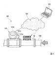
図1は、一実施形態に係る温度差発電装置1を有する測定システム100を示す概略図である。
測定システム100は、温度差発電装置1と、フィールド機器101と、を含んで構成されている。フィールド機器101は、通信ネットワーク102を介して、端末103と接続されている。本実施形態においては、温度差発電装置1及びフィールド機器101が、例えば、温泉(温水)が湧き出る山奥の水源近くに設置され、温泉配管104を流れる温水(高温流体)の状態量を測定する。ここでいう「高温流体」とは、外気よりも高温な流体を意味する。
FIG. 1 is a schematic diagram illustrating a
The
フィールド機器101は、測定対象物の状態量を測定する測定部101aと、測定部101aの測定結果を外部に提供する通信部101b(フィールド機器本体)と、を有する。本実施形態において、測定部101aは、通信部101bが取り付けられた配管部を含み、温泉配管104を流通する温水の状態量を測定する。このような測定部101aは、例えば、温度センサー、圧力センサー、流量センサー、またはpHセンサー等を有してもよい。
The
通信部101bと測定部101aとは、伝送線101cを介して接続されている。なお、図1においては、伝送線101cは、フィールド機器101の本体部および測定部101aの外部を通して配線されているが、これに限られるものではない。伝送線101cは、フィールド機器101の本体部の内部を通して配線されてもよい。
The
伝送線101cは、例えば、「4〜20mA」のアナログ信号の伝送に用いられる伝送線、「0〜1kHz」のパルス信号の伝送に用いられる伝送線、およびフィールド機器101の内部に設けられた接点(図示せず)をオン/オフすることによりHigh信号/Low信号を送信する伝送線を含む。
The
通信部101bは、測定部101aから取得した測定値(例えば、温度、圧力、流量、またはpH値等)に基づく測定結果情報を記憶することができる。また、通信部101bは、記憶した測定結果情報を用いて様々な統計処理を行い、当該統計処理の結果に基づく統計情報を記憶することができる。
The
端末103は、コンピュータ装置、例えば、パーソナルコンピュータ等である。通信部101bと端末103とは、通信ネットワーク102(例えば、インターネット、またはLAN(Local Area Network;構内通信網)等)を介して通信接続されている。
The
通信部101bは、通信ネットワーク102を介して端末103と通信接続するための通信インターフェースとなる。通信部101bは、無線通信を介して通信ネットワーク102に通信接続し、記憶した測定結果情報および統計情報を、端末103(外部の機器)へ送信する。なお、ここでいう無線通信は、例えば、Wi−Fi(登録商標)、WiMAX(登録商標)、または3G/LTE(登録商標)等の無線通信規格に準拠した無線通信である。
The
なお、本実施形態においては、通信部101bは、無線通信を介して通信ネットワーク102に通信接続するものとしたが、有線通信を介して通信ネットワーク102に通信接続する構成であっても構わない。
In the present embodiment, the
端末103は、通信部101bから送信された情報、例えば、測定部101aによって測定された測定値(例えば、温度、圧力値、流量、またはpH値等)に基づく測定結果情報、および、上述した統計処理の結果に基づく統計情報を受信して、表示することができる。
The terminal 103 receives information transmitted from the
なお、端末103から通信部101bへの情報の送信は、端末103から通信部101bに対して要求が行われた際に送信が行われるような構成であってもよいし、通信部101bが自ら定期的に送信を行うような構成であってもよい。
The transmission of information from the terminal 103 to the
このようなフィールド機器101は、その隣に付設された温度差発電装置1から図示しない電力線を介して電力を供給されている。すなわち、フィールド機器101は、自前のバッテリーを有せず、また、周辺から電力線を引かずとも、上述した動作を継続することができる。すなわち、フィールド機器101と温度差発電装置1との間以外は、配線をする必要がない。但し、フィールド機器101は、メンテナンス時や非常用バッテリーとして、バッテリーを搭載していてもよい。
Such a
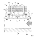
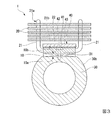
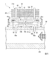
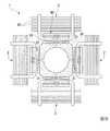
図2は、一実施形態に係る温度差発電装置1の断面構成図である。図3は、図2における矢視A−A図である。
温度差発電装置1は、図2に示すように、熱電交換素子10と、放熱フィン20と、パイプ30と、押付機構40と、を有する。
Drawing 2 is a section lineblock diagram of temperature
As shown in FIG. 2, the temperature difference
熱電交換素子10は、外気(例えば20℃程度)と温水(例えば90℃程度)との温度差により熱エネルギーを電気エネルギーに変換するものである。本実施形態においては、熱電交換素子10として、ゼーベック効果を伴うゼーベック素子を用いる。熱電交換素子10の高温部側10aは、パイプ30と熱的に接続されている。また、熱電交換素子10の低温部側10bは、高温部側10aと反対側にあり、放熱フィン20と熱的に接続されている。なお、熱電交換素子10は、トムソン効果やペルチェ効果などを伴う素子であってもよい。
The
放熱フィン20は、熱電交換素子10の低温部側10bにヒートパイプ21を介して熱的に接続されている。放熱フィン20は、高い放熱性を有する金属材、例えば、アルミニウムやアルミニウム合金などから形成するとよい。放熱フィン20は、矩形板状に形成され、それらが隙間をあけて積層された積層構造を有する。放熱フィン20は、ヒートパイプ21の一端部21aに支持されている。ヒートパイプ21の一端部21aは、積層された複数の放熱フィン20を貫通し、複数の放熱フィン20と接合されている。
The
ヒートパイプ21の他端部21bは、熱電交換素子10の低温部側10bにベースプレート22を介して熱的に接続されている。ベースプレート22は、高い熱伝導率を有する銅や銅合金などから形成するとよい。ベースプレート22は、熱電交換素子10の低温部側10bに接している。図3に示すように、ベースプレート22の幅は、熱電交換素子10の幅と略同一である。なお、ベースプレート22と熱電交換素子10との間には、放熱グリスなどを塗布するとよい。
The
ベースプレート22には、複数のヒートパイプ21が植設されている。本実施形態においては、ベースプレート22に4本のヒートパイプ21が植設され、それら4本のヒートパイプ21がベースプレート22の幅方向両側の側端面から幅方向両側に延在し、放熱フィン20の四隅を支持する構成となっている。なお、ヒートパイプ21は、ベースプレート22にさらに複数本設けられていてもよい。
A plurality of
パイプ30は、図1に示すように、温泉配管104と接続され、内部に温水が流通する。このパイプ30は、温水に対して耐腐食性を有する材料、例えば、ステンレス鋼材などから形成するとよい。なお、パイプ30は、温水に対して耐腐食性を有する樹脂材などで形成してもよい。このパイプ30の外周面30bには、図3に示すように、平面部31が形成されている。平面部31は、パイプ30の外周面30bの一部を、外周面30bの接線に対し平行に切り欠いたものである。
As shown in FIG. 1, the
熱電交換素子10の高温部側10aは、平面部31と接している。平面部31は、鏡面仕上げするとよい。これにより、平面部31における表面粗さ(凹凸)が小さくなり、熱電交換素子10の高温部側10aとの接触面積が増加する。なお、平面部31と熱電交換素子10との間には、放熱グリスなどを塗布するとよい。
The high
押付機構40は、図2に示すように、熱電交換素子10の高温部側10aを、パイプ30側に押し付けるものである。押付機構40は、押付プレート41と、ネジ部材42と、樹脂ワッシャー43(断熱部)と、を有する。押付プレート41は、図3に示すように、左右のヒートパイプ21の間を通ってパイプ30の長手方向に沿って延び、図2に示すように、ベースプレート22の外側(反熱電交換素子側)を跨ぐように配置されている。
As shown in FIG. 2, the
図3に示すように、押付プレート41の幅は、熱電交換素子10(ベースプレート22)の幅よりも大きくするとよい。これにより、熱電交換素子10の高温部側10aの全域を平面部31に押し付けることができる。この押付プレート41の両端部には、図2に示すように、パイプ30側に向かって屈曲する第1曲部41aと、第1曲部41aの先端からパイプ30の長手方向に沿って屈曲する第2曲部41bと、が形成されている。
As shown in FIG. 3, the width of the
第1曲部41aは、パイプ30の長手方向におけるベースプレート22の端面に対向し、接している。第2曲部41bは、パイプ30の長手方向に沿って平行に延び、挿通孔41cが形成されている。挿通孔41cには、ネジ部材42が挿通されている。ネジ部材42は、パイプ30の平面部31に形成されたネジ孔32に螺合している。なお、挿通孔41cは、ネジ部材42のシャフト部よりも径を大きくし、当該シャフト部との間に隙間を確保するとよい。
The first
樹脂ワッシャー43は、ネジ部材42のヘッド部の裏側に配置されている。この樹脂ワッシャー43は、ネジ部材42と押付プレート41との間に介在し、パイプ30からネジ部材42、押付プレート41を通り、熱電交換素子10の低温部側10bに至る伝熱経路を遮断する。すなわち、パイプ30から熱電交換素子10の高温部側10aに至る伝熱経路以外の伝熱経路を遮断する。なお、樹脂ワッシャー43の一部は、ネジ部材42のシャフト部と挿通孔41cとの隙間に挿入されるように延在していてもよい。また、樹脂ワッシャー43の代わりに、押付プレート41ないしネジ部材42自体が断熱材(樹脂材など)から形成されていてもよい。
The
上記構成の温度差発電装置1によれば、パイプ30を流通する温水と、当該温水に対して比較的低温の外気との温度差により、熱電交換素子10が熱エネルギーを電気エネルギーに変換する。温水は、パイプ30の内部を流通するため、熱電交換素子10や放熱フィン20などが温水の湯気に曝されることはない。このため、熱電交換素子10や放熱フィン20などが腐食し難くなり、長期間に亘ってメンテナスフリーで温度差発電を継続することができる。
According to the temperature difference
また、本実施形態においては、図2に示すように、熱電交換素子10の高温部側10aを、パイプ30側に押し付ける押付機構40を有する。この構成によれば、押付機構40による押し付けによって熱電交換素子10に対するパイプ30側からの伝熱効率が向上するため、効率よく発電することが可能となる。また、押付機構40には、樹脂ワッシャー43(断熱部)が設けられており、パイプ30側からネジ部材42及び押付プレート41を介した伝熱を遮断するため、熱電交換素子10に対するパイプ30側からの伝熱効率が低下することはない。
Moreover, in this embodiment, as shown in FIG. 2, it has the
さらに、本実施形態においては、図3に示すように、パイプ30の外周面30bには、平面部31が形成されており、熱電交換素子10の高温部側10aが、平面部31に接している。この構成によれば、熱電交換素子10の高温部側10aとパイプ30とが密着し易くなり、伝熱効率が向上し、効率よく発電することが可能となる。
Further, in the present embodiment, as shown in FIG. 3, a
このように、上述の本実施形態によれば、温度差により熱エネルギーを電気エネルギーに変換する熱電交換素子10と、熱電交換素子10の低温部側10bに熱的に接続され、外気に触れる放熱フィン20と、熱電交換素子10の高温部側10aに熱的に接続され、内部に温水が流通可能なパイプ30と、を有する、温度差発電装置1を採用することによって、高温流体が腐食性を有する温水であっても長期間に亘って温度差発電を継続することができる。
As described above, according to the above-described embodiment, the
また、本実施形態の測定システム100は、図1に示すように、上述の温度差発電装置1と、温水の状態量を測定する測定部101a、及び、測定部101aの測定結果を外部に提供する通信部101bを備えるフィールド機器101と、を備え、温度差発電装置1が、フィールド機器101に電力を供給する。この構成によれば、温水によって自家発電しつつ、発電した電力によって温水の状態量を測定し、その測定結果を外部に通信できるため、例えば、温水が山奥の僻地で湧き出る場合、当該僻地に電力線を引いたり、人が出向いて行かなくても温水の状態量をモニタリングすることが可能となる。
In addition, as shown in FIG. 1, the
以上、図面を参照しながら本発明の好適な実施形態について説明したが、本発明は上記実施形態に限定されるものではない。上述した実施形態において示した各構成部材の諸形状や組み合わせ等は一例であって、本発明の主旨から逸脱しない範囲において設計要求等に基づき種々変更可能である。 As mentioned above, although preferred embodiment of this invention was described referring drawings, this invention is not limited to the said embodiment. Various shapes, combinations, and the like of the constituent members shown in the above-described embodiments are examples, and various modifications can be made based on design requirements and the like without departing from the gist of the present invention.
例えば、本発明では、図4〜図10に示すような形態を採用することができる。なお、以下の説明において、上述の実施形態と同一又は同等の構成については同一の符号を付し、その説明を簡略若しくは省略する。 For example, in the present invention, forms as shown in FIGS. 4 to 10 can be adopted. In the following description, the same or equivalent components as those in the above-described embodiment are denoted by the same reference numerals, and the description thereof is simplified or omitted.
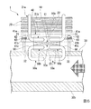
図4に示す形態では、熱電交換素子10の高温部側10aとパイプ30が、ヒートパイプ50を介して熱的に接続されている。この構成によれば、ヒートパイプ50の封入液の気化潜熱を利用して熱を輸送できるため、伝熱効率が向上し、効率よく発電することが可能となる。また、ヒートパイプ50の一端部50a(一部)は、パイプ30に埋設するとよい。この構成によれば、ヒートパイプ50とパイプ30との接触面積が増えるため、伝熱効率が向上し、効率よく発電することが可能となる。
In the form shown in FIG. 4, the high
なお、この形態では、ヒートパイプ50以外の伝熱経路を遮断するために、熱電交換素子10をヒートパイプ50で支持し、熱電交換素子10とパイプ30との間に隙間をあけて(浮かせて)配置するとよい。このヒートパイプ50の他端部50bは、熱電交換素子10の高温部側10aにベースプレート51を介して熱的に接続されている。ベースプレート51は、ベースプレート22と同様に、高い熱伝導率を有する銅や銅合金などから形成するとよい。
In this embodiment, in order to block the heat transfer path other than the
図5に示す形態では、ヒートパイプ50の一端部50aが、パイプ30を貫通して配置されている。この構成によれば、ヒートパイプ50を直接温水に接触させることができるため、さらに効率よく発電することができる。なお、この場合、ヒートパイプ50を耐腐食性の材料から形成するとよい。
In the form shown in FIG. 5, one
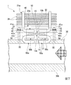
図6に示す形態では、ヒートパイプ50の一端部50aが、パイプ30の内部で折り曲げられている。この構成によれば、図5に示す形態と同様に、ヒートパイプ50を直接温水に接触させることができると共に、図5に示す形態よりも折り曲げによって温水に接触する面積が増えるため、さらに効率よく発電することができる。なお、ヒートパイプ50の折り曲げ方向は、温水の流れに対して上流側、下流側のいずれであってもよい。
In the form shown in FIG. 6, one
図7に示す形態では、ヒートパイプ50の一端部50aが折り曲げられた状態で、パイプ30に埋設されている。この構成によれば、ヒートパイプ50が直接温水に接触することがないので、ヒートパイプ50を耐腐食性の材料から形成する必要がない。また、ヒートパイプ50と温水との距離が近くなり、伝熱効率が向上し、効率よく発電することが可能となる。
In the form shown in FIG. 7, the
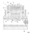
図8に示す形態では、ヒートパイプ50の一端部50aが、パイプ30を貫通し、パイプ30に内装されたライニング材60に埋設されている。ライニング材60は、温水に対する耐腐食性を有する樹脂材などから形成されている。この構成によれば、パイプ30の内部に挿入されたヒートパイプ50は、ライニング材60に埋設されるため、腐食性の温水でも効率よく発電することが可能となる。また、この構成は、図7に示す形態(例えば鋳造)よりも、安価に製造できる。また、ヒートパイプ50と温水との距離が近くなり、伝熱効率が向上し、効率よく発電することが可能となる。
In the form shown in FIG. 8, one
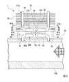
図9に示す形態では、熱電交換素子10、放熱フィン20、押付機構40を含む発電ユニット2が、パイプ30の周方向に間隔をあけて複数(図9の例では4つ)設けられていている。この構成によれば、パイプ30を長くしなくても発電ユニット2を密集して設置できるため、小スペースで高い電圧の発電が可能となる。なお、この場合、複数の発電ユニット2に対応して、パイプ30に複数の平面部31を形成するとよい。
In the form shown in FIG. 9, a plurality (four in the example of FIG. 9) of the
また、上記実施形態では、高温流体として温泉を例示したが、温泉以外の高温流体に対しても本発明を適用することができる。 Moreover, although the hot spring was illustrated as a high temperature fluid in the said embodiment, this invention is applicable also to high temperature fluids other than a hot spring.
また、上述した図4〜図8に示す形態では、ヒートパイプ50の一部がパイプ30に埋設され、または、ヒートパイプ50がパイプ30を貫通して配置されていたが、例えば、ヒートパイプ50をロウ付けによりパイプ30の外周面30bに、U字状ないしΩ字状に巻き付ける形態を採用してもよい。この構成によれば、パイプ30に貫通孔を設けたり、また、パイプ30にヒートパイプ50を埋設しなくても、ヒートパイプ50とパイプ30との接触面積を増やし、効率よく発電することが可能となる。
4 to 8 described above, a part of the
1 温度差発電装置
2 発電ユニット
10 熱電交換素子
10a 高温部側
10b 低温部側
20 放熱フィン
30 パイプ
30b 外周面
31 平面部
40 押付機構
42 ネジ部材
43 樹脂ワッシャー(断熱部)
50 ヒートパイプ
60 ライニング材
100 測定システム
101 フィールド機器
101a 測定部
101b 通信部
101c 伝送線
DESCRIPTION OF
50
Claims (8)
前記熱電交換素子の低温部側に熱的に接続され、外気に触れる放熱フィンと、
前記熱電交換素子の高温部側に熱的に接続され、内部に前記外気よりも高温な高温流体が流通可能なパイプと、を有する、ことを特徴とする温度差発電装置。 A thermoelectric exchange element that converts thermal energy into electrical energy due to a temperature difference; and
A heat dissipating fin that is thermally connected to the low temperature part side of the thermoelectric exchange element and touches the outside air;
A temperature difference power generation device comprising: a pipe thermally connected to a high temperature portion side of the thermoelectric exchange element and capable of circulating a high temperature fluid higher in temperature than the outside air.
前記押付機構には、前記パイプ側からの伝熱を遮断する断熱部が設けられている、ことを特徴とする請求項1に記載の温度差発電装置。 Having a pressing mechanism for pressing the high temperature part side of the thermoelectric exchange element against the pipe side;
The temperature difference power generation device according to claim 1, wherein the pressing mechanism is provided with a heat insulating portion that blocks heat transfer from the pipe side.
前記熱電交換素子の高温部側が、前記平面部に接している、ことを特徴とする請求項1または2に記載の温度差発電装置。 A flat surface portion is formed on the outer peripheral surface of the pipe,
The temperature difference power generator according to claim 1, wherein a high temperature part side of the thermoelectric exchange element is in contact with the flat part.
前記ヒートパイプの一部は、前記パイプを貫通し、前記ライニング材に埋設されている、ことを特徴とする請求項4に記載の温度差発電装置。 The pipe is internally provided with a lining material having corrosion resistance to the high-temperature fluid,
The temperature difference power generation device according to claim 4, wherein a part of the heat pipe penetrates the pipe and is embedded in the lining material.
前記高温流体の状態量を測定する測定部、及び、前記測定部の測定結果を外部に提供する通信部を備えるフィールド機器と、を備え、
前記温度差発電装置が、前記フィールド機器に電力を供給する、ことを特徴とする測定システム。 The temperature difference power generation device according to any one of claims 1 to 7,
A measurement unit that measures the state quantity of the high-temperature fluid, and a field device that includes a communication unit that provides measurement results of the measurement unit to the outside.
The temperature difference power generator supplies power to the field device.
Priority Applications (4)
| Application Number | Priority Date | Filing Date | Title |
|---|---|---|---|
| JP2018109437A JP6953365B2 (en) | 2018-06-07 | 2018-06-07 | Temperature difference power generation device and measurement system |
| CN201910480141.0A CN110581674B (en) | 2018-06-07 | 2019-06-04 | Thermoelectric power generation device and measurement system |
| US16/431,804 US11839156B2 (en) | 2018-06-07 | 2019-06-05 | Temperature difference power generation apparatus and measurement system |
| EP19178533.6A EP3579287B1 (en) | 2018-06-07 | 2019-06-05 | Temperature difference power generation apparatus and measurement system |
Applications Claiming Priority (1)
| Application Number | Priority Date | Filing Date | Title |
|---|---|---|---|
| JP2018109437A JP6953365B2 (en) | 2018-06-07 | 2018-06-07 | Temperature difference power generation device and measurement system |
Publications (2)
| Publication Number | Publication Date |
|---|---|
| JP2019213402A true JP2019213402A (en) | 2019-12-12 |
| JP6953365B2 JP6953365B2 (en) | 2021-10-27 |
Family
ID=66770403
Family Applications (1)
| Application Number | Title | Priority Date | Filing Date |
|---|---|---|---|
| JP2018109437A Active JP6953365B2 (en) | 2018-06-07 | 2018-06-07 | Temperature difference power generation device and measurement system |
Country Status (4)
| Country | Link |
|---|---|
| US (1) | US11839156B2 (en) |
| EP (1) | EP3579287B1 (en) |
| JP (1) | JP6953365B2 (en) |
| CN (1) | CN110581674B (en) |
Cited By (1)
| Publication number | Priority date | Publication date | Assignee | Title |
|---|---|---|---|---|
| JP2019220654A (en) * | 2018-06-22 | 2019-12-26 | 三菱電機エンジニアリング株式会社 | Thermoelectric generator and cooling device |
Families Citing this family (2)
| Publication number | Priority date | Publication date | Assignee | Title |
|---|---|---|---|---|
| CN113765435B (en) * | 2021-07-23 | 2024-05-07 | 重庆燃气集团股份有限公司 | Pipeline fluid signal transmitting system based on thermoelectric generation |
| EP4276017A1 (en) * | 2022-05-10 | 2023-11-15 | Airbus SAS | Fluid transport device and method for manufacturing a fluid transport device |
Citations (7)
| Publication number | Priority date | Publication date | Assignee | Title |
|---|---|---|---|---|
| JPH10113845A (en) * | 1996-10-08 | 1998-05-06 | Mitsubishi Heavy Ind Ltd | Spindle |
| JPH11215867A (en) * | 1998-01-23 | 1999-08-06 | Tokyo Gas Co Ltd | Thermoelectric power generation element structure and system thereof |
| JP3079577U (en) * | 2001-02-14 | 2001-08-24 | 邦博 山本 | Non-linear connection structure of high temperature water pipe |
| JP2002030717A (en) * | 2000-07-18 | 2002-01-31 | Ace Plan:Kk | Sewer for constructing sewage-utilizing heat-source facility |
| JP2010505383A (en) * | 2006-09-28 | 2010-02-18 | ローズマウント インコーポレイテッド | Thermoelectric generator assembly for field process equipment |
| WO2010090350A1 (en) * | 2009-02-05 | 2010-08-12 | ティーエス ヒートロニクス株式会社 | Electric generator |
| JP2013045929A (en) * | 2011-08-25 | 2013-03-04 | Science Park Corp | Temperature difference power generator |
Family Cites Families (16)
| Publication number | Priority date | Publication date | Assignee | Title |
|---|---|---|---|---|
| US4520305A (en) * | 1983-08-17 | 1985-05-28 | Cauchy Charles J | Thermoelectric generating system |
| GB2145876A (en) * | 1983-08-24 | 1985-04-03 | Shlomo Beitner | DC power generation for telemetry and like equipment from geothermal energy |
| JPH11121816A (en) * | 1997-10-21 | 1999-04-30 | Morikkusu Kk | Thermoelectric module unit |
| US6880346B1 (en) * | 2004-07-08 | 2005-04-19 | Giga-Byte Technology Co., Ltd. | Two stage radiation thermoelectric cooling apparatus |
| US9184364B2 (en) * | 2005-03-02 | 2015-11-10 | Rosemount Inc. | Pipeline thermoelectric generator assembly |
| US20080142067A1 (en) | 2006-12-14 | 2008-06-19 | Robert Dell | Thermoelectric power generation device |
| TWI421148B (en) | 2009-06-02 | 2014-01-01 | Cpumate Inc | Heat sink having grinding heat-contacting plane and method and apparatus of making the same |
| GB2483293A (en) * | 2010-09-03 | 2012-03-07 | Spirax Sarco Ltd | Steam flow meter with thermoelectric power source |
| JP5989302B2 (en) | 2011-02-07 | 2016-09-07 | サイエンスパーク株式会社 | Power generation system |
| US20130005372A1 (en) * | 2011-06-29 | 2013-01-03 | Rosemount Inc. | Integral thermoelectric generator for wireless devices |
| US20160146083A1 (en) * | 2014-11-25 | 2016-05-26 | Hyundai Motor Company | Clamp mounted thermoelectric generator |
| CN204390843U (en) * | 2014-12-27 | 2015-06-10 | 浙江宝威电气有限公司 | There is the transformer of thermo-electric generation function |
| JP2018109437A (en) | 2017-01-05 | 2018-07-12 | 常正 船津 | Uncontrolled magnetic levitation method and uncontrolled magnetic levitation device |
| CN107528499A (en) * | 2017-09-05 | 2017-12-29 | 上海电力学院 | The energy storage of heat pipe-type thermo-electric generation and transmission system applied to boiler back end ductwork |
| CN207304412U (en) * | 2017-10-13 | 2018-05-01 | 大连海事大学 | Heat pipe-type marine main engine waste gas heat utilization temperature difference electricity generation device |
| CN107592035B (en) * | 2017-10-13 | 2020-05-05 | 大连海事大学 | Tail gas waste heat utilization method based on thermoelectric power generation and pulsating heat pipe technology |
-
2018
- 2018-06-07 JP JP2018109437A patent/JP6953365B2/en active Active
-
2019
- 2019-06-04 CN CN201910480141.0A patent/CN110581674B/en active Active
- 2019-06-05 EP EP19178533.6A patent/EP3579287B1/en active Active
- 2019-06-05 US US16/431,804 patent/US11839156B2/en active Active
Patent Citations (7)
| Publication number | Priority date | Publication date | Assignee | Title |
|---|---|---|---|---|
| JPH10113845A (en) * | 1996-10-08 | 1998-05-06 | Mitsubishi Heavy Ind Ltd | Spindle |
| JPH11215867A (en) * | 1998-01-23 | 1999-08-06 | Tokyo Gas Co Ltd | Thermoelectric power generation element structure and system thereof |
| JP2002030717A (en) * | 2000-07-18 | 2002-01-31 | Ace Plan:Kk | Sewer for constructing sewage-utilizing heat-source facility |
| JP3079577U (en) * | 2001-02-14 | 2001-08-24 | 邦博 山本 | Non-linear connection structure of high temperature water pipe |
| JP2010505383A (en) * | 2006-09-28 | 2010-02-18 | ローズマウント インコーポレイテッド | Thermoelectric generator assembly for field process equipment |
| WO2010090350A1 (en) * | 2009-02-05 | 2010-08-12 | ティーエス ヒートロニクス株式会社 | Electric generator |
| JP2013045929A (en) * | 2011-08-25 | 2013-03-04 | Science Park Corp | Temperature difference power generator |
Cited By (2)
| Publication number | Priority date | Publication date | Assignee | Title |
|---|---|---|---|---|
| JP2019220654A (en) * | 2018-06-22 | 2019-12-26 | 三菱電機エンジニアリング株式会社 | Thermoelectric generator and cooling device |
| JP7305313B2 (en) | 2018-06-22 | 2023-07-10 | 三菱電機エンジニアリング株式会社 | thermoelectric generator |
Also Published As
| Publication number | Publication date |
|---|---|
| US11839156B2 (en) | 2023-12-05 |
| US20190376848A1 (en) | 2019-12-12 |
| CN110581674A (en) | 2019-12-17 |
| JP6953365B2 (en) | 2021-10-27 |
| EP3579287B1 (en) | 2021-02-17 |
| CN110581674B (en) | 2023-01-10 |
| EP3579287A1 (en) | 2019-12-11 |
Similar Documents
| Publication | Publication Date | Title |
|---|---|---|
| JP6953365B2 (en) | Temperature difference power generation device and measurement system | |
| US10355561B2 (en) | Slipring with active cooling | |
| Ahmed et al. | Performance analysis of a passively cooled thermoelectric generator | |
| JP5444787B2 (en) | Thermoelectric generator | |
| JP5611739B2 (en) | Thermoelectric power generation system | |
| JP5677519B2 (en) | Temperature detection device | |
| JP2006217756A (en) | Thermoelectric generator | |
| RU2676551C1 (en) | Autonomous thermoelectric generator on pipeline | |
| JP2011192759A (en) | Thermoelectric generation system | |
| JP5149659B2 (en) | Liquefied gas vaporizer | |
| JP2014225509A (en) | Waste heat power generator | |
| JPH11215867A (en) | Thermoelectric power generation element structure and system thereof | |
| JP4706983B2 (en) | Heating device including thermoelectric module | |
| JP2009272327A (en) | Thermoelectric conversion system | |
| JP6149407B2 (en) | Thermoelectric power generation system | |
| JP5989302B2 (en) | Power generation system | |
| CN208690302U (en) | A kind of organic/inorganic composite material thermoelectric generating device | |
| CN111446887A (en) | Heat energy conversion structure and underground temperature difference power generation device | |
| JP2011027190A (en) | Expansion joint | |
| CN108417705A (en) | A kind of organic/inorganic composite material thermoelectric generating device | |
| CN214959331U (en) | Flow meter | |
| RU2804784C1 (en) | Heat exchanger for electric water boiler with thermal energy generation by flat thermistor heating elements and method of its manufacture | |
| TW201442550A (en) | Heater | |
| TWM496191U (en) | Heat energy generator set of thermal system monitor | |
| CN209896945U (en) | Thermoelectric power generation equipment utilizing heat energy of dry hot rock |
Legal Events
| Date | Code | Title | Description |
|---|---|---|---|
| A521 | Request for written amendment filed |
Free format text: JAPANESE INTERMEDIATE CODE: A523 Effective date: 20180705 |
|
| A621 | Written request for application examination |
Free format text: JAPANESE INTERMEDIATE CODE: A621 Effective date: 20190618 |
|
| A977 | Report on retrieval |
Free format text: JAPANESE INTERMEDIATE CODE: A971007 Effective date: 20200624 |
|
| A131 | Notification of reasons for refusal |
Free format text: JAPANESE INTERMEDIATE CODE: A131 Effective date: 20200630 |
|
| A521 | Request for written amendment filed |
Free format text: JAPANESE INTERMEDIATE CODE: A523 Effective date: 20200827 |
|
| A131 | Notification of reasons for refusal |
Free format text: JAPANESE INTERMEDIATE CODE: A131 Effective date: 20201201 |
|
| A521 | Request for written amendment filed |
Free format text: JAPANESE INTERMEDIATE CODE: A523 Effective date: 20210120 |
|
| A02 | Decision of refusal |
Free format text: JAPANESE INTERMEDIATE CODE: A02 Effective date: 20210518 |
|
| A521 | Request for written amendment filed |
Free format text: JAPANESE INTERMEDIATE CODE: A523 Effective date: 20210803 |
|
| C60 | Trial request (containing other claim documents, opposition documents) |
Free format text: JAPANESE INTERMEDIATE CODE: C60 Effective date: 20210803 |
|
| A911 | Transfer to examiner for re-examination before appeal (zenchi) |
Free format text: JAPANESE INTERMEDIATE CODE: A911 Effective date: 20210811 |
|
| C21 | Notice of transfer of a case for reconsideration by examiners before appeal proceedings |
Free format text: JAPANESE INTERMEDIATE CODE: C21 Effective date: 20210817 |
|
| TRDD | Decision of grant or rejection written | ||
| A01 | Written decision to grant a patent or to grant a registration (utility model) |
Free format text: JAPANESE INTERMEDIATE CODE: A01 Effective date: 20210914 |
|
| A61 | First payment of annual fees (during grant procedure) |
Free format text: JAPANESE INTERMEDIATE CODE: A61 Effective date: 20210929 |
|
| R150 | Certificate of patent or registration of utility model |
Ref document number: 6953365 Country of ref document: JP Free format text: JAPANESE INTERMEDIATE CODE: R150 |