JP2019210152A - Automatic warehouse system - Google Patents

Automatic warehouse system Download PDF

Info

Publication number
JP2019210152A
JP2019210152A JP2019169091A JP2019169091A JP2019210152A JP 2019210152 A JP2019210152 A JP 2019210152A JP 2019169091 A JP2019169091 A JP 2019169091A JP 2019169091 A JP2019169091 A JP 2019169091A JP 2019210152 A JP2019210152 A JP 2019210152A
Authority
JP
Japan
Prior art keywords
load
storage
storage shelf
automatic warehouse
warehouse system
Prior art date
Legal status (The legal status is an assumption and is not a legal conclusion. Google has not performed a legal analysis and makes no representation as to the accuracy of the status listed.)
Granted
Application number
JP2019169091A
Other languages
Japanese (ja)
Other versions
JP2019210152A5 (en
JP6987819B2 (en
Inventor
健司 西前
Kenji Nishimae
健司 西前
Current Assignee (The listed assignees may be inaccurate. Google has not performed a legal analysis and makes no representation or warranty as to the accuracy of the list.)
Sumitomo Heavy Industries Material Handling Systems Co Ltd
Original Assignee
Sumitomo Heavy Industries Material Handling Systems Co Ltd
Priority date (The priority date is an assumption and is not a legal conclusion. Google has not performed a legal analysis and makes no representation as to the accuracy of the date listed.)
Filing date
Publication date
Priority claimed from JP2017040842A external-priority patent/JP6621430B2/en
Application filed by Sumitomo Heavy Industries Material Handling Systems Co Ltd filed Critical Sumitomo Heavy Industries Material Handling Systems Co Ltd
Priority to JP2019169091A priority Critical patent/JP6987819B2/en
Publication of JP2019210152A publication Critical patent/JP2019210152A/en
Publication of JP2019210152A5 publication Critical patent/JP2019210152A5/ja
Priority to JP2021195191A priority patent/JP7203183B2/en
Application granted granted Critical
Publication of JP6987819B2 publication Critical patent/JP6987819B2/en
Active legal-status Critical Current
Anticipated expiration legal-status Critical

Links

Images

Abstract

To provide an automated warehouse system capable of making it easy to take out cargoes while increasing a storage space of the cargoes.SOLUTION: In an automated warehouse system 10, a storage shelf part 20 includes a storage part array 23 having storage parts 21 of M (M: an integer of 2 or more) lines and N (N: an integer of 2 or more) rows, and the respective storage parts 21 are constituted so as to store cargoes 12. A housing shelf part 30 includes a housing part array 33 having housing parts 31 of M lines, and the respective housing parts 31 are constituted so as to receive the cargoes 12 from the outside and house them. An intermediate conveying device 40 conveys the cargoes 12 between the storage shelf part 20 and the housing shelf part 30. The storage shelf part 20 includes the storage part array 23 of K (K: an integer of 2 or more) stages, and the housing shelf part 30 includes the housing part array 33 of K stages.SELECTED DRAWING: Figure 1

Description

本発明は、荷を入庫・出庫する自動倉庫システムに関する。   The present invention relates to an automatic warehouse system for loading and unloading loads.

少ないスペースで多数の荷を効率的に入庫・出庫可能な倉庫システムとして自動倉庫システムが知られている。自動倉庫システムも種々の構造が提供されているが、その一つとして、立体的に構成された自動倉庫にスタッカークレーンやフォークリフトなどの搬送機器を用いて荷の授受を行う自動倉庫が提供されている。例えば特許文献1には、多段高層棚の入出庫位置に配置され、スタッカークレーンやフォークリフトなどの搬送機器との間で荷の受け渡しを行う入出庫装置を備えた立体自動倉庫が記載されている。この自動倉庫では、棚間においてスタッカークレーンが走行して、各棚からへの荷の搬入及び搬出を行うように構成されている。   An automatic warehouse system is known as a warehouse system that can efficiently store and retrieve a large number of loads in a small space. Various structures are also provided in the automatic warehouse system. One of them is an automatic warehouse that transfers and receives loads using a three-dimensional automatic warehouse using transport equipment such as stacker cranes and forklifts. Yes. For example, Patent Document 1 describes a three-dimensional automatic warehouse provided with a loading / unloading device that is arranged at a loading / unloading position of a multi-stage high-rise shelf and transfers a load to / from a transfer device such as a stacker crane or a forklift. This automatic warehouse is configured such that a stacker crane runs between shelves and loads and unloads loads from each shelf.

特開平11−227906号公報JP-A-11-227906

本発明者は自動倉庫システムについて以下のような認識を得た。
自動倉庫システムとして、対面する二つの保管棚の間にスタッカークレーンが走行する走行スペースを設ける構成が考えられる。この倉庫では、入庫する荷をフォークリフトで各保管棚に設けた置台上に移載し、その荷をスタッカークレーンが棚の所定の収容部に移動して収容する。この構成では、対面する二つの保管棚ごとに、スタッカークレーンの走行スペースを設けることになり、スタッカークレーンの走行スペースの分だけ荷の保管スペースが減ってしまう。このため、保管スペースを増やすように、スタッカークレーンの走行スペースを保管棚で埋めてしまうことも考えられるが、この場合、スタッカークレーンが保管棚間へ進入できなくなり、荷の取り出しが難しくなる。このことから、本発明者は、自動倉庫システムには荷の保管スペースを増やしつつ、荷の取り出しを容易にする観点から改善すべき課題があることを認識した。
このような課題はスタッカークレーンを用いる自動倉庫システムに限られず他の種類の自動倉庫システムについても生じうる。
The present inventor has obtained the following recognition regarding the automatic warehouse system.
As an automatic warehouse system, a configuration in which a traveling space in which a stacker crane travels is provided between two storage shelves facing each other is conceivable. In this warehouse, the load to be received is transferred onto a table provided on each storage shelf by a forklift, and the stacker crane moves to and stores the load in a predetermined storage portion of the shelf. In this configuration, a traveling space for the stacker crane is provided for each of the two storage shelves facing each other, and the storage space for the load is reduced by the traveling space of the stacker crane. For this reason, it is conceivable that the travel space of the stacker crane is filled with storage shelves so as to increase the storage space, but in this case, the stacker crane cannot enter between the storage shelves, and it becomes difficult to take out the load. From this, the present inventor has recognized that the automatic warehouse system has a problem to be improved from the viewpoint of facilitating the removal of the load while increasing the storage space for the load.
Such a problem is not limited to an automatic warehouse system using a stacker crane, but may occur in other types of automatic warehouse systems.

本発明は、こうした状況に鑑みてなされたものであり、その目的は、荷の保管スペースを増やしつつ、荷の取り出しを容易にすることが可能な自動倉庫システムを提供することにある。   The present invention has been made in view of such circumstances, and an object of the present invention is to provide an automatic warehouse system capable of easily removing a load while increasing a storage space for the load.

上記課題を解決するために、本発明のある態様の自動倉庫システムは、M(Mは2以上の整数)行、N(Nは2以上の整数)列の保管部を有する保管部配列を含み、当該各保管部は荷を保管可能に構成される保管棚部と、M行の収容部を有する収容部配列を含み、当該各収容部は外部から荷を受け入れて収容可能に構成される収容棚部と、保管棚部と収容棚部との間で荷を搬送する中間搬送装置と、を備える。   In order to solve the above problems, an automatic warehouse system according to an aspect of the present invention includes a storage unit array having storage units of M (M is an integer of 2 or more) rows and N (N is an integer of 2 or more) columns. Each storage unit includes a storage shelf configured to store a load and a storage unit array having M rows of storage units, and each storage unit is configured to receive and accept a load from the outside. A shelf, and an intermediate transport device that transports the load between the storage shelf and the storage shelf.

この態様によると、自動倉庫システムにおいて、中間搬送装置を備えることにより収容棚部に収容した荷を保管棚部に搬送して保管することができる。   According to this aspect, in the automatic warehouse system, by providing the intermediate transfer device, the load stored in the storage shelf can be transferred to the storage shelf and stored.

本発明によれば、荷の保管スペースを増やしつつ、荷の取り出しを容易にすることが可能な自動倉庫システムを提供することができる。   ADVANTAGE OF THE INVENTION According to this invention, the automatic warehouse system which can make picking up a load easy can be provided, increasing the storage space of a load.

実施の形態に係る自動倉庫システムの斜視図である。1 is a perspective view of an automatic warehouse system according to an embodiment. 図1の自動倉庫システムの平面図である。It is a top view of the automatic warehouse system of FIG. 図1の自動倉庫システムの中間搬送装置の一例を示す平面図である。It is a top view which shows an example of the intermediate conveyance apparatus of the automatic warehouse system of FIG. 図1の自動倉庫システムの第1台車の一例を示す平面図である。It is a top view which shows an example of the 1st trolley | bogie of the automatic warehouse system of FIG. 図4の第1台車の側面図である。It is a side view of the 1st trolley | bogie of FIG. 図1の自動倉庫システムの第2台車の一例を示す平面図である。It is a top view which shows an example of the 2nd trolley | bogie of the automatic warehouse system of FIG. 図6の第2台車の側面図である。It is a side view of the 2nd trolley | bogie of FIG. 図1の自動倉庫システムのブロック図である。It is a block diagram of the automatic warehouse system of FIG. 図1の自動倉庫システムの出庫時の搬送動作の一例を示す説明図である。It is explanatory drawing which shows an example of the conveyance operation at the time of leaving of the automatic warehouse system of FIG. 図1の自動倉庫システムの出庫時の搬送動作の一例を示すフローチャートである。It is a flowchart which shows an example of the conveyance operation at the time of leaving of the automatic warehouse system of FIG. 図1の自動倉庫システムの入庫時の搬送動作の一例を示すフローチャートである。It is a flowchart which shows an example of the conveyance operation at the time of warehousing of the automatic warehouse system of FIG. 第1変形例に係る自動倉庫システムの斜視図である。It is a perspective view of the automatic warehouse system which concerns on a 1st modification. 図12の自動倉庫システムのスタッカークレーンの平面図である。It is a top view of the stacker crane of the automatic warehouse system of FIG. 図12のスタッカークレーンの側面図である。It is a side view of the stacker crane of FIG. 図12の自動倉庫システムの出庫時の搬送動作の一例を示すフローチャートである。It is a flowchart which shows an example of the conveyance operation at the time of leaving of the automatic warehouse system of FIG. 図12の自動倉庫システムの入庫時の搬送動作の一例を示すフローチャートである。It is a flowchart which shows an example of the conveyance operation at the time of warehousing of the automatic warehouse system of FIG.

近年、倉庫の高密度化や高速化のニーズが高まる中、本発明者は自動倉庫システムについて考察し、以下のような認識を得た。
自動倉庫システムとして、スタッカークレーンの走行スペースの両側に、対面する二つの保管棚を設ける構成が考えられる。しかしこの構成では、2列の保管棚ごとに走行スペースを設けることになり、その分、荷を保管するスペースが減ってしまう。一方で、走行スペースを保管棚で埋めるとすると、保管棚間にスタッカークレーンが進入できなくなり、荷の取り出しが難しくなる。これらのことから、本発明者は、自動倉庫システムには荷の保管スペースを増やすことと、荷の取り出しを容易にすることとは、二律背反の関係にあることを認識した。
In recent years, as the need for higher density and higher speed of warehouses has increased, the present inventor has considered automatic warehouse systems and has gained the following recognition.
As an automatic warehouse system, a configuration in which two storage shelves facing each other on both sides of the traveling space of the stacker crane can be considered. However, in this configuration, a traveling space is provided for each of the two storage shelves, and the space for storing the load is reduced accordingly. On the other hand, if the traveling space is filled with storage shelves, the stacker crane cannot enter between the storage shelves, making it difficult to take out the load. From these facts, the present inventor has recognized that there is a trade-off between increasing the storage space for loads and facilitating the removal of loads in an automatic warehouse system.

そこで、本発明者は、収容棚を小容量の一次収容棚である収容棚部と、大容量の二次収容棚である保管棚部とに分けて、収容棚部には外部搬送装置により搬入・搬出を可能とし、収容棚部と保管棚部の間には中間搬送装置を設けることで、保管スペースを確保しつつ、入出庫を効率化できることを見出した。例えば、入庫する場合、搬入・搬出するための外部搬送装置(例えば、フォークリフト)により、荷を収容棚部に搬入する。収容棚部に搬入した荷は、中間搬送装置によって保管棚部の所定の保管部に搬送して保管することができる。また、出庫する場合には、出庫する荷を、保管棚部の所定の保管部から収容棚部に中間搬送装置によって搬送し、収容棚部からは外部搬送装置によって荷を搬出・出庫することができる。   Therefore, the present inventor divides the storage shelf into a storage shelf portion that is a small-capacity primary storage shelf and a storage shelf portion that is a large-capacity secondary storage shelf. -It was found that loading and unloading can be made more efficient while securing storage space by enabling unloading and providing an intermediate transfer device between the storage shelf and the storage shelf. For example, when warehousing, a load is carried into the storage shelf by an external transfer device (for example, a forklift) for carrying in / out. The cargo carried into the storage shelf can be transported and stored in a predetermined storage unit of the storage shelf by the intermediate transport device. In addition, when leaving the goods, the goods to be delivered may be transported from a predetermined storage part of the storage shelf part to the storage shelf part by an intermediate transport device, and the load may be unloaded from the storage shelf part by an external transport device. it can.

このように構成することで、外部搬送装置は、中間搬送装置の動作を待たずに、入庫する荷を連続して収容棚部の空いている収容部に搬入することができる。中間搬送装置は収容棚部の収容部に搬入された荷を順次保管棚部の所定の収容部に搬送できる。このため、入庫に要する入庫時間は収容棚部への連続的な搬入動作の時間で決まるから、中間搬送装置の動作を待つ時間の分短縮することが可能になる。出庫の場合は、出庫すべき荷を、予め収容棚部へ移送しておくことで、出庫に要する出庫時間を同様に短縮することが可能になる。
実施の形態はこのような思索に基づいて案出されたもので、以下にその具体的な構成を説明する。
By configuring in this way, the external transfer device can continuously load the incoming goods into the empty storage portion of the storage shelf without waiting for the operation of the intermediate transfer device. The intermediate transfer device can sequentially transfer the load carried into the storage unit of the storage shelf to a predetermined storage unit of the storage shelf. For this reason, since the warehousing time required for warehousing is determined by the time of the continuous carrying-in operation to the storage shelf, it is possible to reduce the time for waiting for the operation of the intermediate transfer device. In the case of unloading, it is possible to shorten the unloading time required for unloading by transferring the load to be unloaded to the storage shelf in advance.
The embodiment has been devised based on such thought, and the specific configuration will be described below.

以下、本発明を好適な実施の形態をもとに各図面を参照しながら説明する。実施形態、比較例および変形例では、同一または同等の構成要素、部材には、同一の符号を付するものとし、適宜重複した説明は省略する。また、各図面における部材の寸法は、理解を容易にするために適宜拡大、縮小して示される。また、各図面において実施の形態を説明する上で重要ではない部材の一部は省略して表示する。
また、第1、第2などの序数を含む用語は多様な構成要素を説明するために用いられるが、この用語は一つの構成要素を他の構成要素から区別する目的でのみ用いられ、この用語によって構成要素が限定されるものではない。
The present invention will be described below based on preferred embodiments with reference to the drawings. In the embodiment, the comparative example, and the modified example, the same or equivalent components and members are denoted by the same reference numerals, and repeated description is appropriately omitted. In addition, the dimensions of the members in each drawing are appropriately enlarged or reduced for easy understanding. Also, in the drawings, some of the members that are not important for describing the embodiment are omitted.
In addition, terms including ordinal numbers such as first and second are used to describe various components, but this term is used only for the purpose of distinguishing one component from other components. However, the constituent elements are not limited.

[実施の形態]
図1は、実施の形態に係る自動倉庫システム10の斜視図である。図2は自動倉庫システム10の平面図である。実施の形態に係る自動倉庫システム10は、多数の荷12を入庫・出庫可能な自動倉庫を含むシステムである。以下、XYZ直交座標系をもとに説明する。X軸方向は水平な左右方向に対応し、Y軸方向は水平な前後方向に対応し、Z軸方向は鉛直な上下方向に対応する。Y軸方向、Z軸方向はそれぞれX軸方向に直交する。特に、後述する行方向および列方向は、それぞれX軸方向およびY軸方向に対応する。入出庫では、パレットを用いずに荷12を単独で扱うようにしてもよいが、実施の形態では荷12をパレット12pに載せた状態で扱うようにしている。以下、荷12をパレット12pに載せた状態で搬送することを、単に荷12を搬送するという。
[Embodiment]
FIG. 1 is a perspective view of an automatic warehouse system 10 according to an embodiment. FIG. 2 is a plan view of the automatic warehouse system 10. The automatic warehouse system 10 according to the embodiment is a system including an automatic warehouse capable of receiving and unloading a large number of loads 12. Hereinafter, description will be made based on the XYZ orthogonal coordinate system. The X-axis direction corresponds to the horizontal left-right direction, the Y-axis direction corresponds to the horizontal front-back direction, and the Z-axis direction corresponds to the vertical up-down direction. The Y-axis direction and the Z-axis direction are each orthogonal to the X-axis direction. In particular, the row direction and the column direction described later correspond to the X-axis direction and the Y-axis direction, respectively. In loading / unloading, the load 12 may be handled alone without using the pallet, but in the embodiment, the load 12 is handled in a state of being placed on the pallet 12p. Hereinafter, conveying the load 12 on the pallet 12p is simply referred to as conveying the load 12.

図2に示すように、自動倉庫システム10は、保管棚部20と、収容棚部30と、中間搬送装置40と、を主に含む。自動倉庫システム10では、一例として、荷12を入庫する際、荷12は外部搬送装置であるフォークリフト50によって収容棚部30に搬入される。収容棚部30に搬入された荷12は、中間搬送装置40によって、保管棚部20の所定の保管部に搬送されて保管される。自動倉庫システム10では、一例として、荷12を出庫する際、出庫する荷12は中間搬送装置40によって予め保管棚部20の所定の保管部から収容棚部30に搬送される。収容棚部30に搬送された荷12は、例えばフォークリフト50により搬出されて出庫される。   As shown in FIG. 2, the automatic warehouse system 10 mainly includes a storage shelf 20, a storage shelf 30, and an intermediate transfer device 40. In the automatic warehouse system 10, as an example, when the load 12 is received, the load 12 is carried into the storage shelf 30 by a forklift 50 that is an external transfer device. The load 12 carried into the storage shelf 30 is transported to a predetermined storage unit of the storage shelf 20 by the intermediate transport device 40 and stored. In the automatic warehouse system 10, as an example, when the load 12 is unloaded, the unloaded load 12 is conveyed from the predetermined storage unit of the storage shelf unit 20 to the storage shelf unit 30 by the intermediate conveyance device 40 in advance. The load 12 transported to the storage shelf 30 is unloaded by a forklift 50, for example.

図1に示すように、自動倉庫システム10には、外部搬送装置が作業するための作業スペース14が設けられる。作業スペース14は、収容棚部30の保管棚部20とは反対側に設けられる空間である。作業スペース14は、収容棚部30の列方向に隣接して設けられてもよい。作業スペース14は、フォークリフト50などの外部搬送装置が収容棚部30に荷12を搬入・搬出できる程度の立体的な大きさを有する。つまり、作業スペース14は、荷12の搬入・搬出が可能な程度の、X軸方向寸法と、Y軸方向寸法と、Z軸方向寸法と、を有する。例えば、作業スペース14のX軸方向寸法は、収容棚部30のX軸方向寸法より大きく設定されてもよい。作業スペース14を有することで、荷12の搬入・搬出が容易になり、作業効率が向上する。   As shown in FIG. 1, the automatic warehouse system 10 is provided with a work space 14 for an external transfer device to work. The work space 14 is a space provided on the opposite side of the storage shelf 30 from the storage shelf 20. The work space 14 may be provided adjacent to the storage shelf 30 in the row direction. The work space 14 has a three-dimensional size such that an external transfer device such as a forklift 50 can carry the load 12 into and out of the storage shelf 30. In other words, the work space 14 has an X-axis direction dimension, a Y-axis direction dimension, and a Z-axis direction dimension that allow loading and unloading of the load 12. For example, the dimension of the work space 14 in the X-axis direction may be set larger than the dimension of the storage shelf 30 in the X-axis direction. By having the work space 14, the loading and unloading of the load 12 are facilitated, and the work efficiency is improved.

保管棚部20は多数の荷12を収容して保管する、いわば高密度保管型の保管スペースである。保管棚部20は、複数の荷12を収容・保管可能であれば、構造に特別な制限はない。実施の形態の保管棚部20は、水平面に沿って配置される、M(Mは2以上の整数)行、N(Nは2以上の整数)列の保管部21を有する保管部配列23を含む。つまり、Mは行数であり、Nは列数である。この各保管部21は荷12を保管可能に構成される。各行の保管部21それぞれは列方向に接続され、列方向に伸びる保管部列22を構成する。荷12は、保管部列22の中を列方向に搬送されることができる。各保管部列22は行方向に接続されて保管部配列23を構成する。各保管部列22の収容棚部30側の端部には、荷12を出し入れするための出入口部22bが設けられる。各保管部配列23は、K(Kは1以上の整数)段、上下方向に層状に接続されて保管棚部20を構成する。つまり、Kは段数である。実施の形態では、保管棚部20の列数、行数および段数は、一例として、5列、6行、3段としている。つまり、保管棚部20は、5列の保管部21を接続した保管部列22を、行方向に6行連ねた保管部配列23を、3段重ねて構成されている。   The storage shelf 20 is a high-density storage type storage space that accommodates and stores a large number of loads 12. The storage shelf 20 is not particularly limited in structure as long as it can accommodate and store a plurality of loads 12. The storage shelf 20 according to the embodiment includes a storage unit array 23 having storage units 21 arranged in a horizontal plane and having M (M is an integer of 2 or more) rows and N (N is an integer of 2 or more) columns. Including. That is, M is the number of rows and N is the number of columns. Each storage unit 21 is configured to store the load 12. Each storage unit 21 in each row is connected in the column direction, and constitutes a storage unit column 22 extending in the column direction. The load 12 can be transported in the storage unit row 22 in the row direction. Each storage unit column 22 is connected in the row direction to form a storage unit array 23. At the end of each storage section row 22 on the storage shelf section 30 side, an entrance / exit section 22b for loading and unloading the load 12 is provided. Each storage unit array 23 is connected in layers in the vertical direction with K (K is an integer equal to or greater than 1), and constitutes a storage shelf unit 20. That is, K is the number of stages. In the embodiment, the number of columns, the number of rows, and the number of stages of the storage shelf 20 are, for example, 5 columns, 6 rows, and 3 stages. That is, the storage shelf unit 20 is configured by stacking storage unit arrays 23 in which six storage units 21 connected to five columns of storage units 21 are connected in six rows in three rows.

収容棚部30は、複数の荷12を一時的に収容する、いわば仮置き用の収容スペースである。収容棚部30に収容可能な荷12の数は、保管棚部20に収容可能な荷12の数より小さくてもよい。収容棚部30は、複数の荷12を一時的に収容可能であれば、構造に特別な制限はない。実施の形態の収容棚部30は、水平面に沿って配置される、M行の収容部31を有する収容部配列33を含む。この各収容部31は外部から荷12を受け入れて収容可能に構成されている。各収容部31は行方向に接続されて収容部配列33を構成する。収容棚部30は、収容部配列33を、K段上下方向に層状に重ねて構成される。収容部配列33の行数、列数および段数は、任意に設定することができる。つまり、収容部配列33に含まれる収容部31の列数は1列に限られない。実施の形態では、動作の円滑化の観点から、収容部配列33の行数は保管部配列23の行数と同数の6行とし、収容部配列33の段数は保管部配列23の段数と同数の3段としている。つまり、収容棚部30は、1列の収容部31を、行方向に6行連ねた収容部配列33を、3段重ねて構成されている。   The storage shelf 30 is a temporary storage space for temporarily storing a plurality of loads 12. The number of loads 12 that can be stored in the storage shelf 30 may be smaller than the number of loads 12 that can be stored in the storage shelf 20. As long as the storage shelf 30 can temporarily store a plurality of loads 12, there is no particular limitation on the structure. The storage shelf 30 according to the embodiment includes a storage unit array 33 having M storage units 31 arranged along a horizontal plane. Each of the storage portions 31 is configured to receive and load the load 12 from the outside. Each accommodating portion 31 is connected in the row direction to constitute an accommodating portion array 33. The storage shelf 30 is configured by stacking the storage array 33 in the K-stage vertical direction in layers. The number of rows, the number of columns, and the number of stages of the accommodation unit array 33 can be arbitrarily set. That is, the number of columns of the accommodating units 31 included in the accommodating unit array 33 is not limited to one column. In the embodiment, from the viewpoint of facilitating the operation, the number of rows in the storage unit array 33 is the same as the number of rows in the storage unit array 23, and the number of stages in the storage unit array 33 is the same as the number of rows in the storage unit array 23. It has three stages. In other words, the storage shelf 30 is configured by stacking three rows of storage unit arrays 33 in which a row of storage units 31 are arranged in six rows in the row direction.

収容棚部30は、保管棚部20の列方向に離隔して配置される。収容棚部30と保管棚部20の間には後述する第1台車45が走行可能な空間が介在する。各収容部31は、外部出入口部31bと、内部出入口部31cと、を備える。外部出入口部31bは、倉庫に荷を搬入・搬出するための外部搬送装置との間で荷の授受をするためのポートである。内部出入口部31cは中間搬送装置との間で荷の授受をするためのポートである。外部出入口部31bは、例えば各収容部31の保管棚部20と反対側に設けられる。内部出入口部31cは、例えば各収容部31の保管棚部20に近い側に、外部出入口部31bとは別に設けられる。   The storage shelves 30 are spaced apart in the row direction of the storage shelves 20. Between the storage shelf 30 and the storage shelf 20, there is a space in which a first cart 45 (to be described later) can travel. Each accommodating part 31 is provided with the external entrance / exit part 31b and the internal entrance / exit part 31c. The external entrance / exit part 31b is a port for sending / receiving a load to / from an external transfer device for loading / unloading the load into / from the warehouse. The internal entrance 31c is a port for sending and receiving a load with the intermediate transfer device. The external entrance / exit part 31b is provided in the opposite side to the storage shelf part 20 of each accommodating part 31, for example. The internal entrance / exit part 31c is provided separately from the external entrance / exit part 31b, for example, on the side close to the storage shelf 20 of each storage part 31.

(中間搬送装置)
次に中間搬送装置40について説明する。中間搬送装置40は、保管棚部20と収容棚部30との間で荷12の搬送を行う搬送機構である。中間搬送装置40は荷を搬送可能であれば構造に特別な制限はないが、実施の形態の中間搬送装置40は、複数の軌条と、この軌条を走行する複数の台車と、を含んでいる。図3は、中間搬送装置40の一例を示す平面図である。特に、中間搬送装置40は、第1軌条41と、第2軌条42と、第3軌条43と、第1台車45と、第2台車46と、を含む。図3は、第1軌条41、第2軌条42および第3軌条43の配置の一例を示している。第1軌条41は、例えば、行方向に伸びるレールの対であり、収容棚部30と保管棚部20の間の空間に設けられる。第1軌条41は、第1台車45を行方向に走行させるように各段に設けられる。
(Intermediate transfer device)
Next, the intermediate transfer device 40 will be described. The intermediate transport device 40 is a transport mechanism that transports the load 12 between the storage shelf 20 and the storage shelf 30. The intermediate transport device 40 is not particularly limited in structure as long as it can transport a load, but the intermediate transport device 40 according to the embodiment includes a plurality of rails and a plurality of carriages that travel on the rails. . FIG. 3 is a plan view illustrating an example of the intermediate conveyance device 40. In particular, the intermediate transfer device 40 includes a first rail 41, a second rail 42, a third rail 43, a first cart 45, and a second cart 46. FIG. 3 shows an example of the arrangement of the first rail 41, the second rail 42 and the third rail 43. The first rail 41 is, for example, a pair of rails extending in the row direction, and is provided in a space between the storage shelf 30 and the storage shelf 20. The 1st rail 41 is provided in each stage so that the 1st cart 45 may run in the row direction.

第2軌条42は、例えば、列方向に伸びるレールの対であり、保管棚部20の各保管部21を接続した保管部列22の中に設けられる。第2軌条42は、第2台車46を列方向に走行させるように各段に設けられる。第3軌条43は、例えば、列方向に伸びるレールの対であり、収容棚部30の各収容部31の中に設けられる。第3軌条43は、第2台車46を列方向に走行させるように各段に設けられる。図3において、第1軌条41はY軸方向に延在し、第2軌条42および第3軌条43はX軸方向に延在する。これらの軌条は、第2軌条42および第3軌条43の延伸方向が第1軌条41の延伸方向と直交するように配置される。   The second rail 42 is, for example, a pair of rails extending in the row direction, and is provided in the storage unit row 22 to which the storage units 21 of the storage shelf 20 are connected. The 2nd rail 42 is provided in each step so that the 2nd dolly 46 may run in the line direction. The third rails 43 are, for example, a pair of rails extending in the row direction, and are provided in the respective accommodating portions 31 of the accommodating shelf 30. The third rails 43 are provided at each stage so that the second carriage 46 travels in the row direction. In FIG. 3, the first rail 41 extends in the Y-axis direction, and the second rail 42 and the third rail 43 extend in the X-axis direction. These rails are arranged so that the extending direction of the second rail 42 and the third rail 43 is orthogonal to the extending direction of the first rail 41.

(第1台車)
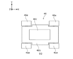
図4は、第1台車45の一例を示す平面図である。図5は、第1台車45の側面図である。第1台車45は、第1軌条41を行方向に走行して、荷12を行方向に搬送する走行台車である。第1台車45は各段の第1軌条41にそれぞれ配置される。各段に第1台車45を設けることにより、各第1台車45を独立して同時に動作させることが可能で、収容棚部30と保管棚部20との間の搬送効率を向上させることかできる。第1台車45は、車体45bと、載置部45cと、4つの車輪45dと、を主に含む。車体45bは、上下方向に偏平な略直方体形状の輪郭を有する。車体45bの内部には、車輪45dを駆動するモータ(不図示)と、このモータを駆動するバッテリー(不図示)と、これらを制御する制御回路(不図示)と、を搭載している。載置部45cは、第2台車46を載置する部分で、上面視で略矩形で、側面視で車体45bの上面から下方に後退した凹部形状を有する。
(First car)
FIG. 4 is a plan view showing an example of the first cart 45. FIG. 5 is a side view of the first cart 45. The first carriage 45 is a traveling carriage that travels in the row direction on the first rail 41 and transports the load 12 in the row direction. The first carriage 45 is arranged on the first rail 41 of each stage. By providing the first cart 45 in each stage, it is possible to operate each first cart 45 independently and simultaneously, and it is possible to improve the conveyance efficiency between the storage shelf 30 and the storage shelf 20. . The first carriage 45 mainly includes a vehicle body 45b, a placement portion 45c, and four wheels 45d. The vehicle body 45b has a substantially rectangular parallelepiped outline that is flat in the vertical direction. A motor (not shown) that drives the wheels 45d, a battery (not shown) that drives the motor, and a control circuit (not shown) that controls these are mounted inside the vehicle body 45b. The placement portion 45c is a portion on which the second carriage 46 is placed, and has a substantially rectangular shape when viewed from the top, and has a recessed shape that recedes downward from the top surface of the vehicle body 45b when viewed from the side.

図4、図5に示すように、載置部45cの大きさは、後述する第2台車46が載置部45cの周面と干渉することなく図中でX軸方向である列方向に走行できるように、第2台車46の大きさに十分な量のマージンを加えた大きさとされる。4つの車輪45dは、車体45bの4隅に回転可能に支持される。第1台車45は、4つの車輪45dを軌条にて回転させることによって、軌条を走行する。第1台車45は、荷12および第2台車46を載せた状態で第1軌条41上を走行することができる。第1台車45の走行動作は、後述する制御部52aによって制御される。   As shown in FIGS. 4 and 5, the size of the mounting portion 45 c is such that the second carriage 46 described later travels in the row direction that is the X-axis direction in the drawing without interfering with the peripheral surface of the mounting portion 45 c. In order to be able to do so, the size of the second carriage 46 is set to a size obtained by adding a sufficient amount of margin. The four wheels 45d are rotatably supported at the four corners of the vehicle body 45b. The first carriage 45 travels on the rail by rotating the four wheels 45d on the rail. The first carriage 45 can travel on the first rail 41 with the load 12 and the second carriage 46 placed thereon. The traveling operation of the first cart 45 is controlled by a control unit 52a described later.

(第2台車)
図6は、第2台車46の一例を示す平面図である。図7は、第2台車46の側面図である。図7は、第2台車46が荷12を載せた状態で第2軌条42上を走行する状態を示している。第2台車46は、第2軌条42を列方向に走行して、荷12を列方向に搬送する走行台車である。第2台車46は、各段の第2軌条42または第3軌条43にそれぞれ配置される。第2台車46は、荷12を載せた状態で第1台車45の載置部45cに進入することができる。第2台車46は、車体46bと、支持部46cと、リフト機構46dと、4つの車輪46eと、を主に含む。車体46bは、上下方向に偏平な略直方体形状の輪郭を有する。車体46bの内部には、車輪46eを駆動するモータ(不図示)と、このモータを駆動するバッテリー(不図示)と、これらを制御する制御回路(不図示)と、を搭載している。支持部46cは、荷12を持上げて保持する略矩形板状の部分である。
(Second car)
FIG. 6 is a plan view showing an example of the second carriage 46. FIG. 7 is a side view of the second carriage 46. FIG. 7 shows a state in which the second carriage 46 travels on the second rail 42 with the load 12 placed thereon. The second carriage 46 is a traveling carriage that travels in the row direction on the second rail 42 and transports the load 12 in the row direction. The second carriage 46 is disposed on the second rail 42 or the third rail 43 of each stage. The second carriage 46 can enter the placement portion 45 c of the first carriage 45 with the load 12 placed thereon. The second carriage 46 mainly includes a vehicle body 46b, a support portion 46c, a lift mechanism 46d, and four wheels 46e. The vehicle body 46b has a substantially rectangular parallelepiped outline that is flat in the vertical direction. A motor (not shown) that drives the wheels 46e, a battery (not shown) that drives the motor, and a control circuit (not shown) that controls these are mounted inside the vehicle body 46b. The support portion 46c is a substantially rectangular plate-like portion that lifts and holds the load 12.

リフト機構46dは、支持部46cを昇降させる機構である。リフト機構46dは、支持部46cを上昇させて荷12を保管部21または収容部31に設けられた軌条から持上げることができる。リフト機構46dは、支持部46cを降下させて荷12を保管部21または収容部31に設けられた軌条に降ろすことができる。図7は、支持部46cが荷12を第2軌条42から持上げた状態を示している。4つの車輪46eは、車体46bの4隅に回転可能に支持される。第2台車46は、4つの車輪46eを軌条にて回転させることによって軌条を走行する。図7に示すように、第2台車46は、荷12を載せた状態で第2軌条42上および第3軌条43上を走行することができる。第2台車46の走行動作およびリフト機構46dの昇降動作は、制御部52aによって制御される。   The lift mechanism 46d is a mechanism that raises and lowers the support portion 46c. The lift mechanism 46 d can lift the load 12 from the rail provided in the storage unit 21 or the storage unit 31 by raising the support unit 46 c. The lift mechanism 46 d can lower the support portion 46 c to lower the load 12 on a rail provided in the storage portion 21 or the storage portion 31. FIG. 7 shows a state in which the support portion 46 c lifts the load 12 from the second rail 42. The four wheels 46e are rotatably supported at the four corners of the vehicle body 46b. The second carriage 46 travels on the rail by rotating the four wheels 46e on the rail. As shown in FIG. 7, the second carriage 46 can travel on the second rail 42 and the third rail 43 with the load 12 placed thereon. The traveling operation of the second carriage 46 and the lifting operation of the lift mechanism 46d are controlled by the control unit 52a.

次に、実施の形態の自動倉庫システム10のその他の構成を説明する。図8は自動倉庫システム10のブロック図である。自動倉庫システム10は、制御装置52と、保管部荷検知部54bと、収容部荷検知部54cと、第1台車位置検知部54dと、第2台車位置検知部54eと、をさらに含む。保管部荷検知部54bは、各保管部21において、荷12の有無を検知して、その検知結果を制御部52aに出力するセンサ機構である。収容部荷検知部54cは、各収容部31において、荷12の有無を検知して、その検知結果を制御部52aに出力するセンサ機構である。第1台車位置検知部54dは、第1軌条41において、第1台車45の位置を検知して、その検知結果を制御部52aに出力するセンサ機構である。第2台車位置検知部54eは、第2軌条42および第3軌条43において、第2台車46の位置を検知して、その検知結果を制御部52aに出力するセンサ機構である。   Next, the other structure of the automatic warehouse system 10 of embodiment is demonstrated. FIG. 8 is a block diagram of the automatic warehouse system 10. The automatic warehouse system 10 further includes a control device 52, a storage unit load detection unit 54b, a storage unit load detection unit 54c, a first cart position detection unit 54d, and a second cart position detection unit 54e. The storage unit load detection unit 54b is a sensor mechanism that detects the presence or absence of the load 12 in each storage unit 21 and outputs the detection result to the control unit 52a. The storage unit load detection unit 54c is a sensor mechanism that detects the presence or absence of the load 12 in each storage unit 31 and outputs the detection result to the control unit 52a. The first dolly position detection unit 54d is a sensor mechanism that detects the position of the first dolly 45 in the first rail 41 and outputs the detection result to the control unit 52a. The second carriage position detection unit 54e is a sensor mechanism that detects the position of the second carriage 46 in the second rail 42 and the third rail 43 and outputs the detection result to the control unit 52a.

(制御装置)
制御装置52は、制御部52aと、操作部52k、表示部52mと、を含む。操作部52kは、自動倉庫システム10を制御するための操作を受け入れて、その操作結果を制御部52aに出力する操作ユニットである。操作部52kは、例えば自動倉庫システム10の起動や停止などの操作を受け入れる。表示部52mは、制御部52aの制御により、自動倉庫システム10の動作状況を表示する表示ユニットである。表示部52mは、例えば、各台車の動作状況や保管部21や収容部31における荷12の保管状況などを表示するようにしてもよい。操作部52kおよび表示部52mは、例えば制御装置52の正面に設けられる。
(Control device)
The control device 52 includes a control unit 52a, an operation unit 52k, and a display unit 52m. The operation unit 52k is an operation unit that receives an operation for controlling the automatic warehouse system 10 and outputs the operation result to the control unit 52a. The operation unit 52k accepts operations such as starting and stopping of the automatic warehouse system 10, for example. The display unit 52m is a display unit that displays the operation status of the automatic warehouse system 10 under the control of the control unit 52a. The display unit 52m may display, for example, the operation status of each carriage, the storage status of the load 12 in the storage unit 21 or the storage unit 31, and the like. The operation unit 52k and the display unit 52m are provided in front of the control device 52, for example.

次に制御部52aについて説明する。図8に示す制御部52aの各ブロックは、ハードウエア的には、コンピュータのCPU(Central Processing Unit)をはじめとする素子や機械装置で実現でき、ソフトウエア的にはコンピュータプログラム等によって実現されるが、ここでは、それらの連携によって実現される機能ブロックを描いている。したがって、これらの機能ブロックはハードウエア、ソフトウエアの組合せによっていろいろなかたちで実現できることは、本明細書に触れた当業者には理解されるところである。   Next, the control unit 52a will be described. Each block of the control unit 52a shown in FIG. 8 can be realized in hardware by an element such as a computer CPU (Central Processing Unit) or a mechanical device, and in software by a computer program or the like. However, here, functional blocks realized by their cooperation are depicted. Therefore, it is understood by those skilled in the art who have touched this specification that these functional blocks can be realized in various forms by a combination of hardware and software.

制御部52aは、保管部荷検知部54b、収容部荷検知部54c、第1台車位置検知部54dおよび第2台車位置検知部54eの検知結果に応じて、主に第1台車45および第2台車46の動作を制御する制御ユニットである。制御部52aは、操作結果取得部52bと、第1荷検知結果取得部52cと、第2荷検知結果取得部52dと、第1位置検知部52eと、第2位置検知部52fと、表示制御部52gと、第1台車制御部52hと、第2台車制御部52jと、を主に含む。操作結果取得部52bは、操作部52kからその操作結果を取得する。第1荷検知結果取得部52cは、保管部荷検知部54bからその検知結果を取得する。第2荷検知結果取得部52dは、収容部荷検知部54cからその検知結果を取得する。第1位置検知部52eは、第1台車位置検知部54dからその検知結果を取得する。第2位置検知部52fは、第2台車位置検知部54eからその検知結果を取得する。表示制御部52gは、所定の表示をするように表示部52mを制御する。第1台車制御部52hは、第1台車45の走行を制御する。第2台車制御部52jは、第2台車46の走行および支持部46cの昇降動作を制御する。   The control unit 52a mainly includes the first cart 45 and the second cart according to the detection results of the storage unit load detection unit 54b, the storage unit load detection unit 54c, the first cart position detection unit 54d, and the second cart position detection unit 54e. It is a control unit that controls the operation of the carriage 46. The control unit 52a includes an operation result acquisition unit 52b, a first load detection result acquisition unit 52c, a second load detection result acquisition unit 52d, a first position detection unit 52e, a second position detection unit 52f, and display control. It mainly includes a part 52g, a first cart control unit 52h, and a second cart control unit 52j. The operation result acquisition unit 52b acquires the operation result from the operation unit 52k. The first load detection result acquisition unit 52c acquires the detection result from the storage unit load detection unit 54b. The second load detection result acquisition unit 52d acquires the detection result from the storage unit load detection unit 54c. The first position detection unit 52e acquires the detection result from the first cart position detection unit 54d. The second position detection unit 52f acquires the detection result from the second carriage position detection unit 54e. The display control unit 52g controls the display unit 52m to perform a predetermined display. The first cart control unit 52 h controls the travel of the first cart 45. The second cart control unit 52j controls the travel of the second cart 46 and the lifting / lowering operation of the support 46c.

次に、このように構成された自動倉庫システム10の動作を説明する。   Next, the operation of the automatic warehouse system 10 configured as described above will be described.

(出庫動作)
自動倉庫システム10の出庫時の搬送動作の一例を説明する。この搬送動作は、出庫する荷12を、保管棚部20の保管部21から、収容棚部30の収容部31に搬送する動作を含む。収容部31に搬送された荷12は、外部搬送装置により搬出される。図9は、自動倉庫システム10の出庫時の搬送動作の一例を示す説明図である。図10は、出庫時の搬送動作の一例を示すフローチャートであり、この動作に関する処理S60を示している。
(1)処理S60が開始されると、制御部52aは、第2台車46を搬送元の保管部21に移動させ、出庫対象の荷12の下に進入させる(ステップS61)。
(2)制御部52aは、第2台車46の支持部46cを上昇させて荷12を保管部21から持ち上げて支持させる(ステップS62)。このとき、荷12は移動可能な状態になる。
(3)制御部52aは、荷12を載せた第2台車46を出入口部22bに向かって移動させる(ステップS63)。
(4)制御部52aは、このとき同時に、第1台車45を搬送元の保管部21の行に移動させる(ステップS64、図9(a)を参照)。
(5)制御部52aは、第1台車45が搬送元の保管部21の行に到着したか否かを判定する(ステップS65)。
(Outgoing operation)
An example of the conveyance operation at the time of delivery of the automatic warehouse system 10 will be described. This transport operation includes an operation of transporting the cargo 12 to be delivered from the storage unit 21 of the storage shelf unit 20 to the storage unit 31 of the storage shelf unit 30. The load 12 transported to the storage unit 31 is carried out by an external transport device. FIG. 9 is an explanatory diagram illustrating an example of a transport operation when the automatic warehouse system 10 is leaving. FIG. 10 is a flowchart showing an example of the transport operation at the time of delivery, and shows processing S60 related to this operation.
(1) When the process S60 is started, the control unit 52a moves the second carriage 46 to the storage unit 21 that is the transport source, and enters under the load 12 to be delivered (step S61).
(2) The control part 52a raises the support part 46c of the 2nd trolley | bogie 46, lifts the load 12 from the storage part 21, and supports it (step S62). At this time, the load 12 becomes movable.
(3) The control unit 52a moves the second carriage 46 on which the load 12 is loaded toward the entrance / exit portion 22b (step S63).
(4) At this time, the control unit 52a moves the first cart 45 to the row of the storage unit 21 that is the conveyance source (see step S64, FIG. 9A).
(5) The control unit 52a determines whether or not the first cart 45 has arrived at the row of the storage unit 21 that is the transport source (step S65).

(6)第1台車45が未到着の場合(ステップS65のN)、制御部52aは処理をステップS65の先頭に戻す。
(7)第1台車45が到着した場合(ステップS65のY)、制御部52aは、荷12を載せた第2台車46を出入口部22bから第1台車45の載置部45cに進入させる(ステップS66、図9(b)を参照)。
(8)制御部52aは、載置部45cに第2台車46を載せた第1台車45を、搬送先の収容部31の行に移動させる(ステップS67、図9(c)を参照)。
(9)第1台車45が搬送先に到着したら、制御部52aは、荷12を載せた第2台車46を、第1台車45から退出させて搬送先の収容部31に移動させる(ステップS68、図9(d)を参照)。
(10)第2台車46が収容部31に移動したら、制御部52aは、第2台車46の支持部46cを下降させて荷12を収容部31に降ろさせる(ステップS69)。荷12を降ろすことでこの処理S60は終了する。
収容部31に搬送された荷12は、フォークリフト50により外部出入口部31bから搬出され、トラックなどに積み入れされる。荷12を降ろした第2台車46は、例えばその位置で待機するようにしてもよい。
上述の処理S60はあくまでも一例であり、他のステップを追加したり、一部のステップを変更または削除したり、ステップの順序を入れ替えてもよい。
(6) If the first cart 45 has not arrived (N in Step S65), the control unit 52a returns the process to the beginning of Step S65.
(7) When the first cart 45 arrives (Y in Step S65), the control unit 52a causes the second cart 46 on which the load 12 is loaded to enter the placement unit 45c of the first cart 45 from the entrance / exit 22b ( Step S66, see FIG. 9B).
(8) The control unit 52a moves the first cart 45 on which the second cart 46 is placed on the placement unit 45c to the row of the accommodation unit 31 that is the transport destination (see step S67, FIG. 9C).
(9) When the first cart 45 arrives at the transport destination, the control unit 52a causes the second cart 46 loaded with the load 12 to leave the first cart 45 and move to the transport destination storage unit 31 (step S68). FIG. 9 (d)).
(10) If the 2nd trolley | bogie 46 moves to the accommodating part 31, the control part 52a will lower the support part 46c of the 2nd trolley | bogie 46, and will drop the load 12 to the accommodating part 31 (step S69). The processing S60 is completed when the load 12 is unloaded.
The load 12 transported to the accommodating portion 31 is carried out from the external entrance / exit portion 31b by the forklift 50 and loaded into a truck or the like. The second carriage 46 that has unloaded the load 12 may wait at that position, for example.
The above-described process S60 is merely an example, and other steps may be added, some steps may be changed or deleted, and the order of steps may be changed.

(入庫動作)
次に、自動倉庫システム10の入庫時の搬送動作の一例を説明する。この搬送動作は、入庫する荷12を、収容棚部30の収容部31から、保管棚部20の保管部21に搬送する動作を含む。入庫する荷12は、この搬送動作の前に外部搬送装置により収容部31に搬入される。図11は、入庫時の搬送動作の一例を示すフローチャートであり、この動作に関する処理S70を示している。
(1)処理S70が開始されると、制御部52aは、保管棚部20の搬送先である保管部21に待機していた第2台車46を、保管棚部20の出入口部22bに移動させる(ステップS71)。
(2)制御部52aは、このとき同時に、第1台車45を搬送先の保管部21の行に移動させる(ステップS72)。
(3)制御部52aは、第1台車45が搬送先の保管部21の行に到着したか否かを判定する(ステップS73)。
(Receipt operation)
Next, an example of the transfer operation at the time of warehousing of the automatic warehouse system 10 will be described. This transport operation includes an operation of transporting the incoming load 12 from the storage unit 31 of the storage shelf 30 to the storage unit 21 of the storage shelf 20. The load 12 to be stored is carried into the storage unit 31 by the external transfer device before this transfer operation. FIG. 11 is a flowchart showing an example of the transport operation at the time of warehousing, and shows processing S70 related to this operation.
(1) When the process S70 is started, the control unit 52a moves the second carriage 46 that has been waiting in the storage unit 21 that is the transport destination of the storage shelf unit 20 to the entrance / exit portion 22b of the storage shelf unit 20. (Step S71).
(2) At this time, the control unit 52a moves the first cart 45 to the row of the storage unit 21 that is the transport destination (step S72).
(3) The control unit 52a determines whether or not the first cart 45 has arrived at the line of the storage unit 21 that is the transport destination (step S73).

(4)第1台車45が未到着の場合(ステップS73のN)、制御部52aは処理をステップS73の先頭に戻す。
(5)第1台車45が到着した場合(ステップS73のY)、制御部52aは、第2台車46を出入口部22bから載置部45cに進入させる(ステップS74)。
(6)制御部52aは、載置部45cに第2台車46を載せた第1台車45を、搬送元の収容部31の行に移動させる(ステップS75)。
(7)制御部52aは、第2台車46を搬送元の収容部31にて荷12の下側に進入させる(ステップS76)。
(8)制御部52aは、第2台車46の支持部46cを上昇させて収容部31から荷12を持ち上げて支持させる(ステップS77)。
(9)制御部52aは、荷12を載せた第2台車46を、第1台車45の載置部45cに進入させる(ステップS78)。
(4) When the first cart 45 has not arrived (N in Step S73), the control unit 52a returns the process to the top of Step S73.
(5) When the first cart 45 arrives (Y in step S73), the control unit 52a causes the second cart 46 to enter the placement unit 45c from the entrance / exit portion 22b (step S74).
(6) The control unit 52a moves the first carriage 45 on which the second carriage 46 is placed on the placement section 45c to the row of the storage unit 31 that is the transport source (step S75).
(7) The control unit 52a causes the second carriage 46 to enter the lower side of the load 12 in the storage unit 31 of the transfer source (step S76).
(8) The control part 52a raises the support part 46c of the 2nd trolley | bogie 46, lifts the load 12 from the accommodating part 31, and supports it (step S77).
(9) The control unit 52a causes the second carriage 46 on which the load 12 is placed to enter the placement section 45c of the first carriage 45 (step S78).

(10)制御部52aは、載置部45cに第2台車46を載せた第1台車45を、搬送先の保管部21の行に移動させる(ステップS79)。
(11)制御部52aは、荷12を載せた第2台車46を、出入口部22bから搬送先の保管部21に移動させる(ステップS80)。
(12)制御部52aは、第2台車46の支持部46cを下降させて荷12を保管部21に降ろさせる(ステップS81)。荷12を降ろすことでこの処理S70は終了する。
荷12を降ろした第2台車46は、例えばその位置で待機するようにしてもよい。
上述の処理S70はあくまでも一例であり、他のステップを追加したり、一部のステップを変更または削除したり、ステップの順序を入れ替えてもよい。
自動倉庫システム10によれば、第1台車45や第2台車46が移動している間も、フォークリフト50は別の入庫する荷12を別の収容部31に順次搬入することができる。
(10) The control unit 52a moves the first cart 45 on which the second cart 46 is placed on the placement unit 45c to the row of the storage unit 21 that is the transport destination (step S79).
(11) The control unit 52a moves the second carriage 46 on which the load 12 is loaded from the entrance / exit part 22b to the storage unit 21 that is the transport destination (step S80).
(12) The control unit 52a lowers the support unit 46c of the second carriage 46 and lowers the load 12 to the storage unit 21 (step S81). This processing S70 is completed by unloading the load 12.
The second carriage 46 that has unloaded the load 12 may wait at that position, for example.
The process S70 described above is merely an example, and other steps may be added, some steps may be changed or deleted, and the order of steps may be changed.
According to the automatic warehouse system 10, the forklift 50 can sequentially carry different loads 12 into the different storage units 31 while the first cart 45 and the second cart 46 are moving.

次に、このように構成された自動倉庫システム10の作用・効果を説明する。   Next, the operation and effect of the automatic warehouse system 10 configured as described above will be described.

倉庫スペースの高密度化の観点から、例えばスタッカークレーンなどの搬送装置が走行するための空間が占める割合は小さいことが望ましい。そこで、実施の形態の自動倉庫システム10は、M(Mは2以上の整数)行、N(Nは2以上の整数)列の保管部21を有する保管部配列23を含み、当該各保管部21は荷12を保管可能に構成される保管棚部20と、M行の収容部31を有する収容部配列33を含み、当該各収容部31は外部から荷12を受け入れて収容可能に構成される収容棚部30と、保管棚部20と収容棚部30との間で荷12を搬送する中間搬送装置40と、を備える。この構成によれば、対面する保管棚ごとに、その間にスタッカークレーンなどの搬送装置の走行空間を設ける構成と比較して、荷の保管スペースを増やして、搬送装置の走行空間が占める割合を小さくすることができる。   From the viewpoint of increasing the density of the warehouse space, for example, it is desirable that the space occupied by a transport device such as a stacker crane is small. Therefore, the automatic warehouse system 10 according to the embodiment includes a storage unit array 23 having storage units 21 having M (M is an integer of 2 or more) rows and N (N is an integer of 2 or more) columns, and each of the storage units 21 includes a storage shelf 20 configured to store the load 12 and a storage unit array 33 having M rows of storage units 31. Each of the storage units 31 is configured to receive and store the load 12 from the outside. Storage shelf 30, and intermediate transport device 40 that transports load 12 between storage shelf 20 and storage shelf 30. According to this configuration, compared to a configuration in which a traveling space for a transport device such as a stacker crane is provided between the storage shelves facing each other, the storage space for the load is increased, and the traveling space occupied by the transport device is reduced. can do.

外部搬送装置と中間搬送装置の干渉は回避できることが望ましい。そこで、実施の形態の自動倉庫システム10では、各収容部31は、保管棚部20に向いた側に設けられ、保管棚部20に搬送する荷12を通過させるための第1出入口部である内部出入口部31cと、内部出入口部31cとは別に設けられ、外部から受け入れる荷12を通過させるための第2出入口部である外部出入口部31bと、を有する。この構成によれば、各収容部31における荷を通過させる出入口部が一つだけの場合と比較して、中間搬送装置を外部搬送装置から離れた位置に配置することができるので、これらの装置の間の干渉を抑制することができる。   It is desirable that interference between the external transfer device and the intermediate transfer device can be avoided. Therefore, in the automatic warehouse system 10 according to the embodiment, each storage unit 31 is provided on the side facing the storage shelf unit 20 and is a first entrance / exit unit for allowing the load 12 conveyed to the storage shelf unit 20 to pass therethrough. The internal entrance / exit part 31c and the internal entrance / exit part 31c are provided separately and have an external entrance / exit part 31b which is a second entrance / exit part for allowing the load 12 received from the outside to pass therethrough. According to this configuration, the intermediate transfer device can be arranged at a position away from the external transfer device as compared with the case where there is only one entrance / exit portion through which the load in each storage unit 31 passes. Can be suppressed.

また、複数の荷12を入庫する場合に、この複数の荷12を、一旦、収容棚部30に連続して搬入し、この荷12を、順次、中間搬送装置40により保管棚部20に搬送して保管することができる。この場合、中間搬送装置40が荷12を搬送している間も、別の荷12を別の収容部31に搬入することが可能になる。このため、中間搬送装置40の搬送完了を待って別の荷12を搬入する場合と比較して、待ち時間が減って搬入時間が短縮され、荷の搬入を迅速化することができる。出庫の場合にも、入庫の場合と同様の作用により荷の搬出時間が短縮され、荷の搬出を迅速化することができる。また、収容棚部30が保管棚部20と同じ行数で構成されているから、保管空間を略直方体形状にすることが容易になり、不要な空間の発生を抑制してスペース効率を向上することができる。   In addition, when a plurality of loads 12 are received, the plurality of loads 12 are once carried continuously into the storage shelf 30, and the loads 12 are sequentially transferred to the storage shelf 20 by the intermediate transfer device 40. Can be stored. In this case, it is possible to load another load 12 into another storage unit 31 while the intermediate transfer device 40 is transferring the load 12. For this reason, compared with the case where another load 12 is carried in after waiting for the completion of the conveyance of the intermediate conveyance device 40, the waiting time is reduced, the carrying-in time is shortened, and the loading of the load can be accelerated. Also in the case of unloading, the load unloading time is shortened by the same action as in the case of unloading, and the unloading of the load can be speeded up. Further, since the storage shelf 30 is configured with the same number of rows as the storage shelf 20, it is easy to make the storage space into a substantially rectangular parallelepiped shape, and the generation of unnecessary space is suppressed to improve space efficiency. be able to.

倉庫のスペース効率は高いことが望ましい。そこで、実施の形態の自動倉庫システム10では、保管棚部20は、K(Kは2以上の整数)段の保管部配列23を含み、収容棚部30は、K段の収容部配列33を含む。この構成によれば、収容棚部30が保管棚部20と同じ段数で構成されているから、段数が異なる場合と比較して、保管空間を略直方体形状にすることが容易になり、不要な空間の発生を抑制してスペース効率を向上することができる。   It is desirable that the warehouse has high space efficiency. Therefore, in the automatic warehouse system 10 of the embodiment, the storage shelf 20 includes a storage unit array 23 of K (K is an integer of 2 or more), and the storage shelf 30 includes a storage unit array 33 of K stages. Including. According to this configuration, since the storage shelf 30 is configured with the same number of steps as the storage shelf 20, the storage space can be easily formed into a substantially rectangular parallelepiped shape as compared with the case where the number of steps is different. Space efficiency can be improved by suppressing the generation of space.

中間搬送装置40の搬送時間は短いことが望ましい。そこで、実施の形態の自動倉庫システム10では、中間搬送装置40は、荷12を行方向に搬送可能な行方向搬送装置36と、荷12を列方向に搬送可能な列方向搬送装置38と、を含み、列方向搬送装置38は、荷12を、搬送元から搬送して行方向搬送装置36に積み入れるように構成され、行方向搬送装置36は、積み入れられた荷12を、搬送先の行に向かって搬送するように構成される。この構成によれば、行方向搬送装置36と列方向搬送装置38と別々に設け、これらを連携させて動作させることで、一方が動作している間に他方が別の動作をすることが可能になる。このため、相手の動作を待つ時間が少なくなり、全体として搬送時間を短くすることが可能になる。   The conveyance time of the intermediate conveyance device 40 is preferably short. Therefore, in the automatic warehouse system 10 of the embodiment, the intermediate transport device 40 includes a row direction transport device 36 that can transport the load 12 in the row direction, a column direction transport device 38 that can transport the load 12 in the column direction, The column-direction transport device 38 is configured to transport the load 12 from the transport source and load it into the row-direction transport device 36. The row-direction transport device 36 transports the loaded load 12 to the transport destination. Configured to be transported toward the row. According to this configuration, the row-direction transport device 36 and the column-direction transport device 38 are separately provided and operated in cooperation with each other so that the other can perform another operation while one is operating. become. For this reason, the time to wait for the other party's operation is reduced, and the conveyance time can be shortened as a whole.

行方向搬送装置36から離れている保管部21に対して容易に荷12を出し入れできることが望ましい。そこで、実施の形態の自動倉庫システム10では、行方向搬送装置36は、保管棚部20と収容棚部30との間にて行方向に伸びる第1軌条41と、第1軌条41を走行可能な第1台車45と、を含み、列方向搬送装置38は、保管棚部20にて列方向に伸びる第2軌条42と、収容棚部30にて列方向に伸びる第3軌条43と、第2軌条42および第3軌条43を走行可能な第2台車46と、を含む。この構成によれば、第2台車が保管棚部20に設けた第2軌条42を走行可能であるので、行方向搬送装置36から離れている保管部21に対して荷12を出し入れすることが容易になる。   It is desirable that the load 12 can be easily taken in and out of the storage unit 21 that is away from the row direction conveying device 36. Therefore, in the automatic warehouse system 10 according to the embodiment, the row direction transfer device 36 can travel on the first rail 41 and the first rail 41 extending in the row direction between the storage shelf 20 and the storage shelf 30. The first-direction cart 45 includes a second rail 42 that extends in the column direction at the storage shelf 20, a third rail 43 that extends in the column direction at the storage shelf 30, and a first rail 43. A second carriage 46 capable of traveling on the second rail 42 and the third rail 43. According to this configuration, since the second carriage can travel on the second rail 42 provided in the storage shelf 20, the load 12 can be taken in and out of the storage unit 21 that is away from the row-direction transport device 36. It becomes easy.

中間搬送装置40の搬送時間はより短いことが望ましい。そこで、実施の形態の自動倉庫システム10では、第1台車45は、第2台車46を載置して第1軌条41を走行可能に構成される。この構成によれば、第2台車46は、荷12を載せた状態で第2軌条を走行して第1台車45に進入し、行方向に移動して、第1台車45から退出して第3軌条にそのまま乗り入れることができる。搬送中に荷を積み替える場合と比較して、積み替えに費やされる時間の分、搬送時間を短くすることができる。   It is desirable that the transport time of the intermediate transport device 40 is shorter. Therefore, in the automatic warehouse system 10 of the embodiment, the first cart 45 is configured to be able to travel on the first rail 41 by placing the second cart 46 thereon. According to this configuration, the second carriage 46 travels on the second rail with the load 12 loaded, enters the first carriage 45, moves in the row direction, exits the first carriage 45, and enters the first carriage 45. You can enter the 3-rail as it is. Compared with the case where the load is reloaded during the transfer, the transfer time can be shortened by the amount of time spent for the transfer.

以上、本発明の実施の形態をもとに説明した。これらの実施の形態は例示であり、いろいろな変形および変更が本発明の特許請求の範囲内で可能なこと、またそうした変形例および変更も本発明の特許請求の範囲にあることは当業者に理解されるところである。従って、本明細書での記述および図面は限定的ではなく例証的に扱われるべきものである。   In the above, it demonstrated based on embodiment of this invention. It is to be understood by those skilled in the art that these embodiments are illustrative, and that various modifications and changes are possible within the scope of the claims of the present invention, and that such modifications and changes are also within the scope of the claims of the present invention. It is understood. Accordingly, the description and drawings herein are to be regarded as illustrative rather than restrictive.

以下、変形例について説明する。変形例の図面および説明では、実施の形態と同一または同等の構成要素、部材には、同一の符号を付する。実施の形態と重複する説明を適宜省略し、実施の形態と相違する構成について重点的に説明する。   Hereinafter, modified examples will be described. In the drawings and description of the modification, the same reference numerals are given to the same or equivalent components and members as those in the embodiment. The description overlapping with the embodiment will be omitted as appropriate, and the configuration different from the embodiment will be described mainly.

(第1変形例)
実施の形態の自動倉庫システム10の説明では、中間搬送装置40が昇降機構を備えない例について説明したが、これに限られない。例えば、中間搬送装置は昇降機構を有するスタッカークレーンを含んでもよい。スタッカークレーンを含むことで、荷12を行方向に搬送すると共に上下方向に昇降することができる。図12は、第1変形例に係る自動倉庫システム90の斜視図であり、図1に対応する。自動倉庫システム90は、実施の形態の自動倉庫システム10に対して、第1台車45の代わりにスタッカークレーン47を備える点で相違し、その他の構成は同様である。したがって、重複する説明を省略し、自動倉庫システム10と相違する点を中心に説明する。
(First modification)
In the description of the automatic warehouse system 10 according to the embodiment, the example in which the intermediate transfer device 40 does not include the lifting mechanism has been described, but the present invention is not limited thereto. For example, the intermediate transfer device may include a stacker crane having a lifting mechanism. By including the stacker crane, the load 12 can be transported in the row direction and raised and lowered in the vertical direction. FIG. 12 is a perspective view of an automatic warehouse system 90 according to the first modification, and corresponds to FIG. The automatic warehouse system 90 is different from the automatic warehouse system 10 of the embodiment in that a stacker crane 47 is provided instead of the first cart 45, and the other configurations are the same. Therefore, the description which overlaps is abbreviate | omitted and it demonstrates centering on the point which is different from the automatic warehouse system 10. FIG.

スタッカークレーン47は荷12を行方向に搬送すると共に上下方向に昇降する機能を有する走行台車である。スタッカークレーン47は、保管棚部20と収容棚部30との間に、床面に設けられた行方向に伸びる軌条44に沿って、行方向に走行可能に設けられる。図13は、スタッカークレーン47の平面図である。図14は、スタッカークレーン47の側面図である。スタッカークレーン47は、基台部47bと、載置部47cと、4つの車輪47dと、一対の支柱47hと、昇降機構47gと、を主に含む。基台部47bは、スタッカークレーン47の下部に設けられる上下方向に偏平な板状の部材である。基台部47bには、車輪47dを駆動するモータ(不図示)と、このモータを駆動するバッテリー(不図示)と、これらを制御する制御回路(不図示)と、を搭載している。スタッカークレーン47は、バッテリーに代わって図外の架線から受電するように構成されてもよい。   The stacker crane 47 is a traveling carriage having a function of moving the load 12 in the row direction and moving up and down in the vertical direction. The stacker crane 47 is provided between the storage shelf 20 and the storage shelf 30 so as to be able to travel in the row direction along the rails 44 extending in the row direction provided on the floor surface. FIG. 13 is a plan view of the stacker crane 47. FIG. 14 is a side view of the stacker crane 47. The stacker crane 47 mainly includes a base portion 47b, a placement portion 47c, four wheels 47d, a pair of support columns 47h, and an elevating mechanism 47g. The base portion 47 b is a plate-like member that is provided in the lower portion of the stacker crane 47 and is flat in the vertical direction. A motor (not shown) that drives the wheels 47d, a battery (not shown) that drives the motor, and a control circuit (not shown) that controls these are mounted on the base 47b. The stacker crane 47 may be configured to receive power from an overhead line (not shown) instead of the battery.

載置部47cは、第2台車46を載置可能に設けられる上下方向に偏平な板状の部材である。載置部47cは、第2台車46を載置した状態で昇降可能に構成される。載置部47cの前後両端には上向きに伸びる延伸部47fが設けられる。4つの車輪47dは、基台部47bの4隅に回転可能に支持される。一対の支柱47hは、上下方向に伸びる支柱であり、載置部47cを昇降可能にガイドする。一対の支柱47hは、間に載置部47cを挟むように行方向に離隔されて基台部47bに固定される。支柱47hは、例えば上面視で略矩形の断面を有する。昇降機構47gは、載置部47cを上下に昇降駆動する機構である。昇降機構47gは、支柱47hの近傍において基台部47bに設けられる。昇降機構47gが載置部47cを吊っているワイヤーロープ(不図示)を巻取り・送出しすることで、載置部47cを昇降駆動する。この構成により、載置部47cは昇降可能な昇降台として機能する。スタッカークレーン47は、4つの車輪47dを軌条44にて回転させることによって、軌条44を走行する。スタッカークレーン47は、荷12および第2台車46を載せた状態で軌条44上を走行することができる。   The placing portion 47c is a plate-like member that is flat in the vertical direction and is provided so that the second carriage 46 can be placed thereon. The mounting portion 47c is configured to be movable up and down while the second carriage 46 is mounted. Extending portions 47f extending upward are provided at both front and rear ends of the mounting portion 47c. The four wheels 47d are rotatably supported at the four corners of the base portion 47b. The pair of pillars 47h are pillars extending in the vertical direction, and guide the placement portion 47c so as to be movable up and down. The pair of pillars 47h are fixed to the base portion 47b while being separated in the row direction so as to sandwich the placement portion 47c therebetween. The support 47h has, for example, a substantially rectangular cross section when viewed from above. The lifting mechanism 47g is a mechanism that drives the mounting portion 47c up and down. The raising / lowering mechanism 47g is provided in the base part 47b in the vicinity of the support | pillar 47h. The lifting mechanism 47g winds and sends out a wire rope (not shown) that suspends the mounting portion 47c, thereby driving the mounting portion 47c up and down. With this configuration, the mounting portion 47c functions as a lifting platform that can be raised and lowered. The stacker crane 47 travels on the rail 44 by rotating the four wheels 47 d on the rail 44. The stacker crane 47 can travel on the rail 44 with the load 12 and the second carriage 46 placed thereon.

(出庫動作)
次に、このように構成された第1変形例に係る自動倉庫システム90の出庫時の搬送動作の一例を説明する。この搬送動作は、出庫する荷12を、保管棚部20の第2の段(例えば最下段の保管部21から、収容棚部30の第1の段(例えば最上段)の収容部31に搬送する動作を含む。収容部31に搬送された荷12は、外部搬送装置により搬出される。図15は、自動倉庫システム90の出庫時の搬送動作の一例を示すフローチャートであり、この動作に関する処理S160を示している。
(1)処理S160が開始されると、制御部52aは、第2台車46を搬送元の保管部21に移動させ、出庫対象の荷12の下に進入させる(ステップS161)。
(2)制御部52aは、第2台車46の支持部46cを上昇させて荷12を保管部21から持ち上げて支持させる(ステップS162)。このとき、荷12は移動可能な状態になる。
(Outgoing operation)
Next, an example of the transfer operation at the time of delivery of the automatic warehouse system 90 according to the first modified example configured as described above will be described. In this transfer operation, the cargo 12 to be delivered is transferred from the second stage (for example, the lowermost storage part 21) of the storage shelf 20 to the storage part 31 of the first stage (for example, the uppermost stage) of the storage shelf 30. The load 12 transported to the storage unit 31 is unloaded by the external transport device 31. Fig. 15 is a flowchart showing an example of the transport operation at the time of unloading of the automatic warehouse system 90, and processing related to this operation S160 is shown.
(1) When the process S160 is started, the control unit 52a moves the second carriage 46 to the storage unit 21 that is the transport source, and enters under the load 12 to be delivered (step S161).
(2) The control part 52a raises the support part 46c of the 2nd trolley | bogie 46, lifts the load 12 from the storage part 21, and supports it (step S162). At this time, the load 12 becomes movable.

(3)制御部52aは、荷12を載せた第2台車46を出入口部22bに向かって移動させる(ステップS163)。
(4)制御部52aは、スタッカークレーン47の載置部47cを第2の段の高さまで昇降させる(ステップS164)。
(5)制御部52aは、このとき同時に、スタッカークレーン47を搬送元の保管部21の行に移動させる(ステップS165)。
(6)制御部52aは、スタッカークレーン47が搬送元の保管部21の行に到着したか否かを判定する(ステップS166)。
(7)スタッカークレーン47が未到着の場合(ステップS166のN)、制御部52aは処理をステップS166の先頭に戻す。
(8)スタッカークレーン47が到着した場合(ステップS166のY)、制御部52aは、荷12を載せた第2台車46を出入口部22bから載置部47cに進入させる(ステップS167)。
(3) The control unit 52a moves the second carriage 46 on which the load 12 is loaded toward the entrance / exit portion 22b (step S163).
(4) The control unit 52a raises and lowers the placement unit 47c of the stacker crane 47 to the height of the second stage (step S164).
(5) At the same time, the control unit 52a moves the stacker crane 47 to the row of the storage unit 21 that is the transport source (step S165).
(6) The control unit 52a determines whether or not the stacker crane 47 has arrived at the row of the storage unit 21 that is the transport source (step S166).
(7) When the stacker crane 47 has not arrived (N in Step S166), the control unit 52a returns the process to the head of Step S166.
(8) When the stacker crane 47 arrives (Y in step S166), the control unit 52a causes the second carriage 46 on which the load 12 is loaded to enter the placement unit 47c from the entrance / exit 22b (step S167).

(9)制御部52aは、第2台車46を載せたスタッカークレーン47を、搬送先の収容部31の行に移動させる(ステップS168)。
(10)制御部52aは、スタッカークレーン47の載置部47cを第1の段の高さまで上昇させる(ステップS169)。
(11)スタッカークレーン47が搬送先に到着したら、制御部52aは、荷12を載せた第2台車46を、スタッカークレーン47から退出させて搬送先の収容部31に移動させる(ステップS170)。
(12)第2台車46が収容部31に移動したら、制御部52aは、第2台車46の支持部46cを下降させて荷12を収容部31に降ろさせる(ステップS171)。荷12を降ろすことでこの処理S160は終了する。
収容部31に搬送された荷12は、フォークリフト50により外部出入口部31bから搬出され、トラックなどに積み入れされる。荷12を降ろした第2台車46は、例えばその位置で待機するようにしてもよい。
上述の処理S160はあくまでも一例であり、他のステップを追加したり、一部のステップを変更または削除したり、ステップの順序を入れ替えてもよい。
(9) The control unit 52a moves the stacker crane 47 on which the second carriage 46 is placed to the row of the accommodation unit 31 that is the transport destination (step S168).
(10) The controller 52a raises the placement portion 47c of the stacker crane 47 to the height of the first stage (step S169).
(11) When the stacker crane 47 arrives at the transport destination, the control unit 52a causes the second carriage 46 loaded with the load 12 to move out of the stacker crane 47 and move to the transport destination storage unit 31 (step S170).
(12) If the 2nd trolley | bogie 46 moves to the accommodating part 31, the control part 52a will lower the support part 46c of the 2nd trolley | bogie 46, and will drop the load 12 to the accommodating part 31 (step S171). The processing S160 ends when the load 12 is unloaded.
The load 12 transported to the accommodating portion 31 is carried out from the external entrance / exit portion 31b by the forklift 50 and loaded into a truck or the like. The second carriage 46 that has unloaded the load 12 may wait at that position, for example.
The process S160 described above is merely an example, and other steps may be added, some steps may be changed or deleted, and the order of steps may be changed.

(入庫動作)
次に、自動倉庫システム90の入庫時の搬送動作の一例を説明する。この搬送動作は、入庫する荷12を、収容棚部30の第1の段(例えば最上段)の収容部31から、保管棚部20の第2の段(例えば最下段)の保管部21に搬送する動作を含む。入庫する荷12は、この搬送動作の前に外部搬送装置により収容部31に搬入される。図16は、自動倉庫システム90の入庫時の搬送動作の一例を示すフローチャートであり、この動作に関する処理S180を示している。
(1)処理S180が開始されると、制御部52aは、保管棚部20の搬送先である保管部21に待機していた第2台車46を、保管棚部20の出入口部22bに移動させる(ステップS181)。
(2)制御部52aは、このとき同時にスタッカークレーン47を搬送先の保管部21の行に移動させる(ステップS182)。
(3)制御部52aは、スタッカークレーン47の載置部47cを第2の段の高さまで昇降させる(ステップS183)。
(4)制御部52aは、スタッカークレーン47が搬送先の保管部21の行に到着したか否かを判定する(ステップS184)。
(Receipt operation)
Next, an example of the transfer operation at the time of warehousing of the automatic warehouse system 90 will be described. In this transfer operation, the load 12 to be stored is transferred from the storage unit 31 at the first level (for example, the uppermost level) of the storage shelf 30 to the storage unit 21 at the second level (for example, the lowest level) of the storage rack 20. Includes transporting action. The load 12 to be stored is carried into the storage unit 31 by the external transfer device before this transfer operation. FIG. 16 is a flowchart showing an example of the transport operation at the time of warehousing of the automatic warehouse system 90, and shows a process S180 related to this operation.
(1) When the process S180 is started, the control unit 52a moves the second carriage 46 that has been waiting in the storage unit 21 that is the transport destination of the storage shelf unit 20 to the entrance / exit portion 22b of the storage shelf unit 20. (Step S181).
(2) At this time, the control unit 52a moves the stacker crane 47 to the row of the storage unit 21 that is the transport destination (step S182).
(3) The control unit 52a raises and lowers the placement unit 47c of the stacker crane 47 to the height of the second stage (step S183).
(4) The control unit 52a determines whether or not the stacker crane 47 has arrived in the row of the storage unit 21 that is the transport destination (step S184).

(5)スタッカークレーン47が未到着の場合(ステップS184のN)、制御部52aは処理をステップS184の先頭に戻す。
(6)スタッカークレーン47が到着した場合(ステップS184のY)、制御部52aは、第2台車46を出入口部22bから載置部47cに進入させる(ステップS185)。
(7)制御部52aは、第2台車46を載せたスタッカークレーン47を、搬送元の収容部31の行に移動させる(ステップS186)。
(8)制御部52aは、スタッカークレーン47の載置部47cを第1の段の高さまで上昇させる(ステップS187)。
(9)制御部52aは、第2台車46を搬送元の収容部31にて荷12の下側に進入させる(ステップS188)。
(10)制御部52aは、第2台車46の支持部46cを上昇させて収容部31から荷12を持ち上げて支持させる(ステップS189)。
(11)制御部52aは、荷12を載せた第2台車46を、スタッカークレーン47の載置部47cに進入させる(ステップS190)。
(5) When the stacker crane 47 has not arrived (N in Step S184), the control unit 52a returns the process to the head in Step S184.
(6) When the stacker crane 47 arrives (Y in Step S184), the control unit 52a causes the second carriage 46 to enter the placement unit 47c from the entrance / exit 22b (Step S185).
(7) The control unit 52a moves the stacker crane 47 on which the second carriage 46 is placed to the row of the storage unit 31 that is the transport source (step S186).
(8) The controller 52a raises the placement portion 47c of the stacker crane 47 to the height of the first stage (step S187).
(9) The control unit 52a causes the second carriage 46 to enter the lower side of the load 12 in the storage unit 31 of the transfer source (step S188).
(10) The control unit 52a raises the support unit 46c of the second carriage 46 to lift and support the load 12 from the storage unit 31 (step S189).
(11) The control unit 52a causes the second carriage 46 on which the load 12 is placed to enter the placement unit 47c of the stacker crane 47 (step S190).

(12)制御部52aは、第2台車46を載せたスタッカークレーン47を、搬送先の保管部21の行に移動させる(ステップS191)。
(13)制御部52aは、スタッカークレーン47の載置部47cを第2の段の高さまで下降させる(ステップS192)。
(14)制御部52aは、荷12を載せた第2台車46を、出入口部22bから搬送先の保管部21に移動させる(ステップS193)。
(15)制御部52aは、支持部46cを下降させて荷12を収容部31に降ろさせる(ステップS194)。荷12を降ろすことでこの処理S180は終了する。
荷12を降ろした第2台車46は、例えばその位置で待機するようにしてもよい。
上述の処理S180はあくまでも一例であり、他のステップを追加したり、一部のステップを変更または削除したり、ステップの順序を入れ替えてもよい。
(12) The control unit 52a moves the stacker crane 47 on which the second carriage 46 is placed to the row of the storage unit 21 that is the transport destination (step S191).
(13) The control unit 52a lowers the placement unit 47c of the stacker crane 47 to the height of the second stage (step S192).
(14) The control unit 52a moves the second carriage 46 on which the load 12 is loaded from the entrance / exit part 22b to the storage unit 21 as the transport destination (step S193).
(15) The controller 52a lowers the support 46c and lowers the load 12 to the storage unit 31 (step S194). The processing S180 ends when the load 12 is unloaded.
The second carriage 46 that has unloaded the load 12 may wait at that position, for example.
The above-described process S180 is merely an example, and other steps may be added, some steps may be changed or deleted, and the order of steps may be changed.

第1変形例に係る自動倉庫システム90によれば、スタッカークレーン47や第2台車46が移動している間も、フォークリフト50は、別の荷12を別の収容部31に続けて搬入し、または別の荷12を別の収容部31から続けて搬出することができる。
自動倉庫システム90は、スタッカークレーン47を備えることにより、収容棚部30の任意の段の収容部31と、保管棚部20の別の段の保管部21との間で荷12を搬送することができる。
According to the automatic warehouse system 90 according to the first modification, while the stacker crane 47 and the second carriage 46 are moving, the forklift 50 continues to load another load 12 into another container 31, Alternatively, another load 12 can be continuously carried out from another storage unit 31.
The automatic warehouse system 90 includes the stacker crane 47 to convey the load 12 between the storage unit 31 at any stage of the storage rack 30 and the storage unit 21 at another stage of the storage rack 20. Can do.

(第2変形例)
実施の形態の自動倉庫システム10の説明では、中間搬送装置40は、荷を載せた状態の第2台車を第1台車の載置部に進入・退出させることで、第1台車から荷12を出し入れする例について説明したが、これに限定されない。第1台車やスタッカークレーンなどの荷を行方向に移動させる行方向移動機構が可動アームなど公知の移載機構を備え、この移載機構により、この行方向移動機構から荷を出し入れするようにしてもよい。
(Second modification)
In the description of the automatic warehouse system 10 according to the embodiment, the intermediate transfer device 40 moves the second carriage with the load on it from the first carriage by moving it into and out of the placement section of the first carriage. Although the example of putting in / out was demonstrated, it is not limited to this. The row direction moving mechanism for moving the load such as the first carriage or the stacker crane in the row direction has a known transfer mechanism such as a movable arm, and the transfer mechanism allows the load to be taken in and out of the row direction moving mechanism. Also good.

(第3変形例)
実施の形態の自動倉庫システム10の説明では、パレット92に載せられた荷12を搬送する例について説明したがこれに限定されない。パレット92を使用することは必須ではなく、荷12を単独の状態で搬送および収容をするようにしてもよい。
(Third Modification)
In the description of the automatic warehouse system 10 according to the embodiment, the example in which the load 12 placed on the pallet 92 is conveyed has been described, but the present invention is not limited to this. The use of the pallet 92 is not essential, and the load 12 may be transported and stored in a single state.

(第4変形例)
実施の形態の自動倉庫システム10の説明では、フォークリフト50を用いて収容棚部の荷を出し入れする例について説明したがこれに限定されない。例えば、クレーンを備えた移載装置など、別の種類の移載装置によって収容棚部の荷を出し入れするようにしてもよい。
(Fourth modification)
In the description of the automatic warehouse system 10 according to the embodiment, the example in which the forklift 50 is used to load and unload the storage shelf is described, but the present invention is not limited to this. For example, you may make it load / unload a storage shelf part with another types of transfer apparatuses, such as a transfer apparatus provided with the crane.

(第5変形例)
実施の形態の自動倉庫システム10の説明では、第1台車45は行方向にのみ移動して、上下方向には移動しない例について説明したがこれに限定されない。例えば、第1台車45を上下方向へ昇降させる昇降装置を設けて、第1台車45を各段間で移動させるようにしてもよい。
(5th modification)
In the description of the automatic warehouse system 10 according to the embodiment, the example in which the first cart 45 moves only in the row direction and does not move in the vertical direction is described, but the present invention is not limited to this. For example, an elevating device that raises and lowers the first cart 45 in the vertical direction may be provided, and the first cart 45 may be moved between the stages.

(第6変形例)
実施の形態の自動倉庫システム10の説明では、第2台車46が搭載されたバッテリーの電力によって駆動される例について説明したがこれに限定されない。例えば、棚側に設けられた給電線などの給電機構から第2台車46へ給電するようにしてもよい。この場合、第2台車46は、給電された電力により駆動されるから、バッテリーを搭載しても搭載しなくてもよい。
(Sixth Modification)
In the description of the automatic warehouse system 10 according to the embodiment, the example in which the second cart 46 is driven by the power of the battery on which the second carriage 46 is mounted has been described, but the present invention is not limited to this. For example, power may be supplied to the second carriage 46 from a power supply mechanism such as a power supply line provided on the shelf side. In this case, since the second carriage 46 is driven by the supplied electric power, the battery may or may not be mounted.

(第7変形例)
実施の形態の自動倉庫システム10の説明では、第2台車46が各段の各行に設けられる例について説明したがこれに限定されない。第2台車46が各段の各行に設けられることは必須ではなく、必ずしも各段に設けられなくてもよい。
(Seventh Modification)
In the description of the automatic warehouse system 10 of the embodiment, the example in which the second carriage 46 is provided in each row of each stage has been described, but the present invention is not limited to this. It is not essential for the second carriage 46 to be provided in each row of each stage, and it is not necessarily required to be provided in each stage.

(第8変形例)
実施の形態の自動倉庫システム10の説明では、収容棚部30の段数と保管棚部20の段数とが一致している例について説明したがこれに限定されない。収容棚部30の段数と保管棚部20の段数とが一致していることは必須ではない。例えば、第1台車45を上下方向へ昇降させる昇降装置を設けることで、収容棚部30を保管棚部20の段数と異なる段数にて構成することができる。
(Eighth modification)
In the description of the automatic warehouse system 10 according to the embodiment, an example in which the number of stages of the storage shelf 30 matches the number of stages of the storage shelf 20 has been described, but the present invention is not limited to this. It is not essential that the number of stages of the storage shelf 30 matches the number of stages of the storage shelf 20. For example, the storage shelf 30 can be configured with a number of stages different from the number of stages of the storage shelf 20 by providing a lifting device that raises and lowers the first cart 45 in the vertical direction.

(第9変形例)
実施の形態の自動倉庫システム10の説明では、第2台車46が車輪などの走行機構を備えて、自走可能に構成される例について説明したがこれに限定されない。例えば、棚側にベルトやチェーンなどによる搬送機構を備え、第2台車は、この搬送機構によって列方向に搬送されてもよい。この場合、第2台車は走行機構を備えても備えなくてもよい。
(Ninth Modification)
In the description of the automatic warehouse system 10 according to the embodiment, an example in which the second carriage 46 includes a traveling mechanism such as wheels and is configured to be capable of self-running is described, but the present invention is not limited thereto. For example, a transport mechanism such as a belt or a chain may be provided on the shelf side, and the second carriage may be transported in the row direction by the transport mechanism. In this case, the second carriage may or may not include a traveling mechanism.

これらの各変形例は、実施の形態の自動倉庫システム10と同様の構成を具備することで、上述した自動倉庫システム10と同様の作用効果を奏する。   Each of these modified examples has the same configuration as that of the automatic warehouse system 10 according to the embodiment, and thus has the same effect as the above-described automatic warehouse system 10.

説明に使用した図面では、部材の関係を明瞭にするために一部の部材の断面にハッチングを施しているが、当該ハッチングはこれらの部材の素材や材質を制限するものではない。   In the drawings used for the description, in order to clarify the relationship between members, the cross sections of some members are hatched. However, the hatching does not limit the materials and materials of these members.

10・・自動倉庫システム、 12・・荷、 20・・保管棚部、 21・・保管部、 30・・収容棚部、 31・・収容部、 40・・中間搬送装置、 41・・第1軌条、 42・・第2軌条、 43・・第3軌条、 44・・軌条、 45・・第1台車、 45c・・載置部、 46・・第2台車、 47・・スタッカークレーン。   10 .... Automatic warehouse system, 12 .... Load, 20 .... Storage shelf, 21 ... Storage unit, 30 ... Storage shelf, 31 ... Storage unit, 40 ... Intermediate transfer device, 41 ... Rails, 42 ·· 2 rails, 43 ·· 3 rails, 44 ·· rails, 45 ·· first carts, 45c ·· mounting sections, 46 ·· second carts, 47 ·· stacker cranes.

Claims (7)

M(Mは2以上の整数)行、N(Nは2以上の整数)列の保管部を有する保管部配列を含み、当該各保管部は荷を保管可能に構成される保管棚部と、
M行の収容部を有する収容部配列を含み、当該各収容部は外部から荷を受け入れて収容可能に構成される収容棚部と、
前記保管棚部と前記収容棚部との間で荷を搬送する中間搬送装置と、
を備えることを特徴とする自動倉庫システム。
A storage unit having storage units having storage units of M (M is an integer of 2 or more) rows and N (N is an integer of 2 or more) columns, each storage unit configured to be capable of storing a load;
A storage shelf that includes a storage array having M rows of storage units, each of the storage units configured to receive and store a load from the outside; and
An intermediate transfer device for transferring a load between the storage shelf and the storage shelf;
An automatic warehouse system characterized by comprising:
前記各収容部は、前記保管棚部に向いた側に設けられ、前記保管棚部に搬送する荷を通過させるための第1出入口部と、前記第1出入口部とは別に設けられ、外部から受け入れる荷を通過させるための第2出入口部と、を有することを特徴とする請求項1に記載の自動倉庫システム。   Each of the storage units is provided on the side facing the storage shelf, and is provided separately from the first entrance and exit and the first entrance and exit for passing the load transported to the storage shelf. The automatic warehouse system according to claim 1, further comprising: a second entrance / exit part for passing a load to be received. 前記保管棚部は、K(Kは2以上の整数)段の前記保管部配列を含み、
前記収容棚部は、K段の前記収容部配列を含むことを特徴とする請求項1または2に記載の自動倉庫システム。
The storage shelf includes the storage unit array of K (K is an integer of 2 or more) stages,
The automatic storage system according to claim 1, wherein the storage shelf includes the storage unit array of K stages.
前記中間搬送装置は、
荷を行方向に搬送可能な行方向搬送装置と、
荷を列方向に搬送可能な列方向搬送装置と、
を含み、
前記列方向搬送装置は、荷を、搬送元から搬送して前記行方向搬送装置に積み入れるように構成され、
前記行方向搬送装置は、積み入れられた荷を、搬送先の行に向かって搬送するように構成されることを特徴とする請求項1から3のいずれかに記載の自動倉庫システム。
The intermediate transfer device is
A row direction transport device capable of transporting a load in the row direction;
Including
The column direction conveyance device is configured to convey a load from a conveyance source and load the load in the row direction conveyance device,
The automatic warehouse system according to any one of claims 1 to 3, wherein the row-direction conveying device is configured to convey the loaded load toward a destination row.
前記行方向搬送装置は、前記保管棚部と前記収容棚部との間にて行方向に伸びる第1軌条と、前記第1軌条を走行可能な第1台車と、を含み、
前記列方向搬送装置は、前記保管棚部にて列方向に伸びる第2軌条と、前記収容棚部にて列方向に伸びる第3軌条と、前記第2軌条および前記第3軌条を走行可能な第2台車と、を含むことを特徴とする請求項4に記載の自動倉庫システム。
The row direction transport device includes a first rail extending in the row direction between the storage shelf and the storage shelf, and a first carriage capable of traveling on the first rail,
The row direction transport device can travel on the second rail extending in the row direction at the storage shelf, the third rail extending in the row direction at the storage shelf, the second rail, and the third rail. The automatic warehouse system according to claim 4, further comprising a second carriage.
前記第1台車は、前記第2台車を積載して前記第1軌条を走行可能に構成されることを特徴とする請求項5に記載の自動倉庫システム。   6. The automatic warehouse system according to claim 5, wherein the first carriage is configured to be able to travel on the first rail with the second carriage loaded thereon. 前記第1台車は、前記第2台車を積載可能なスタッカークレーンであることを特徴とする請求項5に記載の自動倉庫システム。   6. The automatic warehouse system according to claim 5, wherein the first cart is a stacker crane on which the second cart can be loaded.
JP2019169091A 2017-03-03 2019-09-18 Automated warehouse system Active JP6987819B2 (en)

Priority Applications (2)

Application Number Priority Date Filing Date Title
JP2019169091A JP6987819B2 (en) 2017-03-03 2019-09-18 Automated warehouse system
JP2021195191A JP7203183B2 (en) 2017-03-03 2021-12-01 Automated warehouse system

Applications Claiming Priority (2)

Application Number Priority Date Filing Date Title
JP2017040842A JP6621430B2 (en) 2017-03-03 2017-03-03 Automatic warehouse system
JP2019169091A JP6987819B2 (en) 2017-03-03 2019-09-18 Automated warehouse system

Related Parent Applications (1)

Application Number Title Priority Date Filing Date
JP2017040842A Division JP6621430B2 (en) 2017-03-03 2017-03-03 Automatic warehouse system

Related Child Applications (1)

Application Number Title Priority Date Filing Date
JP2021195191A Division JP7203183B2 (en) 2017-03-03 2021-12-01 Automated warehouse system

Publications (3)

Publication Number Publication Date
JP2019210152A true JP2019210152A (en) 2019-12-12
JP2019210152A5 JP2019210152A5 (en) 2020-04-09
JP6987819B2 JP6987819B2 (en) 2022-01-05

Family

ID=79239684

Family Applications (1)

Application Number Title Priority Date Filing Date
JP2019169091A Active JP6987819B2 (en) 2017-03-03 2019-09-18 Automated warehouse system

Country Status (1)

Country Link
JP (1) JP6987819B2 (en)

Cited By (1)

* Cited by examiner, † Cited by third party
Publication number Priority date Publication date Assignee Title
GB2594516A (en) * 2020-05-01 2021-11-03 Edwards Vacuum Llc Transport device and method of moving vacuum system components in a confined space

Citations (4)

* Cited by examiner, † Cited by third party
Publication number Priority date Publication date Assignee Title
JPS5043438A (en) * 1973-08-21 1975-04-19 Mitsubishi Heavy Industries Ltd. Charging method of carriage
JPH01115608U (en) * 1988-01-27 1989-08-03
JPH05301604A (en) * 1992-04-27 1993-11-16 Matsushita Electric Ind Co Ltd Automated warehouse
JP2007217116A (en) * 2006-02-16 2007-08-30 Dainippon Printing Co Ltd Warehouse system

Patent Citations (4)

* Cited by examiner, † Cited by third party
Publication number Priority date Publication date Assignee Title
JPS5043438A (en) * 1973-08-21 1975-04-19 Mitsubishi Heavy Industries Ltd. Charging method of carriage
JPH01115608U (en) * 1988-01-27 1989-08-03
JPH05301604A (en) * 1992-04-27 1993-11-16 Matsushita Electric Ind Co Ltd Automated warehouse
JP2007217116A (en) * 2006-02-16 2007-08-30 Dainippon Printing Co Ltd Warehouse system

Cited By (1)

* Cited by examiner, † Cited by third party
Publication number Priority date Publication date Assignee Title
GB2594516A (en) * 2020-05-01 2021-11-03 Edwards Vacuum Llc Transport device and method of moving vacuum system components in a confined space

Also Published As

Publication number Publication date
JP6987819B2 (en) 2022-01-05

Similar Documents

Publication Publication Date Title
JP6509150B2 (en) Automatic warehouse system and stacker crane
CN110891882A (en) Transport vehicle and transport facility
JPWO2019181241A1 (en) Stocker system
KR20230026498A (en) How to operate the storage device
JP6621430B2 (en) Automatic warehouse system
JP2019077508A (en) Automatic warehouse system
JP2019006517A (en) Package delivery system
JP6987819B2 (en) Automated warehouse system
JP7425408B2 (en) Goods storage equipment
JP3521473B2 (en) Automatic warehouse with transfer equipment for picking
JP2016169083A (en) Lifting transport device
JP6514404B1 (en) Automatic warehouse system
JP6806856B2 (en) Automated warehouse system
JP2023129565A (en) automatic warehouse system
JP7203183B2 (en) Automated warehouse system
JP7189192B2 (en) Automated warehouse system
JP6639721B1 (en) Automatic warehouse system, operation method of automatic warehouse system
JP3446865B2 (en) Article storage facility
JP6564541B2 (en) Automatic warehouse system
JP2018080028A (en) Automated warehouse
JP6563559B1 (en) Automatic warehouse system
JPH08133416A (en) Load carrying-out device
JP2003237908A (en) Stacker crane
JP2019135185A (en) Automatic warehouse system
WO2021215132A1 (en) Automated warehouse system

Legal Events

Date Code Title Description
A521 Request for written amendment filed

Free format text: JAPANESE INTERMEDIATE CODE: A523

Effective date: 20200228

A625 Written request for application examination (by other person)

Free format text: JAPANESE INTERMEDIATE CODE: A625

Effective date: 20200302

A977 Report on retrieval

Free format text: JAPANESE INTERMEDIATE CODE: A971007

Effective date: 20210122

A131 Notification of reasons for refusal

Free format text: JAPANESE INTERMEDIATE CODE: A131

Effective date: 20210316

A521 Request for written amendment filed

Free format text: JAPANESE INTERMEDIATE CODE: A523

Effective date: 20210510

TRDD Decision of grant or rejection written
A01 Written decision to grant a patent or to grant a registration (utility model)

Free format text: JAPANESE INTERMEDIATE CODE: A01

Effective date: 20211102

A61 First payment of annual fees (during grant procedure)

Free format text: JAPANESE INTERMEDIATE CODE: A61

Effective date: 20211201

R150 Certificate of patent or registration of utility model

Ref document number: 6987819

Country of ref document: JP

Free format text: JAPANESE INTERMEDIATE CODE: R150

S531 Written request for registration of change of domicile

Free format text: JAPANESE INTERMEDIATE CODE: R313531

R350 Written notification of registration of transfer

Free format text: JAPANESE INTERMEDIATE CODE: R350