JP2019208352A - Electric motor drive control device and method, and electric motor drive control system - Google Patents
Electric motor drive control device and method, and electric motor drive control system Download PDFInfo
- Publication number
- JP2019208352A JP2019208352A JP2019090434A JP2019090434A JP2019208352A JP 2019208352 A JP2019208352 A JP 2019208352A JP 2019090434 A JP2019090434 A JP 2019090434A JP 2019090434 A JP2019090434 A JP 2019090434A JP 2019208352 A JP2019208352 A JP 2019208352A
- Authority
- JP
- Japan
- Prior art keywords
- unit
- electric motor
- load torque
- motor drive
- drive control
- Prior art date
- Legal status (The legal status is an assumption and is not a legal conclusion. Google has not performed a legal analysis and makes no representation as to the accuracy of the status listed.)
- Granted
Links
Images


Classifications
-
- Y—GENERAL TAGGING OF NEW TECHNOLOGICAL DEVELOPMENTS; GENERAL TAGGING OF CROSS-SECTIONAL TECHNOLOGIES SPANNING OVER SEVERAL SECTIONS OF THE IPC; TECHNICAL SUBJECTS COVERED BY FORMER USPC CROSS-REFERENCE ART COLLECTIONS [XRACs] AND DIGESTS
- Y02—TECHNOLOGIES OR APPLICATIONS FOR MITIGATION OR ADAPTATION AGAINST CLIMATE CHANGE
- Y02T—CLIMATE CHANGE MITIGATION TECHNOLOGIES RELATED TO TRANSPORTATION
- Y02T10/00—Road transport of goods or passengers
- Y02T10/60—Other road transportation technologies with climate change mitigation effect
- Y02T10/72—Electric energy management in electromobility
Abstract
Description
本発明は、電動機の駆動を制御する電動機駆動制御装置および電動機駆動制御方法に関する。そして、本発明は、前記電動機駆動制御装置を備える電動機駆動制御システムに関する。 The present invention relates to an electric motor drive control device and an electric motor drive control method for controlling driving of an electric motor. And this invention relates to an electric motor drive control system provided with the said electric motor drive control apparatus.
電動機の駆動制御には、例えばPI制御を用いたフィードバック制御が用いられることが多い。その速度制御では、目標速度に対する応答性は、電動機が用いられた製品の性能に影響するため、その高さが要求される。前記フィードバック制御では、フィードバックゲインを大きく設定することで、応答性を向上できるが、いわゆるオーバーシュートやハンチングが生じてしまう虞がある。 For the drive control of the electric motor, for example, feedback control using PI control is often used. In the speed control, since the responsiveness to the target speed affects the performance of the product using the electric motor, its height is required. In the feedback control, responsiveness can be improved by setting a large feedback gain, but there is a possibility that so-called overshoot or hunting may occur.
このため、従来の前記フィードバック制御に較べて高い応答性を実現できることから、モデル予測制御(model predictive control、MPC)が電動機の駆動制御に提案されている(例えば、特許文献1および特許文献2参照)。このモデル予測制御では、制御周期ごとに次の一連の処理が繰り返し実行されることで電動機が駆動制御される。前記一連の処理において、まず、電動機のモデルを用いることで複数の候補入力電圧ごとに、電動機における将来の挙動が予測される。次に、各予測結果(電動機の各挙動)が評価され、最も目標に近い予測結果が選択され、この選択された予測結果を与える候補入力電圧で電動機が駆動制御される。このようなモデル予測制御では、予測結果を基に最適化した候補入力電圧を決定できることから、従来の前記フィードバック制御を超える高い応答性が期待できる。
For this reason, model responsive control (MPC) has been proposed for motor drive control (see, for example,
モデル予測制御で速度制御する場合、上述のように予測が必要であり、この予測には、電動機の場合、電動機自身の特性パラメータだけでなく、電動機に外部から働く負荷トルクの情報も必要となる。しかしながら、負荷トルクは、一般に、未知であり、事前の予測が難しい。そこで、例えば、非特許文献1に開示された技術がある。この非特許文献1に開示された、電動機をモデル予測制御で速度制御する技術では、カルマンフィルタを用いて負荷トルクが推定されている。
When speed control is performed using model predictive control, prediction is necessary as described above. In the case of an electric motor, not only the characteristic parameters of the motor itself but also information on load torque acting on the motor from the outside is necessary. . However, the load torque is generally unknown and difficult to predict in advance. Therefore, for example, there is a technique disclosed in
前記非特許文献1に開示された技術は、カルマンフィルタを用いて負荷トルクを推定することで、電動機をモデル予測制御で速度制御できている。しかしながら、モデル予測制御では、前記予測の情報処理に演算リソースの多くが占められ、負荷トルクの推定等のその他の情報処理に対し演算リソースを割くことが難しい。演算処理能力の比較的高い、例えばFPGA(field programmable gate array)等を用いることによって、前記非特許文献1に開示された技術における負荷トルク推定が、モデル予測制御での速度制御の実行中に可能となり得るが、コスト高になってしまう。コストの制約から演算処理能力の比較的高くない情報処理装置を用いて非特許文献1に開示された技術を用いると、リアルタイムで速度制御することが難しい。
The technique disclosed in Non-Patent
本発明は、上述の事情に鑑みて為された発明であり、その目的は、より少ない情報処理量で負荷トルクを推定でき、モデル予測制御で電動機を駆動制御できる電動機駆動制御装置および電動機駆動制御方法ならびに前記電動機駆動制御装置を備える電動機駆動制御システムを提供することである。 The present invention has been made in view of the above-described circumstances, and an object of the present invention is to provide a motor drive control device and a motor drive control capable of estimating a load torque with a smaller amount of information processing and driving and controlling the motor by model predictive control. And a motor drive control system comprising the method and the motor drive control device.
本発明者は、種々検討した結果、上記目的は、以下の本発明により達成されることを見出した。すなわち、本発明の一態様にかかる電動機駆動制御装置は、インバータ回路の出力で駆動される電動機を制御する電動機駆動制御装置であって、前記電動機に働く負荷トルクを推定する負荷トルク推定部と、前記インバータ回路で出力可能な時系列な電圧パターンを、互いに異なるように複数、生成する電圧パターン生成部と、前記電圧パターン生成部で生成された複数の時系列な電圧パターンそれぞれについて、前記負荷トルク推定部で推定された負荷トルクが前記電動機に働いている場合であって、当該時系列な電圧パターンが前記電動機に入力された場合における前記電動機の回転速度を回転速度予測値として予測する速度予測部と、前記電圧パターン生成部で生成された複数の時系列な電圧パターンの中から、前記速度予測部で予測された前記電動機の各回転速度予測値の中で最も高い評価の回転速度予測値に対応する時系列な電圧パターンを選択する電圧パターン選択部と、前記電圧パターン選択部で選択された時系列な電圧パターンに基づいて、前記インバータ回路を制御するインバータ制御部とを備え、前記負荷トルク推定部は、前記速度予測部で過去に予測された現在の回転速度予測値に基づいて前記負荷トルクを推定する。好ましくは、電動機駆動制御装置は、インバータ回路の出力で駆動される電動機を制御する電動機駆動制御装置であって、前記電動機の回転速度を回転速度現在値として求める速度出力処理を実施する速度出力部と、前記電動機に働く負荷トルクを推定する負荷トルク推定処理を実施する負荷トルク推定部と、前記インバータ回路で出力可能な時系列な電圧パターンを、互いに異なるように複数、生成する電圧パターン生成処理を実施する電圧パターン生成部と、前記電圧パターン生成部で生成された複数の時系列な電圧パターンそれぞれについて、前記負荷トルク推定部で推定された負荷トルクが前記電動機に働いている場合であって、当該時系列な電圧パターンが前記電動機に入力された場合における前記電動機の回転速度を回転速度予測値として予測する速度予測処理を実施する速度予測部と、前記電圧パターン生成部で生成された複数の時系列な電圧パターンの中から、前記速度予測部で予測された前記電動機の各回転速度予測値の中で最も高い評価の回転速度予測値に対応する時系列な電圧パターンを選択する電圧パターン選択処理を実施する電圧パターン選択部と、前記電圧パターン選択部で選択された時系列な電圧パターンに基づいて、前記インバータ回路を制御するインバータ制御処理を実施するインバータ制御部と、前記速度出力処理、前記負荷トルク推定処理、前記電圧パターン生成処理、前記速度予測処理、前記電圧パターン選択処理およびインバータ制御処理を、前記速度出力部、前記負荷トルク推定部、電圧パターン生成部、前記速度予測部、前記電圧パターン選択部および前記インバータ制御部に、所定の制御周期で繰り返し実施させる繰返し制御部とを備え、前記前記負荷トルク推定部は、前記速度予測部で過去に予測された現在の回転速度予測値に基づいて前記負荷トルクを推定する。 As a result of various studies, the present inventor has found that the above object is achieved by the present invention described below. That is, an electric motor drive control device according to one aspect of the present invention is an electric motor drive control device that controls an electric motor driven by an output of an inverter circuit, and a load torque estimation unit that estimates a load torque acting on the electric motor, A voltage pattern generation unit that generates a plurality of time-series voltage patterns that can be output by the inverter circuit to be different from each other, and the load torque for each of the plurality of time-series voltage patterns generated by the voltage pattern generation unit. Speed prediction for predicting the rotation speed of the motor as a rotation speed prediction value when the load torque estimated by the estimation unit is applied to the motor and the time-series voltage pattern is input to the motor And the speed prediction unit predicts from a plurality of time-series voltage patterns generated by the voltage pattern generation unit. A voltage pattern selection unit that selects a time-series voltage pattern corresponding to the highest estimated rotation speed value among the estimated rotation speed values of the electric motor, and a time-series voltage selected by the voltage pattern selection unit. An inverter control unit that controls the inverter circuit based on a voltage pattern, and the load torque estimation unit estimates the load torque based on a current predicted rotational speed value predicted in the past by the speed prediction unit. To do. Preferably, the electric motor drive control device is an electric motor drive control device that controls an electric motor driven by an output of an inverter circuit, and a speed output unit that performs a speed output process for obtaining a rotation speed of the motor as a rotation speed current value A load torque estimation unit that performs a load torque estimation process that estimates a load torque that acts on the motor, and a voltage pattern generation process that generates a plurality of time-series voltage patterns that can be output by the inverter circuit so as to be different from each other And a load torque estimated by the load torque estimating unit for each of a plurality of time-series voltage patterns generated by the voltage pattern generating unit, The rotation speed of the motor when the time-series voltage pattern is input to the motor A speed prediction unit that performs a speed prediction process that predicts a value, and each rotational speed prediction of the motor predicted by the speed prediction unit from among a plurality of time-series voltage patterns generated by the voltage pattern generation unit A voltage pattern selection unit for performing a voltage pattern selection process for selecting a time-series voltage pattern corresponding to the highest estimated rotational speed value among the values, and a time-series voltage pattern selected by the voltage pattern selection unit An inverter control unit for performing an inverter control process for controlling the inverter circuit, the speed output process, the load torque estimation process, the voltage pattern generation process, the speed prediction process, the voltage pattern selection process, and the inverter The control process includes the speed output unit, the load torque estimation unit, the voltage pattern generation unit, the speed prediction unit, and the voltage. The turn selection unit and the inverter control unit are repeatedly implemented with a predetermined control cycle, and the load torque estimation unit sets the current rotational speed prediction value predicted in the past by the speed prediction unit. Based on this, the load torque is estimated.
このような電動機駆動制御装置は、負荷トルクの推定に、過去に予測された現在の回転速度予測値を用いるので、従来のカルマンフィルタを用いる場合に較べてより少ない情報処理量で負荷トルクを推定でき、負荷トルクが働く使用条件でも、モデル予測制御で電動機を駆動制御できる。このため、演算処理能力の比較的低い、安価な演算処理装置でモデル予測制御を実現する場合でも、上記電動機駆動制御装置は、略リアルタイムで電動機を駆動制御できる。 Since such an electric motor drive control device uses the current predicted rotational speed value predicted in the past for estimating the load torque, the load torque can be estimated with a smaller amount of information processing than when a conventional Kalman filter is used. The motor can be driven and controlled by model predictive control even under use conditions where load torque is applied. For this reason, even when model predictive control is realized by an inexpensive arithmetic processing device having a relatively low arithmetic processing capability, the motor drive control device can drive and control the motor in substantially real time.
他の一態様では、上述の電動機駆動制御装置において、前記電動機の回転速度を回転速度現在値として求める速度出力部をさらに備え、前記負荷トルク推定部は、前記速度予測部で過去に予測された現在の回転速度予測値と前記速度出力部で求めた回転速度現在値との差分に、所定の係数を乗じた差分乗算値を、制御周期ごとに積算することで前記負荷トルクを推定する。 In another aspect, the motor drive control device described above further includes a speed output unit that obtains the rotation speed of the motor as a rotation speed current value, and the load torque estimation unit is predicted in the past by the speed prediction unit. The load torque is estimated by integrating a difference multiplication value obtained by multiplying the difference between the current predicted rotational speed value and the current rotational speed value obtained by the speed output unit by a predetermined coefficient for each control period.
このような電動機駆動制御装置は、速度予測部で過去に予測された現在の回転速度予測値と速度出力部で求めた回転速度現在値との差分に、所定の係数を乗じた差分乗算値を、制御周期ごとに積算することで負荷トルクを推定するので、簡便に、より少ない情報処理量で負荷トルクを推定でき、モデル予測制御で電動機を駆動制御できる。 Such an electric motor drive control device uses a difference multiplication value obtained by multiplying a difference between a current rotation speed predicted value predicted in the past by the speed prediction unit and a rotation speed current value obtained by the speed output unit by a predetermined coefficient. Since the load torque is estimated by integrating every control cycle, the load torque can be easily estimated with a smaller amount of information processing, and the drive of the motor can be controlled by model predictive control.
他の一態様では、上述の電動機駆動制御装置において、前記負荷トルクを入力とし前記速度予測部の推定誤差を出力とする伝達関数が、安定性を満足する範囲内に、前記所定の係数を設定する係数設定部をさらに備える。 In another aspect, in the above-described electric motor drive control device, the predetermined coefficient is set within a range in which a transfer function that receives the load torque and outputs an estimation error of the speed prediction unit satisfies stability. And a coefficient setting unit.
このような電動機駆動制御装置は、制御系が安定するように係数を適切に設定できる。このため、不適切な係数によって駆動の際に生じる発振や不安定化が事前に回避できる。 Such an electric motor drive control device can appropriately set the coefficient so that the control system is stabilized. For this reason, it is possible to avoid in advance oscillation and instability caused by driving with an inappropriate coefficient.
他の一態様では、これら上述の電動機駆動制御装置において、前記電圧パターン選択部は、制御目標の回転速度を含む評価関数を用いることによって前記評価を行い、現在以前の実績値に基づいて将来の制御目標の回転速度を予測する制御目標予測部をさらに備える。好ましくは、上述の電動機駆動制御装置において、前記制御目標予測部は、現在以前の実績値における変化量に基づいて将来の制御目標の回転速度を予測する。他の一態様では、これら上述の電動機駆動制御装置において、前記制御目標予測部は、現在以前の実績値を外挿することによって将来の制御目標の回転速度を予測する。 In another aspect, in the above-described electric motor drive control device, the voltage pattern selection unit performs the evaluation by using an evaluation function including the rotation speed of the control target, and determines the future based on the past actual value. A control target prediction unit that predicts the rotation speed of the control target is further provided. Preferably, in the above-described electric motor drive control device, the control target prediction unit predicts a rotational speed of a future control target based on an amount of change in the previous actual value. In another aspect, in the above-described electric motor drive control device, the control target prediction unit predicts the rotational speed of the future control target by extrapolating the actual value before the present.
このような電動機駆動制御装置は、制御目標予測部をさらに備えるので、制御目標の回転速度が変化する場合でも、より適切に制御できる。 Since such an electric motor drive control device further includes a control target prediction unit, even when the rotation speed of the control target changes, it can be controlled more appropriately.
本発明の他の一態様にかかる電動機駆動制御方法は、インバータ回路の出力で駆動される電動機を制御する電動機駆動制御方法であって、前記電動機に働く負荷トルクを推定する負荷トルク推定工程と、前記インバータ回路で出力可能な時系列な電圧パターンを、互いに異なるように複数、生成する電圧パターン生成工程と、前記電圧パターン生成工程で生成された複数の時系列な電圧パターンそれぞれについて、前記負荷トルク推定工程で推定された負荷トルクが前記電動機に働いている場合であって、当該時系列な電圧パターンが前記電動機に入力された場合における前記電動機の回転速度を回転速度予測値として予測する速度予測工程と、前記電圧パターン生成工程で生成された複数の時系列な電圧パターンの中から、前記速度予測工程で予測された前記電動機の各回転速度予測値の中で最も高い評価の回転速度予測値に対応する時系列な電圧パターンを選択する電圧パターン選択工程と、前記電圧パターン選択工程で選択された時系列な電圧パターンに基づいて、前記インバータ回路を制御するインバータ制御工程とを備え、前記負荷トルク推定工程は、前記速度予測工程で過去に予測された現在の回転速度予測値に基づいて前記負荷トルクを推定する。 An electric motor drive control method according to another aspect of the present invention is an electric motor drive control method for controlling an electric motor driven by an output of an inverter circuit, and a load torque estimation step for estimating a load torque acting on the electric motor, A voltage pattern generation step for generating a plurality of time-series voltage patterns that can be output by the inverter circuit so as to be different from each other, and the load torque for each of the plurality of time-series voltage patterns generated in the voltage pattern generation step Speed prediction for predicting the rotation speed of the motor as a rotation speed prediction value when the load torque estimated in the estimation step is applied to the motor and the time-series voltage pattern is input to the motor And the speed prediction process from a plurality of time-series voltage patterns generated in the voltage pattern generation step. A voltage pattern selection step for selecting a time-series voltage pattern corresponding to the highest estimated rotational speed value among the predicted rotational speed values of the electric motor predicted in step (i), and when selected in the voltage pattern selection step. An inverter control step of controlling the inverter circuit based on a series of voltage patterns, wherein the load torque estimation step includes the load torque based on a current predicted rotational speed value predicted in the past in the speed prediction step. Is estimated.
このような電動機駆動制御方法は、負荷トルクの推定に、過去に予測された現在の回転速度予測値を用いるので、従来のカルマンフィルタを用いる場合に較べてより少ない情報処理量で負荷トルクを推定でき、負荷トルクが働く使用条件でも、モデル予測制御で電動機を駆動制御できる。このため、演算処理能力の比較的低い、安価な演算処理装置でモデル予測制御を実現する場合でも、上記電動機駆動制御方法は、略リアルタイムで電動機を駆動制御できる。 Such an electric motor drive control method uses the current predicted rotational speed predicted in the past for the estimation of the load torque, so that the load torque can be estimated with a smaller amount of information processing than when a conventional Kalman filter is used. The motor can be driven and controlled by model predictive control even under use conditions where load torque is applied. For this reason, even when model predictive control is realized with an inexpensive arithmetic processing device having a relatively low arithmetic processing capability, the motor drive control method can drive and control the motor in substantially real time.
本発明の他の一態様にかかる電動機駆動制御システムは、電動機と、前記電動機を駆動するインバータ回路と、前記インバータ回路を制御することで前記電動機を制御する電動機駆動制御部とを備え、前記電動機駆動制御部は、これら上述のいずれかの電動機駆動制御装置である。 An electric motor drive control system according to another aspect of the present invention includes an electric motor, an inverter circuit that drives the electric motor, and an electric motor drive control unit that controls the electric motor by controlling the inverter circuit. The drive control unit is any one of the above-described electric motor drive control devices.
これによれば、これら上述のいずれかの電動機駆動制御装置を備えた電動機駆動制御システムが提供できる。このような電動機駆動制御システムは、これら上述のいずれかの電動機駆動制御装置を備えるので、より少ない情報処理量で負荷トルクを推定でき、モデル予測制御で電動機を駆動制御できる。 According to this, the electric motor drive control system provided with either of the above-mentioned electric motor drive control devices can be provided. Since such an electric motor drive control system includes any of the above-described electric motor drive control devices, the load torque can be estimated with a smaller amount of information processing, and the electric motor can be driven and controlled by model predictive control.
本発明にかかる電動機駆動制御装置および電動機駆動制御方法は、より少ない情報処理量で負荷トルクを推定でき、モデル予測制御で電動機を駆動制御できる。そして、本発明によれば、この電動機駆動制御装置を備えた電動機駆動制御システムが提供できる。 The motor drive control device and the motor drive control method according to the present invention can estimate the load torque with a smaller amount of information processing, and can drive and control the motor by model predictive control. And according to this invention, the motor drive control system provided with this motor drive control apparatus can be provided.
以下、図面を参照して、本発明の1または複数の実施形態が説明される。しかしながら、発明の範囲は、開示された実施形態に限定されない。なお、各図において同一の符号を付した構成は、同一の構成であることを示し、適宜、その説明を省略する。本明細書において、総称する場合には添え字を省略した参照符号で示し、個別の構成を指す場合には添え字を付した参照符号で示す。 Hereinafter, one or more embodiments of the present invention will be described with reference to the drawings. However, the scope of the invention is not limited to the disclosed embodiments. In addition, the structure which attached | subjected the same code | symbol in each figure shows that it is the same structure, The description is abbreviate | omitted suitably. In this specification, when referring generically, it shows with the reference symbol which abbreviate | omitted the suffix, and when referring to an individual structure, it shows with the reference symbol which attached the suffix.
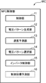
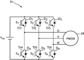
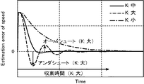
図1は、実施形態における電動機駆動制御システムの構成を示すブロック図である。図2は、前記電動機駆動制御システムにおけるMPC制御部の構成を示すブロック図である。図3は、前記電動機駆動制御システムにおけるインバータ回路の構成を示す回路図である。図4は、前記電動機駆動制御システムにおける負荷トルク推定部の構成を示すブロック図である。図5は、前記インバータ回路で出力可能な電圧を示すベクトル図である。図6は、前記インバータ回路で出力可能な時系列な電圧パターンの一例を説明するための図である。図7は、負荷トルクを入力とし、回転速度予測の推定誤差を出力とする伝達関数のステップ応答を説明するための図である。図7の横軸は、経過時間であり、その縦軸は、回転速度の推定誤差である。 FIG. 1 is a block diagram illustrating a configuration of an electric motor drive control system in the embodiment. FIG. 2 is a block diagram showing a configuration of an MPC control unit in the electric motor drive control system. FIG. 3 is a circuit diagram showing a configuration of an inverter circuit in the electric motor drive control system. FIG. 4 is a block diagram showing a configuration of a load torque estimating unit in the electric motor drive control system. FIG. 5 is a vector diagram showing voltages that can be output by the inverter circuit. FIG. 6 is a diagram for explaining an example of a time-series voltage pattern that can be output by the inverter circuit. FIG. 7 is a diagram for explaining the step response of the transfer function having the load torque as an input and the rotation speed prediction estimation error as an output. The horizontal axis in FIG. 7 is the elapsed time, and the vertical axis is the estimation error of the rotational speed.
実施形態における電動機駆動制御システムは、電動機を、制御しつつ、駆動するシステムであり、インバータ回路の出力で駆動される電動機を制御する電動機駆動制御装置を備える。本実施形態では、電動機駆動制御システムSは、モデル予測制御を用いたベクトル制御によって、電動機を、制御しつつ、駆動する。このような電動機駆動制御システムSは、例えば、図1に示すように、電動機Mと、インバータ回路IVと、モデル予測制御部MCと、3相2相変換部CVと、負荷トルク推定部TEと、回転速度処理部RSCと、電流測定部CSと、回転角度測定部VSとを備える。 The motor drive control system in the embodiment is a system that drives while controlling the motor, and includes a motor drive control device that controls the motor driven by the output of the inverter circuit. In the present embodiment, the motor drive control system S drives the motor while controlling it by vector control using model predictive control. For example, as shown in FIG. 1, such an electric motor drive control system S includes an electric motor M, an inverter circuit IV, a model prediction control unit MC, a three-phase two-phase conversion unit CV, and a load torque estimation unit TE. The rotation speed processing unit RSC, the current measurement unit CS, and the rotation angle measurement unit VS are provided.
電動機Mは、インバータ回路IVに接続され、インバータ回路IVの交流出力で駆動される電動機である。例えば、電動機Mは、インバータ回路IVから出力されるU相、V相およびW相の三相交流電流で駆動される同期電動機、より具体的には、本実施形態では永久磁石式同期電動機(permanent magnet synchronous motor、PMSM)である。なお、電動機Mは、これに限定されるものではなく、例えば、誘導電動機(induction motor、IM)やSRモータ(Switched Reluctance motor、SRM)等の他の種類であっても良い。 The electric motor M is an electric motor connected to the inverter circuit IV and driven by the AC output of the inverter circuit IV. For example, the motor M is a synchronous motor driven by a three-phase alternating current of U phase, V phase and W phase output from the inverter circuit IV. More specifically, in this embodiment, a permanent magnet type synchronous motor (permanent) is used. magnet synchronous motor (PMSM). The electric motor M is not limited to this, and may be other types such as an induction motor (IM) or an SR motor (Switched Reluctance motor, SRM).
インバータ回路IVは、モデル予測制御部MCに接続され、モデル予測制御部MCの制御に従って、直流電源Vdcの直流電力を、所定の周波数の交流電力へ変換する回路である。インバータ回路IVは、例えば、図3に示すように、直列に接続された2個のスイッチング素子Trを1組として、互いに並列に接続された3組Tr1、Tr4;Tr2、Tr5;Tr3、Tr6を備える。より具体的には、インバータ回路IVは、6個の第1ないし第6スイッチングTr1〜Tr6を備える。これら第1ないし第6スイッチング素子Tr1〜Tr6は、例えば絶縁ゲートバイポーラトランジスタ(IGBT)等の、オンオフするスイッチ機能を持つ電力用半導体素子である。第1ないし第3スイッチング素子Tr1〜Tr3の各一方端子(例えば各コレクタ端子)は、それぞれ、直流電源Vdcの一方端子に接続される。第1スイッチング素子Tr1の他方端子(例えばエミッタ端子)は、第4スイッチング素子Tr4の一方端子(例えば各コレクタ端子)に接続される。第2スイッチング素子Tr2の他方端子(例えばエミッタ端子)は、第5スイッチング素子Tr5の一方端子(例えば各コレクタ端子)に接続される。第3スイッチング素子Tr3の他方端子(例えばエミッタ端子)は、第6スイッチング素子Tr6の一方端子(例えば各コレクタ端子)に接続される。これら第4ないし第6スイッチング素子Tr4〜Tr6の各他方端子(例えば各エミッタ端子)は、それぞれ、直流電源Vdcの他方端子に接続される。これら第1ないし第6スイッチング素子Tr1〜Tr6における、スイッチング素子Trをオンオフするための制御信号が入力される各制御端子(例えばゲート端子)は、モデル予測制御部MCに接続される。これら第1ないし第6スイッチング素子Tr1〜Tr6それぞれにおいて、その一方端子と他方端子との各間それぞれには、他方端子にアノード端子を接続した各ダイオードD1〜D6が接続される。そして、第1スイッチング素子Tr1と第4スイッチング素子Tr4とを接続する第1接続点は、例えばU相の交流電流を出力し、電動機MのU相を接続する入力端子に接続される。第2スイッチング素子Tr2と第5スイッチング素子Tr5とを接続する第2接続点は、例えばV相の交流電流を出力し、電動機MのV相を接続する入力端子に接続される。第3スイッチング素子Tr3と第6スイッチング素子Tr6とを接続する第3接続点は、例えばW相の交流電流を出力し、電動機MのW相を接続する入力端子に接続される。このような構成のインバータ回路IVは、いわゆる2レベル3相インバータ回路であり、各組の一方のスイッチング素子Tr1、Tr2、Tr3と他方のスイッチング素子Tr4、Tr5、Tr6とは、互いに逆のスイッチング態様(一方がオンの場合には他方がオフで、一方がオフの場合には他方がオンである態様)となるようにモデル予測制御部MCの制御に従って制御され、U相、V相およびW相の3相の交流電流を電動機Mへ出力する。 The inverter circuit IV is a circuit that is connected to the model prediction control unit MC and converts the DC power of the DC power supply Vdc into AC power having a predetermined frequency in accordance with the control of the model prediction control unit MC. For example, as shown in FIG. 3, the inverter circuit IV includes two switching elements Tr connected in series as one set, and three sets Tr1, Tr4; Tr2, Tr5; Tr3, Tr6 connected in parallel to each other. Prepare. More specifically, the inverter circuit IV includes six first to sixth switching Tr1 to Tr6. The first to sixth switching elements Tr1 to Tr6 are power semiconductor elements having a switching function for turning on and off, such as an insulated gate bipolar transistor (IGBT). Each one terminal (for example, each collector terminal) of the first to third switching elements Tr1 to Tr3 is connected to one terminal of the DC power supply Vdc. The other terminal (for example, an emitter terminal) of the first switching element Tr1 is connected to one terminal (for example, each collector terminal) of the fourth switching element Tr4. The other terminal (eg, emitter terminal) of the second switching element Tr2 is connected to one terminal (eg, each collector terminal) of the fifth switching element Tr5. The other terminal (eg, emitter terminal) of the third switching element Tr3 is connected to one terminal (eg, each collector terminal) of the sixth switching element Tr6. Each other terminal (for example, each emitter terminal) of the fourth to sixth switching elements Tr4 to Tr6 is connected to the other terminal of the DC power supply Vdc. In each of the first to sixth switching elements Tr1 to Tr6, each control terminal (for example, a gate terminal) to which a control signal for turning on / off the switching element Tr is input is connected to the model prediction control unit MC. In each of the first to sixth switching elements Tr1 to Tr6, diodes D1 to D6 each having an anode terminal connected to the other terminal are connected between the one terminal and the other terminal. And the 1st connection point which connects 1st switching element Tr1 and 4th switching element Tr4 outputs the alternating current of U phase, for example, and is connected to the input terminal which connects the U phase of the motor M. A second connection point that connects the second switching element Tr2 and the fifth switching element Tr5 is connected to an input terminal that outputs, for example, a V-phase alternating current and connects the V-phase of the electric motor M. A third connection point connecting the third switching element Tr3 and the sixth switching element Tr6 is connected to an input terminal that outputs, for example, a W-phase AC current and connects the W-phase of the electric motor M. The inverter circuit IV having such a configuration is a so-called two-level three-phase inverter circuit, in which one switching element Tr1, Tr2, Tr3 and the other switching element Tr4, Tr5, Tr6 of each set are opposite to each other. (The mode in which the other is off when one is on and the other is on when one is off) is controlled according to the control of the model predictive control unit MC, and the U phase, V phase, and W phase The three-phase alternating current is output to the motor M.
電流測定部CSは、3相2相変換部CVに接続され、インバータ回路IVから電動機Mへ流れる電流、本実施形態では、U相電流、V相電流およびW相電流それぞれを測定し、その各測定結果を3相2相変換部CVへ出力する装置である。電流測定部CSは、例えば交流電流計を備えて構成される。 The current measurement unit CS is connected to the three-phase / two-phase conversion unit CV and measures each of the current flowing from the inverter circuit IV to the motor M, in this embodiment, the U-phase current, the V-phase current, and the W-phase current. It is a device that outputs measurement results to the three-phase to two-phase converter CV. The current measuring unit CS is configured with, for example, an AC ammeter.
回転角度測定部VSは、3相2相変換部CVおよび回転速度処理部RSCそれぞれに接続され、電動機Mにおける磁極位置を角度で測定し、その測定結果(回転角度)を3相2相変換部CVおよび回転速度処理部RSCそれぞれに出力する装置である。回転角度測定部VSは、例えば、ロータリエンコーダ(パルスジェネレータ)や、ホールIC等を備えて構成される。なお、センサレスの場合には、回転角度測定部VSは、電動機Mのモデルを用いて電流および電圧から電動機Mの回転角度を求めても良い。 The rotation angle measurement unit VS is connected to each of the three-phase two-phase conversion unit CV and the rotation speed processing unit RSC, measures the magnetic pole position in the electric motor M by angle, and the measurement result (rotation angle) is the three-phase two-phase conversion unit. It is a device that outputs to each of the CV and the rotation speed processing unit RSC. The rotation angle measurement unit VS includes, for example, a rotary encoder (pulse generator), a Hall IC, and the like. In the case of sensorless, the rotation angle measurement unit VS may obtain the rotation angle of the electric motor M from the current and voltage using a model of the electric motor M.
3相2相変換部CVは、モデル予測制御部MCに接続され、電流測定部CSから入力された測定結果(U相電流、V相電流およびW相電流)および回転角度測定部VSから入力された測定結果(回転角度)から、いわゆるクラーク(Clarke)変換およびパーク(Park)変換によって、励磁電流(d軸電流)idおよびトルク分電流(q軸電流)iqを求め、この求めたd軸電流idおよびq軸電流iqをモデル予測制御部MCへ出力するものである。 The three-phase / two-phase conversion unit CV is connected to the model prediction control unit MC and is input from the measurement result (U-phase current, V-phase current and W-phase current) input from the current measurement unit CS and the rotation angle measurement unit VS. From the measured result (rotation angle), excitation current (d-axis current) id and torque component current (q-axis current) i q are obtained by so-called Clarke conversion and Park conversion, and the obtained d The shaft current id and the q-axis current iq are output to the model prediction control unit MC.
回転速度処理部RSCは、モデル予測制御部MCおよび負荷トルク推定部TEそれぞれに接続され、回転角度測定部VSから入力された測定結果(回転角度)から、電動機Mの回転速度ωmを求め、この求めた回転速度ωmを回転速度現在値ωmとしてモデル予測制御部MCおよび負荷トルク推定部TEそれぞれへ出力するものである。すなわち、回転速度処理部RSCは、回転角度測定部VSから入力された測定結果(回転角度)から、電動機Mの回転速度ωmを求め、この求めた回転速度ωmを回転速度現在値ωmとしてモデル予測制御部MCおよび負荷トルク推定部TEそれぞれへ出力する速度出力処理を実施する。例えば、回転角度測定部VSで測定された回転角度θeを時間微分して電動機Mの極対数pの逆数を乗じることによって回転速度ωmが求められる。 The rotation speed processing unit RSC is connected to each of the model prediction control unit MC and the load torque estimation unit TE, and obtains the rotation speed ω m of the electric motor M from the measurement result (rotation angle) input from the rotation angle measurement unit VS. The obtained rotation speed ω m is output as the rotation speed current value ω m to each of the model prediction control unit MC and the load torque estimation unit TE. That is, the rotation speed processing unit RSC obtains the rotation speed ω m of the electric motor M from the measurement result (rotation angle) input from the rotation angle measurement unit VS, and uses the obtained rotation speed ω m as the current rotation speed value ω m. As described above, a speed output process for outputting to the model prediction control unit MC and the load torque estimation unit TE is performed. For example, the rotational speed ω m is obtained by time-differentiating the rotational angle θ e measured by the rotational angle measurement unit VS and multiplying by the reciprocal number of the pole pair number p of the electric motor M.
負荷トルク推定部TEは、モデル予測制御部MCに接続され、電動機Mに働く負荷トルクを推定するものである。すなわち、負荷トルク推定部TEは、電動機Mに働く負荷トルクを推定する負荷トルク推定処理を実施する。モデル予測制御では、その性質上、現時点における電動機Mの回転速度を過去に予測している。回転速度の予測値は、電動機Mに負荷トルクを加えた電圧方程式および運動方程式に基づいて導出される。ここで、仮に、予測された回転速度予測値と実測された回転速度現在値との間に誤差が生じている場合、電動機Mのモデルに含まれる誤差を無視すると、そこには、回転速度の予測に用いられた負荷トルクの推定値に誤差が含まれていると考えられる。この考えから、本実施形態では、負荷トルク推定部TEは、モデル予測制御部MCにおける後述の速度予測部13で過去に予測された現在の回転速度予測値に基づいて負荷トルクを推定する。より具体的には、負荷トルク推定部TEは、速度予測部13で過去に予測された現在の回転速度予測値と回転角度測定部VSで測定された回転角度から求めた回転速度現在値との差分に、予め設定された所定の係数を乗じた差分乗算値を、制御周期ごとに積算することで負荷トルクを推定する。
The load torque estimation unit TE is connected to the model prediction control unit MC and estimates the load torque acting on the motor M. That is, the load torque estimation unit TE performs a load torque estimation process for estimating the load torque acting on the electric motor M. In model predictive control, due to its nature, the current rotational speed of the motor M is predicted in the past. The predicted value of the rotational speed is derived based on a voltage equation and a motion equation in which a load torque is applied to the electric motor M. Here, if there is an error between the predicted predicted rotational speed value and the actual measured rotational speed value, ignoring the error included in the model of the motor M, there is the rotational speed. It is considered that the estimated value of the load torque used for the prediction includes an error. From this idea, in this embodiment, the load torque estimation unit TE estimates the load torque based on the current predicted rotational speed value predicted in the past by the
すなわち、モデル予測制御部MCが、予め設定された所定の制御周期ごとに繰り返し電動機Mをインバータ回路IVを介して制御する場合、k番目の制御における負荷トルク推定値を、上にハット(^)付きのTl(k)とし、電動機Mの慣性モーメントをJとし、k番目の制御(現在)における回転速度予測値を、上にハット(^)付きのω(k)とし、k番目の制御(現在)における回転速度現在値をω(k)とし、制御周期(モデル予測制御における繰り返し制御の時間間隔)をTsとし、前記所定の係数として、負荷トルクのゲイン(更新量を調整するための更新量調整ゲイン)をKとする場合に、負荷トルク推定値は、次式1で表される。
That is, when the model predictive control unit MC repeatedly controls the electric motor M via the inverter circuit IV at a predetermined control period set in advance, the estimated load torque value in the k-th control is set to the upper (^) T 1 (k) with an added value, J is the moment of inertia of the motor M, the predicted rotational speed in the kth control (current) is ω (k) with a hat (^), and the kth control the rotational speed present value of (current) and omega (k), the control period (time interval of the iterative learning control in the model predictive control) and T s, as the predetermined coefficient, for adjusting the gain (amount of updated load torque When the update amount adjustment gain) is K, the estimated load torque is expressed by the

より具体的には、本実施形態では、負荷トルク推定部TEは、上記式1から、例えば、図4に示すように、減算部31と、ローパスフィルタ部32と、パラメータ演算部33と、ゲイン演算部34とを備える。
More specifically, in the present embodiment, the load torque estimation unit TE calculates the
減算部31は、回転速度処理部RSCおよびモデル予測制御部MCそれぞれに接続され、モデル予測制御部MCの速度予測部13で過去、例えば制御周期の1つ前に求められた現在の回転速度予測値(上にハット(^)付きのω(k))と回転速度処理部RSCで求められた現在の回転速度現在値ω(k)との差分を求め、この求めた差分をローパスフィルタ部32へ出力するものである。
The
ローパスフィルタ部32は、減算部31から出力された前記差分に含まれる、例えばノイズ等に起因する高周波成分を除去し、この高周波成分を除去した前記差分をパラメータ演算部33へ出力するものである。ローパスフィルタ部32は、例えば、次式2で表される2次のデジタルローパスフィルタF(z)を備えて構成される。ここで、a0、a1、a2、b0、b1、およびb2は、フィルタ係数であり、ローパスフィルタ部32の仕様等に応じて適宜に設定される。なお、デジタルローパスフィルタF(z)は、2次に限定されるものではなく、1次や3次以上あっても良い。また、前記差分に含まれる高周波成分が無視できる場合には、ローパスフィルタ部32は、省略されても良い。
The low-
パラメータ演算部33は、ローパスフィルタ部32の出力(前記高周波成分を除去した前記差分)に、式1におけるパラメータ(−J/Ts)を乗算し、この乗算結果をゲイン演算部34へ出力するものである。
The
ゲイン演算部34は、モデル予測制御部MCに接続され、パラメータ演算部33の出力(パラメータ(−J/Ts)を乗算した前記差分)に、負荷トルクのゲインKを乗算し、この乗算結果をモデル予測制御部MCへ出力するものである。
The
このゲインKは、回転速度予測値と回転速度現在値との間の差異に振動成分が生じて回転速度予測値が発散しないように、適切に設定されなければならない。このため、本実施形態では、例えば、負荷トルクを入力とし、速度予測部13の推定誤差を出力とする伝達関数が安定性を満足する範囲内に、前記所定の係数としてのゲインKが、設定される。より具体的には、回転速度予測値と回転速度現在値とは、それぞれ、次式3および次式4に従う。ここで、Bは、電動機Mにおける回転体の摩擦係数であり、Te(k)は、電動機Mにおける実際の出力トルクであり、Tl(k)は、電動機Mに働く実際の負荷トルクであり、上にハット(^)付きのTe(k)は、電動機Mにおける実際の出力トルクの推定値であり、上にハット(^)付きのTl(k)は、電動機Mに働く実際の負荷トルクの推定値であり、△Tl(k)は、制御周期ごとに負荷トルク推定値をインクリメント(またはデクリメント)するための負荷トルク更新量、すなわち、k番目の制御で、(k−1)番目の制御における負荷トルク推定値に積算される前記差分であり、次式5で表される。なお、上にハット(^)付きのω(k|k−1)は、(k−1)番目の制御(過去)で求められたk番目の制御(現在)における回転速度予測値である。
This gain K must be set appropriately so that a vibration component is not generated in the difference between the predicted rotational speed value and the current rotational speed value, and the predicted rotational speed value does not diverge. For this reason, in the present embodiment, for example, the gain K as the predetermined coefficient is set within a range in which the transfer function that receives the load torque and outputs the estimation error of the
![]()
![]()
式5から、現在の制御で求められる、過去に予測された現在の回転速度予測値と回転速度現在値との差分に基づき更新量を求めて制御周期ごとに積算することで、負荷トルクが、推定されている。 By calculating the update amount based on the difference between the current predicted rotational speed value predicted in the past and the current rotational speed value, which is obtained by the current control, from Equation 5, the load torque is obtained by integrating each control cycle. It is estimated.
これら式1ないし式5から、前記伝達関数H(z)は、次式6となる。
From these
この式6から、ゲインKが負荷トルクと回転速度推定誤差との間における応答特性に寄与していることが分かる。負荷トルクが加わった際に、式5に基づく更新量で負荷トルク推定値が更新されることによってモデル予測制御における回転速度推定誤差の推移が図7に示されている。ゲインKの大きさによってステップ応答の過渡特性が異なっている。式6で表される伝達関数H(z)が安定となるためには、式6で表される伝達関数H(z)の全ての極piで、その大きさが1以内となる必要がある。すなわち、pi=ci+di(式6では極数i=1、2、3、4)、|ci+jdi|<1である。ここで、jは、虚数単位である(j2=−1)。このようなゲインKは、ユーザによって予め求められて負荷トルク推定部TEのゲイン演算部34に設定されて良く、あるいは、負荷トルク推定部TEは、前記負荷トルクを入力とし、前記速度予測部の推定誤差を出力とする伝達関数が安定性を満足する範囲内に前記所定の係数を設定する係数設定部(不図示)をさらに備え、後述のフローチャートに従って前記係数設定部によって求められても良い。
From this
モデル予測制御部MCは、モデル予測制御を用いたベクトル制御によって、電動機Mをインバータ回路IVを介して駆動制御するものである。モデル予測制御部MCは、より具体的には、例えば、図2に示すように、制御部11と、電圧パターン生成部12と、速度予測部13と、電圧パターン選択部14と、インバータ制御部15とを備える。
The model prediction control unit MC performs drive control of the electric motor M via the inverter circuit IV by vector control using model prediction control. More specifically, the model prediction control unit MC includes, for example, as shown in FIG. 2, a
制御部11は、電動機駆動制御システムSの各部を当該各部の機能に応じて制御し、電動機駆動制御システムS全体の制御を司るものである。
The
電圧パターン生成部12は、インバータ回路IVで出力可能な時系列な電圧パターンを、互いに異なるように複数、生成するものである。すなわち、電圧パターン生成部12は、インバータ回路IVで出力可能な時系列な電圧パターンを、互いに異なるように複数、生成する電圧パターン生成処理を実施する。インバータ回路IVは、本実施形態では、上述のように、2レベル3相インバータであるので、第1ないし第6スイッチング素子Tr1〜Tr6のスイッチング態様に応じて、図5に示すように、23=8通りの電圧を出力できる。なお、電圧ベクトルV0は、第1ないし第3スイッチング素子Tr1〜Tr3がオフであって第4ないし第6スイッチング素子Tr4〜Tr6がオンであり、電動機Mに給電されない場合(V0=(0、0、0))である。電圧ベクトルV7は、第1ないし第3スイッチング素子Tr1〜Tr3がオンであって第4ないし第6スイッチング素子Tr4〜Tr6がオフであり、電動機Mに給電されない場合(V7=(0、0、0))である。時系列な電圧パターンは、予測する制御周期数である予測ホライズン、および、制御入力である電圧を可変とする制御周期数である制御ホライズンによって決定される。このため、モデル予測制御部MCには、予め予測ホライズンの数値および制御ホライズンの数値が、モデル予測制御の仕様等に応じて適宜に予め設定され、電圧パターン生成部12は、インバータ回路IVで出力可能な電圧(上述では8通り)、予測ホライズンの数値および制御ホライズンの数値に応じて互いに異なる複数の時系列な電圧パターンを生成する。図6には、一例として、予測ホライズンが2であり、制御ホライズンが1である場合のインバータ回路IVで出力可能な全ての時系列な電圧パターンが樹形図で図示されている。図6では、現在のN番目の制御における電圧に対し、予測ホライズンが2であるので、次の(N+1)番目の制御における電圧と、さらに次の(N+2)番目の制御における電圧とが予測され、制御ホライズンが1であるので、インバータ回路IVで出力可能な全ての時系列な電圧パターンは、現在のN番目の制御における電圧から、次の(N+1)番目の制御では、8通りの電圧V0〜V8に分岐し、さらに次の(N+2)番目の制御では、各電圧V0〜V8から、それぞれ当該電圧V0〜V8に維持された8組の時系列な電圧パターンである。なお、他の一例として、予測ホライズンが2であり、制御ホライズンが2である場合、現在のN番目の制御における電圧に対し、予測ホライズンが2であるので、次の(N+1)番目の制御における電圧と、さらに次の(N+2)番目の制御における電圧とが予測され、制御ホライズンが2であるので、インバータ回路IVで出力可能な全ての時系列な電圧パターンは、(N+1)番目の制御および(N+2)番目の制御それぞれで8通りの電圧V0〜V8に分岐し、64組の時系列な電圧パターンである。
The voltage
速度予測部13は、電圧パターン生成部12で生成された複数の時系列な電圧パターンそれぞれについて、負荷トルク推定部TEで推定された負荷トルクが電動機Mに働いている場合であって、当該時系列な電圧パターンが電動機Mに入力された場合における電動機Mの回転速度を回転速度予測値として予測するものである。すなわち、速度予測部13は、電圧パターン生成部12で生成された複数の時系列な電圧パターンそれぞれについて、負荷トルク推定部TEで推定された負荷トルクが電動機Mに働いている場合であって、当該時系列な電圧パターンが電動機Mに入力された場合における電動機Mの回転速度を回転速度予測値として予測する速度予測処理を実施する。より具体的には、速度予測部13は、次式7によってd軸電流idを求め、次式8によってq軸電流iqを求める。そして、速度予測部13は、次式9によって電動機Mの出力トルクTeを求め、次式10によって回転速度予測値(上にハット(^)付きのωm)を求める。ここで、id(k)は、k番目の制御におけるd軸電流であり、iq(k)は、k番目の制御におけるq軸電流であり、Ldは、d軸インダクタンスであり、Lqは、q軸インダクタンスである。なお、本実施形態では、電動機Mが永久磁石式同期電動機であるので、Ld=Lq=Lとなる。Rは、電動機Mの巻線抵抗であり、ωe(k)は、k番目の制御における電動機Mの電気角速度であり、vd(k)は、k番目の制御におけるd軸電圧であり、vq(k)は、k番目の制御におけるq軸電圧であり、Ψは、電動機Mにおける永久磁石の鎖交磁束であり、Dは、電動機Mにおける回転子の動摩擦抵抗である。
The
上述の例では、予測ホライズンが2であるので、速度予測部13は、8組の時系列な電圧パターンそれぞれについて、現在のk番目の制御に対し、2制御周期先までの、dq軸での電流予測値[idq(k+1)、idq(k+2)]および回転速度予測値[上にハット(^)付きのω(k+1)、上にハット(^)付きのω(k+2)]を求める。なお、電流ベクトルidq(k)は、[id(k)、iq(k)]Tである(idq(k)=[id(k)、iq(k)]T)。
In the above example, since the predicted horizon is 2, the
電圧パターン選択部14は、電圧パターン生成部12で生成された複数の時系列な電圧パターンの中から、速度予測部13で予測された電動機Mの各回転速度予測値の中で最も高い評価の回転速度予測値に対応する時系列な電圧パターンを選択するものである。すなわち、電圧パターン選択部14は、電圧パターン生成部12で生成された複数の時系列な電圧パターンの中から、速度予測部13で予測された電動機Mの各回転速度予測値の中で最も高い評価の回転速度予測値に対応する時系列な電圧パターンを選択する電圧パターン選択処理を実施する。より具体的には、電圧パターン選択部14は、電圧パターン生成部12で生成された複数の時系列な電圧パターンそれぞれについて、速度予測部13で予測された電動機Mの電流予測値および回転速度予測値を、例えば次式11の評価式gに用いることによって、前記時系列な電圧パターン定量的に評価し、前記複数の時系列な電圧パターンの中から、最も高い評価の電流予測値および回転速度予測値に対応する時系列な電圧パターンを選択する。式11の評価式gでは、評価値が小さいほど、評価が高い。したがって、前記複数の時系列な電圧パターンの中から、最も小さい評価値を与える電流予測値および回転速度予測値に対応する時系列な電圧パターンが最適な時系列な電圧パターンとして選択される。なお、モデル予測制御部MCには、外部から制御目標の回転速度ωm *が入力され、設定される。
The voltage
上記式11の評価式gは、速度制御の上で重要となることから、速度偏差を第1項とし、永久磁石式同期電動機の場合、無駄な給電を防止するために、トルクの発生に寄与しないd軸電流idを0に保持することが重要であることから、電流偏差を第2項とし、これら第1項および第2項を係数a、bで線形結合することで構成されている。したがって、第1項と第2項とにおける相対的な重要度に応じて係数a、bが予め適宜に決定される。言い換えれば、係数a、bで第1項と第2項とにおける相対的な重要度が調整できる。すなわち、電動機Mの制御で、速度偏差が電流偏差より相対的に重要である場合には、評価式g中の第1項と係数aを乗じた値が、第2項と係数bを乗じた値よりも十分大きい値となるよう係数a、係数bを設定し、逆に、電動機Mの制御で、電流偏差が速度偏差より相対的に重要である場合には、評価式g中の第2項と係数bを乗じた値が、第1項と係数aを乗じた値よりも十分大きい値となるよう係数a、係数bを設定する。
Since the evaluation formula g of the
インバータ制御部15は、電圧パターン選択部14で選択された時系列な電圧パターンに基づいて、インバータ回路IVを制御するものである。すなわち、インバータ制御部15は、電圧パターン選択部14で選択された時系列な電圧パターンに基づいて、インバータ回路IVを制御するインバータ制御処理を実施する。より具体的には、インバータ制御部15は、現在、k番目の制御である場合に、電圧パターン選択部14で選択された時系列な電圧パターンにおける次回の(k+1)番目の制御での電圧を目標電圧として、この目標電圧に対応する目標のU相電流、V相電流およびW相電流をインバータ回路IVから出力するように、インバータ回路IVにおける第1ないし第6スイッチング素子Tr1〜Tr6の各制御端子へ制御信号を出力する。
The
そして、制御部11は、前記速度出力処理、前記負荷トルク推定処理、前記電圧パターン生成処理、前記速度予測処理、前記電圧パターン選択処理およびインバータ制御処理を、回転速度処理部RSC、負荷トルク推定部TE、電圧パターン生成部12、速度予測部13、電圧パターン選択部14およびインバータ制御部15に、所定の制御周期で繰り返し実施させる。
Then, the
このようなモデル予測制御部MC、3相2相変換部CV、負荷トルク推定部TEおよび回転速度処理部RSCは、CPU(Central Processing Unit)、メモリおよびその周辺回路を備えて構成されるマイクロプロセッサで構成可能であり、モデル予測制御部MCにおける制御部11、電圧パターン生成部12、速度予測部13、電圧パターン選択部14およびインバータ制御部、3相2相変換部CV、負荷トルク推定部TEにおける減算部31、ローパスフィルタ部32、パラメータ演算部33およびゲイン演算部34、ならびに、回転速度処理部RSCは、所定のプログラムの実行により、前記CPUに機能的に構成される。
The model predictive control unit MC, the three-phase / two-phase conversion unit CV, the load torque estimation unit TE, and the rotation speed processing unit RSC include a CPU (Central Processing Unit), a memory, and a peripheral circuit thereof. In the model prediction control unit MC, the
本実施形態では、回転角度測定部VSおよび回転速度処理部RSCが、電動機の回転速度を回転速度現在値として求める速度出力部の一例に相当し、モデル予測制御部MC、電流測定部CS、回転角度測定部VS、3相2相変換部CV、負荷トルク推定部TEおよび回転速度処理部RSCが、インバータ回路の出力で駆動される電動機を制御する電動機駆動制御部の一例に相当する。 In the present embodiment, the rotation angle measurement unit VS and the rotation speed processing unit RSC correspond to an example of a speed output unit that obtains the rotation speed of the motor as a rotation speed current value, and includes a model prediction control unit MC, a current measurement unit CS, a rotation The angle measurement unit VS, the three-phase / two-phase conversion unit CV, the load torque estimation unit TE, and the rotation speed processing unit RSC correspond to an example of an electric motor drive control unit that controls the electric motor driven by the output of the inverter circuit.
次に、本実施形態の動作について説明する。図8は、前記電動機駆動制御システムにおける動作を示すフローチャートである。図9は、負荷トルクの更新量を調整するためのゲインを求めるためのフローチャートである。図10は、速度制御のシミュレーション結果を示す図である。 Next, the operation of this embodiment will be described. FIG. 8 is a flowchart showing an operation in the motor drive control system. FIG. 9 is a flowchart for obtaining a gain for adjusting the update amount of the load torque. FIG. 10 is a diagram illustrating a simulation result of speed control.
まず、負荷トルクのゲインKの設定について説明する。この負荷トルクのゲインKの設定では、図9において、前記ゲインKが適当な値に初期設定される(S31)。次に、式6の伝達関数H(z)における極piが求められる(S32、上述の例では、i=1、2、3、4)。次に、全ての極piで、その大きさが1以内であるか否かが判定される(S33)。 First, the setting of the load torque gain K will be described. In the setting of the gain torque gain K, the gain K is initially set to an appropriate value in FIG. 9 (S31). Next, pole p i is determined in the transfer function H of the equation 6 (z) (S32, in the above example, i = 1, 2, 3, 4). Then, in all poles p i, its magnitude is determined whether or not within one (S33).
この判定の結果、全ての極piで、その大きさが1以内である場合(Yes)には、次に、処理S34が実施され、少なくとも1つの極piで、その大きさが1以内ではない場合(No)には、次に、処理S36が実施される。 The result of this determination, in all poles p i, in the case (Yes) its size is within 1, then the processing S34 is being carried out, at least one pole p i, whose magnitude is 1 within If not (No), the process S36 is performed next.
この処理S36では、前記ゲインKが、予め設定された所定値△K1だけ減算され(K←K−△K1)、処理が処理S32に戻される。 In this process S36, the gain K is subtracted by a predetermined value ΔK1 set in advance (K ← K−ΔK1), and the process returns to the process S32.
一方、前記処理S34では、式6の伝達関数H(z)におけるステップ応答の収束時間が、予め設定された所定値Tco以内か否かが判定される。前記所定値Tcoは、当該電動機駆動制御システムSの仕様で許容される応答時間等に応じて適宜に設定される。
On the other hand, in the process S34, it is determined whether or not the convergence time of the step response in the transfer function H (z) of
この判定の結果、前記収束時間が前記所定値Tco以内である(Yes)には、次に、処理S35が実施され、前記収束時間が前記所定値Tco以内ではない(No)には、次に、処理S37が実施される。 As a result of this determination, if the convergence time is within the predetermined value Tco (Yes), the process S35 is then performed, and if the convergence time is not within the predetermined value Tco (No), then Processing S37 is performed.
この処理S37では、前記ゲインKが、予め設定された所定値△K2だけ加算され(K←K+△K2)、処理が処理S32に戻される。なお、前記所定値△K1と前記所定値△K2とは、同値でも異値でも良い。 In this process S37, the gain K is added by a preset predetermined value ΔK2 (K ← K + ΔK2), and the process returns to the process S32. The predetermined value ΔK1 and the predetermined value ΔK2 may be the same value or different values.
一方、前記処理S35では、式6の伝達関数H(z)におけるステップ応答のオーバーシュート量(減衰振動におけるオーバーシュートの最大振幅幅)およびアンダーシュート量(前記減衰振動におけるアンダーシュートの最大振幅幅)が、予め設定された所定値OU以内か否かが判定される。前記所定値OUは、当該電動機駆動制御システムSの仕様で許容される減衰振動幅等に応じて適宜に設定される。
On the other hand, in the process S35, the overshoot amount (maximum amplitude width of overshoot in the damped vibration) and the undershoot amount (maximum amplitude width of undershoot in the damped vibration) in the transfer function H (z) of
この判定の結果、前記オーバーシュート量およびアンダーシュート量が前記所定値OU以内である(Yes)には、このときの値で前記ゲインKが決定され、処理が終了され、前記オーバーシュート量およびアンダーシュート量が前記所定値OU以内ではない(No)には、次に、処理S36が実施された後に、処理が処理S32に戻される。 As a result of this determination, if the overshoot amount and the undershoot amount are within the predetermined value OU (Yes), the gain K is determined based on the value at this time, the processing is terminated, and the overshoot amount and undershoot amount are determined. If the shoot amount is not within the predetermined value OU (No), the process returns to the process S32 after the process S36 is performed.
このような負荷トルクの更新量を調整するためのゲインKの設定処理は、例えばユーザによって実施され、電動機駆動制御システムSに設定されて良く、あるいは、前記CUPに機能的に構成される前記係数設定部(不図示)によって自動的に実行され、電動機駆動制御システムSに設定されて良い。 Such a setting process of the gain K for adjusting the update amount of the load torque may be performed by, for example, a user and set in the motor drive control system S, or the coefficient functionally configured in the CUP It may be automatically executed by a setting unit (not shown) and set in the motor drive control system S.
次に、モデル予測制御による電動機駆動制御システムSの動作について説明する。このような電動機駆動制御システムSでは、電源が投入されると、必要な各部の初期化を実行し、その稼働を始める。そして、例えば、プログラムの実行によって、前記CPUには、モデル予測制御部MC、3相2相変換部CV、負荷トルク推定部TEおよび回転速度処理部RSCが機能的に構成され、モデル予測制御部MCには、制御部11、電圧パターン生成部12、速度予測部13、電圧パターン選択部14およびインバータ制御部15が機能的に構成され、負荷トルク推定部TEには、減算部31、ローパスフィルタ部32、パラメータ演算部33およびゲイン演算部34が機能的に構成される。
Next, the operation of the motor drive control system S by model predictive control will be described. In such an electric motor drive control system S, when the power is turned on, initialization of each necessary part is executed and its operation is started. For example, by executing a program, the CPU is functionally configured with a model prediction control unit MC, a three-phase two-phase conversion unit CV, a load torque estimation unit TE, and a rotation speed processing unit RSC. The MC includes a
そして、図8に示す処理S11ないし処理S17の各処理が、電動機Mの駆動が停止されるまで、制御部11によって所定の制御周期ごとに繰り返し実行される。
And each process of process S11 thru | or process S17 shown in FIG. 8 is repeatedly performed by the
図8において、まず、今回(k番目)において、電流測定部CSによって測定された各相の電流値が取得され、回転角度測定部VSによって測定された回転角度の値が取得される(S11)。電流測定部CSは、この取得した各相の電流値を、3相2相変換部CVへ出力し、回転角度測定部VSは、この取得した回転角度値を、3相2相変換部CVおよび回転速度処理部RSCそれぞれへ出力する。 In FIG. 8, first, the current value of each phase measured by the current measuring unit CS is acquired this time (kth), and the value of the rotation angle measured by the rotation angle measuring unit VS is acquired (S11). . The current measuring unit CS outputs the acquired current value of each phase to the three-phase / two-phase converting unit CV, and the rotation angle measuring unit VS outputs the acquired rotation angle value to the three-phase / two-phase converting unit CV and Output to each rotation speed processing unit RSC.
続いて、3相2相変換部CVは、処理S11で取得された各相の電流値および回転角度値から、d軸電流idおよびq軸電流iqを求め、この求めたd軸電流idおよびq軸電流iqをモデル予測制御部MCへ出力し、回転速度処理部RSCは、処理S11で取得された各相の電流値および回転角度値から、回転速度ωmを求め、この求めた回転速度ωmを、回転速度現在値ωm(=ω(k))としてモデル予測制御部MCおよび負荷トルク推定部TEそれぞれへ出力する(S12、速度出力処理)。 Subsequently, the three-phase / two-phase conversion unit CV obtains the d-axis current i d and the q-axis current i q from the current value and rotation angle value of each phase acquired in the process S11, and the obtained d-axis current i The d and q-axis current i q is output to the model prediction control unit MC, and the rotation speed processing unit RSC obtains the rotation speed ω m from the current value and the rotation angle value of each phase acquired in the process S11. The rotation speed ω m is output to the model prediction control unit MC and the load torque estimation unit TE as the rotation speed current value ω m (= ω (k)) (S12, speed output process).
続いて、負荷トルク推定部TEは、モデル予測制御部MCの速度予測部13で過去に予測された現在の回転速度予測値(上にハット付きのωm=上にハット付きのω(k))に基づいて負荷トルクを推定する(S13、負荷トルク推定処理)。本実施形態では、負荷トルク推定部TEは、減算部31によって、制御周期の1つ前に処理S15で求められた現在の回転速度予測値(上にハット付きのω(k))と処理S12で回転速度処理部RSCによって求められた現在の回転速度現在値ω(k)との差分を求め、この求めた差分を、ローパスフィルタ部32でフィルタリング(濾波)し、このフィルタリングした前記差分に、パラメータ演算部33によって、パラメータ(−J/Ts)を乗算し、このパラメータ(−J/Ts)を乗算した前記差分、上述のように設定された負荷トルクの更新量を調整するためのゲインKを乗算し、この乗算結果をモデル予測制御部MCへ出力する。
Subsequently, the load torque estimation unit TE has a current rotational speed prediction value (ω m with a hat on top = ω (k) with a hat on top) predicted in the past by the
続いて、モデル予測制御部MCは、電圧パターン生成部12によって、予め設定された予測ホライズンの値および制御ホライズンの値に応じて、インバータ回路IVで出力可能な時系列な電圧パターンを、互いに異なるように複数、生成する(S14、電圧パターン生成処理)。
Subsequently, the model prediction control unit MC uses the voltage
続いて、モデル予測制御部MCは、速度予測部13によって、電圧パターン生成部12で生成された複数の時系列な電圧パターンそれぞれについて、負荷トルク推定部TEで推定された負荷トルクが電動機Mに働いている場合であって、当該時系列な電圧パターンが電動機Mに入力された場合における電動機Mの回転速度を回転速度予測値として予測する(S15、速度予測処理)。より具体的には、速度予測部13は、次式7によってd軸電流idを求め、次式8によってq軸電流iqを求め、次式9によって電動機Mの出力トルクTeを求め、次式10によって回転速度予測値(上にハット付きのωm)を求める。上述の例では、速度予測部13は、8組の時系列な電圧パターンそれぞれについて、現在のk番目の制御に対し、2制御周期先までの、dq軸での電流予測値[idq(k+1)、idq(k+2)]および回転速度予測値[上にハット(^)付きのω(k+1)、上にハット(^)付きのω(k+2)]を求める。
Subsequently, the model prediction control unit MC receives the load torque estimated by the load torque estimation unit TE from the
続いて、モデル予測制御部MCは、電圧パターン選択部14によって、式11の評価式gを用いることで、電圧パターン生成部12で生成された複数の時系列な電圧パターンの中から、処理S15で速度予測部13によって予測された電動機Mの各回転速度予測値の中で最も高い評価の回転速度予測値に対応する時系列な電圧パターンを選択する(S16、電圧パターン選択処理)。
Subsequently, the model prediction control unit MC uses the evaluation formula g of
続いて、モデル予測制御部MCは、インバータ制御部15によって、インバータ回路IVにおける第1ないし第6スイッチング素子Tr1〜Tr6の各制御端子へ制御信号を出力することで、電圧パターン選択部14で選択された時系列な電圧パターンに基づいて、インバータ回路IVを制御して電動機Mを駆動する(S17、インバータ制御処理)。
Subsequently, the model prediction control unit MC is selected by the voltage
このように電動機Mが、目標速度ωm *となるように、モデル予測制御で制御され、駆動される。 Thus, the electric motor M is controlled and driven by the model predictive control so that the target speed ω m * is obtained.
シミュレーション(数値実験)によって、本実施形態における電動機駆動制御システムS、電動機駆動制御装置およびこれに実装された電動機駆動制御方法の効果が検証された。その一実施例の速度制御のシミュレーション結果がその比較例と共に図10に示されている。図10Aは、本実施形態における電動機駆動制御システムSによる速度制御のシミュレーション結果を示し、図10Bは、比較例による速度制御のシミュレーション結果を示す。図10Aおよび図10Bにおける各横軸は、経過時間であり、それら各縦軸は、回転速度である。 Simulation (numerical experiments) verified the effects of the motor drive control system S, the motor drive control device, and the motor drive control method mounted thereon in the present embodiment. The simulation result of the speed control of one embodiment is shown in FIG. 10 together with the comparative example. FIG. 10A shows a simulation result of speed control by the electric motor drive control system S in the present embodiment, and FIG. 10B shows a simulation result of speed control by a comparative example. Each horizontal axis in FIG. 10A and FIG. 10B is an elapsed time, and each vertical axis is a rotation speed.
比較例では、負荷トルクは、推定されず、負荷トルクの項は0とした。比較例では、図10Bに示すように、負荷トルクが印加されると、回転速度は、目標速度より低下してしまうが、本実施形態では、図10Aに示すように、負荷トルクが印加されても、回転速度は、略目標速度となっている。したがって、本実施形態では、負荷トルクが適切に推定されており、回転速度を予測する式10に用いることで、回転速度予測値がより精度高く予測できている。この結果、本実施形態では、適切な時系列な電圧パターンが選択でき、回転速度が目標速度の追従できている。 In the comparative example, the load torque is not estimated, and the term of the load torque is 0. In the comparative example, as shown in FIG. 10B, when the load torque is applied, the rotation speed is lower than the target speed, but in this embodiment, the load torque is applied as shown in FIG. 10A. However, the rotational speed is substantially the target speed. Therefore, in the present embodiment, the load torque is appropriately estimated, and the predicted rotational speed can be predicted with higher accuracy by using the formula 10 for predicting the rotational speed. As a result, in the present embodiment, an appropriate time-series voltage pattern can be selected, and the rotation speed can follow the target speed.
以上説明したように、本実施形態における電動機駆動制御システムS、電動機駆動制御装置およびこれに実装された電動機駆動制御方法は、負荷トルクの推定に、過去に予測された現在の回転速度予測値を用いるので、従来のカルマンフィルタを用いる場合に較べてより少ない情報処理量で負荷トルクを推定でき、負荷トルクが働く使用条件でも、モデル予測制御で電動機を駆動制御できる。このため、演算処理能力の比較的低い、安価な演算処理装置でモデル予測制御を実現する場合でも、上記電動機駆動制御システムS、電動機駆動制御装置および電動機駆動制御方法は、略リアルタイムで電動機を駆動制御できる。 As described above, the electric motor drive control system S, the electric motor drive control device, and the electric motor drive control method mounted thereon according to the present embodiment use the current predicted rotational speed value predicted in the past for the estimation of the load torque. Therefore, the load torque can be estimated with a smaller amount of information processing than in the case of using a conventional Kalman filter, and the motor can be driven and controlled by model predictive control even under use conditions where the load torque works. For this reason, even when model predictive control is realized with an inexpensive arithmetic processing device having a relatively low arithmetic processing capability, the motor drive control system S, the motor drive control device, and the motor drive control method drive the motor in substantially real time. Can be controlled.
上記電動機駆動制御システムS、電動機駆動制御装置および電動機駆動制御方法は、速度予測部13で過去に予測された現在の回転速度予測値と回転速度現在値との差分に、所定の係数を乗じた差分乗算値を、制御周期ごとに積算することで負荷トルクを推定するので、簡便に、より少ない情報処理量で負荷トルクを推定でき、モデル予測制御で電動機Mを駆動制御できる。
In the motor drive control system S, the motor drive control device, and the motor drive control method, the difference between the current predicted rotational speed value predicted in the past by the
上記電動機駆動制御システムS、電動機駆動制御装置および電動機駆動制御方法は、図9を用いて説明したように、制御系が安定するように負荷トルクの更新量を調整するためのゲインKを適切に設定できる。このため、不適切な前記ゲインKによって駆動の際に生じる発振や不安定化が事前に回避できる。 As described with reference to FIG. 9, the motor drive control system S, the motor drive control device, and the motor drive control method appropriately set the gain K for adjusting the update amount of the load torque so that the control system is stabilized. Can be set. For this reason, it is possible to avoid in advance oscillation and instability that occur during driving due to an inappropriate gain K.
なお、上述の実施形態では、電圧パターン選択部14は、例えば式11に示すように、制御目標の回転速度ωm *を含む評価関数の評価式gを用いることによって前記評価を行い、モデル予測制御部MCには、制御目標の回転速度ωm *が外部から入力され設定されたが、これに限定されるものではなく、例えば、電動機駆動制御システムSおよび電動機駆動制御装置は、現在以前の実績値に基づいて将来の制御目標の回転速度を予測する制御目標予測部をさらに備えても良い。このような制御目標予測部16は、例えば、図2に破線で示すように、モデル予測制御部MCにさらに備えられ、例えば前記CPUに機能的に構成される。制御目標の回転速度ωm *が、例えば固定値(一定値)であったり、例えば操作スイッチでオペレータによって指示入力された所定値であったりする場合、上述の実施形態でも対処可能であるが、制御目標の回転速度ωm *が、変化するようにオペレータによって指示入力された可変値である場合、制御目標の回転速度ωm *の変化を検知してからこれに対応することになるので、応答遅れが生じる虞がある。このような電動機駆動制御システムSおよび電動機駆動制御装置は、前記制御目標予測部をさらに備えるので、制御目標の回転速度が変化する場合でも、前記応答遅れを低減でき、より適切に制御できる。
In the above-described embodiment, the voltage
この制御目標予測部16は、例えば、現在以前の実績値における変化量に基づいて将来の制御目標の回転速度を予測するものである(第1変形形態)。
For example, the control
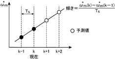
図11は、前記電動機駆動制御システムの第1変形形態を説明するための図である。図11の横軸は、前記所定の制御周期で繰り返し制御される制御回数を示し、k番目が現在の制御回数である。図11の縦軸は、制御目標の回転速度ωm *である。黒丸(●)は、現在以前の実績値である制御目標の回転速度ωm *を示し(ここではk番目および(k−1)番目の各制御における制御目標の各回転速度ωm *(k)、ωm *(k−1))、白丸(○)は、将来における制御目標の各回転速度ωm *を示す(ここでは(k+1)番目および(k+2)番目の各制御における制御目標の各回転速度ωm *(k+1)、ωm *(k+2))。 FIG. 11 is a diagram for explaining a first modification of the electric motor drive control system. The horizontal axis in FIG. 11 indicates the number of times of control that is repeatedly controlled in the predetermined control cycle, and the kth is the current number of times of control. The vertical axis in FIG. 11 is the rotational speed ω m * of the control target. A black circle (●) indicates the rotational speed ω m * of the control target that is the actual value before the present (here, each rotational speed ω m * (k of the control target in each of the k-th and (k−1) -th controls). ), Ω m * (k−1)), and white circles (◯) indicate the respective rotational speeds ω m * of the control target in the future (here, the control target in the (k + 1) th and (k + 2) th control). Each rotational speed ω m * (k + 1), ω m * (k + 2)).
この制御目標予測部16では、現在以前の実績値である制御目標の回転速度ωm *(k)、ωm *(k−1)、・・・は、将来の制御目標の回転速度ωm *を演算するために必要なデータ分だけ少なくとも記憶される。そして、制御目標予測部16は、現在以前の実績値である制御目標の回転速度ωm *(k)、ωm *(k−1)、・・・から、1制御回数当たりの、制御目標の回転速度ωm *における変化量を求め、この求めた変化量だけ制御目標の回転速度ωm *を変化させることで、将来における制御目標の各回転速度ωm *を求める。より具体的には、例えば、図11に示すように、現在以前の実績値における変化量は、一定値であり、将来もこの一定値で、将来における制御目標の各回転速度ωm *も変化する場合、制御目標予測部16は、次式12によって将来における制御目標の各回転速度ωm *を求める。
In the control
電圧パターン選択部14は、上述のように式11の評価式gを用いて評価する場合、前記式12で求めたωm *を用いる。
As described above, the voltage
あるいは、例えば、制御目標予測部16は、現在以前の実績値を外挿することによって将来の制御目標の回転速度を予測するものである(第2変形形態)。より具体的には、制御目標予測部16は、例えば、次式13で示すラグランジュ外挿を用いることによって、将来における制御目標の各回転速度ωm *を求める。
Alternatively, for example, the control
ここで、Nは、次数を示す。例えば、次数が2であり、2制御周期先まで予測する場合、前記式13を用いることによって、次式14−1、14−2のように、(k+1)番目および(k+2)番目における制御目標の各回転速度ωm *(k+1)、ωm *(k+2)が求められる。なお、次数Nは、2に限定されるものではなく、前記CPUの演算能力に応じて適宜に設定されてよい。
Here, N indicates the order. For example, when the order is 2 and the prediction is performed up to two control cycles ahead, by using the
電圧パターン選択部14は、上述のように式11の評価式gを用いて評価する場合、前記式13で求めたωm *を用いる。
When the voltage
本発明を表現するために、上述において図面を参照しながら実施形態を通して本発明を適切且つ十分に説明したが、当業者であれば上述の実施形態を変更および/または改良することは容易に為し得ることであると認識すべきである。したがって、当業者が実施する変更形態または改良形態が、請求の範囲に記載された請求項の権利範囲を離脱するレベルのものでない限り、当該変更形態または当該改良形態は、当該請求項の権利範囲に包括されると解釈される。 In order to express the present invention, the present invention has been properly and fully described through the embodiments with reference to the drawings. However, those skilled in the art can easily change and / or improve the above-described embodiments. It should be recognized that this is possible. Therefore, unless the modifications or improvements implemented by those skilled in the art are at a level that departs from the scope of the claims recited in the claims, the modifications or improvements are not limited to the scope of the claims. To be construed as inclusive.
S 電動機駆動制御システム
M 電動機
IV インバータ回路
MC モデル予測制御部
CS 電流測定部
VS 回転角度測定部
CV 3相2相変換部
TE 負荷トルク推定部
RSC 回転速度処理部
11 制御部
12 電圧パターン生成部
13 速度予測部
14 電圧パターン選択部
15 インバータ制御部
31 減算部
32 ローパスフィルタ部
33 パラメータ演算部
34 ゲイン演算部
S motor drive control system M motor IV inverter circuit MC model prediction control unit CS current measurement unit VS rotation angle measurement unit CV three-phase two-phase conversion unit TE load torque estimation unit RSC rotation
Claims (8)
前記電動機に働く負荷トルクを推定する負荷トルク推定部と、
前記インバータ回路で出力可能な時系列な電圧パターンを、互いに異なるように複数、生成する電圧パターン生成部と、
前記電圧パターン生成部で生成された複数の時系列な電圧パターンそれぞれについて、前記負荷トルク推定部で推定された負荷トルクが前記電動機に働いている場合であって、当該時系列な電圧パターンが前記電動機に入力された場合における前記電動機の回転速度を回転速度予測値として予測する速度予測部と、
前記電圧パターン生成部で生成された複数の時系列な電圧パターンの中から、前記速度予測部で予測された前記電動機の各回転速度予測値の中で最も高い評価の回転速度予測値に対応する時系列な電圧パターンを選択する電圧パターン選択部と、
前記電圧パターン選択部で選択された時系列な電圧パターンに基づいて、前記インバータ回路を制御するインバータ制御部とを備え、
前記負荷トルク推定部は、前記速度予測部で過去に予測された現在の回転速度予測値に基づいて前記負荷トルクを推定する、
電動機駆動制御装置。 An electric motor drive control device for controlling an electric motor driven by an output of an inverter circuit,
A load torque estimating unit for estimating a load torque acting on the electric motor;
A voltage pattern generation unit that generates a plurality of time-series voltage patterns that can be output by the inverter circuit so as to be different from each other,
For each of a plurality of time-series voltage patterns generated by the voltage pattern generation unit, the load torque estimated by the load torque estimation unit is acting on the motor, and the time-series voltage pattern is the A speed prediction unit that predicts the rotational speed of the motor when input to the motor as a rotational speed prediction value;
Corresponds to the highest estimated rotational speed predicted value among the predicted rotational speed values of the electric motor predicted by the speed predicting unit from among a plurality of time-series voltage patterns generated by the voltage pattern generating unit. A voltage pattern selection unit for selecting a time-series voltage pattern;
An inverter control unit that controls the inverter circuit based on the time-series voltage pattern selected by the voltage pattern selection unit;
The load torque estimation unit estimates the load torque based on a current rotation speed prediction value predicted in the past by the speed prediction unit,
Electric motor drive control device.
前記負荷トルク推定部は、前記速度予測部で過去に予測された現在の回転速度予測値と前記速度出力部で求めた回転速度現在値との差分に、所定の係数を乗じた差分乗算値を、制御周期ごとに積算することで前記負荷トルクを推定する、
請求項1に記載の電動機駆動制御装置。 A speed output unit for obtaining the rotation speed of the electric motor as a rotation speed current value;
The load torque estimating unit is configured to multiply a difference between a current rotational speed predicted value predicted in the past by the speed predicting unit and a current rotational speed value obtained by the speed output unit by a difference multiplied value by a predetermined coefficient. The load torque is estimated by integrating every control cycle.
The electric motor drive control device according to claim 1.
請求項2に記載の電動機駆動制御装置。 A coefficient setting unit that sets the predetermined coefficient within a range in which a transfer function that receives the load torque as an input and outputs an estimation error of the speed prediction unit satisfies stability;
The electric motor drive control device according to claim 2.
現在以前の実績値に基づいて将来の制御目標の回転速度を予測する制御目標予測部をさらに備える、
請求項1ないし請求項3のいずれか1項に記載の電動機駆動制御装置。 The voltage pattern selection unit performs the evaluation by using an evaluation function including a rotation speed of a control target,
A control target prediction unit that predicts the rotational speed of the future control target based on the past actual value;
The electric motor drive control device according to any one of claims 1 to 3.
請求項4に記載の電動機駆動制御装置。 The control target prediction unit predicts the rotational speed of the future control target based on the amount of change in the previous actual value,
The electric motor drive control device according to claim 4.
請求項4に記載の電動機駆動制御装置。 The control target prediction unit predicts the rotational speed of the future control target by extrapolating the previous actual value.
The electric motor drive control device according to claim 4.
前記電動機に働く負荷トルクを推定する負荷トルク推定工程と、
前記インバータ回路で出力可能な時系列な電圧パターンを、互いに異なるように複数、生成する電圧パターン生成工程と、
前記電圧パターン生成工程で生成された複数の時系列な電圧パターンそれぞれについて、前記負荷トルク推定工程で推定された負荷トルクが前記電動機に働いている場合であって、当該時系列な電圧パターンが前記電動機に入力された場合における前記電動機の回転速度を回転速度予測値として予測する速度予測工程と、
前記電圧パターン生成工程で生成された複数の時系列な電圧パターンの中から、前記速度予測工程で予測された前記電動機の各回転速度予測値の中で最も高い評価の回転速度予測値に対応する時系列な電圧パターンを選択する電圧パターン選択工程と、
前記電圧パターン選択工程で選択された時系列な電圧パターンに基づいて、前記インバータ回路を制御するインバータ制御工程とを備え、
前記負荷トルク推定工程は、前記速度予測工程で過去に予測された現在の回転速度予測値に基づいて前記負荷トルクを推定する、
電動機駆動制御方法。 An electric motor drive control method for controlling an electric motor driven by an output of an inverter circuit,
A load torque estimating step of estimating a load torque acting on the electric motor;
A voltage pattern generation step of generating a plurality of time-series voltage patterns that can be output by the inverter circuit so as to be different from each other;
For each of a plurality of time-series voltage patterns generated in the voltage pattern generation step, the load torque estimated in the load torque estimation step is acting on the motor, and the time-series voltage pattern is the A speed prediction step of predicting the rotation speed of the motor when input to the motor as a rotation speed prediction value;
Corresponds to the highest predicted rotational speed predicted value among the predicted rotational speed values of the electric motor predicted in the speed predicting step from among a plurality of time-series voltage patterns generated in the voltage pattern generating step. A voltage pattern selection step for selecting a time-series voltage pattern; and
An inverter control step for controlling the inverter circuit based on the time-series voltage pattern selected in the voltage pattern selection step;
The load torque estimating step estimates the load torque based on a current rotation speed prediction value predicted in the past in the speed prediction step.
Electric motor drive control method.
前記電動機を駆動するインバータ回路と、
前記インバータ回路を制御することで前記電動機を制御する電動機駆動制御部とを備え、
前記電動機駆動制御部は、請求項1ないし請求項6のいずれか1項に記載の電動機駆動制御装置である、
電動機駆動制御システム。 An electric motor,
An inverter circuit for driving the electric motor;
An electric motor drive control unit for controlling the electric motor by controlling the inverter circuit,
The motor drive control unit is the motor drive control device according to any one of claims 1 to 6.
Electric motor drive control system.
Applications Claiming Priority (2)
| Application Number | Priority Date | Filing Date | Title |
|---|---|---|---|
| JP2018098626 | 2018-05-23 | ||
| JP2018098626 | 2018-05-23 |
Publications (2)
| Publication Number | Publication Date |
|---|---|
| JP2019208352A true JP2019208352A (en) | 2019-12-05 |
| JP7130595B2 JP7130595B2 (en) | 2022-09-05 |
Family
ID=68767895
Family Applications (1)
| Application Number | Title | Priority Date | Filing Date |
|---|---|---|---|
| JP2019090434A Active JP7130595B2 (en) | 2018-05-23 | 2019-05-13 | MOTOR DRIVE CONTROL APPARATUS AND METHOD, AND MOTOR DRIVE CONTROL SYSTEM |
Country Status (1)
| Country | Link |
|---|---|
| JP (1) | JP7130595B2 (en) |
Cited By (5)
| Publication number | Priority date | Publication date | Assignee | Title |
|---|---|---|---|---|
| CN111092583A (en) * | 2019-12-24 | 2020-05-01 | 南京航空航天大学 | Current loop delay compensation method for three-phase permanent magnet synchronous motor driving system |
| CN111162714A (en) * | 2020-01-03 | 2020-05-15 | 湖南大学 | Multiphase energy storage permanent magnet motor robust prediction torque control method, system and medium considering parameter mismatch |
| CN111193386A (en) * | 2020-02-17 | 2020-05-22 | 南京邮电大学 | Model prediction control method for feedback compensation parameter self-adaption of full-bridge converter |
| CN111969916A (en) * | 2020-09-01 | 2020-11-20 | 南通大学 | Multi-current-difference-updating model-free prediction current control method for permanent magnet synchronous motor |
| CN112671285A (en) * | 2020-11-17 | 2021-04-16 | 珠海格力电器股份有限公司 | Air conditioner, system motor, drive control method, control system and storage medium |
Citations (6)
| Publication number | Priority date | Publication date | Assignee | Title |
|---|---|---|---|---|
| JP2005168115A (en) * | 2003-12-01 | 2005-06-23 | Nissan Motor Co Ltd | Controller for motor for vehicle |
| JP2008228419A (en) * | 2007-03-12 | 2008-09-25 | Mie Univ | Torque control method of motor based on model prediction control |
| JP2009181392A (en) * | 2008-01-31 | 2009-08-13 | Omron Corp | Model prediction control method and model prediction control device |
| JP2012253943A (en) * | 2011-06-03 | 2012-12-20 | Denso Corp | Rotary machine controller |
| JP2015223023A (en) * | 2014-05-22 | 2015-12-10 | 株式会社デンソー | Controller of synchronous motor |
| WO2017126095A1 (en) * | 2016-01-22 | 2017-07-27 | 東芝三菱電機産業システム株式会社 | Speed control device for electric motor |
-
2019
- 2019-05-13 JP JP2019090434A patent/JP7130595B2/en active Active
Patent Citations (6)
| Publication number | Priority date | Publication date | Assignee | Title |
|---|---|---|---|---|
| JP2005168115A (en) * | 2003-12-01 | 2005-06-23 | Nissan Motor Co Ltd | Controller for motor for vehicle |
| JP2008228419A (en) * | 2007-03-12 | 2008-09-25 | Mie Univ | Torque control method of motor based on model prediction control |
| JP2009181392A (en) * | 2008-01-31 | 2009-08-13 | Omron Corp | Model prediction control method and model prediction control device |
| JP2012253943A (en) * | 2011-06-03 | 2012-12-20 | Denso Corp | Rotary machine controller |
| JP2015223023A (en) * | 2014-05-22 | 2015-12-10 | 株式会社デンソー | Controller of synchronous motor |
| WO2017126095A1 (en) * | 2016-01-22 | 2017-07-27 | 東芝三菱電機産業システム株式会社 | Speed control device for electric motor |
Cited By (6)
| Publication number | Priority date | Publication date | Assignee | Title |
|---|---|---|---|---|
| CN111092583A (en) * | 2019-12-24 | 2020-05-01 | 南京航空航天大学 | Current loop delay compensation method for three-phase permanent magnet synchronous motor driving system |
| CN111162714A (en) * | 2020-01-03 | 2020-05-15 | 湖南大学 | Multiphase energy storage permanent magnet motor robust prediction torque control method, system and medium considering parameter mismatch |
| CN111193386A (en) * | 2020-02-17 | 2020-05-22 | 南京邮电大学 | Model prediction control method for feedback compensation parameter self-adaption of full-bridge converter |
| CN111969916A (en) * | 2020-09-01 | 2020-11-20 | 南通大学 | Multi-current-difference-updating model-free prediction current control method for permanent magnet synchronous motor |
| CN112671285A (en) * | 2020-11-17 | 2021-04-16 | 珠海格力电器股份有限公司 | Air conditioner, system motor, drive control method, control system and storage medium |
| CN112671285B (en) * | 2020-11-17 | 2024-01-23 | 珠海格力电器股份有限公司 | Air conditioner, system motor, driving control method, control system and storage medium |
Also Published As
| Publication number | Publication date |
|---|---|
| JP7130595B2 (en) | 2022-09-05 |
Similar Documents
| Publication | Publication Date | Title |
|---|---|---|
| JP7130595B2 (en) | MOTOR DRIVE CONTROL APPARATUS AND METHOD, AND MOTOR DRIVE CONTROL SYSTEM | |
| US6462491B1 (en) | Position sensorless motor control apparatus | |
| JP5982901B2 (en) | Electric motor control device and electric motor control method | |
| US9912275B2 (en) | Normalization of motor phase measurements | |
| US20070296371A1 (en) | Position sensorless control apparatus for synchronous motor | |
| JP2007060897A (en) | Self-tuning method and device of permanent magnet sensorless control | |
| JP6867267B2 (en) | Motor controller and motor system | |
| EP2258043B1 (en) | Sensorless control of salient-pole machines | |
| JP2006054995A (en) | Drive control device and method for ac motor | |
| US20160294314A1 (en) | Fractional Delay Adjustment in a Field-Oriented Control Architecture | |
| US10644627B2 (en) | Control device of synchronous electric motor, integrated motor system, pump system, and positioning system | |
| Derammelaere et al. | Load angle estimation for two‐phase hybrid stepping motors | |
| JP6658023B2 (en) | Automatic current command table generation system and current command table automatic generation method for embedded magnet synchronous motor | |
| Guven et al. | An improved sensorless DTC-SVM for three-level inverter-fed permanent magnet synchronous motor drive | |
| JP5733404B2 (en) | PM motor position sensorless control device | |
| JP2009290962A (en) | Controller of permanent magnet type synchronous motor | |
| JP2010035351A (en) | Device for estimating rotor position of synchronous electric motor | |
| Alex et al. | An efficient position tracking smoothing algorithm for sensorless operation of brushless DC motor drives | |
| JP2021118672A (en) | Motor drive device, adjustment device, and electric washing machine | |
| JPH11262286A (en) | Controller of permanent magnet synchronous motor | |
| JP5186352B2 (en) | Electric motor magnetic pole position estimation device | |
| Terorde et al. | Speed, flux and torque estimation of induction motor drives with adaptive system model | |
| JP2010028981A (en) | Rotor position estimating method for synchronous motor, and controller for the synchronous motor | |
| JP2021005943A (en) | Position determination device | |
| JP2007082380A (en) | Synchronous motor control device |
Legal Events
| Date | Code | Title | Description |
|---|---|---|---|
| A621 | Written request for application examination |
Free format text: JAPANESE INTERMEDIATE CODE: A621 Effective date: 20211026 |
|
| A977 | Report on retrieval |
Free format text: JAPANESE INTERMEDIATE CODE: A971007 Effective date: 20220817 |
|
| TRDD | Decision of grant or rejection written | ||
| A01 | Written decision to grant a patent or to grant a registration (utility model) |
Free format text: JAPANESE INTERMEDIATE CODE: A01 Effective date: 20220823 |
|
| A61 | First payment of annual fees (during grant procedure) |
Free format text: JAPANESE INTERMEDIATE CODE: A61 Effective date: 20220824 |
|
| R150 | Certificate of patent or registration of utility model |
Ref document number: 7130595 Country of ref document: JP Free format text: JAPANESE INTERMEDIATE CODE: R150 |