JP2019201735A - Game machine - Google Patents
Game machine Download PDFInfo
- Publication number
- JP2019201735A JP2019201735A JP2018097391A JP2018097391A JP2019201735A JP 2019201735 A JP2019201735 A JP 2019201735A JP 2018097391 A JP2018097391 A JP 2018097391A JP 2018097391 A JP2018097391 A JP 2018097391A JP 2019201735 A JP2019201735 A JP 2019201735A
- Authority
- JP
- Japan
- Prior art keywords
- effect
- game
- image
- component
- big hit
- Prior art date
- Legal status (The legal status is an assumption and is not a legal conclusion. Google has not performed a legal analysis and makes no representation as to the accuracy of the status listed.)
- Pending
Links
Images


Abstract
Description
本発明は、遊技が可能な遊技機に関する。 The present invention relates to a gaming machine capable of playing games.
遊技機の一例として、遊技領域に遊技球を発射することで遊技が可能なパチンコ遊技機等がある。 As an example of a gaming machine, there is a pachinko gaming machine or the like capable of playing a game by firing a gaming ball in a gaming area.
この種の遊技機として、例えば、遊技領域を流下する流下経路として第1経路と該第1経路とは異なる第2経路とを有し、大当り遊技状態の終了後に、遊技球が第2経路を流下することで第1経路を流下するよりも有利となる有利状態(時短状態など)に制御されるものにおいて、有利状態が開始される前に、第2経路を遊技球が流下するように遊技球を発射することを促す促進演出(右打ち報知)が可能なもの等があった(例えば、特許文献1参照)。 As this type of gaming machine, for example, there are a first route and a second route that is different from the first route as a flow-down route that flows down the game area, and after the big hit gaming state, the game ball passes through the second route. In the case where the current state is controlled to be in an advantageous state (such as a short time state) that is more advantageous than flowing down the first path, the game ball is caused to flow down the second path before the advantageous state is started. Some of them have a promotion effect (right-handed notification) that prompts them to fire a ball (see, for example, Patent Document 1).
上記特許文献1に記載の遊技機では、促進演出において第2経路を遊技球が流下するように遊技球を発射することを促すだけで演出が単調であるため、興趣を向上させることができないという問題があった。
In the gaming machine described in the above-mentioned
本発明は、このような問題点に着目してなされたもので、興趣を向上させることができる遊技機を提供することを目的とする。 The present invention has been made paying attention to such problems, and an object thereof is to provide a gaming machine capable of improving the interest.
手段1の遊技機は、
遊技領域(例えば、遊技領域Y)に遊技媒体(例えば、遊技球)を発射することにより遊技が可能な遊技機(例えば、パチンコ遊技機1)であって、
遊技媒体の発射操作を行うための発射操作部(例えば、打球操作ハンドル30)と、
前記遊技領域に発射された遊技媒体が流下可能な第1経路(例えば、第1経路K1)及び該第1経路とは異なる第2経路(例えば、第2経路K2)と、
前記第2経路を遊技媒体が流下するように遊技媒体の発射操作を促す促進演出を実行可能な促進演出実行手段(例えば、演出制御用CPU120が、大当りの開始時に発射操作促進演出Aを実行可能な部分)と、
を備え、
前記発射操作部は、第1部品(例えば、部品B1)及び第2部品(例えば、部品B4)を含む複数の部品(例えば、部品B1〜B4)にて構成され、
前記促進演出実行手段は、前記促進演出において、前記第1部品に関連する第1部品画像(例えば、部品画像ZB1)と前記第2部品に関連する第2部品画像(例えば、部品画像ZB4)とを表示するとともに、前記第1部品画像と前記第2部品画像との少なくとも一部を用いた特定部品画像(例えば、完成画像ZB5など)を表示可能である(例えば、演出制御用CPU120が、ハンドル組立演出において、部品画像ZB1〜ZB4を組付ける態様にて表示することで、最終的に全ての部品画像ZB1〜ZB4が用いられた打球操作ハンドル30の完成画像ZB5を表示可能な部分。図8−16(A)〜(E)参照)
ことを特徴としている。
この特徴によれば、発射操作部に好適に注目させることができるため、興趣を向上させることができる。
The gaming machine of
A gaming machine (for example, a pachinko gaming machine 1) capable of playing a game by launching a game medium (for example, a game ball) in a game area (for example, a game area Y),
A launch operation unit (e.g., a hitting operation handle 30) for launching a game medium;
A first path (for example, the first path K1) through which the game medium launched in the gaming area can flow down, and a second path (for example, the second path K2) different from the first path;
Promotion effect execution means capable of executing a promotion effect that prompts the launch operation of the game medium so that the game medium flows down the second path (for example, the
With
The firing operation unit includes a plurality of parts (for example, parts B1 to B4) including a first part (for example, part B1) and a second part (for example, part B4).
The promotion effect executing means includes a first component image (for example, component image ZB1) related to the first component and a second component image (for example, component image ZB4) related to the second component in the promotion effect. And a specific component image (for example, a completed image ZB5) using at least a part of the first component image and the second component image can be displayed (for example, the
It is characterized by that.
According to this feature, it is possible to appropriately focus on the launch operation unit, so that interest can be improved.
手段2の遊技機は、
遊技領域(例えば、遊技領域Y)に遊技媒体(例えば、遊技球)を発射することにより遊技が可能な遊技機(例えば、パチンコ遊技機1)であって、
遊技媒体の発射操作を行うための発射操作部(例えば、打球操作ハンドル30)と、
前記遊技領域に発射された遊技媒体が流下可能な第1経路(例えば、第1経路K1)及び該第1経路とは異なる第2経路(例えば、第2経路K2)と、
前記第2経路を遊技媒体が流下するように遊技媒体の発射操作を促す促進演出を実行可能な促進演出実行手段(例えば、演出制御用CPU120が、大当りの開始時に発射操作促進演出Aを実行可能な部分)と、
を備え、
前記発射操作部は、第1部品(例えば、部品B1)及び第2部品(例えば、部品B4)を含む複数の部品(例えば、部品B1〜B4)にて構成され、
前記促進演出実行手段は、前記促進演出において、前記第1部品に関連する第1部品画像と前記第2部品に関連する第2部品画像とを順に表示可能である(例えば、演出制御用CPU120が、ハンドル組立演出において、部品画像ZB1〜ZB4を順次組付ける態様にて表示する部分。図8−16(A)〜(E)参照)
ことを特徴としている。
この特徴によれば、発射操作部に好適に注目させることができるため、興趣を向上させることができる。
The gaming machine of
A gaming machine (for example, a pachinko gaming machine 1) capable of playing a game by launching a game medium (for example, a game ball) in a game area (for example, a game area Y),
A launch operation unit (e.g., a hitting operation handle 30) for launching a game medium;
A first path (for example, the first path K1) through which the game medium launched in the gaming area can flow down, and a second path (for example, the second path K2) different from the first path;
Promotion effect execution means capable of executing a promotion effect that prompts the launch operation of the game medium so that the game medium flows down the second path (for example, the
With
The firing operation unit includes a plurality of parts (for example, parts B1 to B4) including a first part (for example, part B1) and a second part (for example, part B4).
In the promotion effect, the promotion effect execution means can sequentially display a first component image related to the first component and a second component image related to the second component (for example, the
It is characterized by that.
According to this feature, it is possible to appropriately focus on the launch operation unit, so that interest can be improved.
手段3の遊技機は、手段1または2に記載の遊技機であって、
前記複数の部品は第3部品(例えば、ハンドルベース720が有する配線CやコネクタCN及びタッチリング728、ハンドルセンサ(図示略)、単発スイッチ725等の電子部品)を含み、
前記促進演出実行手段は、前記促進演出において、前記第3部品に関連する第3部品画像を表示しない(例えば、演出制御用CPU120が、ハンドル組立演出において、部品B1(ハンドルベース720)に対応する部品画像ZB1は、実際のハンドルベース720が有する配線CやコネクタCN及びタッチリング728、ハンドルセンサ(図示略)、単発スイッチ725等の電子部品に対応する電子部品画像の表示を省略している(表示しない)部分。)
ことを特徴としている。
この特徴によれば、第1部品や第2部品の見栄えが第3部品により損なわれることを抑制できる。
The gaming machine of
The plurality of parts include third parts (for example, wiring C and connector CN and
The promotion effect execution means does not display the third part image related to the third component in the promotion effect (for example, the
It is characterized by that.
According to this feature, it is possible to suppress the appearance of the first component and the second component from being damaged by the third component.
手段4の遊技機は、手段1〜3のいずれかに記載の遊技機であって、
前記第2部品(例えば、部品B4)は、前記第1部品(例えば、部品B1)よりも特徴的な部品であり、
前記促進演出実行手段は、前記促進演出において、前記第2部品画像を前記第1部品画像よりも後に表示する(例えば、演出制御用CPU120が、ハンドル組立演出において、部品B1〜B3よりも特徴的な部品B4に対応する部品画像ZB4を、部品画像ZB1〜ZB3よりも後に組付ける態様にて表示する部分。)
ことを特徴としている。
この特徴によれば、インパクトを与え、演出効果を高めることができる。
The gaming machine of
The second part (for example, part B4) is a characteristic part than the first part (for example, part B1),
The promotion effect execution means displays the second part image after the first component image in the promotion effect (for example, the
It is characterized by that.
According to this characteristic, an impact can be given and the production effect can be enhanced.
手段5の遊技機は、手段1〜4のいずれかに記載の遊技機であって、
前記遊技機(例えば、パチンコ遊技機1)は、機種固有の機種固有部(例えば、当該パチンコ遊技機1に固有(特有)の遊技情報(例えば、賞球数、大当り確率、機種名(タイトル名)など)が表示される遊技情報表示部、障害釘や風車等の障害物、演出用の可動体、装飾部など)を有し、
前記促進演出実行手段は、前記促進演出において、前記遊技領域に関連する遊技領域画像を表示する場合があり、該遊技領域画像を表示する場合において、前記機種固有部の少なくとも一部を省略して表示する(例えば、演出制御用CPU120が、遊技盤2に対応する遊技盤画像Z20や、ガラス扉枠を含む遊技機用枠3に対応する扉枠画像Z16などを経路組立演出やハンドル組立演出において表示する場合、機種固有部の少なくとも一部を省略して表示する部分。)
ことを特徴としている。
この特徴によれば、複数種類の機種間で同じ促進演出を実行可能となる。
The gaming machine of
The gaming machine (for example, pachinko gaming machine 1) is a model-specific part (for example, game information unique (specific) to the pachinko gaming machine 1 (for example, number of winning balls, jackpot probability, model name (title name)). ) Etc.) are displayed, obstructions such as obstacle nails and windmills, movable bodies for production, decoration parts, etc.)
The promotion effect executing means may display a game area image related to the game area in the promotion effect, and when displaying the game area image, omit at least a part of the model specific part. (For example, the
It is characterized by that.
According to this feature, the same promotion effect can be executed among a plurality of types of models.
手段6の遊技機は、手段1〜5のいずれかに記載の遊技機であって、
前記第1経路を遊技媒体が流下するように遊技媒体を発射することを促す特別促進演出を実行可能であり(例えば、演出制御用CPU120が、時短状態が終了したことに基づいて、左打ち報知を実行可能な部分。図8−15(F)参照)、
前記特別促進演出において前記第1部品画像と前記第2部品画像とを表示しない(例えば、演出制御用CPU120が、時短状態が終了したことに基づいて左打ち報知(左打ち操作促進演出)を実行する前に、ハンドル組立演出を実行しない部分。図8−15(F)参照)
ことを特徴としている。
この特徴によれば、煩わしくなることを抑制できる。
The gaming machine of
It is possible to execute a special promotion effect that prompts the game medium to flow so that the game medium flows down the first route (for example, the
The first part image and the second part image are not displayed in the special promotion effect (for example, the
It is characterized by that.
According to this characteristic, it can suppress becoming troublesome.
手段7の遊技機は、手段1〜6のいずれかに記載の遊技機であって、
前記促進演出実行手段は、前記促進演出において、前記第1部品画像と前記第2部品画像とを組付ける態様にて表示する(例えば、演出制御用CPU120が、打球操作ハンドル30を構成する複数の部品のうち4つの部品B1〜B4各々に対応する部品画像ZB1〜ZB4を組付ける態様にて表示するハンドル組立演出を実行可能な部分。)
ことを特徴としている。
この特徴によれば、興趣を向上させることができる。
The gaming machine of
The promotion effect executing means displays the first component image and the second component image in the promotion effect in a manner of assembling (for example, the
It is characterized by that.
According to this feature, interest can be improved.
手段8の遊技機は、手段7に記載の遊技機であって、
前記遊技機の製造工程において、前記第1部品と前記第2部品とは所定手順により他の部品に組付けられるものであって、
前記促進演出実行手段は、前記促進演出において、前記第1部品画像と前記第2部品画像とを前記所定手順とは異なる手順で組付ける態様にて表示する(例えば、ハンドル組立演出における部品画像ZB1〜ZB4の組付け順序は、遊技者に対し打球操作ハンドル30が組立てられていくことを分かりやすく演出表示するために、いずれも図8−3にて説明した製造工程における実際の組付順序とは異なる順序とされている。)
ことを特徴としている。
この特徴によれば、演出効果を高めることができる。
The gaming machine of
In the manufacturing process of the gaming machine, the first part and the second part are assembled to other parts by a predetermined procedure,
The promotion effect execution means displays the first component image and the second component image in a manner different from the predetermined procedure in the promotion effect (for example, the component image ZB1 in the handle assembly effect). The assembly order of ZB4 is the actual assembly order in the manufacturing process described with reference to FIG. 8-3, in order to provide an easy-to-understand indication that the hitting operation handle 30 is assembled to the player. Are in a different order.)
It is characterized by that.
According to this feature, the production effect can be enhanced.
手段9の遊技機は、手段7または8に記載の遊技機であって、
前記促進演出実行手段は、前記促進演出において、前記第1部品画像と前記第2部品画像とを組付ける態様にて表示した後、前記発射操作部に対応する操作部品画像を遊技媒体を発射させる態様にて表示可能である(例えば、演出制御用CPU120が、ハンドル組立演出や経路組立演出を行った後、図8−16(F)や図8−18(L)に示すように打球操作ハンドル30を右方向に回転操作することを示すハンドル画像Z17や右矢印画像Z18を表示することで右打ち報知(右打ち操作促進演出)を行う部分。)
ことを特徴としている。
この特徴によれば、演出効果を高めることができる。
The gaming machine of
The promotion effect executing means causes the operation component image corresponding to the launch operation unit to fire a game medium after displaying the first component image and the second component image in a manner of assembling in the promotion effect. (For example, after the
It is characterized by that.
According to this feature, the production effect can be enhanced.
尚、本発明は、本発明の請求項に記載された発明特定事項のみを有するものであっても良いし、本発明の請求項に記載された発明特定事項とともに該発明特定事項以外の構成を有するものであっても良い。 In addition, this invention may have only the invention specific matter described in the claim of this invention, and the structure other than this invention specific matter is included with the invention specific matter described in the claim of this invention. You may have.
(基本説明)
まず、パチンコ遊技機1の基本的な構成及び制御(一般的なパチンコ遊技機の構成及び制御でもある。)について説明する。
(Basic explanation)
First, a basic configuration and control of the pachinko gaming machine 1 (which is also a configuration and control of a general pachinko gaming machine) will be described.
(パチンコ遊技機1の構成等)
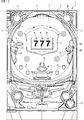
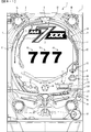
図1は、パチンコ遊技機1の正面図であり、主要部材の配置レイアウトを示す。パチンコ遊技機(遊技機)1は、大別して、遊技盤面を構成する遊技盤(ゲージ盤)2と、遊技盤2を支持固定する遊技機用枠(台枠)3とから構成されている。遊技盤2には、遊技領域が形成され、この遊技領域には、遊技媒体としての遊技球が、所定の打球発射装置から発射されて打込まれる。
(Configuration of pachinko machine 1)
FIG. 1 is a front view of a
遊技盤2の所定位置(図1に示す例では、遊技領域の右側方)には、複数種類の特別識別情報としての特別図柄(特図ともいう)の可変表示(特図ゲームともいう)を行う第1特別図柄表示装置4A及び第2特別図柄表示装置4Bが設けられている。これらは、それぞれ、7セグメントのLEDなどからなる。特別図柄は、「0」〜「9」を示す数字や「−」などの点灯パターンなどにより表される。特別図柄には、LEDを全て消灯したパターンが含まれてもよい。
In a predetermined position of the game board 2 (in the example shown in FIG. 1, to the right of the game area), a variable display (also called a special figure game) of special symbols (also called special figures) as a plurality of types of special identification information is provided. A first special
尚、特別図柄の「可変表示」とは、例えば、複数種類の特別図柄を変動可能に表示することである(後述の他の図柄についても同じ)。変動としては、複数の図柄の更新表示、複数の図柄のスクロール表示、1以上の図柄の変形、1以上の図柄の拡大/縮小などがある。特別図柄や後述の普通図柄の変動では、複数種類の特別図柄又は普通図柄が更新表示される。後述の飾り図柄の変動では、複数種類の飾り図柄がスクロール表示又は更新表示されたり、1以上の飾り図柄が変形や拡大/縮小されたりする。尚、変動には、ある図柄を点滅表示する態様も含まれる。可変表示の最後には、表示結果として所定の特別図柄が停止表示(導出又は導出表示などともいう)される(後述の他の図柄の可変表示についても同じ)。尚、可変表示を変動表示、変動と表現する場合がある。 The “variable display” of the special symbol is, for example, to display a plurality of special symbols in a variable manner (the same applies to other symbols described later). Examples of the fluctuation include an update display of a plurality of symbols, a scroll display of a plurality of symbols, deformation of one or more symbols, and enlargement / reduction of one or more symbols. In the case of a special symbol or a variation of a normal symbol described later, a plurality of types of special symbols or normal symbols are updated and displayed. In the variation of the decorative pattern described later, a plurality of types of decorative patterns are scroll-displayed or updated, or one or more decorative symbols are deformed or enlarged / reduced. Note that the variation includes a mode in which a certain symbol is blinked. At the end of the variable display, a predetermined special symbol is stopped as a display result (also referred to as derivation or derivation display) (the same applies to variable display of other symbols described later). Note that variable display may be expressed as variable display or fluctuation.
尚、第1特別図柄表示装置4Aにおいて可変表示される特別図柄を「第1特図」ともいい、第2特別図柄表示装置4Bにおいて可変表示される特別図柄を「第2特図」ともいう。また、第1特図を用いた特図ゲームを「第1特図ゲーム」といい、第2特図を用いた特図ゲームを「第2特図ゲーム」ともいう。尚、特別図柄の可変表示を行う特別図柄表示装置は1種類であってもよい。
The special symbol variably displayed on the first special
遊技盤2における遊技領域の中央付近には画像表示装置5が設けられている。画像表示装置5は、例えばLCD(液晶表示装置)や有機EL(Electro Luminescence)等から構成され、各種の演出画像を表示する。画像表示装置5は、プロジェクタ及びスクリーンから構成されていてもよい。画像表示装置5には、各種の演出画像が表示される。
An
例えば、画像表示装置5の画面上では、第1特図ゲームや第2特図ゲームと同期して、特別図柄とは異なる複数種類の装飾識別情報としての飾り図柄(数字などを示す図柄など)の可変表示が行われる。ここでは、第1特図ゲーム又は第2特図ゲームに同期して、「左」、「中」、「右」の各飾り図柄表示エリア5L、5C、5Rにおいて飾り図柄が可変表示(例えば上下方向のスクロール表示や更新表示)される。尚、同期して実行される特図ゲーム及び飾り図柄の可変表示を総称して単に可変表示ともいう。
For example, on the screen of the
画像表示装置5の画面上には、実行が保留されている可変表示に対応する保留表示や、実行中の可変表示に対応するアクティブ表示を表示するための表示エリアが設けられていてもよい。保留表示及びアクティブ表示を総称して可変表示に対応する可変表示対応表示ともいう。
On the screen of the
保留されている可変表示の数は保留記憶数ともいう。第1特図ゲームに対応する保留記憶数を第1保留記憶数、第2特図ゲームに対応する保留記憶数を第2保留記憶数ともいう。また、第1保留記憶数と第2保留記憶数との合計を合計保留記憶数ともいう。 The number of variable displays that are held is also called the number of stored memories. The number of reserved memories corresponding to the first special figure game is also referred to as a first reserved memory number, and the number of reserved memories corresponding to the second special figure game is also referred to as a second reserved memory number. The total of the first reserved memory number and the second reserved memory number is also referred to as the total reserved memory number.
また、遊技盤2の所定位置には、複数のLEDを含んで構成された第1保留表示器25Aと第2保留表示器25Bとが設けられ、第1保留表示器25Aは、LEDの点灯個数によって、第1保留記憶数を表示し、第2保留表示器25Bは、LEDの点灯個数によって、第2保留記憶数を表示する。
In addition, a
画像表示装置5の下方には、入賞球装置6Aと、可変入賞球装置6Bとが設けられている。
Below the
入賞球装置6Aは、例えば所定の玉受部材によって常に遊技球が進入可能な一定の開放状態に保たれる第1始動入賞口を形成する。第1始動入賞口に遊技球が進入したときには、所定個(例えば3個)の賞球が払い出されるとともに、第1特図ゲームが開始され得る。
The winning
可変入賞球装置6B(普通電動役物)は、ソレノイド81(図2参照)によって閉鎖状態と開放状態とに変化する第2始動入賞口を形成する。可変入賞球装置6Bは、例えば、一対の可動翼片を有する電動チューリップ型役物を備え、ソレノイド81がオフ状態であるときに可動翼片が垂直位置となることにより、当該可動翼片の先端が入賞球装置6Aに近接し、第2始動入賞口に遊技球が進入しない閉鎖状態になる(第2始動入賞口が閉鎖状態になるともいう。)。その一方で、可変入賞球装置6Bは、ソレノイド81がオン状態であるときに可動翼片が傾動位置となることにより、第2始動入賞口に遊技球が進入できる開放状態になる(第2始動入賞口が開放状態になるともいう。)。第2始動入賞口に遊技球が進入したときには、所定個(例えば3個)の賞球が払い出されるとともに、第2特図ゲームが開始され得る。尚、可変入賞球装置6Bは、閉鎖状態と開放状態とに変化するものであればよく、電動チューリップ型役物を備えるものに限定されない。
The variable winning
遊技盤2の所定位置(図1に示す例では、遊技領域の左右下方4箇所)には、所定の玉受部材によって常に一定の開放状態に保たれる一般入賞口10が設けられる。この場合には、一般入賞口10のいずれかに進入したときには、所定個数(例えば10個)の遊技球が賞球として払い出される。
At a predetermined position of the game board 2 (in the example shown in FIG. 1, four places in the lower left and right sides of the game area), there are provided general winning holes 10 that are always kept in a certain open state by a predetermined ball receiving member. In this case, when entering any of the general winning
入賞球装置6Aと可変入賞球装置6Bの下方には、大入賞口を有する特別可変入賞球装置7が設けられている。特別可変入賞球装置7は、ソレノイド82(図2参照)によって開閉駆動される大入賞口扉を備え、その大入賞口扉によって開放状態と閉鎖状態とに変化する特定領域としての大入賞口を形成する。
Below the winning
一例として、特別可変入賞球装置7では、大入賞口扉用(特別電動役物用)のソレノイド82がオフ状態であるときに大入賞口扉が大入賞口を閉鎖状態として、遊技球が大入賞口に進入(通過)できなくなる。その一方で、特別可変入賞球装置7では、大入賞口扉用のソレノイド82がオン状態であるときに大入賞口扉が大入賞口を開放状態として、遊技球が大入賞口に進入しやすくなる。
As an example, in the special variable winning
大入賞口に遊技球が進入したときには、所定個数(例えば14個)の遊技球が賞球として払い出される。大入賞口に遊技球が進入したときには、例えば第1始動入賞口や第2始動入賞口及び一般入賞口10に遊技球が進入したときよりも多くの賞球が払い出される。
When game balls enter the big prize opening, a predetermined number (for example, 14) of game balls are paid out as prize balls. When game balls enter the big prize opening, for example, more prize balls are paid out than when game balls enter the first start prize opening, the second start prize opening, and the
一般入賞口10を含む各入賞口に遊技球が進入することを「入賞」ともいう。特に、始動口(第1始動入賞口、第2始動入賞口始動口)への入賞を始動入賞ともいう。
The entry of a game ball into each winning opening including the general winning
遊技盤2の所定位置(図1に示す例では、遊技領域の左側方)には、普通図柄表示器20が設けられている。一例として、普通図柄表示器20は、7セグメントのLEDなどからなり、特別図柄とは異なる複数種類の普通識別情報としての普通図柄の可変表示を行う。普通図柄は、「0」〜「9」を示す数字や「−」などの点灯パターンなどにより表される。普通図柄には、LEDを全て消灯したパターンが含まれてもよい。このような普通図柄の可変表示は、普図ゲームともいう。
A
画像表示装置5の左方には、遊技球が通過可能な通過ゲート41が設けられている。遊技球が通過ゲート41を通過したことに基づき、普図ゲームが実行される。
On the left side of the
普通図柄表示器20の上方には、普図保留表示器25Cが設けられている。普図保留表示器25Cは、例えば4個のLEDを含んで構成され、実行が保留されている普図ゲームの数である普図保留記憶数をLEDの点灯個数により表示する。
Above the
遊技盤2の表面には、上記の構成以外にも、遊技球の流下方向や速度を変化させる風車及び多数の障害釘が設けられている。遊技領域の最下方には、いずれの入賞口にも進入しなかった遊技球が取り込まれるアウト口が設けられている。
In addition to the above-described configuration, the surface of the
遊技機用枠3の左右上部位置には、効果音等を再生出力するためのスピーカ8L、8Rが設けられており、さらに遊技領域周辺部には、遊技効果用の遊技効果ランプ9が設けられている。遊技効果ランプ9は、LEDを含んで構成されている。
遊技盤2の所定位置(図1では図示略)には、演出に応じて動作する可動体32が設けられている。
At a predetermined position (not shown in FIG. 1) of the
遊技機用枠3の右下部位置には、遊技球を打球発射装置により遊技領域に向けて発射するために遊技者等によって操作される打球操作ハンドル(操作ノブ)30が設けられている。
At the lower right position of the
遊技領域の下方における遊技機用枠3の所定位置には、賞球として払い出された遊技球や所定の球貸機により貸し出された遊技球を、打球発射装置へと供給可能に保持(貯留)する打球供給皿(上皿)が設けられている。上皿の下方には、上皿満タン時に賞球が払い出される打球供給皿(下皿)が設けられている。
At a predetermined position of the
遊技領域の下方における遊技機用枠3の所定位置には、遊技者が把持して傾倒操作が可能なスティックコントローラ31Aが取付けられている。スティックコントローラ31Aには、遊技者が押下操作可能なトリガボタンが設けられている。スティックコントローラ31Aに対する操作は、コントローラセンサユニット35A(図2参照)により検出される。
At a predetermined position of the
遊技領域の下方における遊技機用枠3の所定位置には、遊技者が押下操作などにより所定の指示操作を可能なプッシュボタン31Bが設けられている。プッシュボタン31Bに対する操作は、プッシュセンサ35B(図2参照)により検出される。
At a predetermined position of the
パチンコ遊技機1では、遊技者の動作(操作等)を検出する検出手段として、スティックコントローラ31Aやプッシュボタン31Bが設けられるが、これら以外の検出手段が設けられていてもよい。
In the
(遊技の進行の概略)
パチンコ遊技機1が備える打球操作ハンドル30への遊技者による回転操作により、遊技球が遊技領域に向けて発射される。遊技球が通過ゲート41を通過すると、普通図柄表示器20による普図ゲームが開始される。尚、前回の普図ゲームの実行中の期間等に遊技球が通過ゲート41を通過した場合(遊技球が通過ゲート41を通過したが当該通過に基づく普図ゲームを直ちに実行できない場合)には、当該通過に基づく普図ゲームは所定の上限数(例えば4)まで保留される。
(Outline of game progress)
A game ball is launched toward the game area by a rotation operation by the player to the hitting operation handle 30 provided in the
この普図ゲームでは、特定の普通図柄(普図当り図柄)が停止表示されれば、普通図柄の表示結果が「普図当り」となる。その一方、確定普通図柄として、普図当り図柄以外の普通図柄(普図ハズレ図柄)が停止表示されれば、普通図柄の表示結果が「普図ハズレ」となる。「普図当り」となると、可変入賞球装置6Bを所定期間開放状態とする開放制御が行われる(第2始動入賞口が開放状態になる)。
In this ordinary game, if a specific ordinary symbol (a symbol per ordinary symbol) is stopped and displayed, the display result of the ordinary symbol becomes “per ordinary symbol”. On the other hand, if a normal symbol other than the symbols per ordinary symbol (ordinary symbol losing symbol) is stopped and displayed as the fixed ordinary symbol, the display result of the ordinary symbol becomes “ordinary symbol losing”. When the “normal hit” is reached, an opening control is performed to open the variable winning
入賞球装置6Aに形成された第1始動入賞口に遊技球が進入すると、第1特別図柄表示装置4Aによる第1特図ゲームが開始される。
When a game ball enters the first start winning opening formed in the winning
可変入賞球装置6Bに形成された第2始動入賞口に遊技球が進入すると、第2特別図柄表示装置4Bによる第2特図ゲームが開始される。
When the game ball enters the second start winning opening formed in the variable winning
尚、特図ゲームの実行中の期間や、後述する大当り遊技状態や小当り遊技状態に制御されている期間に、遊技球が始動入賞口へ進入(入賞)した場合(始動入賞が発生したが当該始動入賞に基づく特図ゲームを直ちに実行できない場合)には、当該進入に基づく特図ゲームは所定の上限数(例えば4)までその実行が保留される。 If a game ball enters (wins) a start winning opening during a period during which a special figure game is being executed, or a period where a big hit gaming state or a small hit gaming state, which will be described later, is controlled (a start winning has occurred) In the case where the special game based on the start prize cannot be immediately executed), the special game based on the entry is suspended until a predetermined upper limit number (for example, 4).
特図ゲームにおいて、確定特別図柄として特定の特別図柄(大当り図柄、例えば「7」、後述の大当り種別に応じて実際の図柄は異なる。)が停止表示されれば、「大当り」となり、大当り図柄とは異なる所定の特別図柄(小当り図柄、例えば「2」)が停止表示されれば、「小当り」となる。また、大当り図柄や小当り図柄とは異なる特別図柄(ハズレ図柄、例えば「−」)が停止表示されれば「ハズレ」となる。 In a special game, if a specific special symbol (a jackpot symbol, for example, “7”, the actual symbol differs depending on the jackpot type to be described later) is stopped and displayed as a special symbol, it will be a “hit” symbol. If a predetermined special symbol different from (a small hit symbol, for example, “2”) is stopped and displayed, “small hit” is obtained. In addition, if a special symbol (losing symbol, for example, “-”) different from the big hit symbol or the small winning symbol is stopped and displayed, it is “lost”.
特図ゲームでの表示結果が「大当り」になった後には、遊技者にとって有利な有利状態として大当り遊技状態に制御される。特図ゲームでの表示結果が「小当り」になった後には、小当り遊技状態に制御される。 After the display result in the special figure game becomes “big hit”, the big hit gaming state is controlled as an advantageous state advantageous to the player. After the display result in the special figure game becomes “small hit”, the game is controlled to the small hit gaming state.
大当り遊技状態においては、遊技者は、遊技球を大入賞口に進入させることで、賞球を得ることができる。従って、大当り遊技状態は、遊技者にとって有利な状態である。大当り遊技状態におけるラウンド数が多い程、また、開放上限期間が長い程遊技者にとって有利となる。 In the big hit game state, the player can obtain a prize ball by causing the game ball to enter the big prize opening. Therefore, the big hit gaming state is an advantageous state for the player. The greater the number of rounds in the big hit gaming state, and the longer the opening upper limit period, the more advantageous for the player.
尚、「大当り」には、大当り種別が設定されている。例えば、大入賞口の開放態様(ラウンド数や開放上限期間)や、大当り遊技状態後の遊技状態(後述の、通常状態、時短状態、確変状態など)を複数種類用意し、これらに応じて大当り種別が設定されている。大当り種別として、多くの賞球を得ることができる大当り種別や、賞球の少ない又はほとんど賞球を得ることができない大当り種別が設けられていてもよい。 Note that a “big hit” type is set for the big hit. For example, a number of types of opening of the big prize opening (number of rounds and opening upper limit period) and gaming state after the big hit gaming state (described later, normal state, short-time state, probability change state, etc.) are prepared, and depending on them Type is set. As the jackpot type, there may be provided a jackpot type that can obtain many prize balls, or a jackpot type that has few prize balls or hardly obtains prize balls.
小当り遊技状態では、特別可変入賞球装置7により形成される大入賞口が所定の開放態様で開放状態となる。例えば、小当り遊技状態では、一部の大当り種別のときの大当り遊技状態と同様の開放態様(大入賞口の開放回数が上記ラウンド数と同じであり、かつ、大入賞口の閉鎖タイミングも同じ等)で大入賞口が開放状態となる。尚、大当り種別と同様に、「小当り」にも小当り種別を設けてもよい。
In the small hit gaming state, the special winning opening formed by the special variable winning
大当り遊技状態が終了した後は、上記大当り種別に応じて、時短状態や確変状態に制御されることがある。 After the big hit gaming state is ended, depending on the big hit type, it may be controlled to a short time state or a probable change state.
時短状態では、平均的な特図変動時間(特図を変動させる期間)を通常状態よりも短縮させる制御(時短制御)が実行される。時短状態では、平均的な普図変動時間(普図を変動させる期間)を通常状態よりも短縮させたり、普図ゲームで「普図当り」となる確率を通常状態よりも向上させる等により、第2始動入賞口に遊技球が進入しやすくなる制御(高開放制御、高ベース制御)も実行される。時短状態は、特別図柄(特に第2特別図柄)の変動効率が向上する状態であるので、遊技者にとって有利な状態である。 In the short-time state, control (short-time control) is executed to shorten the average special figure change time (period during which the special figure is changed) compared to the normal state. In the short-time state, by reducing the average normal map change time (period in which the normal map is changed) from the normal state, or by improving the probability of “per normal map” in the normal game, than the normal state, Control (high opening control, high base control) that makes it easy for the game ball to enter the second start winning opening is also executed. The short-time state is a state advantageous for the player because the variation efficiency of the special symbol (especially the second special symbol) is improved.
確変状態(確率変動状態)では、時短制御に加えて、表示結果が「大当り」となる確率が通常状態よりも高くなる確変制御が実行される。確変状態は、特別図柄の変動効率が向上することに加えて「大当り」となりやすい状態であるので、遊技者にとってさらに有利な状態である。 In the probability variation state (probability variation state), in addition to the time reduction control, probability variation control is executed in which the probability that the display result is “big hit” is higher than in the normal state. The probability variation state is a state that is more advantageous for the player because it is likely to be a “hit” in addition to the improvement of the variation efficiency of the special symbol.
時短状態や確変状態は、所定回数の特図ゲームが実行されたことと、次回の大当り遊技状態が開始されたこと等といった、いずれか1つの終了条件が先に成立するまで継続する。所定回数の特図ゲームが実行されたことが終了条件となるものを、回数切り(回数切り時短、回数切り確変等)ともいう。 The short-time state or the probability change state continues until any one end condition such as that a predetermined number of special game has been executed and the next big hit game state has been established. A game whose end condition is that a predetermined number of special game has been executed is also referred to as a number of cuts (short time cut, number change probability change, etc.).
通常状態とは、遊技者にとって有利な大当り遊技状態等の有利状態、時短状態、確変状態等の特別状態以外の遊技状態のことであり、普図ゲームにおける表示結果が「普図当り」となる確率及び特図ゲームにおける表示結果が「大当り」となる確率などのパチンコ遊技機1が、パチンコ遊技機1の初期設定状態(例えばシステムリセットが行われた場合のように、電源投入後に所定の復帰処理を実行しなかったとき)と同一に制御される状態である。
The normal state is a gaming state other than a special state such as a big hit gaming state advantageous for the player, a short-time state, a probable change state, etc., and the display result in the ordinary game is “per ordinary figure”. The
確変制御が実行されている状態を高確状態、確変制御が実行されていない状態を低確状態ともいう。時短制御が実行されている状態を高ベース状態、時短制御が実行されていない状態を低ベース状態ともいう。これらを組合せて、時短状態は低確高ベース状態、確変状態は高確高ベース状態、通常状態は低確低ベース状態などともいわれる。高確状態かつ低ベース状態は高確低ベース状態ともいう。 A state in which the probability variation control is being executed is also referred to as a high probability state, and a state in which the probability variation control is not being performed is also referred to as a low probability state. The state where the time reduction control is executed is also referred to as a high base state, and the state where the time reduction control is not executed is also referred to as a low base state. By combining these, it is also said that the time-short state is a low-accuracy base state, the probability variation state is a high-accuracy high-base state, the normal state is a low-accuracy low-base state, and the like. The highly accurate state and the low base state are also referred to as a highly accurate low base state.
小当り遊技状態が終了した後は、遊技状態の変更が行われず、特図ゲームの表示結果が「小当り」となる以前の遊技状態に継続して制御される(但し、「小当り」発生時の特図ゲームが、上記回数切りにおける上記所定回数目の特図ゲームである場合には、当然遊技状態が変更される)。尚、特図ゲームの表示結果として「小当り」がなくてもよい。 After the small hit game state ends, the game state is not changed, and the game state before the display result of the special game is “small hit” is controlled continuously (however, “small hit” occurs) If the special figure game at the time is the special figure game of the predetermined number of times, the gaming state is naturally changed). It should be noted that there is no “small hit” as the display result of the special game.
尚、遊技状態は、大当り遊技状態中に遊技球が特定領域(例えば、大入賞口内の特定領域)を通過したことに基づいて、変化してもよい。例えば、遊技球が特定領域を通過したとき、その大当り遊技状態後に確変状態に制御してもよい。 Note that the gaming state may change based on the fact that the game ball has passed a specific area (for example, a specific area in the big prize opening) during the big hit gaming state. For example, when the game ball passes through a specific area, the game ball may be controlled to be in a probable change state after the big hit game state.
(演出の進行など)
パチンコ遊技機1では、遊技の進行に応じて種々の演出(遊技の進行状況を報知したり、遊技を盛り上げたりする演出)が実行される。当該演出について以下説明する。尚、当該演出は、画像表示装置5に各種の演出画像を表示することによって行われるが、当該表示に加えて又は代えて、スピーカ8L、8Rからの音声出力、及び/又は、遊技効果ランプ9の点等/消灯、可動体32の動作等により行われてもよい。
(Progress of production, etc.)
In the
遊技の進行に応じて実行される演出として、画像表示装置5に設けられた「左」、「中」、「右」の飾り図柄表示エリア5L、5C、5Rでは、第1特図ゲーム又は第2特図ゲームが開始されることに対応して、飾り図柄の可変表示が開始される。第1特図ゲームや第2特図ゲームにおいて表示結果(確定特別図柄ともいう。)が停止表示されるタイミングでは、飾り図柄の可変表示の表示結果となる確定飾り図柄(3つの飾り図柄の組合せ)も停止表示(導出)される。
In the “left”, “middle”, and “right” decorative
飾り図柄の可変表示が開始されてから終了するまでの期間では、飾り図柄の可変表示の態様が所定のリーチ態様となる(リーチが成立する)ことがある。ここで、リーチ態様とは、画像表示装置5の画面上にて停止表示された飾り図柄が後述の大当り組合せの一部を構成しているときに未だ停止表示されていない飾り図柄については可変表示が継続している態様などのことである。
In the period from the start of the variable display of the decorative design to the end thereof, the variable display mode of the decorative design may be a predetermined reach mode (reach is established). Here, the reach mode is a variable display for decorative symbols that have not been stopped yet when the decorative symbols stopped on the screen of the
また、飾り図柄の可変表示中に上記リーチ態様となったことに対応してリーチ演出が実行される。パチンコ遊技機1では、演出態様に応じて表示結果(特図ゲームの表示結果や飾り図柄の可変表示の表示結果)が「大当り」となる割合(大当り信頼度、大当り期待度とも呼ばれる。)が異なる複数種類のリーチ演出が実行される。リーチ演出には、例えば、ノーマルリーチと、ノーマルリーチよりも大当り信頼度の高いスーパーリーチと、がある。
In addition, a reach effect is executed in response to the above-described reach mode during variable display of decorative symbols. In the
特図ゲームの表示結果が「大当り」となるときには、画像表示装置5の画面上において、飾り図柄の可変表示の表示結果として、予め定められた大当り組合せとなる確定飾り図柄が導出される(飾り図柄の可変表示の表示結果が「大当り」となる)。一例として、「左」、「中」、「右」の飾り図柄表示エリア5L、5C、5Rにおける所定の有効ライン上に同一の飾り図柄(例えば、「7」等)が揃って停止表示される。
When the display result of the special figure game is “big hit”, a predetermined decorative pattern that is a predetermined big hit combination is derived as a display result of variable display of decorative symbols on the screen of the image display device 5 (decoration) The display result of the variable display of the symbol is “big hit”). As an example, the same decorative symbols (for example, “7”, etc.) are stopped and displayed together on predetermined active lines in the “left”, “middle”, and “right” decorative
大当り遊技状態の終了後に確変状態に制御される「確変大当り」である場合には、奇数の飾り図柄(例えば、「7」等)が揃って停止表示され、大当り遊技状態の終了後に確変状態に制御されない「非確変大当り(通常大当り)」である場合には、偶数の飾り図柄(例えば、「6」等)が揃って停止表示されるようにしてもよい。この場合、奇数の飾り図柄を確変図柄、偶数の飾り図柄を非確変図柄(通常図柄)ともいう。非確変図柄でリーチ態様となった後に、最終的に「確変大当り」となる昇格演出を実行するようにしてもよい。 In the case of “probable big hit”, which is controlled to the probable change state after the big hit gaming state, odd numbers of decorative symbols (for example, “7”, etc.) are all stopped and displayed, and after the big hit gaming state is finished, In the case of a “non-probable big hit (normal big hit)” that is not controlled, an even number of decorative symbols (for example, “6”, etc.) may be stopped and displayed together. In this case, odd-numbered decorative symbols are also referred to as probability variation symbols, and even-numbered decorative symbols are also referred to as non-probable variation symbols (normal symbols). After becoming a reach mode with a non-probable variation pattern, a promotion effect that finally becomes a “probability large hit” may be executed.
特図ゲームの表示結果が「小当り」となるときには、画像表示装置5の画面上において、飾り図柄の可変表示の表示結果として、予め定められた小当り組合せとなる確定飾り図柄(例えば、「1 3 5」等)が導出される(飾り図柄の可変表示の表示結果が「小当り」となる)。一例として、「左」、「中」、「右」の飾り図柄表示エリア5L、5C、5Rにおける所定の有効ライン上にチャンス目を構成する飾り図柄が停止表示される。尚、特図ゲームの表示結果が、一部の大当り種別(小当り遊技状態と同様の態様の大当り遊技状態の大当り種別)の「大当り」となるときと、「小当り」となるときとで、共通の確定飾り図柄が導出表示されてもよい。
When the display result of the special game is “small hit”, as a display result of variable display of decorative symbols on the screen of the
特図ゲームの表示結果が「ハズレ」となる場合には、飾り図柄の可変表示の態様がリーチ態様とならずに、飾り図柄の可変表示の表示結果として、非リーチ組合せの確定飾り図柄(「非リーチハズレ」ともいう。)が停止表示される(飾り図柄の可変表示の表示結果が「非リーチハズレ」となる)ことがある。また、表示結果が「ハズレ」となる場合には、飾り図柄の可変表示の態様がリーチ態様となった後に、飾り図柄の可変表示の表示結果として、大当り組合せでない所定のリーチ組合せ(「リーチハズレ」ともいう)の確定飾り図柄が停止表示される(飾り図柄の可変表示の表示結果が「リーチハズレ」となる)こともある。 When the display result of the special figure game is “losing”, the decorative display variable display mode is not the reach mode, but the non-reach combination fixed display pattern (“ (Also referred to as “non-reach lose”) may be stopped (the display result of the variable display of the decorative pattern may be “non-reach lose”). Further, when the display result is “losing”, after the decorative display variable display mode becomes the reach mode, the predetermined reach combination (“reach loss”) that is not a big hit combination is displayed as the variable display display result of the decorative design. In other cases, the fixed decorative symbol (also referred to as “definitely”) is stopped and displayed (the display result of the variable display of the decorative symbol is “reach lose”).
パチンコ遊技機1が実行可能な演出には、上記の可変表示対応表示(保留表示やアクティブ表示)を表示することも含まれる。また、他の演出として、例えば、大当り信頼度を予告する予告演出等が飾り図柄の可変表示中に実行される。予告演出には、実行中の可変表示における大当り信頼度を予告する予告演出や、実行前の可変表示(実行が保留されている可変表示)における大当り信頼度を予告する先読み予告演出がある。先読み予告演出として、可変表示対応表示(保留表示やアクティブ表示)の表示態様を通常とは異なる態様に変化させる演出が実行されるようにしてもよい。
The effects that can be executed by the
また、画像表示装置5において、飾り図柄の可変表示中に飾り図柄を一旦仮停止させた後に可変表示を再開させることで、1回の可変表示を擬似的に複数回の可変表示のように見せる擬似連演出を実行するようにしてもよい。
Further, in the
大当り遊技状態中にも、大当り遊技状態を報知する大当り中演出が実行される。大当り中演出としては、ラウンド数を報知する演出や、大当り遊技状態の価値が向上することを示す昇格演出が実行されてもよい。また、小当り遊技状態中にも、小当り遊技状態を報知する小当り中演出が実行される。尚、小当り遊技状態中と、一部の大当り種別(小当り遊技状態と同様の態様の大当り遊技状態の大当り種別で、例えばその後の遊技状態を高確状態とする大当り種別)での大当り遊技状態とで、共通の演出を実行することで、現在が小当り遊技状態中であるか、大当り遊技状態中であるかを遊技者に分からないようにしてもよい。そのような場合であれば、小当り遊技状態の終了後と大当り遊技状態の終了後とで共通の演出を実行することで、高確状態であるか低確状態であるかを識別できないようにしてもよい。 Even during the big hit game state, the big hit effect for informing the big hit game state is executed. As the big hit effect, an effect for notifying the number of rounds or a promotion effect indicating that the value of the big hit gaming state may be executed. In addition, during the small hit game state, the small hit effect during the small hit game state is executed. In addition, the big hit game in the small hit game state and a part of the big hit type (a big hit type of the big hit gaming state in the same mode as the small hit gaming state, for example, a big hit type in which the subsequent gaming state is a high probability state) By executing a common effect with the state, the player may not know whether the current state is the small hit game state or the big hit game state. In such a case, a common performance is executed after the end of the small hit gaming state and after the end of the big hit gaming state, so that it is not possible to identify the high probability state or the low probability state. May be.
また、例えば特図ゲーム等が実行されていないときには、画像表示装置5にデモ(デモンストレーション)画像が表示される(客待ちデモ演出が実行される)。 Further, for example, when a special game or the like is not being executed, a demonstration (demonstration) image is displayed on the image display device 5 (a customer waiting demonstration effect is executed).
(基板構成)
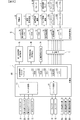
パチンコ遊技機1には、例えば図2に示すような主基板11、演出制御基板12、音声制御基板13、ランプ制御基板14、中継基板15などが搭載されている。その他にも、パチンコ遊技機1の背面には、例えば払出制御基板、情報端子基板、発射制御基板、電源基板などといった、各種の基板が配置されている。
(Board configuration)
In the
主基板11は、メイン側の制御基板であり、パチンコ遊技機1における上記遊技の進行(特図ゲームの実行(保留の管理を含む)、普図ゲームの実行(保留の管理を含む)、大当り遊技状態、小当り遊技状態、遊技状態など)を制御する機能を有する。主基板11は、遊技制御用マイクロコンピュータ100、スイッチ回路110、ソレノイド回路111などを有する。
The
主基板11に搭載された遊技制御用マイクロコンピュータ100は、例えば1チップのマイクロコンピュータであり、ROM(Read Only Memory)101と、RAM(Random Access Memory)102と、CPU(Central Processing Unit)103と、乱数回路104と、I/O(Input/Output port)105とを備える。
The
CPU103は、ROM101に記憶されたプログラムを実行することにより、遊技の進行を制御する処理(主基板11の機能を実現する処理)を行う。このとき、ROM101が記憶する各種データ(後述の変動パターン、後述の演出制御コマンド、後述の各種決定を行う際に参照される各種テーブルなどのデータ)が用いられ、RAM102がメインメモリとして使用される。RAM102は、その一部または全部がパチンコ遊技機1に対する電力供給が停止しても、所定期間記憶内容が保存されるバックアップRAMとなっている。尚、ROM101に記憶されたプログラムの全部又は一部をRAM102に展開して、RAM102上で実行するようにしてもよい。
The
乱数回路104は、遊技の進行を制御するときに使用される各種の乱数値(遊技用乱数)を示す数値データを更新可能にカウントする。遊技用乱数は、CPU103が所定のコンピュータプログラムを実行することで更新されるもの(ソフトウェアで更新されるもの)であってもよい。
The
I/O105は、例えば各種信号(後述の検出信号)が入力される入力ポートと、各種信号(第1特別図柄表示装置4A、第2特別図柄表示装置4B、普通図柄表示器20、第1保留表示器25A、第2保留表示器25B、普図保留表示器25Cなどを制御(駆動)する信号、ソレノイド駆動信号)を伝送するための出力ポートとを含んで構成される。
The I /
スイッチ回路110は、遊技球検出用の各種スイッチ(ゲートスイッチ21、始動口スイッチ(第1始動口スイッチ22Aおよび第2始動口スイッチ22B)、カウントスイッチ23)からの検出信号(遊技球が通過又は進入してスイッチがオンになったことを示す検出信号など)を取り込んで遊技制御用マイクロコンピュータ100に伝送する。検出信号の伝送により、遊技球の通過又は進入が検出されたことになる。
The
ソレノイド回路111は、遊技制御用マイクロコンピュータ100からのソレノイド駆動信号(例えば、ソレノイド81やソレノイド82をオンする信号など)を、普通電動役物用のソレノイド81や大入賞口扉用のソレノイド82に伝送する。
The
主基板11(遊技制御用マイクロコンピュータ100)は、遊技の進行の制御の一部として、遊技の進行に応じて演出制御コマンド(遊技の進行状況等を指定(通知)するコマンド)を演出制御基板12に供給する。主基板11から出力された演出制御コマンドは、中継基板15により中継され、演出制御基板12に供給される。当該演出制御コマンドには、例えば主基板11における各種の決定結果(例えば、特図ゲームの表示結果(大当り種別を含む。)、特図ゲームを実行する際に使用される変動パターン(詳しくは後述))、遊技の状況(例えば、可変表示の開始や終了、大入賞口の開放状況、入賞の発生、保留記憶数、遊技状態)、エラーの発生等を指定するコマンド等が含まれる。
The main board 11 (game control microcomputer 100) sends an effect control command (a command for designating (notifying) the progress of the game) according to the progress of the game as part of the control of the progress of the game. 12 is supplied. The effect control command output from the
演出制御基板12は、主基板11とは独立したサブ側の制御基板であり、演出制御コマンドを受信し、受信した演出制御コマンドに基づいて演出(遊技の進行に応じた種々の演出であり、可動体32の駆動、エラー報知、電断復旧の報知等の各種報知を含む)を実行する機能を有する。
The
演出制御基板12には、演出制御用CPU120と、ROM121と、RAM122と、表示制御部123と、乱数回路124と、I/O125とが搭載されている。
On the
演出制御用CPU120は、ROM121に記憶されたプログラムを実行することにより、表示制御部123とともに演出を実行するための処理(演出制御基板12の上記機能を実現するための処理であり、実行する演出の決定等を含む)を行う。このとき、ROM121が記憶する各種データ(各種テーブルなどのデータ)が用いられ、RAM122がメインメモリとして使用される。
The
演出制御用CPU120は、コントローラセンサユニット35Aやプッシュセンサ35Bからの検出信号(遊技者による操作を検出したときに出力される信号であり、操作内容を適宜示す信号)に基づいて演出の実行を表示制御部123に指示することもある。
The
表示制御部123は、VDP(Video Display Processor)、CGROM(Character Generator ROM)、VRAM(Video RAM)などを備え、演出制御用CPU120からの演出の実行指示に基づき、演出を実行する。
The
表示制御部123は、演出制御用CPU120からの演出の実行指示に基づき、実行する演出に応じた映像信号を画像表示装置5に供給することで、演出画像を画像表示装置5に表示させる。表示制御部123は、さらに、演出画像の表示に同期した音声出力や、遊技効果ランプ9の点灯/消灯を行うため、音指定信号(出力する音声を指定する信号)を音声制御基板13に供給したり、ランプ信号(ランプの点灯/消灯態様を指定する信号)をランプ制御基板14に供給したりする。また、表示制御部123は、可動体32を動作させる信号を当該可動体32又は当該可動体32を駆動する駆動回路に供給する。
The
音声制御基板13は、スピーカ8L、8Rを駆動する各種回路を搭載しており、当該音指定信号に基づきスピーカ8L、8Rを駆動し、当該音指定信号が指定する音声をスピーカ8L、8Rから出力させる。
The
ランプ制御基板14は、遊技効果ランプ9を駆動する各種回路を搭載しており、当該ランプ信号に基づき遊技効果ランプ9を駆動し、当該ランプ信号が指定する態様で遊技効果ランプ9を点灯/消灯する。このようにして、表示制御部123は、音声出力、ランプの点灯/消灯を制御する。
The
尚、音声出力、ランプの点灯/消灯の制御(音指定信号やランプ信号の供給等)、可動体32の制御(可動体32を動作させる信号の供給等)は、演出制御用CPU120が実行するようにしてもよい。
The
乱数回路124は、各種演出を実行するために使用される各種の乱数値(演出用乱数)を示す数値データを更新可能にカウントする。演出用乱数は、演出制御用CPU120が所定のコンピュータプログラムを実行することで更新されるもの(ソフトウェアで更新されるもの)であってもよい。
The
演出制御基板12に搭載されたI/O125は、例えば主基板11などから伝送された演出制御コマンドを取り込むための入力ポートと、各種信号(映像信号、音指定信号、ランプ信号)を伝送するための出力ポートとを含んで構成される。
For example, the I /
演出制御基板12、音声制御基板13、ランプ制御基板14といった、主基板11以外の基板をサブ基板ともいう。パチンコ遊技機1のようにサブ基板が機能別に複数設けられていてもよいし、1のサブ基板が複数の機能を有するように構成してもよい。
Substrates other than the
(動作)
次に、パチンコ遊技機1の動作(作用)を説明する。
(Operation)
Next, the operation (action) of the
(主基板11の主要な動作)
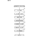
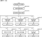
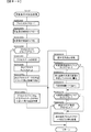
まず、主基板11における主要な動作を説明する。パチンコ遊技機1に対して電力供給が開始されると、遊技制御用マイクロコンピュータ100が起動し、CPU103によって遊技制御メイン処理が実行される。図3は、主基板11におけるCPU103が実行する遊技制御メイン処理を示すフローチャートである。
(Main operations of the main board 11)
First, main operations in the
図3に示す遊技制御メイン処理では、CPU103は、まず、割込禁止に設定する(ステップS1)。続いて、必要な初期設定を行う(ステップS2)。初期設定には、スタックポインタの設定、内蔵デバイス(CTC(カウンタ/タイマ回路)、パラレル入出力ポート等)のレジスタ設定、RAM102をアクセス可能状態にする設定等が含まれる。
In the game control main process shown in FIG. 3, the
次いで、クリアスイッチからの出力信号がオンであるか否かを判定する(ステップS3)。クリアスイッチは、例えば電源基板に搭載されている。クリアスイッチがオンの状態で電源が投入されると、出力信号(クリア信号)が入力ポートを介して遊技制御用マイクロコンピュータ100に入力される。クリアスイッチからの出力信号がオンである場合、初期化処理(ステップS8)を実行する。初期化処理では、CPU103は、RAM102に記憶されるフラグ、カウンタ、バッファをクリアするRAMクリア処理を行い、作業領域に初期値を設定する。
Next, it is determined whether or not the output signal from the clear switch is on (step S3). The clear switch is mounted on, for example, a power supply board. When the power is turned on while the clear switch is on, an output signal (clear signal) is input to the
また、CPU103は、初期化を指示する演出制御コマンドを演出制御基板12に送信する(ステップS9)。演出制御用CPU120は、当該演出制御コマンドを受信すると、例えば画像表示装置5において、遊技機の制御の初期化がなされたことを報知するための画面表示を行う。
Further, the
クリアスイッチからの出力信号がオンでない場合には、RAM102(バックアップRAM)にバックアップデータが保存されているか否かを判定する(ステップS4)。不測の停電等(電断)によりパチンコ遊技機1への電力供給が停止したときには、CPU103は、当該電力供給の停止によって動作できなくなる直前に、電源供給停止時処理を実行する。この電源供給停止時処理では、RAM102にデータをバックアップすることを示すバックアップフラグをオンする処理、RAM102のデータ保護処理等が実行される。データ保護処理には、誤り検出符号(チェックサム、パリティビット等)の付加、各種データをバックアップする処理が含まれる。バックアップされるデータには、遊技を進行するための各種データ(各種フラグ、各種タイマの状態等を含む)の他、前記バックアップフラグの状態や誤り検出符号も含まれる。ステップS4では、バックアップフラグがオンであるか否かを判定する。バックアップフラグがオフでRAM102にバックアップデータが記憶されていない場合、初期化処理(ステップS8)を実行する。
If the output signal from the clear switch is not on, it is determined whether backup data is stored in the RAM 102 (backup RAM) (step S4). When the power supply to the
RAM102にバックアップデータが記憶されている場合、CPU103は、バックアップしたデータのデータチェックを行い(誤り検出符号を用いて行われる)、データが正常か否かを判定する(ステップS5)。ステップS5では、例えば、パリティビットやチェックサムにより、RAM102のデータが、電力供給停止時のデータと一致するか否かを判定する。これらが一致すると判定された場合、RAM102のデータが正常であると判定する。
When the backup data is stored in the
RAM102のデータが正常でないと判定された場合、内部状態を電力供給停止時の状態に戻すことができないので、初期化処理(ステップS8)を実行する。
If it is determined that the data in the
RAM102のデータが正常であると判定された場合、CPU103は、主基板11の内部状態を電力供給停止時の状態に戻すための復旧処理(ステップS6)を行う。復旧処理では、CPU103は、RAM102の記憶内容(バックアップしたデータの内容)に基づいて作業領域の設定を行う。これにより、電力供給停止時の遊技状態に復旧し、特別図柄の変動中であった場合には、後述の遊技制御用タイマ割込み処理の実行によって、復旧前の状態から特別図柄の変動が再開されることになる。
When it is determined that the data in the
そして、CPU103は、電断からの復旧を指示する演出制御コマンドを演出制御基板12に送信する(ステップS7)。これに合わせて、バックアップされている電断前の遊技状態を指定する演出制御コマンドや、特図ゲームの実行中であった場合には当該実行中の特図ゲームの表示結果を指定する演出制御コマンドを送信するようにしてもよい。これらコマンドは、後述の特別図柄プロセス処理で送信設定されるコマンドと同じコマンドを使用できる。演出制御用CPU120は、電断からの復旧時を特定する演出制御コマンドを受信すると、例えば画像表示装置5において、電断からの復旧がなされたこと又は電断からの復旧中であることを報知するための画面表示を行う。演出制御用CPU120は、前記演出制御コマンドに基づいて、適宜の画面表示を行うようにしてもよい。
And CPU103 transmits the production control command which instruct | indicates the recovery | restoration from a power interruption to the production control board 12 (step S7). In conjunction with this, an effect control command for designating a backed-up gaming state before power interruption, or an effect control for designating the display result of the special figure game being executed when the special figure game is being executed. A command may be transmitted. As these commands, the same commands as those set for transmission in the special symbol process processing described later can be used. When the
復旧処理または初期化処理を終了して演出制御基板12に演出制御コマンドを送信した後には、CPU103は、乱数回路104を初期設定する乱数回路設定処理を実行する(ステップS10)。そして、所定時間(例えば2ms)毎に定期的にタイマ割込がかかるように遊技制御用マイクロコンピュータ100に内蔵されているCTCのレジスタの設定を行い(ステップS11)、割込みを許可する(ステップS12)。その後、ループ処理に入る。以後、所定時間(例えば2ms)ごとにCTCから割込み要求信号がCPU103へ送出され、CPU103は定期的にタイマ割込み処理を実行することができる。
After finishing the restoration process or the initialization process and transmitting the effect control command to the
こうした遊技制御メイン処理を実行したCPU103は、CTCからの割込み要求信号を受信して割込み要求を受付けると、図4のフローチャートに示す遊技制御用タイマ割込み処理を実行する。図4に示す遊技制御用タイマ割込み処理を開始すると、CPU103は、まず、所定のスイッチ処理を実行することにより、スイッチ回路110を介してゲートスイッチ21、第1始動口スイッチ22A、第2始動口スイッチ22B、カウントスイッチ23といった各種スイッチからの検出信号の受信の有無を判定する(ステップS21)。続いて、所定のメイン側エラー処理を実行することにより、パチンコ遊技機1の異常診断を行い、その診断結果に応じて必要ならば警告を発生可能とする(ステップS22)。この後、所定の情報出力処理を実行することにより、例えばパチンコ遊技機1の外部に設置されたホール管理用コンピュータに供給される大当り情報(大当りの発生回数等を示す情報)、始動情報(始動入賞の回数等を示す情報)、確率変動情報(確変状態となった回数等を示す情報)などのデータを出力する(ステップS23)。
When the
情報出力処理に続いて、主基板11の側で用いられる遊技用乱数の少なくとも一部をソフトウェアにより更新するための遊技用乱数更新処理を実行する(ステップS24)。この後、CPU103は、特別図柄プロセス処理を実行する(ステップS25)。CPU103がタイマ割込み毎に特別図柄プロセス処理を実行することにより、特図ゲームの実行及び保留の管理や、大当り遊技状態や小当り遊技状態の制御、遊技状態の制御などが実現される(詳しくは後述)。
Subsequent to the information output process, a game random number update process for updating at least a part of the game random numbers used on the
特別図柄プロセス処理に続いて、普通図柄プロセス処理が実行される(ステップS26)。CPU103がタイマ割込み毎に普通図柄プロセス処理を実行することにより、ゲートスイッチ21からの検出信号に基づく(通過ゲート41に遊技球が通過したことに基づく)普図ゲームの実行及び保留の管理や、「普図当り」に基づく可変入賞球装置6Bの開放制御などを可能にする。普図ゲームの実行は、普通図柄表示器20を駆動することにより行われ、普図保留表示器25Cを点灯させることにより普図保留数を表示する。
Following the special symbol process, a normal symbol process is executed (step S26). The
普通図柄プロセス処理を実行した後、遊技制御用タイマ割込み処理の一部として、電断が発生したときの処理、賞球を払い出すための処理等などが行われてもよい。その後、CPU103は、コマンド制御処理を実行する(ステップS27)。CPU103は、上記各処理にて演出制御コマンドを送信設定することがある。ステップS27のコマンド制御処理では、送信設定された演出制御コマンドを演出制御基板12などのサブ側の制御基板に対して伝送させる処理が行われる。コマンド制御処理を実行した後には、割込みを許可してから、遊技制御用タイマ割込み処理を終了する。
After executing the normal symbol process, a process when a power interruption occurs, a process for paying out a prize ball, or the like may be performed as part of the game control timer interrupt process. Thereafter, the
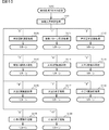
図5は、特別図柄プロセス処理として、図4に示すステップS25にて実行される処理の一例を示すフローチャートである。この特別図柄プロセス処理において、CPU103は、まず、始動入賞判定処理を実行する(ステップS101)。
FIG. 5 is a flowchart showing an example of processing executed in step S25 shown in FIG. 4 as the special symbol process. In this special symbol process, the
始動入賞判定処理では、始動入賞の発生を検出し、RAM102の所定領域に保留情報を格納し保留記憶数を更新する処理が実行される。始動入賞が発生すると、表示結果(大当り種別を含む)や変動パターンを決定するための乱数値が抽出され、保留情報として記憶される。また、抽出した乱数値に基づいて、表示結果や変動パターンを先読み判定する処理が実行されてもよい。保留情報や保留記憶数を記憶した後には、演出制御基板12に始動入賞の発生、保留記憶数、先読み判定等の判定結果を指定するための演出制御コマンドを送信するための送信設定が行われる。こうして送信設定された始動入賞時の演出制御コマンドは、例えば特別図柄プロセス処理が終了した後、図4に示すステップS27のコマンド制御処理が実行されることなどにより、主基板11から演出制御基板12に対して伝送される。
In the start winning determination process, a process of detecting occurrence of a start winning, storing hold information in a predetermined area of the
S101にて始動入賞判定処理を実行した後、CPU103は、RAM102に設けられた特図プロセスフラグの値に応じて、ステップS110〜S120の処理のいずれかを選択して実行する。尚、特別図柄プロセス処理の各処理(ステップS110〜S120)では、各処理に対応した演出制御コマンドを演出制御基板12に送信するための送信設定が行われる。
After executing the start winning determination process in S101, the
ステップS110の特別図柄通常処理は、特図プロセスフラグの値が“0”(初期値)のときに実行される。この特別図柄通常処理では、保留情報の有無などに基づいて、第1特図ゲーム又は第2特図ゲームを開始するか否かの判定が行われる。また、特別図柄通常処理では、表示結果決定用の乱数値に基づき、特別図柄や飾り図柄の表示結果を「大当り」または「小当り」とするか否かや「大当り」とする場合の大当り種別を、その表示結果が導出表示される以前に決定(事前決定)する。さらに、特別図柄通常処理では、決定された表示結果に対応して、特図ゲームにおいて停止表示させる確定特別図柄(大当り図柄や小当り図柄、ハズレ図柄のいずれか)が設定される。その後、特図プロセスフラグの値が“1”に更新され、特別図柄通常処理は終了する。尚、第2特図を用いた特図ゲームが第1特図を用いた特図ゲームよりも優先して実行されるようにしてもよい(特図2優先消化ともいう)。また、第1始動入賞口及び第2始動入賞口への遊技球の入賞順序を記憶し、入賞順に特図ゲームの開始条件を成立させるようにしてもよい(入賞順消化ともいう)。 The special symbol normal process of step S110 is executed when the value of the special symbol process flag is “0” (initial value). In this special symbol normal process, whether or not to start the first special symbol game or the second special symbol game is determined based on the presence or absence of the hold information. Also, in the special symbol normal processing, whether or not the display result of the special symbol or decorative symbol is “big hit” or “small hit” based on the random number value for determining the display result, and the big hit type when “big hit” is assumed Is determined (predetermined) before the display result is derived and displayed. Further, in the special symbol normal process, a confirmed special symbol (any one of the big hit symbol, the small hit symbol, or the lost symbol) to be stopped and displayed in the special symbol game is set according to the determined display result. Thereafter, the value of the special symbol process flag is updated to “1”, and the special symbol normal process ends. It should be noted that the special figure game using the second special figure may be executed with priority over the special figure game using the first special figure (also referred to as special figure 2 priority digestion). In addition, the winning order of the game balls to the first start winning opening and the second starting winning opening may be stored, and the start condition of the special figure game may be established in order of winning (also referred to as winning order digestion).
乱数値に基づき各種の決定を行う場合には、ROM101に格納されている各種のテーブル(乱数値と比較される決定値が決定結果に割り当てられているテーブル)が参照される。主基板11における他の決定、演出制御基板12における各種の決定についても同じである。演出制御基板12においては、各種のテーブルがROM121に格納されている。
When various determinations are made based on random number values, various tables stored in the ROM 101 (tables in which determination values to be compared with random number values are assigned to the determination results) are referred to. The same applies to other decisions on the
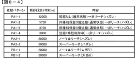
ステップS111の変動パターン設定処理は、特図プロセスフラグの値が“1”のときに実行される。この変動パターン設定処理には、表示結果を「大当り」または「小当り」とするか否かの事前決定結果等に基づき、変動パターン決定用の乱数値を用いて変動パターンを複数種類のいずれかに決定する処理などが含まれている。変動パターン設定処理では、変動パターンを決定したときに、特図プロセスフラグの値が“2”に更新され、変動パターン設定処理は終了する。 The variation pattern setting process in step S111 is executed when the value of the special figure process flag is “1”. In this variation pattern setting process, one of multiple types of variation patterns can be selected using a random value for determining the variation pattern based on the result of prior determination of whether or not the display result is “big hit” or “small hit”. The process to decide on is included. In the variation pattern setting process, when the variation pattern is determined, the value of the special figure process flag is updated to “2”, and the variation pattern setting process ends.
変動パターンは、特図ゲームの実行時間(特図変動時間)(飾り図柄の可変表示の実行時間でもある)や、飾り図柄の可変表示の態様(リーチの有無等)、飾り図柄の可変表示中の演出内容(リーチ演出の種類等)を指定するものであり、可変表示パターンとも呼ばれる。 Fluctuation patterns include special game execution time (special graphic variable time) (also the execution time of decorative symbol variable display), decorative symbol variable display mode (such as presence / absence of reach), and variable decorative symbol display The content of the production (the type of reach production, etc.) is designated and is also called a variable display pattern.
ステップS112の特別図柄変動処理は、特図プロセスフラグの値が“2”のときに実行される。この特別図柄変動処理には、第1特別図柄表示装置4Aや第2特別図柄表示装置4Bにおいて特別図柄を変動させるための設定を行う処理や、その特別図柄が変動を開始してからの経過時間を計測する処理などが含まれている。また、計測された経過時間が変動パターンに対応する特図変動時間に達したか否かの判定も行われる。そして、特別図柄の変動を開始してからの経過時間が特図変動時間に達したときには、特図プロセスフラグの値が“3”に更新され、特別図柄変動処理は終了する。
The special symbol variation process in step S112 is executed when the value of the special symbol process flag is “2”. This special symbol variation process includes a process for setting the special symbol to be varied in the first special
ステップS113の特別図柄停止処理は、特図プロセスフラグの値が“3”のときに実行される。この特別図柄停止処理には、第1特別図柄表示装置4Aや第2特別図柄表示装置4Bにて特別図柄の変動を停止させ、特別図柄の表示結果となる確定特別図柄を停止表示(導出)させるための設定を行う処理が含まれている。そして、表示結果が「大当り」である場合には特図プロセスフラグの値が“4”に更新される。その一方で、大当りフラグがオフであり、表示結果が「小当り」である場合には、特図プロセスフラグの値が“8”に更新される。また、表示結果が「ハズレ」である場合には、特図プロセスフラグの値が“0”に更新される。表示結果が「小当り」又は「ハズレ」である場合、時短状態や確変状態に制御されているときであって、回数切りの終了成立する場合には、遊技状態も更新される。特図プロセスフラグの値が更新されると、特別図柄停止処理は終了する。
The special symbol stop process in step S113 is executed when the value of the special symbol process flag is “3”. In this special symbol stop process, the first special
ステップS114の大当り開放前処理は、特図プロセスフラグの値が“4”のときに実行される。この大当り開放前処理には、表示結果が「大当り」となったことなどに基づき、大当り遊技状態においてラウンドの実行を開始して大入賞口を開放状態とするための設定を行う処理などが含まれている。大入賞口を開放状態とするときには、大入賞口扉用のソレノイド82に対してソレノイド駆動信号を供給する処理が実行される。このときには、例えば大当り種別がいずれであるかに対応して、大入賞口を開放状態とする開放上限期間や、ラウンドの上限実行回数を設定する。これらの設定が終了すると、特図プロセスフラグの値が“5”に更新され、大当り開放前処理は終了する。
The big hit release pre-processing in step S114 is executed when the value of the special figure process flag is “4”. This pre-opening process for jackpots includes a process for starting the execution of the round in the jackpot gaming state and setting the open winning opening based on the fact that the display result is “hit” It is. When the big prize opening is in an open state, a process of supplying a solenoid drive signal to the
ステップS115の大当り開放中処理は、特図プロセスフラグの値が“5”のときに実行される。この大当り開放中処理には、大入賞口を開放状態としてからの経過時間を計測する処理や、その計測した経過時間やカウントスイッチ23によって検出された遊技球の個数などに基づいて、大入賞口を開放状態から閉鎖状態に戻すタイミングとなったか否かを判定する処理などが含まれている。そして、大入賞口を閉鎖状態に戻すときには、大入賞口扉用のソレノイド82に対するソレノイド駆動信号の供給を停止させる処理などを実行した後、特図プロセスフラグの値が“6”に更新し、大当り開放中処理を終了する。
The big hit release processing in step S115 is executed when the value of the special figure process flag is "5". The big hit opening process includes a process for measuring the elapsed time since the big winning opening is in the open state, the measured elapsed time, the number of game balls detected by the
ステップS116の大当り開放後処理は、特図プロセスフラグの値が“6”のときに実行される。この大当り開放後処理には、大入賞口を開放状態とするラウンドの実行回数が設定された上限実行回数に達したか否かを判定する処理や、上限実行回数に達した場合に大当り遊技状態を終了させるための設定を行う処理などが含まれている。そして、ラウンドの実行回数が上限実行回数に達していないときには、特図プロセスフラグの値が“5”に更新される一方、ラウンドの実行回数が上限実行回数に達したときには、特図プロセスフラグの値が“7”に更新される。特図プロセスフラグの値が更新されると、大当り解放後処理は終了する。 The big hit release post-processing in step S116 is executed when the value of the special figure process flag is “6”. In this post-hit-opening process, a process for determining whether or not the number of executions of the round in which the big winning opening is opened has reached the set upper limit execution number, and when the upper limit execution number is reached, the big hit game state The process etc. which perform the setting for ending are included. When the round execution count does not reach the upper limit execution count, the value of the special figure process flag is updated to “5”, whereas when the round execution count reaches the upper limit execution count, the special figure process flag value is updated. The value is updated to “7”. When the value of the special figure process flag is updated, the processing after the big hit release ends.
ステップS117の大当り終了処理は、特図プロセスフラグの値が“7”のときに実行される。この大当り終了処理には、大当り遊技状態の終了を報知する演出動作としてのエンディング演出が実行される期間に対応した待ち時間が経過するまで待機する処理や、大当り遊技状態の終了に対応して確変制御や時短制御を開始するための各種の設定を行う処理などが含まれている。こうした設定が行われたときには、特図プロセスフラグの値が“0”に更新され、大当り終了処理は終了する。 The big hit end process in step S117 is executed when the value of the special figure process flag is “7”. The jackpot end process includes a process of waiting until a waiting time corresponding to a period in which an ending effect is executed as an effect operation for notifying the end of the jackpot game state, and a probability change corresponding to the end of the jackpot game state. This includes processing for performing various settings for starting control and time-saving control. When such a setting is made, the value of the special figure process flag is updated to “0”, and the jackpot end processing ends.
ステップS118の小当り開放前処理は、特図プロセスフラグの値が“8”のときに実行される。この小当り開放前処理には、表示結果が「小当り」となったことに基づき、小当り遊技状態において大入賞口を開放状態とするための設定を行う処理などが含まれている。このときには、特図プロセスフラグの値が“9”に更新され、小当り開放前処理は終了する。 The small hit pre-release process in step S118 is executed when the value of the special figure process flag is “8”. This pre-opening process for small hits includes a process for setting the big winning opening in the small hit gaming state based on the fact that the display result is “small hit”. At this time, the value of the special figure process flag is updated to “9”, and the small hit release pre-processing ends.
ステップS119の小当り開放中処理は、特図プロセスフラグの値が“9”のときに実行される。この小当り開放中処理には、大入賞口を開放状態としてからの経過時間を計測する処理や、その計測した経過時間などに基づいて、大入賞口を開放状態から閉鎖状態に戻すタイミングとなったか否かを判定する処理などが含まれている。大入賞口を閉鎖状態に戻して小当り遊技状態の終了タイミングとなったときには、特図プロセスフラグの値が“10”に更新され、小当り開放中処理は終了する。 The small hit releasing process in step S119 is executed when the value of the special figure process flag is “9”. In the small hit opening process, the process for measuring the elapsed time since the big prize opening is in the open state, and the timing for returning the big prize opening from the open state to the closed state based on the measured elapsed time, etc. The process etc. which determine whether or not were included are included. When the big prize opening is returned to the closed state and the end timing of the small hit gaming state is reached, the value of the special figure process flag is updated to “10”, and the small hit opening process ends.
ステップS120の小当り終了処理は、特図プロセスフラグの値が“10”のときに実行される。この小当り終了処理には、小当り遊技状態の終了を報知する演出動作が実行される期間に対応した待ち時間が経過するまで待機する処理などが含まれている。ここで、小当り遊技状態が終了するときには、小当り遊技状態となる以前のパチンコ遊技機1における遊技状態を継続させる。小当り遊技状態の終了時における待ち時間が経過したときには、特図プロセスフラグの値が“0”に更新され、小当り終了処理は終了する。
The small hit end process in step S120 is executed when the value of the special figure process flag is “10”. This small hit end process includes a process of waiting until a waiting time corresponding to a period during which the effect operation for notifying the end of the small hit gaming state is executed. Here, when the small hit gaming state ends, the gaming state in the
(演出制御基板12の主要な動作)
次に、演出制御基板12における主要な動作を説明する。演出制御基板12では、電源基板等から電源電圧の供給を受けると、演出制御用CPU120が起動して、図6のフローチャートに示すような演出制御メイン処理を実行する。図6に示す演出制御メイン処理を開始すると、演出制御用CPU120は、まず、所定の初期化処理を実行して(ステップS71)、RAM122のクリアや各種初期値の設定、また演出制御基板12に搭載されたCTC(カウンタ/タイマ回路)のレジスタ設定等を行う。また、初期動作制御処理を実行する(ステップS72)。初期動作制御処理では、可動体32を駆動して初期位置に戻す制御、所定の動作確認を行う制御といった可動体32の初期動作を行う制御が実行される。
(Main operations of the production control board 12)
Next, main operations in the
その後、タイマ割込みフラグがオンとなっているか否かの判定を行う(ステップS73)。タイマ割込みフラグは、例えばCTCのレジスタ設定に基づき、所定時間(例えば2ミリ秒)が経過するごとにオン状態にセットされる。このとき、タイマ割込みフラグがオフであれば、ステップS73の処理を繰返し実行して待機する。 Thereafter, it is determined whether or not the timer interrupt flag is on (step S73). The timer interrupt flag is set to the on state every time a predetermined time (for example, 2 milliseconds) elapses based on, for example, the CTC register setting. At this time, if the timer interrupt flag is off, the process of step S73 is repeatedly executed and waits.
また、演出制御基板12の側では、所定時間が経過するごとに発生するタイマ割込みとは別に、主基板11からの演出制御コマンドを受信するための割込みが発生する。この割込みは、例えば主基板11からの演出制御INT信号がオン状態となることにより発生する割込みである。演出制御INT信号がオン状態となることによる割込みが発生すると、演出制御用CPU120は、自動的に割込み禁止に設定するが、自動的に割込み禁止状態にならないCPUを用いている場合には、割込み禁止命令(DI命令)を発行することが望ましい。演出制御用CPU120は、演出制御INT信号がオン状態となることによる割込みに対応して、例えば所定のコマンド受信割込み処理を実行する。このコマンド受信割込み処理では、I/O125に含まれる入力ポートのうちで、中継基板15を介して主基板11から送信された制御信号を受信する所定の入力ポートより、演出制御コマンドを取り込む。このとき取り込まれた演出制御コマンドは、例えばRAM122に設けられた演出制御コマンド受信用バッファに格納する。その後、演出制御用CPU120は、割込み許可に設定してから、コマンド受信割込み処理を終了する。
On the side of the
ステップS73にてタイマ割込みフラグがオンである場合には、タイマ割込みフラグをクリアしてオフ状態にするとともに(ステップS74)、コマンド解析処理を実行する(ステップS75)。コマンド解析処理では、例えば主基板11の遊技制御用マイクロコンピュータ100から送信されて演出制御コマンド受信用バッファに格納されている各種の演出制御コマンドを読み出した後に、その読み出された演出制御コマンドに対応した設定や制御などが行われる。例えば、どの演出制御コマンドを受信したかや演出制御コマンドが特定する内容等を演出制御プロセス処理等で確認できるように、読み出された演出制御コマンドをRAM122の所定領域に格納したり、RAM122に設けられた受信フラグをオンしたりする。また、演出制御コマンドが遊技状態を特定する場合、遊技状態に応じた背景の表示を表示制御部123に指示してもよい。
If the timer interrupt flag is on in step S73, the timer interrupt flag is cleared and turned off (step S74), and command analysis processing is executed (step S75). In the command analysis process, for example, after reading various effect control commands transmitted from the
ステップS75にてコマンド解析処理を実行した後には、演出制御プロセス処理を実行する(ステップS76)。演出制御プロセス処理では、例えば画像表示装置5の表示領域における演出画像の表示動作、スピーカ8L、8Rからの音声出力動作、遊技効果ランプ9及び装飾用LEDといった装飾発光体における点灯動作、可動体32の駆動動作といった、各種の演出装置を動作させる制御が行われる。また、各種の演出装置を用いた演出動作の制御内容について、主基板11から送信された演出制御コマンド等に応じた判定や決定、設定などが行われる。
After executing the command analysis process in step S75, an effect control process process is executed (step S76). In the effect control process, for example, an effect image display operation in the display area of the
ステップS76の演出制御プロセス処理に続いて、演出用乱数更新処理が実行され(ステップS77)、演出制御基板12の側で用いられる演出用乱数の少なくとも一部がソフトウェアにより更新される。その後、ステップS73の処理に戻る。ステップS73の処理に戻る前に、他の処理が実行されてもよい。
Following the effect control process in step S76, an effect random number update process is executed (step S77), and at least a part of the effect random numbers used on the
図7は、演出制御プロセス処理として、図6のステップS76にて実行される処理の一例を示すフローチャートである。図7に示す演出制御プロセス処理において、演出制御用CPU120は、まず、先読予告設定処理を実行する(ステップS161)。先読予告設定処理では、例えば、主基板11から送信された始動入賞時の演出制御コマンドに基づいて、先読み予告演出を実行するための判定や決定、設定などが行われる。また、当該演出制御コマンドから特定される保留記憶数に基づき保留表示を表示するための処理が実行される。
FIG. 7 is a flowchart showing an example of processing executed in step S76 of FIG. 6 as the effect control process. In the effect control process shown in FIG. 7, the
ステップS161の処理を実行した後、演出制御用CPU120は、例えばRAM122に設けられた演出プロセスフラグの値に応じて、以下のようなステップS170〜S177の処理のいずれかを選択して実行する。
After executing the process of step S161, the
ステップS170の可変表示開始待ち処理は、演出プロセスフラグの値が“0”(初期値)のときに実行される処理である。この可変表示開始待ち処理は、主基板11から可変表示の開始を指定するコマンドなどを受信したか否かに基づき、画像表示装置5における飾り図柄の可変表示を開始するか否かを判定する処理などを含んでいる。画像表示装置5における飾り図柄の可変表示を開始すると判定された場合、演出プロセスフラグの値を“1”に更新し、可変表示開始待ち処理を終了する。
The variable display start waiting process in step S170 is a process executed when the value of the effect process flag is “0” (initial value). This variable display start waiting process is a process for determining whether or not to start variable display of decorative symbols on the
ステップS171の可変表示開始設定処理は、演出プロセスフラグの値が“1”のときに実行される処理である。この可変表示開始設定処理では、演出制御コマンドにより特定される表示結果や変動パターンに基づいて、飾り図柄の可変表示の表示結果(確定飾り図柄)、飾り図柄の可変表示の態様、リーチ演出や各種予告演出などの各種演出の実行の有無やその態様や実行開始タイミングなどを決定する。そして、その決定結果等を反映した演出制御パターン(表示制御部123に演出の実行を指示するための制御データの集まり)を設定する。その後、設定した演出制御パターンに基づいて、飾り図柄の可変表示の実行開始を表示制御部123に指示し、演出プロセスフラグの値を“2”に更新し、可変表示開始設定処理を終了する。表示制御部123は、飾り図柄の可変表示の実行開始の指示により、画像表示装置5において、飾り図柄の可変表示を開始させる。
The variable display start setting process in step S171 is a process executed when the value of the effect process flag is “1”. In this variable display start setting process, based on the display result and variation pattern specified by the effect control command, the display result of the variable display of the decorative design (determined decorative design), the variable display mode of the decorative design, the reach effect and various The presence / absence of execution of various effects such as a notice effect, its mode, execution start timing, and the like are determined. Then, an effect control pattern (a collection of control data for instructing the
ステップS172の可変表示中演出処理は、演出プロセスフラグの値が“2”のときに実行される処理である。この可変表示中演出処理において、演出制御用CPU120は、表示制御部123を指示することで、ステップS171にて設定された演出制御パターンに基づく演出画像を画像表示装置5の表示画面に表示させることや、可動体32を駆動させること、音声制御基板13に対する指令(効果音信号)の出力によりスピーカ8L、8Rから音声や効果音を出力させること、ランプ制御基板14に対する指令(電飾信号)の出力により遊技効果ランプ9や装飾用LEDを点灯/消灯/点滅させることといった、飾り図柄の可変表示中における各種の演出制御を実行する。こうした演出制御を行った後、例えば演出制御パターンから飾り図柄の可変表示終了を示す終了コードが読み出されたこと、あるいは、主基板11から確定飾り図柄を停止表示させることを指定するコマンドを受信したことなどに対応して、飾り図柄の表示結果となる確定飾り図柄を停止表示させる。確定飾り図柄を停止表示したときには、演出プロセスフラグの値が“3”に更新され、可変表示中演出処理は終了する。
The variable display effect process in step S172 is a process executed when the value of the effect process flag is “2”. In this variable display effect processing, the
ステップS173の特図当り待ち処理は、演出プロセスフラグの値が“3”のときに実行される処理である。この特図当り待ち処理において、演出制御用CPU120は、主基板11から大当り遊技状態又は小当り遊技状態を開始することを指定する演出制御コマンドの受信があったか否かを判定する。そして、大当り遊技状態又は小当り遊技状態を開始することを指定する演出制御コマンドを受信したきに、そのコマンドが大当り遊技状態の開始を指定するものであれば、演出プロセスフラグの値を“6”に更新する。これに対して、そのコマンドが小当り遊技状態の開始を指定するものであれば、演出プロセスフラグの値を小当り中演出処理に対応した値である“4”に更新する。また、大当り遊技状態又は小当り遊技状態を開始することを指定するコマンドを受信せずに、当該コマンドの受信待ち時間が経過したときには、特図ゲームにおける表示結果が「ハズレ」であったと判定して、演出プロセスフラグの値を初期値である“0”に更新する。演出プロセスフラグの値を更新すると、特図当り待ち処理を終了する。
The special figure waiting process in step S173 is a process executed when the value of the effect process flag is “3”. In this special figure waiting process, the
ステップS174の小当り中演出処理は、演出制御プロセスフラグの値が“4”のときに実行される処理である。この小当り中演出処理において、演出制御用CPU120は、例えば小当り遊技状態における演出内容に対応した演出制御パターン等を設定し、その設定内容に基づく小当り遊技状態における各種の演出制御を実行する。また、小当り中演出処理では、例えば主基板11から小当り遊技状態を終了することを指定するコマンドを受信したことに対応して、演出プロセスフラグの値を小当り終了演出に対応した値である“5”に更新し、小当り中演出処理を終了する。
The small hitting effect process in step S174 is a process executed when the value of the effect control process flag is “4”. In this small hit effect processing, the
ステップS175の小当り終了演出処理は、演出制御プロセスフラグの値が“5”のときに実行される処理である。この小当り終了演出処理において、演出制御用CPU120は、例えば小当り遊技状態の終了などに対応した演出制御パターン等を設定し、その設定内容に基づく小当り遊技状態の終了時における各種の演出制御を実行する。その後、演出プロセスフラグの値を初期値である“0”に更新し、小当り終了演出処理を終了する。
The small hit end effect process in step S175 is a process executed when the value of the effect control process flag is “5”. In this small hit end effect process, the
ステップS176の大当り中演出処理は、演出プロセスフラグの値が“6”のときに実行される処理である。この大当り中演出処理において、演出制御用CPU120は、例えば大当り遊技状態における演出内容に対応した演出制御パターン等を設定し、その設定内容に基づく大当り遊技状態における各種の演出制御を実行する。また、大当り中演出処理では、例えば主基板11から大当り遊技状態を終了することを指定するコマンドを受信したことに対応して、演出制御プロセスフラグの値をエンディング演出処理に対応した値である“7”に更新し、大当り中演出処理を終了する。
The big hit effect process in step S176 is a process executed when the value of the effect process flag is “6”. In the jackpot effect processing, the
ステップS177のエンディング演出処理は、演出プロセスフラグの値が“7”のときに実行される処理である。このエンディング演出処理において、演出制御用CPU120は、例えば大当り遊技状態の終了などに対応した演出制御パターン等を設定し、その設定内容に基づく大当り遊技状態の終了時におけるエンディング演出の各種の演出制御を実行する。その後、演出プロセスフラグの値を初期値である“0”に更新し、エンディング演出処理を終了する。
The ending effect process in step S177 is a process executed when the value of the effect process flag is “7”. In this ending effect process, the
(基本説明の変形例)
この発明は、上記基本説明で説明したパチンコ遊技機1に限定されず、本発明の趣旨を逸脱しない範囲で、様々な変形及び応用が可能である。
(Modification of basic explanation)
The present invention is not limited to the
上記基本説明のパチンコ遊技機1は、入賞の発生に基づいて所定数の遊技媒体を景品として払い出す払出式遊技機であったが、遊技媒体を封入し入賞の発生に基づいて得点を付与する封入式遊技機であってもよい。
The
特別図柄の可変表示中に表示されるものは1種類の図柄(例えば、「−」を示す記号)だけで、当該図柄の表示と消灯とを繰り返すことによって可変表示を行うようにしてもよい。さらに可変表示中に当該図柄が表示されるものも、可変表示の停止時には、当該図柄が表示されなくてもよい(表示結果としては「−」を示す記号が表示されなくてもよい)。 Only one type of symbol (for example, a symbol indicating “−”) is displayed during variable display of the special symbol, and variable display may be performed by repeatedly displaying and extinguishing the symbol. Further, in the case where the symbol is displayed during variable display, the symbol may not be displayed when the variable display is stopped (a symbol indicating “−” may not be displayed as a display result).
上記基本説明では、遊技機としてパチンコ遊技機1を示したが、メダルが投入されて所定の賭け数が設定され、遊技者による操作レバーの操作に応じて複数種類の図柄を回転させ、遊技者によるストップボタンの操作に応じて図柄を停止させたときに停止図柄の組合せが特定の図柄の組合せになると、所定数のメダルが遊技者に払い出されるゲームを実行可能なスロット機(例えば、ビッグボーナス、レギュラーボーナス、RT、AT、ART、CZ(以下、ボーナス等)のうち1以上を搭載するスロット機)にも本発明を適用可能である。
In the above basic explanation, the
本発明を実現するためのプログラム及びデータは、パチンコ遊技機1に含まれるコンピュータ装置などに対して、着脱自在の記録媒体により配布・提供される形態に限定されるものではなく、予めコンピュータ装置などの有する記憶装置にインストールしておくことで配布される形態を採っても構わない。さらに、本発明を実現するためのプログラム及びデータは、通信処理部を設けておくことにより、通信回線等を介して接続されたネットワーク上の、他の機器からダウンロードすることによって配布する形態を採っても構わない。
The program and data for realizing the present invention are not limited to a form distributed and provided by a detachable recording medium with respect to the computer device or the like included in the
そして、ゲームの実行形態も、着脱自在の記録媒体を装着することにより実行するものだけではなく、通信回線等を介してダウンロードしたプログラム及びデータを、内部メモリ等に一旦格納することにより実行可能とする形態、通信回線等を介して接続されたネットワーク上における、他の機器側のハードウェア資源を用いて直接実行する形態としてもよい。さらには、他のコンピュータ装置等とネットワークを介してデータの交換を行うことによりゲームを実行するような形態とすることもできる。 The game execution mode is not only executed by attaching a detachable recording medium, but can also be executed by temporarily storing a program and data downloaded via a communication line or the like in an internal memory or the like. It is also possible to execute directly using hardware resources on the other device side on a network connected via a communication line or the like. Furthermore, the game can be executed by exchanging data with other computer devices or the like via a network.
尚、本明細書において、演出の実行割合などの各種割合の比較の表現(「高い」、「低い」、「異ならせる」などの表現)は、一方が「0%」の割合であることを含んでもよい。例えば、一方が「0%」の割合で、他方が「100%」の割合又は「100%」未満の割合であることも含む。 In the present specification, the comparison expression of various ratios such as the performance execution ratio (expressions such as “high”, “low”, and “difference”) means that one is a ratio of “0%”. May be included. For example, one of the ratios is “0%” and the other is a ratio of “100%” or a ratio of less than “100%”.
(特徴部063SGに関する説明)
次に、本実施の形態の特徴部063SGについて説明する。尚、本実施の形態におけるフローチャートの各ステップの説明において、例えば「ステップS1」と記載する箇所を「S1」や「063SGS1」と略記したり、「ノーマルリーチ」を「Nリーチ」と略記したり、「スーパーリーチ」を「Sリーチ」や「SPリーチ」と略記したりする場合がある。また、基本説明にて説明したパチンコ遊技機1と同様または形態や配置位置等が異なるが同様の機能を有する構成については、同様の符号を付すことにより詳細な説明を省略する。尚、以下において、図8−1の手前側をパチンコ遊技機1の前方(前面、正面)側、奥側を背面(後方)側とし、パチンコ遊技機1を前面側から見たときの上下左右方向を基準として説明する。尚、本実施の形態におけるパチンコ遊技機1の前面とは、該パチンコ遊技機1にて遊技を行う遊技者と対向する対向面である。
(Explanation regarding the feature part 063SG)
Next, the characteristic part 063SG of this Embodiment is demonstrated. In the description of each step of the flowchart in the present embodiment, for example, a place described as “step S1” is abbreviated as “S1” or “063SGS1”, “normal reach” is abbreviated as “N reach”, “Super reach” is sometimes abbreviated as “S reach” or “SP reach”. In addition, the same reference numerals are given to configurations having the same functions as those of the
(遊技領域)
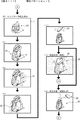
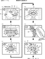
次に、本実施の形態の特徴部063SGで用いられるパチンコ遊技機1について説明する。図8−1は、特徴部063SGで用いられるパチンコ遊技機1を示す正面図である。図8−2は、(A)は操作ユニットを示す斜視図、(B)は操作ユニットの構造を示す分解斜視図である。図8−3は、(A)は打球操作ハンドルを示す斜視図、(B)は打球操作ハンドルの構造を示す分解斜視図である。
(Game area)
Next, the
図8−1に示すように、本実施の形態の特徴部063SGで用いられるパチンコ遊技機1の遊技領域Yは、遊技球が流下する流下経路のうちの第1経路K1が、正面から見て画像表示装置5の周囲を囲むセンター飾り枠5cよりも左側の領域に主に設けられ、遊技球が流下する流下経路のうち第1経路K1とは異なる第2経路K2が、正面から見て画像表示装置5の周囲を囲むセンター飾り枠5cよりも右側の領域に主に設けられている。
As shown in FIG. 8A, in the gaming area Y of the
第1経路K1に遊技球を流下させるために画像表示装置5の左側領域(左側遊技領域)に遊技球を打込むことが左打ちと呼ばれる。第2経路K2に遊技球を流下させるために画像表示装置5の右側領域(右側遊技領域)に遊技球を打込むことが右打ちと呼ばれる。第1経路は、遊技領域Yの左側に遊技球を打込むことにより遊技球が流下可能となる経路であるので、左打ち経路と呼ばれてもよい。また、第2経路K2は、遊技領域Yの右側に遊技球を打込むことにより遊技球が流下可能となる経路であるので、右打ち経路と呼ばれてもよい。尚、第1経路K1と第2経路K2とは、別の経路により構成されてもよく、一部が共有化された経路であってもよい。左遊技領域と右遊技領域とは、例えば、遊技領域Y内における画像表示装置5の端面や障害釘の配列等により区分けされていればよい。
Driving a game ball into the left area (left game area) of the
本実施の形態では、第1経路K1を流下する遊技球は、入賞球装置6Aに進入可能に誘導される一方で、第2経路K2を流下する遊技球は、通過ゲート41、可変入賞球装置6B及び特別可変入賞球装置7に進入可能に誘導されるようになっている。尚、第2経路K2を流下する遊技球が入賞球装置6Aに進入可能とされていてもよい。
In the present embodiment, the game ball flowing down the first path K1 is guided so as to enter the winning
また、画像表示装置5の表示領域の上方には、動作可能な可動体32が設けられている。可動体32は、画像表示装置5の表示領域の上方の原点位置と、画像表示装置5の表示領域の略中央に位置する演出位置と、の間で上下方向に移動可能に設けられており(図8−19(A)参照)、演出制御用CPU120は、可変表示期間中や大当り遊技状態中における所定タイミングにて、可動体32を原点位置から演出位置へ移動させることが可能である。
An operable
(操作ユニット600)
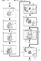
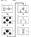
図8−2に示すように、スティックコントローラ31Aとプッシュボタン31Bとは、操作ユニット600として一体的に構成されている。図8−2(B)に示すように、スティックコントローラ31Aは、主に金属材からなるベース体601と、ベース体601を左右側から覆う把持部材602L,602Rと、把持部材602L,602Rの前面側に取付けられるレンズカバー603と、ベース体601の背面側に配置される背面ベース604と、一体化された把持部材602L,602Rの上部に取付けられるプッシュボタン31Bと、を主に有する。
(Operation unit 600)
As illustrated in FIG. 8B, the
ベース体601は、ベース部601Aと、ベース部601Aに対し左右方向を向く回動軸601Bを中心として回動可能な回動部601Cと、から構成される。背面ベース604には、コントローラセンサユニット35A(図2参照)が設けられているとともに、コントローラセンサユニット35Aやプッシュボタン31Bに内蔵されるプッシュセンサ35B(図2参照)を演出制御基板12に接続するための配線CやコネクタCN等が設けられている。
The
操作ユニット600は、製造時において、例えば、1.ベース体601に対し背面ベース604を組付け、2.把持部材602L,602Rを回動部601Cに組付け、3.把持部材602L,602Rの前面にレンズカバー603を組付け、4.把持部材602L,602Rの上部にプッシュボタン31Bを組付ける、といった1〜4の工程で組付けることにより構成される。尚、組付工程は任意であり、上記以外の工程で組付けられてもよい。また、実際には上記より多くの部材を組付ける工程を有している。
The
また、以下においては、説明の便宜上、ベース体601を部品A1、背面ベース604を部品A2、レンズカバー603を部品A3、プッシュボタン31Bを部品A4、把持部材602L,602Rを部品A5と称して説明することもある。さらに、これら部品A1〜A5のうち部品A5(把持部材602L,602R)を、他の部品A1〜A4よりも特徴的な部品として説明する。尚、「特徴的な部品」とは、操作ユニット600の一部を構成するスティックコントローラ31Aを構成する部品であることを遊技者が最も認識(特定)し易い部品である。
In the following, for convenience of explanation, the
詳しくは、部品A5(把持部材602L,602R)は、A.遊技者が操作(把持)する部材であること、B.把持部であることを想起しやすい形状であること、C.他の部品A1〜A4よりも大きい(操作ユニット600全体に対する専有領域が大きい)こと、D.遊技者に目立つ位置に配置される部品であること、のうち少なくとも一の条件(例えば、ここでは条件A,B,C,Dなど)を満たす部品であるため、本特徴部063SGでは、スティックコントローラ31Aの部品のうち特徴的な部品を部品A5(把持部材602L,602R)として説明する。
Specifically, the part A5 (gripping
図8−2(A)に示すように、このように構成されたスティックコントローラ31Aは、把持部材602L,602R及びレンズカバー603にて構成された把持部を握って手前側に引くことにより、コントローラセンサユニット35Aにより遊技者による操作が検出されるようになっている。
As shown in FIG. 8-2 (A), the
(打球操作ハンドル30)
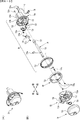
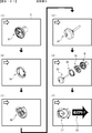
図8−3に示すように、打球操作ハンドル30は、ネジ(図示略)により遊技機用枠3に取付けられるハンドルベース720と、ハンドルベース720の前面側に取付けられる各種部材にて構成される。図8−3(B)に示すように、ハンドルベース720は、筒状部720aと該筒状部720aの前端部から拡径される皿状のフランジ部720bとから構成されている。筒状部720aの中心には、ハンドルシャフト726がハンドルカラー727を介して前面側から挿通される挿通路721が前後方向に貫通して形成されている。フランジ部720bの上部及び下部には、ハンドルカバー735を固定するための固定用ボス722,723が突設されている。尚、ハンドルシャフト726は、外周に環装されたEリング726aにより挿通路721に対する前後位置が決定される。
(Hitball operation handle 30)
As shown in FIG. 8C, the hitting operation handle 30 is configured by a
フランジ部720bの前面左側には、遊技球を1球ずつ発射する際に操作される操作部724bを有する単発スイッチレバー724が、操作部724bがフランジ部720bの外側に配置されるようにネジ724aにより揺動可能に取付けられているとともに、単発スイッチレバー724の近傍には、該単発スイッチレバー724を検出する単発スイッチ725がネジ725aにより取付けられている。
On the left side of the front surface of the
また、フランジ部720bの前面側には、環状のタッチリング728がネジ728aにより回転不能に取付けられるとともに、タッチリング728の前面には環状のタッチ取付プレート729がネジ729aにより取付けられ、タッチリング728をハンドルベース720に固定している。タッチ取付プレート729の前面側には、遊技者により回転操作されるハンドルリング730がタッチ取付プレート729に対して相対回転可能に組付けられる。尚、タッチリング728やハンドルセンサ(図示略)及び単発スイッチ725は、配線CやコネクタCN等により払出制御基板(図示略)を介して主基板11に接続されている。
An
ハンドルリング730は、中心にハンドルシャフト726の先端が相対回転不能に嵌合される嵌合穴732が形成されているとともに、その周囲には、固定用ボス722が挿通される円弧状の挿通溝733a及び固定用ボス723が挿通される円弧状の挿通溝733bが形成されており、挿通溝733aに固定用ボス722が挿通され、挿通溝733bに固定用ボス723が挿通されるようにタッチ取付プレート729の前面に配置される。
The
ハンドルリング730の前面側に配置されるハンドルカバー735は、前面に図示しない装飾(例えば、機種に固有の絵柄、マーク、キャラクタ、タイトル、メーカーのロゴなど)が施されており、ハンドルベース720のフランジ部720bの背面側から固定用ボス722に挿通されるネジ731a及び固定用ボス723aに挿通されるネジ731bにより固定用ボス722,723に固定される。よって、ハンドルリング730は、前後方向を向くハンドルシャフト726を中心として、タッチ取付プレート729に対して約90度の回動範囲で回動可能に環装されている。また、ハンドルカバー735とハンドルリング730との間に介装されるハンドルバネ734により、ハンドルリング730は常時左回転方向に付勢されている。
The
打球操作ハンドル30は、製造時において、例えば、1.ハンドルベース720に対しタッチリング728を組付け、2.タッチ取付プレート729を組付け、3.ハンドルシャフト726が一体化されたハンドルリング730を組付け、4.ハンドルカバー735を組付ける、といった1〜4の工程で組付けることにより構成される。尚、組付工程は任意であり、上記以外の工程で組付けられてもよい。また、実際には上記より多くの部材を組付ける工程を有している。
The hitting operation handle 30 is manufactured at the time of manufacture, for example: 1. Install the
また、以下においては、説明の便宜上、ハンドルベース720及びタッチリング728を部品B1、タッチ取付プレート729を部品B2、ハンドルリング730を部品B3、ハンドルシャフト726が一体化されたハンドルカバー735を部品B4と称して説明することもある。さらに、これら部品B1〜B4のうち部品B4(ハンドルシャフト726が一体化されたハンドルカバー735)を、他の部品B1〜B4よりも特徴的な部品として説明する。尚、「特徴的な部品」とは、打球操作ハンドル30の一部を構成する部品であることを遊技者が最も認識(特定)し易い部品である。
In the following, for convenience of explanation, the
詳しくは、部品B4(ハンドルカバー735)は、A.遊技者が操作する部材であること、B.操作部であることを想起しやすい形状であること、C.他の部品B1〜B4よりも大きい(打球操作ハンドル30全体に対する専有領域が大きい)こと、D.遊技者に目立つ位置に配置される部品であること、のうち少なくとも一の条件(例えば、ここでは条件C,Dなど)を満たす部品であるため、本実施の形態では、打球操作ハンドル30の部品のうち特徴的な部品を部品B4(ハンドルカバー735)として説明する。
Specifically, the part B4 (handle cover 735) is made of A.M. B. a member operated by a player; A shape that is easy to recall that it is an operation unit; Larger than the other parts B1 to B4 (the exclusive area for the entire hitting
図8−3(A)に示すように、このように構成された打球操作ハンドル30は、ハンドルリング730をハンドルバネ734の付勢力に抗して右回転させることでハンドルシャフト726が回転し、図示しない発射装置に回動量が伝達されることで、発射位置にセットされた遊技球が該回動量に応じた力で打ち出される(発射される)ようになっている。
As shown in FIG. 8-3 (A), in the hitting
本特徴部063SGでは、大当り種別判定テーブルがROM101に記憶されている。大当り種別判定テーブルは、特図表示結果を「大当り」として大当り遊技状態に制御すると決定されたときに、大当り種別判定用の乱数値MR2に基づき、大当り種別を複数種類のいずれかに決定するために参照されるテーブルである。大当り種別判定テーブルでは、特図ゲームにおいて可変表示(変動表示)が行われた特別図柄が第1特図(第1特別図柄表示装置お4Aによる特図ゲーム)であるか第2特図(第2特別図柄表示装置4Bによる特図ゲーム)であるかに応じて、大当り種別判定用の乱数値MR2と比較される数値(判定値)が、「非確変大当り」や「確変大当りA」、「確変大当りB」といった複数種類の大当り種別に割り当てられている。
In the feature unit 063SG, a big hit type determination table is stored in the
大当り種別としては、大当り遊技状態の終了後において高確制御と時短制御とが実行されて高確高ベース状態に移行する「確変大当りA」や「確変大当りB」と、大当り遊技状態の終了後において時短制御のみが実行されて低確高ベース状態に移行する「非確変大当り」とが設定されている。 The types of jackpots include “probability big hit A” and “probability big hit B” in which high-accuracy control and short-time control are executed after the big hit gaming state is finished, and after the big hit gaming state is finished. Is set to “non-probable big hit” in which only the short-time control is executed to shift to the low-accuracy base state.
「確変大当りA」による大当り遊技状態は、特別可変入賞球装置7を遊技者にとって有利な第1状態に変化させるラウンドが10回(いわゆる10ラウンド)、繰返し実行される通常開放大当りである。一方、「確変大当りB」による大当り遊技状態は、特別可変入賞球装置7を遊技者にとって有利な第1状態に変化させるラウンドが5回(いわゆる5ラウンド)、繰返し実行される通常開放大当りである。また、「非確変大当り」による大当り遊技状態は、特別可変入賞球装置7を遊技者にとって有利な第1状態に変化させるラウンドが10回(いわゆる10ラウンド)、繰返し実行される通常開放大当りである。よって、「確変大当りA」を10ラウンド(10R)確変大当りと呼称し、「確変大当りB」を5ラウンド(5R)確変大当りと呼称する場合がある。尚、いずれの大当り種別の大当り遊技中においても、確変制御や時短制御は実行されないようになっている。
The big hit gaming state by “probable big hit A” is a normal open big hit that is repeatedly executed 10 times (so-called 10 rounds) in which the special variable winning
確変大当りAや確変大当りBの大当り遊技状態の終了後において実行される高確制御と時短制御は、該大当り遊技状態の終了後において再度大当りが発生するまで継続して実行される。よって、再度発生した大当りが確変大当りAや確変大当りBである場合には、大当り遊技状態の終了後に再度、高確制御と時短制御が実行されるので、大当り遊技状態が通常状態を介することなく連続的に発生する、いわゆる連荘状態となる。 The high-accuracy control and the time-shortening control executed after the end of the big hit gaming state of the probability changing big hit A and the probability changing big hit B are continuously executed until the big hit occurs again after the end of the big hit gaming state. Therefore, when the big hit that has occurred again is the probable big hit A or the probable big hit B, the high-precision control and the short-time control are executed again after the big hit gaming state ends, so the big hit gaming state does not go through the normal state. It becomes a so-called consecutive resort state that occurs continuously.
一方、「非確変大当り」による大当り遊技状態の終了後において実行される時短制御は、所定回数(例えば、100回)の特図ゲームが実行されること、或いは該所定回数の特図ゲームが実行される前に大当り遊技状態となることにより終了する。 On the other hand, the time-shortening control that is executed after the end of the big hit gaming state due to “non-probable big hit” is executed a predetermined number of times (for example, 100 times) a special figure game or a predetermined number of special figure games. It ends when it becomes a big hit game state before being played.
また、大当り種別判定テーブルの設定例では、可変表示される特図が第1特図であるか第2特図であるかに応じて、「確変大当りA」、「確変大当りB」、「非確変大当り」の大当り種別に対する判定値の割当てが異なっている。即ち、可変表示される特図が第1特図である場合には、所定範囲の判定値(例えば、「71」〜「100」の範囲の値)がラウンド数の少ない「確変大当りB」の大当り種別に割り当てられる一方で、可変表示される特図が第2特図である場合には、「確変大当りB」の大当り種別に対して判定値が割り当てられていない。このような設定により、第1特別図柄表示装置4Aによる第1特図を用いた特図ゲームを開始するための第1開始条件が成立したことに基づいて大当り種別を複数種類のいずれかに決定する場合と、第2特別図柄表示装置4Bによる第2特図を用いた特図ゲームを開始するための第2開始条件が成立したことに基づいて大当り種別を複数種類のいずれかに決定する場合とで、大当り種別をラウンド数の少ない「確変大当りB」に決定する割合を異ならせることができる。特に、第2特図を用いた特図ゲームでは大当り種別を「確変大当りB」としてラウンド数の少ない通常開放大当り状態に制御すると決定されることがないので、例えば時短制御に伴う高開放制御により、可変入賞球装置6Bが形成する第2始動入賞口に遊技球が進入しやすい遊技状態において、得られる賞球が少ない大当り状態の頻発を回避して遊技興趣が低下してしまうことを防止できるようになっている。
Also, in the setting example of the big hit type determination table, “probable big hit A”, “probable big hit B”, “non-changeable big bill A” depends on whether the special figure variably displayed is the first special figure or the second special figure. The assignment of the judgment value to the big hit type of “probable big hit” is different. That is, when the special figure variably displayed is the first special figure, the judgment value in the predetermined range (for example, a value in the range of “71” to “100”) is “probability big hit B” with a small number of rounds. When the special figure variably displayed is the second special figure while being assigned to the big hit type, the determination value is not assigned to the big hit type of “probability big hit B”. With such a setting, the jackpot type is determined as one of a plurality of types based on the fact that the first start condition for starting the special figure game using the first special figure by the first special
尚、大当り種別判定テーブルの設定例では、「非確変」の大当り種別に対する判定値の割当ては、第1特図の特図ゲームであるか第2特図であるかに係わらず同一(例えば、「1」〜「51」の範囲の値)とされているので、非確変の大当りとなる確率と確変の大当りとなる確率は、第1特図の特図ゲームであるか第2特図であるかにかかわらず同一とされている。 In the setting example of the big hit type determination table, the assignment of the determination value to the big hit type of “non-probable change” is the same regardless of whether it is the special figure game of the first special figure or the second special figure (for example, Therefore, the probability of being a non-probable jackpot and the probability of being a jackpot of probable change is the special figure game of the first special figure or the second special figure. It is the same regardless of whether it exists.
よって、前述したように、「確変大当りB」に対する判定値の割当てが、第1特図の特図ゲームであるか第2特図であるかに応じて異なることに応じて、「確変大当りA」に対する判定値の割当ても第1特図の特図ゲームであるか第2特図であるかに応じて異なり、ラウンド数の多い「確変大当りA」については、第2特図の特図ゲームである場合の方が第1特図の特図ゲームである場合よりも決定され易くなるように設定されている。つまり、第2特図ゲームの方が第1特図ゲームよりも遊技者にとって有利とされている。 Therefore, as described above, the allocation of the judgment value to “probability variation big hit B” differs depending on whether it is the special figure game of the first special figure or the second special figure, and “probability big hit A” The assignment of the judgment value to "" differs depending on whether it is the special game of the first special figure or the second special figure, and for "probability big hit A" with a large number of rounds, the special figure game of the second special figure Is set so as to be determined more easily than in the case of the special figure game of the first special figure. That is, the second special figure game is more advantageous for the player than the first special figure game.
尚、第2特図の特図ゲームである場合にも、第1特図の特図ゲームである場合とは異なる所定範囲の判定値が、「確変大当りB」の大当り種別に割り当てられるようにしてもよい。例えば、第2特図の特図ゲームである場合には、第1特図の特図ゲームである場合に比べて少ない判定値が、「確変大当りB」の大当り種別に割り当てられてもよい。あるいは、第1特図の特図ゲームであるか第2特図であるかにかかわらず、共通のテーブルデータを参照して、大当り種別の決定を行うようにしてもよい。 Even in the case of the special figure game of the second special figure, a determination value in a predetermined range different from that of the special figure game of the first special figure is assigned to the big hit type of “probability big hit B”. May be. For example, in the case of the special figure game of the second special figure, a smaller judgment value may be assigned to the big hit type of “probability big hit B” than in the case of the special figure game of the first special figure. Alternatively, regardless of whether the game is the special game of the first special figure or the second special figure, the type of jackpot may be determined with reference to the common table data.
このように本特徴部063SGでは、時短状態(高ベース状態)ではない通常状態(低ベース状態)では、右打ちにより遊技球が第2経路K2を流下しても第2始動入賞口に遊技球が進入し難いため、左打ちにより第1始動入賞口に遊技球を入賞させる方が遊技者にとって有利となる一方で、時短状態(高ベース状態)や大当り遊技状態では、右打ちにより遊技球が第2経路K2を流下すれば第2始動入賞口や大入賞口に遊技球が進入し易いため、左打ちにより第1始動入賞口に遊技球を入賞させるよりも遊技者にとって有利となる。 As described above, in this feature portion 063SG, in the normal state (low base state) that is not the short-time state (high base state), even if the game ball flows down the second path K2 by right-handed, the game ball enters the second start winning opening. Since it is difficult for the player to enter, it is advantageous for the player to win the game ball at the first start winning opening by left-handed, while in the short-time state (high base state) or the big hit game state, the game ball is If the second path K2 flows down, the game ball can easily enter the second start winning opening and the big winning opening, which is more advantageous to the player than winning the game ball in the first starting winning opening by left-handed.
図8−4は、本特徴部063SGにおける変動パターンを示している。本特徴部063SGでは、可変表示結果が「ハズレ」となる場合のうち、飾り図柄の可変表示態様が「非リーチ」である場合と「リーチ」である場合のそれぞれに対応して、また、可変表示結果が「大当り」となる場合などに対応して、複数の変動パターンが予め用意されている。尚、可変表示結果が「ハズレ」で飾り図柄の変動表示態様が「非リーチ」である場合に対応した変動パターンは、非リーチ変動パターン(「非リーチハズレ変動パターン」ともいう)と称され、可変表示結果が「ハズレ」で飾り図柄の変動表示態様が「リーチ」である場合に対応した変動パターンは、リーチ変動パターン(「リーチハズレ変動パターン」ともいう)と称される。また、非リーチ変動パターンとリーチ変動パターンは、可変表示結果が「ハズレ」となる場合に対応したハズレ変動パターンに含まれる。可変表示結果が「大当り」である場合に対応した変動パターンは、大当り変動パターンと称される。 FIG. 8D illustrates a variation pattern in the feature portion 063SG. In this feature part 063SG, among the cases where the variable display result is “losing”, the variable display mode of the decorative symbol is “non-reach” and “reach”, respectively. Corresponding to the case where the display result is “big hit”, a plurality of variation patterns are prepared in advance. The variation pattern corresponding to the case where the variable display result is “losing” and the decorative symbol variation display mode is “non-reach” is referred to as a non-reach variation pattern (also referred to as “non-reach loss variation pattern”) and is variable. A variation pattern corresponding to the case where the display result is “losing” and the decorative symbol variation display mode is “reach” is referred to as a reach variation pattern (also referred to as “reach lose variation pattern”). The non-reach variation pattern and the reach variation pattern are included in the loss variation pattern corresponding to the case where the variable display result is “lost”. A variation pattern corresponding to the case where the variable display result is “big hit” is referred to as a big hit variation pattern.
大当り変動パターンやリーチ変動パターンには、ノーマルリーチのリーチ演出が実行されるノーマルリーチ変動パターンと、スーパーリーチα、スーパーリーチβといったスーパーリーチのリーチ演出が実行されるスーパーリーチ変動パターンとがある。尚、本特徴部063SGでは、ノーマルリーチ変動パターンを1種類のみしか設けていないが、本発明はこれに限定されるものではなく、スーパーリーチと同様に、ノーマルリーチα、ノーマルリーチβ、…のように、複数のノーマルリーチ変動パターンを設けてもよい。また、スーパーリーチ変動パターンでも、スーパーリーチαやスーパーリーチβに加えてスーパーリーチγ…といった3以上のスーパーリーチ変動パターンを設けてもよい。 The big hit variation pattern and the reach variation pattern include a normal reach variation pattern in which a normal reach reach effect is executed and a super reach change pattern in which a super reach reach effect such as super reach α and super reach β is executed. In this feature 063SG, only one type of normal reach variation pattern is provided. However, the present invention is not limited to this, and like the super reach, the normal reach α, the normal reach β,... A plurality of normal reach fluctuation patterns may be provided. Also, in the super reach variation pattern, three or more super reach variation patterns such as super reach γ... In addition to super reach α and super reach β may be provided.
図8−4に示すように、本特徴部063SGにおけるノーマルリーチのリーチ演出が実行されるノーマルリーチ変動パターンの特図可変表示時間については、スーパーリーチ変動パターンであるスーパーリーチα、スーパーリーチβよりも短く設定されている。また、本特徴部063SGにおけるスーパーリーチα、スーパーリーチβといったスーパーリーチのリーチ演出が実行されるスーパーリーチ変動パターンの特図可変表示時間については、スーパーリーチβのスーパーリーチ演出が実行される変動パターンの方が、スーパーリーチαのスーパーリーチ演出が実行される変動パターンよりも特図可変表示時間が長く設定されている。 As shown in FIG. 8-4, the special map variable display time of the normal reach fluctuation pattern in which the normal reach reach effect is performed in the feature unit 063SG is shorter than the super reach α and super reach β that are the super reach change patterns. Is set. In addition, regarding the special figure variable display time of the super reach variation pattern in which the super reach reach effect such as super reach α and super reach β in the feature unit 063SG is executed, the change pattern in which the super reach effect of the super reach β is executed. In this case, the special figure variable display time is set longer than the variation pattern in which the super reach production of the super reach α is executed.
尚、本特徴部063SGでは、前述したようにスーパーリーチβ、スーパーリーチα、ノーマルリーチの順に可変表示結果が「大当り」となる期待度が高くなるように設定されているため、ノーマルリーチ変動パターン及びスーパーリーチ変動パターンにおいては可変表示時間が長いほど「大当り」となる期待度が高くなっている。 In the feature unit 063SG, as described above, since the variable display result is set to be a “big hit” in the order of super reach β, super reach α, and normal reach, the normal reach fluctuation pattern and the super reach are set. In the reach variation pattern, the longer the variable display time is, the higher the degree of expectation for “big hit” is.
また、本特徴部063SGにおいては、後述するように、これら変動パターンを、例えば、非リーチの種別や、ノーマルリーチの種別や、スーパーリーチの種別等のように、変動パターンの種別を先に決定してから、該決定した種別に属する変動パターンに属する変動パターンから実行する変動パターンを決定するのではなく、これらの種別を決定することなしに変動パターン判定用の乱数値MR3のみを用いて決定するようにしているが、本発明はこれに限定されるものではなく、たとえば、変動パターン判定用の乱数値MR3に加えて、変動パターン種別判定用の乱数値を設けて、これら変動パターン種別判定用の乱数値から変動パターンの種別を先に決定してから、該決定した種別に属する変動パターンに属する変動パターンから実行する変動パターンを決定するようにしてもよい。 In addition, in the feature unit 063SG, as will be described later, the variation pattern type is determined in advance such as the non-reach type, the normal reach type, the super reach type, and the like. Then, instead of determining the variation pattern to be executed from the variation pattern belonging to the variation pattern belonging to the determined type, it is determined using only the random number MR3 for variation pattern determination without determining these types. However, the present invention is not limited to this. For example, in addition to the random number value MR3 for determining the variation pattern, a random number value for determining the variation pattern type is provided to determine these variation pattern types. The variation pattern type is first determined from the random value of the first and then executed from the variation pattern belonging to the variation pattern belonging to the determined type It may be determined that the variation pattern.
図8−5は、本特徴部063SGにおける変動パターンの決定方法の説明図である。本特徴部063SGでは、実行する可変表示の表示結果や保留記憶数に応じて、選択する変動パターンを異ならせている。 FIG. 8-5 is an explanatory diagram of a method for determining a variation pattern in the feature unit 063SG. In this feature part 063SG, the variation pattern to be selected is varied in accordance with the display result of the variable display to be executed and the number of reserved memories.
具体的には、図8−5に示すように、可変表示結果が非確変大当りである場合は、大当り用変動パターン判定テーブルAを選択し、該大当り用変動パターン判定テーブルAを用いて変動パターンをPB1−1(ノーマルリーチ大当りの変動パターン)とPB1−2(スーパーリーチ大当りの変動パターン)とから決定する。また、可変表示結果が確変大当りAまたは確変大当りBである場合は、大当り用変動パターン判定テーブルBを選択し、該大当り用変動パターン判定テーブルAを用いて変動パターンをPB1−1(ノーマルリーチ大当りの変動パターン)とPB1−2(スーパーリーチ大当りの変動パターン)とから決定する。 Specifically, as shown in FIG. 8-5, when the variable display result is an uncertain variation big hit, the big hit variation pattern determination table A is selected, and the big hit variation pattern determination table A is used to change the variation pattern. Is determined from PB1-1 (a variation pattern per normal reach jackpot) and PB1-2 (a variation pattern per super reach jackpot). When the variable display result is the probability variation big hit A or the probability variation big hit B, the big hit variation pattern determination table B is selected, and the variation pattern is changed to PB1-1 (normal reach big hit based on the big hit variation pattern determination table A). Fluctuation pattern) and PB1-2 (variation pattern per super reach big hit).
尚、図8−5に示すように、大当り用変動パターン判定テーブルAと大当り用変動パターン判定テーブルBとでは、PB1−1とPB1−2に対する判定値の割当て数が異なっている。具体的には、大当り用変動パターン判定テーブルAでは、PB1−1に498個の判定値が割り当てられており、PB1−2に497個の判定値が割り当てられている。一方で、大当り用変動パターン判定テーブルBでは、PB1−1に250個の判定値が割り当てられており、PB1−2に747個の判定値が割り当てられている。つまり、本特徴部063SGでは、可変表示結果が確変大当りAや確変大当りBである場合は、可変表示結果が非確変大当ある場合よりも高い割合で変動パターンがスーパーリーチの変動パターンであるPB1−2に決定されるようになっているため、可変表示における変動パターンに対して遊技者を注目させることが可能となっている。 As shown in FIG. 8-5, the big hit variation pattern determination table A and the big hit variation pattern determination table B have different numbers of determination values assigned to PB1-1 and PB1-2. Specifically, in the big hit variation pattern determination table A, 498 determination values are assigned to PB1-1, and 497 determination values are assigned to PB1-2. On the other hand, in the big hit variation pattern determination table B, 250 determination values are assigned to PB1-1 and 747 determination values are assigned to PB1-2. That is, in the feature unit 063SG, when the variable display result is the probability variation big hit A or the probability variation big hit B, the variation pattern is a super-reach variation pattern at a higher rate than when the variable display result is the non-probability variation big hit. Therefore, it is possible to make the player pay attention to the variation pattern in the variable display.
また、通常遊技状態(低ベース状態)において可変表示結果が「ハズレ」であり、且つ変動特図の保留記憶数が2個以下である場合は、ハズレ用変動パターン判定テーブルAを選択し、該ハズレ用変動パターン判定テーブルAを用いて変動パターンをPA1−1(非リーチハズレの変動パターン)とPA2−1(ノーマルリーチハズレの変動パターン)とPA2−2(スーパーリーチハズレの変動パターン)とから決定する。 Further, when the variable display result is “losing” in the normal gaming state (low base state) and the number of reserved storages of the variation special figure is two or less, the variation pattern determination table A for losing is selected, Using the variation pattern determination table A for loss, the variation pattern is determined from PA1-1 (non-reach loss variation pattern), PA2-1 (normal reach loss variation pattern), and PA2-2 (super reach loss variation pattern).
また、通常遊技状態(低ベース状態)において可変表示結果が「ハズレ」であり、且つ変動特図の保留記憶数が3個である場合は、ハズレ用変動パターン判定テーブルBを選択し、該ハズレ用変動パターン判定テーブルBを用いて変動パターンをPA1−2(非リーチハズレの短縮変動パターン)とPA2−1(ノーマルリーチハズレの変動パターン)とPA2−2(スーパーリーチハズレの変動パターン)とから決定する。 Further, when the variable display result is “losing” in the normal gaming state (low base state) and the number of reserved storages of the variation special figure is 3, the variation pattern determination table B for losing is selected, and the losing is determined. The variation pattern determination table B is used to determine a variation pattern from PA1-2 (non-reach loss shortening variation pattern), PA2-1 (normal reach loss variation pattern), and PA2-2 (super reach loss variation pattern).
また、通常遊技状態(低ベース状態)において可変表示結果が「ハズレ」であり、且つ変動特図の保留記憶数が4個である場合は、ハズレ用変動パターン判定テーブルCを選択し、該ハズレ用変動パターン判定テーブルCを用いて変動パターンをPA1−3(非リーチハズレの短縮変動パターン)とPA2−1(ノーマルリーチハズレの変動パターン)とPA2−2(スーパーリーチハズレの変動パターン)とから決定する。 In addition, when the variable display result is “losing” in the normal gaming state (low base state) and the number of storages of the variable special figure is four, the changing variation pattern determination table C is selected, and the loss The variation pattern determination table C is used to determine the variation pattern from PA1-3 (short reach variation pattern for non-reach loss), PA2-1 (variation pattern for normal reach loss), and PA2-2 (variation pattern for super reach loss).
また、時短状態(高ベース状態)において可変表示結果が「ハズレ」である場合は、ハズレ用変動パターン判定テーブルDを選択し、該ハズレ用変動パターン判定テーブルDを用いて変動パターンをPA1−4(非リーチハズレの時短用短縮変動パターン)とPA2−1(ノーマルリーチハズレの変動パターン)とPA2−2(スーパーリーチハズレの変動パターン)とから決定する。 When the variable display result is “losing” in the time-short state (high base state), the variation pattern determination table D for loss is selected, and the variation pattern is determined by using the variation pattern determination table D for loss as PA1-4. It is determined from (short reach shortening fluctuation pattern of non-reach loss), PA2-1 (normal reach loss change pattern), and PA2-2 (super reach loss change pattern).
つまり、本特徴部063SGにおいて可変表示結果が「ハズレ」となる場合は、変動特図の保留記憶数が3個や4個等であること、或いは、時短状態であることにもとづいて、特図可変表示時間が通常の非リーチハズレの変動パターン(PA1−1)よりも短い短縮用の変動パターン(PA1−2、PA1−3、PA1−4)により可変表示が実行される割合が高くなるので、遊技が間延びしてしまうことを防止しつつ、次に可変表示結果が大当りとなるまでの期間を短縮することが可能となっている。 That is, when the variable display result is “losing” in the feature part 063SG, the special figure is based on the fact that the number of pending storages of the variable special figure is three, four, or the like, or is in a short-time state. Since the variable display is performed at a shorter variation pattern (PA1-2, PA1-3, PA1-4) that is shorter than the normal non-reach loss variation pattern (PA1-1), While preventing the game from being delayed, it is possible to shorten the period until the next variable display result is a big hit.
図8−6は、図7に示す演出制御プロセス処理(ステップS76)を示すフローチャートである。本実施の形態では、演出制御用CPU120は、063SGS161の先読み予告設定処理の後に063SGS162の発射操作促進演出処理を実行した後、演出プロセスフラグの値に応じて063SGS170〜063SGS175のうちのいずれかの処理を行う。尚、本特徴部063SGにおいては、図7に示すS174の小当り中演出処理とS175の小当り終了演出処理は省略され、S176の大当り中演出処理とS177のエンディング演出処理がそれぞれ063SGS174、063SGS175に繰り上がる。また、発射操作促進演出処理の内容については後述する。
FIG. 8-6 is a flowchart showing the effect control process (step S76) shown in FIG. In the present embodiment, the
図8−7は、図7に示された演出制御プロセス処理における可変表示開始設定処理(ステップS171)を示すフローチャートである。可変表示開始設定処理において、演出制御用CPU120は、まず、第1変動開始コマンド受信フラグがセットされているか否かを判定する(063SGS271)。第1変動開始コマンド受信フラグがセットされている場合は(063SGS271;Y)、始動入賞時受信コマンドバッファ063SG194Aにおける第1特図保留記憶のバッファ番号「1−0」〜「1−4」に対応付けて格納されている各種コマンドデータと各種フラグを、バッファ番号1個分ずつ上位にシフトする(063SGS272)。尚、バッファ番号「1−0」の内容については、シフトする先が存在しないためにシフトすることはできないので消去される。
FIG. 8-7 is a flowchart of the variable display start setting process (step S171) in the effect control process shown in FIG. In the variable display start setting process, the
具体的には、第1特図保留記憶のバッファ番号「1−1」に対応付けて格納されている各種コマンドデータと各種フラグをバッファ番号「1−0」に対応付けて格納するようにシフトし、第1特図保留記憶のバッファ番号「1−2」に対応付けて格納されている各種コマンドデータと各種フラグをバッファ番号「1−1」に対応付けて格納するようにシフトし、第1特図保留記憶のバッファ番号「1−3」に対応付けて格納されている各種コマンドデータと各種フラグをバッファ番号「1−2」に対応付けて格納するようにシフトし、第1特図保留記憶のバッファ番号「1−4」に対応付けて格納されている各種コマンドデータと各種フラグをバッファ番号「1−3」に対応付けて格納するようにシフトする。 Specifically, various command data and various flags stored in association with the buffer number “1-1” in the first special figure hold memory are shifted so as to be stored in association with the buffer number “1-0”. Then, the various command data and various flags stored in association with the buffer number “1-2” in the first special figure reservation memory are shifted so as to be stored in association with the buffer number “1-1”. Various command data and various flags stored in association with the buffer number “1-3” in the 1 special figure hold memory are shifted so as to be stored in association with the buffer number “1-2”. Various command data and various flags stored in association with the buffer number “1-4” in the pending storage are shifted so as to be stored in association with the buffer number “1-3”.
また、063SGS271において第1変動開始コマンド受信フラグがセットされていない場合は(063SGS271;N)、第2変動開始コマンド受信フラグがセットされているか否かを判定する(063SGS273)。第2変動開始コマンド受信フラグがセットされていない場合は(063SGS273;N)、可変表示開始設定処理を終了し、第2変動開始コマンド受信フラグがセットされている場合は(063SGS273;Y)、始動入賞時受信コマンドバッファ063SG194Aにおける第2特図保留記憶のバッファ番号「2−0」〜「2−4」に対応付けて格納されている各種コマンドデータと各種フラグを、バッファ番号1個分ずつ上位にシフトする(063SGS274)。尚、バッファ番号「2−0」の内容については、シフトする先が存在しないためにシフトすることはできないので消去される。 Further, when the first variation start command reception flag is not set in 063SGS271 (063SGS271; N), it is determined whether or not the second variation start command reception flag is set (063SGS273). When the second variation start command reception flag is not set (063SGS273; N), the variable display start setting process is terminated, and when the second variation start command reception flag is set (063SGS273; Y), the start is started. The various command data and various flags stored in association with the buffer numbers “2-0” to “2-4” in the second special figure hold memory in the received command buffer 063SG194A at the time of winning are increased by one buffer number. (063SGS274). Note that the contents of the buffer number “2-0” are erased because they cannot be shifted because there is no destination to shift.
具体的には、第2特図保留記憶のバッファ番号「2−1」に対応付けて格納されている各種コマンドデータと各種フラグをバッファ番号「2−0」に対応付けて格納するようにシフトし、第2特図保留記憶のバッファ番号「2−2」に対応付けて格納されている各種コマンドデータと各種フラグをバッファ番号「2−1」に対応付けて格納するようにシフトし、第2特図保留記憶のバッファ番号「2−3」に対応付けて格納されている各種コマンドデータと各種フラグをバッファ番号「2−2」に対応付けて格納するようにシフトし、第2特図保留記憶のバッファ番号「2−4」に対応付けて格納されている各種コマンドデータと各種フラグをバッファ番号「2−3」に対応付けて格納するようにシフトする。 Specifically, various command data and various flags stored in association with the buffer number “2-1” in the second special figure reservation memory are shifted so as to be stored in association with the buffer number “2-0”. Then, the various command data and the various flags stored in association with the buffer number “2-2” in the second special figure reservation memory are shifted so as to be stored in association with the buffer number “2-1”. The second special figure is shifted so that the various command data and the various flags stored in association with the buffer number “2-3” stored in the special figure hold memory are associated with the buffer number “2-2”. Various command data and various flags stored in association with the buffer number “2-4” in the pending storage are shifted so as to be stored in association with the buffer number “2-3”.
063SGS272または063SGS274の実行後、演出制御用CPU120は、変動パターン指定コマンド格納領域から変動パターン指定コマンドを読み出す(063SGS275)。
After execution of 063SGS272 or 063SGS274, the
次いで、表示結果指定コマンド格納領域に格納されているデータ(即ち、受信した表示結果指定コマンド)に応じて飾り図柄の表示結果(停止図柄)を決定する(063SGS276)。この場合、演出制御用CPU120は、表示結果指定コマンドで指定される表示結果に応じた飾り図柄の停止図柄を決定し、決定した飾り図柄の停止図柄を示すデータを飾り図柄表示結果格納領域に格納する。
Next, the display result (stop symbol) of the decorative symbol is determined according to the data stored in the display result specifying command storage area (that is, the received display result specifying command) (063SGS276). In this case, the
尚、本特徴部063SGでは、受信した可変表示結果指定コマンドが確変大当りAに該当する第2可変表示結果指定コマンドである場合において、演出制御用CPU120は、例えば、停止図柄として3図柄が「7」で揃った飾り図柄の組合せ(大当り図柄)を決定する。また、受信した可変表示結果指定コマンドが確変大当りBに該当する第3可変表示結果指定コマンドである場合においては、停止図柄として、「7」以外の奇数図柄の複数の組合せ(例えば「111」、「333」、「555」、「999」などの飾り図柄の組合せ)の中から決定する。また、受信した可変表示結果指定コマンドが非確変大当りに該当する第5可変表示結果指定コマンドである場合において、演出制御用CPU120は、例えば、停止図柄として3図柄が偶数図柄で揃った飾り図柄の組合せ(大当り図柄)を決定する。また、受信した可変表示結果指定コマンドが、ハズレに該当する第1可変表示結果指定コマンドである場合には、停止図柄として3図柄が不揃いとなる飾り図柄であって、上記したチャンス目以外の組合せ(ハズレ図柄)を決定する。
In the feature unit 063SG, when the received variable display result specifying command is the second variable display result specifying command corresponding to the probability variation big hit A, the
これら停止図柄の決定においては、演出制御用CPU120は、例えば、停止図柄を決定するための乱数を抽出し、飾り図柄の組合せを示すデータと数値とが対応付けられている停止図柄判定テーブルを用いて、飾り図柄の停止図柄を決定すればよい。即ち、抽出した乱数に一致する数値に対応する飾り図柄の組合せを示すデータを選択することによって停止図柄を決定すればよい。
In determining these stop symbols, the
063SGS276の処理の後に、063SGS277において演出制御用CPU120は、変動パターン指定コマンドに基づいて当該変動パターンがSPリーチ変動パターンであるか否かを判定する。変動パターンがSPリーチ変動パターンではない場合、変動パターン指定コマンドに応じた演出制御パターン(プロセステーブル)を選択する(063SGS279)。
After the process of 063SGS276, in 063SGS277, the
一方、063SGS277において変動パターンがSPリーチ変動パターンであると判定した場合、演出制御用CPU120は、操作促進演出種別を決定するための操作促進演出パターン決定処理を行う(063SGS278)。ここで、操作促進演出について説明する。
On the other hand, when it is determined in 063SGS277 that the variation pattern is the SP reach variation pattern, the
(操作促進演出)
本特徴部063SGでは、図5に示すS111の変動パターン設定処理においてスーパーリーチ変動パターンPA2−2またはPB1−2が決定された場合、演出制御用CPU120は、可変表示中においてスーパーリーチ演出を実行するとともに、スーパーリーチ演出の実行中における所定タイミングで、遊技者に対しスティックコントローラ31Aまたはプッシュボタン31Bのいずれかの操作を促進する操作促進演出を実行し、操作があった場合には可変表示結果を報知するようになっている。
(Operation promotion production)
In the feature section 063SG, when the super reach variation pattern PA2-2 or PB1-2 is determined in the variation pattern setting process of S111 shown in FIG. 5, the
以下においては、飾り図柄の可変表示の開始からスーパーリーチ演出までの流れについて説明する。図8−10は、(A)〜(D)は飾り図柄の可変表示を開始してからスーパーリーチ演出が開始されるまでの流れの一例を説明する図である。図8−11は、(E)〜(K)は演出パターンAまたはCに基づくコントローラ組立演出の一例を説明する図である。図8−12は、(L)〜(T)は演出パターンBまたはDに基づくコントローラ組立演出の一例を説明する図である。図8−13は、(U)〜(Z)は操作促進演出の一例を説明する図である。 In the following, the flow from the start of variable display of decorative symbols to the super reach effect will be described. FIGS. 8A to 10D are diagrams illustrating an example of a flow from the start of variable display of decorative symbols to the start of super reach production. FIGS. 8-11 is a figure explaining an example of the controller assembly production based on production pattern A or C in (E) to (K). FIGS. 8-12 is a figure explaining an example of the controller assembly production based on production pattern B or D, (L)-(T). FIGS. 8-13 is a figure explaining an example of an operation promotion effect (U)-(Z).
具体的には、演出制御用CPU120は、図8−10(A)に示すように、飾り図柄の可変表示を開始してから、図8−10(B)に示すように、飾り図柄の可変表示の態様を所定のリーチ態様とした後、図8−10(C)に示すように、スーパーリーチの発展に伴い、スーパーリーチ演出を開始する。本特徴部063SGでは、スーパーリーチ演出として、味方キャラクタと敵キャラクタとが対決するバトル演出を実行する。尚、本特徴部063SGでは、スーパーリーチ演出としてバトル演出を実行するが、バトル演出以外の演出を実行してもよい。
Specifically, the
次いで、演出制御用CPU120は、バトル演出を開始してから所定時間が経過したタイミングで、遊技者に対しスティックコントローラ31Aまたはプッシュボタン31Bのいずれかの操作を促進する操作促進演出を実行する。操作促進演出は、図8−13(U)に示すように、画像表示装置5にスティックコントローラ31Aを模したコントローラ画像Z1と「引け!」なる文字画像Z2を表示するか、図8−13(V)に示すように、画像表示装置5にプッシュボタン31Bを模したプッシュボタン画像Z3と「押せ!」なる文字画像Z4を表示することにより行われる。尚、スピーカ8L,8Rから「引け!」や「押せ!」の音声や効果音等を出力してもよい。
Next, the
次いで、これらスティックコントローラ31Aまたはプッシュボタン31Bの操作有効期間内にコントローラセンサユニット35Aまたはプッシュセンサ35Bの検出信号の入力があったタイミング、つまり、遊技者によるスティックコントローラ31Aまたはプッシュボタン31Bの操作を検出したタイミング、あるいは、コントローラセンサユニット35Aまたはプッシュセンサ35Bの検出信号の入力がないまま操作有効期間が経過したタイミングで、バトル演出の結果を報知する。例えば、可変表示結果が大当りである場合、図8−13(W)(X)に示すように、味方キャラクタが敵キャラクタに勝利して可変表示結果が大当りであることが報知される一方、可変表示結果がハズレである場合、図8−13(Y)(Z)に示すように、敗北すれば可変表示結果がハズレであることが報知される。
Next, the timing when the detection signal of the
尚、可変表示結果が大当りの場合に、バトル演出に敗北したことを報知した後、救済演出を実行して可変表示結果が大当りであることを報知するようにしてもよい。 In addition, when the variable display result is a big hit, after notifying that the battle effect has been lost, a relief effect may be executed to notify that the variable display result is a big hit.
(コントローラ組立演出)
また、本特徴部063SGでは、演出制御用CPU120は、操作促進演出において、図8−13(U)または図8−13(V)に示すように、スティックコントローラ31Aを模したコントローラ画像Z1またはプッシュボタン31Bを模したプッシュボタン画像Z3を表示する前、つまり、スティックコントローラ31Aまたはプッシュボタン31Bの操作が有効となる前に、スティックコントローラ31Aを組立てるコントローラ組立演出を実行可能である。そして、組立てが成功(完成)した場合には、スティックコントローラ31Aの操作を促すコントローラ画像Z1が表示され、組立てが失敗した(完成しない)場合には、プッシュボタン31Bの操作を促すプッシュボタン画像Z3が表示される。
(Controller assembly effect)
Further, in the feature section 063SG, the
スティックコントローラ31Aは、図8−2にて説明したように、複数の部品(部材)にて構成されており、コントローラ組立演出では、これら複数の部品のうち5つの部品A1〜A5各々に対応する部品画像ZA1〜ZA5を組付ける態様にて順に表示する演出とされ、図8−8(C)に示すように、組立順序や組立て結果が異なる4つの演出パターンA〜Dのいずれかを実行可能とされている。
As described with reference to FIG. 8B, the
具体的には、演出パターンAは、図8−11(E)〜(J)に示すように、部品A1に対応する部品画像ZA1を表示した後、部品画像ZA1に部品A5に対応する部品画像ZA5を組付ける態様にて表示し、部品画像ZA1に部品A2に対応する部品画像ZA2を組付ける態様にて表示し、部品画像ZA1に部品A3に対応する部品画像ZA3を組付ける態様にて表示し、部品画像ZA1に部品A4に対応する部品画像ZA4を組付ける態様にて表示することで、最終的に全ての部品画像ZA1〜ZA5が用いられ組立てが完成した完成画像ZA6が表示される、つまり、組立てが成功(完成)するパターンである。 Specifically, as shown in FIGS. 8-11 (E) to (J), the effect pattern A displays the component image ZA1 corresponding to the component A1, and then the component image corresponding to the component A5 in the component image ZA1. ZA5 is displayed in an assembled manner, a component image ZA2 corresponding to the component A2 is displayed in the component image ZA1, and a component image ZA3 corresponding to the component A3 is displayed in the component image ZA1. Then, by displaying the component image ZA1 in a form in which the component image ZA4 corresponding to the component A4 is assembled, all the component images ZA1 to ZA5 are finally used and the completed image ZA6 is completed. That is, it is a pattern in which assembly is successful (completed).
演出パターンBは、図8−12(L)〜(S)に示すように、部品A1に対応する部品画像ZA1を表示した後、部品画像ZA1に部品A2に対応する部品画像ZA2を組付ける態様にて表示し、部品画像ZA1に部品A3に対応する部品画像ZA3を組付ける態様にて表示し、部品画像ZA1に部品A4に対応する部品画像ZA4を組付ける態様にて表示し、部品画像ZA1に部品A5に対応する部品画像ZA5を組付ける態様にて表示することで、最終的に全ての部品画像ZA1〜ZA5が用いられ組立てが完成した完成画像ZA6が表示される、つまり、組立てが成功(完成)するパターンである。 In the effect pattern B, as shown in FIGS. 8-12 (L) to (S), after the component image ZA1 corresponding to the component A1 is displayed, the component image ZA2 corresponding to the component A2 is assembled to the component image ZA1. Is displayed in a manner in which the component image ZA3 corresponding to the component A3 is assembled to the component image ZA1, and is displayed in a manner in which the component image ZA4 corresponding to the component A4 is assembled in the component image ZA1. By displaying the component image ZA5 corresponding to the component A5 in the form of assembling, a final image ZA6 in which all the component images ZA1 to ZA5 are finally used and the assembly is completed is displayed, that is, the assembly is successful. (Completed) pattern.
演出パターンCは、図8−11(E)〜(I)、(K)に示すように、演出パターンAと部品の組付順序は同じであるが、部品画像ZA1に部品A4に対応する部品画像ZA4を組付ける態様にて表示した後、最終的に全ての部品画像ZA1〜ZA5が用いられず組立てが完成しない未完成画像ZA7が表示される、つまり、組立てに失敗する(完成しない)パターンである。 As shown in FIGS. 8-11 (E) to (I) and (K), the production pattern C has the same assembly order of the parts as the production pattern A, but the part image ZA1 corresponds to the part A4. After the image ZA4 is displayed in the form of assembling, an unfinished image ZA7 in which all the component images ZA1 to ZA5 are not used and the assembly is not completed is displayed. That is, the assembly fails (not completed) It is.
演出パターンDは、図8−12(L)〜(R)、(T)に示すように、演出パターンBと部品の組付順序は同じであるが、部品画像ZA1に部品A5に対応する部品画像ZA5を組付ける態様にて表示した後、最終的に全ての部品画像ZA1〜ZA5が用いられず組立てが完成しない未完成画像ZA7が表示される、つまり、組立てに失敗する(完成しない)パターンである。 As shown in FIGS. 8-12 (L) to (R), (T), the production pattern D has the same assembly order of the parts as the production pattern B, but the part image ZA1 corresponds to the part A5. After the image ZA5 is displayed in the form of assembling, an unfinished image ZA7 in which all the component images ZA1 to ZA5 are not used and the assembly is not completed is displayed. That is, the assembly fails (not completed) It is.
また、これら演出パターンA〜Dにおける部品画像ZA1〜ZA5の組付け順序は、遊技者に対しスティックコントローラ31Aが組立てられていくことを分かりやすく演出表示するために、いずれも図8−2にて説明した製造工程における実際の組付順序とは異なる順序とされているため、演出効果を高めることができる。尚、演出パターンA〜Dにおける部品画像ZA1〜ZA5の組付け順序は、製造工程における実際の組付順序と同じであってもよい。
In addition, the assembly order of the component images ZA1 to ZA5 in the production patterns A to D is all shown in FIG. 8-2 in order to provide an easy-to-understand production display that the
また、部品画像ZA1〜ZA5は、スティックコントローラ31Aを構成する複数の部品(部材)のうち一部の部品を含まない画像とされている。例えば、図8−11及び図8−12に示すように、部品A2(背面ベース604)に対応する部品画像ZA2は、実際の背面ベース604が有する配線CやコネクタCN、コントローラセンサユニット35Aやプッシュセンサ35B等の電子部品に対応する部品画像の表示が省略されている(表示しない)ため、部品画像ZA1〜ZA5の見栄えが配線CやコネクタCN等の電子部品に対応する電子部品画像により損なわれることを抑制できる。尚、電子部品以外の部品の表示を省略するようにしてもよい。
Further, the component images ZA1 to ZA5 are images that do not include some of the plurality of components (members) constituting the
また、演出パターンBでは、部品画像ZA1〜ZA5を順に組付ける態様にて表示するとともに、図8−12(Q)(R)(S)に示すように、部品A1〜A4よりも特徴的な部品A5に対応する部品画像ZA5を、部品画像ZA1〜ZA4よりも後に組付ける態様にて表示することで、スティックコントローラ31Aに好適に注目させることができるとともに、スティックコントローラ31Aであることを最も認識しやすい部品画像ZA5が最後に表示されることで、最後まで何が組立てられるかを予測し難くすることができるため、興趣が向上する。
In addition, in the effect pattern B, the component images ZA1 to ZA5 are displayed in an assembling manner in order, and are more characteristic than the components A1 to A4 as shown in FIGS. 8-12 (Q) (R) (S). By displaying the component image ZA5 corresponding to the component A5 in a form that is assembled after the component images ZA1 to ZA4, the
さらに、部品画像ZA5については、他の部品画像ZA1〜ZA4よりも遊技者による視認性が高い態様で表示している。具体的には、他の部品画像ZA1〜ZA4よりも遊技者による視認性が高い態様とは、例えば、図8−12(Q)に示すように、部品画像ZA5を部品画像ZA1に組付ける態様で表示するときに、部品画像ZA5を拡大表示したり、部品画像ZA5の周囲にエフェクト画像を表示することで強調表示したり、画像表示装置5の表示領域の周縁から中央に向けて移動表示させたりするなど、他の部品画像ZA1〜ZA4よりも遊技者が部品を特定しやすい態様を含む。そしてこのように表示することで、演出効果をより高めることができる。
Furthermore, the component image ZA5 is displayed in a mode in which the player has higher visibility than the other component images ZA1 to ZA4. Specifically, the mode in which the player has higher visibility than the other component images ZA1 to ZA4 is a mode in which the component image ZA5 is assembled to the component image ZA1, as shown in FIG. 8-12 (Q), for example. The component image ZA5 is displayed in an enlarged manner, the effect image is displayed around the component image ZA5 to highlight the component image ZA5, or moved from the periphery of the display area of the
また、コントローラ組立演出は、部品画像ZA2〜ZA5を部品画像ZA1に組付ける態様にて表示することで完成したコントローラ画像Z1を表示する演出パターンA,Bと、部品画像ZA5を部品画像ZA1に組付けない態様にて表示することで、完成したコントローラ画像Z1を表示しない演出パターンC,Dと、を含み、最終的に完成したコントローラ画像Z1を表示する演出パターンA,Bが決定された場合、最終的に完成したコントローラ画像Z1を表示しない演出パターンC,Dよりも高い割合で大当りとなる。よって、遊技者に対し組立演出が成功(完成)することを期待させることができるため、興趣が向上する。 In addition, the controller assembly effect is a combination of effect patterns A and B for displaying the completed controller image Z1 by displaying the component images ZA2 to ZA5 in the form of assembling the component image ZA1 and the component image ZA5. When the effect patterns A and B including the effect patterns C and D that do not display the completed controller image Z1 and the eventual display of the completed controller image Z1 are determined, It becomes a big hit at a higher rate than the production patterns C and D that do not display the finally completed controller image Z1. Therefore, since the player can expect the assembly production to be successful (completed), the interest is improved.
また、可変表示結果が大当りとなる場合でも、操作対象としてプッシュボタン31Bが決定されることがあったり、特徴的な部品である部品A4が最後に組付けられない演出パターンA,Cが選択されたり、最終的に組付けが失敗して完成されない演出パターンC,Dが選択されることがあるため、いずれの演出パターンが選択された場合でも、遊技者の大当りに対する期待感を持続させることができる。
Further, even when the variable display result is a big hit, the
また、本特徴部063SGでは、コントローラ組立演出の演出パターンとして、演出パターンA〜Dのうちからいずれかを選択する形態を例示したが、本発明はこれに限定されるものではなく、部品点数、部品種別、部品の組立順序等が異なる他の演出パターンを含む複数の演出パターンのうちからいずれかを選択可能としてもよい。 Moreover, in this feature part 063SG, although the form which selects either from the production patterns AD as an effect pattern of a controller assembly production was illustrated, this invention is not limited to this, The number of parts, One of a plurality of effect patterns including other effect patterns having different component types, parts assembly order, and the like may be selectable.
図8−7における063SGS278の操作促進演出パターン決定処理において、演出制御用CPU120は、可変表示結果に基づき、スティックコントローラ31Aまたはプッシュボタン31Bのいずれの操作を有効とするかと、コントローラ組立演出の実行の有無及び実行する場合は演出パターンA〜Dのいずれを実行するかと、を決定する。
In the operation promotion effect pattern determination process of 063SGS278 in FIG. 8-7, the
詳しくは、図8−8(A)に示すように、演出制御用CPU120は、変動パターンが大当り変動パターンである場合(可変表示結果が大当りである場合)、操作を有効とする操作部(操作対象)として、スティックコントローラ31Aを80%の割合で決定し、プッシュボタン31Bを20%の割合で決定する。一方、変動パターンがハズレ変動パターンである場合(可変表示結果がハズレである場合)、操作を有効とする操作部(操作対象)として、スティックコントローラ31Aを20%の割合で決定し、プッシュボタン31Bを80%の割合で決定する。このように、バトル演出の終了時にスティックコントローラ31Aの操作が有効となる場合、プッシュボタン31Bの操作が有効となるよりも高い割合で大当りになるため、スティックコントローラ31Aはプッシュボタン31Bよりも大当り信頼度が高い。尚、上記決定割合は任意であり、種々に変更可能である。
Specifically, as shown in FIG. 8-8 (A), the
また、図8−8(B)に示すように、演出制御用CPU120は、操作対象をスティックコントローラ31Aに決定した場合、コントローラ組立演出の非実行を5%の割合で決定し、演出パターンAを25%の割合で決定し、演出パターンBを60%の割合で決定し、演出パターンC,Dを各々5%の割合で決定する。一方、操作対象をプッシュボタン31Bに決定した場合、コントローラ組立演出の非実行を20%の割合で決定し、演出パターンA,Bを各々5%の割合で決定し、演出パターンCを50%の割合で決定し、演出パターンDを20%の割合で決定する。
Further, as shown in FIG. 8-8 (B), when the
このように、操作対象をスティックコントローラ31Aに決定した場合、コントローラ組立演出が非実行となるよりも高い割合でコントローラ組立演出が実行されるとともに、組立てに成功する演出パターンA,Bが組立てに失敗する演出パターンC,Dよりも高い割合で決定される一方で、操作対象をプッシュボタン31Bに決定した場合、操作対象をスティックコントローラ31Aに決定した場合よりも高い割合でコントローラ組立演出が非実行となるとともに、コントローラ組立演出の実行が決定される場合でも、組立てに失敗する演出パターンC,Dが組立てに成功する演出パターンA,Bよりも高い割合で決定される。
As described above, when the operation target is determined to be the
よって、コントローラ組立演出を実行して組立てに成功すれば、コントローラ組立演出を実行しない場合や組立てに失敗するよりも高い割合で大当りになる。また、コントローラ組立演出を実行しない場合、組立てに成功する場合よりも高い割合でハズレになる。つまり、組立てに成功する演出パターンA,Bは、組立てに失敗する演出パターンC,Dよりも大当り信頼度が高い。また、組立てに成功する演出パターンBは、組立てに成功する演出パターンAよりも大当り信頼度が高く、組立てに失敗する演出パターンCは、組立てに失敗する演出パターンDよりも大当り信頼度が低い。よって、演出パターンB、演出パターンA、演出パターンD、演出パターンCの順に大当り信頼度が高くなるように設定されている。尚、上記決定割合は任意であり、種々に変更可能である。 Therefore, if the controller assembly effect is executed and the assembly is successful, a big hit is made at a higher rate than when the controller assembly effect is not executed or when the assembly fails. Further, when the controller assembly effect is not executed, the loss occurs at a higher rate than when the assembly is successful. That is, the production patterns A and B that succeed in assembling have a higher hit reliability than the production patterns C and D that fail in assembling. In addition, the production pattern B that succeeds in assembly has a higher jackpot reliability than the production pattern A that succeeds in assembly, and the production pattern C that fails to assemble has lower jackpot reliability than the production pattern D that fails in assembly. Therefore, the big hit reliability is set to be higher in the order of the production pattern B, the production pattern A, the production pattern D, and the production pattern C. The determination ratio is arbitrary and can be variously changed.
このように、演出制御用CPU120は、可変表示結果が大当りとなる場合、操作対象としてスティックコントローラ31Aをプッシュボタン31Bよりも高い割合で選択し、かつ、操作対象をスティックコントローラ31Aとした場合、組立てに成功する演出パターンA,Bを組立てに失敗する演出パターンC,Dよりも高い割合で選択するため、コントローラ組立演出に成功してスティックコントローラ31Aの操作が有効になれば高い割合で大当りとなる。
As described above, the
また、操作促進演出において、図8−13(U)や図8−13(V)に示すように操作有効期間の開始タイミングにおいてコントローラ画像Z1またはプッシュボタン画像Z3を表示することで操作促進報知を行うだけでなく、これら操作促進報知を行う前、つまり、操作有効期間が開始される前にコントローラ組立演出を行うことにより、遊技者に対し操作を行うためのスティックコントローラ31Aに注目させることができるため、特に遊技の経験が浅い遊技者等に対し、操作有効期間が開始されることを事前に報知することが可能となる。さらに、図8−13(U)や図8−13(V)に示すコントローラ画像Z1またはプッシュボタン画像Z3を所定期間にわたり表示するのではなく、コントローラ組立演出を用いて操作有効期間の開始タイミングを意識させることが可能となるため、興趣を好適に向上させることができる。
Further, in the operation promotion effect, as shown in FIGS. 8-13 (U) and 8-13 (V), the operation promotion notification is made by displaying the controller image Z1 or the push button image Z3 at the start timing of the operation effective period. In addition to performing the operation promotion notification, that is, before performing the operation effective period, by performing the controller assembly effect, it is possible to make the player pay attention to the
尚、操作促進演出パターン決定処理においてコントローラ組立演出の非実行が決定された場合、コントローラ組立演出の開始タイミングにおいてもコントローラ組立演出を開始せず、その後、図8−13(U)や図8−13(V)に示すようにコントローラ画像Z1またはプッシュボタン画像Z3を表示することで操作促進報知を行うことになる。 If it is determined in the operation promotion effect pattern determination process that the controller assembly effect is not executed, the controller assembly effect is not started at the start timing of the controller assembly effect, and thereafter, FIG. 8-13 (U) and FIG. Displaying the controller image Z1 or the push button image Z3 as shown in FIG.
また、本特徴部063SGでは、操作促進演出パターン決定処理においてコントローラ組立演出の非実行が決定されることがある形態を例示したが、本発明はこれに限定されるものではなく、部品画像ZA1〜ZA5を表示するものの、これら部品画像ZA1〜ZA5を組立てる態様の表示を行わない、つまり、組付けない態様の表示を行う演出パターンを選択可能としてもよい。 Moreover, in this feature part 063SG, although the non-execution of the controller assembly effect may be determined in the operation promotion effect pattern determination process, the present invention is not limited to this, and the component images ZA1 to ZA1. Although ZA5 is displayed, it is possible to select an effect pattern that does not display the mode of assembling these component images ZA1 to ZA5, that is, displays the mode of not assembling.
また、プッシュボタン31Bを構成する部品に対応するボタン部品画像を表示した後、これらボタン部品画像を組立てる態様にて表示するプッシュボタン組立演出を開始した後、組立てが完成する前または完成した後にプッシュボタン画像Z3を分解する態様にて表示することで組立てに失敗する演出パターンを有していてもよい。
In addition, after displaying the button part images corresponding to the parts constituting the
さらに、プッシュボタン画像Z3を分解する態様にて表示した後に、コントローラ組立演出を開始して組付けに成功してコントローラ画像Z1を表示させる演出パターンを有していてもよい。 Furthermore, after displaying the push button image Z3 in a disassembling manner, the controller assembly effect may be started and the assembly may be successfully performed to display the controller image Z1.
また、図8−11(J)や図8−12(S)に示すように、最後の部品画像ZA4、ZA5を組付ける態様の表示を行った後、組立てられたコントローラ画像Z1を遊技機用枠3のガラス扉枠等に組付ける態様の表示を行ってもよい。
Also, as shown in FIGS. 8-11 (J) and 8-12 (S), after displaying the mode of assembling the last part images ZA4 and ZA5, the assembled controller image Z1 is used for a gaming machine. You may perform the display of the aspect assembled | attached to the glass door frame etc. of the
図8−7に戻って、演出制御用CPU120は、操作促進演出の演出態様を決定した後、操作促進演出パターン決定処理にて決定された内容に応じた演出制御パターン(プロセステーブル)を選択する(063SGS280)。次いで、063SGS279または063SGS280の処理を実行した後、選択したプロセステーブルのプロセスデータ1におけるプロセスタイマをスタートさせる(063SGS281)。
Returning to FIG. 8-7, after determining the effect mode of the operation promotion effect, the
尚、プロセステーブルには、画像表示装置5の表示を制御するための表示制御実行データ、各LEDの点灯を制御するためのランプ制御実行データ、スピーカ8L,8Rから出力する音の制御するための音制御実行データや、プッシュボタン31Bやスティックコントローラ31Aの操作を制御するための操作部制御実行データ等が、各プロセスデータn(1〜N番まで)に対応付けて時系列に順番配列されている。
In the process table, display control execution data for controlling display of the
次いで、演出制御用CPU120は、プロセスデータ1の内容(表示制御実行データ1、ランプ制御実行データ1、音制御実行データ1、操作部制御実行データ1)に従って演出装置(演出用部品としての画像表示装置5、演出用部品としての各種ランプ及び演出用部品としてのスピーカ8L,8R、操作部(プッシュボタン31B、スティックコントローラ31A等))の制御を実行する(063SGS282)。例えば、画像表示装置5において変動パターンに応じた画像を表示させるために、表示制御部123に指令を出力する。また、各種ランプを点灯/消灯制御を行わせるために、ランプ制御基板14に対して制御信号(ランプ制御実行データ)を出力する。また、スピーカ8L,8Rからの音声出力を行わせるために、音声制御基板13に対して制御信号(音番号データ)を出力する。
Next, the
尚、この実施例では、演出制御用CPU120は、変動パターン指定コマンドに1対1に対応する変動パターンによる飾り図柄の可変表示が行われるように制御するが、演出制御用CPU120は、変動パターン指定コマンドに対応する複数種類の変動パターンから、使用する変動パターンを選択するようにしてもよい。
In this embodiment, the
そして、可変表示時間タイマに、変動パターン指定コマンドで特定される可変表示時間に相当する値を設定する(063SGS283)。また、可変表示制御タイマに所定時間を設定する(063SGS284)。尚、所定時間は例えば30msであり、演出制御用CPU120は、所定時間が経過する毎に左中右の飾り図柄の表示状態を示す画像データをVRAMに書き込み、表示制御部123がVRAMに書き込まれた画像データに応じた信号を画像表示装置5に出力し、画像表示装置5が信号に応じた画像を表示することによって飾り図柄の可変表示(変動)が実現される。次いで、演出制御プロセスフラグの値を可変表示中演出処理(ステップS172)に対応した値にする(063SGS285)。
Then, a value corresponding to the variable display time specified by the variation pattern designation command is set in the variable display time timer (063 SGS283). Further, a predetermined time is set in the variable display control timer (063 SGS284). The predetermined time is, for example, 30 ms, and the
図8−9は、演出制御プロセス処理における可変表示中演出処理(ステップS172)を示すフローチャートである。可変表示中演出処理において、演出制御用CPU120は、プロセスタイマ、可変表示時間タイマ、可変表示制御タイマのそれぞれの値を−1する(063SGS301,063SGS302,063SGS303)。尚、演出制御用CPU120は、予告演出開始待ちタイマがセットされている(予告演出を行うことに決定されている)か、または予告演出実行中フラグがセットされている(予告演出の実行中である)場合には予告演出処理を実行してもよい。
FIG. 8-9 is a flowchart of the variable display effect process (step S172) in the effect control process. In the variable display effect process, the
063SGS306において演出制御用CPU120は、プロセスタイマがタイマアウトしたか否か確認する。プロセスタイマがタイマアウトしていたら、プロセスデータの切り替えを行う(063SGS307)。即ち、プロセステーブルにおける次に設定されているプロセスタイマ設定値をプロセスタイマに設定することによってプロセスタイマをあらためてスタートさせる(063SGS308)。また、その次に設定されている表示制御実行データ、ランプ制御実行データ、音制御実行データ、操作部制御データ等にもとづいて演出装置(演出用部品)に対する制御状態を変更する(063SGS309a)。一方、プロセスタイマがタイマアウトしていない場合は、プロセスタイマに対応するプロセスデータの内容(表示制御実行データ、ランプ制御実行データ、音制御実行データ、操作部制御データ等)に従って演出装置(演出用部品)の制御を実行する(063SGS309b)。
In 063SGS306, the
次に、演出制御用CPU120は、063SGS278の操作促進演出パターン決定処理において操作促進演出の実行が決定されている場合、操作促進演出の実行タイミングにて、決定された組立演出パターンに基づいて操作促進演出を実行する処理を行う(063SGS310)。
Next, if the execution of the operation promotion effect is determined in the operation promotion effect pattern determination process of 063SGS278, the
そして、可変表示制御タイマがタイマアウトしているか否かを確認する(063SGS311)。可変表示制御タイマがタイマアウトしている場合には(063SGS311;Y)、演出制御用CPU120は、左中右の飾り図柄の次表示画面(前回の飾り図柄の表示切り替え時点から30ms経過後に表示されるべき画面)の画像データを作成し、VRAMの所定領域に書き込む(063SGS312)。そのようにして、画像表示装置5において、飾り図柄の可変表示制御が実現される。表示制御部123は、設定されている背景画像等の所定領域の画像データと、プロセステーブルに設定されている表示制御実行データにもとづく画像データとを重畳したデータに基づく信号を画像表示装置5に出力する。そのようにして、画像表示装置5において、飾り図柄の変動における背景画像、キャラクタ画像及び飾り図柄が表示される。また、可変表示制御タイマに所定値を再セットする(063SGS313)。
Then, it is confirmed whether or not the variable display control timer has expired (063 SGS311). When the variable display control timer has timed out (063 SGS311; Y), the
また、可変表示制御タイマがタイマアウトしていない場合(063SGS311;N)、063SGS313の実行後、演出制御用CPU120は、可変表示時間タイマがタイマアウトしているか否か確認する(063SGS314)。可変表示時間タイマがタイマアウトしていれば、演出制御プロセスフラグの値を特図当り待ち処理(ステップS173)に応じた値に更新する(063SGS316)。可変表示時間タイマがタイマアウトしていなくても、図柄確定指定コマンドを受信したことを示す確定コマンド受信フラグがセットされていたら(063SGS315;Y)、演出制御プロセスフラグの値を特図当り待ち処理(ステップS173)に応じた値に更新する(063SGS316)。可変表示時間タイマがタイマアウトしていなくても図柄確定指定コマンドを受信したら変動を停止させる制御に移行するので、例えば、基板間でのノイズ等に起因して長い変動時間を示す変動パターン指定コマンドを受信したような場合でも、正規の可変表示時間経過時(特別図柄の可変表示終了時)に、飾り図柄の可変表示を終了させることができる。
If the variable display control timer has not timed out (063SGS311; N), after executing 063SGS313, the
尚、飾り図柄の可変表示制御に用いられているプロセステーブルには、飾り図柄の可変表示中のプロセスデータが設定されている。つまり、プロセステーブルにおけるプロセスデータ1〜nのプロセスタイマ設定値の和は飾り図柄の可変表示時間に相当する。よって、063SGS306の処理において最後のプロセスデータnのプロセスタイマがタイマアウトしたときには、切り替えるべきプロセスデータ(表示制御実行データやランプ制御実行データ等)はなく、プロセステーブルにもとづく飾り図柄の可変表示制御は終了する。
In the process table used for variable display control of decorative symbols, process data during variable display of decorative symbols is set. That is, the sum of the process timer setting values of the
(発射操作促進演出)
演出制御用CPU120は、図8−6に示す063SGS162の発射操作促進演出処理において、大当り遊技状態や時短状態が開始されるときに、第2経路K2を遊技球が流下するように遊技球を発射することを促す発射操作促進演出Aや発射操作促進演出Bを実行する。また、時短状態が終了して通常遊技状態(低確低ベース状態)に制御された場合には、第1経路K1を遊技球が流下するように遊技球を発射することを促す左打ち報知を実行する。
(Launching operation promotion effect)
The
演出制御用CPU120が大当り遊技状態において実行する演出の一例について、図8−14及び図8−15に基づいて説明する。図8−14は、大当り遊技状態における演出の一例を説明するタイミングチャートである。図8−15は、大当り遊技状態の開始から時短状態を経由して通常遊技状態に制御されるまでの演出の流れを説明する図である。
An example of the effect executed by the
図8−14に示すように、通常遊技状態(または時短状態)において可変表示の表示結果が大当り(例えば、非確変大当り)になった場合(図8−15(A)参照)、演出制御用CPU120は、図8−6に示す063SGS173の特図当り待ち処理において大当り遊技状態を開始することを指定する演出制御コマンドを受信したタイミングTa0で大当り開始演出(ファンファーレ演出)を開始する。演出制御コマンドを受信したタイミングTa0からラウンド遊技が開始されるタイミングTa2までのファンファーレ期間(大当り開放前処理の実行期間)では、まず、大当りが発生した旨を示す大当り開始演出を実行した後、大当り開始演出を開始してから所定時間が経過したタイミングTa1で、第2経路K2を遊技球が流下するように遊技球を発射することを促す発射操作促進演出Aを開始する(図8−16参照)。
As shown in FIG. 8-14, when the display result of the variable display becomes a big hit (for example, non-probable big hit) in the normal gaming state (or short time state) (see FIG. 8-15 (A)), for effect control The
尚、発射操作促進演出Aにおいては、後述するハンドル組立演出を実行した後、ハンドル組立演出が終了したタイミングTa2からラウンド遊技が開始されるタイミングTa3までの間、右打ち操作する旨の右打ち報知を行う。 In the firing operation promotion effect A, a right-handed notification that a right-handed operation is performed from the timing Ta2 at which the handle assembly effect is ended to the timing Ta3 at which the round game is started after the handle assembly effect to be described later is executed. I do.
次いで、演出制御用CPU120は、ファンファーレ期間が終了したタイミングTa2からラウンド遊技が終了するタイミングTa4までのラウンド遊技期間(大当り開放中処理の実行期間)において大当り中演出(ラウンド中演出)を実行する(図8−15(B)参照)。そして、ラウンド遊技期間が終了したタイミングTa4から大当り遊技状態が終了するタイミングTa7までのエンディング期間(大当り開放後処理の実行期間)では、まず、大当りが終了して時短状態(チャンスタイム)に突入する旨を示す大当り終了演出を実行した後(図8−15(C)参照)、ラウンド中演出を終了してから所定時間が経過したタイミングTa5で、第2経路K2を遊技球が流下するように遊技球を発射することを促す発射操作促進演出Bを開始する(図8−17、図8−18参照)。
Next, the
尚、発射操作促進演出Bにおいては、後述する経路組立演出を実行した後、経路組立演出が終了したタイミングTa6から大当り遊技状態が終了するタイミングTa7までの間、右打ち操作する旨の右打ち報知を行う。 In the firing operation promotion effect B, a right-handed notification that a right-handed operation is performed after the route assembly effect described later is executed until the timing Ta7 at which the jackpot gaming state ends after the route assembly effect is finished. I do.
また、大当り遊技状態が終了し、低確高ベース状態に制御されたタイミングTa7から、新たな大当りが発生することなく100回の可変表示が実行されるタイミングTa8までの時短状態(低確高ベース状態)では、時短状態に対応する演出映像Z10と、飾り図柄の可変表示画像Z11と、時短状態の残り変動回数画像Z12と、右打ちを示す「右打ち」及び「→」からなる報知画像Z13と、を表示する(図8−15(D)参照)。 In addition, the short-time state (low-accuracy base) from timing Ta7 when the big hit gaming state is ended and controlled to the low-accuracy base state until timing Ta8 at which variable display is executed 100 times without occurrence of a new big hit. State), an effect image Z10 corresponding to the short-time state, a variable display image Z11 of a decorative pattern, a remaining variation count image Z12 in the short-time state, and a notification image Z13 including “right-handed” and “→” indicating right-handed. Are displayed (see FIG. 8-15 (D)).
大当り遊技状態の終了から100回目の可変表示が終了したタイミングTa8で、時短状態が終了したことを示す報知画像Z14を表示した後(図8−15(E)参照)、タイミングTa8から所定期間が経過するタイミングTa9までの間、第1経路K1を遊技球が流下するように遊技球を発射する(左打ちに戻す)ことを促す「左打ちに戻して下さい」、「←」及び打球操作ハンドル30を模したハンドル画像からなる報知画像Z15を表示するとともに、スピーカ8L,8Rから「左打ちに戻して下さい」なる音声を出力することにより左打ち報知(左打ち操作促進演出)を行う(図8−15(F)参照)。
After displaying the notification image Z14 indicating that the time-short state has ended at the timing Ta8 when the 100th variable display has ended since the end of the big hit gaming state (see FIG. 8-15 (E)), a predetermined period from the timing Ta8. “Return to left-handed”, “←”, and hitting ball operation handle to urge the game ball to fire (return left-handed) so that the game ball flows down the first path K1 until the time Ta9 passes In addition to displaying a notification image Z15 made up of a handle image simulating 30 and outputting a sound “please return to left-handed” from the
尚、本特徴部063SGでは、非確変大当りの終了後に低確高ベース状態に制御される場合について説明したが、確変大当りAや確変大当りBの終了後に高確高ベース状態に制御される場合でも、大当りの開始時には発射操作促進演出Aを実行し、大当りの終了時には発射操作促進演出Bを実行するが、大当り遊技状態の終了から大当りが発生することなく100回目の可変表示が終了しても高確高ベース状態が継続するため、左打ち報知(左打ち操作促進演出)は行われない。 In this feature portion 063SG, the case where the low probability high base state is controlled after the non-probable large hit is completed has been described. At the start of the big hit, the firing operation promotion effect A is executed, and at the end of the big hit, the firing operation promotion effect B is executed. However, even if the 100th variable display is ended without generating a big hit from the end of the big hit gaming state. Since the highly accurate and high base state continues, left-handed notification (left-handed operation promotion effect) is not performed.
また、演出制御用CPU120は、左打ち報知(左打ち操作促進演出)を行う場合、後述するハンドル組立演出は実行しない。
Further, when performing the left-handed notification (left-handed operation promotion effect), the
(ハンドル組立演出)
次に、発射操作促進演出Aにおけるハンドル組立演出について、図8−16に基づいて説明する。図8−16は、(A)〜(E)は発射操作促進演出Aにおけるハンドル組立演出の流れを説明する図、(F)は右打ち報知を示す図である。
(Handle assembly production)
Next, the handle assembly effect in the firing operation promotion effect A will be described with reference to FIGS. FIGS. 8A to 16E are diagrams illustrating the flow of the handle assembly effect in the firing operation promotion effect A, and FIG. 8F is a diagram illustrating right-handed notification.
打球操作ハンドル30は、図8−3にて説明したように、複数の部品(部材)にて構成されており、ハンドル組立演出では、これら複数の部品のうち4つの部品B1〜B4各々に対応する部品画像ZB1〜ZB4を組付ける態様にて表示する演出とされている。 The hitting operation handle 30 is composed of a plurality of parts (members) as described with reference to FIG. 8C, and corresponds to each of four parts B1 to B4 among the plurality of parts in the handle assembly effect. The component images ZB1 to ZB4 to be displayed are displayed in an assembled manner.
具体的には、図8−16(A)〜(E)に示すように、部品B1に対応する部品画像ZB1を、遊技機用枠3のガラス扉枠に対応する扉枠画像Z16に組付ける態様にて表示した後、部品画像ZB1に部品B2に対応する部品画像ZB2を組付ける態様にて表示し、部品画像ZB1に部品B3に対応する部品画像ZB3を組付ける態様にて表示し、部品画像ZB1に部品B4に対応する部品画像ZB4を組付ける態様にて表示することで、最終的に全ての部品画像ZB1〜ZB4が用いられた打球操作ハンドル30の完成画像ZB5が表示される演出である。
Specifically, as shown in FIGS. 8-16 (A) to (E), the component image ZB1 corresponding to the component B1 is assembled to the door frame image Z16 corresponding to the glass door frame of the
右打ち報知では、打球操作ハンドル30を右方向に回転させるハンドル画像Z17と、「右打ち!」なる文字情報が表示された右矢印に対応する右矢印画像Z18と、を表示するとともに、スピーカ8L,8Rから「右打ちしてください」なる音声を出力する。尚、演出制御用CPU120は、ハンドル組立演出及び右打ち報知の実行中において、右打ちを促す右矢印画像Z5を表示する。
In the right hit notification, a handle image Z17 for rotating the hitting operation handle 30 in the right direction and a right arrow image Z18 corresponding to the right arrow on which the character information “right hit!” Is displayed and the
また、これらハンドル組立演出における部品画像ZB1〜ZB4の組付け順序は、遊技者に対し打球操作ハンドル30が組立てられていくことを分かりやすく演出表示するために、いずれも図8−3にて説明した製造工程における実際の組付順序とは異なる順序とされているため、演出効果を高めることができる。尚、ハンドル組立演出における部品画像ZB1〜ZB4の組付け順序は、製造工程における実際の組付順序と同じであってもよい。 In addition, the assembly order of the component images ZB1 to ZB4 in these handle assembly effects is described with reference to FIG. 8-3 in order to provide an easy-to-understand display to the player that the hitting operation handle 30 is assembled. Since the actual assembly order in the manufacturing process is different from the actual assembly order, the production effect can be enhanced. The assembly order of the component images ZB1 to ZB4 in the handle assembly effect may be the same as the actual assembly order in the manufacturing process.
また、部品画像ZB1〜ZB4は、打球操作ハンドル30を構成する複数の部品(部材)のうち一部の部品を含まない画像とされている。例えば、図8−16に示すように、部品B1(ハンドルベース720)に対応する部品画像ZB1は、実際のハンドルベース720が有する配線CやコネクタCN及びタッチリング728、ハンドルセンサ(図示略)、単発スイッチ725等の電子部品に対応する電子部品画像の表示が省略されている(表示しない)ため、部品画像ZB1〜ZB4の見栄えが配線CやコネクタCN等の部品に対応する部品画像により損なわれることを抑制できる。尚、電子部品以外の部品の表示を省略するようにしてもよい。
In addition, the component images ZB1 to ZB4 are images that do not include some of the components (members) constituting the hitting
また、ハンドル組立演出では、部品B1〜B3よりも特徴的な部品B4に対応する部品画像ZB4を、部品画像ZB1〜ZB3よりも後に組付ける態様にて表示することで、打球操作ハンドル30に好適に注目させることができるとともに、打球操作ハンドル30であることを最も認識しやすい部品画像ZB4が最後に表示されることで、最後まで何が組立てられるかを予測し難くすることができるため、興趣が向上する。
Further, in the handle assembly effect, the component image ZB4 corresponding to the component B4 that is more characteristic than the components B1 to B3 is displayed in a manner that is assembled after the component images ZB1 to ZB3, so that it is suitable for the hitting
さらに、部品画像ZB4については、他の部品画像ZB1〜ZB3よりも遊技者による視認性が高い態様で表示してもよい。具体的には、他の部品画像ZB1〜ZB3よりも遊技者による視認性が高い態様とは、例えば、部品画像ZB4を組付ける態様で表示するときに、部品画像ZB4を拡大表示したり、部品画像ZB4の周囲にエフェクト画像を表示することで強調表示したり、画像表示装置5の表示領域の周縁から中央に向けて移動表示させたりするなど、他の部品画像ZB1〜ZB3よりも遊技者が部品を特定しやすい態様を含む。そしてこのように表示することで、演出効果をより高めることができる。
Furthermore, the component image ZB4 may be displayed in a mode in which the player has higher visibility than the other component images ZB1 to ZB3. Specifically, the aspect with higher visibility by the player than the other component images ZB1 to ZB3 is, for example, when the component image ZB4 is displayed in an assembled manner, and the component image ZB4 is enlarged or displayed. The player can display the effect image around the image ZB4 so that the player highlights the image ZB4 or moves the
また、ハンドル組立演出は、部品画像ZB1〜ZB4を上記順序で扉枠画像Z16に組付ける態様にて表示する演出パターン以外に、部品画像ZB1〜ZB4を上記手順以外で扉枠画像Z16に組付ける態様にて表示する演出パターンと、を含むようにしてもよい。 Further, in the handle assembly effect, the component images ZB1 to ZB4 are assembled to the door frame image Z16 other than the above procedure in addition to the effect pattern in which the component images ZB1 to ZB4 are displayed in the manner of being assembled to the door frame image Z16 in the above order. And an effect pattern to be displayed in a manner.
また、ハンドル組立演出においても、全ての部品画像ZB1〜ZB4が用いられずに組立てに失敗して打球操作ハンドル30の未完成画像を表示した後、再度組付けを開始して完成画像ZB5を表示するようにしてもよい。 Also in the handle assembly effect, all the component images ZB1 to ZB4 are not used and the assembly fails and the incomplete image of the hitting operation handle 30 is displayed, and then the assembly is started again and the completed image ZB5 is displayed. You may make it do.
(経路組立演出)
次に、発射操作促進演出Bにおける経路組立演出について、図8−17に基づいて説明する。図8−17は、(A)〜(F)は発射操作促進演出Bにおける経路組立演出の流れを説明する図である。図8−18は、(G)〜(K)は発射操作促進演出Bにおける遊技球の流下演出の流れを説明する図、(L)は右打ち報知を示す図である。
(Route assembly production)
Next, the route assembly effect in the firing operation promotion effect B will be described with reference to FIGS. 8-17 is a figure explaining the flow of the path | route assembly effect in the firing operation promotion effect B. (A)-(F). FIGS. 8-18 are diagrams for explaining the flow of the game ball flow-down effect in the firing operation promotion effect B, and FIG. 8L is a diagram showing the right-handed notification.
第2経路K2は、図8−1にて説明したように、遊技盤2及び遊技盤2に複数の部品(部材)が配置されることにより構成されており、経路組立演出では、これら遊技盤2を含む複数の部品のうち4つの部品C1〜C4各々に対応する部品画像ZC1〜ZC4を遊技盤2に対応する遊技盤画像Z20に組付ける態様にて表示する演出とされている。以下においては、特別可変入賞球装置7を構成する部品を部品C1、可変入賞球装置6Bを構成する部品を部品C2、通過ゲート41を構成する部品を部品C3、第2経路K2の一部を形成する通路部品(通路部材)を部品C4と称して説明する。
As described in FIG. 8A, the second path K2 is configured by arranging a plurality of parts (members) on the
具体的には、図8−17(A)〜(E)に示すように、演出制御用CPU120は、部品C1に対応する部品画像ZC1を、遊技盤画像Z20に組付ける態様にて表示し、遊技盤画像Z20に部品C2に対応する部品画像ZC2を組付ける態様にて表示し、遊技盤画像Z20に部品C3に対応する部品画像ZC3を組付ける態様にて表示し、遊技盤画像Z20に部品C4に対応する部品画像ZC4を組付ける態様にて表示することで、最終的に第2経路K2に対応する経路画像(例えば、遊技盤画像Z20と部品画像ZC1〜ZC4との少なくとも一部を用いた経路画像)を表示する演出である。
Specifically, as shown in FIGS. 8-17 (A) to (E), the
また、これら経路組立演出における部品画像ZC1〜ZC4の組付け順序は、遊技者に対し第2経路K2が組立てられていくことを分かりやすく演出表示するために、いずれも製造工程における実際の組付順序とは異なる順序とされているため、演出効果を高めることができる。尚、経路組立演出における部品画像ZC1〜ZC4の組付け順序は、製造工程における実際の組付順序と同じであってもよい。 In addition, the assembly order of the component images ZC1 to ZC4 in these route assembly effects is the actual assembly in the manufacturing process, so that the player can easily understand that the second route K2 is assembled. Since the order is different from the order, it is possible to enhance the production effect. Note that the assembly order of the component images ZC1 to ZC4 in the route assembly effect may be the same as the actual assembly order in the manufacturing process.
さらに、部品C4{通路部品(通路部材)}については、実際にはセンター飾り枠5cに一体的に形成されているが、経路組立演出においては、センター飾り枠5cとは別個に形成された部品画像ZC4として表示されることで、演出効果を高めることができる。
Further, although the part C4 {passage part (passage member)} is actually integrally formed with the center
また、部品画像ZC1〜ZC4は、第2経路K2を構成する複数の部品(部材)のうち一部の部品を含まない画像とされている。例えば、図8−17に示すように、部品C1(特別可変入賞球装置7)に対応する部品画像ZC1、部品C2(可変入賞球装置6B)に対応する部品画像ZC2、部品C3(通過ゲート41)に対応する部品画像ZC3は、実際には各部品が有するソレノイド、スイッチ、配線、コネクタ等の電子部品に対応する電子部品画像の表示が省略されている(表示しない)ため、部品画像ZC1〜ZC4の見栄えがソレノイド、スイッチ、配線、コネクタ等の部品に対応する部品画像により損なわれることを抑制できる。尚、電子部品以外の部品の表示を省略するようにしてもよい。
In addition, the component images ZC1 to ZC4 are images that do not include some of the components (members) constituting the second path K2. For example, as shown in FIG. 8-17, a part image ZC1 corresponding to the part C1 (special variable winning ball apparatus 7), a part image ZC2 corresponding to the part C2 (variable winning
また、経路組立演出では、部品C1〜C3よりも特徴的な部品C4に対応する部品画像ZC4を、部品画像ZC1〜ZC3よりも後に組付ける態様にて表示することで、第2経路K2に好適に注目させることができるとともに、第2経路K2であることを最も認識しやすい部品画像ZC4が最後に表示されることで、最後まで何が組立てられるかを予測し難くすることができるため、興趣が向上する。尚、「特徴的な部品」とは、第2経路K2の一部を構成する通路部品(通路部材)であることを遊技者が最も認識(特定)し易い部品である。 Further, in the route assembly effect, the component image ZC4 corresponding to the component C4 that is more characteristic than the components C1 to C3 is displayed in a manner that is assembled after the component images ZC1 to ZC3, which is suitable for the second route K2. Since the part image ZC4 that can be most easily recognized as the second path K2 is displayed last, it is difficult to predict what will be assembled to the end. Will improve. The “characteristic part” is a part that is most easily recognized (specified) by the player to be a passage part (passage member) constituting a part of the second path K2.
詳しくは、部品C4(通路部材)は、A.遊技球が流下する経路を構成する部材であること、B.経路であることを想起しやすい形状であること、C.他の部品C1〜C3よりも大きい(第2経路K2全体に対する専有領域が大きい)こと、D.遊技者に目立つ位置に配置される部品であること、E.遊技者が狙って入賞させる装置であること、のうち少なくとも一の条件(例えば、ここでは条件A,Bなど)を満たす部品等を含む。よって、例えば、遊技者に対し可変入賞球装置6Bへの入賞を促すのであれば、部品画像ZC2を特徴的な部品として、部品画像ZC1、ZC3、ZC4よりも後に組付ける態様にて表示するようにしてもよい。
Specifically, the part C4 (passage member) B. a member constituting a path through which game balls flow down; A shape that is easy to recall that it is a route; Larger than the other parts C1 to C3 (the exclusive region for the entire second path K2 is large); The parts are arranged in a conspicuous position for the player; It includes parts that meet at least one condition (for example, conditions A, B, etc.) among the devices that the player aims to win. Therefore, for example, if the player is prompted to win the variable winning
また、遊技盤2(遊技領域Y)を含むパチンコ遊技機1は、当該パチンコ遊技機1に固有の機種固有部を有しており、このような遊技盤2に対応する遊技盤画像Z20や、ガラス扉枠を含む遊技機用枠3に対応する扉枠画像Z16などを経路組立演出やハンドル組立演出において表示する場合、機種固有部の少なくとも一部を省略して表示することが好ましい。
Further, the
機種固有部は、当該パチンコ遊技機1に固有(特有)の遊技情報(例えば、賞球数、大当り確率、機種名(タイトル名)など)が表示される遊技情報表示部、障害釘や風車等の障害物、演出用の可動体、装飾部等を含み、これらは遊技領域Yにおいて遊技者に視認可能に設けられている。よって、これらを経路組立演出にて表示すると、当該パチンコ遊技機1には対応するが、機種名(タイトル名)は同じであるが、賞球数や大当り確率等の遊技性能(スペック)が異なるパチンコ遊技機や、機種名(タイトル名)が異なる他のパチンコ遊技機において経路組立演出を実行する場合、実際とは異なる情報が遊技者に対し提供され違和感を与えてしまうことになるため、経路組立演出を複数種類のパチンコ遊技機で共通して用いることができない。
The model specific part is a game information display part for displaying game information specific to the pachinko gaming machine 1 (for example, the number of winning balls, the probability of winning a jackpot, the model name (title name), etc.), obstacle nails, windmills, etc. Obstacles, production movable bodies, decorative portions, and the like, which are provided in the game area Y so as to be visible to the player. Therefore, when these are displayed in the route assembly effect, they correspond to the
しかし、図8−17(E)に示すように、賞球数、大当り確率、機種名(タイトル名)などが表示された遊技情報表示部に対応する遊技情報画像Z21を表示する際に、上記遊技情報を遊技者が特定困難(または不能)な態様(例えば、表示しない、ぼかす、塗り潰すなど)で表示することにより、複数種類の機種間で同じ経路組立演出を実行可能となる。 However, as shown in FIG. 8-17 (E), when displaying the game information image Z21 corresponding to the game information display section on which the number of winning balls, the probability of jackpot, the model name (title name), etc. are displayed, By displaying the game information in a manner that is difficult (or impossible) for the player to specify (for example, not displaying, blurring, painting, etc.), it is possible to execute the same route assembly effect among a plurality of types of models.
また、経路組立演出は、部品画像ZC1〜ZC4を上記順序で遊技盤画像Z20に組付ける態様にて表示する演出パターン以外に、部品画像ZC1〜ZC4を上記手順以外で遊技盤画像Z20に組付ける態様にて表示する演出パターンと、を含むようにしてもよい。 Further, in the route assembly effect, the component images ZC1 to ZC4 are assembled to the game board image Z20 by a procedure other than the above procedure, in addition to the effect pattern in which the component images ZC1 to ZC4 are displayed in the manner of being assembled to the game board image Z20 in the above order. And an effect pattern to be displayed in a manner.
次いで、演出制御用CPU120は、部品画像ZC4を遊技盤画像Z20に組付ける態様の表示を行う経路組立演出を行い、図8−17(F)に示すように、キャラクタ画像Z22を表示した後、図8−18(G)〜(J)に示すように、第2経路K2に対応する経路画像を遊技者に認識可能に表示するとともに、該経路画像を遊技球が流下する態様にて表示する流下演出を開始する。
Next, the
詳しくは、図8−18(G)に示すように、遊技領域Yの上部を遊技球が右側に向けて移動する画像を表示し、図8−18(H)に示すように、遊技領域Yの右側を遊技球が下方に向けて移動する画像を表示し、図8−18(I)に示すように、遊技球が通過ゲート41を通過して可変入賞球装置6Bに向けて移動する画像を表示し、図8−18(J)に示すように、遊技球が可変入賞球装置6Bに入賞する画像を表示する。これにより、右打ちすることにより遊技球が通過ゲート41を通過して可変入賞球装置6Bに入賞可能となることを遊技者に認識可能に報知することができる。尚、これら遊技球が移動する画像を表示する際に、遊技球に加えて該遊技球の流下経路を示す矢印画像Z6を表示する。
Specifically, as shown in FIG. 8-18 (G), an image in which the game ball moves toward the right side in the upper part of the game area Y is displayed, and as shown in FIG. 8-18 (H), the game area Y An image in which the game ball moves downward on the right side of the game is displayed, and as shown in FIG. 8-18 (I), the game ball passes through the passing gate 41 and moves toward the variable winning
尚、図8−18(G)に示す遊技盤画像Z20は、本来であれば機種固有部となる可動体32に対応する可動体画像(例えば、図8−18(G)において斜線で示す領域)を含むが、可動体32を遊技者が特定困難(または不能)な態様(例えば、ぼかしを入れた画像または可動体32をデフォルメ化した画像など)にて表示している。また、このような機種固有部となる可動体32に対応する可動体画像の表示を省略してもよいし、特徴的な部位の表示のみを省略してもよい。
Note that the game board image Z20 shown in FIG. 8-18 (G) is originally a movable body image corresponding to the
そして、図8−18(K)に示すように、キャラクタ画像Z22を表示した後、図8−18(L)に示すように、右打ち報知では、打球操作ハンドル30を右方向に回転させるハンドル画像Z17と、「右打ち!」なる文字情報が表示された右矢印に対応する右矢印画像Z18と、キャラクタ画像Z25を表示するとともに、スピーカ8L,8Rから「右打ちしてください」なる音声を出力する。尚、演出制御用CPU120は、経路組立演出及び右打ち報知の実行中において、右打ちを促す右矢印画像Z5を表示する。
Then, as shown in FIG. 8-18 (K), after displaying the character image Z22, as shown in FIG. 8-18 (L), in the right-handed notification, the handle that rotates the hitting operation handle 30 in the right direction. The image Z17, the right arrow image Z18 corresponding to the right arrow on which the character information “right-handed!” Is displayed, and the character image Z25 are displayed, and the voice “please right-handed” is output from the
このように、発射操作促進演出Aや発射操作促進演出Bにおいて、図8−16(F)や図8−18(L)に示すように打球操作ハンドル30を右方向に回転操作することを示すハンドル画像Z17や右矢印画像Z18を表示することで右打ち報知(右打ち操作促進演出)を行うだけでなく、これら右打ち報知を行う前、つまり、右打ち操作の開始タイミングになる前にハンドル組立演出や経路組立演出を行うことにより、遊技者に対し右打ち操作を行うための打球操作ハンドル30や、右打ちにより遊技球が流下する第2経路K2に注目させることができるため、特に遊技の経験が浅い遊技者等に対し、右打ち操作が必要となることを事前に報知することが可能となる。さらに、図8−16(F)や図8−18(L)に示す右打ち報知(右打ち操作促進演出)画像を所定期間にわたり表示するのではなく、ハンドル組立演出や経路組立演出を用いて右打ち操作の開始タイミングを意識させることが可能となるため、興趣を好適に向上させることができる。 As described above, in the firing operation promotion effect A and the firing operation promotion effect B, as shown in FIGS. 8-16 (F) and 8-18 (L), it indicates that the hitting operation handle 30 is rotated to the right. By displaying the handle image Z17 and the right arrow image Z18, not only the right-handed notification (right-handed operation promotion effect) is performed, but also before the right-handed notification is given, that is, before the start timing of the right-handed operation. By performing the assembly effect and the route assembly effect, it is possible to focus on the hitting operation handle 30 for performing a right-handed operation on the player and the second route K2 in which the game ball flows down by right-handing, so that the game is particularly effective. It is possible to notify in advance that a right-handed operation is necessary to a player who has little experience. Furthermore, instead of displaying the right-handed notification (right-handed operation promotion effect) image shown in FIGS. 8-16 (F) and 8-18 (L) over a predetermined period, the handle assembly effect and the route assembly effect are used. Since it becomes possible to be aware of the start timing of the right-handed operation, the interest can be improved suitably.
また、遊技者が短時間で大量の出球を獲得することがないように、予め大当りファンファーレ期間やエンディング期間を長く設定することが考えられるが、ファンファーレ演出やエンディング演出あるいは図8−16(F)や図8−18(L)に示す右打ち報知(右打ち操作促進演出)の実行期間を長く設定するだけでは、同じ演出画像を継続あるいは繰替えし表示するだけで演出が間延びしてしまうところ、発射操作促進演出Aや発射操作促進演出Bとしてハンドル組立演出や経路組立演出の実行を設定することで、発射操作促進演出が間延びして見えることがないように、遊技者等に対し右打ち操作の開始タイミングが到来することを好適に報知することが可能となる。 In order to prevent the player from acquiring a large number of balls in a short time, it is conceivable to set a long jackpot fanfare period or ending period in advance, but the fanfare effect or the ending effect or FIG. 8-16 (F ) Or right-handed notification (right-handed operation promotion effect) shown in FIG. 8-18 (L) is set to be long, the effect is delayed only by continuing or repeating the same effect image. However, by setting execution of the handle assembly effect and the route assembly effect as the launch operation promotion effect A and the launch operation promotion effect B, the player operation etc. It is possible to suitably notify that the start timing of the hitting operation has arrived.
また、ハンドル組立演出や経路組立演出を行わなくても、右打ち報知(右打ち操作促進演出)の実行期間を長く設定することで、遊技者に対し右打ち操作の開始タイミングを十分に意識させることはできるが、右打ち操作の開始タイミングになる前から右打ち報知画像を表示してしまうと、右打ち操作の開始タイミングになる前に右打ち操作を開始してしまい、遊技者が無駄打ちしてしまう虞があるが、ハンドル組立演出や経路組立演出を実行することで、右打ち操作の開始タイミングを意識させつつ、好適なタイミングで右打ち操作を開始させることができるようになる。 Also, even if the steering wheel assembly effect and the route assembly effect are not performed, the player can be fully aware of the start timing of the right-handed operation by setting the execution period of the right-handed notification (right-handed operation promotion effect) to be long. However, if the right-handed notification image is displayed before the start timing of the right-handed operation, the right-handed operation is started before the right-handed operation starts. However, by executing the handle assembly effect and the route assembly effect, the right-handed operation can be started at a suitable timing while being aware of the start timing of the right-handed operation.
以上説明したように、本特徴部063SGには、以下に示す第1発明が含まれている。つまり、従来、遊技領域に遊技球を発射することで遊技が可能な遊技機において、例えば、特開2017−60565号公報等に記載されたもののように、例えば、遊技領域を流下する流下経路として第1経路と該第1経路とは異なる第2経路とを有し、大当り遊技状態の終了後に、遊技球が第2経路を流下することで第1経路を流下するよりも有利となる有利状態(時短状態など)に制御されるものにおいて、有利状態が開始される前に、第2経路を遊技球が流下するように遊技球を発射することを促す促進演出(右打ち報知)が可能なもの等があった。上記特許公報に記載の遊技機では、促進演出において第2経路を遊技球が流下するように遊技球を発射することを促すだけで演出が単調であるため、興趣を向上させることができないという問題があった。そこで、興趣を向上させることができる遊技機を提供することを目的として、
第1発明の手段1の遊技機は、
遊技領域(例えば、遊技領域Y)に遊技媒体(例えば、遊技球)を発射することにより遊技が可能な遊技機(例えば、パチンコ遊技機1)であって、
遊技媒体の発射操作を行うための発射操作部(例えば、打球操作ハンドル30)と、
前記遊技領域に発射された遊技媒体が流下可能な第1経路(例えば、第1経路K1)及び該第1経路とは異なる第2経路(例えば、第2経路K2)と、
前記第2経路を遊技媒体が流下するように遊技媒体の発射操作を促す促進演出を実行可能な促進演出実行手段(例えば、演出制御用CPU120が、大当りの開始時に発射操作促進演出Aを実行可能な部分)と、
を備え、
前記発射操作部は、第1部品(例えば、部品B1)及び第2部品(例えば、部品B4)を含む複数の部品(例えば、部品B1〜B4)にて構成され、
前記促進演出実行手段は、前記促進演出において、前記第1部品に関連する第1部品画像(例えば、部品画像ZB1)と前記第2部品に関連する第2部品画像(例えば、部品画像ZB4)とを表示するとともに、前記第1部品画像と前記第2部品画像との少なくとも一部を用いた特定部品画像(例えば、完成画像ZB5など)を表示可能である(例えば、演出制御用CPU120が、ハンドル組立演出において、部品画像ZB1〜ZB4を組付ける態様にて表示することで、最終的に全ての部品画像ZB1〜ZB4が用いられた打球操作ハンドル30の完成画像ZB5を表示可能な部分。図8−16(A)〜(E)参照)
ことを特徴としている。
この特徴によれば、発射操作部に好適に注目させることができるため、興趣を向上させることができる。
詳しくは、図8−16(F)に示す右打ち報知(右打ち操作促進演出)を実行する前にハンドル組立演出を行うことで、右打ち操作の開始タイミングとなるまでに、右打ち操作を行うための打球操作ハンドル30を遊技者に対し十分に意識させることが可能となることで、遊技者は、右打ち操作の開始タイミングになったときに慌てずに右打ち操作できるようになる。
また、ハンドル組立演出においては、部品画像ZB1〜ZB4を表示する、つまり、未完成画像を表示することで、右打ち操作の開始タイミングになっていないことを遊技者に対し意識させることができるとともに、最終的にこれら部品画像が組付けられてなる完成画像ZB5を表示することで、右打ち操作を好適なタイミングで開始させることができる。
As described above, the feature part 063SG includes the first invention described below. In other words, conventionally, in a gaming machine capable of playing a game by launching a game ball into the game area, for example, as described in Japanese Patent Application Laid-Open No. 2017-60565, etc., for example, as a flow-down path that flows down the game area An advantageous state that has a first route and a second route that is different from the first route, and after the big hit gaming state, the game ball flows down the second route, which is more advantageous than the first route. In the case where the control is performed (such as a short-time state), before the advantageous state is started, a promotion effect (right-handed notification) that prompts the game ball to fire so that the game ball flows down the second path is possible. There were things. In the gaming machine described in the above-mentioned patent publication, the effect is monotonous simply by encouraging the game ball to fire so that the game ball flows down the second path in the promotion effect, so that the interest cannot be improved. was there. Therefore, for the purpose of providing a gaming machine that can improve interest,
The gaming machine of
A gaming machine (for example, a pachinko gaming machine 1) capable of playing a game by launching a game medium (for example, a game ball) in a game area (for example, a game area Y),
A launch operation unit (e.g., a hitting operation handle 30) for launching a game medium;
A first path (for example, the first path K1) through which the game medium launched in the gaming area can flow down, and a second path (for example, the second path K2) different from the first path;
Promotion effect execution means capable of executing a promotion effect that prompts the launch operation of the game medium so that the game medium flows down the second path (for example, the
With
The firing operation unit includes a plurality of parts (for example, parts B1 to B4) including a first part (for example, part B1) and a second part (for example, part B4).
The promotion effect executing means includes a first component image (for example, component image ZB1) related to the first component and a second component image (for example, component image ZB4) related to the second component in the promotion effect. And a specific component image (for example, a completed image ZB5) using at least a part of the first component image and the second component image can be displayed (for example, the
It is characterized by that.
According to this feature, it is possible to appropriately focus on the launch operation unit, so that interest can be improved.
Specifically, by performing the handle assembly effect before executing the right-handed notification (right-handed operation promotion effect) shown in FIG. By making the player fully aware of the hitting operation handle 30 for performing, the player can perform a right-handed operation without rushing when the right-handed operation starts.
Further, in the handle assembly effect, the component images ZB1 to ZB4 are displayed, that is, by displaying the incomplete image, the player can be aware that it is not the timing for starting the right-handed operation. By displaying the completed image ZB5 in which these component images are finally assembled, the right-handed operation can be started at a suitable timing.
第1発明の手段2の遊技機は、
遊技領域(例えば、遊技領域Y)に遊技媒体(例えば、遊技球)を発射することにより遊技が可能な遊技機(例えば、パチンコ遊技機1)であって、
遊技媒体の発射操作を行うための発射操作部(例えば、打球操作ハンドル30)と、
前記遊技領域に発射された遊技媒体が流下可能な第1経路(例えば、第1経路K1)及び該第1経路とは異なる第2経路(例えば、第2経路K2)と、
前記第2経路を遊技媒体が流下するように遊技媒体の発射操作を促す促進演出を実行可能な促進演出実行手段(例えば、演出制御用CPU120が、大当りの開始時に発射操作促進演出Aを実行可能な部分)と、
を備え、
前記発射操作部は、第1部品(例えば、部品B1)及び第2部品(例えば、部品B4)を含む複数の部品(例えば、部品B1〜B4)にて構成され、
前記促進演出実行手段は、前記促進演出において、前記第1部品に関連する第1部品画像と前記第2部品に関連する第2部品画像とを順に表示可能である(例えば、演出制御用CPU120が、ハンドル組立演出において、部品画像ZB1〜ZB4を順次組付ける態様にて表示する部分。図8−16(A)〜(E)参照)
ことを特徴としている。
この特徴によれば、発射操作部に好適に注目させることができるため、興趣を向上させることができる。
詳しくは、図8−16(F)に示す右打ち報知(右打ち操作促進演出)を実行する前にハンドル組立演出を行うことで、右打ち操作の開始タイミングとなるまでに、右打ち操作を行うための打球操作ハンドル30を遊技者に対し十分に意識させることが可能となることで、遊技者は、右打ち操作の開始タイミングになったときに慌てずに右打ち操作できるようになる。
また、ハンドル組立演出においては、部品画像ZB1〜ZB4を順に表示する、つまり、各部品画像ZB1〜ZB4を個別に表示して完成画像を見せないことで、右打ち操作の開始タイミングになっていないことを遊技者に対し意識させることができるとともに、最終的にこれら部品画像が組付けられてなる完成画像ZB5を表示することで、右打ち操作を好適なタイミングで開始させることができる。
The gaming machine of
A gaming machine (for example, a pachinko gaming machine 1) capable of playing a game by launching a game medium (for example, a game ball) in a game area (for example, a game area Y),
A launch operation unit (e.g., a hitting operation handle 30) for launching a game medium;
A first path (for example, the first path K1) through which the game medium launched in the gaming area can flow down, and a second path (for example, the second path K2) different from the first path;
Promotion effect execution means capable of executing a promotion effect that prompts the launch operation of the game medium so that the game medium flows down the second path (for example, the
With
The firing operation unit includes a plurality of parts (for example, parts B1 to B4) including a first part (for example, part B1) and a second part (for example, part B4).
In the promotion effect, the promotion effect execution means can sequentially display a first component image related to the first component and a second component image related to the second component (for example, the
It is characterized by that.
According to this feature, it is possible to appropriately focus on the launch operation unit, so that interest can be improved.
Specifically, by performing the handle assembly effect before executing the right-handed notification (right-handed operation promotion effect) shown in FIG. By making the player fully aware of the hitting operation handle 30 for performing, the player can perform a right-handed operation without rushing when the right-handed operation starts.
Further, in the handle assembly effect, the component images ZB1 to ZB4 are displayed in order, that is, the component images ZB1 to ZB4 are individually displayed and the completed image is not shown, so that the start timing of the right-handed operation is not reached. It is possible to make the player aware of this, and by finally displaying the completed image ZB5 in which these component images are assembled, the right-handed operation can be started at a suitable timing.
第1発明の手段3の遊技機は、手段1または2に記載の遊技機であって、
前記複数の部品は第3部品(例えば、ハンドルベース720が有する配線CやコネクタCN及びタッチリング728、ハンドルセンサ(図示略)、単発スイッチ725等の電子部品)を含み、
前記促進演出実行手段は、前記促進演出において、前記第3部品に関連する第3部品画像を表示しない(例えば、演出制御用CPU120が、ハンドル組立演出において、部品B1(ハンドルベース720)に対応する部品画像ZB1は、実際のハンドルベース720が有する配線CやコネクタCN及びタッチリング728、ハンドルセンサ(図示略)、単発スイッチ725等の電子部品に対応する電子部品画像の表示を省略している(表示しない)部分。)
ことを特徴としている。
この特徴によれば、第1部品や第2部品の見栄えが第3部品により損なわれることを抑制できる。
The gaming machine of
The plurality of parts include third parts (for example, wiring C and connector CN and
The promotion effect execution means does not display the third part image related to the third component in the promotion effect (for example, the
It is characterized by that.
According to this feature, it is possible to suppress the appearance of the first component and the second component from being damaged by the third component.
第1発明の手段4の遊技機は、手段1〜3のいずれかに記載の遊技機であって、
前記第2部品(例えば、部品B4)は、前記第1部品(例えば、部品B1)よりも特徴的な部品であり、
前記促進演出実行手段は、前記促進演出において、前記第2部品画像を前記第1部品画像よりも後に表示する(例えば、演出制御用CPU120が、ハンドル組立演出において、部品B1〜B3よりも特徴的な部品B4に対応する部品画像ZB4を、部品画像ZB1〜ZB3よりも後に組付ける態様にて表示する部分。)
ことを特徴としている。
この特徴によれば、インパクトを与え、演出効果を高めることができる。
詳しくは、打球操作ハンドル30の組立てが完成したこと、つまり、右打ち操作の開始タイミングになったことを遊技者により分かりやすい表示態様で報知することができる。
The gaming machine of
The second part (for example, part B4) is a characteristic part than the first part (for example, part B1),
The promotion effect execution means displays the second part image after the first component image in the promotion effect (for example, the
It is characterized by that.
According to this characteristic, an impact can be given and the production effect can be enhanced.
Specifically, it is possible to notify the player that the assembling of the hitting operation handle 30 has been completed, that is, the start timing of the right hitting operation, in an easy-to-understand display manner.
第1発明の手段5の遊技機は、手段1〜4のいずれかに記載の遊技機であって、
前記遊技機(例えば、パチンコ遊技機1)は、機種固有の機種固有部(例えば、当該パチンコ遊技機1に固有(特有)の遊技情報(例えば、賞球数、大当り確率、機種名(タイトル名)など)が表示される遊技情報表示部、障害釘や風車等の障害物、演出用の可動体、装飾部など)を有し、
前記促進演出実行手段は、前記促進演出において、前記遊技領域に関連する遊技領域画像を表示する場合があり、該遊技領域画像を表示する場合において、前記機種固有部の少なくとも一部を省略して表示する(例えば、演出制御用CPU120が、遊技盤2に対応する遊技盤画像Z20や、ガラス扉枠を含む遊技機用枠3に対応する扉枠画像Z16などを経路組立演出やハンドル組立演出において表示する場合、機種固有部の少なくとも一部を省略して表示する部分。)
ことを特徴としている。
この特徴によれば、複数種類の機種間で同じ促進演出を実行可能となる。
詳しくは、経路組立演出やハンドル組立演出において機種固有部を表示することがないため、同様の経路組立演出やハンドル組立演出を、機種が異なる遊技機にて、遊技者に対し違和感を与えることなく実行できるようになる。
The gaming machine of
The gaming machine (for example, pachinko gaming machine 1) is a model-specific part (for example, game information unique (specific) to the pachinko gaming machine 1 (for example, number of winning balls, jackpot probability, model name (title name)). ) Etc.) are displayed, obstructions such as obstacle nails and windmills, movable bodies for production, decoration parts, etc.)
The promotion effect executing means may display a game area image related to the game area in the promotion effect, and when displaying the game area image, omit at least a part of the model specific part. (For example, the
It is characterized by that.
According to this feature, the same promotion effect can be executed among a plurality of types of models.
Specifically, since the model-specific part is not displayed in the route assembly effect and the handle assembly effect, the same route assembly effect and handle assembly effect can be displayed on the gaming machines of different models without giving the player a sense of incongruity. It becomes possible to execute.
第1発明の手段6の遊技機は、手段1〜5のいずれかに記載の遊技機であって、
前記第1経路を遊技媒体が流下するように遊技媒体を発射することを促す特別促進演出を実行可能であり(例えば、演出制御用CPU120が、時短状態が終了したことに基づいて、左打ち報知を実行可能な部分。図8−15(F)参照)、
前記特別促進演出において前記第1部品画像と前記第2部品画像とを表示しない(例えば、演出制御用CPU120が、時短状態が終了したことに基づいて左打ち報知(左打ち操作促進演出)を実行する前に、ハンドル組立演出を実行しない部分。図8−15(F)参照)
ことを特徴としている。
この特徴によれば、煩わしくなることを抑制できる。
詳しくは、遊技者にとって有利な状態(例えば、大当り遊技状態や時短状態など)に制御されるときはハンドル組立演出や経路組立演出を行う一方で、遊技者にとって有利な状態から不利な状態に制御されるときにはハンドル組立演出や経路組立演出を行わないことで、遊技状態が変化したことを遊技者に認識させることができる。
The gaming machine of
It is possible to execute a special promotion effect that prompts the game medium to flow so that the game medium flows down the first route (for example, the
The first part image and the second part image are not displayed in the special promotion effect (for example, the
It is characterized by that.
According to this characteristic, it can suppress becoming troublesome.
Specifically, when the player is controlled to a state advantageous to the player (for example, a big hit gaming state or a short time state), the steering wheel assembly effect or the route assembly effect is performed, while the player advantageous state is controlled to the disadvantaged state. At this time, by not performing the handle assembly effect or the route assembly effect, the player can be made aware that the gaming state has changed.
第1発明の手段7の遊技機は、手段1〜6のいずれかに記載の遊技機であって、
前記促進演出実行手段は、前記促進演出において、前記第1部品画像と前記第2部品画像とを組付ける態様にて表示する(例えば、演出制御用CPU120が、打球操作ハンドル30を構成する複数の部品のうち4つの部品B1〜B4各々に対応する部品画像ZB1〜ZB4を組付ける態様にて表示するハンドル組立演出を実行可能な部分。)
ことを特徴としている。
この特徴によれば、興趣を向上させることができる。
詳しくは、複数の部品画像を見せるだけでなく、組付けにより打球操作ハンドル30が完成することで、右打ち操作の開始タイミングになることを遊技者に対し好適に報知することができる。
The gaming machine of
The promotion effect executing means displays the first component image and the second component image in the promotion effect in a manner of assembling (for example, the
It is characterized by that.
According to this feature, interest can be improved.
Specifically, in addition to showing a plurality of component images, it is possible to suitably notify the player that it is time to start the right-handed operation by completing the hitting operation handle 30 through assembly.
第1発明の手段8の遊技機は、手段7に記載の遊技機であって、
前記遊技機の製造工程において、前記第1部品と前記第2部品とは所定手順により他の部品に組付けられるものであって、
前記促進演出実行手段は、前記促進演出において、前記第1部品画像と前記第2部品画像とを前記所定手順とは異なる手順で組付ける態様にて表示する(例えば、ハンドル組立演出における部品画像ZB1〜ZB4の組付け順序は、遊技者に対し打球操作ハンドル30が組立てられていくことを分かりやすく演出表示するために、いずれも図8−3にて説明した製造工程における実際の組付順序とは異なる順序とされている。)
ことを特徴としている。
この特徴によれば、演出効果を高めることができる。また、遊技者に分かりやすい態様で見せることができる。
The gaming machine of
In the manufacturing process of the gaming machine, the first part and the second part are assembled to other parts by a predetermined procedure,
The promotion effect execution means displays the first component image and the second component image in a manner different from the predetermined procedure in the promotion effect (for example, the component image ZB1 in the handle assembly effect). The assembly order of ZB4 is the actual assembly order in the manufacturing process described with reference to FIG. 8-3, in order to provide an easy-to-understand indication that the hitting operation handle 30 is assembled to the player. Are in a different order.)
It is characterized by that.
According to this feature, the production effect can be enhanced. In addition, it can be shown in an easy-to-understand manner for the player.
第1発明の手段9の遊技機は、手段7または8に記載の遊技機であって、
前記促進演出実行手段は、前記促進演出において、前記第1部品画像と前記第2部品画像とを組付ける態様にて表示した後、前記発射操作部に対応する操作部品画像を遊技媒体を発射させる態様にて表示可能である(例えば、演出制御用CPU120が、ハンドル組立演出や経路組立演出を行った後、図8−16(F)や図8−18(L)に示すように打球操作ハンドル30を右方向に回転操作することを示すハンドル画像Z17や右矢印画像Z18を表示することで右打ち報知(右打ち操作促進演出)を行う部分。)
ことを特徴としている。
この特徴によれば、演出効果を高めることができる。
詳しくは、右打ち操作の開始タイミングになったことをよりわかりやすく遊技者に提供することができる。
The gaming machine of
The promotion effect executing means causes the operation component image corresponding to the launch operation unit to fire a game medium after displaying the first component image and the second component image in a manner of assembling in the promotion effect. (For example, after the
It is characterized by that.
According to this feature, the production effect can be enhanced.
Specifically, it is possible to provide the player with an easy-to-understand indication that the timing for starting the right-handed operation has come.
また、本特徴部063SGには、以下に示す第2発明が含まれている。つまり、従来、遊技領域に遊技球を発射することで遊技が可能な遊技機において、例えば、特開2017−60565号公報等に記載されたもののように、例えば、遊技領域を流下する流下経路として第1経路と該第1経路とは異なる第2経路とを有し、大当り遊技状態の終了後に、遊技球が第2経路を流下することで第1経路を流下するよりも有利となる有利状態(時短状態など)に制御されるものにおいて、有利状態が開始される前に、第2経路を遊技球が流下するように遊技球を発射することを促す促進演出(右打ち報知)が可能なもの等があった。上記特許公報に記載の遊技機では、促進演出において第2経路を遊技球が流下するように遊技球を発射することを促すだけで演出が単調であるため、興趣を向上させることができないという問題があった。そこで、興趣を向上させることができる遊技機を提供することを目的として、
第2発明の手段1の遊技機は、
遊技領域(例えば、遊技領域Y)に遊技媒体(例えば、遊技球)を発射することにより遊技が可能な遊技機(例えば、パチンコ遊技機1)であって、
前記遊技領域に発射された遊技媒体が流下可能な第1経路(例えば、第1経路K1)及び該第1経路とは異なる第2経路(例えば、第2経路K2)と、
前記第2経路を遊技媒体が流下するように遊技媒体の発射操作を促す促進演出を実行可能な促進演出実行手段(例えば、演出制御用CPU120が、大当りの開始時に発射操作促進演出Aを実行可能な部分)と、
を備え、
前記第2経路は、第1部品(例えば、遊技盤2)及び第2部品(例えば、部品C1〜C4)を含む複数の部品にて構成され、
前記促進演出実行手段は、前記促進演出において、前記第1部品に関連する第1部品画像(例えば、遊技盤画像Z20)と前記第2部品に関連する第2部品画像(例えば、部品画像ZC1〜ZC4)とを表示するとともに、前記第1部品画像と前記第2部品画像との少なくとも一部を用いた特定部品画像(例えば、経路画像など)を表示可能である(例えば、演出制御用CPU120が、経路組立演出において、遊技盤画像Z20に部品画像ZC1〜ZC4を組付ける態様にて表示することで、最終的に第2経路K2に対応する経路画像(例えば、遊技盤画像Z20と部品画像ZC1〜ZC4との少なくとも一部を用いた経路画像)を表示可能な部分。図8−17(A)〜(E)参照)
ことを特徴としている。
この特徴によれば、第2経路に好適に注目させることができるため、興趣を向上させることができる。
詳しくは、図8−18(L)に示す右打ち報知(右打ち操作促進演出)を実行する前に経路組立演出を行うことで、右打ち操作の開始タイミングとなるまでに、右打ち操作により遊技球が流下する第2経路K2を遊技者に対し十分に意識させることが可能となることで、遊技者は、右打ち操作の開始タイミングになったときに慌てずに右打ち操作できるようになる。
また、経路組立演出においては、部品画像ZC1〜ZC4を表示する、つまり、未完成画像を表示することで、右打ち操作の開始タイミングになっていないことを遊技者に対し意識させることができるとともに、遊技盤画像Z20に複数の部品画像ZC1〜ZC4が組付けられる画像を表示することで、右打ち操作を好適なタイミングで開始させることができる。
Further, the feature portion 063SG includes the second invention described below. In other words, conventionally, in a gaming machine capable of playing a game by launching a game ball into the game area, for example, as described in Japanese Patent Application Laid-Open No. 2017-60565, etc., for example, as a flow-down path that flows down the game area An advantageous state that has a first route and a second route that is different from the first route, and after the big hit gaming state, the game ball flows down the second route, which is more advantageous than the first route. In the case where the control is performed (such as a short-time state), before the advantageous state is started, a promotion effect (right-handed notification) that prompts the game ball to fire so that the game ball flows down the second path is possible. There were things. In the gaming machine described in the above-mentioned patent publication, the effect is monotonous simply by encouraging the game ball to fire so that the game ball flows down the second path in the promotion effect, so that the interest cannot be improved. was there. Therefore, for the purpose of providing a gaming machine that can improve interest,
The gaming machine of
A gaming machine (for example, a pachinko gaming machine 1) capable of playing a game by launching a game medium (for example, a game ball) in a game area (for example, a game area Y),
A first path (for example, the first path K1) through which the game medium launched in the gaming area can flow down, and a second path (for example, the second path K2) different from the first path;
Promotion effect execution means capable of executing a promotion effect that prompts the launch operation of the game medium so that the game medium flows down the second path (for example, the
With
The second path is composed of a plurality of parts including a first part (for example, game board 2) and a second part (for example, parts C1 to C4).
In the promotion effect, the promotion effect executing means includes a first component image (for example, game board image Z20) related to the first component and a second component image (for example, component images ZC1 to ZC1) related to the second component. ZC4) and a specific component image (for example, a route image) using at least a part of the first component image and the second component image can be displayed (for example, the
It is characterized by that.
According to this feature, since the second route can be favorably focused, the interest can be improved.
Specifically, by performing the route assembly effect before executing the right-handed notification (right-handed operation promotion effect) shown in FIG. 8-18 (L), the right-handed operation is performed until the start timing of the right-handed operation. By making the player fully aware of the second path K2 through which the game ball flows down, the player can perform a right-handed operation without panicking when the right-handed operation starts. Become.
Further, in the route assembly effect, the component images ZC1 to ZC4 are displayed, that is, by displaying the incomplete image, it is possible to make the player aware that it is not the start timing of the right-handed operation. By displaying an image in which the plurality of component images ZC1 to ZC4 are assembled on the game board image Z20, the right-handed operation can be started at a suitable timing.
第2発明の手段2の遊技機は、
遊技領域(例えば、遊技領域Y)に遊技媒体(例えば、遊技球)を発射することにより遊技が可能な遊技機(例えば、パチンコ遊技機1)であって、
前記遊技領域に発射された遊技媒体が流下可能な第1経路(例えば、第1経路K1)及び該第1経路とは異なる第2経路(例えば、第2経路K2)と、
前記第2経路を遊技媒体が流下するように遊技媒体の発射操作を促す促進演出を実行可能な促進演出実行手段(例えば、演出制御用CPU120が、大当りの開始時に発射操作促進演出Aを実行可能な部分)と、
を備え、
前記第2経路は、第1部品(例えば、遊技盤2)及び第2部品(例えば、部品C1〜C4)を含む複数の部品にて構成され、
前記促進演出実行手段は、前記促進演出において、前記第1部品に関連する第1部品画像と前記第2部品に関連する第2部品画像とを順に表示可能である(例えば、演出制御用CPU120が、経路組立演出において、部品画像ZC1〜ZC4を順次組付ける態様にて表示する部分。図8−17(A)〜(E)参照)
ことを特徴としている。
この特徴によれば、発射操作部に好適に注目させることができるため、興趣を向上させることができる。
詳しくは、図8−18(L)に示す右打ち報知(右打ち操作促進演出)を実行する前に経路組立演出を行うことで、右打ち操作の開始タイミングとなるまでに、右打ち操作を行うための打球操作ハンドル30を遊技者に対し十分に意識させることが可能となることで、遊技者は、右打ち操作の開始タイミングになったときに慌てずに右打ち操作できるようになる。
また、経路組立演出においては、部品画像ZC1〜ZC4を順に表示する、つまり、各部品画像ZC1〜ZC4を個別に表示して完成画像を見せないことで、右打ち操作の開始タイミングになっていないことを遊技者に対し意識させることができるとともに、遊技盤画像Z20に複数の部品画像ZC1〜ZC4が組付けられる画像を表示することで、右打ち操作を好適なタイミングで開始させることができる。
The gaming machine of
A gaming machine (for example, a pachinko gaming machine 1) capable of playing a game by launching a game medium (for example, a game ball) in a game area (for example, a game area Y),
A first path (for example, the first path K1) through which the game medium launched in the gaming area can flow down, and a second path (for example, the second path K2) different from the first path;
Promotion effect execution means capable of executing a promotion effect that prompts the launch operation of the game medium so that the game medium flows down the second path (for example, the
With
The second path is composed of a plurality of parts including a first part (for example, game board 2) and a second part (for example, parts C1 to C4).
In the promotion effect, the promotion effect execution means can sequentially display a first component image related to the first component and a second component image related to the second component (for example, the
It is characterized by that.
According to this feature, it is possible to appropriately focus on the launch operation unit, so that interest can be improved.
Specifically, by performing the route assembly effect before executing the right-handed notification (right-handed operation promotion effect) shown in FIG. By making the player fully aware of the hitting operation handle 30 for performing, the player can perform a right-handed operation without rushing when the right-handed operation starts.
Further, in the route assembly effect, the component images ZC1 to ZC4 are displayed in order, that is, the component images ZC1 to ZC4 are individually displayed and the completed image is not shown, so that the right-handed operation start timing is not reached. The player can be made aware of this, and the right-handed operation can be started at a suitable timing by displaying an image in which a plurality of component images ZC1 to ZC4 are assembled on the game board image Z20.
第2発明の手段3の遊技機は、手段1または2に記載の遊技機であって、
前記複数の部品は第3部品(例えば、ソレノイド、スイッチ、配線、コネクタ等の電子部品など)を含み、
前記促進演出実行手段は、前記促進演出において、前記第3部品に関連する第3部品画像を表示しない(例えば、演出制御用CPU120が、経路組立演出において、部品C1〜C4に対応する部品画像ZC1〜ZC4や遊技盤画像Z20は、実際には各部品が有するソレノイド、スイッチ、配線、コネクタ等の電子部品に対応する電子部品画像の表示を省略している(表示しない)部分。)
ことを特徴としている。
この特徴によれば、第1部品や第2部品の見栄えが第3部品により損なわれることを抑制できる。
The gaming machine of
The plurality of parts include third parts (for example, electronic parts such as solenoids, switches, wirings, connectors, etc.)
The promotion effect execution means does not display the third component image related to the third component in the promotion effect (for example, the
It is characterized by that.
According to this feature, it is possible to suppress the appearance of the first component and the second component from being damaged by the third component.
第2発明の手段4の遊技機は、手段1〜3のいずれかに記載の遊技機であって、
前記第2部品は、前記第1部品よりも特徴的な部品であり、
前記促進演出実行手段は、前記促進演出において、前記第2部品画像を前記第1部品画像よりも後に表示する(例えば、演出制御用CPU120が、経路組立演出において、部品C1〜C3よりも特徴的な部品C4に対応する部品画像ZC4を、部品画像ZC1〜ZC3よりも後に組付ける態様にて表示する部分。)
ことを特徴としている。
この特徴によれば、インパクトを与え、演出効果を高めることができる。
詳しくは、第2経路K2の組立てが完成したこと、つまり、右打ち操作の開始タイミングになったことを遊技者により分かりやすい表示態様で報知することができる。
The gaming machine of
The second part is a characteristic part than the first part,
The promotion effect execution means displays the second part image after the first component image in the promotion effect (for example, the
It is characterized by that.
According to this characteristic, an impact can be given and the production effect can be enhanced.
Specifically, it is possible to notify the player that the assembly of the second path K2 has been completed, that is, the start timing of the right-handed operation, in an easy-to-understand display manner.
第2発明の手段5の遊技機は、手段1〜4のいずれかに記載の遊技機であって、
前記遊技機(例えば、パチンコ遊技機1)は、機種固有の機種固有部(例えば、当該パチンコ遊技機1に固有(特有)の遊技情報(例えば、賞球数、大当り確率、機種名(タイトル名)など)が表示される遊技情報表示部、障害釘や風車等の障害物、演出用の可動体、装飾部など)を有し、
前記促進演出実行手段は、前記促進演出において、前記遊技領域に関連する遊技領域画像を表示する場合があり、該遊技領域画像を表示する場合において、前記機種固有部の少なくとも一部を省略して表示する(例えば、演出制御用CPU120が、遊技盤2に対応する遊技盤画像Z20や、ガラス扉枠を含む遊技機用枠3に対応する扉枠画像Z16などを経路組立演出やハンドル組立演出において表示する場合、機種固有部の少なくとも一部を省略して表示する部分。)
ことを特徴としている。
この特徴によれば、複数種類の機種間で同じ促進演出を実行可能となる。
詳しくは、経路組立演出やハンドル組立演出において機種固有部を表示することがないため、同様の経路組立演出やハンドル組立演出を、機種が異なる遊技機にて、遊技者に対し違和感を与えることなく実行できるようになる。
The gaming machine of
The gaming machine (for example, pachinko gaming machine 1) is a model-specific part (for example, game information unique (specific) to the pachinko gaming machine 1 (for example, number of winning balls, jackpot probability, model name (title name)). ) Etc.) are displayed, obstructions such as obstacle nails and windmills, movable bodies for production, decoration parts, etc.)
The promotion effect executing means may display a game area image related to the game area in the promotion effect, and when displaying the game area image, omit at least a part of the model specific part. (For example, the
It is characterized by that.
According to this feature, the same promotion effect can be executed among a plurality of types of models.
Specifically, since the model-specific part is not displayed in the route assembly effect and the handle assembly effect, the same route assembly effect and handle assembly effect can be displayed on the gaming machines of different models without giving the player a sense of incongruity. It becomes possible to execute.
第2発明の手段6の遊技機は、手段1〜5のいずれかに記載の遊技機であって、
前記第1経路を遊技媒体が流下するように遊技媒体を発射することを促す特別促進演出を実行可能であり(例えば、演出制御用CPU120が、時短状態が終了したことに基づいて、左打ち報知を実行可能な部分。図8−15(F)参照)、
前記特別促進演出において前記第1部品画像と前記第2部品画像とを表示しない(例えば、演出制御用CPU120が、時短状態が終了したことに基づいて左打ち報知(左打ち操作促進演出)を実行する前に、ハンドル組立演出を実行しない部分。図8−15(F)参照)
ことを特徴としている。
この特徴によれば、煩わしくなることを抑制できる。
詳しくは、遊技者にとって有利な状態(例えば、大当り遊技状態や時短状態など)に制御されるときはハンドル組立演出や経路組立演出を行う一方で、遊技者にとって有利な状態から不利な状態に制御されるときにはハンドル組立演出や経路組立演出を行わないことで、遊技状態が変化したことを遊技者に認識させることができる。
A gaming machine of
It is possible to execute a special promotion effect that prompts the game medium to flow so that the game medium flows down the first route (for example, the
The first part image and the second part image are not displayed in the special promotion effect (for example, the
It is characterized by that.
According to this characteristic, it can suppress becoming troublesome.
Specifically, when the player is controlled to a state advantageous to the player (for example, a big hit gaming state or a short time state), the steering wheel assembly effect or the route assembly effect is performed, while the player advantageous state is controlled to the disadvantaged state. At this time, by not performing the handle assembly effect or the route assembly effect, the player can be made aware that the gaming state has changed.
第2発明の手段7の遊技機は、手段1〜6のいずれかに記載の遊技機であって、
前記複数の部品は、前記第1経路を流下する遊技媒体と前記第2経路を流下する遊技媒体の双方が通過可能な共通部品(例えば、図1に示す特別可変入賞球装置7など)を含み、
前記促進演出実行手段は、前記促進演出において前記共通部品に対応する共通部品画像(例えば、図1に示す特別可変入賞球装置7に対応する部品画像)を表示可能である(変形例)
ことを特徴としている。
この特徴によれば、第1経路と第2経路とに共通な部品を含めて演出を行うことができる。
詳しくは、例えば、図1に示す特別可変入賞球装置7のように、第1経路K1を流下した遊技球と第2経路K2を流下した遊技球とが入賞可能な位置に設けられた部品についても、経路組立演出に用いることが可能となる。
The gaming machine of
The plurality of parts include common parts (for example, the special variable winning
The promotion effect execution means can display a common component image (for example, a component image corresponding to the special variable winning
It is characterized by that.
According to this feature, it is possible to produce effects including parts common to the first route and the second route.
Specifically, for example, as in the special variable winning
第2発明の手段8の遊技機は、手段1〜7のいずれかに記載の遊技機であって、
前記促進演出実行手段が前記促進演出を実行した後、前記第2経路に対応する第2経路画像を遊技者に認識可能に表示するとともに、該第2経路画像を遊技媒体が流下する態様にて表示可能である(例えば、演出制御用CPU120が、経路組立演出を行った後、図8−18(G)〜(J)に示すように、第2経路K2に対応する経路画像を遊技者に認識可能に表示するとともに、該経路画像を遊技球が流下する態様にて表示する流下演出を実行可能な部分。)
ことを特徴としている。
この特徴によれば、演出効果を高めることができる。
詳しくは、経路組立演出にて組立てられた第2経路K2に遊技球を打ち出す操作を行うことを遊技者に促すことができる。
The gaming machine of
After the promotion effect executing means executes the promotion effect, the player displays the second route image corresponding to the second route so that the player can recognize it, and the game medium flows down the second route image. (For example, after the
It is characterized by that.
According to this feature, the production effect can be enhanced.
Specifically, it is possible to prompt the player to perform an operation of launching a game ball on the second path K2 assembled by the path assembly effect.
第2発明の手段9の遊技機は、手段1〜8のいずれかに記載の遊技機であって、
前記促進演出実行手段は、前記促進演出において、前記第1部品画像と前記第2部品画像とを組付ける態様にて表示する(例えば、演出制御用CPU120が、第2経路K2を構成する複数の部品のうち4つの部品C1〜C4各々に対応する部品画像ZC1〜ZC4を組付ける態様にて表示する経路組立演出を実行可能な部分。)
ことを特徴としている。
この特徴によれば、興趣を向上させることができる。
詳しくは、複数の部品画像を見せるだけでなく、組付けにより第2経路K2が完成することで、右打ち操作の開始タイミングになることを遊技者に対し好適に報知することができる。
The gaming machine of
The promotion effect executing means displays the first component image and the second component image in the promotion effect in a manner of assembling (for example, the
It is characterized by that.
According to this feature, interest can be improved.
Specifically, in addition to showing a plurality of component images, it is possible to suitably notify the player that it is the start timing of the right-handed operation by completing the second path K2 by assembly.
第2発明の手段10の遊技機は、手段9に記載の遊技機であって、
前記遊技機の製造工程において、前記第1部品と前記第2部品とは所定手順により他の部品に組付けられるものであって、
前記促進演出実行手段は、前記促進演出において、前記第1部品画像と前記第2部品画像とを前記所定手順とは異なる手順で組付ける態様にて表示する(例えば、経路組立演出における部品画像ZC1〜ZC4の組付け順序は、遊技者に対し第2経路K2が組立てられていくことを分かりやすく演出表示するために、いずれも製造工程における実際の組付順序とは異なる順序とされている。)
ことを特徴としている。
この特徴によれば、演出効果を高めることができる。また、遊技者に分かりやすい態様で見せることができる。
The gaming machine of
In the manufacturing process of the gaming machine, the first part and the second part are assembled to other parts by a predetermined procedure,
The promotion effect execution means displays the first component image and the second component image in a manner different from the predetermined procedure in the promotion effect (for example, the component image ZC1 in the route assembly effect). The assembling order of .about.ZC4 is different from the actual assembling order in the manufacturing process so that the player can easily display the fact that the second path K2 is assembled. )
It is characterized by that.
According to this feature, the production effect can be enhanced. In addition, it can be shown in an easy-to-understand manner for the player.
第2発明の手段11の遊技機は、手段9または10に記載の遊技機であって、
前記促進演出実行手段は、前記促進演出において、前記第1部品画像と前記第2部品画像とを組付ける態様にて表示した後、前記発射操作部に対応する操作部品画像を遊技媒体を発射させる態様にて表示可能である(例えば、演出制御用CPU120が、ハンドル組立演出や経路組立演出を行った後、図8−16(F)や図8−18(L)に示すように打球操作ハンドル30を右方向に回転操作することを示すハンドル画像Z17や右矢印画像Z18を表示することで右打ち報知(右打ち操作促進演出)を行う部分。)
ことを特徴としている。
この特徴によれば、演出効果を高めることができる。
詳しくは、右打ち操作の開始タイミングになったことをよりわかりやすく遊技者に提供することができる。
The gaming machine of
The promotion effect executing means causes the operation component image corresponding to the launch operation unit to fire a game medium after displaying the first component image and the second component image in a manner of assembling in the promotion effect. (For example, after the
It is characterized by that.
According to this feature, the production effect can be enhanced.
Specifically, it is possible to provide the player with an easy-to-understand indication that the timing for starting the right-handed operation has come.
また、本特徴部063SGには、以下に示す第3発明が含まれている。つまり、従来、遊技機の一例であるパチンコ遊技機において、例えば、遊技者が操作可能な所定部材と、表示手段とを備える遊技機において、例えば、特開2018−15392号公報等に記載されたもののように、例えば、例えば、所定部材としてのチャンスボタンの操作有効期間が開始される前に、チャンスボタンに対応する画像であって透過率が50%のボタン透過画像を表示手段の左右側から中央に向けて移動表示し、2つのボタン透過画像が中央で重なった状態となったときにチャンスボタンに対応するボタン画像を表示することで、チャンスボタンの操作有効期間が開始されたことを報知するもの等があった。上記特許公報に記載の遊技機では、今一つ興趣を向上させることができないという問題があった。そこで、興趣を向上させることができる遊技機を提供することを目的として、
第3発明の手段1の遊技機は、
遊技が可能な遊技機(例えば、パチンコ遊技機1)であって、
所定部材(例えば、スティックコントローラ31A/プッシュボタン31B/可動体32など)を備え、
前記所定部材は、第1部品(例えば、部品A1)、第2部品(例えば、部品A5)及び第3部品(例えば、部品A2)を含む複数の部品(例えば、部品A1〜A5など)にて構成され、
前記所定部材が使用可能となるときに該所定部材に関連する所定部材画像を表示可能であり(例えば、演出制御用CPU120が、操作促進演出において、図8−13(U)や図8−13(V)に示すように操作有効期間が開始されるときにコントローラ画像Z1またはプッシュボタン画像Z3を表示することで操作促進報知を行う部分。)、
前記所定部材画像を表示する前において、前記第1部品に関連する第1部品画像と前記第2部品に関連する第2部品画像とを表示するが、前記第3部品に関連する第3部品画像は表示しない(例えば、演出制御用CPU120が、コントローラ組立演出において、部品A2(背面ベース604)に対応する部品画像ZA2について、実際の背面ベース604が有する配線CやコネクタCN、コントローラセンサユニット35Aやプッシュセンサ35B等の電子部品に対応する部品画像の表示を省略している(表示しない)部分。)
ことを特徴としている。
この特徴によれば、所定部材に好適に注目させることができるため、興趣が向上する。また、第1部品や第2部品の見栄えが第3部品により損なわれることを抑制できる。
Further, the feature portion 063SG includes the following third invention. That is, conventionally, in a pachinko gaming machine that is an example of a gaming machine, for example, in a gaming machine that includes a predetermined member that can be operated by a player and a display unit, it is described in, for example, JP-A-2018-15392. For example, before the operation effective period of the chance button as the predetermined member is started, for example, a button transmission image corresponding to the chance button and having a transmittance of 50% is displayed from the left and right sides of the display unit. When the two button transparent images are overlapped in the center, and the button image corresponding to the chance button is displayed when the two button transparent images are overlapped at the center, it is notified that the chance button operation effective period has started. There was something to do. In the gaming machine described in the above-mentioned patent publication, there is a problem that the interest cannot be improved. Therefore, for the purpose of providing a gaming machine that can improve interest,
The gaming machine of
A gaming machine capable of playing games (for example, pachinko gaming machine 1),
Provided with predetermined members (for example,
The predetermined member is a plurality of parts (for example, parts A1 to A5) including a first part (for example, part A1), a second part (for example, part A5), and a third part (for example, part A2). Configured,
When the predetermined member becomes usable, it is possible to display a predetermined member image related to the predetermined member (for example, the
Before displaying the predetermined member image, a first part image related to the first part and a second part image related to the second part are displayed, but a third part image related to the third part is displayed. Is not displayed (for example, in the controller assembly effect, the
It is characterized by that.
According to this feature, since the predetermined member can be suitably focused, the interest is improved. Moreover, it can suppress that the appearance of a 1st component or a 2nd component is impaired by the 3rd component.
第3発明の手段2の遊技機は、手段1に記載の遊技機であって、
前記所定部材(例えば、スティックコントローラ31A)は、遊技者の動作を検出可能な検出手段(例えば、コントローラセンサユニット35Aや把持部材602L,602Rなど)の一部を構成する部材であり、
遊技者の動作を促す促進演出を実行可能な促進演出実行手段(例えば、演出制御用CPU120が、スティックコントローラ31Aやプッシュボタン31Bの操作を促す操作促進演出を実行可能な部分。)を備え、
前記促進演出実行手段は、前記促進演出において前記第1部品画像と前記第2部品画像とを表示可能である(例えば、演出制御用CPU120が、コントローラ組立演出において、複数の部品のうち5つの部品A1〜A5各々に対応する部品画像ZA1〜ZA5を組付ける態様にて表示する部分。)
ことを特徴としている。
この特徴によれば、促進演出における演出効果を高めることができる。
詳しくは、図8−13(U)や図8−13(V)に示す操作促進報知を実行する前にコントローラ組立演出を行うことで、スティックコントローラ31Aやプッシュボタン31Bの操作有効期間が開始されるまでに、操作対象となるスティックコントローラ31Aを遊技者に対し十分に意識させることが可能となることで、遊技者は、操作有効期間の開始タイミングになったときに慌てずに操作できるようになる。
また、コントローラ組立演出においては、部品画像ZA1〜ZA4を順に表示する、つまり、各部品画像ZA1〜ZA4を個別に表示して完成画像を見せないことで、操作有効期間の開始タイミングになっていないことを遊技者に対し意識させることができるとともに、複数の部品画像ZA1〜ZA4が組付けられる画像を表示することで、操作を好適なタイミングで開始させることができる。
A gaming machine according to means 2 of the third invention is the gaming machine according to
The predetermined member (for example, the
A promotion effect execution means (for example, a portion where the
The promotion effect execution means can display the first component image and the second component image in the promotion effect (for example, the
It is characterized by that.
According to this feature, it is possible to enhance the production effect in the promotion production.
Specifically, the operation effective period of the
Further, in the controller assembly effect, the component images ZA1 to ZA4 are displayed in order, that is, the component images ZA1 to ZA4 are individually displayed and the completed image is not shown, so that the operation effective period start timing is not reached. It is possible to make the player aware of this, and by displaying an image in which a plurality of component images ZA1 to ZA4 are assembled, the operation can be started at a suitable timing.
第3発明の手段3の遊技機は、手段1または2に記載の遊技機であって、
前記所定部材(例えば、可動体32)は動作可能であり、
前記第1部品画像と前記第2部品画像とを表示するときに前記所定部材を動作させることが可能である(例えば、演出制御用CPU120が、図8−24(A)に示すように、画像表示装置5の表示領域の左側にコントローラ組立演出に対応する部品画像ZA1を表示するとともに、画像表示装置5の表示領域の右側に可動体組立演出に対応する部品画像ZD1を表示する。次いで、図8−24(B)に示すように、コントローラ組立演出と可動体組立演出とを一緒に進行させていくとともに、可動体32を原点位置の近傍において上下動させる部分。変形例5)
ことを特徴としている。
この特徴によれば、所定部材を動作させる際に該所定部材に好適に注目させることができる。
詳しくは、可動体32が演出位置に移動することに対する遊技者の期待感を、可動体32の移動タイミングよりも前に好適に向上させることができる。
A gaming machine according to means 3 of the third invention is the gaming machine according to means 1 or 2, wherein
The predetermined member (for example, the movable body 32) is operable,
The predetermined member can be operated when displaying the first component image and the second component image (for example, as shown in FIG. The component image ZA1 corresponding to the controller assembly effect is displayed on the left side of the display area of the
It is characterized by that.
According to this feature, when the predetermined member is operated, the predetermined member can be suitably focused.
Specifically, the player's sense of expectation that the
第3発明の手段4の遊技機は、手段1〜3のいずれかに記載の遊技機であって、
前記所定部材は、第1所定部材(例えば、スティックコントローラ31A)と第2所定部材(例えば、プッシュボタン31B)とを含み、
前記所定部材画像を表示する前において、前記第1所定部材と前記第2所定部材のいずれに関連する所定部材画像が表示されるかを示唆する示唆演出を実行可能である(例えば、演出制御用CPU120が、スーパーリーチ演出において、スティックコントローラ31Aとプッシュボタン31Bのいずれが組立てられて操作が有効となるかを示唆する組立示唆演出を実行可能な部分など。図8−20の変形例2参照。)
ことを特徴としている。
この特徴によれば、いずれの所定部材が表示されるかが示唆されるので、興趣が向上する。
詳しくは、いずれの操作部材の操作が有効になるかに対する遊技者の期待感を、操作有効期間が開始される前に好適に向上させることができる。
A gaming machine according to means 4 of the third invention is the gaming machine according to any one of
The predetermined member includes a first predetermined member (for example,
Before displaying the predetermined member image, it is possible to execute a suggestion effect that suggests which of the first predetermined member and the second predetermined member the predetermined member image is displayed (for example, for effect control) The
It is characterized by that.
According to this feature, since it is suggested which predetermined member is displayed, the interest is improved.
Specifically, the player's expectation of which operation member operation is to be effective can be suitably improved before the operation effective period is started.
第3発明の手段5の遊技機は、手段1〜4のいずれかに記載の遊技機であって、
前記所定部材画像を表示する前において、前記第1部品画像と前記第2部品画像とを組付ける態様にて表示する(例えば、演出制御用CPU120が、スティックコントローラ31Aを構成する複数の部品のうち5つの部品A1〜A5各々に対応する部品画像ZA1〜ZA5を組付ける態様にて表示するコントローラ組立演出を実行可能な部分。)
ことを特徴としている。
この特徴によれば、興趣を向上させることができる。
詳しくは、複数の部品画像を見せるだけでなく、組付けによりスティックコントローラ31Aが完成することで、操作有効期間の開始タイミングになることを遊技者に対し好適に報知することができる。
A gaming machine according to means 5 of the third invention is the gaming machine according to any one of
Prior to displaying the predetermined member image, the first component image and the second component image are displayed in an assembled manner (for example, the
It is characterized by that.
According to this feature, interest can be improved.
Specifically, in addition to showing a plurality of component images, it is possible to suitably notify the player that the operation effective period starts when the
第3発明の手段6の遊技機は、手段5に記載の遊技機であって、
前記第1部品画像と前記第2部品画像とを組付ける態様にて表示する第1表示パターンと、
前記第1部品画像と前記第2部品画像とを組付けない態様にて表示する第2パターンと、
のいずれかに基づく態様の表示が可能である(例えば、演出制御用CPU120が、コントローラ組立演出において、部品画像ZA2〜ZA5を部品画像ZA1に組付ける態様にて表示することで完成したコントローラ画像Z1を表示する演出パターンA,Bと、部品画像ZA5を部品画像ZA1に組付けない態様にて表示することで、完成したコントローラ画像Z1を表示しない演出パターンC,Dと、のいずれかに基づくコントローラ組立演出を実行可能である部分。図8−8参照)
ことを特徴としている。
この特徴によれば、興趣を向上させることができる。
詳しくは、全ての部品が組付けられて組立てが完成することに対する遊技者の期待感を向上させることができる。
The gaming machine of
A first display pattern for displaying the first component image and the second component image in an assembled manner;
A second pattern for displaying the first component image and the second component image in a manner not assembled;
(For example, the controller image Z1 completed by displaying the component images ZA2 to ZA5 in the component image ZA1 in the controller assembly effect in the controller assembly effect). Controller based on any one of the production patterns A and B for displaying the image, and the production patterns C and D for not displaying the completed controller image Z1 by displaying the component image ZA5 in a form not assembled to the component image ZA1. Part where assembly production can be performed (see Fig. 8-8)
It is characterized by that.
According to this feature, interest can be improved.
Specifically, it is possible to improve the player's expectation that all parts are assembled and the assembly is completed.
第3発明の手段7の遊技機は、手段1〜6のいずれかに記載の遊技機であって、
前記第1部品画像と前記第2部品画像とを含む複数の部品画像を組付ける態様にて表示する前において、該組付けに用いられる部品画像を表示する特別演出を実行可能である(例えば、コントローラ組立演出を実行する前のスーパーリーチ演出中などにおいて、コントローラ組立演出において組付けられる部品画像を集める態様にて表示する組立示唆演出を実行可能である部分。図8−20の変形例2参照)
ことを特徴としている。
この特徴によれば、興趣を向上させることができる。
詳しくは、コントローラ組立演出を実行する前に、コントローラ組立演出により組立てが完成することに対する遊技者の期待感を向上させることができる。
A gaming machine according to means 7 of the third invention is the gaming machine according to any one of
Before displaying a plurality of component images including the first component image and the second component image in a manner of assembling, a special effect for displaying the component image used for the assembling can be executed (for example, A part that can execute an assembly suggestion effect that is displayed in a form of collecting part images to be assembled in the controller assembly effect during a super reach effect before the controller assembly effect is executed, etc. Refer to
It is characterized by that.
According to this feature, interest can be improved.
Specifically, before executing the controller assembly effect, it is possible to improve the player's expectation that the assembly is completed by the controller assembly effect.
また、本特徴部063SGには、以下に示す第4発明が含まれている。つまり、従来、遊技機の一例であるパチンコ遊技機において、例えば、遊技者が操作可能な所定部材と、表示手段とを備える遊技機において、例えば、特開2018−15392号公報等に記載されたもののように、例えば、例えば、所定部材としてのチャンスボタンの操作有効期間が開始される前に、チャンスボタンに対応する画像であって透過率が50%のボタン透過画像を表示手段の左右側から中央に向けて移動表示し、2つのボタン透過画像が中央で重なった状態となったときにチャンスボタンに対応するボタン画像を表示することで、チャンスボタンの操作有効期間が開始されたことを報知するもの等があった。上記特許公報に記載の遊技機では、今一つ興趣を向上させることができないという問題があった。そこで、興趣を向上させることができる遊技機を提供することを目的として、
第4発明の手段1の遊技機は、
遊技が可能な遊技機(例えば、パチンコ遊技機1)であって、
所定部材(例えば、スティックコントローラ31A/プッシュボタン31B/可動体32など)を備え、
前記所定部材は、第1部品(例えば、部品A1)及び該第1部品よりも特徴的な第2部品(例えば、部品A5)を含む複数の部品にて構成され、
前記所定部材が使用可能となるときに該所定部材に関連する所定部材画像を表示可能であり(例えば、演出制御用CPU120が、操作促進演出において、図8−13(U)や図8−13(V)に示すように操作有効期間が開始されるときにコントローラ画像Z1またはプッシュボタン画像Z3を表示することで操作促進報知を行う部分。)、
前記所定部材画像を表示する前において、前記第1部品に関連する第1部品画像と前記第2部品に関連する第2部品画像とを表示可能であり、
前記第2部品画像を前記第1部品画像よりも後に表示する(例えば、演出制御用CPU120が、演出パターンBにおいて、部品画像ZA1〜ZA5を順に組付ける態様にて表示するとともに、図8−12(Q)(R)(S)に示すように、部品A1〜A4よりも特徴的な部品A5に対応する部品画像ZA5を、部品画像ZA1〜ZA4よりも後に組付ける態様にて表示する部分。)
ことを特徴としている。
この特徴によれば、所定部材に好適に注目させることができるため、興趣が向上する。
詳しくは、スティックコントローラ31Aの組立てが完成したこと、つまり、操作有効期間の開始タイミングになったことを遊技者により分かりやすい表示態様で報知することができる。
The feature part 063SG includes the following fourth invention. That is, conventionally, in a pachinko gaming machine that is an example of a gaming machine, for example, in a gaming machine that includes a predetermined member that can be operated by a player and a display unit, it is described in, for example, JP-A-2018-15392. For example, before the operation effective period of the chance button as the predetermined member is started, for example, a button transmission image corresponding to the chance button and having a transmittance of 50% is displayed from the left and right sides of the display unit. When the two button transparent images are overlapped in the center, and the button image corresponding to the chance button is displayed when the two button transparent images are overlapped at the center, it is notified that the chance button operation effective period has started. There was something to do. In the gaming machine described in the above-mentioned patent publication, there is a problem that the interest cannot be improved. Therefore, for the purpose of providing a gaming machine that can improve interest,
The gaming machine of
A gaming machine capable of playing games (for example, pachinko gaming machine 1),
Provided with predetermined members (for example,
The predetermined member is composed of a plurality of parts including a first part (for example, part A1) and a second part (for example, part A5) that is more characteristic than the first part,
When the predetermined member becomes usable, it is possible to display a predetermined member image related to the predetermined member (for example, the
Before displaying the predetermined member image, a first component image related to the first component and a second component image related to the second component can be displayed.
The second component image is displayed after the first component image (for example, the
It is characterized by that.
According to this feature, since the predetermined member can be suitably focused, the interest is improved.
Specifically, it is possible to notify the player that the assembly of the
第4発明の手段2の遊技機は、手段1に記載の遊技機であって、
前記第2部品画像を表示するときに、他の部品に関連する部品画像よりも遊技者に対し視認性が高い態様で表示する(例えば、演出制御用CPU120が、図8−12(Q)に示すように、部品画像ZA5を部品画像ZA1に組付ける態様で表示するときに、部品画像ZA5を拡大表示したり、部品画像ZA5の周囲にエフェクト画像を表示することで強調表示したり、画像表示装置5の表示領域の周縁から中央に向けて移動表示させたりするなど、他の部品画像ZA1〜ZA4よりも遊技者が部品を特定しやすい態様にて表示する部分など。)
ことを特徴としている。
この特徴によれば、演出効果を高めることができる。
A gaming machine according to means 2 of the fourth invention is the gaming machine according to
When the second component image is displayed, it is displayed in a manner that is more visible to the player than the component images related to other components (for example, the
It is characterized by that.
According to this feature, the production effect can be enhanced.
第4発明の手段3の遊技機は、手段1または2に記載の遊技機であって、
前記所定部材(例えば、スティックコントローラ31A)は、遊技者の動作を検出可能な検出手段(例えば、コントローラセンサユニット35Aや把持部材602L,602Rなど)の一部を構成する部材であり、
遊技者の動作を促す促進演出を実行可能な促進演出実行手段(例えば、演出制御用CPU120が、スティックコントローラ31Aやプッシュボタン31Bの操作を促す操作促進演出を実行可能な部分。)を備え、
前記促進演出実行手段は、前記促進演出において前記第1部品画像と前記第2部品画像とを表示可能である(例えば、演出制御用CPU120が、コントローラ組立演出において、複数の部品のうち5つの部品A1〜A5各々に対応する部品画像ZA1〜ZA5を組付ける態様にて表示する部分。)
ことを特徴としている。
この特徴によれば、促進演出における演出効果を高めることができる。
詳しくは、図8−13(U)や図8−13(V)に示す操作促進報知を実行する前にコントローラ組立演出を行うことで、スティックコントローラ31Aやプッシュボタン31Bの操作有効期間が開始されるまでに、操作対象となるスティックコントローラ31Aを遊技者に対し十分に意識させることが可能となることで、遊技者は、操作有効期間の開始タイミングになったときに慌てずに操作できるようになる。
また、コントローラ組立演出においては、部品画像ZA1〜ZA4を順に表示する、つまり、各部品画像ZA1〜ZA4を個別に表示して完成画像を見せないことで、操作有効期間の開始タイミングになっていないことを遊技者に対し意識させることができるとともに、複数の部品画像ZA1〜ZA4が組付けられる画像を表示することで、操作を好適なタイミングで開始させることができる。
A gaming machine according to means 3 of the fourth invention is the gaming machine according to means 1 or 2, wherein
The predetermined member (for example, the
A promotion effect execution means (for example, a portion where the
The promotion effect execution means can display the first component image and the second component image in the promotion effect (for example, the
It is characterized by that.
According to this feature, it is possible to enhance the production effect in the promotion production.
Specifically, the operation effective period of the
Further, in the controller assembly effect, the component images ZA1 to ZA4 are displayed in order, that is, the component images ZA1 to ZA4 are individually displayed and the completed image is not shown, so that the operation effective period start timing is not reached. It is possible to make the player aware of this, and by displaying an image in which a plurality of component images ZA1 to ZA4 are assembled, the operation can be started at a suitable timing.
第4発明の手段4の遊技機は、手段1〜3のいずれかに記載の遊技機であって、
前記所定部材(例えば、可動体32)は動作可能であり、
前記第1部品画像と前記第2部品画像とを表示するときに前記所定部材を動作させることが可能である(例えば、演出制御用CPU120が、図8−24(A)に示すように、画像表示装置5の表示領域の左側にコントローラ組立演出に対応する部品画像ZA1を表示するとともに、画像表示装置5の表示領域の右側に可動体組立演出に対応する部品画像ZD1を表示する。次いで、図8−24(B)に示すように、コントローラ組立演出と可動体組立演出とを一緒に進行させていくとともに、可動体32を原点位置の近傍において上下動させる部分。変形例5)
ことを特徴としている。
この特徴によれば、所定部材を動作させる際に該所定部材に好適に注目させることができる。
詳しくは、可動体32が演出位置に移動することに対する遊技者の期待感を、可動体32の移動タイミングよりも前に好適に向上させることができる。
A gaming machine of
The predetermined member (for example, the movable body 32) is operable,
The predetermined member can be operated when displaying the first component image and the second component image (for example, as shown in FIG. The component image ZA1 corresponding to the controller assembly effect is displayed on the left side of the display area of the
It is characterized by that.
According to this feature, when the predetermined member is operated, the predetermined member can be suitably focused.
Specifically, the player's sense of expectation that the
第4発明の手段5の遊技機は、手段1〜4のいずれかに記載の遊技機であって、
前記所定部材は、第1所定部材(例えば、スティックコントローラ31A)と第2所定部材(例えば、プッシュボタン31B)とを含み、
前記所定部材画像を表示する前において、前記第1所定部材と前記第2所定部材のいずれに関連する所定部材画像が表示されるかを示唆する示唆演出を実行可能である(例えば、演出制御用CPU120が、スーパーリーチ演出において、スティックコントローラ31Aとプッシュボタン31Bのいずれが組立てられて操作が有効となるかを示唆する組立示唆演出を実行可能な部分など。図8−20の変形例2参照。)
ことを特徴としている。
この特徴によれば、いずれの所定部材が表示されるかが示唆されるので、興趣が向上する。
詳しくは、いずれの操作部材の操作が有効になるかに対する遊技者の期待感を、操作有効期間が開始される前に好適に向上させることができる。
A gaming machine of
The predetermined member includes a first predetermined member (for example,
Before displaying the predetermined member image, it is possible to execute a suggestion effect that suggests which of the first predetermined member and the second predetermined member the predetermined member image is displayed (for example, for effect control) The
It is characterized by that.
According to this feature, since it is suggested which predetermined member is displayed, the interest is improved.
Specifically, the player's expectation of which operation member operation is to be effective can be suitably improved before the operation effective period is started.
第4発明の手段6の遊技機は、手段1〜5のいずれかに記載の遊技機であって、
前記所定部材画像を表示する前において、前記第1部品画像と前記第2部品画像とを組付ける態様にて表示する(例えば、演出制御用CPU120が、スティックコントローラ31Aを構成する複数の部品のうち5つの部品A1〜A5各々に対応する部品画像ZA1〜ZA5を組付ける態様にて表示するコントローラ組立演出を実行可能な部分。)
ことを特徴としている。
この特徴によれば、興趣を向上させることができる。
詳しくは、複数の部品画像を見せるだけでなく、組付けによりスティックコントローラ31Aが完成することで、操作有効期間の開始タイミングになることを遊技者に対し好適に報知することができる。
A gaming machine according to means 6 of the fourth invention is the gaming machine according to any one of
Prior to displaying the predetermined member image, the first component image and the second component image are displayed in an assembled manner (for example, the
It is characterized by that.
According to this feature, interest can be improved.
Specifically, in addition to showing a plurality of component images, it is possible to suitably notify the player that the operation effective period starts when the
第4発明の手段7の遊技機は、手段6に記載の遊技機であって、
前記第1部品画像と前記第2部品画像とを組付ける態様にて表示する第1表示パターンと、
前記第1部品画像と前記第2部品画像とを組付けない態様にて表示する第2パターンと、
のいずれかに基づく表示が可能である(例えば、演出制御用CPU120が、コントローラ組立演出において、部品画像ZA2〜ZA5を部品画像ZA1に組付ける態様にて表示することで完成したコントローラ画像Z1を表示する演出パターンA,Bと、部品画像ZA5を部品画像ZA1に組付けない態様にて表示することで、完成したコントローラ画像Z1を表示しない演出パターンC,Dと、のいずれかに基づくコントローラ組立演出を実行可能である部分。図8−8参照)
ことを特徴としている。
この特徴によれば、興趣を向上させることができる。
詳しくは、全ての部品が組付けられて組立てが完成することに対する遊技者の期待感を向上させることができる。
A gaming machine according to means 7 of the fourth invention is the gaming machine according to
A first display pattern for displaying the first component image and the second component image in an assembled manner;
A second pattern for displaying the first component image and the second component image in a manner not assembled;
(For example, the
It is characterized by that.
According to this feature, interest can be improved.
Specifically, it is possible to improve the player's expectation that all parts are assembled and the assembly is completed.
第4発明の手段8の遊技機は、手段1〜7のいずれかに記載の遊技機であって、
前記第1部品画像と前記第2部品画像とを含む複数の部品画像を組付ける態様にて表示する前において、該組付けに用いられる部品画像を表示する特別演出を実行可能である(例えば、コントローラ組立演出を実行する前のスーパーリーチ演出中などにおいて、コントローラ組立演出において組付けられる部品画像を集める態様にて表示する組立示唆演出を実行可能である部分。図8−20の変形例2参照)
ことを特徴としている。
この特徴によれば、興趣を向上させることができる。
詳しくは、コントローラ組立演出を実行する前に、コントローラ組立演出により組立てが完成することに対する遊技者の期待感を向上させることができる。
A gaming machine according to means 8 of the fourth invention is the gaming machine according to any one of
Before displaying a plurality of component images including the first component image and the second component image in a manner of assembling, a special effect for displaying the component image used for the assembling can be executed (for example, A part that can execute an assembly suggestion effect that is displayed in a form of collecting part images to be assembled in the controller assembly effect during a super reach effect before the controller assembly effect is executed, etc. Refer to
It is characterized by that.
According to this feature, interest can be improved.
Specifically, before executing the controller assembly effect, it is possible to improve the player's expectation that the assembly is completed by the controller assembly effect.
以上、本発明の実施の形態を図面により説明してきたが、具体的な構成はこれら実施の形態に限られるものではなく、本発明の要旨を逸脱しない範囲における変更や追加があっても本発明に含まれる。 Although the embodiments of the present invention have been described with reference to the drawings, the specific configuration is not limited to these embodiments, and the present invention can be changed or added without departing from the scope of the present invention. include.
例えば、前記実施の形態では、操作促進演出の一例として、スティックコントローラ31Aを組立てるコントローラ組立演出を実行する形態を例示したが、本発明はこれに限定されるものではなく、コントローラ組立演出に替えて、プッシュボタン31Bを組立てるプッシュボタン組立演出を実行可能としてもよい。また、コントローラ組立演出とプッシュボタン組立演出のうちいずれかを選択して実行するようにしてもよいし、コントローラ組立演出とプッシュボタン組立演出の双方を一緒に開始するようにしてもよい。尚、コントローラ組立演出とプッシュボタン組立演出のうちいずれかを選択して実行する場合、操作対象がスティックコントローラ31Aの場合、コントローラ組立演出をプッシュボタン組立演出よりも高い割合で選択する一方、操作対象がプッシュボタン31Bの場合、プッシュボタン組立演出をコントローラ組立演出よりも高い割合で選択するようにすることが好ましい。
For example, in the above-described embodiment, as an example of the operation promotion effect, the controller assembly effect for assembling the
また、前記実施の形態では、コントローラ組立演出を含む操作促進演出は、スーパーリーチにおけるバトル演出の対決結果を決めるタイミングで実行される形態を例示したが、本発明はこれに限定されるものではなく、擬似連演出において再変動が実行されるか否かを報知するタイミングや、大当りの可能性を示唆する予告演出における各種タイミングや、昇格演出において確率変動大当りに昇格するか否かを報知するタイミングや、大当り中においてラウンドが継続するか否かを報知するタイミングや、大当り中において遊技球が確変スイッチを通過して確率変動状態に制御されるか否かを報知するタイミングなど、他の演出の任意のタイミングでも実行可能である。 Moreover, in the said embodiment, although the operation promotion effect including a controller assembly effect illustrated the form performed at the timing which determines the confrontation result of the battle effect in super reach, this invention is not limited to this. , Timing for notifying whether or not re-variation is executed in the pseudo-continuous effect, various timings in the notice effect that suggests the possibility of jackpot, and timing for notifying whether or not to promote to probability variation jackpot in the promotion effect And other timings such as the timing for notifying whether the round continues during the big hit, the timing for notifying whether the game ball passes through the probability change switch and is controlled to the probability fluctuation state during the big hit, etc. It can be executed at any timing.
また、前記実施の形態では、コントローラ組立演出を含む操作促進演出は、操作対象としてスティックコントローラ31Aとプッシュボタン31Bの2つの操作部を有し、該2つの操作部のうち有効となった操作部の操作を促進する形態を例示したが、本発明はこれに限定されるものではなく、操作対象としてスティックコントローラ31Aとプッシュボタン31B以外の3種類以上の操作部のうちからいずれかを対象とするようにしてもよいし、いずれか一の操作部のみを対象とするものでもよい。
Moreover, in the said embodiment, the operation promotion effect including a controller assembly effect has two operation parts,
(変形例1)
また、上記のように、操作対象としてスティックコントローラ31Aとプッシュボタン31Bの2つの操作部のうちいずれの操作が有効になるかわからないようにする場合において、例えば、組立演出において、スティックコントローラ31Aとプッシュボタン31Bのいずれが組立てられて操作が有効となるかを特定困難な組立演出を実行可能としてもよい。ここで、本特徴部063SGの変形例1について、図8−19に基づいて説明する。図8−19は、(A)〜(F)は本特徴部063SGの変形例1における組立演出を示す図である。
(Modification 1)
Further, as described above, in the case where it is not possible to know which operation is effective between the two operation units of the
本特徴部063SGの変形例1としての操作促進演出における組立演出では、図8−19(A)に示すように、コントローラ画像Z1とプッシュボタン画像Z3とを表示した後、図8−19(B)(C)に示すように、スティックコントローラ31Aとプッシュボタン31Bのいずれに対応する部品であるかを特定困難な部品画像Z30を組付ける態様にて表示し、図8−19(D)に示すように、組付けが進むにつれてスティックコントローラ31Aとプッシュボタン31Bのいずれに対応する部品であるかを特定可能な態様に変化させていき、図8−19(E)(F)に示すように、操作対象がスティックコントローラ31Aであれば最終的にコントローラ画像Z1が組立てられる態様にて表示し、操作対象がプッシュボタン31Bであれば最終的にプッシュボタン画像Z3が組立てられる態様にて表示する(図示略)ことが可能である。
In the assembly effect in the operation promotion effect as the modification example 1 of the feature part 063SG, as shown in FIG. 8-19 (A), after the controller image Z1 and the push button image Z3 are displayed, FIG. ) As shown in (C), it is displayed in a form in which a component image Z30 that is difficult to specify is attached to indicate which of the
尚、本変形例1では、操作対象を特定困難とするための部品画像Z30の表示態様として、「?」なる文字を有する黒丸形態で表示したり(図8−19(B)(C)など)、部品をシルエットで表示する(図8−19(D)など)形態を例示したが、本発明はこれに限定されるものではなく、部品画像にモザイクをかけたり、部品の外形を変形させたり、画像表示装置5の輝度を低下させるなど、上記以外の種々の表示態様を採用してもよい。さらに、組立完成間近で視認性を低下させている間に、部品に色を付けたりシールを貼るなどした後、エフェクト画像の表示とともに部品をカラー表示するなどして完成させてもよい。
In the first modification, the display mode of the component image Z30 for making it difficult to specify the operation target is displayed in the form of a black circle having characters “?” (FIGS. 8-19 (B), (C), etc. However, the present invention is not limited to this, and the present invention is not limited to this. For example, a mosaic is applied to the component image or the external shape of the component is deformed. Alternatively, various display modes other than the above may be employed, such as reducing the luminance of the
(変形例2)
上記のように、操作対象としてスティックコントローラ31Aとプッシュボタン31Bの2つの操作部のうちいずれの操作が有効になるかわからないようにする場合において、例えば、スーパーリーチ演出において、スティックコントローラ31Aとプッシュボタン31Bのいずれが組立てられて操作が有効となるかを示唆する組立示唆演出を実行可能としてもよい。ここで、本特徴部063SGの変形例2について、図8−20に基づいて説明する。図8−20は、(A)〜(E)は本特徴部063SGの変形例2におけるスーパーリーチ演出を示す図である。
(Modification 2)
As described above, in the case of not knowing which operation of the two operation units of the
図8−20(A)〜(E)に示すように、例えば、コントローラ組立演出を実行する前のスーパーリーチ演出中などにおいて、コントローラ組立演出において組付けられる部品画像を集める態様にて表示する組立示唆演出を実行可能としてもよい。具体的には、図8−20(A)に示すように、組立演出にて組立てる操作対象を構成する複数の部品に各々に対応する部品画像Z31を、部品を特定困難な態様(例えば、部品のシルエットの前に「?」なる文字を有する形態で表示するなど)で表示しておき、図8−20(B)(C)に示すように、時間の経過とともに順次部品を特定可能な態様に変化する態様にて表示(フェードイン表示)することにより、組立演出において組立てられる操作対象が段階的に明確になるため、遊技者の興味を引き付けることができる。 As shown in FIGS. 8-20 (A) to (E), for example, during super-reach production before executing the controller assembly production, the assembly is displayed in such a manner that component images assembled in the controller assembly production are collected. The suggestion effect may be executable. Specifically, as shown in FIG. 8-20 (A), a part image Z31 corresponding to each of a plurality of parts constituting an operation target to be assembled in the assembly effect is displayed in a mode in which it is difficult to specify the parts (for example, parts In the form of having a character “?” In front of the silhouette of the icon, etc., and as shown in FIGS. By displaying (fade-in display) in such a manner that changes to, the operation target to be assembled in the assembly effect becomes clear step by step, and the player's interest can be attracted.
尚、部品画像Z31を部品を特定可能な態様に変化させるタイミングは、予め定められたタイミングであってもよいし、スーパーリーチ演出におけるチャンスアップ演出に連動したタイミングであってもよいし、遊技者に対し操作を促す促進演出が実行されていない特定期間において特定態様の操作(例えば、所定時間長押ししたり、所定回数のボタン操作するなど)が行われたタイミング等、種々のタイミングであってもよい。 The timing at which the component image Z31 is changed to a mode in which a component can be specified may be a predetermined timing, a timing linked to a chance up effect in a super reach effect, or a player. There are various timings such as a timing when an operation in a specific mode (for example, pressing and holding for a predetermined time or operating a predetermined number of buttons) is performed in a specific period in which a promotion effect for prompting the operation is not executed. Also good.
また、組立示唆演出においては、図8−20(D)に示すように、最終的に全ての部品画像Z31が特定可能に表示されてもよいし、図8−20(E)に示すように、最終的に一部の部品画像Z31のみが特定可能に表示されてもよい。最終的に全ての部品画像Z31が特定可能に表示された場合、コントローラ組立演出において組立てが完成する演出パターンA,Bが実行されやすく、最終的に一部の部品画像Z31のみが特定可能に表示された場合は、コントローラ組立演出において組立てが完成しない演出パターンC,Dが実行されやすくなるようにすればよい。 Further, in the assembly suggestion effect, as shown in FIG. 8-20 (D), all the component images Z31 may be finally displayed in an identifiable manner, or as shown in FIG. 8-20 (E). Finally, only a part of the component image Z31 may be displayed so as to be specified. When all the component images Z31 are finally displayed in an identifiable manner, the production patterns A and B in which the assembly is completed are easily executed in the controller assembly production, and finally only a part of the component images Z31 can be identified. In such a case, the production patterns C and D that are not completely assembled in the controller assembly production may be easily executed.
また、図8−20(A)〜(E)においては、スティックコントローラ31Aを構成する部品画像のみが表示される形態を例示したが、本発明はこれに限定されるものではなく、スティックコントローラ31Aとプッシュボタン31B双方の部品画像を表示可能とし、最終的にコントローラ組立演出の対象となる操作部が組立てられるようにしてもよい。
8-20 (A) to (E) exemplify a form in which only the component images constituting the
また、演出制御用CPU120は、組立示唆演出の実行期間中において、他の演出(例えば、保留記憶表示に関する先読み演出や予告演出など)においてスティックコントローラ31Aやプッシュボタン31Bの操作を促す促進演出の実行を制限するようにするようにしてもよい。このようにすることで、組立示唆演出の実行期間中において、組立てが完成していないスティックコントローラ31Aやプッシュボタン31Bの促進演出が行われてしまい遊技者に違和感を与えることを回避できる。
In addition, during the execution period of the assembly suggestion effect, the
また、操作対象として複数の操作部のうちいずれの操作が有効になるかわからない状態で組立示唆演出を実行可能であるとともに、複数の操作部のうち少なくとも2つの操作部が各々に固有の固有部品と各々に共通な共通部品とを有する場合、組立示唆演出において共通部品を固有部品より先に表示するようにすることが好ましい。このようにすることで、共通部品が表示されただけではいずれの操作部の操作が有効となるかを予測できないため、遊技者の興味を持続させることができる。 In addition, the assembly suggestion effect can be executed without knowing which operation is effective among the plurality of operation units as the operation target, and at least two operation units among the plurality of operation units are unique parts unique to each. And common parts common to each other, it is preferable to display the common parts before the unique parts in the assembly suggestion effect. By doing so, it is impossible to predict which operation unit will be effective only by displaying the common parts, so that the player's interest can be sustained.
(変形例3)
前記実施の形態では、ハンドル組立演出において、打球操作ハンドル30を構成する部品画像ZB1〜ZB4を組付ける態様にて表示する形態を例示したが、本発明はこれに限定されるものではなく、発射操作促進演出Aにおける右打ち報知を行う前に、打球操作ハンドル30を構成する部品画像ZB1〜ZB4を組付けない態様にて表示するようにしてもよい。ここで、本特徴部063SGの変形例3について、図8−21に基づいて説明する。図8−21は、(A)〜(F)は本特徴部063SGの変形例3におけるハンドル組立演出を示す図である。
(Modification 3)
In the above embodiment, in the handle assembly effect, the form in which the part images ZB1 to ZB4 constituting the hitting ball operation handle 30 are displayed in an assembled manner is exemplified. However, the present invention is not limited to this, and the launch is performed. Before performing the right strike notification in the operation promotion effect A, the component images ZB1 to ZB4 constituting the hitting
ハンドル組立演出においては、打球操作ハンドル30を構成する部品画像ZB1〜ZB4を扉枠画像Z16組付ける態様にて表示していたが、例えば、図8−21(A)〜(D)に示すように、各部品画像ZB1〜ZB4を各々拡大表示する態様にて順次表示し、図8−21(E)に示すように、各部品画像ZB1〜ZB4を集合させた態様にて表示した後、図8−21(F)に示すように右打ち報知を行うようにしてもよい。 In the handle assembly production, the component images ZB1 to ZB4 constituting the hitting operation handle 30 are displayed in the form of assembling the door frame image Z16. For example, as shown in FIGS. 8-21 (A) to (D). The component images ZB1 to ZB4 are sequentially displayed in an enlarged display manner, and as shown in FIG. 8-21 (E), the component images ZB1 to ZB4 are displayed in an aggregated manner. You may make it perform right-handed alerting | reporting as shown to 8-21 (F).
尚、各部品画像ZB1〜ZB4を順次表示する際の態様は種々に変更可能であり、例えば、各部品画像ZB1〜ZB4を1個ずつまたは複数個ずつ、画像表示装置5の表示領域を横切る態様にて表示したり、表示領域の周縁から出現して中央に集まる態様にて表示したり、特定困難な態様から漸次特定可能な態様に変化する態様にて表示(フェードイン表示)したりすることも可能である。
In addition, the aspect at the time of displaying each component image ZB1-ZB4 sequentially can be changed variously, for example, the aspect which crosses the display area of the
(変形例4)
前記実施の形態では、経路組立演出において、第2経路K2を構成する部品画像ZC1〜ZC4を遊技盤画像Z20に組付ける態様にて表示する形態を例示したが、本発明はこれに限定されるものではなく、発射操作促進演出Bにおける右打ち報知を行う前に、第2経路K2を構成する部品画像ZC1〜ZC4を組付けない態様にて表示するようにしてもよい。ここで、本特徴部063SGの変形例4について、図8−22に基づいて説明する。図8−22は、(A)〜(F)は本特徴部063SGの変形例4における経路組立演出を示す図である。
(Modification 4)
In the above-described embodiment, in the route assembly effect, the form in which the component images ZC1 to ZC4 constituting the second route K2 are displayed in a manner assembled to the game board image Z20 is exemplified, but the present invention is limited to this. Instead, the part images ZC1 to ZC4 constituting the second route K2 may be displayed in a manner that is not assembled before the right-hand notification in the firing operation promotion effect B is performed. Here,
経路組立演出においては、第2経路K2を構成する部品画像ZC1〜ZC4を遊技盤画像Z20に組付ける態様にて表示していたが、例えば、図8−22(A)〜(E)に示すように、各部品画像ZC1〜ZC4を各々拡大表示する態様にて順次表示した後、図8−22(F)に示すように右打ち報知を行うようにしてもよい。また、拡大態様で表示する際に、部品画像ZC1〜ZC4の周囲に部品画像を強調表示するためのエフェクト画像Z35を表示するようにしてもよい。 In the route assembly effect, the component images ZC1 to ZC4 constituting the second route K2 are displayed in a manner assembled to the game board image Z20. For example, as shown in FIGS. 8-22 (A) to (E). Thus, after each of the component images ZC1 to ZC4 is sequentially displayed in an enlarged manner, right-handed notification may be performed as shown in FIG. 8-22 (F). Further, when displaying in an enlarged manner, an effect image Z35 for highlighting the component image may be displayed around the component images ZC1 to ZC4.
尚、各部品画像ZC1〜ZC4を各々拡大表示する順序を、右打ちした場合に遊技球が通過する順序としてもよく、このようにすることで、図8−18(G)〜(J)にて説明した流下演出を行うことなく、第2経路K2を遊技球が流下する流れを遊技者に対し認識させることができる。 Note that the order in which the component images ZC1 to ZC4 are enlarged and displayed may be the order in which the game balls pass when the player strikes the right side, and in this way, the order shown in FIGS. 8-18 (G) to (J) Thus, the player can recognize the flow of the game ball flowing down the second path K2 without performing the flow down effect described above.
また、前記実施の形態では、大当りの開始時にハンドル組立演出が実行される発射操作促進演出Aが実行され、大当りの終了時(時短状態の開始時)に経路組立演出が実行される発射操作促進演出Bが実行される形態を例示したが、本発明はこれに限定されるものではなく、大当りの開始時に発射操作促進演出Bを実行し、大当りの終了時(時短状態の開始時)に発射操作促進演出Aを実行してもよい。また、大当りの開始時及び終了時双方で発射操作促進演出Aまたは発射操作促進演出Bのいずれかを実行してもよい。 In the above-described embodiment, the firing operation promotion effect A in which the handle assembly effect is executed at the start of the big hit is executed, and the firing operation promotion in which the route assembly effect is executed at the end of the big hit (at the start of the short time state). The form in which the production B is executed is illustrated, but the present invention is not limited to this, and the firing operation promotion production B is executed at the start of the big hit, and is launched at the end of the big hit (at the start of the short time state) The operation promotion effect A may be executed. Further, either the firing operation promotion effect A or the firing operation promotion effect B may be executed both at the start and end of the big hit.
また、前記実施の形態では、発射操作促進演出Bの図8−17(A)〜(E)において経路組立演出を実行した後、図8−18(G)〜(K)において流下演出を実行した形態を例示したが、本発明はこれに限定されるものではなく、少なくとも経路組立演出を実行すれば、流下演出は省略してもよい。また、大当りの開始時に発射操作促進演出Bを実行する場合、流下演出では、図8−18(J)に示すように、最終的に遊技球が可変入賞球装置6Bに入賞する画像に替えて、最終的に遊技球が特別可変入賞球装置7に入賞する画像を表示するようにすればよい。さらに、発射操作促進演出Aの図8−16(A)〜(E)においてハンドル組立演出を実行した後、流下演出を実行するようにしてもよい。
In the above embodiment, after the route assembly effect is executed in FIGS. 8-17 (A) to (E) of the launch operation promotion effect B, the flow-down effect is executed in FIGS. 8-18 (G) to (K). However, the present invention is not limited to this, and the flow-down effect may be omitted as long as the route assembly effect is executed. In addition, when the launch operation promotion effect B is executed at the start of the big hit, in the downstream effect, as shown in FIG. 8-18 (J), the game ball is finally replaced with an image that wins the variable winning
また、前記実施の形態では、発射操作促進演出Bの図8−17(A)〜(E)に示す経路組立演出において、各部品画像ZC1〜ZC4を遊技盤画像Z20に組付ける態様にて表示した後、最終的に全ての部品画像ZC1〜ZC4が組付けられてなる遊技盤画像Z20(完成画像)を表示しない形態を例示したが、本発明はこれに限定されるものではなく、最終的に全ての部品画像ZC1〜ZC4が組付けられてなる遊技盤画像Z20(完成画像)を表示してもよい。つまり、ハンドル組立演出において、最終的に全ての部品画像ZB1〜ZB4が組付けられてなる完成画像ZB5を表示せず、未完成画像を表示してもよい。このように、各組立演出では、少なくとも2つの部品画像を用いた第3部品画像が表示されるものであれば、必ずしも所定部材の完成画像が表示されなくてもよい。 Moreover, in the said embodiment, in the path | route assembly effect shown to FIGS. 8-17 (A)-(E) of launching operation promotion effect B, each component image ZC1-ZC4 is displayed in the aspect assembled | attached to the game board image Z20. After that, the game board image Z20 (completed image) in which all the component images ZC1 to ZC4 are finally assembled is illustrated, but the present invention is not limited to this, and the final A game board image Z20 (completed image) in which all the component images ZC1 to ZC4 are assembled may be displayed. That is, in the handle assembly effect, the incomplete image may be displayed without displaying the completed image ZB5 in which all the component images ZB1 to ZB4 are finally assembled. Thus, in each assembly effect, as long as the third component image using at least two component images is displayed, the completed image of the predetermined member is not necessarily displayed.
(変形例5)
前記実施の形態では、操作促進演出におけるコントローラ組立演出や、発射操作促進演出におけるハンドル組立演出や経路組立演出において、遊技者の動作を検出する検出手段としての操作部を構成する部品画像を組付ける態様にて表示する形態を例示したが、本発明はこれに限定されるものではなく、例えば、演出制御用CPU120は、動作可能に設けられた可動体32(所定部材)を原点位置から演出位置に向けて動作させる可動体演出を実行する際に、可動体32(所定部材)を構成する部品画像を特定態様(例えば、組付け態様)にて表示する可動体組立演出を実行可能としてもよい。
(Modification 5)
In the above embodiment, in the controller assembly effect in the operation promotion effect and the handle assembly effect and the route assembly effect in the launch operation promotion effect, the component images constituting the operation unit as the detecting means for detecting the operation of the player are assembled. However, the present invention is not limited to this. For example, the
ここで、本特徴部063SGの変形例5について、図8−23〜図8−25に基づいて説明する。図8−23は、(A)は可動体の動作態様を示す図、(B)は可動体の構造を示す分解斜視図である。図8−24は、(A)〜(C)は変形例5としての操作促進演出を示す説明図である。図8−25は、(D)〜(G)は変形例5としての操作促進演出を示す説明図である。
Here, the
図8−23(A)に示すように、可動体32は、画像表示装置5の表示領域の上方の原点位置と、画像表示装置5の表示領域の略中央に位置する演出位置と、の間で上下方向に移動可能に設けられている。また、図8−23(B)に示すように、可動体32は、ベース部材501と、ベース部材501の前面側に組付けられ、前面に複数のLED(発光ダイオード)が配設されたLED基板502と、ベース枠体503と、LEDからの光を透過可能なレンズ部材504A〜504Cと、から主に構成される。そして、以下においては、説明の便宜上、ベース部材501を部品D1、LED基板502を部品D2、ベース枠体503を部品D3、レンズ部材504A〜504Cを部品D4と称して説明する。
As shown in FIG. 8-23 (A), the
本変形例5では、演出制御用CPU120は、前述したバトル演出を開始してから所定時間が経過したタイミングで、図8−13(U)(V)に示すように、スティックコントローラ31Aまたはプッシュボタン31Bのいずれかの操作を促進する操作促進演出を実行し、操作が有効とされたスティックコントローラ31Aまたはプッシュボタン31Bの操作有効期間内にコントローラセンサユニット35Aまたはプッシュセンサ35Bの検出信号の入力があったタイミング、つまり、遊技者によるスティックコントローラ31Aまたはプッシュボタン31Bの操作を検出した場合、あるいは、コントローラセンサユニット35Aまたはプッシュセンサ35Bの検出信号の入力がないまま操作有効期間が経過したタイミングで、可変表示結果が大当りである場合、バトル演出の結果を報知するとともに、可動体32を原点位置から演出位置まで落下させる可動体演出を実行する。また、演出制御用CPU120は、操作促進演出においてコントローラ組立演出を実行する際に、可動体組立演出を一緒に開始する。
In the fifth modification, the
詳しくは、図8−24(A)に示すように、画像表示装置5の表示領域の左側にコントローラ組立演出に対応する部品画像ZA1を表示するとともに、画像表示装置5の表示領域の右側に可動体組立演出に対応する部品画像ZD1を表示する。次いで、図8−24(B)に示すように、コントローラ組立演出と可動体組立演出とを一緒に進行させていくとともに、可動体32を原点位置の近傍において上下動させる。尚、上下動に応じて内蔵されたLEDを発光させてもよい。
Specifically, as shown in FIG. 8-24 (A), the part image ZA1 corresponding to the controller assembly effect is displayed on the left side of the display area of the
次いで、図8−24(C)に示すように、演出制御用CPU120は、可動体組立演出において可動体32の組立てを完成させるよりも先に、コントローラ組立演出においてスティックコントローラ31Aの組立てを完成させた後、図8−25(D)に示すように、コントローラ画像Z1を表示してスティックコントローラ31Aの操作促進報知を行う一方で、可動体32の組立てを完成させる。
Next, as shown in FIG. 8-24 (C), the
そして、図8−25(E)に示すように、操作有効期間においてコントローラセンサユニット35Aの検出信号の入力があったタイミング、または検出信号の入力がないまま操作有効期間が経過したタイミングで、可変表示結果が大当りである場合には、可動体32を原点位置から演出位置まで落下させるとともに、画像表示装置5の表示領域における可動体32の周囲にエフェクト画像Z40を表示し、味方キャラクタが敵キャラクタに勝利して可変表示結果が大当りであることを報知する一方、可変表示結果がハズレである場合には、可動体32を原点位置から演出位置まで落下させず、味方キャラクタが敵キャラクタに敗北して可変表示結果がハズレであることを報知する。
Then, as shown in FIG. 8-25 (E), it is variable at the timing when the detection signal of the
尚、可変表示結果が大当りであるか否かによらず、可動体組立演出において可動体32の組立てが完成しないようにしてもよい。また、コントローラ組立演出と可動体組立演出とが同タイミングで組立完成または組立失敗してもよいし、コントローラ組立演出が可動体組立演出よりも先に組立完成または組立失敗してもよい。
The assembly of the
また、変形例5では、演出制御用CPU120は、コントローラ組立演出と可動体組立演出とが同タイミングで実行される形態を例示したが、本発明はこれに限定されるものではなく、可動体組立演出をコントローラ組立演出(操作促進演出)とは別個に単独で実行可能としてもよい。さらに、変形例5では、所定部位材の一例として動作可能な可動体32を適用した形態を例示したが、本発明はこれに限定されるものではなく、所定部材は、動作不能な装飾部材など他の部材であってもよいし、特別可変入賞球装置7や可変入賞球装置6といった入賞口形成部材や通路形成部材といった遊技に関連する遊技用部材や構造物等であってもよい。
Further, in the fifth modification, the
また、前記実施の形態では、発射操作促進演出Aは大当り遊技状態の開始時に実行され、発射操作促進演出Bは大当り遊技状態の終了時(時短状態の開始時)に実行される形態を例示したが、本発明はこれに限定されるものではなく、大当り遊技状態の開始時に発射操作促進演出Bを実行し、大当り遊技状態の終了時(時短状態の開始時)に発射操作促進演出Aを実行してもよい。また、大当り遊技状態の開始時及び終了時において発射操作促進演出Aまたは発射操作促進演出Bのいずれかを実行するようにしてもよい。 In the above embodiment, the firing operation promotion effect A is executed at the start of the jackpot gaming state, and the firing operation promotion effect B is executed at the end of the jackpot gaming state (at the start of the short time state). However, the present invention is not limited to this, and the firing operation promotion effect B is executed at the start of the big hit gaming state, and the firing operation promotion effect A is executed at the end of the big hit gaming state (at the start of the short time state). May be. Further, either the firing operation promotion effect A or the firing operation promotion effect B may be executed at the start and end of the big hit gaming state.
また、前記実施の形態及び変形例では、操作促進演出におけるコントローラ組立演出、発射操作促進演出におけるハンドル組立演出や経路組立演出、可動体組立演出では、所定部材を構成する部品画像を組付ける態様にて表示する形態を例示したが、本発明はこれに限定されるものではなく、所定部材を構成する部品画像を特定態様にて表示するものであれば、上記したように第1部品を第2部品に組付ける態様で表示するだけでなく、配線をコネクタ接続する態様で表示し、接続された後に配線に信号が流れていることを特定可能に表示するようにしてもよい。 In the embodiment and the modification, in the controller assembly effect in the operation promotion effect, the handle assembly effect and the route assembly effect in the launch operation promotion effect, and the movable body assembly effect, the parts images constituting the predetermined member are assembled. However, the present invention is not limited to this, and the first component may be displayed as the second component as described above as long as the component image constituting the predetermined member is displayed in a specific manner. In addition to displaying in a mode of assembling to a part, it may be displayed in a mode of connecting a wiring to a connector so that it can be specified that a signal is flowing through the wiring after being connected.
つまり、部品を組付ける態様とは、部品同士の組付けだけでなく、部品(配線)の接続、部品に対する着色や加工あるいは成型する態様等を含む。また、変形例3,4のように各部品画像を順次拡大(または縮小)した態様にて表示するものや、各部品画像を順次強調する態様にて表示するものや、所定部材に配置する態様にて表示するもの等、上記組付け態様以外の種々の態様による表示が可能である。すなわち、部品は、所定部材を構成する部材、ソレノイド、モータ、センサ、LED等の電子部品、配線、ネジ等、所定部材を構成する全ての構成物を含む。 That is, the mode of assembling components includes not only the assembly of components but also the connection of components (wiring), the coloring, processing, or molding of components. In addition, as in the third and fourth modifications, each component image is displayed in an enlarged (or reduced) mode, each component image is displayed in a mode in which each component image is sequentially emphasized, or is arranged on a predetermined member. The display by various aspects other than the said assembly | attachment aspect, such as what is displayed by, is possible. That is, the component includes all components that constitute the predetermined member, such as members constituting the predetermined member, electronic components such as solenoids, motors, sensors, and LEDs, wiring, and screws.
また、部品画像とは、所定部材を構成する部品を模した画像(遊技者が部品を特定可能な態様にて表示した画像など)に限定されるものではなく、所定部材を構成する部品に関連する画像であれば、例えば、外形線など最低限の要素にて部品を特定することは可能であるが、部品の一部を省略、白抜き、ぼかし、変形、デフォルメ化などすることにより、遊技者が部品を特定困難な態様にて表示した画像等も含む。 The part image is not limited to an image imitating a part constituting the predetermined member (such as an image displayed in a manner in which the player can identify the part), but is related to the part constituting the predetermined member. For example, it is possible to specify a part with minimum elements such as an outline, but a part of the part is omitted, whitened, blurred, deformed, deformed, etc. The image etc. which displayed the part in a mode in which a person cannot specify parts are also included.
また、前記実施の形態では、操作促進演出におけるコントローラ組立演出、発射操作促進演出におけるハンドル組立演出や経路組立演出、可動体組立演出において、配線、コネクタ、センサ、ソレノイド等の電子部品や見栄えが悪い部品については表示しない形態を例示したが、本発明はこれに限定されるものではなく、これら電子部品や見栄えが悪い部品を表示するようにしてもよい。 Further, in the embodiment, in the controller assembly effect in the operation promotion effect, the handle assembly effect, the path assembly effect, and the movable body assembly effect in the launch operation promotion effect, the electronic parts such as wiring, connectors, sensors, and solenoids and the appearance are poor. Although the form which does not display about a component was illustrated, this invention is not limited to this, You may make it display these electronic components and components with a bad appearance.
また、前記実施の形態では、操作促進演出におけるコントローラ組立演出、発射操作促進演出におけるハンドル組立演出や経路組立演出、可動体組立演出において、各部品に対応する各部品画像を所定の視点位置から見た形態(斜視図)で表示するとともに、各部品画像を所定の部品画像に向けて所定の速度で直進移動させて組付ける形態を例示したが、本発明はこれに限定されるものではなく、部品画像を各々異なる視点位置から見た形態(例えば、正面図、側面図、背面図、平面図、底面図など)で表示してもよい。また、部品画像を回転表示したり、縮小・拡大表示しながら移動させてもよいし、非直線的に移動させたりしてもよい。また、移動速度も種々に変更可能である。 Further, in the embodiment, in the controller assembly effect in the operation promotion effect, the handle assembly effect, the path assembly effect, and the movable body assembly effect in the launch operation promotion effect, each part image corresponding to each part is viewed from a predetermined viewpoint position. In addition to the display in the form (perspective view), the form is illustrated in which each part image is linearly moved at a predetermined speed toward a predetermined part image, but the present invention is not limited to this. You may display a part image in the form (for example, a front view, a side view, a rear view, a top view, a bottom view etc.) which looked at from each different viewpoint position. Further, the component image may be displayed while being rotated, displayed while being reduced or enlarged, or may be moved non-linearly. Also, the moving speed can be variously changed.
また、前記実施の形態では、操作促進演出におけるコントローラ組立演出、発射操作促進演出におけるハンドル組立演出や経路組立演出、可動体組立演出において、各部品に対応する各部品画像を1つずつ組付ける態様にて表示する形態を例示したが、本発明はこれに限定されるものではなく、複数の部品を一緒に組付ける態様で表示してもよい。 Moreover, in the said embodiment, the aspect which assembles each part image corresponding to each part one by one in the controller assembly production in the operation promotion production, the handle assembly production in the launching operation promotion production, the route assembly production, and the movable body assembly production. However, the present invention is not limited to this, and a plurality of parts may be displayed together.
また、前記実施の形態では、操作促進演出におけるコントローラ組立演出、発射操作促進演出におけるハンドル組立演出や経路組立演出においては、遊技者の動作を検出可能な操作部を構成する複数の部品を組付ける態様にて表示する形態を例示したが、本発明はこれに限定されるものではなく、経路組立演出や可動体組立演出のように、遊技者の動作を検出可能な操作部ではない所定部材{例えば、スティックコントローラ31A、プッシュボタン31B、打球操作ハンドル30や可動体32の他に、スピーカ8L,8R、各種装飾部、画像表示装置5、各種入賞口形成部材、可変入賞球装置、遊技領域Yや遊技盤2、パチンコ遊技機1(ガラス扉枠や遊技機用枠3等を含む)}を構成する複数の部品を特定態様にて表示する演出であってもよい。
In the embodiment, in the controller assembly effect in the operation promotion effect, the handle assembly effect and the route assembly effect in the launch operation promotion effect, a plurality of components constituting the operation unit capable of detecting the operation of the player are assembled. However, the present invention is not limited to this, and a predetermined member that is not an operation unit capable of detecting a player's action, such as a route assembly effect or a movable body assembly effect { For example, in addition to the
また、前記実施の形態では、操作促進演出におけるコントローラ組立演出は、コントローラ画像Z1やプッシュボタン画像Z3が表示されるタイミングよりも前の所定タイミングにて開始され、発射操作促進演出におけるハンドル組立演出や経路組立演出は、ハンドル画像Z17が表示されるタイミングよりも前の所定タイミングにて開始される形態を例示したが、例えば、コントローラ組立演出はバトル演出中に開始されてもよく、また、ハンドル組立演出や経路組立演出はファンファーレ期間やエンディング期間の開始タイミングから開始されてもよい。つまり、開始タイミングは任意である。 In the embodiment, the controller assembly effect in the operation promotion effect is started at a predetermined timing before the timing at which the controller image Z1 or the push button image Z3 is displayed. The route assembly effect is exemplified by a form that is started at a predetermined timing before the timing at which the handle image Z17 is displayed. For example, the controller assembly effect may be started during the battle effect. The production and the route assembly production may be started from the start timing of the fanfare period or the ending period. That is, the start timing is arbitrary.
また、前記実施の形態では、コントローラ組立演出、ハンドル組立演出、経路組立演出は、所定期間内に全ての部品画像を連続して組付ける態様の表示を行う形態を例示したが、本発明はこれに限定されるものではなく、例えば、一の部品画像を他の部品画像に組付ける態様の表示(例えば、カットイン表示など)を複数回に分けて段階的に行うようにしてもよい。例えば、コントローラ組立演出(特定演出)は、可変表示の開始時から一の部品画像を他の部品画像に組付ける態様の表示を複数回に分けて段階的に表示してもよい。さらには、保留記憶に基づく先読み予告演出を実行可能とする場合、スーパーリーチ演出において操作促進演出を実行する可変表示よりも前の複数回の可変表示において一の部品画像を他の部品画像に組付ける態様の表示を段階的に行い、操作促進演出を実行する可変表示において組立てが完成する表示を行うようにしてもよい。 In the above embodiment, the controller assembly effect, the handle assembly effect, and the route assembly effect are exemplified as a mode in which all parts images are continuously assembled within a predetermined period. For example, display of a mode in which one component image is assembled to another component image (for example, cut-in display) may be performed step by step in a plurality of times. For example, the controller assembly effect (specific effect) may be displayed stepwise by dividing the display of a mode in which one component image is assembled into another component image from the start of variable display. Further, when the pre-reading notice effect based on the hold memory can be executed, one part image is combined with another part image in a plurality of variable displays before the variable display for executing the operation promotion effect in the super reach effect. The display of the attached mode may be performed step by step, and the display that the assembly is completed may be performed in the variable display that executes the operation promotion effect.
また、前記実施の形態では、コントローラ組立演出、ハンドル組立演出、経路組立演出の実行中に部品画像を組付ける態様の表示を行う際に、部品画像の背景画像やエフェクト画像等を表示したり、演出効果音等を出力することが可能であり、これら背景画像やエフェクト画像の表示態様や演出効果音の態様を異ならせることによって、大当り期待度が異なるようにしてもよい。 Further, in the embodiment, when displaying the aspect of assembling the component image during execution of the controller assembly effect, the handle assembly effect, and the route assembly effect, the background image of the component image, the effect image, etc. are displayed, It is possible to output effect sound effects and the like, and the expectation degree of jackpot may be made different by changing the display mode of these background images and effect images and the mode of effect sound effects.
また、前記実施の形態では、コントローラ組立演出、ハンドル組立演出、経路組立演出において、各部品画像を移動表示(動画像表示)することで組付ける態様の表示を行う形態を例示したが、本発明はこれに限定されるものではなく、例えば、スーパーリーチ演出にて登場させた味方キャラクタや敵キャラクタが各部品画像を組付ける態様で表示してもよい。また、このようにした場合、キャラクタの種類(例えば、組付けるキャラクタが味方キャラクタであるか敵キャラクタであるかなど)や、キャラクタの態様(例えば、キャラクタの洋服の色、表情、体型、所持しているアイテムなど)によって大当り期待度が異なるようにしてもよい。 In the above embodiment, the controller assembly effect, the handle assembly effect, and the route assembly effect have been illustrated in the form of displaying the manner of assembly by moving and displaying each component image (moving image display). Is not limited to this. For example, a teammate character or an enemy character appearing in a super reach effect may be displayed in a form in which each component image is assembled. In addition, in this case, the character type (for example, whether the character to be assembled is an ally character or an enemy character) and the character mode (for example, the character's clothes color, facial expression, body shape, possession) The expectation level of jackpot may be different depending on the item).
また、前記実施の形態におけるコントローラ組立演出では、部品画像ZA1〜ZA5を1個ずつ順に表示させて組付ける態様にて表示していたが、各部品A1〜A5を特定可能な複数の部品画像ZA1〜ZA5を全て表示した状態から、1個ずつまたは複数個ずつ組付ける態様にて表示するようにしてもよい。 Further, in the controller assembly effect in the above embodiment, the component images ZA1 to ZA5 are displayed and assembled one by one in order, but a plurality of component images ZA1 that can identify each component A1 to A5 are displayed. From the state where all of ZA5 are displayed, it may be displayed in a mode of being assembled one by one or plural.
また、前記実施の形態では、コントローラ組立演出におけるスティックコントローラ31A、ハンドル組立演出における打球操作ハンドル30各々を構成する第1部品及び第2部品を含む複数の部品に関連する各部品画像を組付ける態様にて表示した後、第1部品画像と第2部品画像の少なくとも一部を用いた特定部品画像として、組立てが完成した完成画像ZA6、ZB5を表示する形態を例示したが、本発明はこれに限定されるものではなく、第1部品画像と第2部品画像の少なくとも一部を用いた特定部品画像は必ずしもすべての部品画像が組付けられることにより組立てが完成した完成画像に限定されるものではなく、未完成画像ZA7や、経路組立演出における遊技盤画像Z20と部品画像ZC1の少なくとも一部を用いた画像(例えば、遊技盤画像Z20に部品画像ZC1が組付けられた画像。図8−17(B)参照)など、複数のうち少なくとも2個の部品に対応する第1部品画像と第2部品画像が組付けられた未完成画像であってもよい。
Moreover, in the said embodiment, the aspect which assemble | attaches each component image related to several components including the 1st component which comprises each of the
また、前記実施の形態では、演出制御用CPU120は、コントローラ組立演出において、図8−13(J)に示すように、スティックコントローラ31Aの完成画像ZA6を表示した後、図8−13(U)に示すようにスティックコントローラ31Aを模したコントローラ画像Z1を表示する形態を例示したが、本発明はこれに限定されるものではなく、スティックコントローラ31Aの完成画像ZA6を表示した後、該完成画像ZA6を遊技機用枠3に組付ける態様にて表示してから、コントローラ画像Z1を表示するようにしてもよい。また、完成画像ZA6とコントローラ画像Z1とは同一画像であってもよいし、同一画像でなくてもよい。
In the above embodiment, the
また、前記実施の形態では、遊技機の一例としてパチンコ遊技機1を例示しているが、本発明はこれに限定されるものではなく、例えば、予め定められた球数の遊技球が遊技機内部に循環可能に内封され、遊技者による貸出要求に応じて貸し出された貸出球や、入賞に応じて付与された賞球数が加算される一方、遊技に使用された遊技球数が減算されて記憶される、所謂、封入式遊技機にも本発明を適用可能である。尚、これら封入式遊技機においては遊技球ではなく得点やポイントが遊技者に付与されるので、これら付与される得点やポイントが遊技価値に該当する。
In the above embodiment, the
また、前記実施の形態では、遊技媒体の一例として、球状の遊技球(パチンコ球)が適用されていたが、球状の遊技媒体に限定されるものではなく、例えば、メダル等の非球状の遊技媒体であってもよい。 In the above embodiment, a spherical game ball (pachinko ball) is applied as an example of the game medium. However, the present invention is not limited to the spherical game medium, and for example, a non-spherical game such as a medal. It may be a medium.
また、前記実施の形態では、遊技機の一例としてパチンコ遊技機が適用されていたが、例えば遊技用価値を用いて1ゲームに対して所定数の賭数を設定することによりゲームが開始可能となるとともに、各々が識別可能な複数種類の図柄を変動表示可能な変動表示装置に変動表示結果が導出されることにより1ゲームが終了し、該変動表示装置に導出された変動表示結果に応じて入賞が発生可能とされたスロットマシンにも適用可能である。 In the above embodiment, a pachinko gaming machine is applied as an example of a gaming machine. However, for example, a game can be started by setting a predetermined number of bets for one game using a gaming value. At the same time, one game is completed by deriving a variation display result to a variation display device capable of variably displaying a plurality of types of symbols that can be identified, and according to the variation display result derived to the variation display device. The present invention can also be applied to a slot machine in which a winning can be generated.
尚、スロットマシンの場合、本発明の遊技領域とは、例えば、リール等の変動表示装置による図柄の変動表示が実行される可変表示領域などが該当する。また、本発明の表示装置とは、上記のような図柄の変動表示装置(例えば、リールや液晶表示器など)が該当する。 In the case of a slot machine, the game area of the present invention corresponds to, for example, a variable display area in which a variable display of symbols is executed by a variable display device such as a reel. In addition, the display device of the present invention corresponds to the above-described variable display device (for example, a reel or a liquid crystal display).
1 パチンコ遊技機
120 演出制御用CPU
30 打球操作ハンドル
31A スティックコントローラ
31B プッシュボタン
32 可動体
K1 第1経路
K2 第2経路
Z1 コントローラ画像
Z17 ハンドル画像
Z3 プッシュボタン画像
ZA1〜5 部品画像
ZB1〜4 部品画像
ZC1〜4 部品画像
ZD1 部品画像
1
30 Strike
Claims (2)
遊技媒体の発射操作を行うための発射操作部と、
前記遊技領域に発射された遊技媒体が流下可能な第1経路及び該第1経路とは異なる第2経路と、
前記第2経路を遊技媒体が流下するように遊技媒体の発射操作を促す促進演出を実行可能な促進演出実行手段と、
を備え、
前記発射操作部は、第1部品及び第2部品を含む複数の部品にて構成され、
前記促進演出実行手段は、前記促進演出において、前記第1部品に関連する第1部品画像と前記第2部品に関連する第2部品画像とを表示するとともに、前記第1部品画像と前記第2部品画像との少なくとも一部を用いた特定部品画像を表示可能である
ことを特徴とする遊技機。 A gaming machine capable of playing a game by launching a game medium in the game area,
A launch control unit for launching a game medium;
A first path through which game media launched into the game area can flow down, and a second path different from the first path;
A promotion effect execution means capable of executing a promotion effect that prompts a game medium launch operation so that the game medium flows down the second path;
With
The firing operation unit is composed of a plurality of parts including a first part and a second part,
The promotion effect execution means displays a first component image related to the first component and a second component image related to the second component in the promotion effect, and the first component image and the second component. A gaming machine characterized in that a specific part image using at least a part of the part image can be displayed.
遊技媒体の発射操作を行うための発射操作部と、
前記遊技領域に発射された遊技媒体が流下可能な第1経路及び該第1経路とは異なる第2経路と、
前記第2経路を遊技媒体が流下するように遊技媒体の発射操作を促す促進演出を実行可能な促進演出実行手段と、
を備え、
前記発射操作部は、第1部品及び第2部品を含む複数の部品にて構成され、
前記促進演出実行手段は、前記促進演出において、前記第1部品に関連する第1部品画像と前記第2部品に関連する第2部品画像とを順に表示可能である
ことを特徴とする遊技機。 A gaming machine capable of playing a game by launching a game medium in the game area,
A launch control unit for launching a game medium;
A first path through which game media launched into the game area can flow down, and a second path different from the first path;
A promotion effect execution means capable of executing a promotion effect that prompts a game medium launch operation so that the game medium flows down the second path;
With
The firing operation unit is composed of a plurality of parts including a first part and a second part,
In the promotion effect, the promotion effect executing means can sequentially display a first component image related to the first component and a second component image related to the second component.
Priority Applications (1)
| Application Number | Priority Date | Filing Date | Title |
|---|---|---|---|
| JP2018097391A JP2019201735A (en) | 2018-05-21 | 2018-05-21 | Game machine |
Applications Claiming Priority (1)
| Application Number | Priority Date | Filing Date | Title |
|---|---|---|---|
| JP2018097391A JP2019201735A (en) | 2018-05-21 | 2018-05-21 | Game machine |
Publications (1)
| Publication Number | Publication Date |
|---|---|
| JP2019201735A true JP2019201735A (en) | 2019-11-28 |
Family
ID=68725332
Family Applications (1)
| Application Number | Title | Priority Date | Filing Date |
|---|---|---|---|
| JP2018097391A Pending JP2019201735A (en) | 2018-05-21 | 2018-05-21 | Game machine |
Country Status (1)
| Country | Link |
|---|---|
| JP (1) | JP2019201735A (en) |
Cited By (1)
| Publication number | Priority date | Publication date | Assignee | Title |
|---|---|---|---|---|
| JP2022167066A (en) * | 2021-04-22 | 2022-11-04 | 株式会社ソフイア | game machine |
-
2018
- 2018-05-21 JP JP2018097391A patent/JP2019201735A/en active Pending
Cited By (2)
| Publication number | Priority date | Publication date | Assignee | Title |
|---|---|---|---|---|
| JP2022167066A (en) * | 2021-04-22 | 2022-11-04 | 株式会社ソフイア | game machine |
| JP7408158B2 (en) | 2021-04-22 | 2024-01-05 | 株式会社ソフイア | gaming machine |
Similar Documents
| Publication | Publication Date | Title |
|---|---|---|
| JP7150645B2 (en) | game machine | |
| JP6967545B2 (en) | Pachinko machine | |
| JP2020081596A (en) | Game machine | |
| JP6931630B2 (en) | Pachinko machine | |
| JP2019201735A (en) | Game machine | |
| JP7150647B2 (en) | game machine | |
| JP7140557B2 (en) | game machine | |
| JP7224952B2 (en) | game machine | |
| JP2019217154A (en) | Game machine | |
| JP6718899B2 (en) | Amusement machine | |
| JP6931631B2 (en) | Pachinko machine | |
| JP2019201736A (en) | Game machine | |
| JP2019201737A (en) | Game machine | |
| JP2019201738A (en) | Game machine | |
| JP7005454B2 (en) | Pachinko machine | |
| JP7023815B2 (en) | Pachinko machine | |
| JP7150646B2 (en) | game machine | |
| JP7140556B2 (en) | game machine | |
| JP2019146743A (en) | Game machine | |
| JP7218218B2 (en) | game machine | |
| JP7218219B2 (en) | game machine | |
| JP7218220B2 (en) | game machine | |
| JP7224951B2 (en) | game machine | |
| JP2019154963A (en) | Game machine | |
| JP2020081595A (en) | Game machine |