JP2019199865A - Riding type vehicle - Google Patents

Riding type vehicle Download PDF

Info

Publication number
JP2019199865A
JP2019199865A JP2018096431A JP2018096431A JP2019199865A JP 2019199865 A JP2019199865 A JP 2019199865A JP 2018096431 A JP2018096431 A JP 2018096431A JP 2018096431 A JP2018096431 A JP 2018096431A JP 2019199865 A JP2019199865 A JP 2019199865A
Authority
JP
Japan
Prior art keywords
pump
turning
type vehicle
air
control unit
Prior art date
Legal status (The legal status is an assumption and is not a legal conclusion. Google has not performed a legal analysis and makes no representation as to the accuracy of the status listed.)
Pending
Application number
JP2018096431A
Other languages
Japanese (ja)
Inventor
慶 長谷川
Kei Hasegawa
慶 長谷川
Current Assignee (The listed assignees may be inaccurate. Google has not performed a legal analysis and makes no representation or warranty as to the accuracy of the list.)
Suzuki Motor Corp
Original Assignee
Suzuki Motor Corp
Priority date (The priority date is an assumption and is not a legal conclusion. Google has not performed a legal analysis and makes no representation as to the accuracy of the date listed.)
Filing date
Publication date
Application filed by Suzuki Motor Corp filed Critical Suzuki Motor Corp
Priority to JP2018096431A priority Critical patent/JP2019199865A/en
Publication of JP2019199865A publication Critical patent/JP2019199865A/en
Pending legal-status Critical Current

Links

Images

Classifications

    • YGENERAL TAGGING OF NEW TECHNOLOGICAL DEVELOPMENTS; GENERAL TAGGING OF CROSS-SECTIONAL TECHNOLOGIES SPANNING OVER SEVERAL SECTIONS OF THE IPC; TECHNICAL SUBJECTS COVERED BY FORMER USPC CROSS-REFERENCE ART COLLECTIONS [XRACs] AND DIGESTS
    • Y02TECHNOLOGIES OR APPLICATIONS FOR MITIGATION OR ADAPTATION AGAINST CLIMATE CHANGE
    • Y02ATECHNOLOGIES FOR ADAPTATION TO CLIMATE CHANGE
    • Y02A50/00TECHNOLOGIES FOR ADAPTATION TO CLIMATE CHANGE in human health protection, e.g. against extreme weather
    • Y02A50/20Air quality improvement or preservation, e.g. vehicle emission control or emission reduction by using catalytic converters

Landscapes

  • Exhaust Gas After Treatment (AREA)

Abstract

To provide a riding type vehicle including an air pump for secondary air supply, for improving its operability during vehicle turning.SOLUTION: The riding type vehicle includes an exhaust passage 53 where exhaust gas discharged from a combustion chamber 31 of an engine 7 flows, a catalyst 52 arranged in the exhaust passage 53, a secondary air supply passage 61 connected at the upstream side further than the catalyst 52 to the exhaust passage 53, an air pump 62 for delivering secondary air supplied from an air cleaner 41 to the exhaust passage 53, a pump control part 83 for controlling the rotation speed of the air pump 62, and a turning determination part 82 for determining whether the riding type vehicle is turning or not. The pump control part 83 changes control contents for the rotation speed of the air pump 62 according to the determination result of the turning determination part 82.SELECTED DRAWING: Figure 2

Description

本発明は、二次エア供給用のエアポンプを備えた鞍乗型車両に関する。   The present invention relates to a straddle-type vehicle equipped with an air pump for supplying secondary air.

従来、自動二輪車等の鞍乗型車両は、エンジンの燃焼室から排出された排気ガスが流れる排気通路を備えており、この排気通路には、排気ガスを浄化するための触媒が設けられている。この触媒による排気ガスの浄化性能を向上させるために、排気通路に向けて二次エアを送り出すエアポンプを備えた鞍乗型車両が知られている。例えば、特許文献1には、二次空気を専用排気経路に向かって圧送するポンプを有する鞍乗型車両が開示されている。   Conventionally, straddle-type vehicles such as motorcycles are provided with an exhaust passage through which exhaust gas discharged from an engine combustion chamber flows, and a catalyst for purifying the exhaust gas is provided in the exhaust passage. . In order to improve the exhaust gas purification performance by this catalyst, a straddle-type vehicle equipped with an air pump that sends secondary air toward an exhaust passage is known. For example, Patent Document 1 discloses a straddle-type vehicle having a pump that pumps secondary air toward a dedicated exhaust path.

特開2016−118205号公報Japanese Patent Laid-Open No. 2006-118205

ところで、鞍乗型車両や自動四輪車等の車両の部品には、車輪やクランク軸等の回転体が含まれている。このような回転体が車両走行時に回転すると、回転体の回転軸の向きを保とうとする力(いわゆる「ジャイロ効果」)が発生することが知られている。   By the way, parts of a vehicle such as a saddle-ride type vehicle or a four-wheeled vehicle include rotating bodies such as wheels and a crankshaft. It is known that when such a rotating body rotates during traveling of the vehicle, a force (so-called “gyro effect”) is generated to maintain the direction of the rotating shaft of the rotating body.

特に、車両旋回時に車体を傾けることになる鞍乗型車両は、自動四輪車と比べて、車両旋回時にジャイロ効果が車両の安定性や運動性能に与える影響が大きい。そのため、車両旋回時に二次エア供給用のエアポンプが回転すると、エアポンプの制御内容によっては、エアポンプの回転によって発生するジャイロ効果によって、ライダーが操作性に違和感を覚える可能性がある。   In particular, a straddle-type vehicle that tilts the vehicle body when turning the vehicle has a greater influence on the stability and motion performance of the vehicle due to the gyro effect when turning the vehicle than a four-wheeled vehicle. For this reason, when the air pump for supplying secondary air rotates during turning of the vehicle, the rider may feel uncomfortable with the gyro effect generated by the rotation of the air pump depending on the control content of the air pump.

また、鞍乗型車両の一種である自動二輪車は、自動四輪車と比べて軽量であるが、高出力の機種が多い。このような高出力の自動二輪車において、触媒による排気ガスの浄化性能を十分に向上させるためには、二次エア供給用のエアポンプを大型化することが求められる。そのため、高出力の自動二輪車にエアポンプを搭載する場合には、自動四輪車にエアポンプを搭載する場合と比べて、車両に対するエアポンプの比重が大きくなる。これに伴って、車両旋回時におけるジャイロ効果の影響が大きくなり、ライダーが操作性に違和感を覚える可能性が高まる。   In addition, a motorcycle, which is a kind of saddle-type vehicle, is lighter than an automobile, but has many high-output models. In such a high-power motorcycle, in order to sufficiently improve the exhaust gas purification performance by the catalyst, it is required to increase the size of the air pump for supplying secondary air. Therefore, when an air pump is mounted on a high-power motorcycle, the specific gravity of the air pump with respect to the vehicle is greater than when an air pump is mounted on a motorcycle. Along with this, the influence of the gyro effect at the time of turning of the vehicle increases, and the possibility that the rider feels uncomfortable with the operability increases.

そこで、本発明は、二次エア供給用のエアポンプを備えた鞍乗型車両において、車両旋回時における操作性を向上させることを目的とする。   Therefore, an object of the present invention is to improve the operability when the vehicle turns in a saddle-ride type vehicle equipped with an air pump for supplying secondary air.

本発明に係る鞍乗型車両は、少なくとも1個の燃焼室が内部に形成されたエンジンと、前記燃焼室から排出された排気ガスが流れる排気通路と、前記排気通路内に配置される触媒と、前記触媒よりも上流側において前記排気通路に接続される二次エア供給通路と、前記二次エア供給通路に接続されるエアクリーナと、前記二次エア供給通路に配置され、前記エアクリーナから供給される二次エアを前記排気通路に向けて送り出すエアポンプと、前記エアポンプの回転数を制御するポンプ制御部と、鞍乗型車両の状態を検出する状態検出部と、前記状態検出部の検出結果に基づいて前記鞍乗型車両が旋回しているか否かを判定する旋回判定部と、を備え、前記ポンプ制御部は、前記旋回判定部の判定結果に応じて前記エアポンプの回転数に対する制御内容を変える。   A straddle-type vehicle according to the present invention includes an engine in which at least one combustion chamber is formed, an exhaust passage through which exhaust gas discharged from the combustion chamber flows, and a catalyst disposed in the exhaust passage. A secondary air supply passage connected to the exhaust passage upstream of the catalyst, an air cleaner connected to the secondary air supply passage, and the secondary air supply passage, and is supplied from the air cleaner. An air pump that sends secondary air toward the exhaust passage, a pump control unit that controls the rotation speed of the air pump, a state detection unit that detects the state of the saddle-ride type vehicle, and a detection result of the state detection unit And a turn determination unit that determines whether or not the saddle riding type vehicle is turning based on the rotation number of the air pump according to a determination result of the turn determination unit. Changing the control content.

本発明によれば、二次エア供給用のエアポンプを備えた鞍乗型車両において、車両旋回時における操作性を向上させることができる。   ADVANTAGE OF THE INVENTION According to this invention, the operativity at the time of vehicle turning can be improved in the straddle-type vehicle provided with the air pump for secondary air supply.

本発明の一実施例に係る自動二輪車を示す左側面図である。1 is a left side view showing a motorcycle according to an embodiment of the present invention. 本発明の一実施例に係るエンジン、吸気装置、排気装置、二次エア供給装置及び制御装置を示す模式図である。1 is a schematic diagram illustrating an engine, an intake device, an exhaust device, a secondary air supply device, and a control device according to an embodiment of the present invention. 本発明の一実施例に係る自動二輪車の第1制御例を示すフロー図である。It is a flowchart which shows the 1st control example of the motorcycle which concerns on one Example of this invention. 本発明の一実施例に係る自動二輪車の第2制御例を示すフロー図である。It is a flowchart which shows the 2nd control example of the motorcycle which concerns on one Example of this invention. 本発明の一実施例に係る自動二輪車の第3制御例を示すフロー図である。It is a flowchart which shows the 3rd control example of the motorcycle which concerns on one Example of this invention. 本発明の一実施例に係る自動二輪車の第4制御例を示すフロー図である。It is a flowchart which shows the 4th control example of the motorcycle which concerns on one Example of this invention. 本発明の一実施例に係る自動二輪車の第4制御例において、エアポンプの回転数をトラクションコントロールの制御量と比例させる場合を示すグラフである。It is a graph which shows the case where the rotation speed of an air pump is made proportional to the control amount of traction control in the 4th control example of the motorcycle concerning one example of the present invention. 本発明の一実施例に係る自動二輪車の第4制御例において、エアポンプの回転数をトラクションコントロールの制御量と反比例させる場合を示すグラフである。It is a graph which shows the case where the rotation speed of an air pump is made in inverse proportion to the control amount of traction control in the 4th control example of the motorcycle concerning one example of the present invention. 本発明の他の異なる実施例に係るエンジン、吸気装置、排気装置、二次エア供給装置及び制御装置を示す模式図である。It is a schematic diagram showing an engine, an intake device, an exhaust device, a secondary air supply device and a control device according to another different embodiment of the present invention.

本発明の一実施形態では、ポンプ制御部は、旋回判定部の判定結果に応じてエアポンプの回転数に対する制御内容を変える。これにより、車両旋回時に適切な大きさのジャイロ効果を発生させることができ、車両旋回時における操作性を向上させることができる。   In one embodiment of the present invention, the pump control unit changes the control content for the rotation speed of the air pump according to the determination result of the turning determination unit. As a result, a gyro effect having an appropriate magnitude can be generated when the vehicle turns, and the operability when turning the vehicle can be improved.

また、上記のように車両旋回時に適切な大きさのジャイロ効果を発生させることができるため、車両旋回時にジャイロ効果の影響を懸念してエアポンプの駆動を停止させる必要がない。そのため、車両旋回時もエアポンプを駆動させることができ、エアポンプの駆動時間を増加させて、触媒による排気ガスの浄化性能を向上させることができる。   In addition, since the gyro effect having an appropriate magnitude can be generated when the vehicle turns as described above, it is not necessary to stop the driving of the air pump because of concern about the effect of the gyro effect when turning the vehicle. Therefore, the air pump can be driven even when the vehicle is turning, and the driving time of the air pump can be increased, so that the exhaust gas purification performance by the catalyst can be improved.

(自動二輪車1)
以下、図面に基づき、本発明の一実施例に係るオンロード型の自動二輪車1(鞍乗型車両の一例)について説明する。以下、前後、左右、上下等の方向を示す語は、自動二輪車1のライダーから見た方向を基準として用いる。図1に付される矢印Fr、Rr、U、Loは、それぞれ自動二輪車1の前方、後方、上方、下方を示している。なお、図2は模式図であるため、図2の図面上における自動二輪車1の各構成要素の位置は、実際の空間上における自動二輪車1の各構成要素の位置とは、必ずしも一致していない。
(Motorcycle 1)
Hereinafter, an on-road motorcycle 1 (an example of a straddle-type vehicle) according to an embodiment of the present invention will be described with reference to the drawings. Hereinafter, words indicating directions such as front and rear, left and right, and up and down are used with reference to the direction viewed from the rider of the motorcycle 1. Arrows Fr, Rr, U, Lo attached to FIG. 1 indicate the front, rear, upper, and lower sides of the motorcycle 1, respectively. Since FIG. 2 is a schematic diagram, the position of each component of the motorcycle 1 on the drawing of FIG. 2 does not necessarily match the position of each component of the motorcycle 1 on the actual space. .

図1、図2を参照して、自動二輪車1は、車体フレーム2と、車体フレーム2の前方に配置されるステアリング機構3及び前輪4(車輪の一例)と、車体フレーム2の後下方に配置されるスイングアーム5及び後輪6(車輪の一例)と、車体フレーム2に支持されるエンジン7と、エンジン7に接続される吸気装置8、排気装置9及び二次エア供給装置10と、エンジン7及び二次エア供給装置10を制御する制御装置11と、を主体として構成されている。以下、上記各構成要素について順番に説明する。   Referring to FIGS. 1 and 2, a motorcycle 1 includes a body frame 2, a steering mechanism 3 and a front wheel 4 (an example of wheels) disposed in front of the body frame 2, and a rear lower portion of the body frame 2. Swing arm 5 and rear wheel 6 (an example of a wheel), an engine 7 supported by the body frame 2, an intake device 8, an exhaust device 9 and a secondary air supply device 10 connected to the engine 7, an engine 7 and a control device 11 that controls the secondary air supply device 10. Hereafter, each said component is demonstrated in order.

(車体フレーム2)
図1を参照して、車体フレーム2は、ヘッドパイプ13と、ヘッドパイプ13から後方に向けて延びている左右一対のメインフレーム14と、左右一対のメインフレーム14の後方に設けられる左右一対のシートレール15と、を主体として構成されている。各メインフレーム14には、燃料タンク18が支持されている。各シートレール15には、ライダーシート(図示せず)が支持されている。
(Body frame 2)
With reference to FIG. 1, the body frame 2 includes a head pipe 13, a pair of left and right main frames 14 extending rearward from the head pipe 13, and a pair of left and right main frames 14 provided behind the pair of left and right main frames 14. The seat rail 15 is mainly configured. A fuel tank 18 is supported on each main frame 14. A rider seat (not shown) is supported on each seat rail 15.

(ステアリング機構3及び前輪4)
図1を参照して、ステアリング機構3は、ヘッドパイプ13に挿通されているステアリングシャフト(図示せず)と、ステアリングシャフトに接続されているハンドルバー3a及び左右一対のフロントフォーク3bと、を備えている。各フロントフォーク3bの下端部には、前輪4が回転可能に支持されている。
(Steering mechanism 3 and front wheel 4)
Referring to FIG. 1, the steering mechanism 3 includes a steering shaft (not shown) inserted through the head pipe 13, a handle bar 3a connected to the steering shaft, and a pair of left and right front forks 3b. ing. A front wheel 4 is rotatably supported at the lower end of each front fork 3b.

(スイングアーム5及び後輪6)
図1を参照して、スイングアーム5の前端部は、各メインフレーム14の後部にピボット軸19を介して接続されている。これにより、スイングアーム5がピボット軸19を中心に揺動可能となっている。スイングアーム5の後端部には、後輪6が回転可能に支持されている。
(Swing arm 5 and rear wheel 6)
Referring to FIG. 1, the front end portion of swing arm 5 is connected to the rear portion of each main frame 14 via a pivot shaft 19. As a result, the swing arm 5 can swing around the pivot shaft 19. A rear wheel 6 is rotatably supported at the rear end of the swing arm 5.

(エンジン7)
図1、図2を参照して、エンジン7は、例えば、水冷式の並列4気筒エンジンである。以下、エンジン7の気筒ごとに設けられている構成要素は、エンジン7の1気筒分のみ説明を行う。
(Engine 7)
Referring to FIGS. 1 and 2, the engine 7 is, for example, a water-cooled parallel 4-cylinder engine. Hereinafter, only one cylinder of the engine 7 will be described as components provided for each cylinder of the engine 7.

エンジン7は、クランクケース21と、クランクケース21の上方に配置されるシリンダブロック22と、シリンダブロック22の上方に配置されるシリンダヘッド23と、シリンダヘッド23を上方から覆うシリンダヘッドカバー24と、を備えている。   The engine 7 includes a crankcase 21, a cylinder block 22 disposed above the crankcase 21, a cylinder head 23 disposed above the cylinder block 22, and a cylinder head cover 24 that covers the cylinder head 23 from above. I have.

図2を参照して、クランクケース21には、クランク軸25が収容されている。クランク軸25は、左右方向(車幅方向)を長手方向としている。クランク軸25は、所定の回転方向に回転する(図2の矢印R1参照)。   With reference to FIG. 2, a crankshaft 25 is accommodated in the crankcase 21. The crankshaft 25 has a longitudinal direction in the left-right direction (vehicle width direction). The crankshaft 25 rotates in a predetermined rotation direction (see arrow R1 in FIG. 2).

シリンダブロック22には、ピストン26が収容されている。ピストン26は、コネクティングロッド27を介してクランク軸25に接続されている。   The cylinder block 22 accommodates a piston 26. The piston 26 is connected to the crankshaft 25 via a connecting rod 27.

シリンダブロック22とシリンダヘッド23の間には、燃焼室31が設けられている。シリンダヘッド23の後壁部には吸気ポート32が開口され、シリンダヘッド23の前壁部には排気ポート33が開口されている。吸気ポート32及び排気ポート33は、燃焼室31と連通している。シリンダヘッド23には、燃焼室31を開閉する吸気バルブ34及び排気バルブ35が取り付けられている。シリンダヘッド23には、燃焼室31内の混合気に点火する点火プラグ36が取り付けられている。   A combustion chamber 31 is provided between the cylinder block 22 and the cylinder head 23. An intake port 32 is opened in the rear wall portion of the cylinder head 23, and an exhaust port 33 is opened in the front wall portion of the cylinder head 23. The intake port 32 and the exhaust port 33 are in communication with the combustion chamber 31. An intake valve 34 and an exhaust valve 35 that open and close the combustion chamber 31 are attached to the cylinder head 23. A spark plug 36 that ignites the air-fuel mixture in the combustion chamber 31 is attached to the cylinder head 23.

(吸気装置8)
図2を参照して、吸気装置8は、エアクリーナ41と、エアクリーナ41とエンジン7を接続する吸気管42と、吸気管42に配置されるスロットルバルブ43と、を備えている。吸気管42は、エンジン7の吸気ポート32と共に、吸気通路44を構成している。以下、吸気装置8の構成要素について「上流側」又は「下流側」と記載する場合には、吸気通路44内における空気の流れ方向(図2の実線矢印参照)における「上流側」又は「下流側」を示す。
(Intake device 8)
Referring to FIG. 2, the intake device 8 includes an air cleaner 41, an intake pipe 42 that connects the air cleaner 41 and the engine 7, and a throttle valve 43 that is disposed in the intake pipe 42. The intake pipe 42 forms an intake passage 44 together with the intake port 32 of the engine 7. Hereinafter, when the component of the intake device 8 is described as “upstream side” or “downstream side”, “upstream side” or “downstream” in the air flow direction (see the solid line arrow in FIG. 2) in the intake passage 44. Side ".

エアクリーナ41は、フィルタ46を備えている。フィルタ46は、エアクリーナ41の内部空間をダーティサイドS1(上流側の空間)とクリーンサイドS2(下流側の空間)に区画している。   The air cleaner 41 includes a filter 46. The filter 46 divides the internal space of the air cleaner 41 into a dirty side S1 (upstream space) and a clean side S2 (downstream space).

吸気管42の上流側の端部は、エアクリーナ41のクリーンサイドS2に接続されている。吸気管42の下流側の端部は、エンジン7の吸気ポート32に接続されている。   The upstream end of the intake pipe 42 is connected to the clean side S <b> 2 of the air cleaner 41. The downstream end of the intake pipe 42 is connected to the intake port 32 of the engine 7.

(排気装置9)
図2を参照して、排気装置9は、排気管51と、排気管51内に配置される触媒52と、を備えている。排気管51は、エンジン7の排気ポート33と共に、排気通路53を構成している。以下、排気装置9の構成要素について「上流側」又は「下流側」と記載する場合には、排気通路53内における排気ガスの流れ方向(図2の点線矢印参照)における「上流側」又は「下流側」を示す。
(Exhaust device 9)
With reference to FIG. 2, the exhaust device 9 includes an exhaust pipe 51 and a catalyst 52 disposed in the exhaust pipe 51. The exhaust pipe 51 and the exhaust port 33 of the engine 7 constitute an exhaust passage 53. Hereinafter, when the components of the exhaust device 9 are described as “upstream” or “downstream”, “upstream” or “in the flow direction of exhaust gas in the exhaust passage 53 (see the dotted arrow in FIG. 2) "Downstream".

排気管51の上流側の端部は、エンジン7の排気ポート33に接続されている。排気管51の下流側の端部は、マフラ(図示せず)に接続されている。   The upstream end of the exhaust pipe 51 is connected to the exhaust port 33 of the engine 7. The downstream end of the exhaust pipe 51 is connected to a muffler (not shown).

触媒52は、例えば、ハニカム構造の三元触媒によって構成されている。触媒52は、排気管51内を流れる排気ガス中の有害成分(例えば、一酸化炭素、炭化水素、窒素酸化物)を化学反応によって無害成分(例えば、二酸化炭素、水、窒素)に変化させることで、排気管51内を流れる排気ガスを浄化する。   The catalyst 52 is constituted by, for example, a three-way catalyst having a honeycomb structure. The catalyst 52 changes harmful components (for example, carbon monoxide, hydrocarbons, nitrogen oxides) in the exhaust gas flowing through the exhaust pipe 51 into harmless components (for example, carbon dioxide, water, nitrogen) by a chemical reaction. Thus, the exhaust gas flowing in the exhaust pipe 51 is purified.

(二次エア供給装置10)
図2を参照して、二次エア供給装置10は、二次エア供給通路61と、二次エア供給通路61に配置されるエアポンプ62、制御バルブ63及びリードバルブ64と、を備えている。以下、二次エア供給装置10の構成要素について「上流側」又は「下流側」と記載する場合には、二次エア供給通路61内における二次エアの流れ方向(図2の二点鎖線矢印参照)における「上流側」又は「下流側」を示す。
(Secondary air supply device 10)
With reference to FIG. 2, the secondary air supply device 10 includes a secondary air supply passage 61, an air pump 62 disposed in the secondary air supply passage 61, a control valve 63, and a reed valve 64. Hereinafter, when the component of the secondary air supply device 10 is described as “upstream side” or “downstream side”, the flow direction of the secondary air in the secondary air supply passage 61 (the two-dot chain line arrow in FIG. “Upstream side” or “downstream side”.

二次エア供給通路61は、エンジン7の外部に設けられる第1〜第3配管61a〜61cと、エンジン7の内部に設けられるエンジン内通路61dと、を備えている。第1配管61aは、エアクリーナ41のクリーンサイドS2とエアポンプ62を接続している。第2配管61bは、エアポンプ62と制御バルブ63を接続している。第3配管61cは、制御バルブ63とリードバルブ64を接続している。エンジン内通路61dは、リードバルブ64とエンジン7の排気ポート33を接続している。   The secondary air supply passage 61 includes first to third pipes 61 a to 61 c provided outside the engine 7, and an engine internal passage 61 d provided inside the engine 7. The first pipe 61a connects the clean side S2 of the air cleaner 41 and the air pump 62. The second pipe 61 b connects the air pump 62 and the control valve 63. The third pipe 61 c connects the control valve 63 and the reed valve 64. The engine internal passage 61 d connects the reed valve 64 and the exhaust port 33 of the engine 7.

エアポンプ62は、駆動軸62aと、駆動軸62aの外周に設けられるファン62bと、駆動軸62aに接続されるモータ(図示せず)と、を備えている。駆動軸62a及びファン62bは、モータの駆動力によって、エンジン7のクランク軸25と同一の回転方向に回転する(図2の矢印R2参照)。つまり、エアポンプ62は、電動式である。駆動軸62aは、左右方向を軸方向としている。駆動軸62aは、エンジン7のクランク軸25と平行に配置されている。ファン62bは、放射状に配置された複数の羽根(図示せず)を備えている。   The air pump 62 includes a drive shaft 62a, a fan 62b provided on the outer periphery of the drive shaft 62a, and a motor (not shown) connected to the drive shaft 62a. The drive shaft 62a and the fan 62b rotate in the same rotational direction as the crankshaft 25 of the engine 7 by the driving force of the motor (see arrow R2 in FIG. 2). That is, the air pump 62 is an electric type. The drive shaft 62a has the left-right direction as the axial direction. The drive shaft 62 a is disposed in parallel with the crankshaft 25 of the engine 7. The fan 62b includes a plurality of blades (not shown) arranged radially.

制御バルブ63は、エアポンプ62よりも下流側に配置されている。制御バルブ63は、例えば、ソレノイドバルブによって構成されている。制御バルブ63は、バルブ制御部84(詳細は後述)からの制御信号によって開閉する。   The control valve 63 is disposed downstream of the air pump 62. The control valve 63 is constituted by a solenoid valve, for example. The control valve 63 is opened and closed by a control signal from a valve control unit 84 (details will be described later).

リードバルブ64は、制御バルブ63よりも下流側に配置されている。リードバルブ64は、大気圧(リードバルブ64よりも上流側の圧力)と排気通路53内の圧力(リードバルブ64よりも下流側の圧力)の差圧によって開閉する。リードバルブ64は、エンジン7の排気ポート33を流れる排気ガスが二次エア供給通路61を通ってエアクリーナ41へと逆流するのを抑制する逆止弁である。   The reed valve 64 is disposed on the downstream side of the control valve 63. The reed valve 64 opens and closes due to a differential pressure between atmospheric pressure (pressure upstream of the reed valve 64) and pressure in the exhaust passage 53 (pressure downstream of the reed valve 64). The reed valve 64 is a check valve that suppresses the exhaust gas flowing through the exhaust port 33 of the engine 7 from flowing back to the air cleaner 41 through the secondary air supply passage 61.

(制御装置11)
図2を参照して、制御装置11は、各種センサ71〜79と、各種センサ71〜79に接続されるECU80(Engine Control Unit)と、を備えている。
(Control device 11)
Referring to FIG. 2, the control device 11 includes various sensors 71 to 79 and an ECU 80 (Engine Control Unit) connected to the various sensors 71 to 79.

傾斜センサ71(状態検出部の一例)は、例えば、ジャイロセンサ及び加速度センサによって構成されている。傾斜センサ71は、自動二輪車1の左右方向の傾斜角度(自動二輪車1の状態の一例)を検出し、検出結果をECU80に出力する。   The inclination sensor 71 (an example of a state detection unit) is configured by, for example, a gyro sensor and an acceleration sensor. The inclination sensor 71 detects the inclination angle in the left-right direction of the motorcycle 1 (an example of the state of the motorcycle 1), and outputs the detection result to the ECU 80.

車速センサ72(状態検出部の一例)は、前輪4又は後輪6の近傍に配置されている。車速センサ72は、前輪4又は後輪6の回転数(以下、「車輪回転数」と称する)を検出することで、自動二輪車1の車速(自動二輪車1の状態の一例)を検出し、検出結果をECU80に出力する。   The vehicle speed sensor 72 (an example of a state detection unit) is disposed in the vicinity of the front wheel 4 or the rear wheel 6. The vehicle speed sensor 72 detects the speed of the motorcycle 1 (an example of the state of the motorcycle 1) by detecting the rotational speed of the front wheels 4 or the rear wheels 6 (hereinafter referred to as “wheel rotational speed”). The result is output to the ECU 80.

水温センサ73は、エンジン7の冷却水通路に配置されている。水温センサ73は、エンジン7の冷却水の温度(以下、「エンジン7の水温」と称する)を検出し、検出結果をECU80に出力する。   The water temperature sensor 73 is disposed in the cooling water passage of the engine 7. The water temperature sensor 73 detects the temperature of the cooling water of the engine 7 (hereinafter referred to as “the water temperature of the engine 7”), and outputs the detection result to the ECU 80.

油温センサ74は、エンジン7のオイル通路に配置されている。油温センサ74は、エンジン7の潤滑オイルの温度(以下、「エンジン7の油温」と称する)を検出し、検出結果をECU80に出力する。   The oil temperature sensor 74 is disposed in the oil passage of the engine 7. The oil temperature sensor 74 detects the temperature of the lubricating oil of the engine 7 (hereinafter referred to as “oil temperature of the engine 7”), and outputs the detection result to the ECU 80.

スロットルポジションセンサ75は、スロットルバルブ43の近傍に配置されている。スロットルポジションセンサ75は、スロットルバルブ43の開度(以下、「スロットル開度」と称する)を検出し、検出結果をECU80に出力する。   The throttle position sensor 75 is disposed in the vicinity of the throttle valve 43. The throttle position sensor 75 detects the opening of the throttle valve 43 (hereinafter referred to as “throttle opening”), and outputs the detection result to the ECU 80.

クランクポジションセンサ76は、エンジン7のクランク軸25の近傍に配置されている。クランクポジションセンサ76は、クランク軸25の回転数(以下、「クランク回転数」と称する)及びクランク軸25の角度を検出し、検出結果をECU80に出力する。   The crank position sensor 76 is disposed in the vicinity of the crankshaft 25 of the engine 7. The crank position sensor 76 detects the rotation speed of the crankshaft 25 (hereinafter referred to as “crank rotation speed”) and the angle of the crankshaft 25, and outputs the detection result to the ECU 80.

酸素センサ77は、触媒52の上流側において排気管51に取り付けられている。酸素センサ78は、触媒52の下流側において排気管51に取り付けられている。各酸素センサ77、78は、排気管51を流れる排気ガス中の酸素濃度を検出し、検出結果をECU80に出力する。   The oxygen sensor 77 is attached to the exhaust pipe 51 on the upstream side of the catalyst 52. The oxygen sensor 78 is attached to the exhaust pipe 51 on the downstream side of the catalyst 52. Each oxygen sensor 77, 78 detects the oxygen concentration in the exhaust gas flowing through the exhaust pipe 51, and outputs the detection result to the ECU 80.

触媒温度センサ79は、触媒52に取り付けられている。触媒温度センサ79は、触媒52の温度を検出し、検出結果をECU80に出力する。   The catalyst temperature sensor 79 is attached to the catalyst 52. The catalyst temperature sensor 79 detects the temperature of the catalyst 52 and outputs the detection result to the ECU 80.

ECU80は、各種センサ71〜79の検出結果に応じてエンジン7を制御している。ECU80は、点火プラグ36に接続されており、各種センサ71〜79の検出結果に応じて点火プラグ36の点火回数や点火タイミングを制御している。また、ECU80は、スロットルバルブ43に接続されており、各種センサ71〜79の検出結果に応じてスロットル開度を制御している。なお、図2では、ECU80と点火プラグ36を繋ぐ配線やECU80とスロットルバルブ43を繋ぐ配線の表示が省略されている。   The ECU 80 controls the engine 7 according to the detection results of the various sensors 71 to 79. The ECU 80 is connected to the ignition plug 36 and controls the number of ignitions and the ignition timing of the ignition plug 36 according to the detection results of the various sensors 71 to 79. The ECU 80 is connected to the throttle valve 43 and controls the throttle opening according to the detection results of the various sensors 71 to 79. In FIG. 2, the display of the wiring connecting the ECU 80 and the spark plug 36 and the wiring connecting the ECU 80 and the throttle valve 43 are omitted.

ECU80は、条件判定部81を備えている。条件判定部81は、水温センサ73又は油温センサ74の検出結果に基づいてエアポンプ62が駆動条件を満たしているか否かを判定する。例えば、条件判定部81は、エンジン7の水温又は油温が所定の基準温度以下である場合には、エアポンプ62が駆動条件を満たしていると判定する。一方で、条件判定部81は、エンジン7の水温又は油温が上記基準温度を超える場合には、エアポンプ62が駆動条件を満たしていないと判定する。同様に、条件判定部81は、エアポンプ62が停止条件を満たしているか否かを判定する。   The ECU 80 includes a condition determination unit 81. The condition determination unit 81 determines whether or not the air pump 62 satisfies the driving condition based on the detection result of the water temperature sensor 73 or the oil temperature sensor 74. For example, the condition determination unit 81 determines that the air pump 62 satisfies the drive condition when the water temperature or oil temperature of the engine 7 is equal to or lower than a predetermined reference temperature. On the other hand, the condition determination unit 81 determines that the air pump 62 does not satisfy the drive condition when the water temperature or the oil temperature of the engine 7 exceeds the reference temperature. Similarly, the condition determination unit 81 determines whether or not the air pump 62 satisfies the stop condition.

ECU80は、旋回判定部82を備えている。旋回判定部82は、傾斜センサ71及び車速センサ72の検出結果に基づいて自動二輪車1が旋回しているか否かを判定する。例えば、旋回判定部82は、傾斜センサ71が検出する自動二輪車1の左右方向の傾斜角度が所定の基準値以上であり、且つ、車速センサ72が検出する自動二輪車1の車速が所定の基準範囲内である場合には、自動二輪車1が旋回していると判定する。一方で、旋回判定部82は、傾斜センサ71が検出する自動二輪車1の左右方向の傾斜角度が上記基準値未満である場合や、車速センサ72が検出する自動二輪車1の車速が上記基準範囲外である場合には、自動二輪車1が旋回していないと判定する。   The ECU 80 includes a turning determination unit 82. The turning determination unit 82 determines whether or not the motorcycle 1 is turning based on the detection results of the inclination sensor 71 and the vehicle speed sensor 72. For example, the turning determination unit 82 is such that the left-right inclination angle of the motorcycle 1 detected by the inclination sensor 71 is greater than or equal to a predetermined reference value, and the vehicle speed of the motorcycle 1 detected by the vehicle speed sensor 72 is within a predetermined reference range. If it is within the range, it is determined that the motorcycle 1 is turning. On the other hand, the turning determination unit 82 determines that the lateral inclination angle of the motorcycle 1 detected by the inclination sensor 71 is less than the reference value or the vehicle speed of the motorcycle 1 detected by the vehicle speed sensor 72 is outside the reference range. If it is, it is determined that the motorcycle 1 is not turning.

ECU80は、ポンプ制御部83を備えている。ポンプ制御部83は、エアポンプ62に接続されており、エンジン7及び触媒52の状態に応じてエアポンプ62の回転数(以下、「ポンプ回転数」と称する)を制御している。   The ECU 80 includes a pump control unit 83. The pump control unit 83 is connected to the air pump 62 and controls the rotation speed of the air pump 62 (hereinafter referred to as “pump rotation speed”) according to the states of the engine 7 and the catalyst 52.

ECU80は、バルブ制御部84を備えている。バルブ制御部84は、制御バルブ63に接続されており、エンジン7及び触媒52の状態に応じて制御バルブ63を制御している。   The ECU 80 includes a valve control unit 84. The valve control unit 84 is connected to the control valve 63 and controls the control valve 63 according to the states of the engine 7 and the catalyst 52.

(エンジン7の吸排気)
図2を参照して、エンジン7の駆動時には、自動二輪車1の前方の空気がエアクリーナ41のダーティサイドS1に吸入される。エアクリーナ41のダーティサイドS1に吸入された空気は、エアクリーナ41のフィルタ46によって浄化された後、エアクリーナ41のクリーンサイドS2から吸気管42に導入される。吸気管42に導入された空気は、吸気管42と吸気ポート32を順次流れて、燃焼室31に導入される。
(Intake and exhaust of engine 7)
Referring to FIG. 2, when the engine 7 is driven, air in front of the motorcycle 1 is sucked into the dirty side S <b> 1 of the air cleaner 41. The air sucked into the dirty side S1 of the air cleaner 41 is purified by the filter 46 of the air cleaner 41 and then introduced into the intake pipe 42 from the clean side S2 of the air cleaner 41. The air introduced into the intake pipe 42 sequentially flows through the intake pipe 42 and the intake port 32 and is introduced into the combustion chamber 31.

また、エンジン7の駆動時には、燃焼室31から排気ガスが排出される。燃焼室31から排出された排気ガスは、排気ポート33と排気管51を順次流れて、触媒52によって浄化された後、マフラ(図示せず)を介して自動二輪車1の後方に排出される。   Further, when the engine 7 is driven, exhaust gas is discharged from the combustion chamber 31. The exhaust gas discharged from the combustion chamber 31 sequentially flows through the exhaust port 33 and the exhaust pipe 51, is purified by the catalyst 52, and is then discharged to the rear of the motorcycle 1 through a muffler (not shown).

(触媒52への二次エアの供給)
図2を参照して、触媒52に二次エアを供給する時には、バルブ制御部84からの制御信号によって制御バルブ63が開放されると共に、ポンプ制御部83からの制御信号によってエアポンプ62のモータ(図示せず)が駆動する。このようにエアポンプ62のモータが駆動すると、エアポンプ62の駆動軸62a及びファン62bが回転する。これに伴って、エアクリーナ41のクリーンサイドS2から第1配管61aに導入された二次エアが、第1配管61a、エアポンプ62、第2配管61b、制御バルブ63、第3配管61c、リードバルブ64、エンジン内通路61dを順次流れて、排気ポート33に供給される。つまり、エアポンプ62は、エアクリーナ41のクリーンサイドS2から供給される二次エアを排気ポート33に向けて送り出す。
(Supply of secondary air to the catalyst 52)
With reference to FIG. 2, when supplying secondary air to the catalyst 52, the control valve 63 is opened by a control signal from the valve control unit 84, and a motor ( Drive (not shown). When the motor of the air pump 62 is driven in this way, the drive shaft 62a and the fan 62b of the air pump 62 rotate. Accordingly, the secondary air introduced from the clean side S2 of the air cleaner 41 to the first pipe 61a becomes the first pipe 61a, the air pump 62, the second pipe 61b, the control valve 63, the third pipe 61c, and the reed valve 64. The engine passage 61d sequentially flows and is supplied to the exhaust port 33. That is, the air pump 62 sends the secondary air supplied from the clean side S <b> 2 of the air cleaner 41 toward the exhaust port 33.

上記のように排気ポート33に供給された二次エアは、排気ポート33と排気管51を順次流れて、触媒52に供給される。これにより、触媒52による排気ガスの浄化性能が向上する。なお、触媒52への二次エアの供給を停止する時には、ポンプ制御部83からの制御信号によってエアポンプ62のモータの駆動が停止すると共に、バルブ制御部84からの制御信号によって制御バルブ63が閉止される。   The secondary air supplied to the exhaust port 33 as described above sequentially flows through the exhaust port 33 and the exhaust pipe 51 and is supplied to the catalyst 52. Thereby, the exhaust gas purification performance by the catalyst 52 is improved. When the supply of secondary air to the catalyst 52 is stopped, the drive of the motor of the air pump 62 is stopped by a control signal from the pump control unit 83 and the control valve 63 is closed by a control signal from the valve control unit 84. Is done.

(第1制御例)
以下、図3を参照しつつ、自動二輪車1の第1制御例について説明する。第1制御例は、ポンプ回転数を目標値N(N≠0)まで上昇させるための制御例である。
(First control example)
Hereinafter, a first control example of the motorcycle 1 will be described with reference to FIG. The first control example is a control example for increasing the pump rotational speed to a target value N (N ≠ 0).

第1制御例がスタートすると、条件判定部81は、エアポンプ62が駆動条件を満たしているか否かを判定する(ステップS101)。ステップS101の判定がNoの場合には、ポンプ制御部83がエアポンプ62を駆動させることなく、第1制御例が終了する。   When the first control example starts, the condition determination unit 81 determines whether or not the air pump 62 satisfies the driving condition (step S101). When the determination in step S101 is No, the first control example ends without the pump control unit 83 driving the air pump 62.

一方で、ステップS101の判定がYesの場合には、旋回判定部82は、自動二輪車1が旋回しているか否かを判定する(ステップS102)。   On the other hand, when the determination in step S101 is Yes, the turning determination unit 82 determines whether or not the motorcycle 1 is turning (step S102).

ステップS102の判定がNoの場合には、ポンプ制御部83は、ポンプ回転数をT1秒で素早く目標値Nまで上昇させる(ステップS103)。   When the determination in step S102 is No, the pump control unit 83 quickly increases the pump speed to the target value N in T1 seconds (step S103).

一方で、ステップS102の判定がYesの場合には、ポンプ制御部83は、ポンプ回転数をT1+X秒掛けて目標値Nまで上昇させる(ステップS104)。つまり、ポンプ制御部83は、ステップS102の判定がYesの場合には、ステップS102の判定がNoの場合よりも時間を掛けてポンプ回転数を目標値Nまで上昇させる。具体的には、ポンプ制御部83は、ステップS102の判定がYesの場合には、ステップS102の判定がNoの場合よりもポンプ回転数の上昇速度を減少させる。   On the other hand, when the determination in step S102 is Yes, the pump control unit 83 increases the pump rotation speed by T1 + X seconds to the target value N (step S104). That is, when the determination in step S102 is Yes, the pump control unit 83 increases the pump rotational speed to the target value N by taking more time than in the case where the determination in step S102 is No. Specifically, when the determination in step S102 is Yes, the pump control unit 83 decreases the pump rotation speed increase rate compared to the case where the determination in step S102 is No.

(第2制御例)
以下、図4を参照しつつ、自動二輪車1の第2制御例について説明する。第2制御例は、エアポンプ62を停止させるための制御例である。言い換えると、第2制御例は、ポンプ回転数を目標値0まで下降させるための制御例である。
(Second control example)
Hereinafter, a second control example of the motorcycle 1 will be described with reference to FIG. The second control example is a control example for stopping the air pump 62. In other words, the second control example is a control example for decreasing the pump speed to the target value 0.

第2制御例がスタートすると、条件判定部81は、エアポンプ62が停止条件を満たしているか否かを判定する(ステップS201)。ステップS201の判定がNoの場合には、ポンプ制御部83がエアポンプ62を停止させることなく、第2制御例が終了する。   When the second control example starts, the condition determination unit 81 determines whether or not the air pump 62 satisfies the stop condition (step S201). If the determination in step S201 is No, the second control example ends without the pump control unit 83 stopping the air pump 62.

一方で、ステップS201の判定がYesの場合には、旋回判定部82は、自動二輪車1が旋回しているか否かを判定する(ステップS202)。   On the other hand, when the determination in step S201 is Yes, the turning determination unit 82 determines whether or not the motorcycle 1 is turning (step S202).

ステップS202の判定がNoの場合には、ポンプ制御部83は、エアポンプ62をT2秒で素早く停止させる(ステップS203)。   When the determination in step S202 is No, the pump control unit 83 quickly stops the air pump 62 in T2 seconds (step S203).

一方で、ステップS202の判定がYesの場合には、ポンプ制御部83は、エアポンプ62をT2+Y秒掛けて停止させる(ステップS204)。つまり、ポンプ制御部83は、ステップS202の判定がYesの場合には、ステップS202の判定がNoの場合よりも時間を掛けてエアポンプ62を停止させる。具体的には、ポンプ制御部83は、ステップS202の判定がYesの場合には、ステップS202の判定がNoの場合よりもポンプ回転数の下降速度を減少させる。   On the other hand, when the determination in step S202 is Yes, the pump control unit 83 stops the air pump 62 over T2 + Y seconds (step S204). That is, when the determination in step S202 is Yes, the pump control unit 83 stops the air pump 62 over a longer time than when the determination in step S202 is No. Specifically, when the determination in step S202 is Yes, the pump control unit 83 decreases the lowering speed of the pump rotation speed than when the determination in step S202 is No.

(第3制御例)
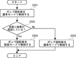
以下、図5を参照しつつ、自動二輪車1の第3制御例について説明する。第3制御例は、複数の制御内容でポンプ回転数を制御するための制御例である。
(Third control example)
Hereinafter, a third control example of the motorcycle 1 will be described with reference to FIG. The third control example is a control example for controlling the pump rotation speed with a plurality of control contents.

第3制御例がスタートすると、ポンプ制御部83は、ポンプ回転数を通常モードで制御する(ステップS301)。この通常モードでは、ポンプ制御部83は、触媒52による排気ガスの浄化性能を向上させるために必要な二次エアの供給量に応じて、ポンプ回転数を制御する。例えば、ポンプ制御部83は、各酸素センサ77、78が検出する排気ガス中の酸素濃度又は触媒温度センサ79が検出する触媒52の温度に応じて、ポンプ回転数を制御する。   When the third control example starts, the pump control unit 83 controls the pump rotation speed in the normal mode (step S301). In this normal mode, the pump control unit 83 controls the number of revolutions of the pump in accordance with the supply amount of secondary air necessary for improving the exhaust gas purification performance by the catalyst 52. For example, the pump control unit 83 controls the pump rotation speed according to the oxygen concentration in the exhaust gas detected by the oxygen sensors 77 and 78 or the temperature of the catalyst 52 detected by the catalyst temperature sensor 79.

次に、旋回判定部82は、自動二輪車1が旋回しているか否かを判定する(ステップS302)。   Next, the turning determination unit 82 determines whether or not the motorcycle 1 is turning (step S302).

ステップS302の判定がNoの場合には、ポンプ制御部83は、ステップS301と同様に、ポンプ回転数を通常モードで制御する(ステップS303)。つまり、ステップS302の判定がNoの場合には、ポンプ制御部83は、第3制御例のスタート時と同一の制御内容でポンプ回転数を制御する。   When the determination in step S302 is No, the pump control unit 83 controls the pump rotation speed in the normal mode as in step S301 (step S303). That is, when the determination in step S302 is No, the pump control unit 83 controls the pump rotation speed with the same control content as at the start of the third control example.

一方で、ステップS302の判定がYesの場合には、ポンプ制御部83は、ポンプ回転数を旋回モードで制御する(ステップS304)。この旋回モードでは、ポンプ制御部83は、適切な大きさのジャイロ効果を発生させるように、ポンプ回転数を制御する。以下、旋回モードの例1〜例4について説明する。   On the other hand, when the determination in step S302 is Yes, the pump control unit 83 controls the pump speed in the turning mode (step S304). In this turning mode, the pump control unit 83 controls the pump rotation speed so as to generate a gyro effect having an appropriate magnitude. Hereinafter, Examples 1 to 4 of the turning mode will be described.

(旋回モードの例1)
旋回モードの例1では、ポンプ制御部83は、スロットルポジションセンサ75が検出するスロットル開度に応じてポンプ回転数を制御する。具体的には、ポンプ制御部83は、ステップS302の時点(自動二輪車1が旋回しているか否かを判定した時点)におけるスロットル開度とポンプ回転数を基準に、Δt秒ごとのスロットル開度の変化にポンプ回転数の変化を追従させる。例えば、ポンプ制御部83は、ステップS302の時点からΔt秒間にスロットル開度が上昇した場合にはポンプ回転数も上昇させ、ステップS302の時点からΔt秒間にスロットル開度が下降した場合にはポンプ回転数も下降させる(それ以降も、Δt秒ごとに同様の制御が繰り返される)。
(Example 1 of turning mode)
In the turning mode example 1, the pump control unit 83 controls the pump rotation speed in accordance with the throttle opening detected by the throttle position sensor 75. Specifically, the pump control unit 83 determines the throttle opening at every Δt seconds based on the throttle opening and the pump speed at the time of step S302 (when it is determined whether or not the motorcycle 1 is turning). The change of the pump speed is made to follow the change of. For example, the pump control unit 83 increases the pump rotation speed when the throttle opening increases for Δt seconds from the time of step S302, and pumps when the throttle opening decreases for Δt seconds from the time of step S302. The number of revolutions is also decreased (the same control is repeated every Δt seconds thereafter).

(旋回モードの例2)
旋回モードの例2では、ポンプ制御部83は、クランクポジションセンサ76が検出するクランク回転数に応じてポンプ回転数を制御する。具体的には、ポンプ制御部83は、ステップS302の時点(自動二輪車1が旋回しているか否かを判定した時点)におけるクランク回転数とポンプ回転数を基準に、Δt秒ごとのクランク回転数の変化率にポンプ回転数の変化率を追従させる。例えば、ポンプ制御部83は、ステップS302の時点からΔt秒間にクランク回転数が10%上昇した場合にはポンプ回転数も10%上昇させ、ステップS302の時点からΔt秒間にクランク回転数が10%下降した場合にはポンプ回転数も10%下降させる(それ以降も、Δt秒ごとに同様の制御が繰り返される)。なお、この場合、クランク回転数の変化率(上記の例では10%)とポンプ回転数の変化率(上記の例では10%)は一致しているのが好ましいが、クランク回転数自体とポンプ回転数自体は必ずしも一致していなくても良い。
(Example 2 of turning mode)
In the second example of the turning mode, the pump control unit 83 controls the pump rotation speed in accordance with the crank rotation speed detected by the crank position sensor 76. Specifically, the pump control unit 83 determines the crank rotational speed per Δt second based on the crank rotational speed and the pump rotational speed at the time of step S302 (when it is determined whether or not the motorcycle 1 is turning). The rate of change of the pump speed is made to follow the rate of change. For example, when the crank rotational speed increases by 10% in Δt seconds from the time of step S302, the pump control unit 83 increases the pump rotational speed by 10%, and the crank rotational speed increases by 10% in Δt seconds from the time of step S302. If it is lowered, the pump rotational speed is also lowered by 10% (the same control is repeated every Δt seconds thereafter). In this case, it is preferable that the change rate of the crank rotation speed (10% in the above example) and the change rate of the pump rotation speed (10% in the above example) coincide with each other. The rotational speeds themselves do not necessarily have to match.

(旋回モードの例3)
旋回モードの例3では、ポンプ制御部83は、車速センサ72が検出する車輪回転数に応じてポンプ回転数を制御する。具体的には、ポンプ制御部83は、ステップS302の時点(自動二輪車1が旋回しているか否かを判定した時点)における車輪回転数とポンプ回転数を基準に、Δt秒ごとの車輪回転数の変化率にポンプ回転数の変化率を追従させる。例えば、ポンプ制御部83は、ステップS302の時点からΔt秒間に車輪回転数が10%上昇した場合にはポンプ回転数も10%上昇させ、ステップS302の時点からΔt秒間に車輪回転数が10%下降した場合にはポンプ回転数も10%下降させる(それ以降も、Δt秒ごとに同様の制御が繰り返される)。なお、この場合、車輪回転数の変化率(上記の例では10%)とポンプ回転数の変化率(上記の例では10%)は一致しているのが好ましいが、車輪回転数自体とポンプ回転数自体は必ずしも一致していなくても良い。
(Example 3 of turning mode)
In the example 3 of the turning mode, the pump control unit 83 controls the pump rotation speed according to the wheel rotation speed detected by the vehicle speed sensor 72. Specifically, the pump control unit 83 uses the wheel rotation speed and the pump rotation speed at the time of step S302 (when it is determined whether or not the motorcycle 1 is turning) as a reference for the wheel rotation speed every Δt seconds. The rate of change of the pump speed is made to follow the rate of change. For example, the pump controller 83 increases the pump rotational speed by 10% when the wheel rotational speed has increased by 10% in Δt seconds from the time of step S302, and the wheel rotational speed by 10% in Δt seconds from the time of step S302. If it is lowered, the pump rotational speed is also lowered by 10% (the same control is repeated every Δt seconds thereafter). In this case, it is preferable that the change rate of the wheel rotation speed (10% in the above example) and the change rate of the pump rotation speed (10% in the above example) coincide with each other. The rotational speeds themselves do not necessarily have to match.

(旋回モードの例4)
旋回モードの例4では、ポンプ制御部83は、自動二輪車1が旋回していないと旋回判定部82が判定するまで、ポンプ回転数を固定する。具体的には、ポンプ制御部83は、ステップS302の時点(自動二輪車1が旋回しているか否かを判定した時点)におけるポンプ回転数を基準に、自動二輪車1が旋回していないと旋回判定部82が判定するまで、ポンプ回転数の目標値を一定に保つ。
(Example 4 of turning mode)
In the turning mode example 4, the pump control unit 83 fixes the pump rotation speed until the turning determination unit 82 determines that the motorcycle 1 is not turning. Specifically, the pump control unit 83 determines that the motorcycle 1 is not turning based on the pump rotation speed at the time of step S302 (when it is determined whether or not the motorcycle 1 is turning). Until the unit 82 determines, the target value of the pump speed is kept constant.

なお、旋回モードの例4の実行中には、旋回判定部82は、自動二輪車1が旋回しているか否かの判定を定期的に繰り返す。ポンプ制御部83は、自動二輪車1が旋回していると旋回判定部82が判定している間は、ポンプ回転数の制御モードを旋回モードのまま維持する。一方で、ポンプ制御部83は、自動二輪車1が旋回していないと旋回判定部82が判定した時点で、ポンプ回転数の制御モードを旋回モードから通常モードに復帰させる。   During execution of the turning mode example 4, the turning determination unit 82 periodically repeats the determination of whether or not the motorcycle 1 is turning. The pump control unit 83 maintains the pump rotation speed control mode in the turning mode while the turning determination unit 82 determines that the motorcycle 1 is turning. On the other hand, the pump control unit 83 returns the control mode of the pump rotation speed from the turning mode to the normal mode when the turning determination unit 82 determines that the motorcycle 1 is not turning.

(第4制御例)
以下、図6〜図8を参照しつつ、自動二輪車1の第4制御例について説明する。第4制御例は、ポンプ回転数の目標値を設定するための制御例である。
(Fourth control example)
Hereinafter, a fourth control example of the motorcycle 1 will be described with reference to FIGS. The fourth control example is a control example for setting a target value for the pump speed.

第4制御例がスタートすると、旋回判定部82は、自動二輪車1が旋回しているか否かを判定する(ステップS401)。   When the fourth control example starts, the turning determination unit 82 determines whether or not the motorcycle 1 is turning (step S401).

ステップS401の判定がNoの場合には、ポンプ制御部83は、ポンプ回転数の目標値をZに設定する(ステップS402)。その際に、ポンプ制御部83は、触媒52による排気ガスの浄化性能を向上させるために必要な二次エアの供給量に応じて、Zの値を決定する。例えば、ポンプ制御部83は、各酸素センサ77、78が検出する排気ガス中の酸素濃度又は触媒温度センサ79が検出する触媒52の温度に応じて、Zの値を決定する。   When the determination in step S401 is No, the pump control unit 83 sets the target value of the pump speed to Z (step S402). At that time, the pump control unit 83 determines the value of Z according to the supply amount of secondary air necessary for improving the exhaust gas purification performance by the catalyst 52. For example, the pump control unit 83 determines the value of Z according to the oxygen concentration in the exhaust gas detected by the oxygen sensors 77 and 78 or the temperature of the catalyst 52 detected by the catalyst temperature sensor 79.

一方で、ステップS401の判定がYesの場合には、ECU80は、後輪6の空転を抑制するためのトラクションコントロールを介入させる(ステップS403)。このトラクションコントロールでは、ECU80は、後輪6の空転しやすさに関連する検出値(例えば、傾斜センサ71が検出する自動二輪車1の左右方向の傾斜角度)に基づいてトラクションコントロールの制御量(例えば、点火カットの実行頻度)を決定する。   On the other hand, when the determination in step S401 is Yes, the ECU 80 intervenes traction control for suppressing idling of the rear wheel 6 (step S403). In this traction control, the ECU 80 controls the amount of traction control (for example, the amount of traction control that is detected by the tilt sensor 71 in the horizontal direction of the motorcycle 1) based on the detection value related to the ease of idling of the rear wheel 6. The execution frequency of the ignition cut is determined.

次に、ECU80は、トラクションコントロールの制御量が閾値Th1以上であるか否かを判定する(ステップS404)。   Next, the ECU 80 determines whether or not the control amount of the traction control is greater than or equal to the threshold value Th1 (step S404).

ステップS404の判定がYesの場合には、トラクションコントロールの制御量が「大」である。この場合、ポンプ制御部83は、ポンプ回転数の目標値をAに設定する(ステップS405)。   If the determination in step S404 is Yes, the control amount of traction control is “large”. In this case, the pump control unit 83 sets the target value of the pump speed to A (step S405).

一方で、ステップS404の判定がNoの場合には、ECU80は、トラクションコントロールの制御量が閾値Th2(但し、Th2<Th1)以上であるか否かを判定する(ステップS406)。   On the other hand, when the determination in step S404 is No, the ECU 80 determines whether or not the control amount of the traction control is equal to or greater than a threshold value Th2 (where Th2 <Th1) (step S406).

ステップS406の判定がYesの場合には、トラクションコントロールの制御量が「中」である。この場合、ポンプ制御部83は、ポンプ回転数の目標値をBに設定する(ステップS407)。   When the determination in step S406 is Yes, the control amount of the traction control is “medium”. In this case, the pump control unit 83 sets the target value for the pump speed to B (step S407).

一方で、ステップS406の判定がNoの場合には、トラクションコントロールの制御量が「小」である。この場合、ポンプ制御部83は、ポンプ回転数の目標値をCに設定する(ステップS408)。   On the other hand, when the determination in step S406 is No, the control amount of the traction control is “small”. In this case, the pump control unit 83 sets the target value for the pump speed to C (step S408).

上記のようにポンプ回転数の目標値A〜Cを設定する際に、ポンプ制御部83は、目標値A>目標値B>目標値Cとなるように目標値A〜Cを設定しても良い(図7参照)。つまり、ポンプ制御部83は、トラクションコントロールの制御量に比例するように目標値A〜Cを変化させても良い。これにより、トラクションコントロールの制御量が大きくなるのに従ってエアポンプ62の回転に伴うジャイロ効果も大きくなり、自動二輪車1の安定性が向上する。   When setting the target values A to C of the pump speed as described above, the pump control unit 83 sets the target values A to C so that the target value A> the target value B> the target value C. Good (see FIG. 7). That is, the pump control unit 83 may change the target values A to C so as to be proportional to the control amount of the traction control. As a result, the gyro effect associated with the rotation of the air pump 62 increases as the control amount of the traction control increases, and the stability of the motorcycle 1 is improved.

一方で、上記のようにポンプ回転数の目標値A〜Cを設定する際に、ポンプ制御部83は、目標値A<目標値B<目標値Cとなるように目標値A〜Cを設定しても良い(図8参照)。つまり、ポンプ制御部83は、トラクションコントロールの制御量に反比例するように目標値A〜Cを変化させても良い。これにより、トラクションコントロールの制御量が大きくなるのに従ってエアポンプ62の回転に伴うジャイロ効果が小さくなり、自動二輪車1の旋回性が向上する。   On the other hand, when setting the target values A to C of the pump speed as described above, the pump control unit 83 sets the target values A to C so that the target value A <target value B <target value C. You may do it (refer FIG. 8). That is, the pump control unit 83 may change the target values A to C so as to be inversely proportional to the control amount of the traction control. As a result, the gyro effect associated with the rotation of the air pump 62 decreases as the control amount of the traction control increases, and the turning performance of the motorcycle 1 improves.

(効果)
上記した第1〜第4制御例では、ポンプ制御部83は、旋回判定部82の判定結果に応じてポンプ回転数に対する制御内容を変えている。そのため、自動二輪車1の旋回時に適切な大きさのジャイロ効果を発生させることができ、自動二輪車1の旋回時における操作性を向上させることができる。
(effect)
In the first to fourth control examples described above, the pump control unit 83 changes the control content with respect to the pump rotation speed in accordance with the determination result of the turning determination unit 82. Therefore, a gyro effect having an appropriate magnitude can be generated when the motorcycle 1 turns, and the operability during turning of the motorcycle 1 can be improved.

また、上記のように自動二輪車1の旋回時に適切な大きさのジャイロ効果を発生させることができるため、自動二輪車1の旋回時にジャイロ効果の影響を懸念してエアポンプ62の駆動を停止させる必要がない。そのため、自動二輪車1の旋回時もエアポンプ62を駆動させることができ、エアポンプ62の駆動時間を増加させて、触媒52による排気ガスの浄化性能を向上させることができる。   In addition, since the gyro effect having an appropriate magnitude can be generated when the motorcycle 1 turns as described above, it is necessary to stop the driving of the air pump 62 because of the influence of the gyro effect when the motorcycle 1 turns. Absent. Therefore, the air pump 62 can be driven even when the motorcycle 1 is turning, and the driving time of the air pump 62 can be increased, so that the exhaust gas purification performance by the catalyst 52 can be improved.

また、上記した第1、第2制御例では、ポンプ制御部83は、自動二輪車1が旋回していると旋回判定部82が判定した場合に、自動二輪車1が旋回していないと旋回判定部82が判定した場合よりも時間を掛けて、ポンプ回転数を目標値(第1制御例ではN、第2制御例では0)に到達させている。このような制御を実行することで、自動二輪車1の旋回時におけるポンプ回転数の急激な変化を抑制することができる。そのため、自動二輪車1の旋回時におけるジャイロ効果の急激な変化も抑制することができ、自動二輪車1の旋回時における操作性を一層向上させることができる。   In the first and second control examples described above, the pump control unit 83 determines that the motorcycle 1 is not turning when the turning determination unit 82 determines that the motorcycle 1 is turning. The pump rotation speed is made to reach the target value (N in the first control example, 0 in the second control example) by taking more time than the case where 82 is determined. By executing such control, it is possible to suppress a rapid change in the pump rotational speed when the motorcycle 1 turns. Therefore, a sudden change in the gyro effect at the time of turning of the motorcycle 1 can be suppressed, and the operability at the time of turning of the motorcycle 1 can be further improved.

また、上記した第3制御例の旋回モードの例1では、ポンプ制御部83は、スロットル開度に応じてポンプ回転数を制御している。このような制御を実行することで、自動二輪車1の旋回時に、ライダーによるスロットル開度の操作に合わせてポンプ回転数を変化させることができる。そのため、ポンプ回転数の変化に伴ってジャイロ効果が変化しても、ライダーが違和感を覚えにくくなる。   In the first example of the turning mode of the third control example, the pump control unit 83 controls the pump rotation speed in accordance with the throttle opening. By executing such control, the number of revolutions of the pump can be changed in accordance with the operation of the throttle opening by the rider when the motorcycle 1 turns. Therefore, even if the gyro effect changes with changes in the pump speed, it is difficult for the rider to feel uncomfortable.

また、上記した第3制御例の旋回モードの例2では、ポンプ制御部83は、クランク回転数に応じてポンプ回転数を制御している。このような制御を実行することで、自動二輪車1の旋回時に、クランク軸25の回転により発生する大きなジャイロ効果の変化に、エアポンプ62の回転により発生するジャイロ効果の変化を同調させることができる。そのため、ポンプ回転数の変化に伴ってジャイロ効果が変化しても、ライダーが違和感を覚えにくくなる。   In the second example of the turning mode of the third control example described above, the pump control unit 83 controls the pump speed according to the crank speed. By executing such control, the change in the gyro effect generated by the rotation of the air pump 62 can be synchronized with the large change in the gyro effect generated by the rotation of the crankshaft 25 when the motorcycle 1 turns. Therefore, even if the gyro effect changes with changes in the pump speed, it is difficult for the rider to feel uncomfortable.

また、上記した第3制御例の旋回モードの例3では、ポンプ制御部83は、車輪回転数に応じてポンプ回転数を制御している。このような制御を実行することで、自動二輪車1の旋回時に、前輪4又は後輪6の回転により発生する大きなジャイロ効果の変化に、エアポンプ62の回転により発生するジャイロ効果の変化を同調させることができる。そのため、ポンプ回転数の変化に伴ってジャイロ効果が変化しても、ライダーが違和感を覚えにくくなる。   In the third example of the turning mode of the third control example described above, the pump control unit 83 controls the pump speed according to the wheel speed. By executing such control, the change of the gyro effect generated by the rotation of the air pump 62 is synchronized with the large change of the gyro effect generated by the rotation of the front wheel 4 or the rear wheel 6 when the motorcycle 1 turns. Can do. Therefore, even if the gyro effect changes with changes in the pump speed, it is difficult for the rider to feel uncomfortable.

また、上記した第3制御例の旋回モードの例4では、ポンプ制御部83は、自動二輪車1が旋回していると旋回判定部82が判定した場合に、自動二輪車1が旋回していないと旋回判定部82が判定するまで、ポンプ回転数を固定している。これに伴って、自動二輪車1の旋回時に、ポンプ回転数の変化に伴うジャイロ効果の変化を無くすことができ、ライダーが違和感を覚えにくくなる。   Further, in the turning mode example 4 of the third control example described above, the pump control unit 83 determines that the motorcycle 1 is not turning when the turning determination unit 82 determines that the motorcycle 1 is turning. The pump rotational speed is fixed until the turning determination unit 82 determines. Along with this, when the motorcycle 1 turns, the change in the gyro effect accompanying the change in the pump rotation speed can be eliminated, and the rider is less likely to feel uncomfortable.

また、上記した第4制御例では、ポンプ制御部83は、トラクションコントロールの制御量に応じてポンプ回転数の目標値を変化させている。このような制御を実行することで、トラクションコントロールの制御量に応じた適切な大きさのジャイロ効果を発生させることができ、ライダーが違和感を覚えにくくなる。   In the fourth control example described above, the pump control unit 83 changes the target value of the pump rotation speed in accordance with the control amount of the traction control. By executing such control, it is possible to generate a gyro effect having an appropriate magnitude according to the control amount of the traction control, and it is difficult for the rider to feel uncomfortable.

特に、上記した第4制御例では、トラクションコントロールの制御量に比例するようにポンプ回転数の目標値を変化させるか、又は、トラクションコントロールの制御量に反比例するようにポンプ回転数の目標値を変化させるかを、選択可能となっている。そのため、エアポンプ62の搭載位置、エアポンプ62の回転方向、自動二輪車1の車両特性等を考慮した上で、ポンプ回転数の目標値を適切に設定することができる。   In particular, in the fourth control example described above, the target value of the pump speed is changed so as to be proportional to the control amount of the traction control, or the target value of the pump speed is set to be inversely proportional to the control amount of the traction control. It is possible to select whether to change. Therefore, the target value of the pump speed can be appropriately set in consideration of the mounting position of the air pump 62, the rotation direction of the air pump 62, the vehicle characteristics of the motorcycle 1, and the like.

(変形例)
本実施例では、傾斜センサ71及び車速センサ72を状態検出部として用いている。一方で、他の異なる実施例では、水温センサ73、油温センサ74、スロットルポジションセンサ75、クランクポジションセンサ76、各酸素センサ77、78、触媒温度センサ79、エンジン温度センサ(エンジン7のクランクケース21、シリンダブロック22又はシリンダヘッド23等の温度を検出するセンサ)、吸気温度センサ(エンジン7の吸気温度を検出するセンサ)、吸気量センサ(エンジン7の吸気量を検出するセンサ)、吸気圧センサ(エンジン7の吸気圧を検出するセンサ)、排気温度センサ(エンジン7の排気温度を検出するセンサ)、エキゾーストバルブポジションセンサ(排気管51に設置されたエキゾーストバルブの開度を検出するセンサ)、カムポジションセンサ(吸気バルブ34及び排気バルブ35を駆動させる動弁機構に設けられたカムの位置を検出するセンサ)、ギヤポジションセンサ(変速装置のギヤポジションを検出するセンサ)、慣性センサ(自動二輪車1の加速度及び角速度を検出するセンサ)、加速度センサ(自動二輪車1の加速度を検出するセンサ)、サスストロークセンサ(サスペンションのストローク位置を検出するセンサ)、サス荷重センサ(サスペンションの荷重を検出するセンサ)、ブレーキスイッチ(ブレーキのON/OFFを検出するスイッチ)、ブレーキ油圧センサ(ブレーキの油圧を検出するセンサ)、GPS(Global Positioning System)等を状態検出部として用いても良い。
(Modification)
In the present embodiment, the inclination sensor 71 and the vehicle speed sensor 72 are used as the state detection unit. On the other hand, in other different embodiments, the water temperature sensor 73, the oil temperature sensor 74, the throttle position sensor 75, the crank position sensor 76, the oxygen sensors 77 and 78, the catalyst temperature sensor 79, the engine temperature sensor (the crankcase of the engine 7). 21, a sensor for detecting the temperature of the cylinder block 22 or the cylinder head 23), an intake air temperature sensor (a sensor for detecting the intake air temperature of the engine 7), an intake air amount sensor (a sensor for detecting the intake air amount of the engine 7), an intake air pressure Sensor (sensor for detecting intake pressure of engine 7), exhaust temperature sensor (sensor for detecting exhaust temperature of engine 7), exhaust valve position sensor (sensor for detecting opening of exhaust valve installed in exhaust pipe 51) , Cam position sensor (drives intake valve 34 and exhaust valve 35) Sensor for detecting the position of the cam provided in the valve mechanism to be operated), gear position sensor (sensor for detecting the gear position of the transmission), inertial sensor (sensor for detecting the acceleration and angular velocity of the motorcycle 1), acceleration sensor (Sensor for detecting the acceleration of the motorcycle 1), suspension stroke sensor (sensor for detecting the stroke position of the suspension), suspension load sensor (sensor for detecting the load of the suspension), brake switch (detecting brake ON / OFF) Switch), brake oil pressure sensor (sensor for detecting brake oil pressure), GPS (Global Positioning System), and the like may be used as the state detection unit.

本実施例では、エアポンプ62を駆動するタイミングと制御バルブ63を開放するタイミングを同期させている。一方で、他の異なる実施例では、エアポンプ62を駆動するタイミングと制御バルブ63を開放するタイミングをずらしても良い。例えば、エアポンプ62の回転に伴うジャイロ効果を発生させたいが触媒52に二次エアを供給したくない場合には、制御バルブ63を閉止した状態でエアポンプ62を駆動しても良い。   In this embodiment, the timing for driving the air pump 62 and the timing for opening the control valve 63 are synchronized. On the other hand, in another different embodiment, the timing for driving the air pump 62 and the timing for opening the control valve 63 may be shifted. For example, when it is desired to generate the gyro effect accompanying the rotation of the air pump 62 but not to supply the secondary air to the catalyst 52, the air pump 62 may be driven with the control valve 63 closed.

なお、このように制御バルブ63を閉止した状態でエアポンプ62を駆動する場合には、図9に示されるように、制御バルブ63よりも上流側において二次エア供給通路61に弁体91を設け、この弁体91とエアクリーナ41のクリーンサイドS2を補助配管92で接続するのが好ましい。このような構成を採用することで、制御バルブ63を閉止した状態でエアポンプ62を駆動した際に、二次エア供給通路61内の二次エアを弁体91及び補助配管92を介してエアクリーナ41のクリーンサイドS2に戻すことができる。そのため、二次エア供給通路61内の圧力が高まって配管61a、61bの接続が解除されるような不具合を抑制することができる。   When the air pump 62 is driven with the control valve 63 closed as described above, a valve body 91 is provided in the secondary air supply passage 61 upstream of the control valve 63 as shown in FIG. The valve body 91 and the clean side S2 of the air cleaner 41 are preferably connected by an auxiliary pipe 92. By adopting such a configuration, when the air pump 62 is driven with the control valve 63 closed, the secondary air in the secondary air supply passage 61 is passed through the valve element 91 and the auxiliary pipe 92 to the air cleaner 41. To the clean side S2. Therefore, the malfunction that the pressure in the secondary air supply passage 61 increases and the connection of the pipes 61a and 61b is released can be suppressed.

本実施例では、エアポンプ62の駆動軸62a及びファン62bがエンジン7のクランク軸25と同一の回転方向に回転する。一方で、他の異なる実施例では、エアポンプ62の駆動軸62a及びファン62bがエンジン7のクランク軸25と逆の回転方向に回転しても良い。   In this embodiment, the drive shaft 62 a and the fan 62 b of the air pump 62 rotate in the same rotational direction as the crankshaft 25 of the engine 7. On the other hand, in another different embodiment, the drive shaft 62 a and the fan 62 b of the air pump 62 may rotate in the direction opposite to the crankshaft 25 of the engine 7.

本実施例では、燃焼室31への吸気用と二次エアの供給用に1個のエアクリーナ41を併用している。そのため、二次エアを供給するための専用のエアクリーナ41が不要となり、自動二輪車1の軽量化を図ることができる。一方で、他の異なる実施例では、燃焼室31への吸気用のエアクリーナ41と二次エアの供給用のエアクリーナ41を別個に設けても良い。   In this embodiment, one air cleaner 41 is used in combination for intake to the combustion chamber 31 and supply of secondary air. Therefore, a dedicated air cleaner 41 for supplying secondary air is not required, and the motorcycle 1 can be reduced in weight. On the other hand, in another different embodiment, an air cleaner 41 for intake air to the combustion chamber 31 and an air cleaner 41 for supplying secondary air may be provided separately.

本実施例では、触媒52よりも上流側において二次エア供給通路61が排気ポート33に接続されている。一方で、他の異なる実施例では、触媒52よりも上流側において二次エア供給通路61が排気管51に接続されていても良い。   In the present embodiment, the secondary air supply passage 61 is connected to the exhaust port 33 on the upstream side of the catalyst 52. On the other hand, in another different embodiment, the secondary air supply passage 61 may be connected to the exhaust pipe 51 on the upstream side of the catalyst 52.

本実施例では、水冷式の並列4気筒エンジンをエンジン7の一例としている。一方で、他の異なる実施例では、空冷式エンジンや油冷式エンジン等、水冷式以外の冷却方式のエンジンをエンジン7の一例としても良い。また、他の異なる実施例では、並列2気筒エンジンやV型エンジン等、並列4気筒エンジン以外の多気筒エンジンをエンジン7の一例としても良いし、単気筒エンジンをエンジン7の一例としても良い。従って、エンジン7の内部には、燃焼室31が複数個形成されていても良いし、燃焼室31が1個だけ形成されていても良い。   In this embodiment, a water-cooled parallel 4-cylinder engine is taken as an example of the engine 7. On the other hand, in another different embodiment, a cooling type engine other than the water cooling type such as an air cooling type engine or an oil cooling type engine may be used as an example of the engine 7. In other different embodiments, a multi-cylinder engine other than the parallel 4-cylinder engine such as a parallel 2-cylinder engine or a V-type engine may be used as an example of the engine 7, and a single-cylinder engine may be used as an example of the engine 7. Accordingly, a plurality of combustion chambers 31 may be formed inside the engine 7 or only one combustion chamber 31 may be formed.

本実施例では、オンロード型の自動二輪車1を鞍乗型車両の一例としている。一方で、他の異なる実施例では、オフロード型の自動二輪車を鞍乗型車両の一例としても良いし、自動三輪車等の自動二輪車以外の車両を鞍乗型車両の一例としても良い。   In this embodiment, the on-road motorcycle 1 is an example of a saddle-ride type vehicle. On the other hand, in other different embodiments, an off-road motorcycle may be an example of a saddle-type vehicle, and a vehicle other than a motorcycle such as an automatic tricycle may be an example of a saddle-type vehicle.

1 自動二輪車(鞍乗型車両の一例)
4 前輪(車輪の一例)
6 後輪(車輪の一例)
7 エンジン
25 クランク軸
31 燃焼室
41 エアクリーナ
43 スロットルバルブ
44 吸気通路
52 触媒
53 排気通路
61 二次エア供給通路
62 エアポンプ
71 傾斜センサ(状態検出部の一例)
72 車速センサ(状態検出部の一例)
82 旋回判定部
83 ポンプ制御部
1 Motorcycle (an example of a saddle type vehicle)
4 Front wheels (an example of wheels)
6 Rear wheels (example of wheels)
7 Engine 25 Crankshaft 31 Combustion chamber 41 Air cleaner 43 Throttle valve 44 Intake passage 52 Catalyst 53 Exhaust passage 61 Secondary air supply passage 62 Air pump 71 Tilt sensor (an example of state detection unit)
72 Vehicle speed sensor (an example of a state detector)
82 Turning determination unit 83 Pump control unit

Claims (7)

少なくとも1個の燃焼室が内部に形成されたエンジンと、
前記燃焼室から排出された排気ガスが流れる排気通路と、
前記排気通路内に配置される触媒と、
前記触媒よりも上流側において前記排気通路に接続される二次エア供給通路と、
前記二次エア供給通路に接続されるエアクリーナと、
前記二次エア供給通路に配置され、前記エアクリーナから供給される二次エアを前記排気通路に向けて送り出すエアポンプと、
前記エアポンプの回転数を制御するポンプ制御部と、
鞍乗型車両の状態を検出する状態検出部と、
前記状態検出部の検出結果に基づいて前記鞍乗型車両が旋回しているか否かを判定する旋回判定部と、を備え、
前記ポンプ制御部は、前記旋回判定部の判定結果に応じて前記エアポンプの回転数に対する制御内容を変えることを特徴とする鞍乗型車両。
An engine having at least one combustion chamber formed therein;
An exhaust passage through which exhaust gas discharged from the combustion chamber flows;
A catalyst disposed in the exhaust passage;
A secondary air supply passage connected to the exhaust passage upstream of the catalyst;
An air cleaner connected to the secondary air supply passage;
An air pump that is disposed in the secondary air supply passage and sends out secondary air supplied from the air cleaner toward the exhaust passage;
A pump control unit for controlling the rotation speed of the air pump;
A state detection unit for detecting the state of the saddle riding type vehicle;
A turn determination unit that determines whether or not the straddle-type vehicle is turning based on a detection result of the state detection unit,
The straddle-type vehicle, wherein the pump control unit changes a control content for the rotation speed of the air pump according to a determination result of the turning determination unit.
前記ポンプ制御部は、前記鞍乗型車両が旋回していると前記旋回判定部が判定した場合に、前記鞍乗型車両が旋回していないと前記旋回判定部が判定した場合よりも時間を掛けて、前記エアポンプの回転数を目標値に到達させることを特徴とする請求項1に記載の鞍乗型車両。   When the turning determination unit determines that the straddle-type vehicle is turning, the pump control unit has a longer time than when the turning determination unit determines that the straddle-type vehicle is not turning. The straddle-type vehicle according to claim 1, wherein the rotation speed of the air pump is reached to a target value. 前記燃焼室に導入される空気が流れる吸気通路と、
前記吸気通路に配置されるスロットルバルブと、を更に備え、
前記ポンプ制御部は、前記鞍乗型車両が旋回していると前記旋回判定部が判定した場合に、前記スロットルバルブの開度に応じて前記エアポンプの回転数を制御することを特徴とする請求項1又は2に記載の鞍乗型車両。
An intake passage through which air introduced into the combustion chamber flows;
A throttle valve disposed in the intake passage;
The said pump control part controls the rotation speed of the said air pump according to the opening degree of the said throttle valve, when the said turning determination part determines that the said saddle riding type vehicle is turning. Item 3. The saddle riding type vehicle according to item 1 or 2.
前記ポンプ制御部は、前記鞍乗型車両が旋回していると前記旋回判定部が判定した場合に、前記エンジンのクランク軸の回転数に応じて前記エアポンプの回転数を制御することを特徴とする請求項1又は2に記載の鞍乗型車両。   The pump control unit controls the number of rotations of the air pump according to the number of rotations of the crankshaft of the engine when the turning determination unit determines that the saddle riding type vehicle is turning. The straddle-type vehicle according to claim 1 or 2. 前記ポンプ制御部は、前記鞍乗型車両が旋回していると前記旋回判定部が判定した場合に、車輪の回転数に応じて前記エアポンプの回転数を制御することを特徴とする請求項1又は2に記載の鞍乗型車両。   2. The pump control unit according to claim 1, wherein when the turning determination unit determines that the saddle riding type vehicle is turning, the pump control unit controls the number of rotations of the air pump according to the number of rotations of a wheel. Or the saddle riding type vehicle according to 2. 前記ポンプ制御部は、前記鞍乗型車両が旋回していると前記旋回判定部が判定した場合に、前記鞍乗型車両が旋回していないと前記旋回判定部が判定するまで、前記エアポンプの回転数を固定することを特徴とする請求項1〜5のいずれか1項に記載の鞍乗型車両。   When the turning determination unit determines that the straddle-type vehicle is turning, the pump control unit is configured to control the air pump until the turning determination unit determines that the straddle-type vehicle is not turning. The straddle-type vehicle according to any one of claims 1 to 5, wherein the rotational speed is fixed. 前記ポンプ制御部は、前記鞍乗型車両が旋回していると前記旋回判定部が判定し、且つ、車輪の空転を抑制するためのトラクションコントロールが実行された場合に、前記トラクションコントロールの制御量に応じて前記エアポンプの回転数の目標値を変化させることを特徴とする請求項1〜6のいずれか1項に記載の鞍乗型車両。   The pump control unit determines a control amount of the traction control when the turning determination unit determines that the saddle type vehicle is turning and traction control for suppressing idling of wheels is executed. The straddle-type vehicle according to any one of claims 1 to 6, wherein the target value of the rotation speed of the air pump is changed according to the conditions.
JP2018096431A 2018-05-18 2018-05-18 Riding type vehicle Pending JP2019199865A (en)

Priority Applications (1)

Application Number Priority Date Filing Date Title
JP2018096431A JP2019199865A (en) 2018-05-18 2018-05-18 Riding type vehicle

Applications Claiming Priority (1)

Application Number Priority Date Filing Date Title
JP2018096431A JP2019199865A (en) 2018-05-18 2018-05-18 Riding type vehicle

Publications (1)

Publication Number Publication Date
JP2019199865A true JP2019199865A (en) 2019-11-21

Family

ID=68613048

Family Applications (1)

Application Number Title Priority Date Filing Date
JP2018096431A Pending JP2019199865A (en) 2018-05-18 2018-05-18 Riding type vehicle

Country Status (1)

Country Link
JP (1) JP2019199865A (en)

Similar Documents

Publication Publication Date Title
EP3236035B1 (en) Straddled vehicle
EP3165737B1 (en) Saddle-driven vehicle and single-cylinder 4-stroke engine unit
CN106661981B (en) Vehicle and single-cylinder four-stroke engine unit
JP6208353B2 (en) Vehicle and single cylinder 4-stroke engine unit
CN106471229B (en) Vehicle and single-cylinder four-stroke engine unit
EP3165437B1 (en) Straddled vehicle
WO2016002959A1 (en) Saddle-driven vehicle and single-cylinder 4-stroke engine unit
JP2019015277A (en) Exhaust gas sensor arrangement structure and motor cycle
WO2016002953A1 (en) Saddle-driven vehicle
WO2016002951A1 (en) Vehicle and single-cylinder 4-stroke engine unit
WO2016002957A1 (en) Saddle-driven vehicle and single-cylinder 4-stroke engine unit
JP6690440B2 (en) Exhaust gas sensor layout
JP2019199865A (en) Riding type vehicle
WO2016002954A1 (en) Saddle-driven vehicle
JP2018115652A (en) Arrangement structure of exhaust gas sensor
JP2019199867A (en) Riding type vehicle
JP2019199866A (en) Riding type vehicle
TWI773188B (en) straddle vehicle
JP7275775B2 (en) motorcycle
JP6011319B2 (en) Intake system of motorcycle
JP2019002301A (en) Exhaust device