JP2019192564A - All-solid battery - Google Patents
All-solid battery Download PDFInfo
- Publication number
- JP2019192564A JP2019192564A JP2018086171A JP2018086171A JP2019192564A JP 2019192564 A JP2019192564 A JP 2019192564A JP 2018086171 A JP2018086171 A JP 2018086171A JP 2018086171 A JP2018086171 A JP 2018086171A JP 2019192564 A JP2019192564 A JP 2019192564A
- Authority
- JP
- Japan
- Prior art keywords
- negative electrode
- solid
- positive electrode
- active material
- electrode active
- Prior art date
- Legal status (The legal status is an assumption and is not a legal conclusion. Google has not performed a legal analysis and makes no representation as to the accuracy of the status listed.)
- Granted
Links
Images


Classifications
-
- H—ELECTRICITY
- H01—ELECTRIC ELEMENTS
- H01M—PROCESSES OR MEANS, e.g. BATTERIES, FOR THE DIRECT CONVERSION OF CHEMICAL ENERGY INTO ELECTRICAL ENERGY
- H01M4/00—Electrodes
- H01M4/02—Electrodes composed of, or comprising, active material
- H01M4/64—Carriers or collectors
- H01M4/70—Carriers or collectors characterised by shape or form
-
- H—ELECTRICITY
- H01—ELECTRIC ELEMENTS
- H01M—PROCESSES OR MEANS, e.g. BATTERIES, FOR THE DIRECT CONVERSION OF CHEMICAL ENERGY INTO ELECTRICAL ENERGY
- H01M10/00—Secondary cells; Manufacture thereof
- H01M10/05—Accumulators with non-aqueous electrolyte
- H01M10/052—Li-accumulators
- H01M10/0525—Rocking-chair batteries, i.e. batteries with lithium insertion or intercalation in both electrodes; Lithium-ion batteries
-
- H—ELECTRICITY
- H01—ELECTRIC ELEMENTS
- H01M—PROCESSES OR MEANS, e.g. BATTERIES, FOR THE DIRECT CONVERSION OF CHEMICAL ENERGY INTO ELECTRICAL ENERGY
- H01M10/00—Secondary cells; Manufacture thereof
- H01M10/05—Accumulators with non-aqueous electrolyte
- H01M10/056—Accumulators with non-aqueous electrolyte characterised by the materials used as electrolytes, e.g. mixed inorganic/organic electrolytes
- H01M10/0561—Accumulators with non-aqueous electrolyte characterised by the materials used as electrolytes, e.g. mixed inorganic/organic electrolytes the electrolyte being constituted of inorganic materials only
- H01M10/0562—Solid materials
-
- H—ELECTRICITY
- H01—ELECTRIC ELEMENTS
- H01M—PROCESSES OR MEANS, e.g. BATTERIES, FOR THE DIRECT CONVERSION OF CHEMICAL ENERGY INTO ELECTRICAL ENERGY
- H01M10/00—Secondary cells; Manufacture thereof
- H01M10/05—Accumulators with non-aqueous electrolyte
- H01M10/058—Construction or manufacture
- H01M10/0585—Construction or manufacture of accumulators having only flat construction elements, i.e. flat positive electrodes, flat negative electrodes and flat separators
-
- H—ELECTRICITY
- H01—ELECTRIC ELEMENTS
- H01M—PROCESSES OR MEANS, e.g. BATTERIES, FOR THE DIRECT CONVERSION OF CHEMICAL ENERGY INTO ELECTRICAL ENERGY
- H01M4/00—Electrodes
- H01M4/02—Electrodes composed of, or comprising, active material
- H01M4/64—Carriers or collectors
- H01M4/70—Carriers or collectors characterised by shape or form
- H01M4/72—Grids
-
- H—ELECTRICITY
- H01—ELECTRIC ELEMENTS
- H01M—PROCESSES OR MEANS, e.g. BATTERIES, FOR THE DIRECT CONVERSION OF CHEMICAL ENERGY INTO ELECTRICAL ENERGY
- H01M50/00—Constructional details or processes of manufacture of the non-active parts of electrochemical cells other than fuel cells, e.g. hybrid cells
- H01M50/40—Separators; Membranes; Diaphragms; Spacing elements inside cells
- H01M50/463—Separators, membranes or diaphragms characterised by their shape
-
- H—ELECTRICITY
- H01—ELECTRIC ELEMENTS
- H01M—PROCESSES OR MEANS, e.g. BATTERIES, FOR THE DIRECT CONVERSION OF CHEMICAL ENERGY INTO ELECTRICAL ENERGY
- H01M50/00—Constructional details or processes of manufacture of the non-active parts of electrochemical cells other than fuel cells, e.g. hybrid cells
- H01M50/40—Separators; Membranes; Diaphragms; Spacing elements inside cells
- H01M50/489—Separators, membranes, diaphragms or spacing elements inside the cells, characterised by their physical properties, e.g. swelling degree, hydrophilicity or shut down properties
- H01M50/491—Porosity
-
- H—ELECTRICITY
- H01—ELECTRIC ELEMENTS
- H01M—PROCESSES OR MEANS, e.g. BATTERIES, FOR THE DIRECT CONVERSION OF CHEMICAL ENERGY INTO ELECTRICAL ENERGY
- H01M4/00—Electrodes
- H01M4/02—Electrodes composed of, or comprising, active material
- H01M2004/021—Physical characteristics, e.g. porosity, surface area
-
- H—ELECTRICITY
- H01—ELECTRIC ELEMENTS
- H01M—PROCESSES OR MEANS, e.g. BATTERIES, FOR THE DIRECT CONVERSION OF CHEMICAL ENERGY INTO ELECTRICAL ENERGY
- H01M4/00—Electrodes
- H01M4/02—Electrodes composed of, or comprising, active material
- H01M2004/026—Electrodes composed of, or comprising, active material characterised by the polarity
- H01M2004/027—Negative electrodes
-
- H—ELECTRICITY
- H01—ELECTRIC ELEMENTS
- H01M—PROCESSES OR MEANS, e.g. BATTERIES, FOR THE DIRECT CONVERSION OF CHEMICAL ENERGY INTO ELECTRICAL ENERGY
- H01M2220/00—Batteries for particular applications
- H01M2220/20—Batteries in motive systems, e.g. vehicle, ship, plane
-
- H—ELECTRICITY
- H01—ELECTRIC ELEMENTS
- H01M—PROCESSES OR MEANS, e.g. BATTERIES, FOR THE DIRECT CONVERSION OF CHEMICAL ENERGY INTO ELECTRICAL ENERGY
- H01M50/00—Constructional details or processes of manufacture of the non-active parts of electrochemical cells other than fuel cells, e.g. hybrid cells
- H01M50/40—Separators; Membranes; Diaphragms; Spacing elements inside cells
- H01M50/409—Separators, membranes or diaphragms characterised by the material
- H01M50/411—Organic material
- H01M50/414—Synthetic resins, e.g. thermoplastics or thermosetting resins
- H01M50/417—Polyolefins
-
- H—ELECTRICITY
- H01—ELECTRIC ELEMENTS
- H01M—PROCESSES OR MEANS, e.g. BATTERIES, FOR THE DIRECT CONVERSION OF CHEMICAL ENERGY INTO ELECTRICAL ENERGY
- H01M50/00—Constructional details or processes of manufacture of the non-active parts of electrochemical cells other than fuel cells, e.g. hybrid cells
- H01M50/40—Separators; Membranes; Diaphragms; Spacing elements inside cells
- H01M50/489—Separators, membranes, diaphragms or spacing elements inside the cells, characterised by their physical properties, e.g. swelling degree, hydrophilicity or shut down properties
Abstract
Description
本発明は、固体電解質を備えた全固体電池に関する。詳しくは、全固体電池のセパレータ層の構成に関する。 The present invention relates to an all-solid battery including a solid electrolyte. In detail, it is related with the structure of the separator layer of an all-solid-state battery.
リチウムイオン二次電池等の比較的高い出力と高い容量が実現できる二次電池は、電気を駆動源とする車両搭載用電源、あるいはパソコンおよび携帯端末等の電気製品等に搭載される電源として重要である。特に、軽量で高エネルギー密度が得られるリチウムイオン二次電池は、電気自動車(EV)、プラグインハイブリッド自動車(PHV)、ハイブリッド自動車(HV)等の車両の駆動用高出力電源として好ましく、今後ますます需要が拡大することが予想される。 Rechargeable batteries that can achieve relatively high output and high capacity, such as lithium-ion secondary batteries, are important as power sources for vehicles that use electricity as driving sources, or power supplies that are mounted on electrical products such as personal computers and portable terminals. It is. In particular, lithium ion secondary batteries that are lightweight and provide high energy density are preferred as future high-output power sources for driving vehicles such as electric vehicles (EV), plug-in hybrid vehicles (PHV), and hybrid vehicles (HV). Demand is expected to increase further.
かかる高出力の二次電池の一形態として、液状の電解質(電解液)に代えて粉末状の固体電解質を使用する形態の電池、いわゆる全固体電池とも呼称される形態の二次電池が挙げられる。
全固体電池は、液状の電解質を使用しないため、非水電解液等の有機溶媒を取り扱う場合の煩雑な処理を行うことなく、正負極ならびにセパレータ層(固体電解質層ともいう)からなる積層構造の積層電極体を容易に構築することができる。また、電解液を使用しないことから電極体の構造がシンプルとなり、電池の単位体積あたりの電池容量の向上にも寄与し得る。このため、さらなる高容量が求められる車両の駆動用高出力電源として期待されている。
As one form of such a high output secondary battery, a battery using a powdered solid electrolyte instead of a liquid electrolyte (electrolytic solution), a so-called all-solid-state secondary battery may be mentioned. .
All-solid batteries do not use liquid electrolytes, and therefore have a laminated structure consisting of positive and negative electrodes and a separator layer (also referred to as a solid electrolyte layer) without the complicated treatment of handling organic solvents such as non-aqueous electrolytes. A laminated electrode body can be easily constructed. In addition, since the electrolytic solution is not used, the structure of the electrode body is simplified, which can contribute to an improvement in battery capacity per unit volume of the battery. For this reason, it is expected as a high-output power source for driving vehicles that require higher capacity.
ところで、全固体電池の一形態として、セパレータ層(固体電解質層)に、固体電解質粒子とともに、ポリオレフィン等のポリマーからなる多孔質構造の基材を備えるものが挙げられる。例えば、特許文献1には、平均粒径が5〜100μmの結晶性酸化物系無機固体電解質粒子がポリオレフィン系樹脂等からなる多孔質基材上に一層に保持されてなるセパレータが記載されている。このような多孔質基材を備えるセパレータは、セパレータ層の薄層化によるイオン導電性の向上に寄与するとともに、セパレータ層の柔軟性が向上して電池の加工性が高まる、等の利点がある。
By the way, as one form of an all-solid-state battery, a separator layer (solid electrolyte layer) having a porous structure base material made of a polymer such as polyolefin together with solid electrolyte particles can be cited. For example,
しかしながら、上記特許文献1に記載されるような、固体電解質粒子を多孔質基材に保持させたセパレータを備える積層電極体では、次のような問題点が存在していた。
即ち、この種の積層電極体では、安定的な充放電を保証するため、正極よりも負極のサイズを大きくすることが一般的である。したがって、負極は、正負極対向部分(正負極積層部分)よりも外方に張り出した出代部分を有している。
そして、セパレータ層は、短絡の防止をより確実に行うため、負極と同等またはそれよりもさらに大きいサイズに形成される。したがって、セパレータ層においても、正負極の対向部分よりも外方に張り出した出代部分を有している。ここで、かかる出代部分は、該積層電極体の正負極対向部分から張り出しているため、積層方向にかけられた圧力があまり強くかからない部分である。このことから、該出代部分では、何らかの衝撃が加わった際などに固体電解質粒子が多孔質基材から脱落し易い傾向にある。該出代部分における固体電解質粒子の脱落、特に負極出代部分に対向する部分からの固体電解質粒子の脱落は、積層電極体の端部において動きやすい負極出代部分が正極端部と接触して短絡する一要因となり得るため、好ましくない。
However, the multilayer electrode body including the separator in which the solid electrolyte particles are held on the porous substrate as described in
That is, in this type of laminated electrode body, the size of the negative electrode is generally larger than that of the positive electrode in order to ensure stable charge / discharge. Therefore, the negative electrode has a protruding portion protruding outward from the positive and negative electrode facing portion (positive and negative electrode laminated portion).
The separator layer is formed in a size that is equal to or larger than that of the negative electrode in order to more reliably prevent a short circuit. Therefore, the separator layer also has a protruding portion protruding outward from the opposing portion of the positive and negative electrodes. Here, since the protrusion part protrudes from the positive / negative electrode opposing part of this laminated electrode body, it is a part where the pressure applied to the lamination direction is not so strong. For this reason, in the margin portion, the solid electrolyte particles tend to fall off the porous substrate when some kind of impact is applied. The falling of the solid electrolyte particles in the protruding portion, particularly the falling of the solid electrolyte particles from the portion facing the negative electrode protruding portion, is caused by the fact that the negative electrode protruding portion that is movable at the end of the laminated electrode body contacts the positive electrode end. This is not preferable because it may cause a short circuit.
本発明は、かかる固体電解質粒子を多孔質基材に保持させたセパレータ層を備える全固体電池に関する上記問題を解決するべく創出されたものであり、その目的とするところは、固体電解質粒子を多孔質基材に保持させたセパレータ層であって、負極の出代部分と正極端部との接触を確実に防止し得る構成のセパレータ層を備えた全固体電池を提供することである。 The present invention was created in order to solve the above-mentioned problems relating to an all-solid battery comprising a separator layer in which such a solid electrolyte particle is held on a porous substrate. The object of the present invention is to make the solid electrolyte particle porous. It is an object of the present invention to provide an all-solid-state battery comprising a separator layer that is held on a porous substrate and that can reliably prevent contact between a protruding portion of a negative electrode and a positive electrode end.
上記目的を実現するべく、ここで開示される全固体電池は、正極活物質粒子と固体電解質粒子とを含む正極活物質層が正極集電体上に形成された正極と、負極活物質粒子と固体電解質粒子とを含む負極活物質層が負極集電体上に形成された負極と、多孔質構造の基材(以下、単に「多孔質基材」ともいう。)と該基材に保持された固体電解質粒子とを含むセパレータ層とを有する積層構造の積層電極体を備える全固体電池である。
ここで開示される全固体電池では、上記積層電極体の端部の少なくとも一部において、上記負極および上記セパレータ層は、上記正極と負極の対向部の端部よりも外方に張り出した出代部をそれぞれ有している。
そして、上記セパレータ層の出代部の少なくとも一部は、上記正極と負極の接触を阻止する程度に緻密な緻密構造部により形成されていることを特徴とする。
さらに、上記正極と負極の対向部の端部から上記緻密構造部に至るまでの最短距離をAとし、上記正極と負極の対向部の端部における上記負極活物質層の表面から該対向部の端部における上記正極集電体に至るまでの最短距離をBとしたとき、A<Bを具備する位置に上記緻密構造部が形成されている。
In order to achieve the above object, an all-solid battery disclosed herein includes a positive electrode in which a positive electrode active material layer including positive electrode active material particles and solid electrolyte particles is formed on a positive electrode current collector, negative electrode active material particles, A negative electrode in which a negative electrode active material layer containing solid electrolyte particles is formed on a negative electrode current collector, a substrate having a porous structure (hereinafter also referred to simply as “porous substrate”), and the substrate An all-solid-state battery including a laminated electrode body having a laminated structure having a separator layer containing solid electrolyte particles.
In the all-solid-state battery disclosed herein, the negative electrode and the separator layer at least part of the end portion of the laminated electrode body have a protrusion extending outward from the end portion of the opposing portion of the positive electrode and the negative electrode. Each part.
In addition, at least a part of the protruding portion of the separator layer is formed by a dense structure portion that is dense enough to prevent contact between the positive electrode and the negative electrode.
Furthermore, the shortest distance from the end of the facing portion of the positive electrode and the negative electrode to the dense structure portion is A, and the surface of the negative electrode active material layer at the end of the facing portion of the positive electrode and the negative electrode is The dense structure portion is formed at a position where A <B, where B is the shortest distance from the end portion to the positive electrode current collector.
本発明者は、上記セパレータ層の出代部分における固体電解質粒子の脱落に伴う不具合が生じるのを未然に防止するべく、少なくとも負極出代部における正極端部と接触可能な部分に対向するセパレータ層の出代部分を上記緻密構造部で形成することを創案し、本発明を完成するに至った。
即ち、ここで開示される全固体電池では、上記のとおり、セパレータ層の出代部においてA<Bを満たすようにして緻密構造部を有している。これにより、何らかの外力が加わった際に、負極の出代部が、対向する正極の端部に近接する位置まで動いた場合であっても、固体電解質粒子の脱落に伴う不具合が生じる状況がそもそも発生しない構成となっており、負極出代部における正極端部(より具体的には端部に露出する正極集電体)との接触を確実に防止することができる。
The present inventor has at least a separator layer facing a portion that can be in contact with the positive electrode end portion in the negative electrode protruding portion in order to prevent a problem caused by the falling of the solid electrolyte particles in the protruding portion of the separator layer. The present invention has been completed by forming the above-mentioned prone portion of the dense structure portion.
That is, the all-solid-state battery disclosed here has a dense structure portion so as to satisfy A <B in the protruding portion of the separator layer as described above. As a result, when some external force is applied, even if the negative electrode protrusion moves to a position close to the end of the opposite positive electrode, there is a situation in which a problem occurs due to the dropout of the solid electrolyte particles in the first place. It does not occur, and can reliably prevent contact with the positive electrode end (more specifically, the positive electrode current collector exposed at the end) at the negative electrode margin.
ここで開示される全固体電池の好適な一態様では、上記多孔質基材および上記緻密構造部は、いずれも熱可塑性樹脂によって構成されていることを特徴とする。
熱可塑性樹脂は、多孔質基材を形成するポリマー材料として好適であり、さらに、加熱することによって、多孔質構造の一部を容易に熱溶着体として緻密構造に変化させることができる。また、セパレータ基材として好適な絶縁性を実現することもできる。
少なくとも80%の空孔率(例えばアルキメデス法に基づく測定値)を有する多孔質基材が好適である。かかる高い空孔率の多孔質基材によると、より高率に固体電解質粒子を保持することができ、セパレータ層における高いイオン導電性を実現することができる。
In a preferred aspect of the all-solid battery disclosed herein, the porous base material and the dense structure portion are both made of a thermoplastic resin.
The thermoplastic resin is suitable as a polymer material for forming the porous substrate, and further, by heating, a part of the porous structure can be easily changed into a dense structure as a heat welded body. Moreover, insulation suitable as a separator base material can also be realized.
A porous substrate having a porosity of at least 80% (for example measured values based on the Archimedes method) is preferred. According to such a porous substrate having a high porosity, the solid electrolyte particles can be held at a higher rate, and high ionic conductivity in the separator layer can be realized.
また、ここで開示される全固体電池の好適な一形状は、上記積層電極体が矩形状の正負極およびセパレータ層が積層されて形成されたことを特徴とする。そして、上記緻密構造部が上記矩形状セパレータ層の各辺縁の端部の出代部において形成されていることを特徴とする。
かかる構成の全固体電池では、矩形状の正負極およびセパレータ層が積層されて構成された積層電極体において、いずれの辺縁端部においても上述した短絡防止を実現することができる。
In addition, a preferred shape of the all solid state battery disclosed herein is characterized in that the laminated electrode body is formed by laminating rectangular positive and negative electrodes and a separator layer. And the said dense structure part is formed in the protrusion part of the edge part of each edge of the said rectangular separator layer, It is characterized by the above-mentioned.
In the all-solid-state battery having such a configuration, the above-described short-circuit prevention can be realized at any edge portion of the laminated electrode body formed by laminating the rectangular positive and negative electrodes and the separator layer.
以下、図面を適宜参照しながら、ここで開示される全固体電池の好適な実施形態について説明する。なお、本明細書において特に言及している事項以外の事柄であって本発明の実施に必要な事柄は、該分野における従来技術に基づく当業者の設計事項として把握され得る。本明細書中の数値範囲A〜B(A、Bは任意の数)は、A以上B以下を示すものとする。
本明細書において「(正負極)活物質」とは、正極側または負極側において電荷担体(例えばリチウムイオン二次電池においてはリチウムイオン)の吸蔵および放出に関与する物質をいう。
なお、以下の説明では、ここで開示される技術の適用対象として全固体リチウムイオン二次電池を例にしているが、これに限られない。ここで開示される全固体電池の種類としては、他の金属イオンを電荷担体とするもの、例えば、ナトリウムイオン二次電池、マグネシウムイオン二次電池、等を構成する全固体電池であってもよい。
Hereinafter, preferred embodiments of the all-solid battery disclosed herein will be described with appropriate reference to the drawings. Note that matters other than matters specifically mentioned in the present specification and necessary for the implementation of the present invention can be grasped as design matters of those skilled in the art based on the prior art in the field. The numerical range A to B (A and B are arbitrary numbers) in this specification shall indicate A or more and B or less.
In this specification, “(positive and negative electrode) active material” refers to a substance that is involved in the insertion and extraction of charge carriers (for example, lithium ions in a lithium ion secondary battery) on the positive electrode side or the negative electrode side.
In the following description, an all-solid-state lithium ion secondary battery is taken as an example of an application target of the technology disclosed herein, but is not limited thereto. The type of the all solid state battery disclosed herein may be an all solid state battery that constitutes another metal ion as a charge carrier, for example, a sodium ion secondary battery, a magnesium ion secondary battery, or the like. .
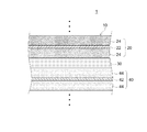
図1に、典型的な積層構造である積層電極体10を備えた全固体電池(ここでは全固体リチウムイオン二次電池)1を模式的に示している。即ち、本実施形態に係る全固体リチウムイオン二次電池1は、大まかにいって、シート状の正極20および負極40が、正負極間にセパレータ層(固体電解質層)30を介在させつつ、所定の数だけ積層されて構成された積層電極体10が、図示しない所定の筐体(電池ケース)に収容されて構成される電池である。
筐体としては、高い物理的強度、放熱性等の観点から、金属製(例えばアルミニウム製)のものを好ましく使用することができる。或いは、積載性や電池モジュール全体の重量が軽量になることから、ラミネートフィルムで構成されていてもよい。この場合の好適例として、2つの合成樹脂層の間にアルミニウム等の金属層を配置した三層構造を有するラミネートフィルムが挙げられる。
FIG. 1 schematically shows an all solid state battery (here, all solid state lithium ion secondary battery) 1 including a laminated
As the casing, a metal (for example, aluminum) can be preferably used from the viewpoint of high physical strength, heat dissipation, and the like. Alternatively, since the stackability and the weight of the entire battery module become light, it may be made of a laminate film. A suitable example in this case is a laminate film having a three-layer structure in which a metal layer such as aluminum is disposed between two synthetic resin layers.
図示されるように、正極20は、アルミニウム箔等からなる正極集電体22と、その両面に形成された所定の正極活物質および固体電解質を含む正極活物質層24とを備えている。また、負極40は、銅箔等からなる負極集電体42と、その両面に形成された所定の負極活物質および固体電解質を含む負極活物質層44とを備えている。
セパレータ層30は、正負極活物質層24,44に含まれる固体電解質と同種の固体電解質粒子と、後述する多孔質基材とを含む層であり、イオン導電性を確保しつつ正負極間を絶縁するセパレータとして機能する層である。次に、積層電極体10を構成する各層について詳細に説明する。
As illustrated, the
The
本実施形態に係る全固体リチウムイオン二次電池1に備えられる正極20は、この種の電池で使用されているものを特に制限なく用いることができる。
正極集電体22は、この種の電池の正極集電体として用いられるものを特に制限なく使用することができる。典型的には、良好な導電性を有する金属製の正極集電体が好ましく、例えば、アルミニウム、ニッケル、チタン、ステンレス鋼等の金属材から構成される。特にアルミニウム(例えばアルミニウム箔)が好ましい。正極集電体22の厚みは特に限定されないが、電池の容量密度と集電体の強度との兼ね合いから、5μm〜50μm程度が適当であり、8μm〜30μm程度がより好ましい。
As the
As the positive electrode
正極活物質層24は、正極活物質ならびに固体電解質を含有する層であり、さらに必要に応じて、導電材やバインダ(結着材)を含有してもよい。
使用され得る固体電解質としては、種々の酸化物系固体電解質または硫化物系固体電解質が挙げられる。酸化物系固体電解質としては、NASICON構造、ガーネット型構造あるいはペロブスカイト型構造を有する種々の酸化物が好適例として挙げられる。
例えば、一般式:LixAOy(ここでAは、B、C、Al、Si、P、S、Ti、Zr、Nb、Mo、Ta、またはWであり、x及びyは正の実数である。)で表されるものを挙げることができる。具体例として、Li3BO3、LiBO2、Li2CO3、LiAlO2、Li4SiO4、Li2SiO3、Li3PO4、Li2SO4、Li2TiO3、Li4Ti5O12、Li2Ti2O5、Li2ZrO3、LiNbO3、Li2MoO4、Li2WO4、等が挙げられる。あるいは、Li2O−B2O3−P2O5系、Li2O−SiO2系、Li2O−B2O3系、Li2O−B2O3−ZnO系、等のガラス若しくはガラスセラミックスも好適例として挙げられる。
The positive electrode
Examples of solid electrolytes that can be used include various oxide solid electrolytes or sulfide solid electrolytes. Preferable examples of the oxide-based solid electrolyte include various oxides having a NASICON structure, a garnet structure, or a perovskite structure.
For example, the general formula: Li x AO y (where A is B, C, Al, Si, P, S, Ti, Zr, Nb, Mo, Ta, or W, and x and y are positive real numbers) Can be mentioned. As specific examples, Li 3 BO 3 , LiBO 2 , Li 2 CO 3 , LiAlO 2 , Li 4 SiO 4 , Li 2 SiO 3 , Li 3 PO 4 , Li 2 SO 4 , Li 2 TiO 3 , Li 4 Ti 5 O 12 , Li 2 Ti 2 O 5 , Li 2 ZrO 3 , LiNbO 3 , Li 2 MoO 4 , Li 2 WO 4 , and the like. Alternatively, Li 2 O-B 2 O 3 -P 2 O 5 based, Li 2 O-SiO 2 system, Li 2 O-B 2 O 3 system, Li 2 O-B 2 O 3 -ZnO system, glass etc. Or a glass ceramic is also mentioned as a suitable example.
特に、高いイオン導電性を有するという観点から、硫化物系固体電解質の使用が好ましい。例えば、Li2S−SiS2系、Li2S−P2S3系、Li2S−P2S5系、Li2S−GeS2系、Li2S−B2S3系、Li3PO4−P2S5系、Li4SiO4−Li2S−SiS2系、等のガラス若しくはガラスセラミックスが挙げられる。
また、より高いイオン導電性を実現するという観点から、Li2Sとハロゲン化リチウム(例えばLiCl、LiBr、LiI)とから構成されるLi2Sベースの固溶体の利用が好ましい。好適例として、LiBr−Li2S−P2S5、LiI−Li2S−P2S5、LiBr−LiI−Li2S−P2S5、等が挙げられる。
使用される固体電解質粒子のレーザ回折・散乱法に基づく平均粒子径(D50)としては、例えば0.5μm〜10μm程度が適当であり、1μm〜5μm程度が特に好ましい。
In particular, it is preferable to use a sulfide-based solid electrolyte from the viewpoint of high ionic conductivity. For example, Li 2 S—SiS 2 system, Li 2 S—P 2 S 3 system, Li 2 S—P 2 S 5 system, Li 2 S—GeS 2 system, Li 2 S—B 2 S 3 system, Li 3 Examples of the glass or glass ceramics include PO 4 —P 2 S 5 series and Li 4 SiO 4 —Li 2 S—SiS 2 series.
From the viewpoint of realizing higher ionic conductivity, Li 2 S and lithium halide (e.g. LiCl, LiBr, LiI) the use of Li 2 S-based solid solution composed from the preferred. Preferable examples include LiBr—Li 2 S—P 2 S 5 , LiI—Li 2 S—P 2 S 5 , LiBr—LiI—Li 2 S—P 2 S 5 , and the like.
The average particle diameter (D 50 ) based on the laser diffraction / scattering method of the solid electrolyte particles used is, for example, preferably about 0.5 μm to 10 μm, and particularly preferably about 1 μm to 5 μm.
正極活物質層24に含まれる正極活物質としては、この種の電池で従来から用いられている種々の化合物を使用することができる。好適例として、例えば、LiCoO2、LiNiO2、LiNixCoyMn(1−x−y)O2(ここで0<x<1、0<y<1、0<x+y<1)等に代表される層状構造の複合酸化物が挙げられる。あるいは、Li2NiMn3O8、LiMn2O4、Li1+xMn2−yMyO4(ここでMは存在しないか若しくはAl、Mg、Co、Fe、Ni、Znから選ばれる一種以上の金属元素、0≦x<1、0≦y<2)で表されるようなスピネル構造の複合酸化物、LiFePO4等のオリビン構造の複合化合物、等が挙げられる。
正極活物質のレーザ回折・散乱法に基づく平均粒子径(D50)は、例えば0.5μm〜20μm程度が適当であり、1μm〜10μm程度が特に好ましい。
As the positive electrode active material contained in the positive electrode
The average particle diameter (D 50 ) based on the laser diffraction / scattering method of the positive electrode active material is, for example, preferably about 0.5 μm to 20 μm, and particularly preferably about 1 μm to 10 μm.
特に好ましい正極活物質として、該活物質粒子の表面の少なくとも一部が固体電解質からなる被膜によって被覆されている形態のものが挙げられる。特に、酸化物系固体電解質によって被覆された正極活物質の利用が好ましい。固体電解質によって被覆された正極活物質粒子を採用することにより、正極活物質層24内における正極活物質と固体電解質とをより良好に密着させることができる。
正極活物質粒子を被覆する固体電解質膜の厚さは、特に限定しないが、導電性を大きく阻害しない程度の厚さが好ましい。例えば、平均膜厚が0.1nm〜100nmであることが好ましい。また、正極活物質粒子の表面積にしめる固体電解質膜の被覆率が、30%以上、さらには40%以上であることが好ましい。
正極活物質層24における正極活物質と固体電解質との配合比は特に限定されない。典型的には、正極活物質(P)と固体電解質(S)との質量比(P:S)が、50:50〜95:5程度であり得る。
正極活物質層24の厚みは、特に限定されない。典型的には、10μm〜500μmであり得る。
As a particularly preferable positive electrode active material, a material in which at least a part of the surface of the active material particles is covered with a coating made of a solid electrolyte can be cited. In particular, it is preferable to use a positive electrode active material coated with an oxide-based solid electrolyte. By employing the positive electrode active material particles coated with the solid electrolyte, the positive electrode active material and the solid electrolyte in the positive electrode
The thickness of the solid electrolyte membrane covering the positive electrode active material particles is not particularly limited, but is preferably a thickness that does not significantly impair the conductivity. For example, the average film thickness is preferably 0.1 nm to 100 nm. Moreover, it is preferable that the coverage of the solid electrolyte membrane to be the surface area of the positive electrode active material particles is 30% or more, more preferably 40% or more.
The compounding ratio of the positive electrode active material and the solid electrolyte in the positive electrode
The thickness of the positive electrode
なお、正極活物質層24には、正極活物質および固体電解質の他に、従来のこの種の電池の正極活物質層と同様に種々の任意成分を含ませることができる。例えば、導電材やバインダ等を含み得る。導電材としては、アセチレンブラック等のカーボンブラックやその他(グラファイト、カーボンナノチューブ等)の炭素材料を好適に使用し得る。バインダとしては、ポリフッ化ビニリデン(PVDF)、ポリテトラフルオロエチレン(PTFE)等のフッ素系バインダや、スチレンブタジエンゴム(SBR)等のゴム系バインダを好適に使用することができる。
In addition to the positive electrode active material and the solid electrolyte, the positive electrode
本実施形態に係る全固体リチウムイオン二次電池1に備えられる負極40は、この種の電池で使用されているものを特に制限なく用いることができる。
負極集電体42は、この種の電池の負極集電体として用いられるものを特に制限なく使用することができる。典型的には、良好な導電性を有する金属製の負極集電体が好ましく、例えば、銅(例えば銅箔)や銅を主体とする合金を用いることができる。負極集電体42の厚みは特に限定されないが、電池の容量密度と集電体の強度との兼ね合いから、5μm〜50μm程度が適当であり、8μm〜30μm程度がより好ましい。
As the
As the negative electrode
負極活物質層44は、負極活物質ならびに固体電解質を含有する層であり、さらに必要に応じて、バインダ等を含有してもよい。
負極活物質層44に含まれる固体電解質は、上述した正極活物質層24に含まれるものと同様のものでよく、重複した説明は省略する。
負極活物質層24に含まれる負極活物質としては、この種の電池で従来から用いられている種々の化合物を使用することができる。例えば、グラファイト、メソカーボンマイクロビーズ、カーボンブラック(アセチレンブラック、ケッチェンブラック等)のような炭素系の負極活物質が一例として挙げられる。
The negative electrode
The solid electrolyte contained in the negative electrode
As the negative electrode active material contained in the negative electrode
また、高エネルギー密度の負極活物質としてケイ素(Si)またはスズ(Sn)を構成元素とする負極活物質が挙げられる。
具体的には、Si(シリコン)系負極活物質としては、Si、SiOa(ここで0.05<a<1.95)で表される酸化ケイ素、SiCb(0<b<1)で表される炭化ケイ素、SiNc(0<c<4/3)で表される窒化ケイ素、等が挙げられる。
ケイ素系負極活物質のその他の例として、ケイ素とケイ素以外の元素とからなる合金材料が挙げられる。ケイ素以外の元素としては、例えば、Fe、Co、Sb、Bi、Pb、Ni、Cu、Zn、Ge、In、Sn、Ti等が挙げられる。
Moreover, the negative electrode active material which uses silicon (Si) or tin (Sn) as a constituent element is mentioned as a high energy density negative electrode active material.
Specifically, as the Si (silicon) negative electrode active material, Si, silicon oxide represented by SiO a (here 0.05 <a <1.95), SiC b (0 <b <1) Examples thereof include silicon carbide, silicon nitride represented by SiN c (0 <c <4/3), and the like.
Other examples of the silicon-based negative electrode active material include an alloy material composed of silicon and an element other than silicon. Examples of elements other than silicon include Fe, Co, Sb, Bi, Pb, Ni, Cu, Zn, Ge, In, Sn, and Ti.
一方、 Sn系負極活物質としては、例えば、スズ、スズ酸化物、スズ窒化物、スズ含有合金等、及びこれらの固溶体等が挙げられる。これらに含有されるスズ原子の一部が1種又は2種以上の元素で置換されていてもよい。
酸化物としては、SnOd(0<d<2)で表される酸化スズ、二酸化スズ(SnO2)等が挙げられる。スズ含有合金としては、Ni−Sn合金、Mg−Sn合金、Fe−Sn合金、Cu−Sn合金、Ti−Sn合金等が挙げられる。スズ化合物としては、SnSiO3、Ni2Sn4、Mg2Sn等が挙げられる。
負極活物質のレーザ回折・散乱法に基づく平均粒子径(D50)は、例えば1μm〜20μm程度が適当であり、2μm〜10μm程度が特に好ましい。
On the other hand, examples of the Sn-based negative electrode active material include tin, tin oxide, tin nitride, tin-containing alloy, and solid solutions thereof. Some of the tin atoms contained in these may be substituted with one or more elements.
Examples of the oxide include tin oxide represented by SnO d (0 <d <2), tin dioxide (SnO 2 ), and the like. Examples of the tin-containing alloy include a Ni—Sn alloy, a Mg—Sn alloy, a Fe—Sn alloy, a Cu—Sn alloy, and a Ti—Sn alloy. Examples of the tin compound include SnSiO 3 , Ni 2 Sn 4 , and Mg 2 Sn.
The average particle diameter (D 50 ) based on the laser diffraction / scattering method of the negative electrode active material is, for example, preferably about 1 μm to 20 μm, and particularly preferably about 2 μm to 10 μm.
負極活物質層44の厚みは、特に限定されない。典型的には、10μm〜500μmであり得る。
負極活物質層44における負極活物質と固体電解質との配合比は特に限定されない。典型的には、負極活物質(N)と固体電解質(S)との質量比(N:S)が、50:50〜95:5程度であり得る。
The thickness of the negative electrode
The compounding ratio of the negative electrode active material and the solid electrolyte in the negative electrode
なお、負極活物質層44には、負極活物質および固体電解質の他に、従来のこの種の電池の負極活物質層と同様に種々の任意成分を含ませることができる。例えば、正極活物質層24と同様に、導電材やバインダ等を含み得る。導電材としては、アセチレンブラック等のカーボンブラックやその他(グラファイト、カーボンナノチューブ等)の炭素材料を好適に使用し得る。バインダとしては、PVDF、PTFE等のフッ素系バインダや、SBR等のゴム系バインダを好適に使用することができる。
In addition to the negative electrode active material and the solid electrolyte, the negative electrode
本実施形態に係る全固体リチウムイオン二次電池1に備えられるセパレータ層30は、従前のこの種の電池と同様、種々の固体電解質粒子34と、多孔質構造の基材32とから構成されている。セパレータ層30には、多孔質基材32と固体電解質粒子34の他に、種々の任意成分を含ませることができる。例えば、正負極活物質層と同様にバインダが含まれ、基材32への固体電解質粒子34の保持性を向上させることができる。
The
図2に示すように、多孔質基材32は、空孔率が好ましくは80%以上である三次元網目構造の基材であり、固体電解質粒子34が該基材32の空孔内に保持される。これにより、セパレータ層30のリチウムイオン導電性を維持しつつ機械的強度を向上させることができる。空孔率は、アルキメデス法により求めることができる。或いは、一定の大きさの基材の体積(cm3)と質量(g)および真密度(g/cm3)から簡易的に求めてもよい。
セパレータ層30の厚みは特に限定されない。高いリチウムイオン導電性と内部抵抗の抑制を考慮すると、10μm〜200μm程度が適当であり、なかでも100μm以下が好ましい。
As shown in FIG. 2, the
The thickness of the
多孔質基材32は、好ましくは、熱可塑性樹脂材料から形成される。例えば、ポリエチレン、ポリプロピレン、等のポリオレフィン系樹脂が好ましい。或いは、ポリアミド、ポリアミドイミド、熱可塑性ポリイミド、熱可塑性ポリエステル系樹脂、等の熱可塑性樹脂も好ましい。或いは、ガラス繊維等からなる不織布性の基材であってもよい。
The
図2に示すように、本実施形態に係るセパレータ層30の多孔質基材32は、正負極対向部(正負極積層部)よりも外方に張り出した出代部33においては、固体電解質粒子が保持されずに基材32のみで構成されている。
そして、図3に示すように、かかる出代部33は、熱可塑性樹脂の種類に応じた適切な加熱温度による熱溶着により、予め三次元網目構造を消失させて緻密な構造の緻密構造部33Aを形成している。
これにより、図4に示すように、アルミラミネートフィルム等からなる筐体50内で積層電極体10に振動その他の外力が加わり、負極40の出代部41が対向する正極20(正極集電体22)の端部に近接した場合であっても、緻密構造部33Aが障壁となり、正負極の接触を阻止し、短絡を防止することができる。
As shown in FIG. 2, the
Then, as shown in FIG. 3, the
As a result, as shown in FIG. 4, vibration or other external force is applied to the
なお、図5に示すように、典型的には、正負極対向部(正負極積層部)の端部から緻密構造部33Aに至るまでの最短距離をAとし、該正負極対向部の端部における負極活物質層44の表面から該対向部の端部における正極集電体22に至るまでの最短距離をBとしたとき、A<Bを具備する位置に緻密構造部33Aを形成する。これにより、図4に示した短絡防止効果を確実に実現することができる。
As shown in FIG. 5, typically, the shortest distance from the end of the positive / negative electrode facing portion (positive / negative electrode stacking portion) to the
ここで開示される全固体リチウムイオン二次電池1は、上述した構成を有する限りにおいて、製造プロセスは限定されない。典型的には、正極と、負極と、セパレータ層とを備える積層電極体を形成する工程と、該積層電極体をその積層方向にプレスする工程と、該プレスした積層電極体を所定の筐体に収容して電池組立体を形成する工程と、該電池組立体(即ち積層電極体)に対して初回充電を行う工程とを包含する。
As long as the all-solid-state lithium ion
例えば、正極活物質層24および負極活物質層44それぞれの形成は、従来のこの種の電池と同様、上述した各種成分を含むペースト(スラリー)状組成物を調製し、正極集電体22または負極集電体42上に該ペースト(スラリー)状組成物を塗布し、乾燥させ、適当な圧力(例えば5MPa〜300MPa程度)でプレスすることにより、形成することができる。
また、セパレータ層30は、固体電解質粒子および他の成分(バインダ等)を含むペースト(スラリー)状組成物を調製し、別途用意した多孔質基材上に該ペースト(スラリー)状組成物を塗布し、乾燥させることにより、形成することができる。
For example, each of the positive electrode
The
そして、正極活物質層24が形成された正極20、負極活物質層44が形成された負極40、ならびにセパレータ層30を積層することにより積層電極体10を作製することができる。
次いで、積層電極体10を所定のプレス圧(例えば2〜10トン/cm2)でプレスすることにより、積層電極体10の機械的強度と各層における導電性(換言すればイオン導電経路)を向上させる。そして、外部接続用の正極端子および負極端子(図示せず)を積層電極体10の正極20および負極40にそれぞれ接続することにより、電池組立体を得ることができる。
得られた電池組立体を初回充電処理、さらには初回放電処理を行い、所望によりさらに適当なエージング処理を施すことによって、目的の全固体電池(本実施形態では全固体リチウムイオン二次電池)1を製造することができる。なお、初回充放電処理やエージング処理は、使用目的や電池容量に応じて適切に行われればよく、本発明を特徴付けるものではないため、詳細な説明は省略する。
また、ここで開示される全固体電池を車両の駆動用高出力電源として使用する場合は、複数の全固体電池が相互に接続されて電池モジュール(組電池ともいう。)が構築されるが、かかる電池モジュールの形態は、従来と同様でよく、本発明を特徴付けるものではない。
Then, the
Next, the
The obtained battery assembly is subjected to an initial charge process, an initial discharge process, and an appropriate aging process if desired, whereby an intended all solid battery (all solid lithium ion secondary battery in this embodiment) 1 Can be manufactured. Note that the first charge / discharge process and the aging process may be appropriately performed according to the purpose of use and the battery capacity and do not characterize the present invention, and thus detailed description thereof is omitted.
When the all solid state battery disclosed here is used as a high output power source for driving a vehicle, a plurality of all solid state batteries are connected to each other to form a battery module (also referred to as an assembled battery). The form of such a battery module may be the same as the conventional one and does not characterize the present invention.
以下、ここで開示される全固体電池(ここでは全固体リチウムイオン二次電池)に関するいくつかの試験例を説明するが、本発明をかかる試験例に示すものに限定することを意図したものではない。なお、以下の配合比は、重量比である。 Hereinafter, some test examples related to the all-solid battery (here, all-solid lithium ion secondary battery) disclosed herein will be described, but the present invention is not intended to be limited to those shown in the test examples. Absent. In addition, the following compounding ratios are weight ratios.
[試験例1:試験用全固体電池の製造]
以下に説明するプロセスにより、サンプル1〜11の計11種類の全固体リチウムイオン二次電池を製造した。
<サンプル1>
−固体電解質コーティング正極活物質の作製−
正極活物質として、レーザ回折・散乱法に基づいて測定される平均粒子径(D50)が、6μmのLiNi1/3Mn1/3Co1/3O2粉体を使用した。そして、ゾルゲル法を用いて該正極活物質の表面にLiNbO3を被覆した。
具体的には、エタノール溶媒に等モルのLiOC2H5およびNb(OC2H5)5を溶解して被覆用金属アルコキシド液を作製した。そして、大気圧下、転動流動コーティング装置(型式:SFP−01、パウレック社製品)を用いて被覆用金属アルコキシド液を上記正極活物質の表面にコーティングした。その際、コーティング膜の厚みが凡そ5nmになるように処理時間を調整した。次いで、上記コーティングされた正極活物質を350℃、大気圧下で1時間にわたって熱処理することにより、LiNbO3で表面が被覆されたLiNi1/3Mn1/3Co1/3O2からなる正極活物質を得た。
[Test Example 1: Production of all-solid battery for test]
A total of 11 types of all-solid-state lithium ion secondary batteries of
<
-Production of solid electrolyte coated positive electrode active material-
As the positive electrode active material, LiNi 1/3 Mn 1/3 Co 1/3 O 2 powder having an average particle diameter (D 50 ) measured based on a laser diffraction / scattering method of 6 μm was used. It was then coated with LiNbO 3 on a surface of the positive electrode active material using the sol-gel method.
Specifically, equimolar LiOC 2 H 5 and Nb (OC 2 H 5 ) 5 were dissolved in an ethanol solvent to prepare a coating metal alkoxide solution. Then, the surface of the positive electrode active material was coated with a coating metal alkoxide solution using a tumbling fluidized coating apparatus (model: SFP-01, product of POWREC) under atmospheric pressure. At that time, the treatment time was adjusted so that the thickness of the coating film was about 5 nm. Next, the coated positive electrode active material is heat-treated at 350 ° C. under atmospheric pressure for 1 hour, whereby a positive electrode comprising LiNi 1/3 Mn 1/3 Co 1/3 O 2 whose surface is coated with LiNbO 3. An active material was obtained.
−正極の作製−
上記得られた正極活物質と、硫化物固体電解質としてレーザ回折・散乱法に基づいて測定される平均粒子径(D50)が2.5μmの15LiBr・10LiI・75(0.75Li2S・0.25P2S5)ガラスセラミックスを使用し、正極を作製した。
具体的には、上記正極活物質と硫化物固体電解質との重量比率が活物質:固体電解質=75:25となるように秤量し、さらに活物質100部に対してPVDF系バインダを4部および導電材(アセチレンブラック)を6部ほど秤量し、これらを酪酸ブチルに固形分70wt%となるように調合し、攪拌機で混練することにより、正極活物質層形成用の組成物(正極ぺ−スト)を得た。
次いで、得られた正極ペーストを、市販のアプリケーターを用いるブレードコーティングによって、厚さ15μmのアルミニウム箔製の正極集電体上に目付量が25mg/cm2となるように均一に塗布した。その後、塗膜を120℃で3分間ほど乾燥処理し、アルミニウム箔製の正極集電体の片面に正極活物質層が形成された正極を得た。
-Production of positive electrode-
The above-obtained positive electrode active material and 15LiBr · 10LiI · 75 (0.75Li 2 S · 0) having an average particle diameter (D 50 ) of 2.5 μm measured as a sulfide solid electrolyte based on a laser diffraction / scattering method .25P 2 S 5 ) Glass ceramics were used to produce a positive electrode.
Specifically, the positive electrode active material and the sulfide solid electrolyte are weighed so that the weight ratio of active material: solid electrolyte = 75: 25, and 4 parts of PVDF binder is further added to 100 parts of the active material. About 6 parts of a conductive material (acetylene black) is weighed, blended with butyl butyrate to a solid content of 70 wt%, and kneaded with a stirrer to form a composition for forming a positive electrode active material layer (positive electrode paste). )
Next, the obtained positive electrode paste was uniformly applied on a positive electrode current collector made of aluminum foil having a thickness of 15 μm so as to have a basis weight of 25 mg / cm 2 by blade coating using a commercially available applicator. Thereafter, the coating film was dried at 120 ° C. for about 3 minutes to obtain a positive electrode in which a positive electrode active material layer was formed on one side of a positive electrode current collector made of aluminum foil.
−負極の作製−
負極活物質としてレーザ回折・散乱法に基づいて測定される平均粒子径(D50)が6μmのSi(シリコン)粉末を使用し、固体電解質としては、正極と同じ硫化物固体電解質を使用し、負極を作製した。
具体的には、上記負極活物質と硫化物固体電解質との重量比率が活物質:固体電解質=55:45となるように秤量し、さらに活物質100部に対してPVDF系バインダを6部および導電材(アセチレンブラック)を6部ほど秤量し、これらを酪酸ブチルに固形分70wt%となるように調合し、攪拌機で混練することにより、負極活物質層形成用の組成物(負極ぺ−スト)を得た。
次いで、得られた負極ペーストを、市販のアプリケーターを用いるブレードコーティングによって、厚さ15μmの銅箔製の負極集電体上に目付量が5.6mg/cm2となるように均一に塗布した。その後、塗膜を120℃で3分間ほど乾燥処理し、銅箔製の負極集電体の片面に負極活物質層が形成された負極を得た。
-Production of negative electrode-
As the negative electrode active material, Si (silicon) powder having an average particle diameter (D 50 ) measured based on a laser diffraction / scattering method of 6 μm is used, and as the solid electrolyte, the same sulfide solid electrolyte as that of the positive electrode is used. A negative electrode was produced.
Specifically, the negative electrode active material and the sulfide solid electrolyte were weighed so that the weight ratio of active material: solid electrolyte = 55: 45, and 6 parts of PVDF-based binder with respect to 100 parts of active material and About 6 parts of a conductive material (acetylene black) is weighed, blended with butyl butyrate to a solid content of 70 wt%, and kneaded with a stirrer to form a composition for forming a negative electrode active material layer (negative electrode paste). )
Next, the obtained negative electrode paste was uniformly applied on a negative electrode current collector made of copper foil having a thickness of 15 μm by blade coating using a commercially available applicator so as to have a basis weight of 5.6 mg / cm 2 . Thereafter, the coating film was dried at 120 ° C. for about 3 minutes to obtain a negative electrode in which a negative electrode active material layer was formed on one side of a negative electrode current collector made of copper foil.
−セパレータ層の作製−
多孔質基材として空孔率85%、厚み40μmの繊維状ポリエチレンフィルムを採用し、該ポリエチレンフィルムの両面に固体電解質層形成用組成物を塗布した。
具体的には、正負極と同様の硫化物固体電解質98部、SBR系バインダ2部を秤量し、ヘプタン溶媒中に固形分70wt%となるように調合し、超音波分散装置(型式:UH−50、エスエムテー社製品)を用いて2分間ほど超音波分散処理することにより、固体電解質形成用の組成物(固体電解質ぺ−スト)を得た。
次いで、得られたペーストを、上述した正極作製時と同様の操作により、上記ポリエチレンフィルムの両面に目付量が片面あたり4mg/cm2となるように均一に塗布した。その後、自然乾燥させた。その後、塗布面を2cm×2cmとなるように、両面の塗工部をヘプタンにより拭き取って、100℃で30分間乾燥させた。これにより、中心部に2cm×2cmの固体電解質塗工部があり、その周囲に1cm以上の固体電解質未塗工部が形成された4cm×4cmの矩形状セパレータシートを複数作製した。
-Production of separator layer-
A fibrous polyethylene film having a porosity of 85% and a thickness of 40 μm was employed as the porous substrate, and the composition for forming a solid electrolyte layer was applied to both sides of the polyethylene film.
Specifically, 98 parts of a sulfide solid electrolyte similar to that of the positive and negative electrodes and 2 parts of an SBR binder were weighed and prepared so as to have a solid content of 70 wt% in a heptane solvent, and an ultrasonic dispersion apparatus (model: UH- 50, a product of SMT Co., Ltd.) for 2 minutes to obtain a composition for forming a solid electrolyte (solid electrolyte paste).
Next, the obtained paste was uniformly applied to both sides of the polyethylene film so that the basis weight was 4 mg / cm 2 per one side by the same operation as that for producing the positive electrode described above. Then, it was naturally dried. Then, the coating part of both surfaces was wiped off with heptane so that an application surface might be set to 2 cm x 2 cm, and was dried at 100 degreeC for 30 minutes. As a result, a plurality of 4 cm × 4 cm rectangular separator sheets having a 2 cm × 2 cm solid electrolyte coated portion at the center and a 1 cm or more solid electrolyte uncoated portion formed therearound were produced.
−全固体電池の作製−
上記作製した正極を2cm×2cmに打ち抜き、上記セパレータシートの2cm×2cm固体電解質塗工面に正極活物質層を貼り合わせるように配置し、1トン/cm2のプレス圧でプレスした。
次いで、負極を3cm×3cmに打ち抜き、負極活物質層上の中央部に上記セパレータシートの正極を貼り合わせていない方の面を配置した。これにより、2cm×2cmの正負極対向部(正負極積層部)の周囲に負極とセパレータシートの出代部がそれぞれ形成された積層体を形成した。そして、170℃の温度条件で積層方向に3トン/cm2のプレス圧でプレスした。かかるプレス工程は、計12回行った。この積層体を2つ作製し、負極集電体同士を貼り合わせて重ね、さらに上記プレスを3回行うことにより、積層電極体を作製した。
-Fabrication of all-solid battery-
The produced positive electrode was punched out to 2 cm × 2 cm, arranged so that the positive electrode active material layer was bonded to the 2 cm × 2 cm solid electrolyte coating surface of the separator sheet, and pressed at a pressing pressure of 1 ton / cm 2 .
Next, the negative electrode was punched out to 3 cm × 3 cm, and the surface of the separator sheet on which the positive electrode was not bonded was disposed at the center on the negative electrode active material layer. In this way, a laminate was formed in which the negative electrode and the protruding portion of the separator sheet were respectively formed around the 2 cm × 2 cm positive and negative electrode facing portion (positive and negative electrode laminate portion). And it pressed with the press pressure of 3 tons / cm < 2 > in the lamination direction on the temperature conditions of 170 degreeC. This pressing process was performed 12 times in total. Two of these laminates were prepared, the negative electrode current collectors were bonded together and stacked, and the above pressing was performed three times to produce a laminate electrode body.
次に、該積層電極体の4辺に存在するセパレータシートの出代部を、ラミシーラにより180℃で5秒間ほど熱溶着し、緻密構造部を形成した。この際、目視では、上記Aと上記Bの数値(距離)が判別し難いため、光学顕微鏡にて正負極積層部の端部を観察し、A/Bが0.8となるように緻密構造部を形成した。
こうして得られた積層電極体を予め正負極端子が付設されたアルミニウム製のラミネートフィルムからなる筐体で密閉し、サンプル1の試験用全固体電池(全固体リチウムイオン二次電池)を作製した。
Next, the protruding portion of the separator sheet present on the four sides of the laminated electrode body was thermally welded at 180 ° C. for about 5 seconds with a lamellar sealer to form a dense structure portion. At this time, since the numerical values (distances) of A and B are difficult to distinguish visually, the end of the positive and negative electrode laminates is observed with an optical microscope, and the dense structure is set so that A / B is 0.8. Part was formed.
The laminated electrode body thus obtained was sealed in a casing made of an aluminum laminate film with positive and negative terminals attached thereto in advance, and a test all-solid battery (all-solid lithium ion secondary battery) of
<サンプル2>
ラミシーラによる熱溶着温度を170℃に変更した以外は、サンプル1と同様の材料および工程により、サンプル2の試験用全固体電池(全固体リチウムイオン二次電池)を作製した。
<Sample 2>
A test all-solid-state battery (all-solid-state lithium ion secondary battery) of Sample 2 was manufactured using the same materials and processes as
<サンプル3>
A/Bが0.5となるように緻密構造部を形成した以外は、サンプル1と同様の材料および工程により、サンプル3の試験用全固体電池(全固体リチウムイオン二次電池)を作製した。
<Sample 3>
A test all-solid-state battery (all-solid-state lithium ion secondary battery) of Sample 3 was manufactured using the same materials and processes as
<サンプル4>
セパレータシートの作製において、上記ポリエチレンフィルムの空孔率を80%に変更し、片面あたりの目付量を3.8mg/cm2に変更した以外は、サンプル1と同様の材料および工程により、サンプル4の試験用全固体電池(全固体リチウムイオン二次電池)を作製した。
<Sample 4>
In the production of the separator sheet, sample 4 was prepared by the same material and process as
<サンプル5>
セパレータシートの作製において、上記ポリエチレンフィルムの空孔率を90%に変更し、片面あたりの目付量を4.2mg/cm2に変更した以外は、サンプル1と同様の材料および工程により、サンプル5の試験用全固体電池(全固体リチウムイオン二次電池)を作製した。
<Sample 5>
Sample 5 was prepared in the same manner as in
<サンプル6>
セパレータシートの作製において、上記ポリエチレンフィルムに代えて、空孔率85%のポリアミドイミド製フィルムを使用し、且つ、ラミシーラによる熱溶着温度を250℃に変更した以外は、サンプル1と同様の材料および工程により、サンプル6の試験用全固体電池(全固体リチウムイオン二次電池)を作製した。
<Sample 6>
In the production of the separator sheet, in place of the polyethylene film, a material made of polyamideimide having a porosity of 85% was used, and the heat welding temperature by a lamellar was changed to 250 ° C. The test all-solid-state battery (all-solid-state lithium ion secondary battery) of Sample 6 was produced by the process.
<サンプル7>
セパレータシートの作製において、上記ポリエチレンフィルムに代えて、空孔率85%の熱可塑性ポリイミド製フィルムを使用し、且つ、ラミシーラによる熱溶着温度を250℃に変更した以外は、サンプル1と同様の材料および工程により、サンプル7の試験用全固体電池(全固体リチウムイオン二次電池)を作製した。
<Sample 7>
In the production of the separator sheet, the same material as
<サンプル8>
ラミシーラによる熱溶着処理を行わなかった(即ち、緻密構造部を形成しなかった)以外は、サンプル1と同様の材料および工程により、サンプル8の試験用全固体電池(全固体リチウムイオン二次電池)を作製した。
<Sample 8>
The test all-solid-state battery of sample 8 (all-solid-state lithium ion secondary battery) was made using the same materials and processes as those of
<サンプル9>
支持体を用いずに固体電解質ペーストを直接正極活物質層上に塗布した以外は、サンプル1と同様の材料および工程により、サンプル9の試験用全固体電池(全固体リチウムイオン二次電池)を作製した。
<Sample 9>
The test solid-state battery (all-solid-state lithium ion secondary battery) of Sample 9 was made using the same material and process as
<サンプル10>
ラミシーラによる熱溶着温度を150℃に変更した以外は、サンプル1と同様の材料および工程により、サンプル10の試験用全固体電池(全固体リチウムイオン二次電池)を作製した。
<
A test all-solid-state battery (all-solid-state lithium ion secondary battery) of
<サンプル11>
A/Bが1.3となるように緻密構造部を形成した以外は、サンプル1と同様の材料および工程により、サンプル11の試験用全固体電池(全固体リチウムイオン二次電池)を作製した。
<Sample 11>
A test all-solid-state battery (all-solid-state lithium ion secondary battery) of Sample 11 was produced using the same materials and processes as
[試験例2:各サンプルのセパレータシートの出代部の熱溶着部の空孔率の測定]
光学顕微鏡にて熱溶着部の厚みを測定し、熱溶着部の空孔率を算出した。算出結果を表1の該当欄に示した。
[Test Example 2: Measurement of porosity of heat-welded portion of the protruding portion of the separator sheet of each sample]
The thickness of the heat welded part was measured with an optical microscope, and the porosity of the heat welded part was calculated. The calculation results are shown in the corresponding column of Table 1.
[試験例3:各サンプルの抵抗測定と振動試験]
各サンプルの電池について初回充放電を行い、次いで、抵抗測定と振動試験による短絡の有無を調べた。
具体的には、各サンプルの電池を10MPaで電極体の積層方向に定寸拘束した後、以下の条件で初回充放電を行った。即ち、充電は、4.1V−CCCV充電、電流レート15mA、1mA電流カットとし、放電は、CC2.5Vカット、電流レート15mAとした。そして、初回で得られた放電容量の半分の容量を充電した後、50mA、5秒間の放電を行い、その際の電圧降下量から電池抵抗を割り出した。その結果、すべてのサンプルが3.4〜4.6Ωの電池抵抗にとどまり、使用に支障のないことが認められた。
振動試験は、初回充電と同様の条件で4.1Vまで充電した後、振動試験機により電流値を測定しつつ1000Hzで1時間の振動試験を行った。かかる試験による短絡の発生の有無を表1の該当欄に示した。
[Test Example 3: Resistance measurement and vibration test of each sample]
The batteries of each sample were charged and discharged for the first time, and then checked for the presence or absence of a short circuit by resistance measurement and a vibration test.
Specifically, after the batteries of each sample were restrained by 10 MPa in the stacking direction of the electrode body, the initial charge / discharge was performed under the following conditions. That is, charging was 4.1 V-CCCV charging, current rate 15 mA, 1 mA current cut, and discharging was CC 2.5 V cut, current rate 15 mA. Then, after charging half the capacity of the discharge capacity obtained at the first time, 50 mA was discharged for 5 seconds, and the battery resistance was determined from the voltage drop at that time. As a result, it was confirmed that all the samples had a battery resistance of 3.4 to 4.6Ω, and there was no problem in use.
In the vibration test, after charging to 4.1 V under the same conditions as the first charge, a vibration test was performed at 1000 Hz for 1 hour while measuring the current value with a vibration tester. The presence or absence of occurrence of a short circuit due to this test is shown in the corresponding column of Table 1.

表1に示す結果から明らかなように、セパレータシートの出代部の熱溶着によって空孔率が10%未満である緻密構造部がA/Bが0.8以下となる位置に形成されたサンプル1〜7の電池では、上記振動試験において正負極の短絡は発生しなかった。一方、サンプル11の電池は、緻密構造部が形成された部位がA/Bが1以上であったため、振動試験開始から36分後に短絡が生じた。これにより、A<Bを具備する位置に緻密構造部を形成することが好ましいことが認められる。
As is clear from the results shown in Table 1, a sample in which a dense structure portion having a porosity of less than 10% is formed at a position where A / B is 0.8 or less by thermal welding of the protruding portion of the separator sheet. In the
以上、本発明の具体例を詳細に説明したが、これらは例示にすぎず、請求の範囲を限定するものではない。請求の範囲に記載の技術には、以上に例示した具体例を様々に変形、変更したものが含まれる。ここで開示される全固体電池は、電気自動車(EV)、ハイブリッド自動車(HV)、プラグインハイブリッド自動車(PHV)等の車両に搭載される駆動用電源として好適である。 As mentioned above, although the specific example of this invention was demonstrated in detail, these are only illustrations and do not limit a claim. The technology described in the claims includes various modifications and changes of the specific examples illustrated above. The all-solid-state battery disclosed here is suitable as a driving power source mounted on a vehicle such as an electric vehicle (EV), a hybrid vehicle (HV), or a plug-in hybrid vehicle (PHV).
1 全固体電池(一実施形態に係る全固体リチウムイオン二次電池)
10 積層電極体
20 正極
22 正極集電体
24 正極活物質層
30 セパレータ層
32 基材
33 出代部
33A 緻密構造部
34 固体電解質粒子
40 負極
41 出代部
42 負極集電体
44 負極活物質層
50 筐体
1 All-solid-state battery (all-solid-state lithium ion secondary battery according to one embodiment)
DESCRIPTION OF
Claims (4)
負極活物質粒子と固体電解質粒子とを含む負極活物質層が負極集電体上に形成された負極と、
多孔質構造の基材と該基材に保持された固体電解質粒子とを含むセパレータ層と
を有する積層構造の積層電極体を備える全固体電池であって、
前記積層電極体の端部の少なくとも一部において、前記負極および前記セパレータ層は、前記正極と負極の対向部の端部よりも外方に張り出した出代部をそれぞれ有しており、
前記セパレータ層の出代部の少なくとも一部は、前記正極と負極の接触を阻止する程度に緻密な緻密構造部により形成されており、
ここで、前記正極と負極の対向部の端部から前記緻密構造部に至るまでの最短距離をAとし、前記正極と負極の対向部の端部における前記負極活物質層の表面から該対向部の端部における前記正極集電体に至るまでの最短距離をBとしたとき、A<Bを具備する位置に前記緻密構造部が形成されている、全固体電池。 A positive electrode in which a positive electrode active material layer including positive electrode active material particles and solid electrolyte particles is formed on a positive electrode current collector;
A negative electrode in which a negative electrode active material layer including negative electrode active material particles and solid electrolyte particles is formed on a negative electrode current collector;
An all-solid battery comprising a laminated electrode body having a laminated structure having a porous substrate and a separator layer containing solid electrolyte particles held on the substrate,
In at least a part of the end portion of the laminated electrode body, the negative electrode and the separator layer each have a protruding portion protruding outward from the end portion of the opposing portion of the positive electrode and the negative electrode,
At least a part of the protruding portion of the separator layer is formed by a dense structure portion that is dense enough to prevent contact between the positive electrode and the negative electrode,
Here, the shortest distance from the end of the facing portion of the positive electrode and the negative electrode to the dense structure portion is A, and the facing portion from the surface of the negative electrode active material layer at the end of the facing portion of the positive electrode and the negative electrode An all-solid-state battery in which the dense structure portion is formed at a position where A <B, where B is the shortest distance to the positive electrode current collector at the end of the battery.
The laminated electrode body is formed by laminating rectangular positive and negative electrodes and a separator layer, and the dense structure portion is formed at a protruding portion at an end of each edge of the rectangular separator layer. The all-solid-state battery as described in any one of Claims 1-3.
Priority Applications (3)
| Application Number | Priority Date | Filing Date | Title |
|---|---|---|---|
| JP2018086171A JP7045642B2 (en) | 2018-04-27 | 2018-04-27 | All solid state battery |
| US16/366,364 US10826073B2 (en) | 2018-04-27 | 2019-03-27 | All-solid-state battery |
| CN201910333307.6A CN110416630B (en) | 2018-04-27 | 2019-04-24 | All-solid-state battery |
Applications Claiming Priority (1)
| Application Number | Priority Date | Filing Date | Title |
|---|---|---|---|
| JP2018086171A JP7045642B2 (en) | 2018-04-27 | 2018-04-27 | All solid state battery |
Publications (2)
| Publication Number | Publication Date |
|---|---|
| JP2019192564A true JP2019192564A (en) | 2019-10-31 |
| JP7045642B2 JP7045642B2 (en) | 2022-04-01 |
Family
ID=68291243
Family Applications (1)
| Application Number | Title | Priority Date | Filing Date |
|---|---|---|---|
| JP2018086171A Active JP7045642B2 (en) | 2018-04-27 | 2018-04-27 | All solid state battery |
Country Status (3)
| Country | Link |
|---|---|
| US (1) | US10826073B2 (en) |
| JP (1) | JP7045642B2 (en) |
| CN (1) | CN110416630B (en) |
Cited By (1)
| Publication number | Priority date | Publication date | Assignee | Title |
|---|---|---|---|---|
| WO2024013532A1 (en) * | 2022-07-14 | 2024-01-18 | 日産自動車株式会社 | Secondary battery |
Families Citing this family (2)
| Publication number | Priority date | Publication date | Assignee | Title |
|---|---|---|---|---|
| JP7082032B2 (en) | 2018-11-06 | 2022-06-07 | 本田技研工業株式会社 | Solid electrolyte sheet and solid battery |
| DE102020214769A1 (en) | 2020-11-25 | 2022-05-25 | Forschungszentrum Jülich GmbH | Solid state cell and associated manufacturing process |
Citations (6)
| Publication number | Priority date | Publication date | Assignee | Title |
|---|---|---|---|---|
| JP2000285896A (en) * | 1999-03-31 | 2000-10-13 | Toyota Motor Corp | Electrode structure for battery and capacitor and manufacture thereof |
| JP2011044252A (en) * | 2009-08-19 | 2011-03-03 | Ohara Inc | Lithium ion secondary battery, and electrode for lithium ion secondary battery |
| KR20130021209A (en) * | 2011-08-22 | 2013-03-05 | 주식회사 엘지화학 | A separator having microcapsules and electrochemical device containing the same |
| US20140147731A1 (en) * | 2012-11-27 | 2014-05-29 | Apple Inc. | Laminar Battery System |
| JP2015050149A (en) * | 2013-09-04 | 2015-03-16 | トヨタ自動車株式会社 | All-solid-state battery and manufacturing method therefor |
| JP2017183111A (en) * | 2016-03-30 | 2017-10-05 | 旭化成株式会社 | Separator and method of manufacturing the same |
Family Cites Families (12)
| Publication number | Priority date | Publication date | Assignee | Title |
|---|---|---|---|---|
| JPH07249403A (en) * | 1994-03-11 | 1995-09-26 | Yuasa Corp | Layered battery and manufacture thereof |
| JP4366783B2 (en) * | 1998-11-16 | 2009-11-18 | 株式会社デンソー | Multilayer battery and method of manufacturing electrode thereof |
| JP2003092092A (en) * | 2001-09-18 | 2003-03-28 | Matsushita Electric Ind Co Ltd | Secondary battery and its manufacturing method |
| JP2004311357A (en) * | 2003-04-10 | 2004-11-04 | Japan Storage Battery Co Ltd | Lead-acid storage battery |
| JP4876920B2 (en) * | 2004-12-10 | 2012-02-15 | 日産自動車株式会社 | Bipolar battery |
| KR20060118955A (en) * | 2005-05-18 | 2006-11-24 | 삼성에스디아이 주식회사 | Jelly-roll type electrode assembly and li secondary battery with the same |
| JP2011165352A (en) * | 2010-02-05 | 2011-08-25 | Nec Energy Devices Ltd | Laminated secondary battery |
| JP5417241B2 (en) * | 2010-04-01 | 2014-02-12 | 日立ビークルエナジー株式会社 | Rectangular lithium ion secondary battery and method for manufacturing prismatic lithium ion secondary battery |
| JP2012185976A (en) * | 2011-03-04 | 2012-09-27 | Ihi Corp | Laminated battery |
| WO2014157419A1 (en) * | 2013-03-26 | 2014-10-02 | 日産自動車株式会社 | Non-aqueous electrolyte secondary battery |
| JP2015041538A (en) * | 2013-08-22 | 2015-03-02 | トヨタ自動車株式会社 | All-solid-state battery and method for manufacturing the same |
| KR102221807B1 (en) * | 2014-08-11 | 2021-03-02 | 삼성에스디아이 주식회사 | Secondary battery |
-
2018
- 2018-04-27 JP JP2018086171A patent/JP7045642B2/en active Active
-
2019
- 2019-03-27 US US16/366,364 patent/US10826073B2/en active Active
- 2019-04-24 CN CN201910333307.6A patent/CN110416630B/en active Active
Patent Citations (6)
| Publication number | Priority date | Publication date | Assignee | Title |
|---|---|---|---|---|
| JP2000285896A (en) * | 1999-03-31 | 2000-10-13 | Toyota Motor Corp | Electrode structure for battery and capacitor and manufacture thereof |
| JP2011044252A (en) * | 2009-08-19 | 2011-03-03 | Ohara Inc | Lithium ion secondary battery, and electrode for lithium ion secondary battery |
| KR20130021209A (en) * | 2011-08-22 | 2013-03-05 | 주식회사 엘지화학 | A separator having microcapsules and electrochemical device containing the same |
| US20140147731A1 (en) * | 2012-11-27 | 2014-05-29 | Apple Inc. | Laminar Battery System |
| JP2015050149A (en) * | 2013-09-04 | 2015-03-16 | トヨタ自動車株式会社 | All-solid-state battery and manufacturing method therefor |
| JP2017183111A (en) * | 2016-03-30 | 2017-10-05 | 旭化成株式会社 | Separator and method of manufacturing the same |
Cited By (1)
| Publication number | Priority date | Publication date | Assignee | Title |
|---|---|---|---|---|
| WO2024013532A1 (en) * | 2022-07-14 | 2024-01-18 | 日産自動車株式会社 | Secondary battery |
Also Published As
| Publication number | Publication date |
|---|---|
| CN110416630B (en) | 2022-08-26 |
| US20190334178A1 (en) | 2019-10-31 |
| US10826073B2 (en) | 2020-11-03 |
| JP7045642B2 (en) | 2022-04-01 |
| CN110416630A (en) | 2019-11-05 |
Similar Documents
| Publication | Publication Date | Title |
|---|---|---|
| JP5448964B2 (en) | All solid-state lithium ion secondary battery | |
| JP6659609B2 (en) | Electrode structure, secondary battery, battery pack and vehicle | |
| US11430994B2 (en) | Protective coatings for lithium metal electrodes | |
| JP5413129B2 (en) | Solid battery manufacturing method | |
| JP2019053862A (en) | Laminated electrode body and power storage element | |
| CN110416630B (en) | All-solid-state battery | |
| CN110178247A (en) | The manufacturing method of charge storage element electrode, charge storage element and charge storage element electrode | |
| JP5806335B2 (en) | Electrode body and manufacturing method thereof | |
| JP2019212590A (en) | Laminated battery | |
| JP2011222215A (en) | Lithium ion secondary battery | |
| CN110998951A (en) | Electrode sheet manufacturing method, all-solid-state battery, and all-solid-state battery manufacturing method | |
| CN111799440B (en) | Nonaqueous electrolyte secondary battery | |
| JP2019207840A (en) | All-solid battery | |
| JP2019192563A (en) | All-solid battery and its manufacturing method | |
| JP5849543B2 (en) | Electrode body for lithium ion secondary battery, method for producing electrode body for lithium ion secondary battery, and lithium ion secondary battery | |
| JP2020095852A (en) | All-solid battery | |
| JP2014017089A (en) | Lithium ion secondary battery | |
| US9099729B2 (en) | Assembled battery and manufacturing method of assembled battery | |
| JP2014116136A (en) | All-solid-state secondary battery | |
| JP2014041732A (en) | Positive electrode active material, and secondary battery | |
| JP2017195076A (en) | Bipolar type battery | |
| JP2018181525A (en) | All-solid battery | |
| JP2015032495A (en) | Manufacturing method of solid-state battery | |
| JP2004327374A (en) | Bipolar battery, method of manufacturing bipolar battery, battery pack, and vehicle | |
| JP2022175835A (en) | Secondary battery current collector and secondary battery |
Legal Events
| Date | Code | Title | Description |
|---|---|---|---|
| A621 | Written request for application examination |
Free format text: JAPANESE INTERMEDIATE CODE: A621 Effective date: 20201125 |
|
| A977 | Report on retrieval |
Free format text: JAPANESE INTERMEDIATE CODE: A971007 Effective date: 20210811 |
|
| A131 | Notification of reasons for refusal |
Free format text: JAPANESE INTERMEDIATE CODE: A131 Effective date: 20210812 |
|
| A521 | Request for written amendment filed |
Free format text: JAPANESE INTERMEDIATE CODE: A523 Effective date: 20211008 |
|
| TRDD | Decision of grant or rejection written | ||
| A01 | Written decision to grant a patent or to grant a registration (utility model) |
Free format text: JAPANESE INTERMEDIATE CODE: A01 Effective date: 20220217 |
|
| A61 | First payment of annual fees (during grant procedure) |
Free format text: JAPANESE INTERMEDIATE CODE: A61 Effective date: 20220302 |
|
| R151 | Written notification of patent or utility model registration |
Ref document number: 7045642 Country of ref document: JP Free format text: JAPANESE INTERMEDIATE CODE: R151 |