JP2019192533A - X-ray tube device - Google Patents

X-ray tube device Download PDF

Info

Publication number
JP2019192533A
JP2019192533A JP2018085198A JP2018085198A JP2019192533A JP 2019192533 A JP2019192533 A JP 2019192533A JP 2018085198 A JP2018085198 A JP 2018085198A JP 2018085198 A JP2018085198 A JP 2018085198A JP 2019192533 A JP2019192533 A JP 2019192533A
Authority
JP
Japan
Prior art keywords
ray tube
housing
insulating member
vacuum envelope
damping material
Prior art date
Legal status (The legal status is an assumption and is not a legal conclusion. Google has not performed a legal analysis and makes no representation as to the accuracy of the status listed.)
Pending
Application number
JP2018085198A
Other languages
Japanese (ja)
Inventor
英隆 中林
Hidetaka Nakabayashi
英隆 中林
Current Assignee (The listed assignees may be inaccurate. Google has not performed a legal analysis and makes no representation or warranty as to the accuracy of the list.)
Canon Electron Tubes and Devices Co Ltd
Original Assignee
Canon Electron Tubes and Devices Co Ltd
Priority date (The priority date is an assumption and is not a legal conclusion. Google has not performed a legal analysis and makes no representation as to the accuracy of the date listed.)
Filing date
Publication date
Application filed by Canon Electron Tubes and Devices Co Ltd filed Critical Canon Electron Tubes and Devices Co Ltd
Priority to JP2018085198A priority Critical patent/JP2019192533A/en
Publication of JP2019192533A publication Critical patent/JP2019192533A/en
Pending legal-status Critical Current

Links

Images

Landscapes

  • X-Ray Techniques (AREA)

Abstract

To provide an X-ray tube device having a damping structure.SOLUTION: An X-ray tube device 10 includes a rotating anode type X-ray tube 30, a housing 20, a coolant 7, an insulating member 4, and a damping material 6. The insulating member 4 is supported by the housing 20, surrounds a vacuum envelope 31 in a direction perpendicular to an axis a of the anode target, and is positioned with a gap with the vacuum envelope 31. The damping material 6 is positioned between the vacuum envelope 31 and the insulating member 4, has electrical insulation, presses the X-ray tube 30, and absorbs at least part of the vibration generated by the X-ray tube 30.SELECTED DRAWING: Figure 1

Description

本発明の実施形態は、X線管装置に関する。   Embodiments described herein relate generally to an X-ray tube apparatus.

X線管装置は、医療診断用途や、非破壊検査用途など、多くの用途に利用されている。X線管装置は、回転陽極型のX線管、ハウジング及び冷却液を備えている。ハウジングは、X線管を収容している。冷却液は、X線管とハウジングとの間の空間に充填されている。冷却液は、X線管が発生する熱を吸収し、X線管を冷却している。   X-ray tube apparatuses are used in many applications such as medical diagnostic applications and nondestructive inspection applications. The X-ray tube apparatus includes a rotary anode type X-ray tube, a housing, and a coolant. The housing contains an X-ray tube. The cooling liquid is filled in a space between the X-ray tube and the housing. The cooling liquid absorbs heat generated by the X-ray tube and cools the X-ray tube.

回転陽極型のX線管の場合、陽極ターゲットは回転するため、X線管は振動する。X線管に振動が生じると、騒音などの悪影響が発生し得る。そのため、X線管の振動を吸収する技術が求められている。   In the case of a rotating anode type X-ray tube, the anode target rotates, so that the X-ray tube vibrates. When vibration occurs in the X-ray tube, adverse effects such as noise may occur. Therefore, a technique for absorbing the vibration of the X-ray tube is required.

実用新案登録第3147341号公報Utility Model Registration No. 3147341

本実施形態は、制振構造を持つX線管装置を提供する。   The present embodiment provides an X-ray tube apparatus having a vibration control structure.

一実施形態に係るX線管装置は、
電子を放出する陰極と、X線を放出する回転自在な陽極ターゲットと、前記陰極及び前記陽極ターゲットを収容した真空外囲器と、を有する回転陽極型のX線管と、前記回転陽極型X線管を収納したハウジングと、前記X線管と前記ハウジングとの間の空間に充填される冷却液と、前記ハウジングに支持され、前記陽極ターゲットの軸線に垂直な方向にて前記真空外囲器を囲み、前記真空外囲器との間に隙間を空けて位置する絶縁部材と、前記真空外囲器と前記絶縁部材との間に位置し、電気絶縁性を有し、前記X線管を押圧し、前記X線管が発生する振動の少なくとも一部を吸収する制振材と、を備える。
An X-ray tube apparatus according to one embodiment
A rotary anode type X-ray tube having a cathode that emits electrons, a rotatable anode target that emits X-rays, and a vacuum envelope containing the cathode and the anode target, and the rotary anode type X A housing containing the tube, a coolant filled in a space between the X-ray tube and the housing, and the vacuum envelope supported by the housing in a direction perpendicular to the axis of the anode target An insulating member that is positioned with a gap between the vacuum envelope and the vacuum envelope and the insulating member, and has electrical insulation, and the X-ray tube And a damping material that absorbs at least a part of the vibration generated by the X-ray tube.

図1は、一実施形態に係るX線管装置を示す断面図である。FIG. 1 is a cross-sectional view showing an X-ray tube apparatus according to an embodiment. 図2は、図1の線II−IIに沿ってX線管装置の一部を拡大して示す図である。FIG. 2 is an enlarged view of a part of the X-ray tube apparatus along the line II-II in FIG. 図3は、図1に示したX線管を示す断面図である。FIG. 3 is a cross-sectional view showing the X-ray tube shown in FIG. 図4は、図1の線IV−IVに沿って真空外囲器、絶縁部材、及び制振材を示す断面図である。4 is a cross-sectional view showing the vacuum envelope, the insulating member, and the damping material along line IV-IV in FIG. 図5は、上記実施形態の変形例1に係るX線管装置を示す断面図である。FIG. 5 is a cross-sectional view showing an X-ray tube apparatus according to Modification 1 of the above embodiment. 図6は、上記実施形態の変形例2に係るX線管装置を示す断面図である。FIG. 6 is a cross-sectional view showing an X-ray tube apparatus according to Modification 2 of the above embodiment. 図7は、上記実施形態の変形例3に係るX線管装置を示す断面図である。FIG. 7 is a cross-sectional view showing an X-ray tube apparatus according to Modification 3 of the embodiment. 図8は、図7の線VIII−VIIIに沿ってX線管装置の一部を拡大して示す図である。FIG. 8 is an enlarged view showing a part of the X-ray tube apparatus along line VIII-VIII in FIG. 図9は、上記実施形態の変形例4に係るX線管装置の真空外囲器、絶縁部材、及び制振材を示す断面図である。FIG. 9 is a cross-sectional view showing a vacuum envelope, an insulating member, and a damping material of an X-ray tube apparatus according to Modification 4 of the embodiment.

以下に、本発明の実施形態及び変形例について、図面を参照しつつ説明する。なお、開示はあくまで一例にすぎず、当業者において、発明の主旨を保っての適宜変更について容易に想到し得るものについては、当然に本発明の範囲に含有されるものである。また、図面は説明をより明確にするため、実際の態様に比べ、各部の幅、厚さ、形状等について模式的に表される場合があるが、あくまで一例であって、本発明の解釈を限定するものではない。また、本明細書と各図において、既出の図に関して前述したものと同様の要素には、同一の符号を付して、詳細な説明を適宜省略することがある。   Embodiments and modifications of the present invention will be described below with reference to the drawings. It should be noted that the disclosure is merely an example, and those skilled in the art can easily conceive of appropriate modifications while maintaining the gist of the invention are naturally included in the scope of the present invention. In addition, the drawings may be schematically represented with respect to the width, thickness, shape, and the like of each part in comparison with actual aspects for the sake of clarity of explanation, but are merely examples, and the interpretation of the present invention is not limited. It is not limited. In addition, in the present specification and each drawing, elements similar to those described above with reference to the previous drawings are denoted by the same reference numerals, and detailed description may be omitted as appropriate.

(一実施形態)
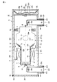
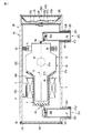
まず、一実施形態に係るX線管装置について説明する。始めに、X線管装置の構成について説明する。図1は、一実施形態に係るX線管装置を示す断面図である。
(One embodiment)
First, an X-ray tube apparatus according to an embodiment will be described. First, the configuration of the X-ray tube apparatus will be described. FIG. 1 is a cross-sectional view showing an X-ray tube apparatus according to an embodiment.

図1に示すように、X線管装置10は、大まかにハウジング20と、ハウジング20内に収納された回転陽極型のX線管30と、X線管30とハウジング20との間の空間に充填された冷却液7と、絶縁部材4と、制振材6と、保持部材8と、ゴム部材2d、2eと、回転駆動部としてのステータコイル9と、保持部材3と、リセプタクル300、400とを備えている。本実施形態において、冷却液7は、絶縁性の冷却液である絶縁油である。冷却液7は、X線管30、ステータコイル9などが発生する熱の少なくとも一部を吸収するものである。   As shown in FIG. 1, the X-ray tube apparatus 10 is roughly arranged in a housing 20, a rotary anode type X-ray tube 30 housed in the housing 20, and a space between the X-ray tube 30 and the housing 20. Filled coolant 7, insulating member 4, damping material 6, holding member 8, rubber members 2 d and 2 e, stator coil 9 as a rotational drive unit, holding member 3, and receptacles 300 and 400. And. In the present embodiment, the coolant 7 is an insulating oil that is an insulating coolant. The coolant 7 absorbs at least a part of heat generated by the X-ray tube 30, the stator coil 9, and the like.

ハウジング20は、筒状に形成されたハウジング本体20eと、蓋部(側板)20f,20g,20hとを有している。ハウジング本体20e、蓋部20f,20g,20hは、金属材料又は樹脂材料で形成されている。この実施形態において、ハウジング本体20e、蓋部20f、20g、20hはアルミニウムを用いた鋳物で形成されている。樹脂材料を使用する場合は、ネジ部など強度を必要とする個所や、樹脂の射出成形で成形し難い個所、またハウジング20の外部への電磁気ノイズの漏洩を防止する図示しない遮蔽層など、部分的に金属を併用してもよい。   The housing 20 includes a housing main body 20e formed in a cylindrical shape, and lid portions (side plates) 20f, 20g, and 20h. The housing body 20e and the lid portions 20f, 20g, and 20h are formed of a metal material or a resin material. In this embodiment, the housing body 20e and the lid portions 20f, 20g, and 20h are formed of a casting using aluminum. When using a resin material, parts such as screw parts that require strength, parts that are difficult to be molded by resin injection molding, and shielding layers (not shown) that prevent leakage of electromagnetic noise to the outside of the housing 20 Alternatively, a metal may be used in combination.

後述する高電圧供給端子44が位置する側のハウジング本体20eの開口部には、環状の段差部が形成されている。上記段差部の内周面には、環状の溝部が形成されている。X線管装置の管軸に沿った方向において、蓋部20fの周縁部はハウジング本体20eの段差部に接触している。ハウジング本体20eの上記溝部にはC形止め輪20iが嵌合されている。   An annular stepped portion is formed in the opening of the housing body 20e on the side where the high voltage supply terminal 44 described later is located. An annular groove is formed on the inner peripheral surface of the step. In the direction along the tube axis of the X-ray tube apparatus, the peripheral edge portion of the lid portion 20f is in contact with the step portion of the housing body 20e. A C-shaped retaining ring 20i is fitted in the groove portion of the housing body 20e.

C形止め輪20iは、管軸に沿った方向における、ハウジング本体20eに対する蓋部20fの位置を規制している。この実施形態において、蓋部20fのがたつきを防止するため、蓋部20fの位置は固定されている。高電圧供給端子44が位置する側のハウジング本体20eの開口部は、蓋部20f及びC形止め輪20iなどにより液密に閉塞されている。   The C-shaped retaining ring 20i regulates the position of the lid portion 20f with respect to the housing body 20e in the direction along the tube axis. In this embodiment, the position of the lid 20f is fixed in order to prevent the lid 20f from rattling. The opening of the housing main body 20e on the side where the high voltage supply terminal 44 is located is liquid-tightly closed by a lid 20f and a C-shaped retaining ring 20i.

ハウジング本体20eと蓋部20fとの間に設けられた環状の被シール部は、ゴム部材2aで液密にシールされている。この実施形態において、ゴム部材2aはOリングで形成されている。ゴム部材2aは、ハウジング20外部への冷却液7の漏れを防止する機能を有している。   An annular sealed portion provided between the housing body 20e and the lid portion 20f is liquid-tightly sealed with the rubber member 2a. In this embodiment, the rubber member 2a is formed of an O-ring. The rubber member 2 a has a function of preventing leakage of the coolant 7 to the outside of the housing 20.

後述する高電圧供給端子54が位置する側のハウジング本体20eの開口部の内周面には、環状の溝部が形成されている。蓋部20gはハウジング本体20eの内部に位置している。蓋部20hは蓋部20gに対向している。蓋部20gは、冷却液7が出入りする開口部20kを有している。蓋部20hには、雰囲気としての空気が出入りする通気孔20mが形成されている。   An annular groove is formed on the inner peripheral surface of the opening of the housing body 20e on the side where the high voltage supply terminal 54 described later is located. The lid 20g is located inside the housing body 20e. The lid part 20h faces the lid part 20g. The lid 20g has an opening 20k through which the coolant 7 enters and exits. The lid 20h is formed with a vent 20m through which air as an atmosphere enters and exits.

ハウジング本体20eの上記溝部にはC形止め輪20jが嵌合されている。C形止め輪20jは、蓋部20hがゴム部材2bの周縁部(シール部)へ応力を加えている状態を保持している。ゴム部材2bのシール部はOリングのように形成されている。上記のことから、高電圧供給端子54が位置する側のハウジング本体20eの開口部は、蓋部20g、蓋部20h、C形止め輪20j及びゴム部材2bなどにより液密に閉塞されている。   A C-shaped retaining ring 20j is fitted in the groove portion of the housing body 20e. The C-shaped retaining ring 20j maintains a state in which the lid portion 20h applies stress to the peripheral edge portion (seal portion) of the rubber member 2b. The seal part of the rubber member 2b is formed like an O-ring. From the above, the opening of the housing body 20e on the side where the high voltage supply terminal 54 is located is liquid-tightly closed by the lid 20g, the lid 20h, the C-shaped retaining ring 20j, the rubber member 2b, and the like.

ハウジング本体20eと蓋部20gと蓋部20hとの間に設けられた環状の被シール部は、ゴム部材2bのシール部で液密にシールされている。ゴム部材2bは、ハウジング20外部への冷却液7の漏れを防止する機能を有している。   An annular sealed portion provided between the housing body 20e, the lid portion 20g, and the lid portion 20h is liquid-tightly sealed by the seal portion of the rubber member 2b. The rubber member 2b has a function of preventing leakage of the coolant 7 to the outside of the housing 20.

この実施形態において、ゴム部材2bはゴムベローズ(ゴム膜)であり、冷却液7に接している。ゴム部材2bは、ハウジング20内において、蓋部20g及び蓋部20hで囲まれた領域を、第1空間と、第2空間とに仕切っている。第1空間は、開口部20kと繋がった空間であり、冷却液7が存在する空間である。第2空間は、通気孔20mと繋がった空間であり、外気が存在する空間である。ゴム部材2bは、冷却液7の体積変化を吸収し、冷却液7の圧力調整を行っている。   In this embodiment, the rubber member 2 b is a rubber bellows (rubber film) and is in contact with the coolant 7. In the housing 20, the rubber member 2b partitions the region surrounded by the lid portion 20g and the lid portion 20h into a first space and a second space. The first space is a space connected to the opening 20k and is a space where the coolant 7 exists. The second space is a space connected to the vent hole 20m, and is a space where outside air exists. The rubber member 2 b absorbs the volume change of the coolant 7 and adjusts the pressure of the coolant 7.

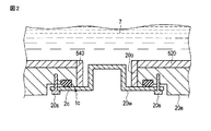
図2は、図1の線II−IIに沿ってX線管装置の一部を拡大して示す図である。図1及び図2に示すように、ハウジング本体20eは、X線透過領域R1に位置したX線放射口20oを有している。X線放射口20oは、ハウジング本体20eの一部を貫通して形成されている。ハウジング20は、X線放射窓20wを有している。X線放射窓20wは、X線を透過しハウジング20外部に放射する。   FIG. 2 is an enlarged view of a part of the X-ray tube apparatus along the line II-II in FIG. As shown in FIGS. 1 and 2, the housing body 20e has an X-ray radiation port 20o located in the X-ray transmission region R1. The X-ray emission port 20o is formed through a part of the housing body 20e. The housing 20 has an X-ray emission window 20w. The X-ray emission window 20w transmits X-rays and radiates out of the housing 20.

なお、後述するX線遮蔽部520及び540は、X線放射口20oにおけるハウジング20外部へのX線の放射を妨げることのないように設けられている。このため、X線遮蔽部540は、X線放射口20oの側縁に設けられている。   Note that X-ray shielding portions 520 and 540, which will be described later, are provided so as not to prevent X-ray emission to the outside of the housing 20 at the X-ray emission port 20o. For this reason, the X-ray shielding part 540 is provided on the side edge of the X-ray radiation port 20o.

X線放射窓20wは、ハウジング20の外側に位置している。X線放射窓20wは、機械的強度の高い材料を利用して形成することができる。この実施形態において、X線放射窓20wは、アルミニウムを利用して形成されているが、他の金属材料や樹脂などを利用して形成することも可能である。X線放射窓20wは凹型形状を有し、X線管30とX線放射窓20wとの間隔の低減を図っている。   The X-ray emission window 20 w is located outside the housing 20. The X-ray radiation window 20w can be formed using a material having high mechanical strength. In this embodiment, the X-ray emission window 20w is formed using aluminum, but can be formed using other metal materials or resins. The X-ray radiation window 20w has a concave shape, and the distance between the X-ray tube 30 and the X-ray radiation window 20w is reduced.

X線放射窓20wに対向したハウジング本体20eの外壁には、取付け面が形成されている。X線放射口20oを囲むようにハウジング本体20eの取付け面には枠状の溝部が形成されている。X線放射窓20wは、上記取付け面に対向した状態で、上記取付け面に接触され、締め具としてのねじ20sによりハウジング本体20eに締め付けられている。ねじ20sは、X線放射窓20wに形成された貫通孔を通り、ハウジング本体20eに形成されたねじ穴に締め付けられている。X線放射窓20wはX線放射口20oを閉塞している。   A mounting surface is formed on the outer wall of the housing body 20e facing the X-ray emission window 20w. A frame-like groove is formed on the mounting surface of the housing main body 20e so as to surround the X-ray emission port 20o. The X-ray radiation window 20w is in contact with the mounting surface in a state of facing the mounting surface, and is fastened to the housing body 20e by a screw 20s as a fastener. The screw 20s passes through a through hole formed in the X-ray emission window 20w and is tightened in a screw hole formed in the housing body 20e. The X-ray emission window 20w closes the X-ray emission port 20o.

ハウジング本体20eとX線放射窓20wとの間に設けられた枠状の被シール部は、ゴム部材2cで液密にシールされている。この実施形態において、ゴム部材2cはOリングで形成されている。ゴム部材2cは、ハウジング本体20eの取付け面に形成された溝部に設けられている。ゴム部材2cは、ハウジング20外部への冷却液7の漏れを防止する機能を有している。   A frame-shaped sealed portion provided between the housing body 20e and the X-ray radiation window 20w is liquid-tightly sealed with a rubber member 2c. In this embodiment, the rubber member 2c is formed of an O-ring. The rubber member 2c is provided in a groove formed on the mounting surface of the housing body 20e. The rubber member 2 c has a function of preventing leakage of the coolant 7 to the outside of the housing 20.

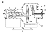
図3は、図1に示したX線管30を示す断面図である。
図1及び図3に示すように、X線管30は、真空外囲器31を備えている。真空外囲器31は、径大部31aと、径小部31bと、接続部31cと、を有している。径大部31aは、筒状の形状を有し、軸線aに垂直な方向にて陽極ターゲット35を囲んでいる。
径小部31bは、径大部31aより外径の小さい筒状の形状を有し、軸線aに垂直な方向にてロータ14を囲んでいる。接続部31cは、円錐形の形状を有し、径大部31aと径小部31bとを接続している。接続部31cは、ハウジング20側に位置する円錐面31Sを有している。
FIG. 3 is a cross-sectional view showing the X-ray tube 30 shown in FIG.
As shown in FIGS. 1 and 3, the X-ray tube 30 includes a vacuum envelope 31. The vacuum envelope 31 has a large-diameter portion 31a, a small-diameter portion 31b, and a connection portion 31c. The large diameter portion 31a has a cylindrical shape and surrounds the anode target 35 in a direction perpendicular to the axis a.
The small diameter portion 31b has a cylindrical shape having a smaller outer diameter than the large diameter portion 31a, and surrounds the rotor 14 in a direction perpendicular to the axis a. The connection part 31c has a conical shape and connects the large diameter part 31a and the small diameter part 31b. The connection part 31c has a conical surface 31S located on the housing 20 side.

真空外囲器31は、真空容器32を有している。真空容器32は、上記径大部31a、径小部31b、及び接続部31cを有している。真空容器32は、例えば、ガラス、又は銅、ステンレス及びアルミニウム等の金属で形成されている。この実施形態において、真空容器32はガラスで形成されている。なお、真空容器32を金属で形成する場合、真空容器32は、X線透過領域R1に対向した開口を有している。そして、真空容器32の開口は、X線を透過する材料としてのベリリウムで形成されたX線透過窓で気密に閉塞されている。真空外囲器31の一部は、高電圧絶縁部材50で形成されている。本実施形態において、高電圧絶縁部材50は、ガラスで形成されている。   The vacuum envelope 31 has a vacuum container 32. The vacuum container 32 has the large diameter part 31a, the small diameter part 31b, and the connection part 31c. The vacuum container 32 is made of, for example, glass or a metal such as copper, stainless steel, or aluminum. In this embodiment, the vacuum vessel 32 is made of glass. When the vacuum container 32 is formed of metal, the vacuum container 32 has an opening facing the X-ray transmission region R1. The opening of the vacuum vessel 32 is hermetically closed by an X-ray transmission window formed of beryllium as a material that transmits X-rays. A part of the vacuum envelope 31 is formed by a high voltage insulating member 50. In the present embodiment, the high voltage insulating member 50 is made of glass.

X線管30は、真空外囲器31に収納された陽極ターゲット35及び陰極36を有している。
陽極ターゲット35は、真空外囲器31内に設けられている。陽極ターゲット35は、円盤状に形成されている。陽極ターゲット35は、この陽極ターゲットの外面の一部に設けられた傘状のターゲット層35aを有している。ターゲット層35aは、陰極36から照射される電子が衝突することによりX線を放出する。陽極ターゲット35は、モリブデン合金などの金属で形成されている。
The X-ray tube 30 has an anode target 35 and a cathode 36 housed in a vacuum envelope 31.
The anode target 35 is provided in the vacuum envelope 31. The anode target 35 is formed in a disc shape. The anode target 35 has an umbrella-shaped target layer 35a provided on a part of the outer surface of the anode target. The target layer 35a emits X-rays when electrons irradiated from the cathode 36 collide. The anode target 35 is made of a metal such as a molybdenum alloy.

ターゲット層35aはタングステン合金等の金属で形成されている。陽極ターゲット35は、管軸を中心に回転自在である。このため、陽極ターゲット35の軸線aは、管軸と平行である。   The target layer 35a is made of a metal such as a tungsten alloy. The anode target 35 is rotatable around the tube axis. For this reason, the axis a of the anode target 35 is parallel to the tube axis.

陰極36は、真空外囲器31内に設けられている。陰極36は、陽極ターゲット35に照射する電子を放出する。陰極36には相対的に負の電圧が印加される。低膨張合金であるKOV部材55は、真空外囲器31内で高電圧供給端子54を覆っている。ここでは、高電圧供給端子54はガラス製の高電圧絶縁部材50に封着され、KOV部材55は高電圧絶縁部材50に摩擦ばめを利用して固定されている。KOV部材55には、陰極支持部材37が取付けられている。陰極36は、陰極支持部材37に取付けられている。   The cathode 36 is provided in the vacuum envelope 31. The cathode 36 emits electrons that irradiate the anode target 35. A relatively negative voltage is applied to the cathode 36. The KOV member 55, which is a low expansion alloy, covers the high voltage supply terminal 54 in the vacuum envelope 31. Here, the high voltage supply terminal 54 is sealed to a high voltage insulating member 50 made of glass, and the KOV member 55 is fixed to the high voltage insulating member 50 using a friction fit. A cathode support member 37 is attached to the KOV member 55. The cathode 36 is attached to a cathode support member 37.

高電圧供給端子54は、陰極支持部材37の内部を通って陰極36に接続されている。高電圧供給端子54は、陰極36に相対的に負の電圧を印加するともに陰極36の図示しないフィラメント(電子放出源)にフィラメント電流を供給するものである。   The high voltage supply terminal 54 is connected to the cathode 36 through the inside of the cathode support member 37. The high voltage supply terminal 54 applies a relatively negative voltage to the cathode 36 and supplies a filament current to a filament (electron emission source) (not shown) of the cathode 36.

X線管30は、固定軸11、回転体12、軸受け13及びロータ14を備えている。固定軸11は、円柱状に形成されている。固定軸11の外周の一部には突出部が形成され、突出部は真空外囲器31に気密に取付けられている。固定軸11には、高電圧供給端子44が電気的に接続されている。固定軸11は回転体12を回転可能に支持する。   The X-ray tube 30 includes a fixed shaft 11, a rotating body 12, a bearing 13, and a rotor 14. The fixed shaft 11 is formed in a cylindrical shape. A protrusion is formed on a part of the outer periphery of the fixed shaft 11, and the protrusion is attached to the vacuum envelope 31 in an airtight manner. A high voltage supply terminal 44 is electrically connected to the fixed shaft 11. The fixed shaft 11 rotatably supports the rotating body 12.

回転体12は、筒状に形成され、固定軸11と同軸的に設けられている。回転体12の外面にロータ14が取り付けられている。回転体12には、陽極ターゲット35が取付けられている。軸受け13は、固定軸11と回転体12の間に形成されている。回転体12及びロータ14は、陽極ターゲット35とともに回転自在に設けられている。   The rotating body 12 is formed in a cylindrical shape and is provided coaxially with the fixed shaft 11. A rotor 14 is attached to the outer surface of the rotating body 12. An anode target 35 is attached to the rotating body 12. The bearing 13 is formed between the fixed shaft 11 and the rotating body 12. The rotating body 12 and the rotor 14 are rotatably provided with the anode target 35.

高電圧供給端子44は、固定軸11、軸受け13及び回転体12を介して陽極ターゲット35に相対的に正の電圧を印加する。この実施形態において、高電圧供給端子44及び高電圧供給端子54は、金属端子である。   The high voltage supply terminal 44 applies a relatively positive voltage to the anode target 35 via the fixed shaft 11, the bearing 13, and the rotating body 12. In this embodiment, the high voltage supply terminal 44 and the high voltage supply terminal 54 are metal terminals.

X線管30の固定軸11は絶縁部材4にも固定されている。絶縁部材4は、ハウジング20に支持されている。本実施形態において、絶縁部材4は、ステータコイル9及び保持部材3を介してハウジング20に支持されている。絶縁部材4は、軸線aに垂直な方向にて真空外囲器31を囲んでいる。絶縁部材4は、真空外囲器31との間に隙間を空けて位置している。絶縁部材4は、筒部4a及び円錐部4bを有し、管状に形成されている。筒部4aは、軸線aに垂直な方向にて径小部31bを囲んでいる。円錐部4bは、軸線aに垂直な方向にて接続部31cを囲み、筒部4aに接続されている。絶縁部材4は、X線管30とステータコイル9との間を電気的に絶縁するものである。絶縁部材4は、絶縁材料として、例えばエポキシ系の材料で形成されている。   The fixed shaft 11 of the X-ray tube 30 is also fixed to the insulating member 4. The insulating member 4 is supported by the housing 20. In the present embodiment, the insulating member 4 is supported by the housing 20 via the stator coil 9 and the holding member 3. The insulating member 4 surrounds the vacuum envelope 31 in a direction perpendicular to the axis a. The insulating member 4 is located with a gap between the insulating member 4 and the vacuum envelope 31. The insulating member 4 has a cylindrical portion 4a and a conical portion 4b, and is formed in a tubular shape. The cylinder part 4a surrounds the small diameter part 31b in a direction perpendicular to the axis a. The conical part 4b surrounds the connection part 31c in a direction perpendicular to the axis a, and is connected to the cylinder part 4a. The insulating member 4 electrically insulates between the X-ray tube 30 and the stator coil 9. The insulating member 4 is formed of, for example, an epoxy material as an insulating material.

絶縁部材4の高電圧供給端子44側の端部には、例えば、複数の貫通孔hが形成されている。そのため、絶縁部材4の高電圧供給端子44側の端部が閉塞されている場合と比較して、真空外囲器31と絶縁部材4との間の領域にも冷却液7の自然対流が生じ易くなる。但し、本実施形態と異なり、絶縁部材4の高電圧供給端子44側の端部は閉塞されていてもよい。   For example, a plurality of through holes h are formed at the end of the insulating member 4 on the high voltage supply terminal 44 side. Therefore, natural convection of the coolant 7 also occurs in the region between the vacuum envelope 31 and the insulating member 4 as compared with the case where the end of the insulating member 4 on the high voltage supply terminal 44 side is closed. It becomes easy. However, unlike the present embodiment, the end of the insulating member 4 on the high voltage supply terminal 44 side may be closed.

図1及び図2に示すように、X線管装置10は、鉛で形成されたX線遮蔽部510、520、530、540、590をさらに備えている。これらのX線遮蔽部は、少なくとも鉛を含むX線不透過材で形成されていればよく、鉛合金等で形成されていてもよい。   As shown in FIGS. 1 and 2, the X-ray tube apparatus 10 further includes X-ray shielding portions 510, 520, 530, 540 and 590 made of lead. These X-ray shielding parts may be formed of an X-ray opaque material containing at least lead, and may be formed of a lead alloy or the like.

図1に示すように、X線遮蔽部510は、管軸に沿った方向にターゲット層35aと対向したハウジング20の一端側に設けられている。X線遮蔽部510は、ターゲット層35aから放射されるX線を遮蔽するものである。X線遮蔽部510は、第1遮蔽部511及び第2遮蔽部512を有している。   As shown in FIG. 1, the X-ray shielding part 510 is provided on one end side of the housing 20 facing the target layer 35a in the direction along the tube axis. The X-ray shielding unit 510 shields X-rays emitted from the target layer 35a. The X-ray shielding part 510 has a first shielding part 511 and a second shielding part 512.

第1遮蔽部511は、管軸に沿った方向にターゲット層35aと対向した側の蓋部20gに貼り付けられている。第1遮蔽部511は、蓋部20g全体を覆っている。第1遮蔽部511は、開口部20kと対向した個所が開口して形成され、開口部20kによる冷却液7の出入りを維持している。   The first shielding portion 511 is attached to the lid portion 20g on the side facing the target layer 35a in the direction along the tube axis. The first shielding part 511 covers the entire lid part 20g. The first shielding portion 511 is formed by opening a portion facing the opening 20k, and keeps the coolant 7 in and out of the opening 20k.

第2遮蔽部512は、第1遮蔽部511上に設けられている。第2遮蔽部512は、開口部20k付近からハウジング20の外部に漏れる恐れのあるX線を遮蔽するものである。   The second shielding part 512 is provided on the first shielding part 511. The second shielding part 512 shields X-rays that may leak from the vicinity of the opening 20k to the outside of the housing 20.

X線遮蔽部520は円筒状に形成されている。X線遮蔽部520の一端部は、第1遮蔽部511に近接している。このため、X線遮蔽部510及びX線遮蔽部520間の隙間から漏れる恐れのあるX線を遮蔽することができる。   The X-ray shielding part 520 is formed in a cylindrical shape. One end of the X-ray shield 520 is close to the first shield 511. For this reason, X-rays that may leak from the gap between the X-ray shield 510 and the X-ray shield 520 can be shielded.

X線遮蔽部520は、管軸に沿って第1遮蔽部511から陽極ターゲット35(ターゲット層35aの表面の延長線上)を越える位置まで延出している。この実施形態において、X線遮蔽部520は、第1遮蔽部511からステータコイル9と対向する位置まで延出している。X線遮蔽部520は、必要に応じてハウジング20に固定されている。   The X-ray shielding part 520 extends along the tube axis from the first shielding part 511 to a position exceeding the anode target 35 (on the extended line of the surface of the target layer 35a). In this embodiment, the X-ray shielding part 520 extends from the first shielding part 511 to a position facing the stator coil 9. The X-ray shielding part 520 is fixed to the housing 20 as necessary.

X線遮蔽部530は、筒状に形成され、ハウジング20の筒部20r内に設けられている。X線遮蔽部530の一端部は、X線遮蔽部520に近接している。X線遮蔽部530は、必要に応じて筒部20rに固定されている。ここでは、X線遮蔽部530は、筒部20rの内壁に形成された突出部に固定されている。なお、上記突出部は、X線遮蔽部530の位置決めにも利用されている。このため、筒部20rから漏れる恐れのあるX線を遮蔽することができる。   The X-ray shielding part 530 is formed in a cylindrical shape and is provided in the cylindrical part 20 r of the housing 20. One end of the X-ray shield 530 is close to the X-ray shield 520. The X-ray shielding part 530 is fixed to the cylinder part 20r as necessary. Here, the X-ray shielding part 530 is fixed to a protruding part formed on the inner wall of the cylindrical part 20r. Note that the protruding portion is also used for positioning the X-ray shielding portion 530. For this reason, the X-ray which may leak from the cylinder part 20r can be shielded.

図2に示すように、X線遮蔽部540は、枠状に形成され、ハウジング20のX線放射口20oの側縁に設けられている。X線遮蔽部540の一端部は、X線遮蔽部520に近接している。X線遮蔽部540は、必要に応じてX線放射口20oの側縁に固定されている。   As shown in FIG. 2, the X-ray shielding portion 540 is formed in a frame shape and is provided on the side edge of the X-ray emission port 20 o of the housing 20. One end of the X-ray shield 540 is close to the X-ray shield 520. The X-ray shielding part 540 is fixed to the side edge of the X-ray emission port 20o as necessary.

図1に示すように、X線遮蔽部材590は、環状に形成されている。X線遮蔽部材590は、ステータコイル9に取り付けられ、ハウジング20と同電位に設定されている。軸線aに垂直な方向において、X線遮蔽部材590は、X線遮蔽部520で取り囲まれている。X線遮蔽部材590は、散乱X線の遮蔽に寄与している。   As shown in FIG. 1, the X-ray shielding member 590 is formed in an annular shape. The X-ray shielding member 590 is attached to the stator coil 9 and set to the same potential as the housing 20. In the direction perpendicular to the axis a, the X-ray shielding member 590 is surrounded by the X-ray shielding portion 520. The X-ray shielding member 590 contributes to shielding scattered X-rays.

図1及び図3に示すように、保持部材8及びゴム部材2d、2eは、X線管30とハウジング20との間の領域に位置している。
X線管装置10は、複数のゴム部材2dと、複数のゴム部材2eとを有している。この実施形態において、X線管装置10は、3個のゴム部材2dと3個のゴム部材2eとを有している。ゴム部材2dは軸線aを中心とする回りで等間隔に位置し、ゴム部材2eも軸線aを中心とする回りで等間隔に位置している。ゴム部材2d、2eは、X線管30及びハウジング20の少なくとも一方を押圧し、ハウジング20に対するX線管30の位置を固定する。また、この実施形態において、ゴム部材2d、2eは、軸線aに垂直な方向にX線管30及びハウジング20の少なくとも一方を押圧している。
As shown in FIGS. 1 and 3, the holding member 8 and the rubber members 2 d and 2 e are located in a region between the X-ray tube 30 and the housing 20.
The X-ray tube apparatus 10 includes a plurality of rubber members 2d and a plurality of rubber members 2e. In this embodiment, the X-ray tube apparatus 10 has three rubber members 2d and three rubber members 2e. The rubber members 2d are equally spaced around the axis a, and the rubber members 2e are also equally spaced around the axis a. The rubber members 2 d and 2 e press at least one of the X-ray tube 30 and the housing 20 to fix the position of the X-ray tube 30 with respect to the housing 20. In this embodiment, the rubber members 2d and 2e press at least one of the X-ray tube 30 and the housing 20 in a direction perpendicular to the axis a.

保持部材8は、環状に形成され、X線管30及びハウジング20からそれぞれ離れて位置している。保持部材8は、機械的強度の高い材料で形成されている。保持部材8は、少なくともゴム部材2d及びゴム部材2eより高い剛性を有している。この実施形態において、保持部材8は、電気絶縁材料である樹脂材料で形成されている。   The holding member 8 is formed in an annular shape and is located away from the X-ray tube 30 and the housing 20. The holding member 8 is made of a material having high mechanical strength. The holding member 8 has at least higher rigidity than the rubber member 2d and the rubber member 2e. In this embodiment, the holding member 8 is formed of a resin material that is an electrically insulating material.

ゴム部材2dは、保持部材8に取付けられている。ここでは、ゴム部材2dの突出部を保持部材8の貫通孔に嵌め入れている。ゴム部材2dは、ハウジング20と保持部材8との間の隙間に挟み込まれ、ハウジング20を直接又は間接的に押圧している。この実施形態において、ゴム部材2dは、X線遮蔽部520に接触し、ハウジング20を間接的に押圧している。   The rubber member 2d is attached to the holding member 8. Here, the protruding portion of the rubber member 2 d is fitted into the through hole of the holding member 8. The rubber member 2d is sandwiched in a gap between the housing 20 and the holding member 8 and presses the housing 20 directly or indirectly. In this embodiment, the rubber member 2d is in contact with the X-ray shielding part 520 and indirectly presses the housing 20.

ゴム部材2eは、保持部材8に取付けられている。ここでは、ゴム部材2eの突出部を保持部材8の貫通孔に嵌め入れている。ゴム部材2eは、保持部材8とX線管30との間の隙間に挟み込まれ、X線管30を直接又は間接的に押圧している。この実施形態において、ゴム部材2eは、X線管30(真空外囲器31)に接触し、X線管30を直接押圧している。   The rubber member 2e is attached to the holding member 8. Here, the protruding portion of the rubber member 2 e is fitted into the through hole of the holding member 8. The rubber member 2 e is sandwiched in a gap between the holding member 8 and the X-ray tube 30 and presses the X-ray tube 30 directly or indirectly. In this embodiment, the rubber member 2e is in contact with the X-ray tube 30 (vacuum envelope 31) and directly presses the X-ray tube 30.

この実施形態において、ゴム部材2d、2eは、保持部材8とともにハウジング20に対するX線管30の位置を固定している。ゴム部材2d、2e及び保持部材8は、ハウジング20に対するX線管30の位置ずれを防止している。特に、ゴム部材2d、2e及び保持部材8は、軸線aに垂直な方向におけるハウジング20に対するX線管30の位置ずれを防止している。ゴム部材2d、2eは、制振材としても機能している。ゴム部材2d、2eは、X線管30に生じる振動のハウジング20への伝達量を軽減する。ゴム部材2d、2eは冷却液7の存在する空間に位置している。   In this embodiment, the rubber members 2 d and 2 e fix the position of the X-ray tube 30 with respect to the housing 20 together with the holding member 8. The rubber members 2 d and 2 e and the holding member 8 prevent the X-ray tube 30 from being displaced with respect to the housing 20. In particular, the rubber members 2d and 2e and the holding member 8 prevent the X-ray tube 30 from being displaced with respect to the housing 20 in the direction perpendicular to the axis a. The rubber members 2d and 2e also function as vibration damping materials. The rubber members 2 d and 2 e reduce the amount of vibration generated in the X-ray tube 30 to the housing 20. The rubber members 2d and 2e are located in a space where the coolant 7 exists.

図1及び図3に示すように、ステータコイル9は、絶縁部材4とハウジング20との間に位置し、絶縁部材4に固定されている。ステータコイル9は、ロータ14、回転体12及び陽極ターゲット35を回転させるものである。ステータコイル9に所定の電流が供給されることで、ステータコイル9はロータ14に与える磁界を発生するため、陽極ターゲット35などが所定の速度で回転される。   As shown in FIGS. 1 and 3, the stator coil 9 is positioned between the insulating member 4 and the housing 20 and is fixed to the insulating member 4. The stator coil 9 rotates the rotor 14, the rotating body 12 and the anode target 35. By supplying a predetermined current to the stator coil 9, the stator coil 9 generates a magnetic field to be applied to the rotor 14, so that the anode target 35 and the like are rotated at a predetermined speed.

ステータコイル9は、ハウジング20に固定されている。本実施形態において、ステータコイル9は、保持部材3によりハウジング20に固定されている。保持部材3は、ハウジング20に固定され、ステータコイル9を保持している。また、保持部材3は、金属で形成されている。そのため、ステータコイル9の電位は、ハウジング20の電位である接地電位に接地絵される。   The stator coil 9 is fixed to the housing 20. In the present embodiment, the stator coil 9 is fixed to the housing 20 by the holding member 3. The holding member 3 is fixed to the housing 20 and holds the stator coil 9. The holding member 3 is made of metal. Therefore, the potential of the stator coil 9 is grounded to the ground potential that is the potential of the housing 20.

X線管装置10は、陽極用のリセプタクル300及び陰極用のリセプタクル400を有している。リセプタクル300は、ハウジング20の筒部20qの内部に位置し、筒部20qに取付けられている。リセプタクル400は、ハウジング20の筒部20rの内部に位置し、筒部20rに取付けられている。   The X-ray tube apparatus 10 includes an anode receptacle 300 and a cathode receptacle 400. The receptacle 300 is located inside the cylindrical portion 20q of the housing 20, and is attached to the cylindrical portion 20q. The receptacle 400 is located inside the cylindrical portion 20r of the housing 20, and is attached to the cylindrical portion 20r.

リセプタクル300は、電気絶縁部材としてのハウジング301と、高電圧供給端子としての端子302とを有している。
ハウジング301は、筒部20q(ハウジング20)の外側に開口した桶状に形成されている。ハウジング301は、ほぼ軸対称なコップ形状を有している。また、ハウジング301のプラグ差込口がハウジング20の外側に開口している。
The receptacle 300 has a housing 301 as an electrical insulating member and a terminal 302 as a high voltage supply terminal.
The housing 301 is formed in a bowl shape opened to the outside of the cylindrical portion 20q (housing 20). The housing 301 has a substantially axisymmetric cup shape. Further, the plug insertion port of the housing 301 is opened to the outside of the housing 20.

ハウジング301の開口側の端部において、ハウジング301の外面には、環状の突出部が形成されている。ハウジング301は、絶縁性の材料として、例えば樹脂で形成されている。端子302は、ハウジング301の底部に液密に取付けられ、上記底部を貫通している。端子302は絶縁被覆配線を介して高電圧供給端子44と接続されている。   An annular protrusion is formed on the outer surface of the housing 301 at the end of the housing 301 on the opening side. The housing 301 is made of, for example, resin as an insulating material. The terminal 302 is liquid-tightly attached to the bottom of the housing 301 and penetrates the bottom. The terminal 302 is connected to the high voltage supply terminal 44 through an insulating coating.

筒部20qの段差部には、雌ねじの加工がなされている。リングナット310は、側面に雄ねじの加工がなされている。リングナット310は、筒部20qの段差部に締め付けられ、ハウジング301を押圧している。   A female screw is processed in the step portion of the cylindrical portion 20q. The ring nut 310 has a male thread on the side. The ring nut 310 is fastened to the step portion of the cylindrical portion 20q and presses the housing 301.

リセプタクル300及びリセプタクル300に挿入される図示しないプラグは、非面圧式であり、着脱可能に形成されている。プラグをリセプタクル300に連結した状態で、プラグから端子302に高電圧(例えば、+70〜+80kV)が供給される。   The receptacle 300 and the plug (not shown) inserted into the receptacle 300 are non-surface pressure type and are detachable. With the plug connected to the receptacle 300, a high voltage (for example, +70 to +80 kV) is supplied from the plug to the terminal 302.

リセプタクル400は、リセプタクル300と同様に形成されている。
リセプタクル400は、電気絶縁部材としてのハウジング401と、高電圧供給端子としての端子402とを有している。ハウジング401は、筒部20r(ハウジング20)の外側に開口した桶状に形成されている。
The receptacle 400 is formed in the same manner as the receptacle 300.
The receptacle 400 includes a housing 401 as an electrical insulating member and a terminal 402 as a high voltage supply terminal. The housing 401 is formed in a bowl shape opened to the outside of the cylindrical portion 20r (housing 20).

ハウジング401の開口側の端部において、ハウジング401の外面には、環状の突出部が形成されている。ハウジング401は、絶縁性の材料として、例えば樹脂で形成されている。端子402は、ハウジング401の底部に液密に取付けられ、上記底部を貫通している。端子402は絶縁被覆配線を介して高電圧供給端子54と接続されている。   An annular protrusion is formed on the outer surface of the housing 401 at the end of the housing 401 on the opening side. The housing 401 is made of, for example, a resin as an insulating material. The terminal 402 is liquid-tightly attached to the bottom of the housing 401 and penetrates through the bottom. The terminal 402 is connected to the high voltage supply terminal 54 through an insulating coating.

筒部20rの段差部には、雌ねじの加工がなされている。リングナット410は、側面に雄ねじの加工がなされている。リングナット410は、筒部20rの段差部に締め付けられ、ハウジング401を押圧している。
リセプタクル400及びリセプタクル400に挿入される図示しないプラグは、非面圧式であり、着脱可能に形成されている。プラグをリセプタクル400に連結した状態で、プラグから端子402に高電圧(例えば、−70〜−80kV)が供給される。
A female thread is processed in the step portion of the cylindrical portion 20r. The ring nut 410 has a male thread on the side. The ring nut 410 is fastened to the step portion of the cylindrical portion 20r and presses the housing 401.
The receptacle 400 and the plug (not shown) inserted into the receptacle 400 are non-surface pressure type and are detachable. With the plug connected to the receptacle 400, a high voltage (for example, −70 to −80 kV) is supplied from the plug to the terminal 402.

筒部20qとリセプタクル300との間に設けられた枠状の被シール部は、ゴム部材2fで液密にシールされている。この実施形態において、ゴム部材2fはOリングで形成されている。ゴム部材2fは、ハウジング20外部への冷却液7の漏れを防止する機能を有している。
なお、ゴム部材2gは、ゴム部材2fと同様にOリングで形成されている。ゴム部材2gは、筒部20rとリセプタクル400との間に設けられた被シール部を液密にシールしている。
The frame-shaped sealed portion provided between the cylindrical portion 20q and the receptacle 300 is liquid-tightly sealed with the rubber member 2f. In this embodiment, the rubber member 2f is formed of an O-ring. The rubber member 2 f has a function of preventing leakage of the coolant 7 to the outside of the housing 20.
The rubber member 2g is formed of an O-ring, like the rubber member 2f. The rubber member 2g liquid-tightly seals a sealed portion provided between the cylindrical portion 20r and the receptacle 400.

図1に示すように、制振材6は、真空外囲器31と絶縁部材4との間に位置している。制振材6は、電気絶縁性及び高耐熱性を有している。制振材6は、X線管30を押圧し、X線管30が発生する振動の少なくとも一部を吸収するように構成されている。   As shown in FIG. 1, the damping material 6 is located between the vacuum envelope 31 and the insulating member 4. The damping material 6 has electrical insulation and high heat resistance. The damping material 6 is configured to press the X-ray tube 30 and absorb at least a part of vibration generated by the X-ray tube 30.

本実施形態の制振材6は、真空外囲器31の円錐面31Sと絶縁部材4の円錐部4bとの間に位置し、円錐面31Sを押圧している。制振材6が、真空外囲器31と筒部4aとの間に位置している場合と比較して、絶縁部材4とX線管30との組み立ては容易となる。
制振材6は、絶縁部材4(円錐部4b)に接着されている。そのため、制振材6に振動が伝わっても、制振材6の位置ずれを抑制することができる。
The damping material 6 of the present embodiment is located between the conical surface 31S of the vacuum envelope 31 and the conical portion 4b of the insulating member 4, and presses the conical surface 31S. As compared with the case where the damping material 6 is located between the vacuum envelope 31 and the cylindrical portion 4a, the assembly of the insulating member 4 and the X-ray tube 30 is facilitated.
The damping material 6 is bonded to the insulating member 4 (conical portion 4b). Therefore, even if vibration is transmitted to the damping material 6, it is possible to suppress the displacement of the damping material 6.

また、本実施形態の制振材6は、絶縁部材4を形成する材料と異なる絶縁材料で形成されている。例えば、制振材6は、高耐熱樹脂で形成されている。ここで、高耐熱樹脂とは、250℃以上の融点を有する樹脂を言う。   Further, the damping material 6 of the present embodiment is formed of an insulating material different from the material forming the insulating member 4. For example, the damping material 6 is made of a high heat resistant resin. Here, the high heat-resistant resin refers to a resin having a melting point of 250 ° C. or higher.

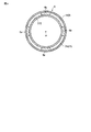
図4は、図1の線IV−IVに沿った真空外囲器31、絶縁部材4、及び制振材6を示す断面図である。図4において、真空外囲器31以外のX線管30の部材の図示を省略している。
図1及び図4に示すように、制振材6は、物理的に独立した複数の制振部6aを有している。複数の制振部6aは、軸線aを中心とする回りで、真空外囲器31と絶縁部材4との間に間隔を空けて設けられている。本実施形態において、複数の制振部6aは、等間隔に設けられている。
4 is a cross-sectional view showing the vacuum envelope 31, the insulating member 4, and the damping material 6 along the line IV-IV in FIG. In FIG. 4, illustration of members of the X-ray tube 30 other than the vacuum envelope 31 is omitted.
As shown in FIGS. 1 and 4, the damping material 6 has a plurality of damping units 6 a that are physically independent. The plurality of damping parts 6 a are provided around the axis “a” with a space between the vacuum envelope 31 and the insulating member 4. In the present embodiment, the plurality of vibration control units 6a are provided at equal intervals.

上記のように構成されたX線管装置では、ステータコイル9に所定の電流を印加することでロータ14が回転し、陽極ターゲット35が回転する。次に、リセプタクル300、400に所定の高電圧を印加する。
リセプタクル300に印加された高電圧は、高電圧供給端子44、固定軸11、軸受け13及び回転体12を介して陽極ターゲット35に供給される。リセプタクル400に印加された高電圧は、高電圧供給端子54を介して陰極36に供給される。
これにより、陰極36から放出された電子は陽極ターゲット35のターゲット層35aに衝突し、陽極ターゲット35からX線が放射される。X線は、真空容器32(又はX線透過窓)及びX線放射窓20wを通ってハウジング20の外部へ放射される。
In the X-ray tube apparatus configured as described above, when a predetermined current is applied to the stator coil 9, the rotor 14 rotates and the anode target 35 rotates. Next, a predetermined high voltage is applied to the receptacles 300 and 400.
The high voltage applied to the receptacle 300 is supplied to the anode target 35 via the high voltage supply terminal 44, the fixed shaft 11, the bearing 13, and the rotating body 12. The high voltage applied to the receptacle 400 is supplied to the cathode 36 via the high voltage supply terminal 54.
Thereby, electrons emitted from the cathode 36 collide with the target layer 35 a of the anode target 35, and X-rays are emitted from the anode target 35. X-rays are emitted to the outside of the housing 20 through the vacuum vessel 32 (or X-ray transmission window) and the X-ray emission window 20w.

上記のように構成された第1の実施形態に係るX線管装置10によれば、X線管装置10は、回転陽極型のX線管30と、ハウジング20と、冷却液7と、絶縁部材4と、制振材6と、を備えている。制振材6は、真空外囲器31と絶縁部材4との間に位置し、電気絶縁性を有し、X線管30を押圧している。制振材6は、X線管30が発生する振動の少なくとも一部を吸収するように構成されている。   According to the X-ray tube apparatus 10 according to the first embodiment configured as described above, the X-ray tube apparatus 10 includes the rotary anode type X-ray tube 30, the housing 20, the coolant 7, and the insulation. A member 4 and a damping material 6 are provided. The damping material 6 is located between the vacuum envelope 31 and the insulating member 4, has electrical insulation, and presses the X-ray tube 30. The damping material 6 is configured to absorb at least part of the vibration generated by the X-ray tube 30.

詳しくは、X線管30から制振材6に伝搬した振動は、制振材6のせん断変形を引き起こし、振動エネルギの一部が制振材中の摩擦や粘性抵抗によって熱エネルギに変換される。これにより、振動が制振材6によって吸収される。保持部材8及びゴム部材2d,2eの集合体より、制振材6の方が、X線管30が発生する振動を多く吸収する。例えば、X線管30に生じる振動のハウジング20への伝達量を軽減することができる。ハウジング20の外部の空気の振動の発生を抑えることができ、音の発生を抑えることができる。
上記のことから、制振構造を持つX線管装置10を得ることができる。そして、騒音など、X線管の振動に起因した悪影響の発生を抑制することができる。
Specifically, the vibration propagated from the X-ray tube 30 to the damping material 6 causes shear deformation of the damping material 6, and a part of the vibration energy is converted into thermal energy by friction and viscous resistance in the damping material. . Thereby, the vibration is absorbed by the damping material 6. The damping material 6 absorbs more vibration generated by the X-ray tube 30 than the assembly of the holding member 8 and the rubber members 2d and 2e. For example, the transmission amount of vibration generated in the X-ray tube 30 to the housing 20 can be reduced. Generation of vibrations of air outside the housing 20 can be suppressed, and generation of sound can be suppressed.
From the above, it is possible to obtain the X-ray tube apparatus 10 having a vibration control structure. And generation | occurrence | production of the bad influence resulting from the vibration of X-ray tubes, such as a noise, can be suppressed.

(変形例1)
次に、上記実施形態の変形例1に係るX線管装置10について説明する。図5は、本変形例1に係るX線管装置10を示す断面図である。
図5に示すように、変形例1のX線管装置10では、制振材6と絶縁部材4との関係について上記実施形態と相違している。制振材6は、絶縁部材4を形成する材料と同一の絶縁材料で形成され、かつ、絶縁部材4と一体に形成されている。
本変形例1においても、上記実施形態と同様の効果を得ることができる。
(Modification 1)
Next, an X-ray tube apparatus 10 according to Modification 1 of the above embodiment will be described. FIG. 5 is a cross-sectional view showing the X-ray tube apparatus 10 according to the first modification.
As shown in FIG. 5, in the X-ray tube apparatus 10 of the modification 1, the relationship between the damping material 6 and the insulating member 4 is different from the above embodiment. The damping material 6 is formed of the same insulating material as that for forming the insulating member 4 and is formed integrally with the insulating member 4.
Also in the first modification, the same effect as in the above embodiment can be obtained.

(変形例2)
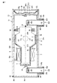
次に、上記実施形態の変形例2に係るX線管装置10について説明する。図6は、本変形例2に係るX線管装置10を示す断面図である。
図6に示すように、変形例2のX線管装置10では、制振材6を配置する位置について上記実施形態と相違している。制振材6は、真空外囲器31の径小部31bと絶縁部材4の筒部4aとの間に位置し、径小部31bを押圧している。制振材6は、筒部4aに接着されている。
本変形例2においても、上記実施形態と同様の効果を得ることができる。
(Modification 2)
Next, an X-ray tube apparatus 10 according to Modification 2 of the above embodiment will be described. FIG. 6 is a cross-sectional view showing the X-ray tube apparatus 10 according to the second modification.
As shown in FIG. 6, in the X-ray tube apparatus 10 of the modification 2, the position which arrange | positions the damping material 6 is different from the said embodiment. The damping material 6 is positioned between the small-diameter portion 31b of the vacuum envelope 31 and the cylindrical portion 4a of the insulating member 4 and presses the small-diameter portion 31b. The damping material 6 is bonded to the cylindrical portion 4a.
Also in the second modification, the same effect as in the above embodiment can be obtained.

(変形例3)
次に、上記実施形態の変形例3に係るX線管装置10について説明する。図7は、本変形例3に係るX線管装置10を示す断面図である。図8は、図7の線VIII−VIIIに沿ってX線管装置10の一部を拡大して示す図である。
図7及び図8に示すように、変形例3のX線管装置10では、絶縁部材4の形状、及び制振材6を配置する位置について上記実施形態と相違している。絶縁部材4は、筒部4cをさらに備えている。筒部4cは、軸線aに垂直な方向にて径大部31aを囲み、円錐部4bに接続されている。筒部4cは、X線透過領域R1に位置した開口4coを有している。開口4coはX線放射口20oと対向し、筒部4cがハウジング20外部へのX線の放射を妨げることのないように設けられている。
(Modification 3)
Next, an X-ray tube apparatus 10 according to Modification 3 of the above embodiment will be described. FIG. 7 is a cross-sectional view showing an X-ray tube apparatus 10 according to the third modification. FIG. 8 is an enlarged view showing a part of the X-ray tube apparatus 10 along the line VIII-VIII in FIG.
As shown in FIGS. 7 and 8, the X-ray tube apparatus 10 of Modification 3 is different from the above embodiment with respect to the shape of the insulating member 4 and the position where the damping material 6 is disposed. The insulating member 4 further includes a cylindrical portion 4c. The cylindrical portion 4c surrounds the large diameter portion 31a in a direction perpendicular to the axis a, and is connected to the conical portion 4b. The cylinder portion 4c has an opening 4co located in the X-ray transmission region R1. The opening 4co faces the X-ray emission port 20o, and the cylindrical portion 4c is provided so as not to prevent X-ray emission to the outside of the housing 20.

制振材6は、真空外囲器31の径大部31aと絶縁部材4の筒部4cとの間に位置し、径大部31aを押圧している。制振材6は、筒部4cに接着されている。制振材6は、X線の放射を妨げることのないように設けられている。そのため、制振材6は、X線透過領域R1に位置しておらず、X線透過領域R1以外の領域に位置している。
本変形例3においても、上記実施形態と同様の効果を得ることができる。
The damping material 6 is positioned between the large-diameter portion 31a of the vacuum envelope 31 and the cylindrical portion 4c of the insulating member 4, and presses the large-diameter portion 31a. The damping material 6 is bonded to the cylindrical portion 4c. The damping material 6 is provided so as not to prevent X-ray radiation. Therefore, the damping material 6 is not located in the X-ray transmission region R1, but is located in a region other than the X-ray transmission region R1.
Also in the third modification, the same effect as in the above embodiment can be obtained.

(変形例4)
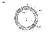
次に、上記実施形態の変形例4に係るX線管装置10について説明する。図9は、上記実施形態の変形例4に係るX線管装置10の真空外囲器31、絶縁部材4、及び制振材6を示す断面図である。図9において、真空外囲器31以外のX線管30の部材の図示を省略している。
(Modification 4)
Next, an X-ray tube apparatus 10 according to Modification 4 of the above embodiment will be described. FIG. 9 is a cross-sectional view showing the vacuum envelope 31, the insulating member 4, and the damping material 6 of the X-ray tube apparatus 10 according to Modification 4 of the above embodiment. In FIG. 9, illustration of members of the X-ray tube 30 other than the vacuum envelope 31 is omitted.

図9及び図1に示すように、変形例4のX線管装置10では、制振材6について上記実施形態と相違している。制振材6は、軸線aを中心とする回りで、真空外囲器31と絶縁部材4との間に全周にわたって設けられている。制振材6は、途切れること無しに連続的に環状に形成されている。制振材6は、真空外囲器31と絶縁部材4との間の領域を、第1領域s1と第2領域s2とに区域している、
制振材6は、真空外囲器31と対向する側の面に形成された一以上の溝vを有している。本変形例4では、制振材6は、4つの溝vを有している。各々の溝vは、第1領域s1から第2領域s2まで連続して設けられている。そのため、制振材6に溝vを形成することにより、真空外囲器31と絶縁部材4との間の領域にも冷却液7の自然対流が生じ易くなる。また、絶縁部材4に対する制振材6の接着面積を大きくすることができるため、より制振材6の位置ずれを抑制することができる。
本変形例3においても、上記実施形態と同様の効果を得ることができる。
As shown in FIGS. 9 and 1, in the X-ray tube device 10 of the fourth modification, the damping material 6 is different from the above embodiment. The damping material 6 is provided over the entire circumference between the vacuum envelope 31 and the insulating member 4 around the axis a. The damping material 6 is continuously formed in an annular shape without interruption. The damping material 6 divides a region between the vacuum envelope 31 and the insulating member 4 into a first region s1 and a second region s2.
The damping material 6 has one or more grooves v formed on the surface facing the vacuum envelope 31. In the fourth modification, the damping material 6 has four grooves v. Each groove v is provided continuously from the first region s1 to the second region s2. Therefore, by forming the groove v in the damping material 6, natural convection of the coolant 7 is easily generated also in the region between the vacuum envelope 31 and the insulating member 4. Moreover, since the adhesion area of the damping material 6 with respect to the insulating member 4 can be enlarged, the position shift of the damping material 6 can be suppressed more.
Also in the third modification, the same effect as in the above embodiment can be obtained.

本発明の実施形態を説明したが、上記の実施形態は、例として提示したものであり、発明の範囲を限定することは意図していない。上記の新規な実施形態は、その他の様々な形態で実施されることが可能であり、発明の要旨を逸脱しない範囲で、種々の省略、置き換え、変更を行うことができる。上記の実施形態やその変形は、発明の範囲や要旨に含まれるとともに、特許請求の範囲に記載された発明とその均等の範囲に含まれる。   Although the embodiments of the present invention have been described, the above-described embodiments are presented as examples, and are not intended to limit the scope of the invention. The above-described novel embodiments can be implemented in various other forms, and various omissions, replacements, and changes can be made without departing from the spirit of the invention. The above embodiments and modifications thereof are included in the scope and gist of the invention, and are included in the invention described in the claims and the equivalents thereof.

例えば、X線管装置10は、保持部材8無しに構成されていてもよい。この場合、ゴム部材が直接、X線管30とハウジング20の内壁との隙間に挟まれていてもよく、これにより上述した実施形態と同様の効果を得ることができる。
X線管装置10は、図示しない循環冷却システムをさらに備えていてもよい。循環冷却システムは、例えば、ハウジング20内の冷却液7を放熱及び循環させる冷却器と、冷却器をハウジング20の導入口及び排出口に液密及び気密に連結する導管(ホースなど)とを備えている。冷却器は、循環ポンプ及び熱交換器を有している。循環ポンプは、ハウジング20側から取り入れた冷却液7を熱交換器に吐出し、冷却液7の流れをハウジング20内に作り出す。熱交換器は、ハウジング20及び循環ポンプ間に連結され、冷却液7の熱を外部に放出する。上記のように、ハウジング20の内部に冷却液7の強制対流を生じさせてもよい。
For example, the X-ray tube apparatus 10 may be configured without the holding member 8. In this case, the rubber member may be directly sandwiched between gaps between the X-ray tube 30 and the inner wall of the housing 20, whereby the same effect as that of the above-described embodiment can be obtained.
The X-ray tube apparatus 10 may further include a circulation cooling system (not shown). The circulating cooling system includes, for example, a cooler that radiates and circulates the coolant 7 in the housing 20 and a conduit (such as a hose) that couples the cooler to the inlet and outlet of the housing 20 in a liquid-tight and air-tight manner. ing. The cooler has a circulation pump and a heat exchanger. The circulation pump discharges the coolant 7 taken from the housing 20 side to the heat exchanger, and creates a flow of the coolant 7 in the housing 20. The heat exchanger is connected between the housing 20 and the circulation pump, and releases the heat of the coolant 7 to the outside. As described above, forced convection of the coolant 7 may be generated inside the housing 20.

X線管装置10は、陽極ターゲット35及び陰極36にそれぞれ高電圧を印加する中性点接地型に限定されるものではなく、陰極接地型を採っていてもよい。
本発明の実施形態は、上述したX線管装置10に限らず、各種のX線管装置に適用することができる。
The X-ray tube apparatus 10 is not limited to the neutral point grounding type in which a high voltage is applied to the anode target 35 and the cathode 36, but may be a cathode grounding type.
The embodiment of the present invention is not limited to the X-ray tube apparatus 10 described above, and can be applied to various X-ray tube apparatuses.

4…絶縁部材、4a,4c…筒部、4b…円錐部、6…制振材、6a…制振部、
7…冷却液、9…ステータコイル、10…X線管装置、11…固定軸、12…回転体、
14…ロータ、20…ハウジング、30…X線管、31…真空外囲器、31a…径大部、
31b…径小部、31c…接続部、31S…円錐面、35…陽極ターゲット、
36…陰極、v…溝、a…軸線、s1…第1領域、s2…第2領域。
4 ... Insulating member, 4a, 4c ... Tube part, 4b ... Conical part, 6 ... Damping material, 6a ... Damping part,
7 ... Coolant, 9 ... Stator coil, 10 ... X-ray tube device, 11 ... Fixed shaft, 12 ... Rotating body,
14 ... Rotor, 20 ... Housing, 30 ... X-ray tube, 31 ... Vacuum envelope, 31a ... Large diameter part,
31b ... small diameter part, 31c ... connection part, 31S ... conical surface, 35 ... anode target,
36 ... cathode, v ... groove, a ... axis, s1 ... first region, s2 ... second region.

Claims (10)

電子を放出する陰極と、X線を放出する回転自在な陽極ターゲットと、前記陰極及び前記陽極ターゲットを収容した真空外囲器と、を有する回転陽極型のX線管と、
前記X線管を収納したハウジングと、
前記X線管と前記ハウジングとの間の空間に充填される冷却液と、
前記ハウジングに支持され、前記陽極ターゲットの軸線に垂直な方向にて前記真空外囲器を囲み、前記真空外囲器との間に隙間を空けて位置する絶縁部材と、
前記真空外囲器と前記絶縁部材との間に位置し、電気絶縁性を有し、前記X線管を押圧し、前記X線管が発生する振動の少なくとも一部を吸収する制振材と、を備える、
X線管装置。
A rotary anode type X-ray tube comprising: a cathode that emits electrons; a rotatable anode target that emits X-rays; and a vacuum envelope that houses the cathode and the anode target;
A housing containing the X-ray tube;
A cooling liquid filled in a space between the X-ray tube and the housing;
An insulating member that is supported by the housing, surrounds the vacuum envelope in a direction perpendicular to the axis of the anode target, and is positioned with a gap between the vacuum envelope;
A damping material that is located between the vacuum envelope and the insulating member, has electrical insulation, presses the X-ray tube, and absorbs at least part of vibrations generated by the X-ray tube; Comprising
X-ray tube device.
前記X線管は、前記陽極ターゲットとともに回転自在なロータをさらに有し、
前記真空外囲器は、前記軸線に垂直な方向にて前記陽極ターゲットを囲む径大部と、前記軸線に垂直な方向にて前記ロータを囲む径小部と、前記径大部と前記径小部とを接続し前記ハウジング側に位置する円錐面を有する接続部と、を含み、
前記絶縁部材は、前記軸線に垂直な方向にて前記径小部を囲む筒部と、前記軸線に垂直な方向にて前記接続部を囲む円錐部と、を有し、管状に形成され、
前記制振材は、前記真空外囲器の前記円錐面と前記絶縁部材の前記円錐部との間に位置し、前記円錐面を押圧している、
請求項1に記載のX線管装置。
The X-ray tube further includes a rotor that is rotatable together with the anode target,
The vacuum envelope includes a large diameter portion surrounding the anode target in a direction perpendicular to the axis, a small diameter portion surrounding the rotor in a direction perpendicular to the axis, the large diameter portion, and the small diameter portion. And a connecting portion having a conical surface located on the housing side.
The insulating member has a cylindrical portion that surrounds the small diameter portion in a direction perpendicular to the axis, and a conical portion that surrounds the connection portion in a direction perpendicular to the axis, and is formed in a tubular shape,
The damping material is located between the conical surface of the vacuum envelope and the conical portion of the insulating member, and presses the conical surface.
The X-ray tube apparatus according to claim 1.
前記制振材は、物理的に独立した複数の制振部を有し、
前記複数の制振部は、前記軸線を中心とする回りで、前記真空外囲器と前記絶縁部材との間に間隔を空けて設けられている、
請求項1に記載のX線管装置。
The damping material has a plurality of physically independent damping parts,
The plurality of vibration control portions are provided around the axis line with a space between the vacuum envelope and the insulating member.
The X-ray tube apparatus according to claim 1.
前記制振材は、前記軸線を中心とする回りで、前記真空外囲器と前記絶縁部材との間に全周にわたって設けられている、
請求項1に記載のX線管装置。
The damping material is provided over the entire circumference between the vacuum envelope and the insulating member around the axis.
The X-ray tube apparatus according to claim 1.
前記制振材は、
前記真空外囲器と前記絶縁部材との間の領域を、第1領域と第2領域とに区域し、
前記真空外囲器と対向する側の面に形成された一以上の溝を有し、
各々の前記溝は、前記第1領域から前記第2領域まで連続して設けられている。
請求項4に記載のX線管装置。
The damping material is
A region between the vacuum envelope and the insulating member is divided into a first region and a second region;
Having one or more grooves formed on the surface facing the vacuum envelope;
Each of the grooves is provided continuously from the first region to the second region.
The X-ray tube apparatus according to claim 4.
前記制振材は、前記絶縁部材を形成する材料と異なる絶縁材料で形成されている、
請求項1に記載のX線管装置。
The vibration damping material is formed of an insulating material different from the material forming the insulating member.
The X-ray tube apparatus according to claim 1.
前記制振材は、前記絶縁部材に接着されている、
請求項6に記載のX線管装置。
The damping material is bonded to the insulating member,
The X-ray tube apparatus according to claim 6.
前記制振材は、前記絶縁部材を形成する材料と同一の絶縁材料で形成され、かつ、前記絶縁部材と一体に形成されている、
請求項1に記載のX線管装置。
The vibration damping material is formed of the same insulating material as the material forming the insulating member, and is formed integrally with the insulating member.
The X-ray tube apparatus according to claim 1.
前記制振材は、250℃以上の融点を有する樹脂で形成されている、
請求項1に記載のX線管装置。
The vibration damping material is formed of a resin having a melting point of 250 ° C. or higher.
The X-ray tube apparatus according to claim 1.
回転駆動部と、
前記ハウジングに固定され、前記回転駆動部を保持する保持部材と、をさらに備え、
前記X線管は、前記陽極ターゲットとともに回転自在なロータをさらに有し、
前記回転駆動部は、前記絶縁部材と前記ハウジングとの間に位置し、前記絶縁部材に固定され、前記ロータに与える磁界を発生し、
前記絶縁部材は、前記回転駆動部及び前記保持部材を介して前記ハウジングに支持されている、
請求項1に記載のX線管装置。
A rotation drive unit;
A holding member that is fixed to the housing and holds the rotation driving unit,
The X-ray tube further includes a rotor that is rotatable together with the anode target,
The rotational drive unit is located between the insulating member and the housing, is fixed to the insulating member, generates a magnetic field to be applied to the rotor,
The insulating member is supported by the housing via the rotation driving unit and the holding member.
The X-ray tube apparatus according to claim 1.
JP2018085198A 2018-04-26 2018-04-26 X-ray tube device Pending JP2019192533A (en)

Priority Applications (1)

Application Number Priority Date Filing Date Title
JP2018085198A JP2019192533A (en) 2018-04-26 2018-04-26 X-ray tube device

Applications Claiming Priority (1)

Application Number Priority Date Filing Date Title
JP2018085198A JP2019192533A (en) 2018-04-26 2018-04-26 X-ray tube device

Publications (1)

Publication Number Publication Date
JP2019192533A true JP2019192533A (en) 2019-10-31

Family

ID=68390765

Family Applications (1)

Application Number Title Priority Date Filing Date
JP2018085198A Pending JP2019192533A (en) 2018-04-26 2018-04-26 X-ray tube device

Country Status (1)

Country Link
JP (1) JP2019192533A (en)

Cited By (1)

* Cited by examiner, † Cited by third party
Publication number Priority date Publication date Assignee Title
CN113506718A (en) * 2021-07-23 2021-10-15 昆山医源医疗技术有限公司 X-ray tube assembly with noise reduction function

Cited By (1)

* Cited by examiner, † Cited by third party
Publication number Priority date Publication date Assignee Title
CN113506718A (en) * 2021-07-23 2021-10-15 昆山医源医疗技术有限公司 X-ray tube assembly with noise reduction function

Similar Documents

Publication Publication Date Title
JP6202995B2 (en) Rotating anode type X-ray tube device
US6361208B1 (en) Mammography x-ray tube having an integral housing assembly
JP5825892B2 (en) Radiation generator and radiation imaging apparatus using the same
JP6214899B2 (en) Rotating anode type X-ray tube unit and rotating anode type X-ray tube device
WO2016136360A1 (en) X-ray tube device
JP2016126969A (en) X-ray tube device
JP2015232944A (en) X-ray tube device
JP6173849B2 (en) Rotating anode type X-ray tube device
JP2019192533A (en) X-ray tube device
JP2007250328A (en) X-ray tube and x-ray tube device
JP2011233363A (en) X-ray tube device and x-ray device
JP7066568B2 (en) Rotating anode X-ray tube and rotating anode X-ray tube device
JP2016018687A (en) Rotary anode type x-ray tube device
JP7254647B2 (en) X-ray tube device
JP2009043651A (en) Rotating anode type x-ray tube device
JP2020095846A (en) X-ray tube device
JP2015106506A (en) X-ray tube device
JP2013254652A (en) X-ray tube device
JP2011233364A (en) Rotating anode x-ray tube and rotating anode x-ray tube assembly
JP6367050B2 (en) X-ray tube device
JP2009158418A (en) Rotary anode type x-ray tube assembly
JP7368683B1 (en) X-ray source device
JP2017069037A (en) X-ray tube device
JP2020013715A (en) X-ray tube device and x-ray computer tomographic device
JP2013157176A (en) X-ray tube device